Перейти к контенту
-
Contents
-
Table of Contents
-
Bookmarks
Quick Links
GDS-806/810/820/840 Programming Manual
Digital Storage Oscilloscope
GDS-806/810/820/840
Programming Manual
© 2004 GOOD WILL Instrument Co., Ltd. All rights reserved
GW Part No: 82DS-82000I0
0
Related Manuals for GW Instek GDS-820
Summary of Contents for GW Instek GDS-820
-
Page 1: Digital Storage Oscilloscope
GDS-806/810/820/840 Programming Manual Digital Storage Oscilloscope GDS-806/810/820/840 Programming Manual © 2004 GOOD WILL Instrument Co., Ltd. All rights reserved GW Part No: 82DS-82000I0…
-
Page 2: Table Of Contents
GDS-806/810/820/840 Programming Manual Table of Contents Pages 1. INTRODUCTION……………………2 2. COMPUTER’S CONNECTION ………………… 6 3. REMOTE CONTROL’S COMMANDS …………….12 4. DETAILS OF COMMAND REFERENCE …………….19 5. STATUS REPORTS………………….71 6. ERROR MESSAGES ………………….79 7. PROGRAM TEMPLATE FOR GPIB………………. 80 8.
-
Page 3: Introduction
GDS-806/810/820/840 Programming Manual 1. Introduction Users can drive this digital storage oscilloscope by using the GPIB (General Purpose Interface Bus) system with a computer, or from a computer across the RS-232 serial connection. Commands sent over either interface can read or set any GDS-806/810/820/840’s instructions.
-
Page 4
GDS-806/810/820/840 Programming Manual Notes for RS-232 Configuration This oscilloscope contains a DB 9-pin, male RS-232 connector for serial communication with a computer or terminal. The RS-232 interface of this oscilloscope is configured as an RS-232 “Data Terminal Equipment”, so that data is sent from pin 3 and received on pin 2. -
Page 5: Computer’s Connection
GDS-806/810/820/840 Programming Manual When the oscilloscope is set up with a RS-232 interface, please check the following points: Do not connect the output line of one DTE device to the output line of the other. Many devices require a constant high signal on one or more input pins. Ensure that the signal ground of the equipment is connected to the signal ground of the external device.
-
Page 6
GDS-806/810/820/840 Programming Manual Figure 1-3. Rear panel of the oscilloscope (1): Main power switch (2): AC power socket (3): GPIB port (option for all series oscilloscopes) (4): Fuse drawer (5): “SELF CAL” BNC output (6): “GO/NO GO” BNC output (option for GDS-806/810) (7): USB connector (option for GDS-806/810) (8): Printer port (option for GDS-806/810) (9): RS-232 port… -
Page 7
GDS-806/810/820/840 Programming Manual 2. Computer’s Connection A personal computer with a GPIB card is the essential stuff in order to operate the oscilloscope via GPIB interface. The connections between oscilloscope and computer are following: Connect one end of a GPIB cable to the computer. Connect the other end of the GPIB cable to the GPIB port on the Oscilloscope. -
Page 8
GDS-806/810/820/840 Programming Manual SR1 (Service Request): The oscilloscope asserts the SRQ (Service request) line to notify the controller when it requires service. RL1 (Remote/Local): The oscilloscope responds to both the GTL (Go to Local) and LLO (Local Lock Out) interface messages. PP0 (Parallel Poll): The oscilloscope has no Parallel Poll interface function. -
Page 9
GDS-806/810/820/840 Programming Manual The GPIB connection testing If you want to test the GPIB connection is whether working or not, use the National Instrument’s “Interactive Control utility” for instance, you communicate with the GPIB devices through calls you interactively type in at the keyboard. The Interactive Control can help you to learn about the instrument and to troubleshoot problems by displaying the following information on your screen after you enter a command:… -
Page 10
GDS-806/810/820/840 Programming Manual The following example uses ibdev to open a device, assigns it to access board gpib0, chooses a primary address of 7 with no secondary address, sets a timeout of 10 seconds, enables the END message, and disables the EOS mode. :ibdev enter board index: 0 enter primary address: 7… -
Page 11
GDS-806/810/820/840 Programming Manual To write data to the device, use ibwrt. ud0: ibwrt «*IDN?» [0100] (cmpl) count: 5 To read data from your device, use ibrd. The data that is read from the instrument is displayed. For example, to read 28 bytes, enter the following: ud0: ibrd 28 [0100] (cmpl) count: 28… -
Page 12
GDS-806/810/820/840 Programming Manual The RS232 connection testing If you want to test whether the RS-232 connection is working or not, you can send a command from computer. For instance, using a terminal program send the query command *idn? should return the Manufacturer, model number, serial number and firmware version in the following format: GW,GDS-820,P920130,V.2.01 If you do not receive a proper response from the oscilloscope, please check if the… -
Page 13: Remote Control’s Commands
GDS-806/810/820/840 Programming Manual 3. Remote Control’s Commands This oscilloscope can be operated from computer via the GPIB port or RS-232 port. The remote commands of this oscilloscope are compatible with IEEE-488.2 and SCPI standards partially. SCPI SCPI (Standard Commands for Programmable Instruments) is a standard that created by an international consortium of the major test and measurement equipment manufacturers.
-
Page 14
GDS-806/810/820/840 Programming Manual As shown in the figure 3-1, the IEEE-488.1 standard locates at layer A, the layer A is belonged to the protocol of interface function on the GPIB bus. The source handshake (SH), acceptor handshake (AH) and talker are included in this layer (10 interface functions totally). -
Page 15
GDS-806/810/820/840 Programming Manual Command Header The command header has a hierarchical structure that can be represented by a command tree (Figure 3-2). Root node :TRIGger: :SLOP ? :DELay Lower- level nodes :TIMe ? :TYPe Leaf node (event) (Delay) Figure 3-2: Tree hierarchy The top level of the tree is the root level. -
Page 16
GDS-806/810/820/840 Programming Manual Parameter If the command has parameters, the values have to be included. In this manual, when we expressed the syntax of the command, the < > symbols are used for enclosing the parameter type. For instance, the syntax of the command in Figure 8-5 includes the Boolean parameter type NOTE: Do not include the <, >, or | symbols when entering the actual value for a parameter. -
Page 17
GDS-806/810/820/840 Programming Manual For the actual value of the parameter type <Boolean>, you have to enter 0 instead of “OFF” or enter 1 instead of “ON”. The following example includes both the header and a value for the parameter type: :TRIGger:NREJ 0 Parameter values that appeared in this manual are often separated by a vertical line. -
Page 18
GDS-806/810/820/840 Programming Manual Entering Commands The standards that govern the command set for this oscilloscope allow for a certain amount of flexibility when you enter commands. For instance, you can abbreviate many commands or combine commands into one message that you send to the oscilloscope. -
Page 19
GDS-806/810/820/840 Programming Manual Combining Commands You can use a semicolon (;) to combine commands and queries. This oscilloscope executes coherent commands in the order it receives them. When you coherent queries, the oscilloscope will combine the responses into a single response message. -
Page 20: Details Of Command Reference
GDS-806/810/820/840 Programming Manual 4. Details of Command Reference Each command in this chapter will give a brief description. The examples of each command will be provided and what query form might return. *CLS (no query form) Clears all event status data register. This includes the Output Queue, Operation Event Status Register, Questionable Event Status Register, and Standard Event Status Register.
-
Page 21
GDS-806/810/820/840 Programming Manual Examples *ESE 65 sets the ESER to binary 0100 0001. If the ESER contains the binary value 1000 0010, the *ESE? will return the value of 130. *ESR? (query only) Returns and clears the contents of the Standard Event Status Register (SESR). Syntax *ESR? Returns… -
Page 22
GDS-806/810/820/840 Programming Manual *LRN? (query only) Returns the string that the oscilloscope settings will be listed. Syntax *LRN? Returns *OPC? The command form (*OPC) sets the operation complete bit (bit 0) in the Standard Event Status Register (SESR) when all pending operations finish. The query form (*OPC?) tells the oscilloscope to place an ASCII 1 in the Output Queue when the oscilloscope completes all pending operations. -
Page 23
GDS-806/810/820/840 Programming Manual *RCL Recall the setting data from memory which previous saved. The settings of RS-232 (or GPIB) can be stored in memory of M1~M15. However, if users recall the stored memory which the settings of RS-232 or GPIB are different with present settings, the RS-232 (or GPIB) settings will keep with the present situation. -
Page 24
GDS-806/810/820/840 Programming Manual *SRE Setup the contents of the Service Request Enable Register (SRER). The query form returns the contents of the SRER. Bit 6 of the SRER is always zero. The bits on the SRER correspond to the bits on the SBR. Syntax *SRE <NR1>… -
Page 25
GDS-806/810/820/840 Programming Manual *WAI (no query form) WAI prevents the programming instrument from executing further commands or queries until all pending operations finish. Syntax *WAI :ACQuire:AVERage Select the average number of waveform acquisition. The range for averaging is from 2 to 256 in powers of 2. Note: Before implement this instrument, please apply “:ACQuire:MODe 2”… -
Page 26
GDS-806/810/820/840 Programming Manual :ACQuire:LENGth Select the number of record length. This oscilloscope provides record length of 500, 1250, 2500, 5000, 12500, 25000, 50000, and 125000. Syntax :ACQuire:LENGth {0|1|2|3|4|5|6|7} :ACQuire:LENGth? Arguments 0→Record length is 500 1→Record length is 1250 2→Record length is 2500 3→Record length is 5000 4→Record length is 12500 5→Record length is 25000… -
Page 27
GDS-806/810/820/840 Programming Manual :ACQuire<X>:MEMory? (query only) (Available for firmware 2.03 and above only) Transfer the total waveform data from the acquisition memory. (The memory capacity can be selected as 500, 1250, 2500, 5000, 12500, 25000, 50000, or 125000 points. See Page 25 for details.) Syntax :ACQuire<X>:MEMory? Arguments… -
Page 28
GDS-806/810/820/840 Programming Manual : Indicates the corresponding sample rate of received waveform data Sample Rate (4 bytes). The sample rate is indicated by floating point format which compatible with IEEE 754 standards. Note: This block uses little-endian byte ordering. See Appendix A for more conversion information Channel indicator: Show the channel which sent the waveform data (1 byte). -
Page 29
GDS-806/810/820/840 Programming Manual :ACQuire<X>:POINt (query only) Transfer the displayed waveform data (always 500 points data totally) from the oscilloscope. Each point is composed by two bytes (the integer value of 16 bits). The high byte (MSD) will be prior transferred. Syntax :ACQuire<X>:POINt Arguments… -
Page 30
GDS-806/810/820/840 Programming Manual :AUToset Perform an automatic setup in order to optimize the acquisition parameters. Syntax :AUToset :CHANnel<X>:BWLimit Enable or disable the bandwidth limit function. Syntax :CHANnel<X>:BWLimit {0|1} :CHANnel<X>:BWLimit? Arguments <X>→Specify the channel number (1|2) 0→Disable bandwidth limit 1→Enable bandwidth limit Returns <NR1>… -
Page 31
GDS-806/810/820/840 Programming Manual :CHANnel<X>:DISPlay Enable or disable the channel’s display. Syntax :CHANnel<X>:DISPlay {0|1} :CHANnel<X>:DISPlay? Arguments <X>→Specify the channel number (1|2) 0→Disable channel <X> display 1→Enable channel <X> display Returns <NR1> :CHANnel<X>:INVert Enable or disable the waveform invert function. Syntax :CHANnel<X>:INVert {0|1} :CHANnel<X>:INVert? Arguments <X>→Specify the channel number (1|2) -
Page 32
GDS-806/810/820/840 Programming Manual :CHANnel<X>:MATH Set the math expression. Syntax :CHANnel<X>:MATH {0|1|2|3} Arguments <X>→Specify the channel number (1|2) 0→Select the add operator 1→Select the subtract operator 2→Select the FFT operation 3→Turn off math function Returns <NR1> :CHANnel<X>:OFFSet Sets or query the offset voltage. Syntax :CHANnel<X>:OFFSet <NR3>… -
Page 33
GDS-806/810/820/840 Programming Manual Next table shows the relationship between the <NR3> value and matching offset voltage. 0.002 2mV 0.01 10mV 0.1 100mV 1 1V 0.005 2mV 0.02 20mV 0.2 200mV 2 2V 0.05 50mV 0.5 500mV 5 5V Returns <NR3> :CHANnel<X>:PROBe Select the different probe attenuation factor. -
Page 34
GDS-806/810/820/840 Programming Manual :CHANnel<X>:SCALe Sets or query the vertical scale of the specified channel. Syntax :CHANnel<X>:SCALe <NR3> :CHANnel<X>:SCALe? Arguments <X>→Specify the channel number (1|2) <NR3> is the desired gain value in volts per division. The range is 2mV/div to 5V/div (with 1X probe). Next table shows the relationship between the <NR3>… -
Page 35
GDS-806/810/820/840 Programming Manual :CURSor:X<X>Position Select the cursors position of X axis. Syntax :CURSor:X<X>Position <NR1> :CURSor:X<X>Position? Arguments <X>→Specify the cursor (1|2) <NR1> is the desired position. For x-axis operation, the range is 1 to 249; for y-axis operation, the range is 1 to 199. Returns <NR1>… -
Page 36
GDS-806/810/820/840 Programming Manual :CURSor:<X>DELta? (query only) Return the time or voltage diversity between the two vertical or horizontal cursors. Syntax :CURSor:XDELta? :CURSor:YDELta? Arguments <X>→Specify the time or voltage diversity (X|Y) Returns <NR3> :CURSor:XDISplay Enable or disable the cursors display for X axis. Syntax :CURSor:XDISplay {0|1} Arguments… -
Page 37
GDS-806/810/820/840 Programming Manual :CURSor:SOURce Select which channel cursors is active for front panel control. Syntax :CURSor:SOURce {1|2|3} :CURSor:SOURce? Arguments 1→Select channel 1 for cursors measurement 2→Select channel 2 for cursors measurement 3→Select math function for cursors measurement Returns <NR1> :DISPlay:ACCumulate Select the accumulate display mode. -
Page 38
GDS-806/810/820/840 Programming Manual :DISPlay:CONTrast Select contrast level of LCD screen for data readout and waveform displays. Syntax :DISPlay:CONTrast <NR1> :DISPlay:CONTrast? Arguments <NR1> is the desired brightness level. The range is from 0~20 (0% to 100%). Returns <NR1> :DISPlay:GRATicule Select graticule display type for LCD screen. Syntax :DISPlay:GRATicule {0|1|2} :DISPlay:GRATicule? -
Page 39
GDS-806/810/820/840 Programming Manual :DISPlay:WAVeform Select the dots (or vectors) display for data.points. Syntax :DISPlay:WAVeform <0|1> :DISPlay:WAVeform? Arguments 0→Enable vectors display 1→Enable dots display Returns <NR1> :GONogo:CLEar (Available for firmware 2.0 and above only) Clear the total and failure counter value on the screen. This command is equal to the function key “F5”… -
Page 40
GDS-806/810/820/840 Programming Manual :GONogo:EXECute (Available for firmware 2.0 and above only) Start or stop the execution of GO/NO-GO comparison function. This command is equal to the function key “F4” of GO/NO-GO menu. Syntax :GONogo:EXECute {0|1} :GONogo:EXECute? Arguments 0→Stop GO/NO-GO comparison 1→Start GO/NO-GO comparison Returns <NR1>… -
Page 41
GDS-806/810/820/840 Programming Manual :GONogo:NGCount? (query only) (Available for firmware 2.0 and above only) Return the value of fail count and total count. Syntax :GONogo:NGCount? Returns <NR1> :GONogo:NGDefine (Available for firmware 2.0 and above only) Sets and query the user-defined NO-GO conditions. This command is equal to the function key “F4”… -
Page 42
GDS-806/810/820/840 Programming Manual :GONogo:SOURce (Available for firmware 2.0 and above only) Sets and query the user-defined GO/NO-GO comparison source channel. This command is equal to the function key “F2” pressing of GO/NO-GO menu. Syntax :GONogo:SOURce {0|1} :GONogo:SOURce? Arguments 0→Select CH1 to be the comparison 1→Select CH2 to be the source. -
Page 43
GDS-806/810/820/840 Programming Manual :MEASure:FALL? (query only) Return the value of timing measurement that taken for falling edge of the first pulse in the waveform. Syntax :MEASure:FALL? Returns <NR3>. Note: Please select the specific channel before implement any measurement. See explanation for “:MEASure:SOURce” :MEASure:FREQuency? (query only) Return the value of Frequency measurement. -
Page 44
GDS-806/810/820/840 Programming Manual :MEASure:PDUTy? (query only) Return the ratio of the positive pulse width to the signal period. Syntax :MEASure:PDUTy? Returns <NR2>. is the percentage of ratio. The range is from 1 to 99. Note: Please select the specific channel before implement any measurement. See explanation for “:MEASure:SOURce”… -
Page 45
GDS-806/810/820/840 Programming Manual :MEASure:PWIDth? (query only) Return the value of timing measurement of the first positive pulse in the waveform. Syntax :MEASure:PWIDth? Returns <NR3>. Note: Please select the specific channel before implement any measurement. See explanation for “:MEASure:SOURce” :MEASure:RISe? (query only) Return the value of timing measurement that taken for rising edge of the first pulse in the waveform. -
Page 46
GDS-806/810/820/840 Programming Manual :MEASure:SOURce Select the measured channel (channel 1 or 2). The default setting of measured channel is channel one. Note: Please select the specific channel before implement any measurement. Syntax :MEASure:SOURce {1|2} Arguments 1→Enable the measurement functions for channel 1 2→Enable the measurement functions for channel 2 Returns <NR1>. -
Page 47
GDS-806/810/820/840 Programming Manual :MEASure:VAVerage? (query only) Return the average voltages. Syntax :MEASure:VAVerage? Returns <NR3>. Note: Please select the specific channel before implement any measurement. See explanation for “:MEASure:SOURce” :MEASure:VHI? (query only) Return the value of global high voltage. Syntax :MEASure:VHI? Returns <NR3>. -
Page 48
GDS-806/810/820/840 Programming Manual :MEASure:VMAX? (query only) Return the value of maximum amplitude. Syntax :MEASure:VMAX? Returns <NR3>. Note: Please select the specific channel before implement any measurement. See explanation for “:MEASure:SOURce” :MEASure:VMIN? (query only) Return the value of minimum amplitude. Syntax :MEASure:VMIN? Returns <NR3>. -
Page 49
GDS-806/810/820/840 Programming Manual :MEASure:VRMS? (query only) Return the value of true Root Mean Square voltage. Syntax :MEASure:VRMS? Returns <NR3>. Note: Please select the specific channel before implement any measurement. See explanation for “:MEASure:SOURce” :PRINt Begin a hardcopy to a specified printer. Syntax :PRINt :REFResh… -
Page 50
GDS-806/810/820/840 Programming Manual :SYSTem:UNLock The front panel keyboards and knobs of the oscilloscope will be disabled after any one of the remote control command received. Use this command in order to re-activate the front panel keyboards and knobs. Syntax :SYSTem:UNLock :TEMPlate<X>:DOWNload? (Available for firmware 2.0 and above only) Download the user-selected template. -
Page 51
GDS-806/810/820/840 Programming Manual Template number: The location of template stored in memory. The valid range is from 1 to 100 dots. The content is a single byte in hex (0x01 ~ 0x64). Position: The position of template. The valid range is from -300 to +300 dots. The content is a two bytes signed integer in hex (0xFED4 ~ 0x012C). -
Page 52
GDS-806/810/820/840 Programming Manual :TEMPlate<X>:UPLoad (Available for firmware 2.0 and above only) Upload the user-defined template to the assigned location. Syntax :TEMPlate1:UPLoad#3548……… Format: The string of data is following. # Data size Data size Package Template Position Text Reserved Check Template digit type number… -
Page 53
GDS-806/810/820/840 Programming Manual Check sum: The check sum value is coming from the sum of 500 bytes of template data. This value is 32 bits unsigned integer in hex (4 bytes, high byte first). Template data: The effective template data which covers 250 points totally(500 bytes). -
Page 54
GDS-806/810/820/840 Programming Manual :TEMPlate:MIN (Available for firmware 2.0 and above only) Sets and query the number of template used for minimum boundary. Syntax :TEMPlate:MIN {1|100} :TEMPlate:MIN? Returns <NR1> Note: A template can be defined as either MAX or MIN template only. :TEMPlate:MODe (Available for firmware 2.0 and above only) Sets and query the template mode. -
Page 55
GDS-806/810/820/840 Programming Manual :TEMPlate:POSition:MAX (Available for firmware 2.0 and above only) Sets and query the position of maximum template. This command will not change the position value that stored in flash ROM. Unless you press the “Save & Create” key in GO/NO-GO edit menu. That means if you exit from the GO/NO-GO function, we will recall the value from flash ROM. -
Page 56
GDS-806/810/820/840 Programming Manual :TEMPlate:TOLerance (Available for firmware 2.0 and above only) Sets and query the tolerance of auto template. Syntax :TEMPlate:TOLerance <NR2> :TEMPlate:TOLerance? Arguments <NR2> is the desired tolerance percentage. The range is from 0.4~40 (0.4% to 40%). Returns <NR2> % TIMebase:DELay Sets the horizontal position (delay timebase) parameter. -
Page 57
GDS-806/810/820/840 Programming Manual :TIMebase:SCALe Sets the horizontal timebase scale per division (SEC/DIV). Syntax :TIMebase:SCALe <NR3> :TIMebase:SCALe? Arguments Sec/div Sec/div Sec/div 25ms 5μs 2.5ns 10μs 50ms 2.5e 100ms 25μs 100e 10ns 50μs 250ms 250e 25ns 100μs 100e 500ms 500e 50ns 250μs 250e 100ns 100e 500μs 500e… -
Page 58
GDS-806/810/820/840 Programming Manual :TIMebase:SWEep Selects the horizontal timebase sweep mode. This command is equivalent to setting the horizontal menu. Syntax :TIMebase:SWEep <0|1|2|3|4> :TIMebase:SWEep? Arguments 0→Main timebase 1→Window 2→Window Zoom 3→Roll mode 4→XY mode Returns <NR1> :TIMebase:WINDow:DELay Setting and query the zoomed area (the gray color area) for window zoomed display. -
Page 59
GDS-806/810/820/840 Programming Manual :TIMebase:WINDow:SCALe Sets and query the scale (length) of the windows zoomed timebase. Syntax :TIMebase:WINDow:SCALe <NR3> :TIMebase:WINDow:SCALe? Arguments <NR3> is the desired scale (length) of the windows zoomed timebase. Returns <NR3> :TRIGger:COUPle Select and query the type of trigger coupling. Syntax :TRIGger:COUPle <0|1>… -
Page 60
GDS-806/810/820/840 Programming Manual :TRIGger:DELay:TIMe Sets and query the user-defined delay trigger time. Syntax :TRIGger:DELay:TIMe <NR3> :TRIGger:DELay:TIMe? Arguments <NR3> is the desired user-defined delay time. The range is from 100ns~1.3ms. Returns <NR3> Note: Please select the specific delay type before implement any measurement. See explanation for “:TRIGger:DELay:TYPe”… -
Page 61
GDS-806/810/820/840 Programming Manual :TRIGger:DELay:LEVel Sets and query the user-defined start trigger signal level. Syntax :TRIGger:DELay:LEVel <NR3> :TRIGger:DELay:LEVel? Arguments <NR3> is the desired user-defined start trigger signal level. The range is ±12. Returns <NR3> :TRIGger:DELay:MODe Select and query the different start trigger (i.e. external trigger) signal level. Syntax :TRIGger:DELay:MODe <0|1|2>… -
Page 62
GDS-806/810/820/840 Programming Manual :TRIGger:DELay:TYPe Select and query the different delay trigger settings. Syntax :TRIGger:ADVance:TYPe <0|1> :TRIGger:ADVance:TYPe? Arguments 0→Time setting 1→Event setting Returns <NR1> :TRIGger:FREQuency? (query only) Return the readout value of trigger frequency counter. Syntax :TRIGger:FREQuency? Returns <NR3>. -
Page 63
GDS-806/810/820/840 Programming Manual :TRIGger:LEVel Select and query the trigger level. Syntax :TRIGger:LEVel <NR3> :TRIGger:LEVel? Arguments <NR3> is the desired trigger level voltage. Returns <NR3> :TRIGger:MODe Select and query the trigger mode. Syntax :TRIGger:MODe <0|1|2|3> :TRIGger:MODe? Arguments 0→Auto Level 1→Auto 2→Normal 3→Single Returns <NR1>… -
Page 64
GDS-806/810/820/840 Programming Manual :TRIGger:NREJ Switch and query the noise rejection mode. Syntax :TRIGger:NREJ <0|1> :TRIGger:NREJ? Arguments 0→OFF 1→ON Returns <NR1> :TRIGger:PULSe:MODe Switch and query different pulse trigger type. Syntax :TRIGger:PULSe:MODe <0|1|2|3> :TRIGger:PULSe:MODe? Arguments 0→< 1→> 2→= 3→≠ Returns <NR1>… -
Page 65
GDS-806/810/820/840 Programming Manual :TRIGger:PULSe:TIMe Select the time value for pulse width. Syntax :TRIGger:PULSe:TIMe <NR3> :TRIGger:PULSe:TIMe? Arguments <NR3> is the desired time value of pulse width, the unit is in second. Returns <NR3> :TRIGger:REJect Select and query the frequency rejection mode. Syntax :TRIGger:REJect <0|1|2>… -
Page 66
GDS-806/810/820/840 Programming Manual :TRIGger:SLOP Switch and query the rising or falling trigger slope. Syntax :TRIGger:SLOP <0|1> :TRIGger:SLOP? Arguments 0→Rising slope 1→Falling slope Returns <NR1> :TRIGger:SOURce Select and query the trigger source. Syntax :TRIGger:SOURce <0|1|2|3> :TRIGger:SOURce? Arguments 0→Channel 1 1→Channel 2 2→External trigger 3→AC line voltage Returns… -
Page 67
GDS-806/810/820/840 Programming Manual :TRIGger:TYPe Select and query the trigger type. Syntax :TRIGger:TYPe <0|1|2|3> :TRIGger:TYPe? Arguments 0→Edge 1→Video 2→Pulse 3→Delay Returns <NR1>… -
Page 68
GDS-806/810/820/840 Programming Manual :TRIGger:VIDeo:FIELd Select and query the field on which the video trigger mode will be triggered. Syntax :TRIGger:VIDeo:FIELd <0|1|2> :TRIGger:VIDeo:FIELd? Arguments 1→Odd frame (Field 1) 0→Line 2→Even frame (Field 2) Returns <NR1> :TRIGger:VIDeo:LINe Select and query the specified line for video signal. Syntax :TRIGger:VIDeo:LINe <NR1>… -
Page 69
GDS-806/810/820/840 Programming Manual :TRIGger:VIDeo:POLarity Select and query the input video polarity. Syntax :TRIGger:VIDeo:POLarity <0|1> :TRIGger:VIDeo:POLarity? Arguments 0→Positive-going sync pulses 1→Negative-going sync pulses Returns <NR1> :TRIGger:VIDeo:TYPe Select and query the TV broadcast system. Syntax :TRIGger:VIDeo:TYPe <0|1|2> :TRIGger:VIDeo:TYPe? Arguments 0→PAL 1→NTSC 2→SECAM Returns <NR1>… -
Page 70
GDS-806/810/820/840 Programming Manual :WMEMory<X>:DISPlay Select whether the stored waveform will be displayed after being saved. Syntax :WMEMory<X>:DISPlay <NR1> :WMEMory<X>:DISPlay? Arguments <X>→Specify the location of RefA or RefB memory (1|2) 0→OFF 1→ON Returns <NR1> :WMEMory<X>:ERASe Select whether the stored waveform will be erased after being saved. Syntax :WMEMory<X>:ERASe Arguments… -
Page 71
GDS-806/810/820/840 Programming Manual :WMEMory<X>:OFFSet After the “:WMEMory<X>:LOCate” command is specified, you can adjust the position up or down by this command. Syntax :WMEMory<X>:OFFSet <NR1> Arguments <X>→Specify the location of RefA or RefB memory (1|2) <NR1> is the desired offset position. The rage is from –100 to +100. :WMEMory<X>:SAVe Select whether the memory set will be saved. -
Page 72: Status Reports
GDS-806/810/820/840 Programming Manual 5. Status Reports A set of status registers allows the user to quickly determine the Digital storage oscilloscope’s internal processing status. The status register, as well as the status and event reporting system, adhere to SCPI recommendations. Structure of System The sketch of the status and event reporting system is showed on figure 5-1.
-
Page 73
GDS-806/810/820/840 Programming Manual Figure 5-1. A graphic represents the status registers and their connections. -
Page 74
GDS-806/810/820/840 Programming Manual STATus :QUEStionable :OPERation :QUEue [EVENt]? :CONDition :ENABle :CONDition :ENABle EVENt? EVENt? Figure 5-2: STATus hierarchy of SCPI defined register To SBR Event Enable Condition Register Register Register Figure 5-3: Status registers and related commands The CONDition register is a read-only register which monitors the present state of the instrument. -
Page 75
GDS-806/810/820/840 Programming Manual QUEStionable Status Registers. Table 5-1 shows the bit designations of the 16 bit QUEStionable Status Register. Bit 15 Bit 14 Bit 13 Bit 12 Bit 11 Bit 10 Bit 9 Bit 8 ∗ 32768 16384 8192 4096 2048 1024 Bit 7 Bit 6 Bit 5… -
Page 76
GDS-806/810/820/840 Programming Manual Status Registers. There are two status registers are included with this oscilloscope which defined by IEEE-488.1 and IEEE-488.2 standards. Status Byte Register (SBR) Standard Event Status Register (SESR) Status Byte Register (SBR): The SBR (Table 5-3) summaries the status of all other registers and queue. -
Page 77
GDS-806/810/820/840 Programming Manual Use serial poll or the *STB? Query to read the contents of the SBR. The bits in the SBR are set and cleared depending on the contents of the Standard Event Status Register (SESR), the Standard Event Status Register (SESR), and the Output Queue. -
Page 78
GDS-806/810/820/840 Programming Manual Enable Registers. The enable registers determine whether certain events are reported to the Status Byte Register and SRQ. This oscilloscope has the following enable registers. Event Status Enable Register (ESER) OPERation Enable Register QUEStionable Enable Register Service Request Enable Register (SRER) When one of the bits of the enable registers is high and the corresponding bit in the status register is high, the enable registers will perform a logical OR function, the output that controls the set bit of the Status Byte Register is high. -
Page 79
GDS-806/810/820/840 Programming Manual Queues The output queue is included with this digital storage oscilloscope. Output Queue: This digital storage oscilloscope store query responses in the output queue by succeeding the IEEE 488.2 protocol. If the Digital storage oscilloscope receives a lot of un-read query data simultaneously, the output buffer of Digital storage oscilloscope will be covered repeatedly;… -
Page 80: Error Messages
GDS-806/810/820/840 Programming Manual 6. Error Messages Table 6-1 lists the SCPI error messages for this digital storage oscilloscope. Error SCPI Error Code/Explanation Code -100 Command error -102 Syntax error /*Execution Error*/ -220 Parameter error -221 Settings conflict -222 Data out of range -223 Too much data -224…
-
Page 81: Program Template For Gpib
GDS-806/810/820/840 Programming Manual 7. Program Template for GPIB /* Filename — gds820ex1.c * This is an example program written in C. We use a NI’s GPIB interface * card and one X86 PC to control GDS-806/810/820/840. This program could * get the waveform data from GDS-806/810/820/840, and save them to a file. * You can use Microsoft Visual C++ or Borland C++ Builder to compile this * file.
-
Page 82
GDS-806/810/820/840 Programming Manual #define EOTMODE /* Enable the END message #define EOSMODE /* Disable the EOS mode void Acquire(void); void Delay(int); void ShowIbsta(char); int Dev; /* Device handle unsigned char ReadBuffer[201]; /* Read data buffer char ErrorMnemonic[21][5] = {«EDVR», «ECIC», «ENOL», «EADR», «EARG», «ESAC», «EABO», «ENEB», «EDMA», «», «EOIP», «ECAP», «EFSO», «», «EBUS», «ESTB», «ESRQ», «», «», «», «ETAB»};… -
Page 83
GDS-806/810/820/840 Programming Manual Delay(1000); ibwrt (Dev, «*IDN?n», 6L); /*Get the unique identification */ printf(«*IDN?nr»); /*code of the GDS-806/810/820/840.*/ if((ibsta&ERR)||(ibsta&TIMO)){ ShowIbsta(1); return 0; while(1){ ibrd (Dev, ReadBuffer, 100); /*Read datas from input bufer. */ if((ibsta&ERR)||(ibsta&TIMO)){ ShowIbsta(0); return 0; for(i=0;i<ibcntl;i++){ ch=ReadBuffer[i]; WaveBuf[count++]=ch; if(ch==’n’){ WaveBuf[count]=0x00;… -
Page 84
GDS-806/810/820/840 Programming Manual Delay(1000); ibwrt (Dev, «:CHANnel1:DISPlay 1n», 20L);/*Set channel 1 display on */ printf(«:CHANnel1:DISPlay 1nr»); if((ibsta&ERR)||(ibsta&TIMO)){ ShowIbsta(1); return 0; Delay(1000); ibwrt (Dev, «:TIMebase:SCALe 2.5e-4n», 23L);/*Set timebase: 200us/div*/ printf(«:TIMebase:SCALe 2.5e-4nr»); if((ibsta&ERR)||(ibsta&TIMO)){ ShowIbsta(1); return 0; Delay(1000); ibwrt (Dev, «:CHANnel1:OFFSet 0n», 19L); /*Set offset voltage: 0V */ printf(«:CHANnel1:OFFSet 0nr»);… -
Page 85
GDS-806/810/820/840 Programming Manual Delay(1000); ibwrt (Dev, «:ACQuire:MODe 0n», 16L); /*Set acquire mode: sample mode */ printf(«:ACQuire:MODe 0nr»); if((ibsta&ERR)||(ibsta&TIMO)){ ShowIbsta(1); return 0; Delay(1000); ibwrt (Dev, «:TRIGger:LEVel 0.3n», 19L); /*Set trigger level: 0.3V*/ printf(«:TRIGger:LEVel 0.3nr»); if((ibsta&ERR)||(ibsta&TIMO)){ ShowIbsta(1); return 0; Delay(1000); ibwrt (Dev, «:TRIGger:MODe 1n», 16L); /*Set trigger mode: AUTO */ printf(«:TRIGger:MODe 1nr»);… -
Page 86
GDS-806/810/820/840 Programming Manual ibwrt (Dev, «:SYSTEM:UNLOCKn»,15L); /*Unlock GDS-806/810/820/840 from remote control.*/ printf(«:SYSTEM:UNLOCKnr»); if((ibsta&ERR)||(ibsta&TIMO)){ ShowIbsta(1); return 0; ibonl(Dev,0); /*Take the device offline. */ return 1; void Acquire(void) short i, j; FILE *writeP; char writeFilename[15] = «wavedata.txt»; short wave; int tmp, count=0; ibwrt (Dev, «:ACQUIRE1:POINTn», 16L);… -
Page 87
GDS-806/810/820/840 Programming Manual while(1){ ibrd(Dev, ReadBuffer, 100); if((ibsta&ERR)||(ibsta&TIMO)){ ShowIbsta(0); Delay(100000); exit (1); for(i=0;i<ibcntl;i++) WaveBuf[count++]=ReadBuffer[i]; printf(«rReceived: %7d «, count); if(count>=1014){ printf(«rReceived: %7d bytes.nr», count); break; /*Open file «wavedata.txt» and write waveform datas to it.*/ writeP=fopen(writeFilename, «w»); if(writeP == NULL){ printf(«error: cannot write ‘%s’n», writeFilename); exit(1);… -
Page 88
GDS-806/810/820/840 Programming Manual void Delay(int i) int j,k; for(j=0;j<i;j++){ for(k=0;k<30000;k++) void ShowIbsta(char c) if(ibsta & ERR){ if(c) printf(«nrUnable write to device(ibsta= %x), (iberr=%x)nr»,ibsta,iberr); else printf(«nrUnable read from device(ibsta= %x), (iberr=%x)nr»,ibsta,iberr); else{ if(c) printf(«nrWrite, ibsta= %x»,ibsta); else printf(«nrRead, ibsta= %x»,ibsta);… -
Page 89: Appendix A: How Can We Convert The Hexadecimal Format To A Floating Point Format
GDS-806/810/820/840 Programming Manual Appendix A: How can we convert the hexadecimal format to a floating point format Question: As the previous example listed on page 27, how can the hexadecimal value of “0×4C 0×BE 0×BC 0×20” transfer to 100M(Sa/s)? Answer: just use the attached C language program: #include <stdio.h>…
| Параметр | Значения |
| КАНАЛ ВЕРТИКАЛЬНОГО ОТКЛОНЕНИЯ | |
| Полоса пропускания (-3 дБ) | 0 … 150 МГц Ограничение полосы пропускания до 20 МГц |
| Коэффициент отклонения | 2 мВ/дел … 5 В/дел (шаг 1-2-5) |
| Погрешность установки | ± 3 % |
| Время нарастания | < 2,3 нс |
| Входной импеданс | 1 МОм (± 2 %) / 22 пФ |
| Максимальное входное напряжение | 300 В (DC+AС пик, до 1 кГц) |
| Режимы работы | Канал 1, канал 2, канал 1 (2) инвертированный, канал 1 и 2 |
| Математика | Кан 1 + Кан 2; Кан 1 — Кан 2; БПФ |
| КАНАЛ ГОРИЗОНТАЛЬНОГО ОТКЛОНЕНИЯ | |
| Коэффициент развертки | 1 нс/дел … 10 с/дел (шаг 1-2-5) |
| Погрешность установки | ± 0,01 % |
| Режимы работы | Основной, окно, ZOOM окна, самописец, X-Y |
| СИНХРОНИЗАЦИЯ | |
| Источники синхросигнала | Канал 1, канал 2, сеть, внешний |
| Режимы запуска развертки | Автоколебательный, ждущий, однократный, ТВ (NTSC, PAL / SECAM), пред- (20 дел.) и послезапуск (1000 дел), по времени (100 нс…1,3 мс), по событию (2…65000), по уровню (ТТЛ, ЭСЛ, ± 20 В), по фронту, по длительности импульса (20 нс … 10 с) |
| Фильтры синхронизации | ФНЧ, ФВЧ, фильтр шума, связь АС, связь DC |
| Вход внешней синхронизации | 1 МОм (± 2 %) / 22 пФ |
| АНАЛОГО-ЦИФРОВОЕ ПРЕОБРАЗОВАНИЕ | |
| Разрешение по вертикали | 8 бит |
| Частота дискретизации | До 100 МГц на канал |
| Эквивалентная частота дискретизации | До 25 ГГц на канал |
| Длина записи | 125 Кбайт на канал |
| Пиковый детектор | 10 нс |
| Режимы работы | Выборка, пик. детектор (> 10 нс); усреднение (2 /…/ 256); накопление; выбор длины записи (0,5 К /…/ 125 К) |
| АВТОМАТИЧЕСКИЕ ИЗМЕРЕНИЯ | |
| Функции по вертикали | U пик-пик; U; U ср. кв.; U0; -U; +U; U макс.; U мин. |
| Функции по горизонтали | f; T; t нарастания; t среза; +τ; -τ; коэф. заполнения |
| ЧАСТОТОМЕР | |
| Разрешение | 6 разрядов |
| Диапазон измерений | 10 Гц … 150 МГц |
| Погрешность измерения | ± 2 % |
| ДОПОЛНИТЕЛЬНЫЕ ВОЗМОЖНОСТИ | |
| Интерфейс | RS-232, LPT+ модуль «годен-негоден»+USB или опция GPIB |
| Синхронизация | Автовыбор синхросигнала (2-кан. режим) |
| Автоустановка | В/дел, с/дел, параметры синхросигнала |
| Режим X-Y | Х – кан 1; Y – кан 2; разность фаз < 3° до 100 кГц |
| Глубокая память | Запись/считывание: 2 осциллограммы; 15 профилей |
| Функции | Сравнение формы сигнала с шаблоном; автовоспроизведение профилей с авто- или курсорными измерениями |
| ОБЩИЕ ДАННЫЕ | |
| ЖК-дисплей | Монохромный 8 × 12 дел (разрешение 320 × 240) |
| Напряжение питания | 100 … 240 В, 48 … 63 Гц (автовыбор) |
| Габаритные размеры | 254 × 142 × 310 мм |
| Масса | 4,1 кг |
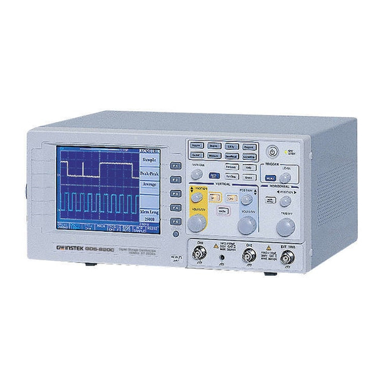
Good Will GDS-820 Oscilloscope
Manufacturer:

Image 1 of 1
If you have any other photos or manuals for the
Good Will GDS-820 you can upload the files here .
Model:
GDS-820
Date:
2004
Category:
Group:
Description:
User Manual
Manual Type:
User Manual

Pages:
89
Size:
708.28 Kbytes (725277 Bytes)
Language:
english
Revision:
Manual-ID:
82DS-82000I0
Date:
Quality:
Electronic document, no scan, very well readable.
Upload date:
2011 06 22
MD5:
52aa9725ad5032c453d867160f021354
Downloads:
2683
Information
Programming Manual
show more

GDS-800 Series Digital Storage Oscilloscope Operation Manual
1
Table of Contents Pages
1. USAGE PRECAUTIONS AND RECOMMENDATIONS …………………………2
2. GENERAL DESCRIPTION AND FEATURES………………………………………7
3. FIRST TIME OPERATION ………………………………………………………………..9
4. PANEL DESCRIPTION …………………………………………………………………..12
5. OPERATION …………………………………………………………………………………17
6. BLOCK DIAGRAM…………………………………………………………………………68
7. RS-232 CONFIGURATION ……………………………………………………………..69
8. SPECIFICATIONS………………………………………………………………………….72
9. EC DECLARATION OF CONFORMITY…………………………………………….82
Due to continuous improvements in the GDS-800 series Digital Storage
Oscilloscope, information contained in this manual is subject to change
without notice. Contact GW, for revisions and corrections.
This document supports firmware version v1.0 for GDS-806S/C and GDS-810S/C; firmware version
v2.03 for GDS-820S/C, GDS-840S/C and previous version
GDS-806/810/820/840 Programming Manual
Users can drive this digital storage oscilloscope by using the GPIB (General
Purpose Interface Bus) system with a computer, or from a computer across the
RS-232 serial connection. Commands sent over either interface can read or set
any GDS-806/810/820/840’s instructions. This chapter explains how to carry out
the following tasks.
Notes for GPIB installation
If you are setting up the oscilloscope with a GPIB system, please check the
following regulations:
Only a maximum of 15 devices can be connected to a single GPIB bus.
Do not use more than 20 m of cable to connect devices to a bus.
Connect one device for every 2 m of cable used.
Each device on the bus needs a unique device address. No two devices can
share the same device address.
Turn on at least two-thirds of the devices on the GPIB system while you use
the system.
Do not use loop or parallel structure for the topology of GPIB system.
2
-
Contents
-
Table of Contents
-
Bookmarks
Quick Links
GDS-806/810/820/840 Programming Manual
Digital Storage Oscilloscope
GDS-806/810/820/840
Programming Manual
© 2004 GOOD WILL Instrument Co., Ltd. All rights reserved
GW Part No: 82DS-82000I0
0
Related Manuals for GW Instek GDS-820
Summary of Contents for GW Instek GDS-820
-
Page 1: Digital Storage Oscilloscope
GDS-806/810/820/840 Programming Manual Digital Storage Oscilloscope GDS-806/810/820/840 Programming Manual © 2004 GOOD WILL Instrument Co., Ltd. All rights reserved GW Part No: 82DS-82000I0…
-
Page 2: Table Of Contents
GDS-806/810/820/840 Programming Manual Table of Contents Pages 1. INTRODUCTION……………………2 2. COMPUTER’S CONNECTION ………………… 6 3. REMOTE CONTROL’S COMMANDS …………….12 4. DETAILS OF COMMAND REFERENCE …………….19 5. STATUS REPORTS………………….71 6. ERROR MESSAGES ………………….79 7. PROGRAM TEMPLATE FOR GPIB………………. 80 8.
-
Page 3: Introduction
GDS-806/810/820/840 Programming Manual 1. Introduction Users can drive this digital storage oscilloscope by using the GPIB (General Purpose Interface Bus) system with a computer, or from a computer across the RS-232 serial connection. Commands sent over either interface can read or set any GDS-806/810/820/840’s instructions.
-
Page 4
GDS-806/810/820/840 Programming Manual Notes for RS-232 Configuration This oscilloscope contains a DB 9-pin, male RS-232 connector for serial communication with a computer or terminal. The RS-232 interface of this oscilloscope is configured as an RS-232 “Data Terminal Equipment”, so that data is sent from pin 3 and received on pin 2. -
Page 5: Computer’s Connection
GDS-806/810/820/840 Programming Manual When the oscilloscope is set up with a RS-232 interface, please check the following points: Do not connect the output line of one DTE device to the output line of the other. Many devices require a constant high signal on one or more input pins. Ensure that the signal ground of the equipment is connected to the signal ground of the external device.
-
Page 6
GDS-806/810/820/840 Programming Manual Figure 1-3. Rear panel of the oscilloscope (1): Main power switch (2): AC power socket (3): GPIB port (option for all series oscilloscopes) (4): Fuse drawer (5): “SELF CAL” BNC output (6): “GO/NO GO” BNC output (option for GDS-806/810) (7): USB connector (option for GDS-806/810) (8): Printer port (option for GDS-806/810) (9): RS-232 port… -
Page 7
GDS-806/810/820/840 Programming Manual 2. Computer’s Connection A personal computer with a GPIB card is the essential stuff in order to operate the oscilloscope via GPIB interface. The connections between oscilloscope and computer are following: Connect one end of a GPIB cable to the computer. Connect the other end of the GPIB cable to the GPIB port on the Oscilloscope. -
Page 8
GDS-806/810/820/840 Programming Manual SR1 (Service Request): The oscilloscope asserts the SRQ (Service request) line to notify the controller when it requires service. RL1 (Remote/Local): The oscilloscope responds to both the GTL (Go to Local) and LLO (Local Lock Out) interface messages. PP0 (Parallel Poll): The oscilloscope has no Parallel Poll interface function. -
Page 9
GDS-806/810/820/840 Programming Manual The GPIB connection testing If you want to test the GPIB connection is whether working or not, use the National Instrument’s “Interactive Control utility” for instance, you communicate with the GPIB devices through calls you interactively type in at the keyboard. The Interactive Control can help you to learn about the instrument and to troubleshoot problems by displaying the following information on your screen after you enter a command:… -
Page 10
GDS-806/810/820/840 Programming Manual The following example uses ibdev to open a device, assigns it to access board gpib0, chooses a primary address of 7 with no secondary address, sets a timeout of 10 seconds, enables the END message, and disables the EOS mode. :ibdev enter board index: 0 enter primary address: 7… -
Page 11
GDS-806/810/820/840 Programming Manual To write data to the device, use ibwrt. ud0: ibwrt «*IDN?» [0100] (cmpl) count: 5 To read data from your device, use ibrd. The data that is read from the instrument is displayed. For example, to read 28 bytes, enter the following: ud0: ibrd 28 [0100] (cmpl) count: 28… -
Page 12
GDS-806/810/820/840 Programming Manual The RS232 connection testing If you want to test whether the RS-232 connection is working or not, you can send a command from computer. For instance, using a terminal program send the query command *idn? should return the Manufacturer, model number, serial number and firmware version in the following format: GW,GDS-820,P920130,V.2.01 If you do not receive a proper response from the oscilloscope, please check if the… -
Page 13: Remote Control’s Commands
GDS-806/810/820/840 Programming Manual 3. Remote Control’s Commands This oscilloscope can be operated from computer via the GPIB port or RS-232 port. The remote commands of this oscilloscope are compatible with IEEE-488.2 and SCPI standards partially. SCPI SCPI (Standard Commands for Programmable Instruments) is a standard that created by an international consortium of the major test and measurement equipment manufacturers.
-
Page 14
GDS-806/810/820/840 Programming Manual As shown in the figure 3-1, the IEEE-488.1 standard locates at layer A, the layer A is belonged to the protocol of interface function on the GPIB bus. The source handshake (SH), acceptor handshake (AH) and talker are included in this layer (10 interface functions totally). -
Page 15
GDS-806/810/820/840 Programming Manual Command Header The command header has a hierarchical structure that can be represented by a command tree (Figure 3-2). Root node :TRIGger: :SLOP ? :DELay Lower- level nodes :TIMe ? :TYPe Leaf node (event) (Delay) Figure 3-2: Tree hierarchy The top level of the tree is the root level. -
Page 16
GDS-806/810/820/840 Programming Manual Parameter If the command has parameters, the values have to be included. In this manual, when we expressed the syntax of the command, the < > symbols are used for enclosing the parameter type. For instance, the syntax of the command in Figure 8-5 includes the Boolean parameter type NOTE: Do not include the <, >, or | symbols when entering the actual value for a parameter. -
Page 17
GDS-806/810/820/840 Programming Manual For the actual value of the parameter type <Boolean>, you have to enter 0 instead of “OFF” or enter 1 instead of “ON”. The following example includes both the header and a value for the parameter type: :TRIGger:NREJ 0 Parameter values that appeared in this manual are often separated by a vertical line. -
Page 18
GDS-806/810/820/840 Programming Manual Entering Commands The standards that govern the command set for this oscilloscope allow for a certain amount of flexibility when you enter commands. For instance, you can abbreviate many commands or combine commands into one message that you send to the oscilloscope. -
Page 19
GDS-806/810/820/840 Programming Manual Combining Commands You can use a semicolon (;) to combine commands and queries. This oscilloscope executes coherent commands in the order it receives them. When you coherent queries, the oscilloscope will combine the responses into a single response message. -
Page 20: Details Of Command Reference
GDS-806/810/820/840 Programming Manual 4. Details of Command Reference Each command in this chapter will give a brief description. The examples of each command will be provided and what query form might return. *CLS (no query form) Clears all event status data register. This includes the Output Queue, Operation Event Status Register, Questionable Event Status Register, and Standard Event Status Register.
-
Page 21
GDS-806/810/820/840 Programming Manual Examples *ESE 65 sets the ESER to binary 0100 0001. If the ESER contains the binary value 1000 0010, the *ESE? will return the value of 130. *ESR? (query only) Returns and clears the contents of the Standard Event Status Register (SESR). Syntax *ESR? Returns… -
Page 22
GDS-806/810/820/840 Programming Manual *LRN? (query only) Returns the string that the oscilloscope settings will be listed. Syntax *LRN? Returns *OPC? The command form (*OPC) sets the operation complete bit (bit 0) in the Standard Event Status Register (SESR) when all pending operations finish. The query form (*OPC?) tells the oscilloscope to place an ASCII 1 in the Output Queue when the oscilloscope completes all pending operations. -
Page 23
GDS-806/810/820/840 Programming Manual *RCL Recall the setting data from memory which previous saved. The settings of RS-232 (or GPIB) can be stored in memory of M1~M15. However, if users recall the stored memory which the settings of RS-232 or GPIB are different with present settings, the RS-232 (or GPIB) settings will keep with the present situation. -
Page 24
GDS-806/810/820/840 Programming Manual *SRE Setup the contents of the Service Request Enable Register (SRER). The query form returns the contents of the SRER. Bit 6 of the SRER is always zero. The bits on the SRER correspond to the bits on the SBR. Syntax *SRE <NR1>… -
Page 25
GDS-806/810/820/840 Programming Manual *WAI (no query form) WAI prevents the programming instrument from executing further commands or queries until all pending operations finish. Syntax *WAI :ACQuire:AVERage Select the average number of waveform acquisition. The range for averaging is from 2 to 256 in powers of 2. Note: Before implement this instrument, please apply “:ACQuire:MODe 2”… -
Page 26
GDS-806/810/820/840 Programming Manual :ACQuire:LENGth Select the number of record length. This oscilloscope provides record length of 500, 1250, 2500, 5000, 12500, 25000, 50000, and 125000. Syntax :ACQuire:LENGth {0|1|2|3|4|5|6|7} :ACQuire:LENGth? Arguments 0→Record length is 500 1→Record length is 1250 2→Record length is 2500 3→Record length is 5000 4→Record length is 12500 5→Record length is 25000… -
Page 27
GDS-806/810/820/840 Programming Manual :ACQuire<X>:MEMory? (query only) (Available for firmware 2.03 and above only) Transfer the total waveform data from the acquisition memory. (The memory capacity can be selected as 500, 1250, 2500, 5000, 12500, 25000, 50000, or 125000 points. See Page 25 for details.) Syntax :ACQuire<X>:MEMory? Arguments… -
Page 28
GDS-806/810/820/840 Programming Manual : Indicates the corresponding sample rate of received waveform data Sample Rate (4 bytes). The sample rate is indicated by floating point format which compatible with IEEE 754 standards. Note: This block uses little-endian byte ordering. See Appendix A for more conversion information Channel indicator: Show the channel which sent the waveform data (1 byte). -
Page 29
GDS-806/810/820/840 Programming Manual :ACQuire<X>:POINt (query only) Transfer the displayed waveform data (always 500 points data totally) from the oscilloscope. Each point is composed by two bytes (the integer value of 16 bits). The high byte (MSD) will be prior transferred. Syntax :ACQuire<X>:POINt Arguments… -
Page 30
GDS-806/810/820/840 Programming Manual :AUToset Perform an automatic setup in order to optimize the acquisition parameters. Syntax :AUToset :CHANnel<X>:BWLimit Enable or disable the bandwidth limit function. Syntax :CHANnel<X>:BWLimit {0|1} :CHANnel<X>:BWLimit? Arguments <X>→Specify the channel number (1|2) 0→Disable bandwidth limit 1→Enable bandwidth limit Returns <NR1>… -
Page 31
GDS-806/810/820/840 Programming Manual :CHANnel<X>:DISPlay Enable or disable the channel’s display. Syntax :CHANnel<X>:DISPlay {0|1} :CHANnel<X>:DISPlay? Arguments <X>→Specify the channel number (1|2) 0→Disable channel <X> display 1→Enable channel <X> display Returns <NR1> :CHANnel<X>:INVert Enable or disable the waveform invert function. Syntax :CHANnel<X>:INVert {0|1} :CHANnel<X>:INVert? Arguments <X>→Specify the channel number (1|2) -
Page 32
GDS-806/810/820/840 Programming Manual :CHANnel<X>:MATH Set the math expression. Syntax :CHANnel<X>:MATH {0|1|2|3} Arguments <X>→Specify the channel number (1|2) 0→Select the add operator 1→Select the subtract operator 2→Select the FFT operation 3→Turn off math function Returns <NR1> :CHANnel<X>:OFFSet Sets or query the offset voltage. Syntax :CHANnel<X>:OFFSet <NR3>… -
Page 33
GDS-806/810/820/840 Programming Manual Next table shows the relationship between the <NR3> value and matching offset voltage. 0.002 2mV 0.01 10mV 0.1 100mV 1 1V 0.005 2mV 0.02 20mV 0.2 200mV 2 2V 0.05 50mV 0.5 500mV 5 5V Returns <NR3> :CHANnel<X>:PROBe Select the different probe attenuation factor. -
Page 34
GDS-806/810/820/840 Programming Manual :CHANnel<X>:SCALe Sets or query the vertical scale of the specified channel. Syntax :CHANnel<X>:SCALe <NR3> :CHANnel<X>:SCALe? Arguments <X>→Specify the channel number (1|2) <NR3> is the desired gain value in volts per division. The range is 2mV/div to 5V/div (with 1X probe). Next table shows the relationship between the <NR3>… -
Page 35
GDS-806/810/820/840 Programming Manual :CURSor:X<X>Position Select the cursors position of X axis. Syntax :CURSor:X<X>Position <NR1> :CURSor:X<X>Position? Arguments <X>→Specify the cursor (1|2) <NR1> is the desired position. For x-axis operation, the range is 1 to 249; for y-axis operation, the range is 1 to 199. Returns <NR1>… -
Page 36
GDS-806/810/820/840 Programming Manual :CURSor:<X>DELta? (query only) Return the time or voltage diversity between the two vertical or horizontal cursors. Syntax :CURSor:XDELta? :CURSor:YDELta? Arguments <X>→Specify the time or voltage diversity (X|Y) Returns <NR3> :CURSor:XDISplay Enable or disable the cursors display for X axis. Syntax :CURSor:XDISplay {0|1} Arguments… -
Page 37
GDS-806/810/820/840 Programming Manual :CURSor:SOURce Select which channel cursors is active for front panel control. Syntax :CURSor:SOURce {1|2|3} :CURSor:SOURce? Arguments 1→Select channel 1 for cursors measurement 2→Select channel 2 for cursors measurement 3→Select math function for cursors measurement Returns <NR1> :DISPlay:ACCumulate Select the accumulate display mode. -
Page 38
GDS-806/810/820/840 Programming Manual :DISPlay:CONTrast Select contrast level of LCD screen for data readout and waveform displays. Syntax :DISPlay:CONTrast <NR1> :DISPlay:CONTrast? Arguments <NR1> is the desired brightness level. The range is from 0~20 (0% to 100%). Returns <NR1> :DISPlay:GRATicule Select graticule display type for LCD screen. Syntax :DISPlay:GRATicule {0|1|2} :DISPlay:GRATicule? -
Page 39
GDS-806/810/820/840 Programming Manual :DISPlay:WAVeform Select the dots (or vectors) display for data.points. Syntax :DISPlay:WAVeform <0|1> :DISPlay:WAVeform? Arguments 0→Enable vectors display 1→Enable dots display Returns <NR1> :GONogo:CLEar (Available for firmware 2.0 and above only) Clear the total and failure counter value on the screen. This command is equal to the function key “F5”… -
Page 40
GDS-806/810/820/840 Programming Manual :GONogo:EXECute (Available for firmware 2.0 and above only) Start or stop the execution of GO/NO-GO comparison function. This command is equal to the function key “F4” of GO/NO-GO menu. Syntax :GONogo:EXECute {0|1} :GONogo:EXECute? Arguments 0→Stop GO/NO-GO comparison 1→Start GO/NO-GO comparison Returns <NR1>… -
Page 41
GDS-806/810/820/840 Programming Manual :GONogo:NGCount? (query only) (Available for firmware 2.0 and above only) Return the value of fail count and total count. Syntax :GONogo:NGCount? Returns <NR1> :GONogo:NGDefine (Available for firmware 2.0 and above only) Sets and query the user-defined NO-GO conditions. This command is equal to the function key “F4”… -
Page 42
GDS-806/810/820/840 Programming Manual :GONogo:SOURce (Available for firmware 2.0 and above only) Sets and query the user-defined GO/NO-GO comparison source channel. This command is equal to the function key “F2” pressing of GO/NO-GO menu. Syntax :GONogo:SOURce {0|1} :GONogo:SOURce? Arguments 0→Select CH1 to be the comparison 1→Select CH2 to be the source. -
Page 43
GDS-806/810/820/840 Programming Manual :MEASure:FALL? (query only) Return the value of timing measurement that taken for falling edge of the first pulse in the waveform. Syntax :MEASure:FALL? Returns <NR3>. Note: Please select the specific channel before implement any measurement. See explanation for “:MEASure:SOURce” :MEASure:FREQuency? (query only) Return the value of Frequency measurement. -
Page 44
GDS-806/810/820/840 Programming Manual :MEASure:PDUTy? (query only) Return the ratio of the positive pulse width to the signal period. Syntax :MEASure:PDUTy? Returns <NR2>. is the percentage of ratio. The range is from 1 to 99. Note: Please select the specific channel before implement any measurement. See explanation for “:MEASure:SOURce”… -
Page 45
GDS-806/810/820/840 Programming Manual :MEASure:PWIDth? (query only) Return the value of timing measurement of the first positive pulse in the waveform. Syntax :MEASure:PWIDth? Returns <NR3>. Note: Please select the specific channel before implement any measurement. See explanation for “:MEASure:SOURce” :MEASure:RISe? (query only) Return the value of timing measurement that taken for rising edge of the first pulse in the waveform. -
Page 46
GDS-806/810/820/840 Programming Manual :MEASure:SOURce Select the measured channel (channel 1 or 2). The default setting of measured channel is channel one. Note: Please select the specific channel before implement any measurement. Syntax :MEASure:SOURce {1|2} Arguments 1→Enable the measurement functions for channel 1 2→Enable the measurement functions for channel 2 Returns <NR1>. -
Page 47
GDS-806/810/820/840 Programming Manual :MEASure:VAVerage? (query only) Return the average voltages. Syntax :MEASure:VAVerage? Returns <NR3>. Note: Please select the specific channel before implement any measurement. See explanation for “:MEASure:SOURce” :MEASure:VHI? (query only) Return the value of global high voltage. Syntax :MEASure:VHI? Returns <NR3>. -
Page 48
GDS-806/810/820/840 Programming Manual :MEASure:VMAX? (query only) Return the value of maximum amplitude. Syntax :MEASure:VMAX? Returns <NR3>. Note: Please select the specific channel before implement any measurement. See explanation for “:MEASure:SOURce” :MEASure:VMIN? (query only) Return the value of minimum amplitude. Syntax :MEASure:VMIN? Returns <NR3>. -
Page 49
GDS-806/810/820/840 Programming Manual :MEASure:VRMS? (query only) Return the value of true Root Mean Square voltage. Syntax :MEASure:VRMS? Returns <NR3>. Note: Please select the specific channel before implement any measurement. See explanation for “:MEASure:SOURce” :PRINt Begin a hardcopy to a specified printer. Syntax :PRINt :REFResh… -
Page 50
GDS-806/810/820/840 Programming Manual :SYSTem:UNLock The front panel keyboards and knobs of the oscilloscope will be disabled after any one of the remote control command received. Use this command in order to re-activate the front panel keyboards and knobs. Syntax :SYSTem:UNLock :TEMPlate<X>:DOWNload? (Available for firmware 2.0 and above only) Download the user-selected template. -
Page 51
GDS-806/810/820/840 Programming Manual Template number: The location of template stored in memory. The valid range is from 1 to 100 dots. The content is a single byte in hex (0x01 ~ 0x64). Position: The position of template. The valid range is from -300 to +300 dots. The content is a two bytes signed integer in hex (0xFED4 ~ 0x012C). -
Page 52
GDS-806/810/820/840 Programming Manual :TEMPlate<X>:UPLoad (Available for firmware 2.0 and above only) Upload the user-defined template to the assigned location. Syntax :TEMPlate1:UPLoad#3548……… Format: The string of data is following. # Data size Data size Package Template Position Text Reserved Check Template digit type number… -
Page 53
GDS-806/810/820/840 Programming Manual Check sum: The check sum value is coming from the sum of 500 bytes of template data. This value is 32 bits unsigned integer in hex (4 bytes, high byte first). Template data: The effective template data which covers 250 points totally(500 bytes). -
Page 54
GDS-806/810/820/840 Programming Manual :TEMPlate:MIN (Available for firmware 2.0 and above only) Sets and query the number of template used for minimum boundary. Syntax :TEMPlate:MIN {1|100} :TEMPlate:MIN? Returns <NR1> Note: A template can be defined as either MAX or MIN template only. :TEMPlate:MODe (Available for firmware 2.0 and above only) Sets and query the template mode. -
Page 55
GDS-806/810/820/840 Programming Manual :TEMPlate:POSition:MAX (Available for firmware 2.0 and above only) Sets and query the position of maximum template. This command will not change the position value that stored in flash ROM. Unless you press the “Save & Create” key in GO/NO-GO edit menu. That means if you exit from the GO/NO-GO function, we will recall the value from flash ROM. -
Page 56
GDS-806/810/820/840 Programming Manual :TEMPlate:TOLerance (Available for firmware 2.0 and above only) Sets and query the tolerance of auto template. Syntax :TEMPlate:TOLerance <NR2> :TEMPlate:TOLerance? Arguments <NR2> is the desired tolerance percentage. The range is from 0.4~40 (0.4% to 40%). Returns <NR2> % TIMebase:DELay Sets the horizontal position (delay timebase) parameter. -
Page 57
GDS-806/810/820/840 Programming Manual :TIMebase:SCALe Sets the horizontal timebase scale per division (SEC/DIV). Syntax :TIMebase:SCALe <NR3> :TIMebase:SCALe? Arguments Sec/div Sec/div Sec/div 25ms 5μs 2.5ns 10μs 50ms 2.5e 100ms 25μs 100e 10ns 50μs 250ms 250e 25ns 100μs 100e 500ms 500e 50ns 250μs 250e 100ns 100e 500μs 500e… -
Page 58
GDS-806/810/820/840 Programming Manual :TIMebase:SWEep Selects the horizontal timebase sweep mode. This command is equivalent to setting the horizontal menu. Syntax :TIMebase:SWEep <0|1|2|3|4> :TIMebase:SWEep? Arguments 0→Main timebase 1→Window 2→Window Zoom 3→Roll mode 4→XY mode Returns <NR1> :TIMebase:WINDow:DELay Setting and query the zoomed area (the gray color area) for window zoomed display. -
Page 59
GDS-806/810/820/840 Programming Manual :TIMebase:WINDow:SCALe Sets and query the scale (length) of the windows zoomed timebase. Syntax :TIMebase:WINDow:SCALe <NR3> :TIMebase:WINDow:SCALe? Arguments <NR3> is the desired scale (length) of the windows zoomed timebase. Returns <NR3> :TRIGger:COUPle Select and query the type of trigger coupling. Syntax :TRIGger:COUPle <0|1>… -
Page 60
GDS-806/810/820/840 Programming Manual :TRIGger:DELay:TIMe Sets and query the user-defined delay trigger time. Syntax :TRIGger:DELay:TIMe <NR3> :TRIGger:DELay:TIMe? Arguments <NR3> is the desired user-defined delay time. The range is from 100ns~1.3ms. Returns <NR3> Note: Please select the specific delay type before implement any measurement. See explanation for “:TRIGger:DELay:TYPe”… -
Page 61
GDS-806/810/820/840 Programming Manual :TRIGger:DELay:LEVel Sets and query the user-defined start trigger signal level. Syntax :TRIGger:DELay:LEVel <NR3> :TRIGger:DELay:LEVel? Arguments <NR3> is the desired user-defined start trigger signal level. The range is ±12. Returns <NR3> :TRIGger:DELay:MODe Select and query the different start trigger (i.e. external trigger) signal level. Syntax :TRIGger:DELay:MODe <0|1|2>… -
Page 62
GDS-806/810/820/840 Programming Manual :TRIGger:DELay:TYPe Select and query the different delay trigger settings. Syntax :TRIGger:ADVance:TYPe <0|1> :TRIGger:ADVance:TYPe? Arguments 0→Time setting 1→Event setting Returns <NR1> :TRIGger:FREQuency? (query only) Return the readout value of trigger frequency counter. Syntax :TRIGger:FREQuency? Returns <NR3>. -
Page 63
GDS-806/810/820/840 Programming Manual :TRIGger:LEVel Select and query the trigger level. Syntax :TRIGger:LEVel <NR3> :TRIGger:LEVel? Arguments <NR3> is the desired trigger level voltage. Returns <NR3> :TRIGger:MODe Select and query the trigger mode. Syntax :TRIGger:MODe <0|1|2|3> :TRIGger:MODe? Arguments 0→Auto Level 1→Auto 2→Normal 3→Single Returns <NR1>… -
Page 64
GDS-806/810/820/840 Programming Manual :TRIGger:NREJ Switch and query the noise rejection mode. Syntax :TRIGger:NREJ <0|1> :TRIGger:NREJ? Arguments 0→OFF 1→ON Returns <NR1> :TRIGger:PULSe:MODe Switch and query different pulse trigger type. Syntax :TRIGger:PULSe:MODe <0|1|2|3> :TRIGger:PULSe:MODe? Arguments 0→< 1→> 2→= 3→≠ Returns <NR1>… -
Page 65
GDS-806/810/820/840 Programming Manual :TRIGger:PULSe:TIMe Select the time value for pulse width. Syntax :TRIGger:PULSe:TIMe <NR3> :TRIGger:PULSe:TIMe? Arguments <NR3> is the desired time value of pulse width, the unit is in second. Returns <NR3> :TRIGger:REJect Select and query the frequency rejection mode. Syntax :TRIGger:REJect <0|1|2>… -
Page 66
GDS-806/810/820/840 Programming Manual :TRIGger:SLOP Switch and query the rising or falling trigger slope. Syntax :TRIGger:SLOP <0|1> :TRIGger:SLOP? Arguments 0→Rising slope 1→Falling slope Returns <NR1> :TRIGger:SOURce Select and query the trigger source. Syntax :TRIGger:SOURce <0|1|2|3> :TRIGger:SOURce? Arguments 0→Channel 1 1→Channel 2 2→External trigger 3→AC line voltage Returns… -
Page 67
GDS-806/810/820/840 Programming Manual :TRIGger:TYPe Select and query the trigger type. Syntax :TRIGger:TYPe <0|1|2|3> :TRIGger:TYPe? Arguments 0→Edge 1→Video 2→Pulse 3→Delay Returns <NR1>… -
Page 68
GDS-806/810/820/840 Programming Manual :TRIGger:VIDeo:FIELd Select and query the field on which the video trigger mode will be triggered. Syntax :TRIGger:VIDeo:FIELd <0|1|2> :TRIGger:VIDeo:FIELd? Arguments 1→Odd frame (Field 1) 0→Line 2→Even frame (Field 2) Returns <NR1> :TRIGger:VIDeo:LINe Select and query the specified line for video signal. Syntax :TRIGger:VIDeo:LINe <NR1>… -
Page 69
GDS-806/810/820/840 Programming Manual :TRIGger:VIDeo:POLarity Select and query the input video polarity. Syntax :TRIGger:VIDeo:POLarity <0|1> :TRIGger:VIDeo:POLarity? Arguments 0→Positive-going sync pulses 1→Negative-going sync pulses Returns <NR1> :TRIGger:VIDeo:TYPe Select and query the TV broadcast system. Syntax :TRIGger:VIDeo:TYPe <0|1|2> :TRIGger:VIDeo:TYPe? Arguments 0→PAL 1→NTSC 2→SECAM Returns <NR1>… -
Page 70
GDS-806/810/820/840 Programming Manual :WMEMory<X>:DISPlay Select whether the stored waveform will be displayed after being saved. Syntax :WMEMory<X>:DISPlay <NR1> :WMEMory<X>:DISPlay? Arguments <X>→Specify the location of RefA or RefB memory (1|2) 0→OFF 1→ON Returns <NR1> :WMEMory<X>:ERASe Select whether the stored waveform will be erased after being saved. Syntax :WMEMory<X>:ERASe Arguments… -
Page 71
GDS-806/810/820/840 Programming Manual :WMEMory<X>:OFFSet After the “:WMEMory<X>:LOCate” command is specified, you can adjust the position up or down by this command. Syntax :WMEMory<X>:OFFSet <NR1> Arguments <X>→Specify the location of RefA or RefB memory (1|2) <NR1> is the desired offset position. The rage is from –100 to +100. :WMEMory<X>:SAVe Select whether the memory set will be saved. -
Page 72: Status Reports
GDS-806/810/820/840 Programming Manual 5. Status Reports A set of status registers allows the user to quickly determine the Digital storage oscilloscope’s internal processing status. The status register, as well as the status and event reporting system, adhere to SCPI recommendations. Structure of System The sketch of the status and event reporting system is showed on figure 5-1.
-
Page 73
GDS-806/810/820/840 Programming Manual Figure 5-1. A graphic represents the status registers and their connections. -
Page 74
GDS-806/810/820/840 Programming Manual STATus :QUEStionable :OPERation :QUEue [EVENt]? :CONDition :ENABle :CONDition :ENABle EVENt? EVENt? Figure 5-2: STATus hierarchy of SCPI defined register To SBR Event Enable Condition Register Register Register Figure 5-3: Status registers and related commands The CONDition register is a read-only register which monitors the present state of the instrument. -
Page 75
GDS-806/810/820/840 Programming Manual QUEStionable Status Registers. Table 5-1 shows the bit designations of the 16 bit QUEStionable Status Register. Bit 15 Bit 14 Bit 13 Bit 12 Bit 11 Bit 10 Bit 9 Bit 8 ∗ 32768 16384 8192 4096 2048 1024 Bit 7 Bit 6 Bit 5… -
Page 76
GDS-806/810/820/840 Programming Manual Status Registers. There are two status registers are included with this oscilloscope which defined by IEEE-488.1 and IEEE-488.2 standards. Status Byte Register (SBR) Standard Event Status Register (SESR) Status Byte Register (SBR): The SBR (Table 5-3) summaries the status of all other registers and queue. -
Page 77
GDS-806/810/820/840 Programming Manual Use serial poll or the *STB? Query to read the contents of the SBR. The bits in the SBR are set and cleared depending on the contents of the Standard Event Status Register (SESR), the Standard Event Status Register (SESR), and the Output Queue. -
Page 78
GDS-806/810/820/840 Programming Manual Enable Registers. The enable registers determine whether certain events are reported to the Status Byte Register and SRQ. This oscilloscope has the following enable registers. Event Status Enable Register (ESER) OPERation Enable Register QUEStionable Enable Register Service Request Enable Register (SRER) When one of the bits of the enable registers is high and the corresponding bit in the status register is high, the enable registers will perform a logical OR function, the output that controls the set bit of the Status Byte Register is high. -
Page 79
GDS-806/810/820/840 Programming Manual Queues The output queue is included with this digital storage oscilloscope. Output Queue: This digital storage oscilloscope store query responses in the output queue by succeeding the IEEE 488.2 protocol. If the Digital storage oscilloscope receives a lot of un-read query data simultaneously, the output buffer of Digital storage oscilloscope will be covered repeatedly;… -
Page 80: Error Messages
GDS-806/810/820/840 Programming Manual 6. Error Messages Table 6-1 lists the SCPI error messages for this digital storage oscilloscope. Error SCPI Error Code/Explanation Code -100 Command error -102 Syntax error /*Execution Error*/ -220 Parameter error -221 Settings conflict -222 Data out of range -223 Too much data -224…
-
Page 81: Program Template For Gpib
GDS-806/810/820/840 Programming Manual 7. Program Template for GPIB /* Filename — gds820ex1.c * This is an example program written in C. We use a NI’s GPIB interface * card and one X86 PC to control GDS-806/810/820/840. This program could * get the waveform data from GDS-806/810/820/840, and save them to a file. * You can use Microsoft Visual C++ or Borland C++ Builder to compile this * file.
-
Page 82
GDS-806/810/820/840 Programming Manual #define EOTMODE /* Enable the END message #define EOSMODE /* Disable the EOS mode void Acquire(void); void Delay(int); void ShowIbsta(char); int Dev; /* Device handle unsigned char ReadBuffer[201]; /* Read data buffer char ErrorMnemonic[21][5] = {«EDVR», «ECIC», «ENOL», «EADR», «EARG», «ESAC», «EABO», «ENEB», «EDMA», «», «EOIP», «ECAP», «EFSO», «», «EBUS», «ESTB», «ESRQ», «», «», «», «ETAB»};… -
Page 83
GDS-806/810/820/840 Programming Manual Delay(1000); ibwrt (Dev, «*IDN?\n», 6L); /*Get the unique identification */ printf(«*IDN?\n\r»); /*code of the GDS-806/810/820/840.*/ if((ibsta&ERR)||(ibsta&TIMO)){ ShowIbsta(1); return 0; while(1){ ibrd (Dev, ReadBuffer, 100); /*Read datas from input bufer. */ if((ibsta&ERR)||(ibsta&TIMO)){ ShowIbsta(0); return 0; for(i=0;i<ibcntl;i++){ ch=ReadBuffer[i]; WaveBuf[count++]=ch; if(ch==’\n’){ WaveBuf[count]=0x00;… -
Page 84
GDS-806/810/820/840 Programming Manual Delay(1000); ibwrt (Dev, «:CHANnel1:DISPlay 1\n», 20L);/*Set channel 1 display on */ printf(«:CHANnel1:DISPlay 1\n\r»); if((ibsta&ERR)||(ibsta&TIMO)){ ShowIbsta(1); return 0; Delay(1000); ibwrt (Dev, «:TIMebase:SCALe 2.5e-4\n», 23L);/*Set timebase: 200us/div*/ printf(«:TIMebase:SCALe 2.5e-4\n\r»); if((ibsta&ERR)||(ibsta&TIMO)){ ShowIbsta(1); return 0; Delay(1000); ibwrt (Dev, «:CHANnel1:OFFSet 0\n», 19L); /*Set offset voltage: 0V */ printf(«:CHANnel1:OFFSet 0\n\r»);… -
Page 85
GDS-806/810/820/840 Programming Manual Delay(1000); ibwrt (Dev, «:ACQuire:MODe 0\n», 16L); /*Set acquire mode: sample mode */ printf(«:ACQuire:MODe 0\n\r»); if((ibsta&ERR)||(ibsta&TIMO)){ ShowIbsta(1); return 0; Delay(1000); ibwrt (Dev, «:TRIGger:LEVel 0.3\n», 19L); /*Set trigger level: 0.3V*/ printf(«:TRIGger:LEVel 0.3\n\r»); if((ibsta&ERR)||(ibsta&TIMO)){ ShowIbsta(1); return 0; Delay(1000); ibwrt (Dev, «:TRIGger:MODe 1\n», 16L); /*Set trigger mode: AUTO */ printf(«:TRIGger:MODe 1\n\r»);… -
Page 86
GDS-806/810/820/840 Programming Manual ibwrt (Dev, «:SYSTEM:UNLOCK\n»,15L); /*Unlock GDS-806/810/820/840 from remote control.*/ printf(«:SYSTEM:UNLOCK\n\r»); if((ibsta&ERR)||(ibsta&TIMO)){ ShowIbsta(1); return 0; ibonl(Dev,0); /*Take the device offline. */ return 1; void Acquire(void) short i, j; FILE *writeP; char writeFilename[15] = «wavedata.txt»; short wave; int tmp, count=0; ibwrt (Dev, «:ACQUIRE1:POINT\n», 16L);… -
Page 87
GDS-806/810/820/840 Programming Manual while(1){ ibrd(Dev, ReadBuffer, 100); if((ibsta&ERR)||(ibsta&TIMO)){ ShowIbsta(0); Delay(100000); exit (1); for(i=0;i<ibcntl;i++) WaveBuf[count++]=ReadBuffer[i]; printf(«\rReceived: %7d «, count); if(count>=1014){ printf(«\rReceived: %7d bytes.\n\r», count); break; /*Open file «wavedata.txt» and write waveform datas to it.*/ writeP=fopen(writeFilename, «w»); if(writeP == NULL){ printf(«error: cannot write ‘%s’\n», writeFilename); exit(1);… -
Page 88
GDS-806/810/820/840 Programming Manual void Delay(int i) int j,k; for(j=0;j<i;j++){ for(k=0;k<30000;k++) void ShowIbsta(char c) if(ibsta & ERR){ if(c) printf(«\n\rUnable write to device(ibsta= %x), (iberr=%x)\n\r»,ibsta,iberr); else printf(«\n\rUnable read from device(ibsta= %x), (iberr=%x)\n\r»,ibsta,iberr); else{ if(c) printf(«\n\rWrite, ibsta= %x»,ibsta); else printf(«\n\rRead, ibsta= %x»,ibsta);… -
Page 89: Appendix A: How Can We Convert The Hexadecimal Format To A Floating Point Format
GDS-806/810/820/840 Programming Manual Appendix A: How can we convert the hexadecimal format to a floating point format Question: As the previous example listed on page 27, how can the hexadecimal value of “0×4C 0×BE 0×BC 0×20” transfer to 100M(Sa/s)? Answer: just use the attached C language program: #include <stdio.h>…
GDS-800 Series Digital Storage Oscilloscope Operation Manual
1
Table of Contents Pages
1. USAGE PRECAUTIONS AND RECOMMENDATIONS …………………………2
2. GENERAL DESCRIPTION AND FEATURES………………………………………7
3. FIRST TIME OPERATION ………………………………………………………………..9
4. PANEL DESCRIPTION …………………………………………………………………..12
5. OPERATION …………………………………………………………………………………17
6. BLOCK DIAGRAM…………………………………………………………………………68
7. RS-232 CONFIGURATION ……………………………………………………………..69
8. SPECIFICATIONS………………………………………………………………………….72
9. EC DECLARATION OF CONFORMITY…………………………………………….82
Due to continuous improvements in the GDS-800 series Digital Storage
Oscilloscope, information contained in this manual is subject to change
without notice. Contact GW, for revisions and corrections.
This document supports firmware version v1.0 for GDS-806S/C and GDS-810S/C; firmware version
v2.03 for GDS-820S/C, GDS-840S/C and previous version
Технические характеристики цифрового осциллографа GDS-820S:
| Параметр | Значения |
| КАНАЛ ВЕРТИКАЛЬНОГО ОТКЛОНЕНИЯ | |
| Полоса пропускания (-3 дБ) | 0 … 150 МГц Ограничение полосы пропускания до 20 МГц |
| Коэффициент отклонения | 2 мВ/дел … 5 В/дел (шаг 1-2-5) |
| Погрешность установки | ± 3 % |
| Время нарастания | < 2,3 нс |
| Входной импеданс | 1 МОм (± 2 %) / 22 пФ |
| Максимальное входное напряжение | 300 В (DC+AС пик, до 1 кГц) |
| Режимы работы | Канал 1, канал 2, канал 1 (2) инвертированный, канал 1 и 2 |
| Математика | Кан 1 + Кан 2; Кан 1 — Кан 2; БПФ |
| КАНАЛ ГОРИЗОНТАЛЬНОГО ОТКЛОНЕНИЯ | |
| Коэффициент развертки | 1 нс/дел … 10 с/дел (шаг 1-2-5) |
| Погрешность установки | ± 0,01 % |
| Режимы работы | Основной, окно, ZOOM окна, самописец, X-Y |
| СИНХРОНИЗАЦИЯ | |
| Источники синхросигнала | Канал 1, канал 2, сеть, внешний |
| Режимы запуска развертки | Автоколебательный, ждущий, однократный, ТВ (NTSC, PAL / SECAM), пред- (20 дел.) и послезапуск (1000 дел), по времени (100 нс…1,3 мс), по событию (2…65000), по уровню (ТТЛ, ЭСЛ, ± 20 В), по фронту, по длительности импульса (20 нс … 10 с) |
| Фильтры синхронизации | ФНЧ, ФВЧ, фильтр шума, связь АС, связь DC |
| Вход внешней синхронизации | 1 МОм (± 2 %) / 22 пФ |
| АНАЛОГО-ЦИФРОВОЕ ПРЕОБРАЗОВАНИЕ | |
| Разрешение по вертикали | 8 бит |
| Частота дискретизации | До 100 МГц на канал |
| Эквивалентная частота дискретизации | До 25 ГГц на канал |
| Длина записи | 125 Кбайт на канал |
| Пиковый детектор | 10 нс |
| Режимы работы | Выборка, пик. детектор (> 10 нс); усреднение (2 /…/ 256); накопление; выбор длины записи (0,5 К /…/ 125 К) |
| АВТОМАТИЧЕСКИЕ ИЗМЕРЕНИЯ | |
| Функции по вертикали | U пик-пик; U; U ср. кв.; U0; -U; +U; U макс.; U мин. |
| Функции по горизонтали | f; T; t нарастания; t среза; +τ; -τ; коэф. заполнения |
| ЧАСТОТОМЕР | |
| Разрешение | 6 разрядов |
| Диапазон измерений | 10 Гц … 150 МГц |
| Погрешность измерения | ± 2 % |
| ДОПОЛНИТЕЛЬНЫЕ ВОЗМОЖНОСТИ | |
| Интерфейс | RS-232, LPT+ модуль «годен-негоден»+USB или опция GPIB |
| Синхронизация | Автовыбор синхросигнала (2-кан. режим) |
| Автоустановка | В/дел, с/дел, параметры синхросигнала |
| Режим X-Y | Х – кан 1; Y – кан 2; разность фаз < 3° до 100 кГц |
| Глубокая память | Запись/считывание: 2 осциллограммы; 15 профилей |
| Функции | Сравнение формы сигнала с шаблоном; автовоспроизведение профилей с авто- или курсорными измерениями |
| ОБЩИЕ ДАННЫЕ | |
| ЖК-дисплей | Монохромный 8 × 12 дел (разрешение 320 × 240) |
| Напряжение питания | 100 … 240 В, 48 … 63 Гц (автовыбор) |
| Габаритные размеры | 254 × 142 × 310 мм |
| Масса | 4,1 кг |
«Правила пользования порталом» содержат правила размещения комментариев на портале Cita Rīga. Добавляя свой комментарий, Вы подтверждаете, что согласны со следующим:
- Хотя модератор и будет пытаться проверить комментарии, невозможно оперативно проверить все добавленные комментарии.
- Все комментарии содержат мнения и суждения соответствующих авторов, но ни в коем случае не администратора или авторов портала Cita Rīga.
- Вы соглашаетесь не размещать в своих комментариях заведомо ложный, незаконный, содержащий угрозы, оскорбительный, порнографический материал, а также разжигающий ненависть или нарушающий частную жизнь других.
- Администратор сохраняет за собой право без предупреждения редактировать, перемещать или удалять любой комментарий, если он не соответствует данным Правилам пользования порталом.
Нарушение данных Правил может привести к лишению возможности добавления комментариев в дальнейшем.
Эти Правила могут измениться в любой момент и без предупреждения.