-
Contents
-
Table of Contents
-
Bookmarks
Quick Links
Questo manuale d’istruzione è fornito da trovaprezzi.it. Scopri tutte le offerte per
UD
o cerca il tuo prodotto tra le
Z490 UD AC
Z490 UD
User’s Manual
Rev. 1001
12ME-Z49UD-1001R
Z490 UD AC
Z490 UD
To reduce the impacts on global warming, the packaging materials of this product
are recyclable and reusable. GIGABYTE works with you to protect the environment.
migliori offerte di Schede Madri
For more product details, please visit GIGABYTE’s website.
Gigabyte Z490
Summary of Contents for Gigabyte Z490 UD AC
This manual is also suitable for:
Z490 ud

To reduce the impacts on global warming, the packaging materials of this product
are recyclable and reusable. GIGABYTE works with you to protect the environment.
For more product details, please visit GIGABYTE’s website.
Z490 UDZ490 UD AC
Z490 UD AC
Z490 UD
User’s Manual
Rev. 1001
12ME-Z49UD-1001R
Copyright
© 2020 GIGA-BYTE TECHNOLOGY CO., LTD. All rights reserved.
The trademarks mentioned in this manual are legally registered to their respective owners.
Disclaimer
Information in this manual is protected by copyright laws and is the property of GIGABYTE.
Changes to the specications and features in this manual may be made by GIGABYTE
without prior notice.
No part of this manual may be reproduced, copied, translated, transmitted, or published in any
form or by any means without GIGABYTE’s prior written permission.
In order to assist in the use of this product, carefully read the User’s Manual.
For product-related information, check on our website at: https://www.gigabyte.com
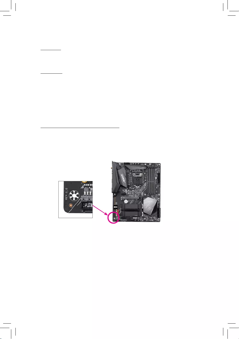
Identifying Your Motherboard Revision
The revision number on your motherboard looks like this: «REV: X.X.» For example, «REV:
1.0″ means the revision of the motherboard is 1.0. Check your motherboard revision before
updating motherboard BIOS, drivers, or when looking for technical information.
Example:

— 3 —
Table of Contents
Z490 UD (AC) Motherboard Layout ………………………………………………………………………4
Chapter 1 Hardware Installation ………………………………………………………………………….5
1-1 Installation Precautions ………………………………………………………………………… 5
1-2 ProductSpecications ………………………………………………………………………….. 6
1-3 Installing the CPU ……………………………………………………………………………….. 9
1-4 Installing the Memory …………………………………………………………………………… 9
1-5 Installing an Expansion Card ………………………………………………………………. 10
1-6 Back Panel Connectors ………………………………………………………………………. 10
1-7 Internal Connectors ……………………………………………………………………………. 12
Chapter 2 BIOS Setup ……………………………………………………………………………………..21
2-1 Startup Screen ………………………………………………………………………………….. 21
2-2 The Main Menu …………………………………………………………………………………. 22
2-3 Favorites (F11) ………………………………………………………………………………….. 23
2-4 Tweaker ……………………………………………………………………………………………. 24
2-5 Settings ……………………………………………………………………………………………. 29
2-6 System Info. ……………………………………………………………………………………… 35
2-7 Boot …………………………………………………………………………………………………. 36
2-8 Save & Exit ……………………………………………………………………………………….. 39
Chapter 3 Appendix …………………………………………………………………………………………40
3-1 ConguringaRAIDSet ………………………………………………………………………. 40
3-2 Installing an Intel® Optane™ Memory …………………………………………………….. 42
3-3 Drivers Installation ……………………………………………………………………………… 44
RegulatoryNotices ………………………………………………………………………………………. 45
Contact Us …………………………………………………………………………………………………. 48
— 4 —
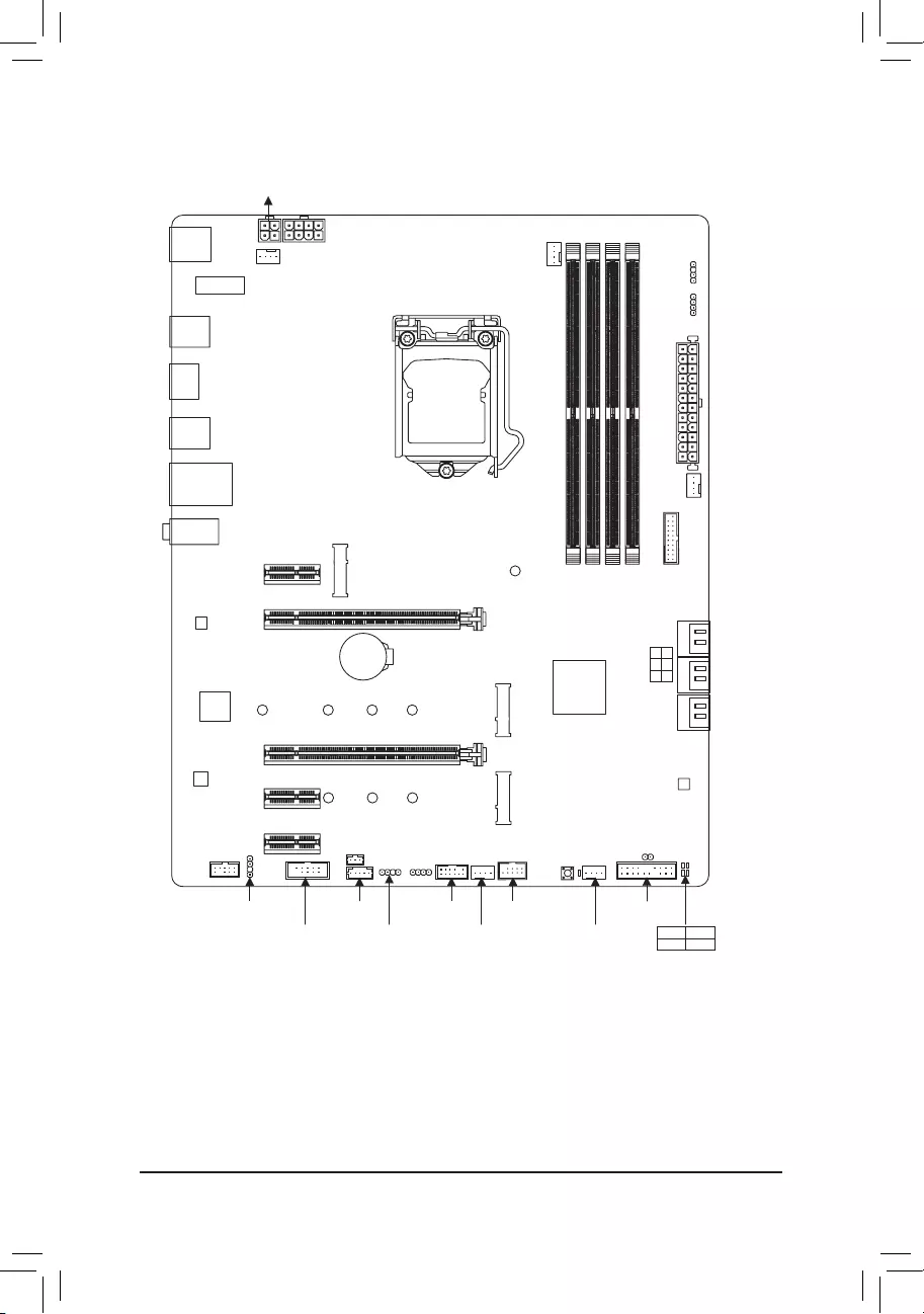
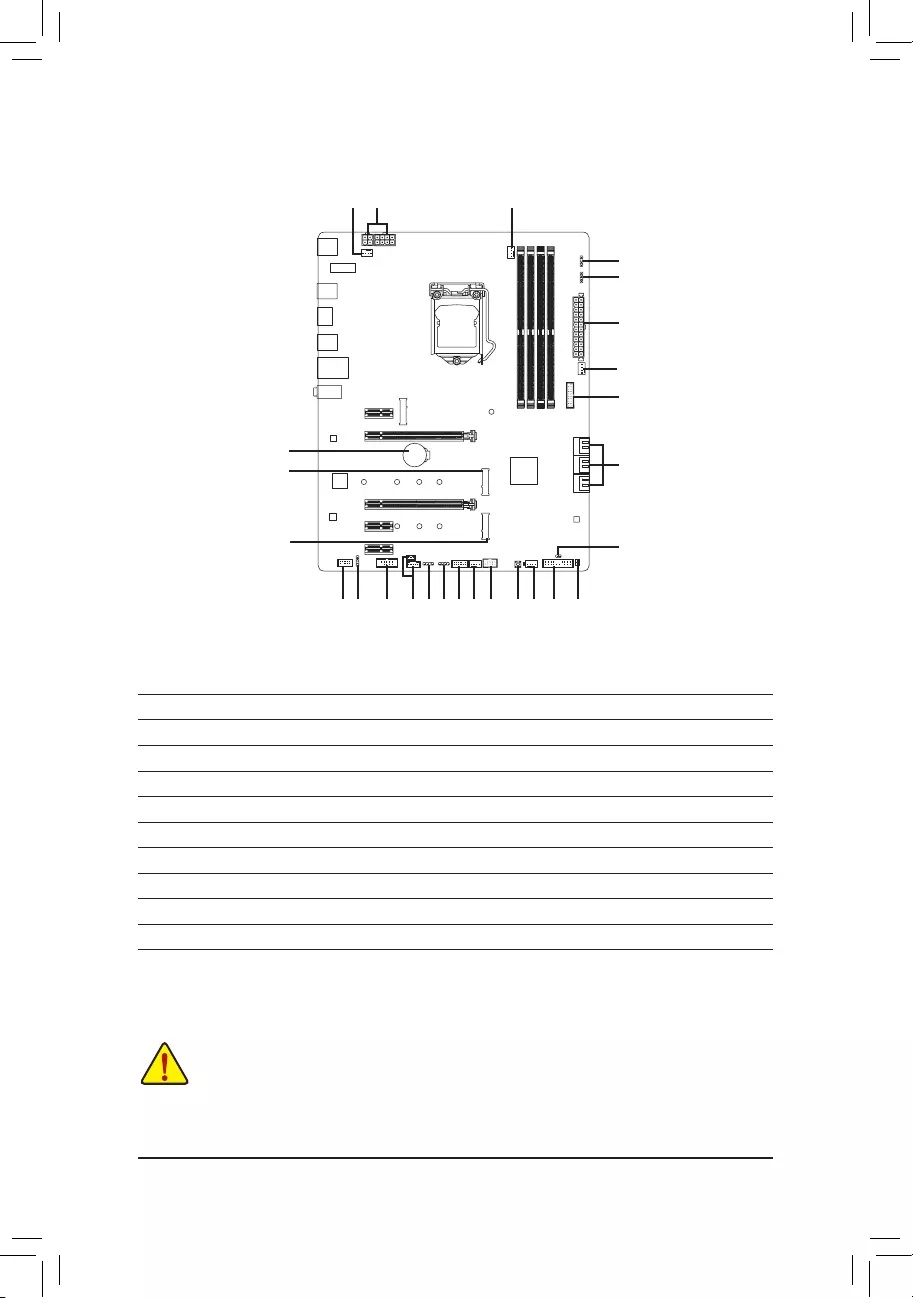
Z490 UD (AC) Motherboard Layout
* The box contents above are for reference only and the actual items shall depend on the product package you
obtain. The box contents are subject to change without notice.
Box Contents
5Z490 UD AC or Z490 UD Motherboard
5Motherboard driver disc 5Two SATA cables
5User’s Manual 5One antennaj
KB_MS_USB
HDMI
U32
U32_LAN
LGA1200
ATX
AUDIO
ATX_12V_2X4
Intel® Z490
CLR_CMOS
M_BIOS
PCIEX1_1
PCIEX4
PCIEX16
PCIEX1_2
PCIEX1_3
F_U32
M2P_32G (Note)
CODEC
Z490 UD (AC)
F_PANEL
F_USB
LED_C1
F_AUDIO
COM SYS_FAN3
SPI_TPM
SYS_FAN1
SYS_FAN2
CPU_FAN
iTE®
Super I/O
80
SATA3 531
420
BAT
Realtek®
GbELAN
CPU DRAM
VGA BOOT
U32_G2
THB_C1
M2M_SB
426080
ATX_12V_2X2
DDR4_B1
DDR4_B2
DDR4_A1
DDR4_A2
D_LED2
LED_C2
QFLASH_PLUS
426080110
M2A_SB
SYS_FAN4
D_LED1
SPDIF_O
CNVIj
(Note) TheM.2connectorisreservedonly.Nofunctionalities.
j Only for the Z490 UD AC.
QFLED
THB_C2

Chapter 1 Hardware Installation
1-1 Installation Precautions
The motherboard contains numerous delicate electronic circuits and components which can become
damaged as a result of electrostatic discharge (ESD). Prior to installation, carefully read the user’s
manual and follow these procedures:
•Prior to installation, make sure the chassis is suitable for the motherboard.
•Priortoinstallation,donotremoveorbreak motherboard S/N (Serial Number) stickeror
warranty sticker provided by your dealer. These stickers are required for warranty validation.
•Always remove the AC power by unplugging the power cord from the power outlet before
installing or removing the motherboard or other hardware components.
•When connecting hardware components to the internal connectors on the motherboard, make
sure they are connected tightly and securely.
•When handling the motherboard, avoid touching any metal leads or connectors.
•It is best to wear an electrostatic discharge (ESD) wrist strap when handling electronic
components such as a motherboard, CPU or memory. If you do not have an ESD wrist strap,
keepyourhandsdryandrsttouchametalobjecttoeliminatestaticelectricity.
•Prior to installing the motherboard, please have it on top of an antistatic pad or within an
electrostatic shielding container.
•Before connecting or unplugging the power supply cable from the motherboard, make sure
the power supply has been turned off.
•Before turning on the power, make sure the power supply voltage has been set according to
the local voltage standard.
•Before using the product, please verify that all cables and power connectors of your hardware
components are connected.
•To prevent damage to the motherboard, do not allow screws to come in contact with the
motherboard circuit or its components.
•Make sure there are no leftover screws or metal components placed on the motherboard or
within the computer casing.
•Do not place the computer system on an uneven surface.
•Do not place the computer system in a high-temperature or wet environment.
•Turning on the computer power during the installation process can lead to damage to system
components as well as physical harm to the user.
•If you are uncertain about any installation steps or have a problem related to the use of the
product,pleaseconsultacertiedcomputertechnician.
•If you use an adapter, extension power cable, or power strip, ensure to consult with its installation
and/or grounding instructions.
— 5 —
1-2 ProductSpecications
CPU Support for 10th Generation Intel® Core™ i9 processors/Intel® Core™ i7 processors/
Intel® Core™ i5 processors/Intel® Core™ i3 processors/Intel® Pentium® processors/
Intel® Celeron® processors in the LGA1200 package
L3 cache varies with CPU
Chipset Intel® Z490 Express Chipset
Memory Intel® Core™ i9/i7 processors:
— Support for DDR43200/3000/2933/2666/2400/2133MHzmemory modules
Intel® Core™ i5/i3/Pentium®/Celeron® processors:
— Support for DDR42666/2400/2133MHzmemory modules
4xDDR4DIMMsocketssupportingupto128GB(32GBsingleDIMMcapacity)
of system memory
Dual channel memory architecture
SupportforECCUn-bufferedDIMM1Rx8/2Rx8memorymodules(operatein
non-ECC mode)
Supportfornon-ECCUn-bufferedDIMM1Rx8/2Rx8/1Rx16memorymodules
SupportforExtremeMemoryProle(XMP)memorymodules
(Go to GIGABYTE’s website for the latest supported memory speeds and memory
modules.)
Onboard
Graphics
Integrated Graphics Processor-Intel® HD Graphics support:
- 1xHDMIport,supportingamaximumresolutionof4096×2160@30Hz
* Support for HDMI 1.4 version and HDCP 2.3.
Maximum shared memory of 512 MB
Audio Realtek® ALC887 codec
HighDenitionAudio
2/4/5.1/7.1-channel
* Tocongure7.1-channelaudio,youneedtoopentheaudiosoftwareandselect
Deviceadvancedsettings>PlaybackDevicetochange the default setting rst.
PleasevisitGIGABYTE’swebsitefordetailsonconguringtheaudiosoftware.
Support for S/PDIF Out
LAN Realtek®GbELANchip(1000 Mbit/100 Mbit)
Wireless
Communication
Modulej
Intel® Wi-Fi AC 9462:
— Intel®CNViinterface802.11a/b/g/n/ac,supporting2.4/5GHzDual-Band
— BLUETOOTH 5
— Support for 1×1 11ac wireless standard and up to 433 Mbps data rate
* Actual data rate may vary depending on environment and equipment.
Expansion Slots 1 x PCI Express x16 slot, running at x16 (PCIEX16)
* For optimum performance, if only one PCI Express graphics card is to be installed,
be sure to install it in the PCIEX16 slot.
1 x PCI Express x16 slot, running at x4 (PCIEX4)
3 x PCI Express x1 slots
(All of the PCI Express slots conform to PCI Express 3.0 standard.)
Multi-Graphics
Technology Support for AMD Quad-GPU CrossFire™ and 2-Way AMD CrossFire™ technologies
Storage Interface 1 x M.2 connector (Socket 3, M key, type 2242/2260/2280/22110 SATA and PCIe
x4/x2 SSD support) (M2A_SB)
1 x M.2 connector (Socket 3, M key, type 2242/2260/2280 PCIe x4/x2 SSD
support) (M2M_SB)
6 x SATA 6Gb/s connectors
j Only for the Z490 UD AC.
— 6 —

j Only for the Z490 UD AC.
Storage Interface SupportforRAID0,RAID1,RAID5,andRAID10
* Referto»1-7InternalConnectors,»fortheinstallationnoticesfortheM.2andSATA
connectors.
Intel® Optane™MemoryReady
USB Chipset:
— 1 x USB 3.2 Gen 2 Type-A port (red) on the back panel
— 7 x USB 3.2 Gen 1 ports (5 ports on the back panel, 2 ports available through
the internal USB header)
— 4 x USB 2.0/1.1 ports (2 ports on the back panel, 2 ports available through
the internal USB header)
Internal
Connectors
1 x 24-pin ATX main power connector
1 x 4-pin ATX 12V power connector
1 x 8-pin ATX 12V power connector
1 x CPU fan header
4 x system fan headers
2 x addressable LED strip headers
2xRGBLEDstripheaders
1 x Q-Flash Plus button
6 x SATA 6Gb/s connectors
2 x M.2 Socket 3 connectors
1 x front panel header
1 x front panel audio header
1 x S/PDIF Out header
1 x USB 3.2 Gen 1 header
1 x USB 2.0/1.1 header
1 x Trusted Platform Module header (For the GC-TPM2.0 SPI/GC-TPM2.0 SPI
2.0 module only)
2 x Thunderbolt™ add-in card connectors
1 x serial port header
1 x Clear CMOS jumper
Back Panel
Connectors
1 x PS/2 keyboard/mouse port
2xSMAantennaconnectors(1T1R)j
1 x HDMI port
1 x USB 3.2 Gen 2 Type-A port (red)
5 x USB 3.2 Gen 1 ports
2 x USB 2.0/1.1 ports
1xRJ-45port
3 x audio jacks
I/O Controller iTE® I/O Controller Chip
Hardware
Monitor
Voltage detection
Temperature detection
Fan speed detection
Overheating warning
Fan fail warning
Fan speed control
* Whether the fan speed control function is supported will depend on the cooler you
install.
— 7 —
BIOS 1x256Mbitash
Use of licensed AMI UEFI BIOS
PnP 1.0a, DMI 2.7, WfM 2.0, SM BIOS 2.7, ACPI 5.0
Unique Features Support for APP Center
* Available applications in APP Center may vary by motherboard model.
Supported functions of each application may also vary depending on
motherboardspecications.
— @BIOS
— EasyTune
— Fast Boot
— Game Boost
- ON/OFFCharge
- RGBFusion
— Smart Backup
— System Information Viewer
Support for Q-Flash Plus
Support for Q-Flash
Support for Xpress Install
Bundled
Software
Norton® Internet Security (OEM version)
Realtek® 8118 Gaming LAN Bandwidth Control Utility
Operating
System Support for Windows 10 64-bit
Form Factor ATX Form Factor; 30.5cm x 24.4cm
* GIGABYTEreservestherighttomakeanychangestotheproductspecicationsandproduct-relatedinformationwithout
prior notice.
Please visit GIGABYTE’s website for support lists of CPU, memory modules,
SSDs, and M.2 devices.
Z490 UD AC Z490 UD
Please visit the Support\Utility List page on GIGABYTE’s website to download the latest
version of apps.
— 8 —

1-3 Installing the CPU
1-4 Installing the Memory
Readthefollowingguidelinesbeforeyoubegintoinstallthememory:
•Make sure that the motherboard supports the memory. It is recommended that memory of the same
capacity, brand, speed, and chips be used.
(Go to GIGABYTE’s website for the latest supported memory speeds and memory modules.)
•Always turn off the computer and unplug the power cord from the power outlet before installing the
memory to prevent hardware damage.
•Memory modules have a foolproof design. A memory module can be installed in only one direction.
If you are unable to insert the memory, switch the direction.
DualChannelMemoryConguration
This motherboard provides four memory sockets and supports Dual Channel Technology. After the memory
isinstalled,theBIOSwillautomaticallydetectthespecicationsandcapacityofthememory.EnablingDual
Channel memory mode will double the original memory bandwidth.
Please visit GIGABYTE’s website for details on hardware installation.
ReadthefollowingguidelinesbeforeyoubegintoinstalltheCPU:
•Make sure that the motherboard supports the CPU.
(Go to GIGABYTE’s website for the latest CPU support list.)
•Always turn off the computer and unplug the power cord from the power outlet before installing the
CPU to prevent hardware damage.
•Locate the pin one of the CPU. The CPU cannot be inserted if oriented incorrectly. (Or you may
locate the notches on both sides of the CPU and alignment keys on the CPU socket.)
•Apply an even and thin layer of thermal grease on the surface of the CPU.
•Do not turn on the computer if the CPU cooler is not installed, otherwise overheating and damage
of the CPU may occur.
•SettheCPUhostfrequencyinaccordancewiththeCPUspecications.Itisnotrecommended
thatthesystembusfrequencybesetbeyondhardwarespecicationssinceitdoesnotmeetthe
standard requirements for the peripherals. If you wish to set the frequency beyond the standard
specications,pleasedosoaccordingtoyourhardwarespecicationsincludingtheCPU,graphics
card, memory, hard drive, etc.
Installing the CPU
Locate the alignment keys on the motherboard CPU socket and the notches on the CPU.
Do not remove the CPU socket cover before inserting the CPU. It may pop off from the load
plate automatically during the process of re-engaging the lever after you insert the CPU.
Triangle Pin One Marking on the CPU
Notch
Notch
LGA1200 CPU
Alignment
Key
Alignment
Key
LGA1200 CPU Socket
Pin One Corner of the CPU Socket
— 9 —
The four memory sockets are divided into two channels and each channel has two memory sockets as following:
ChannelA:DDR4_A1,DDR4_A2
ChannelB:DDR4_B1,DDR4_B2
RecommandedDualChannelMemoryConguration:
DDR4_A1 DDR4_A2 DDR4_B1 DDR4_B2
2 Modules — — DS/SS — — DS/SS
4 Modules DS/SS DS/SS DS/SS DS/SS
(SS=Single-Sided,DS=Double-Sided,»--«=NoMemory)
Due to CPU limitations, read the following guidelines before installing the memory in Dual Channel mode.
1. Dual Channel mode cannot be enabled if only one memory module is installed.
2. When enabling Dual Channel mode with two or four memory modules, it is recommended that memory
of the same capacity, brand, speed, and chips be used.
1-5 Installing an Expansion Card
Readthefollowingguidelinesbeforeyoubegintoinstallanexpansioncard:
•Make sure the motherboard supports the expansion card. Carefully read the manual that came
with your expansion card.
•Always turn off the computer and unplug the power cord from the power outlet before installing an
expansion card to prevent hardware damage.
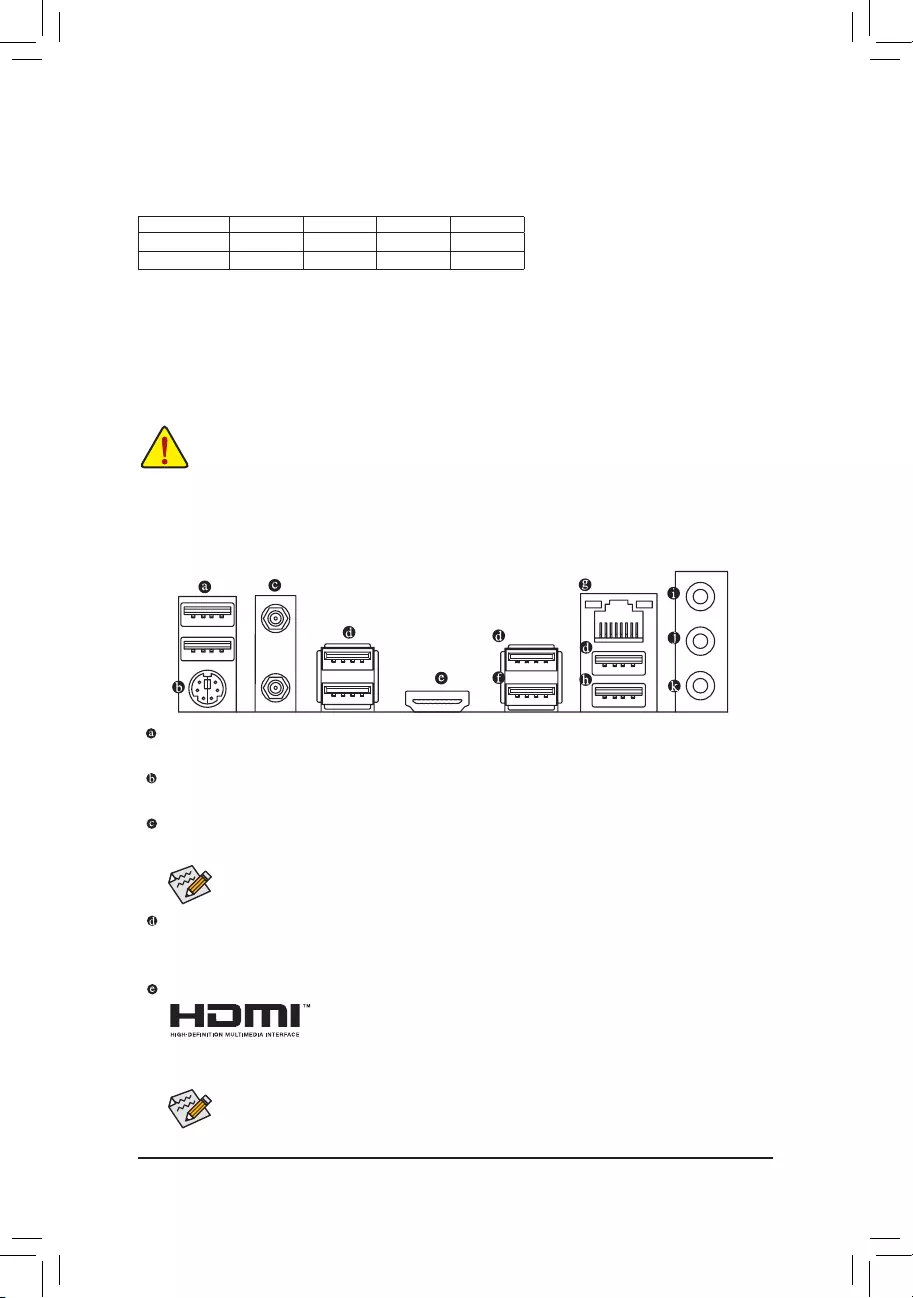
1-6 Back Panel Connectors
USB 2.0/1.1 Port
TheUSBportsupportstheUSB2.0/1.1specication.UsethisportforUSBdevices.
PS/2 Keyboard/Mouse Port
Use this port to connect a PS/2 mouse or keyboard.
SMA Antenna Connectors (1T1R)j
Use this connector to connect an antenna.
After installing the HDMI device, make sure to set the default sound playback device to HDMI.
(The item name may differ depending on your operating system.)
j
USB 3.2 Gen 1 Port
TheUSB3.2Gen1portsupportstheUSB3.2Gen1specicationandiscompatibletotheUSB2.0
specication.UsethisportforUSBdevices.
HDMI Port
The HDMI port supports HDCP 2.3 and Dolby TrueHD and DTS HD Master Audio
formats.Italsosupportsupto192KHz/16bit7.1-channelLPCMaudiooutput.
You can use this port to connect your HDMI-supported monitor. The maximum supported resolution is
4096×2160@30Hz,buttheactualresolutionssupportedaredependentonthemonitorbeingused.
Tighten the antennas to the antenna connectors and then aim the antennas correctly for better
signal reception.
j Only for the Z490 UD AC.
— 10 —
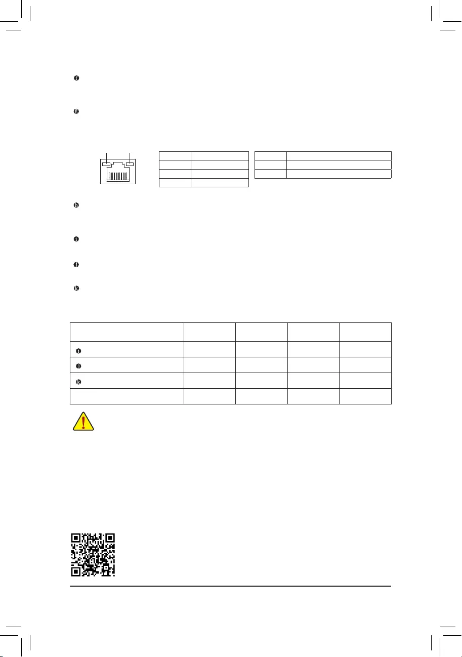
Activity LED
Connection/
Speed LED
LANPort
Activity LED:Connection/Speed LED:
State Description
Orange 1 Gbps data rate
Green 100 Mbps data rate
Off 10 Mbps data rate
USB 3.2 Gen 2 Type-A Port (Red)
TheUSB3.2Gen2Type-AportsupportstheUSB3.2Gen2specicationandiscompatibletotheUSB
3.2Gen1andUSB2.0specication.UsethisportforUSBdevices.
RJ-45 LAN Port
TheGigabitEthernetLANportprovidesInternetconnectionatupto1Gbpsdatarate.Thefollowing
describesthestatesoftheLANportLEDs.
PleasevisitGIGABYTE’swebsitefordetailsonconguringtheaudiosoftware.
•Whenremovingthecableconnectedtoabackpanelconnector,rstremovethecablefromyour
device and then remove it from the motherboard.
•When removing the cable, pull it straight out from the connector. Do not rock it side to side to
prevent an electrical short inside the cable connector.
AudioJackCongurations:
Jack Headphone/
2-channel 4-channel 5.1-channel 7.1-channel
LineIn/RearSpeakerOut a a a
Line Out/Front Speaker Out a a a a
Mic In/Center/Subwoofer Speaker Out a a
Front Panel Line Out/Side Speaker Out a
USB 3.2 Gen 1 Type-A Port (Q-Flash Plus Port)
TheUSBportsupportstheUSB3.2Gen1specication.UsethisportforUSBdevices.Beforeusing
Q-Flash Plus (Note),makesuretoinserttheUSBashdriveintothisportrst.
Line In/Rear Speaker Out (Blue)
The line in jack. Use this audio jack for line in devices such as an optical drive, walkman, etc.
Line Out/Front Speaker Out (Green)
The line out jack.
Mic In/Center/Subwoofer Speaker Out (Pink)
The Mic in jack.
State Description
Blinking Data transmission or receiving is occurring
Off Nodatatransmissionorreceivingisoccurring
(Note) ToenabletheQ-FlashPlusfunctionpleasevisitthe»UniqueFeatures»webpageofGIGABYTE’swebsite.
— 11 —
1-7 Internal Connectors
Readthefollowingguidelinesbeforeconnectingexternaldevices:
•First make sure your devices are compliant with the connectors you wish to connect.
•Before installing the devices, be sure to turn off the devices and your computer. Unplug the power
cord from the power outlet to prevent damage to the devices.
•After installing the device and before turning on the computer, make sure the device cable has
been securely attached to the connector on the motherboard.
1) ATX_12V_2X2/ATX_12V_2X4
2) ATX
3) CPU_FAN
4) SYS_FAN1/2/3/4
5) D_LED1/D_LED2
6) LED_C1/LED_C2
7) SATA3 0/1/2/3/4/5
 M2A_SB/M2M_SB
9) F_PANEL
10) F_ AUDIO
11) SPDIF_O
12) F_U32
13) F_USB
14) THB_C1/THB_C2
15) COM
16) SPI_TPM
17) QFLASH_PLUS
18) CLR_CMOS
19) BAT
20) CPU/DRAM/VGA/BOOT
920
4
2
7
12
16
5
10 11
1
4
14
18
19
15 13 4
3
8
4
5
6
6
8
17
— 12 —
131
2412
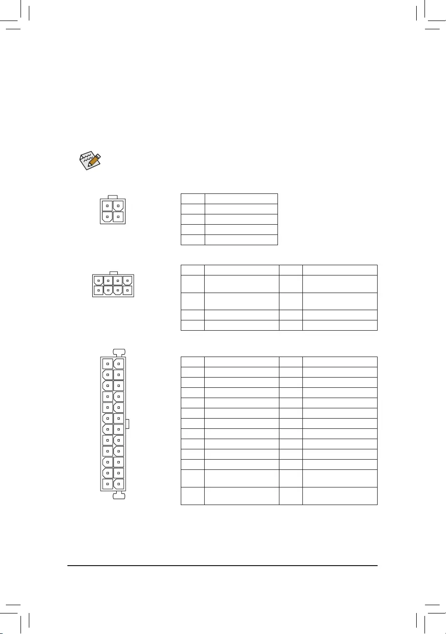
ATX
1/2) ATX_12V_2X2/ATX_12V_2X4/ATX (2×2, 2×4, 12V Power Connectors and 2×12 Main Power
Connector)
With the use of the power connector, the power supply can supply enough stable power to all the components
onthemotherboard.Beforeconnectingthepowerconnector,rstmakesurethepowersupplyisturnedoffand
all devices are properly installed. The power connector possesses a foolproof design. Connect the power
supply cable to the power connector in the correct orientation.
The 12V power connector mainly supplies power to the CPU. If the 12V power connector is not connected,
the computer will not start.
To meet expansion requirements, it is recommended that a power supply that can withstand high
power consumption be used (500W or greater). If a power supply is used that does not provide the
required power, the result can lead to an unstable or unbootable system.
ATX:
PinNo. Denition PinNo. Denition
1 3.3V 13 3.3V
2 3.3V 14 -12V
3GND 15 GND
4 +5V 16 PS_ON(softOn/Off)
5GND 17 GND
6 +5V 18 GND
7GND 19 GND
8 Power Good 20 NC
9 5VSB (stand by +5V) 21 +5V
10 +12V 22 +5V
11 +12V (Only for 2×12-pin
ATX)
23 +5V (Only for 2×12-pin
ATX)
12 3.3V (Only for 2×12-pin
ATX)
24 GND(Onlyfor2×12-pin
ATX)
ATX_12V_2X4:
PinNo. Denition PinNo. Denition
1GND(Onlyfor2×4-pin12V) 5 +12V (Only for 2×4-pin
12V)
2GND(Onlyfor2×4-pin12V) 6 +12V (Only for 2×4-pin
12V)
3GND 7 +12V
4GND 8 +12V
ATX_12V_2X4
41
85
ATX_12V_2X2:
PinNo. Denition
1GND
2GND
3 +12V
4 +12V
ATX_12V_2X2
3 4
21
— 13 —
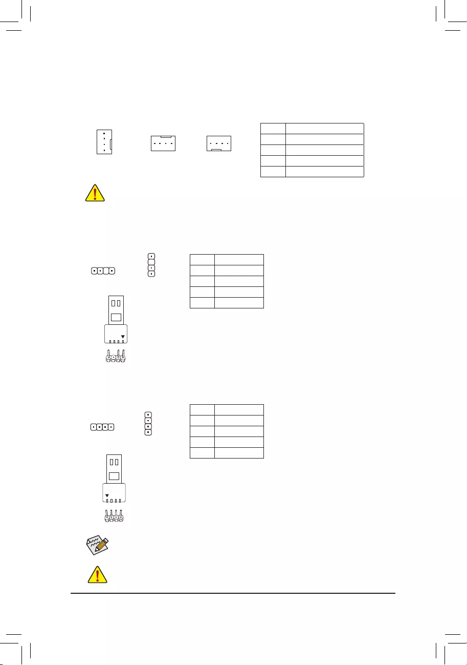
3/4) CPU_FAN/SYS_FAN1/2/3/4 (Fan Headers)
All fan headers on this motherboard are 4-pin. Most fan headers possess a foolproof insertion design.
When connecting a fan cable, be sure to connect it in the correct orientation (the black connector wire is
the ground wire). The speed control function requires the use of a fan with fan speed control design. For
optimum heat dissipation, it is recommended that a system fan be installed inside the chassis.
•Be sure to connect fan cables to the fan headers to prevent your CPU and system from
overheating. Overheating may result in damage to the CPU or the system may hang.
•Thesefanheadersarenotcongurationjumperblocks.Donotplaceajumpercapontheheaders.
SYS_FAN1
11
CPU_FAN/SYS_FAN2 SYS_FAN3/SYS_FAN4
1
PinNo. Denition
1GND
2 Voltage Speed Control
3 Sense
4 PWM Speed Control
5) D_LED1/D_LED2 (Digital LED Strip Headers)
The headers can be used to connect a standard 5050 addressable LED strip, with maximum power rating
of 5A (5V) and maximum number of 1000 LEDs.
PinNo. Denition
1 V (5V)
2 D
3NoPin
4 G
11
F_USB30 F_U
B_
F_ F_
_
B
BS_
B
SB_
B
_S
S_
_
B
_U
_
B
S
123
123
123
123
1
1
1
1
BSS
S
_S
SSU
1 2 3
S3 BSSS
U
__ 3
F_USB3F
S _
S _
S _
SF
B_
B_
F
_0
S
S
_0F
_F
_
_
__B
U
S _S
_ SF_
B
USB0_B
B_
B_
F_USB3
F_USB303
_
_3U
S_
F_USB30 F_U
B_
F_ F_
_
B
BS_
B
SB_
B
_S
S_
_
B
_U
_
B
S
123
123
123
123
1
1
1
1
BSS
S
_S
SSU
1 2 3
S3 BSSS
U
__ 3
F_USB3F
S _
S _
S _
SF
B_
B_
F
_0
S
S
_0F
_F
_
_
__B
U
S _S
_ SF_
B
USB0_B
B_
B_
F_USB3
F_USB303
_
_3U
S_
D_LED1 D_LED2
Connect your addressable LED strip to the header. The power pin
(marked with a triangle on the plug) of the LED strip must be connected
to Pin 1 of the addressable LED strip header. Incorrect connection may
lead to the damage of the LED strip.
6) LED_C1/LED_C2 (RGB LED Strip Headers)
Theheaderscanbeusedtoconnectastandard5050RGBLEDstrip(12V/G/R/B),withmaximumpower
rating of 2A (12V) and maximum length of 2m.
PinNo. Denition
1 12V
2 G
3R
4 B
Before installing the devices, be sure to turn off the devices and your computer. Unplug the power
cord from the power outlet to prevent damage to the devices.
1
ConnectyourRGBLEDstriptotheheader.Thepowerpin(marked
with a triangle on the plug) of the LED strip must be connected to Pin
1 (12V) of this header. Incorrect connection may lead to the damage
of the LED strip.
Forhowtoturnon/offthelightsoftheLEDstrippleasevisitthe«UniqueFeatures»webpageof
GIGABYTE’s website.
LED_C2
1
LED_C1
RGBLEDStrip
1
12V
Addressable LED
Strip
1
— 14 —

7) SATA3 0/1/2/3/4/5 (SATA 6Gb/s Connectors)
The SATA connectors conform to SATA 6Gb/s standard and are compatible with SATA 3Gb/s and SATA
1.5Gb/s standard. Each SATA connector supports a single SATA device. The Intel®ChipsetsupportsRAID0,
RAID1,RAID5,andRAID10.RefertoChapter3,»ConguringaRAIDSet,»forinstructionsonconguring
aRAIDarray.
PinNo. Denition
1GND
2 TXP
3TXN
4GND
5RXN
6RXP
7GND
Toenablehot-pluggingfortheSATAports,refertoChapter2,«BIOSSetup,»«Settings\IOPorts\
SATAAndRSTConguration,»formoreinformation.
1
1
SATA3 531
420
7
7
M2A_SB/M2M_SB (M.2 Socket 3 Connectors)
TheM.2connectorssupportM.2SATASSDsorM.2PCIeSSDsandsupportRAIDconguration.Please
notethatanM.2PCIeSSDcannotbeusedtocreateaRAIDseteitherwithanM.2SATASSDoraSATA
harddrive.TocreateaRAIDarraywithanM.2PCIeSSD,youmustsetupthecongurationinUEFIBIOS
mode.RefertoChapter3,»ConguringaRAIDSet,»forinstructionsonconguringaRAIDarray.
F_USB30 F_U
B_
F_ F_
_
B
BS_
B
SB_
B
_S
S_
_
B
_U
_
B
S
123
123
123
123
1
1
1
1
BSS
S
_S
SSU
1 2 3
S3 BSSS
U
__ 3
F_USB3F
S _
S _
S _
SF
B_
B_
F
_0
S
S
_0F
_F
_
_
__B
U
S _S
_ SF_
B
USB0_B
B_
B_
F_USB3
F_USB303
_
_3U
S_
80110 60
M2A_SB
F_USB30 F_U
B_
F_ F_
_
B
BS_
B
SB_
B
_S
S_
_
B
_U
_
B
S
123
123
123
123
1
1
1
1
BSS
S
_S
SSU
1 2 3
S3 BSSS
U
__ 3
F_USB3F
S _
S _
S _
SF
B_
B_
F
_0
S
S
_0F
_F
_
_
__B
U
S _S
_ SF_
B
USB0_B
B_
B_
F_USB3
F_USB303
_
_3U
S_
80 60
M2M_SB
42
42
Follow the steps below to correctly install an M.2 SSD in the M.2 connector.
Step 1:
Use a screw driver to unfasten the screw and standoff from the motherboard. Locate the proper mounting
holefortheM.2SSDtobeinstalledandthenscrewthestandoffrst.
Step 2:
Slide the M.2 SSD into the connector at an angle.
Step 3:
Press the M.2 SSD down and then secure it with the screw.
— 15 —
•M2A_SB:
SATA3 0 SATA3 1 SATA3 2 SATA3 3 SATA3 4 SATA3 5
M.2 SATA SSD araaaa
M.2 PCIe SSD
aaaaaa
NoM.2SSDInstalled aaaaaa
a: Available, r:Notavailable
Connector
Type of
M.2 SSD
Installation Notices for the M.2 and SATA Connectors:
The availability of the SATA connectors may be affected by the type of device installed in the M.2 sockets. The
M2A_SBconnectorsharesbandwidthwiththeSATA31connector.Refertothefollowingtablesfordetails.
•M2M_SB:
SATA3 0 SATA3 1 SATA3 2 SATA3 3 SATA3 4 SATA3 5
M.2 PCIe SSD *
aaaaaa
NoM.2SSDInstalled aaaaaa
a: Available, r:Notavailable
* The M2M_SB connector supports only PCIe SSDs.
Connector
Type of
M.2 SSD
— 16 —
The front panel design may differ by chassis. A front panel module mainly consists of power switch, reset
switch, power LED, hard drive activity LED, speaker and etc. When connecting your chassis front panel
module to this header, make sure the wire assignments and the pin assignments are matched correctly.
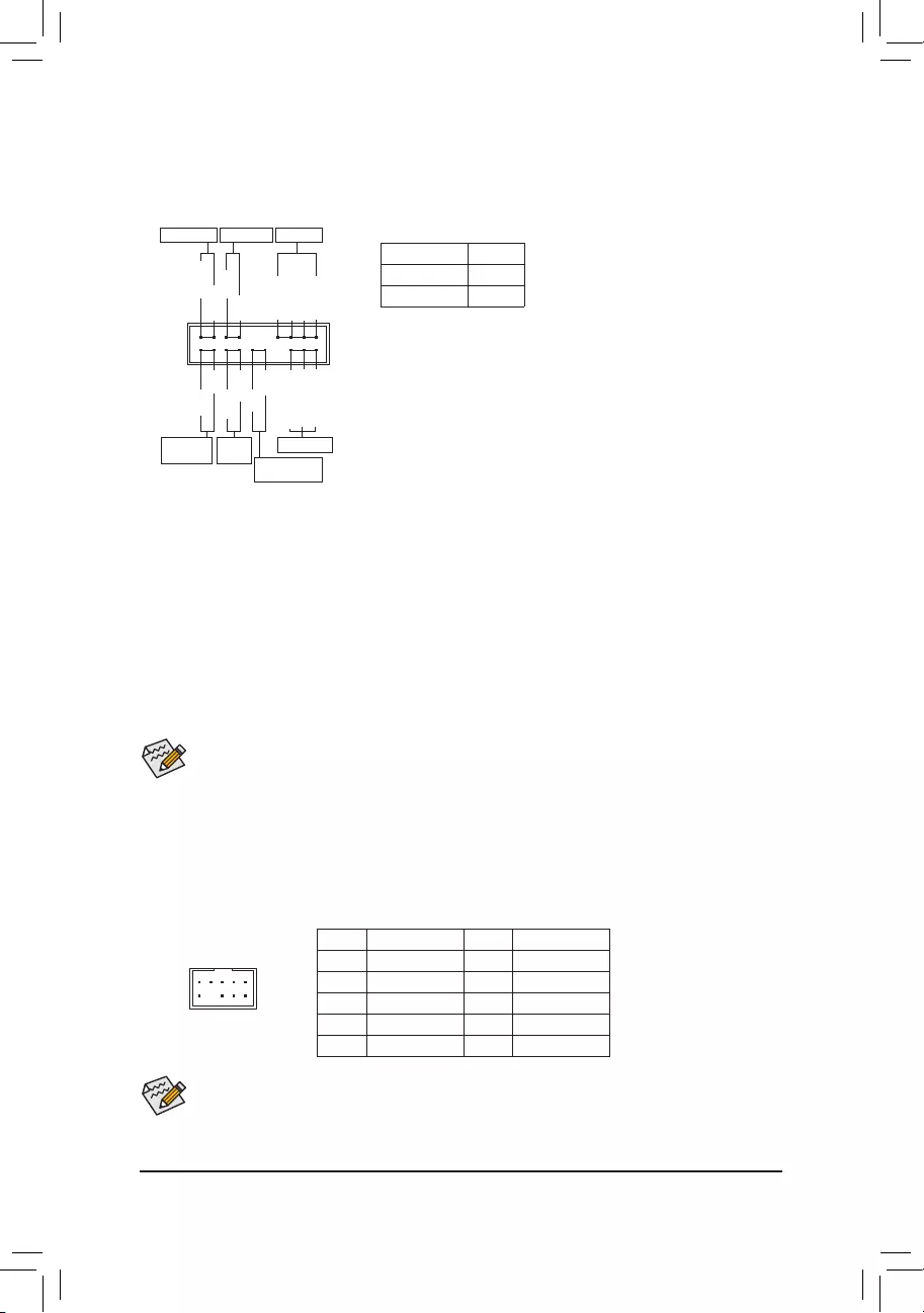
9) F_PANEL (Front Panel Header)
Connect the power switch, reset switch, speaker, chassis intrusion switch/sensor and system status indicator
onthechassistothisheaderaccordingtothepinassignmentsbelow.Notethepositiveandnegativepins
before connecting the cables.
System Status LED
S0 On
S3/S4/S5 Off
•PW(PowerSwitch,Red):
Connects to the power switch on the chassis front panel. You may
congure the way to turn off your system using thepower switch
(refertoChapter2,«BIOSSetup,»«Settings\PlatformPower,»formore
information).
•SPEAK (Speaker, Orange):
Connects to the speaker on the chassis front panel. The system reports
system startup status by issuing a beep code. One single short beep
•PLED/PWR_LED (Power LED, Yellow/Purple):
Connects to the power status indicator
on the chassis front panel. The LED is on
when the system is operating. The LED is
off when the system is in S3/S4 sleep state
or powered off (S5).
will be heard if no problem is detected at system startup.
•HD (Hard Drive Activity LED, Blue):
Connects to the hard drive activity LED on the chassis front panel. The LED is on when the hard drive
is reading or writing data.
•RES (ResetSwitch,Green):
Connects to the reset switch on the chassis front panel. Press the reset switch to restart the computer
ifthecomputerfreezesandfailstoperformanormalrestart.
•CI (Chassis Intrusion Header, Gray):
Connects to the chassis intrusion switch/sensor on the chassis that can detect if the chassis cover has
been removed. This function requires a chassis with a chassis intrusion switch/sensor.
•NC (Orange):NoConnection.
Power LED
1
2
19
20
CI-
CI+
PWR_LED-
PWR_LED+
PLED-
PW-
SPEAK+
SPEAK-
PLED+
PW+
Power LED
HD-
RES+
HD+
RES-
Hard Drive
Activity LED
Reset
Switch Chassis Intrusion
Header
Power Switch Speaker
PWR_LED-
NC
NC
10) F_AUDIO (Front Panel Audio Header)
ThefrontpanelaudioheadersupportsHighDenitionaudio(HD).Youmayconnectyourchassisfront
panel audio module to this header. Make sure the wire assignments of the module connector match the
pin assignments of the motherboard header. Incorrect connection between the module connector and the
motherboard header will make the device unable to work or even damage it.
Some chassis provide a front panel audio module that has separated connectors on each wire instead
of a single plug. For information about connecting the front panel audio module that has different wire
assignments, please contact the chassis manufacturer.
F_USB30 F_U
B_
F_ F_
_
B
BS_
B
SB_
B
_S
S_
_
B
_U
_
B
S
123
123
123
123
1
1
1
1
BSS
S
_S
SSU
1 2 3
S3 BSSS
U
__ 3
F_USB3F
S _
S _
S _
SF
B_
B_
F
_0
S
S
_0F
_F
_
_
__B
U
S _S
_ SF_
B
USB0_B
B_
B_
F_USB3
F_USB303
_
_3U
S_
9 1
10 2
PinNo. Denition PinNo. Denition
1 MIC2_L 6 Sense
2GND 7FAUDIO_JD
3MIC2_R 8NoPin
4NC 9LINE2_L
5LINE2_R 10 Sense
— 17 —
11) SPDIF_O (S/PDIF Out Header)
This header supports digital S/PDIF Out and connects a S/PDIF digital audio cable (provided by expansion
cards) for digital audio output from your motherboard to certain expansion cards like graphics cards and
sound cards. For example, some graphics cards may require you to use a S/PDIF digital audio cable for
digital audio output from your motherboard to your graphics card if you wish to connect an HDMI display
to the graphics card and have digital audio output from the HDMI display at the same time. For information
about connecting the S/PDIF digital audio cable, carefully read the manual for your expansion card.
PinNo. Denition
1 5VDUAL
2NoPin
3 SPDIFO
4GND
1
F_USB30 F_U
B_
F_ F_
_
B
BS_
B
SB_
B
_S
S_
_
B
_U
_
B
S
123
123
123
123
1
1
1
1
BSS
S
_S
SSU
1 2 3
S3 BSSS
U
__ 3
F_USB3F
S _
S _
S _
SF
B_
B_
F
_0
S
S
_0F
_F
_
_
__B
U
S _S
_ SF_
B
USB0_B
B_
B_
F_USB3
F_USB303
_
_3U
S_
PinNo. Denition PinNo. Denition PinNo. Denition
1 VBUS 8 D1- 15 SSTX2-
2SSRX1- 9 D1+ 16 GND
3SSRX1+ 10 NC 17 SSRX2+
4GND 11 D2+ 18 SSRX2-
5 SSTX1- 12 D2- 19 VBUS
6 SSTX1+ 13 GND 20 NoPin
7GND 14 SSTX2+
12) F_U32 (USB 3.2 Gen 1 Header)
TheheaderconformstoUSB3.2Gen1andUSB2.0specicationandcanprovidetwoUSBports.For
purchasingtheoptional3.5″frontpanelthatprovidestwoUSB3.2Gen1ports,pleasecontactthelocal
dealer.
F_USB30 F_U
B_
F_ F_
_
B
BS_
B
SB_
B
_S
S_
_
B
_U
_
B
S
123
123
123
123
1
1
1
1
BSS
S
_S
SSU
1 2 3
S3 BSSS
U
__ 3
F_USB3F
S _
S _
S _
SF
B_
B_
F
_0
S
S
_0F
_F
_
_
__B
U
S _S
_ SF_
B
USB0_B
B_
B_
F_USB3
F_USB303
_
_3U
S_
10
20 1
11
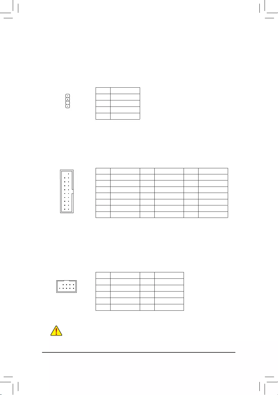
13) F_USB (USB 2.0/1.1 Header)
TheheaderconformstoUSB2.0/1.1specication.EachUSBheadercanprovidetwoUSBportsviaan
optional USB bracket. For purchasing the optional USB bracket, please contact the local dealer.
PinNo. Denition PinNo. Denition
1 Power (5V) 6 USB DY+
2 Power (5V) 7 GND
3 USB DX- 8 GND
4 USB DY— 9 NoPin
5 USB DX+ 10 NC
•Do not plug the IEEE 1394 bracket (2×5-pin) cable into the USB 2.0/1.1 header.
•Prior to installing the USB bracket, be sure to turn off your computer and unplug the power cord
from the power outlet to prevent damage to the USB bracket.
10
9
2
1
— 18 —
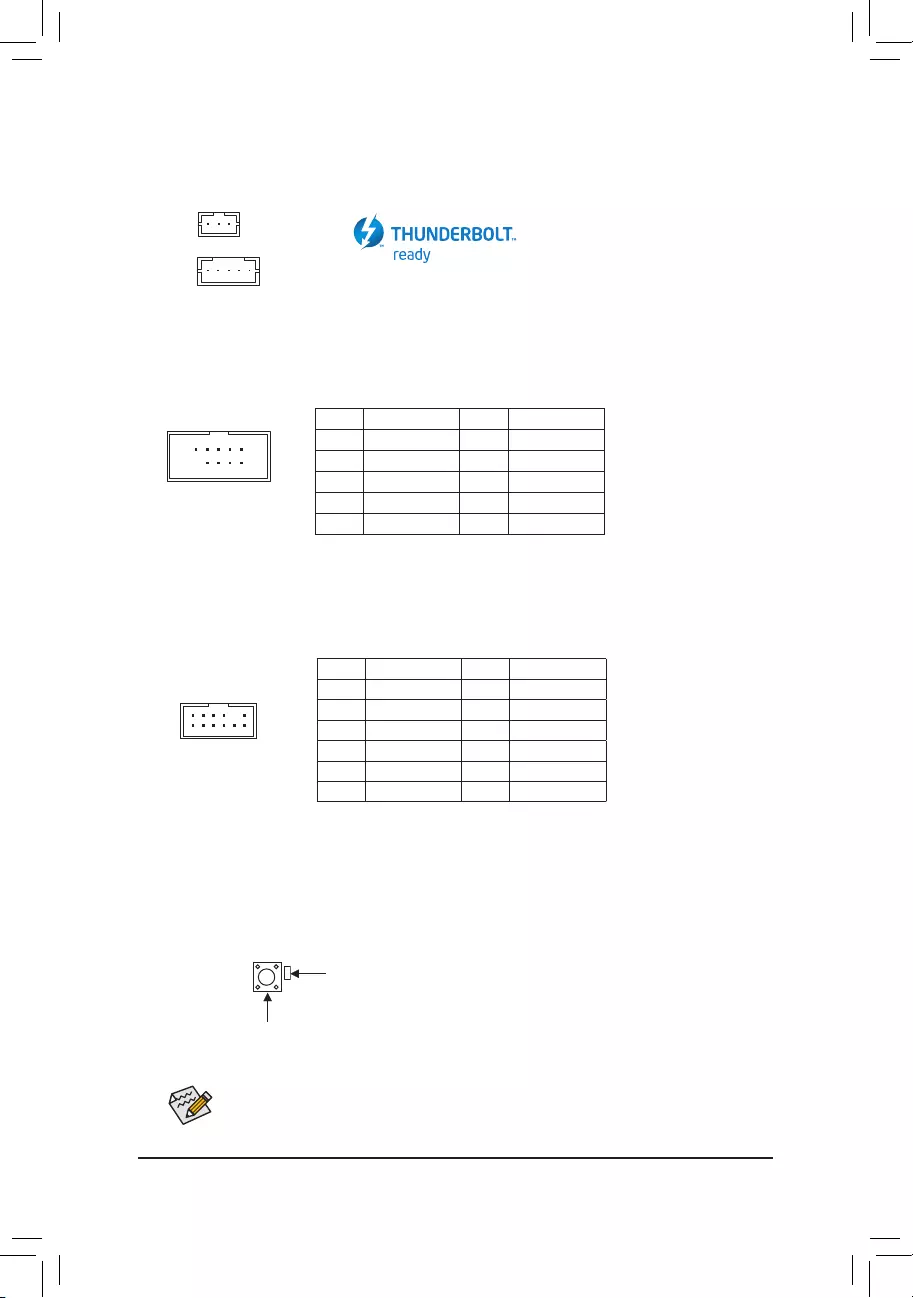
14) THB_C1/THB_C2 (Thunderbolt™ Add-in Card Connectors)
The connectors are used to connect to a GIGABYTE Thunderbolt™ add-in card
Supports a Thunderbolt™ add-in card.
10
9
2
1
15) COM (Serial Port Header)
The COM header can provide one serial port via an optional COM port cable. For purchasing the optional
COM port cable, please contact the local dealer.
PinNo. Denition PinNo. Denition
1NDCD- 6NDSR-
2NSIN 7NRTS-
3NSOUT 8NCTS-
4NDTR- 9NRI-
5GND 10 NoPin
12
11
2
1
16) SPI_TPM (Trusted Platform Module Header)
You may connect an SPI TPM (Trusted Platform Module) to this header.
PinNo. Denition PinNo. Denition
1Data Output 7Chip Select
2Power (3.3V) 8GND
3NoPin 9IRQ
4NC 10 NC
5Data Input 11 NC
6CLK 12 RST
F_USB30 F_U
B_
F_ F_
_
B
BS_
B
SB_
B
_S
S_
_
B
_U
_
B
S
123
123
123
123
1
1
1
1
BSS
S
_S
SSU
1 2 3
S3 BSSS
U
__ 3
F_USB3F
S _
S _
S _
SF
B_
B_
F
_0
S
S
_0F
_F
_
_
__B
U
S _S
_ SF_
B
USB0_B
B_
B_
F_USB3
F_USB303
_
_3U
S_
17) QFLASH_PLUS (Q-Flash Plus Button)
Q-Flash Plus allows you to update the BIOS when your system is off (S5 shutdown state). Save the latest
BIOSonaUSBthumbdriveandplugitintothededicatedport,andthenyoucannowashtheBIOS
automaticallybysimplypressingtheQ-FlashPlusbutton.TheQFLEDwillashwhentheBIOSmatching
andashingactivitiesstartandwillstopashingwhenthemainBIOSashingiscomplete.
ForhowtouseQ-FlashPluspleasevisitthe«UniqueFeatures»webpageofGIGABYTE’swebsite.
QFLASH_PLUS
QFLED
F_USB30 F_U
B_
F_ F_
_
B
BS_
B
SB_
B
_S
S_
_
B
_U
_
B
S
123
123
123
123
1
1
1
1
BSS
S
_S
SSU
1 2 3
S3 BSSS
U
__ 3
F_USB3F
S _
S _
S _
SF
B_
B_
F
_0
S
S
_0F
_F
_
_
__B
U
S _S
_ SF_
B
USB0_B
B_
B_
F_USB3
F_USB303
_
_3U
S_
1
F_USB30 F_U
B_
F_ F_
_
B
BS_
B
SB_
B
_S
S_
_
B
_U
_
B
S
123
123
123
123
1
1
1
1
BSS
S
_S
SSU
1 2 3
S3 BSSS
U
__ 3
F_USB3F
S _
S _
S _
SF
B_
B_
F
_0
S
S
_0F
_F
_
_
__B
U
S _S
_ SF_
B
USB0_B
B_
B_
F_USB3
F_USB303
_
_3U
S_
1THB_C2
THB_C1
— 19 —

19) BAT (Battery)
Thebatteryprovidespowertokeepthevalues(suchasBIOScongurations,date,andtimeinformation)
intheCMOSwhenthecomputeristurnedoff.Replacethebatterywhenthebatteryvoltagedropstoalow
level, or the CMOS values may not be accurate or may be lost.
You may clear the CMOS values by removing the battery:
1. Turn off your computer and unplug the power cord.
2. Gently remove the battery from the battery holder and wait for one minute. (Or use a metal
object like a screwdriver to touch the positive and negative terminals of the battery holder,
making them short for 5 seconds.)
3. Replacethebattery.
4. Plug in the power cord and restart your computer.
•Always turn off your computer and unplug the power cord before replacing the battery.
•Replacethebatterywithanequivalentone.Damagetoyourdevicesmayoccurifthebatteryis
replaced with an incorrect model.
•Contact the place of purchase or local dealer if you are not able to replace the battery by yourself
or uncertain about the battery model.
•When installing the battery, note the orientation of the positive side (+) and the negative side (-)
of the battery (the positive side should face up).
•Used batteries must be handled in accordance with local environmental regulations.
20) CPU/DRAM/VGA/BOOT (Status LEDs)
The status LEDs show whether the CPU, memory, graphics card, and operating system are working
properlyaftersystempower-on.IftheCPU/DRAM/VGALEDison,thatmeansthecorrespondingdevice
is not working normally; if the BOOT LED is on, that means you haven’t entered the operating system yet.
CPU: CPU status LED
DRAM: Memory status LED
VGA: Graphics card status LED
BOOT: Operating system status LED
F_USB30 F_U
B_
F_ F_
_
B
BS_
B
SB_
B
_S
S_
_
B
_U
_
B
S
123
123
123
123
1
1
1
1
BSS
S
_S
SSU
1 2 3
S3 BSSS
U
__ 3
F_USB3F
S _
S _
S _
SF
B_
B_
F
_0
S
S
_0F
_F
_
_
__B
U
S _S
_ SF_
B
USB0_B
B_
B_
F_USB3
F_USB303
_
_3U
S_
18) CLR_CMOS (Clear CMOS Jumper)
UsethisjumpertocleartheBIOScongurationandresettheCMOSvaluestofactorydefaults.Toclear
the CMOS values, use a metal object like a screwdriver to touch the two pins for a few seconds.
•Always turn off your computer and unplug the power cord from the power outlet before clearing
the CMOS values.
•Aftersystemrestart,gotoBIOSSetuptoloadfactorydefaults(selectLoadOptimizedDefaults)or
manuallyconguretheBIOSsettings(refertoChapter2,«BIOSSetup,»forBIOScongurations).
Open:Normal
Short: Clear CMOS Values
— 20 —
CPU DRAM
VGA BOOT
BIOS (Basic Input and Output System) records hardware parameters of the system in the CMOS on the
motherboard. Its major functions include conducting the Power-On Self-Test (POST) during system startup,
saving system parameters and loading operating system, etc. BIOS includes a BIOS Setup program that allows
theusertomodifybasicsystemcongurationsettingsortoactivatecertainsystemfeatures.
When the power is turned off, the battery on the motherboard supplies the necessary power to the CMOS to
keepthecongurationvaluesintheCMOS.
To access the BIOS Setup program, press the <Delete> key during the POST when the power is turned on.
To upgrade the BIOS, use either the GIGABYTE Q-Flash or @BIOS utility.
•Q-Flash allows the user to quickly and easily upgrade or back up BIOS without entering the operating system.
•@BIOS is a Windows-based utility that searches and downloads the latest version of BIOS from the Internet
and updates the BIOS.
Chapter 2 BIOS Setup
•BecauseBIOSashingispotentiallyrisky,ifyoudonotencounterproblemsusingthecurrentversionofBIOS,
itisrecommendedthatyounotashtheBIOS.ToashtheBIOS,doitwithcaution.InadequateBIOSashing
may result in system malfunction.
•It is recommended that you not alter the default settings (unless you need to) to prevent system instability or other
unexpected results. Inadequately altering the settings may result in system’s failure to boot. If this occurs, try to
cleartheCMOSvaluesandresettheboardtodefaultvalues.(Refertothe»LoadOptimizedDefaults»sectionin
this chapter or introductions of the battery/clear CMOS jumper in Chapter 1 for how to clear the CMOS values.)
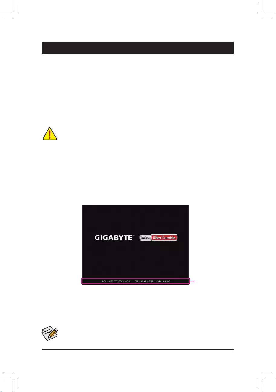
2-1 Startup Screen
The following startup Logo screen will appear when the computer boots.
•When the system is not stable as usual, select the Load Optimized Defaults item to set your system to its defaults.
•The BIOS Setup menus described in this chapter are for reference only and may differ by BIOS version.
Function Keys
There are two different BIOS modes as follows and you can use the <F2> key to switch between the two modes.
Easy Mode allows users to quickly view their current system information or to make adjustments for optimum
performance.InEasyMode,youcanuseyourmousetomovethroughcongurationitems.TheAdvancedMode
provides detailed BIOS settings. You can press the arrow keys on your keyboard to move among the items
and press <Enter> to accept or enter a sub-menu. Or you can use your mouse to select the item you want.
— 21 —

2-2 The Main Menu
Hardware
Information
Option Description Current Settings
Setup Menus
Conguration
Items
System
Time
Quick Access Bar allows you to quickly move to
the General Help, Easy Mode, Smart Fan 5, or
Q-Flash screen.
Advanced Mode Function Keys
<f><g> Move the selection bar to select a setup menu
<h><i>Movetheselectionbartoselectancongurationitemonamenu
<Enter>/Double Click Execute command or enter a menu
<+>/<Page Up> Increase the numeric value or make changes
<—>/<Page Down> Decrease the numeric value or make changes
<F1> Show descriptions of the function keys
<F2> Switch to Easy Mode
<F3> SavethecurrentBIOSsettingstoaprole
<F4> LoadtheBIOSsettingsfromaprolecreatedbefore
<F5> RestorethepreviousBIOSsettingsforthecurrentsubmenus
<F6> Display the Smart Fan 5 screen
<F7> LoadtheOptimizedBIOSdefaultsettingsforthecurrentsubmenus
<F8> Access the Q-Flash utility
<F10> Save all the changes and exit the BIOS Setup program
<F11> Switch to the Favorites submenu
<F12> Capture the current screen as an image and save it to your USB drive
<Insert> Add or remove a favorite option
<Ctrl>+<S> Display information on the installed memory
<Esc> Main Menu: Exit the BIOS Setup program
Submenus: Exit current submenu
— 22 —
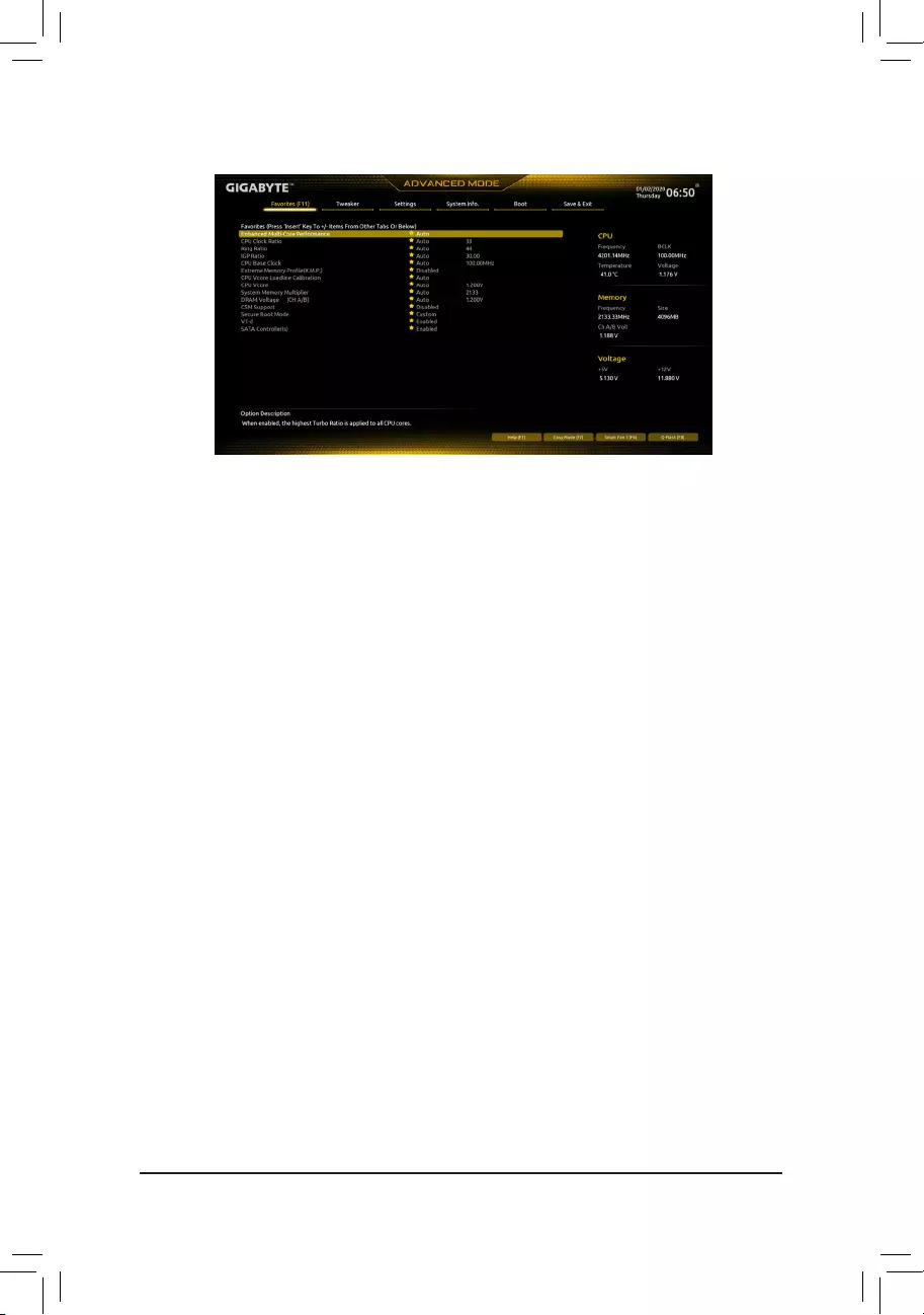
2-3 Favorites (F11)
Set your frequently used options as your favorites and use the <F11> key to quickly switch to the page where
all of your favorite options are located. To add or remove a favorite option, go to its original page and press
<Insert>ontheoption.Theoptionismarkedwithastarsignifsetasa»favorite.»
— 23 —
`Advanced Frequency Settings
&CPU Upgrade
AllowsyoutosettheCPUfrequency.ThenalresultmayvarydependingontheCPUused.Prole.Options
are:Default,GamingProle,Advanced(Default:Default)
&CPU Base Clock
AllowsyoutomanuallysettheCPUbaseclockin0.01MHzincrements.(Default:Auto)
Important: It is highly recommended that the CPU frequency be set in accordance with the CPU
specications.
&Enhanced Multi-Core Performance
DetermineswhethertoallowtheCPUtorunatTurbo1Cspeed.AutoletstheBIOSautomaticallycongure
this setting. (Default: Auto)
&CPU Clock Ratio
Allows you to alter the clock ratio for the installed CPU. The adjustable range is dependent on the CPU
being installed.
&Ring Ratio
Allows you to set the CPU Uncore ratio. The adjustable range is dependent on the CPU being used. (Default:
Auto)
&IGP Ratio (Note)
AllowsyoutosettheGraphicsRatio.(Default:Auto)
&AVX Offset (Note)
AVX offset is the negative offset of AVX ratio.
Advanced CPU Settings
&CPU Over Temperature Protection (Note)
Allowsyoutone-tunetheTJMaxoffsetvalue.(Default:Auto)
(Note) ThisitemispresentonlywhenyouinstallaCPUthatsupportsthisfeature.Formoreinformationabout
Intel® CPUs’ unique features, please visit Intel’s website.
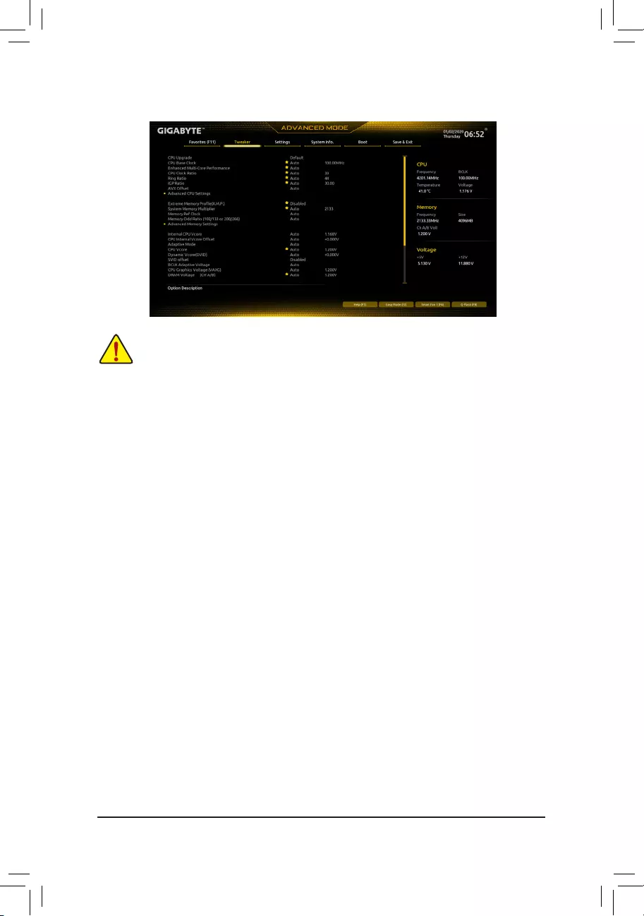
2-4 Tweaker
Whether the system will work stably with the overclock/overvoltage settings you made is dependent on your overall
systemcongurations.Incorrectlydoingoverclock/overvoltagemayresultindamagetoCPU,chipset,ormemory
and reduce the useful life of these components. This page is for advanced users only and we recommend you not to
alter the default settings to prevent system instability or other unexpected results. (Inadequately altering the settings
may result in system’s failure to boot. If this occurs, clear the CMOS values and reset the board to default values.)
— 24 —

&FCLK Frequency for Early Power On
AllowsyoutosettheFCLKfrequency.Optionsare:Normal(800Mhz),1GHz,400MHz.(Default:1GHz)
&Hyper-Threading Technology
Allows you to determine whether to enable multi-threading technology when using an Intel® CPU that
supports this function. This feature only works for operating systems that support multi-processor mode.
AutoletstheBIOSautomaticallycongurethissetting.(Default:Auto)
&No. of CPU Cores Enabled
Allows you to select the number of CPU cores to enable in an Intel® multi-core CPU (the number of CPU
coresmayvarybyCPU).AutoletstheBIOSautomaticallycongurethissetting.(Default:Auto)
dPer Core HT Disable Setting
&HT Disable (Note)
AllowsyoudeterminewhethertodisabletheHTfeatureforeachCPUcore.Thisitemiscongurableonly
when Per Core HT Disable Setting is set to Manual. (Default: Disabled)
&VT-d
Enables or disables Intel®VirtualizationTechnologyforDirectedI/O.(Default:Enabled)
&Intel(R) Speed Shift Technology (Intel® Speed Shift Technology) (Note)
Enables or disables Intel® Speed Shift Technology. Enabling this feature allows the processor to ramp up
its operating frequency more quickly and then improves the system responsiveness. (Default: Enabled)
&CPU Thermal Monitor (Note)
Enables or disables Intel® Thermal Monitor function, a CPU overheating protection function. When enabled,
the CPU core frequency and voltage will be reduced when the CPU is overheated. Auto lets the BIOS
automaticallycongurethissetting.(Default:Auto)
&Ring to Core offset (Down Bin)
AllowsyoutodeterminewhethertodisabletheCPURingratioauto-downfunction.Auto lets the BIOS
automaticallycongurethissetting.(Default:Auto)
&CPU EIST Function (Note)
Enables or disables Enhanced Intel® Speed Step Technology (EIST). Depending on CPU loading, Intel®
EIST technology can dynamically and effectively lower the CPU voltage and core frequency to decrease
average power consumption and heat production. AutoletstheBIOSautomaticallycongurethissetting.
(Default: Auto)
&Race To Halt (RTH) (Note)/EnergyEfcientTurbo (Note)
Enables or disables the CPU power saving related settings.
&Voltage Optimization
Allowsyoutodeterminewhethertoenablevoltageoptimizationtoreducepowerconsumption.(Default:
Auto)
&Intel(R) Turbo Boost Technology (Note)
Allows you to determine whether to enable the Intel® CPU Turbo Boost technology. Auto lets the BIOS
automaticallycongurethissetting.(Default:Auto)
&CPU Flex Ratio Override
EnablesordisablestheCPUFlexRatio.ThemaximumCPUclockratiowillbebasedontheCPU Flex
Ratio Settings value if CPU Clock Ratio is set to Auto. (Default: Disabled)
&CPU Flex Ratio Settings
AllowsyoutosettheCPUFlexRatio.TheadjustablerangemayvarybyCPU.
(Note) ThisitemispresentonlywhenyouinstallaCPUthatsupportsthisfeature.Formoreinformationabout
Intel® CPUs’ unique features, please visit Intel’s website.
— 25 —

&Frequency Clipping TVB (Note)
Allows you to enable or disable automatic CPU frequency reduction initiated by Thermal Velocity Boost.
AutoletstheBIOSautomaticallycongurethissetting.(Default:Auto)
&Voltage reduction initiated TVB (Note)
Allows you to enable or disable automatic CPU voltage reduction initiated by Thermal Velocity Boost. Auto
letstheBIOSautomaticallycongurethissetting.(Default:Auto)
dActive Turbo Ratios
&Turbo Ratio (1-Core Active~10-Core Active)
Allows you to set the CPU Turbo ratios for different number of active cores. Auto sets the CPU Turbo
ratiosaccordingtotheCPUspecications.
Thisitemiscongurableonlywhen
Active Turbo Ratios is set
to
Enabled
.
(Default: Auto)
dC-States Control
&CPU Enhanced Halt (C1E)
Enables or disables Intel
®
CPU Enhanced Halt (C1E) function, a CPU power-saving function in system halt state.
When enabled, the CPU core frequency and voltage will be reduced during system halt state to decrease
power consumption. AutoletstheBIOSautomaticallycongurethissetting.Thisitemiscongurableonly
when C-States Control is set to Enabled. (Default: Auto)
&C3 State Support (Note)
Allows you to determine whether to let the CPU enter C3 mode in system halt state. When enabled, the
CPU core frequency and voltage will be reduced during system halt state to decrease power consumption.
The C3 state is a more enhanced power-saving state than C1. AutoletstheBIOSautomaticallycongure
thissetting.ThisitemiscongurableonlywhenC-States Control is set to Enabled. (Default: Auto)
&C6/C7 State Support (Note)
Allows you to determine whether to let the CPU enter C6/C7 mode in system halt state. When enabled, the
CPU core frequency and voltage will be reduced during system halt state to decrease power consumption.
The C6/C7 state is a more enhanced power-saving state than C3. AutoletstheBIOSautomaticallycongure
thissetting.ThisitemiscongurableonlywhenC-States Control is set to Enabled. (Default: Auto)
&C8 State Support (Note)
Allows you to determine whether to let the CPU enter C8 mode in system halt state. When enabled, the CPU
core frequency and voltage will be reduced during system halt state to decrease power consumption. The
C8 state is a more enhanced power-saving state than C6/C7. AutoletstheBIOSautomaticallycongure
thissetting.ThisitemiscongurableonlywhenC-States Control is set to Enabled. (Default: Auto)
&C10 State Support (Note)
Allows you to determine whether to let the CPU enter C10 mode in system halt state. When enabled, the
CPU core frequency and voltage will be reduced during system halt state to decrease power consumption.
The C10 state is a more enhanced power-saving state than C8. AutoletstheBIOSautomaticallycongure
thissetting.ThisitemiscongurableonlywhenC-States Control is set to Enabled. (Default: Auto)
&Package C State Limit (Note)
Allows you to specify the C-state limit for the processor. AutoletstheBIOSautomaticallycongurethis
setting.ThisitemiscongurableonlywhenC-States Control is set to Enabled. (Default: Auto)
(Note) ThisitemispresentonlywhenyouinstallaCPUthatsupportsthisfeature.Formoreinformationabout
Intel® CPUs’ unique features, please visit Intel’s website.
— 26 —

dTurbo Power Limits
Allows you to set a power limit for CPU Turbo mode. When the CPU power consumption exceeds the
speciedpowerlimit,theCPUwillautomaticallyreducethecorefrequencyinordertoreducethepower.
AutosetsthepowerlimitaccordingtotheCPUspecications.(Default:Auto)
&Package Power Limit TDP (Watts) / Package Power Limit Time
AllowsyoutosetthepowerlimitforCPUTurbomodeandhowlongittakestooperateatthespeciedpower
limit.Ifthespeciedvalueisexceeded,theCPUwillautomaticallyreducethecorefrequencyinorderto
reduce the power. AutosetsthepowerlimitaccordingtotheCPUspecications.Thisitemiscongurable
only when Turbo Power Limits is set to Enabled. (Default: Auto)
&DRAM Power Limit (Watts) / DRAM Power Limit Time
AllowsyoutosetthepowerlimitformemoryTurbomodeandhowlongittakestooperateatthespecied
power limit. AutoletstheBIOSautomaticallycongurethissetting.Thisitemiscongurableonlywhen
Turbo Power Limits is set to Enabled. (Default: Auto)
&Core Current Limit (Amps)
AllowsyoutosetacurrentlimitforCPUTurbomode.WhentheCPUcurrentexceedsthespeciedcurrent
limit, the CPU will automatically reduce the core frequency in order to reduce the current. Auto sets the
powerlimitaccordingtotheCPUspecications.ThisitemiscongurableonlywhenTurbo Power Limits
is set to Enabled. (Default: Auto)
dTurbo Per Core Limit Control (Note 1)
Allows you to control each CPU core limit separately. (Default: Auto)
&ExtremeMemoryProle(X.M.P.)(Note 2)
Allows the BIOS to read the SPD data on XMP memory module(s) to enhance memory performance when
enabled.
Disabled Disables this function. (Default)
Prole1 UsesProle1settings.
Prole2(Note2) UsesProle2settings.
&System Memory Multiplier
Allows you to set the system memory multiplier. Auto sets memory multiplier according to memory SPD
data. (Default: Auto)
&Memory Ref Clock
Allows you to manually adjust the memory reference clock. (Default: Auto)
&Memory Odd Ratio (100/133 or 200/266)
Enabled allows Qclk to run in odd frequency. (Default: Auto)
Advanced Memory Settings
&Memory Multiplier Tweaker
Provides different levels of memory auto-tuning. (Default: Auto)
&Channel Interleaving
Enables or disables memory channel interleaving. Enabled allows the system to simultaneously access
different channels of the memory to increase memory performance and stability. Auto lets the BIOS
automaticallycongurethissetting.(Default:Auto)
(Note1) ThisitemispresentonlywhenyouinstallaCPUthatsupportsthisfeature.Formoreinformationabout
Intel® CPUs’ unique features, please visit Intel’s website.
(Note2) ThisitemispresentonlywhenyouinstallaCPUandamemorymodulethatsupportthisfeature.
— 27 —

&Rank Interleaving
Enables or disables memory rank interleaving. Enabled allows the system to simultaneously access different
ranks of the memory to increase memory performance and stability. Auto lets the BIOS automatically
congurethissetting.(Default:Auto)
&Memory Boot Mode
Provides memory detection and training methods.
Auto LetstheBIOSautomaticallycongurethissetting.(Default)
Normal TheBIOSautomaticallyperformsmemorytraining.Pleasenotethatifthesystem
becomes unstable or unbootable, try to clear the CMOS values and reset the board
todefaultvalues.(Refertotheintroductionsofthebattery/clearCMOSjumperin
Chapter 1 for how to clear the CMOS values.)
Fast Skipmemorydetectionandtraininginsomespeciccriteriaforfastermemory
boot.
Disable Fast Boot Detect and train memory at every single boot.
&Realtime Memory Timing
Allowsyoutone-tunememorytimingsaftertheBIOSstage.(Default:Auto)
&Memory Enhancement Settings
Providesseveralmemoryperformanceenhancementsettings:Auto,RelaxOC,EnhancedStability,Normal,
EnhancedPerformance,HighFrequency,HighDensity,andDDR-4500+.(Default:Auto)
&Memory Channel Detection Message
Allows you to determine whether to show an alert message when the memory is not installed in the optimal
memory channel. (Default: Enabled)
SPD Info
Displays information on the installed memory.
Memory Channels Timing
d Channels Standard Timing Control, Channels Advanced Timing Control, Channel Misc
Timing Control
Thesesectionsprovidememorytimingsettings.Note:Yoursystemmaybecomeunstableorfailtoboot
after you make changes on the memory timings. If this occurs, please reset the board to default values by
loadingoptimizeddefaultsorclearingtheCMOSvalues.
& Vcore Voltage Mode/SVID offset/BCLK Adaptive Voltage/CPU Graphics Voltage
(VAXG)/DRAM Voltage (CH A/B)/CPU VCCIO/CPU VCCIO2/CPU System Agent Voltage/
VCC Substained/VCCPLL/VCCPLL OC/VCCVTT/PCH Core
These items allow you to adjust the CPU Vcore and memory voltages.
Advanced Voltage Settings
ThissubmenuallowsyoutocongureLoad-LineCalibrationlevel,over-voltageprotectionlevel,andover-
current protection level.
— 28 —

2-5 Settings
Platform Power
&Platform Power Management
Enables or disables the Active State Power Management function (ASPM). (Default: Disabled)
&Power On By Keyboard
Allows the system to be turned on by a PS/2 keyboard wake-up event.
Note:Tousethisfunction,youneedanATXpowersupplyprovidingatleast1Aonthe+5VSBlead.
Disabled Disables this function. (Default)
Password Set a password with 1~5 characters to turn on the system.
Keyboard98 PressPOWERbuttonontheWindows98keyboardtoturnonthesystem.
Any Key Press any key to turn on the system.
&Power On Password
Set the password when Power On By Keyboard is set to Password.
Press <Enter> on this item and set a password with up to 5 characters and then press <Enter> to accept.
To turn on the system, enter the password and press <Enter>.
Note:Tocancelthepassword,press<Enter>onthisitem.Whenpromptedforthepassword,press<Enter>
again without entering the password to clear the password settings.
&Power On By Mouse
Allows the system to be turned on by a PS/2 mouse wake-up event.
Note:Tousethisfunction,youneedanATXpowersupplyprovidingatleast1Aonthe+5VSBlead.
Disabled Disables this function. (Default)
Move Move the mouse to turn on the system.
Double Click Double click on left button on the mouse to turn on the system.
&ErP
Determines whether to let the system consume least power in S5 (shutdown) state. (Default: Disabled)
Note:WhenthisitemissettoEnabled,thefollowingfunctionswillbecomeunavailable:ResumebyAlarm,
power on by mouse, and power on by keyboard.
&Soft-Off by PWR-BTTN
ConguresthewaytoturnoffthecomputerinMS-DOSmodeusingthepowerbutton.
Instant-Off Press the power button and then the system will be turned off instantly. (Default)
Delay 4 Sec. Press and hold the power button for 4 seconds to turn off the system. If the power
button is pressed for less than 4 seconds, the system will enter suspend mode.
— 29 —

&Resume by Alarm
Determines whether to power on the system at a desired time. (Default: Disabled)
If enabled, set the date and time as following:
Wakeupday:Turnonthesystemataspecictimeoneachdayoronaspecicdayinamonth.
Wake up hour/minute/second: Set the time at which the system will be powered on automatically.
Note:Whenusingthisfunction,avoidinadequateshutdownfromtheoperatingsystemorremovalofthe
AC power, or the settings may not be effective.
&Power Loading
Enables or disables dummy load. When the power supply is at low load, a self-protection will activate causing
it to shutdown or fail. If this occurs, please set to Enabled. AutoletstheBIOSautomaticallycongurethis
setting. (Default: Auto)
&RC6(Render Standby)
Allows you to determine whether to let the onboard graphics enter standby mode to decrease power
consumption. (Default: Enabled)
&AC BACK
Determines the state of the system after the return of power from an AC power loss.
Memory The system returns to its last known awake state upon the return of the AC power.
Always On The system is turned on upon the return of the AC power.
Always Off The system stays off upon the return of the AC power. (Default)
IO Ports
&Initial Display Output
SpeciestherstinitiationofthemonitordisplayfromtheinstalledPCIExpressgraphicscardortheonboard
graphics.
IGD Video(Note) Setstheonboardgraphicsastherstdisplay.
PCIe1Slot SetsthegraphicscardonthePCIEX16slotastherstdisplay.(Default)
PCIe2Slot SetsthegraphicscardonthePCIEX4slotastherstdisplay.
&Internal Graphics
Enables or disables the onboard graphics function. (Default: Auto)
&DVMT Pre-Allocated
Allowsyoutosettheonboardgraphicsmemorysize.Optionsare:32M~512M.(Default:64M)
&DVMT Total Gfx Mem
AllowsyoutoallocatetheDVMTmemorysizeoftheonboardgraphics.Optionsare:128M,256M,MAX.
(Default: 256M)
&Aperture Size
Allows you to set the maximum amount of system memory that can be allocated to the graphics card.
Options are: 128MB, 256MB, 512MB, 1024MB, and 2048MB. (Default: 256MB)
&PCIE Bifurcation Support
Allows you to determine how the bandwidth of the PCIEX16 slot is divided. Options: PCIE x16, PCIE x8/
x8, PCIE x8/x4/x4. (Default: Auto)
&OnBoard LAN Controller
EnablesordisablestheonboardLANfunction.(Default:Enabled)
Ifyouwishtoinstalla3rdpartyadd-innetworkcardinsteadofusingtheonboardLAN,setthisitemto
Disabled.
(Note) ThisitemispresentonlywhenyouinstallaCPUthatsupportsthisfeature.
— 30 —

&Audio Controller
Enables or disables the onboard audio function. (Default: Enabled)
If you wish to install a 3rd party add-in audio card instead of using the onboard audio, set this item to
Disabled.
&Above 4G Decoding
Enables or disables 64-bit capable devices to be decoded in above 4 GB address space (only if your system
supports 64-bit PCI decoding). Set to Enabled if more than one advanced graphics card are installed and
their drivers are not able to be launched when entering the operating system (because of the limited 4 GB
memory address space). (Default: Disabled)
&IOAPIC 24-119 Entries
Enables or disables this function. (Default: Enabled)
SuperIOConguration
&Serial Port
Enables or disables the onboard serial port. (Default: Enabled)
USBConguration
&Legacy USB Support
Allows USB keyboard/mouse to be used in MS-DOS. (Default: Enabled)
&XHCI Hand-off
Determines whether to enable XHCI Hand-off feature for an operating system without XHCI Hand-off
support. (Default: Enabled)
&USB Mass Storage Driver Support
Enables or disables support for USB storage devices. (Default: Enabled)
&Mass Storage Devices
Displays a list of connected USB mass storage devices. This item appears only when a USB storage device
is installed.
NetworkStackConguration
&Network Stack
Disables or enables booting from the network to install a GPT format OS, such as installing the OS from
the Windows Deployment Services server. (Default: Disabled)
&IPv4 PXE Support
EnablesordisablesIPv4PXESupport.ThisitemiscongurableonlywhenNetwork Stack is enabled.
&IPv4 HTTP Support
EnablesordisablesHTTPbootsupportforIPv4.ThisitemiscongurableonlywhenNetwork Stack is
enabled.
&IPv6 PXE Support
EnablesordisablesIPv6PXESupport.ThisitemiscongurableonlywhenNetwork Stack is enabled.
&IPv6 HTTP Support
EnablesordisablesHTTPbootsupportforIPv6.ThisitemiscongurableonlywhenNetwork Stack is
enabled.
&PXE boot wait time
Allowsyoutocongurehowlongtowaitbeforeyoucanpress<Esc>toabortthePXEboot.Thisitemis
congurableonlywhenNetwork Stack is enabled. (Default: 0)
&Media detect count
Allowsyoutosetthenumberoftimestocheckthepresenceofmedia.Thisitemiscongurableonlywhen
Network Stack is enabled. (Default: 1)
— 31 —

NVMeConguration
DisplaysinformationonyourM.2NVMEPCIeSSDifinstalled.
SATAAndRSTConguration
&SATA Controller(s)
Enables or disables the integrated SATA controllers. (Default: Enabled)
&SATA Mode Selection
EnablesordisablesRAIDfortheSATAcontrollersintegratedintheChipsetorcongurestheSATAcontrollers
to AHCI mode.
IntelRSTPremiumWithIntelOptaneSystemAcceleration EnablesRAIDfortheSATAcontroller.
AHCI CongurestheSATAcontrollerstoAHCImode.AdvancedHostControllerInterface
(AHCI)isaninterfacespecicationthatallowsthestoragedrivertoenableadvanced
SerialATAfeaturessuchasNativeCommandQueuingandhotplug.(Default)
&Aggressive LPM Support
Enables or disables the power saving feature, ALPM (Aggressive Link Power Management), for the Chipset
SATA controllers. (Default: Disabled)
&Port 0/1/2/3/4/5
Enables or disables each SATA port. (Default: Enabled)
&Hot plug
Enables or disable the hot plug capability for each SATA port. (Default: Disabled)
&ConguredaseSATA
Enables or disables support for external SATA devices.
EZ RAID
AllowsyoutoquicklysetupaRAIDarray.RefertoChapter3,»ConguringaRAIDSet,»forinstructions
onconguringaRAIDarray.
Realtek PCIe GBE Family Controller
Thissub-menuprovidesinformationonLANcongurationandrelatedcongurationoptions.
Miscellaneous
&LEDs in System Power On State
Allows you to enable or disable motherboard LED lighting when the system is on.
Off Disables the selected lighting mode when the system is on.
On Enables the selected lighting mode when the system is on. (Default)
&LEDs in Sleep, Hibernation, and Soft Off States
Allows you to set the lighting mode of the motherboard LEDs in system S3/S4/S5 state.
ThisitemiscongurablewhenLEDs in System Power On State is set to On.
Off Disables the selected lighting mode when the system enters S3/S4/S5 state. (Default)
On Enables the selected lighting mode when the system enters S3/S4/S5 state.
&Intel Platform Trust Technology (PTT)
Enables or disables Intel® PTT Technology. (Default: Disabled)
&Software Guard Extensions (SGX)
Enables or disables the Intel® Software Guard Extensions technology. This feature allows legal software
to operate in a safe environment and protects the software against attacks from malicious software. The
Software Controlled option allows you to enable or disable this feature with an Intel-provided application.
(Default: Software Controlled)
— 32 —

&Max Link Speed
Allows you to set the operation mode of the PCI Express slots to Gen 1, Gen 2, or Gen 3. Actual operation
modeissubjecttothehardwarespecicationofeachslot.AutoletstheBIOSautomaticallycongurethis
setting. (Default: Auto)
&3DMark01 Enhancement
Allows you to determine whether to enhance some legacy benchmark performance. (Default: Disabled)
Trusted Computing
Enables or disables Trusted Platform Module (TPM).
PC Health Status
&Reset Case Open Status
Disabled Keeps or clears the record of previous chassis intrusion status. (Default)
Enabled Clears the record of previous chassis intrusion status and the Case Openeldwill
show»No»atnextboot.
&Case Open
Displays the detection status of the chassis intrusion detection device attached to the motherboard CI
header.Ifthesystemchassiscoverisremoved,thiseldwillshow»Yes»,otherwiseitwillshow«No».To
clear the chassis intrusion status record, set Reset Case Open Status to Enabled, save the settings to
the CMOS, and then restart your system.
& CPU Vcore/CPU VCCSA/DRAM Channel A/B Voltage/+3.3V/+5V/+12V/CPU VAXG
Displays the current system voltages.
Smart Fan 5
&Monitor
Allowsyoutoselectatargettomonitorandtomakefurtheradjustment.(Default:CPUFAN)
&Fan Speed Control
Allows you to determine whether to enable the fan speed control function and adjust the fan speed.
Normal Allowsthefantorunatdifferentspeedsaccordingtothetemperature.Youcanadjust
the fan speed with System Information Viewer based on your system requirements.
(Default)
Silent Allows the fan to run at slow speeds.
Manual Allows you to control the fan speed in the curve graph.
Full Speed Allows the fan to run at full speeds.
&Fan Control Use Temperature Input
Allows you to select the reference temperature for fan speed control.
&Temperature Interval
Allows you to select the temperature interval for fan speed change.
&FanControl Mode
Auto Lets the BIOS automatically detect the type of fan installed and sets the optimal control
mode. (Default)
Voltage Voltage mode is recommended for a 3-pin fan.
PWM PWM mode is recommended for a 4-pin fan.
&Fan Stop
Enables or disables the fan stop function. You can set the temperature limit using the temperature curve.
The fan stops operation when the temperature is lower than the limit. (Default: Disabled)
&Temperature
Displays the current temperature of the selected target area.
— 33 —

&Fan Speed
Displays current fan speeds.
&Temperature Warning Control
Sets the warning threshold for temperature. When temperature exceeds the threshold, BIOS will emit
warning sound. Options are: Disabled (default), 60oC/140oF, 70oC/158oF, 80oC/176oF, 90oC/194oF.
&Fan Fail Warning
Allows the system to emit warning sound if the fan is not connected or fails. Check the fan condition or
fan connection when this occurs. (Default: Disabled)
— 34 —
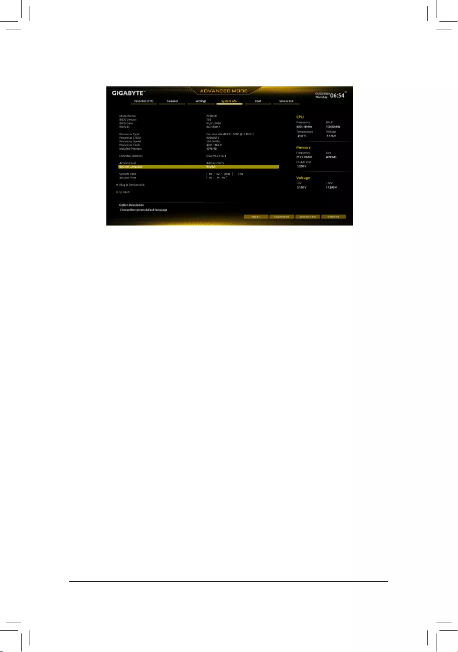
2-6 System Info.
This section provides information on your motherboard model and BIOS version. You can also select the default
language used by the BIOS and manually set the system time.
&Access Level
Displays the current access level depending on the type of password protection used. (If no password is
set, the default will display as Administrator.) The Administrator level allows you to make changes to all
BIOS settings; the User level only allows you to make changes to certain BIOS settings but not all.
&System Language
Selects the default language used by the BIOS.
&System Date
Sets the system date. The date format is week (read-only), month, date, and year. Use <Enter> to switch
betweentheMonth,Date,andYeareldsandusethe<PageUp>or<PageDown>keytosetthedesired
value.
&System Time
Sets the system time. The time format is hour, minute, and second. For example, 1 p.m. is 13:00:00. Use
<Enter>toswitchbetweentheHour,Minute,andSecondeldsandusethe<PageUp>or<PageDown>
key to set the desired value.
Plug in Devices Info
Displays information on your PCI Express, and M.2 devices if installed.
Q-Flash
AllowsyoutoaccesstheQ-FlashutilitytoupdatetheBIOSorbackupthecurrentBIOSconguration.
— 35 —

2-7 Boot
&Bootup NumLock State
EnablesordisablesNumlockfeatureonthenumerickeypadofthekeyboardafterthePOST.(Default:On)
&Security Option
Specieswhetherapasswordisrequiredeverytimethesystemboots,oronlywhenyouenterBIOSSetup.
Afterconguringthisitem,setthepassword(s)undertheAdministrator Password/User Password item.
Setup A password is only required for entering the BIOS Setup program.
System A password is required for booting the system and for entering the BIOS Setup program.
(Default)
&Full Screen LOGO Show
Allows you to determine whether to display the GIGABYTE Logo at system startup. Disabled skips the
GIGABYTE Logo when the system starts up. (Default: Enabled)
&Boot Option Priorities
Speciestheoverallbootorderfromtheavailabledevices.RemovablestoragedevicesthatsupportGPT
formatwillbeprexedwith«UEFI:»stringonthebootdevicelist.Tobootfromanoperatingsystemthat
supportsGPTpartitioning,selectthedeviceprexedwith»UEFI:»string.
Or if you want to install an operating system that supports GPT partitioning such as Windows 10 64-bit,
selecttheopticaldrivethatcontainstheWindows1064-bitinstallationdiscandisprexedwith«UEFI:»
string.
& Hard Drive/CD/DVD ROM Drive/Floppy Drive/Network Device BBS Priorities
Speciesthebootorderforaspecicdevicetype,suchasharddrives,opticaldrives,oppydiskdrives,
anddevicesthatsupportBootfromLANfunction,etc.Press<Enter>onthisitemtoenterthesubmenuthat
presents the devices of the same type that are connected. This item is present only if at least one device
for this type is installed.
&Fast Boot
Enables or disables Fast Boot to shorten the OS boot process. Ultra Fast provides the fastest bootup
speed. (Default: Disable Link)
&SATA Support
Last Boot SATA Devices Only Except for the previous boot drive, all SATA devices are disabled
before the OS boot process completes. (Default)
All SATA Devices All SATA devices are functional in the operating system and during the POST.
ThisitemiscongurableonlywhenFast Boot is set to Enabled or Ultra Fast.
— 36 —

&VGA Support
Allows you to select which type of operating system to boot.
Auto EnableslegacyoptionROMonly.
EFIDriver EnablesEFIoptionROM.(Default)
ThisitemiscongurableonlywhenFast Boot is set to Enabled or Ultra Fast.
&USB Support
Disabled All USB devices are disabled before the OS boot process completes.
Full Initial All USB devices are functional in the operating system and during the POST.
(Default)
Partial Initial Part of the USB devices are disabled before the OS boot process completes.
ThisitemiscongurableonlywhenFast Boot is set to Enabled or Ultra Fast. This function is disabled
when Fast Boot is set to Ultra Fast.
&PS2 Devices Support
Disabled All PS/2 devices are disabled before the OS boot process completes.
Enabled All PS/2 devices are functional in the operating system and during the POST.
(Default)
ThisitemiscongurableonlywhenFast Boot is set to Enabled or Ultra Fast. This function is disabled
when Fast Boot is set to Ultra Fast.
&NetWork Stack Driver Support
Disabled Link Disables booting from the network. (Default)
Enabled Enables booting from the network.
ThisitemiscongurableonlywhenFast Boot is set to Enabled or Ultra Fast.
&Next Boot After AC Power Loss
NormalBoot EnablesnormalbootupuponthereturnoftheACpower.(Default)
Fast Boot Keeps the Fast Boot settings upon the return of the AC power.
ThisitemiscongurableonlywhenFast Boot is set to Enabled or Ultra Fast.
&Mouse Speed
Allows you to set the mouse cursor movement speed. (Default: 1 X)
&Windows 10 Features
Allows you to select the operating system to be installed. (Default: Windows 10)
&CSM Support
Enables or disables UEFI CSM (Compatibility Support Module) to support a legacy PC boot process.
Disabled Disables UEFI CSM and supports UEFI BIOS boot process only. (Default)
Enabled Enables UEFI CSM.
&LAN PXE Boot Option ROM
AllowsyoutoselectwhethertoenablethelegacyoptionROMfortheLANcontroller.(Default:Disabled)
ThisitemiscongurableonlywhenCSM Support is set to Enabled.
&Storage Boot Option Control
AllowsyoutoselectwhethertoenabletheUEFIorlegacyoptionROMforthestoragedevicecontroller.
Donotlaunch DisablesoptionROM.
UEFI EnablesUEFIoptionROMonly.
Legacy EnableslegacyoptionROMonly.(Default)
ThisitemiscongurableonlywhenCSM Support is set to Enabled.
— 37 —

&Other PCI devices
AllowsyoutoselectwhethertoenabletheUEFIorLegacyoptionROMforthePCIdevicecontrollerother
thantheLAN,storagedevice,andgraphicscontrollers.
Donotlaunch DisablesoptionROM.
UEFI EnablesUEFIoptionROMonly.(Default)
Legacy EnableslegacyoptionROMonly.
ThisitemiscongurableonlywhenCSM Support is set to Enabled.
&Administrator Password
Allowsyoutocongureanadministratorpassword.Press<Enter>onthisitem,typethepassword,and
thenpress<Enter>.Youwillberequestedtoconrmthepassword.Typethepasswordagainandpress
<Enter>. You must enter the administrator password (or user password) at system startup and when entering
BIOS Setup. Differing from the user password, the administrator password allows you to make changes to
all BIOS settings.
&User Password
Allowsyoutocongureauserpassword.Press<Enter>onthisitem,typethepassword,andthenpress
<Enter>.Youwillberequestedtoconrmthepassword.Typethepasswordagainandpress<Enter>.
You must enter the administrator password (or user password) at system startup and when entering BIOS
Setup. However, the user password only allows you to make changes to certain BIOS settings but not all.
To cancel the password, press <Enter> on the password item and when requested for the password, enter
thecorrectonerst.Whenpromptedforanewpassword,press<Enter>withoutenteringanypassword.
Press<Enter>againwhenpromptedtoconrm.
NOTE:BeforesettingtheUserPassword,besuretosettheAdministratorPasswordrst.
Secure Boot
AllowsyoutoenableordisableSecureBootandcongurerelatedsettings.Thisitemiscongurableonly
when CSM Support is set to Disabled.
&Preferred Operating Mode
Allows you to select whether to enter Easy mode or Advanced mode after entering BIOS Setup. Auto
enters the BIOS mode where it was last time. (Default: Auto)
— 38 —

2-8 Save & Exit
&Save & Exit Setup
Press <Enter> on this item and select Yes. This saves the changes to the CMOS and exits the BIOS Setup
program. Select No or press <Esc> to return to the BIOS Setup Main Menu.
&Exit Without Saving
Press <Enter> on this item and select Yes. This exits the BIOS Setup without saving the changes made
in BIOS Setup to the CMOS. Select No or press <Esc> to return to the BIOS Setup Main Menu.
&Load Optimized Defaults
Press <Enter> on this item and select Yes to load the optimal BIOS default settings. The BIOS defaults
settingshelpthesystemtooperateinoptimumstate.AlwaysloadtheOptimizeddefaultsafterupdating
the BIOS or after clearing the CMOS values.
&Boot Override
Allows you to select a device to boot immediately. Press <Enter> on the device you select and select Yes
toconrm.Yoursystemwillrestartautomaticallyandbootfromthatdevice.
&SaveProles
ThisfunctionallowsyoutosavethecurrentBIOSsettingstoaprole.Youcancreateupto8prolesand
saveasSetupProle1~SetupProle8.Press<Enter>tocomplete.OryoucanselectSelect File in
HDD/FDD/USBtosavetheproletoyourstoragedevice.
&LoadProles
If your system becomes unstable and you have loaded the BIOS default settings, you can use this function
toloadtheBIOS settingsfromaprolecreatedbefore,withoutthehasslesofreconguringtheBIOS
settings.Firstselecttheproleyouwishtoloadandthenpress<Enter>tocomplete.YoucanselectSelect
File in HDD/FDD/USBtoinputtheprolepreviouslycreatedfromyourstoragedeviceorloadtheprole
automatically created by the BIOS, such as reverting the BIOS settings to the last settings that worked
properly (last known good record).
— 39 —
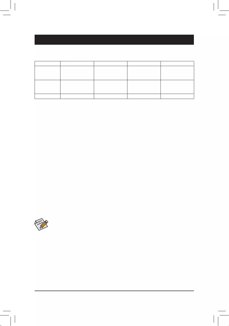
Chapter 3 Appendix
Before you begin, please prepare the following items:
•At least two SATA hard drives or SSDs. (Note1) (To ensure optimal performance, it is recommended that you
use two hard drives with identical model and capacity). (Note2)
•Windows setup disc.
•Motherboard driver disc.
•A USB thumb drive.
ConguringtheOnboardSATAController
A. Installing SATA hard drive(s) in your computer
Install the hard drives/SSDs in the Intel® Chipset controlled connectors on the motherboard. Then connect the
power connectors from your power supply to the hard drives.
B.ConguringSATAcontrollermodeinBIOSSetup
MakesuretoconguretheSATAcontrollermodecorrectlyinsystemBIOSSetup.
Steps:
1. Turn on your computer and press <Delete> to enter BIOS Setup during the POST (Power-On Self-Test). Go
to Settings\IOPorts\SATAAndRSTConguration, make sure SATA Controller(s) is enabled. To create
RAID,setSATA Mode Selection to Intel RST Premium With Intel Optane System Acceleration. Then
savethesettingsandrestartyourcomputer.Note:WhenusingaPCIeSSD,makesuretosettheUse RST
Legacy OROM item under Settings\IOPorts\SATAAndRSTConguration to Disabled and RST Control
PCIe Storage Devices to Manual. Then depending the M.2 connector you use, set the corresponding PCIe
Storage Dev on Port XX item to RST Controlled. Finally, save the settings and exit BIOS Setup. If you want
touseNVMePCIeSSDstocongureRAID,makesuretosetNVMe RAID mode to Enabled.
2. TousetheEZRAIDfeature,followthestepsin»C-1.»TocongureUEFIRAID,followthestepsin«C-2.»To
enterthelegacyRAIDROM,referto«C-3″formoreinformation.Finally,savethesettingsandexitBIOSSetup.
3-1 ConguringaRAIDSet
The BIOS Setup menus described in this section may differ from the exact settings for your motherboard.
The actual BIOS Setup menu options you will see shall depend on the motherboard you have and
the BIOS version.
C-1. Using EZ RAID
GIGABYTEmotherboardsprovideyouwiththeEZRAIDfeature,allowingyoutoquicklycongureaRAID
arraywithsimpliedsteps.
Steps:
1. After restarting the computer, enter the BIOS Setup and go to Settings. Press <Enter> on the EZ RAID item.
SelectthetypeofharddrivesyouuseforRAIDintheType tab and then press <Enter>.
2. Go to the ModetabtoselectaRAIDlevel.RAIDlevelssupportedincludeRAID0,RAID1,RAID10,andRAID5
(the selections available depend on the number of the hard drives being installed). Then press <Enter> to
move to the Create tab. Click Proceed to begin.
(Note1) AnM.2PCIeSSDcannotbeusedtosetupaRAIDseteitherwithanM.2SATASSDoraSATAharddrive.
(Note2) Referto»InternalConnectors»fortheinstallationnoticesfortheM.2andSATAconnectors.
RAID Levels
RAID 0 RAID 1 RAID 5 RAID 10
Minimum
NumberofHard
Drives
≥2 2≥3 4
Array Capacity Numberofhard
drives*Sizeofthe
smallest drive
Sizeofthesmallest
drive
(Numberofhard
drives-1)*Sizeof
the smallest drive
(Numberofhard
drives/2)*Sizeofthe
smallest drive
Fault Tolerance No Yes Yes Yes
— 40 —

C-2.UEFIRAIDConguration
Steps:
1. In BIOS Setup, go to Boot and set CSM Support to Disabled. Save the changes and exit BIOS Setup.
2. After the system reboot, enter BIOS Setup again. Then enter the Settings\IO Ports\Intel(R) Rapid Storage
Technology sub-menu.
3. On the Intel(R) Rapid Storage Technology menu, press <Enter> on Create RAID Volume to enter the Create
RAID Volume screen. Enter a volume name with 1~16 letters (letters cannot be special characters) under the
Nameitemandpress<Enter>.Then,selectaRAIDlevel.RAIDlevelssupportedincludeRAID0,RAID1,
RAID10,andRAID5(theselectionsavailabledependonthenumberoftheharddrivesbeinginstalled).Next,
use the down arrow key to move to Select Disks.
4. Under Select Disksitem,selecttheharddrivestobeincludedintheRAIDarray.Pressthe<Space>key
ontheharddrivestobeselected(selectedharddrivesaremarkedwith«X»).Thensetthestripeblocksize.
Thestripeblocksizecanbesetfrom4KBto128KB.Onceyouhaveselectedthestripeblocksize,setthe
volume capacity.
5. After setting the capacity, move to Create Volume and press <Enter> to begin.
6. After completing, you’ll be brought back to the Intel(R) Rapid Storage Technology screen. Under RAID
VolumesyoucanseethenewRAIDvolume.Toseemoredetailedinformation,press<Enter>onthevolume
tocheckforinformationonRAIDlevel,stripeblocksize,arrayname,andarraycapacity,etc.
PleasevisitGIGABYTE’swebsitefordetailsonconguringaRAIDarray.
C-3.ConguringLegacyRAIDROM
You’llneedadiscretegraphicscardtoenterthelegacyRAIDROMutility.Enter the Intel®legacyRAIDBIOS
setuputilitytocongureaRAIDarray.SkipthisstepandproceedwiththeinstallationofWindowsoperating
systemforanon-RAIDconguration.
Steps:
1. In BIOS Setup, go to Boot and set CSM Support to Enabled and Storage Boot Option Control to Legacy.
Next,gotoSettings\IOPorts\SATAAndRSTConguration and make sure Use RST Legacy OROM is
set to Enabled. Save the changes and exit BIOS Setup. After the POST memory test begins and before the
operatingsystembootbegins,lookforamessagewhichsays«Press<Ctrl-I>toenterCongurationUtility».
Press<Ctrl>+<I>toentertheRAIDCongurationUtility.
2. After you press <Ctrl> + <I>, the MAIN MENUscreenwillappear.IfyouwanttocreateaRAIDarray,select
Create RAID VolumeinMAINMENUandpress<Enter>.
3. After entering the CREATE VOLUME MENU screen, enter a volume name with 1~16 letters (letters cannot
be special characters) under the Nameitemandpress<Enter>.Then,selectaRAIDlevel.RAIDlevels
supportedincludeRAID0,RAID1,RAID10,andRAID5(theselectionsavailabledependonthenumberof
the hard drives being installed). Press <Enter> to proceed.
4. Under Disksitem,selecttheharddrivestobeincludedintheRAIDarray.Ifonlytwoharddrivesareinstalled,
theywillbeautomaticallyassignedtothearray.Setthestripeblocksizeifnecessary.Thestripeblocksize
canbesetfrom4KBto128KB.Onceyouhaveselectedthestripeblocksize,press<Enter>.
5. Enter the array capacity and press <Enter>. Finally press <Enter> on the Create Volume item to begin
creatingtheRAIDarray.Whenpromptedtoconrmwhethertocreatethisvolume,press<Y>toconrmor
<N>tocancel.
6. Whencompleted,youcanseedetailedinformationabouttheRAIDarrayintheDISK/VOLUME INFORMATION
section,includingtheRAIDlevel,stripeblocksize,arrayname,andarraycapacity,etc.ToexittheRAID
BIOS utility, press <Esc> or select 6. Exit in MAIN MENU.
3. After completing, you’ll be brought back to the Intel(R) Rapid Storage Technology screen. Under RAID
VolumesyoucanseethenewRAIDvolume.Toseemoredetailedinformation,press<Enter>onthevolume
tocheckforinformationonRAIDlevel,stripeblocksize,arrayname,andarraycapacity,etc.
— 41 —

3-2 Installing an Intel® Optane™ Memory
System Requirements
1. Intel® Optane™ memory
2. The Optane™ memory must have at least 16 GB capacity, and it must have equal or smaller capacity than
the hard drive/SSD to be accelerated.
3. The Optane™memorycannotbeusedtoaccelerateanexistingRAIDarray;theacceleratedharddrive/SSD
cannotbeincludedinaRAIDarray.
4. The hard drive/SSD to be accelerated must be a SATA hard drive or M.2 SATA SSD.
5. The hard drive/SSD to be accelerated can be a system drive or data drive. The system drive must be GPT
formatted and have Windows 10 64-bit (or later version) installed on it. The data drive must also be GPT
formatted.
6. The motherboard driver disc
Installation Guidelines
A-1: Installation in AHCI mode
IftheSATAcontrollerhasbeenconguredinAHCImode,pleasefollowthestepsbelow:
1. After entering the operating system, insert the motherboard driver disk into your optical drive. On the Xpress
Install screen, select Intel(R) Optane(TM) Memory System Acceleration (Note) to install. Follow the on-screen
instructions to continue. When completed, restart the system.
2. After re-entering the operating system, follow the on-screen instructions to complete the settings, and then the
Intel® Optane™ Memory application will appear automatically. If you install more than one Optane™ memory,
please select which one you are going to use. Then select which drive to be accelerated. Click Enable. All
data on the Optane™ memory will be erased. Make sure you back up the data before continuing. Follow the
on-screen instructions to proceed. When completed, restart the system.
3. Launch the Intel® Optane™ Memory application from the Start menu and make sure the Intel® Optane™
Memory has been enabled. (The SATA controller mode is changed to Intel RST Premium With Intel Optane
System AccelerationfromAHCImode.DONOTchangeyourSATAcontrollermodebacktoAHCI.Doing
so will cause the Optane™ memory unable to function properly.)
4. Ifyouwanttoacceleratethesystemdrive,youcanselectspecicfolders,les,orapplicationstoaccelerate
using the Intel® Optane™ Memory Pinning function. (The Optane™ memory used must have at least 32
GB capacity.)
(Note) IfthesystemalreadyhasIntel®RapidStorageTechnologyutilityinstalled,youhavetoremoveitrst
beforeinstallingtheIntel(R)Optane(TM)MemorySystemAccelerationapplication.
Install the RAID/AHCI driver and operating system
With the correct BIOS settings, you are ready to install the operating system.
Installing the Operating System
As some operating systems already include Intel®RAID/AHCIdriver,youdonotneedtoinstallseparateRAID/
AHCI driver during the Windows installation process. After the operating system is installed, we recommend
thatyouinstallallrequireddriversfromthemotherboarddriverdiskusing«XpressInstall»toensuresystem
performanceandcompatibility.IftheoperatingsystemtobeinstalledrequiresthatyouprovideadditionalRAID/
AHCI driver during the OS installation process, please refer to the steps below:
1. Copy the IRST folder under \Boot in the driver disk to your USB thumb drive.
2. Boot from the Windows setup disk and perform standard OS installation steps. When the screen requesting
you to load the driver appears, select Browse.
3. ThenbrowsetotheUSBashdriveandselectthelocationofthedriver.Thelocationofthedriverisas
follows:\IRST\f6py-x64
4. When a screen as shown, select Intel(R) Chipset SATA/PCIe RST Premium Controller and click Next to
load the driver and continue the OS installation.
— 42 —

A-2: Installation in Intel RST Premium With Intel Optane System Acceleration mode
IftheSATAcontrollerhasbeenconguredin Intel RST Premium With Intel Optane System Acceleration
mode, please follow the steps below:
1. After system restarts, go to the BIOS Setup, make sure CSM Support under the Boot menu is disabled.
2. Go to Settings\IOPorts\SATAAndRSTConguration and make sure USE RST Legacy OROM is disabled
and RST Control PCIe Storage Devices is set to Manual. If you want to enable the Optane™ memory installed
in the M2A_SB connector, set PCIe Storage Device on Port 9 to RST Controlled; to enable the Optane™
memory installed in the M2M_SB connector, set PCIe Storage Device on Port 21 to RST Controlled.
3. Enter the operating system, launch the Intel® Rapid Storage Technology utility from the Start menu, and
then enable Intel® Optane™ Memory on the Intel® Optane™ Memory screen.
4. If you install more than one Optane™ memory, please select which one you are going to use. Then select
which drive to be accelerated. Click Enable. Follow the on-screen instructions to proceed. When completed,
restart the system.
5. Launch the Intel® Rapid Storage Technology utility from the Start menu and make sure the Intel® Optane™
Memoryhasbeenenabled.Ifyouwanttoacceleratethesystemdrive,youcanselectspecicfolders,les,
or applications to accelerate using the Intel® Optane™ Memory Pinning function. (The Optane™ memory
used must have at least 32 GB capacity.)
•An Optane™ memory cannot be used to accelerate an M.2 PCIe SSD.
•If more than one Optane™ memory is installed, you can select only one of them to accelerate your
SATA-based boot drive. The other(s) can only be used as data drive(s).
•Do not abruptly remove the Optane™ memory. Doing so will cause the operating system to stop
functioning correctly.
•If you want to change/remove the Optane™ memory, you must disable it using the Intel®Rapid
StorageTechnologyorIntel(R)Optane™Memoryapplicationrst.
•After enabling the Optane™ memory, the related BIOS settings will remain even after a BIOS update.
— 43 —
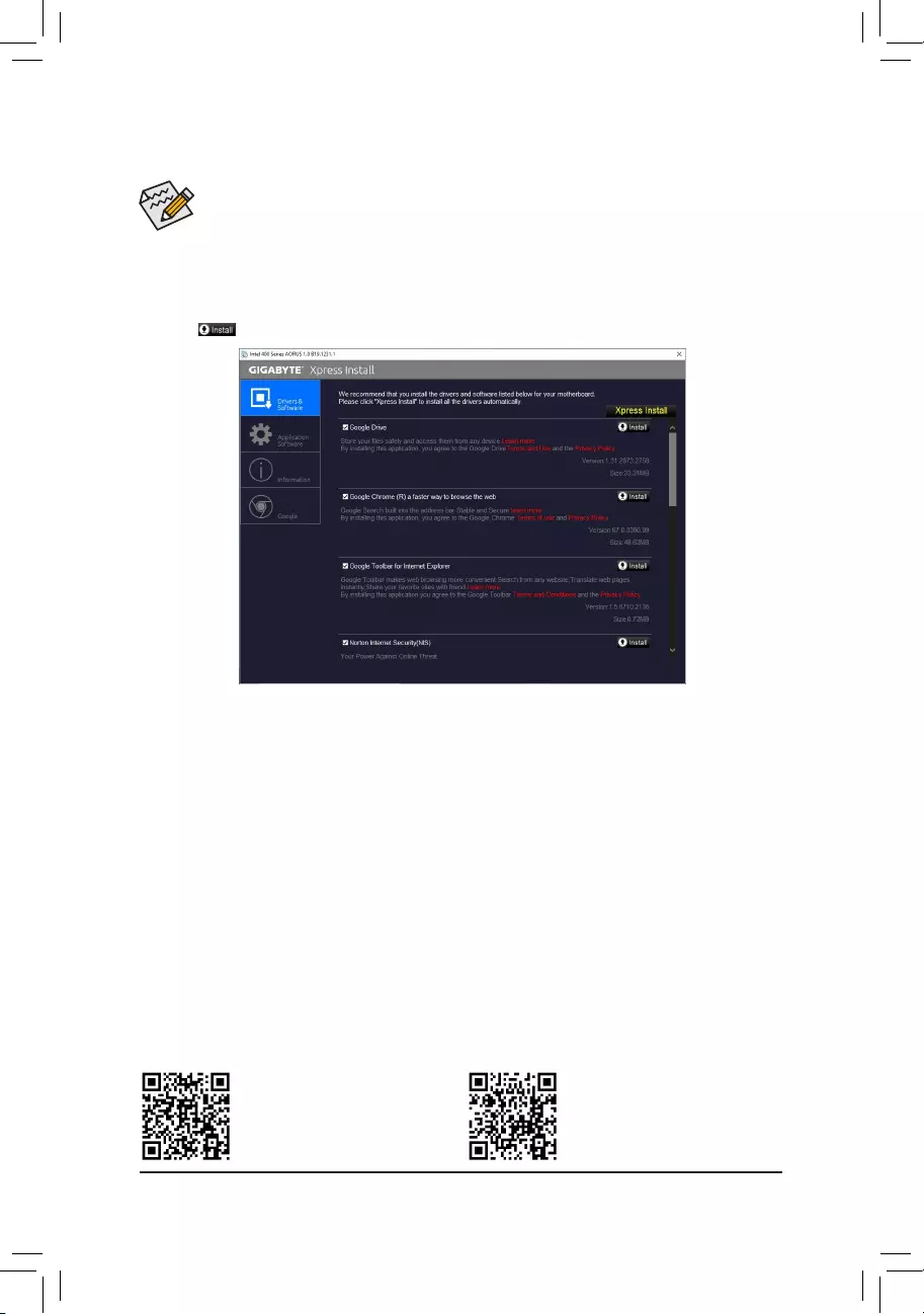
•Beforeinstallingthedrivers,rstinstalltheoperatingsystem.
•After installing the operating system, insert the motherboard driver disc into your optical drive. Click
onthemessage»Taptochoosewhathappenswiththisdisc»onthetop-rightcornerofthescreen
andselect»RunRun.exe.»(OrgotoMyComputer,double-clicktheopticaldriveandexecutethe
Run.exeprogram.)
«XpressInstall»willautomaticallyscanyoursystemandthenlistallofthedriversthatarerecommendedto
install. You can click the Xpress Installbuttonand«XpressInstall»willinstallalloftheselecteddrivers.Orclick
the arrow icon to individually install the drivers you need.
3-3 Drivers Installation
Please visit GIGABYTE’s website for
more software information.
Please visit GIGABYTE’s website for
more troubleshooting information.
— 44 —

Regulatory Notices
CAUTION:
Themanufacturerisnotresponsibleforanyinterferencecausedbyunauthorizedmodicationsand/oruseofunauthorizedantennas.Suchchanges
and/ormodicationsnotexpresslyapprovedbythepartyresponsibleforcomplianceofthisdevicecouldvoidtheuser’sauthoritytooperatethe
equipment.
RF exposure statement / Antenna Use
FurtherRFexposurereductioncanbeachievediftheproductcanbekeptasfaraspossiblefromtheuserbodyorsetthedevicetoloweroutput
power if such function is available.
•Do not touch or move antenna while the unit is transmitting or receiving.
•Do not hold any component containing the radio such that the antenna is very close or touching any exposed parts of the body, especially the face
or eyes, while transmitting.
•Do not operate the radio or attempt to transmit data unless the antenna is connected; this behavior may cause damage to the radio.
United States of America, Federal Communications Commission Statement
Supplier’s Declaration of Conformity
47 CFR § 2.1077 Compliance Information
Product Name: Motherboard
Trade Name: GIGABYTE
Model Number: Z490 UD AC/Z490 UD
Responsible Party – U.S. Contact Information: G.B.T. Inc.
Address: 17358 Railroad street, City Of Industry, CA91748
Tel.: 1-626-854-9338
Internet contact information: https://www.gigabyte.com
FCC Compliance Statement:
This device complies with Part 15 of the FCC Rules, Subpart B, Unintentional Radiators.
Operation is subject to the following two conditions: (1) This device may not cause harmful interference, and (2) this
device must accept any interference received, including interference that may cause undesired operation.
This equipment has been tested and found to comply with the limits for
aClassBdigitaldevice,pursuanttoPart15oftheFCCRules.These
limits are designed to provide reasonable protection against harmful
interference in a residential installation. This equipment generates,
uses and can radiate radio frequency energy and, if not installed
and used in accordance with manufacturer’s instructions, may cause
harmful interference to radio communications. However, there is no
guarantee that interference will not occur in a particular installation. If
this equipment does cause harmful interference to radio or television
reception, which can be determined by turning the equipment off and
on, the user is encouraged to try to correct the interference by one or
more of the following measures:
•Reorientorrelocatethereceivingantenna.
•Increase the separation between the equipment and receiver.
•Connect the equipment to an outlet on a circuit different from that to
which the receiver is connected.
•Consult the dealer or an experienced radio/TV technician for help.
Notice for 5GHz
Operationsinthe5.15-5.25GHzbandarerestrictedtoindoorusage
only.(For5GHzonly)
Canadian Department of Communications Statement
This digital apparatus does not exceed the Class B limits for radio
noiseemissionsfromdigitalapparatussetoutintheRadioInterference
RegulationsoftheCanadianDepartmentofCommunications.Thisclass
B digital apparatus complies with Canadian ICES-003.
Avis de conformité à la réglementation d’Industrie Canada
CetappareilnumériquedelaclasseBestconformeàlanormeNMB-
003 du Canada.
Canada-Industry Canada (IC) Regulatory statement
ThisdevicecomplieswithCanadianRSS-210.
ThisdevicecomplieswithIndustryCanadalicense-exemptRSS
standard(s). Operation is subject to the following two conditions: (1) this
device may not cause interference, and (2) this device must accept any
interference, including interference that may cause undesired operation
of the device.
CetappareilseconformeauxnormesCanadad’IndustriedeRSS
permis-exempt. L’utilisation est assujetti aux deux conditions suivantes:
(1) cet appareil ne peut pas causer d’interférences, et (2) cet appareil
doit accepter des interférences, y compris des interférences qui peuvent
causer desopérations non désirées de l’appareil.
Caution: WhenusingIEEE802.11awirelessLAN,thisproductis
restrictedtoindooruseduetoitsoperationinthe5.15-to5.25-GHz
frequency range. Industry Canada requires this product to be used
indoorsforthefrequencyrangeof5.15GHzto5.25GHztoreducethe
potential for harmful interference to co-channel mobile satellite systems.
High power radar is allocated as the primary user of the 5.25-to 5.35-
GHzand5.65to5.85-GHzbands.Theseradarstationscancause
interference with and/or damage to this device. The maximum allowed
antenna gain for use with this device is 6dBi in order to comply with the
E.I.R.Plimitforthe5.25-to5.35and5.725to5.85GHzfrequencyrange
inpoint-to-pointoperation.TocomplywithRFexposurerequirements
all antennas should be located at a minimum distance of 20cm, or the
minimum separation distance allowed by the module approval, from the
body of all persons.
Attention:l’utilisationd’unréseausanslIEEE802.11aestrestreinte
à une utilisation en intérieur à cause du fonctionnement dansla bande
defréquence5.15-5.25GHz.IndustryCanadarequiertqueceproduit
soit utilisé à l’intérieur des bâtiments pour la bande de fréquence 5.15-
5.25GHzanderéduirelespossibilitésd’interférencesnuisiblesaux
canaux co-existants des systèmes de transmission satellites. Les radars
de puissances ont fait l’objet d’une allocation primaire de fréquences
danslesbandes5.25-5.35GHzet5.65-5.85GHz.Cesstationsradar
peuvent créer des interférences avec ce produit et/ou lui être nuisible.
Le gain d’antenne maximum permissible pour une utilisation avec
ceproduitestde6dBiand’êtreconformeauxlimitesdepuissance
isotropiquerayonnéeéquivalente(P.I.R.E.)applicabledanslesbandes
5.25-5.35GHzet5.725-5.85GHzenfonctionnementpoint-à-point.Pour
seconformerauxconditionsd’expositiondeRFtouteslesantennes
devraient être localisées à une distance minimum de 20 cm, ou la
distance de séparation minimum permise par l’approbation du module,
ducorpsdetouteslespersonnes.»
— 45 —
Radiation Exposure Statement:
Under Industry Canada regulations, this radio transmitter may only
operate using an antenna of a type and maximum (or lesser) gain
approved for the transmitter by Industry Canada. To reduce potential
radio interference to other users, the antenna type and its gain should
be so chosen that the equivalent isotopically radiated power (e.i.r.p.) is
not more than that necessary for successful communication.
Selon les règlements de Canada d’Industrie, cet émetteur de radio
peut seulement fonctionner en utilisant une antenne du typeet de gain
maximum (ou moindre) que le gainapprouvé pour l’émetteur par Canada
d’Industrie. Pour réduire lesinterférencesradio potentiellesavec les
autres utilisateurs, le type d’antenne et son gain devraient êtrechoisis de
façonàcequelapuissanceisotroperayonnéeéquivalente(P.I.R.E.)ne
soit pas supérieure à celle qui estnécessaire pour une communication
réussie.
European Union (EU) CE Declaration of Conformity
This device complies with the following directives: Electromagnetic
CompatibilityDirective2014/30/EU,RadioEquipmentDirective(RED)
2014/53/EU,Low-voltageDirective2014/35/EU,RoHSdirective(recast)
2011/65/EU & the 2015/863 Statement.
This product has been tested and found to comply with all essential
requirements of the Directives
European Union (EU) RoHS (recast) Directive 2011/65/EU & the
European Commission Delegated Directive (EU) 2015/863 Statement
GIGABYTEproductshavenotintendedtoaddandsafefromhazardous
substances (Cd, Pb, Hg, Cr+6, PBDE, PBB, DEHP, BBP, DBP and
DIBP). The parts and components have been carefully selected to meet
RoHSrequirement.Moreover,weatGIGABYTEarecontinuingour
efforts to develop products that do not use internationally banned toxic
chemicals.
European Union (EU) Community Waste Electrical & Electronic
Equipment (WEEE) Directive Statement
GIGABYTEwillfulllthenationallawsasinterpretedfromthe2012/19/
EU WEEE (Waste Electrical and Electronic Equipment) (recast)
directive.TheWEEEDirectivespeciesthetreatment,collection,
recycling and disposal of electric and electronic devices and their
components. Under the Directive, used equipment must be marked,
collected separately, and disposed of properly.
WEEE Symbol Statement
The symbol shown below is on the product or on its
packaging, which indicates that this product must not be
disposed of with other waste. Instead, the device should
be taken to the waste collection centers for activation of
the treatment, collection, recycling and disposal procedure.
For more information about where you can drop off your waste
equipmentforrecycling,pleasecontactyourlocalgovernmentofce,
your household waste disposal service or where you purchased the
product for details of environmentally safe recycling.
End of Life Directives-Recycling
The symbol shown below is on the product or on its
packaging, which indicates that this product must not be
disposed of with other waste. Instead, the device should be
taken to the waste collection centers for activation of the
treatment, collection, recycling and disposal procedure.
Déclaration de Conformité aux Directives de l’Union européenne (UE)
Cet appareil portant la marque CE est conforme aux directives de
l’UE suivantes: directive Compatibilité Electromagnétique 2014/30/
UE,directiveRED(équipementsradioélectriques)2014/53/UE,
directiveBasseTension2014/35/UEetdirectiveRoHSII2011/65/UE.
La conformité à ces directives est évaluée sur la base des normes
européennes harmonisées applicables.
European Union (EU) CE-Konformitätserklärung
DiesesProduktemitCE-KennzeichnungerfüllenfolgendenEU-
Richtlinien:EMV-Richtlinie2014/30/EU,RichtlinieRED(Funkanlagen)
2014/53/EU,Niederspannungsrichtlinie2014/30/EUundRoHS-
Richtlinie2011/65/EUerfüllt.DieKonformitätmitdiesenRichtlinienwird
unterVerwendungderentsprechendenStandardszurEuropäischen
Normierungbeurteilt.
CE declaração de conformidade
Este produto com a marcação CE estão em conformidade com das
seguintes Diretivas UE: Diretiva de equipamentos de rádio 2014/53/EU,
Diretiva Baixa Tensão 2014/35/EU; Diretiva CEM 2014/30/EU; Diretiva
RSP2011/65/UE.Aconformidadecomestasdiretivasévericada
utilizandoasnormaseuropeiasharmonizadas.
CE Declaración de conformidad
Este producto que llevan la marca CE cumplen con las siguientes
Directivas de la Unión Europea: Directiva EMC 2014/30/EU, Directiva
de equipos radioeléctricos 2014/53/EU, Directiva de bajo voltaje
2014/35/EU,DirectivaRoHS(recast)2011/65/EU.Elcumplimientode
estasdirectivasseevalúamediantelasnormaseuropeasarmonizadas.
Dichiarazione di conformità CE
Questo prodotto è conforme alle seguenti direttive: Direttiva
sulla compatibilità elettromagnetica 2014/30/UE, Direttiva sulle
apparecchiatureradio(RED)2014/53/UE,Direttivasullabassatensione
2014/35/UE,DirettivaRoHS(rifusione)2011/65/UE.Questoprodotto
èstatotestatoetrovatoconformeatuttiirequisitiessenzialidelle
Direttive.
— 46 —

European Community Directive RED Directive Compliance Statement:
ThisequipmentissuitableforhomeandofceuseinalltheEuropeanCommunityMemberStatesandEFTAMemberStates.
Thelowband5.15-5.35GHzisforindooruseonlyforthecountrieslistedinthetablebelow:
AT BE BG CH CY CZ DE
DK EE EL ES FI FR HR
HU IE IS IT LI LT LU
LV MT NL PL PT RO SE
SI SK TR UK
Wireless module country approvals:
Wirelessmodulemodelname: 9462NGW
Wireless module manufacturer: Intel® Corporation
Korea Wireless Statement:
5.15—5.35GHz대역에서의 작동은 실내로。
Japan Wireless Statement:
5.15GHz帯~5.35GHz帯: 屋内のみの使用。
Taiwan NCC Wireless Statements / 無線設備警告聲明:
低功率電波輻射性電機管理辦法
第十二條: 經型式認證合格之低功率射頻電機,非經許可,公司、商號或使用者均不得擅自變更頻率、加大功率或變更原
設計之特性及功能。
第十四條: 低功率射頻電機之使用不得影響飛航安全及干擾合法通信;經發現有干擾現象時,應立即停用,並改善至無干
擾時方得繼續使用。前項合法通信,指依電信法規定作業之無線電通信。低功率射頻電機須忍受合法通信或工
業、科學及醫療用電波輻射性電機設備之干擾。
在5.25-5.35秭赫頻帶內操作之無線資訊傳輸設備,限於室內使用。
— 47 —

Contact Us
GIGA-BYTE TECHNOLOGY CO., LTD.
Address:No.6,BaoqiangRd.,XindianDist.,NewTaipeiCity231,Taiwan
TEL: +886-2-8912-4000, FAX: +886-2-8912-4005
Tech.andNon-Tech.Support(Sales/Marketing):https://esupport.gigabyte.com
WEB address (English): https://www.gigabyte.com
WEB address (Chinese): https://www.gigabyte.com/tw
•GIGABYTE eSupport
To submit a technical or non-technical (Sales/Marketing) question, please link to:
https://esupport.gigabyte.com
— 48 —
|
Код: 124288 Извините, товара сейчас нет в наличии
Бесплатная доставка
Извините, товара сейчас нет в наличии Сравнить Новости интернет-магазина «Лаукар»:28.03.2023 22.02.2023 13.02.2023 Дополнительная информация в категории Материнская плата:Таблица Авторизованных сервисных центров по брендам. Описание Инструкция Отзывы (0) В интернет-магазине бытовой техники «Лаукар» Вы можете скачать инструкцию к товару Материнская плата GIGABYTE Z490 UD совершенно бесплатно. Все инструкции, представленные на сайте интернет-магазина бытовой техники «Лаукар», предоставляются производителем товара. Для того чтобы скачать инструкцию, Вам необходимо нажать на ссылку «скачать инструкцию», расположенную ниже, а в случае, если ссылки нет, Скачать инструкцию Смотреть инструкцию
Фирма-производитель оставляет за собой право на внесение изменений в конструкцию, дизайн и комплектацию товара: Материнская плата GIGABYTE Z490 UD. Пожалуйста, сверяйте информацию о товаре с информацией на |


инструкцияGigabyte Z490 UD

To reduce the impacts on global warming, the packaging materials of this product
are recyclable and reusable. GIGABYTE works with you to protect the environment.
For more product details, please visit GIGABYTE’s website.
Z490 UDZ490 UD AC
Z490 UD
User’s Manual
Rev. 1001
12ME-Z49UD-1001R
Посмотреть инструкция для Gigabyte Z490 UD бесплатно. Руководство относится к категории материнские платы, 1 человек(а) дали ему среднюю оценку 7.5. Руководство доступно на следующих языках: английский. У вас есть вопрос о Gigabyte Z490 UD или вам нужна помощь? Задайте свой вопрос здесь
- Z490 UD (AC) Motherboard Layout
- Chapter 1 Hardware Installation
- Chapter 2 BIOS Setup
- Chapter 3 Appendix
Материнская плата Gigabyte Z490 UD имеет девять отверстий для крепления и поддерживает процессоры Intel с разъемом LGA 1200. Совместима с процессорными сериями Intel Celeron, Intel Core i3, Intel Core i5, Intel Core i7, Intel Core i9 и Intel Pentium. Обеспечивает работу одного SMP процессора. Использует чипсет Intel Z490 и имеет четыре слота памяти типа DIMM. Максимальный объем памяти составляет 128 ГБ, а частоты памяти поддерживаются в диапазоне от 2133 до 4500 МГц. Помимо этого, материнская плата поддерживает ECC и non-ECC.
Продукт изготовлен из высококачественных материалов, обеспечивая надежность и долговечность в использовании.

Главная
| Gigabyte | |
| Z490 UD | Z490 UD | |
| материнская плата | |
| 0889523021330, 4719331808518 | |
| английский | |
| Руководство пользователя (PDF), Инструкция по установке (PDF) |
Свойства
| Количество отверстий для монтажа | 9 |
| Семейство чипсета материнской платы | Intel |
| Чипсет материнской платы | Intel Z490 |
| Аудио чип | Realtek ALC887 |
| Выходные звуковые каналы | 7.1 канала |
| Мониторинг состояния ПК | FAN, Temperature, Voltage |
| Поддерживаемые операционные системы Windows | Windows 10 |
| Комплектующие для | ПК |
| Формат материнской платы | ATX |
| Тип источника питания | ATX |
Процессор
| Производитель процессора | Intel |
| Сокет процессора | LGA 1200 (Socket H5) |
| Совместимые серии процессоров | Intel Celeron, Intel Core i3, Intel Core i5, Intel Core i7, Intel Core i9, Intel Pentium |
| Максимальное число процессоров для SMP | 1 |
Память
| Поддерживаемые типы памяти | DDR4-SDRAM |
| Количество слотов памяти | 4 |
| Тип слотов памяти | DIMM |
| Максимальная внутренняя память | 128 GB |
| Поддерживаемые частоты памяти | 2133,2400,2666,2800,2933,3000,3200,3300,3333,3400,3466,3600,3666,3733,3800,3866,4000,4133,4266,4300,4400,4500 MHz |
| Каналы памяти | Dual-channel |
| Error-correcting code (ECC) | Да |
| без функции коррекции ошибок | Да |
| Небуферизованная память | Да |
Графический адаптер
| Поддержка технологии параллельной обработки | 2-Way CrossFireX, Quad-GPU CrossFireX |
| Встроенный графический адаптер | Да |
| Семейство графического адаптера | Intel |
| Видеокарта | HD Graphics |
| Максимальное разрешение | 4096 x 2160 пикселей |
| HDCP | Да |
| Объём памяти графического адаптера | 512 MB |
Порты на задней панели
| Порт выхода S/PDIF | Да |
| Количество портов PS/2 | 1 |
| Количество HDMI портов | 1 |
| Количество портов USB 3.2 Gen 2 (3.1 Gen 2) Type-A | 1 |
| Количество портов USB 3.2 Gen 1 (3.1 Gen 1) Type-A | 5 |
| Количество портов USB 2.0 | 2 |
| Количество портов Ethernet LAN ( RJ-45) | 1 |
| Количество портов DVI-D | 0 |
| Количество портов VGA (D-Sub) | 0 |
| Порты FireWire | 0 |
| Количество портов eSATA | 0 |
| Количество портов USB 3.2 Gen 2 (3.1 Gen 2) Type-С | 0 |
| Количество портов USB 3.2 Gen 1 (3.1 Gen 1) Type-С | 0 |
| Линейные выходы наушников | 1 |
| Линейный вход микрофона | Да |
Сеть
| Подключение Ethernet | Да |
| Тип Ethernet интерфейса | Гигабитный Ethernet |
| Wi-Fi | Нет |
Слоты расширения
| PCI Express x16 слоты | 2 |
| PCI Express x1 слоты | 3 |
| Количество M.2 (M) слотов | 2 |
Контроллеры хранения данных
| Поддерживаемые типы накопителей | HDD & SSD |
| Поддерживаемые интерфейсы носителя | SATA III |
| Уровни RAID | 0, 1,5, 10 |
Внутренние порты
| Разъем питания ATX (24-конт.) | Да |
| 12В разъем питания | Да |
| EPS разъем питания (8-конт) | Да |
| Разъем вентилятора центрального процессора | Да |
| Количество разъемов вентилятора корпуса | 4 |
| RGB LED контактный разъем | Да |
| Количество разъемов SATA III | 6 |
| Аудиоразъем передней панели | Да |
| Разъем передней панели | Да |
| Разъем выхода S/PDIF | Да |
| Разъемы USB 3.2 Gen 2 (3.1 Gen 2) | 0 |
| Разъемы USB 3.2 Gen 1 (3.1 Gen 1) | 1 |
| Разъемы USB 2.0 | 1 |
| Количество разъемов SATA II | 0 |
| TPM коннектор | Да |
| разъемы Thunderbolt | 2 |
| Коннекторы последовательного порта | 1 |
| Количество параллельных разъемов ATA (PATA) | 0 |
BIOS
| Перемычка Clear CMOS | Да |
| Тип BIOS | UEFI AMI |
| Размер памяти BIOS | 256 Mbit |
| Версия ACPI | 5.0 |
| Desktop Management Interface (DMI) версия | 2.7 |
| Версия BIOS (SMBIOS) | 2.7 |
Содержимое упаковки
| Поставляемое ПО | Norton Internet Security, Realtek 8118 Gaming LAN Bandwidth Control Utility |
Вес и размеры
| Ширина | 305 mm |
| Глубина | 244 mm |
показать больше
Не можете найти ответ на свой вопрос в руководстве? Вы можете найти ответ на свой вопрос ниже, в разделе часто задаваемых вопросов о Gigabyte Z490 UD.
Какая ширина Gigabyte Z490 UD?
Gigabyte Z490 UD имеет ширину 305 mm.
Какая толщина Gigabyte Z490 UD?
Gigabyte Z490 UD имеет толщину 244 mm.
Инструкция Gigabyte Z490 UD доступно в русский?
К сожалению, у нас нет руководства для Gigabyte Z490 UD, доступного в русский. Это руководство доступно в английский.
Не нашли свой вопрос? Задайте свой вопрос здесь