- Manuals
- Brands
- Yamaha Manuals
- Motorcycle
- YZF-R6
- Owner’s manual
-
Contents
-
Table of Contents
-
Troubleshooting
-
Bookmarks
Quick Links
Read this manual carefully before operating this vehicle.
OWNER’S MANUAL
YZF-R6
13S-28199-E2
Related Manuals for Yamaha YZF-R6
Summary of Contents for Yamaha YZF-R6
-
Page 1
Read this manual carefully before operating this vehicle. OWNER’S MANUAL YZF-R6 13S-28199-E2… -
Page 2
Read this manual carefully before operating this vehicle. This manual should stay with this vehicle if it is sold. YAMAHA MOTOR ELECTRONICS CO., LTD. 1450-6, Mori, Mori-machi, Shuchi-gun, Shizuoka-ken, 437-0292 Japan DECLARATION of CONFORMITY Company: YAMAHA MOTOR ELECTRONICS CO., LTD. Address: 1450-6, Mori, Mori-Machi, Shuchi-gun, Shizuoka-Ken, 437-0292 Japan Hereby declare that the product: Kind of equipment: IMMOBILIZER… -
Page 3
Yamaha a reputation for dependability. Please take the time to read this manual thoroughly, so as to enjoy all advantages of your YZF-R6. The Owner’s Manual does not only instruct you in how to operate, inspect and maintain your motorcycle, but also in how to safeguard yourself and others from trouble and injury. -
Page 4: Important Manual Information
IMPORTANT MANUAL INFORMATION EAU10132 Particularly important information is distinguished in this manual by the following notations: This is the safety alert symbol. It is used to alert you to potential personal injury hazards. Obey all safety messages that follow this symbol to avoid possible injury or death.
-
Page 5
IMPORTANT MANUAL INFORMATION EAU10200 YZF-R6 OWNER’S MANUAL ©2009 by Yamaha Motor Co., Ltd. 1st edition, July 2009 All rights reserved. Any reprinting or unauthorized use without the written permission of Yamaha Motor Co., Ltd. is expressly prohibited. Printed in Japan. -
Page 6: Table Of Contents
TABLE OF CONTENTS SAFETY INFORMATION ….1-1 EXUP system ……. 3-28 Checking the throttle cable free Sidestand ……..3-28 play ……….. 6-18 DESCRIPTION ……..2-1 Ignition circuit cut-off system ..3-29 Valve clearance ……6-19 Left view ……….2-1 Tires ……….6-19 Right view ……..2-2 FOR YOUR SAFETY –…
-
Page 7
TABLE OF CONTENTS Replacing the fuses ……6-33 Replacing a headlight bulb …6-34 Tail/brake light ……6-35 Replacing a turn signal light bulb ………..6-35 Replacing the license plate light bulb ………..6-36 Auxiliary light ……..6-37 Supporting the motorcycle ….6-37 Front wheel ……..6-38 Rear wheel ……..6-40 Troubleshooting ……6-41 Troubleshooting charts ….6-43 MOTORCYCLE CARE AND… -
Page 8: Safety Information
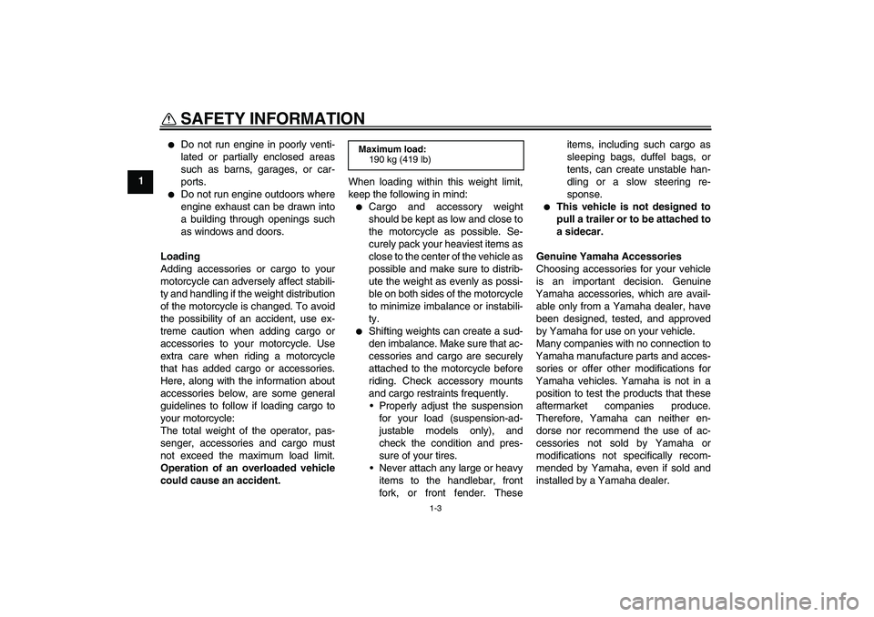
SAFETY INFORMATION EAU10283 Safe Riding • Ride where other motorists can Perform the pre-operation checks each see you. Avoid riding in another time you use the vehicle to make sure it motorist’s blind spot. Be a Responsible Owner is in safe operating condition. Failure to Many accidents involve inexperi- As the vehicle’s owner, you are respon- inspect or maintain the vehicle properly…
-
Page 9
SAFETY INFORMATION due to excessive speed or under- This motorcycle is designed for on- A passenger should also observe cornering (insufficient lean angle road use only. It is not suitable for the above precautions. for the speed). off-road use. • Always obey the speed limit and Avoid Carbon Monoxide Poisoning never travel faster than warrant- Protective apparel… -
Page 10
Yamaha accessories, which are avail- of the motorcycle is changed. To avoid to minimize imbalance or instabili- able only from a Yamaha dealer, have the possibility of an accident, use ex- been designed, tested, and approved treme caution when adding cargo or Shifting weights can create a sud- by Yamaha for use on your vehicle. -
Page 11
• Accessories fitted to the handle- Use caution when adding electri- genuine Yamaha accessories, recog- bar or the front fork area can cal accessories. If electrical acces- nize that some aftermarket accessories… -
Page 12: Description
DESCRIPTION EAU10410 Left view 1. Fuse box 2 (page 6-33) 8. Shock absorber assembly rebound damping force adjusting screw (page 3-25) 2. Front fork spring preload adjusting bolt (page 3-23) 9. Shift pedal (page 3-16) 3. Front fork rebound damping force adjusting screw (page 3-23) 10.Engine oil filter cartridge (page 6-12) 4.
-
Page 13: Right View
DESCRIPTION EAU10420 Right view 3,4,5,6 1. Luggage strap holder (page 3-27) 9. Radiator cap (page 6-15) 2. Helmet cable holder (page 3-21) 10.Engine oil filler cap (page 6-12) 3. Fuse box 1 (page 6-33) 11.Coolant drain bolt (page 6-16) 4. Main fuse (page 6-33) 12.Engine oil dipstick (page 6-12) 5.
-
Page 14: Controls And Instruments
DESCRIPTION EAU10430 Controls and instruments 1. Clutch lever (page 3-15) 2. Left handlebar switches (page 3-14) 3. Main switch/steering lock (page 3-2) 4. Multi-function meter unit (page 3-8) 5. Front brake fluid reservoir (page 6-24) 6. Right handlebar switches (page 3-14) 7.
-
Page 15: Instrument And Control Functions
Do not expose any key to exces- a Yamaha dealer to have them re-reg- sively high temperatures. istered. Do not use the key with the red Do not place any key close to bow for driving.
-
Page 16: Main Switch/Steering Lock
INSTRUMENT AND CONTROL FUNCTIONS Keep other immobilizer system EAU10472 EAU38530 Main switch/steering lock keys away from the main switch All electrical circuits are supplied with as they may cause signal inter- power; the meter lighting, taillight, li- ference. cense plate light and auxiliary light come on, and the engine can be start- ed.
-
Page 17
INSTRUMENT AND CONTROL FUNCTIONS EAU10683 To unlock the steering ECA11020 LOCK NOTICE The steering is locked, and all electrical Do not use the parking position for systems are off. The key can be re- an extended length of time, other- moved. -
Page 18: Indicator And Warning Lights
The oil level warning high beam of the headlight is switched light will flash ten times, then go off for 2.5 seconds. If this occurs, have a Yamaha dealer check the vehicle. EAU11254 Oil level warning light “ ”…
-
Page 19
3.0 seconds. If this oc- the coolant temperature in the ra- curs, have a Yamaha dealer check the diator. vehicle. If the engine overheats, see page 6-43 for further instructions. -
Page 20
INSTRUMENT AND CONTROL FUNCTIONS Coolant Display Conditions What to do temperature TRIP A Under 39 °C ˚C Message “Lo” is displayed. OK. Go ahead with riding. (Under 103 °F) TRIP A 40–116 °C ˚C Temperature is displayed. OK. Go ahead with riding. (104–242 °F) Stop the vehicle and allow it to idle until TRIP A… -
Page 21
If this occurs, go off. diagnosis device for the immobilizer have a Yamaha dealer check the self- If the indicator light does not come on system. (See page 3-11 for an explana- diagnosis system. (See page 3-11 for initially when the key is turned to “ON”,… -
Page 22: Multi-Function Meter Unit
INSTRUMENT AND CONTROL FUNCTIONS EAU39046 multi-function meter unit For the U.K. only: To switch the Multi-function meter unit equipped with the following: speedometer and odometer/trip- a speedometer meter displays between kilometers a tachometer and miles, press the “SELECT” an odometer button for at least one second.
-
Page 23
INSTRUMENT AND CONTROL FUNCTIONS ECA10031 5. Push the “RESET” button to set serve tripmeter mode “F-TRIP” and NOTICE the minutes. start counting the distance traveled 6. Push the “SELECT” button and from that point. In that case, push the Do not operate the engine in the ta- then release it to start the clock. -
Page 24
INSTRUMENT AND CONTROL FUNCTIONS Standard measurement Coolant temperature display Air intake temperature display 1. Push the “RESET” button to start the stopwatch. 2. Push the “SELECT” button to stop the stopwatch. TRIP A TRIP A ˚C ˚C 3. Push the “SELECT” button again to reset the stopwatch. -
Page 25: Self-Diagnosis Device
If the right display indicates any error codes, note the code number, and then Self-diagnosis device have a Yamaha dealer check the vehi- If the right display indicates error code cle. 52, this could be caused by transpon- ECA11590 der interference.
-
Page 26
INSTRUMENT AND CONTROL FUNCTIONS Display brightness and shift timing Shift timing indicator light activity: To adjust the brightness of the multi- indicator light control mode This function allows you to choose function meter displays and tachometer whether or not the indicator light 1. -
Page 27
INSTRUMENT AND CONTROL FUNCTIONS The indicator light will flash 1. Push the “RESET” button to select 1. Push the “RESET” button to select when activated. (This setting the desired engine speed for acti- the desired engine speed for deac- is selected when the indicator vating the indicator light. -
Page 28: Anti-Theft Alarm (Optional)
EAU12348 Right Anti-theft alarm (optional) Handlebar switches This model can be equipped with an Left optional anti-theft alarm by a Yamaha dealer. Contact a Yamaha dealer for more information. 1. Engine stop switch “ ” 2. Start switch “ ”…
-
Page 29: Clutch Lever
INSTRUMENT AND CONTROL FUNCTIONS position. To cancel the turn signal EAU12733 EAU12820 Hazard switch “ ” Clutch lever lights, push the switch in after it has re- With the key in the “ON” or “ ” posi- turned to the center position. tion, use this switch to turn on the haz- ard lights (simultaneous flashing of all EAU12500…
-
Page 30: Shift Pedal
INSTRUMENT AND CONTROL FUNCTIONS EAU12870 EAU33851 be sure to set it by aligning a groove on Shift pedal Brake lever the adjusting knob with the “ ” mark on the brake lever. 1. Shift pedal 1. Brake lever 2. Distance between brake lever and handlebar The shift pedal is located on the left grip side of the engine and is used in com-…
-
Page 31: Brake Pedal
INSTRUMENT AND CONTROL FUNCTIONS EAU12941 EAU13074 Brake pedal Fuel tank cap The fuel tank cap cannot be closed un- less the key is in the lock. In addition, the key cannot be removed if the cap is not properly closed and locked. EWA11091 WARNING Make sure that the fuel tank cap is…
-
Page 32: Fuel
Gasoline is poisonous and can hole. Stop filling when the fuel Your Yamaha engine has been de- cause injury or death. Handle gaso- reaches the bottom of the filler signed to use premium unleaded gaso- line with care.
-
Page 33: Fuel Tank Breather/Overflow Hose
INSTRUMENT AND CONTROL FUNCTIONS brand. Use of unleaded fuel will extend EAU39451 EAU13445 Fuel tank breather/overflow Catalytic converters spark plug life and reduce maintenance hose This vehicle is equipped with catalytic costs. converters in the exhaust system. EWA10862 WARNING The exhaust system is hot after op- eration.
-
Page 34: Seats
INSTRUMENT AND CONTROL FUNCTIONS ECA10701 EAU39032 Seats NOTICE Use only unleaded gasoline. The use Rider seat of leaded gasoline will cause unre- pairable damage to the catalytic To remove the rider seat converter. Pull back the rear of the rider seat as shown, remove the bolts, and then pull the seat off.
-
Page 35: Helmet Holding Cable
INSTRUMENT AND CONTROL FUNCTIONS EAU39073 Helmet holding cable 1. Passenger seat lock 1. Projection 2. Unlock. 2. Seat holder 1. Helmet holding cable 2. While holding the key in that posi- 2. Remove the key. 2. Helmet cable holder tion, lift the front of the passenger 3.
-
Page 36: Rear View Mirrors
INSTRUMENT AND CONTROL FUNCTIONS 3. Pass one of the other snap hooks EAU39671 Rear view mirrors of the cable through the helmet The rear view mirrors of this vehicle can strap buckle, and then clip the be folded forward or backward for park- snap hook onto the cable holder as ing in narrow spaces.
-
Page 37: Adjusting The Front Fork
INSTRUMENT AND CONTROL FUNCTIONS EAU38943 Spring preload Adjusting the front fork EWA10180 WARNING Always adjust both fork legs equal- ly, otherwise poor handling and loss of stability may result. This front fork is equipped with spring preload adjusting bolts, rebound damp- ing force adjusting screws, compres- 1.
-
Page 38
INSTRUMENT AND CONTROL FUNCTIONS Rebound damping force Compression damping force Compression damping setting (for fast compression damping): To adjust the compression damping Minimum (soft): 4 turn(s) in direction (b)* force (for fast compression damping) Standard: 2 turn(s) in direction (b)* Maximum (hard): 0 turn(s) in direction (b)* * With the adjusting bolt fully turned in… -
Page 39: Adjusting The Shock Absorber Assembly
INSTRUMENT AND CONTROL FUNCTIONS and thereby soften the compression EAU42944 Spring preload Adjusting the shock absorber damping, turn the adjusting bolt on assembly each fork leg in direction (b). This shock absorber assembly is equipped with a spring preload adjust- Compression damping setting (for slow compression damping): ing ring, a rebound damping force ad-…
-
Page 40
INSTRUMENT AND CONTROL FUNCTIONS sion damping force and thereby soften Spring preload setting: Rebound damping setting: the compression damping, turn the ad- Minimum (soft): Minimum (soft): justing bolt in direction (b). 20 click(s) in direction (b)* Standard: Standard: 16 click(s) in direction (b)* Compression damping setting (for Maximum (hard): Maximum (hard):… -
Page 41: Luggage Strap Holders
Take the shock adjusting mechanism. This adjustment absorber assembly to a Yamaha range may not exactly match the spec- 1. Luggage strap holder dealer for any service.
-
Page 42: Exup System
EAU15303 EXUP system Sidestand passenger seat, unhook the straps This model is equipped with Yamaha’s The sidestand is located on the left side from the hooks, and then install the EXUP (EXhaust Ultimate Power valve) of the frame. Raise the sidestand or seat with the straps hanging out from system.
-
Page 43: Ignition Circuit Cut-Off System
INSTRUMENT AND CONTROL FUNCTIONS below and have a Yamaha dealer re- EAU44892 Ignition circuit cut-off system pair it if it does not function proper- The ignition circuit cut-off system (com- prising the sidestand switch, clutch switch and neutral switch) has the fol- lowing functions.
-
Page 44
INSTRUMENT AND CONTROL FUNCTIONS WARNING With the engine turned off: 1. Move the sidestand down. If a malfunction is noted, have a Yamaha 2. Make sure that the engine stop switch is set to “ ”. dealer check the system before riding. -
Page 45: For Your Safety — Pre-Operation Checks
• If necessary, add recommended coolant to specified level. 6-15 • Check cooling system for leakage. • Check operation. • If soft or spongy, have Yamaha dealer bleed hydraulic system. • Check brake pads for wear. Front brake • Replace if necessary.
-
Page 46
• Make sure that operation is smooth. • Check cable free play. Throttle grip 6-18, 6-28 • If necessary, have Yamaha dealer adjust cable free play and lubricate cable and grip housing. • Make sure that operation is smooth. Control cables 6-27 •… -
Page 47
• Tighten if necessary. Instruments, lights, signals • Check operation. — and switches • Correct if necessary. • Check operation of ignition circuit cut-off system. Sidestand switch 3-28 • If system is not working correctly, have Yamaha dealer check vehicle. -
Page 48: Operation And Important Riding Points
Yamaha dealer. The transmission is in the neutral gine in case of a turnover. In this position.
-
Page 49: Shifting
(See page 5-2.) The quate lubrication may damage neutral indicator light should come the transmission. 1. Shift pedal on. If not, ask a Yamaha dealer to 2. Neutral position Always use the clutch while check the electrical circuit. changing gears to avoid damag- Shifting gears lets you control the 3.
-
Page 50: Tips For Reducing Fuel Consumption
Yamaha dealer check the vehi- to the correct operating clearances. Turn the engine off instead of let- cle.
-
Page 51: Parking
OPERATION AND IMPORTANT RIDING POINTS EAU17213 Parking When parking, stop the engine, and then remove the key from the main switch. EWA10311 WARNING Since the engine and exhaust system can become very hot, park in a place where pedestri- ans or children are not likely to touch them and be burned.
-
Page 52: Periodic Maintenance And Adjustment
If If you do not have the tools or experi- you are not familiar with vehicle ser- ence required for a particular job, have vice, have a Yamaha dealer perform a Yamaha dealer perform it for you. service.
-
Page 53: Periodic Maintenance Chart For The Emission Control System
From 50000 km (30000 mi), repeat the maintenance intervals starting from 10000 km (6000 mi). Items marked with an asterisk should be performed by a Yamaha dealer as they require special tools, data and technical skills.
-
Page 54: General Maintenance And Lubrication Chart
PERIODIC MAINTENANCE AND ADJUSTMENT EAU1770C General maintenance and lubrication chart ODOMETER READING ANNUAL ITEM CHECK OR MAINTENANCE JOB 1000 km 10000 km 20000 km 30000 km 40000 km CHECK (600 mi) (6000 mi) (12000 mi) (18000 mi) (24000 mi) √ 1 * Air filter element •…
-
Page 55
PERIODIC MAINTENANCE AND ADJUSTMENT ODOMETER READING ANNUAL ITEM CHECK OR MAINTENANCE JOB 1000 km 10000 km 20000 km 30000 km 40000 km CHECK (600 mi) (6000 mi) (12000 mi) (18000 mi) (24000 mi) • Check chain slack, alignment and condition. Every 800 km (500 mi) and after washing the motorcycle, riding in the rain or Drive chain •… -
Page 56
PERIODIC MAINTENANCE AND ADJUSTMENT ODOMETER READING ANNUAL ITEM CHECK OR MAINTENANCE JOB 1000 km 10000 km 20000 km 30000 km 40000 km CHECK (600 mi) (6000 mi) (12000 mi) (18000 mi) (24000 mi) Rear suspension re- lay arm and con- √… -
Page 57
PERIODIC MAINTENANCE AND ADJUSTMENT EAU18680 Air filter • This model’s air filter is equipped with a disposable oil-coated paper element, which must not be cleaned with com- pressed air to avoid damaging it. • The air filter element needs to be replaced more frequently when riding in unusually wet or dusty areas. Hydraulic brake service •… -
Page 58: Removing And Installing Cowlings And Panels
PERIODIC MAINTENANCE AND ADJUSTMENT EAU18712 EAU44931 Removing and installing cowl- Cowlings A and B ings and panels To remove one of the cowlings The cowlings and panels shown need 1. Remove the bolts, quick fasteners, to be removed to perform some of the and quick fastener screw.
-
Page 59
PERIODIC MAINTENANCE AND ADJUSTMENT 1. Quick fastener 1. Quick fastener 1. Cowling A 2. Quick fastener screw 2. Cowling B 3. Remove the forward-most projec- tion from the slot, slide the cowling forward, and then remove the re- maining projections from the slots as shown. -
Page 60
PERIODIC MAINTENANCE AND ADJUSTMENT 2. Fit the projections into the slots, 3. Fit the projection on cowling A into slide the cowling rearward, and the hole in cowling B as shown. then fit the forward-most projection into the slot. 1. Cowling A 2. -
Page 61
PERIODIC MAINTENANCE AND ADJUSTMENT To install the cowling 1. Fit the slot in cowling C over the projection on the front cowling. 1. Plastic fastener 1. Panel B 2. Projection 2. Bolt 3. Wire harness To install the panel 1. Cowling C 3. -
Page 62: Checking The Spark Plugs
Do not attempt to diagnose wipe off any grime from the spark plug such problems yourself. Instead, have threads. a Yamaha dealer check the vehicle. If a spark plug shows signs of electrode Tightening torque: Spark plug: erosion and excessive carbon or other 12.5 Nm (1.25 m·kgf, 9.0 ft·lbf)
-
Page 63: Engine Oil And Oil Filter Cartridge
PERIODIC MAINTENANCE AND ADJUSTMENT EAU3899A 6. Insert and tighten the engine oil Engine oil and oil filter car- dipstick, and then install and tight- tridge en the oil filler cap. The engine oil level should be checked before each ride. In addition, the oil To change the engine oil (with or must be changed and the oil filter car- without oil filter cartridge replace-…
-
Page 64
PERIODIC MAINTENANCE AND ADJUSTMENT An oil filter wrench is available at a Yamaha dealer. 9. Apply a thin coat of clean engine oil to the O-ring of the new oil filter cartridge. 1. Engine oil drain bolt 1. Bolt 2. Gasket 2. -
Page 65
PERIODIC MAINTENANCE AND ADJUSTMENT not move correctly and you may 14. Refill with the specified amount of not be able to shift up or down. the recommended engine oil, and then install and tighten the oil filler [ECA15342] cap. Recommended engine oil: See page 8-1. -
Page 66: Coolant
WARNING! Remove only off and have a Yamaha dealer check the coolant reservoir cap. Never 2. Check the coolant level in the cool- the vehicle.
-
Page 67
2. Remove cowlings B and C. (See corrosion. If water has been page 6-7.) added to the coolant, have a 3. Place a container under the engine Yamaha dealer check the anti- to collect the used coolant. freeze content of the coolant as 4. Remove radiator cap. -
Page 68
17. Start the engine, and then check into the reservoir to the maximum the vehicle for coolant leakage. If level mark, and then install the coolant is leaking, have a Yamaha coolant reservoir cap. dealer check the cooling system. 14. Pour the recommended coolant 18. -
Page 69: Air Filter Element
Check the engine idling speed and, if maintenance and lubrication chart. necessary, have it corrected by a Have a Yamaha dealer replace the air Yamaha dealer. filter element. Engine idling speed: 1250–1350 r/min 1.
-
Page 70: Valve Clearance
250 kPa (2.50 kgf/cm², 36 psi) Rear: from occurring, the valve clearance the specified tires. 290 kPa (2.90 kgf/cm², 42 psi) must be adjusted by a Yamaha dealer 90–186 kg (198–410 lb): at the intervals specified in the periodic Tire air pressure Front: maintenance and lubrication chart.
-
Page 71
Tire information glass fragments in it, or if the sidewall is high-speed ride. cracked, have a Yamaha dealer re- After extensive tests, only the tires list- place the tire immediately. ed below have been approved for this model by Yamaha Motor Co., Ltd. -
Page 72: Cast Wheels
Always adjust the tire air pres- 180/55 ZR17M/C (73W) fore each ride. If any damage is Manufacturer/model: sure according to the operating found, have a Yamaha dealer re- BRIDGESTONE/BT016R F conditions. DUNLOP/Qualifier PT M place the wheel. Do not attempt…
-
Page 73: Adjusting The Clutch Lever Free Play
PERIODIC MAINTENANCE AND ADJUSTMENT EAU33891 4. Tighten the locknut. Adjusting the clutch lever free If the specified clutch lever free play play cannot be obtained as described above, proceed as follows. 1. Fully turn the adjusting bolt at the clutch lever in direction (a) to loos- en the clutch cable.
-
Page 74: Brake Light Switches
Brake light switches Checking the front and rear touches the brake disc, have a Yamaha brake pads dealer replace the brake pads as a set. The front and rear brake pads must be…
-
Page 75: Checking The Brake Fluid Level
However, if the Use only the recommended quality brake fluid level goes down sud- 1. Minimum level mark brake fluid, otherwise the rubber denly, have a Yamaha dealer Rear brake seals may deteriorate, causing check the cause. leakage and poor braking perfor- mance.
-
Page 76: Changing The Brake Fluid
EAU22731 EAU22760 Changing the brake fluid Drive chain slack Have a Yamaha dealer change the The drive chain slack should be brake fluid at the intervals specified in checked before each ride and adjusted the TIP after the periodic maintenance if necessary.
-
Page 77
PERIODIC MAINTENANCE AND ADJUSTMENT To prevent this from occurring, Tightening torque: keep the drive chain slack with- Locknut: in the specified limits. 16 Nm (1.6 m·kgf, 11 ft·lbf) [ECA10571] Using the alignment marks on each drive chain puller, make sure that both chain pullers are in the same position for proper wheel alignment. -
Page 78: Cleaning And Lubricating The Drive Chain
If a cable is damaged wet areas. Service the drive chain as or does not move smoothly, have a follows. Yamaha dealer check or replace it. WARNING! Damage to the outer ECA10583 NOTICE sheath may interfere with proper ca-…
-
Page 79: Checking And Lubricating The Throttle Grip And Cable
The operation of the throttle grip should Brake pedal be checked before each ride. In addi- tion, the cable should be lubricated by a Yamaha dealer at the intervals speci- fied in the periodic maintenance chart. Shift pedal The operation of the brake and shift…
-
Page 80: Checking And Lubricating The Brake And Clutch Levers
EWA10731 WARNING If the sidestand does not move up and down smoothly, have a Yamaha dealer check or repair it. Otherwise, the sidestand could contact the ground and distract the operator, re- The operation of the brake and clutch sulting in a possible loss of control.
-
Page 81: Lubricating The Swingarm Pivots
The swingarm pivots must be lubricat- face and hold it in an upright posi- fork does not operate smoothly, ed by a Yamaha dealer at the intervals tion. WARNING! To avoid injury, have a Yamaha dealer check or re- specified in the periodic maintenance securely support the vehicle so pair it.
-
Page 82: Checking The Steering
If any free lyte or to add distilled water. However, the wheel bearings. play can be felt, have a Yamaha the battery lead connections need to be dealer check or repair the steering. checked and, if necessary, tightened.
-
Page 83
[ECA16302] To charge the battery 2. If the battery will be stored for more Have a Yamaha dealer charge the bat- than two months, check it at least tery as soon as possible if it seems to once a month and fully charge it if have discharged. -
Page 84: Replacing The Fuses
4. If the fuse immediately blows 2. Remove the blown fuse, and then 7. Spare fuse again, have a Yamaha dealer install a new fuse of the specified Fuse box 2 is located under panel A. check the electrical system.
-
Page 85: Replacing A Headlight Bulb
PERIODIC MAINTENANCE AND ADJUSTMENT EAU39012 Replacing a headlight bulb This model is equipped with quartz bulb headlights. If a headlight bulb burns out, replace it as follows. ECA10650 NOTICE Take care not to damage the follow- ing parts: Headlight bulb 1.
-
Page 86: Tail/Brake Light
Replacing a turn signal light turning it clockwise. This model is equipped with an LED- bulb 7. Have a Yamaha dealer adjust the type tail/brake light. 1. Remove the turn signal light lens headlight beam if necessary. If the tail/brake light does not come on, by removing the screw.
-
Page 87: Replacing The License Plate Light Bulb
PERIODIC MAINTENANCE AND ADJUSTMENT EAU24312 3. Remove the burnt-out bulb by pull- Replacing the license plate ing it out. light bulb 4. Insert a new bulb into the socket. 1. Remove the license plate light unit 5. Install the socket (together with the by removing the screws.
-
Page 88: Auxiliary Light
1. Stabilize the rear of the motorcycle If the auxiliary light does not come on, by using a motorcycle stand or, if have a Yamaha dealer check it. an additional motorcycle stand is not available, by placing a jack un- der the frame in front of the rear wheel.
-
Page 89: Front Wheel
PERIODIC MAINTENANCE AND ADJUSTMENT EAU24360 3. Remove the brake hose holder on Front wheel each side by removing the bolt and nut. EAU33923 4. Remove the brake caliper on each To remove the front wheel side by removing the bolts. EWA10821 WARNING To avoid injury, securely support the…
-
Page 90
PERIODIC MAINTENANCE AND ADJUSTMENT Tightening torque: Tightening torque: Brake caliper bolt: Wheel axle pinch bolt: 35 Nm (3.5 m·kgf, 25 ft·lbf) 21 Nm (2.1 m·kgf, 15 ft·lbf) 5. Install the brake hose holders by 12. While applying the front brake, installing the bolts and nuts. -
Page 91: Rear Wheel
PERIODIC MAINTENANCE AND ADJUSTMENT EAU25080 4. Loosen the locknut on each side of 7. While supporting the brake caliper Rear wheel the swingarm. bracket, pull the wheel axle out, 5. Turn the drive chain slack adjust- and then remove the wheel. EAU44951 ing bolts in direction (a) to loosen NOTICE: Do not apply the brake…
-
Page 92: Troubleshooting
However, should your motorcycle Tightening torque: require any repair, take it to a Yamaha 1. Retainer Drive chain slack adjusting bolt: dealer, whose skilled technicians have 2. Slot 2 Nm (0.2 m·kgf, 1.4 ft·lbf)
-
Page 93
PERIODIC MAINTENANCE AND ADJUSTMENT heaters or furnaces. Gasoline or gasoline vapors can ignite or ex- plode, causing severe injury or property damage. 6-42… -
Page 94: Troubleshooting Charts
Remove the spark plugs and check the electrodes. The engine does not start. Have a Yamaha dealer check the vehicle. Check the battery. 4. Battery The engine turns over The battery is good.
-
Page 95
Start the engine. If the engine overheats again, have a The coolant level Yamaha dealer check and repair the cooling system. is OK. If coolant is not available, tap water can be temporarily used instead, provided that it is changed to the recommended coolant as soon as possible. -
Page 96: Motorcycle Care And Storage
Rust and corrosion can develop matte colored finished parts. Be Cleaning even if high-quality components are sure to consult a Yamaha dealer for ECA11142 advice on what products to use be- used. A rusty exhaust pipe may go un- NOTICE fore cleaning the vehicle.
-
Page 97
MOTORCYCLE CARE AND STORAGE off any detergent residue using pounds for plastic may leave plenty of water, as it is harmful scratches on the windshield. Salt sprayed on roads in the winter may to plastic parts. Test the product on a small hid- remain well into spring. -
Page 98
WARNING muffler is normal and cannot be re- moved. Contaminants on the brakes or tires Consult a Yamaha dealer for ad- can cause loss of control. vice on what products to use. After cleaning Make sure that there is no oil or Washing, rainy weather or humid 1. -
Page 99: Storage
MOTORCYCLE CARE AND STORAGE EAU26181 3. Perform the following steps to pro- 4. Lubricate all control cables and the Storage tect the cylinders, piston rings, etc. pivoting points of all levers and from corrosion. pedals as well as of the side- Short-term a.
-
Page 100: Specifications
SPECIFICATIONS Dimensions: Engine oil: Fuel: Overall length: Recommended brand: Recommended fuel: 2040 mm (80.3 in) YAMALUBE Premium unleaded gasoline only Overall width: Type: Fuel tank capacity: 705 mm (27.8 in) SAE 10W-40, 10W-50, 15W-40, 20W-40 or 17.3 L (4.57 US gal, 3.81 Imp.gal) Overall height: 20W-50 Fuel reserve amount:…
-
Page 101
SPECIFICATIONS Gear ratio: Manufacturer/model: Rear wheel: 1st: BRIDGESTONE/BT016R F Wheel type: 31/12 (2.583) Manufacturer/model: Cast wheel 2nd: DUNLOP/Qualifier PT M Rim size: 32/16 (2.000) Loading: 17M/C x MT5.50 3rd: Maximum load: Front brake: 30/18 (1.667) 186 kg (410 lb) Type: 4th: (Total weight of rider, passenger, cargo and Dual disc brake… -
Page 102
SPECIFICATIONS Electrical system: Turn signal indicator light: Ignition system: Fuel level warning light: TCI (digital) Charging system: Coolant temperature warning light: AC magneto Battery: Engine trouble warning light: Model: YTZ10S Immobilizer system indicator light: Voltage, capacity: 12 V, 8.6 Ah Shift timing indicator light: Headlight: Bulb type:… -
Page 103: Consumer Information
Record the vehicle identification num- ber and model label information in the spaces provided below for assistance when ordering spare parts from a Yamaha dealer or for reference in case the vehicle is stolen. VEHICLE IDENTIFICATION NUMBER: 1. Vehicle identification number 1.
-
Page 104
INDEX Engine trouble warning light ….3-7 Multi-function meter unit……3-8 EXUP system ……..3-28 Air filter element ……..6-18 Anti-theft alarm (optional)…… 3-14 Neutral indicator light ……3-4 Auxiliary light……… 6-37 Front and rear brake pads, checking..6-23 Front fork, adjusting……3-23 Oil level warning light …… -
Page 105
INDEX Tool kit ………… 6-1 Troubleshooting……..6-41 Troubleshooting charts ……6-43 Turn signal indicator lights …… 3-4 Turn signal light bulb, replacing…. 6-35 Turn signal switch……… 3-14 Valve clearance ……..6-19 Vehicle identification number….9-1 Wheel bearings, checking ….6-31 Wheel (front) ……… -
Page 108
YAMAHA MOTOR CO., LTD. PRINTED ON RECYCLED PAPER PRINTED IN JAPAN 2009.08-0.3×1 CR…
- Manuals
- Brands
- Yamaha Manuals
- Motorcycle
- 2009 YZF-R6Y
- Owner’s manual
-
Contents
-
Table of Contents
-
Troubleshooting
-
Bookmarks
Quick Links
Read this manual carefully before operating this vehicle.
OWNER’S MANUAL
YZF-R6Y
13S-28199-21
Related Manuals for Yamaha 2009 YZF-R6Y
Summary of Contents for Yamaha 2009 YZF-R6Y
-
Page 1
Read this manual carefully before operating this vehicle. OWNER’S MANUAL YZF-R6Y 13S-28199-21… -
Page 2
EAU46090 Read this manual carefully before operating this vehicle. This manual should stay with this vehicle if it is sold. -
Page 3
Welcome to the Yamaha world of motorcycling! As the owner of the YZF-R6Y, you are benefiting from Yamaha’s vast experience and newest technology regarding the de- sign and manufacture of high-quality products, which have earned Yamaha a reputation for dependability. -
Page 4: Important Manual Information
IMPORTANT MANUAL INFORMATION EAU10132 Particularly important information is distinguished in this manual by the following notations: This is the safety alert symbol. It is used to alert you to potential personal injury hazards. Obey all safety messages that follow this symbol to avoid possible injury or death.
-
Page 5
IMPORTANT MANUAL INFORMATION EAU10200 YZF-R6Y OWNER’S MANUAL ©2008 by Yamaha Motor Co., Ltd. 1st edition, July 2008 All rights reserved. Any reprinting or unauthorized use without the written permission of Yamaha Motor Co., Ltd. is expressly prohibited. Printed in Japan. -
Page 6: Table Of Contents
TABLE OF CONTENTS LOCATION OF IMPORTANT Sidestand ……..4-27 Tires ……….7-19 LABELS ……….1-1 Ignition circuit cut-off system ..4-28 Cast wheels ……… 7-22 Adjusting the clutch lever free SAFETY INFORMATION ….2-1 FOR YOUR SAFETY – play ……….. 7-22 PRE-OPERATION CHECKS ….. 5-1 Adjusting the rear brake light DESCRIPTION ……..3-1 switch ……..
-
Page 7
TABLE OF CONTENTS Tail/brake light ……7-35 Replacing a turn signal light bulb ………..7-35 Replacing the license plate light bulb ………..7-36 Auxiliary light ……..7-37 Supporting the motorcycle ….7-37 Front wheel ……..7-38 Rear wheel ……..7-40 Troubleshooting ……7-41 Troubleshooting charts ….7-43 MOTORCYCLE CARE AND STORAGE ……….8-1 Matte color caution ……8-1 Care ……….8-1… -
Page 8: Location Of Important Labels
Read and understand all of the labels on your vehicle. They contain important information for safe and proper operation of your vehicle. Never remove any labels from your vehicle. If a label becomes difficult to read or comes off, a replacement label is available from your Yamaha dealer.
-
Page 9
LOCATION OF IMPORTANT LABELS… -
Page 10: Safety Information
SAFETY INFORMATION EAU10283 Safe Riding • Ride where other motorists can Perform the pre-operation checks each see you. Avoid riding in another time you use the vehicle to make sure it motorist’s blind spot. Be a Responsible Owner is in safe operating condition. Failure to Many accidents involve inexperi- As the vehicle’s owner, you are respon- inspect or maintain the vehicle properly…
-
Page 11
SAFETY INFORMATION due to excessive speed or under- This motorcycle is designed for on- A passenger should also observe cornering (insufficient lean angle road use only. It is not suitable for the above precautions. for the speed). off-road use. • Always obey the speed limit and Avoid Carbon Monoxide Poisoning never travel faster than warrant- Protective apparel… -
Page 12
Yamaha accessories, which are avail- of the motorcycle is changed. To avoid to minimize imbalance or instabili- able only from a Yamaha dealer, have the possibility of an accident, use ex- been designed, tested, and approved treme caution when adding cargo or Shifting weights can create a sud- by Yamaha for use on your vehicle. -
Page 13
• Accessories fitted to the handle- Use caution when adding electri- genuine Yamaha accessories, recog- bar or the front fork area can cal accessories. If electrical acces- nize that some aftermarket accessories… -
Page 14: Description
DESCRIPTION EAU10410 Left view 1. Fuse box 2 (page 7-33) 8. Shock absorber assembly rebound damping force adjusting screw (page 4-24) 2. Front fork spring preload adjusting bolt (page 4-21) 9. Shift pedal (page 4-15) 3. Front fork rebound damping force adjusting screw (page 4-21) 10.Engine oil filter cartridge (page 7-12) 4.
-
Page 15: Right View
DESCRIPTION EAU10420 Right view 1. Luggage strap holder (page 4-26) 9. Radiator cap (page 7-15) 2. Helmet holder (page 4-20) 10.Coolant reservoir (page 7-15) 3. Fuse box 1 (page 7-33) 11.Engine oil filler cap (page 7-12) 4. Main fuse (page 7-33) 12.Coolant drain bolt (page 7-16) 5.
-
Page 16: Controls And Instruments
DESCRIPTION EAU10430 Controls and instruments 1. Clutch lever (page 4-15) 2. Left handlebar switches (page 4-13) 3. Main switch/steering lock (page 4-2) 4. Multi-function meter unit (page 4-7) 5. Right handlebar switches (page 4-13) 6. Brake lever (page 4-15) 7. Throttle grip (page 7-19)
-
Page 17: Instrument And Control Functions
Do not expose any key to exces- a Yamaha dealer to have them re-reg- sively high temperatures. istered. Do not use the key with the red Do not place any key close to bow for driving.
-
Page 18: Main Switch/Steering Lock
INSTRUMENT AND CONTROL FUNCTIONS Keep other immobilizer system EAU10471 EAU38530 Main switch/steering lock keys away from the main switch All electrical circuits are supplied with as they may cause signal inter- power; the meter lighting, taillight, li- ference. cense plate light and auxiliary light come on, and the engine can be start- ed.
-
Page 19
INSTRUMENT AND CONTROL FUNCTIONS EAU10681 To unlock the steering ECA11020 LOCK NOTICE The steering is locked, and all electrical Do not use the parking position for systems are off. The key can be re- an extended length of time, other- moved. -
Page 20: Indicator And Warning Lights
“ ” warning light may flicker when have a Yamaha dealer check the elec- The corresponding indicator light flash- riding on a slope or during sudden trical circuit. es when the turn signal switch is acceleration or deceleration, but pushed to the left or right.
-
Page 21
3.0 seconds. If this oc- the coolant temperature in the ra- curs, have a Yamaha dealer check the diator. vehicle. If the engine overheats, see page 7-43 for further instructions. -
Page 22
INSTRUMENT AND CONTROL FUNCTIONS Coolant Display Conditions What to do temperature TRIP A Under 39 °C ˚C Message “Lo” is displayed. OK. Go ahead with riding. (Under 103 °F) TRIP A 40–116 °C ˚C Temperature is displayed. OK. Go ahead with riding. (104–242 °F) Stop the vehicle and allow it to idle until TRIP A… -
Page 23: Multi-Function Meter Unit
If this occurs, EAU38621 have a Yamaha dealer check the self- Immobilizer system indicator light diagnosis system. (See page 4-10 for The electrical circuit of the indicator…
-
Page 24
INSTRUMENT AND CONTROL FUNCTIONS multi-function meter unit Tachometer Clock equipped with the following: a speedometer (which shows the riding speed) a tachometer (which shows engine km/h TRIP A speed) an odometer (which shows the to- tal distance traveled) two tripmeters (which show the distance traveled since they were last set to zero) 1. -
Page 25
INSTRUMENT AND CONTROL FUNCTIONS Odometer, tripmeter, and stopwatch between the various tripmeter, odome- 3. Push the “SELECT” button again modes ter, and stopwatch modes in the follow- to reset the stopwatch. ing order: F-TRIP → Stopwatch → TRIP A → Split-time measurement TRIP B →… -
Page 26
INSTRUMENT AND CONTROL FUNCTIONS Coolant temperature display Air intake temperature display When the air intake temperature display is selected, “A” is displayed before the temperature. Self-diagnosis device TRIP A TRIP A ˚C ˚C 1. Coolant temperature display 1. Air intake temperature display The coolant temperature display indi- The air intake temperature display indi- cates the temperature of the coolant. -
Page 27
If the right display indicates any error ror code. codes, note the code number, and then km/h have a Yamaha dealer check the vehi- cle. If the right display indicates error code ECA11590 52, this could be caused by transpon- NOTICE der interference. -
Page 28
INSTRUMENT AND CONTROL FUNCTIONS Shift timing indicator light activity: To adjust the brightness of the multi- The indicator light will flash This function allows you to choose function meter displays and tachometer when activated. (This setting whether or not the indicator light 1. -
Page 29: Handlebar Switches
INSTRUMENT AND CONTROL FUNCTIONS 1. Push the “RESET” button to select 1. Push the “RESET” button to select EAU12347 Handlebar switches the desired engine speed for acti- the desired engine speed for deac- vating the indicator light. tivating the indicator light. Left 2.
-
Page 30
INSTRUMENT AND CONTROL FUNCTIONS Right position. To cancel the turn signal EAU12733 Hazard switch “ ” lights, push the switch in after it has re- With the key in the “ON” or “ ” posi- turned to the center position. tion, use this switch to turn on the haz- ard lights (simultaneous flashing of all EAU12500… -
Page 31: Clutch Lever
INSTRUMENT AND CONTROL FUNCTIONS EAU12820 EAU12870 EAU33851 Clutch lever Shift pedal Brake lever 1. Clutch lever 1. Shift pedal 1. Brake lever 2. “ ” mark The clutch lever is located at the left The shift pedal is located on the left 3.
-
Page 32: Brake Pedal
INSTRUMENT AND CONTROL FUNCTIONS be sure to set it by aligning a groove on EAU12941 EAU13074 Brake pedal Fuel tank cap the adjusting knob with the “ ” mark on the brake lever. 1. Brake pedal 1. Fuel tank cap lock cover 2.
-
Page 33: Fuel
INSTRUMENT AND CONTROL FUNCTIONS EAU13221 Fuel The fuel tank cap cannot be closed un- Make sure there is sufficient gasoline in less the key is in the lock. In addition, the tank. the key cannot be removed if the cap is EWA10881 WARNING not properly closed and locked.
-
Page 34: Catalytic Converters
Your Yamaha engine has been de- signed to use premium unleaded gaso- line with a research octane number of 95 or higher. If knocking (or pinging) oc-…
-
Page 35: Seats
INSTRUMENT AND CONTROL FUNCTIONS ECA10701 EAU39032 Seats NOTICE Use only unleaded gasoline. The use Rider seat of leaded gasoline will cause unre- pairable damage to the catalytic To remove the rider seat converter. Pull back the rear of the rider seat as shown, remove the bolts, and then pull the seat off.
-
Page 36: Helmet Holding Cable
INSTRUMENT AND CONTROL FUNCTIONS EAU39073 Helmet holding cable 1. Passenger seat lock 1. Projection 2. Unlock. 2. Seat holder 1. Helmet holding cable 2. While holding the key in that posi- 2. Remove the key. 2. Helmet cable holder tion, lift the front of the passenger 3.
-
Page 37: Adjusting The Front Fork
INSTRUMENT AND CONTROL FUNCTIONS 3. Pass one of the other snap hooks EAU38943 Adjusting the front fork of the cable through the helmet EWA10180 strap buckle, and then clip the WARNING snap hook onto the cable holder as Always adjust both fork legs equal- shown.
-
Page 38
INSTRUMENT AND CONTROL FUNCTIONS Spring preload Rebound damping force 1. Current setting 2. Front fork collar 1. Spring preload adjusting bolt 1. Rebound damping force adjusting screw To increase the spring preload and To increase the rebound damping force Spring preload setting: thereby harden the suspension, turn and thereby harden the rebound damp- Minimum (soft):… -
Page 39
INSTRUMENT AND CONTROL FUNCTIONS Compression damping force and thereby soften the compression Compression damping setting (for damping, turn the adjusting bolt on fast compression damping): To adjust the compression damping each fork leg in direction (b). Minimum (soft): 4 turn(s) in direction (b)* force (for fast compression damping) Standard: Compression damping setting (for… -
Page 40: Adjusting The Shock Absorber Assembly
INSTRUMENT AND CONTROL FUNCTIONS EAU42942 Spring preload Spring preload setting: Adjusting the shock absorber Minimum (soft): assembly This shock absorber assembly is Standard: equipped with a spring preload adjust- Maximum (hard): ing ring, a rebound damping force ad- justing screw, a compression damping force adjusting bolt (for fast compres- Rebound damping force sion damping) and a compression…
-
Page 41
INSTRUMENT AND CONTROL FUNCTIONS direction (a). To decrease the compres- Rebound damping setting: Compression damping setting (for sion damping force and thereby soften Minimum (soft): slow compression damping): the compression damping, turn the ad- 20 click(s) in direction (b)* Minimum (soft): Standard: 20 click(s) in direction (b)* justing bolt in direction (b). -
Page 42: Luggage Strap Holders
1. Luggage strap holder sembly yourself. Take the shock 2. Hook absorber assembly to a Yamaha dealer for any service. 1. Luggage strap holder There are six luggage strap holders, four on the bottom of the passenger seat and one on each passenger foot- rest.
-
Page 43: Exup System
INSTRUMENT AND CONTROL FUNCTIONS EAU41940 EAU15301 below and have a Yamaha dealer re- EXUP system Sidestand pair it if it does not function proper- This model is equipped with Yamaha’s The sidestand is located on the left side EXUP (EXhaust Ultimate Power valve) of the frame.
-
Page 44: Ignition Circuit Cut-Off System
INSTRUMENT AND CONTROL FUNCTIONS EAU44891 Ignition circuit cut-off system The ignition circuit cut-off system (com- prising the sidestand switch, clutch switch and neutral switch) has the fol- lowing functions. It prevents starting when the trans- mission is in gear and the side- stand is up, but the clutch lever is not pulled.
-
Page 45
WARNING With the engine turned off: 1. Move the sidestand down. If a malfunction is noted, have a Yamaha 2. Make sure that the engine stop switch is turned on. dealer check the system before riding. 3. Turn the key on. -
Page 46: For Your Safety — Pre-Operation Checks
• If necessary, add recommended coolant to specified level. 7-15 • Check cooling system for leakage. • Check operation. • If soft or spongy, have Yamaha dealer bleed hydraulic system. • Check brake pads for wear. Front brake • Replace if necessary.
-
Page 47
• Make sure that operation is smooth. • Check cable free play. Throttle grip 7-19, 7-28 • If necessary, have Yamaha dealer adjust cable free play and lubricate cable and grip housing. • Make sure that operation is smooth. Control cables 7-27 •… -
Page 48
• Tighten if necessary. Instruments, lights, signals • Check operation. — and switches • Correct if necessary. • Check operation of ignition circuit cut-off system. Sidestand switch 4-27 • If system is not working correctly, have Yamaha dealer check vehicle. -
Page 49: Operation And Important Riding Points
Yamaha dealer. The transmission is in the neutral a turnover. To start the engine after a position.
-
Page 50: Shifting
(See page 6-2.) The properly lubricated only when neutral indicator light should come the engine is running. Inade- on. If not, ask a Yamaha dealer to quate lubrication may damage check the electrical circuit. the transmission. 1. Shift pedal 3.
-
Page 51: Tips For Reducing Fuel Consumption
Yamaha dealer check the vehi- to the correct operating clearances. Turn the engine off instead of let- cle.
-
Page 52: Parking
OPERATION AND IMPORTANT RIDING POINTS EAU17213 Parking When parking, stop the engine, and then remove the key from the main switch. EWA10311 WARNING Since the engine and exhaust system can become very hot, park in a place where pedestri- ans or children are not likely to touch them and be burned.
-
Page 53: Periodic Maintenance And Adjustment
If If you do not have the tools or experi- you are not familiar with vehicle ser- ence required for a particular job, have vice, have a Yamaha dealer perform a Yamaha dealer perform it for you. service.
-
Page 54: Periodic Maintenance And Lubrication Chart
From 50000 km (30000 mi), repeat the maintenance intervals starting from 10000 km (6000 mi). Items marked with an asterisk should be performed by a Yamaha dealer as they require special tools, data and technical skills.
-
Page 55
PERIODIC MAINTENANCE AND ADJUSTMENT ODOMETER READING ANNUAL ITEM CHECK OR MAINTENANCE JOB 1000 km 10000 km 20000 km 30000 km 40000 km CHECK (600 mi) (6000 mi) (12000 mi) (18000 mi) (24000 mi) √ √ √ √ √ • Check for cracks or damage. 8 * Brake hoses •… -
Page 56
PERIODIC MAINTENANCE AND ADJUSTMENT ODOMETER READING ANNUAL ITEM CHECK OR MAINTENANCE JOB 1000 km 10000 km 20000 km 30000 km 40000 km CHECK (600 mi) (6000 mi) (12000 mi) (18000 mi) (24000 mi) Brake pedal pivot • Lubricate with lithium-soap-based √… -
Page 57
PERIODIC MAINTENANCE AND ADJUSTMENT ODOMETER READING ANNUAL ITEM CHECK OR MAINTENANCE JOB 1000 km 10000 km 20000 km 30000 km 40000 km CHECK (600 mi) (6000 mi) (12000 mi) (18000 mi) (24000 mi) Front and rear brake √ √ √ √… -
Page 58
PERIODIC MAINTENANCE AND ADJUSTMENT • Every two years replace the internal components of the brake master cylinders and calipers, and change the brake fluid. • Replace the brake hoses every four years and if cracked or damaged. -
Page 59: Removing And Installing Cowlings And Panels
PERIODIC MAINTENANCE AND ADJUSTMENT EAU18712 EAU44931 Removing and installing cowl- Cowlings A and B ings and panels To remove one of the cowlings The cowlings and panels shown need 1. Remove the bolts, quick fasteners, to be removed to perform some of the and quick fastener screw.
-
Page 60
PERIODIC MAINTENANCE AND ADJUSTMENT 1. Quick fastener screw 1. Quick fastener 1. Cowling A 2. Quick fastener 2. Cowling B 3. Remove the forward-most projec- tion from the slot, slide the cowling forward, and then remove the re- maining projections from the slots as shown. -
Page 61
PERIODIC MAINTENANCE AND ADJUSTMENT 2. Fit the projections into the slots, 3. Fit the projection on cowling A into slide the cowling rearward, and the hole in cowling B as shown. then fit the forward-most projection into the slot. 1. Cowling A 2. -
Page 62
PERIODIC MAINTENANCE AND ADJUSTMENT To install the cowling 1. Fit the slot in cowling C over the projection on the front cowling. 1. Plastic fastener 1. Panel B 2. Projection 2. Bolt 3. Wire harness To install the panel 1. Cowling C 3. -
Page 63: Checking The Spark Plugs
Do not attempt to diagnose wipe off any grime from the spark plug such problems yourself. Instead, have threads. a Yamaha dealer check the vehicle. If a spark plug shows signs of electrode Tightening torque: Spark plug: erosion and excessive carbon or other 12.5 Nm (1.25 m·kgf, 9.0 ft·lbf)
-
Page 64: Engine Oil And Oil Filter Cartridge
PERIODIC MAINTENANCE AND ADJUSTMENT EAU38999 Engine oil and oil filter car- tridge The engine oil level should be checked before each ride. In addition, the oil must be changed and the oil filter car- tridge replaced at the intervals speci- fied in the periodic maintenance and lubrication chart.
-
Page 65
5. Remove the engine oil filler cap and drain bolt to drain the oil from An oil filter wrench is available at a the crankcase. Yamaha dealer. 9. Apply a thin coat of clean engine oil to the O-ring of the new oil filter cartridge. -
Page 66
PERIODIC MAINTENANCE AND ADJUSTMENT not move correctly and you may Tightening torque: not be able to shift up or down. Engine oil drain bolt: 43 Nm (4.3 m·kgf, 31 ft·lbf) [ECA15342] 14. Refill with the specified amount of the recommended engine oil, and then install and tighten the oil filler cap. -
Page 67: Coolant
If the oil level warning light flickers EAU39086 or remains on, immediately turn the To check the coolant level engine off and have a Yamaha dealer 1. Place the vehicle on a level sur- check the vehicle. face and hold it in an upright posi- tion.
-
Page 68
If water has been 2. Remove cowlings B and C. (See added to the coolant, have a page 7-7.) Yamaha dealer check the anti- 3. Place a container under the engine freeze content of the coolant as to collect the used coolant. -
Page 69
PERIODIC MAINTENANCE AND ADJUSTMENT 6. Move the hose clamp in the direc- Tightening torque: tion shown, and then disconnect Coolant drain bolt: the radiator hose to drain the radi- 10 Nm (1.0 m·kgf, 7.2 ft·lbf) ator. 13. Pour the recommended coolant into the reservoir to the maximum level mark, and then install the coolant reservoir cap. -
Page 70: Air Filter Element
17. Start the engine, and then check maintenance and lubrication chart. necessary, have it adjusted by a the vehicle for coolant leakage. If Have a Yamaha dealer replace the air Yamaha dealer. coolant is leaking, have a Yamaha filter element.
-
Page 71: Checking The Throttle Cable Free Play
Yamaha dealer at the intervals specified in the periodic Tire air pressure maintenance and lubrication chart. The tire air pressure should be checked and, if necessary, adjusted before each ride.
-
Page 72
* Total weight of rider, passenger, car- if the tire has a nail or glass fragments go and accessories in it, or if the sidewall is cracked, con- tact a Yamaha dealer immediately and EWA10511 WARNING have the tire replaced. -
Page 73
After extensive tests, only the tires list- tively poor grip on certain road ed below have been approved for this surfaces until they have been model by Yamaha Motor Co., Ltd. “broken in”. Therefore, it is ad- visable before doing any high- Front tire:… -
Page 74: Cast Wheels
If any damage is 2. Loosen the locknut at the crank- found, have a Yamaha dealer re- case. place the wheel. Do not attempt 3. To increase the clutch lever free…
-
Page 75: Adjusting The Rear Brake Light Switch
PERIODIC MAINTENANCE AND ADJUSTMENT 4. Tighten the locknut. EAU22271 EAU22390 Adjusting the rear brake light Checking the front and rear switch brake pads The front and rear brake pads must be checked for wear at the intervals spec- ified in the periodic maintenance and lubrication chart.
-
Page 76: Checking The Brake Fluid Level
EAU22580 Before riding, check that the brake fluid Checking the brake fluid level touches the brake disc, have a Yamaha is above the minimum level mark and dealer replace the brake pads as a set. replenish if necessary. A low brake fluid…
-
Page 77: Changing The Brake Fluid
EAU22760 Changing the brake fluid Drive chain slack ter the brake fluid reservoir when Have a Yamaha dealer change the The drive chain slack should be refilling. Water will significantly brake fluid at the intervals specified in checked before each ride and adjusted…
-
Page 78
PERIODIC MAINTENANCE AND ADJUSTMENT Using the alignment marks on each chain puller, make sure that both chain pullers are in the same position for proper wheel alignment. Use the end of the swingarm as the reference point for the alignment marks. 3. -
Page 79: Cleaning And Lubricating The Drive Chain
If a cable is damaged wet areas. Service the drive chain as or does not move smoothly, have a follows. Yamaha dealer check or replace it. WARNING! Damage to the outer ECA10581 NOTICE sheath may interfere with proper ca-…
-
Page 80: Checking And Lubricating The Throttle Grip And Cable
PERIODIC MAINTENANCE AND ADJUSTMENT EAU23111 EAU44271 Recommended lubricant: Checking and lubricating the Checking and lubricating the Lithium-soap-based grease throttle grip and cable brake and shift pedals The operation of the throttle grip should be checked before each ride. In addi- tion, the cable should be lubricated at the intervals specified in the periodic maintenance chart.
-
Page 81: Checking And Lubricating The Brake And Clutch Levers
EWA10731 WARNING If the sidestand does not move up and down smoothly, have a Yamaha dealer check or repair it. Otherwise, the sidestand could contact the ground and distract the operator, re- The operation of the brake and clutch sulting in a possible loss of control.
-
Page 82: Lubricating The Swingarm Pivots
WARNING! To avoid injury, have a Yamaha dealer check or re- odic maintenance and lubrication chart. securely support the vehicle so pair it.
-
Page 83: Checking The Steering
There is no need to check the electro- ward and backward. If any free lyte or to add distilled water. However, play can be felt, have a Yamaha the battery lead connections need to be dealer check or repair the steering.
-
Page 84
“OFF”, then discon- To charge the battery nect the negative lead before Have a Yamaha dealer charge the bat- disconnecting the positive lead. tery as soon as possible if it seems to [ECA16302] have discharged. -
Page 85: Replacing The Fuses
4. If the fuse immediately blows 2. Remove the blown fuse, and then 7. Spare fuse again, have a Yamaha dealer install a new fuse of the specified Fuse box 2 is located under panel A. check the electrical system.
-
Page 86: Replacing A Headlight Bulb
PERIODIC MAINTENANCE AND ADJUSTMENT EAU39012 Replacing a headlight bulb This model is equipped with quartz bulb headlights. If a headlight bulb burns out, replace it as follows. ECA10650 NOTICE Take care not to damage the follow- ing parts: Headlight bulb 1.
-
Page 87: Tail/Brake Light
Replacing a turn signal light turning it clockwise. This model is equipped with an LED- bulb 7. Have a Yamaha dealer adjust the type tail/brake light. 1. Remove the turn signal light lens headlight beam if necessary. If the tail/brake light does not come on, by removing the screw.
-
Page 88: Replacing The License Plate Light Bulb
PERIODIC MAINTENANCE AND ADJUSTMENT EAU24312 3. Remove the burnt-out bulb by pull- Replacing the license plate ing it out. light bulb 4. Insert a new bulb into the socket. 1. Remove the license plate light unit 5. Install the socket (together with the by removing the screws.
-
Page 89: Auxiliary Light
1. Stabilize the rear of the motorcycle If the auxiliary light does not come on, by using a motorcycle stand or, if have a Yamaha dealer check it. an additional motorcycle stand is not available, by placing a jack un- der the frame in front of the rear wheel.
-
Page 90: Front Wheel
PERIODIC MAINTENANCE AND ADJUSTMENT EAU24360 3. Remove the brake hose holder on Front wheel each side by removing the bolt and nut. EAU33923 4. Remove the brake caliper on each To remove the front wheel side by removing the bolts. EWA10821 WARNING To avoid injury, securely support the…
-
Page 91
PERIODIC MAINTENANCE AND ADJUSTMENT Tightening torque: Tightening torque: Brake caliper bolt: Wheel axle pinch bolt: 35 Nm (3.5 m·kgf, 25 ft·lbf) 21 Nm (2.1 m·kgf, 15 ft·lbf) 5. Install the brake hose holders by 12. While applying the front brake, installing the bolts and nuts. -
Page 92: Rear Wheel
PERIODIC MAINTENANCE AND ADJUSTMENT EAU25080 4. Loosen the locknut on each side of 7. While supporting the brake caliper Rear wheel the swingarm. bracket, pull the wheel axle out, 5. Turn the drive chain slack adjust- and then remove the wheel. EAU44951 ing bolts in direction (a) to loosen NOTICE: Do not apply the brake…
-
Page 93: Troubleshooting
However, should your motorcycle Tightening torque: require any repair, take it to a Yamaha 1. Retainer Drive chain slack adjusting bolt: dealer, whose skilled technicians have 2. Slot 2 Nm (0.2 m·kgf, 1.4 ft·lbf)
-
Page 94
PERIODIC MAINTENANCE AND ADJUSTMENT heaters or furnaces. Gasoline or gasoline vapors can ignite or ex- plode, causing severe injury or property damage. 7-42… -
Page 95: Troubleshooting Charts
Remove the spark plugs and check the electrodes. The engine does not start. Have a Yamaha dealer check the vehicle. Check the battery. 4. Battery The engine turns over The battery is good.
-
Page 96
Start the engine. If the engine overheats again, have a The coolant level Yamaha dealer check and repair the cooling system. is OK. If coolant is not available, tap water can be temporarily used instead, provided that it is changed to the recommended coolant as soon as possible. -
Page 97: Motorcycle Care And Storage
Rust and corrosion can develop matte colored finished parts. Be Cleaning even if high-quality components are sure to consult a Yamaha dealer for ECA11142 advice on what products to use be- used. A rusty exhaust pipe may go un- NOTICE fore cleaning the vehicle.
-
Page 98
MOTORCYCLE CARE AND STORAGE off any detergent residue using pounds for plastic may leave plenty of water, as it is harmful scratches on the windshield. Salt sprayed on roads in the winter may to plastic parts. Test the product on a small hid- remain well into spring. -
Page 99
EWA11131 WARNING muffler is normal and cannot be re- moved. Contaminants on the brakes or tires Consult a Yamaha dealer for ad- vice on what products to use. can cause loss of control. After cleaning Washing, rainy weather or humid… -
Page 100: Storage
MOTORCYCLE CARE AND STORAGE EAU26181 3. Perform the following steps to pro- 4. Lubricate all control cables and the Storage tect the cylinders, piston rings, etc. pivoting points of all levers and from corrosion. pedals as well as of the side- Short-term a.
-
Page 101: Specifications
SPECIFICATIONS Dimensions: Engine oil: Spark plug (s): Overall length: Type: Manufacturer/model: 2040 mm (80.3 in) SAE 10W-40, SAE 10W-50, SAE 15W-40, NGK/CR10EK Overall width: SAE 20W-40 or SAE 20W-50 Spark plug gap: 705 mm (27.8 in) Recommended engine oil grade: 0.6–0.7 mm (0.024–0.028 in) Overall height: API service SG type or higher, JASO…
-
Page 102
SPECIFICATIONS Chassis: Loading condition: Recommended fluid: 90–190 kg (198–419 lb) DOT 4 Frame type: Front: Front suspension: Diamond 250 kPa (2.50 kgf/cm², 36 psi) Caster angle: Type: Rear: 24.00 ° Telescopic fork 290 kPa (2.90 kgf/cm², 42 psi) Trail: Spring/shock absorber type: High-speed riding: 97.0 mm (3.82 in) Coil spring/oil damper… -
Page 103
SPECIFICATIONS Front turn signal light: Taillight fuse: 12 V, 10.0 W × 2 7.5 A Rear turn signal light: Signaling system fuse: 12 V, 10.0 W × 2 10.0 A Auxiliary light: Ignition fuse: 15.0 A License plate light: Radiator fan fuse: 12 V, 5.0 W ×… -
Page 104: Consumer Information
Record the key identification number, vehicle identification number and mod- el label information in the spaces pro- vided below for assistance when ordering spare parts from a Yamaha dealer or for reference in case the vehi- cle is stolen. KEY IDENTIFICATION NUMBER: 1.
-
Page 105: Motorcycle Noise Regulation (For Australia)
This informa- b. The use of the vehicle after such tion will be needed when ordering device or element of design has spare parts from a Yamaha dealer. been removed or rendered inoper- ative by any person. 10-2…
-
Page 106
INDEX Air filter element ……..7-18 Front and rear brake pads, checking..7-23 Neutral indicator light ……4-4 Auxiliary light……… 7-37 Front fork, adjusting……4-21 Noise regulation (for Australia)….10-2 Front fork, checking ……7-30 Fuel…………4-17 Battery……….. 7-31 Oil level warning light ……4-4 Fuel consumption, tips for reducing.. -
Page 107
INDEX Throttle grip and cable, checking and lubricating ……….. 7-28 Tires…………7-19 Tool kit ………… 7-1 Troubleshooting……..7-41 Troubleshooting charts ……7-43 Turn signal indicator lights …… 4-4 Turn signal light bulb, replacing…. 7-35 Turn signal switch……… 4-14 Valve clearance ……..7-19 Vehicle identification number…. -
Page 110
YAMAHA MOTOR CO., LTD. PRINTED ON RECYCLED PAPER PRINTED IN JAPAN 2008.07-0.3×1 CR…
Manufacturer: YAMAHA, Model Year: 2009,
Model line: YZF-R6,
Model: YAMAHA YZF-R6 2009
Pages: 108, PDF Size: 3.71 MB
Trending: headlights, immobilizer, light, key, bulb, maintenance
Page 1 of 108

Page 2 of 108

Page 3 of 108

Page 4 of 108

Page 5 of 108

Page 6 of 108

Page 7 of 108

Page 8 of 108

Page 9 of 108
.
Always obey the speed limit and
never travel faster than warrant-
ed by road and traffic c")
Page 10 of 108
- Load next 10 pages
Trending: light, key, maintenance, headlights, immobilizer, bulb
View, print and download for free: YAMAHA YZF-R6 2009 Owners Manual, 108 Pages, PDF Size: 3.71 MB. Search in YAMAHA YZF-R6 2009 Owners Manual online. CarManualsOnline.info is the largest online database of car user manuals. YAMAHA YZF-R6 2009 Owners Manual PDF Download.
All product names, logos, and brands are property of their respective owners.
Privacy Policy | About Us & Contact

Руководство по эксплуатации и техническому обслуживанию мотоциклов Yamaha YZF-R1.
- Издательство: Yamaha Motor Co., Ltd.
- Год издания: 2003
- Страниц: 120
- Формат: PDF
- Размер: 3,4 Mb

Руководство по эксплуатации и техническому обслуживанию мотоциклов Yamaha YZF-R1.
- Издательство: Yamaha Motor Co., Ltd.
- Год издания: 2011
- Страниц: 114
- Формат: PDF
- Размер: 4,9 Mb
Руководство по эксплуатации и техническому обслуживанию мотоциклов Yamaha YZF-R6.
- Издательство: Yamaha Motor Co., Ltd.
- Год издания: 2002
- Страниц: 140
- Формат: PDF
- Размер: 3,9 Mb

Руководство по эксплуатации и техническому обслуживанию мотоциклов Yamaha YZF-R6.
- Издательство: Yamaha Motor Co., Ltd.
- Год издания: 2007
- Страниц: 114
- Формат: PDF
- Размер: 2,9 Mb

Сборник руководств на английском языке по эксплуатации и техническому обслуживанию мотоциклов Yamaha моделей YZF600 Thundercat и YZF1000 Thunderace различных модификаций.
- Издательство: Yamaha Motor Co., Ltd.
- Год издания: —
- Страниц: —
- Формат: PDF
- Размер: 43,3 Mb
Сборник руководств на английском языке по эксплуатации и техническому обслуживанию мотоциклов Yamaha моделей YZF-R1, YZF-R6 и YZF-R125 различных модификаций.
- Издательство: Yamaha Motor Co., Ltd.
- Год издания: —
- Страниц: —
- Формат: PDF
- Размер: 213,3 Mb
Руководство на английском языке по техническому обслуживанию и ремонту мотоциклов Yamaha FZS600 Fazer и YZF600R Thundercat 1996-2003 годов выпуска.
- Издательство: Haynes Publishing
- Год издания: —
- Страниц: 219
- Формат: PDF
- Размер: 12,1 Mb
Руководство на английском языке по ремонту мотоциклов Yamaha YZF600RJ.
- Издательство: Yamaha Motor Co., Ltd.
- Год издания: 1996
- Страниц: 373
- Формат: PDF
- Размер: 66,3 Mb
Руководство по эксплуатации и ремонту мотоциклов Yamaha YZF750R/YZF750SP 1993-1998 и YZF1000 Thunderace 1996-2000 годов выпуска.
- Издательство: Монолит
- Год издания: 2011
- Страниц: 280
- Формат: PDF
- Размер: 195,4 Mb
Руководство на английском языке по техническому обслуживанию и ремонту мотоциклов Yamaha YZF750R/YZF750SP 1993-1998 и YZF1000 Thunderace 1996-2000 годов выпуска.
- Издательство: Haynes Publishing
- Год издания: 2000
- Страниц: 147
- Формат: PDF
- Размер: 45,9 Mb
Руководство на английском языке по ремонту мотоциклов Yamaha моделей YZF1000RJ и YZF1000RJC.
- Издательство: Yamaha Motor Co., Ltd.
- Год издания: 1996
- Страниц: 407
- Формат: PDF
- Размер: 36,5 Mb
Сборник руководств на английском языке по ремонту мотоциклов Yamaha YZF-R1 различных модификаций 1998-2009 годов выпуска.
- Издательство: Yamaha Motor Co., Ltd.
- Год издания: 1997-2008
- Страниц: —
- Формат: PDF
- Размер: 85,7 Mb

Руководство на английском языке по установке комплекта гоночных запчастей для мотоциклов Yamaha YZF-R1 2009 года выпуска.
- Издательство: —
- Год издания: —
- Страниц: 81
- Формат: PDF
- Размер: 3,0 Mb

Руководство на английском языке по установке комплекта гоночных запчастей для мотоциклов Yamaha YZF-R6 2004 года выпуска.
- Издательство: —
- Год издания: —
- Страниц: 73
- Формат: PDF
- Размер: 3,6 Mb
Сборник руководств на английском языке по ремонту мотоциклов Yamaha YZF-R6 различных модификаций 1999-2008 годов выпуска.
- Издательство: Yamaha Motor Co., Ltd.
- Год издания: 1998-2007
- Страниц: —
- Формат: PDF
- Размер: 108,9 Mb

Руководство на английском языке по ремонту мотоциклов Yamaha YZF-R7.
- Издательство: Yamaha Motor Co., Ltd.
- Год издания: 1999
- Страниц: 381
- Формат: PDF
- Размер: 15,9 Mb

Руководство на английском языке по ремонту мотоциклов Yamaha YZF-R125.
- Издательство: MBK Industrie
- Год издания: 2008
- Страниц: 356
- Формат: PDF
- Размер: 10,4 Mb

Сборник руководств на английском, французском, немецком, испанском и итальянском языках по ремонту мотоциклов Yamaha моделей YZF-R1, YZF-R6 и др.
- Издательство: Yamaha
- Год издания: —
- Страниц: —
- Формат: ISO
- Размер: 1,7 Gb

PERIODIC MAINTENANCE AND ADJUSTMENT. Check each rear brake pad for damage and measure the lining thickness. If a brake pad is damaged or if the lining thickness is less than 1.0 mm (0.04 in), have a dealer replace the brake pads as a set. Insufficient brake fluid may allow air to enter the brake system, possibly causing it to become ineffective.
Before riding, check that the brake fluid is above the minimum level mark and replenish if necessary. A low brake fluid level may indicate worn brake pads and/or brake system leakage. If the brake fluid level is low, be sure to check the brake pads for wear and the brake system for leakage. Observe these precautions: When checking the fluid level, make sure that the top of the brake fluid reservoir is level.
Use only the recommended quality brake fluid, otherwise the rubber seals may deteriorate, causing leakage and poor braking performance. Refill with the same type of brake fluid. Mixing fluids may result in a harmful chemical reaction and lead to poor braking performance.