
- Manuals
- Brands
- Yamaha Manuals
- Motorcycle
- YZ250F
- Owner’s service manual
-
Contents
-
Table of Contents
-
Bookmarks
Quick Links
OWNER’S SERVICE MANUAL
MANUEL D’ATELIER DU
PROPRIETAIRE
FAHRER- UND
WARTUNGS-HANDBUCH
MANUALE DI SERVIZIO DEL
PROPRIETARIO
YZ250F(T)
5XC-28199-31
Related Manuals for Yamaha YZ250F
Summary of Contents for Yamaha YZ250F
-
Page 1
OWNER’S SERVICE MANUAL MANUEL D’ATELIER DU PROPRIETAIRE FAHRER- UND WARTUNGS-HANDBUCH MANUALE DI SERVIZIO DEL PROPRIETARIO YZ250F(T) 5XC-28199-31… -
Page 2
EC010010 YZ250F(T) OWNER’S SERVICE MANUAL ©2004 by Yamaha Motor Co., Ltd. 1st Edition, July 2004 All rights reserved. Any reprinting or unauthorized use without the written permission of Yamaha Motor Co., Ltd. is expressly prohibited. Printed in Japan… -
Page 3
EC020000 INTRODUCTION Congratulations on your purchase of a Yamaha YZ series. This model is the culmina- tion of Yamaha’s vast experience in the pro- duction of pacesetting racing machines. It represents the highest grade of craftsmanship and reliability that have made Yamaha a leader. -
Page 4: Important Notice
IMPORTANT NOTICE THIS MACHINE IS DESIGNED STRICTLY FOR COMPETITION USE, ONLY ON A CLOSED COURSE. It is illegal for this machine to be operated on any public street, road, or highway. Off-road use on public lands may also be illegal. Please check local regula- tions before riding.
-
Page 5
6. GASOLINE CAN CAUSE INJURY. If you should swallow some gasoline, inhale excess gasoline vapors, or allow any gasoline to get into your eyes, contact a doctor immediately. If any gasoline spills onto your skin or clothing, immediately wash skin areas with soap and water, and change your clothes. -
Page 6
If you have any questions regarding the operation or maintenance of your machine, please consult your Yamaha dealer. NOTE: This manual should be considered a perma- nent part of this machine and should remain with it even if the machine is subsequently sold. -
Page 7
EC080000 HOW TO USE THIS MANUAL EC081000 PARTICULARLY IMPORTANT INFORMATION The Safety Alert Symbol means ATTENTION! BECOME ALERT! YOUR SAFETY INVOLVED! WARNING Failure to follow WARNING instructions could result in severe injury or death to the machine operator, a bystander, or a person inspecting or repairing the machine. -
Page 8
EC083000 MANUAL FORMAT All of the procedures in this manual are organized in a sequential, step-by-step format. The informa- tion has been complied to provide the mechanic with an easy to read, handy reference that contains comprehensive explanations of all disassembly, repair, assembly, and inspection operations. In this revised format, the condition of a faulty component will precede an arrow symbol and the course of action required will follow the symbol, e.g., •… -
Page 9
ILLUSTRATED SYMBOLS (Refer to the illustration) SPEC INFO Illustrated symbols 1 to 7 are designed as thumb tabs to indicate the chapter’s number and content. INSP 1 General information 2 Specifications 3 Regular inspection and adjustments 4 Engine 5 Chassis 6 Electrical CHAS ELEC… -
Page 10
EC090010 INDEX GENERAL INFORMATION SPECIFICATIONS REGULAR INSPECTION AND ADJUSTMENTS ENGINE CHASSIS ELECTRICAL TUNING… -
Page 11: Table Of Contents
EC0A0000 CONTENTS CHAPTER 1 GENERAL INFORMATION DESCRIPTION ………..1-1 MACHINE IDENTIFICATION …..1-2 IMPORTANT INFORMATION ….1-3 CHECKING OF CONNECTION ….1-6 SPECIAL TOOLS ……..1-7 CONTROL FUNCTIONS ……1-10 FUEL …………1-13 STARTING AND BREAK-IN ….1-14 TORQUE-CHECK POINTS ……1-18 CLEANING AND STORAGE ….1-19 CHAPTER 2 SPECIFICATIONS GENERAL SPECIFICATIONS ….2-1 MAINTENANCE SPECIFICATIONS ..2-4 GENERAL TORQUE…
-
Page 12
CHAPTER 4 ENGINE SEAT, FUEL TANK AND SIDE COVERS ……..4-1 EXHAUST PIPE AND SILENCER …..4-3 RADIATOR ……….4-5 CARBURETOR ……….4-8 CAMSHAFTS ………..4-21 CYLINDER HEAD ……..4-30 VALVES AND VALVE SPRINGS ….4-33 CYLINDER AND PISTON ……4-42 CLUTCH ………..4-49 OIL FILTER ELEMENT, WATER PUMP AND RIGHT CRANKCASE COVER ..4-56 BALANCER ……….4-63 OIL PUMP ……….4-66… -
Page 13
CHAPTER 6 ELECTRICAL ELECTRICAL COMPONENTS AND WIRING DIAGRAM ……6-1 MAP-CONTROLLED CDI UNIT ….6-2 IGNITION SYSTEM ……..6-3 THROTTLE POSITION SENSOR SYSTEM ………….6-7 CHAPTER 7 TUNING ENGINE …………7-1 CHASSIS ……….7-11… -
Page 14: General Information
DESCRIPTION INFO EC100000 GENERAL INFORMATION EC110000 DESCRIPTION 1 Clutch lever NOTE: 2 Hot starter lever • The machine you have purchased may differ 3 Front brake lever slightly from those shown in the following. 4 Throttle grip • Designs and specifications are subject to 5 Radiator cap 6 Fuel tank cap change without notice.
-
Page 15: Machine Identification
There are two significant reasons for knowing the serial number of your machine: 1. When ordering parts, you can give the number to your Yamaha dealer for positive identification of the model you own. 2. If your machine is stolen, the authorities will need the number to search for and identify your machine.
-
Page 16: Important Information
IMPORTANT INFORMATION INFO EC130000 IMPORTANT INFORMATION EC131010 PREPARATION FOR REMOVAL AND DISASSEMBLY 1. Remove all dirt, mud, dust, and foreign material before removal and disassembly. When washing the machine with high pres- sured water, cover the parts follows. • Silencer exhaust port •…
-
Page 17
IMPORTANT INFORMATION INFO EC132000 ALL REPLACEMENT PARTS 1. We recommend to use Yamaha genuine parts for all replacements. Use oil and/or grease recommended by Yamaha for assembly and adjustment. EC133000 GASKETS, OIL SEALS AND O-RINGS 1. All gaskets, oil seals, and O-rings should be replaced when an engine is overhauled. -
Page 18
IMPORTANT INFORMATION INFO EC136000 CIRCLIPS 1. All circlips should be inspected carefully before reassembly. Always replace piston pin clips after one use. Replace distorted circlips. When installing a circlip 1, make sure that the sharp-edged corner 2 is posi- tioned opposite to the thrust 3 it receives. See the sectional view. -
Page 19: Checking Of Connection
CHECKING OF CONNECTION INFO EC1C0001 CHECKING OF CONNECTION Dealing with stains, rust, moisture, etc. on the connector. 1. Disconnect: • Connector 2. Dry each terminal with an air blower. 3. Connect and disconnect the connector two or three times. 4. Pull the lead to check that it will not come off.
-
Page 20: Special Tools
SPECIAL TOOLS INFO SPECIAL TOOLS The proper special tools are necessary for complete and accurate tune-up and assembly. Using the correct special tool will help prevent damage caused by the use of improper tools or improvised techniques. The shape and part number used for the special tool differ by country, so two types are provided.
-
Page 21
YM-34487 90890-06754 90890-06754 Ignition checker This instrument is necessary for checking the ignition system components. ACC-QUICK-GS-KT Quick gasket ACC-QUICK-GS-KT 90890-85505 ® 90890-85505 YAMAHA Bond No. 1215 This sealant (Bond) is used for crankcase mating sur- face, etc. 1 — 9… -
Page 22: Control Functions
CONTROL FUNCTIONS INFO EC150000 CONTROL FUNCTIONS ENGINE STOP SWITCH The engine stop switch 1 is located on the left handlebar. Continue pushing the engine stop switch till the engine comes to a stop. EC152000 CLUTCH LEVER The clutch lever 1 is located on the left han- dlebar;…
-
Page 23
CONTROL FUNCTIONS INFO EC156000 FRONT BRAKE LEVER The front brake lever 1 is located on the right handlebar. Pull it toward the handlebar to acti- vate the front brake. EC157000 REAR BRAKE PEDAL The rear brake pedal 1 is located on the right side of the machine. -
Page 24
CONTROL FUNCTIONS INFO EC15R001 DETACHABLE SIDESTAND This sidestand 1 is used to support only the machine when standing or transporting it. WARNING • Never apply additional force to the side- stand. • Remove this sidestand before starting out. EC15F000 VALVE JOINT This valve joint 1 prevents fuel from flowing out and is installed to the fuel tank breather hose. -
Page 25: Fuel
FUEL INFO FUEL Always use the recommended fuel as stated below. Also, be sure to use new gasoline the day of a race. Recommended fuel: Premium unleaded gasoline only with a research octane number of 95 or higher. CAUTION: Use only unleaded gasoline. The use of leaded gasoline will cause severe damage to the engine internal parts such as valves, piston rings, and exhaust system, etc.
-
Page 26: Starting And Break-In
STARTING AND BREAK-IN INFO STARTING AND BREAK-IN WARNING Never start or run the engine in a closed area. The exhaust fumes are poisonous; they can cause loss of consciousness and death in a very short time. Always operate the machine in a well-ventilated area. CAUTION: •…
-
Page 27
STARTING AND BREAK-IN INFO 6. Return the cold starter knob to its original position and run the engine at 3,000 ~ 5,000 r/min for 1 or 2 minutes. NOTE: Since this model is equipped with an accelera- tor pump, if the engine is raced (the throttle opened and closed), the air/fuel mixture will be too rich and the engine may stall. -
Page 28
STARTING AND BREAK-IN INFO STARTING A WARM ENGINE Do not operate the cold starter knob and throt- tle. Pull the hot starter lever 1 and start the engine by kicking the kickstarter crank force- fully with a firm stroke. As soon as the engine starts, Release the hot starter lever to close the air passage. -
Page 29
STARTING AND BREAK-IN INFO BREAK-IN PROCEDURES 1. Before starting the engine, fill the fuel tank with the fuel. 2. Perform the pre-operation checks on the machine. 3. Start and warm up the engine. Check the idle speed, and check the operation of the controls and the engine stop switch. -
Page 30: Torque-Check Points
TORQUE-CHECK POINTS INFO TORQUE-CHECK POINTS Frame construction Frame to rear frame Combined seat and fuel tank Fuel tank to frame Exhaust system Silencer to rear frame Engine mounting Frame to engine Engine bracket to engine Engine bracket to frame Steering Steering stem to Steering stem to frame handlebar…
-
Page 31: Cleaning And Storage
CLEANING AND STORAGE INFO EC1B0000 CLEANING AND STORAGE EC1B1000 CLEANING Frequent cleaning of your machine will enhance its appearance, maintain good overall performance, and extend the life of many com- ponents. 1. Before washing the machine, block off the end of the exhaust pipe to prevent water from entering.
-
Page 32
CLEANING AND STORAGE INFO EC1B2001 STORAGE If your machine is to be stored for 60 days or more, some preventive measures must be taken to avoid deterioration. After cleaning the machine thoroughly, prepare it for storage as follows: 1. Drain the fuel tank, fuel lines, and the car- buretor float bowl. -
Page 33: Specifications
SPEC GENERAL SPECIFICATIONS EC200000 SPECIFICATIONS EC211000 GENERAL SPECIFICATIONS Model name: YZ250FT (USA, CDN, AUS, NZ) YZ250F (EUROPE, ZA) Model code number: 5XC5 (USA) 5XC6 (EUROPE) 5XC8 (CDN, AUS, NZ, ZA) Dimensions: EUROPE USA, ZA, (Except AUS, NZ for F) Overall length…
-
Page 34
SPEC GENERAL SPECIFICATIONS Oil type or grade: Engine oil (For USA and CDN) At 5 °C (40 °F) or higher È Yamalube 4 (20W-40) or SAE 20W-40 type SG motor oil (Non-Friction modified) At 15 °C (60 °F) or lower É Yamalube 4 (10W-30) or SAE 10W-30 type SG motor oil (Non-Friction modified) -
Page 35
SPEC GENERAL SPECIFICATIONS Transmission: Primary reduction system Gear Primary reduction ratio 57/17 (3.353) Secondary reduction system Chain drive Secondary reduction ratio 48/13 (3.692) (Except for EUROPE) 49/13 (3.769) (For EUROPE) Transmission type Constant mesh, 5-speed Operation Left foot operation Gear ratio: 1st 30/14 (2.143) 28/16 (1.750) 29/20 (1.450) -
Page 36: Maintenance Specifications
SPEC MAINTENANCE SPECIFICATIONS MAINTENANCE SPECIFICATIONS ENGINE Item Standard Limit Cylinder head: Warp limit —- 0.05 mm (0.002 in) Cylinder: Bore size 77.00 ~ 77.01 mm —- (3.0315 ~ 3.0319 in) Out of round limit —- 0.05 mm (0.002 in) Camshaft: Drive method Chain drive (Left) —-…
-
Page 37
SPEC MAINTENANCE SPECIFICATIONS Item Standard Limit Timing chain: Timing chain type/No. of links 92RH2010-114M/114 —- Timing chain adjustment method Automatic —- Valve, valve seat, valve guide: Valve clearance (cold) 0.10 ~ 0.15 mm —- (0.0039 ~ 0.0059 in) 0.17 ~ 0.22 mm —- (0.0067 ~ 0.0087 in) Valve dimensions:… -
Page 38
SPEC MAINTENANCE SPECIFICATIONS Item Standard Limit Stem runout limit —- 0.01 mm (0.0004 in) Valve seat width 0.9 ~ 1.1 mm 1.6 mm (0.0354 ~ 0.0433 in) (0.0630 in) 0.9 ~ 1.1 mm 1.6 mm (0.0354 ~ 0.0433 in) (0.0630 in) Valve spring: Free length 37.81 mm (1.49 in) -
Page 39
SPEC MAINTENANCE SPECIFICATIONS Item Standard Limit Piston pin bore inside diameter 16.002 ~ 16.013 mm 16.043 mm (0.6300 ~ 0.6304 in) (0.6316 in) Piston pin outside diameter 15.991 ~ 16.000 mm 15.971 mm (0.6296 ~ 0.6299 in) (0.6288 in) Piston rings: Top ring: Type Barrel… -
Page 40
SPEC MAINTENANCE SPECIFICATIONS Item Standard Limit Clutch plate thickness 1.1 ~ 1.3 mm (0.043 ~ 0.051 in) —- Quantity —- Warp limit —- 0.1 mm (0.004 in) Clutch spring free length 40.4 mm (1.59 in) 39.4 mm (1.55 in) Quantity —- Clutch housing thrust clearance 0.10 ~ 0.35 mm… -
Page 41
SPEC MAINTENANCE SPECIFICATIONS Item Standard Limit Lubrication system: Oil filter type Paper type —- Oil pump type Trochoid type —- Tip clearance 0.12 mm or less 0.20 mm (0.0047 in or less) (0.008 in) Side clearance 0.09 ~ 0.17 mm 0.24 mm (0.0035 ~ 0.0067 in) (0.009 in) -
Page 42
SPEC MAINTENANCE SPECIFICATIONS Tightening torque Part to be tightened Thread size Q’ty m·kg ft·lb M10S × 1.0 Spark plug M6 × 1.0 Camshaft cap M12 × 1.0 Cylinder head blind plug screw M6 × 1.0 Cylinder head (stud bolt) M8 × 1.25 (stud bolt) M9 ×… -
Page 43
SPEC MAINTENANCE SPECIFICATIONS Tightening torque Part to be tightened Thread size Q’ty m·kg ft·lb M8 × 1.25 Silencer M8 × 1.25 Silencer clamp M6 × 1.0 Crankcase M6 × 1.0 Crankcase bearing stopper M6 × 1.0 Crankcase bearing stopper (crankshaft) M6 ×… -
Page 44
SPEC MAINTENANCE SPECIFICATIONS CHASSIS Item Standard Limit Steering system: Steering bearing type Taper roller bearing —- Front suspension: Front fork travel 300 mm (11.8 in) —- Fork spring free length 465 mm (18.3 in) 460 mm (18.1 in) Spring rate, STD K = 4.3 N/mm —- (0.438 kg/mm, 24.5 lb/in) -
Page 45
SPEC MAINTENANCE SPECIFICATIONS Item Standard Limit Wheel: Front wheel type Spoke wheel —- Rear wheel type Spoke wheel —- 21 × 1.60/Aluminum Front rim size/material —- 19 × 1.85/Aluminum Rear rim size/material —- Rim runout limit: Radial —- 2.0 mm (0.08 in) Lateral —- 2.0 mm (0.08 in) -
Page 46
SPEC MAINTENANCE SPECIFICATIONS Tightening torque Part to be tightened Thread size Q’ty m·kg ft·lb M8 × 1.25 Upper bracket and outer tube M8 × 1.25 Lower bracket and outer tube M24 × 1.0 Upper bracket and steering stem 14.5 M8 × 1.25 Handlebar holder and upper bracket M28 ×… -
Page 47
SPEC MAINTENANCE SPECIFICATIONS Tightening torque Part to be tightened Thread size Q’ty m·kg ft·lb Nipple (spoke) — M8 × 1.25 Rear wheel sprocket M6 × 1.0 Rear brake disc cover M6 × 1.0 Rear brake caliper protector M8 × 1.25 Drive chain puller adjust bolt and locknut Engine mounting: M10 ×… -
Page 48
248 ~ 372 Ω at 20 °C (68 °F) Pickup coil resistance (color) —- (White – Red) CDI unit-model/manufacturer 5XC-50/YAMAHA (For USA) —- 5XC-60/YAMAHA (Except for USA) —- Ignition coil: Model/manufacturer 5UL-10/DENSO —- Minimum spark gap 6 mm (0.24 in) —- 0.08 ~ 0.10 Ω… -
Page 49: General Torque Specifications
GENERAL TORQUE SPECIFICATIONS/ SPEC DEFINITION OF UNITS EC220001 GENERAL TORQUE SPECIFICATIONS This chart specifies torque for standard fasten- ers with standard I.S.O. pitch threads. Torque specifications for special components or assemblies are included in the applicable sec- tions of this book. To avoid warpage, tighten multi-fastener assemblies in a crisscross fash- ion, in progressive stages, until full torque is reached.
-
Page 50: Cable Routing Diagram
SPEC CABLE ROUTING DIAGRAM EC240000 CABLE ROUTING DIAGRAM 1 Fuel tank breather hose È Insert the end of the fuel tank Í Fasten the engine stop switch 2 Clutch cable breather hose into the hole in lead, neutral switch lead and 3 Oil tank breather hose the steering stem cap.
-
Page 51
SPEC CABLE ROUTING DIAGRAM Ò Make sure that the throttle Ø Pass the carburetor breather position sensor coupler does hoses and overflow hose so not go out side the chassis. that all there hoses do not con- Ó Fasten the throttle position tact the rear shock absorber. -
Page 52
SPEC CABLE ROUTING DIAGRAM 1 CDI unit È Pass the hot starter cable and Í First install the CDI unit and 2 Hot starter cable throttle cables through the CDI unit band to the CDI unit 3 Throttle cable (pull) cable guides. -
Page 53
SPEC CABLE ROUTING DIAGRAM 1 Brake master cylinder È Install the brake hose so that its pipe portion 2 Brake hose holder directs as shown and lightly touches the projection 3 Brake hose on the brake caliper. É Pass the brake hose into the brake hose holders. Ê… -
Page 54
SPEC CABLE ROUTING DIAGRAM 1 Throttle cable È Fasten the engine stop switch lead to the handlebar. 2 Fuel tank breather hose É Pass the brake hose in front of the number plate. 3 Clamp 4 Clutch cable 5 Hot starter cable 6 Engine stop switch lead 7 Brake hose 8 Hose guide… -
Page 55: Regular Inspection And Adjustments
If you are a doubt as to what intervals to follow in maintaining and lubricating your machine, consult your Yamaha dealer. Every…
-
Page 56
INSP MAINTENANCE INTERVALS Every Every After Every As re- third fifth Item Remarks break-in race quired 500 km) 1,000 km) SHIFT FORK, SHIFT CAM, GUIDE BAR Inspect Inspect wear ROTOR NUT Retighten EXHAUST PIPE, SILENCER, PRO- TECTOR Inspect and retighten Clean Replace * Whichever comes first… -
Page 57
Retighten sprocket bolt Inspect bearings Replace bearings Lubricate Lithium base grease THROTTLE, CONTROL CABLE Yamaha cable lube or SAE 10W-30 motor oil Check routing and connection Inspect dirt and wear on Lubricate the throttle cable on the Inspect and clean (throttle cable) carburetor side. -
Page 58: Engine
INSP ENGINE/COOLANT LEVEL INSPECTION EC350000 ENGINE COOLANT LEVEL INSPECTION WARNING Do not remove the radiator cap 1, drain bolt and hoses when the engine and radia- tor are hot. Scalding hot fluid and steam may be blown out under pressure, which could cause serious injury.
-
Page 59
INSP COOLANT REPLACEMENT COOLANT REPLACEMENT WARNING Do not remove the radiator cap when the engine is hot. CAUTION: Take care so that coolant does not splash on painted surfaces. If it splashes, wash it away with water. 1. Place a container under the engine. 2. -
Page 60
INSP RADIATOR CAP INSPECTION CAUTION: • Do not mix more than one type of ethyl- ene glycol antifreeze containing corro- sion inhibitors for aluminum engine. • Do not use water containing impurities or oil. Handling notes of coolant: The coolant is harmful so it should be han- dled with special care. -
Page 61
INSP RADIATOR CAP OPENING PRESSURE INSPECTION/ COOLING SYSTEM INSPECTION RADIATOR CAP OPENING PRESSURE INSPECTION 1. Attach: • Radiator cap tester 1 and adapter 2 Radiator cap tester: YU-24460-01/90890-01325 Radiator cap tester adapter: YU-33984/90890-01352 NOTE: Apply water on the radiator cap seal. 3 Radiator cap 2. -
Page 62
INSP CLUTCH ADJUSTMENT NOTE: • Do not apply pressure more than specified pressure. • Radiator should be filled fully. 4. Inspect: • Pressure Impossible to maintain the specified pres- sure for 10 seconds → Repair. • Radiator 1 • Radiator hose joint 2 Coolant leakage →… -
Page 63
INSP THROTTLE CABLE ADJUSTMENT/ THROTTLE LUBRICATION THROTTLE CABLE ADJUSTMENT 1. Check: • Throttle grip free play a Out of specification → Adjust. Throttle grip free play a: 3 ~ 5 mm (0.12 ~ 0.20 in) 2. Adjust: • Throttle grip free play Throttle grip free play adjustment steps: •… -
Page 64
INSP HOT STARTER LEVER ADJUSTMENT/ AIR FILTER CLEANING HOT STARTER LEVER ADJUSTMENT 1. Check: • Hot starter lever free play a Out of specification → Adjust. Hot starter lever free play a: 3 ~ 6 mm (0.12 ~ 0.24 in) 2. -
Page 65
INSP AIR FILTER CLEANING 2. Clean: • Air filter element Clean them with solvent. NOTE: After cleaning, remove the remaining solvent by squeezing the element. CAUTION: • Do not twist the element when squeezing the element. • Leaving too much of solvent in the ele- ment may result in poor starting. -
Page 66
INSP ENGINE OIL LEVEL INSPECTION 7. Install: • Air filter element 1 • Washer • Fitting bolt 2 Nm (0.2 m · kg, 1.4 ft · lb) NOTE: Align the projection a on filter guide with the hole b in air filter case. ENGINE OIL LEVEL INSPECTION 1. -
Page 67
INSP ENGINE OIL LEVEL INSPECTION (For USA and CDN) Recommended oil: At 5 °C (40 °F) or higher È Yamalube 4 (20W-40) or SAE 20W-40 type SG motor oil (Non- Friction modified) At 15 °C (60 °F) or lower É Yamalube 4 (10W-30) or SAE 10W-30 type SG motor oil (Non- Friction modified) -
Page 68
INSP ENGINE OIL REPLACEMENT ENGINE OIL REPLACEMENT 1. Start the engine and warm it up for several minutes, and then turn off the engine and wait for five minute. 2. Place the machine on a level place and hold it on upright position by placing the suitable stand under the engine. -
Page 69: Engine Oil Replacement
INSP ENGINE OIL REPLACEMENT 7. If the oil filter is to be replaced during this oil change, remove the following parts and reinstall them. Replacement steps: • Remove the oil filter element cover 1 and oil filter element 2. • Check the O-rings 3, if cracked or dam- aged, replace them with a new one.
-
Page 70
INSP OIL PRESSURE INSPECTION/ PILOT SCREW ADJUSTMENT OIL PRESSURE INSPECTION 1. Check: • Oil pressure Checking steps: • Slightly loosen the oil pressure check bolt • Start the engine and keep it idling until oil starts to seep from the oil pressure check bolt. -
Page 71
INSP ENGINE IDLING SPEED ADJUSTMENT/ VALVE CLEARANCE INSPECTION AND ADJUSTMENT ENGINE IDLING SPEED ADJUSTMENT 1. Start the engine and thoroughly warm it up. 2. Adjust: • Engine idling speed Adjustment steps: • Adjust the pilot screw. Refer to “PILOT SCREW ADJUSTMENT” section. -
Page 72
INSP VALVE CLEARANCE INSPECTION AND ADJUSTMENT 3. Remove: • Right radiator Refer to “RADIATOR” section in the CHAPTER 4. • Carburetor Refer to “CARBURETOR” section in the CHAPTER 4. • Spark plug • Upper engine bracket • Cylinder head cover Refer to “CAMSHAFTS”… -
Page 73
INSP VALVE CLEARANCE INSPECTION AND ADJUSTMENT Checking steps: • Turn the crankshaft counterclockwise with a wrench. • Align the T.D.C. mark a on the rotor with the align mark b on the crankcase cover when piston is at T.D.C. on compression stroke. -
Page 74
INSP VALVE CLEARANCE INSPECTION AND ADJUSTMENT • Remove the valve lifters 1 and the pads NOTE: • Place a rag in the timing chain space to prevent pads from falling into the crank- case. • Identity each valve lifter and pad position very carefully so that they can be rein- stalled in their original place. -
Page 75
INSP VALVE CLEARANCE INSPECTION AND ADJUSTMENT • Install the new pads 3 and the valve lift- ers 4. NOTE: • Apply the engine oil on the valve lifters. • Apply the molybdenum disulfide oil on the valve stem ends. • Valve lifter must turn smoothly when rotated with a finger. -
Page 76: Valve Clearance Inspection And Adjustment
INSP VALVE CLEARANCE INSPECTION AND ADJUSTMENT INTAKE MEASURED INSTALLED PAD NUMBER CLEARANCE 120 125 130 135 140 145 150 155 160 165 170 175 180 185 190 195 200 205 210 215 220 225 230 235 240 0.00 ~ 0.04 120 125 130 135 140 145 150 155 160 165 170 175 180 185 190 195 200 205 210 215 220 225 230 0.05 ~ 0.09 120 125 130 135 140 145 150 155 160 165 170 175 180 185 190 195 200 205 210 215 220 225 230 235…
-
Page 77: Chassis
INSP CHASSIS/BRAKE SYSTEM AIR BLEEDING EC360000 CHASSIS EC361012 BRAKE SYSTEM AIR BLEEDING WARNING Bleed the brake system if: • The system has been disassembled. • A brake hose has been loosened or removed. • The brake fluid is very low. •…
-
Page 78
INSP FRONT BRAKE ADJUSTMENT NOTE: If bleeding is difficult, it may be necessary to let the brake fluid system stabilize for a few hours. Repeat the bleeding procedure when the tiny bubbles in the system have disap- peared. Add brake fluid to the level line on the reservoir. -
Page 79: Rear Brake Adjustment
INSP REAR BRAKE ADJUSTMENT/ FRONT BRAKE PAD INSPECTION AND REPLACEMENT EC364002 REAR BRAKE ADJUSTMENT 1. Check: • Brake pedal height a Out of specification → Adjust. Brake pedal height a: 5 mm (0.20 in) 2. Adjust: • Brake pedal height Pedal height adjustment steps: •…
-
Page 80
INSP FRONT BRAKE PAD INSPECTION AND REPLACEMENT • Loosen the pad pin 2. • Remove the brake caliper 3 from the front fork. • Remove the pad pin and brake pads 4. • Connect the transparent hose 5 to the bleed screw 6 and place the suitable con- tainer under its end. -
Page 81
INSP REAR BRAKE PAD INSPECTION AND REPLACEMENT • Install the pad pin plug 0. Pad pin plug: 3 Nm (0.3 m • kg, 2.2 ft • lb) 3. Inspect: • Brake fluid level Refer to “BRAKE FLUID LEVEL INSPEC- TION” section. 4. -
Page 82
INSP REAR BRAKE PAD INSPECTION AND REPLACEMENT • Remove the pad pin 6 and brake pads 7. • Connect the transparent hose 8 to the bleed screw 9 and place the suitable con- tainer under its end. • Loosen the bleed screw and push the brake caliper piston in. -
Page 83
INSP REAR BRAKE PAD INSULATOR INSPECTION/ BRAKE FLUID LEVEL INSPECTION 3. Inspect: • Brake fluid level Refer to “BRAKE FLUID LEVEL INSPEC- TION” section. 4. Check: • Brake pedal operation A softy or spongy feeling → Bleed brake system. Refer to “BRAKE SYSTEM AIR BLEED- ING”… -
Page 84
INSP SPROCKETS INSPECTION/DRIVE CHAIN INSPECTION SPROCKETS INSPECTION 1. Inspect: • Sprocket teeth a Excessive wear → Replace. NOTE: Replace the drive sprocket, rear wheel sprocket and drive chain as a set. DRIVE CHAIN INSPECTION 1. Measure: • Drive chain length (15 links) a Out of specification →… -
Page 85
INSP DRIVE CHAIN SLACK ADJUSTMENT 4. Check: • Drive chain stiffness a Clean and oil the drive chain and hold as illustrated. Stiff → Replace drive chain. 5. Install: • Drive chain 1 • Joint 2 • Master link clip 3 CAUTION: Be sure to install the master link clip to the direction as shown. -
Page 86
INSP FRONT FORK INSPECTION 3. Adjust: • Drive chain slack Drive chain slack adjustment steps: • Loosen the axle nut 1 and locknuts 2. • Adjust the drive chain slack by turning the adjusters 3. To tighten → Turn the adjuster 3 coun- terclockwise. -
Page 87
FRONT FORK OIL SEAL AND DUST SEAL CLEANING/ INSP FRONT FORK INTERNAL PRESSURE RELIEVING/ FRONT FORK REBOUND DAMPING FORCE ADJUSTMENT EC36D001 FRONT FORK OIL SEAL AND DUST SEAL CLEANING 1. Remove: • Protector • Dust seal 1 NOTE: Use a thin screw driver, and be careful not to damage the inner fork tube and dust seal. -
Page 88
INSP FRONT FORK COMPRESSION DAMPING FORCE ADJUSTMENT Extent of adjustment Maximum Minimum Fully turned in 20 clicks out (from position maximum position) • STANDARD POSITION: This is the position which is back by the spe- cific number of clicks from the fully turned-in position. -
Page 89: Rear Shock Absorber Inspection
INSP REAR SHOCK ABSORBER INSPECTION Extent of adjustment Maximum Minimum 20 clicks out Fully turned in (from maximum position position) • STANDARD POSITION: This is the position which is back by the spe- cific number of clicks from the fully turned-in position.
-
Page 90
INSP REAR SHOCK ABSORBER SPRING PRELOAD ADJUSTMENT REAR SHOCK ABSORBER SPRING PRELOAD ADJUSTMENT 1. Elevate the rear wheel by placing the suit- able stand under the engine. 2. Remove: • Rear frame 3. Loosen: • Locknut 1 4. Adjust: • Spring preload By turning the adjuster 2. -
Page 91
INSP REAR SHOCK ABSORBER REBOUND DAMPING FORCE ADJUSTMENT EC36N014 REAR SHOCK ABSORBER REBOUND DAMPING FORCE ADJUSTMENT 1. Adjust: • Rebound damping force By turning the adjuster 1. Stiffer a → Increase the rebound damp- ing force. (Turn the adjuster 1 in.) Softer b →… -
Page 92
INSP REAR SHOCK ABSORBER LOW COMPRESSION DAMPING FORCE ADJUSTMENT EC36c000 REAR SHOCK ABSORBER LOW COMPRESSION DAMPING FORCE ADJUSTMENT 1. Adjust: • Low compression damping force By turning the adjuster 1. Stiffer a → Increase the low compres- sion damping force. (Turn the adjuster 1 in.) Softer b →… -
Page 93
INSP REAR SHOCK ABSORBER HIGH COMPRESSION DAMPING FORCE ADJUSTMENT EC36d000 REAR SHOCK ABSORBER HIGH COMPRESSION DAMPING FORCE ADJUSTMENT 1. Adjust: • High compression damping force By turning the adjuster 1. Stiffer a → Increase the high compres- sion damping force. (Turn the adjuster 1 in.) Softer b →… -
Page 94
INSP TIRE PRESSURE CHECK/SPOKES INSPECTION AND TIGHTENING/WHEEL INSPECTION EC36Q000 TIRE PRESSURE CHECK 1. Measure: • Tire pressure Out of specification → Adjust. Standard tire pressure: 100 kPa (1.0 kgf/cm , 15 psi) NOTE: • Check the tire while it is cold. •… -
Page 95
INSP STEERING HEAD INSPECTION AND ADJUSTMENT 2. Inspect: • Bearing free play Exist play → Replace. EC36U013 STEERING HEAD INSPECTION AND ADJUSTMENT 1. Elevate the front wheel by placing a suit- able stand under the engine. 2. Check: • Steering stem Grasp the bottom of the forks and gently rock the fork assembly back and forth. -
Page 96
INSP STEERING HEAD INSPECTION AND ADJUSTMENT • Tighten the steering ring nut 3 using steering nut wrench 4. NOTE: • Apply the lithium soap base grease on the thread of the steering stem. • Set the torque wrench to the steering nut wrench so that they form a right angle. -
Page 97
INSP STEERING HEAD INSPECTION AND ADJUSTMENT Steering stem nut: 145 Nm (14.5 m • kg, 105 ft • lb) Handlebar upper holder: 28 Nm (2.8 m • kg, 20 ft • lb) Pinch bolt (upper bracket): 23 Nm (2.3 m • kg, 17 ft • lb) Number plate: 7 Nm (0.7 m •… -
Page 98
INSP LUBRICATION LUBRICATION È Use Yamaha cable lube or equivalent on these areas. To ensure smooth operation of all compo- É Use SAE 10W-30 motor oil or suitable chain nents, lubricate your machine during setup, lubricants. after break-in, and after every race. -
Page 99: Electrical
INSP ELECTRICAL/SPARK PLUG INSPECTION EC370000 ELECTRICAL EC371001 SPARK PLUG INSPECTION 1. Remove: • Spark plug 2. Inspect: • Electrode 1 Wear/damage → Replace. • Insulator color 2 Normal condition is a medium to light tan color. Distinctly different color → Check the engine condition.
-
Page 100
INSP IGNITION TIMING CHECK IGNITION TIMING CHECK 1. Remove: • Timing mark accessing screw 1 2. Attach: • Timing light • Inductive tachometer To the ignition coil lead (orange lead 1). Timing light: YM-33277-A/90890-03141 3. Adjust: • Engine idling speed Refer to “ENGINE IDLING SPEED ADJUSTMENT”… -
Page 101: Seat, Fuel Tank And Side Covers
SEAT, FUEL TANK AND SIDE COVERS EC400000 ENGINE SEAT, FUEL TANK AND SIDE COVERS Extent of removal: 1 Seat removal 2 Fuel tank removal 3 Side covers removal 4 Number plate removal Extent of removal Order Part name Q’ty Remarks SEAT, FUEL TANK AND SIDE COVERS REMOVAL Preparation for removal…
-
Page 102
SEAT, FUEL TANK AND SIDE COVERS REMOVAL POINTS Side cover 1. Remove: • Bolt (side cover) • Left side cover 1 • Right side cover 2 NOTE: Draw the side cover downward to remove it because its claws a are inserted in the air fil- ter case. -
Page 103: Exhaust Pipe And Silencer
EXHAUST PIPE AND SILENCER EC4S0000 EXHAUST PIPE AND SILENCER È Except for USA Extent of removal: 1 Silencer removal 2 Exhaust pipe removal Extent of removal Order Part name Q’ty Remarks EXHAUST PIPE AND SILENCER REMOVAL Preparation for removal Right side cover Refer to “SEAT, FUEL TANK AND SIDE COVERS”…
-
Page 104
EXHAUST PIPE AND SILENCER INSPECTION Silencer and exhaust pipe 1. Inspect: • Gasket 1 Damage → Replace. ASSEMBLY AND INSTALLATION Silencer and exhaust pipe 1. Install: • Gasket • Exhaust pipe 1 • Nut (exhaust pipe) 2 13 Nm (1.3 m · kg, 9.4 ft · lb) •… -
Page 105: Radiator
RADIATOR EC450001 RADIATOR Extent of removal: 1 Radiator removal Extent of removal Order Part name Q’ty Remarks RADIATOR REMOVAL Preparation for removal Drain the coolant. Refer to “COOLANT REPLACEMENT” section in the CHAPTER 3. Seat and fuel tank Refer to “SEAT, FUEL TANK AND SIDE COVERS”…
-
Page 106
RADIATOR EC456000 HANDLING NOTE WARNING Do not remove the radiator cap when the engine and radiator are hot. Scalding hot fluid and steam may be blown out under pressure, which could cause serious injury. When the engine has cooled, open the radi- ator cap by the following procedure: Place a thick rag, like a towel, over the radi- ator cap, slowly rotate the cap counter-… -
Page 107
RADIATOR 3. Install: • Right radiator 1 • Bolt (right radiator) 2 10 Nm (1.0 m · kg, 7.2 ft · lb) • Radiator hose 3 3 Refer to “CABLE ROUTING DIAGRAM” section in the CHAPTER 2. 4. Install: • Left radiator 1 •… -
Page 108: Carburetor
CARBURETOR CARBURETOR 4 Nm (0.4 m kg, 2.9 ft • • 2 Nm (0.2 m kg, 1.4 ft • • 11 Nm (1.1 m kg, 8.0 ft • • 4 Nm (0.4 m kg, 2.9 ft • • 3 Nm (0.3 m kg, 2.2 ft •…
-
Page 109
CARBURETOR EC468000 CARBURETOR DISASSEMBLY Extent of removal: 1 Carburetor disassembly Extent of removal Order Part name Q’ty Remarks CARBURETOR DISASSEMBLY Carburetor breather hose Valve lever housing cover Screw (throttle shaft) Throttle valve Needle holder Jet needle Accelerator pump cover Spring Diaphragm (accelerator pump) Float chamber Leak jet… -
Page 110
CARBURETOR Extent of removal Order Part name Q’ty Remarks Main jet Needle jet Spacer Pilot jet Starter jet Push rod Pull the push rod. Throttle shaft assembly Push rod link lever assembly Pilot air jet Cold starter plunger 4 — 10… -
Page 111
CARBURETOR HANDLING NOTE CAUTION: Do not loosen the screws (throttle position sensor) 1 except when changing the throt- tle position sensor due to failure because it will cause a drop in engine performance. REMOVAL POINTS Pilot screw 1. Remove: • Pilot screw 1 NOTE: To optimize the fuel flow at a small throttle opening, each machine’s pilot screw has been… -
Page 112
CARBURETOR 2. Inspect: • Main jet 1 • Pilot jet 2 • Needle jet 3 • Starter jet 4 • Pilot air jet 5 • Leak jet 6 Damage → Replace. Contamination → Clean. NOTE: • Use a petroleum based solvent for cleaning. Blow out all passages and jets with com- pressed air. -
Page 113
CARBURETOR Float height 1. Measure: • Float height a Out of specification → Adjust. Float height: 8.0 mm (0.31 in) Measurement and adjustment steps: • Hold the carburetor in an upside down position. NOTE: • Slowly tilt the carburetor in the opposite direction, then take the measurement when the needle valve aligns with the float arm. -
Page 114
CARBURETOR Starter plunger 1. Inspect: • Cold starter plunger 1 • Hot starter plunger 2 Wear/damage → Replace. Accelerator pump 1. Inspect: • Diaphragm (accelerator pump) 1 • Spring (accelerator pump) 2 • Accelerator pump cover 3 • O-ring 4 •… -
Page 115
CARBURETOR 3. Install: • Spring 1 1 • Lever 1 2 To lever 2 3. NOTE: Make sure the spring 1 fits on the stopper a of the lever 2. 4. Install: • Spring 2 1 To lever 2 2. 5. -
Page 116
CARBURETOR 8. Install: 1 2 3 • Throttle shaft assembly 1 • Washer (metal) 2 • Washer (resin) 3 • Valve lever 4 NOTE: • Apply the fluorochemical grease on the bear- ings. • Fit the projection a on the throttle shaft assembly into the slot b in the throttle posi- tion sensor. -
Page 117
CARBURETOR 11. Install: • Needle valve 1 • Float 2 • Float pin 3 NOTE: • After installing the needle valve to the float, install them to the carburetor. • Check the float for smooth movement. 12. Install: • Pilot screw 1 •… -
Page 118
CARBURETOR 15. Install: • Jet needle 1 • Collar 2 • Spring 3 • Needle holder 4 • Throttle valve plate 5 To throttle valve 6. 16. Install: • Throttle valve assembly 1 • Screw (throttle shaft) 2 NOTE: Install the valve lever rollers 3 into the slits a of the throttle valve. -
Page 119
CARBURETOR • Fully turn in the accelerator pump adjust- ing screw 3. • Check that the link lever 4 has free play b by pushing lightly on it. • Gradually turn out the adjusting screw while moving the link lever until it has no more free play. -
Page 120
CARBURETOR 5. Install: • Throttle cable (pull) 1 4 Nm (0.4 m · kg, 2.9 ft · lb) • Throttle cable (return) 2 11 Nm (1.1 m · kg, 8.0 ft · lb) 6. Adjust: • Throttle grip free play Refer to “THROTTLE CABLE ADJUST- MENT”… -
Page 121: Camshafts
CAMSHAFTS CAMSHAFTS CYLINDER HEAD COVER Extent of removal: 1 Cylinder head cover removal Extent of removal Order Part name Q’ty Remarks CYLINDER HEAD COVER REMOVAL Preparation for removal Seat and fuel tank Refer to “SEAT, FUEL TANK AND SIDE COVERS” section. Carburetor Refer to “CARBURETOR”…
-
Page 122
CAMSHAFTS CAMSHAFTS Extent of removal: 1 Camshaft removal Extent of removal Order Part name Q’ty Remarks CAMSHAFTS REMOVAL Timing mark accessing screw Crankshaft end accessing screw Timing chain tensioner cap bolt Timing chain tensioner Refer to “REMOVAL POINTS”. Camshaft cap Clip Exhaust camshaft Intake camshaft… -
Page 123
CAMSHAFTS REMOVAL POINTS Camshaft 1. Remove: • Timing mark accessing screw 1 • Crankshaft end accessing screw 2 2. Align: • T.D.C. mark With align mark. Checking steps: • Turn the crankshaft counterclockwise with a wrench. • Align the T.D.C. mark a on the rotor with the align mark b on the crankcase cover when piston is at T.D.C. -
Page 124
CAMSHAFTS 5. Remove: • Exhaust camshaft 1 • Intake camshaft 2 NOTE: Attach a wire 3 to the timing chain to prevent it from falling into the crankcase. INSPECTION Camshaft 1. Inspect: • Cam lobe → Pitting/scratches/blue discoloration Replace. 2. Measure: •… -
Page 125
CAMSHAFTS 4. Measure: • Camshaft-to-cap clearance Out of specification → Measure camshaft outside diameter. Camshaft-to-cap clearance: 0.028 ~ 0.062 mm (0.0011 ~ 0.0024 in) <Limit>: 0.08 mm (0.003 in) Measurement steps: • Install the camshaft onto the cylinder head. ® •… -
Page 126
CAMSHAFTS Decompression system 1. Check: • Decompression system Checking steps: • Check that the decompression mecha- nism cam 1 moves smoothly. • Check that the decompression mecha- nism cam lever pin 2 projects from the camshaft. Timing chain tensioner 1. Check: •… -
Page 127
CAMSHAFTS • Fit the timing chain 3 onto both camshaft sprockets and install the camshafts on the cylinder head. NOTE: The camshafts should be installed onto the cylinder head so that the punch mark c on the exhaust camshaft and the punch mark d on the intake camshaft must align with the cylinder head surface, as shown in the illustration. -
Page 128
CAMSHAFTS • With the rod fully wound and the chain ten- sioner UP mark a facing upward, install the gasket 1 and the timing chain ten- sioner 2, and tighten the bolt 3 to the specified torque. Bolt (timing chain tensioner): 10 Nm (1.0 m •… -
Page 129
NOTE: Apply the sealant on the cylinder head cover gasket. Quick gasket ® ACC-QUICK-GS-KT YAMAHA Bond No. 1215: 90890-85505 7. Install: • Oil tank breather hose • Cylinder head breather hose • Spark plug 13 Nm (1.3 m · kg, 9.4 ft · lb) -
Page 130: Cylinder Head
CYLINDER HEAD CYLINDER HEAD Extent of removal: 1 Cylinder head removal Extent of removal Order Part name Q’ty Remarks CYLINDER HEAD REMOVAL Preparation for removal Seat and fuel tank Refer to “SEAT, FUEL TANK AND SIDE COVERS” section. Exhaust pipe and silencer Refer to “EXHAUST PIPE AND SILENCER”…
-
Page 131
CYLINDER HEAD INSPECTION Cylinder head 1. Eliminate: • Carbon deposits (from the combustion chambers) Use a rounded scraper. NOTE: Do not use a sharp instrument to avoid damag- ing or scratching: • Spark plug threads • Valve seats 2. Inspect: •… -
Page 132
CYLINDER HEAD ASSEMBLY AND INSTALLATION Cylinder head 1. Install: • Dowel pin 1 • Cylinder head gasket 2 • Timing chain guide (exhaust side) 3 • Cylinder head 4 NOTE: While pulling up the timing chain, install the timing chain guide (exhaust side) and cylinder head. -
Page 133: Valves And Valve Springs
VALVES AND VALVE SPRINGS VALVES AND VALVE SPRINGS Extent of removal: 1 Valve removal Extent of removal Order Part name Q’ty Remarks VALVES AND VALVE SPRINGS REMOVAL Preparation for removal Cylinder head Refer to “CYLINDER HEAD” section. Valve lifter Use special tool. Adjusting pad Refer to “REMOVAL POINTS”.
-
Page 134
VALVES AND VALVE SPRINGS REMOVAL POINTS Valve lifter and valve cotter 1. Remove: • Valve lifter 1 • Pad 2 NOTE: Identify each lifter 1 and pad 2 position very carefully so that they can be reinstalled in their original place. 2. -
Page 135
VALVES AND VALVE SPRINGS INSPECTION Valve 1. Measure: • Stem-to-guide clearance Stem-to-guide clearance = valve guide inside diameter a – valve stem diameter b Out of specification → Replace the valve guide. Clearance (stem to guide): Intake: 0.010 ~ 0.037 mm (0.0004 ~ 0.0015 in) <Limit>: 0.08 mm (0.003 in) Exhaust:… -
Page 136
VALVES AND VALVE SPRINGS Valve guide remover: Intake: 4.0 mm (0.16 in) YM-4111/90890-04111 Exhaust: 4.5 mm (0.18 in) YM-4116/90890-04116 Valve guide installer: Intake: 4.0 mm (0.16 in) YM-4112/90890-04112 Exhaust: 4.5 mm (0.18 in) YM-4117/90890-04117 Valve guide reamer: Intake: 4.0 mm (0.16 in) YM-4113/90890-04113 Exhaust: 4.5 mm (0.18 in) YM-4118/90890-04118… -
Page 137
VALVES AND VALVE SPRINGS 5. Measure: • Runout (valve stem) Out of specification → Replace. Runout limit: 0.01 mm (0.0004 in) NOTE: • When installing a new valve always replace the guide. • If the valve is removed or replaced always replace the oil seal. -
Page 138
VALVES AND VALVE SPRINGS 9. Lap: • Valve face • Valve seat NOTE: After refacing the valve seat or replacing the valve and valve guide, the valve seat and valve face should be lapped. Lapping steps: • Apply a coarse lapping compound to the valve face. -
Page 139
VALVES AND VALVE SPRINGS Valve spring 1. Measure: • Valve spring free length a Out of specification → Replace. Free length (valve spring): Intake: 37.81 mm (1.49 in) <Limit>: 36.81 mm (1.45 in) Exhaust: 37.54 mm (1.48 in) <Limit>: 36.54 mm (1.44 in) 2. -
Page 140
VALVES AND VALVE SPRINGS ASSEMBLY AND INSTALLATION Valve and valve spring 1. Apply: • Molybdenum disulfide oil Onto the valve stem and valve stem seal. 2. Install: • Valve 1 • Valve spring seat 2 • Valve stem seal 3 •… -
Page 141
VALVES AND VALVE SPRINGS 5. Install: • Adjusting pad 1 • Valve lifter 2 NOTE: • Apply the molybdenum disulfide oil on the valve stem end. • Apply the engine oil on the valve lifters. • Valve lifter must turn smoothly when rotated with a finger. -
Page 142: Cylinder And Piston
CYLINDER AND PISTON CYLINDER AND PISTON Extent of removal: 1 Cylinder removal 2 Piston removal Extent of removal Order Part name Q’ty Remarks CYLINDER AND PISTON REMOVAL Preparation for removal Cylinder head Refer to “CYLINDER HEAD” section. Bolt (cylinder) Cylinder Piston pin clip Piston pin Use special tool.
-
Page 143
CYLINDER AND PISTON REMOVAL POINTS Piston and piston ring 1. Remove: • Piston pin clip 1 • Piston pin 2 • Piston 3 NOTE: • Put identification marks on each piston head for reference during reinstallation. • Before removing each piston pin, deburr the clip groove and pin hole area. -
Page 144
CYLINDER AND PISTON 77.00 ~ 77.01 mm Cylinder bore “C” (3.0315 ~ 3.0319 in) Taper limit “T” 0.05 mm (0.002 in) Out of round “R” 0.05 mm (0.002 in) “C” = Maximum D “T” = (Maximum D or D – (Maximum D or D “R”… -
Page 145
CYLINDER AND PISTON Piston ring 1. Measure: • Ring side clearance Use a feeler gauge 1. Out of specification → Replace the piston and rings as a set. NOTE: Clean carbon from the piston ring grooves and rings before measuring the side clearance. Side clearance: Standard <Limit>… -
Page 146
CYLINDER AND PISTON Piston pin 1. Inspect: • Piston pin Blue discoloration/grooves → Replace, then inspect the lubrication system. 2. Measure: • Piston pin-to-piston clearance Measurement steps: • Measure the outside diameter (piston pin) If out of specification, replace the piston pin. -
Page 147
CYLINDER AND PISTON 2. Position: • Top ring • 2nd ring • Oil ring Offset the piston ring end gaps as shown. Top ring end 2nd ring end Oil ring end (upper) Oil ring Oil ring end (lower) 3. Install: •… -
Page 148
CYLINDER AND PISTON 3. Install: • Cylinder gasket 1 • Cylinder 2 NOTE: Install the cylinder with one hand while com- pressing the piston rings with the other hand. CAUTION: • Pass the timing chain 3 through the tim- ing chain cavity. •… -
Page 149: Clutch
CLUTCH EC4A0000 CLUTCH Extent of removal: 1 Push rod 1, 2 and push lever shaft removal 2 Push pod 1 disassembly 3 Friction plate and clutch plate removal 4 Primary driven gear removal Extent of removal Order Part name Q’ty Remarks CLUTCH REMOVAL Preparation for removal…
-
Page 150
CLUTCH Extent of removal Order Part name Q’ty Remarks Friction plate Clutch plate Cushion spring Seat plate Nut (clutch boss) Use special tool. Look washer Refer to “REMOVAL POINTS”. Clutch boss Thrust washer Primary driven gear Push lever shaft 4 — 50… -
Page 151
CLUTCH EC4A3000 REMOVAL POINTS Clutch boss 1. Remove: • Nut 1 • Lock washer 2 • Clutch boss 3 NOTE: Straighten the lock washer tab and use the clutch holding tool 4 to hold the clutch boss. È É Clutch holding tool: YM-91042/90890-04086 È… -
Page 152
CLUTCH Friction plate 1. Measure: • Friction plate thickness Out of specification → Replace friction plate as a set. Measure at all four points. Friction plate thickness: 2.9 ~ 3.1 mm (0.114 ~ 0.122 in) <Limit>: 2.7 mm (0.106 in) EC484600 Clutch plate 1. -
Page 153
CLUTCH EC4A5000 ASSEMBLY AND INSTALLATION Push lever shaft 1. Install: • Push lever shaft 1 • Bolt (push lever shaft) 2 10 Nm (1.0 m · kg, 7.2 ft · lb) NOTE: • Apply the lithium soap base grease on the oil seal lip. -
Page 154
CLUTCH 3. Bend the lock washer 1 tab. 4. Install: • Seat plate 1 • Cushion spring 2 NOTE: • Install the seat plate with its chamfered por- tion a facing the clutch boss 3. • Install the seat plate so that it is not caught on the step b. -
Page 155
CLUTCH 7. Install: • Push rod 2 1 • Ball 2 • Push rod 1 3 NOTE: Apply the engine oil on the push rod 1, 2 and ball. 8. Install: • Pressure plate 1 9. Install: • Clutch spring 1 •… -
Page 156: Oil Filter Element, Water Pump And Right Crankcase Cover
OIL FILTER ELEMENT, WATER PUMP AND RIGHT CRANKCASE COVER OIL FILTER ELEMENT, WATER PUMP AND RIGHT CRANKCASE COVER Extent of removal: 1 Oil filter element removal 2 Water pump removal 3 Right crankcase cover removal Extent of removal Order Part name Q’ty Remarks OIL FILTER ELEMENT, WATER…
-
Page 157
OIL FILTER ELEMENT, WATER PUMP AND RIGHT CRANKCASE COVER Extent of removal Order Part name Q’ty Remarks Water pump housing Oil delivery pipe Bolt (oil hose) Kickstarter crank Right crankcase cover Impeller Washer Impeller shaft Refer to “REMOVAL POINTS”. Oil seal Bearing 4 — 57… -
Page 158
OIL FILTER ELEMENT, WATER PUMP AND RIGHT CRANKCASE COVER REMOVAL POINTS Impeller shaft 1. Remove: • Impeller 1 • Washer 2 • Impeller shaft 3 NOTE: Hold the impeller shaft on its width across the flats a with spanners, etc. and remove the impeller. -
Page 159
OIL FILTER ELEMENT, WATER PUMP AND RIGHT CRANKCASE COVER EC444200 Impeller shaft 1. Inspect: • Impeller shaft 1 Bend/wear/damage → Replace. Fur deposits → Clean. EC444300 Impeller shaft gear 1. Inspect: • Gear teeth a Wear/damage → Replace. EC4H4600 Bearing 1. -
Page 160
OIL FILTER ELEMENT, WATER PUMP AND RIGHT CRANKCASE COVER 2. Install: • Bearing 1 NOTE: Install the bearing by pressing its outer race parallel. Impeller shaft 1. Install: • Impeller shaft 1 • Washer 2 • Impeller 3 14 Nm (1.4 m · kg, 10 ft · lb) NOTE: •… -
Page 161
OIL FILTER ELEMENT, WATER PUMP AND RIGHT CRANKCASE COVER 2. Install: • Right crankcase cover 1 • Bolt (right crankcase cover) 2 10 Nm (1.0 m · kg, 7.2 ft · lb) NOTE: • Apply the engine oil on the impeller shaft end. -
Page 162
OIL FILTER ELEMENT, WATER PUMP AND RIGHT CRANKCASE COVER Water pump housing 1. Install: • Dowel pin 1 • O-ring 2 NOTE: Apply the lithium soap base grease on the O- ring. 2. Install: • Water pump housing 1 • Bolt (water pump housing) 2 10 Nm (1.0 m ·… -
Page 163: Balancer
BALANCER BALANCER Extent of removal: 1 Balancer shaft drive gear 2 Balancer shaft Extent of removal Order Part name Q’ty Remarks BALANCER REMOVAL Preparation for removal Primary driven gear Refer to “CLUTCH” section. Right crankcase cover Refer to “OIL FILTER ELEMENT, WATER PUMP AND RIGHT CRANK- CASE COVER”…
-
Page 164
BALANCER REMOVAL POINTS Balancer shaft drive gear and balancer shaft driven gear 1. Straighten the lock washer tab. 2. Loosen: • Nut (primary drive gear) 1 • Nut (balancer shaft driven gear) 2 NOTE: Place an aluminum plate a between the teeth of the balancer shaft drive gear 3 and driven gear 4. -
Page 165
BALANCER ASSEMBLY AND INSTALLATION Balancer shaft, balancer shaft drive gear and balancer shaft driven gear 1. Install: • Balancer shaft 1 NOTE: • Apply the engine oil on the bearing. • When installing the balancer shaft, align the center a of the balancer shaft weight along the line connecting the centers of the crank- shaft and balancer shaft. -
Page 166: Oil Pump
OIL PUMP OIL PUMP Extent of removal: 1 Oil pump removal 2 Oil pump disassembly Extent of removal Order Part name Q’ty Remarks OIL PUMP REMOVAL AND DIS- ASSEMBLY Preparation for removal Primary driven gear Refer to “CLUTCH” section. Right crankcase cover Refer to “OIL FILTER ELEMENT, WATER PUMP AND RIGHT CRANK- CASE COVER”…
-
Page 167
OIL PUMP Extent of removal Order Part name Q’ty Remarks Dowel pin Washer Oil pump drive shaft Rotor housing 4 — 67… -
Page 168
OIL PUMP INSPECTION Oil pump 1. Inspect: • Oil pump drive gear 1 • Oil pump drive shaft 2 • Rotor housing 3 • Oil pump cover 4 Cracks/wear/damage → Replace. 2. Measure: • Tip clearance a (between the inner rotor 1 and outer rotor 2) •… -
Page 169
OIL PUMP ASSEMBLY AND INSTALLATION Oil pump 1. Install: • Oil pump drive shaft 1 • Washer 2 • Dowel pin 3 • Inner rotor 1 4 NOTE: • Apply the engine oil on the oil pump drive shaft and inner rotor 1. •… -
Page 170
OIL PUMP 4. Install: • Outer rotor 2 1 • Dowel pin 2 • Oil pump assembly 3 • Bolt (oil pump assembly) [L = 25 mm (0.94 in)] 4 10 Nm (1.0 m · kg, 7.2 ft · lb) •… -
Page 171: Kick Shaft And Shift Shaft
KICK SHAFT AND SHIFT SHAFT KICK SHAFT AND SHIFT SHAFT Extent of removal: 1 Kick shaft removal 2 Kick shaft disassembly 3 Shift shaft removal 4 Segment removal Extent of removal Order Part name Q’ty Remarks KICK SHAFT AND SHIFT SHAFT REMOVAL Preparation for removal Oil pump…
-
Page 172
KICK SHAFT AND SHIFT SHAFT Extent of removal Order Part name Q’ty Remarks Torsion spring Roller Shift guide Refer to “REMOVAL POINTS”. Shift lever assembly Shift lever Pawl Pawl pin Spring Bolt (stopper lever) Stopper lever Torsion spring Segment Refer to “REMOVAL POINTS”. 4 — 72… -
Page 173
KICK SHAFT AND SHIFT SHAFT REMOVAL POINTS Kick shaft assembly 1. Remove: • Kick shaft assembly 1 NOTE: Unhook the torsion spring 2 from the hole a in the crankcase. EC4C3101 Shift guide and shift lever assembly 1. Remove: • Bolt (shift guide) •… -
Page 174
KICK SHAFT AND SHIFT SHAFT EC4B4400 Shift shaft 1. Inspect: • Shift shaft 1 Bend/damage → Replace. • Spring 2 Broken → Replace. EC4C4100 Shift guide and shift lever assembly 1. Inspect: • Shift guide 1 • Shift lever 2 •… -
Page 175
KICK SHAFT AND SHIFT SHAFT EC4B5111 Stopper lever 1. Install: • Torsion spring 1 • Stopper lever 2 • Bolt (stopper lever) 3 10 Nm (1.0 m · kg, 7.2 ft · lb) NOTE: Align the stopper lever roller with the slot on segment. -
Page 176
KICK SHAFT AND SHIFT SHAFT Shift shaft 1. Install: • Roller 1 • Collar 2 • Torsion spring 3 • Shift shaft 4 NOTE: Apply the engine oil on the roller and shift shaft. 2. Install: • Shift pedal 1 •… -
Page 177
KICK SHAFT AND SHIFT SHAFT 3. Install: • Spring guide 1 NOTE: Slide the spring guide into the kick shaft, make sure the groove a in the spring guide fits on the stopper of the torsion spring. 4. Install: • Kick shaft assembly 1 •… -
Page 178: Cdi Magneto
CDI MAGNETO EC4L0000 CDI MAGNETO Extent of removal: 1 CDI magneto removal Extent of removal Order Part name Q’ty Remarks CDI MAGNETO REMOVAL Preparation for removal Seat and fuel tank Refer to “SEAT, FUEL TANK AND SIDE COVERS” section. Bolt (left radiator) Refer to “RADIATOR”…
-
Page 179
CDI MAGNETO EC4L3000 REMOVAL POINTS Rotor 1. Remove: • Nut (rotor) 1 • Washer 2 Use the rotor holding tool 3. Rotor holding tool: YU-1235/90890-01235 2. Remove: • Rotor 1 Use the flywheel puller 2. Flywheel puller: YM-1189/90890-01189 NOTE: When installing the flywheel puller, turn it counterclockwise. -
Page 180
• Apply the sealant on the grommet of the CDI magneto lead. • Tighten the screws using the T30 bit. Quick gasket ® ACC-QUICK-GS-KT YAMAHA Bond No. 1215: 90890-85505 2. Install: • Woodruff key 1 • Rotor 2 NOTE: • Clean the tapered portions of the crankshaft and rotor. -
Page 181
CDI MAGNETO 4. Connect: • CDI magneto lead Refer to “CABLE ROUTING DIAGRAM” section in the CHAPTER 2. 5. Install: • Dowel pin • Gasket (left crankcase cover) • Left crankcase cover 1 • Hose guide (cylinder head breather hose) •… -
Page 182: Engine Removal
ENGINE REMOVAL EC4M0000 ENGINE REMOVAL Extent of removal Order Part name Q’ty Remarks ENGINE REMOVAL Preparation for removal Hold the machine by placing the WARNING suitable stand under the frame. Support the machine securely so there is no danger of it falling over. Seat and fuel tank Refer to “SEAT, FUEL TANK AND SIDE COVERS”…
-
Page 183
ENGINE REMOVAL Extent of removal: 1 Engine removal Extent of removal Order Part name Q’ty Remarks Ignition coil Disconnect the CDI magneto lead. Right engine guard Lower engine guard Neutral switch Bolt (oil hose) Drive chain sprocket cover Nut (drive sprocket) Lock washer Refer to “REMOVAL POINTS”. -
Page 184
ENGINE REMOVAL EC4M3000 REMOVAL POINTS EC4F3100 Drive sprocket 1. Remove: • Nut (drive sprocket) 1 • Lock washer 2 NOTE: • Straighten the lock washer tab. • Loosen the nut while applying the rear brake. 2. Remove: • Drive sprocket 1 •… -
Page 185: Engine Installation
ENGINE REMOVAL EC4M5000 ASSEMBLY AND INSTALLATION Engine installation 1. Install: • Engine 1 Install the engine from right side. • Pivot shaft 2 85 Nm (8.5 m · kg, 61 ft · lb) • Engine mounting bolt (lower) 3 69 Nm (6.9 m · kg, 50 ft · lb) •…
-
Page 186
ENGINE REMOVAL 2. Install: • Lock washer 1 • Nut (drive sprocket) 2 75 Nm (7.5 m · kg, 54 ft · lb) NOTE: Tighten the nut while applying the rear brake. 3. Bend the lock washer tab to lock the nut. 4. -
Page 187: Crankcase And Crankshaft
CRANKCASE AND CRANKSHAFT CRANKCASE AND CRANKSHAFT Extent of removal: 1 Crankcase separation 2 Crankshaft removal Extent of removal Order Part name Q’ty Remarks CRANKCASE AND CRANK- SHAFT REMOVAL Preparation for removal Engine Refer to “ENGINE REMOVAL” section. Piston Refer to “CYLINDER AND PISTON” sec- tion.
-
Page 188
CRANKCASE AND CRANKSHAFT Extent of removal Order Part name Q’ty Remarks Bolt [L = 45 mm (1.77 in)] Bolt [L = 55 mm (2.17 in)] Bolt [L = 70 mm (2.76 in)] Hose guide Refer to “REMOVAL POINTS”. Clutch cable holder Right crankcase Left crankcase Oil strainer… -
Page 189
CRANKCASE AND CRANKSHAFT CRANKCASE BEARING Extent of removal: 1 Crankcase bearing removal Extent of removal Order Part name Q’ty Remarks CRANKCASE BEARING REMOVAL Preparation for removal Transmission Refer to “TRANSMISSION, SHIFT CAM AND SHIFT FORK” section. Shift cam and shift fork Oil seal Bearing Refer to “REMOVAL POINTS”. -
Page 190
CRANKCASE AND CRANKSHAFT REMOVAL POINTS Crankcase 1. Separate: • Right crankcase • Left crankcase Separation steps: • Remove the crankcase bolts 1, hose guide 2 and clutch cable holder 3. NOTE: Loosen each bolt 1/4 of a turn at a time and after all the bolts are loosened, remove them. -
Page 191
CRANKCASE AND CRANKSHAFT Crankshaft 1. Remove: • Crankshaft 1 Use the crankcase separating tool 2. Crankcase separating tool: YU-1135-A/90890-01135 CAUTION: Do not use a hammer to drive out the crankshaft. Crankcase bearing 1. Remove: • Bearing 1 NOTE: • Remove the bearing from the crankcase by pressing its inner race. -
Page 192
CRANKCASE AND CRANKSHAFT EC4N4201 Crankshaft 1. Measure: • Runout limit a • Small end free play limit b • Connecting rod big end side clearance c • Crank width d Out of specification → Replace. Use the dial gauge and a thickness gauge. -
Page 193
CRANKCASE AND CRANKSHAFT EC4N5000 ASSEMBLY AND INSTALLATION Crankcase bearing 1. Install: • Bearing • Bearing stopper • Bolt (bearing stopper) 10 Nm (1.0 m · kg, 7.2 ft · lb) • Screw (bearing stopper) 10 Nm (1.0 m · kg, 7.2 ft · lb) •… -
Page 194
10 Nm (1.0 m · kg, 7.2 ft · lb) 4. Apply: • Sealant On the right crankcase 1. Quick gasket ® ACC-QUICK-GS-KT YAMAHA Bond No. 1215: 90890-85505 NOTE: Clean the contacting surface of left and right crankcase before applying the sealant. 5. Install: • Dowel pin 1 •… -
Page 195
CRANKCASE AND CRANKSHAFT 6. Tighten: • Hose guide 1 • Clutch cable holder 2 • Bolt (crankcase) 3 12 Nm (1.2 m · kg, 8.7 ft · lb) NOTE: Tighten the crankcase tightening bolts in stage, using a crisscross pattern. 7. -
Page 196: Transmission, Shift Cam And Shift Fork
TRANSMISSION, SHIFT CAM AND SHIFT FORK EC4H0000 TRANSMISSION, SHIFT CAM AND SHIFT FORK Extent of removal: 1 Shift fork, shift cam, main axle and drive axle removal Extent of removal Order Part name Q’ty Remarks TRANSMISSION, SHIFT CAM AND SHIFT FORK REMOVAL Preparation for removal Engine Refer to “ENGINE REMOVAL”…
-
Page 197
TRANSMISSION, SHIFT CAM AND SHIFT FORK EC4H3000 REMOVAL POINTS EC4H3230 Transmission 1. Remove: • Main axle 1 • Drive axle 2 • Shift cam • Shift fork 3 • Shift fork 2 • Shift fork 1 NOTE: • Remove assembly with the collar 3 installed to the crankcase. -
Page 198
TRANSMISSION, SHIFT CAM AND SHIFT FORK EC4H4810 Shift fork, shift cam and segment 1. Inspect: • Shift fork 1 Wear/damage/scratches → Replace. 2. Inspect: • Shift cam 1 • Segment 2 Wear/damage → Replace. 3. Check: • Shift fork movement Unsmooth operation →… -
Page 199
TRANSMISSION, SHIFT CAM AND SHIFT FORK 2. Install: • 2nd wheel gear (28T) 1 • 4th wheel gear (27T) 2 • 3rd wheel gear (29T) 3 • 5th wheel gear (25T) 4 • 1st wheel gear (30T) 5 • O-ring 6 To drive axle 7. -
Page 200
TRANSMISSION, SHIFT CAM AND SHIFT FORK 5. Install: • Shift fork 1 (L) 1 • Shift fork 2 (C) 2 • Shift fork 3 (R) 3 • Shift cam 4 To main axle and drive axle. NOTE: • Apply the molybdenum disulfide oil on the shift fork grooves. -
Page 201: Chassis
CHAS FRONT WHEEL AND REAR WHEEL EC500000 CHASSIS EC590000 FRONT WHEEL AND REAR WHEEL EC598000 FRONT WHEEL Extent of removal: 1 Front wheel removal 2 Wheel bearing removal 3 Brake disc removal Extent of removal Order Part name Q’ty Remarks FRONT WHEEL REMOVAL WARNING Preparation for removal…
-
Page 202
CHAS FRONT WHEEL AND REAR WHEEL EC598100 REAR WHEEL Extent of removal: 1 Rear wheel removal 2 Wheel bearing removal 3 Brake disc removal Extent of removal Order Part name Q’ty Remarks REAR WHEEL REMOVAL WARNING Preparation for removal Hold the machine by placing the Support the machine securely so suitable stand under the engine. -
Page 203
CHAS FRONT WHEEL AND REAR WHEEL EC593000 REMOVAL POINTS EC523101 Rear wheel 1. Remove: • Wheel 1 NOTE: Push the wheel forward and remove the drive chain 2. EC513201 Wheel bearing (if necessary) 1. Remove: • Bearing 1 NOTE: Remove the bearing using a general bearing puller 2. -
Page 204
CHAS FRONT WHEEL AND REAR WHEEL EC514200 Wheel axle 1. Measure: • Wheel axle bends Out of specification → Replace. Use the dial gauge 1. Wheel axle bending limit: 0.5 mm (0.020 in) NOTE: The bending value is shown by one half of the dial gauge reading. -
Page 205
CHAS FRONT WHEEL AND REAR WHEEL EC595000 ASSEMBLY AND INSTALLATION Front wheel 1. Install: • Bearing (left) 1 • Spacer 2 • Bearing (right) 3 • Oil seal 4 NOTE: • Apply the lithium soap base grease on the bearing and oil seal lip when installing. •… -
Page 206
CHAS FRONT WHEEL AND REAR WHEEL 5. Install: • Wheel axle 1 NOTE: Apply the lithium soap base grease on the wheel axle. 6. Install: • Nut (wheel axle) 1 105 Nm (10.5 m · kg, 75 ft · lb) 7. -
Page 207
CHAS FRONT WHEEL AND REAR WHEEL Rear wheel 1. Install: • Bearing (right) 1 • Circlip 2 • Spacer 3 • Bearing (left) 4 • Oil seal 5 NOTE: • Apply the lithium soap base grease on the bearing and oil seal lip when installing. •… -
Page 208
CHAS FRONT WHEEL AND REAR WHEEL 4. Install: • Collar 1 NOTE: Apply the lithium soap base grease on the oil seal lip. 5. Install: • Wheel NOTE: Install the brake disc 1 between the brake pads 2 correctly. 6. Install: •… -
Page 209
CHAS FRONT WHEEL AND REAR WHEEL 9. Adjust: • Drive chain slack a Drive chain slack: 48 ~ 58 mm (1.9 ~ 2.3 in) Refer “DRIVE CHAIN SLACK ADJUSTMENT” section in the CHAPTER 10. Tighten: • Nut (wheel axle) 1 125 Nm (12.5 m ·… -
Page 210: Front Brake And Rear Brake
CHAS FRONT BRAKE AND REAR BRAKE EC5A0000 FRONT BRAKE AND REAR BRAKE EC5A8000 FRONT BRAKE Extent of removal: 1 Brake hose removal 2 Brake caliper removal 3 Brake master cylinder removal Extent of removal Order Part name Q’ty Remarks FRONT BRAKE REMOVAL WARNING Preparation for removal Hold the machine by placing the…
-
Page 211: Rear Brake
CHAS FRONT BRAKE AND REAR BRAKE EC5A8100 REAR BRAKE Extent of removal: 1 Brake master cylinder removal 2 Brake hose removal 3 Brake caliper removal Extent of removal Order Part name Q’ty Remarks REAR BRAKE REMOVAL WARNING Preparation for removal Hold the machine by placing the Support the machine securely so suitable stand under the engine.
-
Page 212
CHAS FRONT BRAKE AND REAR BRAKE BRAKE CALIPER DISASSEMBLY È Front É Rear Extent of removal: 1 Front brake caliper disassembly 2 Rear brake caliper disassembly Extent of removal Order Part name Q’ty Remarks BRAKE CALIPER DISASSEM- Pad pin Brake pad Pad support Brake caliper piston Dust seal… -
Page 213
CHAS FRONT BRAKE AND REAR BRAKE BRAKE MASTER CYLINDER DISASSEMBLY È Front É Rear Extent of removal: 1 Front brake master cylinder disassembly 2 Rear brake master cylinder disassembly Extent of removal Order Part name Q’ty Remarks BRAKE MASTER CYLINDER DISASSEMBLY Brake master cylinder cap Diaphragm… -
Page 214
CHAS FRONT BRAKE AND REAR BRAKE EC5A3000 È REMOVAL POINTS Brake fluid 1. Remove: [Front] • Brake master cylinder cap 1 [Rear] • Brake master cylinder cap 1 • Protector NOTE: Do not remove the diaphragm. É È Front É Rear 2. -
Page 215
CHAS FRONT BRAKE AND REAR BRAKE Brake caliper piston seal kit È 1. Remove: • Dust seal 1 • Piston seal 2 NOTE: Remove the piston seals and dust seals by pushing them with a finger. CAUTION: Never attempt to pry out piston seals and É… -
Page 216
CHAS FRONT BRAKE AND REAR BRAKE 4. Inspect: È É • Brake master cylinder piston 1 • Brake master cylinder cup 2 Wear/damage/score marks → Replace brake master cylinder kit. È Front É Rear Brake caliper È É 1. Inspect: •… -
Page 217
CHAS FRONT BRAKE AND REAR BRAKE Brake caliper piston È 1. Clean: • Brake caliper • Piston seal • Dust seal • Brake caliper piston Clean them with brake fluid. 2. Install: • Piston seal 1 • Dust seal 2 É… -
Page 218
CHAS FRONT BRAKE AND REAR BRAKE 2. Install: • Brake caliper 1 • Bolt (brake caliper) 2 23 Nm (2.3 m · kg, 17 ft · lb) 3. Tighten: • Pad pin 3 18 Nm (1.8 m · kg, 13 ft · lb) 4. -
Page 219
CHAS FRONT BRAKE AND REAR BRAKE 3. Install: • Brake caliper 1 • Rear wheel 2 Refer to “FRONT WHEEL AND REAR WHEEL” section. 4. Tighten: • Pad pin 3 18 Nm (1.8 m · kg, 13 ft · lb) 5. -
Page 220
CHAS FRONT BRAKE AND REAR BRAKE 4. Install: È [Front] • Brake master cylinder kit 1 • Washer 2 • Circlip 3 • Brake master cylinder boot 4 To brake master cylinder 5. [Rear] • Brake master cylinder kit 1 •… -
Page 221
CHAS FRONT BRAKE AND REAR BRAKE 2. Install: • Brake lever 1 • Bolt (brake lever) 2 6 Nm (0.6 m · kg, 4.3 ft · lb) • Nut (brake lever) 3 6 Nm (0.6 m · kg, 4.3 ft · lb) NOTE: Apply the lithium soap base grease on the brake lever sliding surface, bolt and contacting… -
Page 222
CHAS FRONT BRAKE AND REAR BRAKE 4. Install: • Pin 1 • Washer 2 • Cotter pin 3 NOTE: After installing, check the brake pedal height. Refer to “REAR BRAKE ADJUSTMENT” sec- tion in the CHAPTER 3. Front brake hose 1. -
Page 223
CHAS FRONT BRAKE AND REAR BRAKE 4. Pass the brake hose through the cable guide 1. 5. Install: • Copper washer 1 • Brake hose 2 • Union bolt 3 30 Nm (3.0 m · kg, 22 ft · lb) WARNING Always use new copper washers. -
Page 224
CHAS FRONT BRAKE AND REAR BRAKE 2. Install: • Brake hose holder 1 • Screw (brake hose holder) 2 1 Nm (0.1 m · kg, 0.7 ft · lb) CAUTION: After installing the brake hose holders, make sure the brake hose does not contact the spring (rear shock absorber). -
Page 225
CHAS FRONT BRAKE AND REAR BRAKE 2. Air bleed: • Brake system Refer to “BRAKE SYSTEM AIR BLEED- ING” section in the CHAPTER 3. 3. Inspect: • Brake fluid level Fluid at lower level → Fill up. Refer to “BRAKE FLUID LEVEL INSPEC- TION”… -
Page 226: Front Fork
CHAS FRONT FORK EC550000 FRONT FORK Extent of removal: 1 Front fork removal Extent of removal Order Part name Q’ty Remarks FRONT FORK REMOVAL WARNING Preparation for removal Hold the machine by placing the Support the machine securely so there is no suitable stand under the engine.
-
Page 227: Front Fork Disassembly
CHAS FRONT FORK EC558000 FRONT FORK DISASSEMBLY Extent of removal: 1 Oil seal removal 2 Damper assembly removal Extent of removal Order Part name Q’ty Remarks FRONT FORK DISASSEMBLY Adjuster Drain the fork oil. Use special tool. Refer to “REMOVAL POINTS”. Fork spring Dust seal Stopper ring…
-
Page 228
CHAS FRONT FORK EC556000 HANDLING NOTE NOTE: The front fork requires careful attention. So it is recommended that the front fork be maintained at the dealers. CAUTION: To prevent an accidental explosion of air, following instructions should observed: • The front fork with a built-in piston rod has a very sophisticated internal con- struction and is particularly sensitive to foreign material. -
Page 229
CHAS FRONT FORK Adjuster 1. Drain the outer tube of its front fork oil at its top. 2. Loosen: • Adjuster 1 3. Remove: • Adjuster 1 NOTE: • While compressing the inner tube 2, set the cap bolt ring wrench 4 between the inner tube and locknut 3. -
Page 230
CHAS FRONT FORK Base valve 1. Remove: • Base valve 1 From damper assembly 2. NOTE: Hold the damper assembly with the cap bolt ring wrench 3 and use the cap bolt wrench 4 to remove the base valve. Cap bolt wrench: YM-01500/90890-01500 Cap bolt ring wrench: YM-01501/90890-01501… -
Page 231
CHAS FRONT FORK Base valve 1. Inspect: • Base valve 1 Wear/damage → Replace. Contamination → Clean. • O-ring 2 Wear/damage → Replace. • Bushing 3 Wear/damage → Replace base valve. • Spring 4 Damage/fatigue → Replace base valve. • Air bleed screw 5 Wear/damage →… -
Page 232
CHAS FRONT FORK EC554600 Outer tube 1. Inspect: • Outer tube 1 Score marks/wear/damage → Replace. Adjuster 1. Inspect: • Adjuster 1 • O-ring 2 Wear/damage → Replace. EC555000 ASSEMBLY AND INSTALLATION Front fork assembly 1. Wash the all parts in a clean solvent. 2. -
Page 233
CHAS FRONT FORK 4. After filling, pump the damper assembly 1 slowly up and down (about 200 mm (7.9 in) stroke) several times to bleed the damper assembly of air. NOTE: Be careful not to excessive full stroke. A stroke of 200 mm (7.9 in) or more will cause air to enter. -
Page 234
CHAS FRONT FORK 9. Tighten: • Base valve 1 29 Nm (2.9 m · kg, 21 ft · lb) NOTE: Hold the damper assembly with the cap bolt ring wrench 2 and use the cap bolt wrench 3 to tighten the base valve with specified torque. Cap bolt wrench: YM-01500/90890-01500 Cap bolt ring wrench:… -
Page 235
CHAS FRONT FORK 13. Check: • Damper assembly smooth movement Tightness/binding/rough spots → Repeat the steps 2 to 12. 14. Install: • Dust seal 1 • Stopper ring 2 • Oil seal 3 • Oil seal washer 4 • Slide metal 5 To inner tube 6. -
Page 236
CHAS FRONT FORK 17. Install: • Slide metal 1 • Oil seal washer 2 To outer tube slot. NOTE: Press the slide metal into the outer tube with fork seal driver 3. Fork seal driver: YM-01442/90890-01442 18. Install: • Oil seal 1 NOTE: Press the oil seal into the outer tube with fork seal driver 2. -
Page 237
CHAS FRONT FORK 21. Check: • Inner tube smooth movement Tightness/binding/rough spots → Repeat the steps 14 to 20. 22. Measure: • Distance a Out of specification → Turn into the lock- nut. Distance a: 19 mm (0.75 in) or more Between damper assembly 1 bottom and locknut 2 bottom. -
Page 238
CHAS FRONT FORK 26. Install: • Push rod 1 • Copper washer 2 • Adjuster 3 To damper assembly 4. NOTE: • While compressing the inner tube 5, set the cap bolt ring wrench 7 between the inner tube and locknut 6. •… -
Page 239
CHAS FRONT FORK 29. Install: • Adjuster 1 55 Nm (5.5 m · kg, 40 ft · lb) To inner tube. 30. Fill: • Front fork oil 1 From outer tube top. Recommended oil: Suspension oil “S1” Standard oil amount: 245 cm (8.62 Imp oz, 8.28 US oz) Extent of adjustment:… -
Page 240
CHAS FRONT FORK 32. Install: • Protector guide 1 Installation 1. Install: • Front fork 1 NOTE: • Temporarily tighten the pinch bolts (lower bracket). • Do not tighten the pinch bolts (upper bracket) yet. 2. Tighten: • Damper assembly 1 30 Nm (3.0 m ·… -
Page 241
CHAS FRONT FORK 4. Tighten: • Pinch bolt (upper bracket) 1 23 Nm (2.3 m · kg, 17 ft · lb) • Pinch bolt (lower bracket) 2 20 Nm (2.0 m · kg, 14 ft · lb) CAUTION: Tighten the lower bracket to specified torque. -
Page 242: Handlebar
CHAS HANDLEBAR EC5B0000 HANDLEBAR Extent of removal: 1 Handlebar removal Extent of removal Order Part name Q’ty Remarks HANDLEBAR REMOVAL Preparation for removal Number plate Remove the clamp portion only. Hot starter cable Disconnect at the lever side. Hot starter lever holder Clutch cable Disconnect at the lever side.
-
Page 243
CHAS HANDLEBAR EC5B3000 REMOVAL POINTS Brake master cylinder 1. Remove: • Brake master cylinder bracket 1 • Brake master cylinder 2 CAUTION: • Do not let the brake master cylinder hang on the brake hose. • Keep the brake master cylinder cap side horizontal to prevent air from coming in. -
Page 244
CHAS HANDLEBAR EC5B5000 ASSEMBLY AND INSTALLATION Handlebar 1. Install: • Handlebar 1 • Handlebar upper holder 2 • Bolt (handlebar upper holder) 3 28 Nm (2.8 m · kg, 20 ft · lb) NOTE: • The handlebar upper holder should be installed with the punched mark a forward. -
Page 245
CHAS HANDLEBAR 3. Install: • Right grip 1 • Collar 2 Apply the adhesive on the tube guide 3. NOTE: • Before applying the adhesive, wipe off grease or oil on the tube guide surface a with a lacquer thinner. •… -
Page 246
CHAS HANDLEBAR 6. Install: • Throttle cable cap 1 • Screw (throttle cable cap) 2 4 Nm (0.4 m · kg, 2.9 ft · lb) WARNING After tightening the screws, check that the throttle grip 3 moves smoothly. If it does not, retighten the bolts for adjustment. -
Page 247
CHAS HANDLEBAR 9. Install: • Engine stop switch 1 • Clutch lever holder 2 • Bolt (clutch lever holder) 3 4 Nm (0.4 m · kg, 2.9 ft · lb) • Hot starter lever holder 4 • Bolt (hot starter lever holder) 5 4 Nm (0.4 m ·… -
Page 248: Steering
CHAS STEERING EC560000 STEERING Extent of removal: 1 Lower bracket removal 2 Bearing removal Extent of removal Order Part name Q’ty Remarks STEERING REMOVAL WARNING Preparation for removal Hold the machine by placing the Support the machine securely so suitable stand under the engine. there is no danger of it falling over.
-
Page 249
CHAS STEERING EC563000 REMOVAL POINTS Steering ring nut 1. Remove: • Steering ring nut 1 Use the steering nut wrench 2. Steering nut wrench: YU-33975/90890-01403 WARNING Support the steering stem so that it may not fall down. Lower bearing 1. Remove: •… -
Page 250
CHAS STEERING Bearing and bearing race 1. Wash the bearings and bearing races with a solvent. 2. Inspect: • Bearing 1 • Bearing race Pitting/damage → Replace bearings and bearing races as a set. Install the bearing in the bearing races. Spin the bearings by hand. -
Page 251
CHAS STEERING 4. Install: • Steering ring nut 1 7 Nm (0.7 m · kg, 5.1 ft · lb) Tighten the steering ring nut using the steering nut wrench 2. Refer to “STEERING HEAD INSPEC- TION AND ADJUSTMENT” section in the CHAPTER 3. -
Page 252
CHAS STEERING 9. Install: • Steering stem cap 1 10. After tightening the nut, check the steering for smooth movement. If not, adjust the steering by loosening the steering ring nut little by little. 11. Adjust: • Front fork top end a Front fork top end (standard) a: 5 mm (0.20 in) 12. -
Page 253: Swingarm
CHAS SWINGARM EC570000 SWINGARM Extent of removal: 1 Swingarm removal Extent of removal Order Part name Q’ty Remarks SWINGARM REMOVAL WARNING Preparation for removal Hold the machine by placing the Support the machine securely so suitable stand under the engine. there is no danger of it falling over.
-
Page 254
CHAS SWINGARM EC578000 SWINGARM DISASSEMBLY Extent of removal: 1 Swingarm disassembly 2 Connecting rod removal and disassembly 3 Relay arm removal and disassembly Extent of removal Order Part name Q’ty Remarks SWINGARM DISASSEMBLY Refer to “REMOVAL POINTS”. Relay arm Connecting rod Collar Oil seal Thrust bearing… -
Page 255
CHAS SWINGARM EC573000 REMOVAL POINTS 1. Remove: • Left cap 1 NOTE: Remove with a slotted-head screwdriver inserted under the mark a on the left cap. EC573200 Bearing 1. Remove: • Bearing 1 NOTE: Remove the bearing by pressing its outer race. INSPECTION Wash the bearings, bushings, collars, and cov- ers in a solvent. -
Page 256
CHAS SWINGARM Connecting rod 1. Inspect: • Bearing 1 • Collar 2 Free play exists/unsmooth revolution/rust → Replace bearing and collar as a set. 2. Inspect: • Oil seal 3 Damage → Replace. EC575000 ASSEMBLY AND INSTALLATION Bearing and oil seal 1. -
Page 257
CHAS SWINGARM 3. Install: • Bearing 1 • Oil seal 2 To connecting rod. NOTE: • Apply the molybdenum disulfide grease on the bearing when installing. • Install the bearing by pressing it on the side having the manufacture’s marks or numbers. Installed depth of bearings a: 5 mm (0.20 in) Swingarm… -
Page 258
CHAS SWINGARM 3. Install: • Collar 1 To connecting rod 2. NOTE: Apply the molybdenum disulfide grease on the collar and oil seal lips. 4. Install: • Connecting rod 1 • Bolt (connecting rod) 2 • Washer 3 • Nut (connecting rod) 4 80 Nm (8.0 m ·… -
Page 259
CHAS SWINGARM 8. Install: • Bolt (connecting rod) 1 • Washer 2 • Nut (connecting rod) 3 NOTE: • Apply the molybdenum disulfide grease on the bolt. • Do not tighten the nut yet. 9. Install: • Bolt (rear shock absorber-relay arm) 1 •… -
Page 260
CHAS SWINGARM 13. Install: • Bolt (lower chain tensioner) 1 • Washer 2 • Collar 3 • Lower chain tensioner 4 • Nut (lower chain tensioner) 5 20 Nm (2.0 m · kg, 14 ft · lb) 14. Install: • Drive chain support 1 •… -
Page 261: Rear Shock Absorber
CHAS REAR SHOCK ABSORBER EC580000 REAR SHOCK ABSORBER Extent of removal: 1 Rear shock absorber removal 2 Rear shock absorber disassembly Extent of removal Order Part name Q’ty Remarks REAR SHOCK ABSORBER WARNING REMOVAL Support the machine securely so Preparation for removal Hold the machine by placing the there is no danger of it falling over.
-
Page 262
CHAS REAR SHOCK ABSORBER Extent of removal Order Part name Q’ty Remarks Upper spring guide Spring (rear shock absorber) Bearing Refer to “REMOVAL POINTS”. 5 — 62… -
Page 263
1. Wear eye protection to prevent eye damage from escaping gas and/or metal chips. WARNING To dispose of a damaged or worn-out rear shock absorber, take the unit to your Yamaha dealer for this disposal procedure. 5 — 63… -
Page 264
CHAS REAR SHOCK ABSORBER EC583000 REMOVAL POINTS EC583320 Bearing 1. Remove: • Stopper ring (upper bearing) 1 NOTE: Press in the bearing while pressing its outer race and remove the stopper ring. 2. Remove: • Upper bearing 1 NOTE: Remove the bearing by pressing its outer race. 3. -
Page 265
CHAS REAR SHOCK ABSORBER EC585000 ASSEMBLY AND INSTALLATION EC585300 Bearing 1. Install: • Upper bearing 1 NOTE: Install the bearing parallel until the stopper ring groove appears by pressing its outer race. CAUTION: Do not apply the grease on the bearing outer race because it will wear the rear shock absorber surface on which the bear- ing is press fitted. -
Page 266
CHAS REAR SHOCK ABSORBER 2. Tighten: • Adjuster 1 3. Adjust: • Spring length (installed) a Spring length (installed) a: Extent of Standard length adjustment 250.5 mm (9.86 in) 240.5 ~ 258.5 mm * 248.5 mm (9.78 in) (9.47 ~ 10.18 in) * For EUROPE NOTE: The length of the spring (installed) changes… -
Page 267
CHAS REAR SHOCK ABSORBER 2. Install: • Bushing 1 • Collar 2 • Dust seal 3 NOTE: • Apply the molybdenum disulfide grease on the bearing. • Apply the lithium soap base grease on the bushing, collars and dust seals. •… -
Page 268: Electrical Components And Wiring Diagram
ELEC – ELECTRICAL COMPONENTS AND WIRING DIAGRAM EC600000 ELECTRICAL EC610000 ELECTRICAL COMPONENTS AND WIRING DIAGRAM EC611000 ELECTRICAL COMPONENTS COLOR CODE 1 Engine stop switch B…… Black W …..White 2 Throttle position sensor Br ….Brown Y ……Yellow 3 Neutral switch G …..
-
Page 269: Map-Controlled Cdi Unit
MAP-CONTROLLED CDI UNIT MAP-CONTROLLED CDI UNIT A map-controlled, CDI ignition system is used in the YZ250F. The microcomputer in the CDI unit detects the engine speed and throttle position, thus determining the optimum ignition timing through the entire operating range. In this way, quick throttle response can be achieved according to various riding conditions.
-
Page 270: Ignition System
ELEC – IGNITION SYSTEM EC620000 IGNITION SYSTEM INSPECTION STEPS Use the following steps for checking the possibility of the malfunctioning engine being attributable to ignition system failure and for checking the spark plug which will not spark. Spark *Clean or replace Spark gap test spark plug.
-
Page 271
ELEC – IGNITION SYSTEM SPARK GAP TEST È 1. Disconnect the spark plug cap from spark plug. 2. Remove the ignition coil cap. 3. Connect the dynamic spark tester 1 (igni- tion checker 2) as shown. • Ignition coil 3 •… -
Page 272
ELEC – IGNITION SYSTEM EC626002 IGNITION COIL INSPECTION 1. Inspect: • Primary coil resistance Out of specification → Replace. Tester (+) lead → Orange lead 1 Tester (–) lead → Black lead 2 Primary coil Tester selector resistance position 0.08 ~ 0.10 Ω at Ω… -
Page 273
ELEC – IGNITION SYSTEM 2. Inspect: • Charging coil 1 resistance Out of specification → Replace. Tester (+) lead → Brown lead 1 Tester (–) lead → Green lead 2 Charging coil 1 Tester selector resistance position 720 ~ 1,080 Ω Ω… -
Page 274: Throttle Position Sensor System
ELEC – THROTTLE POSITION SENSOR SYSTEM THROTTLE POSITION SENSOR SYSTEM INSPECTION STEPS If the throttle position sensor will not operate, use the following inspection steps. No good Check entire ignition Repair or replace. system for connection. No good Check throttle position Throttle posi- Replace.
-
Page 275
ELEC – THROTTLE POSITION SENSOR SYSTEM HANDLING NOTE CAUTION: Do not loosen the screws (throttle position sensor) 1 except when changing the throt- tle position sensor due to failure because it will cause a drop in engine performance. EC624000 COUPLERS AND LEADS CONNECTION INSPECTION 1. -
Page 276
ELEC – THROTTLE POSITION SENSOR SYSTEM 3. Inspect: • Throttle position sensor coil variable resistance Check that the resistance in increased as the throttle grip is moved from the full close position to the full open position. Out of specification → Replace. Tester (+) lead →… -
Page 277
ELEC – THROTTLE POSITION SENSOR SYSTEM 4. Install: • Throttle position sensor coupler 5. Adjust: • Engine idling speed Refer to “ENGINE IDLING SPEED ADJUSTMENT” section in the CHAPTER 6. Insert the thin electric conductors 2 (lead) into the throttle position sensor coupler 1, as shown, and connect the tester to them. -
Page 278
ELEC – THROTTLE POSITION SENSOR SYSTEM 9. Tighten: • Screw (throttle position sensor) 1 NOTE: Tighten the screws (throttle position sensor) using the T25 bit. 10. Stop the engine. THROTTLE POSITION SENSOR INPUT VOLTAGE INSPECTION 1. Disconnect the throttle position sensor cou- pler. -
Page 279: Tuning
T U N SETTING EC700000 TUNING EC710000 ENGINE Carburetor setting • The air/fuel mixture will vary depending on atmospheric conditions. Therefore, it is nec- essary to take into consideration the air pres- sure, ambient temperature, humidity, etc., when adjusting the carburetor. •…
-
Page 280
T U N SETTING CAUTION: • The carburetor is extremely sensitive to foreign matter (dirt, sand, water, etc.). During installation, do not allow foreign matter to get into the carburetor. • Always handle the carburetor and its components carefully. Even slight scratches, bends or damage to carburetor parts may prevent the carburetor from… -
Page 281
T U N SETTING Effects of the setting parts on the throttle valve opening È É È Closed É Fully open 1 Pilot screw/pilot jet 2 Throttle valve cutaway 3 Jet needle 4 Main jet Main system The FLATCR carburetor has a primary main jet. -
Page 282
T U N SETTING 1 Jet needle 2 Pilot air jet 3 Needle jet 4 Main jet 5 Pilot jet 6 Pilot screw Main jet adjustment The richness of the air-fuel mixture at full throt- tle can be set by changing the main jet 1. Standard main jet #182 If the air-fuel mixture is too rich or too lean, the… -
Page 283
T U N SETTING Pilot screw adjustment The richness of the air-fuel mixture with the throttle fully closed to 1/4 open can be set by turning the pilot screw 1. Turning in the pilot screw will make the mixture lean at low speeds, and turning it out will enrich it. -
Page 284
T U N SETTING Effects of adjusting the pilot jet (reference) È É –5% È Idle É Fully open Jet needle groove position adjustment Adjusting the jet needle 1 position affects the acceleration when the throttle is 1/8 to 3/4 open. -
Page 285
T U N SETTING Jet needle adjustment The jet needle is adjusted by changing it. OBELR Standard jet needle * OBEKS * Except for USA The tapered sections of all jet needles have the same starting positions, but the needles are available with different straight-portion diameters. -
Page 286
T U N SETTING Leak jet adjustment (accelerator pump adjustment) The leak jet 1 is a setting part that adjusts the flow of fuel discharged by the accelerator pump. Since the accelerator pump operates only when throttle is open, the leak jet is used to adjust a fuel mixture ratio for quick throttle opening and is therefore different from other setting parts that adjust a fuel mixture for each… -
Page 287
T U N SETTING EC71Q000 Carburetor setting parts Part name Size Part number Main jet Rich #192 4MX-14943-96 #190 4MX-14943-45 #188 4MX-14943-95 #185 4MX-14943-44 (STD) #182 4MX-14943-94 #180 4MX-14943-43 #178 4MX-14943-93 #175 4MX-14943-42 Lean #172 4MX-14943-92 Pilot jet Rich 4MX-14948-06 4MX-14948-05 (STD) 4MX-14948-04… -
Page 288
T U N SETTING Examples of carburetor setting depending on symptom Symptom Setting Checking Discoloration of spark plug → At full throttle Increase main jet calibration no. Hard breathing (Gradually) If tan color, it is in good condition. Shearing noise If cannot be corrected: Whitish spark plug Clogged float valve seat… -
Page 289: Chassis
T U N SETTING EC720000 CHASSIS Selection of the secondary reduction ratio (Sprocket) Secondary Number of rear wheel sprocket teeth reduction Number of drive sprocket teeth ratio Standard secondary 48/13 (3.692) reduction ratio *49/13 (3.769) * For EUROPE <Requirement for selection of secondary gear reduction ratio>…
-
Page 290
T U N SETTING Drive and rear wheel sprockets setting parts Part name Size Part number Drive sprocket 1 (STD) 9383B-13218 Rear wheel 1C3-25447-00 sprocket 2 (STD) 1C3-25448-00 * (STD) 1C3-25449-00 1C3-25450-00 1C3-25451-00 1C3-25452-00 * For EUROPE EC721002 Tire pressure Tire pressure should be adjust to suit the road surface condition of the circuit. -
Page 291
T U N SETTING Front fork setting The front fork setting should be made depend- ing on the rider’s feeling of an actual run and the circuit conditions. The front fork setting includes the following three factors: 1. Setting of air spring characteristics •… -
Page 292
T U N SETTING Spring preload adjustment The spring preload is adjusted by installing the adjustment washer 1 between the spacer 2 and fork spring 3. CAUTION: Do not install three or more adjustment washers for each front fork. WARNING Always adjust each front fork to the same setting. -
Page 293
T U N SETTING 2. Use of stiff spring Generally a stiff spring gives a stiff riding feeling. Rebound damping tends become weaker, resulting in lack of a sense of contact with the road surface or in a vibrating handlebar. To set a stiff spring: •… -
Page 294
T U N SETTING Front fork setting parts • Adjustment washer 1 TYPE (thickness) PART NUMBER T = 2.3 mm (0.09 in) 1C3-23364-00 • Front fork spring 2 I.D. SPRING SPRING PART TYPE MARK RATE NUMBER (slits) 0.398 1C3-23141-00 0.408 1C3-23141-10 SOFT 0.418… -
Page 295
T U N SETTING EC72C001 Choosing set length 1. Place a stand or block under the engine to put the rear wheel above the floor, and measure the length a between the rear wheel axle center and the rear fender hold- ing bolt. -
Page 296
T U N SETTING Setting of spring after replacement After replacement, be sure to adjust the spring to the set length [sunken length 90 ~ 100 mm (3.5 ~ 3.9 in)] and set it. 1. Use of soft spring • Set the soft spring for less rebound damping to compensate for its less spring load. -
Page 297
T U N SETTING EC72Q000 Rear shock absorber setting parts • Rear shock spring 1 [Equal pitch spring] I.D. SPRING TYPE SPRING SPRING COLOR/ FREE RATE PART NUMBER POINT LENGTH 5UN-22212-00 Brown/1 SOFT 5UN-22212-10 Green/1 5UN-22212-20 Red/1 5UN-22212-30 Black/1 5UN-22212-40 Blue/1 5UN-22212-50 Yellow/1… -
Page 298: Suspension Setting
T U N SETTING EC72H002 Suspension setting • Front fork NOTE: • If any of the following symptoms is experienced with the standard position as the base, make resetting by reference to the adjustment procedure given in the same chart. •…
-
Page 299
T U N SETTING • Rear shock absorber NOTE: • If any of the following symptoms is experienced with the standard position as the base, make resetting by reference to the adjustment procedure given in the same chart. • Adjust the rebound damping in 2-click increments or decrements. •… -
Page 300
YAMAHA MOTOR CO., LTD. PRINTED ON RECYCLED PAPER PRINTED IN JAPAN 2004.07-2.6×1 CR 2500 SHINGAI IWATA SHIZUOKA JAPAN (E,F,G,H)
Посмотреть инструкция для Yamaha YZ250F (2016) бесплатно. Руководство относится к категории мотоциклы, 7 человек(а) дали ему среднюю оценку 9.1. Руководство доступно на следующих языках: английский. У вас есть вопрос о Yamaha YZ250F (2016) или вам нужна помощь? Задайте свой вопрос здесь
Yamaha YZ250F (2016) — это мотоцикл для эксплуатации в условиях кросс-кантри. Он оснащен четырехтактным двигателем, объемом 250 куб.см. и системой охлаждения жидкостью. Установленная система управления дроссельной заслонкой YCC-T позволяет динамично реагировать на управляющие сигналы и предоставлять высокоэффективный отклик на ускорение и торможение. Компактный фрейм-шасси обеспечивает улучшенную управляемость на поворотах и маневренность мотоцикла в целом. Подвеска KYB и перильная лопасть обеспечивают также оптимальное соотношение мягкости, жесткости и подробного управления для пилота. Адаптивные шипы на покрышках позволяют обеспечить великолепное сцепление с поверхностью при езде в различных условиях. Мотоцикл имеет новую систему электронного запуска и питание от аккумуляторной батареи, что обеспечивает более точную работу системы. Наконец, дизайн этого мотоцикла был создан так, чтобы сохранить оптимальное сочетание эргономики и аэродинамики.
Главная
Не можете найти ответ на свой вопрос в руководстве? Вы можете найти ответ на свой вопрос ниже, в разделе часто задаваемых вопросов о Yamaha YZ250F (2016).
Как перевести мили в километры?
1 миля равна 1,609344 километрам, а 1 километр — 0,62137119 милям.
В чем разница между топливом E10 и E5?
В топливе E10 содержится до десяти процентов этанола, в то время как в E5 содержится менее пяти процентов. Соответственно, топливо E10 менее вредит окружающей среде.
Какова рекомендуемая частота замены масляного фильтра в двигателе Yamaha?
В большинстве двигателей масляный фильтр необходимо менять через каждые 6000 километров (около 4000 миль).
Как часто следует менять масло в двигателе Yamaha?
В большинстве двигателей масло необходимо менять через каждые 6000 километров (около 4000 миль).
Как удалить ржавчину с устройства Yamaha мотоцикл?
1. Замочите поржавевшую деталь в уксусе, пока ржавчина не размокнет полностью. 2. Обрабатывайте ржавчину уксусом в течение 24 часов. 3. Удалите ржавчину с помощью металлической щетки или алюминиевой фольги.
Инструкция Yamaha YZ250F (2016) доступно в русский?
К сожалению, у нас нет руководства для Yamaha YZ250F (2016), доступного в русский. Это руководство доступно в английский.
Не нашли свой вопрос? Задайте свой вопрос здесь
- Manuals
- Brands
- Yamaha Manuals
- Motorcycle
- YZ250F
Manuals and User Guides for Yamaha YZ250F. We have 10 Yamaha YZ250F manuals available for free PDF download: Owner’s Service Manual, Owner’s Manual
YAMAHA YZ250F Owner’s Service Manual (663 pages)
Brand: YAMAHA
|
Category: Motorcycle
|
Size: 40.32 MB
Table of Contents
-
Introduction
4
-
Important Notice
6
-
FIM Machine Weights
10
-
Description
12
-
Finding the Required Page
12
-
How to Use the Manual
12
-
-
Renseignements Generaux
13
-
How to Read Descriptions
14
-
Manual Format
14
-
Illustrated Symbols
16
-
Index
18
-
Table of Contents
20
-
-
Moteur
23
-
Partie Cycle
23
-
Partie Electrique
25
-
Engine
26
-
General Information Description
26
-
Fahrzeugbeschreibung
27
-
Informazioni Generali
27
-
Chapter 1
28
-
Machine Identification
28
-
Vehicle Identification Number
28
-
Engine Serial Number
28
-
Model Label
28
-
Identificazione del Veicolo
29
-
-
Identification de la Machine
29
-
Fahrzeug-Identifizierung
29
-
Preparation for Removal and Disassembly
30
-
Important Information
30
-
Informations Importantes
31
-
Wichtige Informationen
31
-
Informazioni Importanti
31
-
All Replacement Parts
32
-
Gaskets, Oil Seals and O-Rings
32
-
Lock Washers/Plates and Cotter Pins
32
-
Bearings and Oil Seals
32
-
Circlips
34
-
-
Checking of Connection
36
-
Verification des Connexions
37
-
Anschlüsse Prüfen
37
-
Controllo Dei Collegamenti
37
-
Special Tools
38
-
Outils Speciaux
41
-
Spezialwerkzeuge
44
-
Utensili Speciali
47
-
Control Functions
50
-
Engine Stop Switch
50
-
Clutch Lever
50
-
Shift Pedal
50
-
-
Fonctions des Commandes
51
-
Funzioni DI Comando
51
-
Front Brale Lever
52
-
Rear Brake Pedal
52
-
Fuel Cock
52
-
Cold Starter Knob
52
-
Hot Starter Lever
52
-
Detachable Sidestand
54
-
Valve Joint
54
-
Nipple Wrench
54
-
-
Essence
57
-
Kraftstoff
57
-
Starting and Break-In
58
-
Starting a Cold Engine
58
-
Mise en Marche Et Rodage
59
-
Avvio E Rodaggio
59
-
Anlassen und Einfahren
59
-
Starting a Warm Engine
62
-
Restarting an Engine after a Fall
62
-
The Engine Fails to Start
62
-
Break-In Procedures
64
-
-
Torque-Check Points
64
-
Torque-Check Points
66
-
Points de Verification de Couple de Serrage
67
-
Anzugsmomente Kontrollieren
68
-
Punti Per Il Controllo del Serraggio
69
-
Cleaning and Storage
70
-
Nettoyage Et Rangement
71
-
Reinigung und Stillegung
71
-
Pulizia Ed Immagazzinaggio
71
-
Storage
72
-
-
-
Chapter 2
74
-
General Specifications
74
-
Chassis
75
-
Maintenance Specifications
77
-
Engine
77
-
General Torque Specifications
90
-
-
Definition of Units
90
-
Caracteristiques Generales
91
-
Caracteristiques Generales de Couple
107
-
-
Technische Daten
108
-
Allgemeine Technische Daten
108
-
Wartungsdaten
111
-
Allgemeine Anzugsmomente
124
-
Einheiten
124
-
Specifiche Generali
125
-
Specifiche Generali
126
-
Specifiche DI Manutenzione
128
-
-
Specifiche Relative alle Coppie DI Serraggio Generali
141
-
Definizione Delle Unità DI Misura
141
-
Cable Routing Diagram
142
-
Cheminement des Cables
143
-
Kabelführung
143
-
-
Schema del Percorso
143
-
Regular Inspection and Adjustments
152
-
-
Chapter 3
152
-
Maintenance Intervals
152
-
Wartungsintervalle und Schmierdienst
158
-
Anlassen und Einfahren
159
-
Ispezioni Eregistrazioni Regolari
161
-
-
Intervalli DI Manutenzione
161
-
Pre-Operation Inspection and Maintenance
164
-
General Inspection and Maintenance
164
-
Engine
164
-
Chassis
164
-
-
Controlli Preliminarie Manutenzione
167
-
Engine
168
-
Coolant Level Inspection
168
-
-
Motore
169
-
Coolant Replacement
170
-
Radiator Cap Inspection
172
-
Radiator Cap Opening Pressure Inspection
174
-
Cooling System Inspection
174
-
Clutch Adjustment
176
-
Throttle Cable Adjustment
178
-
Throttle Lubrication
178
-
Hot Starter Lever Adjustment
180
-
Air Filter Cleaning
180
-
Engine Oil Level Inspection
184
-
Engine Oil Replacement
188
-
Engine Oil Replacement
190
-
Oil Pressure Inspection
192
-
Pilot Screw Adjustment
192
-
Engine Idling Speed Adjustment
194
-
Valve Clearance Inspection and Adjustment
194
-
-
Selle, Reservoir
195
-
Lateraux
195
-
Valve Clearance Inspection and Adjustment
204
-
Chassis
208
-
Brake System Air Bleeding
208
-
-
Parte Ciclistica
209
-
Partie Cycle
209
-
Front Brake Adjustment
210
-
Rear Brake Adjustment
212
-
Front Brake Pad Inspection and Replacement
212
-
Rear Brake Pad Inspection and Replacement
216
-
Rear Brake Pad Insulator Inspection
220
-
Brake Fluid Level Inspection
220
-
Sprockets Inspection
222
-
Drive Chain Inspection
222
-
Drive Chain Slack Adjustment
224
-
Front Fork Inspection
226
-
Front Fork Oil Seal and Dust Seal Cleaning
228
-
Front Fork Internal Pressure Relieving
228
-
Front Fork Rebound Damping Force Adjustment
228
-
Front Fork Compression Damping Force Adjustment
230
-
Rear Shock Absorber Inspection
232
-
Rear Shock Absorber Spring Preload Adjustment
234
-
Rear Shock Absorber Rebound Damping Force Adjustment
236
-
Rear Shock Absorber Low Compression Damping Force Adjustment
238
-
Rear Shock Absorber High Compression Damping Force Adjustment
240
-
Tire Pressure Check
242
-
Spokes Inspection and Tightening
242
-
Wheel Inspection
242
-
Steering Head Inspection and Adjustment
244
-
Lubrication
248
-
-
Electrical
250
-
Sperk Plug Inspection
250
-
Parte Elettrica
251
-
Moteur
251
-
Ignition Timing Check
252
-
Seat, Fuel Tak and Side Covers
254
-
-
Advertisement
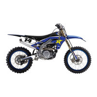
YAMAHA YZ250F Owner’s Service Manual (675 pages)
YZ Series
Brand: YAMAHA
|
Category: Motorcycle
|
Size: 22.59 MB
Table of Contents
-
Important Notice
6
-
F.I.M. Machine Weights
10
-
Weights of Machines Without Fuel
10
-
Description
12
-
Finding the Required Page
12
-
Particularly Important Information
12
-
-
Renseignements Generaux
13
-
How to Read Descriptions
14
-
Illustrated Symbols
16
-
Index
18
-
Table of Contents
20
-
-
Chapter 7
26
-
Description
26
-
Engine
26
-
General Information
26
-
Informazioni Generali
27
-
-
-
Chapter 1
28
-
Engine Serial Number
28
-
Machine Identification
28
-
Model Label
28
-
Vehicle Identification Number
28
-
-
Identification de la Moto
29
-
Numero DI Serie del Mezzo
29
-
Important Information
30
-
Preparation for Removal and Disassembly
30
-
Informations Importantes
31
-
Informazioni Importanti
31
-
Wichtige Informationen
31
-
All Replacement Parts
32
-
Bearings and Oil Seals
32
-
Gaskets, Oil Seals and O-Rings
32
-
Lock Washers/Plates and Cotter Pins
32
-
Circlips
34
-
-
Checking of Connection
36
-
Controllo del Collegamento
37
-
Verification des Connexions
37
-
Special Tools
38
-
Outils Speciaux
41
-
Attrezzi Speciali
47
-
-
Clutch Lever
50
-
Control Functions
50
-
Engine Stop Switch
50
-
Shift Pedal
50
-
Bedienungselemente und Deren Funktion
51
-
Funzioni DI Controllo
51
-
-
Fonctions des Commandes
51
-
Cold Starter Knob
52
-
Front Brake Lever
52
-
Fuel Cock
52
-
Hot Starter Lever
52
-
Rear Brake Pedal
52
-
Detachable Sidestand
54
-
Nipple Wrench
54
-
Spark Plug Wrench
54
-
Valve Joint
54
-
Fuel
56
-
-
Carburant
57
-
Starting a Cold Engine
58
-
Starting and Break-In
58
-
Avviamento E Rodaggio
59
-
Mise en Marche Et Rodage
59
-
Starten und Einfahren
59
-
Mise en Marche Et Rodage
61
-
Restarting an Engine after a Fall
62
-
Starting a Warm Engine
62
-
The Engine Fails to Start
62
-
Break-In Procedures
64
-
-
Torque-Check Points
64
-
Torque-Check Points
66
-
Points de Verification des Couples de Serrage
67
-
Anzugsdrehmomente Kontrollieren
68
-
Punti DI Controllo Serraggio
69
-
-
Cleaning and Storage
70
-
Nettoyage Et Remisage
71
-
Pflege und Lagerung
71
-
-
Chapter 2
74
-
General Specifications
74
-
Chassis
76
-
Engine
77
-
-
Maintenance Specifications
77
-
Definition of Units
90
-
General Torque Specifications
90
-
Caracteristiques
91
-
Caracteristiques Generales
91
-
Caracteristiques D’entretien
94
-
Caracteristiques Generales de Couple
107
-
Definition des Unites
107
-
Moteur
107
-
Allgemeine Technische Daten
108
-
Technische Daten
108
-
Wartungsdaten
111
-
Elektrische Anlage
123
-
Allgemeine Anzugsmomente
124
-
Carburante
125
-
Dati Tecnici
125
-
Dati Tecnici Generali
125
-
Specifiche DI Manutenzione
132
-
Specifiche Generali DI Serraggio
141
-
Definizione Delle Unità DI Misura
141
-
-
Cable Routing Diagram
142
-
D’acheminement des Cables
143
-
Kabelführungsdia Gramme
143
-
Schema Percorso Dei Cavi
143
-
Regular Inspection and Adjustments
154
-
-
-
Chapter 3
154
-
Maintenance Intervals
154
-
Mise en Marche Et Rodage
158
-
Controllie Regolazioni Periodiche
163
-
Intervalli DI Manutenzione
163
-
Chassis
166
-
Engine
166
-
General Inspection and Maintenance
166
-
Pre-Operation Inspection and Maintenance
166
-
-
-
Kraftstoff
168
-
Controlli E Manutenzione da Compiere Prima Della Messa in Funzione
169
-
-
Carburante
169
-
Coolant Level Inspection
170
-
Motore
171
-
Coolant Replacement
172
-
Radiator Cap Inspection
174
-
Cooling System Inspection
176
-
Radiator Cap Opening Pressure Inspection
176
-
Clutch Adjustment
178
-
Throttle Cable Adjustment
180
-
Throttle Lubrication
180
-
Air Filter Cleaning
182
-
Hot Starter Lever Adjustment
182
-
Engine Oil Level Inspection
186
-
Engine Oil Replacement
190
-
Engine Oil Replacement
192
-
Oil Pressure Inspection
194
-
Pilot Screw Adjustment
194
-
Engine Idling Speed Adjustment
196
-
Valve Clearance Inspection and Adjustment
196
-
Brake System Air Bleeding
208
-
Chassis
208
-
-
Parte Ciclistica
209
-
Front Brake Adjustment
210
-
Front Brake Pad Inspection and Replacement
212
-
Rear Brake Adjustment
212
-
Rear Brake Pad Inspection and Replacement
216
-
Brake Fluid Level Inspection
220
-
Rear Brake Pad Insulator Inspection
220
-
Drive Chain Inspection
222
-
Sprockets Inspection
222
-
Drive Chain Slack Adjustment
224
-
Front Fork Inspection
226
-
Front Fork Internal Pressure Relieving
228
-
Front Fork Oil Seal and Dust Seal Cleaning
228
-
Front Fork Rebound Damping Force Adjustment
228
-
Front Fork Compression Damping Force Adjustment
230
-
Rear Shock Absorber Inspection
232
-
Rear Shock Absorber Spring Preload Adjustment
234
-
Rear Shock Absorber Rebound Damping Force Adjustment
236
-
Rear Shock Absorber Low Compression Damping Force Adjustment
238
-
Rear Shock Absorber High Compression Damping Force Adjustment
240
-
Spokes Inspection and Tightening
242
-
Tire Pressure Check
242
-
Wheel Inspection
242
-
Steering Head Inspection and Adjustment
244
-
Lubrication
250
-
-
-
Engine
170
-
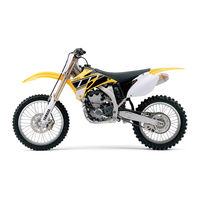
YAMAHA YZ250F Owner’s Service Manual (676 pages)
YZ Series
Brand: YAMAHA
|
Category: Motorcycle
|
Size: 22.79 MB
Table of Contents
-
Important Notice
6
-
Machine Weights
10
-
Description
12
-
Renseignements Generaux
13
-
Table of Contents
20
-
Description
26
-
Engine
26
-
Informazioni Generali
27
-
Chapter 1
28
-
Machine Identification
28
-
Numero DI Serie del Mezzo
29
-
Identification de la Moto
29
-
Important Information
30
-
Informations Importantes
31
-
Wichtige Informationen
31
-
Informazioni Importanti
31
-
Checking of Connection
36
-
Verification des Connexions
37
-
Controllo del Collegamento
37
-
Special Tools
38
-
Outils Speciaux
41
-
Attrezzi Speciali
47
-
-
Control Functions
50
-
Bedienungselemente und Deren Funktion
51
-
Funzioni DI Controllo
51
-
-
Fonctions des Commandes
51
-
Fuel
52
-
Hot Starter Lever
52
-
Carburant
57
-
Starting and Break-In
58
-
Mise en Marche Et Rodage
59
-
Starten und Einfahren
59
-
Avviamento E Rodaggio
59
-
Mise en Marche Et Rodage
61
-
-
Torque-Check Points
64
-
Points de Verification des Couples de Serrage
67
-
Anzugsdrehmomente Kontrollieren
68
-
Punti DI Controllo Serraggio
69
-
-
Cleaning and Storage
70
-
Nettoyage Et Remisage
71
-
Pflege und Lagerung
71
-
Carburant
73
-
-
Chapter 2
74
-
General Specifications
74
-
Chassis
76
-
Maintenance Specifications
77
-
Engine
77
-
General Torque Specifications
90
-
-
Definition of Units
90
-
Caracteristiques
91
-
Caracteristiques Generales
91
-
Caracteristiques D’entretien
94
-
Caracteristiques Generales de Couple
107
-
Definition des Unites
107
-
Moteur
107
-
Technische Daten
108
-
Allgemeine Technische Daten
108
-
Schmiersystem
108
-
Elektrische Anlage
123
-
Allgemeine Anzugsmomente
124
-
Carburante
125
-
Dati Tecnici
125
-
Dati Tecnici Generali
125
-
Specifiche DI Manutenzione
132
-
-
Specifiche Generali DI Serraggio
141
-
Definizione Delle Unità DI Misura
141
-
-
Lubrication Diagrams
142
-
Diagrammes de Lubrification
143
-
Schemi DI Lubrificazione
143
-
-
Cable Routing Diagram
146
-
D’acheminement des Cables
147
-
Kabelführungsdia Gramme
147
-
Schema Percorso Dei Cavi
147
-
-
Advertisement
YAMAHA YZ250F Owner’s Service Manual (668 pages)
Brand: YAMAHA
|
Category: Motorcycle
|
Size: 16.43 MB
Table of Contents
-
Important Notice
6
-
Machine Weights
10
-
Description
12
-
Renseignements Generaux
13
-
Table of Contents
20
-
Description
26
-
Engine
26
-
Informazioni Generali
27
-
Machine Identification
28
-
Numero DI Serie del Mezzo
29
-
Identification de la Moto
29
-
Important Information
30
-
Informations Importantes
31
-
Wichtige Informationen
31
-
Informazioni Importanti
31
-
Checking of Connection
36
-
Verification des Connexions
37
-
Controllo del Collegamento
37
-
Special Tools
38
-
Outils Speciaux
41
-
Attrezzi Speciali
47
-
Control Functions
50
-
Bedienungselemente und Deren Funktion
51
-
Funzioni DI Controllo
51
-
Fonctions des Commandes
51
-
Fuel
52
-
Hot Starter Lever
52
-
Carburant
57
-
Starting and Break-In
58
-
Mise en Marche Et Rodage
59
-
Starten und Einfahren
59
-
Avviamento E Rodaggio
59
-
Mise en Marche Et Rodage
61
-
Torque-Check Points
64
-
Points de Verification des Couples de Serrage
67
-
Anzugsdrehmomente Kontrollieren
68
-
Punti DI Controllo Serraggio
69
-
Cleaning and Storage
70
-
Nettoyage Et Remisage
71
-
Pflege und Lagerung
71
-
Carburant
73
-
General Specifications
74
-
Chassis
76
-
Maintenance Specifications
77
-
Engine
77
-
General Torque Specifications
90
-
Definition of Units
90
-
Caracteristiques
91
-
Caracteristiques Generales
91
-
Caracteristiques D’entretien
94
-
Caracteristiques Generales de Couple
107
-
Definition des Unites
107
-
Moteur
107
-
Technische Daten
108
-
Allgemeine Technische Daten
109
-
Wartungsdaten
111
-
Elektrische Anlage
123
-
Allgemeine Anzugsmomente
124
-
Carburante
125
-
Dati Tecnici
125
-
Dati Tecnici Generali
126
-
Specifiche DI Manutenzione
132

YAMAHA YZ250F Owner’s Service Manual (662 pages)
Brand: YAMAHA
|
Category: Motorcycle
|
Size: 31.6 MB
Table of Contents
-
Important Notice
6
-
Machine Weights
10
-
Description
12
-
Renseignements Generaux
13
-
Table of Contents
20
-
Moteur
23
-
Partie Cycle
23
-
Partie Electrique
25
-
Chapter 7
26
-
Description
26
-
Engine
26
-
Fahrzeugbeschreibung
27
-
Informazioni Generali
27
-
-
Chapter 1
28
-
Machine Identification
28
-
Fahrzeug-Identifizierung
29
-
Identification de la Machine
29
-
Identificazione del Veicolo
29
-
Important Information
30
-
Informations Importantes
31
-
Informazioni Importanti
31
-
Wichtige Informationen
31
-
Checking of Connection
36
-
Anschlüsse Prüfen
37
-
Controllo Dei Collegamenti
37
-
Verification des Connexions
37
-
Special Tools
38
-
Outils Speciaux
41
-
Spezialwerkzeuge
44
-
Utensili Speciali
47
-
Control Functions
50
-
Armaturen und Deren
51
-
Fonctions des Commandes
51
-
Funzioni DI Comando
51
-
Fuel
52
-
Hot Starter Lever
52
-
Essence
57
-
Kraftstoff
57
-
Starting and Break-In
58
-
Anlassen und Einfahren
59
-
Mise en Marche Et Rodage
59
-
Torque-Check Points
64
-
Points de Verification de Couple de Serrage
67
-
Anzugsmomente Kontrollieren
68
-
Punti Per Il Controllo del Serraggio
69
-
Cleaning and Storage
70
-
Nettoyage Et Rangement
71
-
Pulizia Ed Immagazzinaggio
71
-
Reinigung und Stillegung
71
-
-
Chapter 2
74
-
General Specifications
74
-
Chassis
75
-
Engine
77
-
Maintenance Specifications
77
-
Definition of Units
90
-
General Torque Specifications
90
-
Caracteristiques Generales
91
-
Caracteristiques Generales de Couple
107
-
-
Allgemeine Technische Daten
108
-
Kraftstoff
108
-
Technische Daten
108
-
Wartungsdaten
111
-
Allgemeine Anzugsmomente
124
-
Einheiten
124
-
Carburante
125
-
Specifiche
125
-
Specifiche Generali
125
-
Specifiche DI Manutenzione
128
-
Coppie DI Serraggio
141
-
Definizione Delle Unità DI Misura
141
-
Generali
141
-
Specifiche Relative alle
141
-
Cable Routing Diagram
142
-
Cheminement des Cables
143
-
Kabelführung
143
-
-
Schema del Percorso Dei
143
-
YAMAHA YZ250F Owner’s Service Manual (666 pages)
Brand: YAMAHA
|
Category: Motorcycle
|
Size: 42.57 MB
Table of Contents
-
Important Notice
6
-
Machine Weights
10
-
Description
12
-
Renseignements Generaux
13
-
Table of Contents
20
-
Moteur
23
-
Partie Cycle
23
-
Partie Electrique
25
-
Chapter 7
26
-
Description
26
-
Engine
26
-
Fahrzeugbeschreibung
27
-
Informazioni Generali
27
-
-
Chapter 1
28
-
Machine Identification
28
-
Fahrzeug-Identifizierung
29
-
Identification de la Machine
29
-
Identificazione del Veicolo
29
-
Important Information
30
-
Informations Importantes
31
-
Informazioni Importanti
31
-
Wichtige Informationen
31
-
Checking of Connection
36
-
Anschlüsse Prüfen
37
-
Controllo Dei Collegamenti
37
-
Verification des Connexions
37
-
Special Tools
38
-
Outils Speciaux
41
-
Spezialwerkzeuge
44
-
Utensili Speciali
47
-
Control Functions
50
-
Fonctions des Commandes
51
-
Funzioni DI Comando
51
-
Fuel
54
-
Essence
59
-
Kraftstoff
59
-
Starting and Break-In
60
-
Anlassen und Einfahren
61
-
Avvio E Rodaggio
61
-
Mise en Marche Et Rodage
61
-
Torque-Check Points
66
-
Points de Verification de Couple de Serrage
69
-
Anzugsmomente Kontrollieren
70
-
Punti Per Il Controllo del Serraggio
71
-
Cleaning and Storage
72
-
Nettoyage Et Rangement
73
-
Pulizia Ed Immagazzinaggio
73
-
Reinigung und Stillegung
73
-
-
Chapter 2
76
-
General Specifications
76
-
Chassis
77
-
Maintenance Specifications
79
-
Definition of Units
92
-
General Torque Specifications
92
-
Caracteristiques Generales
93
-
Caracteristiques Generales de Couple
109
-
-
Allgemeine Technische Daten
110
-
Technische Daten
110
-
Allgemeine Technische Daten
111
-
Wartungsdaten
113
-
Allgemeine Anzugsmomente
126
-
Einheiten
126
-
Specifiche
127
-
-
Specifiche Generali
127
-
Specifiche DI Manutenzione
130
-
Definizione Delle Unità DI Misura
143
-
Specifiche Relative alle Coppie DI Serraggio Generali
143
-
Cable Routing Diagram
144
-
Cheminement des Cables
145
-
Kabelführung
145
-
-
Schema del Percorso
145
-
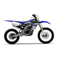
Yamaha YZ250F Owner’s Service Manual (356 pages)
2015
Brand: Yamaha
|
Category: Motorcycle
|
Size: 11.95 MB
Table of Contents
-
Table of Contents
11
-
Important Manual Information
6
-
Safety Information
7
-
How to Use this Manual
8
-
General Information
13
-
Location of Important Labels
15
-
Description
18
-
Identification
19
-
Vehicle Identification Number
19
-
Engine Serial Number
19
-
Model Label
19
-
-
Features
20
-
Outline of the Fi System
20
-
Fi System
21
-
-
Included Parts
22
-
Sidestand
22
-
Spark Plug Wrench
22
-
Nipple Wrench
22
-
Handlebar Protector
22
-
Fuel Hose Joint Cover
22
-
Coupler for Connecting Optional Part
22
-
-
Important Information
24
-
Preparation for Removal and Disassembly
24
-
Replacement Parts
24
-
Gaskets, Oil Seals and O-Rings
25
-
Lock Washers/Plates and Cotter Pins
25
-
Bearings and Oil Seals
25
-
Circlips
25
-
-
Basic Service Information
26
-
Electrical System
26
-
-
Special Tools
29
-
Control Functions
34
-
Engine Stop Switch
34
-
Clutch Lever
34
-
Shift Pedal
34
-
Kickstarter Lever
34
-
Throttle Grip
34
-
Front Brake Lever
34
-
Rear Brake Pedal
35
-
Starter Knob/Idle Adjusting Screw
35
-
Fuel Tank Cap
35
-
-
Starting and Break-In
36
-
Fuel
36
-
Starting a Cold Engine
36
-
Starting a Warm Engine
37
-
Break-In Procedures
37
-
-
Maintenance after Break-In
38
-
Major Maintenance
38
-
-
Torque-Check Points
39
-
Cleaning and Storage
41
-
Cleaning
41
-
Storage
41
-
-
-
-
Specifications
43
-
General Specifications
44
-
Engine Specifications
45
-
Chassis Specifications
51
-
Electrical Specifications
54
-
Tightening Torques
55
-
General Tightening Torque Specifications
55
-
Engine Tightening Torques
56
-
Chassis Tightening Torques
59
-
-
Lubrication Points and Lubricant Types
62
-
Engine
62
-
Chassis
64
-
-
Lubrication System Chart and Diagrams
66
-
Lubrication Diagrams
66
-
-
Cable Routing Diagram
74
-
-
Periodic Checks and Adjustments
85
-
Maintenance Intervals
87
-
Pre-Operation Inspection and Maintenance
93
-
General Inspection and Maintenance
93
-
-
Engine
94
-
Checking the Coolant Level
94
-
Checking the Cooling System
94
-
Changing the Coolant
94
-
Checking the Radiator Cap
95
-
Checking the Radiator Cap Opening Pressure
95
-
Checking the Coolant Circulatory System for Leaks
96
-
Adjusting the Clutch Lever Position
96
-
Adjusting the Clutch Lever Free Play
96
-
Adjusting the Throttle Grip Free Play
97
-
Lubricating the Throttle Cable
98
-
Cleaning the Air Filter Element
98
-
Checking the Throttle Body Joint
99
-
Checking the Breather Hoses
99
-
Checking the Exhaust System
99
-
Checking the Fuel Line
100
-
Checking the Engine Oil Level
100
-
Changing the Engine Oil
101
-
Adjusting the Engine Idling Speed
102
-
Adjusting the Valve Clearance
103
-
-
Chassis
107
-
Bleeding the Brake System
107
-
Checking the Brake Hose
108
-
Adjusting the Front Brake
108
-
Adjusting the Rear Brake
109
-
Checking the Front Brake Pads
109
-
Checking the Rear Brake Pads
111
-
Checking the Rear Brake Pad Insulator
112
-
Checking the Brake Fluid Level
112
-
Adjusting the Drive Chain Slack
113
-
Checking the Front Fork Legs
114
-
Checking the Front Fork Protector Guide
114
-
Cleaning the Front Fork Oil Seal and Dust Seal
114
-
Air Bleeding from Front Fork
114
-
Adjusting the Front Fork Legs
115
-
Checking the Swingarm Operation
116
-
Checking the Rear Suspension
116
-
Adjusting the Rear Shock Absorber Assembly
116
-
Checking the Tires
118
-
Checking and Tightening the Spokes
118
-
Checking the Wheels
119
-
Checking the Wheel Bearings
119
-
Checking and Adjusting the Steering Head
119
-
Lubricating the Levers
120
-
Lubricating the Pedal
120
-
-
-
Electrical System
121
-
Checking the Spark Plug
121
-
Checking the Ignition Timing
121
-
-
Yamaha YZ250F Owner’s Service Manual (304 pages)
Motorcycles
Brand: Yamaha
|
Category: Motorcycle
|
Size: 23.52 MB
Table of Contents
-
Important Notice
6
-
Table of Contents
14
-
Chapter 1 General Information
17
-
Description
17
-
Machine Identification
18
-
Important Information
19
-
Checking of Connection
22
-
Special Tools
23
-
Control Functions
26
-
Fuel
29
-
Starting and Break-In
30
-
Torque-Check Points
34
-
Cleaning and Storage
35
-
-
Chapter 2 Specifications
37
-
General Specifications
37
-
Maintenance Specifications
40
-
General Torque Specifications
53
-
Definition of Units
53
-
Cable Routing Diagram
54
-
-
Chapter 3 Regular Inspection and Adjustments
59
-
Maintenance Intervals
59
-
Pre-Operation Inspection and Maintenance
62
-
Engine
63
-
Engine Oil Replacement
74
-
Valve Clearance Inspection and Adjustment
81
-
-
Chassis
82
-
Rear Brake Adjustment
84
-
Rear Shock Absorber Inspection
94
-
Rear Shock Absorber Rebound Damping Force Adjustment
96
-
-
Electrical
103
-
-
Chapter 4
105
-
Seat, Fuel Tank and Side Covers
105
-
Exhaust Pipe and Silencer
107
-
Radiator
109
-
Carburetor
112
-
Camshafts
125
-
Cylinder Head
134
-
Valves and Valve Springs
137
-
Cylinder and Piston
146
-
Clutch
153
-
Oil Filter Element, Water Pump and Right Crankcase Cover
160
-
Balancer
167
-
Oil Pump
170
-
Kick Shaft and Shift Shaft
175
-
CDI Magneto
182
-
Engine Removal
186
-
Crankcase and Crankshaft
191
-
Transmission, Shift Cam and Shift Fork
200
-
-
Chapter 5 Chassis
205
-
Front Wheel and Rear Wheel
205
-
Front Brake and Rear Brake
214
-
Front Fork
230
-
Handlebar
243
-
Steering
249
-
Swingarm
254
-
Rear Shock Absorber
262
-
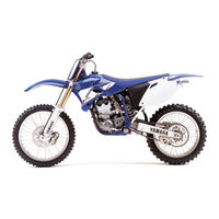
Yamaha YZ250F Owner’s Service Manual (300 pages)
Brand: Yamaha
|
Category: Motorcycle
|
Size: 27.9 MB
Table of Contents
-
Important Notice
4
-
Table of Contents
11
-
Chapter 1 General Information
14
-
Description
14
-
Machine Identification
15
-
Important Information
16
-
Checking of Connection
19
-
Special Tools
20
-
Control Functions
22
-
Fuel
25
-
Starting and Break-In
26
-
Torque-Check Points
30
-
Cleaning and Storage
31
-
-
Chapter 2 Specifications
33
-
General Specifications
33
-
Maintenance Specifications
36
-
General Torque Specifications
49
-
Definition of Units
49
-
Cable Routing Diagram
50
-
-
Chapter 3 Regular Inspection and Adjustments
55
-
Maintenance Intervals
55
-
Engine
58
-
Engine Oil Replacement
69
-
Valve Clearance Inspection and Adjustment
76
-
-
Chassis
77
-
Rear Brake Adjustment
79
-
Rear Shock Absorber Inspection
89
-
-
Electrical
99
-
-
Chapter 4
101
-
Seat, Fuel Tank and Side Covers
101
-
Exhaust Pipe and Silencer
103
-
Radiator
105
-
Carburetor
108
-
Camshafts
121
-
Cylinder Head
130
-
Valves and Valve Springs
133
-
Cylinder and Piston
142
-
Clutch
149
-
Oil Filter Element, Water Pump and Right Crankcase Cover
156
-
Balancer
163
-
Oil Pump
166
-
Kick Shaft and Shift Shaft
171
-
CDI Magneto
178
-
Engine Removal
182
-
Engine Installation
185
-
Crankcase and Crankshaft
187
-
Transmission, Shift Cam and Shift Fork
196
-
-
Chapter 5 Chassis
201
-
Front Wheel and Rear Wheel
201
-
Front Brake and Rear Brake
210
-
Rear Brake
211
-
Front Fork
226
-
Front Fork Disassembly
227
-
Handlebar
242
-
Steering
248
-
Swingarm
253
-
Rear Shock Absorber
261
-
Yamaha YZ250F Owner’s Manual (164 pages)
Brand: Yamaha
|
Category: Motorcycle
|
Size: 8.03 MB
Table of Contents
-
Table of Contents
7
-
General Information
9
-
For Safety, be Sure to Obey the Following
11
-
Safety Information
11
-
Location of Important Labels
14
-
Description
17
-
Identification
18
-
Vehicle Identification Number
18
-
Engine Serial Number
18
-
Fuel Hose Joint Cover
19
-
Power Tuner
19
-
Included Parts
19
-
Handlebar Protector
19
-
Nipple Wrench
19
-
Specifications
19
-
Important Information
21
-
Preparation for Removal and Disassembly
21
-
Replacement Parts
21
-
Start Switch
22
-
Mode Switch
22
-
Engine Stop Switch
22
-
Instrument and Control Functions
22
-
Warning Lights
22
-
Shift Pedal
23
-
Front Brake Lever
23
-
Sidestand
23
-
Rear Brake Pedal
23
-
Starter Knob
23
-
Fuel Tank Cap
24
-
Starting and Break-In
25
-
Fuel
25
-
Starting a Cold Engine
25
-
Engine Starting Precaution
26
-
Starting a Warm Engine
26
-
Break-In Procedures
26
-
Maintenance after Break-In
27
-
Major Maintenance
27
-
Air Filter Maintenance
27
-
Torque-Check Points
28
-
-
Specifications
33
-
General Specifications
34
-
Specifications
34
-
Engine Specifications
35
-
Chassis Specifications
37
-
Electrical Specifications
39
-
General Tightening Torque Specifications
40
-
Tightening Torques
40
-
-
Periodic Checks and Adjustments
47
-
Maintenance Intervals
49
-
General Inspection and Maintenance
53
-
Pre-Operation Inspection and Maintenance
53
-
Adjusting the Valve Clearance
54
-
Engine
54
-
Checking the Engine Idling Speed
55
-
Checking the Throttle Grip
55
-
Checking the Spark Plug
56
-
Changing the Engine Oil
57
-
Checking the Engine Oil Level
57
-
Adjusting the Clutch Lever Free Play
59
-
Adjusting the Clutch Lever Position
60
-
Cleaning the Air Filter Element
60
-
Checking the Throttle Body Joint
61
-
Checking the Cylinder Head Breather Hose
62
-
Checking the Exhaust System
62
-
Checking the Fuel Line
62
-
Checking the Coolant Level
64
-
Changing the Coolant
65
-
Checking the Cooling System
65
-
Adjusting the Front Disc Brake
67
-
Adjusting the Rear Disc Brake
67
-
Chassis
67
-
Checking the Brake Fluid Level
67
-
Checking the Front Brake Hose
68
-
Checking the Front Brake Pads
68
-
Checking the Rear Brake Hose
68
-
Checking the Rear Brake Pads
68
-
Bleeding the Hydraulic Brake System
69
-
Checking the Brake Operation
69
-
Drive Chain Slack
70
-
Lubricating the Drive Chain
70
-
Checking and Adjusting the Steering Head
71
-
Checking the Front Fork Legs
72
-
Lubricating the Steering Head
72
-
Adjusting the Front Fork Legs
73
-
Adjusting the Rear Shock Absorber Assembly
74
-
Checking the Rear Shock Absorber Assembly
74
-
Checking the Swingarm Operation
76
-
Checking the Tires
76
-
Lubricating the Swingarm Pivot
76
-
Checking and Tightening the Spokes
77
-
Checking the Chassis Fasteners
77
-
Checking the Wheels
77
-
Electrical System
79
-
Advertisement
Related Products
-
YAMAHA YZ250F(Y)
-
YAMAHA YZ250F(D)
-
YAMAHA YZ250F(W)
-
YAMAHA YZ250F(N)/LC
-
YAMAHA YZ250F(P)/LC
-
YAMAHA YZ250F(R)
-
YAMAHA YZ250F(T)
-
YAMAHA YZ250F(S)
-
YAMAHA YZ250F(V)
-
Yamaha YZ250F X 2008
Yamaha Categories
Motorcycle
Musical Instrument
Electronic Keyboard
Receiver
Amplifier
More Yamaha Manuals
Перейти к контенту
- Manuals
- Brands
- Yamaha Manuals
- Motorcycle
- YZ250
Manuals and User Guides for Yamaha YZ250. We have 10 Yamaha YZ250 manuals available for free PDF download: Owner’s Service Manual, Parts Catalog
YAMAHA YZ250 Owner’s Service Manual (587 pages)
YZ Series
Brand: YAMAHA
|
Category: Motorcycle
|
Size: 16.24 MB
Table of Contents
-
How to Use this Manual
12
-
Renseignements Generaux
13
-
How to Read Descriptions
14
-
-
-
Machine Identification
28
-
Vehicle Identification Number
28
-
Identification de la Machine
29
-
Preparation for Removal and Disassembly
30
-
Informations Importantes
31
-
Informazioni Importanti
31
-
-
Wichtige Informationen
31
-
Bearings and Oil Seals
32
-
Gaskets, Oil Seals and O-Rings
32
-
Lock Washers/Plates and Cotter Pins
32
-
Checking of Connection
36
-
Controllo Dei Collegamenti
37
-
-
Verification des Connexions
37
-
Fonctions des Commandes
47
-
Fuel and Engine Mixing Oil
52
-
Essence Et Huile de Melange du Moteur
53
-
Starting a Cold Engine
54
-
Starting a Warm Engine
54
-
-
Mise en Marche Et Rodage
55
-
Points de Verification de Couple de Serrage
61
-
Nettoyage Et Rangement
65
-
-
General Specifications
68
-
Maintenance Specifications
70
-
Chassis Specifications
74
-
Electrical Specifications
78
-
-
General Torque Specifications
79
-
Caracteristiques Generales
80
-
Caracteristiques D’entretien
82
-
Specifications Generales de Couple
91
-
Allgemeine Technische Daten
92
-
Allgemeine Anzugsdaten
103
-
Definition der Einheiten
103
-
-
Specifiche DI Manutenzione
106
-
Definizione Delle Unità
115
-
Cable Routing Diagram
116
-
Diagramma del Passaggio Dei Cavi
117
-
Schema de Cheminement des Cables
117
-
Kabelführungsübersichtplan
117
-
Regular Inspection and Adjustments
126
-
-
-
-
-
Maintenance Intervals
126
-
Revisione Eregolazioni Regolari
135
-
Intervalli DI Manutenzione
135
-
Pre-Operation Inspection and Maintenance
138
-
General Inspection and Maintenance
138
-
-
-
-
Ispezione E Manutenzione Prima del Funzionamento
141
-
Engine Coolant Level Inspection
142
-
-
-
Radiator Cap Inspection
146
-
Handling Notes of Coolant
146
-
Radiator Cap Opening Pressure Inspection
148
-
Cooling System Inspection
148
-
Throttle Cable Adjustment
152
-
Transmission Oil Level Check
156
-
Transmission Oil Replacement
158
-
Pilot Air Screw Adjustment
160
-
Idle Speed Adjustment
162
-
Silencer Fiber Replacement
162
-
Silencer Fiber Replacement
164
-
Brake System Air Bleeding
166
-
-
Front Brake Adjustment
168
-
Rear Brake Adjustment
170
-
Pedal Height Adjustment Steps
170
-
Front Brake Pad Inspection and Replacement
170
-
Rear Brake Pad Inspection and Replacement
174
-
Front Wheel and Rear Wheel
174
-
-
Roue Avant Et Roue Arriere
175
-
Brake Fluid Level Inspection
178
-
Rear Brake Pad Insulator Inspection
178
-
Drive Chain Inspection
180
-
Drive Chain Slack Adjustment
182
-
Front Fork Inspection
184
-
Front Fork Internal Pressure Relieving
186
-
Front Fork Oil Seal and Dust Seal Cleaning
186
-
Front Fork Rebound Damping Force Adjustment
186
-
Front Fork Compression Damping Force Adjustment
188
-
-
-
Rear Shock Absorber Inspection
190
-
Rear Shock Absorber Spring Preload Adjustment
192
-
Rear Shock Absorber Rebound Damping Force Adjustment
194
-
Rear Shock Absorber Low Compression Damping Force Adjustment
196
-
Rear Shock Absorber High Compression Damping Force Adjustment
198
-
Spokes Inspection and Tightening
200
-
Steering Head Inspection and Adjustment
202
-
Spark Plug Inspection
208
-
-
Ignition Timing Check
210
-
Advertisement
YAMAHA YZ250 Owner’s Service Manual (579 pages)
YZ series
Brand: YAMAHA
|
Category: Motorcycle
|
Size: 15.16 MB
Table of Contents
-
F.I.M. Machine Weights
10
-
-
Finding the Required Page
12
-
How to Use this Manual
12
-
Particularly Important Information
12
-
-
Renseignements Generaux
13
-
How to Read Descriptions
14
-
-
-
Machine Identification
28
-
Vehicle Identification Number
28
-
Identificazione del Veicolo
29
-
Identification de la Machine
29
-
Preparation for Removal and Disassembly
30
-
Informations Importantes
31
-
-
Bearings and Oil Seals
32
-
Gaskets, Oil Seals and O-Rings
32
-
Lock Washers/Plates and Cotter Pins
32
-
Checking of Connections
36
-
Controllo Dei Collegamenti
37
-
Verification des Connexions
37
-
Fonctions des Commandes
47
-
Fuel and Engine Mixing Oil
52
-
Essence Et Huile de Melange du Moteur
53
-
-
Starting a Cold Engine
54
-
Starting a Warm Engine
54
-
-
Mise en Marche Et Rodage
55
-
Points de Verification de Couple de Serrage
61
-
Nettoyage Et Rangement
65
-
-
-
General Specifications
68
-
Maintenance Specifications
70
-
General Torque Specifications
79
-
Caracteristiques Generales
80
-
Caracteristiques D’entretien
82
-
Specifications Generales de Couple
91
-
Allgemeine Technische Daten
92
-
Allgemeine Anzugsdaten
103
-
Definition der Einheiten
103
-
Definizione Delle Unità
115
-
Cable Routing Diagram
116
-
Diagramma del Passaggio
117
-
Schema de Cheminement des Cables
117
-
Kabelführungsübersichtplan
117
-
-
-
-
-
Maintenance Intervals
124
-
Regular Inspection and Adjustments
124
-
Intervalli DI Manutenzione
133
-
Revisione Eregolazioni Regolari
133
-
General Inspection and Maintenance
136
-
Pre-Operation Inspection and Maintenance
136
-
-
-
Ispezione E Manutenzione Prima del Funzionamento
139
-
Coolant Level Inspection
140
-
-
-
Radiator Cap Inspection
144
-
Radiator Cap Opening Pressure Inspection
146
-
Coolant System Inspection
146
-
Throttle Cable Adjustment
150
-
Transmission Oil Level Check
154
-
Transmission Oil Replacement
156
-
Pilot Air Screw Adjustment
158
-
Idle Speed Adjustment
160
-
Silencer Fiber Replacement
160
-
Silencer Fiber Replacement
162
-
Brake System Air Bleeding
164
-
-
-
Front Brake Adjustment
166
-
Reare Brake Adjustment
168
-
Front Brake Pad Inspection and Replacement
168
-
Rear Brake Pad Inspection and Replacement
172
-
Front Wheel and Rear Wheel
172
-
Roue Avant Et Roue Arriere
173
-
Rear Brake Pad Insulator Inspection
176
-
Brake Fluid Level Inspection
176
-
Drive Chain Inspection
178
-
Drive Chain Slack Adjustment
180
-
Front Fork Inspection
182
-
Front Fork Oil Seal and Dust Seal Cleaning
184
-
Front Fork Rebound Damping Force Adjustment
184
-
Front Fork Compression Damping Force Adjustment
186
-
Rear Shock Absorber Inspection
188
-
-
Rear Shock Absorber Spring Preload Adjustment
190
-
-
Rear Shock Absorber Rebound Damping Force Adjustment
192
-
Rear Shock Absorber Low Compression Damping Force Adjustment
194
-
Rear Shock Absorber High Compression Damping Force Adjustment
196
-
Spokes Inspection and Tightening
198
-
Steering Head Inspection and Adjustment
200
-
-
Spark Plug Inspection
206
-
Ignition Timing Check
208
-
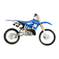
YAMAHA YZ250 Owner’s Service Manual (597 pages)
YZ Series
Brand: YAMAHA
|
Category: Motorcycle
|
Size: 12.89 MB
Table of Contents
-
Weights of Machines Without Fuel
10
-
Finding the Required Page
12
-
Renseignements Generaux
13
-
How to Read Descriptions
14
-
-
-
Machine Identification
28
-
Vehicle Identification Number
28
-
Identification de la Machine
29
-
Preparation for Removal and Dis Assembly
30
-
Informations Importantes
31
-
Informazioni Importanti
31
-
Wichtige Informationen
31
-
Bearings and Oil Seals
32
-
Gaskets, Oil Seals and O-Rings
32
-
Lock Washers/Plates and Cotter Pins
32
-
Checking of Connection
36
-
Controllo Dei Collegamenti
37
-
Verification des Connexions
37
-
Fonctions des Commandes
47
-
Fuel and Engine Mixing Oil
52
-
Essence Et Huile de Melange du Moteur
53
-
Starting a Cold Engine
54
-
Starting a Warm Engine
54
-
-
Mise en Marche Et Rodage
55
-
Points de Verification de Couple de Serrage
61
-
Nettoyage Et Rangement
65
-
-
General Specifications
68
-
Maintenance Specifications
70
-
General Torque Specifications
80
-
Caracteristiques Generales
81
-
Caracteristiques D’entretien
83
-
Specifications Generales de Couple
93
-
Allgemeine Technische Daten
94
-
Allgemeine Anzugsdaten
106
-
Definition der Einheiten
106
-
Specifiche DI Manutenzione
109
-
Definizione Delle Unità
119
-
Specifiche Generali Relative Alla Coppia
119
-
Cable Routing Diagram
120
-
Diagramma del Passaggio Dei Cavi
121
-
Kabelführungsübersichtplan
121
-
Schema de Cheminement des Cables
121
-
-
-
-
Maintenance Intervals
130
-
Regular Inspection and Adjustments
130
-
Intervalli DI Manutenzione
139
-
Revisione Eregolazioni Regolari
139
-
-
General Inspection and Maintenance
142
-
Pre-Operation Inspection and Maintenance
142
-
Ispezione E Manutenzione Prima del Funzionamento
145
-
Coolant Level Inspection
146
-
-
-
Radiator Cap Inspection
150
-
Cooling System Inspection
152
-
Radiator Cap Opening Pressure Inspection
152
-
Throttle Cable Adjustment
156
-
Transmission Oil Level Check
160
-
Transmission Oil Replacement
162
-
Pilot Air Screw Adjustment
164
-
Idle Speed Adjustment
166
-
Silencer Fiber Replacement
166
-
Silencer Fiber Replacement
168
-
Brake System Air Bleeding
170
-
-
-
Front Brake Adjustment
172
-
Front Brake Pad Inspection and Replacement
174
-
Rear Brake Adjustment
174
-
Front Wheel and Rear Wheel
178
-
Rear Brake Pad Inspection and Replacement
178
-
-
Roue Avant Et Roue Arriere
179
-
Brake Fluid Level Inspection
182
-
Rear Brake Pad Insulator Inspection
182
-
Drive Chain Inspection
184
-
Drive Chain Slack Adjustment
186
-
Front Fork Inspection
188
-
Front Fork Internal Pressure Relieving
190
-
Front Fork Oil Seal and Dust Seal Cleaning
190
-
Front Fork Rebound Damping Force Adjustment
190
-
Front Fork Compression Damping Force Adjustment
192
-
Rear Shock Absorber Inspection
194
-
-
Rear Shock Absorber Spring Preload Adjustment
196
-
-
Rear Shock Absorber Rebound Damping Force Adjustment
198
-
Rear Shock Absorber Low Compression Damping Force Adjustment
200
-
Rear Shock Absorber High Compression Damping Force Adjustment
202
-
Spokes Inspection and Tightening
204
-
Steering Head Inspection and Adjustment
206
-
-
-
-
Spark Plug Inspection
212
-
Ignition Timing Check
214
-
Advertisement
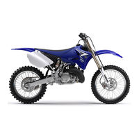
Yamaha YZ250 Owner’s Service Manual (596 pages)
YZ series
Brand: Yamaha
|
Category: Motorcycle
|
Size: 13.22 MB
Table of Contents
-
Renseignements Generaux
13
-
CHAPTER 1 General Information
26
-
-
Product View and Parts
26
-
-
Machine Identification
28
-
Identification de la Machine
29
-
Identificazione del Veicolo
29
-
-
Informations Importantes
31
-
Wichtige Informationen
31
-
Informazioni Importanti
31
-
-
Checking of Connection
36
-
Controllo Dei Collegamenti
37
-
Verification des Connexions
37
-
Fonctions des Commandes
47
-
Fuel and Engine Mixing Oil
52
-
Essence Et Huile de Melange du Moteur
53
-
Mise en Marche Et Rodage
55
-
Points de Verification de Couple de Serrage
61
-
Nettoyage Et Rangement
65
-
-
-
General Specifications
68
-
Maintenance Specifications
70
-
General Torque Specifications
80
-
Caracteristiques Generales
81
-
Caracteristiques D’entretien
83
-
Specifications Generales de Couple
93
-
Allgemeine Technische Daten
94
-
Allgemeine Anzugsdaten
106
-
Definition der Einheiten
106
-
-
Specifiche DI Manutenzione
109
-
Definizione Delle Unità
119
-
Cable Routing Diagram
120
-
Diagramma del Passaggio Dei Cavi
121
-
-
-
-
Maintenance Intervals
130
-
Revisione Eregolazioni Regolari
139
-
Intervalli DI Manutenzione
139
-
Ispezione E Manutenzione Prima del Funzionamento
145
-
-
-
Silencer Fiber Replacement
168
-
Rear Brake Adjustment
174
-
-
Roue Avant Et Roue Arriere
179
-
Rear Shock Absorber Inspection
194
-
Elektrische Einrichtungen
213
-
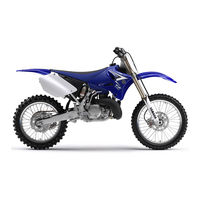
YAMAHA YZ250 Owner’s Service Manual (596 pages)
Brand: YAMAHA
|
Category: Motorcycle
|
Size: 15.97 MB
Table of Contents
-
Renseignements Generaux
13
-
-
Machine Identification
28
-
Identification de la Machine
29
-
Informations Importantes
31
-
Informazioni Importanti
31
-
Wichtige Informationen
31
-
Checking of Connection
36
-
Controllo Dei Collegamenti
37
-
Verification des Connexions
37
-
Fonctions des Commandes
47
-
Fuel and Engine Mixing Oil
52
-
Essence Et Huile de Melange du Moteur
53
-
Mise en Marche Et Rodage
55
-
Points de Verification de Couple de Serrage
61
-
Nettoyage Et Rangement
65
-
-
-
General Specifications
68
-
Maintenance Specifications
70
-
General Torque Specifications
80
-
Caracteristiques Generales
81
-
Caracteristiques D’entretien
83
-
Specifications Generales de Couple
93
-
Allgemeine Technische Daten
94
-
Allgemeine Anzugsdaten
106
-
Definition der Einheiten
106
-
Specifiche DI Manutenzione
109
-
Definizione Delle Unità
119
-
Specifiche Generali Relative Alla Coppia
119
-
Cable Routing Diagram
120
-
Diagramma del Passaggio Dei Cavi
121
-
Kabelführungsübersichtplan
121
-
Schema de Cheminement des Cables
121
-
-
YAMAHA YZ250 Owner’s Service Manual (584 pages)
YZ series
Brand: YAMAHA
|
Category: Motorcycle
|
Size: 15.9 MB
Table of Contents
-
Renseignements Generaux
13
-
-
Machine Identification
28
-
Identificazione del Veicolo
29
-
-
Identification de la Machine
29
-
Informations Importantes
31
-
Checking of Connection
36
-
Controllo Dei Collegamenti
37
-
Verification des Connexions
37
-
Fonctions des Commandes
47
-
Fuel and Engine Mixing Oil
52
-
Essence Et Huile de Melange du Moteur
53
-
Mise en Marche Et Rodage
55
-
Points de Verification de Couple de Serrage
61
-
Nettoyage Et Rangement
65
-
-
-
General Specifications
68
-
Maintenance Specifications
70
-
General Torque Specifications
79
-
Caracteristiques Generales
80
-
Caracteristiques D’entretien
82
-
Specifications Generales de Couple
91
-
Allgemeine Technische Daten
92
-
Allgemeine Anzugsdaten
103
-
Definition der Einheiten
103
-
Specifiche DI Manutenzione
106
-
Specifiche Generali Relative Alla Coppia
115
-
Definizione Delle Unità
115
-
Cable Routing Diagram
116
-
Diagramma del Passaggio Dei Cavi
117
-
Schema de Cheminement des Cables
117
-
Kabelführungsübersichtplan
117
-
-
-
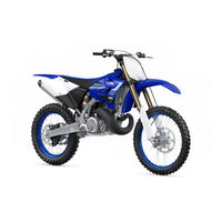
Yamaha YZ250 Owner’s Service Manual (578 pages)
YZ Series
Brand: Yamaha
|
Category: Motorcycle
|
Size: 14.8 MB
Table of Contents
-
Renseignements Generaux
13
-
CHAPTER 1 General Information
26
-
Machine Identification
28
-
Identification de la Machine
29
-
Identificazione del Veicolo
29
-
-
Informations Importantes
31
-
Checking of Connection
36
-
Controllo Dei Collegamenti
37
-
-
Verification des Connexions
37
-
Fonctions des Commandes
47
-
Fuel and Engine Mixing Oil
52
-
Essence Et Huile de Melange du Moteur
53
-
Mise en Marche Et Rodage
55
-
Points de Verification de Couple de Serrage
61
-
Nettoyage Et Rangement
65
-
-
General Specifications
68
-
Maintenance Specifications
70
-
General Torque Specifications
79
-
Caracteristiques Generales
80
-
Caracteristiques D’entretien
82
-
Specifications Generales de Couple
91
-
Allgemeine Technische Daten
92
-
Allgemeine Anzugsdaten
103
-
Definition der Einheiten
103
-
-
Definizione Delle Unità
115
-
Cable Routing Diagram
116
-
Diagramma del Passaggio Dei Cavi
117
-
-

Yamaha YZ250 Owner’s Service Manual (171 pages)
Brand: Yamaha
|
Category: Motorcycle
|
Size: 8.65 MB
Table of Contents
-
How to Read Descriptions
8
-
-
-
Machine Identification
12
-
Vehicle Identification Number
12
-
Bearings and Oil Seals
13
-
Checking of Connection
13
-
Gaskets, Oil Seals and O-Rings
13
-
Lock Washers/Plates and Cotter Pins
13
-
-
Air Filter Maintenance
18
-
Starting a Cold Engine
18
-
General Specifications
21
-
Maintenance Specifications
22
-
-
General Torque Specifications
32
-
Regular Inspection and Adjustments
41
-
General Inspection and Maintenance
44
-
Pre-Operation Inspection and Maintenance
44
-
Checking the Coolant Level
45
-
Checking the Radiator Cap
45
-
Checking the Radiator Cap Opening Pressure
45
-
-
-
Adjusting the Clutch Cable Free Play
46
-
Adjusting the Throttle Cable Free Play
46
-
Checking the Cooling System
46
-
Lubricating the Throttle
46
-
Checking the Transmission Oil Level
47
-
Cleaning the Air Filter Element
47
-
Adjusting the Engine Idling Speed
48
-
Adjusting the Pilot Air Screw
48
-
Changing the Transmission Oil
48
-
-
-
Checking the Exhaust Pipe
48
-
Adjusting the Front Brake
49
-
Adjusting the Rear Brake
49
-
Checking and Replacing the Front Brake Pads
49
-
Checking and Replacing the Rear Brake Pads
50
-
-
-
Chapter 2 Specifications
51
-
Checking the Brake Fluid Level
51
-
Checking the Drive Chain
51
-
Checking the Rear Brake Pad Insulator
51
-
Adjusting the Drive Chain Slack
52
-
Checking the Front Fork
52
-
Cleaning the Front Fork Oil Seal and Dust Seal
52
-
Relieving the Front Fork Internal Pressure
52
-
Adjusting the Front Fork Compression Damping Force
53
-
Adjusting the Front Fork Rebound Damping Force
53
-
Adjusting the Rear Shock Absorber Spring Preload
53
-
-
-
Checking the Rear Shock Absorber
53
-
Adjusting the Rear Shock Absorber Low Compression Damping Force
54
-
Adjusting the Rear Shock Absorber Rebound Damping Force
54
-
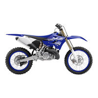
Yamaha YZ250 Owner’s Service Manual (252 pages)
Brand: Yamaha
|
Category: Offroad Vehicle
|
Size: 11.09 MB
Yamaha YZ250 Parts Catalog (55 pages)
Yamaha Automobile Parts Catalogue
Brand: Yamaha
|
Category: Motorcycle
|
Size: 0.91 MB
Advertisement
Related Products
-
Yamaha YZ250M
-
YAMAHA YZ250(W)/W1
-
YAMAHA YZ250F(Y)
-
YAMAHA YZ250F(D)
-
YAMAHA YZ250F(W)
-
YAMAHA YZ250(N)/LC
-
YAMAHA YZ250(P)/LC
-
YAMAHA YZ250(R)/LC
-
YAMAHA YZ250(S)/LC
-
YAMAHA YZ250(V)
Yamaha Categories
Motorcycle
Musical Instrument
Electronic Keyboard
Receiver
Amplifier
More Yamaha Manuals
Материал из BikesWiki — энциклопедия японских мотоциклов
Перейти к: навигация, поиск

Yamaha YZ250F
Ниже представлены прямые ссылки на скачку сервисной документации.
Для Yamaha YZ 250 F
- Руководство по ремонту и обслуживанию (Owners Service Manual) для Yamaha YZ250F(N)/LC (2000)
- Руководство по ремонту и обслуживанию (Owners Service Manual) для Yamaha YZ250F(P)/LC (2001)
- Руководство по ремонту и обслуживанию (Owners Service Manual) для Yamaha YZ250F(R) (2002)
- Руководство по ремонту и обслуживанию (Owners Service Manual) для Yamaha YZ250F(S) (2003)
- Руководство по ремонту и обслуживанию (Owners Service Manual) для Yamaha YZ250F(T) (2004)
- Руководство по ремонту и обслуживанию (Owners Service Manual) для Yamaha YZ250F(V) (2005)
- Руководство по ремонту и обслуживанию (Owners Service Manual) для Yamaha YZ250F(W) (2006)
- Руководство по ремонту и обслуживанию (Owners Service Manual) для Yamaha YZ250F(X) (2008)
- Руководство по ремонту и обслуживанию (Owners Service Manual) для Yamaha YZ250F(Y) (2009)
- Руководство по ремонту и обслуживанию (Owners Service Manual) для Yamaha YZ250F(Z) (2010)
- Руководство по ремонту и обслуживанию (Owners Service Manual) для Yamaha YZ250F(A) (2011)
- Руководство по ремонту и обслуживанию (Owners Service Manual) для Yamaha YZ250F(D) (2012)
- Руководство по ремонту и обслуживанию (Owners Service Manual) для Yamaha YZ250F(E) (2013)
- Руководство по ремонту и обслуживанию (Owners Service Manual) для Yamaha YZ250F(F) (2015)
- Руководство по ремонту и обслуживанию (Owners Service Manual) для Yamaha YZ250F(G) (2016)
Обзор модели
- Yamaha YZ250F
Источник — «https://bikeswiki.ru/index.php?title=Yamaha_YZ250F:_мануалы&oldid=10120»
Категория:
- Сервисная документация
Посмотреть инструкция для Yamaha YZ250F бесплатно. Руководство относится к категории Мотоциклы, 9 человек(а) дали ему среднюю оценку 8.8. Руководство доступно на следующих языках: английский. У вас есть вопрос о Yamaha YZ250F или вам нужна помощь? Задайте свой вопрос здесь
Не можете найти ответ на свой вопрос в руководстве? Вы можете найти ответ на свой вопрос ниже, в разделе часто задаваемых вопросов о Yamaha YZ250F.
Как перевести мили в километры?
В чем разница между топливом E10 и E5?
Какова рекомендуемая частота замены масляного фильтра в двигателе Yamaha?
Как часто следует менять масло в двигателе Yamaha?
Как удалить ржавчину с устройства Yamaha Мотоцикл?
Инструкция Yamaha YZ250F доступно в русский?
Не нашли свой вопрос? Задайте свой вопрос здесь
Note for Owners:
Guidesimo.com webproject is not a service center of Yamaha trademark and does not carries out works for diagnosis and repair of faulty Yamaha YZ250F(X) equipment. For quality services, please contact an official service center of Yamaha company. On our website you can read and download documentation for your Yamaha YZ250F(X) device for free and familiarize yourself with the technical specifications of device.
-
Indian Motorcycle 2003 Chief Vintage
INDIAN CHIEF, POWERPLUS, INDIAN, INDIAN SCRIPT, INDIAN MOTORCYCLE AND THE LOGOS ARE TRADEMARKS AND REGISTERED TRADEMARKS OF IMCOA LICENSING AMERICA, INC. ©2003 INDIAN MOTORCYCLE CORPORATIONPRINTED IN THE USA MAY 2003P/N 98-17398-173 …
2003 Chief Vintage Motorcycle, 305
-
Suzuki PE175C
June 28, 2007 Thanks to James Grooms, editor, Clymer Publications who granted copyright permission to provide access to the out of print manual, Suzuki PE175-400 Singles, 1977-1981. Other Clymer manuals may be viewed at http://clymer.com . …
PE175C Motorcycle, 207
-
Triumph 900 Cruisers
1ForewordFOREWORDThis handbook contains information on the Triumph America and Speedmaster motorcycles.Always store this owner’s handbook with the motorcycle.Warnings, Cautions and NotesThroughout this owner’s handbookparticularly important information ispresented in the following form:Note:• This note symbol indicates pointsof particular interest for moreefficient and convenient opera …
900 Cruisers Motorcycle, 105
-
Malaguti PHANTOM F12
1La MALAGUTI moto S.p.A. declina la propria responsabilità per eventuali errori nella compilazione del manuale di uso e manutenzione e si riserva il diritto diapportare modifiche in qualsiasi momento ai propri modelli, fermo restando le caratteristiche essenziali qui descritte ed illustrate.INTRODUZIONE• Congratulazioni per l’ottima scelta ed un “grazie” per la fiducia, dai tecnici della …
PHANTOM F12 Scooter, 103
-
Honda TRX500FA 2006
Honda Motor Co., Ltd. 2005The vehicle pictured on the front cover may not match your vehicle.No part of this publication may be reproduced without writtenpermission.This publication includes the latest production information availablebefore printing. Honda Motor Co., Ltd. reserves the right to makechanges at any time without notice and without incurring any obligation.This manual should be conside …
TRX500FA 2006 Motorcycle, 301
-
Kawasaki ER-6N —
ONE-YEAR WARRANTYYour new Kawasaki motorcycle comes with a 12-month/unlimited mileage limited factory warranty. Read the next paragraph to find out how you can extend your coverage inexpensively, or ask your dealer for details about the factory warranty and availableextended coverage.UP TO FOUR YEARSADDITIONAL COVERAGE*Let Kawasaki protect your new machine for years to come* with the exclusive G …
ER-6N — Motorcycle, 9
-
Texas A/S Cruise 250 2005
2005/3 Model Texas Cruise 250 Texas A/S — Knullen 2 — DK-5260 Odense S — Danmark Tel: +45 6395 5555 — www.texas.dk DK Betjeningsvejledning …
Cruise 250 2005 Motorcycle, 36
-
BMW 2008 R 1200 GS
GR SeriesGlycerin Filled GaugesTechnical DataOutside diameterConnectionstandard 1/8″NPT bottom connectionClass1.6 accuracyZero point adjustableGauge internals are all brass, no plastic piecesGlycerin-filledDesignationbarkPapsiR12R22R502R134aR404AR507R407CR410APart No.GR-220-F-R12● ● ● ●7714013GR-320-F-R12● ● ● ●7714098GR-220-F-R134a● ● ● ●7714064GR-320-F-R134a● ● � …
2008 R 1200 GS Motorcycle, 4
Popular Motorcycle User Guides:
Смотреть руководство для Yamaha YZ250F (2015) ниже. Все руководства на ManualsCat.com могут просматриваться абсолютно бесплатно. Нажав кнопку «Выбор языка» вы можете изменить язык руководства, которое хотите просмотреть.

MANUALSCAT | RU
Вопросы и ответы
У вас есть вопрос о Yamaha YZ250F (2015), но вы не можете найти ответ в пользовательском руководстве? Возможно, пользователи ManualsCat.com смогут помочь вам и ответят на ваш вопрос. Заполните форму ниже — и ваш вопрос будет отображаться под руководством для Yamaha YZ250F (2015). Пожалуйста, убедитесь, что вы опишите свои трудности с Yamaha YZ250F (2015) как можно более детально. Чем более детальным является ваш вопрос, тем более высоки шансы, что другой пользователь быстро ответит на него. Вам будет автоматически отправлено электронное письмо, чтобы проинформировать вас, когда кто-то из пользователей ответит на ваш вопрос.
Задать вопрос о Yamaha YZ250F (2015)
- Бренд:
- Yamaha
- Продукт:
- Мотоциклы
- Модель/название:
- YZ250F (2015)
- Тип файла:
- Доступные языки:
- английский
Сопутствующие товары Yamaha YZ250F (2015)
File Specifications:1017/1017069-yz250f.pdf file (02 Jul 2023) |
Accompanying Data:
Yamaha YZ250F Motorcycle PDF Owner’s Service Manual (Updated: Sunday 2nd of July 2023 07:59:48 AM)
Rating: 4.9 (rated by 63 users)
Compatible devices: TW200Z, WR400F(M), JT1 Series, FZS600(P), XT250D, TMAX ABS Series, 2011 XVS1300AA, FZ09F.
Recommended Documentation:
Owner’s Service Manual (Text Version):
(Ocr-Read Summary of Contents of some pages of the Yamaha YZ250F Document (Main Content), UPD: 02 July 2023)
-
Yamaha YZ250F User Manual
-
Yamaha YZ250F User Guide
-
Yamaha YZ250F PDF Manual
-
Yamaha YZ250F Owner’s Manuals
Recommended: 4-139-513-11(1), DVD-R157, 2490, CD-5, SGH-L258
Links & Tools
-
Honda Motorcycle & Scooter India Pvt. Ltd.WELCOMEThe vehicle presents you a challenge to master the machine, a challenge to adventure. You ride through the wind, linked to the road by a vehicle that responds to your commands as no other does. Unlike an automobile, there is no metal cage around you. Like an air pl …
Dream DX CD110 81
-
Introduction Congratulations to the new GPX Owner! GP Motor (Thailand) Co., Ltd. would like to thank you for your trust in purchasing this motorcycle. With our sophisticated engineering innovation, GPX Demon 150GN is finely crafted to be one of the decent motorcycles one can desire for. The design is …
GPX Demon 150GN 44
-
MXU 500 IRSBy KWANG YANG Motor Co., Ltd.First Edition, Dec. 2008All rights reserved. Any reproduction orunauthorized use without the written permission ofKWANG YANG Motor Co., Ltd.is expressly prohibited.T100-LAA0CD-IT …
MXU 500 IRS 22
-
2007 GOES HI-PERF 300SSERVICE MANUAL FOREWORD This service manual is designed primarily for use by certified Goes Master Service Dealer technicians in a properly equipped shop and should be kept available for reference. All references to left and right side of the vehicle are from the operator’ …
GOES 300S 188
Operating Impressions, Questions and Answers: