|
YAMAHA greywolf.ru : Файловый архив
Инструкции пользователя ФайлыУпорядочить по: ID | Названию | tt250r_raid-japan.pdfСкачать
Yamaha_TT250RG_1994_owner_manual-28199-20.pdfСкачать
Yamaha_TTR250M_2000-owner_manual.pdfСкачать
Yamaha_TTR250N_2001-owner_manual.pdfСкачать
Yamaha_TTR250P_2002-owner_manual.pdfСкачать
Yamaha_TTR250RM_2000-owner_manual-ES.pdfСкачать
Yamaha_TTR250R_2003-owner_manual.pdfСкачать
Yamaha_TTR250S_2004-owner_manual.pdfСкачать
Yamaha_TTR250T_2005-owner_manual.pdfСкачать
Yamaha_TTR250V_2006-owner_manual.pdfСкачать
Поиск в файловом архиве… Загрузить файл в файловый архив
|
- Manuals
- Brands
- Yamaha Manuals
- Motorcycle
- TT-R250
- Owner’s manual
-
Contents
-
Table of Contents
-
Troubleshooting
-
Bookmarks
Quick Links
OWNER’S MANUAL
TTR250T(C)
5GF-28199-16
LIT-11626-18-24
Related Manuals for Yamaha TT-R250
Summary of Contents for Yamaha TT-R250
-
Page 1
OWNER’S MANUAL TTR250T(C) 5GF-28199-16 LIT-11626-18-24… -
Page 3
INTRODUCTION EAU10060 Congratulations on your purchase of the Yamaha TTR250 This model is the result of Yamaha’s vast experience in the pro- duction of fine sporting, touring, and pacesetting racing machines. It represents the high degree of craftsmanship and reli- ability that have made Yamaha a leader in these fields. -
Page 4: Important Manual Information
This manual should be considered a permanent part of this machine and should remain with it even if the machine is subsequently sold. Yamaha continually seeks advancements in product design and quality. Therefore, while this manual contains the most current product information available at the time of printing, there may be minor discrepancies between your machine…
-
Page 5
IMPORTANT MANUAL INFORMATION EWA10010 WARNING PLEASE READ THIS MANUAL AND THE “YOU AND YOUR MOTORCYCLE: RIDING TIPS” BOOKLET CAREFULLY AND COMPLETELY BEFORE OPERATING THIS MACHINE. DO NOT ATTEMPT TO OPERATE THIS MACHINE UNTIL YOU HAVE ATTAINED ADEQUATE KNOWLEDGE OF ITS CONTROLS AND OPERATING FEATURES AND UNTIL YOU HAVE BEEN TRAINED IN SAFE AND PROPER RIDING TECHNIQUES. -
Page 6
IMPORTANT MANUAL INFORMATION EAU10192 AFFIX DEALER LABEL HERE TTR250T OWNER’S MANUAL ©2004 by Yamaha Motor Corporation, U.S.A. 1st edition, April 2004 All rights reserved. Any reprinting or unauthorized use without the written permission of Yamaha Motor Corporation, U.S.A. is expressly prohibited. -
Page 7: Table Of Contents
TABLE OF CONTENTS SAFETY INFORMATION ….1-1 OPERATION AND IMPORTANT Adjusting the clutch lever free Location of important labels ….1-6 RIDING POINTS……..5-1 play ……….6-18 Starting and warming up a cold Adjusting the brake lever free DESCRIPTION ……..2-1 engine ………. 5-1 play ……….6-18 Left view ………..2-1 Starting a warm engine ….
-
Page 8
TABLE OF CONTENTS MACHINE CARE AND STORAGE ..7-1 Care ……….7-1 Storage ……….7-3 SPECIFICATIONS ……8-1 CONSUMER INFORMATION….9-1 Identification numbers …..9-1 Motorcycle noise regulation …..9-3 Maintenance record ……9-4 YAMAHA MOTOR CORPORATION, U.S.A. OFF-ROAD MOTORCYCLE LIMITED WARRANTY ….9-5 YAMAHA EXTENDED SERVICE (Y.E.S.) ………9-7… -
Page 9: Safety Information
SAFETY INFORMATION EAU10330 TIONS. is veering wide on a turn due to MACHINES ARE SINGLE TRACK VE- Safe riding EXCESSIVE SPEED or undercor- HICLES. THEIR SAFE USE AND OP- Always make pre-operation nering (insufficient lean angle for ERATION ARE DEPENDENT UPON checks.
-
Page 10
Modifications made to this machine not keep the following in mind: available, you must personally be re- approved by Yamaha, or the removal of Cargo accessory weight sponsible for the proper selection, in-… -
Page 11
SAFETY INFORMATION those provided under “Loading”. winds. the vicinity of an open flame. Never install accessories or carry Certain accessories can dis- Never start the engine or let it run cargo that would impair the perfor- place the operator from his or for any length of time in a closed mance of your machine. -
Page 12
SAFETY INFORMATION flame), otherwise it could catch fire. When transporting the machine in another vehicle, make sure that it is kept upright and that the fuel cock(s) are turned to “ON” or “RES” (for vacuum type)/“OFF” (for manual type). If the machine should lean over, gasoline may leak out of the carburetor or fuel tank. -
Page 13: Location Of Important Labels
SAFETY INFORMATION EAU10381 Location of important labels Please read the following important labels carefully before operating this vehicle.
-
Page 14
This unit contains high pressure nitrogen gas. follows. Mishandling can cause explosion. FRONT : 100 kPa,{1.00 kgf/cm }, 15 psi Read owner’s manual for instructions. REAR 100 kPa,{1.00 kgf/cm }, 15 psi Do not incinerate, puncture or open. 3RV-21668-A0 YAMAHA 4AA-22259-80… -
Page 15: Description
DESCRIPTION EAU10410 Left view 1. Headlight (page 6-29) 8. Front fork damping adjusting screw (page 3-7) 2. Front fork air valve (page 3-7) 3. Fuel cock (page 3-5) 4. Starter (choke) knob (page 3-6) 5. Air filter element (page 6-11) 6.
-
Page 16: Right View
DESCRIPTION EAU10420 Right view 1. Spark arrester (page 6-13) 8. Shock absorber assembly spring preload adjusting nut (page 3-9) 2. Battery (page 6-27) 3. Fuse (page 6-28) 4. Shock absorber assembly compression damping force adjusting knob (page 3-9) 5. Main switch (page 3-1) 6.
-
Page 17: Controls And Instruments
DESCRIPTION EAU10430 Controls and instruments 1. Clutch lever (page 3-2) 2. Left handlebar switch (page 3-1) 3. Tripmeter (page 3-1) 4. Right handlebar switches (page 3-1) 5. Brake lever (page 3-3) 6. Throttle grip (page 6-14) 7. Fuel tank cap (page 3-4)
-
Page 18: Instrument And Control Functions
INSTRUMENT AND CONTROL FUNCTIONS EAU10450 EAU11830 EAU12343 Main switch Tripmeter Handlebar switches Left The main switch controls the ignition 1. Tripmeter 1. Light switch “ ” and lighting systems. The various main 2. Tripmeter reset knob switch positions are described below. Right The tripmeter shows the distance trav- eled since it was last set to zero with the…
-
Page 19: Clutch Lever
INSTRUMENT AND CONTROL FUNCTIONS EAU12540 tions prior to starting the engine. EAU31640 Light switch “ ” Clutch lever Set this switch to “ ” to turn on the headlight and the taillight. ECA10980 CAUTION: Always turn the key to “OFF” and light switch to “OFF”…
-
Page 20: Shift Pedal
INSTRUMENT AND CONTROL FUNCTIONS EAU12870 EAU12890 EAU12941 Shift pedal Brake lever Brake pedal 1. Shift pedal 1. Brake lever 1. Brake pedal The shift pedal is located on the left The brake lever is located at the right The brake pedal is on the right side of side of the engine and is used in com- handlebar grip.
-
Page 21: Fuel Tank Cap
EWA10880 WARNING wise. Your Yamaha engine has been de- Do not overfill the fuel tank, oth- EWA11090 signed to use regular unleaded gaso- WARNING erwise it may overflow when the…
-
Page 22: Fuel Tank Breather Hose
10%. Gasohol containing methanol is not recom- mended by Yamaha because it can cause damage to the fuel system or ve- hicle performance problems. 1. Fuel tank breather hose…
-
Page 23: Starter (Choke) Knob «1
INSTRUMENT AND CONTROL FUNCTIONS fuel while riding, move the lever to this EAU13600 Starter (choke) knob “ ” position. Fill the tank at the first oppor- tunity. Be sure to set the lever back to “ON” after refueling! FUEL 1. Arrow mark positioned over “ON” 1.
-
Page 24: Seat
INSTRUMENT AND CONTROL FUNCTIONS EAU13960 EAU14671 (×2) Seat Adjusting the front fork To remove the seat The front fork is equipped with air 1. Remove the bolts, and then pull valves for adjusting the spring rate and the seat off. screws for adjusting the damping force.
-
Page 25
An optional air pressure gauge is avail- EWA10180 WARNING soften the damping, turn the ad- able at a Yamaha dealer. Always adjust both fork legs equal- justing screw on each fork leg in di- 4. To increase the spring rate and ly, otherwise poor handling and loss rection (b). -
Page 26: Adjusting The Shock Absorber
INSTRUMENT AND CONTROL FUNCTIONS EAU15070 ECA10960 Adjusting the shock absorber CAUTION: assembly Be sure to install the rubber caps to This shock absorber assembly is prevent dust, etc. from entering the equipped with a spring preload adjust- fork legs. ing nut, a rebound damping force ad- NOTE: justing dial…
-
Page 27
A special wrench is needed to Rebound damping force make this adjustment and it can be Compression damping force obtained at a Yamaha dealer. The spring preload setting is deter- mined by measuring distance A, shown in the illustration. The short- er the distance A is, the higher the spring preload;… -
Page 28: Starting Circuit Cut-Off System
If a malfunction is noted, have a Although the total number of clicks of a high heat sources, otherwise it Yamaha dealer check the system be- damping force adjusting mechanism may explode due to excessive fore riding.
-
Page 29
4. Push the start switch. Does the engine start? The neutral switch may be defective. The motorcycle should not be ridden until checked by a Yamaha dealer. 5. Turn the engine off. 6. Shift the transmission into gear. 7. Keep the clutch lever pulled. -
Page 30: Pre-Operation Checks
PRE-OPERATION CHECKS EAU15591 The condition of a vehicle is the owner’s responsibility. Vital components can start to deteriorate quickly and unexpectedly, even if the vehicle remains unused (for example, as a result of exposure to the elements). Any damage, fluid leakage or loss of tire air pressure could have serious consequences.
-
Page 31: Pre-Operation Check List
Lubricate cable if necessary. Clutch 6-18 Check lever free play. Adjust if necessary. Make sure that operation is smooth. Check cable free play. Throttle grip 6-14, 6-24 If necessary, have Yamaha dealer adjust cable free play and lubricate cable and grip housing.
-
Page 32
PRE-OPERATION CHECKS ITEM CHECKS PAGE Make sure that operation is smooth. Control cables 6-23 Lubricate if necessary. Check chain slack. Adjust if necessary. Drive chain 6-21, 6-23 Check chain condition. Lubricate if necessary. Check for damage. Check tire condition and tread depth. Wheels and tires 6-15, 6-17 Check air pressure. -
Page 33: Operation And Important Riding Points
OPERATION AND IMPORTANT RIDING POINTS EAU15960 EAU16451 completely close the throttle. (See EWA10280 Starting and warming up a page 3-6.) WARNING cold engine 5. Start the engine by pushing the This model is designed for In order for the starting circuit cut-off start switch.
-
Page 34: Starting A Warm Engine
OPERATION AND IMPORTANT RIDING POINTS (choke) turned off. EAU16640 EAU16671 Starting a warm engine Shifting Follow the same procedure as for start- ing a cold engine with the exception that the starter (choke) is not required when the engine is warm. 1.
-
Page 35: Engine Break-In
If any engine trouble should occur od for the engine. To allow the engine during the engine break-in period, to cool down from the temporary build- immediately have a Yamaha dealer up of heat, cruise at a lower engine check the vehicle. speed.
-
Page 36: Parking
OPERATION AND IMPORTANT RIDING POINTS EAU17170 Parking When parking, stop the engine, remove the key from the main switch, and then turn the fuel cock lever to “OFF”. EWA10310 WARNING Since the engine and exhaust system can become very hot, park in a place where pedestri- ans or children are not likely to touch them.
-
Page 37: Periodic Maintenance And Minor Repair
If you are not familiar with mainte- If you do not have the tools or experi- nance work, have a Yamaha dealer ence required for a particular job, have do it for you. a Yamaha dealer perform it for you. EWA10340 WARNING Modifications approved…
-
Page 38: Periodic Maintenance Chart For The Emission Control System
From 1800 mi (3000 km) or 18 months, repeat the maintenance intervals starting from 600 mi (1000 km) or 6 months. Items marked with an asterisk should be performed by a Yamaha dealer as they require special tools, data and technical skills.
-
Page 39: General Maintenance And Lubrication Chart
PERIODIC MAINTENANCE AND MINOR REPAIR EAU35340 General maintenance and lubrication chart INITIAL EVERY 100 mi 600 mi 1200 mi ITEM CHECKS AND MAINTENANCE JOBS (150 km) (1000 km) (2000 km) 1 month 6 months 12 months Check operation. √ √ √…
-
Page 40
17 * Shock absorber assembly Replace if necessary. √ 18 * Rear suspension link pivots Apply molybdenum disulfide grease lightly. Apply Yamaha chain and cable lube or engine oil 10W-30 thor- √ √ √ 19 * Control and meter cables oughly. -
Page 41
PERIODIC MAINTENANCE AND MINOR REPAIR EAU18670 NOTE: The air filter needs more frequent service if you are riding in unusually wet or dusty areas. Hydraulic brake service Regularly check and, if necessary, correct the brake fluid level. Every two years replace the internal components of the brake master cylinders and calipers, and change the brake fluid. -
Page 42: Removing And Installing The Cowling And Panels
PERIODIC MAINTENANCE AND MINOR REPAIR EAU18721 To install the cowling Removing and installing the Place the cowling in the original posi- cowling and panels tion, and then install the screws. The cowling and panels shown need to be removed to perform some of the EAU19292 Panels A and B maintenance jobs described in this…
-
Page 43: Checking The Spark Plug
Do not attempt to diagnose such problems yourself. Instead, have a Yamaha dealer check the vehicle. 1. Spark plug cap 2. Remove the spark plug as shown, 2. Check the spark plug for electrode…
-
Page 44
PERIODIC MAINTENANCE AND MINOR REPAIR necessary. 3. Install the spark plug with the EAU19784 Engine filter spark plug wrench, and then tight- Specified spark plug: element en it to the specified torque. NGK/CR9E The engine oil level should be checked DENSO/U27ESR-N Tightening torque: before each ride. -
Page 45
PERIODIC MAINTENANCE AND MINOR REPAIR 3. Remove the engine oil filler bolt place them if necessary. NOTE: and drain bolt to drain the oil from The engine oil should be between the 4. Remove the oil filter element drain the crankcase. minimum and maximum level marks. -
Page 46
PERIODIC MAINTENANCE AND MINOR REPAIR Tightening torque: Recommended oil: (×3) Oil filter element cover bolt: See page 8-1. 10 Nm (1.0 m·kgf, 7.2 ft·lbf) Oil quantity: Without oil filter element replace- ment: NOTE: 1.10 L (1.16 US qt) (0.97 Imp.qt) Make sure that the O-rings are properly With oil filter element replacement: seated. -
Page 47: Cleaning The Air Filter Element
7 Nm (0.7 m·kgf, 5.0 ft·lbf) turn the engine off immediately so it will not seize. If this occurs, (×3) have a Yamaha dealer repair the vehicle. After checking the oil pressure, tighten the bleed bolt to the specified torque.
-
Page 48
NOTE: The sponge material should be wet but not dripping. Recommended oil: Yamaha foam air filter oil or other quality air filter oil 7. Install the sponge material onto 1. Sponge material the frame, insert the air filter ele- 2. -
Page 49: Cleaning The Spark Arrester
PERIODIC MAINTENANCE AND MINOR REPAIR EAU21240 Cleaning the spark arrester NOTE: Make sure to select a well-ventilated area free of combustible materials to clean the spark arrester. 1. Remove the tailpipe by removing the bolts, and then pulling it out of the muffler.
-
Page 50: Adjusting The Carburetor
Yamaha dealer, who has the neces- must be adjusted by a Yamaha dealer sary professional knowledge and expe- at the intervals specified in the periodic rience. However, the following may be maintenance and lubrication chart.
-
Page 51: Tires
PERIODIC MAINTENANCE AND MINOR REPAIR EAU35830 during a ride. Tires Off-road riding: Securely pack the heaviest Front: To maximize the performance, durabil- items close to the center of the 100 kPa (15 psi) (1.00 kgf/cm ity, and safe operation of your machine, Rear: vehicle distribute…
-
Page 52
PERIODIC MAINTENANCE AND MINOR REPAIR has a nail or glass fragments in it, or if very carefully and replace it as Front tire: the sidewall is cracked, have a Yamaha soon possible with Size: dealer replace the tire immediately. high-quality product. -
Page 53: Spoke Wheels
If any dam- this model, and they must be se- age is found, have a Yamaha curely mounted to maintain the in- dealer replace the wheel. Do not herent stability of the original attempt even the smallest repair to design.
-
Page 54: Adjusting The Clutch Lever Free Play
PERIODIC MAINTENANCE AND MINOR REPAIR EAU22030 lever free play, turn the adjusting EAU22092 Adjusting the clutch lever free Adjusting the brake lever free bolt in direction (b). play play 3. If the specified clutch lever free play could be obtained as de- scribed above, tighten the locknut and skip the rest of the procedure, otherwise proceed as follows.
-
Page 55: Checking The Front And Rear Brake Pads
If there is air in the hy- have a Yamaha dealer replace the draulic system, have a Yamaha brake pads as a set. dealer bleed the system before 1.
-
Page 56: Checking The Brake Fluid Level
However, if the make sure that the top of the brake brake fluid level goes down sud- fluid reservoir is level. denly, have a Yamaha dealer 1. Minimum level mark Use only the recommended quality check the cause.
-
Page 57: Changing The Brake Fluid
EAU22730 EAU22760 Changing the brake fluid Drive chain slack Have a Yamaha dealer change the The drive chain slack should be brake fluid at the intervals specified in checked before each ride and adjusted the NOTE after the periodic mainte- if necessary.
-
Page 58
PERIODIC MAINTENANCE AND MINOR REPAIR 3. Tighten the axle nut to the speci- EWA10700 NOTE: WARNING fied torque. Make sure that both adjusting plates Always use a new cotter pin for the are in the same position for proper Tightening torque: axle nut. -
Page 59: Lubricating The Drive Chain
Service the drive chain as ed if necessary. If a cable is damaged follows. or does not move smoothly, have a ECA10581 Yamaha dealer check or replace it. CAUTION: Recommended lubricant: The drive chain must be lubricated Yamaha Chain and Cable Lube…
-
Page 60: Checking And Lubricating The Throttle Grip And Cable
PERIODIC MAINTENANCE AND MINOR REPAIR EAU23110 EAU23140 EAU23180 Checking and lubricating the Checking and lubricating the Lubricating the brake pedal throttle grip and cable brake and clutch levers The operation of the throttle grip should be checked before each ride. In addi- tion, the cable should be lubricated or replaced at the intervals specified in the periodic maintenance chart.
-
Page 61: Checking And Lubricating The Sidestand
Yamaha dealer check or re- To check the operation sidestand pivot and metal-to-metal 1. Place the vehicle on a level sur- pair it.
-
Page 62: Checking The Steering
2. Hold the lower ends of the front fork legs and try to move them for- ward and backward. If any free play can be felt, have a Yamaha dealer check or repair the steering. 6-26…
-
Page 63: Battery
To charge the battery burns. Avoid any contact with Have a Yamaha dealer charge the bat- skin, eyes or clothing and al- tery as soon as possible if it seems to ways shield your eyes when have discharged.
-
Page 64: Replacing The Fuse
2. Spare fuse sealed-type (MF) battery charg- devices operate. The fuse holder is located behind panel er, have a Yamaha dealer 4. If the fuse immediately blows B. (See page 6-6.) charge your battery. again, have a Yamaha dealer If the fuse is blown, replace it as fol- check the electrical system.
-
Page 65: Replacing The Headlight Bulb
PERIODIC MAINTENANCE AND MINOR REPAIR EAU23841 Replacing the headlight bulb This model is equipped with a quartz bulb headlight. If the headlight bulb burns out, replace it as follows. 1. Remove cowling A together with the headlight unit. (See page 6-6.) 2.
-
Page 66: Replacing The Taillight Bulb
1. Screw the headlight unit. 4. Install the lens by installing the 2. Taillight lens 7. Have a Yamaha dealer adjust the screws. 2. Remove the defective bulb by headlight beam if necessary. ECA10680 pushing it in and turning it counter- CAUTION: clockwise.
-
Page 67: Supporting The Machine
WARNING (×4) requiring the machine to stand upright. It is advisable to have a Yamaha Check that the machine is in a stable dealer service the wheel. and level position before starting any Securely support the machine maintenance.
-
Page 68
PERIODIC MAINTENANCE AND MINOR REPAIR the wheel hub so that the projec- tions mesh with the slots. (×4) 1. Retainer 1. Upper nut 2. Wheel axle 2. Lower nut 3. Wheel axle holder nut 3. Gap 1. Tripmeter gear unit 3. -
Page 69: Rear Wheel
3. Remove each swingarm end cover by removing the screws. EAU25280 To remove the rear wheel EWA10820 WARNING (×2) It is advisable to have a Yamaha dealer service the wheel. Securely support the machine (×2) (×2) so that there is no danger of it NOTE: falling over.
-
Page 70: Troubleshooting
However, should your machine re- ter pin. quire any repair, take it to a Yamaha dealer, whose skilled technicians have Tightening torque: the necessary tools, experience, and Axle nut: 105 Nm (10.5 m·kgf, 76 ft·lbf)
-
Page 71: Troubleshooting Chart
Remove the spark plug and check the electrodes. The engine does not start. Have a Yamaha dealer check the vehicle. Check the battery. 4. Battery The engine turns over The battery is good.
-
Page 72: Machine Care And Storage
MACHINE CARE AND STORAGE EAU26000 brush, but never apply such prod- sponges which have been in Care ucts onto seals, gaskets, sprock- contact with strong or abrasive While the open design of a machine re- ets, the drive chain and wheel cleaning products, solvent or veals the attractiveness of the technol- axles.
-
Page 73
MACHINE CARE AND STORAGE any marks. If the windshield is and a mild detergent, after the en- tection spray metal, scratched, use a quality plastic gine has cooled down. including chrome- and nickel-plat- polishing compound after ed, surfaces. ECA10790 CAUTION: washing. -
Page 74: Storage
NOTE: from corrosion. will allow water and humidity to Consult a Yamaha dealer for advice on a. Remove the spark plug cap seep in and cause rust. what products to use. and spark plug.
-
Page 75
MACHINE CARE AND STORAGE install the spark plug and the Do not store the battery in an ex- spark plug cap. cessively cold or warm place [less than 0 °C (30 °F) or more EWA10950 WARNING than 30 °C (90 °F)]. For more in- To prevent damage or injury from formation on storing the battery, sparking, make sure to ground the… -
Page 76: Specifications
SPECIFICATIONS EAU26337 Engine oil: Type x quantity: Dimensions: Y30P x 1 Type: Spark plug(s): Overall length: YAMALUBE 4, SAE10W30 or SAE20W40 2095 mm (82.5 in) Manufacturer/model: 0° 10° 30° 50° 70° 90° 110° 130°F Overall width: NGK/CR9E 835 mm (32.9 in) YAMALUBE 4 (10W30) Manufacturer/model: or SAE 10W30…
-
Page 77
SPECIFICATIONS 4th: Tire air pressure (measured on cold Front suspension: 27/25 (1.080) tires): Type: 5th: Telescopic fork Off-road riding: 24/27 (0.889) Spring/shock absorber type: Front: 6th: Coil-air spring/oil damper 100 kPa (15 psi) (1.00 kgf/cm 22/29 (0.759) Wheel travel: Rear: Chassis: 280.0 mm (11.02 in) 100 kPa (15 psi) (1.00 kgf/cm… -
Page 78
SPECIFICATIONS Fuse: Fuse: 15.0 A… -
Page 79: Consumer Information
Record the key identification number, vehicle identification number and mod- el label information in the spaces pro- vided below for assistance when ordering spare parts from a Yamaha dealer or for reference in case the vehi- cle is stolen. KEY IDENTIFICATION NUMBER: 1.
-
Page 80
1. Model label The model label is affixed to the frame under the seat. (See page 3-7.) Record the information on this label in the space provided. This information will be needed when ordering spare parts from a Yamaha dealer. -
Page 81: Motorcycle Noise Regulation
CONSUMER INFORMATION EAU26560 Motorcycle noise regulation TAMPERING WITH NOISE CONTROL SYSTEM PROHIBITED: Federal law prohibits the following acts or the causing thereof: (1) The removal or rendering inoperative by any person other than for purposes of maintenance, repair, or replacement of any device or element of design incorporated into any new ve- hicle for the purpose of noise control prior to its sale or delivery to the ultimate purchaser or while it is in use or (2) the use of the vehicle after such device or element of design has been removed or rendered inoperative by any person.
-
Page 82: Maintenance Record
CONSUMER INFORMATION EAU26651 Maintenance record Have a Yamaha dealer complete this record when the machine is serviced. Maintenance Date of Servicing dealer Mileage Remarks interval service name and address…
-
Page 83: Yamaha Motor Corporation, U.s.a. Off-Road Motorcycle Limited Warranty
CONSUMER INFORMATION EAU26670 YAMAHA MOTOR CORPORATION, U.S.A. OFF-ROAD MOTORCYCLE LIMITED WARRANTY…
-
Page 84
CONSUMER INFORMATION… -
Page 85: Yamaha Extended Service (Y.e.s.)
This excellent Y.E.S. plan coverage is only available to dealer to see how comforting uninterrupted factory- Yamaha owners like you, and only while your Yamaha is still backed protection can be. within the Yamaha Limited Warranty period. So visit your authorized Yamaha dealer to get all the facts.
-
Page 86
Yamaha Limited Warranty expires. A special note: If visiting your dealer isn’t convenient, contact Yamaha with your Primary ID number (your frame number). We’ll be happy to help you get the Y.E.S. coverage you need. -
Page 87
INDEX Fuel…………3-4 Sidestand, checking and lubricating..6-25 Fuel cock ………..3-5 Spark plug, checking ……… 6-7 Accessories and replacement parts..6-17 Fuel tank breather hose……3-5 Specifications ……….8-1 Air filter element, cleaning……. 6-11 Fuel tank cap ……….3-4 Starter (choke) knob……..3-6 Fuse, replacing ……..6-28 Starting and warming up a cold Battery…………. -
Page 88
YAMAHA MOTOR CO., LTD. PRINTED IN JAPAN PRINTED IN JAPAN PRINTED ON RECYCLED PAPER 2002·5–0.6×1(E) 2004.5–0.7×1 !
-
Page 1
OWNER’S MANUAL TTR250R(C) LIT-11626-16-24 5GF-28199-14… -
Page 2
EAU03438… -
Page 3
Congratulations on your purchase of the Yamaha TTR250R. This model is the result of Yamaha’s vast experience in the production of fine sporting, touring, and pacesetting racing machines. It repre- sents the high degree of craftsmanship and reliability that have made Yamaha a leader in these fields. -
Page 4: Important Manual Information
8 This manual should be considered a permanent part of this machine and should remain with it even if the machine is subsequently sold. 8 Yamaha continually seeks advancements in product design and quality. Therefore, while this manual contains the most current product information available at the time of printing, there may be minor discrepancies between your machine and this manual.
-
Page 5
IMPORTANT MANUAL INFORMATION EW000000 PLEASE READ THIS MANUAL AND THE “YOU AND YOUR MOTORCYCLE: RIDING TIPS” BOOKLET CAREFULLY AND COMPLETELY BEFORE OPERATING THIS MACHINE. DO NOT ATTEMPT TO OPERATE THIS MACHINE UNTIL YOU HAVE ATTAINED ADEQUATE KNOWLEDGE OF ITS CONTROLS AND OPERATING FEATURES AND UNTIL YOU HAVE BEEN TRAINED IN SAFE AND PROPER RIDING TECHNIQUES. -
Page 6
AFFIX DEALER LABEL HERE EAU04247 TTR250R OWNER’S MANUAL ©2002 by Yamaha Motor Corporation, U.S.A. 1st edition, April 2002 All rights reserved. Any reprinting or unauthorized use without the written permission of Yamaha Motor Corporation, U.S.A. is expressly prohibited. Printed in Japan. -
Page 7: Table Of Contents
EAU00009 TABLE OF CONTENTS SAFETY INFORMATION ……..1-1 Fuel cock …………3-5 Safe riding …………1-1 Starter (choke) knob ……..3-6 Protective apparel ………..1-2 Seat …………..3-7 Modifications ………..1-3 Adjusting the front fork ……..3-7 Loading and accessories ……..1-3 Adjusting the shock absorber assembly ..3-10 Gasoline and exhaust gas …….1-5 Starting circuit cut-off system ……3-12 Location of important labels ……1-7 PRE-OPERATION CHECKS ……4-1…
-
Page 8
TABLE OF CONTENTS Engine oil and oil filter element …….6-8 Checking the front fork ……..6-27 Cleaning the air filter element …….6-12 Checking the steering ……..6-28 Cleaning the spark arrester ……6-13 Checking the wheel bearings ……6-28 Adjusting the carburetor ……..6-14 Battery …………6-29 Adjusting the throttle cable free play …..6-14 Replacing the fuse ……..6-30 Adjusting the valve clearance …….6-15… -
Page 9
TABLE OF CONTENTS Motorcycle noise regulation ……9-3 Maintenance record ……..9-5 Off-road motorcycle limited warranty ….9-7 Yamaha extended service (Y.E.S.) ….9-9… -
Page 10: Safety Information
EAU02912 Q SAFETY INFORMATION MACHINES ARE SINGLE TRACK VEHICLES. THEIR SAFE USE AND OPERATION ARE DEPEN- DENT UPON THE USE OF PROPER RIDING TECHNIQUES AS WELL AS THE EXPERTISE OF THE OPERATOR. EVERY OPERATOR SHOULD KNOW THE FOLLOWING REQUIREMENTS BEFORE RIDING THIS MACHINE. HE OR SHE SHOULD: 1.
-
Page 11: Protective Apparel
Q SAFETY INFORMATION 6. Ride cautiously in unfamiliar areas. You may encounter hidden obstacles that could cause an accident. 7. The posture of the operator is important for proper control. The operator should keep both hands on the handlebar and both feet on the operator footrests during operation to maintain control of the machine.
-
Page 12: Modifications
Q SAFETY INFORMATION Modifications Modifications made to this machine not approved by Yamaha, or the removal of original equipment, may render the machine unsafe for use and may cause severe personal injury. Modifications may also make your machine illegal to use.
-
Page 13
Genuine Yamaha accessories have been specifically designed for use on this machine. Since Yamaha cannot test all other accessories that may be available, you must personally be responsible for the proper selection, installation and use of non-Yamaha accessories. Use extreme caution when selecting and installing any accessories. -
Page 14: Gasoline And Exhaust Gas
Q SAFETY INFORMATION Gasoline and exhaust gas 1. GASOLINE IS HIGHLY FLAMMABLE: a. Always turn the engine off when refueling. b. Take care not to spill any gasoline on the engine or exhaust pipe(s)/muffler(s) when refueling. c. Never refuel while smoking or in the vicinity of an open flame. 2.
-
Page 15
Q SAFETY INFORMATION… -
Page 16: Location Of Important Labels
Q SAFETY INFORMATION EAU02977 Location of important labels Please read the following important labels carefully before operating this machine.
-
Page 17
This unit contains high pressure nitrogen gas. follows. Mishandling can cause explosion. FRONT : 100 kPa,{1.00 kgf/cm }, 15 psi Read owner’s manual for instructions. REAR 100 kPa,{1.00 kgf/cm }, 15 psi Do not incinerate, puncture or open. 3RV-21668-A0 YAMAHA 4AA-22259-80… -
Page 18: Description
EAU00026 DESCRIPTION Left view 1. Headlight (page 6-31) 6. Shock absorber rebound 2. Front fork air valve (page 3-7) damping adjusting dial (page 3-11) 3. Fuel cock (page 3-5) 7. Shift pedal (page 3-2) 4. Starter (choke) knob (page 3-6) 8.
-
Page 19: Right View
DESCRIPTION Right view 9. Spark arrester (page 6-13) 14. Engine oil filter element (page 6-9) 10. Battery (page 6-29) 15. Brake pedal (page 3-3, 6-20) 11. Fuse (page 6-30) 16. Shock absorber spring preload 12. Shock absorber compression adjusting nut (page 3-10) damping adjusting knob (page 3-11)
-
Page 20: Controls And Instruments
DESCRIPTION Controls and instruments 1. Clutch lever (page 3-2, 6-19) 6. Throttle grip (page 6-14) 2. Left handlebar switch (page 3-1) 7. Fuel tank cap (page 3-3) 3. Tripmeter (page 3-1) 4. Right handlebar switches (page 3-2) 5. Brake lever (page 3-3, 6-19)
-
Page 21: Instrument And Control Functions
EAU00027 INSTRUMENT AND CONTROL FUNCTIONS 1. Tripmeter 1. Light switch “:” 2. Reset knob EAU00028 EAU00118 EAU01760 Main switch Handlebar switches Tripmeter The main switch controls the ignition The tripmeter shows the distance EAU04305 and lighting systems. The various traveled since it was last set to zero Light switch “:”…
-
Page 22: Clutch Lever
INSTRUMENT AND CONTROL FUNCTIONS 1. Engine stop switch “#/$” 1. Clutch lever 1. Shift pedal 2. Start switch “START” EAU00152 EAU00157 EAU03890 Clutch lever Shift pedal Engine stop switch “#/$” The clutch lever is located at the left The shift pedal is located on the left Set this switch to “#”…
-
Page 23: Brake Lever
INSTRUMENT AND CONTROL FUNCTIONS 1. Brake lever 1. Brake pedal 1. Fuel tank cap a. Remove. EAU00158 EAU00162 EAU00179 Brake lever Brake pedal Fuel tank cap The brake lever is located at the right The brake pedal is on the right side To remove the fuel tank cap, turn it handlebar grip.
-
Page 24: Fuel
INSTRUMENT AND CONTROL FUNCTIONS EAU00185 EAU04265 Recommended fuel: Immediately wipe off spilled fuel UNLEADED GASOLINE with a clean, dry, soft cloth, since ONLY fuel may deteriorate painted sur- Fuel tank capacity: faces or plastic parts. Total amount: 10.0 L (2.2 lmp gal, 2.64 US gal) Reserve amount: 1.
-
Page 25: Fuel Tank Breather Hose
INSTRUMENT AND CONTROL FUNCTIONS Your Yamaha engine has been OFF: closed position designed to use regular unleaded gasoline with a pump octane number [(R+M)/2] of 86 or higher, or a research octane number of 91 or higher. knocking pinging) FUEL occurs, use a gasoline of a different brand or premium unleaded fuel.
-
Page 26: Starter (Choke) Knob
INSTRUMENT AND CONTROL FUNCTIONS ON: normal position RES: reserve position FUEL FUEL 1. Arrow mark positioned over “ON” 1. Arrow mark positioned over “RES” 1. Starter (choke) knob “1” EAU04038 Starter (choke) knob “1” With the lever in this position, fuel This indicates reserve.
-
Page 27: Seat
INSTRUMENT AND CONTROL FUNCTIONS EAU04834 Adjusting the front fork The front fork is equipped with air valves for adjusting the spring rate and screws for adjusting the damping force. EW000036 There should be no difference in air pressure between the fork legs. 1.
-
Page 28
Air pressure = 0 kPa gauge. (0 kgf/cm , 0 psi) Maximum (hard): NOTE: Air pressure = 40 kPa An optional air pressure gauge is (0.4 kgf/cm , 5.8 psi) available at a Yamaha dealer. -
Page 29
INSTRUMENT AND CONTROL FUNCTIONS EC000015 Never attempt to turn an adjusting mechanism beyond the maximum or minimum settings. 3. Securely install the rubber caps. ECA00034 1. Rubber cap 1. Damping force adjusting screw Be sure to install the rubber caps to prevent dust, etc. -
Page 30: Adjusting The Shock Absorber Assembly
NOTE: Adjusting the shock 8 A special wrench is needed to absorber assembly make this adjustment and it can This shock absorber assembly is be obtained at a Yamaha dealer. equipped with spring preload 8 The spring preload setting is…
-
Page 31
INSTRUMENT AND CONTROL FUNCTIONS Tightening torque: Locknut: 70 Nm (7.0 m0kgf, 51 ft0lbf) ECA00076 Always tighten the locknut against the adjusting nut, and then tighten the locknut to the specified torque. 1. Rebound damping force adjusting dial 1. Compression damping force adjusting knob Rebound damping force Compression damping force… -
Page 32: Starting Circuit Cut-Off System
8 Do not deform or damage the gas cylinder in any way, as this will result in poor damp- ing performance. 8 Always have a Yamaha dealer service the shock absorber. 3-12…
-
Page 33
4. Push the start switch. Does the engine start? The neutral switch may be defective. The motorcycle should not be ridden until checked by a Yamaha dealer. 5. Turn the engine off. 6. Shift the transmission into gear. 7. Keep the clutch lever pulled. -
Page 34: Pre-Operation Checks
• If necessary, add recommended oil to specified level. 6-8–6-11 • Check vehicle for oil leakage. • Check operation. • If soft or spongy, have Yamaha dealer bleed hydraulic system. • Check lever free play. Front brake • Adjust if necessary.
-
Page 35
• Make sure that operation is smooth. • Check cable free play. Throttle grip 6-14 • If necessary, have Yamaha dealer adjust cable free play and lubricate cable and grip housing. • Make sure that operation is smooth. Control cables 6-25 •… -
Page 36
PRE-OPERATION CHECKS NOTE: Pre-operation checks should be made each time the machine is used. Such an inspection can be accomplished in a very short time; and the added safety it assures is more than worth the time involved. EWA00033 If any item in the Pre-operation check list is not working properly, have it inspected and repaired before operat- ing the machine. -
Page 37: Operation And Important Riding Points
EAU00372 OPERATION AND IMPORTANT RIDING POINTS EAU00374 EAU00376 EAU04383 Starting and warming up a cold engine 8 This model is designed for off- 8 8 Make sure not to store person- In order for the starting circuit cut-off road only. most al items near the air cleaner system to enable starting, one of the…
-
Page 38
OPERATION AND IMPORTANT RIDING POINTS NOTE: NOTE: If the engine fails to start, release the The engine is warm when it responds start switch, wait a few seconds, and normally to the throttle with the starter then try again. Each starting attempt (choke) turned off. -
Page 39: Starting A Warm Engine
OPERATION AND IMPORTANT RIDING POINTS EAU01258 EC000048 Starting a warm engine Follow the same procedure as for 8 Even with the transmission in starting a cold engine with the excep- the neutral position, do not tion that the starter (choke) is not coast for long periods of time required when the engine is warm.
-
Page 40: Engine Break-In
8 After every hour of operation, first 20 hours of riding. For this rea- immediately have a Yamaha dealer stop the engine, and then let it son, you should read the following check the vehicle.
-
Page 41: Parking
OPERATION AND IMPORTANT RIDING POINTS EAU00457 Parking When parking, stop the engine, remove the key from the main switch, and then turn the fuel cock lever to “OFF”. EW000058 8 Since the engine and exhaust system can become very hot, park in a place where pedestri- ans or children are not likely to touch them.
-
Page 42: Periodic Maintenance And Minor Repair
Yamaha If you do not have the tools or experi- dealer do it for you. ence required for a particular job, have a Yamaha dealer perform it for you. EW000062 Modifications not approved by Yamaha may cause loss of perfor- mance, excessive emissions, and render the vehicle unsafe for use.
-
Page 43: Periodic Maintenance And Lubrication Chart
PERIODIC MAINTENANCE AND MINOR REPAIR EAU00473 Periodic maintenance and lubrication chart Initial EVERY 100 mi 600 mi 1,200 mi ITEM CHECKS AND MAINTENANCE JOBS (150 km) or (1,000 km) or (2,000 km) or 1 month 6 months 12 months 9 Check fuel hoses for cracks or damage. √…
-
Page 44
PERIODIC MAINTENANCE AND MINOR REPAIR Initial EVERY 100 mi 600 mi 1,200 mi ITEM CHECKS AND MAINTENANCE JOBS (150 km) or (1,000 km) or (2,000 km) or 1 month 6 months 12 months 9 Check operation, fluid level and vehicle for fluid leakage. (See NOTE on page 6-4.) √… -
Page 45
PERIODIC MAINTENANCE AND MINOR REPAIR Initial EVERY 100 mi 600 mi 1,200 mi ITEM CHECKS AND MAINTENANCE JOBS (150 km) or (1,000 km) or (2,000 km) or 1 month 6 months 12 months 9 Check operation and shock absorber for oil leakage. Shock absorber √… -
Page 46: Removing And Installing The Cowling And Panels
PERIODIC MAINTENANCE AND MINOR REPAIR 1. Cowling A 1. Panel B 1. Screw (×3) 2. Panel A EAU00484 Refer to this section each time the EAU03516 Cowling A cowling or a panel needs to be Removing and installing the To remove the cowling removed and installed.
-
Page 47: Checking The Spark Plug
PERIODIC MAINTENANCE AND MINOR REPAIR 1. Screw 1. Screw 1. Spark plug cap 2. Panel A 2. Panel B EAU01833 EAU04003 Checking the spark plug Panels A and B The spark plug is an important To remove one of the panels engine component, which is easy to Remove the screw, and then pull the check.
-
Page 48
Instead, shown, with the spark plug 1. Measure the spark plug gap with have a Yamaha dealer check the wrench included in the owner’s a wire thickness gauge and, if machine. tool kit. necessary, adjust the gap to specification. -
Page 49: Engine Oil And Oil Filter Element
PERIODIC MAINTENANCE AND MINOR REPAIR EAU04614 3. Install the spark plug with the Engine oil and oil filter spark plug wrench, and then element tighten it to the specified torque. The engine oil level should be checked before each ride. In addition, Tightening torque: the oil must be changed and the oil Spark plug:…
-
Page 50
PERIODIC MAINTENANCE AND MINOR REPAIR 1. Engine oil filler bolt 1. Engine oil drain bolt 1. Oil filter element drain bolt 2. Oil filter element cover bolt (×2) To change the engine oil (with or Check the washer for damage and 3. -
Page 51
PERIODIC MAINTENANCE AND MINOR REPAIR 12. Add the specified amount of the Tightening torque: recommended engine oil, and Oil filter element cover bolt: then install and tighten the oil 10 Nm filler bolt. (1.0 m0kgf, 7.2 ft0lbf) 10. Install the oil filter element drain Recommended oil: bolt, and then tighten it to the See page 8-1. -
Page 52
II ” or higher. seize. If this occurs, have a idle for several minutes while 8 8 Make sure that no foreign Yamaha dealer repair the vehi- checking it for oil leakage. If oil is material enters the crankcase. cle. -
Page 53: Cleaning The Air Filter Element
PERIODIC MAINTENANCE AND MINOR REPAIR 1. Holding clip (×3) 1. Air filter element 2. Sponge material EAU03602 5. Clean the sponge material with 3. Air filter element frame Cleaning the air filter solvent, and then squeeze the 3. Pull the air filter element out of element remaining solvent out.
-
Page 54: Cleaning The Spark Arrester
PERIODIC MAINTENANCE AND MINOR REPAIR 7. Install the sponge material onto the frame, insert the air filter ele- ment into the air filter case, and then install the air filter case cover by installing the holding clips. EC000082 8 Make sure that the air filter ele- 1.
-
Page 55: Adjusting The Carburetor
The carburetor is an important part of the engine and requires very sophisti- cated adjustment. Therefore, most carburetor adjustments should be left to a Yamaha dealer, who has the necessary professional knowledge and experience. However, the follow- ing may be serviced by the owner as 1.
-
Page 56: Adjusting The Valve Clearance
* Total weight of rider, cargo and accessories this from occurring, the valve clear- ance must be adjusted by a Yamaha Tire air pressure dealer at the intervals specified in the The tire air pressure should be…
-
Page 57
Yamaha maximum load for the vehicle. dealer replace the tire immediately. 8 8 Do not carry along loosely… -
Page 58: Spoke Wheels
If any damage is 8 8 After extensive tests, only the including the tires, should be found, have a Yamaha dealer left to a Yamaha dealer, who tires listed below have been replace wheel. has the necessary profession-…
-
Page 59: Accessories And Replacement Parts
PERIODIC MAINTENANCE AND MINOR REPAIR 8 Ride at moderate speeds after EAU00691 Yamaha cannot be held liable for Accessories and changing a tire since the tire sur- any consequences caused by the replacement parts face must first be “broken in” for…
-
Page 60: Adjusting The Clutch Lever Free Play
PERIODIC MAINTENANCE AND MINOR REPAIR 3. If the specified clutch lever free play could obtained described above, tighten the locknut and skip the rest of the procedure, otherwise proceed as follows. 4. Fully turn the adjusting bolt in direction a to loosen the clutch cable.
-
Page 61: Adjusting The Brake Pedal Position
(0.39 in) below the top of the footrest ing performance, which may as shown. Periodically check the result in loss of control and an brake pedal position and, if neces- accident. sary, have a Yamaha dealer adjust it. 6-20…
-
Page 62: Checking The Front And Rear Brake Pads
Yamaha dealer specified in the periodic maintenance causing it to become ineffective. replace the brake pads as a set.
-
Page 63: Changing The Brake Fluid
EAU03976 REAR Changing the brake fluid fluid. Mixing fluids may result in a Have a Yamaha dealer change the harmful chemical reaction and brake fluid at the intervals specified in lead to poor braking perfor- the NOTE after the periodic mainte- mance.
-
Page 64: Drive Chain Slack
PERIODIC MAINTENANCE AND MINOR REPAIR EAU00744 Drive chain slack The drive chain slack should be checked before each ride and adjust- ed if necessary. To check the drive chain slack 1. Place the machine on a level surface and hold it in an upright position.
-
Page 65: Lubricating The Drive Chain
PERIODIC MAINTENANCE AND MINOR REPAIR EAU04366 NOTE: Lubricating the drive chain Make sure that both adjusting plates The drive chain must be cleaned and are in the same position for proper lubricated at the intervals specified in wheel alignment. the periodic maintenance and lubrica- tion chart, otherwise it will quickly EC000096 wear out, especially when riding in…
-
Page 66: Checking And Lubricating The Cables
If a cable is damaged or does not move smoothly, have a Yamaha dealer check or replace it. Recommended lubricant: Yamaha Chain and Cable Lube…
-
Page 67: Checking And Lubricating The Throttle Grip And Cable
PERIODIC MAINTENANCE AND MINOR REPAIR EAU04034 Checking and lubricating the throttle grip and cable The operation of the throttle grip should be checked before each ride. In addition, the cable should be lubri- cated or replaced at the intervals specified in the periodic maintenance chart.
-
Page 68: Checking And Lubricating The Sidestand
If the sidestand does not move up down smoothly, have If any damage is found or the front Yamaha dealer check or repair it. fork does not operate smoothly, have a Yamaha dealer check or Recommended lubricant: repair it. Lithium-soap-based grease…
-
Page 69: Checking The Steering
Yamaha 1. Place a stand under the engine dealer check the wheel bearings. to raise the front wheel off the ground.
-
Page 70: Battery
To charge the battery severe burns. Avoid any con- Have a Yamaha dealer charge the tact with skin, eyes or clothing battery as soon as possible if it and always shield your eyes seems to have discharged.
-
Page 71: Replacing The Fuse
The fuse holder is located beside the battery charger, have the battery leads are properly battery compartment behind panel B. Yamaha dealer charge your connected to the battery termi- (See page 6-6 for panel removal and battery. nals. installation procedures.) If the fuse is blown, replace it as fol- lows.
-
Page 72: Replacing The Headlight Bulb
EAU04285 4. If the fuse immediately blows er by pushing it inward and turn- Replacing the headlight bulb again, have a Yamaha dealer ing it counterclockwise, and then This machine is equipped with a check the electrical system. remove the defective bulb.
-
Page 73
PERIODIC MAINTENANCE AND MINOR REPAIR 6. Install the cowling together with the headlight unit. 7. Have a Yamaha dealer adjust the headlight beam if necessary. 1. Bulb a. Do not touch the glass part of the bulb. EW000119 EC000105 Headlight bulbs get very hot. -
Page 74: Replacing The Taillight Bulb
PERIODIC MAINTENANCE AND MINOR REPAIR EAU01579 Supporting the machine Since this model is not equipped with a centerstand, follow these precau- tions when removing the front and rear wheel or performing other main- tenance requiring the machine to stand upright. Check that machine is in a stable and level posi-…
-
Page 75: Front Wheel
Front wheel brake pads will be forced shut. To remove the front wheel EW000122 8 It is advisable to have a Yamaha dealer service the wheel. 8 Securely support the machine so that there is no danger of it falling over.
-
Page 76
PERIODIC MAINTENANCE AND MINOR REPAIR 4. Tighten the wheel axle holder nuts to the specified torque. 1. Tripmeter gear unit 1. Retainer 2. Wheel axle EAU04367 3. Wheel axle holder nut (×4) To install the front wheel NOTE: 1. Install the tripmeter gear unit into Make sure that there is enough the wheel hub so that the projec- space… -
Page 77: Rear Wheel
EW000122 tightened in this sequence, there should be a gap at the bottom of the 8 It is advisable to have a axle holder. Yamaha dealer service the wheel. 8 Securely support the machine Tightening torque: Wheel axle holder nut: so that there is no danger of it 10 Nm (1.0 m0kgf, 7.2 ft0lbf)
-
Page 78
PERIODIC MAINTENANCE AND MINOR REPAIR EAU04368 To install the rear wheel 1. Install the wheel. NOTE: Make sure that there is enough space between brake pads before inserting brake disc between the pads. 1. Swingarm end cover (×2) 2. Screw (×4) 2. -
Page 79: Troubleshooting
Use only genuine Yamaha replace- ment parts. Imitation parts may look like Yamaha parts, but they are often inferior, have a shorter service life and can lead to expensive repair bills. 6-38…
-
Page 80: Troubleshooting Chart
There is compression. Check the ignition. Operate the electric starter. There is no compression. Have a Yamaha dealer check the vehicle. 3. Ignition Wipe off with a dry cloth and correct the Open throttle halfway and operate Remove the spark spark plug gap, or replace the spark plug.
-
Page 81: Machine Care And Storage
EAU03521 MACHINE CARE AND STORAGE Before cleaning Cleaning Care 1. Cover the muffler outlet with a ECA00010 While the open design of a machine plastic bag after the engine has reveals the attractiveness of the tech- 8 Avoid using strong acidic cooled down.
-
Page 82
MACHINE CARE AND STORAGE 8 Do not use any harsh chemical 8 For machines equipped with a After riding in the rain, near the sea products on plastic parts. Be windshield: Do not use strong or on salt-sprayed roads sure to avoid using cloths or cleaners or hard sponges as Since sea salt or salt sprayed on sponges which have been in… -
Page 83
NOTE: test its braking performance 4. To prevent corrosion, it is recom- Consult a Yamaha dealer for advice and cornering behavior. mended to apply a corrosion pro- on what products to use. tection spray on all metal, includ- ing chrome- and nickel-plated, surfaces. -
Page 84: Storage
MACHINE CARE AND STORAGE Storage Long-term c. Install the spark plug cap onto Before storing your machine for sev- the spark plug, and then place Short-term eral months: the spark plug on the cylinder Always store your machine in a cool, 1.
-
Page 85
MACHINE CARE AND STORAGE 6. Lubricate all control cables and 9. Remove the battery and fully the pivoting points of all levers charge it. Store it in a cool, dry and pedals as well as of the place and charge it once a sidestand/centerstand. -
Page 86: Specifications
EAU01038 SPECIFICATIONS Specifications Model TTR250R(C) Engine oil 0° 10° 30° 50° 70° 90° 110° 130°F Type Dimensions Overall length 2,095 mm (82.5 in) YAMALUBE 4 (10W30) Overall width 835 mm (32.9 in) or SAE 10W30 Overall height 1,260 mm (49.6 in) YAMALUBE 4 (20W40) Seat height 915 mm (36 in)
-
Page 87: Specifications
SPECIFICATIONS Air filter Wet type element Gear ratio 2.467 Fuel 1.813 Type UNLEADED GASOLINE ONLY 1.364 Fuel tank capacity 10 L (2.2 Imp gal, 2.64 US gal) 1.080 Reserve amount 2 L (0.44 Imp gal, 0.53 US gal) 0.889 Carburetor 0.759 Manufacturer TEIKEI…
-
Page 88
SPECIFICATIONS Maximum load* 90 kg (198 lb) Suspension * Load is total weight of rider, cargo and accessories. Front Tire air pressure (measured on cold tires) Type Telescopic fork Front 100 kPa (1.00 kgf/cm , 15.0 psi) Rear Rear 100 kPa (1.00 kgf/cm , 15.0 psi) Type Swingarm (link suspension) -
Page 89
SPECIFICATIONS Headlight type Halogen bulb Bulb voltage, wattage × quantity 12 V, 35/36.5W × 1 Headlight 12 V, 21/5W × 1 Taillight Fuse… -
Page 90: Consumer Information
Record the key identification number, vehicle identification number and model label information in the spaces provided below for assistance when ordering spare parts from a Yamaha dealer or for reference in case the vehicle is stolen. 1. KEY IDENTIFICATION 1. Key identification number 1.
-
Page 91: Model Label
The model label is affixed to the frame under the seat. (See page 3-7 for seat removal and installation pro- cedures.) Record the information on this label in the space provided. This information will be needed when ordering spare parts from a Yamaha dealer.
-
Page 92: Motorcycle Noise Regulation
CONSUMER INFORMATION EAU01053 Motorcycle noise regulation TAMPERING WITH NOISE CONTROL SYSTEM PROHIBITED: Federal law prohibits the following acts or the causing thereof: (1) The removal or rendering inoperative by any person other than for purposes of maintenance, repair, or replacement of any device or element of design incorporated into any new vehicle for the purpose of noise control prior to its sale or delivery to the ultimate purchaser or while it is in use or (2) the use of the vehicle after such device or element of design has been removed or rendered inoperative by any per- son.
-
Page 93
CONSUMER INFORMATION… -
Page 94: Maintenance Record
CONSUMER INFORMATION EAU02932 Maintenance record Have a Yamaha dealer complete this record when the machine is serviced. Maintenance Date of Servicing dealer Mileage Remarks interval service name and address…
-
Page 95
CONSUMER INFORMATION Maintenance Date of Servicing dealer Mileage Remarks interval service name and address… -
Page 96: Off-Road Motorcycle Limited Warranty
CONSUMER INFORMATION EAU02922 YAMAHA MOTOR CORPORATION, U.S.A. OFF-ROAD MOTORCYCLE LIMITED WARRANTY…
-
Page 97
CONSUMER INFORMATION… -
Page 98: Yamaha Extended Service (Y.e.s.)
CONSUMER INFORMATION EAU01063 YAMAHA EXTENDED SERVICE (Y.E.S.)
-
Page 99
CONSUMER INFORMATION 9-10… -
Page 100
YAMAHA MOTOR CO., LTD. PRINTED IN JAPAN PRINTED ON RECYCLED PAPER 2002·5–0.6×1(E)
 YAMAHA
TTR250L(C)
РУКОВОДСТВО ПО ТЕХНИЧЕСКОМУ ОБСЛУЖИВАНИЮ
|
LIT 11616-12-57 |
5GF-28197-E0 |
|
Yamaha TTR250L(C) Service Manual Rev_01 |
Sargas Kiev 14/05/11 |

TTR250L(C)
РУКОВОДСТВО ПО ТЕХНИЧЕСКОМУ ОБСЛУЖИВАНИЮ
©2011 Саргас Издание 1-е, Май 2011 Все права защищены 
Воспроизведение или использование любой части данного документа без моего письменного разрешения будет жестоко наказано Вашей совестью.
|
Yamaha TTR250L(C) Service Manual Rev_01 |
2/276 |

ПРИМЕЧАНИЕ
Изначально этот руководство разрабатывалось Yamaha Motor Company для использования в авторизированных дилерских и сервисных центрах Yamaha. Поскольку невозможно вместить всю информацию в одно руководство, подразумевается, что каждый, использующий данное руководство, обладает базовыми знаниями в области обслуживания и ремонта мотоциклов. Попытки проведения ремонта без таковых знаний могут сделать Ваш мотоцикл небезопасным или даже непригодным к эксплуатации.
Yamaha Motors постоянно работает над усовершенствованием своих моделей. Информация о модификации и значительных изменениях в спецификациях или процедурах направляется во все авторизированные дилерские центры Yamaha и отображается в последующих редакциях данного руководства.
ПРИМЕЧАНИЕ:______________________________________________________________________________
Дизайн и спецификации могут быть изменены без уведомления.
___________________________________________________________________________________________
ВАЖНАЯ ИНФОРМАЦИЯ
Особо важная информация в данном руководстве сопровождается следующими обозначениями.
Предостерегающий сигнал, означающий БУДЬТЕ ВНИМАТЕЛЬНЫ! ВЛИЯЕТ НА БЕЗОПАСНОСТЬ!
Игнорирование требований обозначенных ОСТОРОЖНО может привести к травмам или гибели мотоциклиста, находящих близко людей или человека, выполняющего ремонт/обслуживание мотоцикла.
Знаком ВНИМАНИЕ помечаются специальные меры, игнорирование которых может привести к повреждению мотоцикла.
ПРИМЕЧАНИЕ: В примечаниях приводится информация, позволяющая лучше понимать и выполнять действия.
|
Yamaha TTR250L(C) Service Manual Rev_01 |
3/276 |
КАК ИСПОЛЬЗОВАТЬ ДАННОЕ РУКОВОДСТВО
СТРУКТУРА РУКОВОДСТВА
Это руководство разработано как простой, удобный для чтения справочник. Руководство поделено на главы, разделы и подразделы. Здесь не приведены всеобъемлющие пояснения по установке, снятию, сборке, разборке и диагностике.
ОРГАНИЗАЦИЯ СТРАНИЦ
Указанные ниже цифры в кружках относятся к примеру страницы (см. ниже).
 Аббревиатура и изображение в верхнем правом углу каждой страницы соответствует текущей главе.
 Текущий раздел указан в верхней части страницы.
 Подраздел указан более мелким шрифтом, нежели раздел.
 Линией из звездочек (*) обрамляются важные процедуры. Каждый шаг такой процедуры обозначается маркером (●).
 Важная информация, такая как тип жидкости, момент затяжки, специальный инструмент помещена в рамку и помечена соответствующим символом.
 Цифры в кружках относятся к графическим схемам и изображениям
 Буквы нижнего регистра в кружках относятся к размерам, указанным на схемах или меткам
 Буквы верхнего регистра в квадратах относятся к другим пояснениям по графическим схемам
 Стрелки, помещенные после указания дефектов, сопровождают рекомендуемые действия.
 В Главе 3, «Периодический Контроль и Регулировка», вместо раздела в верхней части страницы указывается подраздел.
СБОРОЧНЫЕ СХЕМЫ
Для облегчения идентификации частей и шагов процедуры в начале каждого раздела, посвященного разборке узла, приводится сборочная схема.
|
Yamaha TTR250L(C) Service Manual Rev_01 |
4/276 |
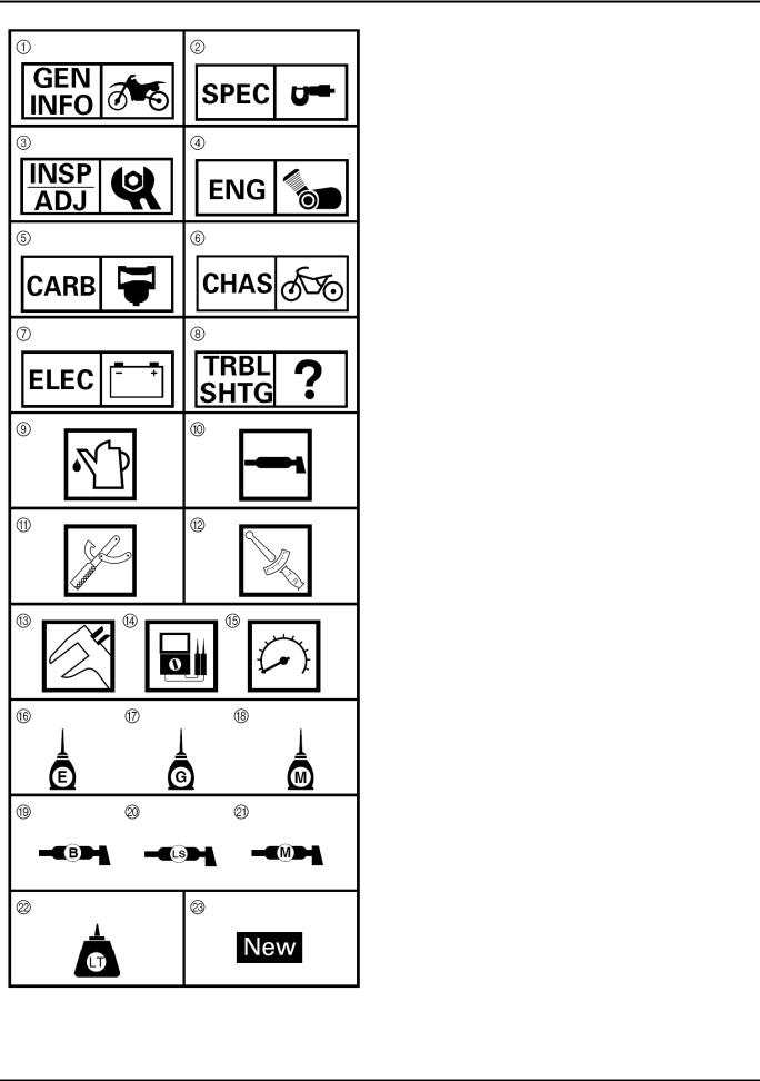
ГРАФИЧЕСКИЕ СИМВОЛЫ
Графические символы с  по
по  размещаются в правом верхнем углу каждой страницы и указывают тему Главы.
 Общая информация
 Спецификации
 Периодический контроль и регулировка
 Двигатель
 Карбюратор
 Ходовая
 Электрика
  Решение проблем
Графические символы с  по
по  служат для определения спецификаций, встречающихся в тексте.
 Заливаемая жидкость
 Смазка
 Специальный инструмент
 Момент затяжки
 Предел износа, зазор, люфт
 Обороты двигателя
 Ω, V, A
Графические символы с  по
по  на сборочных схемах служат для указания типа смазки и точек нанесения смазки.
 Моторное масло
 Трансмиссионное масло
 Дисульфид молибденовое масло
 Консистентная смазка для подшипников колес
 Легкая литиевая смазка
  Дисульфид молибденовая смазка
Графические символы с  по
по  на сборочных схемах указывают где необходимо применять
фиксатор  и где необходимо устанавливать новые части
  .
.
 Фиксатор (LOCTITE®)
 Замена
|
Yamaha TTR250L(C) Service Manual Rev_01 |
5/276 |

ОГЛАВЛЕНИЕ
ОБЩАЯ ИНФОРМАЦИЯ
СПЕЦИФИКАЦИИ
ПЕРИОДИЧЕСКИЙ КОНТРОЛЬ И РЕГУЛИРОВКА
ДВИГАТЕЛЬ
КАРБЮРАТОР
ХОДОВАЯ
БОРТОВАЯ СЕТЬ
РЕШЕНИЕ ПРОБЛЕМ
|
Yamaha TTR250L(C) Service Manual Rev_01 |
6/276 |

ОГЛАВЛЕНИЕ ГЛАВА 1.
ОБЩАЯ ИНФОРМАЦИЯ
|
Yamaha TTR250L(C) Service Manual Rev_01 |
7/276 |

|
Yamaha TTR250L(C) Service Manual Rev_01 |
8/276 |

|
Yamaha TTR250L(C) Service Manual Rev_01 |
9/276 |

|
Yamaha TTR250L(C) Service Manual Rev_01 |
10/276 |
![]()
OWNER’S MANUAL
TTR250R(C)
|
LIT-11626-16-24 |
5GF-28199-14 |
EAU03438

EAU00000
INTRODUCTION
Congratulations on your purchase of the Yamaha TTR250R. This model is the result of Yamaha’s vast experience in the production of fine sporting, touring, and pacesetting racing machines. It represents the high degree of craftsmanship and reliability that have made Yamaha a leader in these fields.
This manual will give you an understanding of the operation, inspection, and basic maintenance of this machine. If you have any questions concerning the operation or maintenance of your machine, please consult a Yamaha dealer.
EAU00003
IMPORTANT MANUAL INFORMATION
Particularly important information is distinguished in this manual by the following notations:
Q
The Safety Alert Symbol means ATTENTION! BECOME ALERT! YOUR SAFETY IS INVOLVED!
wFailure to follow WARNING instructions could result in severe injury or death to the machine operator, a bystander or a person inspecting or repairing the
machine.
|
cC |
A CAUTION indicates special precautions that must be taken to avoid damage |
|
|
to the machine. |
||
|
NOTE: |
A NOTE provides key information to make procedures easier or clearer. |
|
NOTE:
8This manual should be considered a permanent part of this machine and should remain with it even if the machine is subsequently sold.
8Yamaha continually seeks advancements in product design and quality. Therefore, while this manual contains the most current product information available at the time of printing, there may be minor discrepancies between your machine and this manual. If you have any questions concerning this manual, please consult your Yamaha dealer.

IMPORTANT MANUAL INFORMATION
EW000000
w
PLEASE READ THIS MANUAL AND THE “YOU AND YOUR MOTORCYCLE: RIDING TIPS” BOOKLET CAREFULLY AND COMPLETELY BEFORE OPERATING THIS MACHINE. DO NOT ATTEMPT TO OPERATE THIS MACHINE UNTIL YOU HAVE ATTAINED ADEQUATE KNOWLEDGE OF ITS CONTROLS AND OPERATING FEATURES AND UNTIL YOU HAVE BEEN TRAINED IN SAFE AND PROPER RIDING TECHNIQUES. REGULAR INSPECTIONS AND CAREFUL MAINTENANCE, ALONG WITH GOOD RIDING SKILLS, WILL ENSURE THAT YOU SAFELY ENJOY THE CAPABILITIES AND THE RELIABILITY OF THIS MACHINE.
EAU00006
w
THIS MACHINE IS DESIGNED AND MANUFACTURED FOR OFF-ROAD USE ONLY. IT IS ILLEGAL TO OPERATE THIS MACHINE ON ANY PUBLIC STREET, ROAD OR HIGHWAY. SUCH USE IS PROHIBITED BY LAW. THIS MACHINE COMPLIES WITH ALMOST ALL STATE OFF-HIGHWAY NOISE LEVEL AND SPARK ARRESTER LAWS AND REGULATIONS. PLEASE CHECK YOUR LOCAL RIDING LAWS AND REGULATIONS BEFORE OPERATING THIS MACHINE.
AFFIX DEALER
LABEL HERE
EAU04247
TTR250R
OWNER’S MANUAL
©2002 by Yamaha Motor Corporation, U.S.A. 1st edition, April 2002
All rights reserved.
Any reprinting or unauthorized use without the written permission of Yamaha Motor Corporation, U.S.A. is expressly prohibited.
Printed in Japan.
P/N LIT-11626-16-24

EAU00009
TABLE OF CONTENTS
|
1 |
……………………………..SAFETY INFORMATION |
1-1 |
|
|
……………………………………………….Safe riding |
1-1 |
||
|
Protective apparel ……………………………………. |
1-2 |
||
|
Modifications …………………………………………… |
1-3 |
||
|
Loading and accessories ………………………….. |
1-3 |
||
|
Gasoline and exhaust gas …………………………. |
1-5 |
||
|
Location of important labels ………………………. |
1-7 |
||
|
DESCRIPTION |
2-1 |
||
|
2 |
|||
|
Left view …………………………………………………. |
2-1 |
||
|
Right view ……………………………………………….. |
2-2 |
||
|
Controls and instruments ………………………….. |
2-3 |
||
|
INSTRUMENT AND CONTROL |
|||
|
3 |
|||
|
FUNCTIONS ……………………………………………… |
3-1 |
||
|
Main switch …………………………………………….. |
3-1 |
||
|
Tripmeter ………………………………………………… |
3-1 |
||
|
Handlebar switches ………………………………….. |
3-1 |
||
|
Clutch lever …………………………………………….. |
3-2 |
||
|
Shift pedal ………………………………………………. |
3-2 |
||
|
Brake lever ……………………………………………… |
3-3 |
||
|
Brake pedal …………………………………………….. |
3-3 |
||
|
Fuel tank cap …………………………………………… |
3-3 |
||
|
Fuel ……………………………………………………….. |
3-4 |
||
|
Fuel tank breather hose ……………………………. |
3-5 |
|
Fuel cock ………………………………………………… |
3-5 |
||
|
Starter (choke) knob …………………………………. |
3-6 |
||
|
Seat ……………………………………………………….. |
3-7 |
||
|
Adjusting the front fork ……………………………… |
3-7 |
||
|
Adjusting the shock absorber assembly …….. |
3-10 |
||
|
Starting circuit cut-off system …………………… |
3-12 |
||
|
PRE-OPERATION CHECKS |
4-1 |
||
|
4 |
|||
|
Pre-operation check list …………………………….. |
4-1 |
||
|
OPERATION AND IMPORTANT RIDING |
|||
|
5 |
|||
|
POINTS …………………………………………………….. |
5-1 |
||
|
Starting and warming up a cold engine ……….. |
5-1 |
||
|
Starting a warm engine …………………………….. |
5-3 |
||
|
Shifting …………………………………………………… |
5-3 |
||
|
Engine break-in ……………………………………….. |
5-4 |
||
|
Parking …………………………………………………… |
5-5 |
||
|
PERIODIC MAINTENANCE AND MINOR |
|||
|
6 |
|||
|
REPAIR …………………………………………………….. |
6-1 |
||
|
Owner’s tool kit ………………………………………… |
6-1 |
||
|
Periodic maintenance and lubrication chart …. |
6-2 |
||
|
Removing and installing the cowling and |
|||
|
panels …………………………………………………. |
6-5 |
||
|
Checking the spark plug ……………………………. |
6-6 |

TABLE OF CONTENTS
|
Engine oil and oil filter element ………………….. |
6-8 |
|
Cleaning the air filter element ………………….. |
6-12 |
|
Cleaning the spark arrester ……………………… |
6-13 |
|
Adjusting the carburetor ………………………….. |
6-14 |
|
Adjusting the throttle cable free play …………. |
6-14 |
|
Adjusting the valve clearance ………………….. |
6-15 |
|
Tires …………………………………………………….. |
6-15 |
|
Spoke wheels ………………………………………… |
6-17 |
|
Accessories and replacement parts ………….. |
6-18 |
|
Adjusting the clutch lever free play …………… |
6-19 |
|
Adjusting the brake lever free play ……………. |
6-19 |
|
Adjusting the brake pedal position ……………. |
6-20 |
|
Checking the front and rear brake pads …….. |
6-21 |
|
Checking the brake fluid level ………………….. |
6-21 |
|
Changing the brake fluid …………………………. |
6-22 |
|
Drive chain slack ……………………………………. |
6-23 |
|
Lubricating the drive chain ………………………. |
6-24 |
|
Checking and lubricating the cables …………. |
6-25 |
|
Checking and lubricating the throttle grip |
|
|
and cable …………………………………………… |
6-26 |
|
Checking and lubricating the brake and |
|
|
shift pedals …………………………………………. |
6-26 |
|
Checking and lubricating the brake and |
|
|
clutch levers ……………………………………….. |
6-26 |
|
Checking and lubricating the sidestand …….. |
6-27 |
|
Checking the front fork ……………………………. |
6-27 |
||
|
Checking the steering …………………………….. |
6-28 |
||
|
Checking the wheel bearings …………………… |
6-28 |
||
|
Battery ………………………………………………….. |
6-29 |
||
|
Replacing the fuse ………………………………… |
6-30 |
||
|
Replacing the headlight bulb ……………………. |
6-31 |
||
|
Replacing the taillight bulb ………………………. |
6-33 |
||
|
Supporting the machine ………………………….. |
6-33 |
||
|
Front wheel …………………………………………… |
6-34 |
||
|
Rear wheel ……………………………………………. |
6-36 |
||
|
Troubleshooting …………………………………….. |
6-38 |
||
|
Troubleshooting chart …………………………….. |
6-39 |
||
|
MACHINE CARE AND STORAGE |
7-1 |
||
|
7 |
|||
|
Care ………………………………………………………. |
7-1 |
||
|
Storage …………………………………………………… |
7-4 |
||
|
SPECIFICATIONS |
8-1 |
||
|
8 |
|||
|
Specifications ………………………………………….. |
8-1 |
||
|
CONSUMER INFORMATION |
9-1 |
||
|
9 |
|||
|
Identification numbers ………………………………. |
9-1 |
||
|
Key identification number ………………………….. |
9-1 |
||
|
Vehicle identification number …………………….. |
9-1 |
||
|
Model label ……………………………………………… |
9-2 |

TABLE OF CONTENTS
|
Motorcycle noise regulation ………………………. |
9-3 |
|
Maintenance record …………………………………. |
9-5 |
|
Off-road motorcycle limited warranty ………….. |
9-7 |
|
Yamaha extended service (Y.E.S.) …………….. |
9-9 |

|
EAU02912 |
||
QSAFETY INFORMATION |
||
|
MACHINES ARE SINGLE TRACK VEHICLES. THEIR SAFE USE AND OPERATION ARE DEPEN- |
||
|
DENT UPON THE USE OF PROPER RIDING TECHNIQUES AS WELL AS THE EXPERTISE OF |
||
|
THE OPERATOR. EVERY OPERATOR SHOULD KNOW THE FOLLOWING REQUIREMENTS |
||
|
1 |
||
|
BEFORE RIDING THIS MACHINE. |
||
|
HE OR SHE SHOULD: |
1.OBTAIN THOROUGH INSTRUCTIONS FROM A COMPETENT SOURCE ON ALL ASPECTS OF MACHINE OPERATION.
2.OBSERVE THE WARNINGS AND MAINTENANCE REQUIREMENTS IN THE OWNER’S MANUAL.
3.OBTAIN QUALIFIED TRAINING IN SAFE AND PROPER RIDING TECHNIQUES.
4.OBTAIN PROFESSIONAL TECHNICAL SERVICE AS INDICATED BY THE OWNER’S MANUAL AND/OR WHEN MADE NECESSARY BY MECHANICAL CONDITIONS.
Safe riding
1.Always make pre-operation checks. Careful checks may help prevent an accident.
2.This machine is designed for off-road use only, therefore, it is illegal to operate it on public streets, roads, or highways. Off-road use on public lands may be illegal. Please check local regulations before riding.
3.This machine is designed to carry the operator only. No passengers.
4.Many accidents involve inexperienced operators.
a.Make sure that you are qualified and that you only lend your machine to other qualified operators.
b.Know your skills and limits. Staying within your limits may help you to avoid an accident.
5.Many accidents have been caused by error of the machine operator. A typical error made by the operator is veering wide on a turn due to EXCESSIVE SPEED or undercornering (insufficient lean angle for the speed). Never travel faster than warranted by conditions.
1-1
![]()
QSAFETY INFORMATION
6.Ride cautiously in unfamiliar areas. You may encounter hidden obstacles that could cause an accident.
7.The posture of the operator is important for proper control. The operator should keep both hands
|
on the handlebar and both feet on the operator footrests during operation to maintain control of |
1 |
|
the machine. |
|
|
8. Never ride under the influence of alcohol or other drugs. |
Protective apparel
The majority of fatalities from machine accidents are the result of head injuries. The use of a safety helmet is the single most critical factor in the prevention or reduction of head injuries.
1.Always wear an approved helmet.
2.Wear a face shield or goggles. Wind in your unprotected eyes could contribute to an impairment of vision that could delay seeing a hazard.
3.The use of a jacket, heavy boots, trousers, gloves, etc., is effective in preventing or reducing abrasions or lacerations.
4.Never wear loose-fitting clothes, otherwise they could catch on the control levers, footrests, or wheels and cause injury or an accident.
5.Never touch the engine or exhaust system during or after operation. They become very hot and can cause burns. Always wear protective clothing that covers your legs, ankles, and feet.
1-2

QSAFETY INFORMATION
Modifications
Modifications made to this machine not approved by Yamaha, or the removal of original equipment, 1 may render the machine unsafe for use and may cause severe personal injury. Modifications may
also make your machine illegal to use.
Loading and accessories
Adding accessories or cargo to your machine can adversely affect stability and handling if the weight distribution of the machine is changed. To avoid the possibility of an accident, use extreme caution when adding cargo or accessories to your machine. Use extra care when riding a machine that has added cargo or accessories. Here are some general guidelines to follow if loading cargo or adding accessories to your machine:
Loading
The total weight of the operator, accessories and cargo must not exceed the maximum load limit of 90 kg (198 lb). When loading within this weight limit, keep the following in mind:
1.Cargo and accessory weight should be kept as low and close to the machine as possible. Make sure to distribute the weight as evenly as possible on both sides of the machine to minimize imbalance or instability.
2.Shifting weights can create a sudden imbalance. Make sure that accessories and cargo are securely attached to the machine before riding. Check accessory mounts and cargo restraints frequently.
3.Never attach any large or heavy items to the handlebar, front fork, or front fender. These items, including such cargo as sleeping bags, duffel bags, or tents, can create unstable handling or a slow steering response.
1-3

QSAFETY INFORMATION
Accessories
Genuine Yamaha accessories have been specifically designed for use on this machine. Since Yamaha cannot test all other accessories that may be available, you must personally be responsible 1 for the proper selection, installation and use of non-Yamaha accessories. Use extreme caution when selecting and installing any accessories.
Keep these guidelines in mind for mounting accessories in addition to those provided under “Loading”.
1.Never install accessories or carry cargo that would impair the performance of your machine. Carefully inspect the accessory before using it to make sure that it does not in any way reduce ground clearance or cornering clearance, limit suspension travel, steering travel or control operation, or obscure lights or reflectors.
a.Accessories fitted to the handlebar or the front fork area can create instability due to improper weight distribution or aerodynamic changes. If accessories are added to the handlebar or front fork area, they must be as lightweight as possible and should be kept to a minimum.
b.Bulky or large accessories may seriously affect the stability of the machine due to aerodynamic effects. Wind may attempt to lift the machine, or the machine may become unstable in cross winds.
c.Certain accessories can displace the operator from his or her normal riding position. This improper position limits the freedom of movement of the operator and may limit control ability, therefore, such accessories are not recommended.
2.Use caution when adding electrical accessories. If electrical accessories exceed the capacity of the machine’s electrical system an electric failure could result, which could cause a dangerous loss of lights or engine power.
1-4

QSAFETY INFORMATION
|
Gasoline and exhaust gas |
|
|
1. GASOLINE IS HIGHLY FLAMMABLE: |
|
|
1 |
a. Always turn the engine off when refueling. |
b.Take care not to spill any gasoline on the engine or exhaust pipe(s)/muffler(s) when refueling.
c.Never refuel while smoking or in the vicinity of an open flame.
2.Never start the engine or let it run for any length of time in a closed area. The exhaust fumes are poisonous and may cause loss of consciousness and death within a short time. Always operate your machine in an area that has adequate ventilation.
3.Always turn the engine off before leaving the machine unattended and remove the key from the main switch. When parking the machine, note the following:
a.The engine and exhaust pipe(s)/muffler(s) may be hot, therefore, park the machine in a place where pedestrians or children are not likely to touch these hot areas.
b.Do not park the machine on a slope or soft ground, otherwise it may fall over.
c.Do not park the machine near a flammable source (e.g., a kerosene heater, or near an open flame), otherwise it could catch fire.
4.When transporting the machine in another vehicle, make sure that it is kept upright and that the fuel cock(s) are turned to “ON” or “RES” (for vacuum type)/”OFF” (for manual type). If the machine should lean over, gasoline may leak out of the carburetor or fuel tank.
5.If you should swallow any gasoline, inhale a lot of gasoline vapor, or allow gasoline to get into your eyes, see your doctor immediately. If any gasoline spills on your skin or clothing, immediately wash the affected area with soap and water and change your clothes.
1-5

1-6
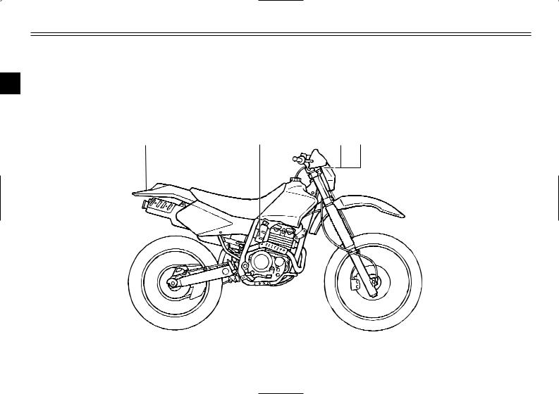
QSAFETY INFORMATION
EAU02977
Location of important labels
Please read the following important labels carefully before operating this machine.
1
1-7
QSAFETY INFORMATION
1
qWARNING
Riding as a passenger can cause the vehicle to go out of control.
Loss of control can cause a collision or rollover, which can result in severe injury or death.
NEVER ride as a passenger.
3XJ-2151H-A0
3
q WARNING
|
8BEFORE YOU OPERATE THIS |
VEHICLE, READ |
1 |
|
THE OWNER’S MANUAL AND |
ALL LABELS. |
8NEVER CARRY A PASSENGER. You increase your risk of losing control if you carry a passenger.
8NEVER OPERATE THIS VEHICLE ON PUBLIC
ROADS. You can collide with another vehicle if you operate this vehicle on a public road.
8ALWAYS WEAR AN APPROVED MOTORCYCLE HELMET,eye protection, and protective clothing.
8EXPERIENCED RIDER ONLY.
5PA-2118K-00
2
qWARNING
This unit contains high pressure nitrogen gas. Mishandling can cause explosion.
8Read owner’s manual for instructions.
8Do not incinerate, puncture or open.
4
TIRE INFORMATION
Cold tire normal pressure should be set as follows.
FRONT : 100 kPa,{1.00 kgf/cm2}, 15 psi REAR : 100 kPa,{1.00 kgf/cm2}, 15 psi
3RV-21668-A0
1-8
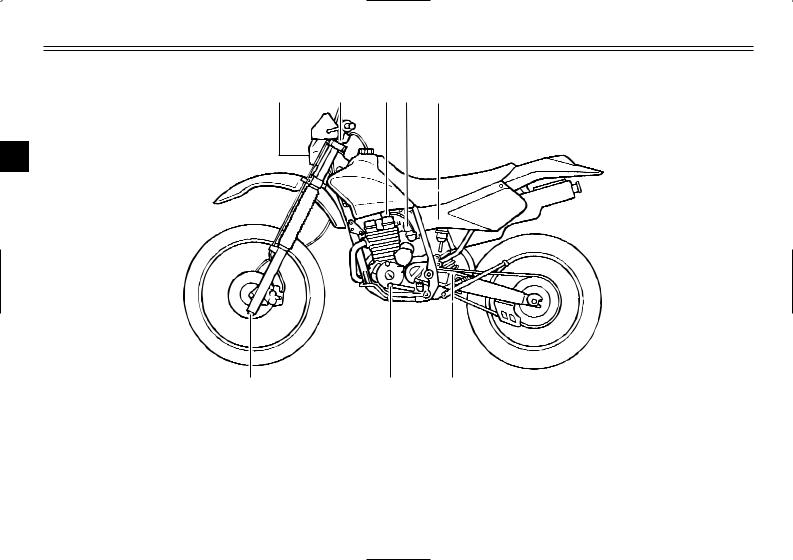
EAU00026
DESCRIPTION
Left view
|
1 |
2 |
3 |
4 |
5 |
2
|
8 |
7 |
6 |
|||
|
1. |
Headlight |
(page 6-31) |
6. |
Shock absorber rebound |
|
|
2. |
Front fork air valve |
(page 3-7) |
damping adjusting dial |
(page 3-11) |
|
|
3. |
Fuel cock |
(page 3-5) |
7. |
Shift pedal |
(page 3-2) |
|
4. |
Starter (choke) knob |
(page 3-6) |
8. |
Front fork damping adjusting |
|
|
5. |
Air filter element |
(page 6-12) |
screw |
(page 3-9) |
2-1

DESCRIPTION
Right view
|
9 |
10 |
11 |
12 |
13 |
2
|
16 |
15 |
14 |
|||
|
9. |
Spark arrester |
(page 6-13) |
14. |
Engine oil filter element |
(page 6-9) |
|
10. |
Battery |
(page 6-29) |
15. |
Brake pedal |
(page 3-3, 6-20) |
|
11. |
Fuse |
(page 6-30) |
16. |
Shock absorber spring preload |
|
|
12. |
Shock absorber compression |
adjusting nut |
(page 3-10) |
||
|
damping adjusting knob |
(page 3-11) |
||||
|
13. |
Main switch |
(page 3-1) |
2-2
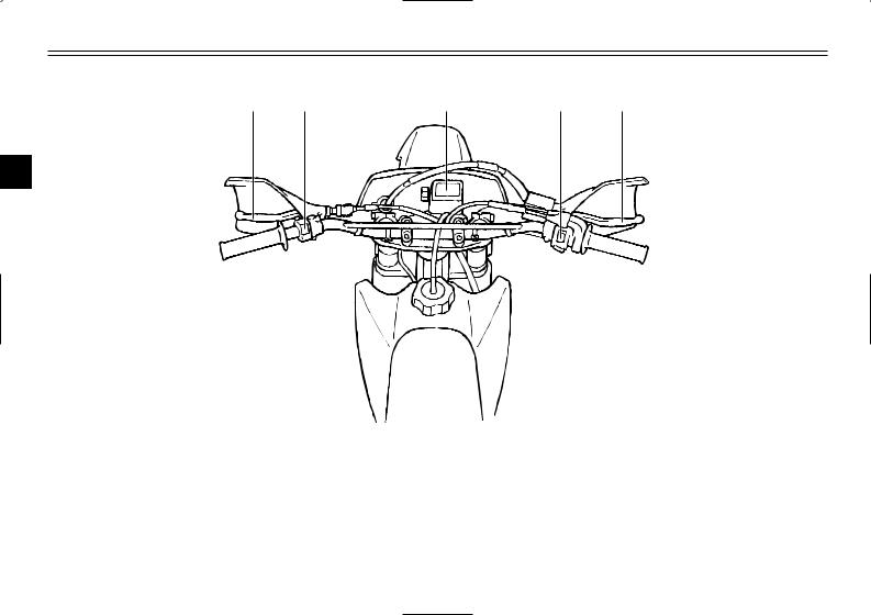
DESCRIPTION
Controls and instruments
1 2 3 4 5
2
|
7 |
6 |
||||||
|
1. |
Clutch lever |
(page 3-2, 6-19) |
6. |
Throttle grip |
(page 6-14) |
||
|
2. |
Left handlebar switch |
(page 3-1) |
7. |
Fuel tank cap |
(page 3-3) |
||
|
3. |
Tripmeter |
(page 3-1) |
|||||
|
4. |
Right handlebar switches |
(page 3-2) |
|||||
|
5. |
Brake lever |
(page 3-3, 6-19) |
2-3
![]()
|
EAU00027 |
INSTRUMENT AND CONTROL FUNCTIONS |
|||
|
ON |
OFF |
1 |
||
|
1 |
||||
|
2 |
3 |
|||
|
1. |
Tripmeter |
1. |
Light switch “:” |
|
|
2. |
Reset knob |
|||
|
EAU00028 |
EAU00118 |
Main switch
The main switch controls the ignition and lighting systems. The various main switch positions are described below.
EAU00036
ON
All electrical systems are supplied with power, and the engine can be started. The key cannot be removed.
EAU00038
OFF
All electrical systems are off. The key can be removed.
EAU01760
Tripmeter
The tripmeter shows the distance traveled since it was last set to zero with the reset knob. The tripmeter can be used to estimate the distance that can be traveled with a full tank of fuel. This information will enable you to plan future fuel stops.
Handlebar switches
EAU04305
Light switch “:”
Set this switch to “:” to turn on the headlight and the taillight.
ECA00037
cC
Always turn the key to “OFF” and light switch to “OFF” when the engine is not running, otherwise the headlight will stay on and the battery may discharge due to extended use.
3-1
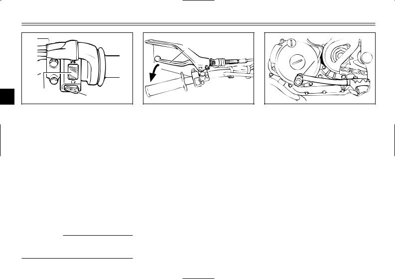
INSTRUMENT AND CONTROL FUNCTIONS
1.Engine stop switch “#/$”
2.Start switch “START”
EAU03890
Engine stop switch “#/$”
Set this switch to “#” before starting the engine. Set this switch to “$” to stop the engine in case of an emergency, such as when the machine overturns or when the throttle cable is stuck.
EAU00141
Start switch “START”
Push this switch to crank the engine with the starter.
EC000005
cC
See page 5-1 for starting instructions prior to starting the engine.
1. Clutch lever
EAU00152
Clutch lever
The clutch lever is located at the left handlebar grip. To disengage the clutch, pull the lever toward the handlebar grip. To engage the clutch, release the lever. The lever should be pulled rapidly and released slowly for smooth clutch operation.
The clutch lever is equipped with a clutch switch, which is part of the ignition circuit cut-off system. (See page 3-12 for an explanation of the ignition circuit cut-off system.)
1 
1. Shift pedal
EAU00157
Shift pedal
The shift pedal is located on the left side of the engine and is used in combination with the clutch lever when shifting the gears of the 6-speed constant-mesh transmission equipped on this machine.
3-2
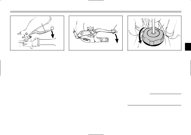
INSTRUMENT AND CONTROL FUNCTIONS
1. Brake lever
EAU00158
Brake lever
The brake lever is located at the right handlebar grip. To apply the front brake, pull the lever toward the handlebar grip.
1. Brake pedal
EAU00162
Brake pedal
The brake pedal is on the right side of the machine. To apply the rear brake, press down on the brake pedal.
1
a 3
3
1. Fuel tank cap a. Remove.
EAU00179
Fuel tank cap
To remove the fuel tank cap, turn it counterclockwise, and then pull it off. To install the fuel tank cap, insert it into the tank opening, and then turn it clockwise.
EWA00025
w
Make sure that the fuel tank cap is properly closed before riding.
3-3
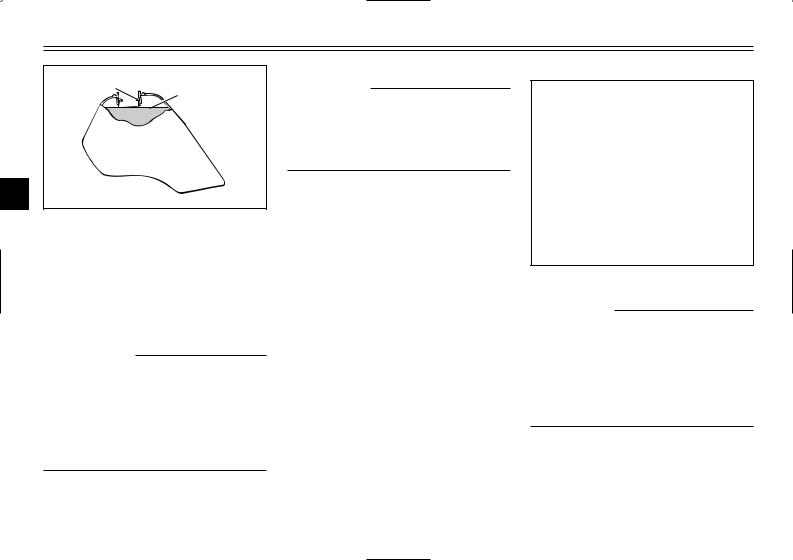
INSTRUMENT AND CONTROL FUNCTIONS
1 2
3
1.Filler tube
2.Fuel level
EAU03753
Fuel
Make sure that there is sufficient fuel in the tank. Fill the fuel tank to the bottom of the filler tube as shown.
EW000130
w
8Do not overfill the fuel tank, otherwise it may overflow when the fuel warms up and expands.
8Avoid spilling fuel on the hot engine.
EAU00185
cC
Immediately wipe off spilled fuel with a clean, dry, soft cloth, since fuel may deteriorate painted surfaces or plastic parts.
EAU04265
Recommended fuel: UNLEADED GASOLINE ONLY
Fuel tank capacity: Total amount:
10.0 L
(2.2 lmp gal, 2.64 US gal) Reserve amount:
2.0 L
(0.44 lmp gal, 0.53 US gal)
ECA00104
cC
Use only unleaded gasoline. The use of leaded gasoline will cause severe damage to internal engine parts, such as the valves and piston rings, as well as to the exhaust system.
3-4
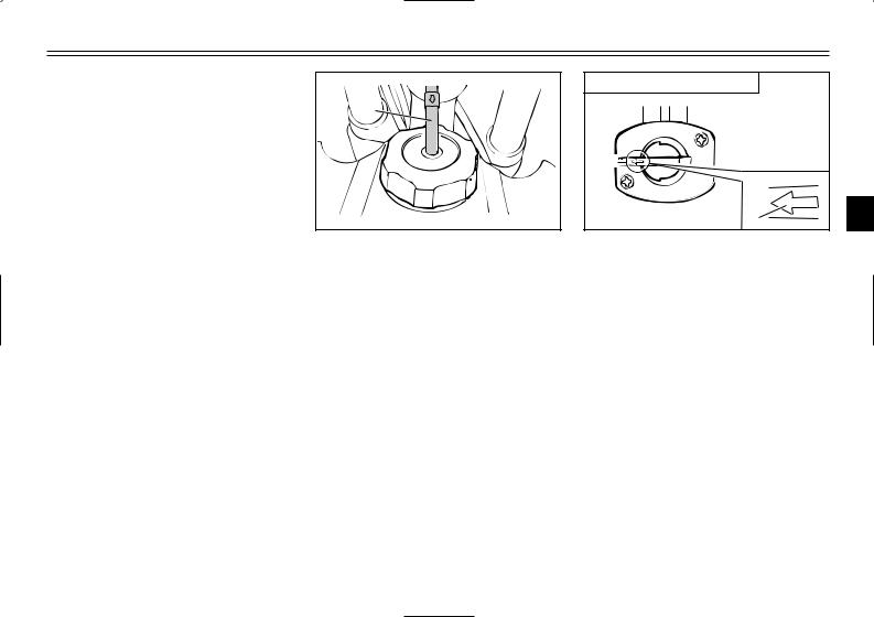
INSTRUMENT AND CONTROL FUNCTIONS
Your Yamaha engine has been designed to use regular unleaded gasoline with a pump octane number [(R+M)/2] of 86 or higher, or a research octane number of 91 or higher. If knocking (or pinging) occurs, use a gasoline of a different brand or premium unleaded fuel. Use of unleaded fuel will extend spark plug life and reduce maintenance costs.
Gasohol
There are two types of gasohol: gasohol containing ethanol and that containing methanol. Gasohol containing ethanol can be used if the ethanol content does not exceed 10%. Gasohol containing methanol is not recommended by Yamaha because it can cause damage to the fuel system or vehicle performance problems.
1
1. Fuel tank breather hose
EAU02955
Fuel tank breather hose
Before operating the machine:
8Check the fuel tank breather hose connection.
8Check the fuel tank breather hose for cracks or damage, and replace it if damaged.
8Make sure that the end of the fuel tank breather hose is not blocked, and clean it if necessary.
|
OFF: closed position |
|
|
RES |
|
|
OFF |
|
|
ON |
|
|
1 |
3 |
1. Arrow mark positioned over “OFF”
EAU03050
Fuel cock
The fuel cock supplies fuel from the tank to the carburetor while filtering it also.
The fuel cock has three positions:
OFF
With the lever in this position, fuel will not flow. Always return the lever to this position when the engine is not running.
3-5
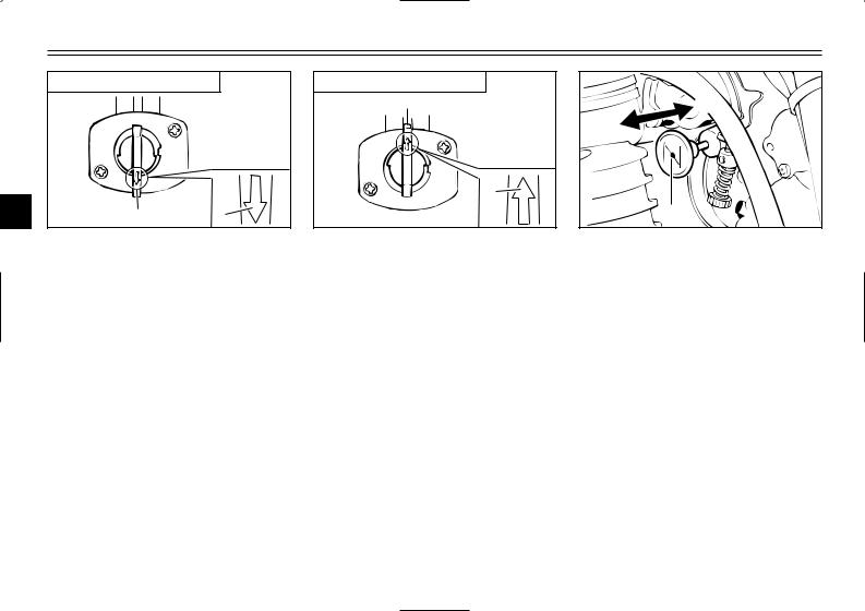
INSTRUMENT AND CONTROL FUNCTIONS
|
ON: normal position |
||
|
RES |
||
|
OFF |
||
|
3 |
ON |
1 |
1. Arrow mark positioned over “ON”
ON
With the lever in this position, fuel flows to the carburetor. Normal riding is done with the lever in this position.
|
RES: reserve position |
|
|
RES |
|
|
OFF |
|
|
FUEL |
1 |
|
ON |
1. Arrow mark positioned over “RES”
RES
This indicates reserve. If you run out of fuel while riding, move the lever to this position. Fill the tank at the first opportunity. Be sure to set the lever back to “ON” after refueling!
 b a
b a 


1

1.Starter (choke) knob “1”
EAU04038
Starter (choke) knob “1”
Starting a cold engine requires a richer air-fuel mixture, which is supplied by the starter (choke).
Move the knob in direction a to turn on the starter (choke).
Move the knob in direction b to turn off the starter (choke).
3-6
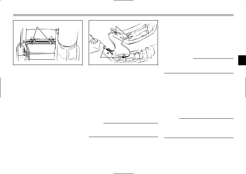
INSTRUMENT AND CONTROL FUNCTIONS
|
1 |
|
|
2 |
|
|
1. |
Projection (×2) |
|
2. |
Seat holder (×2) |
EAU00240
EAU04834
Adjusting the front fork
The front fork is equipped with air valves for adjusting the spring rate and screws for adjusting the damping force.
EW000036
w
3
There should be no difference in air pressure between the fork legs.
Seat
To remove the seat
Remove the bolts, and then pull the seat off.
To install the seat
1.Insert the projections on the front of the seat into the seat holders as shown.
2.Place the seat in the original position, and then tighten the bolts.
NOTE:
Make sure that the seat is properly secured before riding.
Spring rate
The total spring rate is adjusted by changing the air pressure as follows.
1.Lift the front wheel off the ground according to the procedure on page 6-33.
NOTE:
When checking and adjusting the air pressure, there should be no weight on the front end of the machine.
3-7
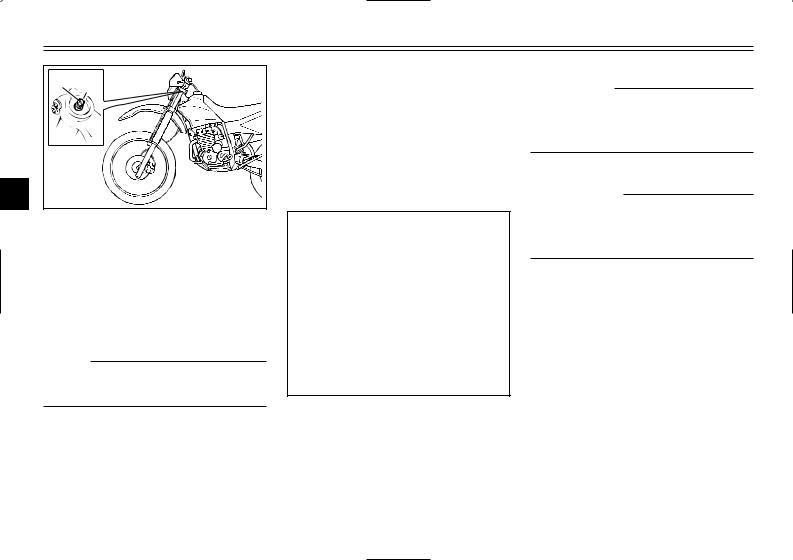
INSTRUMENT AND CONTROL FUNCTIONS
2 1
3
1.Air valve cap
2.Air valve
2.Remove the air valve cap from each fork leg.
3.Check the air pressure in each fork leg with an air pressure gauge.
NOTE:
An optional air pressure gauge is available at a Yamaha dealer.
4.To increase the spring rate and thereby harden the suspension, increase the air pressure with an air pump. To decrease the spring rate and thereby soften the suspension, decrease the air pressure by pushing each valve stem down.
Spring rate: Minimum (soft):
Air pressure = 0 kPa (0 kgf/cm2, 0 psi)
Standard:
Air pressure = 0 kPa (0 kgf/cm2, 0 psi)
Maximum (hard):
Air pressure = 40 kPa (0.4 kgf/cm2, 5.8 psi)
EC000012
cC
Never exceed the maximum air pressure, otherwise the front fork oil seals may become damaged.
EW000035
w
Always adjust both fork legs equally, otherwise poor handling and loss of stability may result.
5.Securely install the air valve caps.
3-8
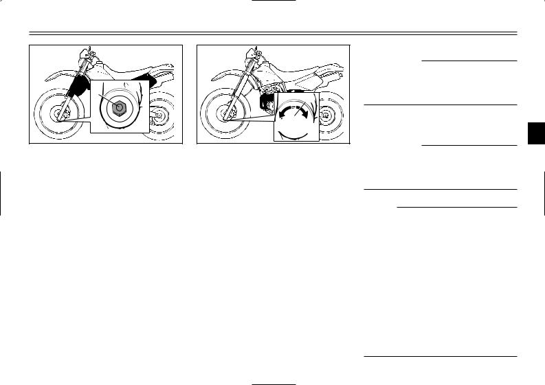
INSTRUMENT AND CONTROL FUNCTIONS
|
Damping force |
2. To increase |
the damping force |
|
|
1. Remove the rubber cap from |
and thereby harden the damping, |
||
|
each fork leg. |
turn the adjusting screw on each |
||
|
fork leg in direction a. To |
|||
|
decrease the damping force and |
|||
|
thereby soften the damping, turn |
|||
|
the adjusting screw on each fork |
|||
|
leg in direction b. |
|||
|
Minimum (soft) |
20 clicks in direction b* |
||
|
Standard |
11 clicks in direction b* |
||
|
Maximum (hard) |
1 click in direction b* |
||
|
* With the adjusting screw fully turned in direction a |
EC000015
cC
Never attempt to turn an adjusting mechanism beyond the maximum or minimum settings.
3. Securely install the rubber caps.
ECA00034 3
cC
Be sure to install the rubber caps to prevent dust, etc. from entering the fork legs.
NOTE:
Although the total number of clicks of a damping force adjusting mechanism may not exactly match the above specifications due to small differences in production, the actual number of clicks always represents the entire adjusting range. To obtain a precise adjustment, it would be advisable to check the number of clicks of each damping force adjusting mechanism and to modify the specifications as necessary.
3-9
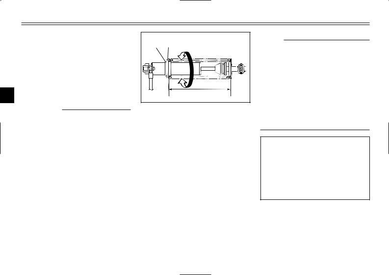
INSTRUMENT AND CONTROL FUNCTIONS
|
EAU03676 |
||||
|
Adjusting the shock |
1 |
2 b |
||
|
absorber assembly |
||||
|
This shock absorber assembly is |
||||
|
equipped with a spring preload |
||||
|
adjusting nut, a rebound damping |
||||
|
force adjusting dial and a compres- |
a |
|||
|
3 |
sion damping force adjusting knob. |
A |
||
|
EC000015 |
||||
|
cC |
1. |
Locknut |
||
|
Never attempt to turn an adjusting |
2. |
Adjusting nut |
||
|
mechanism beyond the maximum |
Spring preload |
|
or minimum settings. |
1. |
Loosen the locknut. |
|
2. |
To increase the spring preload |
|
|
and thereby harden the suspen- |
sion, turn the adjusting nut in direction a. To decrease the spring preload and thereby soften the suspension, turn the adjusting nut in direction b.
NOTE:
8A special wrench is needed to make this adjustment and it can be obtained at a Yamaha dealer.
8The spring preload setting is determined by measuring distance A, shown in the illustration. The shorter the distance A is, the higher the spring preload; the longer distance A is, the lower the spring preload.
Spring preload: Minimum (soft):
Distance A = 236 mm (9.3 in) Standard:
Distance A = 228 mm (9.0 in) Maximum (hard):
Distance A = 224 mm (8.8 in)
3.Tighten the locknut to the specified torque.
3-10
 Loading…