
YAMAHA ELECTRONICS CORPORATION, USA
6660 ORANGETHORPE AVE., BUENA PARK, CALIF. 90620, U.S.A.
YAMAHA CANADA MUSIC LTD.
135 MILNER AVE., SCARBOROUGH, ONTARIO M1S 3R1, CANADA
YAMAHA ELECTRONIK EUROPA G.m.b.H.
SIEMENSSTR. 22-34, 25462 RELLINGEN BEI HAMBURG, GERMANY
YAMAHA ELECTRONIQUE FRANCE S.A.
RUE AMBROISE CROIZAT BP70 CROISSY-BEAUBOURG 77312 MARNE-LA-VALLEE CEDEX02, FRANCE
YAMAHA ELECTRONICS (UK) LTD.
YAMAHA HOUSE, 200 RICKMANSWORTH ROAD WATFORD, HERTS WD18 7GQ, ENGLAND
YAMAHA SCANDINAVIA A.B.
J A WETTERGRENS GATA 1, BOX 30053, 400 43 VÄSTRA FRÖLUNDA, SWEDEN
YAMAHA MUSIC AUSTRALIA PTY, LTD.
17-33 MARKET ST., SOUTH MELBOURNE, 3205 VIC., AUSTRALIA
2006 All rights reserved.
RX-V459
Printed in Malaysia WG73610
AV Receiver
Ampli-tuner audio-vidéo
OWNER’S MANUAL
MODE D’EMPLOI
BEDIENUNGSANLEITUNG
BRUKSANVISNING
GEBRUIKSAANWIJZING
ИНСТРУКЦИЯ ПО ЭКСПЛУАТАЦИИ
G
RX-V459_G_cv.fm Page 1 Tuesday, January 24, 2006 2:53 PM
-
Contents
-
Table of Contents
-
Troubleshooting
-
Bookmarks
Quick Links
U
RX-V459
AV Receiver
OWNER’S MANUAL
Related Manuals for Yamaha RX-V459
Summary of Contents for Yamaha RX-V459
-
Page 1
RX-V459 AV Receiver OWNER’S MANUAL… -
Page 2: Important Safety Instructions
IMPORTANT SAFETY INSTRUCTIONS IMPORTANT SAFETY INSTRUCTIONS CAUTION RISK OF ELECTRIC SHOCK DO NOT OPEN CAUTION: TO REDUCE THE RISK OF ELECTRIC SHOCK, DO NOT REMOVE COVER (OR BACK). NO USER-SERVICEABLE PARTS INSIDE. REFER SERVICING TO QUALIFIED SERVICE PERSONNEL. • Explanation of Graphical Symbols The lightning flash with arrowhead symbol, within an equilateral triangle, is intended to alert you to the presence of uninsulated “dangerous voltage”…
-
Page 3
This product, when installed as indicated in the instructions contained in this manual, meets FCC requirements. Modifications not expressly approved by Yamaha may void your authority, granted by the FCC, to use the product. 2 IMPORTANT: When connecting this product to accessories and/or another product use only high quality shielded cables. -
Page 4
– and, most importantly, without affecting your sensitive hearing. Since hearing damage from loud sounds is often undetectable until it is too late, YAMAHA and the Electronic Industries Association’s Consumer Electronics Group recommend you to avoid prolonged exposure from excessive volume levels. -
Page 5: Table Of Contents
INTRODUCTION FEATURES… 2 GETTING STARTED… 3 Supplied accessories … 3 Installing batteries in the remote control … 3 CONTROLS AND FUNCTIONS … 4 Front panel … 4 Remote control… 6 Front panel display … 9 Rear panel … 11 PREPARATION CONNECTIONS …
-
Page 6: Features
Center: 90 W Surround: 90 W + 90 W Surround back: 90 W Sound field features Proprietary YAMAHA technology for the creation of sound fields Dolby Digital/Dolby Digital EX decoder DTS/DTS-ES Matrix 6.1, Discrete 6.1, DTS Neo:6, DTS 96/24 decoder…
-
Page 7: Getting Started
Supplied accessories Check that you received all of the following parts. Remote control Batteries (2) (AA, R6, UM-3) CODE SET TRANSMIT POWER POWER STANDBY POWER SLEEP CD-R MULTI CH IN TUNER V-AUX SOURCE TV VOL TV CH VOLUME TV MUTE TV INPUT MUTE STEREO…
-
Page 8: Controls And Functions
CONTROLS AND FUNCTIONS CONTROLS AND FUNCTIONS Front panel Note The XM Satellite Radio controlling functions in the following buttons (SEARCH MODE, CATEGORY, PRESET/TUNING/CH l / h, MEMORY, and DISPLAY) are only applicable to the U.S.A. model and are operational only when “XM” is selected as the input source. For details, see “XM Satellite Radio controls and functions”…
-
Page 9
8 Front panel display Shows information about the operational status of this unit (see page 9). 9 TUNING MODE (AUTO/MAN’L) Switches between automatic tuning (the AUTO indicator is turned on) and manual tuning (the AUTO indicator is turned off) (see page 44). 0 VOLUME Controls the output level of all audio channels. -
Page 10: Remote Control
CONTROLS AND FUNCTIONS Remote control This section describes the function of each control on the remote control used to control this unit. To operate other components, see “REMOTE CONTROL FEATURES” on page 86. Notes • The XM Satellite Radio controlling functions in the following buttons (XM, XM MEMORY, SRCH MODE, DISPLAY, cursor buttons u / d / j / i, numeric buttons and ENT.) are only applicable to the U.S.A.
-
Page 11
8 Cursor buttons u / d / j / i, ENTER Select and adjust the sound field program parameters or the “SET MENU” parameters. 9 RETURN Returns to the previous menu level when adjusting the “SET MENU” parameters. 0 TRANSMIT indicator Flashes while the remote control is sending infrared signals. -
Page 12: Using The Remote Control
CONTROLS AND FUNCTIONS Controlling the TUNER functions Set the component selector switch to SOURCE and then press TUNER to select “TUNER” as the input source. 4 Numeric buttons Use numbers 1 through 8 to select preset stations. 7 BAND Switches the reception band between FM and AM (see page 44).
-
Page 13: Front Panel Display
Front panel display Note The XM is only applicable to the U.S.A. model and the cursor on the left of the XM indicator lights up only when “XM” is selected as the input source. For details, see “Basic XM Satellite Radio operations” on page 54. MATRIX DISCRETE VIRTUAL STANDARD…
-
Page 14
CONTROLS AND FUNCTIONS F Headphones indicator Lights up when headphones are connected (see page 32). G NIGHT indicator Lights up when you select a night listening mode (see page 32). H HiFi DSP indicator Lights up when you select a HiFi DSP sound field program (see page 63). -
Page 15: Rear Panel
Rear panel AUDIO AUDIO MULTI CH INPUT FRONT SURROUND (PLAY) CD-R (REC) DTV/CBL MONITOR DTV/CBL VIDEO S VIDEO TUNER FM ANT FRONT UNBAL. 1 Video component jacks See pages 18 and 19 for connection information. 2 Audio component jacks See page 21 for connection information. 3 MULTI CH INPUT jacks See page 22 for connection information.
-
Page 16: Connections
Subwoofer (SW) The use of a subwoofer with a built-in amplifier, such as the YAMAHA Active Servo Processing Subwoofer System, is effective not only for reinforcing bass frequencies from any or all channels, but also for hi-fi stereo reproduction of the LFE (low-frequency effect) channel included in Dolby Digital and DTS sources.
-
Page 17: Connecting Speakers
Connecting speakers Be sure to connect the left channel (L), right channel (R), “+” (red) and “–” (black) properly. If the connections are faulty, no sound will be heard from the speakers, and if the polarity of the speaker connections is incorrect, the sound will be unnatural and lack bass.
-
Page 18
Connect surround speakers (4, 5) to these terminals. SURROUND BACK terminals Connect a surround back speaker (6) to these terminals. SUBWOOFER jack Connect a subwoofer with a built-in amplifier (7) (such as the YAMAHA Active Servo Processing Subwoofer System) to this jack. Speaker layout… -
Page 19
Connecting the speaker cable Remove approximately 10 mm (0.4 in) of insulation from the end of each speaker cable and then twist the exposed wires of the cable together to prevent short circuits. 10 mm (0.4 in) Loosen the knob. Red: positive (+) Black: negative (–) Insert one bare wire into the hole on the side… -
Page 20: Information On Jacks And Cable Plugs
CONNECTIONS Information on jacks and cable plugs Audio jacks and cables PORTABLE DIGITAL AUDIO AUDIO (White) (Red) (Orange) Left and right Stereo Coaxial analog audio analog digital cable plug audio audio cable mini cable plug Audio jacks This unit has four types of audio jacks. Connection depends on the availability of audio jacks on your other components.
-
Page 21: Audio And Video Signal Flow
Audio and video signal flow Audio signal flow for AUDIO OUT (REC) AUDIO PORTABLE Analog output Note This unit handles digital and analog signals independently. Thus, audio signals input at the analog jacks are output only at the analog AUDIO OUT (REC) jacks. Video signal flow for MONITOR OUT Input COMPONENT…
-
Page 22: Connecting A Tv
CONNECTIONS Connecting a TV Connect your TV to the VIDEO MONITOR OUT jack, the S VIDEO MONITOR OUT jack or the COMPONENT VIDEO MONITOR OUT jacks of this unit. CAUTION Do not connect this unit or other components to the AC power supply until all connections between components are complete.
-
Page 23: Connecting A Dvd Player, A Dvd Recorder, A Vcr Or An Stb
Connect your DVD player, DVD player, VCR or STB (set-top box) using the same type of video connections as those made for your TV (see page 18). The cable TV receiver and the satellite receiver are examples of the STB.
-
Page 24
Connecting a DVD recorder or a VCR AUDIO VIDEO S VIDEO Audio in Video in Video out Audio out Connecting an STB Cable TV receiver or Audio out Video out S-video out AUDIO DTV/CBL DTV/CBL VIDEO S VIDEO S-video out… -
Page 25: Connecting A Cd Player, An Md Player Or A Tape Deck
CONNECTIONS Connecting a CD player, an MD player or a tape deck Connect your CD player, MD player or tape deck via analog connection. CAUTION Do not connect this unit or other components to the AC power supply until all connections between components are complete.
-
Page 26: Connecting A Multi-Format Player Or An External Decoder
CONNECTIONS Connecting a multi-format player or an external decoder This unit is equipped with 6 additional input jacks (FRONT L/R, CENTER, SURROUND L/R and SUBWOOFER) for discrete multi-channel input from a multi-format player, external decoder, sound processor or pre-amplifier. Connect the output jacks on your multi- format player or external decoder to the MULTI CH INPUT jacks.
-
Page 27: Connecting The Fm And Am Antennas
• A properly installed outdoor antenna provides clearer reception than an indoor one. If you experience poor reception quality, install an outdoor antenna. Consult the nearest authorized YAMAHA dealer or service center about outdoor antennas. AM loop antenna (supplied) Indoor FM antenna (supplied) (U.S.A.
-
Page 28: Connecting The Power Cable
CONNECTIONS Connecting the power cable Once all connections are complete, plug the power cable into the AC wall outlet. CAUTION VOLTAGE SELECTOR (Asia and General models only) The VOLTAGE SELECTOR on the rear panel of this unit must be set for your local voltage BEFORE plugging the power cable into the AC wall outlet.
-
Page 29: Setting The Speaker Impedance
Setting the speaker impedance CAUTION If you are to use 4 or 6 ohm speakers, set “SP IMP.” to “6 MIN” as follows BEFORE using this unit. STANDBY l PRESET/TUNING/CH h PRESET/TUNING FM/AM A/B/C/D/E MEMORY CATEGORY SEARCH MODE EDIT NEXT LEVEL MAN’L/AUTO FM INPUT…
-
Page 30: Turning On This Unit Or Setting It To The Standby Mode
CONNECTIONS Turning on this unit or setting it to the standby mode When all connections are complete, turn on this unit. STANDBY/ON STANDBY PRESET/TUNING FM/AM A/B/C/D/E l PRESET/TUNING/CH h MEMORY CATEGORY SEARCH MODE EDIT NEXT LEVEL MAN’L/AUTO FM INPUT STRAIGHT PROGRAM PHONES SPEAKERS…
-
Page 31: Basic Setup
The “BASIC SETUP” feature is a useful way to set up your system quickly and with minimal effort. Notes • Make sure you disconnect your headphones from this unit. • If you wish to configure this unit manually using more precise adjustments, use the detailed parameters in “SOUND MENU” (see page 78).
-
Page 32
BASIC SETUP Press d to select “SUBWOOFER” and then j / i to select the desired setting. PRESET/CH ENTER A-E/CAT. A-E/CAT. A-E/CAT. SUBWOOFER .. YES Choices: YES, NONE • Select “YES” if you have a subwoofer in your system. • Select “NONE” if you do not have a subwoofer in your system. -
Page 33
Press j / i to select the desired setting. PRESET/CH ENTER A-E/CAT. A-E/CAT. CHECK OK? .. YES Choices: YES, NO • Select “YES” to complete the setup procedure if the test tone levels from each speaker were satisfactory. • Select “NO” to proceed to the speaker level adjustment menu to balance the output level of each speaker. -
Page 34: Playback
PLAYBACK CAUTION Extreme caution should be exercised when you play back CDs encoded in DTS. If you play back a CD encoded in DTS on a DTS-incompatible CD player, you will only hear some unwanted noise that may damage your speakers. Check whether your CD player supports CDs encoded in DTS. Also, check the sound output level of your CD player before you play back a CD encoded in DTS.
-
Page 35
Rotate VOLUME on the front panel (or press VOLUME +/– on the remote control) to adjust the volume to the desired output level. VOLUME Front panel Press TONE CONTROL on the front panel repeatedly to select “TREBLE” or “BASS” and then press BASS/TREBLE +/– buttons to adjust the corresponding frequency response level. -
Page 36: Using Other Features
USING OTHER FEATURES Using SILENT CINEMA SILENT CINEMA allows you to enjoy multi-channel music or movie sound, including Dolby Digital and DTS sources, through ordinary headphones. SILENT CINEMA activates automatically whenever you connect headphones to the PHONES jack while listening to CINEMA DSP or HiFi DSP sound field programs (see page 63).
-
Page 37: Selecting The Input Mode
“NIGHT:CINEMA” and “NIGHT:MUSIC” adjustments are stored independently. Notes • You cannot use the night listening modes when the “DIRECT STEREO” program (see page 38) is selected or when the component connected to the MULTI CH INPUT jacks is selected as the input source (see page 37) even though the NIGHT indicator lights up when “DIRECT STEREO”…
-
Page 38: Using The Sleep Timer
USING OTHER FEATURES Using the sleep timer Use this feature to automatically set this unit to the standby mode after a certain amount of time. The sleep timer is useful when you are going to sleep while this unit is playing or recording a source. The sleep timer also automatically turns off any external components connected to AC OUTLET(S) (see page 24).
-
Page 39: Adjusting The Speaker Level
Adjusting the speaker level You can adjust the output level of each speaker while listening to a music source. This is also possible when playing sources input at the MULTI CH INPUT jacks. Note This operation will override the level adjustments made in “BASIC SETUP”…
-
Page 40: Selecting The Compressed Music Enhancer Mode
USING OTHER FEATURES Selecting the Compressed Music Enhancer mode Compression artifacts (such as the MP3 format) are created by a lossy compression scheme where the audio is resampled to lower the bitrate and to remove sounds that are indistinguishable to typical human hearing. The Compressed Music Enhancer feature of this unit enhances your listening experience by regenerating the missing harmonics in a compression artifact.
-
Page 41: Selecting The Multi Ch Input Component
Selecting the MULTI CH INPUT component Use this feature to select the component connected to the MULTI CH INPUT jacks (see page 22) as the input source. Press MULTI CH INPUT on the front panel (or MULTI CH IN on the remote control) so that “MULTI CH INPUT”…
-
Page 42: Enjoying Pure Hi-Fi Stereo Sound
USING OTHER FEATURES Enjoying pure hi-fi stereo sound The “DIRECT STEREO” mode allows sources to bypass the decoders and DSP processors of this unit so that you can enjoy pure hi-fi sound from 2-channel PCM and analog sources. Set the component selector switch to AMP and then press DIRECT ST.
-
Page 43: Playing Video Sources In The Background
The following information appears in the front panel display for a few seconds. Signal format Signal format display. When this unit cannot detect a digital signal, it automatically switches to analog input. Display status: Analog, Digital, Dolby Digital, DTS, PCM, Unknown Digital Note “Unknown Digital”…
-
Page 44: Enjoying Surround Sound
ENJOYING SURROUND SOUND ENJOYING SURROUND SOUND Enjoying multi-channel sources in surround If you connected a surround back speaker, use this feature to enjoy 6.1-channel playback for multi-channel sources using the Dolby Pro Logic IIx, Dolby Digital EX or DTS-ES decoders. Set the component selector switch to AMP and then press EXTD SUR.
-
Page 45: Enjoying 2-Channel Sources In Surround
Enjoying 2-channel sources in surround Signals input from 2-channel sources can also be played back on multi-channels. Set the component selector switch to AMP and then press STANDARD on the remote control repeatedly to switch between the “SUR. STANDARD” and “SUR. ENHANCED” programs or press MOVIE to select the “MOVIE THEATER”…
-
Page 46: Using Virtual Cinema Dsp
ENJOYING SURROUND SOUND Using Virtual CINEMA DSP Virtual CINEMA DSP allows you to enjoy the CINEMA DSP programs without surround speakers. It creates virtual speakers to reproduce the natural sound field. If you set “SUR. LR” NONE” (see page 78), Virtual to “…
-
Page 47: Recording
Recording adjustments and other operations are performed from the recording components. Refer to the operating instructions for those components. Notes • When this unit is set to the standby mode, you cannot record between other components connected to this unit. •…
-
Page 48: Fm/Am Tuning
FM/AM TUNING There are 2 tuning methods: automatic and manual. Automatic tuning is effective when station signals are strong and there is no interference. If the signal from the station you want to select is weak, tune into it manually. You can also use the automatic and manual preset tuning features to store up to 40 stations (A1 to E8: 8 preset station numbers in each of the 5 preset station groups).
-
Page 49: Manual Tuning
Manual tuning If the signal received from the station you want to select is weak, tune into it manually. Note Manually tuning into an FM station automatically switches the tuner to monaural reception to increase the signal quality. STANDBY l PRESET/TUNING/CH h PRESET/TUNING FM/AM A/B/C/D/E…
-
Page 50: Automatic Preset Tuning
FM/AM TUNING Automatic preset tuning You can use the automatic preset tuning feature to store FM stations with strong signals up to 40 (A1 to E8: 8 preset station numbers in each of the 5 preset station groups) of those stations in order. You can then recall any preset station easily by selecting the preset station number.
-
Page 51: Manual Preset Tuning
Automatic preset tuning options You can specify the preset number from which this unit stores FM stations and/or begins tuning toward lower frequencies. Note First carry out steps 1 through 3 in “Automatic preset tuning” on page 46. • Press A/B/C/D/E and then PRESET/TUNING/ CH l / h to select the preset station number under which the first station will be stored.
-
Page 52: Selecting Preset Stations
FM/AM TUNING Press PRESET/TUNING/CH l / h to select a preset station number (1 to
 while the MEMORY indicator is flashing. • Press h to select a higher preset station number. • Press l to select a lower preset station number. l PRESET/TUNING/CH h LEVEL V-AUX…
 -
Page 53: Exchanging Preset Stations
Press PRESET/TUNING/CH l / h on the front panel (or PRESET/CH u / d on the remote control) to select the desired preset station number (1 to 8). The preset station group and number appear in the front panel display along with the station band and frequency.
-
Page 54
FM/AM TUNING Select preset station “A5” using A/B/C/D/E and PRESET/TUNING/CH l / h. “A5” and the MEMORY indicator flash in the front panel display. See “Selecting preset stations” on page 48. PRESET/TUNING A/B/C/D/E SEARCH MODE CATEGORY NEXT V-AUX DTV/CBL A5:FM 90.6 MHz Flashes Press EDIT again. -
Page 55: Xm ® Satellite Radio Tuning
® XM Satellite Radio is the satellite radio service with millions of listeners across the United States, broadcasting live daily. The XM Satellite Radio channel lineup includes more than 150 digital channels of choice from coast to coast: 67 commercial-free music channels, featuring hip hop to opera, classical to country, bluegrass to blues; 33 channels of premier sports, talk, comedy, children’s and entertainment programming;…
-
Page 56: Xm Satellite Radio Controls And Functions
XM® SATELLITE RADIO TUNING XM Satellite Radio controls and functions Note The following controls are available only when “XM” is selected as the input source. Rotate the INPUT selector on the front panel (or set the component selector switch to SOURCE and then press XM on the remote control) to select “XM” as the input source. Front panel functions (U.S.A.
-
Page 57: Activating Xm Satellite Radio
Activating XM Satellite Radio To sign up for an account with the XM Satellite Radio service, an XM Satellite Radio ID number is required. Follow the procedure below to check your ID number, and then visit the website at “http://activate.xmradio.com” or call “1-800-XM-RADIO (1-800-967-2346)”…
-
Page 58: Basic Xm Satellite Radio Operations
XM® SATELLITE RADIO TUNING Basic XM Satellite Radio operations SLEEP CD-R MULTI CH IN TUNER V-AUX SOURCE TV VOL TV CH VOLUME TV MUTE TV INPUT MUTE STEREO MUSIC ENTERTAIN MOVIE (U.S.A. model) Set the component selector switch to SOURCE and then press XM on the remote control to select “XM”…
-
Page 59: Selecting The Xm Satellite Radio Search Mode
Selecting the XM Satellite Radio search mode You can search for the desired channel using one of the three search modes (All Channel Search, Category Search, and Preset Search modes). You can also enter the channel number directly to select the desired channel by using the Direct Number Access mode (see page 58).
-
Page 60: Category Search Mode
XM® SATELLITE RADIO TUNING Category Search mode STANDBY l PRESET/TUNING/CH h PRESET/TUNING FM/AM A/B/C/D/E MEMORY SEARCH MODE CATEGORY EDIT NEXT LEVEL MAN’L/AUTO FM INPUT STRAIGHT PROGRAM PHONES SPEAKERS INPUT MODE EFFECT TONE CONTROL BASS/TREBLE SILENT CINEMA STEREO SLEEP CD-R MULTI CH IN STANDARD TUNER SPEAKERS…
-
Page 61
Preset Search mode Prior to selecting a preset channel in the Preset Search mode, you must preset XM Satellite Radio channels. For details, see “Setting the XM Satellite Radio preset channels” on page 59. All preset channels (A1 to E8) recalls “001 Preview” by the initial factory setting. -
Page 62
XM® SATELLITE RADIO TUNING Direct Number Access mode STEREO SLEEP CD-R STANDARD MULTI CH IN TUNER SPEAKERS V-AUX LEVEL TITLE SOURCE BAND TV VOL TV CH VOLUME A-E/CAT. RETURN TV MUTE TV INPUT MUTE XM MEMORY STEREO MUSIC ENTERTAIN MOVIE (U.S.A. -
Page 63: Setting The Xm Satellite Radio Preset Channels
Setting the XM Satellite Radio preset channels You can use this feature to store up to 40 XM Satellite Radio channels (A1 to E8: 8 preset channel numbers in each of the 5 preset channel groups). You can then recall any preset channel easily by selecting the preset channel group and number as described in “Preset Search mode”…
-
Page 64: Displaying The Xm Satellite Radio Information
XM® SATELLITE RADIO TUNING Press PRESET/TUNING/CH l / h on the front panel (or PRESET/CH u / d on the remote control) repeatedly to select a preset channel number (1 to
while the MEMORY indicator is flashing. The preset channel number appears in the front panel display. -
Page 65
When the channel number / name is displayed: V-AUX DTV/CBL MD/CD-R [040] Deep Tra When the channel category is displayed: V-AUX DTV/CBL MD/CD-R <CAT>Rock When the artist name / song title is displayed: V-AUX DTV/CBL MD/CD-R Coldplay / Clo • The front panel display can indicate up to 14 alphanumeric characters at once. -
Page 66: Sound Field Programs
The acoustics in your room could be changed to those of a concert hall, a dance floor, or a room with virtually any size at all. This ability to create sound fields at will is exactly what YAMAHA has done with the digital sound field processor.
-
Page 67: Sound Field Program Descriptions
(DSP) chip containing several sound field programs which you can use to enhance your playback experience. The YAMAHA CINEMA DSP modes are compatible with all Dolby Digital, DTS, and Dolby Surround sources. Set “INPUT MODE” to “AUTO” (see page 33) to enable this unit to automatically switch to the appropriate digital decoder according to the input signal.
-
Page 68: For Music Sources
SOUND FIELD PROGRAMS Remote control Sound FIeld Program button MOVIE THEATER Spectacle MOVIE THEATER Sci-Fi MOVIE THEATER Adventure MOVIE THEATER General SUR. STANDARD SUR. ENHANCED For music sources You can select from the following sound fields when playing music sources, like CD, FM/AM broadcasting, tapes, etc. Press the PROGRAM l / h buttons on the front panel (or set the component selector switch to AMP and then press one of the sound field program selector buttons on the remote control) to select the desired sound field program (see page 62).
-
Page 69: Changing Sound Field Parameter Settings
Changing sound field parameter settings You can enjoy good quality sound with the initial factory settings. Although you do not have to change the initial factory settings, you can change some of the parameters to better suit the input source or your listening room. Notes •…
-
Page 70: Sound Field Parameter Descriptions
SOUND FIELD PROGRAMS Sound field parameter descriptions You can adjust the values of certain digital sound field parameters so that the sound fields are recreated accurately in your listening room. Not all of the following parameters are found in every program. To change sound field parameter settings to suit your listening environment, see page 65 for details.
-
Page 71
Sound field parameter ROOM SIZE Room size. Presence, surround and surround back room size. Adjusts the apparent size of the surround sound field. The larger the value, the larger the surround sound field becomes. As the P.ROOM SIZE sound is repeatedly reflected around a room, the larger the hall is, the longer the time between S.ROOM SIZE the original reflected sound and the subsequent reflections. -
Page 72
SOUND FIELD PROGRAMS Sound field parameter REV.TIME Reverberation time. Adjusts the amount of time taken for the dense, subsequent reverberation sound to decay by 60 dB at 1 kHz. This changes the apparent size of the acoustic environment over an extremely wide range. Set a longer reverberation time for “dead” sources and listening room environments, and a shorter time for “live”… -
Page 73
Sound field parameter REV.LEVEL Reverberation level. Adjusts the volume of the reverberation sound. The larger the value, the stronger the reverberation becomes. Control range: 0 to 100% 2ch Stereo 2-channel stereo direct. Bypasses the decoders and DSP processors of this unit for pure hi-fi stereo sound when playing 2-channel analog sources. -
Page 74
SOUND FIELD PROGRAMS Sound field parameter PRO LOGIC IIx Music Pro Logic IIx Music and Pro Logic II Music panorama. Sends stereo signals to the surround speakers as well as the front speakers for a wraparound effect. PRO LOGIC II Music PANORAMA Choices: OFF, ON PRO LOGIC IIx Music… -
Page 75: Sound Field Program Speaker Layouts
Sound field program speaker layouts Sound output from each speaker depends on the type of audio signals being input. Refer to the diagrams in the table below to understand the speaker layout for each sound field program. Note Be advised that there may be no or not enough sound output from speakers depending on the type of input source being played back. Furthermore, there may be some channels that can only be used partially when they are adjusted to specific aspects of movies, such as special sound effects, etc.
-
Page 76: Sound Field Programs Sound Field Programs
SOUND FIELD PROGRAMS Sound field program MOVIE THEATER Spectacle Sci-Fi Adventure General SUR. STANDARD DOLBY DIGITAL PRO LOGIC SUR. STANDARD PLII Movie PLII Music PLII Game PLIIx Movie PLIIx Music PLIIx Game SUR. STANDARD Neo:6 Cinema Neo:6 Music SUR. STANDARD Neural Sur.
-
Page 77: Dolby Digital
2-channel audio Sound field program SUR. ENHANCED DOLBY DIGITAL PRO LOGIC SUR. ENHANCED PLII Movie PLIIx Movie SUR. ENHANCED Neo:6 Cinema STRAIGHT Monaural playback DIRECT STEREO Monaural playback 2-channel audio (monaural) (stereo) Pro Logic Pro Logic Pro Logic II Pro Logic IIx SOUND FIELD PROGRAMS 5.1/6.1-channel audio *…
-
Page 78: Set Menu
SET MENU You can use the following parameters in “SET MENU” to adjust a variety of system settings and customize the way this unit operates. Change the initial settings (indicated in bold under each parameter) to reflect the needs of your listening environment.
-
Page 79
Option menu 3 OPTION MENU Use this menu to manually adjust the optional system parameters. Parameter A)DISPLAY SET Adjusts the brightness of the display. B)MEMORY GUARD Locks sound field program parameters and other “SET MENU” settings. C)PARAM. INI Initializes the parameters of a group of sound field programs. D)MULTI ZONE Specifies the location of the speakers connected to the SPEAKERS B terminals. -
Page 80: Using Set Menu
SET MENU Using SET MENU Use the remote control to access and adjust each parameter. STEREO SLEEP CD-R STANDARD MULTI CH IN TUNER SPEAKERS V-AUX LEVEL TITLE SOURCE BAND TV VOL TV CH VOLUME A-E/CAT. RETURN TV MUTE TV INPUT MUTE XM MEMORY STEREO…
-
Page 81
Press u / d repeatedly and then press ENTER to select and enter the desired submenu. Repeat steps 5 and 6 to navigate to and enter the items you want to adjust. To return to the previous menu level, press RETURN. PRESET/CH ENTER A-E/CAT. -
Page 82: Sound Menu
SET MENU 1 SOUND MENU Use this menu to manually adjust any speaker settings or compensate for video signal processing delays when using LCD monitors or projectors. Speaker settings A)SPEAKER SET Use this feature to manually adjust any speaker settings. If you are not satisfied with the bass sounds from your speakers, you can change these settings according to your preference.
-
Page 83
LFE/Bass out BASS OUT Use this feature to select the speakers that output the LFE (low-frequency effect) and the low-frequency signals. Choices: SWFR, FRNT, BOTH • Select “SWFR” (subwoofer) if you connected a subwoofer. The LFE signals as well as the low- frequency signals of other speakers set to “SML”… -
Page 84
SET MENU Speaker distance C)SP DISTANCE Use this feature to manually adjust the distance of each speaker and the delay applied to the respective channel. Ideally, each speaker should be the same distance from the main listening position. However, this is not possible in most home situations. -
Page 85: Input Menu
Dynamic range F)D. RANGE Use this feature to select the amount of dynamic range compression to be applied to your speakers or headphones. This setting is effective only when this unit is decoding Dolby Digital and DTS signals. Speaker SP D.R Adjusts the speaker compression.
-
Page 86
SET MENU Input mode B)INPUT MODE Use this feature to set this unit to reset “INPUT MODE” back to “AUTO” (see page 33) regardless of the previous setting or to recall the last input mode (“AUTO”, “DTS”, or “ANALOG”) used for that source whenever you turn on this unit. -
Page 87: Option Menu
3 OPTION MENU Use this menu to adjust the optional system parameters. Display settings A)DISPLAY SET Dimmer DIMMER Use this feature to adjust the brightness of the front panel display. Control range: – 4 to 0 Control step: 1 • Press j to make the front panel display dimmer. •…
-
Page 88: Advanced Setup
ADVANCED SETUP This unit has additional menus that are displayed in the front panel display. The advanced setup menu offers additional operations to adjust and customize the way this unit operates. Change the initial settings (indicated in bold under each parameter) to reflect the needs of your listening environment.
-
Page 89
Speaker impedance SP IMP. Use this feature to set the speaker impedance of this unit so that it matches that of your speakers. Choices: 8 MIN, 6 MIN • Select “8 MIN” to set the speaker impedance to 8 • Select “6 MIN” to set the speaker impedance to 6 SP IMP. -
Page 90: Remote Control Features
REMOTE CONTROL FEATURES In addition to controlling this unit, the remote control can also operate other audiovisual components made by YAMAHA and other manufacturers. To control your TV or other components, you must set the appropriate remote control code for each input source (see page 88).
-
Page 91: Controlling Other Components
Controlling other components Set the component selector switch to SOURCE to control other components selected with the input selector buttons, , or . You must set the appropriate remote control code for each input source (see page 88). The following table shows the function of each control button used to control other components assigned to each input selector button,…
-
Page 92: Setting Remote Control Codes
Note You may not be able to operate your YAMAHA component even if a YAMAHA remote control code is initially set as listed above. In this case, try setting other YAMAHA remote control codes. Press one of the input selector buttons or set up.
-
Page 93: Setting Library Codes
Setting library codes You can operate multiple YAMAHA receivers or amplifiers in the same room with the supplied remote control simultaneously. Set the appropriate library code to select and operate the desired component with the supplied remote control. Setting remote control AMP ID library…
-
Page 94: Resetting All Remote Control Codes
• You need to set the corresponding remote control XM ID of this unit in the advanced setup(see page 85). • When using multiple YAMAHA receivers/amplifiers, you may be able to operate the other components simultaneously with the default code setting. In this case, set one of the alternative codes to operate this unit separately.
-
Page 95: Resetting The System
RESETTING THE SYSTEM Use this feature to reset all the parameters of this unit to the initial factory settings. Notes • This procedure completely resets all the parameters of this unit including the “SET MENU” parameters. However, the advanced setup menu parameters will not be initialized.
-
Page 96: Troubleshooting
Refer to the table below when this unit does not function properly. If the problem you are experiencing is not listed below or if the instruction below does not help, set this unit to the standby mode, disconnect the power cable, and contact the nearest authorized YAMAHA dealer or service center. General…
-
Page 97
Problem The sound suddenly The protection circuitry has been activated goes off. because of a short circuit, etc. The sleep timer has turned off this unit. The sound is muted. Sound is heard from Incorrect cable connections. the speaker on one side only. -
Page 98
TROUBLESHOOTING Problem Dolby Digital or DTS The connected component is not set to sources cannot be output Dolby Digital or DTS digital played. (Dolby Digital signals. or DTS indicator in “INPUT MODE” is set to “ANALOG”. the front panel display does not light up.) A humming sound is Incorrect cable connections. -
Page 99
Tuner Problem FM stereo reception is The characteristics of FM stereo noisy. broadcasts may cause this problem when the transmitter is too far away or the antenna input is poor. There is distortion, and There is multi-path interference. clear reception cannot be obtained even with a good FM antenna. -
Page 100
TROUBLESHOOTING Remote control Problem The remote control Wrong distance or angle. does not work nor function properly. Direct sunlight or lighting (from an inverter type of fluorescent lamp, etc.) is striking the remote control sensor of this unit. The batteries are weak. The remote control code is not correctly set. -
Page 101: Glossary
Audio information Dolby Digital Dolby Digital is a digital surround sound system that gives you completely independent multi-channel audio. With 3 front channels (front L/R and center), and 2 surround stereo channels, Dolby Digital provides 5 full-range audio channels. With an additional channel especially for bass effects, called LFE (Low Frequency Effect), the system has a total of 5.1-channels (LFE is counted as 0.1 channel).
-
Page 102: Video Information
GLOSSARY LFE 0.1 channel This channel reproduces low-frequency signals. The frequency range of this channel is from 20 Hz to 120 Hz. This channel is counted as 0.1 because it only enforces a low-frequency range compared to the full-range reproduced by the other 5/6 channels in Dolby Digital or DTS 5.1/6.1-channel systems.
-
Page 103: Sound Field Program Information
SILENT CINEMA YAMAHA has developed a natural, realistic sound effect DSP algorithm for headphones. Parameters for headphones have been set for each sound field so that accurate representations of all the sound field programs can be enjoyed on headphones.
-
Page 104: Specifications
SPECIFICATIONS AUDIO SECTION • Minimum RMS Output Power for Front, Center, Surround, Surround back 20 Hz to 20 kHz, 0.06% THD, 8 … 90 W • Maximum Power (EIAJ) [Asia, China, Korea and General models] 1 kHz, 10% THD, 8 …
-
Page 105: Satellite Receiver
LIST OF REMOTE CONTROL CODES CABLE TV RECEIVER CABLE/PVR COMBINATION 10003, 10008, 10014, 10017, AMERICAST 10899 10033 DIGEO AMERICAST 10899 GENERAL INSTRUMENT BELL & HOWELL 10014 JERROLD BELL SOUTH 10899 MOTOROLA CLEARMASTER 10883 PACE CLEARMAX 10883 PIONEER COOLMAX 10883 DIGEO…
-
Page 106
ROKU 11486 CURTIS MATHES SAMSUNG 11190, 11490 SASEM 11641 SENSORY SCIENCE 11126 SHARP 11010 11456 SONY 11272, 11324, 11364 STACK 9 11272 DAEWOO STREAMZAP 11309 SYLVANIA 11563 SYSTEMAX 11272 TAGAR SYSTEMS DELL 11272 TELEMANN 11604 DENON TOSHIBA 11272 DUMONT TOUCH 11272 DURABRAND 20171, 20178, VIEWSONIC… -
Page 107
20178, 20866, ASHA 21156 AUDIOVOX WAYCON 20156 BEAUMARK WESTINGHOUSE BELL & HOWELL 20451, 20889 WHITE WESTINGHOUSE BROKSONIC 30002, 30121, 20463, 20623 YAMAHA 20030, 20650, 20769, 20833, CALIX 20839, 21405, CANON 21406, 21407 CARVER ZENITH 20017, 20092, 20178, 20463, CITIZEN 21145, 21904,… -
Page 108: Dvd Player
FUNAI WARDS 30035, 30042, GATEWAY 30047, 30048, 30060, 30072, 30081, 30149, GO VIDEO 30240 WHITE WESTINGHOUSE 30072, 30209 XR-1000 30035, 30072 YAMAHA 30038 GO VISION ZENITH 30033, 30039, GOLDSTAR 30209, 30479, 31139 GRADIENTE 40490 ZT GROUP 31972 GREENHILL GRUNDIG HARMAN/KARDON…
-
Page 109
51158 QUASAR SHARP 50675, 51550, 51556, 50630 SONY 51033, 51069, 51070, 51431 REALISTIC SYLVANIA 50675 TOSHIBA 51510 ROTEL VICTOR 51275 YAMAHA 51544 SANSUI ZENITH 50741 SANYO SHARP SHERWOOD CD PLAYER SONIC FRONTIERS AIWA 60157 ARCAM 60157 SONY BURMESTER 60420 SUGDEN… -
Page 110
TECHNICS 80039, 80309, 81308, 81518 THORENS 81189 TOSHIBA 80135 VICTOR 80074 WARDS 80014, 80054, 80158, 80189 81406, 81414 YAMAHA 80176, 81176, 81276, 81331, 81375, 81908, (TUNER ID1) 81916 (TUNER ID2) 81917 (XM ID1) 81918 (XM ID 2) 81919 APPENDIX-vi… -
Page 111
YAMAHA ELECTRONICS (UK) LTD. YAMAHA HOUSE, 200 RICKMANSWORTH ROAD WATFORD, HERTS WD18 7GQ, ENGLAND YAMAHA SCANDINAVIA A.B. J A WETTERGRENS GATA 1, BOX 30053, 400 43 VÄSTRA FRÖLUNDA, SWEDEN YAMAHA MUSIC AUSTRALIA PTY, LTD. 17-33 MARKET ST., SOUTH MELBOURNE, 3205 VIC., AUSTRALIA…
 while the MEMORY indicator is flashing. • Press h to select a higher preset station number. • Press l to select a lower preset station number. l PRESET/TUNING/CH h LEVEL V-AUX…

Популярность:
13039 просмотры
Подсчет страниц:
93 страницы
Тип файла:
Размер файла:
2.1 Mb
-
Yamaha YHT-585B Брошюра
Популярность:
320 просмотры
Подсчет страниц:
2 страницы
Тип файла:
PDF
Размер файла:
287 Kb

Инструкцию для Yamaha RX-V459 RDS T на русском языке, в формате pdf можно скачать с нашего сайта. Наш каталог предоставляем Вам инструкцию производителя фирмы Yamaha, которая была взята из открытых источников. Ознакомившись с руководством по эксплуатации от Yamaha, Вы на все 100% и правильно сможете воспользоваться всеми функциями устройства.
Для сохранения инструкции «Ресивер Yamaha RX-V459 RDS T» на русском языке на вашем компьютере либо телефоне, нажмите кнопку «Скачать инструкцию». Если активна кнопка «Инструкция онлайн», то Вы можете просмотреть документ (manual), в своём браузере онлайн.
Если у Вас нет возможности скачать инструкцию по эксплуатации либо просмотреть её, Вы можете поделиться ссылкой на эту страницу в социальных сетях и при удобном моменте скачать инструкцию. Либо добавьте эту страницу в закладки Вашего браузера, нажав кнопку «Добавить страницу в закладки браузера».

YAMAHA ELECTRONICS CORPORATION, USA
6660 ORANGETHORPE AVE., BUENA PARK, CALIF. 90620, U.S.A.
YAMAHA CANADA MUSIC LTD.
135 MILNER AVE., SCARBOROUGH, ONTARIO M1S 3R1, CANADA
YAMAHA ELECTRONIK EUROPA G.m.b.H.
SIEMENSSTR. 22-34, 25462 RELLINGEN BEI HAMBURG, GERMANY
YAMAHA ELECTRONIQUE FRANCE S.A.
RUE AMBROISE CROIZAT BP70 CROISSY-BEAUBOURG 77312 MARNE-LA-VALLEE CEDEX02, FRANCE
YAMAHA ELECTRONICS (UK) LTD.
YAMAHA HOUSE, 200 RICKMANSWORTH ROAD WATFORD, HERTS WD18 7GQ, ENGLAND
YAMAHA SCANDINAVIA A.B.
J A WETTERGRENS GATA 1, BOX 30053, 400 43 VÄSTRA FRÖLUNDA, SWEDEN
YAMAHA MUSIC AUSTRALIA PTY, LTD.
17-33 MARKET ST., SOUTH MELBOURNE, 3205 VIC., AUSTRALIA
2006 All rights reserved.
RX-V459
Printed in Malaysia WG73610
RX-V459
AV Receiver
Ampli-tuner audio-vidéo
OWNER’S MANUAL
MODE D’EMPLOI
BEDIENUNGSANLEITUNG
BRUKSANVISNING
GEBRUIKSAANWIJZING
ИНСТРУКЦИЯ ПО ЭКСПЛУАТАЦИИ
G
RX-V459_G_cv.fm Page 1 Tuesday, January 24, 2006 2:53 PM

CAUTION: READ THIS BEFORE OPERATING YOUR UNIT.
1 To assure the finest performance, please read this manual
carefully. Keep it in a safe place for future reference.
2 Install this sound system in a well ventilated, cool, dry, clean
place – away from direct sunlight, heat sources, vibration,
dust, moisture, and/or cold. Allow ventilation space of at
least 30 cm on the top, 20 cm on the left and right, and 20
cm on the back of this unit.
3 Locate this unit away from other electrical appliances,
motors, or transformers to avoid humming sounds.
4 Do not expose this unit to sudden temperature changes from
cold to hot, and do not locate this unit in a environment with
high humidity (i.e. a room with a humidifier) to prevent
condensation inside this unit, which may cause an electrical
shock, fire, damage to this unit, and/or personal injury.
5 Avoid installing this unit where foreign object may fall onto
this unit and/or this unit may be exposed to liquid dripping
or splashing. On the top of this unit, do not place:
– other components, as they may cause damage and/or
discoloration on the surface of this unit.
– burning objects (i.e. candles), as they may cause fire,
damage to this unit, and/or personal injury.
– containers with liquid in them, as they may fall and
liquid may cause electrical shock to the user and/or
damage to this unit.
6 Do not cover this unit with a newspaper, tablecloth, curtain,
etc. in order not to obstruct heat radiation. If the temperature
inside this unit rises, it may cause fire, damage to this unit,
and/or personal injury.
7 Do not plug in this unit to a wall outlet until all connections
are complete.
8 Do not operate this unit upside-down. It may overheat,
possibly causing damage.
9 Do not use force on switches, knobs and/or cords.
10 When disconnecting the power cable from the wall outlet,
grasp the plug; do not pull the cord.
11 Do not clean this unit with chemical solvents; this might
damage the finish. Use a clean, dry cloth.
12 Only voltage specified on this unit must be used. Using this
unit with a higher voltage than specified is dangerous and
may cause fire, damage to this unit, and/or personal injury.
YAMAHA will not be held responsible for any damage
resulting from use of this unit with a voltage other than
specified.
13 To prevent damage by lightning, keep the power cable and
outdoor antennas disconnected from a wall outlet or this unit
during a lightning storm.
14 Do not attempt to modify or fix this unit. Contact qualified
YAMAHA service personnel when any service is needed.
The cabinet should never be opened for any reasons.
15 When not planning to use this unit for long periods of time
(i.e. vacation), disconnect the AC power plug from the wall
outlet.
16 Install this unit near the AC wall outlet where the power
cable plug can be reached easily.
17 Be sure to read the “TROUBLESHOOTING” section on
common operating errors before concluding that this unit is
faulty.
18 Before moving this unit, press STANDBY/ON to set this
unit in the standby mode, and then disconnect the power
cable from the AC wall outlet.
19 VOLTAGE SELECTOR (Asia and General models only)
The VOLTAGE SELECTOR on the rear panel of this unit
must be set for your local main voltage BEFORE plugging
into the AC wall outlet. Voltages are:
Asia model …………….………… 220/230–240 V AC, 50/60 Hz
General model …….. 110/120/220/230–240 V AC, 50/60 Hz
■ For U.K. customers
If the socket outlets in the home are not suitable for the
plug supplied with this appliance, it should be cut off and
an appropriate 3 pin plug fitted. For details, refer to the
instructions described below.
The plug severed from the mains lead must be destroyed, as a
plug with bared flexible cord is hazardous if engaged in a live
socket outlet.
■ Special Instructions for U.K. Model
CAUTION: READ THIS BEFORE OPERATING YOUR UNIT.
WARNING
TO REDUCE THE RISK OF FIRE OR ELECTRIC
SHOCK, DO NOT EXPOSE THIS UNIT TO RAIN
OR MOISTURE.
This unit is not disconnected from the AC power
source as long as it is connected to the wall outlet, even
if this unit itself is turned off. In this state, this unit is
designed to consume a very small quantity of power.
Note
IMPORTANT
THE WIRES IN MAINS LEAD ARE COLOURED IN
ACCORDANCE WITH THE FOLLOWING CODE:
Blue: NEUTRAL
Brown: LIVE
As the colours of the wires in the mains lead of this
apparatus may not correspond with the coloured
markings identifying the terminals in your plug,
proceed as follows:
The wire which is coloured BLUE must be connected
to the terminal which is marked with the letter N or
coloured BLACK. The wire which is coloured
BROWN must be connected to the terminal which is
marked with the letter L or coloured RED.
Making sure that neither core is connected to the earth
terminal of the three pin plug.

1
PREPARATIONINTRODUCTION
BASIC
OPERATION
SOUND FIELD
PROGRAMS
ADVANCED
OPERATION
ADDITIONAL
INFORMATION
English
FEATURES….………………………….………………….…. 2
GETTING STARTED………….…………………………. 3
Supplied accessories ….…………….…………….………….. 3
Installing batteries in the remote control ……..……….. 3
CONTROLS AND FUNCTIONS .………………..…. 4
Front panel ………………….…………….………….………….. 4
Remote control.……………………….…………….………….. 6
Front panel display ………………….…………….………….. 8
Rear panel ………..……………………….………….………… 10
CONNECTIONS ..…………………………….………….. 11
Placing speakers..…………….………………………….…… 11
Connecting speakers …………..…………….……………… 12
Information on jacks and cable plugs ……………….… 15
Audio and video signal flow…..…………….…………… 16
Connecting a TV….…………….……………………….…… 17
Connecting a DVD player,
a DVD recorder, a VCR or an STB………………… 18
Connecting a CD player,
an MD player or a tape deck…………..……………… 20
Connecting a multi-format player
or an external decoder ……………….………….……… 21
Connecting a game console,
a video camera or a portable audio player……….. 21
Connecting the FM and AM antennas ………………… 22
Connecting the power cable……………….……………… 23
Setting the speaker impedance…..…………….………… 24
Turning on this unit
and setting it to the standby mode…..……………… 25
BASIC SETUP………….………………….………………. 26
PLAYBACK…..……….……………………………………. 29
USING OTHER FEATURES.……………………….. 31
Using SILENT CINEMA ………………….……………… 31
Muting the audio output…………………………….……… 31
Selecting the night listening mode..…………….……… 31
Selecting the input mode ……………….………….……… 32
Using the sleep timer ……………….………….…………… 33
Adjusting the speaker level……….…………….………… 34
Selecting the Compressed Music
Enhancer mode ..………….……………………….……… 35
Selecting the MULTI CH INPUT component……… 36
Enjoying multi-channel sources
in 2-channel stereo……………….………….…………… 36
Enjoying unprocessed input sources…………………… 36
Enjoying pure hi-fi stereo sound……..…………….…… 37
Displaying the input source information …………….. 37
Playing video sources in the background ………….… 38
ENJOYING SURROUND SOUND…….…………..39
Enjoying multi-channel sources in surround ……….. 39
Enjoying 2-channel sources in surround….………….. 40
Using Virtual CINEMA DSP ………..…………….……. 41
RECORDING………………………………………………..42
FM/AM TUNING…….…………………………….………43
Automatic tuning ……………..………….…………….……. 43
Manual tuning…………….………….……………………….. 44
Automatic preset tuning….………….…………….………. 45
Manual preset tuning ……………………………………….. 46
Selecting preset stations.…………….…………….………. 47
Exchanging preset stations ……………………….………. 48
RADIO DATA SYSTEM TUNING
(U.K. AND EUROPE MODELS ONLY)……..50
Selecting the Radio Data System program ………….. 50
Using the Radio Data System station network …….. 51
Displaying the Radio Data System information …… 52
SOUND FIELD PROGRAMS …..……………………54
Selecting sound field programs ……………..………….. 54
Sound field program descriptions…………..………….. 55
Changing sound field parameter settings…………….. 57
Sound field program speaker layouts …………………. 63
SET MENU ……….………………………….……………….66
Using SET MENU………………………….………….……. 68
1 SOUND MENU………….………….…………….………. 70
2 INPUT MENU……………………….…………….………. 73
3 OPTION MENU………………………….………….……. 75
ADVANCED SETUP.…………………………………….76
REMOTE CONTROL FEATURES …………..…..78
Controlling this unit, a TV,
or other components ..…………….…………………….. 78
Setting remote control codes ……………………….……. 80
RESETTING THE SYSTEM………………………….81
TROUBLESHOOTING ……..………………………….82
GLOSSARY………….……………………………….………86
Audio information …………………….…………….………. 86
Video information.……………………….………….………. 87
Sound field program information ………………………. 88
SPECIFICATIONS………………………………………..89
CONTENTS
INTRODUCTION
PREPARATION
BASIC OPERATION
SOUND FIELD PROGRAMS
ADVANCED OPERATION
ADDITIONAL INFORMATION

FEATURES
2
Built-in 6-channel power amplifier
◆ Minimum RMS output power
(0.06% THD, 20 Hz to 20 kHz, 8 Ω)
Front: 90 W + 90 W
Center: 90 W
Surround: 90 W + 90 W
Surround back: 90 W
Sound field features
◆ Proprietary YAMAHA technology for the creation of
sound fields
◆ Dolby Digital/Dolby Digital EX decoder
◆ DTS/DTS-ES Matrix 6.1, Discrete 6.1, DTS Neo:6,
DTS 96/24 decoder
◆ Dolby Pro Logic/Dolby Pro Logic II/
Dolby Pro Logic IIx decoder
◆ Virtual CINEMA DSP
◆ SILENT CINEMA
™
Sophisticated AM/FM tuner
◆ 40-station random and direct preset tuning
◆ Automatic preset tuning
◆ Preset station shifting capability (preset editing)
Radio Data System
(U.K. and Europe models only)
◆ Radio Data System tuning capability
Other features
◆ 192-kHz/24-bit D/A converter
◆ 6 additional input jacks for discrete multi-channel input
◆ S-video signal input/output capability
◆ Component video input/output capability
(3 COMPONENT VIDEO INs and 1 MONITOR
OUT)
◆ Optical and coaxial digital audio signal jacks
◆ Sleep timer
◆ Cinema and music night listening modes
◆ Remote control with preset remote control codes
◆ PORTABLE mini analog input jack on the front panel
for a portable audio player
◆ Compressed Music Enhancer mode to improve the
sound quality of compression artifacts (such as the
MP3 format) to that of a high-quality stereo
• y indicates a tip for your operation.
• Some operations can be performed by using either the buttons on the front panel or the ones on the remote control. In case the button
names differ between the front panel and the remote control, the button name on the remote control is given in parentheses.
• This manual is printed prior to production. Design and specifications are subject to change in part as a result of improvements, etc. In
case of differences between the manual and product, the product has priority.
Manufactured under license from Dolby Laboratories.
“Dolby”, “Pro Logic”, and the double-D symbol are trademarks
of Dolby Laboratories.
Manufactured under license from Digital Theater Systems, Inc.
“DTS”, “DTS-ES”, “NEO:6”, and “DTS 96/24” are trademarks
of Digital Theater Systems, Inc. Copyright 1996, 2003 Digital
Theater Systems, Inc. All right reserved.
“SILENT CINEMA” is a trademark of YAMAHA
CORPORATION.
FEATURES
Notes

GETTING STARTED
3
INTRODUCTION
English
Check that you received all of the following parts.
1 Press the part and slide the battery
compartment cover off.
2 Insert the two supplied batteries (AA, R6,
UM-3) according to the polarity markings
(+ and –) on the inside of the battery
compartment.
3 Slide the cover back until it snaps into place.
• Change all of the batteries if you notice a decrease in the
operation range of the remote control.
• Do not use an old battery together with a new one.
• Do not use different types of batteries (such as alkaline and
manganese batteries) together. Read the packaging carefully as
these different types of batteries may have the same shape and
color.
• If the batteries have leaked, dispose of them immediately. Avoid
touching the leaked material or letting it come into contact with
clothing, etc. Clean the battery compartment thoroughly before
installing new batteries.
• Do not throw away batteries with general house waste; dispose
of them correctly in accordance with your local regulations.
• If the remote control is without batteries for more than
2 minutes, or if exhausted batteries remain in the remote
control, the contents of the memory may be cleared. When the
memory is cleared, insert new batteries, set up the remote
control code and program any acquired functions that may have
been cleared.
GETTING STARTED
Supplied accessories
Installing batteries in the remote control
Remote control Batteries (2)
(AA, R6, UM-3)
Indoor FM antenna
(U.S.A., Canada, China, Asia and General
models)
AM loop antenna
75-ohm/300-ohm
antenna adapter
(U.K. model only)
Indoor FM antenna
(U.K., Europe, Australia and Korea models)
CD
MD/CD-R
TUNER
START
SRCH MODE
SET MENU
CODE SET
BAND
LEVEL
A/B/C/D/E A/B/C/D/E
MODE PTY SEEK
DAB MEMORY
PRESET/CH
STRAIGHT
MOVIEENTERTAINMUSIC
V-AU XDVD
AMP
POWER
POWER POWER
REC
DISC SKIP
FREQ/TEXT EON
DIRECT ST.EXTD SUR.STANDARD
SELECT
NIGHT
ENHANCER
SPEAKERS
TV MUTE TV INPUT
VCR
DTV/CBL
SLEEP
MULTI CH IN
STANDBY
MUTE
MENUTITLE
VOLUME
STEREO
4321
8
10
7
09
65
ENT.
DISPLAYRETURN
TV VOL TV CH
AVTV
ENTER
1
3
2
Notes

CONTROLS AND FUNCTIONS
4
1 STANDBY/ON
Turns on this unit or set it to the standby mode
(see page 25).
• In the standby mode, this unit consumes a small amount of
power in order to receive infrared signals from the remote
control.
• When you turn on this unit, there will be a 4 to 5-second delay
before this unit can reproduce sound.
2 Remote control sensor
Receives signals from the remote control (see page 7).
3 PRESET/TUNING, EDIT
• Switches the function of PRESET/TUNING
l
/
h
between selecting preset station numbers and selecting the
tuning frequency.
• Edits the assignments of preset stations (see page 48).
4 FM/AM
Switches the reception band between FM and AM when
“TUNER” is selected as the input source (see page 43).
5 A/B/C/D/E, NEXT
• Selects one of the 5 preset station groups (A to E) when
“TUNER” is selected as the input source (see page 43).
• Selects the speaker channel whose output level you
want to adjust when “TUNER” is not selected as the
input source (see page 34).
6 PRESET/TUNING l / h, LEVEL +/– buttons
• Selects one of the 8 preset station numbers (1 to
when “TUNER” is selected as the input source. The
colon (:) is displayed in the front panel display (see
page 47).
• Selects the tuning frequency when “TUNER” is
selected as the input source. The colon (:) is not
displayed in the front panel display (see page 44).
• Adjusts the level of the speaker channel selected using
NEXT when “TUNER” is not selected as the input
source (see page 34).
7 MEMORY (MAN’L/AUTO FM)
Stores a preset station in the memory. Hold down this
button for more than 3 seconds to start automatic preset
tuning (see page 45).
CONTROLS AND FUNCTIONS
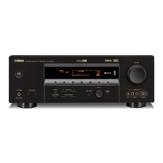
Front panel
VIDEO PORTABLEL AUDIO R
VIDEO AUX
STANDBY
/ON
AUTO/MAN’L
TUNING MODE
MAN’L/AUTO FM
MEMORY
LEVEL
l
PRESET/TUNING
h
NEXT
A/B/C/D/E
FM/AM
EDIT
PRESET/TUNING
VOLUME
BASS/TREBLE
TONE CONTROL
l PROGRAM h
EFFECT
STRAIGHT
SILENT CINEMA
PHONES
BA
SPEAKERS
MULTI CH
INPUT
INPUT MODE
INPUT
A
214356897
GHIED
0
J
B
CF
Notes

CONTROLS AND FUNCTIONS
5
INTRODUCTION
English
8 Front panel display
Shows information about the operational status of this unit
(see page 8).
9 TUNING MODE (AUTO/MAN’L)
Switches between automatic tuning (the AUTO indicator
is turned on) and manual tuning (the AUTO indicator is
turned off) (see page 43).
0 VOLUME
Controls the output level of all audio channels.
y
This does not affect the AUDIO OUT (REC) level.
A PHONES (SILENT CINEMA) jack
Outputs audio signals for private listening with
headphones (see page 31).
• When you connect headphones, no signals are output at the
SUBWOOFER OUTPUT jack or the speaker terminals.
• All Dolby Digital and DTS audio signals are mixed down to the
left and right headphone channels.
B SPEAKERS A/B buttons
Turns on or off the set of front speakers connected to the A
and/or B terminals on the rear panel each time the
corresponding button is pressed.
C STRAIGHT (EFFECT)
Turns the sound field programs off or on. When
“STRAIGHT” is selected, 2-channel or multi-channel
input signals are output directly from their respective
speakers without effect processing (see page 36).
D TONE CONTROL
Selects “BASS” or “TREBLE” to adjust the total balance
of the front left and right speakers in conjunction with
BASS/TREBLE +/– buttons (see page 30).
E BASS/TREBLE +/– button
Adjusts the bass/treble balance of the front left and right
speakers in conjunction with TONE CONTROL (see
page 30).
F PROGRAM l / h buttons
Selects sound field programs (see page 54).
G INPUT MODE
Selects either digital or analog input signals exclusively or
sets this unit to automatically detect the type of input
signals and select the corresponding input signals when
one component is connected via both digital and analog
connections (see page 32).
H INPUT selector
Selects the desired input source.
I MULTI CH INPUT
Selects the input source connected to the MULTI CH
INPUT jacks (see page 36).
The input source connected to the MULTI CH INPUT jacks takes
priority over the source selected with the INPUT selector on the
front panel (or the input selector buttons on the remote control).
J VIDEO AUX jacks
Input audio and video signals from a portable external
source such as a game console, a video camera or a
portable audio player (see page 21).
y
To reproduce the source signals input at these jacks, select
“V-AUX” as the input source.
The audio signals input at the PORTABLE mini jack take priority
over the ones input at the AUDIO L/R jacks.
Notes
Note
Note

CONTROLS AND FUNCTIONS
6
This section describes the function of each control on the
remote control used to control this unit. To operate other
components, see “REMOTE CONTROL FEATURES” on
page 78.
■ Controlling this unit
Press AMP to control this unit.
1 Infrared signal transmitter
Outputs infrared control signals. Aim the transmitter at the
component you want to operate (see page 7).
2 Input selector buttons
Select the input source.
3 Sound field program selector buttons
Select sound field programs (see page 54).
– Use SELECT to play back 2-channel sources in
surround (see page 40).
– Use EXTD SUR. to switch between 5.1 and 6.1-
channel playback of multi-channel sources (see
page 39).
– Use DIRECT ST. to play back 2-channel sources in
hi-fi stereo sound (see page 37).
4 SPEAKERS
Turns on or off the set of front speakers connected to the
FRONT A and/or B terminals on the rear panel. Press this
button repeatedly to toggle as follows:
5 ENHANCER
Turns on or off the Compressed Music Enhancer mode
(see page 35).
6 LEVEL
Selects the speaker channel to be adjusted (see page 34).
7 Cursor buttons u / d / j / i, ENTER
Select and adjust the sound field program parameters or
the “SET MENU” parameters.
8 RETURN
Returns to the previous menu level when adjusting the
“SET MENU” parameters.
9 STANDBY
Sets this unit to the standby mode (see page 25).
0 POWER
Turns on this unit (see page 25).
Remote control
CD
MD/CD-R
TUNER
START
SRCH MODE
SET MENU
CODE SET
BAND
LEVEL
A/B/C/D/E A/B/C/D/E
MODE PTY SEEK
DAB MEMORY
PRESET/CH
STRAIGHT
MOVIEENTERTAINMUSIC
V-AUXDVD
AMP
POWER
POWER POWER
REC
DISC SKIP
FREQ/TEXT EON
DIRECT ST.EXTD SUR.STANDARD
SELECT
NIGHT
ENHANCER
SPEAKERS
TV MUTE TV INPUT
DVR
DTV/CBL
SLEEP
MULTI CH IN
STANDBY
MUTE
MENUTITLE
VOLUME
STEREO
4321
8
10
7
09
65
ENT.
DISPLAYRETURN
TV VOL TV CH
AVTV
ENTER
9
0
B
A
C
D
E
F
G
I
1
2
3
5
4
7
6
8
H
J
A on B on
A and B off

CONTROLS AND FUNCTIONS
7
INTRODUCTION
English
A MULTI CH IN
Selects the component connected to the MULTI CH
INPUT jacks as the input source when using an external
decoder, etc. (see page 36).
B CODE SET
Use to set up remote control codes (see page 80).
C SLEEP
Sets the sleep timer (see page 33).
D AMP
Sets the remote control to the operation mode of this unit.
E VOLUME +/–
Controls the output level of all audio channels.
This does not affect the AUDIO OUT (REC) level.
F MUTE
Mutes the audio output. Press again to restore the audio
output to the previous volume level (see page 31).
G STRAIGHT
Turns the sound field programs off or on. When
“STRAIGHT” is selected, 2-channel or multi-channel
input signals are output directly from their respective
speakers without effect processing (see page 36).
H NIGHT
Turns on or off the night listening modes (see page 31).
I SET MENU
Enters “SET MENU” (see page 68).
■ Controlling the TUNER functions
Press TUNER to control the TUNER functions.
3 Numeric buttons
Use numbers 1 through 8 to select preset stations.
6 BAND
Switches the reception band between FM and AM
(see page 43).
7 A/B/C/D/E j / i, PRESET/CH u / d
Press PRESET/CH u / d to select a preset station group
(A to E) and A/B/C/D/E j / i to select a preset station
number (1 to (see page 47).
J Radio Data System tuning buttons
(U.K. and Europe models only)
FREQ/TEXT
Switches the Radio Data System display between the
PS mode, PTY mode, RT mode, CT mode (if the
station offers the corresponding data services) and the
frequency display (see page 52).
PTY SEEK MODE
Sets this unit to the PTY SEEK mode (see page 50).
PTY SEEK START
Starts searching for a station once the desired program
type is selected in the PTY SEEK mode (see page 51).
EON
Selects a program type (NEWS, AFFAIRS, INFO, or
SPORT) for automatic tuning (see page 52).
■ Using the remote control
The remote control transmits a directional infrared ray.
Be sure to aim the remote control directly at the remote
control sensor on the main unit during operation.
• Do not spill water or other liquids on the remote control.
• Do not drop the remote control.
• Do not leave or store the remote control in the following types
of conditions:
– places of high humidity, such as near a bath
– places of high temperatures, such as near a heater or stove
– places of extremely low temperatures
– dusty places
Note
Notes
VOLUME
AUTO/MAN’LMAN’L/AUTO FMLEVELNEXT
EDIT
EFFECT
MEMORY
FM/AM
PRESET/TUNING
A/B/C/D/E
l PROGRAM h
BASS/TREBLE
l
PRESET/TUNING/CH
h
TUNING MODE
INPUT MODE
TONE CONTROL
STRAIGHT
SPEAKERS
PHONES
SILENT CINEMA
STANDBY
/ON
BA
MULTI CH
INPUT
INPUT
VIDEO PORTABLEL AUDIO R
VIDEO AUX
30 30
Approximately 6 m (20 ft)

CONTROLS AND FUNCTIONS
8
1 Decoder indicators
The respective indicator lights up when any of the
decoders of this unit function.
2 ENHANCER indicator
Lights up when the Compressed Music Enhancer mode is
turned on (see page 35).
3 Sound field indicators
Light up to indicate the active DSP sound fields.
4 VIRTUAL indicator
Lights up when Virtual CINEMA DSP is active (see
page 41).
5 Input source indicators
The corresponding cursor lights up to show the currently
selected input source.
6 SILENT CINEMA indicator
Lights up when headphones are connected and a sound
field program is selected (see page 31).
7 CINEMA DSP indicator
Lights up when you select a CINEMA DSP sound field
program (see page 55).
8 AUTO indicator
Lights up when this unit is in the automatic tuning mode
(see page 43).
9 TUNED indicator
Lights up when this unit is tuned into a station
(see page 43).
0 STEREO indicator
Lights up when this unit is receiving a strong signal for an
FM stereo broadcast while the AUTO indicator is lit
(see page 43).
A MEMORY indicator
Flashes to show that a station can be stored (see page 45).
B VOLUME level indicator
Indicates the current volume level.
C PCM indicator
Lights up when this unit is reproducing PCM (Pulse Code
Modulation) digital audio signals.
D STANDARD indicator
Lights up when the “SUR. STANDARD” or
“SUR. ENHANCED” programs are selected (see
page 40).
E SP A B indicators
Light up according to the set of front speakers selected.
Front panel display
96
24
q PL
q EX
q PL
ENHANCER
MATRIX DISCRETE
SILENT CINEMA
NIGHTSTANDARD
AUTO
PSHOLD RT
EON
PTYPTY
TUNED
MUTE
VOLUME
MEMORY
SLEEP
VIRTUAL
PCM
q PL x
A B
SP
mS
ft
dB
96/24
HiFi DSP
LFE
LCR
SL SB SR
q
DIGITAL
t
dB
STEREO
CT
2
DGFHI JLKNM
O
C
E
134567 A
908B
(U.K. and Europe models only)
Presence DSP sound field
Listening position
Surround left
DSP sound field
Surround right
DSP sound field
Surround back DSP sound field

CONTROLS AND FUNCTIONS
9
INTRODUCTION
English
F Headphones indicator
Lights up when headphones are connected (see page 31).
G NIGHT indicator
Lights up when you select a night listening mode
(see page 31).
H HiFi DSP indicator
Lights up when you select a HiFi DSP sound field
program (see page 55).
I Multi-information display
Shows the name of the current sound field program and
other information when adjusting or changing settings.
J SLEEP indicator
Lights up while the sleep timer is on (see page 33).
K MUTE indicator
Flashes while the MUTE function is on (see page 31).
L 96/24 indicator
Lights up when a DTS 96/24 signal is input to this unit.
M Input channel indicators
Indicate the channel components of the current digital
input signal (see page 27).
N LFE indicator
Lights up when the input signal contains the LFE signal.
O Radio Data System indicators
(U.K. and Europe models only)
Lights up when the Radio Data System data is being
received.
EON
Lights up when the EON data service is being
received.
PTY HOLD
Lights up while searching for the Radio Data System
stations in the PTY SEEK mode.

CONTROLS AND FUNCTIONS
10
1 Video component jacks
See pages 17 and 18 for connection information.
2 Audio component jacks
See page 20 for connection information.
3 MULTI CH INPUT jacks
See page 21 for connection information.
4 SUBWOOFER OUTPUT jack
See page 13 for connection information.
5 DIGITAL INPUT jacks
See pages 18 and 19 for connection information.
6 COMPONENT VIDEO jacks
See pages 17 and 18 for connection information.
7 Antenna terminals
See page 22 for connection information.
8 Speaker terminals
See page 12 for connection information.
9 AC OUTLET(S)
Use to supply power to your other audiovisual
components.
See page 23 for details.
■ VOLTAGE SELECTOR
(Asia and General models only)
See page 23 for details.
Rear panel
AUDIO AUDIO
OUTPUT DIGITAL INPUT
DVD DVD
COAXIAL
DTV/CBL
SUB
WOOFER
SUB
WOOFER
SURROUND
FRONT
OUT
(REC)
IN
(PLAY)
MD/
CD-R
CD
DVD
MONITOR OUTDTV/CBL
DVD DVR
COMPONENT VIDEO
P
RPBY
FM ANT
75Ω
UNBAL.
AM
ANT
GND
TUNER SPEAKERS
DTV/CBL
IN OUT
DVR DVD DTV/CBL
IN
OUT
DVR
CENTER
MULTI CH INPUT
VIDEO S VIDEO
MONITOR
OUT
MONITOR
OUT
FRONT
A
B
AC OUTLETS
SURROUND
CENTER SURROUND BACK
PRPBY
OPTICAL
654321
7
89

CONNECTIONS
11
PREPARATION
English
The speaker layout below shows the standard ITU-R
*
speaker setting. You can use it to enjoy CINEMA DSP and
multi-channel audio sources.
*
ITU-R is the radio communication sector of the ITU
(International Telecommunication Union).
Front speakers (FL and FR)
The front speakers are used for the main source sound plus
effect sounds. Place these speakers at an equal distance
from the ideal listening position. The distance of each
speaker from each side of the video monitor should be the
same.
Center speaker (C)
The center speaker is for the center channel sounds
(dialog, vocals, etc.). If for some reason it is not practical
to use a center speaker, you can do without it. Best results,
however, are obtained with the full system. Place the
center speaker centrally between the front speakers and as
close to the monitor as possible, such as directly over or
under it.
Surround speakers (SL and SR)
The surround speakers are used for effect and surround
sounds. Place these speakers behind your listening
position, facing slightly inwards, about 1.8 m (6 ft) above
the floor.
Surround back speaker (SB)
The surround back speaker supplements the surround
speakers and provides more realistic front-to-back
transitions. Place this speaker directly behind the listening
position and at the same height as the surround speakers.
Subwoofer (SW)
The use of a subwoofer with a built-in amplifier, such as
the YAMAHA Active Servo Processing Subwoofer
System, is effective not only for reinforcing bass
frequencies from any or all channels, but also for hi-fi
stereo reproduction of the LFE (low-frequency effect)
channel included in Dolby Digital and DTS sources. The
position of the subwoofer is not so critical, because low
bass sounds are not highly directional. But it is better to
place the subwoofer near the front speakers. Turn it
slightly toward the center of the room to reduce wall
reflections.
CONNECTIONS
Placing speakers
60˚
30˚
SB
FL
FR
C
SL
SR
SR
80˚
SL
SW
FR
FL
SB
SL
SR
C
1.8 m (6 ft)

12
CONNECTIONS
Be sure to connect the left channel (L), right channel (R), “+” (red) and “–” (black) properly. If the connections are faulty,
no sound will be heard from the speakers, and if the polarity of the speaker connections is incorrect, the sound will be
unnatural and lack bass.
• Before connecting the speakers, make sure that this unit is in the standby mode (see page 25).
• Do not let the bare speaker wires touch each other or do not let them touch any metal part of this
unit. This could damage this unit and/or speakers.
• Use magnetically shielded speakers. If this type of speakers still creates the interference with the
monitor, place the speakers away from the monitor.
• If you are to use 4 or 6 ohm speakers, be sure to set “SP IMP.” to “6ΩMIN” before using this unit
(see page 24).
• A speaker cord is actually a pair of insulated cables running side by side. Cables are colored or shaped differently, perhaps with a
stripe, groove or ridge. Connect the striped (grooved, etc.) cable to the “+” (red) terminals of this unit and your speaker. Connect the
plain cable to the “–” (black) terminals.
• The low-frequency signals of other speakers set to “SML” (or “SMALL”) to “NONE” in “SPEAKER SET” (see pages 70 and 71) are
directed to the speakers selected in “BASS OUT” (see page 71).
Connecting speakers
Notes
CAUTION
OUTPUT
SUB
WOOFER
SPEAKERS
FRONT
A
B
SURROUND
CENTERCLASS 2 WIRING SURROUND BACK
7
6
54
3
21
Subwoofer
Center
speaker
Front speakers
A
Surround back
speaker
Surround speakers
Front
speakers (B)
Right
LeftRight
Left

13
CONNECTIONS
PREPARATION
English
FRONT terminals
Connect one or two front speaker systems (1, 2) to these
terminals. If you use only one front speaker system,
connect it to the FRONT A or B terminal.
CENTER terminals
Connect a center speaker (3) to these terminals.
SURROUND terminals
Connect surround speakers (4, 5) to these terminals.
SURROUND BACK terminals
Connect a surround back speaker (6) to these terminals.
SUBWOOFER jack
Connect a subwoofer with a built-in amplifier (7) (such as
the YAMAHA Active Servo Processing Subwoofer
System) to this jack.
7
1
2
6
5
4
3
Speaker layout

14
CONNECTIONS
■ Connecting the speaker cable
1 Remove approximately 10 mm (0.4 in) of
insulation from the end of each speaker
cable and then twist the exposed wires of the
cable together to prevent short circuits.
2 Loosen the knob.
3 Insert one bare wire into the hole on the side
of each terminal.
4 Tighten the knob to secure the wire.
■ Connecting the banana plug
(except U.K., Europe and Asia models)
The banana plug is a single-pole electrical connector
widely used to terminate speaker cables.
1 Tighten the knob.
2 Insert the banana plug connector into the
end of the corresponding terminal.
10 mm (0.4 in)
Red: positive (+)
Black: negative (–)
Red: positive (+)
Black: negative (–)
Red: positive (+)
Black: negative (–)
Red: positive (+)
Black: negative (–)
Banana plug

15
CONNECTIONS
PREPARATION
English
■ Audio jacks
This unit has four types of audio jacks. Connection
depends on the availability of audio jacks on your other
components.
AUDIO jacks
For conventional analog audio signals transmitted via left
and right analog audio cables. Connect red plugs to the
right jacks and white plugs to the left jacks.
PORTABLE jack
For analog audio signals transmitted via stereo analog
audio mini cables.
DIGITAL AUDIO COAXIAL jacks
For digital audio signals transmitted via coaxial digital
audio cables.
DIGITAL AUDIO OPTICAL jacks
For digital audio signals transmitted via optical digital
audio cables.
• You can use the digital jacks to input PCM, Dolby Digital and
DTS bitstreams. When you connect components to both the
COAXIAL and OPTICAL jacks, priority is given to the signals
input at the COAXIAL jack. All digital input jacks are
compatible with 96-kHz sampling digital signals.
• Pull out the cap from the optical jack before you connect the
fiber optic cable. Do not discard the cap. When you are not
using the optical jack, be sure to put the cap back in place. This
cap protects the jack from dust.
■ Video jacks
This unit has three types of video jacks. Connection
depends on the availability of input jacks on your video
monitor.
VIDEO jacks
For conventional composite video signals transmitted via
composite video cables.
S VIDEO jacks
For S-video signals, separated into the luminance (Y) and
chrominance (C) video signals transmitted on separate
wires of S-video cables.
COMPONENT VIDEO jacks
For component video signals, separated into the
luminance (Y) and chrominance (P
B, PR) video signals
transmitted on separate wires of component video cables.
Information on jacks and cable plugs
COAXIAL
DIGITAL AUDIO
AUDIO
PORTABLE
OPTICAL
DIGITAL AUDIO
R
L
C
O
M
R
L
VIDEO S VIDEO
COMPONENT VIDEO
Y PB PR
PB
Y
P
R
S
V
Audio jacks and cables Video jacks and cables
Component
video cable
plug
(Red)(White) (Orange)
(Blue)(Green)(Yellow)
Stereo
analog
audio
mini cable
plug
(Red)(Green)
Optical
digital
audio cable
plug
Left and right
analog audio
cable plug
Coaxial
digital audio
cable plug
S-video
cable plug
Composite
video cable
plug
(Green)
Notes

16
CONNECTIONS
■ Audio signal flow for AUDIO OUT (REC)
This unit handles digital and analog signals independently. Thus, audio signals input at the analog jacks are output only at the analog
AUDIO OUT (REC) jacks.
■ Video signal flow for MONITOR OUT
Audio and video signal flow
Note
L RRL
PORTABLE
AUDIO
Output
AUDIO OUT (REC)
Input
Analog output
Analog audio
S VIDEO
VIDEO
COMPONENT
VIDEO
Y P
B
P
R
Y P
B
P
R
Through
Output
(MONITOR OUT)
Input
Analog video

17
CONNECTIONS
PREPARATION
English
Connect your TV to the VIDEO MONITOR OUT jack, the S VIDEO MONITOR OUT jack or the COMPONENT
VIDEO MONITOR OUT jacks of this unit.
Do not connect this unit or other components to the AC power supply until all connections between
components are complete.
Connecting a TV
CAUTION
MONITOR OUT
COMPONENT VIDEO
VIDEO S VIDEO
MONITOR
OUT
MONITOR
OUT
PRPBY
V
S
PRPBY
TV
S-video in
Video in
Component video in

18
CONNECTIONS
Connect your DVD player, DVD recorder, VCR or STB (set-top box) using the same type of video connections as those
made for your TV (see page 17). The cable TV receiver and the satellite receiver are examples of the STB.
Do not connect this unit or other components to the AC power supply until all connections between
components are complete.
• Be sure to make the same type of video connections as those made for your TV (see page 17). For example, if you connected your TV
to the VIDEO MONITOR OUT jack of this unit, connect your other components to the VIDEO jacks.
• To make a digital connection to a component other than the default component assigned to each DIGITAL INPUT jack, select the
corresponding setting for “OPTICAL IN” or “COAXIAL IN” in “INPUT ASSIGN” (see page 73).
• If you connect your DVD player to both the DIGITAL INPUT (OPTICAL) and the DIGITAL INPUT (COAXIAL) jacks, priority is
given to the signals input at the DIGITAL INPUT (COAXIAL) jack.
■ Connecting a DVD player
Connecting a DVD player, a DVD recorder, a VCR or an STB
CAUTION
Notes
AUDIO
DIGITAL INPUT
DVD DVD
COAXIAL
DVD
DVD
COMPONENT VIDEO
P
RPBY
DVD
VIDEO S VIDEO
OPTICAL
V
Y PB
PR
LR
S
O
C
DVD Player
Component video out
S-Video out
Optical audio out
Video out
Coaxial audio out
Audio out
S-Video out