- Manuals
- Brands
- Yamaha Manuals
- Offroad Vehicle
- Raptor 700R YFM70RSPX
- Owner’s manual
-
Contents
-
Table of Contents
-
Troubleshooting
-
Bookmarks
Quick Links
READ THIS MANUAL CAREFULLY!
It contains important safety information.
OWNER’S MANUAL
YFM70RSPX
This A
WARNING
This ATV should not be ridden by anyone under 16 years of age.
LIT-11626-21-12
1S3-28199-15
Related Manuals for Yamaha Raptor 700R YFM70RSPX
Summary of Contents for Yamaha Raptor 700R YFM70RSPX
-
Page 1
READ THIS MANUAL CAREFULLY! It contains important safety information. OWNER’S MANUAL YFM70RSPX This A WARNING This ATV should not be ridden by anyone under 16 years of age. LIT-11626-21-12 1S3-28199-15… -
Page 2
EBU17091… -
Page 3
Yamaha experience in the production of fine sporting, touring, and pace-setting racing machines. With the purchase of this Yamaha, you can now appreciate the high degree of craftsmanship and reliability that have made Yamaha a leader in these fields. -
Page 4
EBU17330 IMPORTANT MANUAL INFORMATION EBU17341 FAILURE TO FOLLOW THE WARNINGS CONTAINED IN THIS MANUAL CAN RESULT IN SERIOUS IN- JURY OR DEATH. Particularly important information is distinguished in this manual by the following notations: The Safety Alert Symbol means ATTENTION! BECOME ALERT! YOUR SAFETY IS INVOLVED! Failure to follow WARNING instructions could result in severe injury WARNING… -
Page 5
EBU17350 IMPORTANT NOTICE EBU17360 Welcome to the Yamaha world of motor sports! This ATV is designed and manufactured for OFF-ROAD use only. It is illegal and unsafe to operate this ATV on any public street, road or highway. This ATV complies with all applicable OFF-ROAD noise level and spark arrester laws and regulations in effect at the time of manufacture. -
Page 6: Table Of Contents
EWB00010 Clutch lever ……….4-6 WARNING Brake lever ……….4-6 Brake pedal ……….4-7 Indicates a potential hazard that could result in Parking brake lever ……..4-7 serious injury or death. Shift pedal ……….4-8 Reverse knob “REV” ……..4-9 Fuel tank cap ……….
-
Page 7
Starting the engine ……..6-1 Periodic maintenance chart for the emission control system ……8-3 Operating the reverse knob and driving in reverse ………… 6-2 General maintenance and lubrication chart …………8-4 Shifting …………6-3 Removing and installing the panel ….. 8-7 Engine break-in ……… -
Page 8
Checking and lubricating the brake and YAMAHA EXTENDED SERVICE shift pedals ……….8-37 (Y.E.S.) ……….11-7 Checking the wheel hub bearings … 8-37 Lubricating the swingarm pivots ….8-37 Lubricating the upper and lower arm pivots …………. 8-38 Battery …………. 8-39 Replacing a fuse …….. -
Page 9: Safety Information
EBU17430 SAFETY INFORMATION SAFETY INFORMATION EBU26661 – A child under 16 years old should never oper- ate an ATV with engine size greater than 90 cc. AN ATV IS NOT A TOY AND CAN BE HAZARD- Never allow a child under age 16 to operate an OUS TO OPERATE.
-
Page 10
that is proper for the terrain, visibility, operating before attempting larger hills. conditions, and your experience. Always follow proper procedures for climbing Never attempt wheelies, jumps, or other stunts. hills as described in this manual. Check the ter- Always inspect your ATV each time you use it to rain carefully before you start up any hill. -
Page 11
ing, use the proper gear and maintain a steady Always be sure there are no obstacles or people speed when climbing a hill. If you stall or roll behind you when you operate in reverse. When backwards, follow the special procedure for it is safe to proceed in reverse, go slowly. -
Page 12
EWB02320 HOW TO AVOID THE HAZARD WARNING If you should swallow some gasoline or in- POTENTIAL HAZARD hale a lot of gasoline vapor, or get some gas- Improper handling of gasoline. oline in your eyes, seek medical help WHAT CAN HAPPEN immediately. -
Page 13: Location Of The Warning And Specification Labels
EBU17660 LOCATION OF THE WARNING AND SPECIFICATION LABELS…
-
Page 14
Read and understand all of the labels on your ATV. These labels contain important information for safe and proper operation. Never remove any labels from your ATV. If a label becomes difficult to read or comes off, request a replace- ment label from your Yamaha dealer. -
Page 15
WARNING WARNING Improper ATV use can result in SEVERE INJURY or DEATH. UNDER ALWAYS USE NEVER USE NEVER CARRY NEVER USE AN APPROVED ON PUBLIC PASSENGERS WITH DRUGS HELMET AND ROADS OR ALCOHOL PROTECTIVE GEAR Operating this ATV if you are under NEVER operate : without proper training or instruction. -
Page 16
WARNING WARNING IMPROPER TIRE PRESSURE OR OVERLOADING CAN NEVER ride as a CAUSE LOSS OF CONTROL. LOSS OF CONTROL CAN RESULT IN SEVERE passenger. INJURY OR DEATH. OPERATING TIRE PRESSURE: Set with tires cold Passengers can cause Recommended : FRONT : 27.5 kPa, { 0.275 kgf/cm } 4.0 psi a loss of control, REAR : 27.5 kPa, { 0.275 kgf/cm… -
Page 17: Description
EBU17680 DESCRIPTION EBU17690 EBU17700 Left view Right view 1. Engine oil tank 1. Spark arrester 2. Coolant reservoir 2. Seat 3. Idle adjusting screw 3. Headlight 4. Tail/brake light 4. Brake pedal 5. Shift pedal…
-
Page 18: Controls And Instruments
EBU17712 from the figures shown in this manual. Controls and instruments 1. Clutch lever 2. Parking brake lever 3. Main switch 4. Brake lever 5. Throttle lever 6. Reverse knob 7. Fuel tank cap 8. Handlebar switches NOTE: The ATV you have purchased may differ slightly…
-
Page 19: Instrument And Control Functions
EBU17720 INSTRUMENT AND CONTROL FUNCTIONS EWB00010 WARNING Indicates a potential hazard that could result in serious injury or death. EBU17760 Main switch The positions of the main switch are as follows: All electrical systems are supplied with power. The headlights and taillight come on when the light switch is on, and the engine can be started.
-
Page 20: Indicator Lights And Warning Lights
The electrical circuit of the warning light can be checked by turning the key to “ON”. If the warning light does not come on, and then go off, have a Yamaha dealer check the electrical circuit. ECB00010 CAUTION: 1. Neutral indicator light “N”…
-
Page 21: Handlebar Switches
” This warning light comes on or flashes when an electrical circuit monitoring the engine is defective. When this occurs, have a Yamaha dealer check the self-diagnosis system. The electrical circuit of the warning light can be checked by turning the key to “ON”. If the warning 1.
-
Page 22: Throttle Lever
EBU18090 tle lever will increase the engine speed. Start switch “START” Regulate the speed of the ATV by varying the Push this switch to crank the engine with the start- throttle position. Because the throttle is spring- loaded, the ATV will decelerate, and the engine will ECB00050 return to an idle any time the hand is removed from CAUTION:…
-
Page 23: Speed Limiter
Check the operation of the throttle lever be- fore you start the engine. If it does not work smoothly, check for the cause. Correct the problem before riding the ATV. Consult a Yamaha dealer if you can’t find or solve the problem yourself. 1. Locknut EBU18311 2.
-
Page 24: Clutch Lever
EWB00190 off system.) WARNING POTENTIAL HAZARD Improper adjustment of the speed limiter and throttle. WHAT CAN HAPPEN The throttle cable could be damaged. Im- proper throttle operation could result. You could lose control, have an accident or be in- jured. HOW TO AVOID THE HAZARD Do not turn the adjusting screw out more than 12 mm (0.47 in).
-
Page 25: Brake Pedal
1. Brake lever 1. Brake pedal 2. Locknut 3. Brake lever position adjusting bolt EBU18510 4. Distance between brake lever and handlebar grip Parking brake lever Use the parking brake before starting the engine or EBU18432 Brake pedal parking the ATV, especially on a slope. To apply the parking brake, move the parking brake lever in The brake pedal is located on the right side of the direction (a).
-
Page 26: Shift Pedal
EWB00170 WARNING POTENTIAL HAZARD Improper use of the parking brake. WHAT CAN HAPPEN The ATV could start moving unexpectedly if the parking brake is not applied before start- ing the engine. This could cause loss of con- trol or a collision. The brake could overheat if you ride the ATV without releasing the parking brake.
-
Page 27: Reverse Knob «Rev
when shifting. 1. Reverse knob “REV” 1. Shift pedal EBU18720 Fuel tank cap EBU18641 Reverse knob “REV” Remove the fuel tank cap by turning it counter- The reverse knob is used to shift into reverse. See clockwise. the “Operating the reverse knob and driving in re- verse”…
-
Page 28: Fuel
1. Filler tube 1. Fuel tank cap 2. Fuel level EBU18730 Fuel Recommended fuel: Make sure that there is sufficient fuel in the tank. UNLEADED GASOLINE ONLY Fill the fuel tank to the bottom of the filler tube as Fuel tank capacity: shown.
-
Page 29: Seat
WHAT CAN HAPPEN Fuel can spill, which can cause a fire and se- Your Yamaha engine has been designed to use vere injury. regular unleaded gasoline with a pump octane Fuel expands when it heats up. If the fuel…
-
Page 30: Adjusting The Front Shock Absorber Assemblies
1. Seat lock lever 1. Projection 2. Seat holder To install the seat EBU27892 Insert the projections on the front of the seat into Adjusting the front shock absorber the seat holders and push down on the seat at the assemblies rear.
-
Page 31
Do not dispose of a damaged or worn out shock absorber assembly yourself. Take NOTE: the shock absorber assembly to a Yamaha A special wrench can be obtained at a Yamaha dealer for any service. dealer to make this adjustment. The spring preload setting is determined by Spring preload measuring distance A, shown in the illustration. -
Page 32
adjusting nut, distance A is changed by 1.5 mm 3. Tighten the locknut to the specified torque. (0.06 in). Tightening torque: Locknut: Spring preload setting: 30 Nm (3.0 m·kgf, 22 ft·lbf) Minimum (hard): Distance A = 246.5 mm (9.7 in) ECB00080 Standard: CAUTION:… -
Page 33
Compression damping force Compression damping force (for fast compression damping) 1. To increase the compression damping force and thereby harden the compression damp- ing, turn the adjusting bolt in direction (a). To decrease the compression damping force and thereby soften the compression damping, turn the adjusting bolt in direction (b). -
Page 34
Compression damping setting (for fast com- pression damping): Minimum (soft): Adjusting bolt 3 turn(s) out from the fully turned in position Standard: Adjusting bolt 1 1/4 turn(s) out from the ful- ly turned in position Maximum (hard): Adjusting bolt fully turned in 1. -
Page 35: Specifications
the minimum and maximum settings. EWB00350 WARNING NOTE: POTENTIAL HAZARD Improper shock absorber assembly adjust- Although the total number of clicks of a damping ment. force adjusting mechanism may not exactly match WHAT CAN HAPPEN the above specifications due to small differences in Uneven adjustment can cause poor handling production, the actual number of clicks always rep- and loss of stability, which could lead to an…
-
Page 36
Do not dispose of a damaged or worn out shock absorber assembly yourself. Take NOTE: the shock absorber assembly to a Yamaha A special wrench can be obtained at a Yamaha dealer for any service. dealer to make this adjustment. The spring preload setting is determined by Spring preload measuring distance A, shown in the illustration. -
Page 37
adjusting nut, distance A is changed by 1.5 mm 3. Tighten the locknut to the specified torque. (0.06 in). Tightening torque: Locknut: Spring preload setting: 42 Nm (4.2 m·kgf, 30 ft·lbf) Minimum (hard): Distance A = 228 mm (8.98 in) ECB00080 Standard: CAUTION:… -
Page 38
damping) 1. To increase the compression damping force and thereby harden the compression damp- ing, turn the adjusting bolt in direction (a). To decrease the compression damping force and thereby soften the compression damping, turn the adjusting bolt in direction (b). 1. -
Page 39
Compression damping setting (for fast com- pression damping): Minimum (soft): Adjusting bolt 4 turn(s) out from the fully turned in position Standard: Adjusting bolt 2 turn(s) out from the fully turned in position Maximum (hard): Adjusting bolt fully turned in 1. -
Page 40
the minimum and maximum settings. EWB00010 WARNING NOTE: Indicates a potential hazard that could result in Although the total number of clicks of a damping serious injury or death. force adjusting mechanism may not exactly match the above specifications due to small differences in production, the actual number of clicks always rep- resents the entire adjusting range. -
Page 41: Pre-Operation Checks
Always follow the inspection and maintenance procedures and schedules described in the Own- er’s Manual. NOTE: The maintenance of some items in the table has to be performed by a Yamaha dealer. Refer to the periodic maintenance charts on page 8-3 to determine which service should be performed by a Yamaha dealer.
-
Page 42
Coolant specified level if necessary. 5-4, 8-14 Check cooling system for leakage. Correct if necessary. Check operation. If soft or spongy, have Yamaha dealer bleed hydraulic system. Check brake pads for wear, and replace if necessary. Front brake 5-5, 8-25, 8-26, 8-28 Check brake fluid level in reservoir, and add recommended brake… -
Page 43
ITEM ROUTINE PAGE Check wheel condition, and replace if damaged. Wheels and tires Check tire condition and tread depth. Replace if necessary. 5-6, 5-7, 5-8 Check air pressure. Correct if necessary. Make sure that operation is smooth. Lubricate pedal pivoting points Brake and shift pedals 8-37 if necessary. -
Page 44: Fuel
EBU19530 EBU19620 Fuel Coolant Make sure that there is sufficient fuel in the tank. Make sure that the coolant is at the specified level. (See page 4-10.) Add coolant as necessary. (See page 8-14.) EWB00500 NOTE: WARNING The coolant level must be checked on a cold en- POTENTIAL HAZARD gine since the level varies with engine tempera- Improper care when refueling.
-
Page 45: Front And Rear Brakes
Check that there is no free play in the brake le- make sure they are working properly. If the brakes ver. If there is free play, have a Yamaha dealer do not provide proper braking performance, check check the brake system.
-
Page 46: Drive Chain
HOW TO AVOID THE HAZARD The tires listed below have been approved EBU19770 by Yamaha Motor Co., Ltd. for this model. Drive chain Other tire combinations are not recom- Check the condition of the drive chain and check mended.
-
Page 47: Measuring The Tire Pressure
The tires should be set to the recommend- Maximum tire seating pressure: ed pressure: Front: Recommended tire pressure: 250 kPa (36 psi) (2.5 kgf/cm Front: Rear: 27.5 kPa (4.0 psi) (0.275 kgf/cm 250 kPa (36 psi) (2.5 kgf/cm Rear: Higher pressures and fast inflation may 27.5 kPa (4.0 psi) (0.275 kgf/cm cause a tire to burst.
-
Page 48: Tire Wear Limit
Recommended pressure: Front 27.5 kPa (4.0 psi) (0.275 kgf/cm Rear 27.5 kPa (4.0 psi) (0.275 kgf/cm Minimum: Front 24.5 kPa (3.5 psi) (0.245 kgf/cm Rear 24.5 kPa (3.5 psi) (0.245 kgf/cm 1. Low-pressure tire gauge Maximum: Front Set the tire pressure when the tires are cold. Set 30.5 kPa (4.4 psi) (0.305 kgf/cm the tire pressures to the following specifications: Rear…
-
Page 49: Chassis Fasteners
1. Tire wear limit EBU19840 Chassis fasteners Make sure that all nuts, bolts and screws are prop- erly tightened. EBU19850 Instruments, lights and switches Check that all instruments, lights and switches are working properly. Correct if necessary.
-
Page 50: Operation
See the “Engine break-in” section on page 6-5 a control or function you do not understand, prior to operating the engine for the first time. ask your Yamaha dealer. 1. Set the parking brake. 2. Turn the main switch to “ON” and the engine stop switch to “RUN”.
-
Page 51: Operating The Reverse Knob And Driving In Reverse
For maximum engine life, always warm the en- indicator light should come on, if it does not gine up before starting off. Never accelerate come on, have a Yamaha dealer check the hard when the engine is cold! electrical circuit.
-
Page 52: Shifting
If the indicator light does not come on, closed position, apply the clutch, and then repeat- have a Yamaha dealer check the electrical circuit. edly depress the shift pedal until it stops. 4. Check behind you for people or obstacles, When it stops, it will be in first gear.
-
Page 53
time, release the clutch lever slowly. 5. Once the ATV has attained adequate speed, release the throttle, and at the same time, quickly pull in the clutch lever. 6. Shift the transmission into second gear. (Make sure not to shift the transmission into neutral) 7. -
Page 54: Engine Break-In
tle and apply the brakes smoothly and evenly. As ning. Inadequate lubrication may damage you slow down, shift to a lower gear. Be sure that the transmission. the engine has sufficiently slowed before engaging Always use the clutch when changing gears. a lower gear.
-
Page 55: Parking
ECB00220 CAUTION: If any engine trouble should occur during the engine break-in period, immediately have a Yamaha dealer check the ATV. EBU26760 Parking When parking the ATV, stop the engine, shift into first gear, and then apply the parking brake.
-
Page 56: Parking On A Slope
EBU20870 4. With the front and rear brakes applied, pull the Parking on a slope clutch lever, shift into first gear, and then re- EWB00800 lease the clutch lever, brake lever and brake WARNING pedal. POTENTIAL HAZARD NOTE: Parking on a hill or other incline. Make sure that the neutral indicator light goes off.
-
Page 57
However, judgment as the stability and handling of an ATV it is not possible for Yamaha to test all non- can be changed. When adding accessories, keep Yamaha accessories, nor control over their qual- the following points in mind: ity or suitability. -
Page 58
Make sure the load does not interfere with con- HOW TO AVOID THE HAZARD trols or your ability to see where you are going. Never exceed the stated load capacity for Ride more slowly than you would without a load. this ATV. -
Page 59: Riding Your Atv
EBU21131 RIDING YOUR ATV…
-
Page 60: Getting To Know Your Atv
EWB00010 RIDE WITH CARE AND GOOD JUDGEMENT WARNING Get training if you are inexperienced. Indicates a potential hazard that could result in Beginners should get training from a certified in- serious injury or death. structor. Become familiar with this ATV at slow speeds first, EBU21591 even if you are an experienced operator.
-
Page 61
A child under 16 should never operate an should complete the certified training course ATV with engine size greater than 90 cc. offered by Yamaha. They should then regu- larly practice the skills learned in the course and the operating techniques described in this Owner’s Manual. -
Page 62
This ATV is designed to carry operator only – passengers prohibited. EWB00910 WARNING POTENTIAL HAZARD Carrying a passenger on this ATV. WHAT CAN HAPPEN Greatly reduces your ability to balance and control this ATV. Could cause an accident, resulting in harm to you and/or your passen- ger. -
Page 63
WHAT CAN HAPPEN Operating without an approved motorcycle helmet increases your chances of a severe head injury or death in the event of an acci- dent. Operating without eye protection can result in an accident and increases your chances of a severe injury in the event of an accident. -
Page 64
Pre-operation checks Always perform the pre-operation checks listed on page 5-1 before riding for proper care of the ATV and to ensure safety. EWB00940 WARNING POTENTIAL HAZARD Failure to inspect the ATV before operating. Failure to properly maintain the ATV. WHAT CAN HAPPEN Increases the possibility of an accident or EWB00930… -
Page 65
WHAT CAN HAPPEN HOW TO AVOID THE HAZARD Use of improper tires on this ATV, or opera- Always go at a speed that is proper for the tion of this ATV with improper or uneven tire terrain, visibility and operating conditions, pressure, may cause loss of control, increas- and your experience. -
Page 66
MAXIMUM LOADING LIMIT ATV loading limit (total weight of cargo, rider, accessories, and tongue): 100.0 kg (220 lb) EWB00970 WARNING POTENTIAL HAZARD Overloading this ATV or carrying or towing cargo improperly. 1. Locknut WHAT CAN HAPPEN 2. Adjusting screw Could cause changes in ATV handling which could lead to an accident. -
Page 67
During operation WHAT CAN HAPPEN Always keep your feet on the footboards during op- Removing even one hand or foot can reduce eration, otherwise they may contact the rear your ability to control the ATV or could cause wheels. you to lose your balance and fall off of the ATV. -
Page 68
Never modify this ATV through improper in- stallation or use of accessories. All parts and accessories added to this ATV should be genuine Yamaha or equivalent components designed for use on this ATV and should be installed and used according to instructions. -
Page 69: Be Careful Where You Ride
EWB01020 HOW TO AVOID THE HAZARD WARNING Do not operate, idle, or park the ATV in dry POTENTIAL HAZARD grass or other dry ground cover. Operating this ATV on paved surfaces. Keep the engine area free of dry grass, WHAT CAN HAPPEN brush, or other combustible material.
-
Page 70
HOW TO AVOID THE HAZARD Never operate this ATV on any public street, road or highway, even a dirt or gravel one. In many states it is illegal to operate ATVs on public streets, roads and highways. Do not ride on any public road, street, or highway. Riding on public roads can result in collisions with other vehicles. -
Page 71
EWB01040 WARNING POTENTIAL HAZARD Failure to use extra care when operating this ATV on unfamiliar terrain. WHAT CAN HAPPEN You can come upon hidden rocks, bumps, or holes, without enough time to react. Could result in the ATV overturning or going out of control. -
Page 72
EWB01050 WARNING POTENTIAL HAZARD Failure to use extra care when operating on excessively rough, slippery or loose terrain. WHAT CAN HAPPEN Could cause loss of traction or ATV control, which could result in an accident, including an overturn. HOW TO AVOID THE HAZARD Do not operate on excessively rough, slip- pery or loose terrain until you have learned and practiced the skills necessary to control… -
Page 73
mission. EWB01060 Select a large, flat area off-road to become familiar WARNING with your ATV. Make sure that this area is free of POTENTIAL HAZARD obstacles and other riders. You should practice Operating in areas where you might not be control of the throttle, brakes, shifting procedures, seen by other off-road vehicles. -
Page 74
do not allow skin or clothing to come in contact with WHAT CAN HAPPEN these components. The ATV could wheelie. This would increase With the engine idling, pull the clutch lever to dis- the chance of an accident, including over- engage the clutch and shift into 1st gear, and then turn. -
Page 75: Turning Your Atv
WHAT CAN HAPPEN HOW TO AVOID THE HAZARD The wheels could stop rotating. This could Always follow proper procedures for turning cause loss of control, an accident and injury. as described in this Owner’s Manual. Prac- It could also cause engine or drive train dam- tice turning at low speeds before attempting age.
-
Page 76: Climbing Uphill
be able to perform it at higher speeds or in tighter curves. Improper riding procedures such as abrupt throttle changes, excessive braking, incorrect body move- ments, or too much speed for the sharpness of the turn may cause the ATV to tip. If the ATV begins to tip over to the outside while negotiating a turn, lean more to the inside.
-
Page 77
WHAT CAN HAPPEN HOW TO AVOID THE HAZARD The ATV can overturn more easily on ex- Always follow proper procedures for climb- tremely steep hills than on level surfaces or ing hills as described in this Owner’s Manual. small hills. Always check the terrain carefully before you HOW TO AVOID THE HAZARD start up any hill. -
Page 78
WHAT CAN HAPPEN Could cause loss of control or cause the ATV to overturn. HOW TO AVOID THE HAZARD Never attempt to turn the ATV around on any hill until you have mastered the turning tech- nique as described in the Owner’s Manual on level ground. -
Page 79
EWB01251 WARNING POTENTIAL HAZARD Stalling, rolling backwards or improperly dis- mounting while climbing a hill. WHAT CAN HAPPEN Could result in the ATV overturning. HOW TO AVOID THE HAZARD Use the proper gear and maintain a steady speed when climbing a hill. If you lose all forward speed: Keep weight uphill. -
Page 80: Riding Downhill
braking may also cause a loss of traction. Whenever possible, ride your ATV straight down- hill. Avoid sharp angles which could allow the ATV to tip or roll over. Carefully choose your path and ride no faster than you will be able to react to ob- stacles which may appear.
-
Page 81: Crossing A Slope
HOW TO AVOID THE HAZARD Always follow proper procedures for going down hills as described in this Owner’s Man- ual. Note: a special technique is required when braking as you go down a hill. Always check the terrain carefully before you start down any hill.
-
Page 82: Crossing Through Shallow Water
steering when riding on loose surfaces by pointing When crossing the side of a hill: the front wheels slightly uphill. When riding on Always follow proper procedures as de- slopes, be sure not to make sharp turns either up scribed in the Owner’s Manual. or down hill.
-
Page 83
low water of up to a maximum of 35 cm (14 in) in depth. Before entering the water, choose your path carefully. Enter where there is no sharp drop off, and avoid rocks or other obstacles which may be slippery or upset the ATV. Drive slowly and care- fully. -
Page 84: Riding Over Rough Terrain
1. Air filter case check hose RIDING OVER ROUGH TERRAIN ECB00240 Riding over rough terrain should be done with cau- CAUTION: tion. Look out for obstacles which could cause damage to the ATV or could lead to an upset or ac- After riding your ATV in water, be sure to drain cident.
-
Page 85: Sliding And Skidding
WHAT CAN HAPPEN Could cause loss of control or a collision. Could cause the ATV to overturn. HOW TO AVOID THE HAZARD Before operating in a new area, check for ob- stacles. Never attempt to ride over large obstacles, such as large rocks or fallen trees. When you go over obstacles, always follow proper pro- cedures as described in the Owner’s Manual.
-
Page 86: What To Do If
HOW TO AVOID THE HAZARD Learn to safely control skidding or sliding by practicing at low speeds and on level, smooth terrain. On extremely slippery surfaces, such as ice, go slowly and be very cautious in order to re- duce the chance of skidding or sliding out of control.
-
Page 87
Steer in the direction of the slide if you have the you come out of the water. Do not continue to room. Applying the brakes or accelerating is not ride your ATV until you have regained adequate recommended until you have corrected the braking ability. -
Page 88: Periodic Maintenance And Minor Repair
Safety is an obligation of the owner. Periodic in- nance unless otherwise specified. Have a spection, adjustment and lubrication will keep your Yamaha dealer perform the service if you are ATV in the safest and best operating condition not familiar with maintenance work.
-
Page 89
If you have questions, consult an authorized additional tools such as a torque wrench may be Yamaha ATV dealer. necessary to perform certain maintenance work correctly. NOTE: If you do not have the tools or experience required for a particular job, have a Yamaha dealer perform… -
Page 90: Periodic Maintenance Chart For The Emission Control System
However, keep in mind that if the ATV isn’t used for a long period of time, the month maintenance intervals should be followed. Items marked with an asterisk should be performed by a Yamaha dealer as they require special tools, data and technical skills.
-
Page 91: General Maintenance And Lubrication Chart
EBU21864 General maintenance and lubrication chart INITIAL EVERY month Whichev- CHECK OR MAINTENANCE ITEM er comes 1300 2500 2500 5000 first (mi) (200) (800) (1600) (1600) (3200) hours Every 20–40 hours (more often in wet or Air filter element Clean and replace if necessary. dusty areas) √…
-
Page 92
INITIAL EVERY month Whichev- CHECK OR MAINTENANCE er comes ITEM 1300 2500 2500 5000 first (mi) (200) (800) (1600) (1600) (3200) hours Upper and lower √ √ √ 10 * Lubricate with lithium-soap-based grease. arm pivots Check chain slack and adjust if necessary. Check rear wheel alignment and correct if necess- √… -
Page 93
INITIAL EVERY month Whichev- CHECK OR MAINTENANCE er comes ITEM 1300 2500 2500 5000 first (mi) (200) (800) (1600) (1600) (3200) hours Moving parts and √ √ √ √ 20 * Lubricate. cables Check operation and correct if necessary. Throttle lever hous- Check throttle cable free play and adjust if neces- √… -
Page 94: Removing And Installing The Panel
EWB00010 EBU23100 Panel A WARNING To remove the panel Indicates a potential hazard that could result in Remove the bolts, and then take the panel off. serious injury or death. EBU23080 Removing and installing the panel The panel shown needs to be removed to perform some of the maintenance jobs described in this chapter.
-
Page 95: Checking The Spark Plug
Do not spark plug wrench included in the owner’s tool attempt to diagnose such problems yourself. In- kit. stead, have a Yamaha dealer check the ATV. 2. Check the spark plug for electrode erosion and excessive carbon or other deposits, and…
-
Page 96: Engine Oil And Oil Filter Element
replace it if necessary. and its mating surface, and then wipe off any grime from the spark plug threads. Specified spark plug: 3. Install the spark plug with the spark plug NGK/CR8E wrench, and then tighten it to the specified torque.
-
Page 97
To check the engine oil level 1. Place the ATV on a level surface. 2. Start the engine, warm it up until the engine oil has reached a normal temperature of 60 °C (141 °F), let it continue to idle for ten seconds or more, and then turn the engine off. -
Page 98
NOTE: When adding oil, be careful not to overfill the en- gine oil tank; the oil level rises faster starting from the half-level-portion on the dipstick. 6. Insert the dipstick into the engine oil tank filler hole, and then tighten the engine oil tank filler cap. -
Page 99
5. Remove the engine oil tank filler cap and the engine oil tank drain bolt. 1. Oil filter element cover 2. Bolt 1. Engine oil tank drain bolt 8. Check the O-rings for damage, and replace them if necessary. 6. Check the washers for damage, and replace if necessary. -
Page 100
11. Install the crankcase engine oil drain bolt and the engine oil tank drain bolt, and then tighten them to the specified torques. Tightening torques: Crankcase engine oil drain bolt: 23 Nm (2.3 m·kgf, 16.6 ft·lbf) Engine oil tank drain bolt: 19 Nm (1.9 m·kgf, 13.7 ft·lbf) 12. -
Page 101: Coolant
16. Install and tighten the engine oil tank filler cap. is leaking, immediately turn the engine off and check for the cause. Recommended oil: 18. Turn the engine off, and then check the oil lev- See page 10-1. el and correct it if necessary. Oil quantity: Without oil filter element replacement: EBU23470…
-
Page 102
If water has been added to the coolant, have a Yamaha dealer check the antifreeze con- tent of the coolant as soon as possible, oth- erwise the effectiveness of the coolant will be reduced. -
Page 103
4. Remove the radiator cap. WHAT CAN HAPPEN You could be burned by hot fluid and steam blown out under pressure. HOW TO AVOID THE HAZARD Wait for the engine to cool before removing the radiator cap. Always place a thick rag over the cap. -
Page 104
voir to the maximum level mark, and then in- stall the reservoir cap. 11. Pour the recommended coolant into the radia- tor until it is full. Antifreeze/water mixture ratio: Recommended antifreeze: High-quality ethylene glycol antifreeze con- taining corrosion inhibitors for aluminum en- gines Coolant quantity: 1. -
Page 105: Cleaning The Air Filter Element
14. Start the engine, and then check for coolant leakage. NOTE: If any leakage is found, have a Yamaha dealer check the cooling system. 15. Install the panel. 1. Air filter case check hose EBU26791 1.
-
Page 106
1. Wing bolt 1. Air filter case cover 2. Air filter element 2. Air filter case cover holder 5. Remove the wing bolt and washer from the air 3. Loosen the wing bolt. filter element. 4. Remove the air filter element together with the 6. -
Page 107
WHAT CAN HAPPEN 9. Check the sponge material and replace it if Low-flash-point solvents or gasoline can damaged. catch fire or explode. 10. Apply Yamaha foam air filter oil or other qual- ity foam air filter oil to the sponge material. 8-20… -
Page 108
13. Insert the air filter element into the air filter NOTE: case, and then tighten the wing bolt. The sponge material should be wet but not drip- 14. Install the air filter case cover by hooking the ping. holders onto the air filter case. 11. -
Page 109: Cleaning The Spark Arrester
will affect the fuel injection system with sub- brush to remove any carbon deposits from the sequent poor performance and possible en- spark arrester portion of the tailpipe and inside gine overheating. of the tailpipe housing. EBU23872 Cleaning the spark arrester Select a well-ventilated area free of combustible materials and make sure the exhaust and muffler are cool.
-
Page 110: Adjusting The Engine Idling Speed
WHAT CAN HAPPEN Could injure the eyes. Could cause burns. Could cause carbon monoxide poisoning, possibly leading to death. Could start a fire. HOW TO AVOID THE HAZARD When purging the exhaust system: Always let the exhaust system cool prior to touching exhaust components.
-
Page 111: Adjusting The Throttle Cable Free Play
If the specified idling speed cannot be obtained as 2. Attach the tachometer to the spark plug lead. described above, have a Yamaha dealer make the 3. Check the engine idling speed and, if neces- adjustment. sary, adjust it to specification by turning the idle adjusting screw.
-
Page 112: Valve Clearance
The valve clearance changes with use, resulting in improper air-fuel mixture and/or engine noise. To prevent this from occurring, the valve clearance must be adjusted by a Yamaha dealer at the inter- 1. Wear indicator groove vals specified in the periodic maintenance and lu-…
-
Page 113: Checking The Brake Fluid Level
Front brake 1. Minimum level mark 1. Wear indicator groove Rear brake EBU26821 Checking the brake fluid level Insufficient brake fluid may allow air to enter the brake system, possibly causing it to become inef- fective. Before riding, check that the brake fluid is above the minimum level mark and replenish if neces- sary.
-
Page 114
NOTE: To check the rear brake fluid level, remove the seat. (See page 4-11.) If the rear brake fluid level is low, replenish as fol- lows. 1. Remove the cowling bolt and quick fastener. 1. Cowling 2. Brake fluid reservoir cap 3. -
Page 115: Changing The Brake Fluid
(zero in) as shown. If the free result in vapor lock. play is incorrect, have a Yamaha dealer check the Brake fluid may deteriorate painted surfaces or brake system.
-
Page 116: Checking The Brake Pedal Position
EWB02010 shown. If the brake pedal is not positioned as spec- WARNING ified, have a Yamaha dealer adjust it. POTENTIAL HAZARD Operating with improperly serviced or ad- justed brakes. WHAT CAN HAPPEN You could lose braking ability, which could lead to an accident.
-
Page 117: Adjusting The Parking Brake Free Play
Make sure the brakes are not spongy. All air must be bled from the brake system. Replacement of brake components requires professional knowledge. These procedures should be performed by a Yamaha dealer. 1. Cable length “A” EBU26840 Adjusting the parking brake free play 1.
-
Page 118: Brake Light Switches
Yamaha dealer. The brake light switch for the brake pedal can be adjusted as follows, but the other brake light 4. Tighten the locknut on the brake cable. switches should be adjusted by a Yamaha dealer. EWB02030 WARNING NOTE:…
-
Page 119: Adjusting The Clutch Lever Free Play
switch in place. To make the brake light come on earlier, turn the adjusting nut in direction (a). To make the brake light come on later, turn the adjust- ing nut in direction (b). 1. Locknut 2. Clutch lever free play adjusting bolt 3.
-
Page 120: Drive Chain Slack
Drive chain slack: clutch lever. 25.0–35.0 mm (0.98–1.38 in) NOTE: If the specified free play cannot be obtained as de- scribed above or if the clutch does not operate cor- rectly, have a Yamaha dealer check the internal clutch mechanism. 8-33…
-
Page 121
To adjust the drive chain slack NOTE: 1. Loosen the rear axle pinch bolts. A rod can be obtained at a Yamaha dealer to make 2. Insert a rod of a diameter of 8 mm (0.3 in) and this adjustment. -
Page 122: Lubricating The Drive Chain
ECB00541 EBU24880 Lubricating the drive chain CAUTION: The drive chain must be cleaned and lubricated at Improper drive chain slack will overload the en- the intervals specified in the periodic maintenance gine as well as other vital parts of the ATV and and lubrication chart, otherwise it will quickly wear can lead to drive chain slippage or breakage.
-
Page 123: Checking And Lubricating The Cables
If a cable is damaged or does not move smoothly, have a Yamaha dealer check or replace Recommended lubricant: Engine oil 8-36…
-
Page 124: Shift Pedals
If there is play in a wheel hub or if a wheel does not turn smoothly, Recommended lubricants: have a Yamaha dealer check the wheel hub bear- Brake lever: ings. Silicone grease Clutch lever: EBU24992 Lubricating the swingarm pivots…
-
Page 125: Lubricating The Upper And Lower Arm Pivots
1. Grease nipple EBU25030 Lubricating the upper and lower arm pivots The upper and lower arm pivots must be lubricated at the intervals specified in the periodic mainte- nance and lubrication chart. Lubricate the pivoting points using a grease gun. Recommended lubricant: Lithium-soap-based grease 1.
-
Page 126: Battery
Left side Right side 1. Upper grease nipple 1. Upper grease nipple 2. Lower grease nipple 2. Lower grease nipple EBU25212 Battery This model is equipped with a sealed-type (MF) battery, which does not require any maintenance. There is no need to check the electrolyte or to add distilled water.
-
Page 127
EWB02140 To charge the battery WARNING Have a Yamaha dealer charge the battery as soon as possible if it seems to have discharged. Keep in POTENTIAL HAZARD mind that the battery tends to discharge more Failure to handle batteries or battery electro- quickly if the ATV is equipped with optional electri- lyte carefully. -
Page 128: Replacing A Fuse
To charge a sealed-type (MF) battery, a spe- cial constant-voltage battery charger is re- quired. Using a conventional battery charger will damage the battery. If you do not have access to a constant-voltage battery charg- er, have a Yamaha dealer charge your bat- tery. 8-41…
-
Page 129
fuse. 2. Remove the blown fuse, and then install a new fuse of the specified amperage. Specified fuses: Main fuse: 20.0 A Headlight fuse: 15.0 A Ignition fuse: 10.0 A Signaling system fuse: 1. Signaling system fuse 10.0 A 2. Headlight fuse Fuel injection system fuse: 3. -
Page 130: Replacing A Headlight Bulb
2. Bolt circuits to check if the devices operate. 4. If the fuse immediately blows again, have a 2. Disconnect the headlight coupler. Yamaha dealer check the electrical system. 3. Remove the headlight bulb holder cover. EBU25430 Replacing a headlight bulb If a headlight bulb burns out, replace it as follows.
-
Page 131
1. Headlight bulb holder 1. Headlight bulb holder cover 2. Headlight coupler EWB02180 WARNING 4. Remove the headlight bulb holder by pushing POTENTIAL HAZARD it in and turning it counterclockwise, and then A headlight bulb is hot when it is on and im- remove the defective bulb. -
Page 132: Adjusting A Headlight Beam
EBU25560 Adjusting a headlight beam ECB00690 CAUTION: It is advisable to have a Yamaha dealer make this adjustment. To raise a headlight beam, turn the adjusting bolt in direction (a). 1. Do not touch the glass part of the bulb.
-
Page 133: Tail/Brake Light
Rear Tail/brake light This model is equipped with an LED type of tail/ brake light. If the tail/brake light does not come on, have a Yamaha dealer check it. EBU25650 Removing a wheel 1. Loosen the wheel nuts. Front 1. Nut 2.
-
Page 134
Front Rear 1. Arrow mark 1. Arrow mark 2. Lower the ATV to the ground. 3. Tighten the wheel nuts to the specified torques. Tightening torques: Front wheel nut: 45 Nm (4.5 m·kgf, 33 ft·lbf) Rear wheel nut: 45 Nm (4.5 m·kgf, 33 ft·lbf) 8-47… -
Page 135: Troubleshooting
However, should your ATV re- quire any repair, take it to a Yamaha dealer, whose skilled technicians have the necessary tools, expe- rience, and know-how to service the ATV properly.
-
Page 136: Troubleshooting Charts
EBU27680 Troubleshooting charts Starting problems or poor engine performance 1. Fuel 2. Compression 3. Ignition 4. Battery 8-49…
-
Page 137
Start the engine. If the engine overheats again, have a The coolant level Yamaha dealer check and repair the cooling system. is OK. NOTE: If coolant is not available, tap water can be temporarily used instead, provided that it is changed to the rec- ommended coolant as soon as possible. -
Page 138: Cleaning And Storage
EBU25860 CLEANING AND STORAGE EBU25890 ed from improper high-pressure detergent Cleaning applications such as those available in coin- Frequent, thorough cleaning of your ATV will not operated car washers. only enhance its appearance but will improve its 4. Once most of the dirt has been hosed off, general performance and extend the useful life of wash all surfaces with warm water and mild, many components.
-
Page 139: Storage
EWB02300 nia) and areas where strong chemicals are WARNING stored. POTENTIAL HAZARD Operation with wet brakes after washing. Long-term WHAT CAN HAPPEN Before storing your ATV for several months: Wet brakes may have reduced stopping abil- 1. Follow all the instructions in the “Cleaning” ity, increasing the chance of an accident.
-
Page 140
plug, and then place the spark plug on the 8-39. cylinder head so that the electrodes are NOTE: grounded. (This will limit sparking during Make any necessary repairs before storing the the next step.) ATV. d. Turn the engine over several times with the starter. -
Page 141: Specifications
EBU25960 SPECIFICATIONS EBU2597A Compression ratio: Dimensions: 9.20 :1 Overall length: Starting system: 1845 mm (72.6 in) Electric starter Overall width: Lubrication system: 1170 mm (46.1 in) Dry sump Overall height: Engine oil: 1130 mm (44.5 in) Type: Seat height: YAMALUBE 4, SAE5W30 or SAE10W30 or SAE20W40 815 mm (32.1 in) Wheelbase: 0˚…
-
Page 142
Engine oil quantity: Spark plug (s): Without oil filter element replacement: Manufacturer/model: 1.75 L (1.85 US qt) (1.54 Imp.qt) NGK/CR8E With oil filter element replacement: Spark plug gap: 1.85 L (1.96 US qt) (1.63 Imp.qt) 0.7–0.8 mm (0.028–0.031 in) Cooling system: Clutch: Coolant reservoir capacity (up to the maximum level mark): Clutch type:… -
Page 143
Reverse gear: Rear: 24/13 × 29/12 (4.462) 27.5 kPa (4.0 psi) (0.275 kgf/cm Chassis: Minimum: Front: Frame type: 24.5 kPa (3.5 psi) (0.245 kgf/cm Aluminum die-cast and steel tube frame Rear: Caster angle: 24.5 kPa (3.5 psi) (0.245 kgf/cm 5.0 ° Maximum: Trail: Front:… -
Page 144
Rear brake: Headlight: Type: Bulb type: Single disc brake Krypton bulb Operation: Bulb voltage, wattage x quantity: Right foot operation Headlight: 12 V, 30.0/30.0 W × 2 Recommended fluid: DOT 4 Neutral indicator light: Front suspension: Type: Fuel level warning light: Double wishbone Spring/shock absorber type: Reverse indicator light:… -
Page 145: Consumer Information
Yamaha dealer or for ref- erence in case the ATV is stolen. KEY IDENTIFICATION NUMBER: VEHICLE IDENTIFICATION NUMBER: 1.
-
Page 146: Model Label
EBU26050 Model label The model label is affixed at the location in the il- lustration. Record the information on this label in the space provided. This information will be need- ed when ordering spare parts from a Yamaha deal- 11-2…
-
Page 147: Noise Regulation
EBU26060 Noise regulation TAMPERING WITH NOISE CONTROL SYSTEM PROHIBITED: Federal law prohibits the following acts or the causing thereof: (1) The removal or rendering inoperative by any person other than for purposes of maintenance, repair, or replacement of any device or element of de- sign incorporated into any new vehicle for the purpose of noise control prior to its sale or delivery to the ultimate purchaser or while it is in use or (2) the use of the vehicle after such device or element of design has been removed or rendered inoperative by any person.
-
Page 148: Maintenance Record
EBU26080 Maintenance record Copies of work orders and/or receipts for parts you purchase and install will be required to document main- tenance done in accordance with the warranty. The chart below is printed only as a reminder to you that the maintenance work is required.
-
Page 149: Yamaha Motor Corporation, U.s.a. Atv Limited Warranty
(6) months from the date of purchase. appropriate owner’s manual; YAMAHA MOTOR CORPORATION, U.S.A. MAKES NO 2. Give notice to an authorized Yamaha ATV dealer OTHER WARRANTY OF ANY KIND, EXPRESSED OR of any and all apparent defects within ten (10) days DURING THE PERIOD OF WARRANTY any authorized IMPLIED.
-
Page 150
Attention: Warranty Department 3. Each Yamaha ATV dealer is held responsible for his setup, service and war- ranty repair work. This will ensure that Yamaha Motor Corporation, U.S.A. has an up-to-date registration record in accordance with federal law. -
Page 151
Yamaha people who handle your warranty – and it Y.E.S. coverage is transferable to a new owner if you shows in the comprehensive coverage benefits. There sell or trade in your ATV. That can make your Yamaha are no mileage limitations. Coverage isn’t limited to much more valuable! “moving par ts”… -
Page 152
Y.E.S. costs less within the first 90 days after you buy your Yamaha. See your dealer today! A special note: If visiting your dealer isn’t convenient, contact Yamaha with your Primar y ID number (your frame number). We’ll be happy to help you get the Y.E.S. coverage you need. -
Page 153
EBU26132 11-9… -
Page 154
INDEX Drive chain, lubricating……….8-35 Drive chain slack …………8-33 Accessories and loading ……….6-7 Air filter element, cleaning……….8-18 Engine break-in ………….. 6-5 Engine idling speed…………8-23 Battery…………….8-39 Engine oil …………… 5-4 Brake and clutch levers, checking and lubricating ..8-36 Engine oil and oil filter element …….. -
Page 155
Shift pedal …………..4-8 Shock absorber assemblies, adjusting the front ..4-12 Label locations …………..2-1 Shock absorber assembly, adjusting the rear….4-17 Light switch …………..4-4 Spark arrester, cleaning……….8-22 Spark plug, checking…………8-7 Main switch …………..4-1 Specifications…………… 10-1 Maintenance and lubrication chart ……..8-4 Speed limiter ………….. -
Page 156
LOCATE AND READ OWNER’S MANUAL. FOLLOW ALL INSTRUCTIONS AND WARNINGS. (For replacement manual, call 1-800-532-1558) YAMAHA MOTOR CO., LTD. PRINTED IN JAPAN PRINTED ON RECYCLED PAPER 2007.04-1.6×1 ! -
Page 157
8 TAKE THE FREE HANDS-ON TRAINING COURSE OFFERED BY YAMAHA – ASK YOUR DEALER FOR DETAILS OR CALL 1-800-887-2887 If you have any questions about these points, or if you purchased your ATV from an authorized Yamaha dealership and were not informed of the age recommendation for your ATV by the dealership, please fill out the information below and mail this card to yamaha today. -
Page 158
NO POSTAGE NECESSARY IF MAILED IN THE UNITED STATES FIRST CLASS PERMIT NO. 4 CYPRESS, CA POSTAGE WILL BE PAID BY ADDRESSEE YAMAHA MOTOR CORPORATION U.S.A. P.O. BOX 6555 CYPRESS, CALIFORNIA 90630-9989 ATTN: SALES ADMINISTRATION…
![]()
|
LIT-11616-19-13 |
1S3-28197-10 |

EBS00001
YFM700RV
SERVICE MANUAL
©2005 by Yamaha Motor Corporation, U.S.A. First Edition, May 2005
All rights reserved.
Any reproduction or unauthorized use without the written permission of Yamaha Motor Corporation, U.S.A. is expressly prohibited.
Printed in U.S.A.
LIT-11616-19-13

EBS00002
NOTICE
This manual was produced by the Yamaha Motor Company primarily for use by Yamaha dealers and their qualified mechanics. It is not possible to include all the knowledge of a mechanic in one manual, so it is assumed that anyone who uses this book to perform maintenance and repairs on Yamaha vehicle has a basic understanding of the mechanical ideas and the procedures of vehicle repair. Repairs attempted by anyone without this knowledge are likely to render the vehicle unsafe and unfit for use.
Yamaha Motor Company, Ltd. is continually striving to improve all its models. Modifications and significant changes in specifications or procedures will be forwarded to all authorized Yamaha dealers and will appear in future editions of this manual where applicable.
NOTE:
Designs and specifications are subject to change without notice.
EBS00003
IMPORTANT INFORMATION
Particularly important information is distinguished in this manual by the following notations.
 WARNING
CAUTION:
NOTE:
The Safety Alert Symbol means ATTENTION! BECOME ALERT! YOUR SAFETY IS INVOLVED!
Failure to follow WARNING instructions could result in severe injury or death to the vehicle operator, a bystander or a person checking or repairing the vehicle.
A CAUTION indicates special precautions that must be taken to avoid damage to the vehicle.
A NOTE provides key information to make procedures easier or clearer.

EBS00004
HOW TO USE THIS MANUAL
MANUAL ORGANIZATION
This manual consists of chapters for the main categories of subjects. (See “symbols”)
1st title 1: This is the title of the chapter with its symbol in the upper right corner of each page. 2nd title 2: This title indicates the section of the chapter and only appears on the first page of each section. It is located in the upper left corner of the page.
3rd title 3: This title indicates a sub-section that is followed by step-by-step procedures accompanied by corresponding illustrations.
EXPLODED DIAGRAMS
To help identify parts and clarify procedure steps, there are exploded diagrams at the start of each removal and disassembly section.
1.An easy-to-see exploded diagram 4 is provided for removal and disassembly jobs.
2.Numbers 5 are given in the order of the jobs in the exploded diagram. A number that is enclosed by a circle indicates a disassembly step.
3.An explanation of jobs and notes is presented in an easy-to-read way by the use of symbol marks 6. The meanings of the symbol marks are given on the next page.
4.A job instruction chart 7 accompanies the exploded diagram, providing the order of jobs, names of parts, notes in jobs, etc.
5.For jobs requiring more information, the step-by-step format supplements 8 are given in addition to the exploded diagram and the job instruction chart.
|
1 |
2 |
|||
|
GEN |
SPEC |
|||
|
INFO |
||||
|
3 |
4 |
|||
|
CHK |
ENG |
|||
|
ADJ |
||||
|
5 |
6 |
|||
|
COOL |
FI |
|||
|
7 |
8 |
|||
|
CHAS |
ELEC – |
+ |
||
|
9 |
0 |
|||
|
TRBL |
||||
|
SHTG |
||||
|
A |
B |
|||
|
C |
D |
|||
|
T |
||||
|
. |
||||
|
R |
||||
|
. |
||||
|
E |
F |
G |
||
|
H |
I |
J |
||
|
E |
G |
M |
||
|
K |
L |
M |
||
|
B |
LS |
M |
||
|
N |
O |
|||
|
LT |
New |
|||
EBS00006
SYMBOLS
The following symbols are not relevant to every vehicle.
Symbols 1 to 9 indicate the subject of each chapter.
1 General information
2Specifications
3Periodic checks and adjustments
4Engine
5Cooling system
6Fuel injection system
7Chassis
8Electrical
9Troubleshooting
Symbols 0 to G indicate the following.
0 Serviceable with engine mounted A Filling fluid
BLubricant
CSpecial tool
DTightening torque
EWear limit, clearance
FEngine speed
GElectrical data (Ω, V, A)
Symbols H to M in the exploded diagrams indicate the types of lubricants and lubrication points.
H Apply engine oil I Apply gear oil
J Apply molybdenum disulfide oil K Apply wheel bearing grease
LApply lithium-soap-based grease
MApply molybdenum disulfide grease
Symbols N to O in the exploded diagrams indicate where to apply a locking agent N and when to install a new part O.
NApply the locking agent (LOCTITE®)
OReplace

EBS00008
TABLE OF CONTENTS
|
GENERAL INFORMATION |
|||
|
INFOGEN |
1 |
||
|
SPECIFICATIONS |
|||
|
SPEC |
2 |
||
|
PERIODIC CHECKS AND |
|||
|
ADJUSTMENTS |
CHKADJ |
3 |
ENGINE
ENG 4
COOLING SYSTEM
COOL 5
FUEL INJECTION SYSTEM
FI 6
CHASSIS
CHAS 7
TROUBLESHOOTING SHTGTRBL 9

CONTENTS
CHAPTER 1
GENERAL INFORMATION
|
VEHICLE IDENTIFICATION…………………………………………………………………. |
1-1 |
|
VEHICLE IDENTIFICATION NUMBER …………………………………………….. |
1-1 |
|
MODEL LABEL……………………………………………………………………………… |
1-1 |
|
FEATURES………………………………………………………………………………………… |
1-2 |
|
OUTLINE OF THE FI SYSTEM……………………………………………………….. |
1-2 |
|
FI SYSTEM…………………………………………………………………………………… |
1-3 |
|
SELF-ADJUSTING PARKING BRAKE MECHANISM…………………………. |
1-4 |
|
IMPORTANT INFORMATION ………………………………………………………………. |
1-7 |
|
PREPARATION FOR REMOVAL AND DISASSEMBLY……………………… |
1-7 |
|
REPLACEMENT PARTS………………………………………………………………… |
1-7 |
|
GASKETS, OIL SEALS AND O-RINGS ……………………………………………. |
1-7 |
|
LOCK WASHERS/PLATES AND COTTER PINS ………………………………. |
1-8 |
|
BEARINGS AND OIL SEALS ………………………………………………………….. |
1-8 |
|
CIRCLIPS …………………………………………………………………………………….. |
1-8 |
|
CHECKING THE CONNECTIONS…………………………………………………… |
1-9 |
|
SPECIAL TOOLS ……………………………………………………………………………… |
1-10 |
|
CHAPTER 2 |
|
|
SPECIFICATIONS |
|
|
GENERAL SPECIFICATIONS ……………………………………………………………… |
2-1 |
|
ENGINE SPECIFICATIONS …………………………………………………………………. |
2-4 |
|
CHASSIS SPECIFICATIONS ……………………………………………………………… |
2-12 |
|
ELECTRICAL SPECIFICATIONS ……………………………………………………….. |
2-14 |
|
TIGHTENING TORQUES …………………………………………………………………… |
2-16 |
|
ENGINE TIGHTENING TORQUES ……………………………………………….. |
2-16 |
|
CHASSIS TIGHTENING TORQUES ……………………………………………… |
2-19 |
|
HOW TO USE THE CONVERSION TABLE………………………………………….. |
2-22 |
|
GENERAL TIGHTENING TORQUE SPECIFICATIONS…………………………. |
2-22 |

|
LUBRICATION POINTS AND LUBRICANT TYPES ……………………………… |
2-23 |
|
ENGINE……………………………………………………………………………………… |
2-23 |
|
COOLANT FLOW DIAGRAMS …………………………………………………………… |
2-24 |
|
OIL FLOW DIAGRAMS ……………………………………………………………………… |
2-28 |
|
CABLE ROUTING …………………………………………………………………………….. |
2-33 |
|
CHAPTER 3 |
|
|
PERIODIC CHECKS AND ADJUSTMENTS |
|
|
INTRODUCTION…………………………………………………………………………………. |
3-1 |
|
PERIODIC MAINTENANCE CHART FOR THE EMISSION CONTROL |
|
|
SYSTEM …………………………………………………………………………………………… |
3-1 |
|
GENERAL MAINTENANCE AND LUBRICATION CHART………………………. |
3-2 |
|
SEAT, FENDERS AND FUEL TANK …………………………………………………….. |
3-3 |
|
REMOVING THE FUEL TANK ………………………………………………………… |
3-9 |
|
REMOVING THE FUEL PUMP ……………………………………………………….. |
3-9 |
|
INSTALLING THE FUEL PUMP…………………………………………………….. |
3-10 |
|
INSTALLING THE FUEL HOSE …………………………………………………….. |
3-10 |
|
ENGINE …………………………………………………………………………………………… |
3-11 |
|
ADJUSTING THE VALVE CLEARANCE ………………………………………… |
3-11 |
|
ADJUSTING THE ENGINE IDLING SPEED ……………………………………. |
3-13 |
|
ADJUSTING THE THROTTLE LEVER FREE PLAY ………………………… |
3-14 |
|
ADJUSTING THE SPEED LIMITER……………………………………………….. |
3-15 |
|
CHECKING THE SPARK PLUG ……………………………………………………. |
3-16 |
|
CHECKING THE IGNITION TIMING………………………………………………. |
3-17 |
|
MEASURING THE COMPRESSION PRESSURE……………………………. |
3-18 |
|
CHECKING THE ENGINE OIL LEVEL……………………………………………. |
3-20 |
|
CHANGING THE ENGINE OIL ……………………………………………………… |
3-22 |
|
ADJUSTING THE CLUTCH CABLE……………………………………………….. |
3-25 |
|
CLEANING THE AIR FILTER ELEMENT………………………………………… |
3-25 |
|
CHECKING THE THROTTLE BODY JOINT……………………………………. |
3-27 |
|
CHECKING THE FUEL HOSE ………………………………………………………. |
3-28 |
|
CHECKING THE BREATHER HOSES …………………………………………… |
3-28 |
|
CHECKING THE COOLANT LEVEL………………………………………………. |
3-29 |
|
CHANGING THE COOLANT…………………………………………………………. |
3-29 |
|
CHECKING THE COOLING SYSTEM ……………………………………………. |
3-32 |
|
CHECKING THE COOLANT TEMPERATURE WARNING LIGHT……… |
3-33 |
|
CHECKING THE EXHAUST SYSTEM……………………………………………. |
3-34 |
|
CLEANING THE SPARK ARRESTER ……………………………………………. |
3-34 |

|
CHASSIS …………………………………………………………………………………………. |
3-36 |
|
ADJUSTING THE FRONT BRAKE ………………………………………………… |
3-36 |
|
ADJUSTING THE REAR BRAKE…………………………………………………… |
3-36 |
|
ADJUSTING THE PARKING BRAKE……………………………………………… |
3-37 |
|
CHECKING THE BRAKE FLUID LEVEL…………………………………………. |
3-38 |
|
CHECKING THE FRONT BRAKE PADS ………………………………………… |
3-39 |
|
CHECKING THE REAR BRAKE PADS ………………………………………….. |
3-39 |
|
ADJUSTING THE REAR BRAKE LIGHT SWITCH …………………………… |
3-40 |
|
CHECKING THE BRAKE HOSES………………………………………………….. |
3-40 |
|
BLEEDING THE HYDRAULIC BRAKE SYSTEM …………………………….. |
3-41 |
|
ADJUSTING THE SHIFT PEDAL…………………………………………………… |
3-43 |
|
ADJUSTING THE REVERSE CONTROL CABLE ……………………………. |
3-43 |
|
ADJUSTING THE DRIVE CHAIN SLACK ……………………………………….. |
3-44 |
|
CHECKING THE STEERING SYSTEM ………………………………………….. |
3-46 |
|
ADJUSTING THE TOE-IN…………………………………………………………….. |
3-46 |
|
CHECKING THE FRONT AND REAR SHOCK ABSORBERS …………… |
3-48 |
|
ADJUSTING THE FRONT SHOCK ABSORBERS …………………………… |
3-48 |
|
ADJUSTING THE REAR SHOCK ABSORBER ……………………………….. |
3-49 |
|
CHECKING THE TIRES……………………………………………………………….. |
3-52 |
|
CHECKING THE WHEELS …………………………………………………………… |
3-54 |
|
CHECKING AND LUBRICATING THE CABLES ……………………………… |
3-54 |
|
LUBRICATING THE LEVERS AND PEDALS ………………………………….. |
3-55 |
|
ELECTRICAL SYSTEM……………………………………………………………………… |
3-56 |
|
CHECKING AND CHARGING THE BATTERY………………………………… |
3-56 |
|
CHECKING THE FUSES ……………………………………………………………… |
3-62 |
|
ADJUSTING THE HEADLIGHT BEAMS…………………………………………. |
3-64 |
|
REPLACING A HEADLIGHT BULB ……………………………………………….. |
3-64 |
|
CHAPTER 4 |
|
|
ENGINE |
|
|
ENGINE REMOVAL ……………………………………………………………………………. |
4-1 |
|
MUFFLER AND EXHAUST PIPES ………………………………………………….. |
4-1 |
|
INSTALLING THE EXHAUST PIPES AND MUFFLER ……………………….. |
4-2 |
|
OIL TANK …………………………………………………………………………………….. |
4-3 |
|
LEADS, CABLES AND HOSES ………………………………………………………. |
4-4 |
|
ENGINE MOUNTING BOLTS …………………………………………………………. |
4-6 |
|
INSTALLING THE ENGINE…………………………………………………………….. |
4-8 |
|
CYLINDER HEAD……………………………………………………………………………….. |
4-9 |
|
REMOVING THE CYLINDER HEAD………………………………………………. |
4-11 |
|
CHECKING THE CYLINDER HEAD ………………………………………………. |
4-12 |
|
CHECKING THE TAPPET COVERS AND CAMSHAFT SPROCKET |
|
|
COVER……………………………………………………………………………………… |
4-13 |
|
CHECKING THE TIMING CHAIN TENSIONER……………………………….. |
4-13 |
|
CHECKING THE CAMSHAFT SPROCKET…………………………………….. |
4-13 |
|
INSTALLING THE CYLINDER HEAD …………………………………………….. |
4-13 |

|
ROCKER ARMS AND CAMSHAFT …………………………………………………….. |
4-17 |
|
REMOVING THE ROCKER ARMS AND CAMSHAFT………………………. |
4-19 |
|
CHECKING THE CAMSHAFT……………………………………………………….. |
4-19 |
|
CHECKING THE DECOMPRESSION SYSTEM………………………………. |
4-20 |
|
CHECKING THE ROCKER ARMS AND ROCKER ARM SHAFTS …….. |
4-21 |
|
INSTALLING THE CAMSHAFT AND ROCKER ARMS …………………….. |
4-22 |
|
VALVES AND VALVE SPRINGS………………………………………………………… |
4-24 |
|
REMOVING THE VALVES AND VALVE SPRINGS …………………………. |
4-25 |
|
CHECKING THE VALVES AND VALVE SPRINGS ………………………….. |
4-26 |
|
INSTALLING THE VALVES AND VALVE SPRINGS ………………………… |
4-31 |
|
CYLINDER AND PISTON…………………………………………………………………… |
4-33 |
|
REMOVING THE PISTON ……………………………………………………………. |
4-34 |
|
CHECKING THE CYLINDER AND PISTON ……………………………………. |
4-34 |
|
CHECKING THE PISTON RINGS………………………………………………….. |
4-36 |
|
CHECKING THE PISTON PIN ………………………………………………………. |
4-37 |
|
INSTALLING THE PISTON AND CYLINDER ………………………………….. |
4-38 |
|
A.C. MAGNETO………………………………………………………………………………… |
4-41 |
|
REMOVING THE A.C. MAGNETO ROTOR…………………………………….. |
4-43 |
|
CHECKING THE STATOR COIL |
|
|
AND CRANKSHAFT POSITION SENSOR …………………………………….. |
4-43 |
|
CHECKING THE STARTER CLUTCH ……………………………………………. |
4-44 |
|
CHECKING THE TORQUE LIMITER……………………………………………… |
4-45 |
|
INSTALLING THE A.C. MAGNETO ROTOR …………………………………… |
4-45 |
|
CLUTCH ………………………………………………………………………………………….. |
4-47 |
|
REMOVING THE CLUTCH …………………………………………………………… |
4-51 |
|
REMOVING THE PRIMARY DRIVE GEAR |
|
|
AND BALANCER DRIVEN GEAR …………………………………………………. |
4-52 |
|
CHECKING THE FRICTION PLATES…………………………………………….. |
4-52 |
|
CHECKING THE CLUTCH PLATES ………………………………………………. |
4-53 |
|
CHECKING THE CLUTCH SPRINGS…………………………………………….. |
4-53 |
|
CHECKING THE CLUTCH HOUSING ……………………………………………. |
4-54 |
|
CHECKING THE CLUTCH BOSS………………………………………………….. |
4-54 |
|
CHECKING THE PRESSURE PLATE ……………………………………………. |
4-54 |
|
CHECKING THE PULL LEVER SHAFT AND PULL ROD …………………. |
4-54 |
|
CHECKING THE PRIMARY DRIVE GEARS …………………………………… |
4-55 |
|
CHECKING THE BALANCER DRIVE GEARS ………………………………… |
4-55 |
|
INSTALLING THE PRIMARY DRIVE GEAR |
|
|
AND BALANCER DRIVEN GEARS ………………………………………………. |
4-55 |
|
INSTALLING THE CLUTCH………………………………………………………….. |
4-56 |
|
OIL PUMP………………………………………………………………………………………… |
4-59 |
|
CHECKING THE OIL PUMP …………………………………………………………. |
4-61 |
|
ASSEMBLING THE OIL PUMP……………………………………………………… |
4-62 |
![]()
|
SHIFT SHAFT…………………………………………………………………………………… |
4-63 |
|
CHECKING THE SHIFT SHAFT ……………………………………………………. |
4-65 |
|
CHECKING THE STOPPER LEVER ……………………………………………… |
4-65 |
|
CHECKING THE SHIFT GUIDE…………………………………………………….. |
4-65 |
|
CHECKING THE SHIFT DRUM SEGMENT ……………………………………. |
4-65 |
|
INSTALLING THE SHIFT LEVER ………………………………………………….. |
4-65 |
|
INSTALLING THE SHIFT SHAFT ………………………………………………….. |
4-66 |
|
CRANKCASE …………………………………………………………………………………… |
4-67 |
|
CRANKCASE BEARINGS…………………………………………………………….. |
4-69 |
|
SEPARATING THE CRANKCASE…………………………………………………. |
4-70 |
|
CHECKING THE OIL STRAINER ………………………………………………….. |
4-70 |
|
CHECKING THE TIMING CHAIN AND GUIDE………………………………… |
4-71 |
|
CHECKING THE BEARINGS AND OIL SEALS……………………………….. |
4-71 |
|
CHECKING THE CRANKCASE …………………………………………………….. |
4-71 |
|
ASSEMBLING THE CRANKCASE…………………………………………………. |
4-72 |
|
CRANKSHAFT …………………………………………………………………………………. |
4-74 |
|
CRANKSHAFT AND BALANCER ………………………………………………….. |
4-74 |
|
REMOVING THE CRANKSHAFT ………………………………………………….. |
4-75 |
|
CHECKING THE CRANKSHAFT …………………………………………………… |
4-75 |
|
INSTALLING THE CRANKSHAFT …………………………………………………. |
4-76 |
|
TRANSMISSION……………………………………………………………………………….. |
4-77 |
|
MAIN AXLE ………………………………………………………………………………… |
4-79 |
|
DRIVE AXLE ………………………………………………………………………………. |
4-80 |
|
COUNTER AXLE…………………………………………………………………………. |
4-82 |
|
CHECKING THE SHIFT FORKS……………………………………………………. |
4-83 |
|
CHECKING THE SHIFT DRUM ASSEMBLY…………………………………… |
4-83 |
|
CHECKING THE TRANSMISSION ………………………………………………… |
4-83 |
|
ASSEMBLING THE MAIN AXLE AND DRIVE AXLE ………………………… |
4-84 |
|
INSTALLING THE TRANSMISSION ………………………………………………. |
4-85 |
|
CHAPTER 5 |
|
|
COOLING SYSTEM |
|
|
RADIATOR ………………………………………………………………………………………… |
5-1 |
|
CHECKING THE RADIATOR………………………………………………………….. |
5-3 |
|
INSTALLING THE RADIATOR………………………………………………………… |
5-4 |
|
THERMOSTAT …………………………………………………………………………………… |
5-5 |
|
CHECKING THE THERMOSTAT…………………………………………………….. |
5-6 |
|
INSTALLING THE THERMOSTAT…………………………………………………… |
5-6 |
|
WATER PUMP……………………………………………………………………………………. |
5-7 |
|
DISASSEMBLING THE WATER PUMP……………………………………………. |
5-9 |
|
CHECKING THE WATER PUMP …………………………………………………….. |
5-9 |
|
ASSEMBLING THE WATER PUMP……………………………………………….. |
5-10 |

CHAPTER 6
FUEL INJECTION SYSTEM
|
FUEL INJECTION SYSTEM…………………………………………………………………. |
6-1 |
|
CIRCUIT DIAGRAM ………………………………………………………………………. |
6-2 |
|
ECU’S SELF-DIAGNOSTIC FUNCTION…………………………………………… |
6-4 |
|
SELF-DIAGNOSTIC FUNCTION TABLE ………………………………………….. |
6-5 |
|
TROUBLESHOOTING CHART ……………………………………………………….. |
6-6 |
|
DIAGNOSTIC MODE …………………………………………………………………….. |
6-7 |
|
TROUBLESHOOTING DETAILS …………………………………………………… |
6-11 |
|
CHECKING THE SPEED SENSOR ……………………………………………….. |
6-25 |
|
CHECKING THE INTAKE AIR PRESSURE SENSOR ……………………… |
6-26 |
|
CHECKING THE INTAKE AIR TEMPERATURE SENSOR ……………….. |
6-27 |
|
THROTTLE BODY…………………………………………………………………………….. |
6-28 |
|
CHECKING THE INJECTOR ………………………………………………………… |
6-31 |
|
CHECKING THE THROTTLE BODY ……………………………………………… |
6-31 |
|
INSTALLING THE THROTTLE BODY ASSEMBLY………………………….. |
6-31 |
|
CHECKING THE FUEL PUMP |
|
|
AND PRESSURE REGULATOR OPERATION……………………………….. |
6-32 |
|
CHECKING AND ADJUSTING THE THROTTLE POSITION |
|
|
SENSOR …………………………………………………………………………………… |
6-33 |
|
CHAPTER 7 |
|
|
CHASSIS |
|
|
FRONT AND REAR WHEELS ……………………………………………………………… |
7-1 |
|
FRONT WHEELS ………………………………………………………………………….. |
7-1 |
|
REAR WHEELS ……………………………………………………………………………. |
7-3 |
|
CHECKING THE WHEELS …………………………………………………………….. |
7-4 |
|
CHECKING THE WHEEL HUBS……………………………………………………… |
7-4 |
|
CHECKING THE BRAKE DISCS …………………………………………………….. |
7-5 |
|
INSTALLING THE FRONT WHEEL HUB BEARINGS ………………………… |
7-6 |
|
INSTALLING THE FRONT BRAKE DISCS……………………………………….. |
7-6 |
|
INSTALLING THE FRONT WHEELS……………………………………………….. |
7-6 |
|
INSTALLING THE FRONT WHEEL HUBS ……………………………………….. |
7-7 |
|
INSTALLING THE REAR WHEEL HUBS………………………………………….. |
7-7 |
|
REAR AXLE AND REAR AXLE HUB ……………………………………………………. |
7-8 |
|
REMOVING THE REAR BRAKE CALIPER …………………………………….. |
7-10 |
|
REMOVING THE REAR AXLE………………………………………………………. |
7-10 |
|
CHECKING THE REAR AXLE ………………………………………………………. |
7-11 |
|
CHECKING THE DRIVEN SPROCKET ………………………………………….. |
7-11 |
|
CHECKING THE BRAKE DISC……………………………………………………… |
7-12 |
|
INSTALLING THE DRIVEN SPROCKET ………………………………………… |
7-12 |
|
INSTALLING THE REAR AXLE …………………………………………………….. |
7-12 |

|
FRONT AND REAR BRAKES…………………………………………………………….. |
7-14 |
|
FRONT BRAKE PADS …………………………………………………………………. |
7-14 |
|
REAR BRAKE PADS……………………………………………………………………. |
7-15 |
|
REPLACING THE FRONT BRAKE PADS ………………………………………. |
7-16 |
|
REPLACING THE REAR BRAKE PADS…………………………………………. |
7-18 |
|
FRONT BRAKE MASTER CYLINDER……………………………………………. |
7-20 |
|
REAR BRAKE MASTER CYLINDER ……………………………………………… |
7-22 |
|
REMOVING THE FRONT BRAKE LIGHT SWITCH …………………………. |
7-25 |
|
CHECKING THE MASTER CYLINDERS………………………………………… |
7-25 |
|
ASSEMBLING THE FRONT BRAKE MASTER CYLINDER ………………. |
7-26 |
|
ASSEMBLING THE REAR BRAKE MASTER CYLINDER…………………. |
7-26 |
|
INSTALLING THE FRONT BRAKE MASTER CYLINDER…………………. |
7-27 |
|
INSTALLING THE REAR BRAKE MASTER CYLINDER …………………… |
7-29 |
|
FRONT BRAKE CALIPERS ………………………………………………………….. |
7-31 |
|
REAR BRAKE CALIPER ………………………………………………………………. |
7-33 |
|
REMOVING THE REAR BRAKE CALIPER …………………………………….. |
7-36 |
|
DISASSEMBLING THE FRONT BRAKE CALIPERS………………………… |
7-36 |
|
DISASSEMBLING THE REAR BRAKE CALIPER ……………………………. |
7-37 |
|
CHECKING THE FRONT AND REAR BRAKE CALIPERS ……………….. |
7-37 |
|
ASSEMBLING THE FRONT BRAKE CALIPERS……………………………… |
7-38 |
|
ASSEMBLING THE REAR BRAKE CALIPER …………………………………. |
7-39 |
|
INSTALLING THE FRONT BRAKE CALIPERS ……………………………….. |
7-40 |
|
INSTALLING THE REAR BRAKE CALIPER……………………………………. |
7-41 |
|
STEERING SYSTEM …………………………………………………………………………. |
7-44 |
|
HANDLEBAR………………………………………………………………………………. |
7-44 |
|
REMOVING THE FRONT BRAKE LIGHT SWITCH |
|
|
AND CLUTCH SWITCH ………………………………………………………………. |
7-46 |
|
REMOVING THE HANDLEBAR GRIPS………………………………………….. |
7-46 |
|
CHECKING THE HANDLEBAR …………………………………………………….. |
7-46 |
|
INSTALLING THE HANDLEBAR …………………………………………………… |
7-47 |
|
INSTALLING THE HANDLEBAR GRIPS ………………………………………… |
7-47 |
|
INSTALLING THE CLUTCH LEVER ………………………………………………. |
7-48 |
|
INSTALLING THE BRAKE MASTER CYLINDER …………………………….. |
7-48 |
|
STEERING STEM ……………………………………………………………………….. |
7-49 |
|
REMOVING THE BEARING RETAINER ………………………………………… |
7-51 |
|
CHECKING THE STEERING STEM ………………………………………………. |
7-51 |
|
INSTALLING THE BEARING RETAINER ……………………………………….. |
7-51 |
|
INSTALLING THE LOCK WASHER……………………………………………….. |
7-51 |
|
INSTALLING THE PITMAN ARM…………………………………………………… |
7-52 |
|
TIE-RODS AND STEERING KNUCKLES ……………………………………….. |
7-53 |
|
REMOVING THE STEERING KNUCKLES ……………………………………… |
7-54 |
|
CHECKING THE TIE-RODS …………………………………………………………. |
7-54 |
|
CHECKING THE STEERING KNUCKLES………………………………………. |
7-54 |
|
INSTALLING THE TIE-RODS ……………………………………………………….. |
7-54 |
|
FRONT ARMS AND FRONT SHOCK ABSORBER ASSEMBLIES …………. |
7-55 |
|
REMOVING THE FRONT ARMS …………………………………………………… |
7-57 |
|
CHECKING THE FRONT ARMS……………………………………………………. |
7-57 |
|
CHECKING THE FRONT SHOCK ABSORBER ASSEMBLIES …………. |
7-57 |
|
CHECKING THE BALL JOINTS…………………………………………………….. |
7-58 |
|
INSTALLING THE FRONT ARMS………………………………………………….. |
7-59 |

|
REAR SHOCK ABSORBER AND RELAY ARM …………………………………… |
7-60 |
|
HANDLING THE REAR SHOCK ABSORBER AND GAS CYLINDER…. |
7-62 |
|
DISPOSING OF A REAR SHOCK ABSORBER |
|
|
AND GAS CYLINDER …………………………………………………………………. |
7-62 |
|
REMOVING THE REAR SHOCK ABSORBER ………………………………… |
7-63 |
|
CHECKING THE REAR SHOCK ABSORBER…………………………………. |
7-63 |
|
CHECKING THE RELAY ARM AND CONNECTING ARM………………… |
7-63 |
|
INSTALLING THE RELAY ARM AND CONNECTING ARM………………. |
7-64 |
|
INSTALLING THE REAR SHOCK ABSORBER……………………………….. |
7-64 |
|
SWINGARM AND DRIVE CHAIN………………………………………………………… |
7-65 |
|
REMOVING THE SWINGARM………………………………………………………. |
7-67 |
|
CHECKING THE SWINGARM ………………………………………………………. |
7-67 |
|
CHECKING THE DRIVE CHAIN ……………………………………………………. |
7-68 |
|
INSTALLING THE SWINGARM …………………………………………………….. |
7-70 |
|
INSTALLING THE DRIVE SPROCKET…………………………………………… |
7-70 |
|
CHAPTER 8 |
|
|
ELECTRICAL |
|
|
ELECTRICAL COMPONENTS……………………………………………………………… |
8-1 |
|
CHECKING SWITCH CONTINUITY………………………………………………………. |
8-2 |
|
CHECKING THE SWITCHES……………………………………………………………….. |
8-3 |
|
CHECKING THE BULBS AND BULB SOCKETS …………………………………… |
8-5 |
|
TYPES OF BULBS ………………………………………………………………………… |
8-5 |
|
CHECKING THE CONDITION OF THE BULBS ………………………………… |
8-5 |
|
CHECKING THE CONDITION OF THE BULB SOCKETS ………………….. |
8-7 |
|
IGNITION SYSTEM …………………………………………………………………………….. |
8-8 |
|
CIRCUIT DIAGRAM ………………………………………………………………………. |
8-8 |
|
TROUBLESHOOTING …………………………………………………………………… |
8-9 |
|
ELECTRIC STARTING SYSTEM ………………………………………………………… |
8-14 |
|
CIRCUIT DIAGRAM …………………………………………………………………….. |
8-14 |
|
STARTING CIRCUIT CUT-OFF SYSTEM OPERATION …………………… |
8-15 |
|
TROUBLESHOOTING …………………………………………………………………. |
8-16 |
|
STARTER MOTOR……………………………………………………………………………. |
8-20 |
|
CHECKING THE STARTER MOTOR …………………………………………….. |
8-22 |
|
ASSEMBLING THE STARTER MOTOR…………………………………………. |
8-23 |

|
CHARGING SYSTEM………………………………………………………………………… |
8-25 |
|
CIRCUIT DIAGRAM …………………………………………………………………….. |
8-25 |
|
TROUBLESHOOTING …………………………………………………………………. |
8-26 |
|
LIGHTING SYSTEM ………………………………………………………………………….. |
8-28 |
|
CIRCUIT DIAGRAM …………………………………………………………………….. |
8-28 |
|
TROUBLESHOOTING …………………………………………………………………. |
8-29 |
|
CHECKING THE LIGHTING SYSTEM……………………………………………. |
8-30 |
|
SIGNALING SYSTEM ……………………………………………………………………….. |
8-33 |
|
CIRCUIT DIAGRAM …………………………………………………………………….. |
8-33 |
|
TROUBLESHOOTING …………………………………………………………………. |
8-34 |
|
CHECKING THE SIGNALING SYSTEM …………………………………………. |
8-35 |
|
COOLING SYSTEM…………………………………………………………………………… |
8-42 |
|
CIRCUIT DIAGRAM …………………………………………………………………….. |
8-42 |
|
TROUBLESHOOTING …………………………………………………………………. |
8-43 |
|
CHAPTER 9 |
|
|
TROUBLESHOOTING |
|
|
STARTING FAILURE/HARD STARTING ………………………………………………. |
9-1 |
|
FUEL SYSTEM……………………………………………………………………………… |
9-1 |
|
ELECTRICAL SYSTEM………………………………………………………………….. |
9-1 |
|
COMPRESSION SYSTEM……………………………………………………………… |
9-1 |
|
POOR IDLE SPEED PERFORMANCE ………………………………………………….. |
9-2 |
|
POOR IDLE SPEED PERFORMANCE…………………………………………….. |
9-2 |
|
POOR MEDIUM AND HIGH-SPEED PERFORMANCE……………………………. |
9-2 |
|
POOR MEDIUM AND HIGH-SPEED PERFORMANCE ……………………… |
9-2 |
|
FAULTY GEAR SHIFTING…………………………………………………………………… |
9-2 |
|
HARD SHIFTING…………………………………………………………………………… |
9-2 |
|
SHIFT PEDAL DOES NOT MOVE …………………………………………………… |
9-2 |
|
JUMPS OUT GEAR……………………………………………………………………….. |
9-2 |
|
CLUTCH SLIPPING/DRAGGING………………………………………………………….. |
9-3 |
|
CLUTCH SLIPPING ………………………………………………………………………. |
9-3 |
|
CLUTCH DRAGGING ……………………………………………………………………. |
9-3 |
|
OVERHEATING………………………………………………………………………………….. |
9-3 |
|
OVERHEATING ……………………………………………………………………………. |
9-3 |
|
OVERCOOLING …………………………………………………………………………………. |
9-3 |
|
COOLING SYSTEM ………………………………………………………………………. |
9-3 |

|
FAULTY BRAKE ………………………………………………………………………………… |
9-4 |
|
POOR BRAKING EFFECT……………………………………………………………… |
9-4 |
|
SHOCK ABSORBER MALFUNCTION ………………………………………………….. |
9-4 |
|
MALFUNCTION…………………………………………………………………………….. |
9-4 |
|
UNSTABLE HANDLING………………………………………………………………………. |
9-4 |
|
UNSTABLE HANDLING …………………………………………………………………. |
9-4 |
|
LIGHTING SYSTEM ……………………………………………………………………………. |
9-5 |
|
HEADLIGHT DOES NOT COME ON ……………………………………………….. |
9-5 |
|
TAIL/BRAKE LIGHT DOES NOT COME ON …………………………………….. |
9-5 |
|
HEADLIGHT BULB BURNT OUT…………………………………………………….. |
9-5 |
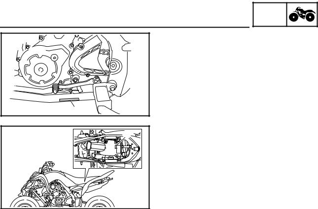
GEN
VEHICLE IDENTIFICATION INFO
EBS00009
GENERAL INFORMATION
VEHICLE IDENTIFICATION
EBS00010
VEHICLE IDENTIFICATION NUMBER
The vehicle identification number 1 is stamped into the left side of the frame.
EBS00011
MODEL LABEL
The model label 1 is affixed to the air filter case cover. This information will be needed to order spare parts.
1 — 1
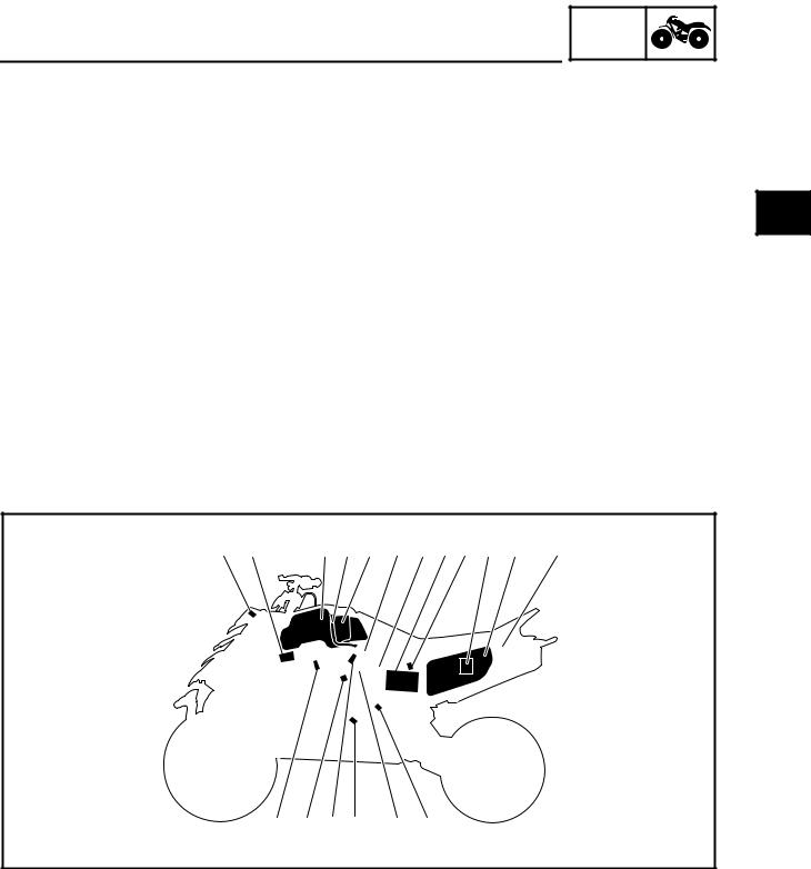
GEN
FEATURES INFO
EAS20170
FEATURES
OUTLINE OF THE FI SYSTEM
The main function of a fuel supply system is to provide fuel to the combustion chamber at the optimum air-fuel ratio in accordance with the engine operating conditions and the atmospheric temperature. In the conventional carburetor system, the air-fuel ratio of the mixture that is supplied to the combustion chamber is created by the volume of the intake air and the fuel that is metered by the jet used in the respective carburetor.
Despite the same volume of intake air, the fuel volume requirement varies with the engine operating conditions, such as acceleration, deceleration, or operating under a heavy load. Carburetors that meter the fuel through the use of jets have been provided with various auxiliary devices, so that an optimum air-fuel ratio can be achieved to accommodate the constant changes in the operating conditions of the engine.
As the requirements for the engine to deliver more performance and cleaner exhaust gases increase, it becomes necessary to control the air-fuel ratio in a more precise and finely tuned manner. To accommodate this need, this model has adopted an electronically controlled fuel injection (FI) system, in place of the conventional carburetor system. This system can achieve an optimum air-fuel ratio required by the engine at all times by using a microprocessor that regulates the fuel injection volume according to the engine operating conditions detected by various sensors.
The adoption of the FI system has resulted in a highly precise fuel supply, improved engine response, better fuel economy, and reduced exhaust emissions.
|
1 2 |
3 4 5 6 7 8 9 0 A B |
||||||
|
H G F E |
D C |
|
1 Engine trouble warning light |
0 ECU (electronic control unit) |
|
2 Ignition coil |
A Air filter case |
|
3 Fuel tank |
B Relay unit (fuel pump relay) |
|
4 Fuel hose |
C Speed sensor |
|
5 Fuel pump |
D Throttle position sensor |
|
6 Intake air pressure sensor |
E Crankshaft position sensor |
|
7 Lean angle sensor |
F Fuel injector |
|
8 Battery |
G Coolant temperature sensor |
|
9 Intake air temperature sensor |
H Spark plug |
1 — 2

The fuel pump delivers fuel to the fuel injector via the fuel filter. The pressure regulator maintains the fuel pressure that is applied to the fuel injector at only 324 kPa (3.24 kg/cm2, 46.1 psi). Accordingly, when the energizing signal from the ECU energizes the fuel injector, the fuel passage opens, causing the fuel to be injected into the intake manifold only during the time the passage remains open. Therefore, the longer the length of time the fuel injector is energized (injection duration), the greater the volume of fuel that is supplied. Conversely, the shorter the length of time the fuel injector is energized (injection duration), the lesser the volume of fuel that is supplied.
The injection duration and the injection timing are controlled by the ECU. Signals that are input from the throttle position sensor, crankshaft position sensor, intake air pressure sensor, intake air temperature sensor, coolant temperature sensor and speed sensor enable the ECU to determine the injection duration. The injection timing is determined through the signals from the crankshaft position sensor. As a result, the volume of fuel that is required by the engine can be supplied at all times in accordance with the driving conditions.
Illustration is for reference only.
|
Ê |
B |
|
|
4 |
||
|
1 |
2 |
|
|
È |
||
|
3 |
||
|
A |
||
|
0 |
||
|
É |
||
|
9 |
||
|
8 |
||
|
7 |
5 |
|
|
6 |
|
1 Fuel pump |
9 Intake air temperature sensor |
|
2 Fuel injector |
0 Air filter case |
|
3 Ignition coil |
A Throttle position sensor |
|
4 ECU (electronic control unit) |
B Speed sensor |
|
5 Coolant temperature sensor |
|
|
6 Crankshaft position sensor |
È Fuel system |
|
7 Intake air pressure sensor |
É Air system |
|
8 Throttle body |
Ê Control system |
1 — 3

FEATURES
SELF-ADJUSTING PARKING BRAKE MECHANISM
GEN  INFO
INFO 


Usually, for vehicles equipped with a parking brake that must be adjusted manually, it is necessary to adjust the adjusting bolt 5 to achieve the proper clearance between the brake caliper piston 7 and the adjusting bolt 5.
This adjustment procedure is unnecessary for vehicles equipped with a self-adjusting parking brake mechanism. The proper clearance is automatically maintained at all times, ensuring stable braking performance when parking the vehicle.
|
1 |
|||
|
2 |
|||
|
3 |
|||
|
7 |
6 |
5 |
4 |
|
1 Parking brake arm |
5 Adjusting bolt |
|
2 Parking brake shaft |
6 Nut |
|
3 Adjusting bolt |
7 Brake caliper piston |
|
4 Adjusting bolt sleeve |
1 — 4
![]()
FEATURES
Parking Brake Operation
GEN  INFO
INFO 


|
1 |
||
|
2 |
||
|
3 |
||
|
6 |
5 |
4 |
|
1 Parking brake arm |
4 Adjusting bolt sleeve |
|
2 Parking brake shaft |
5 Brake caliper piston |
|
3 Adjusting bolt |
6 Brake pad |
When the parking brake is operated, the parking brake cable turns the parking brake arm 1. The rotation of the parking brake arm is changed to axial thrust in the parking brake shaft 2 and the adjusting bolt 3 is pushed against the adjusting bolt sleeve 4.
When the adjusting bolt sleeve receives the force, the dark shaded area in the above illustration is pushed and the brake pad 6 is pushed against the brake disc.
When the brake pad wears, the clearance between the brake caliper piston 5 and the brake pad becomes larger and the force applied to the brake pad becomes weaker.
If this occurs, the self-adjusting parking brake mechanism adjusts automatically to achieve the proper clearance.
1 — 5
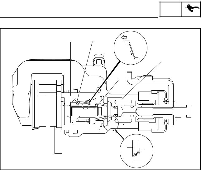
FEATURES
Parking Brake Operation
GEN  INFO
INFO 


|
1 |
2 |
È |
|
É |
||
|
4 |
||
|
3 |
||
|
Ê |
|
1 Brake caliper piston |
3 Adjusting bolt |
|
2 Nut |
4 Adjusting bolt sleeve |
When the brake pedal is operated, the brake fluid pressure in the master cylinder increases and the brake caliper piston 1 and the nut 2 are pushed.
When there is proper clearance between the brake caliper piston and the brake pad, no other parts move because the movement of the brake caliper piston and the nut is absorbed by the backlash of the threads of the nut and the adjusting bolt 3.
When the movement of the nut is greater than the backlash between the nut and the adjusting bolt, the parking brake adjusts automatically.
The amount of the adjustment varies with brake fluid pressure. Operating the parking brake makes no adjustment.
The adjustment operation is as follows.
1.When the brake pedal is operated, the brake fluid pressure increases and the brake caliper piston and the nut move.
2.When the movement of the brake caliper piston and the nut is greater than the backlash of the threads of the nut and the adjusting bolt, the force È will be required to pull the adjusting bolt. The force to pull the adjusting bolt will be turned into the rotation torque É by the shape of the threads of the nut and the adjusting bolt.
3.At this time, the clutch torque Ê between the adjusting bolt and the adjusting bolt sleeve 4 will decrease depending on the force required to pull the adjusting bolt.
When the rotation torque exceeds the clutch torque, the adjusting bolt rotates and the clearance between the brake caliper piston and the brake pad decreases by the movement of the threads of the nut and the adjusting bolt.
1 — 6

IMPORTANT INFORMATION
EBS00013
GEN  INFO
INFO 


IMPORTANT INFORMATION
PREPARATION FOR REMOVAL AND
DISASSEMBLY
1.Before removal and disassembly remove all dirt, mud, dust and foreign material.
2.Use only the proper tools and cleaning equipment.
Refer to “SPECIAL TOOLS”.
3.When disassembling always keep mated parts together. This includes gears, cylinders, pistons and other parts that have been “mated” through normal wear. Mated parts must always be reused or replaced as an assembly.
4.During disassembly, clean all of the parts and place them in trays in the order of disassembly. This will speed up assembly and allow for the correct installation of all parts.
5.Keep all parts away from any source of fire.
EBS00014
REPLACEMENT PARTS
1.Use only genuine Yamaha parts for all replacements. Use oil and grease recommended by Yamaha for all lubrication jobs. Other brands may be similar in function and appearance, but inferior in quality.
EBS00015
GASKETS, OIL SEALS AND O-RINGS
1.When overhauling the engine, replace all gaskets, seals and O-rings. All gasket surfaces, oil seal lips and O-rings must be cleaned.
2.During reassembly properly oil all mating parts and bearings, and lubricate the oil seal lips with grease.
1 — 7

IMPORTANT INFORMATION
EBS00016
GEN  INFO
INFO 


LOCK WASHERS/PLATES AND COTTER PINS
After removal, replace all lock washers/plates 1 and cotter pins. After the bolt or nut has been tightened to specification, bend the lock tabs along a flat of the bolt or nut.
EBS00017
BEARINGS AND OIL SEALS
Install bearings and oil seals so that the manufacturer’s marks or numbers are visible. When installing oil seals, lubricate the oil seal lips with a light coat of lithium-soap-based grease. Oil bearings liberally when installing, if appropriate.
1 Oil seal
CAUTION:
Do not spin the bearing with compressed air because this will damage the bearing surfaces.
1 Bearing
EBS00018
CIRCLIPS
Before reassembly, check all circlips carefully and replace damaged or distorted circlips. Always replace piston pin clips after one use. When installing a circlip 1, make sure the sharp-edged corner 2 is positioned opposite the thrust 3 that the circlip receives.
4 Shaft
1 — 8
GEN
IMPORTANT INFORMATION INFO
EBS00019
CHECKING THE CONNECTIONS
Check the leads, couplers, and connectors for stains, rust, moisture, etc.
1.Disconnect:
•lead
•coupler
•connector
2.Check:
•lead
•coupler
•connector
Moisture → Dry with an air blower. Rust/stains → Connect and disconnect sev-
eral times.
3.Check:
•all connections
Loose connection → Connect properly.
NOTE:
If the pin 1 on the terminal is flattened, bend it up.
4.Connect:
•lead
•coupler
•connector
NOTE:
Make sure all connections are tight.
5.Check:
•continuity (with the pocket tester)
Pocket tester 90890-03112
Analog pocket tester YU-03112-C
NOTE:
•If there is no continuity, clean the terminals.
•When checking the wire harness, perform steps (1) to (3).
•As a quick remedy, use a contact revitalizer available at most part stores.
1 — 9

SPECIAL TOOLS
EBS00021
SPECIAL TOOLS
GEN  INFO
INFO 


The following special tools are necessary for complete and accurate tune-up and assembly. Use only the appropriate special tools; this will help prevent damage caused by the use of inappropriate tools or improvised techniques. Special tools may differ by shape and part number from country to country. In such a case, two types are provided.
When placing an order, refer to the list provided below to avoid any mistakes. For US and CDN
P/N. YM-, YU-, YS-, YK-, ACCExcept for US and CDN
P/N. 90890-
|
Tool No. |
Tool name/Function |
Illustration |
|
Slide hammer bolt |
||
|
Slide hammer bolt (6 mm) |
||
|
90890-01083 |
||
|
YU-01083-1 |
||
|
This tool is used to remove the rocker arm |
||
|
shaft. |
||
|
Weight |
||
|
90890-01084 |
||
|
YU-01083-3 |
||
|
This tool is used to remove the rocker arm |
||
|
shaft. |
||
|
Crankcase separating tool |
||
|
Crankcase separator |
||
|
90890-01135 |
||
|
YU-01135-B |
||
|
This tool is used to separate the crank- |
||
|
case. |
||
|
Ring nut wrench |
||
|
Spanner wrench |
||
|
90890-01268 |
||
|
YU-01268 |
||
|
This tool is used to loosen or tighten the |
||
|
rear shock absorber locknuts. |
||
|
Crankshaft installer pot |
||
|
90890-01274 |
Installer pot |
|
|
Pot installer |
||
|
YU-90058 |
||
|
YU-90059 |
||
|
This tool is used to install the crankshaft. |
||
|
Crankshaft installer bolt |
||
|
Bolt |
||
|
90890-01275 |
||
|
YU-90060 |
||
|
This tool is used to install the crankshaft. |
||
1 — 10

|
SPECIAL TOOLS |
GEN |
|||||
|
INFO |
||||||
|
Tool No. |
Tool name/Function |
Illustration |
||||
|
Adapter (M16) |
||||||
|
Adapter #13 |
||||||
|
90890-04130 |
||||||
|
YM-04059 |
||||||
|
This tool is used to install the crankshaft. |
||||||
|
Spacer (crankshaft installer) |
||||||
|
Pot spacer |
||||||
|
90890-04081 |
||||||
|
YM-91044 |
||||||
|
This tool is used to install the crankshaft. |
||||||
|
Piston pin puller set |
||||||
|
Piston pin puller |
||||||
|
90890-01304 |
||||||
|
YU-01304 |
||||||
|
This tool is used to remove the piston pin. |
||||||
|
Tappet adjusting tool |
||||||
|
Valve adjuster (3 mm & 4 mm) |
||||||
|
90890-01311 |
||||||
|
YM-08035-A |
||||||
|
This tool is necessary for adjusting the |
||||||
|
valve clearance. |
||||||
|
Radiator cap tester |
||||||
|
Radiator pressure tester |
||||||
|
90890-01325 |
||||||
|
YU-24460-01 |
||||||
|
This tool is used to check the cooling sys- |
||||||
|
tem. |
||||||
|
Radiator cap tester adapter |
||||||
|
Radiator pressure tester adapter |
||||||
|
90890-01352 |
||||||
|
YU-33984 |
||||||
|
This tool is used to check the cooling sys- |
||||||
|
tem. |
||||||
|
Damper rod holder (30 mm) |
||||||
|
90890-01327 |
||||||
|
YM-01327 |
||||||
|
This tool is needed to loosen and tighten |
||||||
|
the steering stem bearing retainer. |
||||||
|
Flywheel puller |
90890-01404 YM-01404
This tool is used to remove the A.C.magneto rotor.
1 — 11
|
SPECIAL TOOLS |
GEN |
|||||
|
INFO |
||||||
|
Tool No. |
Tool name/Function |
Illustration |
||||
|
Steering nut wrench |
||||||
|
Spanner wrench |
||||||
|
90890-01443 |
||||||
|
YU-33975 |
This tool is needed to loosen and tighten |
|||||
|
the front shock absorber and rear shock |
||||||
|
absorber locknuts. |
||||||
|
Ball joint remover |
||||||
|
90890-01474 |
||||||
|
YM-01474 |
||||||
|
This tool is used to remove or install the |
||||||
|
ball joints. |
||||||
|
Ball joint remover attachment set |
||||||
|
Ball joint adapter set |
||||||
|
90890-01480 |
||||||
|
YM-01480 |
||||||
|
These tools are used to remove or install |
||||||
|
the ball joints. |
||||||
|
Rear axle nut wrench (46 mm) |
||||||
|
Axle nut wrench (46 mm) |
||||||
|
90890-01498 |
||||||
|
YM-37134 |
||||||
|
This tool is needed to loosen or tighten the |
||||||
|
rear axle nut. |
||||||
|
Sheave holder |
||||||
|
Primary clutch holder |
||||||
|
90890-01701 |
||||||
|
YS-01880-A |
This tool is used to hold the A.C. magneto |
|||||
|
rotor when loosen or tighten the A.C. mag- |
||||||
|
neto rotor nut. |
||||||
|
Thickness gauge |
||||||
|
Narrow gauge set |
||||||
|
90890-03079 |
||||||
|
YM-34483 |
||||||
|
This tool is used to measure the valve |
||||||
|
clearance. |
||||||
|
Compression gauge |
||||||
|
Engine compression tester |
||||||
|
90890-03081 |
||||||
|
YU-33223 |
||||||
|
This tool is used to measure engine com- |
||||||
|
pression. |
||||||
|
Extension |
90890-04082
This tool is used to measure engine compression.
1 — 12

|
SPECIAL TOOLS |
GEN |
||||
|
INFO |
|||||
|
Tool No. |
Tool name/Function |
Illustration |
Pocket tester Analog pocket tester
90890-03112 YU-03112-C
This instrument is needed for checking the electrical system.
Timing light
Inductive clamp timing light
90890-03141 YU-03141
This tool is necessary for checking ignition timing.
Pressure gauge
90890-03153 YU-03153
This tool is used to measure fuel pressure.
Fuel pressure adapter
90890-03176 YM-03176
This tool is used to measure fuel pressure.
Digital circuit tester
Model 88 Multimeter with tachometer
90890-03174 YU-A1927
This tool is used to check the electrical system.
FI diagnostic tool
90890-03182 YU-03182
This tool is used to check the diagnosis.
Valve spring compressor
90890-04019 YM-04019
This tool is needed to remove and install the valve assemblies.
Valve spring compressor attachment Valve spring compressor adapter (26 mm)
90890-01243 YM-01253-1
This tool is needed to remove and install the valve assemblies.
1 — 13

|
SPECIAL TOOLS |
GEN |
|||||
|
INFO |
||||||
|
Tool No. |
Tool name/Function |
Illustration |
||||
|
Middle driven shaft bearing driver |
||||||
|
Bearing driver (40 mm) |
||||||
|
90890-04058 |
||||||
|
YM-04058 |
||||||
|
This tool is used to install the water pump |
||||||
|
seal. |
||||||
|
Mechanical seal installer |
||||||
|
Water pump seal installer |
||||||
|
90890-04132 |
||||||
|
YM-33221-A |
||||||
|
This tool is used to install the water pump |
||||||
|
seal. |
||||||
|
Valve guide remover (ø6) |
||||||
|
Valve guide remover (6.0 mm) |
||||||
|
90890-04064 |
||||||
|
YM-4064-A |
||||||
|
This tool is needed to remove and install |
||||||
|
the valve guides. |
||||||
|
Valve guide installer (ø6) |
||||||
|
Valve guide installer (6.0 mm) |
||||||
|
90890-04065 |
||||||
|
YM-4065-A |
||||||
|
This tool is needed to install the valve |
||||||
|
guides. |
||||||
|
Valve guide reamer (ø6) |
||||||
|
Valve guide reamer (6.0 mm) |
||||||
|
90890-04066 |
||||||
|
YM-04066 |
||||||
|
This tool is needed to rebore the new |
||||||
|
valve guides. |
||||||
|
Universal clutch holder |
||||||
|
90890-04086 |
||||||
|
YM-91042 |
This tool is needed to hold the clutch boss |
|||||
|
when removing or installing the clutch |
||||||
|
boss nut. |
||||||
|
Ignition checker |
||||||
|
Opama pet-4000 spark checker |
||||||
|
90890-06754 |
||||||
|
YM-34487 |
||||||
|
This tool is used to check the ignition sys- |
||||||
|
tem components. |
||||||
|
Digital tachometer |
90890-06760 YU-39951-B
This tool is needed to observe engine rpm.
1 — 14
![]()
|
SPECIAL TOOLS |
GEN |
||||
|
INFO |
|||||
|
Tool No. |
Tool name/Function |
Illustration |
Yamaha bond No. 1215 (Three bond No. 1215)
90890-85505
This bond is used on crankcase mating surfaces, etc.
1 — 15

GENERAL SPECIFICATIONS SPEC
EBS01001
|
SPECIFICATIONS |
|
GENERAL SPECIFICATIONS |
|
|
Item |
Standard |
|
Model code |
1S31 |
|
Dimensions |
|
|
Overall length |
1,845 mm (72.6 in) |
|
Overall width |
1,170 mm (46.1 in) |
|
Overall height |
1,130 mm (44.5 in) |
|
Seat height |
815 mm (32.1 in) |
|
Wheelbase |
1,280 mm (50.4 in) |
|
Minimum ground clearance |
240 mm (9.45 in) |
|
Minimum turning radius |
3,500 mm (137.8 in) |
|
Basic weight |
|
|
With oil and full fuel tank |
192 kg (423 lb) |
|
Engine |
|
|
Engine type |
Liquid-cooled 4-stroke, SOHC |
|
Cylinder arrangement |
Forward-inclined single cylinder |
|
Displacement |
686 cm3 (41.86 cu in) |
|
Bore × stroke |
102.0 × 84.0 mm (4.02 × 3.31 in) |
|
Compression ratio |
9.20:1 |
|
Standard compression pressure (at sea level) |
450 kPa (4.5 kg/cm2, 64.0 psi) |
|
Starting system |
Electric starter |
|
Lubrication system |
Dry sump |
Oil type or grade
|
Engine oil |
||||||||
|
0° |
10° |
30° 50° 70° 90° 110° |
130°F |
API service SE, SF, SG type or higher |
||||
|
YAMALUBE4 (20W40) or SAE 20W40 |
||||||||
|
YAMALUBE4 (10W30) or SAE 10W30 |
||||||||
|
SAE 5W30 |
||||||||
|
-20° |
-10° |
0° |
10° |
20° |
30° |
40° |
50°C |
2 — 1

|
GENERAL SPECIFICATIONS |
SPEC |
|||
|
Item |
Standard |
|||
|
Oil capacity |
||||
|
Engine oil |
||||
|
Periodic oil change |
1.75 L (1.54 Imp qt, 1.85 US qt) |
|||
|
With oil filter replacement |
1.85 L (1.63 Imp qt, 1.96 US qt) |
|||
|
Total amount |
2.30 L (2.02 Imp qt, 2.43 US qt) |
|||
|
Radiator capacity (including all routes) |
1.61 L (1.42 Imp qt, 1.70 US qt) |
|||
|
Air filter |
Wet type element |
|||
|
Fuel |
||||
|
Type |
Regular unleaded gasoline only (For CDN, |
|||
|
Europe) |
||||
|
Unleaded gasoline only (For Oceania) |
||||
|
Fuel tank capacity |
11.0 L (2.42 Imp gal, 2.91 US gal) |
|||
|
Fuel reserve amount |
2.6 L (0.57 Imp gal, 0.69 US gal) |
|||
|
Fuel injector |
||||
|
Type/quantity |
297500-0390/1 |
|||
|
Manufacturer |
DENSO |
|||
|
Spark plug |
||||
|
Type/manufacturer |
CR8E/NGK |
|||
|
Spark plug gap |
0.7 ~ 0.8 mm (0.028 ~ 0.031 in) |
|||
|
Clutch type |
Wet, multiple disc |
|||
|
Transmission |
||||
|
Primary reduction system |
Spur gear |
|||
|
Primary reduction ratio |
77/34 (2.265) |
|||
|
Secondary reduction system |
Chain drive |
|||
|
Secondary reduction ratio |
38/14 (2.714) |
|||
|
Transmission type |
Constant mesh, 5-speed/forward, 1 speed/ |
|||
|
reverse |
||||
|
Operation |
Left foot operation |
|||
|
Gear ratio |
||||
|
1st gear |
38/13 (2.923) |
|||
|
2nd gear |
28/14 (2.000) |
|||
|
3rd gear |
25/17 (1.471) |
|||
|
4th gear |
25/22 (1.136) |
|||
|
5th gear |
22/24 (0.917) |
|||
|
Reverse gear |
24/13 × 29/12 (4.462) |
|||
|
Chassis |
||||
|
Frame type |
Aluminum die-cast and steel tube frame |
|||
|
Caster angle |
5° |
|||
|
Camber angle |
–1.0° |
|||
|
Kingpin angle |
14.8° |
|||
|
Kingpin offset |
2.8 mm (0.11 in) |
|||
|
Trail |
21.0 mm (0.83 in) |
|||
|
Tread front (STD) |
940 mm (37.01 in) |
|||
|
Tread rear (STD) |
900 mm (35.43 in) |
|||
|
Toe-in (with tires touching the ground) |
2 ~ 12 mm (0.08 ~ 0.47 in) |
|||
2 — 2

GENERAL SPECIFICATIONS SPEC
|
Item |
Standard |
|
|
Tire |
||
|
Type |
Tubeless |
|
|
Size |
front |
AT21 × 7-10 |
|
rear |
AT20 × 10-9 |
|
|
Manufacturer |
front |
DUNLOP |
|
rear |
DUNLOP |
|
|
Type |
front |
KT341 Radial |
|
rear |
KT345 Radial |
|
|
Tire pressure (cold tire) |
||
|
Maximum load* |
100 kg (220 lb) |
|
|
Off-road riding |
front |
27.5 kPa (0.28 kg/cm2, 4.0 psi) |
|
rear |
27.5 kPa (0.28 kg/cm2, 4.0 psi) |
|
|
*Load is total weight of cargo, rider and |
||
|
accessories |
||
|
Brake |
||
|
Front brake |
type |
Dual disc brake |
|
operation |
Right hand operation |
|
|
Rear brake |
type |
Single disc brake |
|
operation |
Right foot operation |
|
|
Suspension |
||
|
Front suspension |
Double wishbone |
|
|
Rear suspension |
Swingarm (link suspension) |
|
|
Shock absorber |
||
|
Front shock absorber |
Coil spring/oil damper |
|
|
Rear shock absorber |
Coil spring/gas-oil damper |
|
|
Wheel travel |
||
|
Front wheel travel |
230 mm (9.06 in) |
|
|
Rear wheel travel |
256 mm (10.08 in) |
|
|
Electrical system |
||
|
Ignition system |
Transistorized coil ignition (digital) |
|
|
Generator system |
A.C. magneto |
|
|
Battery type |
GT9B-4 |
|
|
Battery capacity |
12 V 8.0 Ah |
|
|
Bulb type |
Krypton bulb |
|
|
Bulb voltage/wattage × quantity |
||
|
Headlight |
12 V 30 W/30 W × 2 |
|
|
Tail/brake light |
LED |
|
|
Indicator light |
||
|
Neutral indicator light |
LED |
|
|
Fuel level warning light |
LED |
|
|
Reverse indicator light |
LED |
|
|
Coolant temperature warning light |
LED |
|
|
Engine trouble warning light |
LED |
|
2 — 3

ENGINE SPECIFICATIONS SPEC
EBS01002
ENGINE SPECIFICATIONS
|
Item |
Standard |
Limit |
|
|
Cylinder head |
|||
|
Maximum warpage |
—- |
0.03 mm |
|
|
(0.0012 in) |
|||
|
Cylinder |
||
|
Bore |
102.000 ~ 102.010 mm (4.0157 ~ 4.0161 in) |
102.080 mm |
|
(4.0189 in) |
||
|
Measuring point |
50.0 mm (1.97 in) |
—- |
|
Out of round |
0.05 mm |
|||
|
(0.002 in) |
||||
|
Camshaft |
||||
|
Drive system |
Chain drive (left) |
—- |
||
|
Camshaft lobe dimensions |
||||
A
|
B |
|||||||||||||
|
Intake measurement |
“A” |
43.300 ~ 43.400 mm (1.7047 ~ 1.7087 in) |
43.200 mm |
||||||||||
|
(1.7008 in) |
|||||||||||||
|
“B” |
37.026 ~ 37.126 mm (1.4577 ~ 1.4617 in) |
36.926 mm |
|||||||||||
|
(1.4538 in) |
|||||||||||||
|
Exhaust measurement |
“A” |
43.129 ~ 43.229 mm (1.6980 ~ 1.7019 in) |
43.029 mm |
||||||||||
|
(1.6941 in) |
|||||||||||||
|
“B” |
37.057 ~ 37.157 mm (1.4589 ~ 1.4629 in) |
36.957 mm |
|||||||||||
|
(1.4550 in) |
|||||||||||||
|
Maximum camshaft runout |
—- |
0.03 mm |
|||||||||||
|
(0.0012 in) |
|||||||||||||
|
Timing chain |
|||
|
Model/number of links |
98XRH2010/126 |
—- |
|
|
Tensioning system |
Automatic |
—- |
2 — 4

|
ENGINE SPECIFICATIONS |
SPEC |
||||||||||
|
Item |
Standard |
Limit |
|||||||||
|
Rocker arm/rocker arm shaft |
|||||||||||
|
Rocker arm inside diameter |
12.000 ~ 12.018 mm (0.4724 ~ 0.4731 in) |
—- |
|||||||||
|
Shaft outside diameter |
11.981 ~ 11.991 mm (0.4717 ~ 0.4721 in) |
—- |
|||||||||
|
Arm-to-shaft clearance |
0.009 ~ 0.037 mm (0.0004 ~ 0.0015 in) |
—- |
|||||||||
|
Valve, valve seat, valve guide |
|||||||||||
|
Valve clearance–intake (cold) |
0.09 ~ 0.13 mm (0.0035 ~ 0.0051 in) |
—- |
|||||||||
|
Valve clearance–exhaust (cold) |
0.16 ~ 0.20 mm (0.0063 ~ 0.0079 in) |
—- |
|||||||||
|
Valve dimensions |
|||||||||||
|
B |
C |
||||||||||
|
A |
D |
||||||||||
|
Head Diameter |
Face Width |
Seat Width |
Margin Thickness |
||||||||
|
Valve head diameter “A” |
|||||||||||
|
Intake |
37.9 ~ 38.1 mm (1.4921 ~ 1.5000 in) |
—- |
|||||||||
|
Exhaust |
31.9 ~ 32.1 mm (1.2559 ~ 1.2638 in) |
—- |
|||||||||
|
Valve face width “B” |
|||||||||||
|
Intake |
2.26 mm (0.0890 in) |
—- |
|||||||||
|
Exhaust |
2.26 mm (0.0890 in) |
—- |
|||||||||
|
Valve seat width “C” |
|||||||||||
|
Intake |
1.0 ~ 1.2 mm (0.0394 ~ 0.0472 in) |
1.6 mm |
|||||||||
|
(0.063 in) |
|||||||||||
|
Exhaust |
1.0 ~ 1.2 mm (0.0394 ~ 0.0472 in) |
1.6 mm |
|||||||||
|
(0.063 in) |
|||||||||||
|
Valve margin thickness “D” |
|||||||||||
|
Intake |
0.8 ~ 1.2 mm (0.0315 ~ 0.0472 in) |
—- |
|||||||||
|
Exhaust |
0.8 ~ 1.2 mm (0.0315 ~ 0.0472 in) |
—- |
|||||||||
|
Valve stem diameter |
|||||||||||
|
Intake |
5.975 ~ 5.990 mm (0.2352 ~ 0.2358 in) |
5.945 mm |
|||||||||
|
(0.2341 in) |
|||||||||||
|
Exhaust |
5.960 ~ 5.975 mm (0.2346 ~ 0.2352 in) |
5.930 mm |
|||||||||
|
(0.2335 in) |
|||||||||||
|
Valve guide inside diameter |
|||||||||||
|
Intake |
6.000 ~ 6.012 mm (0.2362 ~ 0.2367 in) |
6.050 mm |
|||||||||
|
(0.2382 in) |
|||||||||||
|
Exhaust |
6.000 ~ 6.012 mm (0.2362 ~ 0.2367 in) |
6.050 mm |
|||||||||
|
(0.2382 in) |
|||||||||||
|
Valve-stem-to-valve-guide clearance |
|||||||||||
|
Intake |
0.010 ~ 0.037 mm (0.0004 ~ 0.0015 in) |
0.080 mm |
|||||||||
|
(0.0031 in) |
|||||||||||
|
Exhaust |
0.025 ~ 0.052 mm (0.0010 ~ 0.0020 in) |
0.100 mm |
|||||||||
|
(0.0039 in) |
|||||||||||
2 — 5

|
ENGINE SPECIFICATIONS |
SPEC |
||||||||||||||||||
|
Item |
Standard |
Limit |
|||||||||||||||||
|
Valve stem runout |
—- |
0.01 mm |
|||||||||||||||||
|
(0.0004 in) |
|||||||||||||||||||
|
Valve seat width |
||
|
Intake |
1.0 ~ 1.2 mm (0.0394 ~ 0.0472 in) |
1.6 mm |
|
(0.0630 in) |
||
|
Exhaust |
1.0 ~ 1.2 mm (0.0394 ~ 0.0472 in) |
1.6 mm |
|
(0.0630 in) |
||
|
Valve spring |
||
|
Free length |
||
|
Intake |
38.79 mm (1.53 in) |
36.85 mm |
|
(1.45 in) |
||
|
Exhaust |
38.79 mm (1.53 in) |
36.85 mm |
|
(1.45 in) |
||
|
Installed length (valve closed) |
||
|
Intake |
35.00 mm (1.38 in) |
—- |
|
Exhaust |
35.00 mm (1.38 in) |
—- |
|
Compressed spring force (installed) |
||
|
Intake |
169.0 ~ 199.0 N |
—- |
|
(17.23 ~ 20.29 kg, 37.99 ~ 44.73 lb) |
||
|
Exhaust |
169.0 ~ 199.0 N |
—- |
|
(17.23 ~ 20.29 kg, 37.99 ~ 44.73 lb) |
||
|
Spring tilt |
|
Intake |
—- |
2.5°/1.70 mm |
|
(2.5°/0.067 in) |
||
|
Exhaust |
—- |
2.5°/1.70 mm |
|
(2.5°/0.067 in) |
||
|
Winding direction (top view) |
||
|
Intake |
Clockwise |
—- |
|
Exhaust |
Clockwise |
—- |
2 — 6

ENGINE SPECIFICATIONS SPEC
|
Item |
Standard |
Limit |
||
|
Piston |
||||
|
Piston-to-cylinder clearance |
0.030 ~ 0.055 mm (0.0012 ~ 0.0022 in) |
0.13 mm |
||
|
(0.0051 in) |
||||
|
Diameter “D” |
101.955 ~ 101.970 mm |
—- |
||
|
(4.0140 ~ 4.0146 in) |
||||
|
H |
|||||||||||
|
D |
|||||||||||
|
Height “H” |
10 mm (0.39 in) |
—- |
|||||||||
|
Offset |
0.5 mm (0.0197 in) |
—- |
|||||||||
|
Offset direction |
Intake side |
—- |
|||||||||
|
Piston pin bore inside diameter |
23.004 ~ 23.015 mm (0.9057 ~ 0.9061 in) |
23.045 mm |
|||||||||
|
(0.9073 in) |
|||||||||||
|
Piston pin outside diameter |
22.991 ~ 23.000 mm (0.9052 ~ 0.9055 in) |
22.971 mm |
|||||||||
|
(0.9044 in) |
|||||||||||
|
Piston-pin-to-piston-pin-bore clear- |
0.004 ~ 0.024 mm (0.0002 ~ 0.0009 in) |
0.074 mm |
|||||||||
|
ance |
(0.0029 in) |
||||||||||
|
Piston rings |
|||||||||||
|
Top ring |
|||||||||||
|
B |
|||||||||||
|
T |
|||||||||||
|
Ring type |
Barrel |
—- |
|||||||||
|
Dimensions (B × T) |
1.20 × 3.80 mm (0.05 × 0.15 in) |
—- |
|||||||||
|
End gap (installed) |
0.20 ~ 0.35 mm (0.008 ~ 0.014 in) |
0.60 mm |
|||||||||
|
(0.024 in) |
|||||||||||
|
Ring side clearance |
0.030 ~ 0.070 mm (0.0012 ~ 0.0028 in) |
0.12 mm |
|||||||||
|
(0.0047 in) |
|||||||||||
|
2nd ring |
|||||||||||
|
B |
|||||||||||
|
T |
|||||||||||
|
Ring type |
Taper |
—- |
|||||||||
|
Dimensions (B × T) |
1.20 × 4.00 mm (0.05 × 0.16 in) |
—- |
|||||||||
|
End gap (installed) |
0.35 ~ 0.50 mm (0.014 ~ 0.020 in) |
0.85 mm |
|||||||||
|
(0.033 in) |
|||||||||||
|
Ring side clearance |
0.030 ~ 0.070 mm (0.0012 ~ 0.0028 in) |
0.13 mm |
|||||||||
|
(0.0051 in) |
2 — 7

ENGINE SPECIFICATIONS SPEC
|
Item |
Standard |
Limit |
||||||||||||||||||
|
Oil ring |
||||||||||||||||||||
|
B |
||||||||||||||||||||
|
T |
||||||||||||||||||||
|
Dimensions (B × T) |
2.50 × 3.40 mm (0.10 × 0.13 in) |
—- |
||||||||||||||||||
|
End gap (installed) |
0.20 ~ 0.70 mm (0.008 ~ 0.028 in) |
—- |
||||||||||||||||||
|
Ring side clearance |
0.060 ~ 0.150 mm (0.0024 ~ 0.0059 in) |
—- |
||||||||||||||||||
|
Crankshaft |
||||||||||||||||||||
|
F |
||||||||||||||||||||
|
C |
C |
|||||||||||||||||||
|
E |
||||||||||||||||||||
|
D |
||||||||||||||||||||
|
A |
||||||||||||||||||||
|
Crank width “A” |
74.95 ~ 75.00 mm (2.951 ~ 2.953 in) |
—- |
||||||||||||||||||
|
Maximum runout “C” |
—- |
0.03 mm |
||||||||||||||||||
|
(0.0012 in) |
||||||||||||||||||||
|
Big end side clearance “D” |
0.350 ~ 0.650 mm (0.0138 ~ 0.0256 in) |
1.00 mm |
||||||||||||||||||
|
(0.040 in) |
||||||||||||||||||||
|
Big end radial clearance “E” |
0.010 ~ 0.025 mm (0.0004 ~ 0.0010 in) |
—- |
||||||||||||||||||
|
Small end free play “F” |
0.16 ~ 0.40 mm (0.0063 ~ 0.0157 in) |
—- |
||||||||||||||||||
|
Balancer |
||||||||||||||||||||
|
Balancer drive method |
Gear |
—- |
||||||||||||||||||
|
Clutch |
||||||||||||||||||||
|
Friction plate 1 (inside dia.: 121 mm) |
||||||||||||||||||||
|
Thickness |
2.92 ~ 3.08 mm (0.115 ~ 0.121 in) |
2.82 mm |
||||||||||||||||||
|
(0.111 in) |
||||||||||||||||||||
|
Quantity |
7 |
—- |
||||||||||||||||||
|
Friction plate 2 (inside dia.: 128 mm) |
||||||||||||||||||||
|
Thickness |
2.90 ~ 3.10 mm (0.114 ~ 0.122 in) |
2.80 mm |
||||||||||||||||||
|
(0.110 in) |
||||||||||||||||||||
|
Quantity |
1 |
—- |
||||||||||||||||||
|
Clutch plate |
||||||||||||||||||||
|
Thickness |
1.50 ~ 1.60 mm (0.059 ~ 0.063 in) |
—- |
||||||||||||||||||
|
Quantity |
7 |
—- |
||||||||||||||||||
|
Maximum warpage |
—- |
0.20 mm |
||||||||||||||||||
|
(0.0079 in) |
||||||||||||||||||||
|
Clutch spring |
||||||||||||||||||||
|
Free length |
50.0 mm (1.97 in) |
48.0 mm |
||||||||||||||||||
|
(1.89 in) |
||||||||||||||||||||
|
Quantity |
6 |
—- |
||||||||||||||||||
|
Clutch release method |
Outer pull, rack and pinion pull |
—- |
||||||||||||||||||
2 — 8

ENGINE SPECIFICATIONS SPEC
|
Item |
Standard |
Limit |
|
Transmission |
||
|
Maximum main axle runout |
—- |
0.08 mm |
|
(0.0031 in) |
||
|
Maximum drive axle runout |
—- |
0.08 mm |
|
(0.0031 in) |
||
|
Shifting mechanism |
||
|
Shift mechanism type |
Shift drum and guide bar |
—- |
|
Decompression device |
||
|
Device type |
Auto decomp |
—- |
|
Air filter oil grade |
Air-cooled 2-stroke engine oil |
—- |
|
Throttle body |
||
|
Model/manufacturer × quantity |
44EHS/MIKUNI × 1 |
—- |
|
Engine idle speed |
1,500 ~ 1,700 r/min |
—- |
|
Intake vacuum |
37.8 kPa (284 mmHg, 11.2 inHg) |
—- |
|
Fuel pump |
||
|
Pump type |
Electrical |
—- |
|
Model/manufacturer |
1S3/DENSO |
—- |
|
Maximum consumption amperage |
4.8 A |
—- |
|
Output pressure |
324 kPa (3.24 kg/cm2, 46.1 psi) |
—- |
|
Oil filter type |
Paper |
—- |
|
Oil pump |
||
|
Oil pump type |
Trochoid |
—- |
|
Inner-rotor-to-outer-rotor-tip clear- |
Less than 0.12 mm (0.0047 in) |
0.20 mm |
|
ance |
(0.0079 in) |
|
|
Outer-rotor-to-oil-pump-housing |
0.09 ~ 0.15 mm (0.0035 ~ 0.0059 in) |
0.22 mm |
|
clearance |
(0.0087 in) |
|
|
Bypass valve opening pressure |
40.0 ~ 80.0 kPa |
—- |
|
(0.40 ~ 0.80 kg/cm2, 5.70 ~ 11.4 psi) |
||
|
Oil pressure (hot) |
40.0 kPa at 1,600 r/min (0.40 kg/cm2 at |
—- |
|
1,600 r/min, 5.70 psi at 1,600 r/min) |
||
|
Pressure check location |
Element cover |
—- |
|
Cooling system |
||
|
Radiator core |
||
|
Width |
197 mm (7.76 in) |
—- |
|
Height |
300 mm (11.81 in) |
—- |
|
Depth |
22 mm (0.87 in) |
—- |
|
Radiator cap opening pressure |
93.3 ~ 122.7 kPa |
—- |
|
(0.933 ~ 1.227 kg/cm2, 13.27 ~ 17.45 psi) |
||
|
Coolant reservoir capacity |
||
|
Up to the maximum level mark |
0.25 L (0.22 Imp qt, 0.26 US qt) |
—- |
|
From low to full level |
0.15 L (0.13 Imp qt, 0.16 US qt) |
—- |
|
Water pump |
||
|
Water pump type |
Single-suction centrifugal pump |
—- |
|
Reduction ratio |
27/28 (0.964) |
—- |
2 — 9

|
ENGINE SPECIFICATIONS |
SPEC |
||
|
Lubrication chart |
|||
|
Counter axle |
Cylinder head |
||
|
Decompression |
|||
|
To oil tank |
Camshaft |
||
|
Main axle |
|||
|
Oil delivery pipe |
|||
|
Oil tank inlet pipe |
|||
|
A.C. magneto |
Drive axle |
||
|
cover |
|||
|
From oil tank |
|||
|
Oil filter |
Right crankcase |
||
|
element |
|||
|
Left |
Oil tank outlet |
||
|
crankcase |
hose joint |
||
|
Drain bolt |
|||
|
Right |
Right crankcase Clutch cover |
To clutch cover |
|
|
crankcase |
|||
|
Oil |
Oil pump |
||
|
strainer |
|||
|
Crankshaft |
|||
|
2 — 10 |

ENGINE SPECIFICATIONS SPEC
Cylinder head tightening sequence
|
5 |
||
|
7 |
2 |
|
|
3 |
||
|
8 |
1 |
|
|
4 |
||
|
6 |
2 — 11

CHASSIS SPECIFICATIONS SPEC
EBS01003
CHASSIS SPECIFICATIONS
|
Item |
Standard |
Limit |
|
Steering system |
||
|
Steering bearing type |
Ball and race bearing |
—- |
|
Front suspension |
||
|
Shock absorber travel |
115.0 mm (4.53 in) |
—- |
|
Spring free length |
269.0 mm (10.59 in) |
—- |
|
Installed length |
260.5 mm (10.26 in) |
—- |
|
Spring rate (K1) |
21.60 N/mm (2.20 kg/mm, 123.33 lb/in) |
—- |
|
Spring rate (K2) |
29.40 N/mm (3.00 kg/mm, 167.87 lb/in) |
—- |
|
Optional spring available |
No |
—- |
|
Rear suspension |
||
|
Shock absorber travel |
110.0 mm (4.33 in) |
—- |
|
Spring free length |
255.0 mm (10.04 in) |
—- |
|
Installed length |
236.0 mm (9.29 in) |
—- |
|
Spring rate (K1) |
46.00 N/mm (4.69 kg/mm, 262.66 lb/in) |
—- |
|
Spring stroke (K1) |
0 ~ 110.0 mm (0 ~ 4.33 in) |
—- |
|
Optional spring available |
No |
—- |
|
Swingarm |
||
|
Free play limit (radial) |
—- |
1.0 mm |
|
(0.04 in) |
||
|
Free play limit (axial) |
—- |
1.0 mm |
|
(0.04 in) |
||
|
Front wheel |
||
|
Type |
Panel wheel |
—- |
|
Rim size |
10 × 5.5 AT |
—- |
|
Rim material |
Aluminum |
—- |
|
Maximum radial wheel runout |
—- |
2.0 mm |
|
(0.08 in) |
||
|
Maximum lateral wheel runout |
—- |
2.0 mm |
|
(0.08 in) |
||
|
Rear wheel |
||
|
Type |
Panel wheel |
—- |
|
Rim size |
9 × 8.5 AT |
—- |
|
Rim material |
Aluminum |
—- |
|
Maximum radial wheel runout |
—- |
2.0 mm |
|
(0.08 in) |
||
|
Maximum lateral wheel runout |
—- |
2.0 mm |
|
(0.08 in) |
||
|
Drive chain |
||
|
Type/manufacturer |
520MXV/DAIDO |
—- |
|
Link quantity |
98 |
—- |
|
Drive chain slack |
25 ~ 35 mm (0.98 ~ 1.38 in) |
—- |
2 — 12

|
CHASSIS SPECIFICATIONS |
SPEC |
|||||
|
Item |
Standard |
Limit |
||||
|
Front disc brake |
||||||
|
Type |
Dual |
—- |
||||
|
Disc outside diameter × thickness |
161.0 × 3.5 mm (6.34 × 0.14 in) |
—- |
||||
|
Pad thickness inner |
4.3 mm (0.17 in) |
1.0 mm |
||||
|
(0.04 in) |
||||||
|
Pad thickness outer |
4.3 mm (0.17 in) |
1.0 mm |
||||
|
(0.04 in) |
||||||
|
Master cylinder inside diameter |
12.70 mm (0.50 in) |
—- |
||||
|
Caliper cylinder inside diameter |
25.40 mm (1.00 in) |
—- |
||||
|
Brake fluid type |
DOT 4 |
—- |
||||
|
Rear disc brake |
||||||
|
Type |
Single |
—- |
||||
|
Disc outside diameter × thickness |
200.0 × 3.6 mm (7.87 × 0.14 in) |
—- |
||||
|
Pad thickness inner |
5.6 mm (0.22 in) |
1.0 mm |
||||
|
(0.04 in) |
||||||
|
Pad thickness outer |
5.6 mm (0.22 in) |
1.0 mm |
||||
|
(0.04 in) |
||||||
|
Master cylinder inside diameter |
12.70 mm (0.50 in) |
—- |
||||
|
Caliper cylinder inside diameter |
32.03 mm (1.26 in) |
—- |
||||
|
Brake fluid type |
DOT 4 |
—- |
||||
|
Brake lever and brake pedal |
||||||
|
Brake pedal position |
15.3 mm (0.60 in) |
—- |
||||
|
Parking brake cable end length |
58 ~ 60 mm (2.28 ~ 2.36 in) |
—- |
||||
|
Clutch lever free play (lever end) |
5 ~ 10 mm (0.20 ~ 0.39 in) |
—- |
||||
|
Throttle lever free play |
2 ~ 4 mm (0.08 ~ 0.16 in) |
—- |
||||
|
Speed limiter length |
Less than 12 mm (0.47 in) |
—- |
||||
|
Shift pedal height |
48 mm (1.89 in) |
—- |
||||
2 — 13

ELECTRICAL SPECIFICATIONS SPEC
EBS01004
ELECTRICAL SPECIFICATIONS
|
Item |
Standard |
Limit |
|
|
System voltage |
12 V |
—- |
|
|
Ignition system |
|||
|
Ignition timing (B.T.D.C.) |
9.0°/1,600 r/min |
—- |
|
|
Advancer type |
Digital type |
—- |
|
|
Transistorized coil ignition |
|||
|
Crankshaft position sensor resis- |
192 ~ 288 Ω at 20 °C (68 °F)/ |
—- |
|
|
tance/color |
blue/yellow-green/white |
||
|
ECU |
|||
|
Model/manufacturer |
TBDF18/DENSO |
—- |
|
|
Ignition coil |
|||
|
Model/manufacturer |
JO267/DENSO |
—- |
|
|
Minimum ignition spark gap |
6.0 mm (0.24 in) |
—- |
|
|
Primary winding resistance |
3.4 ~ 4.6 Ω at 20 °C (68 °F) |
—- |
|
|
Secondary winding resistance |
10.4 ~ 15.6 kΩ at 20 °C (68 °F) |
—- |
|
|
Spark plug cap |
|||
|
Material |
Resin |
—- |
|
|
Resistance |
10.0 kΩ |
—- |
|
|
A.C. magneto |
|||
|
Model/manufacturer |
LMX58/DENSO |
—- |
|
|
Standard output |
14 V 17.2 A at 5,000 r/min |
—- |
|
|
Stator coil resistance/color |
0.248 ~ 0.372 Ω at 20 °C (68 °F)/ |
—- |
|
|
white-white |
|||
|
Rectifier/regulator |
|||
|
Type |
Semiconductor, short-circuit type |
—- |
|
|
Model/manufacturer |
SH650D-11/SHINDENGEN |
—- |
|
|
No load regulated voltage |
(DC) |
14.1 ~ 14.9 V |
—- |
|
Rectifier capacity |
18.0 A |
—- |
|
|
Withstand voltage |
200.0 V |
—- |
|
|
Electric starting system |
|||
|
Type |
Constant mesh type |
—- |
|
|
Starter motor |
|||
|
Model/manufacturer |
SM-13/MITSUBA |
—- |
|
|
Power output |
0.80 kW |
—- |
|
|
Armature coil resistance |
0.0250 ~ 0.0350 Ω at 20 °C (68 °F) |
—- |
|
|
Brush overall length |
12.5 mm (0.49 in) |
5.00 mm |
|
|
(0.20 in) |
|||
|
Spring force |
7.65 ~ 10.01 N |
—- |
|
|
(780 ~ 1,021 gf, 27.54 ~ 36.03 oz) |
|||
|
Commutator diameter |
28.0 mm (1.10 in) |
27.0 mm |
|
|
(1.06 in) |
|||
|
Mica undercut |
0.70 mm (0.03 in) |
—- |
|
2 — 14

|
ELECTRICAL SPECIFICATIONS |
SPEC |
|||||
|
Item |
Standard |
Limit |
||||
|
Starter relay |
||||||
|
Model/manufacturer |
2768106-A/JIDECO |
—- |
||||
|
Amperage rating |
180.0 A |
—- |
||||
|
Coil winding resistance |
4.18 ~ 4.62 Ω at 20 °C (68 °F) |
—- |
||||
|
Circuit breaker |
||||||
|
Circuit breaker type |
Fuse |
—- |
||||
|
Fuses |
||||||
|
Main fuse |
20 A |
—- |
||||
|
Headlight fuse |
15 A |
—- |
||||
|
Signaling system fuse |
10 A |
—- |
||||
|
Ignition fuse |
10 A |
—- |
||||
|
Fuel injection system fuse |
10 A |
—- |
||||
|
Spare fuse |
20 A |
—- |
||||
|
15 A |
—- |
|||||
|
10 A |
—- |
|||||
2 — 15

TIGHTENING TORQUES SPEC
EBS01005
TIGHTENING TORQUES
ENGINE TIGHTENING TORQUES
|
Part to be tightened |
Part name |
Thread |
Q’ty |
Tightening torque |
Remarks |
||||||
|
size |
Nm |
m · kg |
ft · lb |
||||||||
|
Cylinder head (exhaust pipe) |
Stud bolt |
M8 |
4 |
15 |
1.5 |
11 |
|||||
|
Cylinder head |
Bolt |
M9 |
4 |
35 |
3.5 |
25 |
M |
||||
|
Cylinder head |
Bolt |
M9 |
2 |
38 |
3.8 |
27 |
|||||
|
E |
|||||||||||
|
Cylinder head |
Bolt |
M6 |
2 |
10 |
1.0 |
7.2 |
|||||
|
Spark plug |
— |
M10 |
1 |
13 |
1.3 |
9.4 |
|||||
|
Oil gallery bolt |
Union bolt |
M8 |
1 |
10 |
1.0 |
7.2 |
|||||
|
Tappet cover |
Bolt |
M6 |
8 |
10 |
1.0 |
7.2 |
|||||
|
Camshaft sprocket cover |
Bolt |
M6 |
2 |
10 |
1.0 |
7.2 |
|||||
|
Camshaft sprocket |
Bolt |
M7 |
2 |
20 |
2.0 |
14 |
|||||
|
Decompressor assembly |
Bolt |
M7 |
2 |
20 |
2.0 |
14 |
|||||
|
Cylinder |
Bolt |
M10 |
4 |
50 |
5.0 |
36 |
See NOTE. |
||||
|
E |
|||||||||||
|
Cylinder |
Bolt |
M6 |
2 |
10 |
1.0 |
7.2 |
|||||
|
Cable guide |
Bolt |
M6 |
1 |
7 |
0.7 |
5.1 |
|||||
|
Water jacket joint |
Bolt |
M6 |
2 |
10 |
1.0 |
7.2 |
|||||
|
A.C. magneto rotor |
Nut |
M16 |
1 |
60 |
6.0 |
43 |
E |
||||
|
A.C. magneto cover |
Bolt |
M6 |
14 |
10 |
1.0 |
7.2 |
|||||
|
Balancer driven gear |
Nut |
M16 |
2 |
60 |
6.0 |
43 |
Use a lock |
||||
|
washer. |
|||||||||||
|
Breather plate |
Bolt |
M6 |
3 |
10 |
1.0 |
7.2 |
|||||
|
Use a lock |
|||||||||||
|
Primary drive gear |
Nut |
M20 |
1 |
110 |
11.0 |
80 |
washer. |
||||
|
Valve adjusting screw |
Nut |
M6 |
4 |
14 |
1.4 |
10 |
M |
||||
|
Camshaft bearing retainer |
Bolt |
M6 |
2 |
10 |
1.0 |
7.2 |
LT |
||||
|
Timing chain guide (intake side) |
Bolt |
M6 |
2 |
10 |
1.0 |
7.2 |
|||||
|
Timing chain tensioner cap bolt |
Bolt |
M16 |
1 |
20 |
2.0 |
14 |
|||||
|
Timing chain tensioner |
Bolt |
M6 |
2 |
10 |
1.0 |
7.2 |
|||||
|
Water pump outlet hose clamp |
Screw |
M4 |
2 |
2 |
0.2 |
1.4 |
|||||
|
Water pump |
Bolt |
M6 |
3 |
10 |
1.0 |
7.2 |
|||||
|
Water pump housing cover |
Bolt |
M6 |
3 |
11 |
1.1 |
8.0 |
|||||
|
Thermostat cover |
Bolt |
M6 |
2 |
10 |
1.0 |
7.2 |
|||||
|
Radiator |
Bolt |
M6 |
2 |
7 |
0.7 |
5.1 |
|||||
|
Engine oil drain bolt (crankcase) |
Bolt |
M14 |
1 |
23 |
2.3 |
17 |
|||||
|
Engine oil drain bolt (oil tank) |
Bolt |
M8 |
1 |
19 |
1.9 |
13 |
|||||
|
Oil baffle plate 1 |
Bolt |
M5 |
2 |
4 |
0.4 |
2.9 |
LT |
||||
|
Oil baffle plate 2 |
Bolt |
M6 |
2 |
10 |
1.0 |
7.2 |
|||||
|
Oil pump |
Bolt |
M6 |
1 |
10 |
1.0 |
7.2 |
|||||
|
Oil pump housing 2 |
Screw |
M6 |
1 |
7 |
0.7 |
5.1 |
|||||
|
Oil strainer |
Bolt |
M6 |
2 |
10 |
1.0 |
7.2 |
LT |
||||
2 — 16

|
TIGHTENING TORQUES |
SPEC |
||||||||||
|
Part to be tightened |
Part name |
Thread |
Q’ty |
Tightening torque |
Remarks |
||||||
|
size |
Nm |
m · kg |
ft · lb |
||||||||
|
Oil filter cover drain bolt |
Bolt |
M6 |
1 |
10 |
1.0 |
7.2 |
|||||
|
Oil filter cover |
Bolt |
M6 |
2 |
10 |
1.0 |
7.2 |
|||||
|
Check screw (oil filter cover) |
Screw |
M5 |
1 |
5 |
0.5 |
3.6 |
|||||
|
Oil delivery pipe |
Union bolt |
M10 |
2 |
20 |
2.0 |
14 |
|||||
|
Oil delivery pipe |
Bolt |
M6 |
1 |
10 |
1.0 |
7.2 |
|||||
|
Oil pipe joint |
Bolt |
M14 |
1 |
50 |
5.0 |
36 |
|||||
|
Oil tank inlet hose (oil tank side) |
Bolt |
M6 |
1 |
10 |
1.0 |
7.2 |
|||||
|
Oil tank inlet hose (engine side) |
Bolt |
M6 |
1 |
10 |
1.0 |
7.2 |
|||||
|
Oil tank outlet hose |
Nut |
M16 |
1 |
35 |
3.5 |
25 |
|||||
|
Oil tank outlet hose |
Bolt |
M6 |
2 |
10 |
1.0 |
7.2 |
|||||
|
Intake manifold clamp |
Screw |
M4 |
2 |
3 |
0.3 |
2.2 |
|||||
|
Air filter case joint clamp |
Screw |
M5 |
1 |
4 |
0.4 |
2.9 |
|||||
|
ECU bracket |
Bolt |
M6 |
2 |
7 |
0.7 |
5.1 |
|||||
|
Exhaust pipe 2 and exhaust pipe 1 |
Bolt |
M8 |
1 |
16 |
1.6 |
11 |
|||||
|
Spark arrester |
Bolt |
M6 |
1 |
8 |
0.8 |
5.8 |
|||||
|
Muffler and exhaust pipe 2 |
Bolt |
M8 |
1 |
18 |
1.8 |
13 |
|||||
|
Muffler |
Bolt |
M8 |
2 |
38 |
3.8 |
27 |
|||||
|
Exhaust pipes |
Nut |
M8 |
4 |
20 |
2.0 |
14 |
|||||
|
Muffler protector |
Screw |
M6 |
2 |
8 |
0.8 |
5.8 |
LT |
||||
|
Exhaust pipe protector |
Bolt |
M6 |
4 |
8 |
0.8 |
5.8 |
LT |
||||
|
Oil seal retainer (clutch cover) |
Bolt |
M6 |
2 |
10 |
1.0 |
7.2 |
LT |
||||
|
Timing mark accessing screw |
Screw |
M14 |
1 |
6 |
0.6 |
4.3 |
|||||
|
Crankshaft end accessing screw |
Screw |
M36 |
1 |
10 |
1.0 |
7.2 |
|||||
|
Crankcase bearing retainer |
Screw |
M6 |
2 |
10 |
1.0 |
7.2 |
LT |
||||
|
Crankcase bearing retainer |
Bolt |
M6 |
2 |
10 |
1.0 |
7.2 |
LT |
||||
|
Crankcase |
Bolt |
M6 |
17 |
10 |
1.0 |
7.2 |
|||||
|
Engine oil filler bolt |
Bolt |
M20 |
1 |
12 |
1.2 |
8.7 |
|||||
|
Starter clutch |
Bolt |
M8 |
3 |
30 |
3.0 |
22 |
LT |
||||
|
Clutch spring |
Bolt |
M6 |
6 |
8 |
0.8 |
5.8 |
|||||
|
Clutch boss |
Nut |
M20 |
1 |
95 |
9.5 |
68 |
Stake |
||||
|
Clutch cover |
Bolt |
M6 |
14 |
10 |
1.0 |
7.2 |
|||||
|
Drive sprocket |
Nut |
M22 |
1 |
85 |
8.5 |
61 |
Use a lock |
||||
|
washer. |
|||||||||||
|
Oil seal retainer (left crankcase) |
Bolt |
M6 |
2 |
10 |
1.0 |
7.2 |
|||||
|
Shift drum segment |
Bolt |
M8 |
1 |
30 |
3.0 |
22 |
|||||
|
Shift guide |
Bolt |
M6 |
2 |
10 |
1.0 |
7.2 |
LT |
||||
|
Reverse shift lever |
Bolt |
M6 |
1 |
13 |
1.3 |
9.4 |
|||||
|
Shift pedal |
Bolt |
M6 |
1 |
16 |
1.6 |
11 |
|||||
|
Stator coil |
Bolt |
M6 |
3 |
7 |
0.7 |
5.1 |
LT |
||||
|
Crankshaft position sensor |
Bolt |
M5 |
2 |
7 |
0.7 |
5.1 |
LT |
||||
|
A.C. magneto lead holder |
Bolt |
M5 |
1 |
7 |
0.7 |
5.1 |
LT |
||||
|
Coolant temperature sensor |
— |
M12 |
1 |
18 |
1.8 |
13 |
|||||
|
Starter motor |
Bolt |
M6 |
2 |
10 |
1.0 |
7.2 |
|||||
2 — 17

|
TIGHTENING TORQUES |
SPEC |
||||||||
|
Part to be tightened |
Part name |
Thread |
Q’ty |
Tightening torque |
Remarks |
||||
|
size |
Nm |
m · kg |
ft · lb |
||||||
|
Reverse switch |
— |
M10 |
1 |
17 |
1.7 |
12 |
|||
|
Neutral switch |
— |
M10 |
1 |
17 |
1.7 |
12 |
|||
NOTE:
Temporarily tighten the cylinder bolts to 15 Nm (1.5 m · kg, 11 ft · lb), and then tighten them to 50 Nm (5.0 m · kg, 36 ft · lb).
2 — 18

TIGHTENING TORQUES SPEC
EBS01006
CHASSIS TIGHTENING TORQUES
|
Part to be tightened |
Thread size |
Tightening torque |
Remarks |
||||
|
Nm |
m · kg |
ft · lb |
|||||
|
Engine upper bracket |
M8 |
33 |
3.3 |
24 |
|||
|
Engine mounting bolt (upper) |
M10 |
40 |
4.0 |
29 |
|||
|
Engine lower bracket |
M8 |
41 |
4.1 |
30 |
|||
|
Engine mounting bolt (middle) |
M10 |
66 |
6.6 |
48 |
|||
|
Engine mounting bolt (lower) |
M10 |
66 |
6.6 |
48 |
|||
|
Swingarm pivot shaft, engine, and frame |
M16 |
100 |
10.0 |
72 |
|||
|
Middle frame and rear frame |
M10 |
54 |
5.4 |
39 |
|||
|
Frame and oil tank |
M6 |
7 |
0.7 |
5.1 |
|||
|
Frame and coolant reservoir |
M6 |
7 |
0.7 |
5.1 |
|||
|
Rear shock absorber and frame |
M12 |
55 |
5.5 |
40 |
|||
|
Relay arm and swingarm |
M10 |
43 |
4.3 |
31 |
|||
|
Connecting arm and frame |
M12 |
55 |
5.5 |
40 |
|||
|
Relay arm and rear shock absorber |
M10 |
43 |
4.3 |
31 |
|||
|
Relay arm and connecting arm |
M10 |
43 |
4.3 |
31 |
|||
|
Rear axle pinch bolt |
M8 |
21 |
2.1 |
15 |
|||
|
Swingarm and guide pin |
M12 |
55 |
5.5 |
40 |
LT |
||
|
Swingarm skid plate and swingarm |
M6 |
7 |
0.7 |
5.1 |
|||
|
Drive chain guide 1 and swingarm |
M6 |
7 |
0.7 |
5.1 |
|||
|
Drive sprocket cover and engine |
M6 |
10 |
1.0 |
7.2 |
|||
|
Upper front arm and frame |
M10 |
38 |
3.8 |
27 |
|||
|
Lower front arm and frame |
M10 |
55 |
5.5 |
40 |
|||
|
Front shock absorber and frame |
M10 |
48 |
4.8 |
35 |
|||
|
Front shock absorber and lower front arm |
M10 |
48 |
4.8 |
35 |
|||
|
Steering stem, pitman arm, and frame |
M14 |
180 |
18.0 |
130 |
|||
|
Steering stem bushing and frame |
M8 |
23 |
2.3 |
17 |
Use a lock |
||
|
washer. |
|||||||
|
Steering stem and handlebar holder |
M8 |
23 |
2.3 |
17 |
|||
|
Tie-rod end and locknut |
M12 |
18 |
1.8 |
13 |
|||
|
Steering knuckle and front wheel hub |
M14 |
70 |
7.0 |
50 |
|||
|
Steering knuckle and front arm (upper and lower) |
M10 |
25 |
2.5 |
18 |
|||
|
Steering knuckle and tie-rod ball joint |
M10 |
25 |
2.5 |
18 |
|||
|
Pitman arm and tie-rod ball joint |
M10 |
25 |
2.5 |
18 |
|||
|
Frame and bearing retainer |
M42 |
65 |
6.5 |
47 |
|||
|
Fuel tank and fuel pump |
M6 |
7 |
0.7 |
5.1 |
|||
|
Fuel tank and frame |
M6 |
7 |
0.7 |
5.1 |
|||
|
Front wheel and front wheel hub |
M10 |
45 |
4.5 |
32 |
|||
|
Steering knuckle and front brake caliper bracket |
M8 |
28 |
2.8 |
20 |
|||
|
Front brake disc and front wheel hub |
M8 |
28 |
2.8 |
20 |
LT |
||
|
Rear brake caliper and brake caliper bracket |
M8 |
34 |
3.4 |
24 |
|||
|
Rear axle and rear wheel hub |
M16 |
200 |
20.0 |
145 |
See NOTE. |
||
|
Rear wheel and rear wheel hub |
M10 |
45 |
4.5 |
32 |
|||
2 — 19
 Loading…
- Manuals
- Brands
- Yamaha Manuals
- Offroad Vehicle
- RAPTOR YFM700RF 2015
- Service manual
-
Contents
-
Table of Contents
-
Troubleshooting
-
Bookmarks
Related Manuals for Yamaha RAPTOR YFM700RF 2015
Summary of Contents for Yamaha RAPTOR YFM700RF 2015
-
Page 1
2015 SERVICE MANUAL YFM700RF YFM700RSF LIT-11616-28-28 2LS-F8197-10… -
Page 2
EAS20050 YFM700RF/YFM700RSF SERVICE MANUAL ©2014 by Yamaha Motor Corporation, U.S.A. First edition, July 2014 All rights reserved. Any reproduction or unauthorized use without the written permission of Yamaha Motor Corporation, U.S.A. is expressly prohibited. Printed in U.S.A. LIT-11616-28-28… -
Page 3
If there is any question about a service procedure, it is imperative that you contact a Yamaha dealer for any service information changes that apply to this model. This policy is intended to provide the customer with the most satisfaction from his vehicle and to conform to federal environmental quality objectives. -
Page 4
EAS20090 HOW TO USE THIS MANUAL This manual is intended as a handy, easy-to-read reference book for the mechanic. Comprehensive explanations of all installation, removal, disassembly, assembly, repair and check procedures are laid out with the individual steps in sequential order. •… -
Page 5
EAS20100 1. Serviceable with engine mounted SYMBOLS 2. Filling fluid The following symbols are used in this manual 3. Lubricant for easier understanding. 4. Special tool 5. Tightening torque The following symbols are not relevant to every 6. Wear limit, clearance vehicle. -
Page 7: Table Of Contents
EAS20110 TABLE OF CONTENTS GENERAL INFORMATION SPECIFICATIONS PERIODIC CHECKS AND ADJUSTMENTS CHASSIS ENGINE COOLING SYSTEM FUEL SYSTEM ELECTRICAL SYSTEM TROUBLESHOOTING…
-
Page 9: General Information
GENERAL INFORMATION IDENTIFICATION ……………….. 1-1 VEHICLE IDENTIFICATION NUMBER ………….1-1 MODEL LABEL………………1-1 FEATURES…………………. 1-2 OUTLINE OF THE FI SYSTEM…………..1-2 FI SYSTEM………………..1-3 INSTRUMENT FUNCTIONS …………..1-4 IMPORTANT INFORMATION …………….. 1-5 PREPARATION FOR REMOVAL AND DISASSEMBLY……1-5 REPLACEMENT PARTS…………….1-5 GASKETS, OIL SEALS AND O-RINGS ………… 1-5 LOCK WASHERS/PLATES AND COTTER PINS ……..
-
Page 10: Identification
IDENTIFICATION EAS20130 IDENTIFICATION EAS20140 VEHICLE IDENTIFICATION NUMBER The vehicle identification number “1” is stamped into the left side of the frame. EAS20150 MODEL LABEL The model label “1” is affixed to the air filter case cover. This information will be needed to order spare parts.
-
Page 11: Features
FEATURES EAS20170 FEATURES EAS1S3L001 OUTLINE OF THE FI SYSTEM The main function of a fuel supply system is to provide fuel to the combustion chamber at the optimum air-fuel ratio in accordance with the engine operating conditions and the atmospheric temperature. In the conventional carburetor system, the air-fuel ratio of the mixture that is supplied to the combustion chamber is created by the volume of the intake air and the fuel that is metered by the jet used in the respective carburetor.
-
Page 12: Fi System
FEATURES EAS1S3L002 FI SYSTEM The fuel pump delivers fuel to the fuel injector via the fuel filter. The pressure regulator maintains the fuel pressure that is applied to the fuel injector at only 324 kPa (3.24 kgf/cm², 46.1 psi). Accordingly, when the energizing signal from the ECU energizes the fuel injector, the fuel passage opens, causing the fuel to be injected into the intake manifold only during the time the passage remains open.
-
Page 13: Instrument Functions
FEATURES The electrical circuit of the warning light can be EAS1S3L005 INSTRUMENT FUNCTIONS checked by turning the main switch to “ON”. The warning light should come on for a few seconds, Indicator lights and warning lights and then go off. If the warning light does not come on initially when the main switch is turned to “ON”, or if the warning light remains on, check the electrical cir-…
-
Page 14: Important Information
5. Keep all parts away from any source of fire. EAS20200 REPLACEMENT PARTS Use only genuine Yamaha parts for all replace- ments. Use oil and grease recommended by Yamaha for all lubrication jobs. Other brands may be similar in function and appearance, but…
-
Page 15: Bearings And Oil Seals
IMPORTANT INFORMATION EAS20230 EAS2LS1001 BEARINGS AND OIL SEALS RUBBER PARTS Install bearings “1” and oil seals “2” so that the Check rubber parts for deterioration during in- manufacturer marks or numbers are visible. spection. Some of the rubber parts are sensitive When installing oil seals “2”, lubricate the oil seal to gasoline, flammable oil, grease, etc.
-
Page 16: Basic Service Information
BASIC SERVICE INFORMATION EAS30380 BASIC SERVICE INFORMATION EAS30390 QUICK FASTENERS Rivet type 1. Remove: • Quick fastener To remove the quick fastener, push its pin with a screwdriver, then pull the fastener out. Screw type 1. Remove: • Quick fastener To remove the quick fastener, loosen the screw with a screwdriver, then pull the fastener out.
-
Page 17: Electrical System
BASIC SERVICE INFORMATION ECA16760 EAS30402 NOTICE ELECTRICAL SYSTEM Be sure to connect the battery leads to the correct battery terminals. Reversing the bat- Electrical parts handling tery lead connections could damage the ECA16600 NOTICE electrical components. Never disconnect a battery lead while the en- gine is running;…
-
Page 18
BASIC SERVICE INFORMATION ECA16620 Checking the electrical system NOTICE Handle electrical components with special Before checking the electrical system, make care, and do not subject them to strong sure that the battery voltage is at least 12 V. shocks. ECA14371 ECA16630 NOTICE NOTICE… -
Page 19
BASIC SERVICE INFORMATION 2. Check: Checking the connections • Lead Check the leads, couplers, and connectors for • Coupler stains, rust, moisture, etc. • Connector 1. Disconnect: Moisture → Dry with an air blower. • Lead Rust/stains → Connect and disconnect sev- •… -
Page 20
BASIC SERVICE INFORMATION • As a quick remedy, use a contact revitalizer available at most part stores. 4. Connect: • Lead • Coupler • Connector • When connecting a coupler or connector, push both sections of the coupler or connector to- gether until they are connected securely. -
Page 21
SPECIAL TOOLS EAS20260 SPECIAL TOOLS The following special tools are necessary for complete and accurate tune-up and assembly. Use only the appropriate special tools as this will help prevent damage caused by the use of inappropriate tools or improvised techniques. Special tools, part numbers or both may differ depending on the country. When placing an order, refer to the list provided below to avoid any mistakes. -
Page 22: Special Tools
SPECIAL TOOLS Reference Tool name/Tool No. Illustration pages Crankshaft installer pot 5-63 90890-01274 Installing pot YU-90058 YU-90058/YU-90059 Crankshaft installer bolt 5-63 90890-01275 Bolt YU-90060 Piston pin puller set 5-27 90890-01304 Piston pin puller YU-01304 YU-01304 Spacer 5-63 ø35 90890-01309 Pot spacer YU-90059 Tappet adjusting tool 90890-01311…
-
Page 23
SPECIAL TOOLS Reference Tool name/Tool No. Illustration pages Radiator cap tester 90890-01325 Mityvac cooling system tester kit YU-24460-A YU-24460-A Damper rod holder (30 mm) 4-47, 4-47 90890-01327 Damper rod holder (30 mm) YM-01327 Radiator cap tester adapter 90890-01352 Pressure tester adapter YU-33984 YU-33984 Flywheel puller… -
Page 24
SPECIAL TOOLS Reference Tool name/Tool No. Illustration pages Ball joint remover attachment set 4-53 90890-01480 Ball joint adapter set YM-01480 Axle nut wrench (46 mm) 4-14, 4-15 90890-01498 Rear axle nut wrench 46 mm YM-37134 Sheave holder 5-33, 5-35 90890-01701 Primary clutch holder YS-01880-A Compression gauge… -
Page 25
YU-03153 Digital circuit tester 90890-03174 Model 88 Multimeter with tachometer YU-A1927 Fuel pressure adapter 90890-03176 Fuel pressure adapter YM-03176 Yamaha diagnostic tool (US) 8-34 90890-03234 Valve spring compressor 5-20, 5-25 90890-04019 Valve spring compressor YM-04019 Middle driven shaft bearing driver 90890-04058 Middle drive bearing installer 40 &… -
Page 26
SPECIAL TOOLS Reference Tool name/Tool No. Illustration pages Spacer (crankshaft installer) 5-63 90890-04081 Pot spacer YM-91044 YM-91044 Extension 90890-04082 Universal clutch holder 5-44, 5-48 90890-04086 Universal clutch holder YM-91042 Adapter (M16) 5-63 90890-04130 Adapter #13 YM-04059 Mechanical seal installer 90890-04132 Water pump seal installer YM-33221-A Ignition checker… -
Page 27
SPECIAL TOOLS Reference Tool name/Tool No. Illustration pages Yamaha bond No. 1215 5-35, 5-60 90890-85505 (Three bond No.1215®) 1-18… -
Page 28
SPECIAL TOOLS 1-19… -
Page 29: Specifications
SPECIFICATIONS GENERAL SPECIFICATIONS ……………. 2-1 ENGINE SPECIFICATIONS …………….2-2 CHASSIS SPECIFICATIONS …………….2-9 ELECTRICAL SPECIFICATIONS …………..2-12 TIGHTENING TORQUES …………….2-14 GENERAL TIGHTENING TORQUE SPECIFICATIONS……2-14 ENGINE TIGHTENING TORQUES…………2-15 CHASSIS TIGHTENING TORQUES…………2-18 LUBRICATION POINTS AND LUBRICANT TYPES ……..2-21 ENGINE………………..2-21 LUBRICATION SYSTEM CHART AND DIAGRAMS……..2-23 ENGINE OIL LUBRICATION CHART ………….2-23 LUBRICATION DIAGRAMS …………..
-
Page 30: General Specifications
GENERAL SPECIFICATIONS EAS29110 GENERAL SPECIFICATIONS Model Model YFM700RF 2LS1 YFM700RSF B461 Dimensions Overall length 1845 mm (72.6 in) Overall width 1155 mm (45.5 in) Overall height 1115 mm (43.9 in) Seat height 830 mm (32.7 in) Wheelbase 1280 mm (50.4 in) Ground clearance 240 mm (9.4 in) Minimum turning radius…
-
Page 31: Engine Specifications
ENGINE SPECIFICATIONS EAS29120 ENGINE SPECIFICATIONS Engine Engine type Liquid cooled 4-stroke, SOHC Displacement 686.0 cm³ Cylinder arrangement Single cylinder Bore × stroke 102.0 × 84.0 mm (4.02 × 3.31 in) Compression ratio 10.0 : 1 Standard compression pressure (at sea level) 570 kPa (5.7 kgf/cm², 81.1 psi) Minimum-maximum 500–640 kPa (5.0–6.4 kgf/cm², 71.1–91.0 psi)
-
Page 32
ENGINE SPECIFICATIONS Valve full open temperature 85°C (185°F) Valve lift (full open) 8.0 mm (0.31 in) Radiator core Width 198.0 mm (7.80 in) Height 300.0 mm (11.81 in) Depth 24.0 mm (0.94 in) Water pump Water pump type Single suction centrifugal pump Reduction ratio 27/28 (0.964) Impeller shaft tilt limit… -
Page 33
ENGINE SPECIFICATIONS Rocker arm/rocker arm shaft Rocker arm inside diameter 12.000–12.018 mm (0.4724–0.4731 in) Rocker arm shaft outside diameter 11.981–11.991 mm (0.4717–0.4721 in) Rocker-arm-to-rocker-arm-shaft clearance 0.009–0.037 mm (0.0004–0.0015 in) Valve, valve seat, valve guide Valve clearance (cold) Intake 0.09–0.13 mm (0.0035–0.0051 in) Exhaust 0.16–0.20 mm (0.0063–0.0079 in) Valve dimensions… -
Page 34
ENGINE SPECIFICATIONS Installed compression spring force (intake) 169.00–199.00 N (17.23–20.29 kgf, 37.99– 44.73 lbf) Installed compression spring force (exhaust) 169.00–199.00 N (17.23–20.29 kgf, 37.99– 44.73 lbf) Spring tilt (intake) 2.5°/1.70 mm (2.5°/0.07 in) Spring tilt (exhaust) 2.5°/1.70 mm (2.5°/0.07 in) Winding direction (intake) Clockwise Winding direction (exhaust) -
Page 35
ENGINE SPECIFICATIONS End gap (installed) 0.20–0.35 mm (0.008–0.014 in) Limit 0.60 mm (0.024 in) Ring side clearance 0.030–0.070 mm (0.0012–0.0028 in) Limit 0.12 mm (0.0047 in) 2nd ring Ring type Taper Dimensions (B × T) 1.20 × 4.00 mm (0.05 × 0.16 in) End gap (installed) 0.75–0.90 mm (0.03–0.04 in) Limit… -
Page 36
ENGINE SPECIFICATIONS Friction plate 2 thickness 2.90–3.10 mm (0.11–0.12 in) Wear limit 2.8 mm (0.11 in) Plate quantity 1 pcs Clutch plate thickness 1.50–1.60 mm (0.059–0.063 in) Plate quantity 7 pcs Warpage limit 0.20 mm (0.0079 in) Clutch spring free length 50.0 mm (1.97 in) Minimum length 48.0 mm (1.89 in) -
Page 37
ENGINE SPECIFICATIONS Manufacturer DENSO Idling condition Engine idling speed 1500–1700 r/min CO% (air induction system ON) 1.0 % CO% (air induction system OFF) 1.5-8.5 % Intake vacuum 33.0 kPa (248 mmHg, 9.7 inHg) Water temperature 80 °C (176 °F) Oil temperature 55–65 °C (131–149 °F) Throttle lever free play 2.0–4.0 mm (0.08–0.16 in) -
Page 38: Chassis Specifications
CHASSIS SPECIFICATIONS EAS29130 CHASSIS SPECIFICATIONS Chassis Frame type Aluminum die-cast and steel tube frame Caster angle 5.0° Camber angle -1.0° Kingpin angle 14.8° Kingpin offset 5.2 mm (0.20 in) Trail 22.0 mm (0.87 in) Tread rear (STD) 900.0 mm (35.43 in) Tread front (STD) 940.0 mm (37.01 in) Toe-in (with tires touching the ground)
-
Page 39
CHASSIS SPECIFICATIONS Front disc brake Disc outside diameter × thickness 161.0 × 3.5 mm (6.34 × 0.14 in) Brake disc thickness limit 3.0 mm (0.12 in) Brake disc deflection limit 0.15 mm (0.006 in) Brake pad lining thickness (inner) 4.3 mm (0.17 in) Limit 1.0 mm (0.04 in) Brake pad lining thickness (outer) -
Page 40
CHASSIS SPECIFICATIONS Standard 2 (YFM700RF) 262.0 mm (10.31 in) (YFM700RSF) Maximum 5 (YFM700RF) 253.0 mm (9.96 in) (YFM700RSF) Rebound damping adjusting positions Minimum 30 (YFM700RSF) Standard 18 (YFM700RSF) Maximum 1 (YFM700RSF) Compression damping setting (for fast compression damping) Minimum 2 (YFM700RSF) Standard 1.5 (YFM700RSF) Maximum… -
Page 41: Electrical Specifications
ELECTRICAL SPECIFICATIONS EAS29140 ELECTRICAL SPECIFICATIONS Voltage System voltage 12 V Ignition system Ignition system Advancer type Digital Ignition timing (B.T.D.C.) 9.0 °/1600 r/min Engine control unit Model/manufacturer F8T85971/MITSUBISHI Fuel injection sensor 192.0–288.0 Ω Crankshaft position sensor resistance Intake air pressure sensor output voltage 3.57 –…
-
Page 42
ELECTRICAL SPECIFICATIONS Indicator light Neutral indicator light Fuel level warning light Reverse indicator light Coolant temperature warning light Engine trouble warning light Electric starting system System type Constant mesh Starter motor Power output 0.80 kW 0.025–0.035 Ω Armature coil resistance Brush overall length 12.5 mm (0.49 in) Limit… -
Page 43: Tightening Torques
TIGHTENING TORQUES EAS20320 TIGHTENING TORQUES EAS20330 GENERAL TIGHTENING TORQUE SPECIFICATIONS This chart specifies tightening torques for stan- dard fasteners with a standard ISO thread pitch. Tightening torque specifications for special com- ponents or assemblies are provided for each chapter of this manual. To avoid warpage, tight- en multi-fastener assemblies in a crisscross pat- tern and progressive stages until the specified tightening torque is reached.
-
Page 44: Engine Tightening Torques
TIGHTENING TORQUES EAS20340 ENGINE TIGHTENING TORQUES Thread Item Q’ty Tightening torque Remarks size Cylinder head stud bolt (exhaust 15 Nm (1.5 m·kg, 11 ft·lb) pipe) l =135 Cylinder head bolt 35 Nm (3.5 m·kg, 25 ft·lb) (5.31 in) l =145 Cylinder head bolt 35 Nm (3.5 m·kg, 25 ft·lb) (5.71 in)
-
Page 45
TIGHTENING TORQUES Thread Item Q’ty Tightening torque Remarks size Timing chain tensioner cap bolt 20 Nm (2 m·kg, 14 ft·lb) Timing chain tensioner bolt 10 Nm (1 m·kg, 7.2 ft·lb) Water pump outlet hose clamp 2 Nm (0.2 m·kg, 1.4 ft·lb) screw Water pump bolt 10 Nm (1 m·kg, 7.2 ft·lb) -
Page 46
TIGHTENING TORQUES Thread Item Q’ty Tightening torque Remarks size Oil seal retainer bolt (clutch cov- 10 Nm (1 m·kg, 7.2 ft·lb) Timing mark accessing screw 2 Nm (0.2 m·kg, 1.4 ft·lb) Crankshaft end accessing screw 2 Nm (0.2 m·kg, 1.4 ft·lb) Crankcase bearing retainer 10 Nm (1 m·kg, 7.2 ft·lb) screw… -
Page 47: Chassis Tightening Torques
TIGHTENING TORQUES EAS20350 CHASSIS TIGHTENING TORQUES Thread Item Q’ty Tightening torque Remarks size Engine upper bracket bolt 33 Nm (3.3 m·kg, 24 ft·lb) Engine mounting nut (upper) 40 Nm (4 m·kg, 29 ft·lb) Engine lower bracket bolt/nut 41 Nm (4.1 m·kg, 30 ft·lb) Engine mounting nut (middle) 66 Nm (6.6 m·kg, 48 ft·lb) Engine mounting nut (lower)
-
Page 48
TIGHTENING TORQUES Thread Item Q’ty Tightening torque Remarks size Steering knuckle and tie-rod ball 25 Nm (2.5 m·kg, 18 ft·lb) joint nut Pitman arm and tie-rod ball joint 25 Nm (2.5 m·kg, 18 ft·lb) Front brake disc guard (inner) 7 Nm (0.7 m·kg, 5.1 ft·lb) screw Bearing retainer nut 65 Nm (6.5 m·kg, 47 ft·lb) -
Page 49
TIGHTENING TORQUES Thread Item Q’ty Tightening torque Remarks size Rear brake caliper union bolt 30 Nm (3 m·kg, 22 ft·lb) Parking brake case bolt 22 Nm (2.2 m·kg, 16 ft·lb) Rear brake master bolt 20 Nm (2 m·kg, 14 ft·lb) Rear brake master cylinder union 30 Nm (3 m·kg, 22 ft·lb) bolt… -
Page 50: Lubrication Points And Lubricant Types
Transmission gears (wheel and pinion) Shift drum Shift forks Shift fork guide bar Shift lever assembly Shift shaft Reverse shift shaft Yamaha bond No. Crankcase mating surface 1215 (Three bond No.1215®) Yamaha bond No. AC magneto lead grommet (AC magneto cover) 1215 (Three bond No.1215®)
-
Page 51
LUBRICATION POINTS AND LUBRICANT TYPES 2-22… -
Page 52: Lubrication System Chart And Diagrams
LUBRICATION SYSTEM CHART AND DIAGRAMS EAS20390 LUBRICATION SYSTEM CHART AND DIAGRAMS EAS20400 ENGINE OIL LUBRICATION CHART 2-23…
-
Page 53
LUBRICATION SYSTEM CHART AND DIAGRAMS 1. Oil strainer 2. Oil pump 3. Right crankcase 4. Left crankcase 5. AC magneto cover 6. Oil tank inlet hose 7. To oil tank 8. Main axle 9. Drive axle 10. Counter axle 11. From oil tank 12. -
Page 54: Lubrication Diagrams
LUBRICATION SYSTEM CHART AND DIAGRAMS EAS20410 LUBRICATION DIAGRAMS 2-25…
-
Page 55
LUBRICATION SYSTEM CHART AND DIAGRAMS 1. Oil tank breather hose 2. Oil tank outlet hose 3. Oil tank inlet hose 4. Oil tank 2-26… -
Page 56
LUBRICATION SYSTEM CHART AND DIAGRAMS 2-27… -
Page 57
LUBRICATION SYSTEM CHART AND DIAGRAMS 1. Oil delivery pipe 2. Oil filter 3. Oil pump 2-28… -
Page 58
LUBRICATION SYSTEM CHART AND DIAGRAMS 2-29… -
Page 59
LUBRICATION SYSTEM CHART AND DIAGRAMS 1. Oil filter 2. Oil pump driven gear 3. Oil pump rotor 1 4. Oil pump rotor 2 5. Oil tank outlet hose joint 6. Main axle 7. Counter axle 2-30… -
Page 60
LUBRICATION SYSTEM CHART AND DIAGRAMS 2-31… -
Page 61
LUBRICATION SYSTEM CHART AND DIAGRAMS 1. Oil strainer 2. Oil pump rotor 2 3. Oil pump rotor 1 4. Oil pump driven gear A. To oil tank 2-32… -
Page 62
LUBRICATION SYSTEM CHART AND DIAGRAMS 2-33… -
Page 63
LUBRICATION SYSTEM CHART AND DIAGRAMS 1. Balancer 1 2. Crankshaft 2-34… -
Page 64: Cooling System Diagrams
COOLING SYSTEM DIAGRAMS EAS20420 COOLING SYSTEM DIAGRAMS 2-35…
-
Page 65
COOLING SYSTEM DIAGRAMS 1. Thermostat cover 2. Fast idle plunger outlet hose 3. Radiator inlet hose 4. Radiator 5. Radiator outlet hose 6. Water pump breather hose 7. Water pump A. Install the radiator inlet hose onto the thermostat cover pipe, making sure that it contacts the cover and its yellow paint mark is facing outward. -
Page 66
COOLING SYSTEM DIAGRAMS 2-37… -
Page 67
COOLING SYSTEM DIAGRAMS 1. Radiator 2. Radiator fan motor breather hose 3. Fuel tank shield 4. Coolant reservoir breather hose 5. Coolant reservoir 6. Coolant reservoir hose 7. Drain hose A. Pass the radiator fan motor breather hose through the guide. B. -
Page 68
COOLING SYSTEM DIAGRAMS 2-39… -
Page 69
COOLING SYSTEM DIAGRAMS 1. Water pump outlet hose 2. Water pump 3. Water pump breather hose 4. Water jacket inlet housing A. From radiator B. Install the water pump outlet hose onto the water jacket inlet housing, making sure to align the yellow paint mark on the hose with the projection on the water jacket inlet housing. -
Page 70: Cable Routing
CABLE ROUTING EAS20430 CABLE ROUTING Handlebar (top and front view) 2-41…
-
Page 71
CABLE ROUTING 1. Handlebar switch L. Route the throttle cable in front of the clutch cable and parking brake cable, then above the fuel tank 2. Handlebar switch lead shield. 3. Clutch switch lead M. Pass the throttle cable, clutch cable, parking brake 4. -
Page 72
CABLE ROUTING Engine (left side view) 2-43… -
Page 73
CABLE ROUTING 1. Headlight lead (left) K. Secure the plastic band by inserting the projection on the band into the hole in the frame, and then 2. Resistor fasten the wire harness at the center of its 3. Radiator positioning tape with the band, making sure that 4. -
Page 74
CABLE ROUTING Electrical components tray (left side view) 2-45… -
Page 75
CABLE ROUTING 1. Starter relay lead 2. Fuel pump relay 3. Yamaha diagnostic tool coupler 4. Fuse box lead 5. Radiator fan motor relay 6. Headlight relay 7. Tail/brake light 8. Tail/brake light lead 9. Fuel pump relay lead 10. ECU (engine control unit) 11. -
Page 76
CABLE ROUTING Electrical components tray (top view) 2-47… -
Page 77
CABLE ROUTING 1. Parking brake cable N. Fasten the indicator light assembly lead with the holder on the radiator grill. 2. Radiator fan motor coupler O. Fasten the leads with the holder at the section 3. Ignition coil leads before the intake air temperature sensor lead 4. -
Page 78
CABLE ROUTING Rear fender (top view) 2-49… -
Page 79
14. Tail/brake light lead A. Route the starter motor lead under the starter relay lead. B. Route the Yamaha diagnostic tool lead over the fuel pump relay lead, fuse box lead, headlight relay lead, and radiator fan motor relay lead. -
Page 80
CABLE ROUTING Engine (right side view) 2-51… -
Page 81
CABLE ROUTING 1. Throttle position sensor lead 2. Fast idle plunger outlet hose 3. Air induction system hose (air filter case joint to air cut-off valve) 4. Fuel injector lead 5. Intake air pressure sensor 6. Coolant temperature sensor lead 7. -
Page 82
CABLE ROUTING Front brake hose (front and top view) 2-53… -
Page 83
CABLE ROUTING 1. Front brake pipe 2. Front brake hose 3. Front brake hose holder A. Face the mark on the front brake pipe upward. B. Fasten the front brake pipe with the holder. C. Route the front brake hose over the upper front arm. -
Page 84
CABLE ROUTING Rear brake hose (right side view) 2-55… -
Page 85
CABLE ROUTING 1. Parking brake cable 2. Rear brake hose 3. Brake fluid reservoir hose 4. Rear brake light switch lead A. Make sure that the ends of the hose clamp are not pointing outward. B. Face the white paint marks on both ends of the brake fluid reservoir hose rearward. -
Page 86
CABLE ROUTING Throttle body (left and right side view) 2-57… -
Page 87
CABLE ROUTING 1. Throttle body 2. Air induction system hose (air filter case joint to air cut-off valve) 3. Air filter case 4. Air filter case joint 5. Crankcase breather hose 6. Idle air hose 7. Cylinder head 8. Brake fluid reservoir 9. -
Page 88
CABLE ROUTING 2-59… -
Page 89: Periodic Checks And Adjustments
PERIODIC CHECKS AND ADJUSTMENTS PERIODIC MAINTENANCE …………….3-1 INTRODUCTION ………………3-1 PERIODIC MAINTENANCE CHART FOR THE EMISSION CONTROL SYSTEM …………….3-1 GENERAL MAINTENANCE AND LUBRICATION CHART …….3-1 ENGINE ………………….3-4 ADJUSTING THE VALVE CLEARANCE ……….3-4 ADJUSTING THE ENGINE IDLING SPEED ……….3-6 ADJUSTING THE THROTTLE LEVER FREE PLAY ……..3-6 ADJUSTING THE SPEED LIMITER…………
-
Page 90
CHASSIS ………………….. 3-19 ADJUSTING THE FRONT DISC BRAKE (YFM700RSF)……3-19 ADJUSTING THE REAR DISC BRAKE ……….3-19 CHECKING THE BRAKE FLUID LEVEL……….3-19 CHECKING THE FRONT BRAKE PADS ……….3-20 CHECKING THE REAR BRAKE PADS ……….3-20 CHECKING THE FRONT BRAKE HOSES ……….3-20 CHECKING THE REAR BRAKE HOSE ………. -
Page 92: Periodic Maintenance
However, keep in mind that if the ATV isn’t used for a long period of time, the month mainte- nance intervals should still be followed. • Items marked with an asterisk should be performed by a Yamaha dealer as they require special tools, data and technical skills.
-
Page 93
PERIODIC MAINTENANCE INITIAL EVERY month CHECK OR MAINTENANCE Whichever ITEM 1300 2500 2500 5000 comes first km (mi) (200) (800) (1600) (1600) (3200) hours Every 20–40 hours (more often in wet or Air filter element • Clean and replace if necessary. dusty areas) √… -
Page 94
PERIODIC MAINTENANCE INITIAL EVERY month CHECK OR MAINTENANCE Whichever ITEM 1300 2500 2500 5000 comes first km (mi) (200) (800) (1600) (1600) (3200) hours Reverse lock release √ √ √ • Check operation and adjust or replace if necessary. cable •… -
Page 95: Engine
ENGINE EAS20472 ENGINE EAS20520 ADJUSTING THE VALVE CLEARANCE The following procedure applies to all of the valves. • Valve clearance adjustment should be made on a cold engine, at room temperature. • When the valve clearance is to be measured or 6.
-
Page 96
ENGINE • Hold the adjusting screw to prevent it from moving and tighten the locknut to specifica- tion. Locknut 14 Nm (1.4 m·kg, 10 ft·lb) d. Measure the valve clearance again. e. If the valve clearance is still out of specifica- tion, repeat all of the valve clearance adjust- ment steps until the specified clearance is ▲… -
Page 97: Adjusting The Engine Idling Speed
ENGINE • Front fender EAS1S3L006 ADJUSTING THE THROTTLE LEVER FREE • Seat PLAY Refer to “GENERAL CHASSIS” on page 4-1. EAS20620 Prior to adjusting the throttle lever free play, the ADJUSTING THE ENGINE IDLING SPEED engine idling speed should be adjusted. 1.
-
Page 98: Adjusting The Speed Limiter
ENGINE If the specified throttle lever free play cannot be obtained on the throttle body side of the cable, use the adjusting nut on the throttle lever side. ▲ ▲▲▲ ▲ ▲▲▲ ▲ ▲ ▲▲▲ ▲ ▲ ▲▲▲ ▲ ▲ ▲▲▲ ▲…
-
Page 99: Measuring The Compression Pressure
ENGINE ECA13330 NOTICE Spark plug 13 Nm (1.3 m·kg, 9.4 ft·lb) Before removing the spark plug, blow away any dirt accumulated in the spark plug well with compressed air to prevent it from falling Before installing the spark plug, clean the spark into the cylinder.
-
Page 100: Checking The Engine Oil Level
ENGINE Compression pressure (with oil applied into the cylinder) Reading Diagnosis Higher than without Piston ring(s) wear or damage → Repair. Piston, valves, cylin- der head gasket or Same as without oil piston ring(s) possi- bly defective → Re- pair. 6.
-
Page 101: Changing The Engine Oil
ENGINE 4. Start the engine, warm it up for several min- utes, and then turn it off. 5. Check the engine oil level again. Before checking the engine oil level, wait a few minutes until the oil has settled. EAS20800 CHANGING THE ENGINE OIL 1.
-
Page 102
ENGINE 6. Remove: • Oil filter element drain bolt • Oil filter element drain bolt “1” (along with the gasket) Oil filter element drain bolt 10 Nm (1.0 m·kg, 7.2 ft·lb) 11.Fill: • Oil tank • Crankcase (with the specified amount of the recom- mended engine oil) Engine oil quantity Total amount… -
Page 103: Adjusting The Clutch Lever Free Play
ENGINE b. Start the engine and keep it idling until engine oil starts to seep from the oil check bolt. If no engine oil comes out after one minute, turn the engine off so that it will not seize. c. Check the engine oil passages, the oil filter element and the oil pump for damage or leak- age.
-
Page 104: Checking The Air Induction System
ENGINE 1. Remove: EWA13020 WARNING • Seat Never use low flash point solvents, such as Refer to “GENERAL CHASSIS” on page 4-1. gasoline, to clean the air filter element. Such 2. Remove: solvents may cause a fire or an explosion. •…
-
Page 105: Checking The Fuel Line
ENGINE ECA13450 EAS21030 NOTICE CHECKING THE FUEL LINE Make sure the crankcase breather hose is 1. Remove: routed correctly. • Seat • Front fender • Fuel tank EAS21080 CHECKING THE EXHAUST SYSTEM Refer to “GENERAL CHASSIS” on page 4-1. The following procedure applies to all of the ex- 2.
-
Page 106: Cleaning The Spark Arrester
ENGINE f. Tap the tailpipe lightly with a soft-face ham- mer or suitable tool, then use a wire brush to remove any carbon deposits from the spark arrester portion of the tailpipe and the inner contact surfaces of the muffler. EAS28970 CLEANING THE SPARK ARRESTER 1.
-
Page 107: Checking The Cooling System
ENGINE ECA13470 NOTICE • Adding water instead of coolant lowers the antifreeze content of the coolant. If water is used instead of coolant check, and if nec- essary, correct the antifreeze concentra- tion of the coolant. • Use only distilled water. However, if dis- tilled water is not available, soft water may be used.
-
Page 108
ENGINE 3. Drain: • Coolant (from the coolant reservoir) 7. Drain: • Coolant (from the engine and radiator) 4. Connect: 8. Check: • Coolant reservoir hose • Coolant drain bolt “1” 5. Remove: Damage → Replace. • Radiator cap “1” 9. -
Page 109
ENGINE Recommended antifreeze High-quality ethylene glycol anti- freeze containing corrosion in- hibitors for aluminum engines Mixing ratio 1:1 (antifreeze:water) Radiator capacity (including all routes) 1.68 L (1.78 US qt, 1.48 Imp.qt) Coolant reservoir capacity (up to the maximum level mark) 15.Install: 0.25 L (0.26 US qt, 0.22 Imp.qt) •… -
Page 110: Chassis
CHASSIS b. Turn the adjusting bolt “2” until the brake ped- EAS29360 CHASSIS al height is within the specified limits. EAS21170 Brake pedal position (from foot- ADJUSTING THE FRONT DISC BRAKE rest) (YFM700RSF) 15.3 mm (0.60 in) 1. Adjust: • Brake lever position “a” ▼…
-
Page 111: Checking The Front Brake Pads
CHASSIS 1. Remove: • Front wheel Refer to “FRONT WHEELS” on page 4-5. 2. Check: • Front brake pad Wear indicator grooves “a” have almost dis- appeared → Replace the brake pads as a set. Refer to “FRONT BRAKES” on page 4-17. 3.
-
Page 112: Checking The Rear Brake Hose
CHASSIS 2. Check: EAS29210 ADJUSTING THE PARKING BRAKE • Brake hose “1” 1. Check: Cracks/damage/wear → Replace. • Parking brake cable end length “a” Out of specification → Adjust. Parking brake cable end length 47.0–51.0 mm (1.85–2.01 in) 3. Check: •…
-
Page 113: Adjusting The Rear Brake Light Switch
CHASSIS caution could allow air to enter the hydraulic EAS21330 ADJUSTING THE REAR BRAKE LIGHT brake system, considerably lengthening the SWITCH bleeding procedure. • If bleeding is difficult, it may be necessary to let The rear brake light switch is operated by move- the brake fluid settle for a few hours.
-
Page 114: Adjusting The Shift Pedal
CHASSIS j. Tighten the bleed screw to specification. Shift pedal bolt 16 Nm (1.6 m·kg, 11 ft·lb) Bleed screw 6 Nm (0.6 m·kg, 4.3 ft·lb) ▲ ▲▲▲ ▲ ▲▲▲ ▲ ▲ ▲▲▲ ▲ ▲ ▲▲▲ ▲ ▲ ▲▲▲ ▲ ▲ ▲▲▲ ▲…
-
Page 115: Adjusting The Drive Chain Slack
CHASSIS Loosen the rear axle pinch bolts in the proper se- quence as shown. b. Insert an appropriate shaft “2” in the hole “4” of rear axle hub “3” so that the sprocket bracket “5” does not move. d. Tighten the locknut. e.
-
Page 116: Checking The Steering System
CHASSIS EAS29280 CHECKING THE STEERING SYSTEM 1. Place the vehicle on a level surface. 2. Check: • Steering assembly bushings Move the handlebar up and down, and back and forth. Excessive play → Replace the steering stem bushings. EAS29290 ADJUSTING THE TOE-IN 1.
-
Page 117: Checking The Front Shock Absorber Assemblies
CHASSIS d. Tighten the rod end locknuts of both tie-rods. Locknut (tie-rod end) 18 Nm (1.8 m·kg, 13 ft·lb) Adjust the tie-rod ends so that “A” and “B” are equal. C. Forward ▲ ▲▲▲ ▲ ▲▲▲ ▲ ▲ ▲▲▲ ▲ ▲…
-
Page 118: Adjusting The Front Shock Absorber Assemblies
CHASSIS Refer to “FRONT ARMS AND FRONT Spring preload adjusting positions SHOCK ABSORBER ASSEMBLIES” on Minimum page 4-50. 3. Check: Standard • Operation Pump the front shock absorber assembly up Maximum and down several times. Unsmooth operation → Replace front shock absorber assembly.
-
Page 119
CHASSIS ▼ ▼▼▼ ▼ ▼▼▼ ▼ ▼ ▼▼▼ ▼ ▼ ▼▼▼ ▼ ▼ ▼▼▼ ▼ ▼ ▼▼▼ ▼ ▼▼▼ a. Turn the adjusting screw “1” in direction “a” or “b”. Direction “a” Rebound damping force is increased (suspension is harder). Direction “b”… -
Page 120: Checking The Rear Shock Absorber Assembly
CHASSIS ECA1S3L003 NOTICE Compression damping setting (for fast compression damping) Do not force the adjuster past the minimum Minimum or maximum extent of adjustment. The ad- 2 turn(s) out* juster may be damaged. Standard 1.5 turn(s) out* Maximum Adjusting bolt fully turned in * With the adjusting bolt fully turned in ECA1S3L003 NOTICE…
-
Page 121: Adjusting The Rear Shock Absorber Assembly
CHASSIS Spring preload adjusting length “c” Minimum 238.5 mm (9.39 in) Standard 228.5 mm (9.00 in) Maximum 223.5 mm (8.80 in) EAS1S3L008 ADJUSTING THE REAR SHOCK ABSORBER ASSEMBLY 1. Remove: • Seat • Air filter case Refer to “GENERAL CHASSIS” on page 4-1. 2.
-
Page 122
CHASSIS ▼ ▼▼▼ ▼ ▼▼▼ ▼ ▼ ▼▼▼ ▼ ▼ ▼▼▼ ▼ ▼ ▼▼▼ ▼ ▼ ▼▼▼ ▼ ▼▼▼ a. Turn the adjusting bolt “1” in direction “a” or “b”. Direction “a” Compression damping force is in- creased (suspension is harder). Direction “b”… -
Page 123: Checking The Tires
Rear 24.5 kPa (0.245 kgf/cm², 3.6 vehicles. The tires listed below have been psi) approved by Yamaha Motor Co., Ltd. for this model. If other tire combinations are used, they can adversely affect your vehicle’s han- Maximum loading limit dling characteristics and are therefore not…
-
Page 124: Checking The Wheels
CHASSIS EWA1S3L015 WARNING Maximum loading limit 100.0 kg (220 lb) It is dangerous to ride with a worn-out tire. When the tire tread reaches the wear limit * Total weight of the cargo, trailer hitch “a”, replace the tire immediately. vertical load, rider, and accessories.
-
Page 125: Lubricating The Clutch Lever
CHASSIS 1. Check: • Outer cable Damage → Replace. 2. Check: • Cable operation Rough movement → Lubricate. Recommended lubricant Engine oil or a suitable cable lu- bricant Hold the cable end upright and pour a few drops of lubricant into the cable sheath or use a suit- able lubricating device.
-
Page 126: Electrical System
ELECTRICAL SYSTEM EAS21750 ECA13690 ELECTRICAL SYSTEM NOTICE Avoid touching the glass part of the head- EAS21760 light bulb to keep it free from oil, otherwise CHECKING AND CHARGING THE BATTERY the transparency of the glass, the life of the Refer to “ELECTRICAL COMPONENTS” on bulb and the luminous flux will be adversely page 8-59.
-
Page 127
ELECTRICAL SYSTEM ▲ ▲▲▲ ▲ ▲▲▲ ▲ ▲ ▲▲▲ ▲ ▲ ▲▲▲ ▲ ▲ ▲▲▲ ▲ ▲ ▲▲▲ ▲ ▲▲▲ 3-36… -
Page 128
ELECTRICAL SYSTEM 3-37… -
Page 129
CHASSIS GENERAL CHASSIS………………4-1 FRONT WHEELS ……………….. 4-5 REMOVING THE FRONT WHEELS …………4-6 CHECKING THE FRONT WHEELS…………4-6 CHECKING THE FRONT WHEEL HUBS ……….4-6 INSTALLING THE FRONT WHEEL HUB BEARINGS ……4-7 INSTALLING THE FRONT BRAKE DISCS……….4-7 INSTALLING THE FRONT WHEEL HUBS ……….4-7 INSTALLING THE FRONT WHEELS…………4-8 REAR WHEELS……………….. -
Page 130
REAR BRAKE ………………..4-28 INTRODUCTION ………………4-35 CHECKING THE REAR BRAKE DISC…………4-35 REPLACING THE REAR BRAKE PADS……….4-35 REMOVING THE REAR BRAKE CALIPER ……….4-36 DISASSEMBLING THE REAR BRAKE CALIPER ……..4-36 CHECKING THE REAR BRAKE CALIPER……….4-37 ASSEMBLING THE REAR BRAKE CALIPER ……..4-37 INSTALLING THE REAR BRAKE CALIPER………..4-38 CHECKING THE REAR BRAKE MASTER CYLINDER …… -
Page 131
REAR SHOCK ABSORBER ASSEMBLY …………4-55 HANDLING THE REAR SHOCK ABSORBER ASSEMBLY….4-57 DISPOSING OF A REAR SHOCK ABSORBER ASSEMBLY ….4-57 REMOVING THE REAR SHOCK ABSORBER ASSEMBLY….4-57 CHECKING THE RELAY ARM AND CONNECTING ARM…..4-57 CHECKING THE REAR SHOCK ABSORBER ASSEMBLY ….4-57 INSTALLING THE REAR SHOCK ABSORBER ASSEMBLY …. -
Page 132: General Chassis
GENERAL CHASSIS EAS21830 GENERAL CHASSIS Removing the seat, front panel, foot protectors and engine skid plate 4 Nm (0.4 m kg, 2.9 ft • • 16 Nm (1.6 m kg, 11 ft • • 12 Nm (1.2 m kg, 8.7 ft •…
-
Page 133
GENERAL CHASSIS Removing the headlights and front fender 7 Nm (0.7 m kg, 5.1 ft • • 7 Nm (0.7 m kg, 5.1 ft • • 7 Nm (0.7 m kg, 5.1 ft • • 7 Nm (0.7 m kg, 5.1 ft •… -
Page 134
GENERAL CHASSIS Removing the rear fender 7 Nm (0.7 m kg, 5.1 ft • • 7 Nm (0.7 m kg, 5.1 ft • • 9 Nm (0.9 m kg, 6.5 ft • • 7 Nm (0.7 m kg, 5.1 ft •… -
Page 135
GENERAL CHASSIS Removing the rear fender 7 Nm (0.7 m kg, 5.1 ft • • 7 Nm (0.7 m kg, 5.1 ft • • 9 Nm (0.9 m kg, 6.5 ft • • 7 Nm (0.7 m kg, 5.1 ft •… -
Page 136: Front Wheels
FRONT WHEELS EAS21870 FRONT WHEELS Removing the front wheels and brake discs Order Job/Parts to remove Q’ty Remarks The following procedure applies to both of the front wheels. Place the vehicle on a level surface. Front wheel Brake disc guard (outer) Cotter pin Front wheel axle nut Do not squeeze the brake lever when the…
-
Page 137: Removing The Front Wheels
FRONT WHEELS EAS21890 REMOVING THE FRONT WHEELS 1. Place the vehicle on a level surface. 2. Elevate: • Front wheels Place the vehicle on a suitable stand so that the front wheels are elevated. 3. Remove: • Front brake calipers Do not apply the brake lever when removing the brake calipers.
-
Page 138: Installing The Front Wheel Hub Bearings
FRONT WHEELS Face the oil seal side of the bearing inward. 2. Check: • Wheel bearings Wheel hub play/wheel turns roughly → Re- place. EAS1S3L013 INSTALLING THE FRONT BRAKE DISCS ▼ ▼▼▼ ▼ ▼▼▼ ▼ ▼ ▼▼▼ ▼ ▼ ▼▼▼ ▼…
-
Page 139: Installing The Front Wheels
FRONT WHEELS Wheel nut 45 Nm (4.5 m·kg, 32 ft·lb) 2. Check: • Brake disc Refer to “CHECKING THE FRONT BRAKE DISCS” on page 4-22. EAS29420 INSTALLING THE FRONT WHEELS The following procedure applies to both of the front wheels. 1.
-
Page 140: Rear Wheels
REAR WHEELS EAS22020 REAR WHEELS Removing the rear wheels Order Job/Parts to remove Q’ty Remarks The following procedure applies to both of the rear wheels. Place the vehicle on a level surface. Rear wheel Cotter pin Rear wheel axle nut Rear wheel hub For installation, reverse the removal proce- dure.
-
Page 141: Removing The Rear Wheels
REAR WHEELS EAS1S3L014 REMOVING THE REAR WHEELS 1. Place the vehicle on a level surface. 2. Elevate: • Rear wheels Place the vehicle on a suitable stand so that the rear wheels are elevated. EAS29430 CHECKING THE REAR WHEELS EAS29450 The following procedure applies to both of the INSTALLING THE REAR WHEEL HUBS rear wheels.
-
Page 142
REAR WHEELS 1. Install: • Wheel The arrow mark “1” on the tire must point in the direction of rotation “A” of the wheel. 2. Tighten: • Wheel nut Wheel nut 45 Nm (4.5 m·kg, 32 ft·lb) 4-11… -
Page 143: Rear Axle And Rear Axle Hub
REAR AXLE AND REAR AXLE HUB EAS29470 REAR AXLE AND REAR AXLE HUB Removing the rear axle and rear axle hub 34 Nm (3.4 m kg, 24 ft • • 7 Nm (0.7 m kg, 5.1 ft • • 21 Nm (2.1 m kg, 15 ft •…
-
Page 144
REAR AXLE AND REAR AXLE HUB Removing the rear axle and rear axle hub 34 Nm (3.4 m kg, 24 ft • • 7 Nm (0.7 m kg, 5.1 ft • • 21 Nm (2.1 m kg, 15 ft • •… -
Page 145: Removing The Rear Axle
REAR AXLE AND REAR AXLE HUB EAS29490 ECA16180 REMOVING THE REAR AXLE NOTICE 1. Place the vehicle on a level surface. • Never directly tap the axle end with a ham- 2. Remove: mer, since this will result in damage to the •…
-
Page 146: Checking The Rear Wheel Sprocket
REAR AXLE AND REAR AXLE HUB 2. Install: EAS29510 CHECKING THE REAR WHEEL SPROCKET • Rear wheels 1. Check: Refer to “REAR WHEELS” on page 4-9. • Rear wheel sprocket 3. Tighten: Refer to “CHAIN DRIVE” on page 4-63. • Rear axle ring nut “1” •…
-
Page 147
REAR AXLE AND REAR AXLE HUB 4. Adjust: • Drive chain slack Refer to “ADJUSTING THE DRIVE CHAIN SLACK” on page 3-24. 4-16… -
Page 148: Front Brakes
FRONT BRAKES EAS22210 FRONT BRAKES Removing the front brake pads 17 Nm (1.7 m kg, 12 ft • • 28 Nm (2.8 m kg, 20 ft • • Order Job/Parts to remove Q’ty Remarks The following procedure applies to both of the front brake calipers.
-
Page 149
FRONT BRAKES Removing the front brake master cylinder Order Job/Parts to remove Q’ty Remarks Brake fluid Drain. Brake fluid reservoir cap Brake fluid reservoir diaphragm Front brake light switch connector Disconnect. Front brake light switch Brake lever Union bolt Copper washer Brake hose Disconnect. -
Page 150
FRONT BRAKES Disassembling the front brake master cylinder Order Job/Parts to remove Q’ty Remarks Dust boot Circlip Brake master cylinder kit Brake master cylinder body For assembly, reverse the disassembly pro- cedure. 4-19… -
Page 151
FRONT BRAKES Removing the front brake calipers 17 Nm (1.7 m kg, 12 ft • • 28 Nm (2.8 m kg, 20 ft • • 27 Nm (2.7 m kg, 19 ft • • Order Job/Parts to remove Q’ty Remarks The following procedure applies to both of the front brake calipers. -
Page 152
FRONT BRAKES Disassembling the front brake calipers 17 Nm (1.7 m kg, 12 ft • • 6 Nm (0.6 m kg, 4.3 ft • • Order Job/Parts to remove Q’ty Remarks The following procedure applies to both of the front brake calipers. Brake caliper retaining bolt Brake pad/pad shim Brake pad spring… -
Page 153: Introduction
FRONT BRAKES EAS22220 INTRODUCTION Brake disc deflection limit EWA14100 0.15 mm (0.006 in) WARNING Disc brake components rarely require disas- ▼ ▼▼▼ ▼ ▼▼▼ ▼ ▼ ▼▼▼ ▼ ▼ ▼▼▼ ▼ ▼ ▼▼▼ ▼ ▼ ▼▼▼ ▼ ▼▼▼ a. Hold the dial gauge at a right angle against sembly.
-
Page 154: Replacing The Front Brake Pads
FRONT BRAKES e. If out of specification, repeat the adjustment ▼ ▼▼▼ ▼ ▼▼▼ ▼ ▼ ▼▼▼ ▼ ▼ ▼▼▼ ▼ ▼ ▼▼▼ ▼ ▼ ▼▼▼ ▼ ▼▼▼ a. Connect a clear plastic hose “1” tightly to the steps until the brake disc deflection is within bleed screw “2”.
-
Page 155: Checking The Front Brake Caliper
FRONT BRAKES Recommended brake component replace- Before disassembling the brake caliper, drain ment schedule the brake fluid from the entire brake system. Brake hoses Every four years 1. Remove: Every two years and • Brake caliper pistons Brake fluid whenever the brake •…
-
Page 156: Installing The Front Brake Calipers
FRONT BRAKES EWA13530 WARNING Specified brake fluid DOT 4 Proper brake hose routing is essential to in- sure safe vehicle operation. Refer to “CABLE 1. Install: ROUTING” on page 2-41. • Brake caliper piston seals “1” ECA1S3L011 NOTICE • Brake caliper piston dust seals “2” When installing the brake hose onto the brake caliper, make sure the brake pipe “a”…
-
Page 157: Checking The Front Brake Master Cylinder
FRONT BRAKES 4. Check: • Brake fluid level Below the minimum level mark → Add the specified brake fluid to the proper level. Refer to “CHECKING THE BRAKE FLUID LEVEL” on page 3-19. 5. Check: • Brake lever operation Soft or spongy feeling → Bleed the brake sys- tem.
-
Page 158
FRONT BRAKES 2. Install: • When refilling, be careful that water does not enter the brake master cylinder reser- • Copper washers voir. Water will significantly lower the boil- • Brake hose ing point of the brake fluid and could cause •… -
Page 159: Rear Brake
REAR BRAKE EAS22550 REAR BRAKE Removing the rear brake pads 17 Nm (1.7 m kg, 12 ft • • 43 Nm (4.3 m kg, 31 ft • • Order Job/Parts to remove Q’ty Remarks Brake caliper bolt Brake pad retaining bolt Brake pad Brake pad spring For installation, reverse the removal proce-…
-
Page 160
REAR BRAKE Removing the rear brake master cylinder 4 Nm (0.4 m kg, 2.9 ft • • 20 Nm (2.0 m kg, 14 ft • • 30 Nm (3.0 m kg, 22 ft • • 20 Nm (2.0 m kg, 14 ft •… -
Page 161
REAR BRAKE Removing the rear brake master cylinder 4 Nm (0.4 m kg, 2.9 ft • • 20 Nm (2.0 m kg, 14 ft • • 30 Nm (3.0 m kg, 22 ft • • 20 Nm (2.0 m kg, 14 ft •… -
Page 162
REAR BRAKE Disassembling the rear brake master cylinder Order Job/Parts to remove Q’ty Remarks Hose joint Brake master cylinder kit Brake master cylinder For assembly, reverse the disassembly pro- cedure. 4-31… -
Page 163
REAR BRAKE Removing the rear brake caliper 30 Nm (3.0 m kg, 22 ft • • 43 Nm (4.3 m kg, 31 ft • • Order Job/Parts to remove Q’ty Remarks Brake fluid Drain. Parking brake cable Disconnect. Union bolt Copper washer Brake hose Disconnect. -
Page 164
REAR BRAKE Disassembling the rear brake caliper 22 Nm (2.2 m kg, 16 ft • • 17 Nm (1.7 m kg, 12 ft • • 5 Nm (0.5 m kg, 3.6 ft • • 22 Nm (2.2 m kg, 16 ft •… -
Page 165
REAR BRAKE Disassembling the rear brake caliper 22 Nm (2.2 m kg, 16 ft • • 17 Nm (1.7 m kg, 12 ft • • 5 Nm (0.5 m kg, 3.6 ft • • 22 Nm (2.2 m kg, 16 ft •… -
Page 166: Introduction
REAR BRAKE EAS22560 INTRODUCTION Brake disc thickness limit EWA14100 3.5 mm (0.14 in) WARNING Disc brake components rarely require disas- 5. Adjust: sembly. Therefore, always follow these pre- • Brake disc deflection ventive measures: Refer to “CHECKING THE FRONT BRAKE •…
-
Page 167: Removing The Rear Brake Caliper
REAR BRAKE 6. Check: • Brake pedal operation Always install new brake pads and brake pad Soft or spongy feeling → Bleed the brake sys- spring as a set. tem. ▼ ▼▼▼ ▼ ▼▼▼ ▼ ▼ ▼▼▼ ▼ ▼ ▼▼▼ ▼…
-
Page 168: Checking The Rear Brake Caliper
REAR BRAKE EWA1PE1003 WARNING Whenever a brake caliper is disassembled, replace the brake caliper piston seals and dust seals. EAS22660 ASSEMBLING THE REAR BRAKE CALIPER EWA1PE1004 WARNING • Before installation, all internal brake com- b. Remove the brake caliper piston dust seals ponents should be cleaned and lubricated and caliper piston seals.
-
Page 169: Installing The Rear Brake Caliper
REAR BRAKE ECA1S3L012 NOTICE When installing the parking brake shaft, the When installing the brake hose onto the punch mark “a” should be between the marks “b” brake caliper, make sure the brake pipe “a” with the parking brake shaft fully turned in. touches the projection “b”…
-
Page 170: Checking The Rear Brake Master Cylinder
REAR BRAKE 5. Check: EWA1S3L010 WARNING • Brake pedal operation Soft or spongy feeling → Bleed the brake sys- After this adjustment is performed, lift the rear wheels off the ground by placing a block tem. under the engine, and spin the rear wheels to Refer to “BLEEDING THE HYDRAULIC ensure there is no brake drag.
-
Page 171: Assembling The Rear Brake Master Cylinder
REAR BRAKE 4. Check: 2. Fill: • Brake hoses • Brake fluid reservoir Cracks/damage/wear → Replace. (to the maximum level mark) EAS22730 Specified brake fluid ASSEMBLING THE REAR BRAKE MASTER DOT 4 CYLINDER EWA1S3L011 EWA13090 WARNING WARNING • Before installation, all internal brake com- •…
-
Page 172
REAR BRAKE Brake pedal position (from foot- rest) 15.3 mm (0.60 in) 6. Adjust: • Rear brake light operation timing Refer to “ADJUSTING THE REAR BRAKE LIGHT SWITCH” on page 3-22. 4-41… -
Page 173: Handlebar
HANDLEBAR EAS22840 HANDLEBAR Removing the handlebar 7 Nm (0.7 m kg, 5.1 ft • • 23 Nm (2.3 m kg, 17 ft • • 4 Nm (0.4 m kg, 2.9 ft • • 4 Nm (0.4 m kg, 2.9 ft •…
-
Page 174: Removing The Clutch Switch
HANDLEBAR EAS1S3L016 REMOVING THE CLUTCH SWITCH 1. Remove: • Clutch switch “1” EAS22911 INSTALLING THE HANDLEBAR 1. Place the vehicle on a level surface. 2. Install: • Handlebar Push the fastener when removing the clutch • Upper handlebar holders switch out of the clutch lever holder. Upper handlebar holder bolt 23 Nm (2.3 m·kg, 17 ft·lb) EAS22860…
-
Page 175
HANDLEBAR Install the clutch lever bracket as shown. a. 53–54 mm (2.09–2.13 in) 5. Install: • Brake master cylinder “1” Brake master cylinder bracket bolt 7 Nm (0.7 m·kg, 5.1 ft·lb) 3. Install: • Handlebar grip “1” • Install the brake master cylinder holder with the ▼… -
Page 176
HANDLEBAR 7. Install: • Clutch cable 8. Connect: • Clutch switch coupler Lubricate the end of the clutch cable with a thin coat of lithium-soap-based grease. 9. Adjust: • Clutch cable free play Refer to “ADJUSTING THE CLUTCH LEVER FREE PLAY” on page 3-12. Clutch lever free play (lever end) 8.0–13.0 mm (0.31–0.51 in) 10.Adjust:… -
Page 177: Steering Stem
STEERING STEM EAS29540 STEERING STEM Removing the steering stem Order Job/Parts to remove Q’ty Remarks Refer to “GENERAL CHASSIS” on page Front fender/fuel tank 4-1. Pitman arm Lock washer Steering stem bushing Spacer Oil seal Steering stem Oil seal Oil seal Bearing retainer Bearing For installation, reverse the removal proce-…
-
Page 178: Removing The Bearing Retainer
STEERING STEM EAS29550 REMOVING THE BEARING RETAINER Damper rod holder (30 mm) 1. Remove: 90890-01327 • Bearing retainer Damper rod holder (30 mm) YM-01327 Damper rod holder (30 mm) 90890-01327 EAS29580 Damper rod holder (30 mm) INSTALLING THE LOCK WASHER YM-01327 1.
-
Page 179
TIE-RODS AND STEERING KNUCKLES EAS29660 TIE-RODS AND STEERING KNUCKLES Removing the tie-rods and steering knuckles Order Job/Parts to remove Q’ty Remarks The following procedure applies to both of the tie-rods and steering knuckles. Front wheel/brake disc Refer to “FRONT WHEELS” on page 4-5. Front brake caliper Refer to “FRONT BRAKES”… -
Page 180: Tie-Rods And Steering Knuckles
TIE-RODS AND STEERING KNUCKLES EAS29670 REMOVING THE STEERING KNUCKLES The following procedure applies to both of the steering knuckles. 1. Remove: • Steering knuckle “1” Use a general puller to separate the ball joints “2” from the steering knuckle “1”. EAS29700 INSTALLING THE TIE-RODS The following procedure applies to both of the…
-
Page 181: Front Arms And Front Shock Absorber Assemblies
FRONT ARMS AND FRONT SHOCK ABSORBER ASSEMBLIES EAS29710 FRONT ARMS AND FRONT SHOCK ABSORBER ASSEMBLIES Removing the front arms and front shock absorber assemblies 40 Nm (4.0 m kg, 29 ft 55 Nm (5.5 m kg, 40 ft • • •…
-
Page 182
FRONT ARMS AND FRONT SHOCK ABSORBER ASSEMBLIES Removing the front arms and front shock absorber assemblies 40 Nm (4.0 m kg, 29 ft 55 Nm (5.5 m kg, 40 ft • • • • 50 Nm (5.0 m kg, 36 ft •… -
Page 183: Handling The Front Shock Absorber Assemblies (Yfm700Rsf)
FRONT ARMS AND FRONT SHOCK ABSORBER ASSEMBLIES EAS1PE1002 ▼ ▼▼▼ ▼ ▼▼▼ ▼ ▼ ▼▼▼ ▼ ▼ ▼▼▼ ▼ ▼ ▼▼▼ ▼ ▼ ▼▼▼ ▼ ▼▼▼ HANDLING THE FRONT SHOCK ABSORBER a. Check the front arm side play “A” by moving ASSEMBLIES (YFM700RSF) it from side to side.
-
Page 184: Checking The Front Shock Absorber Assemblies
FRONT ARMS AND FRONT SHOCK ABSORBER ASSEMBLIES c. Remove the ball joint assembly with the spe- EAS29760 CHECKING THE FRONT SHOCK ABSORBER cial tools. ASSEMBLIES The following procedure applies to both of the Ball joint remover front shock absorber assemblies. 90890-01474 1.
-
Page 185: Installing The Front Arms And Front Shock Absorber Assemblies
FRONT ARMS AND FRONT SHOCK ABSORBER ASSEMBLIES h. Attach the assembled special tools, ball joint assembly “10”, installer spacer “6” and install- er washer “7” to the front arm “9”. • Do not tap or damage the top of the ball joint. •…
-
Page 186: Rear Shock Absorber Assembly
REAR SHOCK ABSORBER ASSEMBLY EAS1S3L019 REAR SHOCK ABSORBER ASSEMBLY Removing the rear shock absorber assembly 55 Nm (5.5 m kg, 40 ft • • 43 Nm (4.3 m kg, 31 ft • • 43 Nm (4.3 m kg, 31 ft •…
-
Page 187
REAR SHOCK ABSORBER ASSEMBLY Removing the rear shock absorber assembly 55 Nm (5.5 m kg, 40 ft • • 43 Nm (4.3 m kg, 31 ft • • 43 Nm (4.3 m kg, 31 ft • • 55 Nm (5.5 m kg, 40 ft •… -
Page 188: Handling The Rear Shock Absorber Assembly
REAR SHOCK ABSORBER ASSEMBLY EAS1S3L045 EAS23230 HANDLING THE REAR SHOCK ABSORBER REMOVING THE REAR SHOCK ABSORBER ASSEMBLY ASSEMBLY EWA1S3L016 1. Place the vehicle on a level surface. WARNING This rear shock absorber assembly contains Place the vehicle on a suitable stand so that the highly compressed nitrogen gas.
-
Page 189: Installing The Rear Shock Absorber Assembly
REAR SHOCK ABSORBER ASSEMBLY • Gas cylinder Damage/gas leaks → Replace the rear shock absorber assembly. 3. Install: • Connecting arm • Relay arm • Rear shock absorber EAS1S3L021 INSTALLING THE REAR SHOCK ABSORBER ASSEMBLY When installing the rear shock absorber, lift up 1.
-
Page 190: Swingarm
SWINGARM EAS23330 SWINGARM Removing the swingarm 100 Nm (10.0 m kg, 72 ft 7 Nm (0.7 m kg, 5.1 ft • • • • (4) 1 7 Nm (0.7 m kg, 5.1 ft • • 55 Nm (5.5 m kg, 40 ft •…
-
Page 191
SWINGARM Removing the swingarm 100 Nm (10.0 m kg, 72 ft 7 Nm (0.7 m kg, 5.1 ft • • • • 12 9 10 10 7 Nm (0.7 m kg, 5.1 ft • • 55 Nm (5.5 m kg, 40 ft •… -
Page 192: Removing The Swingarm
SWINGARM 2. Check: EAS23350 REMOVING THE SWINGARM • Pivot shaft 1. Place the vehicle on a level surface. Roll the pivot shaft on a flat surface. 2. Check: Bends → Replace. • Swingarm side play EWA13770 • Swingarm vertical movement WARNING ▼…
-
Page 193
SWINGARM 3. Install: • Relay arm • Rear shock absorber assembly Refer to “REAR SHOCK ABSORBER AS- SEMBLY” on page 4-55. 4. Install: • Rear wheels Refer to and “REAR WHEELS” on page 4-9. 5. Adjust: • Drive chain slack Refer to “ADJUSTING THE DRIVE CHAIN SLACK”… -
Page 194: Chain Drive
CHAIN DRIVE EAS23400 CHAIN DRIVE Removing the drive chain 10 Nm (1.0 m kg, 7.2 ft • • 85 Nm (8.5 m kg, 61 ft • • 32 Nm (3.2 m kg, 23 ft • • Order Job/Parts to remove Q’ty Remarks Swingarm…
-
Page 195: Checking The Drive Chain
CHAIN DRIVE c. Remove the drive chain from the kerosene EAS23441 CHECKING THE DRIVE CHAIN and completely dry it. 1. Measure: ECA14290 • 15-link section of the drive chain NOTICE Out of specification → Replace the drive • This motorcycle has a drive chain with chain.
-
Page 196: Installing The Drive Chain
CHAIN DRIVE While applying the rear brake, tighten the drive sprocket nut. Drive sprocket nut 85 Nm (8.5 m·kg, 61 ft·lb) 4. Lubricate: • Drive chain Recommended lubricant Engine oil or chain lubricant suitable for O-ring chains 5. Check: 3. Bend the lock washer tab along a flat side of •…
-
Page 197: Engine
ENGINE ENGINE REMOVAL ………………5-1 INSTALLING THE EXHAUST PIPE AND MUFFLER……..5-2 INSTALLING THE ENGINE…………… 5-7 CYLINDER HEAD……………….. 5-8 REMOVING THE CYLINDER HEAD…………5-10 CHECKING THE CYLINDER HEAD …………5-10 CHECKING THE CAMSHAFT SPROCKET……….5-11 CHECKING THE TAPPET COVERS AND CAMSHAFT SPROCKET COVER …………….5-11 CHECKING THE TIMING CHAIN TENSIONER……..
-
Page 198
CLUTCH ………………….5-40 REMOVING THE CLUTCH …………..5-44 REMOVING THE PRIMARY DRIVE GEAR AND BALANCER DRIVEN GEAR …………..5-44 CHECKING THE FRICTION PLATES………….5-44 CHECKING THE CLUTCH PLATES …………5-45 CHECKING THE CLUTCH SPRINGS………….5-45 CHECKING THE CLUTCH HOUSING …………5-45 CHECKING THE CLUTCH BOSS…………5-45 CHECKING THE PRESSURE PLATE …………5-46 CHECKING THE PRIMARY DRIVE GEARS ……….5-46 CHECKING THE BALANCER DRIVE GEARS …….. -
Page 200: Engine Removal
ENGINE REMOVAL EAS23711 ENGINE REMOVAL Removing the muffler and exhaust pipe 38 Nm (3.8 m kg, 27 ft • • 18 Nm (1.8 m kg, 13 ft • • 7 Nm (0.7 m kg, 5.1 ft • • 20 Nm (2.0 m kg, 14 ft •…
-
Page 201: Installing The Exhaust Pipe And Muffler
ENGINE REMOVAL EAS2LS1003 INSTALLING THE EXHAUST PIPE AND MUFFLER 1. Install: • Gasket “1” (to muffler) Install the gasket with the chamfer “a”, located on an inner rim of the gasket, and the chamfer “b”, located on an outer rim of the gasket, as shown.
-
Page 202
ENGINE REMOVAL Removing the oil tank 16 Nm (1.6 m kg, 11 ft • • 10 Nm (1.0 m kg, 7.2 ft • • 7 Nm (0.7 m kg, 5.1 ft • • 7 Nm (0.7 m kg, 5.1 ft •… -
Page 203
ENGINE REMOVAL Disconnecting the leads, cables and hoses Order Job/Parts to remove Q’ty Remarks Coolant Drain. Right foot protector/air filter case/battery/fuel Refer to “GENERAL CHASSIS” on page tank 4-1. Rear brake light switch/right footrest Refer to “REAR BRAKE” on page 4-28. Radiator inlet hose Refer to “THERMOSTAT”… -
Page 204
ENGINE REMOVAL Disconnecting the leads, cables and hoses Order Job/Parts to remove Q’ty Remarks Negative battery sub-wire harness coupler Disconnect. Speed sensor coupler Disconnect. AC magneto coupler Disconnect. Crankshaft position sensor coupler Disconnect. Rear brake light switch coupler Rear brake light switch lead Neutral switch and reverse switch sub-wire har- ness Ground lead… -
Page 205
ENGINE REMOVAL Removing the engine 33 Nm (3.3 m kg, 24 ft • • 40 Nm (4.0 m kg, 29 ft • • 100 Nm (10.0 m kg, 72 ft • • 66 Nm (6.6 m kg, 48 ft • •… -
Page 206: Installing The Engine
ENGINE REMOVAL EAS23720 INSTALLING THE ENGINE Engine upper bracket bolt “1” ECA1S3L015 33 Nm (3.3 m·kg, 24 ft·lb) NOTICE Engine upper bracket bolt “2” Install all of the bolts/nuts and then tighten 33 Nm (3.3 m·kg, 24 ft·lb) them to full torque specifications. Engine mounting bolt (upper)/nut “3”…
-
Page 207: Cylinder Head
CYLINDER HEAD EAS24100 CYLINDER HEAD Removing the cylinder head 20 Nm (2.0 m kg, 14 ft • • 33 Nm (3.3 m kg, 24 ft 13 Nm (1.3 m kg, 9.4 ft • • • • 35 Nm (3.5 m kg, 25 ft •…
-
Page 208
CYLINDER HEAD Removing the cylinder head 20 Nm (2.0 m kg, 14 ft • • 33 Nm (3.3 m kg, 24 ft 13 Nm (1.3 m kg, 9.4 ft • • • • 35 Nm (3.5 m kg, 25 ft •… -
Page 209: Removing The Cylinder Head
CYLINDER HEAD • Camshaft sprocket EAS24130 REMOVING THE CYLINDER HEAD • Timing chain 1. Align: • “I” mark “a” on the AC magneto rotor To prevent the timing chain from falling into the (with the stationary pointer “b” on the AC crankcase, fasten it with a wire.
-
Page 210: Checking The Camshaft Sprocket
CYLINDER HEAD 3. Measure: • Cylinder head warpage Out of specification → Resurface the cylinder head. Warpage limit 0.03 mm (0.0012 in) ▼ ▼▼▼ ▼ ▼▼▼ ▼ ▼ ▼▼▼ ▼ ▼ ▼▼▼ ▼ ▼ ▼▼▼ ▼ ▼ ▼▼▼ ▼ ▼▼▼ a.
-
Page 211: Installing The Cylinder Head
CYLINDER HEAD • Timing chain ▼ ▼▼▼ ▼ ▼▼▼ ▼ ▼ ▼▼▼ ▼ ▼ ▼▼▼ ▼ ▼ ▼▼▼ ▼ ▼ ▼▼▼ ▼ ▼▼▼ a. Turn the crankshaft counterclockwise. b. Align the “I” mark “a” on the AC magneto rotor with the stationary pointer “b” on the AC mag- neto cover.
-
Page 212
CYLINDER HEAD b. Release the timing chain tensioner one-way Refer to the installation steps above. cam “4” and push the timing chain tensioner rod “5” all the way into the timing chain ten- sioner housing. c. Install the timing chain tensioner and gasket “6”… -
Page 213: Camshaft
CAMSHAFT EAS23730 CAMSHAFT Removing the rocker arms and camshaft 14 Nm (1.4 m kg, 10 ft • • 14 Nm (1.4 m kg, 10 ft • • 10 Nm (1.0 m kg, 7.2 ft • • Order Job/Parts to remove Q’ty Remarks Cylinder head…
-
Page 214: Removing The Rocker Arms And Camshaft
CAMSHAFT EAS23770 EAS23840 REMOVING THE ROCKER ARMS AND CHECKING THE CAMSHAFT CAMSHAFT 1. Check: 1. Loosen: • Camshaft lobes Blue discoloration/pitting/scratches → Re- • Locknuts • Valve clearance adjusting screws place the camshaft. 2. Remove: 2. Measure: • Camshaft retainer “1” •…
-
Page 215: Checking The Decompression System
CAMSHAFT Camshaft runout limit Rocker arm inside diameter 0.030 mm (0.0012 in) 12.000–12.018 mm (0.4724– 0.4731 in) EAS1S3L025 4. Measure: CHECKING THE DECOMPRESSION SYSTEM • Rocker arm shaft outside diameter 1. Check: Out of specification → Replace. • Decompression system ▼…
-
Page 216
CAMSHAFT • Apply engine oil to the bearing. Install the camshaft so that the camshaft sprock- • Install the bearing so that the seal “a” is facing et mounting pins “a” can be aligned with the the camshaft. camshaft sprocket cover bolt holes “b”. Installed depth “b”… -
Page 217
CAMSHAFT Camshaft retainer bolt 10 Nm (1.0 m·kg, 7.2 ft·lb) 5-18… -
Page 218
VALVES AND VALVE SPRINGS EAS24270 VALVES AND VALVE SPRINGS Removing the valves and valve springs Order Job/Parts to remove Q’ty Remarks Cylinder head Refer to “CYLINDER HEAD” on page 5-8. Rocker arms/rocker arm shafts/camshaft Refer to “CAMSHAFT” on page 5-14. Valve cotter Valve spring retainer Valve spring… -
Page 219: Valves And Valve Springs
VALVES AND VALVE SPRINGS EAS24280 REMOVING THE VALVES The following procedure applies to all of the valves and related components. Before removing the internal parts of the cylinder head (e.g., valves, valve springs, valve seats), make sure the valves properly seal. 1.
-
Page 220
VALVES AND VALVE SPRINGS b. Install the new valve guide with the valve Valve-stem-to-valve-guide clear- guide installer “2” and valve guide remover ance (intake) “1”. 0.010–0.037 mm (0.0004–0.0015 Limit 0.080 mm (0.0031 in) Valve-stem-to-valve-guide clear- ance (exhaust) 0.025–0.052 mm (0.0010–0.0020 Limit 0.100 mm (0.0039 in) c. -
Page 221: Checking The Valve Seats
VALVES AND VALVE SPRINGS • Valve stem end Mushroom shape or diameter larger than the body of the valve stem → Replace the valve. 5. Measure: • Valve stem runout Out of specification → Replace the valve. • When installing a new valve, always replace the valve guide.
-
Page 222: Checking The Valve Springs
VALVES AND VALVE SPRINGS b. Apply molybdenum disulfide oil onto the h. Install the valve into the cylinder head. valve stem. i. Press the valve through the valve guide and onto the valve seat to make a clear impres- sion. j.
-
Page 223: Installing The Valves
VALVES AND VALVE SPRINGS 2. Measure: EAS24340 INSTALLING THE VALVES • Compressed valve spring force “a” Out of specification → Replace the valve The following procedure applies to all of the valves and related components. spring. 1. Deburr: • Valve stem end (with an oil stone) b.
-
Page 224
VALVES AND VALVE SPRINGS • Make sure each valve is installed in its original place. • Install the valve springs with the larger pitch “a” facing up. 5. To secure the valve cotters onto the valve stem, lightly tap the valve tip with a soft-face hammer. -
Page 225: Cylinder And Piston
CYLINDER AND PISTON EAS24350 CYLINDER AND PISTON Removing the cylinder and piston 1st 15Nm (1.5 m kg, 11 ft • • 2nd 50Nm (5.0m kg, 5.1 ft • • 7 Nm (0.7 m kg, 5.1 ft • • 10 Nm (1.0 m kg, 7.2 ft •…
-
Page 226: Removing The Piston
CYLINDER AND PISTON EAS24380 REMOVING THE PISTON When removing a piston ring, open the end gap 1. Remove: with your fingers and lift the other side of the ring • Piston pin clips “1” over the piston crown. • Piston pin “2” •…
-
Page 227: Checking The Piston Rings
CYLINDER AND PISTON EAS24430 CHECKING THE PISTON RINGS Bore 1. Measure: 102.000–102.010 mm (4.0157– • Piston ring side clearance 4.0161 in) Out of specification → Replace the piston Wear limit 102.080 mm (4.0189 in) and piston rings as a set. Taper limit 0.05 mm (0.002 in) Before measuring the piston ring side clearance,…
-
Page 228: Checking The Piston Pin
CYLINDER AND PISTON 3. Measure: Piston pin bore inside diameter • Piston ring end gap 23.004–23.015 mm (0.9057– Out of specification → Replace the piston 0.9061 in) ring. Limit 23.045 mm (0.9073 in) The oil ring expander spacer’s end gap cannot be measured.
-
Page 229
CYLINDER AND PISTON 2. Install: 6. Install: • Piston “1” • Cylinder “1” • Piston pin “2” • Timing chain guide (exhaust side) • Piston pin clips “3” • While compressing the piston rings with one hand, install the cylinder with the other hand. •… -
Page 230: Ac Magneto And Starter Clutch
AC MAGNETO AND STARTER CLUTCH EAS1S3L026 AC MAGNETO AND STARTER CLUTCH Removing the AC magneto and starter clutch 7 Nm (0.7 m kg, 5.1 ft • • 7 Nm (0.7 m kg, 5.1 ft • • (14) 7 Nm (0.7 m kg, 5.1 ft •…
-
Page 231
AC MAGNETO AND STARTER CLUTCH Removing the AC magneto and starter clutch 7 Nm (0.7 m kg, 5.1 ft • • 7 Nm (0.7 m kg, 5.1 ft • • (14) 7 Nm (0.7 m kg, 5.1 ft • • 30 Nm (3.0 m kg, 22 ft •… -
Page 232: Removing The Ac Magneto Rotor
AC MAGNETO AND STARTER CLUTCH EAS24490 ECA13880 REMOVING THE AC MAGNETO ROTOR NOTICE 1. Remove: To protect the end of the crankshaft, place an • AC magneto cover appropriate sized socket between the fly- wheel puller set center bolt and the crank- Loosen each bolt 1/4 of a turn at a time, in stag- shaft.
-
Page 233: Checking The Torque Limiter
AC MAGNETO AND STARTER CLUTCH • Bolts “2” b. When turning the starter wheel gear counter- Loose → Replace with a new one, and clinch clockwise “A”, the starter clutch and the start- the end of the bolt. er wheel gear should engage, otherwise the starter clutch is faulty and must be replaced.
-
Page 234
90890-01701 Primary clutch holder YS-01880-A 2. Apply: • Sealant “1” (onto the crankshaft position sensor/stator assembly lead grommet) Yamaha bond No. 1215 5. Install: 90890-85505 (Three bond No.1215®) • Gasket • AC magneto cover • AC magneto cover bolts AC magneto cover bolt 10 Nm (1.0 m·kg, 7.2 ft·lb) -
Page 235: Electric Starter
ELECTRIC STARTER EAS24780 ELECTRIC STARTER Removing the starter motor 5 Nm (0.5 m kg, 3.6 ft • • 10 Nm (1.0 m kg, 7.2 ft • • Order Job/Parts to remove Q’ty Remarks Exhaust pipe Refer to “ENGINE REMOVAL” on page 5-1. Starter motor lead Disconnect.
-
Page 236
ELECTRIC STARTER Disassembling the starter motor Order Job/Parts to remove Q’ty Remarks O-ring Starter motor front cover Square ring Lock washer Shim Armature assembly Starter motor yoke Brush holder assembly Square ring Shim Starter motor rear cover For assembly, reverse the disassembly pro- cedure. -
Page 237: Checking The Starter Motor
ELECTRIC STARTER EAS24790 ▼ ▼▼▼ ▼ ▼▼▼ ▼ ▼ ▼▼▼ ▼ ▼ ▼▼▼ ▼ ▼ ▼▼▼ ▼ ▼ ▼▼▼ ▼ ▼▼▼ CHECKING THE STARTER MOTOR a. Measure the armature assembly resistances 1. Check: with the pocket tester. • Commutator Dirt → Clean with 600 grit sandpaper. Pocket tester 90890-03112 2.
-
Page 238: Assembling The Starter Motor
ELECTRIC STARTER Brush spring force 7.65–10.01 N (780–1021 gf, 27.54–36.03 oz) 7. Check: • Gear teeth Damage/wear → Replace the gear. 8. Check: • Bushing • Bearing • Oil seal Damage/wear → Replace the defective part(s). EAS24800 ASSEMBLING THE STARTER MOTOR 1.
-
Page 239: Clutch
CLUTCH EAS25061 CLUTCH Removing the clutch cover 10 Nm (1.0 m kg, 7.2 ft • • 12 Nm (1.2 m kg, 8.7 ft • • 10 Nm (1.0 m kg, 7.2 ft • • (14) 10 Nm (1.0 m kg, 7.2 ft •…
-
Page 240
CLUTCH Removing the pull lever shaft Order Job/Parts to remove Q’ty Remarks Circlip Pull lever Pull lever spring Circlip Pull lever shaft Oil seal Bearing Bearing For installation, reverse the removal proce- dure. 5-41… -
Page 241
CLUTCH Removing the clutch 8 Nm (0.8 m kg, 5.8 ft • • 60 Nm (6.0 m kg, 43 ft • • 10 Nm (1.0 m kg, 7.2 ft • • 110 Nm (11.0 m kg, 80 ft • • 60 Nm (6.0 m kg, 43 ft 95 Nm (9.5 m… -
Page 242
CLUTCH Removing the clutch 8 Nm (0.8 m kg, 5.8 ft • • 60 Nm (6.0 m kg, 43 ft • • 10 Nm (1.0 m kg, 7.2 ft • • 110 Nm (11.0 m kg, 80 ft • • 60 Nm (6.0 m kg, 43 ft 95 Nm (9.5 m… -
Page 243: Removing The Clutch
CLUTCH EAS25070 REMOVING THE CLUTCH 1. Remove: • Clutch cover Loosen each bolt 1/4 of a turn at a time, in stag- es and in a crisscross pattern. After all of the bolts are fully loosened, remove them. EAS1S3L030 REMOVING THE PRIMARY DRIVE GEAR AND BALANCER DRIVEN GEAR 1.
-
Page 244: Checking The Clutch Plates
CLUTCH 1. Check: • Clutch spring Measure the friction plate at four places. Damage → Replace the clutch springs as a set. Friction plate 1 thickness 2. Measure: 2.92–3.08 mm (0.11–0.12 in) • Clutch spring free length “a” Wear limit Out of specification →…
-
Page 245: Checking The Pressure Plate
CLUTCH • Water pump drive gear “4” Damage/wear → Replace the balancer drive gear and balancer driven gear as a set. Replace the water pump drive gear and water pump driven gear as a set. Excessive noise during operation → Replace the balancer drive gear and balancer driven gear as a set.
-
Page 246: Installing The Clutch
CLUTCH 3. Bend the lock washer tabs along a flat side of the nut. • Align the punch mark “a” on the balancer drive gear with the punch mark “b” on the balancer EAS25240 driven gear 2. INSTALLING THE CLUTCH •…
-
Page 247
CLUTCH • While holding the clutch boss “1” with the uni- versal clutch holder “4”, tighten the clutch boss nut. • Stake the clutch boss nut “3” at a cutout “b” in the main axle. Universal clutch holder 90890-04086 Universal clutch holder YM-91042 6. -
Page 248
CLUTCH 9. Adjust: • Clutch cable length Move the pull lever a notch until the cable length is within specification. 10.Adjust: • Clutch lever free play Refer to “ADJUSTING THE CLUTCH LEVER FREE PLAY” on page 3-12. 5-49… -
Page 249: Oil Pump
OIL PUMP EAS24911 OIL PUMP Removing the oil pump Order Job/Parts to remove Q’ty Remarks Clutch housing Refer to “CLUTCH” on page 5-40. Oil baffle plate 1 Circlip Oil pump driven gear Oil baffle plate 2 Oil pump Oil pump gasket O-ring For installation, reverse the removal proce- dure.
-
Page 250
OIL PUMP Disassembling the oil pump Order Job/Parts to remove Q’ty Remarks Oil pump housing 1/oil seal Oil pump outer rotor 1 Dowel pin Oil pump inner rotor 1 Oil pump housing cover/oil seal Dowel pin Oil pump shaft Dowel pin Oil pump inner rotor 2 Oil pump outer rotor 2 Oil pump housing 2… -
Page 251: Checking The Oil Pump
OIL PUMP EAS24960 CHECKING THE OIL PUMP 1. Check: • Oil pump driven gear “1” • Oil pump housing 1 “2” • Oil pump housing cover “3” • Oil pump housing 2 “4” Cracks/damage/wear → Replace the defec- tive part(s). EAS25000 ASSEMBLING THE OIL PUMP 1.
-
Page 252: Shift Shaft
SHIFT SHAFT EAS25410 SHIFT SHAFT Removing the shift shaft and stopper lever Order Job/Parts to remove Q’ty Remarks Clutch housing Refer to “CLUTCH” on page 5-40. Shift pedal Shift shaft Shift shaft spring Stopper lever/washer Stopper lever spring Roller Shift guide Shift lever assembly Pawl holder Pawl…
-
Page 253: Checking The Shift Shaft
SHIFT SHAFT EAS25420 CHECKING THE SHIFT SHAFT 1. Check: • Shift shaft “1” Bends/damage/wear → Replace. • Shift lever spring “2” Damage/wear → Replace. EAS1S3L034 CHECKING THE SHIFT DRUM SEGMENT 1. Check: • Shift drum segment Damage/wear → Replace. EAS25430 CHECKING THE STOPPER LEVER 1.
-
Page 254: Installing The Shift Shaft
SHIFT SHAFT 3. Install: • Shift lever assembly “1” • Shift guide “2” Shift guide bolt 10 Nm (1.0 m·kg, 7.2 ft·lb) LOCTITE® The shift lever assembly is installed at the same time as the shift guide. 2. Install: • Shift pedal Refer to “ADJUSTING THE SHIFT PEDAL”…
-
Page 255: Crankcase
CRANKCASE EAS25540 CRANKCASE Separating the crankcase Order Job/Parts to remove Q’ty Remarks Engine assembly Refer to “ENGINE REMOVAL” on page 5-1. Refer to “CYLINDER AND PISTON” on page Piston 5-26. Refer to “AC MAGNETO AND STARTER AC magneto CLUTCH” on page 5-31. Balancer driven gears Refer to “CLUTCH”…
-
Page 256
CRANKCASE Separating the crankcase Order Job/Parts to remove Q’ty Remarks Oil pipe joint Reverse shift lever Reverse shift lever spring Circlip Right crankcase Left crankcase Dowel pin Dowel pin/O-ring Oil strainer For installation, reverse the removal proce- dure. 5-57… -
Page 257
CRANKCASE Removing the crankcase bearings 10 Nm (1.0 m kg, 7.2 ft • • 10 Nm (1.0 m kg, 7.2 ft • • 10 Nm (1.0 m kg, 7.2 ft • • Order Job/Parts to remove Q’ty Remarks Crankshaft Refer to “CRANKSHAFT” on page 5-62. Transmission Refer to “TRANSMISSION”… -
Page 258: Separating The Crankcase
CRANKCASE EAS1S3L036 SEPARATING THE CRANKCASE 1. Remove: • Crankcase bolts Loosen each bolt 1/4 of a turn at a time, in stag- es and in a crisscross pattern. After all of the bolts are fully loosened, remove them. 2. Check: •…
-
Page 259: Checking The Crankcase
• Sealant “1” (onto the crankcase mating surfaces) • Install the bearing by pressing its outer race evenly. Yamaha bond No. 1215 • To prevent the bearing retainer screws “2” from 90890-85505 becoming loose, flatten the edge “a” of each (Three bond No.1215®)
-
Page 260
CRANKCASE 5. Fit the right crankcase onto the left crank- case. Tap lightly on the case with a soft ham- mer. ECA1S3L018 NOTICE Before installing and torquing the crankcase holding bolts, be sure to check whether the transmission is functioning properly by manually rotating the shift drum in both di- rections. -
Page 261: Crankshaft
CRANKSHAFT EAS25960 CRANKSHAFT Removing the crankshaft Order Job/Parts to remove Q’ty Remarks Separate. Crankcase Refer to “CRANKCASE” on page 5-56. Balancer 1 Balancer 2 Crankshaft For installation, reverse the removal proce- dure. 5-62…
-
Page 262: Removing The Crankshaft
CRANKSHAFT EAS1S3L038 REMOVING THE CRANKSHAFT 1. Remove: • Crankshaft “1” • Remove the crankshaft with the crankcase separating tool “2”. • Make sure the crankcase separating tool is centered over the crankshaft. Crankcase separating tool 90890-01135 Crankcase separator YU-01135-B EAS1S3L040 INSTALLING THE CRANKSHAFT 1.
-
Page 263
CRANKSHAFT ECA1S3L019 NOTICE Apply engine oil to each bearing to protect the crankshaft against scratches and to make installation easier. Hold the connecting rod at top dead center (TDC) with one hand while turning the nut of the crankshaft installer bolt with the other. Turn the crankshaft installer bolt until the crankshaft as- sembly bottoms against the bearing. -
Page 264: Transmission
TRANSMISSION EAS26241 TRANSMISSION Removing the transmission, shift drum assembly, and shift forks Order Job/Parts to remove Q’ty Remarks Separate. Crankcase Refer to “CRANKCASE” on page 5-56. Spacer Circlip Washer Reverse wheel gear 2 Spacer Counter axle assembly Shift drum Shift fork “R” Shift fork “C”…
-
Page 265
TRANSMISSION Removing the transmission, shift drum assembly, and shift forks Order Job/Parts to remove Q’ty Remarks Drive axle assembly Main axle assembly Reverse shift shaft For installation, reverse the removal proce- dure. 5-66… -
Page 266
TRANSMISSION Disassembling the main axle Order Job/Parts to remove Q’ty Remarks Circlip 2nd pinion gear Toothed lock washer Toothed washer retainer 4th pinion gear Toothed spacer Toothed washer Circlip 3rd pinion gear 5th pinion gear Main axle/1st pinion gear For assembly, reverse the disassembly pro- cedure. -
Page 267
TRANSMISSION Disassembling the drive axle Order Job/Parts to remove Q’ty Remarks Circlip Washer Reverse wheel gear 2 Spacer Dog clutch Circlip Toothed washer 1st wheel gear Toothed spacer 5th wheel gear Toothed lock washer Toothed washer retainer 3rd wheel gear Toothed spacer 5-68… -
Page 268
TRANSMISSION Disassembling the drive axle Order Job/Parts to remove Q’ty Remarks Toothed washer Circlip 4th wheel gear Circlip Toothed washer 2nd wheel gear Spacer Drive axle For assembly, reverse the disassembly pro- cedure. 5-69… -
Page 269
TRANSMISSION Disassembling the counter axle Order Job/Parts to remove Q’ty Remarks Circlip Washer Spacer Reverse wheel gear 1 Counter axle For assembly, reverse the disassembly pro- cedure. 5-70… -
Page 270: Checking The Shift Forks
TRANSMISSION EAS26260 EAS26270 CHECKING THE SHIFT FORKS CHECKING THE SHIFT DRUM ASSEMBLY The following procedure applies to all of the shift 1. Check: forks. • Shift drum grooves Damage/scratches/wear → Replace the shift 1. Check: • Shift fork cam follower “1” drum assembly.
-
Page 271: Assembling The Main Axle And Drive Axle
TRANSMISSION 3. Check: • Shift fork-C “4” • Transmission gear engagement (to main axle) (each pinion gear to its respective wheel • Shift fork-R “5” gear) (to drive axle) Incorrect → Reassemble the transmission • Shift drum “6” axle assemblies. 4.
-
Page 272
TRANSMISSION 5-73… -
Page 273: Cooling System
COOLING SYSTEM RADIATOR …………………. 6-1 CHECKING THE RADIATOR…………..6-2 INSTALLING THE RADIATOR…………..6-2 THERMOSTAT ………………..6-3 CHECKING THE THERMOSTAT………….. 6-4 INSTALLING THE THERMOSTAT…………6-4 WATER PUMP………………..6-5 DISASSEMBLING THE WATER PUMP………… 6-7 CHECKING THE WATER PUMP ………….. 6-7 ASSEMBLING THE WATER PUMP…………6-7…
-
Page 274: Radiator
RADIATOR EAS26380 RADIATOR Removing the radiator 7 Nm (0.7 m kg, 5.1 ft • • 7 Nm (0.7 m kg, 5.1 ft • • Order Job/Parts to remove Q’ty Remarks Refer to “GENERAL CHASSIS” on page Front fender 4-1. Coolant Drain.
-
Page 275: Checking The Radiator
RADIATOR EAS26390 CHECKING THE RADIATOR 1. Check: • Radiator fins Obstruction → Clean. Apply compressed air to the rear of the radia- tor. Damage → Repair or replace. Straighten any flattened fins with a thin, flat-head screwdriver. b. Apply the specified pressure for ten seconds and make sure there is no drop in pressure.
-
Page 276: Thermostat
THERMOSTAT EAS26440 THERMOSTAT Removing the thermostat 18 Nm (1.8 m kg, 13 ft • • 10 Nm (1.0 m kg, 7.2 ft • • Order Job/Parts to remove Q’ty Remarks Refer to “GENERAL CHASSIS” on page Front fender 4-1. Coolant Drain.
-
Page 277: Checking The Thermostat
THERMOSTAT 2. Check: EAS26450 CHECKING THE THERMOSTAT • Thermostat cover 1. Check: • Thermostat housing (cylinder head) • Thermostat “1” Cracks/damage → Replace. Does not open at 69–73 °C (156.2–163.4 °F) → Replace. EAS1S3L009 INSTALLING THE THERMOSTAT 1. Install: • Thermostat “1” •…
-
Page 278: Water Pump
WATER PUMP EAS26500 WATER PUMP Removing the water pump 10 Nm (1.0 m kg, 7.2 ft • • 10 Nm (1.0 m kg, 7.2 ft • • 10 Nm (1.0 m kg, 7.2 ft • • Order Job/Parts to remove Q’ty Remarks It is not necessary to remove the water…
-
Page 279
WATER PUMP Disassembling the water pump 11 Nm (1.1 m kg, 8.0 ft • • Order Job/Parts to remove Q’ty Remarks Water pump housing cover Gasket Circlip Impeller shaft gear Washer Impeller shaft assembly Water pump seal Oil seal Bearing Water pump housing For assembly, reverse the disassembly pro- cedure. -
Page 280: Disassembling The Water Pump
WATER PUMP 2. Check: EAS26510 DISASSEMBLING THE WATER PUMP • Bearing 1. Remove: Rough movement → Replace. • Water pump seal “1” • Impeller shaft gear Pitting/wear → Replace. Remove the water pump seal from the inside of EAS26560 the water pump housing “2”. ASSEMBLING THE WATER PUMP 1.
-
Page 281
WATER PUMP 3. Mechanical seal installer 4. Middle driven shaft bearing driver A. Push down 3. Measure: • Impeller shaft tilt Impeller shaft tilt limit 0.15 mm (0.006 in) 1. Straightedge 2. Impeller… -
Page 282
WATER PUMP… -
Page 283: Fuel System
FUEL SYSTEM FUEL TANK………………… 7-1 REMOVING THE FUEL TANK …………..7-2 REMOVING THE FUEL PUMP …………..7-2 CHECKING THE FUEL PUMP BODY…………7-2 INSTALLING THE FUEL PUMP…………..7-2 INSTALLING THE FUEL HOSE …………..7-3 THROTTLE BODY………………. 7-4 CHECKING THE INJECTOR …………..7-7 CHECKING THE THROTTLE BODY …………7-7 CHECKING THE PRESSURE REGULATOR OPERATION …..
-
Page 284: Fuel Tank
FUEL TANK EAS26620 FUEL TANK Removing the fuel tank 7 Nm (0.7 m kg, 5.1 ft • • 7 Nm (0.7 m kg, 5.1 ft • • 7 Nm (0.7 m kg, 5.1 ft • • Order Job/Parts to remove Q’ty Remarks Refer to “GENERAL CHASSIS”…
-
Page 285: Removing The Fuel Tank
FUEL TANK 3. Remove: EAS26630 REMOVING THE FUEL TANK • Fuel tank 1. Extract the fuel in the fuel tank through the fuel tank cap with a pump. Do not set the fuel tank down on the installation 2. Remove: surface of the fuel pump.
-
Page 286: Installing The Fuel Hose
FUEL TANK EAS1S3L011 INSTALLING THE FUEL HOSE 1. Install: • Fuel hose • Fuel hose holder • Fuel pump coupler ECA1S3L007 NOTICE When installing the fuel hose, make sure that it is securely connected, and that the fuel hose holder is in the correct position, other- wise the fuel hose will not be properly in- stalled.
-
Page 287
THROTTLE BODY EAS26970 THROTTLE BODY Removing the throttle body 3 Nm (0.3 m kg, 2.2 ft • • 4 Nm (0.4 m kg, 2.9 ft • • Order Job/Parts to remove Q’ty Remarks Refer to “GENERAL CHASSIS” on page Fuel tank shield 4-1. -
Page 288
THROTTLE BODY Removing the throttle body 3 Nm (0.3 m kg, 2.2 ft • • 12 13 4 Nm (0.4 m kg, 2.9 ft • • Order Job/Parts to remove Q’ty Remarks Fast idle plunger outlet hose Disconnect. Intake air pressure sensor hose Intake air pressure sensor Intake manifold clamp screw Loosen. -
Page 289: Throttle Body
THROTTLE BODY Disassembling the throttle body Order Job/Parts to remove Q’ty Remarks Throttle position sensor Fuel injection pipe Fuel injector ECA1S3L008 NOTICE Throttle body The throttle body should not be disas- sembled. For assembly, reverse the disassembly pro- cedure.
-
Page 290: Checking The Injector
THROTTLE BODY d. Connect the pressure gauge “3” and adapter EAS26980 CHECKING THE INJECTOR “4” to the fuel pump and fuel hose. 1. Check: • Injector Pressure gauge Damage → Replace. 90890-03153 Pressure gauge EAS26990 YU-03153 CHECKING THE THROTTLE BODY Fuel pressure adapter 1.
-
Page 291: Installing The Throttle Body
THROTTLE BODY Digital circuit tester 90890-03174 Model 88 Multimeter with ta- chometer YU-A1927 2. Install: • Throttle cable 3. Adjust: • Throttle lever free play Refer to “ADJUSTING THE THROTTLE LE- VER FREE PLAY” on page 3-6. 4. Adjust: c. Measure the throttle position sensor voltage. •…
-
Page 292: Air Induction System
AIR INDUCTION SYSTEM EAS27040 AIR INDUCTION SYSTEM…
-
Page 293
AIR INDUCTION SYSTEM 1. Air induction system hose (air filter case joint to air cut-off valve) 2. Air cut-off valve 3. Air induction system hose (air cut-off valve to reed valve) 4. Reed valve A. from the air filter case joint 7-10… -
Page 294
AIR INDUCTION SYSTEM Removing the air cut-off valve Order Job/Parts to remove Q’ty Remarks Seat/Front panel/Fuel tank top panel/Front fend- Refer to “GENERAL CHASSIS” on page 4-1. Fuel tank shield Refer to “FUEL TANK” on page 7-1. Air cut-off valve coupler Disconnect. -
Page 295
AIR INDUCTION SYSTEM Removing the reed valve 10 Nm (1.0 m kg, 7.2 ft • • Order Job/Parts to remove Q’ty Remarks Air induction system hose (air cut-off valve to Disconnect. reed valve) Refer to “Removing the air cut-off valve”. Reed valve cover Reed valve assembly Reed valve plate… -
Page 296: Checking The Air Induction System
AIR INDUCTION SYSTEM 2. Check: EAS27060 CHECKING THE AIR INDUCTION SYSTEM • Reed valve • Reed valve stopper Air injection • Reed valve seat The air induction system burns unburned ex- Cracks/damage → Replace the reed valve haust gases by injecting fresh air (secondary air) assembly.
-
Page 297: Electrical System
TROUBLESHOOTING …………….8-21 COOLING SYSTEM………………8-25 CIRCUIT DIAGRAM …………….8-25 TROUBLESHOOTING …………….8-27 FUEL INJECTION SYSTEM…………….8-29 CIRCUIT DIAGRAM …………….8-29 ECU SELF-DIAGNOSTIC FUNCTION…………8-31 TROUBLESHOOTING METHOD…………8-33 YAMAHA DIAGNOSTIC TOOL ……………8-34 TROUBLESHOOTING DETAILS …………8-37 FUEL PUMP SYSTEM……………….8-55 CIRCUIT DIAGRAM …………….8-55 TROUBLESHOOTING …………….8-57…
-
Page 298
ELECTRICAL COMPONENTS…………..8-59 CHECKING THE SWITCHES …………..8-61 CHECKING THE BULBS AND BULB SOCKETS ……..8-64 CHECKING THE FUSES …………….8-65 CHECKING AND CHARGING THE BATTERY……..8-66 CHECKING THE RELAYS …………..8-69 CHECKING THE DIODE ……………..8-70 CHECKING THE SPARK PLUG CAP ………….8-70 CHECKING THE IGNITION COIL ………… -
Page 300: Ignition System
IGNITION SYSTEM EAS27090 IGNITION SYSTEM EAS27100 CIRCUIT DIAGRAM…
-
Page 301
IGNITION SYSTEM 1. Crankshaft position sensor 3. Main switch 5. Battery 6. Main fuse 24.ECU (engine control unit) 25.Ignition coil 26.Spark plug 32.Lean angle sensor 33.Joint coupler 35.Handlebar switch 37.Engine stop switch 41.Fuel injection system fuse 43.Ignition fuse A. Wire harness C. -
Page 302: Troubleshooting
IGNITION SYSTEM EAS27130 TROUBLESHOOTING The ignition system fails to operate (no spark or intermittent spark). • Before troubleshooting, remove the following part(s): 1. Seat 2. Fuel tank top panel 3. Fuel tank 4. Front panel 5. Front fender NG → 1.
-
Page 303
IGNITION SYSTEM NG → 8. Check the main switch. Refer to “CHECKING THE Replace the main switch. SWITCHES” on page 8-61. OK ↓ NG → 9. Check the engine stop switch. The engine stop switch is faulty. Replace Refer to “CHECKING THE the handlebar switch. -
Page 304: Electric Starting System
ELECTRIC STARTING SYSTEM EAS27160 ELECTRIC STARTING SYSTEM EAS27170 CIRCUIT DIAGRAM…
-
Page 305
ELECTRIC STARTING SYSTEM 3. Main switch 5. Battery 6. Main fuse 7. Starter relay 8. Starter motor 16.Diode 17.Clutch switch 19.Neutral switch 24.ECU (engine control unit) 33.Joint coupler 35.Handlebar switch 37.Engine stop switch 38.Start switch 41.Fuel injection system fuse 43.Ignition fuse A. -
Page 306: Starting Circuit Cut-Off System Operation
ELECTRIC STARTING SYSTEM EAS27180 STARTING CIRCUIT CUT-OFF SYSTEM OPERATION If the engine stop switch is set to “ ” and the main switch is set to “ON” (both switches are closed), the starter motor can only operate if at least one of the following conditions is met: •…
-
Page 307: Troubleshooting
ELECTRIC STARTING SYSTEM EAS27190 TROUBLESHOOTING The starter motor fails to turn. • Before troubleshooting, remove the following part(s): 1. Seat 2. Fuel tank top panel 3. Front fender NG → 1. Check the fuses. (Main and ignition) Replace the fuse(s). Refer to “CHECKING THE FUS- ES”…
-
Page 308
ELECTRIC STARTING SYSTEM NG → 9. Check the clutch switch. Refer to “CHECKING THE Replace the clutch switch. SWITCHES” on page 8-61. OK ↓ NG → 10.Check the start switch. The start switch is faulty. Replace the han- Refer to “CHECKING THE dlebar switch. -
Page 309
ELECTRIC STARTING SYSTEM 8-10… -
Page 310: Charging System
CHARGING SYSTEM EAS27200 CHARGING SYSTEM EAS27210 CIRCUIT DIAGRAM 8-11…
-
Page 311
CHARGING SYSTEM 2. AC magneto 4. Rectifier/regulator 5. Battery 6. Main fuse A. Wire harness C. Negative battery sub-wire harness 8-12… -
Page 312: Troubleshooting
CHARGING SYSTEM EAS27230 TROUBLESHOOTING The battery is not being charged. • Before troubleshooting, remove the following part(s): 1. Seat 2. Fuel tank top panel 3. Front panel 4. Front fender NG → 1. Check the fuse. (Main) Replace the fuse. Refer to “CHECKING THE FUS- ES”…
-
Page 313
CHARGING SYSTEM 8-14… -
Page 314: Lighting System
LIGHTING SYSTEM EAS27240 LIGHTING SYSTEM EAS27250 CIRCUIT DIAGRAM 8-15…
-
Page 315
LIGHTING SYSTEM 3. Main switch 5. Battery 6. Main fuse 35.Handlebar switch 36.Light switch 39.Headlight relay 40.Headlight 45.Headlight fuse 48.Tail/brake light A. Wire harness C. Negative battery sub-wire harness 8-16… -
Page 316: Troubleshooting
LIGHTING SYSTEM EAS27260 TROUBLESHOOTING Any of the following fail to light: headlight or taillight. • Before troubleshooting, remove the following part(s): 1. Seat 2. Fuel tank top panel 3. Front panel 4. Front fender NG → 1. Check the condition of each bulb and bulb socket.
-
Page 317
LIGHTING SYSTEM 8-18… -
Page 318: Signaling System
SIGNALING SYSTEM EAS27270 SIGNALING SYSTEM EAS27280 CIRCUIT DIAGRAM 8-19…
-
Page 319
SIGNALING SYSTEM 3. Main switch 5. Battery 6. Main fuse 10.Indicator light assembly 11.Fuel level warning light 13.Coolant temperature warning light 14.Reverse indicator light 15.Neutral indicator light 19.Neutral switch 20.Fuel pump 23.Reverse switch 24.ECU (engine control unit) 28.Coolant temperature sensor 33.Joint coupler 34.Resistor 41.Fuel injection system fuse… -
Page 320: Troubleshooting
SIGNALING SYSTEM EAS27290 TROUBLESHOOTING • Any of the following fail to light: warning light, brake light or an indicator light. • Before troubleshooting, remove the following part(s): 1. Seat 2. Fuel tank top panel 3. Front panel 4. Front fender NG →…
-
Page 321
SIGNALING SYSTEM NG → 3. Check the entire signaling system wiring. Properly connect or replace the wire har- Refer to “CIRCUIT DIAGRAM” on ness. page 8-19. OK ↓ Replace the tail/brake light assembly. The neutral indicator light fails to come on. NG →… -
Page 322
SIGNALING SYSTEM NG → 2. Check the entire signaling system wiring. Properly connect or replace the wire har- Refer to “CIRCUIT DIAGRAM” on ness. page 8-19. OK ↓ Replace the indicator light assembly or ECU. The fuel level warning light fails to come on. NG →… -
Page 323
SIGNALING SYSTEM 8-24… -
Page 324: Cooling System
COOLING SYSTEM EAS27300 COOLING SYSTEM EAS27310 CIRCUIT DIAGRAM 8-25…
-
Page 325
COOLING SYSTEM 3. Main switch 5. Battery 6. Main fuse 24.ECU (engine control unit) 28.Coolant temperature sensor 33.Joint coupler 41.Fuel injection system fuse 42.Radiator fan motor fuse 43.Ignition fuse 49.Circuit breaker (fan motor) 50.Radiator fan motor relay 51.Radiator fan motor A. -
Page 326: Troubleshooting
COOLING SYSTEM EAS27320 TROUBLESHOOTING The radiator fan motor fails to turn. • Before troubleshooting, remove the following part(s): 1. Seat 2. Fuel tank top panel 3. Front panel 4. Front fender NG → 1. Check the fuses. (Main and ignition) Replace the fuse(s).
-
Page 327
COOLING SYSTEM NG → 8. Check the entire cooling system wiring. Properly connect or replace the wire har- Refer to “CIRCUIT DIAGRAM” on ness. page 8-25. OK ↓ Replace the ECU. 8-28… -
Page 328: Fuel Injection System
FUEL INJECTION SYSTEM EAS27330 FUEL INJECTION SYSTEM EAS27340 CIRCUIT DIAGRAM 8-29…
-
Page 329
FUEL INJECTION SYSTEM 1. Crankshaft position sensor 3. Main switch 5. Battery 6. Main fuse 9. Yamaha diagnostic tool coupler 10.Indicator light assembly 12.Engine trouble warning light 16.Diode 17.Clutch switch 18.Fuel pump relay 19.Neutral switch 20.Fuel pump 21.Air induction system solenoid 22.Fuel injector… -
Page 330: Ecu Self-Diagnostic Function
• After the engine has been stopped, the lowest fault code number is indicated by the engine trouble warning light (or displayed on the Yamaha diagnostic tool). It remains stored in the memory of the ECU until it is deleted.
-
Page 331
FUEL INJECTION SYSTEM Engine trouble warning light indication and fuel injection system operation Warning light indica- Fuel injection opera- ECU operation Vehicle operation tion tion Warning provided Flashing* when unable to start Operation stopped Cannot be operated engine Operated with substi- tute characteristics in Can or cannot be oper- Remains on… -
Page 332: Troubleshooting Method
▼▼▼ 36: Fuel injector a. Check the fault code number displayed on the Yamaha diagnostic tool. If a malfunction is detected in the sensors or b. Identify the faulty system with the fault code actuators, repair or replace all faulty parts.
-
Page 333: Yamaha Diagnostic Tool
FUEL INJECTION SYSTEM EAS1XC1028 YAMAHA DIAGNOSTIC TOOL This model uses the Yamaha diagnostic tool to identify malfunctions. For information about using the Yamaha diagnostic tool, refer to the operation manual that is included with the tool. Yamaha diagnostic tool (US) 90890-03234…
-
Page 334
FUEL INJECTION SYSTEM Operation of the Yamaha diagnostic tool (Malfunction mode) Malfunction results are displayed in the top part of the window area. 1. Recovered The item list of the malfunction detected in the past (already recovered) are displayed. 2. Detected The item list of the malfunction currently occurred are displayed. -
Page 335
FUEL INJECTION SYSTEM 5. Item The item names of the detected malfunction are displayed. 6. Condition The current conditions are displayed. (Detected/Recovered) 7. Symptom The symptoms of the detected malfunction are displayed. 8. Diagnosis code The diagnosis codes related to the detected malfunction are displayed. 9. -
Page 336: Troubleshooting Details
Check and service the items or components that are the probable cause of the malfunction following the order given. After the check and service of the malfunctioning part have been completed, reset the Yamaha diag- nostic tool display according to the reinstatement method.
-
Page 337
FUEL INJECTION SYSTEM Fault code No. Crankshaft position sensor: no normal signals are received Item from the crankshaft position sensor. Installed condition of crank- Improperly installed sensor Crank the engine. → Reinstall or replace the shaft position sensor. Fault code number is not dis- played →… -
Page 338
FUEL INJECTION SYSTEM Fault code No. Item Intake air pressure sensor: open or short circuit detected. Open or short circuit → Re- Wire harness continuity. Turn the main switch to “ ” place the wire harness. (on). Between intake air pressure Fault code number is not dis- played →… -
Page 339
FUEL INJECTION SYSTEM If fault code numbers “13” and “14” are both indicated, take the actions specified for fault code number “13” first. Fault code No. Intake air pressure sensor: hose system malfunction (clogged Item or detached hose). Able to start engine Fail-safe system Able to drive vehicle Diagnostic code No. -
Page 340
FUEL INJECTION SYSTEM If fault code numbers “13” and “14” are both indicated, take the actions specified for fault code number “13” first. Fault code No. Item Throttle position sensor: open or short circuit detected. Able to start engine Fail-safe system Able to drive vehicle Diagnostic code No. -
Page 341
FUEL INJECTION SYSTEM Fault code No. Item Throttle position sensor: open or short circuit detected. Throttle position sensor re- Measure the throttle position Turn the main switch to “ ” sistance. sensor resistance. (on). Refer to “CHECKING THE Fault code number is not dis- played →… -
Page 342
FUEL INJECTION SYSTEM Fault code No. Throttle position sensor: stuck throttle position sensor is de- Item tected. Defective throttle position Check throttle position sen- Turn the main switch to “ ” sensor. sor signal. (on), then operate the throt- Execute the diagnostic tle. -
Page 343
FUEL INJECTION SYSTEM Fault code No. Item Coolant temperature sensor: open or short circuit detected. Open or short circuit → Re- Wire harness continuity. Turn the main switch to “ ” place the wire harness. (on). Between coolant tempera- Fault code number is not dis- played →… -
Page 344
FUEL INJECTION SYSTEM Fault code No. Item Intake air temperature sensor: open or short circuit detected. Improperly connected → Connection of intake air tem- Turn the main switch to “ ” perature sensor coupler. Connect the coupler secure- (on). Check the locking condition ly or replace the wire har- Fault code number is not dis- played →… -
Page 345
Actuates the ignition coil five times at one-second intervals. Actuation The “CHECK” indicator and “ ” on the Yamaha diagnostic tool screen come on each time the ignition coil is actuated. Check that power is supplied to the ingnition coil. -
Page 346
FUEL INJECTION SYSTEM Fault code No. Ignition coil: malfunction detected in the primary lead of the Item ignition coil. Probable cause of mal- Confirmation of service Item Maintenance job function and check completion Improperly connected → Connection of ignition coil Start the engine and let it idle connector. -
Page 347
Injector: open or short circuit detected. Actuates injector five times at one-second intervals. Actuation The “CHECK” indicator and “ ” on the Yamaha diagnostic tool screen come on each time the fuel injector is actuated. Check that power is supplied to the injector. Procedure Check the injector operation by listening for the operating sound or by confirming the operation visually. -
Page 348
FUEL INJECTION SYSTEM Fault code No. Item Lean angle sensor: open or short circuit detected. Lean angle sensor output voltage Indicated • 0.4–1.4 (upright) • 3.7–4.4 (overturned) Remove the lean angle sensor and incline it more than 65 de- Procedure grees. -
Page 349
FUEL INJECTION SYSTEM Fault code No. Speed sensor: no normal signals are received from the speed Item sensor. Able to start engine Fail-safe system Able to drive vehicle Diagnostic code No. Vehicle speed pulse Indicated 0–999 Check that the number increases when the rear wheels are rotat- Procedure ed. -
Page 350
Actuation (When the relay is on, the “CHECK” indicator and “ ” on the Yamaha diagnostic tool screen go off. When the relay is off, the “CHECK” indicator and “ ” on the Yamaha diagnostic tool screen come on.) -
Page 351
FUEL INJECTION SYSTEM Fault code No. Fuel system voltage: incorrect voltage supplied to the fuel in- Item jector and fuel pump. Open or short circuit → Re- Wire harness continuity. Start the engine and let it idle place the wire harness. for approximately 5 seconds. -
Page 352
FUEL INJECTION SYSTEM Fault code No. Item Charging voltage is abnormal. Probable cause of mal- Confirmation of service Item Maintenance job function and check completion Malfunction in charging sys- Check the charging system. Start the engine and let it idle tem. -
Page 353
FUEL INJECTION SYSTEM 8-54… -
Page 354: Fuel Pump System
FUEL PUMP SYSTEM EAS27550 FUEL PUMP SYSTEM EAS27560 CIRCUIT DIAGRAM 8-55…
-
Page 355
FUEL PUMP SYSTEM 3. Main switch 5. Battery 6. Main fuse 18.Fuel pump relay 20.Fuel pump 24.ECU (engine control unit) 33.Joint coupler 35.Handlebar switch 37.Engine stop switch 41.Fuel injection system fuse 43.Ignition fuse A. Wire harness C. Negative battery sub-wire harness 8-56… -
Page 356: Troubleshooting
FUEL PUMP SYSTEM EAS27570 TROUBLESHOOTING If the fuel pump fails to operate. • Before troubleshooting, remove the following part(s): 1. Seat 2. Fuel tank top panel NG → 1. Check the fuses. (Main, ignition and fuel injection system) Replace the fuse(s). Refer to “CHECKING THE FUS- ES”…
-
Page 357
FUEL PUMP SYSTEM 8-58… -
Page 358: Electrical Components
ELECTRICAL COMPONENTS EAS27972 ELECTRICAL COMPONENTS 8-59…
-
Page 359
ELECTRICAL COMPONENTS 1. Main switch 2. Indicator light assembly 3. Front brake light switch 4. Clutch switch 5. Handlebar switch 6. Lean angle sensor 7. Battery 8. Starter relay 9. Main fuse 10. Circuit breaker (fan) 11. Fuse box 12. Radiator fan motor relay 13. -
Page 360: Checking The Switches
ELECTRICAL COMPONENTS EAS27980 CHECKING THE SWITCHES Y/R L Y Br R/B L/B B R/B R/L R Br 8-61…
-
Page 361
ELECTRICAL COMPONENTS 1. Light switch 2. Engine stop switch 3. Start switch 4. Main switch 5. Front brake light switch 6. Clutch switch 7. Fuse 8. Reverse switch 9. Neutral switch 10. Rear brake light switch 8-62… -
Page 362
ELECTRICAL COMPONENTS Check each switch for continuity with the pocket tester. If the continuity reading is incorrect, check the wiring connections and if necessary, replace the switch. ECA14370 NOTICE Never insert the tester probes into the coupler terminal slots “a”. Always insert the probes from the opposite end of the coupler, taking care not to loosen or damage the leads. -
Page 363: Checking The Bulbs And Bulb Sockets
ELECTRICAL COMPONENTS • Avoid touching the glass part of a headlight EAS27990 CHECKING THE BULBS AND BULB bulb to keep it free from oil, otherwise the SOCKETS transparency of the glass, the life of the bulb, and the luminous flux will be adverse- Do not check any of the lights that use LEDs.
-
Page 364: Checking The Fuses
ELECTRICAL COMPONENTS Check each bulb socket for continuity in the same manner as described in the bulb section; however, note the following. ▼ ▼▼▼ ▼ ▼▼▼ ▼ ▼ ▼▼▼ ▼ ▼ ▼▼▼ ▼ ▼ ▼▼▼ ▼ ▼ ▼▼▼ ▼ ▼▼▼ a.
-
Page 365: Checking And Charging The Battery
ELECTRICAL COMPONENTS specific gravity of the electrolyte. Therefore, the EAS28030 CHECKING AND CHARGING THE BATTERY charge of the battery has to be checked by mea- EWA13290 suring the voltage at the battery terminals. WARNING Batteries generate explosive hydrogen gas 1. Remove: and contain electrolyte which is made of poi- •…
-
Page 366
ELECTRICAL COMPONENTS • To reduce the chance of sparks, do not plug in the battery charger until the battery charger leads are connected to the battery. • Before removing the battery charger lead clips from the battery terminals, be sure to turn off the battery charger. -
Page 367
ELECTRICAL COMPONENTS Set the charging voltage at 16–17 V. If the set- If the current is lower than the standard charging ting is lower, charging will be insufficient. If too current written on the battery, this type of battery high, the battery will be over-charged. charger cannot charge the VRLA (Valve Regu- lated Lead Acid) battery. -
Page 368: Checking The Relays
ELECTRICAL COMPONENTS EAS28040 CHECKING THE RELAYS Result Check each switch for continuity with the pocket Continuity tester. If the continuity reading is incorrect, re- (between “3” and “4”) place the relay. Headlight relay Pocket tester 90890-03112 First step: Analog pocket tester YU-03112-C 1.
-
Page 369: Checking The Diode
ELECTRICAL COMPONENTS Radiator fan motor relay Lg,Sb B/Y,Sb ▼ ▼▼▼ ▼ ▼▼▼ ▼ ▼ ▼▼▼ ▼ ▼ ▼▼▼ ▼ ▼ ▼▼▼ ▼ ▼ ▼▼▼ ▼ ▼▼▼ a. Disconnect the diode from the wire harness. 1. Positive battery terminal b. Connect the pocket tester (Ω × 1) to the diode 2.
-
Page 370: Checking The Ignition Spark Gap
ELECTRICAL COMPONENTS Primary coil resistance 3.40–4.60 Ω ▼ ▼▼▼ ▼ ▼▼▼ ▼ ▼ ▼▼▼ ▼ ▼ ▼▼▼ ▼ ▼ ▼▼▼ ▼ ▼ ▼▼▼ ▼ ▼▼▼ a. Disconnect the ignition coil connectors from the ignition coil terminals. b. Connect the pocket tester (Ω × 1) to the igni- tion coil as shown.
-
Page 371: Checking The Crankshaft Position Sensor
ELECTRICAL COMPONENTS e. Crank the engine by pushing the start switch Lean angle sensor output voltage “ ” and gradually increase the spark gap un- Less than 65°: 0.4–1.4 V til a misfire occurs. More than 65°: 3.7–4.4 V ▲ ▲▲▲…
-
Page 372: Checking The Stator Coil
ELECTRICAL COMPONENTS • This check is likely to produce sparks, therefore, make sure no flammable gas or fluid is in the vicinity. b. Measure the stator coil resistance. ▲ ▲▲▲ ▲ ▲▲▲ ▲ ▲ ▲▲▲ ▲ ▲ ▲▲▲ ▲ ▲ ▲▲▲ ▲…
-
Page 373: Checking The Fuel Sender
ELECTRICAL COMPONENTS EAS28230 CHECKING THE FUEL SENDER 1. Disconnect: • Fuel pump coupler DC 5A (from the wire harness) 2. Drain • Fuel (from the fuel tank) O/G B/W B 3. Remove: • Fuel pump assembly (from the fuel tank) 4.
-
Page 374: Checking The Radiator Fan Motor
ELECTRICAL COMPONENTS The radiator fan motor circuit breaker “1” is at- tached to the wire harness with white tape near the headlight relay “2”. b. Set the main switch to “ON”. c. Elevate the rear wheels and slowly rotate them. d.
-
Page 375: Checking The Throttle Position Sensor
ELECTRICAL COMPONENTS • Never subject the coolant temperature sen- e. Measure the coolant temperature sensor re- sor to strong shocks. If the coolant temper- sistance. ature sensor is dropped, replace it. ▲ ▲▲▲ ▲ ▲▲▲ ▲ ▲ ▲▲▲ ▲ ▲ ▲▲▲ ▲…
-
Page 376: Checking The Intake Air Pressure Sensor
ELECTRICAL COMPONENTS EAS28410 CHECKING THE INTAKE AIR PRESSURE Intake air temperature sensor re- SENSOR sistance 2.21–2.69 Ω 1. Check: • Intake air pressure sensor output voltage Out of specification → Replace. ▼ ▼▼▼ ▼ ▼▼▼ ▼ ▼ ▼▼▼ ▼ ▼ ▼▼▼ ▼…
-
Page 377
ELECTRICAL COMPONENTS • Positive tester probe → Air induction system solenoid terminal “1” • Negative tester probe → Air induction system solenoid terminal “2” Br/R c. Measure the air induction system solenoid re- sistance. ▲ ▲▲▲ ▲ ▲▲▲ ▲ ▲ ▲▲▲ ▲… -
Page 378
ELECTRICAL COMPONENTS 8-79… -
Page 379: Troubleshooting
TROUBLESHOOTING TROUBLESHOOTING………………9-1 GENERAL INFORMATION …………… 9-1 STARTING FAILURES…………….9-1 INCORRECT ENGINE IDLING SPEED ………… 9-1 POOR MEDIUM-AND-HIGH-SPEED PERFORMANCE ……9-2 FAULTY GEAR SHIFTING……………. 9-2 SHIFT PEDAL DOES NOT MOVE …………9-2 JUMPS OUT OF GEAR…………….9-2 FAULTY CLUTCH ………………9-2 OVERHEATING ………………9-3 OVERCOOLING………………9-3 POOR BRAKING PERFORMANCE…………
-
Page 380: Troubleshooting
TROUBLESHOOTING 3. Throttle body EAS28451 TROUBLESHOOTING • Deteriorated or contaminated fuel • Vacuum leak EAS28460 GENERAL INFORMATION Electrical system 1. Battery The following guide for troubleshooting does not • Discharged battery cover all the possible causes of trouble. It should •…
-
Page 381: Poor Medium-And-High-Speed Performance
TROUBLESHOOTING • Improper throttle cable free play Transmission • Flooded throttle body • Seized transmission gear • Faulty air induction system • Foreign object between transmission gears • Improperly assembled transmission Electrical system EAS28550 1. Battery JUMPS OUT OF GEAR •…
-
Page 382: Overheating
TROUBLESHOOTING EAS28600 EAS28620 OVERHEATING POOR BRAKING PERFORMANCE • Worn brake pad Engine • Worn brake disc 1. Clogged coolant passages • Air in hydraulic brake system • Cylinder head and piston • Leaking brake fluid • Heavy carbon buildup • Faulty brake caliper kit 2.
-
Page 383: Faulty Lighting Or Signaling System
TROUBLESHOOTING • Damaged frame EAS28710 FAULTY LIGHTING OR SIGNALING SYSTEM Headlight does not come on • Wrong headlight bulb • Too many electrical accessories • Hard charging • Incorrect connection • Improperly grounded circuit • Poor contacts (main or light switch) •…
-
Page 384: Self-Diagnostic Function And Diagnostic Code Table
SELF-DIAGNOSTIC FUNCTION AND DIAGNOSTIC CODE TABLE EAS2LS1004 SELF-DIAGNOSTIC FUNCTION AND DIAGNOSTIC CODE TABLE Self-diagnostic function table Fault Reference Item code No. pages Crankshaft position sensor: no normal signals are received from the 8-37 crankshaft position sensor. Intake air pressure sensor: open or short circuit detected. 8-38 Intake air pressure sensor: hose system malfunction (clogged or de- 8-40…
-
Page 385
SELF-DIAGNOSTIC FUNCTION AND DIAGNOSTIC CODE TABLE Diagnostic code: sensor operation table Diagnostic Item Display Procedure code No. Throttle position sensor signal • Fully closed position 14–20 Check with throttle valve fully closed. Intake air pressure Displays the intake air Push the start switch and pressure. -
Page 386
Check that power is sup- five times at one-second plied to the ignition coil. intervals. • Check that a spark is The “CHECK” indicator generated. and “ ” on the Yamaha diagnostic tool screen come on each time the ig- nition coil is actuated. -
Page 387
(When the relay is on, the “CHECK” indicator and “ ” on the Yamaha diag- nostic tool screen go off. When the relay is off, the “CHECK” indicator and “ ” on the Yamaha diag- nostic tool screen come on.) -
Page 388
(When the relay is on, the “CHECK” indicator and “ ” on the Yamaha diag- nostic tool screen go off. When the relay is off, the “CHECK” indicator and “ ” on the Yamaha diag- nostic tool screen come on.) -
Page 389
SELF-DIAGNOSTIC FUNCTION AND DIAGNOSTIC CODE TABLE 9-10… -
Page 390
5. Battery Orange 6. Main fuse Pink 7. Starter relay 8. Starter motor Sky blue White 9. Yamaha diagnostic tool coupler Yellow 10. Indicator light assembly Black/Blue 11. Fuel level warning light Black/White 12. Engine trouble warning light Black/Yellow 13. Coolant temperature warning… -
Page 393
YFM700RF/YFM700RSF 2015 WIRING DIAGRAM Br/Y Br/Y Y Sb G/W (Gy) (Gy) Br/G Br/W (Gy) Br/W B/L G/Y O/B B/W Br Br/W Br/W W/L G/L Sb P O/R Br/L Br/L L/W L/B Br/G Br/G Br/G Br/R R/B Br/R Br/G Br/G Lg,Sb R/L R/B B/Y ,Sb (Gy) -
Page 394
YFM700RF/YFM700RSF 2015 WIRING DIAGRAM (Gy) (Gy) (Gy) (Gy) (Gy) (Gy) (Gy)
![]()
4-я Красноармейская, 2А
Санкт-Петербург, 190005
Email: info@lenmoto.ru
Телефон: +7 (921) 930-81-18
Телефон: +7 (911) 928-08-06
Компания ЛенМото
Запчасти, аксессуары, экипировка, тюнинг для мотоциклов, скутеров, квадроциклов, снегоходов, багги, гидроциклов, катеров и лодочных моторов.
Подпишитесь на наши новости
Подписаться
File Specifications:2009/2009722-raptor_700.pdf file (18 Jun 2023) |
Accompanying Data:
Yamaha RAPTOR 700 Boat, Electronic Keyboard PDF Owner’s Manual (Updated: Sunday 18th of June 2023 10:38:58 PM)
Rating: 4.4 (rated by 2 users)
Compatible devices: PSS-103, 2500390, Vector RS90LTGTZ, PSR-E303, PSR-620, WaveRunner FZR SVHO 2016, piano, 105.
Recommended Documentation:
Owner’s Manual (Text Version):
(Ocr-Read Summary of Contents of some pages of the Yamaha RAPTOR 700 Document (Main Content), UPD: 18 June 2023)
-
Yamaha RAPTOR 700 User Manual
-
Yamaha RAPTOR 700 User Guide
-
Yamaha RAPTOR 700 PDF Manual
-
Yamaha RAPTOR 700 Owner’s Manuals
Recommended: DELTA 200, Multimedia Projector X70, AKZM 656, CD30H, Lytespan 8318
Links & Tools
-
Grandstream Networks, Inc.126 Brookline Ave, 3rd FloorBoston, MA 02215 USATel : +1 (617) 566 – 9300 Fax: +1 (617) 249 – 1987 www.grandstream.comFor Warranty and RMA information, please visit www.grandstream.com UCM6108 IP PBX Appliance Quick Installation G …
UCM6108 17
-
23-006 www.powercommander.com 2008-2011 Husqvarna 250 models — PCV — 1PARTS LIST1 Power Commander1 USB Cable1 Installation Guide2 Power Commander Decals2 Dynojet Decals2 Velcro strips1 Alcohol swab1 O2 Optimizer1 Posi-tapTHE LATEST POWER COMMANDER SOFTWARE AND MAP FILES CAN BE DOWNLOADED FROM OUR …
Power commander v 4
-
KX-TDA30/KX-TDA100Model KX-TDA200/KX-TDA600Hybrid IP-PBXFeature GuideThank you for purchasing a Panasonic Hybrid IP-PBX.Please read this manual carefully before using this product and save this manual for future use.KX-TDA30: PSMPR Software File Version 3.0000 or laterKX-TDA100/KX-TDA200: PMPR Software File Ver …
KX-TDA30 412
-
…
Raider 141
Operating Impressions, Questions and Answers: