-
#1
Руководство пользователя (русский язык)
-
7,2 MB
Просмотры: 9.926
-
#2
Yamaha Phazer FX (Help)
Ребят куплю (или возьму на 3 дня за 3  ) руководство по ремонту. Книжку, которая идет в комплекте, или если кто знает, где ее можно найти в Интернете на данный снегоход.
Заранее спасибо!
-
#3
Re: Yamaha Phazer FX (Help)
 +1, ищу мануалку на PHAZER MTX, поделитесь плз
  …..
…..
С Уважением,
eLoX.
-
#4
Re: Yamaha Phazer FX (Help)
Вот нашел, может кому понадобится  ….
….
З.Ы. по SERVICE и OWNERS мануалам для PZ50MW 8GP1, вопрос остается открытым….
C Уважением,
eLoX.
-
1,8 MB
Просмотры: 2.290
-
#5
Re: Yamaha Phazer FX (Help)
 service manual для Фазиков 2007….
+ дополнение для моделей 2008….
З.Ы. осталась мануалка …..
С Уважением,
eLoX.
-
15,5 MB
Просмотры: 2.703 -
9,1 MB
Просмотры: 1.418
-
#6
Re: Yamaha Phazer FX (Help)
Ну и ,собственно, мануал …
С Уважением,
eLoX.
-
5,9 MB
Просмотры: 2.325
-
#7
Re: Руководство пользователя Yamaha venture MP и вся платформа
Сервисное Руководство. PZ50 07-08
-
9,1 MB
Просмотры: 7.750
-
#8
Re: Руководство пользователя Yamaha venture MP и вся платформа
Полный cервис мануал Yamaha Multi Purpose и Yamaha Phazer
-
22,9 MB
Просмотры: 5.077
-
#9
MAD написал(а):
Руководство пользователя (русский язык)
Не получается скачать, выдает:
Вы не авторизованы для скачивания этого вложения.
Что это значит?
-
#10
Надоели лишние страницы в мануале.
Удалил из сервис мануала Фазера и Мультика французский и норвежский, оставил только английский язык
-
14,8 MB
Просмотры: 901
-
#11
Бюллетень про проблемы с задней передачей
-
1,3 MB
Просмотры: 424
-
#12
Чтоб не забылось, парни меняли
Замена бензонасоса от тойота-лексус:
23220-21130
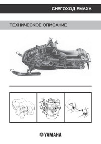
Описание конструкции снегохода Yamaha.
- Год издания: —
- Страниц: 65
- Формат: PDF
- Размер: 6,9 Mb
Руководство на английском языке по техническому обслуживанию и ремонту снегохода Yamaha BR250F.
- Год издания: 1981
- Страниц: 191
- Формат: PDF
- Размер: 8,7 Mb

Руководство по эксплуатации и техническому обслуживанию снегоходов Yamaha BR250TG и Yamaha VK540EG.
- Год издания: 2001
- Страниц: 88
- Формат: PDF
- Размер: 8,7 Mb
Дополнение к руководству по техническому обслуживанию и ремонту снегохода Yamaha ET300E.
- Год издания: 1980
- Страниц: 8
- Формат: PDF
- Размер: 790 Kb

Сборник руководств по эксплуатации и техническому обслуживанию снегоходов Yamaha FX Nytro моделей FX10/RFX10 различных модификаций.
- Год издания: 2007-2012
- Страниц: 94/118/122
- Формат: PDF
- Размер: 32,0 Mb
Сборник руководств на английском языке по эксплуатации и техническому обслуживанию снегоходов Yamaha FX Nytro модели FX10 различных модификаций.
- Год издания: 2007-2011
- Страниц: 92/104
- Формат: PDF
- Размер: 18,5 Mb
Руководство на английском языке по техническому обслуживанию и ремонту снегохода Yamaha FX Nytro модели FX10 различных модификаций.
- Год издания: 2007
- Страниц: 410
- Формат: PDF
- Размер: 13,5 Mb

Руководство по эксплуатации и техническому обслуживанию снегоходов Yamaha MM700/VT700/VX700ER.
- Год издания: 2001
- Страниц: 100
- Формат: PDF
- Размер: 9,2 Mb

Сборник руководств на английском языке по эксплуатации и техническому обслуживанию снегоходов Yamaha MM600/MM700/SX600/VT600/VT700/VX600/VX700 различных модификаций.
- Год издания: 1998-2002
- Страниц: —
- Формат: PDF
- Размер: 32,0 Mb

Сборник руководств по эксплуатации и техническому обслуживанию снегоходов Yamaha PZ50/RPZ50 Venture различных модификаций.
- Год издания: 2006/2012
- Страниц: 110/120
- Формат: PDF
- Размер: 11,7 Mb

Сборник руководств на английском языке по эксплуатации и техническому обслуживанию снегоходов Yamaha PZ50 Phazer, Venture различных модификаций.
- Год издания: 2006-2009
- Страниц: 88/92/98/104
- Формат: PDF
- Размер: 21,6 Mb

Сборник руководств на английском языке по техническому обслуживанию и ремонту снегохода Yamaha PZ50 Phazer, Venture различных модификаций.
- Год издания: 2006-2007
- Страниц: 424/114
- Формат: PDF
- Размер: 21,2 Mb

Руководство на английском языке по техническому обслуживанию и ремонту снегоходов Yamaha PZ500C и Yamaha VT500XLC.
- Год издания: 1998
- Страниц: 209
- Формат: PDF
- Размер: 6,0 Mb

Руководство на английском языке по эксплуатации и техническому обслуживанию снегоходов Yamaha PZ 500D/PZ500MLD/VT500XLD.
- Год издания: 1999
- Страниц: 83
- Формат: PDF
- Размер: 2,4 Mb

Сборник руководств по эксплуатации и техническому обслуживанию снегоходов Yamaha RS10/RS90/RSG90/RST90 RS Vecror, RS Venture различных модификаций.
- Год издания: 2004/2011/2012
- Страниц: 100/108/162
- Формат: PDF
- Размер: 31,0 Mb

Сборник руководств на английском языке по эксплуатации и техническому обслуживанию снегоходов Yamaha RS90/RSG90/RST90 RS Vector, RS Venture различных модификаций.
- Год издания: 2004-2011
- Страниц: —
- Формат: PDF
- Размер: 63,5 Mb

Сборник руководств на английском языке по техническому обслуживанию и ремонту снегоходов Yamaha RS90/RSG90/RST90 RS Venture различных модификаций.
- Год издания: 2004/2006/2008
- Страниц: 414/202/299
- Формат: PDF
- Размер: 37,1 Mb

Сборник руководств по эксплуатации и техническому обслуживанию снегоходов Yamaha RX10/RXW10 Apex различных модификаций.
- Год издания: 2001-2012
- Страниц: —
- Формат: PDF
- Размер: 28,6 Mb

Сборник руководств на английском языке по эксплуатации и техническому обслуживанию снегоходов Yamaha RX90/RXW90 Apex различных модификаций.
- Год издания: 2002-2010
- Страниц: —
- Формат: PDF
- Размер: 48,2 Mb

Руководство на английском языке по эксплуатации и техническому обслуживанию снегоходов Yamaha SRX700G.
- Год издания: 2001
- Страниц: 84
- Формат: PDF
- Размер: 6,6 Mb

Сборник руководств по эксплуатации и техническому обслуживанию снегоходов Yamaha SXV60/SXV70/VT60/VT70 различных модификаций.
- Год издания: 2003
- Страниц: 113/127
- Формат: PDF
- Размер: 10,5 Mb

Сборник руководств на английском языке по эксплуатации и техническому обслуживанию снегоходов Yamaha SXV60/SXV70/VT60/VT70 различных модификаций.
- Год издания: 2001-2005
- Страниц: —
- Формат: PDF
- Размер: 48,3 Mb

Сборник руководств по эксплуатации и техническому обслуживанию снегоходов Yamaha VK10/VK10D RS Viking.
- Год издания: 2007/2012
- Страниц: 98/108
- Формат: PDF
- Размер: 15,6 Mb

Сборник руководств на английском языке по эксплуатации и техническому обслуживанию снегоходов Yamaha VK10L и Yamaha VK10X.
- Год издания: 2005/2007
- Страниц: 98/88
- Формат: PDF
- Размер: 7,9 Mb

Дополнение к руководству по техническому обслуживанию и ремонту снегоходов Yamaha VK10L/VK10W.
- Год издания: 2005-2006
- Страниц: 360/103
- Формат: PDF
- Размер: 12,2 Mb

Руководство по эксплуатации и техническому обслуживанию снегоходов Yamaha VK540E/VK540EC.
- Год издания: 2012
- Страниц: 82
- Формат: PDF
- Размер: 3,2 Mb

Сборник руководств на английском языке по эксплуатации и техническому обслуживанию снегоходов Yamaha VK540EG/VK540EK.
- Год издания: 2001/2004
- Страниц: 76
- Формат: PDF
- Размер: 4,8 Mb

Руководство на английском языке по техническому обслуживанию и ремонту снегохода Yamaha VK540EK.
- Год издания: 2000
- Страниц: 211
- Формат: PDF
- Размер: 4,9 Mb

Руководство по эксплуатации и техническому обслуживанию снегохода Yamaha VT500XL.
- Год издания: 2001
- Страниц: 84
- Формат: PDF
- Размер: 8,2 Mb
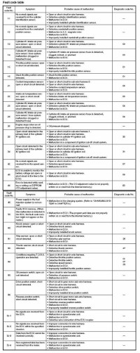
Коды неисправностей Yamaha.
- Год издания: —
- Страниц: 11
- Формат: JPG
- Размер: 1,7 Mb

-
Page 1
E115A 115B 140B SERVICE MANUAL 61U-28197-5H-11… -
Page 2: Important Information
NOTICE This manual has been prepared by Yamaha primarily for use by Yamaha dealers and their trained mechanics when performing maintenance procedures and repairs to Yamaha equipment. It has been written to suit the needs of persons who have a basic understanding of the mechanical and electrical concepts and procedures inherent in the work, for without such knowledge attempted repairs or service to the equipment could render it unsafe or unfit for use.
-
Page 3: Table Of Contents
Contents General information INFO Specification SPEC Periodic check and adjustment Fuel system FUEL Power unit POWR Lower unit LOWR Bracket unit BRKT Electrical system ELEC Troubleshooting TRBL SHTG Index…
-
Page 5: General Information
INFO General information How to use this manual …………….1-1 Manual format ………………1-1 Symbol ………………… 1-2 Safety while working ………………. 1-3 Fire prevention ………………1-3 Ventilation ………………..1-3 Self-protection ………………1-3 Parts, lubricant, and sealant …………..1-3 Good working practice …………….1-4 Disassembly and assembly …………..
-
Page 6: How To Use This Manual
INFO General information How to use this manual Manual format The format of this manual has been designed to make service procedures clear and easy to under- stand. Use the information below as a guide for effective and quality service. 9 Parts are shown and detailed in an exploded diagram and are listed in the components list (see in the figure below for an example page).
-
Page 7: Symbol
7 Apply Yamaha 2-stroke outboard motor oil q Apply corrosion resistant grease 8 Apply gear oil (Yamaha grease D) 9 Apply water resistant grease (Yamaha grease A) w Apply low temperature resistant grease 0 Apply molybdenum disulfide grease (Yamaha grease C)
-
Page 8: Safety While Working
Parts, lubricant, and sealant Use only genuine Yamaha parts, lubricants, and sealants or those recommended by Yamaha, when servicing or repairing the out- board motor. Ventilation Gasoline vapor and exhaust gas are heavier than air and extremely poisonous.
-
Page 9: Good Working Practice
Safety while working 6. Keep a supply of clean, lint-free cloths for Disassembly and assembly wiping up spills, etc. 1. Use compressed air to remove dust and dirt during disassembly. Good working practice 2. Apply engine oil to the contact surfaces Special service tool of moving parts before assembly.
-
Page 10: Identification
115BE, 115BET, 140BET Serial number The outboard motor serial number is stamped on a label attached to the port clamp bracket. 6G410010 YAMAHA MOTOR CO., LTD. MADE IN JAPAN PAYS D’ORIGINE JAPON 6B410020 1 Model name 2 Approved model code…
-
Page 11: Special Service Tool
Identification/Special service tool Special service tool Digital tachometer Compression gauge 90890-06760 90890-03160 Timing light Flywheel holder 90890-03141 90890-06522 Leakage tester Flywheel puller 90890-06840 90890-06521 Ball bearing attachment Digital caliper 90890-06704 90890-06663 Driver rod LS Vacuum/pressure pump gauge set 90890-06606 90890-06756 61U5H11…
-
Page 12
INFO General information Needle bearing attachment Gear puller 90890-06609, 90890-06610, 90890-06611, 90890-06612, 90890-06653, 90890-06654 90890-06540 Bearing separator Driver rod L3 90890-06534 90890-06652 Cylinder gauge Ball bearing attachment 90890-06759 90890-06633, 90890-06636 90890-06637, 90890-06656 Support Bearing outer race attachment 90890-02394 90890-06620, 90890-06624 Bearing inner race attachment Small end bearing installer 90890-06640, 90890-06662… -
Page 13
Special service tool Piston slider Stopper guide plate 90890-06530 90890-06501 Dial gauge set Bearing housing puller claw L 90890-01252 90890-06502 Shift rod push arm Center bolt 90890-06052 90890-06504 Ring nut wrench 3 Stopper guide stand 90890-06511 90890-06538 Bearing puller assembly Ring nut wrench extension 90890-06535 90890-06513… -
Page 14
INFO General information Bearing outer race puller assembly Driver rod SS 90890-06523 90890-06604 Bearing depth plate Driver rod SL 90890-06603 90890-06602 Pinion height gauge Drive shaft holder 6 90890-06710 90890-06520 Pinion nut holder Shimming plate 90890-06715 90890-06701 Backlash indicator Driver rod LL 90890-06706 90890-06605 61U5H11… -
Page 15
Special service tool Magnet base plate Test harness (4 pins) 90890-07003 90890-06878 Magnet base B Trim and tilt wrench 90890-06844 90890-06587 Digital circuit tester Ignition tester 90890-03174 90890-06754 Up relief fitting 90890-06773 Peak voltage adaptor B Down relief fitting 90890-03172 90890-06774 Test harness (4 pins) Hydraulic pressure gauge… -
Page 16: Propeller Selection
INFO General information Propeller selection Selection When the engine speed is at the full throttle The performance of a boat and outboard operating range (4,500–5,500 r/min), the motor will be critically affected by the size and ideal propeller for the boat is one that pro- type of propeller you choose.
-
Page 17: Predelivery Check
Propeller selection Checking the battery Predelivery check (E, ET, WH) To make the delivery process smooth and 1. Check the capacity, electrolyte level, and efficient, the predelivery checks should be specified gravity of the battery. completed as explained below. Recommended battery capacity: Checking the fuel system CCA/EN: 430 A 1.
-
Page 18: Checking The Remote Control Cable (Remote Control Model)
INFO General information Checking the remote control cable 4. Check that the remote control lever is in the neutral position, and check that the (Remote control model) center of the set pin 5 is aligned with the 1. Set the remote control lever to the neutral alignment mark a on the bottom cowling.
-
Page 19: Checking The Steering System
Predelivery check Checking the steering system Checking the gear shift and throttle 1. Check the steering friction for proper operation adjustment. 1. Check that the gear shift operates smoothly when the shift lever or remote control lever is shifted from neutral to for- ward or reverse.
-
Page 20: Checking The Ptt System (Et)
INFO General information 3. Check that the choke solenoid operates Checking the PTT system when the engine start switch is pushed (ET) in. (E, ET) 1. Check that the outboard motor tilts up and down smoothly when operating the PTT unit. 2.
-
Page 21: Checking The Cooling Water Pilot Hole
Predelivery check Checking the cooling water pilot hole Break-in 1. Start the engine, then check that the During the test run, perform the break-in cooling water is discharged from the operation in the following 5 stages. 1. 10 minutes a at the lowest possible cooling water pilot hole.
-
Page 22: After Test Run
INFO General information After test run 1. Check for water in the gear oil. 2. Check for fuel leakage in the cowling. 3. Flush the cooling water passage with fresh water using the flushing kit 1 and with the engine running at idle. 6S310070 Be sure to supply sufficient water when flushing the cooling water passage, other-…
-
Page 23: Specification
SPEC Specification General specification ………………2-1 Maintenance specification …………….2-5 Power unit (E115A models) ……………2-5 Lower unit (E115A models)…………….2-7 Electrical (E115A models)…………….2-7 Power unit (115B, 140B models) ………….2-10 Lower unit (115B, 140B models) ………….2-12 Electrical (115B, 140B models) ……………2-12 Dimension ………………..2-15 Tightening torque………………2-19 Specified torque………………2-19…
-
Page 24: General Specification
SPEC Specification General specification Model Item Unit E115AMH E115AWH E115AE E115AET Dimension Overall length mm (in) 1,458 (57.4) 828 (32.6) Overall width mm (in) 600 (23.6) Overall height mm (in) 1,558 (61.3) 1,435 (56.5) mm (in) 1,611 (63.4) — mm (in) 1,684 (66.3) 1,561 (61.5) Boat transom height…
-
Page 25
General specification Model Item Unit E115AMH E115AWH E115AE E115AET Cooling system Water Exhaust system Propeller boss Lubrication system Pre-mixed fuel and oil Fuel and oil Fuel type Regular unleaded gasoline Engine oil 2-stroke outboard motor oil Engine oil grade NMMA-certified TC-W3 Gear oil type Hypoid gear oil Gear oil grade (*1) -
Page 26
SPEC Specification Model Item Unit 115BE 115BET 140BET Dimension Overall length mm (in) 828 (32.6) Overall width mm (in) 600 (23.6) Overall height mm (in) 1,435 (56.5) mm (in) 1,561 (61.5) Boat transom height mm (in) 508 (20.0) mm (in) 635 (25.0) Weight (with aluminum propeller) -
Page 27
General specification Model Item Unit 115BE 115BET 140BET Cooling system Water Exhaust system Propeller boss Lubrication system Pre-mixed fuel and oil Fuel and oil Fuel type Regular unleaded gasoline Engine oil 2-stroke outboard motor oil Engine oil grade NMMA-certified TC-W3 Gear oil type Hypoid gear oil Gear oil grade (*1) -
Page 28: Maintenance Specification
SPEC Specification Maintenance specification Power unit (E115A models) Model Item Unit E115AMH E115AWH E115AE E115AET Power unit Minimum compression — 450 (4.5, 64) pressure (*1) at electric starter (kgf/cm , psi) at manual starter 400 (4.0, 57) — Cylinder head…
-
Page 29
Maintenance specification Model Item Unit E115AMH E115AWH E115AE E115AET Piston ring Top ring Dimension B mm (in) 1.970–1.990 (0.0776–0.0783) Dimension T mm (in) 2.700–2.900 (0.1063–0.1142) End gap mm (in) 0.30–0.40 (0.0118–0.0157) Side clearance mm (in) 0.02–0.06 (0.0008–0.0024) Oversize outside diameter mm (in) 90.25 (3.5531) mm (in) -
Page 30: Lower Unit (E115A Models)
SPEC Specification Lower unit (E115A models) Model Item Unit E115AMH E115AWH E115AE E115AET Gear backlash Pinion-to-forward mm (in) 0.32–0.50 (0.0126–0.0197) Pinion-to-reverse mm (in) 0.80–1.17 (0.0315–0.0461) Pinion gear shims 0.10, 0.12, 0.15, 0.18, 0.30, 0.40, 0.50 Forward gear shims 0.10, 0.12, 0.15, 0.18, 0.30, 0.40, 0.50 Reverse gear shims 0.10, 0.12, 0.15, 0.18, 0.30, 0.40, 0.50…
-
Page 31
Maintenance specification Model Item Unit E115AMH E115AWH E115AE E115AET Charge coil output peak voltage (B/R–L: High-speed) at Cranking (unloaded) at Cranking (loaded) at 1,500 r/min (loaded) at 3,500 r/min (loaded) (R–Br: Low-speed) at Cranking (unloaded) at Cranking (loaded) at 1,500 r/min (loaded) at 3,500 r/min (loaded) Charge coil resistance at 20°C (68°F) -
Page 32
SPEC Specification Model Item Unit E115AMH E115AWH E115AE E115AET PTT system Trim sensor resistance Ω — 239–379 at 20°C (68°F) (P–B) Fluid type — Dexron 2 Motor type — 64E00 Output — 0.40 Brushes Standard length mm (in) — 9.8 (0.39) Wear limit mm (in) —… -
Page 33: Power Unit (115B, 140B Models)
Maintenance specification Power unit (115B, 140B models) Model Item Unit 115BE 115BET 140BET Power unit Minimum compression 450 (4.5, 64) pressure (*1) (kgf/cm , psi) Cylinder head Warpage limit mm (in) 0.10 (0.0039) (lines indicate straightedge position) Cylinder Bore size mm (in) 90.000–90.020 (3.5433–3.5441) Piston…
-
Page 34
SPEC Specification Model Item Unit 115BE 115BET 140BET Piston ring Top ring Dimension B mm (in) 1.970–1.990 (0.0776–0.0783) Dimension T mm (in) 2.700–2.900 (0.1063–0.1142) End gap mm (in) 0.30–0.50 (0.0118–0.0197) Side clearance mm (in) 0.02–0.06 (0.0008–0.0024) Oversize outside diameter mm (in) 90.25 (3.5531) mm (in) 90.50 (3.5630) -
Page 35: Lower Unit (115B, 140B Models)
Maintenance specification Lower unit (115B, 140B models) Model Item Unit 115BE 115BET 140BET Gear backlash Pinion-to-forward mm (in) 0.32–0.50 (0.0126–0.0197) Pinion-to-reverse mm (in) 0.80–1.17 (0.0315–0.0461) Pinion gear shims 0.10, 0.12, 0.15, 0.18, 0.30, 0.40, 0.50 Forward gear shims 0.10, 0.12, 0.15, 0.18, 0.30, 0.40, 0.50 Reverse gear shims 0.10, 0.12, 0.15, 0.18, 0.30, 0.40, 0.50 Electrical (115B, 140B models)
-
Page 36
SPEC Specification Model Item Unit 115BE 115BET 140BET Charge coil output peak voltage (B/R–L: High-speed) at Cranking (unloaded) at Cranking (loaded) at 1,500 r/min (loaded) at 3,500 r/min (loaded) (R–Br: Low-speed) at Cranking (unloaded) at Cranking (loaded) at 1,500 r/min (loaded) at 3,500 r/min (loaded) Charge coil resistance at 20°C (68°F) -
Page 37
Maintenance specification Model Item Unit 115BE 115BET 140BET PTT system Trim sensor resistance Ω — 239–379 at 20°C (68°F) (P–B) ATF Dexron 2 Fluid type — Motor type — 64E00 Output — 0.40 Brushes Standard length mm (in) — 9.8 (0.39) Wear limit mm (in) —… -
Page 38: Dimension
SPEC Specification Dimension Exterior E115A mm (in) 325 (12.8) 539 (21.2) 845 (33.3) L: 1,005 (39.6) Y: 1,055 (41.5) 570 (22.4) X: 1,120 (44.1) 270 (10.6) 64 (2.5) MH, WH 616 (24.3) 61U2001M 2-15 61U5H11…
-
Page 39
Maintenance specification E115A, 115B, 140B mm (in) 539 (21.2) L: 1,005 (39.6) 482 (19.0) X: 1,120 (44.1) 214 (8.4) 64 (2.5) 616 (24.3) ** ET 6IU2002M 61U5H11 2-16… -
Page 40
SPEC Specification Clamp bracket mm (in) 182 (7.2) 182 (7.2) 163.5 (6.4) 163.5 (6.4) 62 (2.4) 13 (0.5) 13 (0.5) 125.4 (4.9) 125.4 (4.9) 6IU2003M 2-17 61U5H11… -
Page 41
Maintenance specification mm (in) 180 (7.1) 180 (7.1) 163.5 (6.4) 163.5 (6.4) 82 (3.2) 13 (0.5) 13 (0.5) 6G42003M 101.5 (4.0) 101.5 (4.0) 125.4 (4.9) 125.4 (4.9) 61U5H11 2-18… -
Page 42: Tightening Torque
SPEC Specification Tightening torque Specified torque Tightening torques Part to be tightened Thread size N·m kgf·m ft·lb Fuel system Intake silencer cover bolt Manual injection cable end bolt Screw (carburetor) — Plug (carburetor) — Plug (float chamber) — Fuel pump screw —…
-
Page 43
Thread size N·m kgf·m ft·lb Lower unit Check screw — Drain screw — Lower case mount bolt 28.8 Lower case mount nut (E115A: Y-transom) — 28.8 Trim tab bolt 28.8 Water pump housing bolt 13.3 Ring nut — 10.3 76.0 Pinion nut —… -
Page 44: General Torque
SPEC Specification General torque General torque specifications This chart specifies tightening torques for Nut (A) Bolt (B) standard fasteners with a standard ISO N·m kgf·m ft·lb thread pitch. Tightening torque specification 8 mm for special components or assemblies are 10 mm provided in applicable sections of this manu- 12 mm 14 mm…
-
Page 45
Periodic check and adjustment Maintenance interval chart …………….3-1 Top cowling ………………..3-2 Checking the top cowling …………….. 3-2 Fuel system ………………..3-2 Checking the fuel joint and fuel hose (fuel joint-to-carburetor) ….3-2 Checking the fuel filter …………….3-2 Power unit ………………… -
Page 46: Periodic Check And Adjustment
Check / charge 3-14 Cooling water passages Clean Cowling clamp Check Fuel filter (can be dis- Check / clean assembled) Fuel system Check Fuel tank (Yamaha por- Check / clean — table tank) Gear oil Change 3-12 Lubrication points Lubricate 3-14…
-
Page 47: Top Cowling
Maintenance interval chart/Top cowling/Fuel system Top cowling Fuel system Checking the top cowling Checking the fuel joint and fuel 1. Check the fitting by pushing the cowling hose (fuel joint-to-carburetor) with both hands. Adjust the fittings if nec- 1. Check the fuel hose connections and fuel essary.
-
Page 48: Periodic Check And Adjustment
Periodic check and adjustment 5. Install the spark plug temporary tight, Power unit then to the specified torque with a spark Checking the spark plug plug wrench. 1. Disconnect the spark plug caps, and then remove the spark plugs. Spark plug: 25 N·m (2.5 kgf·m, 18.4 ft·lb) 2.
-
Page 49: Checking The Cooling Water Passage
Power unit/Control system 3. Check for water flow at the cooling water Water pilot hole. If there is no water flow, check Valve lift a temperature the cooling water passage inside of the 48–52°C 0.05 mm (0.002 in) outboard motor. (118.4–125.6°F) (valve begins to tilt) above…
-
Page 50: Checking The Control Link And Throttle Link Position
Periodic check and adjustment NOTE: Checking the control link and throt- Make a note that how many times you turn tle link position out the throttle stop screw. 1. Remove the throttle cable. 3. Loosen the throttle lever tightening 2. Measure the length of control link rod 1. screws 3 and 4 clockwise.
-
Page 51: Checking The Engine Idle Speed
Control system 3. Turn the throttle stop screw 3 in direc- 8. Tighten the throttle lever tightening screw 4 counterclockwise on the lower carbu- tion a or b until the specified engine idle retor. speed is obtained. NOTE: The screw 4 is left hand thread. 9.
-
Page 52: Checking The Gear Shift Operation
Periodic check and adjustment 4. Connect the cable joint 3, install the nut 2. Set the throttle grip or remote control 2, and then tighten the lock nut 1. lever to the fully closed position. 61U30095 61U30085 3. Adjust the position of the throttle cable 5.
-
Page 53: Checking The Ignition Timing
Control system 6. Install the shift cable joint 3, install the 4. Make sure to align the center of the set pin a on the shift lever with the align- clip 2, and then tighten the locknut 1. ment mark b on the bottom cowling. 61U30100 7.
-
Page 54: Checking The Choke Solenoid (E, Et)
61U30250 Engine speed (throttle fully opened): 5,500 r/min Engine idle speed: 700–800 r/min Timing plate position: E115A: Timing light 3: 90890-03141 BTDC 22–24° 115B: 4. Check that the ATDC 5° scale a on the BTDC 24–26° flywheel magnet is aligned with the point-…
-
Page 55: Bracket
Control system/Bracket Checking the PTT fluid level Bracket (ET) Checking the PTT operation 1. Fully tilt the outboard motor up, and then (ET) support it with the tilt stop lever 1. 1. Fully tilt the outboard motor up and down a few times and check the entire trim and tilt range for smooth operation.
-
Page 56: Lower Unit
Periodic check and adjustment 3. If necessary, add sufficient fluid of the 3. Fully tilt the outboard motor up, then sup- port it with the tilt stop lever 2 to check recommended type until it overflows out of the filler hole. the lock mechanism of the lever.
-
Page 57: Changing The Gear Oil
Bracket/Lower unit Changing the gear oil 1. Tilt the outboard motor so that the gear oil drain screw at the lowest point possi- ble. 2. Place a drain pan under the drain screw 1, remove the drain screw, then the check screw 2 and let the oil drain com- pletely.
-
Page 58: Checking The Lower Unit For Air Leakage
Periodic check and adjustment Checking the lower unit for air leak- General Checking the anode 1. Check the anode and trim tab. Clean if there are scales, grease, or oil. Do not over pressurize the lower unit, oth- erwise the oil seals may be damaged. 1.
-
Page 59: Checking The Battery (Wh, E, Et)
Lower unit/General Checking the battery (WH, E, ET) NOTE: 9 Batteries vary per manufacturer. The proce- 1. Check the battery electrolyte level. If the dures mentioned in this manual may not level is at or below the minimum level always apply, therefore, consult the instruc- mark a, add distilled water until the level tion manual of the battery.
-
Page 60
Periodic check and adjustment 61U30170 6G430530 NOTE: 6G430500 Apply grease to the grease nipple until it flows from the bushings a. 2. Apply low temperature resistant grease to the area shown. 6G430510 6G430540 3. Apply corrosion resistant grease to the area shown. -
Page 61
FUEL Fuel system Hose routing ………………..4-1 Fuel hose and breather hose …………..4-1 Fuel line ………………….4-3 Carburetor ………………… 4-6 Disassembling the carburetor …………..4-12 Checking the carburetor ……………. 4-12 Assembling the carburetor …………..4-13 Fuel pump ………………..4-15 Checking the fuel pump …………….. -
Page 62: Fuel System
FUEL Fuel system Hose routing Fuel hose and breather hose 61U4001A 1 Fuel hose (fuel joint-to-fuel filter) 2 Fuel hose (fuel filter-to-manual injection : MH, WH) 3 Fuel hose (fuel filter-to-fuel pump) 4 Manual injection pump : MH, WH 5 Fuel hose (manual injection-to-upper carburetor : MH, WH) 6 Fuel hose (fuel pump-to-carburetor) 61U5H11…
-
Page 63
Hose routing PORT STBD MH, WH E, ET 61U4001B 1 Breather hose (manifold-to-cylinder body #2) 2 Breather hose (manifold-to-cylinder body #4) 3 Breather hose (breather hose-to-manual injection) 4 Breather hose (manifold-to-manual injection) 5 Breather hose (breather hose-to-manual injection hose) 6 Breather hose (manifold-to-cylinder body #1) 7 Breather hose (cylinder body #3-to-manual injection hose) 8 Breather hose (manifold-to-intake silencer) 9 Breather hose (manifold-to-cylinder body #3) -
Page 64: Fuel Line
FUEL Fuel system Fuel line 4 N·m (0.4 kgf·m, 3.0 ft·lb) 61U4040E Part name Q’ty Remarks M6 × 16 mm Bolt Fuel filter assembly Lock tie MH, WH Not reusable Lock tie Not reusable E, ET Fuel hose Fuel hose MH, WH Fuel hose Joint…
-
Page 65
Fuel line 4 N·m (0.4 kgf·m, 3.0 ft·lb) 61U4040E Part name Q’ty Remarks Fuel pump assembly Gasket Not reusable Fuel hose Joint Fuel hose Fuel hose M6 × 10 mm MH, WH Bolt Start-in-gear protection cable MH, WH M6 × 12 mm MH, WH Bolt M5 ×… -
Page 66
FUEL Fuel system 6G44040E Part name Q’ty Remarks M6 × 16 mm Bolt Washer Holder M6 × 14 mm Bolt Bracket Fuel filter assembly O-ring Not reusable Fuel filter element Fuel filter cup 61U5H11… -
Page 67: Carburetor
Fuel line/Carburetor Carburetor E, ET 6 N·m (0.6 kgf·m, 4.4 ft·lb) 61U4060E Part name Q’ty Remarks M6 × 20 mm Bolt Cover Gasket Not reusable M6 × 20 mm Bolt Intake silencer M6 × 20 mm Bolt Breather hose Gasket Not reusable Upper carburetor assembly Lower carburetor assembly…
-
Page 68
FUEL Fuel system E, ET 6 N·m (0.6 kgf·m, 4.4 ft·lb) 61U4060E Part name Q’ty Remarks M6 × 16 mm Bolt Choke solenoid Intake silencer Grommet 61U5H11… -
Page 69
Carburetor MH, WH 6 N·m (0.6 kgf·m, 4.4 ft·lb) 2 N·m (0.2 kgf·m, 1.5 ft·lb) 10 N·m (1.0 kgf·m, 7.4 ft·lb) 61U4070E Part name Q’ty Remarks Plug Gasket Screw Plate Gasket Not reusable Main air bleed Pilot screw Spring Screw Gasket Air bleed plug Pilot air jet… -
Page 70
FUEL Fuel system 6 N·m (0.6 kgf·m, 4.4 ft·lb) 2 N·m (0.2 kgf·m, 1.5 ft·lb) 10 N·m (1.0 kgf·m, 7.4 ft·lb) 61U4070E Part name Q’ty Remarks Gasket Not reusable Plug Gasket Main jet Drain plug Gasket Float chamber Plug Gasket Pilot jet ø5 ×… -
Page 71
Carburetor E, ET 6 N·m (0.6 kgf·m, 4.4 ft·lb) 2 N·m (0.2 kgf·m, 1.5 ft·lb) 10 N·m (1.0 kgf·m, 7.4 ft·lb) 61U4065E Part name Q’ty Remarks Plug Gasket Screw Plate Pilot screw Spring Screw Gasket Air bleed plug Pilot air jet Carburetor body Needle valve Clip… -
Page 72
FUEL Fuel system 6 N·m (0.6 kgf·m, 4.4 ft·lb) 2 N·m (0.2 kgf·m, 1.5 ft·lb) 10 N·m (1.0 kgf·m, 7.4 ft·lb) 61U4065E Part name Q’ty Remarks Gasket Main jet Float chamber Plug Gasket Pilot jet ø5 × 16 mm Screw Throttle stop screw Spring Lower carburetor assembly… -
Page 73: Disassembling The Carburetor
Carburetor Disassembling the carburetor 4. Check the pilot screw and needle valve for bends or wear. Replace the pilot NOTE: screw and needle valve if necessary. 9 Before disassembling the carburetors, make sure to note the number of times the pilot screw is turned out from the seated position to its set position.
-
Page 74: Assembling The Carburetor
FUEL Fuel system Assembling the carburetor ∫ 1. Install the gaskets 1, plugs 2, pilot air jets 3, and air bleed plugs 4, main air bleed 5 onto the carburetor body. å 6G440110 å MH, WH ∫ E, ET 61U40100 4.
-
Page 75
Carburetor NOTE: When disassemble the carburetor, be sure to set the pilot screw by the specified times. Pilot screw turns out: E115A : 1–1 1/2 115B : 3/8–7/8 140B : 5/8–1 1/8 7. Install the carburetor assembly. 61U5H11 4-14… -
Page 76: Fuel Pump
FUEL Fuel system Fuel pump 3.5 N·m (0.35 kgf·m, 2.6 ft·lb) 6G44030E Part name Q’ty Remarks Base Gasket Not reusable Diaphragm Body assembly ø5 × 28 mm Screw Washer Check valve Body Gasket Not reusable Diaphragm Collar O-ring Not reusable Cover Plate Spring…
-
Page 77: Checking The Fuel Pump
Fuel pump Checking the fuel pump 6. Apply the specified positive pressure and check that there is no air leakage. 1. Place a drain pan under the fuel hose Disassemble the fuel pump if necessary. connections, and then disconnect the fuel hoses from the fuel pump.
-
Page 78: Assembling The Fuel Pump
FUEL Fuel system NOTE: Assembling the fuel pump Make sure that the gaskets and diaphragms NOTE: are kept in place through the assembly Clean the parts and soak the valves and the process. diaphragms in gasoline before assembly to obtain prompt operation of the fuel pump when starting the engine.
-
Page 79
— MEMO — 61U5H11 4-18… -
Page 80: Powr
POWR Power unit Power unit ………………… 5-1 Checking the compression pressure …………5-1 Disassembling the manual starter (MH, WH) ……..5-14 Checking the spiral spring (MH, WH) ………… 5-15 Checking the drive pawl (MH, WH) …………5-15 Checking the starter rope (MH, WH) …………. 5-15 Assembling the manual starter (MH, WH) ……….
-
Page 81
Checking the piston ring ……………. 5-37 Checking the piston ring side clearance ……….5-38 Checking the piston pin boss bore …………5-38 Checking the piston pin …………….. 5-38 Checking the internal anode …………..5-38 Checking the connecting rod small end axial play …….. 5-39 Checking the connecting rod big end side clearance …… -
Page 82: Power Unit
POWR Power unit Power unit 5. If the compression pressure is below specification and the compression pres- Checking the compression pressure sure for each cylinder is unbalanced, add 1. Start the engine, warm it up for 5 min- a small amount of engine oil to the cylin- utes, and then turn it off.
-
Page 83
Power unit E,ET 25 N·m (2.5 kgf·m, 18.4 ft·lb) 61U5010E 8 N·m (0.8 kgf·m, 5.9 ft·lb) Part name Q’ty Remarks M8 × 35 mm MH, WH Bolt Grommet MH, WH Manual starter assembly MH, WH Collar MH, WH M6 × 20 mm MH, WH Bolt Power unit Dowel… -
Page 84
POWR Power unit E,ET 25 N·m (2.5 kgf·m, 18.4 ft·lb) 61U5010E 8 N·m (0.8 kgf·m, 5.9 ft·lb) Part name Q’ty Remarks M8 × 135 mm Bolt Apron Apron M6 × 25 mm E, ET Bolt Grommet E, ET Collar E, ET Grommet E, ET Flywheel cover… -
Page 85
Power unit 186 N·m (18.6 kgf·m, 137 ft·lb) 3 N·m (0.3 kgf·m, 2.2 ft·lb) 61U5020E Part name Q’ty Remarks Washer Starter pulley MH, WH M8 × 25 mm MH, WH Bolt Flywheel magnet M6 × 60 mm Bolt Stator assembly Pulser coil assembly ø5 ×… -
Page 86
POWR Power unit 186 N·m (18.6 kgf·m, 137 ft·lb) 3 N·m (0.3 kgf·m, 2.2 ft·lb) 61U5020E Part name Q’ty Remarks Washer Rectifier Regulator M6 × 12 mm Bolt Main harness Control link If equipped ø5 × 20 mm Screw Hour meter If equipped Case If equipped… -
Page 87
Power unit 61U5030E Part name Q’ty Remarks Joint Lock nut Control link rod Throttle link rod M6 × 25 mm Bolt Collar Wave washer Lock nut Screw Spring Screw M8 × 45 mm Bolt Washer Collar Bushing 61U5H11… -
Page 88
POWR Power unit 61U5030E Part name Q’ty Remarks Bushing Spring Control lever 1 Plastic washer Washer Bracket M8 × 30 mm Bolt Bushing Control lever 2 61U5H11… -
Page 89
Power unit 6IU5060E Part name Q’ty Remarks ø6 × 16 mm Screw Cover ø6 × 40 mm Screw CDI unit Charge coil coupler M6 × 12 mm Bolt Spark plug cap M6 × 20 mm Bolt Ignition coil M6 × 12 mm Bolt M6 ×… -
Page 90
POWR Power unit WH, E 30 N·m (3.0 kgf·m, 22.1 ft·lb) 29 N·m (2.9 kgf·m, 21.4 ft·lb) 9 N·m (0.9 kgf·m, 6.6 ft·lb) 4 N·m (0.4 kgf·m, 3.0 ft·lb) 61U5050E Part name Q’ty Remarks M8 × 45 mm Bolt Starter motor Washer M8 ×… -
Page 91
Power unit WH, E 30 N·m (3.0 kgf·m, 22.1 ft·lb) 29 N·m (2.9 kgf·m, 21.4 ft·lb) 9 N·m (0.9 kgf·m, 6.6 ft·lb) 4 N·m (0.4 kgf·m, 3.0 ft·lb) 61U5050E Part name Q’ty Remarks M6 × 12 mm Bolt Clamp Holder PTT relay (up) Holder PTT relay (down) -
Page 92
POWR Power unit MH, WH 61U5040E Part name Q’ty Remarks Manual starter case Plastic washer Spiral spring Collar Sheave drum Washer Clip Collar Drive pawl Spring Spring Drive plate Washer M6 × 16 mm Bolt M6 × 12 mm Bolt Washer M6 ×… -
Page 93
Power unit MH, WH 61U5040E Part name Q’ty Remarks Rope guide Roller Bushing M6 × 30 mm Bolt Grommet Collar M6 × 20 mm Bolt Bracket Damper Starter handle Bracket M6 × 12 mm Bolt Cotter pin Washer Start-in-gear protection cable 61U5H11 5-12… -
Page 94
POWR Power unit MH, WH 61U5040E Part name Q’ty Remarks Spring Guide Bolt Stopper Spring Starter rope 5-13 61U5H11… -
Page 95: Disassembling The Manual Starter (Mh, Wh)
Power unit Disassembling the manual starter 3. Remove the bolt, drive plate 6, spring (MH, WH) 7, drive pawl 8, spring 9, clip 0, wash- er q and collar w. 9 The sheave drum can pop out. Hold the sheave drum with your hand, then pull it out.
-
Page 96: Checking The Spiral Spring (Mh, Wh)
POWR Power unit Assembling the manual starter 6. Remove the plastic washers r, spiral spring t from the manual starter case. (MH, WH) 1. Install the starter rope 1 into the sheave drum 2. 2. Install the manual starter handle 3. 61U50040 7.
-
Page 97
Power unit 4. Install the plastic washer 4 and spiral 6. Install the collar 8, washer 9, clip 0, spring 5 into the manual starter case 6. drive pawl q, spring w, spring e, and drive plate r. 61U50520 61U50060 NOTE: Install the outer end c of the spiral spring onto the pin d of the starter case. -
Page 98: Removing The Power Unit
POWR Power unit 1. Remove the CDI unit cover, start-in-gear 9. Pull the manual starter handle several protection cable 1, then remove the times in the direction of the arrow to manual starter and starter pully (MH, check that the sheave drum turns WH).
-
Page 99
Power unit 8. Remove the bracket bolt w 3. Disconnect the 10-pin main harness cou- manual pler 5. injection pump cable end e and start-in- gear protection cable end r. 61U50470 61U50460 4. Disconnect the fuel hose 6. 61U50461 61U50560 5. -
Page 100: Removing The Flywheel Magnet
POWR Power unit 11. Remove the power unit by removing the 2. Remove the flywheel magnet. bolts i, bolts o and nuts p. 61U50590 6B450090 Removing the flywheel magnet 1. Loosen the flywheel magnet nut. To prevent damage to the engine or tools, screw in the flywheel puller set bolts evenly and completely so that the fly- wheel puller is parallel to the flywheel…
-
Page 101: Removing The Electrical Component
Power unit Removing the electrical component 1. Remove the cover 1 and disconnect the coupler. 61U50630 4. Remove the starter relay 8 and the PTT relay assembly 9. 61U50600 61U50600 61U50610 2. Remove the hour meter 2. 61U50650 61U50615 5. Remove the starter motor 0. 3.
-
Page 102
POWR Power unit 6. Disconnect the ignition coil leads, and then remove the CDI unit q and case w. 61U50600 5-21 61U5H11… -
Page 103
Power unit/Intake manifold Intake manifold 4 N·m (0.4 kgf·m, 3.0 ft·lb) 8 N·m (0.8 kgf·m, 5.9 ft·lb) MH, WH E, ET 4 N·m (0.4 kgf·m, 3.0 ft·lb) 8 N·m (0.8 kgf·m, 5.9 ft·lb) 61U5070E Part name Q’ty Remarks Gasket Not reusable Reed valve Gasket Not reusable… -
Page 104
POWR Power unit 4 N·m (0.4 kgf·m, 3.0 ft·lb) 8 N·m (0.8 kgf·m, 5.9 ft·lb) MH, WH E, ET 4 N·m (0.4 kgf·m, 3.0 ft·lb) 8 N·m (0.8 kgf·m, 5.9 ft·lb) 61U5070E Part name Q’ty Remarks Bracket Bracket Intake manifold Bracket MH, WH M6 ×… -
Page 105: Intake Manifold
Intake manifold Removing the intake manifold Checking the reed valve 1. Check the reed valves for bends a. 1. Remove the carburetor assemblies and the fuel hoses. Replace the reed valves if above specifi- cation. 2. Disconnect the breather hoses 1. 6G450180 61U50370 Valve bending limit a:…
-
Page 106: Exhaust Cover
POWR Power unit Exhaust cover 4 N·m (0.4 kgf·m, 3.0 ft·lb) 8 N·m (0.8 kgf·m, 5.9 ft·lb) 4 N·m (0.4 kgf·m, 3.0 ft·lb) 8 N·m (0.8 kgf·m, 5.9 ft·lb) 4 N·m (0.4 kgf·m, 3.0 ft·lb) 8 N·m (0.8 kgf·m, 5.9 ft·lb) 61U5080E Part name Q’ty…
-
Page 107: Removing The Exhaust Cover
Exhaust cover Removing the exhaust cover Checking the PCV 1. Remove the exhaust cover bolts in the 1. Remove the PCV. sequence shown. 2. Check the PCV for wear or deformation. Replace the PCV if necessary. 3. Check the grommet for deformation. Replace the grommet if necessary.
-
Page 108: Cylinder Head
POWR Power unit Cylinder head MH, WH 25 N·m (2.5 kgf·m, 18.4 ft·lb) 4 N·m (0.4 kgf·m, 3.0 ft·lb) 8 N·m (0.8 kgf·m, 5.9 ft·lb) E, ET 4 N·m (0.4 kgf·m, 3.0 ft·lb) 15 N·m (1.5 kgf·m, 11.1 ft·lb) 8 N·m (0.8 kgf·m, 5.9 ft·lb) 30 N·m (3.0 kgf·m, 22.1 ft·lb) 61U5090E Part name…
-
Page 109
Cylinder head MH, WH 25 N·m (2.5 kgf·m, 18.4 ft·lb) 4 N·m (0.4 kgf·m, 3.0 ft·lb) 8 N·m (0.8 kgf·m, 5.9 ft·lb) E, ET 4 N·m (0.4 kgf·m, 3.0 ft·lb) 15 N·m (1.5 kgf·m, 11.1 ft·lb) 8 N·m (0.8 kgf·m, 5.9 ft·lb) 30 N·m (3.0 kgf·m, 22.1 ft·lb) 61U5090E Part name… -
Page 110: Removing The Cylinder Head
POWR Power unit Removing the cylinder head 5. Remove the cylinder head bolts in the sequence shown. 1. Remove the spark plugs. 2. Remove the thermostat cover bolts in the PORT STBD sequence as shown, and then remove the thermostat. 61U50170 61U50210 3.
-
Page 111
Cylinder head 2. Check the cylinder head warpage using a straightedge 1 and thickness gauge 2 in 4 directions as shown. Replace the cylinder head if above specification. 61U50240 61U50250 Cylinder head warpage limit: 0.10 mm (0.0039 in) 61U5H11 5-30… -
Page 112: Crankcase
POWR Power unit Crankcase 12 N·m (1.2 kgf·m, 8.9 ft·lb) 20 N·m (2.0 kgf·m, 14.8 ft·lb) 37 N·m (3.7 kgf·m, 27.3 ft·lb) 10 N·m (1.0 kgf·m, 7.4 ft·lb) 18 N·m (1.8 kgf·m, 13.3 ft·lb) 61U5100E Part name Q’ty Remarks M6 × 25 mm Bolt Oil seal Not reusable…
-
Page 113
Crankcase 19 N·m (1.9 kgf·m, 14.0 ft·lb) 36 N·m (3.6 kgf·m, 26.6 ft·lb) 23 N·m (2.3 kgf·m, 17.0 ft·lb) 19 N·m (1.9 kgf·m, 14.0 ft·lb) 36 N·m (3.6 kgf·m, 26.6 ft·lb) 61U5110E Part name Q’ty Remarks M8 × 22 mm Bolt Piston and connecting rod assembly Roller bearing… -
Page 114
POWR Power unit 61U5120E Part name Q’ty Remarks Connecting rod Piston (starboard side) Washer Needle bearing Clip Not reusable Piston pin Piston ring set Piston (port side) 5-33 61U5H11… -
Page 115: Removing The Crankcase
Crankcase Removing the crankcase 1. Remove the bearing housing bolts. 6G450270 61U50280 2. Remove the oil seal housing bolts. NOTE: Insert a flat-head screw driver between the pry tabs to pry off the crankcase. Disassembling the bearing housing 1. Remove the oil seal 1 and O-rings 2. 6G450280 3.
-
Page 116: Disassembling The Oil Seal Housing
POWR Power unit Disassembling the oil seal housing NOTE: 9 Mark each piston with the identification 1. Remove the oil seals and O-ring. number a of the corresponding cylinder. Also, mark each connecting rod and con- necting rod cap with an identification num- ber b as shown.
-
Page 117: Disassembling The Crankshaft
Crankcase Disassembling the crankshaft Checking the piston diameter 1. Remove the seal rings 1. 1. Measure the piston outside diameter at the specified measuring point. Replace the piston and piston rings as a set if out of specification. 61U50290 NOTE: To remove the seal rings 1, widen the seal 6G450410 ring end gap a, and then remove the ring…
-
Page 118: Checking The Cylinder Bore
6F650430 NOTE: Be sure to rebore the cylinder for matching Piston ring end gap a: the replacement oversize pistons, when E115A: using the specified oversize pistons. 0.30–0.40 mm (0.0118–0.0157 in) 115B, 140B: Top: Piston clearance: 0.30–0.50 mm (0.0118–0.0197 in) 0.080–0.085 mm…
-
Page 119: Checking The Piston Ring Side Clearance
Replace the piston and piston rings as a set if out of specification. 6S350110 6G450420 Piston pin diameter: Piston ring side clearance: E115A: Top ring and 2nd piston ring: 21.495–21.500 mm 0.02–0.06 mm (0.8463–0.8465 in) (0.0008–0.0024 in) 115B, 140B: 23.065–23.070 mm…
-
Page 120: Checking The Connecting Rod Small End Axial Play
POWR Power unit Checking the connecting rod small Checking the crankshaft 1. Measure the crankshaft journal diameter end axial play a and crankpin diameter b. Replace the 1. Measure the connecting rod small end crankshaft if out of specification. axial play. Replace the bearing and con- necting rod if above specification.
-
Page 121: Assembling The Crankshaft
Crankcase 2. Install the seal rings 4. 2. Measure the crankshaft runout. Replace the crankshaft if above specification. 61U50700 NOTE: First pass the seal ring 4 over the crankpin a, and then widen the seal ring end gap b 61U50430 to install the ring into the crankshaft groove.
-
Page 122: Assembling The Bearing Housing
POWR Power unit Assembling the bearing housing Assembling the oil seal housing 1. Install the needle bearing. 1. Apply grease to the new oil seals, new O- ring and then install them into the oil seal housing. 6G450620 6G450640 Do not reuse the needle bearing, always replace it with a new one.
-
Page 123: Assembling The Piston And Connecting Rod Assembly
1. Set the crankshaft in the cylinder block. 61U50720 NOTE: 9 Face the embossed “YAMAHA” mark a on the connecting rod in the same direction as the “UP” mark b on the piston. 9 Use the small end bearing installer 7 to install the needle bearings.
-
Page 124
POWR Power unit 2. Install the pistons into the cylinders with Piston slider 3: the “UP” mark on the piston crown facing 90890-06530 towards the flywheel magnet. 3. Install the connecting rod bearings and connecting rod caps onto the connecting rods, and then tighten the connecting rod bolts 4 to the specified torques in 5 stages. -
Page 125
Crankcase NOTE: 4. Install the bearing housing onto the cylin- Do not get any sealant on the journals. der block. 7. Install the dowels, crankcase onto the cylinder block, and then temporarily tight- en the crankcase bolts. 61U50760 NOTE: Install the bearing housing with the arrow mark facing toward the cylinder block. -
Page 126
POWR Power unit 12. Install the new gasket 5, exhaust inner 10. Tighten the crankcase bolts to the speci- cover 6, new gasket 7, exhaust outer fied torques in 2 stages and in the cover 8, and then tighten the exhaust sequence shown. -
Page 127
Crankcase 13. Install the new gaskets 9 and the cylin- 15. Install the new gaskets e and the cylin- der head 0, and then tighten the cylinder der head covers r, and then tighten the head bolts to the specified torques in 2 cylinder head cover bolts to the specified stages and in the sequence shown. -
Page 128
POWR Power unit 16. Install the new gaskets, thermostats and the thermostat covers, and then tighten MH, WH the thermostat cover bolts to the speci- fied torques in 2 stages and in the sequence shown. 61U50810 61U50160 Intake manifold bolt u: 1st: 4 N·m (0.4 kgf·m, 3.0 ft·lb) NOTE: 2nd: 8 N·m (0.8 kgf·m, 5.9 ft·lb) -
Page 129
Crankcase 61U50835 å MH, WH ∫ E, ET 20. Install the starter motor i, pulser coil 61U50605 assembly o and stator assembly p onto 22. Install the starter relay f, the PTT relay the power unit. assembly g and Rectifier Regulator h onto the power unit. -
Page 130: Installing The Power Unit
POWR Power unit Installing the power unit 23. Install the hour meter into the case, and 1. Clean the power unit matching surface, and then onto the power unit. install the dowels 1 and a new gasket 2. 61U50850 2. Install the power unit 3, and then tighten 61U50636 the power unit bolts 4, bolts 5 and nut 6 to the specified torque.
-
Page 131
Crankcase 3. Install the apron 7, and then tighten the 6. Install the bushing w and clip e. apron bolt 8 to specified torque. 6G450905 7. Connect the choke link rod. 8. Connect the 10-pin main harness coupler 61U50585 Apron bolt 8: 8 N·m (0.8 kgf·m, 5.9 ft·lb) 4. -
Page 132
POWR Power unit 15. Connect the negative battery cable o, 10. Install the Woodruff key and flywheel positive battery cable p, and PTT motor magnet. lead a. å 11. Tighten the flywheel magnet nut to the specified torque. 61U50355 Apply force in the direction of the arrows shown, to prevent the flywheel holder from slipping off easily. -
Page 133: Adjusting The Timing Plate
Crankcase Adjusting the timing plate Cylinder #1 piston position (BTDC): E115A, 115B: NOTE: 3.33 mm (0.1311 in) Remove the all spark plugs and lock plate 140B: before adjusting the timing plate. 3.91 mm (0.1539 in) 1. Remove the manual starter or flywheel 5.
-
Page 134: Adjusting The Ignition Timing Stopper
2. 61U50905 61U50910 Timing plate position: Specified length c : E115A: BTDC 23° (Reference data) E115A, 115B: 115B: 24.5 mm (0.96 in) BTDC 25° 140B: 140B: 22.0 mm (0.87 in) BTDC 22° 2. Set the control lever 1 to the full 5.
-
Page 135
Crankcase Timing plate position: ATDC 5° 6. Set the control lever 1 to the full retard position, and check that the adjusting screw 2 contact with the stopper. 61U10045 7. Check that the mark 3 on the flywheel magnet aligned with the pointer 4 on the pulser coil assembly. -
Page 136
POWR Power unit — MEMO — 5-55 61U5H11… -
Page 137: Lowr
LOWR Lower unit Lower unit …………………..6-1 Removing the lower unit …………….6-4 Removing the water pump and shift rod ………..6-5 Checking the water pump and shift rod………….6-5 Propeller shaft housing ……………..6-6 Removing the propeller shaft housing assembly……..6-8 Disassembling the propeller shaft assembly ……….6-8 Disassembling the propeller shaft housing……….6-8 Checking the propeller shaft housing …………6-9 Checking the propeller shaft…………..6-9…
-
Page 138: Lower Unit
M10 × 45 mm Bolt M10 × 70 mm Bolt Trim tab Spacer Propeller Washer Washer Cotter pin Not reusable Dowel E115A: Y-transom M10 × 45 mm Bolt Grommet E115A: Y-transom Spring washer E115A: Y-transom Washer E115A: Y-transom Extension E115A: Y-transom 61U5H11…
-
Page 139
Lower unit 18 N·m (1.8 kgf·m, 13.3 ft·lb) 9 N·m (0.9 kgf·m, 6.6 ft·lb) 61U6020E Part name Q’ty Remarks Shift rod Oil seal Not reusable Cover O-ring Not reusable Spring Circlip M6 × 20 mm Bolt Joint Woodruff key M8 × 45 mm Bolt Cover Seal… -
Page 140
LOWR Lower unit 18 N·m (1.8 kgf·m, 13.3 ft·lb) 9 N·m (0.9 kgf·m, 6.6 ft·lb) 61U6020E Part name Q’ty Remarks Spacer Washer Wave washer Impeller Outer plate cartridge Gasket Not reusable Dowel Rubber seal Plate Check screw Gasket Not reusable Drain screw Dowel Lock tie… -
Page 141: Removing The Lower Unit
å vent the propeller from turning, and then remove the propeller nut and propeller. 61U60040 å E115A: Y-transom 6. Remove the stud bolts. (E115A: Y-transom) 61U60010 9 Do not hold the propeller with your hands when loosening or tightening it.
-
Page 142: Removing The Water Pump And Shift Rod
LOWR Lower unit Removing the water pump and shift Checking the water pump and shift 1. Remove the water pump housing 1, col- 1. Check the water pump housing. Replace lar 2, spacer 3, washer 4, wave wash- if there is deformation. er 5, washer 6 and impeller 7.
-
Page 143: Propeller Shaft Housing
Propeller shaft housing Propeller shaft housing 103 N·m (10.3 kgf·m, 76.0 ft·lb) 4 N·m (0.4 kgf·m, 3.0 ft·lb) 61U6030E Part name Q’ty Remarks Shift rod joint Ball Shift slider Ball Ball Spring Dog clutch Crosspin Spring Propeller shaft Reverse gear shim —…
-
Page 144
LOWR Lower unit 103 N·m (10.3 kgf·m, 76.0 ft·lb) 4 N·m (0.4 kgf·m, 3.0 ft·lb) 61U6030E Part name Q’ty Remarks Straight key Needle bearing Oil seal Not reusable Claw washer Ring nut Cooling water inlet cover ø5 × 45 mm Screw 61U5H11… -
Page 145: Removing The Propeller Shaft Housing Assembly
Propeller shaft housing Removing the propeller shaft hous- Stopper guide plate 4: ing assembly 90890-06501 1. Remove the ring nut from the lower case, Bearing housing puller claw L 5: use the special service tools. 90890-06502 Center bolt 6: 90890-06504 Disassembling the propeller shaft assembly 1.
-
Page 146: Checking The Propeller Shaft Housing
LOWR Lower unit Checking the propeller shaft 2. Remove the ball bearing. 1. Check the propeller shaft. Replace if bent or worn. 2. Measure the propeller shaft runout. Do not reuse the bearing, always replace S6P26200 it with a new one. Stopper guide plate 2: Runout limit: 0.02 mm (0.0008 in) 90890-06501…
-
Page 147: Assembling The Propeller Shaft Housing
Propeller shaft housing 2. Install the dog clutch 5 onto the propeller 6. The hole in the dog clutch align with the shaft 6. 2 holes (propeller shaft and shift slider). NOTE: 7. Install the cross pin 0 and spring q. Face the marking side to original direction, and then install the dog clutch 5.
-
Page 148
LOWR Lower unit 2. Apply grease to new oil seals, and then 4. Install the reverse gear assembly into the install them into the propeller shaft hous- propeller shaft housing using a press. ing to the specified depth. 61U60080 NOTE: Install an oil seal halfway into the propeller shaft housing, then the other oil seal. -
Page 149: Drive Shaft And Lower Case
Drive shaft and lower case Drive shaft and lower case 93 N·m (9.3 kgf·m, 68.6 ft·lb) 61U6040E Part name Q’ty Remarks Drive shaft Sleeve Cover Oil seal Not reusable M8 × 25 mm Bolt Drive shaft housing Needle bearing O-ring Not reusable Pinion shim —…
-
Page 150: Removing The Drive Shaft
LOWR Lower unit Removing the drive shaft Disassembling the drive shaft 1. Loosen the pinion nut. housing 1. Remove the cover, oil seals, and needle bearing. 6F660190 S6P26070E Drive shaft holder 6 1: 90890-06520 Needle bearing attachment 1: Pinion nut holder 2: 90890-06610 90890-06715 Driver rod L3 2: 90890-06652…
-
Page 151: Disassembling The Lower Case
Drive shaft and lower case 2. Remove the needle bearing from the for- 2. Remove the taper roller bearing outer ward gear using a chisel. race and shim(s). 61U60030 6G460100 Bearing outer race puller assembly 3: 90890-06523 Do not reuse the bearing, always replace NOTE: it with a new one.
-
Page 152: Checking The Lower Case
LOWR Lower unit Checking the lower case Needle bearing attachment 3: 1. Check the skeg and torpedo. Replace the 90890-06609 lower case if cracked or damaged. Driver rod SL 4: 90890-06602 Assembling the lower case Bearing depth plate 5: 1. Install the original shim(s) and taper roller 90890-06603 bearing outer race.
-
Page 153: Assembling The Drive Shaft Housing
Drive shaft and lower case Assembling the drive shaft housing Installing the drive shaft 1. Install the new needle bearing into the 1. Install the forward gear into the lower drive shaft housing to the specified case. depth. 2. Install the thrust bearing 1 and original shim(s) 2 onto the drive shaft 3.
-
Page 154: Installing The Propeller Shaft Housing
LOWR Lower unit 6F660310 61U60130 NOTE: Drive shaft holder 6 7: Face the shift rod joint connect part to 90890-06520 upward. Pinion nut holder 8: 90890-06715 4. Install the original shim(s) 4 and pro- peller shaft housing assembly 5 into the Pinion nut: lower case, and then install the straight 93 N·m (9.3 kgf·m, 68.6 ft·lb)
-
Page 155: Installing The Water Pump And Shift Rod
Drive shaft and lower case 2. Install a new gasket 2, the outer plate cartridge 3, and dowels 4. 6F600065 NOTE: 9 To secure the ring nut, bend one tab q of the claw washer into a slot in the ring nut. 9 Bend all other tabs toward the propeller shaft housing assembly.
-
Page 156: Installing The Lower Unit
LOWR Lower unit NOTE: 6. Install the new O-ring q and insert car- 9 When installing the pump housing, apply tridge w into the pump housing e. grease to the inside of the housing, and then turn the drive shaft clockwise while pushing down the pump housing.
-
Page 157
Shift rod push arm: 90890-06052 3. Install the 2 dowels 1 into the lower unit and extension 2 (E115A: Y-transom). 4. Connect the speedometer hose 3. 5. Install the lower unit into the upper case, and then tighten the lower case mount bolts 4 or nuts to the specified torque. -
Page 158
LOWR Lower unit 9. Insert a gear oil tube or gear oil pump into the drain hole and slowly fill the gear oil until oil flows out of the check hole and no air bubbles are visible. 69D10050 Recommended gear oil: Hypoid gear oil API: GL-4 SAE: 90… -
Page 159: Shimming
Shimming Shimming 6G46090E 61U5H11 6-22…
-
Page 160: Selecting The Pinion Shim
LOWR Lower unit Shimming 2. Install the pinion and pinion nut, and then tighten the nut to the specified torque. NOTE: 9 Shimming is not required when assembling Pinion nut: the original lower case and inner parts. 93 N·m (9.3 kgf·m, 68.6 ft·lb) 9 Shimming is required when assembling the 3.
-
Page 161: Selecting The Forward Gear Shim
Shimming 5. Calculate the pinion shim thickness (T3) Example: as shown in the examples below. If “T3” is 0.70 mm, then the pinion shim is 0.68 mm. If “T3” is 0.74 mm, then the pinion shim is 0.72 mm. Selecting the forward gear shim 1.
-
Page 162: Selecting The Reverse Gear Shim
LOWR Lower unit 2. Calculate the forward gear shim thick- Available shim thicknesses: ness (T1) as shown in the examples 0.10, 0.12, 0.15, 0.18, 0.30, 0.40 and below. 0.50 mm Example: If “T1” is 0.85 mm, then the forward gear shim is 0.82 mm.
-
Page 163: Backlash
Shimming/Backlash NOTE: 4. Select the reverse gear shim(s) (T2) as 9 Without the O-ring, when measuring the follows. reverse gear height. Calculated numeral 9 Select the shim thickness (T2) by using the Rounded numeral at 1/100th place specified measurement(s) and the calcula- 1, 2 tion formula.
-
Page 164
LOWR Lower unit 3. Install the special service tools so that it 5. Set the lower unit upside down. pushes against the propeller shaft. 6S360190 NOTE: Install the dial gauge so that the plunger a NOTE: contacts the mark b on the backlash indica- While turning the drive shaft clockwise 5–6 times to contact the gear evenly it tightens tor. -
Page 165
Backlash 8. Remove the special service tools from 10. Slowly turn the drive shaft clockwise and the propeller shaft. counterclockwise, and measure the backlash when the drive shaft stops in 9. Apply a load to the reverse gear by each direction. installing the propeller 8, the spacer 9 (without the washer 0), then the washer q as shown. -
Page 166: Brkt
BRKT Bracket unit Tiller handle ………………..7-1 Checking the throttle cable and shift cable ……….7-4 Assembling the tiller handle……………7-4 Lubricating the throttle gear……………7-4 Bottom cowling ………………..7-5 Upper case, steering arm …………….7-8 Disassembling the upper case …………..7-12 Checking the upper case……………..7-13 Assembling the upper case …………..7-13 Removing the steering arm …………..7-17 Removing the oil seal of swivel bracket (MH, WH, E)……7-17 Installing the oil seal of swivel bracket (MH, WH, E)…….7-17…
-
Page 167
Tilt cylinder and trim cylinder…………..7-48 Disassembling the tilt cylinder and trim cylinder ……..7-50 Checking the tilt cylinder and trim cylinder ……….7-51 Assembling the tilt piston and trim piston ……….7-51 Assembling the PTT unit ……………..7-52 Bleeding the PTT unit …………….7-55 Bleeding the PTT unit (built-in) …………..7-56 PTT electrical system ………………7-57 Checking the fuse ………………7-57 Checking the PTT relay …………….7-57… -
Page 168
BRKT Bracket unit Tiller handle 11 N·m (1.1 kgf·m, 8.1 ft·lb) 37 N·m (3.7 kgf·m, 27.3 ft·lb) 4 N·m (0.4 kgf·m, 3.0 ft·lb) 3 N·m (0.3 kgf·m, 2.2 ft·lb) 61U7010E 37 N·m (3.7 kgf·m, 27.3 ft·lb) Part name Q’ty Remarks Throttle cable M6 ×… -
Page 169
Tiller handle 11 N·m (1.1 kgf·m, 8.1 ft·lb) 37 N·m (3.7 kgf·m, 27.3 ft·lb) 4 N·m (0.4 kgf·m, 3.0 ft·lb) 3 N·m (0.3 kgf·m, 2.2 ft·lb) 61U7010E 37 N·m (3.7 kgf·m, 27.3 ft·lb) Part name Q’ty Remarks Washer Bushing Collar Ball Spring Shift lever… -
Page 170
BRKT Bracket unit 11 N·m (1.1 kgf·m, 8.1 ft·lb) 37 N·m (3.7 kgf·m, 27.3 ft·lb) 4 N·m (0.4 kgf·m, 3.0 ft·lb) 3 N·m (0.3 kgf·m, 2.2 ft·lb) 61U7010E 37 N·m (3.7 kgf·m, 27.3 ft·lb) Part name Q’ty Remarks ø6 × 8 mm Screw ø5 ×… -
Page 171: Tiller Handle
Tiller handle Checking the throttle cable and shift cable 1. Check that the operation of the throttle cable and shift cable. 2. Check the inner wire, outer wire of the throttle cable and shift cable. Replace if the outer wire is bent or damaged and the rubber seals are damaged.
-
Page 172: Bottom Cowling
BRKT Bracket unit Bottom cowling 24 N·m (2.4 kgf·m, 17.7 ft·lb) 61U7030E Part name Q’ty Remarks Clip Shift rod Bushing Washer Shift lever O-ring Not reusable Washer Bushing Bracket Grease nipple Not reusable Circlip Grommet Ball Spring Bolt 61U5H11…
-
Page 173
Bottom cowling 61U7040E Part name Q’ty Remarks Clamp M6 × 20 mm Bolt Plate M8 × 20 mm Bolt Bracket Holder Holder M6 × 12 mm Bolt Wave washer Clamp lever M6 × 12 mm Bolt Collar Pilot hole Lock lever M8 ×… -
Page 174
BRKT Bracket unit 61U7040E Part name Q’ty Remarks M6 × 28 mm Bolt Grommet M8 × 35 mm Bolt Ground lead Grommet Collar Washer Grommet Hose Screw E, ET Bracket E, ET Bracket E, ET 61U5H11… -
Page 175: Upper Case, Steering Arm
Bottom cowling/Upper case, steering arm Upper case, steering arm 51 N·m (5.1 kgf·m, 37.6 ft·lb) 71 N·m (7.1 kgf·m, 52.4 ft·lb) 61U7060E Part name Q’ty Remarks Grommet Upper mount Bracket Washer Rubber washer Washer Bolt Damper Washer M10 × 45 mm Bolt Mount housing Spring…
-
Page 176
BRKT Bracket unit 51 N·m (5.1 kgf·m, 37.6 ft·lb) 71 N·m (7.1 kgf·m, 52.4 ft·lb) 61U7060E Part name Q’ty Remarks Washer Ground lead M14 × 180 mm Bolt Upper case assembly Ground lead Hose M10 × 45 mm Bolt M6 × 10 mm Bolt Cover Screw… -
Page 177
Upper case, steering arm 21 N·m (2.1 kgf·m, 15.5 ft·lb) 18 N·m (1.8 kgf·m, 13.3 ft·lb) 18 N·m (1.8 kgf·m, 13.3 ft·lb) 18 N·m (1.8 kgf·m, 13.3 ft·lb) 61U7070E Part name Q’ty Remarks M8 × 45 mm Bolt M8 × 30 mm Bolt Gasket Not reusable… -
Page 178
BRKT Bracket unit 21 N·m (2.1 kgf·m, 15.5 ft·lb) 18 N·m (1.8 kgf·m, 13.3 ft·lb) 18 N·m (1.8 kgf·m, 13.3 ft·lb) 18 N·m (1.8 kgf·m, 13.3 ft·lb) 61U7070E Part name Q’ty Remarks Dowel Upper case Rubber seal Pipe Rubber seal Bushing Circlip Hose… -
Page 179: Disassembling The Upper Case
Upper case, steering arm 3. Remove the bolts q, exhaust manifold Disassembling the upper case w and gasket e. 1. Remove the bolts 1, 2, muffler assem- bly 3 and rubber seal 4 from the upper case 5. 61U70040 4. Remove the bolts r, lower exhaust guide t and gasket y from the upper exhaust guide u.
-
Page 180: Checking The Upper Case
BRKT Bracket unit 2. Install a new gasket 3, the lower exhaust 5. Remove the circlip, and then remove guide 4, and bolts 5, and then tighten drive shaft bushing. the bolts to the specified torque. 61U70220 Bearing puller assembly i: 90890-06535 Stopper guide stand o: 90890-06538…
-
Page 181
Upper case, steering arm 4. Install the rubber damper 9 and clip 0 onto the muffler q. 5. Install the cooling water pipe w onto the muffler q. 6. Install the new gasket, muffler q onto the exhaust guide assembly e, and then tighten the bolts r to the specified torque. -
Page 182
BRKT Bracket unit 10. Install the upper mounts a and bracket 12. Install the lower mounts f and mount s into the upper case assembly, and housings j and tighten the bolts k. then tighten it with the bolts d. 61U70240 S60V7230 NOTE:… -
Page 183
Upper case, steering arm MH, WH, E 36 N·m (3.6 kgf·m, 26.6 ft·lb) 61U7080E Part name Q’ty Remarks Steering arm Washer Bushing Bracket assembly O-ring Not reusable Bushing Washer Steering yoke Circlip Trim stopper Damper Not reusable Oil seal 61U5H11 7-16… -
Page 184: Removing The Steering Arm
BRKT Bracket unit Removing the steering arm Installing the oil seal of swivel 1. Remove the circlip 1. bracket (MH, WH, E) 1. Install the bushing 1 and oil seal 2. S69J7075 61U70250 2. Remove the steering yoke 2 as shown. Needle bearing attachment 3: 90890-06654 Driver rod L3 4: 90890-06652…
-
Page 185: Installing The Steering Arm
Upper case, steering arm 4. Install the steering yoke 9 to the steer- Installing the steering arm ing arm 3 by aligning the center a of the 1. Install the washer 1 and bushing 2 onto yoke with the center b of the steering the steering arm 3.
-
Page 186: Installing The Upper Case
BRKT Bracket unit Installing the upper case 1. Install the upper and lower mount assem- bly into the bracket assembly 1 simulta- neously. 2. Install the upper mount nuts 2 and lower mount nuts 3, and then tighten them to the specified torques.
-
Page 187: Clamp Bracket And Swivel Bracket
Upper case, steering arm/Clamp bracket and swivel bracket Clamp bracket and swivel bracket 15 N·m (1.5 kgf·m, 11.1 ft·lb) 61U7035E Part name Q’ty Remarks Self-locking nut M10 × 45 mm Bolt Clamp bracket Grease nipple Ground lead Washer Bushing Swivel bracket Bushing Shock absorber Bushing…
-
Page 188
BRKT Bracket unit 15 N·m (1.5 kgf·m, 11.1 ft·lb) 61U7035E Part name Q’ty Remarks Anode M6 × 30 mm Bolt Tilt pin Circlip 7-21 61U5H11… -
Page 189
Clamp bracket and swivel bracket 61U7140E Part name Q’ty Remarks Tilt stop lever Bushing Tilt lock lever Spring Plate M6 × 10 mm Bolt Distance collar Collar Cotter pin Lever Cotter pin Washer Bracket 61U5H11 7-22… -
Page 190
BRKT Bracket unit 61U7140E Part name Q’ty Remarks M6 × 16 mm Bolt Spring Lever Lever Washer Cotter pin Spring Washer Tilt lock lever Tilt stop lever 7-23 61U5H11… -
Page 191: Removing The Clamp Bracket (Mh, Wh, E)
Clamp bracket and swivel bracket Removing the clamp bracket (MH, WH, E) 9 Do not tamper or attempt to open the shock absorber. 9 Do not subject the shock absorber to an open flame or any other source of high heat.
-
Page 192: Disassembling The Swivel Bracket (Mh, Wh, E)
BRKT Bracket unit Disassembling the swivel bracket Assembling the swivel bracket (MH, WH, E) (MH, WH, E) 1. Remove the 2 large springs 1 and 2 cot- 1. Install the rod 1 and rod 2 into the tilt ter pins 2. lock lever 3, and then install the tilt lock lever to the swivel bracket 4.
-
Page 193: Assembling The Clamp Bracket (Mh, Wh, E)
Clamp bracket and swivel bracket 6. Install the lever y to the swivel bracket 4 with the cotter pin u. 7. Install the lever i to the lever y with the 2 cotter pins o. 8. Install the 2 large springs p. 9.
-
Page 194
BRKT Bracket unit 15 N·m (1.5 kgf·m, 11.1 ft·lb) 2 N·m (0.2 kgf·m, 1.5 ft·lb) 61U7020E Part name Q’ty Remarks Swivel bracket Clamp bracket Clamp bracket Self-locking nut Grease nipple Ground lead ø6 × 12 mm Screw Washer Bushing Trim sensor ø6 ×… -
Page 195
Clamp bracket and swivel bracket 15 N·m (1.5 kgf·m, 11.1 ft·lb) 2 N·m (0.2 kgf·m, 1.5 ft·lb) 61U7020E Part name Q’ty Remarks Through tube M8 × 20 mm Bolt Tilt stop lever Bushing Collar Distance collar Spring pin Spring Spring hook M6 ×… -
Page 196
BRKT Bracket unit 61U7090E Part name Q’ty Remarks PTT unit PTT motor lead Lock tie Not reusable Circlip M8 × 16 mm Bolt Washer Shaft Bushing M6 × 10 mm Bolt Ground lead Trim sensor lead 7-29 61U5H11… -
Page 197: Removing The Ptt Unit (Et)
Clamp bracket and swivel bracket Removing the PTT unit (ET) 1. Fully tilt the outboard motor up, and then Do not remove the tilt stop lever 1 from support it with the tilt stop lever 1. the clamp brackets. 5. Remove the lock ties 6, and then pull out the PTT motor lead 7.
-
Page 198: Installing The Clamp Bracket (Et)
BRKT Bracket unit 3. Assemble the clamp brackets, washers, swivel bracket, trim sensor, and then install the through tube. 6G470765 NOTE: 9 Align the projection inside of the trim sensor cam with the through tube hole a, and then 61U70360 install it.
-
Page 199: Installing The Ptt Unit (Et)
Clamp bracket and swivel bracket Installing the PTT unit (ET) 7. Fasten the PTT motor lead and trim sen- sor lead with the lock ties 9. 1. Fully tilt the outboard motor up, and then support it with the tilt stop lever 1. 6G470720 61U70280 9 When installing the PTT unit without…
-
Page 200: Adjusting The Trim Sensor Cam (Et)
BRKT Bracket unit 5. If the trim sensor voltage is out of specifi- Adjusting the trim sensor cam (ET) cation, adjust the trim sensor cam 2 until 1. Fully retract the PTT unit. the specified trim sensor setting voltage is obtained. 2.
-
Page 201: Ptt Unit
Clamp bracket and swivel bracket/PTT unit PTT unit 7 N·m (0.7 kgf·m, 5.2 ft·lb) 5 N·m (0.5 kgf·m, 3.7 ft·lb) 5 N·m (0.5 kgf·m, 3.7 ft·lb) 61U7100E Part name Q’ty Remarks PTT motor Reservoir Reservoir cap Not reusable O-ring O-ring Not reusable M6 ×…
-
Page 202: Checking The Hydraulic Pressure
BRKT Bracket unit Checking the hydraulic pressure 1. Fully extend the trim and tilt rams. 2. Remove the reservoir cap, and then check the fluid level in the reservoir. 6G470240 NOTE: 6G470250 If the fluid is at the correct level, the fluid NOTE: should overflow out of the filler hole when the Quickly install the special service tools before…
-
Page 203
PTT unit 8. Reverse the PTT motor leads between 10. Remove the reservoir cap, and then the battery terminals to fully extend the check the fluid level. trim and tilt rams, and then measure the hydraulic pressure. 6G470240 NOTE: 6G470270 If the fluid is at the correct level, the fluid should overflow out of the filler hole when the Battery… -
Page 204
BRKT Bracket unit 13. Connect the PTT motor leads to the bat- 15. Remove the special service tools, and tery terminals to fully retract the trim and then install the manual valve and circlip. tilt rams, and then measure the hydraulic NOTE: pressure. -
Page 205
PTT unit/PTT motor PTT motor 61U7110E Part name Q’ty Remarks ø4 × 15 mm Screw Stator Armature O-ring Not reusable ø4 × 12 mm Screw Brush holder Brush 1 Brush 2 Brush holder Brush spring PTT motor base Oil seal Not reusable Bearing ø4 ×… -
Page 206: Ptt Motor
BRKT Bracket unit 4. Remove the armature from the PTT Disassembling the PTT motor motor base. 1. Loosen the bolts 1, remove the PTT motor 2, O-ring 3, gear pump filter 4, and joint 5 from the gear pump housing. Do not allow grease or oil to contact the commutator.
-
Page 207: Checking The Ptt Motor
PTT motor 3. Measure the commutator undercut b. Replace the armature if below specifica- 9 Do not pull the PTT motor leads out from tion limit. the stator. 9 Do not touch the bimetal a, otherwise the operation of the circuit breaker can be affected.
-
Page 208: Checking The Filter
BRKT Bracket unit 5. Measure the brush length. Replace if Assembling the PTT motor below specification limit. 1. Connect the PTT motor leads 1, and then tighten the screws 2. 6S370150 6G470370 Brush standard length: 9.8 mm (0.39 in) 2. Install the spring and push the brushes 3 Wear limit f: into the brush holder, and then install the 4.8 mm (0.19 in)
-
Page 209
PTT motor/Gear pump Gear pump 6 N·m (0.6 kgf·m, 4.4 ft·lb) 8 N·m (0.8 kgf·m, 5.9 ft·lb) 8 N·m (0.8 kgf·m, 5.9 ft·lb) 3 N·m (0.3 kgf·m, 2.2 ft·lb) 61U7120E Part name Q’ty Remarks M5 × 16 mm Bolt Gear pump assembly Ball Shuttle piston O-ring… -
Page 210
BRKT Bracket unit 6 N·m (0.6 kgf·m, 4.4 ft·lb) 8 N·m (0.8 kgf·m, 5.9 ft·lb) 8 N·m (0.8 kgf·m, 5.9 ft·lb) 3 N·m (0.3 kgf·m, 2.2 ft·lb) 61U7120E Part name Q’ty Remarks Up-relief valve seat O-ring Not reusable Filter O-ring Not reusable Down-relief valve Valve pin… -
Page 211: Gear Pump
Gear pump 3. Remove the bolts 9, gear pump cover Disassembling the gear pump hous- 0, drive gear q and driven gear w. 1. Remove the bolts 1 and gear pump housing 2. 61U70170 NOTE: 61U70180 Make sure that the O-rings 3, valve pin 4, NOTE: and valve seat assembly 5 are removed.
-
Page 212: Checking The Main Valve
BRKT Bracket unit 5. Cover the pump housing with a clean Checking the main valve cloth, and then blow compressed air 1. Check the main valve 1. Clean if there is through holes a and b while holding the dirt or residue. cloth down.
-
Page 213: Assembling The Gear Pump Housing
Gear pump 4. Install the balls 0, shuttle pistons q, and Assembling the gear pump housing balls w into the gear pump cover. 1. Install a new O-ring 1, up-relief valve seat 2, ball 3, absorber valve pin 4, and spring 5 into the gear pump hous- ing.
-
Page 214
BRKT Bracket unit 7. Install a new O-ring r onto the down- relief valve t. 8. Install the filter y, down-relief valve t, and filter u into the gear pump housing 6G470500 9. Install a new O-ring o, p onto the man- ual valve a. -
Page 215
Gear pump/Tilt cylinder and trim cylinder Tilt cylinder and trim cylinder 127 N·m (12.7 kgf·m, 93.7 ft·lb) 132 N·m (13.2 kgf·m, 97.4 ft·lb) 96 N·m (9.6 kgf·m, 70.8 ft·lb) 61U7130E Part name Q’ty Remarks Tilt ram Trim ram Cylinder body Free piston Backup ring O-ring… -
Page 216
BRKT Bracket unit 127 N·m (12.7 kgf·m, 93.7 ft·lb) 132 N·m (13.2 kgf·m, 97.4 ft·lb) 96 N·m (9.6 kgf·m, 70.8 ft·lb) 61U7130E Part name Q’ty Remarks O-ring Not reusable O-ring Not reusable Washer Ball Valve Spring 7-49 61U5H11… -
Page 217: Tilt Cylinder And Trim Cylinder
Tilt cylinder and trim cylinder Disassembling the tilt cylinder and 5. Drain the fluid. trim cylinder 6. Install the trim piston assemblies, and 1. Hold the PTT body in a vise using alu- then temporarily tighten the trim cylinder minum plates on the both sides. end screws.
-
Page 218: Checking The Tilt Cylinder And Trim Cylinder
BRKT Bracket unit Checking the tilt cylinder and trim Assembling the tilt piston and trim cylinder piston 1. Install the new dust seal 1 and new O- 1. Disassemble the tilt piston assembly. rings 2 and 3 onto the tilt cylinder end screw.
-
Page 219: Assembling The Ptt Unit
Tilt cylinder and trim cylinder 6. Install a new backup ring w and a new Recommended PTT fluid: O-ring e onto the free piston r. ATF Dexron II Fluid quantity: 30 cm (1.0 US oz, 1.1 Imp oz) 2. Push the free piston 1 into the tilt cylin- der until it bottoms out.
-
Page 220
BRKT Bracket unit 4. Install the trim piston assemblies into the Gear pump housing mounting bolt 8: trim cylinders, and then tighten the trim 8 N·m (0.8 kgf·m, 5.9 ft·lb) cylinder end screws to the specified torque. 7. Install the O-ring into the reservoir cap. 8. -
Page 221
Tilt cylinder and trim cylinder 13. Remove all of the air bubble using a syringe or suitable tool. NOTE: Turn the joint with a screwdriver to bleed the gear pump. 14. Install a new O-ring w and the PTT motor e, and then tighten the bolts r to the 6G470650 specified torque. -
Page 222: Bleeding The Ptt Unit
BRKT Bracket unit 6. Connect the PTT motor leads to the bat- Bleeding the PTT unit tery terminals to fully retract the trim and 1. Tighten the manual valve 1 clockwise. tilt rams. 6G470830 Battery Rams PTT motor lead terminal 2.
-
Page 223: Bleeding The Ptt Unit (Built-In)
Tilt cylinder and trim cylinder 8. Check the fluid level when the tilt ram is 3. Support the outboard motor with the tilt stop lever 1. fully extended. Add sufficient fluid if nec- essary. Bleeding the PTT unit (built-in) 1. Check the manual valve is fully tightened, and then connect the battery to the bat- tery leads.
-
Page 224: Ptt Electrical System
BRKT Bracket unit 7. Install the reservoir cap, and then tighten 3. Connect the sky blue (Sb) lead or the it to the specified torque. light green (Lg) lead to the positive bat- tery terminal and the black (B) lead to the NOTE: negative battery terminal as shown.
-
Page 225: Elec
ELEC Electrical system Checking the electrical component…………..8-1 Measuring the peak voltage …………..8-1 Electrical component ………………8-2 Port view ………………..8-2 Starboard view……………….8-3 Aft view ………………….8-4 Top view …………………8-5 Ignition and ignition control system …………8-6 Checking the ignition spark gap …………..8-6 Checking the spark plug cap …………..8-6 Checking the ignition coil…………….8-7 Checking the CDI unit…………….8-7 Checking the pulser coil …………….8-8…
-
Page 226: Electrical System
ELEC Electrical system Checking the electrical NOTE: 9 Before measuring the peak voltage, check component all wiring for proper connection and corro- Measuring the peak voltage sion, and check that the battery is fully To check the electrical components or mea- charged.
-
Page 227: Electrical Component
Checking the electrical component/Electrical component Electrical component Port view 61U80040D 1 Starter motor (WH, E, ET) 2 Starter relay (WH, E, ET) 3 PTT relay (ET) 4 Ignition coil 5 Fuse holder (20A: WH, E, ET) 61U5H11…
-
Page 228: Starboard View
ELEC Electrical system Starboard view å ç ∫ ∫ 61U80020B 1 Choke solenoid (E, ET) å To pulser coil assembly. 2 Rectifier Regulator ∫ To CDI unit. ç To wire harness. 3 Hour meter (if equipped) 61U5H11…
-
Page 229
Electrical component Aft view å ∫ ∫ å BOTTOM 61U80030C 1 Ignition coil #1 2 Ignition coil #2 3 Ignition coil #3 4 Ignition coil #4 5 Spark plug 6 Spark plug cap 7 Thermoswitch 8 CDI unit 9 PCV 61U5H11… -
Page 230: Top View
ELEC Electrical system Top view å å 61U80010A 1 Spark plug 2 Thermoswitch 3 Ignition coil #1 4 Ignition coil #2 5 Rectifier Regulator 6 Starter motor (WH, E, ET) 7 Stator assembly 8 Pulser coil assembly 9 Neutral switch (WH) 61U5H11…
-
Page 231: Ignition And Ignition Control System
Ignition and ignition control system Ignition and ignition control Checking the spark plug cap 1. Check the spark plug caps. Replace if system cracked or damaged. Checking the ignition spark gap 1. Disconnect the spark plug caps from the spark plugs. 2.
-
Page 232: Checking The Ignition Coil
ELEC Electrical system Checking the ignition coil Checking the CDI unit 1. Remove the spark plug cap from the 1. Remove the CDI unit cover. spark plug. 2. Connect the digital circuit tester with 2. Disconnect the ignition coil connectors. peak voltage adaptor B to the ignition coil lead and the ground.
-
Page 233: Checking The Pulser Coil
Ignition and ignition control system Checking the pulser coil 1. Remove the CDI unit cover. 2. Connect the test harness to the pulser coil. 3. Measure the pulser coil output peak volt- age. Replace the pulser coil if less than specification.
-
Page 234: Checking The Thermoswitch
ELEC Electrical system Checking the thermoswitch Test harness 1: 90890-06871 1. Place the thermoswitches in a container of water and slowly heat the water. Charge coil output peak voltage: (low-speed) Red (R) – Brown (Br) Unloaded Loaded r/min Cranking 1,500 3,500 DC V (100)
-
Page 235: Checking The Engine Start Switch (Wh, E, Et)
Ignition and ignition control system/Starting system Checking the engine start switch Checking the engine stop lanyard (WH, E, ET) switch 1. Disconnect the 10-pin main harness cou- 1. Check the engine stop lanyard switch for pler. continuity. Replace if there is no continu- ity.
-
Page 236: Checking The Starter Relay (Wh, E, Et)
ELEC Electrical system Checking the starter relay Checking the neutral switch (WH) 1. Check the neutral switch for continuity. (WH, E, ET) Replace if there is no continuity. 1. Remove the starter relay 1. 6F680140 61U80030 2. Connect the digital circuit tester leads to Switch Lead color the starter relay terminals.
-
Page 237
Starting system/Starter motor (WH, E, ET) Starter motor (WH, E, ET) 30 N·m (3.0 kgf·m, 22.1 ft·lb) 9 N·m (0.9 kgf·m, 6.6 ft·lb) 18 N·m (1.8 kgf·m, 13.3 ft·lb) 61U8010E Part name Q’ty Remarks M8 × 25 mm Bolt Starter motor bracket Clip Pinion stopper Spring… -
Page 238
ELEC Electrical system 30 N·m (3.0 kgf·m, 22.1 ft·lb) 9 N·m (0.9 kgf·m, 6.6 ft·lb) 18 N·m (1.8 kgf·m, 13.3 ft·lb) 61U8010E Part name Q’ty Remarks Screw M6 × 115 mm Bolt 8-13 61U5H11… -
Page 239: Removing The Starter Motor Pinion
Starter motor (WH, E, ET) Removing the starter motor pinion 1. Slide the pinion stopper 1 down using the box wrench, and then remove the clips 2. 6G480220 2. Measure the commutator diameter a. Replace the armature if below specifica- tion limit.
-
Page 240: Checking The Brush
ELEC Electrical system 4. Check the armature for continuity. 2. Check the brush holder assembly for Replace the armature if not shown as continuity. Replace the brush holder if not below chart. shown as below chart. 6G480270 Brush continuity: 6G480256 Brush 1 –…
-
Page 241: Charging System
Starter motor (WH, E, ET)/Charging system Charging system Checking the Rectifier Regulator 1. Disconnect the Rectifier Regulator (R) Checking the lighting coil connector, then connect the digital circuit 1. Disconnect the lighting coil connector. tester to Rectifier Regulator (R) connec- tor and ground 2.
-
Page 242: Checking The Hour Meter
ELEC Electrical system Checking the hour meter 1. Disconnect the hour meter coupler from the wiring harness. 2. Connect the positive battery lead to the yellow (Y) terminal a, also connect the negative battery lead to the black (B) ter- minal b, and then check that the hour meter displayed the all segments which has been illuminated for 2 seconds.
-
Page 243: Trbl Shtg
TRBL TRBL SHTG SHTG Troubleshooting Troubleshooting the power unit …………..9-1 Troubleshooting the power unit…………..9-1 Troubleshooting the PTT unit…………..9-6 Troubleshooting the lower unit …………..9-7 61U5H11…
-
Page 244
TRBL TRBL SHTG SHTG Troubleshooting Troubleshooting the power unit Troubleshooting the power unit (trouble code not available) The trouble shooting when a trouble code is not available consists of the following 4 items. Symptom 1: Specific trouble conditions. Symptom 2: Trouble conditions of an area or individual part. Cause 1: The content considered as the trouble factors of symptom 2. -
Page 245
Troubleshooting the power unit Refer Symptom 2 Cause 1 Cause 2 Checking step page Stuck piston Manual starter Disassemble and — 5-17 Piston lock due to check the power unit. or starter motor water or oil in the com- operates, but bustion chamber the engine does not crank… -
Page 246
TRBL SHTG Troubleshooting Refer Symptom 2 Cause 1 Cause 2 Checking step page Measure the pulser coil Pulser coil out- resistance. put peak volt- Pulser coil malfunction age less than Change the pulser coil specifications and check the ignition spark. Spark plug does not spark Measure the charge… -
Page 247
Trouble shooting the power unit Refer Symptom 2 Cause 1 Cause 2 Checking step page Fuel not sup- Float height Disassemble and Carburetor malfunction 4-12 plied properly improperly check the carburetor. Spark plug gap Check the spark plug Spark plug malfunction improperly gap and condition. -
Page 248
TRBL SHTG Troubleshooting Symptom 1: Limited engine speed (below 2,000 r/min) Refer Symptom 2 Cause 1 Cause 2 Checking step page Clogged cooling water Check the cooling — inlet water inlet. Check the impeller. Water pump impeller Check the Woodruff malfunction 9Buzzer comes key. -
Page 249
Troubleshooting the power unit Troubleshooting the PTT unit Symptom 1: PTT unit does not operate Refer Symptom 2 Cause 1 Cause 2 Checking step page Short, open, or loose Check the wiring har- connection of the — PTT relay does ness continuity. -
Page 250
TRBL SHTG Troubleshooting Symptom 1: PTT unit does not hold the outboard motor up Refer Symptom 2 Cause 1 Cause 2 Checking step page Manual valve Check the manual Manual valve opened — malfunction valve for open. Insufficient PTT fluid —… -
Page 251
Checking the PTT fluid level (ET) ….3-10 Checking the PTT motor……7-40 Adjusting the ignition timing stopper..5-53 Checking the PTT operation (ET)….3-10 Adjusting the start-in-gear protection Checking the PTT relay ……7-57 (MH, WH) ……….3-4 Checking the PTT system (ET) ….1-15 Adjusting the throttle cable ……3-6 Checking the Rectifier Regulator …..8-16 Adjusting the timing plate ……5-52 Checking the anode………3-13… -
Page 252
Checking the reservoir……7-45 Checking the spark plug ……3-3 Electrical (115B, 140B models) ….2-12 Checking the spark plug cap …..8-6 Electrical (E115A models) ……2-7 Checking the spiral spring (MH, WH) ..5-15 Electrical component ………8-2 Checking the starter motor operation ..8-15 Exhaust cover ……….5-25 Checking the starter motor pinion …8-14… -
Page 253
Selecting the forward gear shim ….6-24 Lower unit ………3-11, 6-1 Selecting the pinion shim……6-23 Lower unit (115B, 140B models) …..2-12 Selecting the reverse gear shim ….6-25 Lower unit (E115A models) …….2-7 Selection ……….1-11 Lubricating the outboard motor….3-14 Self-protection……….1-3 Lubricating the throttle gear…….7-4 Serial number ……….1-5… -
Page 254
WIRING DIAGRAM E115AMH Color code : Black 1 Thermoswitch : Brown 2 Spark plug : Green 3 Ignition coil : Gray 4 CDI unit 5 Charge coil : Blue : Pink 6 Lighting coil : Red 7 Pulser coil : White 8 Rectifier Regulator B/R : Black/red 9 Engine stop lanyard switch… -
Page 256
YAMAHA MOTOR CO., LTD. Printed in Japan Oct. 2005 – 1.2 × 1 ! Printed on recycled paper (E_1) -
Page 257
E115AMH 1 2 3 4 1 2 3 4 1 2 3 4… -
Page 258
WIRING DIAGRAM E115AE, E115AWH, 115BE Color code 1 Starter motor : Black 2 Starter relay : Brown 3 Battery : Green : Gray 4 Fuse (20A) 5 Thermoswitch : Blue 6 Spark plug : Light green 7 Ignition coil : Pink : Red 8 CDI unit 9 Charge coil… -
Page 259
E115AE,E115AWH,115BE Gy/B Gy/B 1 2 3 4 1 2 3 4 1 2 3 4 Gy/B… -
Page 260
Pulser coil Gy/B : Gray/black t Rectifier Regulator G/W : Green/white W/B : White/black y Choke solenoid u Hour meter (E115A) W/G : White/green i Trim sender W/L : White/blue o Over revolution W/R : White/red W/Y : White/yellow å… -
Page 261
E115AET,115BET,140BET Gy/B Gy/B 1 2 3 4 1 2 3 4 1 2 3 4 1 2 3 Gy/B Gy/B…

Summary of Content for Yamaha PZ50RTF, PZ50XTF, PZ50MTF 2015 Venture Multi Purpose Owner’s Manual PDF
DIC183
OWNERS MANUAL
Read this manual carefully
before operating this vehicle.
PZ50RTF PZ50XTF PZ50MTF PZ50MPF
8GK-28199-77
ESU10012
LIT-12628-03-17
ESU10043
Les missions du moteur de ce produit contiennent des substances chimiques connues dans ltat de Californie pour provoquer des cancers, des malformations congnitales et des troubles de la reproduction.
Read this manual carefully before operating this vehicle. This manual should stay with this vehicle if it is sold.
U8GK77E0.book Page 1 Wednesday, April 2, 2014 11:49 AM
Introduction ESU10122
Congratulations on your purchase of a Yamaha snowmobile. This model is the result of Yamahas vast experience in the produc- tion of fine sporting and touring snowmo- biles. It represents the high degree of craftsmanship and reliability that have made Yamaha a leader in these fields. This manual will give you an understanding of the operation, inspection, and basic mainte- nance of this snowmobile. If you have any questions concerning the operation or main- tenance of your snowmobile, please consult a Yamaha dealer. Yamaha continually seeks advancements in product design and quality. Therefore, while this manual contains the most current prod- uct information available at the time of print- ing, there may be minor discrepancies between your snowmobile and this manual. If there is any question concerning this manual, please consult a Yamaha dealer.
WARNING EWS00671
Please read this manual carefully before operating this snowmobile. Do not at- tempt to operate this snowmobile until you have attained adequate knowledge of its controls and operating features. Regular inspections and careful mainte- nance, along with good operating techni- ques, will help ensure that you safely enjoy the capabilities and reliability of this snow- mobile.
PZ50RTF PZ50XTF PZ50MTF PZ50MPF
OWNERS MANUAL 2014 by Yamaha Motor Corporation,
U.S.A. 1st Edition, March 2014
All rights reserved. Any reprinting or unauthorized use without the written permission of
Yamaha Motor Corporation, U.S.A. is expressly prohibited.
Printed in Japan. P/N LIT-12628-03-17
U8GK77E0.book Page 1 Wednesday, April 2, 2014 11:49 AM
Important manual information ESU10152
Particularly important information is distin- guished in this manual by the following nota- tions.
This is the safety alert symbol. It is used to alert you to potential personal injury haz- ards. Obey all safety messages that follow this symbol to avoid possible injury or death.
WARNING EWS00022
A WARNING indicates a hazardous situa- tion which, if not avoided, could result in death or serious injury.
NOTICE ECS00012
A NOTICE indicates special precautions that must be taken to avoid damage to the snowmobile or other property.
TIP A TIP provides key information to make pro- cedures easier or clearer.
U8GK77E0.book Page 1 Wednesday, April 2, 2014 11:49 AM
Contents
Location of the important labels……1
Safety information………………………..6
Description…………………………………..9
Control functions……………………….. 11 Main switch …………………………….. 11 Throttle lever …………………………… 11 Throttle override system
(T.O.R.S.)……………………………… 11 Multi-function meter unit…………… 12 High beam indicator light …………. 13 Low coolant temperature indicator
light ……………………………………. 13 Knock control system indicator
light ……………………………………. 14 Drive indicator light and reverse
indicator light ………………………. 14 Fuel meter and grip/thumb
warmer level indicator ……………. 14 Fuel level warning indicator ……… 16 Oil level/pressure warning
indicator ……………………………… 16 Coolant temperature warning
indicator ……………………………… 17 Self-diagnosis device……………….. 17 Drive select switch …………………… 18 Engine stop switch ………………….. 18 Headlight beam switch
LIGHTS …………………………….. 18 Grip/thumb warmer adjusting
switch………………………………….. 19 Auxiliary DC jack (PZ50MP) ………. 19 Brake lever ……………………………… 19 Parking brake lever ………………….. 20 Drive guard……………………………… 20 V-belt holder (PZ50MP)…………….. 21 Passenger grip warmer switch
(PZ50MP) …………………………….. 21 Backrest (PZ50MP) ………………….. 22 Storage pouch ………………………… 22
Rear carrier (PZ50MP) ……………… 23 Tow hitch (PZ50MP) ………………… 23 Fuel ……………………………………….. 24 Suspension …………………………….. 25
Pre-operation checks………………… 33 Pre-operation check list……………. 33
Operation………………………………….. 35 Starting the engine…………………… 35 Break-in …………………………………. 36 Riding your snowmobile …………… 36 Maximizing drive track life ………… 40 Strap (PZ50MT)……………………….. 41 Driving……………………………………. 41 Stopping the engine ………………… 42 Transporting……………………………. 42
Periodic maintenance and adjustment………………………………… 44
Periodic maintenance chart for the emission control system………… 45
General maintenance and lubrication chart ……………………. 46
Tool kit …………………………………… 48 Recommended equipment ……….. 48 Removing and installing the
shroud and covers ………………… 48 Checking the spark plugs …………. 52 Adjusting the engine idling
speed………………………………….. 53 Adjusting the throttle lever free
play (PZ50RT / PZ50XT / PZ50MT) ……………………………… 53
Checking the throttle lever free play (PZ50MP) ……………………… 54
Checking the throttle override system (T.O.R.S.) ………………….. 54
Checking the air filter……………….. 55 High-altitude settings……………….. 56 Valve clearance……………………….. 56 Engine oil and oil filter cartridge … 56
U8GK77E0.book Page 1 Wednesday, April 2, 2014 11:49 AM
Contents
Cooling system ……………………….. 60 V-belt……………………………………… 62 Drive chain housing………………….. 63 Brake and parking brake…………… 65 Skis and ski runners…………………. 67 Steering system ………………………. 69 Drive track and slide runners …….. 69 High-profile pattern drive track ….. 72 Lubrication ……………………………… 72 Replacing a headlight bulb ……….. 73 Adjusting the headlight beams ….. 74 Fittings and fasteners……………….. 74 Battery……………………………………. 74 Replacing a fuse ……………………… 75
Troubleshooting ………………………… 77
Storage………………………………………80
Specifications ……………………………. 82
Consumer information……………….. 84 Identification number records ……. 84 Vehicle Emission Control
Information label …………………… 85 YAMAHA SNOWMOBILE
LIMITED WARRANTY 2015 and Later Models ………….. 86
YAMAHA EXTENDED SERVICE (Y.E.S.) FOR U.S.A. CUSTOMERS……………………….. 89
YAMAHA PROTECTION PLUS (YPP) FOR CANADIAN CUSTOMERS……………………….. 90
Index…………………………………………. 91
U8GK77E0.book Page 2 Wednesday, April 2, 2014 11:49 AM
Location of the important labels
1
ESU10217
Read and understand all of the labels on your vehicle. They contain important information for safe and proper operation of your vehicle. Never remove any labels from your vehicle. If a label becomes difficult to read or comes off, a replacement label is available from your Yamaha dealer.
1420 21 15 16
18 17
9
13 1
2
356
19
12 11
21
10 8 7
4
U8GK77E0.book Page 1 Wednesday, April 2, 2014 11:49 AM
Location of the important labels
2
NOTICE
ATTENTION
This snowmobile is originally equipped with a high-profile pattern track of more than 38 mm (1.5 in.) for deep snow riding conditions. Operation on light snowfall, ice, hard-packed snow, dirt, etc., will result in rapid wear or damage to track and slide runners.
Cette motoneige est quipe de srie d’une chenill crampons de plus de 38 mm (1,5 in.) pour la conduite sur neige profonde. La conduite sur de la neige peu profonde, de la glace, de la neige tasse, de la salet, etc. provoquera une usure rapide ou lendommagement de la chenille et des patins. 8JJ-2815M-E0
1 PZ50RT/PZ50XT/PZ50MT
1 PZ50MP
2 PZ50XT/PZ50MT
U8GK77E0.book Page 2 Wednesday, April 2, 2014 11:49 AM
Location of the important labels
3
NOTICE
8ET-2815K-00
ATTENTION
8ET-2815K-10
8GC-2415E-E0
PREMIUM UNLEADED GASOLINE. MIN. OCTANE (PUMP : 91 RON : 95) ESSENCE SUPER SANS PLOMB. INDICE DOCTANE MIN. (POMPE : 91 RON : 95)
TUNE-UP SPECIFICATIONS ENGINE
1.SPARK PLUG 2.SPARK PLUG GAP 3.IDLE SPEED
SPECIFICATIONS DE LA MISE AU POINT MOTEUR
1.TYPE DE BOUGIE 2.ECARTEMENT DES LECTRODES 3.RGIME DE RALENTI
CR9EKB(NGK) 0.6 ~ 0.7 mm (0.024 ~ 0.028 in) 1800 100 r/min
CR9EKB(NGK) 0.6 ~ 0.7 mm
1800 100 r/min
8GC
8GC-1417E-01
3 PZ50RT/PZ50XT/PZ50MT
4 PZ50RT/PZ50XT/PZ50MT
8
9
10
5 PZ50RT/PZ50XT/PZ50MT 6 PZ50MP
7 PZ50MT
U8GK77E0.book Page 3 Wednesday, April 2, 2014 11:49 AM
Location of the important labels
4
20kg {44lbs}
LOAD LIMIT / CHARGE LIMITE
8FM-24897-01
88C-77769-00
DRIVE 1. CHAIN CASE OIL QTY 2. CHAIN CASE OIL TYPE
3. TRACK TENSION
* FOR MORE INFO: SEE SERVICE MANUAL FOR THIS MODEL. * SPECIFICATIONS SUBJECT TO CHANGE WITHOUT NOTICE.
ENTRANEMENT 1. CAPACIT DHUILE DU CARTER DE CHANE
2. TYPE DHUILE DU CARTER DE CHANE
3. FLCHE DE LA CHENILLE
* POUR PLUS DE DTAIL: VOIR LE MANUEL DATELIER POUR CE MODLE. * LES CARACTRISTIQUE TECHNIQUES SONT SUSCEPTIBLES DE CHANGER SANS NOTIFICATION PRALABLE.
250 cm (8.5 oz)
GL-3 75W or 80W
30 ~ 35 mm (1.18 ~ 1.38 in)/100 N (10 kg, 22 lb)
250 cm
GL-3 75W or 80W
8ES-47578-00
30 ~ 35 mm/100 N (10 kg)
TUNE-UP SPECIFICATIONS SPECIFICATIONS DE LA MISE AU POINT
11
12
13 PZ50XT/PZ50MT
14 PZ50MP
15
U8GK77E0.book Page 4 Wednesday, April 2, 2014 11:49 AM
Location of the important labels
5
WARNING This unit contains high pressure nitrogen gas. Mishandling can cause explosion. Read owners manual for instructions. Do not incinerate, puncture or open.
AVERTISSEMENT Cette unit contient de Iazote haute pression. Une mauvaise manipulation peut entraner dexplosion. Voir le manuel dutilisateur pour les instructions. Ne pas brler ni perforer ni ouvrir.
8GT-F2259-50
C M
V SS
CANADA NSVA C
TRANSPORT
506
This spark ignition system meets all requirements of the Canadian Interference Causing Equipment Regulations.
Ce systme dallumage par tincelle de vhicule respecte toutes les exigences du Rglement sur le matriel brouilleur du Canada.
3JK-82377-10
MAX. TOWING FORCE FORCE DE REMORQUAGE MAX. 1176 N (120 kgf), 264 lbf
MAX. VERTICAL FORCE FORCE VERTICALE MAX. 147 N (15 kgf), 33 lbf 8G
S- 28
17 S-
E0
NEVER stand behind or near a rotating track.
Debris or a broken track could be thrown back with great force which could cause severe leg or other injuries, or death.
Ne JAMAIS se tenir proximit ou larrire dune chenille en mouvement.
Des dbris ou une chenille casse pourraient tre projets violemment et entraner des blessures svres aux jambes ou autre, voire la mort.
8JT-77765-E0
WARNING AVERTISSEMENT
16
17 PZ50RT/PZ50XT/PZ50MT/PZ50MP 18 PZ50XT/PZ50MT/PZ50MP 19 PZ50XT/PZ50MP
18 PZ50RT
19 PZ50RT
20 PZ50MP
21
U8GK77E0.book Page 5 Wednesday, April 2, 2014 11:49 AM
Safety information
6
ESU10194
As the vehicles owner, you are responsible for the safe and proper operation of your snowmobile. When you ride your snowmo- bile, you must know and use the following for your safety. Severe injury or death may result if you ignore any of the following.
Before you operate your snowmobile Read the Owners Manual and all labels.
Become familiar with all of the operating controls and their function. Consult a Yamaha dealer about any control or func- tion you do not understand.
Wear protective clothing. Wear an ap- proved helmet, and a face shield or gog- gles. Also, wear a good quality snowmobile suit, boots, and a pair of gloves or mittens that will permit use of your thumbs and fin- gers for operation of the controls.
Do not operate the snowmobile after or while drinking alcohol or taking drugs. Your ability to operate the snowmobile is re- duced by the influence of alcohol or drugs.
Prepare your snowmobile Perform the pre-operation checks each
time you use the vehicle to make sure it is in safe operating condition. Failure to in- spect or maintain the vehicle properly in-
creases the possibility of an accident or equipment damage. See page 33 for a list of pre-operation checks.
Apply the parking brake before starting the engine. Never drive the snowmobile with the parking brake applied. This may over- heat the brake disc and reduce braking ability.
While using your snowmobile This snowmobile was not manufactured for
use on public streets, roads, or highways. Such use is prohibited by law, and you could collide with another vehicle.
PZ50RT, PZ50XT and PZ50MT are de- signed to carry the OPERATOR ONLY. Passengers are prohibited. Carrying a pas- senger can cause loss of control.
Be careful where you ride. There may be obstacles hidden beneath the snow. Stay on established trails to minimize your expo- sure to hazards. Ride slowly and cautiously when you ride off of established trails. Hit- ting a rock or stump, or running into wires could cause an accident and injury.
This snowmobile is not designed for use on surfaces other than snow or ice. Use on dirt, sand, grass, rocks, or bare pavement may cause loss of control and may dam- age the snowmobile.
U8GK77E0.book Page 6 Wednesday, April 2, 2014 11:49 AM
Safety information
7
Always ride with other snowmobilers when going on a ride. You may need help if you run out of fuel, have an accident, or dam- age your snowmobile.
Many surfaces such as ice and hard- packed snow require much longer stop- ping distances. Be alert, plan ahead and begin decelerating early. The best braking method on most surfaces is to release the throttle and apply the brake gentlynot suddenly.
Avoid carbon monoxide poisoning All engine exhaust contains carbon monox- ide, a deadly gas. Breathing carbon monox- ide can cause headaches, dizziness, drowsiness, nausea, confusion, and eventu- ally death. Carbon monoxide is a colorless, odorless, tasteless gas which may be present even if you do not see or smell any engine ex- haust. Deadly levels of carbon monoxide can collect rapidly and you can quickly be over- come and be unable to save yourself. Also, deadly levels of carbon monoxide can linger for hours or days in enclosed or poorly-venti- lated areas. If you experience any symptoms of carbon monoxide poisoning, leave the area immediately, get fresh air, and SEEK MEDICAL TREATMENT. Do not run the engine indoors. Even if you
try to ventilate engine exhaust with fans or open windows and doors, carbon monox- ide can rapidly reach dangerous levels.
Do not run the engine in poorly ventilated or partially enclosed areas such as barns, garages, or carports.
Do not run the engine outdoors where en- gine exhaust can be drawn into a building through openings such as windows and doors.
Genuine Yamaha Accessories Choosing accessories for your snowmobile is an important decision. Genuine Yamaha Ac- cessories, which are available only from a Yamaha dealer, have been designed, tested, and approved by Yamaha for use on your snowmobile. Many companies with no con- nection to Yamaha manufacture parts and accessories or offer other modifications for Yamaha vehicles. Yamaha is not in a position to test the products that these aftermarket companies produce. Therefore, Yamaha can neither endorse nor recommend the use of accessories not sold by Yamaha or modifica- tions not specifically recommended by Yamaha, even if sold and installed by a Yamaha dealer.
Maintenance and storage When laying the snowmobile on its side for
maintenance, use a suitable stand to keep it in a stable and level position.
Do not leave the snowmobile on its left side for an extended period of time. Fuel may leak out from the fuel breather hose.
Do not allow anyone to stand behind the snowmobile when starting, inspecting, or adjusting the snowmobile. A broken track, track fittings, or debris thrown by the track could be dangerous to the operator or by- standers.
Modifications made to the snowmobile not approved by Yamaha, or the removal of original equipment may render your snow- mobile unsafe for use, which may cause severe personal injury. Modifications may also make the snowmobile illegal to use.
Never store the snowmobile with fuel in the fuel tank inside a building where ignition sources are present such as hot water and space heaters, an open flame, sparks,
U8GK77E0.book Page 7 Wednesday, April 2, 2014 11:49 AM
Safety information
8
clothes dryers, and the like. Allow the en- gine to cool off before storing the snowmo- bile in an enclosed space.
U8GK77E0.book Page 8 Wednesday, April 2, 2014 11:49 AM
Description
9
ESU10262
PZ50XT PZ50MP
PZ50RT PZ50MT
18
1,2 3 144,5,6,7,8
17 16 18
1,2 3 144,5,6,7,8
17 16
10
18
1,2 3 144,5,6,7,8
17 16 18
1,2 3 114,5,6,7,8,9
17 16
12 13 14
15 1. Storage pouch 2. Tool kit 3. Air filter 4. Oil filler cap 5. Battery 6. Main fuse 7. Fuse box 8. Coolant reservoir 9. V-belt holder (PZ50MP) 10. Strap (PZ50MT) 11. Passenger grip warmer switch (PZ50MP) 12. Backrest (PZ50MP) 13. Rear carrier (PZ50MP) 14. Tail/brake light 15. Tow hitch (PZ50MP) 16. Slide rail suspension 17. Drive track 18. Idle adjusting screw
U8GK77E0.book Page 9 Wednesday, April 2, 2014 11:49 AM
Description
10
TIP The snowmobile you have purchased may differ slightly from those shown in the figures of
this manual. Design and specifications are subjected to change without notice.
PZ50RT/PZ50XT/PZ50MT PZ50MP
1. Brake lever 2. Parking brake lever 3. Grip/thumb warmer adjusting switch 4. Headlight beam switch 5. Multi-function meter unit 6. Engine stop switch
7. Throttle lever 8. Shroud latch (PZ50MP) 9. Main switch 10. Auxiliary DC jack (PZ50MP)
U8GK77E0.book Page 10 Wednesday, April 2, 2014 11:49 AM
Control functions
11
ESU10293
Main switch The main switch controls the ignition and lighting systems. The various positions are described below.
Off The ignition circuit is switched off. The key can be removed only in this position.
On The ignition circuit is switched on.
Start The starting circuit is switched on. The starter motor cranks the engine. NOTICE: Release the switch immediately after the engine starts. [ECS00022]
TIP The headlights and taillight come on after the engine is started.
ESU10313
Throttle lever Once the engine is running cleanly, squeez- ing the throttle lever will increase the engine speed and cause engagement of the drive train. Regulate the speed of the snowmobile by varying the throttle position. Because the
throttle is spring-loaded, the snowmobile will decelerate, and the engine will return to idle when it is released.
ESU10348
Throttle override system (T.O.R.S.)
WARNING EWS00042
If the T.O.R.S. is activated, make sure that the cause of the malfunction has been corrected and that the engine can be op- erated without a problem before restarting the engine. Continuing to operate with a malfunction could cause loss of control or damage.
If the throttle valves or throttle cable malfunc- tions during operation, the T.O.R.S. will be activated when the throttle lever is released. The T.O.R.S. is designed to override the fuel injection and limit the engine speed to less than the clutch engagement speed if the throttle valves fail to return to the idle position when the throttle lever is released. (See page 82 for the clutch engagement speed.)
1. Off 2. On 3. Start
1 3 2
1. Throttle lever
U8GK77E0.book Page 11 Wednesday, April 2, 2014 11:49 AM
Control functions
12
TIP If the T.O.R.S. is activated, the warning light and engine trouble warning indicator will flash, and the two-digit code 84 will flash in the meter display. If this occurs, have a Yamaha dealer check the system as soon as possible.
ESU10397
Multi-function meter unit The multi-function meter unit is equipped with the following: a digital speedometer an odometer a tripmeter (which shows the distance trav-
eled since it was last set to zero) an engine speed meter (which shows the
engine speed; not for use while riding) warning indicators (which show engine
trouble, coolant temperature, fuel level, oil level, and oil pressure warnings)
indicator lights (which show high beam, low coolant temperature, transmission po- sition, and knock control system condi- tions)
a warning light (which shows warnings to- gether with the warning indicators)
a fuel meter (which shows the fuel remain- ing in the fuel tank)
a grip/thumb warmer level indicator (which shows the grip warmer or the thumb warm- er level)
When the key is turned to the on position, the warning light, the low coolant temperature in- dicator light, the knock control system indi- cator light, the drive indicator light, the reverse indicator light, and all segments of the meter display come on and go off. The grip warmer level is initially displayed for 5 seconds, then the display switches to the fuel meter.
Idling Riding Malfunc- tion
Throttle lever Released Squeezed Released
Throttle valve Closed Open Open
T.O.R.S. Engine
runs properly.
Engine runs
properly.
T.O.R.S. will be
activated.
1. Warning light 2. Engine trouble warning indicator 3. Two-digit code 84
1. Meter display 2. Drive indicator light 3. Reverse indicator light 4. Drive select switch 5. Knock control system indicator light 6. High beam indicator light 7. Low coolant temperature indicator
light 8. Warning light 9. RESET button 10. SELECT button 11. Warning indicators
2 3 4
5678
9
10
111
U8GK77E0.book Page 12 Wednesday, April 2, 2014 11:49 AM
Control functions
13
Odometer, tripmeter, and engine speed meter modes
Pushing the SELECT button switches the display between the odometer mode ODO, tripmeter mode TRIP, and engine speed meter mode r/min in the following order: ODO TRIP r/min ODO To reset the tripmeter, push the RESET button for at least 1 second while the tripme- ter is displayed.
TIP To switch the speedometer, odometer, and
tripmeter displays between kilometers and miles, select the odometer mode ODO, and then push the SELECT button for at least 10 seconds while the snowmobile is stopped.
Use the engine speed meter only when checking the snowmobile and performing basic maintenance. The engine speed me- ter should not be used while riding the snowmobile since the reading will vary from the actual engine speed.
ESU10412
High beam indicator light The high beam indicator light comes on when the high beams of the headlights are switched on. (See page 18 for headlight beam switch operation.)
ESU10474
Low coolant temperature indi- cator light The low coolant temperature indicator light comes on when the coolant temperature is low and informs the rider that the snowmobile should be warmed up. After the engine is started, warm it up until the indicator light goes off. The snowmobile can be operated normally after the indicator light goes off.
TIP Drive the snowmobile at low speeds when the low coolant temperature indicator light is on. If the engine speed is too high, maximum engine speed is reduced to protect the en- gine.
1. Odometer/tripmeter/engine speed meter
1
1. High beam indicator light
1. Low coolant temperature indicator light
U8GK77E0.book Page 13 Wednesday, April 2, 2014 11:49 AM
Control functions
14
ESU10502
Knock control system indicator light This snowmobile is equipped with a system which detects engine knocking in order to protect the engine from damage. The knock control system indicator light comes on if knocking is detected, then flash- es if the knocking increases.
After the knocking has stopped, the knock control system indicator light goes off.
NOTICE ECS00032
If the knock control system indicator light comes on, the fuel tank may not have been filled with the recommended fuel. Reduce the engine speed to 6000 r/min or less. As soon as possible, stop the engine, let it cool sufficiently, and then drain the fuel and refuel with the recommended fuel.
If the knock control system indicator light is flashing, have a Yamaha dealer check the snowmobile as soon as pos- sible.
TIP To help prevent knocking, use premium un- leaded gasoline only. (See page 24 for more details.)
ESU10494
Drive indicator light and re- verse indicator light These indicator lights show whether the snowmobile is shifted into drive or reverse. The drive indicator light comes on when the transmission is in drive (forward). The reverse indicator light comes on when the transmission is in reverse.
The snowmobile can be shifted into drive or reverse by pushing the drive select switch. (See page 18 for drive select switch opera- tion.) ESU10435
Fuel meter and grip/thumb warmer level indicator The fuel meter and grip/thumb warmer level indicator have eight segments which show the amount of fuel remaining in the fuel tank, the grip warmer level, or the thumb warmer level.
1. Knock control system indicator light 1. Drive select switch 2. Drive indicator light 3. Reverse indicator light
U8GK77E0.book Page 14 Wednesday, April 2, 2014 11:49 AM
Control functions
15
Fuel meter The display segments of the fuel meter disap- pear towards E (Empty) as the fuel level de- creases. When only one segment is left near E, the fuel level warning indicator and the warning light come on.
If the fuel level warning indicator and the warning light come on, refuel as soon as pos- sible.
TIP The snowmobile must be stopped on a level surface to obtain an accurate fuel meter reading, since the reading changes accord- ing to the movement and inclination of the snowmobile.
Grip/thumb warmer level indicator When the grip warmer side of the grip/thumb warmer adjusting switch is pressed, the grip warmer indicator comes on and the display switches to the grip warmer level. When the thumb warmer side of the grip/thumb warmer adjusting switch is pressed, the thumb warmer indicator comes on and the display switches to the thumb warmer level. See Grip/thumb warmer adjusting switch on page 19 for detailed information.
TIP The grip/thumb warmer level is displayed
for 5 seconds after releasing the grip/thumb warmer adjusting switch, then the display switches to the fuel meter.
1. Fuel meter and grip/thumb warmer level in- dicator
1. Fuel level warning indicator 2. Warning light
1. Grip/thumb warmer adjusting switch
1. Grip warmer indicator 2. Thumb warmer indicator
1
U8GK77E0.book Page 15 Wednesday, April 2, 2014 11:49 AM
Control functions
16
When the engine is started, the grip/thumb warmer levels are set to the levels selected when the engine was last stopped.
ESU10456
Fuel level warning indicator The fuel level warning indicator and the warn- ing light come on when the fuel level is low. (See page 14 for details.) The fuel level warning indicator, the warning light, and all segments of the fuel meter start to flash when a malfunctioning sensor, dis- connected coupler, broken lead, or short cir- cuit is detected by the self-diagnosis device of the snowmobile to warn the rider of any of the above problems. If the fuel level warning indicator, the warning light, and all segments of the fuel meter flash, have a Yamaha dealer inspect the snowmo- bile as soon as possible.
ESU13992
Oil level/pressure warning indicator The oil level/pressure warning indicator has two functions. The warning indicator comes on when the engine oil level is low and when the engine oil pressure is low. The functions are explained in the following sections.
Oil level warning The warning indicator and the warning light come on when the engine oil level is low.
If the warning indicator and the warning light come on, place the snowmobile on a level surface and allow it to idle for one minute. If the warning indicator and the warning light go off, the engine oil level is sufficient, how- ever it is getting low. Add engine oil as soon as possible. If the warning indicator and the warning light do not go off, check the engine oil level in the oil tank (see page 56 for engine oil level checking procedures), and add engine oil if necessary. If the warning indicator and the warning light still remain on, have a Yamaha dealer check the snowmobile.
Oil pressure warning The warning indicator comes on and OP- LO (oil pressure low) appears in the odome- ter display if the engine oil pressure is low when the engine is started. At the same time, the engine speed is limited to less than the clutch engagement speed until the warning indicator goes off. If the engine oil pressure remains low for one minute, the engine stops. If this occurs, have a Yamaha dealer check the snowmobile.
1. Fuel level warning indicator 2. Warning light 3. Fuel meter
1. Oil level/pressure warning indicator 2. Warning light
U8GK77E0.book Page 16 Wednesday, April 2, 2014 11:49 AM
Control functions
17
TIP If there is no engine oil in the oil passages when the engine is started, such as after the engine oil is changed, the warning indicator may come on and OP-LO may appear in the odometer display for a few seconds until the oil circulates through the engine. The snowmobile can be operated normally after the warning indicator goes off.
ESU10514
Coolant temperature warning indicator If the engine overheats, the coolant tempera- ture warning indicator and the warning light come on. When this occurs, stop the engine immediately and allow the engine to cool down, and then check the coolant level in the coolant reservoir. (See page 60 for checking procedures.)
NOTICE ECS00042
Do not continue to operate the engine if it is overheating.
ESU12687
Self-diagnosis device This model is equipped with a self-diagnosis device for various electrical circuits. If a problem is detected in any of those cir- cuits, the warning light and the engine trouble warning indicator flash, and an error code flashes slowly in the meter display. Note the error code, and then have a Yamaha dealer inspect the snowmobile as soon as possible. NOTICE: Do not continue to operate the engine longer than necessary if there is an error code to avoid possible engine dam- age. [ECS00821]
1. OP-LO (oil pressure low) 2. Oil level/pressure warning indicator
1
2
1. Coolant temperature warning indicator
2. Warning light
U8GK77E0.book Page 17 Wednesday, April 2, 2014 11:49 AM
Control functions
18
ESU10546
Drive select switch The drive select switch is used to shift the snowmobile into drive or reverse. After com- ing to a complete stop, press the drive select switch. The drive indicator light comes on when the transmission is in drive (forward). The reverse indicator light comes on when the transmission is in reverse.
NOTICE ECS00053
Do not use the drive select switch while the snowmobile is moving. Otherwise, the drive train could be damaged.
ESU10532
Engine stop switch The engine stop switch is used to stop the engine in an emergency. Simply push the stop switch to stop the engine. To start the engine, pull the stop switch and proceed with starting the engine. (See page 35 for engine starting procedures.)
During the first few rides, practice using the stop switch so that you can react quickly in an emergency. ESU10662
Headlight beam switch LIGHTS Push the headlight beam switch to change the headlight to high beam HI or to low beam LO.
1. Warning light 2. Engine trouble warning indicator 3. Error code display
1. Drive select switch 2. Drive indicator light 3. Reverse indicator light
3 2
1. Engine stop switch
1. Headlight beam switch LIGHTS 2. High beam HI 3. Low beam LO
U8GK77E0.book Page 18 Wednesday, April 2, 2014 11:49 AM
Control functions
19
ESU10677
Grip/thumb warmer adjusting switch The grip/thumb warmer adjusting switch controls the electrically heated handlebar grips and throttle lever.
To raise the temperature To raise the grip warmer temperature, press the side of the switch. To raise the thumb warmer temperature, press the side of the switch.
To lower the temperature Continue to press the switch until the temper- ature level returns to the minimum level, and then raise the temperature to the desired lev- el. See Fuel meter and grip/thumb warmer level indicator on page 14 for detailed informa- tion. ESU10697
Auxiliary DC jack (PZ50MP) The auxiliary DC jack is located in the front panel and can be used for accessories.
TIP The auxiliary DC jack can only be used if the engine is running.
To use the auxiliary DC jack 1. Start the engine.
2. Open the auxiliary DC jack cap, and then insert the accessory power plug into the jack.
3. After using the auxiliary DC jack, be sure to remove the accessory power plug from the jack and to close the auxiliary DC jack cap.
NOTICE ECS00123
To avoid circuit overload and a possible fuse blowing, do not use accessories re- quiring more than the maximum rated capacity for the auxiliary DC jack. (See page 75 for the specified fuse amper- age.)
Do not use an automotive cigarette lighter or other accessory with a plug that gets hot because the jack can be damaged.
ESU10552
Brake lever The snowmobile is stopped by braking the entire drive system. Squeeze the brake lever towards the handle- bar grip to stop the snowmobile.
1. Grip/thumb warmer adjusting switch
1
1. Auxiliary DC jack cap 2. Auxiliary DC jack
Maximum rated capacity: DC 12 V, 2.5 A (30 W)
U8GK77E0.book Page 19 Wednesday, April 2, 2014 11:49 AM
Control functions
20
TIP When the brake lever is squeezed, the brake light comes on.
NOTICE ECS00061
Make sure that the brake lever end does not project out over the handlebar end. This will help prevent brake lever damage when the snowmobile is placed on its side for service.
ESU10582
Parking brake lever When parking the snowmobile or starting the engine, apply the parking brake by moving the parking brake lever to the left.
To release the parking brake, move the park- ing brake lever to the right.
ESU14212
Drive guard
WARNING EWS00403
Coming in contact with the rotating V- belt or clutch parts can cause severe in- jury or death. Never run the engine with the drive guard removed.
Make sure that the drive guard is in- stalled securely before operating the snowmobile to protect against severe injury or death from a broken V-belt or other part should it come off the snow- mobile while it is in operation.
NOTICE ECS00931
Never run the engine with the V-belt re- moved. Clutch components can be damaged.
Be careful not to scratch the windshield when removing or installing the drive guard.
The drive guard is designed to protect the V- belt clutch and V-belt in case parts break or come loose. The drive guard is located behind the left side cover. (See page 48 for removal procedures.)
To remove the drive guard 1. Pull out the drive guard locking pin from
the drive guard upper holder.
1. Brake lever
1. Parking brake lever
U8GK77E0.book Page 20 Wednesday, April 2, 2014 11:49 AM
Control functions
21
2. Slightly raise the front of the drive guard, and then lift up the drive guard to remove it.
To install the drive guard 1. Fit the slots in the rear of the drive guard
onto the projections on the drive guard rear holder.
2. Align the slots in the top of the drive guard with the projections on the drive guard upper holder, and then insert the drive guard locking pin into the holder.
ESU10771
V-belt holder (PZ50MP) Keep a spare V-belt for emergency use by placing it into the V-belt holder provided.
NOTICE ECS00191
Make sure that the V-belt is installed se- curely in the holder.
ESU10682
Passenger grip warmer switch (PZ50MP) The passenger grip warmer switch controls the electrically heated passenger grips.
1. Drive guard locking pin 2. Drive guard
1. Drive guard
1. V-belt holder
1. Passenger grip warmer switch 2. Off 3. HI (high) 4. LO (low)
U8GK77E0.book Page 21 Wednesday, April 2, 2014 11:49 AM
Control functions
22
ESU10803
Backrest (PZ50MP) The backrest is adjustable.
To adjust the backrest angle 1. Open the backrest zipper and loosen the
backrest bolts.
2. Adjust the backrest angle to the desired position.
3. Tighten the bolts and close the zipper.
WARNING EWS00132
Do not sit on the backrest. Otherwise, you could lose your balance, fall, and be in- jured.
ESU12994
Storage pouch The storage pouch is located behind the front bumper. Use the storage pouch to store the tool kit, spare parts, such as the V-belt (PZ50RT / PZ50XT / PZ50MT), or other small items.
To remove the storage pouch Unfasten the storage pouch upper and lower buckles, and then pull the storage pouch off as shown.
To install the storage pouch 1. Put the storage pouch in the original po-
sition. 2. Fasten the storage pouch upper buckles. 3. Pass the storage pouch lower strap be-
tween the bracket and the frame, and then fasten the buckle to secure the pouch.
1. Backrest bolt
Backrest bolt tightening torque: 23 Nm (2.3 mkgf, 17 ftlbf)
1. Storage pouch
1. Storage pouch buckle
U8GK77E0.book Page 22 Wednesday, April 2, 2014 11:49 AM
Control functions
23
TIP Be sure to route the storage pouch lower
strap above the bracket fasteners. When installing the storage pouch, make
sure that the storage pouch buckles are se- curely fastened.
Storing the spare V-belt (PZ50RT / PZ50XT / PZ50MT) Keep a spare V-belt for emergency use by storing it in the storage pouch.
TIP When storing a spare V-belt in the storage pouch, be sure to secure it with the hook and loop fastener.
ESU10841
Rear carrier (PZ50MP) The rear carrier is located at the rear of the snowmobile.
WARNING EWS00141
Do not use the rear carrier to lift the snow- mobile. The snowmobile could fall, which could result in severe injury or death.
ESU10853
Tow hitch (PZ50MP)
NOTICE ECS00242
To prevent premature wear of the V-belt, avoid traveling under 10 km/h (6 mi/h) when towing for long distances or long pe- riods of time.
Use the tow hitch within the specified weight limits.
1. Storage pouch lower strap 2. Storage pouch 3. Bracket fastener
1. Hook and loop fastener
1. Rear carrier
Maximum load limit: 20 kg (44 lbs)
U8GK77E0.book Page 23 Wednesday, April 2, 2014 11:49 AM
Control functions
24
ESU10627
Fuel
WARNING EWS00072
Gasoline and gasoline vapors are ex- tremely flammable. To avoid fires and ex- plosions and to reduce the risk of injury when refueling, follow these instructions.
Make sure there is sufficient gasoline in the tank. 1. Before refueling, turn off the engine and
be sure that nobody is on the snowmo- bile. Never refuel while smoking, or while in the vicinity of sparks, open flames, or other sources of ignition such as the pilot lights of water heaters and clothes dry- ers.
2. Do not overfill the fuel tank. Stop filling when the fuel reaches the bottom of the filler tube. Because fuel expands when it heats up, heat from the engine or the sun can cause fuel to spill out of the fuel tank.
3. Wipe up any spilled fuel immediately. 4. Be sure the fuel tank cap is closed se-
curely by turning it clockwise.
WARNING EWS00681
Gasoline is poisonous and can cause inju- ry or death. Handle gasoline with care. Never siphon gasoline by mouth. If you should swallow some gasoline or inhale a lot of gasoline vapor, or get some gasoline
1. Tow hitch
Tow weight limit: 120 kgf (264 lbf)
Vertical weight limit: 15 kgf (33 lbf)
1. Filler tube 2. Maximum fuel level
U8GK77E0.book Page 24 Wednesday, April 2, 2014 11:49 AM
Control functions
25
in your eyes, see your doctor immediately. If gasoline spills on your skin, wash with soap and water. If gasoline spills on your clothing, change your clothes.
Your Yamaha engine has been designed to use premium unleaded gasoline with a pump octane number [(R+M)/2] of 91 or higher, or a research octane number of 95 or higher. If the recommended fuel is not used, the en- gine may not perform as it should.
NOTICE ECS00085
Oxygenated fuels (gasohol) containing a maximum 10% of ethanol (E10) can be used, although richer jetting may be re- quired to prevent engine damage. Con- sult a Yamaha dealer. Gasohol containing methanol is not recommend- ed.
Make sure that snow or ice does not en- ter the fuel tank when refueling.
Do not use alcohol deicers or water ab- sorbing additives with oxygenated fuel.
The fuel tank should be filled with the recommended gasoline. The use of oth- er gasoline will cause severe damage to internal engine parts, such as the valves and piston rings, as well as to the ex- haust system.
ESU10875
Suspension The suspension can be adjusted to suit rider preference. Softer settings, for example, may provide greater rider comfort, while harder settings may allow more precise handling and control over certain types of terrain or riding conditions. If you are not familiar with suspension adjust- ments, have a Yamaha dealer make these adjustments.
WARNING EWS00152
Read and understand the following infor- mation before handling shock absorbers that contain highly pressurized nitrogen gas. Do not tamper with or attempt to open
the cylinder assemblies. Do not subject the shock absorbers to
an open flame or other high heat source. This may cause the unit to explode due to excessive gas pressure.
Do not deform or damage the cylinders in any way. Cylinder damage will result in poor damping performance.
Do not dispose of a damaged or worn out shock absorber yourself. Take the shock absorber to a Yamaha dealer for any service.
ESU10906
Adjusting the spring preload of the front shock absorbers (PZ50XT / PZ50MT / PZ50MP)
WARNING EWS00721
The spring preload of the left and right shock absorbers must be adjusted to the same setting. Uneven settings can cause poor handling and loss of stability.
Recommended fuel: PREMIUM UNLEADED GASOLINE ONLY
Fuel tank capacity: PZ50MP 32.9 L (8.69 US gal, 7.24 Imp.gal) PZ50MT 26.7 L (7.05 US gal, 5.87 Imp.gal) PZ50RT 26.7 L (7.05 US gal, 5.87 Imp.gal) PZ50XT 26.7 L (7.05 US gal, 5.87 Imp.gal)
U8GK77E0.book Page 25 Wednesday, April 2, 2014 11:49 AM
Control functions
26
The spring preload can be adjusted by turn- ing the adjusting rings (PZ50MT) or adjusting nuts (PZ50XT / PZ50MP). Adjust the spring preload as follows.
PZ50MT To increase the spring preload and thereby harden the suspension, turn the adjusting ring in direction (a). To decrease the spring preload and thereby soften the suspension, turn the adjusting ring in direction (b).
PZ50XT / PZ50MP 1. Loosen the locknut. 2. To increase the spring preload and
thereby harden the suspension, turn the adjusting nut in direction (a). To decrease the spring preload and thereby soften the suspension, turn the adjusting nut in direction (b).
TIP The spring preload setting is determined by measuring distance A, shown in the illustra- tion. The longer distance A is, the higher the spring preload; the shorter distance A is, the lower the spring preload.
3. Tighten the locknut to the specified torque. NOTICE: Always tighten the locknut against the adjusting nut, and then tighten the locknut to the speci- fied torque. [ECS00861]
1. Spring preload adjusting ring
Spring preload setting: Minimum (soft):
1 Standard:
1 Maximum (hard):
5
(a)
(b)
1. Locknut 2. Distance A 3. Spring preload adjusting nut
Spring preload setting*: Minimum (soft):
PZ50XT 113.5 mm (4.47 in) PZ50MP 137.5 mm (5.41 in)
Standard: 138.5 mm (5.45 in)
Maximum (hard): 148.5 mm (5.85 in)
* Distance A changes 1.5 mm (0.06 in) with each full turn of the adjusting nut.
Tightening torque: Locknut:
PZ50XT 30 Nm (3.0 mkgf, 22 ftlbf) PZ50MP 42 Nm (4.2 mkgf, 30 ftlbf)
(a)
(b)
13
2
U8GK77E0.book Page 26 Wednesday, April 2, 2014 11:49 AM
Control functions
27
ESU12558
Adjusting the air pressure of the front shock absorbers (PZ50RT)
WARNING EWS00731
The air pressure of the left and right shock absorbers must be adjusted to the same setting. Uneven settings can cause poor handling and loss of stability.
The air pressure of the shock absorbers can be adjusted using the shock absorber pump included with your snowmobile.
To adjust the air pressure
WARNING EWS00622
Support the snowmobile securely on a suitable stand before adjusting the shock absorbers. Otherwise, the snowmobile could fall and cause injury.
NOTICE ECS00711
Make sure that there is no load on the shock absorbers and that they are fully ex- tended before making any air pressure ad- justments.
1. Place the snowmobile on a level surface and apply the parking brake.
2. Lift the front of the snowmobile onto a suitable stand to raise the skis off the ground.
3. Remove the air valve cap from the shock absorber.
4. Install the hose connector of the shock absorber pump onto the air valve of the shock absorber and tighten it approxi- mately six turns until the pressure regis- ters on the pump gauge. NOTICE: Do not overtighten the connector onto the air valve as this will damage the connector seal. [ECS00722]
TIP If the shock absorber has no air pressure, the gauge reading will be zero.
5. To increase the air pressure, operate the pump a few times. The pressure should increase slowly. If the pressure increases rapidly, check to make sure that the pump is properly connected and tight- ened onto the air valve. To decrease the
1. Shock absorber pump
1. Air valve cap
1. Hose connector
U8GK77E0.book Page 27 Wednesday, April 2, 2014 11:49 AM
Control functions
28
air pressure, push the black bleed valve button. NOTICE: Do not exceed 1034 kPa (10.3 kgf/cm, 150 psi). [ECS00734]
TIP To allow pressure to escape from the pump and the shock absorber, push the button halfway down and hold it. To allow only a small amount of pressure to escape, push the button all the way down and quickly release it.
6. Remove the hose connector from the air valve.
TIP When removing the connector, the sound of air escaping may be heard, but this is from the pump hose, not the shock absorber.
7. Install the air valve cap.
TIP If the front shock absorber bottoms too easily or rolls too much during cornering, increase the air pressure by 34 kPa (0.3 kgf/cm, 5 psi). If the shock absorber is too firm and you want a more compliant ride, decrease the air pres- sure by 34 kPa (0.3 kgf/cm, 5 psi).
ESU10938
Adjusting the spring preload of the center shock absorber and the rear torsion springs The spring preload can be adjusted by turn- ing the adjusting ring (PZ50MT) or adjusting nut (PZ50RT / PZ50XT / PZ50MP) on the center shock absorber and the adjusters on the rear torsion springs. Adjust the spring preload as follows.
Center shock absorber (PZ50MT) To increase the spring preload and thereby harden the suspension, turn the adjusting ring in direction (a). To decrease the spring preload and thereby soften the suspension, turn the adjusting ring in direction (b).
1. Bleed valve button
Air pressure range: PZ50RT 3451034 kPa (3.510.3 kgf/cm, 50150 psi)
Recommended air pressure: PZ50RT 483 kPa (4.8 kgf/cm, 70 psi)
U8GK77E0.book Page 28 Wednesday, April 2, 2014 11:49 AM
Control functions
29
PZ50MT
Center shock absorber (PZ50RT / PZ50XT / PZ50MP) 1. Loosen the locknut. 2. To increase the spring preload and
thereby harden the suspension, turn the adjusting nut in direction (a). To decrease the spring preload and thereby soften the suspension, turn the adjusting nut in direction (b).
TIP The spring preload setting is determined by measuring distance A, shown in the illustra- tion. The longer distance A is, the higher the spring preload; the shorter distance A is, the lower the spring preload.
3. Tighten the locknut to the specified torque. NOTICE: Always tighten the locknut against the adjusting nut, and then tighten the locknut to the speci- fied torque. [ECS00861]
Rear torsion springs
WARNING EWS00751
The left and right spring preloads must be adjusted to the same setting. Uneven set- tings can cause poor handling and loss of stability.
1. Spring preload adjusting ring
Spring preload setting: Minimum (soft):
1 Standard:
3 Maximum (hard):
5
1. Spring preload adjusting nut 2. Distance A 3. Locknut
(b)
(a)
(a)
(b)
2
1
3
Spring preload setting*: Minimum (soft):
PZ50RT 112.5 mm (4.43 in) PZ50XT 110.5 mm (4.35 in) PZ50MP 111.5 mm (4.39 in)
Standard: PZ50RT 113.5 mm (4.47 in) PZ50XT 120.5 mm (4.74 in) PZ50MP 112.5 mm (4.43 in)
Maximum (hard): PZ50RT 123.5 mm (4.86 in) PZ50XT 126.5 mm (4.98 in) PZ50MP 122.5 mm (4.82 in)
* Distance A changes 1.5 mm (0.06 in) with each full turn of the adjusting nut.
Tightening torque: Locknut:
PZ50XT 30 Nm (3.0 mkgf, 22 ftlbf) PZ50RT / PZ50MP 42 Nm (4.2 mkgf, 30 ftlbf)
U8GK77E0.book Page 29 Wednesday, April 2, 2014 11:49 AM
Control functions
30
To increase the spring preload and thereby harden the suspension, turn the adjuster in direction (a). To decrease the spring preload and thereby soften the suspension, turn the adjuster in direction (b).
ESU13095
Adjusting the 2-up adjusting blocks (PZ50MP)
WARNING EWS00761
Make sure that the 2-up adjusting blocks are installed in the same position on both sides of the snowmobile, otherwise poor handling and loss of stability may result.
The spring force can be adjusted by chang- ing the position of the 2-up adjusting blocks.
TIP Be sure to make this adjustment when
there is no load (rider or cargo) on the snowmobile.
Use the special tools included in the own- ers tool kit to make the adjustment.
1. Insert the special tools into the 2-up ad- justing block as shown.
2. Pull the lock pin and turn the special tools to change the block position.
3. Release the lock pin. 4. Remove the special tools from the 2-up
adjusting block.
1. Spring preload adjuster
Spring preload setting: Minimum (soft):
S Standard:
M Maximum (hard):
H
(a)
(b)
1. 2-up adjusting block
1. 2-up position (rider and passenger) 2. Solo rider position 3. Special tool 4. Lock pin
1
2
3 4
U8GK77E0.book Page 30 Wednesday, April 2, 2014 11:49 AM
Control functions
31
ESU13291
Adjusting the compression damping force of the rear shock absorber (PZ50RT) The compression damping force can be ad- justed by turning the adjusting knob. To increase the compression damping force, turn the adjusting knob in direction (a). To de- crease the compression damping force, turn the adjusting knob in direction (b). NOTICE: Do not continue to turn the adjusting knob in direction (a) after it stops. The shock ab- sorber could be damaged and damping force adjustments will not be able to be made. Do not turn the adjusting knob in di- rection (b) more than 12 click(s). Even if the adjusting knob is continually turned af- ter 12 click(s), there will be no change in the damping force. Be sure to stop the ad- justing knob at a position where there is a click. [ECS00911]
ESU11036
Adjusting the control rods (PZ50MP)
WARNING EWS00771
The left and right adjusting nuts must be set to the same position. Uneven settings can cause poor handling and loss of sta- bility.
The weight transfer can be adjusted by turn- ing the adjusting nuts on the control rods. 1. Loosen the locknut while holding the ad-
justing nut.
2. To increase weight transfer, turn the ad- justing nut in direction (a), and to de- crease weight transfer, turn it in direction (b). WARNING! Never adjust the con- trol rods beyond the maximum set-
1. Compression damping force adjusting knob
Compression damping force setting: Minimum (soft):
12 click(s) in direction (b)* Standard:
6 click(s) in direction (b)* Maximum (hard):
1 click(s) in direction (b)* * With the adjusting knob fully turned in
direction (a)
(b) (a)
1
1. Locknut 2. Control rod adjusting nut
U8GK77E0.book Page 31 Wednesday, April 2, 2014 11:49 AM
Control functions
32
ting, indicated by red paint; otherwise, they could be damaged, which could lead to an accident or injury. [EWS00174]
3. Tighten the locknut while holding the ad- justing nut in place. NOTICE: Always tighten the locknut against the adjust- ing nut, and then tighten the locknut to the specified torque. [ECS00861]
1. Locknut 2. Control rod adjusting nut 3. Standard position 4. Adjustable range 5. Red paint area
Locknut tightening torque: 25 Nm (2.5 mkgf, 18 ftlbf)
1
5
2 3
4
U8GK77E0.book Page 32 Wednesday, April 2, 2014 11:49 AM
Pre-operation checks
33
ESU11072
Inspect your vehicle each time you use it to make sure the vehicle is in safe operating condi- tion. Always follow the inspection and maintenance procedures and schedules described in the Owners Manual.
WARNING EWS00192
Failure to inspect or maintain the vehicle properly increases the possibility of an acci- dent or equipment damage. Do not operate the vehicle if you find any problem. If a prob- lem cannot be corrected by the procedures provided in this manual, have the vehicle inspected by a Yamaha dealer.
ESU11082
Pre-operation check list ITEM CHECKS PAGE
Fuel Check fuel level. Refuel if necessary. Check fuel line for leakage.
24
Engine oil
Check oil level in engine. If necessary, add recommended oil to specified
level. Check vehicle for oil leakage.
56
Coolant Check coolant level. Add if necessary. 60
V-belt Check for wear and damage. Replace if necessary. 62
Drive guard Make sure the drive guard is installed securely. Check the drive guard mounts for damage. 20
Brake
Check operation. If soft or spongy, have Yamaha dealer bleed hy-
draulic system. Check brake pads for wear. Replace if necessary. Check fluid level in master cylinder. If necessary, add recommended brake fluid to
specified level. Check hydraulic system for leakage.
65
Air filter Check that there is no snow under the air filter ele-
ment. If necessary, brush off the snow.
55
Tool kit and recommended equipment Check for proper placement. 48, 48
Shroud and covers Make sure that the shroud and covers are securely fastened. 48
Skis and ski runners Check for wear and damage. If necessary, have Yamaha dealer replace skis or
ski runners. 67
U8GK77E0.book Page 33 Wednesday, April 2, 2014 11:49 AM
Pre-operation checks
34
Front shock absorbers (PZ50RT)
Check air pressure. Adjust if necessary. 27
Drive track
Check the deflection. Adjust if necessary. Check for wear and damage. If necessary, have a Yamaha dealer replace track.
69
Slide runners Check for wear and damage. If necessary, have Yamaha dealer replace slide
runners. 69
Steering Check for excessive free play. 69
Strap (PZ50MT) Check for damage. Replace if necessary. 41
Lights, signals and switch- es
Check operation. Correct if necessary. 18, 18, 73, 74
Throttle lever Make sure that operation is smooth and spring back to its original position when released. 11
Throttle override system (T.O.R.S.)
Check the T.O.R.S. for proper operation. If system is not functioning properly, have Yamaha
dealer check vehicle. 54
ITEM CHECKS PAGE
U8GK77E0.book Page 34 Wednesday, April 2, 2014 11:49 AM
Operation
35
ESU13503
Read the Owners Manual carefully to be- come familiar with all controls. If there is a control or function you do not understand, ask your Yamaha dealer.
WARNING EWS00204
Failure to familiarize yourself with the con- trols can lead to loss of control, which could cause an accident or injury.
ESU13213
TIP This model is equipped with: an engine oil pressure switch to stop the
engine in case an engine oil pressure drop is detected. To start the engine after this system has stopped the engine, be sure to place the snowmobile on a level surface, and then turn the key in the main switch to the off position, and then to the on position. Failing to do so will prevent the engine from starting even though the engine will crank when turning the key to the start position. If the engine does not start or if it stops again, ask a Yamaha dealer to inspect the snowmobile.
an engine overheating prevention system, which prevents overheating when the en- gine is idling. When the engine has been idling for 3 minutes or longer and the cool- ant temperature has risen above 100 C (212 F), the engine automatically stops to prevent overheating. The engine can be started after it stops.
ESU11304
Starting the engine 1. Apply the parking brake.
2. Be sure the engine stop switch is in the run position. The starter motor cannot be operated when the engine stop switch is in the off position.
3. Turn the main switch to the start position and release it when the engine starts. NOTICE: Release the switch immedi- ately after the engine starts. If the en- gine fails to start, release the switch, wait a few seconds, then try again. Each attempt should be as short as possible to preserve the battery. Do not crank the engine more than 10 seconds on any one attempt. [ECS00332]
1. Run position 2. Off position
1 2
U8GK77E0.book Page 35 Wednesday, April 2, 2014 11:49 AM
Operation
36
4. Warm up the engine until it runs smooth- ly.
5. Be sure the low coolant temperature in- dicator light has gone out before opera- tion. (See page 13 for detailed information about the indicator light.)
ESU11321
Break-in There is never a more important period in the life of your engine than the period between 0 and 500 km (300 mi). For this reason, you should read the following material carefully. Since the engine is brand new, do not put an excessive load on it for the first 500 km (300 mi). The various parts in the engine wear and polish themselves to the correct operating clearances. During this period, prolonged full-throttle operation or any condition that might result in engine overheating must be avoided.
Operating your snowmobile for the first time Start the engine and let it idle for 15 minutes. 0160 km (0100 mi) Avoid prolonged operation above 8000 r/min. 160500 km (100300 mi) Avoid prolonged operation above 10000 r/min. 500 km (300 mi) and beyond The snowmobile can now be operated nor- mally.
NOTICE ECS00341
After 800 km (500 mi) of operation, the engine oil must be changed and the oil filter cartridge replaced.
If any engine trouble should occur dur- ing the engine break-in period, immedi- ately have a Yamaha dealer check the snowmobile.
ESU11334
Riding your snowmobile
Getting to know your snowmobile
WARNING EWS00212
To avoid severe injury or death: Keep both hands on the handlebar dur-
ing operation. Never put your feet outside the running
boards. Avoid higher speeds or more difficult
maneuvers until you have become thor- oughly familiar with your snowmobile and all of its controls.
A snowmobile is a rider active vehicle, and your riding position and your balance are the two basic factors of maneuvering your snow- mobile. Riding your snowmobile requires skills ac- quired through practice over a period of time. Take the time to learn the basic techniques well before attempting more difficult maneu- vers. Riding your new snowmobile can be a very enjoyable activity, providing you with hours of pleasure. However, it is essential to familiar- ize yourself with the operation of the snow- mobile to achieve the skill necessary to enjoy riding safely. Before operating the snowmo- bile, read this Owners Manual completely and understand the operation of the controls.
1. Start
1
U8GK77E0.book Page 36 Wednesday, April 2, 2014 11:49 AM
Operation
37
Pay particular attention to the safety informa- tion on page 6. Please read all warning and notice labels on your snowmobile. Also, read the Snowmobil- ers Safety Handbook that is supplied with your snowmobile.
Learning to ride your snowmobile Before you ride, always perform the pre-op- eration checks listed on page 33. The short time spent checking the condition of the snowmobile will be rewarded with added safety and a more reliable snowmobile. Al- ways wear the proper clothing for both warmth and to help protect you from injury if an accident occurs. Become familiar with operating your snow- mobile at low speeds, even if you are an ex- perienced rider. Do not attempt to operate at maximum performance until you are totally familiar with the snowmobiles handling and performance characteristics. The beginning operator should select a large flat area to become familiar with the snowmo- bile. Make sure that this area is free of obsta- cles and other traffic. You should practice control of the throttle and brake, and master turning techniques in this area before trying more difficult terrain. Set the parking brake and follow the instruc- tions on page 35 to start the engine. Once the engine has warmed up, you are ready to be- gin riding your snowmobile.
To start out and accelerate 1. With the engine idling, release the park-
ing brake. 2. Apply the throttle slowly and smoothly.
The V-belt clutch will engage and you will start to accelerate. WARNING! Do not allow anyone to stand behind the snowmobile when starting the engine.
A broken track, track fittings, or debris thrown by the track could be danger- ous to bystanders. [EWS00691]
Braking
WARNING EWS00221
Many surfaces such as ice and hard- packed snow require much longer stop- ping distances. Be alert, plan ahead, and begin decelerating early.
Improper use of the brake can cause the drive track to lose traction, reduce con- trol, and increase the possibility of an accident.
When slowing down or stopping, release the throttle and apply the brake gentlynot sud- denly.
Turning For most snow surfaces, body English is the key to turning. As you approach a curve, slow down and be- gin to turn the handlebar in the desired direc- tion. As you do so, put your weight on the running board to the inside of the turn and lean your upper body into the turn.
This procedure should be practiced at low speeds many times, in a large flat area with no obstacles. Once you have learned this technique, you should be able to perform it at
U8GK77E0.book Page 37 Wednesday, April 2, 2014 11:49 AM
Operation
38
higher speeds or in tighter curves. Lean more as the turn gets sharper or is made at higher speeds. Improper riding techniques such as abrupt throttle changes, excessive braking, incor- rect body movements, or too much speed for the sharpness of the turn may cause the snowmobile to tip. If your snowmobile begins to tip while turn- ing, lean more into the turn to regain balance. If necessary, gradually let off on the throttle or steer to the outside of the turn. Remember: Avoid higher speeds until you are thoroughly familiar with the operation of your snowmo- bile.
Riding uphill
WARNING EWS00232
Operation on slopes can lead to loss of control if proper techniques are not used. Follow these instructions to reduce your risk of an accident. Do not try steeper or more difficult inclines until you have devel- oped your skill on gentle slopes.
You should practice first on gentle slopes. Try more difficult climbs only after you have de- veloped your skill. As you approach a hill, ac- celerate before you start the climb, and then reduce the throttle to prevent track slippage. It is also important to keep your weight on the uphill side at all times. On climbs straight up the hill, this can be accomplished by leaning forward and, on steeper inclines, standing on the running boards and leaning forward over the handlebar. (Also see Traversing a slope.)
Slow down as you reach the crest of the hill, and be prepared to react to obstacles, sharp drops, or other vehicles or people which may be on the other side. If you are unable to con- tinue up a hill, do not spin the track. Stop the engine and set the parking brake. Then pull the rear of the snowmobile around to point the snowmobile back down the hill. When the snowmobile is pointed downhill, mount your snowmobile from the uphill side. Restart the engine, release the parking brake, and de- scend the hill.
Riding downhill
WARNING EWS00241
Use extra caution when applying the brake during a descent. Excessive braking will cause the drive track to lock, causing a loss of control.
When riding downhill, keep speed to a mini- mum. It is important to apply just enough throttle to keep the clutch engaged while de- scending the hill. This will allow you to use engine compression to help slow the snow- mobile, and to keep the snowmobile from rolling freely down the hill. Also apply the brake frequently, with light pressure.
U8GK77E0.book Page 38 Wednesday, April 2, 2014 11:49 AM
Operation
39
Traversing a slope
WARNING EWS00252
Driving across the face of a slope (side- hilling) can lead to overturn or loss of control if proper techniques are not used. Follow these instructions to reduce your risk of an accident. Do not try steeper or more difficult inclines until you have devel- oped your skill on gentle slopes.
Traversing a slope requires you to properly position your weight to maintain proper ba- lance. As you travel across the slope, lean your body to position your weight towards the uphill side. A recommended riding posi- tion is to kneel with the knee of your downhill leg on the seat and the foot of your uphill leg on the running board. This position will make it easier for you to shift your body weight as needed.
Snow and ice are slippery, so be prepared for the possibility that your snowmobile could begin to slip sideways on the slope. If this happens, steer in the direction of the slide if there are no obstacles in your path. As you regain proper balance, gradually steer again in the direction you wish to travel. If your snowmobile starts to tip, steer down the hill to regain balance. WARNING! If you are unable to maintain correct balance, and your snowmobile is going to tip over, dismount your snowmobile immediately on the uphill side to avoid being hit or caught under the snowmobile as it tips over. [EWS00262]
Ice or icy surface
WARNING EWS00271
When you have to operate on ice or icy surfaces, drive slowly and cautiously. Avoid accelerating, turning, and braking rapidly. Steering is minimal and uncon- trolled spins are an ever-present danger.
Operating on ice or icy surfaces can be very dangerous. Traction for turning, stopping, and starting is much less than that on snow.
Hard-packed snow It can be more difficult to negotiate on hard- packed snow as both the skis and drive track do not have as much traction as when the snowmobile is operated on fresh snow. Avoid rapid acceleration, turning, and braking.
Operation on surfaces other than snow or ice Operation of your snowmobile on surfaces other than snow or ice should be avoided. Operation under such conditions will damage or result in rapid wear of the ski runners, drive
U8GK77E0.book Page 39 Wednesday, April 2, 2014 11:49 AM
Operation
40
track, slide runners, and drive sprockets. Op- eration of the snowmobile on the following surfaces should be avoided at all times: Dirt Sand Rocks Grass Bare pavement Other surfaces that should be avoided for the sake of drive track and slide runner life are: Glare ice surfaces Snow mixed with a lot of dirt and sand All of the above surfaces have one thing in common in regard to drive track and slide runners: little or no lubricating ability. Drive track and all slide rail systems require lubrica- tion (snow or water) between the slide run- ners and the slide metal. In the absence of lubrication, the slide runners will rapidly wear and in severe cases, literally melt away, and the drive track will be subject to damage or failure. Also traction aids such as studs, cleats, etc., may cause further track damage or failure.
WARNING EWS00281
Drive track damage or failure could result in loss of braking ability and snowmobile control, which could cause an accident. Always check the drive track for dam-
age or maladjustment before operating the snowmobile.
Do not operate the snowmobile if you find damage to the drive track.
NOTICE ECS00351
Ride on fresh snow frequently. Operating on ice or hard-packed snow will rapidly wear the slide runners.
ESU11351
Maximizing drive track life
Recommendations Track tension During initial break-in, the new drive track will tend to stretch quickly as the track settles. Be sure to correct the track tension and align- ment frequently. (See page 69 for adjustment procedures.) A loose track can slip (ratchet), derail or catch on suspension parts causing severe damage. Do not overtighten the drive track, otherwise it may increase the friction between the track and the slide runners, re- sulting in the rapid wear of both components. Also, this may put an excessive load on the suspension components, resulting in compo- nent failure.
Marginal snow The drive track and the slide runners are lu- bricated and cooled by snow and water. To prevent the drive track and slide runners from overheating, avoid sustained high-speed usage in areas such as icy trails, frozen lakes and rivers that have minimal snow coverage. An overheated track will be weakened inter- nally, which may cause failure or damage.
Off-trail riding Avoid off-trail riding until there is sufficient snow coverage. It generally takes several feet of snow to provide a good overall base to properly cover debris, such as rocks, logs, etc. If snow coverage is not sufficient, stay on trails to avoid impact damage to the drive track.
Studded track In general, track life will be shortened when studs are installed. Drilling stud holes into the drive track will cut the internal fibers, which weakens the track. Avoid spinning the drive track. Studs may catch on an object and pull out of the track, leaving tears and damage
U8GK77E0.book Page 40 Wednesday, April 2, 2014 11:49 AM
Operation
41
around the already weakened area. To mini- mize possible damage, consult your stud manufacturer for installation and stud pattern recommendations. Yamaha does not recommend track stud- ding. ESU11361
Strap (PZ50MT) The strap should be used only by experi- enced operators to assist them when tra- verse (side-hill) riding.
WARNING EWS00291
Improper use of the strap on the handle- bar can result in severe injury or death. Use the strap only as an operator grip
point when needed to shift weight uphill to maintain balance during traverse (side-hill) riding. Only experienced oper- ators should traverse slopes steep enough to require strap use.
Keep the right hand on the right handle- bar grip for steering, and grip the strap with the left hand to shift weight uphill for balance during traverse riding.
Ride cautiously while using the strap. Do not accelerate or decelerate abruptly while holding onto the strap.
Do not use the strap to lift the snowmo- bile.
Do not use the strap as a mounting point for cargo or accessories.
ESU1140A
Driving
WARNING EWS00301
Be sure to read the SAFETY INFORMA- TION section on page 6 and the Riding your snowmobile section on page 36 carefully before operating the snowmo- bile.
WARNING EWS00323
Make sure that the throttle lever is fully released and the snowmobile is at a full stop before shifting.
Be sure to press the drive select switch only while the engine is idling.
Make sure that the reverse indicator light comes on and remains on, and that the area behind the snowmobile is clear before reversing. Watch behind.
Reduce speed and avoid sharp turning when operating the snowmobile in re- verse.
TIP Make sure that the engine is warmed up enough before riding.
1. While the engine is idling, select the de- sired operating position by pressing the drive select switch. Make sure that the drive indicator light or the reverse indica- tor light flashes, and then remains on. Once the indicator light for the selected position remains on, the snowmobile can be driven. NOTICE: Do not shift from drive to reverse or from reverse to drive while the snowmobile is moving, as the drive train could be damaged. [ECS00852]
1. Strap
U8GK77E0.book Page 41 Wednesday, April 2, 2014 11:49 AM
Operation
42
TIP If the indicator light keeps flashing, the snow- mobile is not correctly shifted into drive or re- verse. If this occurs, applying a little throttle while applying the brake will help the trans- mission to engage.
TIP The reverse buzzer beeps while the transmis- sion is in reverse.
2. While squeezing the brake lever, release the parking brake by moving the parking brake lever to the right, and then release the brake lever.
3. Squeeze the throttle lever slowly to start out.
4. Turn the handlebar in the desired direc- tion.
5. Squeeze the brake lever to stop the snowmobile.
6. Apply the parking brake by moving the parking brake lever to the left.
ESU11412
Stopping the engine Turn the main switch to the off position to
stop the engine.
Push down the engine stop switch to stop the engine in an emergency.
ESU11431
Transporting When transporting your snowmobile on a trailer or in a truck, observe the following rec- ommendations to help protect it from dam- age: If transporting the snowmobile in an open
trailer or truck, put a tight fitting cover on the snowmobile. A cover specifically de- signed for your snowmobile is best. This will help keep foreign objects out of the
1. Drive select switch 2. Drive indicator light 3. Reverse indicator light
1. Off
1
U8GK77E0.book Page 42 Wednesday, April 2, 2014 11:49 AM
Operation
43
cooling vents, and also help protect the snowmobile against damage from debris on the road.
If transporting the snowmobile in an open trailer or truck in areas where road salt is used, coat metal suspension surfaces lightly with oil or another protectant. This will help protect against corrosion. Be sure to clean the snowmobile when you get to your destination to remove any corrosive salts.
U8GK77E0.book Page 43 Wednesday, April 2, 2014 11:49 AM
Periodic maintenance and adjustment
44
ESU11453
Periodic inspection, adjustment, and lubrication will keep your snowmobile in the safest and most efficient condition possible. Safety is an obligation of the vehicle owner/operator. The most important points of vehicle inspection, adjustment, and lubrication are explained on the following pages.
WARNING EWS00342
Failure to properly maintain the snowmobile or performing maintenance activities incor- rectly may increase your risk of injury or death during service or while using the snow- mobile. If you are not familiar with snowmobile service, have a Yamaha dealer perform service.
WARNING EWS00701
Turn off the engine when performing maintenance unless otherwise specified. A running engine has moving parts that can catch on body parts or clothing, and elec-
trical parts that can cause shocks or fires. Running the engine while servicing can lead to eye injury, burns, fire, or carbon mon-
oxide poisoningpossibly leading to death. See page 6 for more information about carbon monoxide.
WARNING EWS00791
Brake discs, calipers, and linings can become very hot during use. To avoid possible burns, let brake components cool before touching them.
Maintenance, replacement, or repair of the emission control devices and systems may be performed by any repair establishment or individual that is certified (if applicable). Proper periodic maintenance of your snowmobile is important in order to enjoy long, pleasur- able use. Especially important are the maintenance services related to emission control. These controls not only function to ensure cleaner air, but are also vital to proper engine op- eration and maximum performance. In the following periodic maintenance charts, the services related to emission control are grouped separately. These services require specialized data, knowledge, and equipment. Yamaha dealers are trained and equipped to perform these par- ticular services.
U8GK77E0.book Page 44 Wednesday, April 2, 2014 11:49 AM
Periodic maintenance and adjustment
45
ESU11462
Periodic maintenance chart for the emission control system Items marked with an asterisk should be performed by a Yamaha dealer as they require spe- cial tools, data and technical skills.
ITEM REMARKS
INITIAL EVERY
PAGE 1 month
or 800 km (500 mi) (40 hr)
Seasonally or
4000 km (2500 mi) (200 hr)
Spark plugs Check condition. Adjust gap and clean. Replace if necessary.
52
* Valve clearance Check and adjust valve clear- ance when engine is cold.
Every 40000 km (25000 mi) 56
* Crankcase breath- er system
Check breather hose for cracks or damage.
Replace if necessary.
* Fuel line Check fuel hose for cracks or
damage. Replace if necessary.
* Idle speed Check and adjust idle speed. 53
* Fuel injection Adjust synchronization.
* Exhaust system Check for leakage. Tighten or replace gasket if
necessary.
U8GK77E0.book Page 45 Wednesday, April 2, 2014 11:49 AM
Periodic maintenance and adjustment
46
ESU11566
General maintenance and lubrication chart
ITEM REMARKS
INITIAL EVERY
PAGE 1 month
or 800 km (500 mi) (40 hr)
Seasonally or
4000 km (2500 mi) (200 hr)
Engine oil Change (warm engine before draining). 56
* Engine oil filter car- tridge Replace.
Every 20000 km (12000 mi)
56
* Cooling system Check coolant level. Bleed the cooling system if
necessary. 60
* Primary and sec- ondary clutches
Check engagement and shift speed.
Adjust if necessary.
Whenever operating ele- vation is changed.
Inspect sheaves for wear and damage.
Inspect weights/rollers and bushings for wear for primary.
Inspect ramp shoes/bushings for wear for secondary.
Replace if necessary.
Lubricate with specified grease.
* Drive chain Check chain slack. Adjust if necessary.
Initial at 500 km (300 mi) and every 800 km (500
mi) thereafter. 63
* Drive chain oil Check oil level. 63
Change. 63
* Brake and parking brake
Adjust free play and/or replace pads if necessary. 65
Change brake fluid. See TIP following this chart. 65
Control cables Make sure that operation is
smooth. Lubricate if necessary.
72
* Disc brake installa- tion
Check for slight free play. Lubricate shaft with specified
grease as required. Every 1600 km (1000 mi)
* Slide runners Check for wear and damage. Replace if necessary. 69
* Skis and ski runners Check for wear and damage. Replace if necessary. 67
U8GK77E0.book Page 46 Wednesday, April 2, 2014 11:49 AM
Periodic maintenance and adjustment
47
TIP Brake system: After disassembling the master cylinder or caliper cylinder, always change the brake fluid.
Regularly check the brake fluid level and add fluid if necessary. Replace the oil seals of the master cylinder and caliper cylinder every two years. Replace the brake hose every four years, or if cracked or damaged.
* Steering system Check toe-out. Adjust if necessary. 69
* Steering bearings
Check bearing assemblies for looseness.
Lubricate with specified grease.
* Suspension compo- nent
Lubricate with specified grease.
Check ball joints for wear and damage.
Replace if necessary.
72
* Drive track Check the deflection. Adjust if necessary.
Initial at 500 km (300 mi) and every 800 km (500
mi) thereafter. 69
Fittings and fasten- ers
Make sure that all nuts, bolts and screws are properly tight- ened.
Tighten if necessary.
74
* Battery Check condition. Charge if necessary. 74
ITEM REMARKS
INITIAL EVERY
PAGE 1 month
or 800 km (500 mi) (40 hr)
Seasonally or
4000 km (2500 mi) (200 hr)
U8GK77E0.book Page 47 Wednesday, April 2, 2014 11:49 AM
Periodic maintenance and adjustment
48
ESU13004
Tool kit The owners tool kit is located in the storage pouch. (See page 22 for more information about the storage pouch.) The service information included in this man- ual and the tools provided in the owners tool kit are intended to assist you in the perfor- mance of preventive maintenance and minor repairs. However, additional tools such as a torque wrench may be necessary to perform certain maintenance work correctly.
NOTICE ECS00782
Before starting the engine, make sure that the tool kit is securely fastened (PZ50RT / PZ50XT / PZ50MT) and that the storage pouch zipper is completely closed.
TIP If you do not have a torque wrench available during a service operation requiring one, take your snowmobile to a Yamaha dealer to check the torque settings and adjust them if necessary.
ESU14231
Recommended equipment It is good practice to carry the spare parts and other necessary equipment with you while riding the snowmobile so that minor re- pairs can be done if necessary. The following should be carried at all times: Flashlight Roll of plastic tape Steel wire Tow rope V-belt Light bulbs When you start out for a long distance trip, extra fuel should be carried as well. ESU11767
Removing and installing the shroud and covers
WARNING EWS00092
Be sure shroud and covers are secured before operation. A loose shroud or cover could move and cause loss of control.
Front cover and air filter case cover (PZ50RT / PZ50XT / PZ50MT) To remove the front cover and air filter case cover 1. Unhook the latch, and then slide the front
cover upward.
1. Storage pouch 2. Tool kit
1
1. Latch 2. Front cover
1
2
U8GK77E0.book Page 48 Wednesday, April 2, 2014 11:49 AM
Periodic maintenance and adjustment
49
2. Loosen the fasteners, lift up the air filter case cover slightly, and then unhook the cover from the air filter case to remove it.
To install the front cover and air filter case cover 1. Insert the projections on the end of the
air filter case cover into the slots in the air filter case, place it in the original position, and then tighten the fasteners.
2. Fit the holders on the front cover over the projections on the air filter case cover, slide the front cover downward, and then hook the latch onto the holder on the front of the snowmobile.
Shroud and air filter case cover (PZ50MP) To open the shroud and remove the air filter case cover 1. Unhook the shroud latches, and then
slowly raise the shroud forward until it stops.
2. Loosen the fasteners, lift up the air filter case cover slightly, and then unhook the cover from the air filter case to remove it.
1. Air filter case cover 2. Fastener
1. Projection on the end of the air filter case cover
2. Slot in the air filter case
1
2
1. Holder on the front cover 2. Projection on the air filter case cover
1. Shroud latch 2. Shroud
U8GK77E0.book Page 49 Wednesday, April 2, 2014 11:49 AM
Periodic maintenance and adjustment
50
To close the shroud and install the air filter case cover 1. Insert the projections on the end of the
air filter case cover into the slots in the air filter case, place it in the original position, and then tighten the fasteners.
2. Slowly lower the shroud to the original position, and then hook the shroud latch- es.
Left side cover To remove the left side cover Loosen the fasteners, and then remove the left side cover.
To install the left side cover Place the left side cover in the original posi- tion, and then tighten the fasteners.
Right side cover To remove the right side cover Loosen the quick fastener screws, and then remove the right side cover.
To install the right side cover Place the right side cover in the original posi- tion, and then tighten the quick fastener screws.
Top cover (PZ50RT / PZ50XT / PZ50MT) To remove the top cover Pull up on the rear of the top cover.
1. Air filter case cover 2. Fastener
1. Projection on the end of the air filter case cover
2. Slot in the air filter case
1. Fastener 2. Left side cover
1. Right side cover 2. Quick fastener screw
U8GK77E0.book Page 50 Wednesday, April 2, 2014 11:49 AM
Periodic maintenance and adjustment
51
To install the top cover Insert the projections on the front of the top cover into the slots in the left and right upper covers, and then fit the projections on the rear of the top cover into the grommets.
Right upper cover (PZ50RT / PZ50XT / PZ50MT) To remove the right upper cover 1. Remove the top cover. (See the above
procedure.) 2. Remove the right upper cover by remov-
ing bolts A and bolt B.
To install the right upper cover 1. Place the right upper cover in the original
position, and then install and tighten bolts A and bolt B to their specified torques.
2. Install the top cover.
Left and right upper covers (PZ50MP) To remove an upper cover 1. Open the shroud. (See the above proce-
dure.) 2. Loosen the fasteners, and then remove
the upper cover.
To install an upper cover 1. Insert the projections on the upper cover
into the slots, fit the holders on the cover onto the grommets, and then tighten the fasteners.
1. Top cover
1. Right upper cover bolt A 2. Right upper cover bolt B 3. Right upper cover
2 3
Tightening torques: Right upper cover bolt A:
8 Nm (0.8 mkgf, 5.8 ftlbf) Right upper cover bolt B:
3.0 Nm (0.30 mkgf, 2.2 ftlbf)
1. Fastener 2. Left upper cover
1. Projection 2. Holder
U8GK77E0.book Page 51 Wednesday, April 2, 2014 11:49 AM
Periodic maintenance and adjustment
52
2. Close the shroud.
NOTICE ECS00373
Make sure that all cables, hoses and leads are routed properly before install- ing the shroud and covers.
When installing the shroud and covers, be sure to tighten the fasteners secure- ly.
ESU11785
Checking the spark plugs The spark plugs are important engine com- ponents and are easy to inspect. The condi- tion of the spark plugs can indicate the condition of the engine. Check the coloration on the white porcelain insulator around the center electrode. The ideal coloration at this point is a medium-to- light tan color for a snowmobile that is being ridden normally. If any spark plug shows a
distinctly different color, there could be something wrong with the engine. For exam- ple, a very white center electrode porcelain color could indicate an intake track air leak or carburetion problem for that cylinder. Do not attempt to diagnose such problems yourself. Instead, take the snowmobile to a Yamaha dealer for inspection and possible repairs. You should periodically remove and inspect the spark plugs because heat and deposits will cause any spark plug to slowly break down and erode. Consult a Yamaha dealer before changing to a different type of spark plug.
WARNING EWS00711
Be sure to use the specified spark plug and spark plug cap. Otherwise, the T.O.R.S. may not work properly.
Spark plugs are produced in several different thread lengths. The thread length or reach is the distance from the spark plug gasket seat to the end of the threaded portion. If the reach is too long, overheating and engine damage may result. If the reach is too short, spark plug fouling and poor performance may result. Also, if the reach is too short, car- bon will form on the exposed threads result- ing in combustion chamber hot spots and thread damage. Always use a spark plug with the specified reach.
1. Slot
1. Grommet
Specified spark plug: Manufacturer:
NGK Model:
CR9EKB
Spark plug reach: 19.0 mm (0.75 in)
U8GK77E0.book Page 52 Wednesday, April 2, 2014 11:49 AM
Periodic maintenance and adjustment
53
Before installing any spark plug, measure the spark plug gap with a wire thickness gauge and adjust to specification.
When installing the spark plug, always clean the gasket surface. Wipe off any grime from the threads and tighten the spark plug to the specified torque.
NOTICE ECS00383
Make sure that the spark plug caps are se- curely installed. Otherwise the spark plug caps could be damaged due to engine vi- bration.
ESU11813
Adjusting the engine idling speed 1. Place the snowmobile on a level surface
and apply the parking brake. 2. Start the engine and warm it up. 3. Select the engine speed meter mode.
(See page 12 for details.) 4. Remove the rubber cap.
5. Insert a Phillips screwdriver into the hole, and then turn the idle adjusting screw in or out to adjust the engine idling speed.
6. Install the rubber cap. ESU13664
Adjusting the throttle lever free play (PZ50RT / PZ50XT / PZ50MT) 1. Slide the rubber cover back. 2. Loosen the locknut. 3. To increase the throttle lever free play,
turn the adjusting nut in direction (a). To decrease the throttle lever free play, turn the adjusting nut in direction (b).
1. Spark plug gap 2. Spark plug reach
Spark plug gap: 0.60.7 mm (0.0240.028 in)
Spark plug tightening torque: 13 Nm (1.3 mkgf, 9.4 ftlbf)
1 1
2
1. Rubber cap
1. Idle adjusting screw
Standard engine idling speed: 17001900 r/min
U8GK77E0.book Page 53 Wednesday, April 2, 2014 11:49 AM
Periodic maintenance and adjustment
54
4. Tighten the locknut. 5. Slide the rubber cover to its original posi-
tion. ESU11852
Checking the throttle lever free play (PZ50MP) Check the throttle lever free play.
Have a Yamaha dealer adjust the free play if necessary. ESU11864
Checking the throttle override system (T.O.R.S.)
WARNING EWS00353
When checking the T.O.R.S., take precau- tions to avoid snowmobile movement which could cause an accident: Make sure that the throttle lever moves
smoothly with the engine off before checking the T.O.R.S.
Make sure that the parking brake is ap- plied.
Do not rev the engine to the point that the clutch engages.
Check the T.O.R.S. for proper operation. 1. Start the engine.
TIP Refer to the Starting the engine section on page 35.
2. Hold the pivot point of the throttle lever away from the throttle switch by putting your thumb (above) and forefinger (be- low) between the throttle lever pivot and the engine stop switch housing. While holding the pivot point as de- scribed above, squeeze the throttle lever gradually.
1. Locknut 2. Throttle lever free play adjusting nut 3. Rubber cover 4. Throttle lever free play
Throttle lever free play: 2.03.0 mm (0.080.12 in)
Throttle lever free play: 2.03.0 mm (0.080.12 in)
(a) (b)
1 2
3
4
U8GK77E0.book Page 54 Wednesday, April 2, 2014 11:49 AM
Periodic maintenance and adjustment
55
The T.O.R.S. will be activated and the engine speed will be limited to less than the clutch engagement speed. (See page 82 for the clutch engagement speed.) WARNING! If the engine speed does not decrease to less than the clutch engagement speed, stop the engine by turning the main switch to the off position and consult a Yamaha dealer. Operating the snowmobile with a mal- functioning T.O.R.S. could result in loss of control. [EWS00363]
ESU11895
Checking the air filter Check that there is no snow under the air filter element frame after each ride. In addition, snow may need to be cleaned during a ride depending on the riding conditions.
1. Place the snowmobile on a level surface and apply the parking brake.
2. Remove the front cover (PZ50RT / PZ50XT / PZ50MT) or open the shroud (PZ50MP), and then remove the air filter case cover. (See page 48 for the proce- dures.)
3. Unhook the air filter element frame fas- teners.
4. Lift up the air filter element frame and check the air filter element. If there is any snow on the air filter element, remove the element and brush off the snow, and then install the air filter element.
5. Place the air filter element frame in the original position, and then hook the fas- teners onto the frame.
6. Install the air filter case cover, and then install the front cover (PZ50RT / PZ50XT / PZ50MT) or close the shroud (PZ50MP).
1. Throttle lever pivot 2. Engine stop switch housing 3. Throttle lever
1. Air filter element frame fastener
1
U8GK77E0.book Page 55 Wednesday, April 2, 2014 11:49 AM
Periodic maintenance and adjustment
56
ESU11932
High-altitude settings Operating at high altitude reduces the perfor- mance of a gasoline engine about 3% for ev- ery 305 m (1000 ft) of elevation. This is because there is less air as altitude increases. Less air means less oxygen available for combustion. Your snowmobile utilizes an electronic fuel injection system that delivers the optimal air/fuel ratio required by the engine. There- fore, the fuel injection system does not need to be adjusted, even for operation at high al- titude. Remember: Less air at higher altitude means there is less horsepower available, even with the optimal air/fuel ratio. Expect acceleration and top speed to be reduced at higher altitudes. To overcome operating with less power at high altitudes, your snowmobile may also re- quire different settings for the drive chain gears and V-belt clutch to avoid poor perfor- mance and rapid wear. If you plan to operate your snowmobile at an altitude different from the area where you bought it, be sure to con- sult a Yamaha dealer. The dealer can tell you if there are any changes necessary for the al- titude where you plan to ride. NOTICE: The drive chain gears and V-belt clutch should be adjusted when operating above a high altitude of 900 m (3000 ft). Consult a Yamaha dealer. [ECS00432]
ESU11951
Valve clearance The valve clearance changes with use, result- ing in improper air-fuel mixture and/or engine noise. To prevent this from occurring, the valve clearance must be adjusted by a Yamaha dealer at the intervals specified in the periodic maintenance chart.
ESU11989
Engine oil and oil filter cartridge The engine oil level should be checked before each use. In addition, the oil must be changed and the oil filter cartridge replaced at the intervals specified in the periodic main- tenance and lubrication chart.
WARNING EWS00371
Engine oil is extremely hot immediately af- ter the engine is turned off. Coming into contact with or getting any engine oil on your clothes could result in burns.
NOTICE ECS00442
Do not run the engine with too much or not enough oil in the oil tank. Oil could spray out or the engine could be dam- aged.
Be sure to change the engine oil after the first 800 km (500 mi) of operation, and every 4000 km (2500 mi) thereafter or at the start of a new season, other- wise the engine will wear quickly.
The oil filter cartridge should be re- placed after the first 800 km (500 mi) of operation, and every 20000 km (12000 mi) of operation thereafter. Have a Yamaha dealer replace the oil filter car- tridge.
To check the engine oil level 1. Place the snowmobile on a level surface
and apply the parking brake.
U8GK77E0.book Page 56 Wednesday, April 2, 2014 11:49 AM
Periodic maintenance and adjustment
57
2. Start the engine, warm it up for 1015 mi- nutes, and then turn it off.
TIP The engine can also be warmed up by driv-
ing the snowmobile for 1015 minutes. After driving the snowmobile, allow the en-
gine to idle for at least 10 seconds before turning it off.
3. Remove the right side cover (PZ50RT / PZ50XT / PZ50MT), or open the shroud and remove the right upper cover and the right side cover (PZ50MP). (See page 48 for the procedures.)
4. Disconnect the oil level gauge coupler. NOTICE: Disconnect the oil level gauge coupler before removing the oil filler cap, otherwise the cable could twist and break. [ECS00453]
5. Remove the oil filler cap, wipe the dip- stick clean, insert it back into the oil filler hole (without screwing it in), and then re- move it again to check the oil level.
TIP The engine oil should be between the H and L level marks on the dipstick.
6. If the engine oil is below the L level mark, add sufficient oil of the recom- mended type to raise it to the H level mark. (See page 82 for the recommend- ed oil.) NOTICE: When adding the en- gine oil, be careful not to fill above the H level mark on the dipstick. Use only the recommended oil. (See page 82.) Make sure that no foreign material enters the engine oil tank. [ECS00463]
1. Oil level gauge coupler 2. Oil filler cap
1. Oil filler cap 2. Dipstick
1. H level mark 2. L level mark
U8GK77E0.book Page 57 Wednesday, April 2, 2014 11:49 AM
Periodic maintenance and adjustment
58
7. Insert the dipstick into the oil filler hole, and then tighten the oil filler cap.
8. Connect the oil level gauge coupler. 9. Install the right side cover (PZ50RT /
PZ50XT / PZ50MT), or install the right side cover and the right upper cover, and then close the shroud (PZ50MP).
To change the engine oil 1. Place the snowmobile on a level surface
and apply the parking brake. 2. Start the engine, warm it up for several
minutes, and then turn it off. 3. Remove the right side cover (PZ50RT /
PZ50XT / PZ50MT), or open the shroud and remove the right upper cover and the right side cover (PZ50MP). (See page 48 for the procedures.)
4. Remove the bottom panel by removing the bolts.
5. Remove the right lower cover by remov- ing the bolts.
6. Place an oil pan under the oil tank to col- lect the used oil.
7. Disconnect the oil level gauge coupler.
8. Remove the oil filler cap, and then re- move the engine oil drain bolt and its gasket to drain the oil from the oil tank.
1. Bottom panel 2. Bolt
2
1. Right lower cover 2. Bolt
1. Oil level gauge coupler 2. Oil filler cap
1. Engine oil drain bolt (oil tank) 2. Gasket
2
1
1
2
U8GK77E0.book Page 58 Wednesday, April 2, 2014 11:49 AM
Periodic maintenance and adjustment
59
9. Place an oil pan under the engine to col- lect the used oil.
10. Remove the engine oil drain bolt and its gasket to drain the oil from the crank- case.
TIP Dispose of used oil according to local regula- tions.
11. Install the engine oil drain bolts and their new gasket, and then tighten the bolts to the specified torques.
12. Add 1.5 L (1.59 US qt, 1.32 Imp.qt) of the recommended engine oil to the oil tank, and then install and tighten the oil filler cap.
13. Start the engine, warm it up for several minutes, and then turn it off.
14. Remove the oil filler cap, and then add sufficient oil of the recommended type to raise it to the H level mark on the dip- stick. NOTICE: When adding the en- gine oil, be careful not to fill above the H level mark on the dipstick. Use only the recommended oil. (See page
82.) Make sure that no foreign material enters the engine oil tank. [ECS00463]
15. Install and tighten the oil filler cap. 16. Start the engine, and then let it idle for
several minutes while checking it for oil leakage. If oil is leaking, immediately turn the engine off and make sure that the en- gine oil drain bolt, the oil tank drain bolt, and the oil filler cap are installed correct- ly.
17. Turn the engine off, and then connect the oil level gauge coupler.
18. Install the right lower cover by installing the bolts.
19. Install the bottom panel by installing the bolts.
20. Install the right side cover (PZ50RT / PZ50XT / PZ50MT), or install the right side cover and the right upper cover, and then close the shroud (PZ50MP). NOTICE: If oil is leaking or the oil level
1. Engine oil drain bolt (crankcase) 2. Gasket
Tightening torques: Engine oil drain bolt (crankcase):
30 Nm (3.0 mkgf, 22 ftlbf) Engine oil drain bolt (oil tank):
16 Nm (1.6 mkgf, 12 ftlbf)
1
2
1. H level mark 2. L level mark
Recommended engine oil: See page 82.
Oil quantity: With oil filter cartridge replacement:
2.6 L (2.78 US qt, 2.31 Imp.qt) Without oil filter cartridge replace- ment:
2.4 L (2.59 US qt, 2.16 Imp.qt) Total amount:
3.0 L (3.17 US qt, 2.64 Imp.qt)
U8GK77E0.book Page 59 Wednesday, April 2, 2014 11:49 AM
Periodic maintenance and adjustment
60
warning indicator comes on when the engine is running, immediately turn the engine off and have a Yamaha dealer check the snowmobile. Con- tinuing to operate the engine under such conditions could cause severe engine damage. [ECS00472]
ESU12048
Cooling system The coolant level should be checked before each ride. In addition, the cooling system must be bled at the intervals specified in the periodic maintenance and lubrication chart.
WARNING EWS00381
Do not remove the coolant reservoir cap when the engine is hot. Scalding hot fluid and steam may be blown out under pres- sure, which could cause serious injury. When the engine has cooled, place a thick rag or towel over the coolant reservoir cap, and slowly rotate the cap counter- clockwise to the detent. This procedure allows any residual pressure to escape. When the hissing sound has stopped, press down on the cap while turning coun- terclockwise and remove it.
To check the coolant level 1. Place the snowmobile on a level surface
and apply the parking brake.
2. Remove the top cover (PZ50RT / PZ50XT / PZ50MT) or open the shroud (PZ50MP), and then remove the right up- per cover. (See page 48 for the proce- dures.)
3. Check the coolant level in the coolant reservoir when the engine is cold. If the coolant level is below the COLD LEVEL mark, add coolant until it reaches the COLD LEVEL mark. (See the following section Replenishing the coolant for more details.) NOTICE: If coolant is not available, use distilled water or soft tap water instead. Do not use hard water or salt water since it is harmful to the engine. If water has been used instead of coolant, replace it with coolant as soon as possible, other- wise the cooling system will not be protected against frost and corrosion. If water has been added to the cool- ant, have a Yamaha dealer check the antifreeze content of the coolant as soon as possible, otherwise the effec- tiveness of the coolant will be re- duced. [ECS00493]
4. Install the right upper cover, and then in- stall the top cover (PZ50RT / PZ50XT / PZ50MT) or close the shroud (PZ50MP).
1. Coolant reservoir cap
1
1. COLD LEVEL mark
U8GK77E0.book Page 60 Wednesday, April 2, 2014 11:49 AM
Periodic maintenance and adjustment
61
Bleeding the cooling system The cooling system must be bled if the cool- ant reservoir becomes empty, if air can be seen in the cooling system, or if there is a cooling system leak. Consult a Yamaha deal- er.
NOTICE ECS00501
Operating the engine with an improperly bled cooling system can cause overheat- ing and severe engine damage.
Replenishing the coolant 1. Place the snowmobile on a level surface
and apply the parking brake. 2. Remove the top cover (PZ50RT /
PZ50XT / PZ50MT) or open the shroud (PZ50MP), and then remove the right up- per cover. (See page 48 for the proce- dures.)
3. Remove the coolant reservoir cap, add the recommended coolant until it reach- es the COLD LEVEL mark, and then in- stall the cap. 4. Start the engine, allow it to idle for sever-
al minutes, and then turn it off. 5. Check for any coolant leakage. If coolant
is leaking, check for the cause.
TIP If you find any leaks, consult a Yamaha deal- er.
6. Fill the coolant reservoir with coolant un- til it reaches the COLD LEVEL mark.
7. Install the right upper cover, and then in- stall the top cover (PZ50RT / PZ50XT / PZ50MT) or close the shroud (PZ50MP).
1. COLD LEVEL mark 2. Coolant reservoir cap
Recommended antifreeze: High-quality ethylene glycol anti- freeze containing corrosion inhibitors
Antifreeze and water mixing ratio: 3:2
Total amount: PZ50MP 3.70 L (3.91 US qt, 3.26 Imp.qt) PZ50MT 3.60 L (3.81 US qt, 3.17 Imp.qt) PZ50RT 3.60 L (3.81 US qt, 3.17 Imp.qt) PZ50XT 3.60 L (3.81 US qt, 3.17 Imp.qt)
U8GK77E0.book Page 61 Wednesday, April 2, 2014 11:49 AM
Periodic maintenance and adjustment
62
ESU12086
V-belt
WARNING EWS00403
Coming in contact with the rotating V- belt or clutch parts can cause severe in- jury or death. Never run the engine with the drive guard removed.
Make sure that the drive guard is in- stalled securely before operating the snowmobile to protect against severe injury or death from a broken V-belt or other part should it come off the snow- mobile while it is in operation.
NOTICE ECS00831
Never run the engine with the V-belt re- moved. Clutch components can be dam- aged.
The V-belt should be checked before each ride.
To check the V-belt 1. Remove the left side cover (PZ50RT /
PZ50XT / PZ50MT), or open the shroud and remove the left upper cover and the left side cover (PZ50MP). (See page 48 for the procedures.)
2. Remove the drive guard. 3. Check the V-belt for wear and damage.
Replace if necessary.
4. Install the drive guard. 5. Install the left side cover (PZ50RT /
PZ50XT / PZ50MT), or install the left side cover and the left upper cover, and then close the shroud (PZ50MP).
To replace the V-belt
WARNING EWS00412
When installing a new V-belt, make sure that it is positioned properly. Otherwise, the V-belt clutch engagement speed will be changed and the snowmobile may move unexpectedly when the engine is started, which could cause an accident.
NOTICE ECS00521
To ensure proper clutch performance as the V-belt wears, it is necessary to adjust the gap between the secondary fixed sheave and the secondary sliding sheave by changing the positions of the spacers. Have a Yamaha dealer make this adjust- ment.
1. Place the snowmobile on a level surface and apply the parking brake.
2. Remove the left side cover (PZ50RT / PZ50XT / PZ50MT), or open the shroud and remove the left upper cover and the left side cover (PZ50MP). (See page 48 for the procedures.)
3. Remove the drive guard. 4. Rotate the secondary sliding sheave
clockwise and push it so that it separates from the secondary fixed sheave.
1. V-belt wear limit
New V-belt width: 34.5 mm (1.36 in)
V-belt wear limit width: 32.5 mm (1.28 in)
U8GK77E0.book Page 62 Wednesday, April 2, 2014 11:49 AM
Periodic maintenance and adjustment
63
5. Pull the V-belt up over the secondary fixed sheave.
6. Remove the V-belt from the secondary sheave assembly and primary sheave assembly.
7. Install the new V-belt over the primary sheave assembly.
8. Rotate the secondary sliding sheave clockwise and push it so that it separates from the secondary fixed sheave.
9. Install the V-belt between the secondary fixed sheave and the secondary sliding sheave.
10. Install the drive guard. 11. Install the left side cover (PZ50RT /
PZ50XT / PZ50MT), or install the left side cover and the left upper cover, and then close the shroud (PZ50MP).
ESU12127
Drive chain housing
To check the drive chain housing oil level 1. Place the snowmobile on a level surface
and apply the parking brake. 2. Remove the right side cover. (See page
48 for removal procedures.) 3. Remove the dipstick, wipe it off with a
clean rag, and then insert it back into the filler hole.
1. Secondary sliding sheave 2. Secondary fixed sheave
1. V-belt
1. Secondary sliding sheave 2. Secondary fixed sheave
1. V-belt
U8GK77E0.book Page 63 Wednesday, April 2, 2014 11:49 AM
Periodic maintenance and adjustment
64
4. Remove the dipstick and check that the oil level is within the range shown at the bottom of the dipstick. If the oil does not reach the bottom of the dipstick, add sufficient oil of the recommended type to raise it to the correct level. NOTICE: Make sure that no foreign material en- ters the drive chain housing. [ECS00532]
5. Install the dipstick, making sure to align the notch in the dipstick handle with the projection on the drive chain housing.
6. Install the right side cover. 7. Release the parking brake. 8. Drive the snowmobile for several minutes
at more than 20 km/h (12 mi/h), and then repeat steps 17 to check the oil level again.
To adjust the chain tension 1. Remove the right side cover. (See page
48 for removal procedures.) 2. Loosen the locknut. 3. Turn the chain tension adjusting bolt
clockwise until it is finger tight, and then loosen it 1/4 turn.
1. Dipstick
1. Oil level range
Recommended drive chain oil: SAE 75W or 80W API GL-3 Gear oil
1
1. Notch 2. Projection
1. Locknut 2. Chain tension adjusting bolt
1
2
U8GK77E0.book Page 64 Wednesday, April 2, 2014 11:49 AM
Periodic maintenance and adjustment
65
4. While holding the chain tension adjusting bolt with a wrench, tighten the locknut to the specified torque.
5. Install the right side cover. ESU13433
Brake and parking brake
WARNING EWS00441
A soft, spongy feeling in the brake lever indicates a failure in the brake system.
Do not operate the snowmobile if you find any problems in the brake system. You could lose braking ability, which could lead to an accident. Ask a Yamaha dealer to inspect and repair the brake system.
NOTICE ECS00061
Make sure that the brake lever end does not project out over the handlebar end. This will help prevent brake lever damage when the snowmobile is placed on its side for service.
Test the brake at a low speed when starting out to make sure that it is working properly. If the brake does not provide proper braking performance, inspect the brake for wear or brake fluid leakage. (See the following sec- tion for more details.)
Checking the brake pads Check the brake pads for wear according to the following procedure. 1. Place the snowmobile on a level surface
and apply the parking brake. 2. Remove the right side cover. (See page
48 for removal procedures.)
3. Check the brake pads for wear. If the brake pads reach the wear limit, ask a Yamaha dealer to replace them.
4. Install the right side cover.
Checking the parking brake pads Check the parking brake pads for wear ac- cording to the following procedure. 1. Remove the right side cover. (See page
48 for removal procedures.) 2. Check the parking brake pads for wear
by measuring the thickness of the pads. If the parking brake pads reach the wear limit, ask a Yamaha dealer to replace them.
Tightening torque: Locknut:
25 Nm (2.5 mkgf, 18 ftlbf)
1. Brake pad wear limit
Brake pad wear limit: 4.7 mm (0.19 in)
1. Parking brake pad wear limit
Parking brake pad wear limit: 1.2 mm (0.047 in)
U8GK77E0.book Page 65 Wednesday, April 2, 2014 11:49 AM
Periodic maintenance and adjustment
66
3. Install the right side cover.
To adjust the parking brake As the parking brake pads wear, adjustment may be necessary to ensure proper brake performance. 1. Remove the right side cover. (See page
48 for removal procedures.) 2. Loosen the parking brake pad adjusting
bolt locknut and the parking brake pad adjusting bolt.
3. Loosen the parking brake cable locknut. 4. Turn the parking brake cable adjusting
bolt in or out to adjust the cable length.
5. Tighten the parking brake cable locknut. 6. Turn the parking brake pad adjusting bolt
in or out to adjust the clearance between the parking brake pads and the brake disc.
7. Tighten the parking brake pad adjusting bolt locknut.
8. Install the right side cover.
Checking the brake fluid level Before riding, check that the brake fluid is above the lower level. Check the brake fluid level with the top of the reservoir level. Re- plenish the brake fluid if necessary.
1. Parking brake pad adjusting bolt locknut 2. Parking brake pad adjusting bolt 3. Parking brake cable locknut 4. Parking brake cable adjusting bolt 5. Parking brake cable length
Parking brake cable length: 43.546.5 mm (1.7131.831 in)
1. Parking brake pad 2. Brake disc 3. Parking brake pad adjusting bolt 4. Parking brake pad adjusting bolt locknut
Parking brake pad to brake disc clear- ance (a) + (b):
1.52.0 mm (0.0590.079 in)
1. Lower level
Specified brake fluid: DOT 4
4 3
U8GK77E0.book Page 66 Wednesday, April 2, 2014 11:49 AM
Periodic maintenance and adjustment
67
WARNING EWS00821
Improper maintenance can result in loss of braking ability. Observe these precau- tions: Insufficient brake fluid may allow air to
enter the brake system, reducing brak- ing performance.
Clean the filler cap before removing. Use only DOT 4 brake fluid from a sealed container.
Use only the specified brake fluid; other- wise, the rubber seals may deteriorate, causing leakage.
Refill with the same type of brake fluid. Adding a brake fluid other than DOT 4 may result in a harmful chemical reac- tion.
Be careful that water does not enter the brake fluid reservoir when refilling. Wa- ter will significantly lower the boiling point of the fluid and may result in vapor lock.
NOTICE ECS01051
Brake fluid may damage painted surfaces or plastic parts. Always clean up spilled fluid immediately.
As the brake pads wear, it is normal for the brake fluid level to gradually go down. A low brake fluid level may indicate worn brake pads and/or brake system leakage; therefore, be sure to check the brake pads for wear and the brake system for leakage. If the brake flu- id level goes down suddenly, have a Yamaha dealer check the cause before further riding.
Changing the brake fluid
WARNING EWS00472
Make sure that the brake fluid and the fol- lowing parts are replaced by a Yamaha dealer.
Brake fluid replacement is necessary when the following components are replaced dur- ing the periodic maintenance or if they are damaged or leaking. All oil seals of the master cylinder and cali-
per cylinder The brake hose ESU14511
Skis and ski runners
Checking the skis and ski runners Check the skis and ski runners for wear and damage. Replace if necessary.
NOTICE ECS00561
Avoid scratching the skis when loading and unloading the snowmobile, when rid- ing in areas with little or no snow, or on sharp edges such as concrete, curbs, etc. This will wear or damage the skis.
PZ50MT
1. Ski runner wear limit
1
U8GK77E0.book Page 67 Wednesday, April 2, 2014 11:49 AM
Periodic maintenance and adjustment
68
PZ50RT / PZ50XT / PZ50MP
Aligning the skis 1. Turn the handlebar so the skis face
straight ahead. 2. Check the following for ski alignment:
Skis are facing forward. Ski toe-out (distance A distance B) is
within specification.
1. Ski wear limit 2. Ski runner
Ski runner wear limit: 6.0 mm (0.24 in)
Ski wear limit: 24.0 mm (0.94 in)
1. Ski runner wear limit
1
2
1 1
1. Ski wear limit (front) 2. Ski runner 3. Ski wear limit (rear)
Ski runner wear limit: 6.0 mm (0.24 in)
Ski wear limit (front): 13.0 mm (0.51 in)
Ski wear limit (rear): 8.0 mm (0.31 in)
1. Distance A 2. Distance B
1 3
2 2
U8GK77E0.book Page 68 Wednesday, April 2, 2014 11:49 AM
Periodic maintenance and adjustment
69
TIP Move the front tip of each ski fully inward be- fore measuring or aligning.
3. If the alignment is not correct, consult a Yamaha dealer.
ESU12153
Steering system Check the handlebar for excessive free play.
To check the handlebar 1. Push the handlebar up and down and
back and forth. 2. Turn the handlebar slightly to the right
and left.
If excessive free play is felt, consult a Yamaha dealer. ESU12177
Drive track and slide runners
Drive track
WARNING EWS00482
A broken track, track fittings or debris thrown by the drive track could be danger- ous to an operator or bystanders. Observe the following precautions: Do not allow anyone to stand behind the
snowmobile when the engine is running.
When the rear of the snowmobile is raised to allow the drive track to spin, a suitable stand must be used to support the rear of the snowmobile. Never allow anyone to hold the rear of the snowmo- bile off the ground to allow the drive track to spin. Never allow anyone near a rotating drive track.
Inspect the drive track condition fre- quently. Replace any damaged slide metal. Replace the drive track if it is damaged to the depth where fabric rein- forcement material is visible or support rods are broken. Otherwise, track dam- age or failure could result in loss of braking ability and snowmobile control, which could cause an accident.
Checking the drive track
WARNING EWS00491
Do not operate the snowmobile if you find damage to the drive track, or if it has been maladjusted. Drive track damage or failure could result in loss of braking ability and snowmobile control, which could cause an accident.
Check the drive track alignment and deflec- tion, and check the track for wear and dam- age. Adjust or replace if necessary. (See the fol- lowing section for more details.)
Ski toe-out (distance A distance B): 0.015.0 mm (0.000.59 in)
U8GK77E0.book Page 69 Wednesday, April 2, 2014 11:49 AM
Periodic maintenance and adjustment
70
Checking the drive track alignment 1. Lift the rear of the snowmobile onto a
suitable stand to raise the drive track off the ground.
2. Start the engine and rotate the drive track one or two turns. Stop the engine.
3. Check the drive track alignment with the slide runners. If the alignment is incor- rect, adjust the drive track.
Measuring the drive track deflection 1. Lay the snowmobile on its side. 2. Measure the drive track deflection with a
spring scale. Pull at the center of the drive track with a force of 100 N (10 kgf, 22 lbf).
TIP Measure the gap between the slide runner and the edge of the track window on both sides.
3. If the deflection is incorrect, adjust the drive track.
Adjusting the drive track alignment and de- flection 1. Loosen the rear axle nut.
2. Lift the rear of the snowmobile onto a suitable stand to raise the drive track off the ground.
3. Start the engine and rotate the drive track one or two turns. Stop the engine.
4. Align the drive track by turning the left and right adjusting nuts.
1. Slide runner
1. Spring scale
1
1. Drive track deflection 2. Slide runner
Standard drive track deflection: 30.035.0 mm (1.181.38 in)
1. Rear axle nut
2
U8GK77E0.book Page 70 Wednesday, April 2, 2014 11:49 AM
Periodic maintenance and adjustment
71
Shifted to right
Shifted to left
5. Adjust the drive track deflection to spec- ification. NOTICE: The right and left ad- justing nuts should be turned an equal amount. [ECS00593]
6. Recheck alignment and deflection. If necessary, repeat steps 3 to 5 until the proper adjustment is achieved.
7. Lower the snowmobile to the ground. 8. Tighten the rear axle nut.
Slide runners Check the slide runners for wear and dam- age. If the slide runners reach the wear limit, they should be replaced.
Drive track alignment
Shifted to right Shifted to left
Left adjusting nut Turn out Turn in
Right adjust- ing nut Turn in Turn out
1. Left adjusting nut 2. Right adjusting nut
1. Forward 2. Gap 3. Slide runner 4. Drive track 5. Slide metal
1. Forward 2. Gap 3. Slide runner 4. Drive track 5. Slide metal
Drive track deflection
More than specified
Less than specified
Left adjusting nut Turn in Turn out
Right adjust- ing nut Turn in Turn out
Rear axle nut tightening torque: 75 Nm (7.5 mkgf, 54 ftlbf)
U8GK77E0.book Page 71 Wednesday, April 2, 2014 11:49 AM
Periodic maintenance and adjustment
72
NOTICE ECS00351
Ride on fresh snow frequently. Operating on ice or hard-packed snow will rapidly wear the slide runners.
ESU12183
High-profile pattern drive track
(PZ50XT / PZ50MT) This snowmobile is originally equipped with a high-profile pattern drive track with a lug height of 38 mm (1.5 in.) or more specifically for use in deep snow riding conditions. Therefore, avoid prolonged operation on hard surfaces such as ice, hard-packed snow, dirt, etc., to extend the life of the track and slide runners.
NOTICE ECS00611
Only use in deep snow riding conditions. Operation on areas with light snowfall,
ice, hard-packed snow, dirt, or grass will result in rapid wear or damage to the track and slide runners from lack of snow which serves as a lubricant.
ESU12199
Lubrication Lubricate the following points with the speci- fied grease.
WARNING EWS00512
Do not grease the throttle cable because it could become frozen, which could cause loss of control. Apply a dab of grease onto the cable end only.
TIP For parts equipped with a grease nipple, use a grease gun.
1. Slide runner 2. Wear limit height
Slide runner wear limit height: 10.5 mm (0.41 in)
Lubricants: Brake lever:
Silicone grease Other lubrication points:
Low-temperature grease
1. Lubrication point
1
U8GK77E0.book Page 72 Wednesday, April 2, 2014 11:49 AM
Periodic maintenance and adjustment
73
PZ50RT / PZ50XT / PZ50MT
PZ50MP
ESU12243
Replacing a headlight bulb 1. Remove the top cover (PZ50RT /
PZ50XT / PZ50MT) or open the shroud (PZ50MP). (See page 48 for removal pro- cedures.)
2. Disconnect the headlight coupler.
3. Remove the bulb holder cover.
PZ50RT / PZ50XT / PZ50MT
PZ50MP
4. Unhook the bulb holder, and then re- move the burnt-out bulb.
1. Throttle cable end
1. Grease nipple
1. Grease nipple
1
1. Headlight coupler 2. Bulb holder cover
1. Headlight coupler 2. Bulb holder cover
1. Bulb holder
U8GK77E0.book Page 73 Wednesday, April 2, 2014 11:49 AM
Periodic maintenance and adjustment
74
5. Install a new bulb, and then hook the bulb holder onto the headlight unit. NOTICE: Keep oil and your hands away from the glass part of the bulb or its life and illumination will be affect- ed. If the glass is oil stained, thorough- ly clean it with a cloth moistened with alcohol or lacquer thinner. [ECS00622]
6. Install the bulb holder cover, and then connect the headlight coupler.
7. Install the top cover (PZ50RT / PZ50XT / PZ50MT) or close the shroud (PZ50MP).
ESU12281
Adjusting the headlight beams Turn the headlight beam adjusting screws in or out to adjust the headlight beams. The headlight beams move as follows depending on the turning direction of the headlight beam adjusting screws. Direction (a): Down and to the left Direction (b): Up and to the right Direction (c): Down and to the right Direction (d): Up and to the left
ESU12291
Fittings and fasteners Check the tightness of the fittings and fasten- ers. Tighten in proper sequence and torque if necessary. ESU13891
Battery The battery is located behind the right side cover. (See page 48 for right side cover re- moval procedures.) This model is equipped with a VRLA (Valve Regulated Lead Acid) battery. There is no need to check the electrolyte or to add dis- tilled water. However, the battery lead con- nections need to be checked and, if necessary, tightened.
WARNING EWS00541
Battery electrolyte is poisonous and dan- gerous. It contains sulfuric acid and can cause severe burns. Avoid contact with skin, eyes, or clothing. ANTIDOTE: EXTERNAL: Flush with water. INTERNAL: Drink large quantities of wa-
ter or milk. Follow with milk of magne- sia, beaten egg, or vegetable oil. Call physician immediately.
EYES: Flush with water for 15 minutes and get prompt medical attention.
1. Do not touch the glass part of the bulb.
Bulb type: Halogen bulb
1
1. Headlight beam adjusting screw
U8GK77E0.book Page 74 Wednesday, April 2, 2014 11:49 AM
Periodic maintenance and adjustment
75
Batteries produce explosive gases. Keep sparks, flame, cigarettes, etc. away. Venti- late when charging or using in an enclosed space. Always shield your eyes when working near batteries. KEEP OUT OF THE REACH OF CHILDREN.
Charge or have a Yamaha dealer charge the battery as soon as possible if it seems to have discharged. Keep in mind that the bat- tery tends to discharge more quickly if the snowmobile is equipped with electrical ac- cessories.
WARNING EWS00611
Never smoke around the battery while it is being charged. Sparks may ignite the hydrogen gas created by the battery.
Disconnect the negative lead first, then the positive lead from the battery.
Connect the positive lead first, then the negative lead to the battery when install- ing the battery.
Never connect the battery to or discon- nect it from the snowmobile while it is being charged. Sparks may ignite the hydrogen gas created by the battery.
Make sure that the battery terminals are tight.
NOTICE ECS00844
To charge a VRLA (Valve Regulated Lead Acid) battery, a special (constant- voltage) battery charger is required. Us- ing a conventional battery charger will damage the battery.
Do not charge the battery quickly.
ESU12355
Replacing a fuse
WARNING EWS00551
Be sure to use the specified fuse. A wrong fuse could cause electrical system dam- age or A FIRE HAZARD.
NOTICE ECS00632
Be sure to turn the main switch to the off position and disconnect the negative bat- tery lead to prevent accidental short-cir- cuiting.
1. Remove the right side cover. (See page 48 for removal procedures.)
2. Disconnect the negative battery lead by removing the bolt.
3. Replace the blown fuse with one of the proper amperage.
1. Negative battery lead 2. Bolt
1
2
U8GK77E0.book Page 75 Wednesday, April 2, 2014 11:49 AM
Periodic maintenance and adjustment
76
4. Connect the negative battery lead by in- stalling the bolt.
5. Install the right side cover.
TIP If the fuse immediately blows again, ask a Yamaha dealer to inspect the snowmobile.
1. Main fuse 2. Spare fuse 3. Fuel injection system fuse
1. HEAD (headlight) fuse 2. SIG (signaling system) fuse 3. DC TERM (auxiliary DC jack) fuse 4. IGN (ignition) fuse 5. FAN (radiator fan) fuse 6. GEAR (electric shift reverse system) fuse 7. Spare fuse
Specified fuses: Main fuse:
40.0 A Fuel injection system fuse:
10.0 A Headlight fuse:
20.0 A Signaling system fuse:
7.5 A Auxiliary DC jack fuse:
3.0 A Ignition fuse:
20.0 A Radiator fan fuse:
15.0 A Electric shift reverse system fuse:
4.0 A Spare fuses:
20.0 A, 15.0 A, 10.0 A, 7.5 A, 4.0 A, 3.0 A
U8GK77E0.book Page 76 Wednesday, April 2, 2014 11:49 AM
Troubleshooting
77
ESU12398
Engine turns over but does not start 1. Fuel system
No fuel supplied to combustion cham- ber No fuel in tank:
Supply fuel.
Clogged fuel line: Clean fuel line.
Clogged injector: Ask a Yamaha dealer to check.
Fuel supplied to combustion chamber Flooded engine:
Crank engine or wipe spark plugs dry.
2. Electrical system Poor spark or no spark
Spark plugs are dirty with carbon or are wet: Remove carbon or wipe spark plugs dry. Replace if necessary.
Faulty ignition system: Ask a Yamaha dealer to check.
T.O.R.S. malfunction: Disconnect throttle switch connec- tors and connect wire harness con- nectors together to bypass T.O.R.S. WARNING! Before bypassing the T.O.R.S., make sure that the throt- tle returns properly to the fully closed position. The T.O.R.S. is an important safety device; in the case of a malfunction, take the snowmobile to a Yamaha dealer immediately for repair. [EWS00562]
3. Compression Insufficient
Loose cylinder head nuts: Tighten nuts properly.
Worn or damaged gasket: Replace gasket.
Worn or damaged piston and cylin- der: Ask a Yamaha dealer to check.
Discharged battery If the battery is discharged, the engine can be started using a fully-charged 12-volt battery and jumper cables.
WARNING EWS00581
Connect the jumper cables only to the battery terminals. Do not connect them to the frame or any wire or other lead.
1. Throttle switch connector
1
U8GK77E0.book Page 77 Wednesday, April 2, 2014 11:49 AM
Troubleshooting
78
When connecting the jumper cables, do not contact the jumper cables to each other or to the frame or any metal part of the snowmobile. This can cause electri- cal system damage or A FIRE HAZARD.
1. Apply the parking brake and turn the key to the off position.
2. Remove the right side cover. (See page 48 for removal procedures.)
3. Connect the red (+) jumper cable to the positive (+) terminal of the discharged battery.
4. Connect the other end of the red (+) jumper cable to the positive (+) terminal of the booster battery.
5. Connect the black () jumper cable to the negative () terminal of the booster bat- tery.
6. Connect the other end of the black () jumper cable to the negative () terminal of the discharged battery. NOTICE: Do not reverse the connections! Make sure that all connections are secure and correct before attempting to start the engine. Any wrong connection could damage the electrical system. [ECS00672]
7. Start the engine. 8. Disconnect the black () jumper cable
from the negative () terminal of the dis- charged battery.
9. Disconnect the black () jumper cable from the negative () terminal of the bat- tery used to jump-start the engine.
10. Disconnect the red (+) jumper cable from the positive (+) terminal of the battery used to jump-start the engine.
11. Disconnect the red (+) jumper cable from the positive (+) terminal of the discharged battery.
12. Install the right side cover.
Electric starter does not operate or operates slowly Engine stop switch is pushed in: Pull it out. Faulty wire connections: Check connec-
tions or ask a Yamaha dealer to check. Discharged battery: Charge battery or see
Discharged battery above.
U8GK77E0.book Page 78 Wednesday, April 2, 2014 11:49 AM
Troubleshooting
79
Seized engine: Seizure is caused by poor lubrication, inadequate fuel, or an air leak. Ask a Yamaha dealer to check.
Engine power is low Low coolant temperature indicator light is
flashing: Warm engine up. Faulty spark plugs: Clean or replace spark
plugs. Improper fuel flow: See Fuel system
above. Incorrect V-belt clutch settings for altitude
or conditions: Ask a Yamaha dealer to check.
Engine constantly backfires or mis- fires Faulty spark plugs: Replace spark plugs. Clogged fuel system: See Fuel system
above. Malfunctioning T.O.R.S.: See Electrical
system above.
Engine overheats Insufficient coolant: Add coolant. Air in cooling system: Bleed cooling system
or ask a Yamaha dealer to check. Leaking coolant: Ask a Yamaha dealer to
check.
Snowmobile does not move Malfunctioning V-belt clutch: Ask a
Yamaha dealer to check. Drive track does not move: Foreign object
is caught in drive track, or slide runners have melted to slide metal due to lack of lu- brication.
Tight, loose, or broken drive chain: Ask a Yamaha dealer to check.
V-belt twists Improper V-belt: Replace with correct V-
belt. Incorrect V-belt clutch offset: Ask a
Yamaha dealer to check.
Loose or broken engine mount(s): Ask a Yamaha dealer to check.
V-belt slips or becomes extremely hot Oily or dirty V-belt or primary and second-
ary sheave assembly surfaces: Clean. Problem with driveline: See V-belt twists
above.
Engine does not upshift or downshift properly or engages harshly Worn or damaged V-belt: Replace V-belt or
ask a Yamaha dealer to check. Incorrect V-belt clutch settings for altitude
or conditions: Ask a Yamaha dealer to check.
Worn or sticking primary sheave assembly: Ask a Yamaha dealer to check.
Worn or sticking secondary sheave assem- bly: Ask a Yamaha dealer to check.
Noise or excessive vibration in drive chain and sprockets Broken V-belt clutch components: Ask a
Yamaha dealer to check. Worn or damaged bearings: Ask a Yamaha
dealer to check. Worn or damaged V-belt with flat spots:
Replace. Worn or damaged idler wheels or shafts:
Ask a Yamaha dealer to check. Worn or damaged drive track: Ask a
Yamaha dealer to check.
U8GK77E0.book Page 79 Wednesday, April 2, 2014 11:49 AM
Storage
80
ESU12434
Long-term storage requires some preventive procedures to guard against deterioration.
Cleaning Thoroughly clean the snowmobile, inside and out, to remove the corrosive salts and acids that can accumulate. Use Yamaha Mud, Grease, and Engine Cleaner, or an equivalent product, to loosen mud, grease, and grime. Wash with mild soap, then rinse and dry completely.
NOTICE ECS00871
Improper cleaning can damage plastic parts such as shroud, covers, wind- shields, headlight lenses, meter lenses, etc. Use only a soft, clean cloth or sponge with mild detergent and water to clean plastic.
Do not use any harsh chemical products on plastic parts. Be sure to avoid using cloths or sponges which have been in contact with strong or abrasive cleaning products, solvent or thinner, fuel (gaso- line), rust removers or inhibitors, brake fluid, antifreeze or electrolyte.
Do not use high-pressure washers or steam-jet cleaners since they cause wa- ter seepage and deterioration in the fol- lowing areas: seals (of the slide rail suspension, front suspension and brakes), electric components (couplers, connectors, instruments, switches and lights), breather hoses and vents.
For snowmobiles equipped with a wind- shield: Do not use strong cleaners or hard sponges as they will cause dulling or scratching. Some cleaning com- pounds for plastic may leave scratches on the windshield. Test the product on a small hidden part of the windshield to
make sure that it does not leave any marks. If the windshield is scratched, use a quality plastic polishing com- pound after washing.
Lubrication Lubricate moving parts, suspension linkage, and pivot points. Use the grease or lubricant specified in the MAINTENANCE section, or Yamaha Lube-Zall general-purpose lubri- cant. Proper lubrication fights corrosion while it reduces friction.
Fuel system Add Yamaha Fuel Stabilizer and Conditioner, or an equivalent stabilizer, to the fuel tank to help prevent fuel oxidation and gum and var- nish deposits, and to inhibit corrosion in the fuel system and injectors. In areas where ox- ygenated fuel (gasohol) is used, consult a Yamaha dealer.
Engine Proper storage of the engine is essential to prevent costly rust and corrosion damage to internal engine components. This is more im- portant in areas where oxygenated fuel (gas- ohol) is used, because the alcohol content in the fuel increases the chance for water to en- ter the engine. Use Yamaha Stor-Rite Engine Fogging Oil, or an equivalent fogging oil, to protect both the combustion chamber and crankshaft from corrosion. An alternate method is to remove the intake silencer and squirt oil into the throttle bodies while the en- gine is running. NOTICE: Do not simply start the engine when in storage, starting the engine occasionally during the storage period can cause more harm than good. Moisture and acids form during combus- tion which can actually increase the chan- ce for corrosion damage during the storage period. [ECS00682]
U8GK77E0.book Page 80 Wednesday, April 2, 2014 11:49 AM
Storage
81
Surface protection Apply a coat of wax to painted surfaces. Ap- ply suitable protectants to the exterior of the engine, drive track, and to other metal, plas- tic, and rubber parts.
Battery Remove the battery from the snowmobile. Store it in a cool, dry place that is above 0 C (32 F), but less than 30 C (90 F). Check the condition of the battery once a month, and charge it as necessary. NOTICE: Always keep the battery charged. Storing a dis- charged battery can cause permanent battery damage. [ECS00692]
Drive track Loosen the drive track and block up the chassis so that the track is suspended above the ground.
V-belt Remove the V-belt and store separately.
Storage Store the snowmobile in a dry, well-ventilated place out of direct sunlight. Put a fabric cover over the snowmobile, preferably one that is designed for it. Do not use a plastic or vinyl covercondensation could be trapped un- derneath which could increase the chances of rusting.
Returning to service after storage When returning your snowmobile to service, install the V-belt and battery and adjust the drive track. Remove the spark plugs and clean or replace them if necessary. Perform all other pre-oper- ation and seasonal maintenance checks list- ed in the periodic maintenance chart.
TIP Before installing the battery, have a Yamaha dealer inspect and fully charge it.
For peak performance, it is recommended that you have your snowmobile checked and tuned by a Yamaha dealer. The dealer has the experience and training to help you get the maximum performance and use out of your Yamaha snowmobile.
U8GK77E0.book Page 81 Wednesday, April 2, 2014 11:49 AM
Specifications
82
ESU1246F
Dimensions: Overall length:
PZ50MP 3155 mm (124.2 in) PZ50MT 3195 mm (125.8 in) PZ50RT 2830 mm (111.4 in) PZ50XT 3205 mm (126.2 in)
Overall width: PZ50MP 1215 mm (47.8 in) PZ50MT 1165 mm (45.9 in) PZ50RT 1215 mm (47.8 in) PZ50XT 1215 mm (47.8 in)
Overall height: PZ50MP 1380 mm (54.3 in) PZ50MT 1190 mm (46.9 in) PZ50RT 1340 mm (52.8 in) PZ50XT 1190 mm (46.9 in)
Weight: With oil and fuel:
PZ50MP 304.0 kg (670 lb) PZ50MT 263.0 kg (580 lb) PZ50RT 251.0 kg (553 lb) PZ50XT 263.0 kg (580 lb)
Ski stance: PZ50MP 980 mm (38.6 in) PZ50MT 980 mm (38.6 in) PZ50RT 1080 mm (42.5 in) PZ50XT 1080 mm (42.5 in)
Engine: Type:
Liquid cooled 4-stroke, 10 valves Cylinder arrangement:
Inline 2-cylinder Displacement:
499 cm Bore stroke:
77.0 53.6 mm (3.03 2.11 in) Idling speed:
17001900 r/min Engine oil:
Recommended grade: API service SG type or higher, JASO standard MA
Recommended brand: YAMALUBE
Type: SAE 0W-30
Fuel injection: ID mark:
8GC3 10 Fuel:
Recommended fuel: PREMIUM UNLEADED GASOLINE ONLY
Minimum pump octane (R+M)/2: 91
Starting system: Electric starter
Chassis: Drive track:
Material: Molded rubber, fiberglass-rod reinforced
Type: Internal drive type
Width: PZ50MP 406 mm (16.0 in) PZ50MT 356 mm (14.0 in) PZ50RT 356 mm (14.0 in) PZ50XT 356 mm (14.0 in)
Deflection: 30.035.0 mm (1.181.38 in)
Length on ground: PZ50MP 985 mm (38.8 in) PZ50MT 1084 mm (42.7 in) PZ50RT 769 mm (30.3 in) PZ50XT 1084 mm (42.7 in)
Rear suspension: Type:
Slide rail suspension Track sprocket wheel:
Material: Polyethylene
Number of teeth: PZ50MP 9 PZ50MT 8 PZ50RT 9 PZ50XT 8
Transmission: Clutch type:
Automatic centrifugal engagement Overall reduction ratio:
PZ50MP 9.502.38 : 1 PZ50MT 9.162.29 : 1 PZ50RT 8.662.16 : 1 PZ50XT 8.202.05 : 1
Sheave distance: 267.0270.0 mm (10.5110.63 in)
Sheave offset: 14.517.5 mm (0.570.69 in)
U8GK77E0.book Page 82 Wednesday, April 2, 2014 11:49 AM
Specifications
83
Engagement speed (Subject to change according to elevation settings.):
PZ50MP 29003300 r/min PZ50MT 41004500 r/min PZ50RT 37004100 r/min PZ50XT 37004100 r/min
Shift speed [Subject to change according to elevation settings. Usually achieved after approximately 800 m (0.5 mi) traveled.]:
1080011800 r/min Drive chain type:
Silent chain enclosed in oil bath Drive chain housing oil:
Type: SAE 75W or 80W API GL-3 Gear oil
Capacity: 0.25 L (0.26 US qt, 0.22 Imp.qt)
Reverse system: Yes
Primary reduction ratio: 3.800.95 : 1
Secondary reduction ratio: PZ50MP 45/18 (2.50) PZ50MT 41/17 (2.41) PZ50RT 41/18 (2.28) PZ50XT 41/19 (2.16)
Secondary reduction ratio [R]: PZ50MP 3.33 PZ50MT 3.22 PZ50RT 3.04 PZ50XT 2.88
Fuel tank capacity: PZ50MP 32.9 L (8.69 US gal, 7.24 Imp.gal) PZ50MT 26.7 L (7.05 US gal, 5.87 Imp.gal) PZ50RT 26.7 L (7.05 US gal, 5.87 Imp.gal) PZ50XT 26.7 L (7.05 US gal, 5.87 Imp.gal)
Engine oil quantity: With oil filter cartridge replacement:
2.6 L (2.78 US qt, 2.31 Imp.qt) Without oil filter cartridge replacement:
2.4 L (2.59 US qt, 2.16 Imp.qt) Total amount:
3.0 L (3.17 US qt, 2.64 Imp.qt) Brake:
Type: Hydraulic disc type (ventilated disc)
Operation: Handle lever, left-hand operated
Throttle: Operation:
Handle lever, right-hand operated
Electrical system: Ignition system:
TCI Spark plug:
Manufacturer: NGK
Model: CR9EKB
Gap: 0.60.7 mm (0.0240.028 in)
Battery: Model:
YTX14-BS Voltage, capacity:
12 V, 12.0 Ah Ten-hour rate amperage:
1.2 A Bulb voltage, wattage quantity:
Headlight: 12 V, 60/55 W 2
Headlight bulb type: Halogen bulb
Tail/brake light: LED
Meter lighting: LED
Warning light: LED
High beam indicator light: LED
Low coolant temperature indicator light: LED
Knock control system indicator light: LED
Drive position indicator light: LED
Reverse position indicator light: LED
U8GK77E0.book Page 83 Wednesday, April 2, 2014 11:49 AM
Consumer information
84
ESU12482
Identification number records Record the frame serial number, engine serial number (Primary ID), and key identification number in the spaces provided for assistance when ordering spare parts from a Yamaha dealer. Also, record and keep the ID numbers in a separate place in case the snowmobile is sto- len.
Frame serial number The frame serial number is the seventeen- digit number stamped on the frame of the snowmobile.
Engine serial number (Primary ID) The engine serial number is stamped in the location as shown.
Key identification number The key identification number is stamped in the location as shown.
1. Frame serial number
1. Engine serial number
1. Key identification number
U8GK77E0.book Page 84 Wednesday, April 2, 2014 11:49 AM
Consumer information
85
ESU13462
Vehicle Emission Control Infor- mation label
The Vehicle Emission Control Information la- bel is affixed at the location in the illustration. This label shows specifications related to ex- haust emissions as required by federal law, state law and Environment Canada.
1. Vehicle Emission Control Information label
1
U8GK77E0.book Page 85 Wednesday, April 2, 2014 11:49 AM
Consumer information
86
ESU14492
YAMAHA SNOWMOBILE LIMITED WARRANTY 2015 and Later Models
1. Operate and maintain the snowmobile as specified in the appropriate Owners Manual. It is recommended that the customer keep records to show proof of proper maintenance and off-season storage having been performed.
2. Give notice to an authorized Yamaha snowmobile dealer of any and all apparent defects within ten (10) days after discovery, and make the machine available at that time for inspection and repairs at such dealers place of business.
1. Lack of proper setup and/or pre-delivery service by an authorized Yamaha dealer.
2. Competition, racing, or non-Yamaha authorized rental use.
3. Operation on surfaces other than snow or ice. 4. Installation of parts or accessories that are not
qualitatively equivalent to genuine Yamaha parts. 5. Abnormal strain, neglect, or abuse. 6. Lack of proper maintenance. 7. Accident or collision damage. 8. Modification to original parts.
Thirty (30) months from the original purchase date
GENERAL EXCLUSIONS from this warranty shall include any failures to the machine caused by:
THE CUSTOMERS RESPONSIBILITY under this warranty shall be to:
SPECIFIC EXCLUSIONS from this warranty shall include parts replaced due to normal wear or routine maintenance including oil, spark plugs, clutch drive belts, slide runners, and tracks.
DURING THE PERIOD OF WARRANTY any authorized Yamaha snowmobile dealer, shall, free of charge, repair or replace, at Yamahas option, any part adjudged defective by Yamaha due to faulty workmanship or material from the factory. Parts used in warranty repairs will be warranted for the balance of the warranty period. All parts replaced under warranty become the property of Yamaha.
WARRANTY TRANSFER: To transfer any remaining warranty from the original purchaser to any subsequent purchaser, it is imperative that the machine be inspected and registered for warranty by an authorized Yamaha snowmobile dealer in the country of residence of the original purchaser. In order for this warranty to remain in effect, this inspection and registration must take place within ten (10) days after ownership transfer.
All new Yamaha snowmobiles purchased from an authorized Yamaha dealer in the customers country of residence (United States or Canada) and registered with Yamaha shall be warranted against defects in material and workmanship, subject to the exclusions stated herein, for the following stated period of time:
Yamaha Motor Corporation, U.S.A. and Yamaha Motor Canada Ltd. (Yamaha) hereby warrant that new Yamaha snowmobiles will be free from defects in material and workmanship for the period of time stated herein, subject to certain stated limitations.
All Models
WARRANTY PERIOD:
Yamaha also warrants to the ultimate purchaser and each subsequent purchaser of each applicable model Yamaha snowmobile covered by this warranty that the vehicle is designed, built, and equipped so as to conform at the time of sale with all U.S. emissions standards applicable at the time of manufacture and that it is free from defects in materials and workmanship which would cause it not to meet these standards within the period listed immediately below. Failures other than those resulting from defects in material or workmanship which arise solely as a result of owner abuse and/or lack of proper maintenance are not covered by this warranty.
EMISSION CONTROL SYSTEM WARRANTY (U.S.A. ONLY)
All Yamaha snowmobiles shall be warranted for a term of one (1) year from the date of purchase, plus a special early-season extension (if applicable).
All Yamaha snowmobile batteries are warranted for thirty (30) days from the date of vehicle purchase.
All Yamaha snowmobile clutch components are warranted against normal wear for a period of three (3) months, or 1250 miles (2000 km), whichever comes first.
U8GK77E0.book Page 86 Wednesday, April 2, 2014 11:49 AM
Consumer information
87
Q. What costs are my responsibility during the warranty period?
A. The customers responsibility includes all costs of normal maintenance services, non-warranty repairs, accident and collision damages, as well as oil, spark plugs, clutch drive belts, and slide runners.
Q. What are some examples of abnormal strain, neglect, or abuse?
A. These terms are general and overlap each other in areas. Specific examples include: Running the machine out of oil, hitting an object submerged under snow, operation on surfaces other than snow or ice, operating the machine with a broken or damaged part which causes another part to fail, and so on. If you have any specific questions on operation or maintenance, please contact your dealer for advice.
Q. May I perform any or all of the recommended maintenance shown in the Owners Manual instead of having the dealer do them?
A. Yes, if you are a qualified snowmobile mechanic and follow the procedures specified in the Owners and Service Manual. We do recommend, however, that items requiring special tools or equipment be done by a Yamaha snowmobile dealer.
Q. Will the warranty be void or canceled if I do not operate or maintain my new Yamaha exactly as specified in the Owners Manual?
A. No. The warranty on a new Yamaha cannot be voided or canceled. However, if a particular failure is caused by operation or maintenance other than as shown in the Owners Manual, that failure may not be covered under warranty.
Q. Under what conditions is the clutch not covered by warranty?
A. Clutches as well as clutch components wear with use. Normal wear is not covered under warranty such service is the customers responsibility. Abnormal wear is, however, covered for one (1) year from the date of purchase. Your Yamaha snowmobile dealer possesses criteria as to what constitutes abnormal wear.
A special warranty extension is available for all new Yamaha snowmobiles purchased between May 1 and November 30.
All new Yamaha snowmobiles purchased between May 1 and November 30 will have the warranty extended to November 30 of the following year.
YAMAHA MAKES NO OTHER WARRANTY OF ANY KIND, EXPRESSED OR IMPLIED. ALL IMPLIED WARRANTIES OF MERCHANTABILITY AND FITNESS FOR A PARTICULAR PURPOSE WHICH EXCEED THE OBLIGATIONS AND TIME LIMITS STATED IN THIS WARRANTY ARE HEREBY DISCLAIMED BY YAMAHA AND EXCLUDED FROM THIS WARRANTY.
SOME STATES/PROVINCES DO NOT ALLOW LIMITATIONS ON HOW LONG AN IMPLIED WARRANTY LASTS, SO THE ABOVE LIMITATIONS MAY NOT APPLY TO YOU. ALSO EXCLUDED FROM THIS WARRANTY ARE ANY INCIDENTAL OR CONSEQUENTIAL DAMAGES INCLUDING LOSS OF USE. SOME STATES/PROVINCES DO NOT ALLOW THE EXCLUSION OR LIMITATION OF INCIDENTAL OR CONSEQUENTIAL DAMAGES, SO THE ABOVE EXCLUSION MAY NOT APPLY TO YOU.
THIS WARRANTY GIVES YOU SPECIFIC LEGAL RIGHTS, AND YOU MAY ALSO HAVE OTHER RIGHTS WHICH VARY FROM STATE TO STATE/PROVINCE TO PROVINCE.
WARRANTY QUESTIONS AND ANSWERS
SPECIAL EARLY-SEASON WARRANTY EXTENSION
U8GK77E0.book Page 87 Wednesday, April 2, 2014 11:49 AM
Consumer information
88
Q. What responsibility does my dealer have under this warranty?
A. Each Yamaha snowmobile dealer is expected to: 1. Completely set up every new machine before sale. 2. Explain the operation, maintenance, and warranty
requirements to your satisfaction at the time of sale, and upon your request at any later date.
3. In addition, each Yamaha snowmobile dealer is held responsible for his setup, service and warranty repair work.
Q. Whom should I contact if I have further questions about this warranty?
A. Your Yamaha snowmobile dealer has the information and experience necessary to answer almost any questions about this warranty. If the dealer is not able to do so, he is expected to contact Yamaha, for clarification or assistance.
When contacting Yamaha, be sure to include the model, serial number, names, dates, and receipts.
This will ensure that Yamaha has an up-to-date registration record in accordance with federal law.
If your machine requires warranty service, you must take it to any authorized Yamaha snowmobile dealer within the continental United States or Canada. Be sure to bring your warranty identification card or other valid proof of the original date of purchase. If a question or problem arises regarding warranty, first contact the owner of the dealership. Since all warranty matters are handled at the dealer level, this person is in the best position to help you. If you are still not satisfied and require additional assistance, please write:
FOR U.S.A. CUSTOMERS:
CUSTOMER SERVICE
The federal government requires each manufacturer of a motor vehicle to maintain a complete, up-to-date list of all first purchasers against the possibility of a safety- related defect and recall. This list is compiled from the purchase registrations sent to Yamaha by the selling dealer at the time of your purchase.
If you should move after you have purchased your new snowmobile, please advise Yamaha of your new address by sending a subsequent owners card listing your snowmobile model name, engine serial number, dealer number (or dealers name) as it is shown on your warranty registration identification, your name and new mailing address. Mail to:
CHANGE OF ADDRESS
YAMAHA MOTOR CORPORATION, U.S.A. CUSTOMER RELATIONS
DEPARTMENT P.O. Box 6555
Cypress, California 90630
FOR CANADIAN CUSTOMERS:
YAMAHA MOTOR CANADA LTD. CUSTOMER RELATIONS
DEPARTMENT 480 GORDON BAKER RD Toronto, Ontario M2H 3B4
FOR U.S.A. CUSTOMERS:
YAMAHA MOTOR CORPORATION, U.S.A. CUSTOMER RELATIONS
DEPARTMENT P.O. Box 6555
Cypress, California 90630
FOR CANADIAN CUSTOMERS:
YAMAHA MOTOR CANADA LTD. CUSTOMER RELATIONS
DEPARTMENT 480 GORDON BAKER RD Toronto, Ontario M2H 3B4
U8GK77E0.book Page 88 Wednesday, April 2, 2014 11:49 AM
Consumer information
89
ESU12514
YAMAHA EXTENDED SERVICE (Y.E.S.) FOR U.S.A. CUSTOMERS
U8GK77E0.book Page 89 Wednesday, April 2, 2014 11:49 AM
Consumer information
90
ESU14501
YAMAHA PROTECTION PLUS (YPP) FOR CANADIAN CUSTOM- ERS
No one else offers you the superior engineering, style and performance you enjoy with your Yamaha. And no one else stands behind its product the way Yamaha doeswith the industrys best warranty coverage and best extended warranty plan: Yamaha Protection Plus. Yamaha Protection Plus gives you the option to extend your factory warranty by 12, 24 months, depending on your product and requirements. Combine that with Yamahas unsurpassed reputation for reliability, and youve got the peace of mind you deserve.
For further information, contact your dealer. For a dealer near you, visit our web site:
www.yamaha-motor.ca
While other plans can confuse you with deductibles, parts coverage and claim paperwork hassles, our factory-backed Yamaha Protection Plus gives you bullet-proof protection from the unexpected. And its as easy to understand and use as your Yamaha factory warranty.
Yamaha Protection Plus will be there, whether your repair expense is a few dollars or a few thousand.
Under the Yamaha Protection Plus program, Yamaha picks up the entire cost of parts and labour to repair every applicable mechanical defect.
Yamahas computerized warranty system is updated as soon as you buy coverage, so Yamaha Protection Plus takes over automaticallyand immediatelywhen your factory warranty expires. You can even get Yamaha Protection Plus coverage on many pre-owned Yamaha models.
Your Yamaha Protection Plus warranty is transferable, increasing the value of your Yamaha if you decide to sell or trade it in.
Since we already know your Yamaha, you dont have to fill out claim forms. Your Yamaha Protection Plus coverage information is available to every authorized Yamaha dealer nationwide.
You can purchase years of our Yamaha Protection Plus coverage for a fraction of what a single major repair could cost you.
With Yamaha Protection Plus, Yamaha is ready to step in to make any needed repairs (excluding those repairs due to normal wear or aging) using genuine parts and factory authorized service for the full duration of your coverage.
U8GK77E0.book Page 90 Wednesday, April 2, 2014 11:49 AM
91
Index
A Air filter, checking ……………………………… 55 Auxiliary DC jack (PZ50MP) ………………… 19 B Backrest (PZ50MP) ……………………………. 22 Battery……………………………………………… 74 Brake and parking brake…………………….. 65 Brake lever ……………………………………….. 19 Break-in……………………………………………. 36 C Center shock absorber and rear torsion
springs, adjusting spring preload ……… 28 Control rods, adjusting (PZ50MP)………… 31 Coolant temperature warning indicator … 17 Cooling system …………………………………. 60 D Drive chain housing……………………………. 63 Drive guard……………………………………….. 20 Drive indicator light and reverse
indicator light …………………………………. 14 Drive select switch …………………………….. 18 Drive track and slide runners ………………. 69 Drive track, high-profile pattern …………… 72 Drive track life, maximizing …………………. 40 Driving ……………………………………………… 41 E Engine idling speed, adjusting …………….. 53 Engine oil and oil filter cartridge…………… 56 Engine stop switch…………………………….. 18 F Fittings and fasteners…………………………. 74 Fuel …………………………………………………. 24 Fuel level warning indicator ………………… 16 Fuel meter and grip/thumb warmer level
indicator………………………………………… 14 Fuse, replacing………………………………….. 75 G General maintenance and lubrication
chart……………………………………………… 46 Grip/thumb warmer adjusting switch……. 19 H Headlight beam switch ………………………. 18 Headlight beams, adjusting ………………… 74 Headlight bulb, replacing ……………………. 73 High beam indicator light……………………. 13 High-altitude settings…………………………. 56
I Identification numbers ……………………….. 84 K Knock control system indicator light…….. 14 L Location of the important labels ……………. 1 Low coolant temperature indicator
light ………………………………………………. 13 Lubrication ……………………………………….. 72 M Main switch ………………………………………. 11 Multi-function meter unit…………………….. 12 O Oil level/pressure warning indicator……… 16 P Parking brake lever ……………………………. 20 Part locations ……………………………………… 9 Passenger grip warmer switch
(PZ50MP) ………………………………………. 21 Periodic maintenance chart for the
emission control system………………….. 45 Pre-operation check list ……………………… 33 R Rear carrier (PZ50MP)………………………… 23 Recommended equipment …………………. 48 Riding your snowmobile……………………… 36 S Safety information ……………………………….. 6 Self-diagnosis device…………………………. 17 Shock absorber, rear, adjusting
compression damping force (PZ50RT) ……………………………………….. 31
Shock absorbers, front, adjusting air pressure (PZ50RT) ………………………….. 27
Shock absorbers, front, adjusting spring preload (PZ50XT / PZ50MT / PZ50MP) ……………………………………….. 25
Shroud and covers, removing and installing………………………………………… 48
Skis and ski runners…………………………… 67 Spark plugs, checking ……………………….. 52 Specifications……………………………………. 82 Starting the engine…………………………….. 35 Steering system ………………………………… 69 Stopping the engine…………………………… 42 Storage…………………………………………….. 80
U8GK77E0.book Page 91 Wednesday, April 2, 2014 11:49 AM
Index
92
Storage pouch ………………………………….. 22 Strap (PZ50MT)…………………………………. 41 Suspension ………………………………………. 25 T Throttle lever …………………………………….. 11 Throttle lever free play, adjusting
(PZ50RT / PZ50XT / PZ50MT) ………….. 53 Throttle lever free play, checking
(PZ50MP)………………………………………. 54 Throttle override system (T.O.R.S.)………. 11 Throttle override system (T.O.R.S.),
checking ……………………………………….. 54 Tool kit …………………………………………….. 48 Tow hitch (PZ50MP)…………………………… 23 Transporting……………………………………… 42 Troubleshooting ………………………………… 77 Two-up (2-up) adjusting blocks,
adjusting (PZ50MP) ………………………… 30 V Valve clearance…………………………………. 56 V-belt……………………………………………….. 62 V-belt holder (PZ50MP)………………………. 21 Vehicle Emission Control Information
label ……………………………………………… 85 W Warranty, extended……………………………. 89 Warranty, limited ……………………………….. 86 Warranty, protection plus……………………. 90
U8GK77E0.book Page 92 Wednesday, April 2, 2014 11:49 AM
ESU14243
For your best ownership experience, think Genuine Yamaha!
Genuine Yamaha Parts Genuine Yamaha replacement parts are the exact same parts as the ones originally equipped on your vehicle, providing you with the performance and durability you have come to expect. Why settle for aftermarket parts that may not provide full confidence and satisfaction?
Genuine Yamaha Accessories Yamaha only offers accessories that meet our high standards for quality and performance. Buy with confidence, knowing your Genuine Yamaha Accessories will fit right and perform right right out of the box.
Yamalube Take care of your Yamaha with legendary Yamalube oils, lubricants, and care products. Theyre formulated and approved by the toughest judges we know: the Yamaha engineering teams that know your Yamaha from the inside out.
Genuine Yamaha Service Manuals Get the same factory manual for your vehicle that the technicians at your authorized Yamaha dealer use. Service manuals are available through your Yamaha dealer or you can order them directly through yamahapubs.com (for US consumers only).
Genuine Yamaha products are available only from your Yamaha dealer.
Find out more at: For US consumers, please visit yamaha-motor.com For Canadian consumers, please visit yamaha-motor.ca
U8GK77E0.book Page 1 Wednesday, April 2, 2014 11:49 AM
Manualsnet FAQs
If you want to find out how the PZ50RTF Yamaha works, you can view and download the Yamaha PZ50RTF, PZ50XTF, PZ50MTF 2015 Venture Multi Purpose Owner’s Manual on the Manualsnet website.
Yes, we have the Owner’s Manual for Yamaha PZ50RTF as well as other Yamaha manuals. All you need to do is to use our search bar and find the user manual that you are looking for.
The Owner’s Manual should include all the details that are needed to use a Yamaha PZ50RTF. Full manuals and user guide PDFs can be downloaded from Manualsnet.com.
The best way to navigate the Yamaha PZ50RTF, PZ50XTF, PZ50MTF 2015 Venture Multi Purpose Owner’s Manual is by checking the Table of Contents at the top of the page where available. This allows you to navigate a manual by jumping to the section you are looking for.
This Yamaha PZ50RTF, PZ50XTF, PZ50MTF 2015 Venture Multi Purpose Owner’s Manual consists of sections like Table of Contents, to name a few. For easier navigation, use the Table of Contents in the upper left corner.
You can download Yamaha PZ50RTF, PZ50XTF, PZ50MTF 2015 Venture Multi Purpose Owner’s Manual free of charge simply by clicking the “download” button in the upper right corner of any manuals page. This feature allows you to download any manual in a couple of seconds and is generally in PDF format. You can also save a manual for later by adding it to your saved documents in the user profile.
To be able to print Yamaha PZ50RTF, PZ50XTF, PZ50MTF 2015 Venture Multi Purpose Owner’s Manual , simply download the document to your computer. Once downloaded, open the PDF file and print the Yamaha PZ50RTF, PZ50XTF, PZ50MTF 2015 Venture Multi Purpose Owner’s Manual as you would any other document. This can usually be achieved by clicking on “File” and then “Print” from the menu bar.
|
Title |
File Size |
Download Links |
|
Yamaha BR250 Bravo Snowmobile Service Manual.pdf |
10.3Mb |
Download |
|
Yamaha BR250 Parts Catalog.rar |
8.3Mb |
Download |
|
Yamaha BR250F Service Manual.pdf |
10.8Mb |
Download |
|
Yamaha BR250TG/VK540EG Owner’s Manual.pdf |
8.7Mb |
Download |
|
Yamaha EC340E Supplementary Service Manual.pdf |
892.9kb |
Download |
|
Yamaha ET300E Supplementary Service Manual.pdf |
790.2kb |
Download |
|
Yamaha ET410 Parts Catalog.rar |
4.1Mb |
Download |
|
Yamaha FX Nytro Owner`s Manual.rar |
18.5Mb |
Download |
|
Yamaha FX Nytro Service Manual.pdf |
13.5Mb |
Download |
|
Yamaha FX/FX10/RFX10 Owner’s Manual.rar |
32Mb |
Download |
|
Yamaha FX10 Parts Catalog.rar |
13.2Mb |
Download |
|
Yamaha MM600/MM700 Parts Catalog.rar |
6.2Mb |
Download |
|
Yamaha MM600/MM700/MX600/VT600/VT700/VX600/VX700 Owner`s Manual.rar |
32Mb |
Download |
|
Yamaha MM700/VT700/VX700ER Owner`s Manual.pdf |
9.2Mb |
Download |
|
Yamaha Phazer Venture Lite PZ50MTA 2011 Supplementary Service Manual.pdf |
6.4Mb |
Download |
|
Yamaha PZ-series Parts Catalog.rar |
30Mb |
Download |
|
Yamaha PZ50 Owner`s Manual.rar |
11.7Mb |
Download |
|
Yamaha PZ50 Phazer, Venture Owner`s Manual.rar |
21.6Mb |
Download |
|
Yamaha PZ50 Service Manual.rar |
21.2Mb |
Download |
|
Yamaha PZ500/VT500 Owner`s Manual.pdf |
2.4Mb |
Download |
|
Yamaha PZ500C/VT500XLC Service Manual.rar |
6Mb |
Download |
|
Yamaha RS10/RS90/RSG90/RST90 Owner`s Manual.rar |
31Mb |
Download |
|
Yamaha RS90 Parts Catalog.rar |
7.6Mb |
Download |
|
Yamaha RS90/RSG90/RST90 RS Vector, RS Venture Owner`s Manual.rar |
63.5Mb |
Download |
|
Yamaha RS90/RSG90/RST90 RS Venture Service Manual.rar |
37.1Mb |
Download |
|
Yamaha RS90L Owner`s Manual.pdf |
5.8Mb |
Download |
|
Yamaha RSG90 Parts Catalog.rar |
3.5Mb |
Download |
|
Yamaha RST90 Parts Catalog.rar |
11.9Mb |
Download |
|
Yamaha RX-1 Service Manual.pdf |
18.8Mb |
Download |
|
Yamaha RX10 Parts Catalog.rar |
28Mb |
Download |
|
Yamaha RX10/RXW10 Owner`s Manual.rar |
28.6Mb |
Download |
|
Yamaha RX10LTGTYL Service Manual.pdf |
32.7Mb |
Download |
|
Yamaha RX90/RXW90 Apex Owner`s Manual.rar |
48.2Mb |
Download |
|
Yamaha RXW10 Parts Catalog.rar |
5.1Mb |
Download |
|
Yamaha SL292C 1971 Service Manual.pdf |
26Mb |
Download |
|
Yamaha Snowmobile Design Description.pdf |
6.9Mb |
Download |
|
Yamaha snowmobile fault codes list.rar |
1.7Mb |
Download |
|
Yamaha SRX700 Parts Catalog.rar |
5.9Mb |
Download |
|
Yamaha SRX700 Service Manual.pdf |
7.4Mb |
Download |
|
Yamaha SX500/600/700 Parts Catalog.rar |
10.7Mb |
Download |
|
Yamaha SXV-VT owner`s manual.rar |
48.3Mb |
Download |
|
Yamaha SXV60/SXV70/VT60/VT70 Owner`s Manual.rar |
48.3Mb |
Download |
|
Yamaha SXV70 Parts Catalog.rar |
14.6Mb |
Download |
|
Yamaha SXV70ERJ Owner’s Manual.pdf |
9.6Mb |
Download |
|
Yamaha VK10/VK10D RS Viking Owner`s Manual.rar |
15.6Mb |
Download |
|
Yamaha VK10/VK540 Parts Catalog.rar |
22.7Mb |
Download |
|
Yamaha VK10L/ Yamaha VK10X Owner`s Manual.rar |
7.9Mb |
Download |
|
Yamaha VK540EG/VK540EK Owner`s Manual.rar |
4.8Mb |
Download |
|
Yamaha VK540EK Service Manual.pdf |
4.9Mb |
Download |
|
Yamaha VT Parts Catalog.rar |
65.9Mb |
Download |
|
Yamaha VT500XL Owner`s Manual.pdf |
8.2Mb |
Download |
|
Yamaha VT700F Service Manual.pdf |
13.1Mb |
Download |
|
Yamaha VX500/600/700 Parts Catalog.rar |
21.2Mb |
Download |
|
Yamaha VX500SXBC Service Manual.pdf |
2.3Mb |
Download |
Yamaha is one of the oldest corporations in the world producing musical instruments, sound equipment, sports equipment, etc.
Yamaha began to produce snowmobiles from the beginning of the 60s of the last century, and already in 1968 the mass production of this equipment began. The company’s products were oriented to the
US and Canada markets.
A feature of Yamaha snowmobiles is that their motor was borrowed from motorcycles, due to this, snowmobiles received additional aggression. Every year, Yamaha increased
production, and by 1983, 500 thousand units of equipment had rolled off its conveyors, and by 1997, the line of one million snowmobiles had been overcome.
Production facilities are located in both Japan and the United States. Yamaha is considered the most successful manufacturer of snowmobiles, if we consider their financial performance. The
Japanese manufacturer worldwide employs more than 40 thousand employees. The domestic market of Japan in the total share of sales occupies only 12%, the remaining 88% is export.
The modern market divides snowmobiles into:
- Utilitarian;
- Tourist;
- Sports;
- Mountain.
Japanese utilitarian Yamaha snowmobiles are very popular in Russia. Especially Yamaha RS Viking Professional and Yamaha VK 540. This is a classic of the genre. If you need a
reliable utilitarian snowmobile, the first thing that comes to mind is, of course, Viking.
The latest VK540 IV has even greater cross-country ability in deep snow, carrying capacity, high-torque and endurance. At the same time, it is economical and highly reliable.
Everything in VK540 IV is aimed at giving you maximum pleasure from overcoming the virgin snow. The heart of the snowmobile is the time-tested 535cc 2-cylinder 2-stroke Yamaha engine, powerful
and tough. It is reliable and easy to maintain, and in combination with a 2-speed transmission expands the capabilities of the snowmobile. Innovatively designed wide skis with an optimized skate
profile provide excellent deep snow maneuverability and handling.
Lightweight and durable, the wide Camoplast Ripsaw Full Block ™ caterpillar is known for its exceptional cross-country ability. A new torsion rear suspension was used, leading drive wheels of the
track with external gearing. Electric heating of the handlebars of the steering wheel and the trigger of «gas», a high windshield were installed. Convenient seatpost and spacious trunk, 2-seater
seat, spacious footrests with non-slip surface. With VK540IV, work has never been so much fun!
Yamaha Japanese snowmobiles are always among the best in the world. In the 2011 lineup, 3 models were presented:
- Snowmobile Yamaha RS Venture TF
- Snowmobile Yamaha RS Venture GT
- Snowmobile Yamaha Venture Multi Purpose
Yamaha sports snowmobiles in 2011 were represented by only three models: FX Nytro R-TX, FX Nytro X-TX and APEX X-TX. All these models are suitable for fast driving along natural
trails and are of the rough trail type. It is important to recall that all of these models are 4-stroke. This is the general policy of Yamaha on environmentally friendly technology. Let us focus
on the new product of 2011 for the Russian market — the Yamaha APEX X-TX model. This is the first snowmobile to feature an EPS electric power steering system that sets new standards for handling
and stability. This model is equipped with a modified four-cylinder engine with an EXUP exhaust system and a fuel injection system. These improvements were made in order to significantly increase
peak power and torque at low and medium ranges of engine speed. A long 144 ”/ 3658mm track, new front suspension geometry, Dual Shock® suspensions and wide skis make it easy to cross any trails.
