- Manuals
- Brands
- YAMAHA Manuals
- Motorcycle
- FJR1300AS
Manuals and User Guides for YAMAHA FJR1300AS. We have 10 YAMAHA FJR1300AS manuals available for free PDF download: Owner’s Manual, Assembly Manual, Supplementary Service Manual
Yamaha FJR1300AS Owner’s Manual (126 pages)
Brand: Yamaha
|
Category: Motorcycle
|
Size: 3.68 MB
Table of Contents
-
Important Manual Information
4
-
Table of Contents
5
-
Safety Information
7
-
Description
12
-
Left View
12
-
Right View
13
-
Controls and Instruments
14
-
-
Instrument and Control Functions
15
-
Immobilizer System
15
-
Main Switch/Steering Lock
16
-
Indicator Lights and Warning Lights
18
-
Cruise Control System
22
-
Multi-Function Meter Unit
25
-
D-Mode (Drive Mode)
37
-
Handlebar Switches
38
-
YCC-S System
40
-
Shift Pedal
40
-
Hand Shift Lever
41
-
Brake Lever
42
-
Brake Pedal
42
-
Abs
43
-
Traction Control System
44
-
Fuel Tank Cap
45
-
Fuel
46
-
Fuel Tank Overflow Hose
47
-
Catalytic Converters
48
-
Seats
48
-
Adjusting the Rider Seat Height
50
-
Storage Compartment
52
-
Accessory Box
53
-
Adjusting the Headlight Beams
54
-
Handlebar Position
54
-
Opening and Closing the Cowling Vents
55
-
Rear View Mirrors
56
-
Adjusting the Front and Rear Suspension
57
-
Sidestand
61
-
Ignition Circuit Cut-Off System
62
-
Auxiliary DC Jack
64
-
Cornering Lights
65
-
-
For Your Safety — Pre-Operation Checks
66
-
Operation and Important Riding Points
68
-
Starting the Engine
69
-
Shifting
70
-
Tips for Reducing Fuel Consumption
72
-
Engine Break-In
73
-
Parking
74
-
-
Periodic Maintenance and Adjustment
75
-
Owner’s Tool Kit
76
-
Periodic Maintenance Chart for the Emission Control System
77
-
General Maintenance and Lubrication Chart
78
-
Removing and Installing Panels
81
-
Checking the Spark Plugs
84
-
Canister
85
-
Engine Oil and Oil Filter Cartridge
85
-
Final Gear Oil
88
-
Coolant
89
-
Air Filter Element
91
-
Checking the Engine Idling Speed
91
-
Checking the Throttle Grip Free Play
92
-
Valve Clearance
92
-
Tires
93
-
Cast Wheels
95
-
YCC-S Clutch
96
-
Checking the Brake Lever Free Play
96
-
Brake Light Switches
97
-
Checking the Front and Rear Brake Pads
97
-
Checking the Brake and YCC-S Clutch Fluid Levels
98
-
Changing the Brake and YCC-S Clutch Fluids
100
-
Checking and Lubricating the Cables
100
-
Checking and Lubricating the Throttle Grip and Cable
101
-
Checking and Lubricating the Brake and Shift Pedals
101
-
Checking and Lubricating the Brake Lever
102
-
Checking and Lubricating the Centerstand and Sidestand
102
-
Lubricating the Rear Suspension
103
-
Lubricating the Swingarm Pivots
103
-
Checking the Front Fork
104
-
Checking the Steering
104
-
Checking the Wheel Bearings
105
-
Battery
105
-
Replacing the Fuses
107
-
Vehicle Lights
108
-
Troubleshooting
109
-
Troubleshooting Charts
110
-
-
Motorcycle Care and Storage
112
-
Matte Color Caution
112
-
Care
112
-
Storage
115
-
-
Specifications
117
-
Consumer Information
120
-
Identification Numbers
120
-
Diagnostic Connector
121
-
-
Index
122
Advertisement

Yamaha FJR1300AS Owner’s Manual (124 pages)
Brand: Yamaha
|
Category: Motorcycle
|
Size: 3.55 MB
Table of Contents
-
Important Manual Information
4
-
Table of Contents
6
-
Safety Information
8
-
Description
13
-
Left View
13
-
Right View
14
-
Controls and Instruments
15
-
-
Instrument and Control Functions
16
-
Immobilizer System
16
-
Main Switch/Steering Lock
17
-
Indicator Lights and Warning Lights
19
-
Cruise Control System
22
-
Multi-Function Meter Unit
26
-
D-Mode (Drive Mode)
40
-
Handlebar Switches
40
-
YCC-S System
42
-
Shift Pedal
43
-
Hand Shift Lever
44
-
Brake Lever
44
-
Brake Pedal
44
-
Abs
45
-
Traction Control System
46
-
Fuel Tank Cap
47
-
Fuel
48
-
Fuel Tank Breather/Overflow Hose
49
-
Catalytic Converters
49
-
Seats
50
-
Adjusting the Rider Seat Height
51
-
Storage Compartment
53
-
Accessory Box
54
-
Adjusting the Headlight Beams
55
-
Handlebar Position
55
-
Opening and Closing the Cowling Vents
55
-
Rear View Mirrors
57
-
Adjusting the Front and Rear Suspension
57
-
Sidestand
61
-
Ignition Circuit Cut-Off System
62
-
Auxiliary DC Jack
64
-
-
For Your Safety — Pre-Operation Checks
65
-
Operation and Important Riding Points
68
-
Starting the Engine
68
-
Shifting
70
-
Tips for Reducing Fuel Consumption
71
-
Engine Break-In
71
-
Parking
72
-
-
Periodic Maintenance and Adjustment
73
-
Owner’s Tool Kit
74
-
Periodic Maintenance Chart for the Emission Control System
75
-
General Maintenance and Lubrication Chart
76
-
Removing and Installing Panels
80
-
Checking the Spark Plugs
83
-
Engine Oil and Oil Filter Cartridge
84
-
Final Gear Oil
86
-
Coolant
88
-
Air Filter Element
89
-
Checking the Engine Idling Speed
89
-
Checking the Throttle Grip Free Play
90
-
Valve Clearance
90
-
Tires
90
-
Cast Wheels
93
-
YCC-S Clutch
93
-
Checking the Brake Lever Free
93
-
Play
93
-
Brake Light Switches
94
-
Checking the Front and Rear Brake Pads
94
-
Checking the Brake and YCC-S Clutch Fluid Levels
95
-
Changing the Brake and YCC-S Clutch Fluids
97
-
Checking and Lubricating the Cables
97
-
Checking and Lubricating the Throttle Grip and Cable
97
-
Checking and Lubricating the Brake and Shift Pedals
98
-
Checking and Lubricating the Brake Lever
98
-
Checking and Lubricating the Centerstand and Sidestand
99
-
Lubricating the Rear Suspension
99
-
Lubricating the Swingarm Pivots
100
-
Checking the Front Fork
100
-
Checking the Steering
101
-
Checking the Wheel Bearings
101
-
Battery
101
-
Replacing the Fuses
103
-
Headlight Bulb
104
-
Auxiliary Light
104
-
Front Turn Signal Light
105
-
Replacing a Rear Turn Signal Light Bulb or a Tail/Brake Light Bulb
105
-
Replacing the License Plate Light Bulb
106
-
Troubleshooting
106
-
Troubleshooting Charts
108
-
-
-
Motorcycle Care and Storage
110
-
Matte Color Caution
110
-
Care
110
-
Storage
113
-
-
Specifications
115
-
Consumer Information
118
-
Identification Numbers
118
-

Yamaha FJR1300AS Owner’s Manual (122 pages)
Brand: Yamaha
|
Category: Motorcycle
|
Size: 3.5 MB
Table of Contents
-
Important Manual Information
4
-
Table of Contents
6
-
Safety Information
8
-
Specifications
12
-
-
Description
13
-
Left View
13
-
Right View
14
-
Controls and Instruments
15
-
-
Instrument and Control Functions
16
-
Immobilizer System
16
-
Main Switch/Steering Lock
17
-
Indicator Lights and Warning Lights
19
-
Cruise Control System
22
-
Multi-Function Meter Unit
26
-
D-Mode (Drive Mode)
39
-
Handlebar Switches
40
-
YCC-S System
42
-
Shift Pedal
43
-
Hand Shift Lever
43
-
Brake Lever
44
-
Brake Pedal
44
-
Abs
44
-
Traction Control System
45
-
Fuel Tank Cap
47
-
Fuel
48
-
Fuel Tank Breather/Overflow Hose
49
-
Catalytic Converters
49
-
Seats
50
-
Adjusting the Rider Seat Height
51
-
Storage Compartment
53
-
Accessory Box
54
-
Adjusting the Headlight Beams
54
-
Handlebar Position
55
-
Opening and Closing the Cowling Vents
55
-
Rear View Mirrors
56
-
Adjusting the Front and Rear Suspension
57
-
Sidestand
61
-
Ignition Circuit Cut-Off System
62
-
Auxiliary DC Jack
64
-
-
For Your Safety — Pre-Operation Checks
65
-
Operation and Important Riding Points
68
-
Starting the Engine
68
-
Shifting
70
-
Tips for Reducing Fuel Consumption
71
-
Engine Break-In
71
-
Parking
72
-
-
Periodic Maintenance and Adjustment
73
-
Owner’s Tool Kit
74
-
Periodic Maintenance Chart for the Emission Control System
75
-
General Maintenance and Lubrication Chart
76
-
Removing and Installing Panels
80
-
Checking the Spark Plugs
83
-
Engine Oil and Oil Filter Cartridge
84
-
Final Gear Oil
86
-
Coolant
88
-
Air Filter Element
89
-
Checking the Engine Idling Speed
89
-
Checking the Throttle Grip Free Play
90
-
Valve Clearance
90
-
Tires
90
-
Cast Wheels
93
-
YCC-S Clutch
93
-
Checking the Brake Lever Free Play
94
-
Brake Light Switches
94
-
Checking the Front and Rear Brake Pads
95
-
Checking the Brake and YCC-S Clutch Fluid Levels
95
-
Changing the Brake and YCC-S Clutch Fluids
97
-
Checking and Lubricating the Cables
97
-
Checking and Lubricating the Throttle Grip and Cable
98
-
Checking and Lubricating the Brake and Shift Pedals
98
-
Checking and Lubricating the Brake Lever
99
-
Checking and Lubricating the Centerstand and Sidestand
99
-
Lubricating the Rear Suspension
100
-
Lubricating the Swingarm Pivots
100
-
Checking the Front Fork
100
-
Checking the Steering
101
-
Checking the Wheel Bearings
101
-
Battery
102
-
Replacing the Fuses
103
-
Headlight Bulb
104
-
Front Turn Signal Light
105
-
Replacing a Rear Turn Signal Light Bulb or a Tail/Brake Light Bulb
105
-
Replacing the License Plate Light Bulb
106
-
Auxiliary Light
106
-
Troubleshooting
107
-
Troubleshooting Charts
108
-
-
-
Motorcycle Care and Storage
110
-
Matte Color Caution
110
-
Care
110
-
Storage
113
-
-
Specifications
115
-
Consumer Information
118
-
Identification Numbers
118
-
Advertisement

YAMAHA FJR1300AS Owner’s Manual (108 pages)
2008
Brand: YAMAHA
|
Category: Motorcycle
|
Size: 3.93 MB
Table of Contents
-
Important Manual Information
4
-
Table of Contents
6
-
Safety Information
8
-
Specifications
11
-
-
Description
12
-
Left View
12
-
Right View
13
-
Controls and Instruments
14
-
-
Instrument and Control Functions
15
-
YCC-S System
15
-
Immobilizer System
15
-
Main Switch/Steering Lock
17
-
Indicator and Warning Lights
18
-
Speedometer
21
-
Tachometer
21
-
Multi-Function Display
21
-
Anti-Theft Alarm (Optional)
28
-
Handlebar Switches
29
-
Shift Pedal
31
-
Hand Shift Lever
32
-
Brake Lever
32
-
Brake Pedal
32
-
Abs
33
-
Fuel Tank Cap
34
-
Fuel
34
-
Fuel Tank Breather/Overflow Hose
36
-
Catalytic Converters
36
-
Seats
37
-
Adjusting the Rider Seat Height
38
-
Storage Compartment
40
-
Accessory Box
41
-
Adjusting the Headlight Beams
41
-
Handlebar Position
42
-
Opening and Closing the Cowlings
42
-
Rear View Mirrors
43
-
Adjusting the Front Fork
43
-
Adjusting the Shock Absorber Assembly
45
-
Grip Warmer Adjusting Knob
46
-
Sidestand
47
-
Ignition Circuit Cut-Off System
48
-
Auxiliary DC Jack
50
-
-
For Your Safety — Pre-Operation Checks
51
-
Operation and Important Riding Points
54
-
Starting the Engine
54
-
Shifting
55
-
Tips for Reducing Fuel Consumption
56
-
Engine Break-In
57
-
Parking
57
-
-
Periodic Maintenance and Adjustment
59
-
Owner’s Tool Kit
59
-
Periodic Maintenance Chart for the Emission Control System
60
-
General Maintenance and Lubrication Chart
61
-
Removing and Installing Panels
65
-
Checking the Spark Plugs
68
-
Engine Oil and Oil Filter Cartridge
69
-
Final Gear Oil
72
-
Coolant
73
-
Air Filter Element
75
-
Checking the Engine Idling Speed
75
-
Checking the Throttle Cable Free Play
75
-
Valve Clearance
76
-
Tires
76
-
Cast Wheels
78
-
YCC-S Clutch
79
-
Rear Brake Light Switch
79
-
Checking the Front and Rear Brake Pads
79
-
Checking the Brake and YCC-S Clutch Fluid Levels
80
-
Changing the Brake and YCC-S Clutch Fluids
81
-
Checking and Lubricating the Cables
82
-
Checking and Lubricating the Throttle Grip and Cable
82
-
Checking and Lubricating the Brake and Shift Pedals
82
-
Checking and Lubricating the Brake Lever
83
-
Checking and Lubricating the Centerstand and Sidestand
83
-
Lubricating the Swingarm Pivots
84
-
Lubricating the Rear Suspension
84
-
Checking the Front Fork
85
-
Checking the Steering
85
-
Checking the Wheel Bearings
86
-
Battery
86
-
Replacing the Fuses
87
-
Headlight Bulb
89
-
Front Turn Signal Light
89
-
Replacing a Rear Turn Signal Light Bulb or a Tail/Brake Light Bulb
90
-
Replacing the License Plate Light Bulb
90
-
Auxiliary Light Bulb
91
-
Troubleshooting
91
-
Troubleshooting Charts
93
-
-
-
Motorcycle Care and Storage
95
-
Matte Color Caution
95
-
Care
95
-
Storage
97
-
-
Specifications
99
-
Consumer Information
102
-
Identification Numbers
102
-
YAMAHA FJR1300AS Owner’s Manual (108 pages)
2010
Brand: YAMAHA
|
Category: Motorcycle
|
Size: 3.91 MB
Table of Contents
-
Important Manual Information
4
-
Table of Contents
6
-
Safety Information
8
-
Description
13
-
Left View
13
-
Right View
14
-
Controls and Instruments
15
-
-
Instrument and Control Functions
16
-
YCC-S System
16
-
Immobilizer System
16
-
Main Switch/Steering Lock
18
-
Indicator Lights and Warning Lights
19
-
Speedometer
22
-
Tachometer
22
-
Multi-Function Display
23
-
Anti-Theft Alarm (Optional)
29
-
Handlebar Switches
30
-
Shift Pedal
32
-
Hand Shift Lever
33
-
Brake Lever
33
-
Brake Pedal
33
-
Abs
34
-
Fuel Tank Cap
35
-
Fuel
35
-
Fuel Tank Breather/Overflow Hose
36
-
Catalytic Converters
37
-
Seats
37
-
Adjusting the Rider Seat Height
39
-
Storage Compartment
41
-
Accessory Box
41
-
Adjusting the Headlight Beams
42
-
Handlebar Position
42
-
Opening and Closing the Cowlings
43
-
Rear View Mirrors
44
-
Adjusting the Front Fork
44
-
Adjusting the Shock Absorber Assembly
46
-
Grip Warmer Adjusting Knob
47
-
Sidestand
48
-
Ignition Circuit Cut-Off System
48
-
Auxiliary DC Jack
50
-
-
For Your Safety — Pre-Operation Checks
51
-
Operation and Important Riding Points
54
-
Starting the Engine
54
-
Shifting
55
-
Tips for Reducing Fuel Consumption
56
-
Engine Break-In
57
-
Parking
57
-
-
Periodic Maintenance and Adjustment
59
-
Owner’s Tool Kit
60
-
Periodic Maintenance Chart for the Emission Control System
61
-
General Maintenance and Lubrication Chart
62
-
Removing and Installing Panels
66
-
Checking the Spark Plugs
69
-
Engine Oil and Oil Filter Cartridge
70
-
Final Gear Oil
73
-
Coolant
74
-
Air Filter Element
75
-
Checking the Engine Idling Speed
76
-
Checking the Throttle Grip Free Play
76
-
Valve Clearance
76
-
Tires
77
-
Cast Wheels
79
-
YCC-S Clutch
79
-
Checking the Brake Lever Free Play
80
-
Brake Light Switches
80
-
Checking the Front and Rear Brake Pads
81
-
Checking the Brake and YCC-S Clutch Fluid Levels
81
-
Changing the Brake and YCC-S Clutch Fluids
83
-
Checking and Lubricating the Cables
83
-
Checking and Lubricating the Throttle Grip and Cable
83
-
Checking and Lubricating the Centerstand and Sidestand
83
-
And Shift Pedals
84
-
Checking and Lubricating the Centerstand and Sidestand
85
-
-
Lubricating the Swingarm Pivots
85
-
Lubricating the Rear Suspension
86
-
Checking the Front Fork
86
-
Checking the Steering
87
-
Checking the Wheel Bearings
87
-
Battery
87
-
Replacing the Fuses
89
-
Headlight Bulb
90
-
Front Turn Signal Light
91
-
Replacing a Rear Turn Signal Light Bulb or a Tail/Brake Light Bulb
91
-
Replacing the License Plate Light Bulb
92
-
Auxiliary Light Bulb
92
-
Troubleshooting
93
-
Troubleshooting Charts
94
-
-
Motorcycle Care and Storage
96
-
Matte Color Caution
96
-
Care
96
-
Storage
98
-
-
Specifications
100
-
Identification Numbers
103
-
YAMAHA FJR1300AS Owner’s Manual (104 pages)
2007
Brand: YAMAHA
|
Category: Motorcycle
|
Size: 3.77 MB
Table of Contents
-
Important Manual Information
4
-
Table of Contents
6
-
Safety Information
8
-
Description
12
-
Left View
12
-
Right View
13
-
Controls and Instruments
14
-
-
Instrument and Control Functions
15
-
YCC-S System
15
-
Immobilizer System
15
-
Main Switch/Steering Lock
17
-
Indicator and Warning Lights
18
-
Speedometer
21
-
Tachometer
21
-
Multi-Function Display
21
-
Anti-Theft Alarm (Optional)
28
-
Handlebar Switches
29
-
Shift Pedal
31
-
Hand Shift Lever
32
-
Brake Lever
32
-
Brake Pedal
32
-
Abs
33
-
Fuel Tank Cap
34
-
Fuel
34
-
Fuel Tank Breather/Overflow Hose
35
-
Catalytic Converters
36
-
Seats
36
-
Adjusting the Rider Seat Height
37
-
Storage Compartment
39
-
Accessory Box
40
-
Adjusting the Headlight Beams
41
-
Handlebar Position
41
-
Opening and Closing the Cowlings
41
-
Rear View Mirrors
42
-
Adjusting the Front Fork
43
-
Adjusting the Shock Absorber Assembly
44
-
Specifications
44
-
Grip Warmer Adjusting Knob
46
-
Sidestand
46
-
Ignition Circuit Cut-Off System
47
-
Auxiliary DC Jack
49
-
-
Pre-Operation Checks
50
-
Pre-Operation Check List
51
-
-
Operation and Important Riding Points
53
-
Starting the Engine
53
-
Shifting
54
-
Tips for Reducing Fuel Consumption
55
-
Engine Break-In
56
-
Parking
56
-
-
Periodic Maintenance and Minor Repair
58
-
Owner’s Tool Kit
58
-
Periodic Maintenance and Lubrication Chart
59
-
Removing and Installing Panels
64
-
Checking the Spark Plugs
65
-
Engine Oil and Oil Filter Cartridge
66
-
-
-
E
66
-
Final Gear Oil
69
-
Coolant
71
-
Air Filter Element
72
-
Checking the Engine Idling Speed
73
-
Checking the Throttle Cable Free Play
73
-
Valve Clearance
73
-
Tires
74
-
Cast Wheels
76
-
YCC-S Clutch
77
-
Rear Brake Light Switch
77
-
Checking the Front and Rear Brake Pads
77
-
Checking the Brake and YCC-S Clutch Fluid Levels
78
-
Changing the Brake and YCC-S Clutch Fluids
79
-
Checking and Lubricating the Cables
80
-
Checking and Lubricating the Throttle Grip and Cable
80
-
Checking and Lubricating the Brake and Shift Pedals
80
-
Checking and Lubricating the Brake Lever
81
-
Checking and Lubricating the Centerstand and Sidestand
81
-
Lubricating the Swingarm Pivots
82
-
Lubricating the Rear Suspension
82
-
Checking the Front Fork
82
-
Checking the Steering
83
-
Checking the Wheel Bearings
84
-
Battery
84
-
Replacing the Fuses
85
-
Headlight Bulb
87
-
Front Turn Signal Light
87
-
Replacing a Rear Turn Signal Light Bulb or a Tail/Brake Light Bulb
87
-
Replacing the License Plate Light Bulb
88
-
Auxiliary Light Bulb
89
-
Troubleshooting
89
-
Troubleshooting Charts
90
-
-
-
Motorcycle Care and Storage
92
-
Matte Color Caution
92
-
Care
92
-
Storage
94
-
-
Specifications
96
-
Consumer Information
99
-
Identification Numbers
99
-

Yamaha FJR1300AS Owner’s Manual (102 pages)
Brand: Yamaha
|
Category: Motorcycle
|
Size: 5.69 MB
Table of Contents
-
Important Manual Information
4
-
Table of Contents
6
-
Safety Information
8
-
Description
12
-
Left View
12
-
Right View
13
-
Controls and Instruments
14
-
-
Instrument and Control Functions
15
-
YCC-S System
15
-
Immobilizer System
15
-
Main Switch/Steering Lock
17
-
Indicator and Warning Lights
18
-
Speedometer
21
-
Tachometer
21
-
Multi-Function Display
21
-
Anti-Theft Alarm (Optional)
28
-
Handlebar Switches
29
-
Shift Pedal
31
-
Hand Shift Lever
32
-
Brake Lever
32
-
Brake Pedal
32
-
Abs
33
-
Fuel Tank Cap
33
-
Fuel
34
-
Fuel Tank Breather/Overflow Hose
35
-
Catalytic Converter
35
-
Seats
36
-
Adjusting the Rider Seat Height
37
-
Storage Compartment
39
-
Accessory Box
40
-
Adjusting the Headlight Beams
40
-
Handlebar Position
41
-
Opening and Closing the Cowlings
41
-
Rear View Mirrors
42
-
Adjusting the Front Fork
42
-
Adjusting the Shock Absorber Assembly
44
-
Grip Warmer Adjusting Knob
45
-
Sidestand
46
-
Ignition Circuit Cut-Off System
47
-
Auxiliary DC Jack
49
-
-
Pre-Operation Checks
50
-
Pre-Operation Check List
51
-
-
Operation and Important Riding Points
53
-
Starting the Engine
53
-
Shifting
54
-
Tips for Reducing Fuel Consumption
55
-
Engine Break-In
55
-
Parking
56
-
-
Periodic Maintenance and Minor Repair
57
-
Owner’s Tool Kit
57
-
Periodic Maintenance and Lubrication Chart
58
-
Removing and Installing Panels
62
-
Checking the Spark Plugs
64
-
Engine Oil and Oil Filter Cartridge
65
-
Final Gear Oil
67
-
Coolant
69
-
Air Filter Element
70
-
Checking the Engine Idling Speed
71
-
Checking the Throttle Cable Free Play
71
-
Valve Clearance
71
-
Tires
72
-
Cast Wheels
74
-
YCC-S Clutch
75
-
Rear Brake Light Switch
75
-
Checking the Front and Rear Brake Pads
75
-
Checking the Brake and YCC-S Clutch Fluid Levels
76
-
Changing the Brake and YCC-S Clutch Fluids
77
-
Checking and Lubricating the Cables
78
-
Checking and Lubricating the Throttle Grip and Cable
78
-
Checking and Lubricating the Brake and Shift Pedals
78
-
Checking and Lubricating the Brake Lever
79
-
Checking and Lubricating the Centerstand and Sidestand
79
-
Lubricating the Swingarm Pivots
80
-
Lubricating the Rear Suspension
80
-
Checking the Front Fork
80
-
Checking the Steering
81
-
Checking the Wheel Bearings
82
-
Battery
82
-
Replacing the Fuses
83
-
Headlight Bulb
85
-
Front Turn Signal Light
85
-
Replacing a Rear Turn Signal Light Bulb or a Tail/Brake Light Bulb
85
-
Replacing the License Plate Light Bulb
86
-
Auxiliary Light Bulb
87
-
Troubleshooting
87
-
Troubleshooting Charts
88
-
-
-
Motorcycle Care and Storage
90
-
Matte Color Caution
90
-
Care
90
-
Storage
92
-
-
Specifications
94
-
Consumer Information
97
-
Identification Numbers
97
-
Yamaha FJR1300AS Owner’s Manual (99 pages)
Brand: Yamaha
|
Category: Motorcycle
|
Size: 7.52 MB
Table of Contents
-
Important Manual Information
4
-
Table of Contents
6
-
Safety Information
8
-
Location of Important Labels
12
-
-
Description
15
-
Left View
15
-
Right View
16
-
Controls and Instruments
17
-
-
Instrument and Control Functions
18
-
Main Switch/Steering Lock
18
-
Indicator and Warning Lights
19
-
Speedometer
20
-
Tachometer
20
-
Multi-Function Display
21
-
Handlebar Switches
22
-
Clutch Lever
24
-
Shift Pedal
24
-
Brake Lever
25
-
Brake Pedal
25
-
ABS (for FJR1300A Only)
25
-
Fuel Tank Cap
26
-
Fuel
27
-
Catalytic Converter
28
-
Seats
28
-
Storage Compartment
29
-
Accessory Box
29
-
Adjusting the Front Fork
30
-
Specifications
31
-
Adjusting the Shock Absorber Assembly
32
-
Locks for the Optional Side Cases and Travel Trunk
33
-
Sidestand
33
-
Ignition Circuit Cut-Off System
34
-
-
Pre-Operation Checks
36
-
Pre-Operation Check List
37
-
-
Operation and Important Riding Points
39
-
Starting the Engine
39
-
Shifting
40
-
Engine Break-In
41
-
Parking
42
-
-
Periodic Maintenance and Minor Repair
43
-
Periodic Maintenance
43
-
Owner’s Tool Kit
43
-
Periodic Maintenance Chart for the Emission Control System
45
-
General Maintenance and Lubrication Chart
46
-
Removing and Installing Panels
50
-
Checking the Spark Plugs
52
-
Canister (for California Only)
53
-
Engine Oil and Oil Filter Cartridge
53
-
Final Gear Oil
56
-
Coolant
57
-
Cleaning the Air Filter Element
58
-
Adjusting the Throttle Cable Free Play
60
-
Adjusting the Valve Clearance
60
-
Tires
60
-
Cast Wheels
63
-
Accessories and Replacement Parts
63
-
Clutch Lever Free Play
64
-
Adjusting the Brake Pedal Position
64
-
Adjusting the Rear Brake Light Switch
65
-
Checking the Front and Rear Brake Pads
65
-
Checking the Brake and Clutch Fluid Levels
66
-
Changing the Brake and Clutch
67
-
Fluids
67
-
Checking and Lubricating the Cables
68
-
Checking and Lubricating the Throttle Grip and Cable
68
-
Checking and Lubricating the Brake and Shift Pedals
68
-
Checking and Lubricating the Brake and Clutch Levers
69
-
Checking and Lubricating the Centerstand and Sidestand
70
-
Lubricating the Rear Suspension
70
-
Checking the Front Fork
70
-
Checking the Steering
71
-
Checking the Wheel Bearings
72
-
Battery
72
-
Replacing the Fuses
73
-
Replacing a Headlight Bulb
75
-
Replacing a Rear Turn Signal Light Bulb or a Tail/Brake Light Bulb
76
-
Troubleshooting
77
-
Troubleshooting Charts
78
-
-
-
Motorcycle Care and Storage
80
-
Care
80
-
Storage
82
-
-
Specifications
84
-
Consumer Information
87
-
Identification Numbers
87
-
Reporting Safety Defects
89
-
Motorcycle Noise Regulation
90
-
Maintenance Record
91
-
Yamaha Motor Corporation, U.s.a. Street and Enduro Motorcycle Limited Warranty
93
-
Yamaha Extended Service (Y.e.s.)
95
-
Yamaha FJR1300AS Assembly Manual (95 pages)
Brand: Yamaha
|
Category: Motorcycles
|
Size: 2.38 MB
Table of Contents
-
Avant-Propos
2
-
Symbole in der Anleitung
5
-
Parts Location
10
-
Emplacement des Pièces
10
-
Ubicación de las Piezas
11
-
Setup Procedures
21
-
Procedimientos de Ajuste
21
-
Roue Avant
24
-
Front Fender
26
-
Rear View Mirrors
28
-
Front Cowling
34
-
Cable Routing
38
-
Cheminement des Câbles
38
-
Colocación de Los Cables
39
-
Adjustments and Predelivery Service
42
-
Measuring the Tire Pressure
46
-
Checking the Engine Oil Level
46
-
Checking the Final Gear Oil Level
48
-
Checking the Coolant Level
50
-
Adjusting the Front Brake
54
-
Adjusting the Rear Brake
56
-
Checking the Clutch Fluid Level
62
-
Adjusting the Front Fork Legs
66
-
Adjusting the Rear Shock Absorber Assembly
68
-
Adjusting the Headlight Beams
70
-
Standard Equipment
74
-
Equipamiento Estándar
75
-
Owner’s Tool Kit
76
-
Juego de Herramientas
77
-
Tightening Torques
78
-
Couples de Serrage
81
-
Coppie DI Serraggio
87
-
Pares de Apriete
90
Yamaha FJR1300AS Supplementary Service Manual (44 pages)
Brand: Yamaha
|
Category: Motorcycle
|
Size: 1.74 MB
Table of Contents
-
Important Manual Information
4
-
How to Use this Manual
5
-
Table of Contents
7
-
General Information
9
-
Features
9
-
Outline
9
-
Fi System
10
-
-
-
Specifications
11
-
General Specifications
11
-
Engine Specifications
11
-
Electrical Specifications
12
-
-
Periodic Checks and Adjustments
13
-
Introduction
13
-
Periodic Maintenance and Lubrication Chart
13
-
Seats and Fuel Tank
15
-
Fuel Tank
15
-
Removing the Fuel Tank
17
-
-
Air Filter Case
18
-
-
Fuel Injection System
20
-
Wiring Diagram (Fjr1300)
21
-
Wiring Diagram (Fjr1300A)
22
-
Substitute Characteristics Operation Control (Fail-Safe Action)
24
-
Throttle Bodies
29
-
Air Induction System
33
-
Installing the Reed Valves
33
-
-
-
Electrical
34
-
Electrical Components
34
-
Fuel Injection System
36
-
Circuit Diagram (Fjr1300)
36
-
Circuit Diagram (Fjr1300A)
37
-
Checking the Fuel Pump
38
-
-
-
Fjr1300 Wiring Diagram
39
Advertisement
Related Products
-
YAMAHA FJR1300AS 2011
-
Yamaha FJR1300AS(C)
-
Yamaha FJR1300ASV
-
Yamaha FJR1300AS(X)
-
Yamaha FJR1300ASW
-
Yamaha FJR1300AS 2017
-
YAMAHA FJR1300A
-
Yamaha FJR1300-AEL 2020
-
Yamaha FJR1300AW
-
Yamaha FJR1300A(X)
YAMAHA Categories
Motorcycle
Musical Instrument
Electronic Keyboard
Receiver
Amplifier
More YAMAHA Manuals
Manufacturer: YAMAHA, Model Year: 2016,
Model line: FJR1300AS,
Model: YAMAHA FJR1300AS 2016
Pages: 126, PDF Size: 3.51 MB
Trending: light, tires, engine, lights, warning, engine oil, suspension
- Load previous 10 pages
Page 41 of 126

Page 42 of 126

Page 43 of 126
 features a dual electronic control
system, which acts on the front and
rear brakes independently.
Opera")
Page 44 of 126

Page 45 of 126

Page 46 of 126

Page 47 of 126

occurs, use a gasoline of a different
brand or premium unleaded fuel. Use
of unleaded fuel will extend spark plug
life an")
Page 48 of 126

Page 49 of 126

Page 50 of 126

- Load next 10 pages
Trending: tires, engine, warning, ECO mode, suspension, engine oil, light
View, print and download for free: YAMAHA FJR1300AS 2016 Service Manual, 126 Pages, PDF Size: 3.51 MB. Search in YAMAHA FJR1300AS 2016 Service Manual online. CarManualsOnline.info is the largest online database of car user manuals. YAMAHA FJR1300AS 2016 Service Manual PDF Download. Instrument and control functions
3-27
3
2. Move the shift pedal to the desired
position.
3. Install the bolt, and then tighten it to the specified torque.
EAU55
All product names, logos, and brands are property of their respective owners.
Privacy Policy | About Us & Contact
инструкцияYamaha FJR1300AS (2016)

DIC183
FJR1300-AS
OWNER’S MANUAL
B95-28199-E0
MOTORCYCLE
[English (E)]
Read this manual carefully before oper-
ating this vehicle.
Посмотреть инструкция для Yamaha FJR1300AS (2016) бесплатно. Руководство относится к категории мотоциклы, 1 человек(а) дали ему среднюю оценку 7.5. Руководство доступно на следующих языках: английский. У вас есть вопрос о Yamaha FJR1300AS (2016) или вам нужна помощь? Задайте свой вопрос здесь
- Introduction
- Important manual information
- Table of contents
- Safety information
- Description
- Instrument and control functions
- For your safety – pre-operation checks
- Operation and important riding points
- Periodic maintenance and adjustment
- Motorcycle care and storage
- Specifications
- Consumer information
- Index
Главная
| Yamaha | |
| FJR1300AS (2016) | |
| мотоцикл | |
| английский | |
| Руководство пользователя (PDF) |
Не можете найти ответ на свой вопрос в руководстве? Вы можете найти ответ на свой вопрос ниже, в разделе часто задаваемых вопросов о Yamaha FJR1300AS (2016).
Как перевести мили в километры?
1 миля равна 1,609344 километрам, а 1 километр — 0,62137119 милям.
В чем разница между топливом E10 и E5?
В топливе E10 содержится до десяти процентов этанола, в то время как в E5 содержится менее пяти процентов. Соответственно, топливо E10 менее вредит окружающей среде.
Какова рекомендуемая частота замены масляного фильтра в двигателе Yamaha?
В большинстве двигателей масляный фильтр необходимо менять через каждые 6000 километров (около 4000 миль).
Как часто следует менять масло в двигателе Yamaha?
В большинстве двигателей масло необходимо менять через каждые 6000 километров (около 4000 миль).
Как удалить ржавчину с устройства Yamaha мотоцикл?
1. Замочите поржавевшую деталь в уксусе, пока ржавчина не размокнет полностью. 2. Обрабатывайте ржавчину уксусом в течение 24 часов. 3. Удалите ржавчину с помощью металлической щетки или алюминиевой фольги.
Инструкция Yamaha FJR1300AS (2016) доступно в русский?
К сожалению, у нас нет руководства для Yamaha FJR1300AS (2016), доступного в русский. Это руководство доступно в английский.
Не нашли свой вопрос? Задайте свой вопрос здесь

Summary of Content for Yamaha FJR13AG, FJR13AGC FJR1300A 2016 Owner’s Manual PDF
DIC183
OWNERS MANUAL
FJR13AG FJR13AGC
B88-28199-10LIT-11626-29-61
FJR1300A MOTORCYCLE
Read this manual carefully before oper-
ating this vehicle.
EAU10043
Read this manual carefully before operating this vehicle. This manual
should stay with this vehicle if it is sold.
UB8810E0.book Page 1 Friday, November 6, 2015 9:51 AM
Introduction
EAU10084
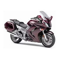
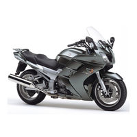
Congratulations on your purchase of the Yamaha FJR13AG / FJR13AGC. This model is the result of Yamahas vast experience in the production of fine sporting, touring, and pacesetting racing machines. It represents the high degree of crafts- manship and reliability that have made Yamaha a leader in these fields. This manual will give you an understanding of the operation, inspection, and basic maintenance of this motorcycle. If you have any questions concerning the opera- tion or maintenance of your motorcycle, please consult a Yamaha dealer. The design and manufacture of this Yamaha motorcycle fully comply with the emissions standards for clean air applicable at the date of manufacture. Yamaha has met these standards without reducing the performance or economy of oper- ation of the motorcycle. To maintain these high standards, it is important that you and your Yamaha dealer pay close attention to the recommended maintenance schedules and operating instructions contained within this manual. Yamaha continually seeks advancements in product design and quality. There- fore, while this manual contains the most current product information available at the time of printing, there may be minor discrepancies between your motorcycle and this manual. If there is any question concerning this manual, please consult a Yamaha dealer.
WARNING
EWA10012
Please read this manual and the YOU AND YOUR MOTORCYCLE: RIDING
TIPS booklet carefully before operating this motorcycle. Do not attempt to
operate this motorcycle until you have attained adequate knowledge of its
controls and operating features. Regular inspections and careful mainte-
nance, along with good operating techniques, will help ensure that you safe-
ly enjoy the capabilities and reliability of this motorcycle.
UB8810E0.book Page 1 Friday, November 6, 2015 9:51 AM
Important manual information
EAU63350
Particularly important information is distinguished in this manual by the following notations:
*Product and specifications are subject to change without notice.
EAU10194
This is the safety alert symbol. It is used to alert you to potential personal injury haz- ards. Obey all safety messages that follow this symbol to avoid possible injury or death.
A WARNING indicates a hazardous situation which, if not avoided, could result in death or serious injury.
A NOTICE indicates special precautions that must be taken to avoid damage to the vehi- cle or other property.
A TIP provides key information to make proce- dures easier or clearer.
FJR13AG / FJR13AGC OWNERS MANUAL
2015 by Yamaha Motor Corporation, U.S.A. 1st edition, October 2015
All rights reserved. Any reprinting or unauthorized use without the written permission of
Yamaha Motor Corporation, U.S.A. is expressly prohibited.
Printed in Japan. P/N LIT-11626-29-61
WARNING
NOTICE
TIP
UB8810E0.book Page 1 Friday, November 6, 2015 9:51 AM
Table of contents
Location of important labels…………1-1
Safety information ……………………….2-1
Description ………………………………….3-1 Left view ……………………………………3-1 Right view………………………………….3-2 Controls and instruments…………….3-3
Instrument and control functions….4-1 Main switch/steering lock ……………4-1 Indicator lights and warning
lights ……………………………………..4-2 Cruise control system …………………4-5 Multi-function meter unit ……………..4-7 D-mode (drive mode) ………………..4-19 Handlebar switches…………………..4-20 Clutch lever ……………………………..4-21 Shift pedal ……………………………….4-22 Brake lever ………………………………4-22 Brake pedal ……………………………..4-23 ABS ………………………………………..4-23 Traction control system……………..4-24 Fuel tank cap……………………………4-26 Fuel…………………………………………4-26 Fuel tank breather/overflow
hose …………………………………….4-28 Catalytic converters …………………4-28 Seats ………………………………………4-29 Adjusting the rider seat height ……4-30 Storage compartments ……………..4-32 Accessory box………………………….4-33 Adjusting the headlight beams……4-34 Handlebar position……………………4-35 Opening and closing the cowling
vents ……………………………………4-35 Rear view mirrors ……………………..4-37 Adjusting the front fork………………4-37 Adjusting the shock absorber
assembly………………………………4-39 Sidestand ………………………………..4-41 Ignition circuit cut-off system……..4-41 Auxiliary DC jack ………………………4-43
For your safety pre-operation
checks ……………………………………….. 5-1
Operation and important riding
points…………………………………………. 6-1 Starting the engine…………………….. 6-2 Shifting…………………………………….. 6-3 Engine break-in…………………………. 6-4 Parking…………………………………….. 6-5
Periodic maintenance and
adjustment ………………………………….7-1 Owners tool kit…………………………. 7-2 Periodic maintenance chart for the
emission control system………….. 7-3 General maintenance and
lubrication chart……………………… 7-4 Removing and installing panels ……7-7 Checking the spark plugs …………. 7-10 Canister (for California only)………. 7-11 Engine oil and oil filter cartridge … 7-11 Final gear oil……………………………. 7-14 Coolant ………………………………….. 7-15 Cleaning the air filter element ……. 7-17 Checking the engine idling
speed………………………………….. 7-18 Checking the throttle grip free
play …………………………………….. 7-19 Valve clearance……………………….. 7-19 Tires ………………………………………. 7-20 Cast wheels ……………………………. 7-22 Clutch lever …………………………….. 7-23 Checking the brake lever free
play …………………………………….. 7-23 Brake light switches…………………. 7-24 Checking the front and rear brake
pads…………………………………….7-24 Checking the brake and clutch
fluid levels……………………………. 7-25 Changing the brake and clutch
fluids …………………………………… 7-27 Checking and lubricating the
cables …………………………………. 7-27 Checking and lubricating the
throttle grip and cable ……………7-28
UB8810E0.book Page 1 Friday, November 6, 2015 9:51 AM
Table of contents
Checking and lubricating the brake and shift pedals…………… 7-28
Checking and lubricating the brake and clutch levers…………. 7-29
Checking and lubricating the centerstand and sidestand ……. 7-29
Lubricating the rear suspension … 7-30 Lubricating the swingarm
pivots …………………………………. 7-30 Checking the front fork…………….. 7-31 Checking the steering………………. 7-31 Checking the wheel bearings ……. 7-32 Battery …………………………………… 7-32 Replacing the fuses…………………. 7-34 Vehicle lights ………………………….. 7-35 Troubleshooting………………………. 7-36 Troubleshooting charts…………….. 7-37
Motorcycle care and storage………. 8-1 Matte color caution …………………… 8-1 Care ………………………………………… 8-1 Storage……………………………………. 8-4
Specifications…………………………….. 9-1
Consumer information………………. 10-1 Identification numbers……………… 10-1 Diagnostic connector ………………. 10-3 Reporting safety defects ………….. 10-4 Motorcycle noise regulation ……… 10-5 Maintenance record ………………… 10-6 YAMAHA MOTOR
CORPORATION, U.S.A. 2015 AND LATER MODEL STREET & DUAL-PURPOSE MOTORCYCLE LIMITED WARRANTY ………………………… 10-7
YAMAHA EXTENDED SERVICE (Y.E.S.) ……………………………….. 10-9
Index………………………………………… 11-1
UB8810E0.book Page 2 Friday, November 6, 2015 9:51 AM
Location of important labels
1-1
1
EAU63360
Read and understand all of the labels on your vehicle. They contain important in- formation for safe and proper operation of your vehicle. Never remove any labels from your vehicle. If a label becomes difficult to read or comes off, a replacement label is available from your Yamaha dealer.
89
62,31 4,5 7
UB8810E0.book Page 1 Friday, November 6, 2015 9:51 AM
Location of important labels
1-2
1
1 kg {2 lbs} 4BR-24877-A0
LOAD LIMIT
3 kg {7 lbs} 3TB-24877-A0
LOAD LIMIT
#4 #3
#2 #1
FUEL TANK
THROTTLE BODY CHARCOAL CANISTER
ATMOSPHERE
EMISSION HOSE ROUTING
1MC-21686-00
VACUUM HOSE ROUTING
13S-21684-10
INTAKE MANIFOLD
PRESS. SENSOR
#1#2#3#4
WARNING BEFORE YOU OPERATE THIS VEHICLE, READ THE OWNERS MANUAL AND ALL LABELS. ALWAYS WEAR AN APPROVED MOTORCYCLE HELMET, eye protection, and protective clothing.
1TP-2118K-A1
6
2 California only1
3 California only 4
5
UB8810E0.book Page 2 Friday, November 6, 2015 9:51 AM
Location of important labels
1-3
1
NOTICE Cleaning with alkaline or acid cleaner, gasoline or solvent will damage windshield. Use neutral detergent.
4B5-2815K-00
250 kPa, {2.50 kgf/cm2}, 36 psi
290 kPa, {2.90 kgf/cm2}, 42 psi
250 kPa, {2.50 kgf/cm2}, 36 psi
290 kPa, {2.90 kgf/cm2}, 42 psi
5VY-21668-00
WARNING This unit contains high pressure nitrogen gas. Mishandling can cause explosion.
Read owners manual for instructions. Do not incinerate, puncture or open.
1MC-22259-10
8
9
7
UB8810E0.book Page 3 Friday, November 6, 2015 9:51 AM
2-1
2
Safety information
EAU1028B
Be a Responsible Owner
As the vehicles owner, you are re- sponsible for the safe and proper oper- ation of your motorcycle. Motorcycles are single-track vehicles. Their safe use and operation are de- pendent upon the use of proper riding techniques as well as the expertise of the operator. Every operator should know the following requirements be- fore riding this motorcycle. He or she should: Obtain thorough instructions from
a competent source on all aspects of motorcycle operation.
Observe the warnings and mainte- nance requirements in this Own- ers Manual.
Obtain qualified training in safe and proper riding techniques.
Obtain professional technical ser- vice as indicated in this Owners Manual and/or when made neces- sary by mechanical conditions.
Never operate a motorcycle with- out proper training or instruction. Take a training course. Beginners should receive training from a cer- tified instructor. Contact an autho- rized motorcycle dealer to find out about the training courses nearest you.
Safe Riding
Perform the pre-operation checks each time you use the vehicle to make sure it is in safe operating condition. Failure to inspect or maintain the vehi- cle properly increases the possibility of
an accident or equipment damage. See page 5-1 for a list of pre-operation checks. This motorcycle is designed to
carry the operator and a passen- ger.
The failure of motorists to detect and recognize motorcycles in traf- fic is the predominating cause of automobile/motorcycle accidents. Many accidents have been caused by an automobile driver who did not see the motorcycle. Making yourself conspicuous ap- pears to be very effective in reduc- ing the chance of this type of accident. Therefore:
Wear a brightly colored jacket. Use extra caution when you are
approaching and passing through intersections, since in- tersections are the most likely places for motorcycle accidents to occur.
Ride where other motorists can see you. Avoid riding in another motorists blind spot.
Never maintain a motorcycle without proper knowledge. Contact an authorized motorcy- cle dealer to inform you on ba- sic motorcycle maintenance. Certain maintenance can only be carried out by certified staff.
UB8810E0.book Page 1 Friday, November 6, 2015 9:51 AM
Safety information
2-2
2
Many accidents involve inexperi- enced operators. In fact, many op- erators who have been involved in accidents do not even have a cur- rent motorcycle license. Make sure that you are qualified
and that you only lend your mo- torcycle to other qualified oper- ators.
Know your skills and limits. Staying within your limits may help you to avoid an accident.
We recommend that you prac- tice riding your motorcycle where there is no traffic until you have become thoroughly famil- iar with the motorcycle and all of its controls.
Many accidents have been caused by error of the motorcycle operator. A typical error made by the operator is veering wide on a turn due to excessive speed or un- dercornering (insufficient lean an- gle for the speed). Always obey the speed limit and
never travel faster than warrant- ed by road and traffic condi- tions.
Always signal before turning or changing lanes. Make sure that other motorists can see you.
The posture of the operator and passenger is important for proper control. The operator should keep both
hands on the handlebar and both feet on the operator foot- rests during operation to main- tain control of the motorcycle.
The passenger should always hold onto the operator, the seat strap or grab bar, if equipped, with both hands and keep both feet on the passenger footrests. Never carry a passenger unless he or she can firmly place both feet on the passenger footrests.
Never ride under the influence of alcohol or other drugs.
This motorcycle is designed for on-road use only. It is not suitable for off-road use.
Protective Apparel
The majority of fatalities from motorcy- cle accidents are the result of head in- juries. The use of a safety helmet is the single most critical factor in the pre- vention or reduction of head injuries. Always wear an approved helmet. Wear a face shield or goggles.
Wind in your unprotected eyes could contribute to an impairment of vision that could delay seeing a hazard.
The use of a jacket, heavy boots, trousers, gloves, etc., is effective in preventing or reducing abra- sions or lacerations.
Never wear loose-fitting clothes, otherwise they could catch on the control levers, footrests, or wheels and cause injury or an accident.
Always wear protective clothing that covers your legs, ankles, and feet. The engine or exhaust sys- tem become very hot during or af- ter operation and can cause burns.
A passenger should also observe the above precautions.
UB8810E0.book Page 2 Friday, November 6, 2015 9:51 AM
Safety information
2-3
2
Avoid Carbon Monoxide Poisoning
All engine exhaust contains carbon monoxide, a deadly gas. Breathing carbon monoxide can cause head- aches, dizziness, drowsiness, nausea, confusion, and eventually death. Carbon Monoxide is a colorless, odor- less, tasteless gas which may be pres- ent even if you do not see or smell any engine exhaust. Deadly levels of car- bon monoxide can collect rapidly and you can quickly be overcome and un- able to save yourself. Also, deadly lev- els of carbon monoxide can linger for hours or days in enclosed or poorly ventilated areas. If you experience any symptoms of carbon monoxide poi- soning, leave the area immediately, get fresh air, and SEEK MEDICAL TREAT- MENT. Do not run engine indoors. Even if
you try to ventilate engine exhaust with fans or open windows and doors, carbon monoxide can rap- idly reach dangerous levels.
Do not run engine in poorly venti- lated or partially enclosed areas such as barns, garages, or car- ports.
Do not run engine outdoors where engine exhaust can be drawn into a building through openings such as windows and doors.
Loading
Adding accessories or cargo to your motorcycle can adversely affect stabil- ity and handling if the weight distribu- tion of the motorcycle is changed. To avoid the possibility of an accident, use extreme caution when adding cargo or accessories to your motorcycle. Use
extra care when riding a motorcycle that has added cargo or accessories. Here, along with the information about accessories below, are some general guidelines to follow if loading cargo to your motorcycle: The total weight of the operator, pas- senger, accessories and cargo must not exceed the maximum load limit. Operation of an overloaded vehicle
could cause an accident.
When loading within this weight limit, keep the following in mind: Cargo and accessory weight
should be kept as low and close to the motorcycle as possible. Se- curely pack your heaviest items as close to the center of the vehicle as possible and make sure to dis- tribute the weight as evenly as possible on both sides of the mo- torcycle to minimize imbalance or instability.
Shifting weights can create a sud- den imbalance. Make sure that accessories and cargo are se- curely attached to the motorcycle before riding. Check accessory mounts and cargo restraints fre- quently. Properly adjust the suspension
for your load (suspension-ad- justable models only), and check the condition and pres- sure of your tires.
Never attach any large or heavy items to the handlebar, front fork, or front fender. These
Maximum load: 215 kg (474 lb) (FJR13AGC) 216 kg (476 lb) (FJR13AG)
UB8810E0.book Page 3 Friday, November 6, 2015 9:51 AM
Safety information
2-4
2
items, including such cargo as sleeping bags, duffel bags, or tents, can create unstable han- dling or a slow steering re- sponse.
This vehicle is not designed to
pull a trailer or to be attached to
a sidecar.
Genuine Yamaha Accessories
Choosing accessories for your vehicle is an important decision. Genuine Yamaha accessories, which are avail- able only from a Yamaha dealer, have been designed, tested, and approved by Yamaha for use on your vehicle. Many companies with no connection to Yamaha manufacture parts and ac- cessories or offer other modifications for Yamaha vehicles. Yamaha is not in a position to test the products that these aftermarket companies produce. Therefore, Yamaha can neither en- dorse nor recommend the use of ac- cessories not sold by Yamaha or modifications not specifically recom- mended by Yamaha, even if sold and installed by a Yamaha dealer.
Aftermarket Parts, Accessories, and
Modifications
While you may find aftermarket prod- ucts similar in design and quality to genuine Yamaha accessories, recog- nize that some aftermarket accesso- ries or modifications are not suitable because of potential safety hazards to you or others. Installing aftermarket products or having other modifications performed to your vehicle that change any of the vehicles design or operation characteristics can put you and others
at greater risk of serious injury or death. You are responsible for injuries related to changes in the vehicle. Keep the following guidelines in mind, as well as those provided under Load- ing when mounting accessories. Never install accessories or carry
cargo that would impair the per- formance of your motorcycle. Carefully inspect the accessory before using it to make sure that it does not in any way reduce ground clearance or cornering clearance, limit suspension travel, steering travel or control opera- tion, or obscure lights or reflec- tors. Accessories fitted to the han-
dlebar or the front fork area can create instability due to improp- er weight distribution or aerody- namic changes. If accessories are added to the handlebar or front fork area, they must be as lightweight as possible and should be kept to a minimum.
Bulky or large accessories may seriously affect the stability of the motorcycle due to aerody- namic effects. Wind may at- tempt to lift the motorcycle, or the motorcycle may become unstable in cross winds. These accessories may also cause in- stability when passing or being passed by large vehicles.
Certain accessories can dis- place the operator from his or her normal riding position. This improper position limits the freedom of movement of the
UB8810E0.book Page 4 Friday, November 6, 2015 9:51 AM
Safety information
2-5
2
operator and may limit control ability, therefore, such accesso- ries are not recommended.
Use caution when adding electri- cal accessories. If electrical ac- cessories exceed the capacity of the motorcycles electrical sys- tem, an electric failure could re- sult, which could cause a dangerous loss of lights or engine power.
Aftermarket Tires and Rims
The tires and rims that came with your motorcycle were designed to match the performance capabilities and to provide the best combination of han- dling, braking, and comfort. Other tires, rims, sizes, and combinations may not be appropriate. Refer to page 7-20 for tire specifications and more in- formation on replacing your tires.
Transporting the Motorcycle
Be sure to observe following instruc- tions before transporting the motorcy- cle in another vehicle. Remove all loose items from the
motorcycle. Check that the fuel cock (if
equipped) is in the OFF position and that there are no fuel leaks.
Point the front wheel straight ahead on the trailer or in the truck bed, and choke it in a rail to pre- vent movement.
Shift the transmission in gear (for models with a manual transmis- sion).
Secure the motorcycle with tie- downs or suitable straps that are attached to solid parts of the mo-
torcycle, such as the frame or up- per front fork triple clamp (and not, for example, to rubber-mounted handlebars or turn signals, or parts that could break). Choose the location for the straps carefully so the straps will not rub against painted surfaces during transport.
The suspension should be com- pressed somewhat by the tie- downs, if possible, so that the mo- torcycle will not bounce exces- sively during transport.
UB8810E0.book Page 5 Friday, November 6, 2015 9:51 AM
Description
3-1
3
EAU63371
Left view
1 2 3 4
57 68910111213 1. Coolant reservoir (page 7-15) 2. Accessory box (page 4-33) 3. Front fork spring preload adjusting bolt (page 4-37) 4. Owners tool kit (page 7-2) 5. Final gear oil filler bolt (page 7-14) 6. Final gear oil drain bolt (page 7-14) 7. Shock absorber assembly spring preload adjusting lever (page 4-39) 8. Air filter element (page 7-17) 9. Shift pedal (page 4-22) 10.Engine oil filler cap (page 7-11) 11.Engine oil filter cartridge (page 7-11) 12.Engine oil level check window (page 7-11) 13.Engine oil drain bolt (page 7-11)
UB8810E0.book Page 1 Friday, November 6, 2015 9:51 AM
Description
3-2
3
EAU63391
Right view
891011
6,753,421
1. Storage compartment (page 4-32) 2. Fuel tank cap (page 4-26) 3. Front fork spring preload adjusting bolt (page 4-37) 4. Front fork rebound damping force adjusting knob (page 4-37) 5. Windshield (page 4-10) 6. Fuses (page 7-34) 7. Battery (page 7-32) 8. Front fork compression damping force adjusting screw (page 4-37) 9. Brake pedal (page 4-23) 10.Shock absorber assembly rebound damping force adjusting knob
(page 4-39) 11.Rear brake fluid reservoir (page 7-25)
UB8810E0.book Page 2 Friday, November 6, 2015 9:51 AM
Description
3-3
3
EAU63401
Controls and instruments
1 2 3 4 5 6 7 8 2 9
10,111211 1. Clutch lever (page 4-21) 2. Rear view mirror (page 4-37) 3. Left handlebar switches (page 4-20) 4. Clutch fluid reservoir (page 7-25) 5. Multi-function meter unit (page 4-7) 6. Main switch/steering lock (page 4-1) 7. Front brake fluid reservoir (page 7-25) 8. Right handlebar switches (page 4-20) 9. Brake lever (page 4-22) 10.Throttle grip (page 7-19) 11.Grip warmer (page 4-10) 12.Headlight beam adjusting knob (page 4-34)
UB8810E0.book Page 3 Friday, November 6, 2015 9:51 AM
Instrument and control functions
4-1
4
EAU10462
Main switch/steering lock
The main switch/steering lock controls the ignition and lighting systems, and is used to lock the steering. The various positions are described below.
EAU10601
ON
All electrical circuits are supplied with power, the meter lighting, taillight, li- cense plate light, auxiliary lights and position lights come on, and the engine can be started. The key cannot be re- moved.
TIP
The headlights come on automatically when the engine is started and stay on until the key is turned to OFF, even if the engine stalls.
EAU10662
OFF
All electrical systems are off. The key can be removed.
WARNING
EWA10062
Never turn the key to OFF or
LOCK while the vehicle is moving.
Otherwise the electrical systems will
be switched off, which may result in
loss of control or an accident.
EAU10694
LOCK
The steering is locked and all electrical systems are off. The key can be re- moved.
To lock the steering
1. Turn the handlebars all the way to the left or right.
2. With the key in the OFF position, push the key in and turn it to LOCK.
3. Remove the key.
TIP
If the steering will not lock, try turning the handlebars back to the right or left slightly.
To unlock the steering
OFF ON
LOCK P
1. Push. 2. Turn.
1. Push. 2. Turn.
1 2
1 2
UB8810E0.book Page 1 Friday, November 6, 2015 9:51 AM
Instrument and control functions
4-2
4
1. Insert the key. 2. With the key in the LOCK posi-
tion, push the key in and turn it to OFF.
EAU65680
(Parking)
The hazard lights can be turned on, but all other electrical systems are off. The key can be removed. The steering must be locked before the key can be turned to .
NOTICE ECA22330
Using the hazard lights for an ex-
tended length of time may cause the
battery to discharge.
EAU49398
Indicator lights and warning lights
EAU11032
Turn signal indicator lights
and
Each indicator light will flash when its corresponding turn signal lights are flashing.
EAU11061
Neutral indicator light
This indicator light comes on when the transmission is in the neutral position.
EAU11081
High beam indicator light
This indicator light comes on when the high beam of the headlight is switched on.
1. Left turn signal indicator light 2. Engine trouble warning light 3. Oil level warning light 4. Neutral indicator light 5. High beam indicator light 6. Anti-lock Brake System (ABS) warning
light 7. Right turn signal indicator light 8. Traction control system indicator/warning
light TCS 9. Cruise control indicator lights
GEAR
N 77
A.TEMP F
Lo C.TEMP F
0:06 TIME TRIP
1 72 63
89
54
ABS
UB8810E0.book Page 2 Friday, November 6, 2015 9:51 AM
Instrument and control functions
4-3
4
EAU11124
Oil level warning light
This warning light comes on if the en- gine oil level is low. The electrical circuit of the warning light can be checked by turning the key to ON. The warning light should come on for a few seconds, and then go off. If the warning light does not come on initially when the key is turned to ON, or if the warning light remains on, have a Yamaha dealer check the electrical circuit.
TIP
Even if the oil level is sufficient, the warning light may flicker when riding on a slope or during sudden accelera- tion or deceleration, but this is not a malfunction.
EAU58400
Cruise control indicator lights
These indicator lights come on when the cruise control system is activated. See page 4-5 for a detailed explanation of the function of these indicator lights. The electrical circuit of these indicator lights can be checked by turning the key to ON. These indicator lights should come on for a few seconds, and then go off. If an indicator light does not come on initially when the key is turned to ON, or if an indicator light remains on, have a Yamaha dealer check the electrical circuit.
EAU73171
Engine trouble warning light
This warning light comes on if a prob- lem is detected in the engine or other vehicle control system. If this occurs, have a Yamaha dealer check the on- board diagnostic system. The electrical circuit of the warning light can be checked by turning the key to ON. The warning light should come on for a few seconds, and then go off. If the warning light does not come on initially when the key is turned to ON, or if the warning light remains on, have a Yamaha dealer check the vehicle.
EAU69890
ABS warning light
In normal operation, the ABS warning light comes on when the key is turned to ON, and goes off after traveling at a speed of 10 km/h (6 mi/h) or higher. If the ABS warning light: does not come on when the key is
turned to ON comes on or flashes while riding does not go off after traveling at a
speed of 10 km/h (6 mi/h) or high- er
The ABS may not work correctly. If any of the above occurs, have a Yamaha dealer check the system as soon as possible. (See page 4-23 for an expla- nation of the ABS.)
WARNING
EWA16041
If the ABS warning light does not go
off after traveling at a speed of 10
km/h (6 mi/h) or higher, or if the
warning light comes on or flashes
while riding, the brake system re-
verts to conventional braking. If ei-
ABS
UB8810E0.book Page 3 Friday, November 6, 2015 9:51 AM
Instrument and control functions
4-4
4
ther of the above occurs, or if the
warning light does not come on at
all, use extra caution to avoid possi-
ble wheel lock during emergency
braking. Have a Yamaha dealer
check the brake system and electri-
cal circuits as soon as possible.
EAU54261
Traction control system indica-
tor/warning light TCS
This indicator/warning light flashes when the traction control system en- gages and comes on when the system is turned off. The electrical circuit of the light can be checked by turning the key to ON. The light should come on for a few sec- onds, and then go off. If the light does not come on initially when the key is turned to ON, or if the light remains on, have a Yamaha dealer check the electrical circuit. If the traction control system becomes disabled while riding, the indica- tor/warning light and engine trouble warning light come on. (See page 4-24 for an explanation of the traction con- trol system.)
Try to reset the traction control system and the lights by following the proce- dures under Resetting on page 4-25.
1. Engine trouble warning light 2. Traction control system indicator/warning
light TCS
N A.TEMP
C.TEMP
TIME TR
21
UB8810E0.book Page 4 Friday, November 6, 2015 9:51 AM
Instrument and control functions
4-5
4
EAU54763
Cruise control system This model is equipped with a cruise control system designed to maintain a set cruising speed. The cruise control system operates only when riding in 3rd, 4th or 5th gear at speeds between about 50 km/h (31 mi/h) and 160 km/h (100 mi/h), or 6th gear at speeds between about 55 km/h (34 mi/h) and 160 km/h (100 mi/h).
WARNING
EWA16341
Improper use of the cruise con-
trol system may result in loss of
control, which could lead to an
accident. Do not activate the
cruise control system in heavy
traffic, poor weather conditions,
or among winding, slippery,
hilly, rough or gravel roads.
When traveling uphill or down-
hill, the cruise control system
may not be able to maintain the
set cruising speed.
To prevent accidentally activat-
ing the cruise control system,
turn it off when not in use. Make
sure that the cruise control sys-
tem indicator light is off.
Activating and setting the cruise
control system
1. Push the cruise control power switch located on the left handlebar. The cruise control sys- tem indicator light will come on.
2. Push the SET side of the cruise control setting switch to activate the cruise control system. Your current traveling speed will be- come the set cruising speed. The cruise control setting indicator light SET will come on.
Adjusting the set cruising speed
While the cruise control system is op- erating, push the RES+ side of the cruise control setting switch to in- crease the set cruising speed or the SET side to decrease the set speed.
TIP
Pushing the setting switch once will change the speed in increments of ap- proximately 2.0 km/h (1.2 mi/h). Hold- ing the RES+ or SET side of the cruise control setting switch down will increase or decrease the speed contin- uously until the switch is released.
1. Cruise control system indicator light 2. Cruise control setting indicator light SET
N A.TEMP
C.TEMP
TIME TR
21
1. Cruise control setting switch RES+/SET 2. Cruise control power switch
RES
SET
PASS
1
2
UB8810E0.book Page 5 Friday, November 6, 2015 9:51 AM
Instrument and control functions
4-6
4
You can also manually increase your traveling speed using the throttle. After you have accelerated, you can set a new cruising speed by pushing the SET side of the setting switch. If you do not set a new cruising speed, when you return the throttle grip, the vehicle will decelerate to the previously set cruising speed.
Deactivating the cruise control sys-
tem
Perform one of the following opera- tions to cancel the set cruising speed. The SET indicator light will go off. Turn the throttle grip past the
closed position in the deceleration direction.
Apply the front or rear brake. Disengage the clutch.
Push the power switch to turn off the cruise control system. The indica- tor light and the SET indicator light will go off.
TIP
Traveling speed decreases as soon as the cruise control system is deactivat- ed; unless the throttle grip is turned.
Using the resume function
Push the RES+ side of the cruise control setting switch to reactivate the cruise control system. The traveling speed will return to the previously set cruising speed. The SET indicator light will come on.
WARNING
EWA16351
It is dangerous to use the resume
function when the previously set
cruising speed is too high for current
conditions.
TIP
Pushing the power switch while the system is operating will turn the system off completely and erase the previously set cruising speed. You will not be able to use the resume function until a new cruising speed has been set.
Automatic deactivation of the cruise control system The cruise control system for this mod- el is electronically controlled and is linked with the other control systems. The cruise control system will auto- matically become deactivated under the following conditions: The cruise control system is not
able to maintain the set cruising speed.
Wheel slip or wheel spin is detect- ed. (If the traction control system has not been turned off, the trac- tion control system will work.)
The start/engine stop switch is set to the position.
The engine stalls. The sidestand is lowered.
1. Closed position 2. Cruise control cancel direction
2 1
UB8810E0.book Page 6 Friday, November 6, 2015 9:51 AM
Instrument and control functions
4-7
4
When traveling with a set cruising speed, if the cruise control system is deactivated under the above condi- tions, the indicator light will go off and the SET indicator light will flash for 4 seconds, and then go off. When not traveling with a set cruising speed, if the start/engine stop switch is set to the position, the engine stalls, or the sidestand is lowered, then the indicator light will go off (the SET indicator light will not flash). If the cruise control system is automat- ically deactivated, please stop and confirm that your vehicle is in good op- erating condition. Before using the cruise control system again, activate it using the power switch.
TIP
In some cases, the cruise control sys- tem may not be able to maintain the set cruising speed when the vehicle is traveling uphill or downhill. When the vehicle is traveling up-
hill, the actual traveling speed may become lower than the set cruis- ing speed. If this occurs, acceler- ate to the desired traveling speed using the throttle.
When the vehicle is traveling downhill, the actual traveling speed may become higher than the set cruising speed. If this oc- curs, the setting switch cannot be used to adjust the set cruising speed. To reduce the traveling speed, apply the brakes. When the brakes are applied, the cruise control system will become deac- tivated.
EAU54786
Multi-function meter unit
WARNING
EWA12423
Be sure to stop the vehicle before
making any setting changes to the
multi-function meter unit. Changing
settings while riding can distract the
operator and increase the risk of an
accident.
TIP
The select switch / and the menu switch MENU are located on the left handlebar. These switches al- low you to control or change the set- tings of the multi-function meter unit.
1. RESET button 2. TCS button 3. Tachometer 4. Drive mode display 5. Eco indicator ECO 6. Fuel meter 7. Speedometer 8. Clock 9. Transmission gear display 10.Function display 11.Information display
GEAR
N 77
A.TEMP F
Lo C.TEMP F
0:06 TIME TRIP
12 3 114 5 7 86 9 10
UB8810E0.book Page 7 Friday, November 6, 2015 9:51 AM
Instrument and control functions
4-8
4 The multi-function meter unit is equipped with the following: a speedometer a tachometer a clock a fuel meter an eco indicator a transmission gear display a drive mode display a function display an information display a setting mode display
TIP
Be sure to turn the key to ON be- fore attempting to use the select switch / , menu switch MENU, RESET button or TCS button.
To switch the meter displays be- tween kilometers and miles, see page 4-14.
Speedometer
The speedometer shows the vehicles traveling speed.
Tachometer
The electric tachometer allows the rid- er to monitor the engine speed and keep it within the ideal power range. When the key is turned to ON, the ta- chometer needle sweeps once across the r/min range and then returns to zero r/min in order to test the electrical circuit.
NOTICE ECA10032
Do not operate the engine in the ta-
chometer red zone.
Red zone: 9000 r/min and above
Fuel meter
The fuel meter indicates the amount of fuel in the fuel tank. The display seg- ments of the fuel meter disappear from
1. Menu switch MENU 2. Select switch /
1
2
1. Tachometer 2. Tachometer red zone
1. Fuel meter
1 2
GEAR
N A.TEMP
C.TEMP
1
UB8810E0.book Page 8 Friday, November 6, 2015 9:51 AM
Instrument and control functions
4-9
4
F (full) towards E (empty) as the fuel level decreases. When the last seg- ment starts flashing, refuel as soon as possible. When the key is turned to ON, all dis- play segments come on in order to test the electrical circuit.
TIP
If a problem is detected in the fuel me- ter electrical circuit, the fuel meter dis- play segments will flash repeatedly. Have a Yamaha dealer check the vehi- cle.
Eco indicator
This indicator comes on when the vehi- cle is being operated in an environ- mentally friendly, fuel-efficient manner. The indicator goes off when the vehicle is stopped.
TIP
Consider the following tips to reduce fuel consumption: Avoid high engine speeds during
acceleration. Travel at a constant speed. Select the transmission gear that
is appropriate for the vehicle speed.
Transmission gear display
This display shows the selected gear. The neutral position is indicated by and by the neutral indicator light .
Drive mode display
This display indicates which drive mode has been selected: Touring mode T or sports mode S. For more details on the modes and on how to select them, see pages 4-19 and 4-21.
1. Eco indicator ECO
GEAR
N A.TEMP
C.TEMP
1
1. Neutral indicator light 2. Transmission gear display
1. Drive mode display
GEAR
N 77
A.TEMP F
Lo C.TEMP F
0:06 TIME TRIP
1 2
GEAR
N A.TEMP
C.TEMP
1
UB8810E0.book Page 9 Friday, November 6, 2015 9:51 AM
Instrument and control functions
4-10
4
Function display
Push the MENU switch to switch the display between the windshield adjust- ing function, grip warmer adjusting function, and information display se- lection function.
Adjusting the windshield position To move the windshield up, push the side of the select switch. To move the windshield down, push the side of the select switch.
Adjusting the grip warmer This vehicle is equipped with grip warmers, which can only be used when the engine is running. There are 4 grip warmer settings.
To increase the grip warmer tempera- ture, push the side of the select switch. To decrease the grip warmer temperature, push the side of the select switch.
NOTICE ECA17931
Be sure to wear gloves when
using the grip warmers.
If the ambient temperature is 20
C (68 F) or higher, do not set
the grip warmer to the high set-
ting.
If the handlebar grip or throttle
grip becomes worn or dam-
aged, stop using the grip warm-
ers and replace the grips.
Selecting the information display
There are 3 information displays. The selected information display can be switched by using the select switch. The following items are shown in the information displays: an odometer display tripmeter displays a fuel reserve tripmeter display
1. Function display 2. Windshield adjusting function 3. Grip warmer adjusting function 4. Information display selection function
GEAR
N 77
A.TEMP F
Lo C.TEMP F
0:06 TIME TRIP
1 2
34
Off
Low
Middle
DisplaySetting
High
1. Information display 2. Display1 3. Display2 4. Display3
GEAR
N 3.1
TRIP-1 mile
4.3 TRIP-2 mile
mile
12 ODO
GEAR
N 7
RANGE mile
7.6 FUEL AVG MPG
MPG
7.6 CRNT FUEL
GEAR
N 77
A.TEMP F
Lo C.TEMP F
0:06 TIME TRIP
3
421
UB8810E0.book Page 10 Friday, November 6, 2015 9:51 AM
Instrument and control functions
4-11
4
an estimated traveling range dis- play
an elapsed time display an ambient temperature display a coolant temperature display an average fuel consumption dis-
play an instantaneous fuel consump-
tion display The items shown in each information display can be selected. To set or select the items shown, see page 4-14.
Odometer display:
The odometer shows the total distance traveled by the vehicle.
Tripmeter displays:
TRIP-1 and TRIP-2 show the dis- tance traveled since they were last set to zero.
TIP
The odometer will lock at 999999 and cannot be reset.
The tripmeters will reset and con- tinue counting after 9999.9 is reached.
When approximately 5.5 L (1.45 US gal, 1.21 Imp.gal) of fuel remains in the fuel tank, the last segment of the fuel meter starts flashing. In addition, the information display will automatically change to the fuel reserve tripmeter mode TRIP-F and start counting the distance traveled from that point.
In this case, push the select switch to switch the display in the following or- der:
TRIP-F Display1 Display2 Display3 TRIP-F
To reset a tripmeter, use the select switch to select the information display that contains the tripmeter you want to reset. Push the RESET button briefly so that the tripmeter flashes, and then push the RESET button again for 2 seconds while the tripmeter is flashing. If you do not reset the fuel reserve trip- meter manually, it will reset automati- cally after refueling and traveling 5 km (3 mi).
12 ODO mile
3.1 TRIP-1 mile
4.3 TRIP-2 mile
GEAR
4
2.1 TRIP-F mile
UB8810E0.book Page 11 Friday, November 6, 2015 9:51 AM
Instrument and control functions
4-12
4
Estimated traveling range display:
The distance that can be traveled with the remaining fuel in the fuel tank under the current riding conditions is shown.
Elapsed time display:
The time that has elapsed since the key was turned to ON is shown. The maximum time that can be shown is 99:59. This timer automatically resets when the key is turned to OFF.
TIP
There are also TIME2 and TIME3 elapsed time displays, but they cannot be set to the information display. See Setting mode on page 4-14 for de- tailed information.
Ambient temperature display:
This display shows the ambient tem- perature from 16 F to 122 F in 1 F in- crements. The temperature displayed may vary from the ambient tempera- ture.
TIP
16 F will be displayed even if the ambient temperature falls below 16 F.
122 F will be displayed even if the ambient temperature climbs above 122 F.
The accuracy of the temperature reading may be affected when rid- ing under 20 km/h (12 mi/h) or when stopped at traffic signals, and railroad crossings.
Coolant temperature display:
The coolant temperature display indi- cates the temperature of the coolant. The coolant temperature varies with changes in the weather and engine load. If the message Hi flashes, stop the vehicle, then stop the engine, and let the engine cool. (See page 7-38.)
TIP
The selected information display can- not be switched while the message Hi is flashing.
7 RANGE mile
0:06 TIME TRIP
77 A.TEMP F
Lo C.TEMP F
GEAR
4
Hi C.TEMP F
UB8810E0.book Page 12 Friday, November 6, 2015 9:51 AM
Instrument and control functions
4-13
4
NOTICE ECA10022
Do not continue to operate the en-
gine if it is overheating.
Average fuel consumption display:
The average fuel consumption display modes km/L, L/100km or MPG show the average fuel consumption since the display was last reset. The km/L display shows the av-
erage distance that can be trav- eled on 1.0 L of fuel.
The L/100km display shows the average amount of fuel necessary to travel 100 km.
The MPG display shows the av- erage distance that can be trav- eled on 1.0 US gal of fuel.
To reset the average fuel consumption display, use the select switch to select the information display that contains the average fuel consumption display. Push the RESET button briefly so that the average fuel consumption dis- play flashes, and then push the RE- SET button again for 2 seconds while the display is flashing.
TIP
After resetting the average fuel con- sumption display, _ _._ will be shown for that display until the vehicle has traveled 1 km (0.6 mi).
NOTICE ECA15474
If there is a malfunction, . will
be continuously displayed. Have a
Yamaha dealer check the vehicle.
Instantaneous fuel consumption dis- play:
The instantaneous fuel consumption display modes km/L, L/100km or MPG show the fuel consumption un- der the current riding conditions. The km/L display shows the dis-
tance that can be traveled on 1.0 L of fuel.
The L/100km display shows the amount of fuel necessary to travel 100 km.
The MPG display shows the dis- tance that can be traveled on 1.0 US gal of fuel.
TIP
If traveling at speeds under 10 km/h (6 mi/h), _ _._ will be displayed.
NOTICE ECA15474
If there is a malfunction, . will
be continuously displayed. Have a
Yamaha dealer check the vehicle.
7.6 FUEL AVG MPG
7.6 CRNT FUEL MPG
UB8810E0.book Page 13 Friday, November 6, 2015 9:51 AM
Instrument and control functions
4-14
4
Setting mode
TIP
The transmission must be in neu- tral and the vehicle must be stopped to change settings in this mode.
Shifting the transmission into gear and starting off, or turning the key to OFF, saves all settings made, then exits the setting mode.
Push the MENU switch for 2 seconds to enter the setting mode. To exit the setting mode and return to the normal display, push the MENU switch again for 2 seconds.
Adjusting the temperature levels of the grip warmer settings
1. Use the select switch to highlight Grip Warmer.
1. Setting mode display
Display Description
This function allows you to set the low, middle, and high settings to 10 tem- perature levels. This function allows you to check and reset the OIL oil change interval (dis- tance traveled), and the FREE-1 and FREE-2 maintenance intervals.
MENU
Grip Warmer Maintenance Time Trip Unit Display Brightness Clock
1
Grip Warmer
Maintenance
This function allows you to check and reset the TIME2 and TIME3 functions. These time trips show the total elapsed time that the key has been in the ON position. When the key is turned to OFF, the trip times stop count- ing but are not reset. The maximum time that can be shown is 99:59. When the time trips reach 99:59, they automatically reset to 0:00 and continue counting. This function allows you to switch the display units between kilometers and miles. When kilometers are selected, the fuel con- sumption units can be switched between L/100km and km/L. This function allows you to change the items shown in 3 information displays. This function allows you to adjust the brightness of the multi-function meter unit panel to suit the out- side lighting conditions. This function allows you to set the clock. This function allows you to reset all items, except the odometer and the clock.
Time Trip
Unit
Display
Brightness
Clock
All Reset
UB8810E0.book Page 14 Friday, November 6, 2015 9:51 AM
Instrument and control functions
4-15
4
2. Push the MENU switch. The grip warmer setting display will be shown and High will flash in the display.
3. Push the MENU switch. The temperature level for the high set- ting will start flashing. Use the select switch to set the temperature level, and then push the MENU switch. High will start flashing.
4. Use the select switch to highlight Middle or Low, and then chan- ge the setting using the same pro- cedure that was used for the high setting.
5. When you are finished changing the settings, use the select switch to highlight , and then push the MENU switch to return to the setting mode menu.
TIP
The setting can be set to 10 tempera- ture levels.
Resetting the maintenance counters 1. Use the select switch to highlight
Maintenance.
2. Push the MENU switch, and then push the RESET button to select the item to reset.
MENU
Grip Warmer Maintenance Time Trip Unit Display Brightness Clock
Grip Warmer
High 10
Middle 5
Low 1
Grip Warmer
High 10
Middle 5
Low 1
Grip Warmer
High 10
Middle 5
Low 1
MENU
Grip Warmer Maintenance Time Trip Unit Display Brightness Clock
UB8810E0.book Page 15 Friday, November 6, 2015 9:51 AM
Instrument and control functions
4-16
4
3. While the selected item is flashing, push the RESET button for 2 seconds.
4. Push the MENU switch to return to the setting mode menu.
Checking and resetting TIME2 and TIME3
1. Use the select switch to highlight Time Trip.
2. Push the MENU switch to dis- play TIME2 and TIME3. To reset a time trip, push the RE- SET button to select the item to reset.
3. While the selected item is flashing, push the RESET button for 2 seconds.
4. Push the MENU switch to return to the setting mode menu.
Selecting the units 1. Use the select switch to highlight
Unit.
2. Push the MENU switch. The unit setting display will be shown and km or mile will flash in the dis- play.
12 OIL mile
6 FREE-1 mile
6 FREE-2 mile
Maintenance
MENU
Grip Warmer Maintenance Time Trip Unit Display Brightness Clock
TIME-2 0:07 TIME-3 0:07
Time Trip
MENU
Grip Warmer Maintenance Time Trip Unit Display Brightness Clock
Unit
km or mile mile
UB8810E0.book Page 16 Friday, November 6, 2015 9:51 AM
Instrument and control functions
4-17
4
3. Push the MENU switch. km or mile will flash in the display.
4. Use the select switch to select km or mile, and then push the MENU switch.
TIP
When km is selected, L/100km or km/L can be set as the fuel con- sumption units. To set the fuel con- sumption units, proceed as follows. If mile was selected, skip steps 5 and 6.
5. Use the select switch to select km/L or L/100km.
6. Push the MENU switch, use the select switch to select L/100km or km/L, and then push the MENU switch again.
7. Use the select switch to highlight , and then push the MENU switch to return to the setting mode menu.
Selecting the display items 1. Use the select switch to highlight
Display.
2. Push the MENU switch, use the select switch to highlight the dis- play to change, and then push the MENU switch again.
3. Use the select switch to highlight the item to change, and then push the MENU switch.
4. Use the select switch to select the item to show, and then push the MENU switch.
Unit
km or mile km
km/L or L/100km km/L
Unit
km or mile km
km/L or L/100km km/L
MENU
Grip Warmer Maintenance Time Trip Unit Display Brightness Clock
Display
Display-1 Display-2
Display-3
Display-1
1-1 A.TEMP
1-2 C.TEMP
1-3 TIME TRIP
UB8810E0.book Page 17 Friday, November 6, 2015 9:51 AM
Instrument and control functions
4-18
4
5. When you are finished changing the settings, use the select switch to highlight , and then push the MENU switch to return to the previous display.
6. Use the select switch to highlight , and then push the MENU switch to return to the setting mode menu.
Adjusting the meter panel brightness 1. Use the select switch to highlight
Brightness.
2. Push the MENU switch. 3. Use the select switch to select the
desired brightness level, and then push the MENU switch to return to the setting mode menu.
Setting the clock 1. Use the select switch to highlight
Clock.
2. Push the MENU switch. 3. When the hour digits start flash-
ing, use the select switch to set the hours.
Display-1
1-1 ODO
1-2 C.TEMP
1-3 TIME TRIP
Display-1
1-1 ODO
1-2 C.TEMP
1-3 TIME TRIP
MENU
Grip Warmer Maintenance Time Trip Unit Display Brightness Clock
Brightness
MENU
Grip Warmer Maintenance Time Trip Unit Display Brightness Clock
Clock
5 55
UB8810E0.book Page 18 Friday, November 6, 2015 9:51 AM
Instrument and control functions
4-19
4
4. Push the MENU switch, and the minute digits start flashing.
5. Use the select switch to set the minutes.
6. Push the MENU switch to return to the setting mode menu.
Resetting all of the display items 1. Use the select switch to highlight
All Reset.
2. Push the MENU switch. 3. Use the select switch to highlight
YES, and then push the MENU switch.
TIP
The odometer and the clock cannot be reset.
EAU49432
D-mode (drive mode) D-mode is an electronically controlled engine performance system with two mode selections (touring mode T and sports mode S). Push the drive mode switch MODE to switch between modes. (See page 4-21 for an explanation of the drive mode switch.)
TIP
Before using D-mode, make sure you understand its operation along with the operation of the drive mode switch.
Touring mode T
The touring mode T is suitable for various riding conditions. This mode allows the rider to enjoy smooth drivability from the low-speed range to the high-speed range.
Sports mode S
This mode offers a sportier engine re- sponse in the low- to mid-speed range compared to the touring mode.
MENU
Maintenance Time Trip Unit Display Brightness Clock All Reset
All Reset
YES
NO
1. Drive mode switch MODE
STOP
MODE
RUN START
1
UB8810E0.book Page 19 Friday, November 6, 2015 9:51 AM
Instrument and control functions
4-20
4
EAU1234J
Handlebar switches
Left
Right
EAU54201
Dimmer/Pass switch / /PASS
Set this switch to for the high beam and to for the low beam. To flash the high beam, push the pass side PASS of the switch while the headlights are on low beam.
EAU12461
Turn signal switch /
To signal a right-hand turn, push this switch to . To signal a left-hand turn, push this switch to . When released, the switch returns to the cen- ter position. To cancel the turn signal lights, push the switch in after it has re- turned to the center position.
EAU12501
Horn switch
Press this switch to sound the horn.
EAU54212
Stop/Run/Start switch / /
To crank the engine with the starter, set this switch to , and then push the switch down towards . See page 6-2 for starting instructions prior to starting the engine. Set this switch to to stop the en- gine in case of an emergency, such as when the vehicle overturns or when the throttle cable is stuck.
EAU12735
Hazard switch
With the key in the ON or posi- tion, use this switch to turn on the haz- ard lights (simultaneous flashing of all turn signal lights). The hazard lights are used in case of an emergency or to warn other drivers when your vehicle is stopped where it might be a traffic hazard.
NOTICE ECA10062
Do not use the hazard lights for an
extended length of time with the en-
gine not running, otherwise the bat-
tery may discharge.
1. Menu switch MENU 2. Select switch / 3. Cruise control switches 4. Horn switch 5. Turn signal switch / 6. Dimmer/Pass switch / /PASS
1. Stop/Run/Start switch / / 2. Drive mode switch MODE 3. Hazard switch
RES
SET
PASS
1
6
5
4
2
3
STOP
MODE
RUN START
3
2
1
UB8810E0.book Page 20 Friday, November 6, 2015 9:51 AM
Instrument and control functions
4-21
4
EAU12781
Cruise control switches
See page 4-5 for an explanation of the cruise control system.
EAU54231
Menu switch MENU
This switch is used to perform selec- tions in the function display and setting mode display of the multi-function me- ter unit. See Multi-function meter unit on page 4-7 for detailed information.
EAU54221
Select switch /
This switch is used to perform selec- tions in the function display and setting mode display of the multi-function me- ter unit. See Multi-function meter unit on page 4-7 for detailed information.
EAU54691
Drive mode switch MODE
WARNING
EWA15341
Do not change the D-mode while the
vehicle is moving.
Using this switch changes the drive mode to touring mode T or sports mode S. The throttle grip must be completely closed in order to change the drive mo- de. The selected mode is shown on the drive mode display. (See page 4-9.) The drive mode cannot be changed while the cruise control system is oper- ating.
EAU12832
Clutch lever
The clutch lever is located on the left side of the handlebar. To disengage the clutch, pull the lever toward the handlebar grip. To engage the clutch, release the lever. The lever should be pulled rapidly and released slowly for smooth clutch operation. The clutch lever is equipped with a clutch lever position adjusting dial. To adjust the distance between the clutch lever and the handlebar grip, turn the adjusting dial while holding the lever pushed away from the handlebar grip. Make sure that the appropriate setting on the adjusting dial is aligned with the arrow mark on the clutch lever. The clutch lever is equipped with a clutch switch, which is part of the igni- tion circuit cut-off system. (See page 4-41.)
1. Clutch lever 2. Clutch lever position adjusting dial 3. Arrow mark 4. Distance between clutch lever and handle-
bar grip
1
5
4
3 2
4
1 2
3
UB8810E0.book Page 21 Friday, November 6, 2015 9:51 AM
Instrument and control functions
4-22
4
EAU12872
Shift pedal
The shift pedal is located on the left side of the motorcycle and is used in combination with the clutch lever when shifting the gears of the 6-speed con- stant-mesh transmission equipped on this motorcycle.
EAU26825
Brake lever The brake lever is located on the right side of the handlebar. To apply the front brake, pull the lever toward the throttle grip.
The brake lever is equipped with a brake lever position adjusting dial. To adjust the distance between the brake lever and the throttle grip, turn the ad- justing dial while holding the lever pushed away from the throttle grip. Make sure that the appropriate setting on the adjusting dial is aligned with the mark on the brake lever.
1. Shift pedal
1. Brake lever 2. Brake lever position adjusting dial 3. mark 4. Distance between brake lever and throttle
grip 1
5
4
3 2
4
1
32
UB8810E0.book Page 22 Friday, November 6, 2015 9:51 AM
Instrument and control functions
4-23
4
EAU39542
Brake pedal
The brake pedal is located on the right side of the vehicle. This model is equipped with a unified brake system. When pressing down on the brake pedal, the rear brake and a portion of the front brake are applied. For full braking performance, apply both the brake lever and the brake pedal simul- taneously.
EAU73181
ABS This models anti-lock brake system (ABS) features a dual electronic control system, which acts on the front and rear brakes independently. Operate the brakes with ABS as you would conventional brakes. If the ABS is activated, a pulsating sensation may be felt at the brake lever or brake ped- al. In this situation, continue to apply the brakes and let the ABS work; do not pump the brakes as this will re- duce braking effectiveness.
WARNING
EWA16051
Always keep a sufficient distance
from the vehicle ahead to match the
riding speed even with ABS.
The ABS performs best with
long braking distances.
On certain surfaces, such as
rough or gravel roads, the brak-
ing distance may be longer with
the ABS than without.
The ABS is monitored by an ECU, which will revert the system to conven- tional braking if a malfunction occurs.
TIP
The ABS performs a self-diagno- sis test each time the vehicle first starts off after the key is turned to ON and the vehicle has traveled at a speed of 10 km/h (6 mi/h) or higher. During this test, a click- ing noise may be heard from the hydraulic control unit, and if the brake lever or brake pedal is even slightly applied, a vibration can be felt at the lever and pedal, but this does not indicate a malfunction.
1. Brake pedal
1
UB8810E0.book Page 23 Friday, November 6, 2015 9:51 AM
Instrument and control functions
4-24
4
This ABS has a test mode which allows the owner to experience the pulsation at the brake lever or brake pedal when the ABS is op- erating. However, special tools are required, so please consult your Yamaha dealer.
NOTICE ECA16831
Keep any type of magnets (including
magnetic pick-up tools, magnetic
screwdrivers, etc.) away from the
front and rear wheel hubs; other-
wise, the magnetic rotors equipped
in the wheel hubs may be damaged,
resulting in improper performance
of the ABS and the unified brake
system.
EAU54271
Traction control system The traction control system helps maintain traction when accelerating on slippery surfaces, such as unpaved or wet roads. If sensors detect that the rear wheel is starting to slip (uncon- trolled spinning), the traction control system assists by regulating engine power as needed until traction is re- stored. The TCS indicator/warning light flashes to let the rider know that traction control has engaged.
TIP
The rider may also notice slight chang- es in engine and exhaust sounds when the traction control system is engaged.
WARNING
EWA15432
The traction control system is not a
substitute for riding appropriately
for the conditions. Traction control
cannot prevent loss of traction due
to excessive speed when entering
turns, when accelerating hard at a
sharp lean angle, or while braking,
and cannot prevent front wheel slip-
ping. As with any motorcycle, ap-
proach surfaces that may be
slippery with caution and avoid es-
pecially slippery surfaces.
When the key is turned to ON, the traction control system automatically turns on. The traction control system can be turned on or off manually only when the key is in the ON position and the mo- torcycle is stopped.
1. Front wheel hub
1. Rear wheel hub
1
1
UB8810E0.book Page 24 Friday, November 6, 2015 9:51 AM
Instrument and control functions
4-25
4
TIP
Turn the traction control system off to help free the rear wheel if the motorcy- cle gets stuck in mud, sand, or other soft surfaces.
NOTICE ECA16801
Use only the specified tires. (See
page 7-20.) Using different sized
tires will prevent the traction control
system from controlling tire rotation
accurately.
Turning on/off the traction control
system
WARNING
EWA15441
Be sure to stop the vehicle before
making any setting changes to the
traction control system. Changing
settings while riding can distract the
operator and increase the risk of an
accident.
To turn off the traction control system, push the TCS button on the multi- function meter unit for at least 2 sec- onds. The TCS indicator/warning light will come on. To turn on the traction control system, push the TCS button again. The TCS indicator/warning light will go off.
Resetting
The traction control system will be dis- abled in the following conditions: The rear wheel is rotated with the
centerstand down and the key in the ON position.
Either the front wheel or rear wheel comes off the ground while riding.
Excessive rear wheel spinning. If the traction control system has been disabled, both the TCS indica- tor/warning light and the engine trou- ble warning light come on.
To reset the traction control system Turn the key to OFF. Wait at least 1 second, then turn the key back to ON. The TCS indicator/warning light should go off and the system will be enabled. The engine trouble warn- ing light should go off after the motor- cycle reaches at least 20 km/h (12 mi/h). If the TCS indicator/warning light and/or engine trouble warning light still remain on after resetting, the motorcycle may still be ridden; howev- er, have a Yamaha dealer check the motorcycle as soon as possible.
1. TCS button 2. Traction control system indicator/warning
light TCS
1 2
UB8810E0.book Page 25 Friday, November 6, 2015 9:51 AM
Instrument and control functions
4-26
4
EAU13075
Fuel tank cap
To open the fuel tank cap
Open the fuel tank cap lock cover, in- sert the key into the lock, and then turn it 1/4 turn clockwise. The lock will be released and the fuel tank cap can be opened.
To close the fuel tank cap
1. Push the fuel tank cap into posi- tion with the key inserted in the lock.
2. Turn the key counterclockwise to the original position, remove it, and then close the lock cover.
TIP
The fuel tank cap cannot be closed un- less the key is in the lock. In addition, the key cannot be removed if the cap is not properly closed and locked.
WARNING
EWA11092
Make sure that the fuel tank cap is
properly closed after filling fuel.
Leaking fuel is a fire hazard.
EAU13222
Fuel Make sure there is sufficient gasoline in the tank.
WARNING
EWA10882
Gasoline and gasoline vapors are
extremely flammable. To avoid fires
and explosions and to reduce the
risk of injury when refueling, follow
these instructions.
1. Before refueling, turn off the en- gine and be sure that no one is sit- ting on the vehicle. Never refuel while smoking, or while in the vi- cinity of sparks, open flames, or other sources of ignition such as the pilot lights of water heaters and clothes dryers.
2. Do not overfill the fuel tank. When refueling, be sure to insert the pump nozzle into the fuel tank filler hole. Stop filling when the fuel reaches the bottom of the filler tube. Because fuel expands when it heats up, heat from the engine or the sun can cause fuel to spill out of the fuel tank.
1. Unlock. 2. Fuel tank cap lock cover
2
1
1. Fuel tank filler tube 2. Maximum fuel level
UB8810E0.book Page 26 Friday, November 6, 2015 9:51 AM
Instrument and control functions
4-27
4
3. Wipe up any spilled fuel immedi- ately. NOTICE: Immediately
wipe off spilled fuel with a clean,
dry, soft cloth, since fuel may
deteriorate painted surfaces or
plastic parts. [ECA10072]
4. Be sure to securely close the fuel tank cap.
WARNING
EWA15152
Gasoline is poisonous and can cau-
se injury or death. Handle gasoline
with care. Never siphon gasoline by
mouth. If you should swallow some
gasoline or inhale a lot of gasoline
vapor, or get some gasoline in your
eyes, see your doctor immediately. If
gasoline spills on your skin, wash
with soap and water. If gasoline
spills on your clothing, change your
clothes.
EAU13315
NOTICE ECA11401
Use only unleaded gasoline. The use
of leaded gasoline will cause severe
damage to internal engine parts,
such as the valves and piston rings,
as well as to the exhaust system.
Your Yamaha engine has been de- signed to use regular unleaded gaso- line with a pump octane number
[(R+M)/2] of 86 or higher, or a research octane number of 91 or higher. If knocking (or pinging) occurs, use a gasoline of a different brand or premi- um unleaded fuel. Use of unleaded fuel will extend spark plug life and reduce maintenance costs. Gasohol
There are two types of gasohol: gaso- hol containing ethanol and that con- taining methanol. Gasohol containing ethanol can be used if the ethanol con- tent does not exceed 10% (E10). Gas- ohol containing methanol is not recommended by Yamaha because it can cause damage to the fuel system or vehicle performance problems.
Recommended fuel: Regular unleaded gasoline (Gasohol [E10] acceptable)
Fuel tank capacity: 25 L (6.6 US gal, 5.5 Imp.gal)
Fuel reserve amount: 5.5 L (1.45 US gal, 1.21 Imp.gal)
UB8810E0.book Page 27 Friday, November 6, 2015 9:51 AM
Instrument and control functions
4-28
4
EAU48792
Fuel tank breather/overflow hose
TIP
For California: See page 7-11 for breather hose information.
Before operating the motorcycle: Check the fuel tank breather/over-
flow hose connection. Check the fuel tank breather/over-
flow hose for cracks or damage, and replace it if necessary.
Make sure that the end of the fuel tank breather/overflow hose is not blocked, and clean it if necessary.
Make sure that the fuel tank breather/overflow hose is routed through the clamp.
EAU13447
Catalytic converters This vehicle is equipped with catalytic converters in the exhaust system.
WARNING
EWA10863
The exhaust system is hot after op-
eration. To prevent a fire hazard or
burns:
Do not park the vehicle near
possible fire hazards such as
grass or other materials that
easily burn.
Park the vehicle in a place
where pedestrians or children
are not likely to touch the hot
exhaust system.
Make sure that the exhaust sys-
tem has cooled down before
doing any maintenance work.
Do not allow the engine to idle
more than a few minutes. Long
idling can cause a build-up of
heat.
NOTICE ECA10702
Use only unleaded gasoline. The use
of leaded gasoline will cause unre-
pairable damage to the catalytic
converter.
1. Fuel tank breather/overflow hose 2. Clamp
2
1
UB8810E0.book Page 28 Friday, November 6, 2015 9:51 AM
Instrument and control functions
4-29
4
EAU39496
Seats
Passenger seat
To remove the passenger seat 1. Insert the key into the seat lock,
and then turn it counterclockwise.
2. Lift the front of the passenger seat and pull it forward.
To install the passenger seat 1. Insert the projections on the rear
of the passenger seat into the seat holders as shown, and then push the front of the seat down to lock it in place.
2. Remove the key.
Rider seat
To remove the rider seat 1. Remove the passenger seat. 2. Push the rider seat lock lever, lo-
cated under the back of the rider seat, to the left as shown, and then pull the seat off.
To install the rider seat 1. Insert the projection on the front of
the rider seat into the seat holder as shown, and then push the rear of the seat down to lock it in place.
2. Install the passenger seat.
TIP
Make sure that the seats are prop- erly secured before riding.
1. Seat lock 2. Unlock.
1. Projection 2. Seat holder
1
2
1. Rider seat lock lever 2. Rider seat
1. Projection 2. Seat holder
UB8810E0.book Page 29 Friday, November 6, 2015 9:51 AM
Instrument and control functions
4-30
4
The rider seat height can be ad- justed to change the riding posi- tion. (See the following section.)
EAU39633
Adjusting the rider seat height The rider seat height can be adjusted to one of two positions to suit the rid- ers preference. The rider seat height was adjusted to the lower position at delivery.
To change the rider seat height to
the high position
1. Remove the rider seat. (See page 4-29.)
2. Remove the rider seat height posi- tion adjuster by pulling it upward.
3. Move the rider seat holder cover to the lower position as shown.
1. Low position 2. High position
1. Rider seat height position adjuster
UB8810E0.book Page 30 Friday, November 6, 2015 9:51 AM
Instrument and control functions
4-31
4
4. Install the rider seat height posi- tion adjuster so that the H mark is aligned with the match mark.
5. Insert the projection on the front of the rider seat into seat holder B as shown.
6. Align the projection on the bottom of the rider seat with the H posi- tion slot, and then push the rear of the seat down to lock it in place as shown.
7. Install the passenger seat.
To change the rider seat height to
the low position
1. Remove the rider seat. (See page 4-29.)
2. Remove the rider seat height posi- tion adjuster by pulling it upward.
3. Move the rider seat holder cover to the upper position.
4. Install the rider seat height posi- tion adjuster so that the L mark is aligned with the match mark.
1. Rider seat holder cover
1. Rider seat height position adjuster 2. H mark 3. Match mark
1. Projection 2. Seat holder B (for high position) 3. Rider seat holder cover
1
1. H position slot
1. Rider seat height position adjuster 2. L mark 3. Match mark
UB8810E0.book Page 31 Friday, November 6, 2015 9:51 AM
Instrument and control functions
4-32
4
5. Insert the projection on the front of the rider seat into seat holder A as shown.
6. Align the projection on the bottom of the rider seat with the L posi- tion slot, and then push the rear of the seat down to lock it in place as shown.
7. Install the passenger seat.
TIP
Make sure that the seats are properly secured before riding.
EAU40254
Storage compartments This vehicle is equipped with two stor- age compartments. Storage compartment A is located un- der the rider seat. (See page 4-29.)
Storage compartment B is located un- der the passenger seat. (See page 4-29.)
When storing documents or other items in a storage compartment, be sure to wrap them in a plastic bag so that they will not get wet. When wash- ing the vehicle, be careful not to let any water enter a storage compartment.
WARNING
EWA14421
Do not exceed the load limit of 1
kg (2 lb) for storage compart-
ment A.
1. Projection 2. Rider seat holder cover 3. Seat holder A (for low position)
1. L position slot
1 2
3
1. Storage compartment A
1. Storage compartment B
1
1
UB8810E0.book Page 32 Friday, November 6, 2015 9:51 AM
Instrument and control functions
4-33
4
Do not exceed the load limit of 3
kg (7 lb) for storage compart-
ment B.
Do not exceed the maximum
load of 215 kg (474 lb)
(FJR13AGC)
216 kg (476 lb) (FJR13AG) for the
vehicle.
EAU39482
Accessory box The accessory box is located beside the meter panel.
To open the accessory box
1. Insert the key into the main switch, and then turn it to ON.
2. Push the accessory box button, and then open the accessory box lid.
3. Turn the key to OFF to preserve the battery.
To close the accessory box
1. Fold the accessory box lid down. 2. Remove the key.
NOTICE ECA11802
Do not place heat-sensitive items in
the accessory box. The accessory
box can get hot when the engine is
running or the vehicle is in direct
sunlight.
WARNING
EWA11422
Do not exceed the load limit of
0.3 kg (0.66 lb) for the accessory
box.
1. Accessory box lid 2. Accessory box 3. Accessory box button
1
2 3
UB8810E0.book Page 33 Friday, November 6, 2015 9:51 AM
Instrument and control functions
4-34
4
Do not exceed the maximum
load of 215 kg (474 lb)
(FJR13AGC)
216 kg (476 lb) (FJR13AG) for the
vehicle.
EAU39612
Adjusting the headlight beams The headlight beam adjusting knobs are used to raise or lower the height of the headlight beams. It may be neces- sary to adjust the headlight beams to increase visibility and help prevent blinding oncoming drivers when carry- ing more or less load than usual. Obey local laws and regulations when ad- justing the headlights. To raise the headlight beams, turn the knobs in direction (a). To lower the headlight beams, turn the knobs in di- rection (b).
1. Headlight beam adjusting knob
11
(b) (a) (b) (a)
UB8810E0.book Page 34 Friday, November 6, 2015 9:51 AM
Instrument and control functions
4-35
4
EAU39642
Handlebar position The handlebars can be adjusted to one of three positions to suit the riders preference. Have a Yamaha dealer ad- just the position of the handlebars.
EAU54151
Opening and closing the cowl- ing vents The cowling vents can be opened 20 mm (0.79 in) for added ventilation to suit the riding conditions.
To open a cowling vent
1. Remove the quick fastener. 2. Slide the cowling vent panel for-
ward to unhook its projections from the lower slots, and then pull the panel off.
3. Insert the projections into the up- per slots, and then slide the panel backward.
1. Handlebar
1 1
1. Closed position 2. Open position
1. Cowling vent panel 2. Lower slot 3. Quick fastener
1 2
3
1
2
UB8810E0.book Page 35 Friday, November 6, 2015 9:51 AM
Instrument and control functions
4-36
44. Install the quick fastener.
To close a cowling vent
1. Remove the quick fastener. 2. Slide the cowling vent panel for-
ward to unhook its projections from the upper slots, and then pull the panel off.
3. Insert the projections into the low- er slots, and then slide the panel backward.
4. Install the quick fastener.
TIP
Make sure that the cowling vent panels are properly installed before riding.
1. Projection 2. Upper slot 3. Quick fastener
1. Cowling vent panel 2. Upper slot 3. Quick fastener
1
3
2
3
1
2
1. Projection 2. Lower slot 3. Quick fastener
1 3
2
UB8810E0.book Page 36 Friday, November 6, 2015 9:51 AM
Instrument and control functions
4-37
4
EAU39672
Rear view mirrors The rear view mirrors of this vehicle can be folded forward or backward for parking in narrow spaces. Fold the mir- rors back to their original position be- fore riding.
WARNING
EWA14372
Be sure to fold the rear view mirrors
back to their original position before
riding.
EAU54141
Adjusting the front fork
WARNING
EWA14671
Always adjust the spring preload on
both fork legs equally, otherwise
poor handling and loss of stability
may result.
Each front fork leg is equipped with a spring preload adjusting bolt. The right front fork leg is equipped with a re- bound damping force adjusting knob and compression damping force ad- justing screw.
NOTICE ECA10102
To avoid damaging the mechanism,
do not attempt to turn beyond the
maximum or minimum settings.
Spring preload
To increase the spring preload and thereby harden the suspension, turn the adjusting bolt on each fork leg in di- rection (a). To decrease the spring pre- load and thereby soften the suspension, turn the adjusting bolt on each fork leg in direction (b).
The spring preload setting is deter- mined by measuring distance A, shown in the illustration. The shorter
1. Riding position 2. Parking position
2
21
2
2 1
1. Spring preload adjusting bolt
(a) (b)
11
(a) (b)
UB8810E0.book Page 37 Friday, November 6, 2015 9:51 AM
Instrument and control functions
4-38
4
distance A is, the higher the spring pre- load; the longer distance A is, the lower the spring preload.
Rebound damping force
The rebound damping force is adjust- ed on the right front fork leg only. To increase the rebound damping for- ce and thereby harden the rebound damping, turn the adjusting knob in di- rection (a). To decrease the rebound damping force and thereby soften the rebound damping, turn the adjusting knob in direction (b).
Compression damping force
The compression damping force is ad- justed on the right front fork leg only. To increase the compression damping force and thereby harden the com- pression damping, turn the adjusting screw in direction (a). To decrease the compression damping force and there- by soften the compression damping, turn the adjusting screw in direction (b).
1. Distance A
Spring preload setting: Minimum (soft):
Distance A = 20.0 mm (0.79 in) Standard:
Distance A = 15.0 mm (0.59 in) Maximum (hard):
Distance A = 5.0 mm (0.20 in)
1. Rebound damping force adjusting knob
1
(a) (b) 1
Rebound damping setting: Minimum (soft):
22 click(s) in direction (b)* Standard:
12 click(s) in direction (b)* Maximum (hard):
1 click(s) in direction (b)* * With the adjusting knob fully turned
in direction (a)
1. Compression damping force adjusting screw
Compression damping setting: Minimum (soft):
32 click(s) in direction (b)* Standard:
11 click(s) in direction (b)* Maximum (hard):
1 click(s) in direction (b)* * With the adjusting screw fully
turned in direction (a)
UB8810E0.book Page 38 Friday, November 6, 2015 9:51 AM
Instrument and control functions
4-39
4
TIP
Although the total number of clicks of a damping force adjusting mechanism may not exactly match the above specifications due to small differences in production, the actual number of clicks always represents the entire ad- justing range. To obtain a precise ad- justment, it would be advisable to check the number of clicks of each damping force adjusting mechanism and to modify the specifications as necessary.
EAU14917
Adjusting the shock absorber assembly This shock absorber assembly is equipped with a spring preload adjust- ing lever and a rebound damping force adjusting knob.
NOTICE ECA16571
To avoid damaging the mechanism,
do not attempt to move beyond the
maximum or minimum settings.
Spring preload
For riding solo, move the spring pre- load adjusting lever in direction (a). For riding with a passenger, move the spring preload adjusting lever in direc- tion (b).
Rebound damping force
To increase the rebound damping for- ce and thereby harden the rebound damping, turn the adjusting knob in di- rection (a). To decrease the rebound damping force and thereby soften the rebound damping, turn the adjusting knob in direction (b).
1. Spring preload adjusting lever
1
(b)
(a)
UB8810E0.book Page 39 Friday, November 6, 2015 9:51 AM
Instrument and control functions
4-40
4
TIP
To obtain a precise adjustment, it is advisable to check the actual total number of clicks or turns of the damp- ing force adjusting mechanism. This adjustment range may not exactly match the specifications listed due to small differences in production.
WARNING
EWA10222
This shock absorber assembly con-
tains highly pressurized nitrogen
gas. Read and understand the fol-
lowing information before handling
the shock absorber assembly.
Do not tamper with or attempt
to open the cylinder assembly.
Do not subject the shock ab-
sorber assembly to an open
flame or other high heat source.
This may cause the unit to ex-
plode due to excessive gas
pressure.
Do not deform or damage the
cylinder in any way. Cylinder
damage will result in poor
damping performance.
Do not dispose of a damaged or
worn-out shock absorber as-
sembly yourself. Take the shock
absorber assembly to a Yamaha
dealer for any service.
1. Rebound damping force adjusting knob
Rebound damping setting: Minimum (soft):
20 click(s) in direction (b)* Standard:
12 click(s) in direction (b)* Maximum (hard):
1 click(s) in direction (b)* * With the adjusting knob fully turned
in direction (a)
UB8810E0.book Page 40 Friday, November 6, 2015 9:51 AM
Instrument and control functions
4-41
4
EAU15306
Sidestand The sidestand is located on the left side of the frame. Raise the sidestand or lower it with your foot while holding the vehicle upright.
TIP
The built-in sidestand switch is part of the ignition circuit cut-off system, which cuts the ignition in certain situa- tions. (See the following section for an explanation of the ignition circuit cut- off system.)
WARNING
EWA10242
The vehicle must not be ridden with
the sidestand down, or if the side-
stand cannot be properly moved up
(or does not stay up), otherwise the
sidestand could contact the ground
and distract the operator, resulting
in a possible loss of control.
Yamahas ignition circuit cut-off
system has been designed to assist
the operator in fulfilling the respon-
sibility of raising the sidestand be-
fore starting off. Therefore, check
this system regularly and have a
Yamaha dealer repair it if it does not
function properly.
EAU63430
Ignition circuit cut-off system The ignition circuit cut-off system (comprising the sidestand switch, clutch switch and neutral switch) has the following functions. It prevents starting when the
transmission is in gear and the sidestand is up, but the clutch le- ver is not pulled.
It prevents starting when the transmission is in gear and the clutch lever is pulled, but the side- stand is still down.
It cuts the running engine when the transmission is in gear and the sidestand is moved down.
Periodically check the operation of the ignition circuit cut-off system accord- ing to the following procedure.
UB8810E0.book Page 41 Friday, November 6, 2015 9:51 AM
Instrument and control functions
4-42
4
With the engine turned off: 1. Move the sidestand down. 2. Make sure that the start/engine stop
switch is set to . 3. Turn the key on. 4. Shift the transmission into the neutral
position. 5. Push the side of the start/engine
stop switch. Does the engine start?
With the engine still running: 6. Move the sidestand up. 7. Keep the clutch lever pulled. 8. Shift the transmission into gear. 9. Move the sidestand down. Does the engine stall?
After the engine has stalled: 10. Move the sidestand up. 11. Keep the clutch lever pulled. 12. Push the side of the
start/engine stop switch. Does the engine start?
The system is OK. The motorcycle can be ridden.
The neutral switch may not be working correctly. The motorcycle should not be ridden until checked by a Yamaha dealer.
The sidestand switch may not be working correctly. The motorcycle should not be ridden until checked by a Yamaha dealer.
The clutch switch may not be working correctly. The motorcycle should not be ridden until checked by a Yamaha dealer.
WARNING
The vehicle must be placed on the centerstand during this inspection.
If a malfunction is noted, have a Yamaha dealer check the system before riding.
YES NO
YES NO
YES NO
UB8810E0.book Page 42 Friday, November 6, 2015 9:51 AM
Instrument and control functions
4-43
4
EAU39656
Auxiliary DC jack
WARNING
EWA14361
To prevent electrical shock or short-
circuiting, make sure that the cap is
installed when the auxiliary DC jack
is not being used.
NOTICE ECA15432
The accessory connected to the
auxiliary DC jack should not be used
with the engine turned off, and the
load must never exceed 30 W (2.5 A),
otherwise the fuse may blow or the
battery may discharge.
This vehicle is equipped with an auxil- iary DC jack in the accessory box. A 12-V accessory connected to the auxiliary jack can be used when the key is in the ON position and should only be used when the engine is run- ning.
To use the auxiliary DC jack
1. Open the accessory box lid. (See page 4-33.)
2. Turn the key to OFF. 3. Remove the auxiliary DC jack cap.
4. Turn the accessory off.
5. Insert the accessory plug into the auxiliary DC jack.
6. Turn the key to ON, and then start the engine. (See page 6-2.)
7. Turn the accessory on.
1. Auxiliary DC jack cap
1
1. Auxiliary DC jack
1
UB8810E0.book Page 43 Friday, November 6, 2015 9:51 AM
For your safety pre-operation checks
5-1
5
EAU63440
Inspect your vehicle each time you use it to make sure the vehicle is in safe oper- ating condition. Always follow the inspection and maintenance procedures and schedules described in the Owners Manual.
WARNING
EWA11152
Failure to inspect or maintain the vehicle properly increases the possibility
of an accident or equipment damage. Do not operate the vehicle if you find
any problem. If a problem cannot be corrected by the procedures provided
in this manual, have the vehicle inspected by a Yamaha dealer.
Before using this vehicle, check the following points:
ITEM CHECKS PAGE
Fuel
Check fuel level in fuel tank. Refuel if necessary. Check fuel line for leakage. Check fuel tank breather/overflow hose for obstruc-
tions, cracks or damage, and check hose connection.
4-26, 4-28
Engine oil Check oil level in engine. If necessary, add recommended oil to specified level. Check vehicle for oil leakage.
7-11
Final gear oil Check vehicle for oil leakage. 7-14
Coolant
Check coolant level in reservoir. If necessary, add recommended coolant to specified
level. Check cooling system for leakage.
7-15
Front brake
Check operation. If soft or spongy, have Yamaha dealer bleed hydraulic
system. Check brake pads for wear. Replace if necessary. Check fluid level in reservoir. If necessary, add specified brake fluid to specified level. Check hydraulic system for leakage.
7-24, 7-25
Rear brake
Check operation. If soft or spongy, have Yamaha dealer bleed hydraulic
system. Check brake pads for wear. Replace if necessary. Check fluid level in reservoir. If necessary, add specified brake fluid to specified level. Check hydraulic system for leakage.
7-24, 7-25
UB8810E0.book Page 1 Friday, November 6, 2015 9:51 AM
For your safety pre-operation checks
5-2
5
Clutch
Check operation. If soft or spongy, have Yamaha dealer bleed hydraulic
system. Check fluid level in reservoir. If necessary, add specified brake fluid to specified level. Check hydraulic system for leakage.
7-23, 7-25
Throttle grip
Make sure that operation is smooth. Check throttle grip free play. If necessary, have Yamaha dealer adjust throttle grip
free play and lubricate cable and grip housing.
7-19, 7-28
Control cables Make sure that operation is smooth. Lubricate if necessary. 7-27
Wheels and tires
Check for damage. Check tire condition and tread depth. Check air pressure. Correct if necessary.
7-20, 7-22
Brake and shift pedals Make sure that operation is smooth. Lubricate pedal pivoting points if necessary. 7-28
Brake and clutch le- vers
Make sure that operation is smooth. Lubricate lever pivoting points if necessary. 7-29
Centerstand, side- stand
Make sure that operation is smooth. Lubricate pivots if necessary. 7-29
Chassis fasteners Make sure that all nuts, bolts and screws are properly
tightened. Tighten if necessary.
Instruments, lights, signals and switches
Check operation. Correct if necessary.
Sidestand switch Check operation of ignition circuit cut-off system. If system is not working correctly, have Yamaha dealer
check vehicle. 4-41
ITEM CHECKS PAGE
UB8810E0.book Page 2 Friday, November 6, 2015 9:51 AM
Operation and important riding points
6-1
6
EAU15952
Read the Owners Manual carefully to become familiar with all controls. If there is a control or function you do not understand, ask your Yamaha dealer.
WARNING
EWA10272
Failure to familiarize yourself with
the controls can lead to loss of con-
trol, which could cause an accident
or injury.
EAU73450
TIP
This model is equipped with: a lean angle sensor to stop the en-
gine in case of turnover. In this case, turn the key OFF and then to ON before attempting to re- start the engine. Failing to do so will prevent the engine from start- ing even though the engine will crank when the start switch is pushed.
an engine auto-stop system. The engine stops automatically if left idling for 20 minutes. In this case, simply push the start switch to re- start the engine.
UB8810E0.book Page 1 Friday, November 6, 2015 9:51 AM
Operation and important riding points
6-2
6
EAU54751
Starting the engine In order for the ignition circuit cut-off system to enable starting, one of the following conditions must be met: The transmission is in the neutral
position. The transmission is in gear with
the clutch lever pulled and the sidestand up. See page 4-41 for more informa- tion.
1. Turn the key to ON and make sure that the start/engine stop switch is set to . The following warning lights and indicator lights should come on for a few seconds, then go off. Oil level warning light Engine trouble warning light Traction control system indi-
cator/warning light Cruise control indicator lights
NOTICE ECA11834
If a warning or indicator light does
not come on initially when the key is
turned to ON, or if a warning or in-
dicator light remains on, see page
4-2 for the corresponding warning
and indicator light circuit check.
The ABS warning light should come on when the key is turned to ON, and then go off after travel- ing at a speed of 10 km/h (6 mi/h) or higher.
NOTICE ECA17682
If the ABS warning light does not
come on and then go off as ex-
plained above, see page 4-2 for the
warning light circuit check.
2. Shift the transmission into the neutral position. The neutral indi- cator light should come on. If not, ask a Yamaha dealer to check the electrical circuit.
3. Start the engine by pushing the side of the start/engine stop switch. If the engine fails to start, release the start/engine stop switch, wait a few seconds, and then try again. Each starting attempt should be as short as possible to preserve the battery. Do not crank the en- gine more than 10 seconds on any one attempt.
NOTICE ECA11043
For maximum engine life, never ac-
celerate hard when the engine is
cold!
UB8810E0.book Page 2 Friday, November 6, 2015 9:51 AM
Operation and important riding points
6-3
6
EAU16673
Shifting
Shifting gears lets you control the amount of engine power available for starting off, accelerating, climbing hills, etc. The gear positions are shown in the il- lustration.
TIP
To shift the transmission into the neu- tral position, press the shift pedal down repeatedly until it reaches the end of its travel, and then slightly raise it.
NOTICE ECA10261
Even with the transmission in
the neutral position, do not
coast for long periods of time
with the engine off, and do not
tow the motorcycle for long dis-
tances. The transmission is
properly lubricated only when
the engine is running. Inade-
quate lubrication may damage
the transmission.
Always use the clutch while
changing gears to avoid dam-
aging the engine, transmission,
and drive train, which are not
designed to withstand the
shock of forced shifting.
EAU16682
To start out and accelerate
1. Pull the clutch lever to disengage the clutch.
2. Shift the transmission into first gear. The neutral indicator light should go out.
3. Open the throttle gradually, and at the same time, release the clutch lever slowly.
4. At the recommended shift points shown in the following table, close the throttle, and at the same time, quickly pull the clutch lever in.
5. Shift the transmission into second gear. (Make sure not to shift the transmission into the neutral posi- tion.)
6. Open the throttle part way and gradually release the clutch lever.
7. Follow the same procedure when shifting to the next higher gear.
TIP
When shifting gears in normal operat- ing conditions, use the recommended shift points.
EAU58270
To decelerate
1. Release the throttle and apply both the front and the rear brakes smoothly to slow the motorcycle.
2. At the recommended shift points shown in the following table, shift to a lower gear.
3. When the motorcycle reaches 25 km/h (16 mph), the engine is about to stall or runs roughly, pull the
1. Shift pedal 2. Neutral position
UB8810E0.book Page 3 Friday, November 6, 2015 9:51 AM
Operation and important riding points
6-4
6
clutch lever in, use the brakes to slow the motorcycle, and continue to downshift as necessary.
4. Once the motorcycle has stopped, the transmission can be shifted into the neutral position. The neutral indicator light should come on and then the clutch lever can be released.
WARNING
EWA17380
Improper braking can cause
loss of control or traction. Al-
ways use both brakes and apply
them smoothly.
Make sure that the motorcycle
and the engine have sufficiently
slowed before shifting to a low-
er gear. Engaging a lower gear
when the vehicle or engine
speed is too high could make
the rear wheel lose traction or
the engine to over-rev. This
could cause loss of control, an
accident and injury. It could also
cause engine or drive train dam-
age.
EAU64150
Recommended shift points
The recommended shift points during acceleration and deceleration are shown in the table below.
EAU16842
Engine break-in There is never a more important period in the life of your engine than the period between 0 and 1600 km (1000 mi). For this reason, you should read the fol- lowing material carefully. Since the engine is brand new, do not put an excessive load on it for the first 1600 km (1000 mi). The various parts in the engine wear and polish themselves to the correct operating clearances. During this period, prolonged full-throt- tle operation or any condition that might result in engine overheating must be avoided.
EAU17124
01000 km (0600 mi)
Avoid prolonged operation above 4500 r/min. NOTICE: After 1000 km (600
mi) of operation, the engine oil and
final gear oil must be changed, and
the oil filter cartridge or element re-
placed. [ECA10333]
10001600 km (6001000 mi)
Avoid prolonged operation above 5400 r/min.
1600 km (1000 mi) and beyond
The vehicle can now be operated nor- mally.
NOTICE ECA10311
Keep the engine speed out of
the tachometer red zone.
Shift up points: 1st 2nd: 20 km/h (12 mph) 2nd 3rd: 30 km/h (19 mph) 3rd 4th: 40 km/h (25 mph) 4th 5th: 50 km/h (31 mph) 5th 6th: 60 km/h (37 mph)
Shift down points: 6th 5th: 45 km/h (28 mph) 5th 4th: 35 km/h (22 mph) 4th 3rd: 25 km/h (16 mph)
UB8810E0.book Page 4 Friday, November 6, 2015 9:51 AM
Operation and important riding points
6-5
6
If any engine trouble should oc-
cur during the engine break-in
period, immediately have a
Yamaha dealer check the vehi-
cle.
EAU17214
Parking When parking, stop the engine, and then remove the key from the main switch.
WARNING
EWA10312
Since the engine and exhaust
system can become very hot,
park in a place where pedestri-
ans or children are not likely to
touch them and be burned.
Do not park on a slope or on soft
ground, otherwise the vehicle
may overturn, increasing the
risk of a fuel leak and fire.
Do not park near grass or other
flammable materials which
might catch fire.
UB8810E0.book Page 5 Friday, November 6, 2015 9:51 AM
Periodic maintenance and adjustment
7-1
7
EAU17246
Periodic inspection, adjustment, and lubrication will keep your vehicle in the safest and most efficient condition possible. Safety is an obligation of the vehicle owner/operator. The most im- portant points of vehicle inspection, adjustment, and lubrication are ex- plained on the following pages. The intervals given in the periodic maintenance charts should be simply considered as a general guide under normal riding conditions. However, de- pending on the weather, terrain, geo- graphical location, and individual use, the maintenance intervals may need to be shortened.
WARNING
EWA10322
Failure to properly maintain the vehi-
cle or performing maintenance ac-
tivities incorrectly may increase
your risk of injury or death during
service or while using the vehicle. If
you are not familiar with vehicle ser-
vice, have a Yamaha dealer perform
service.
WARNING
EWA15123
Turn off the engine when performing
maintenance unless otherwise
specified.
A running engine has moving
parts that can catch on body
parts or clothing and electrical
parts that can cause shocks or
fires.
Running the engine while ser-
vicing can lead to eye injury,
burns, fire, or carbon monoxide
poisoning possibly leading to
death. See page 2-3 for more in-
formation about carbon monox-
ide.
WARNING
EWA15461
Brake discs, calipers, drums, and
linings can become very hot during
use. To avoid possible burns, let
brake components cool before
touching them.
UB8810E0.book Page 1 Friday, November 6, 2015 9:51 AM
Periodic maintenance and adjustment
7-2
7
EAU17303
Emission controls not only function to ensure cleaner air, but are also vital to proper engine operation and maximum performance. In the following periodic maintenance charts, the services relat- ed to emissions control are grouped separately. These services require specialized data, knowledge, and equipment. Maintenance, replace- ment, or repair of the emission control devices and systems may be per- formed by any repair establishment or individual that is certified (if applicable). Yamaha dealers are trained and equipped to perform these particular services.
EAU17362
Owners tool kit
The owners tool kit is located under the rider seat. (See page 4-29.) The service information included in this manual and the tools provided in the owners tool kit are intended to assist you in the performance of preventive maintenance and minor repairs. How- ever, additional tools such as a torque wrench may be necessary to perform certain maintenance work correctly.
TIP
If you do not have the tools or experi- ence required for a particular job, have a Yamaha dealer perform it for you.
1. Owners tool kit
UB8810E0.book Page 2 Friday, November 6, 2015 9:51 AM
Periodic maintenance and adjustment
7-3
7
EAU48491
TIP
From 24000 mi (37000 km) or 36 months, repeat the maintenance intervals starting from 8000 mi (13000 km) or 12 months.
Items marked with an asterisk require special tools, data and technical skills, have a Yamaha dealer perform the service.
EAU63291
Periodic maintenance chart for the emission control system
No. ITEM
ROUTINE
0.6 4 8 12 16 20
1 7 13 19 25 31
1 6 12 18 24 30
1 * Fuel line Check fuel hoses for cracks or
damage. Replace if necessary.
2 * Spark plugs
Check condition. Adjust gap and clean.
Replace.
3 * Valve clearance Check and adjust valve clear-
ance when engine is cold. Every 26600 mi (42000 km)
4 * Crankcase breather system
Check breather hose for cracks or damage.
Replace if necessary.
5 * Fuel injection Adjust synchronization.
6 * Exhaust system Check for leakage. Tighten if necessary. Replace gasket(s) if necessary.
7 *
Evaporative emis- sion control sys- tem (for California only)
Check control system for dam- age.
Replace if necessary.
8 * Air induction sys- tem
Check the air cut-off valve, reed valve, and hose for damage.
Replace any damaged parts.
1000 mi
1000 km
month
INITIAL ODOMETER READINGS
UB8810E0.book Page 3 Friday, November 6, 2015 9:51 AM
Periodic maintenance and adjustment
7-4
7
EAU63451
General maintenance and lubrication chart
No. ITEM
ROUTINE
0.6 4 8 12 16 20
1 7 13 19 25 31
1 6 12 18 24 30
1 Air filter element Clean with compressed air. Replace if necessary.
2 * Clutch Check operation, fluid level,
and for fluid leakage. Correct if necessary.
3 * Front brake
Check operation, fluid level, and for fluid leakage.
Replace brake pads if neces- sary.
4 * Rear brake
Check operation, fluid level, and for fluid leakage.
Replace brake pads if neces- sary.
5 * Brake hoses
Check for cracks or damage. Check for correct routing and
clamping.
Replace. Every 4 years
6 * Brake fluid Change. Every 2 years
7 * Wheels Check runout and for damage. Replace if necessary.
8 * Tires
Check tread depth and for damage.
Replace if necessary. Check air pressure. Correct if necessary.
9 * Wheel bearings Check bearings for smooth op-
eration. Replace if necessary.
10 * Swingarm pivot bearings
Check bearing assemblies for looseness.
Moderately repack with lithium- soap-based grease.
11 * Steering bearings
Check bearing assemblies for looseness.
Moderately repack with lithium- soap-based grease. Every 16000 mi (25000 km)
12 * Chassis fasteners Check all chassis fitting and
fasteners. Correct if necessary.
1000 mi
1000 km
month
INITIAL ODOMETER READINGS
UB8810E0.book Page 4 Friday, November 6, 2015 9:51 AM
Periodic maintenance and adjustment
7-5
7
13 Brake lever pivot shaft
Apply silicone grease lightly.
14 Brake pedal pivot shaft
Apply lithium-soap-based grease lightly.
15 Clutch lever pivot shaft
Apply silicone grease lightly.
16 Shift pedal pivot shaft
Apply lithium-soap-based grease lightly.
17 * Centerstand and sidestand pivots
Check operation. Apply lithium-soap-based
grease lightly.
18 * Sidestand switch Check operation and replace if
necessary.
19 * Front fork Check operation and for oil
leakage. Replace if necessary.
20 * Shock absorber as- sembly
Check operation and for oil leakage.
Replace if necessary.
21 * Rear suspension link pivots
Apply lithium-soap-based grease lightly.
22 Engine oil Change (warm engine before
draining).
23 Engine oil filter car- tridge
Replace.
24 * Cooling system
Check hoses for cracks or damage.
Replace if necessary.
Change coolant.
25 * Final gear oil Check oil level and for leakage.
Change.
26 * Front and rear brake switches
Check operation.
27 * Control cables Apply Yamaha cable lubricant
or other suitable cable lubricant thoroughly.
No. ITEM
ROUTINE
0.6 4 8 12 16 20
1 7 13 19 25 31
1 6 12 18 24 30
1000 mi
1000 km
month
INITIAL ODOMETER READINGS
UB8810E0.book Page 5 Friday, November 6, 2015 9:51 AM
Periodic maintenance and adjustment
7-6
7
EAU17661
TIP
The air filter needs more frequent service if you are riding in unusually wet or dusty areas.
Hydraulic brake and clutch systems After disassembling the brake or clutch master cylinders, caliper cylinders
or clutch release cylinder, always change the fluid. Regularly check the brake and clutch fluid levels and fill the reservoirs as required.
Replace the oil seals on the inner parts of the brake or clutch master cylin- ders, caliper cylinders and clutch release cylinder every two years.
Replace the brake and clutch hoses every four years or if cracked or dam- aged.
28 * Throttle grip
Check operation. Check throttle grip free play,
and adjust if necessary. Lubricate cable and grip hous-
ing. Lubricate grip warmer wire.
29 * Lights, signals and switches
Check operation. Adjust headlight beam.
No. ITEM
ROUTINE
0.6 4 8 12 16 20
1 7 13 19 25 31
1 6 12 18 24 30
1000 mi
1000 km
month
INITIAL ODOMETER READINGS
UB8810E0.book Page 6 Friday, November 6, 2015 9:51 AM
Periodic maintenance and adjustment
7-7
7
EAU18773
Removing and installing pan- els The panels shown need to be removed to perform some of the maintenance jobs described in this chapter. Refer to this section each time a panel needs to be removed and installed.
EAU54133
Panel A
To remove the panel 1. Remove the bolts and the quick
fasteners.
2. Release the slot at the rear of the panel from the projection on the right side cowling.
3. Release the slot at the front of the panel from the projection on the front cowling, and then pull the panel off as shown.
1. Panel A
1. Panel B
1. Panel C
1
1
1
1. Panel A 2. Bolt 3. Quick fastener
1. Slot 2. Projection
1
23
1 2
UB8810E0.book Page 7 Friday, November 6, 2015 9:51 AM
Periodic maintenance and adjustment
7-8
7
To install the panel 1. Fit the slot at the front of the panel
under the projection on the front cowling, and then fit the slot at the rear of the panel over the projec- tion on the right side cowling as shown.
TIP
Make sure that the fuses are covered and located to the inside of the panel lip.
2. Install the bolts and the quick fas- teners.
Panels B and C
To remove a panel 1. Remove the seats. (See page
4-29.) 2. Remove the bolts and the quick
fastener screws.
1. Slot 2. Projection
1. Slot 2. Projection
1. Slot 2. Projection
2
1
2
1
12
1. Fuse
1. Panel B 2. Quick fastener screw 3. Bolt
1
1 2
2
3
3
2 3
UB8810E0.book Page 8 Friday, November 6, 2015 9:51 AM
Periodic maintenance and adjustment
7-9
7
3. Pull the bottom of the panel out- ward, pull the front of the panel downward, and then slide the panel forward to release it in the rear as shown.
To install a panel 1. Place the panel in the original po-
sition, and then install the bolts and the quick fastener screws.
2. Install the seats.
1. Panel C 2. Quick fastener screw 3. Bolt
1. Panel B
12 2
2
3 3
1
1. Panel B
1
UB8810E0.book Page 9 Friday, November 6, 2015 9:51 AM
Periodic maintenance and adjustment
7-10
7
EAU19653
Checking the spark plugs The spark plugs are important engine components, which should be checked periodically, preferably by a Yamaha dealer. Since heat and depos- its will cause any spark plug to slowly erode, they should be removed and checked in accordance with the peri- odic maintenance and lubrication chart. In addition, the condition of the spark plugs can reveal the condition of the engine. The porcelain insulator around the center electrode of each spark plug should be a medium-to-light tan (the ideal color when the vehicle is ridden normally), and all spark plugs installed in the engine should have the same color. If any spark plug shows a dis- tinctly different color, the engine could be operating improperly. Do not at- tempt to diagnose such problems yourself. Instead, have a Yamaha deal- er check the vehicle. If a spark plug shows signs of elec- trode erosion and excessive carbon or other deposits, it should be replaced.
Before installing a spark plug, the spark plug gap should be measured with a wire thickness gauge and, if necessary, adjusted to specification.
Clean the surface of the spark plug gasket and its mating surface, and then wipe off any grime from the spark plug threads.
TIP
If a torque wrench is not available when installing a spark plug, a good estimate of the correct torque is 1/4 1/2 turn past finger tight. However, the spark plug should be tightened to the specified torque as soon as possible.
NOTICE ECA10841
Do not use any tools to remove or in-
stall the spark plug cap, otherwise
the ignition coil coupler may get
damaged. The spark plug cap may
be difficult to remove because the
rubber seal on the end of the cap fits
tightly. To remove the spark plug
cap, simply twist it back and forth
while pulling it out; to install it, twist
it back and forth while pushing it in.
Specified spark plug: NGK/CPR8EA-9
1. Spark plug gap
Spark plug gap: 0.80.9 mm (0.0310.035 in)
Tightening torque: Spark plug:
13 Nm (1.3 mkgf, 9.4 ftlbf)
UB8810E0.book Page 10 Friday, November 6, 2015 9:51 AM
Periodic maintenance and adjustment
7-11
7
EAU19682
Canister (for California only)
This model is equipped with a canister to prevent the discharging of fuel vapor into the atmosphere. Before operating this vehicle, make sure to check the following: Check each hose connection. Check each hose and canister for
cracks or damage. Replace if damaged.
Make sure that the canister breather is not blocked, and if necessary, clean it.
EAU19888
Engine oil and oil filter car- tridge The engine oil level should be checked before each ride. In addition, the oil must be changed and the oil filter car- tridge replaced at the intervals speci- fied in the periodic maintenance and lubrication chart.
To check the engine oil level
1. Place the vehicle on the center- stand. A slight tilt to the side can result in a false reading.
2. Start the engine, warm it up for several minutes, and then turn it off.
3. Wait a few minutes until the oil set- tles, and then check the oil level through the check window locat- ed at the bottom-left side of the crankcase.
TIP
The engine oil should be between the minimum and maximum level marks.
1. Canister 2. Canister breather
1
2
1. Engine oil level check window 2. Engine oil filler cap 3. Maximum level mark 4. Minimum level mark
3 1
4
2
UB8810E0.book Page 11 Friday, November 6, 2015 9:51 AM
Periodic maintenance and adjustment
7-12
7
4. If the engine oil is below the mini- mum level mark, add sufficient oil of the recommended type to raise it to the correct level.
To change the engine oil (with or
without oil filter cartridge replace-
ment)
1. Place the vehicle on a level surfa- ce.
2. Start the engine, warm it up for several minutes, and then turn it off.
3. Place an oil pan under the engine to collect the used oil.
4. Remove the engine oil filler cap, the engine oil drain bolt and its gasket to drain the oil from the crankcase.
TIP
Skip steps 57 if the oil filter cartridge is not being replaced.
5. Remove the oil filter cartridge with an oil filter wrench.
TIP
An oil filter wrench is available at a Yamaha dealer.
6. Apply a thin coat of clean engine oil to the O-ring of the new oil filter cartridge.
TIP
Make sure that the O-ring is properly seated.
7. Install the new oil filter cartridge, and then tighten it to the specified torque with a torque wrench.
1. Engine oil drain bolt 2. Gasket
1
2
1. Oil filter wrench 2. Oil filter cartridge
1. O-ring
1
2
UB8810E0.book Page 12 Friday, November 6, 2015 9:51 AM
Periodic maintenance and adjustment
7-13
7
8. Install the engine oil drain bolt and its new gasket, and then tighten the bolt to the specified torque.
9. Refill with the specified amount of the recommended engine oil, and then install and tighten the oil filler cap.
TIP
Be sure to wipe off spilled oil on any parts after the engine and exhaust sys- tem have cooled down.
NOTICE ECA11621
In order to prevent clutch slip-
page (since the engine oil also
lubricates the clutch), do not
mix any chemical additives. Do
not use oils with a diesel speci-
fication of CD or oils of a high-
er quality than specified. In
addition, do not use oils labeled
ENERGY CONSERVING II or
higher.
Make sure that no foreign mate-
rial enters the crankcase.
10. Start the engine, and then let it idle for several minutes while checking it for oil leakage. If oil is leaking, immediately turn the engine off and check for the cause.
TIP
After the engine is started, the engine oil level warning light should go off if the oil level is sufficient.
NOTICE ECA10402
If the oil level warning light flickers
or remains on even if the oil level is
correct, immediately turn the engine
off and have a Yamaha dealer check
the vehicle.
11. Turn the engine off, and then check the oil level and correct it if necessary.
1. Torque wrench
Tightening torque: Oil filter cartridge:
17 Nm (1.7 mkgf, 12 ftlbf)
Tightening torque: Engine oil drain bolt:
43 Nm (4.3 mkgf, 31 ftlbf)
Recommended engine oil: See page 9-1.
Oil quantity: Oil change:
3.80 L (4.02 US qt, 3.34 Imp.qt) With oil filter removal:
4.00 L (4.23 US qt, 3.52 Imp.qt)
1
UB8810E0.book Page 13 Friday, November 6, 2015 9:51 AM
Periodic maintenance and adjustment
7-14
7
EAU20017
Final gear oil The final gear case must be checked for oil leakage before each ride. If any leakage is found, have a Yamaha deal- er check and repair the vehicle. In ad- dition, the final gear oil level must be checked and the oil changed as fol- lows at the intervals specified in the periodic maintenance and lubrication chart.
WARNING
EWA10371
Make sure that no foreign mate-
rial enters the final gear case.
Make sure that no oil gets on
the tire or wheel.
To check the final gear oil level
1. Place the vehicle on the center- stand.
TIP
Make sure that the vehicle is posi- tioned straight up when checking the oil level. A slight tilt to the side can re- sult in a false reading.
2. Remove the final gear oil filler bolt and its gasket, and then check the oil level in the final gear case.
TIP
The oil level should be at the brim of the filler hole.
3. If the oil is below the brim of the filler hole, add sufficient oil of the recommended type to raise it to the correct level.
4. Check the gasket for damage, and replace it if necessary.
5. Install the final gear oil filler bolt and its gasket, and then tighten the bolt to the specified torque.
To change the final gear oil
1. Place the vehicle on a level surfa- ce.
2. Place an oil pan under the final gear case to collect the used oil.
3. Remove the final gear oil filler bolt, the final gear oil drain bolt and their gasket to drain the oil from the final gear case.
1. Final gear oil filler bolt 2. Gasket 3. Correct oil level
Tightening torque: Final gear oil filler bolt:
23 Nm (2.3 mkgf, 17 ftlbf)
3
2
1
UB8810E0.book Page 14 Friday, November 6, 2015 9:51 AM
Periodic maintenance and adjustment
7-15
7
4. Install the final gear oil drain bolt and its new gasket, and then tight- en the bolt to the specified torque.
5. Refill with the recommended final gear oil to the brim of the filler hole.
6. Check the oil filler bolt gasket for damage, and replace it if neces- sary.
7. Install the oil filler bolt and its gas- ket, and then tighten the bolt to the specified torque.
8. Check the final gear case for oil leakage. If oil is leaking, check for the cause.
EAU20071
Coolant The coolant level should be checked before each ride. In addition, the cool- ant must be changed at the intervals specified in the periodic maintenance and lubrication chart.
EAU54163
To check the coolant level
1. Place the vehicle on the center- stand.
TIP
The coolant level must be checked on a cold engine since the level varies with engine tem- perature.
Make sure that the vehicle is posi- tioned straight up when checking the coolant level. A slight tilt to the side can result in a false reading.
2. Remove the left cowling vent pan- el. (See page 4-35.)
3. Check the coolant level in the coolant reservoir.
TIP
The coolant should be between the mi- nimum and maximum level marks.
1. Final gear oil filler bolt 2. Gasket 3. Final gear oil drain bolt
Tightening torque: Final gear oil drain bolt:
23 Nm (2.3 mkgf, 17 ftlbf)
Recommended final gear oil: Yamaha genuine shaft drive gear oil SAE 80W-90 API GL-5
Oil quantity: 0.20 L (0.21 US qt, 0.18 Imp.qt)
Tightening torque: Final gear oil filler bolt:
23 Nm (2.3 mkgf, 17 ftlbf)
1
2
3
2
1. Coolant reservoir 2. Maximum level mark 3. Minimum level mark
2 1 3
UB8810E0.book Page 15 Friday, November 6, 2015 9:51 AM
Periodic maintenance and adjustment
7-16
7
4. If the coolant is at or below the mi- nimum level mark, remove the coolant reservoir cap. WARNING!
Remove only the coolant reser-
voir cap. Never attempt to re-
move the radiator cap when the
engine is hot. [EWA15162]
5. Add coolant or distilled water to raise the coolant to the maximum level mark, and install the coolant reservoir cap. NOTICE: If coolant
is not available, use distilled wa-
ter or soft tap water instead. Do
not use hard water or salt water
since it is harmful to the engine.
If water has been used instead
of coolant, replace it with cool-
ant as soon as possible, other-
wise the cooling system will not
be protected against frost and
corrosion. If water has been
added to the coolant, have a
Yamaha dealer check the anti-
freeze content of the coolant as
soon as possible, otherwise the
effectiveness of the coolant will
be reduced. [ECA10473]
6. Install the panel.
EAU33032
Changing the coolant
The coolant must be changed at the in- tervals specified in the periodic mainte- nance and lubrication chart. Have a Yamaha dealer change the coolant. WARNING! Never attempt to remove
the radiator cap when the engine is
hot. [EWA10382]
1. Coolant reservoir cap
Coolant reservoir capacity (up to the maximum level mark):
0.25 L (0.26 US qt, 0.22 Imp.qt)
1
UB8810E0.book Page 16 Friday, November 6, 2015 9:51 AM
Periodic maintenance and adjustment
7-17
7
EAU20474
Cleaning the air filter element The air filter element should be cleaned or replaced at the intervals specified in the periodic maintenance and lubrica- tion chart. Clean or, if necessary, re- place the air filter element more frequently if you are riding in unusually wet or dusty areas.
1. Remove panel B. (See page 7-7.) 2. Remove the intake air shroud by
removing the screw and the quick fastener screws.
3. Remove the air filter case cover by removing the screws.
4. Pull the air filter element out.
5. Lightly tap the air filter element to remove most of the dust and dirt, and then blow the remaining dirt out with compressed air as shown. If the air filter element is damaged, replace it.
6. Insert the air filter element into the air filter case. NOTICE: Make
sure that the air filter element is
properly seated in the air filter
case. The engine should never
be operated without the air filter
element installed, otherwise the
piston(s) and/or cylinder(s) may
become excessively worn.
[ECA10482]
7. Install the air filter case cover by installing the screws. NOTICE: Make sure that the fuel tank
breather/overflow hose is not
pinched. [ECA15412]
1. Intake air shroud 2. Quick fastener screw 3. Screw
1. Air filter case cover 2. Screw
1
3
2
2
2
1
1. Air filter element
1
UB8810E0.book Page 17 Friday, November 6, 2015 9:51 AM
Periodic maintenance and adjustment
7-18
7
8. Install the intake air shroud by in- stalling the screw and the quick fastener screws.
9. Install the panel.
EAU44735
Checking the engine idling speed Check the engine idling speed and, if necessary, have it corrected by a Yamaha dealer.
1. Fuel tank breather/overflow hose
1
Engine idling speed: 10001100 r/min
UB8810E0.book Page 18 Friday, November 6, 2015 9:51 AM
Periodic maintenance and adjustment
7-19
7
EAU21386
Checking the throttle grip free play Measure the throttle grip free play as shown.
Periodically check the throttle grip free play and, if necessary, have a Yamaha dealer adjust it.
EAU21402
Valve clearance The valve clearance changes with use, resulting in improper air-fuel mixture and/or engine noise. To prevent this from occurring, the valve clearance must be adjusted by a Yamaha dealer at the intervals specified in the periodic maintenance and lubrication chart.
1. Throttle grip free play
Throttle grip free play: 1.03.0 mm (0.040.12 in)
1
UB8810E0.book Page 19 Friday, November 6, 2015 9:51 AM
Periodic maintenance and adjustment
7-20
7
EAU64250
Tires Tires are the only contact between the vehicle and the road. Safety in all con- ditions of riding depends on a relatively small area of road contact. Therefore, it is essential to maintain the tires in good condition at all times and replace them at the appropriate time with the speci- fied tires.
Tire air pressure
The tire air pressure should be checked and, if necessary, adjusted before each ride.
WARNING
EWA10504
Operation of this vehicle with im-
proper tire pressure may cause se-
vere injury or death from loss of
control.
The tire air pressure must be
checked and adjusted on cold
tires (i.e., when the temperature
of the tires equals the ambient
temperature).
The tire air pressure must be
adjusted in accordance with the
riding speed and with the total
weight of rider, passenger, car-
go, and accessories approved
for this model.
WARNING
EWA10512
Never overload your vehicle. Opera-
tion of an overloaded vehicle could
cause an accident.
Tire inspection
The tires must be checked before each ride. If a tire tread shows crosswise lines (minimum tread depth), if the tire has a nail or glass fragments in it, or if the sidewall is cracked, contact a Yamaha dealer immediately and have the tire replaced.
Tire air pressure (measured on cold tires):
Up to 90 kg (198 lb) load: Front:
250 kPa (2.50 kgf/cm, 36 psi) Rear:
290 kPa (2.90 kgf/cm, 42 psi) 90 kg (198 lb) to maximum load:
Front: 250 kPa (2.50 kgf/cm, 36 psi)
Rear: 290 kPa (2.90 kgf/cm, 42 psi)
Maximum load*: 215 kg (474 lb) (FJR13AGC) 216 kg (476 lb) (FJR13AG)
* Total weight of rider, passenger, car- go and accessories
1. Tire sidewall 2. Tire wear indicator 3. Tire tread depth
UB8810E0.book Page 20 Friday, November 6, 2015 9:51 AM
Periodic maintenance and adjustment
7-21
7
WARNING
EWA10582
It is dangerous to ride with a
worn-out tire. When a tire tread
begins to show crosswise lines,
have a Yamaha dealer replace
the tire immediately.
The replacement of all wheel-
and brake-related parts, includ-
ing the tires, should be left to a
Yamaha dealer, who has the
necessary professional knowl-
edge and experience to do so.
Ride at moderate speeds after
changing a tire since the tire
surface must first be broken
in for it to develop its optimal
characteristics.
Tire information
This model is equipped with tubeless tires and tire air valves. Tires age, even if they have not been used or have only been used occasion- ally. Cracking of the tread and sidewall rubber, sometimes accompanied by
carcass deformation, is an evidence of ageing. Old and aged tires shall be checked by tire specialists to ascertain their suitability for further use.
WARNING
EWA10902
The front and rear tires should
be of the same make and de-
sign, otherwise the handling
characteristics of the motorcy-
cle may be different, which
could lead to an accident.
Always make sure that the valve
caps are securely installed to
prevent air pressure leakage.
Use only the tire valves and
valve cores listed below to
avoid tire deflation during a ride.
After extensive tests, only the tires list- ed below have been approved for this model by Yamaha.
WARNING
EWA10601
This motorcycle is fitted with super-
high-speed tires. Note the following
points in order to make the most ef-
ficient use of these tires.
Minimum tire tread depth (front and rear):
1.0 mm (0.04 in)
1. Tire air valve 2. Tire air valve core 3. Tire air valve cap with seal
Front tire: Size:
120/70ZR17M/C (58W) Manufacturer/model:
BRIDGESTONE/BT023F F Rear tire:
Size: 180/55ZR17M/C (73W)
Manufacturer/model: BRIDGESTONE/BT023R F
FRONT and REAR: Tire air valve:
TR412 Valve core:
#9100 (original)
UB8810E0.book Page 21 Friday, November 6, 2015 9:51 AM
Periodic maintenance and adjustment
7-22
7
Use only the specified replace-
ment tires. Other tires may run
the danger of bursting at super
high speeds.
Brand-new tires can have a rel-
atively poor grip on certain road
surfaces until they have been
broken in. Therefore, it is ad-
visable before doing any high-
speed riding to ride conserva-
tively for approximately 100 km
(60 mi) after installing a new tire.
The tires must be warmed up
before a high-speed run.
Always adjust the tire air pres-
sure according to the operating
conditions.
EAU21963
Cast wheels To maximize the performance, durabil- ity, and safe operation of your vehicle, note the following points regarding the specified wheels. The wheel rims should be
checked for cracks, bends, warp- age or other damage before each ride. If any damage is found, have a Yamaha dealer replace the wheel. Do not attempt even the smallest repair to the wheel. A de- formed or cracked wheel must be replaced.
The wheel should be balanced whenever either the tire or wheel has been changed or replaced. An unbalanced wheel can result in poor performance, adverse han- dling characteristics, and a short- ened tire life.
UB8810E0.book Page 22 Friday, November 6, 2015 9:51 AM
Periodic maintenance and adjustment
7-23
7
EAU22074
Clutch lever Since this model is equipped with a hy- draulic clutch, adjusting the clutch le- ver free play is not needed. However, it is necessary to check the clutch fluid level and check the hydraulic system for leakage before each ride. (See page 7-25.) If the clutch lever free play does become excessive, and shifting be- comes rough or clutch slippage oc- curs, causing poor acceleration, there may be air in the clutch system. If there is air in the hydraulic system, have a Yamaha dealer bleed the system be- fore operating the motorcycle.
EAU37914
Checking the brake lever free play
There should be no free play at the brake lever end. If there is free play, have a Yamaha dealer inspect the brake system.
WARNING
EWA14212
A soft or spongy feeling in the brake
lever can indicate the presence of
air in the hydraulic system. If there is
air in the hydraulic system, have a
Yamaha dealer bleed the system be-
fore operating the vehicle. Air in the
hydraulic system will diminish the
braking performance, which may re-
sult in loss of control and an acci-
dent.
1. No brake lever free play
1
UB8810E0.book Page 23 Friday, November 6, 2015 9:51 AM
Periodic maintenance and adjustment
7-24
7
EAU22283
Brake light switches The brake light, which is activated by the brake pedal and brake lever, should come on just before braking takes effect. Since the brake light switches are components of the cruise control system, they must be adjusted by a Yamaha dealer, who has the nec- essary professional knowledge and ex- perience.
EAU22393
Checking the front and rear brake pads The front and rear brake pads must be checked for wear at the intervals spec- ified in the periodic maintenance and lubrication chart.
EAU43432
Front brake pads
The front brake calipers are equipped with two sets of brake pads. Each front brake pad is provided with a wear indicator groove, which allows you to check the brake pad wear with- out having to disassemble the brake. To check a brake pad for wear, check its wear indicator groove. If a brake pad has worn to the point that the wear indicator groove has almost disap- peared, have a Yamaha dealer replace the brake pads as a set.
1. Brake pad wear indicator groove
1 1
UB8810E0.book Page 24 Friday, November 6, 2015 9:51 AM
Periodic maintenance and adjustment
7-25
7
EAU22501
Rear brake pads
Check each rear brake pad for damage and measure the lining thickness. If a brake pad is damaged or if the lining thickness is less than 0.8 mm (0.03 in), have a Yamaha dealer replace the brake pads as a set.
EAU40272
Checking the brake and clutch fluid levels Before riding, check that the brake and clutch fluids are above the minimum level marks. Check the brake and clutch fluid levels with the tops of the reservoirs level. Replenish the brake and clutch fluids if necessary.
Front brake
Rear brake
1. Lining thickness
1
1. Minimum level mark
1. Minimum level mark
1
UB8810E0.book Page 25 Friday, November 6, 2015 9:51 AM
Periodic maintenance and adjustment
7-26
7
Clutch
TIP
The rear brake fluid reservoir is located behind panel C. (See page 7-7.)
WARNING
EWA16031
Improper maintenance can result in
loss of braking ability or clutch oper-
ation. Observe these precautions:
Insufficient brake or clutch fluid
may allow air to enter the brake
or clutch system, reducing
braking or clutch performance.
Clean the filler caps before re-
moving. Use only DOT 4 brake
fluid from a sealed container.
Use only the specified brake flu-
id; otherwise, the rubber seals
may deteriorate, causing leak-
age.
Refill with the same type of
brake fluid. Adding a brake fluid
other than DOT 4 may result in a
harmful chemical reaction.
Be careful that water or dust
does not enter the brake or
clutch fluid reservoir when refill-
ing. Water will significantly low-
er the boiling point of the fluid
and may result in vapor lock,
and dirt may clog the ABS hy-
draulic unit valves.
NOTICE ECA17641
Brake fluid may damage painted
surfaces or plastic parts. Always
clean up spilled fluid immediately.
The brake or clutch fluid reservoir dia- phragm will lose its shape from the negative pressure if the fluid level goes down too far. Be sure to return the dia- phragm to its original shape before in- stalling it into the brake or clutch fluid reservoir. As the brake pads wear, it is normal for the brake fluid level to gradually go down. A low brake fluid level may indi- cate worn brake pads and/or brake system leakage; therefore, be sure to check the brake pads for wear and the brake system for leakage. A low clutch fluid level may indicate clutch system leakage; therefore, be sure to check the clutch system for leakage. If the brake or clutch fluid level goes down suddenly, have a Yamaha dealer check the cause before further riding.
1. Minimum level mark
Specified brake and clutch fluid: DOT 4 brake fluid
UB8810E0.book Page 26 Friday, November 6, 2015 9:51 AM
Periodic maintenance and adjustment
7-27
7
EAU22754
Changing the brake and clutch fluids Have a Yamaha dealer change the brake and clutch fluids at the intervals specified in the periodic maintenance and lubrication chart. In addition, have the oil seals of the brake and clutch master cylinders and calipers as well as the brake and clutch hoses replaced at the intervals listed below or whenev- er they are damaged or leaking. Oil seals: Replace every two
years. Brake and clutch hoses: Replace
every four years.
EAU23098
Checking and lubricating the cables The operation of all control cables and the condition of the cables should be checked before each ride, and the ca- bles and cable ends should be lubri- cated if necessary. If a cable is damaged or does not move smoothly, have a Yamaha dealer check or re- place it. WARNING! Damage to the
outer housing of cables may result
in internal rusting and cause inter-
ference with cable movement. Re-
place damaged cables as soon as
possible to prevent unsafe condi-
tions. [EWA10712]
Recommended lubricant: Yamaha cable lubricant or other suitable cable lubricant
UB8810E0.book Page 27 Friday, November 6, 2015 9:51 AM
Periodic maintenance and adjustment
7-28
7
EAU23115
Checking and lubricating the throttle grip and cable The operation of the throttle grip should be checked before each ride. In addition, the cable should be lubricat- ed by a Yamaha dealer at the intervals specified in the periodic maintenance chart. The throttle cable is equipped with a rubber cover. Make sure that the cover is securely installed. Even though the cover is installed correctly, it does not completely protect the cable from wa- ter entry. Therefore, use care not to pour water directly onto the cover or cable when washing the vehicle. If the cable or cover becomes dirty, wipe clean with a moist cloth.
EAU44276
Checking and lubricating the brake and shift pedals The operation of the brake and shift pedals should be checked before each ride, and the pedal pivots should be lu- bricated if necessary.
Brake pedal
Shift pedal
Recommended lubricant: Lithium-soap-based grease
UB8810E0.book Page 28 Friday, November 6, 2015 9:51 AM
Periodic maintenance and adjustment
7-29
7
EAU43602
Checking and lubricating the brake and clutch levers The operation of the brake and clutch levers should be checked before each ride, and the lever pivots should be lu- bricated if necessary.
Brake lever
Clutch lever
EAU23215
Checking and lubricating the centerstand and sidestand
The operation of the centerstand and sidestand should be checked before each ride, and the pivots and metal-to- metal contact surfaces should be lubri- cated if necessary.
WARNING
EWA10742
If the centerstand or sidestand does
not move up and down smoothly,
have a Yamaha dealer check or re-
pair it. Otherwise, the centerstand or
sidestand could contact the ground
and distract the operator, resulting
in a possible loss of control.
Recommended lubricant: Silicone grease
Recommended lubricant: Lithium-soap-based grease
UB8810E0.book Page 29 Friday, November 6, 2015 9:51 AM
Periodic maintenance and adjustment
7-30
7
EAU23252
Lubricating the rear suspen- sion
The pivoting points of the rear suspen- sion must be lubricated by a Yamaha dealer at the intervals specified in the periodic maintenance and lubrication chart.
EAUM1653
Lubricating the swingarm piv- ots
The swingarm pivots must be lubricat- ed by a Yamaha dealer at the intervals specified in the periodic maintenance and lubrication chart.
Recommended lubricant: Lithium-soap-based grease
Recommended lubricant: Lithium-soap-based grease
UB8810E0.book Page 30 Friday, November 6, 2015 9:51 AM
Periodic maintenance and adjustment
7-31
7
EAU23273
Checking the front fork The condition and operation of the front fork must be checked as follows at the intervals specified in the periodic maintenance and lubrication chart.
To check the condition
Check the inner tubes for scratches, damage and excessive oil leakage.
To check the operation
1. Place the vehicle on a level surfa- ce and hold it in an upright posi- tion. WARNING! To avoid injury,
securely support the vehicle so
there is no danger of it falling
over. [EWA10752]
2. While applying the front brake, push down hard on the handle- bars several times to check if the front fork compresses and re- bounds smoothly.
NOTICE ECA10591
If any damage is found or the front
fork does not operate smoothly,
have a Yamaha dealer check or re-
pair it.
EAU45512
Checking the steering Worn or loose steering bearings may cause danger. Therefore, the operation of the steering must be checked as fol- lows at the intervals specified in the periodic maintenance and lubrication chart.
1. Place the vehicle on the center- stand. WARNING! To avoid inju-
ry, securely support the vehicle
so there is no danger of it falling
over. [EWA10752]
2. Hold the lower ends of the front fork legs and try to move them for- ward and backward. If any free play can be felt, have a Yamaha dealer check or repair the steer- ing.
UB8810E0.book Page 31 Friday, November 6, 2015 9:51 AM
Periodic maintenance and adjustment
7-32
7
EAU23292
Checking the wheel bearings
The front and rear wheel bearings must be checked at the intervals specified in the periodic maintenance and lubrica- tion chart. If there is play in the wheel hub or if the wheel does not turn smoothly, have a Yamaha dealer check the wheel bearings.
EAU39526
Battery
The battery is located under panel A. (See page 7-7.) This model is equipped with a VRLA (Valve Regulated Lead Acid) battery. There is no need to check the electro- lyte or to add distilled water. However, the battery lead connections need to be checked and, if necessary, tight- ened.
WARNING
EWA10761
Electrolyte is poisonous and
dangerous since it contains sul-
furic acid, which causes severe
burns. Avoid any contact with
skin, eyes or clothing and al-
ways shield your eyes when
working near batteries. In case
of contact, administer the fol-
lowing FIRST AID.
EXTERNAL: Flush with plenty
of water.
INTERNAL: Drink large quan-
tities of water or milk and im-
mediately call a physician.
EYES: Flush with water for 15
minutes and seek prompt
medical attention.
1. Battery 2. Positive battery lead (red) 3. Negative battery lead (black)
1
2
3
UB8810E0.book Page 32 Friday, November 6, 2015 9:51 AM
Periodic maintenance and adjustment
7-33
7
Batteries produce explosive hy-
drogen gas. Therefore, keep
sparks, flames, cigarettes, etc.,
away from the battery and pro-
vide sufficient ventilation when
charging it in an enclosed
space.
KEEP THIS AND ALL BATTER-
IES OUT OF THE REACH OF
CHILDREN.
To charge the battery
Have a Yamaha dealer charge the bat- tery as soon as possible if it seems to have discharged. Keep in mind that the battery tends to discharge more quick- ly if the vehicle is equipped with op- tional electrical accessories.
NOTICE ECA16522
To charge a VRLA (Valve Regulated
Lead Acid) battery, a special (con-
stant-voltage) battery charger is re-
quired. Using a conventional battery
charger will damage the battery.
To store the battery
1. If the vehicle will not be used for more than one month, remove the battery, fully charge it, and then place it in a cool, dry place. NOTICE: When removing the
battery, be sure the key is
turned to OFF, then discon-
nect the negative lead before
disconnecting the positive lead.
[ECA16303]
2. If the battery will be stored for more than two months, check it at least once a month and fully char- ge it if necessary.
3. Fully charge the battery before installation. NOTICE: When in-
stalling the battery, be sure the
key is turned to OFF, then
connect the positive lead before
connecting the negative lead.
[ECA16841]
4. After installation, make sure that the battery leads are properly con- nected to the battery terminals.
NOTICE ECA16531
Always keep the battery charged.
Storing a discharged battery can
cause permanent battery damage.
UB8810E0.book Page 33 Friday, November 6, 2015 9:51 AM
Periodic maintenance and adjustment
7-34
7
EAU54515
Replacing the fuses The fuse boxes and individual fuses are located under panel A. (See page 7-7.)
If a fuse is blown, replace it as follows. 1. Turn the key to OFF and turn off
the electrical circuit in question. 2. Remove the blown fuse, and then
install a new fuse of the specified amperage. WARNING! Do not
use a fuse of a higher amperage
rating than recommended to
avoid causing extensive dam-
age to the electrical system and
possibly a fire. [EWA15132]
1. Main fuse 2. Spare fuse 3. Cruise control fuse 4. Brake light fuse 5. Fuse box 6. Main fuse 2
5
1 34 2
5
2 6
1. ABS motor fuse 2. ABS solenoid fuse 3. Fuel injection system fuse 4. Backup fuse (for clock) 5. Electronic throttle valve fuse 6. Headlight fuse 7. Spare fuse 8. Hazard fuse 9. Signaling system fuse 10.Terminal fuse 1 (for auxiliary DC jack) 11.ABS control unit fuse 12.Ignition fuse 13.Right radiator fan motor fuse 14.Left radiator fan motor fuse 15.Windshield motor fuse
14 7
9 10 11 12 13
7
158
1
7
2 3 4 5 6
7
UB8810E0.book Page 34 Friday, November 6, 2015 9:51 AM
Periodic maintenance and adjustment
7-35
7
3. Turn the key to ON and turn on the electrical circuit in question to check if the device operates.
4. If the fuse immediately blows again, have a Yamaha dealer check the electrical system.
EAU72980
Vehicle lights This model is equipped with full-LED lighting. There are no user replaceable bulbs. If a light does not come on, check the fuses and then have a Yamaha dealer check the vehicle.
NOTICE ECA16581
Do not affix any type of tinted film or
stickers to the headlight lens.
Specified fuses: Main fuse:
50.0 A Main fuse 2:
30.0 A Terminal fuse 1:
3.0 A Headlight fuse:
7.5 A Brake light fuse:
1.0 A Signaling system fuse:
7.5 A Ignition fuse:
20.0 A Radiator fan motor fuse:
10.0 A 2 Backup fuse:
7.5 A Hazard fuse:
7.5 A Fuel injection system fuse:
15.0 A ABS control unit fuse:
7.5 A ABS motor fuse:
30.0 A ABS solenoid fuse:
20.0 A Cruise control fuse:
1.0 A Windshield motor fuse:
20.0 A Electronic throttle valve fuse:
7.5 A
UB8810E0.book Page 35 Friday, November 6, 2015 9:51 AM
Periodic maintenance and adjustment
7-36
7
EAU25872
Troubleshooting Although Yamaha motorcycles receive a thorough inspection before shipment from the factory, trouble may occur during operation. Any problem in the fuel, compression, or ignition systems, for example, can cause poor starting and loss of power. The following troubleshooting charts represent quick and easy procedures for checking these vital systems your- self. However, should your motorcycle require any repair, take it to a Yamaha dealer, whose skilled technicians have the necessary tools, experience, and know-how to service the motorcycle properly. Use only genuine Yamaha replace- ment parts. Imitation parts may look like Yamaha parts, but they are often inferior, have a shorter service life and can lead to expensive repair bills.
WARNING
EWA15142
When checking the fuel system, do
not smoke, and make sure there are
no open flames or sparks in the ar-
ea, including pilot lights from water
heaters or furnaces. Gasoline or
gasoline vapors can ignite or ex-
plode, causing severe injury or prop-
erty damage.
UB8810E0.book Page 36 Friday, November 6, 2015 9:51 AM
Periodic maintenance and adjustment
7-37
7
EAU63470
Troubleshooting charts
Starting problems or poor engine performance
1. Fuel There is enough fuel.
There is no fuel.
Check the battery.
Supply fuel.
The engine turns over quickly.
The engine turns over slowly.
The engine does not start. Check the battery.
Wipe off with a dry cloth and correct the spark plug gaps, or replace the spark plugs.
Check the battery lead connections, and have a Yamaha dealer charge the battery if necessary.
2. Battery The battery is good.
The engine does not start. Check the ignition.
3. Ignition Wet Operate the electric starter.
Dry
There is compression.
There is no compression.
The engine does not start. Have a Yamaha dealer check the vehicle.
Have a Yamaha dealer check the vehicle.
The engine does not start. Check the compression.
Have a Yamaha dealer check the vehicle.
Remove the spark plugs and check the electrodes.
Operate the electric starter.
Operate the electric starter.
Check the fuel level in the fuel tank.
4. Compression
UB8810E0.book Page 37 Friday, November 6, 2015 9:51 AM
Periodic maintenance and adjustment
7-38
7
Engine overheating
WARNING
EWAT1041
Do not remove the radiator cap when the engine and radiator are hot.
Scalding hot fluid and steam may be blown out under pressure, which
could cause serious injury. Be sure to wait until the engine has cooled.
Place a thick rag, like a towel, over the radiator cap, and then slowly ro-
tate the cap counterclockwise to the detent to allow any residual pres-
sure to escape. When the hissing sound has stopped, press down on the
cap while turning it counterclockwise, and then remove the cap.
TIP
If coolant is not available, tap water can be temporarily used instead, provided that it is changed to the recommended coolant as soon as possible.
Wait until the engine has cooled.
Check the coolant level in the reservoir and radiator.
Add coolant. (See TIP.)
The coolant level is OK.
There is no leakage.
There is leakage.
The coolant level is low. Check the cooling system for leakage.
Have a Yamaha dealer check and repair the cooling system.
Start the engine. If the engine overheats again, have a Yamaha dealer check and repair the cooling system.
UB8810E0.book Page 38 Friday, November 6, 2015 9:51 AM
Motorcycle care and storage
8-1
8
EAU37834
Matte color caution
NOTICE ECA15193
Some models are equipped with
matte colored finished parts. Be
sure to consult a Yamaha dealer for
advice on what products to use be-
fore cleaning the vehicle. Using a
brush, harsh chemical products or
cleaning compounds when cleaning
these parts will scratch or damage
their surface. Wax also should not
be applied to any matte colored fin-
ished parts.
EAU54671
Care While the open design of a motorcycle reveals the attractiveness of the tech- nology, it also makes it more vulnera- ble. Rust and corrosion can develop even if high-quality components are used. A rusty exhaust pipe may go un- noticed on a car, however, it detracts from the overall appearance of a mo- torcycle. Frequent and proper care does not only comply with the terms of the warranty, but it will also keep your motorcycle looking good, extend its life and optimize its performance.
Before cleaning
1. Cover the muffler outlets with plastic bags after the engine has cooled down.
2. Make sure that all caps and cov- ers as well as all electrical cou- plers and connectors, including the spark plug caps, are tightly in- stalled.
3. Remove extremely stubborn dirt, like oil burnt onto the crankcase, with a degreasing agent and a brush, but never apply such prod- ucts onto seals, gaskets and wheel axles. Always rinse the dirt and degreaser off with water.
Cleaning
NOTICE ECA10773
Avoid using strong acidic wheel
cleaners, especially on spoked
wheels. If such products are
used on hard-to-remove dirt, do
not leave the cleaner on the af-
fected area any longer than in-
UB8810E0.book Page 1 Friday, November 6, 2015 9:51 AM
Motorcycle care and storage
8-2
8
structed. Also, thoroughly rinse
the area off with water, immedi-
ately dry it, and then apply a cor-
rosion protection spray.
Improper cleaning can damage
plastic parts (such as cowlings,
panels, windshields, headlight
lenses, meter lenses, etc.) and
the mufflers. Use only a soft,
clean cloth or sponge with wa-
ter to clean plastic. However, if
the plastic parts cannot be thor-
oughly cleaned with water, di-
luted mild detergent with water
may be used. Be sure to rinse
off any detergent residue using
plenty of water, as it is harmful
to plastic parts.
Do not use any harsh chemical
products on plastic parts. Be
sure to avoid using cloths or
sponges which have been in
contact with strong or abrasive
cleaning products, solvent or
thinner, fuel (gasoline), rust re-
movers or inhibitors, brake fluid,
antifreeze or electrolyte.
Do not use high-pressure wash-
ers or steam-jet cleaners since
they cause water seepage and
deterioration in the following ar-
eas: seals (of wheel and swing-
arm bearings, fork and brakes),
electric components (couplers,
connectors, instruments,
switches and lights), breather
hoses and vents.
For motorcycles equipped with
a windshield: Do not use strong
cleaners or hard sponges as
they will cause dulling or
scratching. Some cleaning
compounds for plastic may
leave scratches on the wind-
shield. Test the product on a
small hidden part of the wind-
shield to make sure that it does
not leave any marks. If the wind-
shield is scratched, use a quality
plastic polishing compound af-
ter washing.
After normal use Remove dirt with warm water, a mild detergent, and a soft, clean sponge, and then rinse thoroughly with clean water. Use a toothbrush or bottlebrush for hard-to-reach areas. Stubborn dirt and insects will come off more easily if the area is covered with a wet cloth for a few minutes before cleaning.
After riding in the rain, near the sea or on salt-sprayed roads Since sea salt or salt sprayed on roads during winter are extremely corrosive in combination with water, carry out the following steps after each ride in the rain, near the sea or on salt- sprayed roads.
TIP
Salt sprayed on roads in the winter may remain well into spring.
1. Clean the motorcycle with cold water and a mild detergent, after the engine has cooled down. NOTICE: Do not use warm wa-
ter since it increases the corro-
sive action of the salt. [ECA10792]
UB8810E0.book Page 2 Friday, November 6, 2015 9:51 AM
Motorcycle care and storage
8-3
8
2. After drying the motorcycle, apply a corrosion protection spray on all metal, including chrome- and nickel-plated, surfaces to prevent corrosion.
Windshield cleaning Avoid using any alkaline or strong acid cleaner, gasoline, brake fluid, or any other solvent. Clean the windshield with a cloth or sponge dampened with a neutral detergent, and after cleaning, thoroughly wash it off with water. For additional cleaning, use Yamaha Wind- shield Cleaner or other quality cleaner. Some cleaning compounds for plastics may leave scratches on surfaces of the windshield. Before using them, make a test by polishing an area which does not affect your visibility.
After cleaning
1. Dry the motorcycle with a chamois or an absorbing cloth.
2. Use a chrome polish to shine chrome, aluminum and stainless- steel parts, including the exhaust system. (Even the thermally in- duced discoloring of stainless- steel exhaust systems can be re- moved through polishing.)
3. To prevent corrosion, it is recom- mended to apply a corrosion pro- tection spray on all metal, including chrome- and nickel-plat- ed, surfaces.
4. Use spray oil as a universal clean- er to remove any remaining dirt.
5. Touch up minor paint damage caused by stones, etc.
6. Wax all painted surfaces.
7. Let the motorcycle dry completely before storing or covering it.
WARNING
EWA11132
Contaminants on the brakes or tires
can cause loss of control.
Make sure that there is no oil or
wax on the brakes or tires.
If necessary, clean the brake
discs and brake linings with a
regular brake disc cleaner or
acetone, and wash the tires with
warm water and a mild deter-
gent. Before riding at higher
speeds, test the motorcycles
braking performance and cor-
nering behavior.
NOTICE ECA10801
Apply spray oil and wax spar-
ingly and make sure to wipe off
any excess.
Never apply oil or wax to any
rubber and plastic parts, but
treat them with a suitable care
product.
Avoid using abrasive polishing
compounds as they will wear
away the paint.
TIP
Consult a Yamaha dealer for ad- vice on what products to use.
Washing, rainy weather or humid climates can cause the headlight lens to fog. Turning the headlight on for a short period of time will help remove the moisture from the lens.
UB8810E0.book Page 3 Friday, November 6, 2015 9:51 AM
Motorcycle care and storage
8-4
8
EAU26244
Storage
Short-term
Always store your motorcycle in a cool, dry place and, if necessary, protect it against dust with a porous cover. Be sure the engine and the exhaust sys- tem are cool before covering the mo- torcycle.
NOTICE ECA10811
Storing the motorcycle in a
poorly ventilated room or cover-
ing it with a tarp, while it is still
wet, will allow water and humid-
ity to seep in and cause rust.
To prevent corrosion, avoid
damp cellars, stables (because
of the presence of ammonia)
and areas where strong chemi-
cals are stored.
Long-term
Before storing your motorcycle for sev- eral months:
1. Follow all the instructions in the Care section of this chapter.
2. Fill up the fuel tank and add fuel stabilizer (if available) to prevent the fuel tank from rusting and the fuel from deteriorating.
3. Perform the following steps to protect the cylinders, piston rings, etc. from corrosion. a. Remove the spark plug caps
and spark plugs. b. Pour a teaspoonful of engine
oil into each spark plug bore. c. Install the spark plug caps onto
the spark plugs, and then pla- ce the spark plugs on the cylin-
der head so that the electrodes are grounded. (This will limit sparking during the next step.)
d. Turn the engine over several times with the starter. (This will coat the cylinder walls with oil.) WARNING! To prevent dam-
age or injury from sparking,
make sure to ground the
spark plug electrodes while
turning the engine over.
[EWA10952]
e. Remove the spark plug caps from the spark plugs, and then install the spark plugs and the spark plug caps.
4. Lubricate all control cables and the pivoting points of all levers and pedals as well as of the side- stand/centerstand.
5. Check and, if necessary, correct the tire air pressure, and then lift the motorcycle so that both of its wheels are off the ground. Alterna- tively, turn the wheels a little every month in order to prevent the tires from becoming degraded in one spot.
6. Cover the muffler outlets with plastic bags to prevent moisture from entering them.
7. Remove the battery and fully char- ge it. Store it in a cool, dry place and charge it once a month. Do not store the battery in an exces- sively cold or warm place [less than 0 C (30 F) or more than 30 C (90 F)]. For more information on storing the battery, see page 7-32.
UB8810E0.book Page 4 Friday, November 6, 2015 9:51 AM
Motorcycle care and storage
8-5
8
TIP
Make any necessary repairs before storing the motorcycle.
UB8810E0.book Page 5 Friday, November 6, 2015 9:51 AM
Specifications
9-1
9
Dimensions: Overall length:
2230 mm (87.8 in) Overall width:
750 mm (29.5 in) Overall height:
1325/1455 mm (52.2/57.3 in) Seat height:
805/825 mm (31.7/32.5 in) Wheelbase:
1545 mm (60.8 in) Ground clearance:
130 mm (5.12 in) Minimum turning radius:
3.1 m (10.17 ft) Weight:
Curb weight: 288 kg (635 lb) (FJR13AG) 289 kg (637 lb) (FJR13AGC)
Engine: Combustion cycle:
4-stroke Cooling system:
Liquid cooled Valve train:
DOHC Cylinder arrangement:
Inline Number of cylinders:
4-cylinder Displacement:
1298 cm Bore stroke:
79.0 66.2 mm (3.11 2.61 in) Compression ratio:
10.8 : 1 Starting system:
Electric starter Lubrication system:
Wet sump Engine oil:
Recommended brand: YAMALUBE
SAE viscosity grades: 10W-40, 10W-50, 15W-40, 20W-40 or 20W-50
Recommended engine oil grade: API service SG type or higher, JASO standard MA
Engine oil quantity: Oil change:
3.80 L (4.02 US qt, 3.34 Imp.qt) With oil filter removal:
4.00 L (4.23 US qt, 3.52 Imp.qt) Final gear oil:
Type: Yamaha genuine shaft drive gear oil SAE 80W-90 API GL-5
Quantity: 0.20 L (0.21 US qt, 0.18 Imp.qt)
Coolant quantity: Coolant reservoir (up to the maximum level mark):
0.25 L (0.26 US qt, 0.22 Imp.qt) Radiator (including all routes):
2.60 L (2.75 US qt, 2.29 Imp.qt) Air filter:
Air filter element: Dry element
Fuel: Recommended fuel:
Regular unleaded gasoline (Gasohol [E10] acceptable)
Fuel tank capacity: 25 L (6.6 US gal, 5.5 Imp.gal)
Fuel reserve amount: 5.5 L (1.45 US gal, 1.21 Imp.gal)
Fuel injection: Throttle body:
ID mark: 1MC1 00 (FJR13AG) 1MC4 10 (FJR13AGC)
20 10 0 10 20 30 40 50 C
10 30 50 70 90 1100 130 F
SAE 20W-50
SAE 20W-40
SAE 15W-40
SAE 10W-40
SAE 10W-50
UB8810E0.book Page 1 Friday, November 6, 2015 9:51 AM
Specifications
9-2
9
Spark plug(s): Manufacturer/model:
NGK/CPR8EA-9 Spark plug gap:
0.80.9 mm (0.0310.035 in) Clutch:
Clutch type: Wet, multiple-disc
Drivetrain: Primary reduction ratio:
1.563 (75/48) Final drive:
Shaft Secondary reduction ratio:
2.693 (34/36 x 21/27 x 33/9) Transmission type:
Constant mesh 6-speed Gear ratio:
1st: 2.500 (35/14)
2nd: 1.722 (31/18)
3rd: 1.350 (27/20)
4th: 1.111 (30/27)
5th: 0.963 (26/27)
6th: 0.846 (22/26)
Chassis: Frame type:
Diamond Caster angle:
26.0 Trail:
109 mm (4.3 in) Front tire:
Type: Tubeless
Size: 120/70ZR17M/C (58W)
Manufacturer/model: BRIDGESTONE/BT023F F
Rear tire: Type:
Tubeless Size:
180/55ZR17M/C (73W)
Manufacturer/model: BRIDGESTONE/BT023R F
Loading: Maximum load:
215 kg (474 lb) (FJR13AGC) 216 kg (476 lb) (FJR13AG) (Total weight of rider, passenger, cargo and accessories)
Tire air pressure (measured on cold
tires): Up to 90 kg (198 lb) load:
Front: 250 kPa (2.50 kgf/cm, 36 psi)
Rear: 290 kPa (2.90 kgf/cm, 42 psi)
90 kg (198 lb) load — maximum load: Front:
250 kPa (2.50 kgf/cm, 36 psi) Rear:
290 kPa (2.90 kgf/cm, 42 psi) Front wheel:
Wheel type: Cast wheel
Rim size: 17M/C x MT3.50
Rear wheel: Wheel type:
Cast wheel Rim size:
17M/C x MT5.50 Unified brake system:
Operation: Activated by rear brake
Front brake: Type:
Hydraulic dual disc brake Specified brake fluid:
DOT 4 Rear brake:
Type: Hydraulic single disc brake
Specified brake fluid: DOT 4
Front suspension: Type:
Telescopic fork Spring:
Coil spring Shock absorber:
Hydraulic damper
UB8810E0.book Page 2 Friday, November 6, 2015 9:51 AM
Specifications
9-3
9
Wheel travel: 135 mm (5.3 in)
Rear suspension: Type:
Swingarm (link suspension) Spring:
Coil spring Shock absorber:
Gas-hydraulic damper Wheel travel:
125 mm (4.9 in) Electrical system:
System voltage: 12 V
Ignition system: TCI
Charging system: AC magneto
Battery: Model:
GT14B-4 Voltage, capacity:
12 V, 12.0 Ah (10 HR) Bulb wattage quantity:
Headlight: LED
Brake/tail light: LED
Front turn signal/position light: LED
Rear turn signal light: LED
Auxiliary light: LED
License plate light: LED
Meter lighting: LED
Neutral indicator light: LED
High beam indicator light: LED
Oil level warning light: LED
Turn signal indicator light: LED
Engine trouble warning light: LED
ABS warning light: LED
Cruise control SET indicator light: LED
Cruise control ON indicator light: LED
Traction control system indicator/warning light:
LED Fuse(s):
Main fuse: 50.0 A
Main fuse 2: 30.0 A
Terminal fuse 1: 3.0 A
Headlight fuse: 7.5 A
Brake light fuse: 1.0 A
Signaling system fuse: 7.5 A
Ignition fuse: 20.0 A
Radiator fan motor fuse: 10.0 A 2
Hazard fuse: 7.5 A
Fuel injection system fuse: 15.0 A
ABS control unit fuse: 7.5 A
ABS motor fuse: 30.0 A
ABS solenoid fuse: 20.0 A
Cruise control fuse: 1.0 A
Backup fuse: 7.5 A
Windshield motor fuse: 20.0 A
Electronic throttle valve fuse: 7.5 A
UB8810E0.book Page 3 Friday, November 6, 2015 9:51 AM
Consumer information
10-1
10
EAU26357
Identification numbers Record the vehicle identification num- ber, engine serial number, model label information, and the key identification number in the spaces provided below. These identification numbers are need- ed when registering the vehicle with the authorities in your area and when ordering spare parts from a Yamaha dealer.
VEHICLE IDENTIFICATION NUMBER:
ENGINE SERIAL NUMBER:
MODEL LABEL INFORMATION:
KEY IDENTIFICATION NUMBER:
EAU26401
Vehicle identification number
The vehicle identification number is stamped into the steering head pipe. Record this number in the space pro- vided.
TIP
The vehicle identification number is used to identify your motorcycle and may be used to register your motorcy- cle with the licensing authority in your area.
EAU26442
Engine serial number
The engine serial number is stamped into the crankcase.
1. Vehicle identification number
1. Engine serial number
1
1
UB8810E0.book Page 1 Friday, November 6, 2015 9:51 AM
Consumer information
10-2
10
EAU26521
Model label
The model label is affixed to the frame under the passenger seat. (See page 4-29.) Record the information on this label in the space provided. This infor- mation will be needed when ordering spare parts from a Yamaha dealer.
EAU26382
Key identification number
The key identification number is stamped into the key tag. Record this number in the space provided and use it for reference when ordering a new key.
EAU48271
Vehicle Emission Control Informa-
tion label
The Vehicle Emission Control Informa- tion label is affixed at the location in the illustration. This label shows specifica- tions related to exhaust emissions as required by federal law, state law and Environment Canada.
1. Model label
1. Key identification number
1. Vehicle Emission Control Information label
1
UB8810E0.book Page 2 Friday, November 6, 2015 9:51 AM
Consumer information
10-3
10
EAU69910
Diagnostic connector
The diagnostic connector is located as shown.
1. Diagnostic connector
1
UB8810E0.book Page 3 Friday, November 6, 2015 9:51 AM
Consumer information
10-4
10
EAU26553
Reporting safety defects If you believe that your vehicle has a defect which could cause a crash or could cause injury or death, you should immediately inform the National Highway Traffic Safety Administration (NHTSA) in addition to notifying Yamaha Motor Corpora- tion, U.S.A. If NHTSA receives similar complaints, it may open an investigation, and if it finds that a safety defect exists in a group of vehicles, it may order a recall and remedy campaign. However, NHTSA cannot become involved in individual problems between you, your dealer, or Yamaha Motor Corporation, U.S.A. To contact NHTSA, you may call the Vehicle Safety Hotline toll-free at 1-888-327- 4236 (TTY: 1-800-424-9153); go to http://www.safercar.gov; or write to: Adminis- trator, NHTSA, 1200 New Jersey Avenue, SE, West Building, Washington, DC 20590. You can also obtain other information about motor vehicle safety from http://www.safercar.gov.
UB8810E0.book Page 4 Friday, November 6, 2015 9:51 AM
Consumer information
10-5
10
EAU26561
Motorcycle noise regulation TAMPERING WITH NOISE CONTROL SYSTEM PROHIBITED:
Federal law prohibits the following acts or the causing thereof: (1) The removal or rendering inoperative by any person other than for purposes of maintenance, re- pair, or replacement of any device or element of design incorporated into any new vehicle for the purpose of noise control prior to its sale or delivery to the ultimate purchaser or while it is in use or (2) the use of the vehicle after such device or el- ement of design has been removed or rendered inoperative by any person. AMONG THOSE ACTS PRESUMED TO CONSTITUTE TAMPERING ARE THE ACTS LISTED BELOW. These acts include tampering with the following systems; i.e., modification, re- moval, etc.
Exhaust system Muffler Exhaust pipe Silencer
Intake system Air cleaner case Air cleaner element Intake duct
UB8810E0.book Page 5 Friday, November 6, 2015 9:51 AM
Consumer information
10-6
10
EAU63481
Maintenance record Copies of work orders and/or receipts for parts purchased and installed on your vehicle will be required to document that maintenance has been completed in ac- cordance with the emissions warranty. The chart below is printed only as a re- minder that maintenance work is required. It is not acceptable proof of maintenance work.
Maintenance interval
Date of service
Mileage Servicing dealer
name and address Remarks
600 mi (1000 km) or
1 month 4000 mi
(7000 km) or 6 months 8000 mi
(13000 km) or 12 months 12000 mi
(19000 km) or 18 months 16000 mi
(25000 km) or 24 months 20000 mi
(31000 km) or 30 months 24000 mi
(37000 km) or 36 months 28000 mi
(43000 km) or 42 months 32000 mi
(49000 km) or 48 months 36000 mi
(55000 km) or 54 months 40000 mi
(61000 km) or 60 months
UB8810E0.book Page 6 Friday, November 6, 2015 9:51 AM
Consumer information
10-7
10
EAU63493
YAMAHA MOTOR CORPORATION, U.S.A. 2015 AND LATER MODEL STREET & DUAL-PURPOSE MOTORCYCLE LIMITED WARRANTY
Yamaha Motor Corporation, U.S.A. hereby warrants that each new Yamaha motorcycle purchased from an authorized Yamaha motorcycle dealer in the continental United States will be free from defects in material and workmanship for the period of time stated herein, subject to certain stated limitations.
THE PERIOD OF WARRANTY for Yamaha motorcycles originally equipped with headlight, stoplight, and turn signals shall be one (1) year from the date of purchase, with no mileage limitation, except for the battery, which is warranted for thirty (30) days from the date of purchase.
MODELS EXCLUDED FROM WARRANTY include those used for non-Yamaha-authorized renting, leasing, or other commercial purposes.
DURING THE PERIOD OF WARRANTY any authorized Yamaha motorcycle dealer will, free of charge, repair or replace, at Yamahas option, any part adjudged defective by Yamaha due to faulty workmanship or material from the factory. Parts used in warranty repairs will be warranted for the balance of the products warranty period. All parts replaced under warranty become the property of Yamaha Motor Corporation, U.S.A.
GENERAL EXCLUSIONS from this warranty shall include any failures caused by: a. Competition or racing use. b. Installation of parts or accessories that are not qualitatively equivalent to genuine Yamaha parts. c. Abnormal strain, neglect, or abuse. d. Lack of proper maintenance and off-season storage as described in the Owners Manual. e. Accident or collision damage. f. Modification to original parts.
g. Damage due to improper transportation
SPECIFIC EXCLUSIONS from this warranty shall include parts replaced due to normal wear or routine maintenance.
THE CUSTOMERS RESPONSIBILITY under this warranty shall be to: 1. Operate and maintain the motorcycle as specified in the appropriate Owners Manual, and 2. Give notice to an authorized Yamaha motorcycle dealer of any and all apparent defects within ten (10) days after discovery,
and make the machine available at that time for inspection and repairs at such dealers place of business.
WARRANTY TRANSFER: To transfer the warranty from the original purchaser to any subsequent purchaser, it is imperative that the machine be inspected and registered for warranty by an authorized Yamaha motorcycle dealer. In order for this warranty to remain in effect, this inspection and registration must take place within ten (10) days after transfer. A reasonable dealer-imposed fee may be charged for the inspection.
EMISSIONS CONTROL SYSTEM WARRANTY Yamaha Motor Corporation, U.S.A. also warrants to the ultimate purchaser and each subsequent purchaser of each Yamaha motorcycle covered by this warranty with a displacement of 50cc or greater, that the vehicle is designed, built, and equipped so as to conform at the time of sale with all U.S. emissions standards applicable at the time of manufacture and that it is free from defects in materials and workmanship which would cause it not to meet these standards within the periods listed immediately below. Failures other than those resulting from defects in material or workmanship which arise solely as a result of owner abuse and/or lack of proper maintenance are not covered by this warranty.
ENGINE DISPLACEMENT PERIOD 50cc to 169cc 12,000 km (7,465 miles) or five years, whichever occurs first 170cc to 279cc 18,000 km (11,185 miles) or five years, whichever occurs first 280cc or over 30,000 km (18,641 miles) or five years, whichever occurs first
YAMAHA MOTOR CORPORATION, U.S.A. MAKES NO OTHER WARRANTY OF ANY KIND, EXPRESSED OR IMPLIED. ALL IMPLIED WARRANTIES OF MERCHANTABILITY AND FITNESS FOR A PARTICULAR PURPOSE WHICH EXCEED THE OBLIGATIONS AND TIME LIMITS STATED IN THIS WARRANTY ARE HEREBY DISCLAIMED BY YAMAHA MOTOR CORPORATION, U.S.A. AND EXCLUDED FROM THIS WARRANTY.
SOME STATES DO NOT ALLOW LIMITATIONS ON HOW LONG AN IMPLIED WARRANTY LASTS, SO THE ABOVE LIMITATIONS MAY NOT APPLY TO YOU. ALSO EXCLUDED FROM THIS WARRANTY ARE ANY INCIDENTAL OR CONSEQUENTIAL DAMAGES INCLUDING LOSS OF USE. SOME STATES DO NOT ALLOW THE EXCLUSION OR LIMITATION OF INCIDENTAL OR CONSEQUENTIAL DAMAGES, SO THE ABOVE EXCLUSION MAY NOT APPLY TO YOU.
THIS WARRANTY GIVES YOU SPECIFIC LEGAL RIGHTS, AND YOU MAY ALSO HAVE OTHER RIGHTS WHICH VARY FROM STATE TO STATE.
YAMAHA MOTOR CORPORATION, U.S.A. P.O. Box 6555
Cypress, California 90630
UB8810E0.book Page 7 Friday, November 6, 2015 9:51 AM
Consumer information
10-8
10
WARRANTY QUESTIONS AND ANSWERS
Q. What costs are my responsibility during the warranty period? A. The customers responsibility includes all costs of normal maintenance services, non-warranty repairs, accident and collision
damages, and oil, oil filters, air filters, spark plugs, and brake shoes.
Q. What are some examples of abnormal strain, neglect, or abuse? A. These terms are general and overlap each other in areas. Specific examples include: Running the machine out of oil,
sustained high rpm, full-throttle, operating the machine with a broken or damaged part which causes another part to fail, damage or failure due to improper or careless transportation and/or tie-down. If you have any specific questions on operation or maintenance, please contact your dealer for advice.
Q. Does the warranty cover incidental costs such as towing or transportation due to a failure? A. No. The warranty is limited to repair of the machine itself.
Q. May I perform any or all of the recommended maintenance shown in the Owners Manual instead of having the dealer do them?
A. Yes, if you are a qualified mechanic and follow the procedures specified in the Owners and Service Manual. We do recommend, however, that items requiring special tools or equipment be done by a Yamaha motorcycle dealer.
Q. Will the warranty be void or cancelled if I do not operate or maintain my new motorcycle exactly as specified in the Owners Manual?
A. No. The warranty on a new motorcycle cannot be voided or cancelled. However, if a particular failure is caused by operation or maintenance other than as described in the Owners Manual, that failure may not be covered under warranty.
Q. What responsibility does my dealer have under this warranty? A. Each Yamaha motorcycle dealer is expected to:
1. Completely set up every new machine before sale. 2. Explain the operation, maintenance, and warranty requirements to your satisfaction at the time of sale, and upon your
request at any later date. 3. Each Yamaha motorcycle dealer is held responsible for his setup, service and warranty repair work.
Q. Is the warranty transferable to second owners? A. Yes. The remainder of the existing warranty can be transferred upon request. The unit has to be inspected and re-registered
by an authorized Yamaha motorcycle dealer for the policy to remain effective.
CUSTOMER SERVICE
If your machine requires warranty service, you must take it to any authorized Yamaha motorcycle dealer within the continental United States. Be sure to bring your warranty registration card or other valid proof of the original date of purchase. If a question or problem arises regarding the warranty, first contact the owner of the dealership. Since all warranty matters are handled at the dealer level, this person is in the best position to help you. IF you are still not satisfied and require additional assistance, please write to:
YAMAHA MOTOR CORPORATION, U.S.A. CUSTOMER RELATIONS DEPARTMENT
P.O. Box 6555 Cypress, California 90630
When contacting Yamaha Motor Corporation, U.S.A., dont forget to include any important information such as names, addresses, model, V.I.N. (frame number), dates, and receipts.
CHANGE OF ADDRESS
The federal government requires each manufacturer of a motor vehicle to maintain a complete, up-to-date list of all first purchasers against the possibility of a safety-related defect and recall. This list is compiled from the purchase registrations sent to Yamaha Motor Corporation, U.S.A. by the selling dealer at the time of your purchase.
If you should move after you have purchased your new motorcycle, please advise us of your new address by sending a postcard listing your motorcycle model name, V.I.N. (frame number), dealer number (or dealers name) as it is shown on your warranty card, your name and new mailing address. Mail to:
YAMAHA MOTOR CORPORATION, U.S.A. P.O. Box 6555
Cypress, California 90630 Attention: Warranty Department
This will ensure that Yamaha Motor Corporation, U.S.A. has an up-to-date registration record in accordance with federal law.
UB8810E0.book Page 8 Friday, November 6, 2015 9:51 AM
Consumer information
10-9
10
EAU63502
YAMAHA EXTENDED SERVICE (Y.E.S.)
Keep your Yamaha protected even after your warranty expires with genuine Yamaha Extended Service (Y.E.S.).
This excellent Y.E.S. plan coverage is only available to Yamaha owners like you, and only while your Yamaha is still within the Yamaha Limited Warranty period. So visit your authorized Yamaha dealer to get all the facts. He can show you how easy it is to protect your investment with Yamaha Extended Service.
Y.E.S. is designed and administered by Yamaha Motor Corporation to provide maximum owner satisfaction. You get uninterrupted factory-backed coverage for extra peace of mind.
Y.E.S. is flexible. You choose the plan thats right for you: 12 months, 24 months, 36 months or, on certain models, even 48 months beyond your warranty period.
Y.E.S. is designed and administered by the same Yamaha people who handle your warranty and it shows in the comprehensive coverage benefits. There are no mileage limitations. Coverage isnt limited to moving parts or the drive train like many other plans. And Y.E.S. covers manufacturing defects just like the warranty. See the sample contract at your Yamaha dealer to see how comforting uninterrupted factory-backed protection can be.
You dont have to pay anything for covered repairs. Theres no deductible to pay, and repairs arent pro-rated. You dont have any out-of-pocket expenses for covered repairs.
In addition, Travel and Recreation Interruption Protection (TRIP) is included at no extra cost. TRIP gives you up to $250 reimbursement per occurrence for any reasonable expenses you incur because your Yamaha needs covered service: replacement vehicle rental, emergency towing, phone calls, even food and lodging when you are away from home. This superb coverage goes into effect when you purchase Y.E.S., so it applies to any warranty repairs as well as covered repairs during your entire Y.E.S. plan period.
Y.E.S. coverage is honored at any authorized Yamaha dealer nationwide.
Y.E.S. coverage is transferable to a new owner if you sell or trade-in. That can make your Yamaha much more valuable!
UB8810E0.book Page 9 Friday, November 6, 2015 9:51 AM
Consumer information
10-10
10
We urge you to act now. Youll get the excellent benefits of TRIP coverage right away, and youll rest easy knowing youll have strong factory-backed protection even after your Yamaha Limited Warranty expires.
A special note: If visiting your dealer isnt convenient, contact Yamaha with your Primary ID number (your frame number). Well be happy to help you get the Y.E.S. coverage you need.
Yamaha Service Marketing P.O. Box 6555 Cypress, CA 90630 1-(866)-YES-EXTD (1-866-937-3983)
UB8810E0.book Page 10 Friday, November 6, 2015 9:51 AM
11-1
11
Index
A ABS……………………………………………….4-23 ABS warning light ……………………………..4-3 Accessory box ………………………………..4-33 Air filter element, cleaning ………………..7-17 Auxiliary DC jack……………………………..4-43
B Battery …………………………………………..7-32 Brake and clutch fluid levels,
checking ………………………………………7-25 Brake and clutch fluids, changing ……..7-27 Brake and clutch levers, checking and
lubricating…………………………………….7-29 Brake and shift pedals, checking and
lubricating…………………………………….7-28 Brake lever ……………………………………..4-22 Brake lever free play, checking………….7-23 Brake light switches…………………………7-24 Brake pedal…………………………………….4-23
C Cables, checking and lubricating ………7-27 Canister (for California only) ……………..7-11 Care ………………………………………………..8-1 Catalytic converters …………………………4-28 Centerstand and sidestand, checking
and lubricating………………………………7-29 Clutch lever…………………………… 4-21, 7-23 Coolant ………………………………………….7-15 Cowling vents, opening and closing…..4-35 Cruise control indicator lights……………..4-3 Cruise control switches ……………………4-21 Cruise control system………………………..4-5
D Diagnostic connector……………………….10-3 Dimmer/Pass switch………………………..4-20 D-mode (drive mode) ……………………….4-19
E Engine break-in…………………………………6-4 Engine idling speed, checking …………..7-18 Engine oil and oil filter cartridge ………..7-11 Engine serial number ……………………….10-1 Engine trouble warning light ……………….4-3
F Final gear oil……………………………………7-14 Front and rear brake pads, checking….7-24 Front fork, adjusting…………………………4-37 Front fork, checking…………………………7-31 Fuel ……………………………………………….4-26 Fuel tank breather/overflow hose ………4-28 Fuel tank cap ………………………………….4-26
Fuses, replacing …………………………….. 7-34 H
Handlebar position, adjusting ………….. 4-35 Handlebar switches………………………… 4-20 Hazard switch………………………………… 4-20 Headlight beams, adjusting……………… 4-34 High beam indicator light ………………….. 4-2 Horn switch …………………………………… 4-20
I Identification numbers…………………….. 10-1 Ignition circuit cut-off system…………… 4-41 Indicator lights and warning lights ……… 4-2
K Key identification number ……………….. 10-2
L Labels, location ……………………………….. 1-1
M Main switch/steering lock………………….. 4-1 Maintenance and lubrication, periodic … 7-4 Maintenance, emission control
system………………………………………….. 7-3 Maintenance record ……………………….. 10-6 Matte color, caution …………………………. 8-1 Menu switch ………………………………….. 4-21 Model label……………………………………. 10-2 Multi-function meter unit …………………… 4-7
N Neutral indicator light ……………………….. 4-2 Noise regulation …………………………….. 10-5
O Oil level warning light ……………………….. 4-3
P Panels, removing and installing………….. 7-7 Parking …………………………………………… 6-5 Part locations ………………………………….. 3-1
R Rear suspension, lubricating……………. 7-30 Rear view mirrors …………………………… 4-37 Rider seat height, adjusting……………… 4-30
S Safety defects, reporting…………………. 10-4 Safety information ……………………………. 2-1 Seats ……………………………………………. 4-29 Select switch …………………………………. 4-21 Shifting …………………………………………… 6-3 Shift pedal …………………………………….. 4-22 Shock absorber assembly, adjusting … 4-39 Sidestand ……………………………………… 4-41 Spark plugs, checking…………………….. 7-10 Specifications………………………………….. 9-1
UB8810E0.book Page 1 Friday, November 6, 2015 9:51 AM
Index
11-2
11
Starting the engine …………………………… 6-2 Steering, checking …………………………. 7-31 Stop/Run/Start switch…………………….. 4-20 Storage…………………………………………… 8-4 Storage compartments …………………… 4-32 Swingarm pivots, lubricating……………. 7-30
T Throttle grip and cable, checking and
lubricating …………………………………… 7-28 Throttle grip free play, checking……….. 7-19 Tires……………………………………………… 7-20 Tool kit……………………………………………. 7-2 Traction control system…………………… 4-24 Traction control system
indicator/warning light ……………………. 4-4 Troubleshooting …………………………….. 7-36 Troubleshooting charts …………………… 7-37 Turn signal indicator lights ………………… 4-2 Turn signal switch ………………………….. 4-20
V Valve clearance ……………………………… 7-19 Vehicle Emission Control Information
label …………………………………………… 10-2 Vehicle identification number …………… 10-1 Vehicle lights …………………………………. 7-35
W Warranty, extended………………………… 10-9 Warranty, limited ……………………………. 10-7 Wheel bearings, checking ……………….. 7-32 Wheels………………………………………….. 7-22
UB8810E0.book Page 2 Friday, November 6, 2015 9:51 AM
UB8810E0.book Page 3 Friday, November 6, 2015 9:51 AM
EAU66301
For your best ownership experience, think Genuine Yamaha!
Genuine Yamaha Parts Genuine Yamaha replacement parts are the exact same parts as the ones originally equipped on your vehicle, providing you with the performance and durability you have come to expect. Why settle for aftermarket parts that may not provide full confidence and satisfaction?
Genuine Yamaha Accessories Yamaha only offers accessories that meet our high standards for quality and performance. Buy with confidence, knowing your Genuine Yamaha Accessories will fit right and perform right right out of the box.
Yamalube Take care of your Yamaha with legendary Yamalube oils, lubricants, and care products. Theyre formulated and approved by the toughest judges we know: the Yamaha engineering teams that know your Yamaha from the inside out.
Genuine Yamaha Service Manuals Get the same factory manual for your vehicle that the technicians at your authorized Yamaha dealer use. Service manuals are available through your Yamaha dealer or you can order them directly through yamahapubs.com (for US consumers only).
Genuine Yamaha products are available only from your Yamaha dealer.
Find out more at: For US consumers, please visit yamaha-motor.com For Canadian consumers, please visit yamaha-motor.ca </
Manualsnet FAQs
If you want to find out how the FJR13AG Yamaha works, you can view and download the Yamaha FJR13AG, FJR13AGC FJR1300A 2016 Owner’s Manual on the Manualsnet website.
Yes, we have the Owner’s Manual for Yamaha FJR13AG as well as other Yamaha manuals. All you need to do is to use our search bar and find the user manual that you are looking for.
The Owner’s Manual should include all the details that are needed to use a Yamaha FJR13AG. Full manuals and user guide PDFs can be downloaded from Manualsnet.com.
The best way to navigate the Yamaha FJR13AG, FJR13AGC FJR1300A 2016 Owner’s Manual is by checking the Table of Contents at the top of the page where available. This allows you to navigate a manual by jumping to the section you are looking for.
This Yamaha FJR13AG, FJR13AGC FJR1300A 2016 Owner’s Manual consists of sections like Table of Contents, to name a few. For easier navigation, use the Table of Contents in the upper left corner.
You can download Yamaha FJR13AG, FJR13AGC FJR1300A 2016 Owner’s Manual free of charge simply by clicking the “download” button in the upper right corner of any manuals page. This feature allows you to download any manual in a couple of seconds and is generally in PDF format. You can also save a manual for later by adding it to your saved documents in the user profile.
To be able to print Yamaha FJR13AG, FJR13AGC FJR1300A 2016 Owner’s Manual, simply download the document to your computer. Once downloaded, open the PDF file and print the Yamaha FJR13AG, FJR13AGC FJR1300A 2016 Owner’s Manual as you would any other document. This can usually be achieved by clicking on “File” and then “Print” from the menu bar.
Need a manual for your Yamaha FJR1300A (2016) Motorcycle? Below you can view and download the PDF manual for free. There are also frequently asked questions, a product rating and feedback from users to enable you to optimally use your product. If this is not the manual you want, please contact us.
Is your product defective and the manual offers no solution? Go to a Repair Café for free repair services.
Manual

Rating
Let us know what you think about the Yamaha FJR1300A (2016) Motorcycle by leaving a product rating. Want to share your experiences with this product or ask a question? Please leave a comment at the bottom of the page.
Are you satisfied with this Yamaha product?
Yes No
Be the first to rate this product
0 votes
Frequently Asked Questions
Our support team searches for useful product information and answers to frequently asked questions. If you find an inaccuracy in our frequently asked questions, please let us know by using our contact form.
How many miles is one kilometer? Verified
One kilometer equals 0,621 mile. Ten kilometers makes 6,21 miles. One mile equals 1,609 kilometer. Ten miles makes 16,09 kilometers.
This was helpful (62)