POWERED MIXER
Introduction
Thank you for purchasing the Yamaha EMX640 Powered Mixer. The EMX640 has the following features.
In order to take full advantage of the EMX640 and enjoy long and trouble-free performance, please read this
owner’s manual carefully, and keep it in a safe place for future reference.
Features
• Six input channels compatible with mic/line signals are
provided. The EMX640 has ample power, with a maximum
output of 200 W+200 W (400 W with bridge connection),
and is suitable for a wide range of applications from installed
systems to small-scale PA systems.
• A two-channel power amp is built-in. The input signals for
the two channels can be selected as MAIN+MAIN,
MAIN+MONITOR, or MAIN (bridge connection).
• Independent 7-band graphic EQ is provided for both the
MONITOR section and the MAIN section. This allows the
volume and frequency response to be adjusted separately for
the main speakers and monitor speakers.
• Two limiter circuits are built-in to prevent excessive input
levels to the amp.
• A digital effect with three selectable effect types is built-in.
A variety of effects can be applied to add reverberation or
ambiance to vocals or instrumental sounds.
Precautions
1. Avoid excessive heat, humidity, dust and vibration
Keep the unit away from locations where it is likely to be
exposed to high temperatures or humidity — such as near
radiators, stoves, etc. Also avoid locations which are subject
to excessive dust accumulation or vibration which could
cause mechanical damage.
2. Ventilation
Allow a distance of 30 cm between the unit and the wall so
that heat generated from the unit will be released effectively.
Also, allow enough space between the unit and other devices.
If you mount the unit in an audio rack, keep a space of 40
cm on the top panel, and a space of 15 cm to the side panel.
Remove the rear panel of the rack or open a vent hole. If heat
release is inadequate, the unit will retain heat inside the unit,
which may cause a fire.
3. Avoid physical shocks
Strong physical shocks to the unit can cause damage. Handle
it with care.
4. Do not open the case or attempt repairs or modifications
yourself
This product contains no user-serviceable parts. Refer all
Owner’s Manual
Contents
Control panel …………………………………………………. 2
Rear panel …………………………………………………….. 7
Connections ………………………………………………… 8
Basic Operation …………………………………………… 9
Example setups …………………………………………. 10
As a band PA ……………………………………………….. 11
Specifications …………………………………………….. 13
Dimensions ………………………………………………….. 15
maintenance to qualified Yamaha service personnel. Opening
the case and/or tampering with the internal circuitry voids
the warranty.
5. Always power off before making connections
Always turn the power OFF before connecting or
disconnecting cables. This is important to prevent damage to
the unit itself as well as other connected equipment.
6. Handle cables carefully
Always plug and unplug cables — including the AC power
cord — by gripping the connector, not the cord.
7. Clean with a soft dry cloth
Never use solvents such as benzine or thinner to clean the
unit. Wipe clean with a soft, dry cloth.
8. Always use the correct power supply
Make sure that the power supply voltage specified on the rear
panel matches your local AC mains supply. Also make sure
that the AC mains supply can deliver more than enough
current to handle all equipment used in your system.
9. Do not touch the heatsink when the EMX640 is in use.
It can get very hot.
E

POWERED MIXER
E
Owner’s Manual
Contents
Front and rear panel ……………………………………..2
Control panel …………………………………………………. 2
Input/output panel ………………………………………….. 6
Rear panel …………………………………………………….. 7
Connections…………………………………………………8
Basic Operation ……………………………………………9
Connecting microphones and instruments ………… 9
Using the digital effect…………………………………….. 9
Example setups ………………………………………….10
As a conference PA system/installed sound system 10
As a band PA ……………………………………………….. 11
Specifications……………………………………………..13
General specifications…………………………………… 13
Input specifications……………………………………….. 14
Output specifications…………………………………….. 14
Dimensions………………………………………………….. 15
Block and Level diagram ……………………………….. 15
maintenance to qualified Yamaha service personnel. Opening
the case and/or tampering with the internal circuitry voids
the warranty.
5. Always power off before making connections
Always turn the power OFF before connecting or
disconnecting cables. This is important to prevent damage to
the unit itself as well as other connected equipment.
6. Handle cables carefully
Always plug and unplug cables — including the AC power
cord — by gripping the connector, not the cord.
7. Clean with a soft dry cloth
Never use solvents such as benzine or thinner to clean the
unit. Wipe clean with a soft, dry cloth.
8. Always use the correct power supply
Make sure that the power supply voltage specified on the rear
panel matches your local AC mains supply. Also make sure
that the AC mains supply can deliver more than enough
current to handle all equipment used in your system.
9. Do not touch the heatsink when the EMX640 is in use.
It can get very hot.
Precautions
1. Avoid excessive heat, humidity, dust and vibration
Keep the unit away from locations where it is likely to be
exposed to high temperatures or humidity — such as near
radiators, stoves, etc. Also avoid locations which are subject
to excessive dust accumulation or vibration which could
cause mechanical damage.
2. Ventilation
Allow a distance of 30 cm between the unit and the wall so
that heat generated from the unit will be released effectively.
Also, allow enough space between the unit and other devices.
If you mount the unit in an audio rack, keep a space of 40
cm on the top panel, and a space of 15 cm to the side panel.
Remove the rear panel of the rack or open a vent hole. If heat
release is inadequate, the unit will retain heat inside the unit,
which may cause a fire.
3. Avoid physical shocks
Strong physical shocks to the unit can cause damage. Handle
it with care.
4. Do not open the case or attempt repairs or modifications
yourself
This product contains no user-serviceable parts. Refer all
Features
• Six input channels compatible with mic/line signals are
provided. The EMX640 has ample power, with a maximum
output of 200 W+200 W (400 W with bridge connection),
and is suitable for a wide range of applications from installed
systems to small-scale PA systems.
• A two-channel power amp is built-in. The input signals for
the two channels can be selected as MAIN+MAIN,
MAIN+MONITOR, or MAIN (bridge connection).
• Independent 7-band graphic EQ is provided for both the
MONITOR section and the MAIN section. This allows the
volume and frequency response to be adjusted separately for
the main speakers and monitor speakers.
• Two limiter circuits are built-in to prevent excessive input
levels to the amp.
• A digital effect with three selectable effect types is built-in.
A variety of effects can be applied to add reverberation or
ambiance to vocals or instrumental sounds.
Introduction
Thank you for purchasing the Yamaha EMX640 Powered Mixer. The EMX640 has the following features.
In order to take full advantage of the EMX640 and enjoy long and trouble-free performance, please read this
owner’s manual carefully, and keep it in a safe place for future reference.

2
Front and rear panel
EMX640—Owner’s Manual
Front and rear panel
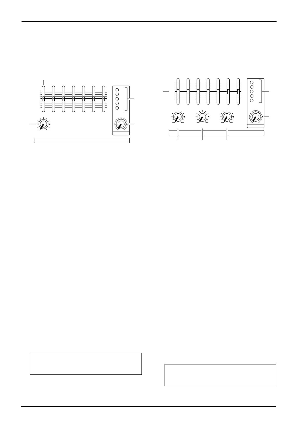
Control panel
■
Channel section
In this section, you can adjust equalization (fre-
quency response), volume level, effect and moni-
tor output levels for the input signal of each
channel.
1
Equalizer controls (HIGH, MID, LOW)
This is a 3-band equalizer that adjusts the high
frequency range, mid frequency range, and low
frequency range of each channel. Response is flat
when the knobs are in the
▼
position. Rotating it
toward the right will boost the corresponding fre-
quency band, and rotating it toward the left will
cut it.
The base frequency (or center frequency), range
of boost or cut, and equalizer type of each band
are as follows.
HIGH: 12 kHz
±
15 dB shelving type
MID: 2.5 kHz
±
15 dB peaking type
LOW: 80 Hz
±
15 dB shelving type
2
Monitor controls (MONI)
For each channel, this controls the amount of sig-
nal that is sent to the MONITOR bus.
The signal of the MONITOR bus is sent to the
speakers connected to the POWER AMP 2 A/B
jacks (only if the power amp select switch is in the
MAIN+MONITOR position) and to the MONI-
TOR jacks (input/output panel
6
).
3
Effect control (EFFECT)
For each channel, this controls the amount of sig-
nal that is sent to the EFFECT bus.
The signal of the EFFECT bus passes through the
EFFECT section and the built-in effect, and is
sent to the external effect device connected to the
EFFECT OUT jacks (input/output panel
3
).
4
Level control (LEVEL)
This adjusts the output level for each channel.
5
Pad switch (PAD) (1~4 only)
This switch attenuates the input signal by 30 dB.
When connecting a line level device to channels
1~4, or if the mic input is distorted, turn this
switch on (the pressed-in position).
HIGH
MID
LOW
MONI
EFFECT
LEVEL
PAD
1
1
–15 +15
–15 +15
–15 +15
010
010
010
1
2
3
4
5
Note:
The signal is sent to the MONITOR bus
from a location before the level control (
4
) of
each channel. This means that it will not be af-
fected by the setting of the LEVEL control.
Note:
The signal is sent to the EFFECT bus
from a location after the level control (
4
) of
each channel. This means that the amount of
signal that is sent to the EFFECT bus will be af-
fected not only by the setting of the effect con-
trol, but also by the setting of the level control.

Control panel
3
EMX640—Owner’s Manual
■
DIGITAL EFFECT section
This section allows you to turn the built-in digital
effect on/off and to select the effect type.
6
Effect select switch
Select the effect type for the built-in digital effect.
7
DIGITAL EFFECT ON switch
When this switch is on (pressed), the digital effect
built into the EMX640 can be used. In that case,
the signal processed by the digital effect will be
sent to the MAIN/MONITOR bus. The mix level
of the effect sound is adjusted by the EFFECT
RTN control of the MAIN and MONITOR sec-
tions.
■
EFFECT section
This section allows you to adjust the level of the
signal sent from the EFFECT bus to an external
effect device.
8
EFFECT OUT control
This adjusts the effect send level for an external
effect device connected to the EFFECT OUT jack
(input/output panel
3
).
DIGITAL
EFFECT
ON
VOCAL
L HALL
S HALL
6
7
Note:
The EFFECT OUT control does not affect
the send level to the built-in effect.
EFFECT
EFFECT OUT
8
4
Front and rear panel
EMX640—Owner’s Manual
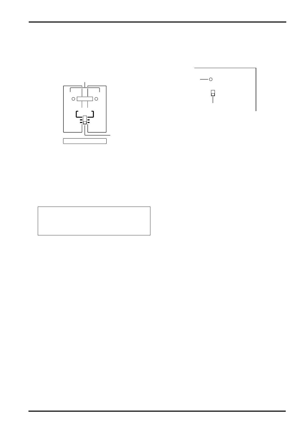
■
MONITOR section
This section allows you to adjust the tone and
volume of the MONITOR bus, and specify the
mix level of the built-in effect.
9
Graphic equalizer
This is a 7-band graphic equalizer that allows you
to adjust the frequency response of the MONI-
TOR bus signal, providing a maximum of
±
12 dB
of cut/boost for each frequency band. You can use
these sliders to reduce the level of frequency
bands at which feedback easily occurs. Frequency
response is flat when a slider is in the center posi-
tion. Moving a slider in the positive direction will
boost, and in the negative direction will cut.
This graphic equalizer affects both the MONI-
TOR bus signal that is output to the speakers and
the line level signal which is output from the
MONITOR jack (input/output panel
6
).
0
EFFECT RTN control
This controls the level of the effect sound which
is returned from the built-in digital effect to the
MONITOR bus.
A
MASTER control
This adjusts the final level of the MONITOR bus.
It affects both the MONITOR bus signal which is
output to the speakers and the line level signal
which is output to the MONITOR jack (input/
output panel
6
).
B
Peak level indicator
This indicator allows you to monitor the level of
the signal which is output from the MONITOR
jack (input/output panel
6
).
■
MAIN section
This section allows you to adjust the tone and
volume of the MAIN bus, the mix level of the
built-in effect, and the mix level of the external
input.
C
Graphic equalizer
This is a 7-band graphic equalizer that allows you
to adjust the frequency response of the MAIN
bus signal, providing a maximum of
±
12 dB of
cut/boost for each frequency band.
This graphic equalizer affects both the MAIN bus
signal that is output to the speakers and the line
level signal which is output from the MAIN jack
(input/output panel
6
).
D
EFFECT RTN control
This adjusts the level of the effect signal which is
returned from the built-in digital effect to the
MAIN bus.
E
AUX IN control
This adjusts the amount of signal that is sent
from the AUX IN jack to the MAIN bus.
F
TAPE IN
This adjusts the amount of signal that is sent
from the TAPE IN jacks to the MAIN bus.
G
MASTER control
This adjusts the final level of the MAIN bus. It
affects both the MAIN bus signal which is output
from the speakers, and the line level signal which
is output from the MAIN jack (input/output
panel
6
).
H
Peak level indicator
This indicator allows you to monitor the level of
the signal which is output from the MAIN jack
(input/output panel
6
).
Note:
To avoid distortion, adjust the MASTER
control (
A
) so that the 0 indicator lights occa-
sionally.
MONITOR
MASTER
EFFECT RTN
+6
+3
0
–5
–10
+12
•
6
•
0
•
6
•
–12
+12
•
6
•
0
•
6
•
–12
125
250 500 1k 2k 4k 8k
9
B
0
A
Note:
To avoid distortion, adjust the MASTER
control (
G
) so that the 0 indicator lights occa-
sionally.
MAIN
MASTER
TAPE IN
AUX INEFFECT RTN
+6
+3
0
–5
–10
+12
•
6
•
0
•
6
•
–12
+12
•
6
•
0
•
6
•
–12
125
250 500 1k 2k 4k 8k
C
H
G
D
E
F
Control panel
5
EMX640—Owner’s Manual
■
POWER AMP section
This section allows you to select the signals that
will be output from the built-in two-channel
power amplifier, and to select the BRIDGE mode.
I
LIMITER indicator
This indicator lights up when the level of the sig-
nal output from the power amp section reaches
the maximum and the limiter is activated. Adjust
appropriate control so that the indicator lights up
for only a short while when the signal reaches the
maximum level.
J
Power amp select switch
Select one of the following three settings to spec-
ify the signals that will be output from power
amp 1/2.
• MAIN-MONITOR
With this setting, the MAIN and MONITOR sec-
tions can be used independently. The MAIN bus
signal will be output from the POWER AMP 1 A/
B jacks, and the MONITOR bus signal will be
output from the POWER AMP 2 A/B jacks.
•
MAIN-MAIN
With this setting, the two power amp channels
can be used independently. The MAIN bus signal
will be output from the POWER AMP 1 A/B jacks
and from the POWER AMP 2 A/B jacks.
• MAIN BRIDGE
With this setting, the two power amp channels (A
and B) will be bridge connected. Only the MAIN
bus signal will be output from the BRIDGE jack,
though.
■
POWER indicator & PHANTOM
switch
K
POWER indicator
This indicator will light when the power of the
EMX640 is turned on.
L
PHANTOM +48 V switch
This switch turns the phantom power supply on/
off for the Lo-Z input jacks of channels 1~4 and
MIC input jacks of channels 5~6.
Note:
The indicator lights up or flashes for a
longer duration if the power amp section is sig-
nificantly overloaded, which could result in
malfunction. Avoid such a situation.
POWER AMP
1
2
LIMITER
MAIN
BRIDGE
MAIN
MONITOR
MAIN
MAIN
I
J
POWER
ON
OFF
PHANTOM +48V
K
L
6
Front and rear panel
EMX640—Owner’s Manual
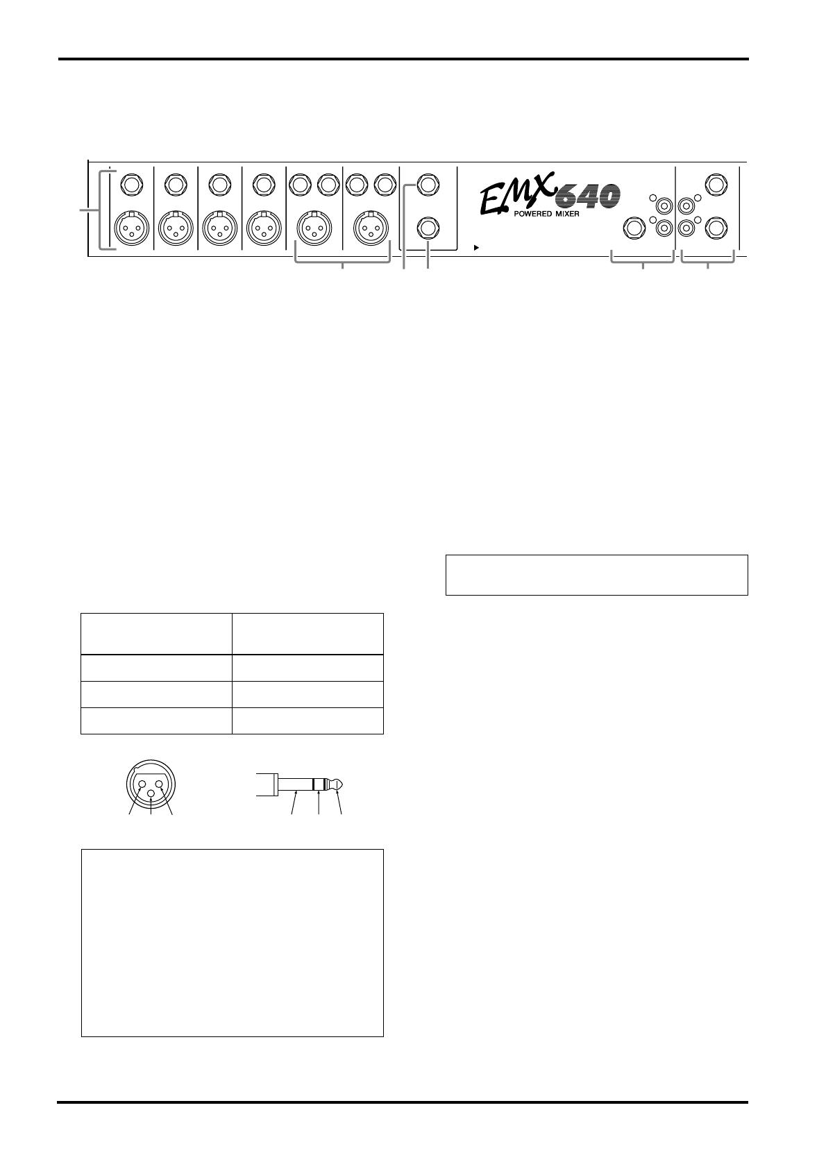
Input/output panel
1
Channel input jacks (Hi-Z, Lo-Z) 1~4
These are the input jacks for channels 1~4. By
using the PAD switches (control panel
5
) you
can connect any of the jacks to a wide range of
sources from mics to line level devices (synthesiz-
ers or rhythm boxes etc.). The Lo-Z jacks can
provide +48 V phantom power, allowing you to
use condenser microphones.
Both Hi-Z and Lo-Z are balanced, and are com-
patible with microphones of output impedance
50~600
Ω
or line level devices of 600
Ω
. The nom-
inal input level is –40 dB~–10 dB for the Hi-Z
jacks, and –50 dB~–20 dB for the Lo-Z jacks.
Pin connections for the Hi-Z and Lo-Z jacks are
as follows.
2
Channel input jacks (MIC/LINE) 5~6
These are the input jacks for channels 5~6.
Microphones can be connected to the MIC jacks,
and stereo line level devices (such as synthesizers
or rhythm boxes) can be connected to the LINE
jacks.
The MIC jacks are balanced, and are compatible
with microphones of output impedance
50~600
Ω
. The LINE jacks are unbalanced, and
are compatible with line level devices of 600
Ω
output impedance. Nominal input level is –50 dB
for the MIC jacks and –20 dB for the LINE jacks.
3
Effect output jack (EFFECT OUT)
The input of an external effect such as a delay or
echo can be connected to this jack. The signal
adjusted by the EFFECT control of each channel
will be sent to the EFFECT bus, its level adjusted
by the EFFECT OUT control, and output from
this jack.
The nominal output level and impedance are
+4 dB/10 k
Ω
.
4
Foot switch jack (FOOT SW)
A separately sold Yamaha FC5 foot switch can be
connected to this jack. If a foot switch is con-
nected to this jack, you can use your foot to
switch the built-in digital effect on/off. The Digi-
tal Effect ON switch on the front panel must be
set to ON in order to use a foot switch.
5
External input jacks (AUX IN/TAPE IN)
These are input jacks that allow the signal from
an external device to be added to the MAIN out-
put. Monaural output devices such as external
effects can be connected to the AUX IN jack, and
stereo output devices such as cassette recorder or
CD players can be connected to the TAPE IN
jacks.
INPUT TO MAIN OUTPUT
MONITOR
MAIN
AUX IN
REC
OUT
TAPE
IN
EFFECT OUT
FOOT SW
1
2
1
2
LINEHi-Z LINE
MIC MICLo-Z
Hi-Z
Lo-Z
Hi-Z
Lo-Z
Hi-Z
Lo-Z
SEE REAR PANEL CAUTION
1
2
5 6
43
Lo-Z jacks
(XLR type)
Hi-Z jacks
(TRS phone jacks)
Pin 1: ground Sleeve: ground
Pin 2: hot (+) Tip: hot (+)
Pin 3: cold (–) Ring: cold (–)
Note: It is not possible to simultaneously use
both the Hi-Z and Lo-Z inputs of a given chan-
nel. For each channel, use only one of the inputs
as appropriate for the input source.
Phantom power is switched on/off in simulta-
neously for channels 1~6. For this reason,
devices which do not require phantom power
must be connected to the Hi-Z or LINE jacks if
the PHANTOM +48 V switch (control panel
L) is on.
GND
RST
+—
GND
+-
Note: It is possible to simultaneously use both
the MIC and LINE inputs for a given channel.

Rear panel 7
EMX640—Owner’s Manual
The nominal input level and impedance are –
10 dB/600Ω for the AUX IN jack, and –10 dBV/
600Ω for the TAPE IN jacks.
6 External output jacks (REC OUT/MONI-
TOR/MAIN)
These are output jacks which send line level sig-
nals from the EMX640 to external devices. A ste-
reo recording device such as a cassette recorder or
MD recorder can be connected to the REC OUT
jacks, and a playback device such a power amp
can be connected to the MONITOR and MAIN
jacks. The signals sent from each jack are as fol-
lows.
• REC OUT jacks: The MAIN bus signal
before it has passed through the MASTER
control and graphic equalizer
• MONITOR jack: The MONITOR bus signal
which has passed through the Monitor MAS-
TER control and graphic equalizer
• MAIN jack: The MAIN bus signal which has
passed through the Main MASTER control
and graphic equalizer
The nominal output level and impedance are –
10 dBV/10 kΩ for the REC OUT jacks, and
+4 dB/10 kΩ for the MONITOR/MAIN jacks.
Rear panel
1 Speaker output jacks (POWER AMP 1 A/B,
POWER AMP 2 A/B, BRIDGE)
Speakers can be connected to these jacks. The
EMX640 contains a two-channel power amp, and
the two channels can be used independently
(maximum output 200 W+200 W) or in bridge
connection (maximum output 400 W).
If the two channels are used independently, two
speakers can be connected to the POWER AMP 1
A/B jacks and two more to the POWER AMP 2 A/
B jacks, for a total of four speakers. If the two
channels are used in a bridge connection, only
one speaker can be connected to the BRIDGE
jack.
If you wish to use the two channels indepen-
dently, but only connect a speaker to the A jack or
B jack, use a 4~8Ω speaker. When using the A
and B jacks simultaneously, connect 8~16Ω
speakers. In this case, be careful not to connect a
speaker to the BRIDGE jack.
If you are connecting a speaker to the BRIDGE
jack, use a 8~16Ω speaker. In this case, be careful
not to connect a speaker to the POWER AMP 1/2
A/B jacks.
Caution:
When using a bridge connection, do not con-
nect anything to the POWER AMP 1 and
POWER AMP 2 jacks. Likewise, when using the
POWER AMP 1 and/or POWER AMP 2 jacks,
do not connect anything to the BRIDGE jack.
2 Power switch
This switch turns the power of the EMX640 on/
off.
SPEAKERS
POWER
BA B
POWER AMP 1BRIDGEPOWER AMP 2
A
ON / OFF
1
2
Note: Use the power amp select switch (control
panel J) to select the signal which is sent to the
jacks, or to activate the bridge connection.
Note: Before turning the EMX640 on/off, turn
down the MASTER controls of the MONITOR
and MAIN section.
8 Connections
EMX640—Owner’s Manual
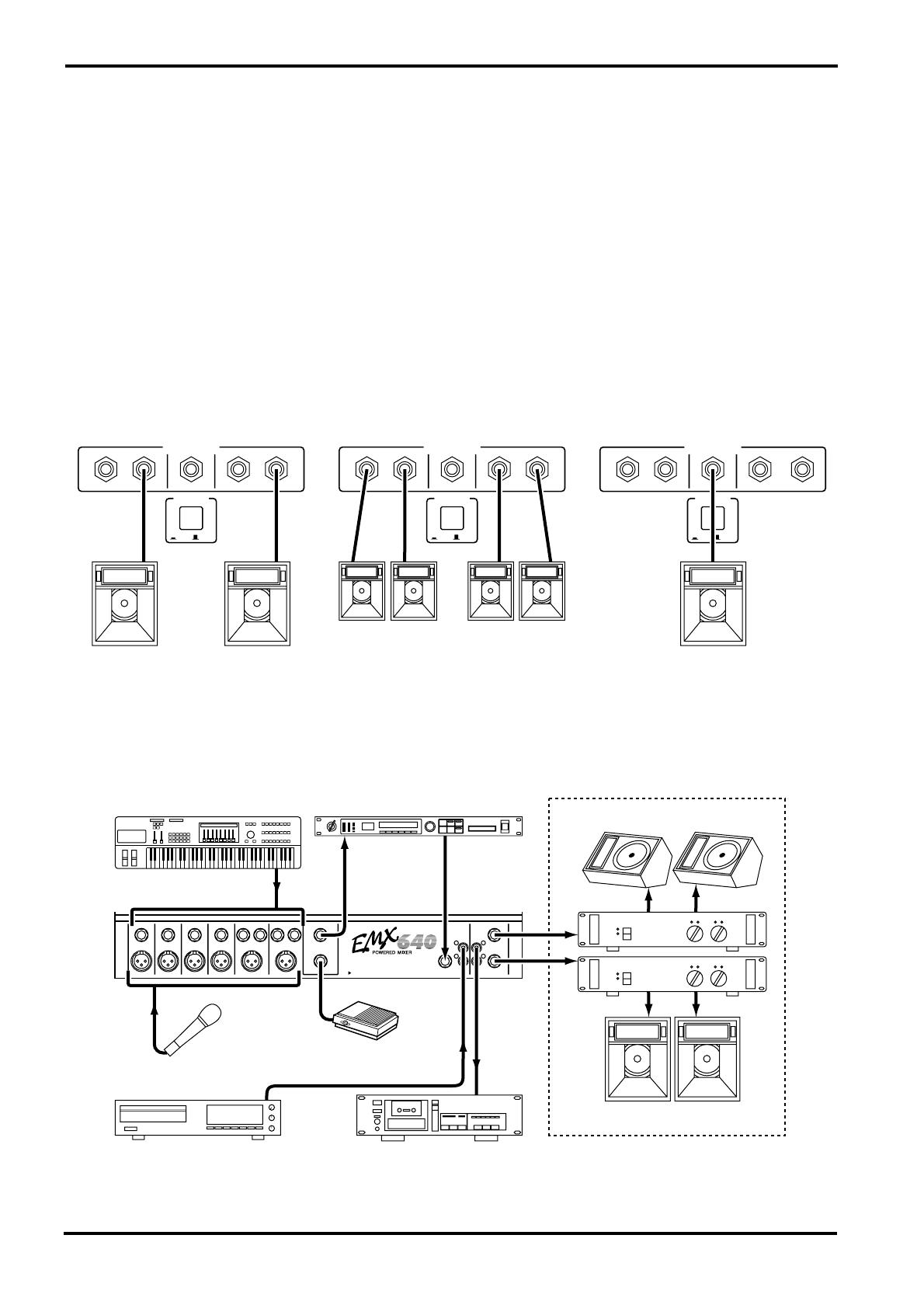
Connections
When connecting various devices, be sure to use cables and plugs of the appropriate standard.
■ Speaker connection
There are three ways in which speakers can be connected to the EMX640; a single speaker each can be con-
nected to either the A or the B jack of POWER AMP 1 and of POWER AMP 2, two speakers can be connected
in parallel to both the A and B jacks of POWER AMP 1 and of POWER AMP 2, or a single speaker can be con-
nected to the BRIDGE jack (bridge connection). For each of these, the required speaker impedance will differ.
Refer to the following diagram, and make sure that the speaker impedance is not less than the specified value.
■ Example connections
• Additional, or alternative amplifiers can be connected to the MAIN and MONITOR jacks on the front panel.
SPEAKERS
POWER
BA B
POWER AMP 1BRIDGEPOWER AMP 2
A
ON / OFF
8Ω~16Ω
Connecting a single speaker
to the BRIDGE jack
(bridge connection)
SPEAKERS
POWER
BA B
POWER AMP 1BRIDGEPOWER AMP 2
A
ON / OFF
4Ω~8Ω 4Ω~8Ω
Connecting speakers to
either the A or B jacks
of POWER AMP 1/2
SPEAKERS
POWER
BA B
POWER AMP 1BRIDGEPOWER AMP 2
A
ON / OFF
8Ω~16Ω 8Ω~16Ω
Connecting speakers to
both the A and B jacks
of POWER AMP 1/2
Main
Speaker
Main
Speaker
Main
Speakers
Main/Monitor
Speaker
Main/Monitor
Speakers
Cassette Recorder
Footswitch
(YAMAHA FC5)
Microphone
INPUT TO MAIN OUTPUT
MONITOR
MAIN
AUX IN
REC
OUT
TAPE
IN
EFFECT OUT
FOOT SW
1
2
1
2
LINEHi-Z LINE
MIC MICLo-Z
Hi-Z
Lo-Z
Hi-Z
Lo-Z
Hi-Z
Lo-Z
SEE REAR PANEL CAUTION
Monitors Speakers
Main Speakers
CD Player
Synthesizer, Drum Box
Power AMP
88
Effects Processor

Basic Operation 9
EMX640—Owner’s Manual
Basic Operation
This section explains basic operation of the EMX640.
Connecting microphones and instruments
1 Before connecting mics or instruments,
make sure that the power of all equip-
ment (where applicable) is turned off.
Also make sure that the level controls of
each channel of the EMX640 and the
MASTER control of the MAIN section are
turned down.
2 Connect cables to your mics and instru-
ments, and insert the other end of the
cable firmly into the appropriate Lo-Z/Hi-
Z jack (channels 1~4) or the MIC/LINE
jack (channels 5~6).
3 Turn the power on in the order of periph-
eral devices ➞ EMX640.
4 Set the MAIN section MASTER control to
the √√
√√
position.
5 While speaking into the mic (while play-
ing the instrument), adjust the channel
LEVEL control so that the 0 LED of the
MAIN section peak level meter lights
occasionally.
6 If you wish to adjust the tone of each
channel, rotate the equalizer controls as
desired.
7 Use the MAIN section graphic equalizer
and MASTER control to adjust the overall
volume and tone.
Using the digital effect
The EMX640 has a built-in digital effect, allowing reverberation or ambiance to be added to vocals or instru-
mental sounds.
1 Connect a mic or instrument to the
desired channels, and adjust the volume
and tone.
2 Press the DIGITAL EFFECT ON switch of
the DIGITAL EFFECT section.
3 Use the effect select switches of the DIGI-
TAL EFFECT section to select the effect
type.
VOCAL……. Reverb appropriate for vocals.
L. HALL…… Reverb typical of a large hall.
S. HALL…… Reverb typical of a small hall.
4 Raise the EFFECT control of the channels
to which you wish to apply the digital
effect.
5 Use the MAIN/MONITOR section EFFECT
RTN control to adjust the level of the
sound processed by the effect.
Note: When connecting a line level device to
channels 1~4, turn on the PAD switch.
You cannot use a channel’s Lo-Z and Hi-Z jacks
at the same time. The MIC and LINE jacks,
however, can be used at the same time.
Note: When turning the power off, reverse this
sequence.
Note: If the effect sound is distorted even if the
EFFECT RTN turned all the way down, lower
the EFFECT controls of each channel.
10 Example setups
EMX640—Owner’s Manual
Example setups
This section provides some ways in which the EMX640 can be used, and explains connections and operation.
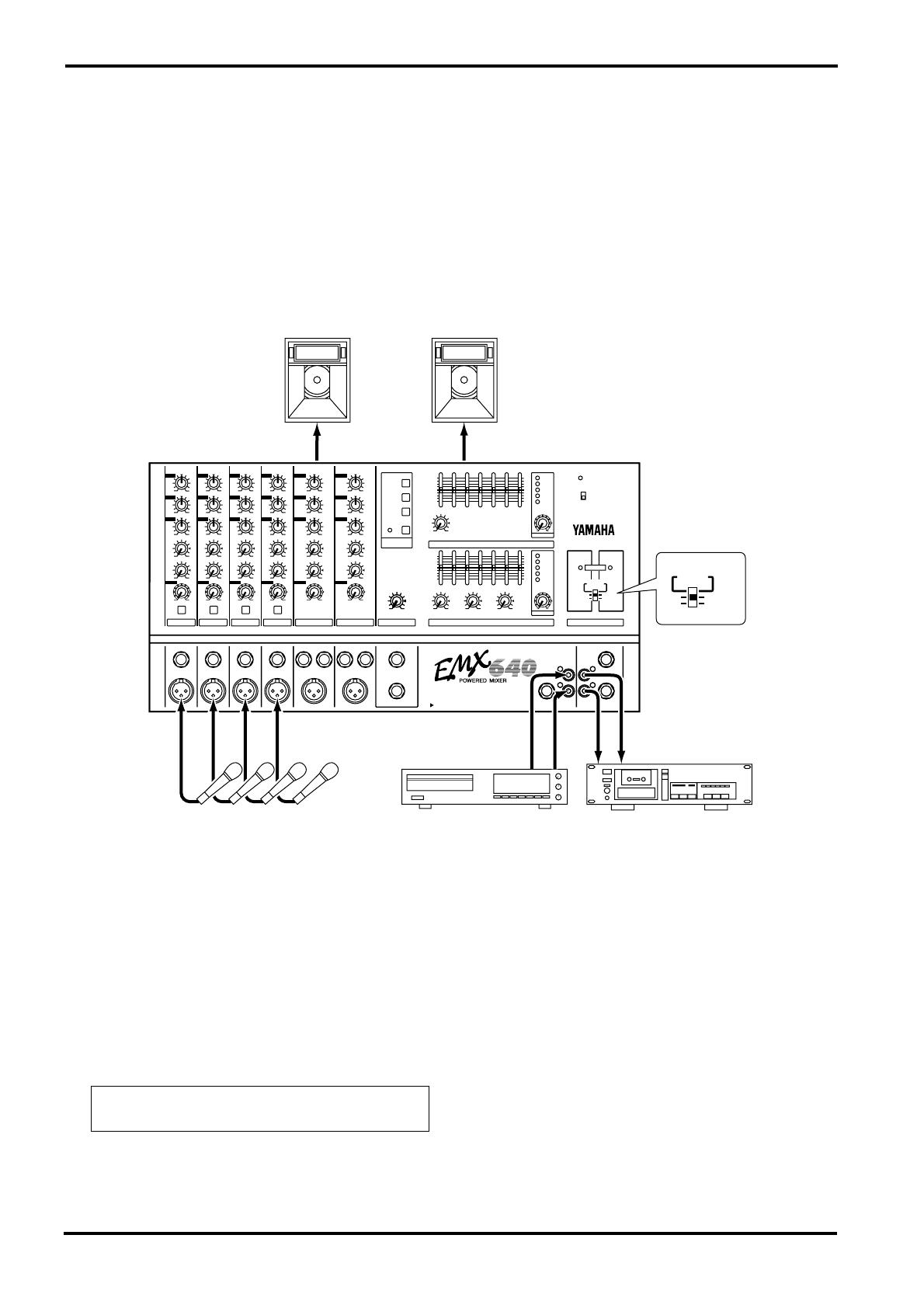
As a conference PA system/installed sound system
Here is an example of using the EMX640 as a conference PA system or as an installed sound system.
Connections
• Connect mics to channel inputs 1~6.
• If you wish to use an external device such as a CD
player or LD player, connect the outputs of the
device to the TAPE IN jacks of the EMX640.
• If you wish to record the audio from the mics to a
cassette deck, connect the REC OUT jacks of the
EMX640 to the input jacks of the cassette deck.
Playing back a CD player
1 Turn the power on in the order of periph-
eral devices ➞ EMX640.
2 Adjust the MASTER control of the MAIN
section to the √√
√√
position.
3 Start playback on the CD player, and use
the MAIN section TAPE IN control to
adjust the level so that the 0 LED of the
MAIN section peak level meter does not
light.
INPUT TO MAIN OUTPUT
MAIN
AUX IN
REC
OUT
TAPE
IN
Main Speakers
Power AMP 1 A/B Power AMP 2 A/B
HIGH
MID
LOW
MONI
EFFECT
LEVEL
PAD
HIGH
MID
LOW
MONI
EFFECT
LEVEL
PAD
HIGH
MID
LOW
MONI
EFFECT
LEVEL
PAD
HIGH
MID
LOW
MONI
EFFECT
LEVEL
PAD
HIGH
MID
LOW
MONI
EFFECT
LEVEL
HIGH
MID
LOW
MONI
EFFECT
LEVEL
1
1
2
2
3
3
4
4
5
5
6
6
EFFECT MAIN POWER AMP
MONITOR
MASTER
MASTER
TAPE IN
AUX INEFFECT RTNEFFECT OUT
EFFECT RTN
POWER
DIGITAL
EFFECT
ON
VOCAL
L HALL
S HALL
INPUT TO MAIN OUTPUT
MONITOR
MAIN
AUX IN
REC
OUT
TAPE
IN
ON
OFF
PHANTOM +48V
1
2
LIMITER
MAIN
BRIDGE
MAIN
MONITOR
MAIN
MAIN
+6
+3
0
–5
–10
+6
+3
0
–5
–10
+12
•
6
•
0
•
6
•
–12
+12
•
6
•
0
•
6
•
–12
+12
•
6
•
0
•
6
•
–12
+12
•
6
•
0
•
6
•
–12
125
250 500 1k 2k 4k 8k
125
250 500 1k 2k 4k 8k
EFFECT OUT
FOOT SW
1
2
1
2
LINEHi-Z LINE
MIC MICLo-Z
Hi-Z
Lo-Z
Hi-Z
Lo-Z
Hi-Z
Lo-Z
–15 +15 –15 +15 –15 +15 –15 +15 –15 +15 –15 +15
–15 +15
–15 +15
–15 +15
–15 +15
–15 +15
–15 +15
–15 +15
–15 +15
–15 +15
–15 +15
–15 +15
–15 +15
010010
010
010
010 010
010
010
010
010
010
010
010
010
010
010
010
010
SEE REAR PANEL CAUTION
Microphone
Cassette Deck
CD Player
MAIN
BRIDGE
MAIN
MONITOR
MAIN
MAIN
Note: A CD player/cassette deck can also be
connected to the LINE jacks of channels 5~6.
As a band PA 11
EMX640—Owner’s Manual
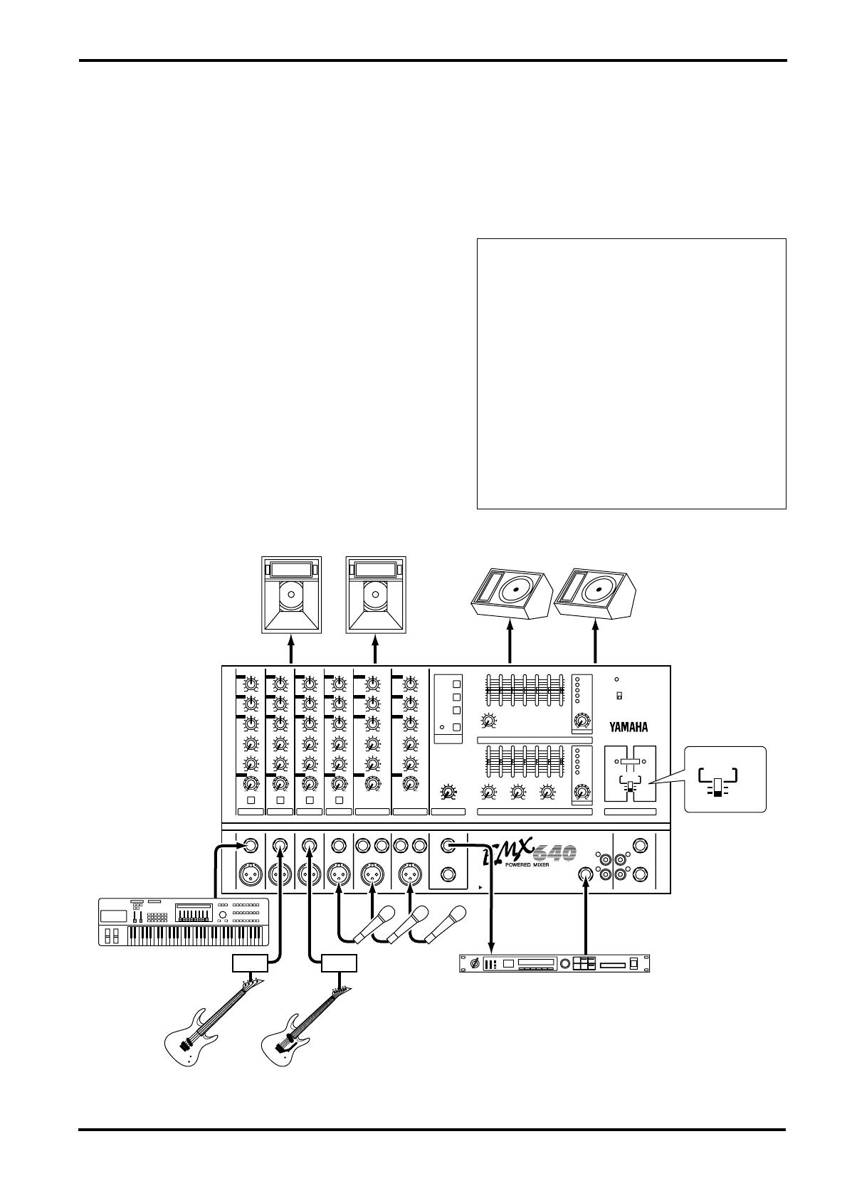
As a band PA
Here is an example of using the EMX640 as a small PA for a band. In this example, the monitor speakers are
being sent a mix that is independent of the MAIN speaker mix. An external effect such as delay or reverb is
also being used.
Connections
• Connect mics or instruments, such as keyboards,
to the channel input jacks 1~6.
• Connect the main speakers to the POWER AMP
1 A/B jacks, and connect the monitor speakers to
the POWER AMP 2 A/B jacks.
• If you will be using an external effect such as
delay or reverb, connect the EMX640’s EFFECT
OUT jack to the input jack of the external effect,
and connect the output jack of the external effect
to the EMX640’s AUX IN jack.
Note: Set the power amp select switch of the
POWER AMP section to the “MAIN MONI-
TOR” position.
If you are using an external effect, we recom-
mend that you turn down the EFFECT RTN
controls of the MAIN and MONITOR sections.
If the external effect has a stereo output, it is
possible to connect its output jacks to the LINE
jacks of channels 5~6. However in this case, be
sure that the EFFECT controls are turned all the
way down for the channels into which the effect
sound is being input. If the EFFECT controls
are raised, feedback will occur, and your speak-
ers may be damaged.
HIGH
MID
LOW
MONI
EFFECT
LEVEL
PAD
HIGH
MID
LOW
MONI
EFFECT
LEVEL
PAD
HIGH
MID
LOW
MONI
EFFECT
LEVEL
PAD
HIGH
MID
LOW
MONI
EFFECT
LEVEL
PAD
HIGH
MID
LOW
MONI
EFFECT
LEVEL
HIGH
MID
LOW
MONI
EFFECT
LEVEL
1
1
2
2
3
3
4
4
5
5
6
6
EFFECT MAIN POWER AMP
MONITOR
MASTER
MASTER
TAPE IN
AUX INEFFECT RTNEFFECT OUT
EFFECT RTN
POWER
DIGITAL
EFFECT
ON
VOCAL
L HALL
S HALL
INPUT TO MAIN OUTPUT
MONITOR
MAIN
AUX IN
REC
OUT
TAPE
IN
ON
OFF
PHANTOM +48V
1
2
LIMITER
MAIN
BRIDGE
MAIN
MONITOR
MAIN
MAIN
+6
+3
0
–5
–10
+6
+3
0
–5
–10
+12
•
6
•
0
•
6
•
–12
+12
•
6
•
0
•
6
•
–12
+12
•
6
•
0
•
6
•
–12
+12
•
6
•
0
•
6
•
–12
125
250 500 1k 2k 4k 8k
125
250 500 1k 2k 4k 8k
EFFECT OUT
FOOT SW
1
2
1
2
LINEHi-Z LINE
MIC MICLo-Z
Hi-Z
Lo-Z
Hi-Z
Lo-Z
Hi-Z
Lo-Z
–15 +15 –15 +15 –15 +15 –15 +15 –15 +15 –15 +15
–15 +15
–15 +15
–15 +15
–15 +15
–15 +15
–15 +15
–15 +15
–15 +15
–15 +15
–15 +15
–15 +15
–15 +15
010010
010
010
010 010
010
010
010
010
010
010
010
010
010
010
010
010
SEE REAR PANEL CAUTION
MAIN
BRIDGE
MAIN
MONITOR
MAIN
MAIN
Main Speakers
Power AMP 1 Power AMP 2AABB
INPUT TO MAIN
Keyboard 1 Microphone
Guitar
Bass
Guitar
Effects Processor
88
Monitors Speakers
DIDI

12 Example setups
EMX640—Owner’s Manual
Sending an independent mix to the
monitor speakers
1 Set the MONITOR section MASTER con-
trol to the √√
√√
position.
2 Raise the MONI controls for the channels
that you wish to hear from the monitor
speakers.
3 Use the graphic equalizers and MASTER
controls of the MAIN/MONITOR sections
to adjust the overall volume and tone.
Using an external effect
1 Set the EFFECT section EFFECT OUT con-
trol to the √√
√√
position.
2 Raise the EFFECT controls for the channels
to which you want the external effect to
be applied.
3 Adjust the input level of the external
effect so that the sound is not distorted at
the input of the external effect.
4 Use the MAIN section AUX IN control to
adjust the level of the sound processed by
the effect.
Note: The MONI controls are not affected by
the level settings of each channel. This allows
you to create a mix that is independent of the
MAIN section.

Specifications 13
EMX640—Owner’s Manual
Specifications
■ General specifications
Maximum output power 200 W/4Ω @0.5% THD at 1 kHz
Frequency response
20 Hz~20 kHz +1 dB, –3 dB @1 W output into 8Ω (POWER AMP OUT)
20 Hz~20 kHz +1 dB, –3 dB @+4 dB output into 10 kΩ (MAIN OUT, MONITOR OUT, EFFECT
SEND)
Total harmonic distortion
Less than 0.5% @20 Hz~20 kHz, 100 W output into 4Ω (POWER AMP OUT)
Less than 0.2% @20 Hz~20 kHz, +14 dB output into 10 kΩ
(MAIN OUT, MONITOR OUT, EFFECT SEND)
Hum & noise
(Average, Rs=150Ω)
(with 20 Hz~20 kHz BPF)
–123 dB equivalent input noise, –65 dB residual output noise
(POWER AMP OUT)
–88 dB residual output noise (MAIN OUT, MONITOR OUT, EFFECT SEND)
–79 dB (83 dB S/N)
MAIN OUT, MONITOR OUT
Master level control at nominal level and all channel
level controls at minimum.
–69 dB (73 dB S/N)
MAIN OUT, MONITOR OUT
Master level control at nominal level and 1 channel
level control at nominal level.
–75 dB (79 dB S/N)
EFFECT SEND
Master level control at nominal level and all channel
level controls at minimum.
–69 dB (73 dB S/N)
EFFECT SEND
Master level control at nominal level and 1 channel
level control at nominal level.
Maximum voltage gain
(PAD: OFF)
86 dB CH IN (Lo-Z) to POWER AMP OUT (CH1~4)
66 dB CH IN (Lo-Z) to MAIN OUT, MONITOR OUT (CH1~4)
72 dB CH IN (Lo-Z) to EFFECT OUT (CH1~4)
48 dB CH IN (Lo-Z) to REC OUT (CH1~4)
56 dB CH IN (Hi-Z) to MAIN OUT, MONITOR OUT (CH1~4)
26 dB AUX IN to MAIN OUT
22 dB TAPE IN to MAIN OUT
66 dB MIC IN to MAIN OUT, MONITOR OUT (CH5•6)
24 dB LINE IN to MAIN OUT, MONITOR OUT (CH5•6)
Crosstalk at 1 kHz 65 dB adjacent input, 65 dB input to output
Input channel equalization
±15 dB Maximum
HIGH 12 kHz shelving
MID 2.5 kHz peaking
LOW 80 Hz shelving
* Turn over/roll-off frequency of shelving: 3 dB below maximum variable level.
Meters 5 POINTS LED METER (–10, –5, 0, +3, +6 dB)
Graphic equalizer
7 bands (125, 250, 500, 1k, 2k, 4k, 8k Hz)
±12 dB Maximum
Internal digital effect 3 types (Vocal, L Hall, S Hall)
Phantom power
+48 V is supplied to electrically balanced inputs for powering condenser microphones via 6.8 kΩ
current limiting/isolation resisters.
Limiter Comp. : THD≥0.5%
LIMIT indicators Turns on. : THD≥0.5%
Foot switch DIGITAL EFFECT MUTE : on/off
Power requirement
USA and Canada 120 V AC 60 Hz
Europe 230 V AC 50 Hz
Other 240 V AC 50 Hz
Power consumption 200 W
Dimensions (WxHxD) 480×275×275 mm
Weight 15 kg

14 Specifications
EMX640—Owner’s Manual
■ Input specifications
■ Output specifications
• All output jacks are unbalanced.
• 0 dB=0.775 Vrms, 0 dBV=1 Vrms.
Specifications are subject to change without prior notice.
1. Sensitivity is the lowest level that can produce an output of +4 dB (1.23 V) or the nominal output level when the unit is set at maximum gain.
(All level controls are at maximum position.)
• CH INPUT and MIC INPUT connectors are balanced and others are unbalanced.
• 0 dB=0.775 Vrms, 0 dBV=1 Vrms.
Input connectors PAD
Actual load
impedance
Nominal
impedance
Input level
Connector
type
Sensitivity
1
Nominal level
Max. before
cliping
CH INPUT (Lo-Z)
(CH1~4)
OFF
3 kΩ
50~600Ω Mics –62 dB (616 µV) –50 dB (2.45 mV) –20 dB (77.5 mV)
XLR-3-31 type
ON 600Ω Lines –32 dB (19.5 mV) –20 dB (77.5 mV) +10 dB (2.45 V)
CH INPUT (Hi-Z)
(CH1~4)
OFF
10 kΩ
50~600Ω Mics –52 dB (1.95 mV) –40 dB (7.75 mV) –10 dB (245 mV)
Phone jack
(TRS)
ON 600Ω Lines –22 dB (61.6 mV) –10 dB (245 mV) +20 dB (7.75 V)
MIC INPUT (CH5•6) 3 kΩ 50~600Ω Mics –62 dB (616 µV) –50 dB (2.45 mV) –20 dB (77.5 mV)
XLR-3-31 type
LINE INPUT (CH5•6) (1, 2) 10 kΩ 600Ω Line –22 dB (61.6 mV) –10 dB (245 mV) +20 dB (7.75 V) Phone jack
TAPE IN (1, 2) 10 kΩ 600Ω Line –20 dBV (100 mV) –10 dBV (316 mV) +17.8 dBV (7.75 V) Phono jack
AUX IN 10 kΩ 600Ω Line –22 dB (61.6 mV) –10 dB (245 mV) +20 dB (7.75 V)
Phone jack
Output connectors
Actual source
impedance
Nominal
impedance
Output level
Connector type
Nominal
Max. before cliping
POWER AMP OUT (1•2) (A, B) 0.1Ω 4/8Ω Speaker 37.7 W/4Ω (200 W/4Ω) Phone jack
BRIDGE OUT 0.1Ω 8Ω Speaker 75.4 W/8Ω (400 W/8Ω)
Phone jack
MAIN OUT 600Ω 10 kΩ Lines +4 dB (1.23 V) +20 dB (7.75 V)
Phone jack
MONITOR OUT 600Ω 10 kΩ Lines +4 dB (1.23 V) +20 dB (7.75 V)
Phone jack
EFFECT OUT 600Ω 10 kΩ Lines +4 dB (1.23 V) +20 dB (7.75 V)
Phone jack
REC OUT (1, 2) 600Ω 10 kΩ Lines –10 dBV (316 mV) +10 dBV (3.16 V) Phono jack
Dimensions 15
EMX640—Owner’s Manual
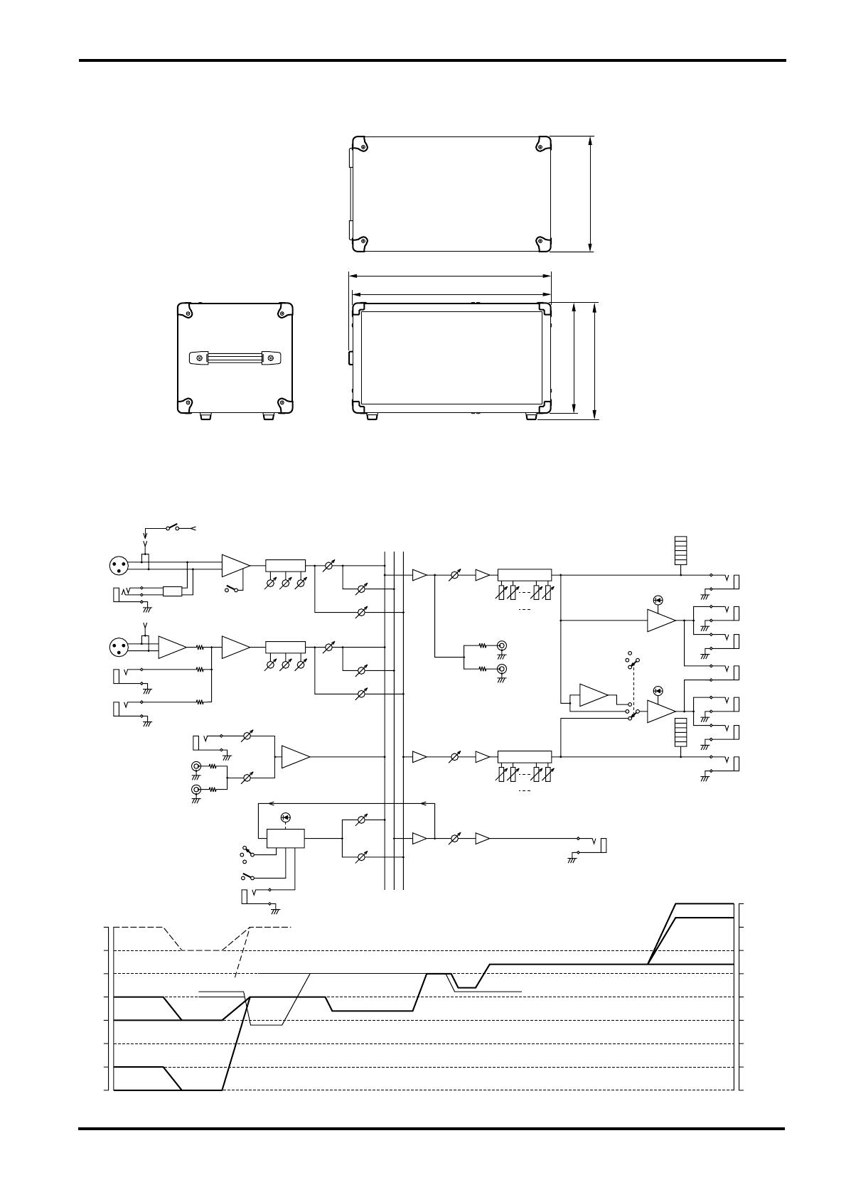
■ Dimensions
■ Block and Level diagram
470
W: 480
260
H: 275
D: 275
Unit: mm
Clipping level
EFFECT OUT
REC OUT
MAIN, MONITOR
POWER AMP
BRIDGE
30
dB
MAIN BRIDGE
MAIN MAIN
MAIN MONITOR
ADD
SUM
DIGITAL EFFECT
TAPE IN
AUX IN
LINE
HI-Z PAD:ON
MIC
Lo-Z PAD:ON
HI-Z PAD:OFF
EFFECT
RTN
EFFECT
RTN
Lo-Z PAD:OFF
EFFECT
OUT
MAIN
TAPE IN
2
1
AUX IN
TAPE IN
AUX IN
MASTER
MASTER
5, 6
1
2
FOOT SW
ON
S HALL
L HALL
VOCAL
LEVEL
LEVEL
PAD
Hi-Z
Lo-Z
DIGITAL
EFFECT
INV
EFFECT
OUT
EQ
8k
4k
250
125
POWER
AMP 1
POWER
AMP 2
BRIDGE
MONITOR
A
B
B
A
PA
2
1
PA
125
250
4k
8k
EQ
MAIN
MONITOR
HA
EFFECT
MONI
MONI
EFFECT
–50
–40
–30
–20
–10
0
10
20 20
10
0
–10
–20
–30
–40
–50
REC OUT
LOW
MID
EQ
HIGH
MIC
LINE
EFFECT
1–4
PAD
PHANTOM
+48V
HIGH
HA
EQ
MID
LOW
dB
LIMITER
1
LIMITER
2

YAMAHA CORPORATION
VY66080 R2 1 IP 16 Pro Audio Division, #18/3
P.O. Box 3, Hamamatsu, 430-8651, Japan
NP Printed in Taiwan
FCC INFORMATION (U.S.A.)
1. IMPORTANT NOTICE: DO NOT MODIFY THIS UNIT! This
product, when installed as indicated in the instructions contained in
this manual, meets FCC requirements. Modifications not expressly
approved by Yamaha may void your authority, granted by the FCC, to
use the product.
2. IMPORTANT: When connecting this product to accessories and/or
another product use only high quality shielded cables. Cable/s supplied
with this product MUST be used. Follow all installation instructions.
Failure to follow instructions could void your FCC authorization to use
this product in the USA.
3. NOTE: This product has been tested and found to comply with the
requirements listed in FCC Regulations, Part 15 for Class “B” digital
devices. Compliance with these requirements provides a reasonable
level of assurance that your use of this product in a residential
environment will not result in harmful interference with other
electronic devices. This equipment generates/uses radio frequencies
and, if not installed and used according to the instructions found in the
users manual, may cause interference harmful to the operation of other
electronic devices. Compliance with FCC regulations does not
guarantee that interference will not occur in all installations. If this
product is found to be the source of interference, which can be
determined by turning the unit “OFF” and “ON”, please try to
eliminate the problem by using one of the following measures:
Relocate either this product or the device that is being affected by the
interference. Utilize power outlets that are on different branch (circuit
breaker or fuse) circuits or install AC line filter/s. In the case of radio
or TV interference, relocate/reorient the antenna. If the antenna lead-in
is 300 ohm ribbon lead, change the lead-in to coaxial type cable. If
these corrective measures do not produce satisfactory results, please
contact the local retailer authorized to distribute this type of product. If
you can not locate the appropriate retailer, please contact Yamaha
Corporation of America, Electronic Service Division, 6600
Orangethorpe Ave, Buena Park, CA 90620
This applies only to products distributed by YAMAHA CORPORA-
TION OF AMERICA.
WARNING: THIS APPARATUS MUST BE EARTHED
IMPORTANT
THE WIRES IN THIS MAINS LEAD ARE COLOURED IN
ACCORDANCE WITH THE FOLLOWING CODE:
GREEN-AND-YELLOW : EARTH
BLUE : NEUTRAL
BROWN : LIVE
As the colours of the wires in the mains lead of this apparatus may
not correspond with the coloured markings identifying the terminals in
your plug, proceed as follows:
The wire which is coloured GREEN and YELLOW must be
connected to the terminal in the plug which is marked by the letter E
or by the safety earth symbol or coloured GREEN and YELLOW.
The wire which is coloured BLUE must be connected to the terminal
which is marked with the letter N or coloured BLACK.
The wire which is coloured BROWN must be connected to the
terminal which is marked with the letter L or coloured RED.
* This applies only to products distributed by YAMAHA KEMBLE
MUSIC (U.K.) LTD.
Хорошее руководство по эксплуатации
Законодательство обязывает продавца передать покупателю, вместе с товаром, руководство по эксплуатации Yamaha EMX640. Отсутствие инструкции либо неправильная информация, переданная потребителю, составляют основание для рекламации в связи с несоответствием устройства с договором. В законодательстве допускается предоставлении руководства в другой, чем бумажная форме, что, в последнее время, часто используется, предоставляя графическую или электронную форму инструкции Yamaha EMX640 или обучающее видео для пользователей. Условием остается четкая и понятная форма.
Что такое руководство?
Слово происходит от латинского «instructio», тоесть привести в порядок. Следовательно в инструкции Yamaha EMX640 можно найти описание этапов поведения. Цель инструкции заключается в облегчении запуска, использования оборудования либо выполнения определенной деятельности. Инструкция является набором информации о предмете/услуге, подсказкой.
К сожалению немного пользователей находит время для чтения инструкций Yamaha EMX640, и хорошая инструкция позволяет не только узнать ряд дополнительных функций приобретенного устройства, но и позволяет избежать возникновения большинства поломок.
Из чего должно состоять идеальное руководство по эксплуатации?
Прежде всего в инструкции Yamaha EMX640 должна находится:
— информация относительно технических данных устройства Yamaha EMX640
— название производителя и год производства оборудования Yamaha EMX640
— правила обслуживания, настройки и ухода за оборудованием Yamaha EMX640
— знаки безопасности и сертификаты, подтверждающие соответствие стандартам
Почему мы не читаем инструкций?
Как правило из-за нехватки времени и уверенности в отдельных функциональностях приобретенных устройств. К сожалению само подсоединение и запуск Yamaha EMX640 это слишком мало. Инструкция заключает ряд отдельных указаний, касающихся функциональности, принципов безопасности, способов ухода (даже то, какие средства стоит использовать), возможных поломок Yamaha EMX640 и способов решения проблем, возникающих во время использования. И наконец то, в инструкции можно найти адресные данные сайта Yamaha, в случае отсутствия эффективности предлагаемых решений. Сейчас очень большой популярностью пользуются инструкции в форме интересных анимаций или видео материалов, которое лучше, чем брошюра воспринимаются пользователем. Такой вид инструкции позволяет пользователю просмотреть весь фильм, не пропуская спецификацию и сложные технические описания Yamaha EMX640, как это часто бывает в случае бумажной версии.
Почему стоит читать инструкции?
Прежде всего здесь мы найдем ответы касательно конструкции, возможностей устройства Yamaha EMX640, использования отдельных аксессуаров и ряд информации, позволяющей вполне использовать все функции и упрощения.
После удачной покупки оборудования/устройства стоит посвятить несколько минут для ознакомления с каждой частью инструкции Yamaha EMX640. Сейчас их старательно готовят или переводят, чтобы они были не только понятными для пользователя, но и чтобы выполняли свою основную информационно-поддерживающую функцию.
Summary
Производитель Yamaha
Категория Musical Instrument
Документы, которые мы получаем от производителя устройства Yamaha EMX640 мы можем разделить на несколько групп. Это в частности:
— технические чертежи Yamaha
— инструкции обслуживания EMX640
— паспорта изделия Yamaha
— информационные брошюры
— энергетические этикетки Yamaha EMX640
Все из них важны, однако самую важную информацию с точки зрения пользователя мы найдем в инструкции обслуживания Yamaha EMX640.
Группа документов, определяемая как инструкции обслуживания, делится также на более подробные типы, такие как: Инструкции монтажа Yamaha EMX640, инструкции обслуживания, короткие инструкции или инструкции пользователя Yamaha EMX640. В зависимости от потребностей, Вам необходимо поискать требуемый документ. На нашем сайте Вы можете просмотреть самую популярную инструкцию использования изделия Yamaha EMX640.
Похожие инструкции обслуживания
-
2 страниц
-
28 страниц
-
30 страниц
-
20 страниц
Полная инструкция обслуживания устройства Yamaha EMX640, как должна выглядеть?
Инструкция обслуживания, определяемая также как пособие пользователя, или просто «руководство» — это технический документ, цель которого заключается в использовании Yamaha EMX640 пользователями. Инструкции пишет, как правило технический писатель, языком, доступным для всех пользователей Yamaha EMX640.
Полная инструкция обслуживания Yamaha, должна заключать несколько основных элементов. Часть из них менее важная, как например: обложка / титульный лист или авторские страницы. Однако остальная часть, должна дать нам важную с точки зрения пользователя информацию.
1. Вступление и рекомендации, как пользоваться инструкцией Yamaha EMX640 — В начале каждой инструкции, необходимо найти указания, как пользоваться данным пособием. Здесь должна находится информация, касающаяся местонахождения содержания Yamaha EMX640, FAQ и самых распространенных проблем — то есть мест, которые чаще всего ищут пользователи в каждой инструкции обслуживания
2. Содержание — индекс всех советов, касающихся Yamaha EMX640, которое найдем в данном документе
3. Советы по использованию основных функций устройства Yamaha EMX640 — которые должны облегчить нам первые шаги во время использования Yamaha EMX640
4. Troubleshooting — систематизированный ряд действия, который поможет нам диагностировать а в дальнейшем очередность решения важнейших проблем Yamaha EMX640
5. FAQ — чаще всего задаваемые вопросы
6. Контактные данные Информация о том, где искать контактные данные производителя / сервисного центра Yamaha EMX640 в данной стране, если самостоятельно не получится решить проблему.
Комментарии (0)
POWERED MIXER
E
Owner’s Manual
Contents
Front and rear panel ……………………………………..2
Control panel …………………………………………………. 2
Input/output panel ………………………………………….. 6
Rear panel …………………………………………………….. 7
Connections…………………………………………………8
Basic Operation ……………………………………………9
Connecting microphones and instruments ………… 9
Using the digital effect…………………………………….. 9
Example setups ………………………………………….10
As a conference PA system/installed sound system 10
As a band PA ……………………………………………….. 11
Specifications……………………………………………..13
General specifications…………………………………… 13
Input specifications……………………………………….. 14
Output specifications…………………………………….. 14
Dimensions………………………………………………….. 15
Block and Level diagram ……………………………….. 15
maintenance to qualified Yamaha service personnel. Opening
the case and/or tampering with the internal circuitry voids
the warranty.
5. Always power off before making connections
Always turn the power OFF before connecting or
disconnecting cables. This is important to prevent damage to
the unit itself as well as other connected equipment.
6. Handle cables carefully
Always plug and unplug cables — including the AC power
cord — by gripping the connector, not the cord.
7. Clean with a soft dry cloth
Never use solvents such as benzine or thinner to clean the
unit. Wipe clean with a soft, dry cloth.
8. Always use the correct power supply
Make sure that the power supply voltage specified on the rear
panel matches your local AC mains supply. Also make sure
that the AC mains supply can deliver more than enough
current to handle all equipment used in your system.
9. Do not touch the heatsink when the EMX640 is in use.
It can get very hot.
Precautions
1. Avoid excessive heat, humidity, dust and vibration
Keep the unit away from locations where it is likely to be
exposed to high temperatures or humidity — such as near
radiators, stoves, etc. Also avoid locations which are subject
to excessive dust accumulation or vibration which could
cause mechanical damage.
2. Ventilation
Allow a distance of 30 cm between the unit and the wall so
that heat generated from the unit will be released effectively.
Also, allow enough space between the unit and other devices.
If you mount the unit in an audio rack, keep a space of 40
cm on the top panel, and a space of 15 cm to the side panel.
Remove the rear panel of the rack or open a vent hole. If heat
release is inadequate, the unit will retain heat inside the unit,
which may cause a fire.
3. Avoid physical shocks
Strong physical shocks to the unit can cause damage. Handle
it with care.
4. Do not open the case or attempt repairs or modifications
yourself
This product contains no user-serviceable parts. Refer all
Features
• Six input channels compatible with mic/line signals are
provided. The EMX640 has ample power, with a maximum
output of 200 W+200 W (400 W with bridge connection),
and is suitable for a wide range of applications from installed
systems to small-scale PA systems.
• A two-channel power amp is built-in. The input signals for
the two channels can be selected as MAIN+MAIN,
MAIN+MONITOR, or MAIN (bridge connection).
• Independent 7-band graphic EQ is provided for both the
MONITOR section and the MAIN section. This allows the
volume and frequency response to be adjusted separately for
the main speakers and monitor speakers.
• Two limiter circuits are built-in to prevent excessive input
levels to the amp.
• A digital effect with three selectable effect types is built-in.
A variety of effects can be applied to add reverberation or
ambiance to vocals or instrumental sounds.
Introduction
Thank you for purchasing the Yamaha EMX640 Powered Mixer. The EMX640 has the following features.
In order to take full advantage of the EMX640 and enjoy long and trouble-free performance, please read this
owner’s manual carefully, and keep it in a safe place for future reference.
2
Front and rear panel
EMX640—Owner’s Manual
Front and rear panel
Control panel
■
Channel section
In this section, you can adjust equalization (fre-
quency response), volume level, effect and moni-
tor output levels for the input signal of each
channel.
1
Equalizer controls (HIGH, MID, LOW)
This is a 3-band equalizer that adjusts the high
frequency range, mid frequency range, and low
frequency range of each channel. Response is flat
when the knobs are in the
▼
position. Rotating it
toward the right will boost the corresponding fre-
quency band, and rotating it toward the left will
cut it.
The base frequency (or center frequency), range
of boost or cut, and equalizer type of each band
are as follows.
HIGH: 12 kHz
±
15 dB shelving type
MID: 2.5 kHz
±
15 dB peaking type
LOW: 80 Hz
±
15 dB shelving type
2
Monitor controls (MONI)
For each channel, this controls the amount of sig-
nal that is sent to the MONITOR bus.
The signal of the MONITOR bus is sent to the
speakers connected to the POWER AMP 2 A/B
jacks (only if the power amp select switch is in the
MAIN+MONITOR position) and to the MONI-
TOR jacks (input/output panel
6
).
3
Effect control (EFFECT)
For each channel, this controls the amount of sig-
nal that is sent to the EFFECT bus.
The signal of the EFFECT bus passes through the
EFFECT section and the built-in effect, and is
sent to the external effect device connected to the
EFFECT OUT jacks (input/output panel
3
).
4
Level control (LEVEL)
This adjusts the output level for each channel.
5
Pad switch (PAD) (1~4 only)
This switch attenuates the input signal by 30 dB.
When connecting a line level device to channels
1~4, or if the mic input is distorted, turn this
switch on (the pressed-in position).
HIGH
MID
LOW
MONI
EFFECT
LEVEL
PAD
1
1
–15 +15
–15 +15
–15 +15
010
010
010
1
2
3
4
5
Note:
The signal is sent to the MONITOR bus
from a location before the level control (
4
) of
each channel. This means that it will not be af-
fected by the setting of the LEVEL control.
Note:
The signal is sent to the EFFECT bus
from a location after the level control (
4
) of
each channel. This means that the amount of
signal that is sent to the EFFECT bus will be af-
fected not only by the setting of the effect con-
trol, but also by the setting of the level control.
Control panel
3
EMX640—Owner’s Manual
■
DIGITAL EFFECT section
This section allows you to turn the built-in digital
effect on/off and to select the effect type.
6
Effect select switch
Select the effect type for the built-in digital effect.
7
DIGITAL EFFECT ON switch
When this switch is on (pressed), the digital effect
built into the EMX640 can be used. In that case,
the signal processed by the digital effect will be
sent to the MAIN/MONITOR bus. The mix level
of the effect sound is adjusted by the EFFECT
RTN control of the MAIN and MONITOR sec-
tions.
■
EFFECT section
This section allows you to adjust the level of the
signal sent from the EFFECT bus to an external
effect device.
8
EFFECT OUT control
This adjusts the effect send level for an external
effect device connected to the EFFECT OUT jack
(input/output panel
3
).
DIGITAL
EFFECT
ON
VOCAL
L HALL
S HALL
6
7
Note:
The EFFECT OUT control does not affect
the send level to the built-in effect.
EFFECT
EFFECT OUT
8
4
Front and rear panel
EMX640—Owner’s Manual
■
MONITOR section
This section allows you to adjust the tone and
volume of the MONITOR bus, and specify the
mix level of the built-in effect.
9
Graphic equalizer
This is a 7-band graphic equalizer that allows you
to adjust the frequency response of the MONI-
TOR bus signal, providing a maximum of
±
12 dB
of cut/boost for each frequency band. You can use
these sliders to reduce the level of frequency
bands at which feedback easily occurs. Frequency
response is flat when a slider is in the center posi-
tion. Moving a slider in the positive direction will
boost, and in the negative direction will cut.
This graphic equalizer affects both the MONI-
TOR bus signal that is output to the speakers and
the line level signal which is output from the
MONITOR jack (input/output panel
6
).
0
EFFECT RTN control
This controls the level of the effect sound which
is returned from the built-in digital effect to the
MONITOR bus.
A
MASTER control
This adjusts the final level of the MONITOR bus.
It affects both the MONITOR bus signal which is
output to the speakers and the line level signal
which is output to the MONITOR jack (input/
output panel
6
).
B
Peak level indicator
This indicator allows you to monitor the level of
the signal which is output from the MONITOR
jack (input/output panel
6
).
■
MAIN section
This section allows you to adjust the tone and
volume of the MAIN bus, the mix level of the
built-in effect, and the mix level of the external
input.
C
Graphic equalizer
This is a 7-band graphic equalizer that allows you
to adjust the frequency response of the MAIN
bus signal, providing a maximum of
±
12 dB of
cut/boost for each frequency band.
This graphic equalizer affects both the MAIN bus
signal that is output to the speakers and the line
level signal which is output from the MAIN jack
(input/output panel
6
).
D
EFFECT RTN control
This adjusts the level of the effect signal which is
returned from the built-in digital effect to the
MAIN bus.
E
AUX IN control
This adjusts the amount of signal that is sent
from the AUX IN jack to the MAIN bus.
F
TAPE IN
This adjusts the amount of signal that is sent
from the TAPE IN jacks to the MAIN bus.
G
MASTER control
This adjusts the final level of the MAIN bus. It
affects both the MAIN bus signal which is output
from the speakers, and the line level signal which
is output from the MAIN jack (input/output
panel
6
).
H
Peak level indicator
This indicator allows you to monitor the level of
the signal which is output from the MAIN jack
(input/output panel
6
).
Note:
To avoid distortion, adjust the MASTER
control (
A
) so that the 0 indicator lights occa-
sionally.
MONITOR
MASTER
EFFECT RTN
+6
+3
0
–5
–10
+12
•
6
•
0
•
6
•
–12
+12
•
6
•
0
•
6
•
–12
125
250 500 1k 2k 4k 8k
9
B
0
A
Note:
To avoid distortion, adjust the MASTER
control (
G
) so that the 0 indicator lights occa-
sionally.
MAIN
MASTER
TAPE IN
AUX INEFFECT RTN
+6
+3
0
–5
–10
+12
•
6
•
0
•
6
•
–12
+12
•
6
•
0
•
6
•
–12
125
250 500 1k 2k 4k 8k
C
H
G
D
E
F
Control panel
5
EMX640—Owner’s Manual
■
POWER AMP section
This section allows you to select the signals that
will be output from the built-in two-channel
power amplifier, and to select the BRIDGE mode.
I
LIMITER indicator
This indicator lights up when the level of the sig-
nal output from the power amp section reaches
the maximum and the limiter is activated. Adjust
appropriate control so that the indicator lights up
for only a short while when the signal reaches the
maximum level.
J
Power amp select switch
Select one of the following three settings to spec-
ify the signals that will be output from power
amp 1/2.
• MAIN-MONITOR
With this setting, the MAIN and MONITOR sec-
tions can be used independently. The MAIN bus
signal will be output from the POWER AMP 1 A/
B jacks, and the MONITOR bus signal will be
output from the POWER AMP 2 A/B jacks.
•
MAIN-MAIN
With this setting, the two power amp channels
can be used independently. The MAIN bus signal
will be output from the POWER AMP 1 A/B jacks
and from the POWER AMP 2 A/B jacks.
• MAIN BRIDGE
With this setting, the two power amp channels (A
and B) will be bridge connected. Only the MAIN
bus signal will be output from the BRIDGE jack,
though.
■
POWER indicator & PHANTOM
switch
K
POWER indicator
This indicator will light when the power of the
EMX640 is turned on.
L
PHANTOM +48 V switch
This switch turns the phantom power supply on/
off for the Lo-Z input jacks of channels 1~4 and
MIC input jacks of channels 5~6.
Note:
The indicator lights up or flashes for a
longer duration if the power amp section is sig-
nificantly overloaded, which could result in
malfunction. Avoid such a situation.
POWER AMP
1
2
LIMITER
MAIN
BRIDGE
MAIN
MONITOR
MAIN
MAIN
I
J
POWER
ON
OFF
PHANTOM +48V
K
L
6
Front and rear panel
EMX640—Owner’s Manual
Input/output panel
1
Channel input jacks (Hi-Z, Lo-Z) 1~4
These are the input jacks for channels 1~4. By
using the PAD switches (control panel
5
) you
can connect any of the jacks to a wide range of
sources from mics to line level devices (synthesiz-
ers or rhythm boxes etc.). The Lo-Z jacks can
provide +48 V phantom power, allowing you to
use condenser microphones.
Both Hi-Z and Lo-Z are balanced, and are com-
patible with microphones of output impedance
50~600
Ω
or line level devices of 600
Ω
. The nom-
inal input level is –40 dB~–10 dB for the Hi-Z
jacks, and –50 dB~–20 dB for the Lo-Z jacks.
Pin connections for the Hi-Z and Lo-Z jacks are
as follows.
2
Channel input jacks (MIC/LINE) 5~6
These are the input jacks for channels 5~6.
Microphones can be connected to the MIC jacks,
and stereo line level devices (such as synthesizers
or rhythm boxes) can be connected to the LINE
jacks.
The MIC jacks are balanced, and are compatible
with microphones of output impedance
50~600
Ω
. The LINE jacks are unbalanced, and
are compatible with line level devices of 600
Ω
output impedance. Nominal input level is –50 dB
for the MIC jacks and –20 dB for the LINE jacks.
3
Effect output jack (EFFECT OUT)
The input of an external effect such as a delay or
echo can be connected to this jack. The signal
adjusted by the EFFECT control of each channel
will be sent to the EFFECT bus, its level adjusted
by the EFFECT OUT control, and output from
this jack.
The nominal output level and impedance are
+4 dB/10 k
Ω
.
4
Foot switch jack (FOOT SW)
A separately sold Yamaha FC5 foot switch can be
connected to this jack. If a foot switch is con-
nected to this jack, you can use your foot to
switch the built-in digital effect on/off. The Digi-
tal Effect ON switch on the front panel must be
set to ON in order to use a foot switch.
5
External input jacks (AUX IN/TAPE IN)
These are input jacks that allow the signal from
an external device to be added to the MAIN out-
put. Monaural output devices such as external
effects can be connected to the AUX IN jack, and
stereo output devices such as cassette recorder or
CD players can be connected to the TAPE IN
jacks.
INPUT TO MAIN OUTPUT
MONITOR
MAIN
AUX IN
REC
OUT
TAPE
IN
EFFECT OUT
FOOT SW
1
2
1
2
LINEHi-Z LINE
MIC MICLo-Z
Hi-Z
Lo-Z
Hi-Z
Lo-Z
Hi-Z
Lo-Z
SEE REAR PANEL CAUTION
1
2
5 6
43
Lo-Z jacks
(XLR type)
Hi-Z jacks
(TRS phone jacks)
Pin 1: ground Sleeve: ground
Pin 2: hot (+) Tip: hot (+)
Pin 3: cold (–) Ring: cold (–)
Note: It is not possible to simultaneously use
both the Hi-Z and Lo-Z inputs of a given chan-
nel. For each channel, use only one of the inputs
as appropriate for the input source.
Phantom power is switched on/off in simulta-
neously for channels 1~6. For this reason,
devices which do not require phantom power
must be connected to the Hi-Z or LINE jacks if
the PHANTOM +48 V switch (control panel
L) is on.
GND
RST
+—
GND
+-
Note: It is possible to simultaneously use both
the MIC and LINE inputs for a given channel.
Rear panel 7
EMX640—Owner’s Manual
The nominal input level and impedance are –
10 dB/600Ω for the AUX IN jack, and –10 dBV/
600Ω for the TAPE IN jacks.
6 External output jacks (REC OUT/MONI-
TOR/MAIN)
These are output jacks which send line level sig-
nals from the EMX640 to external devices. A ste-
reo recording device such as a cassette recorder or
MD recorder can be connected to the REC OUT
jacks, and a playback device such a power amp
can be connected to the MONITOR and MAIN
jacks. The signals sent from each jack are as fol-
lows.
• REC OUT jacks: The MAIN bus signal
before it has passed through the MASTER
control and graphic equalizer
• MONITOR jack: The MONITOR bus signal
which has passed through the Monitor MAS-
TER control and graphic equalizer
• MAIN jack: The MAIN bus signal which has
passed through the Main MASTER control
and graphic equalizer
The nominal output level and impedance are –
10 dBV/10 kΩ for the REC OUT jacks, and
+4 dB/10 kΩ for the MONITOR/MAIN jacks.
Rear panel
1 Speaker output jacks (POWER AMP 1 A/B,
POWER AMP 2 A/B, BRIDGE)
Speakers can be connected to these jacks. The
EMX640 contains a two-channel power amp, and
the two channels can be used independently
(maximum output 200 W+200 W) or in bridge
connection (maximum output 400 W).
If the two channels are used independently, two
speakers can be connected to the POWER AMP 1
A/B jacks and two more to the POWER AMP 2 A/
B jacks, for a total of four speakers. If the two
channels are used in a bridge connection, only
one speaker can be connected to the BRIDGE
jack.
If you wish to use the two channels indepen-
dently, but only connect a speaker to the A jack or
B jack, use a 4~8Ω speaker. When using the A
and B jacks simultaneously, connect 8~16Ω
speakers. In this case, be careful not to connect a
speaker to the BRIDGE jack.
If you are connecting a speaker to the BRIDGE
jack, use a 8~16Ω speaker. In this case, be careful
not to connect a speaker to the POWER AMP 1/2
A/B jacks.
Caution:
When using a bridge connection, do not con-
nect anything to the POWER AMP 1 and
POWER AMP 2 jacks. Likewise, when using the
POWER AMP 1 and/or POWER AMP 2 jacks,
do not connect anything to the BRIDGE jack.
2 Power switch
This switch turns the power of the EMX640 on/
off.
SPEAKERS
POWER
BA B
POWER AMP 1BRIDGEPOWER AMP 2
A
ON / OFF
1
2
Note: Use the power amp select switch (control
panel J) to select the signal which is sent to the
jacks, or to activate the bridge connection.
Note: Before turning the EMX640 on/off, turn
down the MASTER controls of the MONITOR
and MAIN section.
8 Connections
EMX640—Owner’s Manual
Connections
When connecting various devices, be sure to use cables and plugs of the appropriate standard.
■ Speaker connection
There are three ways in which speakers can be connected to the EMX640; a single speaker each can be con-
nected to either the A or the B jack of POWER AMP 1 and of POWER AMP 2, two speakers can be connected
in parallel to both the A and B jacks of POWER AMP 1 and of POWER AMP 2, or a single speaker can be con-
nected to the BRIDGE jack (bridge connection). For each of these, the required speaker impedance will differ.
Refer to the following diagram, and make sure that the speaker impedance is not less than the specified value.
■ Example connections
• Additional, or alternative amplifiers can be connected to the MAIN and MONITOR jacks on the front panel.
SPEAKERS
POWER
BA B
POWER AMP 1BRIDGEPOWER AMP 2
A
ON / OFF
8Ω~16Ω
Connecting a single speaker
to the BRIDGE jack
(bridge connection)
SPEAKERS
POWER
BA B
POWER AMP 1BRIDGEPOWER AMP 2
A
ON / OFF
4Ω~8Ω 4Ω~8Ω
Connecting speakers to
either the A or B jacks
of POWER AMP 1/2
SPEAKERS
POWER
BA B
POWER AMP 1BRIDGEPOWER AMP 2
A
ON / OFF
8Ω~16Ω 8Ω~16Ω
Connecting speakers to
both the A and B jacks
of POWER AMP 1/2
Main
Speaker
Main
Speaker
Main
Speakers
Main/Monitor
Speaker
Main/Monitor
Speakers
Cassette Recorder
Footswitch
(YAMAHA FC5)
Microphone
INPUT TO MAIN OUTPUT
MONITOR
MAIN
AUX IN
REC
OUT
TAPE
IN
EFFECT OUT
FOOT SW
1
2
1
2
LINEHi-Z LINE
MIC MICLo-Z
Hi-Z
Lo-Z
Hi-Z
Lo-Z
Hi-Z
Lo-Z
SEE REAR PANEL CAUTION
Monitors Speakers
Main Speakers
CD Player
Synthesizer, Drum Box
Power AMP
88
Effects Processor
Basic Operation 9
EMX640—Owner’s Manual
Basic Operation
This section explains basic operation of the EMX640.
Connecting microphones and instruments
1 Before connecting mics or instruments,
make sure that the power of all equip-
ment (where applicable) is turned off.
Also make sure that the level controls of
each channel of the EMX640 and the
MASTER control of the MAIN section are
turned down.
2 Connect cables to your mics and instru-
ments, and insert the other end of the
cable firmly into the appropriate Lo-Z/Hi-
Z jack (channels 1~4) or the MIC/LINE
jack (channels 5~6).
3 Turn the power on in the order of periph-
eral devices ➞ EMX640.
4 Set the MAIN section MASTER control to
the √√
√√
position.
5 While speaking into the mic (while play-
ing the instrument), adjust the channel
LEVEL control so that the 0 LED of the
MAIN section peak level meter lights
occasionally.
6 If you wish to adjust the tone of each
channel, rotate the equalizer controls as
desired.
7 Use the MAIN section graphic equalizer
and MASTER control to adjust the overall
volume and tone.
Using the digital effect
The EMX640 has a built-in digital effect, allowing reverberation or ambiance to be added to vocals or instru-
mental sounds.
1 Connect a mic or instrument to the
desired channels, and adjust the volume
and tone.
2 Press the DIGITAL EFFECT ON switch of
the DIGITAL EFFECT section.
3 Use the effect select switches of the DIGI-
TAL EFFECT section to select the effect
type.
VOCAL……. Reverb appropriate for vocals.
L. HALL…… Reverb typical of a large hall.
S. HALL…… Reverb typical of a small hall.
4 Raise the EFFECT control of the channels
to which you wish to apply the digital
effect.
5 Use the MAIN/MONITOR section EFFECT
RTN control to adjust the level of the
sound processed by the effect.
Note: When connecting a line level device to
channels 1~4, turn on the PAD switch.
You cannot use a channel’s Lo-Z and Hi-Z jacks
at the same time. The MIC and LINE jacks,
however, can be used at the same time.
Note: When turning the power off, reverse this
sequence.
Note: If the effect sound is distorted even if the
EFFECT RTN turned all the way down, lower
the EFFECT controls of each channel.
10 Example setups
EMX640—Owner’s Manual
Example setups
This section provides some ways in which the EMX640 can be used, and explains connections and operation.
As a conference PA system/installed sound system
Here is an example of using the EMX640 as a conference PA system or as an installed sound system.
Connections
• Connect mics to channel inputs 1~6.
• If you wish to use an external device such as a CD
player or LD player, connect the outputs of the
device to the TAPE IN jacks of the EMX640.
• If you wish to record the audio from the mics to a
cassette deck, connect the REC OUT jacks of the
EMX640 to the input jacks of the cassette deck.
Playing back a CD player
1 Turn the power on in the order of periph-
eral devices ➞ EMX640.
2 Adjust the MASTER control of the MAIN
section to the √√
√√
position.
3 Start playback on the CD player, and use
the MAIN section TAPE IN control to
adjust the level so that the 0 LED of the
MAIN section peak level meter does not
light.
INPUT TO MAIN OUTPUT
MAIN
AUX IN
REC
OUT
TAPE
IN
Main Speakers
Power AMP 1 A/B Power AMP 2 A/B
HIGH
MID
LOW
MONI
EFFECT
LEVEL
PAD
HIGH
MID
LOW
MONI
EFFECT
LEVEL
PAD
HIGH
MID
LOW
MONI
EFFECT
LEVEL
PAD
HIGH
MID
LOW
MONI
EFFECT
LEVEL
PAD
HIGH
MID
LOW
MONI
EFFECT
LEVEL
HIGH
MID
LOW
MONI
EFFECT
LEVEL
1
1
2
2
3
3
4
4
5
5
6
6
EFFECT MAIN POWER AMP
MONITOR
MASTER
MASTER
TAPE IN
AUX INEFFECT RTNEFFECT OUT
EFFECT RTN
POWER
DIGITAL
EFFECT
ON
VOCAL
L HALL
S HALL
INPUT TO MAIN OUTPUT
MONITOR
MAIN
AUX IN
REC
OUT
TAPE
IN
ON
OFF
PHANTOM +48V
1
2
LIMITER
MAIN
BRIDGE
MAIN
MONITOR
MAIN
MAIN
+6
+3
0
–5
–10
+6
+3
0
–5
–10
+12
•
6
•
0
•
6
•
–12
+12
•
6
•
0
•
6
•
–12
+12
•
6
•
0
•
6
•
–12
+12
•
6
•
0
•
6
•
–12
125
250 500 1k 2k 4k 8k
125
250 500 1k 2k 4k 8k
EFFECT OUT
FOOT SW
1
2
1
2
LINEHi-Z LINE
MIC MICLo-Z
Hi-Z
Lo-Z
Hi-Z
Lo-Z
Hi-Z
Lo-Z
–15 +15 –15 +15 –15 +15 –15 +15 –15 +15 –15 +15
–15 +15
–15 +15
–15 +15
–15 +15
–15 +15
–15 +15
–15 +15
–15 +15
–15 +15
–15 +15
–15 +15
–15 +15
010010
010
010
010 010
010
010
010
010
010
010
010
010
010
010
010
010
SEE REAR PANEL CAUTION
Microphone
Cassette Deck
CD Player
MAIN
BRIDGE
MAIN
MONITOR
MAIN
MAIN
Note: A CD player/cassette deck can also be
connected to the LINE jacks of channels 5~6.
As a band PA 11
EMX640—Owner’s Manual
As a band PA
Here is an example of using the EMX640 as a small PA for a band. In this example, the monitor speakers are
being sent a mix that is independent of the MAIN speaker mix. An external effect such as delay or reverb is
also being used.
Connections
• Connect mics or instruments, such as keyboards,
to the channel input jacks 1~6.
• Connect the main speakers to the POWER AMP
1 A/B jacks, and connect the monitor speakers to
the POWER AMP 2 A/B jacks.
• If you will be using an external effect such as
delay or reverb, connect the EMX640’s EFFECT
OUT jack to the input jack of the external effect,
and connect the output jack of the external effect
to the EMX640’s AUX IN jack.
Note: Set the power amp select switch of the
POWER AMP section to the “MAIN MONI-
TOR” position.
If you are using an external effect, we recom-
mend that you turn down the EFFECT RTN
controls of the MAIN and MONITOR sections.
If the external effect has a stereo output, it is
possible to connect its output jacks to the LINE
jacks of channels 5~6. However in this case, be
sure that the EFFECT controls are turned all the
way down for the channels into which the effect
sound is being input. If the EFFECT controls
are raised, feedback will occur, and your speak-
ers may be damaged.
HIGH
MID
LOW
MONI
EFFECT
LEVEL
PAD
HIGH
MID
LOW
MONI
EFFECT
LEVEL
PAD
HIGH
MID
LOW
MONI
EFFECT
LEVEL
PAD
HIGH
MID
LOW
MONI
EFFECT
LEVEL
PAD
HIGH
MID
LOW
MONI
EFFECT
LEVEL
HIGH
MID
LOW
MONI
EFFECT
LEVEL
1
1
2
2
3
3
4
4
5
5
6
6
EFFECT MAIN POWER AMP
MONITOR
MASTER
MASTER
TAPE IN
AUX INEFFECT RTNEFFECT OUT
EFFECT RTN
POWER
DIGITAL
EFFECT
ON
VOCAL
L HALL
S HALL
INPUT TO MAIN OUTPUT
MONITOR
MAIN
AUX IN
REC
OUT
TAPE
IN
ON
OFF
PHANTOM +48V
1
2
LIMITER
MAIN
BRIDGE
MAIN
MONITOR
MAIN
MAIN
+6
+3
0
–5
–10
+6
+3
0
–5
–10
+12
•
6
•
0
•
6
•
–12
+12
•
6
•
0
•
6
•
–12
+12
•
6
•
0
•
6
•
–12
+12
•
6
•
0
•
6
•
–12
125
250 500 1k 2k 4k 8k
125
250 500 1k 2k 4k 8k
EFFECT OUT
FOOT SW
1
2
1
2
LINEHi-Z LINE
MIC MICLo-Z
Hi-Z
Lo-Z
Hi-Z
Lo-Z
Hi-Z
Lo-Z
–15 +15 –15 +15 –15 +15 –15 +15 –15 +15 –15 +15
–15 +15
–15 +15
–15 +15
–15 +15
–15 +15
–15 +15
–15 +15
–15 +15
–15 +15
–15 +15
–15 +15
–15 +15
010010
010
010
010 010
010
010
010
010
010
010
010
010
010
010
010
010
SEE REAR PANEL CAUTION
MAIN
BRIDGE
MAIN
MONITOR
MAIN
MAIN
Main Speakers
Power AMP 1 Power AMP 2AABB
INPUT TO MAIN
Keyboard 1 Microphone
Guitar
Bass
Guitar
Effects Processor
88
Monitors Speakers
DIDI
12 Example setups
EMX640—Owner’s Manual
Sending an independent mix to the
monitor speakers
1 Set the MONITOR section MASTER con-
trol to the √√
√√
position.
2 Raise the MONI controls for the channels
that you wish to hear from the monitor
speakers.
3 Use the graphic equalizers and MASTER
controls of the MAIN/MONITOR sections
to adjust the overall volume and tone.
Using an external effect
1 Set the EFFECT section EFFECT OUT con-
trol to the √√
√√
position.
2 Raise the EFFECT controls for the channels
to which you want the external effect to
be applied.
3 Adjust the input level of the external
effect so that the sound is not distorted at
the input of the external effect.
4 Use the MAIN section AUX IN control to
adjust the level of the sound processed by
the effect.
Note: The MONI controls are not affected by
the level settings of each channel. This allows
you to create a mix that is independent of the
MAIN section.
Specifications 13
EMX640—Owner’s Manual
Specifications
■ General specifications
Maximum output power 200 W/4Ω @0.5% THD at 1 kHz
Frequency response
20 Hz~20 kHz +1 dB, –3 dB @1 W output into 8Ω (POWER AMP OUT)
20 Hz~20 kHz +1 dB, –3 dB @+4 dB output into 10 kΩ (MAIN OUT, MONITOR OUT, EFFECT
SEND)
Total harmonic distortion
Less than 0.5% @20 Hz~20 kHz, 100 W output into 4Ω (POWER AMP OUT)
Less than 0.2% @20 Hz~20 kHz, +14 dB output into 10 kΩ
(MAIN OUT, MONITOR OUT, EFFECT SEND)
Hum & noise
(Average, Rs=150Ω)
(with 20 Hz~20 kHz BPF)
–123 dB equivalent input noise, –65 dB residual output noise
(POWER AMP OUT)
–88 dB residual output noise (MAIN OUT, MONITOR OUT, EFFECT SEND)
–79 dB (83 dB S/N)
MAIN OUT, MONITOR OUT
Master level control at nominal level and all channel
level controls at minimum.
–69 dB (73 dB S/N)
MAIN OUT, MONITOR OUT
Master level control at nominal level and 1 channel
level control at nominal level.
–75 dB (79 dB S/N)
EFFECT SEND
Master level control at nominal level and all channel
level controls at minimum.
–69 dB (73 dB S/N)
EFFECT SEND
Master level control at nominal level and 1 channel
level control at nominal level.
Maximum voltage gain
(PAD: OFF)
86 dB CH IN (Lo-Z) to POWER AMP OUT (CH1~4)
66 dB CH IN (Lo-Z) to MAIN OUT, MONITOR OUT (CH1~4)
72 dB CH IN (Lo-Z) to EFFECT OUT (CH1~4)
48 dB CH IN (Lo-Z) to REC OUT (CH1~4)
56 dB CH IN (Hi-Z) to MAIN OUT, MONITOR OUT (CH1~4)
26 dB AUX IN to MAIN OUT
22 dB TAPE IN to MAIN OUT
66 dB MIC IN to MAIN OUT, MONITOR OUT (CH5•6)
24 dB LINE IN to MAIN OUT, MONITOR OUT (CH5•6)
Crosstalk at 1 kHz 65 dB adjacent input, 65 dB input to output
Input channel equalization
±15 dB Maximum
HIGH 12 kHz shelving
MID 2.5 kHz peaking
LOW 80 Hz shelving
* Turn over/roll-off frequency of shelving: 3 dB below maximum variable level.
Meters 5 POINTS LED METER (–10, –5, 0, +3, +6 dB)
Graphic equalizer
7 bands (125, 250, 500, 1k, 2k, 4k, 8k Hz)
±12 dB Maximum
Internal digital effect 3 types (Vocal, L Hall, S Hall)
Phantom power
+48 V is supplied to electrically balanced inputs for powering condenser microphones via 6.8 kΩ
current limiting/isolation resisters.
Limiter Comp. : THD≥0.5%
LIMIT indicators Turns on. : THD≥0.5%
Foot switch DIGITAL EFFECT MUTE : on/off
Power requirement
USA and Canada 120 V AC 60 Hz
Europe 230 V AC 50 Hz
Other 240 V AC 50 Hz
Power consumption 200 W
Dimensions (WxHxD) 480×275×275 mm
Weight 15 kg
14 Specifications
EMX640—Owner’s Manual
■ Input specifications
■ Output specifications
• All output jacks are unbalanced.
• 0 dB=0.775 Vrms, 0 dBV=1 Vrms.
Specifications are subject to change without prior notice.
1. Sensitivity is the lowest level that can produce an output of +4 dB (1.23 V) or the nominal output level when the unit is set at maximum gain.
(All level controls are at maximum position.)
• CH INPUT and MIC INPUT connectors are balanced and others are unbalanced.
• 0 dB=0.775 Vrms, 0 dBV=1 Vrms.
Input connectors PAD
Actual load
impedance
Nominal
impedance
Input level
Connector
type
Sensitivity
1
Nominal level
Max. before
cliping
CH INPUT (Lo-Z)
(CH1~4)
OFF
3 kΩ
50~600Ω Mics –62 dB (616 µV) –50 dB (2.45 mV) –20 dB (77.5 mV)
XLR-3-31 type
ON 600Ω Lines –32 dB (19.5 mV) –20 dB (77.5 mV) +10 dB (2.45 V)
CH INPUT (Hi-Z)
(CH1~4)
OFF
10 kΩ
50~600Ω Mics –52 dB (1.95 mV) –40 dB (7.75 mV) –10 dB (245 mV)
Phone jack
(TRS)
ON 600Ω Lines –22 dB (61.6 mV) –10 dB (245 mV) +20 dB (7.75 V)
MIC INPUT (CH5•6) 3 kΩ 50~600Ω Mics –62 dB (616 µV) –50 dB (2.45 mV) –20 dB (77.5 mV)
XLR-3-31 type
LINE INPUT (CH5•6) (1, 2) 10 kΩ 600Ω Line –22 dB (61.6 mV) –10 dB (245 mV) +20 dB (7.75 V) Phone jack
TAPE IN (1, 2) 10 kΩ 600Ω Line –20 dBV (100 mV) –10 dBV (316 mV) +17.8 dBV (7.75 V) Phono jack
AUX IN 10 kΩ 600Ω Line –22 dB (61.6 mV) –10 dB (245 mV) +20 dB (7.75 V)
Phone jack
Output connectors
Actual source
impedance
Nominal
impedance
Output level
Connector type
Nominal
Max. before cliping
POWER AMP OUT (1•2) (A, B) 0.1Ω 4/8Ω Speaker 37.7 W/4Ω (200 W/4Ω) Phone jack
BRIDGE OUT 0.1Ω 8Ω Speaker 75.4 W/8Ω (400 W/8Ω)
Phone jack
MAIN OUT 600Ω 10 kΩ Lines +4 dB (1.23 V) +20 dB (7.75 V)
Phone jack
MONITOR OUT 600Ω 10 kΩ Lines +4 dB (1.23 V) +20 dB (7.75 V)
Phone jack
EFFECT OUT 600Ω 10 kΩ Lines +4 dB (1.23 V) +20 dB (7.75 V)
Phone jack
REC OUT (1, 2) 600Ω 10 kΩ Lines –10 dBV (316 mV) +10 dBV (3.16 V) Phono jack
Dimensions 15
EMX640—Owner’s Manual
■ Dimensions
■ Block and Level diagram
470
W: 480
260
H: 275
D: 275
Unit: mm
Clipping level
EFFECT OUT
REC OUT
MAIN, MONITOR
POWER AMP
BRIDGE
30
dB
MAIN BRIDGE
MAIN MAIN
MAIN MONITOR
ADD
SUM
DIGITAL EFFECT
TAPE IN
AUX IN
LINE
HI-Z PAD:ON
MIC
Lo-Z PAD:ON
HI-Z PAD:OFF
EFFECT
RTN
EFFECT
RTN
Lo-Z PAD:OFF
EFFECT
OUT
MAIN
TAPE IN
2
1
AUX IN
TAPE IN
AUX IN
MASTER
MASTER
5, 6
1
2
FOOT SW
ON
S HALL
L HALL
VOCAL
LEVEL
LEVEL
PAD
Hi-Z
Lo-Z
DIGITAL
EFFECT
INV
EFFECT
OUT
EQ
8k
4k
250
125
POWER
AMP 1
POWER
AMP 2
BRIDGE
MONITOR
A
B
B
A
PA
2
1
PA
125
250
4k
8k
EQ
MAIN
MONITOR
HA
EFFECT
MONI
MONI
EFFECT
–50
–40
–30
–20
–10
0
10
20 20
10
0
–10
–20
–30
–40
–50
REC OUT
LOW
MID
EQ
HIGH
MIC
LINE
EFFECT
1–4
PAD
PHANTOM
+48V
HIGH
HA
EQ
MID
LOW
dB
LIMITER
1
LIMITER
2
YAMAHA CORPORATION
VY66080 R2 1 IP 16 Pro Audio Division, #18/3
P.O. Box 3, Hamamatsu, 430-8651, Japan
NP Printed in Taiwan
FCC INFORMATION (U.S.A.)
1. IMPORTANT NOTICE: DO NOT MODIFY THIS UNIT! This
product, when installed as indicated in the instructions contained in
this manual, meets FCC requirements. Modifications not expressly
approved by Yamaha may void your authority, granted by the FCC, to
use the product.
2. IMPORTANT: When connecting this product to accessories and/or
another product use only high quality shielded cables. Cable/s supplied
with this product MUST be used. Follow all installation instructions.
Failure to follow instructions could void your FCC authorization to use
this product in the USA.
3. NOTE: This product has been tested and found to comply with the
requirements listed in FCC Regulations, Part 15 for Class “B” digital
devices. Compliance with these requirements provides a reasonable
level of assurance that your use of this product in a residential
environment will not result in harmful interference with other
electronic devices. This equipment generates/uses radio frequencies
and, if not installed and used according to the instructions found in the
users manual, may cause interference harmful to the operation of other
electronic devices. Compliance with FCC regulations does not
guarantee that interference will not occur in all installations. If this
product is found to be the source of interference, which can be
determined by turning the unit “OFF” and “ON”, please try to
eliminate the problem by using one of the following measures:
Relocate either this product or the device that is being affected by the
interference. Utilize power outlets that are on different branch (circuit
breaker or fuse) circuits or install AC line filter/s. In the case of radio
or TV interference, relocate/reorient the antenna. If the antenna lead-in
is 300 ohm ribbon lead, change the lead-in to coaxial type cable. If
these corrective measures do not produce satisfactory results, please
contact the local retailer authorized to distribute this type of product. If
you can not locate the appropriate retailer, please contact Yamaha
Corporation of America, Electronic Service Division, 6600
Orangethorpe Ave, Buena Park, CA 90620
This applies only to products distributed by YAMAHA CORPORA-
TION OF AMERICA.
WARNING: THIS APPARATUS MUST BE EARTHED
IMPORTANT
THE WIRES IN THIS MAINS LEAD ARE COLOURED IN
ACCORDANCE WITH THE FOLLOWING CODE:
GREEN-AND-YELLOW : EARTH
BLUE : NEUTRAL
BROWN : LIVE
As the colours of the wires in the mains lead of this apparatus may
not correspond with the coloured markings identifying the terminals in
your plug, proceed as follows:
The wire which is coloured GREEN and YELLOW must be
connected to the terminal in the plug which is marked by the letter E
or by the safety earth symbol or coloured GREEN and YELLOW.
The wire which is coloured BLUE must be connected to the terminal
which is marked with the letter N or coloured BLACK.
The wire which is coloured BROWN must be connected to the
terminal which is marked with the letter L or coloured RED.
* This applies only to products distributed by YAMAHA KEMBLE
MUSIC (U.K.) LTD.
/