- Manuals
- Brands
- Yamaha Manuals
- Outboard Motor
- 40X
- Service manual
-
Contents
-
Table of Contents
-
Bookmarks
Quick Links
40X, E40X
SERVICE MANUAL
E
MANUEL D’ENTRETIEN
F
WARTUNGSHANDBUCH
D
MANUAL DE SERVICIO
ES
290301
Related Manuals for Yamaha 40X
Summary of Contents for Yamaha 40X
-
Page 1
40X, E40X SERVICE MANUAL MANUEL D’ENTRETIEN WARTUNGSHANDBUCH MANUAL DE SERVICIO 290301… -
Page 416
YAMAHA MOTOR CO., LTD. Printed in Japan Sep. 1997 – 2.6 × 1 CR 66T-28197-Z7-C1 (40XMH, 40XWH, 40XW, 40XWT, E40XMH, E40XWH, E40XW) Printed on recycled paper…
This manual is also suitable for:
E40x
Table of Contents
-
Contents
-
Table of Contents
-
Troubleshooting
-
Bookmarks
Quick Links
40
50
OWNER’S MANUAL
U.S.A.Edition
LIT-18626-06-58
63B-28199-1E
Related Manuals for Yamaha 40
Summary of Contents for Yamaha 40
-
Page 1
OWNER’S MANUAL U.S.A.Edition LIT-18626-06-58 63B-28199-1E… -
Page 2
EMU25060 ZMU01690 Read this owner’s manual carefully before operating your outboard motor. -
Page 3: Important Manual Information
EMU25110 tain maximum enjoyment from your new Yamaha. If you have any question about the operation or maintenance of your outboard motor, please consult a Yamaha dealer. 40, 50 In this Owner’s Manual particularly important…
-
Page 4: Table Of Contents
Table of contents General information ……1 Trim tab with anode……16 Trim rod (tilt pin) ……17 Identification numbers record… 1 Tilt support lever for power trim Outboard motor serial number ..1 and tilt or hydro tilt model….17 Key number……..
-
Page 5
Procedure for tilting up ….38 Connecting the battery ….58 Procedure for tilting down ….39 Disconnecting the battery….59 Cruising in shallow water ….40 Checking top cowling …… 59 Power trim and tilt models / Coating the boat bottom ….59 power tilt models…… -
Page 6: General Information
Record your outboard motor serial number in the spaces provided to assist you in ordering spare parts from your Yamaha dealer or for reference in case your outboard motor is sto- len. 1. Key number…
-
Page 7: Safety Information
General information should give you an understanding of the motor and its operation. Before operating the boat, read any own- EMISSION CONTROL INFORMATION er’s or operator’s manuals supplied with it ENGINE FAMILY : THIS ENGINE CONFORMS TO 2001 U.S. EPA REGULATIONS FOR MARINE SI ENGINES. REFER TO THE OWNERS MANUAL FOR MAINTENANCE SPECIFICATIONS AND ADJUSTMENTS.
-
Page 8: Important Labels
Never illegally discard (dump) the product. Attach the engine stop switch lanyard cord Yamaha recommends consulting the deal- to a secure place on your clothing, or your er on discarding the product. arm or leg while operating. If you acciden- Be informed about boating safety.
-
Page 9: Basic Boating Rules (Rules Of The Road)
General information EMU25401 These rules determine which vessel has the Label right-of-way, and what each vessel should EWM01260 WARNING Stand-on vessel Be sure shift control is in neutral before The vessel with the right-of-way has the duty starting engine. (except 2HP) to continue its course and speed, except to Do not touch or remove electrical parts avoid an immediate collision.
-
Page 10: Other Special Situations
General information sel head-on) Crossing When two power driven vessels are crossing Crossing: (you are traveling across the oth- each other’s path close enough to run the er vessel’s path) risk of collision, the vessel which has the oth- Overtaking: (you are passing or being er on the starboard (right) side must keep out passed by another vessel) of the way of the other.
-
Page 11
General information bend that may obstruct the view of other wa- er is going towards the port). This means that ter vessels, the operator should sound a pro- red buoys are passed on the starboard longed blast on the whistle (4 to 6 seconds). (right) side when proceeding from open wa- If another vessel is around the bend, it too ter into port, and black buoys are to port (left) -
Page 12: Fueling Instructions
General information ZMU01708 EMU25540 away from sparks, flames, or other Fueling instructions sources of ignition. EWM00010 Stop engine before refueling. WARNING Refuel in a well-ventilated area. Refuel GASOLINE AND ITS VAPORS ARE HIGH- portable fuel tanks off the boat. LY FLAMMABLE AND EXPLOSIVE! Take care not to spill gasoline.
-
Page 13: Gasoline
The performance of your outboard motor will the fuel meets minimum octane ratings. be critically affected by your choice of propel- Yamaha does not recommended gasohol ler, as an incorrect choice could adversely containing methanol because it can cause affect performance and could also seriously fuel system damage or engine performance damage the motor.
-
Page 14: Start-In-Gear Protection
53. on the engine. EMU25770 Start-in-gear protection Yamaha outboard motors are fitted with pro- Yamaha outboard motors or Yamaha-ap- pellers chosen to perform well over a range proved remote control units are equipped of applications, but there may be uses where with start-in-gear protection device(s).
-
Page 15: Basic Components
Basic components EMU25796 Main components NOTE: * May not be exactly as shown; also may not be included as standard equipment on all mod- els. 40, 50 ZMU05014 1. Battery cable 15. Fuel tank* 2. Anode(s) EMU25802 3. Propeller* Fuel tank 4.
-
Page 16: Fuel Joint
Basic components tions. ZMU03157 1. Power trim and tilt switch 2. Remote control lever 1. Fuel joint 3. Neutral interlock trigger 2. Fuel gauge 4. Neutral throttle lever 3. Fuel tank cap 5. Main switch / choke switch 4. Air vent screw 6.
-
Page 17: Neutral Interlock Trigger
Basic components 6. Throttle 7. Fully open EMU26201 Neutral interlock trigger To shift out of neutral, first pull the neutral in- terlock trigger up. 1. Fully open 2. Fully closed EMU25911 Tiller handle To change direction, move the tiller handle to the left or right as necessary.
-
Page 18: Throttle Grip
Basic components 1. Throttle indicator 1. Forward “ ” 2. Neutral “ ” EMU25970 3. Reverse “ ” Throttle friction adjuster A friction device provides adjustable resis- EMU25941 tance to movement of the throttle grip or the Throttle grip remote control lever, and can be set accord- The throttle grip is on the tiller handle.
-
Page 19: Engine Stop Lanyard Switch
Basic components NOTE: The engine cannot be started with the lock plate removed. When constant speed is desired, tighten the adjuster to maintain the desired throttle set- ting. EMU25990 Engine stop lanyard switch 1. Lanyard 2. Lock plate The lock plate must be attached to the en- gine stop switch for the engine to run.
-
Page 20: Main Switch
Basic components EMU26090 EMU26141 Main switch Power trim and tilt switch on remote The main switch controls the ignition system; control or tiller handle its operation is described below. The power trim and tilt system adjusts the “ ” (off) outboard motor angle in relation to the tran- With the main switch in the “…
-
Page 21: Power Trim And Tilt Switch On Bottom Engine Cowling
Basic components DOWN ZMU03096 EMU26151 NOTE: Power trim and tilt switch on bottom For instructions on using the power trim and engine cowling tilt switch, see page 37. The power trim and tilt switch is located on EMU26241 the side of the bottom engine cowling. Press- Trim tab with anode ing the switch “…
-
Page 22: Trim Rod (Tilt Pin)
Basic components ZMU03097 ZMU03194 EMU26372 1. Trim tab Top cowling lock lever(s) (turn type) 2. Bolt To remove the engine top cowling, turn the lock lever(s) and lift off the cowling. When in- EMU26261 Trim rod (tilt pin) stalling the cowling, check to be sure it fits The position of the trim rod determines the properly in the rubber seal.
-
Page 23: Tachometer
Basic components EMU26470 7. Engine trouble warning indicator Tachometer 8. Set button This gauge shows the engine speed and has 9. Mode button the following functions. NOTE: The water separator and engine trouble warning indicators only operate when the en- gine is equipped with the appropriate func- tions.
-
Page 24: Overheat Warning Indicator (Digital Type)
Basic components rious engine damage will occur. ZMU04581 NOTE: ZMU01867 Memorize the trim angles that work best for 1. Oil level indicator your boat under different conditions. Adjust the trim angle to the desired setting with the EMU26581 Overheat warning indicator (digital power trim and tilt switch.
-
Page 25: Warning System
Warning system ECM00090 CAUTION: Do not continue to operate the engine if a warning device has activated. Consult your Yamaha dealer if the problem can- not be located and corrected. EMU26814 Overheat warning ZMU03025 This engine has an overheat warning device.
-
Page 26: Oil Level Warning And Oil Filter Clogging Warning
Basic components ZMU03942 ZMU03026 The buzzer will sound (if equipped on the EMU26845 Oil level warning and oil filter tiller handle, remote control box, or main clogging warning switch panel). Oil injection models This engine has an oil level warning system. If the oil level falls below the lower limit, the warning system will activate.
-
Page 27
Basic components ZMU03366 1. Oil filter… -
Page 28: Operation
Operation EMU26901 specific boat and motor combination. Installation EWM00830 ECM00110 WARNING CAUTION: Improper mounting of the outboard mo- Incorrect engine height or obstructions tor could result in hazardous conditions to smooth water flow (such as the design such as poor handling, loss of control, or or condition of the boat, or accessories fire hazards.
-
Page 29: Clamping The Outboard Motor
Other- mine the optimum mounting height. Con- wise the engine could be completely lost sult your Yamaha dealer boat if it accidentally falls off the transom. manufacturer for further information on de- termining the proper mounting height.
-
Page 30: Breaking In Engine
Operation board (if packed). For details, consult EMU27060 Gasoline and engine oil mixing chart your Yamaha dealer. (50:1) EWM00650 WARNING Avoid using bolts, nuts or washers other than those contained in the engine pack- aging. If used, they must be of at least the same quality of material and strength and must be tightened securely.
-
Page 31: Preoperation Checks
Keep hands, hair, and clothes away Check fuel line connections to be sure they from the flywheel and other rotating are tight (if equipped Yamaha fuel tank or parts while the engine is running. boat tank). Be sure the fuel tank is positioned on a se-…
-
Page 32: Filling Fuel And Engine Oil
Fuel tank capacity (if equipped Yamaha Ring Free Fuel Additive, available from fuel tank): your Yamaha dealer. Ring Free Fuel Addi- 25 L (6.60 US gal) (5.50 Imp.gal) tive has repeatedly proven its ability to clean combustion deposits from inside the engine, notably the critical piston-ring-land area, and fuel system components.
-
Page 33: Filling Oil For Electric Start Models
EWM00530 WARNING Do not add gasoline into the oil tank. Fire or explosion could result. This engine uses the Yamaha oil injection system, which provides superior lubrication by ensuring the proper oil ratio for all operat- ZMU03370 ing conditions. No fuel premixing is needed.
-
Page 34: Oil Level Indicator Operation
450 No refilling necessary. (0.48 US qt, 0.40 Imp qt) Yellow from 450 cm (0.48 US qt, 0.40 Imp qt) down to Add oil; see page 28. 200 cm (0.21 US qt, 0.18 Imp qt) Buzzer sounds in…
-
Page 35: Starting Engine
Operation tank cap, loosen it 2 or 3 turns. zontally, otherwise fuel cannot be drawn from the fuel tank. Squeeze the primer pump with the outlet end up until you feel it become firm. ZMU02295 If there is a fuel joint on the motor, firmly connect the fuel line to the joint.
-
Page 36
Operation gine stop switch. Turn the main switch to “ ” (start), and hold it for a maximum of 5 seconds. EWM00120 WARNING Attach the engine stop switch lanyard to a secure place on your clothing, or your arm or leg while operating. Do not attach the lanyard to clothing that could tear loose. -
Page 37
Operation EMU27662 Electric start and remote control models Place the remote control lever in neutral. Turn the main switch to “ ” (on). Turn the main switch to “ ” (start), and hold it for a maximum of 5 seconds. NOTE: The start-in-gear protection device prevents the engine from starting except when in neu-… -
Page 38: Warming Up Engine
Place the throttle grip in the fully closed the lower case or the cooling water pilot position. hole is blocked. Consult your Yamaha dealer if the problem cannot be located and corrected. Move the gear shift lever quickly and…
-
Page 39: Reverse (Automatic Reverse Lock And Power Trim And Tilt Models)
Operation firmly from neutral to forward. Move the gear shift lever quickly and firmly from neutral to reverse. Remote control models Pull up the neutral interlock trigger (if equipped) and move the remote control lever quickly and firmly from neutral to forward.
-
Page 40: Procedure
Operation ping the engine immediately after operating at high speed is not recommended. EMU27844 Procedure Push and hold the engine stop button or turn the main switch to “ ” (off). ZMU02301 Remove the key if the boat will be left unattended.
-
Page 41: Adjusting Trim Angle
Operation Adjust the outboard motor trim angle using the power trim and tilt switch. ZMU03110 1. Power trim and tilt switch ZMU03109 1. Trim operating angle DOWN EMU27881 Adjusting trim angle ZMU03096 Power trim and tilt models EWM00750 1. Power trim and tilt switch WARNING Be sure all people are clear of the out- board motor when adjusting the tilt an-…
-
Page 42: Adjusting Boat Trim
Operation “ ” (down). the operator and passengers overboard. Make test runs with the trim set to different angles to find the position that works best for your boat and operating conditions. NOTE: To adjust the trim angle while the boat is moving, use the power trim and tilt switch lo- cated on the remote control device or tiller handle, if equipped.
-
Page 43: Procedure For Tilting Up
Operation sion with obstructions, and also to reduce salt corrosion. EWM00220 WARNING Be sure all people are clear of the out- board motor when tilting up and down, also be careful not to pinch any body parts between the drive unit and engine bracket.
-
Page 44: Procedure For Tilting Down
Operation ZMU01935 ZMU03115 EWM00260 WARNING After tilting the outboard motor, be sure to support it with the tilt support knob or tilt support lever. Otherwise the outboard motor could fall back down suddenly if oil in the power trim and tilt unit loses pres- sure.
-
Page 45: Cruising In Shallow Water
Operation ZMU02569 EMU28060 Push the power tilt / power trim and tilt Cruising in shallow water switch “ ” (down) to lower the outboard The outboard motor can be tilted up partially motor to the desired position. to allow operation in shallow water. EMU28090 Power trim and tilt models / power tilt models…
-
Page 46: Cruising In Other Conditions
ZMU01935 For cooling system flushing instructions, see page 43. Cruising in turbid water Yamaha strongly recommends that you use the optional chromium-plated water pump kit (not available for some models) if you use the outboard motor in turbid (muddy) water…
-
Page 47: Maintenance
Gear ratio: Full throttle operating range: 1.85 (24/13) 4500–5500 r/min Trim and tilt system: Maximum output: Power trim and tilt 40TR 29.4 kW@5000 r/min (40 Propeller mark: HP@5000 r/min) 50TR 36.8 kW@5000 r/min (50 Fuel and oil: HP@5000 r/min) Recommended fuel:…
-
Page 48: Transporting And Storing Outboard Motor
Maintenance Spark plug: sition using a motor support device such as 25.0 Nm (18.4 ft-lb) (2.55 kgf-m) a transom saver bar. Consult your Yamaha Propeller nut: dealer for further details. 35.0 Nm (25.8 ft-lb) (3.57 kgf-m) EMU28235 Clamp screw mounting models…
-
Page 49: Procedure
NOTE: Cooling system flushing is essential to prevent the cooling system from clog- The use of “Yamaha Fuel Conditioner and ging up with salt, sand, or dirt. In addi- Stabilizer” eliminates the need to drain the tion, fogging of the engine is mandatory fuel system.
-
Page 50: Lubrication (Oil Injection Models)
Seal replacement should be per- follow these preventive measures: formed by an authorized Yamaha dealer Charge batteries in a well-ventilated ar- prior to use. Grease all grease fittings. For further de- Keep batteries away from fire, sparks, tails, see page 49.
-
Page 51: Cleaning The Outboard Motor
EMU28510 Replacement parts If replacement parts are necessary, use only genuine Yamaha parts or parts of the same type and of equivalent strength and materi- als. Any part of inferior quality may malfunc- ZMU03223 tion, and the resulting loss of control could endanger the operator and passengers.
-
Page 52: Maintenance Chart
When operating in salt water, turbid or muddy water, the engine should be flushed with clean water after each use. The “ ” symbol indicates the check-ups which you may carry out yourself. The “ ” symbol indicates work to be carried out by your Yamaha dealer. Initial Every 50 hours Item…
-
Page 53
Maintenance Initial Every 50 hours Item Actions 10 hours hours (6 hours (1 (1 month) months) months) year) Inspection / replace- Water pump ment Oil pump Inspection / adjustment Oil tank water drain Inspection / cleaning Cleaning / adjustment / Spark plug(s) replacement… -
Page 54: Greasing
Maintenance EMU28931 Greasing Yamaha marine grease (Water resistant grease) 40, 50 ZMU03414 The spark plug is an important engine com- EMU28952 Cleaning and adjusting spark plug ponent and is easy to inspect. The condition EWM00560 of the spark plug can indicate something WARNING about the condition of the engine.
-
Page 55: Checking Fuel System
Improper repairs can make the outboard unsafe to operate. Check the fuel lines for leaks, crack, or mal- function. If a problem is found, your Yamaha dealer or other qualified mechanic should re- 1. Spark plug gap pair it immediately.
-
Page 56: Inspecting Fuel Filter
If any water is found in the If you have any question about properly fuel, the Yamaha portable fuel tank or doing this procedure, consult your other fuel tanks should be checked and Yamaha dealer.
-
Page 57: Inspecting Idling Speed
If you have difficulty ver- 1. Filter cup ifying the idle speed, or the idle speed re- 2. Filter element quires adjustment, consult a Yamaha dealer 3. Filter housing or other qualified mechanic. 4. O-ring Verify whether the idle speed is set to Reinstall the filter element in the cup.
-
Page 58: Exhaust Leakage
Never get under the lower unit while it NOTE: is tilted, even when the tilt support lever Consult your Yamaha dealer if any operation is locked. Severe injury could occur if is abnormal. the outboard motor accidentally falls.
-
Page 59: Removing The Propeller
Maintenance move the key, and remove the lanyard from the engine stop switch. Turn off the battery cut-off switch if your boat has one. Do not use your hand to hold the pro- peller when loosening or tightening the propeller nut. Put a wood block be- tween the anti-cavitation plate and the propeller to prevent the propeller from turning.
-
Page 60: Installing The Propeller
Apply Yamaha marine grease or a cor- Tilt the outboard motor so that the gear rosion resistant grease to the propeller oil drain screw is at the lowest point pos- shaft.
-
Page 61: Cleaning Fuel Tank
NOTE: Remove the fuel tank from the boat be- For disposal of used oil consult your Yamaha fore cleaning it. Work only outdoors in dealer. an area with good ventilation.
-
Page 62: Inspecting And Replacing Anode(S)
EMU29312 Inspecting and replacing anode(s) Yamaha outboard motors are protected from corrosion by sacrificial anodes. Inspect the ZMU03135 external anodes periodically. Remove scales from the surfaces of the anodes. Consult a Yamaha dealer for replacement of external anodes.
-
Page 63: Connecting The Battery
(for example: welding charge the battery when it is low. equipment, lighted cigarettes, and so NOTE: on.) Consult a Yamaha dealer when charging or DO NOT SMOKE when charging or han- re-charging batteries. dling batteries. EMU29331 KEEP BATTERIES AND ELECTROLYTIC Connecting the battery FLUID OUT OF REACH OF CHILDREN.
-
Page 64: Disconnecting The Battery
EMU29390 Checking top cowling Check the fitting of the top cowling by push- ing it with both hands. If it is loose have it re- paired by your Yamaha dealer. ZMU04678 EMU29400 Coating the boat bottom A clean hull improves boat performance. The boat bottom should be kept as clean of ma- rine growth as possible.
-
Page 65: Trouble Recovery
Q. Has fuel pump malfunctioned? If your outboard motor requires repair, bring A. Have serviced by a Yamaha dealer. it to your Yamaha dealer. If the engine trouble warning indicator is Q. Are spark plug(s) fouled or of incorrect flashing, consult your Yamaha dealer.
-
Page 66
Q. Is fuel contaminated or stale? A. Fill tank with clean, fresh fuel. Q. Is carburetor clogged? A. Have serviced by a Yamaha dealer. Q. Is fuel filter clogged? A. Clean or replace filter. Q. Is fuel joint connection incorrect? A. -
Page 67
Trouble Recovery A. Have serviced by a Yamaha dealer. Q. Are weeds or other foreign matter tangled on gear housing? Q. Is load on boat improperly distributed? A. Remove foreign matter and clean lower A. Distribute load to place boat on an even unit. -
Page 68: Temporary Action In Emergency
EWM00630 Q. Is steering pivot loose or damaged? WARNING A. Tighten or have serviced by a Yamaha Be sure to use the specified fuse. An in- dealer. correct fuse or a piece of wire could allow EMU29432 excessive current flow.
-
Page 69: Power Trim And Tilt / Power Tilt Will Not Operate
NOTE: ate. Make sure the remote control lever Consult your Yamaha dealer if the new fuse is in neutral. Otherwise the boat could immediately blows again. unexpectedly start to move, which EMU29522 could result in an accident.
-
Page 70: Emergency Starting Engine
Trouble Recovery wheel or other moving parts when the main switch must be “ ” (on), if engine is running. Do not install the equipped. starter mechanism or top cowling after the engine is running. Do not touch the ignition coil, spark plug wire, spark plug cap, or other elec- trical components when starting or op- erating the motor.
-
Page 71: Engine Fails To Operate
Trouble Recovery NOTE: When the engine does not start with this pro- cedure, see page 66. EMU29670 Engine fails to operate EMU29704 Cold engine fails to start If the engine fails to start when it is cold, use the following procedure. ZMU03142 EWM00410 WARNING…
-
Page 72: Treatment Of Submerged Motor
Do not keep the starter motor turning If the outboard motor is submerged, immedi- for more than 5 seconds. If the starter ately take it to a Yamaha dealer. Otherwise motor is turned continuously for more some corrosion may begin almost immedi- than 5 seconds, the battery will be ately.
-
Page 73
Feed fogging oil or engine oil through the carburetor(s) and spark plug holes while cranking with the manual starter or emergency starter rope. ZMU01911 Take the outboard motor to a Yamaha dealer as soon as possible. ECM00400 CAUTION: Do not attempt to run the outboard motor… -
Page 74: Consumer Information
Consumer information EMU29811 Important warranty information for U.S.A. and Canada…
-
Page 75
Consumer information… -
Page 76: Yamaha Motor Corporation, U.s.a. Outboard Motor Two Year Limited Warranty
Consumer information EMU29820 YAMAHA MOTOR CORPORATION, U.S.A. OUTBOARD MOTOR TWO YEAR LIMITED WARRANTY…
-
Page 77
Consumer information… -
Page 78
Consumer information… -
Page 79: Important Warranty Information If You Use Your Yamaha Outside The Usa Or Canada
Consumer information EMU29841 IMPORTANT WARRANTY INFORMATION IF YOU USE YOUR YAMAHA OUTSIDE THE USA OR CANADA…
-
Page 80
Printed in Japan May 2005–0.8 × 1 ! Printed on raecycled paper… -
Page 81
(A l’usage du concessionnaire) MODÉLE ET NO. DE SÉRIE DU MOTEUR HORS-BORD (sur l’étiquette d’identification de la presse de fixation) YAMAHA DEALER NUMBER NO. DU CONCESSIONNAIRE YAMAHA DEALER NAME YAMAHA MOTOR CO., LTD. NOM DU MADE IN JAPAN CONCESSIONNAIRE PAYS D’ORIGINE JAPON USAGE… -
Page 82
PLACE POSTAGE HERE ATTN: WARRANTY DEPARTMENT…
This manual is also suitable for:
50
![]()
4-я Красноармейская, 2А
Санкт-Петербург, 190005
Email: info@lenmoto.ru
Телефон: +7 (921) 930-81-18
Телефон: +7 (911) 928-08-06
Компания ЛенМото
Запчасти, аксессуары, экипировка, тюнинг для мотоциклов, скутеров, квадроциклов, снегоходов, багги, гидроциклов, катеров и лодочных моторов.
Подпишитесь на наши новости
Подписаться

40X
E40X
290545
SERVICE MANUAL
66T-28197-5F-11
NOTICE
This manual has been prepared by Yamaha primarily for use by Yamaha dealers and their trained
mechanics when performing maintenance procedures and repairs to Yamaha equipment. It has
been written to suit the needs of persons who have a basic understanding of the mechanical and
electrical concepts and procedures inherent in the work, for without such knowledge attempted
repairs or service to the equipment could render it unsafe or unfit for use.
Because Yamaha has a policy of continuously improving its products, models may differ in detail
from the descriptions and illustrations given in this publication. Use only the latest edition of this
manual. Authorized Yamaha dealers are notified periodically of modifications and significant
changes in specifications and procedures, and these are incorporated in successive editions of this
manual.
Important information
Particularly important information is distinguished in this manual by the following notations:
The Safety Alert Symbol means ATTENTION! BECOME ALERT! YOUR SAFETY IS
INVOLVED!
WARNING
Failure to follow WARNING instructions could result in severe injury or death to the machine
operator, a bystander, or a person inspecting or repairing the outboard motor.
CAUTION:
A CAUTION indicates special precautions that must be taken to avoid damage to the outboard motor.
NOTE:
A NOTE provides key information to make procedures easier or clearer.
1
40X, E40X
SERVICE MANUAL
©2003 by Yamaha Motor Co., Ltd.
1st Edition, December 2003
All rights reserved.
Any reprinting or unauthorized use
without the written permission of
Yamaha Motor Co., Ltd.
is expressly prohibited.
Printed in Japan
Contents
General information
Specifications
Periodic checks and adjustments
Fuel system
Power unit
GEN
INFO
SPEC
CHK
ADJ
FUEL
POWR
1
2
3
4
5
Lower unit
Bracket unit
Electrical systems
Troubleshooting
Index
LOWR
BRKT
–+
ELEC
TRBL
SHTG
6
7
8
9


GEN
INFO
General information
How to use this manual………………………………………………………………………1-1
Manual format………………………………………………………………………………..1-1
Symbols………………………………………………………………………………………..1-2
Safety while working…………………………………………………………………………..1-3
Fire prevention……………………………………………………………………………….1-3
Ventilation……………………………………………………………………………………..1-3
Self-protection ……………………………………………………………………………….1-3
Parts, lubricants, and sealants …………………………………………………………1-3
Good working practices …………………………………………………………………..1-4
Disassembly and assembly ……………………………………………………………..1-4
1
2
Identification………………………………………………………………………………………1-5
Applicable models ………………………………………………………………………….1-5
Serial number ………………………………………………………………………………..1-5
Propeller selection……………………………………………………………………………..1-5
Propeller size…………………………………………………………………………………1-5
Selection……………………………………………………………………………………….1-6
Predelivery checks …………………………………………………………………………….1-6
Checking the fuel system ………………………………………………………………..1-6
Checking the gear oil level ………………………………………………………………1-6
Checking the battery (WH, W)………………………………………………………….1-6
Checking the outboard motor mounting height……………………………………1-7
Checking the remote control cables (remote control model) …………………1-7
Checking the steering system ………………………………………………………….1-8
Checking the gear shift and throttle operation…………………………………….1-8
Checking the engine start switch and engine stop lanyard switch …………1-9
Checking the cooling water pilot hole ………………………………………………..1-9
Test run ………………………………………………………………………………………..1-9
Break-in ………………………………………………………………………………………1-10
After test run ………………………………………………………………………………..1-10
3
4
5
6
7
66T5F11
8
9
GEN
INFO
General information
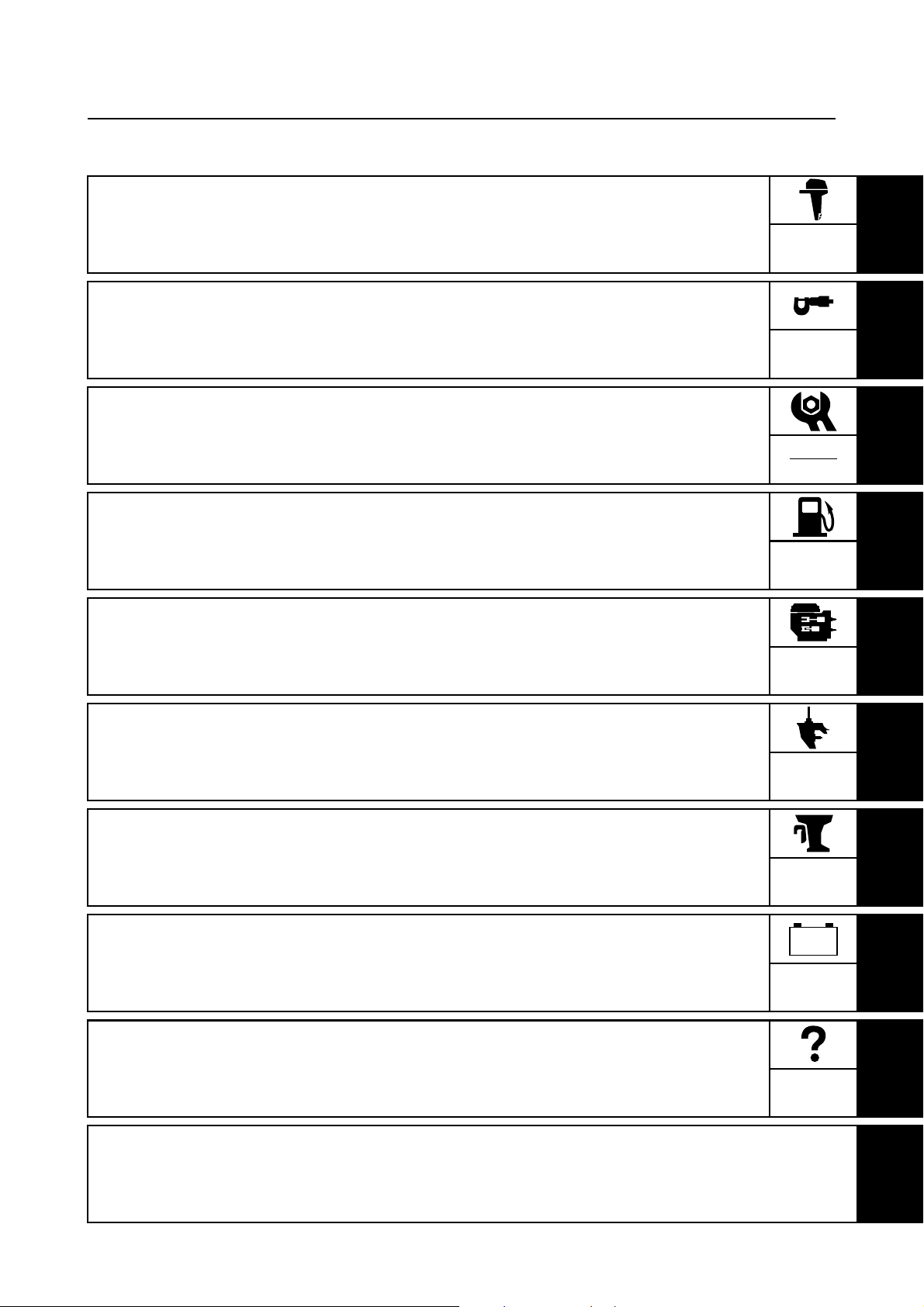
How to use this manual
Manual format
The format of this manual has been designed to make service procedures clear and easy to understand. Use the information below as a guide for effective and quality service.
1
Parts are shown and detailed in an exploded diagram and are listed in the components list.
2
Tightening torque specifications are provided in the exploded diagrams and after a numbered
step with tightening instructions.
3
Symbols are used to indicate important aspects of a procedure, such as the grade of lubricant
and lubrication point.
4
The components list consists of part names and part quantities, as well as bolt and screw dimensions.
5
Service points regarding removal, checking, and installation are shown in individual illustrations
to explain the relevant procedure.
NOTE:
For troubleshooting procedures, see Chapter 9, “Troubleshooting.”
1
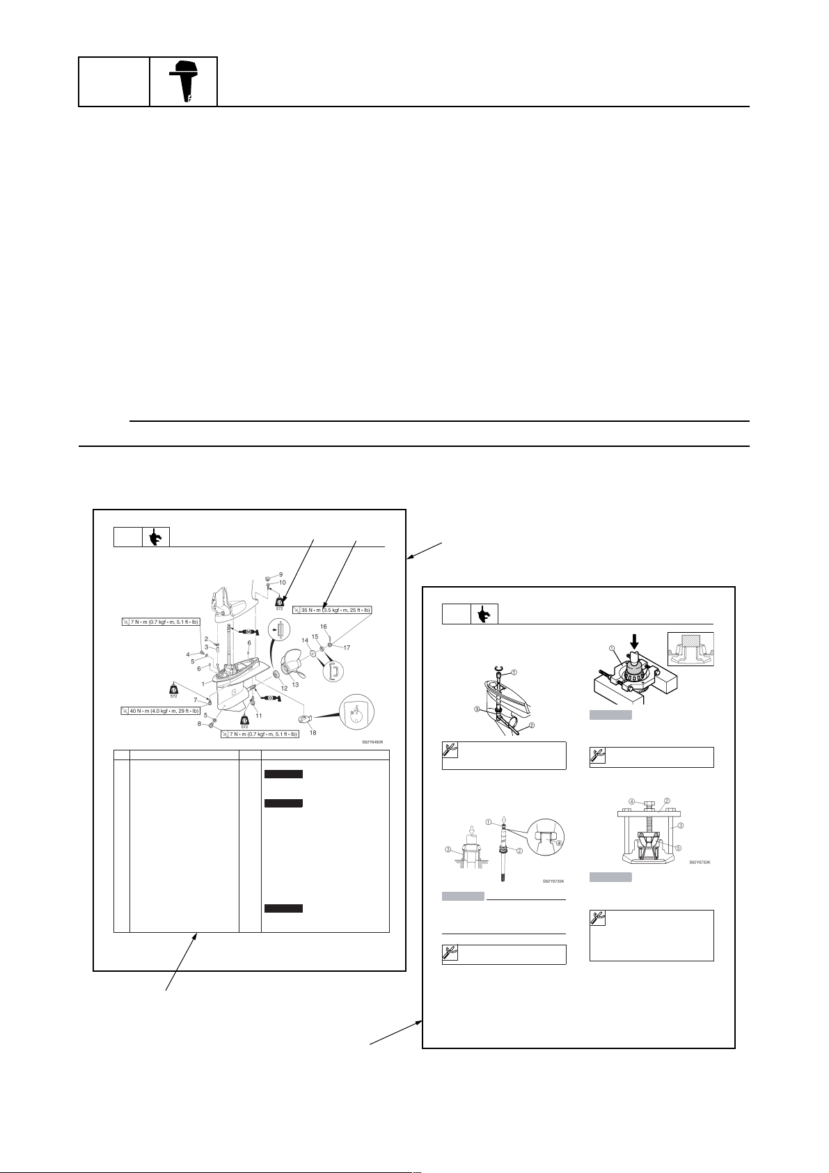
LOWR
Lower unit
No. Part name Q’ty Remarks
1 Lower unit 1
2 Plastic tie 1
3Hose 1
4 Check screw 1
5 Gasket 2
6 Dowel pin 2
7 Bolt 4 M10 40 mm
8 Drain screw 1
9Grommet 1
10 Bolt 1 M10 45 mm
11 Bolt 1 M8 60 mm
12 Thrust washer 1
13 Propeller 1
14 Washer 1
15 Washer 1
16 Cotter pin 1
17 Propeller nut 1
18 Trim tab 1
6-5
Lower unit
Not reusable
Not reusable
Not reusable
3
4
2
62Y5A11
1
LOWR
Removing the drive shaft
1. Remove the drive shaft assembly and
pinion, and then pull out the forward
gear.
Disassembling the drive shaft
1. Install the pinion nut 1, tighten it finger
tight, and then remove the drive shaft
bearing 2 using a press.
CAUTION:
• Do not press the drive shaft threads
directly.
• Do not reuse the bearing, always
replace it with a new one.
Disassembling the forward gear
1. Remove the taper roller bearing from the
forward gear using a press.
Lower unit
S62Y6850K
Drive shaft holder 4 1: 90890-06518
Pinion nut holder 2: 90890-06505
Socket adapter 2 3: 90890-06507
Bearing inner race attachment 3:
90890-06639
CAUTION:
Do not reuse the bearing, always replace
it with a new one.
Bearing separator 1: 90890-06534
2. Remove the needle bearing from the forward gear.
CAUTION:
Do not reuse the bearing, always replace
it with a new one.
a
Stopper guide plate 2: 90890-06501
Stopper guide stand 3:
90890-06538
Bearing puller 4: 90890-06535
Bearing puller claw 1 5:
90890-06536
S62Y6740K
1-1
5
6-19
62Y5A11
66T5F11
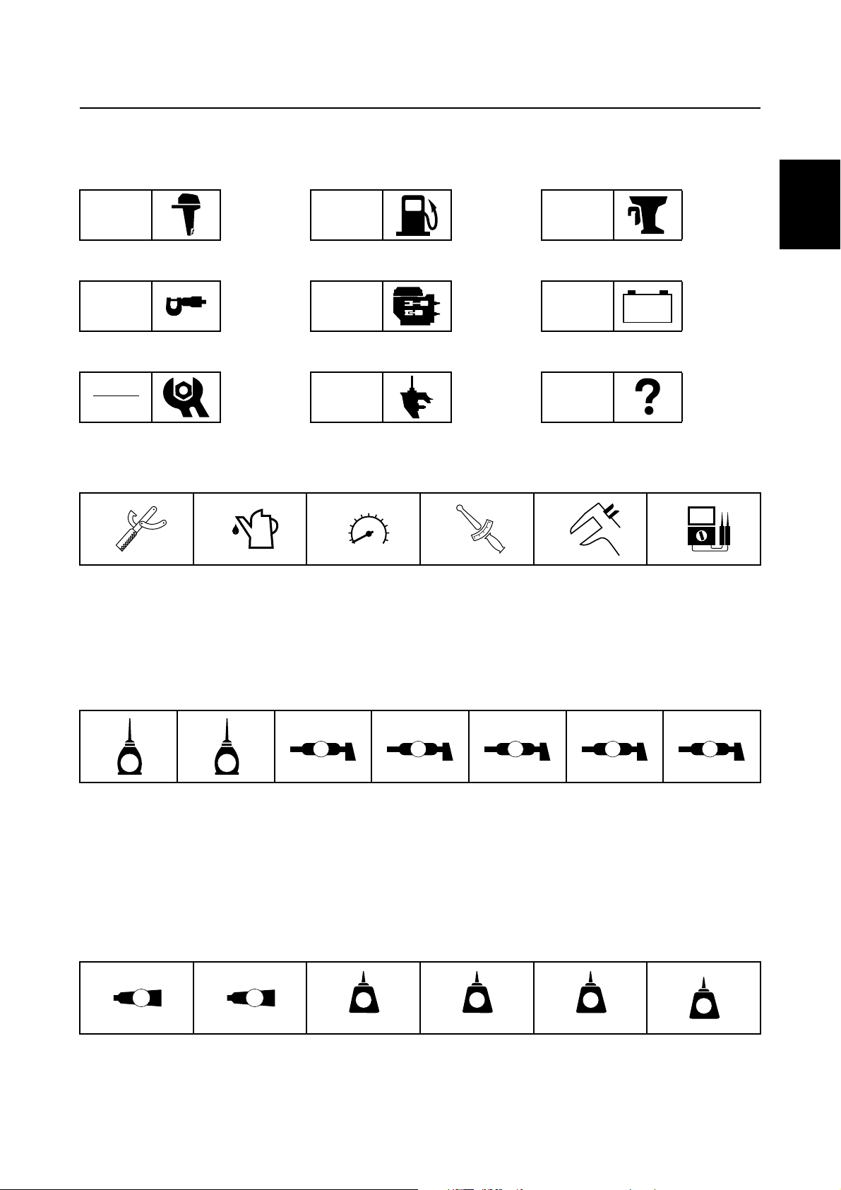
Symbols
The symbols below are designed to indicate the content of a chapter.
How to use this manual
General information
GEN
INFO
Specifications
SPEC
Periodic checks and adjustments
CHK
ADJ
Symbols 1 to 6 indicate specific data.
123456
Fuel system
FUEL
Power unit
POWR
Lower unit
LOWR
Bracket unit
BRKT
Electrical systems
ELEC
Troubleshooting
– +
TRBL
SHTG
1
2
3
4
Special tool
1
Specified oil or fluid
2
Specified engine speed
3
Specified tightening torque
4
Symbols 7 to C in an exploded diagram indicate the grade of lubricant and the lubrication point.
7890ABC
A M
E G
Apply 2-stroke outboard motor oil
7
Apply gear oil
8
Apply water resistant grease (Yamaha grease A)
9
Apply molybdenum disulfide grease
0
Symbols D to I in an exploded diagram indicate the type of sealant or locking agent and the application point.
DEFGHI
GM
4
LT
271
Specified measurement
5
Specified electrical value
6
(resistance, voltage, electric current)
C I
Apply corrosion resistant grease
A
(Yamaha grease D)
Apply low temperature resistant grease
B
(Yamaha grease C)
Apply injector grease
C
LT
572
SS
5
6
7
8
9
Apply Gasket Maker
D
Apply Yamabond No. 4
E
Apply LOCTITE 271 (red)
F
66T5F11
Apply LOCTITE 242 (blue)
G
Apply LOCTITE 572
H
Apply silicon sealant
I
1-2
GEN
INFO
General information
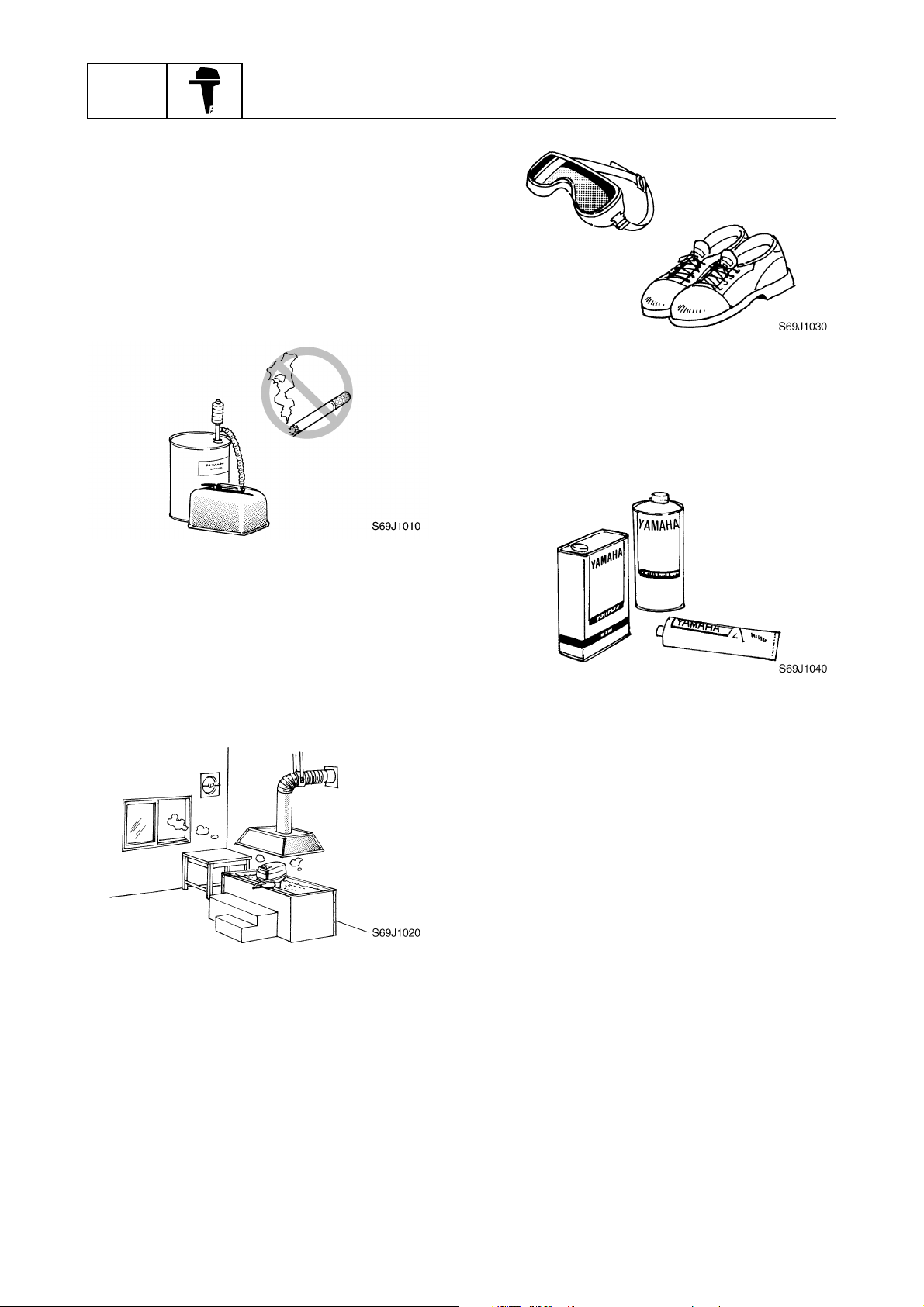
Safety while working
To prevent an accident or injury and to
ensure quality service, follow the safety procedures provided below.
Fire prevention
Gasoline is highly flammable.
Keep gasoline and all flammable products
away from heat, sparks, and open flames.
Ventilation
Gasoline vapor and exhaust gas are heavier
than air and extremely poisonous. If inhaled
in large quantities they may cause loss of
consciousness and death within a short time.
When test running an engine indoors (e.g., in
a water tank) be sure to do so where adequate ventilation can be maintained.
1
Parts, lubricants, and sealants
Use only genuine Yamaha parts, lubricants,
and sealants or those recommended by
Yamaha, when servicing or repairing the outboard motor.
Under normal conditions, the lubricants mentioned in this manual should not harm or be
hazardous to your skin. However, you should
follow these precautions to minimize any risk
when working with lubricants.
Self-protection
Protect your eyes by wearing safety glasses
or safety goggles during all operations involving drilling and grinding, or when using an air
compressor.
Protect your hands and feet by wearing protective gloves and safety shoes when necessary.
1-3
1. Maintain good standards of personal and
industrial hygiene.
2. Change and wash clothing as soon as
possible if soiled with lubricants.
3. Avoid contact with skin. Do not, for
example, place a soiled rag in your
pocket.
4. Wash hands and any other part of the
body thoroughly with soap and hot water
after contact with a lubricant or lubricant
soiled clothing has been made.
5. To protect your skin, apply a protective
cream to your hands before working on
the outboard motor.
66T5F11
Safety while working
6. Keep a supply of clean, lint-free cloths for
wiping up spills, etc.
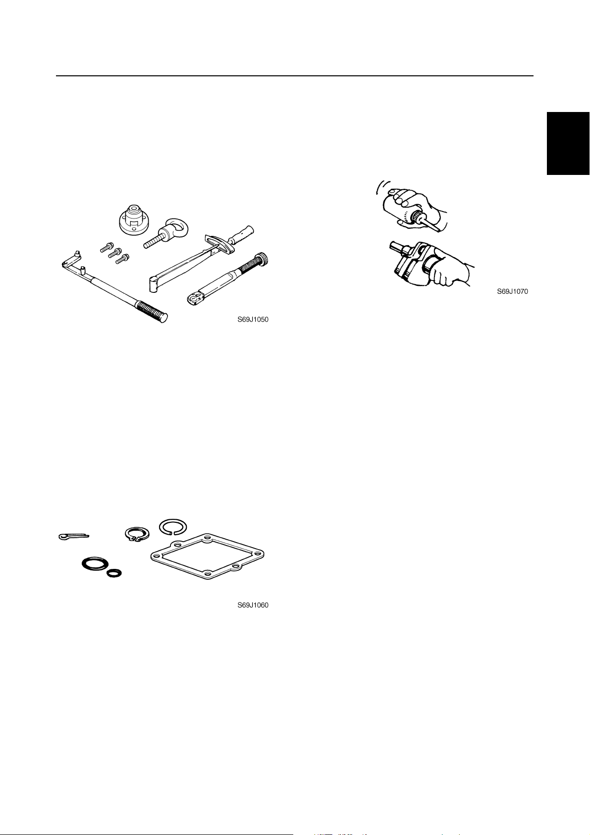
Good working practices
Special service tools
Use the recommended special service tools
to protect parts from damage. Use the right
tool in the right manner—do not improvise.
Tightening torques
Follow the tightening torque specifications
provided throughout the manual. When tightening nuts, bolts, and screws, tighten the
large sizes first, and tighten fasteners starting
in the center and moving outward.
Non-reusable parts
Always use new gaskets, seals, O-rings, cotter pins, circlips, etc., when installing or
assembling parts.
Disassembly and assembly
1. Use compressed air to remove dust and
dirt during disassembly.
2. Apply engine oil to the contact surfaces
of moving parts before assembly.
3. Install bearings with the manufacture
identification mark in the direction indicated in the installation procedure. In
addition, be sure to lubricate the bearings
liberally.
4. Apply a thin coat of water-resistant
grease to the lip and periphery of an oil
seal before installation.
5. Check that moving parts operate normally after assembly.
1
2
3
4
5
6
7
8
9
66T5F11
1-4
GEN
INFO
General information
Identification
Applicable models
This manual covers the following models.
Applicable models
40XWH, 40XW, E40XMH, E40XW
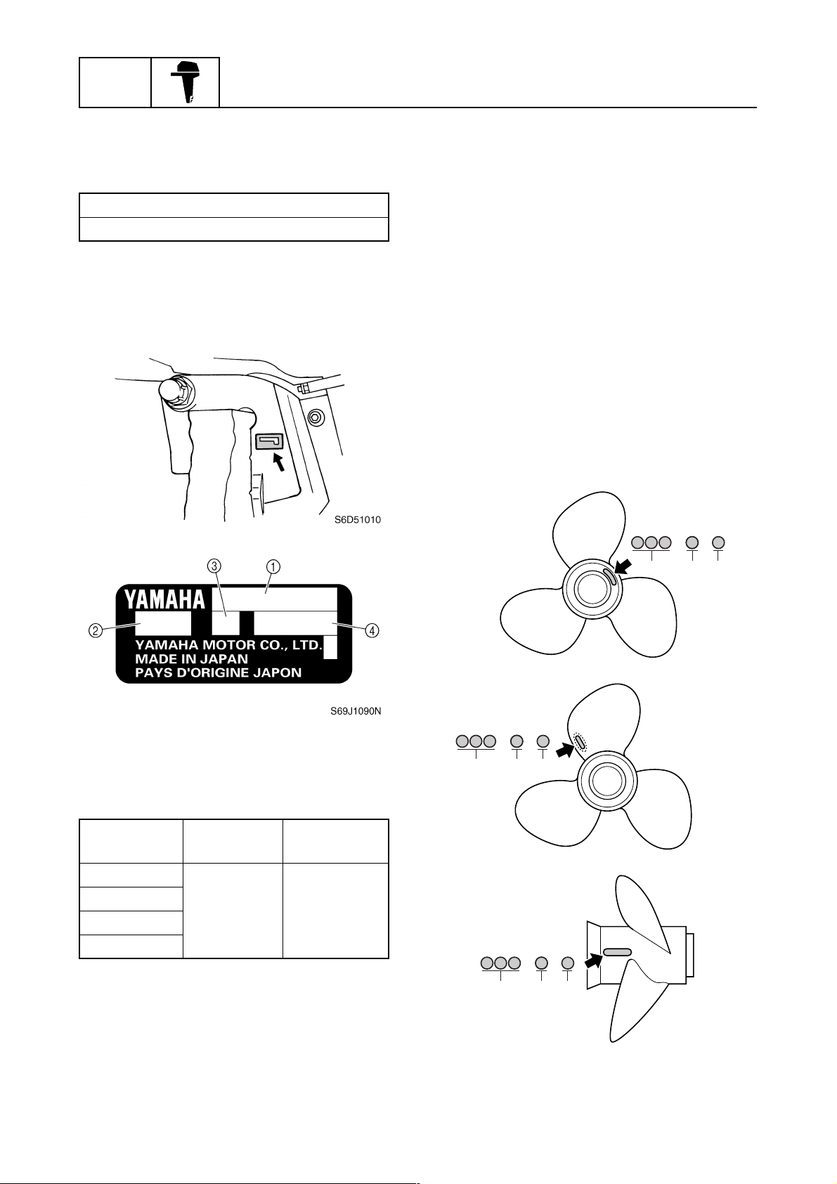
Serial number
The outboard motor serial number is
stamped on a label attached to the port
clamp bracket.
1
Propeller selection
1
The performance of a boat and outboard
motor will be critically affected by the size
and type of propeller you choose. Propellers
greatly affect boat speed, acceleration,
engine life, fuel economy, and even boating
and steering capabilities. An incorrect choice
could adversely affect performance and
could also seriously damage the engine.
Use the following information as a guide for
selecting a propeller that meets the operating
conditions of the boat and the outboard
motor.
Propeller size
The size of the propeller is indicated on a
propeller blade, on the propeller boss end, on
the side of the propeller boss.
Model name
1
Approved model code
2
Transom height
3
Serial number
4
Model name
40XWH
40XW
E40XMH
E40XW
Approved
model code
Starting
serial No.
66TK 1008141–
× —
a
bc
× —
× —
a
bc
S69W1030
S69W1040
1-5
a
bc
S69W1050
66T5F11
Identification / Propeller selection / Predelivery checks
Propeller diameter (in inches)
a
Propeller pitch (in inches)
b
Propeller type (propeller mark)
c
Selection
When the engine speed is at the full throttle
operating range (4,500–5,500 r/min), the
ideal propeller for the boat is one that provides maximum performance in relation to
boat speed and fuel consumption.
1
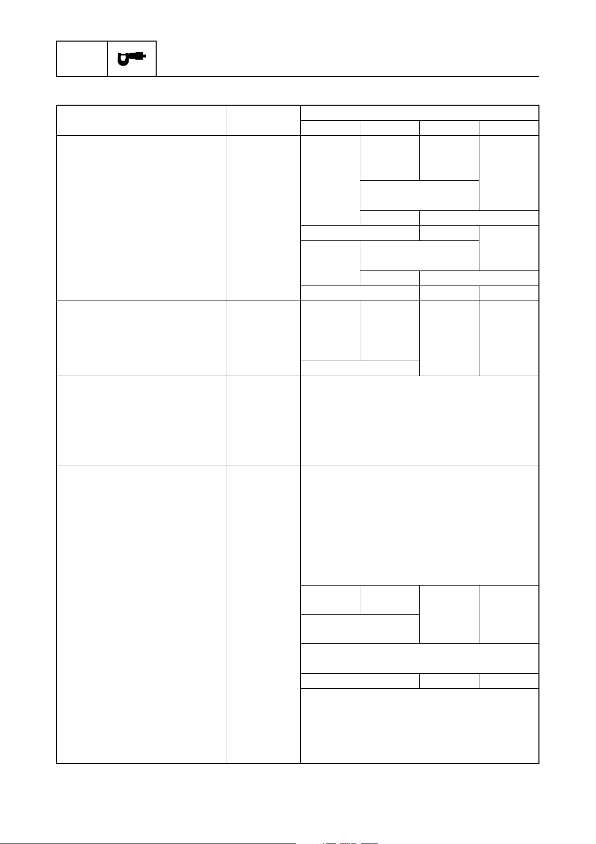
Propeller size (in) Material
10 1/4 × 14 — G
10 1/4 × 15 — G
10 1/4 × 16 — G
10 3/4 × 16 — G
10 3/4 × 17 — G
11 × 15 — G
11 1/8 × 13 — G
11 1/4 × 14 — G
Aluminum
11 3/8 × 12 — G
11 1/2 × 13 — G
11 5/8 × 11 — G
11 3/4 × 10 — G
11 3/4 × 12 — G
12 × 11 — G
12 1/4 × 8 — G
12 1/4 × 9 — G
CAUTION:
Use pre-mixed fuel only.
Fuel and oil mixing ratio is 50:1. For
break-in period, 25:1 mixture shall be
used.
Checking the gear oil level
1. Check the gear oil level.
2
3
4
5
6
Predelivery checks
To make the delivery process smooth and
efficient, the predelivery checks should be
completed as explained below.
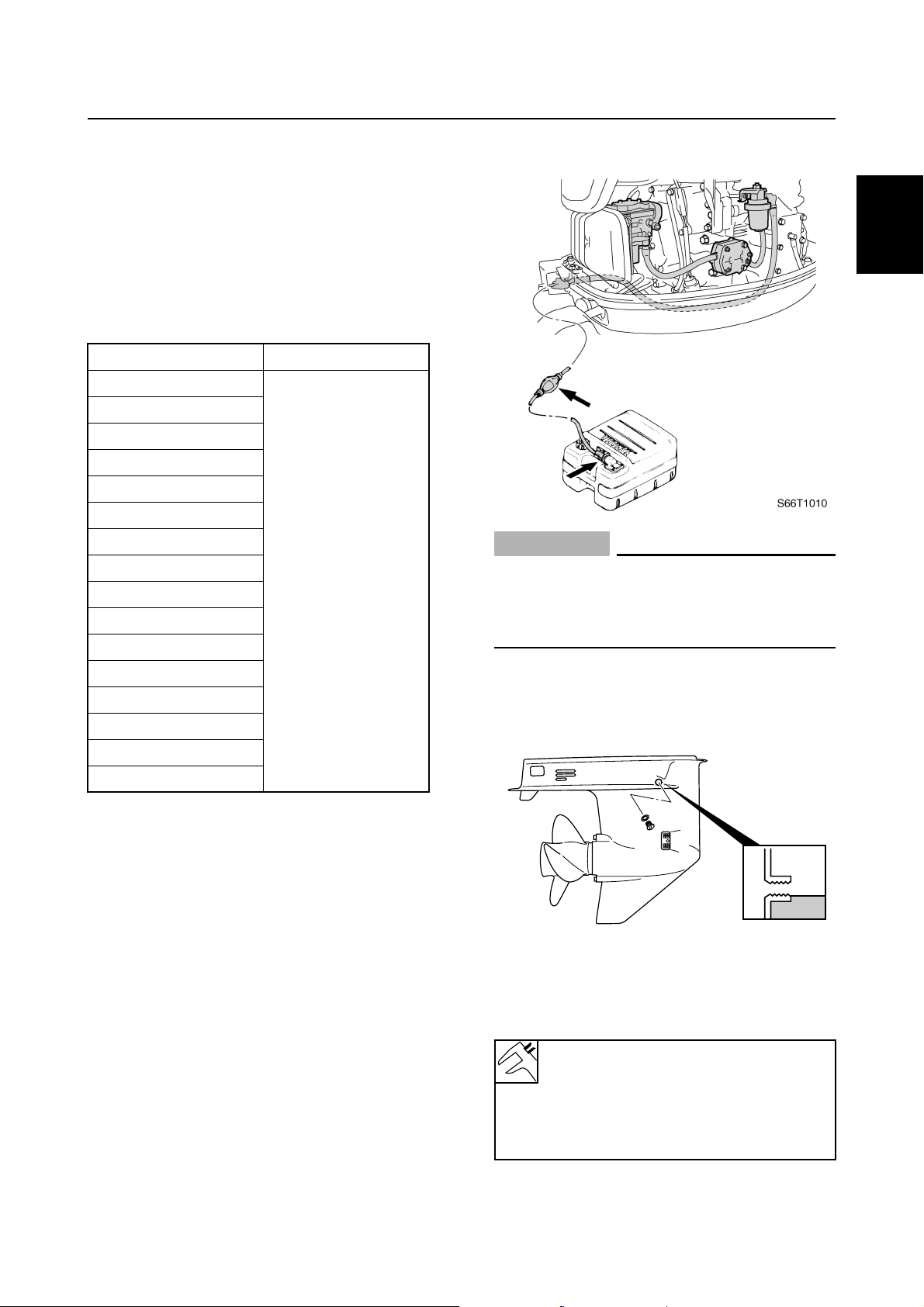
Checking the fuel system
1. Check that the fuel hoses are securely
connected and that the fuel tank is full
with fuel.
66T5F11
1
7
S60V1290
Checking the battery (WH, W)
1. Check the capacity, electrolyte level, and
specified gravity of the battery.
Recommended battery capacity:
CCA/EN: 430 A
20HR/IEC: 70 Ah
Electrolyte specified gravity:
1.280 at 20 °C (68 °F)
1-6
8
9
GEN
INFO
2. Check that the positive and negative battery leads are securely connected.
Checking the outboard motor
mounting height
1. Check that the anti-cavitation plate is
between the bottom of the boat and a
maximum of 25 mm (1 in) a below it. If
the mounting height is too high, cavitation will occur and propulsion will be
reduced. Also, the engine speed will
increase abnormally and cause the
engine to overheat. If the mounting
height is too low, water resistance will
increase and reduce engine efficiency.
General information
a
S6D51030
NOTE:
The optimum mounting height is affected by
the combination of the boat and the outboard
motor. To determine the optimum mounting
height, test run the outboard motor at different heights.
2. Check that the clamp brackets are
secured with the clamp screws.
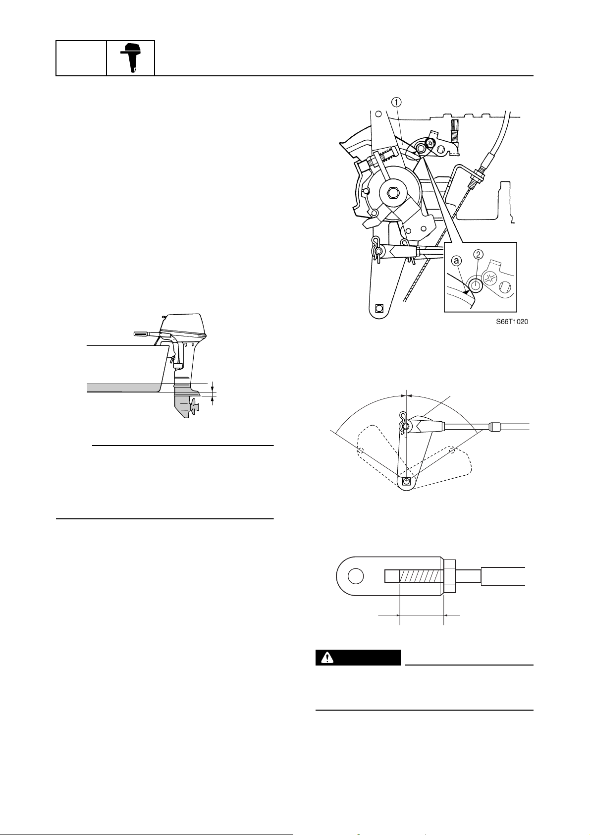
Checking the remote control cables
(remote control model)
1. Set the remote control lever to the neutral position and fully close the throttle
lever.
2. Check that the throttle cam 1 is in its
fully closed position and align the center
of the throttle cam roller 2 with the mark
a
on the throttle cam.
3. Check that the shift link lever 3 is in the
neutral position.
N
R
b
3
F
S66T1030
S66T1050
WARNING
The shift/throttle cable joint must be
screwed in a minimum of 8.0 mm (0.31 in)
b
.
1-7
66T5F11

Predelivery checks
Checking the steering system
1. Check the steering friction for proper
adjustment.
NOTE:
• To increase the friction, turn the friction
adjusting bolt in direction a.
• To decrease the friction, turn the friction
adjusting bolt in direction b.
2. Check that the steering operates
smoothly.
Checking the gear shift and throttle
operation
1. Check that the gear shift operates
smoothly when the remote control lever
or shift lever is shifted from neutral to forward or reverse.
2. Check that the throttle operates smoothly
when the throttle grip (tiller handle
model) is turned from the fully closed
position to the fully open position a.
Check that the throttle operates smoothly
when the remote control lever (remote
control model) is shifted from forward or
reverse to the fully open positions a.
R
N
F
0 100%
1
2
3
4
S66T1060
S66T1040
3. Check that there is no interference with
wires or hoses when the outboard motor
is steered.
a
S66T1070
a
5
N
F
R
a
S69J1210
6
7
8
9
66T5F11
1-8
GEN
INFO
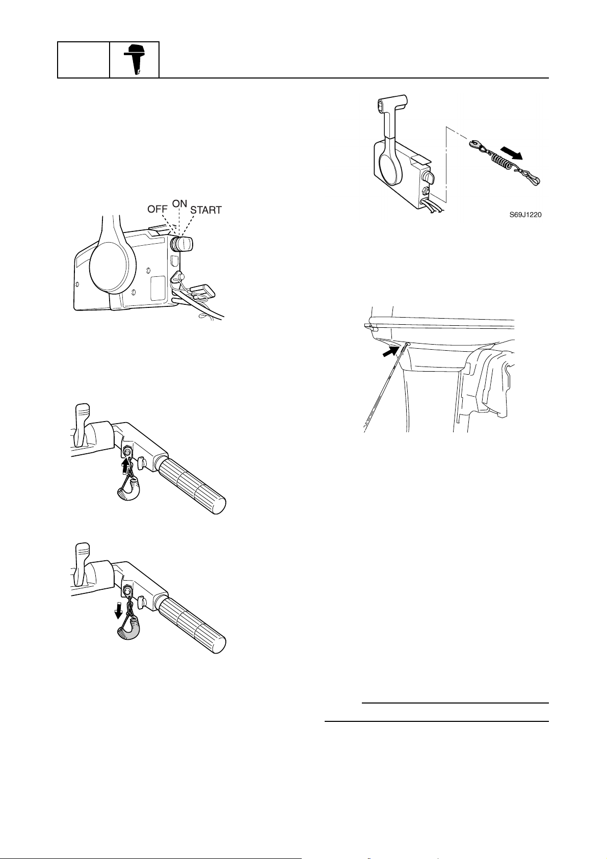
Checking the engine start switch and
engine stop lanyard switch
1. Check that the engine starts when the
engine start switch is turned to START.
2. Check that the engine turns off when the
engine start switch is turned to OFF.
3. Check that the engine turns off when the
engine stop lanyard switch is pushed or
the engine stop lanyard is pulled from the
engine stop lanyard switch.
General information
S60V1070
Checking the cooling water pilot
hole
1. Check that cooling water is discharged
from the cooling water pilot hole.
S66T1080
S66T1090
S66T3050
Test run
1. Start the engine, and then check that the
gear shift operates smoothly.
2. Check the engine idle speed after the
engine has been warmed up.
3. Operate at trolling speed.
4. Run the outboard motor for 1 hour at
3,000 r/min or at half throttle, then for
another hour at 4,000 r/min or at 3/4
throttle.
5. Check that the outboard motor does not
tilt up when shifting into reverse and that
water does not flow in over the transom.
NOTE:
The test run is part of the break-in operation.
1-9
66T5F11

Break-in
During the test run, perform the break-in
operation in the following four stages.
1. First 10 minutes a of operation at idle
Predelivery checks
2. Fifty minutes b at 3,000 r/min or less
3. One hour c at 4,000 r/min or less
4. Eight hours d at 5,000 r/min or less with
repeated wide-open-throttle operation for
5 minutes or less
cdaÈb
0
È
Hour
After test run
1. Check for water in the gear oil.
1
210
S60V1120
1
2
3
4
5
2. Check for fuel leakage in the cowling.
3. Flush the cooling water passage with
fresh water using the flushing kit and with
the engine running at idle.
6
7
8
9
66T5F11
1-10

GEN
INFO
General information
— MEMO —
1-11
66T5F11

SPEC
Specifications
General specifications………………………………………………………………………..2-1
Maintenance specification ………………………………………………………………….2-3
Power unit……………………………………………………………………………………..2-3
Lower unit ……………………………………………………………………………………..2-5
Electrical ……………………………………………………………………………………….2-5
Dimensions……………………………………………………………………………………2-7
Tightening torques……………………………………………………………………………..2-9
Specified torques……………………………………………………………………………2-9
General torques……………………………………………………………………………2-10
1
2
3
4
5
6
7
8
9
66T5F11
SPEC
Specifications
General specifications
Item Unit
40XWH 40XW E40XMH E40XW
Dimension
Overall length mm (in)
1,073 (42.2)
675 (26.6)
Overall width mm (in) 402 (15.8) 362 (14.3) 402 (15.8) 362 (14.3)
Overall height
(S) mm (in) — 1,237 (48.7) —
(L) mm (in)
1,364 (53.7)
(X) mm (in) —
Boat transom height
(S) mm (in) — 381 (15.0) —
(L) mm (in) 508 (20.0) — 508 (20.0)
(X) mm (in) — 635 (25.0) —
Weight
(with aluminum propeller)
(S) kg (lb) —
(L) kg (lb)
78.0 (172.0)
74.6 (164.5) 72.0 (158.8)
(X) kg (lb) —
Performance
Maximum output kW (hp) 29.4 (40) at 5,000 r/min
Full throttle operating range r/min 4,500–5,500
Maximum fuel consumption L (US gal,
20 (5.3, 4.4) at 5,500 r/min
Imp gal)/hr
Engine idle speed r/min 950–1,050
Power unit
Type 2-stroke
Cylinder quantity L2
Total displacement cm
3
(cu. in) 703 (42.9)
Bore × stroke mm (in) 80.0 × 70.0 (3.15 × 2.76)
Compression ratio 6.0
Intake system Reed valve
Scavenging system Loop charge
Control system Tiller
handle
Remote
control
Starting system Manual and electric Manual Manual and
Fuel system Carburetor
Ignition control system CDI
Maximum generator output V, A 12, 6.0 — 12, 6.0
Starting enrichment Choke valve
Spark plug B7HS (NGK), BR7HS (NGK)
Cooling system Water
Exhaust system Propeller boss
Lubrication system Pre-mixed fuel
Model
1,073 (42.2)
675 (26.6)
— 1,364 (53.7)
1,476 (58.1)
—
73.6 (162.3) 76.2 (168.0)
76.7 (169.1)
Tiller
handle
Remote
control
electric
2
—
—
—
2-1
66T5F11

General specifications
Item Unit
Fuel and oil
Fuel type Regular gasoline
Engine oil 2-stroke outboard motor oil
Engine oil grade
Fuel and oil mixing ratio 50:1
Gear oil type Hypoid gear oil
Gear oil grade
Gear oil quantity cm
Bracket unit
Tilt angle Degree 8, 12, 16, 20, 24
(at 12° boat transom)
Tilt-up angle Degree 68
Steering angle Degree 45 + 45
Drive unit
Gear shift positions F-N-R
Gear ratio 2.00 (26/13)
Reduction gear type Spiral bevel gear
Clutch type Dog clutch
Propeller shaft type Spline
Propeller direction (rear view) Clockwise
Propeller mark G
Electrical
Battery minimum capacity
CCA/EN A 430 — 430
20HR/IEC Ah 70 — 70
(*1)
Meeting both API and SAE requirements
(*2)
CCA: Cold Cranking Ampere
EN: European Norm (European standard)
IEC: International Electrotechnical Commission
(*1)
API
(*2)
NMMA-certified
SAE
3
Imp oz)
(US oz,
40XWH 40XW E40XMH E40XW
430 (14.54, 15.17)
Model
TC-W3
GL-4
90
1
2
3
4
5
6
7
66T5F11
8
9
2-2
SPEC
Specifications
Maintenance specification
Power unit
Item Unit
40XWH 40XW E40XMH E40XW
Power unit
Minimum compression
pressure
(*1)
kPa
(kgf/cm2, psi)
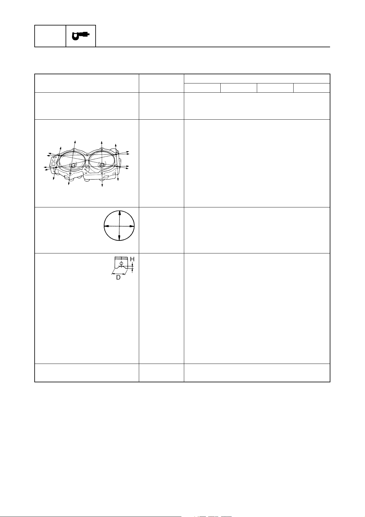
Cylinder heads
Warpage limit
mm (in) 0.1 (0.0039)
(lines indicate straightedge
position)
Cylinders
Bore size mm (in) 80.000–80.020 (3.1496–3.1504)
Bore size limit mm (in) 80.100 (3.1535)
Taper limit mm (in) 0.08 (0.0032)
Out-of-round limit mm (in) 0.05 (0.0020)
Pistons
Piston diameter (D) mm (in) 79.910–79.934 (3.1461–3.1470)
Measuring point (H) mm (in) 10 (0.39)
Piston-to-cylinder clearance mm (in) 0.085–0.090 (0.0033–0.0035)
(Limit) mm (in) 0.14 (0.0055)
Piston pin boss bore mm (in) 19.904–19.915 (0.7836–0.7841)
Oversize piston
1st mm (in) 0.25 (0.010)
2nd mm (in) 0.50 (0.020)
Oversize piston diameter
1st mm (in) 80.160–80.184 (3.1559–3.1568)
2nd mm (in) 80.410–80.434 (3.1657–3.1667)
Piston pins
Outside diameter mm (in) 19.895–19.900 (0.7833–0.7835)
(*1)
Measure conditions:
Ambient temperature 20 °C (68 °F), wide open throttle, with spark plugs removed from all cylinders.
The figures are for reference only.
Model
630 (6.3, 91)
2
2-3
66T5F11
Maintenance specification
Item Unit
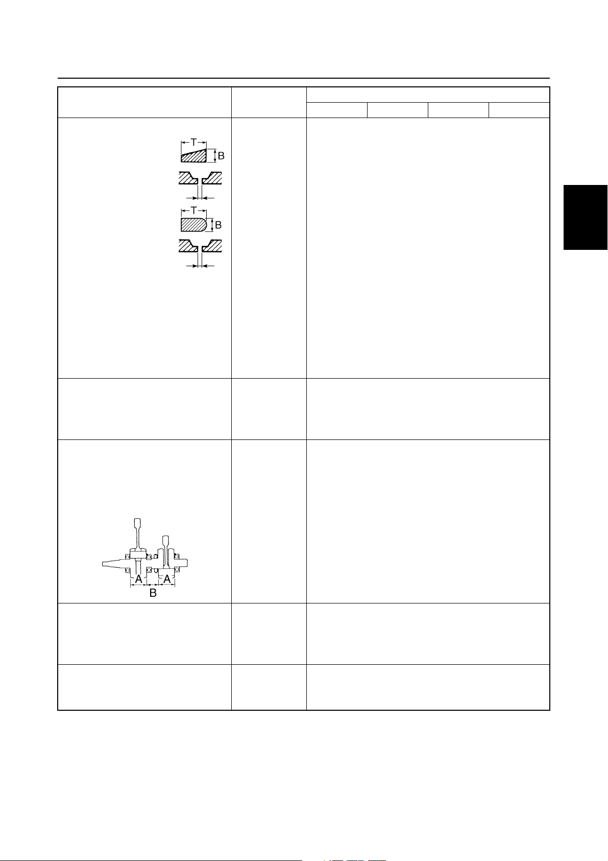
Piston rings
Top ring
Dimension B mm (in) 1.97–1.99 (0.0776–0.0783)
Dimension T mm (in) 2.40–2.60 (0.0945–0.1024)
End gap mm (in) 0.30–0.50 (0.0118–0.0197)
Side clearance mm (in) 0.04–0.08 (0.0015–0.0031)
Oversize diameter
1st mm (in) 80.250 (3.1594)
2nd mm (in) 80.500 (3.1693)
2nd piston ring
Dimension B mm (in) 1.97–1.99 (0.0776–0.0783)
Dimension T mm (in) 2.40–2.60 (0.0945–0.1024)
End gap mm (in) 0.30–0.50 (0.0118–0.0197)
Side clearance mm (in) 0.03–0.07 (0.0012–0.0028)
Oversize diameter
1st mm (in) 80.250 (3.1594)
2nd mm (in) 80.500 (3.1693)
Connecting rods
Small-end inside diameter mm (in) 24.900–24.912 (0.9803–0.9808)
Big-end side clearance mm (in) 0.200–0.700 (0.0079–0.0276)
Small-end axial play limit mm (in) 2.0 (0.08)
Crankshaft
Crankshaft width A mm (in) 63.90–63.95 (2.5157–2.5177)
Crankshaft width B mm (in) 40.88–41.10 (1.6094–1.6181)
Crankpin diameter mm (in) 26.995–27.000 (1.0628–1.0630)
Runout limit mm (in) 0.03 (0.0012)
40XWH 40XW E40XMH E40XW
Model
1
2
3
4
5
6
Thermostats
Opening temperature °C (°F) 48–52 (118–126)
Fully open temperature °C (°F) 60 (140)
Valve open lower limit mm (in) 3.0 (0.12)
Reed valves
Valve stopper height limit mm (in) 10.2–10.4 (0.40–0.41)
Valve bending limit mm (in) 0.2 (0.008)
66T5F11
7
8
9
2-4
SPEC
Specifications
Item Unit
Carburetor
ID mark 66T02 66T12 66T02 66T12
Main jet # 170
Main air jet # 160
Pilot jet # 70
Pilot air jet # 60
Pilot screw turns out 1 3/8–1 7/8
Float height mm (in) 16.5–18.5 (0.65–0.73)
40XWH 40XW E40XMH E40XW
Model
Lower unit
Item Unit
Gear backlash
Pinion-to-forward gear mm (in) 0.19–0.56 (0.0075–0.0220)
Pinion-to-reverse gear mm (in) 0.75–1.13 (0.0295–0.0445)
Pinion shims mm 0.10, 0.12, 0.15, 0.18, 0.30, 0.40, 0.50
Forward gear shims mm 0.10, 0.12, 0.15, 0.18, 0.30, 0.40, 0.50
Reverse gear shims mm 0.10, 0.12, 0.15, 0.18, 0.30, 0.40, 0.50
40XWH 40XW E40XMH E40XW
Model
Electrical
Item Unit
Ignition and ignition control
system
Ignition timing (cylinder #1) Degree
Degree
Spark plug gap mm (in) 0.6–0.7 (0.024–0.028)
Spark plug cap resistance
(with resister type)
Ignition coil resistance
Primary coil (B/W – B)
at 20 °C (68 °F)
Secondary coil
(B/W – spark plug wire)
at 20 °C (68 °F) kΩ 5.4–7.4
CDI unit output peak voltage
(B/O – B, B/W – B)
at cranking (loaded) V 180
at 1,500 r/min (loaded) V 180
at 3,500 r/min (loaded) V 170
kΩ 4.0–6.0
Ω
0.32–0.44
40XWH 40XW E40XMH E40XW
ATDC2 at engine idle speed
BTDC23 at 5,000 r/min
Model
2-5
66T5F11

Maintenance specification
Item Unit
Pulser coil output peak voltage
(W/R – W/B)
at cranking (unloaded) V 7.0
at cranking (loaded) V 4.0
at 1,500 r/min (loaded) V 10.0
at 3,500 r/min (loaded) V 17.0
Pulser coil resistance
Starter motor
Type Bendix — Bendix
Brushes
Length limit mm (in) 6.4 (0.25) — 6.4 (0.25)
Armature
Commutator undercut limit mm (in) 0.8 (0.03) — 0.8 (0.03)
Charging system
Fuse A 10
Charge coil output peak
voltage (Positive side: Br –
Negative side: L)
at cranking (unloaded) V 330
at cranking (loaded) V 190
at 1,500 r/min (loaded) V 190
at 3,500 r/min (loaded) V 190
Charge coil resistance (Br – L)
Lighting coil output peak
voltage
Lighting coil resistance
Rectifier output peak voltage
(*1)
The figures are for reference only.
(*1)
(G – G)
at cranking (unloaded) V 6.0 — 6.0
at 1,500 r/min (unloaded) V 16.0 — 16.0
at 3,500 r/min (unloaded) V 33.0 — 33.0
at 1,500 r/min (unloaded) V 14.0 — 14.0
at 3,500 r/min (unloaded) V 32.0 — 32.0
(*1)
(W/R – W/B)
(*1)
(G – G)
(R – B)
Ω
311.4–380.6
Ω
684–836
Ω
0.31–0.37 — 0.31–0.37
40XWH 40XW E40XMH E40XW
Model
1
2
3
4
5
6
7
8
66T5F11
9
2-6
SPEC
Specifications
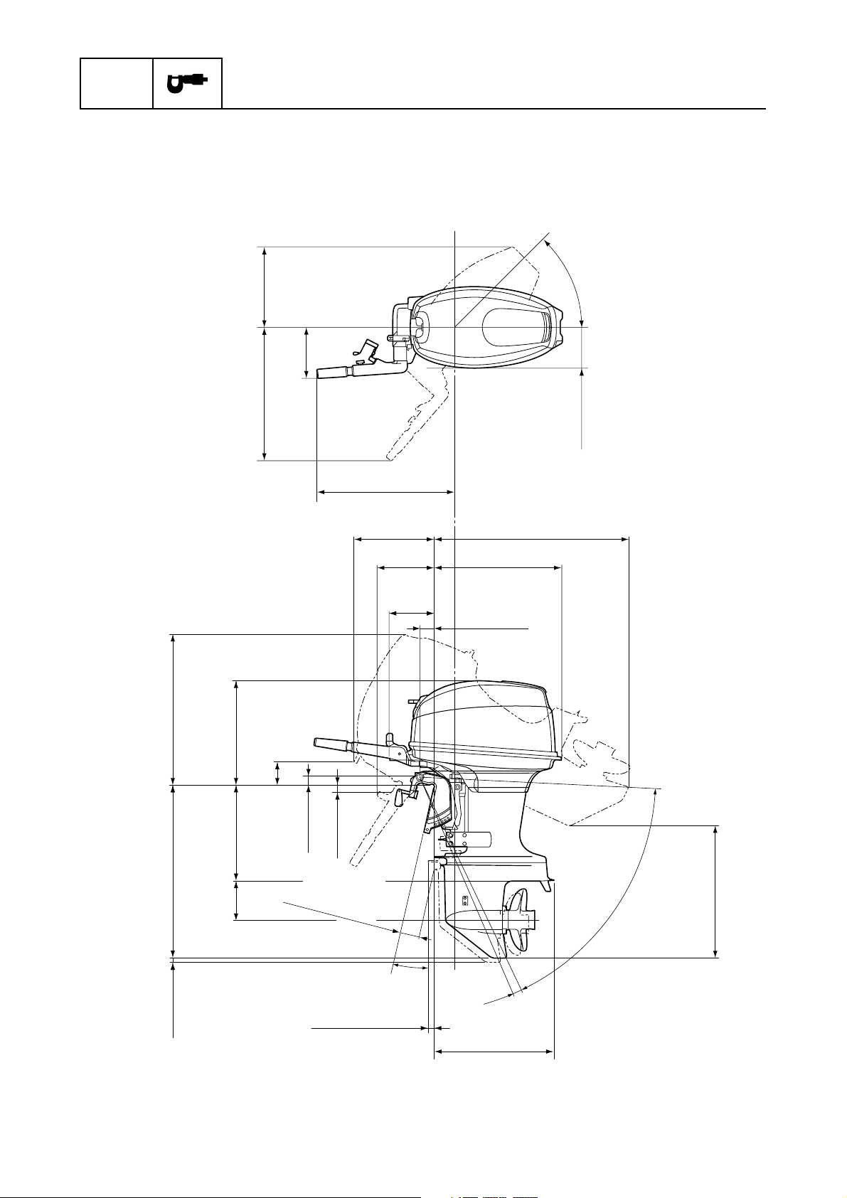
Dimensions
Exterior
* Tiller handle model only
mm (in)
45˚
221 (8.7)*
702 (27.6)
592 (23.3)* 369 (14.5)
159 (6.3)
523 (20.6)*
397 (15.6)
294 (11.6)*
118 (4.7)
190 (7.5)*
182 (7.2)
S: 826 (32.5)
L: 940 (37.0)
X:1,043 (41.1)
553 (21.8)
65 (2.6)
2-7
S: 424 (16.7)
X: 1,007 (39.7)
S: 767 (30.2)
L: 893 (35.2)
S: 25 (1.0)
L: 24 (0.9)
X: 24 (0.9)
L: 550 (21.7)
X: 664 (26.1)
175 (6.9) 471 (18.5)
43 (1.7)
38 (1.5)*
S: 65 (2.6)
L: 91 (3.6)
X: 91 (3.6)
S: 3 (0.1)
L: 8 (0.3)
X:16 (0.6)
12
˚
˚
4
522 (20.6)
64
˚
S: 626 (24.7)
L: 697 (27.4)
X: 761 (30.0)
S66T2010
66T5F11
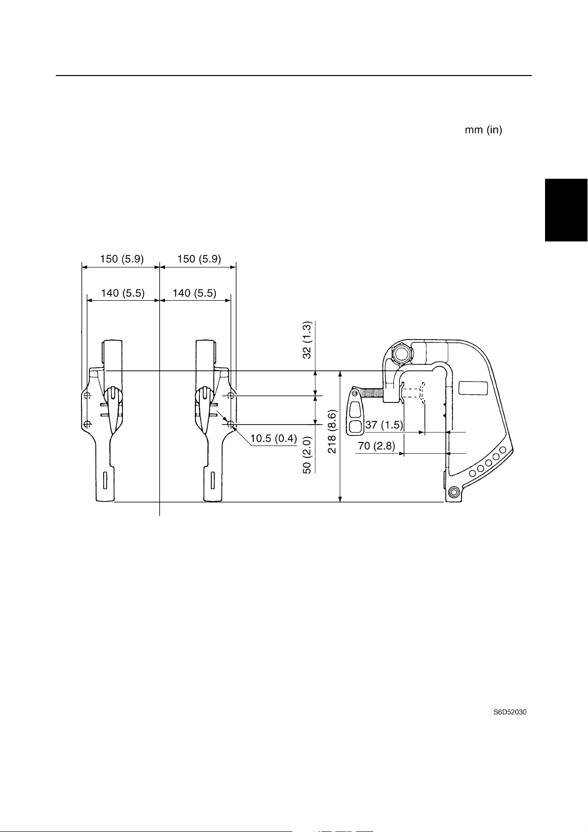
Clamp bracket
Maintenance specification
1
2
3
4
5
6
7
8
66T5F11
9
2-8
SPEC
Specifications
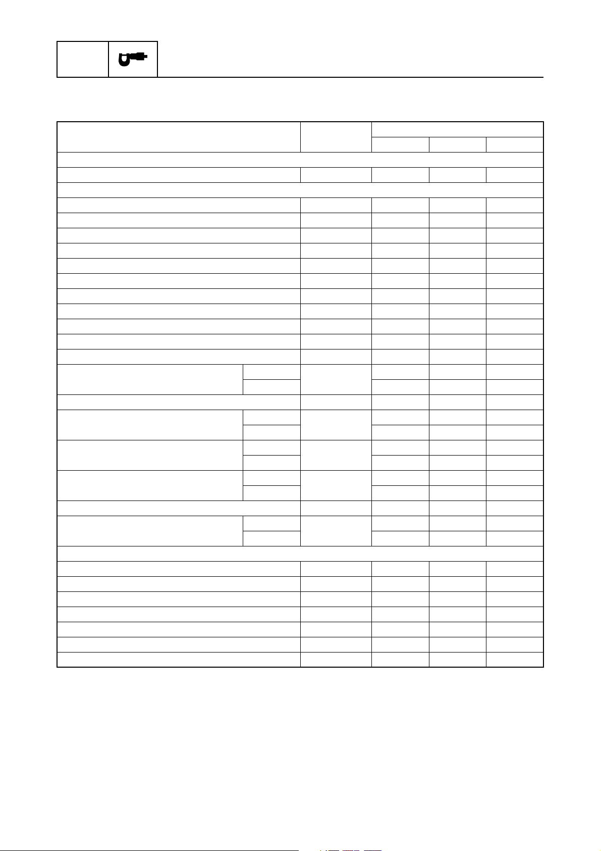
Tightening torques
2
Specified torques
Part to be tightened Thread size
Fuel system
Intake silencer screw M6 2 0.2 1.5
Power unit
Power unit mounting bolt M8 21 2.1 15.5
Engine start button nut M16 5 0.5 3.7
Starter rope guide bolt M6 8 0.8 5.9
Manual starter roller bolt M6 3 0.3 2.2
Sheave drum bolt M6 5 0.5 3.7
Flywheel magnet nut M20 157 15.7 115.8
Starter motor bolt M8 21 2.1 15.5
Starter motor terminal nut M8 7 0.7 5.2
Starter relay terminal nut M6 4 0.4 3.0
Ignition coil bolt M6 8 0.8 5.9
Rectifier screw M5 3 0.3 2.2
Intake manifold bolt
1st
2nd 12 1.2 8.9
M6
Reed valve screw M5 2 0.2 1.5
Cylinder head bolt
Cylinder head cover bolt
Exhaust cover bolt
1st
2nd 30 3.0 22.1
1st
2nd 12 1.2 8.9
1st
2nd 12 1.2 8.9
M8
M6
M6
Spark plug — 25 2.5 18.4
Crankcase bolt
1st
2nd 40 4.0 29.5
M10
Lower unit
Gear oil drain screw — 90.96.6
Gear oil check screw — 90.96.6
Lower case mounting bolt M10 40 4.0 29.5
Cooling water inlet cover screw M5 4 0.4 3.0
Propeller nut M16 40 4.0 29.5
Propeller shaft housing bolt M8 16 1.6 11.8
Pinion nut M12 74 7.4 54.6
Tightening torques
N·mkgf·mft·lb
60.64.4
15 1.5 11.1
60.64.4
60.64.4
20 2.0 14.8
2-9
66T5F11
Tightening torques
Part to be tightened Thread size
Bracket unit
Tiller handle bracket nut M10 10 1.0 7.4
Self-locking nut M10 41 4.1 30.2
Engine stop lanyard switch nut — 20.21.5
Battery lead holder screw M6 2 0.2 1.5
Throttle grip screw M5 3 0.3 2.2
Neutral switch nut — 70.75.2
Upper mounting nut M8 24 2.4 17.7
Upper mount bolt M8 27 2.7 20.0
Mount housing nut M10 54 5.4 39.8
Steering friction adjusting bolt M8 4 0.4 3.0
Upper case bolt M8 21 2.1 15.5
Exhaust manifold bolt M8 21 2.1 15.5
Self-locking nut M22 45 4.5 33.2
Tilt stopper plate nut M8 24 2.4 17.7
Grease nipple — 30.32.2
Clamp bracket nut M8 18 1.8 13.3
Tilt lever screw M5 4 0.4 3.0
Tightening torques
N·mkgf·mft·lb
1
2
3
4
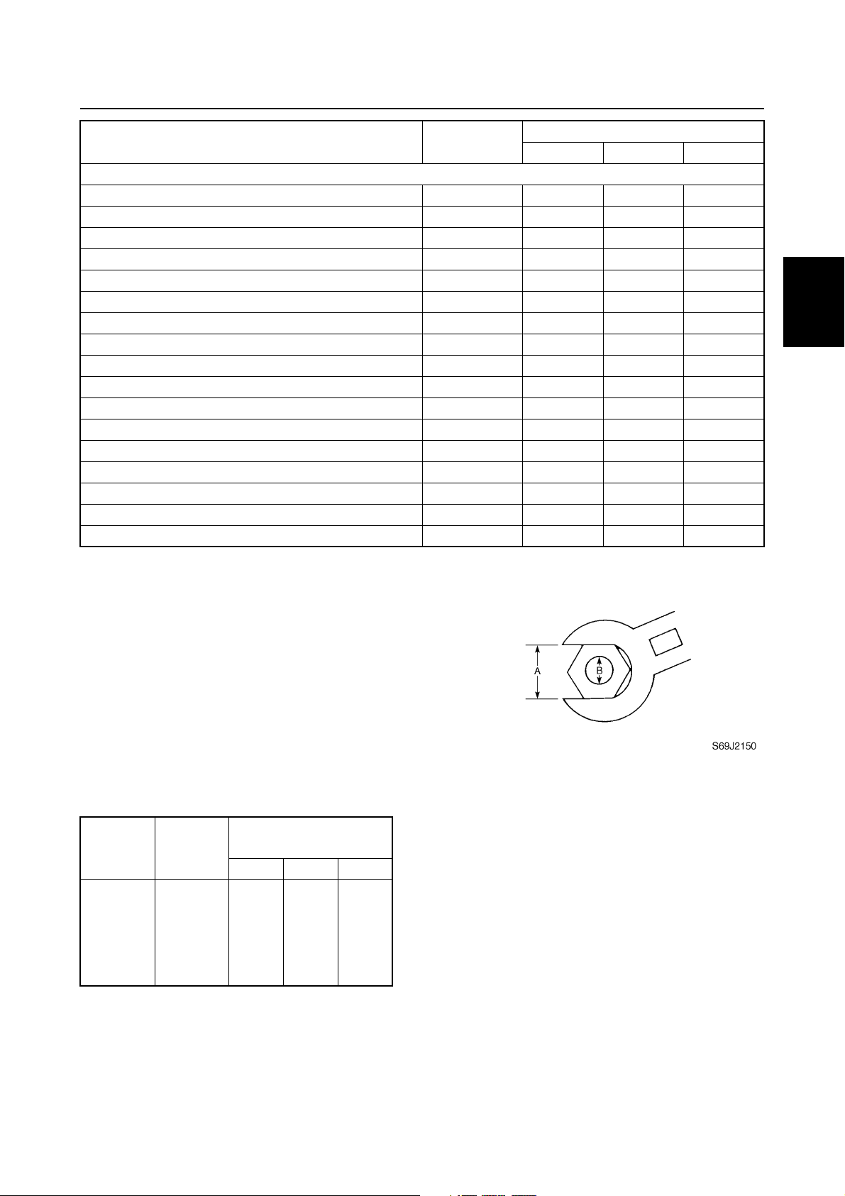
General torques
This chart specifies tightening torques for
standard fasteners with a standard ISO
thread pitch. Tightening torque specifications
for special components or assemblies are
provided in applicable sections of this manual. To avoid warpage, tighten multi-fastener
assemblies in a crisscross fashion and progressive stages until the specified torque is
reached. Unless otherwise specified, torque
specifications require clean, dry threads.
Components should be at room temperature.
General torque
Nut (A) Bolt (B)
8 mm M5 5 0.5 3.6
10 mm M6 8 0.8 5.8
12 mm M8 18 1.8 13
14 mm M10 36 3.6 25
17 mm M12 43 4.3 31
specifications
N·mkgf·mft·lb
5
6
7
8
9
66T5F11
2-10

SPEC
Specifications
— MEMO —
2-11
66T5F11

CHK
ADJ
Periodic checks and adjustments
Special service tools ………………………………………………………………………….3-1
Maintenance interval chart………………………………………………………………….3-2
Top cowling ……………………………………………………………………………………….3-3
Checking the top cowling…………………………………………………………………3-3
Fuel system ……………………………………………………………………………………….3-3
Checking the fuel joint and fuel hoses (fuel joint-to-carburetor) …………….3-3
Checking the fuel filter …………………………………………………………………….3-3
Power unit………………………………………………………………………………………….3-3
Checking the spark plugs ………………………………………………………………..3-3
Checking the thermostat………………………………………………………………….3-4
Adjusting the start-in-gear protection…………………………………………………3-4
Checking the cooling water passage…………………………………………………3-5
Control system…………………………………………………………………………………..3-5
Adjusting the ignition timing……………………………………………………………..3-5
Adjusting the throttle cables (MH, WH) ……………………………………………..3-6
Adjusting the throttle cable (W) ………………………………………………………..3-7
Checking the gear shift operation (MH, WH)………………………………………3-8
Checking the gear shift operation (W) ……………………………………………….3-8
Checking the engine idle speed ……………………………………………………….3-9
Checking the ignition timing……………………………………………………………3-10
1
2
3
4
5
Bracket…………………………………………………………………………………………….3-10
Checking the tilt operation ……………………………………………………………..3-10
Lower unit………………………………………………………………………………………..3-11
Checking the gear oil level …………………………………………………………….3-11
Changing the gear oil ……………………………………………………………………3-11
Checking the lower unit for air leakage ……………………………………………3-12
Checking the propeller…………………………………………………………………..3-12
General…………………………………………………………………………………………….3-12
Checking the anodes…………………………………………………………………….3-12
Checking the battery……………………………………………………………………..3-12
Lubricating the outboard motor……………………………………………………….3-13
6
7
8
9
66T5F11
CHK
ADJ
Periodic checks and adjustments
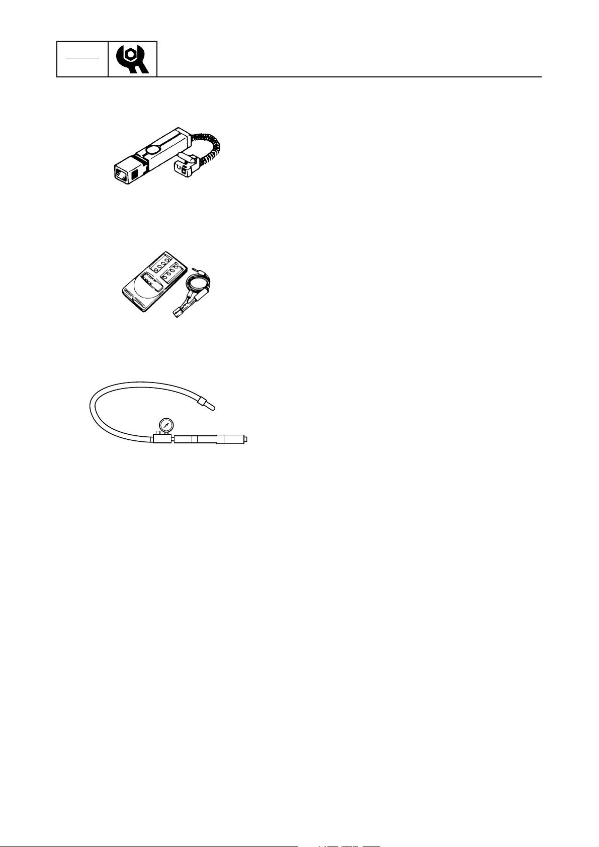
Special service tools
Timing light
90890-03141
Digital tachometer
90890-06760
3
Leakage tester
90890-06840
3-1
66T5F11
Special service tools / Maintenance interval chart
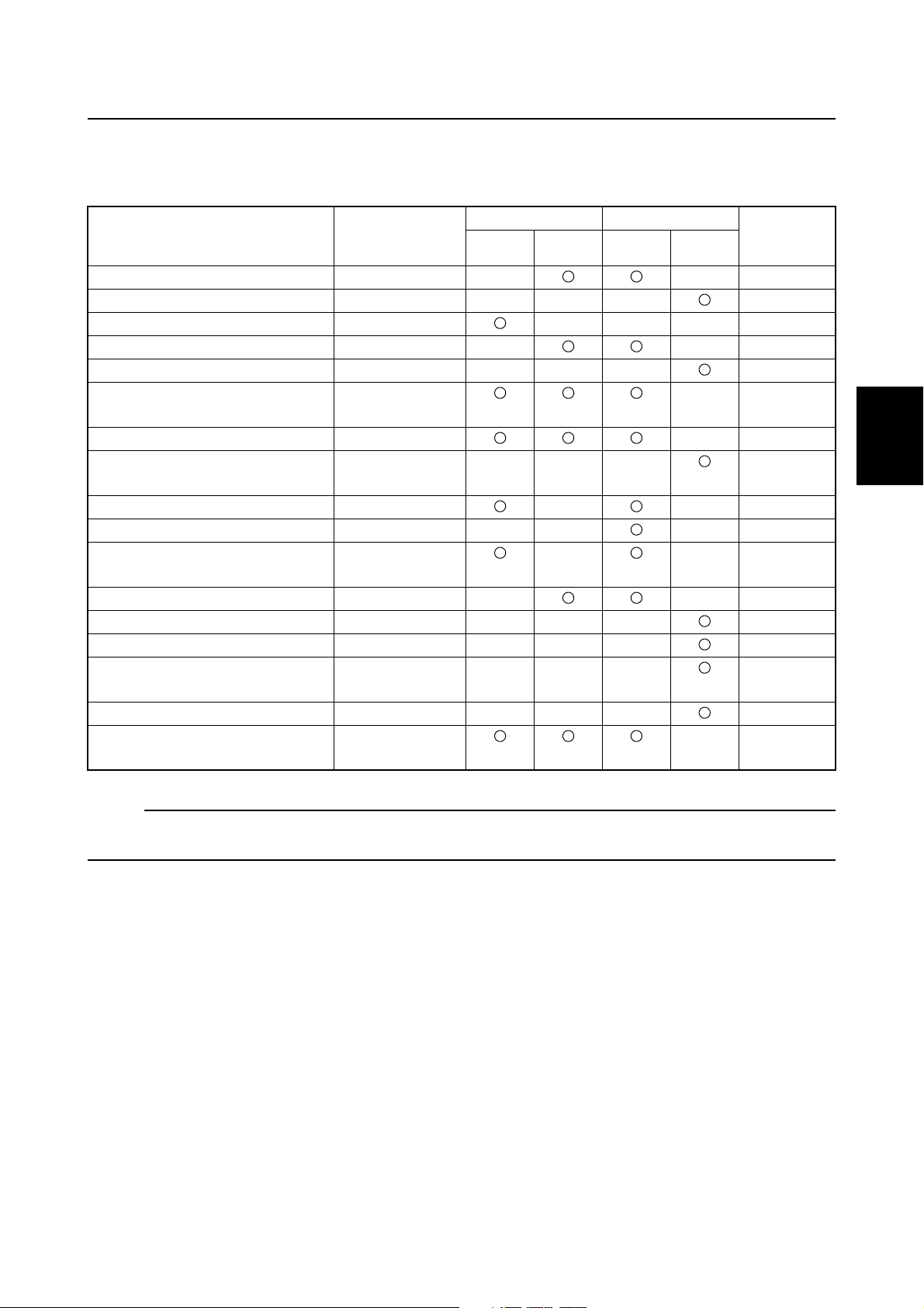
Maintenance interval chart
Use the following chart as a guideline for general maintenance.
Adjust the maintenance intervals according to the operating conditions of the outboard motor.
Item Remarks
Anodes (external) Check/replace
Anodes (internal) Check/replace
Battery Check/charge
Cooling water passages Clean
Top cowling Check
Fuel filter
(can be disassembled)
Fuel system Check
Fuel tank
(Yamaha portable tank)
Gear oil Change
Lubrication points Lubricate
Engine idle speed
(carburetor models)
Propeller and cotter pin Check/replace
Shift link/shift cable Check/adjust
Thermostat Check
Throttle link/throttle cable/
throttle pick-up timing
Water pump Check
Spark plugs Clean/adjust/
Check/replace
Check/clean
Check/adjust
Check/adjust
replace
Initial Every
10 hours
(1 month)
50 hours
(3 months)
100 hours
(6 months)
200 hours
(1 year)
Refer to
page
3
1
2
3
4
5
6
NOTE:
When operating in salt water, turbid or muddy water, the engine should be flushed with clean water
after each use.
66T5F11
3-2
7
8
9
CHK
ADJ
Periodic checks and adjustments
Top cowling
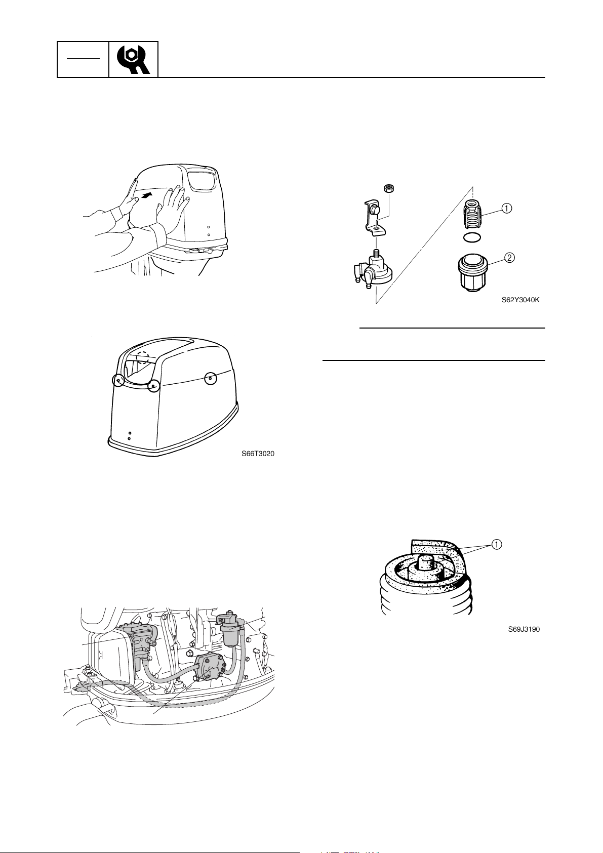
Checking the top cowling
1. Check the fitting by pushing the cowling
with both hands.
S66T3010
2. Check the water separator drain holes for
obstructions. Clean if necessary.
3
Checking the fuel filter
1. Check the fuel filter element 1 for dirt
and residue and check the fuel filter cup
2
for foreign substances and cracks.
Clean the cup with straight gasoline and
replace the element if necessary.
NOTE:
Be sure not to spill any fuel when removing
the fuel filter cup.
Fuel system
Checking the fuel joint and fuel
hoses (fuel joint-to-carburetor)
1. Check the fuel hose connections and fuel
joints for leaks. Replace if necessary.
Also, check the fuel filter 1, fuel pump
2
, and carburetor 3 for leaks or deterio-
ration. Replace if necessary.
1
3
Power unit
3
Checking the spark plugs
1. Disconnect the spark plug caps, and then
remove the spark plugs.
2. Clean the electrodes 1 with a spark plug
3
cleaner or wire brush. Replace the spark
plug if necessary.
3. Check the electrodes for erosion and
excessive carbon or other deposits, and
the gasket for damage. Replace the
spark plug if necessary.
3-3
2
S66T3030
4. Check the spark plug gap a. Adjust if out
of specification.
66T5F11
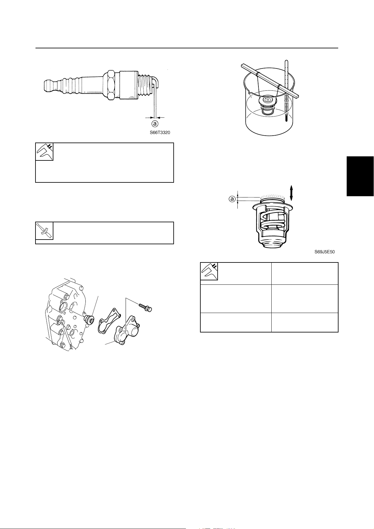
Specified spark plug:
B7HS (NGK), BR7HS (NGK)
Spark plug gap a:
0.6–0.7 mm (0.024–0.028 in)
5. Install the spark plugs, tighten them finger tight, then to the specified torque
using a spark plug wrench.
Top cowling / Fuel system / Power unit
1
S69J5E40
2
4. Check the thermostat valve opening at
the specified water temperatures.
Replace if out of specification.
3
Spark plug:
T
.
R
.
25 N·m (2.5 kgf·m, 18.4 ft·lb)
Checking the thermostat
1. Remove the cover 1 and thermostat 2.
2
1
2. Suspend the thermostat in a container of
water.
3. Place a thermometer in the water and
slowly heat the water.
S66T3040
Water
temperature
48–52 °C
(118–126 °F)
above
60 °C (140 °F)
5. Install the thermostat and cover, and
then tighten the cover bolts.
Adjusting the start-in-gear
protection
1. Set the gear shift to the neutral position.
Valve lift a
0.05 mm
(0.0020 in)
(valve begins to lift)
more than
3.0 mm (0.12 in)
4
5
6
7
8
66T5F11
9
3-4
CHK
ADJ
Periodic checks and adjustments
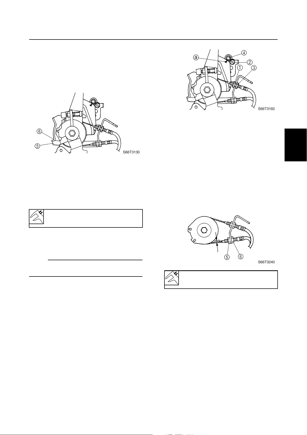
2. Loosen the lock nut 1, and then adjust
the start-in-gear protection adjusting nut
2
until the point a on the wire connector
aligned with the mark b on the manual
starter case.
Checking the cooling water passage
1. Check the cooling water inlet cover
and cooling water inlet for clogs. Clean if
necessary.
1
1
Control system
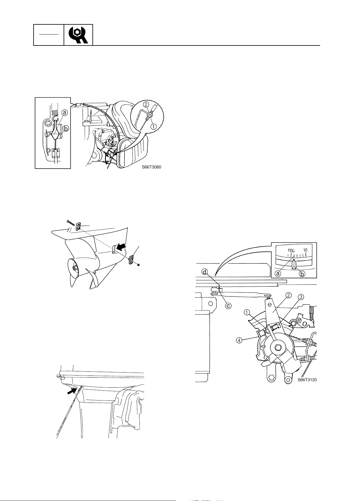
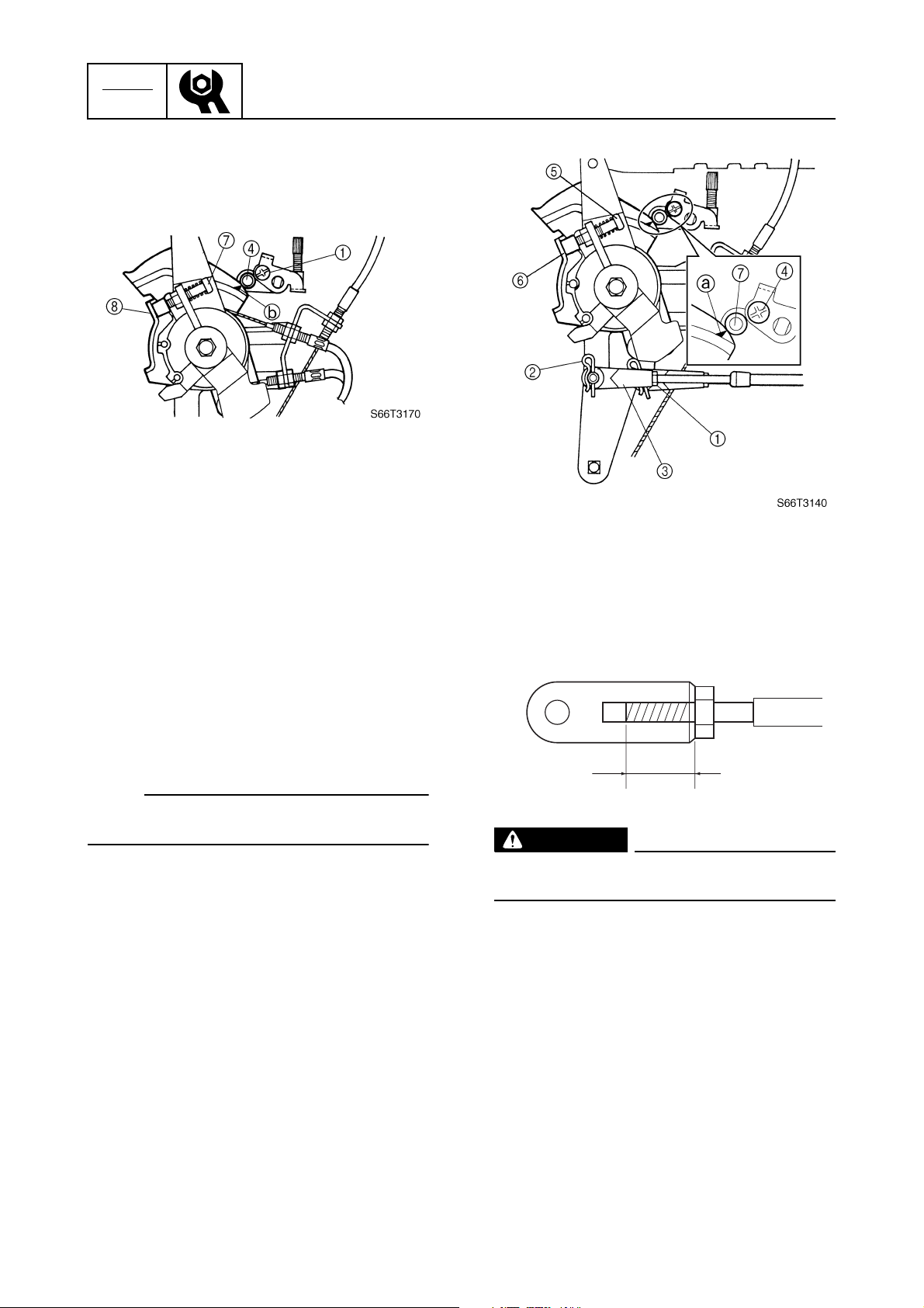
Adjusting the ignition timing
1. Make sure that the engine is stopped
before adjusting the ignition timing.
2. Loosen the throttle cables or remove the
remote control cable.
3. Turn the flywheel magnet clockwise so
that ATDC 2° line a aligns with the mark
b
on the manual starter case.
4. Loosen the locknut 1.
5. Turn the throttle control lever 2 so that
the full-retard screw 3 contacts the stopper 4.
6. Adjust the full-retard screw 3 so that the
timing indicator c aligns with the mark
d
on the flywheel magnet.
7. Tighten the locknut 1.
3
1
S66T3230
2. Place the lower unit in water, and then
start the engine.
3. Check for water flow at the cooling water
pilot hole. If there is no water flow, check
the cooling water passage inside the outboard motor.
8. Adjust the throttle cables or remote control cable.
3-5
S66T3050
66T5F11
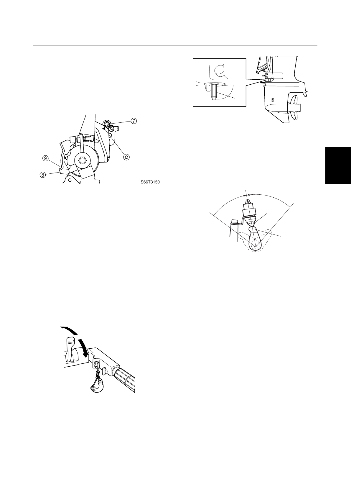
9. Shift the remote control lever or shift
lever to forward or reverse, and then
check that the stopper 5 on the throttle
control lever contacts the stopper 6 on
the throttle cable bracket when the throttle is fully open.
10. Start the engine and warm it up for 5 minutes.
11. Check the ignition timing with a timing
light and, if necessary, repeat steps 1–
10.
Power unit / Control system
1
2
6. Turn the throttle grip to the fully closed
position.
7. Loosen the locknut 5.
3
8. Contact the full-retard screw 7 to the
stopper 8, and then turn the adjusting
nut 6 in or out until the specified throttle
cable free play is obtained.
4
9. Tighten the locknut 5.
Ignition timing at engine idle speed:
ATDC 2°
Adjusting the throttle cables
(MH, WH)
NOTE:
Before adjusting the throttle cables, the throttle stop screw should be properly adjusted.
1. Loosen the locknut 1.
2. Loosen the throttle-cam-roller adjusting
screw (left-hand threads) 2.
3. Turn the throttle grip to the fully open
position.
4. Adjust the throttle cable adjusting nut
until the center of the throttle cam roller
4
aligns with the mark a on the throttle
cam.
3
5
6
Throttle cable free play:
1 mm (0.04 in)
7
8
9
5. Tighten the locknut.
66T5F11
3-6
CHK
ADJ
10. Align the center of the throttle cam roller
4
with the mark b on the throttle cam,
and then tighten the throttle-cam-roller
adjusting screw 1.
11. Check that the center of the throttle cam
roller 4 aligns with the mark a on the
throttle cam when the throttle grip is
turned to the fully open position.
12. Check that the full-retard screw 7 contacts the stopper 8 and that the center of
the throttle cam roller 4 is aligned with
the mark b on the throttle cam when the
throttle grip is turned to the fully closed
position.
Periodic checks and adjustments
5. Adjust the position of the throttle cable
joint until its hole is aligned with the set
pin on the throttle control lever.
13. If necessary, repeat steps 1–12.
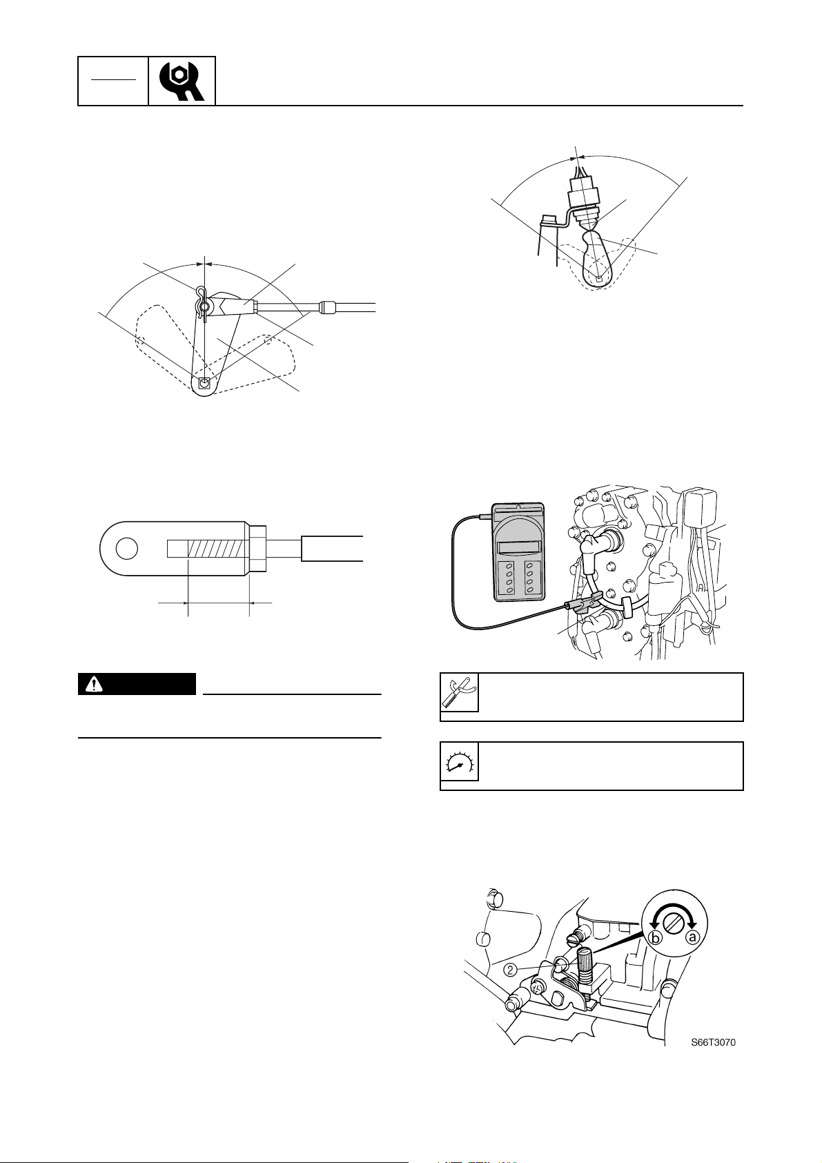
Adjusting the throttle cable (W)
NOTE:
Before adjusting the throttle cable, the throttle stop screw should be properly adjusted.
1. Loosen the locknut 1, remove the clip
2
, and then disconnect the throttle cable
joint 3.
2. Set the remote control lever to the neutral position.
3. Loosen the throttle-cam-roller adjusting
screw (left-hand threads) 4.
4. Check that the full-retard screw 5 contacts the stopper 6 and that the center of
the throttle cam roller 7 is aligned with
the mark a on the throttle cam.
b
S66T1050
WARNING
The throttle cable joint must be screwed
in a minimum of 8.0 mm (0.31 in) b.
6. Connect the cable joint, install the clip,
and then tighten the locknut.
7. Align the center of the throttle cam roller
7
with the mark a on the throttle cam,
and then tighten the throttle-cam-roller
adjusting screw 4.
3-7
66T5F11
8. Check that the stopper 8 on the throttle
control lever contacts the stopper 9 on
the throttle cable bracket and that the
center of the throttle cam roller 7 is
aligned with the mark c on the throttle
cam when the remote control lever is
fully open position.
Control system
1
S66T3290
2. Set the gear shift to the neutral position.
3. Check that the neutral switch lever 2 on
the shift lever assembly is pushing the
neutral switch 3. (WH)
N
1
2
3
9. Check that the full-retard screw 5 contacts the stopper 6 and that the center of
the throttle cam roller 7 is aligned with
the mark a on the throttle cam when the
remote control lever is fully closed position.
10. If necessary, repeat steps 1–9.
Checking the gear shift operation
(MH, WH)
1. Check that the gear shift operates
smoothly when shifting it from neutral to
forward or reverse. Adjust the adjusting
nut 1 if necessary.
R
N
F
R
F
Checking the gear shift operation
(W)
1. Check that the gear shift operates
smoothly when shifting it from neutral to
forward or reverse. Adjust the shift cable
length if necessary.
2. Set the gear shift to the neutral position.
3
2
S66T3260
4
5
6
7
8
66T5F11
S66T3250
9
3-8
CHK
ADJ
3. Loosen the locknut 1, remove the clip
2
, and then disconnect the shift cable
joint 3.
4. Set the shift lever 4 to the neutral position.
Periodic checks and adjustments
N
R
F
6
23
R
N
F
1
4
S66T3220
5. Adjust the position of the shift cable joint
until its hole is aligned with the set pin.
a
S6D53190
5
S66T3270
Checking the engine idle speed
1. Start the engine and warm it up for 5 minutes.
2. Attach the special service tool to spark
plug wire #1 1, and then check the
engine idle speed. Adjust if out of specification.
1
S66T3060
WARNING
The shift cable joint must be screwed in a
minimum of 8.0 mm (0.31 in) a.
6. Connect the cable joint, install the clip,
and then tighten the locknut.
7. Check the gear shift for smooth operation
and, if necessary, repeat steps 2–6.
8. Check that the neutral switch lever on the
shift lever assembly 5 is pushing the
neutral switch 6. (if equipped)
Digital tachometer: 90890-06760
Engine idle speed: 950–1,050 r/min
3. Turn the throttle stop screw 2 in direction a or b until the specified engine
idle speed is obtained.
3-9
66T5F11
Control system / Bracket
NOTE:
• To increase the idle speed, turn the throttle
stop screw in direction a.
• To decrease the idle speed, turn the throttle
stop screw in direction b.
4. If the specified engine idle speed cannot
be obtained, adjust the throttle cable(s).
Checking the ignition timing
1. Start the engine and warm it up for 5 min-
utes.
2. Attach the special service tool to spark
plug wire #1 1, and then check the
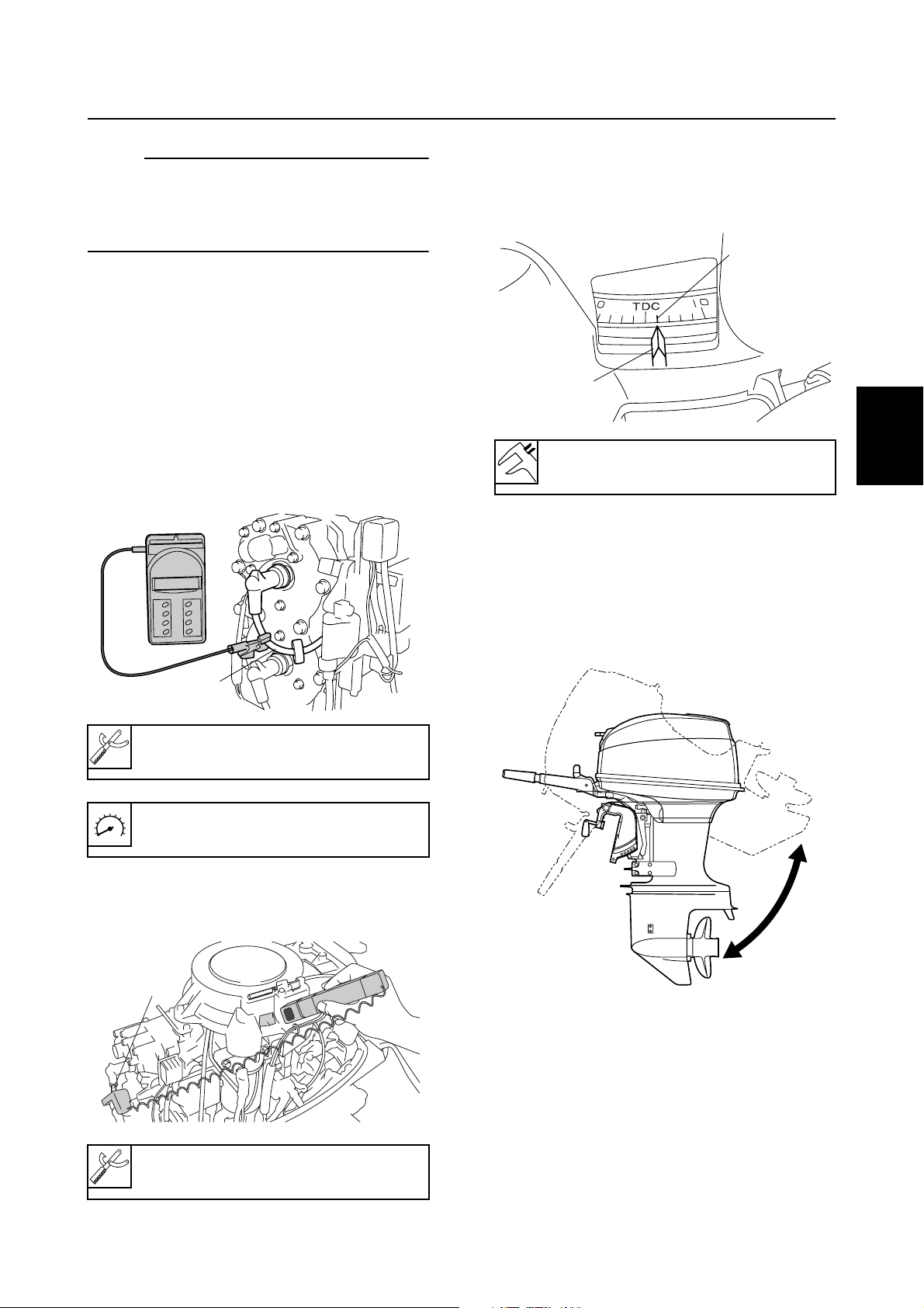
engine idle speed.
4. Check that the ATDC 2° line a on the
flywheel magnet is aligned with the mark
b
on the manual starter case. Adjust if
out of specification.
a
b
S66T3100
Ignition timing at engine idle speed:
ATDC 2°
Bracket
Checking the tilt operation
1. Fully tilt the outboard motor up and down
a few times and check the entire tilt
range for smooth operation.
1
2
3
3
4
1
S66T3060
Digital tachometer: 90890-06760
Engine idle speed: 950–1,050 r/min
3. Attach the special service tool to spark
plug wire #1 1.
1
S66T3090
5
6
7
8
S66T3300
9
66T5F11
Timing light: 90890-03141
3-10
CHK
ADJ
Periodic checks and adjustments
Lower unit
Checking the gear oil level
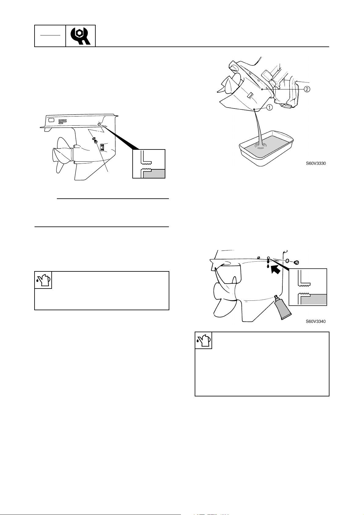
1. Fully tilt the outboard motor down.
2. Remove the check screw 1, and then
check the gear oil level in the lower case.
1
S60V3320
NOTE:
If the oil is at the correct level, the oil should
overflow out of the check hole when the
check screw is removed.
3. If necessary, add sufficient gear oil of the
recommended type until it overflows out
of the check hole.
3
3. Check the oil for metal and discoloration,
and its viscosity. Check the internal parts
of the lower case if necessary.
4. Insert a gear oil tube or gear oil pump
into the drain hole and slowly fill the gear
oil until oil flows out of the check hole and
no air bubbles are visible.
Recommended gear oil:
Hypoid gear oil
API: GL-4
SAE: 90
4. Install the check screw.
Changing the gear oil
1. Tilt the outboard motor up slightly.
2. Place a drain pan under the drain screw
1
, remove the drain screw, then the
check screw 2 and let the oil drain completely.
Recommended gear oil:
Hypoid gear oil
API: GL-4
SAE: 90
Oil quantity:
430 cm
3
(14.54 US oz, 15.17 Imp oz)
5. Install the check screw and quickly install
the drain screw.
3-11
66T5F11
Lower unit / General
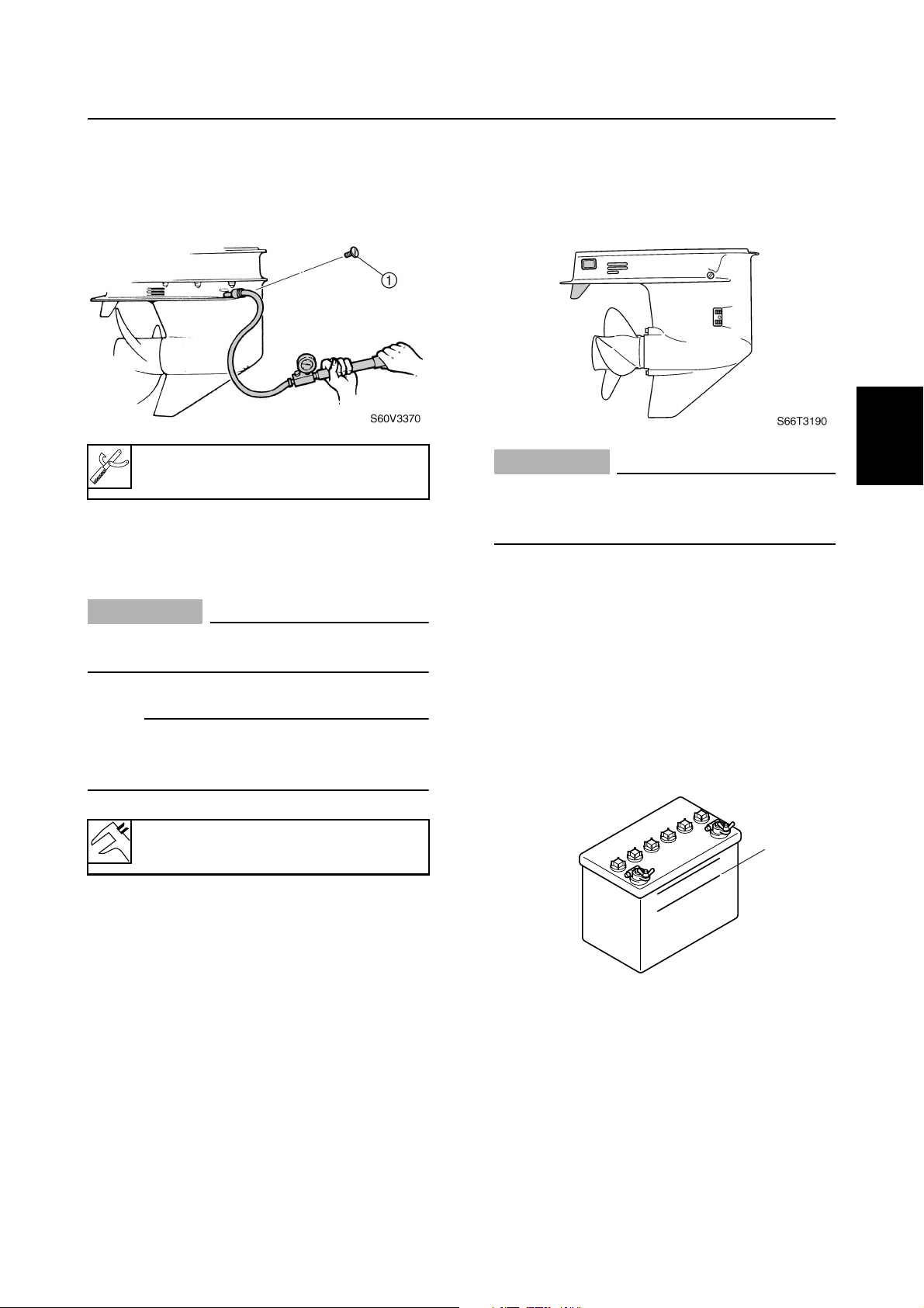
Checking the lower unit for air
leakage
1. Remove the check screw 1, and then
install the special service tool.
Leakage tester: 90890-06840
2. Apply the specified pressure to check
that the pressure is maintained in the
lower unit for at least 10 seconds.
CAUTION:
Do not over pressurize the lower unit, otherwise the oil seals can be damaged.
NOTE:
Cover the check hole with a rag when removing the special service tool from the lower
unit.
General
Checking the anodes
1. Check the anodes and trim tab for
scales, grease, or oil. Clean if necessary.
CAUTION:
Do not oil, grease, or paint the anodes or
the trim tab, otherwise they will be ineffective.
2. Replace the anodes or trim tab if excessively eroded.
Checking the battery
1. Check the battery electrolyte level. If the
level is at or below the minimum level
mark a, add distilled water until the level
is between the maximum and minimum
level marks.
3
1
2
3
4
5
6
Lower unit holding pressure:
100 kPa (1.0 kgf/cm
3. If pressure drops below specification,
check the drive shaft and propeller shaft
oil seals for damage.
Checking the propeller
1. Check the propeller blades and splines
for cracks, damage, or wear. Replace if
necessary.
66T5F11
2
, 14 psi)
a
7
S69J3620
8
9
3-12
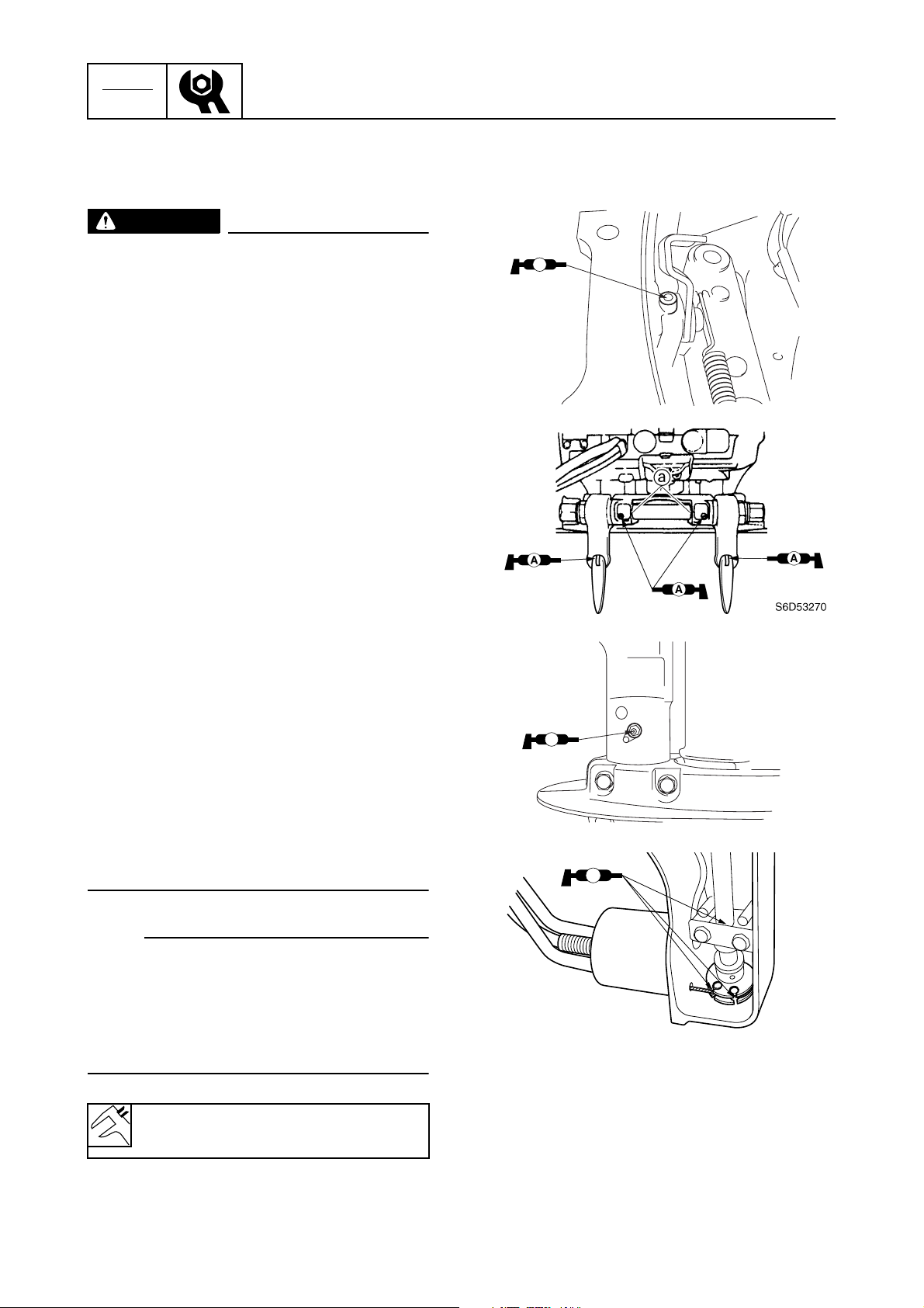
CHK
ADJ
Periodic checks and adjustments
2. Check the specific gravity of the electrolyte. Fully charge the battery if below
specification.
WARNING
Battery electrolyte is dangerous; it contains sulfuric acid which is poisonous and
highly caustic.
Always follow these preventive measures:
• Avoid bodily contact with electrolyte as
it can cause severe burns or permanent
eye injury.
• Wear protective eye gear when handling
or working near batteries.
Antidote (EXTERNAL):
• SKIN – Wash with water.
• EYES – Flush with water for 15 minutes
and get immediate medical attention.
Antidote (INTERNAL):
• Drink large quantities of water or milk
followed with milk of magnesia, beaten
egg, or vegetable oil. Get immediate
medical attention.
Batteries generate explosive, hydrogen
gas. Always follow these preventive measures:
• Charge batteries in a well-ventilated
area.
• Keep batteries away from fire, sparks or
open flames (e.g., welding equipment,
lighted cigarettes).
• DO NOT SMOKE when charging or han-
dling batteries.
KEEP BATTERIES AND ELECTROLYTE
OUT OF REACH OF CHILDREN.
Lubricating the outboard motor
1. Apply water resistant grease to the areas
shown.
AA
S66T3200
AA
S66T3210
È
A
NOTE:
• Batteries vary per manufacturer. The procedures mentioned in this manual may not
always apply, therefore, consult the instruction manual of the battery.
• Disconnect the negative battery lead first,
then the positive battery lead.
Electrolyte specific gravity:
1.280 at 20 °C (68 °F)
3-13
S6D53290
66T5F11
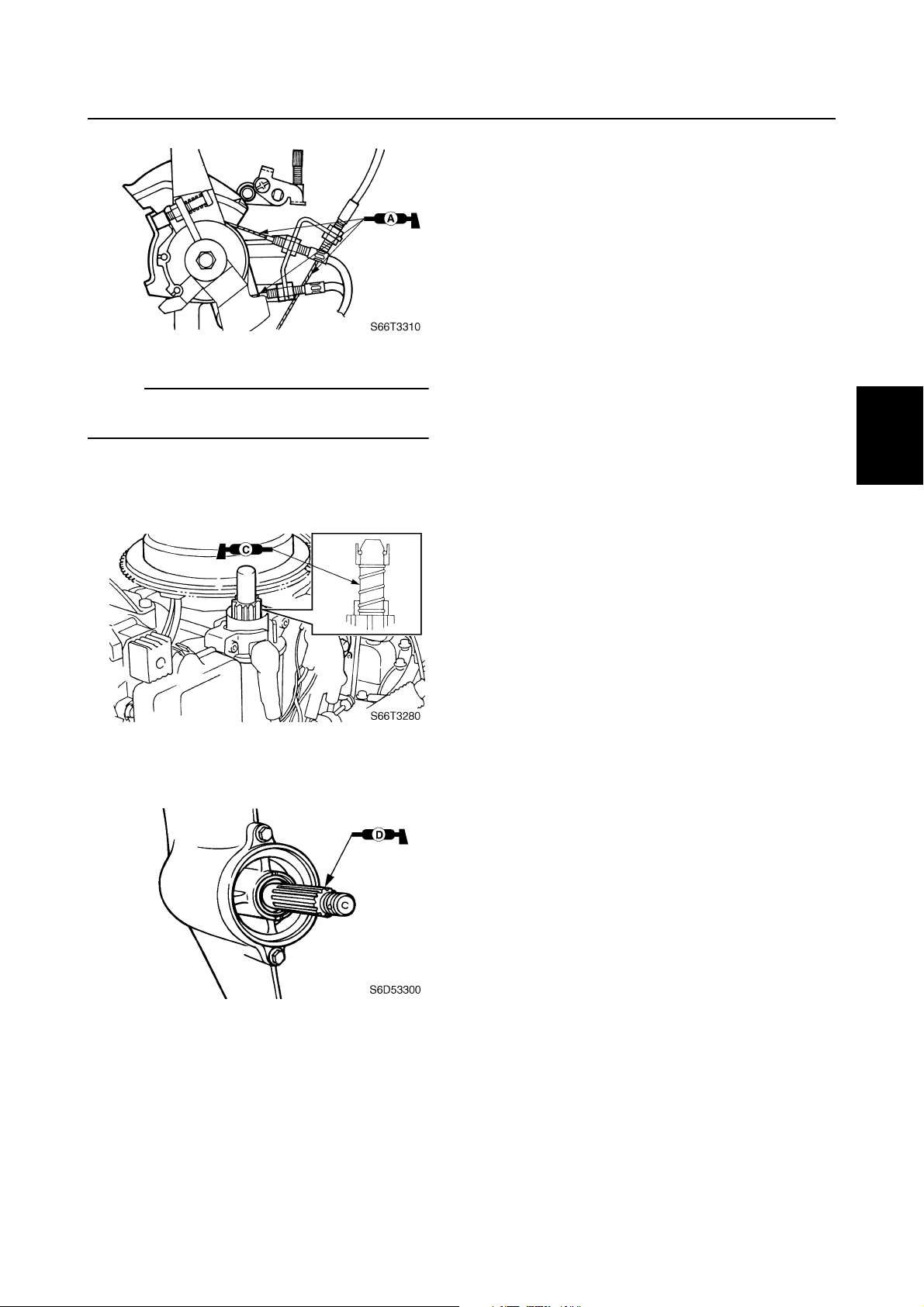
È
Tiller handle model
È
NOTE:
Apply grease to the grease nipples until it
flows from the bushings a.
2. Apply low temperature resistant grease
to the area shown.
General
1
2
3
3. Apply corrosion resistant grease to the
area shown.
4
5
6
7
8
66T5F11
9
3-14

CHK
ADJ
Periodic checks and adjustments
— MEMO —
3-15
66T5F11

FUEL
Fuel system
Special service tools ………………………………………………………………………….4-1
Hose routing………………………………………………………………………………………4-2
Fuel line …………………………………………………………………………………………….4-3
Fuel pump………………………………………………………………………………………….4-5
Checking the fuel pump…………………………………………………………………..4-6
Disassembling the fuel pump …………………………………………………………..4-6
Assembling the fuel pump ……………………………………………………………….4-7
Checking the fuel joint …………………………………………………………………….4-7
Carburetor………………………………………………………………………………………….4-8
Disassembling the carburetor…………………………………………………………4-10
Checking the carburetor ………………………………………………………………..4-10
Assembling the carburetor……………………………………………………………..4-11
Adjusting the throttle stop screw……………………………………………………..4-11
1
2
3
4
5
6
7
8
9
66T5F11

FUEL
Fuel system
Special service tools
Vacuum/pressure pump gauge set
90890-06756
4
4-1
66T5F11
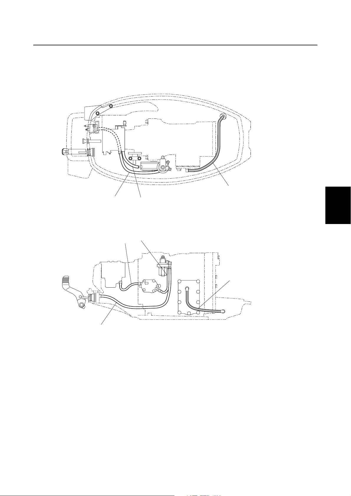
Special service tools / Hose routing
Hose routing
1
4
1
2
3
4
3
4
1
Fuel hose (fuel joint-to-fuel filter)
1
Fuel hose (fuel filter-to-fuel pump)
2
Fuel hose (fuel pump-to-carburetor)
3
Pilot water hose
4
3
2
5
4
6
7
S66T4010
8
66T5F11
9
4-2
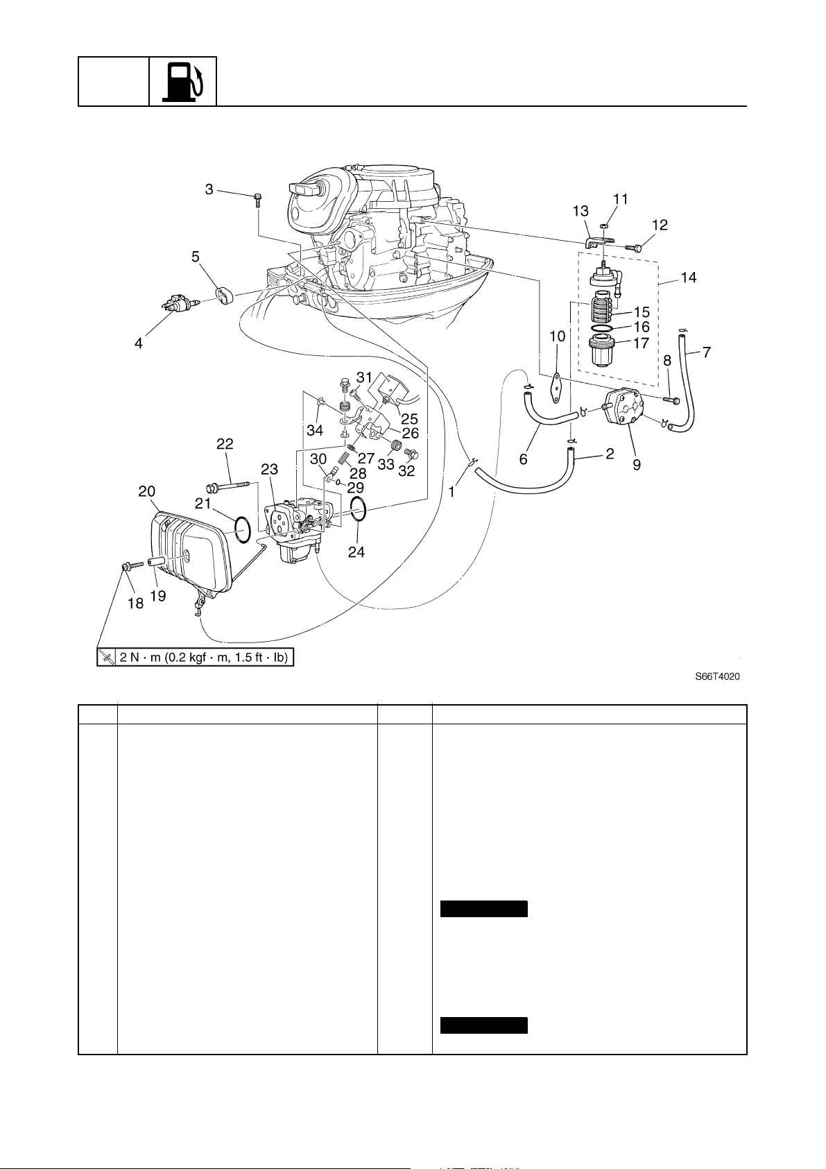
FUEL
Fuel system
Fuel line
4
No. Part name Q’ty Remarks
1 Clamp 6
2 Fuel hose 1
3Bolt 1 M6 × 30 mm
4 Fuel joint 1
5Grommet 1
6 Fuel hose 1
7 Fuel hose 1
8Bolt 2 M6 × 40 mm
9 Fuel pump 1
10 Gasket 1
11 Nut 1
12 Bolt 1 M6 × 14 mm
13 Bracket 1
14 Fuel filter assembly 1
15 Fuel filter element 1
16 O-ring 1
17 Cup 1
Not reusable
Not reusable
4-3
66T5F11
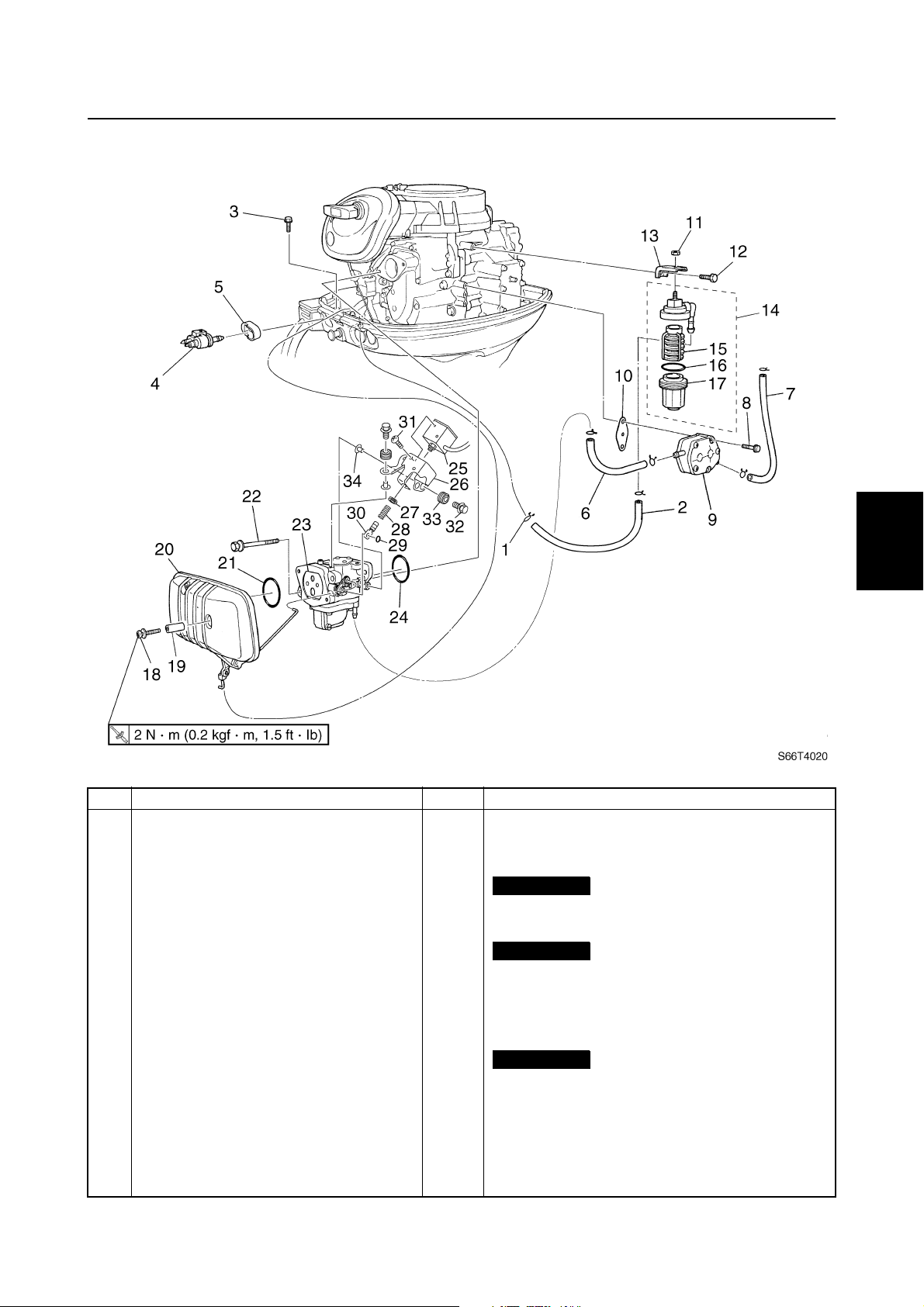
Fuel line
4
1
2
3
No. Part name Q’ty Remarks
18 Screw 2 ø6 × 40 mm
19 Collar 2
20 Intake silencer 1
21 O-ring 1
22 Bolt 2 M8 × 100 mm
23 Carburetor 1
24 O-ring 1
25 Solenoid coil 1 W model
26 Bracket 1 W model
27 Grommet 1 W model
28 Spring 1 W model
29 O-ring 1
30 Hook 1 W model
31 Screw 4 W model
32 Bolt 3 M6 × 25 mm / W model
33 Grommet 3 W model
34 Collar 3 W model
Not reusable
Not reusable
Not reusable
W model
4
5
6
7
8
9
66T5F11
4-4
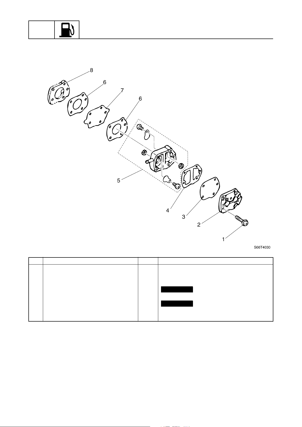
FUEL
Fuel system
Fuel pump
4
No. Part name Q’ty Remarks
1Screw 3 ø5 × 30 mm
2 Cover 1
3 Diaphragm 1
4Gasket 1
5 Fuel pump body assembly 1
6Gasket 2
7 Diaphragm 1
8 Cover 1
Not reusable
Not reusable
4-5
66T5F11
 Loading…
(Ocr-Read Summary of Contents of some pages of the Yamaha 40 Document (Main Content), UPD: 24 May 2023)
-
20, Basic components 15 EMU26090 Main switch The main switch controls the ignition system; its operation is described below. ● “” (off) With the main switch in the “” (off) posi- tion, the electrical circuits are off, and the key can be removed. ● “” (on) With the main switch in the “” (on) posi- tion, the electrical circuits are on, and the key cannot be removed. ● “” (start) With the main switch in the “” (start) …
-
44, Operation 39 4. Push the tilt support knob into the clamp bracket or pull the tilt support lever to- ward you to support the engine. WARNING EWM00260 After tilting the outboard motor, be sure to support it with the tilt support knob or tilt support lever. Otherwise the outboard motor could fall back down suddenly if oil in the power trim and tilt unit loses pres- sure. 5. Models equipped with trim rods: Once the outboard motor is supported with the tilt support lever, press the p…
-
27, Yamaha 40 Basic components 22 1. Oil filter ZMU03366 1 ✩✦✯✬✤✲✲✣ ✥✥
… -
68, Yamaha 40 Trouble Recovery 63 Q. Is fuel joint connection incorrect? A. Connect correctly. Q. Is heat range of spark plug incorrect? A. Inspect spark plug and replace it with rec- ommended type. Q. Is high pressure fuel pump drive belt bro- ken? A. Have serviced by a Yamaha dealer. Q. Is engine not responding properly to shift lever position? A. Have serviced by a Yamaha dealer. Engine vibrates excessively. Q. Is propeller damaged? A. Have propeller repaired or replaced. Q. …
-
34, Operation 29 EMU27321 Oil level indicator operation The various functions of the oil level system are as follows: EMU27350 Electric start models EMU27450 Operating engine EMU27461 Feeding fuel (portable tank) WARNING EWM00420 ● Before starting the engine, make sure that the boat is tightly moored and that you can steer clear of any obstructions. Be sure there are no swimmers in the water near you. ● W…
-
21, Basic components 16 EMU26151 Power trim and tilt switch on bottom engine cowling The power trim and tilt switch is located on the side of the bottom engine cowling. Press- ing the switch “” (up) trims the outboard motor up, then tilts it up. Pressing the switch “” (down) tilts the outboard motor down and trims it down. When the switch is re- leased, the outboard motor will stop in its current posit…
-
17, Basic components 12 EMU26201 Neutral interlock trigger To shift out of neutral, first pull the neutral in- terlock trigger up. EMU26211 Neutral throttle lever To open the throttle without shifting into ei- ther forward or reverse, put the remote con- trol lever in the neutral position and lift the neutral throttle lever. NOTE: The neutral throttle lever will operate only when the remote control lever is in neutral. The remote control lever will operate only when the neutral th…
-
61, Yamaha 40 Maintenance 56 the screw before installing it. 4. Remove the oil level plug to allow the oil to drain completely. CAUTION: ECM00710 Inspect the used oil after it has been drained. If the oil is milky, water is getting into the gear case which can cause gear damage. Consult a Yamaha dealer for re- pair of the lower unit seals. NOTE: For disposal of used oil consult your Yamaha dealer. 5. With the outboard motor in a vertical po- sition, and using a flexible or pressur- ized…
-
56, Maintenance 51 Checkpoints ● Fuel system parts leakage ● Fuel line joint leakage ● Fuel line cracks or other damage ● Fuel connector leakage EMU28980 Inspecting fuel filter WARNING EWM00310 Gasoline is highly flammable, and its va- pors are flammable and explosive. ● If you have any question about properly doing this procedure, consult your Yamaha dealer. ● Do no…
-
37, Operation 32 EMU27662 Electric start and remote control models 1. Place the remote control lever in neutral. NOTE: The start-in-gear protection device prevents the engine from starting except when in neu- tral. 2. Attach the engine stop switch lanyard to a secure place on your clothing, or your arm or leg. Then install the lock plate on the other end of the lanyard into the en- gine s…
-
12, General information 7 EMU25540 Fueling instructions WARNING EWM00010 GASOLINE AND ITS VAPORS ARE HIGH- LY FLAMMABLE AND EXPLOSIVE! ● Do not smoke when refueling, and keep away from sparks, flames, or other sources of ignition. ● Stop engine before refueling. ● Refuel in a well-ventilated area. Refuel portable fuel tanks off the boat. ● Take care not to spill gasoline. If gaso- line spills, wipe it up immediately with ZMU01…
-
9, General information 4 EMU25401 Label WARNING EWM01260 ● Be sure shift control is in neutral before starting engine. (except 2HP) ● Do not touch or remove electrical parts when starting or during operation. ● Keep hands, hair, and clothes away from flywheel and other rotating parts while engine is running. EMU25500 Basic boating rules (Rules of the road) Just as there are rules which apply when you are drivin…
-
38, Operation 33 again. NOTE: ● When the engine is cold, it needs to be warmed up. For further information, see page 33. ● If the engine is warm and fails to start, open the throttle slightly and try to start the engine again. If the engine still fails to start, see page 60. EMU27670 Warming up engine EMU27702 Electric start and prime start models 1. After starting the engine, allow it to idle for 3 minutes to warm up. Failure to do so will shorten engine l…
-
73, Trouble Recovery 68 3. Drain the fuel from the carburetor, fuel filter, and fuel line. 4. Feed fogging oil or engine oil through the carburetor(s) and spark plug holes while cranking with the manual starter or emergency starter rope. 5. Take the outboard motor to a Yamaha dealer as soon as possible. CAUTION: ECM00400 Do not attempt to run the outboard motor until it has been completely inspec…
-
47, 42 Maintenance EMU28217 Specifications Dimension: Overall length: 40TR 646 mm (25.4 in) 50TR 670 mm (26.4 in) Overall width: 40TR 350 mm (13.8 in) 50TR 360 mm (14.2 in) Overall height L: 1319 mm (51.9 in) Transom height L: 533 mm (21.0 in) Weight (without propeller) L: 86.0 kg (190 lb) Performance: Full throttle operating range: 4500–5500 r/min Maximum output: 40TR 29.4 kW@5000 r/min (40 HP@…
-
6, 1 General information EMU25170 Identification numbers record EMU25182 Outboard motor serial number The outboard motor serial number is stamped on the label attached to the port side of the clamp bracket or the upper part of the swivel bracket. Record your outboard motor serial number in the spaces provided to assist you in ordering spare parts from your Yamaha dealer or for reference in case your outboard motor is sto- len. EMU25190 Key number …
-
36, Yamaha 40 Operation 31 gine stop switch. WARNING EWM00120 ● Attach the engine stop switch lanyard to a secure place on your clothing, or your arm or leg while operating. ● Do not attach the lanyard to clothing that could tear loose. Do not route the lanyard where it could become entan- gled, preventing it from functioning. ● Avoid accidentally pulling the lanyard during normal operation. Loss of en- gine power means the loss of most steering control. Also, without engine power,…
-
2, EMU25060 ZMU01690 Read this owner’s manual carefully before operating your outboard motor. 63B-9-1E Hyoshi 4/25/05 9:39 AM Page 2
… -
48, Maintenance 43 Spark plug: 25.0 Nm (18.4 ft-lb) (2.55 kgf-m) Propeller nut: 35.0 Nm (25.8 ft-lb) (3.57 kgf-m) EMU28222 Transporting and storing outboard motor WARNING EWM00690 ● Leaking fuel is a fire hazard. When transporting and storing the outboard motor, close the air vent screw and fuel cock to prevent fuel from leaking. ● USE CARE when transporting fuel tank, whether in a boat or car. ● DO …