-
Contents
-
Table of Contents
-
Troubleshooting
-
Bookmarks
Quick Links
Manual
This device is
compliant.
Related Manuals for Image Access WideTEK 36
Summary of Contents for Image Access WideTEK 36
-
Page 1
Manual This device is compliant. -
Page 2
File: WT36_OperationManual_M3.docx… -
Page 3
Image Access. All other trademarks are the property of their respective owners. Image Access reserves the right to change the described products, the specifications or documents at any time without prior notice. For the most recent version, always check our web site www.imageaccess.de… -
Page 4: Introduction
Dear Customer, We congratulate you on the acquisition of this innovative product from Image Access. We at Image Access are proud of the work we do; it is the result of our extremely high standards of production and stringent quality control.
-
Page 5: About This Manual
Note: Optional the WideTEK 36 can be delivered with an appropriate floor stand. It is recommended to always use the WideTEK 36 in combination with the floor stand. Section B Software. This section describes the integrated Scan2Net software. This section also describes the installation procedure for software options.
-
Page 6: Version History
Prev. chapter B.3.9 renumbered to B.3.10 October 2011 Chapter B.3.3, information about container format added. Update Technical Data. As an ENERGY STAR® Partner, Image Access has determined that this product meets the ENERGY STAR® guidelines for energy efficiency. Page 6 Manual…
-
Page 7: Table Of Contents
Scanning documents on light, thin paper material A.12.4 Scanning documents on normal or heavier paper A.13 Connecting an External Monitor …………….. 28 A.14 Powering up the WideTEK 36 …………….30 A.15 WideTEK 36 Touch Panel ……………… 30 A.15.1 Starting the WideTEK 36 from Stand-By Mode A.15.2 Turning-off the WideTEK 36 A.15.3…
-
Page 8
A.17.3 Lamp On / Off A.17.4 Exit Selftest A.17.5 Touch Adjust A.17.6 Touch Test A.17.7 Stitch Test A.17.8 EMV Test A.17.9 Sensor Test A.17.10 Shutdown Scanner A.18 Start Menu Screen ………………… 39 A.19 Output Control Screens ………………40 A.19.1 Output Control 1 A.19.1.1 Viewer Control A.19.1.2… -
Page 9
A.21.3 Format Control 3 A.21.3.1 Top edge A.21.3.2 Bottom edge A.21.3.3 Units A.21.3.4 Left edge A.21.3.5 Right edge A.22 File Control Screen ……………….. 54 A.22.1 JPEG A.22.2 TIFF A.22.3 A.22.4 A.23 Transport Control Screen ………………. 57 A.23.1 Start button A.23.2 Transport A.23.3 Scan mode… -
Page 10: Technical Data
B.3.5.4 Extended print parameters with iPF option installed B.3.5.5 Printing Enhancements with iPF option installed B.3.6 Output Option FTP Upload B.3.6.1 FTP Server B.3.7 Output Option Mail B.3.7.1 Mail Server B.3.7.2 Transaction mode interactive B.3.8 Output Option Network B.3.8.1 SMB Configuration B.3.9 Output Option Web B.3.9.1…
-
Page 11: Manual Page
Table of Pictures Picture 1: Minimum distances to the scanner …………..17 Picture 2: Transport box opened ………………19 Picture 3: Connectors at WideTEK 36 …………….20 Picture 4: Middle guide plate ………………..21 Picture 5: Allen head screw in slot hole …………….22 Picture 6: Removing the middle guide plate …………..22 Picture 7: Self locking nut on the bottom side of middle guide plate ………23…
-
Page 12
Table of Pictures, part 3 Picture 41: Ftp Server 2 ………………..43 Picture 42: Network parameters ………………44 Picture 43: Input a Network Address …………….44 Picture 44: Output Control 2 ……………….. 45 Picture 45: System events and sound files …………..45 Picture 46: Image Control 1 ………………… -
Page 13: Manual Page
Table of Pictures, part 3 Picture 81: Scan status window ………………78 Picture 82: Format screen ………………..79 Picture 83: Rectangle dragged with mouse …………..80 Picture 84: «Zoom in» result ………………..80 Picture 85: List of available clip size formats …………..80 Picture 86: Output options ………………..81 Picture 87: Output Option Save ………………82 Picture 88: Example for file name ………………82 Picture 89: Output Option Show ………………83…
-
Page 14: A Hardware
(Standard for Canada) EN 60950-1, Safety for Information Technology Equipment (European standard) General Notice This manual describes the functions of a complete equipped WideTEK 36 scanner. If your device is not equipped with all features, deviations are possible. Page 14…
-
Page 15: Safety Precautions
13. Always turn the power off and unplug the power cord from the wall receptacle before cleaning the scanner. 14. When cleaning, only use Image Access-approved cleaners. Do not use any type of solutions, abrasives, or acids such as acetone, benzene, kerosene, mineral spirits, ammonia, or nitric acid.
-
Page 16: Connecting To The Power Source
Connecting to the Power Source Before connecting the scanner to the electrical outlet check the following items: Ensure the electrical outlet is in perfect condition and that it is properly grounded. Ensure that the electrical outlet is equipped with a fuse with the proper capacity.
-
Page 17: Device Location
Do not operate the scanner in an area that has poor air circulation, and/or that is non- ventilated. Place the WideTEK 36 on a flat and solid base. The load bearing capacity of the base must correspond to the device weight.
-
Page 18: Maintenance
Ensure that no liquids will penetrate into the device housing. A.7.1 Touchscreen Before cleaning the touchscreen, switch the WideTEK 36 off and set the main power switch to position 0. The touchscreen can be cleaned with a micro fiber cloth.
-
Page 19: Content On Delivery
Content on Delivery The scanner is delivered in a wooden transport box. The transport box also contains the disassembled floor stand in a separate cardboard box and the paper catch basket. Picture 2: Transport box opened 1: Paper catch basket 2: Scanner 3: White Reference Target 4: Box with cable set, manuals, and accessories (2x Recovery Key) .
-
Page 20: Connectors On The Scanner
Connectors on the Scanner The connectors are positioned at the left side of the housing, as seen from the operators view (i.e. from the front of the scanner). Picture 3: Connectors at WideTEK 36 1: Power connector 2: Foot pedal connector…
-
Page 21: A.11 Adjusting The Middle Guide Plate
Tools: Allen wrench, size 2.5 mm The WideTEK 36, 42 and 48 wide format scanners contain an adjustable guide plate which holds the paper against the glass plate without touching it. The amount of contact pressure exerted by the guide plate is user configurable.
-
Page 22: Picture 5: Allen Head Screw In Slot Hole
With the 2.5 mm Allen wrench loosen the two Allen head screws slightly. Picture 5: Allen head screw in slot hole The screws are mounted in slot holes. This allows moving the metal ballast. If the metal ballast is moved all the way to the front or outer edge of the guide plate, the contact pressure is minimal.
-
Page 23: Picture 7: Self Locking Nut On The Bottom Side Of Middle Guide Plate
Place the middle guide plate upside down on the front side guide plate. Picture 7: Self locking nut on the bottom side of middle guide plate Use a 7 mm ring spanner wrench (not supplied) or a pair of pliers to loosen the self- locking nuts.
-
Page 24: Paper Transport Wings
A.12 Paper Transport Wings To ensure proper functionality of the stitching function, special paper transport wings have to be inserted. Each WideTEK 36 scanner comes with a set of two black paper transport wings. Note: For special document types, e.g. semi-transparent documents, a set of two white paper transport wings and a white guide plate are available.
-
Page 25: How To Insert The Paper Transport Wings
A.12.1 How to insert the Paper Transport Wings Hold the paper transport wing near the two small notches and carefully bend it slightly in the middle. Picture 10 shows how to hold the paper transport wing. Picture 10: Bending the paper transport wing First insert the end of the paper transport wing with notches at the front side of the guide plate.
-
Page 26: Position Of The Paper Transport Wings
A.12.2 Position of the Paper Transport Wings For best results the paper transport wings should be inserted at the guide plate at a position between six and seven inches (approx. 15 to 19 cm) from the center position of the document input. Picture 12 shows the position where the paper transport wings have to be inserted on the guide plate.
-
Page 27: Scanning Documents On Normal Or Heavier Paper
A.12.4 Scanning documents on normal or heavier paper For best results, when scanning documents on normal or heavier paper, the paper transport wings must be inserted at the backside of the paper guide plate. Insert every paper transport wing with the long end forward into the notch at the back of the guide plate.
-
Page 28: Connecting An External Monitor
A.13 Connecting an External Monitor The external monitor will be connected to the VGA connector of the mainboard inside the scanner. To locate the VGA connector it is necessary to remove the middle guide plate at first. Open the upper part of the scanner by releasing the snap locks (see Picture 9) at the left and right side of the housing.
-
Page 29: Picture 19: Guiding The Cable To The Connector
Position the signal cable nearby the VGA connector of the mainboard. Picture 19: Guiding the cable to the connector It is recommended to position the cable connector at its final position with the help of a second person. One person can assist from the back of the scanner finding the VGA connector while the second person inserts the cable into the connector.
-
Page 30: Powering Up The Widetek 36
When the WideTEK 36 is powered up by using the main power switch, the touch panel is illuminated in a dimmed mode and shows the stand-by screen. The stand-by screen shows the Image Access logo and the blinking message Touch screen to power up.
-
Page 31: Turning-Off The Widetek 36
To turn off the WideTEK 36, press and hold the Stop button on the touch panel. While the Stop button is held, a counter in the button shows the remaining time until the WideTEK 36 is powered down.
-
Page 32: Navigating Through The Screens
A.16 Navigating through the Screens Some of the screens show on the bottom line the buttons Returns to the former screen. Sometimes only the symbol < is displayed. Switches to the next logical screen, e.g. from Format Control 1 to Format Control 2.
-
Page 33: Self Test Mode
A.17 Self Test Mode While the start sequence is running the WideTEK 36 can be switched to self-test mode. Tapping on the touch panel at least three times starts the setup mode. After the start sequence is finished, the touch panel shows the Self Test 1 screen.
-
Page 34: Ip Address
A.17.1 IP Address Touch the control field IP Address. The touch panel changes to the Network setup screen. Picture 27: Network setup Touch on the line to be changed, e.g. the Address line. The touch panel shows: Picture 28: Numeric key pad Enter the new values.
-
Page 35: White Balance
A.17.2 White Balance Note: The paper transport wings must be inserted before starting the white balance. Touch the White Balance button to start the white balance measurement sequence. Now insert the control sheet. It must be transported forward and reverse. Then touch the Cont. button.
-
Page 36: Picture 32: Testing The Touch Screen
A.17.5 Touch Adjust This function defines the dimension of the writing area of the touch panel. The first step after selecting this function must be done very quickly to activate the adjustment procedure. Note: It is recommended to read first, and then act. It is recommended to use for the following adjustment steps an appropriate pen, e.g.
-
Page 37: Picture 33: Stitch Test Screen
A.17.7 Stitch Test Picture 33: Stitch Test screen Press the Stitch Test button to start the stitch test. This starts a program in which you can see an automatically updated view of the stitching indicators for each camera. The measurement will be executed continuously, once every second. The cameras left, middle and right are identified as the left, middle and right cameras when looking at the scanner from the operator’s view (i.e.
-
Page 38: Picture 34: Sensor Status
No paper detected by the sensors. Paper detected at input side (PWT). Paper detected at input side (PWT) and at output side (POT). Picture 34: Sensor status A.17.10 Shutdown Scanner Touch this button to switch the WideTEK 36 scanner off. Page 38 Manual…
-
Page 39: Picture 35: Start Menu Screen
A.18 Start Menu Screen Picture 35: Start menu screen When all initial tests are finished, the display shows the start menu screen. At the top of the start menu, the main controls to start a scan sequence and to stop the current action are displayed.
-
Page 40: Picture 37: Output Control 1
Picture 37: Output Control 1 A.19.1.1 Viewer Control An external monitor can be connected to the WideTEK 36 to show the scanned image directly. Touching the Viewer Control button starts the Zoom/Move Control mode. When this mode is active, the displayed image on the screen can be moved and the zoom factor can be changed.
-
Page 41: Picture 39: E-Mail Address Parameters
A.19.1.2 Email Address This menu item enables the user to send the scanned image to any arbitrary e-mail address. Stores all parameters. Erases all changes. Picture 39: E-mail address parameters How to enter an E-mail address Tap on the line of the e-mail address. The screen changes to input mode as shown in Picture 23 and Picture 24.
-
Page 42: Picture 40: Ftp Server 1
A.19.1.3 FTP Server The Ftp Server button enables the user to enter all necessary information for data transfer to a dedicated FTP server. The parameters are entered in two screens named Ftp Server 1 and Ftp Server 2. Ftp Server 1 This screen contains the server IP address and the port, the user name and the password for the server access.
-
Page 43: Picture 41: Ftp Server 2
Ftp Server 2 This screen contains all data for the connection with a FTP server. Stores all parameters. Erases all changes. Picture 41: Ftp Server 2 Use proxy Select Yes to use a proxy server for the connection. Auth. Defines the type of authentication at the FTP server. By tapping on the field the methods will be switched.
-
Page 44: Picture 42: Network Parameters
A.19.1.4 Windows Network Allows the user to • define the network path where the image should be stored, • the define the authentication method, • define the user name, • define the password, • define the filename Picture 42: Network parameters To store all entries of this menu touch the button How to enter a Network Address Picture 43: Input a Network Address…
-
Page 45: Picture 44: Output Control 2
A.19.2 Output Control 2 Picture 44: Output Control 2 A.19.2.1 Sound Control The menu item Sound Control allows the user to link sounds to system events. Picture 45: System events and sound files To select a system event, touch the scroll bar in the left window or the up/down arrows. The currently selected sound file associated with this system event will be displayed in the right window.
-
Page 46: Picture 46: Image Control 1
A.20 Image Control Screen The parameters are set in two screens, Image Control 1 and Image Control 2. A.20.1 Image Control 1 Picture 46: Image Control 1 In general: • Tap on + or – to change the values in steps of one. •…
-
Page 47: A.20.1.4 Sharpness
A.20.1.4 Sharpness An automatic sharpening algorithm is applied to the image before any other operation is performed. The value zero disables the function. Very high values may produce artifacts, depending on the document characteristics. A.20.1.5 Resolution This parameter defines the scanner’s resolution. This button offers three ways to set the desired value: •…
-
Page 48: Picture 47: Image Control 2
A.20.2 Image Control 2 Picture 47: Image Control 2 Note: Depending on the selected color mode, some buttons may not be displayed. A.20.2.1 Threshold (only in Binary mode) Defines the contrast control mode. Available modes are Fixed and Auto. Fixed: The contrast is fixed to defined value.
-
Page 49: A.20.2.4 Stitching
A.20.2.4 Stitching Defines the stitching method which is used to merge the image data of the cameras to one image. Fixed: Merges the image data at a specified offset area, resulting from the camera calibration. Adapt.1D Recommended for all documents with good paper quality and plain surface. This setting delivers a high throughput with large-sized documents.
-
Page 50: Picture 48: Image Control 3
A.20.3 Image Control 3 Picture 48: Image Control 3 Note: Only in the color modes 24b color, 8b color, and Grayscale. A.20.3.1 Exposure Defines the exposure correction mode. Available are Black Cut, Auto and Fixed. Black cut All color values in the image which are below the threshold for black are displayed as black.
-
Page 51: Picture 49: Format Control 1
A.21 Format Control Screen The parameters are set in three screens; Format Control 1 to Format Control 3. To switch between these two screens use the buttons A.21.1 Format Control 1 Picture 49: Format Control 1 A.21.1.1 Format This control specifies the format of the document. In most cases the setting Auto should be selected.
-
Page 52: Picture 50: Format Control 2
A.21.2 Format Control 2 Picture 50: Format control 2 A.21.2.1 Auto margin The Auto margin control detects the edges of a document and cuts it out of the scanned image. If the value (in pixels) is negative, the resulting image will be smaller than the document. If the value is positive some of the background will remain in the scanned image.
-
Page 53: Picture 51: Format Control 3
A.21.3 Format Control 3 Picture 51: Format Control 3 In general: The units can have various units of measurement. Only positive values can be entered. A.21.3.1 Top edge Defines a zone on the document that is not scanned. The zone starts from the top of the document to the value specified via this function. A.21.3.2 Bottom edge Defines a zone on the document that is not scanned.
-
Page 54: Picture 52: File Control
A.22 File Control Screen Picture 52: File Control The control File format specifies the file format of the image file. Depending on the selected file format, the number and the content of the controls in this screen can vary. The list of formats includes JPEG, TIFF, PNM, and PDF (if the option is installed). A.22.1 JPEG When selecting the file format JPEG the functions of the controls are:…
-
Page 55: A.22.2 Tiff
A.22.2 TIFF When selecting the file format TIFF the functions of the controls are: Note: Depending on the selected color mode in Image Control the available compression methods vary. • TIFF compr. None: Available with all color modes. JPEG: Available with “24b color” and “Grayscale”. Additionally the controls “JPEG quality”…
-
Page 56: A.22.4 Pdf
A.22.4 When selecting the file format PDF the functions of the controls are: • JPEG quality: Defines the compression rate. The JPEG quality level is defined with this control. A higher percentage gives better quality but the file size will increase. A lower factor will show some artifacts in the image but the file size will be reduced.
-
Page 57: Picture 53: Transport Control
A.23 Transport Control Screen Picture 53: Transport control A.23.1 Start button Defines the start method of the scanner. • Direct: The scan starts when the scanner receives the start command from the application. • Wait: The scan will only start if the start button in the touch panel is pressed. The start button can also be a foot pedal.
-
Page 58: A.23.4 Feeder Delay
A.23.4 Feeder delay Defines the time delay the scanner waits between when it has detected paper in the transport and when it starts moving the paper. A value of zero disables the delay. The time delay is specified in seconds. A.23.5 Doc.
-
Page 59: Picture 54: List Of Available Jobs
A.24 Picture 54: List of available jobs The control Job allows the user to create and store specific settings of the scanner. This is useful if the scanner is operated by several users with different settings for document size, resolution or other parameters. A.24.1 Creating a Job Creating a “job”…
-
Page 60: Picture 56: Creating A Job
Tap on Create to save the job. Tap on with password to save the job in combination with a password. Tap on Cancel to cancel the procedure. Picture 56: Creating a job If a password should be used, tapping on the button with password opens a screen as shown in the picture on the left.
-
Page 61: Picture 59: Selecting A Job From The List
A.24.2 Selecting a Job New job names are added to the list of available jobs. Jobs can be selected from the list of available jobs by tapping on the selection arrow or directly on the job name. Tapping the Select button activates the job. Picture 59: Selecting a job from the list Selecting a password protected job opens a…
-
Page 62: Picture 61: Confirming To Delete The Job
A.24.3 Deleting a Job Select the job to be deleted from the list of available jobs. Tap on the Delete button. In the next screen tap on the Yes button to delete the job. Picture 61: Confirming to delete the job If the job is password protected, the password must be entered first.
-
Page 63: Picture 63: Touchpanel After Scanning
A.25 Software Option: Scan2VGA An external monitor can be connected to the WideTEK 36 to show, edit and save the actual scanned image on the fly. When the scan sequence has been finished, the menu in the touch panel will change.
-
Page 64: Picture 64: Start Screen
Software Essentially, the scanner is a web server and comes with its own HTML-based user interface. To access a Scan2Net scanner, any standard web browser can be utilized. A basic requirement before using the integrated user interface is to configure the browser as follows: •…
-
Page 65: Picture 65: Main Screen
The Main Screen After launching the scan application, the main screen of the integrated user interface will open. The main screen is structured in three parts. Switching between the sections is done with a mouse click. Picture 65: Main screen 1: The menu bar of the large frame on the upper right part has five menu items: …
-
Page 66: Picture 66: Shutdown Confirmation
2: The control buttons in the lower part of the screen control the output modes. When selecting Save the scanned image will not be displayed. Instead of the second window a box opens where the desired directory can be set. As default the output mode Show is selected.
-
Page 67: Picture 67: Options Screen
B.2.1 The Options Screen Options Picture 67: screen Paper Feed Delay Defines the delay time before the transport starts when a document is inserted. Transport Speed Slow reduces the transport speed to half of the normal speed. It is recommended with sensitive documents. Document Output Eject transports the document through the scanner and ejects it at the back side.
-
Page 68
Preview Scale Allows to set the preview relation. If set to Auto, the function will perform a best fit before the image is displayed on the screen. Preview Quality [%] Determines the compromise between quality and compression rate. A higher quality factor produces larger files. The default setting is a good compromise for most documents. -
Page 69: Picture 68: Properties Screen
B.2.2 The Properties Screen Properties Picture 68: screen Color Mode This mode allows the operator to select various different color modes. The available color modes are displayed in the picture on the left. To select a color mode first click on the selection arrow, then select a mode from the list.
-
Page 70: Picture 69: 24Bit Color, File Format: Pnm
File Format defines the file format that is used to store a scanned document. Note: There are some interdependencies between Color Mode File Format. That means, it is not possible to combine all color modes with all file formats. For example, if an image is scanned in “24bit Color” it cannot be stored in TIFF G4 file format.
-
Page 71
Resolution [DPI] field allows the operator to set the desired resolution in two ways. Selecting the resolution: Click the selection arrow beside the right field. Select the desired value from the list. Entering the resolution: Enter any value between 150 dpi and 1200 dpi into the left field. -
Page 72: Picture 71: Format List
This function is highly advanced and works properly with default values. If Maximum is selected, the size of the scanned area depends on the scanner specification. WideTEK 36: Maximum scan area size 36 inches. If User is selected the User defined format control opens. It…
-
Page 73: Picture 73: Set Deskew Angle
Use Deskew control activates the automatic deskew function. If Yes is selected, a slider is displayed which allows to set the maximum corrected angle. Picture 73: Set deskew angle The desired value can be entered as a numeric value or by clicking on the slider and moving it to the desired value.
-
Page 74: Picture 75: Camera Screen
B.2.3 The Camera Screen Camera Picture 75: screen Brightness slider defines the brightness of the resulting image. Lower brightness values make the image darker. Contrast slider defines the contrast of the resulting image. Higher contrast values show more details. If scanning in binary (i.e. Binary, Photo Mode), the behavior of the contrast slider changes.
-
Page 75: Picture 76: Exposure Control Slider
Exposure control sets the threshold value for the black cut function or for the auto exposure function. Picture 76: Exposure control slider Function disabled. Black Cut Sets the threshold for black. All pixel values found in the image below the selected value are set to black. Value range from 0 (zero) to 100.
-
Page 76: Picture 77: Threshold Method Selector
B.2.3.1 Threshold Dynamic / Threshold Fixed Picture 77: Threshold method selector In the color mode Binary an additional button allows to select between Dynamic Fixed threshold. Dynamic The contrast level in the image varies depending on the content of the document.
-
Page 77: Picture 79: Settings Screen
B.2.4 The Settings Screen Settings Picture 79: screen Language Selector Select the language of the user interface here. Available languages are: Czech (čeština) German (deutsch) English (english) Spanish (español) French (français) Polish (polski) Portuguese (português) Russian (русский Cyrillic script) Chinese (Chinese symbols) Note: After selecting the language the user interface changes immediately to the selected language.
-
Page 78: Picture 80: Available Skins
Skin Selector This selector allows the operator to choose between different surfaces (skins) for the user interface. The skins differ in color and in the graphic elements used for the buttons and controls. The cutout on the left shows the currently available skins.
-
Page 79: Picture 82: Format Screen
B.2.5 The Format Screen Format Picture 82: screen When selecting the Format screen, the test image as shown in the above picture is displayed. The dimension of the image and the color mode depends on the settings made in Properties screen.
-
Page 80: Picture 83: Rectangle Dragged With Mouse
To select a specific area of the image, click with the mouse in the preview area and drag a rectangle. Dragging with the mouse the rectangle starts in the upper left corner and ends in the lower right corner. Click the Zoom in button to display the selected area of the image in detail. …
-
Page 81: Picture 86: Output Options
Output Options Select output option here Picture 86: Output options Ten output options are available on a WideTEK 36 scanner. Each option is selectable at the bottom part of the main window. Manual Page 81…
-
Page 82: Picture 87: Output Option Save
B.3.1 Output Option Save Picture 87: Output Option Save Select the output mode by clicking with the mouse on the button Save. When the output option Save is selected a preview window will not open. This output option scans to a local or network disk drive. After the scan is performed, a window opens and the default file name is shown.
-
Page 83: Picture 89: Output Option Show
B.3.2 Output Option Show In most cases, the button Show is activated. Picture 89: Output Option Show After scanning, an additional window opens and shows the image. The headline of the additional window contains identical buttons as the main window, except the items Show and Print.
-
Page 84: Picture 91: Output Option Multipage
B.3.3 Output Option Multipage Picture 91: Output Option Multipage Selecting the output option Multipage allows saving scanned images in a so called “Container” format. The available “Container” format depends on the file format of the image (see chapter B.2.2) Note: Multipage is selected, a preview window will not open.
-
Page 85: Picture 92: Pop-Up Window To Select Images For The «Container
While the scan sequence is running, a status window shows the current status. At the end of the scan sequence the window closes. To view the scanned images and to select the images, click on the link Finalize below the Multipage button.
-
Page 86: Picture 93: Output Option Print
B.3.4 Output Option Print This output option prints the image at a locally configured printer. Picture 93: Output Option Print After the scan is executed, the standard printer interface opens. The user can select one of the available printers. Picture 94: Available List of Printers for Option Print Page 86 Manual…
-
Page 87: Picture 95: Output Option Copy
B.3.5 Output Option Copy This output option prints directly to a previously installed network printer. The Option is used to configure the remotely connected printer. Picture 95: Output Option Copy Click at the link Options to set the connection to the printer and to define specific parameters.
-
Page 88
Remote Printer, continued Parameter Description Network Type Select Homegroup Network or Workgroup Network. (with SMB Printer Queue only) Password Enter the password for the Homegroup Network. (with SMB Printer Queue Homegroup Network only) Select Yes or No. Server Authentication (with SMB Printer Queue … -
Page 89: B.3.5.2 Printing Enhancement
Remote Printer, continued Parameter Description Duplex Print Switch on/off printing on both sides of a sheet (duplex). (not with HP Design Jet) Duplex Mode Select between Book and Notepad. Book = binding at the wide side of the paper sheet Notepad = binding at the narrow side of the paper sheet Paper Feed Select the paper feed method for the remote printer.
-
Page 90: B.3.5.3 Accounting
B.3.5.3 Accounting Only available with Konica Minolta Bizhub Series Parameter Description Accounting Yes / No Account Name Enter the account name here. Yes / No Use Password Account Password Enter the password for the accounting here. Hold Job Yes / No Public / Private Job Type Hold Key…
-
Page 91: B.3.5.4 Extended Print Parameters With Ipf Option Installed
B.3.5.4 Extended print parameters with iPF option installed After activating the option for Canon iPF printer the number of printing parameters will be extended. The following additional parameters are available. Parameter Description Data Format After installing the option the list of data formats is extended by Canon iPF Series Changing the data format will also change the options.
-
Page 92: B.3.5.5 Printing Enhancements With Ipf Option Installed
B.3.5.5 Printing Enhancements with iPF option installed After activating the option for Canon iPF printer the number of printing enhancements will be extended. The following additional parameters are available. Parameter Description Quality Optimized Level Image: Optimized for color printouts. Linedrawing: Optimized for bitonal line drawings. Quality Level Toggle the printing quality from draft to high quality.
-
Page 93: Picture 96: Output Option Ftp Upload
B.3.6 Output Option FTP Upload The scanner can directly scan to an FTP server. Picture 96: Output Option FTP Upload Go to Options to configure the FTP interface. A configuration window will pop up. B.3.6.1 FTP Server Parameter Description Preset Choose a preconfigured set of parameters out of five possible sets of parameters.
-
Page 94
FTP Server, continued Parameter Description Address Enter the IP address of the remote FTP server. Port (21) Enter the IP port of the remote FTP server. Default is port 21. Server Authentication Select Anonymous FTP or Login/Password. Login Enter the login name. Password Enter the password for the login at the remote FTP server. -
Page 95: Picture 97: Output Option Mail
B.3.7 Output Option Mail The scanner can directly send each scan via e-mail. Picture 97: Output Option Mail Go to Options to configure the mail interface. The above configuration window will pop B.3.7.1 Mail Server Parameter Description Preset Choose a preset out of five possible sets of parameters. If you click on Change Name you can change the name of…
-
Page 96
Mail Server, continued Parameter Description Address Enter the IP address of the outgoing mail (SMTP/LMTP) server. Port (25) Enter the IP Port of the outgoing mail server. Default: Port 25. Set to YES if the mail server requires an authentication. Server Authentication Login Enter the user name for authentication at the outgoing mail… -
Page 97: Picture 98: Parameters For Transaction Mode «Interactive
B.3.7.2 Transaction mode interactive If “Transaction mode” interactive is selected, an additional window opens after scanning. Picture 98: Parameters for transaction mode “interactive” Here all parameters can be entered for the mail transfer. Click into the respective field and enter the desired parameters. Each recipient address will be stored when the Apply button is pressed.
-
Page 98: Picture 100: Output Option Network
B.3.8 Output Option Network SMB is a network protocol which is used by Microsoft Windows-based networks. If output option Network is selected, the scans will be stored directly in a network directory. Picture 100: Output Option Network Go to Option to configure the SMB Upload interface.
-
Page 99: B.3.8.1 Smb Configuration
B.3.8.1 SMB Configuration Parameter Description Preset Choose a preset out of five possible sets of parameters. If you click on Change Name you can change the name of this set. Port (139) Enter the IP port of the SMB network communication. Default is port 139.
-
Page 100: Picture 101: Output Option Web
B.3.9 Output Option Web This option allows the user to store its files and images in the so called “Cloud”; a web space, which is offered by providers at their servers. Three different kinds of web services are available from the scanner. Picture 101: Output Option Web Go to Option…
-
Page 101: B.3.9.1 Web Service Configuration
B.3.9.1 Web Service Configuration Parameter Description Preset Choose a preconfigured set of parameters out of five possible sets of parameters. If you click on Change Name you can change the name of this set. Use a Proxy? Switch on/off the use of a proxy for connecting to a remote server outside the local network.
-
Page 102: Picture 102: Output Option Usb
Picture 102: Output Option USB At the front of the WideTEK 36 scanner (right side of the document input) an USB connector can be found, where suitable storage media can be inserted. Picture 103: USB stick inserted in USB connector…
-
Page 103: B.3.10.1 Usb Storage Device
B.3.10.1 USB Storage Device Go to Options to configure the USB interface. A configuration window will pop up. Parameter Description Partition Shows the status and available memory of the actual mounted partition on the connected USB flash device. Directory Allows choosing a subdirectory on the connected USB drive for storing the scans.
-
Page 104: Picture 104: Information
Information The start screen (Picture 64) shows three buttons. The button Information gives a short summary of the device parameters. Picture 104: Information The screen is helpful if technical support is necessary. It shows e.g. the exact device type, the installed firmware version as well as currently installed options. Click the button Back to return to the start screen.
-
Page 105: Picture 105: Login Screen
The Setup Screen The system level is divided in three access levels. The access levels Poweruser and Admin are password protected. The User access level allows showing certain information about the system like power up time, remaining lamp life time or firmware version. Furthermore the access level User allows setting some basic parameters.
-
Page 106: Picture 106: User Screen
B.5.2 Access Level User Click the button User . This will open the below displayed screen. Picture 106: User screen The user screen is divided into two sections. The section Information shows some details of the scanner and gives a general operation information.
-
Page 107: Picture 107: Device Info Screen
Info. Picture 107: Device Info screen The tables following the keyword show the current status of the WideTEK 36 scanner. The most important information for users is the firmware version in the second table. Other information may be of interest if a service technician is onsite or if the service hotline is called.
-
Page 108: Picture 108: Operation Info Screen
Remaining Lamp Operating The typical remaining lifetime of the lamps. The lifetime of Time the lamps of the WideTEK 36 scanner is so long, that they last under normal work conditions for the complete lifetime of the device. To return to the USER screen (Picture 106) click the button Back to Main Menu or click on the “Return”…
-
Page 109: Picture 109: Available User Settings
B.5.2.3 User Settings Screen In the section User Settings click the button User Settings and the following screen will be displayed. Picture 109: Available user settings Click onto the links below the headline to set the respective parameters. To return to the Login screen (Picture 105) click the button Setup Menu To return to the USER screen (Picture 106) click the button Back to Main Menu .
-
Page 110: Picture 110: Language Selector Screen
Use the function Language Selector to set the language for the Scan2Net user interface of the WideTEK 36 scanner. Picture 110: Language Selector screen Click on the selection arrow and a list of available languages opens. Select the desired language for the user interface with a mouse click.
-
Page 111: Picture 111: List Of Power Down Times
B.5.2.3.2 Power Saving The WideTEK 36 scanner is Energy Star compliant. Use the function Power Saving to set the time until the scanner goes into stand-by mode. Click on the link Power Saving. Click on the selection arrow and select the desired value from the list.
-
Page 112: Picture 112: Volume Level
B.5.2.3.3 Volume Click the button Volume to set the loudspeakers volume of the scanner. Picture 112: Volume level A screen opens and shows a graphic to symbolize the volume. Click on the percentage value to change the volume level. The color of the graphic will change depending on the selected volume level.
-
Page 113: Picture 113: Foot Pedal Settings
B.5.2.3.4 Foot Pedal Click the button Foot Pedal to define a function for the foot pedal. Picture 113: Foot pedal settings The scanner has a foot pedal connector on its left side, seen from the operators position (Picture 3). For the foot pedal a specific action can be defined. Select from the drop-down list which action should be executed when the pedal is operated.
-
Page 114: Picture 114: Splitting Start Page
B.5.2.3.5 Splitting Start Page Click the button Splitting Start Page to define the first page for the splitting function. Picture 114: Splitting Start Page In some cases it is necessary to start splitting the documents image in reverse order, i.e. starting with the right side followed by the left side in the second step.
-
Page 115: Picture 115: Guide Plate Middle
Picture 115: Guide Plate Middle The WideTEK 36 scanner can be equipped with different colored types of guide plates. Black / White: The standard guide plate is black colored.
-
Page 116: C Tests And Troubleshooting
Tests and Troubleshooting Troubleshooting Matrix Fields with a light blue background need the power user access level. All other fields are available to all users. Problem Possible cause Action The touch screen does not No power Check main outlet, power cord, power- show the stand-by message.
-
Page 117: C.2 Error Codes
Error Codes The scanner does report error conditions on the display and through the API. Some errors are only sent to the API. A green problem description signals that operation of the scanner is still possible although the error will have an influence on the behavior or quality of the scanner. A red problem description signals that a problem occurred which will stop the scanner and further scanning is inhibited.
-
Page 118
Error codes, part 2 Error Error message shown in Error message sent to Problem description the display application File format not supported. The specified file format is not supported or it is invalid in combination with the color mode. The application specified an invalid Preview not possible. -
Page 119: C.3 Warnings
Error codes, part 3 Error Error message shown in Error message sent to Problem description the display application Error 70: ADC error camera 2 Camera 2 adc error. Test data transfer through analog digital converter failed. Check cables / connectors to camera 2. Error 71: ADC error camera 3 Camera 3 adc error.
-
Page 120: D Technical Data
Technical Data Scanner Specifications Optical System Maximum document width: 38 inches / 965 mm Scan width: Max. 36 inches / 915 mm Resolution: 1200 x 600 dpi Sensor type: 3x Tri-Color CCD, encapsulated and dust-proof 12 bit grayscale (internal resolution) 36 bit color (internal resolution) Sensor resolution: 68.400 pixels (3x 22.800)
-
Page 121: D.3 Electrical Specifications
Electrical Specifications This device is Energy Star compliant. Voltage 100–240V AC Frequency 50/60 Hz Power Consumption Sleep 0.1 W Standby Ready to scan, lamps off 60 W Scanning 110 W Dimensions and Weight Scanner outer dimensions 220 x 1094 x 555 mm (H x W x D) Scanner outer dimensions (incl.
-
Page 122: D.5 Ce Declaration Of Conformity
Image Access GmbH Hatzfelder Strasse 161 – 163 42281 Wuppertal, Germany herewith declares that the Product: WideTEK 36 Scanner Model Designation: WT36 –XXX XXX represents the device version number and configuration details) Serial number: is in conformity with the following European standards and IEC directives:…
-
Page 123: D.6 Fcc Declaration Of Conformity
Image Access GmbH Hatzfelder Strasse 161 – 163 42281 Wuppertal, Germany Product: WideTEK 36 Scanner Model Designation: WT36 –XXX XXX represents the device version number and configuration details) For unique identification of the product configuration, please submit the 12-digit serial number found on the product to the manufacturer.
-
Page 124
For your notes Page 124 Manual…
File Specifications:630/630005-widetek_36.pdf file (22 Mar 2023) |
Accompanying Data:
Image Access WideTEK 36 Printer, Scanner PDF Instruction Manual (Updated: Wednesday 22nd of March 2023 03:17:10 AM)
Rating: 4.8 (rated by 19 users)
Compatible devices: bookeye 3, Bookeye Color, WideTEK WT42, WideTEK 36 DS, Bookeye 5 V2, WideTEK 36CL, WideTEK WT36ART-600, WideTEK A2.
Recommended Documentation:
Instruction Manual (Text Version):
(Ocr-Read Summary of Contents of some pages of the Image Access WideTEK 36 Document (Main Content), UPD: 22 March 2023)
-
Image Access WideTEK 36 User Manual
-
Image Access WideTEK 36 User Guide
-
Image Access WideTEK 36 PDF Manual
-
Image Access WideTEK 36 Owner’s Manuals
Recommended: XCAA201, PSA220, 689-095000 NA, DH4110
Links & Tools
-
1 Package Contents PP-8900 thermal printer (x 1) Thermal paper roll (x 1) Interface cable (USB cable, or RS-232 cable) (x 1) Paper separator for 2” thermal paper roll (x 1) Power Adaptor (x 1) Power Cord (x 1) User manual (x 1) Product Feature 3″ h …
PP-8900 16
-
EnglishIntroduction …………………………… 2 Parts ………………………………………….2Control Panel ……………………………..3Handling Paper ……………………… 4Selecting Paper ………………………….4Loading Paper ……………………………4Ha …
Stylus Photo RX640 series 56
-
STEP 1STEP 2Setup is Complete!Quick Setup GuideSetting Up the MachineInstalling the Driver & SoftwareSP 1200S Before you can use the machine, you must set up the hardware and install the driver. Please read this ‘Quick Setup Guide’ for proper set up and installation instructions.Keep this ‘Quick Setup Guide� …
SP 1200S 26
-
VERSION 0.9MAY, 2010TECHNICAL MANUALCopyright : 2010 Riso Kagaku CorporationAll Rights Reserved. This Technical Manual was prepared and written for the exclusive use of RISO International Group Certied Dealers. Reproduction and/or transmittal of this material in any form or by any means, …
MZ870 150
Operating Impressions, Questions and Answers:
![]()
Setup and Assembly Manual
This device is  compliant.
File: WT36_SetupAndAssembly_F2.doc

2007 – 2010 by Image Access GmbH, Wuppertal, Germany.
Printed in Germany. All rights reserved.
Reproduction in whole or in part in any form or medium without express written permission of Image Access is prohibited. Scan2Net is a registered trademark of Image Access. Other designated brands herein are trademarks of Image Access.
All other trademarks are the property of their respective owners.
Image Access reserves the right to change the described products, the specifications or documents at every time without prior notice. For the most recent version, always check our web site www.imageaccess.de or the customer service portal at http://service.imageaccess.de
|
Setup and Assembly Manual |
Page 3 |

Introduction
Dear Customer,
We congratulate you on the acquisition of this innovative product from Image Access.
We at Image Access are proud of the work we do; it is the result of our extremely high standards of production and stringent quality control.
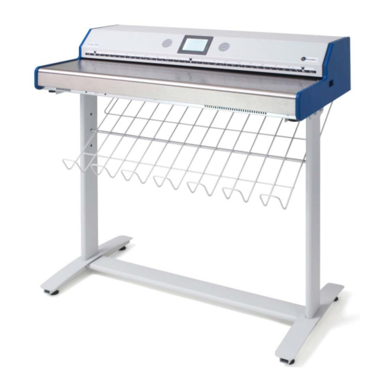
With the WideTEK 36, Image Access offers an efficient scanner which covers a wide scope of applications due to its versatility. Its integrated web-based user interface makes all functions available in structured menus.
This manual is designed to lead the user through all necessary assembly and setup steps after the WideTEK 36 has been delivered.
For this reason, we ask you to read this manual attentively before starting with the assembly procedure. By doing so, you will avoid errors from the beginning and you will be able to control all functions easily.
Please also consider the following points:
Damages to your unit may have occurred during shipping. Please check for damages immediately after delivery of the unit. Inform your supplier if damage has occurred.
Read and ensure that you understand the safety notes. They were developed for your protection and safety as well as to protect the unit.
Regular maintenance conserves the high quality and safe operation of the WideTEK 36 during the entire service life.
If you have any further questions, please feel free to contact your local dealer or Image Access directly. Our staff will be happy to help you.
For your daily work with the WideTEK 36, we wish you success and complete satisfaction.
Regards
Your Image Access Team
|
Page 4 |
Setup and Assembly Manual |

It is recommended to always use the WideTEK 36 in combination with the floor stand.
describes the software setup. It includes the optical adjustments necessary after the setup. The section also describes the option installation procedure.
describes cleaning procedures, troubleshooting procedures, and test scan generation.
shows all technical data and necessary declarations.
describes the hardware setup. It includes unpacking and mechanical installation. These instructions must be followed carefully to ensure proper functionality, best possible quality and performance of the device. This device is a precision optical instrument and should be handled accordingly.
About this Manual
Setup and Assembly Manual
The Setup and Assembly Manual is written for technical staff with some basic mechanical as well as software skills. Many resellers will offer on-site installation; therefore, large parts or all of the setup and assembly manual might not be of interest to the reader. The access level at which the setup and adjustment processes are performed is called “Power user”. This “Power user” level is password protected to prevent access by the normal operator.
All information about the normal operation and behavior of this device is found in the
Operation Manual.
All available manuals for this device can be downloaded from our customer service portal at http://service.imageaccess.de. Be sure to always check for the latest versions of these manuals.
This manual is divided into four sections, A to D. Section A
Note:
Section B
Section C
Section D
|
Setup and Assembly Manual |
Page 5 |

Version History
|
Version |
Published in |
Content/Changes/Supplements |
|
A |
February 2007 |
Preliminary version. |
|
Description of the device elements. |
||
|
Description of assembling steps. |
||
|
Description of Scan2Net Firmware Adjustment Procedure. |
||
|
Description of Recovery Function. |
||
|
B |
May 2007 |
Additional information concerning cleaning, tests and |
|
troubleshooting. |
||
|
C |
August 2007 |
Some minor modifications in the text, some new screenshots |
|
because of new firmware release. |
||
|
D |
August 2008 |
New screenshots because of release of S2N firmware version 5. |
|
Minor modifications in detail descriptions. |
||
|
Table D.4 corrected. Changed values for the device weight and |
||
|
total shipping weight. |
||
|
E |
May 2009 |
Some minor supplements in detail descriptions. |
|
Some screenshots modified. |
||
|
F |
December 2009 |
Error code table supplemented, tables of warnings and |
|
information have been added. |
||
|
F2 |
January 2010 |
Some minor corrections in details description. |
|
Chapter D.3 Electr. Spec. New value for stand-by consumption, |
||
|
another power supply is used. |
|
Page 6 |
Setup and Assembly Manual |

|
Table of Content |
|||
|
Introduction————————————————————————— |
4 |
||
|
About this Manual —————————————————————— |
5 |
||
|
Version History ——————————————————————— |
6 |
||
|
A Hardware Setup ————————————————————— |
14 |
||
|
A.1 |
Content on Delivery ………………………………………………………………………………… |
14 |
|
|
A.1.1 Contents of Floor Stand Box |
15 |
||
|
A.1.1.1 |
List of Assembling Material and Tools |
15 |
|
|
A.1.2 |
Floor Stand Overview |
16 |
|
|
A.1.3 Parts of Floor Stand |
17 |
||
|
A.2 |
Assembling the Floor Stand……………………………………………………………………… |
18 |
|
|
A.3 |
Combining Floor Stand and Scanner…………………………………………………………. |
21 |
|
|
A.4 |
Connecting to the Power Source ………………………………………………………………. |
25 |
|
|
A.4.1 Connectors at the Scanner |
26 |
||
|
A.5 |
Powering up the WideTEK 36…………………………………………………………………… |
27 |
|
|
A.6 |
WideTEK 36 Touch Panel ……………………………………………………………………….. |
27 |
|
|
A.6.1 Starting the WideTEK 36 from Stand-By Mode |
27 |
||
|
A.6.2 Turning-off the WideTEK 36 |
28 |
||
|
A.6.3 |
The Help Function |
28 |
|
|
A.7 |
Navigating through the Screens ……………………………………………………………….. |
29 |
|
|
A.7.1 How to Enter or Change Values |
29 |
||
|
A.8 |
IP Address Setup……………………………………………………………………………………. |
30 |
|
|
A.8.1 IP Address Setup by Touch Panel |
30 |
||
|
A.9 |
Optical Adjustment………………………………………………………………………………….. |
32 |
|
|
A.9.1 |
White Balance |
32 |
|
|
A.9.1.1 |
Helpful information about the white balance adjustment |
32 |
|
|
A.9.1.2 |
Performing the White Balance Adjustment |
33 |
|
Setup and Assembly Manual |
Page 7 |

|
Table of Content, part 2 |
|||
|
B Software Setup ————————————————————— |
34 |
||
|
B.1 Start Screen of the Scan2Net User Interface ……………………………………………… |
34 |
||
|
B.2 |
Setup Menu …………………………………………………………………………………………… |
35 |
|
|
B.2.1 Selecting the Login Level |
35 |
||
|
B.3 |
Poweruser Login Level……………………………………………………………………………. |
36 |
|
|
B.3.1 Setup Network IP Address |
37 |
||
|
B.3.2 Adjust Time & Date |
38 |
||
|
B.3.3 |
Sound Control |
39 |
|
|
B.3.3.1 |
Set Volume |
40 |
|
|
B.3.3.2 |
Wave Files |
41 |
|
|
B.3.3.3 |
Link Events |
42 |
|
|
B.3.4 |
Firmware Update |
43 |
|
|
B.3.5 |
Install ICC Profiles |
45 |
|
|
B.3.6 |
Install Option |
47 |
|
|
B.3.7 |
White Balance |
48 |
|
|
B.3.8 |
Brightness Correction |
50 |
|
|
C Cleaning, Test and Troubleshooting———————————- |
51 |
||
|
C.1 |
Cleaning the Transport Drums …………………………………………………………………. |
51 |
|
|
C.2 |
Cleaning the Glass Plate…………………………………………………………………………. |
53 |
|
|
C.3 |
Replacing the Glass Plate ……………………………………………………………………….. |
53 |
|
|
C.4 |
Scan Test Targets ………………………………………………………………………………….. |
58 |
|
|
C.4.1 Scan CSTT Test Target |
58 |
||
|
C.4.2 Scan IT8 Test Target |
59 |
||
|
C.5 |
Network Analyzer …………………………………………………………………………………… |
60 |
|
|
C.6 |
Recovery Function …………………………………………………………………………………. |
61 |
|
|
C.6.1 Important Notes Before Recovering to Factory Defaults |
61 |
||
|
C.6.2 How to Recover to Factory Defaults |
62 |
||
|
C.7 |
Error Codes …………………………………………………………………………………………… |
65 |
|
|
C.8 |
Warnings ………………………………………………………………………………………………. |
67 |
|
|
C.9 |
Information ……………………………………………………………………………………………. |
67 |
|
Page 8 |
Setup and Assembly Manual |

|
Table of Content, part 3 |
||
|
D Technical Data—————————————————————- |
68 |
|
|
D.1 |
Scanner Specifications ……………………………………………………………………………. |
68 |
|
D.2 |
Ambient Conditions…………………………………………………………………………………. |
68 |
|
D.3 |
Electrical Specifications …………………………………………………………………………… |
69 |
|
D.4 |
Dimensions and Weight…………………………………………………………………………… |
69 |
|
Setup and Assembly Manual |
Page 9 |

|
Table of Pictures |
|
|
Picture 1: Transport box opened …………………………………………………………………………… |
14 |
|
Picture 2: Floor stand box opened ………………………………………………………………………… |
15 |
|
Picture 3: Assembling material……………………………………………………………………………… |
15 |
|
Picture 4: Technical drawing of floor stand …………………………………………………………….. |
16 |
|
Picture 5: Floor stand components………………………………………………………………………… |
17 |
|
Picture 6: Side pillar in foot profile…………………………………………………………………………. |
18 |
|
Picture 7: Traverse inserted into foot bracket………………………………………………………….. |
18 |
|
Picture 8: Inserting screws with washer …………………………………………………………………. |
19 |
|
Picture 9: Bottom and side components assembled ………………………………………………… |
19 |
|
Picture 10: Top bracket on vertical leg …………………………………………………………………… |
20 |
|
Picture 11: Upper traverse inserted……………………………………………………………………….. |
20 |
|
Picture 12: Inserting the rod …………………………………………………………………………………. |
21 |
|
Picture 13: Two persons lifting the scanner out of the transport box ………………………….. |
21 |
|
Picture 14: Lift the scanner to remove the foam rubber element ……………………………….. |
22 |
|
Picture 15:Removing foam rubber element and cardboard element…………………………… |
22 |
|
Picture 16: Bottom side, front side left……………………………………………………………………. |
23 |
|
Picture 17: Bottom side, back side left …………………………………………………………………… |
23 |
|
Picture 18: Fastening the scanner onto the floor stand…………………………………………….. |
23 |
|
Picture 19: WideTEK 36 placed on floor stand, ready to use…………………………………….. |
24 |
|
Picture 20: Connectors at WideTEK 36………………………………………………………………….. |
26 |
|
Picture 21: Start menu screen………………………………………………………………………………. |
27 |
|
Picture 22: Touch panel while shut down in progress ………………………………………………. |
28 |
|
Picture 23: Keyboard with capital letters ………………………………………………………………… |
29 |
|
Picture 24: Keyboard with lower case letters ………………………………………………………….. |
29 |
|
Picture 25: Self Test 1 menu ………………………………………………………………………………… |
30 |
|
Picture 26: Network setup ……………………………………………………………………………………. |
31 |
|
Picture 27: Numeric key pad ………………………………………………………………………………… |
31 |
|
Picture 28: Confirm changes ………………………………………………………………………………… |
31 |
|
Picture 29: White Balance screen …………………………………………………………………………. |
33 |
|
Picture 30: Progress indicator ………………………………………………………………………………. |
33 |
|
Page 10 |
Setup and Assembly Manual |
![]()
|
Table of Pictures, part 2 |
|
|
Picture 31: White balance result ……………………………………………………………………………. |
33 |
|
Picture 32: Start screen ……………………………………………………………………………………….. |
34 |
|
Picture 33: Login level screen……………………………………………………………………………….. |
35 |
|
Picture 34: Poweruser main menu…………………………………………………………………………. |
36 |
|
Picture 35: Network parameters of the scanner ………………………………………………………. |
37 |
|
Picture 36: Adjust Time and Date Screen……………………………………………………………….. |
38 |
|
Picture 37: Sound System screen …………………………………………………………………………. |
39 |
|
Picture 38: Volume level displayed………………………………………………………………………… |
40 |
|
Picture 39: List of sound files………………………………………………………………………………… |
41 |
|
Picture 40: Link Sounds to Events screen ………………………………………………………………. |
42 |
|
Picture 41: Firmware Update ………………………………………………………………………………… |
43 |
|
Picture 42: Summary of successful firmware update………………………………………………… |
44 |
|
Picture 43: ICC Profile screen ………………………………………………………………………………. |
45 |
|
Picture 44: Upload ICC Profile screen ……………………………………………………………………. |
46 |
|
Picture 45: Embed ICC profile ………………………………………………………………………………. |
46 |
|
Picture 46: Install Option screen……………………………………………………………………………. |
47 |
|
Picture 47: Click the marked button……………………………………………………………………….. |
48 |
|
Picture 48: Select „White Balance“ ………………………………………………………………………… |
48 |
|
Picture 49: White Reference Target on document table……………………………………………. |
49 |
|
Picture 50: Selecting “Brightness Correction”………………………………………………………….. |
50 |
|
Picture 51: Selecting the correction factor ………………………………………………………………. |
50 |
|
Picture 52: Self Test 1 …………………………………………………………………………………………. |
51 |
|
Picture 53: Transport drums at front and back ………………………………………………………… |
52 |
|
Picture 54: Hexagon screws at WT 36 backside ……………………………………………………… |
53 |
|
Picture 55: Hexagon head screw at left side of housing……………………………………………. |
53 |
|
Picture 56: Lifting the main cover ………………………………………………………………………….. |
54 |
|
Picture 57: Placing the main cover ………………………………………………………………………… |
54 |
|
Picture 58: Audio connector………………………………………………………………………………….. |
54 |
|
Picture 59: Sensor connector ……………………………………………………………………………….. |
54 |
|
Picture 60: Controller connector ……………………………………………………………………………. |
55 |
|
Setup and Assembly Manual |
Page 11 |

|
Table of Pictures, part 3 |
|
|
Picture 61: Cable connector …………………………………………………………………………………. |
55 |
|
Picture 62: Screw at back, left side ……………………………………………………………………….. |
56 |
|
Picture 63: Screw at back, right side ……………………………………………………………………… |
56 |
|
Picture 64: Screw at front, left side………………………………………………………………………… |
56 |
|
Picture 65: Screw at front, right side ……………………………………………………………………… |
56 |
|
Picture 66: Holding the glass plate rack …………………………………………………………………. |
57 |
|
Picture 67: Removing the glass plate rack ……………………………………………………………… |
57 |
|
Picture 68: Position of CSTT target on the document table ………………………………………. |
58 |
|
Picture 69: Position of IT8 test target on the document table…………………………………….. |
59 |
|
Picture 70: Network Analyzer screen …………………………………………………………………….. |
60 |
|
Picture 71: IP address for testing ………………………………………………………………………….. |
60 |
|
Picture 72: Recovery Key…………………………………………………………………………………….. |
61 |
|
Picture 73: Position of gap on right side…………………………………………………………………. |
62 |
|
Picture 74: Position of gap on left side …………………………………………………………………… |
62 |
|
Picture 75: Moving the compensator plate upwards ………………………………………………… |
62 |
|
Picture 76: Compensator plate on document table ………………………………………………….. |
63 |
|
Picture 77: Compensators lifted ……………………………………………………………………………. |
63 |
|
Picture 78: Inserting recovery key …………………………………………………………………………. |
63 |
|
Picture 79: Connectors on rear panel…………………………………………………………………….. |
63 |
|
Page 12 |
Setup and Assembly Manual |

Thiis page iinttenttiionalllly llefftt bllank
|
Setup and Assembly Manual |
Page 13 |
A Hardware Setup
A.1 Content on Delivery
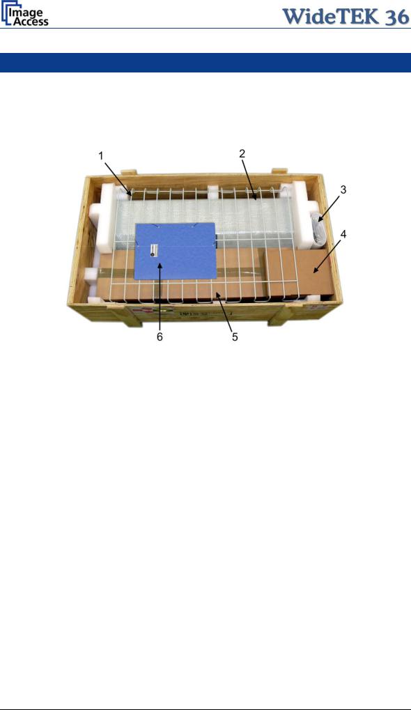
The scanner is delivered in a wooden transport box. The transport box also contains the disassembled floor stand in a separate cardboard box and the paper catch basket.
Picture 1: Transport box opened
1:Paper catch basket
2:Scanner
3:White Reference Target
4:Box with cable set and accessories. The cable set consist of:
Network cable. Connects the scanner to the network. All network parameters such as IP address, subnet mask and gateway must be set via the front panel prior to the first use.
Crossover cable. Connects the scanner directly to a computer via the network card.
Two power cables. US and European standard. Connects the scanner to the wall outlet.
5:Floor stand in separate cardboard box (optional)
6:Folder with CSTT-1 reference targets and the manuals.
Please note: Keep the wooden transport box and the cardboard box for future use! In case of guarantee the scanner must be sent back in the original transport box to avoid transport damages.
|
Page 14 |
Setup and Assembly Manual |
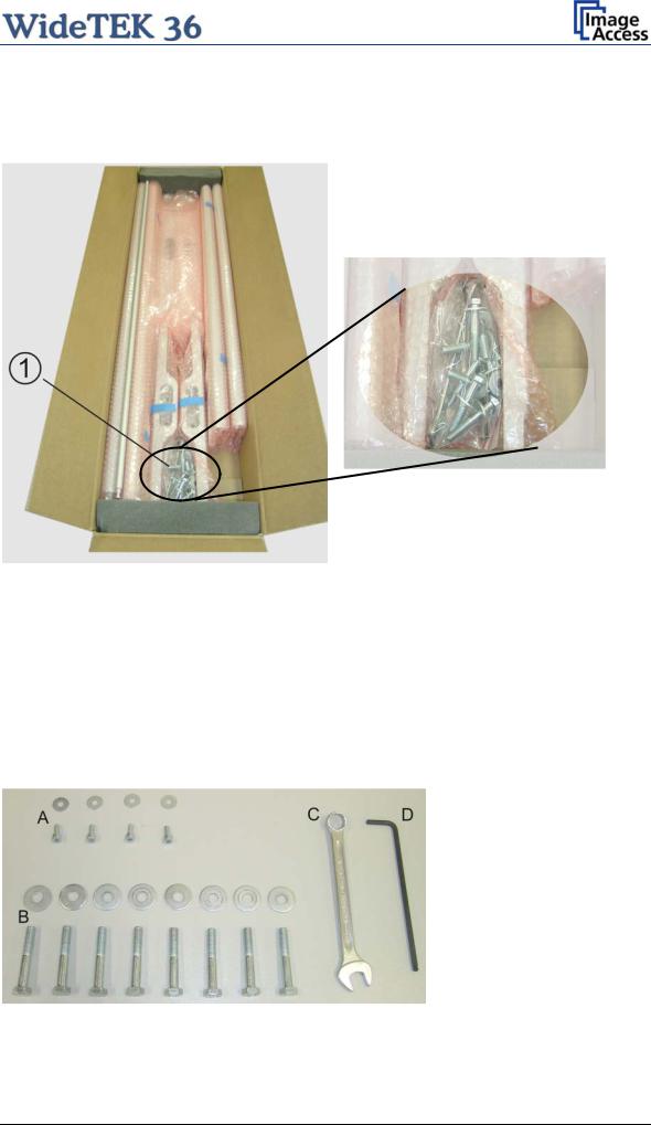
A.1.1 Contents of Floor Stand Box
The cardboard box of the floor stand contains all screws and washers, as well as the tools to assemble the floor stand, in a separate plastic bag.
|
Picture 2: Floor stand box opened |
Picture 3: Assembling material |
1:Plastic bag with assembly material
The plastic bag contains all screws, washers and tools to assemble the floor stand.
A.1.1.1 List of Assembling Material and Tools
A4x screws DIN 912 M5x10
4x washer DIN 9021 – 5.3
C Combination wrench, size 13
D Allen wrench size 4
B8x screws ISO 4016 – M8x50x22-WS
8x washer DIN 9021 – 8.4
|
Setup and Assembly Manual |
Page 15 |
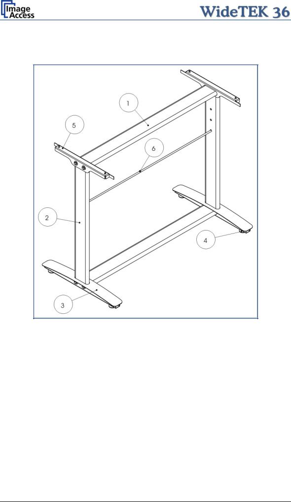
A.1.2 Floor Stand Overview
The engineering drawing below shows all major elements of the floor stand.
|
Picture 4: Technical drawing of floor stand |
||
|
The floor stand is built out of five different components and one round rod. |
||
|
No |
Qty |
Description |
|
1 |
2 |
Horizontal traverse. This part is used on the top as well as on the bottom. |
|
2 |
2 |
Vertical leg. This part is used on the left as well as on the right side. |
|
3 |
2 |
Foot bracket. This preassembled part is used on the left and right side. |
|
4 |
4 |
Adjustable feet. These are preassembled to the foot bracket. |
|
5 |
2 |
Top bracket: This part is used on the left and right top side. |
|
6 |
1 |
Horizontal rod. This part supports the paper exit basket. |
|
Page 16 |
Setup and Assembly Manual |

A.1.3 Parts of Floor Stand
Take all parts out of the box and place them as shown below and check for possible damages.
Picture 5: Floor stand components
The numbers in the picture above correspond to the numbers in the technical drawing.
|
Setup and Assembly Manual |
Page 17 |

A.2 Assembling the Floor Stand
Start with the foot profile (component #3), the side pillar (component #2), and the traverse (component #1).
Note: The three boreholes on the vertical leg (part #2) that are only on one side must face to the inner side of the floor stand. They should also be in the upper part of the leg. The technical drawing illustrates the correct position.
First insert a vertical leg into a foot bracket. The brackets have a cutout for the traverse. The foot brackets are designed symmetrically, therefore either one fits left and right.
Picture 6: Side pillar in foot profile
Next, insert the traverse as shown in the picture below.
Picture 7: Traverse inserted into foot bracket
|
Page 18 |
Setup and Assembly Manual |

Fasten the three components with two screws ISO 4016 – M8x50x22-WS. Place a washer on each screw.
Picture 8: Inserting screws with washer
Tighten the screws with the combination wrench, size 13, which comes with the floor stand.
Note: All screws should only be hand-tightened at first. The components should have a little play until all parts are assembled.
Repeat the steps described above with the second foot bracket and the second vertical leg.
Upon completion, the floor stand should look as shown in the picture below.
Picture 9: Bottom and side components assembled
|
Setup and Assembly Manual |
Page 19 |

Place the top brackets on the vertical legs. The oval cut-out must face to the inner side.
Picture 10: Top bracket on vertical leg
Insert the second traverse between the side legs.
Picture 11: Upper traverse inserted
Assemble the traverse, the top brackets and the legs with two ISO 4016 – M8x50x22-WS screws and a washer on each side.
Tighten all screws on the floor stand with the combination wrench, size 13.
|
Page 20 |
Setup and Assembly Manual |

Finally, insert the rod between the side legs. This rod supports the paper output tray. It has three positions for varying tray positions.
Picture 12: Inserting the rod
A.3 Combining Floor Stand and Scanner
After assembling the floor stand, the WideTEK 36 scanner can easily be placed on it in a safe position.
Note: For safety reasons, the scanner should be handled by two persons.
The transport box has notches at each corner in order to lift the scanner easily out of the box.
Picture 13: Two persons lifting the scanner out of the transport box
|
Setup and Assembly Manual |
Page 21 |
 Loading…
-
Page 1
Manual This device is compliant. -
Page 2
File: WT36_OperationManual_M3.docx… -
Page 3
Image Access. All other trademarks are the property of their respective owners. Image Access reserves the right to change the described products, the specifications or documents at any time without prior notice. For the most recent version, always check our web site www.imageaccess.de… -
Page 4: Introduction
Dear Customer, We congratulate you on the acquisition of this innovative product from Image Access. We at Image Access are proud of the work we do; it is the result of our extremely high standards of production and stringent quality control.
-
Page 5: About This Manual
Note: Optional the WideTEK 36 can be delivered with an appropriate floor stand. It is recommended to always use the WideTEK 36 in combination with the floor stand. Section B Software. This section describes the integrated Scan2Net software. This section also describes the installation procedure for software options.
-
Page 6: Version History
Prev. chapter B.3.9 renumbered to B.3.10 October 2011 Chapter B.3.3, information about container format added. Update Technical Data. As an ENERGY STAR® Partner, Image Access has determined that this product meets the ENERGY STAR® guidelines for energy efficiency. Page 6 Manual…
-
Page 7: Table Of Contents
Scanning documents on light, thin paper material A.12.4 Scanning documents on normal or heavier paper A.13 Connecting an External Monitor …………….. 28 A.14 Powering up the WideTEK 36 …………….30 A.15 WideTEK 36 Touch Panel ……………… 30 A.15.1 Starting the WideTEK 36 from Stand-By Mode A.15.2 Turning-off the WideTEK 36 A.15.3…
-
Page 8
A.17.3 Lamp On / Off A.17.4 Exit Selftest A.17.5 Touch Adjust A.17.6 Touch Test A.17.7 Stitch Test A.17.8 EMV Test A.17.9 Sensor Test A.17.10 Shutdown Scanner A.18 Start Menu Screen ………………… 39 A.19 Output Control Screens ………………40 A.19.1 Output Control 1 A.19.1.1 Viewer Control A.19.1.2… -
Page 9
A.21.3 Format Control 3 A.21.3.1 Top edge A.21.3.2 Bottom edge A.21.3.3 Units A.21.3.4 Left edge A.21.3.5 Right edge A.22 File Control Screen ……………….. 54 A.22.1 JPEG A.22.2 TIFF A.22.3 A.22.4 A.23 Transport Control Screen ………………. 57 A.23.1 Start button A.23.2 Transport A.23.3 Scan mode… -
Page 10: Technical Data
B.3.5.4 Extended print parameters with iPF option installed B.3.5.5 Printing Enhancements with iPF option installed B.3.6 Output Option FTP Upload B.3.6.1 FTP Server B.3.7 Output Option Mail B.3.7.1 Mail Server B.3.7.2 Transaction mode interactive B.3.8 Output Option Network B.3.8.1 SMB Configuration B.3.9 Output Option Web B.3.9.1…
-
Page 11: Manual Page
Table of Pictures Picture 1: Minimum distances to the scanner …………..17 Picture 2: Transport box opened ………………19 Picture 3: Connectors at WideTEK 36 …………….20 Picture 4: Middle guide plate ………………..21 Picture 5: Allen head screw in slot hole …………….22 Picture 6: Removing the middle guide plate …………..22 Picture 7: Self locking nut on the bottom side of middle guide plate ………23…
-
Page 12
Table of Pictures, part 3 Picture 41: Ftp Server 2 ………………..43 Picture 42: Network parameters ………………44 Picture 43: Input a Network Address …………….44 Picture 44: Output Control 2 ……………….. 45 Picture 45: System events and sound files …………..45 Picture 46: Image Control 1 ………………… -
Page 13: Manual Page
Table of Pictures, part 3 Picture 81: Scan status window ………………78 Picture 82: Format screen ………………..79 Picture 83: Rectangle dragged with mouse …………..80 Picture 84: «Zoom in» result ………………..80 Picture 85: List of available clip size formats …………..80 Picture 86: Output options ………………..81 Picture 87: Output Option Save ………………82 Picture 88: Example for file name ………………82 Picture 89: Output Option Show ………………83…
-
Page 14: A Hardware
(Standard for Canada) EN 60950-1, Safety for Information Technology Equipment (European standard) General Notice This manual describes the functions of a complete equipped WideTEK 36 scanner. If your device is not equipped with all features, deviations are possible. Page 14…
-
Page 15: Safety Precautions
13. Always turn the power off and unplug the power cord from the wall receptacle before cleaning the scanner. 14. When cleaning, only use Image Access-approved cleaners. Do not use any type of solutions, abrasives, or acids such as acetone, benzene, kerosene, mineral spirits, ammonia, or nitric acid.
-
Page 16: Connecting To The Power Source
Connecting to the Power Source Before connecting the scanner to the electrical outlet check the following items: Ensure the electrical outlet is in perfect condition and that it is properly grounded. Ensure that the electrical outlet is equipped with a fuse with the proper capacity.
-
Page 17: Device Location
Do not operate the scanner in an area that has poor air circulation, and/or that is non- ventilated. Place the WideTEK 36 on a flat and solid base. The load bearing capacity of the base must correspond to the device weight.
-
Page 18: Maintenance
Ensure that no liquids will penetrate into the device housing. A.7.1 Touchscreen Before cleaning the touchscreen, switch the WideTEK 36 off and set the main power switch to position 0. The touchscreen can be cleaned with a micro fiber cloth.
-
Page 19: Content On Delivery
Content on Delivery The scanner is delivered in a wooden transport box. The transport box also contains the disassembled floor stand in a separate cardboard box and the paper catch basket. Picture 2: Transport box opened 1: Paper catch basket 2: Scanner 3: White Reference Target 4: Box with cable set, manuals, and accessories (2x Recovery Key) .
-
Page 20: Connectors On The Scanner
Connectors on the Scanner The connectors are positioned at the left side of the housing, as seen from the operators view (i.e. from the front of the scanner). Picture 3: Connectors at WideTEK 36 1: Power connector 2: Foot pedal connector…
-
Page 21: A.11 Adjusting The Middle Guide Plate
Tools: Allen wrench, size 2.5 mm The WideTEK 36, 42 and 48 wide format scanners contain an adjustable guide plate which holds the paper against the glass plate without touching it. The amount of contact pressure exerted by the guide plate is user configurable.
-
Page 22: Picture 5: Allen Head Screw In Slot Hole
With the 2.5 mm Allen wrench loosen the two Allen head screws slightly. Picture 5: Allen head screw in slot hole The screws are mounted in slot holes. This allows moving the metal ballast. If the metal ballast is moved all the way to the front or outer edge of the guide plate, the contact pressure is minimal.
-
Page 23: Picture 7: Self Locking Nut On The Bottom Side Of Middle Guide Plate
Place the middle guide plate upside down on the front side guide plate. Picture 7: Self locking nut on the bottom side of middle guide plate Use a 7 mm ring spanner wrench (not supplied) or a pair of pliers to loosen the self- locking nuts.
-
Page 24: Paper Transport Wings
A.12 Paper Transport Wings To ensure proper functionality of the stitching function, special paper transport wings have to be inserted. Each WideTEK 36 scanner comes with a set of two black paper transport wings. Note: For special document types, e.g. semi-transparent documents, a set of two white paper transport wings and a white guide plate are available.
-
Page 25: How To Insert The Paper Transport Wings
A.12.1 How to insert the Paper Transport Wings Hold the paper transport wing near the two small notches and carefully bend it slightly in the middle. Picture 10 shows how to hold the paper transport wing. Picture 10: Bending the paper transport wing First insert the end of the paper transport wing with notches at the front side of the guide plate.
-
Page 26: Position Of The Paper Transport Wings
A.12.2 Position of the Paper Transport Wings For best results the paper transport wings should be inserted at the guide plate at a position between six and seven inches (approx. 15 to 19 cm) from the center position of the document input. Picture 12 shows the position where the paper transport wings have to be inserted on the guide plate.
-
Page 27: Scanning Documents On Normal Or Heavier Paper
A.12.4 Scanning documents on normal or heavier paper For best results, when scanning documents on normal or heavier paper, the paper transport wings must be inserted at the backside of the paper guide plate. Insert every paper transport wing with the long end forward into the notch at the back of the guide plate.
-
Page 28: Connecting An External Monitor
A.13 Connecting an External Monitor The external monitor will be connected to the VGA connector of the mainboard inside the scanner. To locate the VGA connector it is necessary to remove the middle guide plate at first. Open the upper part of the scanner by releasing the snap locks (see Picture 9) at the left and right side of the housing.
-
Page 29: Picture 19: Guiding The Cable To The Connector
Position the signal cable nearby the VGA connector of the mainboard. Picture 19: Guiding the cable to the connector It is recommended to position the cable connector at its final position with the help of a second person. One person can assist from the back of the scanner finding the VGA connector while the second person inserts the cable into the connector.
-
Page 30: Powering Up The Widetek 36
When the WideTEK 36 is powered up by using the main power switch, the touch panel is illuminated in a dimmed mode and shows the stand-by screen. The stand-by screen shows the Image Access logo and the blinking message Touch screen to power up.
-
Page 31: Turning-Off The Widetek 36
To turn off the WideTEK 36, press and hold the Stop button on the touch panel. While the Stop button is held, a counter in the button shows the remaining time until the WideTEK 36 is powered down.
-
Page 32: Navigating Through The Screens
A.16 Navigating through the Screens Some of the screens show on the bottom line the buttons Returns to the former screen. Sometimes only the symbol < is displayed. Switches to the next logical screen, e.g. from Format Control 1 to Format Control 2.
-
Page 33: Self Test Mode
A.17 Self Test Mode While the start sequence is running the WideTEK 36 can be switched to self-test mode. Tapping on the touch panel at least three times starts the setup mode. After the start sequence is finished, the touch panel shows the Self Test 1 screen.
-
Page 34: Ip Address
A.17.1 IP Address Touch the control field IP Address. The touch panel changes to the Network setup screen. Picture 27: Network setup Touch on the line to be changed, e.g. the Address line. The touch panel shows: Picture 28: Numeric key pad Enter the new values.
-
Page 35: White Balance
A.17.2 White Balance Note: The paper transport wings must be inserted before starting the white balance. Touch the White Balance button to start the white balance measurement sequence. Now insert the control sheet. It must be transported forward and reverse. Then touch the Cont. button.
-
Page 36: Picture 32: Testing The Touch Screen
A.17.5 Touch Adjust This function defines the dimension of the writing area of the touch panel. The first step after selecting this function must be done very quickly to activate the adjustment procedure. Note: It is recommended to read first, and then act. It is recommended to use for the following adjustment steps an appropriate pen, e.g.
-
Page 37: Picture 33: Stitch Test Screen
A.17.7 Stitch Test Picture 33: Stitch Test screen Press the Stitch Test button to start the stitch test. This starts a program in which you can see an automatically updated view of the stitching indicators for each camera. The measurement will be executed continuously, once every second. The cameras left, middle and right are identified as the left, middle and right cameras when looking at the scanner from the operator’s view (i.e.
-
Page 38: Picture 34: Sensor Status
No paper detected by the sensors. Paper detected at input side (PWT). Paper detected at input side (PWT) and at output side (POT). Picture 34: Sensor status A.17.10 Shutdown Scanner Touch this button to switch the WideTEK 36 scanner off. Page 38 Manual…
-
Page 39: Picture 35: Start Menu Screen
A.18 Start Menu Screen Picture 35: Start menu screen When all initial tests are finished, the display shows the start menu screen. At the top of the start menu, the main controls to start a scan sequence and to stop the current action are displayed.
-
Page 40: Picture 37: Output Control 1
Picture 37: Output Control 1 A.19.1.1 Viewer Control An external monitor can be connected to the WideTEK 36 to show the scanned image directly. Touching the Viewer Control button starts the Zoom/Move Control mode. When this mode is active, the displayed image on the screen can be moved and the zoom factor can be changed.
-
Page 41: Picture 39: E-Mail Address Parameters
A.19.1.2 Email Address This menu item enables the user to send the scanned image to any arbitrary e-mail address. Stores all parameters. Erases all changes. Picture 39: E-mail address parameters How to enter an E-mail address Tap on the line of the e-mail address. The screen changes to input mode as shown in Picture 23 and Picture 24.
-
Page 42: Picture 40: Ftp Server 1
A.19.1.3 FTP Server The Ftp Server button enables the user to enter all necessary information for data transfer to a dedicated FTP server. The parameters are entered in two screens named Ftp Server 1 and Ftp Server 2. Ftp Server 1 This screen contains the server IP address and the port, the user name and the password for the server access.
-
Page 43: Picture 41: Ftp Server 2
Ftp Server 2 This screen contains all data for the connection with a FTP server. Stores all parameters. Erases all changes. Picture 41: Ftp Server 2 Use proxy Select Yes to use a proxy server for the connection. Auth. Defines the type of authentication at the FTP server. By tapping on the field the methods will be switched.
-
Page 44: Picture 42: Network Parameters
A.19.1.4 Windows Network Allows the user to • define the network path where the image should be stored, • the define the authentication method, • define the user name, • define the password, • define the filename Picture 42: Network parameters To store all entries of this menu touch the button How to enter a Network Address Picture 43: Input a Network Address…
-
Page 45: Picture 44: Output Control 2
A.19.2 Output Control 2 Picture 44: Output Control 2 A.19.2.1 Sound Control The menu item Sound Control allows the user to link sounds to system events. Picture 45: System events and sound files To select a system event, touch the scroll bar in the left window or the up/down arrows. The currently selected sound file associated with this system event will be displayed in the right window.
-
Page 46: Picture 46: Image Control 1
A.20 Image Control Screen The parameters are set in two screens, Image Control 1 and Image Control 2. A.20.1 Image Control 1 Picture 46: Image Control 1 In general: • Tap on + or – to change the values in steps of one. •…
-
Page 47: A.20.1.4 Sharpness
A.20.1.4 Sharpness An automatic sharpening algorithm is applied to the image before any other operation is performed. The value zero disables the function. Very high values may produce artifacts, depending on the document characteristics. A.20.1.5 Resolution This parameter defines the scanner’s resolution. This button offers three ways to set the desired value: •…
-
Page 48: Picture 47: Image Control 2
A.20.2 Image Control 2 Picture 47: Image Control 2 Note: Depending on the selected color mode, some buttons may not be displayed. A.20.2.1 Threshold (only in Binary mode) Defines the contrast control mode. Available modes are Fixed and Auto. Fixed: The contrast is fixed to defined value.
-
Page 49: A.20.2.4 Stitching
A.20.2.4 Stitching Defines the stitching method which is used to merge the image data of the cameras to one image. Fixed: Merges the image data at a specified offset area, resulting from the camera calibration. Adapt.1D Recommended for all documents with good paper quality and plain surface. This setting delivers a high throughput with large-sized documents.
-
Page 50: Picture 48: Image Control 3
A.20.3 Image Control 3 Picture 48: Image Control 3 Note: Only in the color modes 24b color, 8b color, and Grayscale. A.20.3.1 Exposure Defines the exposure correction mode. Available are Black Cut, Auto and Fixed. Black cut All color values in the image which are below the threshold for black are displayed as black.
-
Page 51: Picture 49: Format Control 1
A.21 Format Control Screen The parameters are set in three screens; Format Control 1 to Format Control 3. To switch between these two screens use the buttons A.21.1 Format Control 1 Picture 49: Format Control 1 A.21.1.1 Format This control specifies the format of the document. In most cases the setting Auto should be selected.
-
Page 52: Picture 50: Format Control 2
A.21.2 Format Control 2 Picture 50: Format control 2 A.21.2.1 Auto margin The Auto margin control detects the edges of a document and cuts it out of the scanned image. If the value (in pixels) is negative, the resulting image will be smaller than the document. If the value is positive some of the background will remain in the scanned image.
-
Page 53: Picture 51: Format Control 3
A.21.3 Format Control 3 Picture 51: Format Control 3 In general: The units can have various units of measurement. Only positive values can be entered. A.21.3.1 Top edge Defines a zone on the document that is not scanned. The zone starts from the top of the document to the value specified via this function. A.21.3.2 Bottom edge Defines a zone on the document that is not scanned.
-
Page 54: Picture 52: File Control
A.22 File Control Screen Picture 52: File Control The control File format specifies the file format of the image file. Depending on the selected file format, the number and the content of the controls in this screen can vary. The list of formats includes JPEG, TIFF, PNM, and PDF (if the option is installed). A.22.1 JPEG When selecting the file format JPEG the functions of the controls are:…
-
Page 55: A.22.2 Tiff
A.22.2 TIFF When selecting the file format TIFF the functions of the controls are: Note: Depending on the selected color mode in Image Control the available compression methods vary. • TIFF compr. None: Available with all color modes. JPEG: Available with “24b color” and “Grayscale”. Additionally the controls “JPEG quality”…
-
Page 56: A.22.4 Pdf
A.22.4 When selecting the file format PDF the functions of the controls are: • JPEG quality: Defines the compression rate. The JPEG quality level is defined with this control. A higher percentage gives better quality but the file size will increase. A lower factor will show some artifacts in the image but the file size will be reduced.
-
Page 57: Picture 53: Transport Control
A.23 Transport Control Screen Picture 53: Transport control A.23.1 Start button Defines the start method of the scanner. • Direct: The scan starts when the scanner receives the start command from the application. • Wait: The scan will only start if the start button in the touch panel is pressed. The start button can also be a foot pedal.
-
Page 58: A.23.4 Feeder Delay
A.23.4 Feeder delay Defines the time delay the scanner waits between when it has detected paper in the transport and when it starts moving the paper. A value of zero disables the delay. The time delay is specified in seconds. A.23.5 Doc.
-
Page 59: Picture 54: List Of Available Jobs
A.24 Picture 54: List of available jobs The control Job allows the user to create and store specific settings of the scanner. This is useful if the scanner is operated by several users with different settings for document size, resolution or other parameters. A.24.1 Creating a Job Creating a “job”…
-
Page 60: Picture 56: Creating A Job
Tap on Create to save the job. Tap on with password to save the job in combination with a password. Tap on Cancel to cancel the procedure. Picture 56: Creating a job If a password should be used, tapping on the button with password opens a screen as shown in the picture on the left.
-
Page 61: Picture 59: Selecting A Job From The List
A.24.2 Selecting a Job New job names are added to the list of available jobs. Jobs can be selected from the list of available jobs by tapping on the selection arrow or directly on the job name. Tapping the Select button activates the job. Picture 59: Selecting a job from the list Selecting a password protected job opens a…
-
Page 62: Picture 61: Confirming To Delete The Job
A.24.3 Deleting a Job Select the job to be deleted from the list of available jobs. Tap on the Delete button. In the next screen tap on the Yes button to delete the job. Picture 61: Confirming to delete the job If the job is password protected, the password must be entered first.
-
Page 63: Picture 63: Touchpanel After Scanning
A.25 Software Option: Scan2VGA An external monitor can be connected to the WideTEK 36 to show, edit and save the actual scanned image on the fly. When the scan sequence has been finished, the menu in the touch panel will change.
-
Page 64: Picture 64: Start Screen
Software Essentially, the scanner is a web server and comes with its own HTML-based user interface. To access a Scan2Net scanner, any standard web browser can be utilized. A basic requirement before using the integrated user interface is to configure the browser as follows: •…
-
Page 65: Picture 65: Main Screen
The Main Screen After launching the scan application, the main screen of the integrated user interface will open. The main screen is structured in three parts. Switching between the sections is done with a mouse click. Picture 65: Main screen 1: The menu bar of the large frame on the upper right part has five menu items: …
-
Page 66: Picture 66: Shutdown Confirmation
2: The control buttons in the lower part of the screen control the output modes. When selecting Save the scanned image will not be displayed. Instead of the second window a box opens where the desired directory can be set. As default the output mode Show is selected.
-
Page 67: Picture 67: Options Screen
B.2.1 The Options Screen Options Picture 67: screen Paper Feed Delay Defines the delay time before the transport starts when a document is inserted. Transport Speed Slow reduces the transport speed to half of the normal speed. It is recommended with sensitive documents. Document Output Eject transports the document through the scanner and ejects it at the back side.
-
Page 68
Preview Scale Allows to set the preview relation. If set to Auto, the function will perform a best fit before the image is displayed on the screen. Preview Quality [%] Determines the compromise between quality and compression rate. A higher quality factor produces larger files. The default setting is a good compromise for most documents. -
Page 69: Picture 68: Properties Screen
B.2.2 The Properties Screen Properties Picture 68: screen Color Mode This mode allows the operator to select various different color modes. The available color modes are displayed in the picture on the left. To select a color mode first click on the selection arrow, then select a mode from the list.
-
Page 70: Picture 69: 24Bit Color, File Format: Pnm
File Format defines the file format that is used to store a scanned document. Note: There are some interdependencies between Color Mode File Format. That means, it is not possible to combine all color modes with all file formats. For example, if an image is scanned in “24bit Color” it cannot be stored in TIFF G4 file format.
-
Page 71
Resolution [DPI] field allows the operator to set the desired resolution in two ways. Selecting the resolution: Click the selection arrow beside the right field. Select the desired value from the list. Entering the resolution: Enter any value between 150 dpi and 1200 dpi into the left field. -
Page 72: Picture 71: Format List
This function is highly advanced and works properly with default values. If Maximum is selected, the size of the scanned area depends on the scanner specification. WideTEK 36: Maximum scan area size 36 inches. If User is selected the User defined format control opens. It…
-
Page 73: Picture 73: Set Deskew Angle
Use Deskew control activates the automatic deskew function. If Yes is selected, a slider is displayed which allows to set the maximum corrected angle. Picture 73: Set deskew angle The desired value can be entered as a numeric value or by clicking on the slider and moving it to the desired value.
-
Page 74: Picture 75: Camera Screen
B.2.3 The Camera Screen Camera Picture 75: screen Brightness slider defines the brightness of the resulting image. Lower brightness values make the image darker. Contrast slider defines the contrast of the resulting image. Higher contrast values show more details. If scanning in binary (i.e. Binary, Photo Mode), the behavior of the contrast slider changes.
-
Page 75: Picture 76: Exposure Control Slider
Exposure control sets the threshold value for the black cut function or for the auto exposure function. Picture 76: Exposure control slider Function disabled. Black Cut Sets the threshold for black. All pixel values found in the image below the selected value are set to black. Value range from 0 (zero) to 100.
-
Page 76: Picture 77: Threshold Method Selector
B.2.3.1 Threshold Dynamic / Threshold Fixed Picture 77: Threshold method selector In the color mode Binary an additional button allows to select between Dynamic Fixed threshold. Dynamic The contrast level in the image varies depending on the content of the document.
-
Page 77: Picture 79: Settings Screen
B.2.4 The Settings Screen Settings Picture 79: screen Language Selector Select the language of the user interface here. Available languages are: Czech (čeština) German (deutsch) English (english) Spanish (español) French (français) Polish (polski) Portuguese (português) Russian (русский Cyrillic script) Chinese (Chinese symbols) Note: After selecting the language the user interface changes immediately to the selected language.
-
Page 78: Picture 80: Available Skins
Skin Selector This selector allows the operator to choose between different surfaces (skins) for the user interface. The skins differ in color and in the graphic elements used for the buttons and controls. The cutout on the left shows the currently available skins.
-
Page 79: Picture 82: Format Screen
B.2.5 The Format Screen Format Picture 82: screen When selecting the Format screen, the test image as shown in the above picture is displayed. The dimension of the image and the color mode depends on the settings made in Properties screen.
-
Page 80: Picture 83: Rectangle Dragged With Mouse
To select a specific area of the image, click with the mouse in the preview area and drag a rectangle. Dragging with the mouse the rectangle starts in the upper left corner and ends in the lower right corner. Click the Zoom in button to display the selected area of the image in detail. …
-
Page 81: Picture 86: Output Options
Output Options Select output option here Picture 86: Output options Ten output options are available on a WideTEK 36 scanner. Each option is selectable at the bottom part of the main window. Manual Page 81…
-
Page 82: Picture 87: Output Option Save
B.3.1 Output Option Save Picture 87: Output Option Save Select the output mode by clicking with the mouse on the button Save. When the output option Save is selected a preview window will not open. This output option scans to a local or network disk drive. After the scan is performed, a window opens and the default file name is shown.
-
Page 83: Picture 89: Output Option Show
B.3.2 Output Option Show In most cases, the button Show is activated. Picture 89: Output Option Show After scanning, an additional window opens and shows the image. The headline of the additional window contains identical buttons as the main window, except the items Show and Print.
-
Page 84: Picture 91: Output Option Multipage
B.3.3 Output Option Multipage Picture 91: Output Option Multipage Selecting the output option Multipage allows saving scanned images in a so called “Container” format. The available “Container” format depends on the file format of the image (see chapter B.2.2) Note: Multipage is selected, a preview window will not open.
-
Page 85: Picture 92: Pop-Up Window To Select Images For The «Container
While the scan sequence is running, a status window shows the current status. At the end of the scan sequence the window closes. To view the scanned images and to select the images, click on the link Finalize below the Multipage button.
-
Page 86: Picture 93: Output Option Print
B.3.4 Output Option Print This output option prints the image at a locally configured printer. Picture 93: Output Option Print After the scan is executed, the standard printer interface opens. The user can select one of the available printers. Picture 94: Available List of Printers for Option Print Page 86 Manual…
-
Page 87: Picture 95: Output Option Copy
B.3.5 Output Option Copy This output option prints directly to a previously installed network printer. The Option is used to configure the remotely connected printer. Picture 95: Output Option Copy Click at the link Options to set the connection to the printer and to define specific parameters.
-
Page 88
Remote Printer, continued Parameter Description Network Type Select Homegroup Network or Workgroup Network. (with SMB Printer Queue only) Password Enter the password for the Homegroup Network. (with SMB Printer Queue Homegroup Network only) Select Yes or No. Server Authentication (with SMB Printer Queue … -
Page 89: B.3.5.2 Printing Enhancement
Remote Printer, continued Parameter Description Duplex Print Switch on/off printing on both sides of a sheet (duplex). (not with HP Design Jet) Duplex Mode Select between Book and Notepad. Book = binding at the wide side of the paper sheet Notepad = binding at the narrow side of the paper sheet Paper Feed Select the paper feed method for the remote printer.
-
Page 90: B.3.5.3 Accounting
B.3.5.3 Accounting Only available with Konica Minolta Bizhub Series Parameter Description Accounting Yes / No Account Name Enter the account name here. Yes / No Use Password Account Password Enter the password for the accounting here. Hold Job Yes / No Public / Private Job Type Hold Key…
-
Page 91: B.3.5.4 Extended Print Parameters With Ipf Option Installed
B.3.5.4 Extended print parameters with iPF option installed After activating the option for Canon iPF printer the number of printing parameters will be extended. The following additional parameters are available. Parameter Description Data Format After installing the option the list of data formats is extended by Canon iPF Series Changing the data format will also change the options.
-
Page 92: B.3.5.5 Printing Enhancements With Ipf Option Installed
B.3.5.5 Printing Enhancements with iPF option installed After activating the option for Canon iPF printer the number of printing enhancements will be extended. The following additional parameters are available. Parameter Description Quality Optimized Level Image: Optimized for color printouts. Linedrawing: Optimized for bitonal line drawings. Quality Level Toggle the printing quality from draft to high quality.
-
Page 93: Picture 96: Output Option Ftp Upload
B.3.6 Output Option FTP Upload The scanner can directly scan to an FTP server. Picture 96: Output Option FTP Upload Go to Options to configure the FTP interface. A configuration window will pop up. B.3.6.1 FTP Server Parameter Description Preset Choose a preconfigured set of parameters out of five possible sets of parameters.
-
Page 94
FTP Server, continued Parameter Description Address Enter the IP address of the remote FTP server. Port (21) Enter the IP port of the remote FTP server. Default is port 21. Server Authentication Select Anonymous FTP or Login/Password. Login Enter the login name. Password Enter the password for the login at the remote FTP server. -
Page 95: Picture 97: Output Option Mail
B.3.7 Output Option Mail The scanner can directly send each scan via e-mail. Picture 97: Output Option Mail Go to Options to configure the mail interface. The above configuration window will pop B.3.7.1 Mail Server Parameter Description Preset Choose a preset out of five possible sets of parameters. If you click on Change Name you can change the name of…
-
Page 96
Mail Server, continued Parameter Description Address Enter the IP address of the outgoing mail (SMTP/LMTP) server. Port (25) Enter the IP Port of the outgoing mail server. Default: Port 25. Set to YES if the mail server requires an authentication. Server Authentication Login Enter the user name for authentication at the outgoing mail… -
Page 97: Picture 98: Parameters For Transaction Mode «Interactive
B.3.7.2 Transaction mode interactive If “Transaction mode” interactive is selected, an additional window opens after scanning. Picture 98: Parameters for transaction mode “interactive” Here all parameters can be entered for the mail transfer. Click into the respective field and enter the desired parameters. Each recipient address will be stored when the Apply button is pressed.
-
Page 98: Picture 100: Output Option Network
B.3.8 Output Option Network SMB is a network protocol which is used by Microsoft Windows-based networks. If output option Network is selected, the scans will be stored directly in a network directory. Picture 100: Output Option Network Go to Option to configure the SMB Upload interface.
-
Page 99: B.3.8.1 Smb Configuration
B.3.8.1 SMB Configuration Parameter Description Preset Choose a preset out of five possible sets of parameters. If you click on Change Name you can change the name of this set. Port (139) Enter the IP port of the SMB network communication. Default is port 139.
-
Page 100: Picture 101: Output Option Web
B.3.9 Output Option Web This option allows the user to store its files and images in the so called “Cloud”; a web space, which is offered by providers at their servers. Three different kinds of web services are available from the scanner. Picture 101: Output Option Web Go to Option…
-
Page 101: B.3.9.1 Web Service Configuration
B.3.9.1 Web Service Configuration Parameter Description Preset Choose a preconfigured set of parameters out of five possible sets of parameters. If you click on Change Name you can change the name of this set. Use a Proxy? Switch on/off the use of a proxy for connecting to a remote server outside the local network.
-
Page 102: Picture 102: Output Option Usb
Picture 102: Output Option USB At the front of the WideTEK 36 scanner (right side of the document input) an USB connector can be found, where suitable storage media can be inserted. Picture 103: USB stick inserted in USB connector…
-
Page 103: B.3.10.1 Usb Storage Device
B.3.10.1 USB Storage Device Go to Options to configure the USB interface. A configuration window will pop up. Parameter Description Partition Shows the status and available memory of the actual mounted partition on the connected USB flash device. Directory Allows choosing a subdirectory on the connected USB drive for storing the scans.
-
Page 104: Picture 104: Information
Information The start screen (Picture 64) shows three buttons. The button Information gives a short summary of the device parameters. Picture 104: Information The screen is helpful if technical support is necessary. It shows e.g. the exact device type, the installed firmware version as well as currently installed options. Click the button Back to return to the start screen.
-
Page 105: Picture 105: Login Screen
The Setup Screen The system level is divided in three access levels. The access levels Poweruser and Admin are password protected. The User access level allows showing certain information about the system like power up time, remaining lamp life time or firmware version. Furthermore the access level User allows setting some basic parameters.
-
Page 106: Picture 106: User Screen
B.5.2 Access Level User Click the button User . This will open the below displayed screen. Picture 106: User screen The user screen is divided into two sections. The section Information shows some details of the scanner and gives a general operation information.
-
Page 107: Picture 107: Device Info Screen
Info. Picture 107: Device Info screen The tables following the keyword show the current status of the WideTEK 36 scanner. The most important information for users is the firmware version in the second table. Other information may be of interest if a service technician is onsite or if the service hotline is called.
-
Page 108: Picture 108: Operation Info Screen
Remaining Lamp Operating The typical remaining lifetime of the lamps. The lifetime of Time the lamps of the WideTEK 36 scanner is so long, that they last under normal work conditions for the complete lifetime of the device. To return to the USER screen (Picture 106) click the button Back to Main Menu or click on the “Return”…
-
Page 109: Picture 109: Available User Settings
B.5.2.3 User Settings Screen In the section User Settings click the button User Settings and the following screen will be displayed. Picture 109: Available user settings Click onto the links below the headline to set the respective parameters. To return to the Login screen (Picture 105) click the button Setup Menu To return to the USER screen (Picture 106) click the button Back to Main Menu .
-
Page 110: Picture 110: Language Selector Screen
Use the function Language Selector to set the language for the Scan2Net user interface of the WideTEK 36 scanner. Picture 110: Language Selector screen Click on the selection arrow and a list of available languages opens. Select the desired language for the user interface with a mouse click.
-
Page 111: Picture 111: List Of Power Down Times
B.5.2.3.2 Power Saving The WideTEK 36 scanner is Energy Star compliant. Use the function Power Saving to set the time until the scanner goes into stand-by mode. Click on the link Power Saving. Click on the selection arrow and select the desired value from the list.
-
Page 112: Picture 112: Volume Level
B.5.2.3.3 Volume Click the button Volume to set the loudspeakers volume of the scanner. Picture 112: Volume level A screen opens and shows a graphic to symbolize the volume. Click on the percentage value to change the volume level. The color of the graphic will change depending on the selected volume level.
-
Page 113: Picture 113: Foot Pedal Settings
B.5.2.3.4 Foot Pedal Click the button Foot Pedal to define a function for the foot pedal. Picture 113: Foot pedal settings The scanner has a foot pedal connector on its left side, seen from the operators position (Picture 3). For the foot pedal a specific action can be defined. Select from the drop-down list which action should be executed when the pedal is operated.
-
Page 114: Picture 114: Splitting Start Page
B.5.2.3.5 Splitting Start Page Click the button Splitting Start Page to define the first page for the splitting function. Picture 114: Splitting Start Page In some cases it is necessary to start splitting the documents image in reverse order, i.e. starting with the right side followed by the left side in the second step.
-
Page 115: Picture 115: Guide Plate Middle
Picture 115: Guide Plate Middle The WideTEK 36 scanner can be equipped with different colored types of guide plates. Black / White: The standard guide plate is black colored.
-
Page 116: C Tests And Troubleshooting
Tests and Troubleshooting Troubleshooting Matrix Fields with a light blue background need the power user access level. All other fields are available to all users. Problem Possible cause Action The touch screen does not No power Check main outlet, power cord, power- show the stand-by message.
-
Page 117: C.2 Error Codes
Error Codes The scanner does report error conditions on the display and through the API. Some errors are only sent to the API. A green problem description signals that operation of the scanner is still possible although the error will have an influence on the behavior or quality of the scanner. A red problem description signals that a problem occurred which will stop the scanner and further scanning is inhibited.
-
Page 118
Error codes, part 2 Error Error message shown in Error message sent to Problem description the display application File format not supported. The specified file format is not supported or it is invalid in combination with the color mode. The application specified an invalid Preview not possible. -
Page 119: C.3 Warnings
Error codes, part 3 Error Error message shown in Error message sent to Problem description the display application Error 70: ADC error camera 2 Camera 2 adc error. Test data transfer through analog digital converter failed. Check cables / connectors to camera 2. Error 71: ADC error camera 3 Camera 3 adc error.
-
Page 120: D Technical Data
Technical Data Scanner Specifications Optical System Maximum document width: 38 inches / 965 mm Scan width: Max. 36 inches / 915 mm Resolution: 1200 x 600 dpi Sensor type: 3x Tri-Color CCD, encapsulated and dust-proof 12 bit grayscale (internal resolution) 36 bit color (internal resolution) Sensor resolution: 68.400 pixels (3x 22.800)
-
Page 121: D.3 Electrical Specifications
Electrical Specifications This device is Energy Star compliant. Voltage 100–240V AC Frequency 50/60 Hz Power Consumption Sleep 0.1 W Standby Ready to scan, lamps off 60 W Scanning 110 W Dimensions and Weight Scanner outer dimensions 220 x 1094 x 555 mm (H x W x D) Scanner outer dimensions (incl.
-
Page 122: D.5 Ce Declaration Of Conformity
Image Access GmbH Hatzfelder Strasse 161 – 163 42281 Wuppertal, Germany herewith declares that the Product: WideTEK 36 Scanner Model Designation: WT36 –XXX XXX represents the device version number and configuration details) Serial number: is in conformity with the following European standards and IEC directives:…
-
Page 123: D.6 Fcc Declaration Of Conformity
Image Access GmbH Hatzfelder Strasse 161 – 163 42281 Wuppertal, Germany Product: WideTEK 36 Scanner Model Designation: WT36 –XXX XXX represents the device version number and configuration details) For unique identification of the product configuration, please submit the 12-digit serial number found on the product to the manufacturer.
-
Page 124
For your notes Page 124 Manual…
M a n u a l l
This device is
This device is
compliant.
compliant.
File: WT36_OperationManual_K2.doc
2007 – 2010 by Image Access
GmbH, Wuppertal, Germany
.
Printed in Germany. All rights reserved.
Reproduction in whole or in part in any form or medium without express written permission of
Image Access is prohibite d. Scan 2Net® is a r egistered trad emark of Imag e Access. Oth er designated brands herein are trademarks of Image Access.
All other trademarks are the property of their respective owners.
Image Acce ss reserve s t he ri ght to change the described pro ducts, the specifi cations or documents at any time without prior notice. For the most recent version, always check our web site www.imageaccess.de or the customer service portal at http://service.imageaccess.de
Manual Page 3
Introduction
Dear Customer,
We congratulate you on the acquisition of this innovative product from Image Access.
We at Image Access ar e proud of t he work we do; it is the result o f our extremely high standards of production and stringent quality control.
With the WideTEK 36, Image Acce ss offers an efficient scanner which covers a wide scope of applications due to its versatility. Its in tegrated web based user interface makes all functions available in structured menus.
This operation manual is designed to lead you through all si tuations which will arise when using the WideTEK 36.
For this reason, we ask you to read the manual attentively before starting to work with the
WideTEK 36. By doing so, you will avoid operation errors and you can control all functions from the beginning.
In addition please consider the following points:
Damages t o your unit may have occurred during ship ping. Please check for damages immediately after delivery of the unit. I nform your supplier if damage has occurred.
Read and ensure that you understa nd the safet y notes. They were developed for your protection and safety as well as to protect the unit.
Regular mai ntenance conserves the high quality and safety of the Wi deTEK 3 6 during the entire service life.
If you have any further questions, please fee l free to contact your local dealer or
Image Access, Inc. directly. Our staff will be happy to help you.
For your da ily work wit h the WideTEK 36 sca nner, we wi sh you success and complete satisfaction.
Regards
Your Image Access Team
Page 4 Manual
About this Manual
Operation Manual
The Operation Manual gives all inf ormation about the nor mal operation and beh avior of the device. It is written f or people who only operate the device and do not perform setup and adjustment procedures. All device element s and software functions are describ ed in detail, altho ugh some of them mi ght never be used. This manual does not cover any application software. Refer to the appropriate application software manual to learn about the application software.
Setup and Assembly Manual
The Setup and Assembly Manual is written for technical staff with some basic mechanical as well as software skill s. Many resellers will offer on-site inst allation; therefore, large parts or all of the setup and assembly man ual might not be of inte rest to the reader. The access level at which the setup and adjustment processes are performed is called “Power user”. This “Power user” level is password protected from access by the normal operator.
All available manuals for this device can be downloaded from our customer service portal at http://service.imageaccess.de
. Be sure to always check for the latest versions of these manuals.
This manual is divided into four sections, A to D.
Section A
describes t he hardware of the device. It includes unpacking and mechanical installation. These instr uctions must be followe d carefully to ensure proper functiona lity, best possible qualit y and perfo rmance of t he device. This device is a precise opt ical instrument and should be handled accordingly.
Note:
The WideTEK 36 is delivered with an appropriate floor stand. It is recommended to always use the W ideTEK 36 in combination with the floor stand.
Section B
describes the software setup. It inclu des the optical adjustments necessary after the setup. The section also d escribes the installation procedure for software options.
Section C
describes troubleshooting procedures and test scan generation.
Section D
shows all technical data and declarations.
Manual Page 5
Version History
Version Published in Content/Changes/Supplements
A
B
C
D
G Jun
January 2007
February 2007
May 2007
June 2007 e 2008
Preliminary release version.
Preliminary release version.
Additional information added. Troubleshooting matrix added.
Some details modified.
Preliminary release version.
Description of the extended touch panel functions. Some functions for testing and setup purpose have been added.
Preliminary release version.
Some detail modifications in the touch panel menus.
E August 2007
F
Final release.
Some minor modifications in the text and in some screenshots
December 2007 Renumbering of the chapters.
New:
Chapter A.3 Safety Precautions
Chapter A.4 Device Location with additional details.
Chapter A.5 contains no details concerning the floor stand.
Former chap ter A.6 “Assembling the Floor Stan d” ha s bee n removed. This chapter is found in a separate Assembly Manual.
Firmware V 5.
An important note added to chapter A.11.1 and A.11.2 concerning
powering the scanner on and/or off in the correct way.
H
I May
August 2008
2009
Table D.4 co rrected. Ch anged value s for the device weight and total shipping weight.
Firmware V 5.20.
Order of chapters has been changed.
Changes in the “Content on Delivery” list.
Chapter B.2. 2: Some additional i nformation, e.g. description of
new stitching method.
K Septembe r 2009
Firmware V 5.22.
K2 February 2010
New chapter B.5.2.3.5 Guide Plate Middle inserted.
Error codes added/modified.
Chapter D.3 Electr. Spec .: New value f or stan d-by consumption,
another power supply is used.
Page 6
As an ENERGY STAR® Partner, Image Access has determined that this product meets the ENERGY STAR® guidelines for energy efficiency.
Manual
Table of Content
Introduction ————————————————————————— 4
About this Manual —————————————————————— 5
Version History ——————————————————————— 6
A
Hardware ———————————————————————— 14
A.1
Safety Notes …………………………………………………………………………………………..14
A.1.1
Marking of Safety Notes
14
A.2
Certification…………………………………………………………………………………………….14
A.3
General Notice………………………………………………………………………………………..14
A.4
Safety Precautions…………………………………………………………………………………..15
A.5
Device Location ………………………………………………………………………………………16
A.6
Maintenance and Repair…………………………………………………………………………..17
A.7
Content on Delivery …………………………………………………………………………………17
A.8
Connecting to the Power Source ……………………………………………………………….18
A.8.1
Connectors on the Scanner
19
A.9
Paper Transport Wings…………………………………………………………………………….20
A.9.1
How to insert the Paper Transport Wings
21
A.9.2
Position of the Paper Transport Wings
A.9.3
Scanning documents on light, thin paper material
A.9.4
Scanning documents on normal or heavier paper
22
22
23
A.10
Powering up the WideTEK 36……………………………………………………………………24
A.11
WideTEK 36 Touch Panel ………………………………………………………………………..24
A.11.1
Starting the WideTEK 36 from Stand-By Mode
24
A.11.2
Turning-off the WideTEK 36
A.11.3
The Help Function
A.11.4
Navigating through the Screens
A.11.5
How to Enter or Change Values
25
25
26
26
Manual Page 7
Table of Content, part 2
A.11.6
Self Test Mode
A.11.6.1
IP Address
A.11.6.2
White Balance
A.11.6.3
Lamp On / Off
A.11.6.4
Exit Selftest
A.11.6.5
Touch Adjust
A.11.6.6
Touch Test
A.11.6.7
Stitch Test
A.11.6.8
EMV Test
A.11.6.9
Sensor Test
A.11.6.10
Shutdown Scanner
A.11.7
Start Menu Screen
A.11.8
Output Control Screen
A.11.8.1
FTP Server
A.11.8.2
Email Address
A.11.8.3
Windows Network
A.11.8.4
Viewer Control
A.11.8.5
Sound Control
A.11.9
Image Control Screen
A.11.9.1
Image Control 1
A.11.9.2
Image Control 2
A.11.9.3
Image Control 3
A.11.10
Format Control Screen
A.11.10.1
Format Control 1
A.11.10.2
Format Control 2
A.11.10.3
Format Control 3
A.11.11
File Control Screen
A.11.11.1
JPEG
A.11.11.2
TIFF
A.11.11.3
PNM
A.11.11.4
A.11.12
Transport Control Screen
A.11.12.1
Start button
A.11.12.2
Transport
A.11.12.3
Scan mode
A.11.12.4
Feeder delay
A.11.12.5
Doc. Output
A.11.13
Job
A.11.13.1
Creating a Job
A.11.13.2
Selecting a Job
A.11.13.3
Deleting a Job
A.11.14
Software Option: Scan2VGA
Page 8
34
34
36
37
38
39
40
40
42
44
45
27
28
29
29
29
30
30
31
31
32
32
33
51
51
51
52
52
53
53
55
56
57
48
49
49
50
51
45
46
47
48
Manual
Table of Content, part 3
B
Software ———————————————————————— 58
B.1
The Integrated User Interface……………………………………………………………………58
B.2
The Main Screen …………………………………………………………………………………….59
B.2.1
The Options Screen
61
B.2.2
The Properties Screen
63
B.2.3
The Camera Screen
B.2.3.1
B.2.3.2
Threshold Dynamic / Threshold Fixed
Despeckle
B.2.4
The Settings Screen
B.2.5
The Format Screen
68
70
70
71
73
B.3
Output Options………………………………………………………………………………………..75
B.3.1
Output Option Save
75
B.3.2
Output Option Show
B.3.3
Output Option Print
76
77
B.3.4
Output Option Copy
B.3.4.1
B.3.4.2
Remote Printer
Printing Enhancement
B.3.5
Output Option FTP Upload
78
78
80
81
B.3.5.1
FTP Server
B.3.6
Output Option Mail
B.3.6.1
Mail Server
B.3.7
Output Option Network
B.3.7.1
SMB Configuration
B.3.8
Output Option USB
B.3.8.1
USB Storage Device
81
83
83
85
86
87
88
B.4
Information……………………………………………………………………………………………..89
B.5
The Setup Screen……………………………………………………………………………………90
B.5.1
Login Screen
90
B.5.2
Access Level User
91
B.5.2.1
B.5.2.2
B.5.2.3
Device Info Screen
Operation Info Screen
User Settings Screen
92
93
94
Manual Page 9
Table of Content, part 4
C
Tests and Troubleshooting ———————————————100
C.1
Troubleshooting Matrix………………………………………………………………………….. 100
C.2
Error Codes …………………………………………………………………………………………. 101
C.3
Warnings …………………………………………………………………………………………….. 103
C.4
Information ………………………………………………………………………………………….. 103
D
Technical Data—————————————————————104
D.1
Scanner Specifications………………………………………………………………………….. 104
D.2
Ambient Conditions ………………………………………………………………………………. 104
D.3
Electrical Specifications…………………………………………………………………………. 105
D.4
Dimensions and Weight ………………………………………………………………………… 105
D.5
CE Declaration of Conformity…………………………………………………………………. 106
D.6
FCC Declaration of Conformity ………………………………………………………………. 107
Page 10 Manual
Table of Pictures
Picture 1: Transport box opened ……………………………………………………………………………17
Picture 2: Connectors at WideTEK 36…………………………………………………………………….19
Picture 3: Black paper transport wing……………………………………………………………………..20
Picture 4: Snap lock on left side of the housing………………………………………………………..20
Picture 5: Bending the paper transport wing…………………………………………………………….21
Picture 6: Inserting at the front……………………………………………………………………………….21
Picture 7: Position of paper transport wings …………………………………………………………….22
Picture 8: Position for light paper weights………………………………………………………………..22
Picture 9: Inserting at the back ………………………………………………………………………………23
Picture 10: Position for normal and high paper weights …………………………………………….23
Picture 11: Start menu screen ……………………………………………………………………………….24
Picture 12: Touch panel while shut down in progress ……………………………………………….25
Picture 13: Keyboard with capital letters………………………………………………………………….26
Picture 14: Keyboard with lower case letters……………………………………………………………26
Picture 15: Self Test 1 ………………………………………………………………………………………….27
Picture 16: Self Test 2 ………………………………………………………………………………………….27
Picture 17: Network setup……………………………………………………………………………………..28
Picture 18: Numeric key pad………………………………………………………………………………….28
Picture 19: Confirm changes …………………………………………………………………………………28
Picture 20: Insert control sheet………………………………………………………………………………29
Picture 21: Results of White Balance ……………………………………………………………………..29
Picture 22: Testing the touch screen ………………………………………………………………………30
Picture 23: Stitch Test screen………………………………………………………………………………..31
Picture 24: Sensor status………………………………………………………………………………………32
Picture 25: Start menu screen ……………………………………………………………………………….33
Picture 26: Document transport controls …………………………………………………………………33
Picture 27: Output controls ……………………………………………………………………………………34
Picture 28: Ftp Server 1………………………………………………………………………………………..34
Picture 29: Ftp Server 2………………………………………………………………………………………..35
Picture 30: E-mail address parameters …………………………………………………………………..36
Picture 31: Network parameters …………………………………………………………………………….37
Picture 32: Input a Network Address ………………………………………………………………………37
Picture 33: Viewer Control…………………………………………………………………………………….38
Picture 34: System events and sound files………………………………………………………………39
Picture 35: Image Control 1…………………………………………………………………………………..40
Manual Page 11
Table of Pictures, part 2
Picture 36: Image Control 2………………………………………………………………………………….. 42
Picture 37: Image Control 3………………………………………………………………………………….. 44
Picture 38: Format Control 1 ………………………………………………………………………………… 45
Picture 39: Format control 2…………………………………………………………………………………. 46
Picture 40: Format Control3 …………………………………………………………………………………. 47
Picture 41: File Control………………………………………………………………………………………… 48
Picture 42: Transport control………………………………………………………………………………… 51
Picture 43: List of available jobs……………………………………………………………………………. 53
Picture 44: Keyboard of input screen …………………………………………………………………….. 53
Picture 45: Creating a job…………………………………………………………………………………….. 54
Picture 46: Entering the password ………………………………………………………………………… 54
Picture 47: Number of password elements …………………………………………………………….. 54
Picture 48: Selecting a job from the list………………………………………………………………….. 55
Picture 49: Request for password …………………………………………………………………………. 55
Picture 50: Confirming to delete the job …………………………………………………………………. 56
Picture 51: Enter password to delete job………………………………………………………………… 56
Picture 52: Touchpanel after scanning…………………………………………………………………… 57
Picture 53: Start screen……………………………………………………………………………………….. 58
Picture 54: Main screen……………………………………………………………………………………….. 59
Picture 55: Shutdown confirmation………………………………………………………………………… 60
Picture 56: Options
screen…………………………………………………………………………………61
Picture 57: Properties
screen…………………………………………………………………………….. 63
Picture 58: 24Bit Color, File Format: PNM ……………………………………………………………… 64
Picture 59: Binary, File Format: TIFF with G4 compression………………………………………. 64
Picture 60: Format list …………………………………………………………………………………………. 66
Picture 61: Additional Margin/Auto Density slider ……………………………………………………. 66
Picture 62: Set deskew angle……………………………………………………………………………….. 67
Picture 63: Document edges ………………………………………………………………………………… 67
Picture 64: Camera
screen ……………………………………………………………………………….. 68
Picture 65: Exposure control slider………………………………………………………………………… 69
Picture 66: Threshold method selector…………………………………………………………………… 70
Picture 67: Despeckle function……………………………………………………………………………… 70
Picture 68: Settings
screen ……………………………………………………………………………….. 71
Picture 69: Available skins …………………………………………………………………………………… 72
Picture 70: Scan status window ……………………………………………………………………………. 72
Page 12 Manual
Table of Pictures, part 3
Picture 71: Format
screen ………………………………………………………………………………….73
Picture 72: Rectangle dragged with mouse……………………………………………………………..74
Picture 73: «Zoom in» result …………………………………………………………………………………..74
Picture 74: List of available clip size formats ……………………………………………………………74
Picture 75:Output Option Show ……………………………………………………………………………..76
Picture 76: Output Options in Scan Window…………………………………………………………….76
Picture 77: Output Option Print………………………………………………………………………………77
Picture 78: Available List of Printers for Option Print…………………………………………………77
Picture 79: Output Option Copy……………………………………………………………………………..78
Picture 80: Output Option FTP Upload……………………………………………………………………81
Picture 81: Output Option Mail……………………………………………………………………………….83
Picture 82: Output Option Network …………………………………………………………………………85
Picture 83: Output Option USB………………………………………………………………………………87
Picture 84: Information………………………………………………………………………………………….89
Picture 85: Login screen……………………………………………………………………………………….90
Picture 86: User screen ………………………………………………………………………………………..91
Picture 87: Device Info screen……………………………………………………………………………….92
Picture 88: Operation Info screen…………………………………………………………………………..93
Picture 89: Available user settings………………………………………………………………………….94
Picture 90: List of power down times………………………………………………………………………95
Picture 91: Volume level……………………………………………………………………………………….96
Picture 92: Foot pedal settings ………………………………………………………………………………97
Picture 93: Splitting Start Page………………………………………………………………………………98
Manual Page 13
A Hardware
A.1 Safety Notes
Read and ensure that you understand the safety notes.
They are designed for your protection and for your safety.
Follow all safety notes to avoid damage to the device.
A.1.1 Marking of Safety Notes
All safety notes are marked with a yellow triangle warning sign.
Next to the warning sign, you’ll find a description of the danger.
Safety Note!
Example text.
A.2 Certification
The WideTEK 36 scanner fulfills all requirements of the following standards:
IEC 60950, International Safety Standard for Information Technology Equipment
and
UL 60950, Safety of Information Technology Equipment
(US and Canadian standard)
A.3 General Notice
This manual describes the functions of a complete equipped WideTEK 36 scanner. If your device is not equipped with all features, deviations are possible.
Page 14 Manual
A.4 Safety Precautions
Warning:
Please read all the safety precautions before you operate the scanner. Serious injury can occur to you or to others if you do not know how to use it safely.
To prevent fire or shock hazard, do not expose this device to rain or any type of moisture.
Follow all safety precautions to avoid personal injury or damage to the device.
1. Place the scanner in a clean, well-ventilated roo m. Do not o perate the scanner in an area with poor ventilation.
2. Openings in the scanne r’s housing in the front or at the back are pro vided for air circulation. Do not cover or block the openings.
3. Do not place the scanner near a heat or cold e mitting source such as a space heater, furnace, or air conditioning unit.
4. Do not place the scanner near any devices or electrical boxes emitting high voltage.
5. Always place the scanner on a stable surface.
6. Do not lean on the scanner.
7. Do not place cups containing liquids or other such objects on top of the scanner or on the scanner table. If liqu id spills into the scanner it can cause damage. If this occurs, turn the scanner off, un plug the power cord fro m the wall r eceptacle and contact the
Image Access Technical Support.
8. Do not put any objec ts into any scanner housing openings unless specifically instructed to do so by Image Access Technical Support.
9. Do not disa ssemble th e scanner. If there is a need to disassemble the scann er, please contact the Image Access Technical Support.
10. Do not use the scanne r if it has b een physica lly damaged. If this o ccurs, turn th e scanner off , unplug th e power cord from t he wall receptacle and contact th e
Image Access Technical Support.
11. The scanner should be used only with the p ower cord t hat is supplied with the scanner. If you are unsure, please contact the Image Access Technical Support.
12. Image Access recommends plugging the scanner into an appropriately-rated power conditioner.
13. Always turn the power off and unplu g the power cord from the wall rece ptacle before cleaning the scanner.
14. When clean ing, only use Image Access-approved cleaners. Do not use any type of solutions, a brasives, or acids su ch as a cetone, benzene, kerosene, mineral spirits, ammonia, or nitric acid. Do not use any cleaners that contain these chemicals.
15. Use a dry or damp lint free cloth for cleaning the scanner.
16. Do not spray any liquids direct ly onto the sca nner. Spray cleaning fluid s directly onto the cleaning cloth and use the cloth to clean the scanner.
Manual Page 15
A.5 Device Location
Please allow a minimu m of 150 mm (6 inch) from any side walls and 300 mm (1 2 inch) from a back wall. Leave one meter (3 feet) minimum distance from any door or ent rance way. Use illustration below as a guide.
Picture 1: Minimum distances to the scanner
Do not operate the sca nner in an area that has poor air circulat ion, and/or that is nonventilated.
Place the WideTEK 36 on a flat and solid base. The lo ad bearing capacity of the base must correspond to the device weight.
It is recommended to place the WideTEK 36 al ways on the floor stand which comes with the scanner. The floor stand gives the best ergonomic position when using the scanner.
Choose a lo cation that complies with the limits of temperature and humidity. Refer to the technical specification.
Note:
Before using the WideTEK 36 scanner in the new environ ment allow at least one hour for temperature adaptation.
Temperature adaptation means:
A fast cha nge from cold to war m environ mental con ditions can build up condensation inside the housing. T his will resul t in unfavorable scanne d images and could cause permanent damages to the unit.
Page 16 Manual
A.6 Maintenance and Repair
There are not any parts of the WideTEK 36 scanner which can be repaired by the user.
All repairs should be done by a trained technician.
A.7 Content on Delivery
The scanner is delivered in a wooden transport box. The transport box also contains the disassembled floor stand in a separate cardboard box and the paper catch basket.
Picture 2: Transport box opened
1:
Paper catch basket
2:
Scanner
3:
White Reference Target
4:
Box with cable set and accessories.
The cable set consist of:
Network cable. Connects the scanner to the network. All network parameters such as
IP address, subnet mask and gateway must be set via the front panel prior to the first use.
Crossover cable. Connects the scanner directly to a computer via the network card.
Two power cables. US and European standard . Connects the scanner to the wall outlet.
5:
Floor stand in separate cardboard box
6:
Folder with CSTT-1 reference targets and the manuals.
Note:
Keep the wooden transport box and the cardb oard box for future use! In case of guarantee the scanner must be se nt back in the original t ransport box to avoi d transport damages.
Manual Page 17
A.8 Connecting to the Power Source
Before connecting the scanner to the electrical outlet check the following items:
Ensure the electrical outlet is in perfect co ndition and that it is properly grounded.
Ensure that the ele ctrical outlet is equipped with a fu se w ith the proper capacity.
The electrical outlet must be near this device and must b e easily accessible.
Inspect the power cable and ensure that it is undamaged.
Use only the power cable delivered with the scanner.
Turn the device off before plugging or unplugging any cable.
Page 18 Manual
A.8.1 Connectors on the Scanner
The connectors are positioned at the left side of the housing, as seen from the operators view (i.e. from the front of the scanner).
1:
Power connector
2:
Foot pedal connector
Picture 3: Connectors at WideTEK 36
3:
Network cable connector
4:
Main power switch
Manual Page 19
A.9 Paper Transport Wings
To ensure proper functionality of the stitching function, special paper transport wings have to be inserted. Each WideTEK 36 scanner comes with a se t of two black paper tran sport wings.
Note:
For special document types, e.g. semi-transparent documents, a set of two white paper transport wings and a white guide plate are available.
They can be replaced easily by the user.
Picture 4: Black paper transport wing
The paper transport wings have two small notches at o ne side. This side of th e pape r transport wings must be inserted at the front side of the guide plate.
In order to insert the pa per transport wings, open the upper unit. Press the snap locks at
the left an d right side of the housin g. Picture 5 shows the snap lock position on the left
side.
Page 20
Picture 5: Snap lock on left side of the housing
Manual
A.9.1 How to insert the Paper Transport Wings
Hold the pa per transport wing near the two small notches a nd carefully bend it slightly in
the middle. Picture 6 shows how to hold the paper transport wing.
Picture 6: Bending the paper transport wing
First insert the end of th e paper transport wing with notches at the fron t side of the guide plate. Insert a notch as shown in the picture below, then turn the paper transport wing and insert the second notch.
Picture 7: Inserting at the front
Depending on the docu ment material to be sca nned, the lo ng end of the paper transport wings may handled in two different ways.
Manual Page 21
A.9.2 Position of the Paper Transport Wings
For best results the pa per transport wings should be inserted at the guide plate at a position between six an d seven inches (approx. 15 to 19 cm) fro m the center position of the document input.
Picture 8 shows the position where the paper transport wings have to b e inserted o n the
guide plate. In this picture the upper unit is opened to show more details.
Picture 8: Position of paper transport wings
A.9.3 Scanning documents on light, thin paper material
When scan ning documents of light paper weig ht, the paper transport wings will not b e inserted in the notches at the backside of the paper guide plate.
Page 22
Picture 9: Position for light paper weights
Manual
A.9.4 Scanning documents on normal or heavier paper
For best re sults, when scanning documents on normal or heavier paper, the paper transport wings must be inserted at the backside of the paper guide plate.
Insert every paper transport wing with the long end forward into the not ch at the ba ck of the guide plate.
Picture 10: Inserting at the back
Picture 11 shows the position left from the middle of the document input.
Picture 11: Position for normal and high paper weights
After inserting both paper transport wings, close the upper unit.
Note:
Remove the paper transport wings b efore scanning any stiff documents such as cardboard.
Manual Page 23
A.10 Powering up the WideTEK 36
The main power switch is found beside the power connector.
Picture 3 shows the position of power connector and main power switch.
After connecting the scanner to the electrical outlet, switch the main power swit ch to position I. When the main power switch is in position I, the scanner is in stand-by mode.
Note:
While using the WideTEK 36 in work conditions, it should
only be switched on and off by the touch panel
!
A.11 WideTEK 36 Touch Panel
The WideTEK 36 para meters can be set and modified with the integrated touch panel. It shows an easy-to-use menu and helps the user to control all scanner parameters with the touch of a finger.
When the WideTEK 36 is powere d up by using the main power switch, the touch panel is illuminated i n a dimmed mode and shows th e stand-by screen. The stand-by screen shows the Image Access logo and the blinking message Touch screen to power up.
A.11.1 Starting the WideTEK 36 from Stand-By Mode
When the WideTEK 36 is in stand -by mode, it can be star ted by tapping the touch panel on any arbitrary position. The touch panel lights up and a rotating hourglass indicates that the start sequence is running.
When the start-up sequence is finished, the touch panel shows the start menu screen.
Page 24
Picture 12: Start menu screen
Manual
A.11.2 Turning-off the WideTEK 36
Note:
Always turn off the WideTEK 36 scanner with the Stop button on the touch panel!
The main power switch should only be used when the WideTEK 36 is in stand-by mode and before the scanner is disconnected from the electrical outlet.
To turn the WideTEK 36 off, press and hold the Stop button on the touch panel.
While the Stop button is held, a co unter in the button shows the remaining time until the
WideTEK 36 is powered down. “Going to sleep in x seconds”
Picture 13: Touch panel while shut down in progress
At the end of the power-down sequence the display will be dimmed.
A.11.3 The Help Function
To support the user when working with the WideTEK 36, a h elp function is integrated into the touch p anel menus. A Question Mark (?) symbol in the lower r ight corner of the screen activates the help function.
After touching the que stion mark, all controls in the scr een start blinking. To get the corresponding help text, the appr opriate cont rol must be touched. To return to the respective screen, the screen must be touched again on any arbitrary place.
Manual Page 25
A.11.4 Navigating through the Screens
Some of the screens show on the bottom line the buttons
Returns to the former screen. Sometimes only the symbol < is displayed.
Switches to the next logical scre en, e.g. fr om Format Control 1 to
Format Control 2
. Sometimes only the symbol > is displayed.
Resets all values in the respective screen to default value.
A.11.5 How to Enter or Change Values
To enter ne w values or change existing values, the corresponding field or line in the screen must be touched . If a parameter requires an alphan umeric value, the touch panel display cha nges and shows a keyboard with which text and numeric values ca entered. n be
Moves cursor to the left.
Moves cursor to the right.
Erases character.
Checkmark symbol returns to previous screen.
Picture 14: Keyboard with capital letters
The keyboard enable s the user to enter capital letter s, lower ca se letters, special characters as well as numbers.
The content of the keys is switched with this key:
Toggles between capital letters and special symbols (e.g. backslash or @) and lower case letters and numbers.
Picture 15: Keyboard with lower case letters
Page 26 Manual
A.11.6 Self Test Mode
While the start sequence is running the WideTEK 36 can be switched to Self Test mode .
Tapping on the touch p anel at least three times starts th e setup mode. After th e start sequence is finished, the touch panel shows the Self Test 1 screen.
Picture 16: Self Test 1
To move forward to the Self Test 2 screen touch the button
.
Picture 17: Self Test 2
To return to the former screen touch
.
Manual Page 27
A.11.6.1 IP Address
Touch the control field IP Address. The touch panel changes to a mask where
IP Address, Gatewa y, and Netma sk can be entered. Also the DHCP mode can be selected.
Picture 18: Network setup
Touch on the line to be changed, e.g. the Address line. The touch panel shows:
Picture 19: Numeric key pad
Enter the new values. The < and > keys move the cursor, the X key deletes the number at the cursor position.
To finalize the input tap on the checkmark key.
If entries ha ve been changed, a screen opens where the changes must be confirmed .
Yes
confirms the changes, No discards the changes.
Picture 20: Confirm changes
After the changes have been saved, the setup screen is displayed again.
Page 28 Manual
A.11.6.2 White Balance
Note:
The paper transport wings must be inserted before starting the white balance.
Touch the White Balance button to switch to the next screen. Now insert the control sheet. It must be transported forward and reverse. Then touch the Cont. button.
Picture 21: Insert control sheet
The control sheet will be pulled in and the measurement starts. While the measurement is running a graphic symbol shows the progress.
The Abort button returns to the previous screen.
After the white balance has been finished, the result is displayed.
Touch the Finish button to return to the
Self Test 1
screen.
Picture 22: Results of White Balance
A.11.6.3 Lamp On / Off
Touch the Lamp On / Off button to switch the lamps on. As long as the button is touched, the lamps will shine.
A.11.6.4 Exit Selftest
Touching Exit Selftest finalize s th e setup mode, switche s to the op eration mode and shows the start menu.
Manual Page 29
A.11.6.5 Touch Adjust
This function defines th e dimension of the writing area of the touch pa nel. The first step after selecting this fun ction must be done very quickly to activate the adju stment procedure.
Note:
It is recommended to read first, then act.
It is recommended to use for the following adjustment steps an appropriate pen, e.g. as used with a PDA.
Touch the Touch Adjust button, then press and hold the touch panel. The first message on the screen can be ignored.
After a short moment a blinking dot appears at the upper left corner of the touch panel and the instruction Touch this blinking dot is displayed. Touch the blinking dot with the tip of a suitable pen.
In the next step the instruction cha nges to the lower right corner. Re peat touching the blinking dot in the lower right corner. After this, t he touch panel returns to the Self Test 2 screen and the setup procedure is finished.
It is recommended to check the adjustment with the Touch Test function.
A.11.6.6 Touch Test
Touch Test
is used to check the correct function of the touch screen.
Picture 23: Testing the touch screen
After selecting this function the display changes to a blank area.
By using an appropriate pen, e.g. as used with a PDA, write some symbols or lines on the touch panel. While writing, check t he correlation between the pen’s position an d the position of the signs that have been written.
If the difference is to large, repeat the adjustment as described in chapter A.11.6.5.
To return to the prior screen, touch the button
Page 30 Manual
A.11.6.7 Stitch Test
Picture 24: Stitch Test screen
Press the Stitch Test button to start the stitch test. This starts a program in which you can see an aut omatically updated view of the st itching indicators for e ach camera. The measurement will be executed continuously, once every second.
The cameras left, middle and right are identifie d as the lef t, middle an d right cameras when looking at the sca nner from the operator’s view (i.e. from the front of the scan ner).
Each camera has a set of two stitching coordinate boxes. A stitching coordinate box exists of four quadrants.
Picture 24 shows a typical situation of the stitching indicators. That means, that the setting
of all cameras are in the specified tolerances.
Ideally, the stitching indicators (the small dots inside the four-quadrant boxes) should be positioned close to the center of the crosshairs.
If a stitching adjustments is necessary, it has to be done by a trained technician.
A.11.6.8 EMV Test
This function is used for Electromagnetic Compatibility (EMC) tests.
After inserting a test document into the scanner, the scan sequence is repeated until the
STOP
button is pressed.
Manual Page 31
A.11.6.9 Sensor Test
The Sensor Test function is used to test the sensors of the paper input and paper output.
Insert a paper sheet which covers the whole width of the document input.
The touch screen shows the function of the sensors in three ways.
No paper detected by the sensors.
Paper detected at input side (PWT).
Picture 25: Sensor status
A.11.6.10 Shutdown Scanner
Switches the WideTEK 36 scanner off.
Paper detected at input side (PWT) and at output side (POT).
Page 32 Manual
A.11.7 Start Menu Screen
Picture 26: Start menu screen
When all initial tests are finished, the display shows the start menu screen.
At the top o f the start menu, the main controls t o start a scan sequence and to stop the current action are displayed.
The scanned image can be directed to different targets.
The selected target is n amed in the upper line between the Scan and the Stop buttons.
Picture 26 displays as selected target the network in which the scanner is integrated.
The controls in the mid dle and on the lower line of the menu are used to configure the parameters in detail.
After inserting a document, the touch panel ch anges and shows the document transport controls.
Picture 27: Document transport controls
Touching the Back button returns to the start menu. Touching the arrow buttons will move the document forward or backward.
When a document is inserted and the touch panel shows the start menu, pressing the
Stop
button switches back to the transport controls.
Manual Page 33
A.11.8 Output Control Screen
Picture 28: Output controls
A.11.8.1 FTP Server
The Ftp Server button enables t he user t o enter all ne cessary inf ormation for data transfer to a dedicated FTP server. The para meters are entered in t wo screens named
Ftp Server 1
and Ftp Server 2.
A.11.8.1.1 Ftp Server 1
This screen contains the server IP address and the port, the user name and the password for the server access. Additionally a path to an existing directory on the FTP server where the files should be stored can be entered.
Returns to the previous screen.
Changes to the Ftp Server 2 screen.
Picture 29: Ftp Server 1
Note:
The IP address 127.0.0. 1 (as shown in the above picture) d oes not represent a real existing FTP server. This IP ad dress is typically used in networks to make the own system, the so-called “localhost”, available for TCP/IP applications.
Page 34 Manual
A.11.8.1.2 Ftp Server 2
This screen contains all data for the connection with a FTP server.
Stores all parameters.
Erases all changes.
Picture 30: Ftp Server 2
Use proxy
Select Yes to use a proxy server for the connection.
Auth.
Defines the type of aut hentication at the FTP server. By t apping on the field the methods will be switched.
Anonymous:
An anonymous connect ion will be used. The data in the fields
User
and Password from the FTP Server 1 m ask will be ignored.
Login/Password:
To save the images o n the FTP server a lo gin name and a password must be entered.
Ask the ad ministrator of your FTP server for the necessar y information to get access to the designated FTP server.
Manual Page 35
A.11.8.2 Email Address
This menu item enables the user to send the scanned image to any arbitrary e-mail address.
Stores all parameters.
Erases all changes.
Picture 31: E-mail address parameters
A.11.8.2.1 Input an E-mail Address
Tap on the line of the e -mail address. The scr een changes to input mode as sho wn i n
Picture 14 a nd Picture 15. Enter the desired e- mail address. The @ symbol is found on
the keyboard in the capital letter layout in the bottom line.
To delete a character place the cursor below the character and tap on the X key.
When the complete e-mail address is entere d, tap on the checkmark to return to the previous screen.
To store all entries of this menu touch the button .
To return to the former menu, touch the button .
If entries ha ve been changed, a screen opens where the changes must be confirmed .
Yes
confirms the changes, No discards the changes.
Page 36 Manual
A.11.8.3 Windows Network
Allows the user to
define the network path where the image should be stored,
the define the authentication method,
define the user name,
define the password,
define the filename
Picture 32: Network parameters
To store all entries of this menu touch the button
A.11.8.3.1 Input a Network Address
.
Picture 33: Input a Network Address
Tap on the line of the network path name. Th e touch panel changes and displays the keyboard layout.
The slash symbol / is found on the keyboard in the capital letter layout in the bottom line.
To delete a character place the cursor below the character and tap on the X key.
When the complete network address is entered, tap on the checkmark key to return to the previous screen.
To store all entries of this menu touch the button .
To return to the former menu, touch the button .
If entries ha ve been changed, a screen opens where the changes must be confirmed .
Yes
confirms the changes, No discards the changes.
Manual Page 37
A.11.8.4 Viewer Control
An external monitor ca n be conne cted to the WideTEK 36 to show t he scanned image directly.
Touching th e Viewer Control button starts the Zoom/Mo ve Control mode. Whe n this mode is active, the displayed image on the screen can be moved and the zoom factor can be changed.
Navigation keys
Picture 34: Viewer Control
Increases the zoom factor.
Decreases the zoom factor.
Zooms the image to its genuine dimension (100%) without scaling.
Returns to the prior menu.
If the image dimension overlaps the monitor dimension, the navigation keys can be used to scroll the displayed area on the monitor.
Page 38 Manual
A.11.8.5 Sound Control
The menu item Sound Control allows the user to link sounds to system events.
Picture 35: System events and sound files
To select a system event, touch th e scroll bar in the left window or the up/down arrows.
The currently selected sound file associated with this system event will be displayed in the right window.
To select a different sound file from the list, t ouch the up/down arrows or the scroll bar in the right window until the sound file to be used is marked in reverse color.
To modify the sound volume, move the scroll bar between the loudspeaker symbols up- or downwards.
Returns to the prior menu.
Links the system event and the marked sound.
Plays the sound which is marked in reverse color.
Manual Page 39
A.11.9 Image Control Screen
The parameters are set in the screens named Image Control 1 and Image Control 2.
A.11.9.1 Image Control 1
Picture 36: Image Control 1
In general:
Tap the + or – to change the values in steps of one.
Tap the + or – and hold for at least five steps, then the value changes in steps of five.
A.11.9.1.1 Brightness
The brightness control defines the resulting brightness of the image. A lower value results in darker images, a higher value results in brighter images.
Values close to 0% or 100% may result in unwanted artifacts.
A.11.9.1.2 Contrast
The contrast control def ines the con trast of the image. A lo wer value results in an image that is smoother, a higher value shows more details and the image will become crisper.
Values close to 0% or 100% may result in unwanted artifacts.
A.11.9.1.3 Gamma
The gamma control defines the gamma correction used by the scanner camera. A valu e of 1,6 is a good approximation. T he range of values are from 0 (no gamma) to 2,5
(maximum gamma).
A higher gamma value shows more details in darker areas and compresses bright areas.
Page 40 Manual
A.11.9.1.4 Sharpness
An automatic sharpenin g algorithm is appli ed to the image before any other operat ion is performed.
The value zero disables the functio n. Very high values may produce art ifacts, depending on the document characteristics.
A.11.9.1.5 Resolution
This parameter defines the scanner’s resolutio n. This button offers three ways to set the desired value:
Tap the + or – to change the resolution in steps of one DPI.
Tap the + or – and hold for at least five steps, then the value changes in steps of five
DPI.
Tap the numeric value in the middle of the button. This will step t available resolutions. hrough the list of
A.11.9.1.6 Color mode
The color mode parameter defines t he color mode if sca nning in color or the algorithm used for binarization in binary mode.
24b color 24 bit color mode
8b color 8 bit color mode
Grayscale 8 bit grayscale mode
Binary 1 bit black/white mode
Photo 1 bit black/white mode with dithering. Dithering means that finest details in the image are optimized by rastering.
This control also influences the compression method that is offered in the File Control screen.
Chapter A.11.4 gives information about the buttons
.
Chapter A.11.3 gives information concerning th e help funct ion, which is activated by th e
Question Mark
symbol.
Manual Page 41
A.11.9.2 Image Control 2
Picture 37: Image Control 2
Note:
Depending on the selected color mode, some buttons may not be displayed.
A.11.9.2.1 Threshold
(only in Binary mode)
Defines the contrast control mode.
Available modes are Fixed and Auto.
Fixed
: The contrast is fixed to defined value.
Auto
: The contrast of the image set dynamically, depending on th e values found in the image. This can be used to improve delicate details in the image.
A.11.9.2.2 Despeckle
(only in Binary mode)
Removes isolated pixel in the images.
Available modes are 4x4p and Off.
A.11.9.2.3 Invert
(only in Binary and Photo mode)
Inverts the displayed image.
Page 42 Manual
A.11.9.2.4 Stitching
Defines the stitching method which is used to merge the image data to one image.
Fixed
: Merges the image data at a specifie d offset are a, resulting from the camera calibration.
Adapt.1D
Recommended for all documents with good paper quality and plain surface.
High throughput with large-sized documents.
Adapt.2D
: Default setting. Recommended for all documents with crumpled and uneve n surface. Me rges the im age data of the cameras dynamically. Reduces the throughput but improves the results with problematic documents.
A.11.9.2.5 ICC Profile
ICC profiles add color correction values to each scanned image.
Chapter A.11.4 gives information about the buttons
.
Chapter A.11.3 gives information concerning th e help funct ion, which is activated by th e
Question Mark
symbol.
Manual Page 43
A.11.9.3 Image Control 3
Picture 38: Image Control 3
Note:
Only in the color modes 24b color, 8b color, and Grayscale.
A.11.9.3.1 Exposure
Defines the exposure correction mode.
Available are Black Cut, Auto and Fixed.
Black cut
All color values in the image which are below the threshold for black are displayed as black.
Auto
Fixed
Activates the threshold for black and the au tomatic brightness cont rol.
Automatic brightness control means the bright ness range of the ima ge is expanded to the maximum range of the scan ner. This converts the darkest areas of the image to solid black and the brightest areas to solid white.
Switches off the exposure correction mode.
A.11.9.3.2 Exp. Black
Defines the value for the threshold for black.
Page 44 Manual
A.11.10 Format Control Screen
The parameters are set in three screens; Format Control 1 to Format Control 3.
To switch between the Format Control screens use the buttons
A.11.10.1 Format Control 1
and .
Picture 39: Format Control 1
A.11.10.1.1 Format
This control specifies the format of the document. In most cases the setting Auto should be selected.
The format list includes the well kno wn DIN A f ormats as well as US ANSI formats , e.g.
Letter or US C. Some formats are specified with an additional L(etter) or P(ortrait).
A.11.10.1.2 Start Page
This defines the start page if Splitting is activated.
A.11.10.1.3 Rotation
The value set here defines the rotation of the image i scanning. n a clockwise direction after
A.11.10.1.4 Mirror
This control activates the horizontal mirroring of the image.
It can be useful if scanning a transparency or a blueprint from the back side.
A.11.10.1.5 Splitting
The following options are valid:
Left: The image is taken from the left side of the specified area.
Right: The image is taken from the right side.
Auto: Divides the specified scan area sy mmetrically into two sid es and sends th e images con secutively. The second image will be sent wi thout scann ing the document again.
The start is defined in Start Page (see chapter A.11.10.1.2).
Manual Page 45
A.11.10.2 Format Control 2
Picture 40: Format control 2
A.11.10.2.1 Auto margin
The Auto margin control detects the edges of a document and cuts it out of the scanned image.
If the value (in pixels) is negative, the resulting image will be smaller than the document. If the value is positive some of the background will remain in the scanned image.
A.11.10.2.2 Auto density
The Auto density function detect s the edges of a documen t only if the y are surrounded by a dark background.
This contro l specif ies t he density level used t o decide w hether a pixel belongs to the background or not. A value of 40 is a proper setting in most cases.
A.11.10.2.3 Auto skew
Auto skew
enables the deskew function and defines the maximum angle of the document to be deskewed.
Chapter A.11.4 gives information about the buttons
.
Chapter A.11.3 gives information concerning th e help funct ion, which is activated by th e
Question Mark
symbol.
Page 46 Manual
A.11.10.3 Format Control 3
Picture 41: Format Control 3
In general:
The units can have various units of measurement.
Only positive values can be entered.
A.11.10.3.1 Top edge
Defines a zone on the document that is not scanned.
The zone starts from the top of the document to the value specified via this function.
A.11.10.3.2 Bottom edge
Defines a zone on the document that is not scanned.
The zone st arts from the actual bot tom of the document to the value specified via thi s function.
A.11.10.3.3 Units
Specifies the units used for the margin controls.
The units can be various units of me asurement. The unit of measureme nt mils is defined as 1/1000 of an inch.
A.11.10.3.4 Left edge
Defines a zone on the document that is not scanned.
The zone starts from th e actual left edge of the document t o the value specified via this function.
A.11.10.3.5 Right edge
Defines a zone on the document that is not scanned.
The zone starts from th e actual right edge of th e document to the value specified via this function.
Manual Page 47
A.11.11 File Control Screen
Picture 42: File Control
The control File format specif ies t he file format of the image file. Depending on the selected file format, the number and the conte nt of the controls in this screen can vary.
The list of formats includes JPEG, TIFF, PNM, and PDF (if the option is installed).
A.11.11.1 JPEG
When selecting the file format JPEG the functions of the controls are:
JPEG quality: Defines the compression rate. The JPEG quality level is d efined with this co ntrol. A higher p ercentage g ives better quality but t he file size will increase. A lower fa ctor will show some arti facts in the image but the file size will be reduced.
Prev. quality: The JPEG quality level used for the preview is selected here. A higher percentage gives better quality but the file si ze will increa se. A lower factor will show some artifacts but the file size will be reduced.
Prev. scale: This control defines the preview sc ale factor. Higher valu es result in smaller previews; lowe r factors will produce la rger previe ws but take more time to send and display.
Chapter A.11.4 gives information about the buttons
.
Chapter A.11.3 gives information concerning th e help funct ion, which is activated by th e
Question Mark
symbol.
Page 48 Manual
A.11.11.2 TIFF
When selecting the file format TIFF the functions of the controls are:
Note:
Depending on the selected color mode in
Image Control
the available compression methods vary.
TIFF compr.
None:
JPEG:
Available with all color modes.
Available with “24b color” and “Grayscale”. Addit ionally the controls
“JPEG quality” and “Prev. quality” will be displayed.
CCITT G4: Available with “Photo” and “Binary”.
Prev. scale: This control defines the preview scale factor used. Higher values result in smaller previews; lower factors will produce larger previews but take more time to send and display.
A.11.11.3 PNM
When selecting the file format PNM only the preview scale can be selected.
Manual Page 49
A.11.11.4 PDF
When selecting the file format PDF the functions of the controls are:
JPEG quality: Defines the compression rate. The JPEG quality level is d efined with this co ntrol. A higher p ercentage g ives better quality but t he file size will increase. A lower fa ctor will show some arti facts in the image but the file size will be reduced.
Prev. quality: The JPEG quality level used for the preview is selected here. A higher percentage gives better quality but the data size will increase. A lowe r factor will show some artifacts but the data size will be reduced.
Prev. scale: This control defines the preview sc ale factor. Higher valu es result in smaller previews; lowe r factors will produce la rger previe ws but take more time to send and display.
PDF compr: “None” disa bles the da ta compression. The controls “JP EG quality” and “Prev. quality” will not be displayed.
“JPEG” ena bles the data compression. The controls as sho wn above will be displayed.
Chapter A.11.4 gives information about the buttons
.
Chapter A.11.3 gives information concerning th e help funct ion, which is activated by th e
Question Mark
symbol.
Page 50 Manual
A.11.12 Transport Control Screen
Picture 43: Transport control
A.11.12.1 Start button
Defines the start method of the scanner.
Direct
: The scan starts when the scanner receives t he start co mmand fro m the application.
Wait
:
Always
The scan will only start if the start b utton in the touch panel is pressed. The start button can also be a foot pedal.
The document transpor t starts immediately after the start command is sent from the application.
A.11.12.2 Transport
Defines the transport speed of the scanner.
Normal
Standard transport speed depending on the selected scan re solution, i.e. the higher the scan resolution, the slower the transport speed.
Slow
The scanning speed is reduced and the paper handling is relaxed, in order to make the handling of sensitive documents safer. This can also be helpful for untrained operators.
A.11.12.3 Scan mode
Defines the scanning mode.
H. Quality
: Reduces the scanning speed to achieve the best quality.
Fast
Reduces th e exposure time but the resolutio n as well as all as o ther parameters remain the same.
Manual Page 51
A.11.12.4 Feeder delay
Defines the time delay the scann er waits between when it has dete cted paper in the transport and when it starts moving the paper.
A value of zero disables the delay.
The time delay is specified in seconds.
A.11.12.5 Doc. Output
Defines the paper handling after the scan sequence is finished.
Eject
: The paper will be transported through the scanner and ejected at the back side.
Rewind
: The paper will be transported through the scanner and after finishing the scan sequence, it will be returned to the front s ide. At the front side it will be held in the start position.
Exception
: If the start method “Always” is selected, the document will not be held in start position.
Chapter A.11.4 gives information about the buttons
.
Chapter A.11.3 gives information concerning th e help funct ion, which is activated by th e
Question Mark
symbol.
Page 52 Manual
A.11.13 Job
Picture 44: List of available jobs
The control Job allows the user to create and store specific settings of t he scanner. This is useful if the scanner is operated by several users with different settings for do cument size, resolution or other parameters.
A.11.13.1 Creating a Job
Creating a “job” is done in a few steps.
First, the job settings have to be specified; i.e. definition of document size, re solution, file format etc. When all settings have been specified, tapping on
Start Menu Screen
opens the screen displayed in the picture above.
Job
in the
Tapping in the line Job name will open the input screen with an alphanumeric keybo ard. Here th e job name can be enter ed. The ne w job name must be confirmed with the checkmark button.
Picture 45: Keyboard of input screen
Refer to chapter A.11.5 for get more information how to handle the keyboard.
Manual Page 53
Tap on Create to save the job.
Tap on with password to save the job in combination with a password.
Tap on Cancel to cancel the procedure.
Picture 46: Creating a job
If a password should be used, tapping on the button with password opens a screen as shown in the picture on the left.
Picture 47: Entering the password
Tapping in the empty field opens the screen with the alphanumeric keyboard (Picture 45).
Enter the password.
Tap on the checkmark button in the alphanumeric keyboard to confirm the password and to return to the former screen.
The screen now shows the number of elements of the password.
Tapping on Ok returns to the list of available jobs
(Picture 44).
The job is now active.
Picture 48: Number of password elements
If no password for the job is necessary, tapping on
Create
opens a screen where the operator is asked to confirm the new job name. This is easily done with the Yes button.
Page 54 Manual
A.11.13.2 Selecting a Job
New job names are added to the list of available jobs.
Jobs can b e selected f rom the list of available jobs by tapping on the selection arro w or directly on the job name.
Tapping the Select button activates the job.
Picture 49: Selecting a job from the list
Selecting a password protected job opens a screen where the operator mu st enter the password. Tapping in the empty field opens the alphanumeric keyboard and the password can be entered.
Tapping on the checkmark button finalizes th e input sequence.
Picture 50: Request for password
After the password is entered, the screen shows the Select job screen (see above) again.
Tapping on the Ok button finally selects the job and returns to the Start Menu Screen.
Manual Page 55
A.11.13.3 Deleting a Job
Select the job to be deleted from the list of available jobs.
Tap on the Delete button.
In the next screen tap on the Yes button to delete the job.
Picture 51: Confirming to delete the job
Picture 52: Enter password to delete job
If the job is password protected, the password must be entered first. After selecting the job to be deleted, a screen opens where the password must be entered.
Tap on the empty field. The screen with the alphanumeric keyboard opens. E nter the password and tap on the checkmark button to finalize the input sequence.
In the next screen tap on the Ok button.
The screen returns to the Start Menu Screen.
Page 56 Manual
A.11.14 Software Option: Scan2VGA
An external monitor can be conne cted to the WideTEK 36 to show, edit and sa ve the actual scanned image on the fly.
When the scan sequence has been finished the menu in the touch panel changes.
By tapping at the respective buttons the menus can be selected.
Scan settings which made before can be changed here again and the results are shown directly at the external monitor.
The edited image can be saved by touching the
Save
button. Available targets are:
Picture 53: Touchpanel after scanning
Network
USB
Printer
FTP
With touching the Exit button the mode will be left.
Manual Page 57
B Software
Essentially, the scann er is a web server and comes with its own HTML-base d user interface. To access a Scan2Net scanner, any standard web browser can be utilized.
A basic requirement before using the integrated user interface is to configure the browser as follows:
Force the browser to reload the page content every time directly from the scanner and not to load from the cache memory.
Enter the scanner’s IP address in the exception list.
B.1 The Integrated User Interface
Start your browser.
Enter the IP address of the scanner.
The default IP address of the scanner: 192.168.1.50
The following start screen of the integrated user interface will be displayed.
Picture 54: Start screen
Launch Scan Application switches to the main screen. Detailed information will be found
starting in chapter B.2.
Setup Device switches to the setu p menu. Detailed information will be found starting in
chapter B.5.
Information gives a short sum mary of t he device param eters. Information will be found
in chapter B.4.
Page 58 Manual
B.2 The Main Screen
After launching the scan application, the main screen of the integrated user interface will open. The main screen is structur ed in three parts. Switching between the sectio ns is done with a mouse click.
Picture 55: Main screen
1:
The menu bar of the large frame on the upper right part has five menu items:
Options
Properties
Camera
Settings
Format
Click at a menu item to select and set parameters of the scanner.
Manual Page 59
2:
The eight control buttons in the lower part of the screen control the output modes.
As default the output mode
Show
is selected. After clicking onto the button Preview or onto the button Scan Now a window opens and shows the image.
When selecting
Save
the scanned i mage will not be displa yed. Instead of the seco nd window a box opens where the desired directory can be set.
Selecting
will display the scanned image in a second window and direct the scanned image to locally available printers.
Selecting
Copy
prints directly to a previously installed network printer.
Selecting
FTP Upload
scans directly to a FTP server.
Selecting
sends the scanned image directly to a previously defined e-mail address.
Selecting
Network
uploads the scanned image directly to a previo usly defined workstation in the network.
Selecting
USB
the sca nned image is stored o n an USB stick. A USB stick can b e connected to the scanner at the connector at the front side.
3:
The frame on the left side shows the buttons for preview scan (Preview) and main scan (Scan Now).
Pressing this button switches the scanner off.
If the red button is pressed, the following window will appear.
Picture 56: Shutdown confirmation
Click on the button Shutdown and the scanner switches off.
Page 60 Manual
B.2.1 The Options Screen
Picture 57:
Options
screen
Paper Feed Delay
Allows the operator to define a dela y time for th e paper transport when a new document is placed in the paper transport.
Transport Speed
Reduces th e transport speed to h alf of the n ormal speed. With sensitive documents it is recomme nded to select Slow from the list.
Document Output
Allows to select between Eject and Rewind.
Scan Mode
If Rewind is select ed, the document will be transported backwards to the document desk after it has been scanned.
Allows to select between High Quality mode with a re duced scanning speed or Fast with normal speed.
Manual Page 61
Preview Scale
Preview Quality [%]
Allows to set the previe w relation. If set to Auto, the function will perform a best fit before the i mage is displayed on the screen.
Determines the compromise between quality and compression rate. A high er quality fa ctor produces larger files. The def ault setting is a good compromise for most documents.
Image Rotation
The rotation can be any degree of rotation out of 90°, 180°,
270° or none. The angle is defined in the clockwise direction.
Embedded ICC Profiles
If set to Yes an ICC profile is embedded into every image after scanning.
Embedded Metadata
Select Yes to add metadata information to the image.
Mirror
Clicking the
Option
link opens a window, where the embedded metadata can be entered.
To close the option window click the button Close Window
The image can be mirrored before displaying.
Click on the selection arrow and set the desired mirror axis.
Available are Horizontal or Vertical.
Select None to display the image without mirroring.
Page 62 Manual
B.2.2 The Properties Screen
Picture 58:
Properties
screen
The
Color Mode
allows the operator to select various different color modes.
The available color modes are displayed in the picture on the left.
To select a color mode first click on the selection arrow, then select a mode from the list.
Manual Page 63
The
File Format
defines the file format that is used to store a scanned document.
Note
: There are some interdependencies between
Color Mode
and
File Format
.
That means, it is not possible to co mbine all color modes with all file f ormats.
For exa mple, if an ima ge is scann ed in “24bit Color” it can not be stored in
TIFF G4 file format.
Depending on the selected file format the control right beside can vary:
Some examples:
Picture 59: 24Bit Color, File Format: PNM
Picture 60: Binary, File Format: TIFF with G4 compression
Page 64 Manual
The
Resolution [DPI]
field allows the operator to set the desired resolution in two ways.
Selecting the resolution:
Click the selection arr ow beside the right fie ld. Select t he desired value from the list.
Entering the resolution:
Enter any value between 150 dpi and 1200 dpi into the left field. Confirm the input with the ENTER key or the TAB key on the PC keyboard.
If the entered resolution differs from the values offered in th e list, user defined is displayed in the right field.
The
Stitching
field switches allows to select one of three stitching methods.
The default setting is Adaptive 2D.
Fixed:
Select this setting w hen scanning plain d ocuments with the p aper transport wings inserted.
Adaptive 1D
: Select this setting when scanning large documents with a plain surface or when the paper transport wings are not used.
Adaptive 2D
Default setting.
Select this setting when scanning documents with uneven structure d surface, e.g . multiple folded paper. The ima ge data will be merge d dynamically. The time until the image is displayed will increase a little.
The
Splitting Image
function a llows the ope rator to sp lit the image of the sca nned document.
Off
: No page splitting.
Auto
: The first image is taken from the side which is defined in the setup menu as start page. Click on Preview or Scan
now
again to get the other half.
Left
: The first image is taken from the left side of the specified area.
Right
: The first image is taken from the right side of the specified area.
Manual Page 65
The
Format
list offers various standard paper formats.
With Auto the scanner scans the complete document. After scanning the document is cropped to its real size and displayed.
This function is highly advanced and works properly with default values.
Picture 61: Format list
If Maximum is selected, the size of the scanned area depends on the scanner specification.
WideTEK 36: Maximum scan area size 36 inches.
If User is selected the
User defined format
control ope ns. It allows to set the values for Height and Width of the area to be scanned. It also allows to define the position of the area t o be scanned. X Offset and Y Offset s et the position of the scan area.
Picture 62: Additional Margin/Auto Density slider
An
Additional Margin [mil]
can be added to or taken away from the image.
The margin is defined in mil (1/1 000 inch). The desired value can be entered as a numeric value or by clicking on the slider and moving it to the desired value.
If a numeric value us entered, conf irm the input with the ENTER key o r the TAB key on the PC keyboard.
The
Auto Density (Binary)
parameter defines t he scanner’s sensitivity for the auto matic format detection. Default value: 60
When scan ning dark d ocuments, the value should be reduced in small steps un til the desired result is achieved.
In some cases, the Paper Transport Wings (cha pter A.9) may be seen by the scanner as
part of the scanned document and the automatic format detection will fa il. If this occurs, it is recommended to remove the Paper Transport Wings and to scan again.
In general
: The higher the nume ric value, the more c background and scanned document. ontrast must be between
Page 66 Manual
The
Use Deskew
control activates the automatic deskew function.
If Yes is selected, a slider is displayed which allows to set the maximum corrected angle.
Picture 63: Set deskew angle
The desired value can be entered as a numeric value or by clicking on the slide r an d moving it to the desired value.
If a numeric value us entered, conf irm the input with the ENTER key o r the TAB key on the PC keyboard.
The
Document Edges
function enables the user to define an area on every side of the scanned image. This area is cut from the image. Various units of measurement are available by clicking the selection arrow.
Picture 64: Document edges
To enter the desired value click in the respective field and enter the value. Confirm the input with the ENTER key or the TAB key on the PC keyboard
Manual Page 67
B.2.3 The Camera Screen
Picture 65:
Camera
screen
The
Brightness
slider defines the brightness of the resulting image. Lower brightness values make the image darker.
The
Contrast
slider def ines the co ntrast of th e resulting image. Higher contrast values show more details. If scanning in binary (i.e. Binary, Pho to Mode), t he behavior of the contrast slider changes.
The
Image Sharpness
slider invokes an advanced algorit hm which sharpens the image according to the local content of a given area.
Page 68 Manual
The
Exposure
control sets the thr eshold value for the black cut fun ction or for t he auto exposure function.
Picture 66: Exposure control slider
No
Black Cut
Auto
Value range from 0 (zero) to 100.
Value range from 0 (zero) to 100.
Function disabled.
Sets the threshold for black. All pixel values found in the image below the selected value are set to black.
Result: The image contrast is improved.
Sets the thr eshold for black and activates the automatic
exposure
control.
These function searches the image f or the highest and the lowest pixel value. The highest p ixel value is defined a s
“white”. Is t he lowest p ixel value higher than th e threshold it is define d as “bla ck”. Otherwise all values below th e threshold are defined as “black”.
Result: Automatic contrast control and the imag e contrast is improved.
The
Gamma
slider doe s the gam ma correction direct ly inside the camera elect ronics.
Three typical settings ( sRGB, Win dows & SGI and Mac OS) are a vailable thro ugh the check boxes directly below the slider.
The
Color Gain
drop down list cha nges the ga in on a spe cific channel. This function is used to eliminate any color shift or tints from the background.
Manual Page 69
B.2.3.1 Threshold Dynamic / Threshold Fixed
Picture 67: Threshold method selector
In the color mode Binary an additional button allows to select between
Dynamic
and
Fixed
threshold.
Dynamic
The contrast level in t he image varies depending on the content of the document. This can help to improve fine details in the image.
Fixed
Note:
In this mod e set the setting of the contrast slider carefully because unexpected image artifacts can occur if set to the extremes.
The contrast level is fixed to a specific value.
B.2.3.2 Despeckle
Picture 68: Despeckle function
The
Despeckle
function is only available in color mode Binary.
This funct ion removes isolated speckles in the image. Its use is reco mmended if old documents on crumpled paper or vellum should be scanned.
Page 70 Manual
B.2.4 The Settings Screen
Picture 69:
Settings
screen
Language Selector
Sets the lan guage of th e user interf ace. Available languag es are
English ( english), German ( deutsch), French ( francais), Polish
(polski), and Russian (Cyrillic script).
Note:
After selecting the lang uage the user interface changes immediately to the selected language.
If Russian is selected, all text is displayed in Cyrillic script.
Manual Page 71
Skin Selector
Allows the o perator to choose betw een different surfaces (skins) for th e user interface. The skins differ in color and in the graphic elements used for the buttons and controls.
The picture on the left shows the currently available surfaces. More skins ca n be designed and integrated by the user.
Picture 70: Available skins
Tool Tips
If activated the user will be informed with short texts about the available functions in each screen. With the drop down list, the delay time can be defined.
No Tool Tips
switches this function off.
Show Status Window
If set to is set to Yes a small window opens wh ere some scan status information is displayed.
Use IES
Picture 71: Scan status window
Opens an additional window where the
I mage E nhancement S ystem
is displayed in demo mode. The
IES
allows to modify specific sca n parameters.
Page 72 Manual
B.2.5 The Format Screen
Picture 72:
Format
screen
When selecting the
Format
screen, the test image as shown in the above picture is displayed.
The dimension of the image an d the color mode dep ends on the settings in the
Properties
screen.
The Preview (Maximum) button allows to rescans the co mplete document area. The image will be displayed in the preview area of the
Format
screen.
The Preview button r escans the document area which is
Properties
screen. set in the
To get a new preview s can, first ch ange to the
Properties
screen, set t he new format, and finally return to the
Format
screen. Click on the Preview button to display the new image.
Manual Page 73
To select a specific area of the image, click with the mouse in the preview area and drag a rectangle. Dragging with the mouse the rectangle starts in the upper left corner and ends in the lower right corner.
Click the Zoom in button to display the selected area of the image in detail.
Picture 73: Rectangle dragged with mouse Picture 74: «Zoom in» result
Click the Zoom out button to return to the previous dimension of the image.
Click the Get Clip button to get the selected area of the image in full resolution in a separate window.
X Offset / Y Offset
define the position of the rectangle.
Unit
allows the user to select from a list the unit of measurement for the specification of the rectangle.
Width
/ Height allow the user to set the dimension of the rectan gle for the specific area.
Picture 75: List of available clip size formats
Clip Size
offers a list of formats for the specific area. The content of the list depends on the size of the previe w scan area. I.e. t he smaller the previe w scan area, the shorter the list of available formats.
Page 74 Manual
B.3 Output Options
Select output option here
There are eight output o ptions available on a Scan2Net scanner, selectable at the bottom part of the main window.
B.3.1 Output Option Save
Select the output mode by clicking with the mouse on the button
Save
.
When the output option
Save
is selected, a preview window will not open.
This output option scan s to a local or network disk drive. After the scan is performed, a window opens and the default file name is shown. This window allows to sele ct the directory where the image should be stored and to change the file name.
Options
Metadata
Click on thi s link to def ine the file name. A ad ditional window will open .
Enter the desired file name. When defining the file name, variables can be used. To le arn more a bout the variables click on Wildcard characters in the window
Image Output: File name
.
Click on this link to change the meta data st ored with the image. An additional window will open. Enter the meta data here.
Manual Page 75
B.3.2 Output Option Show
In most cases, the button
Show
is activated.
Picture 76:Output Option Show
A scan will open a new browser window and display the ima ge on the screen. The output options described in this chapter are accessib le via the above menu but are also present in the upper part of each scanned image.
Picture 77: Output Options in Scan Window
Their functionality is identical, therefore only the output option screen is described here.
Page 76 Manual
B.3.3 Output Option Print
This output option prints the image at a locally configured printers.
Picture 78: Output Option Print
After the scan is executed, the standard printer interface op ens. The user can select one of the available printers.
Manual
Picture 79: Available List of Printers for Option Print
Page 77
B.3.4 Output Option Copy
This output option prints directly to a previously installed net work printer. The
Option
key is used to configure the remotely connected printer.
Picture 80: Output Option Copy
B.3.4.1 Remote Printer
Parameter Description
Printer Preset Choose a p rinter conf iguration out of five possible set of parameters. If you click on Change Name you can change the name of this set.
Connection Type Choose between IP Networking and SMB Printer Queue.
Address
(with IP Networking only)
Port (9100)
(with IP Networking only)
Connection Timeout
(with IP Networking only)
Port (139)
(with SMB Printer Queue only)
Enter the IP address of the printer.
Enter the IP port of the remote printer. Default is port 9100.
Choose the timeout for connecting to the remote printe r before the connection is aborted.
Enter the IP port of the remote printer. Default is port 139.
Server Authentication
(with SMB Printer Queue only)
Select Yes or No
Note:
Each change of an entry field is transferred to the scanner immediately.
Page 78 Manual
Parameter Description
Login
(with SMB Printer Queue only)
Enter the login for the printer if Server Authentication is set to Yes.
Password Enter the password for the printer if Server Au thentication is set to Yes.
SMB Path
(with SMB Printer Queue only)
Data Format
Data Compression
(with HP printers only)
Resolution
Enter the path of the directory where the printer is established.
Choose the data format of the re mote printer. Selectable are Postscript, Pos tscript wit h fram ing HP/PJL communication and H P DesignJe t (HP/RTL) compliant printers. Changing the data format will change some of the options in this configuration window.
Select the data compression of the data to be sent to the printer.
Select the printing resolution. If a n exact 1:1 copy of the scanned document is required, the scanning resolution and printing resolution must match.
Choose the paper format for the output. Paper Format
(not with HP Design Jet)
Duplex Print
Paper Feed
Switch on/off printing on both sides of a sheet (duplex).
Select the paper feed method for the remote printer. The menu may contain manual paper feed, various paper trays and paper rolls.
Number of copies of each print Copies
Manual Page 79
B.3.4.2 Printing Enhancement
Parameter Description
Quality Level
(with DesignJet only)
ICC Profile
Color Matching
Brightness
(not with all printer types)
(not with all printer types)
Edge Antialiasing
(not with all printer types)
Toggle the printing quality from draft to high quality.
Only available with HP/RTL compliant remote printers.
Select the profile used for printing. One can upload a set of printer ICC profiles in the Poweruser setup.
Only available with HP/RTL compliant remote printers.
Select the color rendering method for the remote printer.
Best Fit:
T he printer uses the nearest matching colors of its own color space.
Printer Color Range
: The printer uses the full range of it s color spa ce despite of the color de finition of th e scanned document.
Only a vailable in conju nction with HP/PJL communication framework.
Switch on/off printer featured edge anti aliasing.
Only a vailable in conju nction with HP/PJL communication framework.
Modify the brightness level of the print.
Only available with HP/RTL compliant remote printers.
Contrast
Gamma
Modify the contrast level of the print.
Only available with HP/RTL compliant remote printers.
Modify the printer gamma.
Only available with HP/RTL compliant remote printers.
Note:
Each change to an entry field is transferred to the scanner immediately.
Page 80 Manual
B.3.5 Output Option FTP Upload
The scanner can directly scan to an FTP server.
Picture 81: Output Option FTP Upload
Go to
Options
to configure the FTP interface. A configuration window will pop up.
B.3.5.1 FTP Server
Parameter Description
Preset
Address
Choose a preset out of five possible sets of parameters. If you click on Change Name you can change the name of this set.
Enter the IP address of the remote FTP server.
Port (21) Enter the IP port of the remote FTP server.
Default is port 21.
Server Authentication Select the authentication method.
Login
Password
Enter the login name.
Enter the p assword for the login at the remote FTP server. The password is stored using encryption.
Upload Path Enter the upload path at the remot e FTP server, starting with /
(root). Click on the icon, to browse t he directory structure of the remote FT P server. Note: You must have a valid login fo r browsing the directory structure.
Manual Page 81
Parameter Description
File name prefix Enter the file name pr efix. A time stamp will be added to this prefix to form the complete file name.
Use a FTP Proxy ? Switch on/off the use of an FTP proxy for connecting to a remote
FTP server outside the local network.
FTP Proxy Address Specify the IP address of the FTP proxy.
Port Specify the IP port of the FTP proxy.
Configuration Test: Click on this link to te st the settings. A separate window will open and shows the test results.
Note:
Each change to an entry field is transferred to the scanner immediately.
Page 82 Manual
B.3.6 Output Option Mail
The scanner can directly send each scan via e-mail.
Picture 82: Output Option Mail
Go to
Options
to con figure the mail interface. The above configuration window will pop up.
B.3.6.1 Mail Server
Parameter Description
Preset Choose a p reset out of five possible sets of parameters. If you click on Change Name you ca n change th e name of this set.
Transaction mode Choose if al l scanned documents will be sent t o the same recipient (a utomatic batch mode) o r if the scanner should ask after every scan (interactive).
Address
Port (25)
Server Authentication
Enter the I P address of the outg oing mail (SMTP/L MTP) server.
Enter the IP Port of the outgoing mail server.
Default: Port 25.
Set to YES if the mail server requires an authentication.
Manual Page 83
Paramater Description
Login Enter the user name for authentication at the outgoing mail server.
Password
Protocol
Enter the p assword for authentication at the outgoing mail server. The password is stored using encryption.
Choose the connection protocol. SMT common protocol.
P is the most
Connection Timeout
File name prefix
Choose the timeout for connecting to the outgoing mail server before the connection is aborted.
Enter the f ile name prefix. Varia bles can b e used to complete the file name. To learn more about th e variables, click on the link Wildcard characters .
Recipient
Sender
Mail Subject
Type in the recipient of the e-mail.
Format: fully qualified e-mail address.
Type in the sender of the e-mail.
Format: fully qualified e-mail address.
Type in the e-mail subject. (Optional)
Variables can be adde d to the mail subje ct. To learn more about the variables, click on the link Wildcard characters .
Reply To
Force disposition notification?
Type in a reply address for answers. (Optional)
Format: fully qualified e-mail address.
Request for a notif ication when th e recipie nt has opened the mail.
Note:
This feature is no t supported by all mail servers or clients.
Configuration Test : Click on this link to te st the settings. A separate window will open and shows the test results.
Note:
Each change to an entry field is transferred to the scanner immediately.
Page 84 Manual
B.3.7 Output Option Network
SMB is a network protocol which is used by Microsoft Windows-based networks.
If output op tion
Network
is se lected, the scan s will be st ored directl y in a net work directory.
Picture 83: Output Option Network
Go to
Option
to configure the SMB Upload interface. A configuration window will pop up.
Manual Page 85
B.3.7.1 SMB Configuration
Parameter Description
Preset Choose a preset out of five possible sets of p arameters. If you click on Change Name you can change the name of this set.
Port (139)
Server Authentication
Login
Enter the IP port of the SMB network communication. Default is port 139.
Select the authentication method.
Enter the user name on the Windows workstation/file server which you want to connect to.
Password
SMB Path
File name prefix
Enter the password associated wit h the user name for the login at the Windows workstation/f ile server whi ch you want to connect to. The password is stored using encryption.
Enter the upload path at the Windows workstatio n. Start with a backsla sh ( /) for the root director y. Click at the icon to browse the workstation/server list and the directory structure of the Windows workstation/file server.
Note:
You must have a valid login for browsing the directory structure.
Enter the file name pr efix. A time stamp will be added to this prefix to form the complete file name.
Configuration Test
: Click on this link to te st the settings. A separate window will open and shows the test results.
Note:
Each change to an entry field is transferred to the scanner immediately.
Page 86 Manual
B.3.8 Output Option USB
Universal Serial Bus (USB) is a serial bus sta ndard for in terface devices, e.g. st orage devices. The output option USB e nables dire ct scanning to a USB Standard-A flash memory data storage device.
Picture 84: Output Option USB
At the front of the WideTEK 36 scanner (right side of the document input) an USB connector can be found, where suitable storage media can be inserted.
Manual
Picture 85: USB stick inserted in USB connector
Page 87
B.3.8.1 USB Storage Device
Go to
Options
to configure the USB interface. A configuration window will pop up.
Parameter
Partition
Description
Shows the status and available me mory o f the actual mounted partition on the connected USB flash device.
Directory
File name
Wild card characters
Configuration Test
Allows cho osing a su bdirectory on the connected USB drive for storing the scans.
Shows the actually sett ing of wildcard charact ers for the automated naming of each produced image file.
Offer the complete list of the available wild cards.
Initiates a short test connection t o the connected USB device.
Configuration Test : Click on this link to te st the settings. A separate window will open and shows the test results.
Note:
Each change to an entry field is transferred to the scanner immediately.
Page 88 Manual
B.4 Information
The start screen (Picture 54) shows three butto ns. The button Information gives a short
summary of the device parameters.
Picture 86: Information
The screen is helpful if technical support is necessary. It shows e.g. the exact device type, the installed firmware version as well as currently installed options.
Click the button Back to return to the start screen.
Click the button Launch Scan Application to switch to the main screen (Picture 55).
Manual Page 89
B.5 The Setup Screen
The system level is div ided in thre e acce ss levels. The a ccess levels Poweruser and
Admin
are password protected.
The User access level allows showing certain information about the system like po wer up time, remaining lamp life time or firmware version.
Furthermore the access level User allows to set some basic parameters.
Start your browser and enter the IP address of the scanner to get acce ss to the scanner.
The start screen (see chapter B.1) will open.
B.5.1 Login Screen
On the start screen, click the button Setup Device .
The next screen shows the login levels User , Poweruser and Admin .
Picture 87: Login screen
Note:
The login levels Poweruser and Admin are p assword protected. Only trained technicians should use these levels.
Page 90 Manual
B.5.2 Access Level User
Click the button User . This will open the below displayed screen.
Picture 88: User screen
The user screen is divided into two sections.
The section
Information
shows some details of the scanner and gives a ge neral operation information.
The section
User Settings
allows the user t o define so me basic p arameters of the scanner.
The button System Shutdown switches the scanner off.
Manual Page 91
B.5.2.1 Device Info Screen
In the section
Information
click the button Device Info and the following list (Picture 89)
will be displayed.
Specific information can be reached by clicking the links below the headline
Device Info
or by scrolling through the list.
Picture 89: Device Info screen
The tables following the keyword show the current status of the WideTEK 36 scanner.
The most important information for users is th e firmware version in the second table.
Other information ma y be of interest if a service technician is onsit e or if the service hotline is called.
To return to the USER screen (Picture 88) scroll down completely an d click the button
Back to Main Menu or click on the “Return” button in your browser.
To return to the Login screen (Picture 87) click the button Setup Menu .
Click the bu tton Launch Scan Application to switch direct ly to the main screen of t he integrated S2N user interface.
Page 92 Manual
B.5.2.2 Operation Info Screen
In the section
Information
the button Operation Info opens the following list.
It shows various scan counters and elapsed time described in the following table.
Picture 90: Operation Info screen
The following table gives a brief description.
Field Description
Total Scan Count The total number of scans performed since the scanner left the factory. Each CCD scan cycle is counted, regardless of it being a pre-scan or a full scan.
Total Power Up Cycles
Total Operating Time
Lamp Operating Time
The total number of po wer up cycles performed since the scanner left the factory. This function counts the start/sto p button invoked cycles only.
The total op erating time since the scanner left the factory.
This is the on-time only, standby time does not count.
The total lamp operating time since the scanner left the factory. This is the on-time includ ing the dimmed lamp periods.
Remaining Lamp Operating
Time
The typical remaining lifetime of the lamps. The lifetime of the lamps o f the WideT EK 36 scanner is so long, that the y last under normal work conditions f or the comp lete lifetime of the device.
To return to the USER screen (Picture 88) click the button Back to Main Menu or click
on the “Return” button in your browser.
Click the bu tton Launch Scan Application to switch direct ly to the main screen of t he integrated S2N user interface.
Manual Page 93
B.5.2.3 User Settings Screen
In the section
User Settings
click the button User Settings and the following screen will be displayed.
Picture 91: Available user settings
Click onto the links below the headline to set the respective parameters.
To return to the Login screen (Picture 87) click the button Setup Menu .
To return to the USER screen (Picture 88) click the button Back to Main Menu .
Click the bu tton Launch Scan Application to switch direct ly to the main screen of t he integrated S2N user interface.
Page 94 Manual
B.5.2.3.1 Energy Star power down
The WideTEK 36 scanner is Energy Star compliant.
Use the fun ction
Energy Star power down
to set the tim e until the scanner goe s into stand-by mode.
Click on the link
Energy Star power down.
Click on the selection arrow and select the desired value from the list.
Picture 92: List of power down times
The Energy Star guidelines define the default time until the device goes into standby to be
15 minutes.
In stand-by mode its power consumption is six Watts.
Picture 92 shows the list of available values. The list starts with “5 minutes” and ends with
“4 hours”. Four hours is the maximu m time period def ined throug h the Ener gy Star guidelines.
Manual Page 95
B.5.2.3.2 Volume
Click the button Volume to set the loudspeakers volume of the scanner.
Picture 93: Volume level
A screen opens and shows a graphic to symbolize the volume.
Click on the percentage value to ch ange the volume level. The color of the graphic will change depending on the selected volume level.
Volume level Volume bar color
Up to 30%
40% to 60%
70% or higher
Green
Yellow
Red
To return to the Login screen (Picture 87) click the button Setup Menu .
To return to the USER screen (Picture 88) click the button Back to Main Menu .
Click the bu tton Launch Scan Application to switch direct ly to the main screen of t he integrated S2N user interface.
Page 96 Manual
B.5.2.3.3 Foot Pedal
Click the button
Foot Pedal
to define a function for the foot pedal.
Picture 94: Foot pedal settings
The scanner has a foot pedal connector on its left side, seen from the o perators position
(Picture 3). For the foot pedal a specific action can be defined.
Select from the drop-down list which action operated. should be executed when the pedal is
Drop-down list item
Start scan
Start scan & rewind page
Function
Starts the scan with the selected scan area size.
Starts the scan with th e selected scan area size and rewinds it after the scan to its start position.
Manual Page 97
B.5.2.3.4 Splitting Start Page
Click the button
Splitting Start Page
to define the first page for the splitting function.
Picture 95: Splitting Start Page
In some cases it is necessary to start splitting the documents image in reverse order, i.e. starting with the right side followed by the left side in the second step.
Click the button
Splitting Start Page
and select either the left page or t he right page as start page.
To return to the Login screen (Picture 87) click the button Setup Menu .
To return to the USER screen (Picture 88) click the button Back to Main Menu .
Click the bu tton Launch Scan Application to switch direct ly to the main screen of t he integrated S2N user interface.
Page 98 Manual
B.5.2.3.5 Guide Plate Middle
Click the button
Guide Plate Middle
to define the type of g uide plate which is in stalled in the scanner.
Picture 96: Guide Plate Middle
The WideTEK 36 scanner can be equipped with different colored types of guide plates.
Black / White:
The standard guide plate is black colored.
Other:
For transparent documents a white guide plate is available as an option.
When repla cing the guide plate wit h a guide p late colore d other than black or white, select this setting
When changing the guide plate fro m black to white or to any other color or reverse, the scanner must be restarted to detect the changing and to reconfigure its parameters.
.
Manual Page 99
C Tests and Troubleshooting
Fields with a light blue background need the power user access level. All other fields are available to all users.
Problem Possible
The touch screen does not show the stand-by message.
No power
Touching the touch screen does not power up the device.
Touching the STOP button on the touch screen does not power down the device.
Check main outlet, power cord, poweron switch on the left side of the device.
Connector failure, software glitch …
Switch power off for at least 10 seconds. Retry after touch screen is illuminated again.
Internal software hangs, application hangs …
End all applications and retry. If problem persists, touch the STOP button for at least 10 seconds. Power up again.
Image is darker than expected.
Image is brighter than expected.
Image has vertical stripes or streaks.
The target used for white balance is much brighter than the scanning target.
Go to the Adjustments function and modify the Brightness Correction setting.
The document is much brighter than the target used for white balance.
Go to the Adjustments function and modify the Brightness Correction setting.
Improper white balance.
Exercise the White Balance procedure.
Image shows a color shift towards red (tint)
Image shows a color shift towards blue (tint)
Image shows a color shift towards red (tint)
The target used for white balance is more blue than the scanning target.
The target used for white balance is more red than the scanning target.
The scanner receives significant amounts of infrared light (sun or spot lights) not visible to the human eye.
Go to the RGB adjustments and lower the gain on red.
Go to the RGB adjustments and lower the gain on blue.
Change position, close blinds, dim or shut off any bright spotlights.
Page 100 Manual
C.2 Error Codes
The scanner does report error conditions on the display and through the API. Some errors are only sent to the API.
A green problem description signals that operation of the scanner is still possible alt hough the error will have an influence on the behavior or quality of the scanner.
A red problem description signals that a problem occurred which will stop the scanner and further scanning is inhibited.
Note:
Problem description text with a red background indicates a critical error.
Text with green background indicate warnings.
White backgrounds indicate that the message is information only.
Error Error message shown in
# the display
1
Error message sent to application
Scanner in use.
2
4 Invali
5 E05 S2N BOARD
6 E06 POWER SUPPLY
FAILED
7 USER BREAK
8 User
9 Warming
10 Invali
11
12
14
15 Document feeding error.
16 Paper over exit sensor
17 Paper in transport
18 Paper jam
Invalid session ID. d password
S2N board failure
Power supply failed
Stop button pressed. timeout up d setting value.
Setting does not exist.
Invalid user docsize.
Invalid resolution or color mode.
Document feeding error.
Paper over exit sensor.
Paper in transport
Please clear transport
Paper jam
Please clear transport.
Problem description
An attempt to access the scanner was made from a different application.
An attempt to access the scanner with an invalid session ID was made.
An attempt to access the scanner with an invalid password was made.
The S2N board is either not found or found defective. Make sure board is sitting correctly on the motherboard.
A problem with the internal power supply was detected. Operation is not possible.
The stop button was pressed during the operation.
The function ended because of a time out
The device is still warming up and cannot be used.
The value sent to the device is invalid.
The settings does not exist.
The size of the user format is invalid.
Either the resolution or the color mode is invalid.
The document is not inserted correctly.
Please insert the document again.
Using “Transport speed” = “slow”
may help.
Paper is found in the exit sensor region.
Pull paper out of the device.
Paper is found in the transport. Clean transport first.
Paper jam occurred. Clear transport first.
Manual Page 101
Error codes, part 2
Error Error message shown in
# the display
30
Error message sent to application
File format not supported.
31 Previe
32
33
55 Error 55: Wrong S2N Board
(CCD Ports)
Wrong S2N board detected
(not enough CCD ports)
56 Error 56: S2N Board: wrong revision
Wrong S2N Board detected
(Revision not OK)
60 Error 60: General camera error w not possible.
Invalid color conversion
No image available
General camera error.
61 Error 61: Loading camera 1 failed
62 Error 62: Loading camera 2 failed
63 Error 63: Loading camera 3 failed
65 Error 65: Camera 1 data bus error
Load camera 1 failed.
Load camera 2 failed.
Load camera 3 failed.
Camera 1 data bus error.
66 Error 66: Camera 2 data bus error
Camera 2 data bus error.
67 Error 67: Camera 3 data bus error
Camera 3 data bus error.
69 Error 69: ADC error camera 1 Camera 1 adc error.
Problem description
The specified file format is not supported or it is invalid in combination with the color mode.
The application specified an invalid preview scale. Not all scale factors are allowed with all image sizes.
The application changed the color depth between scanning and image transfer and a conversion between these modes is not possible. Example: scan in binary, then changed color mode to truecolor.
The application attempted to get an image from the scanner and there was no scan since the device was turned on.
The S2N board found is not the right one for this device. Error can occur after a repair/exchange. Exchange with correct board.
The S2N board found is not the right one for this device. Error can occur after a repair/exchange. Exchange with correct board.
General error on the CCD camera board. Check power, cables and S2N-
PCI board.
Initializing of camera 1 failed. Check power, cables and S2N-PCI board.
Initializing of camera 2 failed. Check power, cables and S2N-PCI board.
Initializing of camera 3 failed. Check power, cables and S2N-PCI board.
Test data transfer to camera failed.
Check cables / connectors to camera 1 and S2N-PCI board.
Test data transfer to camera failed.
Check cables / connectors to camera 2 and S2N-PCI board.
Test data transfer to camera failed.
Check cables / connectors to camera 3 and S2N-PCI board.
Test data transfer through analog digital converter failed. Check cables / connectors to camera 1.
Page 102 Manual
Error codes, part 3
Error
#
Error message shown in the display
Error message sent to application
70 Error 70: ADC error camera 2 Camera 2 adc error.
71 Error 71: ADC error camera 3 Camera 3 adc error.
75
82 Bad scan background
Please clear transport
99 Internal
General keyboard error
Bad Scan background error.
Problem description
Test data transfer through analog digital converter failed. Check cables / connectors to camera 2.
Test data transfer through analog digital converter failed. Check cables / connectors to camera 3.
General keyboard error. Check keyboard and cables.
Automatic measurement can not be executed. Remove documents from the transport section.
The firmware has detected an internal error of unknown cause.
C.3 Warnings
Warning
#
Warning shown in the display
83 Scan background was changed
Warning sent to application
Scan background was changed
144 Light level is low
145 Camera adjustment required Camera adjustment required
160 W160 NO WHITE BALANCE
DATA
180
No white balance data
Deskew failed
181
182 Stitching
Stitching2D: out of memory. Using fixed stitching
2D: bad matching. Using fixed stitching
Problem description
The background was changed. Repeat scan sequence to correct the measured value. Warning will disappear.
The light level is found to be low during the white balance function.
General information about the camera adjustment. Check for details and readjust.
No white balance data was found.
Perform white balance.
The deskew function failed. Reposition document.
There is not enough memory available to complete the stitching function.
2D stitching can not deliver a matching result. Switch to “Fixed” stitching.
C.4 Information
Information
#
Information shown in the display
Information sent to application
200 CREATING
RECOVERY PART..
Creating Recovery
Partition
Description
While creating the recovery partition, the scanner can not be accessed.
Manual Page 103
D Technical Data
D.1 Scanner Specifications
Optical System
Maximum Document Width
Scan Width:
Optical Resolution
Sensor Type:
Sensor Resolution:
Scan Modes:
Illumination:
Light Source:
Warm-up Time:
Temperature Dependence:
UV / IR Emission
Lifetime
38 inch / 965 mm
Max. 36 inch / 915 mm
1200 x 600 dpi
3x Tri-Color CCD, encapsulated and dust-proof
12 bit grayscale (internal resolution)
36 bit color (internal resolution)
68.400 pixels (3x 22.800)
1bit Black/White
8bit Grayscale
24bit Color, 8bit indexed
Two lamps with 130 white LEDs each
None.
Max. brightness immediately after switch-on.
None
None
50.000 hours scanning time
D.2 Ambient Conditions
Operating Temperature
Storage Temperature
Relative Humidity
Noise Level
+5 to +40° Celsius
0 to +60 °Celsius
20 to 80% (non-condensing)
< 35 dB(A) (Operating)
< 25 dB(A) (Stand-by)
Page 104 Manual
D.3 Electrical Specifications
This device is Energy Star compliant.
Voltage
Frequency 50/60
Power Consumption
Stand-by
Start Procedure
Ready to scan, lamps off
Scanning 190
100–240V AC
Hz
0.1 W
190 W
115 W
W
D.4 Dimensions and Weight
Scanner outer dimensions
Scanner outer dimensions (incl. floor stand)
Weight of Scanner
220 x 1094 x 555 mm (H x W x D)
1070 x 1094 x 555 mm (H x W x D)
45,6 kg
Weight of Floor Stand / incl. Paper Output Tray 17,5 kg / 19,7 kg
Wood Transport Box:
Weight of Transport Box
Dimension of Transport Box:
Total shipping weight
26 kg
540 x 1300 x 745 mm (H x W x D)
96 kg
Manual Page 105
D.5 CE Declaration of Conformity
The undersigned, representing the manufacturer:
Image Access GmbH
Hatzfelder Strasse 161 – 163
42281 Wuppertal, Germany
herewith declares that the
Product:
WideTEK 36 Scanner
Model Designation: WT36
(
XXX represents the device version number and configuration details)
Serial number: All is in conformity with the following European standards and IEC directives:
EMC Directive 2004/108/EEC as per:
EN 55022:2006 Class B
EN 61000-3-2:2006
EN 61000-3-3:1995 + A1:2001 + A2:2005
EN 55024:1998 + A1:2001 + A2:2003
FCC 47 CFR Ch.1 Part 15 2007-09-20
Low Voltage Directive (Safety) 2006/95/EEC as per
IEC 60950-1:2001
EN 60950-1:2001
UL 60950-1:2007
CSA C22.2 No 60950-1-03, 1 st
Ed., 2006-07
Wuppertal, 01.02.2007
Thomas Ingendoh , President and CEO
Page 106 Manual
D.6 FCC Declaration of Conformity
Responsible party:
Image Access GmbH
Hatzfelder Strasse 161 – 163
42281 Wuppertal, Germany
Product:
WideTEK 36 Scanner
–XXX
(
XXX represents the device version number and configuration details)
For u nique i dentification of the product co nfiguration, plea se submit the 1 2-digit serial n umber found on the product to the manufacturer.
This device complies with Part 15, Class B of the FCC Rules. Operation of this product is subject to the following two conditions: (1) This device may not cause harmful interference, and (2) this device must accept any interference received, including interference that may cause undesired operation.
Manual Page 107
For your notes
Page 108 Manual