
Руководство по эксплуатации и техническому обслуживанию подвесного лодочного мотора Parsun F2.6BM.
- Год издания: —
- Страниц: 81
- Формат: PDF
- Размер: 4,1 Mb

Руководство по эксплуатации и техническому обслуживанию подвесных лодочных моторов Parsun T2.5BM и T3.6BM.
- Год издания: —
- Страниц: 67
- Формат: PDF
- Размер: 3,0 Mb

Руководство по эксплуатации и техническому обслуживанию подвесных лодочных моторов Parsun F4BM и F5BM.
- Год издания: —
- Страниц: 80
- Формат: PDF
- Размер: 4,6 Mb

Руководство по эксплуатации и техническому обслуживанию подвесных лодочных моторов Parsun T4BM, T5BM и T5.8BM.
- Год издания: —
- Страниц: 56
- Формат: PDF
- Размер: 1,6 Mb
Руководство по эксплуатации и техническому обслуживанию подвесных лодочных моторов Parsun F9.8BM и F15BM.
- Год издания: —
- Страниц: 78
- Формат: PDF
- Размер: 4,9 Mb
Руководство на английском языке по техническому обслуживанию и ремонту подвесных лодочных моторов Parsun F9.9BM/F9.9W/F15BM/F15W.
- Год издания: —
- Страниц: 106
- Формат: PDF
- Размер: 6,4 Mb

Руководство по эксплуатации и техническому обслуживанию подвесных лодочных моторов Parsun T9.9BM и T15BM.
- Год издания: —
- Страниц: 72
- Формат: PDF
- Размер: 3,3 Mb

Руководство по эксплуатации и техническому обслуживанию подвесных лодочных моторов Parsun T20BM, T25BM и T30BM.
- Год издания: —
- Страниц: 41
- Формат: PDF
- Размер: 797 Kb
Руководство по эксплуатации и техническому обслуживанию подвесных лодочных моторов Parsun T30BM/T30W/T35BM/T35W/T40BM/T40W.
- Год издания: —
- Страниц: 55
- Формат: DOC
- Размер: 1,6 Mb
- Manuals
- Brands
- Parsun Manuals
- Outboard Motor
- T2CBMS
- Owner’s manual
-
Contents
-
Table of Contents
-
Bookmarks
Quick Links
OUTBOARD MOTOR
OWNER’S MANUAL
T2CBMS
T2.6CBMS
SUZHOU PARSUN POWER MACHINE CO., LTD.
Related Manuals for Parsun T2CBMS
Summary of Contents for Parsun T2CBMS
-
Page 1
OUTBOARD MOTOR OWNER’S MANUAL T2CBMS T2.6CBMS SUZHOU PARSUN POWER MACHINE CO., LTD. -
Page 2
Thank you for owning a PARSUN outboard motor. Thank you for your trust in our company and products. “PARSUN” outboard motors are powerful, economic and safe with advanced technology and processing technique. Please read this manual carefully before operating your outboard motor. A thorough understanding of the manual will help you to know this product for proper operation, maintenance and care. -
Page 3
Record your outboard motor serial number in the spaces provided to assist you in ordering spare parts from your PARSUN dealer, or for reference in case your outboard motor is stolen. 1. Outboard motor serial number location… -
Page 4
The engine serial number is carved on the aluminum casting of engine. Serial number as follows:… -
Page 5: Table Of Contents
Table of contents 1. Main components and General information………………..1 1.1 Main components ……………………… 1 1.2 General information ……………………..2 1.2.1 Specifications ……………………….2 1.2.2 Fueling instructions……………………..3 1.2.3 Propeller selection ……………………..4 2. Operation …………………………5 2.1 Installation ………………………… 5 2.1.1 Mounting height ………………………
-
Page 6
2.11.2 Tilting down……………………….20 2.12 Cruising in other conditions……………………. 21 2.12.1 Cruising in shallow water ……………………. 21 2.12.2 Cruising in salt water ……………………21 3. Maintenance……………………….22 3.1 Greasing…………………………. 22 3.2 Cleaning and adjusting spark plug ………………….23 3.3 Checking the fuel system……………………23 3.4 Inspecting idling speed ……………………. -
Page 7
5.3 Treatment of submerged motor………………….36 6. Troubleshooting ……………………….37 7. Circuit diagram ……………………….40… -
Page 8: Main Components And General Information
1. Main components and General information 1.1 Main components 1. Top cowling 5. Throttle handle / steering handle 9. Tank cover 2. Starter handle 6. Fuel cock 10. Top cowling locking hook 3. Engine stop switch 7. Anti-cavitation plate 11.Clamp bracket 4.
-
Page 9: General Information
1.2 General information 1.2.1 Specifications Specifications Items Data Items Data Type of engine 2-stroke Transom 381mm Displacement 50cm Fuel tank capacity 1.2 L Bore X stroke 42mm×36mm Recommended fuel Unleaded regular gasoline 2.08(27/13) Gear ratio Recommended engine oil 2-stroke engine oil Overall length 604mm Recommended gear oil…
-
Page 10: Fueling Instructions
1.2.2 Fueling instructions Fueling instructions: Recommended gasoline: Regular unleaded gasoline, If it is not available, then premium gasoline. If knocking or pinging occurs, use a different brand of gasoline or premium unleaded fuel. If leaded gasoline is usually used, engine valves and related parts should be inspected after every 100 hours of operation. WARNING: Do not smoke when refueling, and keep away from sparks, flames, or other sources of ignition.
-
Page 11: Propeller Selection
“PARSUN” dealers stock a range of propellers and can advise you and install a propeller on your outboard that is best suited to your application.
-
Page 12: Operation
2. Operation 2.1 Installation Mount the outboard motor on the center line (keel line) of the boat. For boats without a keel or which are asymmetrical, consult your dealer. Center line (keel line) NOTE: During water testing check the buoyancy of the boat, at rest, with its maximum load. Check that the static water level on the exhaust housing is low enough to prevent water entry into the power head, when water rises due to waves when the outboard is not running.
-
Page 13: Mounting Height
The optimum mounting height of the outboard motor is affected by the boat and motor combination and the desired use. Test runs at a different height can help determine the optimum mounting height. For further information, consult your “PARSUN” dealer or boat manufacturer.
-
Page 14: Clamping The Outboard Motor
2.1.2 Clamping the outboard motor 1. Tighten the transom clamp screw evenly and securely. Occasionally check the clamp screws for tightness during operation of the outboard motor because they could become loose due to engine vibration. WARNING: Loose clamp screws could allow the outboard motor to fall off or move on the transom. This …
-
Page 15: Breaking In Engine
3. Secure the clamp bracket to the transom using the appropriate bolts. For details, consult your PARSUN dealer. WARNING: Avoid using bolts, nuts or washers inappropriate. After tightening, test running the engine and check their tightness. 2.2 Breaking in engine Your new engine requires a period of break-in to allow mating surfaces of moving parts to wear in evenly.
-
Page 16: Pre-Operation Checks
4. Next 7 hours of operation: Avoid continuous operation at full throttle for more than five minutes at a time. 5. Operate the engine normally. 2.3 Pre-operation checks Fuel Check to be sure you have plenty of fuel for your trip. …
-
Page 17: Filling Fuel
WARNING: If any item in the pre-operation check is not working properly, have it inspected and repaired before operating the outboard motor. Otherwise an accident could occur. CAUTION: Do not start the engine out of water. Overheating and serious engine damage can occur. 2.4 Filling fuel WARNING:…
-
Page 18: Starting Engine
2.5 Starting engine 1. Loosen the air vent screw on the fuel tank cap, 2 or 3 turns. 2. Open the fuel cock. WARNING: Do not attach the lanyard to clothing that could tear loose. Do not route the lanyard where it could become entangled, preventing it from functioning.
-
Page 19
NOTE: Attach the engine stop switch lanyard to secure place on your clothing, or your arm or leg. Then install the lock plate on the other end of the lanyard into the engine stop switch. 3. Slightly rotate the throttle grip to approximately one-quarter of full throttle. 4. -
Page 20
5. Pull the manual starter handle slowly until you feel resistance. Then give a strong pull straight to crank and start the engine. Repeat if necessary. NOTE: It is not necessary to use the choke when starting a warm engine. … -
Page 21: Warming Up Engine
2.6 Warming up engine 1. After starting the engine, allow it to idle for 3 minutes to warm up. Failure to do so will shorten engine life. Gradually return the choke knob to its home position as the engine warms up. 2.
-
Page 22: Reverse
2.7.2 Reverse WARNING: When operating in reverse, go slowly. Do not turn the throttle more than half. Otherwise the boat could become unstable, which could result in loss of control and lead to accident. 1. Rotate the engine by 180 degree with the tiller handle facing toward you. 2.
-
Page 23: Stopping Engine
2.9 Stopping engine NOTE: Before stopping the engine, first let it cool off for a few minutes at idle or low speed. Stopping the engine immediately after operating at high speed is not recommended. PROCEDURE: 1. Push and hold the engine stop button until the engine comes to a complete stop. NOTE: If the outboard motor is equipped with an engine stop switch lanyard, the engine can also be stopped by pulling the lanyard and removing the lock plate from the engine stop switch.
-
Page 24
WARNING: Stop the engine before adjusting the trim angle. Use care to avoid being pinched when removing or installing the rod. Use caution when trying a trim position for the first time. Increase speed gradually and watch for any signs of instability or control problems. -
Page 25: Tilting Up And Down
2.11 Tilting up and down If the engine will be stopped for some time or if the boat is moored in shallows, the outboard motor should be tilted up to protect the propeller and casing from damaged by collision with obstructions, and also to reduce corrosion.
-
Page 26
3. Tighten the air vent screw. 4. Close the fuel cock. 5. Hold the rear top cowling and tilt the engine up, and push the tilt support knob into the clamp bracket. -
Page 27: Tilting Down
2.11.2 Tilting down 1. Slightly tilt the outboard motor up. 2. Pull the knob out, and then slowly tilt the outboard motor down 3. Loose the steering friction adjuster by turning it counterclockwise, and adjust the steering friction according to operator preference. WARNING: If there is too much resistance it could be difficult to steer, which could result in an accident.
-
Page 28: Cruising In Other Conditions
2.12 Cruising in other conditions 2.12.1 Cruising in shallow water The outboard motor can be tilted up partially to allow operation in shallow water. WARNING: The tilt lock mechanism does not work while the shallow water cruising system is being used. Run the boat at the lowest possible speed to avoid the outboard motor being lifted out of the water, resulting in loss of control.
-
Page 29: Maintenance
WARNING: Be sure to turn off the engine when you perform maintenance unless otherwise specified. If you or the owner is not familiar with machine servicing, this work should be done by your PARSUN dealer or other qualified mechanic. CAUTION: If replacement parts are necessary, use only genuine PARSUN parts or parts of the same type and of equivalent strength and materials.
-
Page 30: Cleaning And Adjusting Spark Plug
Wipe off any dirt from the threads and screw in the spark plug to the correct torque. 3.3 Checking the fuel system Check the fuel lines for leaks, crack, or malfunction. If a problem is found, your PARSUN dealer or other qualified mechanic should repair it immediately.
-
Page 31: Inspecting Idling Speed
Correct idling speed inspection is only possible if the engine is fully warmed up. If not warmed up fully, the idle speed will measure higher than normal. If you have difficulty verifying the idle speed, or the idle speed requires adjustment, consult a PARSUN dealer or other qualified mechanic. 3.5 Checking wiring and connectors Check that each grounding wire is properly secured and each connector is engaged securely.
-
Page 32: Checking Propeller
3.7 Checking propeller WARNING: Before inspecting, removing or installing the propeller, always take actions to ensure the engine will not accidentally starts, such as removing the spark plug caps from the spark plugs, placing the shift control in neutral, and removing the lanyard from the engine stop .switch, etc..
-
Page 33: Removing The Propeller
3.7.1 Removing the propeller 1. Straighten the cotter pin and pull it out using a pair of pliers. 2. Remove the propeller and thrust washer. 1. Cotter pin 2. Propeller 3. Cushion 3.7.2 Installing the propeller CAUTION: Be sure to install the propeller cushion before installing the propeller, otherwise the gear box and propeller could be damaged.
-
Page 34: Changing Gear Oil
4. Remove the oil level plug to allow the oil to drain completely. CAUTION: Inspect the used oil after it has been drained. If the oil is milky, water is getting into the gear case which can cause gear damage. Consult PARSUN dealer.
-
Page 35: Checking And Replacing Anode(S)
7. Insert and tighten the gear oil drain screw (If necessary, change the seal spacer). 3.9 Checking and replacing anode(s) Inspect the external anodes periodically. Remove scales from the surfaces of the anodes. Consult a PARSUN dealer for replacement of external anodes.
-
Page 36: Checking Top Cowling
3.10 Checking top cowling Check the fitting of the top cowling by pushing it with both hands. If it is loose have it repaired by your PARSUN dealer. 3.11 Maintenance Table When utilized under normal condition, maintained and repaired in the proper manner, the motor can work normally within the normal life period.
-
Page 37
The “●” symbol indicates the check-ups which you may carry out by yourself. The “○” symbol indicates work to be carried out by your PARSUN dealer. Initial Every Item Operations 10 hours 50 hours 100 hours 200 hours (1 month) -
Page 38: Transporting And Storing
4. Transporting and storing 4.1 Transporting The outboard motor should be trailed and stored in the normal running position. If there is insufficient road clearance in this position, then trailer the outboard motor in the tilt position using a motor support device. CAUTION: Do not use the tilt support lever or knob when trailing the boat.
-
Page 39: Storing
It is advisable to have your outboard motor serviced by an authorized PARSUN dealer prior to storage. However, you, the owner, with a minimum of tools, can perform the following procedures.
-
Page 40
6. Start the engine. Flush the cooling system. Perform the flushing and fogging at the same time, as fogging/lubricating of the engine is mandatory to prevent engine rust. WARNING: Do not touch or remove electrical parts when starting or during the operation. … -
Page 41: Actions In Emergency
2. Inspect the control system and all components for damage. 3. Whether damage is found or not, return to the nearest harbor slowly and carefully. 4. Have a PARSUN dealer inspect the outboard motor before operating it again. 5.2 Starter will not operate If the starter mechanism does not operate, the engine can be started with an emergency starter rope.
-
Page 42
The procedure is as follows: 1. Remove the top cowling. 2. Remove the starter cover after removing the three bolts. 3. Prepare the engine for starting. For further information, see section 2.5. 4. Insert the knotted end of the emergency starter rope into the notch in the flywheel rotor and wind the rope several turns around the flywheel clockwise. -
Page 43
5.3 Treatment of submerged motor If the outboard is submerged, take it to a PARSUN dealer. Otherwise some corrosion may begin almost immediately. 1. Thoroughly wash away contaminants with fresh water. 2. Remove the spark plug(s), and then face the spark plug hole downward to allow any mud, or contaminants to drain. -
Page 44
6. Troubleshooting Trouble type Possible reason Recovery action Starter components are faulty Have serviced by your dealer Starter will not operate Shift lever is not in neutral Shift to neutral Fuel tank is empty Fill tank with clean, fresh fuel Fuel is contaminated or stale Fill tank with clean, fresh fuel Inspect spark plug(s). -
Page 45
Continuation /…1 Trouble type Possible reason Recovery action Check wires for wear or breaks. Ignition wiring damaged or poorly Tighten all loose connections. connected Replace worn or broken wires Specified engine oil is not being used Check and replace oil as specified Thermostat is faulty or clogged Have serviced by your dealer Carburetor adjustments are incorrect… -
Page 46
Continuation /…2 Trouble type Possible reason Recovery action Check for pinched or kinked fuel line or Fuel system is obstructed other obstructions in fuel system Fuel is contaminated or stale Fill tank with clean, fresh fuel Spark plug gap is incorrect Inspect and adjust as specified Check wires for wear or breaks. -
Page 47
7. Circuit diagram Spark plug Ignition coil Engine stop switch Exciter coil black/white Magneto black Orange CD UNIT brown white DESCRIPTION…
This manual is also suitable for:
T2.6cbms
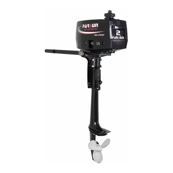
Parsun outboard motors are available for all boats, from PVC fishing boats to solid boats and yachts. Parsun is currently one of the fastest growing
manufacturers in the production of outboard motors.
Having appeared on the Chinese market in 2006, it used all the international experience gained in the production of outboard motors, using the most modern technologies and cheap skilled labor.
Taking as a model the best of the currently existing models of two-stroke and four-stroke outboard engines, Parsun manufactures a wide range of high-quality and
low-cost equipment.
Today, Parsun has 31 exclusive distributors in 39 countries. Quality and reasonable price ensures steady demand for Parsun outboard motors in European countries, for example, in
2008, more than 5,000 units were sold in Sweden alone.
Пользовательское соглашение
ТК «Маяк»
© 2013-2020. Все данные сайта носят исключительно информационный характер и не являются договором офертой ни при каких обстоятельствах.
![]()
![]()
![]()
![]()
Создание сайта«Gurevich.su»
-
Page 1
OUTBOARD MOTOR OWNER’S MANUAL F6ABM F5ABM … -
Page 2
Thank you for owning an outboard motor. Thank you for your trust in our company and products. The outboard motors are powerful, economic and safe, manufactured with advanced technology. Please read this manual carefully before operating your outboard motor. A thorough understanding of the manual will help you to know this product for proper operation, maintenance and care. -
Page 3
Engine Identification Numbers Outboard motor serial number The outboard motor serial number is marked on the label. The label can be found on the bracket left assembly or on the upper part of the bracket swivel. Record your outboard motor serial number in the spaces provided to assist you in ordering spare parts from your dealer or for reference in case your outboard motor is stolen. -
Page 4
Engine serial number The engine serial number is carved on the aluminum casting of engine. Engine serial number as follows: Manufacturer’s Declaration This outboard motor complies with the requirements of Directive 2003/44/EC in relation to the exhaust and noise emissions. The following installation and maintenance instructions, if applied, guarantee that the outboard motor will remain in compliance with: 1. -
Page 5: Table Of Contents
Table of contents 1. Main components and General information ………………1 1.1 Main components ……………………..1 1.2 General information ……………………..3 1.2.1 Specifications ……………………… 3 1.2.2 Fueling instructions …………………….. 4 1.2.3 Propeller selection ……………………… 6 2.
-
Page 6
2.11.2 Tilting down ……………………..29 2.12 Cruising in other conditions ………………….30 2.12.1 Cruising in shallow water ………………….30 2.12.2 Cruising in salt water ……………………30 3. Maintenance ……………………….31 3.1 Greasing ……………………….31 3.2 Cleaning and adjusting spark plug ……………….. -
Page 7
5.1 Impact damage ……………………..47 5.2 Starter will not operate ……………………47 5.3 Treatment of submerged motor ………………….50 6. Troubleshooting ……………………..52 7. Circuit diagram ………………………. 56 … -
Page 8: Main Components And General Information
1. Main components and General information 1.1 Main components 1. Top cowling 6. Clamp bracket 11. Gear shift lever 2. Top cowling lock 7. Tiller handle 12. Choke knob 3. Anti-cavitation plate 8. Throttle grip 13. Engine stop button 4.
-
Page 9
If your model includes a portable fuel tank, its parts are as follows: 4 2 3 1 1. Fuel tank cap 3. Air vent screw 2. Fuel joint 4. Fuel gauge If your model includes a built-in fuel tank, its parts are as follows: 1 … -
Page 10: General Information
WARNING: The fuel tank supplied with this engine could only be used as supply of fuel for its running and must not be as a fuel storage container. The fuel cock must be at close position while using portable fuel tank. …
-
Page 11: Fueling Instructions
Main performance Items Data Items Data Valve clearance IN 3.7Kw/5500Rpm(5HP) 0.08~0.12mm (cold engine) Maximum output Valve clearance EX 4.4Kw/5500Rpm(6HP) 0.08~0.12mm (cold engine) Full throttle operating range 4500~5500Rpm Spark plug 13.0Nm Tightening torque for Engine oil Idling speed (in neutral) 1500±50Rpm 18.0Nm engine…
-
Page 12
If you should swallow some gasoline, inhale gasoline vapor, or get gasoline in your eye, get immediate medical attention. If any gasoline spills onto your skin, immediately wash with soap and water. Change clothing if gasoline spills on it. Touch the fuel nozzle to metal components to prevent electrostatic sparks. -
Page 13: Propeller Selection
1.2.3 Propeller selection The performance of your outboard motor will be critically affected by your choice of propeller, as an incorrect choice could adversely affect performance. The outboard motor is fitted with propeller chosen to perform well over a range of applications, but there may be uses where a propeller with a different pitch would be more appropriate.
-
Page 14
WARNING: Overpowering a boat could cause severe instability. Do not install an outboard motor with more horsepower than the maximum rating on the capacity plate of the boat. If the boat does not have a capacity plate, consult the boat manufacturer. Improper mounting of the outboard motor could result in dangerous conditions and injury. -
Page 15: Mounting Height
2.1.1 Mounting height The mounting height of the outboard motor greatly affects your boat running efficiency. If the mounting height is too high, cavitation tends to occur, thus reducing the propulsion. If the mounting height is too low, the water resistance will increase and thereby reduce engine efficiency.
-
Page 16: Clamping The Outboard Motor
2.1.2 Clamping the outboard motor 1. Tighten the transom clamp screw evenly and securely. Occasionally check the clamp screws for tightness during operation of the outboard motor because they could become loose due to engine vibration. WARNING: Loose clamp screws could allow the outboard motor to fall off or move on the transom. This could cause loss of control.
-
Page 17: Breaking In Engine
3. Secure the clamp bracket to the transom using the appropriate bolts. For details, consult your dealer. WARNING: Avoid using bolts, nuts or washers inappropriate. After tightening, test running the engine and check their tightness. 2.2 Breaking in engine Your new engine requires a period of break-in to allow mating surfaces of moving parts to wear in evenly.
-
Page 18: Pre-Operation Checks
2.3 Pre-operation checks Fuel Check to be sure you have plenty of fuel for your trip. Make sure there are no fuel leaks or gasoline fumes. Check fuel line connections to be sure they are tight. …
-
Page 19: Filling Fuel
2. Check the oil level using the dipstick to be sure the level falls between the upper and lower marks. Fill with oil if it is below the lower mark, or drain to the specified level if it is above the upper mark. 2 …
-
Page 20
3. Securely close the cap after filling the tank. Wipe up any spilled fuel. NOTE: The upper fuel level mark is indicated on the built-in fuel tank. 1 1. Upper level mark … -
Page 21: Starting Engine
2.5 Starting engine 1. Loosen the air vent screw on the fuel tank cap. One turn for built-in tank, 2 or 3 turns for the external fuel tank. 2. Open the fuel cock. Built in fuel tank External fuel tank …
-
Page 22
3. Squeeze the primer pump with the outlet end up until you feel it become firm. 4. Place the gear shift lever in neutral. NOTE: The start-in-gear protection device prevents the engine from starting except when in neutral. Attach the engine stop switch lanyard to secure place on your clothing, or your arm or leg. -
Page 23
WARNING: The engine must be started in neutral; otherwise damage to the engine can occur. Do not attach the lanyard to clothing that could tear loose. Do not route the lanyard where it could become entangled, preventing it from functioning. … -
Page 24
6. Pull out the choke knob fully. NOTE: It is not necessary to use the choke when starting a warm engine. If the choke is left in the “START” (start) position while the engine is running, the engine will run … -
Page 25: Warming Up Engine
8. After the engine starts, slowly return the manual starter handle to its original position before releasing it. 9. Slowly return the throttle grip to the fully closed position. CAUTION: When the engine is cold, it needs to be warmed up. If the engine does not start on the first try, repeat the procedure.
-
Page 26: Shifting
CAUTION: If water is not flowing out of the hole at all times while the engine is running, stop the engine and check whether the cooling water inlet on the lower case or the cooling water pilot hole is blocked. …
-
Page 27: Reverse
2. Move the gear shift lever quickly and firmly from neutral to forward. 2.7.2 Reverse WARNING: When operating in reverse, go slowly. Do not open the throttle more than half. Otherwise the boat could become unstable, which could result in loss of control and an accident. 1.
-
Page 28: Tiller
2. Move the gear shift lever quickly and firmly from neutral to reverse. 2.8 Tiller 1. Change direction To change direction, move the tiller handle to the left or right as necessary. 2. Change speed. Turn the grip counterclockwise to increase speed and clockwise to decrease speed. …
-
Page 29
3. Throttle indicator The throttle indicator is on the throttle grip. The fuel consumption curve on the throttle indicator shows the relative amount of fuel consumed for each throttle position. Choose the setting that offers the best performance and fuel economy for the desired operation. 1. -
Page 30: Stopping Engine
WARNING: Do not over-tighten the friction adjuster. If there is too much resistance, it could be difficult to move throttle lever or grip, which could result in an accident. 2.9 Stopping engine NOTE: Before stopping the engine, first let it cool off for a few minutes at idle or low speed. Stopping the engine immediately after operating at high speed is not recommended.
-
Page 31
NOTE: If the outboard motor is equipped with an engine stop switch lanyard, the engine can also be stopped by pulling the lanyard and removing the lock plate from the engine stop switch. 2. Tighten the air vent screw on the fuel tank cap and set the fuel cock lever or knob to the closed position. 3. -
Page 32: Trimming Outboard Motor
2.10 Trimming outboard motor There are 4 or 5 holes provided in the clamp bracket to adjust the outboard motor trim angle. 1. Stop the engine. 2. Remove the trim rod from the clamp bracket while slightly tilting the outboard motor up. 3.
-
Page 33: Tilting Up And Down
2.11 Tilting up and down If the engine will be stopped for some time or if the boat is moored in shallows, the outboard motor should be tilted up to protect the propeller and casing from damage by collision with obstructions, and also to reduce corrosion.
-
Page 34
2. Tighten the steering friction adjuster by turning it clockwise to prevent the motor from turning freely. 3. Tighten the air vent screw. On models equipped with a fuel joint, disconnect the fuel line from the outboard motor. … -
Page 35
4. Close the fuel cock. 5. Hold the rear handle and tilt the engine up fully until the tilt support lever automatically locks. … -
Page 36: Tilting Down
2.11.2 Tilting down 1. Slightly tilt the outboard motor up. 2. Slowly tilt the outboard motor down while pulling the tilt support bar lever up. 3. Loose the steering friction adjuster by turning it counterclockwise, and adjust the steering friction according to operator preference.
-
Page 37: Cruising In Other Conditions
2.12 Cruising in other conditions 2.12.1 Cruising in shallow water The outboard motor can be tilted up partially to allow operation in shallow water. WARNING: The tilt lock mechanism does not work while the shallow water cruising system is being used. Run …
-
Page 38: Maintenance
3. Maintenance While using the outboard motor, the periodic maintenance is necessary for you to ensure its performance. WARNING: Be sure to turn off the engine when you perform maintenance unless otherwise specified. This work should always be done by a qualified mechanic or your authorized dealer. CAUTION: If replacement parts are necessary, use only genuine parts or appropriate parts of the same type and quality.
-
Page 39: Cleaning And Adjusting Spark Plug
3.2 Cleaning and adjusting spark plug You should periodically remove and inspect the spark plug because heat and deposits will cause the spark plug to slowly break down and erode. If necessary, you should replace the spark plug with another of the correct type.
-
Page 40: Inspecting Idling Speed
CAUTION: The fuel filter is one piece, disposable spare part. 3.4 Inspecting idling speed A diagnostic tachometer should be used for this procedure.
-
Page 41: Changing Engine Oil
3.5 Changing engine oil WARNING: Avoid draining the engine oil immediately after stopping the engine. The oil is hot and should be handled with care to avoid burns. Be sure the outboard motor is securely fastened to the transom or a stable stand. CAUTION: Change the engine oil after the first 10 hours of operation, and every 100 hours or at 6-month …
-
Page 42: Checking Wiring And Connectors
6. Turn off the engine and wait 3 minutes. Recheck the oil level using the dipstick to be sure the level falls between the upper and lower marks. CAUTION: The oil should be changed more often when the engine is operated under adverse conditions such as extended trolling.
-
Page 43: Checking Propeller
3.8 Checking propeller WARNING: Before inspecting, removing or installing the propeller, always take actions to ensure the engine does not accidentally start, such as removing the spark plug caps from the spark plugs, placing the shift control in neutral, and removing the lanyard from the engine stop switch, etc.. Serious injury can occur if the engine should start and you are standing too close to the propeller.
-
Page 44: Removing The Propeller
3.8.1 Removing the propeller 1. Straighten the cotter pin and pull it out using a pair of pliers. 2. Remove the propeller nut, washer, and spacer (if equipped). 3. Remove the propeller and thrust washer. 3.8.2 Installing the propeller CAUTION: Be sure to install the thrust washer before instating the propeller, otherwise the lower case and …
-
Page 45
3. Remove gear oil drain screw. 2 1. Gear oil drain screw 1 2. Oil level plug CAUTION: Change the gear oil after the first 10 hours of operation, and every 100 hours or at 6-month intervals thereafter. Otherwise the gear will wear quickly. 4. -
Page 46: Cleaning Fuel Tank
3.10 Cleaning fuel tank WARNING: Keep away from sparks, cigarettes, flames, or other sources of ignition when cleaning the fuel tank. Cleaning the fuel tank in a well-ventilated open air. 1. Empty the fuel tank into an approved container. 2.
-
Page 47: Checking And Replacing Anode(S)
3.11 Checking and replacing anode(s) Inspect the external anodes periodically. Remove scales from the surfaces of the anodes. Consult a dealer for replacement of external anodes. CAUTION: Do not paint anodes, as this would render them ineffective and can cause more rapid engine corrosion.
-
Page 48: Checking Top Cowling
3.12 Checking top cowling Check the fitting of the top cowling by pushing it with both hands. If it is loose have it repaired by your dealer. …
-
Page 49: Maintenance Table
3.13 Maintenance table When utilized under normal condition, maintained and repaired in the proper manner, the outboard motor can work normally within the normal life period. Frequency of maintenance operations may be adjusted according to the operating conditions, but the following table gives general guidelines.
-
Page 50
Continuation /…1 Initial Every Item Operations 10 hours 50 hours 100 hours 200 hours ( 1 month ) (3 months) (6 months) ( 1 year ) Idling speed Check/adjustme ●/○ ●/○ (carburetor models) ● ● Propeller and cotter pin Check/replacement ○… -
Page 51: Transporting And Storing
4 Transporting and storing 4.1 Transporting The outboard motor should be upright as shown in the following figure 1 when be in transit. If the engine must be laid down, please be sure to put it as shown in the following figure 2 or figure 3 when be in transit. CAUTION: Do not use the tilt support lever or knob when trailering the boat.
-
Page 52: Storing
4.2 Storing When store your outboard motor for prolonged periods of time (2 months or longer), several important procedures must be performed to prevent excessive damage. CAUTION: Keep the outboard motor in an upright attitude when storing it. If storing the outboard motor on its side (not upright), put it on a cushion after draining the engine oil completely.
-
Page 53
CAUTION: If the fresh water level is below the level of the anti-cavitation plate, or if the water supply is insufficient, engine seizure may occur. 6. Start the engine. Flush the cooling system. Perform the flushing and fogging at the same time, as fogging/lubricating of the engine is mandatory to prevent engine rust. -
Page 54: Actions In Emergency
direct sunlight. 5 Actions in emergency 5.1 Impact damage If the outboard motor hits an object in the water, follow the procedure below. 1. Stop the engine immediately. 2. Inspect the control system and all components for damage. 3. Whether damage is found or not, return to the nearest harbor slowly and carefully. 4.
-
Page 55
The procedure is as follows: 1. Remove the top cowling. 2. Remove the start-in-gear protection cable and the choke cable. 1 2 1. Start-in-gear protection cable 2. Choke cable 3. Remove the starter after removing the three bolts. … -
Page 56
4. Reinstall two bolts to secure the fuel tank. 5. Prepare the engine for starting. For further information, see section 2.5. 6. Insert the knotted end of the emergency starter rope into the notch in the flywheel rotor and wind the rope several turns around the flywheel clockwise. -
Page 57: Treatment Of Submerged Motor
8. Give a strong pull straight out to crank and start the engine. Repeat it necessary. 5.3 Treatment of submerged motor If the outboard is submerged, immediately take it to a dealer. Otherwise some corrosion may begin almost immediately. 1.
-
Page 58
6. Take the outboard motor to a dealer as soon as possible. CAUTION: Do not attempt to run the outboard motor until it has been completely inspected. … -
Page 59: Troubleshooting
6. Troubleshooting Trouble type Possible reason Recovery action Starter components are faulty Have serviced by your dealer Starter will not operate Shift level is not in neutral Shift to neutral Fuel tank is empty Fill tank with clean, fresh fuel Fuel is contaminated or stale Fill tank with clean, fresh fuel Fuel filter clogged…
-
Page 60
Continuation /…1 Trouble type Possible reason Recovery action Check for pinched or kinked fuel line or Fuel system is obstructed other obstructions in fuel system Fuel is contaminated or stale Fill tank with clean, fresh fuel Fuel filter clogged Replace with recommended type Spark plug gap is incorrect Inspect and adjust as specified… -
Page 61
Continuation /…2 Trouble type Possible reason Recovery action Propeller is damaged Repair or replace propeller Adjust trim angle to achieve most Trim angle is incorrect efficient operation Motor is mounted at incorrect transom Adjust motor to proper transom height height Boat bottom is fouled with marine growth Clean boat bottom… -
Page 62
Continuation /…3 Trouble type Possible reason Recovery action Thermostat is faulty or clogged Have serviced by your dealer Air vent screw on fuel tank is closed Open air vent screw Engine power Fuel pump has malfunctioned Have serviced by your dealer loss Fuel joint connection is incorrect Connect correctly… -
Page 63: Circuit Diagram
7. Circuit diagram Engine stop switch Spark plug black Ignitor ass’y white DESCRIPTION …