Руководство на английском языке по техническому обслуживанию и ремонту автомбилей Volvo S40 и Volvo V40 1996-2004 годов выпуска с бензиновыми двигателями.
- Автор: —
- Издательство: Haynes Publishing
- Год издания: —
- Страниц: 308
- Формат: PDF
- Размер: 57,6 Mb

Мультимедийное руководство на английском языке по техническому обслуживанию и ремонту автомбилей Volvo S40 и Volvo V40.
- Автор: —
- Издательство: Mitchell
- Год издания: —
- Страниц: —
- Формат: ISO
- Размер: 661,9 Mb
Руководство по эксплуатации, техническому обслуживанию и ремонту автомбилей Volvo S40 и Volvo V50 2004-2007 годов выпуска с бензиновыми и дизельными двигателями.
- Автор: —
- Издательство: Алфамер Паблишинг
- Год издания: —
- Страниц: 320
- Формат: PDF
- Размер: 122,7 Mb
Руководство по эксплуатации, техническому обслуживанию и ремонту автомбилей Volvo S40 и Volvo V40 1996-2004 годов выпуска с бензиновыми двигателями.
- Автор: —
- Издательство: Алфамер Паблишинг
- Год издания: —
- Страниц: 295
- Формат: —
- Размер: —

Сборник руководств по эксплуатации и техническому обслуживанию автомбиля Volvo V40 Cross Country 2014-2015 годов выпуска.
- Автор: —
- Издательство: Volvo Car Corporation
- Год издания: 2013/2014
- Страниц: 540/472
- Формат: PDF
- Размер: 23,6 Mb
Руководство по эксплуатации, техническому обслуживанию и ремонту + каталог расходных запчастей автомбилей Volvo S40 и Volvo V50 2004-2007 годов выпуска с бензиновыми и дизельными двигателями.
- Автор: —
- Издательство: Легион-Автодата
- Год издания: —
- Страниц: 344
- Формат: —
- Размер: —
Руководство по эксплуатации и ремонту автомбилей Volvo S40 и Volvo V40 1996-2004 годов выпуска с бензиновыми и дизельными двигателями.
- Автор: —
- Издательство: Гуси-Лебеди
- Год издания: —
- Страниц: 280
- Формат: —
- Размер: —
Сборник руководств по эксплуатации и техническому обслуживанию автомбиля Volvo S40 с 2004 года выпуска.
- Автор: —
- Издательство: Volvo Car Corporation
- Год издания: 2003-2011
- Страниц: —
- Формат: PDF
- Размер: 66,1 Mb
Руководство по эксплуатации, техническому обслуживанию и ремонту автомбилей Volvo S40 и Volvo V50 с 2003 года выпуска с бензиновыми и дизельными двигателями.
- Автор: —
- Издательство: Арго-Авто
- Год издания: —
- Страниц: 784
- Формат: —
- Размер: —

Всем доброго дня!
Для удобства использования решил собрать в данной записи документацию, технические характеристики, мануалы, руководства, инструкции и прочий полезный материал для своей машины, найденные за несколько лет на просторах интернета. Предвижу, что данная подборка для местных олдовых корифеев покажется несколько скучной, тем не менее, не исключаю, что для кого-то она также может быть информативной и полезной. Информация актуальна для владельцев автомобилей Volvo C30/S40/V50/C70.
— Регламентированный перечень работ по ТО
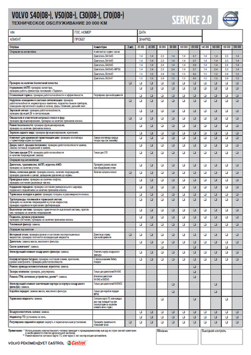
Ссылка на файл в формате PDF (ОД Обухов)
— Каталоги запчастей и аксессуаров Volvo
Carcats.ru
Elcats.ru
Emex.ru
accessories.volvocars.com — официальный каталог аксессуаров
Инструкция подбора запчастей и комплектующих Volvo по VIN-номеру — Часть 1, Часть 2
— Руководство/инструкция по эксплуатации
Ссылка на руководство для Volvo V50 MY2012
Ссылка на руководства для других моделей и/или модельных годов
Ссылка на различные инструкции для всех моделей Volvo (Eng, официальный сайт Volvo)
Ссылка на различные инструкции для Volvo S40/V50 (Eng, ресурс владельцев Volvo в UK)
— Quick Guide
Ссылка на файл в формате PDF
— Схемы соединений проводки (Электрика)
Ссылка на файл в формате PDF
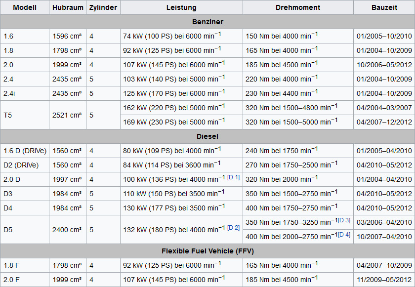
— Характеристики и годы производства двигателей для Volvo C30/S40/V50
Ссылка на источник
— Технические характеристики бензиновых двигателей 2.4 (B5244S4/B5244S5) и 2.5 (B5254T3)
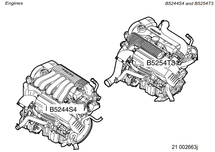
Ссылка на файл в формате PDF (Eng)
— Технические характеристики бензинового двухлитрового двигателя B4204S3 (он же Mazda MZR LF 2.0, он же Ford Duratec HE 2.0)
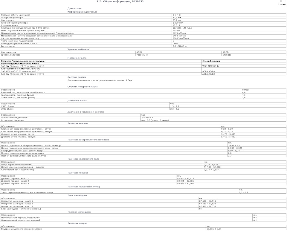
Ссылка на изображение в полном размере (источник VIDA)
Ссылка на подборку полезной информации о двигателе Volvo B4204S3/Mazda MZR LF 2.0/Ford Duratec HE 2.0
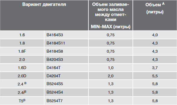
— Моторное масло
Моторное масло — объём, допуск, эксплуатационные свойства, вязкость, артикулы канистр для бензиновых двигателей B4164S3, B4184S8, B4184S11, B4204S3, B4204S4, B5244S4, B5244S5, B5254T3, B5254T7 и дизельных двигателей D4162T, D4164T, D4204T, D4204T2, D5204T, D5204T5, D5244T8, D5244T9, D5244T13.
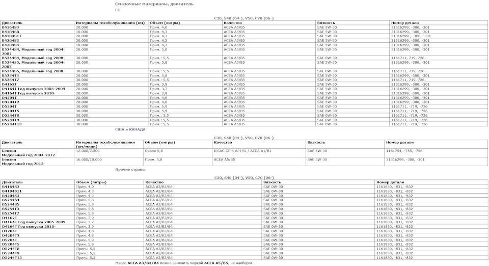
Ссылка на изображение в полном размере (источник VIDA)
— Объём масла между минимальной и максимальной отметками на щупе двигателей Volvo C30/S40/V50
— Автоматическая 5-ти ступенчатая коробка передач Aisin AW55-50/51SN
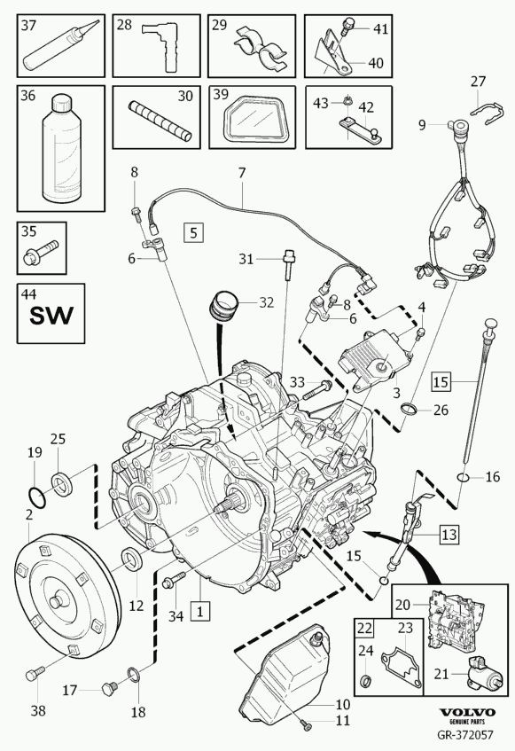
Запчасти на фото: 0835631, 363039, 294140
Ссылка на каталог запчастей в формате PDF (Eng)
Ссылка на мануал в формате PDF (Eng)
— Роботизированная 6-ти ступенчатая коробка передач Getrag 6DCT450 (MPS6, она же PowerShift)
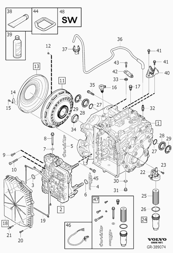
Запчасти на фото: 312223, 333516, 462120
Серия публикаций о PowerShift от технического специалиста Сергея glimmer:
Эксплуатация PowerShift (6DCT450)
Функции коробки PowerShift (6DCT450)
Принцип работы Powershift 6DCT450
Замена масла в коробке PowerShift (6DCT450)
VIDA 2021: Инструкция по замене масла АКПП PowerShift (6DCT450) — NEW!
Замена сцепления 6DCT450 и Eco Boost 203(240)л.с)
Замена уплатнения сцепления 6DCT450 и Eco Boost 203(240)л.с
Модуль управления коробки передач (TCM). Часть 1
Модуль управления коробки передач (TCM). Часть 2
Модуль управления коробки передач (TCM). Замена датчика входного вала
Powershift 6DCT450 в деталях. Часть 1
Powershift 6DCT450 в деталях. Часть 2. Принципиальные схемы ТСМ
Powershift 6DCT450 в деталях. Часть 3. Демпфер.
Powershift 6DCT450 в деталях. Часть 4. Соленоиды ТСМ.
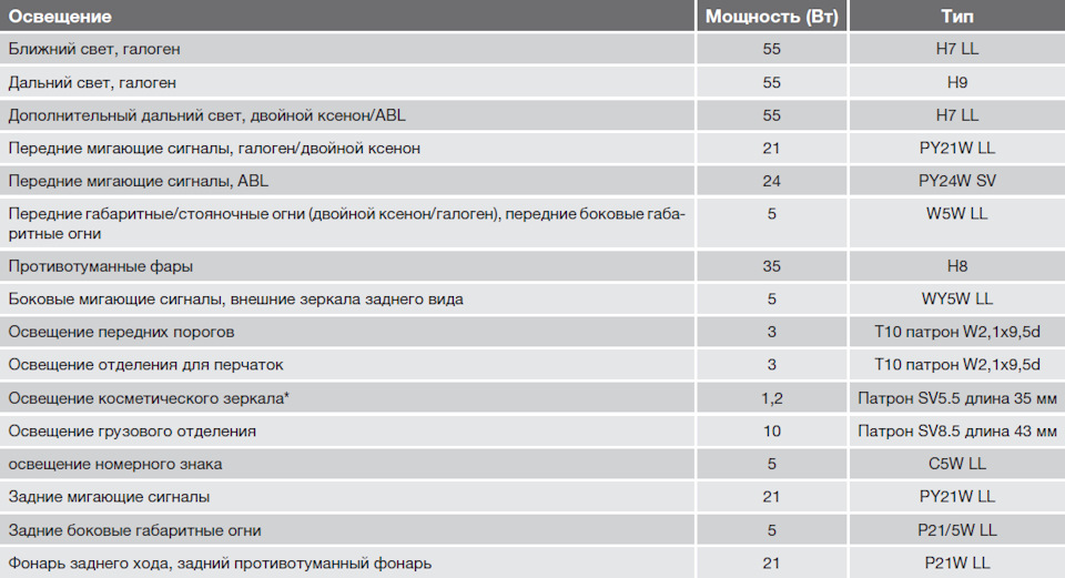
— Типы цоколей и мощность ламп
— Брошюра Volvo V50 (Volvo Cars Russia)
Скачать в формате PDF — описание, фото, комплектации, экстерьер, интерьер, аксессуары
— Официальные пресс-релизы и фото Volvo V50 (Volvo Cars)
Ссылка на официальные пресс-релизы, фото и видео
— Каталог оригинальных литых дисков Volvo (артикулы и размерность)

Ссылка на каталог — названия дисков, размерность и артикулы
— Комплектации Volvo V50
Ссылка
— Проверка доступности обновлений Service 2.0 для всех автомобилей Volvo по VIN-коду

Ссылка
— Расшифровка информации о комплектации для всех автомобилей Volvo по VIN-коду
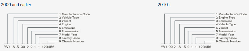
Запчасти на фото: AS992
Ссылка на форму отправки запроса на расшифровку информации по VIN-коду в ОД Volvo Car M1
— Volvo VIDA
VIDA Online (для пользователей clubvolvo.ru)
VIDA 2014D + DiCE (Установка, настройка и использование)
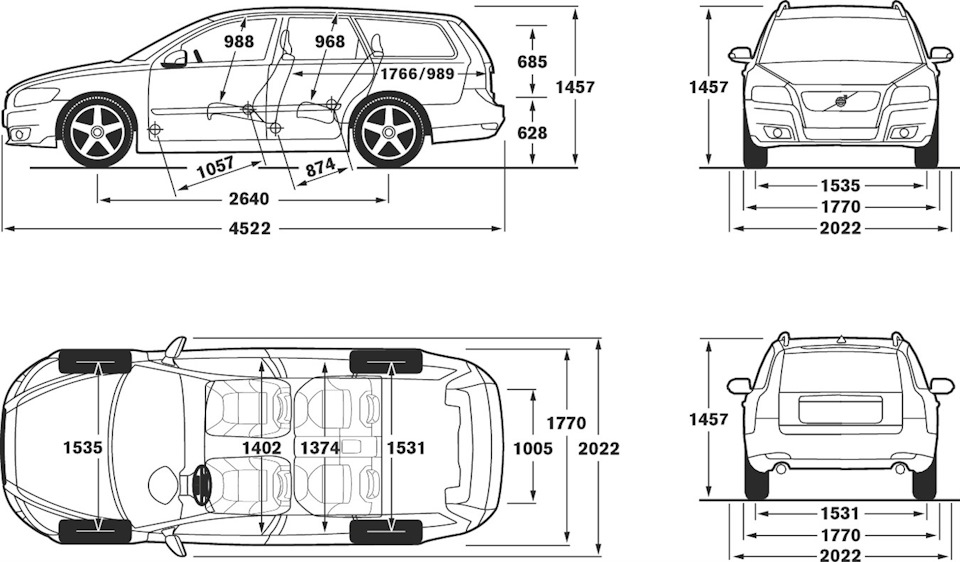
— Кузов
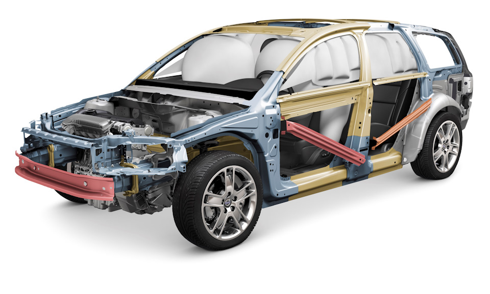
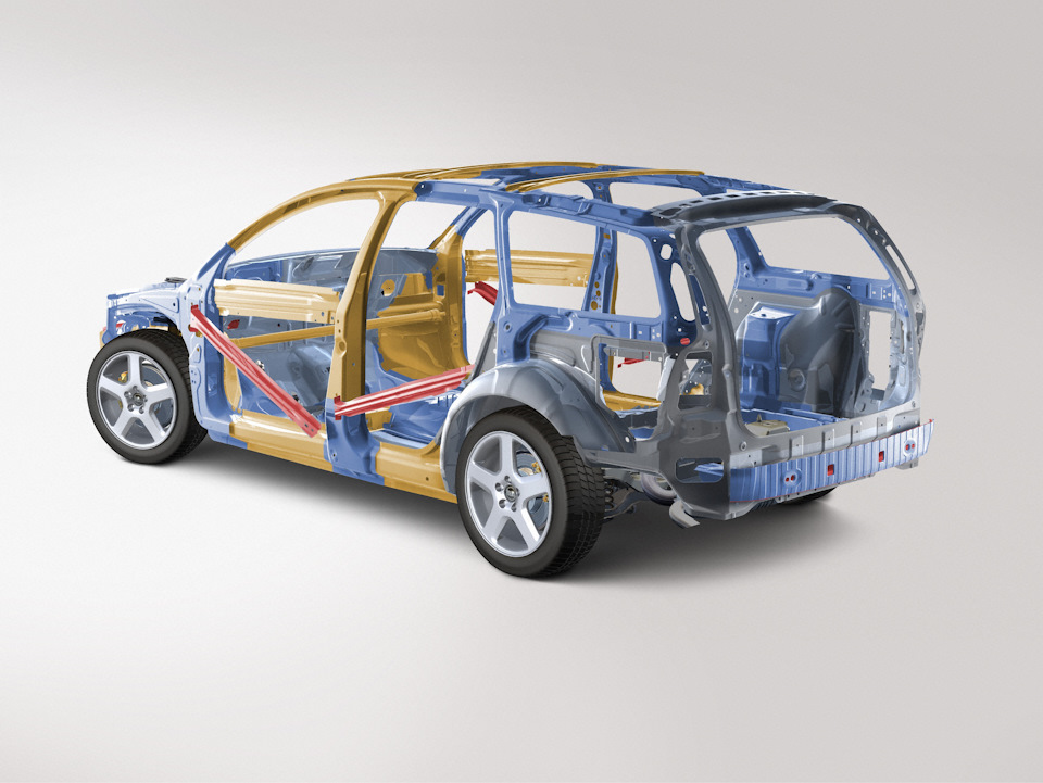
![]()

УВАЖАЕМЫЕ ВЛАДЕЛЬЦЫ АВТОМОБИЛЯ VOLVO!
СПАСИБО ЗА ВАШ ВЫБОР АВТОМОБИЛЯ VOLVO!
Мы надеемся, что Вы в течение многих лет получите наслаждение от управления Вашим автомобилем Volvo. Этот автомобиль создан для обеспечения комфорта и безопасности Вам и Вашим пассажирам. Volvo — это один из самых безопасных легковых автомобилей в мире. Кроме того, Ваш Volvo разработан с учетом всех действующих требований по безопасности и экологических норм.
Для того чтобы этот автомобиль доставил Вам истинное удовольствие, мы рекомендуем ознакомиться с информацией об оборудовании, эксплуатации и техническом обслуживании, которая содержится в данном Руководстве по эксплуатации.

Содержание
|
00 Введение |
01 Безопасность |
||||
|
Введение ……………………………………. |
6 |
Ремни безопасности …………………. |
12 |
||
|
00 |
01 |
15 |
|||
|
Volvo Car Corporation и |
Система AIRBAG ……………………….. |
||||
|
окружающая среда ……………………… |
7 |
Надувные подушки безопасности |
|||
|
(SRS) ………………………………………… |
16 |
||||
|
Активирование/отключение |
|||||
|
подушки безопасности (SRS) …….. |
19 |
||||
|
Боковая подушка безопасности |
|||||
|
(SIPS-bag) …………………………………. |
21 |
||||
|
Надувной занавес (IC) ……………….. |
23 |
||||
|
WHIPS ………………………………………. |
24 |
||||
|
Когда срабатывают системы …….. |
26 |
||||
|
Аварийный режим …………………….. |
27 |
||||
|
Безопасность детей ………………….. |
28 |
||||
02 Приборы и органы управления
|
Обзор, автомобили с левосторонним |
|
|
02 |
36 |
|
управлением ……………………………………. |
|
|
Обзор, автомобили с правосторонним |
|
|
управлением ……………………………………. |
38 |
|
Панель управления в двери водителя .. |
40 |
|
Комбинированный прибор ………………… |
41 |
|
Контрольные и предупреждающие |
|
|
символы …………………………………………… |
42 |
|
Информационный дисплей ……………….. |
46 |
Электрическое гнездо и выключатель в
|
центральной консоли ……………………….. |
47 |
|
Панель освещения ……………………………. |
48 |
|
Левый подрулевой рычаг ………………….. |
50 |
|
Правый подрулевой рычаг ……………….. |
52 |
|
Система поддержания постоянной |
|
|
скорости (опция) ………………………………. |
54 |
Клавиатура на рулевом колесе (опция) 55 Регулировка положения рулевого колеса,
|
аварийная мигающая сигнализация ….. |
56 |
|
Стояночный тормоз, электрическое |
|
|
гнездо ……………………………………………… |
57 |
|
Электрические стеклоподъемники …… |
58 |
|
Зеркала заднего вида ………………………. |
60 |
|
Электроуправляемый люк в крыше |
|
|
(опция) ……………………………………………… |
64 |
|
Персональные настройки …………………. |
66 |
2

Содержание
|
03 Климатическая установка |
04 Интерьер салона |
05 Замки и сигнализация |
||||||
|
Общие сведения о климатической |
Передние кресла ……………………….. |
82 |
Пульт дистанционного |
|||||
|
установке …………………………………. |
70 |
Освещение салона |
84 |
управления с плоским ключом …… |
94 |
|||
|
Ручное управление микроклиматом, |
Keyless drive (опция) |
98 |
||||||
|
Места для хранения вещей в |
||||||||
|
А/С |
72 |
|||||||
|
салоне |
86 |
Запирание и отпирание |
101 |
|||||
|
Электронный климат-контроль, |
||||||||
|
Заднее сиденье |
88 |
Блокировка для безопасности |
||||||
|
ECC (опция) |
74 |
|||||||
|
Багажное отделение |
90 |
детей |
104 |
|||||
|
Распределение воздуха |
77 |
|||||||
|
Охранная сигнализация (опция) |
105 |
|||||||
|
Топливный стояночный отопитель |
04 |
05 |
||||||
|
(опция)03……………………………………… |
78 |
3

Содержание
|
06 Запуск двигателя и |
|
|
вождение |
|
|
Общие сведения …………………………. |
110 |
|
Заправка топливом ……………………… |
112 |
|
Запуск двигателя ………………………… |
113 |
|
Замок зажигания и блокировки |
|
|
рулевого колеса ………………………….. |
114 |
|
Keyless drive ……………………………….. |
115 |
|
Ручная коробка передач ……………… |
116 |
|
Автоматическая коробка передач .. |
118 |
|
Привод на четыре колеса ……………. |
121 |
|
Тормозная система …………………….. |
122 |
|
Система динамической |
|
|
стабилизации и силы тяги …………… |
124 |
|
Помощь при парковке (опция) ……… |
126 |
|
Blind Spot Information System, BLIS |
|
|
(опция) ………………………………………… |
128 |
|
Буксировка и эвакуация ……………… |
131 |
|
вспомогательного |
|
|
Пуск06от |
|
|
источника …………………………………… |
133 |
|
Езда с прицепом …………………………. |
134 |
|
Сцепное устройство ……………………. |
136 |
|
Съемный буксирный крюк …………… |
138 |
|
Погрузка …………………………………….. |
143 |
|
Регулировка направления |
|
|
света фар …………………………………… |
144 |
07 Колеса и шины
|
Общие сведения ……………………… |
148 |
|
07 |
152 |
|
Давление воздуха в шинах ………. |
|
|
Треугольный знак аварийной |
|
|
остановки и запасное колесо ….. |
154 |
|
Замена колес ………………………….. |
156 |
|
Временная герметизация шин …. |
158 |
08 Уход за автомобилем
|
Чистка …………………………………….. |
168 |
|
08 |
|
|
Восстановление лакокрасочного |
|
|
покрытия …………………………………. |
171 |
|
Антикоррозионная защита ……….. |
172 |
4

Содержание
|
09 Уход и техобслуживание |
10 Информационно- |
11 Технические данные |
|||||
|
Плановое техобслуживание |
развлекательная система |
Обозначение типа |
228 |
||||
|
Общие сведения |
204 |
||||||
|
Volvo ………………………………………… |
176 |
11 |
|||||
|
09 |
10 |
229 |
|||||
|
Уход за автомобилем своими |
Функции аудиосистемы ……………. |
205 |
Размеры и массы …………………….. |
||||
|
силами ……………………………………. |
177 |
Функции радиоприемника ………… |
207 |
…Технические данные двигателя |
230 |
||
|
Капот и двигательный отсек ……. |
178 |
Функции CD …………………………….. |
211 |
……………….Масло для двигателя |
232 |
||
|
Дизель ……………………………………. |
179 |
Структура меню – система |
Жидкости и смазочные |
||||
|
……………………Масла и жидкости |
180 |
звуковоспроизведения …………….. |
213 |
Топливо ………………………………….. |
238 |
||
|
……….Щетки стеклоочистителей |
185 |
………..Функции телефона (опция) |
214 |
Катализатор |
241 |
||
|
Аккумуляторная батарея |
186 |
Структура меню – телефон |
221 |
||||
|
Электросистема |
242 |
||||||
|
Замена ламп накаливания |
188 |
||||||
|
Предохранители ……………………… |
194 |
||||||
5

Руководство по эксплуатации
Лучший способ познакомиться с Вашим новым автомобилем — это прочитать настоящее Руководство по эксплуатации, желательно до первой поездки. Это позволит Вам познакомиться с новыми функциями, узнать, как лучше управлять автомобилем в разных ситуациях и как наиболее эффективно использовать различные свойства и возможности автомобиля. Особое внимание уделяйте приведенным инструкциям по безопасности:
 ПРЕДОСТЕРЕЖЕНИЕ
Если невыполнение инструкций влечет за собой риск получения травм, приводятся соответствующие предостережения.
руководстве по эксплуатации описаны опции (оборудование, устанавливаемое на заводе-изготовителе) и некоторые аксессуары (дополнительное оборудование).
 ВНИМАНИЕ
Автомобили Volvo комплектуются в зависимости от требований рынков сбыта и национальных или местных законов и правил.
Технические характеристики, особенности конструкции и иллюстрации, приведенные в настоящем Руководстве по эксплуатации, не являются обязательными. Мы оставляем за собой право вносить изменения без предварительного уведомления.
© Volvo Car Corporation
ВАЖНО
Если невыполнение инструкций может привести к повреждению автомобиля, приводятся соответствующие тексты под рубрикой «Важно».
Оборудование, описанное в настоящем руководстве по эксплуатации, установлено не на всех моделях автомобиля. Помимо стандартного оборудования, в настоящем
6

Введение
Volvo Car Corporation и окружающая среда
Volvo Car Corporation экологическая концепция
Забота об окружающей среде, безопасность и качество являются тремя основополагающими принципами деятельности всех подразделений Volvo Car Corporation. Мы также верим, что наши клиенты разделяют нашу заботу об окружающей среде.
Автомобиль Volvo отвечает жестким международным стандартам по охране окружающей среды и, кроме того, изготавливается на самых экологически чистых и ресурсосберегающих заводах в мире. Volvo Car Corporation
сертифицирован в соответствии с глобальным экологическим стандартом ISO 14001, регламентирующим работы по охране окружающей среды.
Всем автомобилям Volvo выдается экологическая справка EPI (Environmental Product Information), с помощью которой Вы можете проследить, как различные модели и двигатели воздействуют на окружающую среду в течение всего срока службы.
Более подробно см. сайт: www.volvocars.com/EPI.
Расход топлива
Все автомобили Volvo конкурентоспособны в отношении расхода топлива в соответствующих классах. Чем меньше расход топлива, тем ниже в общем случае уровень выбросов диоксида углерода – газа, создающего парниковый эффект.
Вы, как водитель, можете повлиять на расход топлива. Дополнительную информацию можно найти в разделе Охрана окружающей среды на стр. 9.
7

Введение
Volvo Car Corporation и окружающая среда
Эффективная очистка отработавших газов
Ваш автомобиль Volvo изготовлен в соответствии с концепцией Чистота внутри и снаружи – концепция, которая предусматривает как чистую среду в салоне, так и высокую степень очистки отработавших газов. Во многих случаях уровень выбросов отработавших газов намного ниже действующих нормативов.
Кроме того, специальное покрытие внутри радиатора PremAir®1 может преобразовывать опасный приповерхностный озон в чистый кислород, когда озон проходит через охладитель. Чем выше содержание озона в воздухе, тем интенсивнее идет процесс преобразования озона.
Чистый воздух в салоне
Фильтр в салоне препятствует проникновению частиц пыли и пыльцы внутрь салона через воздухозаборники.
1Опция для 5-цил. двигателей.
PremAir® — зарегистрированная торговая марка Engelhard Corporation.
Совершенная система контроля качества воздуха IAQS2 (Interior Air Quality System), следит за тем, чтобы поступающий воздух был чище, чем снаружи в транспортном потоке.
Эта система состоит из электронного датчика и угольного фильтра. Происходит непрерывный мониторинг поступающего воздуха, и подача воздуха прекращается при повышении содержания некоторых вредных для здоровья газов, например, оксида углерода. Подобная ситуация может встретиться, например, в плотном транспортном потоке, пробках или туннелях.
Угольный фильтр препятствует поступлению оксидов азота, приповерхностного озона и углеводородов.
Стандарт для текстильных покрытий
В салоне Volvo создается уютная и приятная атмосфера даже для страдающих контактной аллергией и астмой. Все материалы отделки салона прошли проверку на отсутствие опасных для здоровья и аллергенных веществ и выделений. Это означает, что все ткани отвечают требованиям стандарта
2 Опция
Öko-Tex 1003 – большой успех в создании еще более здорового климата в салоне.
Сертификации согласно Öko-Tex подлежат, например, ремни безопасности, коврики, нити и текстиль. Дубильные вещества для кожаной обивки, отвечающей требованиям этого стандарта, не содержат хрома, а в них входят натуральные растительные вещества.
Станции техобслуживания Volvo и экология
Регулярное обслуживание создает условия для увеличения срока службы автомобиля и низкого расхода топлива, что способствует сохранению более чистой окружающей среды. В нашей системе также учитывается, если Вы доверяете проводить ремонт и обслуживание автомобиля мастерским Volvo. Мы выставляем особые экологические требования по организации помещений в наших мастерских с целью предотвращения загрязнения и выбросов в окружающую среду. Персонал наших станций техобслуживания обладает знаниями и использует оборудование, необходимое для обеспечения максимальной экологической безопасности.
3Дополнительную информацию см. www.oekotex.com
8

Введение
Volvo Car Corporation и окружающая среда
Охрана окружающей среды
Вы можете внести свой вклад в охрану окружающей среды, например, экономичным вождением, приобретением экологической продукции по уходу за автомобилем, а также выполняя рекомендации, приведенные в Руководстве по эксплуатации, по уходу и техобслуживанию автомобиля.
Несколько советом по защите окружающей среды:
•Для низкого расхода топлива поддерживайте в шинах давление ECO, см. стр. 152.
•Груз на крыше и лыжный короб создают большое аэродинамическое сопротивление, из-за которого существенно повышается расход
топлива. Снимайте их сразу же после использования.
•Не возите в автомобиле ненужные вещи. Чем тяжелее груз, тем выше расход топлива.
•Перед холодным пуском обязательно включайте предпусковой подогреватель, если он установлен в автомобиле. Это позволяет уменьшить расход топлива и выбросы в атмосферу.
•Ведите автомобиль плавно, избегая резких торможений.
•Двигайтесь, по возможности, на самой высокой передаче. Чем ниже частота вращения двигателя, тем меньше расход топлива.
•Притормаживайте
двигателем.
•Избегайте работы двигателя на холостых оборотах. Выполняйте местные предписания. Выключайте двигатель, когда оказываетесь в автомобильных «пробках».
•Утилизируйте опасные для окружающей среды отходы, например, аккумуляторы и масло, экологически безопасным способом. Если Вы не знаете точно,
как поступить с этими отходами, спросите совета на официальной станции техобслуживания Volvo.
•Регулярно проводите техобслуживание автомобиля.
•Расход топлива значительно возрастает на высоких скоростях в связи с увеличением сопротивления воздуха. При увеличении скорости в два раза сопротивление воздуха возрастает в четыре раза.
Следуя эти советам, Вы добьетесь экономии топлива без каких-либо негативных последствий для продолжительности и комфортности поездки. Вы сбережете свой автомобиль, деньги и ресурсы планеты.
9
![]()
|
Ремни безопасности …………………………………………………………………… |
12 |
|
Система AIRBAG …………………………………………………………………………. |
15 |
|
Надувные подушки безопасности (SRS) ………………………………………. |
16 |
|
Активирование/отключение подушки безопасности (SRS) ……………. |
19 |
|
Боковая подушка безопасности (SIPS-bag) ………………………………….. |
21 |
|
Надувной занавес (IC) …………………………………………………………………. |
23 |
|
WHIPS ………………………………………………………………………………………… |
24 |
|
Когда срабатывают системы ………………………………………………………. |
26 |
|
Аварийный режим ………………………………………………………………………. |
27 |
|
Безопасность детей ……………………………………………………………………. |
28 |
10

БЕЗОПАСНОСТЬ
01

|
01 Безопасность |
|||
|
01 |
Ремни безопасности |
||
|
Обязательно пристегивайтесь |
Отстегивание ремня |
ПРЕДОСТЕРЕЖЕНИЕ |
|
|
ремнем безопасности |
– Нажмите на красную кнопку замка и |
||
|
дайте катушке втянуть ремень. Если |
Ремень безопасности и надувная |
||
|
ремень втягивается не полностью, |
подушка срабатывают вместе. Если |
||
|
заправьте его вручную, чтобы он не |
ремень безопасности не пристегнут или |
||
|
провисал. |
используется неправильно, это может |
||
|
Ремень блокируется и не |
снизить защитные свойства надувной |
||
|
подушки безопасности в случае |
|||
|
вытягивается |
столкновения. |
Удлинение набедренной части ремня. Ремень должен лежать как можно ниже.
Торможение может привести к серьезным последствиям, если не пристегнуть ремень безопасности. Поэтому следите за тем, чтобы все пассажиры пристегнулись ремнями безопасности.
Пристегивание ремня безопасности:
–Медленно вытяните ремень и застегните его, вставив язычок в замок. Громкий щелчок указывает на фиксацию ремня.
•если вытягивать его резко
•во время торможения и ускорения
•если автомобиль сильно наклонен.
Для того чтобы ремень обеспечивал максимальную защиту, необходимо, чтобы он плотно прилегал к телу. Не отклоняйте спинку сидения слишком далеко назад. Ремень рассчитан на то, чтобы обеспечивать безопасность при нормально поднятом положении.
Всегда помните следующее
•нельзя использовать застежки и т.п., мешающие нормальному прилеганию ремня безопасности
•необходимо следить, чтобы ремень безопасности не был перекручен и не зацепился за что-либо
•набедренная часть ремня должна располагаться низко (не на животе)
•необходимо натянуть набедренную ленту поверх бедер, протянув диагональную ленту, как показано на рисунке
 ПРЕДОСТЕРЕЖЕНИЕ
Каждый ремень безопасности рассчитан только на одного человека.
 ПРЕДОСТЕРЕЖЕНИЕ
Не вносите изменений и не ремонтируйте ремень безопасности самостоятельно. Обращайтесь на официальную станцию техобслуживания Volvo. Если ремень безопасности подвергался большой нагрузке, например, при столкновении, весь ремень безопасности следует заменить. Замене подлежат катушки, крепления и замки. Даже если ремень безопасности выглядит неповрежденным, его защитные свойства могут быть частично утрачены. Заменяйте также изношенный и поврежденный ремень безопасности. Новый ремень должен быть одобрен и предназначен для установки на то же место, что и заменяемый.
12

|
01 Безопасность |
|||
|
Ремни безопасности |
01 |
||
|
Напоминание о ремне |
• Информирует о том, какие ремни |
Беременные женщины и ремни |
|
|
безопасности |
безопасности задействованы на заднем |
безопасности |
|
|
сидении. Это сообщение поступает на |
|||
|
информационный дисплей. Сообщение |
|||
|
удаляется автоматически прим. |
|||
|
через 30 секунд, но может также |
|||
|
подтверждаться вручную нажатием на |
|||
|
клавишу READ. |
Напоминание пассажирам, не пристегнутым ремнями безопасности, подается в виде звукового и светового сигнала. Звуковое напоминание связано со скоростью. Световое напоминание расположено в потолочной консоли и в комбинированном приборе. На низкой скорости звуковое напоминание подается первые шесть секунд.
Детские кресла не включены в систему напоминания о ремне безопасности.
Заднее сиденье
Напоминание о ремне безопасности на заднем сидении состоит из двух подфункций:
•Напоминает, что один из ремней безопасности на заднем сидении был снят во время движения. Напоминание поступает в виде сообщения на информационном дисплее в сочетании со звуковым и световым сигналом. Напоминание аннулируется, если ремень безопасности вновь пристегивается, но может также подтверждаться вручную нажатием клавиши READ.
К сообщению на информационном дисплее, показывающему, какие ремни безопасности используются, имеется постоянный доступ. Для просмотра сохраненных сообщений нажмите клавишу READ.
Некоторые рынки
Напоминание водителю, не пристегнутому ремнем безопасности, подается в виде звукового и светового сигнала. На низкой скорости звуковое напоминание подается первые шесть секунд.
Беременным следует обязательно пользоваться ремнем безопасности. При этом очень важно правильно использовать ремень. Он должен плотно прилегать к плечу, а диагональная часть ремня должна располагаться посередине на груди и сбоку живота. Набедренная часть ремня должна плоско лежать на бедрах как можно ниже под животом. Не допускайте, чтобы она скользила вверх по животу. Необходимо, чтобы ремень плотно прилегал к телу, не провисая без необходимости. Следите также за тем, чтобы ремень не был перекручен.
13

|
01 Безопасность |
|||
|
01 |
Ремни безопасности |
||
|
Вследствие того, что беременность |
Натяжитель ремня безопасности |
Все ремни безопасности (кроме |
|
|
изменяет фигуру спереди, беременным |
заднего центрального) снабжены |
||
|
водителям следует регулировать кресло и |
преднатяжителями. Механизм в |
||
|
рулевое колесо с тем, чтобы не терять |
преднатяжителе ремня натягивает |
||
|
возможность управлять автомобилем (это |
ремень во время достаточно сильного |
||
|
означает, что водитель должен легко |
столкновения. При этом ремень |
||
|
доставать рулевое колесо и ножные |
удерживает пассажира быстрее. |
||
|
педали). В этой связи следует |
|||
|
устанавливать максимально возможное |
|||
|
расстояние между животом и рулевым |
|||
|
колесом. |
Маркировка ремней безопасности с натяжителем.
14

|
01 Безопасность |
||
|
Система AIRBAG |
01 |
|
|
Предупреждающий символ в |
Если это необходимо, |
|
|
комбинированном приборе |
то одновременно с |
|
|
предупреждающим |
||
|
символом на |
||
|
информационном дисплее |
||
|
появляется сообщение. |
||
|
Если предупреждающий |
||
|
символ неисправен, |
||
|
загорается |
||
|
предупреждающий |
||
|
треугольник и на информационном дисплее |
||
|
появляется сообщение: SRS AIRBAG |
Работа системы AIRBAG1 постоянно контролируется модулем управления системы. Предупреждающая лампа в комбинированном приборе загорается после поворота ключа зажигания в положение I, II или III. Символ гаснет примерно через семь секунд, если система AIRBAG1 исправна.
SERVICE REQUIRED или SRS AIRBAG SERVICE URGENT. Срочно обратитесь официальную станцию техобслуживания Volvo.
 ПРЕДОСТЕРЕЖЕНИЕ
Если предупреждающий символ системы AIRBAG продолжает гореть или загорается во время движения, это свидетельствует о неправильном функционировании системы AIRBAG. Этот символ сигнализирует о неисправности в системе ремней безопасности, SIPS, системе SRS
или IC. Незамедлительно обратитесь на официальную станцию техобслуживания Volvo.
1 Входят SRS и натяжитель ремня, SIPS и IC.
15

|
01 Безопасность |
||
|
01 |
Надувные подушки безопасности (SRS) |
|
|
Подушка безопасности (SRS) на |
Надувная подушка безопасности |
|
|
стороне водителя |
(SRS) на стороне пассажира |
|
|
ПРЕДОСТЕРЕЖЕНИЕ |
||
|
Для максимальной травмобезопасности |
||
|
при срабатывании надувной подушки |
||
|
безопасности пассажир должен сидеть |
||
|
как можно прямее, его ноги должны |
||
|
стоять на полу, а голова лежать на |
||
|
подголовнике. Ремни безопасности |
||
|
должны быть пристегнуты. |
В дополнение к ремню безопасности автомобиль оснащен надувной подушкой безопасности SRS (Supplemental Restraint System) в рулевом колесе. Надувная подушка безопасности сложена в центральной части рулевого колеса. Такое рулевое колесо имеет маркировку SRS AIRBAG.
 ПРЕДОСТЕРЕЖЕНИЕ
Ремень безопасности и надувная подушка срабатывают вместе. Если ремень безопасности не пристегнут или используется неправильно, это может снизить защитные свойства надувной подушки безопасности в случае столкновения.
В дополнение к ремню безопасности автомобиль оснащен надувной подушкой безопасности SRS (Supplemental Restraint System). Надувная подушка безопасности на стороне пассажира1 в сложенном виде расположена над перчаточным ящиком. На панели имеется маркировка SRS AIRBAG.
1Не на всех автомобилях имеются надувные подушки безопасности (SRS) на стороне пассажира. От нее можно отказаться при покупке.
 ПРЕДОСТЕРЕЖЕНИЕ
Запрещено сажать детей в детское кресло или опорную подушку на переднем сидении, если надувная подушка безопасности (SRS) активирована.1
Никогда не разрешайте ребенку стоять или сидеть перед пассажирским сиденьем. На переднем сиденье запрещено сидеть пассажирам ростом менее 140 см, если подушка безопасности (SRS) активирована.
Нарушение вышеперечисленных правил может быть опасно для жизни ребенка.
1Информацию об активированной/ отключенной подушке безопасности (SRS), см. стр. 19.
16

|
01 Безопасность |
||
|
Надувные подушки безопасности (SRS) |
01 |
|
|
Система SRS |
ВНИМАНИЕ |
|
Датчики срабатывают по-разному в зависимости от силы столкновения и от того, пристегнут ли ремень безопасности водителя или пассажира соответственно. При столкновении возможна ситуация, когда срабатывает только одна подушка безопасности (или ни одной). Система SRS распознает силу, приложенную к автомобилю при столкновении, и реагирует на это срабатыванием одной или нескольких надувных подушек безопасности.
|
Система SRS, автомобиль с левосторонним |
Система SRS, автомобиль с правосторонним |
ВНИМАНИЕ |
|||
|
управлением. |
управлением. |
||||
|
Система состоит из надувных подушек и |
Подушки безопасности имеют |
||||
|
ПРЕДОСТЕРЕЖЕНИЕ |
способность соизмерять свое действие |
||||
|
датчиков. Датчики реагируют на |
с силой, которая прилагается к |
||||
|
достаточно сильное столкновение и |
Ремонт разрешается проводить |
автомобилю во время столкновения. |
|||
|
подушки/подушка безопасности |
только на официальной станции |
||||
|
надуваются, одновременно нагреваясь при |
техобслуживания Volvo. |
||||
|
Любое вмешательство в систему SRS |
|||||
|
этом. Для амортизации удара подушка |
|||||
|
может привести к неправильному |
|||||
|
безопасности выпускает воздух при |
|||||
|
функционированию системы и, как |
|||||
|
сжатии. При этом в автомобиле образуется |
|||||
|
следствие, серьезным травмам. |
|||||
|
небольшое количество дыма, что |
|||||
|
абсолютно нормально. Весь процесс, |
|||||
|
включая надувание и сдувание подушки |
|||||
|
безопасности, происходит в десятые доли |
|||||
|
секунды. |
17

01 Безопасность
01 Надувные подушки безопасности (SRS)
Расположение надувной подушки безопасности на стороне пассажира, автомобили с левосторонним и правосторонним управлением соответственно
 ПРЕДОСТЕРЕЖЕНИЕ
Запрещено предпринимать какие-либо действия с компонентами системы SRS, расположенными в рулевом колеса или на панели над отделением для перчаток.
Запрещается класть или приклеивать какие-либо предметы или аксессуары на или вблизи панели SRS AIRBAG (над перчаточным ящиком), а также в пределах досягаемости надувной подушки безопасности.
18

|
01 Безопасность |
|||
|
Активирование/отключение подушки безопасности (SRS) |
01 |
||
|
PACOS (опция) |
Активирование/отключение |
ПРЕДОСТЕРЕЖЕНИЕ |
|
|
Если автомобиль оснащен подушкой |
|||
|
безопасности (SRS) на стороне |
|||
|
пассажира впереди, а система PACOS |
|||
|
отсутствует, то подушка безопасности |
|||
|
всегда активирована. |
Индикация, указывающая на отключенную подушку безопасности (SRS) на стороне пассажира.
Подушка безопасности (SRS) пассажира на переднем сидении может отключаться с помощью переключателя. Это необходимо, если на этом сидении, например, размещается ребенок в детском кресле.
Индикация
Текстовое сообщение в потолочной панели указывает на отключенную подушку безопасности (SRS) на месте пассажира.
Переключатель подушки пассажира PACOS
(Passenger Airbag Cut Off Switch).
Переключатель расположен в торце панели инструментов на стороне пассажира и доступен при открытой двери пассажира. Проверьте положение переключателя. Volvo рекомендует использовать ключ зажигания для изменения положения переключателя. (А также другие предметы, по форме напоминающие ключ.)
 ПРЕДОСТЕРЕЖЕНИЕ
Активированная подушка безопасности (место пассажира): Ребенку в детском кресле или на опорной подушке запрещается сидеть на месте пассажира на переднем сидении, если подушка активирована. Это относится ко всем пассажирам ростом менее 140 см.
Отключенная подушка безопасности
(сиденье пассажира): Пассажирам ростом выше 140 см запрещается занимать переднее
сиденье, если подушка безопасности отключена.
Нарушение вышеперечисленных правил может быть опасно для жизни.
19
![]()
|
01 Безопасность |
|
|
01 Активирование/отключение подушки безопасности (SRS) |
|
|
Положения переключателя |
ПРЕДОСТЕРЕЖЕНИЕ |
Не допускается нахождение кого-либо на месте переднего пассажира, если текстовое сообщение в потолочной панели указывает, что надувная подушка безопасности (SRS) отключена, и одновременно с этим в комбинированном приборе виден предупреждающий символ системы AIRBAG. Это указывает на возникновение серьезной неисправности. Срочно обратитесь в официальную станцию техобслуживания Volvo.
Переключатель SRS в положении ON (Вкл).
ON = Подушка безопасности (SRS) активирована. Если переключатель находится в этом положении, пассажир ростом выше 140 см может сидеть на переднем месте, и напротив, ребенку в детском кресле или опорной подушке запрещается сидеть на этом месте.
Переключатель SRS в положении OFF (Выкл).
OFF = Подушка безопасности (SRS) отключена. Если переключатель находится в этом положении, ребенок в детском кресле или опорной подушке может сидеть на месте пассажира на переднем сидении, и напротив, пассажиру ростом выше 140 см запрещается сидеть на этом месте.
20

|
01 Безопасность |
||
|
Боковая подушка безопасности (SIPS-bag) |
01 |
|
|
Боковая подушка безопасности – |
ПРЕДОСТЕРЕЖЕНИЕ |
|
|
SIPS-bag |
||
|
Между внешней боковой поверхностью |
||
|
сиденья и панелью двери не должны |
||
|
находиться посторонние предметы, так |
||
|
как эта зона находиться в пределах |
||
|
досягаемости боковой подушки |
||
|
безопасности. |
|
ПРЕДОСТЕРЕЖЕНИЕ |
|||||
|
Используйте только собственные чехлы |
|||||
|
Volvo или одобренные для |
|||||
|
использования Volvo. Другие чехлы |
|||||
|
могут помешать функционированию |
|||||
|
боковых подушек безопасности. |
|||||
|
Детское кресло и боковая подушка |
|||||
|
Надутая подушка безопасности. |
|||||
|
безопасности |
|||||
|
Расположение боковых подушек |
|||||
|
безопасности. |
ПРЕДОСТЕРЕЖЕНИЕ |
Боковая подушка безопасности не снижает |
||
|
SIPS (Side Impact Protection System) |
защитные свойства автомобиля в |
|||
|
Боковые подушки безопасности |
||||
|
отношении детского кресла и детской |
||||
|
направляет большую часть силы удара |
являются дополнением к системе SIPS. |
|||
|
опорной подушки. |
||||
|
на балки, стойки, пол, крышу и другие |
Всегда пристегивайтесь ремнем |
|||
|
элементы кузова автомобиля. Боковые |
безопасности. |
Детское кресло/опорная подушка может |
||
|
подушки безопасности на стороне |
размещаться на переднем сиденье только, |
|||
|
водителя и пассажира защищают грудь |
ПРЕДОСТЕРЕЖЕНИЕ |
если автомобиль не оборудован |
||
|
и являются важным элементом системы |
активируемой1 подушкой безопасности |
|||
|
Ремонт может выполняться только на |
||||
|
SIPS. Боковая подушка безопасности |
на стороне пассажира. |
|||
|
официальной станции техобслуживания |
||||
|
смонтирована на раме спинки переднего |
||||
|
Volvo. |
||||
|
сидения. |
||||
|
Любое вмешательство с систему SIPS |
||||
|
может привести к ее неправильному |
1 Информацию об активированной/ |
|||
|
функционированию и, как следствие, |
||||
|
к серьезным травмам. |
отключенной подушке безопасности (SRS), |
|||
|
см. стр. 19. |
21

01 Безопасность
01 Боковая подушка безопасности (SIPS-bag)
Подушка SIPS
|
На стороне пассажира |
||
|
На стороне водителя |
Система боковых подушек SIPS состоит из боковых надувных подушек и датчиков. Датчики реагируют на достаточно сильное столкновение, и боковая подушка безопасности надувается между пассажиром и дверной панелью и тем самым гасит силу удара в момент столкновения при сдувании. Обычно при аварии срабатывает боковая надувная подушка только на стороне удара.
22

|
01 Безопасность |
|
|
Надувной занавес (IC) |
01 |
|
Назначение |
Надувной занавес IC (Inflatable Curtain) является дополнением к подушке SIPS. Он установлен вдоль потолка с обеих сторон и защищает пассажиров на передних и задних сидениях. При достаточно сильном столкновении датчик реагируют, и занавес надувается. Он помогает защищать голову водителя и пассажиров от удара о внутреннюю поверхность автомобиля в момент столкновения.
 ПРЕДОСТЕРЕЖЕНИЕ
Запрещается вешать или крепить тяжелые предметы за ручки, расположенные в крыше. Крючок предназначен только для легкой верхней одежды (но не для твердых предметов, таких как, например, зонты).
Не вкручивайте и не монтируйте что-либо на внутренней облицовке потолка, стойки дверей или боковых панелях. Это может снизить защитные свойства автомобиля. В этих зонах можно монтировать только оригинальные детали, одобренные Volvo.
 ПРЕДОСТЕРЕЖЕНИЕ
Груз в автомобиле должен располагаться на 50 мм ниже
верхнего края боковых стекол. В противном случае может пропасть защитный эффект надувного занавеса, спрятанного за обшивкой потолка автомобиля.
 ПРЕДОСТЕРЕЖЕНИЕ
Надувной занавес является дополнением к ремню безопасности.
Обязательно пристегивайтесь ремнем безопасности.
23

01 Безопасность
01 WHIPS
Защита от плетевых травм шеи – WHIPS
Система WHIPS (Whiplash Protection System) состоит из энергопоглощающей спинки и специально модернизированного для данной системы подголовника в передних сидениях. Система активируется в момент удара сзади, и ее срабатывание зависит от угла удара, скорости и вида транспортного средства, нанесшего удар.
 ПРЕДОСТЕРЕЖЕНИЕ
Система WHIPS является дополнением к ремню безопасности. Всегда пристегивайтесь ремнем безопасности.
Функции кресла
При активировании системы WHIPS спинки передних кресел откидываются назад, изменяя положение водителя и пассажира на переднем сиденье. Это снижает опасность плетевых травм шеи, т.н. whiplash травм.
 ПРЕДОСТЕРЕЖЕНИЕ
Никогда самостоятельно не вносите изменений и не ремонтируйте кресло или систему WHIPS. Обращайтесь на официальную станцию техобслуживания Volvo.
Система WHIPS и детское кресло / опорная подушка
Система WHIPS не снижает защитные свойства автомобиля в отношении детского кресла или опорной подушки.
Правильное положение на сиденье
Максимальная защита водителя и пассажира на переднем сиденье обеспечивается, когда они сидят посередине своих сидений с минимальным расстоянием между головой и подголовником.
24

|
01 Безопасность |
||
|
WHIPS |
01 |
|
|
Не создавайте помех для |
ПРЕДОСТЕРЕЖЕНИЕ |
|
|
функционирования системы WHIPS |
||
|
Если сиденье подвергается сильной |
||
|
перегрузке, например, в момент удара |
||
|
сзади, систему WHIPS следует |
||
|
проверить на официальной станции |
||
|
техобслуживания Volvo. |
||
|
Защитные свойства системы WHIPS |
||
|
могут быть частично утрачены, даже |
||
|
если кресло не имеет видимых |
||
|
повреждений. |
||
|
Обратитесь на официальную станцию |
||
|
техобслуживания Volvo для проверки |
||
|
системы даже после незначительного |
||
|
наезда сзади. |
 ПРЕДОСТЕРЕЖЕНИЕ
Не кладите коробки и другой багаж так, чтобы он оказался зажатым между подушкой заднего сидения и спинкой переднего сидения. Не создавайте помех функционированию системы WHIPS.
 ПРЕДОСТЕРЕЖЕНИЕ
Если спинка заднего сидения опущена вниз, следует переместить переднее кресло вперед так, чтобы оно не соприкасалось с опущенной спинкой.
25

01 Безопасность
|
01 |
Когда срабатывают системы |
|||
|
Система |
Активируется |
|||
|
Натяжитель ремня безопасности |
При фронтальном и/или боковом столкновении и/или перевороте. |
|||
|
Надувные подушки безопасности SRS |
При фронтальном столкновении1. |
|||
|
Боковые надувные подушки безопасности |
При боковом столкновении1. |
|||
|
SIPS |
||||
|
Надувной занавес IC |
При боковом столкновении1. |
|||
|
Защита от плетевых травм шеи, WHIPS |
При наезде сзади. |
|||
1В результате столкновения автомобиль может быть сильно деформирован, но подушки безопасности при этом могут не срабатывать. На способ активирования различных систем безопасности автомобиля влияют ряд факторов, как, например, жесткость и вес объекта столкновения, скорость автомобиля, угол, под которым произошло столкновение и пр.
Если надувные подушки безопасности сработали, рекомендуется следующее:
•Эвакуировать автомобиль на официальную станцию техобслуживания Volvo. Запрещается ездить на автомобиле со сработавшими надувными подушками безопасности.
•Предоставьте официальной станции техобслуживания Volvo заменить компоненты системы безопасности автомобиля.
•Обязательно обратитесь к врачу.
 ВНИМАНИЕ
Активирование системы SRS, SIPS, IC и ремней безопасности во время столкновения происходит только однократно.
 ПРЕДОСТЕРЕЖЕНИЕ
Блок управления системы AIRBAG расположен в центральной консоли. Если на центральную консоль попала вода или другая жидкость, отсоедините провода от аккумулятора. Не запускайте двигатель, так как надувные подушки безопасности могут сработать. Эвакуируйте автомобиль на официальную станцию техобслуживания Volvo.
 ПРЕДОСТЕРЕЖЕНИЕ
Запрещается ездить на автомобиле со сработавшими надувными подушками безопасности. Другие системы безопасности также могут быть повреждены. Интенсивное задымление и запыление во время срабатывания подушек может вызвать раздражение/ травмы глаз и кожи. В этом случае промойте холодной водой. Из-за высокой скорости надувания ткань подушки может также вызвать фрикционные травмы и ожоги кожи.
26

|
01 Безопасность |
|||
|
Аварийный режим |
01 |
||
|
Вождение после столкновения |
Попытка пуска двигателя |
ПРЕДОСТЕРЕЖЕНИЕ |
|
|
Сначала убедитесь в отсутствии утечки |
|||
|
Не пытайтесь самостоятельно |
|||
|
топлива из автомобиля. Не должен также |
|||
|
ощущаться запах топлива. |
отремонтировать автомобиль или |
||
|
Если все выглядит нормально, то после |
восстановить электронные системы |
||
|
после включения aварийного режима. |
|||
|
проверки отсутствия утечки топлива можно |
Это может привести к травмам или |
||
|
попытаться завести двигатель. |
неполадкам в работе систем автомо- |
||
|
Сначала выньте ключ из замка зажигания и |
биля. Предоставьте возможность |
||
|
официальной станции техобслуживания |
|||
|
вставьте его вновь. Электронные системы |
Volvo проверить и восстановить |
||
|
автомобиля попытаются самовосстано- |
Нормальный режим систем автомобиля |
||
|
виться до нормального состояния. Затем |
после появления сообщения CRASH |
||
|
попробуйте завести двигатель. Если |
MODE. |
||
|
сообщение CRASH MODE (aварийный |
ПРЕДОСТЕРЕЖЕНИЕ |
||
|
режим) все еще присутствует на дисплее, |
|||
|
автомобиль не может двигаться свои ходом |
Ни при каких обстоятельствах не |
||
|
После столкновения автомобиля на |
или на буксире. Скрытые повреждения |
||
|
запускайте двигатель после появления |
|||
|
информационном дисплее может появиться |
могут препятствовать управлению |
сообщения CRASH MODE, если |
|
|
текст CRASH MODE-SEE MANUAL |
автомобилем во время движения, даже |
чувствуется запах топлива. Без |
|
|
(aварийный режим-см. руководство). Это |
если Вам кажется, что автомобиль не |
промедления покиньте автомобиль. |
|
|
свидетельствует о нарушении функций |
потерял управление. |
||
|
автомобиля. Аварийный режим — это |
Перемещение |
ПРЕДОСТЕРЕЖЕНИЕ |
|
|
защитная функция, которая вступает в |
После сообщения CRASH MODE |
||
|
силу, если в результате столкновения |
Если после сброса CRASH MODE |
||
|
запрещено буксировать автомобиль. |
|||
|
может быть нарушена одна из важных |
появляется сообщение NORMAL MODE, |
||
|
Его следует эвакуировать с места |
|||
|
функций автомобиля, например, |
автомобиль можно осторожно убрать с |
||
|
аварии на официальную станцию |
|||
|
топливопроводов, датчиков одной из |
опасного места на дороге. Не перемещайте |
||
|
техобслуживания Volvo. |
|||
|
систем безопасности или тормозной |
автомобиль больше, чем это необходимо. |
||
|
системы. |
27

|
01 Безопасность |
|||
|
01 |
Безопасность детей |
||
|
Дети должны сидеть так, чтобы им |
Можно выбрать следующие варианты: |
Детское кресло и надувная |
|
|
было удобно и безопасно |
• детское кресло /опорная подушка на |
подушка безопасности |
|
|
Место ребенка в автомобиле и |
переднем сиденье пассажира, если |
||
|
отсутствует активированная1 надувная |
|||
|
необходимое оборудование выбирается в |
|||
|
подушка безопасности на стороне |
|||
|
зависимости от веса и роста ребенка. |
|||
|
пассажира. |
|||
|
Подробную информацию см. стр. 30. |
|||
• повернутое назад детское кресло на
ВНИМАНИЕ заднем сиденье, которое опирается на спинку переднего сиденья.
В разных странах существуют разные правила, регламентирующие размещение ребенка в автомобиле. Ознакомьтесь с действующими правилами.
|
Дети любого возраста и роста должны |
|||
|
всегда сидеть в автомобиле правильно |
|||
|
пристегнутыми. Ребенок ни при каких |
|||
|
Детское кресло и надувная подушка |
|||
|
обстоятельствах не должен сидеть на |
|||
|
безопасности несовместимы. |
|||
|
коленях пассажира. |
Перевозите детей только на заднем |
||
|
Оригинальное оборудование Volvo для |
|||
|
сиденье, если надувная подушка |
|||
|
безопасности детей сконструировано |
|||
|
безопасности на стороне пассажира |
|||
|
специально для Вашего автомобиля. При |
активирована1. Ребенок может получить |
||
|
использовании оригинального |
серьезные травмы, если при срабатывании |
||
|
оборудования Volvo Вы можете быть |
|||
|
надувной подушки безопасности он сидит в |
|||
|
уверены в правильном расположении и |
|||
|
детском кресле на сиденье пассажира. |
|||
|
надежности точек крепления и крепежных |
|||
|
деталей. |
ПРЕДОСТЕРЕЖЕНИЕ |
||
|
Пассажиры ростом менее 140 см могут |
|||
|
1 Информацию об активированной/ |
занимать переднее сиденье, только если |
||
|
отключенной подушке безопасности (SRS), |
надувная подушка безопасности на |
||
|
см. стр. 19. |
стороне пассажира отключена. |
||
28

01 Безопасность
|
Расположение наклейки с информацией о |
Табличка в торце приборной панели. |
Табличка в торце приборной панели (только |
|
подушке безопасности в проеме передней |
для Австралии). |
|
|
двери на стороне пассажира. |
 ПРЕДОСТЕРЕЖЕНИЕ
Запрещено сажать детей в детское кресло или опорную подушку на переднем сиденье, если надувная подушка безопасности (SRS) активирована1. Нарушение этого правила может быть опасно для жизни ребенка.
1Информацию об активированной/ отключенной подушке безопасности (SRS), см. стр. 19.
29
![]()
01 Безопасность
01 Безопасность детей
Размещение детей в автомобиле
|
Вес/возраст |
Переднее сиденье1 |
Внешнее место заднего |
Среднее место заднего |
|
|
сидения |
сиденья |
|||
|
<10 кг |
Повернутое назад детское кресло, |
Повернутое назад детское кресло, |
Повернутое назад детское кресло, |
|
|
(0–9 месяцев) |
крепится с помощью ремня |
крепится с помощью ремня |
крепится с помощью ремня |
|
|
безопасности и крепежной ленты. |
безопасности, опоры и крепежной |
безопасности, опоры и крепежной |
||
|
Используйте защитную подушку |
ленты. |
ленты. |
||
|
между детским креслом и приборной |
L2: Тип разрешения E5 03135 |
L2: Тип разрешения E5 03135 |
||
|
панелью. |
||||
|
L2: Тип разрешения E5 03135 |
||||
|
9–18 кг |
Повернутое назад детское кресло, |
Повернутое назад детское кресло, |
Повернутое назад детское кресло, |
|
|
(9–36 месяцев) |
крепится с помощью ремня |
крепится с помощью ремня |
крепится с помощью ремня |
|
|
безопасности и крепежной ленты. |
безопасности, опоры и крепежной |
безопасности, опоры и крепежной |
||
|
Используйте защитную подушку |
ленты. |
ленты. |
||
|
между детским креслом и приборной |
L2: Тип разрешения E5 03135 |
L2: Тип разрешения E5 03135 |
||
|
панелью. |
||||
|
L2: Тип разрешения E5 03135 |
||||
|
15–36 кг |
Фиксируемая ремнем опорная |
Фиксируемая ремнем опорная |
Фиксируемая ремнем опорная |
|
|
(3–12 лет) |
подушка с/без спинки. |
подушка с/без спинки. |
подушка с/без спинки. |
|
|
L2: Тип разрешения E5 03139 |
L2: Тип разрешения E5 03139 |
L2: Тип разрешения E5 03139 |
||
|
Встроенная фиксируемая ремнем |
||||
|
опорная подушка3. |
||||
|
L2: Тип разрешения E5 03168 |
1Информацию об активированной/отключенной подушке безопасности (SRS), см. стр. 19.
2L: Подходит для определенного типа детских кресел, согласно перечню разрешенных типов. Детские кресла могут быть следующих типов: специализированное, ограниченного действия, полууниверсальное или универсальное.
3Опция
30

|
01 Безопасность |
||
|
Безопасность детей |
01 |
|
|
Встроенные фиксируемые ремнем |
Раскладывание фиксируемой |
|
|
опорные подушки (опция) |
ремнем опорной подушки |
|
|
ПРЕДОСТЕРЕЖЕНИЕ |
Запрещено сажать детей в детское кресло или опорную подушку на переднем сидении, если надувная подушка безопасности (SRS) активирована.
На переднем сиденье запрещено сидеть пассажирам ростом менее 140 см, если подушка безопасности (SRS)
активирована.1
Нарушение вышеперечисленных правил может быть опасно для жизни ребенка.
1Информацию об активированной/ отключенной подушке безопасности (SRS), см. стр. 19.
Встроенная фиксируемая ремнем подушка Volvo для внешних мест заднего сидения сконструирована в расчете на обеспечение оптимальной безопасности ребенка.
Эта опорная подушка в комбинации со штатными ремнями безопасности
рассчитана на детей весом от 15 до 36 кг.
–Потяните за ручку и подушка поднимется (1).
–Возьмитесь за подушку двумя руками и переместите назад (2).
–Вдавите до фиксации (3).
 ПРЕДОСТЕРЕЖЕНИЕ
Опорная подушка должна быть зафиксирована до того, как Вы посадите на нее ребенка.
Убедитесь, что:
•фиксируемая ремнем подушка заблокирована
31

|
01 Безопасность |
||
|
01 |
Безопасность детей |
|
|
• ремень безопасности соприкасается с |
Складывание фиксируемой ремнем |
|
|
телом ребенка, не провисает или не |
опорной подушки |
|
|
перекручен и что ремень безопасности |
||
|
расположен правильно на плече |
•набедренная часть ремня располагается низко на бедрах для обеспечения оптимальной защиты
•ремень не касается шеи ребенка или не лежит ниже плеча
•тщательно отрегулируйте положение подголовника по голове ребенка.
 ПРЕДОСТЕРЕЖЕНИЕ
Ремонт или замену следует проводить только на официальной станции техобслуживания Volvo. Не вносите изменений или дополнений в конструкцию фиксируемой ремнем подушки.
Если встроенная фиксируемая ремнем безопасности подушка была подвержена большой перегрузке, например, при столкновении, то следует заменить всю подушку в комплекте. Даже если встроенная фиксируемая ремнем подушка кажется неповрежденной, некоторые защитные свойства подушки могут быть утрачены. Фиксируемая ремнем безопасности подушка также подлежит замене при сильной степени износа.
–Потяните за ручку (1).
–Переместите сидение вниз и надавите так, чтобы оно зафиксировалось (2).
 ВНИМАНИЕ
Помните, что перед тем опустить спинку сиденья вперед, необходимо предварительно сложить фиксируемую ремнем подушку.
32

|
01 Безопасность |
|||
|
Безопасность детей |
01 |
||
|
Монтаж детского кресла |
ПРЕДОСТЕРЕЖЕНИЕ |
Система креплений ISOFIX для |
|
|
детских кресел (опция) |
|||
|
Volvo выпускает изделия, обеспечивающие |
Запрещается устанавливать детское |
||
|
безопасность детей, которые разработаны |
|||
|
кресло на переднее сиденье в |
|||
|
специально для автомобилей Volvo и |
|||
|
автомобилях, оснащенных |
|||
|
проверены на них. |
активируемой1 подушкой безопасности |
||
|
ПРЕДОСТЕРЕЖЕНИЕ |
на стороне пассажира. В случае |
||
|
затруднений с монтажом оборудования |
|||
|
Запрещается использовать детские |
для безопасности детей обращайтесь к |
||
|
его изготовителю за более четкими |
|||
|
опорные подушки/детские кресла, |
|||
|
инструкциями. |
|||
|
оснащенные стальными скобами или |
|||
|
другими элементами, которые могут |
1Информацию об активированной/ |
||
|
соприкасаться с кнопкой замка ремня |
отключенной подушке безопасности (SRS), |
||
|
безопасности, так как это может |
см. стр. 19. |
||
|
привести к случайному открытию замка |
|||
|
ремня. |
|||
|
Следите за тем, чтобы верхняя часть |
|||
|
детского кресла не опиралась на |
|||
|
ветровое стекло. |
Внешние места заднего сиденья |
||
|
При использовании других изделий для |
приспособлены для использования |
||
|
системы креплений ISOFIX. Обращайтесь к |
|||
|
безопасности детей необходимо |
|||
|
дилеру Volvo за детальной информацией об |
|||
|
ознакомиться с прилагаемыми к этим |
|||
|
оборудовании для безопасности детей. |
|||
|
изделиям инструкциями по монтажу. |
|||
•Нельзя закреплять крепежные ленты детского кресла на штанге регулировки продольного положения сиденья, на пружинах или салазках и балках под сиденьем.
•Спинка детского кресла должна опираться на приборную панель. Это относится к автомобилям без надувной подушки безопасности на месте пассажира или с отключенной подушкой безопасности.
33

|
Обзор, автомобили с левосторонним управлением ……………………… |
36 |
|
Обзор, автомобили с правосторонним управлением ……………………. |
38 |
|
Панель управления в двери водителя …………………………………………. |
40 |
|
Комбинированный прибор ………………………………………………………….. |
41 |
|
Контрольные и предупреждающие символы ……………………………….. |
42 |
|
Информационный дисплей ………………………………………………………….. |
46 |
|
Электрическое гнездо и выключатель в центральной консоли …….. |
47 |
|
Панель освещения ……………………………………………………………………… |
48 |
|
Левый подрулевой рычаг ……………………………………………………………. |
50 |
|
Правый подрулевой рычаг ………………………………………………………….. |
52 |
|
Система поддержания постоянной скорости (опция) …………………… |
54 |
|
Клавиатура на рулевом колесе (опция) ……………………………………….. |
55 |
|
Регулировка положения рулевого колеса, аварийная мигающая |
|
|
сигнализация ……………………………………………………………………………… |
56 |
|
Стояночный тормоз, электрическое гнездо ………………………………… |
57 |
|
Электрические стеклоподъемники ……………………………………………… |
58 |
|
Зеркала заднего вида …………………………………………………………………. |
60 |
|
Электроуправляемый люк в крыше (опция) …………………………………. |
64 |
|
Персональные настройки ……………………………………………………………. |
66 |
34

ПРИБОРЫ И ОРГАНЫ УПРАВЛЕНИЯ
02 

02 Приборы и органы управления
Обзор, автомобили с левосторонним управлением
36

|
02 Приборы и органы управления |
|||
|
Обзор, автомобили с левосторонним управлением |
|||
|
1. |
Регулировка положения рулевого колеса |
26. |
Климатическая установка |
|
2. |
Ручка для открытия капота |
27. |
Рычаг переключения передач |
|
3. |
Панель управления |
28. |
02 |
|
Аварийная мигающая сигнализация |
|||
|
4. |
Указатели поворотов, дальний свет, бортовой компьютер |
29. |
Дверная ручка |
|
5. |
Освещение, ручка для открытия крышки топливного бака |
30. |
Отделение для перчаток |
|
6. |
Дверная ручка, кнопка блокировки замка. |
31. |
Стояночный тормоз |
|
7. |
Вентиляционные сопла в приборной панели |
32. |
Электрическое гнездо/прикуриватель |
|
8. |
Вентиляционное сопло бокового окна |
33. Blind Spot Information System, BLIS |
|
|
9. |
Система поддержания постоянной скорости |
34. |
Переключатель, опционное оборудование |
10.Звуковой сигнал, надувная подушка безопасности
11.Комбинированный прибор
12.Клавиатура системы Infotainment
13.Очиститель и омыватель ветрового стекла и омыватели фар
14.Замок зажигания
15.Управление, люк в крыше
16.Функция отсутствует
17.Отключение датчиков охранной сигнализации, заблокированное запертое положение
18.Освещение салона, выключатель
19.Лампа для чтения, левая сторона
20.Лампа для чтения, правая сторона
21.Напоминание о ремне безопасности
22.Внутреннее зеркало заднего вида
23.Дисплей системы управления микроклиматом и Infotainment
24.Информационно-развлекательная система
25.Настройки управления микроклиматом, Infotainment и персональные настройки
37

02 Приборы и органы управления
Обзор, автомобили с правосторонним управлением
38

|
02 Приборы и органы управления |
|||
|
Обзор, автомобили с правосторонним управлением |
|||
|
1. |
Переключатель, опционное оборудование |
26. |
Комбинированный прибор |
|
2. |
Blind Spot Information System, BLIS |
27. |
Звуковой сигнал, надувная подушка безопасности |
|
3. |
Электрическое гнездо, прикуриватель |
28. |
02 |
|
Клавиатура системы Infotainment |
|||
|
4. |
Стояночный тормоз |
29. |
Аварийная мигающая сигнализация |
|
5. |
Панель управления |
30. |
Дверная ручка, кнопка блокировки замка |
|
6. |
Отделение для перчаток |
31. |
Освещение, ручка для открытия крышки топливного бака |
|
7. |
Дверная ручка |
32. |
Указатели поворотов, дальний свет, бортовой компьютер |
|
8. |
Вентиляционное сопло, боковое окно |
33. |
Ручка для открытия капота |
|
9. |
Вентиляционные сопла, приборная панель |
34. |
Регулировка положения рулевого колеса |
10.Рычаг переключения передач
11.Климатическая установка
12.Настройки управления микроклиматом, Infotainment и персональные настройки
13.Информационно-развлекательная система
14.Дисплей системы управления микроклиматом и Infotainment
15.Внутреннее зеркало заднего вида
16.Напоминание о ремне безопасности
17.Освещение салона, выключатель
18.Лампа для чтения, левая сторона
19.Лампа для чтения, правая сторона
20.Функция отсутствует
21.Отключение датчиков охранной сигнализации, заблокированное запертое положение
22.Управление люком в крыше
23.Замок зажигания
24.Очиститель и омыватель ветрового стекла, омыватели фар
25.Система поддержания постоянной скорости
39
![]()
02 Приборы и органы управления
Панель управления в двери водителя
Панель управления в двери
водителя
02
1.Выключение стеклоподъемников сзади (стандарт)
Электроуправляемый замок для безопасности детей (опция)
2.Стеклоподъемники
3.Наружное зеркало заднего вида, левая сторона
4.Наружное зеркало заднего вида, настройка
5.Наружное зеркало заднего вида, правая сторона
40

02 Приборы и органы управления
Комбинированный прибор
1.Спидометр.
2.Указатель поворотов, левый.
3.Предупреждающий символ.
4.Информационный дисплей – Дисплей показывает информационные и предупреждающие сообщения, наружную температуру и время. При наружной температуре в пределах от +2 °C до –5 °C на дисплее отобра-
жается символ «снежинка». Этот символ предупреждает о скользком дорожном покрытии. Когда автомобиль стоит на месте, указатель температуры окружающего воздуха может давать завышенные показания.
5.Информационный символ
6.Указатель поворотов, правый.
|
7. |
Тахометр – Показывает частоту |
12. |
Индикатор дальнего света. |
|
вращения двигателя в тысячах |
13. |
Кнопка установки часов – Поверните |
|
|
оборотов/минуту. |
кнопку для установки времени. |
||
|
8. |
Контрольные и информационные |
14. |
Датчик температуры – Датчик |
|
символы. |
температуры в системе охлаждения |
||
|
9. |
Счетчик топлива. |
двигателя. Если температура |
|
|
10. |
Кнопка счетчика пройденного пути – |
повышается сверх нормы и стрелка |
|
|
Используется для измерения коротких |
перемещается в красную зону, на |
||
|
отрезков пути. Краткое нажатие на |
дисплее появляется сообщение. |
||
|
кнопку позволяет переключаться между |
Помните, что, например, |
||
|
счетчиками T1 и T2. Длительное нажатие |
дополнительные фары перед |
||
|
(более 2 секунд) обнуляет активиро- |
воздухозаборником снижают |
||
|
ванный счетчик пройденного пути. |
охлаждающую способность при высоких |
||
|
11. |
Дисплей – Показывает положение |
температурах окружающего воздуха и |
|
|
больших нагрузках на двигатель. |
|||
|
передачи в автоматической коробке |
|||
|
15. |
Контрольные и предупреждающие |
||
|
передач, состояние датчика дождя, |
|||
|
счетчика пробега, счетчика пройденного |
символы. |
пути и круиз-контроля.
41

02 Приборы и органы управления
Контрольные и предупреждающие символы
Проверка функционирования,
символы
02
Все контрольные и предупреждающие символы1 загораются после поворота ключа зажигания в положение II перед пуском двигателя. Так проверяется функционирование всех символов. После пуска двигателя все символы должны погаснуть за исключением символа стояночного тормоза, который гаснет после отпускания тормоза.
Если двигатель не заводится в течение пяти секунд, все символы погаснут за исключением символов, указывающих на неисправность в системе очистки отработавших газов и
низкое давление масла. В зависимости от комплектации автомобиля некоторые функции соответствующих символов отсутствуют.
1На некоторых вариантах двигателей символ низкого давления масла не используется. Предупреждение подается текстом на дисплее, см. стр. 180.
Символы в центре прибора
Этот красный предупреждающий символ загорается при возникновении неисправности, которая может повлиять на
безопасность и/или управляемость автомобилем. Одновременно на информационном дисплее появляется пояснительный текст. Символ и текст сообщения остаются до тех пор, пока не будет устранена неисправность. Предупреждающий символ может также появиться в сочетании с другими символами.
–Остановитесь в безопасном месте. На автомобиле ехать дальше нельзя.
–Прочитайте информацию на дисплее.
–Устраните неисправность в соответствии с инструкцией или обратитесь на официальную станцию техобслуживания Volvo.
Желтый информационный символ загорается в комбинации с текстом на дисплее при отклонениях в работе одной из систем автомобиля. Текстовое
сообщение можно погасить при помощи кнопки READ, см. стр. 46, или оно гаснет автоматически через две минуты.
Данный желтый информационный символ может загораться также в комбинации с другими символами.
ВНИМАНИЕ
Когда появляется сообщение
TIME FOR REGULAR SERVICE, индикаторная лампа и текстовое сообщение гасятся с помощью кнопки READ, или автоматически через две минуты.
42

02 Приборы и органы управления
Контрольные и предупреждающие символы
Контрольные символы – левая сторона
1.Неисправность в системе очистки отработавших газов автомобиля
Следуйте на станцию технического обслуживания Volvo для проверки системы.
2.Неисправность в системе ABS
Если загорается этот символ, система не работает.
Обычная тормозная система автомобиля продолжает работать нормально, но без
функции ABS.
–Остановите автомобиль в безопасном месте и выключите двигатель.
–Снова запустите двигатель.
–Если символ продолжает гореть, отгоните автомобиль на официальную станцию техобслуживания Volvo для проверки системы ABS.
3.Противотуманный свет сзади
Этот символ горит при включенном противотуманном свете.
4.Система устойчивости STC или
DSTC
Информацию о работе системы
исимволах см. стр. 124.
5.Функция отсутствует
6.Предпусковой обогреватель двигателя (дизель)
Этот символ загорается во время предпускового подогрева двигателя. Предпусковой подогрев включается при температурах ниже –2 °C. Когда
символ гаснет, можно запускать двигатель.
|
7. Низкий уровень топлива в баке |
|
|
Этот символ загорается, когда |
02 |
|
в топливном баке автомобилей |
|
|
с бензиновым двигателем |
|
|
остается прим. 8 литров |
|
|
топлива и прим. 7 литров в баке |
|
|
автомобилей с дизельным двигателем. |
43

02 Приборы и органы управления
Контрольные и предупреждающие символы
Контрольные символы – правая
сторона
02
1. Контрольный символ прицепа
Этот символ мигает при включении указателей поворотов и присоединенном прицепе. Если символ не мигает, то одна из этих ламп
автомобиля или прицепа вышла из строя.
2. Стояночный тормоз затянут
Лампа горит, когда затянут стояночный тормоз. Затягивайте стояночный тормоз обязательно до упора.
ВНИМАНИЕ
Лампа горит независимо от усилия, с которым затянут стояночный тормоз.
3.Надувные подушки безопасности – SRS
Если этот символ продолжает гореть или загорается во время движения, то обнаружена неисправность в замке ремня
безопасности, системе SRS, SIPS или IC. Незамедлительно отгоните автомобиль на официальную станцию техобслуживания Volvo для проверки.
4.Низкое давление масла1
Если этот символ загорается во время движения, то это указывает на низкое давление масла в двигателе. Немедленно
выключите двигатель и проверьте уровень масла в двигателе; при необходимости, долейте. Если этот символ горит при нормальном уровне масла, обратитесь на официальную станцию техобслуживания Volvo.
1На некоторых вариантах двигателей символ низкого давления масла не используется. Предупреждение подается текстом на дисплее, см. стр. 180.
5.Напоминание о ремне безопасности
Этот символ горит, если водитель или пассажир на переднем сиденье не пристегнул ремень
безопасности или если один из пассажиров на заднем сиденье отстегнул ремень безопасности.
6.Генератор не дает тока
Если этот символ загорается во время движения, в системе электрооборудования возникла неисправность. Обратитесь на
официальную станцию техобслуживания Volvo.
7. Неисправность в тормозной системе
Этот символ загорается при возможном низком уровне тормозной жидкости.
–Остановите автомобиль в безопасном месте и проверьте уровень тормозной жидкости в бачке, см. стр. 184. Если уровень жидкости в бачке ниже отметки MIN, автомобилем управлять дальше запрещено; его необходимо эвакуировать на официальную станцию техобслуживания Volvo для проверки системы тормозов.
44

02 Приборы и органы управления
Контрольные и предупреждающие символы
Если контрольные символы BRAKE и ABS загораются одновременно, возможна неисправность в системе распределения тормозного усилия.
•Остановите автомобиль в безопасном месте и выключите двигатель.
•Снова запустите двигатель.
•Если оба символа погасли, можно продолжать движение.
•Если оба символа продолжают гореть, проверьте уровень тормозной жидкости в бачке. См. стр. 184.
•Если уровень тормозной жидкости в бачке нормальный, а символы продолжают гореть, автомобиль можно очень осторожно отогнать на официальную станцию техобслуживания Volvo для проверки тормозной системы.
•Если уровень жидкости в бачке находится ниже отметки MIN, дальнейшее движение запрещено. Доставьте автомобиль на эвакуаторе на официальную станцию техобслуживания Volvo для проверки тормозной системы.
 ПРЕДОСТЕРЕЖЕНИЕ
Если загораются символы BRAKE и ABS, то при резком торможении существует опасность заноса задней части автомобиля.
Напоминание – не закрыты двери
Если одна из дверей, капот1 или дверь задка не закрыта плотно, на это обращается внимание водителя.
Малая скорость
Если автомобиль двигается со скоростью менее прим. 7 км/ч, загорается информационный символ и одновременно на дисплее показывается текст:
DRIVER DOOR OPEN (открыта дверь водителя), PASSENGER DOOR OPEN, (открыта дверь пассажира),
LEFT REAR DOOR OPEN (открыта левая задняя дверь), BONNET OPEN (открыт капот) или RIGHT REAR DOOR OPEN
(открыта правая задняя дверь). Остановите автомобиль в ближайшем безопасном месте и закройте открытую дверь или крышку.
Высокая скорость
Если автомобиль двигается со скоростью выше прим. 7 км/ч, то символ загорается одновременно с появлением на
дисплее одного из текстов, указанных в предыдущем абзаце.
1Только для автомобилей с охранной сигнализацией.
Напоминание о двери задка
|
Если крышка багажника |
02 |
|
открыта, загорается информа- |
|
|
ционный символ и на дисплее |
|
|
появляется: TAILGATE OPEN. |
45

02 Приборы и органы управления
Информационный дисплей
Если загорается предупреждающий или контрольный символ, то одновременно на информационном дисплее отображается поясняющее сообщение.
– Нажмите кнопку READ (1).
При помощи кнопки READ пролистайте сообщения. Сообщения о неисправности хранятся в памяти, пока неисправность не будет устранена.
ВНИМАНИЕ
Если предупреждающее сообщение отображается во время использования бортового компьютера, работу можно возобновить только после прочтения сообщения (нажать на кнопку READ).
|
Сообщение |
Значение |
|
STOP SAFELY |
Остановитесь, соблюдая меры безопасности, и выключите двигатель. Серьезная опасность повреждения. |
|
STOP ENGINE |
Остановитесь, соблюдая меры безопасности, и выключите двигатель. Серьезная опасность повреждения. |
|
SERVICE URGENT |
Незамедлительно проверьте Ваш автомобиль на официальной станции техобслуживания Volvo. |
|
SEE MANUAL |
Прочитайте Руководство по эксплуатации. |
|
SERVICE REQUIRED |
Как можно быстрее проверьте Ваш автомобиль на официальной станции техобслуживания Volvo. |
|
TIME FOR REGULAR SERVICE |
Пришло время техобслуживания на официальной станции техобслуживания Volvo. Это время зависит от |
|
пробега, количества месяцев с момента последнего техобслуживания и наработки двигателя. |
|
|
CHECK OIL LEVEL |
Проверьте уровень масла. Сообщение показывается через каждые 10000 км (некоторые варианты |
|
двигателя). Информацию о проверке уровня масла, см. стр. 181. |
|
|
SOOT FILTER FULL – |
Необходимо очистить фильтр частиц дизельного топлива, см. стр. 113. |
|
SEE MANUAL |
|
|
STC/DSTC SPIN CONTROL OFF Снижено действие системы динамической устойчивости и тяги, другие варианты см. стр. 125. |
|
46

|
02 Приборы и органы управления |
||||
|
Электрическое гнездо и выключатель в центральной консоли |
||||
|
Электрическое гнездо 12 В |
Прикуриватель (опция) |
|||
|
Для активирования прикуривателя вдавите |
||||
|
02 |
||||
|
кнопку. Когда прикуриватель готов к |
||||
|
использованию, кнопка выскочит обратно. |
||||
|
Выньте прикуриватель и прикурите от |
||||
|
раскаленной спирали. |
||||
|
Дополнительное оборудование |
||||
|
Место для выключателя будущего |
||||
|
дополнительного оборудования. |
||||
Электрическое гнездо, BLIS и дополнительное оборудование
Электрическое гнездо может использоваться для подключения различных электроприборов на 12 В, например, мобильного телефона или холодильника. Максимальная сила тока равна 10 А. Напряжение на гнездо подается, если ключ зажигания находится, как минимум в положении I.
 ПРЕДОСТЕРЕЖЕНИЕ
Пока гнездо не используется, оно всегда должно быть закрыто заглушкой.
47

02 Приборы и органы управления
Панель освещения
Положение Значение
Автоматический/ отключенный ближний свет фар. Только мигание дальним светом фар.
Габаритный/ стояночный свет
Автоматический ближний свет фар. В этом положении можно включить и мигать дальним светом фар.
Регулировка высоты света фар
Груз в автомобиле изменяет положение света фар по высоте, что может приводить к ослеплению водителей встречного транспорта. Избегайте этого регулировкой высоты света фар.
–Поверните ключ зажигания в положение II.
–Поверните ручку регулировки света (2) в одно из крайних положений.
–Прокрутите вверх или вниз маховичок (1) для увеличения или соответственно уменьшения высоты света фар.
Автомобили с Би-ксеноновыми фарами1 оснащены автоматической регулировкой высоты света фар, с этим связано отсутствие маховичка (1).
Габаритный/стояночный свет
Габаритные/стояночные огни можно включить независимо от положения ключа зажигания.
–Поверните ручку регулировки света (2) в среднее положение.
Когда ключ зажигания находится в положении II, включены габаритные/ стояночные огни и освещение номерного знака.
1 Дополнительное оборудование.
Фары
Автоматический ближний свет фар (некоторые страны)
Ближний свет включается автоматически при повороте ключа зажигания в положение II. Исключением является среднее положение ручки регулировки света (2). При необходимости автоматическое включение ближнего света фар можно отменить на официальной станции техобслуживания Volvo.
Автоматический ближний свет, дальний свет фар
–Поверните ключ зажигания в положение II.
–Ближний свет фар активируется при повороте ручки регулировки света (2) в крайнее положение по часовой стрелке.
–Дальний свет фар включается, если переместить левый подрулевой рычаг в сторону рулевого колеса до упора и отпустить, см. стр. 50.
Свет отключается автоматически при повороте ключа зажигания в положение I или 0.
Подсветка приборов
Подсветка приборов включается при повороте ключа зажигания в положение II,
48

02 Приборы и органы управления
Панель освещения
когда ручка регулировки света (2) находится в одном из крайних положений. Интенсивность подсветки автоматически снижается в дневное время и может регулироваться вручную в темное время суток.
–Прокрутите вверх или вниз маховичок (3) для увеличения или уменьшения освещенности.
Дополнительная подсветка дисплеев
Чтобы облегчить просмотр счетчика пробега, счетчика пройденного пути, времени и наружной температуры, подсветка этих приборов горит, когда автомобиль отпирается и когда ключ вынимается из замка зажигания. Когда автомобиль запирается, дисплеи гаснут.
Лампа в клавише (4) горит при включенных противотуманных фарах.
02
Задний противотуманный свет
Задний противотуманный свет можно зажигать только вместе с фарами или противотуманными фарами.
– Нажмите клавишу (6).
При включенном заднем противотуманном свете горят контрольный символ в комбинированном приборе и лампа в клавише (6).
Крышка топливного бака
Если автомобиль не заперт, чтобы открыть крышку топливного бака, нажмите клавишу (5), см. стр. 101.
Противотуманные фары
ВНИМАНИЕ
Правила пользования противотуманным светом в разных странах отличаются.
Противотуманная фара (опция)
Противотуманные фары можно зажигать в сочетании с фарами или габаритным/ стояночным светом.
– Нажмите клавишу (4).
49
 Loading…
DEAR VOLVO OWNER THANK YOU FOR CHOOSING VOLVO
We hope that you will enjoy many years of driving pleasure in your Volvo. The car has been designed for the safety and com- fort of you and your passengers. Volvo is one of the safest cars in the world. Your Volvo has also been designed to satisfy all current safety and environmental requirements.
In order to increase your enjoyment of the car, we recommend that you familiarise yourself with the equipment, instructions and maintenance information contained in this Owners Manual.
Contents
2
00 Introd Introductio Volvo Cars
02 Instruments and controls Overview, left-hand drive cars ………. 36 Overview, right-hand drive cars …….. 38 Drivers door control panel …………… 40 Combined instrument panel …………. 41 Indicator and warning symbols……… 42 Information display ……………………… 46 Electrical socket and switches on centre console ……………………………. 47 Lighting panel …………………………….. 48 Left-hand stalk switch …………………. 50 Right-hand stalk switch ……………….. 52 Cruise control (option) …………………. 54 Steering wheel keypad (option) …….. 55 Steering wheel adjustment, hazard warning flashers………………………….. 56 Parking brake, electrical socket …….. 57 Power windows…………………………… 58 Rearview and door mirrors …………… 60 Power sunroof (option)…………………. 64 Personal preferences …………………… 66
uction n …………………………………. 6 and the environment……… 7
01 Safety Seatbelts …………………………………… 12 Airbag system ……………………………. 15 Airbags (SRS) …………………………….. 16 Activating/deactivating the airbag (SRS) …………………………. 19 Side airbags (SIPS bags)……………… 21 Inflatable Curtain (IC) ………………….. 23 WHIPS………………………………………. 24 When the systems deploy……………. 26 Crash mode……………………………….. 27 Child safety ……………………………….. 28
Contents
3
03 Clim General i control … Manual c Electronic ECC (opt Air distrib Fuel-drive
05 Locks and alarm Remote control with key blade……… 94 Keyless drive (option) ………………….. 98 Locking and unlocking ………………. 101 Child safety locks ……………………… 104 Alarm (option) …………………………… 105
ate control nformation on climate ……………………………………. 70 limate control, A/C…………. 72 climate control,
ion) ………………………………. 74 ution ……………………………. 77 n heater (option) …………… 78
04 Interior Front seats …………………………………. 82 Interior lighting ……………………………. 84 Storage spaces in the passenger compartment ……………………………… 86 Rear seat……………………………………. 88 Cargo area …………………………………. 90
Contents
4
06 Starti General …. Refuelling. Starting th Ignition sw Keyless dr Manual ge Automatic All-wheel d Brake syst Stability an system ….. Parking as Blind Spot (option)….. Towing and Start assis Driving wit Towing equ Detachable Loading…. Adjusting h
8 Car care leaning…………………………………… 168
ouching up paintwork……………….. 171 ustproofing …………………………….. 172
ng and driving ………………………………… 110 ………………………………… 112 e engine ……………………. 113 itch and steering lock…. 114 ive ……………………………. 115 arbox………………………… 116 gearbox ……………………. 118 rive ………………………….. 121
em……………………………. 122 d traction control ………………………………… 124 sistance (option)…………. 126 Information System BLIS ………………………………… 128 recovery………………….. 131
tance………………………… 133 h a trailer…………………… 134 ipment …………………….. 136 towbar ……………………. 138
………………………………… 143 eadlamp pattern ……….. 144
07 Wheels and tyres General……………………………………. 148 Tyre pressure ……………………………. 152 Warning triangle and spare wheel.. 154 Changing wheels………………………. 156 Emergency puncture repair ………… 158
0 C T R
Contents
5
09 Main Volvo ser Self-main Bonnet a Diesel….. Oils and Wiper bla Battery… Replacing Fuses…..
11 Specifications Type designation……………………….. 228 Dimensions and weights ……………. 229 Engine specifications ………………… 230 Engine oil …………………………………. 232 Fluids and lubricants …………………. 236 Fuel …………………………………………. 238 Catalytic converter ……………………. 241 Electrical system ………………………. 242
tenance and service vice …………………………….. 176 tenance ……………………… 177 nd engine compartment .. 178 ………………………………….. 179 fluids ………………………….. 180 des ……………………………. 185 …………………………………. 186 bulbs ……………………….. 188
………………………………….. 194
10 Infotainment system General ……………………………………. 204 Audio functions…………………………. 205 Radio functions…………………………. 207 CD functions …………………………….. 211 Menu structure audio system …… 213 Phone functions (option)…………….. 214 Menu structure phone……………… 221
Introduction
6
Intro
Owner
A good is to rea your firs portunit function in differe use of a tention t the man
The equ manual tion to s describe and cert
W
«Warni risk of structio
IM
«Impor to the c being f
duction
s Manual
way of getting to know your new car d the Owners Manual, ideally before t journey. This will give you the op- y to familiarise yourself with new s, to see how best to handle the car nt situations, and to make the best
ll the cars features. Please pay at- o the safety instructions contained in ual:
ipment described in the owners is not present in all models. In addi- tandard equipment, this manual also s options (factory fitted equipment) ain accessories (extra equipment).
The specifications, design features and illus- trations in this owners manual are not bind- ing. We reserve the right to make modifica- tions without prior notice.
Volvo Car Corporation ARNING
ng!» texts indicate where there is a personal injury in the event of the in- ns not being followed.
PORTANT
tant!» texts indicate a risk of damage ar in the event of the instructions not ollowed.
NOTE
Volvo cars are adapted for the varying re- quirements of different markets, as well as for national or local legal requirements and regulations.
Introduction
7
Volvo Cars and the environment
Volvo C
Environm the thre erations also bel conside
Your Vo environm factured source- Car Cor the ISO which s the envi
Fuel consumption Volvo cars have competitive fuel consump- tion in each of their respective classes. Low- er fuel consumption generally results in lower emission of the greenhouse gas, carbon di- oxide.
It is possible for the driver to influence fuel consumption. For more information read un- der the heading Reducing environmental im- pact on page 9.
ars environmental philosophy
ental care, safety and quality are e core values which influence all op- of the Volvo Car Corporation. We ieve that our customers share our ration for the environment.
lvo complies with strict international ental standards and is also manu-
in one of the cleanest and most re- efficient plants in the world. Volvo poration has global certification to 14001 environmental standard, upports the work within the area of ronment.
EPI (Environmental Product Information) is supplied for all Volvo models. You can now compare the environmental impact of differ- ent models and engines during the entire life- cycle.
Read more at www.volvocars.com/EPI
Introduction
8
Volvo
Efficien Your Vo concept that enc ment as trol. In m well belo
In additi PremAir ground- the ozon ozone c converte
quirements in the ko-Tex 1003 standard, a major advance towards a healthier passen- ger compartment environment.
ko-Tex certification covers seatbelts, car- pets, thread and fabrics for example. The leather in the upholstery undergoes chromi- um-free tanning with natural plant substanc- es and fulfils the certification requirements.
Volvo workshops and the environment Regular maintenance creates the conditions for long service life for the car and low fuel consumption, and this way you contribute to a cleaner environment. When Volvos work- shops are entrusted with the repair and maintenance of the car, it becomes part of our system. We make clear demands regard- ing the way in which our workshops are de- signed in order to prevent spills and dis- charges into the environment. Our workshop staff have the knowledge and the tools re- quired to guarantee good environmental care.
1 Option PremAir Engelha 3 More information on www.oekotex.com
Cars and the environment
t emission control lvo is manufactured following the Clean inside and out a concept ompasses a clean interior environ- well as highly efficient emission con- any cases the exhaust emissions are w the applicable standards.
on there is a special radiator coating, 1, which can convert hazardous level ozone into pure oxygen when e passes the radiator. The higher the
ontent in the air the more ozone is d.
Clean air in the passenger compartment A passenger compartment filter prevents dust and pollen from entering the passenger compartment via the air intake.
A sophisticated air quality system, IAQS2 (In- terior Air Quality System) ensures that the in- coming air is cleaner than the air in the traffic outside.
The system consists of an electronic sensor and a carbon filter. The incoming air is moni- tored continuously and if there is an increase in the level of certain unhealthy gases such as carbon monoxide then the air intake is closed. Such a situation may arise in heavy traffic, queues and tunnels for example.
The entry of nitrous oxides, ground-level ozone and hydrocarbons is prevented by the carbon filter.
Textile standard The interior of a Volvo is designed to be pleasant and comfortable, even for people with contact allergies and for asthma suffer- ers. All of our upholstery and interior textiles are tested with respect to certain unhealthy substances and allergens as well as emis- sions. This means that all textiles fulfil the re-for 5-cylinder engines.
is a registered trademark of rd Corporation. 2 Option
Introduction
9
Volvo Cars and the environment
Reduc You can for exam chasing by servi ing to th
The follo for the e
Decre ECO
A roo incre ance cantl cons them use.
Remo the g cons
Is you heate starti sump
Drive
ing environmental impact help reduce environmental impact, ple, by driving economically, by pur-
eco-labelled car care products and cing and maintaining the car accord- e instructions in the Owners Manual.
wing hints will help you to do your bit nvironment:
ase fuel consumption by choosing tyre pressure, see page 152. f load and ski box ase wind resist- , leading to signifi- y higher fuel umption. Remove immediately after
ve unnecessary items from the car — reater the load the higher the fuel umption. r car equipped with an engine block r? If so, use it for a few hours before ng from cold to reduce fuel con- tion and exhaust emissions. gently and avoid braking too hard.
Drive in the highest gear possible. Low engine speeds result in lower fuel consumption.
Use engine braking to slow down.
Avoid idling. Take consideration of local regulations. Switch off the engine in longer stationary traffic.
Always dispose of envi- ronmentally hazardous waste, such as batteries and oils, in an environ- mentally safe manner. If uncertain about disposal, consult an authorised Volvo workshop for advice.
Service your car regularly. High speed increases consumption con-
siderably due to increased wind resist- ance. A doubling of speed increases wind resistance four times.
These hints will help you to reduce your fuel consumption without increasing your travel time or lessening the enjoyment of driving. Apart from being kind to your car, youll be saving money — and the Earths resources.
10
Seatbelts …………………………………………………………………………………….. 12 Airbag system ……………………………………………………………………………… 15 Airbags (SRS) ………………………………………………………………………………. 16 Activating/deactivating the airbag (SRS) …………………………………………………………………………… 19 Side airbags (SIPS bags) ………………………………………………………………. 21 Inflatable Curtain (IC) ……………………………………………………………………. 23 WHIPS………………………………………………………………………………………… 24 When the systems deploy……………………………………………………………… 26 Crash mode…………………………………………………………………………………. 27 Child safety …………………………………………………………………………………. 28
01 Safety
12
Seat01
Always
Tensioni positione
Heavy b quences that all p
Putting Pull t
press «click
Releas Press
retrac
WARNING
Each belt is intended for one person only.
WARNING
Never modify or repair the belt yourself. Contact an authorised Volvo workshop. If the belt has been subjected to a major load, such as in a collision, the entire belt, includ- ing reel, anchorage and buckle, must be re- placed. Some of the belts protective properties may have been lost even if the belt does not appear damaged. The belt should also be replaced if it shows signs of wear or damage. The new belt must be type-approved and designed for installation at the same location as the replaced belt.
belts
use a seatbelt
ng the hip strap. The belt must be d low down.
raking can have serious conse- if the seatbelts are not used. Ensure assengers use their seatbelts.
on a seatbelt: he belt out slowly and secure it by ing the buckle into the lock. A loud » indicates that the belt has locked.
ing the belt the red lock button and let the belt t. If the belt does not retract fully,
feed the belt in by hand so that it does not hang lose.
The belt locks and cannot be withdrawn if it is pulled out too quickly during braking and acceleration if the car leans heavily. It is important that the belt lies against the body so it can provide maximum protection. Do not lean the backrest too far back. The seatbelt is designed to protect in a normal seating position.
Keep in mind the following: do not use clips or anything else that can
prevent the belt from fitting properly ensure the belt is not be twisted or caught
on anything the hip strap must be positioned low down
(not over the abdomen) tension the hip strap over the lap by
pulling the diagonal shoulder belt as illustrated
WARNING
The seatbelts and airbags interact. If a seat- belt is not used or is used incorrectly, this may diminish the protection provided by the airbag in the event of a collision.
01 Safety
13
Seatbelts 01
Seatbe
Unbelte ten their al remin pendent roof con panel. A sound fo
Child se reminde
Rear se The sea two sub
Provi being
Seatbelts and pregnancy
The seatbelt should always be worn during pregnancy. But it is crucial that it be worn in the correct way. The diagonal section should wrap over the shoulder then be routed be- tween the breasts and to the side of the ab- domen. The lap section should lay flat over the thighs and as low as possible under the abdomen. It must never be allowed to ride upward. Remove all slack from the belt and ensure that it fits close to the body without any twists.
As a pregnancy progresses, pregnant drivers should adjust their seats and steering wheel such that they can easily maintain control of
lt reminder
d occupants will be reminded to fas- seatbelts through an audio and visu- der. The audio reminder is speed-de- . The visual reminder is located in the sole and the combined instrument t low speed, the audio reminder will r the first six seconds.
ats are not covered by the seatbelt r system.
at tbelt reminder in the rear seat has functions:
de information on which seatbelts are used in the rear seat (shown in the
information display). The message is auto- matically cleared after approx. 30 seconds or can be acknowledged manually by pressing the READ button.
Provide a warning if one of the rear seat- belts is unfastened during travel. This warning takes the form of a message in the information display along with the audio/visual signal. The warning ceases when the seatbelt is re-fastened or when manually acknowledged by pressing the READ button.
The message in the information display showing which belts are in use is always available. Press the READ button to see stored messages.
Certain markets An unbelted driver will be reminded to fasten his or her seatbelt through an audio and visu- al reminder. At low speed, the audio reminder will sound for the first six seconds.
01 Safety
14
Seat01
the vehi must be als and they sho large a d abdome
Seatbe
Label on
belts
cle as they drive (which means they able to easily operate the foot ped- steering wheel). Within this context, uld strive to position the seat with as istance as possible between their n and the steering wheel.
lt tensioner
seatbelts with seatbelt tensioner.
All the seatbelts (except the centre rear belt) are equipped with belt tensioners. A mecha- nism in the belt tensioner tightens the seat- belt around in the event of a sufficiently vio- lent collision. This provides more effective re- straint for passengers.
01 Safety
15
Airbag system 01
Warnin instrum
The airb by the s symbol luminate position approx. system1
1 Include and IC.
g symbol on the combined ent panel
ag system1 is continually monitored ystem control module. The warning in the combined instrument panel il- s when the ignition key is turned to I, II or III. The symbol goes out after seven seconds provided the airbag is fault-free.
As well as the warning sym- bol, a message may appear on the information display in appropriate cases. If the warning symbol malfunc- tions, the warning triangle il- luminates and the message SRS AIRBAG SERVICE REQUIRED or SRS AIRBAG SERVICE URGENT appears
in the information display. Contact an author- ised Volvo workshop urgently.
s SRS and seatbelt tensioner, SIPS
WARNING
If the warning symbol for the Airbag system remains on or illuminates while driving, it means that the Airbag system is not func- tioning fully. The symbol indicates a fault in the seatbelt buckle, SIPS, SRS system or IC system. Contact an authorised Volvo workshop urgently.
01 Safety
16
Airba01
Airbag
The car Restrain supplem seatbelt of the st marked
W
The se belt is may di airbag
WARNING
To minimise the risk of injury if the airbag deploys, passengers must sit as upright as possible with their feet on the floor and backs against the backrest. Seatbelts must be secured.
WARNING
Never place a child in a child seat or on a booster cushion in the front seat if the air- bag (SRS) is activated.1
Never allow a child to stand or sit in front of the front passenger seat. No one shorter than 140 cm should sit in the front passen- ger seat if the airbag (SRS) is activated. Failure to follow the advice given above can endanger the life of the child.
1 For information on activated/deactivated air- bag (SRS) see page 19.
gs (SRS)
(SRS) on the drivers side
has an SRS airbag (Supplemental t System) in the steering wheel to ent the protection afforded by the
. This airbag is fitted into the centre eering wheel. The steering wheel is SRS AIRBAG.
Passenger airbag (SRS)
The car has an SRS airbag (Supplemental Restraint System) to supplement the protec- tion afforded by the seatbelt. The passenger airbag1 is fitted behind a panel above the glovebox. This panel is marked SRS AIRBAG.
ARNING
atbelts and airbags interact. If a seat- not used or is used incorrectly, this minish the protection provided by the in the event of a collision.
1 Not all cars have a passenger airbag (SRS). This can be unselected when the car is or- dered.
01 Safety
17
Airbags (SRS) 01
SRS sy
SRS sys
The sys A suffici sors and gas. To flates w smoke e pletely n inflation within te
NOTE
The sensors react differently depending on the course of the collision and whether the seatbelts on the driver and passenger side are used. It is therefore possible that only one (or none) of the airbags may inflate in a collision. The SRS system senses the force of the collision on the car and adapts ac- cordingly so that one or more airbags is de- ployed.
NOTE
The airbags have a function whereby their capacities are adapted to the collision force to which the car is subjected.
stem
tem, left-hand drive.
tem consists of airbags and sensors. ently violent collision trips the sen- the airbag(s) are inflated with hot
cushion the impact, the airbag de- hen compressed. When this occurs, scapes into the car. This is com- ormal. The entire process, including and deflation of the airbag, occurs nths of a second.
SRS system, right-hand drive.
WARNING
Any repair must only be performed by an authorised Volvo workshop. Any interference in the SRS system could cause malfunction and result in serious per- sonal injury.
01 Safety
18
Airba01
Location drive and
W
Never steerin gloveb Object tioned BAG p area af
gs (SRS)
of the passenger airbag in left-hand right-hand drive cars
ARNING
interfere with SRS components in the g wheel or the panel above the ox. s and accessories must not be posi- or glued on or near the SRS AIR- anel (above the glovebox) or in the fected by a deployed airbag.
01 Safety
19
ing/deactivating the airbag (SRS) 01
PACOS
Indicator (SRS) is
The airb can be d necessa for exam
Indicat A text m that the deactiva
WARNING
Activated airbag (passenger seat): Never place a child in a child seat or on a booster cushion on the front passenger seat when the airbag is activated. This ap- plies to everyone shorter than 140 cm. Deactivated airbag (passenger seat): No one taller than 140 cm should ever sit in the front passenger seat when the airbag is deactivated. Failure to follow the advice given above can endanger life.
Activat
(option)
showing that the passenger airbag deactivated.
ag (SRS) for the front passenger seat eactivated using a switch. This is ry if a child seat is to be fitted there ple.
or essage on the roof panel indicates passenger airbag (SRS) is ted.
Activating/deactivating
Switch for PACOS (Passenger Airbag Cut Off Switch).
The switch is located on the passenger end of the dashboard and is accessible when the passenger door is open. Check that the switch is in the required position. Volvo rec- ommends that that the ignition key be used to change position (Other items with a shape similar to a key can be used).
WARNING
If the car is equipped with a front passenger airbag (SRS), but does not have PACOS, the airbag will always be activated.
01 Safety
20
Activ01
Switch
Switch fo
ON = Ai in this p can sit i children cushion
ating/deactivating the airbag (SRS)
position
r SRS in ON position.
rbag (SRS) activated. With the switch osition, persons taller than 140 cm n the front passenger seat, but never in a child seat or on a booster .
Switch for SRS in OFF position.
OFF = Airbag (SRS) is deactivated. With the switch in this position, children in a child seat or on a booster cushion can sit in the front passenger seat, but never persons taller than 140 cm.
WARNING
Do not allow anyone to sit in the front pas- senger seat if the text message in the roof panel indicates that the airbag (SRS) is de- activated and if the warning symbol for the AIRBAG system is also displayed on the combined instrument panel. This indicates that there has been a severe malfunction. Visit an authorised Volvo workshop urgently.
01 Safety
21
Side airbags (SIPS bags) 01
Side ai
Side airb
A large p transfer tion Sys roof and The side senger s an impo bags are
Child seats and side airbags The side airbag does not diminish the protec- tion provided by the car to children seated in a child seat or on a booster cushion.
A child seat or booster cushion can be placed on the front passenger seat provided that the car does not have an activated1 pas- senger airbag.
WARNING
Do not put objects in the area between the outside of the seat and the door panel, since this area is required by the side air- bag.
WARNING
Use only Volvo genuine car seat covers, or seat covers approved by Volvo. Other seat covers may impede the operation of the side air bags.
1 For information on activated/deactivated air- bag (SRS) see page 19
rbags SIPS bags
ag locations.
roportion of the collision force is red by the SIPS (Side Impact Protec- tem) to beams, pillars, the floor, the other structural parts of the body. airbags at the drivers and front pas- eats protect the chest area and are rtant part of the SIPS. The side air- located in the front seat backrests.
Inflated side airbag.
WARNING
Side airbags are a supplement to the SIPS system. Always wear a seatbelt.
WARNING
Repairs must only be performed by an au- thorised Volvo workshop. Work on the SIPS system can cause mal- function and result in serious personal injury.
01 Safety
22
Side 01
SIPS b
Drivers
The SIP bags an sion trip are infla occupan cushion The side the side
airbags (SIPS bags)
ags
side
S bag system consists of side air- d sensors. A sufficiently violent colli- s the sensors and the side airbags ted. The airbag inflates between the t and the door panel and thereby
s the initial impact while deflating. airbag is normally only deployed on of the collision.
Passenger side
01 Safety
23
Inflatable Curtain (IC) 01
Proper
The infla is a sup ted in th roof and passeng ed by se olent co flates. T the drive heads o sion.
WARNING
Do not load the car higher than 50 mm under the top edge of the side windows. Otherwise, the intended protection of the inflatable curtain, which is concealed in the headlining, may be compromised.
WARNING
The inflatable curtain is a supplement to the seatbelts. Always use a seatbelt.
ties
table curtain, IC (Inflatable Curtain), plement to the SIPS system. It is fit- e headlining along both sides of the protects both front and rear seat ers. The inflatable curtain is activat- nsors in the event of a sufficiently vi- llision and the inflatable curtain in- he inflatable curtain helps to prevent r and passengers from striking their
n the inside of the car during a colli-
WARNING
Never hang or attach heavy items onto the handles in the roof. The hook is only de- signed for light clothing (not for solid ob- jects such as umbrellas for example). Do not screw or fit anything to the headlin- ing, door pillars or side panels. This could compromise the intended protection. Only use Volvo genuine parts that are approved for placement in these areas.
01 Safety
24
WHIP01
Protec WHIPS
The whi consists specially front sea end coll the colli vehicle a
WHIPS system and child seats/ booster cushions The WHIPS system does not diminish the protection provided by the car to children seated in a child seat or on a booster cush- ion.
Correct seating position For the best possible protection, the driver and front seat passenger should sit in the centre of the seat with as little space as pos- sible between the head and the head re- straint.
W
The W seatbe
S
tion against whiplash injury
plash protection system (WHIPS) of energy absorbing backrests and designed head restraints for the ts. The system is actuated by a rear-
ision, where the angle and speed of sion, and the nature of the colliding ll have an influence.
Properties of the seat When the WHIPS system is deployed, the front seat backrests fall backward to alter the position of the driver and front seat passen- ger. This diminishes the risk of whiplash injury.
ARNING
HIPS system is a supplement to the lts. Always wear your seatbelt.
WARNING
Never modify or repair the seat or WHIPS system yourself. Contact an authorised Volvo workshop.
01 Safety
25
WHIPS 01
Do not
W
Do not rear se rest. M functio
WARNING
If a seat has been subjected to extreme forces, such as due to a rear-end collision, the WHIPS system must be checked by an authorised Volvo workshop. Part of the WHIPS systems protective ca- pacity may have been lost even if the seat appears to be undamaged. Contact an authorised Volvo workshop to have the system checked after even a minor rear-end collision.
obstruct the WHIPS system
ARNING
squeeze rigid objects between the at cushion and the front seat back- ake sure you do not to obstruct the n of the WHIPS system.
WARNING
If a rear seat backrest is folded down, the corresponding front seat must be moved forward so that it does not touch the folded backrest.
01 Safety
26
When01
If the air lowing i
Have Volvo ploye
Let a comp
Alwa
Syste
Seatbe nd/or overturning. Airbags
Side ai
Inflatab
Whipla
1The bo such as the rigidity and weight of the object hit, the speed
NO
The SR tems a sion
WARNING
Never drive with deployed airbags. They can make steering difficult. Other safety systems may also be damaged. The smoke and dust created when the airbags are de- ployed can cause skin and eye irritation after intensive exposure. In case of irrita- tion, wash with cold water. The rapid de- ployment sequence and airbag fabric may cause friction and skin burns.
the systems deploy
bags have been deployed, the fol- s recommended:
the car transported to an authorised workshop. Do not drive with de- d airbags. n authorised Volvo workshop replace onents in the cars safety system.
ys contact a doctor.
m Triggered
lt tensioner In a frontal collision and/or side-impact accident a (SRS) In a frontal collision1.
rbags (SIPS) In a side-impact accident1. le Curtain IC In a side-impact accident1. sh protection WHIPS In a rear-end collision.
dywork of the car could be greatly deformed in a collision without airbag deployment. A number of factors of the car, the angle of the collision etc. affects how the different safety systems of the car are activated.
TE
S, SIPS, IC and belt tensioner sys- re deployed only once during a colli-
WARNING
The AIRBAG control module is located in the centre console. If the centre console is drenched with water or other liquid, discon- nect the battery cables. Do not attempt to start the car since the airbags may deploy. Have the car transported to an authorised Volvo workshop.
01 Safety
27
Crash mode 01
Driving
If the ca CRASH on the in the car h mode is when th cars vit sensors brake sy
Attemp First, ch car. The
WARNING
Never, under any circumstances, attempt to restart the car if it smells of fuel when the CRASH MODE message is displayed. Leave the car at once.
WARNING
If the car is in CRASH MODE it must not be towed. It must be transported to an author- ised Volvo workshop.
after a collision
r is involved in a collision, the text MODE — SEE MANUAL may appear formation display. This means that as reduced functionality. Crash
a protective state that is enforced e collision may have damaged the al functions, such as the fuel lines, for one of the safety systems, or the stem.
ting to start the car eck that no fuel is leaking from the re should be no smell of fuel.
If everything seems normal and you have checked for indications of fuel leakage, you may attempt to start the car.
Firstly, remove the ignition key and then rein- sert it. The cars electronics will then try to re- set themselves to normal mode. Then try to start the car. If CRASH MODE is still shown in the display then the car must not be driven or towed. Even if the car appears to be drive- able, hidden damage may make the car im- possible to control once moving.
Moving the car If NORMAL MODE is shown after CRASH MODE has been reset, the car can be moved carefully out of a dangerous position. Do not move the car further than necessary.
WARNING
Never attempt to repair your car or reset the electronics yourself if the car has been in crash mode. This could result in personal injury or the car not functioning as normal. Always allow an authorised Volvo workshop to check and restore the car to Normal mode after CRASH MODE has been dis- played.
01 Safety
28
Child01
Childre safely
The pos choice o weight a page 30
Children correctl child to
Volvos signed f equipme points a tioned a
You ma
a chil front seng
a rear uses
Location of airbag decal in door opening on front passenger side.
NO
Regula childre try. Ch
1 For info bag (SR
WARNING
Never place a child in a child seat or on a booster cushion in the front seat if the air- bag (SRS) is activated1. Failure to follow this advice can endanger the life of the child.
1 For information on activated/deactivated air- bag (SRS), see page 19.
safety
n should sit comfortably and
ition of a child in the car and the f equipment is dictated by the childs nd size. For more information see .
of all ages and sizes must always sit y secured in the car. Never allow a sit on the knee of a passenger.
own child safety equipment is de- or your car. Use Volvo genuine nt to best ensure that the mounting
nd attachments are correctly posi- nd are sufficiently strong.
y place:
d seat or booster cushion on the passenger seat, provided the pas- er airbag is not activated1. -facing child seat in the rear seat that the back of the front seat as support.
Child seats and airbags
Child seats and airbags are not compatible.
Always place a child in the rear seat if the passenger airbag is activated1. A child in a child seat on the front passenger seat may suffer serious injury if the airbag deploys.
TE
tions regarding the placement of n in cars vary from country to coun- eck what laws apply.
rmation on activated/deactivated air- S) see page 19.
WARNING
Persons shorter than 140 cm may only sit in the front passenger seat if the passenger airbag is deactivated.
01 Safety
29
Child safety 01
Decal loc
ated on instrument panel end face. Decal located on instrument panel end face (Australia only).
01 Safety
30
Child01
Placem
Weigh Centre rear seat
<10 kg (09 m
h Rear-facing child seat, secured with seatbelt, support legs and straps. L2: Type approval no. E5 03135
918 kg (936 m
h Rear-facing child seat, secured with seatbelt, support legs and straps. L2: Type approval no. E5 03135
1536 k (312 y
Booster cushion with or without backrest. L2: Type approval no. E5 03139
1For inf 2L: Suit ited, semi-universal or universal. 3Option
safety
ent of children in the car
t/age Front seat1 Outer rear seat
onths) Rear-facing child seat, secured with seatbelt and straps. Use a protective cushion between the child seat and the dashboard. L2: Type approval no. E5 03135
Rear-facing child seat, secured wit seatbelt, support legs and straps. L2: Type approval no. E5 03135
onths) Rear-facing child seat, secured with seatbelt and straps. Use a protective cushion between the child seat and the dashboard. L2: Type approval no. E5 03135
Rear-facing child seat, secured wit seatbelt, support legs and straps. L2: Type approval no. E5 03135
g ears)
Booster cushion with or without backrest. L2: Type approval no. E5 03139
Booster cushion with or without backrest. L2: Type approval no. E5 03139
Integrated booster cushion3. L2: Type approval no. E5 03168
ormation on activated/deactivated airbag (SRS), see page 19.
able for certain child seats as listed in the specified type approval. Child seats can be vehicle-specific, lim
01 Safety
31
Child safety 01
Integra
Volvos outer re vide opt with the ion is ap tween 1
Raising the booster cushion
Pull that handle to raise the booster cushion (1).
Grasp the cushion with both hands and push it backwards (2).
Push until it locks in place (3).
Check that:
the booster cushion in locked in position. the seatbelt is in contact with the childs
body and is not slack or twisted, and that
WARNING
The booster cushion must be in the locked position before the child is placed there.
ted booster cushion (option)
integrated booster cushion for the ar seats is specially designed to pro- imum safety for children. Combined regular seatbelts, the booster cush- proved for children weighing be- 5 and 36 kg.
WARNING
Never place a child in a child seat or on a booster cushion in the front seat if the air- bag (SRS) is activated. No one shorter than 140 cm should ever sit in the front passenger seat if the airbag (SRS) is activated.1
Failure to follow the advice given above can endanger the life of the child.
1For information on activated/deactivated airbag (SRS), see page 19.
01 Safety
32
Child01
the b shou
the h optim
the se throa
caref restra
W
Repair formed Do not to the b If an in subjec junctio cushio booste it may tion. Th placed
safety
elt is positioned correctly across the lder. ip strap is low across the hips for um protection. atbelt does not lie across the childs
t or below the shoulder ully adjust the position of the head int to suit the child.
Lowering the booster cushion
Pull the handle (1). Lower the seat and press until it locks (2).
ARNING
or replacement should only be per- by an authorised Volvo workshop. make any modifications or additions ooster cushion.
tegrated booster cushion has been ted to a major load, such as in con- n with a collision, the entire booster n must be replaced. Even if the r cushion appears to be undamaged, not afford the same level of protec- e booster cushion must also be re-
if it is heavily worn.
NOTE
Remember to stow away the booster cush- ion before lowering the rear seat backrest.
01 Safety
33
Child safety 01
Fitting
Volvo ha signed f
When u able on installat product
Do no to the rails o edge
Allow again cars w the a
ISOFIX fixture system for child seats (option)
The outer rear seats have ISOFIX attachment points. Contact a Volvo dealer for further in- formation on child safety equipment.
W
Booste braces on the must n seatbe Do not seat to
a child seat
s child safety products that are de- or and tested by Volvo.
sing other child safety products avail- the market it is important to read the ion instructions included with the .
t attach the straps for the child seat horizontal adjustment bar, springs, r beams under the seat. Sharp
s can damage the straps. the back of the child seat to rest st the dashboard. This applies to ithout a passenger airbag or where
irbag is deactivated.
ARNING
r cushions/child seats with steel or some other design that could rest seatbelt buckles opening button ot be used, as they could cause the lt buckle to open accidentally. allow the upper section of the child rest against the windscreen.
WARNING
Never place the child seat in the front seat if the car is equipped with an activated1 front passenger airbag. If problems arise when fitting child safety products, contact the manufacturer for clearer instructions.
1For information on activated/deactivated airbag (SRS), see page 19.
34
Overview, left-hand drive cars………………………………………………………… 36 Overview, right-hand drive cars ……………………………………………………… 38 Drivers door control panel…………………………………………………………….. 40 Combined instrument panel…………………………………………………………… 41 Indicator and warning symbols………………………………………………………. 42 Information display……………………………………………………………………….. 46 Electrical socket and switches on centre console …………………………….. 47 Lighting panel………………………………………………………………………………. 48 Left-hand stalk switch…………………………………………………………………… 50 Right-hand stalk switch ………………………………………………………………… 52 Cruise control (option)…………………………………………………………………… 54 Steering wheel keypad (option)………………………………………………………. 55 Steering wheel adjustment, hazard warning flashers ………………………… 56 Parking brake, electrical socket ……………………………………………………… 57 Power windows ……………………………………………………………………………. 58 Rearview and door mirrors…………………………………………………………….. 60 Power sunroof (option) ………………………………………………………………….. 64 Personal preferences ……………………………………………………………………. 66
02 INSTRUMENTS AND CONTROLS
02 Instruments and controls
36
Over
02
view, left-hand drive cars
02 Instruments and controls
37
Overview, left-hand drive cars
02
1. Stee 2. Bon 3. Con 4. Dire 5. Ligh 6. Doo 7. Air v 8. Air v 9. Crui 10.Horn 11.Com 12.Keyp 13.Wind 14. Ignit 15.Sun 16.No f 17.Dea 18.Swit 19.Rea 20.Rea 21.Seat 22. Inter 23.Disp 24. Infot 25.Con
pref
hers
garette lighter tion System, BLIS uipment
ring wheel adjustment net release trol panel ction indicators, main beam, trip computer ting, fuel filler flap opener r handle, lock button. ents in dashboard ent for side window se control , airbag bined instrument panel ad for infotainment system screen wipers and washer, headlamp washers
ion switch roof controls unction ctivation of alarm detectors, deadlocks ch for interior lighting ding lamp, left-hand side ding lamp, right-hand side belt reminder ior rearview mirror lay for climate control and infotainment system ainment system trols for climate control, infotainment system and personal erences
26.Climate control 27.Gear lever 28.Hazard warning flas 29.Door handle 30.Glovebox 31.Parking brake 32.Electrical socket/ci 33.Blind Spot Informa 34.Switch, optional eq
02 Instruments and controls
38
Over
02
view, right-hand drive cars
02 Instruments and controls
39
Overview, right-hand drive cars
02
1. Swit 2. Blind 3. Elec 4. Park 5. Con 6. Glov 7. Doo 8. Air v 9. Air v 10.Gea 11.Clim 12.Con
pref 13. Infot 14.Disp 15. Inter 16.Seat 17.Swit 18.Rea 19.Rea 20.No f 21.Dea 22.Sun 23. Ignit 24.Wind 25.Crui
nt panel
ment system hers utton lap opener , main beam, trip computer
stment
ch, optional equipment Spot Information System, BLIS
trical socket, cigarette lighter ing brake trol panel ebox r handle ent for side window ents in dashboard r lever ate control trols for climate control, infotainment system and personal erences ainment system lay for climate control and infotainment system ior rearview mirror belt reminder ch for interior lighting ding lamp, left-hand side ding lamp, right-hand side unction ctivation of alarm detectors, deadlocks roof controls ion switch screen wipers and washers, headlamp washers
se control
26.Combined instrume 27.Horn, airbag 28.Keypad for infotain 29.Hazard warning flas 30.Door handle, lock b 31.Lighting, fuel filler f 32.Direction indicators 33.Bonnet release 34.Steering wheel adju
02 Instruments and controls
40
Drive
02
Driver
1. Bloc (stan Elec
2. Pow 3. Doo 4. Doo 5. Doo
rs door control panel
s door control panel
king switch for rear power windows dard) tric child locks (option) er windows r mirror, left-hand side r mirrors, setting r mirror, right-hand side
02 Instruments and controls
41
Combined instrument panel
02
1. Spee 2. Dire 3. War 4. Infor
pres sage time betw sym warn pera high stati
5. Infor
12.Main beam indicator. 13.Knob for clock Turn the knob to
adjust the time. 14.Temperature gauge Displays the tem-
perature of the engine cooling system. A message will appear on the display if the temperature becomes too high and the gauge goes into the red zone. Bear in mind that extra lights placed in front of the air intake, for example, reduce the cooling capacity at high outside temperatures and high engine loads.
15. Indicator and warning symbols.
dometer. ction indicators, left. ning symbol. mation display The display ents information and warning mes- s, outside temperature and the . When the ambient temperature is een +2 C and 5 C, a snowflake
bol appears on the display. This s of icy roads. The outside tem- ture gauge may show a slightly reading after the car has been onary. mation symbol.
6. Direction indicator, right. 7. Tachometer Indicates engine speed
in thousands of revolutions per minute (rpm).
8. Indicator and information symbols. 9. Fuel gauge. 10.Button for trip meter Used to measure
short distances. Press the button to switch between trip meters T1 and T2. Press and hold (more than 2 seconds) to zero the active trip meter.
11.Display Display for automatic gear position, rain sensor, odometer, trip meter and cruise control.
02 Instruments and controls
42
Indic
02
Functio
All indic when th before s bols are the sym brake sy handbra
the cars
Rectify the fault as instructed or contact an authorised Volvo workshop.
When one of the cars systems does not behave as intended, the yellow information symbol il- luminates and a text appears in the display. The message text is
cleared using the READ button, see page 46, or disappears automatically after two min- utes.
The yellow information symbol can also come on in conjunction with other symbols.
1 For cert oil pres via disp
NOTE
When the message text TIME FOR REGULAR SERVICE is shown, the symbol lamp and message text are cleared using the READ button, or disappear automati- cally after two minutes.
ator and warning symbols
nality check, symbols
ator and warning symbols1 illuminate e ignition key is turned to position II tarting. This is to check that the sym- working. When the engine starts, all bols should go out except the hand- mbol, which extinguishes when the ke is released.
If the engine does not start within five seconds, all sym- bols extinguish except the sym- bols for a fault in the cars emis- sions system and for low oil pressure. Certain symbols may have no function, depending on
specifications.
Symbols in the centre of the instrument panel
The red warning symbol illumi- nates when a fault has been in- dicated which could affect the safety and/or driveability of the car. An explanatory text is
shown on the information display at the same time. The symbol and message text are visi- ble until the fault has been rectified. The warning symbol can also illuminate in con- junction with other symbols.
Stop in a safe place. Do not drive the car further.
Read the information on the information display.
ain engine variants, the symbol for low sure is not used. Warnings are given lay text, see page 180.
02 Instruments and controls
43
Indicator and warning symbols
02
Indicat
1. Fault
2. ABS
Stop the e
Resta
or symbols left-hand side
in cars emissions system Drive to an authorised Volvo workshop to have the system checked.
fault If this symbol lights, the system is not working. The cars regular brake system continues to work, but without the ABS function.
the car in a safe place and turn off ngine. rt the engine.
Drive to an authorised Volvo workshop to have the ABS checked if the symbol re- mains lit.
3. Rear fog lamp This symbol is lit when the rear fog lamp is on.
4. Stability system STC or DSTC For information on the systems functions and symbols, see page 124.
5. No function
6. Engine preheater (diesel) This symbol is lit during engine preheating. Preheating occurs when the temperature is below 2 C. The car can be started once the symbol goes out.
7. Low level in fuel tank This symbol illuminates when there are approximately 8 litres of usable fuel left in a petrol-en- gined car, or approximately 7 litres in a diesel-engined car.
02 Instruments and controls
44
Indic
02
Indicat
1. Indic
on the tr
5. Seatbelt reminder This symbol lights if someone in a front seat has not put on their seatbelt or if someone in a rear seat has taken off their seatbelt.
6. Alternator not charging If this symbol lights while driving, a fault has occurred in the elec- trical system. Contact an author- ised Volvo workshop.
7. Fault in brake system If this symbol lights, the brake fluid level may be too low.
Stop the car in a safe place and check the level in the brake fluid reservoir, see page 183. If the level in the reservoir is below MIN, the car should not be driven any further. Have the car transported to an authorised Volvo workshop to have the brake system checked.
If the BRAKE and ABS symbols illuminate at the same time, there may be a fault in the brake force distribution system.
ator and warning symbols
or symbols right-hand side
ator symbol for trailer This symbol flashes when the di- rection indicators are used and a trailer is coupled. If the symbol does not flash, one of the lamps
ailer or the car is defective.
2. Parking brake applied The lamp comes on when the parking brake is applied. Always pull the parking brake lever to the end position.
3. Airbags SRS If this symbol remains on or comes on while driving, it means a fault has been detected in the seatbelt buckle, SRS, SIPS, or IC
system. Drive directly to an authorised Volvo workshop to have the system checked.
4. Low oil pressure1
If this symbol lights up while driv- ing, the engine oil pressure is too low. Stop the engine immediately and check the engine oil level,
top up if necessary. If the symbol lights up and the oil level is normal, contact an author- ised Volvo workshop.
NOTE
The lamp illuminates irrespective of how hard the parking brake is applied.
1 For certain engine variants, the symbol for low oil pressure is not used. Warnings are given via display text, see page 180.
02 Instruments and controls
45
Indicator and warning symbols
02
Stop the e
Resta If bot
ing. If the
in the If the
symb with g work chec
If the then furthe autho brake
W
If the B same t will ski
the car in a safe place and turn off ngine. rt the engine.
h symbols extinguish, continue driv-
symbols remain on, check the level brake fluid reservoir. See page 183. brake fluid level is normal but the ols are still lit, the car can be driven, reat care, to an authorised Volvo
shop to have the brake system ked. level in the reservoir is below MIN the car should not be driven any r. Have the car transported to an rised Volvo workshop to have the system checked.
Reminder doors not closed If one of the doors, the bonnet1 or the tailgate is not properly closed, the driver will be re- minded of this.
Low speed If the car moves at a speed less than approx. 7 km/h, the infor- mation symbol illuminates at the same time as DRIVER DOOR OPEN, PASSENGER DOOR
OPEN, LEFT REAR DOOR OPEN, BONNET OPEN or RIGHT REAR DOOR OPEN is shown in the display. Stop the car safely as soon as possible and close the door or bon- net.
High speed If the car is moving faster than approx. 7 km/h, the symbol illu- minates and one of the texts in- dicated in the previous para-
graph appears in the display.
Tailgate reminder If the tailgate is open, this infor- mation symbol will illuminate and TAILGATE OPEN will appear on the display.
ARNING
RAKE and ABS symbols are lit at the ime, there is a risk that the rear end d during heavy braking.
1 Only cars with alarm.
02 Instruments and controls
46
Infor
02
Messa
Messa STOP . Serious risk of damage. STOP . Serious risk of damage. SERVI op immediately. SEE M SERVI op as soon as possible. TIME F hop. The timing is determined by the number of
rvice and engine running time. CHECK 00 km (certain engine variants). For information
SOOT 13. STC/D m is reduced, see page 125 for more variants.
mation display
ges When a warning or indicator symbol come, a message appears on the information display.
Press the READ button (1). Switch between messages with the READ button. Fault messages are stored in the memory until the fault is rectified.
NOTE
If a warning message appears while you are using the trip computer, the message must be read (press READ) before the previous activity can be resumed.
ge Specification SAFELY Stop the car in a safe manner and turn off the engine ENGINE Stop the car in a safe manner and turn off the engine CE URGENT Have the car checked by an authorised Volvo worksh ANUAL Read the owners manual. CE REQUIRED Have the car checked by an authorised Volvo worksh OR REGULAR SERVICE Time for regular service at an authorised Volvo works
kilometres driven, number of months since the last se OIL LEVEL Check the oil level. The message is shown every 10 0
on checking the oil level, see page 181. FILTER FULL SEE MANUAL Diesel particle filter requires regeneration, see page 1 STC SPIN CONTROL OFF The function of the stability and traction control syste
02 Instruments and controls
47
t and switches on centre console
02
12 V el
Electrica
The elec accesso and coo For the key mus
W
Always the soc
Electrical socke
ectrical socket
l socket, BLIS and extra equipment
trical socket can be used for 12 V ries, such as mobile phone chargers lers. The maximum current is 10 A. socket to supply current, the ignition t be in at least position I.
Cigarette lighter (option) Activate the lighter by pushing in the button. The button pops out when the lighter is hot. Pull out the lighter and light a cigarette on the heated coils.
Extra equipment Space for an extra switch for retrofitted equipment.
ARNING
leave the plug in the socket when ket is not in use.
02 Instruments and controls
48
Light
02
Headlamps
Automatic dipped beam (certain countries) Dipped beam comes on automatically when the ignition key is turned to position II, ex- cept when the headlamp control (2) is in the centre position. If necessary, the automatic dipped beam can be deactivated by an au- thorised Volvo workshop.
Automatic dipped beam, main beam Turn the ignition key to position II. Dipped beam is activated by means of
turning the headlamp control (2) clockwise to the end position.
Main beam is activated by means of mov- ing the left-hand stalk switch towards the steering wheel to the end position and releasing it, see page 50.
The lamps are switched off automatically when the ignition key is turned to position I or 0.
Instrument lighting The instrument lighting is switched on when the ignition key is in position II and the head- lamp control (2) is in one of the end positions. The lighting is automatically dimmed during
Positi
ing panel
Headlamp levelling The load in the car changes the vertical align- ment of the headlamp beam, which could dazzle oncoming motorists. Avoid this by ad- justing the height of the beam.
Turn the ignition key to position II. Turn the headlamp control (2) to one of the
end positions. Roll the control (1) up or down respective-
ly to raise or lower beam alignment. Cars with Bi-Xenon headlamps1 have auto- matic headlamp levelling, so there is no control (1).
Position/parking lamps Position/parking lamps can be switched on irrespective of ignition key position.
Turn the headlamp control (2) to the centre position.
When the ignition key is in position II the po- sition/parking lamps and number plate light- ing are always on.
on Specification
Automatic/deactivated dipped beam. Only main beam flash. Position/parking lamps
Automatic dipped beam. Main beam and main beam flash work in this position.
1 Option.
02 Instruments and controls
49
Lighting panel
02
the day night.
Roll t or dim
Enhanc To facili clock an illumina the key The disp locked.
Fog lam
Front fo The fron along w lamps/p
Press The ligh the fron
NO
Regula countr
and can be controlled manually at
he control up or down (3) for brighter mer lighting.
ed display lighting tate reading the odometer, trip meter, d outside temperature gauge, these
te when the car is unlocked and when is removed from the ignition switch. lays extinguish when the car is
p
g lamps (option) t fog lamps can be switched on ith the headlamps or the position arking lamps.
the button (4). t in the button (4) illuminates when t fog lamps are switched on.
Rear fog lamp The rear fog lamp can only be switched on with the headlamps or the front fog lamps.
Press the button (6). The rear fog lamp indicator symbol on the combined instrument panel and the light in the button (6) illuminate when the rear fog lamp is switched on.
Fuel filler flap Press button (5) to open the fuel filler flap when the car is unlocked, see page 101.
TE
tions for use of fog lamps vary from y to country.
02 Instruments and controls
50
Left-
02
Stalk s
1. Shor 2. Con
indic 3. Main 4. Swit
hom
Directi
Continu Move
posit The stal and is m ly by ste
Move the stalk switch towards the steer- ing wheel to the end position (4) and re- lease.
Get out of the car and lock the door.
hand stalk switch
witch positions
t flash sequence, direction indicators tinuous flash sequence, direction ators beam flash ching, main and dipped beam, and e safe lighting
on indicators
ous flash sequence the stalk switch up or down to end
ion (2). k switch remains in its end position oved back manually, or automatical- ering wheel movement.
Short flash sequence Move the stalk switch up or down to
position (1) and release. The direction indicators flash three times and the stalk switch returns to its home position.
Switching, main and dipped beam The ignition key must be in position II for main beam to be switched on.
Turn the headlamp control clockwise to the end position, see page 48.
Move the stalk switch towards the steer- ing wheel to the end position (4) and re- lease.
Main beam flash Move the stalk switch gently towards the
steering wheel to position (3). Main beam comes on until the stalk switch is released.
Home safe lighting Some exterior lights can be kept lit and serve as home safe lighting after the car is locked. The standard delay is 30 seconds1, but can be changed to 60 or 90 seconds; see page 67.
Remove the key from the ignition switch.
1 Factory settings.
02 Instruments and controls
51
Left-hand stalk switch
02
Trip co
Contro To scrol turn the ward or turn to t
AVERAGE The average fuel consumption since the last reset (RESET). The average fuel consump- tion is stored when the ignition is switched off and remains until the function is reset. Re- set using the RESET button (C).
KILOMETRES TO EMPTY TANK The range to empty is calculated based on the average fuel consumption over the last 30 km. When the range to empty is shorter than 20 km then «—-» is shown on the display.
Resetting Select AVERAGE SPEED or AVERAGE
Press and hold the RESET button (C) for at least five seconds to reset the average speed and average consumption at the same time.
NO
If a wa are usi must b pressin the trip
NOTE
There may be a slight error in the reading if a fuel-driven heater is used.
NOTE
There may be a slight error in the reading if fuel consumption is changed due to a change in driving style or if a fuel-driven heater is used for example.
mputer (option)
ls l through trip computer information, thumbwheel (B) in steps, either up- downward. Continue turning to re- he starting point.
Functions The trip computer displays the following in- formation:
AVERAGE SPEED ACTUAL SPEED MPH1
INSTANTANEOUS
AVERAGE KILOMETRES TO EMPTY TANK
STC/DSTC, see page 124
AVERAGE SPEED When the ignition is switched off, the average speed is stored and used as the basis of the new value when you continue driving. Reset using the RESET button (C).
ACTUAL SPEED MPH1
Current speed is displayed in mph.
INSTANTANEOUS Current fuel consumption is calculated every second. The information on the display is up- dated every couple of seconds. When the car is stationary, «—-» appears on the display. During the period for regeneration2 fuel con- sumption may increase, see page 113.
TE
rning message interrupts while you ng the trip computer, this message e acknowledged. Acknowledge by g the READ button (A) and revert to computer function.
1 Certain countries. 2 Only applies to diesel cars with particle filter.
02 Instruments and controls
52
Righ
02
Windsc
A. Wind
B. Rain
C. Thum
D. No fu
Windsc
High-pressure headlamp washing (option in certain markets) High-pressure headlamp washing consumes a large quantity of washer fluid. To save fluid, the headlamps are washed as follows.
Dipped beam selected with the switch on lighting panel:
The headlamps are washed the first time the windscreen is washed. Within the next ten minutes, they are washed every fifth wash of the windscreen. If more than ten minutes passes between washes, the headlamps are washed every time.
Parking/position lamps selected with the switch on the lighting panel Bi-Xenon headlamps are only washed
every fifth wash cycle irrespective of the time that elapses.
Halogen headlamps are not washed. The switch on the lighting panel is in position 0 Bi-Xenon headlamps are only washed
every fifth wash cycle irrespective of the time that elapses.
Halogen headlamps are not washed.
t-hand stalk switch
reen wipers
screen and headlamp washers
sensor On/Off
bwheel
nction
reen wipers off The windscreen wipers are off when the stalk switch is in position 0.
Single sweep Raise the stalk switch to make a single sweep.
Intermittent wiping The delay between sweeps can be adjusted. Turn the thumbwheel (C) up for a shorter
interval between sweeps. Turn it down to in- crease the delay.
Continuous wiping The wipers sweep at normal speed.
The wipers sweep at high speed.
Windscreen/headlamp washer Pull the stalk switch towards the steering wheel to start the windscreen and headlamp washers. The wipers will make three more sweeps once the stalk is released.
IMPORTANT
Use plenty of washer fluid when the wipers are cleaning the windscreen. The wind- screen must be wet when the windscreen wipers are operating.
02 Instruments and controls
53
Right-hand stalk switch
02
Rain se
The rain windscr ter it det ity of the the thum
Turn the sensitivi tivity. (A thumbw
On/Off When ac key mus screen w position
nsor (option)
sensor automatically activates the een wipers based on how much wa- ects on the windscreen. The sensitiv- rain sensor can be adjusted using bwheel (C).
thumbwheel clockwise for higher ty and anticlockwise for lower sensi- n extra sweep is made when the heel is turned clockwise.)
tivating the rain sensor, the ignition t be in position I or II and the wind- iper stalk switch must be in 0.
Activating the rain sensor:
Press the button (B). A display symbol shows that the rain sensor is active.
To turn the rain sensor off, either:
Press button (B) Press the stalk switch downward to anoth-
er wiper program. If the stalk switch is raised, the rain sensor will remain active, the wipers make an extra sweep and then return to rain sensor mode when the stalk is released to position 0.
The rain sensor is automatically deactivated when the key is removed from the ignition switch or five minutes after the ignition is switched off.
Thumbwheel Use the thumbwheel to adjust the frequency of sweeps when intermittent wiping is select- ed, or the sensitivity to rain when the rain sensor is selected.
IMPORTANT
At an automatic car wash: Deactivate the rain sensor by pressing the button (B) while the ignition key is in position I or II. Other- wise, the windscreen wipers could start swiping and become damaged.
02 Instruments and controls
54
Cruis
02
Activat
The con of the st
Setting
Press show
Touc CRUI instru
Cruise c below 3
Temporary disengagement Press 0 to disengage the cruise control
temporarily. CRUISE will be shown on the combined instrument panel. The speed set earlier is stored in the memory.
The cruise control is also temporarily disen- gaged when:
the brake pedal or clutch pedal is de- pressed
speed falls below 2530 km/h when trav- elling uphill1
the gear selector is moved to position N wheel spin or wheel lock-up occurs. a temporary increase in speed lasts longer
than one minute.
Return to the set speed Press this button to resume the previously set speed. CRUISE ON appears on the combined instrument panel.
Disengaging Press CRUISE to disengage the cruise
control. CRUISE ON goes out on the com- bined instrument panel.
e control (option)
ing
trols for cruise control are to the left eering wheel.
the desired speed:
the CRUISE button. CRUISE is n on the combined instrument panel. h + or to lock the vehicle speed. SE-ON appears on the combined ment panel. ontrol cannot be engaged at speeds 0 km/h or above 200 km/h.
Increasing or decreasing speed
Increase or decrease the locked speed by pressing and holding + or . The speed of the car when the button is released is set as the new speed.
Pressing (less than half a second) + or changes the speed 1 km/h or 1.6 km/h1.
NOTE
A temporary increase in speed (less than one minute) using the accelerator, such as while overtaking, does not affect the cruise control setting. When you release the accel- erator, the car will return to the pro- grammed speed.
1 Depending on engine type.
02 Instruments and controls
55
Steering wheel keypad (option)
02
Button
The four wheel k phone. T which s keypad stations volume.
Press fast f statio
The pho dio syst the ENT phone fu
To retur
functions
buttons at the bottom of the steering eypad control the radio and the he function of a button depends on
ystem is active. The steering wheel can be used to scroll between preset , change CD tracks and adjust the
and hold one of the arrow keys to orward/reverse or search for the next n. ne must be switched on to adjust au- em settings. It must be activated with ER key to enable control of the nctions with the arrow keys.
n to Audio only, press EXIT.
02 Instruments and controls
56
Stee
02
Steerin
The stee height a
Pull t steer
Adju that s
Push whee steer you p
W
Adjust never w that th
ring wheel adjustment, hazard warning flashers
g wheel adjustment
ring wheel can be adjusted for both nd reach.
he lever towards you to release the ing wheel. st the steering wheel to the position uits you best. back the lever to fix the steering l in place. If the lever is stiff, press the ing wheel lightly at the same time as ush the lever back.
Hazard warning flashers
Use the hazard warning flashers (all direction indicators flash) when the car is stopped where it could be a traffic hazard or obstruc- tion. Press the button to activate the function.
ARNING
the steering wheel before driving off, hile driving. Before driving, check
e steering wheel is fixed in position.
NOTE
Regulations regarding the use of hazard warning flashers vary from country to coun- try.
02 Instruments and controls
57
Parking brake, electrical socket
02
Parking
The leve
How to Press Pull u
its ful Relea
sure
Electrical socket in the rear seat
The electrical socket can be used for 12 V accessories, such as mobile phone chargers and coolers. The maximum current is 10 A. For the socket to supply current, the ignition key must be in at least position I.
Cigarette lighter (option) Activate the lighter by pushing in the button. The button pops out when the lighter is hot. Pull out the lighter and light a cigarette on the heated coils.
NO
The wa instrum how ha
WARNING
Always leave the plug in the socket when it is not in use.
brake (handbrake)
r is located between the front seats.
Apply the parking brake the foot brake pedal down firmly. p the parking brake lever up firmly to l extent. se the foot brake pedal and make
that the car is at a standstill position.
If the vehicle rolls, the parking brake lever must be pulled more firmly.
When parking a vehicle always put the gear selector in 1st gear (for manual transmission) or P (for automatic transmission).
Parking on a hill If the car is parked facing uphill; turn the wheels away from the kerb.
If the car is parked facing downhill; turn the wheels toward the kerb.
How to release the parking brake Press the foot brake down firmly. Pull the parking brake lever up slightly,
press the button, release the parking brake lever and release the button.
TE
rning lamp symbol in the combined ent panel comes on irrespective of rd the parking brake is applied.
02 Instruments and controls
58
Powe
02
Operat
The pow controls be in po to opera a limited ignition doors is caution.
To open
Depr To close
Raise
Remote To oper tons and page 94
will then open or close automatically. If the window is obstructed by an object, the movement will stop.
W
Make s gers ca closing the rea the dri closed
WARNING
The function that interrupts the movement of the windows in the event of blocking works with both automatic and manual closing, although not with pinch protection deployed.
WARNING
If there are children in the car: Remember to switch off the supply to the power windows by removing the ignition key if the driver leaves the car. Make sure that children and other passen- gers cannot be trapped in any way when closing the windows.
r windows
ion
er windows are operated using the in the doors. The ignition key must sition I and II for the power windows te. The windows continue to work for time when the car is stationary and key is removed, provided none of the opened. Operate the windows with
a window:
ess the front of the control. a window:
the front of the control.
control and lock buttons ate the power windows with lock but- remote control, see and 102.
Drivers door
Controls, power windows. A. Front B. Rear.
The driver can operate all of the power win- dows from the drivers seat.
The windows in the front doors can be opened and closed in two ways:
Manual operation Depress one of the controls (A) or (B)
gently or raise it gently. The power window opens or closes as long as the switch is actuated.
Automatic operation Fully depress one of the controls (A) or
raise it fully, then release. The side window
ARNING
ure that children and other passen- nnot be trapped in any way when the windows. Pay close attention if r door windows are controlled from vers door or if the windows are with the remote control.
02 Instruments and controls
59
Power windows
02
Blockin doors
Blocking safety lo
The lig The rear from the
The lig The rear with the the cont
Rear power windows
The rear door windows can be operated with the control on each door or with the switch on the drivers door. If the light in the switch for blocking the rear power windows (located in the control panel in the drivers door) is lit, the rear door windows can only be operated from the drivers door. The windows in the rear doors are operated in the same way as the windows in the front doors.
1Optio
g power windows in the rear
rear power windows and electric child cks1.
ht in the switch is lit door windows can only be operated drivers door.
ht in the switch is extinguished door windows can be operated both control on each rear door and with rols on the drivers door.
Front passenger seat
Front passenger seat
The control in the front passenger door oper- ates that window only.
n.
NOTE
If the car has electric child safety locks on the rear doors, the light indicates that these are activated. The doors then cannot be opened from the inside. A text message is shown on the display when the electric child safety locks are activated.
02 Instruments and controls
60
Rear
02
Interio
The illus either ma
Bright li the rear
Dipping 1. Con 2. Norm 3. Dim
Automa Bright li dimmed (1) is no dimming
Calibrating the compass
The earth is divided into 15 magnetic zones. The compass is set for the geographical area to which the car was delivered. The compass should be calibrated if the car is moved across several magnetic zones.
Stop the car in a wide open area with the engine running at idling speed.
Press and hold button (1) for at least 6 seconds. Following which, the sign C is shown (the button is concealed, so use a paper clip for example to press it in).
Press and hold button (1) for at least 3 seconds. The number for the current magnetic zone is displayed.
view and door mirrors
r rearview mirror
tration is a montage. The mirror has nual dipping or automatic dimming.
ght from behind could be reflected in view mirror and dazzle the driver.
trol for dimming al position
med position.
tic dimming (option) ght from behind is automatically by the rearview mirror. The control t available in mirrors with automatic .
Rearview mirror with compass (option on certain markets)
The upper right-hand corner of the rearview mirror has an integrated display that shows the compass direction in which the front of the car is pointing. Eight different directions are shown with English abbreviations: N (north), NE (north east), E (east), SE (south east), S (south), SW (south west), W (west) and NW (north west).
02 Instruments and controls
61
Rearview and door mirrors
02
Press numb 15 ) is zones
Wait the c
Follo ton fo hand
Drive spee tion is cates
Magnetic
Magnetic zones, Australia.
Magnetic zones, Africa.
the button (1) repeatedly until the er for the required magnetic zone (1 shown, refer to the map of magnetic for the compass.
until the display returns to showing haracter C. wing which, press and hold the but- r 9 seconds and select L for left-
drive cars and R for right-hand drive. slowly in a circle with a maximum d of 10 km/h until a compass direc- shown on the display, which indi- that the calibration is complete.
zones, Europe.
Magnetic zones, Asia.
Magnetic zones, South America.
02 Instruments and controls
62
Rear
02
Door m
The con rors are rest. The ignition
Press mirro The li
Adju centr
Press goes
Release the buttons. The mirrors automat- ically stop in the fully extended position.
Resetting to neutral Mirrors that have been moved out of position by an external force must be reset to the neu- tral position for electric retracting and ex- tending to work.
Use the L and R buttons to retract the mirrors.
Extend the mirrors again with the L and R button. The mirrors are now reset to the neutral.
Home safe and approach lighting The light on the door mirrors (option) illumi- nates when the approach lighting or home safe lighting is activated.
Blind Spot Information System, BLIS (option) BLIS is an information system that under cer- tain conditions can help to draw the drivers attention to vehicles moving in the same di- rection in the so-called «blind spot», see page 128.
view and door mirrors
irrors
trols for adjusting the two door mir- at the front of the drivers door arm- rearview mirrors can be operated in
position I and II.
the L button for the left-hand door r or R for the right-hand door mirror. ght in the button lights. st the position with the joystick in the e. the L or R button again. The lamp
out.
Retractable power door mirrors (option) The mirrors can be retracted for parking and driving in narrow spaces. This can be done in ignition position I and II.
Retracting the mirrors Press the L and R button at the same
time. Release the buttons. The mirrors automat-
ically stop in the fully retracted position.
Folding out the mirrors Press the L and R button at the same
time.
IMPORTANT
Do not use a scraper to remove ice from the mirrors as this could scratch the glass and the water and dirt-repellent coating1 could be damaged. Use the defroster function in- stead, see page 73.
1 Option
WARNING
The driver-side door mirror is wide angled to provide optimal vision. Objects may ap- pear further away than they actually are.
02 Instruments and controls
63
Rearview and door mirrors
02
Water a (option The doo that mai the rain.
In certai the dirt- door mi
Heat the
If the In hea If the
nd dirt-repellent coating ) r mirrors are treated with a coating ntains good rear-view vision despite
The mirrors treated with the water and dirt-repellent coating are marked with a small symbol. For informa- tion on how the mirrors should be maintained, see page 169.
n weather conditions, the function of repellent coating is improved if the rror defrosters are used, see page 73.
door mirrors:
y are covered with ice or snow. vy rain and dirty road conditions.
y are misted.
02 Instruments and controls
64
Powe
02
Open p
The sun panel. T sitions:
A. Venti
B. Slidin
The igni
From ventilation position to fully open sun- roof:
Pull the control rearward to the end position (1) and release.
Sliding position
Automatic operation Pull the control past the point of
resistance (2) to the rear end position (1) or past the point of resistance (3) to the forward end position (4) and release. The sunroof opens/closes completely.
Manual operation
Open: Pull the control rearward to the point of
resistance (2). The sunroof moves toward the fully open position as long as the button is held in this position.
Close: Press the control forward to the point of
resistance (3). The sunroof moves toward the closed position as long as the button is held in this position.
W
If there Switch by rem leaves
WARNING
The sunroofs pinch-protection function only operates during automatic closing, not manual closing.
r sunroof (option)
ositions
roof controls are located in the roof he sunroof can be opened to two po-
lation position, up at the rear edge
g position, backwards/forwards
tion key must be in position I or II.
1. Opening, automatic 2. Opening, manual 3. Closing, manual 4. Closing, automatic 5. Opening, ventilation position 6. Closing, ventilation position
Ventilation position
Open: Press the rear edge of the control (5) up-
ward. Close: Pull the rear edge of the control (6) down-
ward.
ARNING
are children in the car: off the supply to the power sunroof oving the ignition key if the driver the car.
02 Instruments and controls
65
Power sunroof (option)
02
Closing button
Press secon and t
If you ne
Press
W
Make s are not when c contro caution
with remote control or lock
and hold the lock button for two ds. The sunroof and windows close
he doors lock. ed to interrupt closing:
the lock button again.
Sunscreen The sunroof features a manual, sliding interi- or sunscreen. The sunscreen slides back au- tomatically when the sunroof is opened. Grip the handle and slide the screen forwards to close it.
Pinch protection The sunroofs pinch protection function is activated if the hatch is blocked by an object. If blocked, the sunroof will stop and automat- ically open to the previous position.
ARNING
ure that children or other passengers in danger of having hands trapped losing the sunroof with the remote
l. Always operate the sunroof with .
WARNING
The sunroofs pinch protection function only operates during automatic closing, not during manual closing. Make sure childrens hands are clear when closing the sunroof.
02 Instruments and controls
66
Pers
02
Control p
Climate control settings
Automatic fan adjustment The fan speed can be set to AUTO mode in cars equipped with ECC:
Select from Low, Normal and High.
Recirculation timer When the timer is active, the air recirculates for 3 12 minutes, depending on the outside air temperature.
Select On/Off depending on whether or not you wish the recirculation timer to be active.
Reset all Resets the climate function options to the factory settings.
Car settings
Unlock confirm. light The hazard warning flashers can provide feedback when the car is unlocked with the remote control. This function can be turned On or Off.
Lock feedback light The hazard warning flashers can provide feedback when the car is locked with the
onal preferences
anel
Possible settings Personal preferences can be set for some of the cars functions: the locks, climate control and audio functions. For audio functions, see page 204.
Control panel A. Display
B. MENU
C. EXIT
D. ENTER
E. Navigation
Use The settings are shown on the display (A).
Open the menu to enter settings:
Press MENU (B). Scroll, for example, to Car Settings with
the navigation button (E). Press ENTER (D). Select an alternative with the navigation
button (E). Press ENTER to activate the selection. Close the menu:
Press EXIT (C) for approximately one sec- ond.
02 Instruments and controls
67
Personal preferences
02
remote On or O
Automa When th the doo maticall Off. Pull and ope
Unlock There ar
All do trol u
Drive press drive locks
Keyless All do
same Door
doors simul
Both unloc
One f (eithe
control. This function can be turned ff.
tic locking doors e speed of the car exceeds 7 km/h
rs and tailgate can be locked auto- y. This function can be turned On/ ing the door handle twice unlocks ns the doors from the inside.
doors e two alternatives for unlocking:
ors one press of the remote con- nlocks both doors and the tailgate. rs door first, then all others one of the remote control unlocks the rs door. A second press then un- all the other doors and the tailgate. entry (option in certain markets) ors all doors are unlocked at the time. s on the same side front and rear on the same side are unlocked taneously. front doors both front doors are ked simultaneously. ront door one of the front doors r) can be unlocked separately.
Approach lighting Select the time the cars lights should remain on when the approach lighting button is pressed. The following alternatives are avail- able: 30/60/90 seconds.
Home safe lighting Select the time the cars lights should remain on when the left-hand stalk switch is pulled back after the ignition key has been re- moved. The following alternatives are availa- ble: 30/60/90 seconds.
Information VIN (Vehicle Identification Number). The
cars unique identity number. Number of keys. The number of keys
registered for the car is shown.
68
General information on climate control ………………………………………………………………………………………… 70 Manual climate control, A/C…………………………………………………………… 72 Electronic climate control, ECC (option)………………………………………………………………………………… 74 Air distribution……………………………………………………………………………… 77 Fuel-driven heater (option) …………………………………………………………….. 78
03 Climate control
70
Gene
03
Air con The clim and deh ger com either m trol (ECC
Misting Reduce on the in regular w
Ice and Remove trol air in and the
Fault tr Entrust control s shop on
Refrige The air c refrigera rine, wh
Air vents in the dashboard
A. Open
B. Closed
C. Lateral airflow
D. Vertical airflow
Aim the outer vents towards the side win- dows to remove misting from the front side windows.
Cold weather: Close the centre vents for op- timum comfort and best demisting.
NO
The air switch ble air preven always
ral information on climate control
ditioning ate control system cools or heats, umidifies the air entering the passen- partment. The car is equipped with anual (A/C) or electronic climate con- ).
windows the problem of windows misting up side by cleaning the windows. Use a indow cleaner.
snow ice and snow from the climate con- take (the grille between the bonnet windscreen).
acing and repair fault tracing and repair of the climate ystem to an authorised Volvo work- ly.
rant onditioning system contains R134a nt. This refrigerant contains no chlo- ich means that it is harmless to the
ozone layer. The system must only be charged with R134a refrigerant. Have an au- thorised Volvo workshop carry out this work.
Passenger compartment filter All air which enters the passenger compart- ment is first cleaned by a filter. This filter must be replaced regularly. Follow the Volvo Service Programme for the recommended replacement intervals. If the car is used in a severely contaminated environment, it may be necessary to replace the filter more often.
Display There is a display above the climate control panel that displays climate control settings.
Personal preferences You can set preferences for two climate con- trol functions:
Fan speed in AUTO mode (applies only to cars with ECC).
Recirculation timer for passenger com- partment air.
For information about these settings, see page 66.
TE
conditioning system can be ed off, but to ensure the best possi- in the passenger compartment and t the windows from misting, it should be on. NOTE
There are several different types of passen- ger compartment filter. Ensure that the cor- rect filter is installed.
03 Climate control
71
al information on climate control
03
ECC (o
Actual The tem the phys factors s radiation
Sensor The s
dash The t
comp pane
Side wi To ensu isfactori sunroof
Accele The air c tempora tempora
NO
Do not clothin
Gener
ption)
temperature perature you select corresponds to ical experience with reference to uch as air speed, humidity and solar in and around the car.
location un sensor is on the top side of the board. emperature sensor for the passenger artment is behind the climate control
l.
ndows and sunroof re that the air conditioning works sat- ly, close all side windows and the (if fitted).
ration onditioning system switches off rily at full throttle. You may feel a ry rise in temperature.
Vents in parcel shelf
Condensation In warm weather, condensation from the air conditioning system may drip under the car. This is normal.
TE
cover or block the sensors with g or other objects.
NOTE
Do not cover the cargo area vents in the parcel shelf with clothing or other objects.
03 Climate control
72
Manu
03
Contro
1. Fan 2. Rec 3. Defr 4. Air d 5. AC O 6. Hea 7. Hea 8. Rea
ers 9. Tem
2. Recirculation Recirculation can be used to shut out bad air, exhaust fumes, etc. from the pas- senger compartment. The air in the passenger com- partment is recirculated. No outside air is taken into the
car when this function is activated. Recircu- lation (together with the air conditioning sys- tem ) cools the passenger compartment more quickly in hot weather. If the air in the car recirculates for too long, there is a risk of the windows misting.
al climate control, A/C
l panel
irculation oster istribution N/OFF
ted front left seat ted front right seat r window and door mirror defrost-
perature
Functions
1. Fan Increase or decrease the fan speed by turning the knob.
If the knob is turned anti- clockwise and the fan indi- cator in the display goes
out, the fan and the air conditioning are switched off. The display shows the fan sym- bol and OFF.
03 Climate control
73
Manual climate control, A/C
03
Timer The time misting ed. See vate the gram is
3. Defro
The follo froster f vide ma senger c
the a switc A/C b
recirc When th mate co
Lower heat Press the button twice one light illumi- nates.
Heat off Press the button three times light not illuminated.
8. Rear window and door mirror defrosters
Heating is used to quickly remove misting and ice from the rear window and door mirrors.
The rear window and door mirrors are defrosted simul-
taneously if the switch is pressed once. The function is active if one light is lit in the switch. The door mirror heating is deactivat- ed automatically after approximately 6 minutes. The rear window heating is deac- tivated after approximately 12 minutes.
9. Temperature Select cooling or heating for both driver and passenger side.
r function minimises the risk of icing, and bad air if recirculation is select- page 66, for how to activate/deacti- function. When the Defroster (3) pro- selected, recirculation is deactivated.
ster Quickly removes misting and ice from the wind- screen and side windows. Air flows to the windows at high fan speed. The light in the defroster button lights when the function is active.
wing also takes place when the de- unction is activated in order to pro- ximum dehumidification in the pas- ompartment:
ir conditioning (A/C) is automatically hed on (can be switched off with the utton (5) ulation is automatically disengaged. e defroster is switched off the cli- ntrol returns to the previous settings.
4. Air distribution The airflow can be distribut- ed to the windows, dash- board vents or floor by pressing the air distribution buttons.
A symbol on the display above the climate control panel and an illumi- nated light in the relevant button indicate which function has been selected.
See the table on page 77.
5. A/C On/Off ON: Air conditioning is on. It is controlled by the systems AUTO function. This way, in- coming air is cooled and de- humidified.
OFF: Off.
When the defroster function is activated the air conditioning is automatically switched on (can be switched off with the A/C button).
6. and 7. Heated front seats (option on certain markets)
Higher heat Press the button once both lights illuminate.
03 Climate control
74
Elect
03
Contro
1. AUT 2. Fan 3. Rec 4. Defr 5. Air d 6. A/C 7. Hea 8. Hea 9. Rea
defr 10.Tem
2. Fan Increase or decrease fan speed by turning the knob. The fan speed is regulated automatically if AUTO is se- lected, and the previously set fan speed is disen- gaged.
NOTE
If the knob is turned anticlockwise and the fan indication on the display goes out, the fan and the air conditioning are switched off. The display shows the fan symbol and OFF.
ronic climate control, ECC (option)
l panel
O
irculation/Air quality system oster istribution ON/OFF ted front left seat ted front right seat
r window and door mirror osters perature selector
Functions
1. AUTO The AUTO function auto- matically regulates climate control and maintains the selected temperature. The AUTO function controls heating, air conditioning, fan speed, recirculation, and air
distribution. If you select one or more manual functions, the other functions continue to be controlled automatically. All manual settings are switched off when AUTO is switched on. The display shows AUTO CLIMATE.
03 Climate control
75
nic climate control, ECC (option)
03
3. Reci
the car w air in the a risk of dows.
Timer The time misting ed. See vate the
3. Air q
The defroster function for the front, side and rear windows can also be used to demist the windows.
4. Defroster Quickly removes misting and ice from the wind- screen and side windows. Air flows to the windows at high fan speed. The light in the defroster button lights when the function is active.
The following also takes place when the de- froster function is activated in order to pro- vide maximum dehumidification in the pas- senger compartment:
the air conditioning (A/C) is automatically switched on (can be switched off with the A/C button (5)
recirculation is automatically disengaged. When the defroster is switched off the cli- mate control returns to the previous settings.
5. Air distribution The airflow can be distribut- ed to the windows, dash- board vents or floor by pressing the air distribution buttons.
A symbol on the display above the climate control panel and an
NO
When is alwa
Electro
rculation Recirculation can be used to shut out bad air, exhaust fumes, etc. from the pas- senger compartment. The air in the passenger com- partment is recirculated, i.e. no outside air is taken into
hen this function is activated. If the car recirculates for too long, there is misting on the insides of the win-
r function reduces the risk of icing, and bad air if recirculation is select- page 66, for how to activate/deacti- function.
uality system (option) (same button as recircula- tion)
The air quality system con- sists of a multi-filter and a sensor. The filter separates gases and particles to re-
duce the levels of odours and pollution in the passenger compartment. When the sensor detects polluted outside air, the air intakes are closed and the air in the passenger com- partment is recirculated. A green light (A) illu- minates in the button when the air quality sensor is active.
Activating the air quality sensor:
Press AUTO (1) to activate the air quality sensor (normal setting).
Or:
Switch between three functions by press- ing repeatedly the recirculation button.
Air quality sensor engaged the light (A) illuminates.
No recirculation engaged, provided it is not required for cooling in hot weather light not illuminated.
Recirculation engaged the light (M) illu- minates.
Keep the following in mind:
As a rule, the air quality sensor should always be engaged.
Recirculation is limited in cold weather to avoid misting.
If the insides of the windows start misting up, disengage the air quality sensor.
TE
Defroster (4) is selected, recirculation ys deactivated.
03 Climate control
76
Elect
03
illumina cate wh
See the
6. AC
When th air cond (can be
7. and 8
Lowe Press nates
Heat Press illumi
When the car is started, the most recent set- ting is resumed.
NOTE
Heating or cooling cannot be hastened by selecting a higher or lower temperature than the actual desired temperature.
ronic climate control, ECC (option)
ted light in the relevant button indi- ich function has been selected.
table on page 77.
ON/OFF ON: Air conditioning is on. It is controlled by the sys- tems AUTO function. This way, incoming air is cooled and dehumidified.
OFF: Off.
e defroster function is activated the itioning is automatically switched on switched off with the A/C button).
. Heated front seats (option on certain markets)
To activate front seat heat- ing:
Higher heat: Press the button once both lights illuminate.
r heat: the button twice one light illumi- . off: the button three times light not nated.
9. Rear window and door mirror defrosters
Heating is used to quickly remove misting and ice from the rear window and door mirrors.
The rear window and door mirrors are defrosted simul-
taneously if the switch is pressed once. The function is active if one light is lit in the switch. The door mirror heating is deactivat- ed automatically after approximately 6 minutes. The rear window heating is deac- tivated after approximately 12 minutes.
10. Temperature selector The temperatures on the driver and passenger sides can be set independently.
Press the button once to activate one side. Press again to activate the other
side. Press the button a third time to activate both sides.
The active side is indicated by the buttons light and in the display above the climate control panel.
03 Climate control
77
Air distribution
03
stribution Use:
he floor and s. Some air flows
dashboard air vents.
To ensure comfortable conditions and good demisting in cold or humid weather.
loor and from oard air vents.
In sunny weather with cool outside tempera- tures.
he floor. Some air o the dashboard air nd windows.
To warm the feet.
to windows, from oard air vents and to
r.
To provide cooler air for the feet or warmer air to the upper body in cold weather or hot, dry weather.
Air distribution Use: Air di
Air to windows. Some air flows to the dashboard air vents. The air is not recircu- lated. Air conditioning is always engaged.
To remove ice and misting quickly.
Air to t window to the
Air to windscreen and side windows. Some air flows to the dashboard air vents.
To prevent misting and icing in a cold and humid climate. (Not for low fan speed.)
Air to f dashb
Airflow to windows and from dashboard air vents.
To ensure good comfort in warm, dry weather.
Air to t flows t vents a
Airflow to the head and chest from the dashboard air vents.
To ensure efficient cooling in warm weather.
Airflow dashb the floo
03 Climate control
78
Fuel-
03
Genera
The par ately or ing TIME time refe ready. T when he outside the outs minus 1 ning tim
Parking If the ca the car s there is heater.
Activating the heater
Enter the time when the car is to be used. Press RESET (C) to enter the hours and minutes.
Press and hold the RESET (C) button until the timer is activated.
Direct start Use the thumbwheel (B) to scroll
to DIRECT START. Press RESET (C) to access the options
ON and OFF. Select ON. The heater will now run for
60 minutes. Heating of the passenger compartment will begin as soon as the engine coolant has reached a temperature of 30 C.
W
The ca or dies
W
Switch fuelling Check heater running inform
driven heater (option)
l information about heaters
king heater can be started immedi- set with two different start times us- R AM and TIMER PM. Here, start rs to the time the car is heated and
he cars electronic system calculates ating should be started based on the temperature. The heater is not run if ide temperature exceeds 25 C. At 0 C and lower, the maximum run- e of the parking heater is 60 minutes.
on a hill r is parked on a steep hill, the front of hould point downhill to ensure that
a supply of fuel to the parking Warning decal on fuel filler flap.
ARNING
r must be outdoors when the petrol el heater is used.
ARNING
off the fuel-driven heater before re- . Spilled fuel could be ignited.
on the information display that the is off. When the additional heater is , PARK HEAT ON is shown on the
ation display.
03 Climate control
79
Fuel-driven heater (option)
03
Immed Use t
to DI
Press ON a
Selec
Battery If the ba fuel leve switche pears on edge the once (A
Clock/timer If the car clock is reset after the heater timers are programmed, the selected times will be cancelled.
Additional heater (diesel) (certain countries)
Extra heat from the additional heater may be required in cold weather to reach the correct temperature in the passenger compartment.
The additional heater starts automatically when extra heat is required if the engine is running. It is switched off automatically when the correct temperature is reached or when the engine is switched off.
NO
The ca parking
IM
Repea bined w the bat is used the sam the alte tery.
iate stop of heater he thumbwheel (B) to scroll RECT START. RESET (C) to access the options nd OFF. t OFF.
and fuel ttery has insufficient charge or the l is too low, the parking heater will be d off automatically. A message ap- the information display. Acknowl- message by pressing READ
).
Setting the TIMER AM and PM For safety reasons, you can only programme times for the following 24 hours, not several days in advance.
Scroll with the thumbwheel to TIMER. Touch RESET to move to the flashing
hours setting. Scroll with the thumbwheel to the desired
hour. Touch RESET to move to the flashing
minutes setting. Scroll with the thumbwheel to the desired
minute. Touch RESET to confirm the setting. Press RESET to activate the timer. After
setting TIMER AM, a second start time can be programmed with TIMER PM. Ac- cess this with the thumbwheel. Set the alternative start time in the same way as TIMER AM.
Messages on the display When TIMER AM, TIMER PM and DIRECT START are activated, the information symbol on the combined instrument panel lights and an explanatory text appears on the informa- tion display. The display also indicates which TIMER is active when the driver removes the key from the ignition to leave the car.
TE
r can be started and driven while the heater is still running.
PORTANT
ted use of the parking heater com- ith short journeys may discharge
tery and impair starting. If the heater regularly, the car must be driven for e as the heater is run to ensure that
rnator has time to charge the bat-
80
Front seats ………………………………………………………………………………….. 82 Interior lighting …………………………………………………………………………….. 84 Storage spaces in the passenger compartment……………………………….. 86 Rear seat …………………………………………………………………………………….. 88 Cargo area…………………………………………………………………………………… 90
04 Interior
82
Fron
04
Seating
The driv justed to position
1. Forw just and after
2. Rais ion, ger s
3. Rais (opt
Move the seat as far back as possible. Adjust the backrest to an upright position
90 degrees. Lift the catches on the rear of the backrest
while folding it forwards. Push the seat forward so that the head
restraint «locks» in under the glovebox.
Floor mats (option) Volvo supplies floor mats which are especial- ly produced for your car.
WARNING
The floor mat at the drivers seat must be firmly fitted and secured in the attachment clips to prevent it from being trapped around and under the pedals.
t seats
position
ers and passenger seats can be ad- the optimum sitting and driving
s
ard/backward: lift the handle to ad- the distance to the steering wheel pedals. Check that the seat is locked changing position. e/lower the front of the seat cush- pump up/down, (option on passen- ide)
e/lower the seat, pump up/down, ion on passenger side)
4. Lumbar support1, turn the wheel, (op- tion on passenger side)
5. Adjust backrest rake, turn the wheel. 6. Lever for power seat (option).
Lowering the front seat backrest (option)
The passenger seat backrest can be folded forward to make room for long loads.
1 Also applies to power seat.
WARNING
Adjust the position of the drivers seat be- fore setting off, never while driving. Check that the seat is locked in position.
04 Interior
83
Front seats
04
Power
The sea after un trol with nition sw ignition
1. Fron 2. Seat 3. Seat 4. Bac Overloa blocked and wai seat aga can be a
Emergency stop If the seat accidentally begins to move, press any of the buttons to stop the function.
Key memory in remote control key The drivers seat settings are stored in the key memory when the car has been locked with the remote control key. When the car is unlocked with the same remote control key the drivers seat adopts the stored settings when the drivers door is opened.
WARNING
Risk of crushing. Make sure that children do not play with the controls. Check that there are no objects in front of, behind or under the seat during adjustment. Ensure that none of the rear seat passen- gers can be trapped.
NOTE
The key memory is independent of the seat memory.
seat (option)
ts can be adjusted for a certain time locking the door with the remote con- out the key being inserted into the ig- itch. The seat can always be set in
position I or II.
t edge of seat cushion up/down , forwards/backwards , up/down
krest rake d protection is deployed if any seat is . If this occurs, switch off the ignition t a short time before operating the in. Only one of the seats settings djusted at a time.
Memory function
Buttons for memory function
Store setting Adjust seat. Press and hold button M while pressing
button 1, 2 or 3 simultaneously.
Using a stored setting Press one of the memory buttons 1 3 until the seat stops. If you release the button then the movement of the seat will stop.
04 Interior
84
Inter
04
Readin
Passeng lamps.
1. Read 2. Pass
and 3. Rea Switch ( lighting: Off (0
matic Neutr
on wh when funct
On comp
Automatic lighting The passenger compartment lighting is switched on and off automatically when button (2) is in neutral position.
The passenger compartment lighting is switched on and remains on for 30 seconds if:
the car is unlocked from the outside with the key or remote control
the engine is stopped and the ignition key is turned to position 0
The passenger compartment lighting is switched off when:
the engine is started. the car is locked from the outside with the
key or remote control The passenger compartment lighting comes on and remains on for 5 minutes if one of the doors is open.
The interior lighting can be switched on or off with switch (2) within 30 minutes, from when the key is turned to position 0, and the lighting remains on for 5 minutes if it is not switched off.
ior lighting
g lamps and interior lighting
er compartment lighting and reading
ing lamp left-hand, On/Off enger compartment lighting front rear ding lamp right-hand, On/Off 2) has three positions for the interior
) right-hand side depressed, auto- lighting off. al position interior lighting comes en a door is opened and goes out
the door is closed. The dimmer ion is active. left-hand side depressed, passenger artment lighting on.
Reading lamps, rear
4. Reading lamp left-hand rear, On/Off 5. Reading lamp right-hand rear, On/Off The reading lamps can be switched on in ig- nition position I and II as well as when the en- gine is running. They can also be activated within 30 minutes after the engine has been switched off or when one of the doors has been opened/closed.
04 Interior
85
Interior lighting
04
Vanity
The ligh cover is
1 Option
mirror1
t comes on automatically when the lifted.
on certain markets.
ge spaces in the passenger compartment
04 Interior
87
s in the passenger compartment
04
Storag
1. Stor the f
2. Com 3. Tick 4. Coa 5. Glov 6. Was 7. Stor
disc 8. Bott 9. Stor
1 Storage
IM
The wa phone hand s
W
Ensure lie or p cause Always a seatb
Storage space
e spaces
age pocket (also on the front edge of ront seat cushions). partment in door panel. et clip. t hanger, only for light garments. ebox. te bin (accessory). age compartment (e.g. for CD s) and cup holder1. le holder (option). age compartment and cup holder.
Glovebox
1. Unlocking 2. Locking The Owners Manual and maps can be kept here. There are also holders for coins, pens and fuel cards. The glovebox can be locked with the detachable key blade in the remote control. For further information on the key blade, see page 96.
compartment, in certain markets.
PORTANT
ste bin (6) must not be mounted if a handset is mounted on the right- ide of the centre console.
ARNING
that no hard, sharp or heavy objects rotrude in such a way that they could injury during heavy braking. secure large and heavy objects with elt or cargo retaining straps.
04 Interior
88
Rear
04
Head r
All head to suit th edge of with mid the head head res hand pil the head straint, p lar while
Tipping the rear seat backrest The rear seat backrests can be tipped for- wards together, or individually, to make it easier to transport long objects. To avoid damaging the seatbelts when folding the backrests up or down, these should be hooked onto the grab handles.
Hang the seatbelts on the hooks before lowering or raising the backrests.
Lift the rear edge of the seat cushion (1) to fold the seat cushions forward.
NOTE
When tipping the rear seat the safety plug for the 12 V socket should be removed and placed in the glovebox to avoid pressure marks in the upholstery.
seat
estraint, rear
restraints can be adjusted vertically e height of the passenger. The upper the head restraint should be aligned dle of the back of the head. Raise restraint as necessary. To lower the traint, press the button by the right-
lar at the same time as pushing down restraint. To remove the head re- ress the button by the right-hand pil- lifting out the head restraint.
IMPORTANT
The head restraints can be damaged if they are not removed for loading. The head re- straint in the centre must also be removed for heavy loads.
04 Interior
89
Rear seat
04
Lowering
Pull t relea the lo no lo
Fold remo seats must
Place sleev seat c
Bottle holder (option)
A bottle holder for larger bottles is located on the rear of the tunnel console.
the backrest
he lock (2) catch up and forward to se the backrest. A red indicator on ck catch shows that the backrest is
nger locked in place. the backrests (3) forward halfway and ve the head restraints on the outside . The centre seats head restraint be removed for a fully level floor. the head restraints in the plastic es on the undersides (4) of the raised ushions.
NOTE
When the backrest has been raised, the red indicator should no longer be showing. If it is, the backrest is not locked in place.
WARNING
Remember to take down the seatbelts once you have raised the backrest.
04 Interior
90
Carg
04
Load re
The load straps o area.
Bag holder (option)
The bag holder holds shopping bags in place and prevents them tipping over and spilling their contents.
Open the hatch in the cargo area. Secure the shopping bags with the strap.
o area
taining eyelets
retaining eyelets are used to fasten r nets to anchor items in the cargo
Electrical socket in cargo area (option)
Fold down the cover to access the electrical socket. This socket works regardless of whether the ignition is on. If the ignition is switched off and an appliance requiring a current greater than 0.1 A is plugged into the electrical socket, a warning message ap- pears on the information display. Avoid using the electrical socket with the ignition switched off due to the risk of running the battery flat.
92
Remote control with key blade ………………………………………………………. 94 Keyless drive (option) ……………………………………………………………………. 98 Locking and unlocking ………………………………………………………………… 101 Child safety locks ……………………………………………………………………….. 104 Alarm (option)…………………………………………………………………………….. 105
05 Locks and alarm
94
Rem
05
Remot
The car which a controls for mec ers doo
The key authoris new key
A maxim blades c single c
Turn sig unlocki When th Keyless two flas to indica rectly pe only giv doors h
Persona vate ind There w whether page 66
Remote control functions
1. Locking Locks the doors and the boot lid. Press and hold to close the windows and sunroof.
2. Unlocking Unlocks all side doors and the boot lid.
3. Approach lighting When you ap- proach the car: Press the yellow button on the remote control to switch on the interior lighting, position/parking lamps, number plate lighting and door mirror lamps (option). The lighting is switched off automati- cally after 30, 60 or 90 seconds. For information on setting the delay time, see page 67.
ote control with key blade
e control
is supplied with two remote controls lso serve as ignition keys. The remote contain detachable metal key blades hanical locking/unlocking of the driv- r and glovebox.
blades unique code is available at ed Volvo workshops, who can order blades.
um of six remote controls/key an be programmed and used for one
ar.
nal indication during locking/ ng e car is locked or unlocked using the drive system or the remote control,
hes of the direction indicators serve te that locking/unlocking was cor- rformed. When locking, indication is
en if all locks are activated once the ave been closed.
l preferences can be used to deacti- ication via the direction indicators. ill then be no visual indication as to the lock status is correct. See .
Loss of a remote control If you lose a remote control, take the car and the other remote controls to an authorised Volvo workshop. The code of the missing re- mote control must be erased from the sys- tem as a theft prevention measure.
Immobiliser The remote controls are fitted with coded chips. The code must be accepted by the reader (receiver) in the ignition switch. The car can only be started if the correct remote control with the correct code is used.
05 Locks and alarm
95
Remote control with key blade
05
4. Boo unlo
5. Pan tion the r onds seco cato be tu once 5 se swit 30 s
Key bla This fea car, suc hotel. H the rem
Removing the key blade To take the key blade out of the remote con- trol:
Slide the spring-loaded catch (1) to the side while pulling the key blade (2) out.
Inserting the key blade Be careful when inserting the key blade into the remote control.
Hold the remote control with the narrow end pointing downwards and lower the key blade into its slot.
Lightly press the key blade to lock it in position. You should hear a «click».
NO
The fun
IM
The na particu chip. T damag
t lid Press the button once to ck the boot lid only.
ic function Used to attract atten- in an emergency. Press and hold ed button for at least three sec- or press it twice within three nds to activate the direction indi- rs and the horn. The function can rned off with the same button it has been active for at least
conds. Otherwise the function ches off automatically after econds.
de ture is intended for when leaving the h as for servicing or valet parking at a and over the remote control and keep ovable key blade.
Use the remote controls detachable key blade to block access to the glovebox and cargo area1. This means that the remote con- trol can only open the doors and that the car can be driven.
TE
ction does not open the boot lid.
PORTANT
rrow section of the remote control is larly sensitive — this contains the he car cannot be started if the chip is ed.
1 Only certain markets
NOTE
The drivers door can also be unlocked us- ing the remote controls detachable key blade (without activating central locking), but this triggers the alarm which must be deactivated using the remote control. See page 106.
05 Locks and alarm
96
Rem
05
Key bla
1. Activ serv
2. Acti serv
Service Service 180 deg the boo the rem the infor
For info glovebo 1 Certain
ote control with key blade
de
e locks for remote control, without ice locking activated. ve locks for remote control, with ice locking activated.
locking1
locking: turn the key blade rees clockwise. This also means that t lid is blocked against opening with ote control (a message is shown in mation display).
rmation on normal locking of the x, see page 102.
markets
05 Locks and alarm
97
Remote control with key blade
05
Weak r
When th tionality tion sym VOLTAG
Refit the cover and screw it shut. Press the key blade back into place. Dispose of the old battery in an environmen- tally-friendly way.
emote control battery
e battery runs down and full func- cannot be guaranteed, the informa- bol and REMOTE BATTERY LOW E appear on the display.
Replacing the remote control battery
If the locks repeatedly fail to respond to sig- nals from the remote control at a normal dis- tance, the battery should be replaced (type CR 2032, 3 V).
Pull out the key blade. Place the remote control with the keypad
downward and remove the screw (1) using a small screwdriver.
Remove the cover. Carefully note the position of the batterys
(+) and () poles on the inside of the cover.
Prise out (2) and change the battery. Avoid touching the battery and its terminals with your fingers.
05 Locks and alarm
98
Keyle
05
Keyles
The key unlocke need for remote
The sys venient shoppin other. It for the r
The two less driv remote can han
ing message appears on the information dis- play and a reminder signal sounds. The warning message disappears when the re- mote control is brought back to the car or when the ignition dial is turned to position 0. The warning is only issued if the ignition dial is in position I or II after someone has opened and closed a door.
The warning message and reminder signal disappear when the remote control is brought back to the car after one of the fol- lowing actions:
a door has been opened and closed
ss drive (option)
s lock and ignition system
less drive system allows the car to be d, driven and locked without the a key. You simply need to have the
control with you in a pocket or a bag.
tem makes it easier and more con- to open the car, for example with g bags in one hand and a child in the saves you having to take out or look emote control.
remote controls incorporate the key- e feature. You can order additional controls. The keyless drive system dle up to six remote controls.
Remote control max. 1.5 m from the car In order to open a door or the boot lid, a re- mote control must be no more than approx. 1.5 m from the car door handle or boot lid.
This means that the person who wishes to open a door must have the remote control with him or her. It is not possible to open a door if the remote control is on the other side of the car.
The grey areas in the illustration indicate the range covered by the systems antennas.
If someone leaves the car and takes a key- less drive remote control with them, a warn-
05 Locks and alarm
99
Keyless drive (option)
05
the ig posit
the R
Never l car If a remo is left in car is lo try.
If someo remote again. It remote
Interfer Electrom terfere w avoid th near mo example
If interfe use the normal w
Unlocking using the key blade The drivers door can be opened as follows (central locking system not activated):
Carefully prise out the plastic cover in the handle by inserting the key blade in the hole on the bottom of the cover.
Unlock the door using the key blade.
Power seat (option) remote control with memory function If several people with keyless drive remote controls get into the car, then the drivers seat will be adjusted for the person who opens the door first.
nition dial has been turned to ion 0 EAD button has been pressed.
eave any remote control in the
te control with keyless drive function the car, it is made passive when the cked. This prevents unauthorised en-
ne breaks into the car and finds the control, it can be activated and used is therefore important to handle all controls with care.
ence to remote control function agnetic screening and fields can in- ith the keyless drive system. To
is: do not place the remote control bile phones, metallic objects or, for , in a metal briefcase.
rence is experienced nonetheless, remote control and key blade in the
ay. See page 94.
Unlocking When the remote control is within the range covered by the systems antennas:
Open the doors by pulling the relevant handle.
Open the boot lid by pressing under the boot lid opening button and lift the boot lid.
If for some reason the keyless drive function in the remote control is not operating, the car can be unlocked using the remote control functions, see page 94.
05 Locks and alarm
100
Keyle
05
Lockin Lock the
Push hand
All door fore the they will
When th the insid
Person The Key preferen
ss drive (option)
g doors and boot lid as follows:
in the lock button on one of the door les. s and the boot lid must be closed be- lock button is pushed in. Otherwise not lock.
e car is locked, the lock buttons on e of the doors retract.
al preferences less Drive system can have personal ces applied, see page 67.
05 Locks and alarm
101
Locking and unlocking
05
Lockin outside
Unlock The rem the car i persona
with o boot
with o and w door
Locking The rem and the lock but gaged.
The fuel is locked
Boot lid
Unlocking Unlocking boot lid only:
Press the boot lid unlock button on the remote control.
Locking If the doors are locked when the boot lid is closed then it remains unlocked. Lock with the remote control or from inside to lock the both doors and the boot lid.
NO
The ca boot lid there is
1Applie
g/unlocking the car from
ing ote control unlock button can unlock n two different ways (select option in l preferences, see page 67):
ne press unlock both doors and the lid ne press unlock the drivers door ith a second press unlock the other
and the boot lid.
ote control locks both side doors boot lid simultaneously. The door tons and inside handles are disen-
filler flap cannot be opened if the car with the remote control.
Automatic relocking If none of the doors or the boot lid is opened within two minutes of unlocking, all are locked again automatically (does not apply to locking from inside). This function prevents the car from being left unlocked unintention- ally. For cars with alarms, see page 106.
Automatic locking When the speed of the car exceeds 7 km/h the doors and boot lid can be locked auto- matically.
When the function is activated and the doors have been locked they can be opened in two ways:
pull one of the door handles twice press the unlock button by the door han-
dle. The function can be activated/deactivated by means of personal preferences, see page 67.
TE
r can be locked1 even if a door or the is open. When the door is closed a risk that the keys will be locked in.
s to certain markets
WARNING
Be aware that you can be locked in the car if it is locked from the outside with the remote control. You cannot leave the car using any of the controls inside the car.
05 Locks and alarm
102
Lock
05
Lockin
The doo unlocke ton by th
Unlock Press
Press windo
The doo the lock
Locking Press
Press and s
Locking the glovebox
The glovebox can only be locked and un- locked with the removable key blade in the remote control.
Unlock the glovebox (1) by turning the key a quarter of a turn (90 degrees) anticlock- wise. The keyhole is vertical in the un- locked position.
Lock the glovebox (2) by turning the key a quarter of a turn (90 degrees) clockwise. The keyhole is horizontal in the locked position.
ing and unlocking
g/unlocking the car from inside
rs and the boot lid can be locked or d simultaneously using the lock but- e door handle.
ing the upper section of the lock button. and hold to also open the side ws. r cannot be unlocked by pulling up button.
the lower part of the lock button. and hold to also close the windows unroof.
All the doors can be locked using the respec- tive lock button.
Opening the doors When the doors are locked from the inside:
Pull the handle twice to unlock and open the doors.
05 Locks and alarm
103
Locking and unlocking
05
Deadlo
When d opened The dea control. 25 seco
The car lock sta can also key.
If the car is equipped with an alarm, move- ment and tilt detectors are also deactivated. See page 106.
The light in the button illuminates until the car is locked with the key or the remote control. A message remains on the display as long as the key is in the ignition switch. The detec- tors are reactivated and deadlocks re-en- gaged the next time the ignition is switched on.
WARNING
Do not allow anyone to remain in the car without first deactivating the deadlocks.
cks
eadlocked, the doors cannot be from the inside if they are locked. dlocks are activated with the remote The deadlocks are set after a nd delay after the doors are locked.
can only be unlocked from a dead- te with the remote control. The doors be opened from the outside with the
1. Deactivation of the detectors and dead- locks
2. No function
Temporary deactivation of the deadlocks and any alarm detectors If someone is going to stay in the car but you still want to lock the doors from the outside, the deadlocks can be disabled.
Insert the key into the ignition switch, turn it to position II and then back to position I or 0.
Press button (1).
05 Locks and alarm
104
Child
05
Manua
Manual c
To lock found o and are open. U thus act lock.
A. The d B. The d
Electric child safety locks and disabling the rear window buttons (option) Press the switch on the drivers door. A mes- sage appears on the information display.
To activate the child safety locks:
Turn the ignition key to position I or II. Press the button. When the light in the
button illuminates, the rear power win- dows and rear doors are locked.
A message appears on the information dis- play when the child safety locks are activated.
Child safety locks activated An illuminated light, together with a text mes- sage on the display, indicates that the locks are activated. The doors cannot be opened from inside. The power windows can only be operated with the controls on the drivers door.
NOTE
Cars with electric child safety locks do not also have manual child locks.
safety locks
l child locks in the rear doors
hild lock in rear left door.
manually: The child safety locks are n the trailing edge of the rear doors only accessible when the doors are se the key blade to turn the lock and ivate or deactivate the child safety
oors cannot be opened from inside. oors can be opened from inside.
Switch for electric child safety locks and disen- gaging rear power window buttons.
WARNING
Always keep the lock buttons pulled up when driving. In the event of an accident, this allows the emergency services to get into the car quickly. Passengers in the rear seat cannot open the doors from inside if the child safety locks are activated.
05 Locks and alarm
105
Alarm (option)
05
Alarm
When th tors all a
The alar
a doo a non
or if a a mo
comp detec
the c with a
a bat anyo
If there is a fault in the alarm system, a mes- sage appears on the information display. Contact an authorised Volvo workshop.
Arming the alarm Press the lock button on the remote con-
trol. A long flash from the cars direction indicators confirms that the alarm is armed and that all the doors are locked.
Disarming the alarm Press the unlock button on the remote
control. Two short flashes from the cars direction indicators confirm that the alarm is disarmed and that both doors are un- locked.
NOTE
Do not attempt to repair or modify alarm system components. All such attempts may affect the terms of insurance.
IMPORTANT
The alarm is fully armed when the cars di- rection indicators have made one long flash and the light on the dashboard flashes once per second.
system
e alarm is armed, it continually moni- larm inputs.
m is triggered if:
r, the bonnet or boot lid is opened -approved key is used in the ignition n attempt is made to force the lock vement is detected in the passenger artment (if fitted with a movement tor)
ar is raised or towed away (if fitted tilt detector)
tery cable is disconnected ne tries to disconnect the siren.
Alarm light on instrument panel
A light on the instrument panel indicates the alarm systems status:
Light not lit the alarm is not armed. The light flashes rapidly after disarming
the alarm and until the ignition is switched on the alarm has been triggered.
The light flashes once per second after the cars direction indicators have given one long flash the alarm is armed.
05 Locks and alarm
106
Alarm
05
Autom This fun ing the c
If none o opened alarm (a the rem ly rearm time.
Deacti Press
contr switc
Confirm from the
Alarm When th happen
A sire 25 se which cient
The d utes o
Remot If for som working and the
Turn the ignition key to position II and then back to position 0. Remove the key.
Press button (1). The light in the button is illuminated until the car is locked.
A message remains on the display as long as the key remains in the ignition switch (and for one minute after the key is removed).
The detectors are reactivated the next time the ignition is switched on.
If the car has deadlocks, these are also re- engaged.
(option)
atic alarm activation ction prevents you accidentally leav- ar without the alarm on.
f the doors or the boot lid are within two minutes of disarming the nd the car has been unlocked with ote control), the alarm is automatical- ed, and the car is locked at the same
vating a triggered alarm the unlock button on the remote ol or insert the key in the ignition h. ation is given by two short flashes direction indicators.
signals e alarm is triggered, the following
s:
n sounds for no more than conds. The siren has its own battery is used if the car battery has insuffi-
charge or is disconnected. irection indicators flash for five min- r until the alarm is deactivated.
e control not working e reason the remote control is not
, the alarm can still be switched off car started as follows:
Open the drivers door with the key blade. The alarm is triggered and the siren sounds.
Insert the remote control into the ignition switch. The alarm is deactivated. The alarm light flashes rapidly until the ignition key is turned to position II.
Temporary deactivation of the deadlocks and detectors
1. Deactivation of the detectors 2. No function To prevent the alarm being tripped errone- ously, such as during a ferry journey, the movement and tilt detectors can be tempo- rarily disengaged.
05 Locks and alarm
107
Alarm (option)
05
Testing
Testing passen Open Arm t
firme Wait Test
seng out a soun flash.
Deac with t
Testing Arm t Wait Unloc
blade Open
soun Deac
with t
Testing Sit in
ment
the alarm system
the movement detector in the ger compartment all the windows. he alarm. Arming the alarm is con- d by the light flashing slowly. 30 seconds. the movement detector in the pas- er compartment, such as by lifting bag from a seat. A siren should d and all direction indicators should
tivate the alarm by unlocking the car he remote control.
the doors he alarm. 30 seconds. k the drivers door with the key . one of the doors. A siren should d and all direction indicators flash. tivate the alarm by unlocking the car he remote control.
the bonnet the car and deactivate the move- detector.
Arm the alarm. Remain in the car and lock the doors with the button on the remote control.
Wait 30 seconds. Open the bonnet with the handle under
the dashboard. A siren should sound and all direction indicators flash.
Deactivate the alarm by unlocking the car with the remote control.
108
General……………………………………………………………………………………… 110 Refuelling ………………………………………………………………………………….. 112 Starting the engine……………………………………………………………………… 113 Ignition switch and steering lock…………………………………………………… 114 Keyless drive ……………………………………………………………………………… 115 Manual gearbox …………………………………………………………………………. 116 Automatic gearbox……………………………………………………………………… 118 All-wheel drive……………………………………………………………………………. 121 Brake system …………………………………………………………………………….. 122 Stability and traction control system………………………………………………………………………………………. 124 Parking assistance (option) ………………………………………………………….. 126 Blind Spot Information System BLIS (option) …………………………………. 128 Towing and recovery …………………………………………………………………… 131 Start assistance …………………………………………………………………………. 133 Driving with a trailer ……………………………………………………………………. 134 Towing equipment ………………………………………………………………………. 136 Detachable towbar ……………………………………………………………………… 138 Loading …………………………………………………………………………………….. 143 Adjusting headlamp pattern…………………………………………………………. 144
06 Starting and driving
110
Gene
06
Econom
Driving e while th ing style tions.
Get t poss
Do no loads
A col warm
Avoid Do no
car. Do no
are d Remo
being Avoid
Slipper Practise controlle acts.
Engine Under s driving i heavy lo and coo
Driving in water The car can be driven through water at a maximum depth of 25 cm at a maximum speed of 10 km/h. Extra caution should be exercised when passing through flowing water.
When driving in water, maintain a low speed and do not stop the car. When the water has been passed, depress the brake pedal lightly and check that full brake function is attained. Water and mud for example can make the brake linings wet resulting in delayed brake function.
IMPORTANT
Engine damage can occur if water enters the air filter. In greater depths, water can enter the trans- mission. This reduces the lubricating ability of the oils and shortens the service life of these systems.
ral
ical driving
conomically means driving smoothly inking ahead and adjusting your driv- and speed to the prevailing condi-
he engine warmed up as soon as ible. t let the engine idle, but drive at light as soon as it is possible. d engine consumes more fuel than a one. braking too hard. t drive with unnecessary loads in the
t use winter tyres when the roads ry. ve load carriers when they are not used. driving with open windows.
y driving conditions driving on slippery surfaces under d conditions to learn how the car re-
and cooling system pecial conditions, for example when n hilly terrain, extreme heat or with ads, there is a risk that the engine ling system will overheat.
Avoid overheating the cooling system Maintain a low speed when driving with a
trailer up long, steep ascents. Do not turn the engine off immediately you
stop after a hard drive. Remove any auxiliary lamps from in front
of the grille if driving in extreme high temperatures.
Avoid overheating the engine Do not exceed engine speeds of 4500 rpm (diesel engine: 3500 rpm) if driving with a trailer or caravan in hilly terrain. The oil tem- perature could then become too high.
Open tailgate Avoid driving with the tailgate open. If it is necessary to drive with the tailgate open for a short distance:
Close all windows. Set the air distribution to the windscreen
and floor and run the fan at high speed.
WARNING
Do not drive with the tailgate open. Toxic exhaust fumes can be drawn into the car through the cargo area.
06 Starting and driving
111
General
06
Clean th gine blo driving i
IM
Do not sills for cause In the e restart
e electric contacts of the electric en- ck heater and trailer coupling after n water and mud.
Do not overload the battery The electrical functions in the car load the battery to varying degrees. Avoid using the ignition position II when the engine is switched off. Use ignition position I instead, as less power is consumed.
Examples of functions that use a lot of pow- er:
ventilation fan windscreen wipers audio equipment (high volume) parking lights Also, be aware of different accessories that load the electrical system. Do not use func- tions which use a lot of power when the en- gine is switched off.
If the battery voltage is low, a message ap- pears on the display. The energy-saving function shuts down certain functions or re- duces the load on the battery by, for exam- ple, slowing the ventilation fan and switching off the audio equipment. Charge the battery by starting the engine.
PORTANT
let the car stand with water over the any long period of time. This could electrical malfunctions. vent of stalling in water, do not try to
. Tow the car out of the water.
06 Starting and driving
112
Refu
06
Openin
Switch o ling.
Open th lighting be switc opened right win
Closing Push in
Fuel ca Turn
ance Turn
stop.
Petrol
Diesel At low temperatures (5 C to 40 C), a par- affin precipitate may form in the diesel fuel, which can lead to ignition problems.
IMPORTANT
Do not add cleaning additives to the petrol, unless recommended by Volvo.
IMPORTANT
Use special winter grade fuel during cold months.
elling
g the fuel filler flap
ff the fuel-driven heater before refuel-
e fuel filler flap with the button on the panel, see page 49. The engine must hed off before the flap can be
. The fuel flap is located on the rear g.
the flap until you hear a click.
p the fuel cap until an obvious resist- is felt. past the resistance until it comes to a
Take out the cap. 3. Hang up the cap on the inside of the
fuel filler flap.
Filling up with fuel Do not overfill the tank but fill until the pump nozzle cuts out.
Fuel of a lower quality than that specified on page 240 should not be used as engine pow- er and fuel consumption can be negatively affected.
NOTE
Put the petrol cap back after refuelling. Turn until one or more clear clicks are heard.
NOTE
Excess fuel in the tank can overflow in hot weather.
WARNING
Fuel which spills on to the ground can be ig- nited by the exhaust fumes. Switch off the fuel-driven heater before starting to refuel. Never carry an activated mobile phone when refuelling the ring signal could cause spark build-up and ignite petrol fumes, leading to fire and injury.
06 Starting and driving
113
Starting the engine
06
Before Apply
Automa Gear
Manua Put the clutch p larly imp
Diesel particle filter (DPF)1
Diesel cars may be equipped with a particle filter, which results in more efficient emission control. The particles in the exhaust gases are collected in the filter during normal driv- ing. So-called «regeneration» is started in or- der to burn away the particles and empty the filter. This requires the engine to have reached normal operating temperature.
Regeneration of the filter takes place auto- matically at an interval of 300 900 km de- pending on driving conditions. Regeneration normally takes between 10 and 20 minutes. During this time fuel consumption may in- crease slightly.
The rear window heating may be activated automatically to increase the load on the en- gine during regeneration without warning.
Regeneration in cold weather If the car is frequently driven short distances in cold weather then the engine does not reach normal operating temperature. This means that regeneration of the diesel particle filter does not take place and the filter is not emptied.
When the filter has become approximately 80% full of particles, the yellow information
W
Never steerin being t wise b steer th The ign the car
NO
The idl than no cold st system ature a es exh environ
1 Certain markets.
starting the engine the parking brake.
tic gearbox selector in position P or N.
l gearbox gear lever in neutral and hold the edal fully depressed. This is particu- ortant in very cold conditions.
Starting the engine
Petrol Turn the ignition key to position III.
If the engine does not start within 5 10 seconds, release the key and try again.
Diesel Turn the ignition key to position II.
An indicator symbol in the combined in- strument panel shows that engine pre- heating is underway, see page 43.
Turn the ignition key to position III when the indicator symbol goes out.
Autostart (5-cylinder) With the autostart function, there is no need to hold the ignition key (or ignition dial on cars with Keyless Drive, see page 115) in position III until the engine has started.
Turn the ignition key to the start position and then release. The starter motor then works automatically until the engine has started.
ARNING
remove the ignition key from the g lock while driving or when the car is owed. The steering lock could other- e activated, making it impossible to e car. ition key must be in position II when is being towed.
TE
ing speed can be noticeably higher rmal for certain engine types during
arting. This is so that the emissions can reach normal operating temper- s quickly as possible, which minimis- aust emissions and protects the ment.
NOTE
If the diesel engine is started in extreme cold without waiting for engine preheating, then the automatic start sequence can be delayed for a couple of seconds.
06 Starting and driving
114
Ignit
06
symbol the mes MANUA play.
Start reg car until tempera motorw approxi
When re is cleare
Use the weather operatin
Ignition immob The igni keys or The elec acciden
When the steering lock is activated If the front wheels are positioned so that there is tension in the steering lock, a warn- ing message may be shown in the informa- tion display and the car prohibited from starting.
Remove the key and turn the steering wheel to release the tension.
Hold the steering wheel in this position. Reinsert the key and make a new attempt to start the car.
Make sure the steering lock is activated when the car is left to reduce the risk of theft.
IM
If the fi functio the eng will hav
WARNING
Never remove the ignition key from the igni- tion switch while driving or when the car is being towed. The steering lock could other- wise be activated, making it impossible to steer the car.
WARNING
Always remove the ignition key from the ig- nition when leaving the car, especially if there are children in the car.
ion switch and steering lock
on the dashboard illuminates, and sage SOOT FILTER FULL SEE L is shown on the dashboard dis-
eneration of the filter by driving the the engine reaches normal operating ture, preferably on a main road or
ay. The car should then be driven for mately 20 minutes more.
generation is complete the message d automatically.
parking heater (option) in cold so that the engine reaches normal g temperature more quickly.
keys and electronic iliser tion key must not hang with other metal objects on the same key ring. tronic immobiliser could be activated tally.
Ignition switch and steering lock
0 Locked position The steering lock is activat- ed when the key is removed from the lock.
I Radio position Certain electrical compo- nents can be switched on. The engines electrical sys- tem is not activated.
II Driving position The key position when driv- ing. The cars electrical sys- tem is energised.
III Start position The starter motor is en- gaged. Release the key, which springs back auto- matically to the driving po- sition, once the engine has started.
A ticking sound may be heard if the key is be- tween positions. Turn the key to position II and back to eliminate the sound.
PORTANT
lter fills up it may be incapable of ning. Then it can be difficult to start ine and there is a risk that the filter e to be replaced.
06 Starting and driving
115
Keyless drive
06
Genera
The key be unloc need for
The igni same w starting trol is lo ment or
Starting with the remote control
If the remote control battery is discharged then the Keyless Drive function does not work. In which case, start the car by using the remote control as ignition dial.
Press in the catch in the ignition dial and then pull it out from the ignition switch.
Insert the remote control into the ignition switch and start in the same way as with the ignition dial.
l
less drive function allows the car to ked, driven and locked without the a key, see page 98.
tion switch ignition dial is used in the ay as the key. One precondition for the car is that the cars remote con- cated inside the passenger compart- the cargo area.
Starting the car Depress the clutch pedal (cars with manu-
al gearbox) or brake pedal (cars with auto- matic gearbox).
Petrol engine Press in and turn the ignition dial to
position III.
Diesel engine First turn the ignition dial to position II and
wait until the diesel indicator symbol in the combined instrument panel goes out, see page 43.
Following which, turn the ignition dial to position III.
06 Starting and driving
116
Manu
06
Gear p
Depress change. pedal be propriat
For the highest
Gear positions, six-speed (petrol)
Depress the clutch pedal fully with each gear change. Remove your foot from the clutch pedal between gear changes! Follow the ap- propriate shifting pattern.
For the best possible fuel economy, use the highest gear possible as often as possible.
It can be difficult to find the positions for fifth and sixth gear when the car is stationary as the reverse gear inhibitor (which blocks side- ways movement towards reverse) is then not activated.
al gearbox
ositions, five-speed
the clutch pedal fully with each gear Remove your foot from the clutch tween gear changes! Follow the ap-
e shifting pattern.
best possible fuel economy, use the gear possible as often as possible.
Reverse gear inhibitor, five-speed
Only engage reverse gear when the car is stationary. To engage reverse gear, the gear lever must first be put in position N. Reverse gear cannot therefore be engaged directly from fifth gear due to the reverse gear inhibi- tor.
06 Starting and driving
117
Manual gearbox
06
Revers (petrol)
Only en stationa
Reverse gear inhibitor, six-speed (diesel)
Only engage reverse gear when the car is stationary. Engage reverse gear by pressing down the gear lever and moving it to the left.
NO
Revers car is t
e gear inhibitor, six-speed
gage reverse gear when the car is ry.
Gear positions, six-speed (diesel)1
Depress the clutch pedal completely for each gear change. Remove your foot from the clutch pedal between gear changes. Follow the indicated gear pattern. For optimum fuel economy use the highest possible gear as of- ten as possible.
TE
e gear is electronically blocked if the ravelling faster than approx. 20 km/h.
1 Certain markets.
06 Starting and driving
118
Auto
06
Cold st
When st changes due to t perature gearbox engine i
Kick-d When th way to t ly regard is imme kick-dow
If the ac down po changes
Kick-do tion is n
To preve program which p
NO
Depen the eng cold st certain
NOTE
To be able to move the gear selector from the N position to another gear position, the brake pedal must be depressed and the ig- nition key must be in position II.
matic gearbox
art
arting in low temperatures, the gear can sometimes feel hard. This is
he gearbox oils viscosity at low tem- s. To minimise engine emissions, the shifts up later than normal when the s started at low temperatures.
own e accelerator pedal is pressed all the he floor, beyond the position normal- ed as full acceleration, a lower gear
diately engaged. This is known as n.
celerator is released from the kick- sition, the gearbox automatically up.
wn is used when maximum accelera- eeded, such as for overtaking.
nt overrevving, the gearbox control has a protective downshift inhibitor
revents the kick-down function.
The kick-down function cannot be used in manual gear position (Geartronic).
Safety systems Cars with an automatic gearbox have special safety systems:
Keylock To remove the ignition key, the gear selector must be in the P position. The key is locked in all other positions.
Parking position (P position) Stationary car with engine running:
Hold your foot on the brake pedal when moving the gear selector to another posi- tion.
Electric gear inhibitor Shiftlock Parking position (P position) To be able to move the gear selector from the P position to other gear positions, the ignition key must be in position II and the brake ped- al must be depressed.
Shiftlock Neutral (N position) If the gear selector is in the N position and the car has been stationary for at least three seconds (irrespective of whether the engine is running) then the gear selector is locked in the N position.
TE
ding on the engine temperature when ine is started, the idle speed after a
art may be higher than normal for engine types.
06 Starting and driving
119
Automatic gearbox
06
Diseng
In certai move th ample if to move
There the g edge
Fully contr
Hold time posit
Automatic gear positions
P Parking position Select position P when you wish to start the engine or park the car.
IMPORTANT
The car must be stationary when position P is selected.
NOTE
The brake pedal must be depressed to move the gear selector from the P position.
aging shiftlock
n cases, it may be necessary to e car when it is not driveable, for ex- the battery is flat. Proceed as follows the car:
is a small cover behind P-R-N-D on ear selector panel. Open the rear . insert the key blade from the remote ol. the key blade down and at the same move the gear lever out of the P ion.
Mechanical gear selector inhibitor
The gear selector can be moved freely be- tween N and D. Other positions are locked with a latch that is released with the inhibitor button on the gear selector.
The gear selector can be moved between the different gear positions by pressing the inhib- itor button.
06 Starting and driving
120
Auto
06
The gea position ing brak
R Rev The car ed.
N Neu N is the and the parking the gear
D Dri D is the and dow tios occ of accel stationa position
Geartronic automatically shifts down if the driver allows the speed to decrease lower than a level suitable for the selected gear, in order to avoid jerking and stalling.
W Winter The W button is used to ac- tivate and deactivate the winter programme W. Dis- play of the W symbol in the combined instrument panel indicates that the winter programme is active.
The winter programme starts the gearbox in a higher gear to facilitate starting off on slip- pery surfaces. The lower gears are only acti- vated with kick-down when the winter pro- gramme is engaged.
The W programme can be selected regard- less of the position of the gear selector, but is only operational when the selector is in position D.
To prevent overrevving, the gearbox control program has a protective downshift inhibitor.
matic gearbox
rbox is mechanically blocked when P is engaged. Always apply the park- e when parking the car.
erse must be stationary when R is select-
tral neutral position. No gear is engaged engine can be started. Apply the brake when the car is stationary with selector in position N.
ve normal driving position. Shifting up n between the different gearbox ra-
urs automatically based on the level eration and speed. The car should be ry when the gear lever is moved from R to position D.
Manual positions To move from the automatic driving position D to a manual position, move the gear selector to position M. To go from position M to the automatic driving position D, move the selector to position D.
While driving The manual gearshift mode can be selected at any time while driving. The engaged gear is locked until you choose another gear.
If the gear selector is moved to (minus) the car changes down a gear and engine brakes at the same time as the accelerator pedal is released. If the gear selector is moved to + (plus) the car changes up a gear.
The selected gear is indicated on the com- bined instrument panel, see page 41.
Geartronic does not permit downshifting/ kick-down which would result in an engine speed high enough to damage the engine. Nothing happens if the driver tries to shift down in this way. The original gear re- mains engaged.
NOTE
Geartronic contains two safety functions:
06 Starting and driving
121
All-wheel drive
06
All-whe
All-whee
All-whee wheels a automat rear whe clutch s pair of w the best
Under n of powe
All-whee rain, sno
el drive AWD
l drive is always engaged.
l drive means that all four road re driven at the same time. Power is ically distributed between front and els. An electronically controlled
ystem distributes the power to the heels that grips best. This provides traction and prevents wheel spin.
ormal driving conditions, the majority r is transmitted to the front wheels.
l drive improves driving safety in w and icy conditions.
06 Starting and driving
122
Brak
06
Brake s
If the ca engine t pressed the engi pressed feel the the brak be more brake as
Brake
the car. and may pressure the norm
engine braking more efficiently and requires the foot brake for only brief periods.
Bear in mind that driving with a trailer puts an additional load on the cars brakes.
Anti-lock braking system (ABS) The anti-lock braking system (ABS) prevents the wheels from locking up under braking. This means the ability to steer is
maintained and it is easier to swerve to avoid a hazard, for example.
After the engine has been started, the ABS will perform a brief self-test at a speed of about 20 km/h. This can be felt and heard as pulses in the brake pedal.
To get the most out of the ABS:
Depress brake pedal with full force. Pulses will be felt.
Steer the car in the direction of travel. Do not release the pressure on the pedal.
Practice braking with the ABS system in a traffic-free area and in different weather con- ditions.
The ABS symbol comes on for two seconds if there was a fault in the ABS system when the engine was last running.
W
The br gine is
NO
If braki press t peated
e system
ervo
r is rolling or is being towed with the urned off, the brake pedal must be about five times harder than when ne is running. If the brake pedal is when the engine is started, you will pedal drop. This is normal and due to e servo becoming active. This may noticeable if the car has emergency sistance (EBA).
circuits This symbol lights if a brake circuit is not working.
If a fault should occur in one of the circuits, it is still possible to brake
The brake pedal will travel further feel softer than normal. Harder on the pedal is needed to produce al braking effect.
Dampness can affect braking charac- teristics Brake components become wet when the car is driven in heavy rain, through pools of water or when the car is washed. This may alter brake pad friction characteristics so that there is a delay before braking effect is no- ticed.
Press the brake pedal lightly from time to time if driving for long stretches in rain or slushy snow, as well as after setting off in very damp or cold weather. This warms up the braking surfaces and dries off any water. It is also recommended to do this before parking the car for a long period in such weather conditions.
If the brakes are used heavily When driving in the Alps or other roads with similar characteristics, the cars brakes are heavily loaded even if the brake pedal is not being depressed especially hard.
Because speed is often low, the brakes are not cooled as effectively as when driving on flat roads at higher speed.
So as not to overload the brakes, shift down when driving downhill instead of using the foot brake. Use the same gear driving down- hill as you would use driving uphill. This uses
ARNING
ake servo only works when the en- running.
TE
ng with the engine switched off, he brake pedal sharply once, not re- ly.
06 Starting and driving
123
Brake system
06
Emerg (Emerge sudden vided in senses registeri pressed on the b ed when eases. T cannot b
W
If the B lit at th curred brake f ly to th to have If the b brake f fore to The rea be inve
ency brake assistance EBA ncy brake assistance) In case of braking, full-strength braking is pro- stantaneously. The EBA function when heavy braking is underway by ng how quickly the brake pedal is de- . Continue braking without easing off rake pedal. The function is suspend- the pressure on the brake pedal his function is always active and e disengaged.
ARNING
RAKE and ABS warning symbols are e same time, a fault may have oc- in the brake system. If the level in the luid reservoir is normal, drive careful- e nearest authorised Volvo workshop the brake system checked.
rake fluid is under the MIN level in the luid reservoir, do not drive further be- pping up the brake fluid. son for the loss of brake fluid must stigated.
NOTE
When EBA is activated the brake pedal low- ers slightly more than usual, depress (hold) the brake pedal as long as necessary. If the brake pedal is released then all braking ceases.
06 Starting and driving
124
Stab
06
Genera
The Dyn system tion and
A pulsin ing or ac tion. The than exp
The car depend integral
Active The func force of stabilise
Spin Co The func from sp ing acce
Reduced operation
The stability system is activated automatical- ly each time the car is started.
System operation during skidding and accel- eration can be partially deactivated.
Operation during skidding is delayed and so allows more skidding which provides greater freedom for dynamic driving.
Traction in deep snow or sand is improved as acceleration is no longer limited.
Operation Turn thumbwheel (A) until the STC/ DSTC
menu is shown.
Funct
Active
Spin C
Traction
ility and traction control system
l
amic Stability and Traction Control (STC/DSTC) improves the cars trac- helps the driver to avoid skidding.
g sound may be noticed during brak- celeration when the system is in ac- car may accelerate more slowly ected.
is equipped with either STC or DSTC ing on market. The table shows the functions of the respective systems.
Yaw Control tion limits the driving and brake
the wheels individually in order to the car.
ntrol tion prevents the driving wheels
inning against the road surface dur- leration.
Traction control system The function is active at low speed and trans- fers power from the driving wheel that is spinning to the one that is not.
ion/system STC DSTC
Yaw Control X
ontrol X X
control system X X
06 Starting and driving
125
bility and traction control system
06
DSTC O unchang
DSTC S tem ope
Press STC/
At the sa as a rem duced. T engine i
Messa TRACTI means t reduced ature.
The func when th
Constant glow after deactivation reminds that the STC/DSTC system has been re- duced.
W
Suppre driving
NO
DSTC the dis each ti
Sta
N means that the system function is ed.
PIN CONTROL OFF means that sys- ration is reduced.
and hold RESET (B) until the DSTC menu is changed. me time the symbol illuminates inder that the system has been re- he system remains reduced until the
s next started.
ges in the information display ON CONTROL TEMPORARILY OFF hat the system has been temporarily due to excessive brake disc temper-
tion is reactivated automatically e brakes have cooled.
ANTI-SKID SERVICE REQUIRED means that the system has been disabled due to a fault.
Stop the car in a safe place and turn off the engine.
If the message remains when the engine is restarted, drive to an authorised Volvo work- shop.
Symbols in the combined instrument panel
DSTC system
Information
If the symbols and are displayed at the same time, read the message on the in- formation display.
If the symbol appears alone then it may appear as follows:
Flashing light means that the STC/DSTC system is now being activated.
Constant glow for two seconds means system check when the engine is started.
Constant glow after starting the engine or while driving means that there is a fault in the STC/DSTC system.
ARNING
ssing system function may alter the characteristics of the car.
TE
ON is shown for several seconds in play and the symbol illuminates me the engine is started
06 Starting and driving
126
Park
06
Genera
Parking a
Parking ing. A si tected o
The system must be deactivated when re- versing with a trailer, or bike carrier on the towbar or similar. Otherwise the trailer or bike carrier would trigger the sensors.
Rear parking assistance is deactivated auto- matically when towing a trailer if a Volvo gen- uine trailer cable is used.
Front parking assistance The distance covered to the front of the car is about 0.8 metres. The signal comes from the front loudspeakers.
Front parking assistance cannot be com- bined with extra lights because the sensors are affected by the extra lights.
Fault indicator If the information symbol illumi- nates with constant glow and PARK ASSIST SERVICE REQUIRED is shown on the infor-
mation display then parking assistance is disengaged.
1 Depend ance sy tion or a
W
Parkin driver The se cannot and an
WARNING
Some sources may deceive the system with false signals. Examples of such sources in- clude horns, wet tyres on asphalt, pneumat- ic brakes and motorcycle exhaust pipes. Ice and snow covering the sensors may also cause false warning signals.
ing assistance (option)
l 1
ssistance front and rear
assistance is used as an aid to park- gnal indicates the distance to a de- bject.
Function The system is activated automatically when the car is started and the text message Park Assist active, Exit to deactivate is shown on the audio system display.
Parking assistance is active at speeds below 15 km/h. The system is deactivated at higher speeds. The system is reactivated when the speed falls below 10 km/h again.
The frequency of the signal increases as you come closer to an object in front of or behind the car. If the volume of another sound source from the audio system is high, this is automatically muted.
The tone becomes constant at a distance of about 30 cm. If there are objects within this distance both behind and in front of the car, the signal alternates between left and right- hand speakers.
Rear parking assistance The distance covered to the rear of the car is about 1.5 m. Rear parking assistance is acti- vated when reverse gear is engaged. If the system is switched off, the audio system dis- play shows the text Park Assist deactivated Enter to activate as soon as reverse gear is engaged. The signal comes from the rear loudspeakers.ing on the market, the Parking assist-
stem may be either standard, an op- n accessory.
ARNING
g assistance does not relinquish the s own responsibility during parking. nsors have blind spots where objects be detected. Be aware of children imals near the car.
06 Starting and driving
127
Parking assistance (option)
06
Activat Parking pressing page 66 activate tem disp tivated b panel. T active E
ing/deactivating assistance can be deactivated by EXIT on the control panel, see . Park Assist deactivated Enter to will then appear on the audio sys- lay. Parking assistance can be reac- y pressing ENTER on the control
he display then shows Park Assist xit to deactivate.
Cleaning the sensors
Parking assistance sensors
The sensors must be cleaned regularly to en- sure that they work properly. Clean them with water and car shampoo.
06 Starting and driving
128
Blind
06
Genera
Rearview
1. BLIS 2. Indic 3. BLIS
BLIS is a tain con
Blind spots
«Blind spots» covered by BLIS cameras.
Distance A = approx. 3.0 m
Distance B = approx. 9.5 m
Cleaning In order to work most effectively the BLIS camera lenses must be clean. The lenses can be cleaned with a soft cloth or damp sponge. Clean the lenses carefully so that they are not scratched.
W
The sy placem of the r the driv respon ways r IMPORTANT
The lenses are electrically heated to melt ice or snow. If necessary, brush snow away from the lenses.
Spot Information System BLIS (option)
l
mirror with BLIS system.
camera ator lamp symbol
n information system that under cer- ditions can help to draw the drivers
attention to vehicles moving in the same di- rection in the so-called «blind spot».
The system is designed to work most effec- tively when driving in dense traffic on multi- lane highways.
BLIS is based on digital camera technology. The cameras (1) are located under the door mirrors.
When a camera has detected a vehicle inside the blind spot zone the indicator lamp (2) comes on with a constant glow.
BLIS advises the driver with a message if a fault arises in the system. If for example the systems cameras are obscured then the BLIS indicator lamp flashes and the informa- tion display shows a message. In such cas- es, check and clean the lenses. If necessary, the system can be switched off temporarily by pressing the BLIS button, see page 129.
ARNING
stem is a supplement to, not a re- ent for, a safe driving style and use earview mirrors. It can never replace ers attention and responsibility. The sibility for changing lanes safely al- ests with the driver.
NOTE
The lamp illuminates on the side of the car where the system has detected the vehicle. If the car is overtaken on both sides at the same time then both lamps come on.
06 Starting and driving
129
Information System BLIS (option)
06
When B The sys at a spe
Overta The sys take ano 10 km/h
The sys overtake 70 km/h
Dayligh In daylig the surr signed t trucks, b
In darkn lamps o headlam
Activating/deactivating
Button for activating/deactivating.
BLIS is activated when the engine is started. The indicator lamps in the door panels flash three times when BLIS is activated.
The system can be deactivated/activated by pressing BLIS.
When BLIS is deactivated the light in the but- ton goes out and a text message is shown on the dashboard display.
When BLIS is activated the light in the button illuminates, a new text message is shown on the display and the indicator lamps in the door panels flash three times. Press the
W
BLIS d BLIS d ing. A wide ceal ot preven from b
Blind Spot
LIS operates tem operates when the car is driven ed above 10 km/h.
king tem is designed to react if you over- ther vehicle at a speed of up to faster than the other vehicle.
tem is designed to react if you are n by a vehicle travelling up to faster than your vehicle.
t and darkness ht the system reacts to the shape of
ounding vehicles. The system is de- o detect motor vehicles such as cars, uses and motorcycles.
ess the system reacts to the head- f surrounding vehicles. Vehicles with ps that are switched off are not de-
tected by the system. This means for exam- ple that the system does not react to a trailer without headlamps which is towed behind a car or truck.
ARNING
oes not work in sharp bends. oes not work when the car is revers-
trailer coupled to the car can con- her vehicles in adjacent lanes. It can t the vehicle in the screened area eing detected by BLIS.
WARNING
The system does not react to bicycles or mopeds. The BLIS cameras can be disrupted by in- tensive light or when driving in the dark when there are no light sources (e.g. street lighting or other vehicles). The system may then interpret the lack of light as if the cam- eras have been blocked. In both cases a message is shown on the information display. When driving in such conditions system performance may be temporarily reduced and a text message is shown, see page 130. If the message disappears automatically then BLIS has returned to normal function- ality. The BLIS cameras have limitations similar to the human eye, i.e. they «see» worse in heavy snowfall or thick fog for example.
06 Starting and driving
130
Blind
06
READ b more inf
BLIS sy
Text o displa
BLIND SYST S REQUI
BLIS F REDUC
BLIND SYST C BLOCK
BLIND INFO S OFF
BLIND INFO S
Spot Information System BLIS (option)
utton to clear the text message. For ormation on messages, see page 46.
stem message
n the y
System status
-SPOT ERVICE
RED
Blind spot syst. disen- gaged. Contact an authorised Volvo workshop.
UNCTION ED
Reduced function.
-SPOT AMERA ED
One or both cameras blocked. Clean the lenses.
-SPOT YSTEM
BLIS system off.
-SPOT YSTEM ON
BLIS system on.
06 Starting and driving
131
Towing and recovery
06
Never t
Jump st battery Do not b
Towing Find out before t
Turn unloc can b
The ig while
Automa Move
Manua Move Ensu
violen peda
Cars wit towed a
Recovery If only partially raised, cars with automatic gearbox must not be transported at speeds above 80 km/h or further than 80 km. During such transport, the wheels must always roll forward.
Towing eye
Use the towing eye if the car needs to be towed on the road. The towing eye is at- tached in the recess on the right-hand side of the front or rear bumper. To fit the towing eye:
1. Take out the towing eye that is located under the floor hatch in the cargo area.
IM
Bump lytic co
ow the car to bump start it
art the car with a donor battery if the is flat and the engine does not start. ump start the car.
the highest legal speed for towing owing the car.
the ignition switch to position II and k the steering lock so that the car e steered, see page 114. nition key must remain in position II
the car is being towed.
tic gearbox: the gear selector to position N.
l gearbox: gear lever into neutral. re the towrope is always taut to avoid t jerks. Keep your foot on the brake
l. h automatic gearbox must not be t speeds above 80 km/h or further
than 80 km. The car must always be towed facing forward.
PORTANT
starting the car can damage the cata- nverter.
WARNING
The steering lock stays in the position it was in when the power was cut off. The steering lock must be unlocked before towing. The ignition key must be in position II. Never remove the ignition key from the igni- tion switch while driving or when the car is being towed.
WARNING
The brake servo and power steering do not work when the engine is switched off. The brake pedal must be pressed about five times harder than normal, and the steering will be considerable heavier than normal.
06 Starting and driving
132
Towi
06
2. Rele with edge
3. Scre up to to tig
4. Afte retu cove
IM
The to on roa out of sistanc
ng and recovery
ase the cover (1) on the bumper a screwdriver or coin in the bottom . w in the towing eye (3) firmly, right the flange. Use the wheel wrench hten the towing eye.
r use, unscrew the towing eye and rn it in the cargo area. Refit the r on the bumper.
PORTANT
wing eye is only designed for towing ds, not for pulling the car unstuck or a ditch. Call a recovery service for as- e.
06 Starting and driving
133
Start assistance
06
Startin
If the ba can «bo separate Always jump lea sparks d
When ju steps ar plosion:
Turn Ensu If the
switc
WARNING
The battery can generate oxyhydrogen gas, which is highly explosive. One spark, which can be generated if you connect the jump leads incorrectly, is sufficient to make the battery explode. The battery contains sulphuric acid, which can cause serious burns. If the acid comes into contact with eyes, skin or clothing, flush with large quantities of water. If acid splashes into the eyes, seek medical attention immediately.
g with a donor battery
ttery in the car has become flat, you rrow» electric current from either a battery or the battery in another car.
make sure the crocodile clips on the ds are attached securely to eliminate uring the start attempt.
mp starting the car, the following e recommended to avoid risk of ex-
the ignition key to position 0. re that the other battery is 12 volt. donor battery is in another car, h off the engine in the other car and
ensure that the cars do not touch one another.
Connect the red jump lead between the positive terminal on the donor battery (1+) and the one in your car (2+).
Connect one end of the black jump lead to the donor batterys negative terminal (3).
Connect the other end of the black jump lead to the earthing point (4) by the left- hand strut tower.
Start the engine of the «donor car». Let the engine run a few minutes at a speed slightly higher than idle 1500 rpm.
Start the engine of the car with the flat battery.
Remove the jump leads, first the black and then the red. Ensure that neither of the black jump leads clips comes into contact with the batterys positive terminal or the crocodile clip on the red jump lead.
IMPORTANT
Do not touch the crocodile clips during the start procedure. This could cause sparking.
06 Starting and driving
134
Drivi
06
Genera
The load sories m load car combine the towb reduced their we
If the tow ised Vol ered wit ing with
The c appro
If the Volvo for dr
Distri weigh spec
Incre mend press
Clean towb
Trailer weights Information on permitted trailer weights, see page 229.
1 Does no liser hit
WARNING
Follow the stated recommendations for trailer weights. Otherwise, the rig may be difficult to control during evasive manoeu- vres and braking.
NOTE
The stated maximum permitted trailer weights are those permitted by Volvo. Na- tional vehicle regulations can further limit trailer weights and speeds. Towbars can be certified for higher towing weights than the car can actually tow.
ng with a trailer
l
capacity is affected by extra acces- ounted on the car, such as a towbar, riers, space box, the passengers d weight etc. as well as the load on all. The load capacity of the car is by the number of passengers and ight.
ing bracket is fitted by an author- vo workshop, then the car is deliv- h the necessary equipment for driv- a trailer.
ars towing bracket must be of an ved type.
towbar is retrofitted, check with your dealer that the car is fully equipped iving with a trailer. bute the load on the trailer so that the t on the towing bracket follows the
ified maximum towball load. ase the tyre pressure to the recom- ed pressure for a full load. For tyre ure decal location, see page 153. the towbar regularly and grease the
all1.
Do not tow a heavy trailer when the car is brand new. Wait until it has been driven at least 1000 km.
The brakes are loaded much more than usual on long and steep downhill slopes. Downshift to a lower gear and adjust your speed.
The engine is loaded more heavily than usual when driving with a trailer.
The engine and gearbox can overheat if the car is driven with a heavy load in hot weather. If the temperature gauge for the engines cooling system goes into the red zone, stop and let the engine idle for a few minutes. The automatic gearbox responds through a built-in protection system. See the message on the information display. If the car overheats, the air conditioning may be switched off temporarily.
In the interests of safety, speed should be restricted to 80 km/h, even if the laws of certain countries allow for higher speeds.
Move the gear selector to parking position P when parking an automatic car with a hitched trailer. Always use the park- ing brake. Block the wheels with chocks when parking a car with hitched trailer on a hill.
t apply to the towball if using a stabi- ch.
06 Starting and driving
135
Driving with a trailer
06
Autom trailer
Parking 1. App 2. Mov
posi
Startin 1. Mov
posi 2. Rele
Steep i Selec
tion w spee chan coole
Do no engin nomi
Avoid more
atic gearbox, driving with a
on a hill ly the parking brake (handbrake). e the gear selector to parking tion P.
g on a hill e the gear selector to driving tion D. ase the parking brake (handbrake).
nclines t an appropriate manual gear posi- hen climbing steep inclines or at low
ds. This prevents the gearbox from ging up and keeps the gearbox oil r. t use a higher manual gear than the e can «handle». It is not always eco- cal to drive in high gears. driving with a trailer on inclines of than 15 %.
Diesel 1.6D engine with manual gearbox, driving with a trailer If the car is driven with a major load in a hot climate, the engine cooling fan can be re- placed with one of a greater capacity than the standard model. Check with your nearest Volvo dealer regarding the options for your car.
06 Starting and driving
136
Towi
06
Towbar
The tow regularly damper the towb
If the ca bar, the be follow
W
Be sur the cor
W
If the c towbar Follow towbal The tow key be Check green.
NO
Always use. Ke
ng equipment
s
ball must be cleaned and greased . If a towball hitch with vibration
is used, it is not necessary to grease all.
r is equipped with a detachable tow- towball mounting instructions must
ed carefully, see page 138.
Trailer cable
An adapter is required if the cars towbar has 13 pin electrics and the trailer has 7 pin electrics. Use an adapter cable approved by Volvo. Make sure the cable does not drag on the ground.
ARNING
e to attach the trailers safety cable to rect place.
ARNING
ar is fitted with a Volvo detachable : the assembly instructions for the l section carefully. ball section must be locked with the
fore setting off. that the indicator window shows
TE
take off the towball section after ep it in the cargo area
06 Starting and driving
137
Towing equipment
06
Specifi
Dimens
J K
Fixed 00 140
cations
ions for mounting points (mm)
A B C D E F G H I
or detachable towbar
1060 90 964 482 40 141 497 150 113 1
1 Side member
2 Ball centre
06 Starting and driving
138
Deta
06
Fitting
Remo Check that the indicator window (3) shows red. If the window does not show red, press in (1) and turn the locking wheel anticlockwise (2) until you hear a click.
chable towbar
the towball
ve the guard plug. Ensure that the mechanism is in the un- locked position by turning the key clock- wise.
06 Starting and driving
139
Detachable towbar
06
Inser click.
Turn the key anticlockwise to the locked position. Remove the key from the lock.
t the towball section until your hear a Check that the indicator window shows green.
06 Starting and driving
140
Deta
06
NO
Check pulling section remov the pre
chable towbar
TE
that the towball section is secure by it up, down and back. If the towball is not fitted correctly then it must be
ed and refitted in accordance with vious steps
NOTE
The trailers safety cable must be attached to the attachment on the towbar.
06 Starting and driving
141
Detachable towbar
06
Remov
Inser unloc
Turn the locking wheel down fully, until it comes to a stop. Hold it in this position while pulling the towball rearward and upward.
ing the towball
t the key and turn it clockwise to the ked position.
Push in the locking wheel (1) and turn it anticlockwise (2) until you hear a click.
06 Starting and driving
142
Deta
06
Inser
chable towbar
t the guard plug.
06 Starting and driving
143
Loading
06
Genera
The load sories m load car combine the towb reduced their we weights
Loadin Stop the when lo gear lev out of po the car i
To incre head res seats fo
Place th front.
The h they a
Load carriers To avoid damaging the car and for maximum possible safety while driving, it is recom- mended to use load carriers specially de- signed for your car by Volvo.
Carefully follow the mounting instructions supplied with the carriers.
Check periodically that the load carriers and load are properly secured. Lash the load securely with retaining straps.
Distribute the load evenly over the load carriers. Put the heaviest objects at the bottom.
The size of the area exposed to the wind, and therefore fuel consumption, increase with the loads size.
Drive gently. Avoid quick accelerations, heavy braking and taking curves hard.
W
The ca pendin the loa
WARNING
The cars centre of gravity and driving char- acteristics are altered by roof loads.
l
capacity is affected by extra acces- ounted on the car, such as a towbar, riers, space box, the passengers d weight etc. as well as the load on all. The load capacity of the car is by the number of passengers and ight. For information on permitted , see page 229.
g the cargo area engine and apply the parking brake
ading or unloading long objects. The er or gear selector could be knocked sition by long loads, which could set
n motion.
ase the size of the cargo area, the traints can be removed and the
lded down, see page 88.
e load firmly against the backrest in
ead rests can be removed so that re not damaged.
Put wide loads in the centre. Heavy objects should be placed as low as
possible. Avoid placing heavy loads on a lowered backrest.
Cover sharp edges with something soft to avoid damaging the upholstery or the large glass surface of the tailgate.
Secure all loads to the load retaining eye- lets with straps or web lashings.
ARNING
rs driving characteristics change de- g on how heavily it is loaded and how d is distributed.
WARNING
A loose object weighing 20 kg can, in a frontal collision at a speed of 50 km/h, carry the impact of an item weighing 1000 kg.
WARNING
Never load cargo above the backrest. The protection provided by the inflatable curtain in the headlining may be compro- mised or eliminated by high loads. Always secure the load. During heavy brak- ing the load may otherwise shift, causing personal injury.
06 Starting and driving
144
Adju
06
Correc hand tr
A. Headl B. Right-
The hea to avoid pattern
Bi-Xenon headlamps
The headlamp control should be in position (A) for left-hand traffic and position (B) for right-hand traffic.
WARNING
On cars with Bi-Xenon headlamps the re- placement must be carried out by an au- thorised Volvo workshop. The headlamps must be handled with extreme care due to the high-voltage unit in the Xenon lamp.
sting headlamp pattern
t light pattern for left or right- affic
amp pattern for left-hand traffic. hand traffic.
dlamps projection can be adjusted dazzling other motorists. The correct will also better illuminate the verge.
Halogen headlamps
The headlamp control should be in position (A) for left-hand traffic and position (B) for right-hand traffic.
06 Starting and driving
145
06
146
General……………………………………………………………………………………… 148 Tyre pressure ……………………………………………………………………………… 152 Warning triangle and spare wheel…………………………………………………. 154 Changing wheels………………………………………………………………………… 156 Emergency puncture repair ………………………………………………………….. 158
07 Wheels and tyres
148
Gene
07
Driving
The tyre acteristi pressure how the
When ch same ty also the wheels. sures sp see pag
Design The dim Example 205/55R
New tyres Tyres are perishable. After a few years they begin to harden at the same time as the friction capacity/char- acteristics gradually deteri- orate. Therefore aim to get as fresh tyres as possible
when you replace them. This is especially im- portant with regard to winter tyres. The week and year of manufacture, the tyres DOT marking (Department of Transportation), are stated with four digits, for example 1502. The tyre in the illustration was manufactured in week 15 of 2002.
Tyre age All tyres older than six years should be checked by an expert even if they seem un- damaged. The reason for this is that tyres age and decompose, even if they are hardly ever or never used. The function can there- fore be affected due to the tyres constituent materials being broken down. In such a case the tyre should then not be used. This also applies to spare tyres, winter tyres and tyres saved for future use. Examples of external signs which indicate that the tyre is unsuita- ble for use are cracks or discoloration.
The age of the tyre can be determined by the DOT marking, see illustration above.
205 55
R 16 91 W
ral
characteristics and tyres
s greatly affect the cars driving char- cs. The type of tyre, dimensions, tyre and speed rating are important for
car performs.
anging tyres, ensure that tyres of the pe and dimensions, and preferably same make, are fitted to all four Follow the recommended tyre pres- ecified on the tyre pressure label, e 152.
ation of dimensions ensions are stated on all car tyres. : 16 91 W.
Speed ratings The car has «Whole Vehicle Type Approval», which means that dimensions and speed rat- ings must not differ from those specified on the vehicles registration document. The only exception to these conditions is winter tyres (both those with metal studs and those with- out). If such a tyre is chosen, the car must not be driven faster than the speed rating of the tyre (for example, class Q can be driven at a maximum of 160 km/h).
Remember that traffic regulations determine how fast a car can be driven, not the speed class of the tyres.
Note! Maximum permitted speeds indicated.
Section width (mm) Ratio between section height and width (%) Radial ply Rim diameter in inches («) Tyre load index (in this case 615 kg) Speed rating (in this case 270 km/h).
Q 160 km/h (used only on winter tyres) T 190 km/h H 210 km/h V 240 km/h W 270 km/h Y 300 km/h
07 Wheels and tyres
149
General
07
More e
Tread we
The corr even we best tra tyres, th rear tyre The first then at i differenc greatest to the re skidding shop for about tr
Tread depth Road conditions with ice, slush and low tem- peratures place considerably higher de- mands on tyres than summer conditions. It is therefore not recommended to drive on win- ter tyres that have a tread depth of less than four millimetres.
Snow chains Snow chains may only be used on the front wheels. This also applies to all-wheel-drive cars.
Never drive faster than 50 km/h with snow chains. Avoid driving on bare ground as this wears out both the snow chains and tyres. Never use quick-fit snow chains as the space between the brake disks and the wheels is too small .
NOTE
The legal provisions for the use of studded tyres vary from country to country.
IMPORTANT
Use Volvo genuine snow chains or equiva- lent chains designed for the car model, and tyre and rim dimensions. Consult an author- ised Volvo workshop
ven wear and maintenance
ar indicators
ect tyre pressure results in more ar, see page 153. To achieve the
ction and more even wear on the e regular switching of the front and s with each other is recommended. change should be after 5000 km and ntervals of 10000 km, this is to avoid es in tread depth. Tyres with the tread depth should always be fitted ar wheels to decrease the risk of . Contact an authorised Volvo work- an inspection if you are uncertain ead depth.
Wheels should be stored lying down or hang- ing up, and not standing up.
Tyres with tread wear indicators Tread wear indicators are narrow treadless bands across the width of the tread. On the side of the tyre are the letters TWI (Tread Wear Indicator). When the tyres tread depth is down to 1.6 mm, the tread depth will be level in height with the tread wear indicators. Change to new tyres as soon as possible. Remember that tyres with little tread depth provide very poor grip in rain and snow.
Winter tyres Volvo recommends winter tyres with particu- lar dimensions. These are stated on the tyre pressure label, see page 152 for its location. The tyre dimensions are dependent on the engine variant. When driving on winter tyres, these must be fitted to all four wheels.
Studded tyres Studded winter tyres should be run in gently for 5001000 km so the studs settle properly into the tyre. This gives the tyre, and espe- cially the studs, a longer lifespan.
NOTE
Ask a Volvo dealer which rim and tyre types are most suitable.
07 Wheels and tyres
150
Gene
07
Rims a
Standard
Only use by Volvo sories. T pending steel or 90 Nm. wrench.
Spare wheel Temporary Spare The spare wheel1 is only intended to be used for the short time it takes to get the ordinary wheel replaced or repaired. Replace the spare wheel as soon as possible with a nor- mal wheel. The cars handling may be altered by the use of the spare wheel.
Never drive faster than 80 km/h with a spare wheel on the car.
IM
The wh 90 Nm nuts an
1 Certain variants and markets.
IMPORTANT
The car must never be driven fitted with more than one «Temporary Spare» wheel.
ral
nd wheel nuts
(1) and bulge acorn (2) wheel nuts
rims that are tested and approved and which are Volvo genuine acces- here are two types of wheel nut, de- on whether the rims are made of aluminium. Tighten the wheel nuts to Check the torque with a torque
Steel rims standard wheel nuts (1) Steel rims are normally mounted with the standard wheel nuts, but the bulge acorn va- riety may also be used.
Aluminium rims bulge acorn wheel nuts (2) Only use the bulge acorn variety of nuts with aluminium rims. These differ markedly from other nut types as they have a rotating coni- cal washer.
Locking wheel nuts Locking wheel nuts can be used on both alu- minium and steel rims. If steel rims with lock- ing nuts are used in combination with wheel covers, the locking wheel nut should be mounted on the bolt nearest the air valve. Otherwise the wheel cover cannot be fitted to the rim.
PORTANT
eel nuts should be tightened to . Overtightening can damage the d the bolts.
WARNING
Never use standard nuts for aluminium rims. The wheels can come loose.
NOTE
These nuts may also be used with steel rims.
07 Wheels and tyres
151
General
07
Summe
The arro
When su changed side of t ample L tread pa tate in o tation m
The tyre rection t only be sitions, sides, o correctl
r and winter wheels
w shows the tyres direction of rotation
mmer and winter wheels are they should be marked with which
he car they were mounted on, for ex- for left and R for right. Tyres with tterns which are designed to only ro- ne direction have the direction of ro- arked with an arrow on the tyre.
should always rotate in the same di- hroughout its lifespan. Tyres should switched between front and rear po- never between left and right-hand r vice versa. If the tyre is mounted in- y, the cars braking characteristics
and capacity to force rain, snow and slush out of the way are adversely affected.
Tyres with the greatest tread depth should al- ways be fitted to the rear of the car (to de- crease the risk of skidding).
Wheels should be stored lying down or hang- ing up, and not standing up.
Contact an authorised Volvo workshop if you are uncertain about tread depth.
07 Wheels and tyres
152
Tyre
07
Recom
The tyre door pill should h ditions.
Stated o
Tyre whee
ECO Spare
pressure
mended tyre pressure
pressure label on the drivers side ar shows which pressures the tyres ave at different load and speed con-
n the decal:
pressure for the cars recommended l size pressure wheel pressure (Temporary Spare).
Checking the tyre pressure Check the tyre pressure regularly.
Even after several kilometres of driving the tyres warm up and the pressure increases, so air must not be released if the pressure is checked when the tyres are warm, while the pressure must be increased if it is too low. In- adequately inflated tyres adversely affect fuel consumption, tyre lifespan and the cars roadholding. Driving on tyres with tyre pres- sure that is too low can also result in the tyres overheating and disintegrating.
For information on the correct tyre pressure, refer to the tyre pressure table on page 153. («Cold tyres» means the tyres are the same temperature as the ambient temperature.)
Fuel economy, ECO pressure At speeds under 160 km/h, the general tyre pressure for full load is recommended in or- der to obtain optimum fuel economy.
Tyre pressure affects travelling comfort, road noise and steering characteristics.
NOTE
Tyre pressure decreases over time, this is a natural phenomenon. Tyre pressure also varies depending on ambient temperature.
07 Wheels and tyres
153
Tyre pressure
07
Tyre pr
Varian persons Rear (kPa)
Max. load Front (kPa) Rear (kPa)
1.6 1.8 2.0 1.6D
210 250 250 210 280 260
220 250 250 220 280 260
2.4 2.4i 2.0D
210 250 250 210 280 260 220 250 250 220 280 260
T5 210 250 250 210 280 260 220 250 250 220 290 270
D5 220 250 250 220 290 270
All 2501 2501 2501
Spare w 420 420 420
1ECO p 2Tempo
essure table
t Tyre size Speed (km/h)
Load,1-3 Front (kPa)
195/65 R15 91V 205/55 R16 91V/W 195/65 R15 91Q/T/H/V M+S 205/55 R16 91Q/T/H/V M+S
0 160 210 160+ 250
205/50 R17 93W Extra Load 215/45 R18 93W Extra Load 205/50 R17 93Q/T/H/V M+S Extra Load
0160 220 160 + 260
205/55 R16 91V/W 205/55 R16 91Q/T/H/V M+S
0160 210 160+ 250
205/50 R17 93W Extra Load 215/45 R18 93W Extra Load 205/50 R17 93Q/T/H/V M+S Extra Load
0160 220 160+ 260
205/55 R16 91V/W 205/55 R16 91Q/T/H/V M+S
0160 210 160+ 260
205/50 R17 93W Extra Load 215/45 R18 93W Extra Load 205/50 R17 93Q/T/H/V M+S Extra Load
0160 220 160+ 270
205/55 R16 91 V/W 205/50 R17 93W Extra Load 215/45 R18 93W Extra Load 205/55 R16 91Q /T/H/V M+S 205/50 R17 93Q/T/H/V M+S Extra Load
0160 230 160+ 270
All 0160 2501
heel2 T125/85R16 99M 0 80 420
ressure, see page 152
rary Spare
07 Wheels and tyres
154
Warn
07
Warnin
Follow t ing trian a suitab
Undo triang the w
Lowe Ensure t properly
1 Certain
ing triangle and spare wheel
g triangle
he regulations for the use of a warn- gle1. Position the warning triangle in le place with regard to traffic.
the case containing the warning le, it is attached with Velcro. Take arning triangle out of the case. r the warning triangles support legs. he warning triangle and its case are secured in the cargo area after use.
The warning triangle is fitted on the inside of the boot lid with two clips.
markets.
07 Wheels and tyres
155
arning triangle and spare wheel
07
Spare w
The ca The orig changin always b
The spa found u
Taking Fold
ward Relea Take 1 Certain
W
heel and jack
rs original jack inal jack1 should only be used for g wheels. The jacks thread should e well greased.
re wheel, jack and wheel spanner are nder the floor in the cargo area.
out the spare wheel the rear edge of the floor mat for- . se the spare wheel and lift it out.
out the jack and the wheel spanner.
Putting the spare wheel and jack into the cargo area: Crank the jack (1) to halfway. The marking
on the plate (2) should line up with the marking on the arm (3) so that the jack can fit lying down in the holder.
Fold in the handle (4) and place the wheel wrench (5) on the jack.
Put the jack (1) back in the hole on the right (6). Fasten the spare wheel (7) in the hole on the left (8).
variants and markets.
07 Wheels and tyres
156
Chan
07
Remov
Set up t replaced the car a face.
Take span in the
Apply gear, matic
Place whee Use h
Two jacking points are located on each side of the car. Wind down the jacks base so that it sits level on the ground. Check that the jack is seated correctly in the jacking point, as illustrated, and that the base is located directly under it.
Jack up the car high enough that the wheel is clear of the ground. Remove the wheel nuts and lift off the wheel.
ging wheels
ing wheels
he warning triangle if a wheel must be at a busy location. Make sure that nd jack are on a firm horizontal sur-
out the spare wheel, jack and wheel ner, which are found under the carpet cargo area. the parking brake and engage first
or position P if the car has an auto- gearbox. chocks in front of and behind the ls which will remain on the ground. eavy wooden blocks or large stones.
Cars with steel rims have removable wheel covers. Prize off the wheel cover with the end of the wheel wrench, or pull it off by hand.
Loosen the wheel nuts 1 turn anticlock- wise with the wheel spanner.
07 Wheels and tyres
157
Changing wheels
07
Fitting
Clean and h
Put o Lowe
rotate Tight
impo ened the to
Put o
W
Never on the Passen raised Ensure or pref and th
the wheel
the contract surfaces on the wheel ub. n the wheel. Tighten the wheel nuts. r the car so that the wheel cannot .
en the wheel nuts crosswise. It is rtant that the wheel nuts are tight- properly. Tighten to 90 Nm. Check rque with a torque spanner. n the wheel cover (steel rim).
ARNING
crawl under the car when it is raised jack. gers must leave the car when it is
on the jack. that passengers wait with the car — erably a crash barrier — between them e road.
07 Wheels and tyres
158
Emer
07
Genera
Cars wh stead eq repair ki the punc pressure compre sealing
The expiration date is located on the front of the compressor, see the illustration on page 163.
See page 163 for information on canister re- placement.
NO
The jac emerg
NOTE
The emergency puncture repair kit is only intended for sealing tyres with a puncture in the tread.
gency puncture repair
l
ich do not have a spare wheel are in- uipped with an emergency puncture
t. This kit can be used to both seal ture and to check and adjust the tyre . The kit consists of an electric air
ssor and an integrated canister with liquid.
Emergency puncture repair kit The emergency puncture repair kit1 is only in- tended to work as a temporary repair so that the car can be driven a further 200 km (max.) or to the nearest tyre centre. The sealing fluid has the ability to effectively seal tyres which have punctures in the tread.
The sealing fluid canister should be replaced before its expiration date or after use of the puncture repair kit.
TE
k is an option on cars equipped with ency puncture repair kit.
1 Certain variants and markets.
07 Wheels and tyres
159
Emergency puncture repair
07
The eme ed abilit tures in with the have lar lar dama
The eme pressor the carg
12 V soc by the c seat and trical so tyre.
Taking repair k Fold
forwa Lift u
W
The se comes case o fluid w
rgency puncture repair kit has limit- ies to seal tyres which have punc- the wall of the tyre. Do not seal tyres emergency puncture repair kit if they ger slits, cracks, irregularities or simi- ge.
rgency puncture repair kit with com- and tools are found under the floor in o area.
kets for the compressor are located entre console in the front, by the rear in the cargo area. Choose the elec-
cket that is nearest the punctured
out the emergency puncture it
away the rear edge of the floor mat, rd from the back.
p the emergency puncture repair kit.
ARNING
aling fluid may cause irritation if it into direct contact with skin. In the f contact with skin, wash away the ith soap and water.
07 Wheels and tyres
160
Emer
07
Inflatin
Set up t inflated
Ensu posit hose
Screw the b valve
Conn 12 V
Start ventil
afterwards as there is a risk of overheat- ing.
Objects with a volume up to 50 litres can be inflated with the compressor.
WARNING
Inhaling car exhaust fumes can result in danger to life. Never leave the engine run- ning in sealed areas or areas that lack suffi- cient ventilation.
gency puncture repair
g tyres
he warning triangle if a tyre must be in an area close to traffic.
re that the orange switch (2) is in ion 0 and take out the lead (5) and air (4) from the side compartment (3). the air hoses valve connection to
ottom of the thread on the tyres air . ect the lead (5) to one of the cars sockets. the engine. The car must be in a well- ated place.
Start the compressor by flicking the switch (2) to position I.
Pump up the tyre to the pressure specified on the tyre pressure label.
Turn off the compressor, the switch (2) should be in position 0. Detach the air hose and unplug the lead. Replace the valves dust cap.
Put the lead (5) and air hose (4) into the side compartment (3).
Put the puncture repair kit back. The compressor should not run for more
than ten minutes at a time. Let it cool
07 Wheels and tyres
161
Emergency puncture repair
07
Sealing
Set up t repairs m there is
Remo est p punc steer seen
Ensu posit hose
Screw the b valve
Start the compressor by flicking the switch (2) to position I. There will be a temporary pressure increase of max. 4 bar while the sealing fluid is pumped in. After approx. one minute, the pressure will drop and the gauge will indicate the correct tyre pressure.
Pump the tyre to a pressure of between 1.8 bar and 3.5 bar. If the pressure does not reach 1.8 bar after ten minutes of pumping, the compressor should be turned off so it does not overheat.
punctured tyres
he warning triangle if emergency tyre ust be carried out in an area where
other traffic.
ve the decal (1) regarding the high- ermitted speed from the emergency ture repair kit and stick it on the ing wheel where it can be clearly by the driver. re that the orange switch (2) is in ion 0 and take out the lead (5) and air (4) from the side compartment (3). the air hoses valve connection to
ottom of the thread on the tyres air .
Connect the lead (5) to one of the cars 12 V sockets.
Release the safety catch (6) and turn the orange-coloured part (7) 90 degrees to the vertical position, until a click is heard.
Start the engine. The car must be in a well- ventilated place.
WARNING
Inhaling car exhaust fumes can result in danger to life. Never leave the engine run- ning in sealed areas or areas that lack suffi- cient ventilation.
07 Wheels and tyres
162
Emer
07
Undo and p lead orang inal p Keep place
Imme mum ing flu
W
Never presso ant of t or othe presso stance Contac
W
You sh after th used. T change driving
IMPORTANT
The compressor should not run for more than ten minutes at a time. Let it cool after- wards as there is a risk of overheating.
NOTE
The canister with sealant and hose should be replaced after use.
gency puncture repair
the air hose (4) from the air valve ut the dust cap back on. Unplug the
(5) from the electrical socket. Fold the e-coloured part (7) back into its orig- osition and secure the catch (6). the emergency repair kit in a safe in the car. diately drive about 3 km, at a maxi- speed of 80 km/h, to allow the seal- id to seal the tyre well.
Check the tyre pressure again:
Connect the air hose (4) to the air valve on the tyre. Connect the lead (5) to the 12 V power point. Read the pressure on the compressor. If the tyre pressure is below 1.3 bar, the tyre has not been sufficiently well sealed. The journey should not be continued under these circumstances. Contact a tyre centre.
If the tyre pressure is higher than 1.3 bar, the tyre should be pumped up to the pressure stated on the tyre pressure label, for location see page 152. Relieve pres- sure with the reduction valve (8) if the tyre pressure is too high.
Turn off the compressor; the switch (2) should be in position 0. Detach the air hose and unplug the lead. Replace the valves dust cap.
Put the lead (5) and air hose (4) into the side compartment (3).
Put the puncture repair kit back under the floor in the cargo area.
ARNING
stand next to the tyre when the com- r is running. Be particularly observ- he tyre walls. If cracks, irregularities r damage appears, turn off the com- r immediately. Under these circum- s your journey should not continue. t an authorised tyre centre.
ARNING
ould not drive faster than 80 km/h e emergency tyre repair kit has been he temporarily sealed tyre must be d as soon as possible (maximum
distance: 200 km).
NOTE
Do not raise the orange-coloured part (7) when only the compressor is to be used for inflation.
07 Wheels and tyres
163
Emergency puncture repair
07
Chang
The can changed pired, se been se holder (8 changed
This rep authoris the instr
Check that the seal (7) on the new canister is not damaged. Screw the canister into place.
Refit the case (3). Check that the case is correctly fitted. Screw it on with the screws (2).
Affix the speed label (4) and new date label (1) to the tyre repair kit.
Treat the removed canister as hazardous waste.
IM
Read t of the c
ing the sealing fluid canister
ister of sealing fluid should be before the best-before date has ex- e date label (1), or after the tyre has
aled. After use, the canister (6) with ) and air hose (10) should be .
lacement can be carried out by an ed Volvo workshop or by following uctions.
Replacing the canister before the expiration date has been reached Undo the two screws (2) on the orange-
coloured case (3). Remove the speed label (4) and date
label (1), and open the safety catch (5). Loosen the case (3) and take it off.
Unscrew and remove the canister (6).
PORTANT
he safety instructions on the bottom anister.
WARNING
Ensure the compressor is not connected to the 12 V socket when the canister is changed.
07 Wheels and tyres
164
Emer
07
Changi use Undo
colou Remo
label Loos
Push canis Remo
Pull o Wipe
or sc Fit a n
fitted Chec
is not the c until a
Refit corre screw
Affix label
The emp ed as no
gency puncture repair
ng the canister and hose after
the two screws (2) on the orange- red case (3). ve the speed label (4) and date (1), and open the safety catch (5). en the case (3) and take it off. down the button (8) while turning the ter (6) and the holder (9) clockwise. ve them. ut the air hose (10). off remaining sealing fluid with a rag rape it away if it is has already dried. ew air hose (10). Check that it is
correctly. k that the seal (7) on the new canister damaged. Screw the holder (9) onto anister (6) and turn it anticlockwise click is heard.
the case (3). Check that the case is ctly fitted. Screw it on with the s (2).
the speed label (4) and new date (1) to the tyre repair kit. ty canister and air hose can be treat- rmal waste.
07 Wheels and tyres
165
07
166
Cleaning ……………………………………………………………………………………. 168 Touching up paintwork ………………………………………………………………… 171 Rustproofing ……………………………………………………………………………… 172
08 Car care
168
Clea
08
Washin
Wash th Use car to corro
Do no Wash cause Wash water
Thoro the c
Rinse When that t not c not s
Wash plent
If the car u
Dry th a wat
Clean soap
Press the brake pedal lightly from time to time if driving for long periods in rain or slush. This heats and dries the brake pads. You should also do this when you begin driving in extremely damp or cold weather.
Exterior plastic parts A special cleaning agent, available from Vol- vo dealers, is recommended for cleaning ex- terior plastic parts. Never use strong stain re- movers.W
Always shop. T hot.
WARNING
Always test the brakes after washing the car to ensure that moisture and corrosion do not attack the brake pads and reduce brak- ing performance.
IMPORTANT
Washing by hand is gentler to the paintwork than an automatic car wash. Paintwork is also more sensitive when it is new. For this reason, handwashing is recommended dur- ing the first few months with a new car.
ning
g the car
e car as soon as it becomes dirty. shampoo. Dirt and road salt can lead sion.
t park the car in direct sunshine. ing a car with hot paintwork can permanent paintwork damage. the car in a car wash with waste separator. ughly rinse dirt off the underbody of
ar. the entire car to remove loose dirt. using a pressure washer: Make sure
he nozzle of the pressure washer is loser than 30 cm to the bodywork. Do pray directly at the locks. using a sponge, car shampoo and
y of lukewarm water. dirt is difficult to dislodge, wash the sing a cold degreasing agent. e car using a clean, soft chamois or er scraper. the wiper blades with a lukewarm
solution or car shampoo.
Removing bird droppings Wash bird droppings off the paintwork as soon as possible. Bird droppings contain chemicals that affect and discolour paint- work very quickly. This discoloration can only be removed by a specialist.
Chromed wheels
Automatic car washes An automatic car wash is a simple and quick way of washing the car, but it can never re- place a proper handwashing. The brushes of an automatic car wash cannot reach every- where.
ARNING
have the engine cleaned by a work- here is a risk of fire if the engine is
NOTE
Outside lighting such as headlamps, fog lamps and rear lamps may temporarily have condensation on the inside of the lens. This is a natural phenomenon, all outside lighting is designed to withstand this. Condensation is normally vented out of the lamp when it has been switched on for a time.
IMPORTANT
Rim cleaning agents can cause stains on chrome-plated wheels. Wash using a sponge, car shampoo and plenty of luke- warm water.
08 Car care
169
Cleaning
08
Polishi Polish a or to giv
The car is at leas be waxe wax the
Wash an begin po and tar s white sp moved u car pain
Polish fi liquid or the pack contain
Cleaning the interior
Treating stains on fabric upholstery A special cleaning agent, available from Vol- vo dealers, is recommended for cleaning the fabric upholstery. Other chemicals can impair the fire retardant qualities of the upholstery.
Treating stains on leather upholstery Volvos leather upholstery is equipped with surface protection against dirt. Cleaning re- protects the leather but grease and dirt dis- solves the surface protection. There is a comprehensive programme for the care and maintenance of leather upholstery. Volvo of- fers a leather product for cleaning and treat- ing the upholstery by which means the leath- er regains its protective layer.
IM
Paint t protec damag caused Volvo w
IMPORTANT
Sharp objects and Velcro may damage the fabric upholstery.
IMPORTANT
Never use strong solvents. Such products may damage fabric, vinyl and leather uphol- stery.
ng and waxing nd wax the car if the paintwork is dull e the paintwork extra protection.
does not need to be polished until it t one year old. However, the car can d during this time. Do not polish or car in direct sunlight.
d dry the car thoroughly before you lishing or waxing. Clean off asphalt tains using Volvo tar remover or irit. More stubborn marks can be re- sing fine rubbing paste designed for
twork.
rst with a polish and then wax with solid wax. Follow the instructions on aging carefully. Many preparations
both polish and wax.
Cleaning door mirrors with water- repellent surface (option) Never use products such as car wax, de- greaser or similar on mirror surfaces as this could ruin their water-repellent properties.
Take care when cleaning so as not to dam- age the glass surface.
To avoid damaging glass surfaces when re- moving ice only use plastic ice scrapers.
There is natural wear of the water-repellent coating.
Treatment with a special finishing agent available from Volvo dealers is recommend- ed in order to maintain the water-repellent properties. This should be used first after three years and then each year.
PORTANT
reatment such as preserving, sealing, tion, lustre sealing or similar could e the paintwork. Paintwork damage by such treatment is not covered by arranty.
08 Car care
170
Clea
08
To achie cleaning cream tw
Ask you Care pro
Washin uphols Pour
spon Work
move Dab t
Allow not ru
Wipe allow
Protect stery Pour
cream a thin move
Now 20 m
IM
Note th when d may di
ning
ve best results Volvo recommends and application of the protective o to four times per year.
r Volvo dealer about Volvos Leather duct
g instructions for leather tery the leather cleaner on the dampened ge and squeeze out a strong foam. the dirt away with gentle circular ments. he sponge accurately on the stains. the sponge to absorb the stain. Do b.
off with soft paper or a cloth and the leather to dry completely. ive treatment of leather uphol-
a small amount of the protective on the felted cloth and massage in
layer of cream with gentle circular ments on the leather. allow the leather to dry for inutes before use.
The leather has now been given improved protection against stains and a UV filter.
Treating stains on interior plastic parts and surfaces A special cleaning agent, available from Vol- vo dealers, is recommended for cleaning in- terior plastic parts and surfaces. Do not scrape or rub stains. Never use strong stain removers.
Cleaning seatbelts Use water and a synthetic detergent. A spe- cial textile cleaning agent is available from your Volvo dealer. Make sure the seatbelt is dry before allowing it to retract.
PORTANT
at materials with colour that runs ry (new jeans, suede garments etc.)
scolour the upholstery material.
08 Car care
171
Touching up paintwork
08
Paintw
Paint is proofing regularly aged pa ly. The m damage marks o
Colour
Data pla
It is imp The colo data pla
If the stone chip has penetrated to the bare metal Stick a piece of masking tape over the
damaged surface. Then remove the tape to remove any loose paint.
Stir the primer well and apply using a fine brush or matchstick. Apply paint using a brush once the primer is dry.
For scratches, proceed as above, but mask around the damaged area to protect the undamaged paintwork.
After a few days, polish the touched-up areas. Use a soft rag and a small amount of lapping paste.
ork
an important part of the cars rust- and should therefore be checked . To avoid the onset of rust, dam- intwork must be rectified immediate- ost common types of paintwork
are stone chips, scratches, and n the edges of wings and doors.
code
te
ortant that the correct colour is used. ur code number (1) is shown on the te, see page 228.
Stone chips and scratches
Before touching up paintwork, the car must be clean and dry and at a temperature above 15 C.
Materials Primer in a can Paint in a can or touch-up pen Brush Masking tape
Minor stone chips and scratches If the stone chip has not penetrated to the bare metal and there is an undamaged colour coat, you can paint straight after cleaning the damaged area.
08 Car care
172
Rust
08
Inspec
Your ca rustproo are mad derbody anti-cor trating r member
Maintain
Keep body nozzl surfa
Regu proof
The car quire tre After tha year inte ment, p worksho
proofing
tion and maintenance
r received a thorough and complete fing at the factory. Parts of the body e of galvanised sheet metal. The un- is protected by a wear-resistant rosion compound. And, a thin, pene- ustproofing fluid was sprayed into the s, cavities and closed sections.
the cars rustproofing.
the car clean. Hose down the under- . If using a pressure washer, keep the e at least 30 cm from the painted ces. larly check and touch-up the rust- ing treatment as necessary. s rustproofing does not normally re- atment for approximately 12 years. t time, it should be treated at three- rvals. If the car needs further treat-
lease contact an authorised Volvo p.
174
Volvo service ……………………………………………………………………………… 176 Self-maintenance ……………………………………………………………………….. 177 Bonnet and engine compartment …………………………………………………. 178 Diesel ……………………………………………………………………………………….. 179 Oils and fluids ……………………………………………………………………………. 180 Wiper blades ……………………………………………………………………………… 185 Battery……………………………………………………………………………………… 186 Replacing bulbs …………………………………………………………………………. 188 Fuses………………………………………………………………………………………… 194
09 MAINTENANCE AND SERVICE
09 Maintenance and service
176
Volvo09
Volvo s
Before t oughly t accorda ulations
To keep possible gramme ty Book shop ca work. Vo special tee the h
Specia Certain cars ele formed develop authoris or perfo electrica
Corporation will not disclose the stored infor- mation without consent. However, Volvo Car Corporation may be forced to disclose the in- formation due to national legislation. Volvo Car Corporation and authorised Volvo work- shops may also read and use the informa- tion.
Adverse driving conditions Check the oil level more frequently for long journeys:
Towing a caravan or trailer In mountainous regions At high speeds In temperatures colder than 30 C or
hotter than +40 C. Also check the oil level more often if the car is often driven short distances (less than 10 km) when temperatures are low (below +5 C).
This can produce abnormally high oil temper- ature or oil consumption.
IM
For the follow Warran
service
ervice programme
he car left the factory, it was thor- est driven. It was checked again in nce with Volvo Car Corporation reg- before it was handed over to you.
your Volvo as safe and reliable as , follow the Volvo service pro- specified in the Service and Warran- let. Have an authorised Volvo work- rry out service and maintenance lvo workshops have the personnel,
tools and service literature to guaran- ighest quality of service.
l service measures service measures, which affect the ctrical system, can only be per-
using electronic equipment specially ed for your car. Always contact an ed Volvo workshop before beginning rming service work that affects the l system.
Installing accessories The incorrect connection and installation of accessories can negatively affect the cars electrical system. Certain accessories only function when the appropriate software has been programmed into the cars electrical system. Always contact an authorised Volvo workshop before installing accessories which are connected to or affect the electri- cal system.
Recording vehicle data One or more of the computers in your Volvo are capable of recording detailed informa- tion. This information is intended for use in research to enhance safety and for diagnos- ing faults in some of the in-car systems. The data may include details regarding seatbelt use by the driver and passengers, the func- tions of various vehicle systems and mod- ules, and status information about the en- gine, throttle, steering, brakes and other sys- tems. This data can also include details of the way the car is driven. This type of infor- mation can include, without being limited to, specific details such as vehicle speed, the use of the brake and accelerator pedals and steering wheel position. This latter type of data can be stored for a limited period while the car is being driven and subsequently dur- ing a collision or a near-collision. Volvo Car
PORTANT
Volvo warranty to apply, check and the instructions in the Service and ty Booklet.
09 Maintenance and service
177
Self-maintenance 09
Before
Battery Chec
conn Neve
engin batte
Neve batte conn
The batt sive and ronmen dealer a
W
High v tem. T dange ways b compa Do not coils w hot.
starting work on the car
k that the battery cables are correctly ected and tightened. r disconnect the battery when the e is running (e.g. if replacing the ry). r use a quick charger to charge the ry. The battery cables must be dis- ected when charging the battery. ery contains acid that is both corro- toxic. Handle the battery in an envi-
tally-suitable way. Let your Volvo ssist you.
Check regularly Check the following at regular intervals, for example, when refuelling:
Coolant The level must be between the MIN and MAX marks on the expansion tank.
Engine oil The level must be between the MIN and MAX marks.
Power steering fluid The level must be between the MIN and MAX marks.
Washer fluid The reservoir should be well filled. Use washer antifreeze at tempera- tures around freezing.
Brake and clutch fluid The level must be between the MIN and MAX marks.
ARNING
oltage output from the ignition sys- he voltage in the ignition system is rous. The ignition must therefore al- e switched off for work in the engine rtment. touch the spark plugs or ignition hen the ignition is on or the engine is
WARNING
Bear in mind that the radiator fan may start automatically some time after the engine has been switched off. Always have the engine cleaned by a work- shop. There is a risk of fire if the engine is hot.
09 Maintenance and service
178
Bonn09
Openin
Pull t dash relea
Inser front safet
Open
9. Filler opening for engine oil1
10.Brake and clutch fluid reservoir (left- hand drive)
11.Battery 12.Relay and fuse box 13.Air filter1
W
Check closed
et and engine compartment
g the bonnet
he handle on the far left under the board. You will hear when the catch ses. t your hand under the centre of the edge of the bonnet and press the y catch to the right. the bonnet.
Engine compartment 1. Washer fluid reservoir (4-cyl.) 2. Coolant expansion tank 3. Reservoir for the power steering fluid
(concealed behind the headlamp) 4. Engine oil dipstick1
5. Radiator 6. Radiator fan 7. Washer fluid reservoir (5-cyl.) 8. Brake and clutch fluid reservoir (right-
hand drive)
ARNING
that the bonnet locks properly when .
1 Dependent on engine variant.
09 Maintenance and service
179
Diesel 09
Fuel sy
Diesel m standard contami phur pa fuel from diesel o
At low te affin pre which c diesel fu around major oi at low te paraffin
The risk duced if fuelling, filler pip paintwo gent and
IMPORTANT
Certain special additives remove the water separation in the fuel filter.
stem
ust fulfil the EN 590 or JIS K2204 s. Diesel engines are sensitive to
nants, such as high volumes of sul- rticles for example. Only use diesel a well-known producers. Never use
f dubious quality.
mperatures (40 C to 6 C), a par- cipitate may form in the diesel fuel, an lead to ignition problems. Special el designed for low temperatures
freezing point is available from the l companies. This fuel is less viscous mperatures and reduces the risk of precipitate.
of condensation in the fuel tank is re- the tank is kept well filled. When re- check that the area around the fuel e is clean. Avoid spilling fuel onto the rk. Wash off any spillage with deter- water.
Empty tank No special procedures are required if the tank runs dry. The fuel system is bled auto- matically if the ignition switch is kept in position II for approx. 60 seconds before the start attempt.
Draining condensation from the fuel filter The fuel filter separates condensation from the fuel. Condensation can disrupt engine operation.
The fuel filter must be drained at the intervals specified in the Service and Warranty Book- let or if you suspect that the car has been filled with contaminated fuel.
IMPORTANT
Diesel type fuels which must not be used: special additives, Marine Diesel Fuel, fuel oil, RME (Rape Methyl Ester) and vegetable oil. These fuels do not fulfil the requirements in accordance with Volvo recommendations and generate increased wear and engine damage that is not covered by the Volvo warranty.
IMPORTANT
For model year 2006 or later the sulphur content must be a maximum of 50 ppm.
09 Maintenance and service
180
Oils 09
Engine grade
Using o permitte ditions, higher g See pag
Volvo recommends oil products. Change the oil and oil filter in accordance with the intervals specified in the Service and Warranty Booklet.
Volvo uses different systems for warning of low oil level or low oil pressure. Certain vari- ants have an oil pressure sensor, and then the lamp for oil pressure is used. Other vari- ants have an oil level sensor, and then the driver is informed via the warning symbol in the centre of the instrument unit as well as by
IM
Always the eng oil leve larly. T grade the oil
IMPORTANT
In order to fulfil the requirements for the en- gines service intervals all engines are filled with a specially adapted synthetic engine oil at the factory. The choice of oil has been made very carefully with regard to service life, starting characteristics, fuel consump- tion and environmental impact. An approved engine oil must be used in order that the recommended service inter- vals can be applied. Only use a prescribed grade of oil (see the engine compartment decal) for both filling and oil change, other- wise you will risk affecting service life, start- ing characteristics, fuel consumption and environmental impact. Volvo Car Corporation disclaims all warran- ty liability if engine oil of the prescribed grade and viscosity is not used.
and fluids
compartment decal for oil
il of a higher than specified grade is d. If the car is driven in adverse con- Volvo recommends using an oil of a rade than that specified on the decal. e 232.
Checking the engine oil and oil filter
Dipstick, petrol engines
Dipstick, diesel engines.
PORTANT
use oil of the prescribed grade, see ine compartment decal. Check the l frequently and change the oil regu- he engine will be damaged if lower oil is used or if the car is driven with level too low.
09 Maintenance and service
181
Oils and fluids 09
display ants. Co more inf
Checkin cially im change. specifie changes
Volvo re every 2 ments a starting. if taken switche the leve had time
Checking the oil in a warm engine: Park the car on a level surface, switch off
the engine and wait 10 15 minutes to allow the oil time to run back to the sump.
Wipe the dipstick clean before checking the level.
Check the oil level using the dipstick. The oil level must be between the MIN and MAX marks.
If the level is close to the MIN mark, start by topping up with 0.5 litres of oil. Top up until the oil level is nearer the MAX than the MIN mark on the dipstick. See page 232 233 for capacities.
WARNING
Do not spill oil onto the hot exhaust mani- fold due to the risk of fire.
IMPORTANT
Never fill above the MAX mark. Oil con- sumption may increase if too much oil is poured into the engine.
texts. Certain models have both vari- ntact an authorised Volvo dealer for ormation.
g the oil level in a new car is espe- portant before the first scheduled oil The Service and Warranty Booklet s the odometer readings for oil .
commends checking the oil level 500 km. The most accurate measure- re made on a cold engine before The measurement will be inaccurate immediately after the engine is d off. The dipstick will indicate that l is too low because the oil has not to flow down into the oil sump.
Checking the oil
The oil level must be within the area marked on the dipstick.
Checking the oil in a cold engine: Wipe the dipstick clean before checking
the level. Check the oil level using the dipstick. The
oil level must be between the MIN and MAX marks.
If the level is close to the MIN mark, start by topping up with 0.5 litres of oil. Top up until the oil level is nearer the MAX than the MIN mark on the dipstick. See page 232 233 for capacities.
09 Maintenance and service
182
Oils 09
Washe
Location
The win share a
Filler Filler Add wa that the reservoi page 23
Checking and topping up the coolant
When topping up the coolant, follow the in- structions on the packaging. It is important that the mixture of coolant concentrate and water is correct for the prevailing weather conditions. Never top up with water only. The risk of freezing increases with both too little and too much coolant concentrate.
For capacities, see page 236. 1 Depend
IMPORTANT
Always use coolant with anti-corrosion agent as recommended by Volvo. New cars are filled with coolant that can withstand temperatures down to approximately 35 C.
and fluids
r fluid, topping up
of washer fluid reservoir1.
dscreen and headlamp washers common reservoir.
cap on 4-cylinder engines and diesel. cap on 5-cylinder engines. sher antifreeze during the winter so fluid does not freeze in the pump, r and hoses. See the capacities on 6.
ent on engine variant.
NOTE
Mix the washer antifreeze and water before filling the reservoir.
09 Maintenance and service
183
Oils and fluids 09
Check The leve MAX ma system tempera damage the cool mark.
braking, such as driving in mountains or trop- ical climates with high humidity.
W
The co require operat sion ta overpr
NO
The en filled c can oc (cracks
WARNING
If the brake fluid is under the MIN level in the brake fluid reservoir, do not drive further before topping up the brake fluid. The reason for the loss of brake fluid must be investigated.
the coolant regularly l should lie between the MIN and rks on the expansion tank. If the
is not filled sufficiently, high local tures could occur, causing a risk of (cracks) in the cylinder head. Top up ant when the level falls to the MIN
Checking and topping up the brake and clutch fluid
The brake and clutch fluid have a common reservoir1. The fluid level must be between the MIN and MAX marks. Check the level regularly. Change the brake fluid every other year or at every other regular service.
See the capacities and recommended fluid grade on page 235.
The fluid should be changed annually on cars driven in conditions requiring hard, frequent
ARNING
olant may be very hot. If the coolant s topping up when the engine is at ing temperature, unscrew the expan- nk cap slowly to gently release the essure.
TE
gine must only be run with a well- ooling system. High temperatures cur, causing a risk of damage ) to the cylinder head.
1 Location dependent on whether car is left or right-hand drive.
09 Maintenance and service
184
Oils 09
Checki steerin
The fluid pacities page 23
If a fault system must be ever the normal a the whe
NO
Check
and fluids
ng and topping up the power g fluid
does not require changing. For ca- and recommended fluid grade, see 5.
should arise in the power steering or if the car is without power and towed, it can still be steered. How- steering will be much heavier than nd it will require more effort to turn
el.
TE
the level frequently.
09 Maintenance and service
185
Wiper blades 09
Chang
Turn Press
blade paral
Slide «click
Chec Fold
NO
The wi blade o blade o
ing the wiper blades
up the wiper arm. the button located on the wiper mounting and pull straight out (1), lel with the wiper arm. in (2) the new wiper blade until a » is heard. k (3) that the blade is firmly installed. down the wiper arm.
TE
per blades are different lengths. The n the drivers side is longer than the n the passenger side.
09 Maintenance and service
186
Batte09
Battery
There m They are
The serv influenc starts, d ditions a
IM
Always tery wa
NO
An exp environ contain
WARNING
Batteries can generate oxyhydrogen gas, which is highly explosive. A spark, which can be generated if you connect the jump leads incorrectly, is sufficient to make the battery explode. The battery also contains sulphuric acid, which can cause serious burns. If the acid comes into contact with eyes, skin or clothing, flush with large quan- tities of water. If acid splashes into the eyes, seek medical advice immediately.
NOTE
The life of the battery is shortened if it be- comes discharged repeatedly
ry
care
ay be two different types of battery. fully interchangeable with each other.
ice life and function of the battery is ed by factors such as the number of ischarging, driving style, driving con- nd climatic conditions.
For the battery to function satisfactorily:
Regularly check that the electrolyte level is correct (A) and never fill above the level mark.
Check all cells. Use a screwdriver to re- move the cell caps (or the cover).
If necessary, top up with distilled water to the batterys maximum mark.
Fit the cell caps (or the cover) firmly.
PORTANT
use distilled or deionised water (bat- ter).
TE
ended battery must be recycled in an mentally responsible manner as it s lead.
09 Maintenance and service
187
Battery 09
Symbo Changing the battery
Removing the battery Switch off the ignition and remove the key. Wait at least 5 minutes before touching
any electrical terminals. This allows time for the information in the cars electrical system to be stored in the various control modules.
Remove the cover. Disconnect the negative battery lead. Disconnect the positive battery lead. Undo the front wall of the battery box
using a screwdriver. Release the clamp securing the battery. Remove the battery.
Fitting the battery Fit the battery into position. Fit the clamp securing the battery. Reinstall the front wall of the battery box. Connect the positive lead. Connect the negative lead. Refit the cover over the battery.
ls on the battery Use protective goggles
Further information in the owners manual.
Store the battery out of the reach of children.
The battery contains corro- sive acid.
Avoid sparks and naked flames.
Risk of explosion.
09 Maintenance and service
188
Repl09
Genera
All bulb
The follo source l ble for c
Gene Read Indic
ing High- Bi-Xe
Unplug the connector by pressing down the clip with a thumb (3) while moving out the connector (4) with the other hand.
Lift out the lamp housing and place it on a soft surface to avoid scratching the lens.
Fitting the lamp housing: Plug in the connector and refit the lamp
housing and locking pin. Check that the pin is correctly inserted.
Check the lighting. The lamp housing must be plugged in and secured in place before the lighting is turned on or the ignition key inserted into the ignition switch.
W
On car lamp re author must b the hig
IM
Never gers. G vaporis ing the
acing bulbs
l
specifications are given on page 243.
wing list contains bulbs and point- amps that are specialised or unsuita- hanging except at a workshop:
ral interior lighting in the roof ing lamps and glovebox lighting ator, door mirror and approach light-
level brake light non headlamp
Changing front bulbs
All front bulbs (except for fog lamps) are changed by first removing the lamp housing from the engine compartment.
Removing the lamp housing: Remove the ignition key and turn the light
switch to position 0. Withdraw the lamp housings locking
pin (1). Pull the lamp housing to the side and then
forward (2) .
ARNING
s with Bi-Xenon headlamps, Xenon placement must be carried out by an
ised Volvo workshop. The headlamps e handled with extreme care due to h-voltage unit in the Xenon lamp.
PORTANT
touch the bulbs glass with your fin- rease and oils from your fingers are ed by the heat, coating and damag- reflector.
IMPORTANT
Do not pull the electrical cable, only the connector
09 Maintenance and service
189
Replacing bulbs 09
Dipped
Remov Remo Bend
cover Unplu Relea
bulb. then
Pull o Refit
Main beam
Remove the entire lamp housing. Left-hand headlamp:
Turn the bulb holder anticlockwise. Right-hand headlamp: Turn the bulb holder clockwise.
Withdraw the bulb holder and change the bulb.
Refit the bulb holder. It can only be fitted in one way.
Refit the lamp housing.
beam
ing the cover and bulb: ve the entire lamp housing.
aside the catches and remove the . g the connector from the bulb. se the spring clip that secures the
First, press it to the left to release it, out and down. ut the bulb. the lamp housing.
Fitting a new bulb Fit the new bulb. It can only be fitted in
one position. Press the spring clip up and then slightly
to the right so that it clicks into place. Press the connector back on. Refit the plastic cover. Refit the lamp housing.
09 Maintenance and service
190
Repl09
Positio
Pull o pliers pullin
Repla Press
can o
Side marker lamps
Twist the bulb holder anticlockwise and withdraw it. Replace the bulb.
Refit the bulb holder. It can only be fitted in one way.
acing bulbs
n/parking lamps
ut the bulb holder with a pair of . Do not pull out the bulb holder by g the electrical cable. ce the bulb. the bulb holder back into place. It nly be fitted in one way.
Direction indicators
Twist the bulb holder anticlockwise and remove it.
To remove the bulb from the bulb holder, press the bulb in and turn it anticlockwise.
Fit a new bulb and refit the bulb holder into the lamp housing.
09 Maintenance and service
191
Replacing bulbs 09
Fog lam
Switc key to
Remo hous
Remo lamp ing.
Unplu Turn Fit th Plug Secu
and p
Press the bulb holder into place and refit the cover.
NOTE
If the error message BULB FAILURE/ CHECK STOP LAMP remains after a faulty bulb has been replaced then consult an au- thorised Volvo workshop.
ps
h off all lights and turn the ignition position 0. ve the panel from around the lamp
ing. ve the two Torx screws securing the
housing and take out the lamp hous-
g the connector from the bulb. the bulb anticlockwise and pull it out. e new bulb and turn it clockwise. in the connector to the bulb. re the lamp housing with the screws ress the panel back into place.
Removing the bulb holder
All bulbs in the rear lamp cluster can be re- placed from inside the cargo area.
Switch off all lights and turn the ignition key to position 0.
Remove the covers in the left/right-hand panel to access the bulbs.
These bulbs are located in separate bulb holders.
Unplug the connector from the bulb hold- er.
Squeeze together the catches and remove the bulb holder.
Replace the bulb. Plug in the connector.
09 Maintenance and service
192
Repl09
Locatio cluster
Bulb hol
1. Brak 2. Posi 3. Dire 4. Rea 5. Reve
Courtesy lighting
There is courtesy lighting under the dash- board on the driver and passenger sides.
Insert a screwdriver and gently turn so that the lens detaches.
Remove the blown bulb. Fit a new bulb. Refit the lens.
acing bulbs
n of the bulbs in the rear lamp
der
e light tion/parking lamps ction indicators r fog lamp (one side) rsing lamp
Number plate lighting
Switch off all lights and turn the ignition key to position 0.
Remove the screw with a screwdriver. Carefully detach the entire lamp housing
and withdraw it. Turn the connector anti- clockwise and pull out the bulb.
Replace the bulb. Insert the connector and turn clockwise. Refit the entire lamp housing and screw it
into place.
09 Maintenance and service
193
Replacing bulbs 09
Cargo
Inser the la
Remo Fit a n
Fitting the mirror glass: First, press the three lugs at top edge of
mirror glass back into position. Then press the three lower lugs back into
position.
area
t a screwdriver and gently turn so that mp housing comes loose. ve the blown bulb. ew bulb.
Vanity mirror lighting
Removing the mirror glass: Insert a screwdriver underneath the lower
edge, in the centre. Carefully prise up the lug on the edge.
Insert the screwdriver under the edge on both the left and right side (at the black rubber points) and carefully prise so that the lens releases at the lower edge.
Carefully detach and lift aside the entire mirror glass and cover.
Remove the blown bulb and replace it with a new one.
09 Maintenance and service
194
Fuse09
Genera
All elect fused to from da loading.
The fuse car:
Relay ment
Relay ment
Chang If an ele not work nents fu blew.
Look fuse.
Pull o to se
If this fuse o
Each fus fuses. If means t Contact have the
s
l
rical functions and components are protect the cars electrical system mage by short circuiting and over-
s are in two different locations in the
/Fuse box in the engine compart-
/fuse box in the passenger compart- .
ing ctrical component or function does , it may be because the compo- se was temporarily overloaded and
in the fuse diagram to locate the
ut the fuse and check from the side e whether the curved wire has blown. is the case, replace it with a new f the same colour and amperage. e box has space for several spare
the same fuse blows repeatedly it hat there is a fault in the component. an authorised Volvo workshop to system checked.
09 Maintenance and service
195
Fuses 09
Relay/f compa
The fuse to replac the sam
193 Fuse
shou work
Fuse may o Volvo
On the i sist rem
use box in the engine rtment
box has 36 fuse positions. Be sure e a blown fuse with a new fuse of
e colour and amperage.
6 are of the «Mini Fuse» type. s 718 are of the «JCASE» type and ld be replaced by an authorised Volvo shop. s 16 are of the «Midi Fuse» type and nly be replaced by an authorised workshop. nside of the cover are tweezers to as- oving and fitting fuses.
09
09 Maintenance and service
196
Fuse
1. Radi 2. Pow 3. Sup 4. Sup 5. Clim 6. Glow
Glow 7. ABS 8. ABS 9. Engi 10.Vent 11.Hea 12.Sup
…………………………………………………… 30 A
…………………………………………………… 40 A
………………………………………………………… — ent system …………………………………… 30 A …………………………………………………… 30 A r compartment fuse box ………………… 40 A
………………………………………………………… —
…………………………………………………… 15 A nal heater, passenger r ………………………………………………… 20 A ………………………………………………………… — ule ECM (5-cyl. petrol) ………………………………………………….. 10 A TC element oil trap (5-cyl. diesel) ……… 20 A
s
ator fan …………………………………………………………………… 50 A er steering ………………………………………………………… 80 A ply to passenger compartment fuse box …………………. 60 A ply to passenger compartment fuse box …………………. 60 A ate control element, additional heater PTC (option) ….. 80 A plugs (4-cyl. diesel) …………………………………………… 60 A plugs (5-cyl. diesel) …………………………………………… 70 A
pump ………………………………………………………………. 30 A valves ……………………………………………………………… 20 A ne functions ………………………………………………………. 30 A ilation fan………………………………………………………….. 40 A dlamp washers …………………………………………………… 20 A ply to heated rear window ……………………………………. 30 A
13.Starter motor relay 14.Trailer wiring ……… 15.Reserve ……………. 16.Supply to infotainm 17.Windscreen wipers 18.Supply to passenge 19.Reserve ……………. 20.Horn ………………… 21.Fuel-driven additio
compartment heate 22.Reserve ……………. 23.Engine control mod
transmission (TCM) 24.Heated fuel filter, P
09
09 Maintenance and service
197
Fuses
25.Rese 26. Ignit 27.A/C 28.Rese 29.Fron 30.Eng 31.Volta 32. Injec
char and
33.Lam engi heat
34. Ignit (4-c glow
35.Engi elem ECM MAF turb stee (4-c
36.Engi peda
rve ………………………………………………………………………..- ion switch …………………………………………………………. 15 A compressor ………………………………………………………. 10 A rve ………………………………………………………………………..- t fog lamp …………………………………………………………. 15 A
ine control module ECM (1.6 l petrol, 2.0 l diesel) ………..3 A ge regulator, alternator 4-cyl. ………………………………. 10 A tors (5-cyl. petrol), lambda-sond (4-cyl. petrol), ge air cooler (4-cyl. diesel), mass air flow sensor turbo control (5-cyl. diesel) ………………………………….. 10 A bda-sond and vacuum pump (5-cyl. petrol), ne control module (5-cyl. diesel), diesel filter er (4-cyl. diesel) …………………………………………………. 20 A ion coils (petrol), injectors (1.6 l petrol), fuel pump yl. diesel), pressure switch, climate control (5-cyl.), plugs and EGR emission control (5-cyl. diesel) ………. 10 A ne sensors for valves, relay coil, air conditioning PTC ent, oil trap (5-cyl. petrol), engine control module (5-cyl. diesel), canister (petrol), injectors (1.8/2.0 l petrol, mass air flow sensor (5-cyl. petrol, 4-cyl. diesel), o control (4-cyl. diesel), pressure switch power ring (1.6 l petrol), EGR emission control yl. diesel) …………………………………………………………… 15 A ne control module ECM (not 5-cyl. diesel), accelerator l position sensor, lambda-sond (5-cyl. diesel) ………… 10 A
09 Maintenance and service
198
Fuse09
Relay/f compa
The fuse es are lo also pro Tools fo relay/fus see pag
Changi Remo
by pr clips ing th
s
use box in the passenger rtment
box has 50 fuse positions. The fus- cated under the glovebox. The box vides space for several spare fuses. r fuse replacement are located in the e box in the engine compartment,
e 195.
ng fuses ve the trim concealing the fuse box
essing in the pin in the centre of the (1) about one cm and then withdraw- e clips.
Turn the two wing screws (that secure the fuse box) (2) anticlockwise so that they detach.
Lower the fuse box (3) half way. Pull it towards the seat until it stops. Lower it completely. The fuse box can be fully unhooked.
Close the fuse box in the reverse order. Remove the pins from the centre of the
clips. Fit the trim and the clips, and rein- sert the loose pins into the clips, this expands the clips and secures the trim.
09
09 Maintenance and service
199
Fuses
37.Rese 38.Rese 39.Rese 40.Rese 41.Rese 42.Rese 43.Pho 44.SRS 45.Elec 46.Pass 47. Inter 48.Was
…………………………………………………… 10 A
………………………………………………………… — , additional heater for the passenger enon (option) ………………………………… 10 A ol module (TCM), ABS system …………… 5 A …………………………………………………… 10 A ule ECM (5-cyl.) ……………………………. 10 A dule, Keyless control module …………… 20 A le ………………………………………………… 10 A (DLC), brake light switch ……………….. 15 A uxiliary lamps relay coil ………………… 7,5 A
………………………………………………….. 7,5 A
rve ………………………………………………………………………..- rve ………………………………………………………………………..- rve ………………………………………………………………………..- rve ………………………………………………………………………..- rve ………………………………………………………………………..- rve ………………………………………………………………………..-
ne, audio system, RTI (option) ………………………………. 15 A system …………………………………………………………….. 10 A trical socket ………………………………………………………. 15 A enger compartment, glovebox and courtesy lighting ….5 A ior lighting …………………………………………………………..5 A her …………………………………………………………………… 15 A
49.SRS system ………. 50.Reserve ……………. 51.Parking assistance
compartment, Bi-X 52.Transmission contr 53.Power steering …… 54.Engine control mod 55.Remote control mo 56.Siren control modu 57.Data link connector 58.Main beam (right), a 59.Main beam, left …..
09
09 Maintenance and service
200
Fuse
60.Seat 61.Seat 62.Sun 63.Sup 64.Aud 65. Infot 66. Infot 67.Rese 68.Crui 69.Clim 70.Rese 71.Rese 72.Rese 73.Sun
auto 74.Fuel 75.Rese 76.Rese 77.Elec
mod 78.Rese 79.Reve 80.Rese 81.Sup 82.Sup 83.Sup
eat………………………………………………. 25 A ………………………………………………….. 25 A go area lighting, power seats, .8F) ……………………………………………….. 5 A
s
heating (drivers side)…………………………………………. 15 A heating (passenger side) …………………………………….. 15 A
roof …………………………………………………………………. 20 A ply to rear right door ……………………………………………. 20 A io system, RTI (option) ……………………………………………5 A ainment system ……………………………………………………5 A ainment control module (ICM), climate control ………… 10 A rve ………………………………………………………………………..-
se control …………………………………………………………….5 A ate control, rain sensor ………………………………………….5 A rve ………………………………………………………………………..- rve ………………………………………………………………………..- rve ………………………………………………………………………..-
roof, overhead console (OHC) rear seatbelt reminder, dim mirror ……………………………………………………………5 A pump relay ……………………………………………………….. 15 A rve ………………………………………………………………………..- rve ………………………………………………………………………..-
trical socket in cargo area, accessory electronic ule (AEM) ………………………………………………………….. 15 A rve ………………………………………………………………………..- rsing lamp…………………………………………………………..5 A rve ………………………………………………………………………..-
ply to rear left door ……………………………………………… 20 A ply to front right door…………………………………………… 25 A ply to front left door …………………………………………….. 25 A
84.Power passenger s 85.Power drivers seat 86. Interior lighting, car
fuel level display (1
09 Maintenance and service
201
09
202
General……………………………………………………………………………………… 204 Audio functions ………………………………………………………………………….. 205 Radio functions ………………………………………………………………………….. 207 CD functions ……………………………………………………………………………… 211 Menu structure audio system…………………………………………………….. 213 Phone functions (option) ……………………………………………………………… 214 Menu structure phone………………………………………………………………. 221
10 Infotainment system
204
Gene
10
Infotain
Infotainm audio sy ment sy the cont pad1, se messag function
Audio s
On/Off POWER off. If the nition ke
Dolby Surround Pro Logic II Dolby Surround Pro Logic II2 distributes the two stereo audio channels to left, centre, right and rear speakers. This provides a more realistic sound quality than that provided by standard two-channel stereo.
Dolby Surround Pro Logic II and the Dolby icon are trademarks of Dolby Laboratories Licensing Cor-
poration. The Dolby Surround Pro Logic II System is manufactured under li- cense from Dolby Laboratories Licensing Corporation.
1 Option. 2 Premium Sound.
ral
ment system
ent is a system that integrates the stem and the phone1. The infotain- stem can be easily operated using rol panel or the steering wheel key- e page 55. The display (2) shows es and information on the current .
ystem
(1) switches the audio system on or audio system is active when the ig- y is turned to position 0 it continues
to be active until the key is removed from the ignition switch. The audio system is then started automatically the next time the key is turned to position I.
Menus Some infotainment system functions are controlled via a menu system. The current menu level is shown at the top right of the display. Menu options are shown in the mid- dle of the display.
MENU (4) leads to the menu system. Up/down with the navigation button (5)
moves between menu options. ENTER (7) selects or activates/deacti-
vates a menu option. EXIT (6) goes back one step in the menu
structure. A long press on EXIT will exit the menu system.
Shortcuts Menu options are numbered and can also be selected directly with the keypad (3).
Equipment The audio system can be equipped with dif- ferent options and different versions. There are three audio system versions: Perform- ance, High Performance and Premium Sound. FM and AM radio with RDS and CD player is however included in each version.
10 Infotainment system
205
Audio functions
10
Audio c
1. VOL 2. AM/ 3. MOD
CD/ 4. TUN 5. SOU
Volume Use VO pad to r dio volu on vehic
Sometimes the AUX external audio source can be heard at a different volume to the in- ternal audio sources, e.g. the CD player. If the audio volume of the external audio source is too high then the sound quality can be impaired. Prevent this by adjusting the in- put volume of the AUX input. Set the audio system in AUX mode using
MODE. Press MENU and then ENTER. Scroll to AUX input Volume and press
ENTER. Turn TUNING or press right/left on the
navigation button. Audio settings
Adjusting audio settings Repeatedly pressing SOUND browses be- tween the following alternatives. Adjust by turning TUNING. BASS Bass level. TREBLE Treble level. FADER Balance between the front and
rear speakers. BALANCE Balance between the left and
right-hand speakers. SUBWOOFER 2 Bass speaker level. The
subwoofer must be activated before ad- justment is possible. See page 206. 2Option.
ontrols
UME Knob FM Audio source selection E Audio source selection,
AUX ING Knob ND Button
LUME (1) or the steering wheel key- egulate the volume, see page 55. Au- me adjusts automatically depending le speed, see page 206.
Audio source selection Repeatedly pressing AM/FM switches be- tween FM1, FM2 and AM. Repeatedly press- ing MODE switches between CD and AUX.
AUX1
The AUX input can be used for connecting an MP3 player for example.
Input for external audio source (AUX) 3.5 mm
1 High Performance and Premium Sound.
NOTE
The sound quality may be impaired if the player is charged while the audio system is in AUX mode, so avoid charging the player.
10 Infotainment system
206
Audi
10
CENT chan activa See p
SURR Pro L adjus
Activat Press Scrol
ENTE Scrol
Surrou
The Dol Dolby P different
Pro L
3 cha
Off
Activat Press
car increases. There are three levels to choose from4: Low, Medium and High.
Adjusting automatic volume control Press MENU and then ENTER. Scroll to Audio settings and press
ENTER. Scroll to Automatic volume control and
press ENTER. Scroll to Low, Medium or High and press
ENTER.
1 Premium 4 Not Performance Sound.
o functions
RE 1 Centre speaker level. Three nel stereo or Pro Logic II must be ted before adjustment is possible. age 206. OUND 1 Surround sound level.
ogic II must be activated before tment is possible. See page 206.
ing/deactivating the subwoofer MENU and then ENTER. l to Audio settings and press R.
l to Subwoofer and press ENTER.
nd Surround settings1 govern the spa- tial perception of the sound. Set- tings and activating/deactivating are separate for each audio source.
by icon in the display indicates that ro Logic II is active. There are three settings for surround sound:
ogic II
nnel
2-channel stereo.
ing/deactivating surround sound MENU and then ENTER.
Scroll to Audio settings and press ENTER.
Scroll to Surround FM/AM/CD/AUX and press ENTER.
Scroll to Pro Logic II2, 3 channel or Off and press ENTER.
Equalizer front/rear The equalizer3 can be used to adjust different frequency bands separately.
Adjusting equalizer Press MENU and then ENTER. Scroll to Audio settings and press
ENTER. Scroll to Equalizer front or Equalizer rear
and press ENTER. The graphic on the display indicates the au- dio level of the frequency in question.
Adjust the level with TUNING (4) or up/ down on the navigation button. Additional frequencies can be selected using left/ right on the navigation button.
Use ENTER to save or EXIT to close.
Automatic volume control The auto volume control function allows the audio volume to increase as the speed of the
Sound.
2 Not available in AM and FM mode. 3 Certain audio systems.
10 Infotainment system
207
Radio functions
10
Radio c
1. FM/ 2. Stat 3. TUN 4. SCA 5. Nav 6. EXIT 7. AUT
Tuning
Automa Selec Give
navig
Automatic storage of stations AUTO (7) seeks out the ten strongest radio stations and stores them automatically in a separate memory. The function is especially useful in areas where one is unfamiliar with the radio stations and their frequencies.
Starting automatic storage of stations Select wavelength using AM/FM (1). Hold AUTO (7) depressed until Autostor-
ing… appears in the display. Once Autostoring… disappears from the dis- play, the stations are stored. The radio con- tinues in Auto mode and Auto appears in the display. The automatically stored stations can now be selected using the station preset buttons (2).
Cancelling automatic storage of sta- tions Press EXIT (6). Selecting an auto-stored preset Allowing the radio to remain in Auto mode provides access to the autostored presets.
Briefly press AUTO (7). Auto appears in the display.
Press a preset button (2). The radio remains in Auto mode until it is ex- ited by a brief press on AUTO (7), EXIT (6) or AM/FM (1).
ontrols
AM Wavelength selection ion presets ING Knob for station searches N Scanning igation button Tuning and menus Cancel current function O Automatic storage of stations
tic tuning t wavelength using AM/FM (1). a brief press, left or right, on the ation button (5).
Manual tuning Select wavelength using AM/FM (1). Adjust the frequency by turning
TUNING (3). Tune into a station with a long press (left or right) on the navigation button or by using the steering wheel keypad:
Hold the right or left side of the navigation button depressed until the desired fre- quency appears in the display.
As long as the frequency graphic appears in the display, searching can be resumed by briefly pressing the navigation button (left or right) (5)
Storing stations Ten station presets can be stored per wave- length. FM has two memories for presets: FM1 and FM2. Preset stations are selected using the preset buttons (2) or the steering wheel keypad.
Storing stations manually Tune into a station. Hold a station preset button depressed
until the message Station stored appears in the display.
10 Infotainment system
208
Radi
10
Storing memor An auto the FM o
Briefl Auto ap
Press Press
will b the m the d
The rad station c
Scanni SCAN (4 AM or F is played scannin
Activat Selec Press SCAN a SCAN o
Storing A desire while Sc
The programme functions alarm (ALARM), traffic information (TP), news (NEWS), and programme types (PTY) interrupt one anoth- er in order of priority, where alarm has the highest priority and programme types has the lowest. For further programme interrup- tion settings, see EON and REG on page 210. The programme functions are modified via the menu system, see page 204.
Returning to the interrupted audio source Press EXIT to return to the interrupted audio source.
Alarm This function is used to warn of serious acci- dents and catastrophes. The alarm cannot be temporarily interrupted or deactivated. The message ALARM! appears on the dis- play when an alarm message is transmitted.
Traffic information TP This function allows traffic informa- tion sent within a set stations RDS network to break through. TP indi- cates that the function is activated.
If the set station can send traffic information then appears on the display.
o functions
autostored presets in another y stored preset can be transferred to r AM memory.
y press AUTO (7). pears in the display.
a preset button. the button under which the station e stored and hold it depressed until essage Station stored appears in isplay. io exits Auto mode and the stored an be selected as a preset.
ng ) automatically searches for strong
M stations. When a station is found, it for approx. eight seconds before
g is resumed.
ing/deactivating Scan t wavelength using AM/FM. SCAN to activate. ppears in the display. Cancel with r EXIT.
a station d station can be stored as a preset an is active.
Press a preset button and hold it de- pressed until the message Station stored appears in the display.
Scan is interrupted and the stored station can be selected as a preset.
RDS functions Radio Data System RDS links FM transmit- ters into a network. An FM transmitter in such a network sends information that gives an RDS radio the following functions:
Automatically switches to a stronger transmitter if reception in the area is poor.
Searches for programme form, such as traffic information or news.
Receives text information on current radio programme.
Some radio stations do not use RDS or only some if its functionality.
Programme functions In FM mode, the radio can search for stations with certain programme types. If a desired programme type is found, the radio can switch stations, interrupting the audio source currently in use. For example, if the CD player is in use, it is paused. The interrupting trans- mission is played at a preset volume; see page 210. The radio returns to the previous audio source and volume when the set pro- gramme type is no longer broadcast.
10 Infotainment system
209
Radio functions
10
Activat Press Scrol TP from The rad tion from all statio
Selec Press Scrol
press Scrol Scrol Either T TP from play.
Press Activat TP sear while an being pl searche ent RDS
Press Scrol
press Scrol Scrol
transmitted within a set stations RDS net- work to break through.
Activating/deactivating PTY Select FM1 or FM2 with FM/AM. Press MENU and then ENTER. Scroll to PTY and press ENTER. Scroll to Select PTY and press ENTER. A list of programme types appears: Current affairs, Information etc. The PTY function is activated by selecting programme types and deactivated by clearing all PTYs.
Select the desired programme types or Clear all PTY
Search PTY This function searches the entire wavelength for the selected programme type.
Activate PTY. Press MENU and then ENTER. Scroll to PTY and press ENTER. Scroll to Search PTY and press ENTER. If the radio finds any of the selected pro- gramme types, >| To seek appears in the display. Press the navigation button to the right to continue searching for another broadcast of the selected programme types.
ing/deactivating TP MENU and then ENTER. l to TP and press ENTER. current station/all stations
io can interrupt with traffic informa- only the set (current) station or from ns.
t an FM station. MENU and then ENTER. l to Advanced radio settings and ENTER. l to TP and press ENTER. l to TP Station and press ENTER. P from current station or
all stations will appear in the dis-
ENTER. ing/deactivating TP search ch is useful during long journeys audio source other than the radio is ayed. The function automatically s for traffic information within differ- networks.
MENU and then ENTER. l to Advanced radio settings and ENTER. l to TP and press ENTER. l to TP search and press ENTER.
News This function allows news broad- casts within a set stations RDS network to break through. The mes- sage NEWS indicates that the func-
tion is active.
Activating/deactivating News Press MENU and then ENTER. Scroll to News and press ENTER. News from current station/all stations The radio can interrupt with news from only the set (current) station or from all stations.
Select an FM station. Press MENU and then ENTER. Scroll to Advanced radio settings and
press ENTER. Scroll to News station and press ENTER. Either News from current station or News from all stations will appear in the dis- play.
Press ENTER.
Programme types PTY The PTY function can be used to select different programme types, such as Pop music and Serious classic. The
PTY symbol indicates that the function is ac- tive. The function allows programme types
10 Infotainment system
210
Radi
10
Display The pro can be s
Activat Press Scrol Scrol
Radio t Some R program mation c
Activat Press Scrol
Autom The AF transmit sometim FM wav this occ seek Ex
Distant 1 interrupts if the station trans- mitter is far away, even if there is a lot of static.
Off no interruption for programmes from other transmitters.
Activating/deactivating EON Press MENU and then ENTER. Scroll to Advanced radio settings and
press ENTER. Scroll to EON and press ENTER. Scroll to Local, Distant or Off and press
ENTER.
Resetting RDS functions Resets all radio settings to the original facto- ry settings.
Press MENU and then ENTER. Scroll to Advanced radio settings and
press ENTER. Scroll to Reset all and press ENTER.
Volume control, programme types The interrupting programme form is heard at the volume selected for such. If the volume level is adjusted during the programme inter- ruption, the new level is saved until the next programme interruption.
NO
Not all
1 Default/Factory setting.
o functions
of programme type gramme type of the current station hown on the display.
ing/deactivating display MENU and then ENTER. l to PTY and press ENTER. l to Show PTY and press ENTER.
ext DS stations transmit information on me content, artists, etc. This infor- an be shown in the display.
ing/deactivating radio text MENU and then ENTER. l to Radio text and press ENTER.
atic frequency update AF function selects one of the strongest ters for a set station. The radio may es need to search through the entire
elength to find a strong transmitter. If urs, the radio mutes and PI it to cancel appears on the display.
Activating/deactivating AF Press MENU and then ENTER. Scroll to Advanced radio settings and
press ENTER. Scroll to AF and press ENTER.
Regional radio programmes REG This function causes the radio to continue with a regional transmitter even if its signal strength is low. REG indicates that the function is
active. The regional function is normally de- activated.
Activating/deactivating REG Press MENU and then ENTER. Scroll to Advanced radio settings and
press ENTER. Scroll to Regional and press ENTER.
Enhanced Other Networks EON The EON function is particularly useful in ur- ban areas with many regional radio stations. It allows the distance between the car and the radio station transmitter determine when programme functions should interrupt the current audio source.
Local interrupts only if the radio station transmitter is close.
TE
radio stations support this function.
10 Infotainment system
211
CD functions
10
CD fun
1. Navi track
2. CD c 3. CD i 4. CD i 5. MOD
AUX 6. TUN
Startin If a mus system ed autom change
Pause If the volume is turned down completely, the CD player is stopped. The player is restarted when volume is increased.
Audio files1
The CD player also supports MP3 and WMA format audio files.
When a CD containing audio files is inserted into the player the discs directory structure is read in. It may take a while before playback starts depending on the quality of the disc.
Navigation and playback If a disc containing audio files is inside the CD player then ENTER leads to the discs di- rectory structure. The directory structure is navigated in the same way as the audio sys- tems menu structure. Audio files have the symbol and directories have the symbol . Start audio file playback with ENTER.
When the playback of a file is finished the playback of the other files in the same direc- tory continues. Directory change takes place
1 High Pe
NOTE
Certain types of copy-protected audio files cannot be read by the player.
ction controls
gation button Fast forward/rewind, selection and menus hanger position selection1
nsertion/eject nsertion/eject slot E Audio source selection CD and
1
ING Knob for track selection
g playback (CD player) ic CD is in the player when the audio is in CD mode then playback is start-
atically. Otherwise, load a disc and to CD mode by pressing MODE.
Starting playback (CD changer) If a CD position with a music CD is already selected when the audio system is activated then playback starts automatically. Other- wise change to CD changer mode using MODE and select a disc with the number buttons 1 6 or Up/Down on the navigation button.
Inserting a CD (CD changer) Select an empty position with buttons 16
or Up/Down on the navigation button. An empty position is marked on the display. The text Insert disc shows that a new disc can be inserted. The CD changer can hold up to six CDs.
Insert a CD in the slot of the CD changer. CD eject A CD will stay in the ejected position for ap- prox. 12 seconds. Following which it is re-in- serted into the player and playback contin- ues.
Eject individual discs by pressing the eject button (3).
Eject all discs with one long press on the eject button. The entire magazine is emptied disc by disc. The message Eject all is shown in the display.
rformance and Premium Sound.
10 Infotainment system
212
CD fu
10
automat rectory Press le display i audio fil
Fast-w files Short pr button a audio fil wind CD steering this purp
Scan C This fun each CD tivate. In tinue pl dio file.
Random This fun der. The scrolled
Press MENU and then ENTER. Scroll to Random and press ENTER. Scroll to Single disc or Folder and press
ENTER. The function is deactivated when another CD is selected.
Disc text If title information is stored on a music CD it can be shown on the display1.
Activating/deactivating Start CD playback. Press MENU and then ENTER. Scroll to Disc text and press ENTER.
CDs Using low quality CD discs could result in poor or non-existent sound.
NO
It is on CD tra
1 Only applies to CD changer.
IMPORTANT
Only use standard discs (12 cm in diame- ter). Do not use CDs with adhesive disc la- bels. The heat in the CD player may cause the label to come off, damaging the CD player.
nctions
ically when all files in the current di- have been played back. ft/right on the navigation button if the s not wide enough to show the whole e name.
ind/change CD tracks and audio
esses right/left on the navigation re used to scroll between CD tracks/ es. Long presses are used to fast- tracks/audio files. TUNING (or the wheel keypad) can also be used for ose.
D ction plays the first ten seconds of track/audio file. Press SCAN to ac- terrupt with EXIT or SCAN to con-
ayback of the current CD track/au-
ction plays the tracks in random or- random CD tracks/audio files can be through in the normal way.
Different messages appear on the display depending on which random function has been selected.
RANDOM means that the tracks from only one music CD are played
RND ALL means that all tracks on all music CDs in the CD changer are played.
RANDOM FOLDER means that the audio files in a directory on the current CD are played.
Activating/deactivating (CD player) If a normal music CD is being played:
Press MENU and then ENTER. Scroll to Random and press ENTER. If a disc with audio files is being played:
Press MENU and then ENTER. Scroll to Random and press ENTER. Scroll to Folder or Disc and press ENTER. Activating/deactivating (CD changer) If a normal music CD is being played:
Press MENU and then ENTER. Scroll to Random and press ENTER. Scroll to Single disc or All discs and press
ENTER. The option All discs only applies to the mu- sic CDs in the changer.
If a CD with audio files is being played:
TE
ly possible to scroll between random cks on the current disc.
10 Infotainment system
213
Menu structure audio system
10
FM me 1. New 2. TP
3. PTY 4. Rad
5. Adva
6. Aud
AM me 1. Aud
CD me 1. Ran
2. New 3. TP
4. Disc 5. Aud
1 Certain
nu s
io text
nced radio settings
io settings1
nu io settings1
nu dom
s
text io settings1
CD changer menu 1. Random 2. News
3. TP 4. Disc text
5. Audio settings1
AUX menu 1. AUX volume 2. News
3. TP 4. Audio settings1
audio systems.
10 Infotainment system
214
Phon
10
Phone sy
e functions (option)
stem components
10 Infotainment system
215
Phone functions (option)
10
Phone
1. Ante
2. Stee Most ph cessed
3. Micr The han the roof
4. Cent All phon be regu
5. Priva
6. SIM
Genera Alwa If the
hand Switc
ling th Switc Only
autho
SIM card
The phone can only be used with a valid SIM card (Subscriber Identity Module). The card is available from various network operators. Contact your network operator if you experi- ence difficulties with the SIM card.
Double SIM cards Many network operators offer two SIM cards for the same phone number. The extra SIM card can be used in the car.
Inserting the SIM card Switch off the phone and open the glove-
box.
system components
nna
ring wheel keypad (option) one system functions can be ac- via the keypad. See page 216.
ophone ds free microphone is integrated in console beside the rearview mirror.
re console control panel e functions (except call volume) can lated via the control panel.
cy handset (option)
card reader
l ys put traffic safety first. driver needs to use the privacy set, park the car in a safe place first. h off the phone system when refuel- e car. h off the system near blasting work. entrust phone system servicing to an rised Volvo workshop.
Emergency calls Emergency calls to alarm centres can be made without a SIM card as long as there is coverage by a GSM operator.
Making an emergency call Activate the phone. Ring the emergency number that applies
to your region (within EU: 112). Press ENTER.
IDIS (Intelligent Driver Information System) The IDIS system allows incoming phone calls and text (SMS) messages to be delayed so that the driver can concentrate on driving. Incom- ing calls and text messages can be delayed five seconds before they are connected. Missed calls are shown on the display. IDIS can be deactivated using menu function 5.6.2. See page 222.
10 Infotainment system
216
Phon
10
Pull o card
Posit the m edge beve
Caref
Menus Page 20 function
Traffic For safe system cess of menu sy limiter c tion 5.6.
Steering wheel keypad
When the phone is active, the steering wheel keypad is locked to phone functions. To con- trol the audio system, the phone must be in standby mode.
1. ENTER Works the same as on the control panel.
2. EXIT Works the same as on the control panel
3. Call volume Increase/decrease 4. Navigation buttons Scroll in menus
e functions (option)
ut the SIM card holder (1) in the SIM reader. ion the SIM card in the holder with etal surface visible. The bevelled of the SIM card should align with the l of the SIM card holder. ully press in the SIM card holder.
4 describes how to control phone s with the menu system.
safety ty reasons, parts of the phone menu cannot be accessed at speeds in ex- 8 km/h. Only activities started in the stem can be completed. The speed an be deactivated using menu func- 1 Menu lock, see page 221.
Phone controls
Centre console control panel
1. VOLUME Control the background vol- ume from the radio, for example, during a call.
2. Number and letter buttons 3. MENU Opens the main menu 4. EXIT End/refuse calls, clear entered
characters 5. Navigation button Scroll in menus
and character rows 6. ENTER Accept calls, activate the
phone from standby mode 7. PHONE On/off and standby mode
10 Infotainment system
217
Phone functions (option)
10
On/Off
A hands phone s the ignit the phon automat time the
Activat Phone s when th
Press Enter
press
Deactiv No calls deactiva
Hold activa
Standb In stand use whi not poss mode.
Putting The pho fore it ca
Call waiting A two-tone signal during a phone call indi- cates that there is another incoming call. Answer? appears on the display. The call can be refused or taken in the normal man- ner. If the incoming call is taken, the previous call is put on hold.
Putting a call on hold/resuming a call Press MENU. Scroll to Hold or Hold off and press
ENTER.
Dialling a third party Put the call on hold. Dial the number of the third party.
Switching between calls Press MENU. Scroll to Swap and press ENTER.
Starting a conference call A conference call consists of at least three parties that can talk to one another. Once a conference call has been initiated, no more parties can be connected. All calls are ended when the conference call is ended.
Start two phone calls Press MENU. Scroll to Join and press ENTER.
et appears in the display when the ystem is active or in standby mode. If ion key is turned to position 0 when e is in one of these mode, the phone ically resumes this mode the next key is turned to position I or II.
ing the phone system ystem functions can only be used e phone is in active mode.
PHONE. the PIN code (if necessary) and ENTER.
ating the phone system can be received when the phone is ted.
PHONE depressed until the phone is ted.
y by mode, the audio system can be in le calls are received. However, it is ible to make calls when in standby
the phone in standby mode ne must first be in active mode be- n be put in standby mode.
Press PHONE or EXIT. Activating from standby mode Press PHONE.
Making and receiving calls If the privacy handset is raised when a phone call is started, the sound will come from the handsfree system. For information on switch- ing between privacy handset and handsfree during a call, see page 219.
To call Activate the phone system (if necessary). Dial the number or use the phone book,
see page 219. Press ENTER or lift the handset. Release
the handset by pressing it down.
Receiving a call For Auto answer, see menu option 4.3, page 221.
Press ENTER or lift the handset. Release the handset by pressing it down.
Ending a call Press EXIT or hang up the handset.
Refusing a call Press EXIT.
10 Infotainment system
218
Phon
10
Volume The pho speaker
Call vo
the hand
Audio s Audio sy during a the prev ume is r el is reta can also phone c function grated p
Enterin Text is e
Press ter — o
Handling numbers
Calling the last number dialled The phone automatically stores the last phone numbers dialled.
Press ENTER. Scroll to a number and press ENTER.
Phone book If the phone book contains the desired par- tys contact information, these are shown in the display. Contact information can be stored on the SIM card and in the phone.
Storing contacts in the phone book Press MENU. Scroll to Phone book and press ENTER. Scroll to New number and press ENTER. Enter a name and press ENTER. Enter a number and press ENTER. Scroll to SIM card or Phone and press
ENTER. Searching for contacts in the phone book Use the down arrow of the navigation button instead of MENU for direct access to the Search menu.
Press MENU. Scroll to Phone book and press ENTER.
1 Premium
e functions (option)
ne uses the drivers door or centre 1.
lume Call volume is regulated with the buttons of the steering wheel keypad.
If the privacy handset is used, volume is regulated with a wheel on the side of
set.
ystem volume stem volume is temporarily lowered phone call. Once the call is ended ious volume is resumed. If the vol- egulated during the call, the new lev- ined once the call is ended. Sound be automatically muted during a all; see menu 5.5.3, page 222. This is only available with the Volvo inte- hone system.
g text ntered using the phone keypad.
the button with the desired charac- nce for the first character on the
button, twice for the second, etc. See table.
Press 1 for a space. If two characters in a row are to be entered using the same button, press * or wait a few seconds.
A brief press on EXIT will clear an entered character. A long press on EXIT will clear all entered characters.
Sound.
1 space 1- ? ! , . : » ‘ ( ) 2 a b c 2 3 d e f 3 4 g h i 4 5 j k l 5 6 m n o 6 7 p q r s 7 8 t u v 8 9 w x y z 9 * Used if two characters are to be
ended with the same button. 0 + 0 @ * # & $ / % # Switch between upper and lower
case.
10 Infotainment system
219
Phone functions (option)
10
Scrol Enter
press Scrol Copyin and Ph Press Scrol Scrol Scrol
and p Deletin Press Scrol Scrol Enter
press Scrol
ENTE Scrol Erase a Press Scrol Scrol
press If requir set defa
Calling from the phone book Press MENU. Scroll to Phone book and press ENTER. All contacts in the phone book memory are displayed. The number of contacts displayed can be reduced by entering part of the con- tacts name.
Scroll to a contact and press ENTER.
Functions during a call Several functions are available during a call. Some functions can only be used when a call is on hold.
Press MENU to access the In-call menu and scroll to one of the following alternatives:
Mute/Mute off Mute mode. Hold/Hold off Put a call on hold or
resume a call. Handsfree/Handset Use handsfree or
the privacy handset. Phone book Access the phone book. Join Conference calling (available if
more than three parties are connected)
NOTE
Press ENTER to dial.
l to Search and press ENTER. the first few letters of the item and ENTER, or simply press ENTER. l to an item and press ENTER. g entries between the SIM card one book MENU. l to Phone book and press ENTER. l to Copy all and press ENTER. l to SIM to phone or Phone to SIM ress ENTER. g contacts from the phone book MENU. l to Phone book and press ENTER. l to Search and press ENTER. the first few letters of the item and ENTER, or simply press ENTER. l to the item to be erased and press R.
l to Erase and press ENTER. ll contacts MENU. l to Phone book and press ENTER. l to Erase SIM or Erase phone and ENTER.
ed, enter phone code. The factory- ult code is 1234.
Speed dial A keypad button (1— 9) can be used as a speed dial number for a contact in the phone book.
Press MENU. Scroll to Phone book and press ENTER. Scroll to One-key dial and press ENTER. Scroll to Select numbers and press EN-
TER. Scroll to the digit of the keypad button for
the speed dial number and press ENTER. Enter the first few letters of the item and
press ENTER, or simply press ENTER. Scroll to an item and press ENTER. Hold EXIT depressed to leave the menu
system. Calling using speed dial Hold the desired keypad button for
approx. two seconds or briefly press the button and then ENTER.
To use the speed dial function One-key dial must be activated in the Phone book menu, see page 223.
NOTE
When the phone is switched on, it takes a while before speed dialling is available.
10 Infotainment system
220
Phon
10
Swap ble if
SMS
Readin Press Scrol Scrol Scrol The mes ditional ENTER. menu sy
Writing Press Scrol Scrol Enter Scrol Enter
e functions (option)
Switch between two calls (availa- up to three parties are connected).
Short Message Service
g SMS MENU. l to Messages and press ENTER. l to Read and press ENTER. l to a message and press ENTER. sage text appears in the display. Ad-
selections can be made by pressing Hold EXIT depressed to leave the stem.
and sending MENU. l to Messages and press ENTER. l to Write new and press ENTER. text and press ENTER. l to Send and press ENTER. a phone number and press ENTER.
IMEI number To block the phone, you must provide your network operator with the phones IMEI number. This is a 15 digit serial number that is programmed in the phone. To display this number, dial *#06#. Make a note of this number and keep it in a safe place.
Specifications
Output 2 W SIM card Small Memory entries 2551
1The capacity of the SIM cards memory varies depending on the subscription.
SMS (Short Message Service)
Yes
Data/Fax No Dualband (900/1800 MHz) Yes
10 Infotainment system
221
Menu structure phone
10
Overvie
1. Call 1.1. 1.2. 1.3. 1.4.
1.4 1.4 1.4 1.4
1.5. 1.5 1.5 1.5 1.5
2. Mes 2.1. 2.2. 2.3.
2.3 2.3 2.3
5. Tel. settings 5.1. Network
5.1.1. Automatic 5.1.2. Manual select
5.2. Language 5.2.1. English UK 5.2.2. English US 5.2.3. Espaol 5.2.4. Franais CAN 5.2.5. Franais FR 5.2.6. Italiano 5.2.7. Nederlands 5.2.8. Portugus BR 5.2.9. Portugus P 5.2.10. Suomi 5.2.11. Svenska 5.2.12. Dansk 5.2.13. Deutsch
5.3. SIM security 5.3.1. On 5.3.2. Off 5.3.3. Automatic
5.4. Edit codes 5.4.1. PIN code 5.4.2. Phone code
5.5. Sound 5.5.1. Ring volume 5.5.2. Ring signal
w
register Missed calls Received calls Dialled no. Erase list .1. All calls .2. Missed calls .3. Received calls .4. Dialled no. Call duration .1. Last call .2. Number of calls .3. Total time .4. Reset time
sages Read Write Message sett .1. SMSC number .2. Validity time .3. Message type
3. Phone book 3.1. New number 3.2. Search 3.3. Copy all
3.3.1. SIM to phone 3.3.2. Phone to SIM
3.4. One-key dial 3.4.1. Active 3.4.2. Select number
3.5. Erase SIM 3.6. Erase phone 3.7. Memory status
4. Call options 4.1. Send my no. 4.2. Call waiting 4.3. Auto answer 4.4. Automatic redial 4.5. Diversion
4.5.1. All calls 4.5.2. When engag. 4.5.3. Not answered 4.5.4. Not reachable 4.5.5. Fax calls 4.5.6. Data calls 4.5.7. Cancel all diverts
10 Infotainment system
222
Menu
10
5.5 5.5
5.6. 5.6 5.6
5.7.
2. Messages 2.1. Read Received text messages. Select whether to erase, forward, change or save the entire message or parts of it.
2.2. Write Write a message using the keypad. Choose whether to save or send it.
2.3. Message sett Enter the number (SMSC number) of the message centre to which messages are to be transferred as well as how long they are to be saved at the message centre. Contact your network operator for information on message settings. Normally, these settings should not be altered.
2.3.1. SMSC number 2.3.2. Validity time 2.3.3. Message type
3. Phone book 3.1. New number Store names and phone numbers in the phone book; see page 218.
3.2. Search Search for a name in the phone book.
structure phone
.3. Mute radio
.4. Msg. beep Traff. safety .1. Menu lock .2. IDIS Factory sett.
Description of menu options
1. Call register 1.1. Missed calls List of missed calls. You can choose to call, erase or store the number in the phone book.
1.2. Received calls List of received calls. You can choose to call, erase or store the number in the phone book.
1.3. Dialled no. List of previously dialled numbers. You can choose to call, erase or store the number in the phone book.
1.4. Erase list Erase the lists found in the menus 1.1, 1.2 and 1.3 as below.
1.4.1. All 1.4.2. Missed 1.4.3. Received 1.4.4. Dialled no.
1.5. Call duration Duration of all calls or of the most recent call. The phone code is required to reset the call timer (see menu 5.4).
1.5.1. Last call 1.5.2. Number of calls 1.5.3. Total time 1.5.4. Reset time
10 Infotainment system
223
Menu structure phone
10
3.3. Co Copy ph SIM car
3.3.1. 3.3.2.
3.4. On A numb stored a
3.5. Era Erase th
3.6. Era Erase th
3.7. Me Shows h the SIM shows h tions are
4. Call 4.1. Se Displays the pers operato
4.2. Ca Be alert another
5.2.3. Espaol 5.2.4. Franais CAN 5.2.5. Franais FR 5.2.6. Italiano 5.2.7. Nederlands 5.2.8. Portugus BR 5.2.9. Portugus P 5.2.10. Suomi 5.2.11. Svenska 5.2.12. Dansk 5.2.13. Deutsch
5.3. SIM security Select if the PIN code should be on, off or if the phone should automatically give the PIN code.
5.3.1. On 5.3.2. Off 5.3.3. Automatic
5.4. Edit codes Change PIN or phone code. Make a note of the codes and keep them in a safe place.
5.4.1. PIN code 5.4.2. Phone code. The factory-set phone
code 1234 is used until you change to your own code. The phone code is used to reset the call timer.
5.5. Sound 5.5.1. Volume. Adjust the ring tone
volume.
py all one numbers and names from the
d to the phone memory.
From SIM to phone memory From phone to SIM memory
e-key dial er stored in the phone book can be s a speed dial number.
se SIM e entire SIM card memory.
se phone e entire phone memory.
mory status ow many positions are occupied in
card and phone memory. The table ow many of the total number of posi- occupied, e.g. 100 (250).
options nd my no. or hides your phone number to/from on you call. Contact your network r regarding ex-directory numbers.
ll waiting ed during a phone call that there is incoming call.
4.3. Auto answer Automatically answers incoming calls.
4.4. Call back Calls a previously engaged number.
4.5. Diversion Choose when and what type of calls are to be diverted to a specified phone number.
4.5.1. All calls (this setting only applies during the call in progress).
4.5.2. When engag. 4.5.3. Not answered 4.5.4. Not reachable 4.5.5. Fax calls 4.5.6. Data calls 4.5.7. Cancel all diverts
5. Phone settings 5.1. Network Choose a network automatically or manually. The selected operator is shown in the display in the phones basic mode.
5.1.1. Auto 5.1.2. Manual select
5.2. Language Select the phone language.
5.2.1. English UK 5.2.2. English US
10 Infotainment system
224
Menu
10
5.5.2.
5.5.3. 5.5.4.
5.6. Tra 5.6.1.
5.6.2.
5.7. Fa Reset th
structure phone
Ring signal. There are seven different ring tones. Mute radio: On/Off Msg. beep
ffic safety Menu lock. Deactivating the menu lock allows access to the entire menu while driving. IDIS. If the IDIS function is deacti- vated, incoming calls are not delayed, regardless of the driving situation.
ctory sett. e systems factory settings.
10 Infotainment system
225
10
226
Type designation ………………………………………………………………………… 228 Dimensions and weights ……………………………………………………………… 229 Engine specifications ………………………………………………………………….. 230 Engine oil…………………………………………………………………………………… 232 Fluids and lubricants…………………………………………………………………… 236 Fuel…………………………………………………………………………………………… 238 Catalytic converter ……………………………………………………………………… 241 Electrical system ………………………………………………………………………… 242
11 Specifications
228
Type
11
wing the cars type designation, vehicle tification and engine numbers can facili- all contact with a Volvo dealer regarding car and when ordering spare parts and ssories.
ype designation, vehicle identification umber, maximum permissible weights, odes for colour and upholstery and type pproval number. ecal for parking heater. ngine type designation, component nd serial number. ecal for engine oil. earbox type designation and serial umber:
(a) manual gearbox
(b), (c) automatic gearbox
IN number (type and model year des- gnation plus chassis number).
designation
Kno iden tate the acce
1. T n c a
2. D 3. E
a 4. D 5. G
n
6. V i
11 Specifications
229
Dimensions and weights
11
Dimens
Length:
Width: 1
Wheelba
Front tra
Rear tra
Weight Kerb we 90 % fu gers and carriers, (when a es the p the kerb to driver weight.
Maximum load: See registration document.
Max. roof load: 75 kg
Trailer with brakes:
Trailer without brakes
W
The ca pendin the loa
Maximum trailer weight kg
Maximum towball load kg
1.6 1200 75 1.6D 1300 1.8 1300 2.0 1350 others 1500
Maximum trailer weight kg
Maximum towball load
kg
700 50
ions
447 cm
77 cm
se: 264 cm
ck: 154 155 cm
ck: 153 154 cm
s ight includes the driver, the fuel tank ll and all fluids. The weight of passen- accessories, such as a towbar, load space box etc. and towball load trailer is hitched, see table), influenc- ayload and must not be included in weight. Permitted weight (in addition ) = Gross vehicle weightKerb
See decal location on page 228.
1. Max. total weight 2. Max. train weight (car+trailer) 3. Max. front axle load 4. Max. rear axle load
Only for China
1. Max. total weight 2. Maximum trailer weight
ARNING
rs driving characteristics change de- g on how heavily it is loaded and how d is distributed.
11 Specifications
230
Engin
11
Engine t rial num page 22
.4 2.4i T5
Engine 44S5 B5244S4 B5254T3 Output 5000 125/6000 162/5000 (hp/rpm 5000 170/6000 220/5000 Torque 4000 230/4400 320/15004800 No. of c 5 5 5 Bore (m 3 83 83 Stroke 0 90 93.2 Swept .44 2.44 2.52 Compr .3:1 10.3:1 9.0:1
e specifications
ype designation, component and se- ber can be read on the engine, see 8.
1.6 1.8 2.0 2
designation B4164S3 B4184S11 B4204S3 B52 (kW/rpm) 74/6000 92/6000 107/6000 103/ ) 100/6000 125/6000 145/6000 140/
(Nm/rpm) 150/4000 165/4000 185/5000 220/ ylinders 4 4 4 m) 79 83 87 8
(mm) 81,4 83,1 83 9 volume (litres) 1.60 1.80 1.99 2 ession ratio 11.0:1 10.8:1 10.8:1 10
11 Specifications
231
Engine specifications
11
Engine t rial num page 22
D5
Engine D5244T8
Output 132/4000 (hp/rpm 180/4000 Torque 350/1750 — 3250 No. of c 5 Bore (m 81 Stroke 93.2 Swept 2.40 Compr 17.0:1
1Belgiu
ype designation, component and se- ber can be read on the engine, see 8.
1.6D 2.0D 2.4D
designation D4164T D4204T D5244T91
(kW/rpm) 80/4000 100/4000 120/5500 ) 109/4000 136/4000 163/5500
(Nm/rpm) 240/- 320/2000 340/1750-2750 ylinders 4 4 5 m) 75 85 81
(mm) 88,3 88 93.2 volume (litres) 1.56 2.00 2.40 ession ratio 18.3:1 18.5:1 17.0:1
m
11 Specifications
232
Engin
11
Advers
Check t journeys
towin in mo at hig in tem
hotte This can ature or
Also che is often 10 km) w +5 C).
Choose verse dr protecti
Volvo re
Viscosity chart
e oil
e driving conditions
he oil level more frequently for long :
g a caravan or trailer. untainous regions. h speeds. peratures colder than 30 C or
r than +40 C. produce abnormally high oil temper-
oil consumption.
ck the oil level more often if the car driven short distances (less than hen temperatures are low (below
a fully synthetic engine oil for ad- iving conditions. It provides extra on for the engine.
commends oil products.
IMPORTANT
In order to fulfil the requirements for the en- gines service intervals all engines are filled with a specially adapted synthetic engine oil at the factory. The choice of oil has been made very carefully with regard to service life, starting characteristics, fuel consump- tion and environmental impact. An approved engine oil must be used in order that the recommended service inter- vals can be applied. Only use a prescribed grade of oil (see the engine compartment decal) for both filling and oil change, other- wise you will risk affecting service life, start- ing characteristics, fuel consumption and environmental impact. Volvo Car Corporation disclaims all warran- ty liability if engine oil of the prescribed grade and viscosity is not used.
11 Specifications
233
Engine oil
11
Oil dec
Engin
2.4 2.4i T5
1Includ
al When the oil decal shown alongside here is in the cars engine compartment, the following applies. See location on page 228.
Oil grade: ACEA A3/B3/B4
Viscosity: SAE 0W30
When driving under adverse conditions, use ACEA A5/B5 SAE 0W-30.
e variant Volume between
MIN MAX (litres) Volume1
(litres)
B5244S5 1.3 5.8 B5244S4 B5254T3
ing filter change.
11 Specifications
234
Engin
11
Oil dec
Engin
1.6 1.8 2.0 1.6D 2.0D
1Includ
e oil
al When the oil decal shown alongside here is in the cars engine compartment, the following applies. See location on page 228.
Oil grade: WSS-M2C913-B
Viscosity: SAE 5W30
When driving under adverse conditions, use ACEA A5/B5 SAE 0W-30.
e variant Volume between
MIN MAX (litres) Volume1
(litres)
B4164S3 0.75 4.0 B4184S11 4.3 B4204S3 D4164T 1.0 3.7 D4204T 2.0 5.5
ing filter change.
11 Specifications
235
Engine oil
11
Oil dec
Engin
D5 2.4D
1 Includin 2 Belgium
al When the oil decal shown alongside here is in the cars engine compartment, the following applies. See location on page 228.
Oil grade: ACEA A5/B5
Viscosity: SAE 0W30
e variant Volume between MIN MAX
(litres) Volume1
(litres)
D5244T8 1.5 6
D5244T92
g filter change
11 Specifications
236
Fluid
11
Fluid ommended oil grade:
Gearbo smission fluid: WSD-M2C200-C
smission fluid: WSS-M2C200-C3 smission fluid: WSD-M2C200-C smission fluid: JWS 3309 smission fluid: JWS 3309 smission fluid: MTF 97309-10 smission fluid: JWS 3309 smission fluid: MTF 97309-10 smission fluid: JWS 3309
IM
The rec be use Do not id. If th differe worksh
s and lubricants
System Volume (litres) Rec
x oil 1.6 Manual 5 speed 2.1 Tran 1.8 Manual 5 speed 1.9 1.6D Manual 5 speed 1.9 1.8F Manual 5-speed 1.9 2.0 Manual 5-speed 1.9 2.0D Manual 5 speed 2.2 Tran 2.0D Manual 6 speed 1.7 Tran D5 Automatic gearbox 7.75 Tran 2.4 Automatic gearbox 7.75 Tran 2.4i Manual 5 speed 2.1 Tran 2.4i Automatic gearbox 7.75 Tran T5 Manual 6 speed 2.0 Tran T5 Automatic gearbox 7.75 Tran
PORTANT
ommended transmission fluid must d to prevent damage to the gearbox. mix with any other transmission flu- e transmission is topped up with a nt fluid, contact an authorised Volvo op for servicing.
NOTE
Under normal driving conditions the gear- box oil does not need changing during its service life. However, it may be necessary under adverse driving conditions, see page 232
11 Specifications
237
Fluids and lubricants
11
Fluid ecommended oil grade:
Coolan oolant with corrosion inhibitor mixed with ater, see packaging. The thermostat starts pening at: 90 C in petrol engines and at 82 C diesel engines. etrol engine (1.6) 82 C iesel engine (1.6D) 83 C
Air con ompressor oil PAG
efrigerant R134a (HFC134a) Brake f OT 4+ Power ower steering fluid: WSS M2C204-A or equiv-
lent product with same specifications. Washe se a washer antifreeze recommended by Volvo,
ixed with water for temperatures below eezing.
Fuel tan
1Weigh ion.
System Volume (litres) R
t 5-cyl. Petrol, manual gearbox 9.5 C w o in p d
5-cyl. Petrol, automatic gearbox 10.0 5-cyl. Diesel (D5) 11.0 4-cyl. Petrol (1.8, 1.8F and 2.0) 7.5 4-cyl. Diesel (2.0D) 9.5 4-cyl. Petrol (1.6) 6.2 4-cyl. Diesel (1.6D) 7.2
ditioning1 180200 grams C
500600 grams R luid 0.6 D steering 1-1,2 P
a r fluid 4-cyl. Petrol/Diesel 4.0 U
m fr
5-cyl. Petrol 6.5
k See page 238
ts can vary depending on the engine variant. Contact an authorised Volvo workshop for the exact informat
11 Specifications
238
Fuel
11
Consu
Engin Emissions of CO2
(g/km) Tank volume
(litres)
1.6 171 55 1.8 174 1.8F 177 2.0 177 2.4 217 62 2.4i 203
217 T5 208
224 T5 AWD
229 57 241
1Measu
mption, emissions and volume
e Gearbox Consumption1
litre/100 km
B4164S3 Manual 5 speed (IB5) 7.2 B4184S11 Manual 5 speed (MTX75) 7.3 B4184S8 Manual 5 speed (MTX75) 7.4 B4204S3 Manual 5 speed (MTX75) 7.4 B5244S5 Automatic gearbox (AW55-50/51) 9.1 B5244S4 Manual 5 speed (M56H) 8.5
Automatic gearbox (AW55-50/51) 9.1 B5254T3 Manual 6-speed (M66) 8.7
Automatic gearbox (AW55-50/51) 9.4 Manual 6-speed (M66) 9.6 Automatic gearbox (AW55-50/51) 10.1
red in accordance with EU Directive 80/1268 comb, see page 240.
11 Specifications
239
Fuel
11
Engin Emissions of CO2
(g/km) Tank volume
(litres)
1.6D 129 52 2.0D 148
154 148 148
D5 184 60 2.4D 184
1Belgiu
e Gearbox Consumption litre/100 km
D4164T (EURO3) (EURO4) Manual 5 speed (MTX75) 4.9 D4204T (EURO3) Manual 6 speed (MMT6) 5.6 (EURO4) 5.8 (EURO3) Manual 5 speed (M56L2) 5.6 (EURO4) 5.6 D5244T8 Automatic gearbox (AW55-51) 7.0
D5244T91 Automatic gearbox (AW55-51) 7.0
m
11 Specifications
240
Fuel
11
Fuel co carbon
Official f on a sta with EU sumptio equippe the cars is driven affect fu higher a an octan
Diesel The diesel engines fuel system is sensitive to contaminants, see page 179.
nsumption and emissions of dioxide
uel consumption figures are based ndard driving cycle in accordance Directive 80/1268 comb. Fuel con- n figures may change if the car is d with extra equipment that affects weight. The manner in which the car and other non-technical factors can el consumption. Consumption is nd power output lower for fuel with e rating of 91 RON.
Petrol Most engines can be run with octane ratings of 91, 95 and 98 RON.
91 RON must not be used for 4-cylinder engines and should only be used in ex- ceptional cases with other engines.
95 RON can be used for normal driving. 98 RON is recommended for optimum
performance and minimum fuel consump- tion.
When driving in temperatures above +38 C, it is recommended to use fuel with the high- est possible octane rating for optimum per- formance and fuel economy.
Petrol Norm EN 228.
IMPORTANT
Use only unleaded petrol to avoid damag- ing the catalytic converter. In order for the Volvo warranty to apply, never mix alcohol with petrol, the fuel system could be dam- aged.
11 Specifications
241
Catalytic converter
11
Genera
The pur purify ex of exhau it quickl catalytic (ceramic nel walls num, rh act as c accelera used up
l
pose of the catalytic converter is to haust gases. It is located in the flow st gasses close to the engine so that
y reaches operating temperature. The converter consists of a monolith or metal) with channels. The chan- are lined with a thin layer of plati-
odium and palladium. These metals atalysts, i.e. they participate in and te a chemical reaction without being themselves.
Lambda-sondTM oxygen sensor The Lambda-sond is part of a control system intended to reduce emissions and improve fuel economy.
An oxygen sensor monitors the oxygen con- tent of the exhaust gases leaving the engine. This value is fed into an electronic system that continuously controls the injectors. The ratio of air to fuel is continuously adjusted. These adjustments create optimal condi- tions for efficient combustion, and together with the three-way catalytic converter reduce harmful emissions (hydrocarbons, carbon monoxide and nitrous oxides).
11 Specifications
242
Elect
11
Genera
12 volt s nator. S sis and
Battery
If the ba battery reserve on the b
Voltag
Cold st
Reserv Capaci
1Cars e 2Cars e RTI.
rical system
l
ystem with a voltage-regulated alter- ingle pole system in which the chas- engine block are used as conductors.
ttery is changed, replace it with a of the same cold start capacity and capacity as the original (see the decal attery).
e 12 V 12 V 12 V
art capacity (CCA) 590 A 600 A1 700 A2
e capacity (RC) 100 min 120 min 135 min ty (Ah) 60 70 80
quipped with High Performance audio system.
quipped with diesel, keyless drive, audio system Premium Sound, fuel-driven heater or
11 Specifications
243
Electrical system
11
Bulbs
Lighti
Dipped Bi-Xen Main b Brake l Directio Rear po Courte lighting Vanity m Front p Directio Fog lam Gloveb
ng Output W Socket
beam 55 H7 on 35 D2S eam 55 HB3 ights, reversing lamps, rear fog lamp 21 BA15s n indicators, rear/front (yellow) 21 BAU 15s sition/parking lamps, rear side marker lamps 5 BAY15d
sy lighting, cargo area lighting, number plate
5 SV8.5
irror 1.2 SV5.5 osition/parking lamps, front side marker lamps 5 W 2.1 x 9.5d n indicators in door mirrors (yellow) 5 W 2.1 x 9.5d ps 55 H11
ox lighting 3 BA9
11 Specifications
244
Elect
11
Type a
Count
A, B, C D, DK, F, FIN, G H, I, IR LV, M, N PL, S, S
IS, LI, N
HR
1Delphi system require directi
ROK
BR
RC
rical system
pproval, remote control system
ry
Y, CZ, E, EST,
B, GR, L, L, LT,
L, P, K, SLO
, CH
1
hereby certifies that this remote control conforms to the essential characteristic ments and other relevant regulations of
ve 1999/5/EC.
Delphi 2003-07-15, Germany R-LPD1-03-0151
ETC093LPD0155
Alphabetical index
246
A A/C …..
elect manu
ABS ….
ABS Active Y
Addition
AF aut
Air cond
ECC gene
Air distri
ECC Air quali
Air vents
Airbag
deac drive
Alarm
alarm alarm armin autom deac disar gene testin
B Backrest
rear seat, tipping ……………………………… 88 Bass speaker …………………………………….. 205
Battery
care ……………………………………………… 186 jump starting …………………………………. 133 overload ……………………………………….. 111 replacement ………………………………….. 187 replacing the battery in the remote control ……………………………………………. 97 symbols on the battery …………………… 187
Blind spot (BLIS) ………………………………… 128
Bonnet ……………………………………………… 178
Booster cushion
lowering …………………………………………. 32 raising ……………………………………………. 31
Booster cushion, integrated ………………….. 31
Brake fluid, checking and topping up ……. 183
Brake system ……………………………… 122, 183
Brakes
handbrake ………………………………………. 57 Bulb holder
location of the bulbs ………………………. 192 number plate lighting ……………………… 192 removal ………………………………………… 191
…………………………………………………72
ronic climate control …………………..76 al climate control ………………………73
……………………………………………….122
fault …………………………………………43 aw Control ……………………………..124
al heater …………………………………..79
omatic frequency update ………….210
itioning …………………………………….72
………………………………………………..74 ral ……………………………………………70 bution ………………………………………77
………………………………………………..75 ty system, ECC …………………………75
………………………………………………70
tivation ……………………………………..20 rs and front passenger side ……….16
lamp …………………………………….105 signals ………………………………….106 g …………………………………………..105 atic alarm activation ……………….106
tivating a triggered alarm ………….106 ming ………………………………………105 ral ………………………………………….105 g the alarm system ………………….107
Alarm, radio functions ………………………… 208
All-wheel drive …………………………………… 121
Approach light duration
active lamps …………………………………… 62 setting ……………………………………………. 67
Audio
steering wheel keypad …………………….. 55 Audio volume
audio system ………………………………… 205 media player …………………………………. 205
Audio, see also Sound ……………………….. 205
AUTO
climate control settings ……………………. 74 preset storage ………………………………. 207
AUTO CLIMATE …………………………………… 74
Auto volume control …………………………… 206
Automatic car wash ……………………………. 168
Automatic dimming ……………………………… 60
Automatic gearbox …………………………….. 118
safety systems ……………………………… 118 towing and recovery ………………………. 131 trailer ……………………………………. 134, 135 W-button ……………………………………… 120
Automatic locking ………………………………. 101
Automatic relocking ……………………………. 101
Autostart …………………………………………… 113
Average fuel consumption …………………….. 51
AWD ………………………………………………… 121
Alphabetical index
247
Bulbs
repla spec
C Call
funct phon
Call wai
Calls
maki Car care
leath Car sett
Car uph
Car was
Cargo a
bag h elect load loadi
Catalytic
recov CD disc
stora CD func
Centre r
Climate control settings
AUTO …………………………………………….. 74 Clock ………………………………………………….. 41
setting the clock ……………………………… 41 Clutch fluid, checking and topping up …… 183
Coat hanger ………………………………………… 87
Collision
collision sensors ……………………………… 23 crash mode …………………………………….. 27 IC ………………………………………………….. 23 inflatable curtain ……………………………… 23
Colour code, paint ……………………………… 171
Combined instrument panel ………………….. 41
Compass …………………………………………….. 60
calibration ………………………………………. 60 Condensation …………………………………….. 179
Control panel
personal preferences ……………………….. 65 Control panel in drivers door
operation ………………………………………… 58 Coolant, checking and topping up ……….. 182
Cooling system ………………………………….. 110
Crash, see Collision ……………………………… 23
Cruise control ……………………………………… 54
cement …………………………………..188 ifications …………………………………243
ions during an ongoing call ……….219 e volume ………………………………..218 ting …………………………………………217
ng and receiving ………………………217
er upholstery …………………………..170 ings ………………………………………….66
olstery …………………………………….169
h ……………………………………………168
rea
older ……………………………………….90 rical socket ……………………………….90 retaining eyelets ………………………..90 ng ………………………………………….143 converter ………………………………241
ery ………………………………………..131 s
ge compartment ……………………….87 tions ………………………………………211
ear head restraint ………………………88
Checks
fluids and oils ………………………… 177, 180 Child
child seats and airbags ……………………. 28 Child seat
fixture system …………………………………. 33 installation ……………………………………… 33
Children
child safety locks …………………………… 104 child seats and side airbags ……………… 21 position in car, table ………………………… 30 safety …………………………………………….. 31 safety equipment …………………………….. 28
Cigarette lighter socket
front seat ……………………………………….. 47 rear seat ………………………………………… 57
Clean inside and out ………………………………. 8
Cleaning
automatic car wash ……………………….. 168 car wash ………………………………………. 168 leather upholstery ………………………….. 169 seatbelts ………………………………………. 170 upholstery …………………………………….. 169 water-repellent surface ………………….. 169
Climate
personal preferences ……………………….. 66 Climate control
general …………………………………………… 70
Alphabetical index
248
D Deadloc
temp temp of ala
Defroste
door rear w
Designa
Diesel .
engin Diesel fi
Diesel p
Dipped
Direction
Disc tex
Display
mess Display
Dolby S
Door mi
Drivers
overv Driving
adve cooli
Emissions system
fault indicator ………………………………….. 43 Engine ………………………………………………. 178
Engine compartment ………………………….. 178
Engine oil ………………………………………….. 180
capacities ……………………….. 233, 234, 235 changing ………………………………………. 180 driving under adverse driving conditions …………………………………….. 232 filter ……………………………………………… 180 oil grade ……………………………………….. 232 oil pressure …………………………………….. 44
Engine specifications ………………………….. 230
Entry, keyless ………………………………………. 67
Environmental philosophy ………………………. 7
EON Enhanced Other Networks …………. 210
Equalizer …………………………………………… 206
Expectant mothers
safety …………………………………………….. 13
F Fan …………………………………………………….. 72
ECC ………………………………………………. 74 Fast-wind ………………………………………….. 212
Floor mats …………………………………………… 82
Fluids and oils
checks ………………………………….. 177, 180
ks ………………………………………….103
orary deactivation ……………………103 orary disconnection rm detectors …………………………..106 r ……………………………………………..73
mirrors …………………………………….73 indow …………………………………….73
tion of dimensions ……………………148
……………………………………………….179
e preheater ………………………………43 lter …………………………………………179
article filter ………………………………113
beam ………………………………….48, 50
indicators ……………………………….50
t …………………………………………….212
ages …………………………………..45, 46 lighting ……………………………………..49
urround Pro Logic II …………..204, 206
rrors …………………………………………62
door control panel
iew ………………………………………….40
rse driving conditions ……………….176 ng system ……………………………….110
economical …………………………………… 110 in water ………………………………………… 110 slippery driving conditions ……………… 110 with open tailgate ………………………….. 110 with trailer …………………………………….. 134
Driving in water ………………………………….. 110
DSTC, see also Stability control system .. 124
DSTC, see also Stability system
deactivating/activating …………………… 124 symbol …………………………………………… 43
E ECC, electronic climate control ……………… 71
ECO pressure
fuel economy ………………………………… 152 table …………………………………………….. 153
Economical driving …………………………….. 110
Electrical socket
cargo area ……………………………………… 90 centre console ………………………………… 47 rear seat ………………………………………… 57
Electronic immobiliser ………………………….. 94
Emergency calls ………………………………… 215
Emergency puncture repair …………………. 158
Emission control ……………………………………. 7
Emissions …………………………………………. 238
carbon dioxide ……………………………… 240
Alphabetical index
249
Fluids, c
Fog lam
On/O Frequen
Fuel
cons fuel c fuel e fuel f fuel s level parki refue
Fuel gau
Fuse tab
fuses fuses
Fuses
chan gene relay comp relay comp
G Gearbox
autom manu
Instrument overview
left-hand drive ………………………….. 36, 214 right-hand drive ………………………………. 38
Integrated booster cushion ……………………. 31
Interior rearview mirror ………………………….. 60
Intermittent wiping ……………………………….. 52
ISOFIX
fixture system …………………………………. 33
J Jack …………………………………………………. 155
Jump starting …………………………………….. 133
K Kerb weight ……………………………………….. 229
Key …………………………………………………….. 94
keyless lock and ignition system ……….. 98 remote control ………………………………… 94
Key blade ……………………………………………. 95
active locks …………………………………….. 96 Keyless drive ……………………………………….. 98
starting the car ………………………………. 115 Keyless entry ………………………………………. 67
Kick-down
automatic gearbox …………………………. 118
apacities …………………………236, 237
ps
ff ………………………………….51, 52, 49 cy update, automatic ……………….210
umption ………………………………7, 238 onsumption, display ………………….51 conomy …………………………………152 ilter ………………………………………..179 ystem …………………………………….179 indicator …………………………………..43 ng heater ………………………………….79 lling ………………………………………..112 ge …………………………………………..41
le
in the engine compartment ……..196 in the passenger compartment ..199
ging ……………………………………….194 ral ………………………………………….194 /fuse box in the engine artment ………………………………….195
/fuse box in the passenger artment ………………………………….198
atic ………………………………………118 al ………………………………………….116
Glovebox ……………………………………………. 87
locking …………………………………………. 102 Gross vehicle weight ………………………….. 229
H Handbrake ………………………………………….. 57
Hazard warning flashers ……………………….. 56
Headlamp pattern ………………………………. 144
Headlamps
headlamp washers ………………………….. 52 off/on …………………………………………….. 48
Heating
front seats ………………………………… 73, 76 Homesafe light duration ………………….. 50, 62
setting ……………………………………………. 67
I IDIS ………………………………………………….. 215
Ignition keys ……………………………………… 114
IMEI number ……………………………………… 220
Important! texts …………………………………….. 6
Immobiliser ………………………………….. 94, 114
Incoming calls …………………………………… 217
Information display ………………………………. 45
Infotainment
menus ………………………………………….. 204 Instrument lighting ………………………….. 48, 49
Alphabetical index
250
L Lambda
Leather
Lighting
autom autom comp bulb bulbs dippe displ exter front head home in pa instru lighti main posit readi rear f
Lighting
cargo court dippe direc fog la front
Menu structure
media player …………………………………. 213 phone, menu options ……………………… 222 phone, overview ……………………………. 221
Menus
audio system ………………………………… 204 Messages in the information display ………. 45
Misting
rear window ……………………………………. 73 removing with defroster function ….. 73, 75 timer function, A/C …………………………… 73 timer function, ECC …………………………. 75 treating the windows ……………………….. 70
N NEWS ……………………………………………….. 209
News broadcast …………………………………. 209
Note texts …………………………………………….. 6
O Oil, see also Engine oil
oil pressure …………………………………….. 44 Outside temperature gauge …………………… 41
Oxyhydrogen gas ……………………………….. 133
P PACOS ……………………………………………….. 19
Paint
paintwork damage and touching up …. 171
-sond ……………………………………..241
upholstery, washing instructions .170
atic lighting, dipped beam ………..48 atic lighting, passenger
artment ……………………………………84 replacement, general ……………….188 , specifications ……………………….243 d beam ……………………………………48
ay lighting …………………………………49 ior ……………………………………………48 fog lamps ………………………49, 51, 52 lamp levelling ……………………………48 safe light duration ……………….50, 62
ssenger compartment ………………..84 ment lighting ……………………………49
ng panel ……………………………………48 /dipped beam ……………………………50 ion/parking lamps ……………………..48 ng lamps ………………………………….84 og lamp ……………………………………49 , bulb replacement
area ……………………………………..193 esy lighting ……………………………..192 d beam ………………………………….189
tion indicators …………………………190 mp ………………………………………..191
………………………………………………188
location of the bulbs in the bulb holder 192 main beam ……………………………………. 189 parking lamps ……………………………….. 190 position lamps ………………………………. 190 rear lamp ……………………………………… 191 side marker lamps …………………………. 190 vanity mirror …………………………………. 193
Lights
main beam «flash» …………………………… 50 Loading
cargo area ……………………………………… 90 general …………………………………………. 143 load capacity ………………………………… 143
Lock settings, personal ………………………… 65
Locking …………………………………………….. 101
from inside ……………………………………. 102 from outside …………………………………. 101 unlocking ……………………………………… 101
Lubricants, capacities …………………. 236, 237
M Main beam ………………………………………….. 50
off/on …………………………………………….. 48 switching and flashing ……………………… 50
Maintenance
rustproofing ………………………………….. 172 self-maintenance …………………………… 177
Making calls ………………………………………. 217
Manual gearbox …………………………………. 116
Alphabetical index
251
Paintwo
colou Parking
sens Parking
Parking
batte gene parki time
Parking
Passeng
lighti Passeng
Persona
appr auto autom door home keyle lock recirc unloc
Petrol g
Phone .
callin on/of
Rain sensor …………………………………………. 53
Random, CD and audio files ………………… 212
RDS functions ……………………………………. 208
resetting ……………………………………….. 210 Reading lamps …………………………………….. 84
Rearview mirrors
compass ………………………………………… 60 door ………………………………………………. 62 electrically retractable ………………………. 62 interior ……………………………………………. 60
Recirculation ……………………………………….. 72
ECC ………………………………………………. 75 Recovery …………………………………………… 131
Refrigerant ………………………………………….. 70
Refuelling
fuel cap ………………………………………… 112 refuelling ………………………………………. 112
Refuse calls ……………………………………….. 217
REG Regional radio programmes ……….. 210
Relay/fuse box
in the engine compartment ……………… 195 in the passenger compartment ………… 198
Remote control ……………………………………. 94
detachable key blade ………………………. 95 functions ………………………………………… 94 keyless drive …………………………………… 98 replacing the battery ………………………… 97
rk
r code ……………………………………171 assistance ………………………………126
ors for parking assistance …………127 brake ………………………………….44, 57
heater
ry and fuel ………………………………..79 ral ……………………………………………78 ng on a hill ………………………………..78 setting ……………………………………..79 lamps ………………………………………48
er compartment
ng ……………………………………………84 er compartment filter …………………70
l preferences …………………………….66
oach light duration ……………………..67 blower adjust ……………………………66
atic locking ……………………………..67 s unlock ……………………………………67 safe light duration …………………….67 ss entry ……………………………………67 confirm, light ……………………………..66 ulation timer …………………………….66 k confirm, light ………………………….66
rade ……………………………………….240
……………………………………………….216
g from the phone book …………….219 f …………………………………………….217
standby mode ………………………………. 217 steering wheel keypad …………………….. 55 text input ……………………………………… 218
Phone book
handling numbers ………………………….. 218 Phone system ……………………………………. 214
PI seek ……………………………………………… 210
Pinch protection, sunroof ……………………… 65
Polishing …………………………………………… 169
Position lamps …………………………………….. 48
Power seat ………………………………………….. 83
Power steering fluid, checking and topping up ………………………………….. 184
Power windows
blocking …………………………………………. 59 drivers door control panel ……………….. 58 passenger seat ……………………………….. 59 rear seat ………………………………………… 59
Programme functions …………………………. 208
PTY Programme type ………………………. 209
Putting calls on hold …………………………… 217
R Radio
radio settings ………………………………… 207 radio stations ………………………………… 207
Radio text …………………………………………. 210
Alphabetical index
252
Remote
Reverse
five-s six-s
Rustpro
S Safety .
safet SCAN
CD a radio
Seat
key m powe
Seatbelt
pregn rear s seatb
Seatbelt
Seatbelt
Seats
manu Service
Service
Settings
Side airb
Starting from cold
automatic gearbox …………………………. 118 Starting the engine ……………………………… 113
keyless drive …………………………………. 115 STC ………………………………………………….. 124
Steering lock ……………………………………… 114
Steering wheel
adjustment ……………………………………… 56 cruise control ………………………………….. 54 keypad …………………………………………. 216 keypad left-hand side ………………………. 54 keypad right-hand side …………………….. 55
Steering wheel keypad
phone/audio ……………………………………. 55 Stone chips and scratches ………………….. 171
Storage compartment …………………………… 86
CD discs ………………………………………… 87 rear side panels ………………………………. 87
Storage spaces in the passenger compartment ………………………………………. 86
Storing stations, manual and automatic … 207
Subwoofer ………………………………………… 205
Sunroof ………………………………………………. 64
closing with remote control ………………. 65 pinch protection ………………………………. 65 sunscreen ………………………………………. 65
Sunscreen, sunroof ………………………………. 65
control system, type approval …..244
gear inhibitor
peed ……………………………………..116 peed, petrol …………………………….117 ofing ………………………………………172
…………………………………………………12
y systems, table ………………………..26
nd audio files …………………………..212 stations …………………………………208
emory …………………………………….83 r seat ………………………………………83 ……………………………………………….12
ancy ……………………………………….13 eat ………………………………………….13 elt tensioner …………………………….14 reminder ………………………………….13
tensioner …………………………………14
al setting ………………………………….82 locking ……………………………………..96
programme ……………………………..176
, see Personal preferences …………66
ags …………………………………………21
SIM card …………………………………………… 215
SIPS bags …………………………………………… 21
SMS
read …………………………………………….. 220 write …………………………………………….. 220
Soot filter …………………………………….. 46, 113
SOOT FILTER FULL …………………………… 113
Sound
audio settings ……………………………….. 205 audio source …………………………………. 205
Spare wheel ………………………………………. 155
Speed classes, tyres ………………………….. 148
Speed dial ………………………………………… 219
Speed dial numbers …………………………… 219
Speedometer ………………………………………. 41
Spin Control ……………………………………… 124
Spin control ………………………………………. 124
SRS system
general …………………………………………… 17 switch ……………………………………………. 20
Stability control system ………………………. 124
Stability system
indication ……………………………………….. 43 Stains ……………………………………………….. 169
Standby mode, phone ………………………… 217
Standby, phone …………………………………. 217
Alphabetical index
253
Surroun
Symbols
indic warn
T Tachom
Tailgate
drivin locki
Tank vo
Tempera
actua pass elect pass clima
Tempor
Temp Ticket c
Timer
A/C ECC
Towbar,
Towing
Towing
gene insta
tread wear indicators ……………………… 149 winter tyres …………………………………… 149
U Unlocking
from inside ……………………………………. 102 from outside ………………………………….. 101 keyless …………………………………………. 101 settings ………………………………………….. 66 tailgate …………………………………………. 101
V Vehicle data ………………………………………. 176
Ventilation …………………………………………… 70
Volume
auto volume control ……………………….. 206 phone/media player ……………………….. 218 programme types ………………………….. 210
Volume, see also Audio volume ……………. 205
W Warning lamp
Stability and traction control system … 124 Warning symbol, AIRBAG system ………….. 15
Warning! texts ……………………………………….. 6
Warning triangle …………………………………. 154
Washer fluid, topping up ……………………… 182
Washers
windscreen and headlamps ………………. 52
d …………………………………….204, 206
…………………………………………….125
ator symbols ……………………………..43 ing symbols ………………………………42
eter ………………………………………….41
g with open tailgate …………………110 ng/unlocking ………………………94, 101 lume ……………………………………….238
ture
l temperature ……………………………71 enger compartment, ronic climate control …………………..76 enger compartment, manual te control …………………………………73
ary spare
orary spare …………………………….150 lip …………………………………………….87
…………………………………………………73 ………………………………………………..75 see Towing equipment …………….136
………………………………………………131
equipment
ral ………………………………………….136 llation ……………………………………..138
removing ………………………………………. 141 specifications ……………………………….. 137
Towing eye ……………………………………….. 131
TP traffic information ………………………… 208
Traction control …………………………………. 124
Traction control system ………………………. 124
Traffic information ……………………………… 208
Trailer
cable ……………………………………………. 136 driving with a trailer ……………………….. 134 trailer weight …………………………………. 229
Trip computer ……………………………………… 51
Trip meter …………………………………………… 41
Tuning ………………………………………………. 207
Type approval, remote control system ….. 244
Type designation ……………………………….. 228
Tyre
pressure ………………………………………. 152 Tyres
designation of dimensions ……………… 148 direction of rotation ……………………….. 151 driving characteristics ……………………. 148 ECO pressure ……………………………….. 153 general …………………………………………. 148 puncture repair ……………………………… 158 speed classes ……………………………….. 148 summer and winter wheels …………….. 151
Alphabetical index
254
Washing
Water-re
clean Waxing
Wheels
fitting remo rims
Whiplas
WHIPS
child Windscr
rain s Windscr
Winter d
Winter t
Wiper b
chan
the car ………………………………….168
pellent surface
ing …………………………………………169 ………………………………………………169
…………………………………………….157 val …………………………………………156 ………………………………………………150 h injury WHIPS ………………………….24
…………………………………………………24
seat/booster cushion …………………24 een wipers
ensor ………………………………………53 een wipers and washers …………….52
riving ……………………………………..113
yres ………………………………………..149
lades
ging ……………………………………….185
Посмотреть инструкция для Volvo S40 (2007) бесплатно. Руководство относится к категории автомобили, 1 человек(а) дали ему среднюю оценку 6.1. Руководство доступно на следующих языках: русский. У вас есть вопрос о Volvo S40 (2007) или вам нужна помощь? Задайте свой вопрос здесь
Не можете найти ответ на свой вопрос в руководстве? Вы можете найти ответ на свой вопрос ниже, в разделе часто задаваемых вопросов о Volvo S40 (2007).
Как перевести мили в километры?
1 миля равна 1,609344 километрам, а 1 километр — 0,62137119 милям.
Где я могу узнать идентификационный номер транспортного средства Volvo?
Место размещения идентификационного номера транспортного средства зависит от марки и типа транспортного средства. Номер может быть выбит на раме транспортного средства или указан на номерном знаке. Чтобы узнать место расположения идентификационного номера транспортного средства лучше всего ознакомиться с руководством по эксплуатации Volvo S40 (2007).
Что такое идентификационный номер транспортного средства (VIN)?
Идентификационный номер транспортного средства — уникальный для каждого транспортного средства идентификационный номер. Аббревиатура VIN расшифровывается как «Vehicle Identification Number» (Идентификационный номер транспортного средства).
Когда транспортному средству Volvo требуется техническое обслуживание?
Регулярное техническое обслуживание необходимо всем транспортным средствам. С информацией о том, как часто необходимо проходить техническое обслуживание и чему именно стоит уделять особое внимание можно ознакомиться в инструкции по техническому обслуживанию. Как правило, транспортное средство требует технического обслуживания каждые 2 года или 30 000 километров пробега.
Когда следует заменять тормозную жидкость на Volvo?
Тормозную жидкость рекомендуется менять каждые два года.
В чем разница между топливом E10 и E5?
В топливе E10 содержится до десяти процентов этанола, в то время как в E5 содержится менее пяти процентов. Соответственно, топливо E10 менее вредит окружающей среде.
Одна или несколько дверей не открываются изнутри. Что мне делать?
Скорее всего, замок оснащен защитой от детей и поэтому не может быть открыт изнутри. Процедура открытия замка с защитой от детей зависит от марки и типа замка.
Автомобильный радиоприемник не включается, что делать?
Если автомобильный радиоприемник не включен, на него не будет подаваться питание. Убедитесь, что красный провод подключен к контактному источнику питания, а желтый провод — к источнику питания постоянной мощности.
Инструкция Volvo S40 (2007) доступно в русский?
Да, руководствоVolvo S40 (2007) доступно врусский .
Не нашли свой вопрос? Задайте свой вопрос здесь