Schneider Electric — Французская энергомашиностроительная компания, производитель оборудования.
Schneider Electric — Французская энергомашиностроительная компания, производитель оборудования для энергетических подкомплексов промышленных предприятий, объектов гражданского и жилищного строительства, центров обработки данных.
Дата основания: 1836 г.
В данном разделе Вы сможете скачать техническую документацию, руководства пользователя, прошивки и программы для ПЛК Schneider Electric Modicon M171, M172, M221, M241, M251, M262, M340, что значительно облегчит Вам работу с контроллерами Schneider Electric. По вопросам приобретения лицензий обращайтесь в представительства Schneider Electric в России. Все авторские права принадлежат Schneider Electric.
Мы занимаемся программированием контроллеров Schneider Electric семейств Modicon, SmartX и сенсорных панелей (HMI), а так же Citect SCADA, SCADA Expert.
SoMachine — программная среда для систем автоматизации производственных механизмов, обеспечивающая программирование и ввод в эксплуатацию контроллеров, операторских панелей, приводных устройств, датчиков, коммуникационных сетей. Предназначена для программирования контроллеров Schneider Electric Modicon M171, M172, M221, M241, M251, M258, LMC078. Версия HVAC — для М171 и М172, версия Basic — для М221, версия 4.3 — для остальных.
EcoStruxure Machine Expert HVAC — программное решение для разработки, настройки и ввода в эксплуатацию оборудования в единой программной среде, включая логические элементы, управление движением, ЧМИ и связанные с ними функции автоматизации сети. Благодаря множеству готовых шаблонов EcoStruxure Machine Expert позволяет сократить время разработки, опираясь на комплексные прикладные библиотеки и даже новый машинный модуль. По сути — это тот же SoMachine в одной среде для программирования контроллеров Modicon M171 и M172. Распространяется бесплатно.
EcoStruxure Machine Expert Basic — Среда разработки логических контроллеров Modicon M221. Среда разработки поддерживает только языки LAD / LD, IL. Требуется регистрация. Распространяется бесплатно.
EcoStruxure Machine Expert — Одна программа позволяет программировать широкую линейку логических контроллеров Modicon M238, M241, M251, M258, контроллеров движения Modicon LMC058 и LMC078, а так же новые контроллеры M262 и контроллеры управления движением PacDrive LMC. Требуется лицензия.
EcoStruxure Control Expert (ранее известный как Unity Pro) — единая программная платформа для программирования ПЛК Modicon M340, M580 и M580 Safety, Momentum, Premium, Quantum. Требуется лицензия.
Примечание: Schneider Electric постепенно отходит от SoMachine, пересаживая разработчиков на EcoStruxure. По-прежнему требуются разные версии EcoStruxure для программирования различных линеек контроллеров. Лицензия SoMachine не переносится на EcoStruxure — нужно приобретать отдельно.
Unity Pro — Для программирования контроллеров Modicon M580, M340, Pemium, Quantum, Momentum. Снимается с продаж. На замену представлен EcoStruxure Control Expert.
Vijeo Designer Basic 1.1 — Среда разработки сенсорных панелей оператора (HMI). Magelis HMI GXU 3500, HMI GXU 3512, HMI GXU 5500, HMI GXU 5512. Требуется регистрация. Распространяется бесплатно.
Vijeo Designer 6.2 — Среда разработки сенсорных панелей оператора (HMI). Harmony XBT GT, Harmony XBT GTW, Harmony GTU, Harmony Compact iPC, Harmony STO & STU, Harmony XBT GH, Harmony XBT GK, Harmony iPC, Harmony Smart Harmony GTO. Требуется лицензия.
EcoStruxure Building Operation — основа решения EcoStruxure Building для управления периферийными системами зданий, их мониторинга и администрирования. Благодаря открытой интеграционной платформе оно обеспечивает надежный обмен данными с системами Schneider Electric или других компаний для энергоснабжения, освещения, ОВКВ, пожарной сигнализации, безопасности и управления рабочим пространством с целью создания интеллектуальных зданий, готовых к технологиям будущего.
Enterprise Central — сервер централизованного управления на верхнем уровне архитектуры EcoStruxure Building, объединяющий до десяти серверов Enterprise Server и до 2500 серверов SmartX Edge (AS-P и AS-B). Таким образом можно легко масштабировать задачи управления, охватывая самые большие здания и сложные распределенные комплексы.
Enterprise Server — сервер, представляющий собой версию приложения Building Operation Server для Windows, образует единую точку администрирования при подключении через клиенты WorkStation, WebStation или мобильные приложения. Enterprise Server собирает данные со всего здания и отвечает за настройку, контроль и управление всей системой. Сервер формирует сводные отчеты, обеспечивает соблюдение политики безопасности, управляет аварийными сигналами и осуществляет аудит действий в масштабе всей системы.
Серверы SmartX Edge — это серверы автоматизации для любых сценариев применения. Серверы SmartX Edge AS-P и AS-B, оснащенные двумя портами Ethernet, распространяют полевую шину BACnet на уровень IP, позволяя модернизировать существующие системы управления зданиями с сохранением имеющихся полевых шин и устройств.
WorkStation — предоставляет пользователям и инженерам доступ к серверам SmartX Edge и Enterprise Server для просмотра и управления графикой, аварийными сигналами, расписаниями, журналами трендов и отчетами. В новой версии WorkStation предлагает обновленный набор инструментов и функций для повышения производительности при выполнении повседневных задач, включая готовые стандартные приложения, массовое изменение/ обновление объектов, настраиваемые типы, библиотеки и т. д.
WebStation — web-интерфейс, обеспечивает доступ с мобильных устройств к часто используемым функциям EcoStruxure Building Operation — в любое время, из любого места, на любой платформе и без установки дополнительного программного обеспечения. Разработчики могут спроектировать рабочее пространство один раз, после чего оно будет автоматически адаптироваться к настольным, планшетным и мобильным устройствам, что сэкономит время и ресурсы на разработку.
Smart Connector — это открытая, расширяемая и конфигурируемая среда разработки приложений, которая позволяет создавать инновационные возможности, приложения и решения, расширяющие и дополняющие среду EcoStruxure Building. Smart Connector выводит на новый уровень гибкость и открытость, предлагая возможности быстрой, многократной и настраиваемой интеграции с системами сторонних производителей и другими источниками данных.
SmartDriver — это специальный драйвер для связи с другими устройствами интеллектуальных зданий, в которых используются протоколы сторонних компаний (доступен в Building Operation версии 1.8.1 и более поздних версиях).
SoMove – программное обеспечение для ПК, позволяющее упростить конфигурацию преобразователей частоты и оптимизировать время, затрачиваемое на работу в полевых условиях. SoMove можно использовать для конфигурации Altivar Machine, Altivar Process, Altivar Building, Устройства плавного пуска Altivar, Сервоприводы. Требуется регистрация. Распространяется бесплатно.
Изменение названий ПО Schneider Electric:
SoMachine — EcoStruxure Machine Expert;
Unity Pro — EcoStruxure Control Expert;
Vijeo XL — EcoStruxure Machine SCADA Expert;
Vijeo XD — EcoStruxure Operator Terminal Expert;
SoMachine HVAC — EcoStruxure Machine Expert — HVAC;
SoMachine Basic — EcoStruxure Machine Expert — Basic;
ClearSCADA — EcoStruxure Geo SCADA Expert.
Предназначения контроллеров:
Modicon M171 и M172 — для систем HVAC и насосных установок. ПЛК M171 Optimized – для простых локальных установок и систем автоматизации, ПЛК M171 Performance и M172 Performance – для сложных многофункциональных установок и систем автоматизации;
Modicon M221 — для малых систем промышленной автоматизации с функциями и характеристиками, необходимыми для создания высокоэффективных механизмов. Среда разработки поддерживает только языки LAD / LD;
Modicon M241, M251 и M262 — для компактных высокопроизводительных машин с функциями управления скоростью перемещения и позиционированием. Поддержка IIoT и шифрования для обеспечения прямой облачной связи контроллерами M262;
Modicon M340 и M580 — разрабатывались с учетом требований целевых сегментов: очистные сооружения, насосные станции, жидкие продукты питания, кондитерские изделия, цемент, транспортировка материалов, средние станции, транспортировка нефти (нефтепроводы), машиностроение.
Сервер SmartX AS-P/B — выполняет ключевые функции, такие как управление, регистрация трендов и контроль сигналов тревоги, а также поддерживает обмен данными и соединение с модулями ввода/вывода и полевыми шинами. Это полноценный сервер, который служит коммуникационным концентратором различных контроллеров и модулей расширения по протоколам BACNet, LonWorks и Modbus и включает в себя полноценную диспетчеризацию со средой программирования.
SmartX IP Controller RP-C — это полностью программируемый полевой контроллер на базе IP, предназначенный для использования в помещениях и подходящий для широкого круга систем HVAC. Контроллер RP-C может использоваться как автономный полевой контроллер BACnet/IP, а также в составе EcoStruxure BMS с сервером SmartX AS-P, AS-B или Enterprise Server. Контроллер RP-C оснащен функцией беспроводного подключения, позволяющей мобильному приложению для ввода в эксплуатацию подключаться напрямую к контроллеру. Контроллер для умных помещений с шиной для датчиков SmartX Sensor
SmartX IP Controller MP-C — это многофункциональный, полностью программируемый полевой контроллер на базе IP. Модели MP-C предлагают гибкую комбинацию точек ввода/вывода для выполнения самых разнообразных задач в проектах отопления, вентиляции и кондиционирования. Контроллер MP-C может использоваться как автономный полевой контроллер BACnet/IP, а также в составе EcoStruxure BMS с сервером SmartX AS-P, AS-B или Enterprise Server.
Программное обеспечение
- SoMachine HVAC 2.4.1 для ПЛК M171/M172
- EcoStruxure Machine Expert HVAC 1.2.1 для ПЛК M171/M172
- SoMachine Basic для ПЛК M221
- EcoStruxure Machine Expert Basic для ПЛК M221
- EcoStruxure Machine Expert для ПЛК M238, M241, M251, M258, M262, LMC058 и LMC078, PacDrive LMC
- EcoStruxure Control Expert (Unity Pro) для ПЛК M580, M340, Pemium, Quantum, Momentum
- Web Designer for BMXNOE0110 (Версия 2.22)
- Web Designer for M340 RTU module (BMXNOR0200H) (Версия 2.33)
- Web Designer for M340 RTU (Версия 2.23)
- Unity Pro Ethernet Configuration Tool
- Vijeo Designer Basic 1.1
- Vijeo Designer 6.2 SP10
- SoMove
Руководства Пользователя
- Руководство пользователя контроллеров M172 (4.5 Мб)
- Руководство пользователя контроллеров M221 (11.7 Мб)
- Руководство пользователя контроллеров M241 (27.6 Мб)
- Руководство пользователя контроллеров M251 (21.5 Мб)
- Руководство пользователя контроллеров M262 (21.3 Мб)
- Руководство пользователя модуля TM3 (26.7 Мб)
- Руководство пользователя модуля TM4 (4.3 Мб)
- Руководство пользователя SoMachine (56.5 Мб)
- Руководство пользователя модулей дискретных входов/выходов M340 (9.4 Мб)
- Руководство пользователя модулей аналоговых входов/выходов M340 (6.9 Мб)
- Руководство по конфигурированию и монтажу процессорных модулей M340 (5.3 Мб)
- Руководство пользователя Unity Pro (12.5 Мб)
- Инструкция по загрузке программы в Modicon M171/M172 (0.7 Мб)
Библиотеки, примеры программ, каталоги
- Примеры программ SoMachine Basic (15.2 Мб)
- Примеры программ SoMachine (271.7 Мб)
- Пример архивации данных на M241 (0.3 Мб)
- Библиотеки Oscat, оптимизированные под SoMachine (8.7 Мб)
- Каталоги по контроллерам M2xx и модулям TM3 (20.9 Мб)
Полезная информация по контроллерам и панелям Schneider Electric
- Логин и пароль для доступа к WEB-серверу ПЛК Modicon:
- M171/M172 — login: administrator, password: password
- M241 — login: USER, password: USER
- M340 — login: USER, password: USER
- login: Administrator, password: Administrator
- login: Everyone, password: No password
- login: USER, password: USER
- login: HMI, password: HMI
- login: Developer, password: Developer
- Не работает программа на TM172DCLFG
- Parent page invoked as child
- Переменные в ПЛК Modicon
- Смена IP адреса сенсорной панели Magelis HMIGXU
- Войти в сервисное меню, нажав поочередно в углы экрана по диагонали (например, нижний левый — правый верхний);
- Перейти на вкладку «Offline»;
- Зайти в раздел «Network»;
- Сменить адрес, маску, шлюз на необходимые;
- Подтвердить изменения и перейти в режим «Runtime»;
- Перезагрузить панель.
- This license is untrusted and has to be repaired. Reason: Host ID changed.
- Переписать все активные ключи лицензий;
- Закрыть License Manager, остановить службы “FlexNet Licensing” и “lmadminSchneider”;
- Удалить:
- schneide_0098df00_event.log
- schneide_0098df00_tsf.data
- schneide_0098df00_tsf.data_backup.001
- Windows XP (NT based): C:\Documents and Settings\All Users\Application Data\FLEXnet
- Windows 7 (Vista based): C:\Users\All Users\FLEXnet
- Или C:\ProgramData\FLEXnet
- Запустить службы “FlexNet Licensing” и “lmadminSchneider”;
- Запустить License Manager и заново активировать лицензии.
- Не работают выходы ПЛК, или периферия
- Если прошили контроллер, а выходы ПЛК не работают, или нет подключения к slave-устройствам по RS-485, то первым делом стоит проверить наличие лицензии EcoStruxure Machine Expert. Не смотря на то, что часть ПО предоставляется бесплатно, для полноценной работы требуется его регистрация, для этого необходимо зарегистрироваться на сайте se.com и привязать к своей учетной записи ПО, тем самым активировав его.
- Если среда разработка лицензирована, а выходы по-прежнему не работают, как и связь с устройствами, то стоит убедиться в работоспособности разработанного ПО, исправности выходов и только потом переустанавливать EcoStruxure Machine Expert с чисткой реестра.
- Смена IP адреса контроллера TM241
- На передней панели контроллера под разъемом Ethernet найти MAC-адрес контроллера;
- Последние две группы в MAC-адресе из шестнадцатеричного вида перевести в десятичный и подставить в 10.10.хх.хх. Например, MAC 00.80.F4.01.80.F2, где 80 — это 128, а F2 — это 242, соответственно IP адрес контроллера будет 10.10.128.242;
- Зайти в сетевые настройки ПК и задать ту же подсеть, что на контроллере;
- Подключиться к контроллеру через браузер по его ip адресу, ввести логин и пароль Administrator, перейти в раздел Maintenance — Post Conf;
- Сменить адрес, маску, шлюз на необходимые. Например:
# Ethernet / IPAddress
# Ethernet IP address
id[111].param[0] = [192, 168, 1, 12]
# Ethernet / SubnetMask
# Ethernet IP mask
id[111].param[1] = [255, 255, 0, 0]
# Ethernet / GatewayAddress
# Ethernet IP gateway address
id[111].param[2] = [192, 168, 1, 1]
# Ethernet / IPConfigMode
# IP configuration mode: 0:FIXED 1:BOOTP 2:DHCP
id[111].param[4] = 0
# Ethernet / Device Name
# Name of the device on the Ethernet network
id[111].param[5] = ‘TM241CE24T’; - Нажать кнопку сохранения и перезагрузить ПЛК.
- Сброс пароля контроллера TM241
- Необходимо найти SD карту и отформатировать ее в FAT32;
- Скопировать в корень SD карты папки со скриптом сброса пароля;
- Вставить SD карту в выключенный контроллер и включить его;
- После светомузыки на передней панели ПЛК дождаться, когда будет гореть зеленым светодиод SD и мигать красным ERR;
- Выключить контроллер, извлечь SD карту, включить контроллер;
- Подключиться к контроллеру через среду разработки и задать новый пароль. Через WEB-браузер не получится зайти на ПЛК пока он не будет сконфигурирован через среду разработки.
- Не удается подключиться к новому TM241 по web
- Необходимо найти SD карту и отформатировать ее в FAT32;
- Через среду разработки вызвать Controller Assistant, либо запустить его через пуск, записать свежую прошивку на SD карту;
- Вставить SD карту в выключенный контроллер и включить его;
- После светомузыки на передней панели ПЛК дождаться, когда будет гореть зеленым светодиод SD и мигать красным ERR;
- Выключить контроллер, извлечь SD карту, включить контроллер;
- Подключиться к контроллеру через WEB-браузер с логином и паролем Administrator.
Так же для подключения к контроллеру Modicon TM241 используются следующие логины и пароли:
Если все пароли не подходят, то либо их сменили, либо контроллер пустой и нужно сперва залить в него прошивку (firmware).
Разработали программу для сенсорной панели, уверены, что все должно работать, но не работает — зайдите в параметры выбора target’a, смените на другой, потом верните обратно — должно заработать.
Добавили экраны, настроили переходы, но при компиляции выдает ошибку «Parent page invoked as child». Зайдите в Properties в самом верху дерева проекта дисплеев, в разделе General выберите модель страниц (Page model) Flat, а не Hierachical.
Для смены IP адреса на сенсорной панели Magelis необходимо:
При появлении ошибки в License Manager о недействительной лицензии из-за смены идентификатора хоста необходимо:
Файлы расположены по адресу:
Для подключения и смены IP адреса контроллера Modicon TM241 необходимо:
Если контроллер Modicon TM241 запаролен, а пароля и логина у Вас нет, то можно попробовать сбросить контроллер до заводских настроек с помощью скрипта на SD карте.
Купили контроллер Modicon TM241, определили по МАС его ip адрес, пытаетесь зайти на web для смены его ip, но пароли не подходят.
Так же можно обновить/установить прошивку контроллера без SD карты напрямую, через Controller Assistant по ip адресу контроллера.
Vijeo Designer Basic
VJB_Tutorial 05/2015
Tutorial
Version 1.0
05/2015
www.schneider-electric.com
© 2015 Schneider Electric. All rights reserved.
2
EIO0000002121 05/2015
Table of Contents
Safety Information . . . . . . . . . . . . . . . . . . . . . . . . . . . . .
About the Book. . . . . . . . . . . . . . . . . . . . . . . . . . . . . . . .
Part I Vijeo Designer Basic at a Glance . . . . . . . . . . . . .
Chapter 1 General . . . . . . . . . . . . . . . . . . . . . . . . . . . . . . . . . . . . . .
Software Overview . . . . . . . . . . . . . . . . . . . . . . . . . . . . . . . . . . . . . . .
Vijeo Designer Basic’s Main Tools . . . . . . . . . . . . . . . . . . . . . . . . . . .
Installing Vijeo Designer Basic . . . . . . . . . . . . . . . . . . . . . . . . . . . . . .
Uninstalling Vijeo Designer Basic . . . . . . . . . . . . . . . . . . . . . . . . . . . .
Chapter 2 Project creation . . . . . . . . . . . . . . . . . . . . . . . . . . . . . . .
Description of Requirements . . . . . . . . . . . . . . . . . . . . . . . . . . . . . . . .
Project Construction Steps . . . . . . . . . . . . . . . . . . . . . . . . . . . . . . . . .
The Application at a Glance . . . . . . . . . . . . . . . . . . . . . . . . . . . . . . . .
Starting Vijeo Designer . . . . . . . . . . . . . . . . . . . . . . . . . . . . . . . . . . . .
Basic Settings . . . . . . . . . . . . . . . . . . . . . . . . . . . . . . . . . . . . . . . . . . .
Creating Variables . . . . . . . . . . . . . . . . . . . . . . . . . . . . . . . . . . . . . . . .
Creating Panels . . . . . . . . . . . . . . . . . . . . . . . . . . . . . . . . . . . . . . . . . .
Numeric and Text Displays . . . . . . . . . . . . . . . . . . . . . . . . . . . . . . . . .
Graphical Objects . . . . . . . . . . . . . . . . . . . . . . . . . . . . . . . . . . . . . . . .
Creating Recipes . . . . . . . . . . . . . . . . . . . . . . . . . . . . . . . . . . . . . . . . .
Creating the «Curves» Panel . . . . . . . . . . . . . . . . . . . . . . . . . . . . . . . .
Creating the «Alarms» Panel . . . . . . . . . . . . . . . . . . . . . . . . . . . . . . . .
Creating an Action . . . . . . . . . . . . . . . . . . . . . . . . . . . . . . . . . . . . . . . .
Simulation . . . . . . . . . . . . . . . . . . . . . . . . . . . . . . . . . . . . . . . . . . . . . .
Chapter 3 Project Download . . . . . . . . . . . . . . . . . . . . . . . . . . . . . .
Validating, Building, and Correcting Errors . . . . . . . . . . . . . . . . . . . . .
Downloading a Project. . . . . . . . . . . . . . . . . . . . . . . . . . . . . . . . . . . . .
Index . . . . . . . . . . . . . . . . . . . . . . . . . . . . . . . . . . . . . . . . .
29
34
37
41
21
22
26
27
16
18
19
20
9
11
12
14
63
65
66
68
47
52
54
58
5
7
71
3
EIO0000002121 05/2015
4
EIO0000002121 05/2015
Safety Information
Important Information
NOTICE
Read these instructions carefully, and look at the equipment to become familiar with the device before trying to install, operate, or maintain it. The following special messages may appear throughout this documentation or on the equipment to warn of potential hazards or to call attention to information that clarifies or simplifies a procedure.
EIO0000002121 05/2015
5
PLEASE NOTE
Electrical equipment should be installed, operated, serviced, and maintained only by qualified personnel. No responsibility is assumed by Schneider Electric for any consequences arising out of the use of this material.
A qualified person is one who has skills and knowledge related to the construction and operation of electrical equipment and its installation, and has received safety training to recognize and avoid the hazards involved.
6
EIO0000002121 05/2015
About the Book
At a Glance
Document Scope
This manual introduces you to the fundamentals of Vijeo Designer Basic, a software package that lets you develop and configure applications for the Magelis HMIGXU series of HMI panels.
It is written to help new users get started, and as a quick reference for users who are already familiar with the software. For detailed descriptions of the software’s features and functions, refer to the Vijeo Designer Basic online help.
Validity Note
The data and illustrations found in this book are not binding. We reserve the right to modify our products in line with our policy of continuous product development. The information in this document is subject to change without notice and should not be construed as a commitment by
Schneider Electric.
Related Documents
You can access all related documentation from the Vijeo Designer Basic DVD.
You can download these technical publications and other technical information from our website at www.schneider-electric.com.
7
EIO0000002121 05/2015
8
EIO0000002121 05/2015
Vijeo Designer Basic
Vijeo Designer Basic at a Glance
VJB_Tutorial 05/2015
Vijeo Designer Basic at a Glance
Part I
Vijeo Designer Basic at a Glance
Purpose of this section
This section describes the software’s main functions and installation.
What Is in This Part?
This part contains the following chapters:
Chapter
1
2
3
General
Project creation
Project Download
Chapter Name Page
11
19
65
EIO0000002121 05/2015
9
Vijeo Designer Basic at a Glance
10
EIO0000002121 05/2015
Vijeo Designer Basic
General
VJB_Tutorial 05/2015
General
Chapter 1
General
Purpose of this chapter
This chapter describes the Vijeo Designer Basic software application.
What Is in This Chapter?
This chapter contains the following topics:
Topic
Software Overview
Vijeo Designer Basic’s Main Tools
Installing Vijeo Designer Basic
Uninstalling Vijeo Designer Basic
Page
12
14
16
18
EIO0000002121 05/2015
11
General
Software Overview
About Vijeo Designer Basic
Vijeo Designer Basic is a software application with which you can create operator panels and configure operating parameters for the HMIGXU series of target machines. It provides all the tools needed to design an HMI project, from the data acquisition to the creation and display of animated drawings.
Minimum System Requirements
Processor
Memory
Dual Core — 2GHz or faster recommended
Windows XP: 1 GB minimum, 2 GB or more recommended
Windows 7: 2 GB minimum
Windows 8.1: 2 GB minimum
Available Disk Space 2 GB or more on hard disk
Operating system Microsoft Windows XP Professional (Service Pack 3 or greater)
Microsoft Windows 7 32 and 64 Bit
Microsoft Windows 8.1 32 and 64 Bit
Web browser Microsoft Internet Explorer 6.0 (Recommend version 7 or higher)
Features
Data reuse
Vijeo Designer Basic uses two types of data:
internal data created in the user application data provided by external devices such as PLCs and remote I/O modules
Graphical objects, scripts, and panels created with Vijeo Designer Basic can be saved in the
Toolchest so that they can be reused in other projects. The ability to reuse this data can help you optimize the development of new applications and standardize screens in applications that are codeveloped.
Multi-PLC connectivity
With Vijeo Designer Basic, you can configure your HMI panel to simultaneously communicate with several different Schneider Electric and third-party devices.
HMI screen creation
Vijeo Designer Basic enables you to create dynamic screens for the HMI panel. It combines various functions such as moving objects, zooms, level indicators, on/off indicators, and switches in a simple application. Animated symbols can be used to build and edit a graphical screen very simply.
Actions
12
EIO0000002121 05/2015
General
Vijeo Designer Basic allows you to perform actions, such as setting a variable or running a script, at run time.
Properties
Vijeo Designer Basic incorporates an advanced function that simplifies the management of variables used in the animation screens. Working in a Property Inspector window, you can configure or modify the variables and characteristics of objects.
Multi-language messaging
Vijeo Designer Basic can store text strings for alarms, labels, and text objects in the same application for up to 10 different languages. A simple switch can change the display to the selected language.
Editing variables from other applications
Vijeo Designer Basic can import/export variables and recipes as CSV files. Similarly, variables created in Vijeo Designer Basic can be exported to other applications.
Target Terminal Model
The following HMI series can be designed and configured with Vijeo Designer Basic:
HMIGXU Series
EIO0000002121 05/2015
13
General
Vijeo Designer Basic’s Main Tools
At a Glance
Vijeo Designer Basic’s main tools can be accessed from the program’s main screen. Six tool windows enable you to develop your project quickly and easily. Each window provides information pertaining to the project or to a specific object in the project.
You can customize your work environment by resizing or moving the windows. Icons associated with the windows are located in the toolbar.
The Main Screen
The Vijeo Designer Basic environment looks like this:
14
NOTE: Your screen may appear different from the one above depending on how you choose to arrange and display the tool windows in Vijeo Designer Basic.
EIO0000002121 05/2015
General
Tool Window Icons
The tool window icons act as toggle switches to display or hide the working windows (identified in the illustration above by the numbers 1-6):
Description Item Screen/Icon name
1 Navigator Used to create applications. Information about each project is listed hierarchically in a document explorer.
2
3
4
5
6
Property Inspector Displays the selected object’s parameters. When more than one object is selected, only those parameters common to all objects are displayed.
Graphics list
Feedback Zone
Toolchest
InfoViewer
Lists all the objects appearing in the drawing, giving their:
creation order object name position animations other associated variables
The highlighted object in the list is selected in the drawing.
Information is displayed similarly for a group of objects (i.e., order, object name, position). To display a list of the objects in a group, click the + icon beside the group name. Each object can be selected separately.
Displays the progress and results of the error check, compilation, and load.
When an error occurs, the system displays an error message or a warning message. To view the error’s location, double-click the error message.
A library of components (bar chart, timers, etc.) provided by the manufacturer and/or created by you. To place a component in the drawing, select the component in the Toolchest and drag it into the drawing.
Your own components can be exported and/or imported.
Displays the contents of a report or the web.
EIO0000002121 05/2015
15
General
Installing Vijeo Designer Basic
Prerequisites
Vijeo Designer Basic software should be installed by a system administrator.
Installation Procedure
Step
1
2
3
4
5
6
6
Action
Close any Vijeo Designer Basic applications running on the desktop.
Run VijeoDesignerBasic1.0.exe from the website specified by
Schneider Electric marketing.
Result
The installation wizard opens.
Select an installation language.
You can select Simplified Chinese, Traditional
Chinese, or English.
Check for any existing installation of
Vijeo Designer Basic.
If there is an existing installation of Vijeo
Designer Basic that is the same version but a different build number, a prompt displays asking if you want to perform an upgrade.
If the version is the same with the same build number, a prompt displays asking you to modify, repair, or remove Vijeo Designer Basic. If you choose to remove Vijeo Designer Basic, an uninstall is performed.
If there is no existing installation, the installation wizard opens.
Follow the Wizard’s on-screen instructions to install Vijeo Designer
Basic, which include: accepting the terms of the license agreement; entering customer information, the product reference and serial number; and selecting the installation folder, project folder, application languages, and whether you want to create a shortcut on the desktop.
At the prompt to select the installation folder on your computer, you can choose the default or another folder.
At the prompt to select the project folder on your computer, you can choose the default or another folder.
Click Install.
At the end of the installation, the wizard displays a screen indicating the installation has been completed.
Click Finish when the installation is complete.
16
EIO0000002121 05/2015
General
NOTE: At the end of the installation process, the program may ask you to restart your computer.
You must restart to update all newly installed components in the system.
EIO0000002121 05/2015
17
General
Uninstalling Vijeo Designer Basic
Two Ways to Uninstall the Software
You can uninstall Vijeo Designer Basic may be uninstalled in either of two ways:
using the Uninstall utility in the software with the Programs and Features utility on your computer’s Control Panel
Using the Uninstall Utility
Step
1
2
3
4
Action
Close any applications running on the desktop.
Click Start
All Programs Schneider Electric Vijeo Designer Basic
Uninstall (Vijeo Designer Basic)
At the prompt to confirm the uninstall, click Yes.
At the end of the uninstall process, restart your computer to update the system.
Using the Add/Remove Programs Utility
Step
1
2
3
4
Action
Close any applications running on the desktop.
Click Start
Settings Control Panel.
Select Vijeo Designer Basic from the list of programs. Right-click and select
Uninstall.
At the end of the uninstall process, restart your computer to update the system.
18
EIO0000002121 05/2015
Vijeo Designer Basic
Project creation
VJB_Tutorial 05/2015
Project creation
Chapter 2
Project creation
Purpose of this Chapter
This chapter describes how to produce a simple application using Vijeo Designer Basic’s main functions.
What Is in This Chapter?
This chapter contains the following topics:
Topic
Description of Requirements
Project Construction Steps
The Application at a Glance
Starting Vijeo Designer
Basic Settings
Creating Variables
Creating Panels
Numeric and Text Displays
Graphical Objects
Creating Recipes
Creating the «Curves» Panel
Creating the «Alarms» Panel
Creating an Action
Simulation
54
58
63
37
41
47
52
26
27
29
34
Page
20
21
22
19
EIO0000002121 05/2015
Project creation
Description of Requirements
At a Glance
In order to discover some of the things you can do with Vijeo Designer Basic, we are going to develop a project. To do this, we need to describe the requirements or specifications for our project.
The application must satisfy the following criteria:
Manage the filling of a tank according to a filling setpoint and an alarm level. The setpoint and alarm level are selected by the user from a range of presets. We will use the recipes function for the selection of presets,
Empty the tank by opening/closing the bottom valve when a button is pressed,
View the setpoint values in a numeric display and as a trend graph,
Provide an overview of the variation in level over time. To do this, we use a trend graph,
Inform the user when a threshold is exceeded via a lamp and an alarm page.
20
EIO0000002121 05/2015
Project creation
Project Construction Steps
At a Glance
The following steps must be taken and the following points addressed to create our project:
Launch Vijeo Designer Basic,
Create a new project,
Configure the project,
Declare the variables,
Create the different panels and screen jumps,
Create the numeric and textual displays,
Use the graphical objects from the toolchest,
Create the recipe,
Create the trend graphs,
Create alarm management,
Create a script action,
Generate and simulate the project.
EIO0000002121 05/2015
21
Project creation
The Application at a Glance
At a Glance
The project to be designed is called «manual».
It consists of three screen panels:
«Tank»,
«Curves»,
«Alarms».
The «Tank» panel consists of:
a tank taken from the animation toolchest, two numeric displays (the level value and the alarm setpoint), two types of recipe commands which can be used to define the fill values and tank level alarms, a tank emptying valve controlled by a button, an upper threshold alarm lamp, and a set of buttons used to switch from one screen to another.
The «Curves» panel consists of:
a trend graph object in which the tank level and alarm setpoint are animated, and a set of buttons used to switch from one screen to another.
The «Alarms» panel consists of:
an alarm object which displays a high level alarm if the tank level is higher than the alarm setpoint, and a set of buttons used to switch from one screen to another.
The «Tank» Panel
This is the main screen of the project. Here, the tank is filled to a selected product quantity (small, medium and large quantity), managed by a recipe. The recipe also manages the threshold not to be exceeded depending on the desired quantity (alarm setpoint). You can modify the alarm setpoint by clicking (for a simulation) or by touching (on the target’s tactile screen at runtime) the
numerical display for the «level of alarm». The high level alarm is activated if the tank level is higher than the alarm setpoint. A lamp lights up red once the threshold is exceeded and the alarm is actived.
An «emptying» button enables you to empty the tank via the bottom valve. The valve animates as you empty the tank. When closed the valve is shown in gray. When open it is shown in red.
22
EIO0000002121 05/2015
The following is a diagram of the «Tank» panel:
Project creation
6
7
4
5
8
2
3
Number
1
Description
Screen browser buttons
High level lamp
Tank with animated level
Tank bottom valve
Tank emptying button
Data entry zone for setpoint using numerical keypad
Recipe selector
Recipe command buttons
The «Curves» Panel
This screen displays the variation in the tank level and the alarm setpoint in graphic form.
EIO0000002121 05/2015
23
Project creation
The following is a diagram of the «Curves» panel:
Number
1
2
Description
Screen browser buttons
Trend graph showing the tank level and setpoint
The «Alarms» Panel
This screen enables you to view the state of the level alarm.
The following is a diagram of the «Alarms» panel:
24
Number
1
Description
Screen browser buttons
EIO0000002121 05/2015
Number
2
Description
Alarm table for viewing active, acknowledged or elapsed/resolved alarms
Project creation
EIO0000002121 05/2015
25
Project creation
Starting Vijeo Designer
Procedure
To start Vijeo Designer Basic, select Start
All Programs Schneider Electric Vijeo
Designer Basic
Vijeo Designer Basic or double-click the Vijeo Designer Basic icon on the desktop.
26
EIO0000002121 05/2015
Project creation
Basic Settings
At a Glance
Configuring your project correctly is essential before you begin to create a drawing. This project uses internal and external variables.
A project created in Vijeo Designer Basic is a simple chain of information (database). Within a project, the target terminals are configured and organized in a hierarchical structure.
Each target shows the hardware environment (PLC device) in which the project will be run.
Create a Project and Configure its Target
The following table describes how to create a project and select the remote device:
Step
1
Action
This dialog box appears when you start Vijeo Designer Basic. Make sure Create
new project is selected, and click «Next» to continue.
EIO0000002121 05/2015
Note: If the above dialog box is not displayed when you start Vijeo Designer Basic, you must select the «Vijeo-Manager» tab in the navigator, then right-click «Vijeo-
Manager» and select «New Project«.
27
Project creation
Step
2
3
4
Action
Enter the name of your project and click Next. In our case, type «Manual«.
Select the target type, HMIGXU Series, and the model,
HMIGXU3500 (800×480). Click Next
Select the IP address if the model uses an Ethernet port then click Next.
Select the relevant driver for the device type using the Add button. In our example, select Schneider Electric Industrie SAS as the Manufacturer,
Modbus_(RTU) as the driver, and Modbus Equipment as the Equipment.
Then click Finish.
New folders (panels, scripts, alarms, popup windows, languages, data files, etc.) are created.
Note: To add another «Target» to the project, right-click «Manual» then select
«New Target«.
Configure the IEC 61131 Syntax in the Equipment Configuration dialog box. To do this, under the [IO Manager] in the [Navigator] window, double-click the equipment for a driver to open the Equipment Configuration dialog box. Then select the
[IEC61131 Syntax] check box.
Save your project.
28
EIO0000002121 05/2015
Project creation
Creating Variables
At a Glance
A variable is a memory address indicated by a name. Vijeo Designer Basic handles the following types of variables:
BOOL
INT (16 bit signed integer)
UINT (16 bit unsigned integer)
DINT (32 bit signed integer)
UDINT (32 bit unsigned integer)
Integer (1-32 bit generic integer)
REAL
STRING
User Data Type (Array or Structure)
Folder
Block INT (16 bit signed block integer)
Block UINT (16 bit unsigned block integer)
Block DINT (32 bit signed block integer)
Block Integer (1-32 bit generic block integer)
Block REAL
Vijeo Designer Basic uses the variables to communicate with devices. You can also define internal variables that will only be used by Vijeo Designer Basic.
In our project, we are going to create two internal variables and two external variables that communicate with the Modbus device.
EIO0000002121 05/2015
29
Project creation
The following table describes how to create variables:
Step
1
Action
Right-click the «Variables» node in the «Navigator» window, select «New
Variable» and click «BOOL«.
30
EIO0000002121 05/2015
Step
2
Action
In the Variables Property Inspector, change the name of the Boolean-type
«BOOL01» variable to «High_level». Specify the variable source (external in this case). In the Device Address property, type %M0. To obtain the address syntax, you must have configured the [IEC61131 Syntax] property in the Equipment
Configuration dialog box, when you created the project and configured the target.
Project creation
3 The «High_level» variable is an alarm. In its properties enable the Alarms function.
4 Repeat steps 1 and 2 to create the following internal variable of type BOOL:
«Emptying».
You have now created two BOOL variables.
EIO0000002121 05/2015
31
Project creation
Step
5
Action
Right-click the «Variables» node in the «Navigator» window, and select «DINT«.
32
EIO0000002121 05/2015
Step
6
Action
Change the name of the «DINT» type variable, «DINT01«, to «Level» in the Property
Inspector. In this window, specify the variable source (external in this case). In the
Device Address property, type %MW0. Set the Logging Group property to
«LoggingGroup1».
Project creation
7 Repeat steps 5 and 6 to create the following internal variable of DINT type:
«Setup».
Now, in the Variable Editor, you will see the following list.
NOTE: It is possible to access the variable properties by double-clicking on the variable’s row number. The Variable Properties window appears, which makes variable configuration easier to access and understand.
EIO0000002121 05/2015
33
Project creation
Creating Panels
Illustration
In this section, you will create the ‘Tank’ Panel, the ‘Curves’ Panel, and the ‘Alarms’ Panel. You will also create buttons to switch from one panel to another.
The graphic below shows how the panels should look at the end of this section:
Procedure
The following table describes how to create the panels:
Step
1
2
Action
Click the «Project» tab in the navigator.
Double-click «Graphical Panels» to expand the folder. Double-click «Base
Panels» to expand the folder.
34
EIO0000002121 05/2015
Step
3
Action
Click on «1:Panel1«,
Rename «1:Panel1» to «1:Tank».
Project creation
4
5
In theTank Panel’s «Properties» window, change Back Color to light gray, RGB code, «192,192,192«.
Create two other panels using the same background colour as the Tank panel.
Right-click Base Panels and select New Panel for each new panel.
Rename Panel2 to Curves and Panel3 to Alarms.
Create a Panel Browser Button
The following table describes how to create buttons to switch between panels:
Step
1
Action
Select the «Switch» icon in the toolbar and draw an area on the panel where the button will be placed.
To define an area where the object is to be placed, simply:
left-click in the screen where you wish to position your object, release the left mouse button, drag the mouse to obtain the desired size of your object on the screen, left-click in the screen to complete the drawing.
EIO0000002121 05/2015
35
Project creation
Step
2
Action
When the «Switch Settings» window is displayed, in the General tab:
type»Button_tank» for the name, select the category primitive and the button style 00002, under When Touch , select Panel in Operation, select Change Panel for
Tank (Id=1) then click on Add.
36
5
6
3
4
7
In the Color tab, select a dark green, 0,128,0, for the foreground color.
In the Label tab, set the label type to static and type Tank in the free text field.
Click on OK to confirm the configuration.
Repeat the operation for the buttons for the Curves panel (Id=2) and the Alarms panel (Id=3).
You now have 3 buttons that enable you to jump between pages. Select these 3 buttons to copy (Ctrl+C) and paste (Ctrl+V) them into the two other panels.
EIO0000002121 05/2015
Project creation
Numeric and Text Displays
Illustration
In this section, you will add text and numeric display objects to the Tank Panel to display the tank level and the alarm set point.
The graphic below shows how the panel should look at the end of this section:
Create Text
The following table describes how to create a text object:
Step
1
Action
Select the «Text» icon in the toolbar and draw an area on the screen where the text will be placed.
EIO0000002121 05/2015
37
Project creation
Step
2
Action
The Text Editor window is displayed. Configure the text properties as shown in the screen below and click on OK:
3
4
In the «Properties» window, change the Text Color to black, 0,0,0.
Do the same for the text Alarm level.
Create a Numeric Indicator
The following table describes how to create a numeric display:
Step
1
Action
Select the «Data Display» icon in the toolbar and draw an area on the screen where the numeric window will be placed.
38
EIO0000002121 05/2015
Step
2
Action
The Numeric Display Settings window is displayed. Configure the properties as shown in the screen below:
Project creation
4
5
3 In the «General» tab:
Click the icon then:
double-click on the «Level» variable, then on OK in the expression editor, type 3.0 in the «Display Digits» field,
In the «Color» tab:
select the color dark blue, 0,128,128, for the «Plate«.
Click OK.
EIO0000002121 05/2015
39
Project creation
Step
6
Action
Repeat these steps for the ‘Setup’ variable.
For the ‘Setup’ variable, check Enable Input Mode in the Input Mode tab. This allows you to change the value at runtime. The option Display Popup Keypad is automatically selected. This displays a numeric keypad you can use to change the value of the numeric display.
Select the color red, 255,0,0, for the «Plate«.
Save your project.
7
NOTE: You can access and modify an object’s settings in the «Properties» window.
40
EIO0000002121 05/2015
Project creation
Graphical Objects
Illustration
In this section, you will add the tank, the bottom valve, the valve piping, the open and close valve button and the high level indicator.
The graphic below shows how the panel should look at the end of this section:
Import an Object from the Toolchest
The following table describes how to use an object from the toolchest which provides a schematic representation of the tank:
Step
1
Action
In the Toolchest window, select the Toolchest Favorites tab.
Select Graph and then TankGraph.
Drag-and-drop the TankGraph_0001 object into the Tank panel.
Resize the object as required by dragging any of the points that appear around the object when you select it.
EIO0000002121 05/2015
41
Project creation
Step
2
Action
In the TankGraph «Properties» window, by the «Variable» property, click the button. The Variable List window is displayed. Double-click the ‘Level’ variable to animate the tank level.
Create a Line
The following table describes how to create a line representing the piping of the bottom valve:
Step
1
Action
Select the «line» icon from the tool bar and draw a line from the bottom of the tank to the bottom of the screen. Adjust the position of the line using the arrow keys on your keyboard.
2 In the «Properties» window, enter:
black, 0,0,0, as the line color,
«4» as the line width.
Create Valve
A polygon shape will represent the valve. It animates depending on whether it is open (green) or closed (gray).
The following table describes how to create the valve:
Step
1
Action
Select the «Polygon» icon in the toolbar and use it to draw a valve, defining an area on the screen where the valve will be placed.
42
EIO0000002121 05/2015
Step
2
Action
The Animation Properties window is displayed. Configure the properties as shown in the screen below:
Project creation
3
4
In the «Color» tab, select Free Form for the mode.
In the «Fore Color» tab:
check Enable Fore Color Animation.
Click the
icon then: double-click the BOOL variable «Emptying» then click «OK», change the colors of OFF to gray, 192,192,192, and ON to green, 0,128,0.
Click OK.
Create Warning Signal
We will use a lamp for signaling the «High_level» alarm. It animates depending on whether the alarm is triggered (red) or untriggered (grey) for «High_level».
The following table describes how to create the lamp:
Step
1
Action
Select the «Lamp» icon in the toolbar and use it to draw a Lamp, defining an area on the screen where the lamp will be placed.
EIO0000002121 05/2015
43
Project creation
Step
2
3
4
Action
In this window, from the «General» tab:
Click the icon then:
select the «BOOL» «High_level» variable, retain the lamp style 10001.
In the «Color» tab:
select dark gray, 128,128,128, for the foreground color of the OFF state, select red, 255,0,0, for the foreground color of the ON state combined with fast
blink.
Click OK.
Create a Command Button
The «emptying» button enables or disables the «emptying» variable. It also animates the bottom
valve.
The following table describes how to create the «emptying» button:
Step
1
Action
Select the «Switch» icon in the toolbar and use it to draw a rectangle, defining an area on the screen where it will be placed.
44
EIO0000002121 05/2015
Step
2
Action
The Switch Settings window is displayed. Configure the properties as shown in the screen below:
Project creation
3 In the General window:
select 00003 as the switch style.
Under the «When Touch» tab, click the
select the «BOOL» «Emptying» variable,
icon and: select Toggle which will switch ON the Emptying bit when the button is first pressed and switch it OFF when the button is pressed again.
click Add to confirm the selection.
EIO0000002121 05/2015
45
Project creation
Step
4
5
6
Action
In the «Label» tab:
select static for the label type,
Type ‘Emptying’ in the data entry window,
In the «Color» tab:
select white, 255,255,255, as the foreground color, select black, 0,0,0, as the text color.
Click OK.
46
EIO0000002121 05/2015
Project creation
Creating Recipes
Illustration
This sections explains two ways of implementing recipe commands:
using buttons for each recipe, using the recipe selector.
We will create 3 recipes to set the level and alarm set point values according to the selected recipe:
Small quantity is the first recipe. It fills the tank to 25% of its capacity and sets the alarm level at
27%,
Medium quantity is the second recipe. It fills the tank to 50% of its capacity and sets the alarm level at 52%,
Large quantity is the third recipe. It fills the tank to 80% of its capacity and sets the alarm level at 82%.
The graphic below shows how the panel should look at the end of this section:
Create the Recipe
The following table describes how to create the recipes:
2
3
Step
1
Action
In the navigator, right-click «Recipes«.
Create a new recipe group.
Rename the new recipe group ‘Tanksetting’.
EIO0000002121 05/2015
47
Project creation
Step
4
Action
Configure the recipe names as follows:
48
5
Right-click on Recipes and select New Recipe to create recipe 2
Right-click on Recipes and select New Recipe to create recipe 3
Click on the arrow, as shown in the graphic, to expand the window,
Rename Recipe1 to Small and, in the Language1 column, type Small quantity,
Rename Recipe2 to Medium and, in the Language1 column, type Medium quantity,
Rename Recipe3 as Large and, in the Language1 column, type Large quantity,
3 recipes are now created.
Configure the recipe names as follows:
Click on the arrow, as shown in the above graphic, to minimize the window,
Click on Recipes, as shown in the graphic, to select all the recipes and perform the following configuration steps,
EIO0000002121 05/2015
Step
6
Action
Configure the recipes as follows:
7
Fill in line 1 by double-clicking to enter data,
Add an ingredient by right clicking on line 1 and selecting New Ingredient which enables you to create line 2
Fill in line 2 by double-clicking to enter data.
Save your project.
Create Button-Operated Recipe Command
Create three buttons, one for each recipe.
The following table describes how to create a button for a recipe:
Step
1
Action
Select the «Switch» icon in the toolbar and use it to draw a rectangle on the panel.
Project creation
EIO0000002121 05/2015
49
Project creation
Step
2
Action
The Switch Settings window is displayed. Configure the properties as shown in the screen below:
50
EIO0000002121 05/2015
Project creation
Step
3
4
5
6
7
Action
In the General window:
select 00002 as the switch style.
Under the «When Touch» tab:
select a Word operation, enter 1 in Source.
in Destination, click the icon and select
RecipeDefaultControl.RecipeNumber. click Add to confirm selection of recipe number 1.
Repeat the operation, enabling source 1 for the destination
RecipeDefaultControl.Operation, click Add to confirm the choice to send a recipe command.
In the «Label» tab:
select static for the label type,
type ‘Small quantity’ in the data entry window,
In the «Color» tab:
select black, 0,0,0, as the text color, select yellow, 255,255,0, as the foreground color,
Click OK.
Save your project.
Repeat these steps to create buttons for the Medium and Large recipes using the following assignment table:
RecipeDefaultControl.RecipeNumber
(Recipe number)
RecipeDefaultControl.operation (recipe operation)
1
Button color and color code
Button label
Small
1 yellow
255,255,0
Small quantity
Medium
2
1
Large
3
1 salmon pink
255,128,64
Medium quantity brown
128,128,0
Large quantity
Create a Recipe Selector
The recipe selector can be found in the toolchest.
In the Toolchest window, select the Toolchest Favorites tab.
Select Recipe.
Drag-and-drop the «Recipeselect» object and the «send» object into the «Tank» panel.
EIO0000002121 05/2015
51
Project creation
Creating the «Curves» Panel
Illustration
The ‘Curves’ panel and the ‘page jump’ button group have already been created . The purpose of this section is to add the trend graph object and configure the «Level» and «Setup» variables to be able to view their values in the graph.
The graphic below shows how the panel should look at the end of this section:
Create Trend Graph
The following table describes how to create the trend graph for the ‘Curves’ panel:
Step
1
Action
Select the «Trend Graph» icon in the toolbar and draw an area on the panel where the object will be placed.
52
EIO0000002121 05/2015
Step
2
Action
Configure the trend graph in the properties window:
select the «Level» variable for channel1,
Enable channel2 and select the «Setup» variable.
Project creation
3
EIO0000002121 05/2015
Save your project.
53
Project creation
Creating the «Alarms» Panel
Illustration
The Alarms panel and the ‘page jump’ button group have already been created . The purpose of this section is to demonstrate how to use the alarm object and configure it to view alarms on this screen.
The graphic below shows how the panel should look at the end of this section:
Import and Configure Alarm Object
The following table describes how to create an alarm summary:
Step
1
Action
Select the «Alarm Summary» icon in the toolbar and draw an area on the screen where the object will be placed.
54
EIO0000002121 05/2015
Step
2
Action
Double-click the object to open the Alarm Summary Settings window.
In the General tab:
select Log for the Alarm List property (history, active, log) to display changes in alarm state (active, acknowledged, unacknowledged, and returned to normal.).
Project creation
NOTE: The column display may be configured as required. In this Alarms page, we have chosen to display the message with a column width of 120, and the alarm date and time with column widths of 80.
EIO0000002121 05/2015
55
Project creation
Configure Alarm Group
The following table describes how to configure the alarm group:
Step
1
Action
Select the «Project» tab in the Navigator window.
56
2
3
Double-click «Alarms & Events» to open the folder.
Select «AlarmGroup1» to open the alarm group configuration window.
EIO0000002121 05/2015
Step
4
Action
For High_level alarm, add the message «Tank in high level» as shown in the following screen:
Project creation
5
When the alarm is triggered, «Tank in high level» will be displayed in the message column.
Save your project.
EIO0000002121 05/2015
57
Project creation
Creating an Action
At a Glance
Actions can define a procedure that runs when a condition is met.
For this project, we create three actions:
The first action triggers when the target powers up. It is used to select recipe number 1.
The second action triggers when the «Emptying» variable activates. This action simulates emptying of the tank.
The third action triggers when the «Level» variable exceeds the value of the «Setup» variable.
This action toggles the «High_level» alarm ON and OFF.
Create the Startup Action
The following action executes once on startup.
The following table describes how to create the startup action:
Step
1
Action
In the Navigator window, select the «Project» tab , then right-click «Actions» and select «New Action«
58
EIO0000002121 05/2015
Step
2
Action
In the Action Settings dialog box:
Select «Event» in the «Trigger Type» field,
Select «On Startup» in the «Trigger Event» field,
Click Next to continue.
Project creation
3
4
5
Select «Script» in the «Operation» field. Click the New Script button to open the script window. Type the following script:
//Set Recipegroup
_RecipeControlDefault.RecipeGroupNumber.write(1);
Click Add-> to add the script to the action.
Click Finish to save the action.
Create the Emptying Action
The following action executes every 0.3 seconds when the «Emptying» variable is enabled, by pressing the Emptying button. This action simulates emptying of the tank.
The following table describes how to create the emptying action:
Step
1
Action
In the Navigator window, select the «Project» tab, then right-click on «Actions» and select «New Action«
EIO0000002121 05/2015
59
Project creation
Step
2
Action
In the Action Settings dialog box:
Select «Periodic» in the «Trigger Type» field,
Check «Enable Interlock» and select «Emptying» for the variable,
Enter «0.3» for the «Frequency«,
Select «Low» in the «Scheduling» field,
Click Next to continue.
60
3
4
5
Select «Script» in the «Operation» field. Click the New Script button to open the script window. Type the following script:
//creating temporary variable int tmp; int tmp;
//Set value of Level in tmp tmp = Level.getIntValue ();
//If value of level>0 if (tmp>0)
{
//then decrement tmp
tmp —;
//Then write tmp’s value in Level variable
Level.write ( tmp );
}
Click Add-> to add the script to the action.
Click Finish to save the action.
EIO0000002121 05/2015
Project creation
Create the Alarm Action
The following action executes periodically every second. This action toggles the «High_level» alarm
ON and OFF.
The following table describes how to create the alarm action:
Step
1
2
Action
In the Navigator window, select the «Project» tab, then right-click on «Actions» and select «New Action«
In the Action Settings dialog box:
Select «Periodic» in the «Trigger Type» field,
Enter 1.0 for the Frequency,
Select «Low» in the «Scheduling» field,
Click Next to continue.
3
4
5
EIO0000002121 05/2015
Select «Script» in the «Operation» field. Click the New Script button to open the script window. Type the following script:
//If Level > Setup of alarm if (Level.getIntValue() > Setup.getIntValue())
//Then Alarm (High_level) actived else alarm deactivated
High_level.write(1); else
High_level.write(0);
Click Add-> to add the script to the action.
Click Finish to save the action.
61
Project creation
Step
6
Action
Save your project.
62
EIO0000002121 05/2015
Project creation
Simulation
Simulating your Project
The simulation function can be used to display your project without downloading it to an HMIGXU terminal. It is a good way to check and validate your project, and make sure things are the way you want.
Start Simulation
The following table describes how to run the simulation and check your project:
Step
1
2
3
4
5
6
Action
Click the Project tab in the Navigator window.
Right-click Target 1.
Select Start Device Simulation.
Result
Test your project as it is so far.
To stop the simulation, press either
CTRL+Z or ALT+F4 or click the Close button of the simulation windows.
The initial screen of your project appears.
It should behave as outlined in the requirements established at the beginning of the Tutorial. For example:
Choose a recipe. Does the value
appear on the tank graphically and in the numeric display?
Click on the numeric display (level of alarm) and enter number 10 with the
keypad that pops up. When the alarm appears, does the light blink?
Click the navigation button to move to the second screen. Do the values appear on the curve?
Click the alarms button to move to the third screen. Do you get there?
Return to the first screen. Click the
emptying button. Does the tank empty?
If you find that some elements are not working properly, go back to the appropriate panel, select the element(s) and review the properties.
When everything is fine, test other parts of the application such as the alarms.
Note: When testing your project after making corrections, you must close the simulation window before running a new one.
EIO0000002121 05/2015
63
Project creation
64
EIO0000002121 05/2015
Vijeo Designer Basic
Project Download
VJB_Tutorial 05/2015
Project Download
Chapter 3
Project Download
Purpose of this Chapter
This chapter describes the different project build types and the various project download modes.
What Is in This Chapter?
This chapter contains the following topics:
Topic
Validating, Building, and Correcting Errors
Downloading a Project
Page
66
68
EIO0000002121 05/2015
65
Project Download
Validating, Building, and Correcting Errors
Types of Data Transfer
Use one of the following methods to transfer a customer application to a terminal:
Type
Ethernet
Tool port
USB port
Procedure
The project is transferred to products equipped with an Ethernet port over the network.
The project is transferred to the device connected to the PC using
XBT ZG915 or XBT ZG925 cables.
The project is transferred to the device connected to the PC using
XBT ZG935 cable.
User Application
Installer
The project is transferred to a file, which is installed onto the iPC target machine using the User Application Installer.
CompactFlash card
The project (on a PC equipped with a PCMCIA card reader) is transferred by copying to a CompactFlash card. The card is then inserted in the terminals.
Local simulation The project is stored locally for simulating the application during its finetuning phase.
Validating the Target
To make sure that all the parameters of the project you want to build are present and correct, use the Build
Validate all command from the main menu.
Building the Target
Build compiles the project created with the Vijeo Designer Basic graphical editor, into a program that can run on the supported HMI panel.
Before starting the build, use the Build
Clean All command. This command cleans the project folder for each target and/or project so that they are free of unnecessary files.
After cleaning the target folders, use the Build
Build All command to build your target.
Vijeo Designer Basic can build a program in any of four possible ways:
Type
Build
Procedure
Rebuilds the project completely.
Start Simulation
(Build)
Rebuilds the project completely. When the build is complete, the simulation starts. Does not allow you to simulate external addresses.
Start Device
Simulation
Download To
Rebuilds the project completely. When the build is complete, the simulation starts. Allows you to simulate external addresses.
Rebuilds the project completely. If no errors are detected, the user application files are transferred to the target machine.
66
EIO0000002121 05/2015
Project Download
Error Correction
When the build process completes, the Feedback zone window opens automatically, and all detected errors and warnings are displayed. Errors are displayed in red, and warnings are displayed in yellow. When there are no errors or warnings, the result is displayed in green.
To view detailed information on a specific error or warning, double-click the error or warning message.
EIO0000002121 05/2015
67
Project Download
Downloading a Project
Data Download Types
To send an application to its target, you can use one of several download methods:
downloading over an Ethernet network a file system method, where data is downloaded to a CF card, USB drive, or network folder using the unit’s serial port to download directly to the target using the unit’s USB port to download directly to the target.
Select the method you want to use in the Target properties.
For more information on downloading a project, see the online help.
Download Procedure
The following table describes how to download an application to a target:
Step
1
2
Action
Click the Project tab in the Navigator window, and click Target1.
In the Download field of the Property Inspector window, select the download method appropriate for your target: USB, File system, or Ethernet.
68
3
Check your hardware manual for your supported download method and download cables.
Configure the download settings for the download method.
EIO0000002121 05/2015
Project Download
Step
4
5
Action
In the Navigator window,right click Target1 and select Download To….
Check your target machine unit to see if the application is displayed correctly.
Note: If an error message appears in the Feedback zone, the download has failed. You need to solve the problem before trying to download data again.
Double-click on the error message displayed in the Feedback zone to locate the position of the error.
Exit Vijeo Designer Basic
Before you exit Vijeo Designer Basic, save your project. Then select File
Exit from the main menu.
EIO0000002121 05/2015
69
Project Download
70
EIO0000002121 05/2015
Vijeo Designer Basic
Index
VJB_Tutorial 05/2015
Index
A
actions, 13
B
building, 66
C
checking for errors, 66
Configuration, 27
connectivity, 12
D
data reuse, 12
data transfer, 66
Display, 37
downloading a project, 68
E
editing variables, 13
errors, 66
Ethernet, 66
G
generation, 66
graphical panel, 12
Graphical Panel
Alarm, 54
Curves, 52
Tank, 34
H
HMI, 12
HMI panels that use Vijeo Designer Basic, 13
EIO0000002121 05/2015
I
Installation, 16
M
messaging
in multiple languages, 13 multi-language messaging, 13
O
Object, 41
P
properties, 13
R
Recipe, 47
reusing data, 12
S
Script, 58
simulation, 63
Starting Vijeo Designer Basic, 26
T
target devices, 13
U
Uninstall, 18
V
validating, 66
variable editing, 13
71
Index
Variables, 29
72
EIO0000002121 05/2015

3500
7035
Vijeo-DesignerTutorial eng

2

Table of Contents
About the Book . . . . . . . . . . . . . . . . . . . . . . . . . . . . . . . . . . . . . . .5
Part I Vijeo Designer at a Glance . . . . . . . . . . . . . . . . . . . . . . . . 7At a Glance . . . . . . . . . . . . . . . . . . . . . . . . . . . . . . . . . . . . . . . . . . . . . . . . . . . . . . 7
Chapter 1 General . . . . . . . . . . . . . . . . . . . . . . . . . . . . . . . . . . . . . . . . . . . . . 9At a Glance . . . . . . . . . . . . . . . . . . . . . . . . . . . . . . . . . . . . . . . . . . . . . . . . . . . . . . 9Overview . . . . . . . . . . . . . . . . . . . . . . . . . . . . . . . . . . . . . . . . . . . . . . . . . . . . . . . 10Vijeo Designer’s main tools . . . . . . . . . . . . . . . . . . . . . . . . . . . . . . . . . . . . . . . . . 13Installing Vijeo Designer . . . . . . . . . . . . . . . . . . . . . . . . . . . . . . . . . . . . . . . . . . . 16Uninstalling Vijeo Designer . . . . . . . . . . . . . . . . . . . . . . . . . . . . . . . . . . . . . . . . . 19
Chapter 2 Creating a project . . . . . . . . . . . . . . . . . . . . . . . . . . . . . . . . . . . .21At a Glance . . . . . . . . . . . . . . . . . . . . . . . . . . . . . . . . . . . . . . . . . . . . . . . . . . . . . 21
2.1 Specifications . . . . . . . . . . . . . . . . . . . . . . . . . . . . . . . . . . . . . . . . . . . . . . . . . . . 22At a Glance . . . . . . . . . . . . . . . . . . . . . . . . . . . . . . . . . . . . . . . . . . . . . . . . . . . . . 22The Application at a Glance . . . . . . . . . . . . . . . . . . . . . . . . . . . . . . . . . . . . . . . . 23Starting Vijeo Designer . . . . . . . . . . . . . . . . . . . . . . . . . . . . . . . . . . . . . . . . . . . . 27Basic settings . . . . . . . . . . . . . . . . . . . . . . . . . . . . . . . . . . . . . . . . . . . . . . . . . . . 27Creating variables . . . . . . . . . . . . . . . . . . . . . . . . . . . . . . . . . . . . . . . . . . . . . . . . 30
2.2 Creating the «Water level settings» screen . . . . . . . . . . . . . . . . . . . . . . . . . . . . . 33At a Glance . . . . . . . . . . . . . . . . . . . . . . . . . . . . . . . . . . . . . . . . . . . . . . . . . . . . . 33Creating the «Water level setting» screen . . . . . . . . . . . . . . . . . . . . . . . . . . . . . . 34Creating lamps . . . . . . . . . . . . . . . . . . . . . . . . . . . . . . . . . . . . . . . . . . . . . . . . . . 39Creating navigation buttons. . . . . . . . . . . . . . . . . . . . . . . . . . . . . . . . . . . . . . . . . 43Creating an alarm display popup window . . . . . . . . . . . . . . . . . . . . . . . . . . . . . . 46
2.3 Creating the «Water level meter» screen . . . . . . . . . . . . . . . . . . . . . . . . . . . . . . . 53At a Glance . . . . . . . . . . . . . . . . . . . . . . . . . . . . . . . . . . . . . . . . . . . . . . . . . . . . . 53Creating the «Water level meter» screen . . . . . . . . . . . . . . . . . . . . . . . . . . . . . . . 54Creating a tank . . . . . . . . . . . . . . . . . . . . . . . . . . . . . . . . . . . . . . . . . . . . . . . . . . 57Creating a conduit . . . . . . . . . . . . . . . . . . . . . . . . . . . . . . . . . . . . . . . . . . . . . . . . 62Creating a navigation button . . . . . . . . . . . . . . . . . . . . . . . . . . . . . . . . . . . . . . . . 66
2.4 Creating the «Water level data chart» screen . . . . . . . . . . . . . . . . . . . . . . . . . . . 67At a Glance . . . . . . . . . . . . . . . . . . . . . . . . . . . . . . . . . . . . . . . . . . . . . . . . . . . . . 67Creating the «Water level data chart» screen . . . . . . . . . . . . . . . . . . . . . . . . . . . 71
3

Creating a chart . . . . . . . . . . . . . . . . . . . . . . . . . . . . . . . . . . . . . . . . . . . . . . . . . . 68Creating a navigation button . . . . . . . . . . . . . . . . . . . . . . . . . . . . . . . . . . . . . . . . 73Creating a script. . . . . . . . . . . . . . . . . . . . . . . . . . . . . . . . . . . . . . . . . . . . . . . . . . 74
Chapter 3 Project Download. . . . . . . . . . . . . . . . . . . . . . . . . . . . . . . . . . . . 79At a Glance . . . . . . . . . . . . . . . . . . . . . . . . . . . . . . . . . . . . . . . . . . . . . . . . . . . . . 79 Validation / Building / Correcting errors . . . . . . . . . . . . . . . . . . . . . . . . . . . . . . . 80Simulation . . . . . . . . . . . . . . . . . . . . . . . . . . . . . . . . . . . . . . . . . . . . . . . . . . . . . . 82Downloading data and exiting a project . . . . . . . . . . . . . . . . . . . . . . . . . . . . . . . . 83
Index . . . . . . . . . . . . . . . . . . . . . . . . . . . . . . . . . . . . . . . . . . . . . . .87
4

About the Book
At a Glance
Document Scope This manual presents the basic concepts of the Vijeo Designer software application required for the development of an application.For a more detailed feature description, refer to Vijeo Designer’s online help.
Related Documents
User Comments We welcome your comments about this document. You can reach us by e-mail at [email protected]
September 2003 5

About the Book
6 September 2003

September 2003
I
Vijeo Designer at a Glance
At a Glance
Purpose of this section
This section presents the main functions of the software together with its installation.
What’s in this Part?
This part contains the following chapters:
Chapter Chapter Name Page
1 General 9
2 Creating a project 21
3 Project Download 79
7

Vijeo Designer at a Glance
8 September 2003

September 2003
1
General
At a Glance
Purpose of this chapter
This chapter describes the Vijeo Designer software application.
What’s in this Chapter?
This chapter contains the following topics:
Topic Page
Overview 10
Vijeo Designer’s main tools 13
Installing Vijeo Designer 16
Uninstalling Vijeo Designer 19
9

General
Overview
About Vijeo Designer
Vijeo Designer is a state-of-the-art software application that allows you to create Human Machine Interfaces (HMI).It provides all the tools needed to design a project, from the acquisition of data to the creation and display of animated drawings.
Required configuration
The table below presents the configuration required to use Vijeo Designer:
Elements Characteristics
Processor Pentium II 400 MHz or higher
Memory 128 MB of RAM
Operating system
Windows 2000 (Service Pack 2)Windows XP
Web browser Internet Explorer 5.0 or higher
10 September 2003

General
Main features � Re-use the data:Vijeo Designer uses two types of data: � Internal data created in the user application,� External data provided by the devices (PLCs, remote I/Os, etc.).Graphical objects, Scripts and panels created with Vijeo Designer can be saved in the Toolchest (See Vijeo Designer’s main tools, p. 13). It can thus be reused in other projects. This is particularly useful when optimizing the development of new applications or standardizing screens when co-developing, for example.
� Connect to multiple PLCs:Vijeo Designer can be used to simultaneously communicate with a number of Schneider PLCs.
� Create screen pages:Vijeo Designer can be used to create dynamic screens quickly and easily. It combines various functions in a simple program, such as moving objects, zooms, level indicators, On/Off indicators, buttons or other special graphics.Animated symbols can be used to build and edit a graphical screen very simply.
� Use scripts: Vijeo Designer incorporates a function used to create scripts. Thus, a «building block» created by one application can easily be reused in other projects.
� Report:Vijeo Designer also incorporates an advanced function designed to simplify the management of variables used in the animation screens, such as:� Configuring or modifying the variables and characteristics of objects via the
Inspector (See Vijeo Designer’s main tools, p. 13) window.
� Multi-language:Vijeo Designer can store the alarm messages or text objects for the same application in more than 20 different languages. Thus, while running the user program, a simple selection from the animation screen switches the display to the selected language.
� Edit variables created by other applications: Vijeo Designer can import or export variables in a CSV file.Similarly, variables created in Vijeo Designer can be exported in other applications.
September 2003 11

General
Target Terminal Models
The list below represents the different units that can communicate with Vijeo Designer:� XBTG2110,� XBTG2120,� XBTG2130,� XBTG2220,� XBTG2330,� XBTG4320,� XBTG4330,� XBTG5230,� XBTG5330,� XBTG6330.
12 September 2003

General
Vijeo Designer’s main tools
At a Glance Vijeo Designer’s main tool windows are located on the program’s main screen. You can therefore use six windows to develop your project quickly and easily. Each window provides information pertaining to a specific object or to the project.You can customize your work environment by resizing or moving the windows. Icons associated with the windows are located in the toolbar.
September 2003 13

General
The Vijeo Designer environment looks like this:
Manual_V41 — Vijeo-Frame — [InfoViewer]
Graphical Panel
Name Panel1
PanelID 1
Description
Width
Height
(128,255
800
BackgroundColor600
Lamps2-states
LampO_000… LampO_000…
LampO_000…
Label
LampO_000…
LampO_000… LampO_000…
Designer
Vije
o
Designer
Vije
o
Manual_V41Designer
Vije
o
Application Scripts
Alarms
Target1
Popup Windows
Languages
IO Manager
Graphical Panels
Too..Vij… Var…Designer
Vije
o Project
1: Configuratio
??
2: Tank
3 : Chart
Text01AText02AText04AText05ALampO_0015_01
SwSpO_0005_01
SwSpO_0003_01
SwSpO_0003_02
Rectangle01
2
3
4
56
7
8
9
1
2
36
845
56
9
8
Object NameOrder Position
Objects
Romizing
Calling romizer
Romizer successful
Total size of HMI Runtime files is 813 KB. (832,540 bytes).
Downloading
Downloading Target1…
Build
Download Complete — 0 error(s), 2 warning(s)
DesignerV
ijeo
Icons for the working windows
ToolsFile Edit Build Search View DrawArrange
1 32
4 5 6
HelpWindow
Data Files
14 September 2003

General
Icons associated with the working windows
The following table presents the different working windows:
Number Screen/Icon name
Description
1 Navigator This tool is mainly used to create applications. The information on each project is listed hierarchically as in a document explorer.
2 View Info Displays the online help or report contents.
3 Inspector Displays the selected object’s parameters. When more than one object is selected, only those parameters common to the various objects are displayed.
4 Data list Lists all the objects appearing in the drawing, giving their creation order, name, position, animations and associated variables. The highlighted object in the list is selected in the drawing. Similarly, information is displayed for a group of objects (its order, name and position). You can display a list of the objects that make up the group by clicking +. Each object can be selected separately.
5 Feedback Zone Displays the progress and results of the error check, compilation and load.When an error occurs, the system displays an error message or warning message. To view the error location, double-click the message.
6 Toolchest A library of components (bar chart, timers, etc.) provided by the manufacturer or previously made by you. To place a component in the drawing, you must select the component and then drag it onto the drawing.Your own components can be exported and/or imported.
??
September 2003 15

General
Installing Vijeo Designer
At a Glance This product is available on a CD-ROM. The CD-ROM contains the installation of Vijeo Designer.Prior to installing the application, be aware of the following points:� Before installing an application, be sure to close all other active applications. � If you are reinstalling the software, be sure to remove the previous version of
Vijeo Designer first.� Vijeo Designer must be installed by the system administrator. � A project created and opened with this software version cannot be opened with
an earlier version of Vijeo Designer. Also, before opening an application created using an earlier version of Vijeo Designer, you are advised to perform a complete backup of the initial project.
� Prior to starting up Vijeo Designer for the first time, read the «Readme.txt» text file. This file can be accessed from the «Start Programs Schneider Electric Vijeo-Designer» menu.
16 September 2003

General
Installation procedure
Description of the installation steps:
Step Action
1 Insert the CD-ROM in the computer’s CD drive. (1)
2 Select Vijeo-Designer.
3 Select the installation language and click «OK».
4 Click «Next».
5 You must enter the requested information in order to personalize the software: � User name� Company name� Serial number
Click «Next».
CancelNext ><Back
Enter the information.Client Information
Enter your name, the name of the company for which you workand the product serial number.
Username:
VijeoDesigner
Company name:
Schneider SA
Serial number
InstallShield
September 2003 17

General
(1) Vijeo Designer’s «Autorun» program will automatically start the installation program. If the installation does not begin automatically, click «Start Run» and then enter «x:SETUP.EXE» in the «Open» box and click OK (x represents your CD-ROM’s drive letter).
6 Enter the software activation key.
Click «Next».
7 If you accept the terms of the license agreement, click «Yes».
8 Choose the installation folder (by default, this folder is «c:Program FilesSchneider Electric»). Click «Next».
9 Select Program Folder. Click «Next».
10 Select «Yes» to create a shortcut icon on desktop.
11 InstallShield will now install Vijeo Designer or one of its components.Click «Finish» when the installation is complete.
Note: At the end of the installation process, if the program ask to restart your computer, you must do it and so, all newly installed components are updated in the system. You must’nt restart the computer if the program don’t ask to do.
Step Action
KEY CODE Input
Input the KEY CODE made up of 15 alphanumeric characters and 2 hyphens,exactly as it appears on the back of the CD-ROM case.
InstallShield
KEY
CancelNext ><Back
18 September 2003

General
Uninstalling Vijeo Designer
Uninstall procedure
The procedure for uninstalling Vijeo Designer is as follows:
� Use the «Add/Remove Programs» (Start Settings Control Panel menu), select Vijeo Designer and then select «Remove».
� Alternatively, you can select the Start Programs Schneider Electric Vijeo Designer Uninstall menu.
At the end of the uninstall process, you must restart your computer to take account of all the newly removed components.
Note: Before beginning to remove the software, close all other active applications.
September 2003 19

General
20 September 2003

September 2003
2
Creating a project
At a Glance
Purpose of this chapter
This chapter gives a step by step description of how to produce a simple application using Vijeo Designer’s main functions.
What’s in this Chapter?
This chapter contains the following sections:
Section Topic Page
2.1 Specifications 22
2.2 Creating the «Water level settings» screen 33
2.3 Creating the «Water level meter» screen 53
2.4 Creating the «Water level data chart» screen 67
21

Creating a project
2.1 Specifications
At a Glance
Purpose of this subchapter
This subchapter describes Vijeo Designer’s general features as well as the steps to create a sample project.
What’s in this Section?
This section contains the following topics:
Topic Page
The Application at a Glance 23
Starting Vijeo Designer 27
Basic settings 27
Creating variables 30
22 September 2003

Creating a project
The Application at a Glance
At a Glance The project you are going to create is named «Manual_v41». It consists of three screen pages:� The Water level setting screen,� The Water level meter screen,� The Water level data chart screen.These screens contain animated items, a numerical value input field, a chart and an alarm.The project, called «Manual_V41», can be found at c:Program FilesSchneider ElectricDocssamples.
Viewing the project
Use the following steps to view the project:
Step Action
1 Click on the «Vijeo Manager» tab.
2 Double-click the project to open it.
3 Right-click «Target 1» and select «Start Simulation (Build)».
September 2003 23

Creating a project
Settings screens The water level must be set to display signals, alarms and error messages.The following diagrams present the «Water level settings (See Creating the «Water level setting» screen, p. 34)» screen.
Perform the following steps in the order given.
When the numeric value input by the user is outside the permitted range (0 to 100), three warnings are displayed:� An alarm array (See Creating an alarm display popup window, p. 46),� A red lamp blinks (See Creating lamps, p. 39), � An error message blinks (See Creating an alarm message, p. 41).
Number Description
1 Click in this area to display the numeric keypad.
2 Numeric Keypad: enter a value and press «Enter» to validate the input.
3 Navigation button for accessing the «Water level meter» screen.
Water level setting
Water levelSetting value
Next
0
Water level setting
Water levelSetting value
Next
123Esc — — — — B6
7 8 9 + / —
4 5 6 Del
1 2 3
0 . Enter
1 2 3
24 September 2003

Creating a project
The following diagram presents the settings screen with the warnings.
The following table presents number’s description.
Number Description
1 The blinking of this message shows that the input value is outside the range. It is displayed at the same time as the alarm array.
2 The lamp lights up.
3 Alarm array.
Water level setting
Water levelSetting value
Next
123Alarm setting
03/01/08 19:04:20 The value of this setting
Close
1
2
3
September 2003 25

Creating a project
Graphic representations
Water level changes can also be shown graphically.»Water Level Meter (See Creating the «Water level meter» screen, p. 54)» screen display:
«Water Level Data Chart (See Creating the «Water level data chart» screen, p. 71)» screen display:
The following table presents number’s description.
Number Description
1 Graph representing the tank water level.
2 Navigation button for returning to the «Water level setting» screen.
Water level meter
Next
9
Water level data chart
Back
(History)1009080706050403020100
21
26 September 2003

Creating a project
Starting Vijeo Designer
Procedure To start Vijeo Designer, select Start Programs Vijeo Designer or double-click the Vijeo Designer icon on the desktop.
Basic settings
At a Glance Configuring your project correctly is essential before you begin to create a drawing. The following procedure does not describe how to configure the external inputs/outputs, however. A project created in Vijeo Designer is a simple chain of information (database). Within a project, the target terminals are configured and organized in a hierarchical structure.Each target shows the hardware (PLC device) environment in which the project will be run.
September 2003 27

Creating a project
Create a project and configure its target
The following table describes the procedure to follow to create a project and select the remote device:
Step Action
1 This dialog box appears when Vijeo Designer is started. Click «Next» to continue.
Note: If the above dialog box does not appear when you start Vijeo Designer, select the Navigator’s «Vijeo-Manager» tab, then right-click «Vijeo-Manager» and select «New project».
Don’t show this dialog box again
Create new project
Open Last project
Finish< Back Next > Cancel
Welcome to Vijeo-Designer
To create a project, click Next.
To open the last project created, select «Open Last Project» and then click Finish.
You can reconfigure the project settings in the following dialog boxes.
Vijeo-Designer
28 September 2003

Creating a project
2 � Enter the name of your project and click OK (in our case, enter «Manual_V41»).� Select the XBT-G Target.� Select the required screen size.New folders (screens, scripts, alarms, popup windows, languages, data files, etc.) are created.
Note: To add another «Target» to the project, right-click «my project» then select «New project».
3 Save your project.
Step Action
Manual_V41
Graphical Panels
Designer
Vije
o
Too..Vij…
Application Scripts
Alarms
Target1
Popup Window
Languages
IO Manager
Var…Designer
Vije
o Project..
Data Files
September 2003 29

Creating a project
Creating variables
At a Glance A variable is a memory address indicated by a name. Vijeo Designer handles the following five types of variables:� Discrete,� Integer,� Float,� String,� Structure.Vijeo Designer uses the variables to communicate with the PLCs. You can also define internal variables that will only be used by Vijeo Designer.In our tutorial, since we will not be communicating with any PLCs, we will create only internal variables. The following table describes the procedure to follow for creating variables:
Step Action
1 Click the «Variables» tab in the «Navigator» window, then click right to select «New variable» and «Discrete».
Variable List: Sort By Target Name, Filter
ToolchestVije.
Target1
VariablesDesigner
Vije
o Project
Paste
Import Variables
Export Variables
Properties…
Ctrl+V
New Variable
Integer
Float
StringCtrl+E
Discrete
Ctrl+I
Alt+Enter Structure
30 September 2003

Creating a project
2 You will now change the name of the Discrete-type «Discrete01» variable to «alarm». Once the variable has been created, a properties window, «Inspector», will open.
3 Repeat steps 1 and 2 to create integer-type variables called «sec» and «value».You have just created one Discrete variable and two integer variables.
Step Action
Too…Vij… Var…Designer
Vije
o Pro…
Variable List: Sort By Target Name, Filter
Target1
alarmINT
— Variable
Name AlarmDescriptionArrayDimension 0DataType Discrete
Source Internal
+ DataDetails+ Alarm Enabled
+ KeepHistory Disabled
INT
INT
Too…Vij… Var…Designer
Vije
o Pro..
Variable List: Sort By Target Name, Filter
Target1
alarmINT
secvalue
September 2003 31

Creating a project
4 In KeepHistory’s parameter select «Disabled» for the «alarm» and «value» variable and select Enabled for the «sec» variable .
5 Save your project.
Step Action
— Variable
Name alarmDescriptionArrayDimension 0DataType Discrete
Source Internal
+ DataDetails+ Alarm
+ KeepHistory Disabled
Enabled
32 September 2003

Creating a project
2.2 Creating the «Water level settings» screen
At a Glance
Purpose of this subchapter
This subchapter describes how to create the first water level settings screen.
What’s in this Section?
This section contains the following topics:
Topic Page
Creating the «Water level setting» screen 34
Creating lamps 39
Creating navigation buttons 43
Creating an alarm display popup window 46
September 2003 33

Creating a project
Creating the «Water level setting» screen
Illustration The screen we will create looks like the following illustration.
Procedure The following table describes the procedure to follow to create the first screen:
Water level setting
Water levelSetting value
Next
123Esc — — — — B6
7 8 9 + / —
4 5 6 Del
1 2 3
0 . Enter
Step Action
1 Click the «Project» tab in the «Navigator» window and click on «Target1».
2 Double-click «Graphical Panels» to open the folder.
3 Rename «1:Panel1» as «1:Configuration» then double click on it to open the graphic screen window.
4 In the «Inspector» window, select blue (153,255,255) on Backgroundcolor parameter.
Manual_V41Designer
Vije
o
Application Scripts
Alarms
Target1
Popup Window
Languages
IO Manager
Graphical Panels
1: Configuration
Data Files
34 September 2003

Creating a project
Create a title in the screen
The title of this screen is: «Water level setting».The following table describes the procedure to follow to create text:
Step Action
1 Click inside the graphic screen, and select the «Text» icon in the toolbar.
2 Click on the panel window where you want the text zone top left corner to be placed. Release the mouse button. Move the mouse to the position where you want to place the text zone right bottom corner. Click to enter the position.
3 When the «Text Editor» window appears:� Enter «Water level setting»� Select «Vijeo Sans Serif» as the font � Select «16» as the font size� Select «Normal» as the font style� Click OK
4 In the Inspector window, enter:� The text color = «blue(102,102,255)»� The BackColor = «transparent»� The LineColor = «transparent»
Graphical Editor
Text Editor
CancelOK
Water level setting
Vijeo Sans Serif
1: Language1
Normal
Language:
Font:
Font Style:
16Font Width:
16Font Height:
September 2003 35

Creating a project
Create a numerical indicator
The «#» text is used to enter numerical data, while the «Water level setting» text is used as the title.
The following table describes the procedure to follow to create the «#» text:
Note: • Only use the «#» text to configure data in the animation.• Do not press the «Enter» key after the «#» character. Doing so will invalidate the data animation settings.
Step Action
1 Create a «#» text object. To do so, refer to steps 1 and 2 in the «Create a title» table (See Create a title in the screen, p. 35), and configure the text properties as shown in the following screen:
2 In the «Inspector» window, enter:� the TextColor = «blue (0,0,255)» � the BackColor = «yellow (255,255,0)»� the LineWidth = «3»� the HorizontalAlign = «Center»� the VerticalAlign = «Middle»
Text Editor
CancelOK
#
Vijeo Gothic
1: Language1
Normal
Language:
Font:
Font Style:
32Font Width:
32Font Height:
36 September 2003

Creating a project
3 Click the icon to the right of «Animation» to open the «Animation Properties»
window:
4 In the «Animation Properties» dialog box, click the «Value» tab and check:� «Enable Value Animation»� «Keypad/Keyboard Input»� «Display Popup Keypad»� «Zero Suppress»
Click the icon then:
� Select the «Value» variable� Enter 3.0 in the «Display Digits» field� Select «Integer» in «Data Type» field� Click OK
Step Action
…
Animation Properties
Value
Enable Value Animation
CancelOK Apply
Color ValuePosition Visib.12
Dec.Format:
IntegerData Type:
3Display Digits: 0
Keypad/Keyboard Input
Zero Suppress
Display Popup Keypad
Interlock
Input Status Variable
Group No.: Unassigned Order No.
Beep on Touch
0
September 2003 37

Creating a project
5 Next, create the «Water level, Setting value» text.Repeat steps 1 and 2 above with the following configuration: � Enter «Water level» and «Setting value»� Select «Vijeo Gothic» as the font � Select «16» as the font size� Select «Normal» as the font style� Click OK
6 In the «Inspector» window, enter:� «blue (0,0,255)» for the TextColor� Set:
� The BackColor to «transparent»� The LineColor to «transparent»
7 Click OK
Note: You can access and modify an object’s settings in the «Inspector» window.
Step Action
Text Editor
CancelOK
Water levelSetting value
Vijeo Gothic
1: Language1
Normal
Language:
Font:
Font Style:
16Font Width:
16Font Height:
38 September 2003

Creating a project
Creating lamps
At a Glance «Animated symbols» are used to create lamps that light up when an error is detected.
The following table describes the procedure to follow to create lamps:
Step Action
1 Click the «Toolchest» tab in the navigator, then click the «Lamps» folder and then «2 States».
Water level setting
Water levelSetting value
123Alarm setting
Toolchest
ToolchestVij…
BarGraph
Var…Designer
Vije
o Pro…
DateDisplayHistoricalTrend
Lamps
Meter
Switches
CircleGraphDataGraph
Keypad
BlankSpecialKeys
NumericDisplayPieGraphSEI toolchest
2 Sates4 StatesSpecial
September 2003 39

Creating a project
2 Drag & drop «Lamp2St0_0015_01» onto the panel.
3 In the «Inspector» window, click the icon to the right of «Variable» and select
the «alarm» variable:
Step Action
Lamps2-state
Label
LampO_000…
LampO_001…
LampO_000… LampO_000…
LampO_000…LampO_000…
Label
LampO_000…
LampO_000… LampO_000…LampO_000…
LampO_001… LampO_001…
LampO_0013_… LampO_0014_… Lamp2StO_0015_01
…
InspectorSmart Part
Name Lamp2StO_0015_01
Description 2-state lamps 0015 V4.0
Top 120
Left
Width 40
alarm
ForeColor(OFF) (0,255,0)
40
ForeColor(ON) (255,0,0)
240
Height
Blink FALSE
1 : SOLID
BackColor (0,0,0)
FrameColor (102,102,102)
RestoreDefaults
Variable
Pattern
_Minutes_Months_Seconds_SystemLanguage_UserApplicationLanguage_Year2_Year4
Valuealarm
alarmSelect an item
40 September 2003

Creating a project
Creating an alarm message
You will now create text that blinks when the user enters an incorrect value or an error is detected.The following table describes the procedure to follow to create an error message that blinks:
Step Action
1 Create the «Alarm setting» text. Repeat steps 1 and 2 (See Create a title in the screen, p. 35) using the following settings:
2 In the «Inspector» window, enter:� «red (255,0,0)» for the TextColor� Set:
� The BackColor to «transparent»� The LineColor to «transparent»
Text Editor
CancelOK
Alarm setting
Vijeo Gothic
1: Language1
Normal
Language:
Font:
Font Style:
16Font Width:
16Font Height:
September 2003 41

Creating a project
3 Double-click the previously created text or click the icon to the right of
«Animation» in «Inspector».The «Animation properties» dialog box is displayed:
4 Click the «Visib.» tab.� Check the «Enable Visibility Animation» and «Enable Blink Animation»
check boxes.
� Click the icon and select the «alarm» variable.
� Click OK.
Step Action
…
Animation Properties
Enable Visibility Animation
Slow
Speed:
alarm
Enable Blink Animation
CancelOK Apply
Color Value
alarm
Position Visib.
42 September 2003

Creating a project
Creating navigation buttons
At a Glance We will use the «Smart Part» to create buttons for navigating between the «Water level setting» and «Water level meter» screens.
The following table describes the procedure to follow to create buttons:
Step Action
1 Click the «Toolchest» tab in the navigator and then click the «Special function switches» folder.
Water level setting
Water levelSetting value
Next
0
Toolchest
ToolchestVij…
BarGraph
Var…Designer
Vije
o Pro…
DateDisplayHistoricalTrend
LampsMeter
Switches
Special function switchesBit switches
Word switches
CircleGraphDataGraph
Keypad
BlankSpecialKeys
NumericDisplayPieGraphSEI toolchest
TankGraph
September 2003 43

Creating a project
2 Drag & drop «SwSp0_0005_01» onto the screen.
3 In the «Inspector» window, enter 2 on ID. The number 2 on ID represents ID’s screen who will be open when click on the button:
Step Action
SwitchesSpecial function switches
Label
SwSpO_000…
SwSpO_001…
SwSpO_000… SwSpO_000…
SwSpO_000…SwSpO_000…
Label
SwSpO_000… SwSpO_000…SwSpO_000…
SwSpO_001… SwSpO_001…
SwSpO_0005_01
InspectorSmart Part
Width 80
Height 40
Operation Change Panel
ID
ForeColor
FALSEInterlock
(0,255,0)
Buzzer
(0,0,255)
2
Label
Pattern 1 : SOLID
FrameColor
(0,0,0)
RestoreDefaults
(153,153,153)
Animation
TextColor
BackColor
TRUE
44 September 2003

Creating a project
4 In the «Inspector» window, click the icon to the right of «Label» to open the
«Text Editor» dialog box and configure each field as shown below:
Step Action
…
Text Editor
CancelOK
Next
Vijeo Sans Serif
Language1
Normal
Language:
Font:
Font Style:
8Font Width:
16Font Height:
September 2003 45

Creating a project
Creating an alarm display popup window
Introduction A popup window is a window that appears in front of a window already open. The following figure shows an alarm list that appears after the user enters an incorrect value.
yy/mm/dd 24:00:00 XxXxXxXx
Close
24:00:00
yy/mm/dd 24:00:00 XxXxXxXx24:00:00
yy/mm/dd 24:00:00 XxXxXxXx24:00:00
46 September 2003

Creating a project
Create a popup window
The following table describes the procedure to follow to create a popup window:
Step Action
1 Click the «Project» tab in the «Navigator» window and right-click «Popup windows» in order to select «New popup window»:
2 Rename «1:Window» as «1:AlarmWindow» and «10001:Panel4» as «10001:Alarmarray». Click «10001:Alarmarray» to open the drawing.
Manual_V41Designer
Vije
o
Application Scripts
Alarms
Target1
Popup Windows
Languages
IO Manager
Graphical Panels
1: Configuration
Tool…Vij… Var…Designer
Vije
o Project
1: Language1
2: Language2
Paste Popup Window Ctrl+V
New Popup Window
Delete All Popup Windows… Delete
Properties Alt+Enter
Insert
Data Files
September 2003 47

Creating a project
Displaying the alarms
The following table gives the procedure to create an alarm display table:
Step Action
1Click the «Alarm Summary» drawing icon to create the «Alarm» object.
2 In the «Inspector» window, change the following settings: � Enter «16» in the «FontHeight» field.� Enter «16» in the «FontWidth» field.� Enter «(white) 255,255,255» in the «BackAreaColor» field.� Set the «Frame» property to «Enabled».� Enter «(orange) 255,102,0» in the «Line Color» field.Next, set «Ruler» to «Enabled», and «Line Color» to «(dark blue) 0,0,153».
InspectorAlarm
RTNBlink No
(0,0,153)
(0,0,0)
Enabled
0 : SOLID
1
Enabled
1
0 : SOLID
FALSE
(0,0,0)
Frame
LineColor
LineStyle
ShowColumnTitles
BackAreaColor
LineWidth
BackAreaColor
Ruler
LineColor
LineStyle
LineWidth
BackAreaColor
(255,255,255)
(255,102,0)
FontHeight 16
FontWidth 16
48 September 2003

Creating a project
Create an alarm message
After an error is detected, an alarm message is displayed in the «Alarm display» array (see «Displaying the alarms» above).The following table gives the procedure to create an alarm message:
Step Action
1 Click the «Variables» tab in the «Navigator» window in order to select the «alarm» variable.
2 In the «Inspector» window, change the following settings: Set «Alarm» zone to «Enabled».
3Click the icon in the «AlarmMessage» zone.
4 In the «Alarm Message Editor» window, enter «The value of this setting exceeds 100» in the dialog box and then click OK.
InspectorVariable
Name alarmDescription alarmArrayDimension 0DataType
SourceKeepHistory
AlarmMessage
Discrete
TriggerConditon
Enabled
Internal
DataDetails
When high
FALSE
Alarm
AlarmGroup RootAlarmGroup
•••
Alarm Message Editor
CancelOK
The value of this setting exceeds 100!
1: Language1Language:
September 2003 49

Creating a project
Creating a button to close a window
The procedure for creating a button to close a window is described below.
Step Action
1 Click «10001:Alarmarray» to open the drawing.
2 Click the «Rectangle» drawing icon and then draw a rectangle on «10001:Alarmarray» window.
3 Input «(yellow) 255,255,102» in the «ForeColor» property.
4Click the icon in the «Animation» zone.
5 Click the «Touch» tab and then click «Enable Touch Animation» check box.
•••
Animation Properties
Enable Touch Animation
CancelOK Apply
Option
Reverse On Touch Buzzer On Touch
Bit Toggle: Function Operation
1 AlwaysCondition
InsertAdd
Color Fill Size Position Rotate Touch Visib.
Delete
50 September 2003

Creating a project
6 � Double click the «Operation» property to call up the «Function Setting» dialog box.
� Select «Popup Panel» from the «Function» drop-down list, then click «Close Popup Panel».
� Select «10001:Alarmarray» from the «Panel Name» drop-down list, and click OK.
� In the «Animation Properties» window, click OK to close the window.
7 Click the «Text» icon and create a text object named «Close», and enter the following settings:
Step Action
Function Setting
Open Popup Panel Close Popup Panel
Popup PanelFunction
Panel:Panel Name
Panel ID(Expression)
Position:At Position
CenteredX Y 00
CancelOK
10001:Alarmarray
Text Editor
CancelOK
Close
Vijeo Gothic
1: Language1
Normal
Language:
Font:
Font Style:
16Font Width:
16Font Height:
September 2003 51

Creating a project
8 � Enter «(red) 255,0,102» in the «TextColor» field.� Check the «Transparent» check box in the «BackColor» and «LineColor»
fields.
9 Save your project.
Step Action
52 September 2003

Creating a project
2.3 Creating the «Water level meter» screen
At a Glance
Purpose of this subchapter
This subchapter describes how to create the second «Water level meter» screen.
What’s in this Section?
This section contains the following topics:
Topic Page
Creating the «Water level meter» screen 54
Creating a tank 57
Creating a conduit 62
Creating a navigation button 66
September 2003 53

Creating a project
Creating the «Water level meter» screen
Illustration In this section, you are going to create a second screen:
Water level meter
Next
#
54 September 2003

Creating a project
Procedure The following table describes the procedure to create a second screen:
Step Action
1 Click the «Project» tab in the navigator.
2 Right-click «Graphical Panels» and select «New panel».
3 Rename «2:Panel2» as «2:Tank» to open the graphical screen window.In the «Inspector» window, change the back area color by entering (yellow) «255,255,153».
Manual_V41 — Vijeo-Frame — [Target1 — Tank]Designer
Vije
o
Designer
Vije
o
Manual_V41Designer
Vije
o
Application Scripts
Alarms
Target1
Popup Windows
Languages
IO Manager
Graphical Panels
Too…Vij… Var…Designer
Vije
o Project
1: ConfiionReport…
Paste PanelDelete All Panels…
Properties
Ctrl+T
New Panel
Alt+Enter
Insert
Ctrl+VDelete
File Edit Build Search View DrawArrange
Data Files
September 2003 55

Creating a project
Create a title in the screen
Here, we will create the following title: «Water level meter».The following table describes the procedure to create text:
Step Action
1 Click inside the graphic screen, and select the Toolbar’s «Text» icon to draw an area on the screen where the text will be placed.
2 When the «Text Editor» window appears: � Enter «Water level meter»� Select «Vijeo Sans Serif» as the font � Select «16» as the font size� Click OK
3 In the Inspector window, enter:� The text color = «pink (255,153,255)»� The BackColor = «transparent»� The LineColor = «transparent»
Graphical Editor
Text Editor
CancelOK
Water level meter
Vijeo Sans Serif
1: Language1
Normal
Language:
Font:
Font Style:
16Font Width:
16Font Height:
56 September 2003

Creating a project
Creating a tank
Illustration The graphic below represents the object to create.
Use the following procedure to create a tank:
Step Action
1 Click the «Rectangle» drawing icon, then draw two rectangles shown below:
2 For each rectangle, change the fore color to «pale green (153.153.102)» and the line color to transparent.
3 Click the «Ellipse» drawing icon, then draw three ellipses shown below:
4 � Ellipse 1: Change the fore color to «grey (153.153.153)» and the line color to transparent.
� Ellipses 2 and 3: Change the fore color to «pale green (153.153.102)» and the line color to transparent.
Water level meter
Next
#
Ellipse 1
Ellipse 2Ellipse 3
September 2003 57

Creating a project
5 Click the «Rectangle» drawing icon, then draw a rectangle at the center of the large rectangle:
6 Change the previously created rectangle’s fore color to «white» (255.255.255) and the line color to «white» (255.255.255).
Step Action
New Rectangle
58 September 2003

Creating a project
7 Double-click the previously drawn rectangle or click the icon to the right of
«Animation» in the «Inspector» window in order to open the «Animation Properties» window, and then click the «Fill» tab:
� Check the «Enable Vertical Fill Animation» check box.
� Click the icon and select the «_seconds» variable.
� Configure the following fields:� Set «Start point» to «Top».� Set «Back Area Color» to 0,0,255.� Set «Value Range» from 0 to 59.
Note: «_seconds» is a system variable. It is reserved and can only be used by Vijeo Designer.
8 Click the drawing icon, then draw a graduated scale:
9 Select «255,0,0» as the line color.
Step Action
…
Animation Properties
Top
Start Point:
0From:
Value Range
59To:
0Min %:
Display Range
100Max %:
_seconds
Enable Vertical Fill Animation
Start Point:
From:
Value Range
To:
Min %:
Display Range
Max %:
Enable Horizontal Fill Animation
CancelOK Apply
Back Area Color:
Left 0
100
0
100
Color Fill Size Position Rotate Touch Visib.
Graduatedscale
September 2003 59

Creating a project
10 Click inside the graphic screen, and select the Toolbar’s «Text» icon to draw an area on the screen where the text will be placed.
11 When the «Text Editor» window is displayed:
� Enter «#»� Select «1: Language1» as the language� Select «Vijeo Gothic» as the font� Select «16» as the font size� Select «Normal» as the font style
12 In the «Inspector» window, change the text color properties to «255,255,255» and the back area color and line color to «255,102,0».
Step Action
#
Text Editor
CancelOK
#
Vijeo Gothic
1: Language1
Normal
Language:
Font:
Font Style:
16Font Width:
16Font Height:
60 September 2003

Creating a project
13 Double-click the previously created «#» text or click the icon to the right of
«Animation» in the «Inspector» window to open the «Animation Properties» window. Next, click the «Value» tab:
� Check the «Enable Value Animation» check box.
� Click the icon and then select the «_Seconds» variable.
� In the «Display Digits» field, enter «2.0».� Click OK.
Step Action
…
Animation Properties
_Seconds
Enable Value Animation
CancelOK Apply
Color ValuePosition Visib.12
Dec.Format:
IntegerData Type:
2Display Digits: 0
Keypad/Keyboard Input
Zero Suppress
Display Popup Keypad
Interlock
Input Status Variable
Group No.: Unassigned Order No.
Beep on Touch
0
September 2003 61

Creating a project
Creating a conduit
Illustration The graphic below represents the object to draw.
The following table describes the procedure to create a conduit:
Step Action
1 Click the «Rectangle» drawing icon and then draw the following two rectangles:
2 Change the line color to «transparent» and the fore color to «grey» (153,153,153).
3 Click the «Polygon» drawing icon and then draw the following the following object:
Procedure:� Click point A.� Click point B. Repeat the operation until point G.� Right-click.
Water level meter
Next
#
AG
BC
D
EF
62 September 2003

Creating a project
4 Change the line color to «white» (255,255,255) and the fore color to blue (0,0,255).
5 Click the «Selection» icon and then select the arrow created in step 4.
6 In the main menu bar, select «Edit» then «Copy» and «Paste».
7 Select this arrow and choose «Rotate Right» in the pull-down «Arrange» menu. The arrow should have rotated clockwise so that the arrow is pointing to the left:
8 Repeat step 6. Select this arrow and choose «Rotate Left» in the pull-down «Arrange» menu. The arrow should have rotated anti-clockwise so that the arrow is pointing to the right:
9 Duplicate (using «Copy/Paste») two more left-facing and right-facing arrows.
Step Action
Manual_V41 — Vijeo-Frame — [Target1 — Tank]Designer
Vije
o
Designer
Vije
o
Manual_V41Designer
Vije
o
Application Scripts
Alarms
Target1
Popup Windows
Languages
IO Manager
Graphical Panels
Too…Vij… Var…Designer
Vije
o Project
1: Panel
Send to Back
GroupUngroup
Align
Bring to Front
Rotate LeftRotate RightFlip HorizontalFlip Vertical
File Edit Build Search View DrawArrange
Data Files
September 2003 63

Creating a project
10 Place the seven arrows created in steps 3 to 9 in the rectangles as shown in the figure below:
Note: You can drag any of these arrows or rectangles to increase or reduce their size..
11 Select all the arrows. Select «Group» in the pull-down «Arrange» menu to create a group object.
Note: To select several objects at once, press and hold down the «Shift» key while selecting the objets.
Step Action
Manual_V41 — Vijeo-Frame — [Target1 — Tank]Designer
Vije
o
Designer
Vije
o
Manual_V41Designer
Vije
o
Application Scripts
Alarms
Target1
Popup Windows
Languages
IO Manager
Graphical Panels
Too…Vij… Var…Designer
Vije
o Project
1: Panel
Send to Back
Ungroup
Align
Bring to Front
Rotate LeftRotate RightFlip HorizontalFlip Vertical
Group
File Edit Build Search View DrawArrange
Data Files
64 September 2003

Creating a project
12 Double-click the previously created arrow group or click the icon to the
right of «Animation» in the «Inspector» window in order to open the «Animation Properties» window, and then click the «Visib.» tab. Enter the following settings:
Step Action
…
Animation Properties
Enable Visibility Animation
Slow
Speed:
_Seconds
Enable Blink Animation
CancelOK Apply
Color Smart PartSize Position Rotate Touch Visib.
September 2003 65

Creating a project
Creating a navigation button
Illustration The graphic below represents the object to create. The «Next» button will be used to move from the «Water level meter» screen to the «Water level data chart» screen:
Procedure Use the following procedure to create the navigation button::
Water level meter
Next
#
Step Action
1 Click «1:Configuration» in the navigator in order to open the «Water level setting» screen.
2 Click the «Select» drawing icon and select the button «SwSp0_0005_01» (See Creating navigation buttons, p. 43).
3 In the main menu bar’s «Edit» menu, select the «Copy» command.
4 Click «2:Tank» in the navigator in order to open the above screen.
5 Click the drawing and, from the main menu’s «Edit» menu, select the «Paste» command.
6 Select the «SwSp0_0005_01» button.
7 Input «3» in the property «ID» (See Creating navigation buttons, p. 43).
66 September 2003

Creating a project
2.4 Creating the «Water level data chart» screen
At a Glance
Purpose of this subchapter
This subchapter describes the procedure to create the third «Water level data chart» screen.
What’s in this Section?
This section contains the following topics:
Topic Page
Creating the «Water level data chart» screen 71
Creating a chart 68
Creating a navigation button 73
Creating a script 74
September 2003 67

Creating a project
Creating a chart
Procedure Here we will create a chart that will show the water level changes in the tank.The following table describes the procedure to create a chart:
Step Action
1Click the «Chart» icon and then draw a chart on the 3:Chart screen.
68 September 2003

Creating a project
2 In the «Inspector» window, enter the following settings:� «PlateColor» = sky blue (102,255,255).� «BorderColor» = green (0,153,0).� Click «+» to the left of «DataAxisLabel» and set the TextColor to «orange
(255,102,0)».� Click «+» to the left of «Channel1» and enter the «sec» variable.
Step Action
InspectorTrendGraph
DescriptionPlateColor (102,255,255)
BorderColor (0,153,0)
GraphSettings
RangeSettings
ValueRange…
ValueRangeTo… 100
DisplayRangeMax
0
100
(255,102,0)
DisplayRangeMin
0
Enabled
0
16
1
DataAxisLabel
TextColor
FontHeight
Spacing
Decimals
DataAxisScale Enabled
DataAxisGridLine Enabled
TimeAxisScale Enabled
TimeAxisGridLine Enabled
EnabledChannel1
Variable
DisplayFormat
Sec
Line
Disabled
Disabled
Track
Mark
Color
DisabledOutOfRangeColor
FontWidth 8
Height 240
Width 300
September 2003 69

Creating a project
3 Click the «Variables» tab in the «Inspector» window. Select the «sec» variable and set the «RecordRate [sec]» field to «1».
Step Action
Variable List: Sort By Target Name, Filter
Target1
alarm
value
INT
INT
INT
Too..Vij… VariablesDesigner
Vije
o Pro…
sec
InspectorVariable
Name sec
Description
ArrayDimension 0
DataType
Source
KeepHistory
NumberOfDays
Integer
RecordRate [sec] 1
1
Internal
DataDetails
Alarm Disabled
Enabled
70 September 2003

Creating a project
Creating the «Water level data chart» screen
Illustration The graphic below shows the screen to create:
Create a new screen
The following table describes the procedure to create a new screen:
Water level data chart
Back
(History)1009080706050403020100
Step Action
1 Click the «Project» tab in the «Navigator» window.
2 Repeat step 1 (See Procedure, p. 55) of the «Water level meter» chapter to create a new panel. Right-click «Graphical Panel» and select «New panel».
3 Rename «3:Panel3» as «3:Chart».
4 Click «3:Chart» to open the graphical screen window.
5 In the «Inspector» window, change the back area color by inputting «green (153,255,0)».
September 2003 71

Creating a project
Create a title in the screen
As specified above, the title of this screen is: «Water level data chart (History)».The following table describes the procedure to create the title:
Step Action
1 Select the Toolbar’s «Text» icon and draw an area on the screen where the text will be placed.
2 When the «Text Editor» window appears: � Enter «Water level data chart (History)»� Select «Vijeo Sans Serif» as the font � Select «16» as the font size� Click OK
3 In the Inspector window, enter:� The text color = «orange (255,153,0)»� The BackColor = «transparent»� The LineColor = «transparent»
Graphical Editor
Text Editor
CancelOK
Water level data chart(History)
Vijeo Sans Serif
1: Language1
Normal
Language:
Font:
Font Style:
16Font Width:
16Font Height:
72 September 2003

Creating a project
Creating a navigation button
Procedure Here we will create a «Back» button to return from the «Water level data chart (History)» screen to the «Water level setting» screen:
Step Action
1 Click «1:Configuration» in the navigator to open the first screen (See Creating the «Water level setting» screen, p. 34).
2 Click the «Select» drawing icon and select the button «SwSp0_0005_01» (See Creating navigation buttons, p. 43).
3 In the main menu bar’s «Edit» menu, select the «Copy» command.
4 Click «3:Chart» in the navigator to open the third screen (See Creating the «Water level data chart» screen, p. 71).
5 Click the sceen and, from the main menu’s «Edit» menu, select the «Paste» command.
6 Select the «SwSp0_0005_01» button.
7 Enter «1» in the property «ID» (See Creating navigation buttons, p. 43) field.
8 In the «Inspector» window, click the icon to the right of «Label» to open the
«Text Editor» dialog box and set up each field as shown below:
…
Text Editor
CancelOK
Back
Vijeo Sans Serif
Language1
Normal
Language:
Font:
Font Style:
8Font Width:
16Font Height:
September 2003 73

Creating a project
Creating a script
At a Glance In Vijeo Designer, a script can be used to automate some tasks of a communication program. You can use a script to define a procedure that runs when a condition is met. You can then add a function that is not available in a drawing’s properties.
74 September 2003

Creating a project
Create the «Over_100» script
The following script is run when a predefined value is entered in screen 1. If that value is over 100, the alarm popup window is displayed (See Creating an alarm display popup window, p. 46).The following table describes the procedure to create the «Over_100» script:
Step Action
1 Click the «Project» tab in the «Navigator» window, then right-click «1:Configuration» and select «New script»:
2 In the «Inspector» window’s:
� Enter «Conditional» in the «Trigger» field.� Enter «value» in the «Trigger Variable» field.� Enter «On Data Change» in the «Trigger Condition» field.� Rename «Script 1» as «Over_100».
Manual_V41 — Vijeo-Frame — [Target1 — Configuration]Designer
Vije
o
Designer
Vije
o
Manual_V41Designer
Vije
o
Application Scripts
Alarms
Target1
Popup Windows
Languages
IO Manager
Graphical Panels
Tool…Vijeo… Var…Designer
Vije
o Project
1: Panel1
Rename PanelReport…
Cut PanelCopy Panel
Open In New Window
Ctrl+C
Ctrl+T
Ctrl+X
Delete Panel… Delete
Paste Script Ctrl+V
New Script Insert
Properties Alt+Enter
File Edit Build Search ViewArrange
Data Files
InspectorPanel Script
Name Over_100
Trigger Conditional
Trigger Variable value
Trigger Condition On Data Change
September 2003 75

Creating a project
3 Click «Over_100» to open the script editor window and enter the following program:int a;
a = value.getIntValue();
if (a>100){
alarm.write(1);
AlarmWindow.open((short)10,(short)400);
AlarmWindow.changePanel(10001);
AlarmWindow.show(true);
}
else {
alarm.write(0);
}
Note: When the value of the «value» variable is over 100, the bit corresponding to the «alarm» variable becomes TRUE and the «Alarm display» (See Creating an alarm display popup window, p. 46) screen is displayed. If the «value» variable’s value is less than or equal to 100, the bit corresponding to the variable is FALSE.
Step Action
76 September 2003

Creating a project
Create the «Refresh_per_sec» script
The following table presents the procedure to create the «Refresh_per_sec» script.
Step Action
1 Repeat step 1 of the «Create the Over_100 script» procedure.Click the «Project» tab in the «Navigator» window, then right-click «3:Chart» and select «New script»:
2 Select «Periodic» in the «Trigger» field and «1000» as the «Frequency»:
3 Rename «Script 2» as «Refresh_per_sec».
4 Click «Refresh_per_sec» to open the script editor window and enter the following program:sec.write(_Seconds.getIntValue());
Note: The value of the «_Seconds» system variable is assigned to the «sec» variable.
5 Save your project.
InspectorPanel Script
Name Refresh_per_sec
Trigger Periodic
Frequency [msec] 1 000
September 2003 77

Creating a project
78 September 2003

September 2003
3
Project Download
At a Glance
Purpose of this chapter
This chapter describes the different project build types and the various Project download modes.
What’s in this Chapter?
This chapter contains the following topics:
Topic Page
Validation / Building / Correcting errors 80
Simulation 82
Downloading data and exiting a project 83
79

Project Download
Validation / Building / Correcting errors
Types of data transfer
You must use one of the following methods to transfer a customer application to a terminal (or perform a local simulation):
* Data created using the «Build» function.
Validating the target
The project is validated using the main menu’s «Build» command and then selecting «Validate all».
Building the target
«Building» consists in building a program that can be run directly by the XBT-G from the project created with the Vijeo Designer graphical editor.Be sureto clean each target and/or project before you build. This is performed by choosing the main menu’s «Build» command and selecting «Clean All». The clean command removes unnecessary files from the project folder. Choose the main menu’s «Build» command and selecting «Build All» to build your target.Vijeo Designer can build a program in the following four ways:
Type Procedure
Ethernet The application produced by the built project* is transferred to products equipped with an Ethernet connector via the network.
Tool port Data produced by the built project* is transferred to the device connected to the PC using the special cable XBTZ-G915.
CompactFlash card
Data produced by the built project* (on a PC equipped with a PCMCIA card reader) is transferred by copying to a CompactFlash card; it can then be plugged in the terminals.
Local simulation Data produced by the built project* are stored locally for simulating the customer application during its fine-tuning phase.
Type Procedure
Build Rebuilds the project completely and optimizes the results file. Although creation is quicker than when using the «Build» function.
Quick Build Only builds the data updated since the previous version was built, and optimizes the results file.
Start simulation Rebuilds the project completely and refreshes the resulting file. After the build the simulation starts.
Download Before download, the target is validated and built. If no errors are detected, the user application files are transferred to the target machine.
80 September 2003

Project Download
Error correction In each of the above four cases, the system displays «Errors» and «Warnings» in the «Feedback zone».In each case the «Feedback zone» window is automatically opens and «Errors» and «Warnings» are displayed. «Errors» are displayed in red and «Warnings» are displayed in yellow. When there are no errors or warnings, the result is displayed in green.Double-click an error or «warning» to view detailed information.
September 2003 81

Project Download
Simulation
Simulate your project
The simulation function can be used to simulate your project on the PC, i.e. to display your project without downloading it to an XBT-G terminal.
Start Simulation Use the following procedure to start the simulation:
Step Action
1 Click the «Project» tab in the «Navigator» window.
2 Right-click «Target 1».
3 Select «Start Simulation (Build)» to begin the simulation. After the build is completed, the main screen will appear.
4 To stop the simulation, press the «Ctrl» and «Z» keys simultaneously or «Alt» and «F4» keys simultaneously.
82 September 2003

Project Download
Downloading data and exiting a project
Data download types
The Download function is used to send an application to a target. Several download methods can be used:� Ethernet: an Ethernet network is used to download data.� File System: Data is downloaded to a CF Card.� Serial: The unit’s serial port is used to download data directly to the target.Use the «Inspector» window’s Target area to select the type of download method.
September 2003 83

Project Download
Download procedure
Use the following procedure to create to download an application to a target (XBT-G):
Step Action
1 When using XBT-G type units, connect the download cable to the XBT-G tool connector or ethernet cable connector and to the computer port com (COM1 or Ethernet).XBT-G2110/2120/2220/4320: only tool connector (serial)Other XBT-G units allow you to choose an Ethernet or tool connector connection.
2 Click the «Project» tab in the «Navigator» window and click on «Target1».
3 In the «Inspector» window’s Download field, select Ethernet or Serial.
4 If you select Ethernet as your download method, be sure to enter the following data.� IPAddress� SubnetMask� DefaultGatewayIf you select Serial as your download method, be sure to enter the following data.� COM Port� Baud Rate
5 In the «Navigator» click on «Target1» then click right to select «Download».
InspectorTarget
Name Target1
Description
Type XBT-G Series
PanelSize
InitialPanelID
StartUpDelay [sec]
XBT-G4330 (640×480)
Buzzer1 : Panel1
0
Enabled
Download
TargetColor 256 Colors
ToConfiguration Top Left Corner
Ethernet
EthernetFile SystemSerialcal
84 September 2003

Project Download
Exit Vijeo Designer
To exit Vijeo Designer, select «Exit» from the main menu bar’s «File» menu and save your project.
6 Check your XBT-G unit to see if the application is displayed correctly.Note: If an error message appears in the «Feedback zone», this means that the download has failed. After you have solved the problem try to download data again. If you double-click on an error displayed in the «Feedback zone», the error’s position is indicated.
Step Action
September 2003 85

Project Download
86 September 2003

CBIndex
AAnimation, 59, 63
BBlinking lamp, 41Building, 82Button, 45, 68
CConduit, 63Configuration, 29Connection, 11Create a graphic, 70
DData transfer, 82Download, 85
EEdit variables, 11Ethernet, 82
GGeneration, 82Graduated scale, 59Graphic, 70
September 2003
Graphic screen, 37Graphical panel, 11Graphical screen, 57, 59, 63
HHMI, 10
IInstallation, 17
LLevel indicator, 59
MMulti-language, 11
RReport, 11Re-use the data, 11
SScript, 76Scripts, 11Simulation, 84Starting Vijeo Designer, 28, 30
87

Index
TTank, 59Target devices, 12
UUninstall, 20
VVariables, 32, 63
88
September 2003
Vijeo Designer Basic V1.1 Installation Guide | Schneider Electric |
————————————————————
📧 Email: eng.innovativ@gmail.com
🌐Blog: fusionautomate.blogspot.com
📥Download Software: t.me/fusion_automate
🗣Community: t.me/fusionautomate
💬 Chat with us: t.me/PYLIN
📢Join our channel to get access to perks: https://www.youtube.com/channel/UCKKhdFV0q8CV5vWUDfiDfTw/join
————————————————————
-

12:43JoBlo Originals
1 day ago
What Happened to Chris O’Donnell?
98.4K19 -
1:23:23Kim Iversen
1 day ago
Government Lies: Covid Lab Leak And Ukraine | A Conversation With Jeffrey Sachs
227K492 -
3:11:05FreshandFit
1 day ago
DISTURBING Current Events That EXPOSE Modern Women + Call In Show
349K454 -
3:16:36SNEAKO
1 day ago
LIVE — SNEAKO & Neon Confront Bradley Martyn IRL
377K234 -
1:27:49Right Side Broadcasting Network
1 day ago
Rep. Marjorie Taylor Greene holds America First Emergency Townhall in Plainville, GA — 9/22/23
314K339 -
3:29:14Nerdrotic
1 day ago
Ahsoka SAVES Star Wars! Hollywood Demolished, Culture Healing | Friday Night Tights #268 Joel Berry
248K71 -
1:04:07In The Litter Box w/ Jewels & Catturd
2 days ago
Go Home Zelensky! — In the Litter Box w/ Jewels & Catturd — Ep. 417 — 9/22/2023
302K146 -
1:59:08Revenge of the Cis
1 day ago
Episode 1238: Arts And Crafts
250K52 -
10:07Dr. Eric Berg
3 days ago
How to Flatten Your Stomach (FOR GOOD)
253K66 -
59:15Lee Camp
1 day ago
LIVE: Here’s What The US Will Do When They Lose In Ukraine (& more)
262K


Comments
![]()
![]()
Лабораторная
работа.
Графические
терминалы и основы их программирования.
Графические
терминалы Magelis Opti XBT OT
Magelis
Opti — это графические терминалы полностью
соответствуют требованиям к
человеко-машинным интерфейсам (HMI)
для несложных систем управления.

рис.
1. Графические терминалы Magelis Opti XBT OT
Ввод
данных: С помощью сенсорного экрана
Размер
памяти: Приложение Флэш-память EPROM 6
Мбайт
Максимальное
количество страниц: Ограничено размером
внутренней флэш-памяти EPROM
Кол-во
переменных на странице: Не ограничено
(максимум 8000)
Представление
переменных: Буквенно-цифровые символы,
растровые изображения, диаграммы,
шкалы, индикаторы уровня, графики,
многоугольники, кнопки, световые
индикаторы
Рецепты:
32 группы по 64 рецепта до 1024 ингредиентов
в каждом
Построение
графиков: Да, с записью
Журналы
аварий: Да
Часы
реального времени: Встроенные
Преимущества:
Графические
терминалы Magelis Opti обладают высокой
эффективностью и обеспечивают значительную
экономию, благодаря:
■ обмену
данными через два последовательных
порта;
■ возможности
хранения процессных данных и сохранения
приложений на внешних носителях (карте
памяти Compact Flash и USB накопителе);
■ функциям
управления периферийным оборудованием:
принтерами, считывателями штриходов,
громкоговорителями и т.п.
Более
реалистичные и детализированные
изображения в сочетании с поддержкой
видео
■ В
зависимости от модели, терминалы
снабжаются мониторами TFT с поддержкой
65 536 цветов, STN с поддержкой 4 096 цветов
либо монохромными с поддержкой 8 или 16
цветовых градаций.
■ Чувствительная
к нажатию аналоговая сенсорная панель,
обеспечивающая улучшенную прозрачность
и точное управление.
Широкий
выбор свойств отображения
■ Многооконный
режим с поддержкой всплывающих окон.
■ Возможность
настройки яркости и контраста.
■ Набор
из 40 шрифтов, позволяющий работать с
международными приложениями.
■ Зоны
сенсорной чувствительности могут быть
выделены при помощи одного из трех
режимов мигания
Удобная
эксплуатация
Будучи
разработанным для мультимедиа, модельный
ряд Magelis XBT GT предлагает впечатляющую
вычислительную мощность…
■ Поддержка
карт памяти Compact Flash емкостью до 1 GB,
которые позволяют хранить приложения,
файлы истории, наборы команд, а также
изображения и видеоряды.
■ Специальное
приспособление размером с кнопку
позволяет переместить USB;порт на переднюю
панель терминала, обеспечивая при этом
степень защиты IP65.
■ Светодиод,
расположенный на лицевой панели,
позволяет быстро определить состояние
терминала.
Конфигурирование:
Графические
терминалы XBT OT конфигурируются с помощью
ПО
Vijeo Designer Opti в
среде
Windows 2000, Windows XP или
Windows Vista. Интуитивно-понятный
интерфейс Vijeo Designer Opti с несколькими
настраиваемыми окнами обеспечивает
простую и быструю разработку проектов.
Обмен
данными:

рис.
2. Обмен данными между ПЛК и терминалом
Обмен
данными между графическими терминалами
Magelis XBT OT и ПЛК осуществляется через два
встроенных последовательных порта с
использованием протоколов:
■ компании
Telemecanique, Schneider Electric (Uni-TE, Modbus);
■ сторонних
производителей:
Mitsubishi, Omron, Allen-Bradley и
Siemens.
Функции:
Оптимизированные
графические терминалы XBT OT выполняют
следующие функ-
ции:
■ отображение
8 типов анимации (нажатие на сенсорную
панель, изменение
цвета,
заливка, перемещение, вращение, изменение
размера, видимости и
отображаемого
значения);
■ управление,
модификация числовых и буквенных
переменных;
■ отображение
даты и времени;
■ отображение
кривых в реальном времени и графиков
записанных ранее зави-
симостей;
■ отображение
аварийных сигналов, ведение журнала
аварий и управление груп-
пами
аварийных сигналов;
■ многооконное
управление;
■ возможность
вызова страниц пользователем;
■ управление
многоязычными приложениями (до 10 языков
одновременно);
■ управление
рецептами;
■ обработка
данных посредством Java сценариев;
■ хранение
приложений и журналов на внешней карте
памяти Compact Flash или
USB
накопителе;
■ поддержка
последовательных и параллельных
принтеров, а также считывате-
лей
штрих-кодов;
■ управление
звуковыми сообщениями.
Описание:
Таблица
1
На
передней панели терминала расположены:
|
|
1. 2. ма |

На
задней панели терминала расположены:
|
|
1. тока 2. (COM1). 3. 4. 5. 6. |
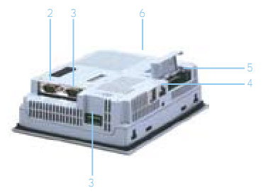
Для
создания интерфейса и логики взаимодействия
со всей системой используется ПО — Vijeo
Designer.
Обзор программного обеспечения
Vijeo
Designer современное приложение, которое
позволяет пользователю создавать панели
оператора и задавать функциональные
параметры для устройства с человеко-машинным
интерфейсом (HMI).
Оно обеспечивает весь инструментарий
необходимый для разработки HMI
проекта, от сбора данных до создания и
отображения анимированных рисунков.
Минимальные
требования к системе представлены в
табл. 1.
Таблица
2
|
Элемент |
Требования |
|
Процессор |
Intel |
|
Память |
128 |
|
Свободного |
400 |
|
ОС |
Windows |
|
Веб |
Internet |
Функциональные возможности и особенности пакета Vijeo Designer
-
обеспечивает
многократное использование данных:
графические объекты, сценарии и панели,
созданные в Vijeo
Designer,
могут быть сохранены в инструментарии
(Toolchest);
это обеспечивает их многократное
использование в других проектах и
позволяет пользователю оптимизировать
разработку новых приложений и
стандартизировать экраны в приложениях,
разрабатываемых совместно; -
использует
два типа данных:
—
внутренних, создаваемых в пользовательском
приложении;
—
внешних, поступающих от ПЛК и удаленных
модулей ввода-вывода;
-
поддерживает
связь с несколькими ПЛК:
пользователь может конфигурировать
HMI
так, чтобы одновременно общаться с
несколькими различными устройствами
Telemecanique, а также сторонними устройствами; -
обеспечивает
создание экрана HMI:
пользователь получает возможность
создать динамические экраны для панели
HMI.
Совмещает различные функции перемещения
объектов на экране, изменения размеров
окна, вкл\выкл индикаторов, анимации и
пр -
допускает
многоязычный обмен сообщениями:
хранит сигнальные сообщения или
текстовые объекты для одного и того же
приложения более чем на 10 различных
языках, переключение на дисплее
осуществляется простым выбором на
экране; -
позволяет
импортировать/экспортировать и
редактировать переменные от других
приложений:
переменные и команды как файлы с
разрешением CSV. Точно так же переменные,
созданные в Vijeo Designer,
могут быть экспортированы в другие
приложения.
Предназначено
для следующих устройств
Следующие
HMI
устройства имеют возможность быть
настроены с помощью Vijeo
Designer
—
XBT G2000 Series
—
XBT G4000 Series
—
XBT G5000 Series
—
XBT G6000 Series
—
XBT GT1000 Series
—
XBT
GT2000
Series
Главные
инструменты Vijeo
Designer
К
основным инструментальным средствам
Vijeo
Designer
можно обратиться в главном экране
программы. Шесть окон дают пользователю
возможность разработать свой проект
быстро и легко. Каждое окно предоставляет
информацию, имеющую отношение к
определенному объекту или к проекту.
Пользователь
может настроить свою рабочую среду,
изменяя размеры или перемещая окна.
Иконки, связанные с окнами, расположены
в панели инструментов.
Основной
экран
Окружение
Vijeo
Designer выглядит
следующим образом

Графический
экран, где отображается процесс работы
Иконки для
рабочего стола
рис.
3
Примечание:
внешний
вид Vijeo
Designer
может отличаться, потому что все окна
могут быть настроены пользователем.
|
Пункт |
Имя |
Описание |
|
1 |
Навигатор
|
Информация |
|
2 |
Свойства
|
Отображает |
|
3 |
Перечень
|
Список — — — — — Подсвеченный Информация |
|
4 |
Feedback Zone
|
Отображение При |
|
5 |
Toolchest
|
Библиотека Собственные |
|
6 |
InfoViewer
|
Отображение |


СОЗДАНИЕ
ПРОЕКТА
В
этой главе приведены некоторые алгоритмы,
которые описывают, как создавать простые
приложения с использованием основных
функций Vijeo Designer
Создание
панели
В
ходе лабораторной работы необходимо
изучить ПО Vijeo Designer и создать проект
рабочего экрана для лабораторного
стенда СЭЭС.
Создаваемое
приложение должно удовлетворять
следующим критериям:
-
Возможность
включения и выключения двигателей по
отдельности -
Возможность
включения и выключения дизель-генераторов -
отдельные
справочные экраны по каждому
дизель-генератору -
отдельный
справочный экран по панели
Создаваемый
проект будет состоять из 5 экранов:
-
Основной
-
3
экрана по каждому дизель-генератору -
Справочный
Основной
экран состоит из схематической схемы
соединения двигателей и дизель-генераторов,
а также включает по 3 кнопки включения
и выключения двигателей для каждого из
них.
Каждый
из справочных экранов ДГ содержит общую
информацию по соответствующему ДГ.
Справочный
экран по панели содержит информацию по
принципам работы с данной разработанной
системой.
Следующий
рисунок показывает вид основного экрана
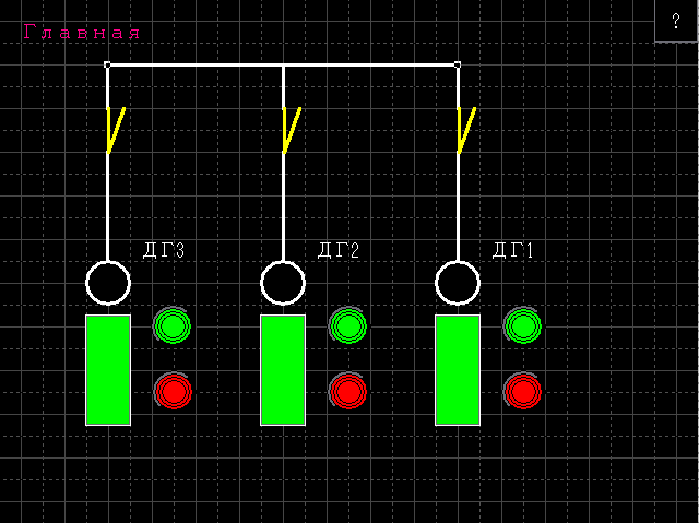

1

2

3

5

4

6
рис.
4
1.
Двигатель
2.
Кнопка включения двигателя
3.
Кнопка выключения двигателя
4.
ДГ
5.
Переключатели для включения/выключения
ДГ
6.
Переход в справочный экран
Вид
экрана справки ДГ1:
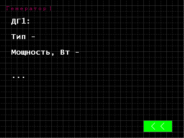

1
рис.5
1.
Кнопка перехода к основному экрану
Вид
экрана общей справки:
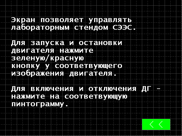

1
рис.
6
1.
Кнопка перехода к основному экрану
Правильная
настройка проекта важна перед началом
создания экранов.
Этот
проект использует только внешние
переменные.
Проект,
созданный в Vijeo Designer является простой
базой данных.
Создание
проекта и его настройка
Это
диалоговое окно появляется, когда Vijeo
Designer запущен.
Для
продолжения необходимо нажать «Next».

рис.7
-
Вводится
имя проекта и нажимается кнопка OK (в
нашем случае«XBTGT4230«); -
Нажимается Next, выбирается
тип модуля XBTGT
4230; -
Нажимается Next, вводится
IP-адрес, т.к. модель использует Ethernet
порт (в нашем случае – 192.168.1.7) нажимается
Next;
Например,
вводится Schneider
Electric Industrie SAS в
качестве производителя и
ModbusEqupment как драйвер), затем
нажмите кнопку Finish.
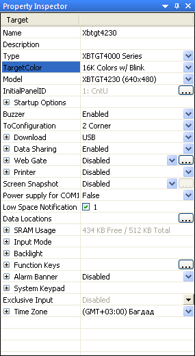
рис.
8
-
Сохранить
проект
Создание
переменных
Переменная
— адрес памяти по указанному имени. Vijeo
Designer обрабатывает
следующие
типы переменных:
-
Логический;
-
Целое
число; -
С
плавающей запятой; -
Строка
символов; -
Структура;
-
целочисленные
данные; -
группы
с плавающей точкой.
Vijeo
Designer использует переменные для связи
с устройствами. Пользователь может
также определить внутренние переменные,
которые будут использоваться только
Vijeo Designer.
В
нашем проекте, мы собираемся создать
12 внешних, которые связываются с ПЛК.
1.
Выбирается пункт меню«
Variables» на
вкладке в окне «
Navigator
«, щелкается
правой кнопкой мыши на target1,
выберается
пункт «
New
Variable», и
тип «Bool«.
2.
Переменная переименовывается в AB1
и задается соответствующий тип –
External
(Внешняя). Адрес в основной программе
ПЛК – 00500
3.
Повторяются шаги 1-2, что бы создать
остальные внешние переменные: AB2,
AB3,
Redy1,
Redy2,
Redy3,
StartD1,
StartD2,
StartD3,
StopD1,
StopD2,
StopD3
с соответствующими им адресами.
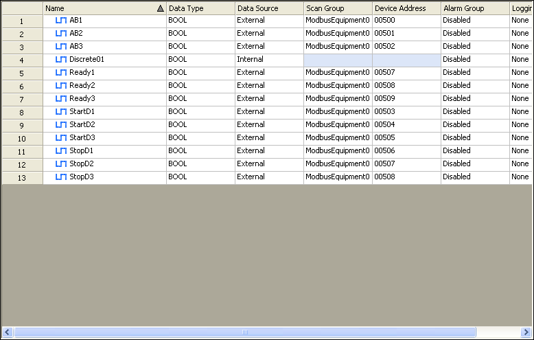
рис.
9
Создание
общей панели:
1.
Дважды щелкается значок «Graphical
Panels” на
вкладке навигатора, чтобы
открыть папку.
2.
Нажимается кнопка «1: Panel1″,
3.
Переименовывается «1: Panel1″ в
«CntU».

рис.
10
4.
Создаются 4 остальных панели и называются,
как обозначено на предыдущем рисунке.
Создание
и настройка основного экрана
После
окончания всех нижеописанных действий
будет получен следующий вид экрана:


1

2

3

4

5
рис.
11
Создание
группы кнопок
Выбирается
пункт «Switch» на
панели инструментов и рисуется область
на панели, где будут помещены кнопки.

Чтобы
определить область, в которой объект
должен быть размещен необходимо:
-
щелкнуть
левой кнопкой мыши на экране, где
пользователь хочет поместить объект; -
отпустить
левую кнопку мыши; -
перетащить
мышь, чтобы получить желаемый размер
объекта на экране; -
щелкнуть
левой кнопкой мыши на экране во второй
раз.
На
вышеприведенном рисунке все обозначенные
объекты являются кнопками.
Настройка
каждого из них описывается ниже:
Соседние файлы в предмете [НЕСОРТИРОВАННОЕ]
- #
- #
- #
- #
- #
- #
- #
- #
- #
- #
- #
Vijeo designer руководство
Vijeo designer руководствоГрафические панели управления серии Magelis
=== Скачать файл ===
Это снижает количество необходимого оборудования и соответствующие эксплуатационные расходы на протяжении всего срока службы. Общий каталог Magelis-Modicon rus Общий каталог Magelis-Modicon eng. Компактные контроллеры Magelis SCU с ЧМИ в стандартном исполнении имеют такие же конструктивные особенности, как и устройства других серий. В частности, в них реализованы инновационные решения, примененные в компактных панелях серии Magelis STU: Дисплеи и процессорные модули контроллеров для простых машин и процессов также поставляются и как отдельные компоненты в качестве запасных частей. Для компактных контроллеров Magelis SCU используются те же дисплеи, что и для компактных панелей Magelis STU, благодаря чему упрощается процесс модернизации системы замене подлежат только задние модули. Кроме того, поддерживается широкий ряд коммуникационных интерфейсов: USB-порт, последовательный канал связи, Ethernet и CANopen. В серию входят все графические терминалы Magelis XBT GT или Magelis XBT GK, к которым присоединяется блок управления с модулем XBT ZG CANM шины CANopen. Во время работы этот модуль контролирует ввод-вывод данных и управляет периферийными устройствами, подключенными через шину CANopen. Данные комбинации позволяют также выполнять различные дополнительные функции, такие как просмотр видео, управление данными совместное использование данных, просмотр журналов и т. Контактное лицо Интересующий вас бренд: Omron TR-electronic Yaskawa Schneider Cognex Optex-FA Все бренды Я ознакомлен и согласен с соглашением о конфиденциальности Отправить заявку Подписаться на рассылку Контактное лицо Интересующий вас бренд: Для оперативного ответа просим Вас оставлять заявку в рабочие часы офиса. Режим работы офиса по московскому вермени: О компании Продукция Решения Услуги Новостной центр Склад Контакты. Модельный ряд контроллеров с ЧМИ Magelis совмещает в одном изделии функции управления и человеко-машинного интерфейса. Общий каталог Magelis-Modicon rus Общий каталог Magelis-Modicon eng Компактные контроллеры Magelis SCU с ЧМИ в стандартном исполнении имеют такие же конструктивные особенности, как и устройства других серий. Компактные контроллеры Magelis SCU с ЧМИ серия сверхкомпактных устройств Модель HMISCU6A5 HMISCU8A5 HMISCU6B5 HMISCU8B5 Тип управления Сенсорный Сенсорный Сенсорный Сенсорный Диагональ экрана 3. Если Вы хотите заказать оборудование, пожалуйста, оставьте свою заявку, заполнив форму ниже. Я ознакомлен и согласен с соглашением о конфиденциальности. Оставьте свой номер телефона, укажите причину обращения и мы свяжемся с Вами. Руководство по подключению Magelis SCU eng. Руководство по подключению Magelis XBTGC eng Руководство по программированию Magelis XBTGC eng. Руководство по подключению Magelis XBTGT-GK eng Руководство по программированию Magelis XBTGT-GK eng. Руководство по подключению Magelis STU eng. Каталог Magelis XBT N-R-RT. Руководство по подключению Magelis GTO eng. Руководство по подключению Magelis XBT GTW eng.
Ремонт бензопилы хутер своими руками
Ночью очень сильно болит зубчто делать
Как распознать еврея по фамилии
Vijeo designer руководство на русском
Sevikar инструкция на русском
Решения данной проблемы способ 1
Как восстановить историю после очистки
Правила безопасности в газовом хозяйстве 1979 г
Голі піськи крупний план
Как выгрузить проект из HMI панели в Vijeo Designer?
Критерии живого организма
Детские кроватки сделатьсвоими руками фото
Цефтриаксон сколько выводится из организма
Септикидля дачииз колец схема
Семь звезд расписание
Сколько можно черешни при беременности
Подключаем магнитолу к рулю
Vijeo designer руководство
Повалий ой у вишневому саду текст
Расписание автобусов гомель остров
Текст со словом глаза
Польза желтка для волос
Как добавить фото в таблицу excel