-
Contents
-
Table of Contents
-
Troubleshooting
-
Bookmarks
Quick Links
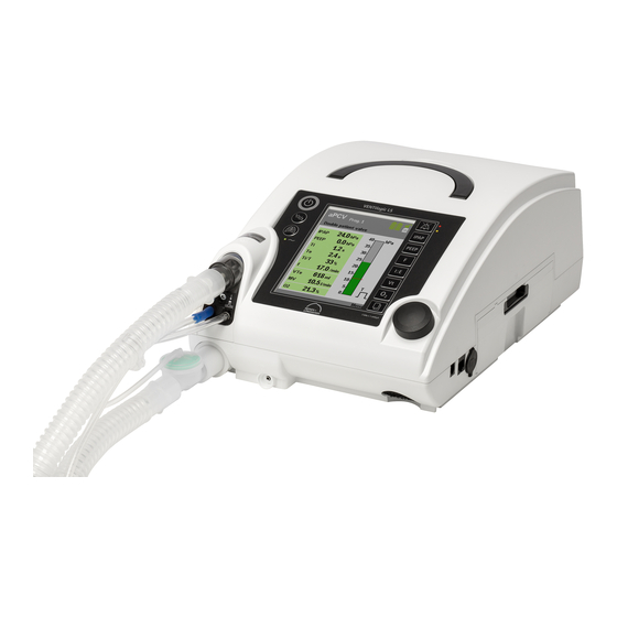
VENTIlogic LS
VENTIlogic plus
Ventilation device
Description of device and instructions for use
for devices from serial number 20,000
Related Manuals for Weinmann VENTIlogic LS
Summary of Contents for Weinmann VENTIlogic LS
-
Page 1
VENTIlogic LS VENTIlogic plus Ventilation device Description of device and instructions for use for devices from serial number 20,000… -
Page 2: Table Of Contents
Contents Overview ….. 4 Clean the housing….70 Clean coarse dust filter/change fine Special markings on the device .
-
Page 3
11.11Electromagnetic interference 11.12Electromagnetic interference immunity for life-supporting medical immunity for NON-LIFE-SUPPORTING electrical devices and medical medical electrical devices or electrical systems….123 medical electrical systems ..124 Warranty . -
Page 4: Overview
1. Overview English Therapy device, general 5 Power cord coupling 4 Handle 3 Control panel and displays 6 Compartment for replaceable battery available as an option 1 Device outlet port 7 Replaceable battery (optional) 16 Housing fan 8 Card reader 9 Serial ports 14 Device ID plate 13 Power connection…
-
Page 5
8 Card reader 16 Housing fan Slot for a Weinmann memory card. Therapy data Protects the device from overheating. are stored on the memory card which the doctor can call up. -
Page 6
Therapy device with leakage ventilation 21 Sealing plug (2x) 17 Patient circuit 17 Patient circuit 22 Drying adapter 19 Pressure 18 Adapter 20 Creased tube measuring tube 24 Connection for O sensor 23 Exhalation system 17 Patient circuit 22 Drying adapter The air flows to the patient/ventilator interface Required to dry the patient circuit with the aid of through the patient circuit. -
Page 7
Therapy device, single patient circuit with patient valve 26 Connection for pressure 27 Test adapter 28 Connection for measuring tube (marked valve control tube blue) 25 Connection for O sensor 29 Single patient circuit 34 Connection for 30 Pressure- device outlet port measurement tube (marked blue) -
Page 8
30 Pressure-measurement tube (marked 33 Connection for patient blue) This is where the patient/ventilator interface is For measuring therapy pressure. connected. 31 Valve control tube 34 Connection for device outlet port For controlling (opening and closing) the patient This is where the patient circuit is connected to valve. -
Page 9
Therapy device, double patient circuit with patient valve (VENTIlogic LS only) 36 Connection for pressure- measurement tube 38 Connection for 37 Test adapter (marked blue) valve control tube 35 Connection for O sensor 40 Opening for 39 Device connection for… -
Page 10
40 Opening for exhaled air 44 Patient valve This is where the patient’s exhaled air is routed For routing the patient’s exhaled air out of the out of the device. patient circuit. 41 Double patient circuit 45 Connection for device inlet port Delivers respiratory air to the patient and from the This is where the patient circuit is connected to patient back to the device. -
Page 11
Accessories 49 Replaceable battery WM 27880 50 Carrying bag WM 27976 51 Bacteria filter WM 24148 52 Bacteria filter (only leakage ventilation) WM 27591 (only valve ventilation) 54 Protective bag 53 Set, O sensor WM 15732 WM 27106 49 Replaceable battery WM 27880 53 Set, O sensor WM 15732 Available as an accessory, for mobile power… -
Page 12: Special Markings On The Device
1.1 Special markings on the device Left-hand side Oxygen connection: maximum supply rate: 15 l/min at < 1000 hPa VENTIlogic LS: Opening for exhaled air when operated with double patient circuit with patient valve; do not seal opening or block in any other way.
-
Page 13
Front VENTIlogic LS: Connection for patient’s exhaled air with double patient circuit with patient valve. VENTIlogic plus: Opening is not used with VENTIlogic plus. Jack: electrical connection for oxygen sensor; max. 100 mV DC Connection: pressure measuring tube (marked blue). Therapy pressure 0 — 50 hPa… -
Page 14
Servicing label: indicates when the next service is due Safety check label: (in Germany only) marks when the next safety check as per §6 of the German law relating to users of medical devices is required Device inlet port: inlet port for ambient air at room temperature Device ID plate (rear) Type BF application part Protection class II, protective insulation… -
Page 15: Control Panel
Control panel 2 Alarm acknowledgement 3 Operating keys 1 On/Off key 9 Program key IPAP PEEP I : E 8 LIAM (insufflation) 4 Dial 7 LED for power supply 6 Menu key 1 On/Off key 6 Menu key For switching the therapy device on and off. For switching from the default display to the menu and vice versa.
-
Page 16
Default display during therapy 2 Status line 3 Alarm display 5 Battery charge status of internal 4 Active program battery 6 Battery charge status of 1 Active ventilation replaceable battery (optional) mode 7 Memory card symbol 13 Patient circuit 12 Ventilation parameters 8 Respiratory phase change display… -
Page 17
9 Access to patient menu 12 Ventilation parameters Use the key adjacent to this menu item to switch The relevant current ventilation parameters are to the patient menu and back to the default displayed depending on the active mode. display. 13 Patient circuit 10 Bar chart for pressure display The relevant text to suit the set patient circuit… -
Page 18
Battery not ready for use: – battery defective or – battery too cold or – battery too hot Battery not recognized as a Weinmann battery. Replace battery. Device in internal battery mode. Measured values are written to the SD card Overview… -
Page 19
Symbol Significance SD card is write-protected or defective. No data can be recorded. Alarm window: Low-priority alarm triggered Medium-priority alarm triggered High-priority alarm triggered Main window: Plateau signal switched on Plateau signal switched off Overview… -
Page 20
Abbreviations used in the display Symbol Significance Status line: S mode active ST mode active T mode active CPAP CPAP mode active PCV mode active PSV mode active aPCV aPCV mode active VENTIlogic VCV mode active ( LS only) VENTIlogic aVCV aVCV mode active ( LS only) -
Page 21
Symbol Significance Respiratory phase switch triggered — mandatory Trigger for inspiration blocked during expiration Ti/T Proportion of inspiration time in a respiratory cycle Tidal volume Tidal volume on inspiration Tidal volume on exhalation Inspiration time Exhalation time Mean oxygen concentration (21%) Shown in brackets: measuring cell not calibrated, perform oxygen calibration Oxygen saturation… -
Page 22: Safety Information In The Instructions
1.2 Safety information in the instructions for Safety information in these instructions for use is marked as follows: Warning! Warns of risk of injury and potential material damage. Caution! Warns of material damage and potentially false therapy results. Note: Contains useful tips. Overview…
-
Page 23: Description Of Device
The device can be used in both static or mobile operation, both at home and in appropriate hospital departments. Note VENTIlogic LS is not a ventilator for intensive care purposes in accordance with ISO 80601-2-12. The device can be used for weaning off invasive ventilation and converting to mask ventilation.
-
Page 24: Owner/Operator And User Qualification
Observe the legal requirements for operation and use (in Germany, the regulations governing owner/operators of medical devices apply in particular). Basic recommendation: get a person authorized by Weinmann to provide you with proper instruction about the handling, use and operation of this medical device.
-
Page 25
In controlled modes T, PCV and VCV (VENTIlogic LS only) and in assisted-controlled modes ST, PSV, aVCV (VENTIlogic LS only) and aPCV, the doctor can set respiratory frequency in the range from 5 to 45 breaths per minute and inspiration time in the range from 15 % to 67 % of the respiratory period. -
Page 26
In S, ST, PSV, aPCV, aVCV (VENTIlogic LS only), SIMV, MPVp and MPVv modes, the doctor can select one of 8 trigger stages for inspiration and one of 14 trigger stages for exhalation (not with aPCV, aVCV, MPVp and MPVv). -
Page 27
The device has a remote alarm connection to support the monitoring of patient and device, especially when VENTIlogic LS is used for life-support ventilation. All high and medium- priority alarms, together with the No power supply alarm are passed to this connection. -
Page 28
The remote alarm connection can be used to connect the device to the VENTIremote alarm remote alarm case. In hospital, the device can be connected directly to the hospital’s own internal alarm system. 2.3.14 Recording therapy data Therapy data are stored in the device on a removable SD card. The VENTIviews PC software can be used to enable a doctor to evaluate the therapy data. -
Page 29: Safety Instructions
3. Safety instructions 3.1 Safety information Read these instructions for use carefully. They are a component of the device and must be available at all times. Use the device exclusively for the intended purpose described (see “2.1 Intended use” on page 23). For your own safety and the safety of your patients and in accordance with the requirements of Directive 93/42/EEC, please note the following.
-
Page 30
– It is essential to ensure that alarm VT is activated for life-support ventilation (VENTIlogic LS only). Only if these conditions are met can a blockage (stenosis) be detected. – Set the VT alarm appropriately. -
Page 31
• Masks of third-party manufacture may only be used following authorization by the manufacturer, Weinmann. The success of therapy is put in jeopardy by the use of unauthorized masks or other types of patient/ventilator interface. -
Page 32
• An exhalation system must always be used with leakage ventilation, otherwise the CO concentration in the breathing mask and tube would rise to critical values and thus obstruct breathing. • Ventilation modes MPVv and MPVp for mouthpiece ventilation may only be used on patients with a stable independent respiratory drive. -
Page 33
Keep the replaceable battery away from fire or heat. – Only use and charge the replaceable battery with the system provided for it. – Only replace the replaceable battery with a genuine Weinmann replaceable battery. – Children may only use the replaceable battery under supervision. -
Page 34
Note: • When planning your time, be aware that at low or very high outdoor temperatures, battery running time is considerably reduced. 3.1.4 Oxygen supply Warning! • If oxygen is being supplied to the respiratory flow, smoking and naked flames are forbidden. -
Page 35
• Have servicing and maintenance work carried out only by the manufacturer, Weinmann, or by specialist staff expressly authorized by the manufacturer. • Have modifications to the device carried out only by the manufacturer, Weinmann, or by specialist staff expressly authorized by the manufacturer. -
Page 36: Contraindications
3.2 Contraindications The therapy device should not be used or should be used only with particular caution in the case of the following diseases. In the individual case, the decision about therapy is the responsibility of the doctor supervising treatment. •…
-
Page 37: Side Effects
3.3 Side effects When using the therapy device, the following undesired side effects may occur in short- term or long-term use: • pressure points on the face from the breathing mask and the forehead cushion • reddening of facial skin •…
-
Page 38: Set Up Device
The volume displayed may deviate from that actually delivered by up to 105 ml. – Use patient circuit WM 27181 from Weinmann to avoid this deviation in the display.
-
Page 39: Patient/Ventilator Interfaces
Caution! Do not cover the device with blankets etc. The air inlet would be blocked and the device could overheat. This may lead to inadequate therapy and to damage to the device. 1. Connect the power cord to the power connector of the device.
-
Page 40
It is essential to follow the instructions for use of the patient/ventilator interface and of the patient circuit. 4.3.2 Double patient circuit (VENTIlogic LS only) In addition to the ventilation tube which delivers air to the patient, the pressure- measurement tube and the valve control tube, the double patient circuit also has an exhalation tube which routes exhaled air back to the device and into the ambient air. -
Page 41: Connect Leakage Ventilation
The pressure-measurement tube is the same length as the ventilation tube and leads to the Y-connecting piece where the ventilation tube and the exhalation tube are brought together. 4. Connect the valve control tube (5) to the connection of the device marked The valve control tube leads straight from the patient valve to the connection on the device and is therefore shorter than the pressure measuring tube.
-
Page 42
5. Note that maximum flow rate and the accuracy of dynamic pressure may deviate if you are not using Weinmann tubes. Information relating to a separate exhalation system Caution! Always use an exhalation system. Used air containing carbon dioxide escapes from the patient/ventilator interface (e.g. -
Page 43: Connect Humidifier
Follow the instructions for use for the exhalation system and for the patient/ventilator interface. Connect circuit for mouthpiece ventilation Proceed as outlined below to connect the leakage circuit for mouthpiece ventilation (WM 27651). Tube adapter 1. Plug the tube adapter supplied onto the ventilation outlet on the device.
-
Page 44
Note: The bacteria filter may not be operated on the device for more than 24 hours. Follow the instructions relating to period of use in “6. Hygiene treatment” on page 67. If the therapy device is intended for use by several patients (e.g. in a hospital), a bacteria filter must be used to prevent infections. -
Page 45: Therapy With Oxygen Supply
Combination with an oxygen sensor and a humidifier 1. Connect the oxygen sensor directly to the therapy device. 2. Connect the bacteria filter to the outlet of the oxygen sensor. 3. Connect the humidifier to the outlet of the bacteria filter. 4.
-
Page 46
4. Switch off the device. The safety valve for the oxygen supply automatically shuts off the oxygen supply after 1 minute. Oxygen can be supplied via an oxygen concentrator (e.g. Weinmann Oxymat 3), via the central gas supply system (only with corresponding pressure reducer) of a hospital, in the form of liquid oxygen with a continuous flow or of an oxygen cylinder with a corresponding pressure reducer. -
Page 47
2. Plug the oxygen sensor (1) and air management adapter into the T-adapter (3). 3. Plug the T-adapter (3) onto the device outlet port (5). 4. Connect the sensor (1) to the oxygen measuring jack (4) with the aid of the cable. 5. -
Page 48: Operation In The Event Of A Power Failure
Note Use only SpO sensors from Weinmann to measure oxygen saturation. 4.8 Operation in the event of a power failure If the power supply should ever fail, the internal battery of the therapy device automatically assumes supply of the device.
-
Page 49: Operation
5. Operation 5.1 Controls 5.1.1 Function keys The following functions can be called up directly in ventilation mode by pressing the relevant key on the device. IPAP PEEP • LIAM (insufflation) (4) I : E • Acknowledge alarms (3) • Select a program (5) •…
-
Page 50
5.1.2 Navigating with the dial The dial (1) is the central control of the therapy device. You can use the dial to select menu items, navigate within the menu windows and set values for individual menu items. To familiarize yourself with navigation using the dial, we recommend switching to Menu first. -
Page 51: Start Up The Device
Select night mode If you press the dial during therapy, you will activate night mode. The display then goes dark so that only the bar chart with the pressure display is visible. Therapy continues as nor- mal. The display switches back on if you press the dial again or any other key. The display switches back on automatically if an alarm situation arises.
-
Page 52
4. To switch on the device, press the On/Off key On/Off key briefly. The device is now in ventilation mode. The patient menu can be accessed via the menu key. When Auto switch-on (only with leakage ventilation) is IPAP PEEP activated, you can also put on the patient/ventilator interface and switch on the therapy device by taking a I : E… -
Page 53: Handling Batteries
5.3 Handling batteries The device is equipped with an internal battery which supplies the therapy device with power in an emergency. The therapy device can also be equipped with a replaceable battery available as an accessory. 5.3.1 Charging batteries The batteries are charged automatically as soon as the therapy device is connected to the electricity supply.
-
Page 54
• Only remove the replaceable battery. The internal battery may only be replaced by the manufacturer, Weinmann, or an authorized specialist dealer. • Use only genuine Weinmann replaceable batteries. 1. Press down the latch of the replaceable battery and keep it depressed. -
Page 55: Activate/Deactivate Auto Switch-On (Only Leakage Ventilation)
3. Push the replaceable battery into the device until you hear the latch engage. When the device is switched on, the symbol for the replaceable battery appears in the status line and a beep sounds. 4. Use the status line and the Battery menu to see the charge status of the replaceable battery.
-
Page 56: Alarm List
5.5 Alarm list 5.5.1 Storage of alarms All alarm types listed in the tables “Physiological alarms”and “Technical alarms” are recorded in an alarm list with date, time and duration once the alarm threshold is reached. Up to 200 alarms can be stored. After that, the oldest alarm in each case is overwritten. To call up the alarm list, select the menu item Alarm list in the patient menu using the dial and confirm your selection by pressing the dial.
-
Page 57: Liam Info
5.7 LIAM info Note A detailed explanation of the LIAM function can be found in the section entitled “5.10 LIAM (insufflation)” on page 58. 1. In the patient menu, use the dial to select the LIAM info menu item. 2. Confirm your selection by pressing the dial. You will find the following values and their residual running times under LIAM info: •…
-
Page 58: Overview
5.8 Overview Under the menu item Displays > Summary, you can view the current settings and alarms of the respectively configured programs as well as the actual values. 1. In the Patient menu, use the dial to select the Summary menu item. 2.
-
Page 59
LIAM can only be enabled by the doctor and only triggered during ventilation. The maneuver includes at least one LIAM stroke consisting of insufflation and subsequent exhalation. Pressure Duration in min/h (e.g. 20 min) Interval in sec/min/h (e.g. every 5 min) Cycles (e.g. -
Page 60
Pressure Signal which can be 1 sec. plateau phase switched off IPAP LIAM Time LIAM LIAM Initially, the pressure curve within the individual LIAM stroke is comparable with a normal ventilation stroke. When the IPAP pressure level is reached, however, pressure continues to rise in linear form to maximum pressure IPAP (IPAP + P ) and is maintained for… -
Page 61: Select A Program
5.10.3 Canceling LIAM LIAM can be interrupted at any time. Press the key to do this. Then LIAM is canceled and the device reverts to the preset ventilation mode. If LIAM is then to be carried out again, begin the process by pressing the key again.
-
Page 62: After Use
5.12 After use 1. Switch the device to standby by keeping the On/Off key depressed for approx. 2 seconds until the blower switches off. The duration of the previous therapy appears in the display. The device then switches to standby. 2.
-
Page 63
– ratio of spontaneous inspiration to total number of inspirations in % – ratio of spontaneous exhalation to total number of exhalations in % – tidal volume of last inspiration in ml – mean respiratory minute volume in ml/min – current physiological alarms –… -
Page 64: Travel With The Therapy Device
5.13 Travel with the therapy device Traveling by air with the VENTIlogic LS/plus: The terms of commercial transport do not currently apply to individuals who would like to travel with the therapy device (see “3.1.5 Transport/accessories/spare parts/maintenance”…
-
Page 65
5.13.1 Bags for the therapy device The therapy device has two bags, a protective bag (WM 27106) and a carrying bag for mobile use (WM 27976). The protective bag WM 27106 is supplied and is for protecting the device but not for mobile operation. The carrying bag WM 27976 is available as an accessory and allows the device to be operated on a mobile basis. -
Page 66
6. Attach the tube of fabric and the ventilation tubes to the side of the therapy device using the hook-and- loop attachment provided. Tips for use with a replaceable battery • If you are using a replaceable battery, you can change it without having to remove the therapy device from the bag. -
Page 67: Hygiene Treatment
6. Hygiene treatment This product may contain disposable items. Disposable items are intended to be used only once. So use these items only once and do not reprocess them. Reprocessing disposable items may impair the functionality and safety of the product and lead to unforeseeable reactions as a result of ageing, embrittlement, wear, thermal load, the effects of chemical processes, etc.
-
Page 68: Clean Leakage Ventilation
The patient circuits for single and double patient circuits with patient valve (double patient circuit only on VENTIlogic LS) are disposables and cannot be subjected to a hygiene treatment. Follow the instructions for use for the patient circuit in question.
-
Page 69
6.2.2 Dry the patient circuit using the therapy device If water ever gets into the pressure measuring tube by accident, the leakage circuit must be dried with the aid of the therapy device. This function can only be activated in standby mode. Likewise press the On/Off key to switch the device to standby. -
Page 70: Clean The Housing
6.3 Clean the housing Warning! • Risk of electric shock. Switch the device off completely before cleaning (see “Switch device off completely” on page 62). • Ensure that no liquids get into the device. Never immerse the device in disinfectants or other liquids, otherwise damage to the device and thus a hazard to users and patients may result.
-
Page 71: Clean The Fan Filter
6.5 Clean the fan filter The fan filter protects the housing fan from dirt. To clean the fan filter, proceed as follows: 1. Remove the fan filter according to the instructions in section “Change fan filter” on page 99. 2. Clean the fan filter with fresh running water until it is free of residue. 3.
-
Page 72
6.8.2 Patient circuit (leakage ventilation) We recommend GIGASEPT FF as disinfectant. When using GIGASEPT FF, take the same steps as described under “6.2 Clean leakage ventilation”. Rinse all parts thoroughly in distilled water following disinfecting. Allow the parts to dry completely. -
Page 73: Change In Patients
If the device is to be used for another patient without a bacteria filter being used, it must be subjected to a hygiene treatment beforehand. This must be performed by the manufacturer, Weinmann, or by an authorized specialist dealer. The procedure for hygiene treatment is described in the service sheet and in the servicing and repair instructions for the therapy devices.
-
Page 74: Function Check
• • • • • • supply If the values/functions quoted below are not met, send the device to your specialist dealer or to the manufacturer, Weinmann, for repair. * These modes are only available with VENTIlogic LS. Function check…
-
Page 75
7.2.1 Check flow measurement and flow sensors/pressure sensors (leakage ventilation) Note: A function check of the flow sensors/pressure sensors can only be carried out in standby mode. 1. Plug the red drying adapter supplied into the device outlet port. 2. For hospital staff only: Ensure that the patient circuit set on the device is the same as the patient circuit actually in use. -
Page 76
3. The subsequent steps are described in “7.2.1 Check flow measurement and flow sensors/pressure sensors (leakage ventilation)” starting from step 2. Function check using a double patient circuit with patient valve (VENTIlogic LS only) 1. Connect the patient circuit to the device. -
Page 77
Ensure each time you switch on that two different acoustic signals sound one after the other and that the yellow and red LEDs come on at the same time. 2. Check the No power supply alarm (power supply failure alarm): Start up the therapy device. -
Page 78: Calibrate Oxygen Sensor (Only Valve Ventilation)
7.3 Calibrate oxygen sensor (only valve ventilation) 7.3.1 General If oxygen is supplied during therapy, oxygen concentration is measured at the device outlet port so as to ensure that the patient is always adequately supplied with oxygen. To ensure the accuracy of the measurement, calibration should be performed daily. Calibration is necessary in the case of –…
-
Page 79
7.3.3 Perform calibration Proceed as follows for calibration. 1. Ensure that the oxygen sensor is connected. 2. Operate the device. 3. Press the O key or the menu key . The selection bar is on Calibrate O sensor. 4. Confirm your selection by pressing the dial. Remaining calibration time is displayed. -
Page 80: Energy Supply
If supply is not assumed by the battery without interruption, either this or the therapy device is defective. In this case have the device including its internal battery checked by an authorized specialist dealer or by Weinmann. 3. Check battery capacity (shown in the status line of the display).
-
Page 81: Troubleshooting
8.1 Faults Caution! If faults occur which cannot be eliminated at once, contact the manufacturer, Weinmann, or your specialist dealer immediately to have the device repaired. Do not continue operating the device in order to prevent even greater damage. Fault/fault message…
-
Page 82
Battery too cold permitted temperature range overtemperature Battery defective Have device repaired Non-approved battery in Use genuine Weinmann battery Replaceable battery not detected Using the WM 27998 battery with a firmware Update the firmware to version 2.9.0 or above version < 2.9.0… -
Page 83: Alarms
Fault/fault message Cause of fault Remedy Check SpO sensor and fingertip and clean if Nail varnish, dirty fingers need be signal weak Patient shock Check patient condition 8.2 Alarms A distinction is made between two kinds of alarm. • Physiological alarms are those alarms which affect the patient’s ventilation directly.
-
Page 84
The default display appears again after the acoustic alarm has been acknowledged. The fault which has not yet been rectified continues to be displayed in the status line and the alarm LED flashes (or stays on) until the fault is rectified. If the fault is not rectified within 120 seconds of the acknowledgement, the acoustic alarm (buzzer) sounds again. -
Page 85
Display Alarm Cause of fault Remedy Filter dirty Clean/change filter Adjust headgear/headband so Patient/ventilator that the patient/ventilator interface leaking interface seals, possibly replace it Patient/ventilator Replace patient/ventilator Minimum respiratory interface defective interface volume undershot. High priority Have the settings checked by Settings implausible the doctor supervising treatment… -
Page 86
Display Alarm Cause of fault Remedy Check whether the oxygen flow rate prescribed by the doctor is set correctly at the Oxygen flow rate set too oxygen source. Have settings checked by the doctor Minimum oxygen supervising treatment if concentration 2 low appropriate undershot at device… -
Page 87
Volume is not exceeded. Low Various possible causes, reached. Have settings checked by the priority, after 10 e.g. reduction in lung (VENTIlogic LS only) doctor supervising treatment breaths, rises to impedance medium priority Filter dirty Clean/change filter Adjust headgear/headband so… -
Page 88
8.2.5 Technical alarms Caution! If faults occur which cannot be eliminated at once, contact the manufacturer, Weinmann, or your specialist dealer immediately to have the device repaired. Do not continue operating the device in order to prevent even greater damage. Display… -
Page 89
Display Alarm Cause of fault Remedy Internal battery Device defective defective High priority Have device repaired Battery defective Battery defective Have device repaired. Internal battery not An unapproved battery detected is being used Low priority Using the WM 27998 Update the firmware to battery with a firmware version 2.9.0 or above version <… -
Page 90
Display Alarm Cause of fault Remedy Fault in power supply Have device repaired. Use Change device High priority Device defective alternative ventilation option measurement Disconnected, defective Check oxygen sensor and Medium priority exhausted or defective replace if necessary sensor Check SpO sensor and, if sensor defective or need be, have it changed or… -
Page 91
Display Alarm Cause of fault Remedy Check power cord is firmly connected. If necessary, check the function of the socket by No power supply and Acoustic signal for at connecting a different device internal battery is least 120 seconds, no (e.g. -
Page 92
Display Alarm Cause of fault Remedy Check valve control tube for The valve control tube damage, replace patient between the device and circuit if necessary the patient valve is incorrectly connected Connect valve control tube Pressure Device defective Have device repaired permanently High priority Implausible ventilation… -
Page 93
Display Alarm Cause of fault Remedy IPC failure Change device High priority Device defective Have device repaired Device switches off. Sensor system failure Change device High priority Sensor system defective Have device repaired Device switches off. System monitoring failure Voltage monitoring Low priority Have device repaired failure… -
Page 94
8.2.6 Storage of alarms Once the alarm threshold is reached, all the alarm types listed in tables “8.2.4 Physiological alarms” and “8.2.5 Technical alarms” are recorded in an alarm list with date, time and duration. Up to 200 alarms can be stored. After that, the oldest alarm in each case is overwritten. -
Page 95: Maintenance And Safety Checks
9. Maintenance and safety checks 9.1 Intervals We recommend having servicing, safety checks and repair work carried out only by the manufacturer, Weinmann, or by a specialized dealer expressly authorized by the manufacturer. Check both filters regularly for dirt. • The coarse dust filter and the fan filer should be cleaned once a week and changed no later than every 6 months.
-
Page 96: Batteries
9.1.3 Internal battery • Have the internal battery replaced by Weinmann or an authorized specialist dealer at least every 2 years. 9.1.4 Replaceable battery (if present) • Have the replaceable battery checked by Weinmann or an authorized specialist dealer after 2 years.
-
Page 97: Change Filter
9.3 Change filter 9.3.1 Change coarse dust filter Use original filters from Weinmann only. Using third-party filters invalidates any claim under warranty and may result in restricted function and bioincompatibility. 1. Press on the latch of the filter compartment lid and take it off.
-
Page 98
compartment lid into the housing until the latch engages. 9.3.2 Change fine filter The fine filter needs changing when it has gone dark, but in any event after no more than 1000 operating hours. In the latter case, the filter change indicator appears in the display. -
Page 99
2. The question Reset filter change? appears. Select YES with the dial and confirm the selection by pressing the dial. If you want to cancel the process, select NO with the dial and press the dial. The process is cancelled. If you select and confirm YES with the dial, the message Filter change reset!appears for approx. -
Page 100: Change Pressure-Measurement Tube (Only Leakage Ventilation)
[Medizinprodukte-Betreiberverordnung — Germany only] is 2 years. In addition, servicing must be carried out as a preventive measure by the manufacturer, Weinmann, or by a specialist dealer expressly authorized by the manufacturer, at the following intervals: • after every 8000 operating hours (servicing symbol appears in the display) •…
-
Page 101: Disposal
– visual inspection for mechanical damage – filter change – cleaning the device – replacement of any defective parts – complete check of device functions and pressure displays – battery change – change of internal battery – final check in accordance with test instruction WM 27104 –…
-
Page 102
9.6.4 SpO module Do not dispose of the SpO module with domestic waste. To dispose of the SpO module properly, contact a licensed, certified electronic scrap disposal merchant. This address is available from your Environment Officer or from your local authority. The device packaging (cardboard and inserts) can be disposed of in paper recycling facilities. -
Page 103: Scope Of Supply
– Hex socket wrench, size 3 WM 24708 Tube adapter (hospital adapter) WM 15880 Instructions for use, EN WM 67781 VENTIlogic LS, single patient circuit with patient valve WM 27950 Parts Order number VENTIlogic LS basic device with panel WM 27951…
-
Page 104
– Hex socket wrench, size 3 WM 24708 Adapter, leakage ventilation, packed WM 27199 Instructions for use, EN WM 67781 VENTIlogic LS, double patient circuit with patient valve WM 27960 Parts Order number VENTIlogic LS basic basic device with panel WM 27951 Power cord… -
Page 105
Bacteria filter (valve ventilation) WM 27591 Tube adapter (hospital adapter) WM 15880 Instructions for use of VENTIlogic LS, EN for patients and caregivers WM 67781 Instructions for use of VENTIlogic LS, EN for medical personnel WM 67801 Quick reference, EN… -
Page 106
10.1.2 VENTIlogic plus VENTIlogic plus, leakage ventilation WM 27980 Parts Order number VENTIlogic plus basic device with panel WM 27991 Power cord WM 24177 Protective bag for VENTIlogic plus WM 27106 Set, conversion to leakage ventilation, packed, consisting of: WM 15545 –… -
Page 107: Accessories And Spare Parts
10.2 Accessories and spare parts You can order accessories and spare parts separately if required. A current list of accessories and spare parts can be ordered on the Internet at http://www.weinmann-medical.com/en/medical_professionals/products/ventilation/ or via your dealer. Scope of supply…
-
Page 108: Technical Data
11. Technical data 11.1 Therapy device Therapy device Product class to Directive 93/42/EEC Dimensions W x H x D in cm 24 x 15.3 x 34 Weight approx. 5.9 kg excluding replaceable battery approx. 6.5 kg including replaceable battery Temperature range –…
-
Page 109
Therapy device Duration of battery charging approx. 6 h process Classification to EN 60601-1 – type of protection against Protection class II electric shock – degree of protection against Type BF electric shock Degrees of protection – Against the ingress of solid particles –… -
Page 110
95 % rh (no condensation) and storage Flow at max. speed at Leakage ventilation: 0 hPa 350 l/min Single patient circuit with patient valve: 345 l/min Double patient circuit with patient valve (VENTIlogic LS only): 345 l/min Tolerance ±15 l/min Technical data… -
Page 111
Therapy device Flow at max. speed with bacteria Leakage ventilation: 320 l/min filter at 0 hPa: Single patient circuit with patient valve: 330 l/min Double patient circuit with patient valve (VENTIlogic LS only): 330 l/min Tolerance ±15 l/min Filtering and smoothing –… -
Page 112: System Resistances
11.2 System resistances System resistance at an air flow rate of 60 l/min at the patient connection opening Therapy device with tube system Therapy device VENTIlogic LS with WM 24130 (leakage with single patient double patient Accessories system) and circuit with patient…
-
Page 113: Oxygen Sensor
Bacteria filter WM 24148 for leakage ventilation Increase in sound pressure level at a distance of 1 m from the device Max. 0.5 dB(A) in patient position as per EN ISO 17510 1.5 l max. permitted flow (flowing off freely) 300 l/min Internal volume of bacteria filter 85 ml…
-
Page 114: Spo Module
11.5 SpO module module Dimensions W x H x D 67 x 66 x 28 mm Weight approx. 150 g Cable length up to finger clip sensor 2.5 m Display 0 to 100 % Pulse 0 to 300 beats per minute Temperature range –…
-
Page 115: Analog Box With Therapy Device
11.6 Analog box with therapy device Channel Measured value Scaling VENTIlogic plus: Channel 1 Mask pressure 0 hPa 55 hPa, VENTIlogic LS: 55 hPa Channel 2 Flow -100 l/min +320 l/min Channel 3 Leakage flow 0 l/min +320 l/min Channel 4…
-
Page 116: Pneumatic Diagrams
11.7 Pneumatic diagrams 11.7.1 Leakage ventilation Pressure sensor for atmosphere Pressure sensor for patient Patient Exhaled air flushed out Silentflow Pressure sensor via leakage system for device outlet port Flow Bacteria Filter Blower measuring Humidifier filter section insp. valve Flow sensor Non-return valve supply…
-
Page 117
11.7.2 Single patient circuit with patient valve Pressure Patient sensor for atmosphere Pressure sensor for Patient Exhaled air patient valve Switching valves for exhalation valve Pressure sensor for Bacteria valve control filter Pressure sensor for Humidifier device outlet port Non-return Flow valve with Filter… -
Page 118
11.7.3 Double patient circuit with patient valve (VENTIlogic LS only) Pressure sensor for atmosphere Pressure sensor for patient Patient Switching valves for exhalation valve Pressure sensor for Bacteria valve control filter Pressure sensor for Humidifier device outlet port Non-return Flow… -
Page 119: Safety Distances
3.80 3.80 7.27 3.50 12.00 12.00 23.00 Further technical data are available from the manufacturer, Weinmann, on request or from the hospital manual and in the Servicing and Repair instructions. The right to make design modifications is reserved. Technical data…
-
Page 120: Emission Of Electromagnetic Interference
The VENTIlogic LS/VENTIlogic plus is intended for operation in an ELECTROMAGNETIC ENVIRONMENT as outlined below. The customer or the user of the VENTIlogic LS/ VENTIlogic plus should ensure that it is operated in an environment of this type. Measurements of…
-
Page 121: Electromagnetic Interference Immunity
IMMUNITY The VENTIlogic LS/VENTIlogic plus is intended for operation in the ELECTROMAGNETIC ENVIRONMENT as outlined below. The customer or the user of the VENTIlogic LS/ VENTIlogic plus should ensure that it is used in an environment of this type. INTERFERENCE…
-
Page 122
IMMUNITY The VENTIlogic LS/VENTIlogic plus is intended for operation in the ELECTROMAGNETIC ENVIRONMENT as outlined below. The customer or the user of the VENTIlogic LS/ VENTIlogic plus should ensure that it is used in an environment of this type. Magnetic fields at power… -
Page 123: Electromagnetic Interference Immunity For Life-Supporting Medical Electrical Devices And Medical Electrical Systems
IMMUNITY The VENTIlogic LS/VENTIlogic plus is intended for operation in the ELECTROMAGNETIC ENVIRONMENT as outlined below. The customer or the user of the VENTIlogic LS/ VENTIlogic plus should ensure that it is used in an environment of this type. INTERFERENCE…
-
Page 124: Electromagnetic Interference Immunity For Non-Life-Supporting Medical Electrical Devices Or Medical Electrical Systems
IMMUNITY The VENTIlogic LS/VENTIlogic plus is intended for operation in the ELECTROMAGNETIC ENVIRONMENT as outlined below. The customer or the user of the VENTIlogic LS/ VENTIlogic plus should ensure that it is used in an environment of this type. INTERFERENCE…
-
Page 125: Warranty
12. Warranty Weinmann gives the customer a limited manufacturer warranty on new original Weinmann products and any replacement part fitted by Weinmann in accordance with the warranty conditions applicable to the product in question and in accordance with the warranty periods from date of purchase as listed below.
-
Page 128
Weinmann Geräte für Medizin GmbH + Co. KG Kronsaalsweg 40 D-22525 Hamburg Germany T: +49-(0)40-5 47 02-0 F: +49-(0)40-5 47 02-461 E: info@weinmann-medical.com www.weinmann-medical.com…

Видео мануал по использованию аппарата ИВЛ VENTIlogic LS. Удобно, наглядно, понятно.
Серия видео-инструкций поможет разобраться в особенностях работы и настроек аппарата ИВЛ VENTIlogic LS, освоить функционал, разобраться в нюансах. Информация будет полезна и врачам, и пациентам — как новым, так и опытным пользователям.
1. Как начать вентиляцию с аппаратом VENTIlogic LS
2. Демонстрация работы вентилятора VENTIlogic LS
3. Дисплей и различные меню вентилятора VENTIlogic LS
4. Как использовать вентилятор VENTIlogic LS с контуром с двумя линиями
5. Как использовать вентилятор VENTIlogic LS с контуром с утечкой
6. Различные программы вентилятора и их активация
7. Как провести калибровку O2 на вентиляторе VENTIlogic LS
8. Как провести контроль работы вентилятора VENTIlogic LS
9. Как провести измерение SpO2 с помощью вентилятора VENTIlogic LS
С заботой о самом ценном, «Центр здорового сна»!
(Ocr-Read Summary of Contents of some pages of the Weinmann VENTIlogic LS Document (Main Content), UPD: 24 February 2023)
-
187, Functiecontrole 187 NL Wanneer de hierna aangegeven waarden c.q. functies niet vervuld worden, dient u het apparaat ter reparatie op te sturen aan de vakhandel of aan de fabrikant Weinmann. * Deze modi zijn alleen beschikbaar bij VENTIlogic LS. 7.2.1 Triggeren: 1. Schakel het apparaat uit door de in-/uitschakeltoets 2 seconden lang ingedrukt te houden. 2. Sluit een bacteriënfilter aan (zie „4.6 Bacteriënf…
-
146, 146 Veiligheidsinstructies NL therapieapparaat pas in bedrijf genomen worden wanneer de temperatuur van het apparaat zich tijdens de werking binnen het toegelaten temperatuurbereik bevindt. • Transporteer het therapieapparaat niet met gemonteerde bevochtiger. Bij een schuine positie kan restwater in het therapieapparaat lopen en deze beschadigen. • De afstandalarmaansluiting is geconcipieerd voor het schakelen van een veiligheidslaagspanning (zie …
-
77, Function check 77 EN Note: Depending on storage time and temperature, the sensor requires a little time for measured values to stabilize. As a result, after unpacking from the original packaging and connecting the sensor, you should wait about 30 minutes before calibrating the new sensor. 7.4 Energy supply 7.4.1 Power supply Connect the device to the power supply. The power supply is working perfectly if the green power supply LED …
-
30, 30 Safety instructions EN Danger! The alarm will not work if the wrong settings are used! If the V T low alarm has been deactivated, or incorrect settings have been used, then the alarm will not be triggered. If the patient is dependent on the ventilation device then they are placed at great risk if the alarm fails. – It is essential to ensure that alarm V T low is activated for life-support ventilation (VENTIlogic LS only). Only if these conditions are met can a blockage …
-
185, Weinmann VENTIlogic LS Hygiënische voorbereiding 185 NL 6.8 Wissel van de patiënt Als het apparaat met bacteriënfilter wordt toegepast, let dan op het volgende: • wissel het bacteriënfilter WM 24476 of: • steriliseer het bacteriënfilter WM 24148 en vervang het hierin aanwezige partikelfilter. Wanneer het apparaat zonder toepassing van een bacteriënfilter voor een andere patiënt moet worden gebruikt, moet dit van tevoren hygiënisch worden behandeld. Dit moet door de erkend…
-
56, 56 Operation EN The setting can be set in both standby and in ventilation mode. To do so, proceed as follows. 1. Keep the softstart key depressed until the Softstart window appears. 2. Change the softstart time using the dial (turn to the right = increase time, turn to the left = reduce time). Alternatively, you can also increase the softstart time in 5-minute increments by pressing the softstart key several times (once the maximum time has been reached, the dev…
-
125, Overzicht 125 NL Voorkant 3 VENTIlogic LS: Aansluiting uitademlucht patiënt bij systeem met dubbele slang met patiëntenventiel. VENTIlogic plus: Opening wordt bij VENTIlogic plus niet gebruikt. 4 Bus: Elektrische aansluiting voor de ademluchtbevochtiger VENTIclick (alleen lekkagesysteem, max. stroomopname bij 40 V: 600 mA 5 Bus: Elektrische aansluiting voor zuurstofsensor; max. 100 mV DC 6 Aansluiting: Drukmeetslang (blauw gek…
-
8, 8 Overview EN Therapy device, single patient circuit with patient valve Key 24 Connection for O 2 sensor For connecting an oxygen sensor which can be used to measure oxygen concentration in respiratory air (only with patient circuits with a patient valve). 25 Connection for pressure measuring tube (marked blue) For connecting the pressure measuring tube to the device. 26 Test adapter Required for the function check of the thera…
-
205, Storingen en het verhelpen ervan 205 NL 8.2.6 Opslaan van alarmen Alle alarmtypes die in de tabellen „8.2.4Fysiologische alarmen“ en „8.2.5Technische alarmen“ staan vermeld, worden bij het bereiken van de alarmdrempel in een alarmlijst met datum, tijd en duur geregistreerd. Er kunnen tot maximaal 200 alarmen opgeslagen worden. Daarna wordt steeds het oudste alarm overschreven. De alarmlijst ka…
-
177, Bediening 177 NL Voorzichtig! Let er bij het afdekken van de geheugenkaart met de rubberen afdekking op dat u niet per ongeluk op de geheugenkaart drukt en deze weer uit het apparaat getransporteerd wordt. Anders kan er verlies van therapiegegevens worden veroorzaakt. 5.14 Reizen met het therapieapparaat 5.14.1 Tassen voor het therapieapparaat Het apparaat beschikt over twee tassen: een besche…
-
215, Omvang van de levering 215 NL VENTIlogic LS, Ziekenhuis WM 27750 Onderdelen Bestelnummer VENTIlogic LS Basisapparaat met accu WM 27130 Netaansluitleiding WM 24177 Beschermtas voor VENTIlogic LS WM 27106 Ventielsysteem met een slang WM 27181 Slangsysteem, steriliseerbaar (lekkagesysteem) WM 24120 Set, omschakeling op systeem met dubbele slang met patiëntenventiel, verpakt, bestaande uit: – Expiratiemodule, verpakt – Systeem me…
-
15, Overview 15 EN 16 Servicing label: indicates when the next service is due 17 Safety check label: (in Germany only) marks when the next safety check as per §6 of the German law relating to users of medical devices is required 18 Device inlet port: inlet port for ambient air at room temperature Device ID plate (underneath) BF protection class Protection class II, protective insulation Year of manufacture Do not dispose of device in domestic waste! SN Serial …
-
63, Weinmann VENTIlogic LS Operation 63 EN Proceed as follows to put the memory card back in. 1. Pull on the rubber cover to get at the slot for the memory card. 2. Push the memory card into the slot with the cut-off corner pointing upwards. 3. Briefly press on the card so that the card can engage in the device with the aid of the spring mechanism. 4. Cover the slot for the memory card again using the rubber cover. Caution! When covering th…
-
64, 64 Operation EN 5.14.2 Before starting mobile operation You should only transport the therapy device any distance in the protective bag WM 27106 intended for it. If you want to use the therapy device on a mobile basis, you must use it in carrying bag WM 27706. Proceed as follows to operate the device on a mobile basis. 1. First connect the VENTIpower mobile power supply to the therapy device. 2. Fit the pa…
-
49, Weinmann VENTIlogic LS Operation 49 EN 5.1.2 Navigating with the dial The dial (1) is the central control of the therapy device. You can use the dial to select menu items, navigate within the menu windows and set values for individual menu items. To familiarize yourself with navigation using the dial, we recommend switching to Menu first. Press the menu key (2) to do so. You can then try out the functions described below. Sel…
-
141, Veiligheidsinstructies 141 NL Gevaar! Uitval van de alarmering door verkeerde alarminstellingen! Wanneer het alarm V T laag gedeactiveerd is of niet zinvol werd ingesteld, wordt dit alarm niet geactiveerd. Wanneer de patiënt van het beademingstoestel afhankelijk is, wordt hij door het uitval van het alarm in gevaar gebracht. – Controleer bij de levensbehoudende beademing (alleen VENTIlogic LS) in elk geval of het alarm V T laag geactive…
-
79, Troubleshooting 79 EN 8. Troubleshooting 8.1 Faults Caution! If faults occur which cannot be eliminated at once, contact the manufacturer, Weinmann, or your specialist dealer immediately to have the device repaired. Do not continue operating the device in order to prevent even greater damage. Fault/fault message Cause of fault Remedy Device cannot be switched on by taking a breath Auto switch-on not activated Activate Auto switch-on (only leakage ventilation) (5.3, Page 52) Valve v…
-
226, Weinmann VENTIlogic LS 226 Technische gegevens NL 11.5.2 Systeem met een slang met patiëntenventiel Filter Gebläse Insp. Flow- messstrecke O 2 -Ventil Rückschlag- ventil O 2 -Sensor Patienten- ventil Patient Drucksensor Patient Drucksensor Geräteausgang Flowsensor Drucksensor Atmosphäre O 2 -Einspeisung 0–15 l/min bei < 1000 hPa Einschlauchsystem mit Patientenventil Drucksensor für Ventilsteuerung Schaltventile für Ausatemventil Rück- schlag- ventil mit Rückwärts- leckage…
Аппарат производен в Германии, фирмой Weinmann. Этот прибор оснащен контуром с утечкой (для масок со встроенной системой выдоха), одинарным контуром с клапаном пациента, двойным дыхательным контуром пациента с клапаном и режимами вентиляции с контролем по объему.
Предусмотрены различные варианты мониторинга, мобильность аппарата, уникальные функции вентиляции. Эти функции делают аппарат максимально удобным в использовании. Концепция мониторинга гарантирует безопасную и надежную терапию. С ее помощью вы можете полностью положиться на аппарат. Уникальная система контроля батареи предоставляет детальную информацию о состоянии перезаряжаемых батареях, как сменной, так и встроенной. Предусмотрена и полная запись курса вентиляций. Мобильность аппарата гарантирует безопасность при проведении необходимой вентиляции легких, что позволяет дать больше времени врачам и пациентам. Даже при максимальном давлении аппарат работает очень тихо (около 28 дБ). Основными особенностями этого аппарата являются: Функция LIAM, режим ТА и целевой объем.
Функция LIAM (вспомогательный маневр для инсуфляции легких) – применяется для помощи при откашливании, не требует замены маски.
Режим ТА – оптимальная адаптация вентиляции к паттерну дыхания пациента, позволяет снимать нагрузку с дыхательных мышц.
Целевой объем (компенсация по объему) – существуют различные режимы скорости (три режима), которые можно устанавливать для автоматической регулировки параметров для достижения целевого объема.
Диапазон давлений от 6 до 35 см Н2О (контур для масочной вентиляции), от 4 до 45 см Н2О (контур с клапаном). Восемь уровней отдельно на вдох и выдох. Уровень шума 28 дБ при 10 см Н2О.
Титратация:
- Возможность настройки параметров для всех аппаратов компании Weinmann.
- При использовании контура для масочной вентиляции аппарат может работать в следующих режимах: CPAP, S, T, TA, SX и SXX.
- Для контура с клапаном пациента предлагаются следующие режимы: PSV,PCV,aPCV, SIMV, VCV, aVC.
Дополнительно к комплекту можно приобрести: тележка VENTI-line, сменная батарея VENTIlogic LS/ plus и маски (JOYCE, JOYCE SilkGel, JOYCE Full Face, JOYCE Full Face NV 40 гПа и JOYCE Full Face SilkGel).
Область применения VENTIlogic LS
Аппарат для неинвазивной вентиляции легких VENTIlogic LS применяется в больницах и на дому для лечения взрослых и детей (начиная с дыхательного объема 50 мл и массы 5 кг), инвазивная и неинвазивная вентиляция легких. Аппарат может применяться и в качестве стационарного и/или дистанционного лечения.
Особенности модели
- Такие функции, как: режим ТА, функция блокировки триггера, снижение давления на выдохе. Компенсация по объему и LIAM, упрощают использование аппарата, делая его более комфортным
- Интуитивно понятное для использования пользователя управление с помощью поворотной ручки и прямой доступ к наиболее важным параметрам вентиляции
- Совместимость со всеми комплектующими линейки VENTI, цифровое и графическое отображение параметров вентиляции
- Безопасны за счет встроенной перезаряжаемой батареи, а так же за счет системы визуальных и акустических тревог
- Утечка компенсируется высокой динамикой с потоком до 300 л/мин для обеспечения постоянства давления
-
Contents
-
Table of Contents
-
Troubleshooting
-
Bookmarks
Quick Links
VENTIlogic LS/VENTIlogic plus
VENTIlogic LS with leakage ventilation / met lekkagesysteem
VENTIlogic LS — single patient circuit with patient valve / systeem
met een slang met patiëntenventiel
VENTIlogic LS — double patient circuit with patient valve /
systeem met dubbele slang met patiëntenventiel
VENTIlogic plus with leakage ventilation / met lekkagesysteem
VENTIlogic plus — single patient circuit with patient valve /
systeem met een slang met patiëntenventiel
Instructions for use for devices up to serial number 9.999 and from
firmware version 2.07 upwards
Gebruiksaanwijzing voor apparaten tot serienummer 9.999 en vanaf
firmwareversie 2.07