-
Contents
-
Table of Contents
-
Troubleshooting
-
Bookmarks
Related Manuals for Mindray DP-50
Summary of Contents for Mindray DP-50
-
Page 1
DP-50/DP-50T/DP-50 PT/DP-50Expert/DP-50 Pro/DP-50S/DP-50W/DP-70/DP-70T/D P-70 Pro/DP-70 Expert/DP-70C/DP-50 Vet/DP-70 Vet/DP-50 Exp Vet Digital Ultrasonic Diagnostic Imaging System Service Manual Revision 6.0… -
Page 3: Table Of Contents
Table of Content Table of Content……………………i Revision History ……………………I Intellectual Property Statement ………………II Applicable for……………………II Statement ……………………… III Responsibility on the Manufacturer Party …………… III Customer Service Department ………………III Preface……………………1-1 Meaning of Signal Words ………………..1-1 Meaning of Symbols ………………….
-
Page 4
Installing Peripherals ………………….. 3-8 3.4.1 Footswitch Installation ………………..3-8 3.4.2 Video Printer Installation………………. 3-8 3.4.3 Installing a Graph / Text Printer …………….3-9 3.4.1 Installing Printer Adapter ………………3-9 3.4.2 Installing External DVD-R/W ……………… 3-14 System Configuration ………………..3-14 3.5.1 Power ON / OFF ……………….. -
Page 5
6.5.1 Product Configuration ………………..6-7 6.5.2 Log Maintenance ………………… 6-7 Display Parameter Setting ………………..6-9 HDD Partition …………………… 6-10 Field Replacement Unit ……………….. 7-1 Explosive View …………………… 7-2 Assembly Explosive View ………………..7-3 7.2.1 Monitor Assembly (A0) ………………… 7-3 7.2.2 Operation Panel Assembly (B0) ……………. -
Page 6
10.1.2 Care and Maintenance Items …………….. 10-2 10.2 Cleaning ……………………10-3 10.2.1 Clean the System ………………..10-3 10.2.2 Content ……………………10-3 10.2.3 Clean the Peripherals ………………… 10-6 10.3 Checking ……………………10-6 10.3.1 General check ………………….10-6 10.3.2 System Function Check ………………10-7 10.3.3 Peripherals and Options Check ……………. -
Page 7: Revision History
Revision History Mindray may revise this publication from time to time without written notice. Revision Date Reason for Change 2019.06 Initial release 2019.08 Update the probe board FRU and add new FRUs in chapter 7. 2020.02 Update monitor assembly procedure and relevant FRUs.
-
Page 8: Intellectual Property Statement
Intellectual Property Statement SHENZHEN MINDRAY BIO-MEDICAL ELECTRONICS CO., LTD. (hereinafter called Mindray) owns the intellectual property rights to this Mindray product and this manual. This manual may referring to information protected by copyright or patents and does not convey any license under the patent rights or copyright of Mindray, or of others.
-
Page 9: Statement
Mindray or repairs by people other than Mindray authorized personnel.
-
Page 11: Preface
Preface This chapter describes important issues related to safety precautions, as well as the labels and icons on the ultrasound machine. Meaning of Signal Words In this operator’s manual, the signal words DANGER, WARNING, CAUTION and NOTE are used regarding safety and other important instructions. The signal words and their meanings are defined as follows.
-
Page 12: Warning Labels
1.2.2 Warning Labels Warning Labels Meaning Please carefully read this manual before use device. The following labels are a. Do not place the device on a sloped surface. Otherwise the available when the system device may slide, resulting in personal injury or the device works with the mobile malfunction.
-
Page 13
Symbol Meaning Location panel Battery indicator Standby indicator Lower right corner on the control panel Hard disk indicator Probe port A Rear panel Probe port B This product is provided with a CE marking in accordance with the regulations stated in Council Directive 93 / 42 / EEC concerning Medical Devices. -
Page 14: Safety Precautions
Do not use any cables other than the cables provided with the device by Mindray. 3. Use the cable provided with this system to connect the printer. Other cables may result in electric shock.
-
Page 15: Mechanical Safety
The user is not allowed to open the covers and panel of the system, neither NOTE: device disassemble is allowed. To ensure the system performance and safety, only Mindray engineers or engineers authorized by Mindray can perform maintenance. Only technical professionals from Mindray or engineers authorized by Mindray after training can perform maintenance.
-
Page 17: Product Specifications
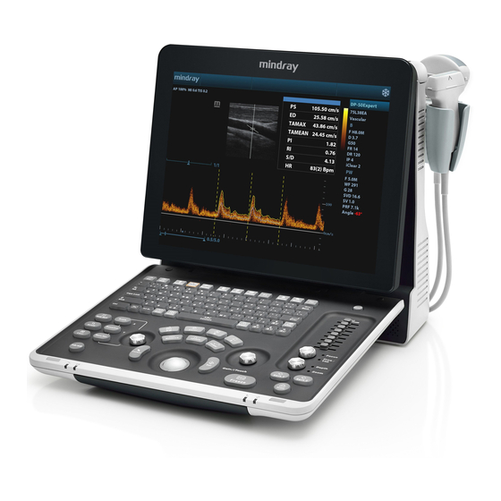
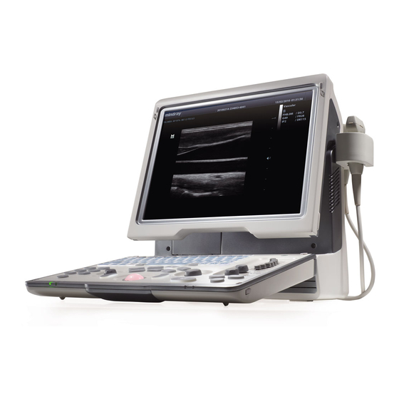
Product Specifications Overview 2.1.1 Intended Use The digital ultrasonic diagnostic imaging system is intended for use in clinical ultrasonic diagnosis. 2.1.2 Introduction of Each Unit Right View Product Specifications 2-1…
-
Page 18
Left View Rear View 2-2 Product Specifications… -
Page 19: I/O Panel
Bottom View Name Function Probe holder Used to place the probe Display Displays the image and parameters during scanning Control Panel Refer to the 2.1.5 Control Panel. USB ports Used to connect USB devices Handle Used to carry the machine Interface panel used for inputting and outputting signals, refer to I/O Panel 2.1.3 I/O Panel.
-
Page 20: Power Supply Panel
Symbol Function Network port USB ports Separate video output, connecting video printer or LCD Remote control port VGA signal output Composite video output Power indicator 2.1.4 Power Supply Panel Name Function Power inlet AC power inlet Used for equipotential connection, that balances the protective Equipotential terminal earth potentials between the system and other electrical equipment.
-
Page 21: Control Panel
2.1.5 Control Panel Name Description Function Off: when system is turned off; Power button Green: when system is turned on by pressing this button. Exit Press to exit the current status to the previous status. Press to display or hide the help information on Help screen.
-
Page 22
Name Description Function User-defined key You can assign a function to the key. Biopsy Press to show or hide the biopsy guide line. Setup Press to open/close the setup menu. Press to delete the comment, etc. Alphanumeric Same as on PC keys Press to enter Dual mode from non-Dual mode;… -
Page 23
Name Description Function Rotate: to adjust the gain Gain/ iTouch Press: to enter/ exit iTouch Move to adjust time gain compensation. Focus Press: to switch between Focus and Freq./THI; Freq./THI Rotate: to adjust corresponding parameter Depth Press: to switch between Depth and Zoom; Zoom Rotate: to adjust corresponding parameter Save 1… -
Page 24: Peripherals Supported
2.1.6 Peripherals Supported Item Model Graph / text printer HP OFFICEJET PRO 8100 Digital Color Video SONY UP-D25MD Printer MITSUBISHI P93W-Z Black and White Video Analog Printer SONY UP-X898MD Footswitch (1-pedal (not for CE region); 2-pedal; 3-pedal) LAN Accessory LPA11 (only for CE region) If the ultrasound system cannot recognize the SONY UP-X898MD printer automatically, you may need to change the settings on the printer: push <PUSH ENTER>…
-
Page 25: Monitor Specification
2.2.4 Monitor Specification Voltage Dimension 15 inch Resolution 1024×768 Adjustable angle ≤60 degree Product Specifications 2-9…
-
Page 27: System Installation
System Installation Preparations for Installation NOTE: Do not install the machine in the following locations: Locations near heat generators; Locations of high humidity; Locations with flammable gases. 3.1.1 Electrical Requirements 3.1.1.1 Requirement of Regulated Power Supply Requirement of power supply is referring to 2.2.2.Due to the difference of the power supply stability of different districts, please advise the user to adopt a regulator of good quality and performance such as an on-line UPS.
-
Page 28: Installation Condition
3.1.2 Installation Condition 3.1.2.1 Space Requirements Place the system with the necessary accessories at a proper position for convenient use. 1. Place the system in a room with good ventilation or having an air conditioning unit. 2. Leave at least 20cm clearance around the system to ensure effective cooling. 3.
-
Page 29: Unpacking
3.2.1 Unpacking Use the scissor to clip the 2 rubber belts as follows: Use a knife to open the tapes: Take out the operation manual: Take out the probe box 1: Take out the accessory box: System Installation 3-3…
-
Page 30
Take out the probe box2, as follows (the box is below the accessory box): Hold the handle tightly and pull the machine with the surrounding foam: Remove the surrounding protective foam to take out the main system. 3-4 System Installation… -
Page 31: Checking
3.2.2 Checking 1. After unpacking, check the objects in the container with the package list to see if anything is in short supply or is wrong. 2. Inspect and make sure there is no damage to the machine, no indentation, no cracks. Installation of Main Unit 3.3.1 Installing Battery…
-
Page 32: Display Adjusting
3.3.3 Display Adjusting 1. Open the display as described in 3.3.2. 2. Put the finger on the rim of the display and pull the display to tilt the display (60 degrees max.). 3. Tear off the screen protective film. Tilt the display Figure 3-3 Open and tilt the display Press <Fn>+ directional keys to adjust brightness and contrast.
-
Page 33: Installing Probe Holder
NOTE: On the monitor, the brightness adjustment comes before contrast. After readjusting the monitor’s contrast and brightness, adjust all preset and peripheral settings. 3.3.4 Installing Probe Holder Fix the probe holder hanger into the groove of the main unit, and push downwards to confirm the installation.
-
Page 34: Installing Peripherals
NOTE: Before inserting the connector into the probe port, inspect the connector pin. If the pin is bent, do not use the probe until it has been inspected / repaired / replaced. Installing Peripherals For the models of the supported peripherals, please refer to “2.1.3 Supported Peripherals”. 3.4.1 Footswitch Installation Connecting: Take 971-SWNOM as an example: insert the USB connector to the system…
-
Page 35: Installing A Graph / Text Printer
Video cable Remote port Figure 3-6 Installing Analog Video Printer Digital Video Printer Connect one terminal of the data cable of the video printer to the USB port of the ultrasound system and the other terminal to the video input port of the video printer; Insert the power cord to a power supply receptacle that is well grounded.
-
Page 36
Name Function 1. Power Button Powers on the printer adapter. 2. USB port Connects the printer to the printer adapter. 3. Network port Connects the printer adapter to the Ultrasound system. Power inlet Connects the printer adapter to power by using the auxiliary output port of the Ultrasound system. -
Page 37
System Connection Note: A maximum of 6 text/graph printers can be connected to the printer adapter at the same time. Before power on, perform the following steps: Connect the printer adapter to the ultrasound system using Shielded Ethernet cable; Connect the printer adapter to the ultrasound system using AC power cord together with the power adapter;… -
Page 38
Open the Network page via [Setup] [Network Preset] [Local TCP/IP]. Select Static; Set the IP Address to any value from 192.168.1.1 to 192.168.1.200 (192.168.1.10 is excluded, because it belongs to the printer adapter); Set the Subnet Mask to 255.255.255.0 and Gateway to 192.168.1.254; Click [Save]. -
Page 39
Printer Adapter Preset Open the Printer Adapter page via [Setup] [Print Preset] [Printer Adapter]. Set the IP Address to 192.168.1.10 and Port number to 6666. Click [Add], and the Printer Adapter name is displayed in the Service List. Print Preset … -
Page 40: Installing External Dvd-R/W
3.4.2 Installing External DVD-R/W Connect the USB cable connector of the external DVD recorder to the USB port in the ultrasound system. cable Figure 3-7 Installing External DVD System Configuration 3.5.1 Power ON / OFF Connect the system power cord to the AC power, and make sure the ultrasound system and other optional devices are correctly connected.
-
Page 41: System Preset
3.5.3 System Preset Press the <Setup> key to enter the [Setup] menu. Click <System Preset> to enter the screen as follows: Region System Installation 3-15…
-
Page 42
In the Region page, set the system language, date format, date, time and hospital related information, etc. General Click <System Preset> to enter: In this page, set the time of standby, brightness/contrast and color temperature of display,etc. Key Config 3-16 System Installation… -
Page 43
Function of keyboard keys <Print>, <Save>, F1 and the footswitch keys (left, mid, right) are user-defined. Key brightness, key volume, trackball backlight and trackball sensitivity can be adjusted. Image Preset Click [Image Preset] to enter: System Installation 3-17… -
Page 44: Print Preset
General image parameters can be set in this page. 3.5.4 Print Preset Press <Setup> and click [Print Preset] to set video printer, graph/text printer parameters: After connecting the local printer, Click “Printer Driver”, the system will display the printer name and status (Ready) automatically which already installed printer driver successfully.
-
Page 45
Return “Printer Service” page, Select the corresponding service from the printer list and increase the service. The system integrates drivers of HP printers, after HP printers are connected, drivers will be installed automatically (about 10s).If auto installation fails, icon will display on the right lower corner of the screen to warn you that manual installation is necessary. -
Page 46: Network Preset
After successful connection, the newly added network printer name will be shown in the printer driver list. NOTE: Before connect the network printer, make sure the ultrasound system and the printer are in the same network domain, and the network is working normally. The IP address and the server name should be valid, e.g.
-
Page 47
DICOM Setting Enter the AE Title of the ultrasound system, port and PDU according to the actual situation, and then click [OK] to exit the screen. NOTE: AE Title should be the same with the SCU AE Title preset in the server (PACS/RIS/HIS). -
Page 48
Only when the system is configured with DICOM basic function module, and installed DICOM Work list, MPPS, DICOM Structured Reporting and Query/ Retrieve modules, can the corresponding preset settings be found in DICOM Service screen. The DICOM Service Setting is used to set properties of DICOM services as Storage, Print, Work list, MPPS, Storage Commitment and Query/ Retrieve. -
Page 49: System Information
3.5.6 System Information In System Information screen, it displays the product configuration, software version, hardware & boards, and driver related information. You can check the product information here. 1. Press the <Setup> and click [System Info] to enter system information screen. 2.
-
Page 51: Hardware Principle
Hardware Principle General Structure of Hardware System Monitor Probe IO board board 4D drive board Main module board Control panel Hard disk Speaker Battery DC-DC connecting Charge/ Battery board discharge board Ultrasound signal AC-DC Power supply board Comm&control AC IN Figure 4-1 Schematic Diagram of System As a portable black-and-white ultrasonic product, the system supports two probe slots.
-
Page 52: Main Unit
Main Unit The main unit mainly involves 3 boards: Probe board (Two probe ports) Main board IO board 4D drive board (optional) 4.2.1 Probe Board A+5V LC filter A+95V +95V 3.3V/5V BOARD ID A-95V -95V PRB_A_VDD_EN, PRB_A_VCC_EN Power ON/OFF D+3V3…
-
Page 53: Main Board
Support 4D probe; recognize the probe via the ID code; switch the 4D drive signal via the electrical relay to make the 4D probe work normally. 4.2.2 Main board The main board could be divided into two parts: front-end of the main board and back-end of the main board.
-
Page 54
BF FPGA combines 64-channel echo signal to output to DSP FPGA, and DSP FPGA is sent to signal processing to a single image which is uploaded to CPU module by PCIE_PHY, then CPU module performs post processing. PCI_PHY implements PCIE interface switching. … -
Page 55: Io Broad
Back-end of the main board MUL FPGA implements display ports, it also supports display assembly, video and s-video interface of IO board. Multifunction FPGA on the back-end of the main board is to implement the REMOTE port on the IO panel. The CPU module implements interfaces including USB, Ethernet and VGA on the IO …
-
Page 56: Drive Board (Optional)
4.2.4 4D Drive Board (Optional) Communication & 4D Drive Board Ultrasonic si gnal Control Power supply Communication signal Voltage control Motor driving signal Power probe amplication 4D probe Hall return signal Amplifies 4D drive signal power and output signal matching the power requirement to drive the …
-
Page 57: Ultrasound System Indicator
Function: On the back-end of the main board, a special monitor IC is used to monitor signal voltages and clock battery power that are provided to the main board by the main unit box power supply module. The system temperature is detected in three positions: BF FPGA, CPU module and power …
-
Page 58: Display
4.2.7 Display Parameter High-voltage Inverter board board screen Display Brightness 3.3V 3.3V LVDS ON/OFF control IO board Brightness 3.3V control triode triode LVDS Control signal Brightness of switch Multifunction FPGA Main board Figure 4-8 Principle Diagram of Display Monitor mainly consists of the inverter board, LCD and the parameter board. Function describes as following: The inverter board produces high voltage to illuminate backlight of LCD which is adjusted …
-
Page 59: Control Panel
4.2.8 Control Panel Trackball TGC board Control panel PCBA ADC curcuit FPGA 5 status backlight Trackball indicators scan scan backlight Main driver curcuit board Main Interface Functional control Single- chip button encoder scan board +12V PWM generating Double- curcuit encoder board Buzzer driver curcuit Buzzer…
-
Page 60: Power System
Power System Power supply module DC-DC Main board boar POWER 14.8V,6600mAh drive board Display Battery in place ARM control signal MUL FPGA Control signal AC in place Restart automatically Power on/off signal control Battery connecting board CPU module Power 12V、5V Temperature signal management Battery in…
-
Page 61: System Power-On Control
Power Support circuit module or function Remarks description 3 +5V HDD, Control panel, Front-end of main board, Probe board 4 -5V Front-end of main board 5 5Vst CPU module 6 VDD Front-end of main board, Back-end of main board, Display 7 1V2 Back-end of main board (FPGA core voltage) 8 1V8A…
-
Page 62
Controlling signal Description Remarks SUS_S3_N CPU module output effectively represents that CPU system has been in the standby status, when 5VSTB which is controlled by power management FPGA is in the charging status. SUS_S4_N CPU module output effectively represents that CPU system has been in the dormancy status. -
Page 63
Pressing power button (Control panel) Receiving PWR_BTN_N effective (Power management FPGA) Is AC in place? (Ppower management FPGA) CPU_PWR_BTN_N is valid PWR_5VSTB_EN_N is valid (Power management FPGA) (Power management FPGA) SUS_S3_N and SUS_S4_N 5VSTB start-up is invalid(CPU module) (Power supply module) Indicating PWR_5VSTB_OK_N is valid 5VSTB_CPU… -
Page 65: Function And Performance Checking Method
The chapter supplies the method to verify main function and performance of product. This is only used for reference, not preventive execution. Function checking and testing of this part shall be carried out by Mindray service engineers and the user together.
-
Page 66: General Exam
General exam 5.3.1 Check Flow Check the control panel Check the monitor Check DVD Check peripherals Check I/O ports 5.3.2 Checking Content 5.3.2.1 Check Control Panel Procedure Standard Check the functions of all keys and knobs All keys and knobs are effective. Follow the direction: left to right, and up to down.
-
Page 67
5.3.2.2 Check the Display Procedure Standard Press “<Fn>+< >”, the brightness increases; and press Adjust LCD brightness “<Fn>+< >”, the brightness decreases. Adjust LCD contrast Press “<Fn>+< >”, the contrast increases; and press Display color temperature … -
Page 68: Function Checks
bar Code scanner: The bar code is correctly displayed on the screen. Perform code bar scanning when the ultrasound system is running normally. 5.3.2.5 Check IO Ports Procedure Standard Checking IO ports: The contents displayed on the VGA/LCD are the same …
-
Page 69: Checking Content
5.4.2 Checking Content 5.4.2.1 B Mode In B Mode scanning, the image parameter area in the right corner of the screen will display the real-time parameter values as follows: Display Image Parameters Frequency Depth Gain Frame Rate B Dynamic Range Parameters that can be adjusted to optimize the B Mode image are indicated in the following.
-
Page 70
Focus Position Adjustment The focus position will change in correspondence with the knob rotates. Press <Focus/Freq./THI.> light Focus indicator, rotate the knob Frequency adjustment Rotate clockwise to increase Press Rotate anticlockwise to decrease <Focus/Freq./THI.> light on the Freq./THI “FR” will be changed relevantly. indicator, rotate the knob iTouch iTouch sign will be displayed in the image area to activate image effect… -
Page 71
mode menu-> parameter. [Line Density] The higher the line density, the higher the resolution, and the lower the frame rate. iClear Click [iClear] to adjust, off represents no iClear is turned on, and the bigger the value the stronger the effect. The bigger the value the more clearly the mode menu->… -
Page 72
Menu Procedure Standard Speed Click [Speed], and rotate the multifunction knob to adjust the parameter. B mode menu-> [Speed] The lower the value the faster the refreshing. Display Format There are 4 formats available for image display: L/R, V1:1, V1:2, Full. M mode menu->… -
Page 73
5.4.2.4 PW Mode In PW Mode scanning, the image parameter area in the right corner of the screen will display the real-time parameter values as follows: Display Angle Pulse Sample Sample Image PW/CW Wall Frequency Repetition Volume Volume Angle Parameters Gain Filter… -
Page 74
Press <ESC> or <Cine> cine review. The images are still frozen but the system exits cine review. Auto Review Region Total frames Start mark Current frame Playback mark End mark 5.4.2.6 Measurement Procedure Standard In B mode Enter the application measurement mode. … -
Page 75: Performance Test
Performance Test 5.5.1 Test Process Resolution Detection depth Geometric Position Accuracy Blackout area test Record the exam images 5.5.2 Test Content The image used here is only for reference, stick to the image effect in the real NOTE: situation. Requirements: Display: set the contrast and brightness at the clinical application value (or the default status) Operation environment: dark room, simulating the clinical application environment.
-
Page 76
In condition that the transverse resolution testing targets are horizontally displayed, record the minimal distance of two targets that can be clearly recognized. Repeat the operation above for the transverse resolution testing targets at other depths. As shown in figure below. Axial resolution … -
Page 77
When using the convex probe, keep the transverse resolution testing targets to NOTE: be displayed near the midline. When using a linear probe with steer function, do not turn on the steer function when perform the transverse resolution test. Zoom in the region where the targets located if necessary. The diameter of the target point at a certain depth is equal to the transverse resolution at the depth. -
Page 78
5.5.2.3 Geometric positioning accuracy Longitudinal geometric positioning accuracy Test Step: Do adjustments as the way in testing the maximum depth. Record the distance by 20mm each segment on the longitudinal targets line using the measurement caliper; Select the value with the greatest error (to 20mm), calculate the accuracy using the formula below The measurement caliper should be positioned at the upper edge of the target, NOTE:… -
Page 79
Transverse geometric positioning accuracy Test Step: Cover the scan surface of the phantom with water or couple gel, gently contact the probe with the scan surface Adjust the depth, making the transverse targets to be displayed in the image. Adjust the focus point to be posited beside the transverse targets (the standard is not clear) Adjust parameters like gain, TGC, making each transverse targets to be clearly displayed. -
Page 80
5.5.2.4 Blackout Area Test Step: Cover the scan surface of the phantom with water or couple gel, gently contact the probe with the scan surface Adjust the depth at a lower value, and set the focus at the nearest place to the scan surface. Decrease the value of parameters like AP, Gain until the background noise just can be seen. -
Page 81: Software Upgrade And Maintenance
Software Upgrade and Maintenance WARNING: DO NOT directly remove a USB memory device; otherwise, the USB memory device and / or the system may be damaged. Enter the Maintenance Window NOTE: Log on the system with the identity of Service before perform system maintenance. To log on the system: When access control function has not been activated: press “Ctrl+/”…
-
Page 82: System Software Installation/ Restoration
System Software Installation/ Restoration Refer to recovery guide. Installation of Optional Devices Copy the optional devices to the U disk, then insert it to the USB port of the ultrasound system; Enter [Preset], click [Maintenance] to enter [Option] menu to select the option module to be installed.
-
Page 83
3. Click [Install]. Select key file from the dialog box, and then click [OK]. 4. The options become Installed after the key files are installed. The corresponding function is activated after returning from preset. Note: After all modules are installed, please go to the previous interface to confirm. Trial: select the corresponding software package, and then click [Trial]. -
Page 84
Note: the promotion function is only applied to the uninstalled key. If the optional key is installed, the promotion function is disabled. 2. Select the key to be promoted. 3. Click [OK] to complete the promotion. Note: it is unavailable to use promotion for multiple optional keys. For the optional key which is promoted, it can also be installed. -
Page 85: Data Backup And Storage
Return to the system preset interface. The option status changes into Uninstalled. The uninstalling function is exclusive to internal users. The service engineers must Note: log in the system with the account of Service, and then conduct the uninstallation. Data Backup and Storage 6.4.1 Manage Settings Press <Setup>…
-
Page 86: Patient Data Backup And Restore
6.4.1.1 Back up the Preset Data 1. On Manage Settings page, Click [Export] to open the [Export Data] dialogue box. 2. Select the path to save data. 3. Click [OK], a progress bar will appear and the preset data of the selected items will be exported to the specified path.
-
Page 87: Software Maintenance
Software Maintenance 6.5.1 Product Configuration NOTE: [Config] is available on the Maintenance menu only if the operator logged on the system as Service. Make the product configuration file—PCF file (generated by the production line or already archived PCF file) according to specific requirements and copy to the USB disk. Connect the USB disk to the machine, click [Config] and load the file in the popped up dialogue box.
-
Page 88
Select the path in the Browse page to save the log, and click [OK]. When the log is exported, the system prompts “Export succeed!” click [OK] to return to the Maintenance menu. The log can be exported to the external USB storage device only, make sure the NOTE: connection between U disk and ultrasound is normal before the exporting. -
Page 89: Display Parameter Setting
NOTE: Before uploading the log, make sure the ultrasound system has been connected to network, otherwise, the system may warn “could not connect to server” The server (smtp.163.com) is already specified by the system, the user doesn’t have to select it. Display Parameter Setting NOTE: In normal condition, when changing display assembly or main board assembly, the…
-
Page 90: Hdd Partition
3. Click the upper icon in the screen (prompts “Update” if you put the cursor on it), the update step is carried out, if fails, please send to R&D center. Figure 6-1 Main Monitor Maintenance Screen 4. After update is successful, restart the machine after power off to make the data effective. HDD Partition …
-
Page 91
structured report related data file and DICOM viewing software Report report template obd.bin OBD data file version.txt Version file Comment Comment file AnatomyImage Anatomical images Measurement Measurement library Doppler program and related boot configuration main file and plug-ins, remote desktop server Multilanguage string file \exe videoplay… -
Page 92
\selftest Self test log appmon_window_monitor.txt Appmon monitor log message.txt Warning message PeriLog.txt Peripheral log commentlog.txt Comment log burn_cd_msg.txt Burn log error.txt System error log \PATIENTDATA Main patient database path \Preset \Current User preset data \temporary Temporary file \PatientBack Patient back up data E drive Catalog Data… -
Page 93: Field Replacement Unit
Field Replacement Unit This chapter lists the details of the Field Replaceable Units (FRU) of the system. Please refer to the explosive view and the FRU table below. Level 0 represent the main Assembly of the system, and the whole system is divided into 4 Assembly. Level X represent the main parts of Level 0 Assembly.
-
Page 94: Explosive View
Explosive View 7-2 Field Replacement Unit…
-
Page 95: Assembly Explosive View
Assembly Explosive View 7.2.1 Monitor Assembly (A0) Order Number Part Name Qty. Remark 115-063844-00 Monitor Assembly(1117Vet/1116/1156/FRU) Field Replacement Unit 7-3…
-
Page 96
Order Number Part Name Qty. Remark 115-068553-00 Monitor Damper(FRU) 7-4 Field Replacement Unit… -
Page 97: Operation Panel Assembly (B0)
7.2.2 Operation Panel Assembly (B0) Order Number Part Name Qty. Remark 115-063914-00 Control Panel Assembly(1156/FRU) 115-063841-00 Dual Encodes Assembly(FRU) With trackball connecting line Field Replacement Unit 7-5…
-
Page 98
Order Number Part Name Qty. Remark 115-063842-00 Single Encode Assembly(FRU) With harness 801-1150-00015-00 optical trackball unit(FRU) With trackball connecting line 801-1150-00016-00 TGC Adjustment Board(FRU) With STC connecting line 115-063875-00 Bottom Cover of Control Panel(Vet) 115-063925-00 Bottom Cover of Control Panel(1156Human) 049-001795-00 keyboard Overlay With four pieces of encode knob and… -
Page 99: Core Assembly (C0)
Order Number Part Name Qty. Remark B1-1 049-001743-00 silcon keyboard 7.2.3 Core Assembly (C0) Field Replacement Unit 7-7…
-
Page 100
OS as well after replacement. 115-063913-00 is obsolete. Please use 115-063913-01 Probe Board Assy(1117/1156/Two Sockets) 115-063913-01 to order. 801-1150-00005-00 IO Board CE only. When applying, please 115-063916-00 HDD(DP-50/CE/FRU) remark: Software version, Serial number of unit. CE only. When applying, please 115-063917-00 HDD(DP-50T/CE/FRU) remark:… -
Page 101
Order Number Part Name Qty. Remark number of unit. CE only. When applying, please 115-063918-00 HDD(DP-50 PT/CE/FRU) remark: Software version, Serial number of unit. CE only. When applying, please 115-063919-00 HDD(DP-50Expert/CE/FRU) remark: Software version, Serial number of unit. CE only. When applying, please… -
Page 102
CE only. When applying, please 115-067388-00 HDD(DP-70C/CE/FRU) remark: Software version, Serial number of unit. CE only. When applying, please 115-068758-00 HDD(DP-50 Expert Vet/CE/FRU) remark: Software version, Serial number of unit. CE only. When applying, please 115-068756-00 HDD(DP-70 Vet/CE/FRU) remark: Software… -
Page 103
Order Number Part Name Qty. Remark number of unit. 115-063836-00 Power Supply Module(FRU) 115-063845-00 Main Unit Fan(FRU) 115-063886-00 Battery Connection Board(FRU) 115-063877-00 FrontCover Assy of MU(1117Vet/1116/1156) 043-011251-00 Handle 115-044346-00 4D Module Kit Optional 043-003940-00 Probe Holster Small 043-004917-00 large probe holster 115-011470-00 one-piece lithium-ion Battery Pack CE only… -
Page 104: Cable Set Of Main Unit (D0)
Order Number Part Name Qty. Remark C6-1 115-051844-00 AC-DC board( FRU) C6-2 115-051845-00 DC-DC Board( FRU) C6-3 115-063846-00 Power Supply Fan(FRU) 7.2.4 Cable Set of Main Unit (D0) Order Number Part Name Qty. Remark Include D2~D9, but only one piece for 115-063885-00 Cable Set of Main Unit(FRU) each of them.
-
Page 105: 台车(E0
Order Number Part Name Qty. Remark Control panel PCBA J7-TGC STC connecting line assembly J1 7.2.5 UMT-170 台车(E0) Order Number Part Number Qty. Remark 115-037617-01 Probe holder & cup bracket(FRU) Field Replacement Unit 7-13…
-
Page 106
Order Number Part Number Qty. Remark 115-070488-00 Bin(FRU) UMT-170 Trolley Caster 115-070487-00 Spanner(FRU) 7-14 Field Replacement Unit… -
Page 107: Structure And Assembly/Disassembly
Structure and Assembly/Disassembly Structure of the Complete System Figure 8-1 Overall Exploded View Name Name Holder Null turning axis of keyboard Rear cover assembly of main unit Control panel Assembly of main unit rack Bottom cover of control panel Display assembly Preparations 8.2.1 Tools Required…
-
Page 108: Engineers Required
8.2.2 Engineers Required Only technical professionals from Mindray or engineers authorized by Mindray after training can perform maintenance and check. 8.2.3 Assembly/Disassembly Required You should perform the following preparations before the disassembling of ultrasound equipment. When you stop the scanning and the image capture, you should power off the system and disconnect the system from the AC power supply, then pull out AC power cables.
-
Page 109: Battery Connecting Board
NOTE: The illustration of disassemble is provided for reference only, and the concrete picture depends on the actual model. 8.3.1 Battery Connecting Board Press the clasp of the battery cover, and then rotate the battery cover down to open it. Figure 8-2 Disassembly of Battery (1) Slide battery to the right side pressing it all the time, and then remove the battery when the battery pops on the recommended distance.
-
Page 110: Power Supply Module
Figure 8-5 Disassembly of Rear Cover Assembly of Main Unit (2) Remove panhead screws with washers (2 M3X6) fixed on the main unit box, and then take off the battery connecting board. Figure 8-6 Removing the Battery Connecting Board 8.3.2 Power Supply Module 1.
-
Page 111
Figure 8-8 Disassemble the Power Module Assembly (1) Figure 8-9 Disassemble the Power Module Assembly (2) Figure 8-10 Disassemble the Power Module Assembly (3) Remove panhead screws with washers (2 M3X6) fixed on power module assembly to take out the lower baffle and remove cables connecting the battery conversion board and the main board. -
Page 112
Remove three cables Figure 8-12 Disassemble the cables 8.3.2.1 Power module Fan After removing panhead screws with washers (5 M3X6) fixed on the power module assembly and pulling out the plug of the fan connecting cables and power input outlet connecting cables, you can take off the rear panel of power supply assembly. -
Page 113
Figure 8-15 Disassemble the Power Module Fan During the assembly, fan label must be pasted towards the surface of the machine, NOTE: and don’t confuse with fans of other products. 8.3.2.2 DC-DC Power Board Remove panhead screws with washers M3X6 (4) used to fix the DC-DC power board. Figure 8-16 Disassemble the DC-DC Power Board (1) Remove the plug of fan cable. -
Page 114: Io Broad
8.3.2.3 AC-DC Power Board Remove panhead screws with washers M3X6 (5) used to fix the AC-DC power board (one of the screws should be removed after the fan is removed). Figure 8-19 Disassemble the AC-DC Power Board (1) After removing the connecting plug between DC-DC power board and AC-DC power board, and the connecting plug between AC-DC power board and power input, you could take out the AC-DC power board.
-
Page 115: Probe Board
NOTE: Make sure that you could pull out and push into the IO board sockets vertically when pulling out and assembling the IO board assembly on the position of the handle. Remove panhead screws with washers M3X6 (4) used to secure the IO board, and then you could take out the IO board.
-
Page 116
Remove panhead screws with washers (2 M3X6) which are fixed on the main unit, take out the upper baffle and then pull out two cables connecting the main board to the power module assembly. Figure 8-24 Disassemble the Main Board Assembly (1) Remove the probe board assembly (referring to 8.3.4 the 2 step) and the IO assembly (referring to 8.3.3 step 3) -
Page 117: Control Panel Assembly
After replacing the CPU module, key file must be generated once again according to the new MAC address and written into HDD of the machine. Or else, the configuration function of the product will be lost. After removing the CPU module, Remove panhead screws with washers (12 M3X6) fixed on the main unit box, you can take off the board.
-
Page 118
Figure 8-29 Disassemble the Control Panel Assembly (1) Hold the upper edge of control panel assembly, and open up the control panel. Figure 8-30 Disassemble the Control Panel Assembly (2) After removing one countersunk head self-tapping screw PT3X10 fixed on the control panel and take out the plug of the keyboard and the main unit connecting cables, you could remove the control panel assembly. -
Page 119
Figure 8-32 Disassemble the Encoder Board (1) After removing the connecting cable plug on the control panel and taking out countersunk head self-tapping screw PT3X10(7) used to secure the encoder board, you could remove the encoder boards. Figure 8-33 Disassemble the Encoder Board (2) 8.3.6.2 Trackball Remove the connecting cable plug of trackball, and countersunk head self-tapping screw… -
Page 120
Figure 8-35 Disassembly of the TGC Board (1) After removing the connecting cable plug of TGC board and removing screws PT3X10 (4) fixed on the TGC board, you could remove the TGC board. Figure 8-36 Disassembly of the TGC Board (2) 8.3.6.4 Buzzer After removing the connecting cable plug of buzzer on the control panel and taking out the… -
Page 121: Display Assembly
Remove 18 PT3X10 self-tapping screws fixed on the control panel. Figure 8-38 Disassemble the Control Panel (1) Pull out the control panel and silicon key from the keyboard cover and then dispatch them apart. Take out the silicon key. Silicon key (upper) Control panel PCBA (lower)
-
Page 122: Hard Disk
Cut off cable ties connecting the main unit on the display by diagonal cutting pliers, and then pull out the corresponding cable plugs. Figure 8-41 Disassemble the Display assembly Pull the display assembly upwards to make it separated from the main unit. Figure 8-42 View of Display Assembly 8.3.8 Hard Disk…
-
Page 123: Speaker
Tilt the display Figure 8-43 Disassembly of HDD (1) Remove panhead screw with washer (1 M3X8 ) which is installed on the rack of the main unit front cover, then remove the HDD cover assembly (including HDD cover, HDD cover metal part and conductive foam ).
-
Page 124
2. Remove 4 combination screws M3X8 used to fix the monitor assembly by using the cross screwdriver. Figure 8-46 Disassembly of Speaker (1) 3. Remove cables connecting the speaker and cables connecting the control panel from machine core unit, and cut the cable ties by using wire cutters. Figure 8-47 Disassembly of Speaker (2) 4. -
Page 125: Printer Adapter (Optional)
5. Remove 4 panhead screws with washers (M3X6) used to fix the speaker assembly from the front cover of the main unit to take out the speaker assembly. Figure 8-49 Disassembly of Speaker (4) 6. Remove 4 panhead screws (M2X8) from the speaker assembly to disassemble the speaker assembly.
-
Page 126
Type-2 screwdriver screws. 8.3.10.3 Engineers Required Only technical professionals from Mindray or engineers authorized by Mindray after training can perform the maintenance and the check. 8.3.10.4 Requirements You should perform the following preparations before disassembling the ultrasound device. Power off the printer adapter, and disconnect all the AC power. -
Page 127
Structure and Assembly/Disassembly 8-21… -
Page 129: System Diagnosis And Support
System Diagnosis and Support General Status Indicator 9.1.1 Status Indicators of the Control Panel Status Icon Status definition and indicators Position indicators Power-on The indicator is not on when the system is turned off; The Control Panel status Press the key, the indicator blinks green at power on. indicator on the upper After power on, the indicator is green.
-
Page 130: Status Indicator Of The Power Supply On The Io Board
Screen-saver default is and the backlight of the freezing status automatically. “mindray” showing on the control panel both monitor. restore to the previous 9-2 System Diagnosis and Support…
-
Page 131: Starting Process Of The Whole System
The system is frozen. status. Ultrasound imaging hardware system is in the dormancy mode The system is on the power-off status: when Press the power switch for a connected the AC power short time, and then the system Starting the system by Power-off supply the AC indicator is is turned off by choosing from…
-
Page 132: Start Process Of Complete System
9.2.1 Start Process of Complete System 9.2.1.1 Powered on by AC Basic Procedures Phenomenon The original status: no indication Finishing loading The AC status indicator on the control panel lights on, but the 3.3VSTB,Finishing loading indicators of HDD and standby are off. 5VSTB Press the power button, The Power-on status indicator flashes continuously on the control…
-
Page 133: Start-Up Process Of Bios
9.2.2 Start-up Process of BIOS The start-up process of BIOS is a black-box operation, and the primary description is as following: Basic Procedures Basic phenomenon Self-test after the system power-on The LCD is blank screen in a short time. Initialization& The settings of record system & BIOS start-up display Providing the resident programmer library &…
-
Page 134: Start-Up Of Doppler
9.2.4 Start-up of Doppler 9.2.4.1 Procedure of Startup Linux app initialization Initialize Related PC HDD peripherals along with PC initialization PC software initialization Initialize ultrasonic Ultrasonic HDD initialization Finish related Ultrasonic startup ,operation and software application of ultrasonic initialization software Finish initialization 9.2.4.2…
-
Page 135
Platform Initializing gui… initialization Ultrasonic software Peripheral Initializing ultrasound peripheral… The total initialization initialization increment is 1 Imaging Initializing ultrasound image… The total initialization increments are 2 Application Initializing ultrasound application… The total initialization increment is 1 Finishing Initialization completed… The total initialization increment is 1… -
Page 136: Alarming And Abnormal Information
Initializing Set related information of the zoom, languages, font In increments of 1. locale… library and input Construct widget factory Configure the GUI layer Set menu items Initialize function library Construct UICenter Initializing Configure the application layer In increments of 1. gui……
-
Page 137: Turning On The System Configuration File Is Abnormal
9.3.1 Turning on the System Configuration File is Abnormal Alarming tips LOG record Suggestion Fail to open the file none Reinstall the system software. «SystemConfiguration.ini», and please check HDD data. 9.3.2 The voltage of system power is abnormal Alarming tips LOG record Suggestion ×××: System Monitor: Power supply alert! [VBAT], Current…
-
Page 138: Fan Alarming
[VVV] represents the current value, and [LLL] represents the first limit of CPU temperature. Temperature The log records are the same The second alarming, XX temperature of CPU [VVV] represents the current value, and [LLL] Shut down represents the second limit of CPU temperature. Suggestion as above (XX means inversion timing,…
-
Page 139: Phv Related Alarming
replace with new battery please change the battery Replace battery and confirm Battery I2C error, the malfunction module. Shutdown State Stop the illegal operation. Battery Hot Plug, Shutdown State 9.3.6 PHV Related Alarming Alarming tips LOG record Potential reason Alarm! Something is wrong with the programmed High-voltage voltage of power module, which make…
-
Page 141: Care And Maintenance
Care and Maintenance 10.1 Overview These procedures in this chapter are recommended. 10.1.1 Tools, Measurement Devices and Consumables Table 10-1 Tools and Measurement Devices Tool/Measurement Devices Qty. Remarks Resin or plastic container 1 pcs Can accommodate two probes Soft brush 1 pcs About a toothbrush size Small plastic basin…
-
Page 142: Care And Maintenance Items
10.1.2 Care and Maintenance Items Table 10-3 Maintenance Items and Frequency Maintain content Frequency Method Clean display Monthly Referring to 9.2.1 Clean trackball Monthly Same as the above Clean control panel Monthly Same as the above Clean probes (the head) Every time after using Same as the above Clean probe cable and the surface of…
-
Page 143: Cleaning
10.2 Cleaning 10.2.1 Clean the System 10.2.1.1 Flow of Cleaning Power off and pull out the power cables Clean display Clean trackball Clean control panel Clean probe Clean holders Clean cover Figure 10-1 View of Cleaning Maintenance Before cleaning the system, be sure to turn off the power and WARNING: disconnect the power cord from the outlet.
-
Page 144
Trackball is one of important interface parts, which are embedded into the main unit keyboard, and part of which is exploded to be operated by users in order to implement variety of module’s control functions. Trackball is one of the most using frequency of input assemblies on the whole operation panel, and the trackball similar to a multi-directory caster can rotate in every direction drived manually, due to the feature, gas or dust can enter into module internal easily, as a result, contamination of lens would lead to the failure of the trackball. -
Page 145
Clean control panel Tools: dry soft cloth, mild soapy water Method: Use dry soft cloth to clean the surface of the system. If the system is dirty, moisten the soft cloth with mild soapy water and wipe off any stains. Use dry soft cloth to remove any moisture and allow all hard surfaces to completely air-dry. -
Page 146: Clean The Peripherals
10.2.3 Clean the Peripherals Do the cleaning maintenance according to your actual peripheral configuration; items which are not configured can be skipped. Table 10-4 Peripherals Cleaning List Content Description First wipe off dust or stain attached to the cover of printer with Color and B/W video soft dry cloth, then clean the inside of printer.
-
Page 147: System Function Check
Content Method Check the battery periodically : a) Check if battery can be charged normally when power-on: That the current capacity is 100% or capacity increases after a short time indicates that the battery can be charged normally. It takes less than 2 minutes to increase 1% capacity when the total Battery capacity is less than 90% and it takes more time when the…
-
Page 148: Peripherals And Options Check
10.3.3 Peripherals and Options Check If the system is not configured with any module or peripheral, the corresponding items checking can be skipped. Table 10-7 Options, Peripherals and Accessories Check list Content Method Color and B/W video Check if the output of video printer is normal. printer Graph / text printer Check if the output of graph / text printer is normal.
-
Page 149: Electrical Safety Inspection
10.3.5 Electrical Safety Inspection Only technical professionals from Mindray or engineers authorized by Mindray after training can perform electric safety inspection. Please refer to appendix A: Electrical Safety Inspection for details. Care and Maintenance 10-9…
-
Page 151: Troubleshooting Of Regular Malfunctions
Troubleshooting of Regular Malfunctions 11.1 System cannot be powered on 11.1.1 Module or Board Related Descriptions Remarks Battery Li-ion 14.8V 6600mAh LI34I002A Power supply module CPU module 11.1.2 Key Points Supporting Troubleshooting Key Points Supporting Troubleshooting Remarks AC power indicator Located on control panel Power-on status indicator Backlight of the power button…
-
Page 152: System Cannot Start Up Normally
The AC input is normal ,AC power indicator Power supply module fails Replace power remains off; supply module Power indicators: off AC power indicator: ON; Power supply module fails Replace power supply module Power-on status indicator: off after power button pressed Power indicators: off AC power indicator: ON;…
-
Page 153: Image Fault
interface BIOS start-up graphics is normally CPU module failure Replace CPU module displayed, but it cannot be kept on Enters BIOS start-up graphics. Cannot find operating system, Find the failure cause the HDD or OS in HDD may by entering BIOS No LINUX start-up graphics be damaged.
-
Page 154: Key Points Supporting Troubleshooting
4D drive board IO board 11.3.2 Key Points Supporting Troubleshooting Key Points Supporting Troubleshooting Remarks Image feature, including dark strips and noise Images appearance when contact occurs between different types of probe in different interface of probe socket. 11.3.3 Troubleshooting Fault Cause Analysis Measure…
-
Page 155: Probe Socket System Malfunction
probe. The image abnormality may be caused by Replace the probe, or the swivel of the 4D probe or the 4D drive replace the 4D drive board board. It is suggested to replace the probe first, and then replace the 4D drive board. 11.4 Probe Socket System Malfunction 11.4.1 Module or Board Related Descriptions…
-
Page 156: Io Interface System
11.5 IO Interface System 11.5.1 Module or Board Related Descriptions Remarks Main board CPU module IO board Speaker 11.5.2 Key Points Supporting Troubleshooting Key Points Supporting Troubleshooting Remarks Working condition of the control panel Confirm if the USB main device is functional since the control panel is connected by internal USB cable Working condition of each USB port…
-
Page 157: Control Panel
11.6 Control Panel 11.6.1 Module or Board Related Descriptions Remarks Silicon key Control panel Dual encoder module Single encoder module Trackball module TGC module 11.6.2 Key Points Supporting Troubleshooting Points Supporting Remarks Troubleshooting Backlight of control panel To confirm if the control panel is powered on normally; Key sound of the control panel.
-
Page 158: Lcd Display
speed in system preset; Degenerated trackball Replace the trackball module performance All key of control panel are Single encoder malfunction Replace the encoder board normal, Single encoder failed. All key of control panel are TGC board malfunction Replace TGC board normal, Single key of TGC failed.
-
Page 159
The color of some mode key turns on orange. monitor board or monitor malfunction assembly No display (blank screen) on the LCD, with backlight only; or, disordered screen. Replace CPU module Control panel powered on normally and no key CPU module indicator turns on orange. -
Page 160: Printer Adapter Related Troubleshooting
11.8 Printer Adapter Related Troubleshooting Failure Description Cause Analysis Measure The ultrasound system Connect the ultrasound and the printer adapter system to the printer are not properly adapter again using connected. Ethernet cables. Check whether the indicator on the printer adapter flashes The following icon is displayed at the normally after power-on, bottom right corner of the ultrasound…
-
Page 161
The indicator on the printer Errors occur when the adapter turns orange, and the printing printer adapter runs. Disconnect and connect the fails. power adapter, power on the printer adapter again, and verify whether the printing is normal after 1 minute. -
Page 163: Electrical Safety Inspection
Appendix A ELECTRICAL SAFETY INSPECTION The following electrical safety tests are recommended as part of a comprehensive preventive maintenance program. They are a proven means of detecting abnormalities that, if undetected, could prove dangerous to either the patient or the operator. Additional tests may be required according to local regulations.
-
Page 164
ELECTRICAL SAFETY INSPECTION 1- Power Cord Plug TEST PROCEDURE The Power Plug The Power Plug Pins No broken or bent pin. No discolored pins. The Plug Body No physical damage to the plug body. No physical damage to the strain relief. No plug The Strain Relief warmth for device in use. -
Page 165
ELECTRICAL SAFETY INSPECTION Device Enclosure And Accessories TEST PROCEDURE Visual Inspection No physical damage to the enclosure and accessories. No physical damage to meters, switches, connectors, etc. No residue of fluid spillage (e.g., water, coffee, The Enclosure and Accessories chemicals, etc.). -
Page 166
ELECTRICAL SAFETY INSPECTION Device Labeling TEST PROCEDURE Check the labels provided by the manufacturer or the healthcare facility is present and legible. Main Unit Label Integrated Warning Labels Slope and High Voltage Caution Label Don’t Stress Label … -
Page 167
ELECTRICAL SAFETY INSPECTION 4- Protective Earth Resistance VOERVIEW Protective Earth Resistance is measured using the RED test lead attached to the DUT Protective Earth terminal or Protective Earth Metal enclosure or equipotential terminal. Select the test current by pressing SOFT KEY 3 to toggle between 1AMP, 10AMP, and 25AMP. The front panel outlet power is turned off for this test. -
Page 168
ELECTRICAL SAFETY INSPECTION 4- Protective Earth Resistance metal area. Press shortcut key 3. The Protective Earth Resistance test is displayed. Press SOFT KEY 3 to select a test current (1AMP, 10AMP, or 25AMP). The selected test current is displayed in the upper right corner of the display. Press START TEST to start the test. -
Page 169
ELECTRICAL SAFETY INSPECTION Earth Leakage Test OVERVIEW Run an Earth Leakage test on the device being tested before performing any other leakage tests. Leakage current is measured the following ways: ♦ Earth Leakage Current, leakage current measured through DUT outlet Earth ♦… -
Page 170
ELECTRICAL SAFETY INSPECTION Earth Leakage Test Figure 1 Earth leakage test Failure Check any short-circuits of the Y capacitor on power unit. Replace a new one if any portion defective. Check any broken of the Power Unit. Replace a new one if any portion defective. Inspect mains wiring for bad crimps, poor connections, or damage. -
Page 171
ELECTRICAL SAFETY INSPECTION Patient Leakage Current OVERVIEW Patient leakage currents are measured between a selected applied part and mains earth. All measurements may have either a true RMS or a DC-only response. TEST PROCEDURE Prepare Perform a calibration from the Mains on Applied Part menu. The following outlet conditions apply when performing this test: Normal Polarity, Earth Open, Outlet ON Normal Polarity, Outlet ON… -
Page 172
ELECTRICAL SAFETY INSPECTION Patient Leakage Current 601PRO. Press the print data key at any time to generate a printout of the latest measurement. Figure 2 patient leakage Current Note 1, In addition to Probes ,Patient leakage current test should be perform if ECG or PCG parts used;… -
Page 173
ELECTRICAL SAFETY INSPECTION Patient Leakage Current LIMITS All countries For BF ECG input and transducer 100μA Normal Condition 500μA Single Fault Condition Electrical Safety Inspection A-11… -
Page 174
ELECTRICAL SAFETY INSPECTION Mains on Applied Part Leakage OVERVIEW The Mains on Applied Part test applies a test voltage, which is 110% of the mains voltage, through a limiting resistance, to selected applied part terminals. Current measurements are then taken between the selected applied part and earth. Measurements are taken with the test voltage (110% of mains) to applied parts in the normal and reverse polarity conditions as indicated on the display. -
Page 175
ELECTRICAL SAFETY INSPECTION Mains on Applied Part Leakage Attach the applied parts to the 601PRO applied part terminals. Attach the red terminal lead to a conductive part on the DUT enclosure. Press shortcut key 7. The Mains on Applied Part test is displayed. Select the desired outlet configuration and applied part to test using the appropriate SOFT KEYS: Press START TEST (SOFT KEY 1) to begin the test. -
Page 176
ELECTRICAL SAFETY INSPECTION Mains on Applied Part Leakage user or owner to correct any deviations. As a work around, check the other outlets to see if they could be used instead. Change another probe to confirm if the fail is caused by console. Inspect wiring for bad crimps, poor connections, or damage. -
Page 177
ELECTRICAL SAFETY INSPECTION FORM (Class I equipment) Overall assessment: □ Scheduled inspection Test item: 1, 2, 3, 9 □ Unopened repair type Test item: 1, 2, 3, 9 □ Opened repair type, not modify the power part Test item: 1, 2, 3, 4, 5, 9 including transformer or patient circuit board □… -
Page 179: Appendix B Phantom Usage Illustration
Appendix B Phantom Usage Illustration Note: The use of Phantom is not required during Preventive Maintenance. Customer may use it as part of their Quality Assurance Program tests。 Note: Best storage and operating temperature of phantom is 10℃~35℃,do not use phantom beyond the specified temperature range, otherwise tested performance indicators may be affected.
-
Page 180
Targets disposal of Phantom KS107BD A1——A4 Axial resolution target group B1——B4 Lateral resolution target group Longitudinal target group Horizontal target group E1——E3 Mimic sacs with diameters of 2, 4, 6mm 4. Line Target System There are 8 groups of line targets disposed in TM material as shown in the figure. 1.A1——A4:… -
Page 181
Phantom Usage Illustration B-3… -
Page 183
P/N: 046-017661-00 (6.0)
(Ocr-Read Summary of Contents of some pages of the Mindray DP-50 Document (Main Content), UPD: 10 May 2023)
-
38, 3-12 System Installation 1. Open the Network page via [Setup] [Network Preset] [Local TCP/IP]. 2. Select Static; 3. Set the IP Address to any value from 192.168.1.1 to 192.168.1.200 (192.168.1.10 is excluded, because it belongs to the printer adapter); 4. Set the Subnet Mask to 255.255.255.0 and Gateway to 192.168.1.254; 5. Click [Save].
… -
141, Care and Maintenance 10-1 10 Care and Maintenance 10.1 Overview These procedures in this chapter are recommended. 10.1.1 Tools, Measurement Devices and Consumables Table 10-1 Tools and Measurement Devices Tool/Measurement Devices Qty. Remarks Resin or plastic container 1 pcs Can accommodate two probes Soft brush 1 pcs About a toothbrush size Small plastic basin 1 pcs Used to fill the soapy water Safety test analyzer 1 pcs R…
-
76, 5-12 Function and Performance Checking Method 4. In condition that the transverse resolution testing targets are horizontally displayed, record the minimal distance of two targets that can be clearly recognized. 5. Repeat the operation above for the transverse resolution testing targets at other depths. As shown in figure below. Axial resolution Test Step: 1. Cover the scan surface of the phantom with water or couple gel, gently contact the probe wi…
-
35, Mindray DP-50 System Installation 3-9 Figure 3-6 Installing Analog Video Printer Digital Video Printer 1. Connect one terminal of the data cable of the video printer to the USB port of the ultrasound system and the other terminal to the video input port of the video printer; 2. Insert the power cord to a power supply receptacle that is well grounded. 3. Please refer to 3.5.4 for the driver installation. And you need not install …
-
111, Structure and Assembly/Disassembly 8-5 Figure 8-8 Disassemble the Power Module Assembly (1) Figure 8-9 Disassemble the Power Module Assembly (2) Figure 8-10 Disassemble the Power Module Assembly (3) 5. Remove panhead screws with washers (2 M3X6) fixed on power module assembly to take out the lower baffle and remove cables connecting the battery conversion board and the main board. F…
-
91, Mindray DP-50 Software Upgrade and Maintenance 6-11 DCM structured report related data file and DICOM viewing software Report report template obd.bin OBD data file version.txt Version file Comment Comment file AnatomyImage Anatomical images Measurement Measurement library \exe main Doppler program and related boot configuration file and plug-ins, remote desktop server nls Multilanguage string file videoplay Video play exe fi…
-
9, III Statement This service manual describes the product according to the most complete configuration; some of the content may not apply to the product you are responsible for. If you have any questions, please contact Mindray Customer Service Department. Do not attempt to service this equipment unless this service manual has been consulted and is understood. Failure to do so may result in personnel injury …
-
72, 5-8 Function and Performance Checking Method 2. Menu Procedure Standard Speed B mode menu-> [Speed] Click [Speed], and rotate the multifunction knob to adjust the parameter. The lower the value the faster the refreshing. Display Format M mode menu-> [Display Format] There are 4 formats available for image display: L/R, V1:1, V1:2, Full. Tips: a) During M Mode scanning, frequency and acoustic power of the probeare synchronous with that of …
-
137, System Diagnosis and Support 9-9 9.3.1 Turning on the System Configuration File is Abnormal 9.3.2 The voltage of system power is abnormal 9.3.3 Temperature Alarming Alarming tips LOG record Suggestion Fail to open the file «SystemConfiguration.ini», and please check HDD data. none Reinstall the system software. Alarming tips LOG record Suggestion The real-time battery will be out…
-
136, 9-8 System Diagnosis and Support Initializing locale… Set related information of the zoom, languages, font library and input Construct widget factory Configure the GUI layer Set menu items Initialize function library Construct UICenter In increments of 1. Initializing gui… Configure the application layer Initialize the keyboard. Construct the user account control management, and remote desktop management In increments of 1. Initializing ultrasound peripheral… Co…
-
134, 9-6 System Diagnosis and Support 9.2.4 Start-up of Doppler 9.2.4.1 Procedure of Startup Linux app initialization PC HDD initialization Ultrasonic HDD initialization Finish initialization PC software initialization Ultrasonic software initialization Initialize Related peripherals along with PC Finish related startup ,operation and application of ultrasonic software Initialize ultrasonic HDD 9.2.4.2 Details of Procedures Now, DOPPLER starting is in in…
-
69, Function and Performance Checking Method 5-5 5.4.2 Checking Content 5.4.2.1 B Mode In B Mode scanning, the image parameter area in the right corner of the screen will display the real-time parameter values as follows: Display F D G FR DR Image Parameters Frequency Depth Gain Frame Rate B Dynamic Range Parameters that can be adjusted to optimize the B Mode image are ind…
-
173, Electrical Safety Inspection A-11 ELECTRICAL SAFETY INSPECTION 6- Patient Leakage Current LIMITS All countries For BF ECG input and transducer 100μA Normal Condition 500μA Single Fault Condition
… -
12, Mindray DP-50 1-2 Preface 1.2.2 Warning Labels No. Warning Labels Meaning 1. Please carefully read this manual before use device. 2. The following labels are available when the system works with the mobile trolley. a. Do not place the device on a sloped surface. Otherwise the device may slide, resulting in personal injury or the device malfunction. Two persons are required to move the device over a sloped surface. b. Do not sit …
-
125, Structure and Assembly/Disassembly 8-19 5. Remove 4 panhead screws with washers (M3X6) used to fix the speaker assembly from the front cover of the main unit to take out the speaker assembly. Figure 8-49 Disassembly of Speaker (4) 6. Remove 4 panhead screws (M2X8) from the speaker assembly to disassemble the speaker assembly. Figure 8-50 Disassembly of Speaker (5) 8.3.10 Printer Adapter (…
-
95, Mindray DP-50 Field Replacement Unit 7-3 7.2 Assembly Explosive View 7.2.1 Monitor Assembly (A0) No. Order Number Part Name Qty. Remark A1 115-063844-00 Monitor Assembly(1117Vet/1116/1156/FRU) 1 / A2 A1
… -
166, A-4 Electrical Safety Inspection ELECTRICAL SAFETY INSPECTION 3- Device Labeling TEST PROCEDURE Check the labels provided by the manufacturer or the healthcare facility is present and legible. Main Unit Label Integrated Warning Labels Slope and High Voltage Caution Label Don’t Stress Label
… -
36, 3-10 System Installation No. Name Function 1. Power Button Powers on the printer adapter. 2. USB port Connects the printer to the printer adapter. 3. Network port Connects the printer adapter to the Ultrasound system. 4. Power inlet Connects the printer adapter to power by using the auxiliary output port of the Ultrasound system. Specification Power Supply Environment Input: 100-240 [email protected] Frequency: 50/60Hz Output: …
-
Contents
-
Table of Contents
-
Troubleshooting
-
Bookmarks
Quick Links
DP-50 Vet/DP-70 Vet/DP-50 Exp Vet
Digital Ultrasonic Diagnostic
Imaging System
Operator’s Manual
[Basic Volume]
Related Manuals for Mindray DP-50 Vet
Summary of Contents for Mindray DP-50 Vet
-
Page 1
DP-50 Vet/DP-70 Vet/DP-50 Exp Vet Digital Ultrasonic Diagnostic Imaging System Operator’s Manual [Basic Volume]… -
Page 3: Table Of Contents
Contents Intellectual Property Statement ………………….I Responsibility on the Manufacturer Party ………………II Warranty ……………………….II Exemptions ……………………… II Customer Service Department ………………..III Important Information ……………………IV About This Manual ……………………..V Notation Conventions ……………………V Operator’s Manuals ……………………… V Manuals on Paper ……………………..
-
Page 4
2.6.3 Control Panel …………………… 2-9 Symbols ……………………..2-12 System Preparation ………………..3-1 Moving / Positioning the System ………………3-1 Power Supply ……………………3-1 3.2.1 Connecting External Power Supply …………….3-1 3.2.2 Powered by Battery …………………. 3-1 Powering ON/ OFF ………………….. 3-2 3.3.1 Powering ON …………………… -
Page 5
Image Optimization ………………..5-1 Switching Between Image Modes ………………5-1 Basic Operations ……………………5-1 Quickly Saving Image Setting (QSave) …………….5-2 B Mode ……………………..5-2 5.4.1 B Mode Exam Protocol ………………..5-2 5.4.2 B Mode Parameters …………………. 5-3 5.4.3 B Mode Image Optimization ………………5-3 M Mode …………………….. -
Page 6
Cine Review ……………………. 6-3 6.2.1 Entering/ Exiting Cine Review ………………6-4 6.2.2 Cine Review in 2D Mode ………………..6-4 6.2.3 Cine Review in M/PW Mode ………………6-5 6.2.4 Linked Cine Review …………………. 6-5 Image Compare ……………………6-6 6.3.1 Image Compare in Review Mode …………….. 6-6 6.3.2 Frame Compare …………………. -
Page 7
9.1.2 Animal Information Setting ………………. 9-1 Image File Management …………………. 9-2 9.2.1 Storage Media………………….. 9-2 9.2.2 Image File Formats ………………….. 9-2 9.2.3 Image Storage Preset ………………..9-2 9.2.4 Saving Images to the System ………………9-3 9.2.5 Quickly Saving Images to USB Flash Drive …………..9-3 9.2.6 Quickly Saving Full Screen Image to the System ………… -
Page 8
11 Setup……………………11-1 11.1 System Preset ……………………11-1 11.1.1 Region ……………………11-1 11.1.2 General ……………………11-3 11.1.3 Image …………………….. 11-4 11.1.4 Application ……………………11-5 11.1.5 Key Config ……………………11-5 11.1.6 Biopsy ……………………. 11-6 11.1.7 Admin …………………….. 11-6 11.2 Exam Preset ……………………11-6 11.3 Measure Preset …………………… -
Page 9
12.2.8 Removing the Needle-guided Bracket …………..12-34 12.2.9 Clean and Sterilize the Needle-guided Bracket …………12-37 12.2.10 Storage and Transportation ………………12-39 12.2.11 Disposal ……………………12-39 12.3 Middle Line ……………………12-39 13 Battery ……………………13-1 13.1 Overview ……………………..13-1 13.2 Precautions ……………………13-2 13.3 Installing and Removing the Batteries ……………. -
Page 10
Appendix B Transducer Maximum Surface Temperature ……..B-1 Appendix C Acoustic Output Reporting Table (60601-2-37) ……..C-1 Appendix D Printer Adapter ………………D-1 viii… -
Page 11: Intellectual Property Statement
Intellectual Property Statement SHENZHEN MINDRAY BIO-MEDICAL ELECTRONICS CO., LTD. (hereinafter called Mindray) owns the intellectual property rights to this Mindray product and this manual. This manual may refer to information protected by copyright or patents and does not convey any license under the patent rights or copyright of Mindray, or of others.
-
Page 12: Responsibility On The Manufacturer Party
Contents of this manual are subject to change without prior notice. All information contained in this manual is believed to be correct. Mindray shall not be liable for errors contained herein or for incidental or consequential damages in connection with the furnishing, performance, or use of this manual.
-
Page 13: Customer Service Department
Customer Service Department Manufacturer: Shenzhen Mindray Bio-Medical Electronics Co., Ltd. Address: Mindray Building, Keji 12th Road South, High-tech industrial park, Nanshan, Shenzhen 518057, P.R. China Website: www.mindray.com E-mail service@mindray.com Address: Tel: +86 755 81888998 Fax: +86 755 26582680 Shanghai International Holding Corp. GmbH (Europe) Representative: Eiffestraβe 80, Hamburg 20537, Germany…
-
Page 14: Important Information
7. Important data must be backed up on external memory media. 8. Mindray shall not be liable for loss of data stored in the memory of this system caused by operator error or accidents. 9. This manual contains warnings regarding foreseeable potential dangers, but you shall always be alert to dangers other than those indicated as well.
-
Page 15: About This Manual
About This Manual This operator’s manual describes the operating procedures for this diagnostic ultrasound system DP-50 Vet/DP-70 Vet/DP-50 Exp Vet and the compatible probes. To ensure safe and correct operations, carefully read and understand the manual before operating the system.
-
Page 16: Conventions
[Dyn Rng (Value)]: Indicates menu items with parameter, (value) shows the current value of the item. Product Differences B-Profile B-Hist Double Dist Trace Length √ √ √ √ DP-50 Vet × √ √ √ DP-70 Vet √ × √ √ DP-50…
-
Page 17: Safety Precautions
Safety Precautions Safety Classification According to the type of protection against electric shock: Externally Powered Class I Equipment + Internally powered equipment According to the degree of protection against electric shock: Type-BF applied part According to the degree of protection against harmful ingress of water: Main unit: IPX0 Probes: IPX7 Footswitch: IP68…
-
Page 18: Meaning Of Signal Words
Meaning of Signal Words DANGER WARNING ”, “ ”, “ ”, CAUTION In this manual, the signal words» “NOTE” and «Tips» are used regarding safety and other important instructions. The signal words and their meanings are defined as follows. Please understand their meanings clearly before reading this manual.
-
Page 19: Safety Precautions
You must use the power adapter provided with the system; otherwise electric shock may result. You can only adopt the power supply method provided by Mindray, other power supply modes (e.g. using a UPS) may result in electric shock. Connect the protective grounding conductor before turning ON the system.
-
Page 20
DO NOT touch the Signal I/O ports if in contact with the animal; otherwise animal injury may result. Do not use an aftermarket probe other than those specified by Mindray. The probes may damage the system causing a profound failure, e.g. a fire in the worst case. -
Page 21
The ultrasound system use a mains plug as isolation means to the mains power supply. Please do not set the ultrasound system in a place difficult to operate the mains plug. Do not modify this equipment without authorization of the manufacture. Safety Precautions 1-5… -
Page 22
If the circuit protector is tripped, it indicates that the system or a peripheral device was improperly shut down and the system is unstable. You cannot repair the system under this circumstance and must call the Mindray Customer Service Department or sales representative. 1-6 Safety Precautions… -
Page 23
There is no risk of high-temperature burns during normal ultrasound examinations. It is possible for the surface temperature of the transducer to exceed the body temperature of an animal due to environmental temperature and exam type combinations. Do not apply the transducer to the same region on the animal for a long time. -
Page 24
If the system is used in a small room, the room temperature may rise. Please provide proper ventilation and free air exchange. To dispose of the system or any part, contact Mindray Customer Service Department or sales representative. Mindray is not responsible for any system content or accessories that have been discarded improperly. -
Page 25
Please read the following precautions carefully to ensure the safety of the animal and the operator when using the probes. The ultrasonic probe is only for use with the specified ultrasonic diagnostic system. Please refer to the “2.5.2 WARNING: Probes Available” to select the proper probe. The ultrasonic probe must be used only by qualified professionals. -
Page 26
Mindray will not be liable for damage caused by other solutions. If you have any questions, please contact Mindray Customer Service Department or sales representative. The probe sheath contains natural rubber that can cause allergic reactions in some individuals. -
Page 27: Latex Alert
Latex Alert When choosing a probe sheath, it is recommended that you directly contact CIVCO for obtaining probe sheath, pricing information, samples and local distribution information. For CIVCO information, please contact the following: CIVCO Medical Instruments Tel: 1-800-445-6741 WWW.civco.com Allergic reactions in latex (natural rubber) sensitive animals may WARNING: range from mild skin reactions (irritation) to fatal anaphylactic shock, and may include difficulty in breathing (wheezing),…
-
Page 28: Warning Labels
Warning Labels The warning labels are attached to this system in order to call your attention to potential hazards. The warning labels use the same signal words as those used in the operator’s manual. Read operator’s manual carefully before using the system. The name, pattern and meaning of each warning label are described as follows: No.
-
Page 29: System Overview
System Overview Intended Use The Digital Ultrasonic Diagnostic Imaging System is intended for veterinary use in ultrasound examination and diagnosis. Contraindication None. Product and Model Code Model code Product code The functions described in the operator’s manual may vary depending upon the NOTE: specific system you purchased.
-
Page 30: Power Supply
2.4.2 Power supply Voltage 100-240V~ Frequency 50/60Hz Input Power 1.5-0.8A 2.4.3 Environmental Conditions Operational Conditions Storage and Transportation Conditions Ambient 0° C-40° C -20° C-55° C temperature Relative 30%-85% (no condensation) 30%-95% (no condensation) humidity Atmospheric 700hPa-1060hPa 700hPa-1060hPa pressure Do not use this system in the conditions other than those WARNING: specified.
-
Page 31
Probe Model Category Region Applied 65C15EA Convex Body surface 65EB10EA Convex Transrectal Linear 75L38EA Body surface array Linear 75L53EA Body surface array Linear 10L24EA Body surface array 35C20EA Convex Body surface 65EC10ED Convex Transrectal 75LT38EA Linear Body surface 65EL60EA Linear Transrectal Linear 50L60EAV… -
Page 32: Options
Needle-guided Biopsy Angle/ Probe Model Applicable Biopsy Needle Bracket Model Depth (± 1° ) NGB-007 Plastic/needle Metal: 14G, 16G, 18G, 20G, 22G 75L53EA 40° , 50° , 60° detachable; Plastic: 13G, 15G, 16G, 18G, 20G Metal/needle detachable NGB-009 65EL60EA 0º 20G, 18G, 16G, 15G, 13G Metal/needle detachable…
-
Page 33: Peripherals Supported
Item Color Power Ultrasound gel (optional configuration in the CE region) 2.5.4 Peripherals Supported Item Model Graph / text printer HP OFFICEJET PRO 8100 Digital Color Video SONY UP-D25MD Printer MITSUBISHI P93W-Z Black and White Video Analog Printer SONY UP-X898MD Footswitch (1-pedal (not for CE region);…
-
Page 34: Introduction Of Each Unit
Introduction of Each Unit Right View Left View 2-6 System Overview…
-
Page 35
Rear View Bottom View Name Function Probe holder Used to place the probe Display Displays the image and parameters during scanning Control Panel Refer to 2.6.3 Control Panel USB ports Used to connect USB devices Handle Used to carry the machine Interface panel used for inputting and outputting signals, refer I/O Panel to 2.6.1 I/O Panel. -
Page 36: I/O Panel
2.6.1 I/O Panel <1> <2> <3> <4> <5> <6> <7> 3.3V <8> Symbol Function Network port USB ports Separate video output, connecting video printer or LCD Remote control port VGA signal output video output Composite Power indicator 2.6.2 Power Supply Panel Name Function Power inlet…
-
Page 37: Control Panel
2.6.3 Control Panel Name Description Function Off: when system is turned off; Power button Green: when system is turned on by pressing this button. Exit Press to exit the current status to the previous status. Press to display or hide the help information on Help screen.
-
Page 38
Name Description Function Press to enter or exit the animal information iStation management system. User-defined You can assign a function to the key. Biopsy Press to show or hide the biopsy guide line. Setup Press to open/close the setup menu. Press to delete the comment, etc. -
Page 39
Name Description Function Measurement status: press to switch between the fixed and active end of the caliper; Multi-imaging mode: press to change the Update currently active window. iScape: press to start/stop image acquisition. Caliper Press to enter/ exit General Measurement Rotate: to adjust the gain Gain/ iTouch Press: to enter/ exit iTouch… -
Page 40: Symbols
Symbols This system uses the symbols listed in the following table, and their meanings are explained as well. Symbol Description Type-BF applied part Caution Dangerous voltage Equipotentiality Power button Network port USB ports Video output Remote control port VGA signal output AC (Alternating current) Battery Status Indicator Standby indicator…
-
Page 41
Symbol Description The device is fully in conformance with the low voltage directive 2014/35/EU and the EMC directive 2014/30/EU System Overview 2-13… -
Page 43: System Preparation
System Preparation Moving / Positioning the System Please read and understand the safety precautions before placing the system to ensure safety for both operator and devices. 1. Switch off the power, and pull out the plug. 2. Disconnect the system from all peripherals. 3.
-
Page 44: Powering On/ Off
– immediately stop scanning. If the system continues to function improperly – fully shut down the system and contact Mindray Customer Service Department or sales representative. If you use the system in a persistently improper functioning state – you may harm the animal or damage the equipment.
-
Page 45: Powering Off
If you find anything not functioning properly, this may indicate that the system is defective. In this case, shut down the system immediately and contact Mindray Customer Service Department or sales representative. NOTE: When you start the system or switch between probes, you will hear clicking sounds –…
-
Page 46: Connecting / Disconnecting A Probe
When connecting or disconnecting a probe, place it in a CAUTION: proper position, to prevent the probe from falling off or becoming damaged. Only use the probes provided by Mindray. Aftermarket probes may result in damage or cause a fire. 3.4.1 Connecting a Probe…
-
Page 47: Disconnecting A Probe
3.4.2 Disconnecting a Probe Turn the probe lock lever counterclockwise to release the connector. Pull the connector straight out. Keep the probe in safety and care. Connecting the Footswitch Connect the footswitch to the main unit via a USB port. Set the functions of the footswitch in the [Key Config] page.
-
Page 48
Power cord Data cord USB port 1. Connect the data cable with the USB port on the ultrasound system. 2. Plug the other end power plug into an appropriate outlet. 3. Power on the system and the printer. 4. Check the printer status: Enter [Setup]->… -
Page 49
6. Click [Save] to finish the installation. Tips: Click [Printer Driver]->[Printer Supported] to view the drivers of some popular printers that have already been integrated in the system. These drivers will be installed automatically. You need to check the following information to check if the auto-installation fails: Model of the connected printer is not displayed in the “Printer Driver”… -
Page 50: Digital Video Printer
4. Click [Verify Net Printer], the IP address, name and port information of the network printer will be displayed under the “Port” box. Change the port to match the verified printer information if necessary. 5. Click [OK] to enter the ppd installing screen: …
-
Page 51: Analog Video Printer
(3) Select the service type as «Digital Image Print» and enter the service name manually. (4) Click OK to return to the Printer Service page. (5) Set the items in the Property box and click [Save] to save the settings. …
-
Page 52: Basic Screen And Operation
3.11 Basic Screen and Operation 3.11.1 Basic Screen The following diagram maps out the different areas in the screen: Hospital name Accession# Animal Information Freeze Logo Operator Exam time icon Probe Acoustic power, MI/TI Product Mode Exam Mode Menu area Image area Image Parameters Thumbnail…
-
Page 53
The freeze icon means the image is frozen. Animal Information Displays animal name, ID, gender and age etc. Enter the animal information through the «Animal Info» screen. Or, import the saved animal data from iStation or the DICOM Worklist server. … -
Page 54
The multifunction knob can be used to operate the menu. Press the knob to open the menu; rotate the know to navigate through the items one by one. Depending on the item types, the multifunction knob can: For a commanding item or command optional item: press the knob to directly activate the item. -
Page 55: Basic Operations Of Screens
None-fixing Area Position of areas illustrated here are not fixed, you can move them by the trackball within a certain area on the display. Result window The measurement result window displays the results of recently performed measurements. To move the result window: a) Place the cursor on the title of result window (you can see the cursor changes into b) Press <Set>…
-
Page 56
Composition Description Radio button: click to select the item. Check box: click to check or uncheck the item. Entry box: enter characters manually via the keyboard. Content Position the cursor into the box, and then enter the letters or characters. -
Page 57: Exam Preparation
Exam Preparation Before examining a new animal, press <End Exam> to end the CAUTION: exam of the previous animal, update the animal ID and information, to avoid mixing data of the next new animal. Start an Exam You can start an animal exam in the following situations: …
-
Page 58: New Animal Information
Click [Quick Register] on the screen to save the animal information quickly and return to the main screen. 4.2.1 New Animal Information The Animal Info page is shown as below: Place the cursor onto the targeted box. The field box is highlighted and a flashing cursor appears.
-
Page 59
Gender Select Male, Female or Unknown for animal gender in the drop down list. DOB (Date of birth): You can either enter the birth date of an animal manually; Or, click to select the date, and click [Save] to confirm. … -
Page 60
Exam Type Information Description Calculate gestation age (GA) and estimated delivery date (EDD) based on last menstrual period (LMP), in vitro fertilization (IVF), basic body temperature (BBT), previous exam date (PRV). Select LMP, IVF, PRV, BBT, or EDD from the drop-down list; or, calculates GA and LMP according to the EDD and entered date. -
Page 61: Retrieve Animal Information
[New Exam]: click to clear the current exam information in order to create a new exam for the current animal. [Pause Exam]: to pause the current exam. [Cancel Exam]: to cancel the current exam. [OK]: click to save the animal data entered and exit the screen. …
-
Page 62
Button Function Description Review Click to enter the Review screen. Image Animal Click to enter the Animal Info screen. Info Review Click to enter the Diagnostic Report screen. Report Delete Click to delete the selected record. Exam Backup Click to export the selected animal data to media supported. Exam Restore Click to import the animal data from an external media. -
Page 63: Select Exam Mode And Probe
Select exam date period, click [Query] to search the animal data in the period. Enter animal ID, animal name, accession #, the system affords the result in real-time. Or select the keyword type, enter the keywords and then click [Query] to search. …
-
Page 64: Dual Probe Switching
(2) Roll the trackball and press <Set> to select the exam mode, and use the direction keys to turn pages of the exam modes. To save the image parameters for the current exam mode quickly: Click [QSave] in the Probe & Exam page or click the user-defined key for QSave to save the image parameters in the current image mode as presets.
-
Page 65: Bi-Plane Endocavity Probe (65Eb10Ea)
4.3.4 Bi-plane Endocavity Probe (65EB10EA) Selecting Exam Mode 1. Connect 65EB10EA to the ultrasound system. 2. Press <Probe> on the control panel to enter the exam mode selecting screen. Roll the trackball and press <Set> to switch the S or T plane of the probe, or select the exam mode of the S/T plane of 65EB10EA probe.
-
Page 66: Selecting Imaging Mode
Selecting Imaging Mode Use the corresponding key in the control panel to enter the imaging modes. For the detailed operations in each imaging mode, please refer to “5 Image Optimization”. Activate& Continue an Exam 4.5.1 Activate an Exam Select an exam finished within 24 hours, select the exam record, click from the menu popped up;…
-
Page 67: End An Exam
4.6.2 End an Exam Before examining a new animal, press <End Exam> to end the exam of the previous animal, update the animal ID and information, to avoid mixing data of the next new animal. To end an exam, you can do one of the following: …
-
Page 69: Image Optimization
Image Optimization The images displayed in this system are only reference for WARNING: diagnosis. Mindray is not responsible for the correctness of diagnostic results. It is the responsibility of the clinician, who performs the exam, to capture the correct diagnostic results.
-
Page 70: Quickly Saving Image Setting (Qsave)
Quickly Saving Image Setting (QSave) To enter image parameter saving screen: Press <Probe> and click [QSave], or; Press the user-defined key for QSave function (for details about user-defined key setting, please refer to “11.1.5 Key Config” chapter). Save image parameter adjustment: Click [Save] to save the current image values for the current exam mode of the certain probe.
-
Page 71: B Mode Parameters
In real-time scanning of all image modes, press <B> on the control panel to return to B mode. 5.4.2 B Mode Parameters In B mode scanning, the image parameter area in the upper left corner of the screen displays the real-time parameter values as follows: Display Parameter Frequency Depth…
-
Page 72
Description The system compensates the signals from deeper tissue by segments to optimize the image. There are 8-segment TGC sliders on the control panel corresponding to the areas in the image. Operation To increase the gain compensation at an area of interest, move the TGC slider to the right. -
Page 73
Imaging Display Adjustment Description More information can be obtained without moving the probe or changing the sampling position. FOV (Field of 1. To change the scan range, click [FOV] on the image menu to enter the View) FOV range and FOV position adjustment status. 2. -
Page 74
Operation Adjust through the [iClear] item in the menu; The system provides 5 levels of iClear effects adjustment, off represents no iClear is turned on, and the bigger the value the stronger the effect. Effects The bigger the value the clearer the profile of the image. Smooth Description Rejects image noise and makes images smooth. -
Page 75
Auto Merge Description In the Dual-split mode, when the images of the two windows use the same probe type, depth, invert status, rotation status and magnification factor, the system will merge the two images so as to extend the field of vision. Operation Turn on/ off the function through the [Auto Merge] item in the menu;… -
Page 76
Operation Press <Gain/ iTouch> on the control panel, the iTouch symbol will display in the image parameter area. Click [iTouch] on the image menu to adjust gain in iTouch status among -12 through 12dB. Gray Rejection Description This function is to reject image signals less than a certain gray scale, then the rejected signal corresponding area turns black. -
Page 77: M Mode
Middle Line: “Middle Line” is used to locate the focus point of lithotrity wave during lithotrity Description treatment. For details, please refer to 12.3 Middle Line Operation Click [Middle Line] in the image menu at the left side of the screen to turn on the lithotrity.
-
Page 78: M Mode Image Optimization
During M mode imaging, you can switch between B and M menu from the menu title. During M Mode scanning, frequency and acoustic power of the transducer are synchronous with that of B Mode. Adjustment of the depth or TGC to the B Mode image will lead to corresponding changes in M Mode image.
-
Page 79
Operation Adjust through the [Acoustic Power] item in the image menu; The adjusting range is 0%-100% and the adjusting level is 32. Effects Generally, increasing the acoustic power will increase the brightness and contrast of the image as well as the force of penetration. Impacts You should perform exams according to actual situation and follow the ALARA Principle. -
Page 80
Colorize and Colorize Map Description Colorize function provides an imaging process based on color difference rather than gray distinction. Operation Turn on or off the function through the [Colorize] item in the menu; Select the colorize map through the [Colorize Map] item in the menu; The adjusting range are off, and 1-25. -
Page 81
Operation Adjust through the [Edge Enhance] item in the menu; The edge enhance adjustment range is 0-14, the bigger the value the stronger the effect. Impacts Larger edge enhance may lead to noise increasing. Dynamic Range Description Adjusts contrast resolution of an image, compresses or expands gray display range. -
Page 82: Color Mode Image Optimization
Color Mode Image Optimization The Color mode is used to detect color flow information, and the color is designed to judge the direction and speed of blood flow. Generally, the color above the color bar indicates the flow towards the probe, while the color below the color bar indicates the flow away from the probe;…
-
Page 83
Operations Rotate the <Gain/iTouch> knob clockwise to increase the gain, and anticlockwise to decrease. The adjusting range is 0-100. Effects Increasing the gain will increase the flow signal presented as well as noise, while the signals may be missing when the gain is adjusted too low. Steer Description The feature is used to adjust the ROI of color flow of different angles with… -
Page 84
Priority Description This function is used to set levels of the flow display, to display the grayscale signal or color signal. Operations Click the [Priority] item on the image menu to select the value. The adjusting range of the priority is 0-100%. The higher the value, color signals are prior to be displayed;… -
Page 85: Power Mode Image Optimization
B/C Align Description To set and constrain the maximum width of the B mode image to that of the Color ROI. Operations Turn on or off the function through the [B/C Align] item on the image menu. Impacts Frame rate increases when the function is turned on. Dual Live Description This function is used to display B image and Color image synchronously.
-
Page 86: Basic Procedures For Power Mode Imaging
5.7.1 Basic Procedures for Power Mode Imaging 1. Select a high-quality image during B + Color scanning, and adjust to place the area of interest in the center of the image. 2. Click [Power] on image menu to enter B + Power mode. Roll the trackball to change position of the Region of Interest (ROI) and press the <Set>…
-
Page 87: Pw Doppler Mode
Operations To select among the maps, turn the knob under [Map] on the image menu. There are 8 kinds of maps provided: P0-P3 belong to Power mode maps, while dP0-dP3 belong to Directional Power mode maps. The Power maps provide information of blood flow, which are highly sensitive to the low-velocity flows.
-
Page 88: Pw Mode Image Parameters
4. Press the user-defined key for the PW mode or <Update> to enter PW mode again and perform the examination. You can also adjust the SV size, angle and depth in real-time scanning. 5. Adjust the image parameters during PW mode scanning to obtain optimized image. 6.
-
Page 89
Effects Generally, increasing the acoustic power will increase the brightness and contrast of the image as well as the force of penetration. Impacts You should perform exams according to actual situation and follow the ALARA Principle. Baseline Description Refers to the area where the velocity is zero in the spectrum. Operations Press the <Baseline>… -
Page 90
T/F Res Description This function is used to adjust for a balance between time resolution and spatial resolution. Operations Adjust through the [T/F Res] item on the image menu. There are 0-4 levels of T/F Res values available. Dynamic Range Description The dynamic range conveys the information that being transformed from echo intensity to gray scale. -
Page 91
Operation Turn on or off the function through the [Colorize] item in the menu; Select the colorize map through the [Colorize Map] item in the menu; The adjusting range are off, and 1-25. Impacts The function is available in real-time imaging, freeze or cine review status. Duplex/ Triplex Description This function is used to set if B image and PW image are displayed… -
Page 92: Anatomical M Mode (Free Xros M)
iTouch Description To optimize image parameters as per the current tissue characteristics for a better image effect. Operations Press <Gain/ iTouch> on the control panel to turn on the function. Angle Description This function is used to adjust the angle between Doppler vector and flow to make the velocity more accurate.
-
Page 93
5.9.1.1 Free Xros M Image Parameters Parameters consistent with those in M mode are not to be introduced, please refer to relevant section of the M mode, while special items of the Free Xros M mode will be introduced in the following. Display/Hide the M-mark Line Description There are 1 M-mark line available. -
Page 94: Smart 3D
5.10 Smart 3D NOTE: 3D imaging is largely environment-dependent, so the images obtained are provided for reference only, not for confirming diagnoses. 5.10.1 Overview Ultrasound data based on three-dimensional imaging methods can be used to image any structure where a view cannot be achieved with the standard 2D-mode and to improve the understanding of complex structures.
-
Page 95
ROI size and position Roll the trackball to change the ROI size and position. Press the <Set> key to toggle between setting the size (dotted line) and position (solid line). Curved VOI adjustment Roll the trackball to change the curved VOI position. Press the <Set> key to switch between the changing ROI and curved VOI states. -
Page 96
B window A window 3D window (VR) C window On the soft menu, select [Current Window: X] to activate the target window. A, B and C sectional images correspond to the following sections of the 3D image. Section A: corresponds to the 2D image in B mode. Section A is the sagittal section . … -
Page 97: Note Before Use
orientation. The blue plane shows the image acquisition where started, while the red plane shows the image acquisition where ended. A yellow plane in the wire cage shows the position of the MPR. See the image below: Wire Cage 5.10.2 Note Before Use 5.10.2.1 3D Image Quality Conditions NOTE: In accordance with the ALARA (As Low As Reasonably Achievable) principle, try to…
-
Page 98
2. Obtain a 2D image. 3. Press <3D/4D> key or user-defined key for [3D] to enter the Smart 3D imaging preparation status, and define the ROI as well as the curved VOI. 4. Select a render mode. 5. Select an acquisition method, and set the corresponding parameters on the soft menu. Rocked mode: set [Angle] parameter. -
Page 99
Type Parameter Description Function: set Max. as the 3D image rendering mode. Displays the maximum echo intensity in the observation Max. direction. This is useful for viewing bony structures. Function: set Min. as the 3D image rendering mode. Displays the minimum echo intensity in the observation Min. -
Page 100
5.10.3.3 Smart 3D Image Viewing In VR viewing, the system supports the following functions: Render setting. B-mode parameter adjustment. Setting the display format. Viewing MPR. Image zooming. Rotation. Image editing. VR parameter adjustment. … -
Page 101
The positions of the other two MPRs are indicated in the selected plane. You can roll the trackball to change the position. Sectional A Sectional B Sectional C Window Display Press <Dual>/ <Quad> to switch window display. Format Select [Format]: A4:1, Single, Dual, or Quad. When the Single formate is selected, the system displays the 3D image (VR) only. -
Page 102
View Direction a. U/D b. D/U c. L/R d. R/L e. F/B f. B/F U: Up D Down L: Left R: Right F: Front B: Back Select [Direction] to be [U/D], [L/R] or [F/B] on the menu to select the direction of the above Figure a, c and e. -
Page 103
Select [VOI] to turn it to “Off.” The ROI image is displayed on the screen. Roll the trackball to observe the MPR. Accept VOI 1. This function is usually used for MPR observation and to determine the relative position of the MPR to the VR. -
Page 104
Parameter Description To quickly rotate the VR. Quick Rotation Selection: 0° , 90° , 180° , 270° . Tint Switch tint map on/off. Selection: Off, 1-25. Reset Curve Parameter Description Reset Ori. To reset the volume rotation, shifting and zooming to its original status. Reset Curve To reset the curve to its original status. -
Page 105
Start position: roll the trackball to view at a certain position. Press the soft menu control behind [Set Start] function key according to the trackball hint area. End position: roll the trackball to view at a certain position. Press the trackball “Set End”… -
Page 106
To undo the last cutting, select [Undo] on the soft menu. To undo all cuttings, select [Undo All]. The image cutting parameters are described as follows: Type Parameters Description Inside/Outside Allows you to trace the portion of the image you want to cut. Contour Edit Type Inside/Outside… -
Page 107: Iscape
5.11 iScape The iScape panoramic imaging feature extends your field of view by piecing together multiple B images into a single, extended B image. Use this feature, for example, to view a complete hand or thyroid. When scanning, you move the probe linearly and acquire a series of B images, the system pieces these images together into single, extended B image in real time.
-
Page 108: Iscape Viewing
To create an iScape image, you start with an optimized 2D image. The 2D image serves as the mid-line for the resulting iScape image. 1. Press the <Update> key or click [Start Capture] on the image menu to start the iScape image capture.
-
Page 109
Image parameters setting, for details, please refer to “5.11.3.1 Image Parameters ”. Image zooming, for details, please refer to “5.11.3.2 Image Zooming”. Image rotation, for details, please refer to “5.11.3.3 Rotating the Image”. Measurement, comment, and body mark, for details, please refer to “5.11.3.4 Measurement, Comment, and Body Mark”. -
Page 110: Cine Review
The image must be continuous (no part of an image moves suddenly or disappears.) No shadow or absent signal along the scan plane. Clear profile of anatomy through the entire scan plane without distortion. Skin line is continuous. …
-
Page 111: Display & Cine Review
Display & Cine Review Image Display 6.1.1 Splitting Display The system supports dual-split (B/B) and quad-split (4B) display format. However, only one window is active. Dual-split: press <Dual> key on the control panel to enter the dual-split mode, and using <Dual>…
-
Page 112: Freeze/ Unfreeze The Image
6.1.2.2 Pan Zoom Procedures: 1. Enter Zoom: Freeze the image, press <Depth/Zoom> knob on the control panel to light the Zoom indicator. Image-in-image is displayed. 2. Rotate <Depth/Zoom> knob to change the magnification factor among 0.8-10. 3. Exit: Press <Depth/Zoom>. …
-
Page 113: Cine Review
In splitting display B mode, press <B> to exit splitting display mode and display the image of the currently activated window in full screen. In freeze mode, the system supports imaging mode switching between the sub- modes (only for the activated window). …
-
Page 114: Entering/ Exiting Cine Review
6.2.1 Entering/ Exiting Cine Review To enter cine review: Enter «[Setup]-> [System Preset]-> [Image Preset]-> “Freeze Config”, to set «Status after Freeze» to be «Cine». Then the system enters the manual cine review status once press <Freeze> to freeze the image. …
-
Page 115: Cine Review In M/Pw Mode
b) Set end frame: move the playback mark to the desired frame, and click [Set End Frame] in the image menu to set the frame as end point. c) Click [Auto Play] in the image menu; the system plays the auto review region automatically.
-
Page 116: Image Compare
Image Compare 6.3.1 Image Compare in Review Mode 1. Press <Review> to enter Review screen, press <Ctrl>+<Set> to select files to be compared. Tip: for B/ B+Color/ B+Power mode image, you can select at most 4 images; for PW/M mode image, you can select at most 2 images. 2.
-
Page 117: Cine Memory Clear
«Auto» for the cine memory indicates the system splits the cine memory as per the number of B image windows. “Split” indicates the system always splits the cine memory, even if in the single-B window, the system splits the cine memory into two as well. You can press <B> key to switch and display the images in either memory, so you can compare images in Split mode.
-
Page 118: Preset
Review screen (press <Review> to enter). 1. In the above condition, press <Cursor> to show the cursor and click the target image file. 2. 3 buttons will appear to the right of the image, click to select the image for comparison marked by a If the wrong image has been chosen, click to cancel the selection of this image.
-
Page 119: Measurement
Measurement There are general measurement and application measurement. You can perform measurements on a zoomed image, cine reviewing image, real-time image, or a frozen image. For measurements details, please refer to the [Advanced Volume]. Be sure to measure areas of interest from the most optimal WARNING: image plane…
-
Page 120: General Measurements
General Measurements 7.2.1 2D General Measurements 2D general measurements refer to general measurements on 2D mode: Measurement Tools Function Distance Measures the distance between two points of interest. The distance between probe surface and the probing point along Depth ultrasound beam. Angle The angle between two intersected planes.
-
Page 121: Doppler General Measurements
Measurement Function Tools Measures the distance and time between two points and calculates the Slope slope. Measures the time of n (n≤8) cardiac cycles and calculates the heart rate in M mode image. Calculates the average velocity by measuring the distance and time Velocity between two points.
-
Page 122: Measurement Accuracy
Measurement Accuracy Table 1 Error of 2D Images Parameter Value Range Error Within ± 3%; or when the measured value is less Distance Full screen than 40 mm, the error is less than1.5 mm. Within ± 7%; or when the measured value is less Area (Trace) Full screen than 16 cm…
-
Page 123: Comments And Body Marks
Comments and Body Marks Comments Comments can be added to an ultrasound image to bring attention, notate or communicate information observed during the examination. You can add comments to: zoomed image, cine review image, real-time image, frozen image. You can type the character as comments; insert the pre-defined comments from the comment library;…
-
Page 124: Adding Comments
Change Font Size/Arrow Size Click [Font Size] to change the font size of comment: Small, Mid, Big. Click [Arrow Size] to change the arrow size of comment: Small, Mid, Big. The default is the comment text library in the current exam mode. When entered the comment status, the system displays the customized comment text library for the current exam.
-
Page 125: Moving Comments
second part of the combined comment. Repeat procedures to add other parts of a combined comment. Press <Set> to complete the comment. Adding an Arrow You can add an arrow to a location where you want to pay attention. Press the <Arrow>…
-
Page 126: Deleting Comments
8.1.6 Deleting Comments Deleting Comment Characters, Texts or Arrows Move the cursor to the comment to be deleted. Press the <Set> key to select the comment. Press the <Del> or <Clear> key to complete the deleting operation. Deleting a recently-added character, text or arrow After you add several comments and the cursor is in the “|”…
-
Page 127: Adding Body Marks
8.2.3 Adding Body Marks To add the first body mark: (1) Enter body mark mode. (2) Select the bodymark library through the menu title. (3) Select the bodymark. Move the cursor onto the desired bodymark to highlight your choice, and press <Set>…
-
Page 129: Animal Data Management
External storage media is recommended for image archive. The system animal database space is limited, please back up or clear animal data in time. Mindray is not responsible for lost data if you DO NOT follow suggested backup procedures. Animal Information Management 9.1.1…
-
Page 130: Image File Management
Image File Management You can store the image files either in the animal database in the system, or to external memory devices. For a save image, you can perform operations like image reviewing, analyzing and demonstration (iVision). 9.2.1 Storage Media System supported memory media including: …
-
Page 131: Saving Images To The System
Set single frame export format Format You can select the image export format in the Send To dialogue box. NOTE: Compression in a JPEG format may result in image distortion. Set cine saving length For details, please refer to “6.6 Preset”. 9.2.4 Saving Images to the System …
-
Page 132: Quickly Saving Full Screen Image To The System
To store cine to USB flash drive Save cine images to a USB flash drive in the AVI format. (1) Set the user-defined key through the path: [Setup]→ [System Preset]→ [Key Config]. Select a key in the Key Function page on the left side and select “Send Cine to USB disk”…
-
Page 133
To exit Review: Click [Exit] on the Review screen; or, Press <ESC> or <Review> again. Basic operations Move the cursor onto an exam item in the Exam History area and press <Set>. The selected item is highlighted. Click [Info] or [Report] to view animal information or report. Double-click a thumbnail to view and analyze an image. -
Page 134: Ivision
[Select All]: click to select all images in the thumbnail window. [Deselect All]: after clicking the [Select All], the button changes into [Deselect All], you can cancel all the selections by clicking [Deselect All]. [Send To]: click to send the selected image to other location, DICOM server, printer and etc.
-
Page 135
The iVision screen is shown as follows: Demonstration item The demonstration items are the image files in the formats that the system supports. You can add the exam data in animal database or system supported image files and folders to demonstration list. For files and folders in demonstration list, the images in the directory and subdirectory are played one by one, and the system will automatically jump over the files that can’t be opened. -
Page 136: Sending Image File
Demonstration mode Interval: refer to the interval time for demonstration, the adjusting range is 1~500s. Option of Demo You can choose whether to repeat the demonstration or exit after a demonstration is completed. 9.2.10 Sending Image File On the image screen, select a stored image thumbnail, click (Send To) on the right corner of the image, the image can be sent to the external device, DVD recorder, DICOM storage server, DICOM print server, system connected printer, iStorage, MedSight and…
-
Page 137: Report Management
Report Management Report storage: The exam reports are stored under the directory of the exam of the animal. Importing, exporting and sending a report In the iStation screen, select animal data, click (Restore) or (Backup) to import or export animal information, images and reports from or to an external memory device.
-
Page 138: Animal Data Management (Istation)
To export the report: (1) Check “Export Report” on the screen. (2) Click [OK] to confirm. You can select paper size for the report in the path: [Setup] → [Print Preset] Printing report Use a connected graph/text printer to print a report. Please refer to “11.6 Print Preset” for details about default report printer setting.
-
Page 139: Searching An Animal
Viewing Animal Information Data Source Select the data source of animal data, the system animal database is default. Animal List Display animal information, exam mode, number of images and cines, exam state, backed up or not. New Exam: After you select an animal data or exam in the iStation screen, click the [New Exam] to enter the Animal Info screen, where you can select a new exam mode and click [OK] to begin a new exam.
-
Page 140: Animal Data View & Management
(4) When you select an animal in the animal list, the images of this animal will be displayed at the bottom of the screen. Note: When you clear the keyword, enter other keyword or cancel the selection “Find in results”, the system will refresh the searched results.
-
Page 141
Send To The system supports to send data to external memory devices or print. Select the animal record, click in the menu to send exam data or images of the selected record. Select the image, click to send the selected image. … -
Page 142: Backing Up And Erasing Files Through Dvd Drive
Backing Up and Erasing Files through DVD Drive The system supports DVD-RW to write data in CD/DVD and to read data from CD/DVD in Support media: DVD± RW, CD-R/W. To write data to a CD/DVD: (1) Put a CD/DVD in the tray. (2) Select the data to be backed up, click the screen (in iStation or Review).
-
Page 143
Including: Storage Task: displays the DICOM storage task. DICOM Print Task: displays the DICOM print task. Media Storage Task: DICOM media storage task (including disc and USB devices) Backup task (system-relevant format): select the exam to be backed up in iStation and click … -
Page 144: Access Control
Select All Click [Select All] to select all the tasks. Task Status Select the undergoing task, the system will display its detailed status information or error information. When there is/are task(s) undergoing, the task management icon displays as , you can click the icon to check the process.
-
Page 145: System Login
9.7.3 System Login If [Enable User Account Control] is selected, you can access the data in the system only after you login the system. You need to enter user name and password in the following cases: Before entering the system …
-
Page 146
2. Click [Add] to enter the following page. 3. Enter the user name (you are not allowed to enter the same name or modify the name already exist). 4. Enter user name and the password. 5. Set the user role in the drop-down list: administrator or operator. 6. -
Page 147: Modify Password
9.7.5 Modify Password The system administrator can modify password of all users. The administrator password by factory is empty. You can set the password for it. The operator can only modify his/her own password. To modify the password, the user has to login the system first. There are two ways to modify password: modify it on “Admin”…
-
Page 149: Dicom
DICOM NOTE: Before using DICOM, please read the electronic file DICOM CONFORMANCE STATEMENT along with the device. This chapter is confined to the preset, connection verification and DICOM services of the DICOM-configured ultrasound machine, not including SCP configurations like PACS/ RIS/ HIS.
-
Page 150: Dicom Preset
1. Press <Setup> to enter the [Setup] menu. 2. Select [Network Preset]. 3. Local TCP/ IP preset items are described as follows: Name Description Current Net Adapter To select network connection mode. DHCP DHCP: IP address will be automatically obtained from DNS server; / Static Static: you need to enter the IP address.
-
Page 151
1. Press <Setup> to enter the [Setup] menu. 2. Select [DICOM Preset]. 3. Preset local DICOM properties and DICOM server. Localhost DICOM Service Property Name Description Application entity title of the ultrasound system. AE Title The AE title here should be the same with the one of the acceptable SCU set in the server. -
Page 152
DICOM Server Setting Name Description Device Name of the device supporting DICOM services. IP Address IP address of the server. You can ping other machines to verify connection after entering the Ping correct IP address. Also you can check the connection of the already added server in the list. -
Page 153
DICOM storage setting items are described as follows: Name Description After you set the server (s) in DICOM Server Setting, the name Device (s) will appear in the drop-down list, select the name of the storage server. Service Name Default is xxx-Storage, and it can be modified. Application Entity title, Here, it should be consistent with that of AE Title the storage server. -
Page 154
Name Description Max Framerate 25, 30, 35, Full are available, user-changeable [Add] Add the DICOM service to the service list. [Cancel] Click to cancel the parameter setting. Select an item in the service list, change the parameters in the [Update] above area, and click [Update] to update the item in the service list. -
Page 155
DICOM print setting items are described as follows: Name Description After you set the server (s) in DICOM Server Setting, the Device name (s) will appear in the drop-down list, select the name of the print server. Service Name Default is xxx-Print, and it can be modified. Application Entity title. -
Page 156
Name Description The system supports RGB (color printing) and Settings MONOCHROME2 (black and white printing). Please select the type the printer supports. Film Orientation Select between LANDSCAPE and PORTRAIT. Specify printing task priority among HIGH, MED and LOW. Priority Select film size among the selections listed in the drop-down Film Size list. -
Page 157
Medium Type: for black and white printing, usually Blue Film or Clear Film is used, and for color printing, Paper is usually used. For details, please refer to printer conformance statement. Change the setting if necessary. 10.1.3.3 DICOM Worklist 1. -
Page 158: Dicom Service
If the verification succeeds, it will prompt “xxx Verify Succeed”. Otherwise, it prompts “xxx Verify Failed”. If verification failed, the possible causes may be: The ultrasound machine can’t communicate normally with the server. Please check if the cable is properly connected; or, Check if the IP of the server is configured in the same segment with that of the ultrasound machine;…
-
Page 159: Dicom Service
(3) Select DICOM in the “Target” list, select a server in the “Storage Server” list. (4) Click [OK] to start the sending. To send images by shortcut key You can save single frame image or multi-frame images to DICOM server while saving to hard drive by shortcut key.
-
Page 160: Dicom Storage
(2) Set a default storage server. a) Enter the DICOM Service Preset screen via “[Setup] → [DICOM Preset] → [Set DICOM Service]”. b) Select a storage server in the Service List and click [Default]; you can see “Y” in the Default column. c) Click [Exit] to exit the page and return to Setup menu, then click [Save] on the Setup menu to make the preset to take effect.
-
Page 161: Dicom Worklist
(2) Set a default print server. a) Enter the DICOM Service Preset screen via “[Setup]→ [DICOM Preset] → [DICOM Service]”. b) Click [Print] to open the Print page. c) Select a Print server in the Service List and click [Default]; you can see “Y” is marked in the Default column.
-
Page 162: Mpps
b) Click [Query]. c) The scheduled animals, which meet the criteria, are displayed in the lower part of the screen. d) After the first query, you can perform the second query based on the preview results. The scheduled animals in the list will update in real time. (4) Select the desired animal record in the displayed animal list, and Select the desired animal and click [Start Exam], the animal information is imported into the system and then an exam is started.
-
Page 163: Query/Retrieve
Before storage commitment, you should set a default storage commitment server. Storage commitment after sending images on iStation screen (1) Open iStation screen: press <iStation> or press <Patient> and click [iStation]. (2) Select an exam record (image (s) is/are stored in the exam record), click open the Send To dialogue box.
-
Page 164: Dicom Media Storage
3. Select the server in “Server and Service” area (both the source and the destination). 4. Enter the query information, such as Animal ID, Animal Name, Accession #, Exam Date, or key words. Click [Clear] to empty the entered query information. 5.
-
Page 165: Dicom Task Manager
3. Select the destination, and select DICOM format. 4. Set whether to remove animal exam data or only images from the local hard disk. 5. Click [Backup] to begin storage. If the backup succeeded, there will be a tick marked in the Backup list in iStation screen; otherwise, no tick is marked.
-
Page 166
For details on tast manager, see 9.6 Animal Task Manager. 10-18 DICOM… -
Page 167: Setup
CD/DVD or USB memory devices. When the setup data is changed, be sure to save the preferences CAUTION: according to the methods described in this chapter. Mindray is not responsible for the loss of the setup data. To enter Setup: …
-
Page 168
Item Description To set the hospital relevant information like name, address, telephone Hospital Information and so on. To select a language for the system, the available languages are Chinese, English, French, German, Italian, Portuguese, Russian, Spanish, Polish, Czech, Turkish, Finnish, Danish, Icelandic, Language Norwegian, and Swedish, Indonesian. -
Page 169: General
11.1.2 General Open the General page via [Setup]-> [System Preset]-> [General], as shown in the figure below. Type Item Description To select if to display the following animal information Patient Banner on the image banner: Gender, Age, Operator, ID, Display Content Animal Info Name, Hospital Name H&W Unit…
-
Page 170: Image
Type Item Description After the screen saver function is enabled, click Select Picture [Browse] to select the figure used for the screen saver and click [Preview] to see the effect. Status after exam Select to enter the imaging scanning, animal info or the Exam Setup ends Worklist after ending an exam.
-
Page 171: Application
11.1.4 Application Open the Application page via [Setup]-> [System Preset]-> [Application]. Through the page, you can set the measure ruler, follicle and relevant information. For details, please refer to the Operator’s Manual [Advanced Volume] 11.1.5 Key Config Open the page via [Setup]-> [System Preset]-> [Key Config], as shown in the figure below. …
-
Page 172: Biopsy
(3) Click [Save] to complete the setting. Other Settings Item Description Key Brightness To set the blightness for the keys. Key Volume To set the key volume. Trackball Speed To set the trackball speed when move the trackball. Trackball Brightness To set the color for the trackball.
-
Page 173: Measure Preset
11.3 Measure Preset For measurements details, please refer to the Advanced Volume. 11.4 Body Mark Preset In order to accommodate your workflow – numerous preferential settings can be captured in Body Mark Preset. This function is to preset, body marks in each exam type, or user-defined body marks.
-
Page 174: Comment Preset
Procedures: 1. Select an exam mode in the drop-down list, the current exam mode is set by default. 2. Enter the library name of custom body marks. 3. Select a package from the drop-down list besides Available Item. 4. Add or delete body mark(s) To add the item selected from the [Available Items] into the [Selected [>] Items].
-
Page 175: Custom Comments
11.5.1 Custom Comments You can preset the custom comments library for each exam mode to your preference. The comments in the library are provided by the system or user-defined ones. The name of the library, which can be set, will appear on the first page of the library. Open the Comment page via [Setup]->…
-
Page 176: Print Preset
Remove item (from the library or user-defined) in the Selected Items list: Select an item in Selected Items list, and click [<] to remove it to the Available Items list. Click [<<] to remove all items in Selected Items. …
-
Page 177: Network Preset
You can add a printer including a network printer, or delete a printer. Check the printer attribute. For details about DICOM print, please refer to “10 DICOM”. Printer Adapter For details, please refer to the “Appendix D Printer Adapter” 11.7 Network Preset For Local TCP/IP preset and DICOM preset, please refer to “10.1 DICOM Preset”.
-
Page 178: Medsight Preset
Click to select the function(s) and click [Trial]. Tips: Every trial option can be used only once. Please refer to the dependence relationship between options in chapter “2.5.3 Options”. Please contact Mindray Customer Service Department or sales representative for details. 11-12 Setup…
-
Page 179: Other Settings
11.8.2 Other Settings Type Item Description Load Factory Local factory default settings. Preset Manager Export Export preset data to disk. Import Import the preset data into the system. Export Log Export the operation log. Other Prepay Installment Display the prepay installment information. 11.9 System Information Click [About] in the Setup menu to enter the system information screen.
-
Page 181: Probes And Biopsy
Probes and Biopsy 12.1 Probe The system supports the following probes: Probe Model Probe Type Illustration 35C50EA Convex 65C15EA Convex 75L38EA Linear array 75L53EA Linear array Probes and Biopsy 12-1…
-
Page 182
Probe Model Probe Type Illustration 10L24EA Linear array 65EB10EA Convex 35C20EA Convex 65EC10ED Convex 75LT38EA Linear array 65EL60EA Linear array 12-2 Probes and Biopsy… -
Page 183: Name And Function Of Each Part Of The Transducer
Probe Model Probe Type Illustration 50L60EAV Linear 75L50EAV Linear Note: For details of storage time and condition for disinfected probes or sterilized probes and brackets, please refer to Technical standard for Disinfection of Medical and Health Structures 12.1.1 Name and Function of Each Part of the Transducer Basic structures and functions of all probes listed above are similar, and are described as follows.
-
Page 184
Name Function It converts the electrical signal into ultrasound signal, making the sound beams focus in the given direction; meanwhile, it will receive the ultrasound signal and then <1> Transducer head convert the received signal into electrical signal. The lens on the surface is the acoustic lens. Apply ultrasound gel on the acoustic lens. -
Page 185: Operating Procedures
12.1.2 Orientation of the Ultrasound Image and the Transducer Head The orientation of the ultrasound image and the transducer are shown below. The “MARK” side of the ultrasound image on the monitor corresponds to the mark side of the transducer. Check the orientation before the examination (take linear probe as an example).
-
Page 186
Procedures for operating (with biopsy function) Inspection before examination Connection to the ultrasonic diagnostic system Examinations Biopsy procedure Disconnection to the ultrasonic diagnostic system Sterilization of the needle- guided bracket Wiping off the ultrasound gel Inspection after use Washing the transducer with water Storage Draining/drying Immersion into disinfectant… -
Page 187
Procedures for operating (with no biopsy function) Inspection before examination Connection to the ultrasonic diagnostic system Examinations Disconnection to the ultrasonic diagnostic system Wiping off the ultrasound gel Washing the transducer with water Draining/drying Disinfection Immersion into disinfectant Removing the transducer from disinfectant Rinsing the transducer into sterile water Draining/drying… -
Page 188: Utilizing The Transducer Sheath
12.1.4 Utilizing the Transducer Sheath A transducer sheath must be installed over the transducer before performing examination. Probe sheaths are available for use with all clinical situations where infection is a concern. A probe sheath must be installed over the probe before performing intra-cavity or biopsy examination.
-
Page 189: Probes Cleaning And Disinfection
12.1.5 Probes Cleaning and Disinfection After completing each examination, clean and disinfect (or sterilize) the probes as required. When biopsy procedures have been performed, be sure to sterilize the needle-guided bracket. Fail to do so may result in the probe and the needle-guided bracket to becoming sources of infection.
-
Page 190
Disinfecting by Immersion 1. Wear sterile gloves to prevent infection. 2. Clean the transducer before disinfecting it.MINDRAY recommends the following solutions to disinfect the transducer. Refer to the instructions provided by the chemical manufacturer concerning concentration of the disinfectant solution, method of disinfection and dilution and cautions during use.Do not soak the transducer connector or the cable near it into… -
Page 191
For intra-operative probes (75LT38EA), they have to be sterilized after completing each examination. 1. Wear sterile gloves to prevent infection. 2. Clean the probe before sterilizing it. MINDRAY recommends the following solutions to sterilize the probe. Hydrogen Peroxide and Peroxyacetic Acid -based sterilization solution… -
Page 192: Environment
Before safety and performance is affected, probe 75LT38EA can be sterilized by Cidex Activated Glutaraldehyde Solution for at least 217 times (10 hours for one time). Refer to the instructions provided by the chemical manufacturer concerning concentration of the sterilization solution, method of sterilization and dilution and cautions during use.
-
Page 193
Ambient Atmospheric Relative humidity Probe temperature pressure 65EC10ED 0℃~40℃ 30%~90%RH(no 700hPa~1060hPa condensation) 75LT38EA 0℃~40℃ 30%~85%RH(no 700hPa~1060hPa condensation) 65EL60EA 700 hPa ~ 1060 hPa 0℃-40℃ 30%~85%RH(no condensation) 700 hPa ~ 1060 hPa 0℃-40℃ 30%~85%RH(no 50L60EAV condensation) 700 hPa ~ 1060 hPa 0℃-40℃… -
Page 194: Biopsy Guide
Excessive vibration Heat generators 2. When the probe is sent to the MINDRAY Customer Service Department or a sales representative for repair, be sure to disinfect it and keep it in the carrying case to prevent infection. 3. Sterilize the carrying case as necessary.
-
Page 195
Do not use a needle-guided bracket when scanning is performed. The needle may advance in an incorrect direction and possibly injure the animal. Never perform a biopsy during image scanning. Do not freeze an image while performing biopsy procedure. During biopsy procedures, the needle may deviate from desired course… -
Page 196
Image of the biopsy target and the actual position of the biopsy needle: Diagnostic ultrasound systems produce tomographic plane images with information of a certain thickness in the thickness direction of the transducer. (That is to say, the information shown in the images consist all the information scanned in the thickness direction of the transducer.) So, even though the biopsy needle appears to have penetrated the target object… -
Page 197: Basic Procedures For Biopsy Guiding
A needle-guided bracket is available for purchase as an optional accessory; it is used in combination with this transducer. Part of the probes have matched needle-guided bracket and needles. To order needle-guided brackets, contact MINDRAY Customer Service Department or sales representative.
-
Page 198
Name of Parts This section describes the parts and corresponding functions of each needle-guided bracket. NGB-001, NGB-002, NGB-003, and NGB-005 (Metal/needle un-detachable) The structure of plastic needle-guided bracket NGB-001, NGB-002, NGB-003 and NGB- 005 are similar to each other. The following figure shows the structure with NGB-001 as an example. -
Page 199
NGB-001 Metal-needle detachable Guiding hole Groove V-shaped guiding block Lock pin Needle fixing nut Needle type adjusting base Needle type dial scale V-shaped cover Clamp Angle block Angle adjusting base Angle pinch Angle shift sign Pinch nut NGB-003 (Metal/needle detachable) Name Description Clamp of needle-… -
Page 200
Name Description Used for installing biopsy needle; there are five <7> Guiding block specifications of guiding blocks for different biopsy needles Specification of <8> Matched with the corresponding biopsy needle (14G) guiding block (14G) <9> Needle guide hole Used for installing the biopsy needle Pinch nut of needle- Used for locking the needle-guided bracket and the <10>… -
Page 201
<8> <7> <6> <10> <9> <3> <4> <1> <5> <2> Name Description Support of needle-guided Used for installing the needle-guided bracket on <1> bracket the transducer Groove and tab of the Respectively matched with the tab and groove of <2> needle-guided bracket the transducer There are 3 types of angles available to be… -
Page 202
Name Description Support of needle- Used for installing the needle-guided bracket on the <1> guided bracket transducer Used for determining the angle of the biopsy; there are <2> Angle block three specifications of blocks of angle Used for installing biopsy needle; there are five <3>… -
Page 203
Name Description Groove Match with the tab on the transducer Support of needle- Used for installing the needle-guided bracket on the guided bracket transducer Knob of fixing needle-guided Used for fixing the needle-guided bracket on the transducer bracket Needle distance Indicate distance between needle and the transducer head scales surface… -
Page 204: Biopsy Preset
Name Description Specification of Matched with the corresponding biopsy needle (13G) guiding block (13G) Knob of fixing the Used for fixing the guiding block guiding block Needle guide angle The needle guide angle of this needle-guided bracket Grooves of the needle-guided Matched with the tabs of the transducer bracket…
-
Page 205: Needle-Guided Bracket Inspection And Installation
Be sure to perform inspections before and after use of the needle-guided bracket. If an abnormality is found on the needle-guided bracket, immediately stop using it and contact MINDRAY Customer Service Department or sales representative. 1. Sterilize the needle-guided bracket before and after use.
-
Page 206
Screw the pinch nut of the needle-guided bracket to confirm that the needle-guided bracket is properly installed on the transducer. Adjust the dial scale to the required needle type shift, and then screw the needle fixing nut to lock the dial scale (To adjust the dial scale you have to loose the needle fixing nut first.) Pull the lock pin and close the V-shaped cover to fix the lock pin in the groove of the needle type adjusting base, so as to install the needle into the guiding hole. -
Page 207
NGB-004 1. Put on the sterile probe sheath. 2. Open the retaining clamp, align the needle-guided bracket with the transducer to locate the locating bulge on the needle guide to the locating grooves on the transducer, and then turn the retaining clamp to match it with the transducer. 3. -
Page 208
4) Select a proper guiding block and push it into the groove above the angle block, and clamp it tightly. 5) Screw the nut of the block to secure the block. 6) Insert a biopsy needle with the same specification as that of the guiding block into the hole of the guiding block. -
Page 209
5) Insert a biopsy needle with the same specification as that of the guiding block into the hole of the guiding block. NGB-009 metal/needle detachable needle-guided bracket (1) Put on the transducer cover. (2) Cover the support of needle-guided bracket on the transducer, making the groove of the needle-guided bracket to match with the tab of the transducer. -
Page 210
NGB-010 metal/needle detachable needle-guided bracket (1) Put on the transducer cover. (2) Hold the transducer by one hand, select proper needle-guided bracket, and hold it with the other hand, and align the grooves of the needle-guided bracket with the tabs of the transducer, then push the needle-guided bracket forward, making the grooves of the needle-guided bracket to match with the tabs of the transducer. -
Page 211: Biopsy Menu
NGB-016 1. Put on the sterile transducer sheath. 2. Select a proper needle-guided bracket, and match the groove with the tab of the transducer. Mount the bracket onto the transducer. 3. Screw the pinch nut of the needle-guided bracket to confirm that the needle-guided bracket is properly installed on the transducer.
-
Page 212: Verify Biopsy Guide Line
Select biopsy bracket angle If the needle-guided bracket supports more than one biopsy angle, you can select the angle from the drop-down list. Select Dot size Move the cursor onto [Dot Size], press <Set> to select the dot size among Small, Medium and Big.
-
Page 213: Ineedle (Needle Visualization Enhancement)
4. When the biopsy needle appears on the image, please adjust the parameters of the menu on the screen to make the biopsy needle is displayed at almost the same position as the selected needle mark. Adjust guide line position Move the cursor onto [Position], press <Set>…
-
Page 214: Removing The Needle-Guided Bracket
Figure 1 Figure 2 To enter/exit iNeedle To enter iNeedle Click [iNeedle] item in B page on the screen. Or, you can assign a user-defined key for entering iNeedle. Open iNeedle in Biopsy status 1. Perform scanning and locate the target, press <Biopsy> to enter the screen. 2.
-
Page 215
Separate the bracket and the transducer from the needle. Screw the pinch nut to release the needle-guided bracket. Separate the bracket and the transducer. NGB-003 Metal/needle detachable needle-guided bracket: (1) Screw the nut of the guiding block and remove the guiding block slightly along the direction of the needle’s tail. -
Page 216
NGB-005 While holding the transducer and the needle-guided bracket, open the Grip knob of the needle-guided bracket. NGB-007 Metal 1) Screw the nut of the guiding block and remove the guiding block slightly along the direction of the needle’s tail. 2) Separate the residual part of the needle-guide bracket and the transducer from the needle. -
Page 217: Clean And Sterilize The Needle-Guided Bracket
(2) Turn on the knob of fixing guiding block and remove the guiding block from the hole of installing guiding block. (3) Turn on the knob of fixing needle-guided bracket and remove the needle-guided bracket. NGB-010 (1) Remove the guiding block slightly along the direction of the needle’s tail, and separate the residual part of the needle-guide bracket and the transducer from the needle.
-
Page 218
2. Clean the needle-guided bracket before sterilizing it. MINDRAY recommends the following solution or sterilizing system to sterilize the needle-guided bracket. 3. Follow local regulations when selecting and using the disinfectant. Glutaraldehyde-based sterilant: Chemical Trade name Procedures name Cidex Please refer to the instructions provided by the manufacturer of the solution for details. -
Page 219: Storage And Transportation
Between examinations, keep the needle-guided bracket in a sterile environment. When the needle-guided bracket is sent to your MINDRAY representative for repair, be sure to disinfect or sterilize it and keep it in the carrying case to prevent infection.
-
Page 221: Battery
Battery DO NOT install or detach the battery ad arbitrium WARNING: The batteries have protective mechanism and circuit. DO NOT disassemble or alter the battery. DO NOT short-circuit the batteries by directly connecting the negative terminals with metal objects. DO NOT heat the battery or discard it in a fire. Keep the batteries away from fire and other heat sources.
-
Page 222: Precautions
NOTE: Only use the specified batteries. If there is only one battery in the system, it cannot supply power and cannot be charged. 13.2 Precautions 1. Before using the battery, carefully read the description in the label on the surface of the battery.
-
Page 223: Battery Status Indicator
13.4 Battery Status Indicator The battery status indicator is located in the lower right corner of the screen, indicating the battery capacity. : indicates the battery capacity is empty. : indicates the battery capacity is full. When the power capacity is not enough, the system will pop up a prompt: Warning! Battery is out of power! Please connect to power supply or system will be shut down in one minute.
-
Page 225: Acoustic Output
Acoustic Output This section of the operator’s manual applies to the overall system including the main unit, probes, accessories and peripherals. This section contains important safety information for operators of the device, pertaining to acoustic output and how to control animal exposure through use of the ALARA (as low as reasonably achievable) principle.
-
Page 226: Mi/Ti Explanation
Users must take responsibility for the safety of animals and utilize ultrasound deliberately. Deliberate use of ultrasound means that output power of ultrasound must be selected based on ALARA. Additional information regarding the concept of ALARA and the possible bioeffects of Ultrasound is available in a document from the AIUM (American Institute of Ultrasound Medicine) title Medical Ultrasound Safety”…
-
Page 227: Mi/Ti Display
TIC: Thermal index for applications, such as pediatric and adult cranial applications, in which the ultrasound beam passes through bone near the beam entrance into the body. WFUMB (World Federation for Ultrasound in Medicine and Biology) guidelines: state that temperature increase of 4 degree C for 5 min or more should be considered as potentially hazardous to embryonic and fetal tissue.
-
Page 228: Acoustic Power Control
characterization-Test methods for the deter mination of thermal and mechanical indices related to medical diagnostic ultrasonic fields. 14.6 Acoustic Power Control The qualified operator may use the system controls to limit the ultrasound output and to adjust the quality of the images. There are three categories of system controls relative to output.
-
Page 229: Limits Of Acoustic Output
Although the attenuation coefficient chosen, 0.3 dB/cm/MHz, is significantly lower than any specific solid tissue in the body, this value was chosen to account for fetal examinations. In early trimester ultrasound fetal examinations, there may be a significant fluid path between the transducer and the fetus, and the attenuation of fluid is very small.
-
Page 230: Measurement Uncertainty
14.8 Measurement Uncertainty Acoustic Quantities Total Uncertainties (Standard) Power 31.97% for non-scan modes; 18.98% for scan modes. Frequency 0.22% Pressure 15.79% 31.97% for non-scan modes; 32.35% for scan modes. 31.98% Mechanical Index 15.79 % Non-scan Modes Scan-Modes Total Uncertainty for TIS 31.97% 18.98% Total Uncertainty for TIB…
-
Page 231: Emc Guidance And Manufacturer’s Declaration
EMC Guidance and Manufacturer’s Declaration The system complies with the EMC standard IEC 60601-1-2: 2014. Intended Environments: HOME HEALTHCARE ENVIRONMENT (except for near active HF SURGICAL EQUIPMENT and the RF shielded room of an ME SYSTEM for magnetic resonance imaging). The use of unapproved accessories may diminish system WARNING: performance.
-
Page 232
Date/time information. TABLE 1 GUIDANCE AND MINDRAY DECLARATION—ELECTROMAGNETIC EMISSIONS The system is intended for use in the electromagnetic environment specified below. The customer or the user of system should assure that it is used in such an environment. ELECTROMAGNETIC ENVIROMENT-… -
Page 233
TABLE 2 GUIDANCE AND MINDRAY DECLARATION—ELECTROMAGNETIC IMMUNITY The system is intended for use in the electromagnetic environment specified below. The customer or the user of system should assure that it is used in such an environment. IEC 60601 COMPLIANCE ELECTROMAGNETIC… -
Page 234
TABLE 3 GUIDANCE AND MINDRAY DECLARATION—ELECTROMAGNETIC IMMUNITY The system is intended for use in the electromagnetic environment specified below. The customer or the user of system should assure that it is used in such an environment. IMMUNITY IEC 60601 TEST… -
Page 235
TABLE 4 RECOMMENDED SEPARATION DISTANCES BETWEEN PORTABLE AND MOBILE RF COMMUNICATION DEVICE AND THE SYSTEM The system is intended for use in an electromagnetic environment in which radiated RF disturbance are controlled. The customer or the user of system can help prevent electromagnetic interference by maintaining a minimum distance between portable and mobile RF communication equipment (transmitters) and system as recommended below, according to the maximum output power of the communication equipment. -
Page 237: System Maintenance
Routine system maintenance shall be carried out by the user. Service maintenance will be provided by Mindray service engineers while the system is under warranty. System maintenance after the warranty has expired is the full responsibility of the owner / operator.
-
Page 238
Method: The trackball on the control panel is used to move the cursor and plays an importance part in man-machine communication. As one of the most frequently used parts on the control panel, it may become ineffective due to dirt that enters into the trackball module. Disassembling the trackball: Rotate the trackball clamp ring 35 degrees anticlockwise. -
Page 239: Checking Transducer
16.2 Maintenance Checks by Service Engineer The following checks must be performed to ensure and maintain system safety and performance. Please contact Mindray Customer Service Department or sales representative to schedule and carry out these checks. Check Category Check Item…
-
Page 240: Consumables And Periodic Part Replacement
16.3 Consumables and Periodic Part Replacement This system contains some consumables and parts requiring periodic replacement. Before replacing them, please contact Mindray Customer Service Department or sales representative for instructions. 16.4 Troubleshooting To ensure proper system operation and function, it is recommended that a maintenance and inspection plan be established to periodically check the safety of the system.
-
Page 241
Troubleshooting Table Failure Cause Measure After the Abnormal power system Verify that the plug has not power supply or incorrect connection become loosened or is turned on, of the power cord. dislodged from the back of the power the system. -
Page 243: Appendix A Electrical Safety Inspection
Appendix A Electrical Safety Inspection The following electrical safety tests are recommended as part of a comprehensive preventive maintenance program. They are a proven means of detecting abnormalities that, if undetected, could prove dangerous to either the animal or the operator. Additional tests may be required according to local regulations.
-
Page 244
Device Enclosure and Accessories A.2.1 Visual Inspection Test Item Acceptance Criteria No physical damage to the enclosure and accessories. No physical damage to meters, switches, connectors, etc. The enclosure and accessories No residue of fluid spillage (e.g., water, coffee, chemicals, etc.). No loose or missing parts (e.g., knobs, dials, terminals, etc.). -
Page 245
Earth Leakage Test Run an Earth Leakage test on the device being tested before performing any other leakage tests. The following outlet conditions apply when performing the Earth Leakage test. normal polarity (Normal Condition); reverse polarity (Normal Condition); … -
Page 246
LIMITS For BF applied parts, 100μA in Normal Condition. 500μA in Single Fault Condition. Mains on Applied Part Leakage The Mains on Applied Part test applies a test voltage, which is 110% of the mains voltage, through a limiting resistance, to selected applied part terminals. Current measurements are then taken between the selected applied part and earth. -
Page 247
The measurement data were obtained under the test conditions employed at Mindray. Maximum surface temperature Maximum surface temperature (°… -
Page 249
Appendix C Acoustic Output Reporting Table (60601- 2-37) Acoustic Output Reporting Table (60601-2-37) C-1… -
Page 250
10L24EA Transducer Model: 10L24EA Imaging Mode: M-mode Below Below Index label surfac surfac surfac surfac Maximum index value 1.07 0.20 0.40 0.31 Index component value 0.20 0.13 0.19 0.40 at z 2.89 (MPa) r,α 6.89 3.27 7.33 (mW) 6.89 3.27 (mW) 1×1 Acoustic… -
Page 251
Transducer Model: 10L24EA Imaging Mode: B-mode/Smart3D /iScape/Tissue Harmonic Imaging Below Below Index label surfac surfac surfac surfac Maximum index value 1.06 0.09 0.21 0.21 Index component value 0.09 0.09 0.21 0.09 at z 2.84 (MPa) r,α 10.00 10.00 10.00 (mW) 2.60 2.60 (mW) -
Page 252
Transducer Model: 10L24EA Imaging Mode: B+M-mode Below Below Index label surfac surfac surfac surfac Maximum index value 1.06 0.16 0.51 0.32 Index component value 0.16 0.14 0.15 0.51 at z 2.85 (MPa) r,α 13.65 12.59 13.66 (mW) 4.77 5.19 (mW) 1×1 Acoustic 1.00… -
Page 253
Transducer Model: 10L24EA Imaging Mode: PW-mode Below Below Index label surfac surfac surfac surfac Maximum index value 1.03 0.27 0.78 0.41 Index component value 0.27 0.18 0.43 0.78 at z 2.62 (MPa) r,α 9.82 5.81 9.83 (mW) 9.82 5.81 (mW) 1×1 Acoustic 1.00… -
Page 254
Transducer Model: 10L24EA Imaging Mode: B+PW-mode Below Below Index label surfac surfac surfac surfac Maximum index value 0.99 0.19 1.04 0.78 Index component value 0.19 0.15 0.23 1.04 at z 2.36 (MPa) r,α 11.94 12.50 26.85 (mW) 6.03 8.07 (mW) 1×1 Acoustic 1.00… -
Page 255
Transducer Model: 10L24EA Imaging Mode: Color+B-Mode / Power+B-Mode Below Below Index label surfac surfac surfac surfac Maximum index value 1.08 0.84 0.84 2.26 Index component value 0.84 0.84 0.84 0.84 at z 2.60 (MPa) r,α 110.30 111.10 109.70 (mW) 28.72 28.93 (mW) 1×1… -
Page 256
Transducer Model: 10L24EA Imaging Mode: Color+B+PW-Mode/Power+B+PW-Mode Index label Below Below surface surface surface surface Maximum index value 0.95 1.25 1.96 2.76 Index component value 1.25 1.18 1.25 1.96 at z (MPa) 2.28 r,α (mW) 143.11 148.54 124.59 (mW) 41.64 42.93 1×1 (cm) 1.00… -
Page 257
35C20EA Transducer Model: 35C20EA Imaging Mode: M-mode Below Below Index label surfac surfac surfac surfac Maximum index value 0.84 0.27 1.11 0.60 Index component value 0.25 0.27 0.60 1.11 at z 1.32 (MPa) r,α 33.77 33.97 34.04 (mW) 21.27 21.40 (mW) 1×1 Acoustic… -
Page 258
Transducer Model: 35C20EA Imaging Mode: B-mode/Smart3D/ Tissue Harmonic Imaging Below Below Index label surfac surfac surfac surfac Maximum index value 0.84 0.35 0.96 0.96 Index component value 0.35 0.35 0.96 0.35 at z 1.32 (MPa) r,α 86.00 86.00 86.00 (mW) 21.67 21.67 (mW) -
Page 259
Transducer Model: 35C20EA Imaging Mode: B+M-mode Below Below Index label surfac surfac surfac surfac Maximum index value 0.84 0.52 0.67 1.23 Index component value 0.52 0.48 0.52 0.67 at z 1.31 (MPa) r,α 100.25 100.42 100.24 (mW) 32.06 32.19 (mW) 1×1 Acoustic 2.04… -
Page 260
Transducer Model: 35C20EA Imaging Mode: PW-mode Below Below Index label surfac surfac surfac surfac Maximum index value 0.42 0.37 0.47 1.31 Index component value 0.37 0.33 0.47 0.34 at z 0.67 (MPa) r,α 38.69 18.38 32.19 (mW) 31.20 14.82 (mW) 1×1 Acoustic 1.89… -
Page 261
Transducer Model: 35C20EA Imaging Mode: B+PW-mode Below Below Index label surfac surfac surfac surfac Maximum index value 0.80 0.38 0.47 2.00 Index component value 0.38 0.38 0.30 0.47 at z 1.31 (MPa) r,α 84.47 59.61 97.21 (mW) 23.77 24.79 (mW) 1×1 Acoustic 1.08… -
Page 262
Transducer Model: 35C20EA Imaging Mode: Color+B-Mode / Power+B-Mode Below Below Index label surfac surfac surfac surfac Maximum index value 0.60 0.74 0.75 1.61 Index component value 0.74 0.74 0.75 0.75 at z 0.99 (MPa) r,α 110.30 111.10 109.70 (mW) 49.55 49.86 (mW) 1×1… -
Page 263
Transducer Model: 35C20EA Imaging Mode: Color+B+PW-Mode/Power+B+PW-Mode Index label Below Below surface surface surface surface Maximum index value 0.66 1.09 1.90 2.58 Index component value 1.09 1.05 1.20 1.90 at z (MPa) 1.08 r,α (mW) 174.90 182.75 144.46 (mW) 91.00 100.99 1×1 (cm) 1.89… -
Page 264
35C50EA Transducer Model: 35C50EA Imaging Mode: M-mode Below Below Index label surfac surfac surfac surfac Maximum index value 1.04 0.25 0.87 0.52 Index component value 0.19 0.25 0.47 0.87 at z 1.64 (MPa) r,α 30.81 27.84 41.00 (mW) 12.25 15.99 (mW) 1×1 Acoustic… -
Page 265
Transducer Model: 35C50EA Imaging Mode: B-mode /Smart3D/Tissue Harmonic Imaging Below Below Index label surfac surfac surfac surfac Maximum index value 0.97 0.27 1.00 1.21 Index component value 0.27 0.27 1.00 0.26 at z 1.53 (MPa) r,α 126.00 126.00 152.00 (mW) 16.28 16.28 (mW) -
Page 266
Transducer Model: 35C50EA Imaging Mode: B+M-mode Below Below Index label surfac surfac surfac surfac Maximum index value 0.98 0.52 1.04 1.70 Index component value 0.46 0.52 0.33 1.04 at z 1.54 (MPa) r,α 162.32 121.17 189.25 (mW) 29.12 28.65 (mW) 1×1 Acoustic 2.89… -
Page 267
Transducer Model: 35C50EA Imaging Mode: PW-mode Below Below Index label surfac surfac surfac surfac Maximum index value 0.87 0.24 1.02 1.57 Index component value 0.16 0.24 0.66 1.02 at z 1.38 (MPa) r,α 33.22 34.43 54.04 (mW) 13.21 25.43 (mW) 1×1 Acoustic 2.89… -
Page 268
Transducer Model: 35C50EA Imaging Mode: B+PW-mode Below Below Index label surfac surfac surfac surfac Maximum index value 0.92 0.48 1.24 2.22 Index component value 0.48 0.45 0.43 1.24 at z 1.46 (MPa) r,α 133.12 93.42 106.85 (mW) 31.51 34.87 (mW) 1×1 Acoustic 1.65… -
Page 269
Transducer Model: 35C50EA Imaging Mode: Color+B-Mode / Power+B-Mode Below Below Index label surfac surfac surfac surfac Maximum index value 0.57 0.17 0.17 0.87 Index component value 0.17 0.17 0.17 0.17 at z 0.90 (MPa) r,α 110.30 111.10 109.70 (mW) 14.26 14.36 (mW) 1×1… -
Page 270
Transducer Model: 35C50EA Imaging Mode: Color+B+PW-Mode/Power+B+PW-Mode Index label Below Below surface surface surface surface Maximum index value 0.62 0.60 1.85 2.04 Index component value 0.47 0.60 0.64 1.85 at z (MPa) 0.99 r,α (mW) 190.68 190.06 160.89 (mW) 39.00 53.36 1×1 (cm) 2.89… -
Page 271
65C15EA Transducer Model: 65C15EA Imaging Mode: M-mode Below Below Index label surfac surfac surfac surfac Maximum index value 0.78 0.05 0.23 0.22 Index component value 0.05 0.03 0.13 0.23 at z 1.71 (MPa) r,α 2.33 3.37 7.62 (mW) 2.27 3.37 (mW) 1×1 Acoustic… -
Page 272
Transducer Model: 65C15EA Imaging Mode: B-mode/Smart3D/Tissue Harmonic Imaging Below Below Index label surfac surfac surfac surfac Maximum index value 0.77 0.11 0.21 0.21 Index component value 0.11 0.11 0.21 0.11 at z 1.69 (MPa) r,α 12.00 12.00 12.00 (mW) 4.69 4.69 (mW) 1×1… -
Page 273
Transducer Model: 65C15EA Imaging Mode: B+M-mode Below Below Index label surfac surfac surfac surfac Maximum index value 0.92 0.21 0.36 0.54 Index component value 0.21 0.19 0.25 0.36 at z 2.03 (MPa) r,α 20.32 19.64 20.35 (mW) 9.30 11.11 (mW) 1×1 Acoustic 1.44… -
Page 274
Transducer Model: 65C15EA Imaging Mode: PW-mode Below Below Index label surfac surfac surfac surfac Maximum index value 1.16 0.04 0.13 0.07 Index component value 0.04 0.02 0.09 0.13 at z 2.60 (MPa) r,α 1.56 2.04 1.39 (mW) 1.52 2.04 (mW) 1×1 Acoustic 1.44… -
Page 275
Transducer Model: 65C15EA Imaging Mode: B+PW-mode Below Below Index label surfac surfac surfac surfac Maximum index value 0.48 0.15 0.09 0.13 Index component value 0.15 0.14 0.05 0.09 at z 1.17 (MPa) r,α 11.53 3.15 5.14 (mW) 5.40 1.93 (mW) 1×1 Acoustic 1.44… -
Page 276
Transducer Model: 65C15EA Imaging Mode: Color+B-Mode / Power+B-Mode Below Below Index label surfac surfac surfac surfac Maximum index value 1.10 0.10 0.13 0.25 Index component value 0.10 0.10 0.13 0.13 at z 2.49 (MPa) r,α 10.00 12.00 14.00 (mW) 3.91 4.69 (mW) 1×1… -
Page 277
Transducer Model: 65C15EA Imaging Mode: Color+B+PW-Mode/Power+B+PW-Mode Index label Below Below surface surface surface surface Maximum index value 0.94 0.41 1.53 0.98 Index component value 0.41 0.31 0.56 1.53 at z (MPa) 2.10 r,α (mW) 25.99 31.31 28.55 (mW) 17.18 22.78 1×1 (cm) 1.44… -
Page 278
65EB10EA_T Transducer Model: 65EB10EA_T Imaging Mode: M-mode Below Below Index label surfac surfac surfac surfac Maximum index value 0.79 0.17 0.37 0.25 Index component value 0.17 0.11 0.26 0.37 at z 1.94 (MPa) r,α 7.37 5.51 7.63 (mW) 7.37 5.51 (mW) 1×1 Acoustic… -
Page 279
Transducer Model: 65EB10EA_T Imaging Mode: B-mode /Smart3D/Tissue Harmonic Imaging Below Below Index label surfac surfac surfac surfac Maximum index value 0.83 0.04 0.04 0.04 Index component value 0.04 0.04 0.04 0.02 at z 2.04 (MPa) r,α 4.00 2.00 2.00 (mW) 1.79 0.89 (mW) -
Page 280
Transducer Model: 65EB10EA_T Imaging Mode: B+M-mode Below Below Index label surfac surfac surfac surfac Maximum index value 0.86 0.05 0.10 0.11 Index component value 0.05 0.05 0.07 0.10 at z 2.11 (MPa) r,α 4.46 6.45 4.45 (mW) 2.24 3.12 (mW) 1×1 Acoustic 0.79… -
Page 281
Transducer Model: 65EB10EA_T Imaging Mode: PW-mode Below Below Index label surfac surfac surfac surfac Maximum index value 0.89 0.09 0.30 0.20 Index component value 0.09 0.06 0.20 0.30 at z 1.99 (MPa) r,α 3.94 4.25 4.26 (mW) 3.94 4.25 (mW) 1×1 Acoustic 1.22… -
Page 282
Transducer Model: 65EB10EA_T Imaging Mode: B+PW-mode Below Below Index label surfac surfac surfac surfac Maximum index value 0.68 0.04 0.41 0.15 Index component value 0.04 0.04 0.14 0.41 at z 1.39 (MPa) r,α 3.01 6.82 5.02 (mW) 1.91 5.72 (mW) 1×1 Acoustic 0.69… -
Page 283
Transducer Model: 65EB10EA_T Imaging Mode: Color+B-Mode / Power+B-Mode Below Below Index label surfac surfac surfac surfac Maximum index value 0.27 0.16 0.11 0.29 Index component value 0.16 0.16 0.11 0.11 at z 0.55 (MPa) r,α 14.00 10.00 14.00 (mW) 6.25 4.46 (mW) 1×1… -
Page 284
Transducer Model: 65EB10EA_T Imaging Mode: Color+B+PW-Mode/Power+B+PW-Mode Index label Below Below surface surface surface surface Maximum index value 0.30 0.12 0.24 0.33 Index component value 0.12 0.11 0.14 0.24 at z (MPa) 0.68 r,α (mW) 9.95 12.01 13.38 (mW) 5.52 6.47 1×1 (cm) 0.96… -
Page 285
65EB10EA_S Transducer Model: 65EB10EA_S Imaging Mode: M-mode Below Below Index label surfac surfac surfac surfac Maximum index value 0.79 0.17 0.37 0.25 Index component value 0.17 0.11 0.26 0.37 at z 1.94 (MPa) r,α 7.37 5.51 7.63 (mW) 7.37 5.51 (mW) 1×1 Acoustic… -
Page 286
Transducer Model: 65EB10EA_S Imaging Mode: B-mode /Smart3D/Tissue Harmonic Imaging Below Below Index label surfac surfac surfac surfac Maximum index value 0.83 0.04 0.04 0.04 Index component value 0.04 0.04 0.04 0.02 at z 2.04 (MPa) r,α 4.00 2.00 2.00 (mW) 1.79 0.89 (mW) -
Page 287
Transducer Model: 65EB10EA_S Imaging Mode: B+M-mode Below Below Index label surfac surfac surfac surfac Maximum index value 0.86 0.05 0.10 0.11 Index component value 0.05 0.05 0.07 0.10 at z 2.11 (MPa) r,α 4.46 6.45 4.45 (mW) 2.24 3.12 (mW) 1×1 Acoustic 0.79… -
Page 288
Transducer Model: 65EB10EA_S Imaging Mode: PW-mode Below Below Index label surfac surfac surfac surfac Maximum index value 0.89 0.09 0.30 0.20 Index component value 0.09 0.06 0.20 0.30 at z 1.99 (MPa) r,α 3.94 4.25 4.26 (mW) 3.94 4.25 (mW) 1×1 Acoustic 1.22… -
Page 289
Transducer Model: 65EB10EA_S Imaging Mode: B+PW-mode Below Below Index label surfac surfac surfac surfac Maximum index value 0.68 0.04 0.41 0.15 Index component value 0.04 0.04 0.14 0.41 at z 1.39 (MPa) r,α 3.01 6.82 5.02 (mW) 1.91 5.72 (mW) 1×1 Acoustic 0.69… -
Page 290
Transducer Model: 65EB10EA_S Imaging Mode: Color+B-Mode / Power+B-Mode Below Below Index label surfac surfac surfac surfac Maximum index value 0.27 0.16 0.11 0.29 Index component value 0.16 0.16 0.11 0.11 at z 0.55 (MPa) r,α 14.00 10.00 14.00 (mW) 6.25 4.46 (mW) 1×1… -
Page 291
Transducer Model: 65EB10EA_S Imaging Mode: Color+B+PW-Mode/Power+B+PW-Mode Index label Below Below surface surface surface surface Maximum index value 0.30 0.12 0.24 0.33 Index component value 0.12 0.11 0.14 0.24 at z (MPa) 0.68 r,α (mW) 9.95 12.01 13.38 (mW) 5.52 6.47 1×1 (cm) 0.96… -
Page 292
65EC10ED Transducer Model: 65EC10ED Imaging Mode: M-mode Below Below Index label surfac surfac surfac surfac Maximum index value 1.24 0.13 0.57 0.24 Index component value 0.13 0.09 0.29 0.57 at z 3.03 (MPa) r,α 6.39 6.56 7.26 (mW) 6.39 6.56 (mW) 1×1 Acoustic… -
Page 293
Transducer Model: 65EC10ED Imaging Mode: B-mode/Smart3D/Tissue Harmonic Imaging Below Below Index label surfac surfac surfac surfac Maximum index value 1.17 0.09 0.16 0.12 Index component value 0.09 0.09 0.16 0.09 at z 2.88 (MPa) r,α 8.00 8.00 6.00 (mW) 3.21 3.21 (mW) 1×1… -
Page 294
Transducer Model: 65EC10ED Imaging Mode: B+M-mode Below Below Index label surfac surfac surfac surfac Maximum index value 1.22 0.08 0.41 0.32 Index component value 0.08 0.06 0.13 0.41 at z 3.02 (MPa) r,α 4.22 7.11 7.54 (mW) 3.02 5.91 (mW) 1×1 Acoustic 1.33… -
Page 295
Transducer Model: 65EC10ED Imaging Mode: PW-mode Below Below Index label surfac surfac surfac surfac Maximum index value 1.14 0.13 0.52 0.30 Index component value 0.13 0.09 0.34 0.52 at z 2.55 (MPa) r,α 5.37 6.08 5.31 (mW) 5.37 6.08 (mW) 1×1 Acoustic 0.96… -
Page 296
Transducer Model: 65EC10ED Imaging Mode: B+PW-mode Below Below Index label surfac surfac surfac surfac Maximum index value 0.97 0.12 0.48 0.35 Index component value 0.12 0.09 0.15 0.48 at z 2.18 (MPa) r,α 5.92 7.42 6.95 (mW) 4.72 6.22 (mW) 1×1 Acoustic 0.96… -
Page 297
Transducer Model: 65EC10ED Imaging Mode: Color+B-Mode / Power+B-Mode Below Below Index label surfac surfac surfac surfac Maximum index value 0.61 0.11 0.11 0.20 Index component value 0.11 0.11 0.11 0.11 at z 1.53 (MPa) r,α 10.00 10.00 10.00 (mW) 4.01 4.01 (mW) 1×1… -
Page 298
Transducer Model: 65EC10ED Imaging Mode: Color+B+PW-Mode/Power+B+PW-Mode Index label Below Below surface surface surface surface Maximum index value 0.49 0.27 0.53 0.47 Index component value 0.27 0.25 0.25 0.53 at z (MPa) 1.25 r,α (mW) 21.06 21.63 19.45 (mW) 10.27 10.84 1×1 (cm) 0.96… -
Page 299
65EL60EA Transducer Model: 65EL60EA Imaging Mode: M-mode Below Below Index label surfac surfac surfac surfac Maximum index value 0.63 0.17 0.81 0.26 Index component value 0.13 0.17 0.29 0.81 at z 1.34 (MPa) r,α 15.01 10.77 13.04 (mW) 6.21 7.91 (mW) 1×1 Acoustic… -
Page 300
Transducer Model: 65EL60EA Imaging Mode: B-mode/Smart3D/Tissue Harmonic Imaging Below Below Index label surfac surfac surfac surfac Maximum index value 1.23 0.04 0.10 0.03 Index component value 0.04 0.04 0.10 0.04 at z 2.65 (MPa) r,α 8.00 8.00 2.00 (mW) 1.32 1.32 (mW) 1×1… -
Page 301
Transducer Model: 65EL60EA Imaging Mode: B+M-mode Below Below Index label surfac surfac surfac surfac Maximum index value 1.38 0.07 0.73 0.09 Index component value 0.06 0.07 0.22 0.73 at z 2.99 (MPa) r,α 9.46 11.57 5.15 (mW) 2.42 9.90 (mW) 1×1 Acoustic 2.00… -
Page 302
Transducer Model: 65EL60EA Imaging Mode: PW-mode Below Below Index label surfac surfac surfac surfac Maximum index value 1.14 0.31 2.79 1.08 Index component value 0.25 0.31 0.95 2.79 at z 2.55 (MPa) r,α 25.75 28.85 29.96 (mW) 10.64 28.85 (mW) 1×1 Acoustic 2.00… -
Page 303
Transducer Model: 65EL60EA Imaging Mode: B+PW-mode Below Below Index label surfac surfac surfac surfac Maximum index value 1.52 0.29 2.28 1.36 Index component value 0.24 0.29 0.74 2.28 at z 3.40 (MPa) r,α 28.46 32.83 38.96 (mW) 10.28 31.17 (mW) 1×1 Acoustic 2.00… -
Page 304
Transducer Model: 65EL60EA Imaging Mode: Color+B-Mode / Power+B-Mode Below Below Index label surfac surfac surfac surfac Maximum index value 0.56 0.05 0.04 0.10 Index component value 0.05 0.05 0.04 0.04 at z 1.39 (MPa) r,α 10.00 10.00 8.00 (mW) 1.65 1.65 (mW) 1×1… -
Page 305
Transducer Model: 65EL60EA Imaging Mode: Color+B+PW-Mode/Power+B+PW-Mode Index label Below Below surface surface surface surface Maximum index value 0.46 0.12 0.38 0.33 Index component value 0.12 0.12 0.15 0.38 at z (MPa) 1.02 r,α (mW) 21.19 19.96 21.40 (mW) 4.60 6.39 1×1 (cm) 1.89… -
Page 306
75L38EA Transducer Model: 75L38EA Imaging Mode: M-mode Below Below Index label surfac surfac surfac surfac Maximum index value 0.71 0.13 0.26 0.18 Index component value 0.13 0.10 0.11 0.26 at z 1.78 (MPa) r,α 6.90 2.71 7.22 (mW) 4.49 2.71 (mW) 1×1 Acoustic… -
Page 307
Transducer Model: 75L38EA Imaging Mode: B-mode/Smart3D/iScape/Tissue Harmonic Imaging Below Below Index label surfac surfac surfac surfac Maximum index value 0.81 0.15 0.32 0.32 Index component value 0.15 0.15 0.32 0.14 at z 2.01 (MPa) r,α 20.00 20.00 20.00 (mW) 5.21 5.21 (mW) 1×1… -
Page 308
Transducer Model: 75L38EA Imaging Mode: B+M-mode Below Below Index label surfac surfac surfac surfac Maximum index value 1.06 0.17 0.27 0.33 Index component value 0.17 0.16 0.11 0.27 at z 2.55 (MPa) r,α 17.83 8.35 18.05 (mW) 6.14 3.91 (mW) 1×1 Acoustic 1.67… -
Page 309
Transducer Model: 75L38EA Imaging Mode: PW-mode Below Below Index label surfac surfac surfac surfac Maximum index value 1.30 0.55 0.98 0.79 Index component value 0.55 0.44 0.70 0.98 at z 3.11 (MPa) r,α 31.08 20.82 31.06 (mW) 20.23 20.82 (mW) 1×1 Acoustic 1.67… -
Page 310
Transducer Model: 75L38EA Imaging Mode: B+PW-mode Below Below Index label surfac surfac surfac surfac Maximum index value 1.33 0.69 0.95 1.01 Index component value 0.69 0.58 0.48 0.95 at z 3.17 (MPa) r,α 47.14 24.21 45.96 (mW) 24.44 19.77 (mW) 1×1 Acoustic 1.67… -
Page 311
Transducer Model: 75L38EA Imaging Mode: Color+B-Mode / Power+B-Mode Below Below Index label surfac surfac surfac surfac Maximum index value 1.00 0.11 0.09 0.32 Index component value 0.11 0.11 0.09 0.09 at z 2.37 (MPa) r,α 14.00 12.00 20.00 (mW) 3.65 3.13 (mW) 1×1… -
Page 312
Transducer Model: 75L38EA Imaging Mode: Color+B+PW-Mode/Power+B+PW-Mode Index label Below Below surface surface surface surface Maximum index value 0.95 0.41 1.31 0.73 Index component value 0.41 0.32 0.35 1.31 at z (MPa) 2.13 r,α (mW) 31.35 23.33 31.91 (mW) 15.39 14.46 1×1 (cm) 1.56… -
Page 313
C.10 75L53EA Transducer Model: 75L53EA Imaging Mode: M-mode Below Below Index label surfac surfac surfac surfac Maximum index value 0.56 0.02 0.04 0.03 Index component value 0.02 0.02 0.02 0.04 at z 1.28 (MPa) r,α 1.33 0.66 1.29 (mW) 0.71 0.66 (mW) 1×1… -
Page 314
Transducer Model: 75L53EA Imaging Mode: B-mode/Tissue Harmonic Imaging Below Below Index label surfac surfac surfac surfac Maximum index value 0.77 0.07 0.19 0.19 Index component value 0.07 0.07 0.19 0.06 at z 1.86 (MPa) r,α 14.00 14.00 14.00 (mW) 2.64 2.64 (mW) 1×1… -
Page 315
Transducer Model: 75L53EA Imaging Mode: B+M-mode Below Below Index label surfac surfac surfac surfac Maximum index value 0.35 0.09 0.08 0.29 Index component value 0.09 0.09 0.07 0.08 at z 0.80 (MPa) r,α 18.64 14.37 20.66 (mW) 3.74 3.01 (mW) 1×1 Acoustic 1.78… -
Page 316
Transducer Model: 75L53EA Imaging Mode: PW-mode Below Below Index label surfac surfac surfac surfac Maximum index value 0.43 0.08 0.32 0.50 Index component value 0.08 0.08 0.32 0.30 at z 0.96 (MPa) r,α 6.51 8.24 23.36 (mW) 3.07 8.24 (mW) 1×1 Acoustic 1.89… -
Page 317
Transducer Model: 75L53EA Imaging Mode: B+PW-mode Below Below Index label surfac surfac surfac surfac Maximum index value 0.59 0.26 0.33 0.47 Index component value 0.25 0.26 0.22 0.33 at z 1.32 (MPa) r,α 28.51 14.55 27.90 (mW) 8.91 8.06 (mW) 1×1 Acoustic 1.89… -
Page 318
Transducer Model: 75L53EA Imaging Mode: Color+B-Mode / Power+B-Mode Below Below Index label surfac surfac surfac surfac Maximum index value 0.94 0.13 0.13 0.35 Index component value 0.13 0.13 0.13 0.13 at z 2.24 (MPa) r,α 24.00 24.00 26.00 (mW) 4.52 4.52 (mW) 1×1… -
Page 319
Transducer Model: 75L53EA Imaging Mode: Color+B+PW-Mode/Power+B+PW-Mode Index label Below Below surface surface surface surface Maximum index value 0.91 0.34 1.59 0.64 Index component value 0.34 0.31 0.51 1.59 at z (MPa) 2.03 r,α (mW) 38.82 40.83 38.19 (mW) 12.34 21.36 1×1 (cm) 1.78… -
Page 320
C.11 75LT38EA Transducer Model: 75LT38EA Imaging Mode: M-mode Below Below Index label surfac surfac surfac surfac Maximum index value 0.77 0.17 0.14 0.23 Index component value 0.17 0.14 0.11 0.14 at z 1.93 (MPa) r,α 8.80 2.32 8.22 (mW) 5.73 2.32 (mW) 1×1… -
Page 321
Transducer Model: 75LT38EA Imaging Mode: B-mode/Smart3D/iScape/Tissue Harmonic Imaging Below Below Index label surfac surfac surfac surfac Maximum index value 0.91 0.12 0.32 0.32 Index component value 0.12 0.12 0.32 0.12 at z 2.08 (MPa) r,α 18.00 18.00 18.00 (mW) 4.69 4.69 (mW) 1×1… -
Page 322
Transducer Model: 75LT38EA Imaging Mode: B+M-mode Below Below Index label surfac surfac surfac surfac Maximum index value 0.87 0.16 0.14 0.33 Index component value 0.16 0.15 0.12 0.14 at z 2.13 (MPa) r,α 16.12 13.78 16.10 (mW) 5.81 4.91 (mW) 1×1 Acoustic 1.44… -
Page 323
Transducer Model: 75LT38EA Imaging Mode: PW-mode Below Below Index label surfac surfac surfac surfac Maximum index value 0.71 0.60 1.16 0.95 Index component value 0.60 0.52 0.81 1.16 at z 1.65 (MPa) r,α 34.33 21.62 33.73 (mW) 22.35 21.62 (mW) 1×1 Acoustic 1.44… -
Page 324
Transducer Model: 75LT38EA Imaging Mode: B+PW-mode Below Below Index label surfac surfac surfac surfac Maximum index value 0.64 0.72 1.69 1.23 Index component value 0.72 0.65 0.75 1.69 at z 1.49 (MPa) r,α 49.40 39.00 49.27 (mW) 25.91 31.61 (mW) 1×1 Acoustic 1.44… -
Page 325
Transducer Model: 75LT38EA Imaging Mode: Color+B-Mode / Power+B-Mode Below Below Index label surfac surfac surfac surfac Maximum index value 0.93 0.84 0.82 1.96 Index component value 0.84 0.84 0.82 0.82 at z 2.23 (MPa) r,α 110.30 111.10 109.70 (mW) 28.72 28.93 (mW) 1×1… -
Page 326
Transducer Model: 75LT38EA Imaging Mode: Color+B+PW-Mode/Power+B+PW-Mode Index label Below Below surface surface surface surface Maximum index value 0.81 1.34 1.60 2.48 Index component value 1.34 1.26 1.14 1.60 at z (MPa) 1.93 r,α (mW) 150.54 151.77 129.53 (mW) 46.42 46.16 1×1 (cm) 1.33… -
Page 327
C.12 50L60EAV Transducer Model: 50L60EAV Imaging Mode: M-mode Below Below Index label surfac surfac surfac surfac Maximum index value 1.00 0.38 0.89 0.59 Index component value 0.38 0.29 0.62 0.89 at z 2.04 (MPa) r,α 26.67 23.90 26.22 (mW) 22.22 23.90 (mW) 1×1… -
Page 328
Transducer Model: 50L60EAV Imaging Mode: B-mode Below Below Index label surfac surfac surfac surfac Maximum index value 1.07 0.18 0.69 0.63 Index component value 0.18 0.18 0.69 0.19 at z 2.15 (MPa) r,α 62.00 68.00 62.00 (mW) 10.33 11.33 (mW) 1×1 Acoustic (cm) -
Page 329
Transducer Model: 50L60EAV Imaging Mode: B+M-mode Below Below Index label surfac surfac surfac surfac Maximum index value 1.05 0.38 0.75 0.99 Index component value 0.38 0.34 0.38 0.75 at z 2.11 (MPa) r,α 79.27 61.89 60.19 (mW) 22.06 21.89 (mW) 1×1 Acoustic 1.78… -
Page 330
Transducer Model: 50L60EAV Imaging Mode: PW-mode Below Below Index label surfac surfac surfac surfac Maximum index value 1.54 0.77 2.27 1.44 Index component value 0.61 0.77 1.52 2.27 at z 2.92 (MPa) r,α 84.04 92.08 89.84 (mW) 35.02 40.92 (mW) 1×1 Acoustic 2.56… -
Page 331
Transducer Model: 50L60EAV Imaging Mode: B+PW-mode Below Below Index label surfac surfac surfac surfac Maximum index value 1.30 0.87 2.01 1.82 Index component value 0.74 0.87 0.78 2.01 at z 2.46 (MPa) r,α 140.29 131.01 139.54 (mW) 40.46 42.67 (mW) 1×1 Acoustic 2.56… -
Page 332
Transducer Model: 50L60EAV Imaging Mode: Color+B-Mode / Power+B-Mode Below Below Index label surfac surfac surfac surfac Maximum index value 0.87 0.07 0.07 0.24 Index component value 0.07 0.07 0.07 0.07 at z 1.65 (MPa) r,α 24.30 24.20 23.40 (mW) 4.05 4.03 (mW) 1×1… -
Page 333
Transducer Model: 50L60EAV Imaging Mode: Color+B+PW-Mode/Power+B+PW-Mode Index label Below Below surface surface surface surface Maximum index value 0.43 0.23 0.62 0.43 Index component value 0.23 0.17 0.24 0.62 at z (MPa) 0.81 r,α (mW) 19.73 20.63 20.93 (mW) 13.32 13.47 1×1 (cm) 1.35… -
Page 334
C.13 75L50EAV Transducer Model: 75L50EAV Imaging Mode: M-mode Below Below Index label surfac surfac surfac surfac Maximum index value 0.25 0.03 0.04 0.02 Index component value 0.03 0.02 0.02 0.04 at z 0.63 (MPa) r,α 1.79 0.38 0.97 (mW) 1.07 0.38 (mW) 1×1… -
Page 335
Transducer Model: 75L50EAV Imaging Mode: B-mode Below Below Index label surfac surfac surfac surfac Maximum index value 0.97 0.13 0.31 0.14 Index component value 0.13 0.13 0.31 0.13 at z 2.44 (MPa) r,α 22.00 22.00 10.00 (mW) 4.58 4.58 (mW) 1×1 Acoustic (cm) -
Page 336
Transducer Model: 75L50EAV Imaging Mode: B+M-mode Below Below Index label surfac surfac surfac surfac Maximum index value 0.27 0.14 0.10 0.37 Index component value 0.14 0.14 0.09 0.10 at z 0.70 (MPa) r,α 26.20 18.08 26.12 (mW) 5.54 3.83 (mW) 1×1 Acoustic 1.67… -
Page 337
Transducer Model: 75L50EAV Imaging Mode: PW-mode Below Below Index label surfac surfac surfac surfac Maximum index value 0.21 0.00 0.02 0.01 Index component value 0.00 0.00 0.01 0.02 at z 0.49 (MPa) r,α 0.35 0.21 0.54 (mW) 0.18 0.21 (mW) 1×1 Acoustic 1.78… -
Page 338
Transducer Model: 75L50EAV Imaging Mode: B+PW-mode Below Below Index label surfac surfac surfac surfac Maximum index value 0.23 0.18 0.11 0.38 Index component value 0.18 0.18 0.10 0.11 at z 0.55 (MPa) r,α 26.37 12.55 26.41 (mW) 5.61 3.05 (mW) 1×1 Acoustic 1.78… -
Page 339
Transducer Model: 75L50EAV Imaging Mode: Color+B-Mode / Power+B-Mode Below Below Index label surfac surfac surfac surfac Maximum index value 0.98 0.17 0.17 0.40 Index component value 0.17 0.17 0.17 0.17 at z 2.31 (MPa) r,α 28.00 28.00 28.00 (mW) 5.83 5.83 (mW) 1×1… -
Page 340
Transducer Model: 75L50EAV Imaging Mode: Color+B+PW-Mode/Power+B+PW-Mode Index label Below Below surface surface surface surface Maximum index value 1.08 0.21 1.39 0.48 Index component value 0.21 0.20 0.38 1.39 at z (MPa) 2.42 r,α (mW) 27.80 36.39 29.80 (mW) 7.21 14.22 1×1 (cm) 0.95… -
Page 341
If peripherals other than those permitted by Mindray used within patient environment, user should ensure the overall leakage current of peripherals and the ultrasound system meets the requirement of the local medical device electrical regulations (e.g., the touch leakage current should be no… -
Page 342
Type Model SONY X898MD D-2 Printer Adapter… -
Page 343
P/N: 046-017713-02 (1.0)
PSHI — гармоническая визуализация с фазовым сдвигом Изолированная гармоническая визуализация для улучшения контрастного разрешения, обеспечивающая более четкое изображение с превосходным пространственным разрешением и меньшим уровнем шума. iBeam Позволяет использовать несколько углов сканирования для формирования единого изображения, что приводит к увеличению контрастного разрешения и улучшению визуализации. iClear
- Позволяет улучшить качество изображения, основываясь на автоматическом распознавании структур.
- Более четкие края и контуры.
- Плавное и однородное отображение тканей.
- Снижение зернистости в «областях без эхосигнала».
Формирование мульти-луча Увеличение скорости обработки сигнала от одного луча до 4 раз, что позволяет достигать превосходного разрешения по времени и более высокой частоты кадров. iScape Дает полный и расширенный обзор анатомических структур посредством панорамной визуализации, в сочетании с индикатором скорости и функцией прямого / обратного сканирования, делая процесс более легким, последовательным и управляемым. ExFOV В Вашем распоряжении окажется самая полная диагностическая информация благодаря детализированной визуализации анатомической структуры на всех конвексных и линейных датчиках. Трапециевидная визуализация Большая точность и полнота диагностической информации обеспечиваются благодаря улучшенному обзору анатомических структур на всех линейных датчиках. B-Steer Ваш инструмент для более глубокой биопсии: обеспечивает маневрирование УЗ-луча, чтобы улучшить видимость иглы, нервных волокон и мелких сосудов. Оптимизация рабочих операций Auto IMT инструмент для определение толщины комплекса интима-медиа, позволяет выполнять автоматическое измерение толщины передней и задней стенки, предоставляющее точную информацию о состоянии сонной артерии. iStorage непосредственная передача изображений и отчетов на ПК по сетевому кабелю. iZoom функция обеспечивает мгновенное переключение в полноэкранный режим нажатием одной клавиши.
-
Page 1
DP-50/DP-50T/DP-50 PT/DP-50Expert/DP-50 Pro/DP-50S/DP-50W/DP-70/DP-70T/D P-70 Pro/DP-70 Expert/DP-70C/DP-50 Vet/DP-70 Vet/DP-50 Exp Vet Digital Ultrasonic Diagnostic Imaging System Service Manual Revision 6.0… -
Page 3: Table Of Contents
Table of Content Table of Content……………………i Revision History ……………………I Intellectual Property Statement ………………II Applicable for……………………II Statement ……………………… III Responsibility on the Manufacturer Party …………… III Customer Service Department ………………III Preface……………………1-1 Meaning of Signal Words ………………..1-1 Meaning of Symbols ………………….
-
Page 4
Installing Peripherals ………………….. 3-8 3.4.1 Footswitch Installation ………………..3-8 3.4.2 Video Printer Installation………………. 3-8 3.4.3 Installing a Graph / Text Printer …………….3-9 3.4.1 Installing Printer Adapter ………………3-9 3.4.2 Installing External DVD-R/W ……………… 3-14 System Configuration ………………..3-14 3.5.1 Power ON / OFF ……………….. -
Page 5
6.5.1 Product Configuration ………………..6-7 6.5.2 Log Maintenance ………………… 6-7 Display Parameter Setting ………………..6-9 HDD Partition …………………… 6-10 Field Replacement Unit ……………….. 7-1 Explosive View …………………… 7-2 Assembly Explosive View ………………..7-3 7.2.1 Monitor Assembly (A0) ………………… 7-3 7.2.2 Operation Panel Assembly (B0) ……………. -
Page 6
10.1.2 Care and Maintenance Items …………….. 10-2 10.2 Cleaning ……………………10-3 10.2.1 Clean the System ………………..10-3 10.2.2 Content ……………………10-3 10.2.3 Clean the Peripherals ………………… 10-6 10.3 Checking ……………………10-6 10.3.1 General check ………………….10-6 10.3.2 System Function Check ………………10-7 10.3.3 Peripherals and Options Check ……………. -
Page 7: Revision History
Revision History Mindray may revise this publication from time to time without written notice. Revision Date Reason for Change 2019.06 Initial release 2019.08 Update the probe board FRU and add new FRUs in chapter 7. 2020.02 Update monitor assembly procedure and relevant FRUs.
-
Page 8: Intellectual Property Statement
Intellectual Property Statement SHENZHEN MINDRAY BIO-MEDICAL ELECTRONICS CO., LTD. (hereinafter called Mindray) owns the intellectual property rights to this Mindray product and this manual. This manual may referring to information protected by copyright or patents and does not convey any license under the patent rights or copyright of Mindray, or of others.
-
Page 9: Statement
Mindray or repairs by people other than Mindray authorized personnel.
-
Page 11: Preface
Preface This chapter describes important issues related to safety precautions, as well as the labels and icons on the ultrasound machine. Meaning of Signal Words In this operator’s manual, the signal words DANGER, WARNING, CAUTION and NOTE are used regarding safety and other important instructions. The signal words and their meanings are defined as follows.
-
Page 12: Warning Labels
1.2.2 Warning Labels Warning Labels Meaning Please carefully read this manual before use device. The following labels are a. Do not place the device on a sloped surface. Otherwise the available when the system device may slide, resulting in personal injury or the device works with the mobile malfunction.
-
Page 13
Symbol Meaning Location panel Battery indicator Standby indicator Lower right corner on the control panel Hard disk indicator Probe port A Rear panel Probe port B This product is provided with a CE marking in accordance with the regulations stated in Council Directive 93 / 42 / EEC concerning Medical Devices. -
Page 14: Safety Precautions
Do not use any cables other than the cables provided with the device by Mindray. 3. Use the cable provided with this system to connect the printer. Other cables may result in electric shock.
-
Page 15: Mechanical Safety
The user is not allowed to open the covers and panel of the system, neither NOTE: device disassemble is allowed. To ensure the system performance and safety, only Mindray engineers or engineers authorized by Mindray can perform maintenance. Only technical professionals from Mindray or engineers authorized by Mindray after training can perform maintenance.
-
Page 17: Product Specifications
Product Specifications Overview 2.1.1 Intended Use The digital ultrasonic diagnostic imaging system is intended for use in clinical ultrasonic diagnosis. 2.1.2 Introduction of Each Unit Right View Product Specifications 2-1…
-
Page 18
Left View Rear View 2-2 Product Specifications… -
Page 19: I/O Panel
Bottom View Name Function Probe holder Used to place the probe Display Displays the image and parameters during scanning Control Panel Refer to the 2.1.5 Control Panel. USB ports Used to connect USB devices Handle Used to carry the machine Interface panel used for inputting and outputting signals, refer to I/O Panel 2.1.3 I/O Panel.
-
Page 20: Power Supply Panel
Symbol Function Network port USB ports Separate video output, connecting video printer or LCD Remote control port VGA signal output Composite video output Power indicator 2.1.4 Power Supply Panel Name Function Power inlet AC power inlet Used for equipotential connection, that balances the protective Equipotential terminal earth potentials between the system and other electrical equipment.
-
Page 21: Control Panel
2.1.5 Control Panel Name Description Function Off: when system is turned off; Power button Green: when system is turned on by pressing this button. Exit Press to exit the current status to the previous status. Press to display or hide the help information on Help screen.
-
Page 22
Name Description Function User-defined key You can assign a function to the key. Biopsy Press to show or hide the biopsy guide line. Setup Press to open/close the setup menu. Press to delete the comment, etc. Alphanumeric Same as on PC keys Press to enter Dual mode from non-Dual mode;… -
Page 23
Name Description Function Rotate: to adjust the gain Gain/ iTouch Press: to enter/ exit iTouch Move to adjust time gain compensation. Focus Press: to switch between Focus and Freq./THI; Freq./THI Rotate: to adjust corresponding parameter Depth Press: to switch between Depth and Zoom; Zoom Rotate: to adjust corresponding parameter Save 1… -
Page 24: Peripherals Supported
2.1.6 Peripherals Supported Item Model Graph / text printer HP OFFICEJET PRO 8100 Digital Color Video SONY UP-D25MD Printer MITSUBISHI P93W-Z Black and White Video Analog Printer SONY UP-X898MD Footswitch (1-pedal (not for CE region); 2-pedal; 3-pedal) LAN Accessory LPA11 (only for CE region) If the ultrasound system cannot recognize the SONY UP-X898MD printer automatically, you may need to change the settings on the printer: push <PUSH ENTER>…
-
Page 25: Monitor Specification
2.2.4 Monitor Specification Voltage Dimension 15 inch Resolution 1024×768 Adjustable angle ≤60 degree Product Specifications 2-9…
-
Page 27: System Installation
System Installation Preparations for Installation NOTE: Do not install the machine in the following locations: Locations near heat generators; Locations of high humidity; Locations with flammable gases. 3.1.1 Electrical Requirements 3.1.1.1 Requirement of Regulated Power Supply Requirement of power supply is referring to 2.2.2.Due to the difference of the power supply stability of different districts, please advise the user to adopt a regulator of good quality and performance such as an on-line UPS.
-
Page 28: Installation Condition
3.1.2 Installation Condition 3.1.2.1 Space Requirements Place the system with the necessary accessories at a proper position for convenient use. 1. Place the system in a room with good ventilation or having an air conditioning unit. 2. Leave at least 20cm clearance around the system to ensure effective cooling. 3.
-
Page 29: Unpacking
3.2.1 Unpacking Use the scissor to clip the 2 rubber belts as follows: Use a knife to open the tapes: Take out the operation manual: Take out the probe box 1: Take out the accessory box: System Installation 3-3…
-
Page 30
Take out the probe box2, as follows (the box is below the accessory box): Hold the handle tightly and pull the machine with the surrounding foam: Remove the surrounding protective foam to take out the main system. 3-4 System Installation… -
Page 31: Checking
3.2.2 Checking 1. After unpacking, check the objects in the container with the package list to see if anything is in short supply or is wrong. 2. Inspect and make sure there is no damage to the machine, no indentation, no cracks. Installation of Main Unit 3.3.1 Installing Battery…
-
Page 32: Display Adjusting
3.3.3 Display Adjusting 1. Open the display as described in 3.3.2. 2. Put the finger on the rim of the display and pull the display to tilt the display (60 degrees max.). 3. Tear off the screen protective film. Tilt the display Figure 3-3 Open and tilt the display Press <Fn>+ directional keys to adjust brightness and contrast.
-
Page 33: Installing Probe Holder
NOTE: On the monitor, the brightness adjustment comes before contrast. After readjusting the monitor’s contrast and brightness, adjust all preset and peripheral settings. 3.3.4 Installing Probe Holder Fix the probe holder hanger into the groove of the main unit, and push downwards to confirm the installation.
-
Page 34: Installing Peripherals
NOTE: Before inserting the connector into the probe port, inspect the connector pin. If the pin is bent, do not use the probe until it has been inspected / repaired / replaced. Installing Peripherals For the models of the supported peripherals, please refer to “2.1.3 Supported Peripherals”. 3.4.1 Footswitch Installation Connecting: Take 971-SWNOM as an example: insert the USB connector to the system…
-
Page 35: Installing A Graph / Text Printer
Video cable Remote port Figure 3-6 Installing Analog Video Printer Digital Video Printer Connect one terminal of the data cable of the video printer to the USB port of the ultrasound system and the other terminal to the video input port of the video printer; Insert the power cord to a power supply receptacle that is well grounded.
-
Page 36
Name Function 1. Power Button Powers on the printer adapter. 2. USB port Connects the printer to the printer adapter. 3. Network port Connects the printer adapter to the Ultrasound system. Power inlet Connects the printer adapter to power by using the auxiliary output port of the Ultrasound system. -
Page 37
System Connection Note: A maximum of 6 text/graph printers can be connected to the printer adapter at the same time. Before power on, perform the following steps: Connect the printer adapter to the ultrasound system using Shielded Ethernet cable; Connect the printer adapter to the ultrasound system using AC power cord together with the power adapter;… -
Page 38
Open the Network page via [Setup] [Network Preset] [Local TCP/IP]. Select Static; Set the IP Address to any value from 192.168.1.1 to 192.168.1.200 (192.168.1.10 is excluded, because it belongs to the printer adapter); Set the Subnet Mask to 255.255.255.0 and Gateway to 192.168.1.254; Click [Save]. -
Page 39
Printer Adapter Preset Open the Printer Adapter page via [Setup] [Print Preset] [Printer Adapter]. Set the IP Address to 192.168.1.10 and Port number to 6666. Click [Add], and the Printer Adapter name is displayed in the Service List. Print Preset … -
Page 40: Installing External Dvd-R/W
3.4.2 Installing External DVD-R/W Connect the USB cable connector of the external DVD recorder to the USB port in the ultrasound system. cable Figure 3-7 Installing External DVD System Configuration 3.5.1 Power ON / OFF Connect the system power cord to the AC power, and make sure the ultrasound system and other optional devices are correctly connected.
-
Page 41: System Preset
3.5.3 System Preset Press the <Setup> key to enter the [Setup] menu. Click <System Preset> to enter the screen as follows: Region System Installation 3-15…
-
Page 42
In the Region page, set the system language, date format, date, time and hospital related information, etc. General Click <System Preset> to enter: In this page, set the time of standby, brightness/contrast and color temperature of display,etc. Key Config 3-16 System Installation… -
Page 43
Function of keyboard keys <Print>, <Save>, F1 and the footswitch keys (left, mid, right) are user-defined. Key brightness, key volume, trackball backlight and trackball sensitivity can be adjusted. Image Preset Click [Image Preset] to enter: System Installation 3-17… -
Page 44: Print Preset
General image parameters can be set in this page. 3.5.4 Print Preset Press <Setup> and click [Print Preset] to set video printer, graph/text printer parameters: After connecting the local printer, Click “Printer Driver”, the system will display the printer name and status (Ready) automatically which already installed printer driver successfully.
-
Page 45
Return “Printer Service” page, Select the corresponding service from the printer list and increase the service. The system integrates drivers of HP printers, after HP printers are connected, drivers will be installed automatically (about 10s).If auto installation fails, icon will display on the right lower corner of the screen to warn you that manual installation is necessary. -
Page 46: Network Preset
After successful connection, the newly added network printer name will be shown in the printer driver list. NOTE: Before connect the network printer, make sure the ultrasound system and the printer are in the same network domain, and the network is working normally. The IP address and the server name should be valid, e.g.
-
Page 47
DICOM Setting Enter the AE Title of the ultrasound system, port and PDU according to the actual situation, and then click [OK] to exit the screen. NOTE: AE Title should be the same with the SCU AE Title preset in the server (PACS/RIS/HIS). -
Page 48
Only when the system is configured with DICOM basic function module, and installed DICOM Work list, MPPS, DICOM Structured Reporting and Query/ Retrieve modules, can the corresponding preset settings be found in DICOM Service screen. The DICOM Service Setting is used to set properties of DICOM services as Storage, Print, Work list, MPPS, Storage Commitment and Query/ Retrieve. -
Page 49: System Information
3.5.6 System Information In System Information screen, it displays the product configuration, software version, hardware & boards, and driver related information. You can check the product information here. 1. Press the <Setup> and click [System Info] to enter system information screen. 2.
-
Page 51: Hardware Principle
Hardware Principle General Structure of Hardware System Monitor Probe IO board board 4D drive board Main module board Control panel Hard disk Speaker Battery DC-DC connecting Charge/ Battery board discharge board Ultrasound signal AC-DC Power supply board Comm&control AC IN Figure 4-1 Schematic Diagram of System As a portable black-and-white ultrasonic product, the system supports two probe slots.
-
Page 52: Main Unit
Main Unit The main unit mainly involves 3 boards: Probe board (Two probe ports) Main board IO board 4D drive board (optional) 4.2.1 Probe Board A+5V LC filter A+95V +95V 3.3V/5V BOARD ID A-95V -95V PRB_A_VDD_EN, PRB_A_VCC_EN Power ON/OFF D+3V3…
-
Page 53: Main Board
Support 4D probe; recognize the probe via the ID code; switch the 4D drive signal via the electrical relay to make the 4D probe work normally. 4.2.2 Main board The main board could be divided into two parts: front-end of the main board and back-end of the main board.
-
Page 54
BF FPGA combines 64-channel echo signal to output to DSP FPGA, and DSP FPGA is sent to signal processing to a single image which is uploaded to CPU module by PCIE_PHY, then CPU module performs post processing. PCI_PHY implements PCIE interface switching. … -
Page 55: Io Broad
Back-end of the main board MUL FPGA implements display ports, it also supports display assembly, video and s-video interface of IO board. Multifunction FPGA on the back-end of the main board is to implement the REMOTE port on the IO panel. The CPU module implements interfaces including USB, Ethernet and VGA on the IO …
-
Page 56: Drive Board (Optional)
4.2.4 4D Drive Board (Optional) Communication & 4D Drive Board Ultrasonic si gnal Control Power supply Communication signal Voltage control Motor driving signal Power probe amplication 4D probe Hall return signal Amplifies 4D drive signal power and output signal matching the power requirement to drive the …
-
Page 57: Ultrasound System Indicator
Function: On the back-end of the main board, a special monitor IC is used to monitor signal voltages and clock battery power that are provided to the main board by the main unit box power supply module. The system temperature is detected in three positions: BF FPGA, CPU module and power …
-
Page 58: Display
4.2.7 Display Parameter High-voltage Inverter board board screen Display Brightness 3.3V 3.3V LVDS ON/OFF control IO board Brightness 3.3V control triode triode LVDS Control signal Brightness of switch Multifunction FPGA Main board Figure 4-8 Principle Diagram of Display Monitor mainly consists of the inverter board, LCD and the parameter board. Function describes as following: The inverter board produces high voltage to illuminate backlight of LCD which is adjusted …
-
Page 59: Control Panel
4.2.8 Control Panel Trackball TGC board Control panel PCBA ADC curcuit FPGA 5 status backlight Trackball indicators scan scan backlight Main driver curcuit board Main Interface Functional control Single- chip button encoder scan board +12V PWM generating Double- curcuit encoder board Buzzer driver curcuit Buzzer…
-
Page 60: Power System
Power System Power supply module DC-DC Main board boar POWER 14.8V,6600mAh drive board Display Battery in place ARM control signal MUL FPGA Control signal AC in place Restart automatically Power on/off signal control Battery connecting board CPU module Power 12V、5V Temperature signal management Battery in…
-
Page 61: System Power-On Control
Power Support circuit module or function Remarks description 3 +5V HDD, Control panel, Front-end of main board, Probe board 4 -5V Front-end of main board 5 5Vst CPU module 6 VDD Front-end of main board, Back-end of main board, Display 7 1V2 Back-end of main board (FPGA core voltage) 8 1V8A…
-
Page 62
Controlling signal Description Remarks SUS_S3_N CPU module output effectively represents that CPU system has been in the standby status, when 5VSTB which is controlled by power management FPGA is in the charging status. SUS_S4_N CPU module output effectively represents that CPU system has been in the dormancy status. -
Page 63
Pressing power button (Control panel) Receiving PWR_BTN_N effective (Power management FPGA) Is AC in place? (Ppower management FPGA) CPU_PWR_BTN_N is valid PWR_5VSTB_EN_N is valid (Power management FPGA) (Power management FPGA) SUS_S3_N and SUS_S4_N 5VSTB start-up is invalid(CPU module) (Power supply module) Indicating PWR_5VSTB_OK_N is valid 5VSTB_CPU… -
Page 65: Function And Performance Checking Method
The chapter supplies the method to verify main function and performance of product. This is only used for reference, not preventive execution. Function checking and testing of this part shall be carried out by Mindray service engineers and the user together.
-
Page 66: General Exam
General exam 5.3.1 Check Flow Check the control panel Check the monitor Check DVD Check peripherals Check I/O ports 5.3.2 Checking Content 5.3.2.1 Check Control Panel Procedure Standard Check the functions of all keys and knobs All keys and knobs are effective. Follow the direction: left to right, and up to down.
-
Page 67
5.3.2.2 Check the Display Procedure Standard Press “<Fn>+< >”, the brightness increases; and press Adjust LCD brightness “<Fn>+< >”, the brightness decreases. Adjust LCD contrast Press “<Fn>+< >”, the contrast increases; and press Display color temperature … -
Page 68: Function Checks
bar Code scanner: The bar code is correctly displayed on the screen. Perform code bar scanning when the ultrasound system is running normally. 5.3.2.5 Check IO Ports Procedure Standard Checking IO ports: The contents displayed on the VGA/LCD are the same …
-
Page 69: Checking Content
5.4.2 Checking Content 5.4.2.1 B Mode In B Mode scanning, the image parameter area in the right corner of the screen will display the real-time parameter values as follows: Display Image Parameters Frequency Depth Gain Frame Rate B Dynamic Range Parameters that can be adjusted to optimize the B Mode image are indicated in the following.
-
Page 70
Focus Position Adjustment The focus position will change in correspondence with the knob rotates. Press <Focus/Freq./THI.> light Focus indicator, rotate the knob Frequency adjustment Rotate clockwise to increase Press Rotate anticlockwise to decrease <Focus/Freq./THI.> light on the Freq./THI “FR” will be changed relevantly. indicator, rotate the knob iTouch iTouch sign will be displayed in the image area to activate image effect… -
Page 71
mode menu-> parameter. [Line Density] The higher the line density, the higher the resolution, and the lower the frame rate. iClear Click [iClear] to adjust, off represents no iClear is turned on, and the bigger the value the stronger the effect. The bigger the value the more clearly the mode menu->… -
Page 72
Menu Procedure Standard Speed Click [Speed], and rotate the multifunction knob to adjust the parameter. B mode menu-> [Speed] The lower the value the faster the refreshing. Display Format There are 4 formats available for image display: L/R, V1:1, V1:2, Full. M mode menu->… -
Page 73
5.4.2.4 PW Mode In PW Mode scanning, the image parameter area in the right corner of the screen will display the real-time parameter values as follows: Display Angle Pulse Sample Sample Image PW/CW Wall Frequency Repetition Volume Volume Angle Parameters Gain Filter… -
Page 74
Press <ESC> or <Cine> cine review. The images are still frozen but the system exits cine review. Auto Review Region Total frames Start mark Current frame Playback mark End mark 5.4.2.6 Measurement Procedure Standard In B mode Enter the application measurement mode. … -
Page 75: Performance Test
Performance Test 5.5.1 Test Process Resolution Detection depth Geometric Position Accuracy Blackout area test Record the exam images 5.5.2 Test Content The image used here is only for reference, stick to the image effect in the real NOTE: situation. Requirements: Display: set the contrast and brightness at the clinical application value (or the default status) Operation environment: dark room, simulating the clinical application environment.
-
Page 76
In condition that the transverse resolution testing targets are horizontally displayed, record the minimal distance of two targets that can be clearly recognized. Repeat the operation above for the transverse resolution testing targets at other depths. As shown in figure below. Axial resolution … -
Page 77
When using the convex probe, keep the transverse resolution testing targets to NOTE: be displayed near the midline. When using a linear probe with steer function, do not turn on the steer function when perform the transverse resolution test. Zoom in the region where the targets located if necessary. The diameter of the target point at a certain depth is equal to the transverse resolution at the depth. -
Page 78
5.5.2.3 Geometric positioning accuracy Longitudinal geometric positioning accuracy Test Step: Do adjustments as the way in testing the maximum depth. Record the distance by 20mm each segment on the longitudinal targets line using the measurement caliper; Select the value with the greatest error (to 20mm), calculate the accuracy using the formula below The measurement caliper should be positioned at the upper edge of the target, NOTE:… -
Page 79
Transverse geometric positioning accuracy Test Step: Cover the scan surface of the phantom with water or couple gel, gently contact the probe with the scan surface Adjust the depth, making the transverse targets to be displayed in the image. Adjust the focus point to be posited beside the transverse targets (the standard is not clear) Adjust parameters like gain, TGC, making each transverse targets to be clearly displayed. -
Page 80
5.5.2.4 Blackout Area Test Step: Cover the scan surface of the phantom with water or couple gel, gently contact the probe with the scan surface Adjust the depth at a lower value, and set the focus at the nearest place to the scan surface. Decrease the value of parameters like AP, Gain until the background noise just can be seen. -
Page 81: Software Upgrade And Maintenance
Software Upgrade and Maintenance WARNING: DO NOT directly remove a USB memory device; otherwise, the USB memory device and / or the system may be damaged. Enter the Maintenance Window NOTE: Log on the system with the identity of Service before perform system maintenance. To log on the system: When access control function has not been activated: press “Ctrl+/”…
-
Page 82: System Software Installation/ Restoration
System Software Installation/ Restoration Refer to recovery guide. Installation of Optional Devices Copy the optional devices to the U disk, then insert it to the USB port of the ultrasound system; Enter [Preset], click [Maintenance] to enter [Option] menu to select the option module to be installed.
-
Page 83
3. Click [Install]. Select key file from the dialog box, and then click [OK]. 4. The options become Installed after the key files are installed. The corresponding function is activated after returning from preset. Note: After all modules are installed, please go to the previous interface to confirm. Trial: select the corresponding software package, and then click [Trial]. -
Page 84
Note: the promotion function is only applied to the uninstalled key. If the optional key is installed, the promotion function is disabled. 2. Select the key to be promoted. 3. Click [OK] to complete the promotion. Note: it is unavailable to use promotion for multiple optional keys. For the optional key which is promoted, it can also be installed. -
Page 85: Data Backup And Storage
Return to the system preset interface. The option status changes into Uninstalled. The uninstalling function is exclusive to internal users. The service engineers must Note: log in the system with the account of Service, and then conduct the uninstallation. Data Backup and Storage 6.4.1 Manage Settings Press <Setup>…
-
Page 86: Patient Data Backup And Restore
6.4.1.1 Back up the Preset Data 1. On Manage Settings page, Click [Export] to open the [Export Data] dialogue box. 2. Select the path to save data. 3. Click [OK], a progress bar will appear and the preset data of the selected items will be exported to the specified path.
-
Page 87: Software Maintenance
Software Maintenance 6.5.1 Product Configuration NOTE: [Config] is available on the Maintenance menu only if the operator logged on the system as Service. Make the product configuration file—PCF file (generated by the production line or already archived PCF file) according to specific requirements and copy to the USB disk. Connect the USB disk to the machine, click [Config] and load the file in the popped up dialogue box.
-
Page 88
Select the path in the Browse page to save the log, and click [OK]. When the log is exported, the system prompts “Export succeed!” click [OK] to return to the Maintenance menu. The log can be exported to the external USB storage device only, make sure the NOTE: connection between U disk and ultrasound is normal before the exporting. -
Page 89: Display Parameter Setting
NOTE: Before uploading the log, make sure the ultrasound system has been connected to network, otherwise, the system may warn “could not connect to server” The server (smtp.163.com) is already specified by the system, the user doesn’t have to select it. Display Parameter Setting NOTE: In normal condition, when changing display assembly or main board assembly, the…
-
Page 90: Hdd Partition
3. Click the upper icon in the screen (prompts “Update” if you put the cursor on it), the update step is carried out, if fails, please send to R&D center. Figure 6-1 Main Monitor Maintenance Screen 4. After update is successful, restart the machine after power off to make the data effective. HDD Partition …
-
Page 91
structured report related data file and DICOM viewing software Report report template obd.bin OBD data file version.txt Version file Comment Comment file AnatomyImage Anatomical images Measurement Measurement library Doppler program and related boot configuration main file and plug-ins, remote desktop server Multilanguage string file exe videoplay… -
Page 92
selftest Self test log appmon_window_monitor.txt Appmon monitor log message.txt Warning message PeriLog.txt Peripheral log commentlog.txt Comment log burn_cd_msg.txt Burn log error.txt System error log PATIENTDATA Main patient database path Preset Current User preset data temporary Temporary file PatientBack Patient back up data E drive Catalog Data… -
Page 93: Field Replacement Unit
Field Replacement Unit This chapter lists the details of the Field Replaceable Units (FRU) of the system. Please refer to the explosive view and the FRU table below. Level 0 represent the main Assembly of the system, and the whole system is divided into 4 Assembly. Level X represent the main parts of Level 0 Assembly.
-
Page 94: Explosive View
Explosive View 7-2 Field Replacement Unit…
-
Page 95: Assembly Explosive View
Assembly Explosive View 7.2.1 Monitor Assembly (A0) Order Number Part Name Qty. Remark 115-063844-00 Monitor Assembly(1117Vet/1116/1156/FRU) Field Replacement Unit 7-3…
-
Page 96
Order Number Part Name Qty. Remark 115-068553-00 Monitor Damper(FRU) 7-4 Field Replacement Unit… -
Page 97: Operation Panel Assembly (B0)
7.2.2 Operation Panel Assembly (B0) Order Number Part Name Qty. Remark 115-063914-00 Control Panel Assembly(1156/FRU) 115-063841-00 Dual Encodes Assembly(FRU) With trackball connecting line Field Replacement Unit 7-5…
-
Page 98
Order Number Part Name Qty. Remark 115-063842-00 Single Encode Assembly(FRU) With harness 801-1150-00015-00 optical trackball unit(FRU) With trackball connecting line 801-1150-00016-00 TGC Adjustment Board(FRU) With STC connecting line 115-063875-00 Bottom Cover of Control Panel(Vet) 115-063925-00 Bottom Cover of Control Panel(1156Human) 049-001795-00 keyboard Overlay With four pieces of encode knob and… -
Page 99: Core Assembly (C0)
Order Number Part Name Qty. Remark B1-1 049-001743-00 silcon keyboard 7.2.3 Core Assembly (C0) Field Replacement Unit 7-7…
-
Page 100
OS as well after replacement. 115-063913-00 is obsolete. Please use 115-063913-01 Probe Board Assy(1117/1156/Two Sockets) 115-063913-01 to order. 801-1150-00005-00 IO Board CE only. When applying, please 115-063916-00 HDD(DP-50/CE/FRU) remark: Software version, Serial number of unit. CE only. When applying, please 115-063917-00 HDD(DP-50T/CE/FRU) remark:… -
Page 101
Order Number Part Name Qty. Remark number of unit. CE only. When applying, please 115-063918-00 HDD(DP-50 PT/CE/FRU) remark: Software version, Serial number of unit. CE only. When applying, please 115-063919-00 HDD(DP-50Expert/CE/FRU) remark: Software version, Serial number of unit. CE only. When applying, please… -
Page 102
CE only. When applying, please 115-067388-00 HDD(DP-70C/CE/FRU) remark: Software version, Serial number of unit. CE only. When applying, please 115-068758-00 HDD(DP-50 Expert Vet/CE/FRU) remark: Software version, Serial number of unit. CE only. When applying, please 115-068756-00 HDD(DP-70 Vet/CE/FRU) remark: Software… -
Page 103
Order Number Part Name Qty. Remark number of unit. 115-063836-00 Power Supply Module(FRU) 115-063845-00 Main Unit Fan(FRU) 115-063886-00 Battery Connection Board(FRU) 115-063877-00 FrontCover Assy of MU(1117Vet/1116/1156) 043-011251-00 Handle 115-044346-00 4D Module Kit Optional 043-003940-00 Probe Holster Small 043-004917-00 large probe holster 115-011470-00 one-piece lithium-ion Battery Pack CE only… -
Page 104: Cable Set Of Main Unit (D0)
Order Number Part Name Qty. Remark C6-1 115-051844-00 AC-DC board( FRU) C6-2 115-051845-00 DC-DC Board( FRU) C6-3 115-063846-00 Power Supply Fan(FRU) 7.2.4 Cable Set of Main Unit (D0) Order Number Part Name Qty. Remark Include D2~D9, but only one piece for 115-063885-00 Cable Set of Main Unit(FRU) each of them.
-
Page 105: 台车(E0
Order Number Part Name Qty. Remark Control panel PCBA J7-TGC STC connecting line assembly J1 7.2.5 UMT-170 台车(E0) Order Number Part Number Qty. Remark 115-037617-01 Probe holder & cup bracket(FRU) Field Replacement Unit 7-13…
-
Page 106
Order Number Part Number Qty. Remark 115-070488-00 Bin(FRU) UMT-170 Trolley Caster 115-070487-00 Spanner(FRU) 7-14 Field Replacement Unit… -
Page 107: Structure And Assembly/Disassembly
Structure and Assembly/Disassembly Structure of the Complete System Figure 8-1 Overall Exploded View Name Name Holder Null turning axis of keyboard Rear cover assembly of main unit Control panel Assembly of main unit rack Bottom cover of control panel Display assembly Preparations 8.2.1 Tools Required…
-
Page 108: Engineers Required
8.2.2 Engineers Required Only technical professionals from Mindray or engineers authorized by Mindray after training can perform maintenance and check. 8.2.3 Assembly/Disassembly Required You should perform the following preparations before the disassembling of ultrasound equipment. When you stop the scanning and the image capture, you should power off the system and disconnect the system from the AC power supply, then pull out AC power cables.
-
Page 109: Battery Connecting Board
NOTE: The illustration of disassemble is provided for reference only, and the concrete picture depends on the actual model. 8.3.1 Battery Connecting Board Press the clasp of the battery cover, and then rotate the battery cover down to open it. Figure 8-2 Disassembly of Battery (1) Slide battery to the right side pressing it all the time, and then remove the battery when the battery pops on the recommended distance.
-
Page 110: Power Supply Module
Figure 8-5 Disassembly of Rear Cover Assembly of Main Unit (2) Remove panhead screws with washers (2 M3X6) fixed on the main unit box, and then take off the battery connecting board. Figure 8-6 Removing the Battery Connecting Board 8.3.2 Power Supply Module 1.
-
Page 111
Figure 8-8 Disassemble the Power Module Assembly (1) Figure 8-9 Disassemble the Power Module Assembly (2) Figure 8-10 Disassemble the Power Module Assembly (3) Remove panhead screws with washers (2 M3X6) fixed on power module assembly to take out the lower baffle and remove cables connecting the battery conversion board and the main board. -
Page 112
Remove three cables Figure 8-12 Disassemble the cables 8.3.2.1 Power module Fan After removing panhead screws with washers (5 M3X6) fixed on the power module assembly and pulling out the plug of the fan connecting cables and power input outlet connecting cables, you can take off the rear panel of power supply assembly. -
Page 113
Figure 8-15 Disassemble the Power Module Fan During the assembly, fan label must be pasted towards the surface of the machine, NOTE: and don’t confuse with fans of other products. 8.3.2.2 DC-DC Power Board Remove panhead screws with washers M3X6 (4) used to fix the DC-DC power board. Figure 8-16 Disassemble the DC-DC Power Board (1) Remove the plug of fan cable. -
Page 114: Io Broad
8.3.2.3 AC-DC Power Board Remove panhead screws with washers M3X6 (5) used to fix the AC-DC power board (one of the screws should be removed after the fan is removed). Figure 8-19 Disassemble the AC-DC Power Board (1) After removing the connecting plug between DC-DC power board and AC-DC power board, and the connecting plug between AC-DC power board and power input, you could take out the AC-DC power board.
-
Page 115: Probe Board
NOTE: Make sure that you could pull out and push into the IO board sockets vertically when pulling out and assembling the IO board assembly on the position of the handle. Remove panhead screws with washers M3X6 (4) used to secure the IO board, and then you could take out the IO board.
-
Page 116
Remove panhead screws with washers (2 M3X6) which are fixed on the main unit, take out the upper baffle and then pull out two cables connecting the main board to the power module assembly. Figure 8-24 Disassemble the Main Board Assembly (1) Remove the probe board assembly (referring to 8.3.4 the 2 step) and the IO assembly (referring to 8.3.3 step 3) -
Page 117: Control Panel Assembly
After replacing the CPU module, key file must be generated once again according to the new MAC address and written into HDD of the machine. Or else, the configuration function of the product will be lost. After removing the CPU module, Remove panhead screws with washers (12 M3X6) fixed on the main unit box, you can take off the board.
-
Page 118
Figure 8-29 Disassemble the Control Panel Assembly (1) Hold the upper edge of control panel assembly, and open up the control panel. Figure 8-30 Disassemble the Control Panel Assembly (2) After removing one countersunk head self-tapping screw PT3X10 fixed on the control panel and take out the plug of the keyboard and the main unit connecting cables, you could remove the control panel assembly. -
Page 119
Figure 8-32 Disassemble the Encoder Board (1) After removing the connecting cable plug on the control panel and taking out countersunk head self-tapping screw PT3X10(7) used to secure the encoder board, you could remove the encoder boards. Figure 8-33 Disassemble the Encoder Board (2) 8.3.6.2 Trackball Remove the connecting cable plug of trackball, and countersunk head self-tapping screw… -
Page 120
Figure 8-35 Disassembly of the TGC Board (1) After removing the connecting cable plug of TGC board and removing screws PT3X10 (4) fixed on the TGC board, you could remove the TGC board. Figure 8-36 Disassembly of the TGC Board (2) 8.3.6.4 Buzzer After removing the connecting cable plug of buzzer on the control panel and taking out the… -
Page 121: Display Assembly
Remove 18 PT3X10 self-tapping screws fixed on the control panel. Figure 8-38 Disassemble the Control Panel (1) Pull out the control panel and silicon key from the keyboard cover and then dispatch them apart. Take out the silicon key. Silicon key (upper) Control panel PCBA (lower)
-
Page 122: Hard Disk
Cut off cable ties connecting the main unit on the display by diagonal cutting pliers, and then pull out the corresponding cable plugs. Figure 8-41 Disassemble the Display assembly Pull the display assembly upwards to make it separated from the main unit. Figure 8-42 View of Display Assembly 8.3.8 Hard Disk…
-
Page 123: Speaker
Tilt the display Figure 8-43 Disassembly of HDD (1) Remove panhead screw with washer (1 M3X8 ) which is installed on the rack of the main unit front cover, then remove the HDD cover assembly (including HDD cover, HDD cover metal part and conductive foam ).
-
Page 124
2. Remove 4 combination screws M3X8 used to fix the monitor assembly by using the cross screwdriver. Figure 8-46 Disassembly of Speaker (1) 3. Remove cables connecting the speaker and cables connecting the control panel from machine core unit, and cut the cable ties by using wire cutters. Figure 8-47 Disassembly of Speaker (2) 4. -
Page 125: Printer Adapter (Optional)
5. Remove 4 panhead screws with washers (M3X6) used to fix the speaker assembly from the front cover of the main unit to take out the speaker assembly. Figure 8-49 Disassembly of Speaker (4) 6. Remove 4 panhead screws (M2X8) from the speaker assembly to disassemble the speaker assembly.
-
Page 126
Type-2 screwdriver screws. 8.3.10.3 Engineers Required Only technical professionals from Mindray or engineers authorized by Mindray after training can perform the maintenance and the check. 8.3.10.4 Requirements You should perform the following preparations before disassembling the ultrasound device. Power off the printer adapter, and disconnect all the AC power. -
Page 127
Structure and Assembly/Disassembly 8-21… -
Page 129: System Diagnosis And Support
System Diagnosis and Support General Status Indicator 9.1.1 Status Indicators of the Control Panel Status Icon Status definition and indicators Position indicators Power-on The indicator is not on when the system is turned off; The Control Panel status Press the key, the indicator blinks green at power on. indicator on the upper After power on, the indicator is green.
-
Page 130: Status Indicator Of The Power Supply On The Io Board
Screen-saver default is and the backlight of the freezing status automatically. “mindray” showing on the control panel both monitor. restore to the previous 9-2 System Diagnosis and Support…
-
Page 131: Starting Process Of The Whole System
The system is frozen. status. Ultrasound imaging hardware system is in the dormancy mode The system is on the power-off status: when Press the power switch for a connected the AC power short time, and then the system Starting the system by Power-off supply the AC indicator is is turned off by choosing from…
-
Page 132: Start Process Of Complete System
9.2.1 Start Process of Complete System 9.2.1.1 Powered on by AC Basic Procedures Phenomenon The original status: no indication Finishing loading The AC status indicator on the control panel lights on, but the 3.3VSTB,Finishing loading indicators of HDD and standby are off. 5VSTB Press the power button, The Power-on status indicator flashes continuously on the control…
-
Page 133: Start-Up Process Of Bios
9.2.2 Start-up Process of BIOS The start-up process of BIOS is a black-box operation, and the primary description is as following: Basic Procedures Basic phenomenon Self-test after the system power-on The LCD is blank screen in a short time. Initialization& The settings of record system & BIOS start-up display Providing the resident programmer library &…
-
Page 134: Start-Up Of Doppler
9.2.4 Start-up of Doppler 9.2.4.1 Procedure of Startup Linux app initialization Initialize Related PC HDD peripherals along with PC initialization PC software initialization Initialize ultrasonic Ultrasonic HDD initialization Finish related Ultrasonic startup ,operation and software application of ultrasonic initialization software Finish initialization 9.2.4.2…
-
Page 135
Platform Initializing gui… initialization Ultrasonic software Peripheral Initializing ultrasound peripheral… The total initialization initialization increment is 1 Imaging Initializing ultrasound image… The total initialization increments are 2 Application Initializing ultrasound application… The total initialization increment is 1 Finishing Initialization completed… The total initialization increment is 1… -
Page 136: Alarming And Abnormal Information
Initializing Set related information of the zoom, languages, font In increments of 1. locale… library and input Construct widget factory Configure the GUI layer Set menu items Initialize function library Construct UICenter Initializing Configure the application layer In increments of 1. gui……
-
Page 137: Turning On The System Configuration File Is Abnormal
9.3.1 Turning on the System Configuration File is Abnormal Alarming tips LOG record Suggestion Fail to open the file none Reinstall the system software. «SystemConfiguration.ini», and please check HDD data. 9.3.2 The voltage of system power is abnormal Alarming tips LOG record Suggestion ×××: System Monitor: Power supply alert! [VBAT], Current…
-
Page 138: Fan Alarming
[VVV] represents the current value, and [LLL] represents the first limit of CPU temperature. Temperature The log records are the same The second alarming, XX temperature of CPU [VVV] represents the current value, and [LLL] Shut down represents the second limit of CPU temperature. Suggestion as above (XX means inversion timing,…
-
Page 139: Phv Related Alarming
replace with new battery please change the battery Replace battery and confirm Battery I2C error, the malfunction module. Shutdown State Stop the illegal operation. Battery Hot Plug, Shutdown State 9.3.6 PHV Related Alarming Alarming tips LOG record Potential reason Alarm! Something is wrong with the programmed High-voltage voltage of power module, which make…
-
Page 141: Care And Maintenance
Care and Maintenance 10.1 Overview These procedures in this chapter are recommended. 10.1.1 Tools, Measurement Devices and Consumables Table 10-1 Tools and Measurement Devices Tool/Measurement Devices Qty. Remarks Resin or plastic container 1 pcs Can accommodate two probes Soft brush 1 pcs About a toothbrush size Small plastic basin…
-
Page 142: Care And Maintenance Items
10.1.2 Care and Maintenance Items Table 10-3 Maintenance Items and Frequency Maintain content Frequency Method Clean display Monthly Referring to 9.2.1 Clean trackball Monthly Same as the above Clean control panel Monthly Same as the above Clean probes (the head) Every time after using Same as the above Clean probe cable and the surface of…
-
Page 143: Cleaning
10.2 Cleaning 10.2.1 Clean the System 10.2.1.1 Flow of Cleaning Power off and pull out the power cables Clean display Clean trackball Clean control panel Clean probe Clean holders Clean cover Figure 10-1 View of Cleaning Maintenance Before cleaning the system, be sure to turn off the power and WARNING: disconnect the power cord from the outlet.
-
Page 144
Trackball is one of important interface parts, which are embedded into the main unit keyboard, and part of which is exploded to be operated by users in order to implement variety of module’s control functions. Trackball is one of the most using frequency of input assemblies on the whole operation panel, and the trackball similar to a multi-directory caster can rotate in every direction drived manually, due to the feature, gas or dust can enter into module internal easily, as a result, contamination of lens would lead to the failure of the trackball. -
Page 145
Clean control panel Tools: dry soft cloth, mild soapy water Method: Use dry soft cloth to clean the surface of the system. If the system is dirty, moisten the soft cloth with mild soapy water and wipe off any stains. Use dry soft cloth to remove any moisture and allow all hard surfaces to completely air-dry. -
Page 146: Clean The Peripherals
10.2.3 Clean the Peripherals Do the cleaning maintenance according to your actual peripheral configuration; items which are not configured can be skipped. Table 10-4 Peripherals Cleaning List Content Description First wipe off dust or stain attached to the cover of printer with Color and B/W video soft dry cloth, then clean the inside of printer.
-
Page 147: System Function Check
Content Method Check the battery periodically : a) Check if battery can be charged normally when power-on: That the current capacity is 100% or capacity increases after a short time indicates that the battery can be charged normally. It takes less than 2 minutes to increase 1% capacity when the total Battery capacity is less than 90% and it takes more time when the…
-
Page 148: Peripherals And Options Check
10.3.3 Peripherals and Options Check If the system is not configured with any module or peripheral, the corresponding items checking can be skipped. Table 10-7 Options, Peripherals and Accessories Check list Content Method Color and B/W video Check if the output of video printer is normal. printer Graph / text printer Check if the output of graph / text printer is normal.
-
Page 149: Electrical Safety Inspection
10.3.5 Electrical Safety Inspection Only technical professionals from Mindray or engineers authorized by Mindray after training can perform electric safety inspection. Please refer to appendix A: Electrical Safety Inspection for details. Care and Maintenance 10-9…
-
Page 151: Troubleshooting Of Regular Malfunctions
Troubleshooting of Regular Malfunctions 11.1 System cannot be powered on 11.1.1 Module or Board Related Descriptions Remarks Battery Li-ion 14.8V 6600mAh LI34I002A Power supply module CPU module 11.1.2 Key Points Supporting Troubleshooting Key Points Supporting Troubleshooting Remarks AC power indicator Located on control panel Power-on status indicator Backlight of the power button…
-
Page 152: System Cannot Start Up Normally
The AC input is normal ,AC power indicator Power supply module fails Replace power remains off; supply module Power indicators: off AC power indicator: ON; Power supply module fails Replace power supply module Power-on status indicator: off after power button pressed Power indicators: off AC power indicator: ON;…
-
Page 153: Image Fault
interface BIOS start-up graphics is normally CPU module failure Replace CPU module displayed, but it cannot be kept on Enters BIOS start-up graphics. Cannot find operating system, Find the failure cause the HDD or OS in HDD may by entering BIOS No LINUX start-up graphics be damaged.
-
Page 154: Key Points Supporting Troubleshooting
4D drive board IO board 11.3.2 Key Points Supporting Troubleshooting Key Points Supporting Troubleshooting Remarks Image feature, including dark strips and noise Images appearance when contact occurs between different types of probe in different interface of probe socket. 11.3.3 Troubleshooting Fault Cause Analysis Measure…
-
Page 155: Probe Socket System Malfunction
probe. The image abnormality may be caused by Replace the probe, or the swivel of the 4D probe or the 4D drive replace the 4D drive board board. It is suggested to replace the probe first, and then replace the 4D drive board. 11.4 Probe Socket System Malfunction 11.4.1 Module or Board Related Descriptions…
-
Page 156: Io Interface System
11.5 IO Interface System 11.5.1 Module or Board Related Descriptions Remarks Main board CPU module IO board Speaker 11.5.2 Key Points Supporting Troubleshooting Key Points Supporting Troubleshooting Remarks Working condition of the control panel Confirm if the USB main device is functional since the control panel is connected by internal USB cable Working condition of each USB port…
-
Page 157: Control Panel
11.6 Control Panel 11.6.1 Module or Board Related Descriptions Remarks Silicon key Control panel Dual encoder module Single encoder module Trackball module TGC module 11.6.2 Key Points Supporting Troubleshooting Points Supporting Remarks Troubleshooting Backlight of control panel To confirm if the control panel is powered on normally; Key sound of the control panel.
-
Page 158: Lcd Display
speed in system preset; Degenerated trackball Replace the trackball module performance All key of control panel are Single encoder malfunction Replace the encoder board normal, Single encoder failed. All key of control panel are TGC board malfunction Replace TGC board normal, Single key of TGC failed.
-
Page 159
The color of some mode key turns on orange. monitor board or monitor malfunction assembly No display (blank screen) on the LCD, with backlight only; or, disordered screen. Replace CPU module Control panel powered on normally and no key CPU module indicator turns on orange. -
Page 160: Printer Adapter Related Troubleshooting
11.8 Printer Adapter Related Troubleshooting Failure Description Cause Analysis Measure The ultrasound system Connect the ultrasound and the printer adapter system to the printer are not properly adapter again using connected. Ethernet cables. Check whether the indicator on the printer adapter flashes The following icon is displayed at the normally after power-on, bottom right corner of the ultrasound…
-
Page 161
The indicator on the printer Errors occur when the adapter turns orange, and the printing printer adapter runs. Disconnect and connect the fails. power adapter, power on the printer adapter again, and verify whether the printing is normal after 1 minute. -
Page 163: Electrical Safety Inspection
Appendix A ELECTRICAL SAFETY INSPECTION The following electrical safety tests are recommended as part of a comprehensive preventive maintenance program. They are a proven means of detecting abnormalities that, if undetected, could prove dangerous to either the patient or the operator. Additional tests may be required according to local regulations.
-
Page 164
ELECTRICAL SAFETY INSPECTION 1- Power Cord Plug TEST PROCEDURE The Power Plug The Power Plug Pins No broken or bent pin. No discolored pins. The Plug Body No physical damage to the plug body. No physical damage to the strain relief. No plug The Strain Relief warmth for device in use. -
Page 165
ELECTRICAL SAFETY INSPECTION Device Enclosure And Accessories TEST PROCEDURE Visual Inspection No physical damage to the enclosure and accessories. No physical damage to meters, switches, connectors, etc. No residue of fluid spillage (e.g., water, coffee, The Enclosure and Accessories chemicals, etc.). -
Page 166
ELECTRICAL SAFETY INSPECTION Device Labeling TEST PROCEDURE Check the labels provided by the manufacturer or the healthcare facility is present and legible. Main Unit Label Integrated Warning Labels Slope and High Voltage Caution Label Don’t Stress Label … -
Page 167
ELECTRICAL SAFETY INSPECTION 4- Protective Earth Resistance VOERVIEW Protective Earth Resistance is measured using the RED test lead attached to the DUT Protective Earth terminal or Protective Earth Metal enclosure or equipotential terminal. Select the test current by pressing SOFT KEY 3 to toggle between 1AMP, 10AMP, and 25AMP. The front panel outlet power is turned off for this test. -
Page 168
ELECTRICAL SAFETY INSPECTION 4- Protective Earth Resistance metal area. Press shortcut key 3. The Protective Earth Resistance test is displayed. Press SOFT KEY 3 to select a test current (1AMP, 10AMP, or 25AMP). The selected test current is displayed in the upper right corner of the display. Press START TEST to start the test. -
Page 169
ELECTRICAL SAFETY INSPECTION Earth Leakage Test OVERVIEW Run an Earth Leakage test on the device being tested before performing any other leakage tests. Leakage current is measured the following ways: ♦ Earth Leakage Current, leakage current measured through DUT outlet Earth ♦… -
Page 170
ELECTRICAL SAFETY INSPECTION Earth Leakage Test Figure 1 Earth leakage test Failure Check any short-circuits of the Y capacitor on power unit. Replace a new one if any portion defective. Check any broken of the Power Unit. Replace a new one if any portion defective. Inspect mains wiring for bad crimps, poor connections, or damage. -
Page 171
ELECTRICAL SAFETY INSPECTION Patient Leakage Current OVERVIEW Patient leakage currents are measured between a selected applied part and mains earth. All measurements may have either a true RMS or a DC-only response. TEST PROCEDURE Prepare Perform a calibration from the Mains on Applied Part menu. The following outlet conditions apply when performing this test: Normal Polarity, Earth Open, Outlet ON Normal Polarity, Outlet ON… -
Page 172
ELECTRICAL SAFETY INSPECTION Patient Leakage Current 601PRO. Press the print data key at any time to generate a printout of the latest measurement. Figure 2 patient leakage Current Note 1, In addition to Probes ,Patient leakage current test should be perform if ECG or PCG parts used;… -
Page 173
ELECTRICAL SAFETY INSPECTION Patient Leakage Current LIMITS All countries For BF ECG input and transducer 100μA Normal Condition 500μA Single Fault Condition Electrical Safety Inspection A-11… -
Page 174
ELECTRICAL SAFETY INSPECTION Mains on Applied Part Leakage OVERVIEW The Mains on Applied Part test applies a test voltage, which is 110% of the mains voltage, through a limiting resistance, to selected applied part terminals. Current measurements are then taken between the selected applied part and earth. Measurements are taken with the test voltage (110% of mains) to applied parts in the normal and reverse polarity conditions as indicated on the display. -
Page 175
ELECTRICAL SAFETY INSPECTION Mains on Applied Part Leakage Attach the applied parts to the 601PRO applied part terminals. Attach the red terminal lead to a conductive part on the DUT enclosure. Press shortcut key 7. The Mains on Applied Part test is displayed. Select the desired outlet configuration and applied part to test using the appropriate SOFT KEYS: Press START TEST (SOFT KEY 1) to begin the test. -
Page 176
ELECTRICAL SAFETY INSPECTION Mains on Applied Part Leakage user or owner to correct any deviations. As a work around, check the other outlets to see if they could be used instead. Change another probe to confirm if the fail is caused by console. Inspect wiring for bad crimps, poor connections, or damage. -
Page 177
ELECTRICAL SAFETY INSPECTION FORM (Class I equipment) Overall assessment: □ Scheduled inspection Test item: 1, 2, 3, 9 □ Unopened repair type Test item: 1, 2, 3, 9 □ Opened repair type, not modify the power part Test item: 1, 2, 3, 4, 5, 9 including transformer or patient circuit board □… -
Page 179: Appendix B Phantom Usage Illustration
Appendix B Phantom Usage Illustration Note: The use of Phantom is not required during Preventive Maintenance. Customer may use it as part of their Quality Assurance Program tests。 Note: Best storage and operating temperature of phantom is 10℃~35℃,do not use phantom beyond the specified temperature range, otherwise tested performance indicators may be affected.
-
Page 180
Targets disposal of Phantom KS107BD A1——A4 Axial resolution target group B1——B4 Lateral resolution target group Longitudinal target group Horizontal target group E1——E3 Mimic sacs with diameters of 2, 4, 6mm 4. Line Target System There are 8 groups of line targets disposed in TM material as shown in the figure. 1.A1——A4:… -
Page 181
Phantom Usage Illustration B-3… -
Page 183
P/N: 046-017661-00 (6.0)