-
Contents
-
Table of Contents
-
Bookmarks
Quick Links
www.dtco.vdo.com
CTC II –
Compact Test Computer II
Roller Interface Module
Installation Instructions
Intended only for the servicing and installation of the CTC II and
the Roller Interface Module
This documentation may not be transferred to third parties
without the written permission of the Continental Trading GmbH.
Related Manuals for VDO CTC II
Summary of Contents for VDO CTC II
-
Page 1
Compact Test Computer II Roller Interface Module Installation Instructions Intended only for the servicing and installation of the CTC II and the Roller Interface Module This documentation may not be transferred to third parties without the written permission of the Continental Trading GmbH. -
Page 2
Continental Trading GmbH shall accept no liability for program errors and for incorrect information in the documentation or for any consequential damages arising from this. ® CTC II, Roller Interface Module and DTCO 1381 are registered trademarks of the Continental Corporation. ®… -
Page 3
Roller Interface Module Installation Manual Document History Document History Date Chapter/ Topic, revision, action taken page 01/2009 First edition As at: 21. January 2009 A2C59512810 © Continental Trading GmbH… -
Page 4: Table Of Contents
An overview of the “Service” menu …………. 23 An overview of the “Service” menu parameters ………. 24 Starting configuration ……………… 27 Connecting the CTC II …………….28 Programming the Bluetooth address …………. 28 Checking field strength …………….29 Configuring communication via a trailing cable ……..31 Automatic roller adjustment …………….
-
Page 5: Pictograms And What They Mean
Roller Interface Module Pictograms and what they mean Installation Manual Pictograms and what they mean The following pictograms are used in this manual to make you aware of a particular circumstance or association. This denotes conditions which must be fulfilled before you can carry out an action or program command successfully.◄…
-
Page 6: For Your Safety
Protect yourself and prevent damage to the test device and tachograph components. ◄ Personnel and technical requirements The service technician contracted to carry out the installation of the CTC II Requirements for components must have received specific training in installing CTC II personnel components.
-
Page 7: General Safety Instructions
The service technician contracted to carry out the installation of the CTC II components must have read and understood this documentation, including the Chapters on safety.
-
Page 8: Notes On Operation
Installation Manual Notes on operation Notes on operation The Roller Interface Module is a CTC II component. It is used for the Designated use inspection, commissioning, and programming of radio slot sized tachographs (EC recording equipment and Non-EC tachographs) on a test stand. The Roller Interface Module may only be used for the purpose for which it was manufactured.
-
Page 9: Fitting Instructions
Roller Interface Module For your safety Installation Manual Fitting instructions Fitting instructions The Roller Interface Module may only be connected to the voltages stipulated Power supply in this Installation Manual; see Chapter entitled “Technical data” on Page 34. The power supply installation must be carried out by an electrician.◄ Important When laying the cables, make sure that no one can stumble over them and Connection cables…
-
Page 10: Notes On Commissioning The Test Stand
Roller Interface Module For your safety Installation Manual Notes on commissioning the test stand Notes on commissioning the test stand This equipment may only be commissioned if the regulations pertaining to the technical equipment and materials in their currently valid versions are Important adhered to and national safety warnings are put up at the workplace/ rolling road test stand.
-
Page 11: Product Overview
Roller Interface Module Product overview Installation Manual Connection overview Product overview Connection overview 14 1 Fig. 1: Connection overview Bluetooth address of the Roller Interface Module Bluetooth module Key switch Fuse Power connection; see the Chapter entitled “Connection J1 – Power supply” on Page 12 Power connection (screw connection) Lifting bar connection;…
-
Page 12
The connection cables for the roller sensor and the light barrier are 20 m Package contents in length. • Communication between the CTC II and the Roller Interface Module takes place via Bluetooth (wireless). • The power connection is not fixed to the device (not supplied). -
Page 13: Connection Configuration
Roller Interface Module Product overview Installation Manual Connection configuration Connection configuration Roller Interface Module ¼ ½ 1 12V DC 12V DC 029.02.006 Fig. 2: Terminal assignment– Roller Interface Module Function Sign Terminal Symbol Description J1 Power input L 230 V AC N 230 V AC Protective earth conductor (PE) J2 Lifting bar…
-
Page 14: Operating Status Of The Roller Interface Module
Protocol error between CTC II and the Roller Interface Module: The Roller Interface Module breaks the connection with the CTC II after some time and waits for a connection to be established by the CTC II A2C59512810 © Continental Trading GmbH…
-
Page 15: Installing The Roller Interface Module
Roller Interface Module Installing the Roller Interface Module Installation Manual Installing connections Installing the Roller Interface Module When choosing a location to mount the Roller Interface Module, please note the following: Condition • The ideal environmental temperature is between +0 °C and +40 °C. •…
-
Page 16: Connection J1 — Power Supply
Roller Interface Module Installing the Roller Interface Module Installation Manual Connection J1 – Power supply Connection J1 – Power supply Connection diagram 230 ~ Fig. 3: Connection diagram plug J1, power supply Captions Roller Interface Function Crosssection Module – J1, terminal 1 mm 1 mm…
-
Page 17: Connection J2 — Magnetic Valve For Lifting Bar
Roller Interface Module Installing the Roller Interface Module Installation Manual Connection J2 – Magnetic valve for lifting bar Connection J2 – Magnetic valve for lifting bar Connection diagram Fig. 4: Connection diagram plug J2, lifting bar Captions Roller Interface Function Crosssection Module –…
-
Page 18: Connection J3 — Roller Sensor
Roller Interface Module Installing the Roller Interface Module Installation Manual Connection J3 – Roller sensor Connection J3 – Roller sensor In the case of double roller sets, the roller sensor and the light barrier can be connected with one 7-pole connecting cable. Important In the case of brake test stands, the roller sensor may have its own cable.◄…
-
Page 19: Connection J4 — Light Barrier
Roller Interface Module Installing the Roller Interface Module Installation Manual Connection J4 – Light barrier Connection J4 – Light barrier In the case of double roll sets, the roller sensor and the light barrier can be connected with one 7-pin connecting cable. Important In the case of test benches for brakes, the light barrier may have its own cable.◄…
-
Page 20: Connection J13 — Trailing Cable Interface (Optional)
Roller Interface Module as well as the field strength displayed at the CTC II; see the Chapters entitled “Operating status of the Roller Interface Module” on Page 10 and “Checking field strength” on Page 29.◄…
-
Page 21
Roller Interface Module Installing the Roller Interface Module Installation Manual Connection J13 – Trailing cable interface (optional) To install the connection for the trailing cable: Remove the Bluetooth module from the spacer bolts: – Press the three spacer bolts (1) on the Bluetooth module together (one after the other) using pliers (A) and –… -
Page 22
Fig. 1 on Page 7). The trailing cable connection has now been installed in the Roller Interface Module. The trailing cable to the CTC II can now be connected. When laying the cables, make sure that no one can stumble over them and… -
Page 23: Hardware Prescaler Sw1
Roller Interface Module Installing the Roller Interface Module Installation Manual Hardware prescaler SW1 Hardware prescaler SW1 The Roller Interface Module can work with a pulse count of between 0.2 and 5 cm/imp. Higher resolution roller sensor signals can be adjusted by means of a hardware prescaler.
-
Page 24: Sealing The Roller Interface Module
Roller Interface Module Installing the Roller Interface Module Installation Manual Sealing the Roller Interface Module Sealing the Roller Interface Module Not every country’s legal regulations stipulate that sealing must take place. Always adhere to your country’s valid legal regulations! Important When sealing, make sure that •…
-
Page 25: Switching On The Roller Interface Module
The LED on the Roller Interface flashes green. The Roller Interface Module now attempts to establish a Bluetooth connection with the CTC II. If the LED turns green, the Roller Interface Module is connected to the CTC II via Bluetooth.◄…
-
Page 26: Configuring The Ctc Ii
Make sure that only authorised persons know the password. Giving the password to unauthorised third parties is expressly forbidden.◄ When configuring the CTC II, always adhere to your country’s valid legal regulations!◄ Important A2C59512810…
-
Page 27: An Overview Of The «Service» Menu
Roller Interface Module Configuring the CTC II Installation Manual An overview of the “Service” menu An overview of the “Service” menu CTC Measuring Adjustments Function Language Auto OFF Info Service Version Distance roller Distance Settings road Length measuring track Setting roller…
-
Page 28: An Overview Of The «Service» Menu Parameters
Roller Interface Module Configuring the CTC II Installation Manual An overview of the “Service” menu parameters An overview of the “Service” menu parameters Program Range of values Remark Version Standard/ Belgium/ France/ Italy/ Portugal Distance roller on/ off Switching on/ off the function for (check on roller distance travelled).
-
Page 29
During the test, a cyclical check is carried out to ascertain whether or not the value is under-run. If the value is under-run, the CTC II aborts the test. Default value: 1 km/h Max. test speed 1 …… -
Page 30
CTC II display texts are translated into German, English and French. To load other languages, a text file can be transferred to the CTC II. To do this, the CTC II must be connected to a computer. Clock calibration This menu item is only required for CTC II manufacture. -
Page 31: Starting Configuration
Installation Manual Starting configuration Starting configuration When the CTC II is connected to the vehicle power supply (or when a specific button is pressed in battery operation), the CTC II starts automatically and the initial menu is displayed. Open the “Adjustments” menu.
-
Page 32: Connecting The Ctc Ii
When programming has been completed, the newly entered value will be shown in the Actual display. Return to the “Communication” menu. Check the connection between the CTC II and the Roller Interface Module; see the Chapter entitled “Checking field strength” on Page 29. A2C59512810…
-
Page 33: Checking Field Strength
BER value < of 500 (see the Chapter entitled “What the Field Strength display means” on Page 30), if the CTC II is facing in the direction of travel.◄ If the connection between the CTC II and the Roller Interface Module is malfunctioning, # NO CONNECTION # is shown in the display.◄…
-
Page 34
-32786: no connection 0 … 3000 This value indicates the bit error rate. In the initial menu of the CTC II, the value for the CTC II is indicated by the bar display 5 bars: 0 <= BER < 500 4 bars: 500 <= BER <… -
Page 35: Configuring Communication Via A Trailing Cable
Chapter entitled “Connection J13 – Trailing cable Condition interface (optional)” on Page 16. The CTC II and the Roller Interface Module are connected via Bluetooth.◄ To program communication in the CTC II via a trailing cable: Open the “Communication” menu.
-
Page 36: Automatic Roller Adjustment
• Measurement of wheel circumference on the road. The steps involved in automatic roller • Entering of “Wheel Circumference Road” in the CTC II. adjustment • Measurement of wheel circumference on the test stand. • Calculation (with display) and saving of the roller adjustment value (distance of the measuring roller per electric pulse in cm/imp).
-
Page 37
Bring the vehicle up to test speed, or drive the measuring roller. Start wheel circumference measurement on the roller. The CTC II ends the measurement independently. The CTC II automatically calculates the roller adjustment value in X.XXX cm/imp format, based on wheel circumference on the road and on the test stand. -
Page 38: Technical Data
Roller Interface Module Technical data Installation Manual Technical data Power supply 100 … 240V AC ± 10%, 50 Hz, 60 Hz Overvoltage category Current consumption max. 1 A Device fuse 1 A slow Operating temperature 0 °C … 40 °C Storage temperature -20 °C ……
-
Page 39: Accessories
Connection cable with an 8-pin plug connection and an interface for the trailing cable, plus a union nut • 20 m of trailing cable Serial connection cable A2C59512181 CTC II set sender unit test: A2C59512170 • Test cable, sender unit test • Operating Instructions, sender unit test A2C59512810 ©…
-
Page 40: Acceptance Report
Roller Interface Module Acceptance report Installation Manual Acceptance report Company _________________________________________ Device No. _________________________________ Town, Street _________________________________________ Telephone Number _________________________________ Represented by Mr./ Ms. ______________________________________________________________________________________________________ Present at delivery acceptance and explanation of functions Company _________________________________________ Device No. _________________________________ _________________________________________ _________________________________ Town, Street Telephone Number The following system groups were installed…
-
Page 41
Roller Interface Module Acceptance report Installation Manual The operator is responsible for adherence to all valid safety regulations and safety precautions. This equipment may only be commissioned if the regulations pertaining to the technical equipment and materials in their currently valid versions are adhered to and national safety warnings are put up at the workplace/ rolling road test stand. -
Page 42: Appendix — Drilling Jig For Wall Mounting
Roller Interface Module Appendix – Drilling jig for wall mounting Installation Manual Appendix – Drilling jig for wall mounting…
-
Page 43
A2C59512810 | Edition 01/2009 VDO – A trademark of the Continental Corporation…
-
Page 1
Compact Test Computer II CTC II Operating Instructions… -
Page 2
© by Continental Trading GmbH. All rights reserved. Responsible for the content Continental Trading GmbH Postfach 16 40 78006 Villingen-Schwenningen Germany Internet www.dtco.vdo.de E-mail tachograph@vdo.com VDO – A trademark of the Continental Corporation © Continental Trading GmbH A2C59512809… -
Page 3
CTC II Operating Instructions Preface Dear User, The Compact Test Computer CTC II is a compact, versatile and easy to use Service Diagnostic System by Continental Trading GmbH. Purpose of These Operating Instructions describe the correct handling this document and use of the CTC II when commissioning, programming and checking the following tachographs: •… -
Page 4: Table Of Contents
3.6.2 Battery operation ………………22 3.6.3 Charging the battery…………….. 23 3.6.4 Operation via the vehicle power supply………… 24 3.7 Connecting the CTC II to a tachograph …………25 3.8 Program overview (menu tree) …………… 26 Kapitel 4 Settings ………………30 4.1 Adjustments: Function, Language, Info …………
-
Page 5
11.4 Date and Time………………..64 11.4.1 Time zones — EU member states …………65 11.4.2 Start and end of daylight saving…………. 66 11.4.3 Programming CTC II …………….67 11.4.4 Programming TCO…………….. 68 11.5 Displaying manufacturing data …………..68 11.6 Distance driven………………… 69 11.7 Error memory ……………….. -
Page 6
Kapitel 12 Checksum/ Test…………… 74 Kapitel 13 Error messages …………… 75 13.1 Invalid user input………………. 75 13.2 Invalid measuring value …………….76 13.3 CTC II error messages …………….. 76 13.3.1 Roller measurement …………….76 13.3.2 Road measurement…………….77 13.3.3 Tachograph communication …………..77 13.3.4 Roller Interface Module communication ………. -
Page 7: Kapitel 2 For Your Safety
Protect yourself and prevent damage to the test device and tachograph components.◄ Personnel/ technical requirements Requirements for Each person given the task of using CTC II components must personnel possess a certificate awarded for carrying out the relevant tasks in accordance with legal regulations.
-
Page 8: General Safety Instructions
Danger of explosion! Caution The CTC II may not be operated in areas which may be endangered by explosions! Do not use the test device near flammable liquids or gases!◄…
-
Page 9: Conventions
Notes on operation Designated use The CTC II is a test device used for the inspection, commissioning, and programming of radio slot sized tachographs (EC recording equipment and Non-EC tachographs). The test device may only be used for the purpose for which it was manufactured.
-
Page 10: Important Notes On Rolling Road Test Stands
CTC II For your safety Operating Instructions Important notes on rolling road test stands Operating Avoid excessive jolting and shaking of the module. instructions Do not use any sharp-cornered or pointed object to press buttons (e. g. ballpoint pens). Cleanliness Prevent dust and dirt from getting into the module.
-
Page 11: Notes On Rolling Road Test Stand Operation
Operating Instructions must also be adhered to. • The test stand type was set up by a VDO service partner during installation. No modifications may be made! • While working at the test stand, adhere to the relevant trade association’s safety and accident prevention regulations.
-
Page 12: Safety Notes On Various Vehicle Types
CTC II For your safety Operating Instructions Important notes on rolling road test stands 1.5.3 Safety notes on various vehicle types • Vehicles with several rigidly-coupled drive axles, or those with tandem rear axles must be rolled using a free- Important running roller set.
-
Page 13: Installation Instructions
For your safety Installation instructions Installation instructions Power supply The test device may only be connected to the voltages stipulated in these Operating Instructions. Connection cables Ensure that no one can stumble over the cables. Danger of short-circuits! Caution Cables damaged by other objects can cause short-circuits, adverse effects and malfunctions.
-
Page 14: Kapitel 3 General Description
Features of the CTC II General description Usage The CTC II is a service diagnostic system (SDS) which uses a test device by Continental Trading GmbH. The test device has been designed for the inspection, commissioning and programming of tachographs, in accordance with legal regulations.
-
Page 15: Product Description
General description Product description Product description Below is a description of your CTC II’s components, features and functions. Package contents CTC II test device Device case CD with Operating Instructions for the CTC II (German, English and French) ® Test cable DTCO 1381/ SE5000/ SmarTach Test cables, MTCO 1324 and 1390 Power supply connection cable 10 –…
-
Page 16: Available Products And Accessories
Available products Below is a short list of available products with article numbers: Available products Article number CTC II complete A2C59512169 «CTC II stationary» set A2C59512714 «Automatic Measured Track» Kit 1602-04020000 2.3.2 Accessories Below is a short list of available accessories with article…
-
Page 17: Functional Elements
Functional elements All functions are carried out by means of the operator buttons on the key panel. The individual operating steps are shown in the display. Fig. 1: CTC II functional elements Display Light barrier connection Key panel Device seal…
-
Page 18: Operating And Display Elements
CTC II General description Operating Instructions Operating and display elements Operating and display elements 2.5.1 Key panel Function Adjust the K value to match the determined «W value». Correction value menu (only rolling road). Start the Device testing menu (range of functions depends on the tachograph).
-
Page 19: Display And Menu Guidance
General description Operating and display elements 2.5.2 Display and menu guidance In the CTC II’s display, the selection screens and the input screens differ fundamentally from one another. Selection screens CTC MEASURING For example, you can use the keys in KITAS <…
-
Page 20: Reset Function
CTC II General description Operating Instructions CTC II power supply 2.5.3 Reset function The CTC II offers you a reset function for cancelling a running program. Press one after another. Then press again. The CTC II cancels the running program and restarts automatically.
-
Page 21: Roller Interface Module
If the LED turns green, the Roller Interface Module is connected to the CTC II via Bluetooth. Important symbol in the CTC II’s display indicates that a connection between the CTC II and the Roller Interface Module exists. This symbol also gives you information about the field strength of the Bluetooth connection.
-
Page 22: Battery Operation
(after the last operation) that the CTC II will wait before automatically entering «Sleep Mode». Restarting When the CTC II is in «Sleep Mode», press any key to restart it. The menu that was used last (before «Sleep Mode» was activated) is displayed.
-
Page 23: Charging The Battery
Connect the charger to a 230 V/ 50 Hz power outlet. The CTC II’s battery starts charging. After two hours (max.) the battery is fully charged. During Important charging, the CTC II is still available for other functions.◄ A2C59512809 © Continental Trading GmbH…
-
Page 24: Operation Via The Vehicle Power Supply
Operation via the vehicle power supply Fig. 2: Connecting the CTC II to the vehicle power supply Connect the CTC II (1) to the vehicle power supply cable (2). Starting the CTC II Connect the plug (3) of the vehicle power supply cable to the vehicle cigarette lighter (4) (or to a suitable vehicle power outlet).
-
Page 25: Connecting The Ctc Ii To A Tachograph
General description Connecting the CTC II to a tachograph Connecting the CTC II to a tachograph Use the diagnostic cable to connect the CTC II to the calibration interface of the tachograph. Refer to the information in the tachograph product manual for guidance.
-
Page 26: Program Overview (Menu Tree)
CTC II General description Operating Instructions Program overview (menu tree) Program overview (menu tree) DTCO Smar MTCO ® 1381 5000 Tach 1324 2400 Function keys Programming (calibration adjustment) Correction value* Device testing (Test device) Speed test Odometer test Test chart…
-
Page 27
General description Program overview (menu tree) DTCO Smar MTCO ® 1381 5000 Tach 1324 2400 Programming Installation data Next calibration Calibration Max. speed Country code Tyre size TCO parameter Configuration CAN Bus CAN on/ off Reset Heartbeat Repetition rate TCO1 Out of scope warn. -
Page 28
CTC II General description Operating Instructions Program overview (menu tree) DTCO Smar MTCO ® 1381 5000 Tach 1324 2400 Programming TCO parameter V-profile V-profile on/ off V-profile border Write V-profile N-profile N-profile on/ off N-profile border Write N-profile 2) 3) State Remote Dl Interface Warn. -
Page 29
German English French User defined Auto off Info Service Access only for VDO service partners. Only for DTCO 1381 Rel. 1.3. Only read access. Function only available on rolling road. Program command available for tachographs. A2C59512809 © Continental Trading GmbH… -
Page 30: Kapitel 4 Settings
Settings The periodic inspection procedure of tachographs may vary due to country-specific regulations. The standard program of the CTC II complies with the legally prescribed tachograph inspection in Germany — an inspection procedure used in many other EU countries. However, in France, Italy, Portugal and Belgium, national regulations and the procedure itself differ somewhat.
-
Page 31: Adjustments: Function, Language, Info
CTC II and Roller Interface Module. Your VDO service partner can provide you with an additional user-defined language. The numerical value indicates the period of time (after the last operation) before the CTC II automatically enters «Sleep Mode».
-
Page 32: Kapitel 5 Entering A Pin For The Workshop Card
Press to select special characters. ◄ PIN via PIN direct The workshop card PIN is not saved in the CTC II — entering it by keyboard merely simplifies the procedure. The value entered is sent directly to the digital tachograph.
-
Page 33: Pin Via User Selection
Entering a PIN for the workshop card PIN via USER SELECTION PIN via User selection Up to 10 users can be created in the CTC II. The workshop card PIN is protected for each user by a personal 4-digit password. The password consists of numerals.
-
Page 34: Calling Up A Saved Pin
CTC II Entering a PIN for the workshop card Operating Instructions PIN via USER SELECTION 4.2.2 Calling up a saved PIN Press to select Input PIN. Select a saved user and confirm. Enter the user’s password and confirm. The PIN is transferred to the tachograph and the basic menu is displayed.
-
Page 35: Kapitel 6 Preparing For Measuring
(manual measurement track) on the vehicle. • connect the CTC II to the tachograph and connect up the power supply; see Chapter 2.7 «Connecting the CTC II to a tachograph» on Page 25 and Chapter 2.6 «CTC II power supply»…
-
Page 36: Notes On Correction Value Determination
Always adhere to your country’s valid legal regulations!◄ Notes on correction value determination The CTC II must be connected to the Roller Interface Module.◄ Condition Wrong measuring In contrast to the actual value (on the road), tyre deformations results can cause wrong rolling road measurements.
-
Page 37
• Measuring wheel circumference on the road • Measuring wheel circumference on the rolling road Set the CTC II correction value here to + 0.0 %. • Calculating the correction value: = determined wheel circumference on the road = determined wheel circumference on the rolling road… -
Page 38: Kapitel 7 The Steps Involved In Measuring And Testing
Road measurement The CTC II is set to the mobile function. Condition The CTC II is connected to the vehicle cigarette lighter via the vehicle power supply cable. The CTC II is connected to the tachograph. The measured track has been prepared, also see Chapter 5 «Preparing for measuring»…
-
Page 39: Automatic Measured Track
Press to adjust the K value to match the determined W value. The CTC II programs the determined W value in the tachograph. Remark: The K value may deviate by ± 2 imp/km from the determined W value, due to electronic splitting.
-
Page 40: Manual Measured Track
Enter the measured track length and confirm. Press to adjust the K value to match the determined W value. The CTC II programs the determined W value in the tachograph. Remark: The K value may deviate by ± 2 imp/km from the determined W value, due to electronic splitting.
-
Page 41: Rolling Road Test Stand
The CTC II is set to Function > Stationary. Condition The CTC II has been started up; see Chapter 2.6 «CTC II power supply» on Page 20. The CTC II is connected to the tachograph.◄ The CTC II reads the tachograph type and identifies it based on the data it receives.
-
Page 42
CTC II The steps involved in measuring and testing Operating Instructions Rolling road test stand Function Action/ Command Value/ Information Engaging brake BR = OFF Releasing brake BR = ON Correct. value Modify correction value and Max. ± 9.9 % confirm. -
Page 43
This function serves as a drive-in, drive-out function for the vehicle and is only effective on a rolling road. Control of this function is carried out by the CTC II. When driving into the roller set the brake must be engaged. -
Page 44: The Steps Involved In Measuring And Testing Smartach
CTC II The steps involved in measuring and testing ® Operating Instructions The steps involved in measuring and testing SmarTach ® The steps involved in measuring and testing SmarTach 6.3.1 General notes The execution of a measuring and testing procedure for a ®…
-
Page 45: Smartach ® Calibration
The determined values are first saved in the test device. ® Step 3 Calibration of the SmarTach using the key: The CTC II carries out the following steps: • Adjustment of the K value • Transfer (programming) of the legal parameters •…
-
Page 46: Kapitel 8 Device Testing
Operating Instructions Device testing • Press to start the «Test device» menu. The CTC II reads the tachograph type. With the CTC II you can carry out the following device tests: • Speed test – Accuracy of the speed indicator –…
-
Page 47: Speed Test (Mtco 1324, Se2400)
Device testing Speed test (MTCO 1324, SE2400) This Chapter explains the possible functions available for device testing using the CTC II. Important Chapter 2.8 «Program overview (menu tree)» on Page 26 tells you which functions are available for a connected tachograph.◄…
-
Page 48: Variable Speed
Device testing Operating Instructions Variable speed Press to start the «Test device» menu. The CTC II reads the tachograph type and the K value. Confirm the current K value or use to enter the new value. Press to increase or decrease the value in increments of 1 km/h (and in increments of 0.1 km/h).
-
Page 49
The speed shown in the digital tachograph display may only deviate by a maximum of ± 1 km/h. Remark: The CTC II automatically sets speeds of < 20 km/h to a value of 20 km/h. The CTC II automatically sets speeds of > 200 km/h to a value of 200 km/h. -
Page 50: Odometer Test
The CTC II reads the tachograph type and the K value. Press to start the test. The CTC II drives the tachograph at a speed of 100 km/h, (85 km/h for digital tachographs). Compare the actual distance to the target distance.
-
Page 51: Creating A Test Chart (Mtco 1324, Se2400)
Driver 1 Driver 2 Fig. 5: Automatically created test chart MTCO 1324: Fully automatic, i. e. the CTC II sets the time groups automatically. Important SE2400: Semi-automatic, i. e. the CTC II emits an acoustic tone ( ) to prompt you to set the time groups, then continue the program.◄…
-
Page 52
CTC II Device testing Operating Instructions Creating a test chart (MTCO 1324, SE2400) Test step Upper limit of the measuring range Time group* [km/h] Duration Driver 1 Driver 2 ‚ € ‚ € Always adhere to your country’s relevant legal regulations!◄… -
Page 53: Clock Test
Device testing Clock test Clock test Press to start the «Test device» menu. The CTC II reads the tachograph type. Start measurement, test follows automatically. Duration is roughly 20 seconds. Please refer to the «MTCO Technical Product Manual» for further information.◄…
-
Page 54: Kapitel 9 Dtco Data Download
Operating Instructions Clock test DTCO data download The CTC II enables you to download (copy) all mass memory data from a digital tachograph in order to archive this data using the KIPAS 2 workshop software for instance. For further information please contact your VDO service partner.◄…
-
Page 55: Kapitel 10 Activating Kitas
Activating KITAS Activating KITAS Select «KITAS > Activate KITAS». The CTC II reads the tachograph type and parameter data and starts KITAS activation automatically. End the program. A2C59512809 © Continental Trading GmbH…
-
Page 56: Kapitel 11 Tachograph Programming
CTC II Tachograph programming Operating Instructions Tachograph programming The CTC II gives you the option of programming or calling the following data from the tachograph’s memory: • Installation data • TCO parameters • Date and Time • Manufacturing data •…
-
Page 57: Programming
Tachograph programming 10.1 Programming You’ll find a brief programming description below. Function Action/ Command Value/ Information Starting programming Start the menu • Installation data • TCO parameter • Date — Time • Manuf. data • Distance covered • Error memory •…
-
Page 58: Installation Data
CTC II Tachograph programming Operating Instructions Installation data 10.2 Installation data Program Remark Value K constant Enter: characteristic • DTCO 1381: 2400 – 25000 coefficient «W» • SE5000: 2000 – 64255 Read: tachograph constant K ® • SmarTach : 2000 – 64255 [imp/km].
-
Page 59
Tachograph programming Installation data Program Remark Value Next calibration • DTCO, SE5000, Date format is dd.mm.yy. ® SmarTach : Enter the date of the next calibration (current date + 2 years). • MTCO: Calibration date. Calibration Message that calibration is SE2400: 1 to 104 weeks due. -
Page 60: Tco Parameters
CTC II Tachograph programming Operating Instructions TCO parameters 10.3 TCO parameters Program Remark Value/ Information Configuration See the MTCO Technical MTCO: binary entry Product Manual. Seal number Will be defined by the MTCO: 8-digit number local Continental subsidiary. CAN on/ off…
-
Page 61
Tachograph programming TCO parameters Program Remark Value/ Information Dim parameters Brightness of device Light off: illumination when light off • DTCO 1381: or on. 0 — 100, 0 – 250 (CAN) • SE5000: 0 – 255 Light on: • DTCO 1381: 0 – 100 •… -
Page 62
CTC II Tachograph programming Operating Instructions TCO parameters Program Remark Value/ Information Speed warniing Time that is to elapse DTCO, SE5000: 0 – 60 s before a warning is output that vmax has been exceeded. V-impulse control B7 Enables/ disables… -
Page 63
Tachograph programming TCO parameters Program Remark Value/ Information Warn. expire date Message that the card DTCO 1381 Rel. 1.3: (driver card, company will expire soon. • on/ off card, control card, • 0 – 92 days workshop card Product code •… -
Page 64: Date And Time
CTC II Tachograph programming Operating Instructions Date and Time 10.4 Date and Time The tachograph saves all determined times (working time, rest time, driving time etc.) in UTC time (Universal Time Coordinated, corresponds to time zone «0») and displays local time (official time of the country where the vehicle is registered).
-
Page 65: Time Zones — Eu Member States
Tachograph programming Date and Time 10.4.1 Time zones — EU member states Time zones — EU member states Belgium + 1 h Bulgaria + 2 h Denmark + 1 h Germany + 1 h Estonia + 2 h Finland + 2 h France + 1 h Greece…
-
Page 66: Start And End Of Daylight Saving
At the factory, the current change-over times (start/ end of daylight saving) and offsets for the EU member states are stored in the test device for the next ten years. The CTC II is used to program change-over times into the MTCO 1324 for the next five year. Year…
-
Page 67: Programming Ctc Ii
Select the first text box (date begin daylight saving). * You cannot change the time in the «end of daylight saving» time text box as the CTC II determines this time based on the start of daylight saving time and the offset.
-
Page 68: Programming Tco
«date» (dd.mm.yy) and confirm. Press to select the position. to enter the «system time» (hh.mm.ss) and confirm. * The CTC II’s system time corresponds to the local time. End the program. 10.5 Displaying manufacturing data Select the «Manuf. data» menu and confirm.
-
Page 69: Distance Driven
Tachograph programming Distance driven 10.6 Distance driven The MTCO 1324 stores the actual distance driven, irrespective of how often the MTCO 1324’s trip counter has Important been reset and the distance driven with the vehicle.◄ Select the «Distance covered» menu and confirm. The distance driven is displayed.
-
Page 70: Error Memory
«active error». End the program. 10.7.2 Deleting the error memory Select «Error memory > Display err memory» and confirm. The CTC II reads the tachograph type and error memory. Press to delete the error memory. Remark: You can only delete inactive errors. Active errors and the «legal error»…
-
Page 71: Saving Tco Data
When replacing a tachograph, all vehicle-specific and device- specific parameters must be programmed into the new tachograph. The CTC II enables you to read, save and program the following parameters into the new tachograph: • Select the «Save TCO Data» menu and confirm.
-
Page 72
CTC II Tachograph programming Operating Instructions Saving TCO data Parameter DTCO 1381 DTCO Rel. 1.3 SE5000 MTCO 1324 CAN2 TCO1 on/ off – – – CAN2 wake up on D3 – – – Dim mode preset – – – Military dimming –… -
Page 73: Reading Tco Data
Saving TCO data 10.8.1 Reading TCO data Select the «Read TCO data» menu and confirm. The CTC II reads the tachograph type and parameters. Press to return to the «Save TCO data» menu. Saved TCO data will be retained even if the test device’s power supply has been interrupted.◄…
-
Page 74: Kapitel 12 Checksum/ Test
The CTC II determines the checksum. PLEASE WAIT The determined checksum is displayed. CHECKSUM/TEST Press to go to the display test. 60314 CONTINUE WITH KEY Display test The CTC II shows all individual display segments in succession. End the program. © Continental Trading GmbH A2C59512809…
-
Page 75: Kapitel 13 Error Messages
In this Chapter, you’ll find all the error messages that can be displayed while checks, measurements and programming are being performed with the CTC II. If you cannot correct an error with the documented measures, please contact your VDO service partner.◄…
-
Page 76: Invalid Measuring Value
Invalid measuring value Error message Cause/ Measure to correct error The «V» and/ or «N» values are not saved in the ERROR CTC II in ascending order. PROFILE INCONSISTENT Measures: CONTINUE WITH KEY – Sort profile entries in ascending order.
-
Page 77: Road Measurement
ERROR Measures: TCO – COMM. TIMEOUT – Check diagnostic cable and replace if necessary. CONTINUE WITH KEY – Check connections. The CTC II cannot establish a connection with the NO CONNECTION Roller Interface Module. KITAS < PROGRAMMING Measures: CHECKSUM/TEST –…
-
Page 78
CTC II Error messages Operating Instructions CTC II error messages Error message Cause/ Measure to correct error The tachograph responds negatively on the ERROR interface to the tachograph. TCO — NEG. RESPONSE Measures: CONTINUE WITH KEY – Check diagnostic cable. -
Page 79
Error messages CTC II error messages Error message Cause/ Measure to correct error The tachograph responds negatively on the ERROR interface to the tachograph. TCO — NEG. RESPONSE Measures: CONTINUE WITH KEY – Check diagnostic cable. – Check whether or not the tachograph supports the function. -
Page 80
CTC II Error messages Operating Instructions CTC II error messages Error message Cause/ Measure to correct error During the sensor check, no KITAS is not ERROR recognised. NO KITAS Measures: CONTINUE WITH KEY – Check sensor test cable and sensor cable and replace if necessary. -
Page 81: Roller Interface Module Communication
Measures: – Switch on the Roller Interface Module. – Check Bluetooth signal’s field strength. – Change position/ angle of CTC II to Roller Interface Module. – Switch the Roller Interface Module off and on. Bluetooth connection timeout occurred. Bluetooth ERROR connection disconnected.
-
Page 82: Other Error Messages
CONTINUE WITH KEY – Send the device (via your VDO service partner) to Continental Trading. No data is available for transfer from the CTC II to ERROR the tachograph. NO DATA AVAILABLE The saved data does not match the current type of CONTINUE WITH KEY tachograph.
-
Page 83: Roller Interface Module Error
Cause/ Measure to correct error CTC II device hardware defective. ERROR Measures: EEPROM ERROR – Send the CTC II to your VDO service partner for CONTINUE WITH KEY repair. 12.4 Roller Interface Module error The following error messages are generated by the Roller Interface Module, but displayed on the CTC II.
-
Page 84
CTC II Error messages Operating Instructions Roller Interface Module error Error message Cause/ Measure to correct error The speed exceeds the physical limits of the ! INTERFACE ERROR measuring system (< 27,000 Hz pulse frequency). SPEED FAILURE Measures: CONTINUE WITH KEY –… -
Page 85: Kapitel 14 Maintenance, Cleaning And Disposal
Maintenance, cleaning and disposal Maintenance Maintenance, cleaning and disposal The CTC II test device has been tested and calibrated for flawless operation in compliance with DIN ISO 9001. The means of measurement used in calibration are in line with (can be traced back to) national standards.
-
Page 86: Cleaning
Cleaning Danger of short-circuits! Important Disconnect the CTC II from the power outlet before starting to clean the device!◄ Use a slightly dampened cloth to clean the CTC II’s housing, display and key panel. If this does not suffice, you can use special plastic or general cleaning agents.
-
Page 87: Kapitel 15 Technical Data
Technical data Technical data CTC II Technical data 14.1 Technical data CTC II Power supply: 10 … 30V DC, internal rechargeable battery Current max. 1.2 A consumption: Operating +5 … +40 °C temperature: Storage temperature -20 … +70 °C Rel. humidity max.
-
Page 88: Technical Data — Roller Interface Module
CTC II Technical data Operating Instructions Technical data — Roller Interface Module Measured track for 20 m road measurement Test speed for «W» manual 0 … 15 km/h, automatic 3 … 25 km/h and «L» measurements on the road 14.2…
-
Page 89
Technical data Technical data — Roller Interface Module Measuring range constant «W» 2000 … 50 000 l/km Measuring range constant «L» 300 … 7200 mm 1 … 60 km/h Test speed for «W» and «L» measurements Measured track for roller 200 m double roller set, measurement 20 m brake test stand… -
Page 90
Continental Trading GmbH P.O. Box 1640 D-78006 Villingen-Schwenningen www.dtco.vdo.com VDO – A trademark of the Continental Corporation A2C59512809 | Edition 01/2009…
| ABEKA |
Цифровые тахографы Карты для тахографов Спутниковый мониторинг Доставка и оплата 630088, г. Новосибирск, ул. Палласа, д. 27, корпус 1. |
+7 (383) 210 60 32, 380 58 02 info@aveca.ru |
Создано в CG-media |
")
Проверочная установка Compact Test Computer II

- CTCII® предназначен для выполнения предусмотренных законом процедур калибровки и настройки выходных сигналов тахографа.
-
CTCII® реализует все 3 метода калибровок: на роликовом стенде, на линейной дистанции с ручной или автоматической отсечкой
-
Прочный корпус CTCII® предохраняет устройство от возможного механического повреждения в условиях эксплуатации и обеспечивает защиту от пыли и влаги
-
CTCII® автоматически определяет модель тахографа, к которой подключен, и запускает программу, соответствующую данной модели
-
CTCII® работает со всеми моделями цифровых тахографов ЕСТР и с российской моделью тахографа с СКЗИ DTCO® 3283
-
CTCII® внесен в реестр средств измерений и имеет подтверждающий сертификат. Это позволяет обеспечить юридическую значимость процедуры калибровки, а владельцу транспортного средства избежать штрафа по части 1 статьи КоАПа 11.23
-
CTCII® выполняет процедуру проверки работоспособности и активации датчика KITAS® 2+
-
CTCII® выполняет настройку выходов универсальной модели DTCO® 3283 на конкретную модель автомобиля
-
CTCII® выполняет все необходимые тесты тахографа по определению погрешностей измерения времени, пробега и скорости
-
CTCII® выполняет калибровку тахографов MTCO® 1324, MTCO ®1390, TSU® 1391 и аналоговых приборов других производителей. Дополнительно тахографы: FTCO® 1319, KTCO® 1318 и 1314 (с пакетом расширения)
-
CTCII® самостоятельно отвечает на запрос PIN-кода карты, что защищает мастера от ошибочного ввода данных и потери доступа к карте
Технические характеристики CTCII®
- Дисплей: ЖК-дисплей с подсветкой,
- 4 строки по 20 знаков, высота знака 5 мм.
- Клавиатура: 32 клавиши, численно-буквенные и функциональные клавиши
- Интерфейсы: Bluetooth и RS232, K-Line, протокол KWP 2000
- Питающее напряжение: 10,5 … 30 В DC, встроенный аккумулятор
- Потребляемая мощность: 4 Вт
- Габариты: 120 x 230 x 40 мм.
- Вес: 650 г.
- Рабочая температура: + 5 … + 40 °C
- Температура хранения: – 20 … + 70 °C
- Генератор импульсов, имитирующих работу датчика для проверки скорости в диапазоне от 20 до 200 км/ч.
- Измерение отклонения хода часов аналоговых тахографов: +/- 0 … 120 с/24 ч.
- Питающее напряжение: 90 … 250 В АС
Диапазоны настройки параметров
- Диапазон измерений характеристического коэффициента транспортного средства — «W» и диапазон регулировки константы тахографа от 2 000
- до 50 000 имп/км.
- Диапазон значений окружности колеса «l»: 300 … 10 000 мм.
- Шаг регулировки значений параметров: ±9,9% с шагом в 0,1%
- Допустимое значение скорости для измерения «W» и «l»: 1 … 60 км/ч
- Измерительный участок: 20 … 1000 м, стандарт 20 м
- Контрольная скорость для измерения «W»: вручную 0 … 15 км/ч, автоматически 3 … 25 км/ч
Комплект поставки CTCII®
- Установка поверочная CTCII®
- Чемодан для устройства
- Соединительный кабель бортового электропитания 10 … 30 В DC (прикуриватель)
- Контрольный кабель DTCO® VDO/Stoneridge/ACTIA
- Контрольный кабель MTCO® 1324, 1390 и 1391
- Контрольный кабель Stoneridge 2400
- Блок питания:
— вход 90 … 250 В AC
— выход 24 В DC, 0,6 A
- Руководство по эксплуатации на электронном носителе
Листовка CTCII
Назад в раздел
Назначение
Описание
Программное обеспечение
Технические характеристики
Знак утверждения типа
Комплектность
Поверка
Сведения о методах измерений
Нормативные документы
Рекомендации к применению
Назначение
Установки поверочные CTC II (далее по тексту — CTC II) предназначены для передачи единицы величины (частота) тахографу при воспроизведении его входного параметра (скорости транспортного средства), а также для измерения пройденного транспортным средством пути.
Установки поверочные CTC II применяются для поверки электронных тахографов.
Описание
Принцип действия CTC II основан на генерировании импульсов частоты,
имитирующих сигнал от датчика скорости автотранспортного средства и подсчете
количества электрических импульсов, пропорциональных пройденному пути автотранспортного средства пути за определенное время. Скорость вычисляется по формуле:
V = (f •ЗбОО) / k, где
f — частота импульсов СТС II, Гц;
k — константа тахографа, имп/км.
При измерении пройденного пути электрические сигналы от датчиков, установленных на транспортном средстве, поступают в электронный блок CTC II, где обрабатываются микропроцессором по заданной программе.
Информация отображается на жидкокристаллическом дисплее.
Конструктивно CTC II состоят из электронного блока, включающего в себя кварцевый генератор импульсов, жидкокристаллического дисплея и аккумуляторной батареи, установленных в пластмассовый корпус. Жидкокристаллический дисплей, буквенно-цифровой, имеющий 4 строки по 20 символов, 5 мм высотой предназначен для индикации выбранных функций, результатов измерений и возможных ошибок. На лицевой части корпуса расположена кнопочная панель управления меню для навигации по установленному программному обеспечению и ввода запрашиваемых CTC II параметров
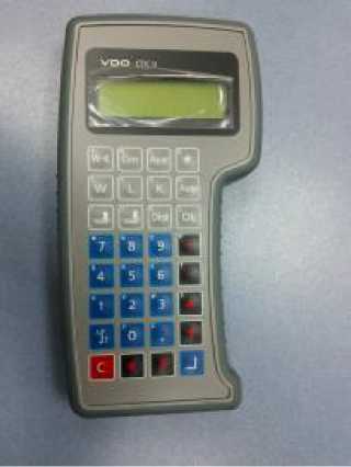
Внешний вид CTC II представлен на рисунке 1.
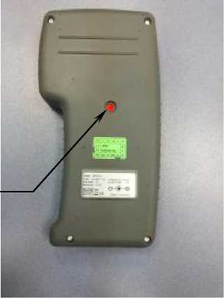
Для предотвращения несанкционированного вмешательства корпус CTC II опломбирован. Расположение пломбы показано на рисунке 1 позиция «а».
Программное обеспечение
ПО CTC II является встроенным. Предназначено для проверки и программирования тахографов. Выполняет функции:
— прием частотных сигналом от тахографов и пересчет их в физическую величину;
— генерация эталонных частотных сигналов для настройки и программирования
тахографов;
— вывод результатов на жидкокристаллическом дисплее;
— обмен данными с персональным компьютером и тахографом по интерфейсам связи RS232, Bluetooth, K-line KWP 2000.
Таблица 1
|
Наименование программного обеспечения |
Идентификаци онное наименование программного обеспече-ния |
Номер версии (идентификац ионный номер) программного обеспече-ния |
Цифровой идентификатор программного обеспечения (контрольная сумма исполняемого кода) |
Алгоритм вычисления цифрового идентификато ра программного обеспечения |
|
Программное обеспечение CTC II |
CTC II |
A2: 13 |
28457 |
CRC-32 |
Влияние программного обеспечения на метрологические характеристики установок поверочных CTC II, составляет 6=10-5 %.
Уровень защиты программного обеспечения от непреднамеренных и преднамеренных изменений в соответствии с МИ 3286-2010 — С.
Технические характеристики
Таблица 2
|
Наименование характеристики |
Значение характеристики |
|
Пределы допускаемой абсолютной погрешности измерения пройденного пути, км |
± 0,001 |
|
Максимальное значение измерения пройденного пути, км |
1,0 |
|
Диапазон воспроизведения скорости, км/ч |
20 — 200 |
|
Пределы допускаемой относительной погрешности воспроизведения скорости, % |
± 0,15 |
|
Пределы допускаемой абсолютной погрешности измерения времени, с/сут |
± 1,0 |
|
Диапазон определения константы тахографа К, имп/км |
2,000 — 50,000 |
|
Рабочая температура, 0С |
+ 5…+ 40 |
|
Температура хранения, 0С |
— 20…+ 70 |
|
Напряжение питания постоянного тока, В |
10.30 |
|
Г абаритные размеры (Ш х Д х В), мм не более |
120 x 236 x 40 |
|
Масса, кг, не более |
0,7 |
Знак утверждения типа
наносится типографским способом на титульный лист формуляра и на корпус прибора методом этикетирования.
Комплектность
Таблица 3
|
№ пп |
Наименование |
Количество |
|
1. |
Установка поверочная CTC II |
1 |
|
2. |
Кейс |
1 |
|
3. |
CD с руководством по эксплуатации CTC II |
1 |
|
4. |
Комплект кабелей |
1 |
|
5. |
Блок питания 100 — 240 В переменного тока |
1 |
|
6. |
Инструкция по эксплуатации |
1 |
|
7. |
Формуляр |
1 |
|
8. |
Методика поверки |
1 |
Поверка
осуществляется по документу 4573-CTC II-2013 МП «Установка поверочная CTC II.
Методика поверки», утверждённая ГЦИ СИ ФБУ «ЦСМ Татарстан» 22 ноября 2013 г.
Перечень средств измерений, применяемых при поверке:
— стандарт частоты и времени Ч1-69, пг ± 5,21 • 10-1 ;
— генератор сигналов специальной формы АКИП-3407/1А, пг ± 2х10-7
Сведения о методах измерений
приведены в Инструкции по эксплуатации.
Нормативные документы
— техническая документация фирмы-изготовителя.
Рекомендации к применению
— применяются при выполнении работ и оказании услуг по обеспечению единства измерений.