- Manuals
- Brands
- ABB Manuals
- Industrial Equipment
- UniGear ZS1
- Instruction manual
-
Contents
-
Table of Contents
-
Bookmarks
Quick Links
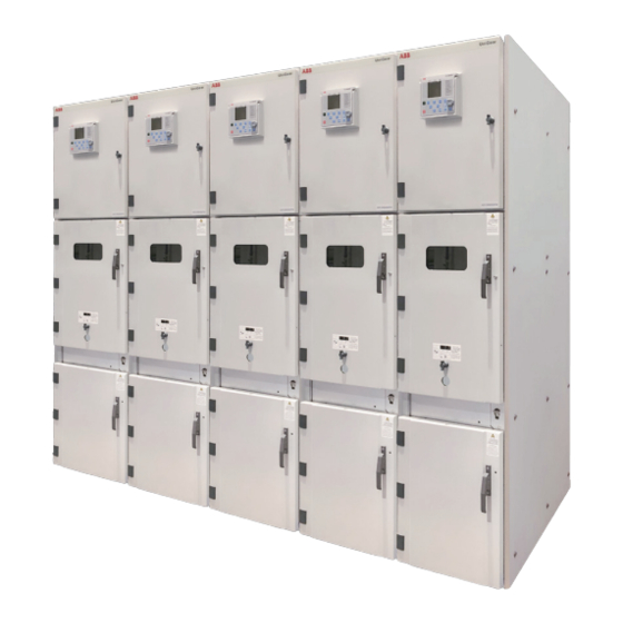
UniGear ZS1
Installation, service and maintenance
instruction manual
Related Manuals for ABB UniGear ZS1
Summary of Contents for ABB UniGear ZS1
-
Page 1
UniGear ZS1 Installation, service and maintenance instruction manual… -
Page 3
Your safety first – at all times! This is why our instruction manual begins with the following recommendations: • Only install switchgear and/or switchboards in closed rooms suitable for electrical equip- ment. • Ensure that installation, operation and maintenance are only carried out by specialist electricians only. -
Page 4: Table Of Contents
Contents Page Page Summary ……..7 5.6.2 Busbar compartment access .
-
Page 5: General
Note The UniGear ZS1 switchgear is indicated in the test reports and type test certificates with the abbreviation ZS1.2 1.2 Standards and specifications UniGear ZS1 switchgear panels comply with the standards and specifications for factory-assembled, metal-enclosed and type tested high voltage switchgear to IEC publications 62271-200 and 60694.
-
Page 6: Technical Data
2. Technical data 2.1 Electrical data 2.1.1 Main parameters for panels with circuit-breakers Rated voltage 17.5 Rated power frequency withstand voltage Rated lightning impulse withstand voltage Rated frequency 50/60 Rated current of busbars …4000 …4000 …3150 Rated current of circuit-breaker branches …4000 …4000 …2500…
-
Page 7: Dimensions And Weights
12/17,5 kV-50kA the panel is always 1390mm depth; Feeders equipped with vacuum contactor are 650mm wide up to the 50kA short-time current; UniGear ZS1 550 series only. The dimension must be verified according to the documentation of the relevant order.
-
Page 8: Dimensions And Weights Of 24 Kv Units
2.3.2 Dimensions and weights of 24 kV units Dimension Height 2325/2720 Width — Feeder panels up to 1250 A — Feeder panels above 1250 A 1000 Depth 1700 Height of the basic part of panel 2200 1620 Height of the control cabinet is 705/1100 mm (dimensions without gas-duct). 1000mm available on request.
-
Page 9: Panel Design And Equipment
The UniGear ZS1 panels can also be set up in two rows; back to back fixed together in so-called duplex arrangement with a double busbar system. Further details about installation and switchgear equipment can be obtained from the documents of relevant order.
-
Page 10: Ventilation Of The Panels
12.2 Lower shutter 20 Horizontal partition, removable metal 13 Withdrawable part 20.2 Ventilation grid 2 Branch conductor 14 Earthing switch operating mechanism 21 Cable clamp 3 Busbar 14.1 Operating shaft for earthing switch 84 Partition Figure 2: Example of UniGear ZS1…
-
Page 11: Compartments In The Panels
3.3 Compartments in the panels 3.3.1 Busbar compartment The busbars 3 (figure 2) have a flat cross-section made of copper and are laid in sections from panel to panel. For higher rated currents (3150, 3600 and 4000 A), the busbars have a D-shaped cross- section.
-
Page 12
In the test/disconnected position, the withdrawable part is still completely inside the panel with the door closed. The ON/OFF pushbutton located on the circuit-breaker, and the mechanical indicators for ON/ OFF and CHARGED/DISCHARGED can be observed through an inspection window if the circuit breaker is in service position. -
Page 13: Withdrawable Parts
45.2 45.3 45.1 Figure 7: Push button for mechanical ON/OFF breaker Figure 8: View of the push rod extension swung out by operation with the door closed (on request). the knob at the front, with the withdrawable If the withdrawable part is in the service circuit-breaker part in service position and the position, operation is carried out using the door open…
-
Page 14: Cable Connection Compartment
18.2 18.1 S8 10.3 13.15 Figure 9: Withdrawable part with circuit-breaker, type Figure 10: Withdrawable assembly for circuit-breaker, VD4, operating mechanism side with auxiliary switches 13.15 Withdrawable assembly Test position indicator Service position indicator 10.3 Control wiring plug connector for Withdrawable assembly 18.1 Square spigot…
-
Page 15: Control Cabinet
The voltage transformers mounted fixed are connected on the primary side with flexible, fully- insulated cables which are inserted in the transformers. The removable voltage transformers are fitted with HRC fuses. The EK6 type earthing switch can be used with either a manual or motor-operated mechanism. Its switching position will be indicated both mechanically by indication on the shaft and electrically by means of the auxiliary switch.
-
Page 16: Interlock/Protection Against Erroneous Operation
3.4 Interlock/protection against erroneous operation 3.4.1 Panel internal interlocking (Figure 2) To prevent hazardous situations and erroneous operation, there is a series of interlocks to protect both personnel and equipment: • The withdrawable part can only be moved from the test/disconnected position (and back) when the circuit-breaker and earthing switch are off (i.e.
-
Page 17
Figure 13: Circuit-breaker compartment door enabling device (A) Figure 14: Circuit-breaker truck enabling slot (A) Figure 15: Circuit-breaker compartment door locking device (B) Figure 16: Circuit-breaker compartment door locking pin (B) -
Page 18
Figure 17: Cable compartment door enabling device (C) Pin ON Pin OFF Figure 18: Cable compartment door enabling slot (C1) and earthing switch enabling pin (C2) Figure 19: Cable compartment door locking device (D) Figure 20: Cable compartment door locking pin (D) -
Page 19: Internal Interlocking Of Panel With Switch-Disconnector
3.4.5 Internal interlocking of panel with switch-disconnector To prevent hazardous situations and erroneous operation, there is a series of interlocks to protect both personnel and equipment: • The switch-disconnector can only be switched on if the earthing switch is off. The earthing switch can only be switched on if the switch-disconnector is off.
-
Page 20
Coding The corresponding coding designation for the control wiring plug is given in brackets (10.2) The coding pins can be fitted in the control wiring socket (10.1) and/or in the control wiring plug (10.2). Basic design The number of sockets is optional, but the basic assignment is 1, 8, 10, 20, 21, 31, 33 and 40. -
Page 21: Fast Recovery Device
3.6 Fast recovery device UniGear ZS1 switchgear can optionally be equipped with “Fast Recovery Device”, a specific protection system. This system is based on pressure sensors (figure 24), suitably located in the switchgear and directly connected to the shunt opening release installed in the circuit-breaker operating mechanism (figure 25).
-
Page 22: Ith Limiters
3.7 Ith Limiters UniGear ZS1 switchgear can optionally be equipped with microswitches on the top of each unit. The microswitch generates a fault signal immediately when the overpressure flap is being opened. Reaction time is less then 15ms. The signal from microswitch can be sent directly to circuit-breaker OFF trigger.
-
Page 23: Dispatch And Storage
4. Dispatch and storage 4.1 Condition on delivery At the time of dispatch, the UniGear ZS1 panels are factory-assembled, the withdrawable parts are in the test position and the doors are closed. The factory-assembled panels are checked at the works for completeness in terms of the order and simultaneously subjected to routine testing (normally without AC voltage testing of the busbars) according to IEC publication 62271-200, and are therefore tested for correct structure and function.
-
Page 24: Delivery
4.4 Delivery The responsibilities of the consignee when the switchgear arrives at site include, but are not limited to, the following: • Checking the consignment for completeness and lack of any damage (e.g. also for moisture and its detrimental effects). In case of doubt, the packing must be opened and then properly resealed, putting in new drying agent bags, when intermediate storage is necessary;…
-
Page 25
Unpacking • Remove the nails and crate lid and sides; • Open the compartment door and loosen the bolts fixing the switchgear to the pallet; • Lift the cubicles by means of the crane following the instructions below; • Remove the pallet; •… -
Page 26: Apparatus
Figure 33: Switchgear handling 4.6.2 Apparatus The apparatus can be handled by means of cranes, fork lift trucks or using the truck provided by ABB. For each piece of apparatus follow the instructions below. • While handling do not put any stress on the insulating parts and on the apparatus terminals.
-
Page 27
4.6.2.1 Handling by means of crane Circuit Breakers Hook the lifting bolts to the relevant supports (figure 34). While handling, pay the utmost attention not to put any stress on the insulating parts and on the circuit-breaker terminals (figure 35). Before putting into service, remove all the lifting eyebolts. -
Page 28
Figure 37: Handling by means of fork lift trucks 4.6.2.3 Handling by means of ABB truck For handling and inserting the apparatus into the switchgear, use the truck 1 supplied by ABB (Figure 38). • Do not use the racking in/out truck for any purpose other than handling our apparatus. -
Page 29: Assembly Of The Switchgear On Site
As standard it is recommended to install the switchgear on the base irons of “C” profile shape set into the concrete floor of switchroom. In this case the units are fastened using the special bolt blocks (ABB delivers by request).
-
Page 30: Method Of Installation A — Installation Of The Base Irons
The general foundation drawing is given in figures 39, 40 according to parameters of units. • The base irons of “C” profile shape can be supplied by ABB manufacturer together with the switchgear. Their installation is usually carried out by site personnel and should, if possible, be performed under supervision of an ABB specialist.
-
Page 31
Top view Section A-A Figure 39: UniGear ZS1 12÷24 kV (i.e. the above section is related to 12 kV, 2500A nominal current) Guideline structural data for foundation frame on concrete floor It is not valid for the panel with switch-disconnector… -
Page 32
Top view Section A-A Figure 40: UniGear 12÷24 kV with NAL switch-disconnector (i.e. the above section is related to 12 kV) Guideline structural data for foundation frame on concrete floor Panel depth is C=1340 mm or 1300 mm according to the depth of the other cubicles – however always consider note 2) Width of operating aisle Panel width… -
Page 33: Method Of Installation C — Fixing To A Raised False
The general foundation drawing is given in figure 42 according to parameters of units. In most cases the floating floor is created by steel structure in which the welded steel frame is installed. The frame produced from suitable steel profiles is used. ABB does not supply this frame. • Clean the installation area.
-
Page 34
12/17.5 bei 3150/4000 A 1390/1350 1560/1520 1450 Figure 42: Guideline structural data for a raised false floor – 12, 17.5 and 24 kV UniGear ZS1 Panel depth Width of operating aisle Panel width Door width = FT + 200 mm Door height = panel height + 200 mm Min. -
Page 35
Figure 43: 12/17.5 kV – 650/800/1000mm wide units Figure 44: 12/17.5 kV – 650/800/1000mm wide units – anchoring bolt fixing system – base iron fixing system (width of cubicle) 1000 Figure 45: 12/17.5kV – 550mm wide units Figure 46: 12/17.5kV – 550mm wide units –… -
Page 36
Figure 47: 24 kV – 800 mm wide units Figure 48: 24 kV – 800 mm wide units – anchoring bolt fixing system – base iron fixing system Figure 49: 24 kV – 1000 mm wide units Figure 50: 24 kV –1000 mm wide units –… -
Page 37
Figure 51: 12/17.5 kV – cubicle with switch-disconnector Figure 52: 12/17.5 kV – cubicle with switch-disconnector – anchoring bolt fixing system – base iron fixing system Figure 53: 24 kV – cubicle with switch-disconnector Figure 54: 24 kV – cubicle with switch-disconnector –… -
Page 38: Assembly Of The Switchgear Panels
Æ 16 Æ 16 Figure 55: Anchoring bolts on concrete floor Figure 56: Base irons on concrete floor M 12 M 12 Figure 57: Through hole on metal structure Figure 58: Threaded hole on metal structure 5.3 Assembly of the switchgear panels Use screws of tensile class 8.8.
-
Page 39
The individual installation stages are as follows: • Remove withdrawable parts 13 (figure 2) from the switchgear panels and store them with suitable protection; • Dismantle lifting eyebolts 1.5 (figure 29); • Transport the switchgear panels to the prepared installation point following the sequence shown on the switchgear plan;… -
Page 40
78.1 Figure 60: Panels — 12/17.5 kV — Top-mounted box with earthing switch for busbar earthing Top-mounted box for top-mounted earthing switch Operating mechanism box 78.1 Operating shaft 78.2 Slide 78.4 Auxiliary switch ON 78.5 Auxiliary switch OFF 78.6 Locking magnet… -
Page 41: Installation Of The Bushing
5.4. Installation of the bushing Before fixing the panels side by side (according the general drawings) bushings 29 (12÷24 kV) must be fixed (for switchgear with busbar barriers only; refer to the table on page 13). 5.4.1 Bushing of 12/17,5 kV panels Figure 61: 12/17.5kV panels — fixing bushings nr.
-
Page 42: Fixing Of The Panels
5.5 Fixing of the panels Fit and screw down the lids. • Align the switchgear panels on the floor frame for correct positioning and vertical alignment (deviations of the panel edges from the vertical must not exceed 2 mm, especially at the front) and bolt the panels together (figure 63).
-
Page 43
• When the switchgear has been properly assembled, fix the panels to the floor using plugs, or weld or adequately bolt them to the foundation frame. Figure 64: Fixing to the floor — method of installation “A” with base irons Figure 65: Fixing to the floor — method of installation “B”… -
Page 44: Installation Of The Busbars
5.6 Installation of the busbars 5.6.1 Preparation of the material Before to fix the panels side by side be sure that the bushings are fixed according to the chapter 3.3.1 at page 11. • Clean the insulation on the busbar sections with a soft, dry cloth, and check for insulation damage. Remove greasy or adhesive dirt as described in section 7.3;…
-
Page 45
58.5 58.1 58.5 During assembly, cut out the insulating cover and lid to fit the cross- section of the feeder bar or busbar. (58.6) 163 164 58.7 a) Arrangement for 1250 A branch current and 1600 or 2500 A busbar current. -
Page 46: Busbar Compartment Access
5.6.2 Busbar compartment access Access to the busbar compartment is possible either from the top of the panel after dismounting the pressure relief plate 1.1 (figure 2) before the mounting of the gas duct, or from the front of the circuit-breaker compartment.
-
Page 47
5.6.3.1 Busbars for 12/17.5kV units Busbars are made of copper and have a flat cross-section for rated current up to 2500A. For 3150, 3600 and 4000A, the busbars have a double D-shaped cross-section. Branch conductors always have a flat cross-section. 12/17.5kV bushings are made of epoxy resin castings and are arranged as a single casting for all three phases (figure 61). -
Page 48
Figure 72: 12/17,5 kV panels – Tee-off 1600-2000A-2500A, busbars 1600A-2000A-2500A nr. 4 10×60 screws nr. 8 M10 washers nr. 4 M10 nuts nr. 1 spacer (5mm) Figure 73: 12-17,5 kV panels – Tee-off 630-1250A, busbars 3150A-3600A-4000A nr. 4 10×60 screws nr. -
Page 49
Figure 74: 12-17,5 kV panels – Tee-off 1600÷4000A, busbars 3150A-3600A-4000A nr. 4 10×60 screws nr. 8 M10 washers nr. 4 M10 nuts nr. 1 spacer (5mm) 5.6.3.2 Busbars for 24 kV units Busbars and branches are made of copper and both have a flat cross-section. Bushings are different from the 12/17.5kV ones. -
Page 50
— 2500 A — 1250 A Figure 76: 24 kV panels – Tee-off 1250A, busbars 2500A nr.4 10×60 screws nr.8 M10 washers nr.4 M10 nuts — 2500 A — 2500 A Figure 77: 24 kV panels – Tee-off 2500A, busbars 2500A nr.4 10×60 screws nr.8 M10 washers nr.4 M10 nuts… -
Page 51: Installation Of The Top-Mounted Boxes
Important note: Always check that there is good contact between the metal tube in the bushing and the busbar via contact spring 29.3. Ensure that the contact spring is in the correct position! (figure 78). Important note: The contact springs 29.3 must be inserted during the installation of busbars.
-
Page 52
Figure 79: 12/17.5kV panels — Bar connection to the top-mounted box. The figure shows the arrangement in panels the busbar ends Branch conductor Connection bar Spacer plate, 5 mm thick Tapped plate 3.10 Spacer plate, 8 mm thick… -
Page 53
58.5 (58.6) 3.4 58.5 (35) 58.1 58.7 58.1 58.7 (58.6) 165 Figure 80: 24 kV panels — Bolted busbar joint for top-mounted box, shown for left-hand busbar end. In continuous busbars is the connection is similar, but without the lid holder 58.1 and without the spacer plate 3.5. Branch conductor Branch conductor to the top-mounted box Busbar section… -
Page 54: Earthing Switch For Busbar Earthing
79.2 79.3 79.1 28.3 Figure 81: 12/17.5kV panels — Top-mounted box with voltage transformers for busbar metering. The figure shows the arrangement in panels without the busbar bushing plate 28 (see the notes in section 5.7.1) 28.3 Partitioning Top-mounted box with voltage transformer 79.1 Intermediate box 79.2…
-
Page 55
• Hexagonal shaft from the operating mechanism box must be pushed through into the bevel gear of the earthing switch. Sequence and angles of the part must be restored! • Connecting bars 2.2 with the branch conductors 2 at the junction point must be screwed together according to figure 5/26 and 5/34. -
Page 56: Pressure Relief Ducts
Hexagonal shaft 5.8 Pressure relief ducts The standard solution provided for the arc-proof version of the UniGear ZS1 consists of a metal sheet duct for collecting and exhausting the hot gases; this duct is mounted on the upper side of the…
-
Page 57: Standard Gas Duct
Figure 85: Schematic diagram of the pressure relief duct. The components are assembled panel by panel and bolted together with overlaps at the panel joints. pressure relief duct If the switchgear is equipped with a pressure relief duct, the pressure relief flap for the cable connection compartment is fixed to the rear side of the panel and will open to the front (into the duct) in case of an arc fault.
-
Page 58
Once that the two sheets are fixed to the panel, it is possible to fix the two sheets between them (figure 90) using nr.6 screws. Figure 90: Junction of the front and rear sheet. Nr. 6 screws 10×30 Nr. 6 M10 nuts Nr. -
Page 59
Fix the rear connection plate between the two gas duct panels (figures 93). Figure 92: Rear connection plates. Nr. 8 screws 8×30 Nr. 8 M8 washer Repeat the above described operations for all the panels. The next operation is the fixing of the left and right end side (figures 93). Figure 93: Side plates. -
Page 60: Compact Gas Duct
Figure 95: Overview of the standard gas duct. 5.8.2 Compact gas duct In order to mount the compact gas duct must be followed the operations described for the standard gas duct. Figure 96: Overview of the compact gas duct.
-
Page 61: Compact Gas Duct With Top Chimneys
5.8.3 Compact gas duct with top chimneys In order to mount the compact gas duct with top chimneys must be followed the operations described for the compact gas duct. The difference between the two solutions is that in this case there are no side exits, but the gas generated from an internal arc goes out from the duct through the top chimneys located on the top part of the gas duct on each panel.
-
Page 62: Cable Connection
5.9 Cable connection 5.9.1 Power cables The standard method for entry of power cables in the switchgear is shown in Figures 100, 101. The cables are conveyed from below through floor covering 17, which is divided at the cable entry point. The cables go through rubber reducer rings 17.2, which can be adapted to the required cable diameter in a range from 27 to 62mm.
-
Page 63: Control Cables
Connection of cables in typical panels: Range Panel Max. number Max. cross- Range of Range of voltage width of parallel cables section of cables cable clamp reducer ring (kV) (mm) in phase (mm) (mm) 12/17.5 1000 35 — 54 27 — 62 1000 1) In the case where there are removable voltage transformers on the truck, or surge arresters are used, the number of parallel cables is reduced to a max.
-
Page 64
Dimension of power cable connection of UniGear ZS1 12/17.5 kV classic panels 17.2 width max. number of cables in one phase – 1000 31.5 1250 1250 1600 2000 1600 31.5/40 2000 2500 1000 3150 4000 Figure 102: Dimension of power cable connection of UniGear ZS1 12/17.5 kV classic panels. -
Page 65
Dimension of power cable connection of UniGear ZS1 12/17.5 kV 550 panels width max. number of cables in one phase 1250 Figure 103: Dimension of power cable connection of UniGear ZS1 12/17.5 kV 550 panels. -
Page 66
Dimension of power cable connection of UniGear ZS1 24 kV classic panels With I th N° of phases (cables) IF 800 31,5 3 (6) IFM 800 31,5 2 (2) IF 1000 31,5 3 (5) IFM 1000 31,5 3 (6) Figure 104: Dimension of power cable connection of UniGear ZS1 24 kV classic panels. -
Page 67
Dimension of power cable connection of UniGear ZS1 12/17.5 kV switch disconnector Figure 105: Dimension of power cable connection of UniGear ZS1 12/17.5 kV switch disconnector. The depth of the panel with switch disconnector in combination with HD4 circuit-breaker panel… -
Page 68: Earthing The Switchgear
Figure 107: Terminal frame swung up for connection works 5.10 Earthing the switchgear • Connect main earthing bar 19 (figure 101) with connections 19.1 provided in every panel. • Protection wiring connection of the floor frame or the erected raised false floor respectively, should be made.
-
Page 69: Operation Of The Switchgear
6. Operation of the switchgear Note on safety at work The relative work and operating procedures must be carried out carefully by trained specialists familiar with the installation, taking into account all the relative safety regulations according to the IEC and other relevant professional bodies, as well as any local and work regulations and instructions.
-
Page 70
• Preparatory works for SF6 circuit-breakers: — Clean the insulating parts with clean dry cloth; — Check that the upper and lower terminals are clean and free of any deformation caused by shocks received during transport and storage; — It is advisable to check the SF6 gas pressure; •… -
Page 71: Start-Up
• On motorized withdrawable parts, check the direction of rotation of the travel motor in accordance with section 7.5.4; • For any other matters regarding operation of the withdrawable circuit-breaker part and testing facilities for the withdrawable part, see section 7.5; •…
-
Page 72
10.2 10.1 121.1 Figure 111: Control wiring plug connector blocked to it is Figure 112: Before inserting the hand crank, necessary to prevent disconnection with the withdrawable open the hole for it — turn the slide by means part in the service position. of the key. -
Page 73
Note The withdrawable part must not be stopped in any intermediate position in the travel range between the service and test/disconnected position! Manual withdrawal from the service position into the test/disconnected position • Ensure that the apparatus is in the OFF position; •… -
Page 74
13.11 124.4 124.1 13.12 Figure 114: Service truck engaged with the switchgear Figure 115: Withdrawable part standing on service truck truck and panel. Withdrawable part released and secured in the catches for withdrawal with the handles slid inwards Withdrawable part Withdrawable part 13.11 Sliding handle 13.11 Sliding handle… -
Page 75: Circuit-Breaker — Type Vd4 And Vmax
6.2.2 Circuit-breaker — type VD4 and V-max Charging the stored energy spring system: • On the circuit-breaker with charging motors, charging is carried out automatically. If the charging motor should fail, the charging procedure can be carried out or completed manually; •…
-
Page 76: Circuit-Breaker — Type Vm1
6.2.3 Circuit-breaker — type VM1 The maintenance-free VM1 circuit-breaker applies a combination of moulded-in vacuum interrupters, a magnetic actuator and an electronic controller without auxiliary switches and with sensors. Before connecting the primary voltage: • Connect the auxiliary voltage. OFF command (closed – circuit release) and the closing lock-out must be energized before the circuit-breaker can be closed;…
-
Page 77: Circuit-Breaker — Type Hd4
6.2.4 Circuit-breaker — type HD4 Manual operation for spring charging: To manually charge the closing springs, fully insert charging lever 90.8 (figure 122) into seat 90.6 and turn it until the yellow indicator 90.7 appears. Electrical operation for spring charging: On request, the circuit-breaker can be fitted with the following accessories for electrical operation: •…
-
Page 78: Vacuum Contactor — Type V-Contact
6.2.5 Vacuum contactor — type V-Contact The V-Contact type vacuum contactor is ideal for controlling users in a.c. requiring a high number of operations. The contactors basically consist of a moulded resin monobloc, where the vacuum interrupters, moving apparatus, control electromagnet, multivoltage control feeder and auxiliary accessories are housed.
-
Page 79: Withdrawable Metering Parts
6.2.6 Withdrawable metering parts Handling of the withdrawable metering part in the metering panel is as described in section 6.2.1, without, however, the switching operations and interlocking functions. Withdrawable metering parts in incoming and outgoing feeder panels are put into the cable compartment using a ramp.
-
Page 80: Busbar Earthing Switch
14.1 14.2 Fig. 127: Preparation for operation of branch earthing Fig. 128: Preparation for operation of branch earthing switch — press the slide downwards. switch — operating lever prepared for switch- ing on/off 14.1 Hexagonal shaft of earthing switch operating mechanism Operating lever 14.2 Slide…
-
Page 81
• Insert the earthing module 142 with short-circuit link 142.8 mounted and earthing cable 133.1 returned from the test/disconnected position into the service position in the panel with hand crank 121. For safety reasons, insert the module only with the circuit- breaker compartment door closed and with door catches 1.8 locked (see Fig. -
Page 82: Nalf Type Switch-Disconnector
The type E earthing switch is always operated locally by means of operating lever 215 (figure 131).To secure the protection of connected HV equipment the UniGear ZS1 switchgear with switch-disconnector uses CEF type high voltage fuses. The UniGear ZS1 switchgear with NALF switch-disconnector can be equipped with fuses in the range indicated in the following table: [kV] min.
-
Page 83
Closing and opening of NALF switch-disconnector • The switch-disconnector can only be switched on if the earthing switch is open; • Put operating lever 215 (figure 131) in pointed upwards or downwards on the grooved shaft of the switch-disconnector so that there is sufficient room for movement of the operating lever even if space is limited at the sides;… -
Page 84: Test Procedure
6.3 Test procedure 6.3.1 Testing the off-circuit condition In switchgear panels which are not equipped with capacitive voltage indication, checking the off-circuit condition is carried out with a HV tester on the isolating contacts 4.1 (figure 133) in the isolating tulips 5 (figure 132), after the corresponding upper shutter 12.1 or lower shutter 12.2 has been opened.
-
Page 85: Service Trucks
6.4 Service trucks The service trucks are divided into four different types: 6.4.1 Earthing truck without making capacity These trucks carry out the same function as the earthing switches without making capacity. Therefore they do not have any capacity to earth the live circuits under fault conditions. They are used to ensure fixed additional earthing, as required by the plant service and maintenance procedures, as a further guarantee for personnel.
-
Page 86: Maintenance
IEC safety regulations and those of other technical authorities, and with other overriding instructions. It is recommended that ABB service personnel be called in to perform the servicing and repair work detailed below.
-
Page 87: Inspection
7.2 Inspection • Where necessary, the working area must be isolated and secured against reconnection in accordance with the Safety Regulations specified by IEC and appropriate national standards before inspection; • Correct condition of the switchgear should be monitored by regular inspections; •…
-
Page 88: Maintenance In Busbar Compartment
• Should any partial discharges occur as a consequence of the condensation phenomenon, a temporary remedy which is often effective is application of a thin layer of silicone over the surface involved. For a permanent remedy to this type of unusual problem, contact the ABB after-sales assistance department.
-
Page 89: Maintenance In Cable Compartment
7.3.2 Maintenance in cable compartment 7.3.2.1 Checking tightening of the cable busbar connections • Make the plant you want to work on safe (follow the plant safety regulations); • Make sure that the circuit-breaker is in the open position; • Rack the circuit-breaker out from the service position to the test/isolated position; •…
-
Page 90
7.3.2.3.4 Reaching mechanical life limit The mechanical life of the earthing switch is set at 2000 opening/closing operations. After the operation counter has reached this number, inform ABB who will verify directly that the mechanical life limit of the earthing switch has been reached. -
Page 91
Reaching mechanical life limit The mechanical life of the earthing switch is set at 2000 opening/closing operations. After the operation counter has reached this number, inform ABB who will verify directly that the mechanical life limit of the earthing switch has been reached. -
Page 92
7.3.2.5.2 Cleaning and checking of the voltage transformers and anti-ferroresonance circuit a) Fixed version voltage transformers • Make the plant you want to work on safe (follow the plant safety regulations); • Make sure that the circuit-breaker is in the open position; •… -
Page 93: Maintenance In Circuit Breaker Compartment
d) Cleaning and checking the anti-ferroresonance circuit • Make the plant you want to work on safe (follow the plant safety regulations); • Make sure that the circuit-breaker is in the open position; • Rack the circuit-breaker out from the service position to the test/isolated position; •…
-
Page 94: Maintenance In The Low Voltage Compartment
7.3.3.2 Checking functionality of the interlocks • Carry out a visual inspection of the mechanical parts of the interlocks (key locks 22, door interlocks 23, fail safe 24) and check for any presence of humidity and signs of corrosion on the moving parts. •…
-
Page 95: Repairs
7.3.4.3 Measuring the insulation resistance of the auxiliary circuits • Make the plant you want to work on safe (follow the plant safety regulations); • Make sure that the circuit-breaker is in the open position; • Rack the circuit-breaker out from the service position to the test/isolated position; •…
-
Page 96
12.2 Figure 147 View of inside circuit-breaker compartment, withdrawable part removed, circuit-breakers open. Isolating contact Isolating tulip 12.2 Bottom circuit-breaker… -
Page 97: Replacement Of Complex Functional Groups
7.4.2 Replacement of complex functional groups Precise matching of functions for control, interlocking and signalling only permits replacement of individual components to a limited extent. The following assemblies are prefabricated and tested at the works, maintaining high quality standards. In the case of faults, they must therefore be completely replaced. 1.
-
Page 98
2. Motor operator for the earthing switch • Disconnect the terminals; • Loosen the grub-screw in the set collars; • Withdraw operating shaft 14.1; • Observe the position of locking disc 14.6 relative to cam 14.7; • Replace the motor operator; •… -
Page 99: Testing Withdrawable Parts
7.5. Testing withdrawable parts When functional tests are carried out on withdrawable parts, compliance with the conditions listed below should also be checked. 7.5.1 Motor-driven withdrawable parts (not standard) Carry out testing of motor-driven withdrawable parts in the same way as for manually operated withdrawable parts: •…
-
Page 100: Testing Interlock Condition
18.2 18.1 S8 10.3 Figure 151 Withdrawable assembly (truck) for circuit-breaker with auxiliary devices. Test position indicator Service position indicator 10.3 Control circuit plug connector for withdrawable assembly 18.1 Square rod 18.2 Hole for shaft insertion lever 7.5.5 Testing interlock conditions 1.
-
Page 101
4. It must only be possible to open the circuit-breaker (manually) when the withdrawable part is in the service position or test/disconnected position and the control voltage has failed. Check this condition. 5. Withdrawable parts with order-related locking magnet Y0 may not be moved in case of control power failure, or when there is no control power. -
Page 102: Tests On The Panel
7.6 Tests on the panel 7.6.1 Auxiliary switch settings on the earthing switch 1. There must be a run-on of 0.5 mm in the fully operated position before the plunger reaches the stop (for safety reasons); 2. Auxiliary limit switch 11.4 (Q8S2) for earthing switch ON must be operated immediately after the dead centre position of the toggle spring mechanism is reached in the closing process and the automatic rapid closing process has started;…
-
Page 103: Operating Accessories
7.8 Operating accessories 31.29 31.28 90.8 Figure 153 Operation accessories 31.28 Manual emergency operating lever (to remove voltage to VM1 type circuit-breaker 31.29 Auxiliary spring to lock the opening capacity (for VM1 type circuit-breaker) 90.8 Charging lever (for HD4 type circuit-breaker) Crank handle (to move the withdrawable part inside the panel) Operating lever (for earthing switch) Charging lever (for HD4 type circuit-breaker)
-
Page 104: Product Quality And Environmental Protection
8. Product quality and environmental protection The UniGear ZS1 type panels are produced in compliance with the requirements of international standards for the quality management system and environmental management system. In these fields, the excellent level is proved by quality certificates according to ISO 9001 and by the EMS according to ISO 14 001.
-
Page 106
ABB S.p.A. ABB s.r.o. Power Products Division Org. unit EJF Unità Operativa Sace-MV Videnská 117. 619 00 Brno Via Friuli, 4 Czech Repubblic I-24044 Dalmine Tel: +420 5 4715 2413, 1111 Tel: +39 035 395 111 Fax: +420 5 4715 2190 Fax: +39 035 395 874 E-mail: info.ejf@cz.abb.com…
Страница 3 из 9
3 КОНСТРУКЦИЯ И ОСНАЩЕНИЕ ШКАФА.
Основные конструкции и варианты КРУ (Рис.3/1 — 3/3)
Основой распределительного устройства UniGear типа ZS1 является шкаф ввода/вывода с выдвижным вакуумным или элегазовым выключателем. Шкаф разделен на шинный отсек А, отсек выключателя В, кабельный отсек С и отсек низковольтного оборудования D. Помимо этих основных типов шкафов имеются другие варианты (секционный шкаф, измерительный шкаф и т .п.), которые удовлетворяют всем потребностям заказчиков. На рис. 3/1 и 3/2 приводятся примеры компоновки шкафов, включая электрооборудование.
Для соединения секций системы сборных шин необходимы два шкафа: секционный шкаф с выдвижным выключателем и шкаф с выдвижным секционным разъединителем (с возможностью измерения напряжения на сборных шинах и заземления сборных шин). В устройствах без секционирования сборных шин выполняется прямое соединение сборных шин.
Более подробные информации об установке и оснащении распределительного устройства приводятся в документах соответствующего заказа.
Внешняя оболочка и перегородки (рис. 3/3)
Внешняя оболочка и внутренние перегородки шкафов изготовлены из качественной листовой стали толщиной 2 мм, который покрыт пленкой из сплава алюминия с цинком. Три высоковольтных отсека (шинный отсек, отсек выключателя и кабельный отсек) оборудованы клапанами для снятия давления, которые помещены в верхней части. Эти клапаны открываются при избыточном давлении в случае внутреннего дугового замыкания. С передней стороны шкаф закрыт пневматическими дверьми, угол открытия которых составляет, практически, 180°. Отсек выключателя имеет свои собственные двери, оборудованные смотровыми отверстиями, изготовленными из безопасного стекла. При сборке соседние шкафы друг от друга отделены боковыми стенками каждого шкафа и, далее, воздушным пространством, который остается между ними.
Внешняя оболочка дополнена клапанами для снятия давления, смонтированными наверху, которые в зависимости от номинального тока фидера изготовлены или из стального листа, или из стальной решетки, а внизу закрывающей пластиной днища 17, которая изготовлена из стального немагнитного листа. Заслонки для снятия давления на одной продольной стороне зафиксированы стальными болтами, на второй продольной стороне — пластмассовыми болтами . В случае создания избыточного внутреннего давления происходит разрыв пластмассовых болтов. При возникновении дугового замыкания ограничение тока Ith можно достигнуть отключением выключателя без задержки, создаваемым вспомогательными переключателями 11.5 (рис. 5/40), которые управляются с помощью заслонок для снятия давления (стандартное оснащение в случае более высокой устойчивости к короткому замыканию).
Необходимые меры безопасности, направленные на ограничение действий внутреннего дугового замыкания, должны обеспечиваться в зависимости от высоты потолка. В некоторых случаях это может требовать дополнительные меры безопасности в шкафах распределительного устройства с учетом обслуживания. Эти меры включают, например:
Монтаж перехода для снятия давления 50 в верхней части распределительного устройства вместе с другими каналами, выходящими из распределительной станции в атмосферу (необходима соответствующая компоновка здания распределительной станции). Ударная волна и действие дуги через переходы отводятся наружу (рис.5/ 17).
Монтаж перехода для снятия давления с выхлопными щелями, располагаемыми над переходом на концах распределительного устройства и направленными к центру распределительного устройства. Ударная волна и действие дуги проявляется в очень заглушенной форме и в месте, которое не является критическим для обслуживающего персонала.
Составной частью перегородок является задняя стенка сборных шин 84, промежуточная стенка 9, монтажная панель 12 с диафрагмами 12.1, 12.2 и горизонтальной перегородкой 20. Внутреннее разделение с помощью перегородок позволяет безопасный доступ в секцию выключателей и кабельную секцию и тогда, когда сборные шины находятся под напряжением.
Отсек низковольтного оборудования полностью изолирован от высокого напряжения.
Концевые шкафы с внешней стороны имеют закрывающие панели из листовой стали, которые механически и теплоизолированы от возможного внутреннего замыкания в концевых шкафах.
Двери и задние стенки шкафов, а также закрывающие пластины из листовой стали концевых шкафов тщательно очищены, обработаны против коррозии, после этого на них было нанесено в печи качественное порошковое покрытие. Покрывающий слой выполнен в цветовом исполнении RAL 7035 (специальное цветовое исполнение по соглашению), который после затвердения обладает значительной устойчивостью к ударам и коррозии.
Двери кабельного отсека и отсека выключателя устойчивы к внутренним замыканиям и оснащены центральным замком.
3.2.1 Вентиляция в шкафах (Рис. 3/3, 6/20, 6/21)
При более высоких значениях номинального тока сборных шин и отпаек от них необходимы вентиляционные отверстия во внешней оболочке.
Для воздуха, поступающего в отсек выключателя, в горизонтальной перегородке 20 выполнены вентиляционные отверстия 20.2. Степень защиты соответствует IP4X, а безопасность в случае выброса горячих газов, образованных в результате дугового замыкания, гарантируется клапаном 20.3. Для воздуха, выходящего наружу, установлены клапаны для снятия давления с вентиляцией 1.7, вместо клапанов из листовой стали. Форма и размер клапанов с вентиляцией обеспечивает степень защиты IP4X.
В случае повышенной температуры окружающего воздуха (> 40 °С) и/или повышенной частоты (60 Гц) в горизонтальной перегородке надо будет установить вентилятор. Это нестандартное исполнение. Информация приведена на рис. 6/20 и 6/21.
Этим вентилятором надо воспользоваться в шкафу 12/17,5 кВ для номинального тока 3600 и 4000 А и в шкафу 25 кВ для номинального тока 2500 А.
3.3 Отсеки в шкафах
3.3.1 Шинный отсек (Рис. 3/3, 5/21 — 5/26, 5/29 — 5/34)
Сборные шины 3 имеют прямоугольное сечение; они изготовлены из меди и проложены частями из шкафа в шкаф. . Для более высоких номинальных токов (3150, 3600 и 4000 А) сборные шины имеют сечение в форме D. В зависимости от величины тока применяют одинарные или сдвоенные шины. Сборные шины прикреплены на плоских проводах отводов 2 и в проходных изоляторах сборных шин 29. Не нужны никакие специальные крепежные зажимы.
Сборные шины и отводы для напряжения 17,5 кВ и 25 кВ изолированы. Резьбовые соединения шинной системы для этого напряжения закрыты изоляционными кожухами 58. Также во всей компоновке отсутствуют места для возникновения короткого дугового замыкания. Сборные шины для напряжения 12 кВ с номинальным током до 1600 А неизолированные , и у них отсутствуют изоляционные кожухи. Плоские сборные шины 2500 А и сборные шины сечением в форме D изолированы и для номинального напряжения 12 кВ.
С помощью проходных панелей 28 и проходных изоляторов 29 можно образовать перегородки между шкафами. Для более высокого номинального кратковременного удерживающего тока эти перегородки необходимы — см. нижеприведенную таблицу:
| Номинальное напряжение |
Ток термической стойкости |
Перегородки |
|
25 кА |
Нет 1) |
|
|
12 / 17,5 кВ |
31,5 кА |
Каждый третий шкаф 2) |
|
> 40 кА |
Каждый шкаф 3) |
|
|
25 кВ |
25 кА |
Нет 1) |
В этих шкафах не надо устанавливать проходные изоляторы 29, а проходные панели 28 надо смонтировать по причине достаточной прочности системы сборных шин.
В этих шкафах проходные изоляторы 29 и проходные панели 28 надо установить в каждый третий шкаф (касается шкафов шириной 800 и 1000 мм).
В этих шкафах проходные изоляторы 29 и проходные панели 28 надо установить в каждый шкаф.
В случае если заказчик требует отделить отдельные шкафы друг от друга с помощью проходных изоляторов 29 и проходных пластин 28 и в распределительных устройствах, где это отделение не обязательно (см. таблицу), то это требование должно быть указано в заказе.
Над распределительным устройством можно поместить надстройку с трансформаторами для измерения напряжения на сборных шинах или заземлителем сборных шин. Более подробно — см. раздел 5.5 и рис. 5/27, 5/28, 5/35 и 5/36.
3.3.2 Отсек выключателя (Рис. 3/3, 3/8, 3/9, 3/10, 3/11, 5/20, 6/22)
Отсек выключателя содержит все необходимое оснащение для согласованного функционирования выдвижной части с выключателем со шкафом. Подобно шинному отсеку этот отсек отделен металлическими перегородками со всех сторон.
Изоляционные камеры 5, содержащие стационарные контакты главной цепи 4.1, помещены в монтажной панели 12. Здесь также находятся металлические шторки 12.1 и 12.2, которые при выдвижении выдвижной части закрывают отверстия в изоляционных камерах. Шторки открываются при введении выдвижной части в рабочее положение надавливанием пластин 13.16 на рычаги 38. При выдвижении выдвижной части из рабочего положения в контрольное/испытательное положение шторки закрываются. Если выдвижная часть находится в контрольном/ испытательном положении, то гарантируется отсоединение главной цепи тока. Разъемы цепей управления 10.1, 10.2 в рабочем положение не нужно разъединять с целью проведения испытаний.
В контрольном/испытательном положении выдвижная часть полностью находится в шкафу при закрытой двери. Кнопка ВКЛ./ОТКЛ. на выключателе, механический указатель ВКЛ/ОТКЛ и указатель натяжения пружины видны через смотровое отверстие.
Включение и отключение выполняется при закрытой двери. По желанию также может быть установлено оборудование для механического управления выключателем при закрытых дверях в рабочем положении (см. рис. 3/14, 3/15).
Разъем 10.1 для цепей управления стационарно установлен в пространстве выключателя.
3.3.3 Выдвижные части (рис. 3/3, 3/12, 3/13, 3/16- 3/19, 3/25)
Выдвижные части с выключателем.
Выдвижной выключатель образует модуль, состоящий из вакуумного выключателя типа VD4 или VM1, или элегазового выключателя (SF6) типа HD4/GT, выдвижной кассеты 13.15, изолированных контактов 4.2 с контактной системой 4.3 и разъема цепей управления 10.2.
Выдвижная кассета 13.15 и выключатель соединены с помощью многополюсного разъема 10.3. Выдвижная кассета обеспечивает механическое соединение шкафа с выключателем. Стационарная часть крепится к шкафу при помощи разъема с кодировкой обеих сторон. Выдвижная часть с выключателем между рабочим и контрольным/испытательным положением передвигается или вручную, или двигателем с помощью шпинделя при закрытой передней двери.
Рабочее и контрольное/испытательное положение точно регистрируются вспомогательными переключателями, которые срабатывают при достижении шпинделем концевого положения и регистрируют также угловое положение шпинделя.
Присоединение заземления между выдвижной частью и шкафом обеспечивается роликами и направляющими 42, которые привинчены в шкафу. Поверхность всех составляющих деталей цепи заземления гальванически оцинкована.
Выдвижные части одинаковой конструкции взаимозаменяемы. В случае если выдвижная часть имеет те же самые размеры, но разное оснащение выключателя, то кодирование штепселя цепей управления предотвратит запрещенное присоединение между выдвижной частью и шкафом. (Рис. 3/25).
Выдвижной контактор (рис. 3/3, 3/20, 3/21).
Выдвижная часть может также быть оснащена вакуумным контактором типа «V-Contact». Контактор можно использовать только для номинального напряжения до 12 кВ. «V-Contact» оснащен предохранителями 91.15.
Другие выдвижные части.
— тележка с измерительными трансформаторами напряжения с предохранителями;
тележка заземлителя без включающей способности (для системы сборных шин и силовых кабелей);
тележка заземлителя со включающей способностью (для системы сборных шин и силовых кабелей);
тележка для испытания силовых кабелей;
тележка разъединителя;
тележка разъединителя с предохранителями.
3.3.4 Кабельный отсек (Рис. 3/3, 5/18 — 5/20, 5/41, 5/42)
Кабельный отсек содержит трансформаторы тока 7, трансформаторы напряжения 8 и заземлитель 6 в зависимости от индивидуальных производственных требований.
Кабельный отсек сконструирован для установки трех трансформаторов тока. Если не требуются все три трансформатора тока, то вместо них установлены макеты с эквивалентным способом установки и крепления. Стационарные трансформаторы напряжения присоединены к первичной стороне с помощью гибких изолированных проводов.
При определенных обстоятельствах можно применить выдвижные трансформаторы. Эти трансформаторы могут быть оснащены предохранителями высокого тока.
Заземлитель типа ЕК6 можно использоваться с ручным или моторным приводом. Его коммутационные положения регистрируются с помощью вспомогательного переключателя как механически, так и электрически. В этом отсеке могут быть помещены ограничители перенапряжения.
Присоединение кабелей в шкафах 12 / 17,5 кВ:
В шкафу шириной 650 мм можно присоединить (по желанию заказчика) до 3-х параллельных одножильных кабелей с пластмассовой изоляцией сечением до 630 мм2. Присоединение при помощи кабельных наконечников. В шкафу шириной 800 и 1000 мм можно присоединить до 6-ти параллельных одножильных кабелей с пластмассовой изоляцией сечением до 500 мм2. Присоединение при помощи кабельных наконечников.
Присоединение кабелей в шкафах для 25 кВ:
В шкафу шириной 800 мм можно присоединить (по желанию заказчика) до 3-х параллельных одножильных кабелей сечением до 500 мм2. В шкафу шириной 1000 мм можно присоединить до 6-ти этих кабелей. В обоих случаях присоединение выполняется при помощи кабельных наконечников.
Важное предупреждение:
Для всех нетиповых кабельных присоединений, при применении специальных кабелей, трехжильных кабелей или при присоединении шкафов с помощью шин необходимо соглашение между потребителем и изготовителем уже на стадии технической подготовки заказа. Детали в разделе 5.7.
3.3.5 Отсек низковольтного оборудования (Рис. 3/3, 3/7, 5/20, 5/39)
В отсеке низковольтного оборудования находятся все приборы, необходимые для управления, защиты и сигнализации.
Она приспособлена для применения классических и электронных защитных реле.
Высота отсека низковольтного оборудования равна 580/705/1100 мм. Более подробно — см. раздел 2.3.
Если отсутствуют управляющие и вспомогательные приборы, предназначенные для монтажа на двери, то они
устанавливаются на специальные металлические рейки. Это позволяет легко выполнять дополнительные изменения
в соединении.
В нижней части отсека на откидном держателе находятся три ряда клеммников, а под ними легко доступный вспомогательный переключатель для штепселя контрольных цепей.
Для дверей, на которых установлены приборы с более высоким напряжением, должно быть обеспечено комплектное присоединение защитного провода. В шкафах это присоединение обеспечено специальным заземляющим проводом. Защита от прикосновения к зажимам и приборами удовлетворяет соответствующим правилам. Внутреннее соединение контрольных цепей в шкафу помещено в канале на правой стороне шкафа. Левая сторона шкафа служит для подвода внешних кабелей низкого напряжения. Каналы закрыты крышками из листовой стали 43.1, 43.2. По сторонам отсека находятся отверстия для соединения с отсеками низковольтного оборудования соседних шкафов.
Подробная информация о соединении вторичных цепей и примененных приборах приводится в документации для соответствующего заказа.
3.4 Блокировка / защита от неправильной эксплуатации
3.4.1 Внутренние блокировки шкафа (Рис. 3/3)
Для предотвращения возникновения опасных ситуаций при неправильной эксплуатации применяются блокировки. • Выдвижная часть может быть перемещена из контрольного/испытательного положения и обратно в рабочее только при отключенных выключателе главной цепи и заземлителе. В промежуточном положении заземлитель блокируется механически. Если выключатель снабжен электрическим расцепителем, блокировка также электрическая.
Выключатель может быть включен только в том случае, если выдвижная часть находится в рабочем или контрольном/испытательном положении. В промежуточном положении блокируется механически.
В шкафах с цифровой технологией управления, блокировки реализуются программным обеспечением.
В рабочем или контрольном/испытательном положении отключение выключателя вручную возможно только при отсутствии контрольного напряжения и он не может быть включен (электромеханическая блокировка).
Подключение и отключение жгута цепи управления возможно только в контрольном/испытательном положении выдвижной части.
Заземлитель может быть включен ,если выдвижная часть в контрольном/испытательном положении или вне шкафа (механическая блокировка 1) ).
Если заземлитель включен, передвижение выдвижной части из контрольного/испытательного положения в рабочее невозможно (механическая блокировка).
Подробная информация о других возможных блокировках предоставляется в технической документации на оборудование.
Блокировки дверей (рис. 3/4-1 — 3/4-8)
В шкафах могут быть применены следующие блокировки:
Выключатель (контактор) не может быть вкачен при открытой двери отсека выключателя.
Дверь отсека выключателя не может быть открыта, если выключатель (контактор) находится в рабочем или промежуточном положении (3/4-3 и 4).
Заземлитель не может быть приведен в действие при открытой двери кабельного отсека (3/4-5 и 6).
Дверь кабельного отсека не может быть открыта, если заземлитель отключен (3/4-7 и 8).
Блокировки между шкафами (рис. 3/1-6, 3/1-7, 3/2-6, 3/2-7)
Включение заземлителя сборной шины возможно только в том случае, если все выдвижные части соответствующей секции находятся в контрольном (испытательном) положении (электромеханическая блокировка^).
Если заземлитель сборной шины включен, выдвижные части в заземленной секции не могут быть перемещены из контрольного (испытательного) положения в рабочее.
Замки (рис.3/3, 6/13, 6/22)
Если выдвижная часть выключателя полностью выкачена, шторки могут быть замкнуты независимо друг от друга навесными замками.
Доступ к управляющему валу заземлителя может быть ограничен навесным замком.
Доступ к каналу вкатывания выключателя может быть ограничен навесным замком.
Доступ в отсек выключателя и в кабельный отсек может быть ограничен навесным замком.
Кодирование разъема цепей управления (рис. 3/25)
Кодирование разъема цепей управления позволяет, чтобы выдвигаемые части коммутационных аппаратов были закреплены за определенными шкафами. Это обеспечит, например, то, что выдвигаемые части с разными токами или разным соединением цепей могут использоваться только в шкафах, для которых они предназначены.
Кодировочные штифты вмонтированы в штекерные розетки цепей управления 10.1 или штепселей цепей управления 10.2 и входят в соответствующие гнезда , когда эти две составляющих соединяются.
Кодирование вводимого штепселя относится к заказу и приводится в соответствующей документации .
Система «Fast recovery» (рис.3/5-1 — 3/5-4)
Шкафы КРУ по заказу могут комплектоваться системой «Fast recovery»- специальной системой защиты. Она основана на применении датчиков 3/4-1, размещенных в выключателе и подсоединенных к разъединителям, установленном в механизме управления выключателем 3/ 4 — 2. Датчики фиксируют фронт возрастания давления во время внутреннего дугового замыкания.
Благодаря системе «Fast recovery» место аварии избирательно отключается в течении около 100 мс (со временем отключения выключателя). Быстрое отключение места аварии наряду с металлическими перегородками между отсеками и применение негорючих материалов, радикально снижает степень возможных повреждений.
![]()
В случае моторного привода , механическая блокировка или блокировочный магнит заменен электрической блокировкой заземлителя. Ручное аварийное выключение не заблокировано !
Блокировочный магнит не устанавливается в случае моторного привода; шинные заземлители или выдвижные части заблокированы электрически. Ручное аварийное выключение не заблокировано!

Рис. 3/1-1 — 3/1-8: Примеры вариантов шкафов 12 — 17,5 кВ

Рис. 3/1-1: Шкаф ввода/вывода 12 кВ, 630 А, 31,5 кА со
стационарными трансформаторами напряжения
Рис. 3/1-2: Шкаф ввода/вывода 12 кВ, 1250 А, 31,5 кА с
выдвижными трансформаторами напряжения и высотой отсека низковольтного оборудования 1100 мм.


Рис. 3/1-3: Шкаф ввода/вывода 12 кВ, 1250 А, 40 кА со
стационарными трансформаторами напряжения, ограничителями перенапряжения и каналом снятия давления
Рис. 3/1-4: Шкаф ввода/вывода 12 кВ, 1250 А, 31,5 кА с шинным заземлителем в надстройке


Рис. 3/1-5: Шкаф ввода/вывода 12 кВ, 4000 А, 40 кА, с принудительной вентиляцией
Рис. 3/1-6: Секционный шкаф 12 кВ, 2500 А, 40 кА, с заземлителем

Рис. 3/1-7: Шкаф подъема шин 12 кВ, 2500 А, 40 кА с

Рис. 3/1-8: Измерительный шкаф 12 кВ, 40 кА, с выдвижными трансформаторами напряжения
выдвижными трансформаторами напряжения
Рис. 3/2-1 — 3/2-8: Примеры вариантов шкафов 25 кВ


Рис. 3/2-1: Шкаф ввода/вывода 25 кВ, 1250 А, 25 кА, с неподвижно смонтированными трансформаторами напряжения

Рис. 3/2-3: Шкаф ввода/вывода 25 кВ, 1250 А, 25 кА, с трансформаторами напряжения для измерения на сборных шинах, помещенными в надстройке
Рис. 3/2-2: Шкаф ввода/вывода 25 кВ, 2000 А, 25 кА, с

Рис. 3/2-4: Шкаф ввода/вывода 25 кВ, 1250 А, 25 кА, с шинным заземлителем в надстройке
выдвижными трансформаторами напряжения

Рис. 3/2-5: Шкаф ввода/вывода 25 кВ, 2500 А, 25 кА с принудительной вентиляцией

Рис. 3/2-6: Секционный шкаф 25 кВ, 2000 А, 25 кА, с заземлителем

Рис. 3/2-7: Шкаф подъема шин 25 кВ, 2000 А, 25 кА с

Рис. 3/2-8: Измерительный шкаф 25 кВ, с выдвижными трансформаторами напряжения
выдвижными трансформаторами напряжения
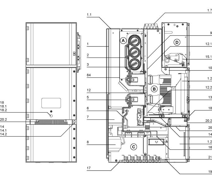
|
А |
Шинный отсек |
12.1. |
Верхняя шторка |
|
В |
Отсек выключателя |
12.2. |
Нижняя шторка |
|
С |
Кабельный отсек |
13 |
Выдвижная часть |
|
D |
Отсек низковольтного оборудования |
14 |
Привод заземлителя |
|
14.1. |
Вал управления заземлителем |
||
|
1 |
Оболочка |
14.2. |
Заслонка |
|
1.1 |
Откидной клапан |
15.1 |
Клеммная колодка |
|
1.2 |
Канал контрольной цепи |
15 |
Кабельный наконечник |
|
1.7 |
Откидной клапан с вентиляцией |
16 |
Пол |
|
2 |
Отпайка |
18 |
Шпиндельный механизм |
|
3 |
Сборная шина |
18.1 |
Вал |
|
5 |
Проходной изолятор |
18.2 |
Отверстие для вставки рукоятки |
|
6 |
Заземлитель |
19 |
Главная заземляющая шина |
|
7 |
Трансформатор тока |
20 |
Съемная горизонтальная перегородка |
|
8 |
Трансформатор напряжения |
20.2 |
Вентиляционная решетка |
|
9 |
Съемная перегородка |
21 |
Кабельный зажим |
|
10 |
Разъем контрольной цепи |
84 |
Перегородка |
|
12 |
Монтажная пластина |
Рис 3/3: Пример шкафа ввода/вывода.

Рис 3/ 4-1: Блокировка вкатывания при открытых дверях отсека выключателя (часть 1)

Рис 3/ 4-2: Блокировка вкатывания при открытых дверях отсека выключателя (часть 2)

Рис 3/ 4-3: Блокировка открытия двери отсека выключателя при открытых шторках (часть 1)

Рис 3/ 4-4: Блокировка открытия двери отсека выключателя при открытых шторках (часть 2)

Рис 3/ 4-5: Блокировка отключения заземлителя при открытых дверях кабельного отсека

Рис 3/ 4-6: Блокировка отключения заземлителя при открытых дверях кабельного отсека — гнездо (С1) и штифт (С2).

Рис 3/4-7: Блокировка открытия двери кабельного отсека

Рис 3/4-8: Штифт блокировки открытия двери кабельного отсека при отключенном заземлителе


Переустановка вторичных контактов
Рис 3/5-1: Датчик давления
Рис 3/5-2: Катушка отключения выключателя.

Рис 3/5 -3: Система «Fast recovery»

Редуктор давления
Рычаг для открывания воздушного клапана
Манометр
Рис 3/5 — 4: Испытательное оборудование.

Рис 3/7 Отсек низковольтного оборудования, вид изнутри

Рис 3/6 Фидер
Рис 3/8 Отсек выключателя, дверь открыта, выключатель в рабочем положении
Рис 3/9 Отсек выключателя, дверь открыта, выключатель отключен, разъем контрольной цепи отсоединен 10.2 Разъем контрольной цепи 13.1 Выдвижная часть
14 Вал управляющего механизма заземлителя 18.1 Четырехгранный вал
Рис 3/10 Выдвижная часть при перемещении в рабочее положение, шторки открыты/ не полностью
Изолированный контакт
Контактная система 5 Изоляционная камера
Верхняя шторка


Рис 3/13 Выдвижная часть с выключателем VD4. Вид со стороны полюсов. 13.10 Изолирующее покрытие 13.16 Пластины, воздействующие на механизм открытия шторок
Рис 3/12 Выдвижная часть с выключателем VD4. Вид со стороны привода. 13.15 Выдвижная кассета
Нижняя шторка
Рис 3/11 Вид изнутри на отсек выключателя. Выдвижная часть отсутствует, шторки открыты. 4.1 Изолированный контакт 5 Изоляционная камера 12.2 Нижняя шторка

Рис 3/14 Кнопка для механического включения/отключения выключателя с закрытой дверью (по заказу). Если выдвижная часть находится в рабочем положении, то управление производится при помощи рукоятки, находящейся на толкателе.
Кнопки для механического управления
Рукоятка

Рис 3/15
45.3
Вид толкателя, провернутого рукояткой с выкатным выключателем в рабочем положении, при открытой двери
Проворачиваемый толкатель

31.5 31.6
Рис 3/16 Выкатная часть с выключателем VM1. Вид со стороны привода.
дисплей готовности
кнопка включения
кнопка отключения
механический счетчик срабатываний
механический индикатор положения переключателя

Рис 3/17 Выкатная часть с выключателем VM1. Вид со стороны полюсов.
31.9 гнездо для аварийного рычага управления 31.16 фронтальная крышка


Рис 3/18 Выключатель HD4, вид сбоку
10.2 Разъем для подключения цепи управления 13.15 Выкатной модуль
Рис 3/19 Панель управления выключателя HD4
Устройство для сигнализации давления элегаза
Кнопка отключения
Кнопка включения
Счетчик срабатываний
Индикатор ВКЛЮЧЕНО/ОТКЛЮЧЕНО
Рукоятка для ручного взвода пружины
Сигнальный указатель ВЗВЕДЕНО/НЕ ВЗВЕДЕНО пружины


Рис 3/20 Вакуумный контактор V-Contact, вид спереди
Сигнализация ВКЛЮЧЕНО/ОТКЛЮЧЕНО
Счетчик срабатываний
Рис 3/21 Вакуумный контактор V-Contact, вид со стороны полюсов
91.15 Предохранители
Рис 3/22 Выкатной модуль для выключателя, с вспомогательными переключателями
Указатель контрольного (испытательного) положения
Указатель рабочего положения
10.3 Разъем для подключения цепи управления
Квадратный стержень

Отверстие для рычага
Рис 3/23 Выкатная часть с выключателем VD4, вид со стороны полюсов
13.9 Колпачки для транспортировки, необходимо

снять при пуске 13.13 Подъемные проушины, необходимо снять при пуске

Рис 3/24 Выкатная часть с измерительным модулем
Трансформатор напряжения
Блок из эпоксидной композиции с предохранителями
Кодировка:
(…) В скобках указывается
соответствующее кодирование для разъема цепей управления (10.2)
Кодирующие штыревые контакты могут быть встроены или в розетку (10.1), или в штепсель (10.2).
Основная конфигурация:
Номера гнезд произвольные, однако, всегда надо
соблюдать основное распределение: 1, 8, 10, 20, 21, 31, 33, 40.

В случае необходимости гнезда и штыревые контакты в штекерной розетке (10.1) и штепселе (10.2) могут быть заменены.
Выключатели и контакторы Кодировка контактов (установка) Кодировка гнезд (установка)
| 12-17,5 kV |
650 мм |
800 мм |
1000 мм B1 |
B2 |
B3 |
B4 |
B5 |
B6 B1 |
B2 |
B3 |
B4 |
B5 |
B6 |
|||||||
|
400 A |
V |
O |
O |
O |
O |
|||||||||||||||
|
630 A |
VD4 |
VM1 |
HD4 |
O |
O |
O |
O |
|||||||||||||
|
1250 A |
VD4 |
VM1 |
HD4 |
VD4 |
VM1 |
HD4 |
O |
O |
||||||||||||
|
1600 A |
VD4 |
VM1 |
HD4 |
VD4 |
VM1 |
O |
O |
O |
O |
|||||||||||
|
2000 A |
VD4 |
VM1 |
HD4 |
VD4 |
VM1 |
O |
O |
|||||||||||||
|
2500 A |
VD4 |
VM1 |
HD4 O |
O |
O |
O |
||||||||||||||
|
3150 A |
VD4 |
VM1 |
HD4 |
|||||||||||||||||
|
3600 A |
VD4 |
VM1 |
HD4 |
|||||||||||||||||
|
4000 A |
VD4 |
VM1 |
HD4 |
Разъединителе
| 12-17,5 kV |
650 мм |
800 мм |
1000 мм |
|||||
|
400 A |
17.12.32 |
|||||||
|
630 A |
||||||||
|
1250 A |
17.20.50 |
|||||||
|
1600 A |
||||||||
|
2000 A |
||||||||
|
2500 A |
17.25.50 |
|||||||
|
3150 A |
17.32.50 |
|||||||
|
3600 A |
||||||||
|
4000 A |
Кодировка контактов (установка) Кодировка гнезд (установка)
| B1 |
B2 |
B3 |
B4 |
B5 |
B6 B1 |
B2 |
B3 |
B4 |
B5 |
B6 |
|
O |
O |
O |
O |
|||||||
|
O |
O |
O |
O |
|||||||
|
O |
O O |
O |
||||||||
Выключатели и контакторы Кодировка контактов (установка) Кодировка гнезд (установка)
| 24 kV |
800 мм |
1000 мм B1 |
B2 |
B3 |
B4 |
B5 |
B6 B1 |
B2 |
B3 |
B4 |
B5 |
B6 |
||||
|
630 A |
VD4 |
VM1 |
HD4 |
VD4 |
VM1 |
O |
O |
O |
O |
|||||||
|
1250 A |
VD4 |
VM1 |
HD4 |
VD4 |
VM1 |
O |
O |
|||||||||
|
1600 A |
VD4 |
VM1 |
HD4 |
O |
O |
O |
O |
|||||||||
|
2000 A |
VD4 |
VM1 |
HD4 |
O |
O |
|||||||||||
|
2500 A |
VD4 |
VM1 |
HD4 O |
O |
O |
O |
Carrelli di sezionamento Кодировка контактов (установка) Кодировка гнезд (установка)
| 24 kV |
800 мм |
1000 мм |
B1 |
B2 |
B3 |
B4 |
B5 |
B6 |
B1 |
B2 |
B3 |
B4 |
B5 |
B6 |
||
|
630 A |
||||||||||||||||
|
1250 A |
24.12.25 |
O |
O |
O |
O |
|||||||||||
|
1600 A |
||||||||||||||||
|
2000 A |
||||||||||||||||
|
2500 A |
24.25.25 |
O |
O |
O |
O |
Рис. 3/24: Кодировка разъема цепей управления, пример для разъема с 58 контактами
10.1 Разъем цепи управления
Центрирующие контакты
Отверстие для исполнительного штырька разъема контрольной цепи для управления вспомогательным переключателем.
ABB UniGear ZS1 Industrial Equipment PDF User Guides and Manuals for Free Download: Found (2) Manuals for ABB UniGear ZS1 Device Model (Installation, Operation And Maintenance Instructions Manual, Instruction Manual)

|
|
More Industrial Equipment Device Models:
-
Robotis
DYNAMIXEL XM430-W210
2/22/2018 ROBOTIS e-Manualhttp://emanual.robotis.com/docs/en/dxl/x/xm430-w210/ 1/34DYNAMIXEL PLATFORM STEAM SOFTWARE PARTS FAQCustom Search Edit on GitHubXM430-W2101. SpecificationsItem SpecificationsMCU ST CORTEX-M3 (STM32F103C8 @ 72Mhz, 32Bit)Position SensorContactless absolute encoder (12Bit, 360°) Maker : ams( …
DYNAMIXEL XM430-W210 Industrial Equipment, 34
-
Mayr
EAS-Compact Type 49. 4. Size 4 Series
Installation and Operational Instructions for EAS®-Compact® overload clutch Type 49_._ _4._ Sizes 4 and 5 (B.4.14.2.ATEX.EN) 30/05/2016 TK/GH/SU Chr. Mayr GmbH + Co. KG Eichenstraße 1, D-87665 Mauerstetten, Germany Tel.: +49 8341 804-0, Fax: +49 8341 804-421 Page 1 of 19 www.mayr.com, E-Mail: [email protected] P …
EAS-Compact Type 49. 4. Size 4 Series Industrial Equipment, 19
-
Wood-mizer
LT70 Series
G57 EngineSafety, Operation, Maintenance & Parts ManualLT70 Series rev. F1.00Safety is our #1 concern! Read and understandall safety information and instructions before oper-ating, setting up or maintaining this machine.Form #2442! …
LT70 Series Engine, 44
-
Leroy-Somer
LSA 49.1
5334310710034778377934970901364284118513159 91278 364 269 3682682797137117736519817228127021430336028468156222344849367255254Caixa de terminais opcionais 6 fios com réguas de ligações27728028128317228227927832015Motor, turbina LSA 49.1 L 11 2014.03 / nThis manual is to be givento the end user3007 en — LSA 49.1 — 4 P …
LSA 49.1 Industrial Equipment, 24
Recommended Documentation:
Table of Contents for ABB UniGear ZS1:
-
ABB Power Distribution 45 • Check that the relevant conductors are in-phase, as far as necessary when several incoming feeder cables and switchgear sections are concerned (see also section 6.3.2). • Carry out all measurements and check all functions dependent on the high-voltage power supply being connected. • Watch out for irregularities of any kind. 6.2 Switching operations Perform switching operations with the front doors shut. 6.2.1 Withdrawable circuit-bre
-
4 ABB Power Distribution Contents Page 1 Summary 6 1.1 General 6 1.2 Standards and specifications 6 1.3 Operating conditions 6 1.3.1 Normal operating conditions 6 1.3.2 Special operating conditions 6 2 Technical data 7 2.1 Electrical data 7 2.2 Resistance to internal arc faults 7 2.3 Dimensions and weights 8 3 Panel design and equipment 9 3.1 Basic structure and variants 9 3.2 Enclosure and partitioning 9 3.2.1 Vent
-
Your safety first – always! • Only install switchgear and/or switchboards in enclosed rooms suitable for electrical equipment. • Ensure that installation, operation and maintenance are carried out by specialist electricians only. • Comply in full with the legally recognized standards (DIN VDE / IEC), the connection conditions of the local electrical utility and the applicable safety at work regulations. • Observe the relevant information in the instruction manual for all actions involving switchgear and switchboards. • Danger! Pay spe
-
46 ABB Power Distribution 6.2.2 Withdrawable metering parts (Figures 3/1 and 3/11) The handling of the withdrawable metering part in the metering panel is as described in section 6.2.1, without however the switching operations and interlocking functions. Withdrawable metering parts in incoming and outgoing feeder panels are inserted into the cable compartment using a ramp. They reach their service position immediately and engage there in the panel ground by means of the two locking pins at the sides. The voltage transfor
-
ABB Power Distribution 67
-
ABB Power Distribution 27 2. Method: • Power cable is to be inserted, cut to length and stripped. • Reducer rings 17.2 are to be adapted to the cable diameter and fitted. • Cable sealing ends 16 are to be prepared and secured according to the manufacturer’s instructions. • Cable cores are to be connected to the prepared connection points 23 with strain relief. Cable core crossings are to be avoided. Other agreed equipment is prepared at
-
ABB Power Distribution 49 The switch-disconnector is then ready to open, also in response to fuse tripping, shunt and undervoltage releases. • Open the switch-disconnector by turning the operating lever 122 clockwise through approx. 15°. Then turn the operating lever back anti-clockwise until the stop is reached. • Observe the position indicator (see also section 6.2.8). 3. Opening and closing of a switch-disconnector wi
-
ABB Power Distribution 15 Figure 3/4: ZS1 Duplex switchgear 12 kV, 1000 A, 31,5 kA Double busbar switchgear according to the two-breaker method 18001300 1300 50 50 1200 12002608 a) Installation front to front b) Installation back to back
-
66 ABB Power Distribution 13.25 13.26 13.24 13.92 13.91 13.91.2 13.27 2 + 1 13.91.1 13.92.1 max. 0,5 13.25 13.26 13.24 13.92 13.91 13.91.2 13.27 13.90 13.91.1 2 + 1 max. 0,5 13.92.1 Figure 7/9: Detail in the area of a withdrawable part with travel motor, viewed from the left-hand side 13.24 Roller 13.25 Cam 13.26 Lever 13.27 Pin 13.90 Travel motor 13.91 Link rod 13.91.1 Bolt 13.91.2 Bolt 13.92 Angle lever 13.92.1 Bolt Figure 7/10: Mechanical interlock, lock and release device/circuit- breaker with manually opera
Questions, Opinions and Exploitation Impressions:
You can ask a question, express your opinion or share our experience of ABB UniGear ZS1 device using right now.
| Document’s Content and Additional Information | Share Manual |
|---|---|
|
ABB UniGear ZS1 Installation, operation and maintenance instructions manual
Pages Preview: Document Transcription:
See Details |
|
|
ABB UniGear ZS1 Instruction manual
Pages Preview: Document Transcription:
See Details |


