Honda_Trx680_Rincon_680_Service_Manual новые ссылки
http://yadi.sk/d/Dr2CDNmpKpUvf
Honda_TRX680_Rincon_Parts_Catalog_2006.ra…
http://yadi.sk/d/_Go2do4mKppao
Honda_TRX680FA_Owners_Manual_RUS_2005.ra…
http://yadi.sk/d/aSETpsGAKpyFV
Honda_Trx680_Rincon_680_Service_Manual_Rep…
http://yadi.sk/d/lqzSVlTyKqTrs
Honda%20Rincon%20Manual.rar
(Ocr-Read Summary of Contents of some pages of the Honda TRX680FA Document (Main Content), UPD: 04 April 2023)
-
84, Honda TRX680FA MAINTENANCE Minor adjustments are made with the upper adjuster. Slide the rubber boot off the adjuster. Loosen the lock nut, turn the adjuster as required and tighten the lock nut. Install the rubber boot securely. ADJUSTER LOCK NUT Major adjustments are made with the lower * adjuster. Remove the seat (page 3-4). Remove the throttle body cover (page 4-4). Slide the rubber boot off the adjuster. Loosen the lock nut, turn the adjuster as required and…
-
341, DRIVETRAIN SYSTEM Make sure the mating surfaces touch evenly, there should be no clearance between the cover and crankcase. Align the flange tabs with the grooves in the cover. Install the following: — front crankcase cover — 14 bolts with the side cover stays and hose guide Tighten the bolts in a crisscross pattern in several steps securely. CRANKCASE COVER BOLTS STAYS Coat a new O-ring with engine oil and install it onto the flange of the feed pipe B. Apply engine oil to the outer…
-
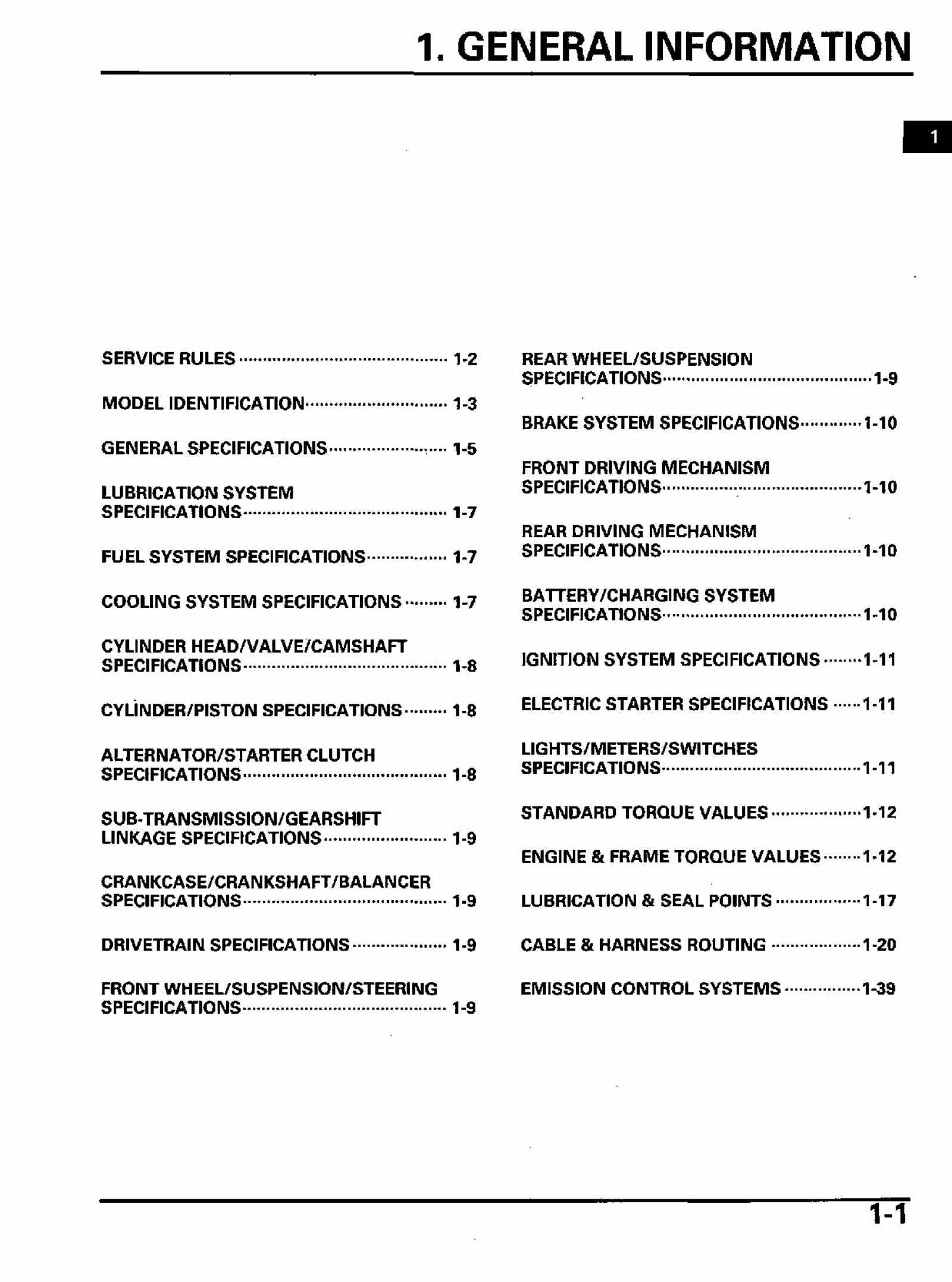
9, GENERAL INFORMATION The Vehicle Emission Control Information Label is attached on the left side of the rear fender under the seat. EMISSION CONTROL INFORMATION LABEL GENERAL SPECIFICATIONS ITEM DIMENSIONS FRAME Overall length Overall width Overall height Wheelbase Front tread Rear tread Seat height Footpeg height Ground clearance Curb weight Maximum weight capacity Frame type Front suspension Front wheel travel Fron…
-
26, GENERAL INFORMATION FUEL LEVEL SENSOR WIRE PCM (POWERTRAIN CONTROL MODULE) DLC SIPHON HOSE OVERFLOW HOSE REAR BRAKE CABLE MAIN WIRE HARNESS THROTTLE CABLE FINAL DRIVE! BREATHER HOSE DIFFERENTIAL BREATHER HOSE SHIFT SOLENOID SUB-HARNESS FUEL LEVEL SENSOR 2P (NATURAL) CONNECTOR FAN MOTOR BREATHER HOSE HEADLIGHT SUB-HARNESS 3P (BLACK) CONNECTOR 1-22
… -
365, FRONT WHEEL/SUSPENSION/STEERING Align the edge of the master cylinder with the punch mark on the handle- bar. Install the brake master cylinder and holder with the «UP» mark facing up. Tighten the upper bolt first, then tighten the lower bolt. TORQUE: 12 N m (1.2 kgf m, 9 Ibf-ft) Connect the connectors to the brake and brake light switches. HOLDER Align the lug on the Install the throttle housing and holder against the throttle housing master cy…
-
103, Honda TRX680FA MAINTENANCE Using a 17 mm wrench, hold the tie-rod ends so that the relative angle of both tie-rods may turn into 16 degrees 30 minutes. Then, using a suitable torque wrench, tighten the tie-rod lock nuts, making sure not to force the tie-rod ends against the ball joint studs. TORQUE: 54 N-m (5.5 kgf-m, 40 Ibfft) After tightening the lock nuts, rotate the tie-rods to make sure the ball joints have operate properly and have an equal range of movement. Raise the wheel off the gr…
-
280, Honda TRX680FA CRANKCASE/CRANKSHAFT/BALANCER Apply engine oil to new bearings. Drive the bearings in with the marks facing up. TOOLS: Mainshaft Bearing Driver 07749-0010000 Attachment, 62 x 68 mm 07746-0010500 Pilot, 35 mm 07746-0040800 The countershaft Countershaft Bearing bearing is installed Driver with the sealed Attachment, 42 x 47 mm side facing down. pj | ot 2 n mm Crankshaft Bearing Driver Attachment, 78 x 90 mm Balancer Bearing Driver Attachment, 37 x 40 mm Pilot, 17 mm 07749…
-
419, BRAKE SYSTEM Rotate the caliper piston clockwise using the special tool or equivalent to retract it and align the piston groove with the index mark on the caliper body. TOOL: Lock nut wrench, 20 x 24 mm 07716-0020100 INDEX MARK GROOVE Install the caliper body over the pads and caliper I BRACKET PIN BOLT bracket, aligning the groove in the piston with the pin on the pad. Install the bracket pin bolt and bracket pin retaining bolt, and tighten them. TORQUE: Bracket pin bolt: 32 N m (3.3 kg…
-
186, COOLING SYSTEM Be careful not to damage the radiator fins with the oil Pipe- Route the wire and hose properly (page 1-20). INSTALLATION Insert the bosses on the radiator bottom into the holes (mounting rubbers) in the frame to install the radiator assembly. Install the mounting bolts and tighten them. Connect the upper and lower water hoses, and tighten the hose clamps securely. RADIATOR Connect the fan motor 2P (White) connector and secure the wires with the clip. Conn…
-
410, BRAKE SYSTEM 30 N-m (3.1 kgfm, 22 Ibf-ft) 34 N-m (3.5 kgfm, 25 Ibf-ft) 32 N-m (3.3 kgfm, 24 Ibf-ft) 2 N-m (0.2 kgfm, 1.4 Ibf-ft) 34 N-m (3.5 kgfm, 25 Ibf-ft) 17-3
… -
349, DRIVETRAIN SYSTEM CLUTCH RETURN SPRING Measure the spring free length. SERVICE LIMIT: 31.8 mm (1.25 in) SHIFT CLUTCH/MAINSHAFT ASSEMBLY MAINSHAFT ASSEMBLY Install the snap ring and washer with the chamfered (rolled) edge facing away from the thrust load. Blow through the oil passages in the mainshaft with compressed air. Apply engine oil to the each gear teeth and bearing. Install the following onto …
-
70, FRAME/BODY PANELS/EXHAUST SYSTEM Carrier/Fender Assembly Removal Procedure Remove the following: — fuel tank side covers (page 3-6) — center front grille (page 3-10) — headlight connector and fender fasteners (page 3-11) — four 8-mm bolt (carrier mounting fasteners). Loosen the three tapping bolts. Remove the front carrier/fender assembly while spreading the rear portion of the fender. Installation is in the reverse order of removal. TORQUE: 8 mm bolt: 37 Nm (3.8 kgf-m, 27 Ibf-ft) SQ…
-
154, FUEL SYSTEM (PGM-FI) Connect the fuel hose and fuel vapor return hose to the sub fuel tank/fuel pump. Connect the fuel feed hose (page 6-33). Connect the fuel pump 2P (Black) connector. 2P BLACK) CONNECTOR FUEL PUMP RELAY INSPECTION Remove the battery and battery case (page 20-6). Disconnect the relay module 8P (Gray) connector. Connect an ohmmeter to the 8P (Gray) connector of the module side connector termin…
-
299, DRIVETRAIN SYSTEM DRIVETRAIN CONNECTOR LOCATION FRONT CONNECTOR LOCATIONS Note 1: Remove the steering cover (page 3-5). Note 2: Remove the VS sensor cover (page 18-12). PCM 33P (BLACK) CONNECTOR (Note 1) PCM 5P (BLACK) CONNECTOR (Note 1) PCM (Note 1) PCM 33P (GRAY) CONNECTOR (Note 1) \ FINAL CLUTCH 2P (GREEN) CONNECTOR (Note 2) 14-17
… -
332, DRIVETRAIN SYSTEM — separator plate — two dowel pins — four sealing bolts and washers PLATE BOLTS AND WASHERS DOWEL PINS Remove the following from the orifice control valve body: — spring seats — valve springs — orifice control valves (2nd and 3rd) ORIFICE CONTROL VALVE (2nd) \ SPRING SPRING ORIFICE CONTROL SEAT VALVE (3rd) Remove the following from the shift valve body: — spring seats — valve springs — shift valves (1-2 and 2-3) Blow through all the Wash all the parts with a high flash…
-
314, DRIVETRAIN SYSTEM Front VS Sensor Output Line Inspection Measure the voltage between the front VS sen- sor 3P (Blue) connector terminals of the wire harness side. Connection: Pink/white (+) — Green (-) Is the voltage about 5 V? NO — Open or short circuit in the Pink/white wire. YES — GO TO STEP 4. FRONT VS SENSOR 3P (BLUE) CONNECTOR (Wire side of male terminal) 1 4- 4J 4. Front VS Sensor Inspection Turn the ignition switch OFF. Replace the front VS sensor with a new one (p…
-
204, CYLINDER HEAD/VALVE/CAMSHAFT SYSTEM COMPONENTS 55 N-m (5.6 kgfm, 41 Ibf ft) 18Nm 12 N-m (1.2 kgfm, 9 Ibf-ft) 32 N-m (3.3 kgf-m, 24 Ibf-ft) 54 N-m (5.5 kgf-m, 40 Ibf-ft) 9-2
…
Full Workshop Service Manual for Honda TRX680FA TRX680 FGA 2006 2007 2008 2009 2010 2011 Models. Original Factory Workshop Manual for Honda TRX680 Motorcycle.
This Free Downloadable Service Manual Includes Everything You would need to Service & Repair your Honda TRX680 Motorbike.
You can download the Individual Pages needed from this Manual by Simply Dragging them to your Desktop.
Use the Navigation at the bottom of the page to navigate to next pages ( Engine,Frame,Suspension,Electrical Systems, Clutch, Transmission etc..) in this Honda TRX680 Service Manual ( Each Page includes 5 Pages from the original PDF Manual).

Сборник руководств на английском языке по эксплуатации и техническому обслуживанию квадроциклов Honda TRX 125/200/250/350 1984-1987 годов выпуска.
- Издательство: Honda Motor Co., Ltd.
- Год издания: 1983-1986
- Страниц: —
- Формат: PDF
- Размер: 16,2 Mb

Сборник руководств на английском языке по эксплуатации и техническому обслуживанию квадроциклов Honda FourTrax 300EX/350/350ES/Foreman 400 и TRX 300EX/350TE/350TM/400FW 1995-2001 годов выпуска.
- Издательство: Honda Motor Co., Ltd.
- Год издания: 1994-2000
- Страниц: 155/159/174/176
- Формат: PDF
- Размер: 12,2 Mb

Сборник руководств на английском языке по эксплуатации и техническому обслуживанию квадроциклов Honda TRX 90/300EX/700XX и Sportrax 90/300EX/700XX 2002-2009 годов выпуска.
- Издательство: Honda Motor Co., Ltd.
- Год издания: 2001/2003/2006/2008
- Страниц: 180/207/237/232
- Формат: PDF
- Размер: 17,2 Mb

Сборник руководств на английском языке по эксплуатации и техническому обслуживанию квадроциклов Honda TRX 350FM/400FA/400FGA/420FE/420TE/500FA/500FGA/500FM/500FPM и FourTrax 350/420ES/Foreman/Foreman Rubicon/Rancher AT 2005-2009 годов выпуска.
- Издательство: Honda Motor Co., Ltd.
- Год издания: 2004-2008
- Страниц: —
- Формат: PDF
- Размер: 30,7 Mb

Руководство на английском языке по техническому обслуживанию и ремонту квадроциклов Honda FourTrax 250R и TRX 250R 1986-1989 годов выпуска.
- Издательство: Honda Motor Co., Ltd.
- Год издания: 1988
- Страниц: 224
- Формат: PDF
- Размер: 117,3 Mb
Руководство на английском языке по техническому обслуживанию и ремонту квадроциклов Honda TRX 350FE/350FM/350TE/350TM.
- Издательство: Honda Motor Co., Ltd.
- Год издания: 2002
- Страниц: 377
- Формат: PDF
- Размер: 17,7 Mb

Руководство на английском языке по техническому обслуживанию и ремонту квадроциклов Honda TRX 400EX FourTrax 1999-2002 годов выпуска.
- Издательство: Honda Motor Co., Ltd.
- Год издания: —
- Страниц: 263
- Формат: PDF
- Размер: 123,1 Mb

Руководство на английском языке по техническому обслуживанию и ремонту квадроциклов Honda TRX 500FA Rubicon 2001-2003 годов выпуска.
- Издательство: Honda Motor Co., Ltd.
- Год издания: 2000
- Страниц: 407
- Формат: PDF
- Размер: 131,9 Mb

Руководство на английском языке по техническому обслуживанию и ремонту квадроциклов Honda TRX 650FA Rubicon 2003 года выпуска.
- Издательство: Honda Motor Co., Ltd.
- Год издания: 2002
- Страниц: 530
- Формат: PDF
- Размер: 63,5 Mb
Инструкция по эксплуатации и техническому обслуживанию квадроциклов Honda TRX 250EX и Sportrax 250EX 2006 года выпуска.
- Издательство: Honda Motor Co., Ltd.
- Год издания: 2005
- Страниц: 205
- Формат: PDF
- Размер: 2,4 Mb

Инструкция по эксплуатации и техническому обслуживанию квадроциклов Honda TRX 400FA Four Trax AT 2005 года выпуска.
- Издательство: Honda Motor Co., Ltd.
- Год издания: 2004
- Страниц: 228
- Формат: PDF
- Размер: 2,4 Mb
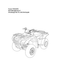
Инструкция по эксплуатации и техническому обслуживанию квадроциклов Honda TRX 420FA.
- Издательство: Honda Motor Co., Ltd.
- Год издания: —
- Страниц: 234
- Формат: PDF
- Размер: 5,3 Mb

Инструкция по эксплуатации и техническому обслуживанию квадроциклов Honda TRX 420FE/420TE и FourTrax 420ES 4×4.
- Издательство: Honda Motor Co., Ltd.
- Год издания: —
- Страниц: 230
- Формат: PDF
- Размер: 3,0 Mb

Инструкция по эксплуатации и техническому обслуживанию квадроциклов Honda TRX 450R 2005 года выпуска.
- Издательство: Honda Motor Co., Ltd.
- Год издания: 2004
- Страниц: 210
- Формат: PDF
- Размер: 3,3 Mb

Инструкция по эксплуатации и техническому обслуживанию квадроциклов Honda TRX 500FA и FourTrax Foreman Rubicon 2005 года выпуска.
- Издательство: Honda Motor Co., Ltd.
- Год издания: 2004
- Страниц: 232
- Формат: PDF
- Размер: 4,8 Mb

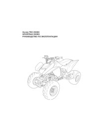
Инструкция по эксплуатации и техническому обслуживанию квадроциклов Honda TRX 680FA и FourTrax Rincon 2006 года выпуска.
- Издательство: Honda Motor Co., Ltd.
- Год издания: 2005
- Страниц: 235
- Формат: PDF
- Размер: 4,1 Mb

Инструкция по эксплуатации и техническому обслуживанию квадроциклов Honda TRX 700XX и Sportrax 700XX 2009 года выпуска.
- Издательство: Honda Motor Co., Ltd.
- Год издания: 2008
- Страниц: 220
- Формат: PDF
- Размер: 4,9 Mb

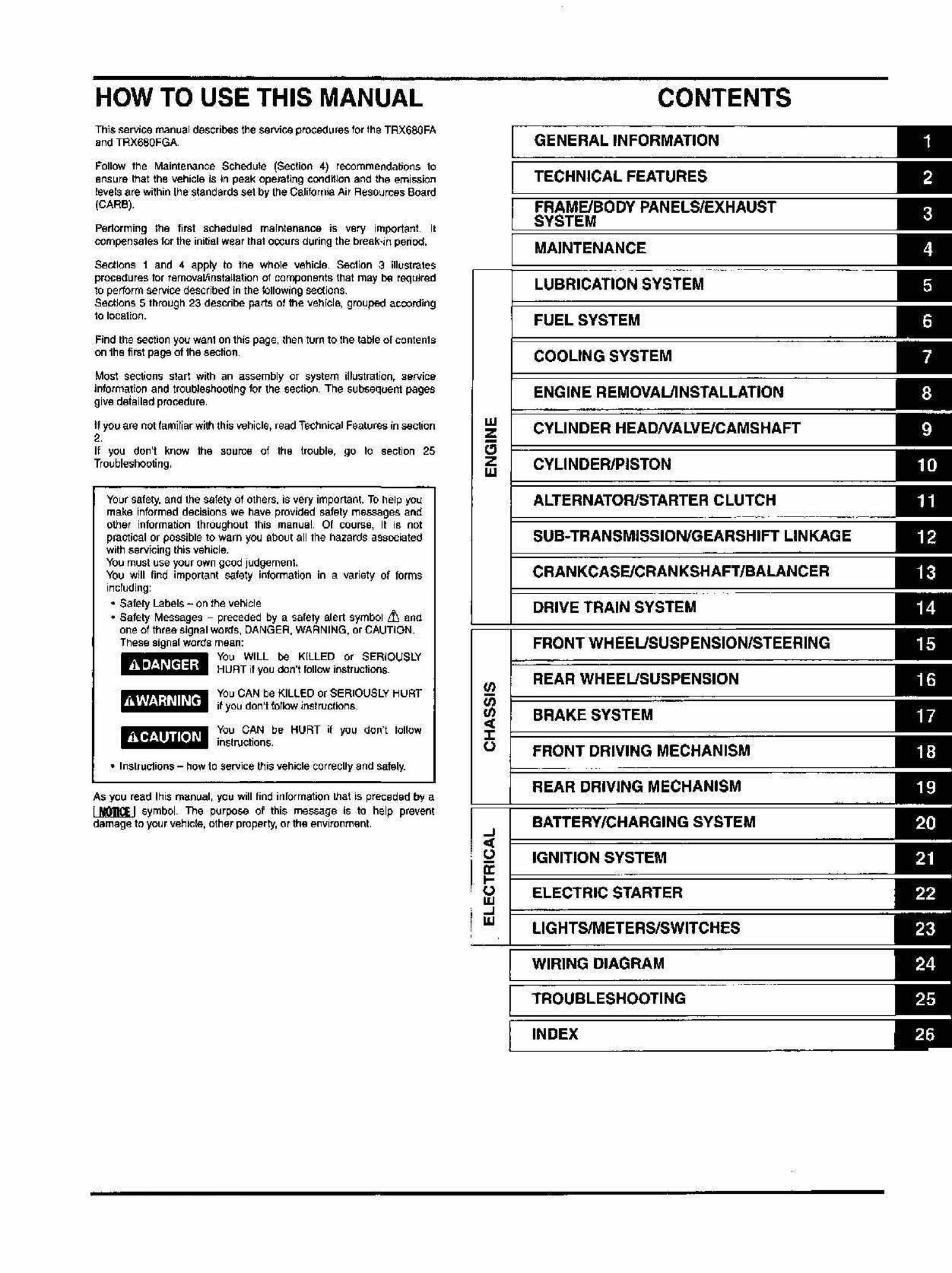
Table of Contents for Honda TRX680FA:
-
FRAME/BODY PANELS/EXHAUST SYSTEM REAR FENDER The rear carrier and rear side body pan- els can be removed as an assembly for service. If removed, use the procedure described on page 3-15. Remove the seat (page 3-4). Right side: Remove the following: — right side cover (page 3-5) — fuse box (by releasing the tab from the reverse side of the fender) — 2P (White) connector — two setting bolts — bolt and collar (front side) — bolt, collar and setting rubbers (rear side) — socket bolt — seven trim cli
-
LUBRICATION SYSTEM Mark the rotors so they can be rein- stalled in their origi- nal locations. oil pump body D outer rotor inner rotor drive pin two dowel pins — oil pump body C — outer rotor — inner rotor — drive pin — oil pump body B — pressure relief valve DOWEL PINS PUMP BODY D OUTER ROTOR DRIVE PIN INNER ROTOR PUMP BODY C OUTER ROTOR DRIVE PIN INNER ROTOR RELIEF VALVE PUMP BODY B — bolt — oil pump driven sprocket DRIVEN SPROCKET BOLT 5-7
-
FRAME/BODY PANELS/EXHAUST SYSTEM MUFFLER Remove the rear carrier assembly (page 3-13). Loosen the muffler band bolts. Remove the mounting nuts and bolts, and the muf- fler. Remove the joint gasket. When tightening, adjust the clearance between the exhaust pipe and cover stay as shown so they do not interfere. INSTALLATION Install new joint gasket and muffler gasket. Install the muffler and exhaust pipe in the reverse order of removal by loosely tightening all the fas- teners. Tighten the joint nuts first, then tighten the mount- ing nuts and the band
-
BRAKE SYSTEM Connect the brake hose to the brake caliper with the oil bolt and new sealing washers, and tighten the oil bolt. TORQUE: 34 N m (3.5 kgf m, 25 Ibf-ft) Install the rear brake cable into the caliper body and connect it to the brake arm with the joint pin. Install the rear brake adjusting nut. Fill and bleed the rear brake hydraulic system (page 17-7). Adjust the rear (parking) brake lever free play (page 4-20). Install the right rear wheel (page 16-6). 17-33
-
GENERAL INFORMATION SERVICE RULES 1. Use genuine Honda or Honda-recommended parts and lubricants or their equivalents. Parts that do not meet Honda’s design specifications may cause damage to the motorcycle. 2. Use the special tools designed for this product to avoid damage and incorrect assembly. 3. Use only metric tools when servicing the motorcycle. Metric bolts, nuts and screws are not interchangeable with English fasteners. 4. Install new gaskets, O-rings, cotter pins, and lock plates when reassembli
-
TRX680FA/FGA: WIRING DIAGRAM 0030Z-HN8-A600 24^3
-
9. CYLINDER HEAD/VALVE/CAMSHAFT SYSTEM COMPONENTS 9-2 SERVICE INFORMATION 9-3 TROUBLESHOOTING 9-5 CYLINDER COMPRESSION 9-6 CYLINDER HEAD COVER REMOVAL/ DISASSEMBLY 9-6 CYLINDER HEAD REMOVAL 9-9 CYLINDER HEAD DISASSEMBLY — 9-10 CYLINDER HEAD INSPECTION 9-11 VALVE GUIDE REPLACEMENT 9-12 VALVE SEAT INSPECTION/REFACING 9-13 CAMSHAFT 9-16 CYLINDER HEAD ASSEMBLY 9-19 CYLINDER HEAD INSTALLATION 9-20 CYLINDER HEAD COVER ASSEMBLY/ INSTALLATION 9-22 9-1
-
SUB-TRANSMISSION/GEARSHIFT LINKAGE SUB-TRANSMISSION DISASSEMBLY Remove the rear crankcase cover (page 12-5). Remove the following: — washer — idle gear (25T) — gear shaft and gear collar (inner and outer) — washer — idle gear (16T) The output shaft can be removed at this time (page 12-10). SHAFT/COLLAR/WASHER Remove the following: — shift fork shaft — shift fork — countershaft assembly (OUTPUT SHAFT) FORK SHAFT Remove the shift drum while lifting the stopper arm with a
-
FRONT WHEEL/SUSPENSION/STEERING INSTALLATION Apply grease to the pivot collar outer surface and install the collar into the upper arm. Apply molybdenum disulfide grease to the dust seal lips and install the dust seal caps onto the upper arm. Install the upper arm into the frame with the pivot bolt and a new nut, and tighten the nut to the speci- fied torque. TORQ
-
FUEL SYSTEM (PGM-FI) 2. IAT Sensor Inspection Turn the ignition switch OFF. Disconnect the IAT sensor 2P (Black) connector. Turn the ignition switch ON and engine stop switch «O»- Check the IAT sensor with the HDS pocket tester. Is about 0 V indicated? YES — GO TO STEP 3. NO — Faulty IAT sensor 2P (BLACK) CONNECTOR • 3. IAT Sensor Output Line Short Circuit Inspection Disconnect the PCM 33P (Gray) connector from the PCM (page 6-43). Check for continuity between the IAT sensor 2P (Black) connector terminal of the w
-
DRIVETRAIN SYSTEM When Shifting in the AUTO (automatic) Mode, Excessive Shift Shock, Engine rpm (min’) Rises or Driving Power Falls Off 1. Vehicle Test-riding Test-ride the vehicle with the mode select switch at ESP. Check above symptoms when shifting with the ESP shift switch. Are there repeated symptoms? YES — • Faulty throttle position sensor sys- tem. Check the installation condition (page 6-43). • Faulty VS sensor system. Check the installation condition (page 18-30). NO — Hydraulic circuit malfunction is likely cause. Check the oil pressure (pag
-
26. INDEX ACCESSORY SOCKET 23-5 AIR CLEANER 4-5 AIR CLEANER HOUSING 6-41 AIR CLEANER HOUSING DRAIN PLUG 4-7 ALTERNATOR CHARGING COIL 20-8 ALTERNATOR STATOR/STARTER REDUCTION GEARS 11-9 ALTERNATOR/STARTER CLUTCH SPECIFICATIONS 1-8 AUTOMATIC TRANSMISSION SYSTEM 2-7 BANK ANGLE SENSOR : 6-51 BATTERY -20-6 BATTERY/CHARGING SYSTEM SPECIFICATIONS 1-10 BODY PANEL LOCATIONS 3-3 BRAKE FLUID 4-17 BRAKE FLUID REPLACEMENT/AIR BLEEDING 17-7 BRAKE LIGHT SWITCH LI
-
FRONT WHEEL/SUSPENSION/STEERING DISASSEMBLY/ASSEMBLY Loosen the lock nuts and remove the ball joints and lock nuts from the tie-rod. Install the unmarked ball joint and gold colored nut on the flat (wrench holding area) side of the tie-rod, and the «L» marked ball joint and silver nut on the opposite side. The ball joint posi- tions are 180° from each other. Tighten these nuts after installing the tie- rod
Questions, Opinions and Exploitation Impressions:
You can ask a question, express your opinion or share our experience of Honda TRX680FA device using right now.