
-
Contents
-
Table of Contents
-
Troubleshooting
-
Bookmarks
Quick Links
GE
Sensing & Inspection Technologies
Flow
TransPort® Model PT878
Portable Liquid Flowmeter
User’s Manual
910-219 Rev. F
November 2009
Related Manuals for GE TransPort PT878
Summary of Contents for GE TransPort PT878
-
Page 1
Sensing & Inspection Technologies Flow TransPort® Model PT878 Portable Liquid Flowmeter User’s Manual 910-219 Rev. F November 2009… -
Page 3
Sensing & Inspection Technologies TransPort® Model PT878 Portable Liquid Flowmeter User’s Manual 910-219 Rev. F November 2009 GESensingInspection.com ©2009 General Electric Company. All rights reserved. Technical content subject to change without notice. -
Page 4
[no content intended for this page — proceed to next page]… -
Page 5
WARNING! It is the responsibility of the user to make sure all local, county, state and national codes, regulations, rules and laws related to safety and safe operating conditions are met for each installation. Transport® Model PT878 Portable Liquid Flowmeter User’s Manual… -
Page 6
Make sure that operators and maintenance personnel have all safety equipment applicable to the auxiliary equipment. Examples include safety glasses, protective headgear, safety shoes, etc. Unauthorized Operation Make sure that unauthorized personnel cannot gain access to the operation of the equipment. Transport® Model PT878 Portable Liquid Flowmeter User’s Manual… -
Page 7
Preface Environmental Compliance Waste Electrical and Electronic Equipment (WEEE) Directive GE Sensing & Inspection Technologies is an active participant in Europe’s Waste Electrical and Electronic Equipment (WEEE) take-back initiative, directive 2002/96/EC. The equipment that you bought has required the extraction and use of natural resources for its production. -
Page 8
Preface [no content intended for this page — proceed to next page] Transport® Model PT878 Portable Liquid Flowmeter User’s Manual… -
Page 9: Table Of Contents
2.2 Caring for the PT878 Batteries……..
-
Page 10
3.11.3 Entering a Calibration Factor ……..67 viii Transport® Model PT878 Portable Liquid Flowmeter User’s Manual… -
Page 11
4.1.11 Transferring a Site File in Text Format to a PC ….84 4.1.12 Transferring a File from a PC to the PT878….. . . 85 4.1.13 Listing Files by Name. -
Page 12
6.12Taking a Bitmap Capture of a Current Screen ……130 Transport® Model PT878 Portable Liquid Flowmeter User’s Manual… -
Page 13
7.6.2 Listing Logs in Chronological Order ……154 Transport® Model PT878 Portable Liquid Flowmeter User’s Manual… -
Page 14
8.12Updating PT878 Software …….. -
Page 15
10.6Available Options ……….. . 218 Transport® Model PT878 Portable Liquid Flowmeter User’s Manual… -
Page 16
C.3.1 Connecting the RTD to the 4 to 20-mA Transmitter … . . 246 C.3.2 Connecting the Transmitter to the PT878….. . . 247 Appendix D. -
Page 17: Chapter 1. Features And Capabilities
The PT878 has the ability to store site data in files which can be accessed at a later time. Within the Main Menu, a set of forms (windows) asks you all the necessary setup information for a particular site.
-
Page 18: System Description
In other words, they act like loudspeakers when transmitting the signal and microphones when receiving it. In the PT878 system, each transducer acts as both a receiver and transmitter, since a series of ultrasonic pulses are alternately sent upstream and then downstream through the flowcell.
-
Page 19: Electronics Package
Chapter 1. Features and Capabilities 1.2.2 Electronics Package The PT878 consists of circuits that generate, receive, and measure the travel time of the ultrasonic pulses. It also contains a microcomputer that controls operation and calculates flow measurement parameters. Specific circuits function as follows: •…
-
Page 20: Theory Of Operation
(downstream) travel slightly faster than the pulses that travel against the flow (upstream). The PT878 uses various digital signal processing techniques, including cross-correlation, to determine transit times and then uses the transit times to calculate flow velocity.
-
Page 21: Chapter 2. Initial Setup
• Obtaining On-Line Help Figure 1 below shows the PT878 in its standard soft case (a) and in the optional solid case (b). In the solid case, the interior is structured for optimal protection of the PT878 and its accessories.
-
Page 22: Making Electrical Connections
• Infrared Interface Make all connections to the top of the PT878 unit as shown in Figure 2 below. Please note that you need to make the proper power and transducer connections only. The other connections are required for particular functions, but are not necessary for basic operation.
-
Page 23: Power Connections
Liquid Transducer Installation Guide (916-055). 2.1.3 Input/Output Connections The PT878 provides one 0/4-20 mA current output and two 4 to 20-mA analog inputs with switchable 16-V supply for loop- powered temperature transmitters. It also supports digital, frequency, and totalizer outputs.
-
Page 24: The Infrared Wireless Interface
-based PCs. Users can send and receive site and log data. They can also program the meter using the optional PanaView software interface. The PT878 was designed for use with products that comply to the IrDA protocol. For more information on establishing IR communications between the PT878 and your PC, refer to Appendix F.
-
Page 25: Caring For The Pt878 Batteries
When the PT878 is plugged into line voltage, the internal battery charger automatically charges the batteries, whether the PT878 is on or off. If the PT878 is on, the Battery icon in the upper right corner of the screen indicates battery status (as shown in Table 2 on page 10).
-
Page 26: Replacing The Batteries
600 times, it is best to replace them when they no longer provide acceptable performance. To replace the batteries, remove the rubber boot, open the panel located on the back of the PT878 unit, disconnect the batteries, and replace with new ones (see Figure 3 on page 11).
-
Page 27: Disposing Of Batteries
Battery Location (behind panel) Figure 3: Battery Location To further extend the battery power on the PT878, the GE Part #705-1283 option uses 6 AA alkaline batteries. 2.2.3 Disposing of Batteries Never dispose of the batteries by incineration. Do not CAUTION! attempt to disassemble or short-circuit the batteries.
-
Page 28: Powering On And Off
Chapter 2. Initial Setup 2.3 Powering ON and OFF To operate the PT878, the power cord must be plugged into line voltage or the battery must be charged as described previously. IMPORTANT: For CE compliance, the PT878 is classified as a battery-powered device, not to be used with the AC adapter.
-
Page 29
After the meter conducts all the self checks, the screen then appears similar to the one shown in Figure 4 below. ABC.SIT 2000/11/30 09:53 AM Velocity, ft/s Signal, dB 0.00 Volume, l/s Delta-T, ns 0.10 E0: No Errors Figure 4: Screen After Powering ON Transport® Model PT878 Portable Liquid Flowmeter User’s Manual… -
Page 30
PT878 to normal [F3] operation. If the PT878 locks up, you can reset it by holding the power key (the red key in the upper right corner) for 15 seconds. Transport® Model PT878 Portable Liquid Flowmeter User’s Manual… -
Page 31: Using The Screen And Keypad
Chapter 2. Initial Setup 2.4 Using the Screen and Keypad The essential features for operating the PT878 are the screen and keypad. Although these features are common on portable instruments, the PT878 design offers particular features to simplify and speed operation.
-
Page 32
(see page 130). (To Printer) The bottom of the screen displays the three function key options: F1, F2 and F3. These keys have different functions, depending on the task you are performing. Transport® Model PT878 Portable Liquid Flowmeter User’s Manual… -
Page 33: Keypad
Chapter 2. Initial Setup 2.4.2 Keypad The PT878 keypad has 25 keys. The functions for each key are as follows (see Figure 7 on page 18): • 3 function keys ( ) — enable you to select the special [F1]…
-
Page 34
Chapter 2. Initial Setup 2.4.2 Keypad (cont.) PT878 – • MENU ENTER Figure 7: PT878 Keypad Transport® Model PT878 Portable Liquid Flowmeter User’s Manual… -
Page 35: Obtaining On-Line Help
Chapter 2. Initial Setup 2.5 Obtaining On-Line Help The PT878 offers context-sensitive on-line help screens that describe various features. You can access on-line help at any time by pressing the [?] key. The screen appears similar to Figure 8 below.
-
Page 36
Chapter 2. Initial Setup [no content intended for this page — proceed to next page] Transport® Model PT878 Portable Liquid Flowmeter User’s Manual… -
Page 37: Chapter 3. Programming Site Data
The PT878 can store up to 1 MB (or 32 site files) of data in the meter at any one time. But through the infrared link, users can store an unlimited number of sites in a PC, and then upload the sites they will actually use.
-
Page 38: Entering The Program Menu
[MENU] PT878 keypad. The Menu Bar replaces the Status Bar at the top of the screen. Press the [ ] arrow key once to scroll from the Site Menu to the Program Menu. At the Program Menu, press .
-
Page 39: Entering Transducer Parameters
The first prompt asks you to select whether you are using a wetted or a clamp-on transducer. Use the [ ] and [ ] keys to scroll between the two types. Press to confirm the choice. [ENTER] Transport® Model PT878 Portable Liquid Flowmeter User’s Manual…
-
Page 40
Note: The choices made early in the Transducer and Pipe options determine the prompts available later. If the PT878 does not scroll to a particular parameter, it is not necessary for that transducer or pipe type. For example, the Lining window is not available if you select a wetted transducer. -
Page 41
302 (Shear) 408 (Shear) 19 (Shear) 37 (Shear) 303 (Shear) 409 (Shear) 20 (Shear) 38 (Shear) 304 (Shear) 410 (Shear) 21 (Shear) 39 (Shear) 305 (Shear) 22 (Shear) 112 (Shear) 306 (Shear) Transport® Model PT878 Portable Liquid Flowmeter User’s Manual… -
Page 42: Parameters For Special Transducers
The next prompt asks for Tw, the time delay. This parameter is actually the time the transducer signal spends travelling through the transducer and cable. The PT878 calculates the flow rate from the upstream and downstream transit times in the fluid, so the Tw (time delay) must be subtracted out for an accurate measurement.
-
Page 43
To change pipe information, see Entering Pipe Parameters on page 30. Transducer/Pipe * * * WARNING * * * Critical Angle Exceeded! Check Angles, Soundspeed!!!!!!!! Cancel Figure 12: High Angle Error Message Window Transport® Model PT878 Portable Liquid Flowmeter User’s Manual… -
Page 44
The valid range is from: 25.000 to 90.000 ° Cancel Figure 13: Low Angle Error Message Window Note: When the corrected information is entered, a message similar to Figure 14 appears. Press [F3] (OK). Transport® Model PT878 Portable Liquid Flowmeter User’s Manual… -
Page 45
0.964 inches ( 24.493 mm) Cancel Figure 14: Transducer Spacing Change Window The PT878 must also take into account the wedge temperature. From the Wedge Angle prompt, press the [ ] key to reach the Wedge Temperature prompt, and press… -
Page 46: Confirming Entries
[F2] or the key. [ESC] In either case, the PT878 returns to Operate Mode. 3.3 Entering Pipe Parameters To enter the Pipe option, scroll to the Pipe entry on the Program Menu and press . (From the Transducer window, you can scroll back up to the…
-
Page 47
Nylon, Polyethylene, Polypropylene, PVC Plastic (CPVC), or Acrylic Steel Carbon Steel or Stainless Steel Rolled Titanium None Tungsten Annealed, Carbide, Drawn Zinc Rolled Other* Any material Press to confirm the choice. [ENTER] Transport® Model PT878 Portable Liquid Flowmeter User’s Manual… -
Page 48
Cancel Figure 16: Soundspeed Error Message Window Note: When the corrected soundspeed is entered, a message similar to Figure 17 on page 33 appears. Press [F3] (OK).to return to the Site Menu. Transport® Model PT878 Portable Liquid Flowmeter User’s Manual… -
Page 49
PVC and CPVC), you have the option of entering the pipe dimensions by a standardized schedule. Once you enter the nominal pipe size and identification, the PT878 determines the OD and wall thickness from an internal table. Transport® Model PT878 Portable Liquid Flowmeter User’s Manual… -
Page 50
Scroll to the desired [ENTER] schedule, and press to confirm the choice. [ENTER] After entering either diameter or schedule settings, pressing the [ ] key returns the meter to the Pipe Material prompt. Transport® Model PT878 Portable Liquid Flowmeter User’s Manual… -
Page 51: Entering Pipe Lining Parameters
(Cancel) [F2] or the key. [ESC] In either case, the PT878 returns to Operate Mode. • To return to the Pipe tab and scroll to other windows, press the [ ] key. 3.4 Entering Pipe Lining Parameters To enter the Lining option, scroll to the Lining entry on the Program Menu and press .
-
Page 52
Chapter 3. Programming Site Data 3.4 Entering Pipe Lining Parameters (cont.) The PT878 first prompts you to select the pipe lining material. Press to open the drop-down list of lining materials. [ENTER] Scroll to the appropriate material. If you do not see your lining material on the list, select “Other.”… -
Page 53: Entering Fluid Types And Speeds
(Default operation is “No.”) Use the [ ] and [ ] keys to scroll to the appropriate radio button. Press to confirm your selection. [ENTER] Transport® Model PT878 Portable Liquid Flowmeter User’s Manual…
-
Page 54
Depending on your selection, additional prompts may appear, as specified in Table 6 above. Press to confirm your selection. [ENTER] At the end of any sequence, pressing the [ ] key returns you to the Tracking Windows prompt. Transport® Model PT878 Portable Liquid Flowmeter User’s Manual… -
Page 55: Entering The Signal Path Parameters
The prompts available for the Path option depend on whether you have selected clamp-on or wetted transducers in the Transducer menu. (If the PT878 does not scroll to a particular parameter, it is not necessary for that transducer type.) Transport® Model PT878 Portable Liquid Flowmeter User’s Manual…
-
Page 56: Path Parameters For Clamp-On Transducers
Chapter 3. Programming Site Data 3.6.1 Path Parameters for Clamp-On Transducers Note: For wetted transducers, go to page 41. If you are using clamp-on transducers, the PT878 path menu includes two parameters: • Traverses • Spacing The PT878 first prompts for traverses, the number of times the ultrasonic signal crosses the pipe (see the Liquid Transducer Installation Guide (916-055) for more details).
-
Page 57: Path Parameters For Wetted Transducers
Chapter 3. Programming Site Data 3.6.2 Path Parameters for Wetted Transducers If you are using wetted transducers, the PT878 path menu includes the following set of parameters: • Path Length • Axial Length The meter first prompts for the path length (P) of the ultrasonic signal.
-
Page 58: Entering The Energy Option Parameters
Use the [ ] and [ ] keys to scroll to the appropriate radio button. Press [ENTER] to confirm your selection. Note: If you select “Disabled,” you cannot select any other prompt in this window. Transport® Model PT878 Portable Liquid Flowmeter User’s Manual…
-
Page 59
To confirm the entries and return to Operate mode, press (OK). The [F3] PT878 returns to Operate Mode. • To leave the window without confirming the entries, press (Cancel) [F2] or the key. The PT878 returns to Operate Mode. [ESC] Transport® Model PT878 Portable Liquid Flowmeter User’s Manual… -
Page 60: Entering Inputs In The Energy Option
The first prompt asks if the temperature supply is fixed or active. Use the [ ] and [ ] keys to scroll to the appropriate radio button. Press to confirm your selection. [ENTER] Transport® Model PT878 Portable Liquid Flowmeter User’s Manual…
-
Page 61
The next prompt depends on whether you have selected a fixed or an active supply. • If you have selected a fixed supply, the PT878 asks for the desired temperature. Use the numeric keys to enter the desired temperature (in degrees C), and press to confirm the entry. -
Page 62: Entering Custom Cp Data In The Energy Option
Energy Options Custom Cp Energy Option Inputs Edit Table Custom Cp Fixed Density Source Table Static Density Edit Table Density Table Cancel Figure 23: Custom Cp Tab in the Energy Option Transport® Model PT878 Portable Liquid Flowmeter User’s Manual…
-
Page 63
Figure 24: Custom Cp (temperature vs. enthalpy) Table Repeat steps b and c for the remainder of the table. When you have completed entering values, press (OK) to [F3] confirm the table and return to the Custom Cp window. Transport® Model PT878 Portable Liquid Flowmeter User’s Manual… -
Page 64
3.7.2 Entering Custom Cp Data in the Energy Option (cont.) The next prompt asks from which source — a fixed value or table — the PT878 will use for fluid density values. Use the [ ] and [ ] keys to scroll to the appropriate radio button, and press [ENTER] The menu now varies, depending on your selection in step 2. -
Page 65
To confirm the entries and return to Operate mode, press [F3] (OK). The PT878 returns to Operate Mode. • To leave the window without confirming the entries, press (Cancel) [F2] or the key. The PT878 returns to Operate Mode. [ESC] Transport® Model PT878 Portable Liquid Flowmeter User’s Manual… -
Page 66: Entering Analog Inputs
The first prompt asks you to select whether the desired function is off or general purpose. Press to open the drop-down menu. [ENTER] Scroll to the desired response. Press to confirm your selection. [ENTER] Transport® Model PT878 Portable Liquid Flowmeter User’s Manual…
-
Page 67
When you have completed the label, press (OK) to confirm the [F3] label, or (Cancel) to leave the window without adding the label. [F2] Transport® Model PT878 Portable Liquid Flowmeter User’s Manual… -
Page 68: Entering Analog Inputs In The Energy Option
Figure 28 below. Analog Input Input A Input B Function Supply Temp Label Supply Temp Units °C Zero °C Span °C Cancel Figure 28: Analog Inputs Option Window — Energy Option Activated Transport® Model PT878 Portable Liquid Flowmeter User’s Manual…
-
Page 69
To confirm the entries and return to Operate mode, press (OK). The [F3] PT878 returns to Operate Mode. • To leave the window without confirming the entries, press (Cancel) [F2] or the key. The PT878 returns to Operate Mode. [ESC] Transport® Model PT878 Portable Liquid Flowmeter User’s Manual… -
Page 70: Entering The Analog Output
Scroll to the desired output from three choices: Off, 0-20 mA, and 4-20 mA. Press to confirm your selection. [ENTER] Note: If you select “Off,” you will not be able to access any other parameters in this option. Transport® Model PT878 Portable Liquid Flowmeter User’s Manual…
-
Page 71
The prompt then moves to a list of unit types. (The available units depend on the selection made at the Data Source prompt.) Scroll to the desired output unit. Press [F3] (OK) to confirm your selection. Transport® Model PT878 Portable Liquid Flowmeter User’s Manual… -
Page 72
Use the numeric keys to enter the desired value. Press to confirm your selection. [ENTER] The last prompt, On Error, asks you to select how the PT878 will handle the analog outputs in the event of a fault condition. The meter offers three alternatives: •… -
Page 73: Entering The Digital Output
Low to High Cancel Figure 31: Digital Output Window The first prompt enables you to select the output function from five choices: • • Pulse Totalizer • Frequency • Test Points • Gate Input Transport® Model PT878 Portable Liquid Flowmeter User’s Manual…
-
Page 74
The prompt asks for the units/pulse, the pulse width (in microseconds), and the polarity. (Figure 31 on page 57 illustrates a Digital Output window configured for the Pulse Totalizer function.) For the Units/Pulse and Pulse Width parameters: Transport® Model PT878 Portable Liquid Flowmeter User’s Manual… -
Page 75
These two windows can be used to trigger an oscilloscope to look at the receive signal output on another channel. Press to open the drop-down menu. [ENTER] Scroll to the desired signal. Press to confirm your selection. [ENTER] Transport® Model PT878 Portable Liquid Flowmeter User’s Manual… -
Page 76
To confirm the entries and return to Operate mode, press (OK). The [F3] PT878 returns to Operate Mode. • To leave the window without confirming the entries, press (Cancel) [F2] or the key. The PT878 returns to Operate Mode. [ESC] Transport® Model PT878 Portable Liquid Flowmeter User’s Manual… -
Page 77: Entering User Functions
The first prompt asks you to select the function number, 1 through 8. Press to open the drop-down menu. [ENTER] Scroll to the desired function number (User F1, User F2, etc.). Press to confirm the entry. [ENTER] Transport® Model PT878 Portable Liquid Flowmeter User’s Manual…
-
Page 78
Repeat this procedure for each letter or symbol you wish to add to the label. If you wish to delete a letter, press (Delete) to erase [F1] each letter or symbol, from right to left on the label. Transport® Model PT878 Portable Liquid Flowmeter User’s Manual… -
Page 79
Note: Pressing causes the screen to alternate between a set of [SEL] symbols and functions and a list of user functions. Use both screens to create the desired function. Transport® Model PT878 Portable Liquid Flowmeter User’s Manual… -
Page 80
User Function window. GE recommends pressing (Check) to test the validity of the [F2] function. The PT878 displays either “OK” or a message such as “Syntax Error.” • Press to delete the entire function, or [F1] •… -
Page 81: Entering Correction Factors
It makes a small adjustment to the flow rate reported by the PT878, based on the Kinematic Viscosity. Reynolds Correction is necessary, as the velocity of the fluid measured along a diametrical path must be related to the total area average velocity over the entire pipe cross-section.
-
Page 82
To confirm the entries and return to Operate Mode, press (OK). The [F3] PT878 returns to Operate Mode. • To leave the window without confirming the entries, press (Cancel) [F2] or the key. [ESC] Transport® Model PT878 Portable Liquid Flowmeter User’s Manual… -
Page 83: Entering A Calibration Factor
3.11.3 Entering a Calibration Factor The Calibration Factor is used to calibrate or adjust the readings of the PT878 to another flow reference. To enter a Calibration Factor, return to the Reynolds Correction tab at the top of the Correction Factors option. Press the [ ] arrow key to reach the Calibration Factor window.
-
Page 84
The following steps depend on whether you select a single value or a table. If you entered Single: The prompt asks for a value. This feature enables a single multiplier to be applied to the flow rate reported by the PT878. Press to open the text box. [ENTER] Use the numeric keys to enter the desired value. -
Page 85
Correction Factor table. This feature allows the user to “curve fit” velocity calibration multiple data points (from several different data sources or flow variables) to the flow rate reported by the PT878. Press to open the Data Source window. -
Page 86
To confirm the entries and return to Operate mode, press (OK). The [F3] PT878 returns to Operate Mode. • To leave the window without confirming the entries, press (Cancel) [F2] or the key. The PT878 returns to Operate Mode. [ESC] Transport® Model PT878 Portable Liquid Flowmeter User’s Manual… -
Page 87: Chapter 4. Creating And Managing Sites
Chapter 4. Creating and Managing Sites Chapter 4. Creating and Managing Sites As mentioned in Chapter 1, the PT878 can store site data in files for current and future access. (To learn how to program setup data, refer to Chapter 3, Programming Site Data.) After you answer the necessary questions, simply…
-
Page 88: The Site Manager
Cancel Figure 39: Site Manager Window Note: Each PT878 comes preprogrammed with a basic site, Default, which serves as a basis for saving data and creating other sites. The right section of the screen supplies information for the site highlighted in the list on the left: its date, time and size, as well as the remaining amount of free memory.
-
Page 89
To transfer a site to a PC, go to page 83. • To transfer a site in text format, go to page 84. • To transfer a site from a PC to the PT878, go to page 85. Transport® Model PT878 Portable Liquid Flowmeter User’s Manual… -
Page 90: Creating A New Site
New Site Site 01 & Delete Cancel Figure 41: Name Entry Window for a New Site Use the four arrow keys to scroll to the desired letter or number, and press [ENTER] Transport® Model PT878 Portable Liquid Flowmeter User’s Manual…
-
Page 91
Use the selected site ‘DEFAULT.SIT’ as a template? Figure 42: Template Confirmation Window The meter returns to Operate Mode, with the new site name displayed in the upper left corner of the screen. Transport® Model PT878 Portable Liquid Flowmeter User’s Manual… -
Page 92: Opening An Existing Site
[F2] • Press (Yes) to open the site. [F3] If you have changed the current site, the PT878 asks if you want to save the changes to the previously opened site. • Press (No) to cancel the changes, or [F2] •…
-
Page 93: Saving A Site
(No) to cancel saving the site, or [F2] • Press [F3] (Yes) to save the site. The PT878 remains in the current window (Operate Mode or Site Manager), with the current site saved. Transport® Model PT878 Portable Liquid Flowmeter User’s Manual…
-
Page 94: Saving A Site With A Different Name
(No) to cancel saving the site, or [F2] • Press [F3] (Yes) to save the site. The PT878 remains in Site Manager, with the current site saved under both the old and new names. Transport® Model PT878 Portable Liquid Flowmeter User’s Manual…
-
Page 95: Refreshing A Site
When you have finished, • Press (Cancel) to erase the entry, or [F2] • Press (OK) to confirm the entry. [F3] PT878 remains in Site Manager, with the site listed under the new name. Transport® Model PT878 Portable Liquid Flowmeter User’s Manual…
-
Page 96: Deleting A Site
, No, to cancel the deletion and return to the Site Manager, or [F2] • Press , Yes, to delete the site. [F3] The Site Manager appears, with the highlighted site now deleted. Transport® Model PT878 Portable Liquid Flowmeter User’s Manual…
-
Page 97: Creating A Site Message
5111 bytes 118272 bytes free Refresh Exit Figure 48: Site Menu in the Site Manager Press to select “Message,” which opens the text creation [ENTER] window, shown in Figure 49 on page 82. Transport® Model PT878 Portable Liquid Flowmeter User’s Manual…
-
Page 98
When you have completed the message, press (OK) to confirm the [F3] message, or (Cancel) to leave the window without adding the message. [F2] Transport® Model PT878 Portable Liquid Flowmeter User’s Manual… -
Page 99: Printing A Current Site
PC that can receive data from the PT878 IR beam. Check that the Communications option on the PT878 (see page 123) has been set to the IrDA protocol, and that the IR beam on the PT878 has clear access to the IR sensor connected to the PC port.
-
Page 100: Transferring A Site File In Text Format To A Pc
4.1.11 Transferring a Site File in Text Format to a PC To transfer a site file in text format from the PT878 to a PC, be sure the PC is equipped with an infrared sensor as discussed on page 83.
-
Page 101: Transferring A File From A Pc To The Pt878
To download a site or meter file from a PC to a PT878: Check that the Communications option on the PT878 (see page 123) has been set to the IrDA protocol, and that the IR beam on the PT878 has clear access to the IR sensor connected to the PC port.
-
Page 102
Chapter 4. Creating and Managing Sites 4.1.12 Transferring a File from a PC to the PT878 (cont.) For Windows 95/98/2000: • Click on the Infrared icon in the System Tray of your PC, as shown in Figure 52 below. Figure 52: Infrared Icon in System Tray The Wireless Link window (for Windows 2000, shown in Figure 53 below) or the Infrared Transfer Application (for Windows 95/98) appears. -
Page 103
Chapter 4. Creating and Managing Sites 4.1.12 Transferring a File from a PC to the PT878 (cont.) • From Windows Explorer, right-click on the selected file. Select Send Infrared Recipient or Nearby Computer. For Windows 2000, you can also drag the selected file to the Wireless Link icon, shown in Figure 54 below. -
Page 104: Listing Files By Name
File Menu to the Sort Menu, and scroll to the By Date option. Press . The Site Manager screen refreshes, [ENTER] with the sites listed in chronological order, from the most recent to the earliest. Transport® Model PT878 Portable Liquid Flowmeter User’s Manual…
-
Page 105: Chapter 5. Displaying And Configuring Data
Chapter 5. Displaying and Configuring Data Chapter 5. Displaying and Configuring Data The PT878 allows you to view from one to four different measurement parameters simultaneously. The screen can show these parameters not only in numeric format, but as line or bar graphs as well.
-
Page 106: The Format Option
Scientific format displays the value in mantissa and exponent format. Press to open the drop-down list of format choices. [ENTER] Scroll to the appropriate selection. Press to confirm your choice. [ENTER] Transport® Model PT878 Portable Liquid Flowmeter User’s Manual…
-
Page 107
[ENTER] • To confirm the entries and return to Operate mode, press (OK). [F3] • To leave the window without confirming the entries, press (Cancel) [F2] or the [ESC] key. Transport® Model PT878 Portable Liquid Flowmeter User’s Manual… -
Page 108: The View Option
Figure 58 below. 2000/11/30 09:53 AM ABC.SIT Velocity, ft/s Signal, dB 12.2 -0.6014 12.2 10 Seconds Volume, l/s Delta-T, ns 0.10 E0: No Errors Figure 58: Screen After Format Change Transport® Model PT878 Portable Liquid Flowmeter User’s Manual…
-
Page 109: The Limits Option
The screen appears similar to Figure 59 below. Set Line Graph Parameters Velocity Programming -12.2 Minimum Maximum 12.2 Seconds Use Lines Plot Average Value Show Minimum and Maximum Cancel Figure 59: Line (or Bar) Graph Parameters Window Transport® Model PT878 Portable Liquid Flowmeter User’s Manual…
-
Page 110
[ENTER] When you have configured the graph, press (OK) to confirm the [F3] graph settings. The screen returns to Operate Mode, and displays any changes. Transport® Model PT878 Portable Liquid Flowmeter User’s Manual… -
Page 111: The Measurement Option
] or [ ] arrow keys to select the desired measurement unit (or diagnostic parameter). Press (OK) to confirm the entry. [F3] The screen returns to Operate Mode, and displays any changes. Transport® Model PT878 Portable Liquid Flowmeter User’s Manual…
-
Page 112
Diagnostics Delta-T Delta-T Velocity Amplitude Up Volume Amplitude Down Fwd Totalizer T Up Rev Totalizer Power T Down Energy Gain Temperature Soundspeed P# Up No Unit Cancel Figure 60: Measurement Menu Window Transport® Model PT878 Portable Liquid Flowmeter User’s Manual… -
Page 113: Customizing The Display Screen
To enter the Site Menu, press the key at the lower right of the [MENU] PT878 keypad. The Menu Bar replaces the Status Bar at the top of the screen. The Site Menu will be highlighted in the upper left corner. Press or the [ ] arrow key.
-
Page 114: Specifying The Number Of Displayed Parameters
Chapter 5. Displaying and Configuring Data 5.5.1 Specifying the Number of Displayed Parameters As mentioned earlier, the PT878 can display one to four different measurement parameters simultaneously. However, sometimes you might wish to display only one or two parameters. To change the number of open…
-
Page 115: Customizing Softkeys
] arrow keys to move to the desired FKey (1, 2 or 3) entry on the menu. Press . The Configure FKey window opens, [ENTER] as shown in Figure 64 on page 100. Transport® Model PT878 Portable Liquid Flowmeter User’s Manual…
-
Page 116
Press the desired softkey. A window appears with the question, “Assign current menu command to FKeyX?” Press (Yes) to confirm the assignment and close the window. (Press [F3] (No) to close the window without changing the key.) [F2] Transport® Model PT878 Portable Liquid Flowmeter User’s Manual… -
Page 117
Configure FKey window, by selecting (Clear) as an entry, pressing [ENTER] and then [F3] (OK). Note: Since the customized softkeys are saved globally, they will remain, even if you change site files. Transport® Model PT878 Portable Liquid Flowmeter User’s Manual… -
Page 118: Managing Files — The Drive Manager
Refresh Exit Figure 66: Drive Manager Window The window on the left lists all the meter, site and log files in the PT878, while the window on the right displays information on the file highlighted in the left window. Transport® Model PT878 Portable Liquid Flowmeter User’s Manual…
-
Page 119
Then press to open the File Menu, and scroll to [MENU] the appropriate option, as shown in Figure 67 above. Press . The [ENTER] PT878 then performs the desired action with the file. Transport® Model PT878 Portable Liquid Flowmeter User’s Manual… -
Page 120: Transferring A File To A Pc
To upload a log, meter, bitmap or site file to a PC: Check that the Communications option on the PT878 (see page 123) has been set to the IrDA protocol, and that the IR beam on the PT878 has clear access to the IR sensor connected to the PC port.
-
Page 121: Transferring A File From A Pc To The Pt878
Once you have stored site or meter files to a PC, you can then transfer them back to the PT878 over the IR interface. The PT878 only accepts files with a .sit (site) or .met (meter) extension. If you try renaming another type of file with a .sit or .met extension and transfer it, it will be transferred, but it will…
-
Page 122
Chapter 5. Displaying and Configuring Data 5.6.2 Transferring a File from a PC to the PT878 (cont.) QuickBeam opens a window indicating that it is downloading the file. When the download is complete, the meter returns to the Drive Manager. If you close and reopen the Drive Manager, the file appears as one of the listed sites. -
Page 123: Refreshing A File
While sending or receiving files, the PT878 continues to perform measurements, but at a slower rate than normal. 5.6.3 Refreshing a File To refresh a file so that the PT878 displays the most recent information, you have two options: •…
-
Page 124: Deleting A File
, No, to cancel the deletion and return to the File Manager, or [F2] • Press , Yes, to delete the site. [F3] The File Manager appears, with the highlighted site now deleted. Transport® Model PT878 Portable Liquid Flowmeter User’s Manual…
-
Page 125: Listing Files By Name
File Menu to the Sort Menu, and scroll to the By Date option. Press . The Site Manager screen refreshes, with [ENTER] the sites listed in chronological order, from the most recent to the earliest. Transport® Model PT878 Portable Liquid Flowmeter User’s Manual…
-
Page 126: Accessing Meter Data -The About Option
5.7 Accessing Meter Data —The About Option The About option displays useful information concerning the model number and software version of any given PT878. While the window normally appears briefly at startup, users might want to access the information for a longer period.
-
Page 127: Chapter 6. Programming Meter Settings
Chapter 6. Programming Meter Settings Chapter 6. Programming Meter Settings Along with display formats and site data, PT878 users can program global settings for the meter that suit their individual preferences. The global settings include: • English or Metric measurement units •…
-
Page 128: Entering The Meter Menu
[MENU] PT878 keypad. The Main Menu replaces the Status Bar at the top of the screen. Press the [ ] arrow key twice to scroll from the Site Menu to the Meter Menu. At the Meter Menu, press .
-
Page 129: Selecting Measurement Units
6.2 Selecting Measurement Units The first option, Units, enables you to select either English or Metric units as global measurement units for the PT878. The selected units then become the default settings for every measurement that has the option for metric/English units.
-
Page 130: The Battery Charger
Note: When conditioning the batteries, be sure you have plugged the AC adapter into the PT878 and pressed the power key. NiMH batteries normally do not require conditioning. To open the option window:…
-
Page 131: Entering Date And Time
This box displays the current meter date. Press to enter the text window. The meter highlights the center [ENTER] number. Use the [ ] and [ ] keys to scroll to any number you wish to change. Transport® Model PT878 Portable Liquid Flowmeter User’s Manual…
-
Page 132
To confirm the entries and return to Operate mode, press (OK). The [F3] PT878 returns to Operate Mode. • To leave the window without confirming the entries, press (Cancel) [F2] or the key. The PT878 returns to Operate Mode. [ESC] Transport® Model PT878 Portable Liquid Flowmeter User’s Manual… -
Page 133: Changing Date And Time Appearance
Display Options Display Locale Separators: Time Date Decimal Date Format MM/DD/YYYY Time Format 12 Hour Date/Time, Decimal Formats: MM/DD/YYYY HH:MM:SS PM, 123.45 Cancel Figure 79: Format Tab in the Display Options Window Transport® Model PT878 Portable Liquid Flowmeter User’s Manual…
-
Page 134
] arrow keys to scroll to the desired format. Press to confirm your entry. [ENTER] The PT878 now asks you to select whether you want the time presented in a 12-hour format (for example, 11:53:23 PM) or in a 24-hour format (23:53:23). Press to open the drop-down menu. -
Page 135
A line at the bottom, the Date/Time, Decimal Formats, displays how the format and separator selections will appear on the screen. Pressing the [ ] arrow key returns the PT878 to the Locale tab. • To confirm the entries and return to Operate mode, press (OK). -
Page 136: Adjusting The Contrast
Chapter 6. Programming Meter Settings 6.6 Adjusting the Contrast For more comfortable viewing in a particular environment, the PT878 enables you to adjust the screen contrast. To adjust the screen contrast: From the Meter menu, scroll to the Contrast entry and press…
-
Page 137: Setting Backlight Timeout
6.7 Setting Backlight Timeout By using the Backlight Timeout option, you can set a specified time that the PT878 backlight will remain on before turning itself off. Automatic turnoff enables the PT878 to conserve battery power. To set the backlight timeout:…
-
Page 138: Changing The Display Language
To use this option, you must have previously loaded a language translation file into the PT878. The PT878 offers the selection of several languages for its display. To change the display language: From the Meter menu, scroll to the Language entry and press…
-
Page 139: Changing Communications Settings
6.9 Changing Communications Settings On occasion, you might need to change the parameters by which the PT878 communicates with a PC over the wireless infrared interface. While programming, see Figure 153 on page 237 of Appendix A, Menu Maps. To check or change these parameters: Transport®…
-
Page 140
You must use IrDA when using an IR printer or transfer application such as QuickBeam. Use the [ ] and [ ] keys to scroll to the desired selection, and press [ENTER] Transport® Model PT878 Portable Liquid Flowmeter User’s Manual… -
Page 141
To confirm the entries and return to Operate Mode, press (OK). The [F3] PT878 returns to Operate Mode. • To leave the window without confirming the entries, press (Cancel) [F2] or the key. The PT878 returns to Operate Mode. [ESC] Transport® Model PT878 Portable Liquid Flowmeter User’s Manual… -
Page 142: Resetting Forward And Reverse Totals
] or [ ] arrow keys to choose the total to be reset. Press to reset the total(s). [ENTER] The meter resets the selected total(s) to 0.0 and returns to Operate Mode. Transport® Model PT878 Portable Liquid Flowmeter User’s Manual…
-
Page 143: Setting Up User Tables
The first prompt asks you to select the table to be programmed. Press to open the drop-down menu. [ENTER] Use the [ ] or [ ] arrow keys to scroll to the table you wish to program. Press to confirm the entry. [ENTER] Transport® Model PT878 Portable Liquid Flowmeter User’s Manual…
-
Page 144
(OK) to confirm the [F3] label, or (Cancel) to leave the window without adding the label. [F2] Note: It is not necessary to enter the “#Data Points” or “Max Points” text boxes. Transport® Model PT878 Portable Liquid Flowmeter User’s Manual… -
Page 145
Repeat steps b, c and d on the previous page 129 until you have completed entering data for the table. When you have finished, press (OK) to confirm the entries or [F3] (Cancel) to leave the window without confirming the table. [F2] Transport® Model PT878 Portable Liquid Flowmeter User’s Manual… -
Page 146: Taking A Bitmap Capture Of A Current Screen
The program now varies, depending on whether you selected printer or file capture. • If you selected To Printer, the PT878 shows a message indicating that its infrared sensor is looking for a receiving printer. (If the sensor spots no printer, a window appears indicating that it cannot find a device.
-
Page 147: Chapter 7. Logging Data
Chapter 7. Logging Data Chapter 7. Logging Data A powerful and flexible feature of the PT878 is data logging. The meter enables you to choose up to 12 parameters to log. You can also select the start time and date, end time and date, and time interval. Logs can run one at a time or simultaneously.
-
Page 148: Entering The Logging Menu
[MENU] PT878 keypad. The Main Menu replaces the Status Bar at the top of the screen. Press the [ ] arrow key three times to scroll from the Site Menu to the Logging Menu. At the Logging Menu, press .
-
Page 149: The Log Manager
The cursor [MENU] highlights the File Menu in the upper left corner. Use the [ ] and [ ] keys to scroll to the desired menu, and press to open the menu. [ENTER] Transport® Model PT878 Portable Liquid Flowmeter User’s Manual…
-
Page 150: The File Menu
S:03/01/01 13:13:41 Delete E:03/01/01 13:23:41 Delete All Logs? Interval: 10 Seconds Records:51 Refresh Print 03/01/01 13:23:21 Transfer 1216 bytes 109568 bytes free Refresh Exit Figure 90: File Menu in the Log Manager Transport® Model PT878 Portable Liquid Flowmeter User’s Manual…
-
Page 151: Setting Up A New Log
(OK) to confirm the entry. Create New Log & Cancel Delete Figure 91: New Log Window The PT878 now asks for log formatting and measurements. The screen appears similar to Figure 92 on page 136. Transport® Model PT878 Portable Liquid Flowmeter User’s Manual…
-
Page 152
The next prompt asks you to choose whether the log is to be a standard or error log. Use the [ ] and [ ] keys to scroll to the appropriate radio button. Press to confirm your selection. [ENTER] Transport® Model PT878 Portable Liquid Flowmeter User’s Manual… -
Page 153
] key to return to the General tab. Finally, press the [ ] key to move to the Measurements tab, and press . The Measurements window appears similar to [ENTER] Figure 93 on page 138. Transport® Model PT878 Portable Liquid Flowmeter User’s Manual… -
Page 154
Figure 93: Log Measurements Window To step through each entry, press the [ ] key. Press to open the first entry. The Select Measurement window [ENTER] opens, as shown in Figure 94 on page 139. Transport® Model PT878 Portable Liquid Flowmeter User’s Manual… -
Page 155
(Activate) to confirm the entries and start the log. [F3] If you started the log from the New Log option, the PT878 returns to Operate Mode, with a Pencil icon in the System Tray; if you started it from within the Log Manager, the meter returns to the Log Manager. -
Page 156: Copying (Cloning) A Selected Log
[F2] (Cancel) to cancel the log or (Activate) to confirm and start the new [F3] log. The PT878 returns to the Log Manager, which now displays the status of the cloned log. Transport® Model PT878 Portable Liquid Flowmeter User’s Manual…
-
Page 157: Renaming A Log
(OK) to confirm the name. [F3] The PT878 returns to the Log Manager, which highlights the renamed log. 7.3.4 Deleting a Log To delete a log: First, select the log you wish to delete in the Log Manager (shown in Figure 89 on page 133)).
-
Page 158: Deleting All Logs
Log Manager. Then open the File Menu, scroll to the Refresh option, and press . The screen [ENTER] momentarily blanks, and then reappears with the most current information on the highlighted log. Transport® Model PT878 Portable Liquid Flowmeter User’s Manual…
-
Page 159: Printing A Log
In either case, press to confirm the entry. [ENTER] Repeat step 2 for any other entries you wish to change. When you have finished, press (OK) to confirm the entries and close the [F3] window. Transport® Model PT878 Portable Liquid Flowmeter User’s Manual…
-
Page 160: Transferring A Log To A Pc
To upload a log to a PC: Check that the Communications option (see Appendix F) has been set to the IrDA protocol, and that the IR beam on the PT878 has clear access to the IR sensor connected to the PC port.
-
Page 161: The Log Menu
Pause All Logs Interval: 10 Seconds Start All Logs Records:51 End All Logs 03/01/01 13:23:21 View All Sites 1216 bytes 109568 bytes free Refresh Exit Figure 97: Log Menu in the Log Manager Transport® Model PT878 Portable Liquid Flowmeter User’s Manual…
-
Page 162: Stopping (Pausing) A Log
Figure 89 on page 133). Then open the Log Menu, scroll to the Pause option, and press [ENTER] The PT878 returns to the Log Manager, which displays the highlighted log with “Paused” in the State line. 7.4.2 Restarting a Log…
-
Page 163: Stopping All Logs
. Logs are associated with the site in use at the [ENTER] time the log is created. Thus, when another site is in use, the PT878 automatically starts different logs. By default, the Log Manager only displays the logs created with the current site. View All Sites allows the Manager to list logs for all sites.
-
Page 164: The View Menu
Log Manager File View Sort Details Info: AAA.LOG Graph State: Finished Spreadsheet S:03/01/01 13:13:41 E:03/01/01 13:23:41 Interval: 10 Seconds Records:51 03/01/01 13:23:21 1216 bytes 109568 bytes free Refresh Exit Figure 98: View Menu Transport® Model PT878 Portable Liquid Flowmeter User’s Manual…
-
Page 165: Displaying Log Details
Records:51 Precision: 8 Error:No (Basic) Velocity: Meters/sec Exit Figure 99: Log Details Display Window — List of Measurements in Log Press (Cancel) or (OK) to return to the Log Manager. [F2] [F3] Transport® Model PT878 Portable Liquid Flowmeter User’s Manual…
-
Page 166: Displaying Log Data In Graphical Form
(Scale) and go to page 151. [F1] • If you wish to alter the time scale, press [F2] (Time) and go to page 152. • To leave the window, press (Exit). [F3] Transport® Model PT878 Portable Liquid Flowmeter User’s Manual…
-
Page 167
[ENTER] If you select Max or Range for limits, you have finished entering data in this form. If you select Set, the PT878 asks for minimum and maximum limits. Press the [ ] key to reach the Minimum text box. -
Page 168
Repeat step 2 for any other entries you wish to change. When you have finished, press (OK) to confirm the entries and close [F3] the window, or press (Cancel) to leave the window without changing [F2] the entries. Transport® Model PT878 Portable Liquid Flowmeter User’s Manual… -
Page 169: Displaying Log Data In Spreadsheet Form
(shown on page 152) opens. Follow the instructions on page 152 to change the date or time. • To refresh the display, press [F2] (Refresh). The display shows the most current data. • Press (Exit) to return to the Log Manager. [F3] Transport® Model PT878 Portable Liquid Flowmeter User’s Manual…
-
Page 170: The Sort Menu
File Menu to the Sort Menu, and scroll to the By Date option. Press . The Log Manager screen refreshes, with the sites listed in chrono- [ENTER] logical order, from the most recent to the earliest. Transport® Model PT878 Portable Liquid Flowmeter User’s Manual…
-
Page 171: Chapter 8. Servicing The Pt878
Chapter 8. Servicing the PT878 Chapter 8. Servicing the PT878 For user convenience, the PT878 offers a Service Menu. This menu enables users to perform a variety of functions that they might occasionally require: • print out reports • set up and view the thickness gauge measurements •…
-
Page 172: Entering The Service Menu
[MENU] PT878 keypad. The Menu Bar replaces the Status Bar at the top of the screen. Press the [ ] arrow key four times to scroll from the Site Menu to the Service Menu. At the Service Menu, press .
-
Page 173: Printing Reports
Chapter 8. Servicing the PT878 8.2 Printing Reports When used with an IR-compatible printer, the PT878 can print out a variety of data (current site, logs, drive contents, and user functions, tables, and settings) in the Reports option. To enter the Reports option, scroll to the Reports entry on the Service Menu and press .
-
Page 174
Chapter 8. Servicing the PT878 8.2 Printing Reports (cont.) Figure 107: Printout of a Typical Drive Report Transport® Model PT878 Portable Liquid Flowmeter User’s Manual… -
Page 175: Setting Up The Thickness Gauge
Chapter 8. Servicing the PT878 8.3 Setting up the Thickness Gauge For greatest accuracy in flow applications, the PT878 can measure pipe wall thickness using an optional thickness gauge transducer, instead of relying on the nominal pipe wall thickness. In Thickness Gauge mode, the PT878 does not measure flow, but it can determine the thickness of most standard metal and plastic pipe materials over a range from 0.05 to 3 in.
-
Page 176: Measuring Pipe Wall Thickness
Press to open the list. [ENTER] Use the [ ] or [ ] arrow keys to scroll to the desired material. Press to confirm your selection. [ENTER] Transport® Model PT878 Portable Liquid Flowmeter User’s Manual…
-
Page 177
• Press [F2] (Cancel) to return to Operate Mode without confirming the soundspeed value. • Press (OK) to confirm the new value. The PT878 returns to [F3] Operate Mode. Transport® Model PT878 Portable Liquid Flowmeter User’s Manual… -
Page 178: Measuring Thickness In Numeric Format
Be sure the “Noise” or “Los” (loss of signal) boxes do not appear. Press [F2] (Cancel) or (OK) to return to Operate Mode, or press the [ ] arrow key [F3] to move to another window in the option. Transport® Model PT878 Portable Liquid Flowmeter User’s Manual…
-
Page 179: Displaying The Receive Signal In Graphical Format
However, if you wish to adjust the graph, press the [ ] key. The screen now appears similar to Figure 111 on page 164. Transport® Model PT878 Portable Liquid Flowmeter User’s Manual…
-
Page 180
Press [ ] and [ ] to move the selected cursor left and right. • Press [ ] to select the graph. • Press [ ] to return to tab navigation. • Press to return to Operate Mode without saving the calibration [ESC] changes. Transport® Model PT878 Portable Liquid Flowmeter User’s Manual… -
Page 181: Calibrating The Thickness Gauge Transducer
For single-point calibration, complete the following procedure, but skip steps 6, 7 and 8. See Appendix D for more information. Transport® Model PT878 Portable Liquid Flowmeter User’s Manual…
-
Page 182
Use the [ ] and [ ] arrow keys to move to the Dual radio button and press [ENTER] The next prompt asks you to enter the length of Block 1. (If you are using a GE-supplied test block, the length is printed on the block.) Press to open the text box. [ENTER] Use the numeric keys to enter the length. -
Page 183
Chapter 8. Servicing the PT878 Dual-Point Calibration (cont.) IMPORTANT: Be sure to hold the transducer steady until the GE wait cursor disappears. Use the [ ] key to return to the Zero tab, and then scroll to the Display tab (page 162) to confirm the block length within ±0.002. If the measurement is not within this limit, recalibrate the transducer offsets. -
Page 184: Calculating Velocity (Pipe Material Soundspeed)
Thickness Gauge Measure Velocity Graph Zero Material Display Block Length Determine the Sound Speed Calculated Current Cancel Figure 113: Soundspeed Window Scroll to the Velocity tab as shown in Figure 113 above. Press [ENTER] Transport® Model PT878 Portable Liquid Flowmeter User’s Manual…
-
Page 185
(Set button) to start the calibration sequence. [ENTER] Thickness Gauge Measure Display Velocity Graph Zero Material Block Length Press Set to Commit Value Current 22129. 74733. Calculated Cancel Figure 114: Velocity Window — Calculated and Current Values Transport® Model PT878 Portable Liquid Flowmeter User’s Manual… -
Page 186: Programming The Thickness Gauge
Chapter 8. Servicing the PT878 8.4.5 Calculating Velocity (Pipe Material Soundspeed) (cont.) The “Calculated” box shows the thickness value measured. The PT878 asks for confirmation of the calculated and current values. Press to commit the calculated value, or to recalculate the value.
-
Page 187
To change this value: Press [ENTER] to open the text box. Use the numeric keys to enter the desired value. Press to confirm your entry. [ENTER] Transport® Model PT878 Portable Liquid Flowmeter User’s Manual… -
Page 188
[ENTER] The final value, the detection threshold, represents the percent of peak the PT878 uses to make measurements. It will consider anything above the entered percentage as part of the signal. To change this value: Press to open the text box. -
Page 189: Displaying Diagnostic Parameters
Figure 116: Diagnostics Window Press (Cancel) or (OK) to close the window and return to Operate [F2] [F3] Mode. Note: For an explanation of diagnostic parameters, refer to Chapter 9, Diagnostics and Troubleshooting. Transport® Model PT878 Portable Liquid Flowmeter User’s Manual…
-
Page 190: Calibrating The Analog Output And Inputs
The analog outputs have a resolution of ±5.0 µA. Press the [ ] arrow key to enter the Analog Output window. Transport® Model PT878 Portable Liquid Flowmeter User’s Manual…
-
Page 191
Input tab. • Press [F2] (Cancel) to return to Operate Mode without confirming the changes. • Press (OK) to confirm the new data. The PT878 returns to Operate [F3] Mode. Transport® Model PT878 Portable Liquid Flowmeter User’s Manual… -
Page 192: Calibrating Inputs
The next prompt asks for the value to which you want to set the low input (0 or 4 mA). Press to open the text box. [ENTER] Use the numeric keys to enter the desired value. Press to confirm your entry. [ENTER] Transport® Model PT878 Portable Liquid Flowmeter User’s Manual…
-
Page 193
Outputs tab. • Press [F2] (Cancel) to return to Operate Mode without confirming the changes. • Press (OK) to confirm the new data. The PT878 returns to [F3] Operate Mode. Transport® Model PT878 Portable Liquid Flowmeter User’s Manual… -
Page 194: Setting Up Signal Parameters
. The screen appears similar to Figure 119 below. [ENTER] Signal Setup Signal Para Peak Detect Pulse/Code Delta-T Offset Transmit Sample Size 0 m/s Zero Cutoff Velocity Averaging Errors Allowed Cancel Figure 119: Signal Parameter Window Transport® Model PT878 Portable Liquid Flowmeter User’s Manual…
-
Page 195: Setting Up Signal Parameters
[ENTER] The next prompt asks for the zero cutoff. Near “zero” flow, the PT878 may have fluctuating readings due to small offsets (caused by factors such as thermal drift in the fluid). The zero cutoff causes velocity measurements less than the cutoff to be reported as zero.
-
Page 196
Peak Detection tab. • Press (Cancel) to return to Operate Mode without confirming the [F2] changes. • Press (OK) to confirm the new data. The PT878 returns to [F3] Operate Mode. Transport® Model PT878 Portable Liquid Flowmeter User’s Manual… -
Page 197: Setting Up Peak Detection
Chapter 8. Servicing the PT878 8.8.2 Setting up Peak Detection The PT878 can use two different methods to identify the peak of the received signal. In the “Peak” method, the peak is identified by testing a derivative of the signal. In the “Threshold” method, the peak is identified as the point where the signal crosses a threshold that is a percentage of the maximum signal detected.
-
Page 198
Signal Parameter tab. • Press (Cancel) to return to Operate Mode without confirming the [F2] changes. • Press (OK) to confirm the new data and return to Operate Mode. [F3] Transport® Model PT878 Portable Liquid Flowmeter User’s Manual… -
Page 199: Selecting The Transmit Code
8.8.3 Selecting the Transmit Code The Pulse/Code tab allows users to select the transmit code used by the PT878 to make measurements. The default option, “Auto,” directs the meter to select the optimal code, based on the pipe size. From the Signal Parameter tab, press the [ ] arrow key twice to move to the Pulse/Code tab, as shown in Figure 121 below.
-
Page 200: Setting Error Limits
Figure 122: Signal Error Limits Option The first prompt asks for the minimum and maximum limits for the transducer signal received by the PT878. The default values are 40 for minimum and 85 for maximum. The E1: LOW SIGNAL error message appears if the signal strength falls below the limit programmed here.
-
Page 201
The third prompt calls for the low and high limits for the amplitude discriminator. The discriminator measures the size of the transducer signal sent from the PT878. If the signal falls outside these limits, the E5: AMPLITUDE ERROR message appears. Repeat Step 1 on page 184 to enter the desired limits. -
Page 202
Chapter 8. Servicing the PT878 8.9.0 Setting Error Limits (cont.) Note: In the velocity and acceleration boxes, if the PT878 currently displays metric measurements, the F1 softkey displays the word “English.” If it displays English measurements, the F1 softkey displays “Metric.” Press… -
Page 203: The Test Option
8.10 The Test Option Within the Service Menu, the Test option includes seven tests to ensure that the PT878 is performing properly: Test Screen, Test Keys, Watchdog Test, Impulse Response, Wave Snapshot, Simulate and Battery Test.To enter this option, scroll to the Test entry on the Service Menu and press .
-
Page 204: Testing The Screen
Chapter 8. Servicing the PT878 8.10.1 Testing the Screen To test the proper functioning of the PT878 screen, scroll to the Test Screen option in the Test Menu and press [ENTER] . The screen then shows the message, “Press Any Key To Continue.” Once you press a key, a screen with a checkerboard pattern appears, as shown in Figure 124 below.
-
Page 205: Testing The Keys
Figure 125: Test Keys Window Pressing the key returns the meter to the Operate Mode. If any key does [F3] not appear on the screen, contact the factory. Note: The power key does not appear. Transport® Model PT878 Portable Liquid Flowmeter User’s Manual…
-
Page 206: Testing The Watchdog Timer Circuit
(No) to cancel the test and return to the Menu screen, or press [F2] [F3] (Yes) to start the test. The PT878 should go blank for a few seconds, and then restart. If it does not follow this sequence, consult the factory. Transport® Model PT878 Portable Liquid Flowmeter User’s Manual…
-
Page 207: Setting Impulse Response
The first prompt asks in which direction you wish the meter to transmit, upstream or downstream. Press [ENTER] to open the drop-down list. Use the [ ] or [ ] arrow keys to scroll to the desired number. Press to confirm your selection. [ENTER] Transport® Model PT878 Portable Liquid Flowmeter User’s Manual…
-
Page 208: Taking Wave Samples For Diagnosis
Refer to page 104 for information on transferring a file to a PC. 8.10.6 Applying a Stored Signal for Diagnosis The Simulate option places the PT878 in a mode in which it uses a stored signal (instead of the live signal from the transducers) to make flow calculations for diagnostic purposes.
-
Page 209: Testing The Battery
Figure 128: Battery Test Option The screen displays current status (Fast Charge, On Charge, Discharging, or On Battery), the time remaining for the PT878 to run on the battery, the time for the Fast Charge, and the current condition of the backup battery.
-
Page 210: Resetting To Factory Default Parameters
Chapter 8. Servicing the PT878 8.11 Resetting to Factory Default Parameters For various reasons, you might wish to return the PT878 to its original settings. The Factory Defaults option enables you to return the meter to its preprogrammed default settings. To enter the option, scroll down to the Factory Defaults entry in the Service Menu and press .
-
Page 211: Updating Pt878 Software
Chapter 8. Servicing the PT878 8.12 Updating PT878 Software By using a Windows-based PC with an infrared adapter, PT878 users can update the meter’s operating software without the need to change the hardware. This software can include the bootloader, FPGA software (timing software for transit-time), instrument software, the meter string file and the Help string file.
-
Page 212: Updating Software Via Irobex
(OK) to confirm that you wish to erase the program. The meter asks for confirmation. Repeat the options shown in Step 1 above. After the PT878 reboots, the screen appears similar to Figure 131 below. Panametrics PCI Loader v3.0 2/26/02…
-
Page 213: Updating Software Via Ircomm
IrCOMM, Windows 2000 and XP do not. Refer to Appendix F. Before you install new coding, you must be sure that the PC has the correct protocols to transmit the software to the meter. Transport® Model PT878 Portable Liquid Flowmeter User’s Manual…
-
Page 214
Infrared Monitor in the Control Panel and clicking on the Options tab.It displays the message, “Providing Application Support on:” and lists the virtual infrared port, as shown in Figure 132 below. Figure 132: Port Settings for COMM 4 Transport® Model PT878 Portable Liquid Flowmeter User’s Manual… -
Page 215
As shown in Figure 133 above, the Flash Update option erases all instrument coding. • Press (Cancel) to return to Operate Mode without erasing the [F2] program. • Press (OK) to confirm that you wish to erase the program. [F3] Transport® Model PT878 Portable Liquid Flowmeter User’s Manual… -
Page 216
Chapter 8. Servicing the PT878 8.12.2b Installing New Software (cont.) The meter asks for confirmation. Repeat the options shown in Step 1 above. The screen on both the PC and the PT878 now appears similar to Figure 134 below. GE Sensing PCI Loader [HW Rev3+] v3.0 2/26/03… -
Page 217
From the Protocol drop-down menu, select Xmodem. Click Send. For a successful transfer, the PC window appears similar to Figure 136 on page 201, while the PT878 screen displays the program ID, size, load address and a count of blocks being loaded. -
Page 218
Chapter 8. Servicing the PT878 [no content intended for this page — proceed to next page] Transport® Model PT878 Portable Liquid Flowmeter User’s Manual… -
Page 219: Chapter 9. Diagnostics And Troubleshooting
This section describes error messages, diagnostic parameters, and shows you how to isolate problems to one of the following areas: • Electronics, including programmed values • Flowcell, which includes the pipe and fluid • Transducers and cables. Transport® Model PT878 Portable Liquid Flowmeter User’s Manual…
-
Page 220: Error Code Messages
See Flowcell Problems on the Program Menu Measurement is very page 208 and Transducer Pipe option, as different from the Problems on page 210. described in programmed Check programming and Chapter 5.) soundspeed. transducer spacing. Transport® Model PT878 Portable Liquid Flowmeter User’s Manual…
-
Page 221
Check that output load is within specification <550 ohm. Temperature Input Supply temperature Check cable and transmitter. Supply input out of range. Temperature Input Return temperature Check cable and transmitter. Return input out of range. Transport® Model PT878 Portable Liquid Flowmeter User’s Manual… -
Page 222: Displaying Diagnostic Parameters
Chapter 9. Diagnostics and Troubleshooting 9.2 Displaying Diagnostic Parameters As part of its measurement menu, the PT878 offers a list of diagnostic parameters to aid in troubleshooting in the event of flowcell, transducer, or electrical problems. You can select any diagnostic parameter for display as a measurement as discussed in Chapter 5, Displaying and Configuring Data, on page 95.
-
Page 223
Displays the density for the return input. (Energy measurement.) DELTh Displays the delta enthalpy, or difference between the supply and return enthalpy (enthalpy is a measure of energy contained in the fluid.) (Energy measurement.) Transport® Model PT878 Portable Liquid Flowmeter User’s Manual… -
Page 224: Flowcell Problems
However, if you are measuring a fluid that is considerably different from the fluid programmed into the TransPort, you may have to adjust the meter for the new fluid. Refer to Chapter 3, Programming Site Data, on page 37. Transport® Model PT878 Portable Liquid Flowmeter User’s Manual…
-
Page 225: Pipe Problems
THE PIPE OR FLOWCELL DIMENSIONS MUST BE ACCURATE. The accuracy of your flow measurements will be no better than the accuracy of your programmed pipe or flowcell dimensions. If GE did not supply your flow cell, the dimensions you program must be consistent with the required flow accuracy.
-
Page 226: Transducer Problems
To check for damage, remove the transducer from the flow cell. If the wetted end of the transducer is rough and pitted, the transducer may have to be replaced. GE can supply suitable transducer materials for most fluids. Contact the factory for information on special transducers.
-
Page 227: Clamp-On Transducer Problems
The crystal itself can also be damaged by the same conditions. The internal wiring can be corroded or shorted if contaminants enter the transducer housing. Transport® Model PT878 Portable Liquid Flowmeter User’s Manual…
-
Page 228: Relocating Transducers
Move one transducer about 1/2 inch (12.7 mm) closer to the other transducer. If this resolves the problem, you must modify the “S” dimension programmed into the PT878 by using the following steps: Press [MENU]. Scroll to the Program menu and press…
-
Page 229: Chapter 10.Specifications
10.1.4 Flow Accuracy (Velocity, % of reading): Clamp-on Transducers: Pipe Diameter > 150 mm (6 in.) ±1% to 2% of reading typical Pipe Diameter ≤ 150 mm (6 in.) ±2 to 5% of reading typical Transport® Model PT878 Portable Liquid Flowmeter User’s Manual…
-
Page 230: Electrical
Battery Life: 9-11 hours of continuous operation is typical Battery Charger: Input: 100-250 VAC, 50/60 Hz, 0.38 A Memory: 1 MB datalog/site battery-backed RAM 1 MB program FLASH memory Transport® Model PT878 Portable Liquid Flowmeter User’s Manual…
-
Page 231
® Acoustic: One pair of LEMO coaxial transducer connectors Cable and length: Cable length 8 m (25 ft) standard. Up to 305 m (1000 ft) optional with extension cables. Transport® Model PT878 Portable Liquid Flowmeter User’s Manual… -
Page 232: Operational Specifications
Graphic displays shows flow in numeric or graphical format. Also displays logged data. Supports multiple languages: English, French, German, Japanese, Spanish, (Castilian and South American), Italian, Portuguese, Dutch, Russian and Swedish. Totalizers: Pulse or frequency totalizer output. Transport® Model PT878 Portable Liquid Flowmeter User’s Manual…
-
Page 233: Transducer
All metals, most plastics; consult GE Sensing for concrete, composite materials and highly corroded or lined pipes Pipe Sizes: 12.7 mm to 7.6 m outside (OD) (0.5 to 300 in.) Pipe Wall Thickness: Up to 75 mm (3 in.) Transport® Model PT878 Portable Liquid Flowmeter User’s Manual…
-
Page 234: Available Options
Infrared adapter plugs into any available serial port to give desktop PCs infrared capability Printer Option Thermal printer with rechargeable battery and 120 to 240-VAC power supply/recharger PC Interface Software PanaView™ Instrument Interface Software Transport® Model PT878 Portable Liquid Flowmeter User’s Manual…
-
Page 235
Meter Menu — Figure 140 on page 223 • Communications Option — Figure 153 on page 237. • Logging Menu — Figure 141 on page 224. • Service Menu — Figure 142 on page 225 • Transport® Model PT878 Portable Liquid Flowmeter User’s Manual… -
Page 236
Appendix A. Menu Maps [no content intended for this page — proceed to next page] Transport® Model PT878 Portable Liquid Flowmeter User’s Manual… -
Page 237
Name Transfer Refresh Delete File Note: Press [F2] (Cancel) to cancel the entries and return to Menu. Press [F3] (OK) to confirm the entries and return to Menu. Figure 138: Site Menu Transport® Model PT878 Portable Liquid Flowmeter User’s Manual… -
Page 238
Note: Press [F2] (Cancel) to cancel the entries and return to Menu. (1/2 to 48) Press [F3] (OK) to confirm the entries and return to Menu. Figure 139: Program Menu with Pipe Option Transport® Model PT878 Portable Liquid Flowmeter User’s Manual… -
Page 239
Date Separator Communications See Figure A-17 Table Time Separator Decimal # Data Points Max Points Edit Tables Date Format YYYY/MM DD/MM MM/DD Time Format 12 Hour 24 Hour Figure 140: Meter Menu Transport® Model PT878 Portable Liquid Flowmeter User’s Manual… -
Page 240
Delete Delete All Print Print All Transfer Name Name Name Name Name Format Format Linear Circular Linear Circular Type Type Standard Standard Error Error Start Start Interval Interval Measurement Measurement Figure 141: Logging Menu Transport® Model PT878 Portable Liquid Flowmeter User’s Manual… -
Page 241
(If Other) Block 1 Length Block 1 Sound Speed Retry Length Block 2 Length Retry Drive Contents Current Site Global Settings User Functions User Tables User Settings Menu Commands Figure 142: Service Menu Transport® Model PT878 Portable Liquid Flowmeter User’s Manual… -
Page 242
Appendix A. Menu Maps Transport® Model PT878 Portable Liquid Flowmeter User’s Manual… -
Page 243
Wedge Temperature Wedge Sound Speed Note: Press [F2] (Cancel) to cancel the entries and return to Menu. Press [F3] (OK) to confirm the entries and return to Menu. Figure 143: Transducer Option Transport® Model PT878 Portable Liquid Flowmeter User’s Manual… -
Page 244
Cement (Pyrex) Sound Speed Thickness Note: Press [F2] (Cancel) to cancel the entries and return to Menu. Press [F3] (OK) to confirm the entries and return to Menu. Figure 144: Lining Option Transport® Model PT878 Portable Liquid Flowmeter User’s Manual… -
Page 245
Tracking Windows (If Energy Option Enabled) Other Water Meth Freon Water Water Other 25 260 Sea 22 Crud Lube Speed Speed Sound Speed Water/ Water Glycol Glycol % Figure 145: Fluid Option Transport® Model PT878 Portable Liquid Flowmeter User’s Manual… -
Page 246
Path Length Traverses Axial Length Spacing Note: Press [F2] (Cancel) to cancel the entries and return to Menu. Press [F3] (OK) to confirm the entries and return to Menu. Figure 146: Path Option Transport® Model PT878 Portable Liquid Flowmeter User’s Manual… -
Page 247
Temperature Return Fixed Active Temperature Note: Press [F2] (Cancel) to cancel the entries and return to Menu. Press [F3] (OK) to confirm the entries and return to Menu. Figure 147: Energy Option Transport® Model PT878 Portable Liquid Flowmeter User’s Manual… -
Page 248
Label Units Zero Span Note: Press [F2] (Cancel) to cancel the entries and return to Menu. Press [F3] (OK) to confirm the entries and return to Menu. Figure 148: Analog Input Option Transport® Model PT878 Portable Liquid Flowmeter User’s Manual… -
Page 249
Force Low Force High Note: Press [F2] (Cancel) to cancel the entries and return to Menu. Press [F3] (OK) to confirm the entries and return to Menu. Figure 149: Analog Output Option Transport® Model PT878 Portable Liquid Flowmeter User’s Manual… -
Page 250
High/Low Duty Cycle % Note: Press [F2] (Cancel) to cancel the entries and return to Menu. Press [F3] (OK) to confirm the entries and return to Menu. Figure 150: Digital Output Option Transport® Model PT878 Portable Liquid Flowmeter User’s Manual… -
Page 251
Units Symbol Decimal Places Equation Note: Press [F2] (Cancel) to cancel the entries and return to Menu. Press [F3] (OK) to confirm the entries and return to Menu. Figure 151: User Functions Option Transport® Model PT878 Portable Liquid Flowmeter User’s Manual… -
Page 252
Edit Table Edit Table Note: Press [F2] (Cancel) to cancel the entries and return to Menu. Press [F3] (OK) to confirm the entries and return to Menu. Figure 152: Correction Factors Option Transport® Model PT878 Portable Liquid Flowmeter User’s Manual… -
Page 253
Even Stop Bits Data Bits Note: Press [F2] (Cancel) to cancel the entries and return to Menu. Press [F3] (OK) to confirm the entries and return to Menu. Figure 153: Communications Option Transport® Model PT878 Portable Liquid Flowmeter User’s Manual… -
Page 254
Appendix A. Menu Maps [no content intended for this page — proceed to next page] Transport® Model PT878 Portable Liquid Flowmeter User’s Manual… -
Page 255: Appendix B. Measuring P And L Dimensions
Appendix B. Measuring P and L Dimensions Appendix B. Measuring P and L Dimensions If you are using wetted transducers, the PT878 requires you to enter the path length (P) and the axial dimension (L). P is the transducer face-to-face distance, and L is the axial projection of P in the flow stream.
-
Page 256
Use Figure 155 below to properly measure the coupling length. Typically, the transducer face is positioned just outside the inside diameter (ID) of the pipe, or slightly retracted inside the coupling. ° Figure 155: Determining the Pipe Coupling Length Transport® Model PT878 Portable Liquid Flowmeter User’s Manual… -
Page 257
(CL) = 2.0” • a transducer face depth (FD) = 1.75” • mounting angle (MA) = 45° The P dimension would be: [48 + 2(3/8)]/(0.7071) + 2(2.0-1.75) = 69.4” Transport® Model PT878 Portable Liquid Flowmeter User’s Manual… -
Page 258
Appendix B. Measuring P and L Dimensions [no content intended for this page — proceed to next page] Transport® Model PT878 Portable Liquid Flowmeter User’s Manual… -
Page 259: Appendix C. Temperature Transmitter Installation
The PT878 requires a supply and return temperature input to measure energy rate and consumption. You must connect the temperature sensors to a 4 to 20 mA transmitter (powered by the PT878 or externally) and then from the transmitter to the PT878 (a special GE cable is required to make transmitter-to-PT878 connections).
-
Page 260: Mounting Rtds On The Pipe
Crimp the strap closed to secure the feeder buckle in place. Repeat steps 1 through 7 for the remaining RTD and clamping fixture. When you have completed assembly, proceed to the next section to fasten the RTD to the pipe. Transport® Model PT878 Portable Liquid Flowmeter User’s Manual…
-
Page 261: Mounting The Rtd To The Pipe
Proceed to the following section to make electrical connections. C.3 Making Electrical Connections The PT878 will not accept a signal directly from the RTD; therefore, you must have some type of 4 to 20-mA transmitter. The factory supplies a dual transmitter (DTR) with a special LEMO connector that attaches to the PT878.
-
Page 262: Connecting The Rtd To The 4 To 20-Ma Transmitter
RTDs should have two common leads and one signal lead. If you are using a GE RTD, the wire colors may vary; however, two of the RTD wires will be the same color. The wires that are the same color are the common leads and the remaining wire is the signal lead.
-
Page 263: Connecting The Transmitter To The Pt878
Appendix C. Temperature Transmitter Installation C.3.2 Connecting the Transmitter to the PT878 If you are using the GE DTR, simply plug the LEMO connector into the I/O connector as shown in Figure 156 below. Transducer Upstream Downstream Power Infrared Transceiver…
-
Page 264
Appendix C. Temperature Transmitter Installation [no content intended for this page — proceed to next page] Transport® Model PT878 Portable Liquid Flowmeter User’s Manual… -
Page 265: Appendix D. Ultrasonic Thickness Gauge Theory Of Operation
With a dual, the receiver element is unlikely to pick up this false echo. Finally, duals may be designed for high temperature measurements that would damage single element contact transducers. Transport® Model PT878 Portable Liquid Flowmeter User’s Manual…
-
Page 266: Factors Affecting Performance And Accuracy
As with any difficult application, experimentation with actual product samples is the best way to determine the limits of a particular gauge/transducer combination on a given surface. Transport® Model PT878 Portable Liquid Flowmeter User’s Manual…
-
Page 267: Transducer Positioning/Alignment
Generally, an inability to obtain a valid thickness reading at a particular point on a test specimen could be a sign of a seriously degraded wall which may warrant investigation by other means. Transport® Model PT878 Portable Liquid Flowmeter User’s Manual…
-
Page 268: Calibration
In many organic materials, such as low density plastics and rubber, sound is attenuated very rapidly at the frequencies used in normal ultrasonic thickness gaging. Therefore, the maximum thickness that can be measured in these materials is often limited by sound attenuation. Transport® Model PT878 Portable Liquid Flowmeter User’s Manual…
-
Page 269: Appendix E. Material Safety Data Sheet For Couplant
Health……0 Flammability….0 Reactivity……0 E.2 Hazardous Ingredients This material does not contain any ingredients having known health hazards in concentrations greater than 1%. This material does not contain any known or suspected carcinogens. Transport® Model PT878 Portable Liquid Flowmeter User’s Manual…
-
Page 270: Physical Data (Nominal)
Unusual Fire and Explosion Hazards: none E.5 Reactivity Data Stability: stable Conditions to Avoid: none Incompatibility (Materials to Avoid): none known Hazardous Polymerization: will not occur Hazardous decomposition or Byproducts: none known Transport® Model PT878 Portable Liquid Flowmeter User’s Manual…
-
Page 271: Health Hazard And First Aid Data
Steps to be taken in case material is released or spilled: Pick up excess for disposal. Clean with water. Waste disposal method: Dispose of in accordance with federal, state, and local regulations. Transport® Model PT878 Portable Liquid Flowmeter User’s Manual…
-
Page 272: Control Measures
Appendix E. Material Safety Data Sheet for Couplant E.8 Control Measures Respiratory Protection: not required Ventilation: not required Protective Gloves: on individuals demonstrating sensitivity to SOUNDSAFE® Eye Protection: as required by working conditions Other Protective Equipment: not required Transport® Model PT878 Portable Liquid Flowmeter User’s Manual…
-
Page 273: Appendix F. Establishing Ir Communications
Appendix F. Establishing IR Communications Appendix F. Establishing IR Communications As discussed in Chapter 2, the PT878 includes an infrared transceiver for communication with IR products that comply with the IrDA protocol. However, you must also be sure that the operating system of your personal…
-
Page 274
In some instances, the infrared port must be enabled in the BIOS of your PC. Consult your computer documentation, manufacturer or MIS department. Assistance is also available from the Microsoft Support Knowledge Base at http://support.microsoft.com. Transport® Model PT878 Portable Liquid Flowmeter User’s Manual… -
Page 275: Appendix G. Glossary
It can be used to offset the flow velocity reading, and is normally set to zero. Detection Threshold — Percent of peak the PT878 thickness gauge uses to make measurements Energy Option — Option that enables flow measurement in a heating or cooling system.
-
Page 276
Receive Window — A window of time during which the PT878 tries to detect the ultrasonic signal. It is determined by using the fluid soundspeed and the signal path length to estimate when the signal will arrive at the receiving transducer. -
Page 277
Tracking Windows — A feature which allows the receive window to move automatically if the ultrasonic signal is lost. The PT878 will set up the window in various positions based on a minimum and maximum soundspeed range. -
Page 278
Wedge Angle — Angle of the transducer’s ultrasonic transmission in the transducer wedge. Zero Cutoff — Parameter that causes velocity measurements less than the absolute value of the cutoff (either positive or negative values) to be reported as zero. Transport® Model PT878 Portable Liquid Flowmeter User’s Manual… -
Page 279: Analog Outputs
Checks, Power Up ……….12 Transport® Model PT878 Portable Liquid Flowmeter User’s Manual…
-
Page 280
Drive Manager ……….. 102 Transport® Model PT878 Portable Liquid Flowmeter User’s Manual… -
Page 281
Frequency …………59 Transport® Model PT878 Portable Liquid Flowmeter User’s Manual… -
Page 282
Locale Option……….. . 117 Transport® Model PT878 Portable Liquid Flowmeter User’s Manual… -
Page 283
Model Number ……….. 110 Transport® Model PT878 Portable Liquid Flowmeter User’s Manual… -
Page 284
Menu Map……….. 222 Transport® Model PT878 Portable Liquid Flowmeter User’s Manual… -
Page 285
Simulate Option ……….192 Transport® Model PT878 Portable Liquid Flowmeter User’s Manual… -
Page 286: Specifications
System Description ……….2 Transport® Model PT878 Portable Liquid Flowmeter User’s Manual…
-
Page 287
Specifications ……….217 Transport® Model PT878 Portable Liquid Flowmeter User’s Manual… -
Page 288
View Option …………92 Transport® Model PT878 Portable Liquid Flowmeter User’s Manual… -
Page 289
Zero Cutoff …………179 Transport® Model PT878 Portable Liquid Flowmeter User’s Manual… -
Page 290
Index [no content intended for this page — proceed to next page] Transport® Model PT878 Portable Liquid Flowmeter User’s Manual… -
Page 291
GE Sensing. Fuses and batteries are specifically excluded from any liability. This warranty is effective from the date of delivery to the original purchaser. If GE Sensing determines that the equipment was defective, the warranty period is: •… -
Page 292
If GE Sensing instructs you to send your instrument to a service center, it must be shipped prepaid to the authorized repair station indicated in the shipping instructions. -
Page 293
Sensing CONFORMITY Panametrics Limited Shannon Industrial Estate Shannon, County Clare Ireland declare under our sole responsibility that the ™ TransPort PT878 Portable Ultrasonic Flowmeter ™ TransPort PT878GC Clamp-On Portable Ultrasonic Flowmeter ™ TransPort 2PT868 2-Channel Portable Ultrasonic Flowmeter ™ TransPort PT868 Portable Ultrasonic Flowmeter ™… -
Page 294
CONFORMITE Nous, Panametrics Limited Shannon Industrial Estate Shannon, County Clare Ireland déclarons sous notre propre responsabilité que les ™ TransPort PT878 Portable Ultrasonic Flowmeter ™ TransPort PT878GC Clamp-On Portable Ultrasonic Flowmeter ™ TransPort 2PT868 2-Channel Portable Ultrasonic Flowmeter ™ TransPort PT868 Portable Ultrasonic Flowmeter ™… -
Page 295
ERKLÄRUNG Wir, Panametrics Limited Shannon Industrial Estate Shannon, County Clare Ireland erklären, in alleiniger Verantwortung, daß die Produkte ™ TransPort PT878 Portable Ultrasonic Flowmeter ™ TransPort PT878GC Clamp-On Portable Ultrasonic Flowmeter ™ TransPort 2PT868 2-Channel Portable Ultrasonic Flowmeter ™ TransPort PT868 Portable Ultrasonic Flowmeter ™… -
Page 297
Customer Support Centers U.S.A. The Boston Center 1100 Technology Park Drive Billerica, MA 01821 U.S.A. Tel: 800 833 9438 (toll-free) 978 437 1000 E-mail: sensing@ge.com Ireland Sensing House Shannon Free Zone East Shannon, County Clare Ireland Tel: +35 361 470291 E-mail: gesensingsnnservices@ge.com www.gesensinginspection.com…
-
Page 1
Sensing & Inspection Technologies Flow TransPort® Model PT878 Portable Liquid Flowmeter User’s Manual 910-219 Rev. F November 2009… -
Page 3
Sensing & Inspection Technologies TransPort® Model PT878 Portable Liquid Flowmeter User’s Manual 910-219 Rev. F November 2009 GESensingInspection.com ©2009 General Electric Company. All rights reserved. Technical content subject to change without notice. -
Page 4
[no content intended for this page — proceed to next page]… -
Page 5
WARNING! It is the responsibility of the user to make sure all local, county, state and national codes, regulations, rules and laws related to safety and safe operating conditions are met for each installation. Transport® Model PT878 Portable Liquid Flowmeter User’s Manual… -
Page 6
Make sure that operators and maintenance personnel have all safety equipment applicable to the auxiliary equipment. Examples include safety glasses, protective headgear, safety shoes, etc. Unauthorized Operation Make sure that unauthorized personnel cannot gain access to the operation of the equipment. Transport® Model PT878 Portable Liquid Flowmeter User’s Manual… -
Page 7
Preface Environmental Compliance Waste Electrical and Electronic Equipment (WEEE) Directive GE Sensing & Inspection Technologies is an active participant in Europe’s Waste Electrical and Electronic Equipment (WEEE) take-back initiative, directive 2002/96/EC. The equipment that you bought has required the extraction and use of natural resources for its production. -
Page 8
Preface [no content intended for this page — proceed to next page] Transport® Model PT878 Portable Liquid Flowmeter User’s Manual… -
Page 9: Table Of Contents
2.2 Caring for the PT878 Batteries……..
-
Page 10
3.11.3 Entering a Calibration Factor ……..67 viii Transport® Model PT878 Portable Liquid Flowmeter User’s Manual… -
Page 11
4.1.11 Transferring a Site File in Text Format to a PC ….84 4.1.12 Transferring a File from a PC to the PT878….. . . 85 4.1.13 Listing Files by Name. -
Page 12
6.12Taking a Bitmap Capture of a Current Screen ……130 Transport® Model PT878 Portable Liquid Flowmeter User’s Manual… -
Page 13
7.6.2 Listing Logs in Chronological Order ……154 Transport® Model PT878 Portable Liquid Flowmeter User’s Manual… -
Page 14
8.12Updating PT878 Software …….. -
Page 15
10.6Available Options ……….. . 218 Transport® Model PT878 Portable Liquid Flowmeter User’s Manual… -
Page 16
C.3.1 Connecting the RTD to the 4 to 20-mA Transmitter … . . 246 C.3.2 Connecting the Transmitter to the PT878….. . . 247 Appendix D. -
Page 17: Chapter 1. Features And Capabilities
The PT878 has the ability to store site data in files which can be accessed at a later time. Within the Main Menu, a set of forms (windows) asks you all the necessary setup information for a particular site.
-
Page 18: System Description
In other words, they act like loudspeakers when transmitting the signal and microphones when receiving it. In the PT878 system, each transducer acts as both a receiver and transmitter, since a series of ultrasonic pulses are alternately sent upstream and then downstream through the flowcell.
-
Page 19: Electronics Package
Chapter 1. Features and Capabilities 1.2.2 Electronics Package The PT878 consists of circuits that generate, receive, and measure the travel time of the ultrasonic pulses. It also contains a microcomputer that controls operation and calculates flow measurement parameters. Specific circuits function as follows: •…
-
Page 20: Theory Of Operation
(downstream) travel slightly faster than the pulses that travel against the flow (upstream). The PT878 uses various digital signal processing techniques, including cross-correlation, to determine transit times and then uses the transit times to calculate flow velocity.
-
Page 21: Chapter 2. Initial Setup
• Obtaining On-Line Help Figure 1 below shows the PT878 in its standard soft case (a) and in the optional solid case (b). In the solid case, the interior is structured for optimal protection of the PT878 and its accessories.
-
Page 22: Making Electrical Connections
• Infrared Interface Make all connections to the top of the PT878 unit as shown in Figure 2 below. Please note that you need to make the proper power and transducer connections only. The other connections are required for particular functions, but are not necessary for basic operation.
-
Page 23: Power Connections
Liquid Transducer Installation Guide (916-055). 2.1.3 Input/Output Connections The PT878 provides one 0/4-20 mA current output and two 4 to 20-mA analog inputs with switchable 16-V supply for loop- powered temperature transmitters. It also supports digital, frequency, and totalizer outputs.
-
Page 24: The Infrared Wireless Interface
-based PCs. Users can send and receive site and log data. They can also program the meter using the optional PanaView software interface. The PT878 was designed for use with products that comply to the IrDA protocol. For more information on establishing IR communications between the PT878 and your PC, refer to Appendix F.
-
Page 25: Caring For The Pt878 Batteries
When the PT878 is plugged into line voltage, the internal battery charger automatically charges the batteries, whether the PT878 is on or off. If the PT878 is on, the Battery icon in the upper right corner of the screen indicates battery status (as shown in Table 2 on page 10).
-
Page 26: Replacing The Batteries
600 times, it is best to replace them when they no longer provide acceptable performance. To replace the batteries, remove the rubber boot, open the panel located on the back of the PT878 unit, disconnect the batteries, and replace with new ones (see Figure 3 on page 11).
-
Page 27: Disposing Of Batteries
Battery Location (behind panel) Figure 3: Battery Location To further extend the battery power on the PT878, the GE Part #705-1283 option uses 6 AA alkaline batteries. 2.2.3 Disposing of Batteries Never dispose of the batteries by incineration. Do not CAUTION! attempt to disassemble or short-circuit the batteries.
-
Page 28: Powering On And Off
Chapter 2. Initial Setup 2.3 Powering ON and OFF To operate the PT878, the power cord must be plugged into line voltage or the battery must be charged as described previously. IMPORTANT: For CE compliance, the PT878 is classified as a battery-powered device, not to be used with the AC adapter.
-
Page 29
After the meter conducts all the self checks, the screen then appears similar to the one shown in Figure 4 below. ABC.SIT 2000/11/30 09:53 AM Velocity, ft/s Signal, dB 0.00 Volume, l/s Delta-T, ns 0.10 E0: No Errors Figure 4: Screen After Powering ON Transport® Model PT878 Portable Liquid Flowmeter User’s Manual… -
Page 30
PT878 to normal [F3] operation. If the PT878 locks up, you can reset it by holding the power key (the red key in the upper right corner) for 15 seconds. Transport® Model PT878 Portable Liquid Flowmeter User’s Manual… -
Page 31: Using The Screen And Keypad
Chapter 2. Initial Setup 2.4 Using the Screen and Keypad The essential features for operating the PT878 are the screen and keypad. Although these features are common on portable instruments, the PT878 design offers particular features to simplify and speed operation.
-
Page 32
(see page 130). (To Printer) The bottom of the screen displays the three function key options: F1, F2 and F3. These keys have different functions, depending on the task you are performing. Transport® Model PT878 Portable Liquid Flowmeter User’s Manual… -
Page 33: Keypad
Chapter 2. Initial Setup 2.4.2 Keypad The PT878 keypad has 25 keys. The functions for each key are as follows (see Figure 7 on page 18): • 3 function keys ( ) — enable you to select the special [F1]…
-
Page 34
Chapter 2. Initial Setup 2.4.2 Keypad (cont.) PT878 – • MENU ENTER Figure 7: PT878 Keypad Transport® Model PT878 Portable Liquid Flowmeter User’s Manual… -
Page 35: Obtaining On-Line Help
Chapter 2. Initial Setup 2.5 Obtaining On-Line Help The PT878 offers context-sensitive on-line help screens that describe various features. You can access on-line help at any time by pressing the [?] key. The screen appears similar to Figure 8 below.
-
Page 36
Chapter 2. Initial Setup [no content intended for this page — proceed to next page] Transport® Model PT878 Portable Liquid Flowmeter User’s Manual… -
Page 37: Chapter 3. Programming Site Data
The PT878 can store up to 1 MB (or 32 site files) of data in the meter at any one time. But through the infrared link, users can store an unlimited number of sites in a PC, and then upload the sites they will actually use.
-
Page 38: Entering The Program Menu
[MENU] PT878 keypad. The Menu Bar replaces the Status Bar at the top of the screen. Press the [ ] arrow key once to scroll from the Site Menu to the Program Menu. At the Program Menu, press .
-
Page 39: Entering Transducer Parameters
The first prompt asks you to select whether you are using a wetted or a clamp-on transducer. Use the [ ] and [ ] keys to scroll between the two types. Press to confirm the choice. [ENTER] Transport® Model PT878 Portable Liquid Flowmeter User’s Manual…
-
Page 40
Note: The choices made early in the Transducer and Pipe options determine the prompts available later. If the PT878 does not scroll to a particular parameter, it is not necessary for that transducer or pipe type. For example, the Lining window is not available if you select a wetted transducer. -
Page 41
302 (Shear) 408 (Shear) 19 (Shear) 37 (Shear) 303 (Shear) 409 (Shear) 20 (Shear) 38 (Shear) 304 (Shear) 410 (Shear) 21 (Shear) 39 (Shear) 305 (Shear) 22 (Shear) 112 (Shear) 306 (Shear) Transport® Model PT878 Portable Liquid Flowmeter User’s Manual… -
Page 42: Parameters For Special Transducers
The next prompt asks for Tw, the time delay. This parameter is actually the time the transducer signal spends travelling through the transducer and cable. The PT878 calculates the flow rate from the upstream and downstream transit times in the fluid, so the Tw (time delay) must be subtracted out for an accurate measurement.
-
Page 43
To change pipe information, see Entering Pipe Parameters on page 30. Transducer/Pipe * * * WARNING * * * Critical Angle Exceeded! Check Angles, Soundspeed!!!!!!!! Cancel Figure 12: High Angle Error Message Window Transport® Model PT878 Portable Liquid Flowmeter User’s Manual… -
Page 44
The valid range is from: 25.000 to 90.000 ° Cancel Figure 13: Low Angle Error Message Window Note: When the corrected information is entered, a message similar to Figure 14 appears. Press [F3] (OK). Transport® Model PT878 Portable Liquid Flowmeter User’s Manual… -
Page 45
0.964 inches ( 24.493 mm) Cancel Figure 14: Transducer Spacing Change Window The PT878 must also take into account the wedge temperature. From the Wedge Angle prompt, press the [ ] key to reach the Wedge Temperature prompt, and press… -
Page 46: Confirming Entries
[F2] or the key. [ESC] In either case, the PT878 returns to Operate Mode. 3.3 Entering Pipe Parameters To enter the Pipe option, scroll to the Pipe entry on the Program Menu and press . (From the Transducer window, you can scroll back up to the…
-
Page 47
Nylon, Polyethylene, Polypropylene, PVC Plastic (CPVC), or Acrylic Steel Carbon Steel or Stainless Steel Rolled Titanium None Tungsten Annealed, Carbide, Drawn Zinc Rolled Other* Any material Press to confirm the choice. [ENTER] Transport® Model PT878 Portable Liquid Flowmeter User’s Manual… -
Page 48
Cancel Figure 16: Soundspeed Error Message Window Note: When the corrected soundspeed is entered, a message similar to Figure 17 on page 33 appears. Press [F3] (OK).to return to the Site Menu. Transport® Model PT878 Portable Liquid Flowmeter User’s Manual… -
Page 49
PVC and CPVC), you have the option of entering the pipe dimensions by a standardized schedule. Once you enter the nominal pipe size and identification, the PT878 determines the OD and wall thickness from an internal table. Transport® Model PT878 Portable Liquid Flowmeter User’s Manual… -
Page 50
Scroll to the desired [ENTER] schedule, and press to confirm the choice. [ENTER] After entering either diameter or schedule settings, pressing the [ ] key returns the meter to the Pipe Material prompt. Transport® Model PT878 Portable Liquid Flowmeter User’s Manual… -
Page 51: Entering Pipe Lining Parameters
(Cancel) [F2] or the key. [ESC] In either case, the PT878 returns to Operate Mode. • To return to the Pipe tab and scroll to other windows, press the [ ] key. 3.4 Entering Pipe Lining Parameters To enter the Lining option, scroll to the Lining entry on the Program Menu and press .
-
Page 52
Chapter 3. Programming Site Data 3.4 Entering Pipe Lining Parameters (cont.) The PT878 first prompts you to select the pipe lining material. Press to open the drop-down list of lining materials. [ENTER] Scroll to the appropriate material. If you do not see your lining material on the list, select “Other.”… -
Page 53: Entering Fluid Types And Speeds
(Default operation is “No.”) Use the [ ] and [ ] keys to scroll to the appropriate radio button. Press to confirm your selection. [ENTER] Transport® Model PT878 Portable Liquid Flowmeter User’s Manual…
-
Page 54
Depending on your selection, additional prompts may appear, as specified in Table 6 above. Press to confirm your selection. [ENTER] At the end of any sequence, pressing the [ ] key returns you to the Tracking Windows prompt. Transport® Model PT878 Portable Liquid Flowmeter User’s Manual… -
Page 55: Entering The Signal Path Parameters
The prompts available for the Path option depend on whether you have selected clamp-on or wetted transducers in the Transducer menu. (If the PT878 does not scroll to a particular parameter, it is not necessary for that transducer type.) Transport® Model PT878 Portable Liquid Flowmeter User’s Manual…
-
Page 56: Path Parameters For Clamp-On Transducers
Chapter 3. Programming Site Data 3.6.1 Path Parameters for Clamp-On Transducers Note: For wetted transducers, go to page 41. If you are using clamp-on transducers, the PT878 path menu includes two parameters: • Traverses • Spacing The PT878 first prompts for traverses, the number of times the ultrasonic signal crosses the pipe (see the Liquid Transducer Installation Guide (916-055) for more details).
-
Page 57: Path Parameters For Wetted Transducers
Chapter 3. Programming Site Data 3.6.2 Path Parameters for Wetted Transducers If you are using wetted transducers, the PT878 path menu includes the following set of parameters: • Path Length • Axial Length The meter first prompts for the path length (P) of the ultrasonic signal.
-
Page 58: Entering The Energy Option Parameters
Use the [ ] and [ ] keys to scroll to the appropriate radio button. Press [ENTER] to confirm your selection. Note: If you select “Disabled,” you cannot select any other prompt in this window. Transport® Model PT878 Portable Liquid Flowmeter User’s Manual…
-
Page 59
To confirm the entries and return to Operate mode, press (OK). The [F3] PT878 returns to Operate Mode. • To leave the window without confirming the entries, press (Cancel) [F2] or the key. The PT878 returns to Operate Mode. [ESC] Transport® Model PT878 Portable Liquid Flowmeter User’s Manual… -
Page 60: Entering Inputs In The Energy Option
The first prompt asks if the temperature supply is fixed or active. Use the [ ] and [ ] keys to scroll to the appropriate radio button. Press to confirm your selection. [ENTER] Transport® Model PT878 Portable Liquid Flowmeter User’s Manual…
-
Page 61
The next prompt depends on whether you have selected a fixed or an active supply. • If you have selected a fixed supply, the PT878 asks for the desired temperature. Use the numeric keys to enter the desired temperature (in degrees C), and press to confirm the entry. -
Page 62: Entering Custom Cp Data In The Energy Option
Energy Options Custom Cp Energy Option Inputs Edit Table Custom Cp Fixed Density Source Table Static Density Edit Table Density Table Cancel Figure 23: Custom Cp Tab in the Energy Option Transport® Model PT878 Portable Liquid Flowmeter User’s Manual…
-
Page 63
Figure 24: Custom Cp (temperature vs. enthalpy) Table Repeat steps b and c for the remainder of the table. When you have completed entering values, press (OK) to [F3] confirm the table and return to the Custom Cp window. Transport® Model PT878 Portable Liquid Flowmeter User’s Manual… -
Page 64
3.7.2 Entering Custom Cp Data in the Energy Option (cont.) The next prompt asks from which source — a fixed value or table — the PT878 will use for fluid density values. Use the [ ] and [ ] keys to scroll to the appropriate radio button, and press [ENTER] The menu now varies, depending on your selection in step 2. -
Page 65
To confirm the entries and return to Operate mode, press [F3] (OK). The PT878 returns to Operate Mode. • To leave the window without confirming the entries, press (Cancel) [F2] or the key. The PT878 returns to Operate Mode. [ESC] Transport® Model PT878 Portable Liquid Flowmeter User’s Manual… -
Page 66: Entering Analog Inputs
The first prompt asks you to select whether the desired function is off or general purpose. Press to open the drop-down menu. [ENTER] Scroll to the desired response. Press to confirm your selection. [ENTER] Transport® Model PT878 Portable Liquid Flowmeter User’s Manual…
-
Page 67
When you have completed the label, press (OK) to confirm the [F3] label, or (Cancel) to leave the window without adding the label. [F2] Transport® Model PT878 Portable Liquid Flowmeter User’s Manual… -
Page 68: Entering Analog Inputs In The Energy Option
Figure 28 below. Analog Input Input A Input B Function Supply Temp Label Supply Temp Units °C Zero °C Span °C Cancel Figure 28: Analog Inputs Option Window — Energy Option Activated Transport® Model PT878 Portable Liquid Flowmeter User’s Manual…
-
Page 69
To confirm the entries and return to Operate mode, press (OK). The [F3] PT878 returns to Operate Mode. • To leave the window without confirming the entries, press (Cancel) [F2] or the key. The PT878 returns to Operate Mode. [ESC] Transport® Model PT878 Portable Liquid Flowmeter User’s Manual… -
Page 70: Entering The Analog Output
Scroll to the desired output from three choices: Off, 0-20 mA, and 4-20 mA. Press to confirm your selection. [ENTER] Note: If you select “Off,” you will not be able to access any other parameters in this option. Transport® Model PT878 Portable Liquid Flowmeter User’s Manual…
-
Page 71
The prompt then moves to a list of unit types. (The available units depend on the selection made at the Data Source prompt.) Scroll to the desired output unit. Press [F3] (OK) to confirm your selection. Transport® Model PT878 Portable Liquid Flowmeter User’s Manual… -
Page 72
Use the numeric keys to enter the desired value. Press to confirm your selection. [ENTER] The last prompt, On Error, asks you to select how the PT878 will handle the analog outputs in the event of a fault condition. The meter offers three alternatives: •… -
Page 73: Entering The Digital Output
Low to High Cancel Figure 31: Digital Output Window The first prompt enables you to select the output function from five choices: • • Pulse Totalizer • Frequency • Test Points • Gate Input Transport® Model PT878 Portable Liquid Flowmeter User’s Manual…
-
Page 74
The prompt asks for the units/pulse, the pulse width (in microseconds), and the polarity. (Figure 31 on page 57 illustrates a Digital Output window configured for the Pulse Totalizer function.) For the Units/Pulse and Pulse Width parameters: Transport® Model PT878 Portable Liquid Flowmeter User’s Manual… -
Page 75
These two windows can be used to trigger an oscilloscope to look at the receive signal output on another channel. Press to open the drop-down menu. [ENTER] Scroll to the desired signal. Press to confirm your selection. [ENTER] Transport® Model PT878 Portable Liquid Flowmeter User’s Manual… -
Page 76
To confirm the entries and return to Operate mode, press (OK). The [F3] PT878 returns to Operate Mode. • To leave the window without confirming the entries, press (Cancel) [F2] or the key. The PT878 returns to Operate Mode. [ESC] Transport® Model PT878 Portable Liquid Flowmeter User’s Manual… -
Page 77: Entering User Functions
The first prompt asks you to select the function number, 1 through 8. Press to open the drop-down menu. [ENTER] Scroll to the desired function number (User F1, User F2, etc.). Press to confirm the entry. [ENTER] Transport® Model PT878 Portable Liquid Flowmeter User’s Manual…
-
Page 78
Repeat this procedure for each letter or symbol you wish to add to the label. If you wish to delete a letter, press (Delete) to erase [F1] each letter or symbol, from right to left on the label. Transport® Model PT878 Portable Liquid Flowmeter User’s Manual… -
Page 79
Note: Pressing causes the screen to alternate between a set of [SEL] symbols and functions and a list of user functions. Use both screens to create the desired function. Transport® Model PT878 Portable Liquid Flowmeter User’s Manual… -
Page 80
User Function window. GE recommends pressing (Check) to test the validity of the [F2] function. The PT878 displays either “OK” or a message such as “Syntax Error.” • Press to delete the entire function, or [F1] •… -
Page 81: Entering Correction Factors
It makes a small adjustment to the flow rate reported by the PT878, based on the Kinematic Viscosity. Reynolds Correction is necessary, as the velocity of the fluid measured along a diametrical path must be related to the total area average velocity over the entire pipe cross-section.
-
Page 82
To confirm the entries and return to Operate Mode, press (OK). The [F3] PT878 returns to Operate Mode. • To leave the window without confirming the entries, press (Cancel) [F2] or the key. [ESC] Transport® Model PT878 Portable Liquid Flowmeter User’s Manual… -
Page 83: Entering A Calibration Factor
3.11.3 Entering a Calibration Factor The Calibration Factor is used to calibrate or adjust the readings of the PT878 to another flow reference. To enter a Calibration Factor, return to the Reynolds Correction tab at the top of the Correction Factors option. Press the [ ] arrow key to reach the Calibration Factor window.
-
Page 84
The following steps depend on whether you select a single value or a table. If you entered Single: The prompt asks for a value. This feature enables a single multiplier to be applied to the flow rate reported by the PT878. Press to open the text box. [ENTER] Use the numeric keys to enter the desired value. -
Page 85
Correction Factor table. This feature allows the user to “curve fit” velocity calibration multiple data points (from several different data sources or flow variables) to the flow rate reported by the PT878. Press to open the Data Source window. -
Page 86
To confirm the entries and return to Operate mode, press (OK). The [F3] PT878 returns to Operate Mode. • To leave the window without confirming the entries, press (Cancel) [F2] or the key. The PT878 returns to Operate Mode. [ESC] Transport® Model PT878 Portable Liquid Flowmeter User’s Manual… -
Page 87: Chapter 4. Creating And Managing Sites
Chapter 4. Creating and Managing Sites Chapter 4. Creating and Managing Sites As mentioned in Chapter 1, the PT878 can store site data in files for current and future access. (To learn how to program setup data, refer to Chapter 3, Programming Site Data.) After you answer the necessary questions, simply…
-
Page 88: The Site Manager
Cancel Figure 39: Site Manager Window Note: Each PT878 comes preprogrammed with a basic site, Default, which serves as a basis for saving data and creating other sites. The right section of the screen supplies information for the site highlighted in the list on the left: its date, time and size, as well as the remaining amount of free memory.
-
Page 89
To transfer a site to a PC, go to page 83. • To transfer a site in text format, go to page 84. • To transfer a site from a PC to the PT878, go to page 85. Transport® Model PT878 Portable Liquid Flowmeter User’s Manual… -
Page 90: Creating A New Site
New Site Site 01 & Delete Cancel Figure 41: Name Entry Window for a New Site Use the four arrow keys to scroll to the desired letter or number, and press [ENTER] Transport® Model PT878 Portable Liquid Flowmeter User’s Manual…
-
Page 91
Use the selected site ‘DEFAULT.SIT’ as a template? Figure 42: Template Confirmation Window The meter returns to Operate Mode, with the new site name displayed in the upper left corner of the screen. Transport® Model PT878 Portable Liquid Flowmeter User’s Manual… -
Page 92: Opening An Existing Site
[F2] • Press (Yes) to open the site. [F3] If you have changed the current site, the PT878 asks if you want to save the changes to the previously opened site. • Press (No) to cancel the changes, or [F2] •…
-
Page 93: Saving A Site
(No) to cancel saving the site, or [F2] • Press [F3] (Yes) to save the site. The PT878 remains in the current window (Operate Mode or Site Manager), with the current site saved. Transport® Model PT878 Portable Liquid Flowmeter User’s Manual…
-
Page 94: Saving A Site With A Different Name
(No) to cancel saving the site, or [F2] • Press [F3] (Yes) to save the site. The PT878 remains in Site Manager, with the current site saved under both the old and new names. Transport® Model PT878 Portable Liquid Flowmeter User’s Manual…
-
Page 95: Refreshing A Site
When you have finished, • Press (Cancel) to erase the entry, or [F2] • Press (OK) to confirm the entry. [F3] PT878 remains in Site Manager, with the site listed under the new name. Transport® Model PT878 Portable Liquid Flowmeter User’s Manual…
-
Page 96: Deleting A Site
, No, to cancel the deletion and return to the Site Manager, or [F2] • Press , Yes, to delete the site. [F3] The Site Manager appears, with the highlighted site now deleted. Transport® Model PT878 Portable Liquid Flowmeter User’s Manual…
-
Page 97: Creating A Site Message
5111 bytes 118272 bytes free Refresh Exit Figure 48: Site Menu in the Site Manager Press to select “Message,” which opens the text creation [ENTER] window, shown in Figure 49 on page 82. Transport® Model PT878 Portable Liquid Flowmeter User’s Manual…
-
Page 98
When you have completed the message, press (OK) to confirm the [F3] message, or (Cancel) to leave the window without adding the message. [F2] Transport® Model PT878 Portable Liquid Flowmeter User’s Manual… -
Page 99: Printing A Current Site
PC that can receive data from the PT878 IR beam. Check that the Communications option on the PT878 (see page 123) has been set to the IrDA protocol, and that the IR beam on the PT878 has clear access to the IR sensor connected to the PC port.
-
Page 100: Transferring A Site File In Text Format To A Pc
4.1.11 Transferring a Site File in Text Format to a PC To transfer a site file in text format from the PT878 to a PC, be sure the PC is equipped with an infrared sensor as discussed on page 83.
-
Page 101: Transferring A File From A Pc To The Pt878
To download a site or meter file from a PC to a PT878: Check that the Communications option on the PT878 (see page 123) has been set to the IrDA protocol, and that the IR beam on the PT878 has clear access to the IR sensor connected to the PC port.
-
Page 102
Chapter 4. Creating and Managing Sites 4.1.12 Transferring a File from a PC to the PT878 (cont.) For Windows 95/98/2000: • Click on the Infrared icon in the System Tray of your PC, as shown in Figure 52 below. Figure 52: Infrared Icon in System Tray The Wireless Link window (for Windows 2000, shown in Figure 53 below) or the Infrared Transfer Application (for Windows 95/98) appears. -
Page 103
Chapter 4. Creating and Managing Sites 4.1.12 Transferring a File from a PC to the PT878 (cont.) • From Windows Explorer, right-click on the selected file. Select Send Infrared Recipient or Nearby Computer. For Windows 2000, you can also drag the selected file to the Wireless Link icon, shown in Figure 54 below. -
Page 104: Listing Files By Name
File Menu to the Sort Menu, and scroll to the By Date option. Press . The Site Manager screen refreshes, [ENTER] with the sites listed in chronological order, from the most recent to the earliest. Transport® Model PT878 Portable Liquid Flowmeter User’s Manual…
-
Page 105: Chapter 5. Displaying And Configuring Data
Chapter 5. Displaying and Configuring Data Chapter 5. Displaying and Configuring Data The PT878 allows you to view from one to four different measurement parameters simultaneously. The screen can show these parameters not only in numeric format, but as line or bar graphs as well.
-
Page 106: The Format Option
Scientific format displays the value in mantissa and exponent format. Press to open the drop-down list of format choices. [ENTER] Scroll to the appropriate selection. Press to confirm your choice. [ENTER] Transport® Model PT878 Portable Liquid Flowmeter User’s Manual…
-
Page 107
[ENTER] • To confirm the entries and return to Operate mode, press (OK). [F3] • To leave the window without confirming the entries, press (Cancel) [F2] or the [ESC] key. Transport® Model PT878 Portable Liquid Flowmeter User’s Manual… -
Page 108: The View Option
Figure 58 below. 2000/11/30 09:53 AM ABC.SIT Velocity, ft/s Signal, dB 12.2 -0.6014 12.2 10 Seconds Volume, l/s Delta-T, ns 0.10 E0: No Errors Figure 58: Screen After Format Change Transport® Model PT878 Portable Liquid Flowmeter User’s Manual…
-
Page 109: The Limits Option
The screen appears similar to Figure 59 below. Set Line Graph Parameters Velocity Programming -12.2 Minimum Maximum 12.2 Seconds Use Lines Plot Average Value Show Minimum and Maximum Cancel Figure 59: Line (or Bar) Graph Parameters Window Transport® Model PT878 Portable Liquid Flowmeter User’s Manual…
-
Page 110
[ENTER] When you have configured the graph, press (OK) to confirm the [F3] graph settings. The screen returns to Operate Mode, and displays any changes. Transport® Model PT878 Portable Liquid Flowmeter User’s Manual… -
Page 111: The Measurement Option
] or [ ] arrow keys to select the desired measurement unit (or diagnostic parameter). Press (OK) to confirm the entry. [F3] The screen returns to Operate Mode, and displays any changes. Transport® Model PT878 Portable Liquid Flowmeter User’s Manual…
-
Page 112
Diagnostics Delta-T Delta-T Velocity Amplitude Up Volume Amplitude Down Fwd Totalizer T Up Rev Totalizer Power T Down Energy Gain Temperature Soundspeed P# Up No Unit Cancel Figure 60: Measurement Menu Window Transport® Model PT878 Portable Liquid Flowmeter User’s Manual… -
Page 113: Customizing The Display Screen
To enter the Site Menu, press the key at the lower right of the [MENU] PT878 keypad. The Menu Bar replaces the Status Bar at the top of the screen. The Site Menu will be highlighted in the upper left corner. Press or the [ ] arrow key.
-
Page 114: Specifying The Number Of Displayed Parameters
Chapter 5. Displaying and Configuring Data 5.5.1 Specifying the Number of Displayed Parameters As mentioned earlier, the PT878 can display one to four different measurement parameters simultaneously. However, sometimes you might wish to display only one or two parameters. To change the number of open…
-
Page 115: Customizing Softkeys
] arrow keys to move to the desired FKey (1, 2 or 3) entry on the menu. Press . The Configure FKey window opens, [ENTER] as shown in Figure 64 on page 100. Transport® Model PT878 Portable Liquid Flowmeter User’s Manual…
-
Page 116
Press the desired softkey. A window appears with the question, “Assign current menu command to FKeyX?” Press (Yes) to confirm the assignment and close the window. (Press [F3] (No) to close the window without changing the key.) [F2] Transport® Model PT878 Portable Liquid Flowmeter User’s Manual… -
Page 117
Configure FKey window, by selecting (Clear) as an entry, pressing [ENTER] and then [F3] (OK). Note: Since the customized softkeys are saved globally, they will remain, even if you change site files. Transport® Model PT878 Portable Liquid Flowmeter User’s Manual… -
Page 118: Managing Files — The Drive Manager
Refresh Exit Figure 66: Drive Manager Window The window on the left lists all the meter, site and log files in the PT878, while the window on the right displays information on the file highlighted in the left window. Transport® Model PT878 Portable Liquid Flowmeter User’s Manual…
-
Page 119
Then press to open the File Menu, and scroll to [MENU] the appropriate option, as shown in Figure 67 above. Press . The [ENTER] PT878 then performs the desired action with the file. Transport® Model PT878 Portable Liquid Flowmeter User’s Manual… -
Page 120: Transferring A File To A Pc
To upload a log, meter, bitmap or site file to a PC: Check that the Communications option on the PT878 (see page 123) has been set to the IrDA protocol, and that the IR beam on the PT878 has clear access to the IR sensor connected to the PC port.
-
Page 121: Transferring A File From A Pc To The Pt878
Once you have stored site or meter files to a PC, you can then transfer them back to the PT878 over the IR interface. The PT878 only accepts files with a .sit (site) or .met (meter) extension. If you try renaming another type of file with a .sit or .met extension and transfer it, it will be transferred, but it will…
-
Page 122
Chapter 5. Displaying and Configuring Data 5.6.2 Transferring a File from a PC to the PT878 (cont.) QuickBeam opens a window indicating that it is downloading the file. When the download is complete, the meter returns to the Drive Manager. If you close and reopen the Drive Manager, the file appears as one of the listed sites. -
Page 123: Refreshing A File
While sending or receiving files, the PT878 continues to perform measurements, but at a slower rate than normal. 5.6.3 Refreshing a File To refresh a file so that the PT878 displays the most recent information, you have two options: •…
-
Page 124: Deleting A File
, No, to cancel the deletion and return to the File Manager, or [F2] • Press , Yes, to delete the site. [F3] The File Manager appears, with the highlighted site now deleted. Transport® Model PT878 Portable Liquid Flowmeter User’s Manual…
-
Page 125: Listing Files By Name
File Menu to the Sort Menu, and scroll to the By Date option. Press . The Site Manager screen refreshes, with [ENTER] the sites listed in chronological order, from the most recent to the earliest. Transport® Model PT878 Portable Liquid Flowmeter User’s Manual…
-
Page 126: Accessing Meter Data -The About Option
5.7 Accessing Meter Data —The About Option The About option displays useful information concerning the model number and software version of any given PT878. While the window normally appears briefly at startup, users might want to access the information for a longer period.
-
Page 127: Chapter 6. Programming Meter Settings
Chapter 6. Programming Meter Settings Chapter 6. Programming Meter Settings Along with display formats and site data, PT878 users can program global settings for the meter that suit their individual preferences. The global settings include: • English or Metric measurement units •…
-
Page 128: Entering The Meter Menu
[MENU] PT878 keypad. The Main Menu replaces the Status Bar at the top of the screen. Press the [ ] arrow key twice to scroll from the Site Menu to the Meter Menu. At the Meter Menu, press .
-
Page 129: Selecting Measurement Units
6.2 Selecting Measurement Units The first option, Units, enables you to select either English or Metric units as global measurement units for the PT878. The selected units then become the default settings for every measurement that has the option for metric/English units.
-
Page 130: The Battery Charger
Note: When conditioning the batteries, be sure you have plugged the AC adapter into the PT878 and pressed the power key. NiMH batteries normally do not require conditioning. To open the option window:…
-
Page 131: Entering Date And Time
This box displays the current meter date. Press to enter the text window. The meter highlights the center [ENTER] number. Use the [ ] and [ ] keys to scroll to any number you wish to change. Transport® Model PT878 Portable Liquid Flowmeter User’s Manual…
-
Page 132
To confirm the entries and return to Operate mode, press (OK). The [F3] PT878 returns to Operate Mode. • To leave the window without confirming the entries, press (Cancel) [F2] or the key. The PT878 returns to Operate Mode. [ESC] Transport® Model PT878 Portable Liquid Flowmeter User’s Manual… -
Page 133: Changing Date And Time Appearance
Display Options Display Locale Separators: Time Date Decimal Date Format MM/DD/YYYY Time Format 12 Hour Date/Time, Decimal Formats: MM/DD/YYYY HH:MM:SS PM, 123.45 Cancel Figure 79: Format Tab in the Display Options Window Transport® Model PT878 Portable Liquid Flowmeter User’s Manual…
-
Page 134
] arrow keys to scroll to the desired format. Press to confirm your entry. [ENTER] The PT878 now asks you to select whether you want the time presented in a 12-hour format (for example, 11:53:23 PM) or in a 24-hour format (23:53:23). Press to open the drop-down menu. -
Page 135
A line at the bottom, the Date/Time, Decimal Formats, displays how the format and separator selections will appear on the screen. Pressing the [ ] arrow key returns the PT878 to the Locale tab. • To confirm the entries and return to Operate mode, press (OK). -
Page 136: Adjusting The Contrast
Chapter 6. Programming Meter Settings 6.6 Adjusting the Contrast For more comfortable viewing in a particular environment, the PT878 enables you to adjust the screen contrast. To adjust the screen contrast: From the Meter menu, scroll to the Contrast entry and press…
-
Page 137: Setting Backlight Timeout
6.7 Setting Backlight Timeout By using the Backlight Timeout option, you can set a specified time that the PT878 backlight will remain on before turning itself off. Automatic turnoff enables the PT878 to conserve battery power. To set the backlight timeout:…
-
Page 138: Changing The Display Language
To use this option, you must have previously loaded a language translation file into the PT878. The PT878 offers the selection of several languages for its display. To change the display language: From the Meter menu, scroll to the Language entry and press…
-
Page 139: Changing Communications Settings
6.9 Changing Communications Settings On occasion, you might need to change the parameters by which the PT878 communicates with a PC over the wireless infrared interface. While programming, see Figure 153 on page 237 of Appendix A, Menu Maps. To check or change these parameters: Transport®…
-
Page 140
You must use IrDA when using an IR printer or transfer application such as QuickBeam. Use the [ ] and [ ] keys to scroll to the desired selection, and press [ENTER] Transport® Model PT878 Portable Liquid Flowmeter User’s Manual… -
Page 141
To confirm the entries and return to Operate Mode, press (OK). The [F3] PT878 returns to Operate Mode. • To leave the window without confirming the entries, press (Cancel) [F2] or the key. The PT878 returns to Operate Mode. [ESC] Transport® Model PT878 Portable Liquid Flowmeter User’s Manual… -
Page 142: Resetting Forward And Reverse Totals
] or [ ] arrow keys to choose the total to be reset. Press to reset the total(s). [ENTER] The meter resets the selected total(s) to 0.0 and returns to Operate Mode. Transport® Model PT878 Portable Liquid Flowmeter User’s Manual…
-
Page 143: Setting Up User Tables
The first prompt asks you to select the table to be programmed. Press to open the drop-down menu. [ENTER] Use the [ ] or [ ] arrow keys to scroll to the table you wish to program. Press to confirm the entry. [ENTER] Transport® Model PT878 Portable Liquid Flowmeter User’s Manual…
-
Page 144
(OK) to confirm the [F3] label, or (Cancel) to leave the window without adding the label. [F2] Note: It is not necessary to enter the “#Data Points” or “Max Points” text boxes. Transport® Model PT878 Portable Liquid Flowmeter User’s Manual… -
Page 145
Repeat steps b, c and d on the previous page 129 until you have completed entering data for the table. When you have finished, press (OK) to confirm the entries or [F3] (Cancel) to leave the window without confirming the table. [F2] Transport® Model PT878 Portable Liquid Flowmeter User’s Manual… -
Page 146: Taking A Bitmap Capture Of A Current Screen
The program now varies, depending on whether you selected printer or file capture. • If you selected To Printer, the PT878 shows a message indicating that its infrared sensor is looking for a receiving printer. (If the sensor spots no printer, a window appears indicating that it cannot find a device.
-
Page 147: Chapter 7. Logging Data
Chapter 7. Logging Data Chapter 7. Logging Data A powerful and flexible feature of the PT878 is data logging. The meter enables you to choose up to 12 parameters to log. You can also select the start time and date, end time and date, and time interval. Logs can run one at a time or simultaneously.
-
Page 148: Entering The Logging Menu
[MENU] PT878 keypad. The Main Menu replaces the Status Bar at the top of the screen. Press the [ ] arrow key three times to scroll from the Site Menu to the Logging Menu. At the Logging Menu, press .
-
Page 149: The Log Manager
The cursor [MENU] highlights the File Menu in the upper left corner. Use the [ ] and [ ] keys to scroll to the desired menu, and press to open the menu. [ENTER] Transport® Model PT878 Portable Liquid Flowmeter User’s Manual…
-
Page 150: The File Menu
S:03/01/01 13:13:41 Delete E:03/01/01 13:23:41 Delete All Logs? Interval: 10 Seconds Records:51 Refresh Print 03/01/01 13:23:21 Transfer 1216 bytes 109568 bytes free Refresh Exit Figure 90: File Menu in the Log Manager Transport® Model PT878 Portable Liquid Flowmeter User’s Manual…
-
Page 151: Setting Up A New Log
(OK) to confirm the entry. Create New Log & Cancel Delete Figure 91: New Log Window The PT878 now asks for log formatting and measurements. The screen appears similar to Figure 92 on page 136. Transport® Model PT878 Portable Liquid Flowmeter User’s Manual…
-
Page 152
The next prompt asks you to choose whether the log is to be a standard or error log. Use the [ ] and [ ] keys to scroll to the appropriate radio button. Press to confirm your selection. [ENTER] Transport® Model PT878 Portable Liquid Flowmeter User’s Manual… -
Page 153
] key to return to the General tab. Finally, press the [ ] key to move to the Measurements tab, and press . The Measurements window appears similar to [ENTER] Figure 93 on page 138. Transport® Model PT878 Portable Liquid Flowmeter User’s Manual… -
Page 154
Figure 93: Log Measurements Window To step through each entry, press the [ ] key. Press to open the first entry. The Select Measurement window [ENTER] opens, as shown in Figure 94 on page 139. Transport® Model PT878 Portable Liquid Flowmeter User’s Manual… -
Page 155
(Activate) to confirm the entries and start the log. [F3] If you started the log from the New Log option, the PT878 returns to Operate Mode, with a Pencil icon in the System Tray; if you started it from within the Log Manager, the meter returns to the Log Manager. -
Page 156: Copying (Cloning) A Selected Log
[F2] (Cancel) to cancel the log or (Activate) to confirm and start the new [F3] log. The PT878 returns to the Log Manager, which now displays the status of the cloned log. Transport® Model PT878 Portable Liquid Flowmeter User’s Manual…
-
Page 157: Renaming A Log
(OK) to confirm the name. [F3] The PT878 returns to the Log Manager, which highlights the renamed log. 7.3.4 Deleting a Log To delete a log: First, select the log you wish to delete in the Log Manager (shown in Figure 89 on page 133)).
-
Page 158: Deleting All Logs
Log Manager. Then open the File Menu, scroll to the Refresh option, and press . The screen [ENTER] momentarily blanks, and then reappears with the most current information on the highlighted log. Transport® Model PT878 Portable Liquid Flowmeter User’s Manual…
-
Page 159: Printing A Log
In either case, press to confirm the entry. [ENTER] Repeat step 2 for any other entries you wish to change. When you have finished, press (OK) to confirm the entries and close the [F3] window. Transport® Model PT878 Portable Liquid Flowmeter User’s Manual…
-
Page 160: Transferring A Log To A Pc
To upload a log to a PC: Check that the Communications option (see Appendix F) has been set to the IrDA protocol, and that the IR beam on the PT878 has clear access to the IR sensor connected to the PC port.
-
Page 161: The Log Menu
Pause All Logs Interval: 10 Seconds Start All Logs Records:51 End All Logs 03/01/01 13:23:21 View All Sites 1216 bytes 109568 bytes free Refresh Exit Figure 97: Log Menu in the Log Manager Transport® Model PT878 Portable Liquid Flowmeter User’s Manual…
-
Page 162: Stopping (Pausing) A Log
Figure 89 on page 133). Then open the Log Menu, scroll to the Pause option, and press [ENTER] The PT878 returns to the Log Manager, which displays the highlighted log with “Paused” in the State line. 7.4.2 Restarting a Log…
-
Page 163: Stopping All Logs
. Logs are associated with the site in use at the [ENTER] time the log is created. Thus, when another site is in use, the PT878 automatically starts different logs. By default, the Log Manager only displays the logs created with the current site. View All Sites allows the Manager to list logs for all sites.
-
Page 164: The View Menu
Log Manager File View Sort Details Info: AAA.LOG Graph State: Finished Spreadsheet S:03/01/01 13:13:41 E:03/01/01 13:23:41 Interval: 10 Seconds Records:51 03/01/01 13:23:21 1216 bytes 109568 bytes free Refresh Exit Figure 98: View Menu Transport® Model PT878 Portable Liquid Flowmeter User’s Manual…
-
Page 165: Displaying Log Details
Records:51 Precision: 8 Error:No (Basic) Velocity: Meters/sec Exit Figure 99: Log Details Display Window — List of Measurements in Log Press (Cancel) or (OK) to return to the Log Manager. [F2] [F3] Transport® Model PT878 Portable Liquid Flowmeter User’s Manual…
-
Page 166: Displaying Log Data In Graphical Form
(Scale) and go to page 151. [F1] • If you wish to alter the time scale, press [F2] (Time) and go to page 152. • To leave the window, press (Exit). [F3] Transport® Model PT878 Portable Liquid Flowmeter User’s Manual…
-
Page 167
[ENTER] If you select Max or Range for limits, you have finished entering data in this form. If you select Set, the PT878 asks for minimum and maximum limits. Press the [ ] key to reach the Minimum text box. -
Page 168
Repeat step 2 for any other entries you wish to change. When you have finished, press (OK) to confirm the entries and close [F3] the window, or press (Cancel) to leave the window without changing [F2] the entries. Transport® Model PT878 Portable Liquid Flowmeter User’s Manual… -
Page 169: Displaying Log Data In Spreadsheet Form
(shown on page 152) opens. Follow the instructions on page 152 to change the date or time. • To refresh the display, press [F2] (Refresh). The display shows the most current data. • Press (Exit) to return to the Log Manager. [F3] Transport® Model PT878 Portable Liquid Flowmeter User’s Manual…
-
Page 170: The Sort Menu
File Menu to the Sort Menu, and scroll to the By Date option. Press . The Log Manager screen refreshes, with the sites listed in chrono- [ENTER] logical order, from the most recent to the earliest. Transport® Model PT878 Portable Liquid Flowmeter User’s Manual…
-
Page 171: Chapter 8. Servicing The Pt878
Chapter 8. Servicing the PT878 Chapter 8. Servicing the PT878 For user convenience, the PT878 offers a Service Menu. This menu enables users to perform a variety of functions that they might occasionally require: • print out reports • set up and view the thickness gauge measurements •…
-
Page 172: Entering The Service Menu
[MENU] PT878 keypad. The Menu Bar replaces the Status Bar at the top of the screen. Press the [ ] arrow key four times to scroll from the Site Menu to the Service Menu. At the Service Menu, press .
-
Page 173: Printing Reports
Chapter 8. Servicing the PT878 8.2 Printing Reports When used with an IR-compatible printer, the PT878 can print out a variety of data (current site, logs, drive contents, and user functions, tables, and settings) in the Reports option. To enter the Reports option, scroll to the Reports entry on the Service Menu and press .
-
Page 174
Chapter 8. Servicing the PT878 8.2 Printing Reports (cont.) Figure 107: Printout of a Typical Drive Report Transport® Model PT878 Portable Liquid Flowmeter User’s Manual… -
Page 175: Setting Up The Thickness Gauge
Chapter 8. Servicing the PT878 8.3 Setting up the Thickness Gauge For greatest accuracy in flow applications, the PT878 can measure pipe wall thickness using an optional thickness gauge transducer, instead of relying on the nominal pipe wall thickness. In Thickness Gauge mode, the PT878 does not measure flow, but it can determine the thickness of most standard metal and plastic pipe materials over a range from 0.05 to 3 in.
-
Page 176: Measuring Pipe Wall Thickness
Press to open the list. [ENTER] Use the [ ] or [ ] arrow keys to scroll to the desired material. Press to confirm your selection. [ENTER] Transport® Model PT878 Portable Liquid Flowmeter User’s Manual…
-
Page 177
• Press [F2] (Cancel) to return to Operate Mode without confirming the soundspeed value. • Press (OK) to confirm the new value. The PT878 returns to [F3] Operate Mode. Transport® Model PT878 Portable Liquid Flowmeter User’s Manual… -
Page 178: Measuring Thickness In Numeric Format
Be sure the “Noise” or “Los” (loss of signal) boxes do not appear. Press [F2] (Cancel) or (OK) to return to Operate Mode, or press the [ ] arrow key [F3] to move to another window in the option. Transport® Model PT878 Portable Liquid Flowmeter User’s Manual…
-
Page 179: Displaying The Receive Signal In Graphical Format
However, if you wish to adjust the graph, press the [ ] key. The screen now appears similar to Figure 111 on page 164. Transport® Model PT878 Portable Liquid Flowmeter User’s Manual…
-
Page 180
Press [ ] and [ ] to move the selected cursor left and right. • Press [ ] to select the graph. • Press [ ] to return to tab navigation. • Press to return to Operate Mode without saving the calibration [ESC] changes. Transport® Model PT878 Portable Liquid Flowmeter User’s Manual… -
Page 181: Calibrating The Thickness Gauge Transducer
For single-point calibration, complete the following procedure, but skip steps 6, 7 and 8. See Appendix D for more information. Transport® Model PT878 Portable Liquid Flowmeter User’s Manual…
-
Page 182
Use the [ ] and [ ] arrow keys to move to the Dual radio button and press [ENTER] The next prompt asks you to enter the length of Block 1. (If you are using a GE-supplied test block, the length is printed on the block.) Press to open the text box. [ENTER] Use the numeric keys to enter the length. -
Page 183
Chapter 8. Servicing the PT878 Dual-Point Calibration (cont.) IMPORTANT: Be sure to hold the transducer steady until the GE wait cursor disappears. Use the [ ] key to return to the Zero tab, and then scroll to the Display tab (page 162) to confirm the block length within ±0.002. If the measurement is not within this limit, recalibrate the transducer offsets. -
Page 184: Calculating Velocity (Pipe Material Soundspeed)
Thickness Gauge Measure Velocity Graph Zero Material Display Block Length Determine the Sound Speed Calculated Current Cancel Figure 113: Soundspeed Window Scroll to the Velocity tab as shown in Figure 113 above. Press [ENTER] Transport® Model PT878 Portable Liquid Flowmeter User’s Manual…
-
Page 185
(Set button) to start the calibration sequence. [ENTER] Thickness Gauge Measure Display Velocity Graph Zero Material Block Length Press Set to Commit Value Current 22129. 74733. Calculated Cancel Figure 114: Velocity Window — Calculated and Current Values Transport® Model PT878 Portable Liquid Flowmeter User’s Manual… -
Page 186: Programming The Thickness Gauge
Chapter 8. Servicing the PT878 8.4.5 Calculating Velocity (Pipe Material Soundspeed) (cont.) The “Calculated” box shows the thickness value measured. The PT878 asks for confirmation of the calculated and current values. Press to commit the calculated value, or to recalculate the value.
-
Page 187
To change this value: Press [ENTER] to open the text box. Use the numeric keys to enter the desired value. Press to confirm your entry. [ENTER] Transport® Model PT878 Portable Liquid Flowmeter User’s Manual… -
Page 188
[ENTER] The final value, the detection threshold, represents the percent of peak the PT878 uses to make measurements. It will consider anything above the entered percentage as part of the signal. To change this value: Press to open the text box. -
Page 189: Displaying Diagnostic Parameters
Figure 116: Diagnostics Window Press (Cancel) or (OK) to close the window and return to Operate [F2] [F3] Mode. Note: For an explanation of diagnostic parameters, refer to Chapter 9, Diagnostics and Troubleshooting. Transport® Model PT878 Portable Liquid Flowmeter User’s Manual…
-
Page 190: Calibrating The Analog Output And Inputs
The analog outputs have a resolution of ±5.0 µA. Press the [ ] arrow key to enter the Analog Output window. Transport® Model PT878 Portable Liquid Flowmeter User’s Manual…
-
Page 191
Input tab. • Press [F2] (Cancel) to return to Operate Mode without confirming the changes. • Press (OK) to confirm the new data. The PT878 returns to Operate [F3] Mode. Transport® Model PT878 Portable Liquid Flowmeter User’s Manual… -
Page 192: Calibrating Inputs
The next prompt asks for the value to which you want to set the low input (0 or 4 mA). Press to open the text box. [ENTER] Use the numeric keys to enter the desired value. Press to confirm your entry. [ENTER] Transport® Model PT878 Portable Liquid Flowmeter User’s Manual…
-
Page 193
Outputs tab. • Press [F2] (Cancel) to return to Operate Mode without confirming the changes. • Press (OK) to confirm the new data. The PT878 returns to [F3] Operate Mode. Transport® Model PT878 Portable Liquid Flowmeter User’s Manual… -
Page 194: Setting Up Signal Parameters
. The screen appears similar to Figure 119 below. [ENTER] Signal Setup Signal Para Peak Detect Pulse/Code Delta-T Offset Transmit Sample Size 0 m/s Zero Cutoff Velocity Averaging Errors Allowed Cancel Figure 119: Signal Parameter Window Transport® Model PT878 Portable Liquid Flowmeter User’s Manual…
-
Page 195: Setting Up Signal Parameters
[ENTER] The next prompt asks for the zero cutoff. Near “zero” flow, the PT878 may have fluctuating readings due to small offsets (caused by factors such as thermal drift in the fluid). The zero cutoff causes velocity measurements less than the cutoff to be reported as zero.
-
Page 196
Peak Detection tab. • Press (Cancel) to return to Operate Mode without confirming the [F2] changes. • Press (OK) to confirm the new data. The PT878 returns to [F3] Operate Mode. Transport® Model PT878 Portable Liquid Flowmeter User’s Manual… -
Page 197: Setting Up Peak Detection
Chapter 8. Servicing the PT878 8.8.2 Setting up Peak Detection The PT878 can use two different methods to identify the peak of the received signal. In the “Peak” method, the peak is identified by testing a derivative of the signal. In the “Threshold” method, the peak is identified as the point where the signal crosses a threshold that is a percentage of the maximum signal detected.
-
Page 198
Signal Parameter tab. • Press (Cancel) to return to Operate Mode without confirming the [F2] changes. • Press (OK) to confirm the new data and return to Operate Mode. [F3] Transport® Model PT878 Portable Liquid Flowmeter User’s Manual… -
Page 199: Selecting The Transmit Code
8.8.3 Selecting the Transmit Code The Pulse/Code tab allows users to select the transmit code used by the PT878 to make measurements. The default option, “Auto,” directs the meter to select the optimal code, based on the pipe size. From the Signal Parameter tab, press the [ ] arrow key twice to move to the Pulse/Code tab, as shown in Figure 121 below.
-
Page 200: Setting Error Limits
Figure 122: Signal Error Limits Option The first prompt asks for the minimum and maximum limits for the transducer signal received by the PT878. The default values are 40 for minimum and 85 for maximum. The E1: LOW SIGNAL error message appears if the signal strength falls below the limit programmed here.
-
Page 201
The third prompt calls for the low and high limits for the amplitude discriminator. The discriminator measures the size of the transducer signal sent from the PT878. If the signal falls outside these limits, the E5: AMPLITUDE ERROR message appears. Repeat Step 1 on page 184 to enter the desired limits. -
Page 202
Chapter 8. Servicing the PT878 8.9.0 Setting Error Limits (cont.) Note: In the velocity and acceleration boxes, if the PT878 currently displays metric measurements, the F1 softkey displays the word “English.” If it displays English measurements, the F1 softkey displays “Metric.” Press… -
Page 203: The Test Option
8.10 The Test Option Within the Service Menu, the Test option includes seven tests to ensure that the PT878 is performing properly: Test Screen, Test Keys, Watchdog Test, Impulse Response, Wave Snapshot, Simulate and Battery Test.To enter this option, scroll to the Test entry on the Service Menu and press .
-
Page 204: Testing The Screen
Chapter 8. Servicing the PT878 8.10.1 Testing the Screen To test the proper functioning of the PT878 screen, scroll to the Test Screen option in the Test Menu and press [ENTER] . The screen then shows the message, “Press Any Key To Continue.” Once you press a key, a screen with a checkerboard pattern appears, as shown in Figure 124 below.
-
Page 205: Testing The Keys
Figure 125: Test Keys Window Pressing the key returns the meter to the Operate Mode. If any key does [F3] not appear on the screen, contact the factory. Note: The power key does not appear. Transport® Model PT878 Portable Liquid Flowmeter User’s Manual…
-
Page 206: Testing The Watchdog Timer Circuit
(No) to cancel the test and return to the Menu screen, or press [F2] [F3] (Yes) to start the test. The PT878 should go blank for a few seconds, and then restart. If it does not follow this sequence, consult the factory. Transport® Model PT878 Portable Liquid Flowmeter User’s Manual…
-
Page 207: Setting Impulse Response
The first prompt asks in which direction you wish the meter to transmit, upstream or downstream. Press [ENTER] to open the drop-down list. Use the [ ] or [ ] arrow keys to scroll to the desired number. Press to confirm your selection. [ENTER] Transport® Model PT878 Portable Liquid Flowmeter User’s Manual…
-
Page 208: Taking Wave Samples For Diagnosis
Refer to page 104 for information on transferring a file to a PC. 8.10.6 Applying a Stored Signal for Diagnosis The Simulate option places the PT878 in a mode in which it uses a stored signal (instead of the live signal from the transducers) to make flow calculations for diagnostic purposes.
-
Page 209: Testing The Battery
Figure 128: Battery Test Option The screen displays current status (Fast Charge, On Charge, Discharging, or On Battery), the time remaining for the PT878 to run on the battery, the time for the Fast Charge, and the current condition of the backup battery.
-
Page 210: Resetting To Factory Default Parameters
Chapter 8. Servicing the PT878 8.11 Resetting to Factory Default Parameters For various reasons, you might wish to return the PT878 to its original settings. The Factory Defaults option enables you to return the meter to its preprogrammed default settings. To enter the option, scroll down to the Factory Defaults entry in the Service Menu and press .
-
Page 211: Updating Pt878 Software
Chapter 8. Servicing the PT878 8.12 Updating PT878 Software By using a Windows-based PC with an infrared adapter, PT878 users can update the meter’s operating software without the need to change the hardware. This software can include the bootloader, FPGA software (timing software for transit-time), instrument software, the meter string file and the Help string file.
-
Page 212: Updating Software Via Irobex
(OK) to confirm that you wish to erase the program. The meter asks for confirmation. Repeat the options shown in Step 1 above. After the PT878 reboots, the screen appears similar to Figure 131 below. Panametrics PCI Loader v3.0 2/26/02…
-
Page 213: Updating Software Via Ircomm
IrCOMM, Windows 2000 and XP do not. Refer to Appendix F. Before you install new coding, you must be sure that the PC has the correct protocols to transmit the software to the meter. Transport® Model PT878 Portable Liquid Flowmeter User’s Manual…
-
Page 214
Infrared Monitor in the Control Panel and clicking on the Options tab.It displays the message, “Providing Application Support on:” and lists the virtual infrared port, as shown in Figure 132 below. Figure 132: Port Settings for COMM 4 Transport® Model PT878 Portable Liquid Flowmeter User’s Manual… -
Page 215
As shown in Figure 133 above, the Flash Update option erases all instrument coding. • Press (Cancel) to return to Operate Mode without erasing the [F2] program. • Press (OK) to confirm that you wish to erase the program. [F3] Transport® Model PT878 Portable Liquid Flowmeter User’s Manual… -
Page 216
Chapter 8. Servicing the PT878 8.12.2b Installing New Software (cont.) The meter asks for confirmation. Repeat the options shown in Step 1 above. The screen on both the PC and the PT878 now appears similar to Figure 134 below. GE Sensing PCI Loader [HW Rev3+] v3.0 2/26/03… -
Page 217
From the Protocol drop-down menu, select Xmodem. Click Send. For a successful transfer, the PC window appears similar to Figure 136 on page 201, while the PT878 screen displays the program ID, size, load address and a count of blocks being loaded. -
Page 218
Chapter 8. Servicing the PT878 [no content intended for this page — proceed to next page] Transport® Model PT878 Portable Liquid Flowmeter User’s Manual… -
Page 219: Chapter 9. Diagnostics And Troubleshooting
This section describes error messages, diagnostic parameters, and shows you how to isolate problems to one of the following areas: • Electronics, including programmed values • Flowcell, which includes the pipe and fluid • Transducers and cables. Transport® Model PT878 Portable Liquid Flowmeter User’s Manual…
-
Page 220: Error Code Messages
See Flowcell Problems on the Program Menu Measurement is very page 208 and Transducer Pipe option, as different from the Problems on page 210. described in programmed Check programming and Chapter 5.) soundspeed. transducer spacing. Transport® Model PT878 Portable Liquid Flowmeter User’s Manual…
-
Page 221
Check that output load is within specification <550 ohm. Temperature Input Supply temperature Check cable and transmitter. Supply input out of range. Temperature Input Return temperature Check cable and transmitter. Return input out of range. Transport® Model PT878 Portable Liquid Flowmeter User’s Manual… -
Page 222: Displaying Diagnostic Parameters
Chapter 9. Diagnostics and Troubleshooting 9.2 Displaying Diagnostic Parameters As part of its measurement menu, the PT878 offers a list of diagnostic parameters to aid in troubleshooting in the event of flowcell, transducer, or electrical problems. You can select any diagnostic parameter for display as a measurement as discussed in Chapter 5, Displaying and Configuring Data, on page 95.
-
Page 223
Displays the density for the return input. (Energy measurement.) DELTh Displays the delta enthalpy, or difference between the supply and return enthalpy (enthalpy is a measure of energy contained in the fluid.) (Energy measurement.) Transport® Model PT878 Portable Liquid Flowmeter User’s Manual… -
Page 224: Flowcell Problems
However, if you are measuring a fluid that is considerably different from the fluid programmed into the TransPort, you may have to adjust the meter for the new fluid. Refer to Chapter 3, Programming Site Data, on page 37. Transport® Model PT878 Portable Liquid Flowmeter User’s Manual…
-
Page 225: Pipe Problems
THE PIPE OR FLOWCELL DIMENSIONS MUST BE ACCURATE. The accuracy of your flow measurements will be no better than the accuracy of your programmed pipe or flowcell dimensions. If GE did not supply your flow cell, the dimensions you program must be consistent with the required flow accuracy.
-
Page 226: Transducer Problems
To check for damage, remove the transducer from the flow cell. If the wetted end of the transducer is rough and pitted, the transducer may have to be replaced. GE can supply suitable transducer materials for most fluids. Contact the factory for information on special transducers.
-
Page 227: Clamp-On Transducer Problems
The crystal itself can also be damaged by the same conditions. The internal wiring can be corroded or shorted if contaminants enter the transducer housing. Transport® Model PT878 Portable Liquid Flowmeter User’s Manual…
-
Page 228: Relocating Transducers
Move one transducer about 1/2 inch (12.7 mm) closer to the other transducer. If this resolves the problem, you must modify the “S” dimension programmed into the PT878 by using the following steps: Press [MENU]. Scroll to the Program menu and press…
-
Page 229: Chapter 10.Specifications
10.1.4 Flow Accuracy (Velocity, % of reading): Clamp-on Transducers: Pipe Diameter > 150 mm (6 in.) ±1% to 2% of reading typical Pipe Diameter ≤ 150 mm (6 in.) ±2 to 5% of reading typical Transport® Model PT878 Portable Liquid Flowmeter User’s Manual…
-
Page 230: Electrical
Battery Life: 9-11 hours of continuous operation is typical Battery Charger: Input: 100-250 VAC, 50/60 Hz, 0.38 A Memory: 1 MB datalog/site battery-backed RAM 1 MB program FLASH memory Transport® Model PT878 Portable Liquid Flowmeter User’s Manual…
-
Page 231
® Acoustic: One pair of LEMO coaxial transducer connectors Cable and length: Cable length 8 m (25 ft) standard. Up to 305 m (1000 ft) optional with extension cables. Transport® Model PT878 Portable Liquid Flowmeter User’s Manual… -
Page 232: Operational Specifications
Graphic displays shows flow in numeric or graphical format. Also displays logged data. Supports multiple languages: English, French, German, Japanese, Spanish, (Castilian and South American), Italian, Portuguese, Dutch, Russian and Swedish. Totalizers: Pulse or frequency totalizer output. Transport® Model PT878 Portable Liquid Flowmeter User’s Manual…
-
Page 233: Transducer
All metals, most plastics; consult GE Sensing for concrete, composite materials and highly corroded or lined pipes Pipe Sizes: 12.7 mm to 7.6 m outside (OD) (0.5 to 300 in.) Pipe Wall Thickness: Up to 75 mm (3 in.) Transport® Model PT878 Portable Liquid Flowmeter User’s Manual…
-
Page 234: Available Options
Infrared adapter plugs into any available serial port to give desktop PCs infrared capability Printer Option Thermal printer with rechargeable battery and 120 to 240-VAC power supply/recharger PC Interface Software PanaView™ Instrument Interface Software Transport® Model PT878 Portable Liquid Flowmeter User’s Manual…
-
Page 235
Meter Menu — Figure 140 on page 223 • Communications Option — Figure 153 on page 237. • Logging Menu — Figure 141 on page 224. • Service Menu — Figure 142 on page 225 • Transport® Model PT878 Portable Liquid Flowmeter User’s Manual… -
Page 236
Appendix A. Menu Maps [no content intended for this page — proceed to next page] Transport® Model PT878 Portable Liquid Flowmeter User’s Manual… -
Page 237
Name Transfer Refresh Delete File Note: Press [F2] (Cancel) to cancel the entries and return to Menu. Press [F3] (OK) to confirm the entries and return to Menu. Figure 138: Site Menu Transport® Model PT878 Portable Liquid Flowmeter User’s Manual… -
Page 238
Note: Press [F2] (Cancel) to cancel the entries and return to Menu. (1/2 to 48) Press [F3] (OK) to confirm the entries and return to Menu. Figure 139: Program Menu with Pipe Option Transport® Model PT878 Portable Liquid Flowmeter User’s Manual… -
Page 239
Date Separator Communications See Figure A-17 Table Time Separator Decimal # Data Points Max Points Edit Tables Date Format YYYY/MM DD/MM MM/DD Time Format 12 Hour 24 Hour Figure 140: Meter Menu Transport® Model PT878 Portable Liquid Flowmeter User’s Manual… -
Page 240
Delete Delete All Print Print All Transfer Name Name Name Name Name Format Format Linear Circular Linear Circular Type Type Standard Standard Error Error Start Start Interval Interval Measurement Measurement Figure 141: Logging Menu Transport® Model PT878 Portable Liquid Flowmeter User’s Manual… -
Page 241
(If Other) Block 1 Length Block 1 Sound Speed Retry Length Block 2 Length Retry Drive Contents Current Site Global Settings User Functions User Tables User Settings Menu Commands Figure 142: Service Menu Transport® Model PT878 Portable Liquid Flowmeter User’s Manual… -
Page 242
Appendix A. Menu Maps Transport® Model PT878 Portable Liquid Flowmeter User’s Manual… -
Page 243
Wedge Temperature Wedge Sound Speed Note: Press [F2] (Cancel) to cancel the entries and return to Menu. Press [F3] (OK) to confirm the entries and return to Menu. Figure 143: Transducer Option Transport® Model PT878 Portable Liquid Flowmeter User’s Manual… -
Page 244
Cement (Pyrex) Sound Speed Thickness Note: Press [F2] (Cancel) to cancel the entries and return to Menu. Press [F3] (OK) to confirm the entries and return to Menu. Figure 144: Lining Option Transport® Model PT878 Portable Liquid Flowmeter User’s Manual… -
Page 245
Tracking Windows (If Energy Option Enabled) Other Water Meth Freon Water Water Other 25 260 Sea 22 Crud Lube Speed Speed Sound Speed Water/ Water Glycol Glycol % Figure 145: Fluid Option Transport® Model PT878 Portable Liquid Flowmeter User’s Manual… -
Page 246
Path Length Traverses Axial Length Spacing Note: Press [F2] (Cancel) to cancel the entries and return to Menu. Press [F3] (OK) to confirm the entries and return to Menu. Figure 146: Path Option Transport® Model PT878 Portable Liquid Flowmeter User’s Manual… -
Page 247
Temperature Return Fixed Active Temperature Note: Press [F2] (Cancel) to cancel the entries and return to Menu. Press [F3] (OK) to confirm the entries and return to Menu. Figure 147: Energy Option Transport® Model PT878 Portable Liquid Flowmeter User’s Manual… -
Page 248
Label Units Zero Span Note: Press [F2] (Cancel) to cancel the entries and return to Menu. Press [F3] (OK) to confirm the entries and return to Menu. Figure 148: Analog Input Option Transport® Model PT878 Portable Liquid Flowmeter User’s Manual… -
Page 249
Force Low Force High Note: Press [F2] (Cancel) to cancel the entries and return to Menu. Press [F3] (OK) to confirm the entries and return to Menu. Figure 149: Analog Output Option Transport® Model PT878 Portable Liquid Flowmeter User’s Manual… -
Page 250
High/Low Duty Cycle % Note: Press [F2] (Cancel) to cancel the entries and return to Menu. Press [F3] (OK) to confirm the entries and return to Menu. Figure 150: Digital Output Option Transport® Model PT878 Portable Liquid Flowmeter User’s Manual… -
Page 251
Units Symbol Decimal Places Equation Note: Press [F2] (Cancel) to cancel the entries and return to Menu. Press [F3] (OK) to confirm the entries and return to Menu. Figure 151: User Functions Option Transport® Model PT878 Portable Liquid Flowmeter User’s Manual… -
Page 252
Edit Table Edit Table Note: Press [F2] (Cancel) to cancel the entries and return to Menu. Press [F3] (OK) to confirm the entries and return to Menu. Figure 152: Correction Factors Option Transport® Model PT878 Portable Liquid Flowmeter User’s Manual… -
Page 253
Even Stop Bits Data Bits Note: Press [F2] (Cancel) to cancel the entries and return to Menu. Press [F3] (OK) to confirm the entries and return to Menu. Figure 153: Communications Option Transport® Model PT878 Portable Liquid Flowmeter User’s Manual… -
Page 254
Appendix A. Menu Maps [no content intended for this page — proceed to next page] Transport® Model PT878 Portable Liquid Flowmeter User’s Manual… -
Page 255: Appendix B. Measuring P And L Dimensions
Appendix B. Measuring P and L Dimensions Appendix B. Measuring P and L Dimensions If you are using wetted transducers, the PT878 requires you to enter the path length (P) and the axial dimension (L). P is the transducer face-to-face distance, and L is the axial projection of P in the flow stream.
-
Page 256
Use Figure 155 below to properly measure the coupling length. Typically, the transducer face is positioned just outside the inside diameter (ID) of the pipe, or slightly retracted inside the coupling. ° Figure 155: Determining the Pipe Coupling Length Transport® Model PT878 Portable Liquid Flowmeter User’s Manual… -
Page 257
(CL) = 2.0” • a transducer face depth (FD) = 1.75” • mounting angle (MA) = 45° The P dimension would be: [48 + 2(3/8)]/(0.7071) + 2(2.0-1.75) = 69.4” Transport® Model PT878 Portable Liquid Flowmeter User’s Manual… -
Page 258
Appendix B. Measuring P and L Dimensions [no content intended for this page — proceed to next page] Transport® Model PT878 Portable Liquid Flowmeter User’s Manual… -
Page 259: Appendix C. Temperature Transmitter Installation
The PT878 requires a supply and return temperature input to measure energy rate and consumption. You must connect the temperature sensors to a 4 to 20 mA transmitter (powered by the PT878 or externally) and then from the transmitter to the PT878 (a special GE cable is required to make transmitter-to-PT878 connections).
-
Page 260: Mounting Rtds On The Pipe
Crimp the strap closed to secure the feeder buckle in place. Repeat steps 1 through 7 for the remaining RTD and clamping fixture. When you have completed assembly, proceed to the next section to fasten the RTD to the pipe. Transport® Model PT878 Portable Liquid Flowmeter User’s Manual…
-
Page 261: Mounting The Rtd To The Pipe
Proceed to the following section to make electrical connections. C.3 Making Electrical Connections The PT878 will not accept a signal directly from the RTD; therefore, you must have some type of 4 to 20-mA transmitter. The factory supplies a dual transmitter (DTR) with a special LEMO connector that attaches to the PT878.
-
Page 262: Connecting The Rtd To The 4 To 20-Ma Transmitter
RTDs should have two common leads and one signal lead. If you are using a GE RTD, the wire colors may vary; however, two of the RTD wires will be the same color. The wires that are the same color are the common leads and the remaining wire is the signal lead.
-
Page 263: Connecting The Transmitter To The Pt878
Appendix C. Temperature Transmitter Installation C.3.2 Connecting the Transmitter to the PT878 If you are using the GE DTR, simply plug the LEMO connector into the I/O connector as shown in Figure 156 below. Transducer Upstream Downstream Power Infrared Transceiver…
-
Page 264
Appendix C. Temperature Transmitter Installation [no content intended for this page — proceed to next page] Transport® Model PT878 Portable Liquid Flowmeter User’s Manual… -
Page 265: Appendix D. Ultrasonic Thickness Gauge Theory Of Operation
With a dual, the receiver element is unlikely to pick up this false echo. Finally, duals may be designed for high temperature measurements that would damage single element contact transducers. Transport® Model PT878 Portable Liquid Flowmeter User’s Manual…
-
Page 266: Factors Affecting Performance And Accuracy
As with any difficult application, experimentation with actual product samples is the best way to determine the limits of a particular gauge/transducer combination on a given surface. Transport® Model PT878 Portable Liquid Flowmeter User’s Manual…
-
Page 267: Transducer Positioning/Alignment
Generally, an inability to obtain a valid thickness reading at a particular point on a test specimen could be a sign of a seriously degraded wall which may warrant investigation by other means. Transport® Model PT878 Portable Liquid Flowmeter User’s Manual…
-
Page 268: Calibration
In many organic materials, such as low density plastics and rubber, sound is attenuated very rapidly at the frequencies used in normal ultrasonic thickness gaging. Therefore, the maximum thickness that can be measured in these materials is often limited by sound attenuation. Transport® Model PT878 Portable Liquid Flowmeter User’s Manual…
-
Page 269: Appendix E. Material Safety Data Sheet For Couplant
Health……0 Flammability….0 Reactivity……0 E.2 Hazardous Ingredients This material does not contain any ingredients having known health hazards in concentrations greater than 1%. This material does not contain any known or suspected carcinogens. Transport® Model PT878 Portable Liquid Flowmeter User’s Manual…
-
Page 270: Physical Data (Nominal)
Unusual Fire and Explosion Hazards: none E.5 Reactivity Data Stability: stable Conditions to Avoid: none Incompatibility (Materials to Avoid): none known Hazardous Polymerization: will not occur Hazardous decomposition or Byproducts: none known Transport® Model PT878 Portable Liquid Flowmeter User’s Manual…
-
Page 271: Health Hazard And First Aid Data
Steps to be taken in case material is released or spilled: Pick up excess for disposal. Clean with water. Waste disposal method: Dispose of in accordance with federal, state, and local regulations. Transport® Model PT878 Portable Liquid Flowmeter User’s Manual…
-
Page 272: Control Measures
Appendix E. Material Safety Data Sheet for Couplant E.8 Control Measures Respiratory Protection: not required Ventilation: not required Protective Gloves: on individuals demonstrating sensitivity to SOUNDSAFE® Eye Protection: as required by working conditions Other Protective Equipment: not required Transport® Model PT878 Portable Liquid Flowmeter User’s Manual…
-
Page 273: Appendix F. Establishing Ir Communications
Appendix F. Establishing IR Communications Appendix F. Establishing IR Communications As discussed in Chapter 2, the PT878 includes an infrared transceiver for communication with IR products that comply with the IrDA protocol. However, you must also be sure that the operating system of your personal…
-
Page 274
In some instances, the infrared port must be enabled in the BIOS of your PC. Consult your computer documentation, manufacturer or MIS department. Assistance is also available from the Microsoft Support Knowledge Base at http://support.microsoft.com. Transport® Model PT878 Portable Liquid Flowmeter User’s Manual… -
Page 275: Appendix G. Glossary
It can be used to offset the flow velocity reading, and is normally set to zero. Detection Threshold — Percent of peak the PT878 thickness gauge uses to make measurements Energy Option — Option that enables flow measurement in a heating or cooling system.
-
Page 276
Receive Window — A window of time during which the PT878 tries to detect the ultrasonic signal. It is determined by using the fluid soundspeed and the signal path length to estimate when the signal will arrive at the receiving transducer. -
Page 277
Tracking Windows — A feature which allows the receive window to move automatically if the ultrasonic signal is lost. The PT878 will set up the window in various positions based on a minimum and maximum soundspeed range. -
Page 278
Wedge Angle — Angle of the transducer’s ultrasonic transmission in the transducer wedge. Zero Cutoff — Parameter that causes velocity measurements less than the absolute value of the cutoff (either positive or negative values) to be reported as zero. Transport® Model PT878 Portable Liquid Flowmeter User’s Manual… -
Page 279: Analog Outputs
Checks, Power Up ……….12 Transport® Model PT878 Portable Liquid Flowmeter User’s Manual…
-
Page 280
Drive Manager ……….. 102 Transport® Model PT878 Portable Liquid Flowmeter User’s Manual… -
Page 281
Frequency …………59 Transport® Model PT878 Portable Liquid Flowmeter User’s Manual… -
Page 282
Locale Option……….. . 117 Transport® Model PT878 Portable Liquid Flowmeter User’s Manual… -
Page 283
Model Number ……….. 110 Transport® Model PT878 Portable Liquid Flowmeter User’s Manual… -
Page 284
Menu Map……….. 222 Transport® Model PT878 Portable Liquid Flowmeter User’s Manual… -
Page 285
Simulate Option ……….192 Transport® Model PT878 Portable Liquid Flowmeter User’s Manual… -
Page 286: Specifications
System Description ……….2 Transport® Model PT878 Portable Liquid Flowmeter User’s Manual…
-
Page 287
Specifications ……….217 Transport® Model PT878 Portable Liquid Flowmeter User’s Manual… -
Page 288
View Option …………92 Transport® Model PT878 Portable Liquid Flowmeter User’s Manual… -
Page 289
Zero Cutoff …………179 Transport® Model PT878 Portable Liquid Flowmeter User’s Manual… -
Page 290
Index [no content intended for this page — proceed to next page] Transport® Model PT878 Portable Liquid Flowmeter User’s Manual… -
Page 291
GE Sensing. Fuses and batteries are specifically excluded from any liability. This warranty is effective from the date of delivery to the original purchaser. If GE Sensing determines that the equipment was defective, the warranty period is: •… -
Page 292
If GE Sensing instructs you to send your instrument to a service center, it must be shipped prepaid to the authorized repair station indicated in the shipping instructions. -
Page 293
Sensing CONFORMITY Panametrics Limited Shannon Industrial Estate Shannon, County Clare Ireland declare under our sole responsibility that the ™ TransPort PT878 Portable Ultrasonic Flowmeter ™ TransPort PT878GC Clamp-On Portable Ultrasonic Flowmeter ™ TransPort 2PT868 2-Channel Portable Ultrasonic Flowmeter ™ TransPort PT868 Portable Ultrasonic Flowmeter ™… -
Page 294
CONFORMITE Nous, Panametrics Limited Shannon Industrial Estate Shannon, County Clare Ireland déclarons sous notre propre responsabilité que les ™ TransPort PT878 Portable Ultrasonic Flowmeter ™ TransPort PT878GC Clamp-On Portable Ultrasonic Flowmeter ™ TransPort 2PT868 2-Channel Portable Ultrasonic Flowmeter ™ TransPort PT868 Portable Ultrasonic Flowmeter ™… -
Page 295
ERKLÄRUNG Wir, Panametrics Limited Shannon Industrial Estate Shannon, County Clare Ireland erklären, in alleiniger Verantwortung, daß die Produkte ™ TransPort PT878 Portable Ultrasonic Flowmeter ™ TransPort PT878GC Clamp-On Portable Ultrasonic Flowmeter ™ TransPort 2PT868 2-Channel Portable Ultrasonic Flowmeter ™ TransPort PT868 Portable Ultrasonic Flowmeter ™… -
Page 297
Customer Support Centers U.S.A. The Boston Center 1100 Technology Park Drive Billerica, MA 01821 U.S.A. Tel: 800 833 9438 (toll-free) 978 437 1000 E-mail: sensing@ge.com Ireland Sensing House Shannon Free Zone East Shannon, County Clare Ireland Tel: +35 361 470291 E-mail: gesensingsnnservices@ge.com www.gesensinginspection.com…
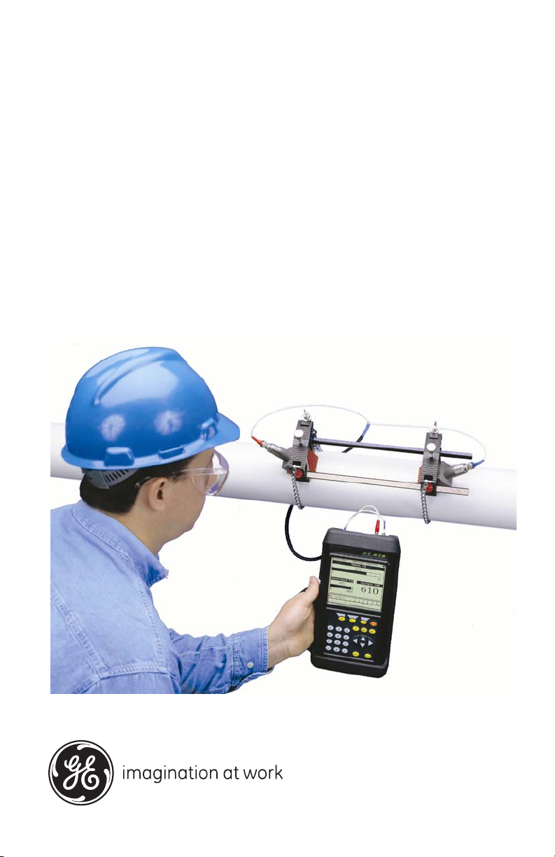
GE
Sensing & Inspection Technologies Flow
TransPort® Model PT878
Portable Liquid Flowmeter
User’s Manual
910-219 Rev. F
November 2009


GE
Sensing & Inspection Technologies
TransPort® Model PT878
Portable Liquid Flowmeter
User’s Manual
910-219 Rev. F
November 2009
GESensingInspection.com
©2009 General Electric Company. All rights reserved.
Technical content subject to change without notice.

[no content intended for this page — proceed to next page]
ii

Preface
Information Paragraphs
• Note paragraphs provide information that provides a deeper understanding of
the situation, but is not essential to the proper completion of the instructions.
• Important paragraphs provide information that emphasizes instructions that
are essential to proper setup of the equipment. Failure to follow these
instructions carefully may cause unreliable performance.
• Caution! paragraphs provide information that alerts the operator to a hazardous
situation that can cause damage to property or equipment.
• Warning! paragraphs provide information that alerts the operator to a
hazardous situation that can cause injury to personnel. Cautionary information
is also included, when applicable.
Safety Issues
WARNING! It is the responsibility of the user to make sure all local, county,
state and national codes, regulations, rules and laws related to
safety and safe operating conditions are met for each
installation.
Transport® Model PT878 Portable Liquid Flowmeter User’s Manual iii

Preface
Auxiliary Equipment
Local Safety Standards
The user must make sure that he operates all auxiliary equipment in accordance
with local codes, standards, regulations, or laws applicable to safety.
Working Area
WARNING! Auxiliary equipment may have both manual and automatic
modes of operation. As equipment can move suddenly and
without warning, do not enter the work cell of this equipment
during automatic operation, and do not enter the work
envelope of this equipment during manual operation. If you do,
serious injury can result.
WARNING! Make sure that power to the auxiliary equipment is turned OFF
and locked out before you perform maintenance procedures on
the equipment.
Qualification of Personnel
Make sure that all personnel have manufacturer-approved training applicable to the
auxiliary equipment.
Personal Safety Equipment
Make sure that operators and maintenance personnel have all safety equipment
applicable to the auxiliary equipment. Examples include safety glasses, protective
headgear, safety shoes, etc.
Unauthorized Operation
Make sure that unauthorized personnel cannot gain access to the operation of the
equipment.
iv Transport® Model PT878 Portable Liquid Flowmeter User’s Manual

Preface
Environmental Compliance
Waste Electrical and Electronic Equipment (WEEE) Directive
GE Sensing & Inspection Technologies is an active participant in Europe’s
Waste Electrical and Electronic Equipment (WEEE) take-back initiative,
directive 2002/96/EC.
The equipment that you bought has required the extraction and use of
natural resources for its production. It may contain hazardous substances
that could impact health and the environment.
In order to avoid the dissemination of those substances in our environment
and to diminish the pressure on the natural resources, we encourage you to
use the appropriate take-back systems. Those systems will reuse or recycle
most of the materials of your end life equipment in a sound way.
The crossed-out wheeled bin symbol invites you to use those systems.
If you need more information on the collection, reuse and recycling
systems, please contact your local or regional waste administration.
Visit http://www.gesensing.com/environment/weee.htm
for take-back
instructions and more information about this initiative.
Transport® Model PT878 Portable Liquid Flowmeter User’s Manual v

Preface
[no content intended for this page — proceed to next page]
vi Transport® Model PT878 Portable Liquid Flowmeter User’s Manual

Contents
Chapter 1. Features and Capabilities
1.1 Overview . . . . . . . . . . . . . . . . . . . . . . . . . . . . . . . . . . . . . . . . . . . . . . . . . . . . . . . . . . . . . . .1
1.2 System Description . . . . . . . . . . . . . . . . . . . . . . . . . . . . . . . . . . . . . . . . . . . . . . . . . . . . .2
1.2.1 The Flowcell . . . . . . . . . . . . . . . . . . . . . . . . . . . . . . . . . . . . . . . . . . . . . . . . . . . . .2
1.2.2 Electronics Package. . . . . . . . . . . . . . . . . . . . . . . . . . . . . . . . . . . . . . . . . . . . . .3
1.3 Theory of Operation . . . . . . . . . . . . . . . . . . . . . . . . . . . . . . . . . . . . . . . . . . . . . . . . . . . .4
Chapter 2. Initial Setup
2.1 Making Electrical Connections. . . . . . . . . . . . . . . . . . . . . . . . . . . . . . . . . . . . . . . . . . .6
2.1.1 Power Connections . . . . . . . . . . . . . . . . . . . . . . . . . . . . . . . . . . . . . . . . . . . . . .7
2.1.2 Transducer Connections . . . . . . . . . . . . . . . . . . . . . . . . . . . . . . . . . . . . . . . . .7
2.1.3 Input/Output Connections. . . . . . . . . . . . . . . . . . . . . . . . . . . . . . . . . . . . . . . .7
2.1.4 The Infrared Wireless Interface . . . . . . . . . . . . . . . . . . . . . . . . . . . . . . . . . . .8
2.2 Caring for the PT878 Batteries. . . . . . . . . . . . . . . . . . . . . . . . . . . . . . . . . . . . . . . . . . .9
2.2.1 Charging and Storing the Batteries . . . . . . . . . . . . . . . . . . . . . . . . . . . . . . .9
2.2.2 Replacing the Batteries. . . . . . . . . . . . . . . . . . . . . . . . . . . . . . . . . . . . . . . . . 10
2.2.3 Disposing of Batteries. . . . . . . . . . . . . . . . . . . . . . . . . . . . . . . . . . . . . . . . . . 11
2.3 Powering ON and OFF . . . . . . . . . . . . . . . . . . . . . . . . . . . . . . . . . . . . . . . . . . . . . . . . 12
2.4 Using the Screen and Keypad . . . . . . . . . . . . . . . . . . . . . . . . . . . . . . . . . . . . . . . . . 15
2.4.1 Screen. . . . . . . . . . . . . . . . . . . . . . . . . . . . . . . . . . . . . . . . . . . . . . . . . . . . . . . . . 15
2.4.2 Keypad. . . . . . . . . . . . . . . . . . . . . . . . . . . . . . . . . . . . . . . . . . . . . . . . . . . . . . . . 17
2.5 Obtaining On-Line Help . . . . . . . . . . . . . . . . . . . . . . . . . . . . . . . . . . . . . . . . . . . . . . . 19
Transport® Model PT878 Portable Liquid Flowmeter User’s Manual vii

Contents
Chapter 3. Programming Site Data
3.1 Entering the Program Menu . . . . . . . . . . . . . . . . . . . . . . . . . . . . . . . . . . . . . . . . . . . 22
3.2 Entering Transducer Parameters . . . . . . . . . . . . . . . . . . . . . . . . . . . . . . . . . . . . . . 23
3.2.1 Parameters for Special Transducers . . . . . . . . . . . . . . . . . . . . . . . . . . . . 26
3.2.2 Confirming Entries . . . . . . . . . . . . . . . . . . . . . . . . . . . . . . . . . . . . . . . . . . . . . 30
3.3 Entering Pipe Parameters . . . . . . . . . . . . . . . . . . . . . . . . . . . . . . . . . . . . . . . . . . . . . 30
3.4 Entering Pipe Lining Parameters. . . . . . . . . . . . . . . . . . . . . . . . . . . . . . . . . . . . . . . 35
3.5 Entering Fluid Types and Speeds . . . . . . . . . . . . . . . . . . . . . . . . . . . . . . . . . . . . . . 37
3.6 Entering the Signal Path Parameters. . . . . . . . . . . . . . . . . . . . . . . . . . . . . . . . . . . 39
3.6.1 Path Parameters for Clamp-On Transducers . . . . . . . . . . . . . . . . . . . . 40
3.6.2 Path Parameters for Wetted Transducers . . . . . . . . . . . . . . . . . . . . . . . 41
3.7 Entering the Energy Option Parameters. . . . . . . . . . . . . . . . . . . . . . . . . . . . . . . . 42
3.7.1 Entering Inputs in the Energy Option . . . . . . . . . . . . . . . . . . . . . . . . . . . . 44
3.7.2 Entering Custom Cp Data in the Energy Option . . . . . . . . . . . . . . . . . . 46
3.8 Entering Analog Inputs. . . . . . . . . . . . . . . . . . . . . . . . . . . . . . . . . . . . . . . . . . . . . . . . 50
3.8.1 Entering General-Purpose Analog Inputs . . . . . . . . . . . . . . . . . . . . . . . . 50
3.8.2 Entering Analog Inputs in the Energy Option. . . . . . . . . . . . . . . . . . . . . 52
3.9 Entering the Analog Output . . . . . . . . . . . . . . . . . . . . . . . . . . . . . . . . . . . . . . . . . . . 54
3.10Entering the Digital Output . . . . . . . . . . . . . . . . . . . . . . . . . . . . . . . . . . . . . . . . . . . . 57
3.11Entering User Functions. . . . . . . . . . . . . . . . . . . . . . . . . . . . . . . . . . . . . . . . . . . . . . . 61
3.11.1 Entering Correction Factors. . . . . . . . . . . . . . . . . . . . . . . . . . . . . . . . . . . . . 65
3.11.2 Entering Reynolds Correction . . . . . . . . . . . . . . . . . . . . . . . . . . . . . . . . . . . 65
3.11.3 Entering a Calibration Factor . . . . . . . . . . . . . . . . . . . . . . . . . . . . . . . . . . . 67
viii Transport® Model PT878 Portable Liquid Flowmeter User’s Manual

Contents
Chapter 4. Creating and Managing Sites
4.1 The Site Manager . . . . . . . . . . . . . . . . . . . . . . . . . . . . . . . . . . . . . . . . . . . . . . . . . . . . . 72
4.1.1 Creating a New Site . . . . . . . . . . . . . . . . . . . . . . . . . . . . . . . . . . . . . . . . . . . . 74
4.1.2 Opening an Existing Site. . . . . . . . . . . . . . . . . . . . . . . . . . . . . . . . . . . . . . . . 76
4.1.3 Saving a Site. . . . . . . . . . . . . . . . . . . . . . . . . . . . . . . . . . . . . . . . . . . . . . . . . . . 77
4.1.4 Saving a Site with a Different Name. . . . . . . . . . . . . . . . . . . . . . . . . . . . . 78
4.1.5 Refreshing a Site . . . . . . . . . . . . . . . . . . . . . . . . . . . . . . . . . . . . . . . . . . . . . . . 79
4.1.6 Renaming a Site . . . . . . . . . . . . . . . . . . . . . . . . . . . . . . . . . . . . . . . . . . . . . . . 79
4.1.7 Deleting a Site . . . . . . . . . . . . . . . . . . . . . . . . . . . . . . . . . . . . . . . . . . . . . . . . . 80
4.1.8 Creating a Site Message. . . . . . . . . . . . . . . . . . . . . . . . . . . . . . . . . . . . . . . . 81
4.1.9 Printing a Current Site . . . . . . . . . . . . . . . . . . . . . . . . . . . . . . . . . . . . . . . . . . 83
4.1.10 Transferring a Site File to a PC . . . . . . . . . . . . . . . . . . . . . . . . . . . . . . . . . . 83
4.1.11 Transferring a Site File in Text Format to a PC . . . . . . . . . . . . . . . . . . . 84
4.1.12 Transferring a File from a PC to the PT878. . . . . . . . . . . . . . . . . . . . . . . 85
4.1.13 Listing Files by Name. . . . . . . . . . . . . . . . . . . . . . . . . . . . . . . . . . . . . . . . . . . 88
4.1.14 Listing Files in Chronological Order. . . . . . . . . . . . . . . . . . . . . . . . . . . . . . 88
Chapter 5. Displaying and Configuring Data
5.1 The Format Option. . . . . . . . . . . . . . . . . . . . . . . . . . . . . . . . . . . . . . . . . . . . . . . . . . . . 90
5.2 The View Option . . . . . . . . . . . . . . . . . . . . . . . . . . . . . . . . . . . . . . . . . . . . . . . . . . . . . . 92
5.3 The Limits Option . . . . . . . . . . . . . . . . . . . . . . . . . . . . . . . . . . . . . . . . . . . . . . . . . . . . . 93
5.4 The Measurement Option . . . . . . . . . . . . . . . . . . . . . . . . . . . . . . . . . . . . . . . . . . . . . 95
5.5 Customizing the Display Screen . . . . . . . . . . . . . . . . . . . . . . . . . . . . . . . . . . . . . . . 97
5.5.1 Specifying the Number of Displayed Parameters . . . . . . . . . . . . . . . . 98
5.5.2 Customizing Softkeys . . . . . . . . . . . . . . . . . . . . . . . . . . . . . . . . . . . . . . . . . . 99
5.6 Managing Files — The Drive Manager . . . . . . . . . . . . . . . . . . . . . . . . . . . . . . . . . 102
5.6.1 Transferring a File to a PC . . . . . . . . . . . . . . . . . . . . . . . . . . . . . . . . . . . . . 104
5.6.2 Transferring a File from a PC to the PT878. . . . . . . . . . . . . . . . . . . . . . 105
5.6.3 Refreshing a File . . . . . . . . . . . . . . . . . . . . . . . . . . . . . . . . . . . . . . . . . . . . . . 107
5.6.4 Deleting a File . . . . . . . . . . . . . . . . . . . . . . . . . . . . . . . . . . . . . . . . . . . . . . . . 108
5.6.5 Listing Files by Name. . . . . . . . . . . . . . . . . . . . . . . . . . . . . . . . . . . . . . . . . . 109
5.6.6 Listing Files in Chronological Order. . . . . . . . . . . . . . . . . . . . . . . . . . . . . 109
5.7 Accessing Meter Data —The About Option . . . . . . . . . . . . . . . . . . . . . . . . . . . . 110
Transport® Model PT878 Portable Liquid Flowmeter User’s Manual ix

Contents
Chapter 6. Programming Meter Settings
6.1 Entering the Meter Menu . . . . . . . . . . . . . . . . . . . . . . . . . . . . . . . . . . . . . . . . . . . . . 112
6.2 Selecting Measurement Units . . . . . . . . . . . . . . . . . . . . . . . . . . . . . . . . . . . . . . . . 113
6.3 The Battery Charger . . . . . . . . . . . . . . . . . . . . . . . . . . . . . . . . . . . . . . . . . . . . . . . . . 114
6.4 Entering Date and Time . . . . . . . . . . . . . . . . . . . . . . . . . . . . . . . . . . . . . . . . . . . . . . 115
6.5 Changing Date and Time Appearance . . . . . . . . . . . . . . . . . . . . . . . . . . . . . . . . 117
6.6 Adjusting the Contrast . . . . . . . . . . . . . . . . . . . . . . . . . . . . . . . . . . . . . . . . . . . . . . . 120
6.7 Setting Backlight Timeout . . . . . . . . . . . . . . . . . . . . . . . . . . . . . . . . . . . . . . . . . . . . 121
6.8 Changing the Display Language. . . . . . . . . . . . . . . . . . . . . . . . . . . . . . . . . . . . . . 122
6.9 Changing Communications Settings . . . . . . . . . . . . . . . . . . . . . . . . . . . . . . . . . . 123
6.10Resetting Forward and Reverse Totals . . . . . . . . . . . . . . . . . . . . . . . . . . . . . . . . 126
6.11Setting Up User Tables . . . . . . . . . . . . . . . . . . . . . . . . . . . . . . . . . . . . . . . . . . . . . . . 127
6.12Taking a Bitmap Capture of a Current Screen . . . . . . . . . . . . . . . . . . . . . . . . . 130
x Transport® Model PT878 Portable Liquid Flowmeter User’s Manual

Contents
Chapter 7. Logging Data
7.1 Entering the Logging Menu. . . . . . . . . . . . . . . . . . . . . . . . . . . . . . . . . . . . . . . . . . . 132
7.2 The Log Manager . . . . . . . . . . . . . . . . . . . . . . . . . . . . . . . . . . . . . . . . . . . . . . . . . . . . 133
7.3 The File Menu. . . . . . . . . . . . . . . . . . . . . . . . . . . . . . . . . . . . . . . . . . . . . . . . . . . . . . . . 134
7.3.1 Setting up a New Log . . . . . . . . . . . . . . . . . . . . . . . . . . . . . . . . . . . . . . . . . 135
7.3.2 Copying (Cloning) a Selected Log . . . . . . . . . . . . . . . . . . . . . . . . . . . . . . 140
7.3.3 Renaming a Log . . . . . . . . . . . . . . . . . . . . . . . . . . . . . . . . . . . . . . . . . . . . . . 141
7.3.4 Deleting a Log . . . . . . . . . . . . . . . . . . . . . . . . . . . . . . . . . . . . . . . . . . . . . . . . 141
7.3.5 Deleting All Logs . . . . . . . . . . . . . . . . . . . . . . . . . . . . . . . . . . . . . . . . . . . . . . 142
7.3.6 Refreshing the Log Manager Screen . . . . . . . . . . . . . . . . . . . . . . . . . . . 142
7.3.7 Printing a Log. . . . . . . . . . . . . . . . . . . . . . . . . . . . . . . . . . . . . . . . . . . . . . . . . 143
7.3.8 Transferring a Log to a PC. . . . . . . . . . . . . . . . . . . . . . . . . . . . . . . . . . . . . 144
7.4 The Log Menu . . . . . . . . . . . . . . . . . . . . . . . . . . . . . . . . . . . . . . . . . . . . . . . . . . . . . . . 145
7.4.1 Stopping (Pausing) a Log . . . . . . . . . . . . . . . . . . . . . . . . . . . . . . . . . . . . . . 146
7.4.2 Restarting a Log . . . . . . . . . . . . . . . . . . . . . . . . . . . . . . . . . . . . . . . . . . . . . . 146
7.4.3 Ending a Log. . . . . . . . . . . . . . . . . . . . . . . . . . . . . . . . . . . . . . . . . . . . . . . . . . 146
7.4.4 Stopping All Logs. . . . . . . . . . . . . . . . . . . . . . . . . . . . . . . . . . . . . . . . . . . . . . 147
7.4.5 Restarting All Logs . . . . . . . . . . . . . . . . . . . . . . . . . . . . . . . . . . . . . . . . . . . . 147
7.4.6 Ending All Logs . . . . . . . . . . . . . . . . . . . . . . . . . . . . . . . . . . . . . . . . . . . . . . . 147
7.4.7 View All Sites . . . . . . . . . . . . . . . . . . . . . . . . . . . . . . . . . . . . . . . . . . . . . . . . . 147
7.5 The View Menu . . . . . . . . . . . . . . . . . . . . . . . . . . . . . . . . . . . . . . . . . . . . . . . . . . . . . . 148
7.5.1 Displaying Log Details. . . . . . . . . . . . . . . . . . . . . . . . . . . . . . . . . . . . . . . . . 149
7.5.2 Displaying Log Data in Graphical Form. . . . . . . . . . . . . . . . . . . . . . . . . 150
7.5.3 Displaying Log Data in Spreadsheet Form . . . . . . . . . . . . . . . . . . . . . . 153
7.6 The Sort Menu . . . . . . . . . . . . . . . . . . . . . . . . . . . . . . . . . . . . . . . . . . . . . . . . . . . . . . . 154
7.6.1 Listing Logs by Name . . . . . . . . . . . . . . . . . . . . . . . . . . . . . . . . . . . . . . . . . 154
7.6.2 Listing Logs in Chronological Order . . . . . . . . . . . . . . . . . . . . . . . . . . . . 154
Transport® Model PT878 Portable Liquid Flowmeter User’s Manual xi

Contents
Chapter 8. Servicing the PT878
8.1 Entering the Service Menu . . . . . . . . . . . . . . . . . . . . . . . . . . . . . . . . . . . . . . . . . . . 156
8.2 Printing Reports . . . . . . . . . . . . . . . . . . . . . . . . . . . . . . . . . . . . . . . . . . . . . . . . . . . . . 157
8.3 Setting up the Thickness Gauge . . . . . . . . . . . . . . . . . . . . . . . . . . . . . . . . . . . . . . 159
8.4 Measuring Pipe Wall Thickness . . . . . . . . . . . . . . . . . . . . . . . . . . . . . . . . . . . . . . . 160
8.4.1 Entering the Material and Soundspeed. . . . . . . . . . . . . . . . . . . . . . . . . 160
8.4.2 Measuring Thickness in Numeric Format . . . . . . . . . . . . . . . . . . . . . . . 162
8.4.3 Displaying the Receive Signal in Graphical Format . . . . . . . . . . . . . . 163
8.4.4 Calibrating the Thickness Gauge Transducer . . . . . . . . . . . . . . . . . . . 165
8.4.5 Calculating Velocity (Pipe Material Soundspeed) . . . . . . . . . . . . . . . . 168
8.5 Programming the Thickness Gauge. . . . . . . . . . . . . . . . . . . . . . . . . . . . . . . . . . . 170
8.6 Displaying Diagnostic Parameters . . . . . . . . . . . . . . . . . . . . . . . . . . . . . . . . . . . . 173
8.7 Calibrating the Analog Output and Inputs . . . . . . . . . . . . . . . . . . . . . . . . . . . . . 174
8.7.1 Calibrating the Analog Output . . . . . . . . . . . . . . . . . . . . . . . . . . . . . . . . . 174
8.7.2 Calibrating Inputs . . . . . . . . . . . . . . . . . . . . . . . . . . . . . . . . . . . . . . . . . . . . . 176
8.8 Setting up Signal Parameters. . . . . . . . . . . . . . . . . . . . . . . . . . . . . . . . . . . . . . . . . 178
8.8.1 Setting up Signal Parameters . . . . . . . . . . . . . . . . . . . . . . . . . . . . . . . . . . 179
8.8.2 Setting up Peak Detection . . . . . . . . . . . . . . . . . . . . . . . . . . . . . . . . . . . . . 181
8.8.3 Selecting the Transmit Code. . . . . . . . . . . . . . . . . . . . . . . . . . . . . . . . . . . 183
8.9 Setting Error Limits. . . . . . . . . . . . . . . . . . . . . . . . . . . . . . . . . . . . . . . . . . . . . . . . . . . 184
8.10The Test Option . . . . . . . . . . . . . . . . . . . . . . . . . . . . . . . . . . . . . . . . . . . . . . . . . . . . . . 187
8.10.1 Testing the Screen . . . . . . . . . . . . . . . . . . . . . . . . . . . . . . . . . . . . . . . . . . . . 188
8.10.2 Testing the Keys . . . . . . . . . . . . . . . . . . . . . . . . . . . . . . . . . . . . . . . . . . . . . . 189
8.10.3 Testing the Watchdog Timer Circuit. . . . . . . . . . . . . . . . . . . . . . . . . . . . 190
8.10.4 Setting Impulse Response . . . . . . . . . . . . . . . . . . . . . . . . . . . . . . . . . . . . . 191
8.10.5 Taking Wave Samples for Diagnosis . . . . . . . . . . . . . . . . . . . . . . . . . . . 192
8.10.6 Applying a Stored Signal for Diagnosis . . . . . . . . . . . . . . . . . . . . . . . . . 192
8.10.7 Testing the Battery . . . . . . . . . . . . . . . . . . . . . . . . . . . . . . . . . . . . . . . . . . . . 193
8.11Resetting to Factory Default Parameters. . . . . . . . . . . . . . . . . . . . . . . . . . . . . . 194
8.12Updating PT878 Software . . . . . . . . . . . . . . . . . . . . . . . . . . . . . . . . . . . . . . . . . . . . 195
8.12.1 Updating Software Via IrOBEX . . . . . . . . . . . . . . . . . . . . . . . . . . . . . . . . . 196
8.12.2 Updating Software Via IrCOMM . . . . . . . . . . . . . . . . . . . . . . . . . . . . . . . . 197
xii Transport® Model PT878 Portable Liquid Flowmeter User’s Manual

Contents
Chapter 9. Diagnostics and Troubleshooting
9.1 Error Code Messages . . . . . . . . . . . . . . . . . . . . . . . . . . . . . . . . . . . . . . . . . . . . . . . . 204
9.2 Displaying Diagnostic Parameters . . . . . . . . . . . . . . . . . . . . . . . . . . . . . . . . . . . . 206
9.3 Flowcell Problems . . . . . . . . . . . . . . . . . . . . . . . . . . . . . . . . . . . . . . . . . . . . . . . . . . . 208
9.3.1 Fluid Problems . . . . . . . . . . . . . . . . . . . . . . . . . . . . . . . . . . . . . . . . . . . . . . . . 208
9.3.2 Pipe Problems . . . . . . . . . . . . . . . . . . . . . . . . . . . . . . . . . . . . . . . . . . . . . . . . 209
9.4 Transducer Problems . . . . . . . . . . . . . . . . . . . . . . . . . . . . . . . . . . . . . . . . . . . . . . . . 210
9.4.1 Wetted Transducer Problems. . . . . . . . . . . . . . . . . . . . . . . . . . . . . . . . . . 210
9.4.2 Clamp-on Transducer Problems . . . . . . . . . . . . . . . . . . . . . . . . . . . . . . . 211
9.4.3 Relocating Transducers . . . . . . . . . . . . . . . . . . . . . . . . . . . . . . . . . . . . . . . 212
Chapter 10. Specifications
10.1Overall . . . . . . . . . . . . . . . . . . . . . . . . . . . . . . . . . . . . . . . . . . . . . . . . . . . . . . . . . . . . . . 213
10.1.1 Hardware Configuration . . . . . . . . . . . . . . . . . . . . . . . . . . . . . . . . . . . . . . 213
10.1.2 Size/Weight. . . . . . . . . . . . . . . . . . . . . . . . . . . . . . . . . . . . . . . . . . . . . . . . . . . 213
10.1.3 Enclosure. . . . . . . . . . . . . . . . . . . . . . . . . . . . . . . . . . . . . . . . . . . . . . . . . . . . . 213
10.1.4 Flow Accuracy (Velocity, % of reading): . . . . . . . . . . . . . . . . . . . . . . . . . 213
10.2Electrical . . . . . . . . . . . . . . . . . . . . . . . . . . . . . . . . . . . . . . . . . . . . . . . . . . . . . . . . . . . . 214
10.3Operational Specifications . . . . . . . . . . . . . . . . . . . . . . . . . . . . . . . . . . . . . . . . . . . 216
10.4Transducer . . . . . . . . . . . . . . . . . . . . . . . . . . . . . . . . . . . . . . . . . . . . . . . . . . . . . . . . . . 217
10.4.1 Clamp-On Ultrasonic Flow Transducers . . . . . . . . . . . . . . . . . . . . . . . . 217
10.4.2 Temperature Transducers . . . . . . . . . . . . . . . . . . . . . . . . . . . . . . . . . . . . . 217
10.5Pipe Size and Material . . . . . . . . . . . . . . . . . . . . . . . . . . . . . . . . . . . . . . . . . . . . . . . 217
10.5.1 Clamp-On Transducers: . . . . . . . . . . . . . . . . . . . . . . . . . . . . . . . . . . . . . . . 217
10.6Available Options . . . . . . . . . . . . . . . . . . . . . . . . . . . . . . . . . . . . . . . . . . . . . . . . . . . . 218
Transport® Model PT878 Portable Liquid Flowmeter User’s Manual xiii

Contents
Appendix A. Menu Maps
Appendix B. Measuring P and L Dimensions
Appendix C. Temperature Transmitter Installation
C.1 Guidelines for RTD Installation. . . . . . . . . . . . . . . . . . . . . . . . . . . . . . . . . . . . . . . . 243
C.2 Mounting RTDs on the Pipe . . . . . . . . . . . . . . . . . . . . . . . . . . . . . . . . . . . . . . . . . . . 244
C.2.1 Assembling the Clamping Fixture . . . . . . . . . . . . . . . . . . . . . . . . . . . . . . 244
C.2.2 Mounting the RTD to the Pipe . . . . . . . . . . . . . . . . . . . . . . . . . . . . . . . . . . 245
C.3 Making Electrical Connections. . . . . . . . . . . . . . . . . . . . . . . . . . . . . . . . . . . . . . . . 245
C.3.1 Connecting the RTD to the 4 to 20-mA Transmitter . . . . . . . . . . . . . 246
C.3.2 Connecting the Transmitter to the PT878. . . . . . . . . . . . . . . . . . . . . . . 247
Appendix D. Ultrasonic Thickness Gauge Theory of Operation
D.1 Factors Affecting Performance and Accuracy . . . . . . . . . . . . . . . . . . . . . . . . . 250
D.1.1 Transducer Positioning/Alignment . . . . . . . . . . . . . . . . . . . . . . . . . . . . . 251
D.1.2 Calibration. . . . . . . . . . . . . . . . . . . . . . . . . . . . . . . . . . . . . . . . . . . . . . . . . . . . 252
D.1.3 Taper or Eccentricity . . . . . . . . . . . . . . . . . . . . . . . . . . . . . . . . . . . . . . . . . . 252
D.1.4 Acoustic Properties of the Material . . . . . . . . . . . . . . . . . . . . . . . . . . . . . 252
Appendix E. Material Safety Data Sheet for Couplant
E.1 Product Identification . . . . . . . . . . . . . . . . . . . . . . . . . . . . . . . . . . . . . . . . . . . . . . . . 253
E.2 Hazardous Ingredients . . . . . . . . . . . . . . . . . . . . . . . . . . . . . . . . . . . . . . . . . . . . . . . 253
E.3 Physical Data (nominal) . . . . . . . . . . . . . . . . . . . . . . . . . . . . . . . . . . . . . . . . . . . . . . 254
E.4 Fire and Explosion Hazard Data . . . . . . . . . . . . . . . . . . . . . . . . . . . . . . . . . . . . . . 254
E.5 Reactivity Data . . . . . . . . . . . . . . . . . . . . . . . . . . . . . . . . . . . . . . . . . . . . . . . . . . . . . . 254
E.6 Health Hazard and First Aid Data . . . . . . . . . . . . . . . . . . . . . . . . . . . . . . . . . . . . . 255
E.7 Storage and Handling Information. . . . . . . . . . . . . . . . . . . . . . . . . . . . . . . . . . . . 255
E.8 Control Measures . . . . . . . . . . . . . . . . . . . . . . . . . . . . . . . . . . . . . . . . . . . . . . . . . . . . 256
Appendix F. Establishing IR Communications
Appendix G. Glossary
xiv Transport® Model PT878 Portable Liquid Flowmeter User’s Manual

Chapter 1. Features and Capabilities
Chapter 1. Features and Capabilities
The TransPort® Model PT878 is a transit-time flowmeter which combines
all the features of a full-size flowmeter with the advantages of a portable
instrument.
This section describes the TransPort features and general system, and
explains the theory of operation.
1.1 Overview
The PT878 measures the flow rate of acoustically conductive single-phase
fluids. This includes most clean liquids, sewage, some slurries, some
oil/water mixtures, and liquids with a small percentage of entrained gas
bubbles. The flowmeter provides one linear (0/4-20 mA) analog output of
flow velocities or volumetric flow rate of these fluids, measuring velocities
from ±0.03 to ±12 m/sec (±0.1 to ±40 ft/sec), along with one selectable
frequency output or pulsed totalizer output.
The PT878 also provides two 4 to 20-mA analog inputs in order to connect
temperature transmitters to measure energy flow rate of liquids. Energy
flow rate may be calculated for water, glycol, and water/glycol mixtures.
The PT878 has the ability to store site data in files which can be accessed at
a later time. Within the Main Menu, a set of forms (windows) asks you all
the necessary setup information for a particular site. Once the necessary
questions are answered, you simply save the information to a file.
The PT878 stores these files and other data in non-volatile memory, which
retains the information even if power is off. The flowmeter itself runs on
rechargeable or alkaline batteries for up to 10 hours.
This small lightweight flowmeter displays measurements in both numeric
and graphical form on a EL-backlit, 240 x 200 pixel LCD graphic screen.
The PT878 also has the capability of logging over 100,000 flow data points
internally.
Using an infrared communications port, the PT878 can transmit or print
logged data, as well as real time data and other stored data. It is also
computer-programmable via GE’s PanaView™ software.
Transport® Model PT878 Portable Liquid Flowmeter User’s Manual 1

Chapter 1. Features and Capabilities
1.1 Overview (cont.)
To assist you, the PT878 is fully equipped with context-sensitive on-line
help which is accessible at any time by simply pressing the “?” (Help) key.
Internal diagnostic and troubleshooting features help is olate and remedy
common flowcell and transducer problems.
The PT878 operates with all standard GE transducers — wetted, clamp-on,
®
hybrids (Pan-Adapta
plug), and buffered styles.
A built-in ultrasonic thickness gauge capability measures the pipe wall
thickness when used with the optional thickness transducer.
1.2 System Description
The PT878 is one part of the flowmeter system. The flowmeter system
consists of two essential subsystems: the flowcell and the electronics
package (the PT878).
1.2.1 The Flowcell
The flowcell is that part of the system that uses ultrasonic pulses to
interrogate the flow. It consists of the flowcell pipe and the transducers.
A. FLOWCELL PIPE — The flowcell can either be created in the existing
piping (for example, by inserting wetted transducers into the pipe, or
clamping non-wetted transducers onto the pipe), or inserted as a
substitute pipe section (spoolpiece). The flowcell must provide
mechanical support for the transducers and assure stable fluid conditions
for accurate flow measurement.
B. TRANSDUCERS — The transducers convert electrical energy into
ultrasonic pulses when in a transmit cycle, and convert the ultrasonic
pulses back to electrical energy when in a receive cycle. In other words,
they act like loudspeakers when transmitting the signal and microphones
when receiving it. In the PT878 system, each transducer acts as both a
receiver and transmitter, since a series of ultrasonic pulses are alternately
sent upstream and then downstream through the flowcell.
2 Transport® Model PT878 Portable Liquid Flowmeter User’s Manual

Chapter 1. Features and Capabilities
1.2.2 Electronics Package
The PT878 consists of circuits that generate, receive, and measure the travel
time of the ultrasonic pulses. It also contains a microcomputer that controls
operation and calculates flow measurement parameters. Specific circuits
function as follows:
• TRANSMIT SIGNAL GENERATOR — The transmit signal generator,
under control of the microcomputer and timing circuit, synthesizes the
signal that drives the transmitter.
• TRANSMITTER — The transmitter amplifies the signals from the
transmit signal generator to a signal that drives the transmit transducer.
• RECEIVER — The receiver amplifies the received signals to a level
suitable for the data acquisition circuitry.
• DATA ACQUISITION — The data acquisition circuitry digitizes the
received signal and stores it in a buffer for processing by the
microcomputer.
• TIMING CIRCUIT — The timing circuit generates the transmitter
frequency, receive window, controls the data acquisition circuit and the
direction of the transmission.
• MICROCOMPUTER — The microcomputer controls the PT878
flowmeter’s operation and calculates flow measurements derived from
the transmitted and digitized received signals. Also, the microcomputer
continually checks for faults and allows the use of built-in diagnostics for
troubleshooting.
• INPUT/OUTPUT — The input/output circuitry allows the flowmeter to
indicate the measured flow with the 0/4-20 mA current loop, and to
output to a printer or other remote device. The digital output supports
frequency or pulse output, as well as use as a gate input; it can also act as
a test point for triggering an oscilloscope from the transmit or receive
window.
Transport® Model PT878 Portable Liquid Flowmeter User’s Manual 3

Chapter 1. Features and Capabilities
1.3 Theory of Operation
The PT878 is a transit-time ultrasonic flowmeter. When ultrasonic pulses
are transmitted through a moving liquid, the pulses that travel in the same
direction as the fluid flow (downstream) travel slightly faster than the pulses
that travel against the flow (upstream). The PT878 uses various digital
signal processing techniques, including cross-correlation, to determine
transit times and then uses the transit times to calculate flow velocity.
During operation, two transducers serve as both ultrasonic signal generators
and receivers. When mounted on a pipe, they are in acoustic communication
with each other, so that each transducer can receive ultrasonic signals
transmitted by the other transducer. Each transducer thus functions as a
transmitter generating a certain number of acoustic pulses, and as a receiver
for an identical number of pulses.
The flowmeter measures the time interval between transmission and
reception of the ultrasonic signals in both directions. When the liquid in the
pipe is not flowing, the transit-time downstream equals the transit-time
upstream. When the liquid is flowing, the transit-time downstream is less
than the transit-time upstream. The difference between the downstream and
upstream transit-times is proportional to the velocity of the flowing liquid,
and its sign indicates the direction of flow.
4 Transport® Model PT878 Portable Liquid Flowmeter User’s Manual
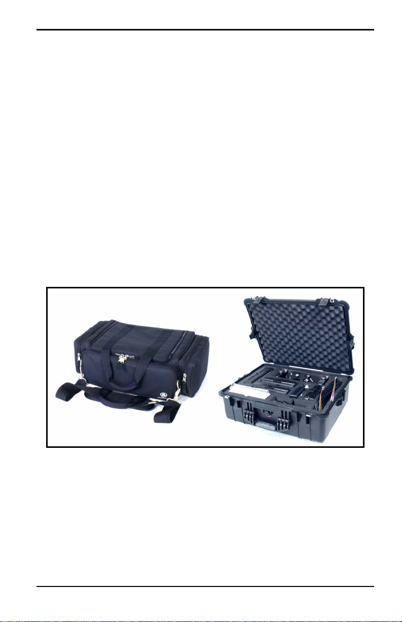
Chapter 2. Initial Setup
Chapter 2. Initial Setup
Before making measurements, you must prepare the PT878 for operation.
This includes the following procedures:
• Making Electrical Connections
• Charging and/or Replacing Batteries
• Powering On and Off
• Using the Screen and Keypad
• Obtaining On-Line Help
Figure 1 below shows the PT878 in its standard soft case (a) and in the
optional solid case (b). In the solid case, the interior is structured for optimal
protection of the PT878 and its accessories.
(a) (b)
Figure 1: The PT878 and Accessories
Transport® Model PT878 Portable Liquid Flowmeter User’s Manual 5
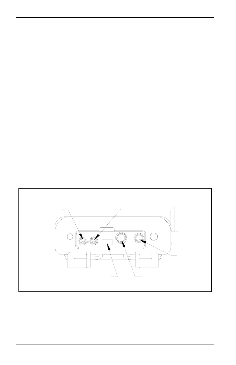
Chapter 2. Initial Setup
2.1 Making Electrical Connections
Before making measurements with the PT878, you must make all the
necessary connections to the unit. This section describes how to connect the
following:
• Power
• Transducers
• Input/Output
• Infrared Interface
Make all connections to the top of the PT878 unit as shown in Figure 2
below. Please note that you need to make the proper power and transducer
connections only. The other connections are required for particular
functions, but are not necessary for basic operation.
Note: For a listing of Input/Output connections, see Table 1 on page 8.
Transducer
Upstream
Infrared Transceiver
Downstream
Power
Input/Output
Figure 2: Connection Locations
6 Transport® Model PT878 Portable Liquid Flowmeter User’s Manual

Chapter 2. Initial Setup
2.1.1 Power Connections
The PT878 is powered by either a 100-120/200-260 VAC wall mount
plug-in module, or by 5 internal C
-size NiCad high-energy rechargeable
s
batteries or by a pack of 3.0 Ahr NiMH batteries. (An optional power
supplement, part #703-1283, uses 6 AA alkaline batteries.) When you
receive the PT878, the batteries are not charged; therefore, to make remote
measurements using the batteries, follow the instructions on page 9 to
charge the batteries. In either case, you must connect the power cord to the
appropriate terminal as shown in Figure 2 on page 6.
WARNING! To ensure the safe operation of the PT878, you must
install and operate it as described in this manual. In
addition, be sure to follow all applicable safety codes and
regulations for installing electrical equipment in your
area. The PT878 and its transducers are designed for use
only in general-purpose locations.
2.1.2 Transducer Connections
The transducer cables connect to the PT878 with LEMO® coaxial type
connectors. Each color-coded cable should have a collar labeled
UPSTREAM or DOWNSTREAM. Make transducer cable connections to
the top of the flowmeter as shown in Figure 2 on page 6. Because there are
various types of transducers and installations, transducer installation is
discussed separately in the Liquid Transducer Installation Guide (916-055).
2.1.3 Input/Output Connections
The PT878 provides one 0/4-20 mA current output and two 4 to 20-mA
analog inputs with switchable 16-V supply for loop- powered temperature
transmitters. It also supports digital, frequency, and totalizer outputs.
Connect the inputs/outputs using a LEMO
Figure 2 on page 6. The pin numbers for the connector and the color code
for the standard input/output cable are shown in Table 1 on page 8.
Transport® Model PT878 Portable Liquid Flowmeter User’s Manual 7
®
multi-pin connector as in

Chapter 2. Initial Setup
2.1.3 Input/Output Connections (cont.)
Table 1: Cable Assembly for Analog Inputs/Outputs
Pin
Number
Wire
Color Description
1 Black Analog Out 1
2 Red 16 V (switched)
3 White Supply or Return Temperature (Input A)
4 Yellow Supply or Return Temperature (Input B)
5 Green Analog Ground
6 Orange Digital Output (frequency output, pulse totalizer,
diagnostic output or calibration gate)
7 Blue Digital Ground
8 Violet Receive Monitor
2.1.4 The Infrared Wireless Interface
The PT878 comes equipped with an internal infrared transceiver (shown in
Figure 2 on page 6) that enables communication between the meter and
other IR devices, particularly the IR ports or dongles (IR to RS232 adapters)
of Windows
They can also program the meter using the optional PanaView software
interface. The PT878 was designed for use with products that comply to the
IrDA protocol. For more information on establishing IR communications
between the PT878 and your PC, refer to Appendix F.
®
-based PCs. Users can send and receive site and log data.
Note: The dongle connection is RS232. The configuration options are either
RS232 or IRDa. Selecting the RS232 does not
link the meter to the
dongle. IrDa must be selected for the link to work.
• To transfer files between the PT878 and PC, see Managing Files — the
Drive Manager on page 102.
• To transfer a log from the PT878 to a PC, see page 144.
8 Transport® Model PT878 Portable Liquid Flowmeter User’s Manual

Chapter 2. Initial Setup
2.2 Caring for the PT878 Batteries
The PT878 comes with self-contained, built-in rechargeable batteries to
support portable operation. For optimum performance, these batteries
require a minimum of maintenance.
CAUTION! Use only GE-approved batteries and desktop chargers.
These chargers are designed to maximize battery life.
Using other batteries or chargers voids the warranty and
may cause damage.
IMPORTANT: For CE compliance, the PT878 is classified as a
battery-powered device, not to be used with the AC
adaptor.
2.2.1 Charging and Storing the Batteries
When you receive the PT878, you will need to initially charge the batteries.
Also, the battery may need recharging if it has not been used for a long
period of time. The batteries must be charged up to 8 hours to receive the
maximum charge. When fully charged, the batteries provide 8 to 10 hours
of continuous operation. An internal battery gauge indicates the remaining
power in the batteries.
To charge the batteries, simply plug the AC power module cord into the
power jack (shown in Figure 2 on page 6) and be sure the battery pack is
installed. When the PT878 is plugged into line voltage, the internal battery
charger automatically charges the batteries, whether the PT878 is on or off.
If the PT878 is on, the Battery icon in the upper right corner of the screen
indicates battery status (as shown in Table 2 on page 10).
Note: For version 1B of the PT878 software, you must also press the red
power key in the upper right corner of the keypad. (See page 110 to
determine your software version.)
For optimal run time, charge the batteries only in temperatures from 50°F to
104°F (10°C to 40°C). Otherwise, the batteries will not be properly charged
and will have a significantly reduced run time.
Transport® Model PT878 Portable Liquid Flowmeter User’s Manual 9
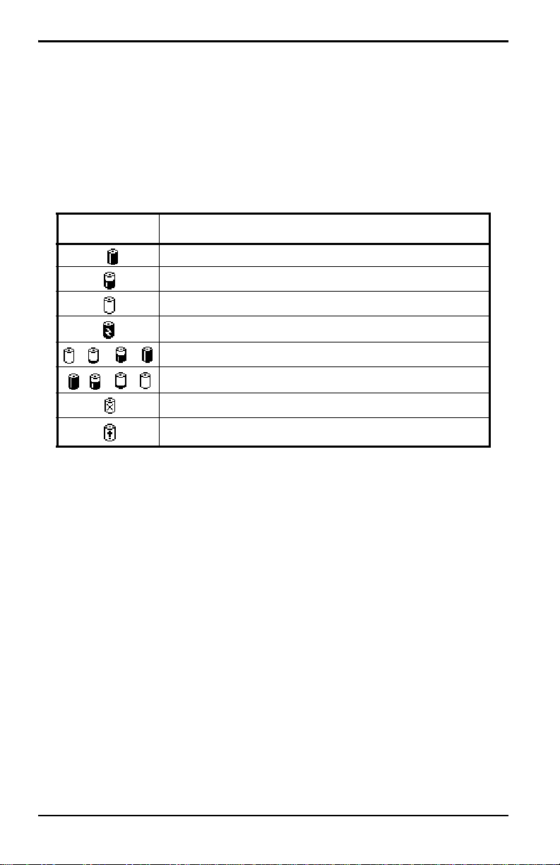
Chapter 2. Initial Setup
2.2.1 Charging and Storing the Batteries (cont.)
Store the batteries at temperatures from –4°F to 131°F (–20°C to 55°C) for
periods of less than one month, or from 32°F to 104°F (0°C to 40°C) for
longer periods. (If you are transporting them for two days or less, the
batteries can withstand temperatures from –40°F to 158°F (–40°C to 70°C).
Table 2: Battery Status Icons
Icon Battery Status
Full battery
Partially full battery
Empty battery
Fully charged battery, connected to AC power
Charging battery
Discharging battery
Failure/missing battery
Notification to check battery form (see page 114)
2.2.2 Replacing the Batteries
CAUTION! Replace batteries only with the specified rechargeable
batteries. The battery charges when the unit is off. Do not
attempt to recharge non-rechargeable batteries.
If you need to replace the rechargeable batteries, use the recommended 3.0
Ahr NiMH batteries (part number 200-081). While the batteries can be
recharged up to 600 times, it is best to replace them when they no longer
provide acceptable performance. T o replace the batteries, remove the rubber
boot, open the panel located on the back of the PT878 unit, disconnect the
batteries, and replace with new ones (see Figure 3 on page 11).
10 Transport® Model PT878 Portable Liquid Flowmeter User’s Manual
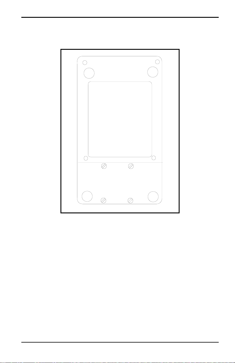
2.2.2 Replacing the Batteries (cont.)
Battery Location
(behind panel)
Chapter 2. Initial Setup
Figure 3: Battery Location
To further extend the battery power on the PT878, the GE Part #705-1283
option uses 6 AA alkaline batteries.
2.2.3 Disposing of Batteries
CAUTION! Never dispose of the batteries by incineration. Do not
attempt to disassemble or short-circuit the batteries. For
safety. do not handle a damaged or leaking battery.
IMPORTANT: Be sure to dispose of your battery properly. In some areas,
battery disposal in business or household trash may be
prohibited. For safe disposal options, contact your nearest
GE-authorized service center.
Transport® Model PT878 Portable Liquid Flowmeter User’s Manual 11

Chapter 2. Initial Setup
2.3 Powering ON and OFF
To operate the PT878, the power cord must be plugged into line voltage or
the battery must be charged as described previously.
IMPORTANT: For CE compliance, the PT878 is classified as a
battery-powered device, not to be used with the AC adapter.
To comply with CE certification, do not operate the meter
with the charger plugged in.
T o turn the PT878 on, press the red button in the upper-right-hand corner of
the keypad. Immediately upon power up the PT878 emits a short beep and
displays a “PCI Loader” message. It then validates the instrument
programming, and then displays the GE logo and the software version and
emits a long beep. If the meter fails any of these tests, contact the factory.
WARNING! If the meter fails the backup battery test, you must send
the unit back to the factory for a battery replacement.
Make sure you keep the batteries charged until you are
ready to ship the unit back to the factory. Before shipping,
print out all the log and site data, or transfer it to your PC.
12 Transport® Model PT878 Portable Liquid Flowmeter User’s Manual
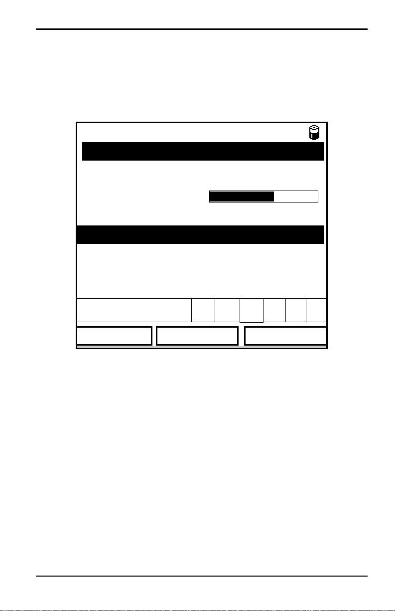
Chapter 2. Initial Setup
2.3 Powering ON and OFF (cont.)
After the meter conducts all the self checks, the screen then appears similar
to the one shown in Figure 4 below.
ABC.SIT
Velocity, ft/s
0.00
Delta-T, ns
E0: No Errors
Figure 4: Screen After Powering ON
0.10
2000/11/30 09:53 AM
Signal, dB
32
Volume, l/s
0.0
Transport® Model PT878 Portable Liquid Flowmeter User’s Manual 13
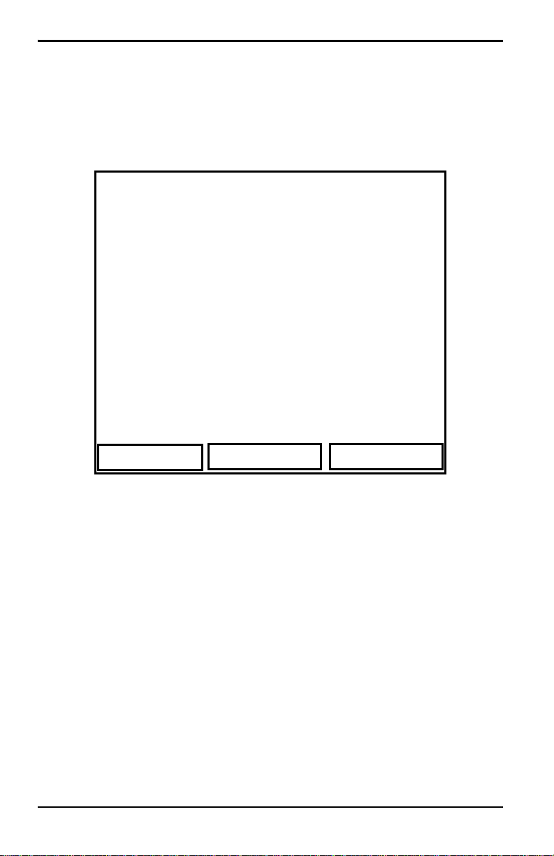
Chapter 2. Initial Setup
2.3 Powering ON and OFF (cont.)
To turn the PT878 off, press the red key for 3 seconds. The screen now
appears similar to Figure 5 below.
Velocity, ft/s
SHUTDOWN: Meter OFF
Signal, dB
SLEEP: Meter Idle
CANCEL: Resume Operations
Delta-T, ns
Shutdown
Figure 5: Shutdown Menu
Three options are available:
Sleep
Volume, l/s
Resume
• Press [F1] to shut down the PT878, turning it completely off.
• Press [F2] to send the PT878 into sleep mode. In this mode, some of the
power supplies shut down, but the PT878 remains in a standby mode.
Users can resume taking measurements immediately by pressing the
power button.
• Press [F3] to cancel the command and return the PT878 to normal
operation.
If the PT878 locks up, you can reset it by holding the power key (the red key
in the upper right corner) for 15 seconds.
14 Transport® Model PT878 Portable Liquid Flowmeter User’s Manual
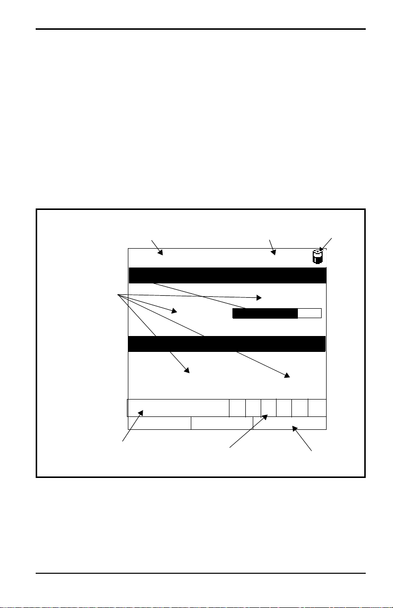
Chapter 2. Initial Setup
2.4 Using the Screen and Keypad
The essential features for operating the PT878 are the screen and keypad.
Although these features are common on portable instruments, the PT878
design offers particular features to simplify and speed operation.
2.4.1 Screen
The primary function of the screen is to display information in order for you
to accurately and easily take measurements. The PT878 screen consists of
seven parts (see Figure 6 below).
Current Site
Measurements
Error Messages
Figure 6: PT878 Screen in Operate Mode
(alternates with Menu Bar)
DEFAULT
Velocity, ft/s
0.00
Delta-T, ns
0.10
E0: No Errors
Status Bar
2000/11/30 09:53 AM
System Tray
Battery
Status
Signal, dB
32
Volume, l/s
0.0
Function Keys
The top line of the screen is the status bar, which normally displays the
time and date. However, when you press
Bar replaces the status line.
Transport® Model PT878 Portable Liquid Flowmeter User’s Manual 15
[MENU] (the menu key), the Menu
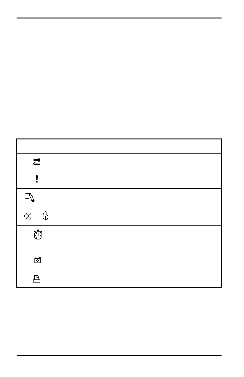
Chapter 2. Initial Setup
2.4.1 Screen (cont).
The middle of the screen shown in Figure 6 on page 15 is the work area,
which displays the measured parameters, numeric measurements, and both
bar and line graphs. (When you enter a selection on the Menu Bar discussed
in Chapter 3, Programming Site Data, this area displays menu prompts.) A
line at the bottom of the area also displays error code messages, which are
described in more detail in Chapter 9, Diagnostics and Troubleshooting.
The system tray displays icons that indicate meter operations not otherwise
shown. Table 3 below lists the icons and their meanings.
Table 3: Icons in the System Tray
Icon Function Meaning
IR Transfer IR data transfer in progress.
Alert Indicates the meter encountered an
error in operation.
Log Indicates a log is pending (no marks)
or running (marks).
Heating/
cooling
Stopwatch Calibration Gate Operation: Watch is
Snapshot
(To file)
(To Printer)
Indicates heating or cooling energy
mode.
stopped when the gate is closed, or
runs when it is open.
Indicates that the Snapshot function
has been activated, so users can take
screen captures (see page 130).
The bottom of the screen displays the three function key options: F1, F2
and F3. These keys have different functions, depending on the task you are
performing.
16 Transport® Model PT878 Portable Liquid Flowmeter User’s Manual

Chapter 2. Initial Setup
2.4.2 Keypad
The PT878 keypad has 25 keys. The functions for each key are as follows
(see Figure 7 on page 18):
• 3 function keys ([F1], [F2], [F3]) — enable you to select the special
functions which appear at the bottom of the screen.
• 12 numeric keys (including – and .) — enable you to enter numeric data.
• 4 arrow keys ([W], [X], [S], [T]) — enable you to move through the
menu options.
• [?] Help key— enables you to access on-line help (discussed on
page 19).
• [MENU] Menu key — enables you to access the Main Menu.
• [ENTER] — enables you to enter a particular menu, and enters selected
values into the PT878 memory.
• [SEL] — enables you to move between data measurements on the screen.
• [ESC] — enables you to exit menus or me nu options at any time; cancels
a numeric entry.
• Red key [ ] — turns the power on or off, and toggles the backlight on
or off.
Transport® Model PT878 Portable Liquid Flowmeter User’s Manual 17
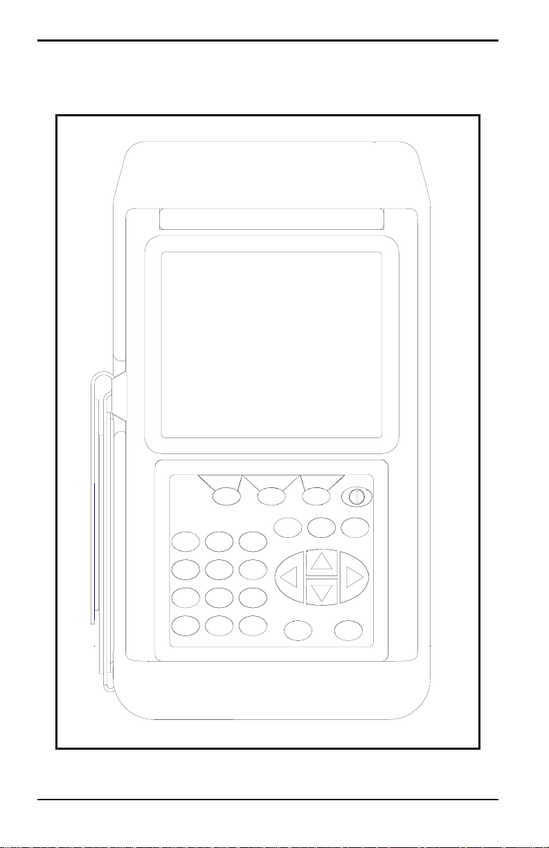
Chapter 2. Initial Setup
2.4.2 Keypad (cont.)
PT878
?
MENU
F3
ESC
SEL
ENTER
F1
2
1
4
5
8
7
0
•
F2
3
6
9
–
Figure 7: PT878 Keypad
18 Transport® Model PT878 Portable Liquid Flowmeter User’s Manual
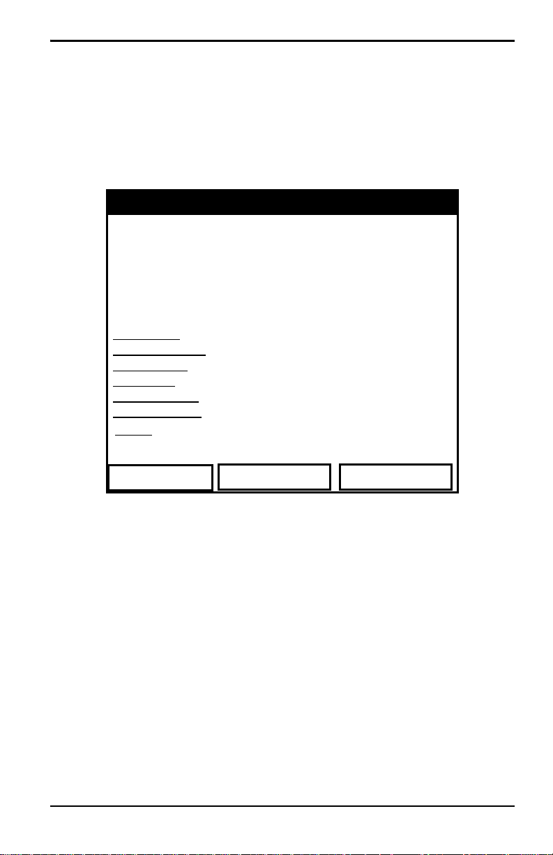
Chapter 2. Initial Setup
2.5 Obtaining On-Line Help
The PT878 offers context-sensitive on-line help screens that describe
various features. You can access on-line help at any time by pressing the [?]
key. The screen appears similar to Figure 8 below.
Help
Velocity, ft/s
Use the arrows and the enter key to
select from the links below. Press [F2]
to return to the TOC.
Site Menu
Program Menu
Meter Menu
Log Menu
Service Menu
Miscellaneous
About
Back TOC
Table of Contents
Signal, dB
Close
Figure 8: Main Help Menu
Use the three function keys and the [
S] and [T] arrow keys to navigate to
the desired menu, and press [ENTER]. Repeat this procedure to access the
desired topic within the menu. When you have finished using the Help
menu:
• Press [F1], Back, to move back one level.
• Press [F2], TOC, to return to the Table of Contents.
• Press [F3], Close, to return to the previous screen.
Transport® Model PT878 Portable Liquid Flowmeter User’s Manual 19

Chapter 2. Initial Setup
[no content intended for this page — proceed to next page]
20 Transport® Model PT878 Portable Liquid Flowmeter User’s Manual

Chapter 3. Programming Site Data
Chapter 3. Programming Site Data
On the PT878, a Program Menu (part of the Main Menu) enables you to
enter information that is specific to each site:
• Transducer types and paths
• Pipe materials and linings
• Fluid types
• Heating or cooling energy flow rate
• Analog input and output parameters
• Digital output parameters
• User functions
• Correction factors
For immediate operation, the PT878 requires only transducer, pipe and fluid
data. However, additional information allows you to tailor measurements as
specifically as possible to your particular application. Once you have
entered this data, you can save it in files and recall these files for later use.
The PT878 can store up to 1 MB (or 32 site files) of data in the meter at any
one time. But through the infrared link, users can store an unlimited number
of sites in a PC, and then upload the sites they will actually use.
This chapter covers entering:
• Transducer, pipe, and fluid parameters
• Input/output and other setup parameters
• User functions.
Transport® Model PT878 Portable Liquid Flowmeter User’s Manual 21
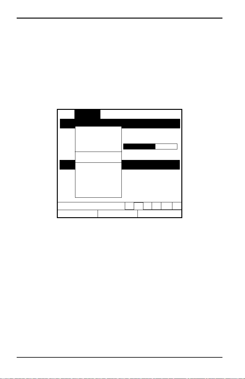
Chapter 3. Programming Site Data
3.1 Entering the Program Menu
To enter the Program Menu, press the [MENU] key at the lower right of the
PT878 keypad. The Menu Bar replaces the Status Bar at the top of the
screen. Press the [
Program Menu. At the Program Menu, press
similar to Figure 9 below. While following the programming instructions,
see Figure 139 on page 222 of Appendix A, Me nu Ma ps .
X] arrow key once to scroll from the Site Menu to the
[ENTER]. The screen appears
Site Program Meter Logging Service
Transducer
Vel
ocity, ft/s
Pipe
Lining
Fluid
0.00
Path
Energy
Delta
-T, ns
Analog Input
Analog Output
Digital Output
User Functions
0.10
Co
Correction Factors
Signal, dB
32
Volume, l/s
0.0
E0: No Errors
Figure 9: Program Menu
To scroll to a particular option, press the [
T]or [S] arrow keys until you
reach the option. Then press [ENTER] to open the option window.
When entering parameters in an option, press:
• The [T] key to step through the available parameters
• The [S] key to scroll back to a previously entered parameter
• The [F2] key (Cancel) or the [ESC] key to exit an option at any time and
return to Operate Mode without changing the parameters.
Note: If you enter an incorrect numeric value, press the [W] key to erase
the last digit entered.
22 Transport® Model PT878 Portable Liquid Flowmeter User’s Manual
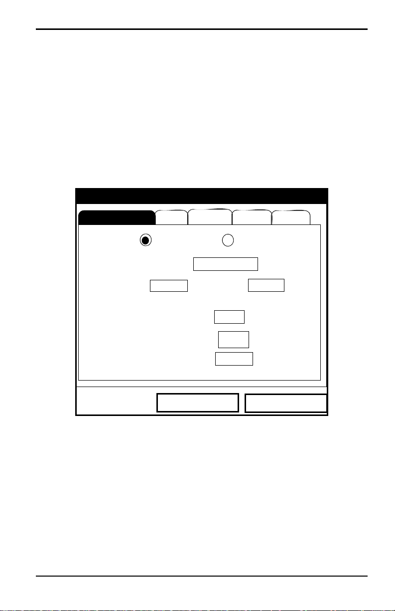
Chapter 3. Programming Site Data
3.2 Entering Transducer Parameters
To enter the Transducer option, scroll to the Transducer entry on the
Program Menu and press
below. To step through each parameter, press the [
Figure 143 on page 227 of Appendix A.
Note: Refer to the Liquid Transducer Installation Guide (916-055) for
additional information about transducers and configurations.
.
[ENTER]. The screen appears similar to Figure 10
T] key. Refer to
Transducer/Pipe
Transducer
Type: Wetted
Frequency
Pipe
Transducer
2.00
Wedge Ang
Wedge Tmp
Wedge SS
Cancel
Lining Path
Fluid
Clamp-on
Special
MHz
Tw
50
25
1219.2
°
°C
14
m/s
µs
OK
Figure 10: Transducer Option Window
1. Th e first prompt asks you to select whether you are using a wetted or a
clamp-on transducer.
a. Use the [W] and [X] keys to scroll between the two types.
b. Press [ENTER] to confirm the choice.
Transport® Model PT878 Portable Liquid Flowmeter User’s Manual 23

Chapter 3. Programming Site Data
3.2 Entering Transducer Parameters (cont.)
Note: The choices made early in the Transducer and Pipe options
determine the prompts available later. If the PT878 does not scroll to
a particular parameter, it is not necessary for that transducer or pipe
type. For example, the Lining window is not available if you select a
wetted transducer.
2. The next prompt asks you to enter the transducer number (printed on
the transducer itself), or to specify that you are using a special
application transducer.
a. From the Type prompt, press the [T] key to reach the Transducer
prompt, and press
b. A drop-down list of transducer numbers opens as in Figure 11 on
page 25. (The list varies, depending on whether you have selected
wetted or clamp-on in the previous prompt. See Table 4 on page 25.)
Press the [
T] or [S] keys to scroll to the appropriate number, or
scroll to “Special” for a special application transducer. To speed
scrolling, you can press the [
W] key to scroll up by a page.
[
[ENTER].
X] key to scroll down by a page, or the
c. Press [ENTER] to confirm your selection.
The program now varies, depending on whether you have selected standard
or special transducers.
• If you have selected a standard wetted or clamp-on transducer, the
PT878 comes programmed with the needed parameters. Proceed to
Confirming Entries on page 30.
• However, if you have selected a special application transducer, go to
page 26.
24 Transport® Model PT878 Portable Liquid Flowmeter User’s Manual
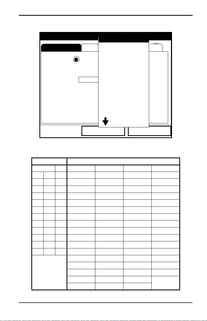
Chapter 3. Programming Site Data
Transducer
Transducer/Pipe
Pipe
SPECIAL
#40
Lining Path
Fluid
#41
Type: Wetted
Transducer
Frequency
2.00
#42
#43
Special
#44
MHz
#45
Clamp-on
Tw
14
µs
#46
Wedge Ang
Wedge Tmp
Wedge SS
#48
#49
Cancel
#47
50
25
1219.2
°C
m/s
OK
°
Figure 11: Transducer Numbers Drop-Down List
Table 4: Transducer Numbers Available
WETTED CLAMP-ON
SPECIAL 64 SPECIAL 23 (Shear) 113 (Shear) 307 (Shear)
40 52 65 1 (Rayleigh) 24 (Shear) 114 (Shear) 308 (Shear)
41 53 66 2 (Rayleigh) 25 (Shear) 115 (Shear) 309 (Shear)
42 54 67 3 (Rayleigh) 26 (Shear) 116 (Shear) 310 (Shear)
43 55 68 10 (Shear) 27 (Shear) 117 (Shear) 311 (Shear)
44 56 69 10 (Shear) 28 (Shear) 125 (Shear) 312 (Shear)
45 57 70 11 (Shear) 29 (Shear) 126 (Shear) 313 (Shear)
46 58 71 12 (Shear) 30 (Shear) 127 (Shear) 314 (Shear)
47 59 72 13 (Shear) 31 (Shear) 133 (Shear) 315 (Shear)
48 60 73 14 (Shear) 32 (Shear) 136 (Shear) 401 (Shear)
49 61 74 15 (Shear) 33 (Shear) 137 (Shear) 402 (Shear)
50 62 75 16 (Shear) 34 (Shear) 139 (Shear) 403 (Shear)
51 63 76 17 (Shear) 35 (Shear) 301 (Shear) 407 (Shear)
18 (Shear) 36 (Shear) 302 (Shear) 408 (Shear)
19 (Shear) 37 (Shear) 303 (Shear) 409 (Shear)
20 (Shear) 38 (Shear) 304 (Shear) 410 (Shear)
21 (Shear) 39 (Shear) 305 (Shear)
22 (Shear) 112 (Shear) 306 (Shear)
Transport® Model PT878 Portable Liquid Flowmeter User’s Manual 25

Chapter 3. Programming Site Data
3.2.1 Parameters for Special Transducers
Note: The factory will supply the information required below with the
transducers.
3. The prompt asks for the transducer frequency, to transmit a signal at a
frequency to which the transducer can respond.
a. From the Transducer prompt, press the [T] key to reach the
Frequency prompt, and press
b. A drop-down list of five frequencies opens, ranging from 0.50 to
4.00 MHz. Scroll to the desired frequency, and press
4. The next prompt asks for Tw, the time delay. This parameter is actually
the time the transducer signal spends travelling through the transducer
and cable. The PT878 calculates the flow rate from the upstream and
downstream transit times in the fluid, so the Tw (time delay) must be
subtracted out for an accurate measurement. The factory supplies the
time delay on a sheet of paper inside the transducer case.
a. From the Frequency prompt, press the [X] key to reach the Tw
prompt, and press
[ENTER].
[ENTER].
[ENTER].
b. Use the numeric keys to enter the GE-supplied time delay and press
[ENTER].
The program now varies, depending on whether you have selected a wetted
or a clamp-on transducer.
• If you have selected a special wetted transducer, proceed to
Confirming Entries on page 30.
• Special clamp-on transducers require three more inputs: wedge
angle, wedge temperature, and wedge soundspeed.
5. When calculating the flow rate, the PT878 must take into account the
wedge angle, the angle of the ultrasonic transmission.
a. From the Tw prompt, press the [T] key to reach the Wedge Angle
prompt, and press
b. Use the numeric keys to enter the factory-supplied wedge angle (in
degrees) and press
26 Transport® Model PT878 Portable Liquid Flowmeter User’s Manual
[ENTER].
[ENTER].
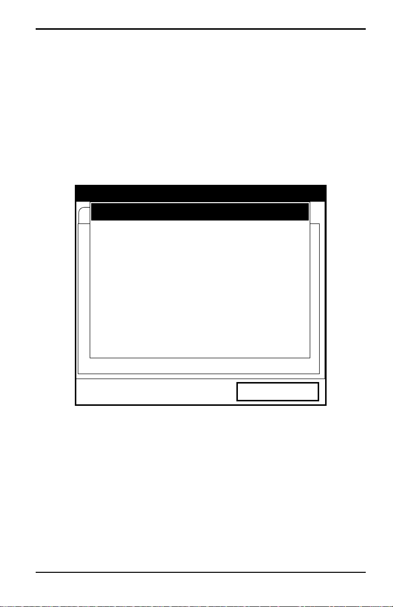
Chapter 3. Programming Site Data
3.2.1 Parameters for Special Transducers (cont.)
Note: If the error message in Figure 12 below, or one similar to Figure 13
on page 28 appears, the Pipe Soundspeed, Wedge Soundspeed,
and/or the Wedge Angle may be in error. Review the pipe and wedge
parameters currently entered and change one or more as necessary.
Note: To change pipe information, see Entering Pipe Parameters on
page 30.
Transducer/Pipe
* * * WARNING * * *
Critical Angle Exceeded!
Check Angles, Soundspeed!!!!!!!!
Cancel
OK
Figure 12: High Angle Error Message Window
Transport® Model PT878 Portable Liquid Flowmeter User’s Manual 27
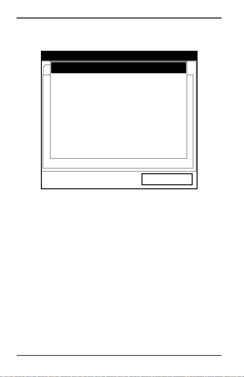
Chapter 3. Programming Site Data
3.2.1 Parameters for Special Transducers (cont.)
Transducer/Pipe
Invalid Value — Too Low
15 is Too Low.
The valid range is from:
25.000 to 90.000 °
Cancel
OK
Figure 13: Low Angle Error Message Window
Note: When the corrected information is entered, a message similar to
Figure 14 appears. Press [F3] (OK).
28 Transport® Model PT878 Portable Liquid Flowmeter User’s Manual

Chapter 3. Programming Site Data
3.2.1 Parameters for Special Transducers (cont.)
Transducer/Pipe
* * * WARNING * * *
Transducer Spacing has changed!
New Spacing:
0.964 inches ( 24.493 mm)
Cancel
OK
Figure 14: Transducer Spacing Change Window
6. The PT878 must also take into account the wedge temperature.
a. From the Wedge Angle prompt, press the [T] key to reach the
Wedge Temperature prompt, and press
b. Use the numeric keys to enter the wedge temperature (in degrees F
or C) and press
7. Finally, the PT878 requires the wedge soundspeed.
a. From the Wedge Temp prompt, press the [T] key to reach the
Wedge SS prompt, and press
b. Use the numeric keys to enter the factory-supplied wedge
[ENTER].
[ENTER].
soundspeed (in ft/sec or m/sec) and press
[ENTER].
[ENTER].
Pressing the [T] key returns the meter to the Transducer tab at the top.
Transport® Model PT878 Portable Liquid Flowmeter User’s Manual 29
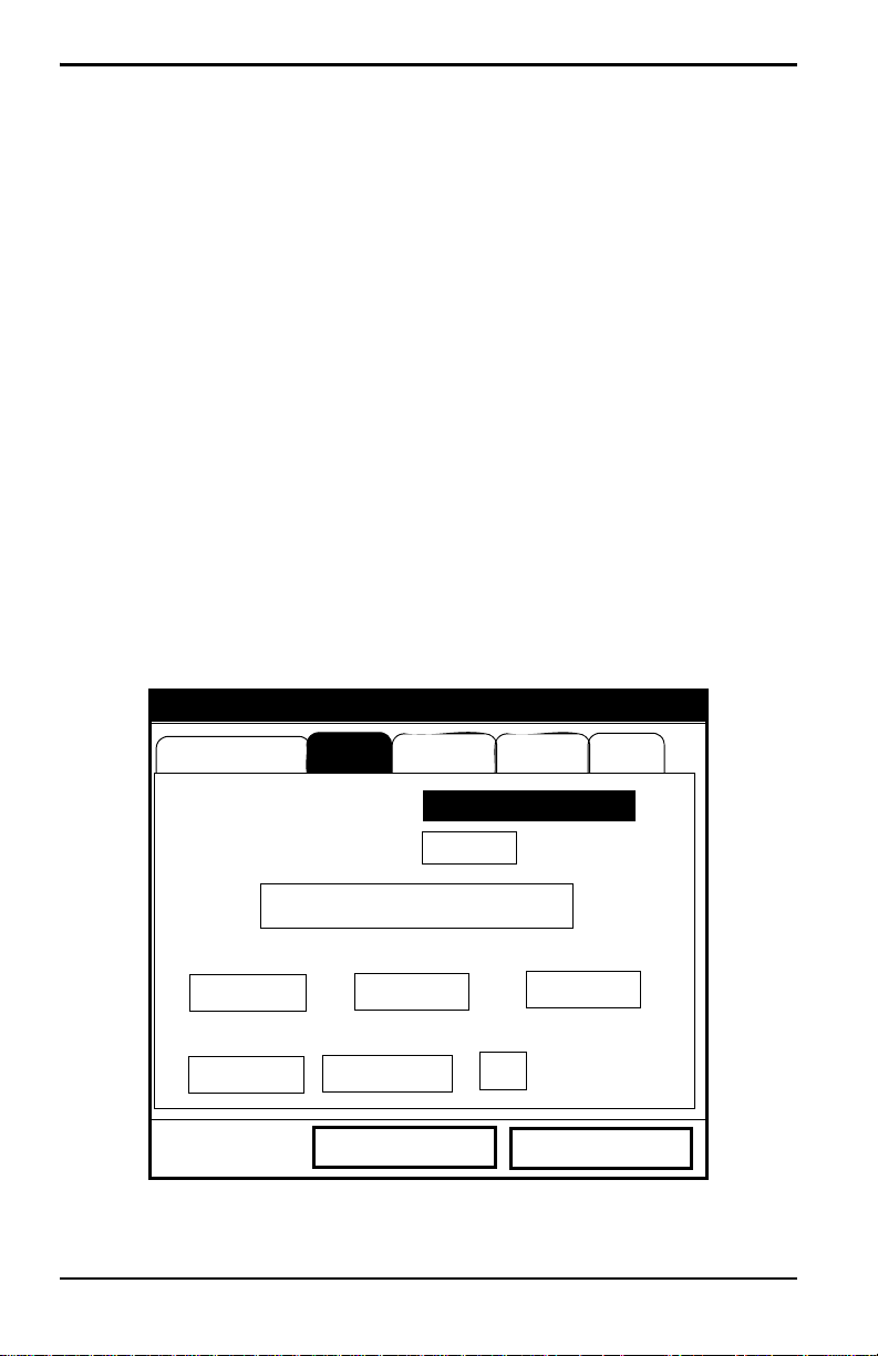
Chapter 3. Programming Site Data
3.2.2 Confirming Entries
• To confirm the entries and return to Operate mode, press [F3] (OK).
• To leave the window without confirming the entries, press [F2] (Cancel)
or the
[ESC] key.
In either case, the PT878 returns to Operate Mode.
3.3 Entering Pipe Parameters
To enter the Pipe option, scroll to the Pipe entry on the Program Menu and
[ENTER]. (From the Transducer window , you can scroll back up to the
press
Transducer tab and press the [
press
[ENTER].) The screen appears similar to Figure 15 below. To step
through each parameter, press the [
of Appendix A, Menu Maps.
Note: Refer to the brochure Soundspeeds and Pi pe Size Data (9 14 -004 ) for
additional information about pipe sizes and soundspeeds.
X] arrow key to reach the Pipe window, and
T] key . Refer to Figure 139 on page 222
Transducer/Pipe
Transducer
Sound Speed
Pipe Fluid
Material
Lining
Other
600.3
Path
m/s
Measure Wall with TGauge
OD, mm
5
Nominal
OD x PI, mm
15.708
Schedule
Wall, mm
2
ANSI
Cancel
OK
Figure 15: Pipe Option Window
30 Transport® Model PT878 Portable Liquid Flowmeter User’s Manual

Chapter 3. Programming Site Data
3.3 Entering Pipe Parameters (cont.)
1. The first prompt asks you to select the pipe material.
a. Press [ENTER] to enter the material prompt.
b. A drop-down list of materials opens. Table 5 below lists the
available preprogrammed materials on the list. Press the [
keys to scroll to the appropriate material, or scroll to “Other” for a
material not on the list. You can press the [
a page, or the [
W] key to scroll up by a page.
Table 5: Preprogrammed Pipe Materials
Pipe Material
Category Specific Material
Al — Aluminum Rolled
Brass None
Cu — Copper Annealed or Rolled
CuNi — Copper/Nickel 70% Cu 30% Ni or 90% Cu 10% Ni
Glass Pyrex, Flint, or Crown
Gold Hard-drawn
Inconel None
Iron Armco, Ductile, Cast, Electrolytic
Monel None
Nickel None
Plastic
Nylon, Polyethylene, Polypropylene, PVC
(CPVC), or Acrylic
Steel Carbon Steel or Stainless Steel
Tin Rolled
Titanium None
Tungsten Annealed, Carbide, Drawn
Zinc Rolled
Other* Any material
X] key to scroll down by
T] or [S]
c. Press [ENTER] to confirm the choice.
Transport® Model PT878 Portable Liquid Flowmeter User’s Manual 31
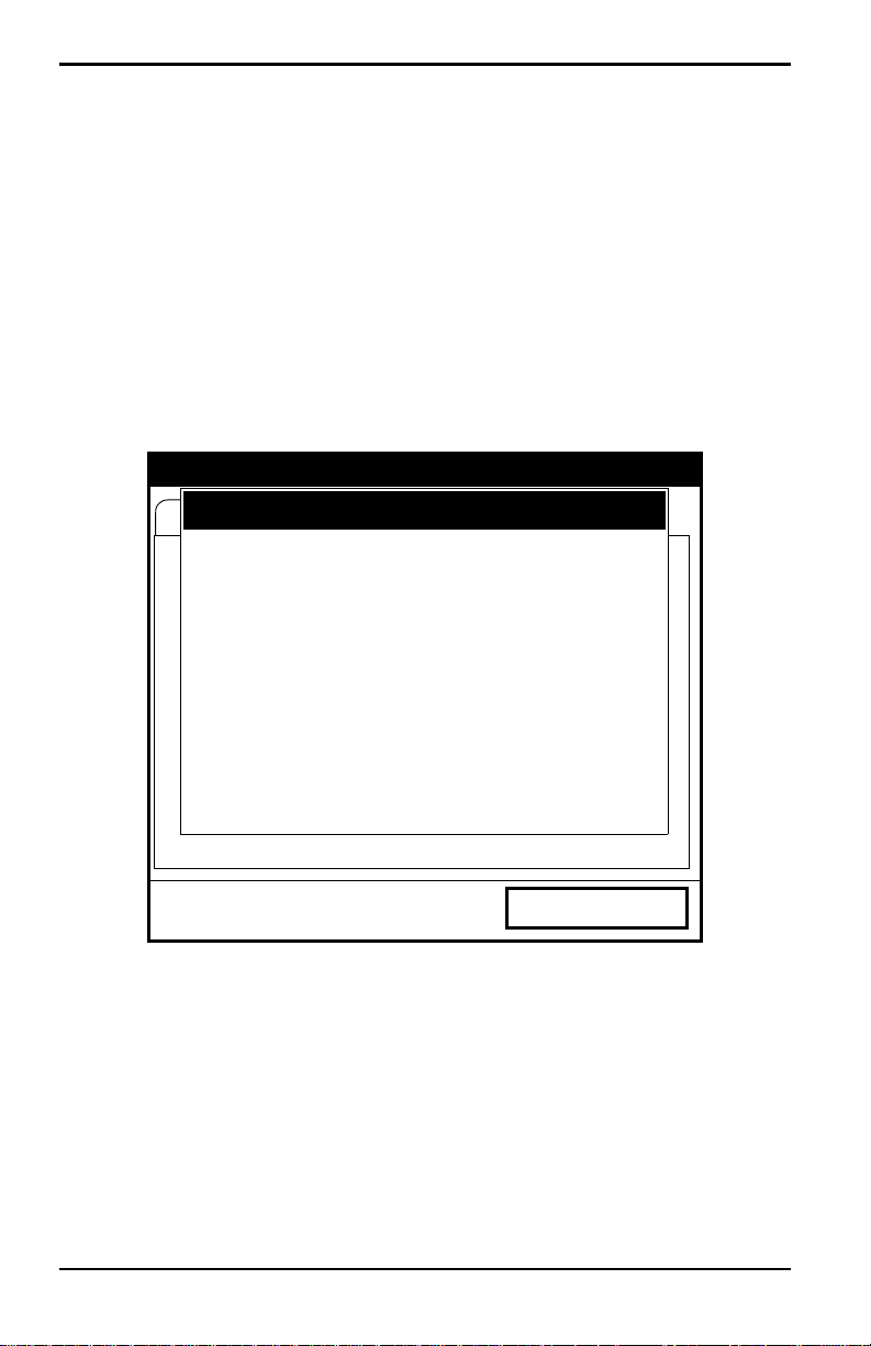
Chapter 3. Programming Site Data
3.3 Entering Pipe Parameters (cont.)
d. If you have selected “Other,” the meter prompts you to enter the
soundspeed. Use the numeric keys to type the desired soundspeed in
the text box, and press
Note: If the “Other” Pipe soundspeed entered is too large, given the
previously entered Wedge soundspeed and angles, an error message
similar to Figure 16 below will appear. Press [F3] (OK) (the error
message disappears), and enter another soundspeed within the range
specified.
100000 is Too High
The valid range is from:
3330.052 to 24000.000 ft/s
[ENTER] to confirm the choice.
Transducer/Pipe
Invalid Value — Too High
Cancel
OK
Figure 16: Soundspeed Error Message Window
Note: When the corrected soundspeed is entered, a message similar to
Figure 17 on page 33 appears. Press [F3] (OK).to return to the Site
Menu.
32 Transport® Model PT878 Portable Liquid Flowmeter User’s Manual
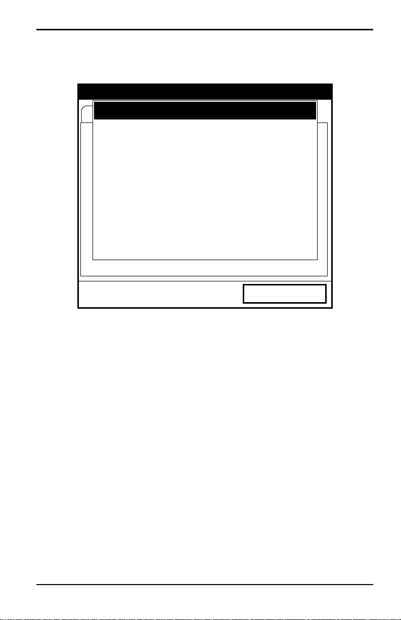
3.3 Entering Pipe Parameters (cont.)
Transducer/Pipe
* * * WARNING * * *
Transducer Spacing has changed!
New Spacing:
0.964 inches ( 24.493 mm)
Chapter 3. Programming Site Data
Cancel
OK
Figure 17: Transducer Spacing Change Window
2. The next prompt asks if you wish to measure the pipe wall with the
internal thickness gauge. If you press
[ENTER], the program moves to
the T-Gauge Display option (as covered on page 159). When you have
completed setting up and using the thickness gauge (as discussed in
Chapter 8), press
3. For pipe diameter, two alternatives are available. At the Diameter
[F2] or [F3] to return to the Pipe tab.
prompt, the meter asks for the pipe outside diameter and thickness. But
if you have selected certain pipe materials (carbon or stainless steel,
cast iron, PVC and CPVC), you have the option of entering the pipe
dimensions by a standardized schedule. Once you enter the nominal
pipe size and identification, the PT878 determines the OD and wall
thickness from an internal table.
Transport® Model PT878 Portable Liquid Flowmeter User’s Manual 33

Chapter 3. Programming Site Data
3.3 Entering Pipe Parameters (cont.)
If you select a material that uses the Diameter alternative:
a. You must select from two choices, outside diameter or
circumference.
• The prompt moves to the OD (outside diameter) text box. Type the
thickness (in mm or in.) into the text box, and press
confirm the choice, or
[ENTER] to
• Move the prompt to the OD X PI (circumference) text box. Type
the OD (in mm or in.) into the box, and press
your choice.
b. In either case, the next prompt asks for the wall thickness. Type the
value (in mm or in.) into the box, and press
choice.
Note: The measurement units shown depend on the choices you have made
in the English/Metric window or the Meter Settings menu.
[ENTER] to confirm
[ENTER] to confirm your
If you select a material that has the Schedule option:
a. The prompt as ks if you wish to apply ANSI (the ANSI schedule).
[ENTER] to select (or deselect) the ANSI box. (If you do not
Press
select the ANSI option, the prompt moves to the OD text box, and
you enter the parameters for the Diameter alternative as discussed
above.)
b. Press the [W] key twice to move the prompt to the Nominal pipe
size drop-down menu. Press
the desired pipe size, and press
c. Press the [X] key to move the prompt to the Schedule drop-down
menu. Press
schedule, and press
[ENTER] to open the menu. Scroll to the desired
[ENTER] to confirm the choice.
After entering either diameter or schedule settings, pressing the [
[ENTER] to open the menu. Scroll to
[ENTER] to confirm your choice.
S] key
returns the meter to the Pipe Material prompt.
34 Transport® Model PT878 Portable Liquid Flowmeter User’s Manual
 Loading…
- Manuals
- Brands
- GE Manuals
- Measuring Instruments
- Transport PT878
Manuals and User Guides for GE Transport PT878. We have 3 GE Transport PT878 manuals available for free PDF download: User Manual, Abridged Manual, Quick Start Manual
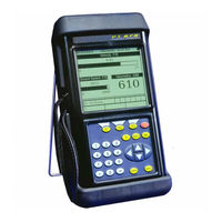
GE Transport PT878 User Manual (297 pages)
TransPort Portable Liquid Flowmeter
Brand: GE
|
Category: Measuring Instruments
|
Size: 1.93 MB
Table of Contents
-
Table of Contents
9
-
Chapter 1. Features and Capabilities
17
-
Overview
17
-
System Description
18
-
The Flowcell
18
-
Electronics Package
19
-
-
Theory of Operation
20
-
-
Chapter 2. Initial Setup
21
-
Making Electrical Connections
22
-
Power Connections
23
-
Transducer Connections
23
-
Input/Output Connections
23
-
The Infrared Wireless Interface
24
-
-
Caring for the PT878 Batteries
25
-
Charging and Storing the Batteries
25
-
Replacing the Batteries
26
-
Disposing of Batteries
27
-
-
Powering on and off
28
-
Using the Screen and Keypad
31
-
Screen
31
-
Keypad
33
-
-
Obtaining On-Line Help
35
-
-
Chapter 3. Programming Site Data
37
-
Entering the Program Menu
38
-
Entering Transducer Parameters
39
-
Parameters for Special Transducers
42
-
Confirming Entries
46
-
-
Entering Pipe Parameters
46
-
Entering Pipe Lining Parameters
51
-
Entering Fluid Types and Speeds
53
-
Entering the Signal Path Parameters
55
-
Path Parameters for Clamp-On Transducers
56
-
Path Parameters for Wetted Transducers
57
-
-
Entering the Energy Option Parameters
58
-
Entering Inputs in the Energy Option
60
-
Entering Custom Cp Data in the Energy Option
62
-
-
Entering Analog Inputs
66
-
Entering General-Purpose Analog Inputs
66
-
Entering Analog Inputs in the Energy Option
68
-
-
Entering the Analog Output
70
-
Entering the Digital Output
73
-
Entering User Functions
77
-
Entering Correction Factors
81
-
Entering Reynolds Correction
81
-
Entering a Calibration Factor
83
-
-
-
Chapter 4. Creating and Managing Sites
87
-
The Site Manager
88
-
Creating a New Site
90
-
Opening an Existing Site
92
-
Saving a Site
93
-
Saving a Site with a Different Name
94
-
Refreshing a Site
95
-
Renaming a Site
95
-
Deleting a Site
96
-
Creating a Site Message
97
-
Printing a Current Site
99
-
Transferring a Site File to a PC
99
-
Transferring a Site File in Text Format to a PC
100
-
Transferring a File from a PC to the PT878
101
-
Listing Files by Name
104
-
Listing Files in Chronological Order
104
-
-
-
Chapter 5. Displaying and Configuring Data
105
-
The Format Option
106
-
The View Option
108
-
The Limits Option
109
-
The Measurement Option
111
-
Customizing the Display Screen
113
-
Specifying the Number of Displayed Parameters
114
-
Customizing Softkeys
115
-
-
Managing Files — the Drive Manager
118
-
Transferring a File to a PC
120
-
Transferring a File from a PC to the PT878
121
-
Refreshing a File
123
-
Deleting a File
124
-
Listing Files by Name
125
-
Listing Files in Chronological Order
125
-
-
Accessing Meter Data -The about Option
126
-
-
Chapter 6. Programming Meter Settings
127
-
Entering the Meter Menu
128
-
Selecting Measurement Units
129
-
The Battery Charger
130
-
Entering Date and Time
131
-
Changing Date and Time Appearance
133
-
Adjusting the Contrast
136
-
Setting Backlight Timeout
137
-
Changing the Display Language
138
-
Changing Communications Settings
139
-
Resetting Forward and Reverse Totals
142
-
Setting up User Tables
143
-
Taking a Bitmap Capture of a Current Screen
146
-
-
Chapter 7. Logging Data
147
-
Entering the Logging Menu
148
-
The Log Manager
149
-
The File Menu
150
-
Setting up a New Log
151
-
Copying (Cloning) a Selected Log
156
-
Renaming a Log
157
-
Deleting a Log
157
-
Deleting All Logs
158
-
Refreshing the Log Manager Screen
158
-
Printing a Log
159
-
Transferring a Log to a PC
160
-
-
The Log Menu
161
-
Stopping (Pausing) a Log
162
-
Restarting a Log
162
-
Ending a Log
162
-
Stopping All Logs
163
-
Restarting All Logs
163
-
Ending All Logs
163
-
View All Sites
163
-
-
The View Menu
164
-
Displaying Log Details
165
-
Displaying Log Data in Graphical Form
166
-
Displaying Log Data in Spreadsheet Form
169
-
-
The Sort Menu
170
-
Listing Logs by Name
170
-
Listing Logs in Chronological Order
170
-
-
-
Chapter 8. Servicing the PT878
171
-
Entering the Service Menu
172
-
Printing Reports
173
-
Setting up the Thickness Gauge
175
-
Measuring Pipe Wall Thickness
176
-
Entering the Material and Soundspeed
176
-
Measuring Thickness in Numeric Format
178
-
Displaying the Receive Signal in Graphical Format
179
-
Calibrating the Thickness Gauge Transducer
181
-
Calculating Velocity (Pipe Material Soundspeed)
184
-
-
Programming the Thickness Gauge
186
-
Displaying Diagnostic Parameters
189
-
Calibrating the Analog Output and Inputs
190
-
Calibrating the Analog Output
190
-
Calibrating Inputs
192
-
-
Setting up Signal Parameters
194
-
Setting up Signal Parameters
195
-
Setting up Peak Detection
197
-
Selecting the Transmit Code
199
-
-
Setting Error Limits
200
-
The Test Option
203
-
Testing the Screen
204
-
Testing the Keys
205
-
Testing the Watchdog Timer Circuit
206
-
Setting Impulse Response
207
-
Taking Wave Samples for Diagnosis
208
-
Applying a Stored Signal for Diagnosis
208
-
Testing the Battery
209
-
-
Resetting to Factory Default Parameters
210
-
Updating PT878 Software
211
-
Updating Software Via Irobex
212
-
Updating Software Via Ircomm
213
-
-
-
Chapter 9. Diagnostics and Troubleshooting
219
-
Error Code Messages
220
-
Displaying Diagnostic Parameters
222
-
Flowcell Problems
224
-
Fluid Problems
224
-
Pipe Problems
225
-
-
Transducer Problems
226
-
Wetted Transducer Problems
226
-
Clamp-On Transducer Problems
227
-
Relocating Transducers
228
-
-
-
Chapter 10.Specifications
229
-
Overall
229
-
Hardware Configuration
229
-
Size/Weight
229
-
Enclosure
229
-
Flow Accuracy (Velocity, % of Reading)
229
-
-
Electrical
230
-
Operational Specifications
232
-
Transducer
233
-
Clamp-On Ultrasonic Flow Transducers
233
-
Temperature Transducers
233
-
-
Pipe Size and Material
233
-
Clamp-On Transducers
233
-
-
Available Options
234
-
-
Appendix A. Menu Maps
255
-
Appendix B. Measuring P and L Dimensions
255
-
Appendix C. Temperature Transmitter Installation
259
-
Guidelines for RTD Installation
259
-
Mounting Rtds on the Pipe
260
-
Assembling the Clamping Fixture
260
-
Mounting the RTD to the Pipe
261
-
-
Making Electrical Connections
261
-
Connecting the RTD to the 4 to 20-Ma Transmitter
262
-
Connecting the Transmitter to the PT878
263
-
-
-
Appendix D. Ultrasonic Thickness Gauge Theory of Operation
265
-
Factors Affecting Performance and Accuracy
266
-
Transducer Positioning/Alignment
267
-
Calibration
268
-
Taper or Eccentricity
268
-
Acoustic Properties of the Material
268
-
-
-
Appendix E. Material Safety Data Sheet for Couplant
269
-
Product Identification
269
-
Hazardous Ingredients
269
-
Physical Data (Nominal)
270
-
Fire and Explosion Hazard Data
270
-
Reactivity Data
270
-
Health Hazard and First Aid Data
271
-
Storage and Handling Information
271
-
Control Measures
272
-
-
Appendix F. Establishing IR Communications
273
-
Appendix G. Glossary
275
-
Analog Outputs
279
-
Specifications
286
-
Advertisement

GE Transport PT878 Abridged Manual (97 pages)
Portable Liquid Ultrasonic Flowmeter
Brand: GE
|
Category: Measuring Instruments
|
Size: 1.42 MB
Table of Contents
-
Table of Contents
5
-
Chapter 1: Installation & Operation
10
-
Introduction
10
-
The Flowcell
10
-
Making Electrical Connections
11
-
Power Connection
12
-
Transducer Connections
12
-
Input/Output Connections
12
-
The Infrared Interface
13
-
Caring for the PT878 Batteries
13
-
Charging the Batteries
13
-
Storing the Batteries
14
-
Replacing the Batteries
15
-
-
-
Powering on and off
16
-
Using the Screen and Keypad
18
-
The Screen
18
-
The Keypad
20
-
Initial Setup
23
-
-
Chapter 2: Initial Setup
24
-
Introduction
24
-
Entering the Program Menu
24
-
Entering the Transducer Parameters
25
-
Special Transducers
26
-
-
Entering the Pipe Parameters
27
-
Entering the Pipe Lining Parameters
29
-
Entering the Fluid Parameters
30
-
-
Entering the Fluid Parameters
31
-
Clamp-On Transducers
32
-
Wetted Transducers
32
-
-
Entering the Signal Path Parameters
31
-
Entering Correction Factors
33
-
Entering Reynolds Correction Data
33
-
Entering a Calibration Factor
34
-
-
Chapter 3: Operation
38
-
Configuring the Display Options
38
-
The Format Option
39
-
The View Option
40
-
The Limits Option
41
-
The Measurement Option
43
-
-
Customizing the Display Screen
44
-
Specifying the Number of Displayed Parameters
45
-
Customizing the Softkeys
46
-
-
Error Messages
49
-
Programming Global Meter Settings
50
-
The Units Option
51
-
The Battery Charger Option
52
-
The Date/Time Option
53
-
The Locale Option
54
-
The Contrast Option
56
-
The Backlight Option
57
-
The Language Option
57
-
The Communications Option
58
-
The Totals Option
60
-
-
Chapter 4: Managing Site Files
62
-
The Site Menu
63
-
The Site Manager Window
64
-
The Site Manager Menu
65
-
The New Option
65
-
The Open Option
67
-
The Save Option
68
-
The Save as Option
69
-
The Refresh Option
70
-
The Rename Option
70
-
The Delete Option
71
-
The Message Option
72
-
The Print Option
74
-
-
-
Chapter 5: Data Logging
76
-
The Logging Menu
77
-
The Log Manager Window
78
-
The Log Manager Menu
78
-
The File Menu
79
-
The Log Menu
86
-
The View Menu
89
-
-
-
Appendix A: Menu Maps
94

GE Transport PT878 Quick Start Manual (23 pages)
Brand: GE
|
Category: Measuring Instruments
|
Size: 0.38 MB
Table of Contents
-
Table of Contents
3
-
Warranty
4
-
Return Policy
5
-
Introduction
6
-
Keypad Description
7
-
Powering on and off
9
-
Programming Transducer, Pipe and Fluid Parameters
11
-
Transducer Parameters
12
-
Pipe Parameters
13
-
Fluid Parameters
14
-
Saving Site Data
16
-
-
Changing the Number of Displayed Measurements
17
-
Changing the Measured Parameters
18
Advertisement
Advertisement
Related Products
-
GE TransPort PT878GC
-
GE PM880
-
GE Phasor XS
-
GE PQM II
-
GE PQM Series
-
GE PQM-T20-C-A
-
GE PACE 1000
-
GE PL2200-B-S
-
GE Phasor CV
-
GE PanaFlow HT
GE Categories
![]()
Refrigerator
Ranges
![]()
Microwave Oven
![]()
Air Conditioner
![]()
Dishwasher
More GE Manuals
(Ocr-Read Summary of Contents of some pages of the GE TransPort PT878GC Document (Main Content), UPD: 29 June 2023)
-
210, GE TransPort PT878GC April 2009 9-6 Servicing the PT878GC Setting up the Thickness Gauge (cont.) Calibrating the thickness gauge involves up to two additional steps: 4. Calibrating the thickness gauge itself (in the Zero window on page 9-12), and 5. Calibrating the velocity of sound in the pipe material (in the Velocity window on page 9-14), if possible and if the pipe material is not the material entered in the Zero window. This …
-
116, April 2009 4-52 Programming Site Data Entering Reynolds Correction (cont.) b. Enter the desired measurement and units as described on page 4-40. c. Press [F3] (OK) to confirm your selection. 4. The prompt then asks if you wish to edit the Reynolds Correction table. a. Press [ENTER] to open the table, which appears similar to Figure 4-25 below. Figure 4-25: Window for Reynolds Correction Table b. Use the numeric keys…
-
177, GE TransPort PT878GC Programming Meter Settings 7-19 April 2009 Setting Up User Tables When you program user functions (see page 4-46), you can also support them with up to six user tables of non-linear or empirical data. To program one or more user tables: 1. From the Meter menu, scroll to the User Tables entry and press [ENTER]. The window now appears similar to Figure 7-8 below. Figure 7-8: The User Tables Window 2. The first prompt asks you to select the table to…
-
290, April 2009 C-4 Ultrasonic Thickness Gauge Theory of Operation Factors Affecting Performance and Accuracy (cont.) Remember that an ultrasonic test measures thickness at only one point within the beam of the transducer, and that in corrosion situations wall thicknesses often vary considerably. Test procedures usually call for making a number of measurements within a defined area and establishing a minimum and/or ave…
-
227, Servicing the PT878GC 9-23 April 2009 Calibrating Inputs To open the Inputs window, press the [X] arrow key and press [ENTER]. The screen appears similar to Figure 9-15 below. Note: Calibrating the analog inputs requires use of a current source. Figure 9-15: The Inputs Window in the Calibrate Option 1. Press the [ T] arrow key to enter the window. 2. The first prompt asks you to select the input. a.…
-
49, Installing the Dampening Material, Transducers and Fixtures 3-19 April 2009 Surveying the Pipe (cont.) Figure 3-14: Marking the 3 o’Clock Position 4. To find the coinciding point on the opposite site of the pipe (180° away from each other), divide the measured circumference by 2 and measure this distance along the circumferential lines from the zero point, as shown in Figure 3-15 below. Place marks on both sides of the circumferential lines made with…
-
96, April 2009 4-32 Programming Site Data Entering Skan/Correlation Parameters To open the Skan/Correlation window in the Skan/Measure option, press the [X] arrow key three times (from the All tab) to reach the Correlate tab, and press [ENTER]. The screen appears similar to Figure 4-14 below. Figure 4-14: The Correlate Window in the Skan/Measure Option To identify the peak of the received signal, the PT878GC uses the “Threshold” method, in which the peak is identified a…
-
34, GE TransPort PT878GC April 2009 3-4 Installing the Dampening Material, Transducers and Fixtures Application Requirements (cont.) • For air, nitrogen, oxygen or argon, refer to Table 3-1 on the next page. • For natural gas, refer to Table 3-2 on page 3-7. • For steam, refer to Table 3-3 on page 3-9. 1. Find the pipe size of your application 2. Then find the pipe wall thickness of your application. 3. With the pipe size and pipe wall …
-
193, April 2009 8-12 Logging Data Deleting a Log (cont.) Figure 8-8: The Delete Confirmation Window Deleting All Logs To clear the Log Manager and memory of all logs, open the File menu, scroll to the Delete All Logs option, and press [ENTER]. A window opens, asking, “Delete All Logs?” Press [F2] (No) to stop the deletion, or [F3] (Yes) to delete the logs. IMPORTANT: This step cannot be undone! A blank Log Manager …
-
90, April 2009 4-26 Programming Site Data Entering Skan/Measure Parameters (cont.) Pressing the [T] key highlights the Advanced prompt. To enter advanced parameters for the Skan/Measure modes, press [ENTER]. The screen now appears similar to Figure 4-11 below. In each case, to enter a value: a. Press [ENTER] to enter the text box. b. Use the numeric keys to enter the value. c. Press [ENTER] to confirm the entry. Figure 4-11: The Advanced Skan/Measure Window 5. The first prompt, the…
-
163, GE TransPort PT878GC Programming Meter Settings 7-5 April 2009 The Battery Charger The Battery option allows you to monitor the current run time and status of the internal rechargeable batteries, as well as to condition NiCad batteries to maintain the maximum life possible. Conditioning NiCad batteries (a process that can take up to 12 hours for a fully charged pack) discharges the pack completely and then performs a fast charge. Note: When conditioning the batterie…
-
303, 11 April 2009 Index (cont.) S Sampling Waves. . . . . . . . . . . . . . . . . . . . . . . . . . . . . . . . . . . . . . . .9-40 Schedule for Pipe Dimensions . . . . . . . . . . . . . . . . . . . . . . . . . . . . . .4-9 Screen Description . . . . . . . . . . . . . . . . . . . . . . . . . . . . . . . . . . . . . . . . . .2-10 On-Line Help. . . . . . . . . . . . . . . . . . . . . . . . . . . . . . . . . . . . . . . . .2-14 Service Menu Menu Map. . . . . . . . . . . . . . . . . . . . . . . .…
-
5, v April 2009 Table of Contents Chapter 1: Features and Capabilities Overview. . . . . . . . . . . . . . . . . . . . . . . . . . . . . . . . . . . . . . . . . . . . . . . . . . . . . . 1-1 System Description . . . . . . . . . . . . . . . . . . . . . . . . . . . . . . . . . . . . . . . . . . . . 1-3 The Flowcell. . . . . . . . . . . . . . . . . . . . . . . . . . . . . . . . . . . . . . . . . . . . . . . 1-3 Electronics Package . . . . . . . . . . . . . . . .…
-
204, Logging Data 8-23 April 2009 The Sort Menu The Sort Menu within the Log Manager allows you to arrange your log list either alphabetically (By Name) or chronologically (By Date). Figure 8-16: Sort Menu in the Log Manager Listing Logs by Name If you want to list your logs alphabetically by log name within the Log Manager, press [MENU] to open the File Menu. Then scroll from the File Menu to the Sort M…
-
33, Installing the Dampening Material, Transducers and Fixtures 3-3 April 2009 Application Requirements Before you begin to use the PT878GC, you should ensure that your meter can handle the frequencies required for your particular application. To check the capabilities of your particular PT878GC, refer to the back label of the PT878GC, shown in Figure 3-2 below. The gray label below “Communication” lists the meter ty…
-
153, April 2009 6-16 Displaying and Configuring Data Refreshing a File You can refresh a file (updating the display with the most current information) in one of two ways: • Press [F2], Refresh, to refresh the highlighted file. • From the File Menu, scroll to the Refresh option and press [ENTER]. The updated information on the highlighted file appears in the window on the right. Transferring a File to a PC To upload a log, meter, screen capture (bitmap) or site file to a PC: 1. Check th…
-
66, April 2009 4-2 Programming Site Data Entering the Program Menu To enter the Program Menu, press the [MENU] key at the lower right of the PT878GC keypad. The Menu Bar replaces the Status Bar at the top of the screen. Press the [ X] arrow key once to scroll from the Site Menu to the Program Menu. At the Program Menu, press [ENTER]. The screen appears similar to Figure 4-1 below. While following the programming instructions, refer to Figure A-2 on page A-2 of Appendix A, Menu Maps Figure 4-…
-
36, Installing the Dampening Material, Transducers and Fixtures 3-6 April 2009 12 (300) < 0.38 (9.7) 0.5 60 (5.1) 55 (16.8) 44 (13.4) 33 (10.1) — — 0.2 200 (13.6) 82 (25) 66 (20.1) 49 (14.9) <0.50 (12.7) 0.5 180 (13.4) 55 (16.8) 44 (13.4) 33 (10.1) 0.2 600 (40.8) 82 (25) 66 (20.1) 49 (14.9) < 1.00 (25.4) 0.5 300 (21.7) 55 (16.8) 44 (13.4) 33 (10.1) 0.2 1000 (68) 82 (25) 66 (20.1) 49 (14.9) 14 (350) <0.38 (9.7) 0.2 90 (7.2) 87 (26.5) 70 (21.3) 52 (15.9) �…