-
Contents
-
Table of Contents
-
Bookmarks
Quick Links
3
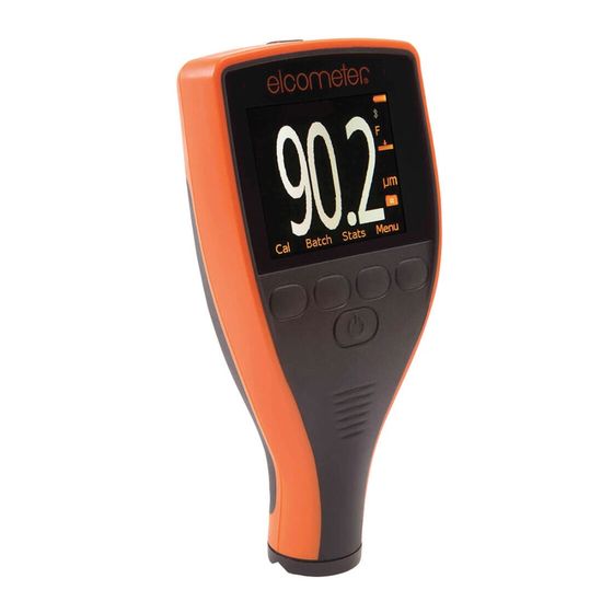
Elcometer 456
Coating Thickness Gauge
Top Models
Operating Instructions
Related Manuals for Elcometer 456
Summary of Contents for Elcometer 456
-
Page 1
Elcometer 456 Coating Thickness Gauge Top Models Operating Instructions… -
Page 2
(electronic, mechanical, magnetic, optical, manual or otherwise) without the prior written permission of Elcometer Instruments Ltd. A copy of this Instruction Manual is available for download on our Website via www.elcometer.com/downloads. Doc.No. TMA-0424 Issue 02… -
Page 3: Table Of Contents
CONTENTS Section Page About your gauge …………. . . 4 1.1 Features .
-
Page 4
The reading screen and menus ……….. 13 4.1 Reading screen . -
Page 5
Transferring readings to a computer ……….40 8.1 Transferring Using a Cable . -
Page 6: About Your Gauge
Thank you for your purchase of this Elcometer 456 The gauge is available in Coating Thickness Gauge. Welcome to Elcometer. three versions; Basic, Standard and Top. This Elcometer are world leaders in the design, manual describes manufacture and supply of coatings inspection operation equipment.
-
Page 7: Features
1.1 FEATURES 1.2 STANDARDS • A range of smooth and rough surface The Elcometer 456 can be used in accordance with calibration adjustments. the following National and International Standards: • Menu driven backlit graphical user interface. Ferrous (F) Non-Ferrous (NF) •…
-
Page 8: What This Box Contains
Operating Instructions. Do not hesitate to menu structure which helps you get the most from contact Elcometer or your Elcometer supplier if your gauge — see page 18. you have any questions. As an example, the LANGUAGES option which is in…
-
Page 9: Getting Started
2 GETTING STARTED 2.2 BATTERY CONDITION. Symbol Battery condition/action required 2.1 FITTING THE BATTERIES 1. Open battery compartment cover; press down 100% in direction of arrow using thumb nail. 2. Insert 2 x LR03 (AAA), alkaline dry batteries 66% to 100% taking care to ensure correct battery polarity 33% to 66%, replacement (Figure 2).
-
Page 10: Fitting Probes
2.3 FITTING PROBES To release the probe (separate versions only) Grasp knurled section and pull gently away from the gauge. The To ensure correct transfer of data from the connection will unlock and the probe and detection of the new probe, the probe will release.
-
Page 11: The Controls
STAT S MENU Press switch on gauge, or place the probe on a surface. Softkeys On/Off key Note: Before switching the gauge on for the first Figure 3. Elcometer 456 control keys time read “Selecting a language” on page 11.
-
Page 12: Switching The Gauge Off
(Figure 5). To maximise character size, switch off statistics (see Stats on LCD, 2.7 THE SCREEN page 32) and unlock the softkeys (see SOFTKEYS Familiarise yourself with the Elcometer 456 screen. LOCKED:, page 23). The screen displays: •…
-
Page 13: Selecting A Language
1. Switch gauge off. When the gauge is switched on for the first time 2. Press and hold left hand softkey. after dispatch from the Elcometer factory the 3. Press key to switch on gauge. display will show the language selection screen The display will show language selection (Figure 6).
-
Page 14: Interfaces
2.9 INTERFACES 3 TAKING A READING ® Your gauge is fitted with a Bluetooth interface which makes creation personalised 3.1 BEFORE YOU START ‘welcome’ screens and transfer of information to • Are you using the correct type of probe? and from a PC quick and easy — see “Transferring See “Probes”…
-
Page 15: Procedure
3.2 PROCEDURE 4 THE READING SCREEN AND MENUS 1. Press key to switch on gauge. 4.1 READING SCREEN 2. Place probe on surface to be measured. The reading may be inaccurate if the probe is The content of the reading screen (Figure 10, not held as shown in Figure 8.
-
Page 16: Main Menu
Menu title softkey symbol is flashing. Menu contents Softkey functions Figure 12. Typical Elcometer 456 menu Some screens allow the status of a feature to be Figure 11. Reading screen in extended mode changed e.g. on to off or select or deselect, etc. A and showing full set of statistical values.
-
Page 17: Main Menu — Extended Menu Off
• Extended menu off (simple menu mode): BACKLIGHT The gauge is shipped from the Elcometer Switches backlight on and off. Toggle tick box to factory with EXTENDED MENU turned off. In activate/deactivate. With BACKLIGHT activated this simple menu mode the gauge can be the display is illuminated for approximately 5 calibrated and used to take measurements.
-
Page 18
INTL GAUGE : Resets gauge to International Supplier or Local Distributor. default settings e.g. DD/MM/YY date format and HELP: Explains symbols used on Elcometer 456 metric units. display screens. Figure 14. About menu International settings can also be activated at switch… -
Page 19
US GAUGE : Resets gauge to USA default settings e.g. MM/DD/YY date format and imperial units. Figure 15. Reset menu A confirmation screen will be displayed. Press YES to reset, NO to cancel. US settings can also be activated at switch on. Press and hold softkey 4 and switch on gauge. -
Page 20: Main Menu — Extended Menu On
4.4 MAIN MENU — EXTENDED MENU ON To toggle EXTENDED MENU on/off select MENU/EXTENDED MENU/SEL PRINT/OUTPUT SINGLE BATCH ALL BATCHES CURRENT STATISTICS SELECT STATS NO. OF READINGS DELETE MEAN LAST READING STD DEVIATION MENU SINGLE BATCH COEF OF VARIAT’N BACKLIGHT ALL BATCHES HIGHEST READING CALIBRATION LOCKED…
-
Page 21
The following features are added to the MENU LAST READING when EXTENDED MENU is active: Deletes last reading either in immediate mode or in batch mode. PRINT/OUTPUT Gauge displays ARE YOU SURE? (Figure 17). Outputs data to a printer or to a PC. A single batch of readings, all batches of readings, or the current ®… -
Page 22
SINGLE BATCH displays NOT AVAILABLE DATA MEMORY EMPTY (Figure 20). Deletes the batch data. The gauge displays the current batch or the last batch used (Figure 19). Figure 20. Memory empty screen ALL BATCHES Figure 19. SINGLE BATCH screen Deletes all batches. Gauge displays ARE YOU SURE? Press NO Use the Right/Left softkeys to locate the… -
Page 23
Display — see “Display” on page 32. TAG — readings still appear in the batch (with a tag- deleted symbol ), but they are not included in DATA: Activates DATA softkey, SHOW DATE statistical calculations. STAMP option selects DELETED READING menu (Figure 21). DELETE — readings are permanently deleted. -
Page 24
ASCII characters from the Courier New font set . This allows printing on devices other than the Elcometer Miniprinter, e.g. RS 232 printers or PC via Elcometer software (page 40) or via HyperTerminal. Figure 24. OUTPUT screen BEEP VOLUME: Changes volume. -
Page 25: Calibration Adjustment
• 0 = off When un-ticked, the softkey functions disappear from the reading screen 5 seconds after the reading • 5 = loudest screen has been displayed, or 5 seconds after • Default = 3 pressing any key. To view the functions again, LANGUAGES: Allows selection of language.
-
Page 26
methods described in National and International SPECIAL SUB: This method uses the 2-Point Standards. calibration for unusual substrate materials such as cast iron, certain types of stainless steel, high The calibration adjustment method chosen is carbon steel, special aluminium alloys, etc. dependant on the condition of the substrate to be measured and is indicated on the screen by a ZERO OFFSET: This is the method described in… -
Page 27: Preset Calibration Methods
5.2 PRESET CALIBRATION METHODS Note: When the calibration method is changed, e.g. from Smooth to Rough, the gauge will display a The gauge also contains four preset calibration message (Figure 28). methods which follow relevant standards. These set the calibration method and the data collection method (data collection method is only set when in batching mode).
-
Page 28: Calibration Foils And Standards
5.3 CALIBRATION FOILS AND STANDARDS Note: To calibrate 5 mm (200 mils) and 13 mm (500 mils) range gauges it will be necessary to Calibration adjustment should be carried out with stack the foils (Figure 29). Care must be taken to the appropriate probe on the same type of metal, avoid errors due to placing the foil labels between the same curvature and similar finish to the item to…
-
Page 29: Calibration Adjustment Procedure
5.4 CALIBRATION ADJUSTMENT PROCEDURE Step 1 1. Hold probe in air and press CAL softkey Calibration adjustment can be carried out at any (Figure 30). time by pressing CAL softkey from the reading screen. prevent inadvertent calibration adjustment the CAL softkey can be locked (MENU/CALIBRATION LOCKED).
-
Page 30
these readings and the last reading. Repeat Note: — — — indicates over-range (Figure 32). this action until a stable reading is obtained. Taking a reading within range clears this Average screen. Last First reading Second reading Figure 32. Over-range reading Figure 31. -
Page 31
reading. Repeat this action until a stable The gauge will display the option to test the reading is obtained. calibration of the gauge. First reading Second reading Figure 35. TEST READINGS screen Figure 33. Step 2 — Calibration adjustment on 5. -
Page 32
readings to be taken on a thin standard value Taking test readings Press YES softkey (see previous section) to take instead of on an uncoated base. test readings. This allows the calibration of the gauge to be tested without adding readings to data memory contributing statistical… -
Page 33: Statistics
6 STATISTICS Calibrating High Temperature PINIP™ Probes Special thickness standards are supplied with The Elcometer 456 Top has a Statistics feature F1 2 High Temperature PINIP™ Probes — see (STATS) which calculates and displays a statistical page 44. These thickness standards should be analysis of readings as they are taken.
-
Page 34: Enlarge Stats
See “Select stats” on page 33 and “Statistics STATS are displayed and the CLOCK is not terminology” on page 46. displayed. Combined 6.1 ENLARGE STATS statistics symbol Displays the chosen statistical values as double- height characters. The example screens (Figure 40) appear when all the statistical values are selected.
-
Page 35: Clear Stats
Use Up/Down softkeys to move cursor and SEL structures or complex assemblies. softkey to select or deselect the statistical values. 7 BATCHING The Elcometer 456 operates in one of two modes; immediate or batch. Figure 44. Reading screen — Batch mode…
-
Page 36: Exit Batching
Batching is configured using the DATA MENU. BATCH in batch mode — see page 37. This is known as ‘cloning’ a batch. To access the DATA MENU (Figure 45) press the DATA softkey (this softkey is only displayed with Cloning typically used when…
-
Page 37
been created — see “Calibration adjustment The second OPEN NEW BATCH screen (Figure procedure” on page 27. 47) shows the current batch settings. Lower and The initial OPEN NEW BATCH screen (Figure 46) Data collection upper limits stays on while the gauge sets up the batch, as method Number of indicated by the progress bar. -
Page 38
. The display toggles between two options, The value for n can be changed by pressing normal and counted average: the n=5 softkey. • NORMAL — Each reading is added to the number of readings and contributes to the statistical calculation. •… -
Page 39
Opening new batch in batch mode The initial OPEN NEW BATCH screen displays ‘CURRENT BATCH’. Opening a new batch in batch mode duplicates (clones) an existing batch. Cloning copies the following settings to the new batch: • Limits Figure 49. Initial OPEN NEW BATCH screen — •… -
Page 40: Open Existing Batch
are removed from the list so that batch numbers If YES is selected, the batch calibration details are above 999 are valid. A deleted batch number retained and the user can locate and fit the original cannot be reused until all the batches are deleted, probe, if they wish.
-
Page 41: Set Limits
• Date stamp (entered whenever the batch is To set the UPPER and LOWER limit values move opened). the cursor to the limit required and press SEL. • Probe change (includes date stamp and probe The gauge will display the current settings (Figure serial number).
-
Page 42: Free Memory
The CD supplied with your gauge includes the measurement data converted; following software: Elcometer EDCS Win, EDCS Plus and EDCS. All this software can also be downloaded from the • Elcometer Data Transfer Software (EDTS Elcometer website www.elcometer.com/downloads Excel Link). This software allows the user to transfer data from the memory of the gauge 8.1 TRANSFERRING USING A CABLE…
-
Page 43: Transferring Using A Bluetooth ® Connection
PC, an error message is displayed on ® BLUETOOTH your gauge and further readings cannot be taken until it is cleared. If at any time ElcoMaster requests a PIN number for your gauge, switch on your Elcometer 456 select MENU>ABOUT>GAUGE INFORMATION.
-
Page 44: Probes
To use this feature, tick the Bluetooth PC Reply 9 PROBES under MENU>SETUP>OUTPUT An extensive range of probes is available for the “OUTPUT:” on page 22. Elcometer 456 Coating Thickness Gauge. Probes ® When the box is ticked, and a Bluetooth ferrous (F), non-ferrous…
-
Page 45
9.2 NON-FERROUS (N) PROBES The following table shows which probes can be N probes measure the thickness of non-metallic used in the three types of Elcometer 456 Gauge. coatings on non-magnetic metals. They can be used on anodising, paint, plastic coatings, powder… -
Page 46
9.6 F1 2 HIGH TEMPERATURE PINIP™ Probe type Gauge Type PROBES These probes are capable of measuring on surfaces up to 250°C (480°F). Wear appropriate protective clothing and take N1 right angle care to avoid bodily contact with the hot N1A anodiser’s surface during measurement. -
Page 47: Personalised Welcome Screen
Use your Bluetooth interface or PC connection components. In the unlikely event of a fault, the cable with ElcoMaster software to create and gauge should be returned to your local Elcometer upload the screen — see the instructions included with ElcoMaster.
-
Page 48: Statistics Terminology
Elcometer. Contact details are 13 STATISTICS TERMINOLOGY stored in the gauge — MENU/ABOUT/CONTACT. Worldwide: sales@elcometer.com Term Meaning Or USA/Canada: inc@elcometer.com COEF OF Coefficient of Variation. The Note: Probes will eventually wear. Probe life will VARIAT’N standard deviation divided by…
-
Page 49: Technical Data
14 TECHNICAL DATA Term Meaning NO. OF Number of Readings. The 14.1 MEASUREMENT SPEED READINGS running value for the number >60 readings per minute. of readings taken in a group. When measuring high temperature materials In the case of the mode, the measurement speed must be reduced to prevent Number of Readings is the overheating…
-
Page 50: Accessories
Integral Probe, 130g (4.6oz) Dimensions: 130 mm x 70 mm x 35 mm 15 ACCESSORIES (5.12″ x 2.76″ x 1.38″) The Elcometer 456 is complete with all the items Gauge 0°C to 50°C (32°F to 120°F) required to get started and take measurements.
-
Page 51
15.4 TEST CERTIFICATES 15.1 PROBES A certificate with results of a standard test on known Full details of the extensive range of 456 probes foil values over the full range of the probe. Order can be obtained from Elcometer, your local using sales part number TEST-456. -
Page 52
T45616161 V Adapter for pipes (F & N T9997381- Integral/Separate Probe Version: T45616162 probes): V Adapter for pipes (FNF probes): T99913133 15.10 PC CONNECTION CABLE 456 to PC Connection Cable (9- T99916217 15.8 Miniprinter pin): column, rechargeable battery powered Miniprinter complete with charger. Three charger… -
Page 53: Related Equipment
16 RELATED EQUIPMENT 17 FITTING THE WRIST HARNESS Elcometer produces a wide range of coating 1. Pass harness thickness gauges and associated paint inspection round pin equipment. Users of the Elcometer 456 may also benefit from the following Elcometer products: •…
-
Page 54: Probe Measurement Performance
18 PROBE MEASUREMENT PERFORMANCE Scale Total range Resolution in range Accuracy 0 µm to 1500 µm ±1% to ±3% or ±2.5 µm 0.1 µm 0 µm to 99.9 µm F1 2 1.0 µm 100 µm to 1500 µm (F1 mode) FNF1 0 mil to 60 mils ±1% to ±3% or ±0.1 mil…
-
Page 55: Probe Capabilities
19 PROBE CAPABILITIES 19.1 INTEGRAL PROBES Minimum Minimum Minimum Probe type convex surface concave Headroom sample Cal foil value diameter surface radius diameter 4 mm (0.16”) 25 mm (0.98”) 130 mm (5.1”) 4 mm (0.16”) 250 µm (10 mil) (or F1 2 set for F1 operation) F1 2 4 mm (0.16”)
-
Page 56
19.2 SEPARATE FERROUS PROBES Minimum Minimum Minimum Probe type convex surface concave Headroom sample Cal foil value diameter surface radius diameter 4 mm (0.16”) 25 mm (0.98”) 85 mm (3.35”) 4 mm (0.16”) 250 µm (10 mil) (or F1 2 set to F1) F1 2 4 mm (0.16”) 25 mm (0.98”) -
Page 57
19.3 SEPARATE NON-FERROUS PROBES Minimum Minimum Minimum Probe type convex surface concave Headroom sample Cal foil value diameter surface radius diameter 35 mm (1.38”) 25 mm (0.98”) 85 mm (3.35”) 6 mm (0.24”) 250 µm (10 mil) N1 Right Angle 35 mm (1.38”) 25 mm (0.98”) 28 mm (1.10”) 6 mm (0.24”) -
Page 58
19.4 SEPARATE DUAL FNF Minimum Minimum Minimum Probe type convex surface concave Headroom sample Cal foil value diameter surface radius diameter FNF1 (N) 38 mm (1.50”) 25 mm (0.98”) 88 mm (3.46”) 8 mm (0.32”) 250 µm (10 mil) FNF1 (F) 4 mm (0.16”) 25 mm (0.98”) 88 mm (3.46”) 4 mm (0.16”) -
Page 59
19.5 PINIP™ PROBES Minimum Minimum Minimum Probe type convex surface concave Headroom sample Cal foil value diameter surface radius diameter 4 mm (0.16”) 60 mm (2.36”) 155 mm (6.10”) 4 mm (0.16”) 250 µm (10 mil) (or F1 2 set to F1) F1 2 4 mm (0.16”) 60 mm (2.36”) -
Page 60
19.6 SEPARATE MINIATURE FERROUS PROBES Minimum Minimum Minimum Minimum Minimum convex concave Overall length Probe Type sample access access surface surface (headroom) diameter height width diameter radius F, Straight, 1.5 mm (0.06”) 6.5 mm (0.26”) 3 mm (0.12”) 6 mm (0.24”) 150 mm (5.91”) 45 mm (1.77”) F, Straight,… -
Page 61
19.7 SEPARATE MINIATURE NON-FERROUS PROBES Minimum Minimum Minimum Minimum Minimum Overall length Probe Type convex concave sample access access (headroom) diameter radius diameter height width NF, Straight, 3 mm (0.12”) 25 mm (0.98”) 4 mm (0.16”) 6 mm (0.24”) 150 mm (5.91”) 45 mm (1.77”) NF, Straight, 3 mm (0.12”) -
Page 62: Error Messages
Error message Causes Action to take #1 — PROBE Probe-to-gauge communication failure. Integral gauge — return to Elcometer*. Separate gauge — remove probe and refit. If error persists, return to Elcometer*. #2 — PROBE Corrupt data output from probe. Integral gauge — return to Elcometer*.
-
Page 63
Incorrect calibration calculation. Re-calibrate. If error persists, return to Elcometer*. LANGUAGE Software error. Return to Elcometer*. MEMORY * Contact Elcometer or your local Elcometer Supplier to arrange return. Figure 58. Example error message — no probe is connected to gauge… -
Page 64: Index
21 INDEX Numerics Beep Calibration certificates Changing volume Calibration methods 2 Point calibration method Switching off 2 POINT Bluetooth AUSTRALIAN Icon in display Accessories Transferring readings ROUGH AS 3894 Bluetooth module SET OFFSET ASTM B 244 BS 3900 (C5) SPECIAL SUB ASTM B 499 BS 5411 (11) SSPC…
-
Page 65
ISO 2178 DATA ISO 2360 DATA MENU ISO 2808 DELETE EDTS+ Excel Link ISO calibration method DELETED READING ElcoMaster DISPLAY Elcometer 456 ENLARGE STATS Features EXIT BATCHING Keypad Overview EXTENDED MENU Error messages FACTORY CAL FREE MEMORY Extended menu Language, selecting… -
Page 66
REVIEW BATCHES Number of readings Fitting of ROUGH FNF (Ferrous/Non-ferrous) RS232 BIT IMAGE Substrate selection modes 21, RS232 PLAIN TEXT On/off SELECT STATS What used for Opening screen SET LIMITS Maximum temperature Creating SET OFFSET N (Non-ferrous) Disabling SETUP What used for SHOW DATE STAMP Performance SMOOTH… -
Page 67
Set offset SS 18 41 60 Units Setting up the gauge SSPC-PA 2 Automatic setting of Shims Statistics Manual setting of Ordering Activating Up/Down Simple menu Choice of US gauge settings Turning on/off Clearing Smooth calibration method Displaying on screen Softkey Dual function probes Weight…
(Ocr-Read Summary of Contents of some pages of the Elcometer 456 Document (Main Content), UPD: 26 August 2023)
-
14, R 12 2.9 INTERFACES Your gauge is fitted with a Bluetooth ® interface which makes the creation of personalised ‘welcome’ screens and transfer of information to and from a PC quick and easy — see “Transferring readings to a computer” on page 40. If you do not have a Bluetooth ® interface on your PC, you can still connect your gauge to your PC by using the PC connection cable supplied and the RS232 5-pin connector on the side of the gauge. Figure 7…
-
53, R 51 16 RELATED EQUIPMENT Elcometer produces a wide range of coating thickness gauges and associated paint inspection equipment. Users of the Elcometer 456 3 may also benefit from the following Elcometer products: • Uncured powder thickness gauges • Coatings analyser • Inspection management software • Mechanical coatings thickness gauges • Appearance testers • Adhesion testers For further information contact Elcometer, your lo…
-
54, Elcometer 456 R 52 18 PROBE MEASUREMENT PERFORMANCE Scale Total range Accuracy a a. Whichever is the greater. Lower value achieved when calibrated close to the thickness to be measured. Resolution in range F1 F1 2 (F1 mode) FNF1 N1, N1A 0 µm to 1500 µm ±1% to ±3% or ±2.5 µm 0.1 µm 1.0 µm 0 µm to 99.9 µm 100 µm to 1500 µm 0 mil to 60 mils ±1% to ±3% or ±0.1 mil 0.01 mil 0.1 mil 0 mil to 4.99 mils …
-
8, R 6 1.3 WHAT THIS BOX CONTAINS • Elcometer 456 3 Gauge with integral probe, or Elcometer 456 3 Gauge and separate probe (probe must be ordered separately) • Calibration foils • Gauge carrying pouch • Wrist harness • Batteries • CD containing data collection software • Operating instructions 1.4 CONVENTIONS IN THESE INSTRUCTIONS The Elcometer 456 3 is controlled using a simple menu structure which helps you get the most from your gauge — see page 18. As an example, th…
-
18, R 16 EXTENDED MENU Provides access to additional features. Toggle tick box to activate/deactivate. See “Main MENU — Extended menu on” on page 18. ABOUT Provides information on Gauge, Probe, Contact information and Help (Figure 14): GAUGE INFORMATION: Elcometer 456 3 model, software versions, etc. PROBE INFORMATION: Probe type, range, etc. CONTACT: Details of Elcometer offices worldwide and, if programmed, the contact details for…
-
64, Elcometer 456 R 62 21 INDEX Numerics 2 Point calibration method 24 A Accessories 48 AS 3894 25 ASTM B 244 5 ASTM B 499 5 ASTM D 1400 5 ASTM D1186 5 Australian calibration method 25 B Batch mode 33 Batch numbering 37 Batches Copying (Cloning) 34 Reviewing 38 Batching 33 Creating new batch 34 Data collection method 35 Exiting 34 Opening existing batch 38 Batteries Fitting 7 Life of 48 Precautions 45 Rechargeable Charging 48 Life of 7 Specification 48 Baud ra…
-
50, R 48 Miniature probes without outer sleeve: 150°C (300°F) All other probes: 80°C (176°F) 14.4 PHYSICAL 14.5 POWER SUPPLY Internal batteries, 2 x LR03 (AAA), alkaline k dry batteries or rechargeable l equivalents. Battery life 30 m hours to 40 hours continuous use with alkaline dry batteries. (15 000 to 20 000 readings at an average of 8 readings per minute.) Battery life is reduced by one third when using the backlight. 14…
-
37, R 35 been created — see “Calibration adjustment procedure” on page 27. The initial OPEN NEW BATCH screen (Figure 46) stays on while the gauge sets up the batch, as indicated by the progress bar. Figure 46. Initial OPEN NEW BATCH screen — Immediate mode ESC takes the gauge back to DATA MENU. The second OPEN NEW BATCH screen (Figure 47) shows the current batch settings. Figure 47. Second OPEN NEW BATCH screen — Immediate mode Upper and lower Limits for the batch can be ch…
-
57, R 55 19.3 SEPARATE NON-FERROUS PROBES Probe type Minimum convex surface diameter Minimum concave surface radius Headroom Minimum sample diameter Cal foil value a a. This is the recommended maximum calibration foil value to achieve the specified accuracy under these measurements conditions N1 35 mm (1.38”) 25 mm (0.98”) 85 mm (3.35”) 6 mm (0.24”) 250 µm (10 mil) N1 Right Angle 35 mm (1.38”) 25 mm (0.98”) 28 mm (1.10�…
-
66, Elcometer 456 R 64 REVIEW BATCHES 38 ROUGH 24 RS232 BIT IMAGE 22 RS232 PLAIN TEXT 22 SELECT STATS 33 SET LIMITS 39 SET OFFSET 24 SETUP 20 SHOW DATE STAMP 21 SMOOTH 24 SOFTKEY ENABLED 21 SOFTKEYS LOCKED 23 SPECIAL SUB 24 SSPC 25 STATISTICS 20 STATS MENU 31 STATS ON LCD 32 SWEDISH 25 TAG 21 UNITS 21 US GAUGE 17 ZERO OFFSET 24 Menus Extended off (simple) 15 Extended on 18 Overview 15 Structure 18 M…
-
36, R 34 Batching is configured using the DATA MENU. To access the DATA MENU (Figure 45) press the DATA softkey (this softkey is only displayed with EXTENDED MENU on). Figure 45. DATA MENU screen 7.1 EXIT BATCHING This option returns the gauge to immediate mode and no further readings are stored in memory. The gauge returns to the Reading Screen. 7.2 OPEN NEW BATCH This option opens (creates) a new batch using the next available batch number. • To create a batch with new calibration …
-
12, R 10 2.6 SWITCHING THE GAUGE OFF To switch off all gauge types, press and hold key for 3 seconds. The gauge will beep, two single tones followed by a double tone. The Elcometer 456 3 switches itself off 60 seconds after the last operation unless the Auto Switch Off time is changed (MENU/SETUP/AUTO SWITCH OFF). The Auto Switch Off feature can be set to a maximum of 10 minutes or can be deactivated — see “…
-
21, R 19 The following features are added to the MENU when EXTENDED MENU is active: PRINT/OUTPUT Outputs data to a printer or to a PC. A single batch of readings, all batches of readings, or the current statistical summary can be output via Bluetooth ® or the RS232 interface. To use this function, first setup using: MENU/SETUP/OUTPUT — see “OUTPUT:” on page 22. If no printers have been setup, PRINT/OUTPUT will display a NOT AVAILABLE message. DELETE Deletes la…
-
35, R 33 6.4 CLEAR STATS Resets to zero all statistical values selected in STATS MENU/DISPLAY. 6.5 SELECT STATS Allows the user to chose which statistical values are displayed. The default condition is all values (Figure 42). Figure 42. Select stats menu Use Up/Down softkeys to move cursor and SEL softkey to select or deselect the statistical values. 7 BATCHING The Elcometer 456 3 operates in one of …
-
45, R 43 9.2 NON-FERROUS (N) PROBES J N probes measure the thickness of non-metallic coatings on non-magnetic metals. They can be used on anodising, paint, plastic coatings, powder paint, etc. applied to aluminium, brass, non- magnetic stainless steel, etc. 9.3 DUAL FERROUS/NON-FERROUS (FNF) PROBES FNF probes are dual function, F and N in one probe. FNF gauges will automatically detect the type of substrate and set the mode accordingly. Alterna…
-
39, Elcometer 456 R 37 Opening new batch in batch mode Opening a new batch in batch mode duplicates (clones) an existing batch. Cloning copies the following settings to the new batch: •Limits • Calibration method • Data collection method • Offset (if applied) • Calibration adjustment Note: Calibration method, data collection method and offset cannot be changed once the cloned batch has been created. Calibration adjustment and limits can be changed after the batch has been creat…
-
32, R 30 Taking test readings Press YES softkey (see previous section) to take test readings. This allows the calibration of the gauge to be tested without adding readings to data memory or contributing to the statistical calculations. Figure 36. TEST READINGS screen NEXT softkey returns the gauge to Step 1 of the calibration adjustment procedure. ESC softkey exits the calibration adjustment procedure and returns the gauge to the reading screen. Other ca…
-
9, R 7 2 GETTING STARTED 2.1 FITTING THE BATTERIES 1. Open battery compartment cover; press down in direction of arrow using thumb nail. 2. Insert 2 x LR03 (AAA), alkaline dry batteries taking care to ensure correct battery polarity (Figure 2). 3. Close battery compartment cover. Rechargeable batteries can be used but they will only have 25% to 30% of the life of alkaline batteries. Figure 2. Fitting batteries — ensure correct battery polarit…
Измеритель толщины покрытия elcometer 456 Диапазон датчиков Руководство пользователя
ОБЪЯВЛЕНИЕ
Датчики сканирования Elcometer 456 были специально разработаны для использования в режимах «Сканирование» и «Автоповтор» на отдельных датчиках Elcometer 456 модели T. Они поставляются с прочным защелкивающимся колпачком зонда, заменяемым пользователем, что позволяет пользователям снимать отдельные показания или быстро сканировать большие площади поверхности, не повреждая зонд или покрытие.
Режим сканирования: Когда выбран режим сканирования, пользователи могут перемещать сканирующий зонд по всей площади поверхности. Когда зонд отрывается от поверхности, датчик отображает среднее значение толщины покрытия (x) вместе с максимальным (Hi) и минимальным (Lo) значениями толщины. Каждый набор из трех показаний может отображаться на графике работы и сохраняться в памяти. Это идеально подходит для онлайн-инспекции.
Режим автоматического повтора: Когда зонд помещается на подложку с покрытием в режиме автоматического повторения, датчик автоматически снимает показания со скоростью 140 в минуту, пока зонд не будет удален с подложки. Каждое отдельное показание сохраняется в памяти. Режим автоматического повторения можно использовать для значительного ускорения осмотра больших участков с покрытием, таких как стальные двутавровые балки (RSJ), резервуары, корпуса кораблей и т. д.
Примечание: «Режим сканирования с удержанием» позволяет снять датчик с поверхности не более чем на 1.5 секунды и заменить его без запуска нового набора показаний, что позволяет пользователю избежать отверстий, сварных швов и т. д. в подложке, не влияя на измерение. Результаты.
КАЛИБРОВКА С ИСПОЛЬЗОВАНИЕМ СКАНЕРНОГО ЗОНДА
При использовании сканирующего датчика в режиме «Сканирование» или «Автоповтор» колпачок датчика должен быть установлен, чтобы избежать повреждения наконечника датчика, а датчик можно калибровать только с использованием «Гладкой» или «Грубой/2-точечной» калибровки. методы.
Масштаб 1: Для «гладкой» калибровки требуется номинальная фольга 1500 мкм (60 мил) и непокрытая основа / нулевая пластина. Для «шероховатого / 2-точечного» также требуется номинальная фольга 50 мкм (2 мила).
Масштаб 2: Для «гладкой» калибровки требуется номинальная фольга 4 мм (160 мил) и непокрытая основа/нулевая пластина. Для «шероховатого / 2-точечного» также требуется номинальная фольга 50 мкм (2 мила).
ПОДКЛЮЧЕНИЕ СКАНЕРНОГО ЗОНДА
- Поверните заглушку зонда, чтобы совместить контакты.
- Вверните хомут – по часовой стрелке.


КАЛИБРОВКА В РЕЖИМЕ «СКАНИРОВАНИЯ» ИЛИ «АВТОПОВТОРА»
- Нажмите программную кнопку Cal и выберите «Метод калибровки».
- Выберите «Гладкая» или «Грубая/2 точки», а затем «Калибровка».
- Следуйте инструкциям на экране.
Во избежание повреждения наконечника зонда в режиме «Сканирование» или «Автоповтор» необходимо установить колпачок зонда. Если во время процедуры калибровки манометр попросит не использовать колпачок, манометр автоматически вернется в «Стандартный» режим измерения.
Датчики сканирования используют запатентованную функцию смещения Elcometer 456, гарантирующую, что любой износ колпачка во время использования учитывается в процедуре калибровки, отображая максимальный диапазон толщины покрытия датчика e и колпачка в конце процедуры калибровки.
- Для выбора режима измерения перейдите в Меню/Настройка/Режим измерения.
- Зонд Scale 2 поставляется с фольгой толщиной 3 мм (120 мил) и 1 мм (40 мил), из которой можно сделать фольгу толщиной 4 мм (160 мил).
- Если выбран альтернативный метод калибровки, датчик предложит пользователю выбрать либо «Гладкая», либо «Грубая/2 точки».
- Крышки датчиков имеют номинальную толщину 500 мкм (20 мил).
ТЕХНИЧЕСКИЕ ХАРАКТЕРИСТИКИ
УСТАНОВЛЕН КОЛПАЧОК ДАТЧИКА
| Диапазон | Шкала 1 | 100 – 1000 мкм (4 – 40 мил) |
| Шкала 2 | 0.1–4.5 мм (4–180 мил) | |
| Постановления | Шкала 1 | 1 мкм (0.1 мил) |
| Шкала 2 | 1 мкм: 0 – 1 мм; 10 мкм: 1–5 мм (0.1 мил: 0–50 мил; 1 мил: 50–200 мил) | |
| точность | Шкала 1 | ±3% или ±2.5 мкм (±0.1 мил)f |
| Шкала 2 | ±1-3% или ±0.02 мм (±1 мил) f |
| Номер детали | Конструкция зонда | Минимальный запас | Минимум Sampле Диаметр |
| Т456CF1U | Железная чешуя 1 | 86 мм (3.38 ″) | 15 мм (0.59 ″) |
| T456CF1UARM | Железная чешуя 1 – Бронированный трос | 140 мм (5.51 ″) | 15 мм (0.59 ″) |
| T456CFNF1U | Двойной масштаб FNF 1 | 89 мм (3.50 ″) | 15 мм (0.59 ″) |
| Т456CF2U | Железная чешуя 2 | 90 мм (3.54 ″) | 15 мм (0.59 ″) |
БЕЗ КОЛПАЧКА ДАТЧИКА
| Диапазон | Шкала 1 | 0 – 1500 мкм (0 – 60 мил) |
| Шкала 2 | 0–5 мм (0–200 мил) | |
| Постановления | Шкала 1 | 1 мкм (0.1 мил) |
| Шкала 2 | 1 мкм: 0 – 1 мм; 10 мкм: 1–5 мм (0.1 мил: 0–50 мил; 1 мил: 50–200 мил) | |
| точность | Шкала 1 | ±1-3% или ±2.5 мкм (±0.1 мил)f |
| Шкала 2 | ±1-3% или ±2.5 мкм (±0.1 мил)f |
| Номер детали | Конструкция зонда | Минимальный запас | Минимум Sampле Диаметр |
| Т456CF1U | Железная чешуя 1 | 85 мм (3.35 ″) | 4 мм (0.16 ″) |
| T456CF1UARM | Железная чешуя 1 – Бронированный трос | 139 мм (5.47 ″) | 4 мм (0.16 ″) |
| T456CFNF1U | Двойной масштаб FNF 1 | 88 мм (3.46 ″) | Fg: 4 мм (0.16 дюйма)
Нг: 6 мм (0.24 дюйма) |
| Т456CF2U | Железная чешуя 2 | 89 мм (3.50 ″) | 4 мм (0.16 ″) |
- В зависимости от того, что больше. При калибровке с использованием asample непокрытой основы.
- F: датчик FNF в режиме F; N: датчик FNF в режиме N.
ЗАПЧАСТИ
Крышки зондов со временем изнашиваются, и прибор сообщит пользователю во время процедуры калибровки, если крышку необходимо заменить. При тестировании h с использованием гладких поверхностей крышки зондов были просканированы на расстоянии более 50 км (30 миль). Сменные колпачки можно приобрести в компании Elcometer или у местного поставщика.
Описание: Номер детали
- Крышки сканирующих датчиков (3 шт. в упаковке): T456C23956
- Набор фольги; Масштаб 1; 0 – 1500 мкм (0 – 60 мил): T99022255-1
- Набор фольги; Масштаб 1; 0 – 1500 мкм (0 – 60 мил) – Сертифицировано: Т99022255-1С
- Набор фольги; Масштаб 2; 0–5 мм (0–200 мил): T99022255-2
- Набор фольги; Масштаб 2; 0 – 5 мм (0 – 200 мил) – Сертифицировано: Т99022255-2С
- Тестовая пластина с нулевым содержанием железа, 1%: T9994910-
- Цветная нулевая тестовая пластина, 1%: T9994911-
ВАЖНАЯ ИНФОРМАЦИЯ
Режимы «Сканирование» и «Автоповтор» доступны только для отдельных датчиков Elcometer 456 Model T. При использовании в этих режимах колпачок зонда должен быть установлен на сканирующем зонде, чтобы избежать повреждения наконечника зонда. Использование в этих режимах без колпачка приведет к аннулированию гарантии на зонд.
Сканирующие датчики можно использовать в «стандартном» режиме — с установленным колпачком датчика или без него — при подключении к любому отдельному датчику Elcometer 456.
Не рекомендуется использовать сканирующие датчики с колпачком датчика для покрытия толщиной менее 100 мкм (4 мила).

Во избежание сомнений, пожалуйста, обратитесь к оригинальной версии на английском языке. Товар упакован в картонную упаковку. Пожалуйста, убедитесь, что вся упаковка утилизирована экологически безопасным способом. Обратитесь в местное управление по охране окружающей среды за дальнейшими указаниями.![]() является зарегистрированным товарным знаком компании Elcometer Limited, Edge Lane, Manchester, M43 6BU. Великобритания Все остальные товарные знаки признаны.
является зарегистрированным товарным знаком компании Elcometer Limited, Edge Lane, Manchester, M43 6BU. Великобритания Все остальные товарные знаки признаны.
@Elcometer Limited 2008–2020. Все права защищены. Никакая часть этого документа не может быть воспроизведена, передана, расшифрована, сохранена (в поисковой системе или иным образом) или переведена на любой язык в любой форме и любыми средствами (электронными, механическими, магнитными, оптическими, ручными или иными) без предварительное письменное разрешение Elcometer Limited.

Документы / Ресурсы
Рекомендации

Elcometer — мировой лидер в производстве инспекционного оборудования, оборудования для взрывных работ, лабораторного оборудования и оборудования для физических испытаний
-
Flocorp GUARDIAN 1000 G1
(877) 356-5463 | (p) 330-331-7331 | (f) 330-331-7172 | www.FLO-CORP.com | © 2017 FLO-CORP | REVA 1116 1 GUARDIAN 1000™ G1WIRELESS MONITORING SYSTEMOPERATING INSTRUCTIONS …
GUARDIAN 1000 G1 Measuring Instruments, 19
-
Milwaukee LDM 30
2 51 3 64 730 30 30 30 30 3030MEASURE ► Measure ► Selecting Units (press 2 sec)POWER► On (push 1.5 sec ► Off (push 1.5 sec) MEASURE ► Measure1.5 sec 1.5 secRange IconMeasurement HistoryLaser Active IndicatorCurrent Measurement414 869 — LDM30-Quick Start Guide.indd 1-3414 869 — LDM30-Quick Start Guide.indd …
LDM 30 Measuring Instruments, 2
-
Korg MetroGnome
Thank you for purchasing the MetroGnome MM-2.4015-2 Yanokuchi, Inagi-city, Tokyo 206-0812 Japan© 2003 KORG INC.特許第 3295051 号/USP#6040517/UK2338088This device complies with Part 15 of the FCC Rules.Operation is subject to the following two conditions: (1) This device may notcause harmful interferenc …
MetroGnome Measuring Instruments, 2
-
AEMC MN126
99-MAN 100318.v1 09/06 OPERATION Making Measurements with the AC Current Probe Model MN126 • Connect the black (S2) and red (S1) terminals to the 2 V range of your DMM or instrument. The MN126 has a ratio of 10:1. This means that for 10A AC in the conductor around which the probe is clamped, 1V AC will come out of …
MN126 Measuring Instruments, 4
-
Altinex SIGNAL MANAGEMENT SOLUTIONS TE460-137
TE460-137 2K/4K HDMI SIGNAL GENERATOR & ANALYZER User’s Guide 400-0753-001 1 Welcome!Everyone at Altinex greatly appreciates your purchase of the TE460-137. We are confident that you will find it to be reliable and easy to use. If you need support, please do not hesitate to call us at 714-990-2300. At Altinex …
SIGNAL MANAGEMENT SOLUTIONS TE460-137 Measuring Instruments, 31
-
3M RFO 144
Instructions de montage Installation Instructions Instruciones de Montaje CHASSIS COMPLET EQUIPE RFO 144 Livré sans module FRAME EQUIPPED COMPLETE RFO 144 Delivered without module CHASIS RFO 144 COMPLETAMENTE EQUIPADO Suministrado sin módulos Nous vous conseillons de lire inté …
RFO 144 Measuring Instruments, 15
-
LaserLiner AQua-Master
AQua-Master8.029.96.01.1 Rev 10.05GBDNLFDKEBedienungsanleitungOperating instructionsGebruiksaanwijzingBetjeningsvejledningMode d´emploiInstrucciones para su usoIstruzioni d’usoInstrukcja ObsługiKäyttöohjeInstruções de uso3-1213-2223-3233-4243-5253-6263-7273-8283-9293-102IPLFINP …
AQua-Master Measuring Instruments, 54
R
These instructions apply to the following Elcometer 456
Ferrous (F), Non-Ferrous (NF) and Dual Ferrous/Non-Ferrous (FNF)
Equipment described in these instructions is covered by the following Patents:
FNF UK Patent No: GB2306009B
F1 2 UK Patent No: 2367135B
F1 2 German Patent Pending
This product meets the emc directive 89/336/EEC, amended 92/31/EEC and 93/68/EEC.
and
®
®
and Bluetooth
are trademarks owned by Bluetooth SIG Inc and licensed to Elcometer Instruments Ltd.
All other trademarks acknowledged.
© Copyright Elcometer Instruments Ltd. 2004-2007.
All rights reserved. No part of this Document may be reproduced, transmitted, transcribed, stored (in a retrieval system or
otherwise) or translated into any language, in any form or by any means (electronic, mechanical, magnetic, optical, manual
or otherwise) without the prior written permission of Elcometer Instruments Ltd.
A copy of this Instruction Manual is available for download on our Website via www.elcometer.com/downloads.
are registered trademarks of Elcometer Instruments Ltd.
models:
3
FNF US Patent No: 5886522
F1 2 US Patent No. US 6,762,603
Doc.No. TMA-0424 Issue 02
Text with Cover No: 20243