-
На Главную
-
testo 320
-
Внесен в Государственный реестр средств измерений РФ ФГИС «АРШИН»
-
Графический дисплей с высоким разрешением
-
Протестирован и одобрен TÜV в соответствии с EN 50379, Части 1-3.
-
Замена сенсоров пользователем
-
Объем памяти на 500 протоколов измерений
Анализатор дымовых газов testo 320 с сенсором О2 в комплекте с перезаряжаемым аккумулятором и заводским протоколом калибровки.
Подробнее
Описание продукта
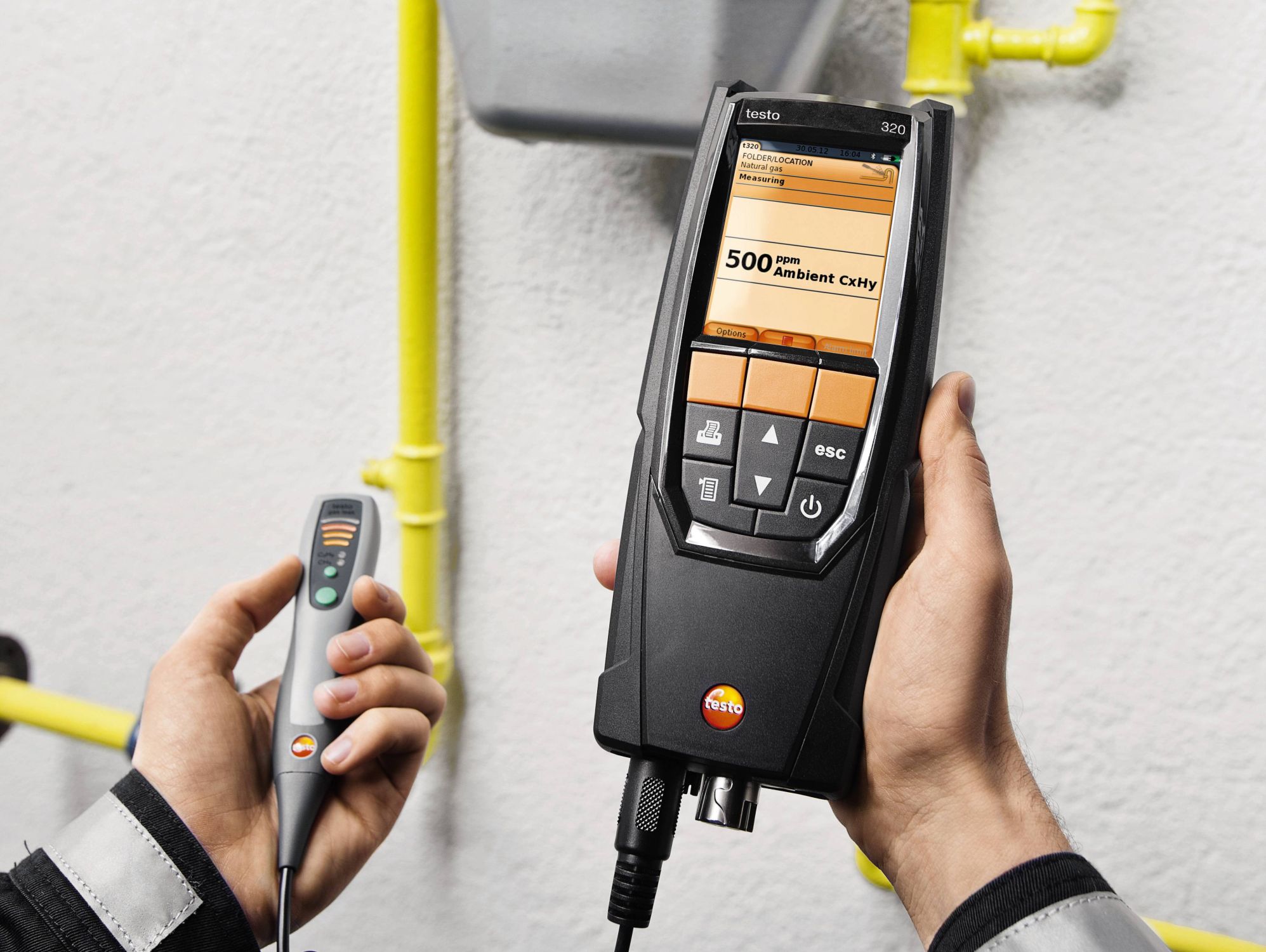
Вы в поиске многофункционального прибора для эффективного анализа дымовых газов, который подходит для проведения всех необходимых измерений на системе отопления и при этом удобен и прост в применении? В таком случае новый testo 320 — это то, что вы ищете.
Анализатор дымовых газов testo 320 оснащен цветным дисплеем высокого разрешения для графического отображения результатов измерений. Управление прибором осуществляется посредством интуитивных, четко структурированных меню измерения. Корпус testo 320 отличается прочностью, эргономичностью и привлекательным дизайном. Прибор оснащен сенсором О2.
Дополнительно вы можете заказать сенсор СО (опция). На основе полученных данных прибор выполняет расчет таких параметров, как СО2, КПД и потери тепла с дымовыми газами. Кроме того, с помощью высокоточного зонда давления Вы можете напрямую измерить тягу и давление — одновременно с проведением анализа дымовых газов. testo 320 протестирован и одобрен TÜV в соответствии с EN 50379, Части 1-3.
Области применения:
- Анализ дымовых газов
- Измерение тяги
- Измерение дифференциального давления
- Обнаружение утечек газа
- Измерение концентрации CO в окр. среде
- Измерение дифференциальной температуры
С подтвержденными метрологическими характеристиками и расширенными техническими данными можно ознакомиться в описании типа в Центре загрузки.
Комплект поставки
Анализатор дымовых газов testo 320 с сенсором О2 в комплекте с перезаряжаемым аккумулятором и заводским протоколом калибровки.
Технические данные
| Общие технические данные | |
|---|---|
|
Вес |
573 г |
|
Размеры |
240 x 85 x 65 мм |
|
Рабочая температура |
-5 … +45 °C |
|
Размер дисплея |
Размер дисплея: 240 х 320 |
|
Дисплей |
Цветной графический |
|
Источник питания |
Перезар. аккумул.: 1500мА-ч; блок питания 5В / 1A |
|
Память |
500 изм. блоков |
|
Температура хранения |
-20 … +50 °C |
| Измерение СО (с Н₂-компенсацией) | |
|---|---|
|
Диапазон измерений |
0 … 8000 ppm |
|
Погрешность |
±10 ppm или ±10 % от изм. знач. (0 … 200 ppm) ±20 ppm или ±5 % от изм. знач. (201 … 2000 ppm) ±10 % от изм. знач. (2001 … 8000 ppm) |
|
Разрешение |
1 ppm |
|
Быстродействие t90 |
< 40 с. |
| Измерение СОниз (С Н₂-компенсацией) | |
|---|---|
|
Диапазон измерений |
0 … 500 ppm |
|
Погрешность |
±2 ppm (0 … 39,9 ppm) ±5 % от изм. знач. (40 … 500 ppm) |
|
Разрешение |
0,1 ppm |
|
Быстродействие t90 |
< 40 с. |
| Измерение дифференциального давления (тяга дымового газа) | |
|---|---|
|
Диапазон измерений |
-9,99 … +40 гПа |
|
Погрешность |
±0,02 гПа или ±5 % от изм. знач. (-0,50 … +0,60 гПа) ±0,03 гПа (+0,61 … +3,00 гПа) ±1,5 % от изм. знач. (+3,01 … +40,00 гПа) |
|
Разрешение |
0,01 гПа с опцией высокоточного измер. тяги 0,001 гПа |
| Измерение температуры | |
|---|---|
|
Диапазон измерений |
-40 … +1200 °C |
|
Погрешность |
±0,5 °C (0 … +100,0 °C) ±0,5 % от изм. знач. (в ост. диапазоне) |
|
Разрешение |
0,1 °C (-40 … +999,9 °C) 1 °C (> +1000 °C) |
| Определение КПД (Eta) | |
|---|---|
|
Диапазон измерений |
0 … 120 % |
|
Разрешение |
0,1 % |
| Определение потери тепла с дымовыми газами | |
|---|---|
|
Диапазон измерений |
0 … 99,9 % |
|
Разрешение |
0,1 % |
| Расчёт CO₂ (через O₂) | |
|---|---|
|
Диапазон измерений |
Диапазон индикации 0 … CO₂ макс |
|
Погрешность |
±0,2 % Об. |
|
Разрешение |
0,1 % Об. |
| Измерение давления | |
|---|---|
|
Диапазон измерений |
0 … +300 гПа |
|
Погрешность |
±0,5 гПа (0,0 … 50,0 гПа) ±1 % от изм. знач. (50,1 … 100,0 гПа) ±1,5 % от изм. знач. (в ост. диапазоне) |
|
Разрешение |
0,1 гПа с опцией высокоточного измер.давл. 0,01 гПа |
| Измерение СО (без Н₂-компенсации) | |
|---|---|
|
Диапазон измерений |
0 … 4000 ppm |
|
Погрешность |
±20 ppm (0 … 400 ppm) ±5 % от изм. знач. (401 … 2000 ppm) ±10 % от изм. знач. (2001 … 4000 ppm) |
|
Разрешение |
1 ppm |
| Измерение СО в окружающей среде | |
|---|---|
|
Диапазон измерений |
0 … 500 ppm |
|
Погрешность |
±5 ppm (0 … 100 ppm) ±5 % от изм. знач. (> 100 ppm) |
|
Разрешение |
1 ppm |
зондом CO 0632 3331
| Измерение CO₂ в окружающей среде | |
|---|---|
|
Диапазон измерений |
0 … 1 % Об. 0 … 10000 ppm |
|
Погрешность |
±75 ppm или ±3 % от изм. знач. (0 … 5000 ppm) ±150 ppm или ±5 % от изм. знач. (5001 … 10000 ppm) |
зондом измер. CO₂в окр.среде 0632 1240
| Обнаружение и локализация утечек горючих газов | |
|---|---|
|
Диапазон измерений |
0 … 10000 ppm CH₄ / C₃H₈; Диапазон индикации |
|
Погрешность |
Тип сигнала:оптическое оповещение(LED) звуковое оповещение(зуммер) |
|
Быстродействие t90 |
< 2 с. |
зондом-течеискателем 0632 3330
Зонды
Зонды
Зонды температуры
Зонды температуры воздуха идущего на горение
Принадлежности
Принадлежности для измерительного прибора
Применение
Измерение окружающего CO в отопляемом помещении
Угарный газ (CO) – это газ без цвета, запаха и вкуса, но обладающий высокой токсичностью. Он вырабатывается при неполном сгорании содержащих углерод веществ (таких как дизельное топливо, газ, твёрдое топливо и т.п.). Если CO попадает в кровоток через лёгкие, то он соединяется с гемоглобином и лишает кровь способности переносить кислород, что приводит к смерти от удушья. По этой причине крайне необходимо регулярно контролировать уровень выбросов CO в точках сгорания систем отопления и в местах установки таких систем.
Измерение параметров дымового газа горелки (CO, O2, температуры и пр.).
Измерение параметров дымовых газов систем отопления служит для определения количества вредных выбросов с дымовым газом (таких как угарный газ CO или углекислый газ CO2) и степени потери тепла с дымовыми газами. В некоторых странах измерение параметров дымовых газов является официальным требованием. Такое требование преследует две основных цели:
1. Максимальное сокращение загрязнения атмосферы вредными выбросами
2. Максимально-эффективное использование энергии.
Превышение концентраций загрязняющих веществ в дымовых газах и потерь энергии недопустимо. Измерения в целях определения соответствия официально установленным результатам проводятся в процессе стандартной эксплуатации (измеряется каждый параметр работы установки). С помощью зонда отбора пробы измерение проводится в области центра потока дымовых газов в соединительной трубе (в самом центре сечения трубы, а не в области углов) между котлом и дымовой трубой. Значения измерений записываются в память анализатора дымовых газов для последующей печати в виде протокола измерений или для переноса на компьютер. Измерение проводится инженером по установке систем в процессе ввода в эксплуатацию и при необходимости – через четыре недели газовщиком-смотрителем/инженером по очистке дымовых труб, а затем – с установленной периодичностью инженером по ремонту и техническому обслуживанию.
Измерение давления на горелках (давления на форсунке, давление дымового газа и пр.).
Стандартные показания, снимаемые в ходе сервисного обслуживания бытовых систем отопления, включают в себя результаты контроля давления газа в горелках. Это результаты измерения динамического и статического давления газа. Динамическое или нагнетаемое давление – это давление подаваемого газа, а статическое давление – это давление газа в статическом состоянии. Если динамическое давление подаваемого в газовые котлы газа немного выходит за пределы необходимого диапазона, то это означает необходимость настроек и отсутствие возможности эксплуатации котла. При вводе такого котла в эксплуатацию горелка не будет правильно функционировать, что чревато взрывами при запале горелки, а также прочими неисправностями. Иными словами, горелка просто не будет работать, и система отопления будет остановлена.
Измерение температуры радиаторов
При измерении температуры радиаторов регистрируется температура подающих и отводных труб, после чего специалист по системам отопления анализирует полученные данные. Температура подающей трубы определяется как температура используемой в системе среды передачи тепла (например, воды). Температура среды на выходе из системы, соответственно, определяется как температура отводной трубы. Во избежание потерь в распределительной тепловой сети и получения более высокого КПД современных высокотехнологичных систем отопления рекомендуется проводить точечные замеры температуры подающих и отводных труб на определённых участках труб радиаторов и на определённых фитингах. Принятие всех необходимых мер в конечном итоге имеет целью выполнение гидравлической настройки с учётом температур подающих и отводных труб. Это определяет процесс подачи в любой радиатор и нагревательный контур радиатора в системе отопления жидкости с заданной температурой с тем, чтобы обеспечить точное количество подаваемой теплоты для получения нужной температуры в индивидуальных помещениях. Ненадлежащие условия эксплуатации приводят к значительному перерасходу электроэнергии итоплива.
Центр загрузки
Брошюры по продукту
-
Каталог testo 320
(PDF, 884.7 kB) -
Каталог Анализаторы дымовых газов 2022
(application/pdf, 16.318 KB) -
Свидетельство Testo 320
(application/pdf, 199 KB)
Инструкции по применению
-
Руководство по эксплуатации testo 320
(application/pdf, 2.746 KB)
Программное обеспечение
-
Микропрограммное обеспечение для testo 320 V1.10
(V1.12, BIN, 13.053 KB)
If the firmware update does not start under Windows 8.1 or Windows 10, a new bootloader must be installed on the measuring device once.
A description and all necessary files can be found under the search term: Update-Kit / Bootloader -
Update-Kit / Bootloader
(V1.22, EXE, 381 KB)
If the firmware update does not start under Windows 8.1 or Windows 10, a new bootloader must be installed on the measuring device once.
A description and all necessary files can be found under the search term: Update-Kit / Bootloader -
Software EasyHeat for testo 300, 312-4, 320, 324, 330, 380
(font/x-font-fon, 105.927 KB)
Если у Вас уже установлено ПО testo easyheat, то текущая версия будет обновлена до версии. Возможно обновление любой версии ПО testo easyheat. Данная версия может быть также использована в качестве демо-версии, если ПО testo easyheat еще не установлено на Вашем компьютере. Срок действия демо-версии составляет 30 дней.
-
Testo ZIV драйвер версия ZIV 2000 для testo 320, testo 330
(ZIP, 8.8 MB)
Testo 300, 320, 330 ZIV драйвер позволяет подключать анализаторы дымовых газов testo 300, 330 к программному обеспечению сторонних производителей. Драйвер соответствует новому постановлению BImSchV, действительному с 22 марта 2010
-
Testo ZIV драйвер версия для testo 300, testo 320, testo 330
(v2.3, ZIP, 8.7 MB)
Testo 300, 320, 330 ZIV драйвер позволяет подключать анализаторы дымовых газов testo 300, 330 к программному обеспечению сторонних производителей. Драйвер соответствует новому постановлению BImSchV, действительному с 22 марта 2010
-
Contents
-
Table of Contents
-
Bookmarks
Quick Links
testo 320 · Flue gas analyzer
Instruction manual
Related Manuals for TESTO 320
Summary of Contents for TESTO 320
-
Page 1
320 · Flue gas analyzer Instruction manual… -
Page 3: Table Of Contents
1 Contents Contents Contents ………………..3 Safety and the environment …………..6 2.1. About this document ……………. 6 2.2. Ensure safety ………………. 7 2.3. Protecting the environment ………….. 8 Specifications ………………9 3.1. Use ………………..9 3.2. Technical data …………….10 3.2.1.
-
Page 4
1 Contents Using the product …………….. 33 6.1. Performing settings …………… 33 6.1.1. Assigning the right function key …………..33 6.1.2. Instrument settings ………………33 6.1.2.1. Measurement view …………….33 6.1.2.2. Alarm limits ………………35 6.1.2.3. Units ………………..35 6.1.2.4. Date / time ………………36 6.1.2.5. -
Page 5
1 Contents Maintaining the product ……………. 57 7.1. Cleaning the measuring instrument ……….57 7.2. Replacing the rechargeable battery ……….57 7.3. Charging the battery …………..59 7.4. Replacing sensors …………….. 60 7.5. Recalibrating/adjusting sensors …………. 60 7.6. Cleaning the modular flue gas probe ……….61 7.7. -
Page 6: Safety And The Environment
2 Safety and the environment Safety and the environment 2.1. About this document This document describes testo 320 products with the instrument setting Country version | Germany. > Please read this documentation through carefully and familiarize yourself with the product before putting it to use. Pay particular attention to the safety instructions and warning advice in order to prevent injuries and damage to the products.
-
Page 7: Ensure Safety
Use only original spare parts from Testo. > Any further or additional work must only be carried out by authorised personnel. Testo will otherwise refuse to accept responsibility for the proper functioning of the measuring instrument after repair and for the validity of certifications.
-
Page 8: Protecting The Environment
> Dispose of faulty rechargeable batteries/spent batteries in accordance with the valid legal specifications. > At the end of its useful life, send the product to the separate collection for electric and electronic devices (observe local regulations) or return the product to Testo for disposal.
-
Page 9: Specifications
These systems can be adjusted using the testo 320 and checked for compliance with the applicable limit values. The following tasks can also be carried out with the testo 320: • Regulating the O2, CO and CO2 values in combustion plants for the purpose of ensuring optimal operation.
-
Page 10: Technical Data
3 Specifications 3.2. Technical data 3.2.1. Examinations and licenses As declared in the certificate of conformity, this product complies with Directive 2004/108/EC. This product is TÜV-tested in compliance with 1. BImSchV. The sensors 0393 0105 (CO, H2-compensated), 0393 0003 (O2), temperature and pressure are TÜV-tested in accordance with EN 50379 part 2 The measuring cell 0393 0053 (CO, not H2-compensated) is TÜV-…
-
Page 11
The FCC demands that the user is to be informed that with any changes and modifications to the device, which have not been explicitly approved by testo AG, the right of the user to use this device will become null and void. -
Page 12: Declaration Of Conformity
3 Specifications 3.2.3. Declaration of Conformity…
-
Page 13: Measurement Ranges And Resolution
3 Specifications 3.2.4. Measurement ranges and resolution Measurement Measuring range Resolution parameter 0 to 21 Vol.% 0.1 vol.% 0…4000 ppm 1 ppm CO, H -comp. 0 to 8000 ppm 1 ppm COlow, H -comp. 0 to 500 ppm 0.1 ppm Draught -9.99 to 40.00 hPa 0.01 hPa Fine…
-
Page 14: Accuracy And Response Time
3 Specifications 3.2.5. Accuracy and response time Measurement Accuracy Response parameter time (t ±0.2 vol.% < 20 s ±20 ppm (0 to 400 ppm) < 60 s ±5% of meas. val. (401 to 2000 ppm) ±10% of meas. val. (2001 to 4000 ppm) CO, H -comp.
-
Page 15: Other Instrument Data
573 g Dimensions 240 x 85 x 65 mm Memory 500 measured values Display Graphic colour display, 240 x 320 pixels Gas leak testing visual indication (LED) probe audible indication by buzzer Optimum rech. batt. Charge level: capacity at 50-80% ambient storage conditions temperature: 10-20°C…
-
Page 16
O2 sensor: 24 months CO sensor: 24 months CO sensor with H2 comp.: 24 months CO/H2 low sensor (TCHL): 24 months Flue gas probe: 24 months Thermocouple: 12 months Rech. batt.: 12 months Terms of warranty: see website Terms of warranty www.testo.com/warranty… -
Page 17: Product Description
4 Product description Product description 4.1. Measuring instrument 4.1.1. Front view 1 Display 2 Function keys 3 Keypad…
-
Page 18: Keypad
Scroll up, increase value, navigate [▼] Scroll down, reduce value, navigate [esc] Back, cancel function Open main menu Transmit data to the Testo protocol printer. 4.1.3. Display 1 Status bar (dark grey background): • Warning symbol (only if there is an instrument error, display of error in instrument diagnosis menu), otherwise: Instrument designation.
-
Page 19: Instrument Connections
4 Product description ® • Indication of Bluetooth status, power supply and remaining rechargeable battery capacity: Icon Feature ® blue symbol = Bluetooth ® grey symbol = Bluetooth Battery operation Display of remaining rechargeable battery capacity by colour and fill level of the battery icon (green = 5-100%, red = <…
-
Page 20: Condensate Outlet And Interfaces
4 Product description 4.1.5. Condensate outlet and interfaces 1 Infrared interface (IrDA) 2 Bluetooth interface (option) 3 Condensate outlet…
-
Page 21: Rear View
4 Product description 4.1.6. Rear view 1 Attachment for carrying strap 2 Condensate trap 3 Magnetic holder CAUTION > Keep a safe distance from products which could be damaged by magnets (e.g. monitors, computers, pacemakers, credit cards). 4 Service lid…
-
Page 22: Components
4 Product description 4.1.7. Components 1 Rechargeable battery 2 Measured gas pump 3 Slot for O2 sensor 4 Slot for CO sensor, COlow sensor or CO, H2-compensated sensor…
-
Page 23: Compact Flue Gas Probe
4 Product description 4.2. Compact flue gas probe 1 Removable filter chamber with window and particle filter 2 Probe handle 3 Connector plug for measuring instrument 4 Connecting cable 4.3. Modular flue gas probe 1 Removable filter chamber with window and particle filter 2 Lock release 3 Probe module 4 Connector plug for measuring instrument…
-
Page 24: First Steps
5 First steps First steps 5.1. Commissioning The measuring instrument is supplied with a rechargeable battery already fitted. > Charge the rechargeable battery fully before using the measuring instrument, see Charging the battery, page 59. 5.2. Getting to know the product 5.2.1.
-
Page 25: Connecting Probes
5 First steps 5.2.2. Connecting probes Probe detection at the flue gas socket is carried out continuously. New probes are recognised automatically. Connect a probe to the probe socket before switching on the measuring instrument or start sensor detection → manually after changing the probe: [Options] Sensor…
-
Page 26: Switching On
5 First steps 5.2.3. Switching on > Press The start screen is displayed (duration: approx 15 s). During commissioning, when the instrument is switched on, the Country version menu is displayed. Set the country version: → [OK]. 1. Select the country version: [▲], [▼] →…
-
Page 27: Printing/Saving Data
5 First steps 3. Set value: [▲], [▼], [◄], [►] (depending on the selected function). 4. Confirm the entry: [OK]. 5. Repeat steps 1 and 4 as required. 6. Save the entry: [Finished]. Input editor 1. Select the value (character) to be changed: [▲], [▼], [◄], [►].
-
Page 28: Saving Data To The Clipboard (Temporary Memory)
5 First steps 5.2.7. Saving data to the clipboard (temporary memory) Using the clipboard, measurement results from various measurement types can be combined to produce a common record, which can then be printed out (see above). Data is saved to the clipboard via the Options menu and the…
-
Page 29: Folders / Locations
5 First steps 5.3. Folders / Locations All measuring values can be saved under the currently active location. Measuring values that have not been saved are lost when the measuring instrument is switched off! Folders and locations can be created, edited, copied and enabled. Folders and locations (incl.
-
Page 30
5 First steps Search → [Edit]. Edit search criteria: [►] → [OK]. Select search criteria: [▲], [▼] Possible options: • Contact person • Folder name • Town/city • Postcode • Street The selected criterion is displayed. 3. Call up entry field for search text: [►] or [▼] >… -
Page 31: Measurement Records
5 First steps Other location options: → > [Options] Edit location: make changes to an existing location. → > [Options] Copy location: make a copy of an existing location in the same folder. → > [Options] Delete location: delete an existing location. Create a new folder: →…
-
Page 32: Instrument Diagnosis
5 First steps 5.5. Instrument diagnosis Important operating values and instrument data are displayed. A gas path check can be carried out. The status of the sensors and any instrument errors not yet rectified can be displayed. Call up function: →…
-
Page 33: Using The Product
6 Using the product Using the product 6.1. Performing settings 6.1.1. Assigning the right function key The right function key can have a function from the Options menu assigned to it. The menu Options is accessed via the left function key and is available in many different menus.
-
Page 34
6 Using the product Oxygen Carbon dioxide Flue gas loss with due consideration of the calorific value range η+ Efficiency with due consideration of the calorific value range Carbon monoxide COunv Carbon monoxide undiluted λ Air ratio COumg Ambient carbon monoxide CO2um Ambient carbon dioxide O2ref… -
Page 35: Alarm Limits
6 Using the product Options: → > [Options] Number of lines: change the number of measured values per display page. → > [Options] Blank line: insert a blank line in front of the selected line. → > [Options] Delete line: delete the selected line. →…
-
Page 36: Date / Time
6 Using the product 6.1.2.4. Date / time Date, time mode and time can be set. Calling up the function: → → → → > Instrument Settings [OK] Date/Time [OK] Setting date/time: → [Edit]. 1. Select parameter: [◄], [▲], [▼] 2.
-
Page 37: Printer
6 Using the product 6.1.2.7. Printer The headers (lines 1-3) and the footers for the printout can be set. The printer that is used can be activated. Calling up the function: → → → → > Instrument Settings [OK] Printer [OK] Activating the printer: The printer 0554 0543 can only be selected after the…
-
Page 38: Language
6 Using the product 6.1.2.9. Language The menu language can be set. The number of available languages depends on the activated country version, see Country version, page 38. Calling up the function: → → → → > Instrument Settings [OK] Language [OK] Activating the language:…
-
Page 39: Password Protection
6 Using the product 6.1.2.11. Password protection The password protection is only valid for functions identified by the following symbol: Password protection can be activated / deactivated, the password can be changed. To deactivate the password protection change the password to 0000 (factory setting).
-
Page 40: Sensor Protection
Recalibration/adjustment The CO sensor can be recalibrated and adjusted. For recalibration/adjustment, Testo recommends using calibration adapter 0554 1205 or sending the instrument off to Testo Customer Service. If obviously unrealistic measured values are displayed, the sensors should be checked (calibrated) and, if required, adjusted.
-
Page 41: Fuels
6 Using the product 1. Connect the calibration adapter to the flue gas socket. 2. Enable CO measurement parameter: [OK]. → Enter the test gas concentration (nominal value). [Edit] 4. Attach the connecting line of the test gas bottle to the calibration adapter.
-
Page 42: Measuring
6 Using the product Setting limits: 1. Select limit → [Edit]. 2. Set values → [OK]. 3. Save changes: [Finished]. 6.2. Measuring 6.2.1. Preparing for measurement The First steps chapter (see First steps, page 24) must have been read. 6.2.1.1. Zeroing phases Measuring the combustion air temperature If no combustion air temperature probe is connected, during the…
-
Page 43: Using The Modular Flue Gas Probe
6 Using the product 6.2.1.2. Using the modular flue gas probe Checking the thermocouple The thermocouple of the flue gas probe must not lie against the probe cage. > Check before use. Bend the thermocouple back if necessary. Aligning the flue gas probe The flue gas must be able to flow freely past the thermocouple.
-
Page 44: Setting The Location And Fuel
6 Using the product 6.2.1.4. Setting the location and fuel Before carrying out measurements, the location and fuel must be correctly selected, see Folders / Locations, page 29 und see Fuels, page 41. 6.2.2. Flue gas Call up function: → →…
-
Page 45
6 Using the product Showing the flue gas matrix This function is only available if the measurement parameter has been activated in the measured value display. Call up function: ✓ The flue gas function is open. → > [Options] Fluegas matrix. -
Page 46: Draught Measurement
6 Using the product 6.2.3. Draught measurement Call up function: ✓ A flue gas probe must be connected. → → → → [OK]. Measurement options [OK] Draught Carrying out the measurement: During the zeroing phase, the flue gas probe must be outside the flue gas duct.
-
Page 47: External Micro Pressure Probe
6 Using the product 6.2.4. External micro pressure probe The following measurements can be performed using the external micro pressure probe (0638 0330): • Ext-Draught • Ext-Delta-P Single meas. • Ext-Delta Program • Ext 4Pa-Measurement (only available if Germany country version is selected) •…
-
Page 48: Bimschv
6 Using the product 3. End measurements: Once the series of measurements has been carried out, the record for averaging is displayed. > If necessary, scroll through the record: [◄], [►] [Next] 5. Enter checks: > Select criterion: [▲], [▼]. →…
-
Page 49: Co Undiluted
6 Using the product Options: → Clipboard: data is saved to the clipboard. > [Options] → > [Options] Delete clipboard: any data saved to the clipboard is deleted. → Save: the measured values are saved in a record. > [Options] →…
-
Page 50: Differential Pressure
6 Using the product Determine smoke tester no./smoke nos./oil depos. with the smoke tester testo 308 and transmit wirelessly: The testo 308 must be in data transfer mode ( lights up). → t308. > [Options] The values recorded by the smoke tester are transferred to the testo 330.
-
Page 51: Differential Temperature
6 Using the product 3. Pressurise the system. The measured value is displayed 4. End measurement: Options: → Clipboard: data is saved to the clipboard. > [Options] → > [Options] Delete clipboard: any data saved to the clipboard is deleted. →…
-
Page 52: O2 Air
6 Using the product 6.2.11. O2 air ✓ An O2 dual wall clearance probe (0632 1260) must be connected. Call up function: → → → → [OK]. > Measurement options [OK] O2air Carrying out the measurement: 1. Start measurement: The measured value is displayed. 2.
-
Page 53: Oil Flow
6 Using the product 6.2.13. Oil flow The function is only available if the chosen fuel is an oil. Calling up the function: → → → → [OK]. > Measurements [OK] Oil Flow Performing the measurement: 1. Select the parameters Oil Flow (of the oil nozzle) and →…
-
Page 54: Co2 Ambient
6 Using the product Carrying out the measurement: 1. Start measurement: The measurement starts and the measured value is displayed graphically (trend display). An audible alarm signal is triggered when the alarm limit is reached. 2. End measurement: 3. Confirm the message: [OK]. Options: →…
-
Page 55: Leak Detection
6 Using the product → > [Options] Alarm limit: the alarm limits menu is opened. → Edit: values for adjustable parameters can be > [Options] edited. → > [Options] Measurement view: (This function is not available during a measurement) The measured value display menu is opened.
-
Page 56: Transferring Data
Transferring data 6.3.1. Report printer To be able to transmit data via infrared or Bluetooth interface to a Testo report printer, the printer to be used must have been activated, see Printer, page 37. Printing out data takes place via [Print] ].
-
Page 57: Maintaining The Product
7 Maintaining the product Maintaining the product 7.1. Cleaning the measuring instrument > If the housing of the measuring instrument is dirty, clean it with a damp cloth. Do not use any aggressive cleaning agents or solvents! Mild household cleaning agents and soap suds may be used.
-
Page 58
7 Maintaining the product 4. Unplug the plug-in connection from the slot. 5. Carefully pull the retaining clips (1, 2) outwards and push rechargeable battery up and out of the holder (3). 6. Insert the new rechargeable battery in the holder. Make sure that the plug-in connection cable is routed out of the holder at the side. -
Page 59: Charging The Battery
±0 to +35°C. If the rechargeable battery has been completely discharged, the charging time at room temperature with the testo mains unit is approx. 6 h. Charging in the measuring instrument 1. Connect the mains unit instrument plug to the instrument’s micro USB socket.
-
Page 60: Replacing Sensors
7 Maintaining the product 7.4. Replacing sensors ✓ The measuring instrument must be switched off. 1. Place the measuring instrument on its front. 2. Unscrew, lift up and remove the service cover. 3. Disconnect the hose connections from the faulty sensor/bridge. 4.
-
Page 61: Cleaning The Modular Flue Gas Probe
7 Maintaining the product 7.6. Cleaning the modular flue gas probe ✓ Disconnect the flue gas probe from the measuring instrument prior to cleaning. 1. Release the probe catch by pressing the key on the probe handle and remove the probe module. 2.
-
Page 62: Changing The Thermocouple
7 Maintaining the product 7.8. Changing the thermocouple 7.8.1. Modular flue gas probe 1. Release the probe catch by pressing the key on the probe handle and remove the probe module. 2. Remove the thermocouple plug-in head from the socket using a screwdriver and pull the thermocouple out of the probe shaft.
-
Page 63: Condensate Container
7 Maintaining the product 7.9. Condensate container The fill level of the condensate container can be monitored via the markings on the condensate trap. Draining the condensate container The condensate consists of a weak mix of acids. Avoid skin contact. Make sure that the condensate does not run over the housing.
-
Page 64: Checking/Replacing The Particle Filter
7 Maintaining the product 2. Let the condensate run out into a sink. 3. Wipe off any drops still on the condensate outlet with a cloth and close the condensate outlet. The condensate outlet must be completely closed (marking), otherwise measuring errors could be caused by infiltrated air.
-
Page 65: Tips And Assistance
> Switch on printer. > Move printer into wireless transmission range. If we could not answer your question, please contact your dealer or Testo Customer Service. For contact details, see back of this document or the website www.testo.com/service-contact. 8.2. Accessories and spare parts…
-
Page 66
8 Tips and assistance Description Article no. Spare thermal paper for printer (6 rolls) 0554 0568 Modular flue gas probes Description Article no. Modular flue gas probe 180mm, 500 °C, 0600 9760 thermocouple 0.5 mm, probe shaft diameter: 8 mm Modular flue gas probe 300 mm, 500 °C, 0600 9761 thermocouple 0.5 mm, probe shaft diameter: 8 mm… -
Page 67
8 Tips and assistance Description Article no. Probe shaft module 180mm, 500°C, thermocouple 0554 9762 0.5mm, probe shaft diameter: 6 mm Probe shaft module 300mm, 500°C, thermocouple 0554 9763 0.5mm, probe shaft diameter: 6 mm Probe shaft module 300 mm, 1000°C, thermocouple 0554 8764 1.0 mm, probe shaft diameter: 6 mm Probe shaft module 700mm, 1000°C, thermocouple… -
Page 68
8 Tips and assistance Temperature probe Description Article no. Combustion air temperature probe, 300mm 0600 9791 Combustion air temperature probe, 190mm 0600 9787 Combustion air temperature probe, 60mm 0600 9797 Surface probe (angled) 0604 0994 Fast reaction surface sensor 0604 0194 Miniature ambient air sensor 0600 3692 Other probes… -
Page 69
Instrument cleaner (100 ml) 0554 1207 Straight Pitot tube 0635 2050 ISO Calibration Certificate Flue Gas 0520 0003 For a complete list of all accessories and spare parts, please refer to the product catalogues and brochures or look up our website www.testo.com… -
Page 70: Updating The Instrument Software
Under www.testo.com/download-center you can download the current instrument software (Firmware) for testo 320 (registration required). > Unplug the mains unit and switch off the testo 320. 1. Hold down [▲]. 2. Plug in the mains unit, continue holding down [▲].
Посмотреть инструкция для Testo 320 бесплатно. Руководство относится к категории измерительные приборы, 1 человек(а) дали ему среднюю оценку 8.2. Руководство доступно на следующих языках: английский. У вас есть вопрос о Testo 320 или вам нужна помощь? Задайте свой вопрос здесь
Не можете найти ответ на свой вопрос в руководстве? Вы можете найти ответ на свой вопрос ниже, в разделе часто задаваемых вопросов о Testo 320.
Инструкция Testo 320 доступно в русский?
Да, руководствоTesto 320 доступно врусский .
Не нашли свой вопрос? Задайте свой вопрос здесь
-
Page 1
All manuals and user guides at all-guides.com testo 320 · Flue gas analyzer Instruction manual Testo-Direct info@Testo-Direct.com 1.888.610.7664 www. .com… -
Page 2
All manuals and user guides at all-guides.com Testo-Direct info@Testo-Direct.com 1.888.610.7664 www. .com… -
Page 3: Table Of Contents
Keypad ………………….20 4.3.3. Display…………………..21 4.3.4. Instrument connections ………………22 4.3.5. Condensate outlet and interfaces …………..22 4.3.6. Rear view ………………….23 4.3.7. Components ………………….24 4.4. Compact flue gas probe …………..25 4.5. Modular flue gas probe …………..25 Testo-Direct info@Testo-Direct.com 1.888.610.7664 www. .com…
-
Page 4
6.1.2.10. Language ………………. 39 6.1.2.11. Country version ……………… 39 6.1.2.12. Password protection …………….40 6.1.3. Sensor settings ………………..40 6.1.3.1. O reference ………………40 6.1.3.2. Sensor protection …………….41 6.1.3.3. Recalibration/adjustment …………..41 6.1.4. Fuels ……………………. 42 Testo-Direct info@Testo-Direct.com 1.888.610.7664 www. .com… -
Page 5
Checking the particle filter……………..66 7.7.4. Replacing the particle filter…………….66 7.8. Condensate container …………..66 Tips and assistance…………….68 8.1. Questions and answers …………..68 8.2. Accessories and spare parts …………69 8.3. Updating the instrument software ……….72 Testo-Direct info@Testo-Direct.com 1.888.610.7664 www. .com… -
Page 6: Safety And The Environment
Always pay attention to information that is marked by the following warnings with warning pictograms. Implement the specified precautionary measures. Representation Explanation WARNING Indicates potential serious injuries CAUTION indicates potential minor injuries indicates circumstances that may lead to NOTICE damage to the products Testo-Direct info@Testo-Direct.com 1.888.610.7664 www. .com…
-
Page 7: Ensure Safety
> Do not perform contact measurements on non-insulated, live parts. > The testo 320 is not suitable for long-term measurements and should not be used as a safety (alarm) instrument. > Do not store the product together with solvents. Do not use any desiccants.
-
Page 8: Protecting The Environment
70 °C unless they are expressly permitted for higher temperatures. > The testo 320 must be checked before commissioning for any visible damage. Do not commission the testo 320 if there are signs of damage on the housing, mains unit or supply lines.
-
Page 9: Specifications
These systems can be adjusted using the testo 320 and checked for compliance with the applicable limit values. The following tasks can also be carried out with the testo 320: • Regulating the O2, CO and CO2 values in combustion plants for the purpose of ensuring optimal operation.
-
Page 10: Bluetooth ® Module (Option)
The FCC demands that the user is to be informed that with any changes and modifications to the device, which have not been explicitly approved by testo AG, the right of the user to use this device will become null and void.
-
Page 11: Declaration Of Conformity
All manuals and user guides at all-guides.com 3 Specifications 3.2.3. Declaration of Conformity Testo-Direct info@Testo-Direct.com 1.888.610.7664 www. .com…
-
Page 12: Measurement Ranges And Resolution
±0.2 vol.% < 20 s ±20 ppm (0 to 400 ppm) < 60 s ±5% of meas. val. (401 to 2000 ppm) ±10% of meas. val. (2001 to 4000 ppm) Depending on the country version Testo-Direct info@Testo-Direct.com 1.888.610.7664 www. .com…
-
Page 13
(50.1 to 100.0 hPa) 1203) ±1.5% of meas. val. (rest of range) temperature ± 0.5°C (0.0 to 100.0°C) depending on the probe ±0.5% of meas. val. (rest of range) Efficiency Flue gas loss higher value is valid Testo-Direct info@Testo-Direct.com 1.888.610.7664 www. .com… -
Page 14: Other Instrument Data
573 g Dimensions 240 x 85 x 65 mm Memory 500 measured values Display Graphic colour display, 240 x 320 pixels Gas leak testing visual indication (LED) probe audible indication by buzzer Optimum rech. batt. Charge level: capacity at 50-80% ambient storage conditions temperature: 10-20°C…
-
Page 15: Product Description
Recommended for stowing away the measuring instrument and accessories (example) 4.1.1. Bottom level view 1 Sealing clip 2 Flue gas analyser testo 320 3 Repository for printer accessories • Spare batteries for IRDA printer • 1 roll of spare thermal paper (0554 0568) 4 Repository for printer •…
-
Page 16: Top Level View
Flue gas probe (e.g. 0600 9741) • Pitot tube for heating check (0635 2050) 8 Large storage compartment • Mains unit fortesto 320 (0554 1105) • Differential temperature set (0554 1208) • Spare dirt filter (0554 0040) 9 Round storage compartment •…
-
Page 17: Case 0516 3301 (Accessory)
5. Surface temperature probe Type K (0604 0994) 4.2. Case 0516 3301 (accessory) Recommended for stowing away the measuring instrument and accessories (example) 4.2.1. Bottom level view 1 Fine pressure probe (0638 0330) 2 testo 308 smoke tester (0632 0308) Testo-Direct info@Testo-Direct.com 1.888.610.7664 www. .com…
-
Page 18: Middle Level View
7 Probes • Flue gas probe (e.g. 0600 9741) • Pitot tube for heating check (0635 2050) 8 Large storage compartment • Mains unit for testo 330-1 /-2 LL (0554 1096) • Differential temperature set (0554 1208) Testo-Direct info@Testo-Direct.com 1.888.610.7664 www.
-
Page 19: Top Level View
3 Storage compartment • Capillary hose set for fine pressure probe (0554 1215) • Connecting cable for surface probe (0430 1215) 4 Combustion air temperature probe (0600 9787) 5. Surface temperature probe Type K (0604 0994) Testo-Direct info@Testo-Direct.com 1.888.610.7664 www. .com…
-
Page 20: Measuring Instrument
Measuring instrument 4.3.1. Front view 1 Display 2 Function keys 3 Keypad 4.3.2. Keypad Button Functions Switch measuring instrument on / off [OK] Function key (orange, 3x), relevant function is shown on the display Example Testo-Direct info@Testo-Direct.com 1.888.610.7664 www. .com…
-
Page 21: Display
Scroll up, increase value, navigate [▼] Scroll down, reduce value, navigate [esc] Back, cancel function Open main menu Transmit data to the Testo protocol printer. 4.3.3. Display 1 Status bar (dark grey background): • Warning symbol (only if there is an instrument error, display of error in instrument diagnosis menu), otherwise: Instrument designation.
-
Page 22: Instrument Connections
Instrument connections 1 Probe socket 2 Gas outlet 3 Probe socket 4 Micro USB socket (battery charging, data transfer) 4.3.5. Condensate outlet and interfaces 1 Infrared interface (IrDA) 2 Bluetooth interface (option) 3 Condensate outlet Testo-Direct info@Testo-Direct.com 1.888.610.7664 www. .com…
-
Page 23: Rear View
All manuals and user guides at all-guides.com 4 Product description 4.3.6. Rear view 1 Attachment for carrying strap 2 Condensate trap Testo-Direct info@Testo-Direct.com 1.888.610.7664 www. .com…
-
Page 24: Components
(e.g. monitors, computers or credit cards). 4 Service lid 4.3.7. Components 1 Rechargeable battery 2 Measured gas pump 3 Slot for O2 sensor 4 Slot for CO sensor, COlow sensor or CO, H2-compensated sensor Testo-Direct info@Testo-Direct.com 1.888.610.7664 www. .com…
-
Page 25: Compact Flue Gas Probe
4 Connecting cable 4.5. Modular flue gas probe 1 Removable filter chamber with window and particle filter 2 Lock release 3 Probe module 4 Connector plug for measuring instrument 5 Probe handle 6 Connecting cable Testo-Direct info@Testo-Direct.com 1.888.610.7664 www. .com…
-
Page 26: First Steps
New probes are recognised automatically. Connect a probe to the probe socket before switching on the measuring instrument or start sensor detection manually after changing the probe: [Options] → Sensor detection. Connecting flue gas probes/gas pressure adapters/temperature adapters Testo-Direct info@Testo-Direct.com 1.888.610.7664 www. .com…
-
Page 27: Switching On
1. Select the country version: [▲], [▼] → [OK]. 2. Confirm confirmation request: → [OK] The testo 320 switches off. 3. Restart instrument: Press If the voltage supply was interrupted for a longer period: The Date/time menu opens. The gas sensors are zeroed.
-
Page 28: Entering Values
4. Confirm the entry: [OK]. 5. Repeat steps 1 and 4 as required. 6. Save the entry: [Finished]. Input editor [▲], [▼], [◄], [►]. 1. Select the value (character) to be changed: 2. Apply value: [OK]. Testo-Direct info@Testo-Direct.com 1.888.610.7664 www. .com…
-
Page 29: Printing/Saving Data
Errors that have occurred but have not yet been rectified are indicated by a warning symbol ( ) in the header. Error messages that have not yet been cancelled can be displayed in the Error diagnosis menu, <dg_ref_source_inline>. Testo-Direct info@Testo-Direct.com 1.888.610.7664 www. .com…
-
Page 30: Switching Off
3. Carry out search according to search setting: [Search] Show all 1. Select address: [▲], [▼]. 2. Show details: [Details]. 3. Enable a location: select the location → [OK]. The location is activated. > Open measurements menu: press [OK] again. Testo-Direct info@Testo-Direct.com 1.888.610.7664 www. .com…
-
Page 31
A location is always created under an address. 1. Select the address in which the location is to be created. [Options] → New/Location → [OK]. 3. Enter values or make settings. 4. Finalise the entry: [Finished]. Testo-Direct info@Testo-Direct.com 1.888.610.7664 www. .com… -
Page 32: Measurement Records
[▲], [▼] 2. Start printout: All records for the location are printed out. Options: [Options] Delete Record: delete the selected record. > → > [Options] → Delete all Records: delete all saved records for a location. Testo-Direct info@Testo-Direct.com 1.888.610.7664 www. .com…
-
Page 33: Instrument Diagnosis
The status of the sensor is indicated by a traffic light. A sensor is able to recover. The sensor status indication may therefore change from yellow to green or from red to yellow. Displaying instrument information > Device information → [OK]. Information is displayed. Testo-Direct info@Testo-Direct.com 1.888.610.7664 www. .com…
-
Page 34: Using The Product
Total overview of selectable measurement parameters and units (available selection depends on the set country version and selected measurement type): Display Measurement parameter Flue gas temperature Combustion air temperature Instrument temperature Testo-Direct info@Testo-Direct.com 1.888.610.7664 www. .com…
-
Page 35
Efficiency without consideration of the heat value range Dew Pt Flue gas dew point temperature Nett Differential temperature Toxin index qA+ — qA Calling up the function: > → Device settings → [OK] → Measurement view → [OK] Testo-Direct info@Testo-Direct.com 1.888.610.7664 www. .com… -
Page 36: Alarm Limits
[OK] → Units → [OK]. Adjustable units Parameter Unit Altitude Pressure mbar, 1. Select the line: [▲], [▼]→ [Edit]. 2. Select the unit to be changed: [▲], [▼] → [OK]. 3. Confirm the entry: [Finished]. Testo-Direct info@Testo-Direct.com 1.888.610.7664 www. .com…
-
Page 37: Date / Time
Choose measurement type Individual measurement types can be shown or hidden. These are displayed or hidden accordingly under Measurement options. Call up function: > → Device settings → [OK] → Choose measurement type [OK]. → Testo-Direct info@Testo-Direct.com 1.888.610.7664 www. .com…
-
Page 38: Printer
Bluetooth. The Bluetooth module can be switched on / off.The relay can now be tested. Calling up the function: Instrument Settings [OK] Bluetooth → [Edit]. > → → → Making settings: > Set parameter → [OK]. Testo-Direct info@Testo-Direct.com 1.888.610.7664 www. .com…
-
Page 39: Language
The selection of the country version influences the menu languages that can be enabled. For information concerning the assignment table, the basis for calculation and the country version, see www.testo.com/download- center. Calling up the function: >…
-
Page 40: Password Protection
Password protection, page 40. Call up function: > → Sensor settings → O2 reference → [Edit]. Possibly: > Enter the password: [Enter] → Enter password → [Next] → [OK]. Setting the O reference: > Set value → [OK]. Testo-Direct info@Testo-Direct.com 1.888.610.7664 www. .com…
-
Page 41: Sensor Protection
Recalibration/adjustment The CO sensor can be recalibrated and adjusted. For recalibration/adjustment, Testo recommends using calibration adapter 0554 1205 or sending the instrument off to Testo Customer Service. If obviously unrealistic measured values are displayed, the sensors should be checked (calibrated) and, if required, adjusted.
-
Page 42: Fuels
Call up function: > → Fuels → [OK]. Activating fuels: > Select the fuel → [OK]. The fuel is activated and the main menu is opened. Testo-Direct info@Testo-Direct.com 1.888.610.7664 www. .com…
-
Page 43: Measuring
All dependent parameters are calculated using this value. This method of measuring combustion air temperature is sufficient for systems dependent on ambient air. If a temperature probe is connected, the combustion air temperature is measured continuously via this probe. Testo-Direct info@Testo-Direct.com 1.888.610.7664 www. .com…
-
Page 44: Using Flue Gas Probe
The tip of the probe must be in the centre of the flue gas flow. > Align the flue gas probe in the flue gas duct so that the tip is in the core current (area of the highest flue gas temperature). Testo-Direct info@Testo-Direct.com 1.888.610.7664 www.
-
Page 45: Measurement View
> → is deleted. > [Options] → Save: the measured values are saved in a record. [Options] Fluegas matrix: the measured values are > → displayed as a flue gas matrix, see below. Testo-Direct info@Testo-Direct.com 1.888.610.7664 www. .com…
-
Page 46
CO2: choose which parameter > → should be assigned to the x-axis of the display matrix (O2 or CO2). > [Options] → Measurement view: (This function is not available during a measurement) Open the measured value display menu. Testo-Direct info@Testo-Direct.com 1.888.610.7664 www. .com… -
Page 47: Draught Measurement
→ is deleted. [Options] → Save: The measured values are saved in a > record. > [Options] → Measurement view: (This function is not available during a measurement): The measured value display menu is opened. Testo-Direct info@Testo-Direct.com 1.888.610.7664 www. .com…
-
Page 48: External Micro Pressure Probe
2. Start measurements > First measurement: > Second and third measurement: [OK] The set measurement parameters, measurement period and measured values are displayed. A signal is sounded after 2 min (recommended measurement period) Testo-Direct info@Testo-Direct.com 1.888.610.7664 www. .com…
-
Page 49: Bimschv
, AT, VT) are determined (30 s). The measurement stops automatically. The measured values are displayed and saved automatically in a record. 3. End measurement: [Close] End measurement and call up draught measurement function: [Draught — Measuring]. Testo-Direct info@Testo-Direct.com 1.888.610.7664 www. .com…
-
Page 50: Co Undiluted
Smoke No. Oil depos. are only available for oil fuels. Determine smoke tester no./smoke nos./oil depos. with the smoke pump and enter manually: 1. Select parameter → [Edit]. 2. Enter data or values → [OK]. Testo-Direct info@Testo-Direct.com 1.888.610.7664 www. .com…
-
Page 51: Pressure
All manuals and user guides at all-guides.com 6 Using the product Determine smoke tester no./smoke nos./oil depos. with the smoke tester testo 308 and transmit wirelessly: The testo 308 must be in data transfer mode ( lights up). > [Options] →…
-
Page 52: Differential Temperature
Any data saved to the clipboard is deleted. > [Options] → Save: The measured values are saved in a record. > [Options] → Measurement view: (This function is not available during a measurement): The measured value display menu is opened. Testo-Direct info@Testo-Direct.com 1.888.610.7664 www. .com…
-
Page 53: O2 Air
Flow: set the gas flow value. > → [Options] Enter heating value: heating value can be set. > → > [Options] → Units setting: the unit for gas flow, heating value, duration and GasPgr can be changed. Testo-Direct info@Testo-Direct.com 1.888.610.7664 www. .com…
-
Page 54: Oil Flow
When using the ambient CO probe and the flue gas probe, note that: the probe must be in the fresh air (CO-free) during the zeroing phase! Call up function: > → Measurement options → [OK] → CO ambient → [OK]. Testo-Direct info@Testo-Direct.com 1.888.610.7664 www. .com…
-
Page 55: Co2 Ambient
> [Options] → Clipboard: data is saved to the clipboard. > [Options] → Delete clipboard: any data saved to the clipboard is deleted. > [Options] → Save: the measured values are saved in a record. Testo-Direct info@Testo-Direct.com 1.888.610.7664 www. .com…
-
Page 56: Leak Detection
[Options] → Alarm signal: (this function is not available during a measurement) Disable/enable alarm signal. > [Options] → Zeroing probe: perform zeroing. > [Options] → Sensor detection: newly inserted sensor is detected. 2. End detection: Testo-Direct info@Testo-Direct.com 1.888.610.7664 www. .com…
-
Page 57: Transferring Data
Transferring data 6.3.1. Report printer To be able to transmit data via infrared or Bluetooth interface to a Testo report printer, the printer to be used must have been activated, see Printer, page 38. Printing out data takes place via [Print] ].
-
Page 58: Maintaining The Product
2. Unscrew, lift up and remove the service cover. 3. Press down on the holder lightly with your fingers. Pull the retaining clip in the direction of the arrow until the catch is released. Remove holder. Testo-Direct info@Testo-Direct.com 1.888.610.7664 www.
-
Page 59
7. Plug the new rechargeable battery plug-in connection into the slot. 8. Insert the holder into the guide rail and slide it in the direction of the arrow until the holder clicks into place. 9. Refit and close the service cover. Testo-Direct info@Testo-Direct.com 1.888.610.7664 www. .com… -
Page 60: Charging The Battery
±0 to +35°C. If the rechargeable battery has been completely discharged, the charging time at room temperature with the testo mains unit is approx. 6 h. Charging in the measuring instrument 1. Connect the mains unit instrument plug to the instrument’s micro USB socket.
-
Page 61: Recalibrating/Adjusting Sensors
(see illustration). Do not use a brush! 3. Fit a new probe module on the handle and engage in place. 7.6.2. Replacing the probe module ✓ Disconnect the flue gas probe from the measuring instrument. Testo-Direct info@Testo-Direct.com 1.888.610.7664 www. .com…
-
Page 62: Replacing The Thermocouple
Checking the particle filter > Check the particle filter of the modular flue gas probe regularly for contamination: check visually by looking through the window of the filter chamber. Replace the filter if there are signs of contamination. Testo-Direct info@Testo-Direct.com 1.888.610.7664 www. .com…
-
Page 63: Replacing The Particle Filter
✓ Disconnect the flue gas probe from the measuring instrument. 1. Loosen and remove halfshell handles (1). 2. Turn the sealing cap (2) clockwise as far as it will go and remove probe shaft. 3. Blow compressed air through the probe shaft. Testo-Direct info@Testo-Direct.com 1.888.610.7664 www. .com…
-
Page 64: Replacing The Thermocouple
✓ Disconnect the flue gas probe from the measuring instrument. 1. Loosen and remove halfshell handles (1). 2. Turn the sealing cap (2) clockwise as far as it will go and remove probe shaft. 3. Release halfshell elements (3) and remove. Testo-Direct info@Testo-Direct.com 1.888.610.7664 www. .com…
-
Page 65
(9), refit halfshell elements. 7. Replace the probe shaft and lock the sealing cap by tightening it anti-clockwise (as far as it will go, observe markings). 8. Replace halfshell handles and secure with screws. Testo-Direct info@Testo-Direct.com 1.888.610.7664 www. -
Page 66: Checking The Particle Filter
2. Remove the filter cartridge and replace it with a new one (0554 0040). 3. Attach the filter chamber and lock it: turn slightly clockwise. 7.8. Condensate container The fill level of the condensate container can be read from the markings on the condensate trap. Testo-Direct info@Testo-Direct.com 1.888.610.7664 www. .com…
-
Page 67
3. Wipe off any drops still on the condensate outlet with a cloth and close the condensate outlet. The condensate outlet must be completely closed (marking), otherwise measuring errors could be caused by infiltrated air. Testo-Direct info@Testo-Direct.com 1.888.610.7664 www. .com… -
Page 68: Tips And Assistance
> Switch on printer. > Move printer into wireless transmission range. If we could not answer your question, please contact your dealer or Testo Customer Service. For contact details, see back of this document or the website www.testo.com/service-contact. Testo-Direct info@Testo-Direct.com 1.888.610.7664…
-
Page 69: Accessories And Spare Parts
1.0 mm, probe shaft diameter: 6 mm incl. cone Flexible compact flue gas probe, length 330 mm, 0600 9742 Tmax. 180 °C, short-term 200 °C, bending radius max. 90° for measurements at difficult to access locations Testo-Direct info@Testo-Direct.com 1.888.610.7664 www. .com…
-
Page 70
Probe modules/accessories for compact flue gas probes Description Article no. Spare thermocouple for 0600 9740 0430 0383 Spare thermocouple for 0600 9741 0430 0382 Particle filter for compact flue gas probe, 10 pieces 0554 0040 Testo-Direct info@Testo-Direct.com 1.888.610.7664 www. .com… -
Page 71
System case with double floor (height:180 mm) for 0516 3301 instrument, probes and accessories System case (height: 130 mm) for instrument, 0516 3300 probes and accessories System case with tool pouch without contents 0516 0329 Testo-Direct info@Testo-Direct.com 1.888.610.7664 www. .com… -
Page 72: Updating The Instrument Software
Under www.testo.com/download-center you can download the current instrument software (Firmware) for testo 320 (registration required). > Unplug the micro USB cable and switch off the testo 320. 1. Hold down [▲]. 2. Reconnect the micro USB mains cable to the testo 320, continue holding down [▲].
-
Page 73
All manuals and user guides at all-guides.com Testo-Direct info@Testo-Direct.com 1.888.610.7664 www. .com… -
Page 74
All manuals and user guides at all-guides.com 0970 3200 en 03 V01.00 en Testo-Direct info@Testo-Direct.com 1.888.610.7664 www. .com…
Точная настройка топочного и котельного оборудования, а также других топливосжигающих агрегатов, позволяет повысить эффективность использования энергетических ресурсов и при этом минимизировать вредные выбросы в атмосферу. Используя для таких работ газоанализатор Testo 320, вы можете быть уверены в высокой точности результатов измерений, так как данная модель сертифицирована в соответствии с требованиями EN 50379.
Особенности газоанализатора Testo 320
Данная модель позволяет не только выполнять измерения, но и документировать их, сохраняя результаты замеров во внутренней памяти. Данная функция особенно полезна при длительных измерениях, так как позволяет отказаться от ведения дополнительных записей, что повышает скорость выполнения работ.
Газоанализатор Testo 320 отличается от более дешевых моделей высокой универсальностью за счет возможности использования широкого набора измерительных зондов. Оригинальная конструкция фиксатора (поворотного типа) позволяет быстро заменить измерительный зонд, сокращая временные затраты на выполнение вспомогательных операций.
Непрерывный мониторинг сенсоров обеспечивает постоянный контроль их исправности, что гарантирует высокую достоверность результатов измерений. При необходимости, вы можете выполнить замену сенсоров самостоятельно, не обращаясь в сервисную службу или ремонтные органы.
Цветной графический дисплей высокого разрешения обеспечивает удобство считывания информации, а благодаря четкому меню с интуитивно понятной структурой вы сможете работать с Testo 320, даже не имея предварительной подготовки.
Подключив газоанализатор Testo 320 к компьютеру и воспользовавшись ПО EasyHeat, вы сможете быстро сконфигурировать прибор нужным образом и обработать данные, полученные в ходе выполнения работ, создав протокол измерений на профессиональном уровне.