- Manuals
- Brands
- Thermo King Manuals
- Refrigerator
- MD-300
- Manual
-
Bookmarks
Quick Links
MD-300
w/TK 3.74
TK 51909-1-MM (Rev. 0, 07/03)
Copyright© 2003 Thermo King Corp., Minneapolis, MN, USA.
Printed in USA.
Related Manuals for Thermo King MD-300
Summary of Contents for Thermo King MD-300
-
Page 1
MD-300 w/TK 3.74 TK 51909-1-MM (Rev. 0, 07/03) Copyright© 2003 Thermo King Corp., Minneapolis, MN, USA. Printed in USA. -
Page 2
If further information is required, Thermo King Corporation should be consulted. Sale of product shown in this manual is subject to Thermo King’s terms and conditions including, but not limited to, the Thermo King Limited Express Warranty. Such terms and conditions are available upon request. -
Page 3
Ester compressor oil in tightly sealed containers. If Polyol Ester oil becomes contaminated with moisture or standard oils, dispose of properly–DO NOT USE. When servicing Thermo King R-404A unit, use only those service tools certified for and dedicated to R-404A refrigerant and Polyol Ester compressor oils. -
Page 5
Table of Contents List of Figures …………….9 Safety Precautions . -
Page 6
Start Up Mode …………… . 56 MD-300 Units Equipped with a Three-Phase Electric Motor and a Phase Converter That Operates on Single-Phase Power . -
Page 7
Table of Contents Refrigeration Maintenance …………..91 Evacuation . -
Page 8
Table of Contents Refrigeration Service Operations (continued) Three-way Valve Repair …………..109 Removal . -
Page 9
Figure 5: Access Panel Open (Curbside)—MD-300 …….. -
Page 10
List of Figures Figure 59: Condenser Pressure Bypass Check Valve ……… . . 108 Figure 60: Three-way Valve Assembly . -
Page 11
Safety Precautions General Practices Auto Start/Stop 1. Always wear goggles or safety glasses. CAUTION: The unit may start Refrigerant liquid, refrigeration oil, and automatically and at any time when the battery acid can permanently damage the eyes. unit On/Off switch is in the On position. 2. -
Page 12
Safety Precautions Refrigeration Oil The following procedures must be rigidly adhered to when servicing units to avoid microprocessor Observe the following precautions when working damage or destruction. with or around synthetic or polyol ester refrigerant 1. Disconnect all power to the unit. oil: 2. -
Page 13
Safety Precautions Welding of Units or Truck Bodies Precautions When electric welding is to be performed on any 1. Be certain the Unit On/Off switch is turned portion of the temperature control unit, truck or Off before connecting or disconnecting the truck chassis when the temperature control unit is standby power plug. -
Page 14
Safety Precautions If the victim must be removed from a live circuit, pull the victim off with a non-conductive material. Use the victim’s coat, a rope, wood, or loop your belt around the victim’s leg or arm and pull the victim off. -
Page 15
Specifications ENGINE SPECIFICATIONS Engine TK 3.74 Fuel Type No. 2 Diesel fuel under normal conditions Oil Capacity: Crankcase & Oil Filter 9 quarts (8.6 liters) w/Bypass Oil Filter 10 quarts (9.6 liters) Fill to full mark on dipstick Oil Type* API Type CF-4 or CG-4 or better API Synthetic type CF-4, CG-4 or better after first 500 hours… -
Page 16
Specifications (Rev 11/98) R-404A REFRIGERATION SYSTEM Compressor Model X214 Refrigerant Charge 6.5 lb. (2.95 kg) R-404A Compressor Oil Charge 102 oz. (3.0 liters)* Compressor Oil Type: R-404A (Solest 35) TK No. 203-413 (Ester base) required Suction Pressure Regulator Setting 20 psig (138 kPa) Heat/Defrost Method: Engine Operation Hot gas Electric Operation… -
Page 17
Specifications (Rev 11/98) ELECTRICAL CONTROL SYSTEM Control System Voltage 12.5 Vdc Battery Charging System 12 V 23 amp brush type integral alternator Voltage Regulator Setting 14 V @ 70 F (21.1 C) Alternator/Regulator Capacitor 4.7 µfd 50 Vdc Alternator/Output Capacitor 0.5 µfd 100 Vdc NOTE: Disconnect components from unit circuit to check resistance. -
Page 19
Maintenance Inspection Schedule A closely followed maintenance program will help to keep your Thermo King unit in top operating condition. The following general schedule is provided to assist in monitoring that maintenance. 1,200 2,000 Annual/ Inspect/Service These Items trip Hours… -
Page 20
Maintenance Inspection Schedule 1,200 2,000 Annual/ Inspect/Service These Items trip Hours Hours 3,000 NOTE: The 1,200 hour maintenance interval may be extended to Hours 2,000 hours or 1 year (whichever occurs first) when equipped with EMI fuel filter and EMI bypass oil filter. Electrical •… -
Page 21
MD-300 30: Cooling and heating on engine operation. Thermo King X214 Compressor MD-300 50: Cooling and hot gas heating on The MD-300 unit features a Thermo King X214, engine operation and electric standby electric two-cylinder compressor with 13.92 in. -
Page 22
Pressing the SELECT key causes the display • X214 Compressor to show the other sensor readings. The alarm icon comes on whenever ALARM ICON: MD-300 Options: there is an alarm code stored in the microprocessor memory. • Automatic Phase Correction (Model 50) The receiver RECEIVER TANK SIGHT GLASS: •… -
Page 23
Unit Description Unit protection devices excess pressure. Tapping the valve lightly may help the valve reseat and SEAL PROPERLY. The A number of fuses are located on the FUSES: valve is non-repairable and requires no relay board. The sizes and functions are shown in adjustment. -
Page 24
Unit Description The preheat Starting Unit (Full Unit Self Check) PREHEAT INDICATOR BUZZER: indicator buzzer is energized whenever the The procedure is used for a complete checkout of GLOW PLUGS are energized on units equipped the truck, unit, and unit control circuits. It should with CYCLE-SENTRY. -
Page 25
Selection of Operating Modes on Consult your grower or shipper if you have any CYCLE-SENTRY Equipped Units questions about the operating mode selection of The Thermo King CYCLE-SENTRY system is your type of load. designed to save refrigeration fuel costs. The Continuous Run Operation savings vary with the commodity, ambient temperatures and trailer insulation. -
Page 26
Unit Description drops to 35 F (18 C on units without Preheat). If cooling or heating is required and the engine When the unit starts up because of low engine temperature is below approximately 120 F (96 C), block temperature, the unit will operate in but the engine fails to start automatically: whichever operating mode the unit thermostat is •… -
Page 27
DO NOT block the evaporator inlet or outlet. 4. Products should be pre-cooled before loading. Thermo King units are designed to maintain loads at the temperature at which they were loaded. Transport refrigeration units are not designed to pull hot loads down to temperature. -
Page 28
Unit Description Unit Photographs AMA412 Figure 1: Front Curbside view—MD-300 AMA455 Figure 2: Front Roadside View—MD-300… -
Page 29
Unit Description AMA397 Note: Apply Thread Sealant When Installing High Pressure Cutout Oil Seal (Location Not Shown) Crankshaft Cylinder Head Figure 3: X214 Compressor… -
Page 30
Unit Description AMA397 Cylinder Head Oil Pump Cover Crankshaft Pressure Regulator Assembly Oil Fill Plug Oil Pump Gauge Access Sight Glass 10. Suction Port Serial Number Suction Valve Adapter Oil Drain Plug 12. Discharge Port Figure 4: X214 Compressor… -
Page 31
Unit Description AMA406 Cyclonic Engine Air Filter Oil Filter Fuel Filter Bypass Oil Filter Throttle Solenoid Figure 5: Access Panel Open (Curbside)—MD-300 AMA411 Evaporator Figure 6: Rear View (Curbside)—MD-300… -
Page 32
Unit Description AMA475 Power Switch Coil Sensor Location Microprocessor Switch Figure 7: Side View (Roadside) -
Page 33
Unit Description AMA409 Muffler Air Defrost Switch Evaporator 10. Drier Suction Pressure Regulator Electric Motor (Model 50) Compressor 12. Condenser Coil Alternator 13. Three-Way Valve Nameplate 14. Expansion Tank High Pressure Relief Valve 15. Fuel Filter Receiver Tank Figure 8: Top View… -
Page 34
Unit Description AMA413 High Voltage Module (Caution) K13 Electric Motor Relay K8 Motor Reset Relay 12. Remote Control Cab Box Harness Connector K5 Throttle Relay 13. K14 Electric/Diesel Relay K1 Alternator Relay 14. Motor Contactor (under cover) K4 Fuel Solenoid Pull-In Coil Relay 15. -
Page 35
Unit Description AMA410 Figure 10: Power Receptacle Box—MD-300 50… -
Page 36
Unit Description AMA404 Keypad LED Display Figure 11: THERMOGUARD Remote Control Panel… -
Page 37
µP-T System Description General Description the Interface Board and control circuits via CB1. To completely remove power from the control The µp-T microprocessor controllers are self system disconnect the unit battery. contained temperature control units designed for MD-II Smart Reefer truck units. Model 30 units are powered by a diesel engine and Model 50 units are powered by either a diesel engine or an external electric standby power… -
Page 38
µP-T System Description CAUTION: Electric operation mode is not stored in the controller if the microprocessor power switch is turned . Turning the switch back again, even with the power cord connected, will not assure start up in Electric Standby. If the voltage is low or an electric phase is missing, the Electric icon will not be present in the display and the unit will… -
Page 39
µP-T System Description Figure 17: High Voltage Tray Figure 15: High Voltage Tray with Single Phase Power and Electric Heater with Electric Heat Figure 16: High Voltage Tray with Phase Correction and Electric Heat… -
Page 40
µP-T System Description… -
Page 41
Remote Control Panel Features The remote panel is connected to the the dashboard using the supplied plastic mounting microprocessor and is used to operate the unit. It strips. An optional body mount enclosure kit is may be located in the truck dashboard using the available to mount the remote control panel on the supplied DIN mounting ring, under the dashboard truck box. -
Page 42
Remote Control Panel Features DISPLAY ICONS READING A TYPICAL DISPLAY COOL ICON. Appears when the unit is cooling. HEAT ICON. Appears when the unit is heating. This icon appears during a remote control This display shows the following information: panel test but is not used on truck units. 1. -
Page 43
Remote Control Panel Features THE STANDARD DISPLAY temperature of 35.8 F and a setpoint of 35 F. The Standard Display is the starting point used to The Standard Display appears when the unit is reach all other prompts and displays. To return to turned ON and no other functions have been this display from any other prompts or display, selected. -
Page 44
Remote Control Panel Features SELECTING CYCLE-SENTRY or CONTINUOUS MODE 1. Press the ON key to turn the unit ON. 4. Press the Enter key to load the new operating mode selection into the microprocessor. 2. Press the Select key to display IMPORTANT: The Enter key must [CYCLS] and [YES] or [no]. -
Page 45
Remote Control Panel Features INITIATING A MANUAL DEFROST CYCLE 1. The unit must be running in either CYCLE when the unit starts a defrost cycle. The SENTRY or CONTINUOUS mode and the defrost cycle will terminate automatically. If coil temperature must be below 45 F. Press the the unit is not running or the coil temperature Defrost key to start a manual defrost cycle. -
Page 46
Remote Control Panel Features VIEWING PROMPT and DISPLAY SCREENS [oIL]Diesel engine oil pressure. OK or LO 1. Press the ON key to turn the unit ON. [Ent]Diesel engine coolant temperature. [rPn]Diesel engine RPM. 2. Press the Select key repeatedly to [bAt]Battery voltage of the unit battery. -
Page 47
Remote Control Panel Features VIEWING and CLEARING ALARM CODES µp-T Alarms 1. Press the ON key to turn the unit ON. Alarms and Alarm Codes If an abnormal condition is sensed by the 2. If the Alarm icon is present, one or microprocessor, an alarm code is generated and more alarms have been detected. -
Page 48
Remote Control Panel Features • Stored Alarm. Indicates that a condition exists that does not affect unit operation but that should be investigated. The Alarm icon will appear for 30 seconds when the unit On-Off switch is turned ON and then disappear. -
Page 49
Remote Control Panel Features µP-T ALARM CODES Stored Check Shutdown Code Description No Fault Evaporator Coil Sensor Return Air Sensor Discharge Air Sensor Engine Water Temperature Sensor Engine RPM Sensor High Evaporator Temperature High Discharge Pressure or Compressor Temperature Unit Controlling on Discharge Air Sensor Sensor Shut Down Engine Failed to Crank (CYCLE SENTRY) High Engine Water Temperature… -
Page 50
Remote Control Panel Features µP-T Unit Self Check Test RPM Check The diesel engine RPM is checked in both high The Unit Self Check is a functional test of the and low speed. unit’s operating capability. Once the test is started by the operator, it is fully automatic and requires Cooling Check no operator attendance. -
Page 51
Electrical Maintenance Alternator (Prestolite) Charging CAUTION: Full-fielding alternators System Diagnostic Procedures with the integral regulator is NOTE: Units manufactured with accomplished by installing a jumper from CYCLE-SENTRY and alternators with integral terminal F2 to ground. Attempting to regulators MUST use replacement alternators full-field the alternator by applying battery with integral regulators. -
Page 52
Setting: circuit. a truck, it is often connected to a truck battery. When both the Thermo King unit and the truck 5. Use the Service Test mode to place the unit in engine are running on the truck battery, the high speed cool before the engine starts. -
Page 53
Electrical Maintenance RPM Sensor Inspect/clean the battery terminals and check the electrolyte level during scheduled maintenance The RPM sensor is in the engine bell housing inspections. A dead or low battery can be the adjacent to, but not touching, the flywheel cause of an ammeter indicating discharge due to (backed off 1/2 turn). -
Page 54
Electrical Maintenance 3. Place the unit in Continuous Run. Run the unit Each glow plug should have a resistance of on low speed and high speed. Check the AC approximately 1.5 ohms or a current draw of voltage output across the sensor terminals. about 8 amps. -
Page 55
Electrical Maintenance the air switch (correct reading is 0.70 ± 0.05 in. [17.8 ± 1.3 mm] H Release the pressure. Adjustment Screw Figure 23: Air Switch 6. Repeat test procedure several times to be sure the setting is correct. 7. Remove the test equipment. Install wire on switch terminal and air sensing tubes on air switch. -
Page 56
1E04148 diagrams in the back of this manual. from the liquid line, through the TherMax MD-300 units are equipped with a three-phase solenoid line, to the accumulator. electric motor. Automatic Phase Conversion is availabel as an option. -
Page 57
Electrical Maintenance NOTE: The suction pressure regulator must be overload relay to become T1. L2A passes through set at a maximum of 19 psig (131 kPa) when the overload relay to become L2B. L2B passes single-phase power is used. A higher setting will through the overload relay to become T2. -
Page 58
Electrical Maintenance Figure 24: First and Second-Phase Connections L1 and L2 supply power directly to the first and second windings in both sets of windings in the motor. A branch of T2 passes through the motor contactor to become T3. A branch of T3 passes through the motor start contactor and a start capacitor to become T3E, which is connected to the third winding in one set. -
Page 59
Electrical Maintenance Figure 25: Motor Start Contactor Control Coil Circuit 7EA energizes the motor start contactor through the start relay when the current in T2-T2A exceeds 27 amps. Wire 7EA supplies control voltage from the unit to the current relay at terminal 4. When the current relay is energized, control voltage passes through the contacts to terminal 2 and wire 7EB to energize the motor start relay. -
Page 60
Electrical Maintenance Figure 26: Third Phase Connection During a Start L2 supplies power to the third windings in both sets of motor windings through the start As the motor approaches normal running speed, the current through T2-T2A drops. When this current drops below 22 amps, the current relay is de-energized. -
Page 61
Electrical Maintenance Figure 27: Third Phase Connection During a Start L2 supplies power to the third windings in both sets of motor windings through the start second windings in both sets of windings in the motor. The primary winding of the run transformer is The current relay, motor start relay, motor start connected to L1A on one side and to L2A on the contactor, and a test point strip are located in the… -
Page 62
Electrical Maintenance Troubleshooting the Phase Electric Motor Tests Conversion System Test 1. Run the motor with three-phase power. If the electric motor does not run properly, first Disconnect the T1, T2, T2A, T3E, and T3F wires check the line voltage, the motor contactor, and from the motor and connect three-phase power the motor overload relay. -
Page 63
Electrical Maintenance If the motor starts correctly but the current remains at approximately 20 amps after 3 seconds, the start system is not being de-energized. Use the following procedure. 1. Locate the current relay in the main control panel. 2. Disconnect the 7EA and 7EB wires. 3. -
Page 64
Electrical Maintenance Troubleshooting Chart NOTE: All amperage and voltage measurements should be taken with the unit turned ON and the motor running or attempting to start. Most of the voltage measurements can be taken inside the unit control box, from the components in the high voltage tray and from the test point strip. -
Page 65
Electrical Maintenance Problem/Probable Cause Test/Solution Current Relay Check the voltage between T1 and T2 at terminal 1 of the current relay and between T1 and T2A at terminal 3 of the current relay. If there is voltage between T1 and T2, but not T1 and T2A, the control coil is open. -
Page 66
Electrical Maintenance Problem/Probable Cause Test/Solution Start Capacitors Voltage Test With line voltage present between T1 and T3C and T1 and T3D at the start capacitors, check the voltage between T1 and T3 and T1 and T3F. Both voltages should be within 10% of line voltage. -
Page 67
2.Check the connections between the electric motor leads and the Thermo King wiring in the connection box on the electric motor. Compare these connections to those indicated in the wiring diagrams and schematics. / Repair the wiring connections as necessary. -
Page 68
Electrical Maintenance CAUTION: If the electric motor is being • Leads 1 and 7 together—8 to 18 amps rewound, it must be rewound to the factory • Leads 3 and 9 together—10 to 14 amps specifications because this special application requires the phases to be split. •… -
Page 69
If engine oil pressure package do require regular inspection in drops below 10 ± 2 psig (69 ± 14 kPa), the switch accordance with Thermo King’s maintenance closes and signals the microprocessor to stop the recommendations. engine. See Microprocessor Controller Diagnosis Manual. -
Page 70
2,000 hours, or 1 year, whichever occurs first. It All water-cooled engines are shipped from the cannot be interchanged with air filter elements factory with a mixture of 50% permanent type used on previous Thermo King truck units. antifreeze concentrate and 50% water in the engine cooling system. -
Page 71
Engine Maintenance This provides the following: 3. Retards corrosion (acid) that can attack accumulator tanks, water tubes, radiators and 1. Prevents freezing down to -30 F (-34 C). core plugs. 2. Retards rust and mineral scale that can cause 4. Provides lubrication for the water pump seal. engine overheating. -
Page 72
To upgrade new production engines for ELC use, The following are the Extended Life Coolants all water pump seal bellows were changed from currently approved by Thermo King for use in NBR to HNBR elastomer, and the o-rings ELC units for five years or 12,000 hours: upgraded from NBR to EPDM elastomer. -
Page 73
Engine Maintenance Antifreeze Maintenance c. Open the drain cock to drain water and flushing solution. Procedure As with all equipment containing antifreeze, CAUTION: Avoid direct contact with hot periodic inspection on a regular basis is required coolant. to verify the condition of the antifreeze. Inhibitors become worn out and must be replaced by 3. -
Page 74
Therefore, this equipment is not found in most repair shops. Engine Fuel System The following procedures can be done under field The fuel system used on the Thermo King diesel conditions: engine is a high pressure system used in •… -
Page 75
Engine Maintenance Bleeding the Fuel System The fuel system will have to have the air bled out if the engine runs out of fuel, if repairs are made to the fuel system, or air gets into the system for any other reason. NOTE: MAKE SURE to keep the fuel tank vent open. -
Page 76
Engine Maintenance Figure 34: Fuel and Oil System Components… -
Page 77
Engine Maintenance Elbow—hose fitting (3/8) Lockwasher Kit—sleeve & eyelet (3/8) Flatwasher Nut (3/8) Washer (nylon) Hose (3/8 od x 35 ft lg) Switch—oil pressure Not Used Nut—switch Kit—sleeve & eyelet (1/4) Lockwasher Nut (1/4) Flatwasher Elbow Fitting—engine (3.0 in lg) Hose Pump—fuel (12V) 10. -
Page 78
Engine Maintenance Draining Water from Fuel Tank Electric Fuel Pump Water run through the system may damage the Operation injection pump or nozzles. Damage to the fuel system will subsequently cause more expensive The electric fuel pump must be mounted next to damage to the engine. -
Page 79
Engine Maintenance 3. The pump voltage and polarity. It must be the change individual cylinder timing unless it had same as the unit system. been through some type of repair process, but if all other possible problems with a rough running If pump operates but does not deliver fuel, engine have been checked, and especially if the check for:… -
Page 80
Engine Maintenance TDC Mark File V-Notch Here Injection Timing Mark Timing Mark Round Notch Figure 37: Timing Marks 1. Rotate the engine in the direction of rotation The timing mark on the starter mounting (clockwise as viewed from the water pump plate is a line stamped on the side of the plate end) until the number 1 cylinder (closest to facing the flywheel. -
Page 81
Engine Maintenance Timing Individual Cylinder Injection CAUTION: The 8S wire on the starter This procedure should be used when a poor motor should be disconnected. running engine has had all possible problems checked but continues to run badly. If the CAUTION: Loosen the injection lines on injection pump has been repaired or replaced, the the injection nozzles of the number 2 and… -
Page 82
California service technicians should 2. The intake valve and exhaust valve are see your local Thermo King dealer for recent adjusted to 0.006 to 0.010 in. (0.152 to 0.254 bulletins. mm) with the temperature at 70 F (21 C). -
Page 83
Engine Maintenance Fuel Solenoid Diagnostic and Replacement See the Interface Board diagnostic procedures in the Microprocessor Controller Diagnosis Manual. Throttle Lever Eye Bolt Fuel Solenoid Boot Low Speed Adjustment Screw Throttle Solenoid Ball Joint Clip Figure 40: Integral Fuel Solenoid Components Belt Tensions WARNING: DO NOT jump belts on by cranking the engine;… -
Page 84
Engine Maintenance AMA414 Engine Fan Pulley Engine Clutch Compressor Drive Motor (Model 50) Fan Pulley Compressor Idler Water Pump Alternator Figure 41: MD-II SR Belt Arrangement Engine/Compressor Belt (Using Belt Tension Adjustor) Auto Start/Stop Install and adjust the new engine/compressor belt and the new compressor/electric motor/jackshaft. -
Page 85
1/2 in. (13 mm) at center of span without any engine movement. Over-tensioned belts cause severe overload on the bearings. Use only approved Thermo King Service Parts replacement belts. They are specially designed for the Thermo King units. Compressor/Electric Motor/Jackshaft Belt Slide the jackshaft or induction alternator away from the compressor to tighten this belt. -
Page 86
Engine Maintenance Idler Assembly Sprocket Flatwasher—1/2 SS Idler Bracket Hex Head Screw—1/2-13 UNC x 4.00 STL Special Water—1/2 STL Lockwasher—1/2 SS Pulley Assembly Engine/Compressor/Jackshaft Idler Bracket Slot Sprocket Figure 43: New Idler Assembly Belt Tension Adjustments pulley. Make sure the belt is also placed in the engine pulley and the compressor pulley. -
Page 87
The engine/compressor belt tension should be set obtain a reading of 40 in-lb (4.5 N•m) on at a reading of 70 to 80 on the Thermo King Belt the torque wrench for used belts and 45 Tension Gauge P/N 204-427. -
Page 88
Engine Maintenance Compressor/Evaporator/Alternator and Belts should be tensioned cold and retensioned Alternator/Evaporator Fan Belts cold after 10 hours of running. Move the alternator upward to tighten the belts enough to obtain 1/2 inch (13 mm) deflection at the center of the longest span of the Compressor/Evaporator Fan/Alternator belts, and 1/2 inch (13 mm) deflection at the center of the span on the Alternator/Evaporator Fan belt. -
Page 89
Engine Maintenance Engine Speed Adjustments Low Speed Adjustment 1. Start the unit and let it run until the engine is warmed up. 2. Set the thermostat to make the engine run in low speed and check the engine speed. The engine speed should be 1625 ±… -
Page 90
Engine Maintenance… -
Page 91
• Evacuate from 3-points to access both sides of See the diagram of the Thermo King Evacuation check valves and solenoids. Energize Station and note the location of the valves. solenoids during evacuation to prevent… -
Page 92
Refrigeration Maintenance AGA654 Two Stage Vacuum Pump Thermistor To 110 Vac Power Calibration Standard Vacuum or Micron Gauge Figure 46: Evacuation Station… -
Page 93
Refrigeration Maintenance 100 Microns 500 Microns 1000 Microns 2500 Microns 5000 Microns 20,000 Microns Atmospheric Pressure Calibration Adjustment Screw Example: Meter needle shown at calibration position when Calibration Standard specifies 0.15 mm Hg. Figure 47: Vacuum Gauge… -
Page 94
Refrigeration Maintenance Set Up and Test of Evacuation • Isolate the pump from the system by closing Equipment the proper valve. Watch the movement of the vacuum gauge needle. If the needle continues NOTE: See the previous two pages for the to rise, this is an indication that a leak exists in following discussion. -
Page 95
CAUTION: Do not attempt to evacuate a Refrigerant Leaks unit until you are certain that the unit is NOTE: Refer to Diagnosing Thermo King leak free. A unit with less than a full Refrigeration Systems (TK 5984-3-TM) for leak refrigerant charge should be thoroughly detection procedures. -
Page 96
Refrigeration Maintenance 4. Back seat (close) the receiver outlet valve. Back seat the discharge service valve. Open the suction service valve. 5. Open the refrigerant supply valve for liquid. Open the gauge manifold hand valve. 6. Start and operate the unit with the thermostat set for cool. -
Page 97
Refrigeration Maintenance Calibration Standard Vacuum or Micron Gauge Thermistor Two Stage Vacuum Pump To 110 Vac Power Figure 50: Unit Charging… -
Page 98
Refrigeration Maintenance Refrigerant Charge 4. As the head pressure is rising, check the receiver tank sight glass. The ball should be Testing the Refrigerant Charge with floating. If there is no indication of refrigerant an Empty Box in the receiver tank sight glass, the unit is low on refrigerant. -
Page 99
Refrigeration Maintenance 1. Connect the gauge manifold to the discharge service port with a heavy duty, black jacketed thick wall #HCA 144 hose with a 900 psig (6204 kPa) working pressure rating. Add Compressor Oil Here Oil Level Sight Glass Figure 51: X214 Compressor To check compressor oil level with an ambient air Run the unit… -
Page 100
Refrigeration Maintenance Compressor Pump Down And Checkout 1. Install a gauge manifold set on the compressor. Open the service valves (crack the valves off of the back seated position) to access system pressure. NOTE: Purge air from the gauge set. 2. -
Page 101
Refrigeration Maintenance NOTE: Repeat the pump down procedure if 5. Operate the unit on cool, and pump down the the pressures equalize above 20 psig low side to 0 in. (0 kPa) of vacuum. (138 kPa). If acceptable low pressures 6. -
Page 102
Refrigeration Maintenance 8. Gauges will remain in this position (approximately 30 to 50 psig [207 to 345 kPa]) if the three-way valve seals properly toward the condenser and the condenser pressure bypass check valve seals properly. 9. Back seat condenser pressure bypass check valve stem against snap ring. -
Page 103
Refrigeration Service Operations NOTE: It is generally good practice to replace 7. Lift the compressor out of the unit. Keep the the filter-drier whenever the high side is opened compressor ports covered to prevent dust, dirt, or when the low side is opened for an extended etc., from falling into the compressor. -
Page 104
Refrigeration Service Operations Dehydrator (Filter-Drier) 5. Unbolt and remove the condenser/radiator cap. Removal Installation 1. Pump down the refrigeration system and 1. Clean the tubes for soldering. equalize the pressure to slightly positive. 2. Place the coil in the unit and install the 2. -
Page 105
Refrigeration Service Operations 4. Solder the suction line and drain pan hot gas line connections to the evaporator coil. 5. Connect the distributor to the expansion valve assembly. 6. Connect the air switch hoses and install the high temperature cutout switch and electric heaters (Model 50). -
Page 106
Refrigeration Service Operations 3. Solder liquid inlet and suction outlet line connections on the condenser side of the bulkhead. Seal openings through bulkhead with putty when refrigerant lines have cooled off. 4. Tighten the heat exchanger mounting hardware securely. 5. Solder suction line connection to the evaporator coil. -
Page 107
Refrigeration Service Operations High Pressure Cutout Switch Pilot Solenoid Removal Removal 1. Install gauge manifold set. 1. Pump down the low side and equalize pressure to slightly positive. 2. Start the unit and pump down the low side. 2. Disconnect the lines to the solenoid and 3. -
Page 108
Refrigeration Service Operations Receiver Tank Removal 1. Remove the refrigerant charge. 2. Unsolder the inlet tube from the receiver tank. 3. Unsolder the filter drier line from the receiver tank outlet tube. 4. Unbolt the mounting brackets and remove the Teflon Check Valve receiver tank from the unit. -
Page 109
Refrigeration Service Operations 7. Coat sealing area in cap with compressor oil a. Stem assembly (use same type of oil that is used in the b. All gaskets system), install and tighten the cap on the three-way valve. c. Teflon seal and o-ring 8. -
Page 110
Refrigeration Service Operations Installation NOTE: Three-way valve kit is used to repair three-way valves (see Tool Catalog). After cleaning and inspecting all parts, reassemble the valve. Clean solder off the condenser line and condenser head with sandpaper and tubing brush. 1. -
Page 111
Refrigeration Service Operations Compressor Pulley Removal and hub, and the mounting screws should be torqued Installation to 7 to 10 ft-lb (23 to 14 N•m). Whenever the two-piece pulley is removed from any type of unit Units with the X214 compressor will have an service, anti-seize lubricant should be applied to anti-seize lubricant on the tapered surfaces of the the outside of the tapered surface on the pulley… -
Page 112
Refrigeration Service Operations Oil Filter Maintenance X214 compressors using R-134a and R-404A are equipped with a bypass oil filter. To ensure the system stays clean, the oil filter and filter-drier MUST be changed every 2 years or whenever a major service procedure has been performed. Stabilizer Bracket Flatwasher 15. -
Page 113
Compressors Shipped with R-134a The Thermo King Evacuation Station is recommended. This station is available from X214 Thermo King compressors are charged with service parts under part number 204-725. See Polyol Ester oil (POE) (TK No. 203-413). All Truck and Trailer Service Bulletin T&T 061 for gauge fittings are 1/4 inch fittings. -
Page 114
Refrigeration Service Operations… -
Page 115
Hilliard Clutch Maintenance Large Truck Unit Centrifugal Clutch Change The centrifugal clutch has three belt grooves and its engagement speed is 600 ± 100 RPM. Figure 63: Front View and Cross Section… -
Page 116
Hilliard Clutch Maintenance aea558 (3 belt grooves) Screw Grease Seal Washer Roller Bearing Inner Race Snap-Ring Pulley Housing Ball Bearing Elastic Stop Nuts (6) Large & Small Spacers Connector Link (6) Rolling Bearing Spring (6) Lockwasher (12) Shoe Assembly (3) Bushing (6) Screws (6) Figure 64: Hilliard Centrifugal Clutch… -
Page 117
Hilliard Clutch Maintenance Clutch Maintenance 3. Remove housing from hub by supporting hub (in a minimum of three places) in spoke area, Using an inspection mirror, inspect the clutch and pressing on the housing shaft. The inner every 1000 hours of operation or yearly, race of the roller bearing will remain on the whichever occurs first. -
Page 118
Hilliard Clutch Maintenance 7. Press bushings out of hub. Figure 67: Bushing Removal 8. Remove inner race of roller bearing from the housing shaft. Figure 68: Bushing Insertion NOTE: This race had Loctite applied and was pressed in place. A puller will be *DO NOT USE SOAP OR OIL TO required to remove it. -
Page 119
Hilliard Clutch Maintenance 6. Apply Mobil (see Tool Catalog) grease to roller bearing and fill cavity between large and small spacers. A small amount of grease should also be applied to the seal lip and space between the seal and roller bearing. 7. -
Page 120
Hilliard Clutch Maintenance… -
Page 121
Structural Maintenance Unit And Engine Mounting Condenser Coil Bolts Clean the condenser coil during scheduled maintenance inspections by blowing compressed Periodically check and tighten all unit and engine air from the back side of the coil out toward the mounting bolts. Torque the unit mounting front of the unit (direction opposite normal air bolts to 60 ft-lb (81.3 N•m). -
Page 122
Structural Maintenance AEA924 Incorrect Incorrect Correct Move Angle Down Move Angle Up Figure 72: Defrost Damper Adjustment… -
Page 123
Structural Maintenance Jackshaft Assembly The MD-300 30 does not have electric standby capability, therefore, the electric motor is replaced by a jackshaft. The jackshaft assembly oil level plug should be removed, and the oil level checked every 1000 operating hours. Check the jackshaft during the pre-trip inspection for oil leakage. -
Page 124
Structural Maintenance Reassembly 1. Coat the edges of the oil seals with a gasket sealant. End Cap Air Vent (P/N 55-6417) Oil Sling Retainer Shaft Tie Band Figure 73: Installing Oil Sling Retainer 2. Using a suitable tool, install the seals in the 6. -
Page 125
Structural Maintenance FanShaft Assembly 2. After draining the oil from the housing, remove the four retaining bolts from the The unit is equipped with a one-piece fanshaft bearing retainer cap. assembly that contains tapered roller bearings in a sealed oil reservoir. This assembly does not require any maintenance. -
Page 126
Structural Maintenance 7. To replace the bearings, first remove the roll 2. When replacing the bearing race on the pin that is in the center of the shaft. evaporator end of the assembly, the splash guard will come out with the race. Reinstall the splash guard after replacing the bearing race. -
Page 127
Structural Maintenance 5. Install the retainer cap assembly over the NOTE: Use ONLY Thermo King special shaft, and then install the bolts. fanshaft grease (P/N 203-278) in this assembly. 6. Torque the bolts in a criss-cross pattern in equal steps to 80 in-lbs (9.04 N•m). -
Page 128
Structural Maintenance… -
Page 129
Mechanical Diagnosis Condition Possible Cause Remedy Unit switch On—nothing happens Dead battery Recharge or replace battery Remote switch Off (optional) Turn On Fuse open Replace Corroded battery connections Clean and tighten Main harness fuse blown Check for shorted main harness and replace fuse Unit switch On—indicator lights Battery low… -
Page 130
Mechanical Diagnosis Condition Possible Cause Remedy Engine stops after starting Air in injection pump Bleed fuel system Fuel filter obstructed Replace filter element High water temperature coolant Add coolant. Check for leaks Low oil pressure Add oil. Check for leaks Vent of fuel tank obstructed Remove obstruction Electric fuel pump not operating… -
Page 131
Mechanical Diagnosis Condition Possible Cause Remedy Engine is sooting heavily, emits Wrong fuel Drain and refill with correct fuel thick black clouds of smoke Clogged air intake system Clean air cleaner (excessive fuel to air ratio) Restricted exhaust system Clean or replace Opening pressure of nozzle is Repair nozzle. -
Page 132
Mechanical Diagnosis Condition Possible Cause Remedy Clogged air cleaner Clean air cleaner Damaged valve seals Replace seals on valve stem Worn valve stem or valve guides Replace valves and valve guides Broken piston rings or cylinder bore Have engine repaired. Replace worn or scored broken piston rings Crankcase breather clogged… -
Page 133
Electric Standby (Optional) Diagnosis Condition Possible Cause Remedy Unit switch On—Microprocessor Battery discharged Charge or replace battery display does not come on Electric motor reset switch tripping Check for short circuit in unit wiring (high voltage) Fuse blown Replace fuse Dirty battery terminals Clean and retighten terminals Unit switch On—Microprocessor… -
Page 134
Electric Standby (Optional) Diagnosis Condition Possible Cause Remedy Contact chatter Low battery voltage Check voltage condition. Check momentary voltage dip during starting—low voltage prevents magnet sealing Defective or incorrect coil Replace coil Poor contact in control circuit Check auxiliary switch contacts and overload relay contacts. -
Page 135
Refrigeration Diagnosis Possible Causes • • • • Overcharge of refrigerant • • • • • • Shortage of refrigerant • • • • • No refrigerant • Air through condenser too hot (ambient) • Air flow through condenser restricted •… -
Page 136
Refrigeration Diagnosis Possible Causes • • • Expansion valve feeler bulb making poor contact • • Expansion valve open too much • • Expansion valve closed too much • • Expansion valve needle eroded or leaking • • • Expansion valve partially closed by ice, dirt or wax •… -
Page 137
Index alternator 51 lift points 121 antifreeze Liquid Injection Valve 104 maintenance procedures 73 Low Side Pump Down 100 low side pump down 103 battery 52 maintenance inspection schedule 19 Mechanical Diagnosis 129 charging system 53 Mounting Bolts 121 Clutch Maintenance 115 commissioning unit 103 compressor 103 oil change, engine 69… -
Page 138
Index… -
Page 139
Wiring and Schematic Diagrams Index Dwg No. Drawing Title Page 1E18921 Schematic Diagram 141-142 1E19109 Wiring Diagram 143-144… -
Page 140
Wiring and Schematic Diagrams Index… -
Page 141
MD-300 Schematic Diagram—Page 1 of 2… -
Page 142
TMD-300 Schematic Diagram—Page 2 of 2… -
Page 143
MD-300 Wiring Diagram—Page 1 of 2… -
Page 144
MD-300 Wiring Diagram—Page 2 of 2…
Руководства, описания, инструкции
Руководство пользователя Thermo King SL
SL-100e, SL-200e, SL-400e с SR-2 и SPECTRUM SL с SR-2
TK60057-2-OP (изд. 1, 08/06)
Авторефрижераторные установки с собственным двигателем TS-200, TS-300, TS-600, TS-500, SPECTRUM TS XDS SR, RD-II, KD-II, MD-200, MD-300, MD-II, SDZ, CD-II MAX UMD-II, URD-III, UTS, RD TLE, MD TLE, RD-MT, MD-MT, MD-200 MT Руководство пользователя
Авторефрижераторные установки с собственным
двигателем TS-200, TS-300, TS-600, TS-500, SPECTRUM TS XDS SR, RD-II, KD-II, MD-200, MD-300, MD-II, SDZ, CD-II MAX UMD-II, URD-III, UTS, RD TLE, MD TLE, RD-MT, MD-MT,
MD-200 MT
TK 60019-RU-1-OP (изд. 0)
Введение…………………………………………………………… 7
Руководство Пользователя Thermo King Старых Моделей Серии С
Руководство Пользователя Thermo King Старых Моделей Серии С
КНОПКИ И ИНДИКАТОРЫ УПРАВЛЕНИЯ
00 Световой индикатор включения; [2] Кнопка включения/выключения; [3) Световой индикатор заданной температуры; [4] Световой индикатор перегрузки по переменному току; [5] Световой индикатор работы установки; [б] Дисплей показаний температуры;0Световой индикатор показания температуры по Цельсию; [8]Световой индикатор показания температуры по Фаренгейту.
Руководство пользователя Thermo King Старых моделей серии V
Руководство пользователя Thermo King Старых моделей серии V
РАБОТА В РЕЖИМЕ ОТТАИВАНИЯ
РУЧНОЕ ВКЛЮЧЕНИЕ РЕЖИМА ОТГАИВАНИЯ*)
При нажатии кнопка ручного включения запускает режим оттаивания, если температура испарителя ниже 2°С или 35°F, при этом светодиод оттаивания должен включиться.
Установка будет работать в режиме охлаждения автоматически, когда цикл оттаивания закончится.
Руководство пользователя Direct Smart Reefer Thermo King Серии V
Руководство пользователя Direct Smart Reefer Thermo King Серии V
Установки с приводом от двигателя автомобиля и контроллером Direct Smart Reefer Руководство по эксплуатации B-100, V-100, V-200, V-300, V-400, V-500, V-700
РУССКИЙ содержание
Руководство оператора пульта управления ThermoGuard uP-T Smart Reefer
Руководство оператораThermoGuard TG-VI
Руководство оператораThermoGuard TG-VI
РАЗДЕЛ I
ПРАВИЛА БЕЗОПАСНОЙ ЭКСПЛУАТАЦИИ
Правила безопасности I-I
Общие правила I-I
Автоматический запуск/остановка I-I
Руководство пользователя Smart Reefer2
Руководство пользователя Smart Reefer2
ФУНКЦИИ ПУЛЬТА УПРАВЛЕНИЯ HMI
Пульт управления HMI (Human/Machine Interface) подключен к контроллеру и служит для управления агрегатом и отображения информации . Пульт HMI и контроллер соединены шиной CAN (Controller Area Network) . HMI также включает в себя регистратор данных о температуре груза Cargo Watch . Он расположен на дверце блока управления
Руководство оператора ThermoGuard Spectrum Multi-Temp
Раздел 1 — Информация по техникебезопасности SPECTRUM
Общие правила………………………………………………………………………………………………………………….. 1-1
Автоматический пуск и останов………………………………………………………………………………………… 1-1
Руководство пользователя SLX
SLX-100, 200 и 400 с контроллером SR-2
Введение
Общие сведения………………………………………………………………………………………………………………………………………………………………………….. 4
СЛУЖБА Thermo Assistance…………………………………………………………………………………………………………………………………………………………. 4
Коды ошибок Thermo King
Расшифровка кодов ошибок Thermo King (Термо Кинг)
Инструкции по эксплуатации органов управления Thermo King
Полезная информация о Thermo King
Инструкции по ремонту авторефрижераторов (рефрижераторов) Thermo King (Термо Кинг) на нашем сайте нет.
Инструкции на пульты управления
![]() SR2 — пульт управления авторефрижераторов SLe и SLX
SR2 — пульт управления авторефрижераторов SLe и SLX
![]() ThermoGuard TG-VI
ThermoGuard TG-VI
![]() ThermoGuard uP-T
ThermoGuard uP-T
![]() Spectrum Multi-Temp
Spectrum Multi-Temp
Инструкции на авторефрижераторы
![]() SL-100e, SL-200e, SL-400e и SPECTRUM SL
SL-100e, SL-200e, SL-400e и SPECTRUM SL
![]() SLX-100, 200 и 400 с контроллером SR-2
SLX-100, 200 и 400 с контроллером SR-2
![]() TS-200, TS-300, TS-600, TS-500, SPECTRUM TS, XDS SR, RD-II, KD-II, MD-200, MD-300, MD-II, SDZ, CD-II MAX, UMD-II, URD-III, UTS, RD TLE, MD TLE, RD-MT, MD-MT, MD-200 MT
TS-200, TS-300, TS-600, TS-500, SPECTRUM TS, XDS SR, RD-II, KD-II, MD-200, MD-300, MD-II, SDZ, CD-II MAX, UMD-II, URD-III, UTS, RD TLE, MD TLE, RD-MT, MD-MT, MD-200 MT
![]() T-500R, T-600R, T-800R, T-1000R, T-1200R (1 часть), (2 часть).
T-500R, T-600R, T-800R, T-1000R, T-1200R (1 часть), (2 часть).
![]() UT-800, UT-1200
UT-800, UT-1200
![]() Нового поколения B-100, V-100, V-200, V-300, V-400, V-500, V-700
Нового поколения B-100, V-100, V-200, V-300, V-400, V-500, V-700
![]() Серия — С
Серия — С
![]() Серия — V
Серия — V
Термокинг рефрижераторы – простота в управлении
Одноименная компания Thermoking, которая производит термокинг рефрижераторы, была образована еще в 1938-м году. Бренд является лидирующим в сфере выпуска холодильного и отопительного оборудования для транспортных средств. Устройства, выпускаемые заводами Термокинг, устанавливаются на железнодорожные вагоны, автобусы, грузовики и полуприцепы.

Инструкции на пульты управления
Поскольку термокинг рефрижераторы работают при помощи пульта дистанционного управления (сокращенно – ДУ), в комплекте с устройством прилагается подробная инструкция. Она состоит из нескольких глав:
- Главные правила по безопасному использованию. Раздел разбит на дополнительные части, посвященные отдельным составляющим (хладагент, масло, осторожность в работе с электронными частями и так далее).
- Описание назначения каждой кнопки контроллера.
- Объяснение принципов работы и эксплуатация программного обеспечения пульта.
- Правила включения и выключения рефрижератора, отстройка температурного режима, запуск мотора, управление циклами оттайки.
- Обзор основного меню пульта (изменения языка, разбор аварийных кодов).
Документ содержит более 60-ти страниц, поэтому информация в нем излагается предельно подробно. Рекомендуется полностью ознакомиться с руководством. От этого зависит, как безопасность пользователя, так и срок службы приобретенного агрегата.
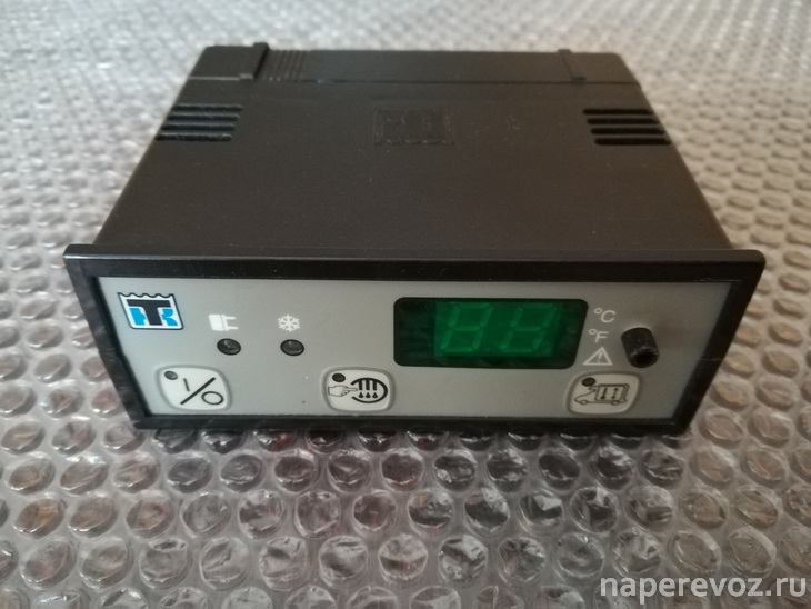
Инструкции на авторефрижераторы
Подробная инструкция по эксплуатации включает в себя несколько основных моментов, которые необходимо изучить каждому пользователю:
- Сведения о приобретенной модели оборудования. В данном разделе находятся технические характеристики аппарата. Также можно схематично ознакомиться с основными принципами архитектуры модели.
- Правила по технике безопасности. Приложенное руководство эксплуатации рефрижераторных систем позволяет ознакомиться с правилами запуска и использования оборудования.
- Разбор составляющей компрессора. Глава посвящена индивидуальным особенностям сборки узла, а также нюансам функционирования компрессора (расход потока воздуха и так далее).
- Контроллер. Поскольку в комплекте с основным устройством прилагается пульт дистанционного управления, в инструкции описаны назначения всех его клавиш.
- Техническое обслуживание рефрижератора. Подробный порядок действий, описанный в документе, позволяет выполнить качественную диагностику прибора, а также необходимую периодичность.
- Таблички с предупреждениями располагаются ближе к концу.
- Талон гарантийного обслуживания так же прилагается в разделе инструкции.
Ремонт термокинг
Произвести ремонт рефрижераторов можно лишь после обнаружения первопричины поломки. Чаще всего в практике встречается следующий спектр неисправностей:
- Выход из строя пускового механизма. Аппарат не запускается;
- Поломка реле, отвечающего за контроль количества смазки и компрессора;
- Необходимость снижения уставки защитного реле;
- Регулировка давления внутри нагнетающей системы.
Для наибольшего удобства при некорректной эксплуатации на экране пульта рефрижератора высвечиваются следующие коды ошибок:
- Показатели системы не поступают на пульт ДУ, даже если рефрижератор запущен, и продолжает работу.
- Датчик температуры, отслеживающий работу испарительного механизма, вышел из строя.
- Сломан датчик, отвечающий за контроль возвратного потока воздуха.
- Цепь нагнетания воздуха вышла из строя.
- Система определения температуры окружающей среды не работает.
- Сломан механизм контроля охладительной жидкости.
- Датчик оборотов дизельного двигателя неисправен.
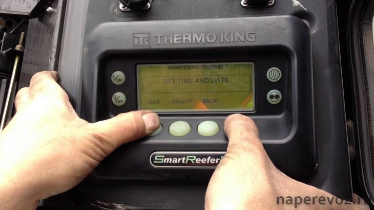
Температурный контроль в установках термокинг
Данный процесс выполняется автоматически. Достаточно запустить двигатель, и начать поездку. Нагрев и охлаждение воздуха зависит от заданных водителем настроек. Контроль полный, поэтому не требует вмешательства пользователя. Благодаря этому, любой продукт, находящийся внутри прицепа, не чувствует перепады температуры воздуха за бортом.
Подбор рефрижератора
Характер груза и его объемы – это параметры, позволяющие определить тип нужного авторефрижератора. Каждый продукт обладает своими требованиями к условиям перевозки.
Чтобы обеспечить приемлемые условия, необходимо настроить рефрижератор в соответствии с требованиями. Примером решения универсальных задач является модель v500 max, которая работает с двумя испарителями, чтобы управлять температурой.
Оценка статьи:
![]() Загрузка…
Загрузка…
Похожие публикации
Что означает «черепашка»? Каким значком обозначается включенная оттайка? Расшифровка символов на контролллерах рефрижераторов Thermo King.
Установки Thermo King серии V и B:

1. Символ обогрева (термометр со стрелкой, направленной вверх). Этот символ указывает, что установка находится в режиме обогрева.
2. Символ охлаждения (термометр со стрелкой, направленной вниз). Этот символ указывает, что установка находится в режиме охлаждения.
3. Символ °C/°F. Этот символ показывает, по какой шкале отображается температура на экране: в градусах Цельсия (С) или Фаренгейта (F).
4. Символ аварийной сигнализации (восклицательный знак в треугольнике). Этот символ указывает, что контроллер обнаружил аварийное состояние (неисправность).
5. Символ технического обслуживания (гаечный ключ). Этот символ указывает на необходимость выполнить техническое обслуживание установки.
6. Символ режима оттайки. Этот символ указывает, что испаритель или конденсатор находится в режиме оттайки.
7. Символ работы от резервного электропривода (прямоугольник с молнией). Этот символ указывает, что установка находится в режиме работы от резервного электропривода.
8. Символ режима оттайки конденсатора (чёрный треугольник вершиной вверх). Этот символ указывает, что блок конденсатора находится в режиме оттайки (появляется одновременно с символом режима оттайки 6).
9. Кнопка ВКЛ/ВЫКЛ. Используется для включения и выключения установки. Индикатор на ней всегда горит, кроме случаев, когда установка отсоединена (нет питания).
10. Жидкокристаллический (ЖК) дисплей. Отображает выбранные экраны. Всегда активен и подсвечивается, кроме случаев, когда установка отсоединена (нет питания) или подсоединена, но выключена вручную с помощью внутрикабинного блока управления. Обычно на нём отображается температура возвратного воздуха (в обоих грузовых отсеках на двухтемпературных установках).
11. Кнопка со СТРЕЛКОЙ ВВЕРХ. Используется для увеличения заданного значения set point температуры.
12. Кнопка со СТРЕЛКОЙ ВНИЗ. Используется для уменьшения заданного значения set point температуры.
13. Кнопка SELECT (ВЫБОР) (стрелки по кругу). Служит для выбора экранов подсказок и информационных экранов.
14. Кнопка ENTER (ВВОД) (знак «равно»). Используется для ввода новой команды, например ручная оттайка и т. д.
15. Зуммер. Издаёт сигнал, если одновременно подключены аккумуляторная батарея транспортного средства и источник электропитания. Также на него подаётся напряжение, если двери открываются при работающей рефрижераторной установке.
Установки Thermo King серии Ce:

1. Символ обогрева (крестообразные лопасти). Установка в режиме обогрева.
2. Символ охлаждения (снежинка). Установка в режиме охлаждения.
3. Символ °C/°F. Этот символ показывает, по какой шкале отображается температура на экране: в градусах Цельсия (С) или Фаренгейта (F).
4. Символ аварийной сигнализации (точка с расходящимися дугами). Этот символ указывает, что в системе присутствует аварийный сигнал.
5. Символ точки (десятичной). Этот символ указывает, что подаётся электропитание, но только если установка выключена.
6. Символ режима оттайки (снежинка с каплями). Этот символ указывает, что испаритель находится в режиме оттайки.
7. Кнопка ВКЛ./ВЫКЛ. Чтобы запустить/остановить установку, нужно нажать эту кнопку и удерживать не менее 1 секунды. При однократном нажатии выполняется переход на предыдущий уровень меню.
8. Жидкокристаллический (ЖК) дисплей. Этот дисплей всегда активен, кроме случаев, когда установка отключена (нет питания) или подключена, но выключена вручную с помощью внутрикабинного блока управления. Обычно на нём отображается температура возвратного воздуха.
9. Кнопка со стрелкой ВВЕРХ. Эта кнопка используется для того, чтобы увеличивать заданное значение set point температуры, отображать значения и прокручивать меню вверх.
10. Кнопка со стрелкой ВНИЗ. Эта кнопка используется для того, чтобы уменьшать заданное значение set point температуры, отображать значения и прокручивать меню вниз.
11. Кнопка SET (НАСТРОЙКА). Служит для выбора экранов подсказок и информационных экранов. Однократное нажатие: вход на следующий уровень меню.
Thermo King серии SLX, SLXi:

1. Кнопка «Вкл» ( I / ON). Эта кнопка используется для включения установки. Сначала на экране появится логотип компании Thermo King, а затем сообщение «Настройка системы — подождите, пожалуйста». После завершения последовательности включения питания на дисплее появляется стандартный экран с температуры отсека и заданным значением set point.
2. Кнопка «Выкл» ( O / OFF). Эта кнопка используется для выключения установки. Сначала на дисплее кратковременно будет показано сообщение «Производится откл.сист. — подождите, пожалуйста. Нажмите кнопку включения, чтобы продолжить», затем на короткое время появится сообщение «Выкл». После выключения на дисплее ничего не отображается.
3. Дисплей.
4. Кнопка оттайки. Нажмите эту кнопку для запуска цикла ручной оттайки.
5. Кнопка CYCLE-SENTRY / непрерывный режим. Нажатие этой кнопки осуществляет переключение между режимами CYCLE-SENTRY и непрерывной работы. Если используется OptiSet Plus, то изменить режим, возможно, не удастся.
6. Функциональные кнопки. Четыре кнопки под дисплеем являются многофункциональными. Их функции изменяются в зависимости от выполняемой операции. Если функциональная кнопка активна, то функция этой кнопки отображается на дисплее непосредственно над кнопкой. Кнопки нумеруются слева направо, так что кнопка 1 — крайняя левая, а кнопка 4 — крайняя правая.
Типовые назначения функциональных кнопок:
-
Заданное значение set point.
-
Приборы
-
Датчики
-
Меню
-
Далее/Назад
-
Да/нет
-
+/–
-
Выбор/Выход;
-
Удалить/Справка.
-
Меню «Счётчики времени»
Thermo King серии T, UT:

1. Кнопка включения.
2. Красный светодиод сигнализации.
3. Заданное значение (уставка).
4. Температура в грузовом отсеке.
5. Стрелка ВВЕРХ.
6. Кнопка выключения.
7. Cycle-Sentry/Непрерывная работа.
8. Блокировка высоких оборотов (кнопка с черепахой). Если функция блокировки высоких оборотов разрешена и включена, то установка будет работать только на низких оборотах до выключения функции блокировки высоких оборотов или превышения времени таймера блокировки высоких оборотов. Эта функция обычно используется в чувствительных к шуму зонах, чтобы понизить уровень шума от двигателя установки. Блокирование высоких оборотов двигателя включается или выключается нажатием кнопки БЛОКИРОВКИ ВЫСОКИХ ОБОРОТОВ, когда установка включена. Нажатие этой кнопки включит блокировку высоких оборотов, повторное ее нажатие выключит блокировку высоких оборотов. Если блокировка высоких оборотов включена, то установка перейдет в режим работы на низких оборотах и загорится желтый светодиодный индикатор. Работа на высоких оборотах невозможна, пока эта функция не будет выключена или не будет превышено время таймера блокировки высоких оборотов. Важное замечание. ТАЙМЕР БЛОКИРОВКИ ВЫСОКИХ ОБОРОТОВ: Если выбран режим блокировки высоких оборотов, то можно разрешить функцию «Лимит времени для блокировки высоких оборотов», чтобы установка возвращалась в нормальный режим работы по истечении заданного периода времени. При этом исключается непредусмотренная продолжительная работа в режиме блокировки высоких оборотов. Период времени может быть установлен от 15 минут до 2 часов. Если период времени был установлен и истек, то установка вернется к нормальному режиму эксплуатации, когда допускается работа на высоких оборотах, а желтый светодиодный индикатор погаснет. При необходимости вернуться в режим блокировки высоких оборотов снова нажмите на кнопку блокировки высоких оборотов.
9. Кнопка запуска оттайки. Если условия позволяют (оттайку можно запустить, если установка работает, а температура змеевика испарителя меньше 7 °C; при некоторых обстоятельствах другие функции, например настройки дверного выключателя, могут блокировать режим ручной оттайки), то установка войдет в цикл оттайки, а желтый светодиод рядом с кнопкой оттайки загорится. Подробнее об оттайке в нашей статье «Режим оттайки в рефрижераторах».
10. Предрейсовая проверка. В ходе предрейсовой проверки проверяется функционирование установки. Кнопка ПРЕДРЕЙСОВОЙ ПРОВЕРКИ позволяет оператору запустить полную предрейсовую проверку или текущую предрейсовую проверку дизельного двигателя. Полная предрейсовая проверка должна запускаться при неработающей установке. Выключите и включите установку, чтобы удалить все коды сигнализации. Выключите установку. Включите установку и подождите индикации на дисплее счетчиков времени наработки установки. Когда на дисплее появится индикация счетчиков времени наработки установки, нажмите и удерживайте кнопку ПРЕДРЕЙСОВОЙ ПРОВЕРКИ в течение 5 секунд. Предрейсовая проверка займет приблизительно 20–30 минут, в зависимости от обстоятельств.
11. Ввод.
12. Стрелка вниз.
- Читайте также другие наши статьи, в которых мы даём ответ на часто задаваемые вопросы.
- Холодильные установки для автотранспорта.
- Аксессуары и дополнительное оборудование.
- Остались вопросы? Наши специалисты помогут вам по телефону: +7 (343) 343-05-08.
The maintenance information in this manual covers unit models:
MD-300 30
MD-300 30 230/3/60
MD-300 50 380-460/3/50-60
MD-300 30 EEC
MD-300 50 220/3/50 EEC
For further information, refer to:
MD-300 Operator’s Manual
MD-300 Parts Manual
2.44, 2.49, 3.66, 3.74, 3.88, and 3.95 Engine Overhaul Manual
Diagnosing Thermo King Refrigeration Systems
Tool Catalog
Thermoguard µP-T Microprocessor Controller
The Collector Refrigeration Recovery Unit
Principals of Evacuation for Field Application
Electrostatic Discharge Training Guide
The information in this manual is provided to assist owners, operators and service people in the proper
upkeep and maintenance of Thermo King units.
This manual is published for informational purposes only and the information so provided should
not be considered as all-inclusive or covering all contingencies. If further information is required,
Thermo King Corporation should be consulted.
Sale of product shown in this manual is subject to Thermo King’s terms and conditions
including, but not limited to, the Thermo King Limited Express Warranty. Such terms and
conditions are available upon request. Thermo King’s warranty will not apply to any
equipment which has been «so repaired or altered outside the manufacturer’s plants as,
in the manufacturer’s judgment, to effect its stability.»
No warranties, express or implied, including warranties of fitness for a particular
purpose or merchantability, or warranties arising from course of dealing or usage of
trade, are made regarding the information, recommendations, and descriptions
contained herein. Manufacturer is not responsible and will not be held liable in contract
or in tort (including negligence) for any special, indirect or consequential damages,
including injury or damage caused to vehicles, contents or persons, by reason of the
installation of any Thermo King product or its mechanical failure.
MD-300 50 230/3/60 EEC
MD-300 50 380/3/50 EEC
MD-300 30 R-134a
MD-300 50 R-134a
TK 51910
TK 51908
TK 8312
TK 5984
TK 5955
TK41087
TK40956
TK 40612
TK 40282
1 MD-200/MD-300/MD-200 MT. Proven reliability, unbeatable quality and multi-temperature flexibility. S-2 Evaporator Now available for multi-temperature trucks Reliability and performance you’ve come to expect in an innovative new design Aluminium frame and exterior panels for light weight and corrosion resistance Reduced maintenance costs through EMI 2000. Exclusive TherMax (MD-200/MD-300) system provides faster defrosts, superior heating capacity Superior quality and reliability High capacity compressor Warranty coverage At the heart of the MD range is the X214 1st year complete warranty Deep Sump two cylinder compressor, 2nd year major components warranty: engineered specifically for R-404A. covers specified components It is considered to be the most efficient reciprocating compressor in Thermo King customers have the the industry, delivering optimum reassurance of our worldwide pumping and cooling capacity.
2 Dealer network. We’re at your service twenty-four hours a day, seven days a week. Our multilingual telephone service ( Thermo Assistance) makes us easy Reduced maintenance to reach from anywhere, at any Maintenance is a significant portion of the time. total life cost of a temperature control system. Thermo King’s MD. Belt-driven dual evaporator fans range uses innovative design to minimise Delivering superior air flow. Thermo King MD-200 /. maintenance, resulting in MD-300 / MD-200 MT systems employ two high output, lower maintenance cost. belt driven fans that are powered by the system’s diesel engine. These units come equipped This creates a large volume of as standard with Thermo high velocity air, which results King’s exclusive EMI-2000.
3 In increased air circulation filters and fluids package Thermo King’s throughout the entire cargo area. increasing service intervals. Load Encircling . Superior air circulation provides 2,000 hour oil change full air throw. faster box temperature pulldowns, 12,000 hour coolant faster recoveries after door openings, minimal temperature fluctuations and virtual Low Decibel Sound Reduction System elimination of hot spots and The new MD range offers our new Low Decibel Sound short cycling. Prevents short Reduction System as an option. cycle air flow. TherMax system for faster defrosts and Service accessibility superior heating capacity Designed for rapid and full access to the engine An exclusive feature in all Thermo King MD-200 / MD-300 compartment, saving time SMART REEFER units is and money in service the proven TherMax heat operations.
4 And defrost system. The unique TherMax is simply a exterior design better way to generate allows individual more heating capacity when panels to be it’s needed. By using a special removed and replaced condenser evacuation cycle, more refrigerant is made instead of the entire skin. available during heat and defrost modes. Economy and efficiency Total Life Cost The MD range’s exclusive space saver condenser provides Too often, purchase price is the prime concern when maximum cab clearance and reduces truck body height on specifying equipment. However, lower fuel costs, lower conventional chassis. maintenance costs and higher resale values mean that a The cube saver evaporators optimise payload space below Thermo King unit’s total life cost is actually lower than the evaporator for all types of cargo.
5 Competitive products. The MD range is designed for use with totally chlorine-free Furthermore, Thermo King offers superior design, R-404A refrigerant. This means that the MD range meets components, build quality and performance. all international requirements for refrigerants. This means enhanced load Fuel economy protection and reduced Fuel contributes downtime approximately 40% resulting in of the total life cost increased of a temperature revenues. control system. The new MD range consumes significantly less fuel than competitive products. Competition This means less fuel costs and reduced Competition Resale value Purchase price environmental emissions. Maintenance Total Life Cost Fuel A system to meet your requirements I.
6 Remote Evaporator S-2. J. Although shown at the front, evaporators can alternatively be placed at the back of a zone. MD-200/MD-300/MD-200 MT: key features and options 1- TOTAL KARE 7- WINTRAC (DATA ANALYSIS SOFTWARE). Because maintenance costs constitute a key Wintrac is a Windows based, simple to use, multilingual management variable in the Total Life Cost of a temperature software package designed to communicate and read data from all control system, we now offer, through Total Kare, a Thermo King temperature recorder devices. It provides quick and complete selection of maintenance programmes. easy answers to all your questions in relation to the performance of the temperature control unit and the temperature of the produce while in transit.
7 2- CYCLE-SENTRY. Stops engine when refrigeration is not needed and restarts when refrigeration or battery charge is needed. 8- TKDL (DATA CAPTURE). Fuel savings of up to 80% User-friendly temperature recorders for all Increases component life makes of temperature-controlled equipment Reduces maintenance costs Simple data offload to PC. Delivery and journey printouts at the touch of a button Approved to EN-12830, CE Mark and IP-65 standards 3- EXTENDED MAINTENANCE INTERVAL Up to four independent sensors and 512K memory Thermo King EMI-2000 will extend your maintenance interval and reduce your operating cost by: Reducing clean-up and disposal cost 9- FLEETWATCH. Reducing environmental impact with less User-friendly software empowers fleet manager spillage and less waste with automatic custom reporting.
8 Extending engine life with improved, highly Provides seamless connection to collect and organise output from efficient filtration Thermo King’s DAS and TKDL data recorders Reducing scheduled maintenance cost by up Automatically organises data recorder output data into simple, to 40% selectable reports useful to your operation Reports are easy to understand and user-friendly 4- Thermo KING HIGH PERFORMANCE. BATTERY 10- TRACKING. The Thermo King high performance Complete load monitoring and fleet tracking battery is designed exclusively for at your fingertips transport refrigeration applications. It is Monitors sensitive loads via the web the only battery recommended by Increases truck asset utilisation Thermo King for its equipment.
9 It incorporates new Silver and Reduces operating costs Calcium technologies that provide performance far superior to Enhances customer satisfaction that of any conventional automotive battery technology. The Increases security and reduces insurance risk Thermo King high performance battery minimises your costs and TracKing can be sold with a Total Kare service contract maximises your confidence on the road; it is totally maintenance TracKing is compatible with all Thermo King dataloggers and free and delivers a service life more than 20% longer than trailer controllers conventional batteries. 5- WARRANTY COVERAGE 11- SMART REEFER IN-CAB CONTROLLER. 1st year complete warranty Simplified keypad to reduce incorrect operation of the system 2nd year major components warranty: Visible set-point confirmation for load protection covers specified components Enhanced temperature management Unit self-check for reduced 6- DAS (DATA ACQUISITION SYSTEM) down-time High performance data recorder system.
10 Records temperatures, set Alarm codes for simplified point, operating modes and external events. trouble-shooting Data can be output to computer or printer Programmable features to tailor Operates independently of unit controller operating conditions to the load 512K memory stores over one year’s data Reassures customer of total quality control Provides evidence of correct practice 12- TG-V IN-CAB. Approved to EN-12830, CE Mark and IP-65 standards Up to six independent sensors CONTROLLER. Automatic power-up and shut-off to protect unit battery Monitor and control of both compartments MD-200/MD-300 MD-200 MT. Life Cost Management 1- Guaranteed Maintenance Contracts . 2- Cycle-Sentry start / stop control system . 3- EMI 2000 extended maintenance.
Руководства, описания, инструкции
Руководство пользователя Thermo King SL
SL-100e, SL-200e, SL-400e с SR-2 и SPECTRUM SL с SR-2
TK60057-2-OP (изд. 1, 08/06)
Авторефрижераторные установки с собственным двигателем TS-200, TS-300, TS-600, TS-500, SPECTRUM TS XDS SR, RD-II, KD-II, MD-200, MD-300, MD-II, SDZ, CD-II MAX UMD-II, URD-III, UTS, RD TLE, MD TLE, RD-MT, MD-MT, MD-200 MT Руководство пользователя
Авторефрижераторные установки с собственным
двигателем TS-200, TS-300, TS-600, TS-500, SPECTRUM TS XDS SR, RD-II, KD-II, MD-200, MD-300, MD-II, SDZ, CD-II MAX UMD-II, URD-III, UTS, RD TLE, MD TLE, RD-MT, MD-MT,
MD-200 MT
TK 60019-RU-1-OP (изд. 0)
Введение…………………………………………………………… 7
Руководство Пользователя Thermo King Старых Моделей Серии С
Руководство Пользователя Thermo King Старых Моделей Серии С
КНОПКИ И ИНДИКАТОРЫ УПРАВЛЕНИЯ
00 Световой индикатор включения; [2] Кнопка включения/выключения; [3) Световой индикатор заданной температуры; [4] Световой индикатор перегрузки по переменному току; [5] Световой индикатор работы установки; [б] Дисплей показаний температуры;0Световой индикатор показания температуры по Цельсию; [8]Световой индикатор показания температуры по Фаренгейту.
Руководство пользователя Thermo King Старых моделей серии V
Руководство пользователя Thermo King Старых моделей серии V
РАБОТА В РЕЖИМЕ ОТТАИВАНИЯ
РУЧНОЕ ВКЛЮЧЕНИЕ РЕЖИМА ОТГАИВАНИЯ*)
При нажатии кнопка ручного включения запускает режим оттаивания, если температура испарителя ниже 2°С или 35°F, при этом светодиод оттаивания должен включиться.
Установка будет работать в режиме охлаждения автоматически, когда цикл оттаивания закончится.
Руководство пользователя Direct Smart Reefer Thermo King Серии V
Руководство пользователя Direct Smart Reefer Thermo King Серии V
Установки с приводом от двигателя автомобиля и контроллером Direct Smart Reefer Руководство по эксплуатации B-100, V-100, V-200, V-300, V-400, V-500, V-700
РУССКИЙ содержание
Руководство оператора пульта управления ThermoGuard uP-T Smart Reefer
Руководство оператораThermoGuard TG-VI
Руководство оператораThermoGuard TG-VI
РАЗДЕЛ I
ПРАВИЛА БЕЗОПАСНОЙ ЭКСПЛУАТАЦИИ
Правила безопасности I-I
Общие правила I-I
Автоматический запуск/остановка I-I
Руководство пользователя Smart Reefer2
Руководство пользователя Smart Reefer2
ФУНКЦИИ ПУЛЬТА УПРАВЛЕНИЯ HMI
Пульт управления HMI (Human/Machine Interface) подключен к контроллеру и служит для управления агрегатом и отображения информации . Пульт HMI и контроллер соединены шиной CAN (Controller Area Network) . HMI также включает в себя регистратор данных о температуре груза Cargo Watch . Он расположен на дверце блока управления
Руководство оператора ThermoGuard Spectrum Multi-Temp
Раздел 1 — Информация по техникебезопасности SPECTRUM
Общие правила………………………………………………………………………………………………………………….. 1-1
Автоматический пуск и останов………………………………………………………………………………………… 1-1
Руководство пользователя SLX
SLX-100, 200 и 400 с контроллером SR-2
Введение
Общие сведения………………………………………………………………………………………………………………………………………………………………………….. 4
СЛУЖБА Thermo Assistance…………………………………………………………………………………………………………………………………………………………. 4
Коды ошибок Thermo King
Расшифровка кодов ошибок Thermo King (Термо Кинг)
Инструкции по эксплуатации органов управления Thermo King
Полезная информация о Thermo King