-
Contents
-
Table of Contents
-
Bookmarks
Quick Links
tds2012_oscilloscope_guide.doc
Authors/Contributors:
Dr. Montoya
Tektronix TDS 2012
Digital Storage Oscilloscope
User’s Guide
Thomas Montoya
James Free
Jake Gunderson
John Preheim
1/18
Rev. 3/16/09
Related Manuals for Tektronix TDS 2012
Summary of Contents for Tektronix TDS 2012
-
Page 1
1/18 tds2012_oscilloscope_guide.doc Tektronix TDS 2012 Digital Storage Oscilloscope User’s Guide Authors/Contributors: Thomas Montoya James Free Jake Gunderson John Preheim Dr. Montoya Rev. 3/16/09… -
Page 2: Table Of Contents
2/18 tds2012_oscilloscope_guide.doc Table of Contents Background/Introduction ……………………………………………………. 3 Simple voltage measurement and display …………………………………. .. 4 Printing oscilloscope display ………………………………………………. .. 4 Default setup ………………………………………………………………..4 Autoset ………………………………………………………………………. 4 Channel menus ……………………………………………………………..5 Volts/Div knobs ……………………………………………………………… 5 Sec/Div knob ………………………………………………………………. .. 5 Position knobs ………………………………………………………………
-
Page 3: Background/Introduction
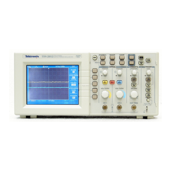
Background/Introduction This guide discusses using the Tektronix TDS 2012 Digital Storage Oscilloscopes to make simple voltage versus time measurements and perform/use elementary functions. Figure 1 shows the front panel of the oscilloscope. Digital storage oscilloscopes sample analog signals, store the values (and corresponding times), and display them on the screen.
-
Page 4: Simple Voltage Measurement And Display
4/18 tds2012_oscilloscope_guide.doc Simple voltage measurement and display For the simplest case of a single self-triggering measurement, connect a P2200 passive probe to the CH1 BNC connector and the tip of the probe to the component/device whose voltage is to be measured.
-
Page 5: Channel Menus
5/18 tds2012_oscilloscope_guide.doc Channel menus The yellow CH1 MENU and blue CH2 MENU buttons are used to cause the oscilloscope to either display or hide the signal from the corresponding channel (yellow trace for CH1 and blue trace for CH2). In addition, when the particular channel is selected, a softkey menu for that channel will be activated.
-
Page 6: Set To Zero
6/18 tds2012_oscilloscope_guide.doc Set to zero Under the “HORIZONTAL” menu, the SET TO ZERO button sets the horizontal position (controlled by the horizontal position knob) to zero (center vertical axis), thus centering the signal horizontally. Help The oscilloscope has a Help system with topics that cover all the features of the oscilloscope. You can use the Help system to display several kinds of information: 1) general information about understanding and using the oscilloscope, 2) information about specific menus and controls, and 3) device about problems you may face while using an oscilloscope (e.g., reducing…
-
Page 7: Math Menu
7/18 tds2012_oscilloscope_guide.doc Table 1 Horizontal Menu choices The axis for vertical scale is the ground level. A readout near the top right of the screen displays the current horizontal position in seconds. An M indicates the Main time base and a W indicates the Window time base.
-
Page 8: Save/Recall
8/18 tds2012_oscilloscope_guide.doc The + and — options will display the sum or difference of the two signals on the display. It is important to note that the sum or difference will be calculated using the visual signals on the display. This means that if one signal is displayed to a higher magnification level (i.e., different VOLTS/DIV setting) than the other, the result will not be a true sum or difference.
-
Page 9: Measure
9/18 tds2012_oscilloscope_guide.doc You can choose an FFT window to eliminate discontinuities that will disrupt your output. As shown in Table 3, there are three window choices. Table 3 FFT window options Problems occur when the oscilloscope acquires a time-domain waveform containing frequency components that are greater than the Nyquist frequency.
-
Page 10: Menus
10/18 tds2012_oscilloscope_guide.doc There are several options for eliminating aliasing: 1. Adjust the Sec/Div control to a faster setting. This will raise the Nyquist frequency and bring the FFT display within range of the aliases. 2. If you do not need to view frequencies components above 20 MHz, set the Bandwidth Limit option to On.
-
Page 11: Utility
11/18 tds2012_oscilloscope_guide.doc Table 4 Save/Recall button Setups options Table 5 Save/Recall button Waveforms options 2) Push the MEASURE button to access automatic measurements. Each of the five softkeys is available to have a measurement source and type defined. For example, pressing the top softkey will bring up a “Measure 1”…
-
Page 12
12/18 tds2012_oscilloscope_guide.doc Table 6 Types of measurements 3) Push the ACQUIRE button to bring up a softkey menu with the selections listed in Table 7. Table 7 ACQUIRE softkey menu Dr. Montoya Rev. 3/16/09… -
Page 13: Cursor
13/18 tds2012_oscilloscope_guide.doc 4) Push the UTILITY button to bring up a softkey menu with the selections listed in the first column of Table 8. Some these selections bring up subchoices as listed in the second column of Table 8. Table 8 UTILITY softkey menu Dr.
-
Page 14
14/18 tds2012_oscilloscope_guide.doc 5) Push the CURSOR button to bring up a “CURSOR” softkey menu with a <Type> softkey and <Source> softkey. As shown in Table 9, pushing the <Type> softkey will toggle the user between selections of Voltage, Time, and Off. As shown in Table 9, pushing the <Source>… -
Page 15: Display
15/18 tds2012_oscilloscope_guide.doc 6) Push the DISPLAY button to bring up a softkey menu with the selections listed in Table 10. Table 10 DISPLAY softkey menu Trigger Controls You can define the trigger (see Table 11) by pushing the TRIG MENU button and front-panel soft keys.
-
Page 16: Edge Trigger
16/18 tds2012_oscilloscope_guide.doc Dr. Montoya Rev. 3/16/09…
-
Page 17: Video Trigger
17/18 tds2012_oscilloscope_guide.doc Dr. Montoya Rev. 3/16/09…
-
Page 18: Pulse Width Trigger
18/18 tds2012_oscilloscope_guide.doc Other Trigger Controls Level Dial Use to select which point on the wave to set the trigger. SET TO 50% The trigger level is set to the vertical midpoint between the peaks of the trigger signal. FORCE TRIG Completes an acquisition regardless of an adequate trigger signal. This button has no effect if the acquisition is already stopped.
Tektronix TDS2012 Осциллограф
Производитель:
Модель:
TDS2012
Дата:
2002
Категория:
Группа:
Описание:
Информация
TDS1000 and TDS2000 Series Oscilloscopes. Colorful
Performance at a Black and White Price.
The TDS1000 Series and TDS2000 Series digital storage
oscilloscopes deliver an unbeatable combination of superior
performance, unmatched ease-of-use and affordability in an
ultra lightweight, portable package. These new products
extend the performance and ease-of-use features in the
former TDS200 Series
the benchmark for low-cost oscilloscopes.
Affordable Digital Performance
With up to 200 MHz bandwidth and 2 GS/s maximum sample rate,
no other color digital storage Oscilloscope offers as much
bandwidth and sample rate for the price. The TDS1000 and
TDS2000 Series oscilloscopes provide accurate real-time acquisition up to their full bandwidth. These instruments offer advanced triggering, such
as pulse width trig gering and line-selectable video triggering, and 11 standard automatic measurements on all models. The Fast Fourier
Transform (FFT) math function allows the user to analyze,
characterize and troubleshoot circuits by viewing frequency
and signal strength (standard on all models).
Simple User Interface
The simple user Interface makes these instruments easy to
use, reducing learning time and increasing efficiency.
Classic, analog-style controls provide instant, front-panel
access to the most frequently used functions. The autoset
function automatically detects sine waves, square waves and
video signals, and provides readouts of relevant
measurements. This function also allows the user to select
additional views of the signal, such as rising and falling
edges, video lines and fields, and FFT. The Probe check
wizard aids the user in setting the attenuation factor and
compensating the Probe. The context-sensitive help menu with
indexed and hyper-linked topics allows the user to
selectively learn about the operation of any Oscilloscope
function. The color LCD display on the TDS2000 Series models
dedicates a different color for each trace and its
associated readouts to simplify viewing complex signals on
multiple channels.
Features & Benefits
60 MHz, 100 MHz and 200 MHz Bandwidths
Sample Rates up to 2 GS/s
2 or 4 Channels
Color or Monochrome LCD Display
Autoset Menu with Waveform Selection
Probe Check Wizard To Ensure Correct Probe Usage
Context-sensitive Help
Dual Time Base
Advanced Triggering
11 Automatic Measurements
Multi-language User Interface
Waveform and Setup
Memories
FFT Standard on All Models
Extended Capabilities Are Provided with Optional TDS2CMA Module,
WaveStarTM Software and Probes
показать больше
Технический паспорт
Hасто́льная кни́га тип:
Технический паспорт

Страницы:
4
Размер:
233.42 Kbytes (239027 Bytes)
Язык:
english
Пересмотр:
Hасто́льная кни́га ID:
Дата:
2002 01 01
Качество:
Электронный документ, ни сканирование, очень хорошо читается.
Дата загрузки:
2017 12 27
MD5:
9ca5be08143a46c550ec36458aa9c5d7
Загрузки:
2801
Руководство по техническому обслуживанию
Hасто́льная кни́га тип:
Руководство по техническому обслуживанию

Страницы:
138
Размер:
2.03 Mbytes (2127399 Bytes)
Язык:
english
Пересмотр:
Hасто́льная кни́га ID:
071-1076-02
Дата:
Качество:
Электронный документ, ни сканирование, очень хорошо читается.
Дата загрузки:
2019 09 28
MD5:
c8a232f598b29fb39efb90c32e6d4abf
Загрузки:
3200
Информация
General Safety Summary … .
Service Safety Summary … .
Environmental Considerations … .
Preface … .
Related Manuals … .
Specifications
Certifications and Compliances … .
Installation …
Power Cord … .
Security Loop … .
Extension Modules … .
Functional Check … .
Self Calibration … .
Default Setup … .
Main Board … .
Acquisition System … .
Processing and Display System … .
Input Signal Interface … .
Probe Compensation … .
External Trigger … .
Main Board Power … .
Power supply … .
Display Module … .
Front Panel … .
Two-Channel Oscilloscopes … .
Four-Channel Oscilloscopes … .
LEDs … .
Extension Modules … .
Required Equipment … .
Test Record … .
Performance Verification Procedures … .
Self Test … .
Self Calibration … .
Check DC Gain Accuracy … .
Check Bandwidth … .
Check Sample Rate and Delay Time Accuracy … .
Check Edge Trigger Sensitivity … .
Check External Edge Trigger Sensitivity … .
Required Equipment … .
Adjustment Procedure … .
Enable the Service Menu … .
Adjustment Procedure … .
Preparation … .
Preventing ESD … .
Inspection and Cleaning … .
General Care … .
Inspection and Cleaning Procedures … .
Removal and Installation Procedures … .
Preparation … .
List of Modules … .
Summary of Procedures … .
Required Tools … .
Rear Feet … .
Flip Feet … .
Front-Panel Knobs … .
Power Button … .
Rear Case … .
Front Feet … .
Power supply Module … .
Internal Assembly … .
Display Cable … .
Front-Panel Cable … .
Main Board Module … .
Display Module … .
Front-Panel Module … .
Keypad … .
Front Case … .
Troubleshooting … .
Adjustment After Repair … .
Required Tools and Equipment … .
Troubleshooting Tree … .
Probe COMP Output … .
Troubleshooting the Power supply … .
Troubleshooting the Display … .
Troubleshooting the Backlight … .
Troubleshooting the Front Panel … .
Troubleshooting the Main Board … .
Running Diagnostics … .
Troubleshooting Input Connections … .
Using the Error Log … .
Repackaging Instructions … .
Packaging … .
Storage … .
Parts Ordering Information … .
Module Servicing … .
Using the Replaceable Parts List … .
Abbreviations … .
Mfr. Code to Manufacturer Cross Index … .
показать больше
tds2012_oscilloscope_guide.doc
Default setup …………………………………………………………………. 4
Autoset ………………………………………………………………………. 4
Channel menus …………………………………………………………….. .. 5
Volts/Div knobs ……………………………………………………………… 5
Sec/Div knob ………………………………………………………………. .. 5
Position knobs ……………………………………………………………… .. 5
Set to zero ………………………………………………………………….. .. 6
Help………………………………………………………………………… .. 6
Run/Stop……………………………………………………………………. .. 6
Single Sequnce……………………………………………………………… .. 6
Horizontal menu ……………………………………………………………. .. 6
Math Menu …………………………………………………………. …………. 7
Menus …………………………………………………………………… …….. 10
Save/Recall…………………………………………………………….. 8
Measure………………………………………………………………. . 9
Acquire……………………………………………………………… … 10
Utility……………………………………………………………….. … 11
Cursor……………………………………………………………….. … 13
Display……………………………………………………………… … 15
Trigger Controls…………………………………………………………… … 15
Trigger Types……………………………………………………….. … 15
Edge Trigger……………………………………………………………. 16
Video Trigger……………………………………………………….. … 17
Pulse Width Trigger………………………………………………… … 18
Other Trigger Controls…………………………………………………….. … 18
Level Dial……………………………………………………………… 18
Set to 50%………………………………………………………………………………. … 19
Force Trig……………………………………………………………… 19
Trig View…………………………………………………………… … 19
Dr. Montoya
2/18
Rev. 3/16/09