TCM — Operation & Maintenance Manual — FB10 FB15 FB20 FB25 FB30 7 7LB 7V — OB-81BAE — 135 pages
- Addeddate
- 2021-05-26 17:56:27
- Identifier
- tcm-operation-maintenance-manual-fb-10-fb-15-fb-20-fb-25-fb-30-7-7-lb-7-v-ob-81-bae-135-pages
- Identifier-ark
- ark:/13960/t0wr16x2c
- Ocr
- tesseract 5.0.0-alpha-20201231-10-g1236
- Ocr_autonomous
- true
- Ocr_detected_lang
- en
- Ocr_detected_lang_conf
- 1.0000
- Ocr_detected_script
- Latin
Cyrillic
- Ocr_detected_script_conf
- 0.9834
0.0159
- Ocr_module_version
- 0.0.13
- Ocr_parameters
- -l kir+eng+lat+kaz+Cyrillic+Latin
- Pdf_module_version
- 0.0.14
comment
Reviews
There are no reviews yet. Be the first one to
write a review.
-
Contents
-
Table of Contents
-
Bookmarks
Quick Links
川 二
w
十
N o . M E F ‑ 4 3 A A E
TCM~
. . . .
n
塁
W O R K S H O P M A N U A L
F O R K L I F T TRUCK
︿
︿
O
刃 ス
ω
工
O
刀
豆
﹀
Z
C
﹀
﹁
ト 一 一
F D 3 5 T 9
F D 4 0 T 9
F D 4 5 T 9
F D 5 0 T 9
F D 3 5 c 9
F D 4 0 C 9
F D 4 5 c 9
F G 3 5 T 9
F G 4 0 T 9
明
H
U
U
師
︒
曲
目
2
u
刷
︒
a
‑
H
O
ω
帥
・
﹃
岨
唱
刊
の
品
0
4
d
TCM C O R P O R A T I O N
Z
0 ・
豆
m
明 ム
‑ ω
﹀
﹀
m
TCMc
仰
O R A T I O
二
ト
Chapters
-
1. General Description
7 -
2. Removing/Reinstalling
43 -
3. Disassembly and Reassembly
113
Related Manuals for TCM FD35C9
Summary of Contents for TCM FD35C9
-
Page 3
IMPORTANT For detailed procedures about operating the lift truck, see the lift truck “OPERATION AND MAINTENANCE MANUAL.” Improper operation of the lift truck might cause serious bodily injury or death to you or fellow workers. The decals on your lift truck indicate the level of hazard, such as “ CAUTION,”… -
Page 4
(Empty page) -
Page 5
INTRODUCTION INDEX TCM offers a wide variety of lift trucks which have 1. GENERAL been enthusiastically welcomed by users all over the world. The lift trucks covered in this Workshop Manual DESCRIPTION have also been developed through years of research and experience, and they feature high quality designs and 2. -
Page 6
(Empty page) -
Page 7: Table Of Contents
1. GENERAL DESCRIPTION SAFETY INSTRUCTIONS …………….1-1 BASIC SERVICING KNOWLEDGE …………1-17 LIST OF LUBRICANTS …………….1-26 PRE-OPERATION INSPECTION …………..1-27 PERIODIC INSPECTIONS …………….1-29…
-
Page 9: Safety Instructions
1.1 SAFETY INSTRUCTIONS 1.1.1 Introduction ■ Lift trucks should only be operated by qualified operators (1) A qualified operator must have training and possess any required licenses to operate this truck. (2) The operation of a crane or performing any welding must be only attempted by qualified personnel.
-
Page 10
(4) Clear away any obstructions or hazards from the work area. (5) Do not stack unstable objects. Take any necessary measures to prevent any stacks of objects from collapsing. (6) Keep the areas around the switchboard, fire extinguisher, stairs, and emergency exits clear of obstacles. -
Page 11
1.1.5 Maintenance precautions (while working) (1) Follow the specified work procedure. (2) Do not remove any covers or components other than those necessary to do the job. (3) Do not allow people other than service personnel to enter the work area. -
Page 12
(6) Make certain all the switches on the electrical equipment you used have been turned off. (7) Use only TCM approved replacement parts and lubricants. (8) After servicing, make sure the truck operates properly. 1.1.7 Modifications to the truck might void your warranty Do not try to modify your truck. -
Page 13
1.1.10 Safety rules for maintenance <Before starting maintenance> Before starting maintenance service, make sure: (1) The travel and load handling control levers are in neutral. (2) The parking brake is securely applied. (3) The wheels are blocked. (4) Put a sign stating “Do not operate” on the truck or mark the off-limits area around the truck with traffic cones or chains to keep people away from the work area. -
Page 14
(4) Use jack stands, supporting blocks or a bench suitable for supporting Rectangular the truck: cross section · Do not use square timbers as supporting blocks. · Use only specified jack stands, supporting blocks or platform. · Use jack stands, supporting blocks and a bench that have enough strength for the purpose. -
Page 15
(4) Chain blocks · Do not toss or drag a chain block. If a block becomes wet, wipe Do not drag! away the moisture and lubricate it properly. An elongated or Do not toss! deformed hook should not be used. ·… -
Page 16
<Removing and reinstalling tires and rims> (1) Deflate the tire before loosening the bolts connecting the rims (for the split rim type) or before removing the side ring or lock ring (for the side ring type). (2) It is particularly dangerous if you try to remove an inflated tire from the truck with the split-rim having a loose or missing rim connecting bolt. -
Page 17
<Precautions to take when overhauling cylinders> (1) Do not try to overhaul cylinders while they are mounted on the truck. Remove the cylinder assembly and overhaul it in a workshop. (2) When removing a cylinder from the truck, secure it to a mast connecting member with rope, to prevent it from falling. -
Page 18
PLATE WING NUT stoppers. (8) Apply genuine TCM Chain Coat chain lubricant to the lift chains from the front of the mast with the forks lowered to the ground. (You can LEVER use engine oil for this purpose. Do not use grease.) <Opening the radiator cap>… -
Page 19
<Electrical system> (1) Precautions when recharging batteries · Make sure the power cable is securely connected before turning on the battery charger. Do not disconnect or reconnect the power cable while the battery charger is on. · Loosen the cap on each cell in the battery. ·… -
Page 20
<Welding> (1) Observe the following conditions when welding: · When welding near a tire, note that there is a danger of the tire exploding if it is heated excessively. · Do not try to weld or gas cut any container or pipe containing fuel or oil. -
Page 21
<Grinding> (1) Put the specified safety cover on the grinding wheel. (2) The clearance between the workrest and the grinding wheel should be COVER SHIELD 3 mm [0.118 in.] less than 3 mm. WORKREST (3) Install a shield to prevent grinding powder from flying off. (4) Make a dry run on the grinding wheel for at least 1 minute before each use or for more than 3 minutes whenever the grinding wheel is replaced with a new one. -
Page 22
<Transporting> (1) When a group is carrying a heavy load, make sure everyone understands the meaning of any hand signals and the communication methods that will be used. (Refer to “1.1.9. When working in a group”.) (2) Prevent back injuries. Use a diagonal foot position and get as close to the load as possible. -
Page 23
(11) If a fire breaks out, observe the following precautions: · If a fire breaks out, give a loud warning to fellow workers immediately. · If an electrical device catches fire, turn off the power switch before trying to fight fire. ·… -
Page 24
(15) The drive shaft and planet carrier should be installed by turning them. Do not push them or hit them. Be careful not to get your fingers pinched. (16) If it is hard to remove the HST motor sprocket in a Bobcat loader, BEARING PULLER do not hit the puller with force. -
Page 25: Basic Servicing Knowledge
1.2 BASIC SERVICING KNOWLEDGE 1. Installing bearings When installing a bearing onto a shaft, tap its inner race with a mallet as shown in Figure 1.1. When installing a bearing into a case, tap its outer race. When removing, use the same procedure as for installing.
-
Page 26
③ When installing an oil seal onto a shaft, apply lubricating oil or grease to its seal lip and the mounting surface of the shaft. For a double-lip type, fill grease by 1/3 to 1/2 of the space between the lips. When inserting an oil seal into a case, use care to damage the seal lip. -
Page 27
5. CLEANING ■ General metallic parts ① Clean parts thoroughly using cleaning fluid. It is recommended that parts be immersed in cleaning fluid and moved up and down slowly until all old lubricant and foreign material is dissolved and parts are thoroughly cleaned. -
Page 28
6. STANDARD BOLT TIGHTENING TORQUE See the bolt torque charts on page 1-22 to 1-25 for the torques of standard bolts when they are used for general applications. Refer to the Shop Manual and Service Manual of your truck model when: 1) Special nuts are used. -
Page 29
Division Surface Name Shape Thread size Material Part number by strength treatment Nominal symbol 01101- SS400 Black SS400 01100- “ M4 — M8 coarse and S45C 01103- “ Normal M10 — M39 fine Yellow SCM435, Boron steel 01106- “ chromate SCM435, Boron steel 10.9 01107-… -
Page 30
1-22… -
Page 31
1-23… -
Page 32
1-24… -
Page 33
1-25… -
Page 34: List Of Lubricants
Lubricant Prevailing ambient Location Grade of viscosity to be used temperature TCM Lube Life C-1 -25°C to 35°C [ -13°F to 95°F] Engine crankcase Engine oil TCM Lube Life S-3 0°C & above [32°F & above] TCM Lube Life X-3 0°C to -25°C [32°F to -13°F]…
-
Page 35: Pre-Operation Inspection
1.4 PRE-OPERATION INSPECTION Component Item to be checked Checking procedure Engine ① Oil level. (A) Remove dipstick and wipe its end with clean cloth. Reinstall and keep it for about 1 minute. Remove it to check oil level. (B) Check for contamination of oil on the dipstick. ②…
-
Page 36
Component Item to be checked Checking procedure Steering wheel ① Wander, pull, hard (A) Run the truck at slow speed to check whether the steering. truck wanders or pulls to one side or has hard steering. Power steering ① Operation and oil leakage. (A) Run the truck at slow speed and turn steering wheel to the right and left to check power steering for operation and oil leakage from piping. -
Page 37: Periodic Inspections
Safety and Sanitation Regulations”) The items that must be inspected and serviced, and the procedures for doing so, are described in the TCM Inspection Service Notes. This requirement should be made clear to the customer when the forklift truck is delivered.
-
Page 38
Periodic inspection items and intervals 1000 1100 1200 Interval Hour Symbol: Item Month Procedure W: Disassemble Engine oil Oil level X X X X X X X X X X X X : Check Engine oil Contamination A A A A… -
Page 39
1000 1100 1200 Interval Hour Symbol: Item Month Procedure C W: Disassemble Fuel pump — strainer (diesel trucks) Contamination Starter motor brush — : Check Wear commutator surface A: Adjust Generator brush — commutator surface Wear O: Remove Carburetor Fuel leakage C… -
Page 40
1000 1100 1200 Interval Hour Symbol: Item Month Procedure W: Disassemble Brake back plate Deformation : Check Brake back plate Cracks A: Adjust Brake back plate Damage O: Remove Parking brake Braking effect A A A A X: Replace Parking brake lever Travel T: Tighten Parking brake lever… -
Page 41
1000 1100 1200 Interval Hour Item Symbol: Month Procedure Lights Operation W: Disassemble Switches Operation : Check Warning lights Function A: Adjust Horn Function O: Remove Turn signal Function X: Replace Turn signal lever Operation T: Tighten Hydraulic oil Level C: Clean X… -
Page 42
1000 1100 1200 Interval Hour Symbol: Item Month Procedure W: Disassemble Retaining roller mounting bolts Looseness : Check Lift cylinder Operation A: Adjust Lift cylinder Oil leakage O: Remove Lift cylinder rod Damage X: Replace Tilt cylinder Operation T: Tighten Tilt cylinder Oil leakage C: Clean… -
Page 43
2. REMOVING/REINSTALLING ELECTRICAL PARTS ………………2-1 2.1.1 HEAD LAMP ………………..2-1 2.1.2 FRONT COMBINATION LAMP …………..2-2 2.1.3 REAR COMBINATION LAMP …………..2-3 2.1.4 BATTERY …………………2-4 HOOD AND OVERHEAD GUARD …………..2-10 ENGINE HOOD ………………..2-15 COUNTERWEIGHT ………………2-18 MUFFLER ………………….2-20 RADIATOR …………………..2-22 AIR CLEANER ………………..2-25 FRONT GUARD ………………..2-27 2.9A BRAKE PEDAL (automatic transmission trucks) ……….2-31 2.9B BRAKE PEDAL AND CLUTCH PEDAL (manual transmission trucks) ..2-34 2.10 ENGINE AND DRIVE UNIT …………….2-37… -
Page 45: Electrical Parts
2.1 ELECTRICAL PARTS 2.1.1 HEAD LAMP ■ REMOVAL ① Disconnect the connector of the head lamp from the connector of the wire harness (1) on the overhead guard. Fig. 2.1 ② Remove the nut (1) and the washer (2). Remove the head lamp (4) from the overhead guard (3).
-
Page 46: Front Combination Lamp
2.1.2 FRONT COMBINATION LAMP ■ REMOVAL ① Disconnect the connector of the front combination lamp from the connector of the wire harness (1) on the overhead guard. Fig. 2.5 ② Remove the two screws (1) and then remove the front combination lamp (3) from the overhead guard (2).
-
Page 47: Rear Combination Lamp
2.1.3 REAR COMBINATION LAMP ■ REMOVAL ① Remove the screws (1) and then remove the rear combination lamp (2) from the overhead guard (3). Fig. 2.9 ② D i s c o n n e c t t h e c o n n e c t o r o f t h e r e a r combination lamp (2) from the connector of the wire harness (1) on the overhead guard.
-
Page 48: Battery
2.1.4 BATTERY ■ REMOVAL (diesel trucks) ① Disconnect the negative (-) battery cable (3) from the negative (-) terminal (2) of the battery 2 (1). Make sure to disconnect the negative (-) battery cable first. Fig. 2.13 ② Disconnect the positive (+) battery cable (3) from the positive (+) terminal (2) of the battery 1 (1).
-
Page 49
④ Remove the nut (2), spring washer (3) and washer (4) from the battery 1’s anchor bolt (1), and then remove the battery holder (5). Fig. 2.16 ⑤ Remove the nut (2), spring washer (3) and washer (4) from the battery 2’s anchor bolt (1), and then remove the battery holder (5). -
Page 50
■ REINSTALLATION (diesel trucks) ① Put the batteries 1 (1) and 2 (2) in place. Pay attention to the direction of the terminals. Fig. 2.19 ② Install the battery holder (2) and anchor bolt (3) on the battery 2 (1), and secure them using the nut (4), spring washer (5), and washer (6). -
Page 51
④ Connect the battery cable (3) to the battery 1’s negative (-) terminal (1) and the battery 2’s positive (+) terminal (2). Fig. 2.22 ⑤ Connect the positive (+) battery cable (2) to the battery 1’s positive (+) terminal (1). Make sure to connect the battery cable to the positive (+) terminal of the battery first. -
Page 52
■ REMOVAL (gasoline trucks) ① Disconnect the negative (-) battery cable (2) from the battery’s negative (-) terminal (1). Make sure to disconnect the negative (-) battery cable first. Fig. 2.25 ② Disconnect the positive (+) battery cable (2) from the battery’s positive (+) terminal (1). Fig. -
Page 53
■ REINSTALLATION (gasoline trucks) ① Put the battery (1) in place. Fig. 2.29 ② Install the battery holder (1) and anchor bolt (2), and secure them using the nut (3), spring washer (4), and washer (5). 2.9 — 4.8 N-m {0.3 — 0.5 kgf-m} [2.1 — 3.5 lbf-ft] Fig. -
Page 54: Hood And Overhead Guard
2.2 HOOD AND OVERHEAD GUARD The following procedure involves removing the fuel tank hose. Make sure to keep flammable materials away from the area. ■ REMOVAL ① Park the truck according to the specified procedure. (See “1.1.10 Safety rules for maintenance”, <Before starting maintenance>) ②…
-
Page 55
⑥ Remove the connectors of the overhead guard wire harness (front) (1) from the connectors of the front guard wire harness. Fig. 2.36 ⑦ Remove the connectors of the overhead guard wire harness (rear) (1) from the connectors of the engine wire harness. Fig. -
Page 56
⑨ Remove the bolts (1) securing the overhead guard. Fig. 2.39 ⑨ Hoist the overhead guard (1) off from the frame with the wire ropes attached to sections 154 kg [340 lbs] Fig. 2.40 2-12… -
Page 57
■ REINSTALLATION ① Hoist the overhead guard (1) with the wire ropes attached to sections A. Then install the overhead guard (1) on the frame (2). 154 kg [340 lbs] Fig. 2.41 ② Secure the overhead guard (2) using the bolts (1). -
Page 58
④ Connect the connectors of the overhead guard wire harness (front) (1) to the connectors of the front guard wire harness (2). Fig. 2.44 ⑤ Install both side covers (1) on the front guard. 5 N-m {0.5 kgf-m} [3.7 lbt-ft] Fig. -
Page 59: Engine Hood
2.3 ENGINE HOOD ■ REMOVAL ① Remove the overhead guard. (See “2.2 HOOD AND OVERHEAD GUARD.”) ② Remove the clip (3) and washer (4) securing the gas spring (1) to the overhead guard (2). Fig. 2.46 ③ Raise the engine hood so that the gas spring (1) is fully stretched.
-
Page 60
④ Unlock the engine hood (1) and then lower it carefully. Fig. 2.48 ⑤ Remove the bolts (2) securing the bracket (1) in place. Then, remove the bracket (1) and engine hood (3) together. Fig. 2.49 2-16… -
Page 61
■ REINSTALLATION ① Fit the bracket (1) to the overhead guard’s rear legs (2), and then secure them using the bolts (3). 21.2 N-m {2.16 kgf-m} [15.6 lbf-ft] Fig. 2.50 ② Raise the engine hood (1). Keep the engine hood raised by fastening it to the overhead guard (2) using a rope. -
Page 62: Counterweight
2.4 COUNTERWEIGHT ■ REMOVAL ① Pass a wire rope (2) through each hole in the counterweight (1) and then attach a ring to each end of the wire rope. Fig. 2.53 ② Remove the bolts (1), spring washers (2), and washers (3) securing the counterweight.
-
Page 63
■ REINSTALLATION ① Hoist the counterweight (1) and place it in its mounting position at the rear section of the frame (2). Align section A of the frame with the recess of the counterweight. (kg [lbs]) 3.5 tons 2044 [4506] 4.0 tons 2474 [5454] 4.5 tons… -
Page 64: Muffler
2.5 MUFFLER ■ REMOVAL ① Remove the counterweight. (See “2.4 COUNTERWEIGHT.”) ② Remove the bolt (1) and nut (2) securing the muffler, and remove the washers (3) and cushions (4). Fig. 2.58 ③ Remove the nut (1) on the engine-side flange, and then remove the muffler (2). Fig. 2.59 2-20…
-
Page 65
■ REINSTALLATION ① Install the muffler-side flange onto the stud of the exhaust manifold flange. ② Secure the muffler using the cushions (1), bolt (2), washers (3) and nut (4). Install the nut (5) on the engine-side flange. Nut (4): 11 N-m {1.1 kgf-m} [8.1 lbf-ft] Nut (5): 21.2 N-m {2.16 kgf-m} [15.6 lbf-ft] Fig. 2.60 ③ I n s t a l l t h e c o u n t e r w e i g h t . ( S e e “ 2 . 4 COUNTERWEIGHT.”) 2-21… -
Page 66: Radiator
2.6 RADIATOR ■ REMOVAL ① Remove the radiator cover (1). Fig. 2.61 ② Remove the counterweight. (See “2.4 COUNTERWEIGHT.”) ③ Drain the coolant. ④ Remove the radiator hoses (1). For an automatic transmission truck, remove the oil cooler hose as well. Tag all hoses for proper reinstallation.
-
Page 67
⑥ Remove the fan shroud mounting bolts (1) and then separate the fan shroud (3) from the radiator (2). Bring the removed fan shroud near the engine. Fig. 2.64 ⑦ Remove the bolts (1), washers (2), rubber cushions (3), and nuts (4) that secure the radiator in place, and then remove the radiator (5). -
Page 68
③ Install the radiator (2) with the rubber cushions (1) and then secure it using the bolts (3), washers (4), and nuts (5). 7.8 — 11.7 N-m {0.8 — 1.2 kgf-m} [5.8 — 8.6 lbf-ft] Fig. 2.68 ④ Align the hook of the fan shroud (1) with the guide located at the center of the tank of the radiator (2). -
Page 69: Air Cleaner
2.7 AIR CLEANER ■ REMOVAL Do not start the engine with the air cleaner removed. ① Open the engine hood and then lock the gas spring securely. ② Remove one end of the hose (1) leading to the engine, from the air cleaner (2). Cover the opening end of the hose.
-
Page 70
■ REINSTALLATION ① Install the air cleaner (1) on the bracket (2) using the bolts (3). 7.8 to 11.7 N-m {0.8 to 1.2 kgf-m} [5.8 — 8.6 lbf-ft] Fig. 2.75 ② Connect one end of the plastic duct (1) leading from the rear pipe, to the air cleaner (2). -
Page 71: Front Guard
2.8 FRONT GUARD ■ REMOVAL ① Remove the overhead guard. (See “2.2 HOOD AND OVERHEAD GUARD.”) ② Remove the steering wheel. (See “2.13 STEERING WHEEL.”) ③ Disconnect the connectors of the front guard wire harness (1) from the connectors of the engine wire harness (2).
-
Page 72
⑧ Remove the wiring to the parking brake switch. ⑨ Remove the brake oil reservoir. Note: The reservoir should be removed with brake oil in it. ⑩ Remove the bolts (3) that secure the pipes (2) leading to the tilt cylinders (1), to the front guard. -
Page 73
■ REINSTALLATION ① Hoist the front guard (1) and place it in the mounting position in the front of the frame. 40 kg [88 lbs] ② Secure the front guard (1) using the four bolts (2), spring washers (3) and washers (4) at the right and left sides of the front guard. -
Page 74
⑦ Install the valve levers (1) on the front guard using the bolts (2). Fig. 2.86 ⑧ Connect the connectors of the front guard wire harness (1) to the connectors of the engine wire harness (2). Fig. 2.87 ⑨ Install the floorboard kit (1). Fig. -
Page 75: A Brake Pedal (Automatic Transmission Trucks)
2.9A BRAKE PEDAL (automatic transmission trucks) ■ REMOVAL ① Remove the floorboard kit. (See “2.8 FRONT GUARD.”) ② Remove the brake pipes (2) from the brake booster (1). Fig. 2.89 ③ Remove the high-pressure hose (2) from the brake booster (1). Remove the two return hoses (3) from the brake booster (1). Fig.
-
Page 76
⑤ Remove the pedal assembly (2) from the transmission (1). Fig. 2.92 ■ REINSTALLATION ① Install the pedal assembly (1) on the transmission (2). 21.2 N-m {2.16 kgf-m} [15.6 lbf-ft] Fig. 2.93 ② Install the connecting rod (2) on the linkage (1). -
Page 77
③ Install the brake pipes (2) on the brake booster (1). Fig. 2.95 ④ Install the high-pressure hose (2) on the brake booster (1). Install the two return hoses (3) on the brake booster (1). Fig. 2.96 ⑤ Install the floorboard kit. (See “2.8 FRONT GUARD.”) 2-33… -
Page 78: B Brake Pedal And Clutch Pedal (Manual Transmission Trucks)
2.9B BRAKE PEDAL AND CLUTCH PEDAL (manual transmission trucks) ■ REMOVAL ① Remove the floorboard kit. (See “2.8 FRONT GUARD.”) ② Remove the split pin (1), washer (2) and pin (3), and then remove the clutch release cylinder (5) from the arm (4). Fig. 2.97 ③ Remove the brake pipes (2) from the brake booster (1).
-
Page 79
⑤ Remove the return hoses (3) from the brake booster (1) and clutch booster (2). Fig. 2.100 ⑥ Remove the pedal assembly (2) from the transmission (1). Fig. 2.101 ■ REINSTALLATION ① Install the pedal assembly (1) on the transmission (2). 21.2 N-m {2.16 kgf-m} [15.6 lbf-ft] Fig. -
Page 80
② Connect the clutch release cylinder (1) and the arm (2) using the pin (3), and secure them using the washer (4) and split pin (5). Fig. 2.103 ③ Install the brake pipes (2) on the brake booster (1). Fig. 2.104 ④… -
Page 81: Engine And Drive Unit
2.10 ENGINE AND DRIVE UNIT ■ REMOVAL ① Park the truck. ② Remove the wheels. ③ Remove the mast assembly. (See “2.17 MAST ASSEMBLY.”) ④ Remove the overhead guard and hood. (See “2.2 HOOD AND OVERHEAD GUARD.”) ⑤ Remove the counterweight. (See “2.4 COUNTERWEIGHT.”) ⑥…
-
Page 82
⑮ Remove the battery. (See “2.1.4 BATTERY.”) ⑯ Remove each wiring from the engine. ・Starter wiring STARTER WIRING STARTER WIRING ・Alternator wiring ALTERNATOR WIRING ALTERNATOR WIRING ・Oil pressure switch wiring OIL PRESSURE SWITCH WIRING OIL PRESSURE SWITCH WIRING ・Temperature sender wiring TEMPERATURE SENDER WIRING TEMPERATURE… -
Page 83
・Grounding ・Distributor wiring (for TB42 only) DISTRIBUTOR WIRING ・Fuel cut valve wiring FUEL CUT VALVE WIRING FUEL CUT VALVE WIRING ・Glow plug wiring (for S6S only) GLOW PLUG WIRING ・Sedimenter wiring (for S6S only) SEDIMENTER WIRING 2-39… -
Page 84
<For an automatic transmission truck> ⑰ Disconnect the wiring from the solenoid valve in the transmission control valve assembly. ⑱ Disconnect the oil cooler hoses (1) from the transmission case (2). Fig. 2.108 <For a manual transmission truck> ⑲ Disconnect the oil cooler hoses (1) from the transmission case (2). -
Page 85
Remove the mounting bolt (1), washers (2), cushions (3), and nut (4). Fig. 2.111 Remove the bolts (1) and washers (2). Then remove the axle support caps (3). Fig. 2.112 Slowly hoist the engine and drive unit assembly and remove it. Be careful not to damage other parts. -
Page 86
■ REINSTALLATION ① Lift the engine (1) and drive unit (2) over the frame together, and carefully lower them in the mounting position. 1100 kg [2425 lbs] Fig. 2.114 ② Secure the engine and drive unit using the cushions (1), mount bolt (2), washers (3), and nut (4). -
Page 87
③ Install the axle support caps (1) using the bolts (2) and washers (3). 175 N-m {17.8 kgf-m} [129.1 lbf-ft] Apply LOCTITE #572. Fig. 2.116 <For an automatic transmission truck> ④ C o n n e c t t h e w i r e h a r n e s s ( 2 ) t o t h e transmission solenoid valve (1). -
Page 88
<For a manual transmission truck> ⑥ Connect the oil cooler hoses (1) to the transmission case (2). Fig. 2.119 ⑦ Connect the wire harness to the neutral switch (1) and the reverse switch (2). Fig. 2.120 2-44… -
Page 89
⑧ Connect the wire harness to each part of the engine. ・Starter wiring STARTER WIRING STARTER WIRING ・Alternator wiring ALTERNATOR WIRING ALTERNATOR WIRING ・Oil pressure switch wiring OIL PRESSURE SWITCH WIRING OIL PRESSURE SWITCH WIRING ・Temperature sender wiring TEMPERATURE SENDER WIRING TEMPERATURE SENDER WIRING 2-45… -
Page 90
・Grounding ・Distributor wiring (for TB42 only) DISTRIBUTOR WIRING ・Fuel cut valve wiring FUEL CUT VALVE WIRING FUEL CUT VALVE WIRING ・Glow plug wiring (for S6S only) GLOW PLUG WIRING ・Sedimenter wiring (for S6S only) SEDIMENTER WIRING 2-46… -
Page 91
⑨ Connect the suction hose (2) leading to the pump (1). Fig. 2.121 ⑩ Install the front plate on the frame. ⑪ Connect the fuel hose to the engine. ⑫ Install the propeller shafts on the engine. ⑬ Install the front guard and the floorboard kit. (See “2.8 FRONT GUARD.”) ⑭ Install the accelerator cable on the front plate. -
Page 92: Drive Axle
2.11 DRIVE AXLE ■ REMOVAL ① Jack up the front end of the truck and support the truck frame with a support stand (1). Place blocks (2) on each rear wheel. Fig. 2.122 ② Remove the wheels. ③ Remove the mast assembly. (See “2.17 MAST ASSEMBLY.”) ④…
-
Page 93
⑦ Remove the axle shafts (1). Fig. 2.125 ⑧ Support the transmission and then remove the bolts (1) that connect the drive axle to the transmission. Fig. 2.126 ⑨ Support the drive axle with a crane and wire ropes. Fig. 2.127 ⑩… -
Page 94
■ REINSTALLATION ① Hold the drive axle (1) near the position of the frame where the drive axle is to be installed. ② Apply liquid gasket to the fitting surface of the drive axle (1), and then install the drive axle (1) on the transmission (2). -
Page 95
⑥ Connect the parking brake cables (1) to the brake lever (2). Fig. 2.133 ⑦ Add gear oil. ⑧ Install the mast assembly. (See “2.17 MAST ASSEMBLY.”) ⑨ Install the wheels. ⑩ Remove the support stand. 2-51… -
Page 96: Steering Axle
2.12 STEERING AXLE ■ REMOVAL ① Jack up the rear wheels and support the frame of the truck with a stand (1). Place blocks (2) on each front wheel. Fig. 2.134 ② Remove the counterweight. (See “2.4 COUNTERWEIGHT.”) ③ Remove the wheels. ④ Remove the ball joint (3) of the steering cylinder rod (2) from the center arm (1).
-
Page 97
⑥ Support the underside of the steering axle (1) with a garage jack. Then remove the bolts (3) and spring washers (4) that secure the axle supports (2) in place. Fig. 2.137 ⑦ Gradually lower the garage jack and remove the steering axle (1) from the frame (2). -
Page 98
③ Secure the steering axle (4) in place by installing the front and back axle supports (1) on the frame using the bolts (2) and spring washers (3). 175 N-m {17.8 kgf-m} [129.1 lbf-ft] Apply LOCTITE #578. Fig. 2.140 ④ Install the ball joint (3) of the drag link (2) on the center arm (1). -
Page 99: Steering Wheel
2.13 STEERING WHEEL ■ REMOVAL ① Remove the bolts (1), and then remove the covers A (2) and B (3). Fig. 2.143 ② R e m o v e t h e b o l t s ( 1 ) a n d m o v e t h e combination meter assembly (2) toward the front guard side.
-
Page 100
④ Remove the bolt (1) and washer (2). Then remove the steering wheel lock lever (3). Fig. 2.146 ⑤ Remove the lock bolt (1) and washer (2). Fig. 2.147 ⑥ Remove the bolts (1) and bushings (2). Then remove the steering wheel assembly (3). Fig. -
Page 101
■ REINSTALLATION ① Install the universal joint (1) on the spline shaft (2) in the steering gear box. Then, install the steering wheel assembly (5) on the front guard (6) and secure it using the bushings (3) and bolts (4). 21.2 N-m {2.16 kgf-m} [15.6 lbf-ft] Fig. -
Page 102
④ C o n n e c t t h e w i r e h a r n e s s ( 2 ) t o t h e combination switch (1). Fig. 2.152 ⑤ Install the combination meter (1) and cover C (2) on the steering wheel column (3) using the bolts (4). -
Page 103: Tilt Cylinder
2.14 TILT CYLINDER When disassembling or reassembling the tilt cylinder, make sure to support the outer channel of the mast using a crane and wire ropes. ■ REMOVAL ① Remove the plastic covers (1) and then remove the tilt cylinder covers (2). Fig.
-
Page 104
④ Remove the bolts (1) and remove the connecting pins (2) from the frame. Then remove the tilt cylinders (3). Fig. 2.158 ■ REINSTALLATION ① Place each tilt cylinder (2) in the mounting position on the frame. Pay attention to the positions of the right and left hydraulic ports (1). -
Page 105
④ Connect the hydraulic hoses (2) to each tilt cylinder (1). Fig. 2.162 ⑤ Install the tilt cylinder covers (1) and plastic covers (2). Fig. 2.163 2-61… -
Page 106: Main Pump
2.15 MAIN PUMP ■ REMOVAL ① Drain the oil from the oil tank. ② Remove the counterweight. (See “2.4 COUNTERWEIGHT.”) ③ Disconnect the hose (1) from the main pump (2) that leads to the oil tank. Fig. 2.164 ④ Disconnect the hoses (1) from the main pump (2), one leading to the control valve and the other to the priority valve.
-
Page 107
■ REINSTALLATION ① Install the main pump (1) on the mounting bracket (2) section and then secure it using the bolts (3), spring washers (4), washers (5) and nuts (6). 33.8 – 50.9 N-m {3.5 – 5.2 kgf-m} [24.9 – 37.5 lbf-ft] Fig. -
Page 108: Control Valve
2.16 CONTROL VALVE ■ REMOVAL ① Remove the pin (1), washer (2), and cotter pin (3). Then remove the rod (4) from each spool. Fig. 2.170 ② Disconnect the hoses (2) from the control valve (1). Temporarily secure each return hose with its end at a level that is higher than the oil level in the tank.
-
Page 109
■ REINSTALLATION ① Install the control valve (1) on the front plate (2). Then secure it using the bolts (3) and nuts (4). 27.7 — 41.5 N-m {2.8 — 4.2 kgf-m} [20.4 — 30.6 lbf-ft] Apply LOCTITE #262 or SCOTCH GRIP 2352 to the threads of the bolts (3). -
Page 110: Mast Assembly
2.17 MAST ASSEMBLY ■ REMOVAL ① Slightly support the top cross-member of the outer channel of the mast assembly using a crane. ② Remove the bolts (1) and plate (2). Then remove the mast-side connecting pin (4) of the tilt cylinder (3). Fig.
-
Page 111
⑤ Remove the mast assembly by lifting it with a crane. 3.5 tons, 4.0 tons 980 kg [2161 lbs] 4.5 tons 1120 kg [2469 lbs] 5.0 tons 1250 kg [2756 lbs] (For a standard mast assembly with a lifting height of 3 m) ■… -
Page 112
⑤ Connect the hoses (2) to the lift cylinders (1). Fig. 2.182 2-68… -
Page 113
3. DISASSEMBLY AND REASSEMBLY 3.1 CLUTCH PEDAL AND BRAKE PEDAL …………..3-1 3.1.1 BRAKE PEDAL (automatic transmission trucks) ……….. 3-1 3.1.2 CLUTCH PEDAL AND BRAKE PEDAL (manual transmission trucks) ….3-5 3.1.3 CLUTCH BOOSTER ………………..3-9 3.1.4 BRAKE BOOSTER ………………..3-15 3.2 DRIVE UNIT …………………… -
Page 115: Clutch Pedal And Brake Pedal
3.1 CLUTCH PEDAL AND BRAKE PEDAL 3.1.1 BRAKE PEDAL (automatic transmission trucks) ■ DISASSEMBLY ① Remove the springs (3) from the brake pedal (1) and inching pedal (2). Fig. 3.1 ② Remove the split pins (1), washers (2), and pins (3). Then remove the joint (5) and inching rod (6) from the linkage (4).
-
Page 116
④ Remove the linkage (2) from the pedal bracket (1). Fig. 3.4 ⑤ Remove the split pin (1), washer (2), and pin (3) from the brake booster (4). Fig. 3.5 ⑥ Remove the bolt (1) and remove the shaft (2). Then remove the brake pedal (4) and inching pedal (5) from the pedal bracket (3). -
Page 117
■ REASSEMBLY ① Install the brake booster (2) on the pedal bracket (1) using the bolts (3). 21.2 N-m {2.2 kgf-m} [15.6 lbf-ft] Fig. 3.8 ② Place the brake pedal (1) and inching pedal (2) in the pedal bracket (3) and then secure them using the shaft (4). -
Page 118
④ Place the linkage (1) and spacers (2) in the pedal bracket (3). Then secure them using the shaft (4). M8: 9.8 N-m {1.0 kgf-m} [7.2 lbf-ft] M6: 4.0 N-m {0.4 kgf-m} [3.0 lbf-ft] Fig. 3.11 ⑤ Install the joint (2) and inching rod (3) on the linkage (1) using the pins (4), washers (5), and split pins (6). -
Page 119: Clutch Pedal And Brake Pedal (Manual Transmission Trucks)
3.1.2 CLUTCH PEDAL AND BRAKE PEDAL (manual transmission trucks) ■ DISASSEMBLY ① Remove the pipe (3) connecting the clutch release cylinder (1) and the clutch booster (2). Fig. 3.14 ② Remove the bolts (1) and remove the clutch release cylinder (2). Fig.
-
Page 120
④ Remove the split pins (3) from the clutch booster (1) and brake booster (2), and then remove the pins (4) and washers (5). Fig. 3.17 ⑤ Remove the bolts (1) and then remove the clutch booster (2) and brake booster (3). Fig. -
Page 121
■ REASSEMBLY ① Place the brake pedal (1) and clutch pedal (2) in the pedal bracket (3). Then secure them to the bracket using the shaft (4). 9.8 N-m {1.0 kgf-m} [7.2 lbf-ft] Fig. 3.20 ② Install the clutch booster (1) and brake booster (2) on the pedal bracket (4) using the bolts (3). -
Page 122
④ Install the springs (3) on the brake pedal (1) and clutch pedal (2). Fig. 3.23 ⑤ Install the clutch release cylinder (2) on the pedal bracket (1) using the bolts (3). 21.2 N-m {2.2 kgf-m} [15.6 lbf-ft] Fig. 3.24 ⑥… -
Page 123: Clutch Booster
3.1.3 CLUTCH BOOSTER Have a repair kit handy before starting the disassembly. Use the new parts from the kit during reassembly. ■ DISASSEMBLY ① Remove the push rod assembly (2) along with the boot (1). Fig. 3.26 ② Slightly push in the guide assembly (1) and remove the stopper ring (2).
-
Page 124
④ Remove the bolt (1) and gasket (2). Fig. 3.29 ⑤ Slightly push in the master cylinder piston (1) and remove the pin (2). Then remove the master cylinder piston (1) and spring (3). Fig. 3.30 ⑥ Remove the snap ring (1) and remove the plug (2), spring (3), and spool (4). -
Page 125
2) Remove the reaction piston 1 (2) from the power piston (1). Fig. 3.33 3) Remove the reaction piston 2 (1) and spring (2) from the power piston (3). Fig. 3.34 4) Remove the snap ring (1) and remove the plug (3), spring (4), and control valve (5) from the power piston (2). -
Page 126
■ REASSEMBLY ① Reassembling the reaction piston 1) Insert the control valve (1), spring (2), and plug (3) into the power piston (4). Then install the snap ring (5). Fig. 3.37 2) Install the spring (2) onto the reaction piston 1 (1). -
Page 127
5) Install the guide assembly (2) on the reaction piston 1 (1). Fig. 3.41 ② Install the spring (1) and master cylinder piston (2) on the cylinder section. Pushing in the master cylinder piston (2), install the pin (3). Fig. 3.42 ③… -
Page 128
⑤ Install the spool (1), spring (2), and plug (3). Then install the snap ring (4). Fig. 3.45 ⑥ Install the push rod (1) along with the boot (2). Fig. 3.46 3-14… -
Page 129: Brake Booster
3.1.4 BRAKE BOOSTER Have a repair kit handy before starting the disassembly. Use the new parts from the kit during reassembly. ■ DISASSEMBLY ① Remove the push rod assembly (2) along with the boot (1). Fig. 3.47 ② Slightly push in the guide assembly (1) and remove the stopper ring (2).
-
Page 130
④ Remove the bolt (1) and gasket (2). Fig. 3.50 ⑤ Slightly push in the master cylinder piston (1) and remove the pin (2). Then remove the master cylinder piston (1) and spring (3). Fig. 3.51 ⑥ Remove the snap ring (1) and remove the plug (2), spring (3), and spool (4). -
Page 131
2) Remove the reaction piston 1 (2) from the power piston (1). Fig. 3.54 3) Remove the reaction piston 2 (1) and spring (2) from the power piston (3). Fig. 3.55 4) Remove the snap ring (1) and remove the plug (3), spring (4), and control valve (5) from the power piston (2). -
Page 132
■ REASSEMBLY ① Reassembling the reaction piston 1) Insert the control valve (1), spring (2), and plug (3) into the power piston (4). Then install the snap ring (5). Fig. 3.58 2) Install the spring (2) onto the reaction piston 1 (1). -
Page 133
5) Install the guide assembly (2) on the reaction piston 1 (1). Fig. 3.62 ② Install the spring (1) and master cylinder piston (2) on the cylinder section. Pushing in the master cylinder piston (2), install the pin (3). Fig. 3.63 ③… -
Page 134
⑤ Install the spool (1), spring (2), and plug (3). Then install the snap ring (4). Fig. 3.66 ⑥ Install the push rod (1) along with the boot (2). Fig. 3.67 3-20… -
Page 135: Drive Unit
3.2 DRIVE UNIT 3.2.1 TORQUE CONVERTER TYPE TRANSMISSION ■ DISASSEMBLING THE UNIT ① Remove the torque converter assembly (1). Fig. 3.68 ② Remove the transmission control valve (1). Note: Remove the old gaskets from the mating surfaces. Use caution to prevent gasket scraps from entering the oil or screw holes.
-
Page 136
④ Separate the transmission from the converter housing. Remove the output gear. Note: Remove the old gaskets from the mating surfaces. Use caution to prevent gasket scraps from entering the oil or screw holes. Fig. 3.71 ■ DISASSEMBLING CONVERTER HOUSING ① Remove the charging pump (1) from the converter housing. -
Page 137
■ REASSEMBLING TORQUE CONVERTER HOUSING ① With a gasket, install the charging pump (1) on the torque converter housing. Fig. 3.75 ② Install the strainer (1) on the converter housing. With an “O”-ring (2) and gasket (3), install the cover (4). Fig. -
Page 138
■ DISASSEMBLING TRANSMISSION ① Remove the forward/reverse clutch pack (1) and 2nd clutch pack (2) from the transmission case. Fig. 3.78 ② Remove the counter gear (1) from the transmission case. Fig. 3.79 ③ Remove the suction pipe (1) from the transmission case. -
Page 139
■ REASSEMBLING TRANSMISSION ① Install the suction pipe (1) on the transmission case. (for 43E-25 only) Note: The suction pipe (1) is not used with the 44E-25. Fig. 3.81 ② Install the counter gear (1) in the transmission case. Fig. 3.82 ③… -
Page 140
⑤ With a gasket, install the torque converter housing on the transmission case. Note: Pay attention to the engagement of the gears. There are three types of bolts with different lengths. For their respective locations, see Fig. 3.86. Fig. 3.85 A : 30 mm [1.18 in] long, 10 pcs. -
Page 141
■ DISASSEMBLING CLUTCH PACK The explanation given below is made using the forward/reverse clutch pack. The explanation about other clutch packs is omitted because they are similar in construction to the forward/reverse clutch pack. ① Remove the three seal rings (1) from the shaft. Fig. -
Page 142
④ Remove the end plate (1). Fig. 3.92 ⑤ Remove the clutch discs (friction plates (1) and separator plates (2)). Friction plates Separator plates Fig. 3.93 ⑥ Using a jig (1), compress the return spring Press and remove the snap ring from the groove. Release the compression slowly and remove the snap ring (2), retainer (3), and return spring (4). -
Page 143
⑦ Remove the piston (1) from the clutch drum. Fig. 3.96 ⑧ Remove the seal ring (1) from the piston. Fig. 3.97 ⑨ Remove the seal ring (1) from the shaft. Fig. 3.98 ⑩ Follow the same steps for disassembling the reverse clutch pack and the 2nd clutch pack. -
Page 144
■ REASSEMBLING CLUTCH PACK The explanation given below is made using the forward/reverse clutch pack. The explanation about other clutch packs is omitted because they are similar in construction to the forward/reverse clutch pack. ① Install the seal ring (1) on the outer diameter of the piston. -
Page 145
Press Fig. 3.103 ⑤ Install the clutch discs (five separator plates (1) and five friction plates (2)) as follows: Install one separator plate first and then one friction plate. Keep installing pairs of plates in that order, ending with a separator plate. Friction plates Separator plates Fig. 3.104 ⑥ Install the end plate (1) and secure with the snap ring (2). Fig. -
Page 146
⑧ Install the thrust washer (1) and bearing (2). Fig. 3.107 ⑨ Install the seal rings (1). Fig. 3.108 ⑩ Follow the same steps for reassembling the reverse clutch pack and 2nd clutch pack. 3-32… -
Page 147
■ DISASSEMBLING CHARGING PUMP ① Remove the bolts assembling the charging pump. Fig. 3.109 ② Separate the case (1) from the stator support (2). Fig. 3.110 ③ Remove the drive gear (1) and driven gear (2) from the case. Fig. 3.111 ④… -
Page 148
■ REASSEMBLING CHARGING PUMP ① Install the seal ring (1) on the case. Fig. 3.113 ② Install the oil seal (2) on the case (1). Fig. 3.114 ③ Install the drive gear (1) and driven gear (2) on the case. Fig. 3.115 ④… -
Page 149
■ DISASSEMBLING CONTROL VALVE ① Remove the forward/reverse solenoid valve (1) and 2nd solenoid valve (2) from the valve body. Fig. 3.117 ② Remove the front cover (1). Fig. 3.118 ③ Remove the accumulator piston (1), three springs (2) and stopper (3). Fig. -
Page 150
⑤ Remove the inching valve piston (1) and spring (2). Fig. 3.121 ⑥ Remove the inching spool (1) along with the spring (2). Fig. 3.122 ⑦ Remove the speed range selector spool (2nd) (1) and spring (2) from the valve body. Fig. -
Page 151
■ REASSEMBLING CONTROL VALVE ① Install the selector spool (1) and the spring (2) in the valve body. Fig. 3.124 ② Install the accumulator springs (outer (1), middle (2), inner (3)) in that order, and then install the pin (4) and piston (5). Fig. -
Page 152
⑤ Install the piston (1) and spring (2) to the back of the inching spool. Fig. 3.128 ⑥ Install the front cover (2) with a gasket (1) into the valve body. Fig. 3.129 ⑦ Install the directional solenoid valve (1) onto the valve body. -
Page 153
■ DISASSEMBLING DIFFERENTIAL ① Remove the bearing cap stopper (1). Fig. 3.132 ② Remove the split pin (1) and nuts (2) and remove the bearing cap (3). Fig. 3.133 ③ Remove the cross case assembly. Fig. 3.134 ④ Remove the drive pinion assembly (1). Note: Record the type and number of shims. -
Page 154
⑤ Disassembling cross case 1) Remove the ring gear (1) from the cross case assembly. Fig. 3.136 2) Put the cross case upright with the flange half upward and remove the assembling bolts and nuts. Fig. 3.137 3) Separate the cross case into the flange half and the plain half. Remove the side gears (1) and pinion gears (2). -
Page 155
⑥ Disassembling drive pinion assembly 1) Extend the caulked part (1) of the lock nut outward. Fig. 3.139 2) Remove the lock nut. Fig. 3.140 3) Remove the drive pinion from the bearing Press cage. Fig. 3.141 3-41… -
Page 156
4) Remove the shims (1) and spacer (2) from the drive pinion. Note: Record the type and number of shims. Fig. 3.142 5) Remove the outside bearing cup (1) and oil Press seal (2) from the bearing cage. Fig. 3.143 6) Remove the bearing cup (1) from inside the bearing cage. -
Page 157
■ REASSEMBLING DIFFERENTIAL ① Reassembling drive pinion 1) Install the oil seal (2) on the bearing cage (1). Note: Pay attention to the direction of the oil seal when installing it. Fig. 3.145 2) Install the inside and outside bearing cups (1) on the bearing cage. -
Page 158
4) Install the “O”-ring (2) on the inner diameter of the spacer (1). Fig. 3.148 5) Install the spacer (1) and shims (2) on the drive pinion. Note: Install the same number and type of shims as removed. Fig. 3.149 6) Install the bearing cage on the drive pinion Press and install the outside bearing cone (1). -
Page 159
7) Install the lock nut on the drive pinion and tighten to 392.3 to 441.3 N-m {40 to 45 kgf-m} [289 to 326 ft-lbs]. Measure the starting torque of the drive pinion. If the measurement is out of the standard value, adjust it by increasing or reducing the number of shims described in step 5). -
Page 160
4) Measure the backlash between each of the side gears and each of the pinion gears. If the measurement is out of the standard value, adjust it by increasing or reducing the thickness of washer for the side gear. Backlash: 0.23 to 0.33 mm [0.009 to 0.013 in.] Washer thickness: 1.8, 1.9, 2.0, 2.2, 2.3, 2.6 mm… -
Page 161
③ Install the drive pinion assembly (1) on the housing along with two 0.5-mm [0.02 in.] shims (2). Tighten only two bolts which are located diagonally. CARRIER Fig. 3.159 ④ Install the cross case assembly on the housing and lightly tighten the cap fitting nuts. Install the two adjustment nuts. Fig. -
Page 162
Table 3.1 Contact Adjustment Reduce the number of M o v e r i n g g e a r further away from bearing cage shims drive pinion Drive pinion far away from the rotational center of ring gear Increase the number M o v e r i n g g e a r of bearing cage shims c l o s e r t o d r i v e… -
Page 163
⑥ After adjusting the engagement of the gears, tighten the bolts securing the cap nut and bearing cage. Cap nut tightening torque: 217.7 to 325.6 N-m {2220 to 3320 kgf-cm} [161 to 240 ft-lbs] Note: Apply LOCTITE #270 on the threaded part. -
Page 164: Synchromesh Type Transmission
3.2.2 SYNCHROMESH TYPE TRANSMISSION ■ DISASSEMBLING CLUTCH HOUSING ① Remove the differential from the transmission. Fig. 3.163 ② Remove the snap ring (1) from the shaft of the clutch release arm. Fig. 3.164 ③ Holding the yoke by hand, pull out the clutch release arm (1) from the yoke, and then remove the yoke (2) and retainer (3).
-
Page 165
⑤ Make sure the drive unit is placed on the workbench with the differential pointed upward, and then remove the clutch housing. Fig. 3.167 ⑥ Remove the cover (1) and remove the strainer. Fig. 3.168 3-51… -
Page 166
■ REASSEMBLING CLUTCH HOUSING ① Insert the arm assembly through the hole in the clutch housing and then install the snap ring (1) on the arm assembly. Install the snap ring (1) here. Fig. 3.169 ② Install the arm assembly on the boss of the clutch housing, aligning the splines of the arm assembly with the splines of the shift arm. -
Page 167
⑤ Install the nozzle (1). Fig. 3.173 ⑥ Install the strainer assembly (3) using the “O”-ring (1) and gasket (2). COVER Fig. 3.174 ⑦ Install the differential assembly on the transmission using a new gasket. Note: Always install the differential assembly parallel to the transmission, aligning the splines of the output gear with the splines of the output shaft. -
Page 168
■ DISASSEMBLING TRANSMISSION ① Remove the transmission case cover (1). Fig. 3.176 ② Remove the fwd/rev shift lever and 1st/2nd speed shift lever. Push in, turn about 45 degrees, and push in again. SNAP RING Fig. 3.177 ③ Remove the neutral switch (1) and reverse switch (2). -
Page 169
⑤ Remove the input shaft assembly (1). Fig. 3.180 ⑥ Remove the main shaft assembly (1). Fig. 3.181 ⑦ Remove the main shaft cover (1) and snap ring (2) from the clutch housing. Fig. 3.182 ⑧ Remove the output gear (1) from the clutch housing. -
Page 170
■ REASSEMBLING TRANSMISSION ① Install the input shaft (1) and main shaft (2) into the transmission case, engaging the gears on both shafts properly. Fig. 3.184 ② Install the output gear (1) on the clutch housing. Apply LOCTITE#270 to the threads of the bolts securing the stopper. -
Page 171
⑤ Install the thrust washer (1) and bearing (2) on the main shaft. Secure with the washer (3) and snap ring (4). Fig. 3.188 ⑥ Install the same number and thickness of shims (1) and spacers (2) that you recorded during removal, and secure with the snap ring (3). -
Page 172
■ DISASSEMBLING MAIN SHAFT The disassembly procedure for the fwd/rev side 1st/2nd speed side Fwd/rev side of the main shaft will be explained in this section. The fwd/rev and 1st/2nd speed sides of the main shaft are similar and therefore this disassembly procedure pertains to both. -
Page 173
④ Remove the block ring (1), collar (fwd/rev side only)(2), and gear (3). Fig. 3.196 ⑤ Disassembling synchronizer 1) Remove the synchronizer support springs (2). Remove the inserts (1) and sleeve (3) from the hub (4). 2) Disassemble the 1st/2nd speed side of the main shaft in the same manner. -
Page 174
■ REASSEMBLING MAIN SHAFT The reassembly procedure for the 1st/2nd speed 1st/2nd speed side Fwd/rev side side of the main shaft will be explained in this section. The fwd/rev and 1st/2nd speed sides of the main shaft are similar and therefore this reassembly procedure pertains to both. -
Page 175
④ Install the thrust washers (1) and press-fit the bearing (2). Then install the snap ring (3) using a spacer. Fig. 3.202 ⑤ Reassemble the fwd/rev side using the same steps, except that you don’t install the shaft- end bearing immediately after installing the forward gear. -
Page 176
■ DISASSEMBLING INPUT SHAFT ① Remove the snap ring (1). Fig. 3.203 ② Using a suitable jig, remove the thrust washer, bearing and counter gear. Press INSERT RUBBER PLATE Fig. 3.204 3-62… -
Page 177
■ REASSEMBLING INPUT SHAFT ① Install the needle bearings (2) and spacer (3) into the counter gear (1). Fig. 3.205 ② Install the thrust washer (1) and counter gear assembly (2) onto the input shaft. Fig. 3.206 ③ Install the thrust washer and press-fit the bearing (1) onto the input shaft. -
Page 178
■ DISASSEMBLING OUTPUT GEAR ① Remove the snap ring (1). Fig. 3.208 ② Using a puller (1) and insert (2), remove the bearings. Fig. 3.209 3-64… -
Page 179
■ REASSEMBLING OUTPUT GEAR ① Using a jig (1) and press, install the bearings (2). Fig. 3.210 ② Install the snap ring (1). Fig. 3.211 3-65… -
Page 180
■ REASSEMBLING SHIFT FORK ① Using a jig (1), install the spring (2) and ball (3) into the shift fork (4) and insert the shaft (5) into it. Note: Use caution not to have the wrong direction of the shaft. See the Figure 3.213. Fig. -
Page 181: Drive Axle
3.3 DRIVE AXLE ■ DISASSEMBLY ① Straighten the lock washer (1) tabs and remove the lock nut (2) and lock washer (1). Fig. 3.214 ② Remove the adjustment nut (1). Fig. 3.215 ③ Using a puller, remove the hub (3) together with the drum (1) and outer tapered roller bearing (2).
-
Page 182
⑤ Remove the bolts (1) and remove the wheel brake assembly (2). Fig. 3.218 ⑥ Disassembling hub 1) Remove the bolts (1) and nuts (2), and remove the drum (3). 2) Remove the outer retainer (4) and oil seal (5). 3) Remove the outer tapered roller bearing (6). -
Page 183
■ REASSEMBLY ① Reassembling hub 1) Install the cup (1) on the inner tapered roller bearing. Note: Check the identification marks made during disassembly. 2) Install the outer tapered roller bearing (2). Note: Check the identification marks made during disassembly. 3) Install the outer oil seal (3) and retainer (4). 4) Install the drum (5) using the bolts (6) and nuts (7). -
Page 184
④ Install the hub assembly (1) on the drive axle, making sure that the identification mark (or number) on the inner tapered roller bearing cup in the hub assembly is the same as that on the inner tapered roller bearing cone at the drive axle side. -
Page 185: Wheel Brake
3.4 WHEEL BRAKE 3.4.1 (3.5- to 4.0-ton trucks) ■ DISASSEMBLY ① Remove the hold pins (3) and spring retainers (4) from each of the primary shoe (1) and secondary shoe (2). Fig. 3.226 ② Remove the two return springs (1). Fig.
-
Page 186
⑤ Remove the washer (1), guide cable (2) and shoe guide plate (3). Fig. 3.230 ⑥ Remove the primary shoe (1) and secondary shoe (2), together with the adjuster (3) and adjuster spring (4). Fig. 3.231 ⑦ Remove the brake pipe from the wheel cylinder (1). -
Page 187
⑨ Remove the eight backing plate mounting bolts (1) and then remove the backing plate (3) from the drive axle (2). Fig. 3.234 ⑩ Remove the retainer (3) and washer (4) securing the brake lever (1) to the primary shoe (2). Remove the brake lever (1). Fig. -
Page 188
■ INSPECTION Inspect all the parts for wear or damage. Repair or replace any defective parts with new ones. ① Inspect the wheel cylinder’s inner surface and piston’s outer surface for sign of corrosion. Measure the clearance between the piston and cylinder. -
Page 189
■ REASSEMBLY ① Reassemble the wheel cylinder as follows: ● Apply brake fluid on the piston cup (1) and piston (2). ● Insert the piston cup (1) and piston (2) into the cylinder in that order. ● Install the dust cover (3) and push rod (4) to each side of the cylinder. Fig. 3.240 ② Install the wheel cylinder (1) to the backing plate (3) with two bolts (2). 27.3 — 49 N-m {2.8 — 5.0 kgf-m} [20.1 — 36.1 lbf-ft] Fig. -
Page 190
⑤ Install the parking brake cable (1) onto the backing plate (2) and secure with the retainer (3). Fig. 3.244 ⑥ Install the parking brake lever (1) to the primary shoe (2), and secure with the retainer (3) and washer (4). Fig. -
Page 191
⑨ Install the adjuster lever (1) and spring (2) to the backing plate. Make sure the adjuster lever end comes in contact with the adjuster teeth. Fig. 3.248 ⑩ Install the spring (2) onto the strut (1) and install the strut between the shoes. Fig. -
Page 192
⑭ Measure the inner diameter (a) of the brake drum and the outer diameter (b) of the shoe assembly. Adjust the adjuster (1) so that (a) — (b) equals 1.0 mm [0.04 in.]. Fig. 3.252 3-78… -
Page 193
■ OPERATION TEST OF AUTOMATIC CLEARANCE ADJUSTER (3.5- to 4.0-ton trucks) ① Adjust the brake shoe outer diameter nearly to the specified setting size. Push up the adjuster lever with the fingers to turn the adjuster teeth. When the adjuster lever is released, it returns to the original position. Note: The adjuster teeth may turn back slightly along with the adjuster lever when your fingers are removed, but the adjuster will operate normally when it is mounted back on the truck. -
Page 194
■ ADJUSITNG BRAKE PEDAL ① Shorten the pushrod of the master cylinder properly. ② Adjust the pedal height as shown in Figure 3.254, using the adjust bolt. ③ Press the brake pedal by the play, extend the pushrod so that its end comes in contact with the master cylinder piston. -
Page 195: To 5.0-Ton Trucks)
3.4.2 (4.5- to 5.0-ton trucks) ■ DISASSEMBLY ① Remove the hold pins (3) and spring retainers (4) from each of the primary shoe (1) and secondary shoe (2). Fig. 3.255 ② Remove the return spring (2) from the secondary shoe (1). Fig.
-
Page 196
⑤ Remove the parking brake cable (3) from the parking lever (2) on the primary shoe (1). Fig. 3.259 ⑥ Remove the adjuster lever (1) and spring (2). Fig. 3.260 ⑦ Remove the linkages (1 and 2), lever (3), washer (4), and split pin (5). Fig. -
Page 197
⑨ Twist the primary shoe (1) and secondary shoe (2) in opposite directions, and remove the adjuster (3) and spring (4). Fig. 3.263 ⑩ Remove the brake pipe from the wheel cylinder (1). Remove the two wheel cylinder mounting bolts (2) and then remove the wheel cylinder (1) from the backing plate (3). -
Page 198
⑬ Disassemble the wheel cylinder as follows: ● Remove the push rod (1) and dust cover (2) from each side of the wheel cylinder. ● Press one piston (3) into one end of the cylinder to remove the piston (4), back-up ring (5), piston cup (6) and spring (7) from the other end of the cylinder. -
Page 199
■ INSPECTION Inspect all the parts for wear or damage. Repair or replace any defective parts with new ones. ① Inspect the wheel cylinder’s inner surface and piston’s outer surface for sign of corrosion. Measure the clearance between the piston and cylinder. -
Page 200
■ REASSEMBLY ① Reassemble the wheel cylinder as follows: ● Apply brake fluid on the piston cup (1) and piston (2). ● Insert the spring (3), piston cup (1), back-up ring (4), and piston (2) into the cylinder in that order. ● Install the dust cover (5) and push rod (6) to each side of the cylinder. Fig. 3.271 ② Install the backing plate (1) to the drive axle (3) with eight bolts (2). -
Page 201
⑤ Install the brake lever (2) to the primary shoe (1), and secure with the retainer (3) and washer (4). Fig. 3.275 ⑥ Install the adjuster (3) and spring (4) that connect between the primary shoe (1) and secondary shoe (2). Fig. -
Page 202
⑨ Install the adjuster lever (1) and spring (2) onto the backing plate. Fig. 3.279 ⑩ Connect the parking cable (3) to the parking lever (2) on the primary shoe (1). Fig. 3.280 ⑪ Install the strut (1). Fig. 3.281 ⑫… -
Page 203
⑬ Install the return spring (2) on the secondary shoe (1). Fig. 3.283 ⑭ Install the brake pipe to the wheel cylinder. ⑮ Secure the primary shoe (1) and the secondary shoe (2) in place with the hold pins (3) and the spring retainers (4). -
Page 204
■ OPERATION TEST OF AUTOMATIC CLEARANCE ADJUSTER (4.5- to 5.0-ton trucks) ① Adjust the brake shoe outer diameter nearly to the specified setting size. Push up the adjuster lever with the fingers to turn the adjuster teeth. When the adjuster lever is released, it returns to the original position. Note: The adjuster teeth may turn back slightly along with the adjuster lever when your fingers are removed, but the adjuster will operate normally when it is mounted back on the truck. -
Page 205: Steering Axle
3.5 STEERING AXLE ■ DISASSEMBLY ① Remove the wheel cap (2) from the hub (1). Fig. 3.287 ② Release the lock on the lock washer (1) and then remove the lock nut (2). Fig. 3.288 ③ Remove the bearing nut (1). Fig.
-
Page 206
⑤ Using a puller, remove the tapered roller bearing cone (2) from the spindle of the knuckle (1). Fig. 3.291 ⑥ Remove the oil seal (1). Fig. 3.292 ⑦ Remove the nut (1) and split pin (2) and remove each tie rod (3). Fig. -
Page 207
⑨ Remove the king pin as follows: ● Remove the king pin (1). Fig. 3.295 ● Remove the knuckle (2), thrust bearing (3), needle bearings (4), shims (5), spacer (6), “O”-rings (7), and oil seals (8) from between the bosses of the steering axle (1). Note: Do not reuse the “O”-rings and oil seals that have been removed. -
Page 208
⑫ Remove the tapered roller bearing cup (2) from the hub (1). Fig. 3.299 3-94… -
Page 209
■ REASSEMBLY ① Install the center arm (2) on the steering axle (1) using the center arm pin (3). Fig. 3.300 ② Install the lock plate (2) on the center arm pin (1). 7.8 — 11.7 N-m {0.8 — 1.2 kgf-m} [5.8 — 8.6 lbf-ft] Fig. -
Page 210
⑤ Place the thrust bearing (1), knuckle (2), the shims (3) selected in step ③ , and spacer (4) between the steering axle bosses. Fig. 3.304 ⑥ Insert the king pin so that the notch (1) in the king pin is aligned with the lock pin hole (2) of the knuckle. -
Page 211
⑨ Install the needle bearings (2) to the top of the king pin (1). Fig. 3.308 ⑩ Install the dust seal (2) to the top (1) of the king pin. Fig. 3.309 ⑪ Install the tie rod (2) on the steering axle (1) using the nut (3) and split pin (4). -
Page 212
⑬ Install the oil seal (2) onto the spindle (1) of the knuckle. Note: Pay attention to the direction of the oil seal. Fig. 3.312 ⑭ Install the tapered roller bearing cone (1) onto the spindle of the knuckle. Install the hub (3) onto the spindle against the oil seal (2) installed in step ⑬… -
Page 213: Steering Cylinder
3.6 STEERING CYLINDER ■ DISASSEMBLY ① Hold the steering cylinder assembly (1) in a vise. Fig. 3.316 ② Loosen the nut (2) on the rod (1) and remove the ball joint assembly (3). Fig. 3.317 ③ Loosen the nut (2) on the rod (1) and remove the rod (1).
-
Page 214
⑤ Remove the rod assembly (1) from the cylinder (2). Fig. 3.320 ⑥ Remove the nut (2) from the rod (1) and remove the piston (3). Fig. 3.321 ⑦ Remove the slipper seal (2) from the piston (1). Fig. 3.322 ⑧… -
Page 215
⑨ Remove the packing (2) from the cylinder cap (1). Fig. 3.324 ⑩ Loosen the nut (2) on the tail end (1) of the cylinder and remove the ball joint assembly (3). Fig. 3.325 3-101… -
Page 216
■ REASSEMBLY ① Install the ball joint assembly (2) on the tail- end (1) of the cylinder. 294 N-m {30 kgf-m} [216.8 lbf-ft] A p p l y L O C T I T E # 2 7 0 o n t h e threaded part. -
Page 217
⑤ Install the piston (1) on the rod (2) using the nut (3). 167 N-m {17 kgf-m} [123.2 lbf-ft] A p p l y L O C T I T E # 2 7 0 o n t h e threaded part. -
Page 218: Steering Gear Box
3.7 STEERING GEAR BOX ■ DISASSEMBLY ① Hold the steering gear box assembly in a vise. Fig. 3.334 ② Remove the cap nut and packing from the adjustment screw. Remove the bolts securing the side cover in place. Then remove the side cover by turning the adjustment screw clockwise.
-
Page 219
⑤ Install the jig (Figure 3.339), as shown in Figure 3.338. Raise the staked portion of the lock nut using a screwdriver and remove the thrust race and thrust bearing. Fig. 3.338 Unit: mm [in.] 3 — 10.5Ø [0.118 — 0.413Ø] 110 [4.3] 54 [2.1] Thickness:… -
Page 220
⑧ Remove the ball nut assembly from the gear box carefully. Make sure to keep the ball nut assembly horizontally at all times. If it is turned vertically, the ball nut may fall off by itself and get damaged, which will prevent the ball nut assembly from operating properly. -
Page 221
■ REASSEMBLY ① Reassembling control valve 1) Install the spool into the valve housing, aligning the “P” mark on the valve housing with the end of the spool that has a smaller chamfer on the inner diameter. 2) Install the reaction pistons and centering springs in the valve body. -
Page 222
④ Install the top cover on the gear case as follows. Apply grease to the oil seal. Also apply a thin coat of grease to the “O”-ring in the gear case where the top cover will be installed. Gradually press the top cover against the gear case. -
Page 223
⑧ Install the lock nut as follows. With the worm shaft turned fully counterclockwise, finger-tighten the lock nut until there is no play in the thrust bearing. Mark the lock nut to identify the position of the groove in the worm shaft. -
Page 224
⑫ Install the sector shaft in the gear case. Install the adjustment screw and shims in the sector shaft groove. Install the “O”-ring in the groove in the side cover. Align the screw hole in the side cover with the adjustment screw. Then install the side cover by turning the adjustment screw. -
Page 225: Tilt Cylinder
3.8 TILT CYLINDER ■ DISASSEMBLY ① Hold the tail-side boss (1) of the tilt cylinder in a vise (2), and support the other side of the tilt cylinder with the block (3). ② Loosen the lock nut (4) and remove the joint (5) and collar (6) from the rod.
-
Page 226
⑦ Remove the wear ring (1), packings (2), and back-up rings (3) from the outer diameter of the piston. ⑧ Remove the “O”-ring (4) from the piston groove. Fig. 3.362 ⑨ Remove the “O”-rings (1) from the outer diameter of the cylinder cap. ⑩… -
Page 227
⑤ Install the piston (2) on the rod (1). ⑥ Install the nut (3) on the rod (1). Stake the nut at three places around the edge. 735±74 N-m {75±7.5 kgf-m} [542.1±54.6 lbf-ft] Fig. 3.366 ⑦ Install the rod assembly (1) into the cylinder (2). -
Page 228: Main Pump
3.9 MAIN PUMP ■ DISASSEMBLY ① Hold the front cover (2) in a vise with the input shaft (1) side downward. Note: 1. T h e b o l t s w i l l b e l o o s e n e d d u r i n g disassembly.
-
Page 229
⑤ Remove the pump body half 2 (1). If the gaskets remain inside the pump body half 2 (1), move them toward the adapter (2) side. Fig. 3.374 ⑥ Put the mark “RV2” on the rear cover side plate (1) at the drive gear (2) side before removing the side plate (1). -
Page 230
⑨ Put the mark “FV2” on the adapter side plate (1) at the drive gear side, and remove the side plate (1). Fig. 3.378 ⑩ Remove the adapter (2) by tapping the side face of the pump body half 1 (1) with a plastic mallet. -
Page 231
⑬ Put the mark “R1” on the driven gear (1) shaft end and remove the driven gear (1). Fig. 3.382 ⑭ Holding the front side plate (1), remove the drive gear (2). Fig. 3.383 ⑮ Turn over the front cover (1) and hold it again in the vise. -
Page 232
■ Inspection CAUTION Inspections are carried out to locate the cause of troubles and to determine whether parts are reusable or not. Inspections must be carried out only by personnel with a certain amount of knowledge and experience in hydraulic equipment. The “useful limit”… -
Page 233
Name of component Items to be checked Remarks (cause and others) (continued from (c) Check for discoloration, undue Contaminants in oil, too high oil previous page) wear, or roughness on the gears. temperature (248°F or 120°C or higher), too frequently idle operations Useful limit 0.1 mm [0.0040 in.] or less (d) Check gear teeth for roughness or… -
Page 234
■ PUMP REASSEMBLY ① As shown in Fig. 3.385, hold the front cover (1) in a vise. Fig. 3.385 ② Install a new gasket (2) in the groove in the front cover (1). Note: Use caution not to twist the gasket. Fig. -
Page 235
④ Install the pump body half 1 (1) on the front cover (2), referring to Fig. 3.390. Fig. 3.389 Counterclockwise Counterclockwise Drive side rotation: rotation: Rear side Front side Clockwise rotation: Clockwise rotation: Front side Rear side Suction port (larger radius) Discharge port (smaller radius) Projection (to be always… -
Page 236
⑥ Install the drive gear (1) in the pump body half 1 (2), with its splines pointed downward. Fig. 3.393 ⑦ Install the driven gear (1) in the pump body half 1 (2), as shown in Fig. 3.395. Fig. 3.394 CAUTION The sketch shows the engagement of an L-shaped pump. -
Page 237
⑧ Install the adapter side plate (1) in the pump body half 1 (2), as shown in Fig. 3.392. Fig. 3.396 ⑨ Apply grease on a new gasket (2) in some points and install the gasket (2) in the adapter (1) groove. -
Page 238
⑪ Install the adapter (1) in the pump body half 1 (2) with its gasket pointed downward. Fig. 3.400 ⑫ Install a new gasket (2) in the groove in the adapter (1). Note: Use caution not to twist the gasket. Fig. -
Page 239
⑭ Install the pump body half 2 (1) on the adapter (2), referring to Fig. 3.405. Fig. 3.404 Counterclockwise Counterclockwise rotation: Drive side rotation: Rear side Front side Clockwise rotation: Clockwise rotation: Front side Rear side Suction port (larger radius) Discharge port (smaller radius) Projection (to be always… -
Page 240
⑯ Install the drive gear (1) in the pump body half 2 (2), with its splines pointed downward. Fig. 3.408 ⑰ Install the driven gear (1) in the pump body half 2 (2), as shown in Fig. 3.410. Fig. 3.409 CAUTION The sketch shows the engagement of an L-shaped pump. -
Page 241
⑱ Install the rear side plate (1) in the pump body half 2 (2), as shown in Fig. 3.407. Fig. 3.411 ⑲ Apply grease on a new gasket (2) in some points and install the gasket (2) in the rear cover (1) groove. -
Page 242
Install the rear cover (1) in the pump body half 2 (2) with its gasket pointed downward. Fig. 3.415 Install the four bolts (1) and spring washers (2), and tighten them to the specified torque: 88 — 98 N-m {9 — 10 kgf-m} [65.1 — 72.3 lbs-ft] Fig. -
Page 243
Secure the oil seal with a snap ring (1) and remove the oil seal guide. Cross section of (Front “C” lock ring cover) Side at which corner is chamfered seal Fig. 3.421 Fig. 3.420 ø4 [0.16] ø17 [0.069] Unit: mm [in.] ø4 [0.16] [0.08]… -
Page 244
Trial run Trial runs should be performed to run in an assembled pump and to ensure that it delivers the specified performance. Trial runs are preferably carried on a special test stand, but may be carried out with the pump on the machine using the following manner: (If the pump were disassembled because of a seized pump or an abnormally worn internal component, be sure to change the hydraulic oil and replace the filters with new ones before trying to make a trial run.) (a) Install the pump on the truck. -
Page 245: Control Valve
3.10 CONTROL VALVE ■ DISASSEMBLY Note: 1. Before disassembly, clean the exterior of the control valve to prevent the possibility of dirt and foreign matter entering the mechanism. 2. Replace all disassembled seals (“O”-rings, back-up rings, and wipers) with new ones. (1) Disassembling valve assembly ①…
-
Page 246
(2) Disassembling tilt spool section ① Remove the “O”-ring (1), poppet (2), and spring (3) from the mating surfaces. Note: Tag the spring and poppet for proper reassembly. Fig. 3.425 ② Loosen the socket head bolt (1) and then remove the cap (2). Remove the spool (3) as a sub-assembly, with the seal plate (4), wiper (5) and “O”-ring (6) of the cap side installed on the spool (3). -
Page 247
④ Hold the sub-assembly of the spool (1) that has been removed in step ② in a vise equipped with soft jaws (pieces of hard wood) shown in Figure 3.428, with care not to damage its exterior. L o o s e n t h e c a p s c r e w ( 2 ) , a n d t h e n (6) (5) disassemble the spring seat (3) and spring (4). -
Page 248
(3) Disassembling lift spool section ① Loosen the socket head bolt (1) and remove the cap (2). Remove the spool (3) from the valve housing as a sub-assembly, with the seal plate (4), wiper (5) and “O”-ring (6) of the cap side installed on the spool (3). -
Page 249
(4) Disassembling main relief valve Note: The relief valve should be replaced as an assembly. Do not disassemble the relief valve unless necessary. ① Remove the plug (1) from the cap (2). Loosen and remove the adjuster kit (3). Fig. 3.433 ②… -
Page 250
(5) Disassemble port relief valve Note: If the port relief valve has a higher pressure setting than the main relief valve, do not try to adjust the port relief valve. Replace the port relief valve with a new one whose pressure setting is factory set. -
Page 251
■ AFTER DISASSEMBLY (1) Cleaning Clean all the disassembled parts thoroughly in clean mineral oil and dry with compressed air. Place them on a clean sheet of paper or cloth for inspection. (2) Inspection Inspect all the disassembled parts for burrs, scratches, scores or other defect. ● Any dent or nicks on the load check seat of the valve housing may be repaired by lapping. Use caution not to leave behind the lapping agent inside the valve. -
Page 252
(1) Reassembling port relief valve ① Install the poppet (4) (with “O”-ring (2) and back-up ring (3) attached) into the sleeve (1). Install the piston (5) and spring (6) into the poppet (4). This is called the assembly “A”. Fig. 3.440 ②… -
Page 253
(2) Reassembling main relief valve ① Insert the main poppet (1) and spring (2) into the sleeve (3). Install the sleeve onto the pilot seat (6) (with “O”-ring (4) and back-up ring (5) attached). Fig. 3.444 ② Install “O”-rings (3) onto the cap (1) and plug (2). -
Page 254
(3) Reassembling lift spool section ① Hold the spool (1) in a vise with soft jaws (pieces of hard wood) shown in Figure 3.448, with care not to damage its exterior. Install the “O”-ring (2), wiper (3) and seal plate (4) to the spool (1). Unit: mm [in.] Fig. -
Page 255
④ Insert the spool (2) into the valve housing (1). Install the cap (3) and then tighten the socket head bolts (4). 9 — 11 N-m {0.9 — 1.1 kgf-m} [6.6 — 8.1 lbf-ft] Threads: Hydraulic oil Fig. 3.451 (4) Reassembling tilt spool section ①… -
Page 256
③ Install the spring seats (2) and spring (3) to the spool (1). Tighten the cap screw (4). 12 — 14 N-m {1.2 — 1.4 kgf-m} [8.9 — 10.3 lbf-ft] Threads: Hydraulic oil Fig. 3.454 ④ Install the “O”-ring (2), wiper (3) and seal plate (4) to the valve housing (1). -
Page 257
(5) Reassembling valve assembly ① Install the poppet (1), spring (2) and “O”- ring (3) between the mating surfaces of each section. Fig. 3.457 ② Insert the stud bolts (1) in the inlet section (2). Threads: Hydraulic oil Fig. 3.458 ③… -
Page 258
■ ADJUSTING RELIEF VALVE (1) Adjusting main relief valve ① Install a pressure gauge at the inlet of the circuit. ② Operate the pump at the rated speed. ③ Switch over the control valve spools and read the pressure gauge at which the cylinder rod has reached the end of its stroke. -
Page 259: Mast
3.11 MAST 3.11.1 VM MAST ■ DISASSEMBLY (1) Remove the carriage and forks along with the load backrest as a complete assembly. ① Lower the carriage and fork assembly on the pallet and loosen the chains. Fig. 3.461 ② Remove the split pins from the joint linkage and remove the chains from the outer mast.
-
Page 260
(2) Adjusting or replacing rollers of the mast: ① Put the front tires on stands 300 mm [12 in.] high. Fig. 3.465 ② Remove the piston head bolt from each of both cylinders. Fig. 3.466 ③ Move the lift lever a few times to remove the oil pressure from the piping. -
Page 261
⑤ Put an oil pan under the cylinders to receive oil drained from the cylinders and piping. FALL PREVENTION BLOCK Fig. 3.469 ⑥ Remove the hoses from the cylinders. Fig. 3.470 ⑦ Remove the set bolts from the bottom of each cylinder. -
Page 262
⑨ Holding the lift cylinder, remove the U bolt. Use caution not to lose the rubber parts. Fig. 3.473 ⑩ Remove the two lift cylinders. Fig. 3.474 ⑪ Using a hoist crane, lower the inner mast so that the rollers at the top and bottom of the mast can be accessed. -
Page 263
⑭ Remove the end rollers. Fig. 3.477 ⑮ For safety’s sake, put a wooden block under the bottom of the inner mast. Fig. 3.478 3-149… -
Page 264
■ REASSEMBLY Reassemble the mast in a sequence opposite to disassembly, observing the following conditions: (1) Select proper end rollers to ensure that the gaps between the channel and end rollers can be assured correctly: one between the outer mast end rollers and inner mast, one between inner mast end rollers and outer mast, and carriage end rollers and inner mast. -
Page 265
■ CYLINDER SUPPORT “U” BOLT Using the adjuster, adjust the distance between ADJUSTER the outer mast and each cylinder so that it is the same for both cylinders. U-BOLT Fig. 3.480 Note: Do not overtighten the “U” bolt; otherwise the cylinder may be damaged. 14.7 –… -
Page 266
■ ADJUSTING LIFT CYLINDER ROD WITH SHIMS After the lift cylinder, inner channel, and outer channel are replaced, the lift cylinder rod length needs to be adjusted. (1) Install a piston head on each rod of the right SHIM and left cylinders without shim. PISTON HEAD (2) Extend the lift cylinder rod slowly and check the difference of the time till each of the right… -
Page 267
(3) Make sure that the clearance between the carriage and the inner channel stoppers is 0 mm when the fork is raised to the maximum INNER CHANNEL STOPPER lifting height. Note: When the mast lifting height is 4000 mm [157.5 in.] or more, 50 mm [2 in.] is added to dimension B . -
Page 268
■ ADJUSTING TILT CYLINDER Lift the forks to the maximum height and tilt the mast forward and backward slowly. If the two cylinder rods are not the same length (if the mast is twisted), adjust them to the same length. (1) Loosen the lock nut at the rod end. (2) Turn the piston rod to the right or left to adjust the length. -
Page 269
■ CHECKING THE FORKS (1) Using Color Check, check the upper and lower hangers of the forks for cracks at the welds. Check the forks for squareness. Check the root of the hangers for damage. In addition, install the forks on the finger bar and check the tips of both forks for alignment. Check that the fork stoppers work properly. -
Page 270
■ NATURAL DROP OF HYDRAULIC CYLINDERS AND HOW TO CHECK FOR IT (1) Lift cylinder (a) Put a specified amount of load on the forks, raise the forks to the eye level and shut off the engine. (b) Punch mark the inner mast and outer mast and hold the load for about 10 minutes. Measure for the natural drop of each lift cylinder. (2) Tilt cylinder (a) Put a specified amount of load on the forks, place the mast in an vertical position, raise the forks to the eye level, and shut off the engine. -
Page 271
■ MAJOR BOLT TORQUE 118.6 N-m {12.1 kgf-m} [87.5 lbf-ft] Apply LOCTITE#262. 26.5 — 30.4 N-m {2.7 — 3.1 kgf-m} [19.5 — 22.4 lbf-ft] Apply LOCTITE#262. 75.4 N-m {7.7 kgf-m} [55.6 lbf-ft] 148 — 223 N-m {15.1 — 22.7 kgf-m} [109.2 — 164.5 lbf-ft] 47.1 — 71.6 N-m {4.8 — 7.3 kgf-m} [34.7 — 52.8 lbf-ft]… -
Page 272: Vfhm Mast
3.11.2 VFHM MAST When adjusting or replacing the mast rollers or slippers or carriage rollers: You can replace the rollers, slippers our carriage bearings without having to remove the mast from the truck. Caution: When lifting the inner mast for the purpose of repairing, take necessary measures to prevent the inner mast from dropping before trying to repair.
-
Page 273
(1) Remove the carriage and forks as a complete assembly. ① Lower the carriage and fork assembly on the pallet and loosen the chains. Fig. 3.492 ② Remove the chain stopper and lift the chains to remove them from the chain sleeves. ③… -
Page 274
⑤ Drive back and remove the carriage from the mast assembly. Adjust or replace as necessary. Fig. 3.495 (2) Adjusting or replacing the inner or outer mast rollers ① Put the front tires on stands 300 mm [12 in.] high. Fig. -
Page 275
④ Remove the hose, sheave, chain and sheave SHEAVE bearing assembly from each of both sides. Put the chains in free state. HOSE Fig. 3.498 ⑤ Remove the rear cylinder ram bolts. RAM BOLT Fig. 3.499 ⑥ Raise the middle and inner masts to their respective maximum heights. -
Page 276
⑦ Push forward the lift lever and hold there until all the oil is drained from the cylinders. ⑧ Remove the four bolts securing the hose guard. ⑨ Remove the right-side rear cylinder hose at its top position. Remove the left-side cylinder cross-over hose at the point connected to the right-side cylinder. -
Page 277
⑫ The mast assembly with both rear cylinders removed. Fig. 3.504 ⑬ Lower the middle and inner masts. Supporting the inner mast alone, lower the middle mast below the usual position so that the bottom rollers of the middle mast and the top rollers of the inner mast can be accessed. -
Page 278
⑯ Raise the middle mast to the usual position and remove the support securing the inner mast. ⑰ Lower the inner mast (with the middle mast in the usual position) so that the bottom rollers of the inner mast and the top rollers of the middle mast can be accessed. -
Page 279: Lift Cylinder
3.12 LIFT CYLINDER ■ DISASSEMBLY ① Install a locking jig shown in Figure 3.508 Unit: mm [in.] onto the lift cylinder. 20 [0.79] ø12 [0.47] ø13 [0.51] 50 [1.97] t = 9 [0.35] 32 [1.26] 500 [19.69] Fig. 3.508 ② Remove the cylinder cap assembly from the cylinder.
-
Page 280
■ REASSEMBLY ① Using a piston’s “U”-ring insertion jig, install Unit: mm [in.] 15 [0.59] a new “U”-ring onto the piston. ø50 ø35 [1.97] [1.38] 60 [2.36] Fig. 3.510 “U”-ring insertion jig for piston ② Install a new back-up ring to the “U”-ring. ③… -
Page 281
4. TROUBLESHOOTING GUIDE CLUTCH …………………..4-1 DRIVE UNIT (SYNCHROMESH TYPE) ………..4-1 DRIVE UNIT (TORQUE CONVERTER TYPE) ………4-2 REDUCTION GEAR AND DIFFERENTIAL ……….4-3 BRAKE ………………….4-3 STEERING WHEEL ………………4-4 STEERING AXLE ………………4-4 MAIN PUMP………………..4-5 CONTROL VALVE ………………4-5 4.10 LIFT CYLINDER ………………4-5 4.11 TILT CYLINDER………………4-6 4.12 MAST ………………….4-6… -
Page 283: Clutch
4.1 CLUTCH Problem Probable cause Remedy Clutch pedal dose not have play Adjust pedal. Pressure spring deteriorated or damaged Replace. 1. Slipping clutch Pressure plate unevenly worn Correct or replace. Facing worn, hardened or contaminated with lubricant Clean or replace. Flywheel facing contact surface worn Correct or replace.
-
Page 284: Drive Unit (Torque Converter Type)
4.3 DRIVE UNIT (TORQUE CONVERTER TYPE) Problem Probable cause Remedy Low torque converter oil level Add oil. 1. Truck won’t start when accelerator Clutch oil pressure is lower than specified See Problem 3. pedal is pressed. Damaged parts inside transmission Replace.
-
Page 285: Reduction Gear And Differential
4.4 REDUCTION GEAR AND DIFFERENTIAL Problem Possible cause Remedy 1. Noisy differential Problems with the differential will usually appear as a noise. However, you may confuse noise from the differential with that from the engine, muffler, torque converter transmission, reduction gear, wheels, or wheel bearings.
-
Page 286: Steering Wheel
4.6 STEERING WHEEL Problem Probable cause Remedy Control valve defective Replace control valve. Relief valve pressure setting is low Adjust. King pin bearing damaged Replace. 1. Hard steering Wheel alignment improper Correct. Low tire inflation pressure Adjust inflation pressure. Steering gear box defective Replace.
-
Page 287: Main Pump
4.8 MAIN PUMP Problem Probable cause Remedy Low oil level in tank Add oil. Air mixed in suction line Retighten pipe connections. 1. Insufficient oil discharge Clean hydraulic line and Clogged suction line or strainer from pump change oil. Bushing, gear or pump body damaged due to Clean hydraulic line and foreign matter replace pump assembly.
-
Page 288: Tilt Cylinder
4.11 TILT CYLINDER Problem Probable cause Remedy Damaged “O”-ring between cap and cylinder Replace. 1. Oil leakage Oil leakage from cap packing Replace. Piston rod damaged or bent Repair or replace. Piston packing seized Replace. Cylinder inner surface damaged Repair or replace. 2.
-
Page 289
No. MEF-43AAE Issued: July, 2009 MARKETING GROUP: 1-15-5, Nishi-shimbashi, Minato-ku, Tokyo 105-0003, Japan FAX: JAPAN +81-3-35918154 All rights reserved JB-0907020(HO) Printed in Japan…
Category Archives: TCM
TCM Forklift and Wheel Loaders Wiring Diagrams, Service and Repair Manuals PDF
TCM Forklifts: Parts Catalogues, Workshop and Maintenance Manuals PDF
TCM Forklifts: owner’s, service and maintenance manuals, error codes list, DTC, spare parts manuals & catalogues, wiring diagrams, schematics free download PDF
TCM Front Loader Workshop and Maintenance Manuals PDF
TCM Front Loader owner’s, service and maintenance manuals, error codes list, DTC, spare parts manuals & catalogues, wiring diagrams, schematics free download PDF
-

Руководства по эксплуатации и техническая документация по вилочным погрузчикам: Toyota, Komatsu, TCM

Техническая информация для вилочных погрузчиков: Toyota, Komatsu, TCM
Каталог запчастей для погрузчиков TCM
Запасыные части для погрузчиков TCM с грузоподъемносью 1,5 – 1,8 тонн, 2 — 2,5 тонн (английский язык инструкции)
Руководство по эксплуатации вилочных погрузчиков фирмы Toyota 7 серии
Toyota Industrial Equipment: вилочные погрузчики серии 7FG / 7FD грузоподъёмностью от 1 до 2 тонны с двигателем внутреннего сгорания на колёсах с пневматическими шинами.
Руководство по эксплуатации вилочных погрузчиков фирмы Toyota 8 серии
Toyota Industrial Equipment: вилочные погрузчики серии 8FG / 8FD грузоподъёмностью от 1 до 3.5 тонны с двигателем внутреннего сгорания на колёсах с пневматическими шинами.
Руководство по техническому обслуживанию вилочных погрузчиков Komatsu
Komatsu forklift: в настоящем руководстве описан порядок работы, осмотра и технического обслуживания погрузчиков серии FG 10/15/20/30, FD 10/20/30, а также приведены обязательные для исполнения правила техники безопасности.
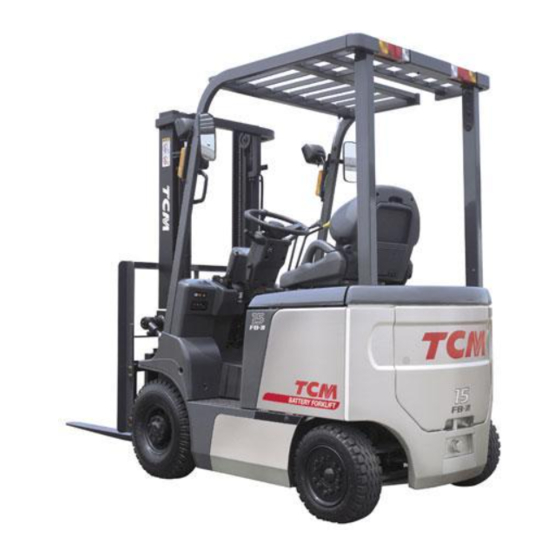
-
Contents
-
Table of Contents
-
Troubleshooting
-
Bookmarks
Quick Links
FORKLIFT TRUCK
TCM CORPORATION
No. SEB-81BBE
Counter Balanced
FB10
FB15
FB18
FB20
FB25
FB30
FB25
FB25
FB30
FB35
-7
-7
-7
-7
-7
-7
-7LB
-7V
-7V
-7S
Related Manuals for TCM FB10-7
Summary of Contents for TCM FB10-7
-
Page 1
No. SEB-81BBE FORKLIFT TRUCK Counter Balanced FB10 FB15 FB18 FB20 FB25 FB30 FB25 -7LB FB25 FB30 FB35 TCM CORPORATION… -
Page 3
No. SEB-81BBE FOREWORD The new TCM’s FB-7 Series battery-powered forklift trucks are provided with a newly designed speed control system and an AC traction motor to assure high performance. The trucks of this series are provided with a self-diagnosis function which keeps watching the operating statuses of the main systems of the truck. -
Page 4
No. SEB-81BBE… -
Page 5
No. SEB-81BBE SPECIFICATIONS (1) Model FB10-7 FB15-7 FB18-7 Item Performance Max. load kg [lbf] 1000 [2000] 1500 [3000] 1750 [3500] Load center mm [in.] 500 [24] ← ← Max. lifting height mm [in.] 3000 [118.1] ← ← Tilting angle °… -
Page 6
No. SEB-81BBE SPECIFICATIONS (2) Model FB25-7LB FB20-7 FB25-7 Item FB25-7V Performance ← Max. load kg [lbf] 2000 [4000] 2500 [5000] ← ← Load center mm [in.] 500 [24] ← ← Max. lifting height mm [in.] 3000 [118.1] Tilting angle ← ←… -
Page 7
No. SEB-81BBE SPECIFICATIONS (3) FB30-7 Model FB35-7S Item FB30-7V Performance Max. load kg [lbf] 3000 [6000] 3500 [7000] Load center mm [in.] 500 [24] ← Max. lifting height mm [in.] 3000 [118.1] ← Tilting angle ° ← ° Free lift A mm [in.] 165 [6.5] 150 [5.9]… -
Page 8
No. SEB-81BBE… -
Page 9
No. SEB-81BBE Unit: mm [in.] Fig. 1 Overall Dimensions… -
Page 10
No. SEB-81BBE… -
Page 11: Table Of Contents
No. SEB-81BBE CONTENTS 1. BATTERY AND CHARGER ………………..1.1 GENERAL DESCRIPTION ………………….. 1.1.1 BATTERY ……………………..1.1.2 CHARGER ……………………… 1.1.3 CHARGING PROCEDURES ………………..13 1.1.4 CHARGER OPERATION ………………..15 2. MOTORS ………………………. 17 2.1 GENERAL DESCRIPTION ………………….. 17 2.1.1 DRIVE MOTOR ……………………17 2.1.2 PUMP MOTOR ……………………
-
Page 12
No. SEB-81BBE 5.2.5 ADJUSTING BRAKE PEDAL ……………….. 77 5.2.6 TROUBLESHOOTING GUIDE ………………78 6. STEERING SYSTEM ………………….79 6.1 GENERAL DESCRIPTION ………………….. 79 6.1.1 OUTLINE OF STEERING SYSTEM ………………. 80 6.1.2 STEERING GEARBOX ………………….81 6.1.3 ACTUATOR …………………….. 84 6.1.4 REAR AXLE ……………………. 84 6.1.5 ADJUSTING PRELOAD OF REAR WHEEL BEARING ……….. -
Page 13: Battery And Charger
The description in this section applies to our optional batteries and chargers. For other types of batteries and chargers, refer to their respective instruction manuals. The description of the VTM unit applies to all the trucks because the VTM unit is standard equipment. Truck model FB15-7 FB10-7 FB20-7 FB25-7 Item FB18-7…
-
Page 14: General Description
1. BATTERY AND CHARGER 1.1 GENERAL DESCRIPTION 1.1.1 BATTERY The battery unit consists of twenty-four 2-volt battery cells connected in series. Figure 1.1 shows its construction. LOCK PIN ELECTROLYTE LEVEL INDICATOR BATTERY CELL WITH ELECTROLYTE LEVEL SENSOR Note: The sketch shows a 48-volt battery unit. The 72-volt battery unit has 36 battery cells. Fig.
-
Page 15
1. BATTERY AND CHARGER Specific gravity (at 20°C) Voltage (V) Voltage Alert ! Specific gravity (Discharge duration) (Discharge rate) Fig. 1.3 An Example of Specific Gravity Drop (2) Charging the battery When discharged, the battery should be recharged as soon as possible. Leaving the battery discharged for a long time may cause sulfation, which will result in a drop of the battery performance. -
Page 16: Charger
1. BATTERY AND CHARGER 1.1.2 CHARGER The charger mounted on the truck is a computer-controlled, semiconstant-voltage type consisting of a transformer, diodes, an operation panel, and a VTM unit. Thermal relay current settings BAND INSULATION TUBE Transformer model Setting (A) INSULATION TUBE M80B M80C…
-
Page 17
1. BATTERY AND CHARGER (1) Transformer The transformer is located at the right side frame and converts input voltage to a voltage of the level necessary for charging the battery. There are three taps provided with a 10-volt difference from one to another. Make a selection among them at the input side according to the input voltage level. -
Page 18
1. BATTERY AND CHARGER (2) Diode The diode, installed on the speed controller, is a 3-phase, full-wave rectification type which converts AC to DC. The current rectified by the diode flows through the fuse F6 to charge the battery. fUSE (130A) (fB25-7LB, fB25-7V: 200A) POSITIVE TERMINAL… -
Page 19
1. BATTERY AND CHARGER (3) Operation panel The operation panel is located on the left side of the cabinet and equipped with a charger control switches, lamps and service power outlet. Fig. 1.7 Operation Panel (4) VTM unit The VTM unit is installed inside the right side frame. It sets the charging time for the battery assembly by the signal from the operation panel. -
Page 20
1. BATTERY AND CHARGER The VTM unit has two timers: One is called first timer and the other second timer. It is the first timer on which the microprocessor sets the charging time (4 hours maximum). The time to be set on the second timer is 15 hours for normal charging. If a single charging continues longer than that duration, charging is treated as an abnormal termination. -
Page 21
1. BATTERY AND CHARGER COMMUNICATION 4-DIGIT ROTARY SWITCH SWITCHES (MODE, HIGH, LOW) SETTING MODE SYMBOL ROTARY SWITCH CALLING UP 4-DIGIT LED Fig. 1.9 VTM Unit (for trucks manufactured on and after February 1, 2004) — 9 -… -
Page 22
Observe the following conditions when changing those settings. Note 1. When changing those settings on the VTM unit, inform your local TCM dealer of the model name, chassis serial number of the truck you are going to change those settings, and the user name of the said truck. -
Page 23
1. BATTERY AND CHARGER [Procedure for changing VTM settings] (for trucks manufactured earlier than January 31, 2004) ① Park the truck on a level surface and turn the key switch off. ② Disconnect the battery connectors. ③ Remove the left side cover of the truck. ④… -
Page 24
1. BATTERY AND CHARGER [Procedure for changing VTM settings] (for trucks manufactured on and after February 1, 2004) ① Preparations Park the truck on a level surface, turn the key switch off, and then disconnect the battery connectors. Remove the right side cover of the truck and then remove the VTM unit cover. Connect the battery connectors. -
Page 25: Charging Procedures
1. BATTERY AND CHARGER 1.1.3 CHARGING PROCEDURES (1) Normal charge ① Turn off the key switch and apply the parking brake. ② Make sure that the power supply at the facility side is off and insert the plug into the receptacle at the truck side.
-
Page 26
However, for the truck-mounted type charger, the second timer is operated after charging the battery for 15 to 17 hours, so that the charging is forcibly terminated and the CHARGING lamp blinks. In such a case, inspect the cause and contact your TCM dealer. Note: Have a helper for this procedure. -
Page 27: Charger Operation
1. BATTERY AND CHARGER 1.1.4 CHARGER OPERATION (1) When the power switch is turned on, the charger is made ready for operation by the photocoupler in the VTM unit. (2) When the START button (PB1) is pressed, a circuit formed through the magnet switch CM, thermal relay TH, and the terminal V-25 of the VTM unit, and at the same time the battery voltage is applied for the terminal M-10 of the meter panel.
-
Page 28
1. BATTERY AND CHARGER NOTE — 16 -… -
Page 29: Motors
2. MOTORS 2. MOTORS Truck model FB30-7 FB10-7 FB15-7 FB20-7 FB25-7 FB30-7V FB18-7 FB25-7LB FB25-7V Item FB35-7S Drive motor Name HO-NR Type Self-ventilated, 3-phase induction motor Rated output 11.5 kW (3-min rate) 13.1 kW (3-min rate) 17.3 kW (3-min rate) Rated voltage 24.5 V…
-
Page 30
2. MOTORS DRIVE AXLE DRIVE MOTOR DRIVE UNIT Fig. 2.1 Drive Motor Installation — 18 -… -
Page 31
2. MOTORS THERMO-SENSOR CONNECTOR REAR BRACKET FRONT BRACKET SLITTED DISC W PHASE SPEED SENSOR A V PHASE SPEED SENSOR B SLITTED DISC U PHASE Detail of Sensor Two slitted discs are joined by aligning their respective teeth. WAVE WASHER SNAP RING View looking from A Detail of Slitted Discs Fig. -
Page 32
2. MOTORS ■ Operating principle of 3-phase induction motor As shown in Fig. 2.3, when the magnetic poles N and S are rotated outside the rectangular oil, the coil side cuts the magnetic flux to induce electromotive force in the direction indicated in the figure, thus (Rotating flowing circulating current inside the coil. -
Page 33: Pump Motor
2. MOTORS 2.1.2 PUMP MOTOR The pump motor is located on the left side frame and is used to drive the main pump. Its rotation is controlled by the load handling chopper built in the speed controller only when the lift lever is operated.
-
Page 34
2. MOTORS BRUSH WEAR INDICATOR THERMAL SWITCH CLAMP BRUSH FIELD COIL YOKE AMATURE BRUSH HOLDER BRUSH COVER Fig. 2.7 Pump Motor — 22 -… -
Page 35: Maintenance
2. MOTORS 2.2 MAINTENANCE 2.2.1 DRIVE MOTOR (1) Check the following points with the motor running Check item Location Criteria Remedy Dust Motor frame No remarkable deposit of dust allowed If too much deposit of compared with usual operation. dust is found, stop the Usual temperature rise.
-
Page 36
2. MOTORS (3) Periodic inspection ■ Inspection criteria Check the motor at periodic intervals, referring to the following troubleshooting chart. If the motor is used under a severe working condition, earlier or more frequent preventive maintenance is required. Operation time more than 12 hours/day 8 –… -
Page 37
2. MOTORS ■ Inspection procedure Inspect the motors observing the following conditions: ① Select a place which is not dusty or humid. ② Parts which have been disassembled should be kept in order and the order of disassembly recorded to ensure correct reassembly. Screws and wave washers removed should be put in order in boxes. -
Page 38
2. MOTORS (4) Maintenance of bearings The service life of bearings varies with the magnitude of loads and operating conditions. Replace the bearings with new ones when the temperature rises excessively or produces noise. Sealed bearings sealing in lithium soap-based grease ensure effective lubrication and prevent the entrance of dust. -
Page 39: Pump Motor
2. MOTORS 2.2.2 PUMP MOTOR (1) Ball bearing In case when the ball bearing gives out abnormal noise or seizes up, remove it from the armature shaft. For removing the ball bearing, apply a force to the outer race of the bearing by using a small-sized puller.
-
Page 40
2. MOTORS (4) Checking the commutator The commutator is the most important part of the motor. If operated with oil or dust sticking to it, the brush will be abnormally worn and commutator operation will be disabled. Keep it always clean by removing such foreign matters by air blow or by wiping with dry, clean cloth. -
Page 41: Control System
3. CONTROL SYSTEM 3. CONTROL SYSTEM 3.1 GENERAL DESCRIPTION The control system consists primarily of an inverter assembly which controls the drive motor, a DC chopper which controls the pump motor, and a PS controller which controls the PS motor. 3.1.1 INVERTER The inverter converts direct current into 3-phase alternating current.
-
Page 42
3. CONTROL SYSTEM Fig. 3.2 Inverter Assembly (1.0- to 2.5-ton Trucks) — 30 -… -
Page 43
3. CONTROL SYSTEM Fig. 3.3 Inverter Assembly (3.0- to 3.5-ton Trucks) — 31 -… -
Page 44
3. CONTROL SYSTEM Fig. 3.4 Controller Wiring (1.0- to 2.5-ton Trucks) — 32 -… -
Page 45
3. CONTROL SYSTEM Fig. 3.5 Controller Wiring (3.0- to 3.5-ton Trucks) — 33 -… -
Page 46: Accelerator Pedal
3. CONTROL SYSTEM 3.1.2 ACCELERATOR PEDAL The accelerator pedal is installed as shown in Fig.3.6, and the amount of accelerator pedal effort is transmitted to the potentiometer. The potentiometer converts pedal effort into voltage change and sends it to the controller. Connection diagram View looking from B LEVER…
-
Page 47: Interlock System
• Don’t rest anything heavy on the operator’s seat; otherwise the driving interlock may fail to operate as it should. • If the operator’s seat is replaced with a new one, use a genuine TCM operator’s seat equipped with a seat switch.
-
Page 48: Back-Down Alarm System
3. CONTROL SYSTEM ■ The interlock system is activated if any of the following conditions occurs. Operation of the truck Power Traction Pump steering ○ The key switch is turned to ON when the operator is not in the operator’s seat. ×…
-
Page 49: Maintenance
3. CONTROL SYSTEM 3.2 MAINTENANCE 3.2.1 TROUBLESHOOTING GUIDE The CPU board of the controller has an LED (green) which shows the content of errors occurring in the truck, using their corresponding code numbers that are distinguished by different blinking intervals. Each error code is displayed by a 2-digit decimal number, with both the second and first digits blinking at an interval of 0.5 seconds while a pause of 1 second OFF is inserted between the second digit and the first digit. Once an error code is displayed, an OFF period of 4 seconds is inserted before the…
-
Page 50
3. CONTROL SYSTEM ■ Checking procedure by error code (1) Traveling system Remedy Problem Error Reset Remarks Proceed with remedy in numerical order of encircled numbers. Traveling power module The truck won’t move. Turn off the If any power module is ① Check traveling power modules (TMDU, shorted (MD contactor does not… -
Page 51
3. CONTROL SYSTEM Remedy Problem Error Reset Remarks Proceed with remedy in numerical order of encircled numbers. Traveling accelerator The truck won’t move. Restore to Accelerator power supply ① Check harness between CN2-8, 9, 20 (CPU [301] output defective board) and traveling accelerator, and repair or normal. -
Page 52
3. CONTROL SYSTEM Remedy Problem Error Reset Remarks Proceed with remedy in numerical order of encircled numbers. Traveling motor temp. The truck can move. Thermo sensor (THD) ① Cool down traveling motor. [502] rises abnormally (This error is detected ② Check the resistance/voltage of traveling motor traveling voltage under normal when the traveling… -
Page 53
3. CONTROL SYSTEM Remedy Problem Error Reset Remarks Proceed with remedy in numerical order of encircled numbers. Load dump error Neither traveling or load Restore to Power module bridge ① Check battery connectors and connection [501] handling system does harness, and repair if needed. normal. -
Page 54
3. CONTROL SYSTEM (2) Load handling system Remedy Problem Error Reset Remarks Proceed with remedy in numerical order of encircled numbers. Load handling power The load handling Turn key If the power module is ① Check load handling power module (TMP) and [403] module shorted system does not work. change if needed. -
Page 55
3. CONTROL SYSTEM Remedy Problem Error Reset Remarks Proceed with remedy in numerical order of encircled numbers. Load handling contactor Load handling system Turn off ① Check load handling contactor (MP), and repair [405] (MP) shorted does not work. or change if needed. key switch. Detection circuit harness (seized contact points or mechanical hitch) defective ②… -
Page 56
3. CONTROL SYSTEM (3) PS system Remedy Problem Error Reset Remarks Proceed with remedy in numerical order of encircled numbers. PS main Tr. shorted Hard steering wheel (PS ① Check main Tr. (TMPS1, 2) and change if needed. Turn off [403] does not work) (When changing either of the TMPS1 or 2, key switch. (MPS contactor does not change the other one, too, along with EPS board.) close.) ②… -
Page 57
3. CONTROL SYSTEM ■ Inspecting controller components Do not touch any electrical component with the truck in conduction. When it is necessary to touch an electrical component for any reason, such as inspection or maintenance, disconnect the battery connectors and wait for more than 2 minutes before starting the operation. If avoidable to inspect an energized truck, raise the drive wheels off the floor or ground to prevent the truck from moving accidentally when the motor suddenly starts rotating for any reason. -
Page 58
3. CONTROL SYSTEM Where to tighten Screw Torque Symbol Truck Model Remarks Part name Item size (N-m) Shunt R Fixed Common MBP20A10MJN 1.5 ± 0.2 Terminal 1.3 ± 0.2 Terminal Fixed +, DU, DV, DW Common 1P-M8X40-M 12 ± 1 Terminal PA, CH, F terminal 9.8 ± 1 Terminal Fixed Common 1P-M8X36X8 12± 1 Terminal 9.8 ± 1 Hex. stud Fixed +, PB… -
Page 59
3. CONTROL SYSTEM 2. CPU board and power supply board The CPU board controls the controller and the power supply board supplies electric power to the CPU board, FET power module drive circuit and sensors. Visually check the CPU board and power supply board for scores, scratches, or undue discoloration, and connectors for corrosion, observing the following conditions: •… -
Page 60
3. CONTROL SYSTEM 3. Checking traveling/load handling power modules (TMDU, TMDV, TMDW, TMP) (1) Composition of FET power module Multiple FETs connected in parallel are connected in series vertically to form a half bridge. Each FET lets electric current flow from the drain (D) to source (S) when a voltage is applied between the gate (G) and source (S). Fig. -
Page 61
3. CONTROL SYSTEM (3) Checking embedded temperature sensor The U-phase power module (TMDU) and load handling power module (TMP) have temperature sensors embedded to monitor the temperature of the power module. When the temperature sensor detects an abnormal temperature of the module, the output current is restricted. -
Page 62
3. CONTROL SYSTEM 4. Checking fuses If an overcurrent flows through the main circuit, the fuses will blow to prevent damage to the controller and the possibility of catching fire. When checking the fuses on the truck, measure the battery voltage in advance. F3 UPPER TERMINAL F2 UPPER TERMINAL F2 LOWER TERMINAL F1 UPPER TERMINAL F3 LOWER TERMINAL F1 LOWER TERMINAL Fig. -
Page 63
3. CONTROL SYSTEM (3) Checking PS fuse (F3) ① Set the tester to the voltage measurement range and attach the negative pole of the tester to the negative cable connection terminal of the controller. ② Attach the positive pole of the tester to the upper terminal of the F3 fuse and then to the lower terminal to measure the voltage at each terminal. -
Page 64
3. CONTROL SYSTEM 6. Checking PS transistors (TMPS1, TMPS2) The PS drive transistors are two IGBT modules which form an H bridge. ① Visually check the transistors for scores, scratches, damage, or excessive discoloration. ② Remove all the cables from the module you are going to check, and measure the resistance between terminals using the tester according to the table given below. -
Page 65
3. CONTROL SYSTEM (2) Checking contactor coils ① Remove the coil wiring connector. ② Set the tester to a resistance range of 100 Ω and MPS CONTACTOR MOVABLE measure the resistance between terminals using CONTACT the tester. ③ Judge whether the coil is good or not using the measured values. CONTACT Judgment Contactor… -
Page 66
3. CONTROL SYSTEM 10. Checking motor thermo sensor The traveling motor has a thermo sensor embedded to monitor the motor temperature at all times. If the temperature monitored by the sensor exceeds a certain level, the output current is restricted. ①… -
Page 67: Drive Unit And Drive Axle
4. DRIVE UNIT AND DRIVE AXLE 4. DRIVE UNIT AND DRIVE AXLE Truck model FB30-7 FB10-7 FB15-7 FB20-7 FB25-7 FB30-7V FB18-7 FB25-7LB FB25-7V Item FB35-7S Drive unit Type Three-stage reduction ← ← Model 81E-25 81N-25 81U-25 Reduction ratio 25.1 30.144 ←…
-
Page 68
4. DRIVE UNIT AND DRIVE AXLE RING GEAR PINION SHAFT Tightening torque: 95 to 142 N-m WASHER {970 to 1450 kgf-cm} [840.8 to 1257 lbf-in.] PINION GEAR WASHER Tightening torque: 44 to 54 N-m SIDE GEAR {450 to 550 kgf-cm} [389.4 to 477.9 lbf-in.] COUNTER GEAR TAPER PIN… -
Page 69
4. DRIVE UNIT AND DRIVE AXLE RING GEAR SPIDER Tightening torque: 95 to 142 N-m {970 to 1450 kgf-cm} WASHER [840.8 to 1257 lbf-in.] PINION GEAR WASHER SIDE GEAR Tightening torque: 44 to 54 N-m {450 to 550 kgf-cm} [389.4 to 477.9 lbf-in.] COUNTER GEAR Tightening torque: 34.3 to 44 N-m… -
Page 70
4. DRIVE UNIT AND DRIVE AXLE Tightening torque: 137 to 177 N-m {1400 to 1800 kgf-cm} RING GEAR [1212.6 to 1566.6 lbf-in.] SPIDER Tightening torque: SIDE GEAR 95 to 142 N-m WASHER {970 to 1450 kgf-cm} [840.8 to 1257 lbf-in.] PINION GEAR WASHER COUNTER GEAR… -
Page 71: Drive Axle
4. DRIVE UNIT AND DRIVE AXLE 4.1.2 DRIVE AXLE The drive axle is composed of an axle housing, wheel hub, and wheels. It is mounted at the front side of the frame. At each end of the axle housing are a wheel hub and a wheel brake. The wheel hub is supported on the spindle by two taper roller bearings, and is driven by the axle shaft.
-
Page 72
4. DRIVE UNIT AND DRIVE AXLE Fig. 4.5 Drive Axle (2- to 2.5-ton Trucks) — 60 -… -
Page 73
4. DRIVE UNIT AND DRIVE AXLE Fig. 4.6 Drive Axle (3.0- to 3.5-ton Trucks) — 61 -… -
Page 74
4. DRIVE UNIT AND DRIVE AXLE ■ Procedure for installing the wheel hub (1) Put the specified amount of grease into the space of the wheel hub and install it onto the spindle. (2) Tighten the adjustment nut to approx. 98 N-m {1 kgf-m} [7.23 lbf-ft] torque and loosen it by 1/2 turn. -
Page 75: Brake System
5. BRAKE SYSTEM 5. BRAKE SYSTEM Model FB30-7 FB10-7 FB15-7 FB20-7 FB25-7 FB30-7V FB18-7 FB25-7LB FB25-7V Item FB35-7S Type Front two wheel braking, internal expansion, hydraulic type Pedal ratio ← ← Master cylinder bore 19.05 mm [0.75 in.] ← ←…
-
Page 76
5. BRAKE SYSTEM Fig. 5.2 Brake Pedal — 64 -… -
Page 77: Master Cylinder
5. BRAKE SYSTEM 5.1.2 MASTER CYLINDER The master cylinder is installed on the bracket of the brake pedal unit as shown in Fig. 5.3. Built in the master cylinder are a check valve, spring and piston. They are kept in position by a snap ring.
-
Page 78: Wheel Brake
5. BRAKE SYSTEM 5.1.3 WHEEL BRAKE The wheel brake is duo-servo type, and is mounted on each of the both ends of the drive axle. ANCHOR PIN The wheel brake is composed of two pairs of brake shoes, a wheel cylinder and adjuster. One end of the brake shoe is contacted with the Working force anchor pin and another end is contacted with the…
-
Page 79
5. BRAKE SYSTEM (3) Automatic clearance adjuster The automatic clearance adjuster automatically keeps the lining-todrum clearance properly. The CABLE components are as shown in Fig. 5.7. It is put in GUIDE action when the brakes are applied while traveling backward. SPRING LEVER ADJUSTER… -
Page 80: Parking Brake Lever
5. BRAKE SYSTEM 5.1.4 PARKING BRAKE LEVER The parking brake lever is a toggle type and it is installed as shown in Fig. 5.9. An adjuster adjusting the braking force is located on the top of the lever. RELEASE PARKING BUTTON BRAKE LEVER View looking from C…
-
Page 81
5. BRAKE SYSTEM Sectional view D — D Sectional view C — C Sectional view E — E Shoe expanding direction Sectional view A — A Sectional view of wheel cyl. Sectional view B — B 1. BRAKE LEVER 8. SHOE HOLD-DOWN PIN 15. -
Page 82
5. BRAKE SYSTEM Sectional view C — C Sectional view E — E Sectional view D — D Shoe expanding direction Sectional view A — A Sectional view B — B Sectional view of wheel cyl. 1. BRAKE LEVER 8. SHOE HOLD-DOWN PIN 15. -
Page 83: Maintenance
5. BRAKE SYSTEM 5.2 MAINTENANCE This section describes the procedure for disassembling, reassembling and adjusting the wheel brake and the procedure for adjusting the brake pedal, with the wheel brake and hub removed. 5.2.1 DISASSEMBLING WHEEL BRAKE (1) Remove the shoe hold-down pin, adjuster lever, adjuster and spring from the secondary shoe.
-
Page 84
5. BRAKE SYSTEM (4) Remove the primary and secondary shoes. Also remove the adjuster and adjuster spring at the same time. Fig. 5.16 (5) Remove the brake pipe from the wheel cylinder. Remove the bolts securing the wheel cylinder. Remove the wheel cylinder from the backing plate. -
Page 85: Inspection
5. BRAKE SYSTEM 5.2.2 INSPECTION Check each part and repair or replace any defective one. (1) Check the wheel cylinder inner surface and piston outer periphery for rust. Measure the clearance between the piston and cylinder. Standard: 0.03 to 0.10 mm [0.0012 to 0.0039 in.] Limit: 0.15 mm [0.0059 in.]…
-
Page 86: Reassembling Wheel Brake
5. BRAKE SYSTEM 5.2.3 REASSEMBLING WHEEL BRAKE (1) Apply brake fluid to the cup and piston of the wheel cylinder. Install the spring, piston cup, piston and boot in this order. (2) Install the wheel cylinder on the backing plate. Tightening torque: 17.7 to 26.5 N-m {180 to 270 kgf-cm} [156.7 to 234.5 lbf-in.] (3) Install the backing plate on the drive axle. Tightening torque: 117.7 to 137.3 N-m {1200 to 1400 kgf-cm} [1042 to 1215 lbf-in.] (4) Apply high-temperature grease to the points shown in Fig.
-
Page 87
5. BRAKE SYSTEM (8) Install the shoe guide pin in the anchor pin, and install the shoe return spring. In this step, install the spring at first on the primary side and then on the secondary side. Fig. 5.25 (9) Install the spring, adjuster, adjuster spring and adjuster lever, paying attention to the following items: ①… -
Page 88: Operation Test Of Automatic Clearance Adjuster
5. BRAKE SYSTEM 5.2.4 OPERATION TEST OF AUTOMATIC CLEARANCE ADJUSTER (1) Set the outer diameter of the brake shoe to nearly the normal mounting dimension. Push up the adjuster lever and adjust the diameter, turning the teeth of the adjuster. When your finger is released, the teeth of the adjuster do not turn and the adjuster lever returns to the original position.
-
Page 89: Adjusting Brake Pedal
5. BRAKE SYSTEM 5.2.5 ADJUSTING BRAKE PEDAL (1) Shorten the push rod length of the master cylinder. (2) Using the stopper bolt, adjust the pedal upheight to the value shown in Fig. 5.29. (3) Keeping the pedal pressed down by the pedal play, extend the push rod so that its tip contacts the piston of the master cylinder.
-
Page 90: Troubleshooting Guide
5. BRAKE SYSTEM 5.2.6 TROUBLESHOOTING GUIDE Trouble Probable Cause Remedy 1. Brake fluid leaks from the brake system Repair. 2. Maladjustment of brake shoe clearance Check and adjust the adjuster. Poor braking 3. Overheating brake Check for dragging. force 4. Poor contact between brake drum and lining Adjust contact.
-
Page 91: Steering System
6. STEERING SYSTEM 6. STEERING SYSTEM Model FB30-7 FB10-7 FB15-7 FB20-7 FB25-7 FB30-7V FB18-7 FB25-7LB FB25-7V Item FB35-7S Steering system Type Rear wheel steering, electric power steering Steering gear Type Ball nut type Name PU41 Reduction ratio 18.9 Operating angle 92°…
-
Page 92: Outline Of Steering System
6. STEERING SYSTEM 6.1.1 OUTLINE OF STEERING SYSTEM As shown in Fig. 6.1, the steering system is composed of a steering gearbox, actuator, and controller. The steering gearbox is provided with a potentiometer which detects the steering handwheel operating force and sends to the controller a signal which corresponds to the strength and direction of the force.
-
Page 93: Steering Gearbox
6. STEERING SYSTEM 6.1.2 STEERING GEARBOX The steering gearbox is constructed as shown in Fig. 6.2. Rotation of the steering handwheel is transmitted to the sector shaft by way of the ball nut screw. At the lower part of the steering gearbox unit is located the potentiometer which converts slight up-and-down movement of the steering shaft into a voltage and sends the voltage to the controller.
-
Page 94
6. STEERING SYSTEM STEERING HANDWHEEL STEERING WHEEL LOCK LEVER JOINT STEERING GEARBOX View looking from A DRAG LINK EPS ACTUATOR Fig. 6.3 Steering Linkage — 82 -… -
Page 95
6. STEERING SYSTEM F/R LEVER LIGHTING SWITCH STEERING HANDWHEEL ASSEMBLY COMBINATION Front of SWITCH ASSEMBLY the truck STEERING SHAFT Front of the truck ASSEMBLY Assembly drawing View looking from C Front of the truck View looking from A View looking from B Adjusting the position of the combination switch angle sensor 1. -
Page 96: Actuator
6. STEERING SYSTEM 6.1.3 ACTUATOR The actuator is a ball and nut screw type. The screw lengthens and shortens according to motor operation. Motor operation is transmitted to the ball and nut unit after its speed is reduced by two gears. The ball and nut unit is supported by two taper roller bearings on the gearbox.
-
Page 97
6. STEERING SYSTEM NEEDLE BEARING OIL SEAL KNUCKLE (RIGHT) TIE ROD (RIGHT) Sectional view A — A CENTER ARM TIE ROD (LEFT) KNUCKLE (LEFT) OIL SEAL OIL SEAL TAPERED ROLLER BEARING NEEDLE BEARING THRUST ADJUSTMENT NUT BEARING COTTER PIN WASHER KING PIN TAPER PIN Detail of knuckle… -
Page 98
6. STEERING SYSTEM KNUCKLE (RIGHT) TIE ROD (RIGHT) TIE ROD (LEFT) KNUCKLE (LEFT) CENTER ARM OIL SEAL OIL SEAL NEEDLE TAPERED ROLLER BEARING BEARING THRUST BEARING ADJUSTMENT NUT COTTER PIN WASHER KING PIN TAPER PIN Detail of knuckle Fig. 6.7 Rear Axle (2- to 3.5-ton Trucks) — 86 -… -
Page 99
6. STEERING SYSTEM (1) Knuckle and king pin The king pin supporting the knuckle is secured to the knuckle side with the lock pin. Its upper and lower ends are each installed on the axle boss through each needle bearing. The thrust bearing is installed between the axle upper boss and the knuckle so that the knuckle rotates smoothly around the king pin with its load. -
Page 100: Adjusting Preload Of Rear Wheel Bearing
6. STEERING SYSTEM 6.1.5 ADJUSTING PRELOAD OF REAR WHEEL BEARING (1) As shown in Fig. 6.9, apply grease to the hub, inner bearing, outer bearing, and cap. Also apply grease to the oil seal lips. (2) Set the bearings on the hub, then installed the hub on the knuckle spindle. (3) Place a washer, then tighten the adjustment nut with a torque of 206 to 235 N-m {21 to 24 kgf-m} [1823 to 2080 lbf-in.].
-
Page 101: Assembling Wheel
6. STEERING SYSTEM 6.1.6 ASSEMBLING WHEEL Put the tube and flap into the tire and assemble the rim paying attention to the following: Notes: 1. Align the air valve with the notch of the rim, directing the valve to the outside of the truck. 2.
-
Page 102: Maintenance
6. STEERING SYSTEM 6.2 MAINTENANCE 6.2.1 MAINTENANCE FOR ACTUATOR (1) Replacing the motor ① As shown in Fig. 6.11, securely hold the actuator assembly by a vise. Note: Be sure to hold it in a lying position. Fig. 6.11 ② Remove the motor securing bolts, then remove the motor.
-
Page 103
6. STEERING SYSTEM (2) Replacing the ball joint ① Securely fix the ball joint with its connector held BOOT BALL JOINT in a vise. • Hold this section by vise Fig. 6.15 ② Loosen the lock nut of the ball joint, then remove the ball joint. -
Page 104
6. STEERING SYSTEM ② Remove the clamp of the boot connector side. CLAMP LOCK NUT Shift the position of the boot. Then loosen the BOOT CLAMP connector lock nut, and remove the connector. • Note: Fix the ball joint to prevent it from turning. •… -
Page 105: Maintenance Of Steering Bearbox
6. STEERING SYSTEM 6.2.2 MAINTENANCE OF STEERING GEARBOX (1) Disassembling the steering gearbox ① Hold the pitman arm in a vise, and remove the fixing nut. Fig. 6.24 ② Move the pitman arm till the slit mark on the end surface of the sector shaft faces down, then hold the steering gear in a vise.
-
Page 106
6. STEERING SYSTEM ⑤ Install a set plate jig (See Fig. 6.61) on the front cover installing position. Tightening torque: 44 N-m {4.5 kgf-m} [32.5 lbf-ft] Fig. 6.28 ⑥ Extend outward the caulked part of the lock nut. Fig. 6.29 ⑦… -
Page 107
6. STEERING SYSTEM ⑨ Remove the set plate. Pull out the sensor housing assembly, taking caution not to lose the spring. Then remove the thrust washer, needle bearing, and thrust washer. Fig. 6.32 ⑩ Remove the bolt securing the side cover. Remove the side cover and sector shaft as one unit. -
Page 108
6. STEERING SYSTEM (2) Reassembling the steering gearbox ① Holding the gearbox by a vise, install the ball screw with its gear facing the sector shaft. Note: Be sure to apply grease to the oil seal lips and bearing. Fig. 6.35 ②… -
Page 109
6. STEERING SYSTEM ⑤ Till the center of the ball nut gear is aligned with the center of the hole, turn the shaft. Fig. 6.39 ⑥ Align the center of the sector shaft gear with the center of the hole, then install the side cover with a packing. -
Page 110
6. STEERING SYSTEM ⑨ Apply grease to the inside of the slide ring, then install it with spring. Fig. 6.43 ⑩ Install the set plate jig. Tightening torque: 44 N-m {4.5 kgf-m} [32.5 lbf-ft] Fig. 6.44 ⑪ Install the washer with an outer diameter of 40 mm [1.6 in.], needle bearing, and washer with an outer diameter of 31 mm [1.22 in.]. -
Page 111
6. STEERING SYSTEM ⑬ Leave your hand from the worm shaft. Caulk the nut at two positions by the caulking jig (See Fig. 6.61). Fig. 6.47 ⑭ Make sure that the nut does not show looseness when the worm shaft is turned clockwise. If still loose, caulk the nut again. -
Page 112
6. STEERING SYSTEM (3) Adjustment ① Install the pitman arm on the sector shaft. While pushing and pulling the pitman arm with a force of about 19.6 N {2 kgf} [4.4 lbf], measure the backlash. Backlash: Below 0.35 mm [0.0138 in.] If not satisfied, take step that follows. -
Page 113
6. STEERING SYSTEM ⑥ Apply grease to the roller of the potentiometer, put the roller in the arm, and then install the potentiometer by lightly tightening the fixing screw. Fig. 6.55 ⑦ Connect a tester, power supply unit, and VOLTMETER resistances to the connector of the potentiometer, (Sub) (Main) -
Page 114
6. STEERING SYSTEM ⑩ Install the potentiometer cover. When installing, fix the wire harness with a clip. Fig. 6.59 ⑪ Hold the pitman arm by a vise, fix it with the nut. Tightening torque: 176.5 to 215.8 N-m {18 to 22 kgf-m} [130 to 159 lbf-ft] Fig. -
Page 115: Hydraulic System
7. HYDRAULIC SYSTEM 7. HYDRAULIC SYSTEM Truck model FB30-7 FB10-7 FB15-7 FB20-7 FB25-7 FB30-7V FB18-7 FB25-7LB FB25-7V Item FB35-7S Main pump ← ← Type Gear type Name TMG1A18 TMG1A20 TMG1A23 Discharge 18.9 c.c./rev 21 c.c./rev 24.5 c.c./rev ← ← Drive…
-
Page 116: Main Pump
7. HYDRAULIC SYSTEM 7.1.1 MAIN PUMP The main pump is a gear type as shown in Fig. 7.1. The main pump consists of a pump body, a pair of gears, bushings and packings. To minimize the gap between the gears’ side-faces, pressure-balanced type bearings and lubrication method are used. The pressure-balanced type directs part of the oil discharged from the main pump into between the pressure plate and pump body, to press the pressure plate toward the gear side.
-
Page 117
7. HYDRAULIC SYSTEM LIFT SPOOL TILT SPOOL PORT G PORT B2 PORT T PORT A2 PORT A1 PORT P RELIEF VALVE SOLENOID VALVE POTENTIOMETER Fig. 7.2 Control Valve — 105 -… -
Page 118
7. HYDRAULIC SYSTEM (1) Valve control The control valve plungers are operated with the levers shown in Figure 7.3, with each of the levers installed on a single shaft. The bracket supporting each shaft is attached to the front guard. The movement of each lever is transmitted through the rod to the corresponding plunger. -
Page 119
7. HYDRAULIC SYSTEM (2) Oil pressure adjustment ① Remove the plug of the check port (G) located in the inlet section of the control valve, then set there a 20 MPa {200 kgf/cm } [2901 psi] capacity oil pressure gauge. ②… -
Page 120: Hydraulic Oil Tank
7. HYDRAULIC SYSTEM 7.1.3 HYDRAULIC OIL TANK The hydraulic oil tank is located at the center of the frame. In the tank, a suction filter and a return filter are provided for the purpose of ensuring clean oil supply. FB10 — 18: 18L FB20 — 35: 25L OIL FILL CAP RETURN FILTER…
-
Page 121: Lift Cylinder
7. HYDRAULIC SYSTEM 7.1.4 LIFT CYLINDER The two lift cylinders of single-acting type are located on the outer mast frame. Each lift cylinder, consists of cylinder body, rod, piston, and cylinder cap. The piston fastened to the rod with a snap ring is provided with a wear ring and packing on its circumference.
-
Page 122
7. HYDRAULIC SYSTEM Cylinder support 1. PISTON HEAD 2. SHIM 3. WIPER SEAL 4. ROD PACKING 5. CYLINDER CAP 6. “O”-RING 7. BUSHING 8. ROD 9. CYLINDER 10. WEAR RING 11. LOCK RING 12. PACKING 13. PISTON 14. SNAP RING 15. -
Page 123
7. HYDRAULIC SYSTEM Cylinder support 1. PISTON HEAD 2. SHIM 3. WIPER SEAL 4. ROD PACKING 5. CYLINDER CAP 6. “O”-RING 7. BUSHING 8. ROD 9. CYLINDER 10. LOCK RING 11. WEAR RING 12. PACKING 13. PISTON 14. SNAP RING 15. -
Page 124
7. HYDRAULIC SYSTEM Cylinder support 1. PISTON HEAD 2. SHIM 3. WIPER SEAL 4. ROD PACKING 5. CYLINDER CAP 6. “O”-RING 7. BUSHING 8. ROD 9. CYLINDER 10. LOCK RING 11. WEAR RING 12. PACKING 13. PISTON 14. SNAP RING 15. -
Page 125
7. HYDRAULIC SYSTEM Cylinder support 1. PISTON HEAD 2. SHIM 3. WIPER SEAL 4. ROD PACKING 5. CYLINDER CAP 6. BUSHING 7. “O”-RING 8. ROD 9. CYLINDER 10. LOCK RING 11. WEAR RING 12. PACKING 13. PISTON 14. CUT-OFF VALVE 15. -
Page 126: Flow Regulator Valve
7. HYDRAULIC SYSTEM 7.1.5 FLOW REGULRATOR VALVE The fl ow regulator valve is located at the position as shown in Fig. 7.12. It not only controls the fork LIFT CYLINDER lowering speed but works as a safety device in case (RIGHT) of a rupture of the high-pressure hose.
-
Page 127
7. HYDRAULIC SYSTEM Free flow Regulated flow Lift cylinder side Control valve side 1. SPRING 5. PISTON 9. “O”-RING 2. CASE 6. SLEEVE 10. NIPPLE 3. SPRING 7. ORIFICE 4. BALL 8. SPRING Fig. 7.14 Flow Regulator Valve (3.5-ton Trucks) ■… -
Page 128: Tilt Cylinder
7. HYDRAULIC SYSTEM 7.1.6 TILT CYLINDER The tilt cylinder is a double-acting type. The piston rod end is supported by the mast, and the cylinder tail by a pin on the frame. Two tilt cylinders are mounted on both sides of the truck, one at each.
-
Page 129
7. HYDRAULIC SYSTEM Fig. 7.16 Hydraulic Oil Piping — 117 -… -
Page 130: Maintenance
7. HYDRAULIC SYSTEM 7.2 MAINTENANCE 7.2.1 MAINTENANCE OF PUMP ■ Cautions 1. Before disassembling the pump, check for oil leaks from the oil seal, the mating section of the pump body and cover, and other areas. 2. Remove rust, dust and dirt at the shaft end and the pump body. Failure to do so might damage the parts or allow them to enter the inside of the pump during disassembly, thus misleading your diagnosis about the pump.
-
Page 131
7. HYDRAULIC SYSTEM ③ Remove the four fitting bolts. Fig. 7.19 ④ Remove the rear cover by tapping the side face of the pump body with a plastic mallet. If the gaskets remain inside the pump body, move them toward the rear cover side. Fig. -
Page 132
7. HYDRAULIC SYSTEM ⑦ Put the mark “R” on the driven gear shaft end and remove the drive gear. Fig. 7.23 ⑧ Holding the front side plate, remove the drive gear. Fig. 7.24 ⑨ Put the mark “FV” on the front side plate at the drive gear side, and remove the side plate. -
Page 133
7. HYDRAULIC SYSTEM ⑪ Remove the oil seal from the front cover. Fig. 7.27 — 121 -… -
Page 134
7. HYDRAULIC SYSTEM (2) Inspection CAUTION 1. Inspections are carried out to locate the cause of troubles and to determine whether parts are reusable or not. Inspections must be carried out only by personnel with a certain amount of knowledge and experience in hydraulic equipment. 2. -
Page 135
7. HYDRAULIC SYSTEM Name of component Items to be checked Remarks (cause and others) (c) Check for discoloration, undue wear, or Contaminants in oil, too high oil temperature (continued from the roughness on the gears. (120℃ [248° F] or higher), too frequently idle preceding page) operations Useful limit… -
Page 136
7. HYDRAULIC SYSTEM (3) Pump reassembly ① As shown in Fig. 7.28, hold the front cover in a vice. Fig. 7.28 ② Install a new gasket in the groove in the front cover. Fig. 7.29 ③ Install a new “E” gasket in the groove in the front cover, referring to Fig. -
Page 137
7. HYDRAULIC SYSTEM ④ Install the pump body on the front cover, referring to Fig. 7.33. Fig. 7.32 Counterclockwise rotation: Drive side Front side Counterclockwise Clockwise rotation: rotation: Rear side Suction port Rear side (larger radius) Clockwise rotation: Discharge port Front side (smaller radius) Projection (to be always… -
Page 138
7. HYDRAULIC SYSTEM ⑥ Install the drive gear in the pump body, with its splines pointed downward. Fig. 7.36 ⑦ Install the drive gear in the pump body, as shown in Fig. 7.38. Fig. 7.37 CAUTION The sketch shows the engagement of the left-rotation pump. Since the tooth profi les of the two gears are asymmetric, install them with their larger pressure angle sides pointed to each other. -
Page 139
7. HYDRAULIC SYSTEM ⑧ Install the rear side plate in the pump body, as shown in Fig. 7.35. Fig. 7.39 ⑨ Apply grease on a new gasket in some points and install the gasket in the rear cover groove. Fig. 7.40 Gasket groove ”E”… -
Page 140
7. HYDRAULIC SYSTEM ⑪ Install the rear cover in the pump body with its gasket pointed downward. Fig. 7.43 ⑫ Install the four bolts and tighten them to the specified torque: Tightening torque: 88 — 98 N-m {9 — 10 kgf-m} [65.1 — 72.3 ft-lbs] Fig. -
Page 141
7. HYDRAULIC SYSTEM ⑭ Secure the oil seal with a snap ring and remove the oil seal guide. Cross section of “C” lock ring (Front cover) Side at which corner is chamfered. Oil seal Fig. 7.48 Fig. 7.49 ø4 [0.16] ø17 ø4 [0.67]… -
Page 142: Trial Run
7. HYDRAULIC SYSTEM 7.2.2 TRIAL RUN Trial runs should be performed to run in an assembled pump and to ensure that it delivers the specified performance. Trial runs are preferably carried on a special test stand, but may be carried out with the pump on the machine using the following manner: (If the pump were disassembled because of a seized pump or an abnormally worn internal component, be sure to change the hydraulic oil and replace the filters with new ones before trying to make a trial…
-
Page 143: Troubleshooting Guide
7. HYDRAULIC SYSTEM 7.2.3 TROUBLESHOOTING GUIDE If any problem occurs in the hydraulic system, locate the cause of the problem and take necessary measures, referring to the tables given below. (1) Control valve Problem Cause Remedy PF circuit pressure does not Spool is stuck.
-
Page 144
7. HYDRAULIC SYSTEM (2) Main pump Problem Cause Remedy No oil discharged from gear Low oil level in oil tank Add oil to specified level. pump Clogged suction tube or strainer Clean or change oil if necessary. • Worn pressure plate •… -
Page 145: Load Handling System
8. LOAD HANDLING SYSTEM 8. LOAD HANDLING SYSTEM Model FB10-7 FB15-7 FB20-7 FB25-7 FB30-7 FB35-7S Item FB18-7 FB25-7LB FB25-7V FB30-7V Name VM-81E VM-81N VM-39F FM-77X Type Roller type 2-step telescopic mast with free lift Max. standard lifting height 3000 mm [118.1 in.]…
-
Page 146: General Description
8. LOAD HANDLING SYSTEM 8.1 GENERAL DESCRIPTION The load handling system is of roller type having a two-staged telescopic mast. It consists of an outer channel, inner channel, and carriage. 8.1.1 OUTER AND INNER CHANNELS Outer and inner channels are of welded construction. The lower part of the outer channel is provided with a support to be used for installing the mast assembly on the drive axle.
-
Page 147
8. LOAD HANDLING SYSTEM 1. INNER CHANNEL 2. OUTER CHANNEL 3. END ROLLER 4. SHIM 5. SNAP RING 6. END ROLLER 7. SHIM 8. SLIPPER 9. SHIM 10. PIN 11. CAP 12. BUSHING Fig. 8.2 Outer and Inner Channels (VM-81N, VM-81R, VM-39F) — 135 -… -
Page 148: Carriage
8. LOAD HANDLING SYSTEM 1. OUTER CHANNEL 2. INNER CHANNEL 3. END ROLLER 4. SNAP RING 5. SLIPPER 6. NUT 7. PLUG 8. SLIPPER 9. SHIM 10. SIDE ROLLER 11. SHIM 12. SPACER 13. PIN 14. STOPPER 15. CAP 16. BUSHING Fig.
-
Page 149
8. LOAD HANDLING SYSTEM 1. FORK 2. CARRIAGE 3. END ROLLER 4. SHIM 5. SNAP RING 6. SIDE ROLLER 7. SHIM 8. SPACER Fig. 8.4 Carriage — 137 -… -
Page 150
8. LOAD HANDLING SYSTEM 1. FORK 2. CARRIAGE 3. END ROLLER 4. SNAP RING 5. SIDE ROLLER 6. SNAP RING 7. SHAFT 8. SHIM 9. RETAINING ROLLER 10. SNAP RING Fig. 8.5 Carriage (VM-77X) — 138 -… -
Page 151: Locations Of Rollers
8. LOAD HANDLING SYSTEM 8.1.3 LOCATIONS OF ROLLERS The end and side rollers are installed on the carriage. The end rollers support longitudinal load and the side rollers support lateral load so that the inner channel and carriage are raised and lowered smoothly. Fig.
-
Page 152
8. LOAD HANDLING SYSTEM Fig. 8.7 Locations of Rollers (2- to 3.0-ton Trucks) — 140 -… -
Page 153
8. LOAD HANDLING SYSTEM Fig. 8.8 Locations of Rollers (3.5-ton Trucks) — 141 -… -
Page 154: Maintenance
8. LOAD HANDLING SYSTEM 8.2 MAINTENANCE 8.2.1 ADJUST LIFT CYLINDER ROD WITH SHIMS After the lift cylinder, inner channel, and outer channel are replaced, the lift cylinder rod length needs to be adjusted. (1) Install a piston head on the rod of each left cylinder without using shims.
-
Page 155
8. LOAD HANDLING SYSTEM (3) Make sure that the clearance between the carriage and the inner channel stoppers is 0 mm INNER CHANNEL STOPPER when the fork is raised to the maximum lifting height Note 1: When the mast lifting height is over 4000 mm [157.5 in.], the dimension is +50 mm [1.97 in.]. -
Page 156: Procedure For Replacing Rollers At Carriage Side
8. LOAD HANDLING SYSTEM 8.2.3 PROCEDURE FOR REPLACING ROLLERS AT CARRIAGE SIDE (excluding VM-77X) (1) Attach the pallet to the fork and stop the truck on a level surface. (2) Lower the fork with the pallet to the ground. (3) Remove the joint link of the mast side anchor pin and remove the chain from the sheave.
-
Page 157
8. LOAD HANDLING SYSTEM (8) Extend the lift cylinder rod so that the inner channel bottom projects the upper section of the carriage. (9) Bring the truck close to the carriage side so that Groove for balls each roller enters inside of the outer channel. (10) Contract the lift cylinder rod to lower the inner channels gradually. -
Page 158: Procedure For Replacing Rollers At Mast Side
8. LOAD HANDLING SYSTEM 8.2.4 PROCEDURE FOR REPLACING ROLLERS AT MAST SIDE (excluding VM-77X) (1) Remove the carriage from the inner channel in the same procedure as described in “8.2.2 PROCEDURE FOR REPLACING ROLLERS AT CARRIAGE SIDE.” (2) Move the truck to a level surface and put the both rear wheels on the bench of 250 –…
-
Page 159: Procedure For Adding Or Subtracting Shims
8. LOAD HANDLING SYSTEM 8.2.5 PROCEDURE FOR ADDING OR SUBTRACING SHIMS (excluding VM-77X) Move the inner channel and carriage to one side of the outer channel. Measure the clearance between the end roller at the opposite side and each channel. Clearance between roller and channel: 0 to 0.5 mm [0 to 0.197 in.] 0 to 0.5 mm at upper side Make contact…
-
Page 160
8. LOAD HANDLING SYSTEM NOTE — 148 -… -
Page 161: Electric Wiring
9. ELECTRIC WIRING 9. ELECTRIC WIRING The electric components of the truck are wired using several types of wire harnesses and color coded by circuit (wire number). The wire harnesses are connected with connectors (2 types) or screws. Table 9.1 Color symbols and examples Wire L 110 Wire…
-
Page 162
9. ELECTRIC WIRING ■ FET UNIT The FET unit consists of semiconductor switches in which FETs are used as switching elements, and turns on and off the lights in response to the input from the mechanical switches. View A Fig. 9.1 — 150 -… -
Page 163
9. ELECTRIC WIRING PR 51W TURN SIGNAL LIGHT (RIGHT) RL 51W TURN SIGNAL LIGHT (LEFT) RM 80W HEAD LIGHT RT 44W TAIL LIGHT BRAKE SIGNAL BB 20W BACK-UP LIGHT BEACON LIGHT OPTIONAL EQUIPMENT CHIME: 0.15A BEACON LIGHT OPTIONAL EQUIPMENT BEACON LIGHT Fig. -
Page 164
9. ELECTRIC WIRING HEAD LIGHT REAR COMBINATION LIGHT FRONT COMBINATION LIGHT FB10-FB18 FB20-FB35 View A Fig. 9.3 Light Installation Position — 152 -… -
Page 165
9. ELECTRIC WIRING ■ HEAD LIGHT The head light has a structure as shown in Figure 9.4. Two head lights are installed on the front poles of the overhead guard, one for each. ① ② 1. LENSE ⑤ 2. RIM 3. -
Page 166
9. ELECTRIC WIRING ■ Replacing light bulbs If you want to remove a bulb, push it into the SCREW reflector and then turn to the left. If you want to install a new bulb, push it into the REFLECTOR reflector and then turn to the right. 40W‑48V GASKET (1) Head light and work light… -
Page 167
9. ELECTRIC WIRING to HORN SWITCH to LIGHTING SWITCH to F/R SWITCH to METER PANEL to KEY SWITCH to RWL SWITCH to FLASHER UNIT OPTION WIRE HARNESS, to WIRE HARNESS, to BRAKE SWITCH OVERHEAD GUARD (RIGHT) OVERHEAD GUARD (LEFT) CAPACITOR to HORN to WIRE HARNESS, FRAME Fig. -
Page 168
9. ELECTRIC WIRING to HORN SWITCH to LIGHTING SWITCH to F/R SWITCH to METER PANEL to KEY SWITCH to FLASHER UNIT to RWL SWITCH OPTION OVERHEAD GUARD (RIGHT) to BRAKE SWITCH to WIRE HARNESS, OVERHEAD GUARD (LEFT) CAPACITOR to HORN to WIRE HARNESS, FRAME Fig. -
Page 175
No. SEB-81BBE Issued: February, 2008 INTERNATIONAL MARKETING DIVISION: 1-15-5, Nishi-shimbashi, Minato-ku, Tokyo 105-0003, Japan FAX: JApAN +81-3-35918152, 3-35918153 All rights reserved JB-0802030(HO) Printed in Japan…