
- Manuals
- Brands
- Kyocera Manuals
- All in One Printer
- TASKalfa 1800
- Service manual
-
Contents
-
Table of Contents
-
Troubleshooting
-
Bookmarks
Quick Links
DP-480/PF-480
/DU-480
SERVICE
MANUAL
Published in August 2014
842NN116
2NNSM066
Rev.6
Related Manuals for Kyocera TASKalfa 1800
Summary of Contents for Kyocera TASKalfa 1800
-
Page 1: Service Manual
TASKalfa 1800/1801 TASKalfa 2200/2201 DP-480/PF-480 /DU-480 SERVICE MANUAL Published in August 2014 842NN116 2NNSM066 Rev.6…
-
Page 2: Taskalfa
Notation of products in the manual For the purpose of this service manual, products are identified by print speed at A4. TASKalfa 1800/1801 :18 ppm model TASKalfa 2200/2201 :22 ppm model Or products are identified by correspondence of FAX.
-
Page 3: Revision History
Revision history Revision Date Pages Revised contents 9 September 2013 Contents Change: Page number of the contents 1-2-20 Correction: Number of the screws 1-2-26 1-5-24 1-5-64 1-5-76 1-5-27 Clerical error correction: Deleted procedure 1 1-5-29 Correction: Number of the screws Deleted: The detaching procedure of the drum unit 1-5-33 Added: Cautions sentence of the refitting…
-
Page 4
Revision Date Pages Revised contents 11 November 2013 1-3-15 Change: Item numbers 1-3-24, 1-3-25 Change: Data digit number of [LSU Out Top] and [LSU Out Left] 1-3-25 to 40 Correct: added the statement of a numerical change key 1-3-42 1-3-44 to 46 1-3-51 to 53 1-3-55, 1-3-63 1-3-67, 1-3-68… -
Page 5
Revision Date Pages Revised contents 11 November 2013 2-3-12 Change: Signal name of YC1, YC2 and YC6 Installation Added: IB-33 and FAX System(X) guide Address Change: Address on New Zealand 27 December 2013 Contents Change: Page numbers of the contents 1-3-79, 1-3-80 Added: “*: This setting is usually unnecessary.”… -
Page 6
This page is intentionally left blank. -
Page 7: Safety Precautions
Safety precautions This booklet provides safety warnings and precautions for our service personnel to ensure the safety of their customers, their machines as well as themselves during maintenance activities. Service personnel are advised to read this booklet carefully to familiarize themselves with the warnings and precautions described here before engaging in maintenance activities.
-
Page 8
Safety warnings and precautions Various symbols are used to protect our service personnel and customers from physical danger and to prevent damage to their property. These symbols are described below: DANGER: High risk of serious bodily injury or death may result from insufficient attention to or incorrect compliance with warning messages using this symbol. -
Page 9: Installation Precautions
1. Installation Precautions WARNING • Do not use a power supply with a voltage other than that specified. Avoid multiple connections to one outlet: they may cause fire or electric shock. When using an extension cable, always check that it is adequate for the rated current…………………. •…
-
Page 10
2. Precautions for Maintenance WARNING • Always remove the power plug from the wall outlet before starting machine disassembly….• Always follow the procedures for maintenance described in the service manual and other related brochures……………………….• Under no circumstances attempt to bypass or disable safety features including safety mechanisms and protective circuits. -
Page 11
• Do not remove the ozone filter, if any, from the copier except for routine replacement……. • Do not pull on the AC power cord or connector wires on high-voltage components when removing them; always hold the plug itself………………….•… -
Page 12
This page is intentionally left blank. -
Page 13: Table Of Contents
2NC/2NF/2NG/2NN/3P7/3P8/3P9-2 CONTENTS 1-1 Specifications 1-1-1 Specifications ……………………1-1-1 (1) Main unit ……………………… 1-1-1 (2) Document processor (DP-480) (Option)…………….1-1-4 (3) Paper Feeder (PF-480) (Option) ………………1-1-5 (4) Duplex Unit (DU-480) (Option) ………………1-1-5 1-1-2 Parts names …………………….. 1-1-6 (1) Parts names ……………………1-1-6 (2) Option ……………………..
-
Page 14: Nc/2Nf/2Ng/2Nn/3P7/3P8/3P9
2NC/2NF/2NG/2NN/3P7/3P8/3P9-4 1-4-3 Self-diagnostic function ………………….. 1-4-19 (1) Self-diagnostic function ………………..1-4-19 (2) Self diagnostic codes…………………. 1-4-20 1-4-4 Image formation problems ………………..1-4-36 1-4-5 Poor image (due to DP and scanner reading) …………..1-4-37 (1) No image appears (entirely white)……………… 1-4-38 (2) No image appears (entirely black)………………
-
Page 15
(1) Precautions……………………1-5-1 (2) Drum unit …………………….. 1-5-1 (3) Toner ……………………..1-5-1 (4) How to tell a genuine Kyocera toner container…………..1-5-2 1-5-2 Paper feed / conveying section ………………… 1-5-3 (1) Cassette paper feed section………………… 1-5-3 (1-1) Detaching and refitting the primary paper feed unit and the pickup roller ….1-5-5 (1-2) Detaching and refitting the retard roller ………….. -
Page 16
2NC/2NF/2NG/2NN/3P7/3P8/3P9-6 1-5-10 Othes ……………………… 1-5-74 (1) Detaching and refitting the rear cover …………….1-5-74 (2) Detaching and refitting the rear sub cover…………..1-5-74 (3) Detaching and refitting the right upper cover…………..1-5-75 (4) Detaching and refitting the right rear cover …………..1-5-76 (5) Detaching and refitting the front upper cover ………….. -
Page 17: Installation Guide
2NC/2NF/2NG/2NN/3P7/3P8/3P9-6 2-2-4 Power source PWB (PSPWB) ………………… 2-2-25 (1) Connector position………………….2-2-25 (2) PWB photograph ………………….2-2-25 (3) Connector lists…………………… 2-2-26 (4) Detaching and refitting the PWB. (PSPWB) …………..2-2-27 2-2-5 Operation panel PWB (OPPWB) ………………2-2-29 (1) Connector position………………….2-2-29 (2) PWB photograph ………………….
-
Page 18
2NC/2NF/2NG/2NN/3P7/3P8/3P9 This page is intentionally left blank. -
Page 19: Specifications
2NC/2NF/2NG/2NN/3P7/3P8/3P9 1-1 Specifications 1-1-1 Specifications (1) Main unit Description Item 18 ppm 22 ppm Desktop Type Electrophotography by semiconductor laser, single drum system Printing Method 64 to 105 g/m Paper Cassette Weight 45 to 160 g/m , 230 g/m (Cardstock) Multi Purpose Tray Plain, Rough, Vellum, Recycled, Preprinted, Bond, Color (Colour),…
-
Page 20
2NC/2NF/2NG/2NN/3P7/3P8/3P9-4 Description Item 18 ppm 22 ppm Heat and pressure fusing with the heat roller and the press roller Fusing system Heat source: halogen heater Abnormally high temperature protection devices: thermostat 10 to 32.5°C/50 to 90.5°F Operating Temperature Environ- 15 to 80 % Humidity ment 3,500 m/11,482.8 ft maximum… -
Page 21
2NC/2NF/2NG/2NN/3P7/3P8/3P9-2 Copy function Description Item 18 ppm 22 ppm A4/Letter: 18 sheets/min 22 sheets/min Copy feed from Cas- A4-R/Letter-R: 13 sheets/min 13 sheets/min Speed sette A3/Ledger: 8 sheets/min 10 sheets/min B4/Legal: 8 sheets/min 11 sheets/min 18 sheets/min 22 sheets/min B5-R: 13 sheets/min 13 sheets/min A5-R:… -
Page 22
2NC/2NF/2NG/2NN/3P7/3P8/3P9 Scanner function Description Item 18 ppm 22 ppm B/W: 600 dpi, 400 dpi, 300 dpi, 200 dpi Resolution Color: 300 dpi, 200 dpi TIFF (MMR/JPEG compression), PDF (MMR/JPEG compression/high File Format compression), JPEG, BMP <600 dpi> Scanning Speed 1-sided B/W 22 Images/min 2-sided B/W 8 Images/min… -
Page 23
2NC/2NF/2NG/2NN/3P7/3P8/3P9-2 (3) Paper Feeder (PF-480) (Option) Item Description Automatic Feeding (No. Sheets: 300, 80 g/m Paper Supply Method A3, B4, A4, A4-R, B5, B5-R, A5-R, Ledger, Legal, Oficio II, Letter-R, Let- Paper Size ter, Statement-R, Folio, 8K, 16K, 16K-R, 216 × 340 mm Paper weight: 64 to 105 g/m Supported Paper Media types: Plain, Rough, Vellum, Recycled, Preprinted, Bond, Color… -
Page 24: Parts Names
2NC/2NF/2NG/2NN/3P7/3P8/3P9 1-1-2 Parts names (1) Parts names Figure 1-1-1 1. Document Processor 7. Operation Panel (Reverse Automatic) (Option) 8. Cassette1 2. Original Width Guides 9. Front Cover 3. Original Table 10. Power Switch 4. Original Eject Table 11. Handles 5. Slit Glass 12.
-
Page 25
2NC/2NF/2NG/2NN/3P7/3P8/3P9-2 24 23 Figure 1-1-2 13. Paper Width Adjusting Tab 22. Support Tray Section of the Multi Purpose 14. Paper Length Guide Tray 15. Paper Width Guide 23. Toner Container 16. Cleaning Cloth 24. Toner Container Lever 17. Original Stopper Compartment 25. -
Page 26
2NC/2NF/2NG/2NN/3P7/3P8/3P9 (2) Option Figure 1-1-3 1. Original Cover 4. Cassette 3 2. Document Processor (Reverse Automatic) 5. Cassette 4 3. Cassette 2 6. Duplex Unit 1-1-8… -
Page 27
2NC/2NF/2NG/2NN/3P7/3P8/3P9-2 (3) Operation panel (3-1) Basic model Figure 1-1-4 1. Logout key 15. Original Image key 2. Energy Saver key 16. Combine key 3. Stop key 17. ID Card Copy key 4. Reset key 18. Paper selection key 5. Clear key 19. -
Page 28
2NC/2NF/2NG/2NN/3P7/3P8/3P9-2 (3-2) Advanced model 16 17 Figure 1-1-5 1. Logout key 19. Combine key 2. Energy Saver key 20. ID Card Copy key 3. Stop key 21. Copy key 4. Reset key 22. Scan key 5. Clear key 23. FAX key 6. -
Page 29: Machine Cross Section
2NC/2NF/2NG/2NN/3P7/3P8/3P9 1-1-3 Machine cross section (Option) Main unit (Option) Original path (Option) Paper path Optical path Paper path (Option) Figure 1-1-6 1. Cassette paper feed section 9. Transfer/Separation sections 2. MP tray paper feed section 10. Fuser/Eject/Feed shift section 3. Paper conveying section 11.
-
Page 30
2NC/2NF/2NG/2NN/3P7/3P8/3P9-2 1-1-4 Option composition (1) DP-480 (1) PLATEN COVER TYPE H (2) DU-480 (4) Fax System(X) (Advanced model only) (5) IB-33 (Advanced model only) (3) PF-480 1-1-12… -
Page 31: Installation Environment
2NC/2NF/2NG/2NN/3P7/3P8/3P9 1-2 Installation 1-2-1 Installation environment 1. Temperature: 10 to 32.5°C/50 to 90.5°F 2. Humidity: 15 to 80% RH 3. Power supply: 120 V AC, 12.0 A 220 — 240 V AC, 6.5 A 4. Power supply frequency: 50 Hz ±2%/60 Hz ±2% 5.
-
Page 32: Unpacking And Installation 1
2NC/2NF/2NG/2NN/3P7/3P8/3P9 1-2-2 Unpacking and installation (1) Installation procedure Start Unpacking Remove the tapes and spacer Connect the power cord Installing toner Install the paper feeder (option) Installing software Install the document processor (option) Output an own-status report Install the platen cover (option) (maintenance item U000) Install the other optional devicees Cleaning the counter…
-
Page 33
2NC/2NF/2NG/2NN/3P7/3P8/3P9-2 Unpacking [Main unit] Figure 1-2-2 1. Hinge joints 7. Operation guide etc. 13. Toner container 2. Outer case 8. Power code 14. Plastic bag 3. Top pads 9. Acsessories 15. Bottom pads 4. Inner case 10. Main unit 16. Skid 5. -
Page 34
2NC/2NF/2NG/2NN/3P7/3P8/3P9-2 [Document Processor (Option)] Figure 1-2-3 1. Acsessory tray 8. Left rear upper pad 2. Plastic bag 9. Plastic sheet 3. Platen 10. Document processor 4. Installation guide etc. 11. Front bottom pad 5. Right front upper pad 12. Rear bottom pad 6. -
Page 35
2NC/2NF/2NG/2NN/3P7/3P8/3P9-2 [Paper feeder (Option)] Figure 1-2-4 1. Acsessory tray 7. Paper Feeder 2. Plastic bag 8. Acsessories 3. Installation guide etc. 9. Right bottom pads 4. Right middle inner case 10. Left bottom pads 5. Left middle inner case 11. Outer case 6. -
Page 36
2NC/2NF/2NG/2NN/3P7/3P8/3P9 [Duplex unit (Option)] Figure 1-2-5 1. Plastic bag 5. Plastic bag 2. Installation guide etc. 6. Duplex unit 3. Inner case 7. Outer case 4. acsessories 1-2-6… -
Page 37
2NC/2NF/2NG/2NN/3P7/3P8/3P9 Remove the tapes and spacer *: Removed the packing components that a fixed tape and shock absorbing material etc. are. Install the paper feeder (option) 1. A main unit is carried on a paper feeder. Machine 2. Fix the fixing plate of PF to main unit by four screws. -
Page 38
2NC/2NF/2NG/2NN/3P7/3P8/3P9 Install the dcument processor (option) 1. A document processor is attached to a main unit. *: Refer to the installation guide for the details of attachment. Main unit Figure 1-2-7 Install the platen cover (option) 1. The hinges of a platen cover are inserted in the attachment hole of a Platen cover main unit. -
Page 39
2NC/2NF/2NG/2NN/3P7/3P8/3P9-2 Install the other optional devices Install the optional devices (Cassette heater, Fax system, Network interface etc.) as required. Load paper 1. Pull the cassette out toward you until it stops. Main unit 2. Remove the protection paper. Cassette Protection paper Figure 1-2-9 3. -
Page 40
2NC/2NF/2NG/2NN/3P7/3P8/3P9 4. Holding the paper width adjusting tab, move the paper width guides to fit the paper. Paper sizes are marked on the cas- sette. Paper width guides Cassette Paper width adjusting tab Figure 1-2-11 5. Squeeze the ends of the bottom of the paper length guide and move the guide to fit the length of the paper. -
Page 41
2NC/2NF/2NG/2NN/3P7/3P8/3P9 6. Align the paper flush against the right side of the cassette. Paper Cassette Figure 1-2-13 7. Insert the appropriate paper size card in the slot to indicate the size of the paper inside. Paper size card Figure 1-2-14 1-2-11… -
Page 42
2NC/2NF/2NG/2NN/3P7/3P8/3P9 Before loading paper When you open a new package of paper, fan the sheets to separate them slightly prior to loading in the following steps. 1. Bend the whole set of sheets to swell them in the middle. 2. Hold the stack at both ends and stretch it while keeping the entire stack swelled. -
Page 43
2NC/2NF/2NG/2NN/3P7/3P8/3P9 Install the toner container 1. Strike the toner container approximately five or more times in the vertical direc- tion to stir toner. Figure 1-2-17 2. Shake the toner container approxi- mately five or more times in the vertical direction to stir toner. Figure 1-2-18 3. -
Page 44
2NC/2NF/2NG/2NN/3P7/3P8/3P9 4. Open the front cover. CLICK! 5. Gently push the toner container into the machine. Note: Push the container all the way into the machine until it locks in place. 6. Close the front cover. Toner container Front cover Figure 1-2-20 1-2-14… -
Page 45
2NC/2NF/2NG/2NN/3P7/3P8/3P9 Connecting USB cable 1. Connect the USB cable to the USB interface connector located on the left side of the body. 2. Connect the other end of the cable to the PC. Figure 1-2-21 Connect the power cord 1. Connect one end of the supplied power cord to the machine and the other end to a power outlet. -
Page 46
2NC/2NF/2NG/2NN/3P7/3P8/3P9-2 Installing toner 1. Turn the main power switch on. Toner installation is started. 2. The drive chain is disengaged when toner installation is completed. Run maintenance mode U130 if [Add Toner] remains displayed even after the drive chain is disengaged. *: A high pitch continuous sound may be heard for about 10 seconds during the toner installation. -
Page 47
2NC/2NF/2NG/2NN/3P7/3P8/3P9-2 Exit maintenance mode the start key. The machine exits the maintenance mode. Enter 001 using the numeric keys and press Make test copies 1. Place an original and make test copies. Attaching the cover label 1. Attach the cover labels to three screw holes in the machine. Completion of machine installation 1-2-17… -
Page 48: Installing An Accessories 1
2NC/2NF/2NG/2NN/3P7/3P8/3P9 1-2-3 Installing an accessories (1) Installing the SD card (Option) Procedure 1. Remove the screw and remove the SDcard cover. 2. Insert the SD card in the SD card slot. 3. Refit the removed SD card cover. SD card slot cover SD card slot Screw SD card…
-
Page 49
2NC/2NF/2NG/2NN/3P7/3P8/3P9 (2) Install the cassette heater (Service parts) Cassette heater installation requires the following parts: Parts Quantity Part.No. Parts heater dehumidifier 120 SP 302KK94430 Parts heater dehumidifier 240 SP 302KK94440 Supplied parts of cassette heater set (302KK94430): Parts Quantity Part.No. Heater dehumidifier 120 302KK45060 Supplied parts of cassette heater set (302KK94440):… -
Page 50
2NC/2NF/2NG/2NN/3P7/3P8/3P9-1 3. Remove nine screws. 4. Remove the left cover by pulling upward and releasing four hooks. Screw Screw Screw Screw Screw Hook Hook Screw Hook Screw Screw Left cover Hook Hook detail Screw Figure 1-2-26 5. Open the front cover. Flat screwdriver 6. -
Page 51
2NC/2NF/2NG/2NN/3P7/3P8/3P9 7. Remove the left tray. Left tray Figure 1-2-28 8. Remove a screw. 9. Remove the right tray. Right tray Screw Figure 1-2-29 1-2-21… -
Page 52
2NC/2NF/2NG/2NN/3P7/3P8/3P9 10. Remove the screw. 11. Remove the exit rear cover forward with releasing two projections by lifting it up. Projection Screw Projection Exit rear cover Figure 1-2-30 12. Remove the screw. 13. Release the projection by sliding the Screw middle rear cover backward. -
Page 53
2NC/2NF/2NG/2NN/3P7/3P8/3P9 15. Pass the heater wire through the aper- ture of the frame. Cut-and-raised portions 16. Set the heater to the cut-and-raised portion parts. 17. Bent two cut-and-raise portions and fix the heater. Heater Heater wire Aperture Heater Figure 1-2-32 18. -
Page 54
2NC/2NF/2NG/2NN/3P7/3P8/3P9 This page is intentionally left blank. 1-2-24… -
Page 55: Maintenance Mode
2NC/2NF/2NG/2NN/3P7/3P8/3P9-1 1-3 Maintenance Mode 1-3-1 Maintenance Mode The machine is equipped with a maintenance function which can be used to maintain and service the machine. (1) Executing a maintenance item Start Enter “10871087” using Maintenance mode is entered. the numeric keys. Enter the maintenance item number using the cursor up/down keys The maintenance item is selected.
-
Page 56
2NC/2NF/2NG/2NN/3P7/3P8/3P9 (2) Maintenance modes item list Item Section Content of maintenance item Summary General U000 Mainte Report It outputs to printing of each report, and USB. U001 Exit Mainte Maintenance mode is canceled. U002 Set Factory Def A factory-shipments setup (initialization) and packing mode are set up. -
Page 57
2NC/2NF/2NG/2NN/3P7/3P8/3P9 Item Section Content of maintenance item Summary Optical U071 DP Timing The timing of DP reading are adjusted. U072 DP Center The center line of DP reading image are adjusted. U074 Adj DP input The input light volume at the time of DP reading are adjusted. -
Page 58
2NC/2NF/2NG/2NN/3P7/3P8/3P9-2 Item Section Content of maintenance item Summary Operation U203 Chk DP Ope Each simulation is operated with DP simple panel and substance. support U204 Set Card/Counter The presence or absence of a key card equipment and a key counter is set up. U207 Chk Panel Key An operation key is checked. -
Page 59
2NC/2NF/2NG/2NN/3P7/3P8/3P9-2 Item Section Content of maintenance item Summary Image pro- U402 Adjust margin The space of a leading edge, AC side, and cessing a trailing edge is adjusted. U403 Scan Margin Tbl The margin of reading data is adjusted by picture reading by a scanner. -
Page 60
2NC/2NF/2NG/2NN/3P7/3P8/3P9-2 Item Section Content of maintenance item Summary U631 Comm Ctrl 2 It is set up whether transmission and reception can be performed in ECM. The frequency of CED is set up. U632 Comm Ctrl 3 It is set up whether sending out after bit33 of a DIS/DTC signal is performed. -
Page 61
2NC/2NF/2NG/2NN/3P7/3P8/3P9-2 Item Section Content of maintenance item Summary Others U901 Clr Paper FD Cnt The feed number of sheets count accord- ing to feed stage are displayed and cleared. U903 Clr paper JAM Cnt The number of times of JAM generating are displayed and cleared. -
Page 62
2NC/2NF/2NG/2NN/3P7/3P8/3P9 (3) Contents of the maintenance mode items U000 Mainte Report Description Outputs lists of the current settings of the maintenance items and paper jam and service call occurrences. Outputs the event log. Also sends output data to the SD card. Purpose To check the current setting of the maintenance items, or paper jam or service call occurrences. -
Page 63
2NC/2NF/2NG/2NN/3P7/3P8/3P9-2 [Event log] Event Log 2013/02/17 15:15 TASKalfa2201 [XXX_XXXX.XXX.XXX] [XXX_XXXX.XXX.XXX] Firmware version 2NG_2000.000.000 2013.02.17 [XXX_XXXX.XXX.XXX] [XXX_XXXX.XXX.XXX] (12) Paper Jam Log Counter Log Count. Event Descriprions Date and Time J0000: J4209: C0000: 5555555 0501.01.08.01 2013/02/12 17:30 J0100: J4211: C0001: 4444444 4002.01.08.01 2013/02/12 17:30 J0101: J4212:… -
Page 64
2NC/2NF/2NG/2NN/3P7/3P8/3P9-2 [Detail of event log] Items Description System version (2) * System date Engine software version Engine boot software version Operation panel software version Option language version Machine serial number Paper Jam Count. Event Remembers 1 to 16 of The total page count at the Log code (hexadecimal, 5 occurrence. -
Page 65
2NC/2NF/2NG/2NN/3P7/3P8/3P9 Items Description Paper Jam (d) Detail of paper type (Hexadecimal) cont. 01: Plain 0A: Color 15: Custom 1 02: Transparency 0B: Prepunched 16: Custom 2 03: Preprinted 0C: Envelope 17: Custom 3 04: Labels 0D: Cardstock 18: Custom 4 05: Bond 0E: Coated 19: Custom 5… -
Page 66
2NC/2NF/2NG/2NN/3P7/3P8/3P9 Items Description (11) Unknown Count. item Toner Log Remembers 1 to 5 of The total page count at the Unknown toner log code occurrence of unknown time of the toner empty (1 byte, 2 categories) toner detection. If the error with using an occurrence of the previous unknown toner container. -
Page 67
2NC/2NF/2NG/2NN/3P7/3P8/3P9-2 [Service status page] Service Status Page 12/12/2012 15:15 [XXXXXXXX] [XXXXXXXX] Firmware version 2NG_2000.000.000 2012.12.12 [XXXXXXXX] [XXXXXXXX] (22) FAX Information (23) Rings (Normal) Memory status (24) Rings (FAX/TEL) Size 256.0 MB (25) Rings (TAD) Time Local Time Zone +01:00 Amsterdam (10) Date and Time 27/10/2010 12:00… -
Page 68
2NC/2NF/2NG/2NN/3P7/3P8/3P9-2 [Detail of service status page] Description Supplement Firmware version (2) * System date Engine software version Engine boot version Operation panel software version Option language version Machine serial number Memory size Local time zone (10) Report output date Day/Month/Year hour:minute (11) Presence or absence of the Installed/Not installed… -
Page 69
2NC/2NF/2NG/2NN/3P7/3P8/3P9-2 Description Supplement (28) Print start timing MPT Leading edge/MPT Center line/Cassette1 Leading edge/Cassette1 Center line/Cassette2 Leading edge/ Cassette2Center line/Cassette3 Leading edge/Cassette3 Center line/Cassette4 Leading edge/Cassette4 Center line/Duplex Leading edge/Duplex Center line (29) Life counter (The first line) Machine life/MP tray/Cassette 1/Cassette 2/ Cassette 3/Cassette 4/Duplex Life counter (The second line) Drum unit/Transfer roller/Developer unit/Fuser unit… -
Page 70
2NC/2NF/2NG/2NN/3P7/3P8/3P9 U001 Exit Mainte Description Exits the maintenance mode and returns to the normal copy mode. Purpose To exit the maintenance mode. Method 1. Press the start key. The normal copy mode is entered. U002 Set Factory Def Description Restores the machine conditions to the factory default settings. Purpose To move the mirror frame of the scanner to the position for transport. -
Page 71
2NC/2NF/2NG/2NN/3P7/3P8/3P9 U004 Machine No. Description Sets or displays the machine number. Purpose To check or set the machine number. Method Press the start key. If the machine serial number of engine PWB matches with that of main PWB. Display Description Machine No. -
Page 72
2NC/2NF/2NG/2NN/3P7/3P8/3P9 U019 Firm Version Description Displays the part number of the ROM fitted to each board. Purpose To check the part number or to decide, if the newest version of ROM is installed. Method 1. Press the start key. The ROM version are displayed. 2. -
Page 73
2NC/2NF/2NG/2NN/3P7/3P8/3P9 U021 Init memory Description Initializes all settings, except those pertinent to the type of machine, namely each counter, service call history and mode setting. Also initializes backup RAM according to region specification selected in maintenance item U252 Setting the destination. Purpose To return the machine settings to their factory default. -
Page 74
2NC/2NF/2NG/2NN/3P7/3P8/3P9 U030 Chk motor Description Drives each motor. Purpose To check the operation of each motor. Method 1. Press the start key. 2. Select the motor to be operated. * : Press the start key. The operation starts. Display Description Main Main motor is turned on. -
Page 75
2NC/2NF/2NG/2NN/3P7/3P8/3P9 U031 Chk switch Description Displays the on-off status of each paper detection switch or sensor on the paper path. Purpose To check if the switches and sensors for paper conveying operate correctly. Method 1. Press the start key. 2. Turn each switch or sensor on and off manually to check the status. Display Description Switch… -
Page 76
2NC/2NF/2NG/2NN/3P7/3P8/3P9 U032 Chk Clutch Description Turns each clutch on. Purpose To check the operation of each clutch. Method 1. Press the start key. 2. Select [Motor On] or [Motor Off]. Display Description Motor On Main motor (MM) is turned on. Motor Off Main motor (MM) is not turned on. -
Page 77
2NC/2NF/2NG/2NN/3P7/3P8/3P9 U033 Chk Solenoid Description Turns each solenoid on. Purpose To check the operation of each solenoid. Method 1. Press the start key. 2. Select [Motor On] or [Motor Off]. Display Description Motor On Main motor (MM) is turned on. Moter Off Main motor (MM) is not turned on. -
Page 78
2NC/2NF/2NG/2NN/3P7/3P8/3P9-2 U034 Adj Paper timing Description Adjusts the leading edge registration or center line. Purpose Make the adjustment if there is a regular error between the leading edges of the copy image and original. Make the adjustment if there is a regular error between the center lines of the copy image and original. -
Page 79
2NC/2NF/2NG/2NN/3P7/3P8/3P9-2 5. Change the setting value using change keys * or numeric keys. * : Zoom/Paper selection key (Basic model), Right/Left arrow key (Advanced model) For output example 1, increase the value. For output example 2, decrease the value Leading edge registration (20 ±… -
Page 80
2NC/2NF/2NG/2NN/3P7/3P8/3P9-2 5. Change the setting value using change keys * or numeric keys. * : Zoom/Paper selection key (Basic model), Right/Left arrow key (Advanced model) For output example 1, increase the value. For output example 2, decrease the value. Center line of printing (within ±… -
Page 81
2NC/2NF/2NG/2NN/3P7/3P8/3P9-2 U035 Adj Folio Sz Description Changes the printing area for copying on folio paper. Purpose To prevent cropped images on the trailing edge or left/right side of copy paper by setting the actual printing area for folio paper. Setting 1. -
Page 82
2NC/2NF/2NG/2NN/3P7/3P8/3P9-2 U051 Adj Paper Loop Description Adjusts the deflection in the paper at the registration roller. Purpose Make the adjustment if the leading edge of the copy image is missing or varies randomly, or if the copy paper is Z-folded. Method 1. -
Page 83
2NC/2NF/2NG/2NN/3P7/3P8/3P9-2 U053 Adj Motor Speed Description Performs fine adjustment of the speeds of the motors. Purpose To adjust the speed of the respective motors when the magnification is not correct. Setting 1. Press the start key. 2. Select the item to be set. 3. -
Page 84
2NC/2NF/2NG/2NN/3P7/3P8/3P9-2 U063 Adj shading Description Changes the shading position of the scanner. Purpose Used when the white line continue to appear longitudinally on the image after the shading plate is cleaned. This is due to flaws or stains inside the shading plate. To prevent this problem, the shading posi- tion should be changed so that shading is possible without being affected by the flaws or stains. -
Page 85
2NC/2NF/2NG/2NN/3P7/3P8/3P9-2 U065 Adj Scn Description Adjusts the magnification of the original scanning. Purpose Make the adjustment if the magnification in the main scanning direction is incorrect. Make the adjustment if the magnification in the auxiliary scanning direction is incorrect. Caution The magnification adjustment along the main scanning direction could cause black streaks depending on the content of the original document. -
Page 86
2NC/2NF/2NG/2NN/3P7/3P8/3P9-2 Adjustment: [X Zoom] 1. Change the setting value using change keys * or numeric keys. * : Zoom/Paper selection key (Basic model), Right/Left arrow key (Advanced model) For copy example 1, increase the value. For copy example 2, decrease the value. Increasing the value makes the image longer, while decreasing the value makes the image shorter. -
Page 87
2NC/2NF/2NG/2NN/3P7/3P8/3P9-2 U066 Table timing Description Adjusts the scanner leading edge registration of the original scanning. Purpose Make the adjustment if there is a regular error between the leading edges of the copy image and original. Adjustment 1. Press the start key. 2. -
Page 88
2NC/2NF/2NG/2NN/3P7/3P8/3P9-2 U067 Table center Description Adjusts the scanner center line of the original scanning. Purpose Make the adjustment if there is a regular error between the center lines of the copy image and original. Adjustment 1. Press the start key. 2. -
Page 89
2NC/2NF/2NG/2NN/3P7/3P8/3P9-2 U068 DP Scn Start Pos Description Adjusts the position for scanning originals from the DP. Performs the test copy at the four scanning positions after adjusting. Purpose Used when the image fogging occurs because the scanning position is not proper when the DP is used. -
Page 90
2NC/2NF/2NG/2NN/3P7/3P8/3P9-2 U070 Adj DP Motor Description Adjusts the DP original scanning speed. Purpose Make the adjustment if the magnification is incorrect in the auxiliary scanning direction when the DP is used. Adjustment 1. Press the start key. 2. Press the system menu key. 3. -
Page 91
2NC/2NF/2NG/2NN/3P7/3P8/3P9-2 U071 DP Timing Description Adjusts the DP original scanning timing. Purpose Make the adjustment if there is a regular error between the leading or trailing edges of the original and the copy image when the DP is used. Method 1. -
Page 92
2NC/2NF/2NG/2NN/3P7/3P8/3P9-2 Adjustment: Trailing edge registration 1. Change the setting value using change keys * or numeric keys. * : Zoom/Paper selection key (Basic model), Right/Left arrow key (Advanced model) For copy example 1, increase the value. For copy example 2, decrease the value. Original Copy Copy… -
Page 93
2NC/2NF/2NG/2NN/3P7/3P8/3P9-2 U072 DP Center Description Adjusts the scanning start position for the DP original. Purpose Make the adjustment if there is a regular error between the centers of the original and the copy image when the DP is used. Adjustment 1. -
Page 94
2NC/2NF/2NG/2NN/3P7/3P8/3P9-2 U074 Adj DP input Description Adjusts the luminosity of the exposure lamp for scanning originals from the DP. Purpose Used if the exposure amount differs significantly between when scanning an original on the platen and when scanning an original from the DP. Setting 1. -
Page 95
2NC/2NF/2NG/2NN/3P7/3P8/3P9 U089 Output MIP-PG Description Selects and outputs the MIP-PG pattern created in the machine. Purpose To check copier status other than scanner when adjusting image printing, using MIP-PG pattern output (with-out scanning). Method 1. Press the start key. 2. Select the MIP-PG pattern to be output and press the start key. Display PG pattern to be output Purpose… -
Page 96
2NC/2NF/2NG/2NN/3P7/3P8/3P9-2 U099 Detect Org Sz Description Checks the operation of the original size sensor and sets the sensing threshold value. Purpose To adjust the sensitiveness of the sensor and size judgement time if the original size sensor mal- functions frequently due to incident light or the like. Method 1. -
Page 97
2NC/2NF/2NG/2NN/3P7/3P8/3P9-2 * : Reducing the value increases the sensitivity of the sensor allowing a document with more density to be detected, however, the document mat could be detected as an original docu- ment. If the values vary excessively, mal-detection could occur depending on how a document is placed. -
Page 98
2NC/2NF/2NG/2NN/3P7/3P8/3P9-2 U100 Main HV Output Description Performs main charging. * : Perform the high altitude settings when a leakage is developed on images in a high altitude installation, such as in Mexico City. Purpose To check main charging. Method 1. Press the start key. 2. -
Page 99
2NC/2NF/2NG/2NN/3P7/3P8/3P9-2 U101 1ST TC Output Description Sets the control voltage for the primary transfer. Purpose To change the setting when any density problems, such as too dark or light, occur. Method 1. Press the start key. 2. Select the item to be adjusted. 3. -
Page 100
2NC/2NF/2NG/2NN/3P7/3P8/3P9-2 U108 Adj Sepa Sbias Description Adjusts output of separation shift bias and ON/OFF timing. Purpose To set when the separated malfunction of the paper occurs. Method 1. Press the start key. 2. Select the item to be set. Display Normal Mormal23 Light… -
Page 101
2NC/2NF/2NG/2NN/3P7/3P8/3P9 U110 Drum Cnt Description Displays the drum counts for checking. Purpose To check the drum status. Method 1. Press the start key. The current drum counts is displayed. Display Description Drum drive time (K). Completion Press the stop key. The screen for selecting a maintenance item No. is displayed. U111 Drum Time Description… -
Page 102
2NC/2NF/2NG/2NN/3P7/3P8/3P9 U117 Drum No. Description A drum number is displayed. Purpose It is used for the check of a drum number. Method 1. Press the start key. The drum number is displayed. Display Description Drum No. (K) Completion Press the stop key. The screen for selecting a maintenance item No. is displayed. U118 Drum History Description… -
Page 103
2NC/2NF/2NG/2NN/3P7/3P8/3P9 U127 Clr Trans Cnt Description Displays and clears the counts of the transfer counter. Purpose To check the count after replacement of the transfer roller. Also to clear the counts after replacing transfer roller. Method 1. Press the start key. The current counts of the transfer counter is displayed. Display Description Transfer counter. -
Page 104
2NC/2NF/2NG/2NN/3P7/3P8/3P9 U135 Chk Toner Motor Description To check the Toner Motor Operation. Purpose To check the Toner Motor Operation. 1. Press the start key. 2. Select [Excute]. 3. Press the start key. Display Description Excute Execute toner motor is turned on. * : A toner motor cannot be operated while an engine drives. -
Page 105
2NC/2NF/2NG/2NN/3P7/3P8/3P9-2 U140 Adj Dev bias Description Adjusts various developer bias value. Purpose To adjust the developer bias value. Method 1. Press the start key. 2. Select the item to be adjusted. 3. Change the value using change keys * or numeric keys. * : Zoom/Paper selection key (Basic model), Right/Left arrow key (Advanced model) Display Description… -
Page 106
2NC/2NF/2NG/2NN/3P7/3P8/3P9-2 U147 Set Toner Apply Description A mode setup of the operation which removes the toner in the development unit which carried out the charge rise is performed. Purpose The basic target does not need to change a setup. However, the mode is changed when outputting a manuscript with an always low printing rate in large quantities. -
Page 107
2NC/2NF/2NG/2NN/3P7/3P8/3P9-2 U150 Chk Toner Sensor Description Displays the status of each sensor associated with the toner. Purpose To check if the sensors operate correctly. Method 1. Press the start key. Display Description Dev sensor State of the developer sensor. 2. Check the status of sensor. The current value is displayed. * : Developer sensor are acquired and re-displayed periodically. -
Page 108
2NC/2NF/2NG/2NN/3P7/3P8/3P9-2 U157 Dev Time Description Displays the developer drive time for checking a figure, which is used as a reference when correct- ing the toner control. Purpose To check the developer drive time after replacing the developer unit. Method 1. Press the start key. The developer drive time is displayed. Display Description Developer drive time. -
Page 109
2NC/2NF/2NG/2NN/3P7/3P8/3P9-2 U161 Adj Fuser Temp Description Changes the fuser control temperature. Purpose Normally no change is necessary. However, can be used to prevent curling or creasing of paper, or solve a fuser problem on thick paper. Method 1. Press the start key. 2. -
Page 110
2NC/2NF/2NG/2NN/3P7/3P8/3P9 U167 Clr Fuser Cnt Description Displays and clears the fuser counts for checking. Purpose To check or clear the fuser counts after replacing the fuser unit. Method 1. Press the start key. The fuser count is displayed. Display Description Fuser unit count value Clear A value is cleared. -
Page 111
2NC/2NF/2NG/2NN/3P7/3P8/3P9-2 U199 Fuser Temp Description Displays the detected fuser temperature. Purpose To check the fuser temperature. Method 1. Press the start key. The fuser temperature is displayed. Display Description Fix Center Temperature in the center of the fixing. (°C) Fix Edge Temperature in the edge of the fixing. -
Page 112
2NC/2NF/2NG/2NN/3P7/3P8/3P9 U204 Set Card/Counter Description Sets the presence or absence of the optional key counter. Purpose To run this maintenance item if a key counter is installed. Method 1. Press the start key. 2. Select the item to be set. Display Description Key-Counter… -
Page 113
2NC/2NF/2NG/2NN/3P7/3P8/3P9-2 U211 Set EH Connection Description Connection of enhancement apparatus is set up. Purpose It uses for a connection setup of enhancement apparatus without connection detection. 1. Press the start key. 2. Select [Duplex Unit]. Display Description Duplex Unit A connection setup of a duplex unit. 3. -
Page 114
2NC/2NF/2NG/2NN/3P7/3P8/3P9 U243 Chk DP motors Description Turns the motors and clutches in the DP. Purpose To check the operation of the DP motors or clutches. Method 1. Press the start key. 2. Select the item to be operated. 3. Press the start key. The operation starts. Display Description Feed Motor… -
Page 115
2NC/2NF/2NG/2NN/3P7/3P8/3P9 U244 Chk DP Switch Description Displays the status of the respective switches in the DP. Purpose To check if respective switches in the DP operate correctly. Method 1. Press the start key. 2. Turn each switch or sensor on and off manually to check the status. Display Description Switch… -
Page 116
2NC/2NF/2NG/2NN/3P7/3P8/3P9 U250 Mnt Cnt Pre-set Description Changes preset values for maintenance cycle. Purpose Provides changing the time when the message to acknowledge to conduct maintenance adjust- ment is periodically displayed. Setting 1. Press the start key. 2. Select the item to be set. 3. -
Page 117
2NC/2NF/2NG/2NN/3P7/3P8/3P9-2 U251 Clr Mnt Cnt Description Displays and clears or changes the maintenance count. Purpose To verify the maintenance counter count. Also to clear the count during maintenance service. Setting 1. Press the start key. 2. Select the item to be changed. 3. -
Page 118
2NC/2NF/2NG/2NN/3P7/3P8/3P9 U252 Set Dest Description Switches the operations and screens of the machine according to the destination. Purpose To be executed after initializing the backup RAM, in order to return the setting to the value before replacement or initialization. Method 1. -
Page 119
2NC/2NF/2NG/2NN/3P7/3P8/3P9 U253 Sel D/S count Description Switches the count system for the total counter and other counters. Purpose Used to select, according to the preference of the user (copy service provider), if folio size paper is to be counted as one sheet (single count) or two sheets (double count). Setting 1. -
Page 120
2NC/2NF/2NG/2NN/3P7/3P8/3P9 U265 Set Model Dest Description Sets the OEM purchaser code. Purpose Sets the code when replacing the main board and the like. Setting 1. Press the start key. 2. Change the setting using the +- keys or numeric keys. Display Description Sets the OEM purchaser code. -
Page 121
2NC/2NF/2NG/2NN/3P7/3P8/3P9-2 U326 Set clean Bk Line Description Sets whether to display the cleaning guidance when detecting the black line. Purpose Displays the cleaning guidance in order to make the call for service with the black line decrease by the rubbish on the contact glass when scanning from the DP. Method 1. -
Page 122
2NC/2NF/2NG/2NN/3P7/3P8/3P9-2 U332 Adj Calc Rate Description Sets the coefficient of nonstandard sizes in relation to the A4/Letter size. The coefficient set here is used to convert the black ratio in relation to the A4/Letter size and to display the result in user simulation. -
Page 123
2NC/2NF/2NG/2NN/3P7/3P8/3P9-4 U341 Set Prn Cass Description Sets a paper feed location specified for printer output. Purpose To use a paper feed location only for printer output. A paper feed location specified for printer output cannot be used for copy output. 1. -
Page 124
2NC/2NF/2NG/2NN/3P7/3P8/3P9-2 U345 Set Mnt Time Disp Description Sets when to display a message notifying that the time for maintenance is about to be reached,by setting the number of copies that can be made before the current maintenance cycle ends. When the difference between the number of copies of the maintenance cycle and that of the main- tenance count reaches the set value, the message is displayed. -
Page 125
2NC/2NF/2NG/2NN/3P7/3P8/3P9 U346 Slct Sleep mode Description A sleep mode-related setting change is performed. Purpose It uses in order to perform a sleep mode-related setting change. Method 1. Press the start key. 2. Select On or Off. Display Description Enable Auto Sleep functionality. Disable Auto Sleep functionality. -
Page 126
2NC/2NF/2NG/2NN/3P7/3P8/3P9-2 U402 Adjust margin Description Adjusts margins for image printing. Purpose Make the adjustment if margins are incorrect. Adjustment 1. Press the start key. 2. Press the system menu key. 3. Press the start key to output a test pattern. 4. -
Page 127
2NC/2NF/2NG/2NN/3P7/3P8/3P9-2 U403 Scan Margin Tbl Description Adjusts margins for scanning the original on the contact glass. Purpose Make the adjustment if margins are incorrect. Adjustment 1. Press the start key. 2. Press the system menu key. 3. Place an original and press the start key to make a test copy. 4. -
Page 128
2NC/2NF/2NG/2NN/3P7/3P8/3P9-2 U404 Scan margin DP Description Adjusts margins for scanning the original from the DP. Purpose Make the adjustment if margins are incorrect. Adjustment 1. Press the start key. 2. Press the system menu key. 3. Place an original on the DP and press the start key to make a test copy. 4. -
Page 129
2NC/2NF/2NG/2NN/3P7/3P8/3P9-5 U411 Scanner Auto Adjustment Description Uses a specified original and automatically adjusts the following items in the scanner and the DP scanning sections. Scanner section: Original size magnification, leading edge timing, center line, input gamma, input gamma in monochrome mode and matrix. DP scanning section: Original size magnification, leading edge timing, center line. -
Page 130
2NC/2NF/2NG/2NN/3P7/3P8/3P9 Method: [All] 1. Load A4/letter paper. 2. Press the start key to output the original for adjustment. 3. Set the output the original for adjustment and press the start key. 4. Set the output the original for adjustment on the DP face up. 5. -
Page 131
2NC/2NF/2NG/2NN/3P7/3P8/3P9 Codes Description Main scanning direction magnification error Service call error DP paper misfeed error Completion Press the stop key. The screen for selecting a maintenance item No. is displayed. 1-3-77… -
Page 132
2NC/2NF/2NG/2NN/3P7/3P8/3P9-5 U425 Set Target Description Enters the lab values that is indicated on the back of the chart (P/N: 7505000005) used for adjust- ment. Purpose Performs data input in order to correct for differences in originals during automatic adjustment. Method 1. -
Page 133
2NC/2NF/2NG/2NN/3P7/3P8/3P9-5 Setting: [Adjust Original] *: This setting is usually unnecessary. 1. Measure the distance from the leading edge to the top of black belt 1 of the original at A, B and Measurement procedure 1) Measure the distance from the leading edge to the top of black belt 1 of the original at A (30 mm from the left edge), B (148.5 mm from the left edge) and C (267 mm from the left edge), respectively. -
Page 134
2NC/2NF/2NG/2NN/3P7/3P8/3P9-5 Setting: [Adjust OriginalDP] *: This setting is usually unnecessary. 1. Measure the distance from the leading edge to the black belt (inside) of the original at A. 2. Enter the measured value usingchange keys * or numeric keys in [Lead]. * : Zoom/Paper selection key (Basic model), Right/Left arrow key (Advanced model) 3. -
Page 135
2NC/2NF/2NG/2NN/3P7/3P8/3P9-4 U600 Init All Data Description Initializes software switches and all data in the backup data on the FAX control board, according to the destination and OEM. Executes the check of the file system, when abnormality of the file system is detected, initializes the file system, communication past record and register setting contents. -
Page 136
2NC/2NF/2NG/2NN/3P7/3P8/3P9-4 Code Destination Code Destination Spain Belgium U.K. Denmark Netherlands Finland Sweden Portugal France Ireland Austria Norway Switzerland Taiwan U601 Init Keep Data Description Initializes software switches on the FAX control board according to the destination and OEM. Purpose To initialize the FAX control board without changing user registration data. 1. -
Page 137
2NC/2NF/2NG/2NN/3P7/3P8/3P9-2 U603 User Data 1 Description Makes user settings to enable the use of the machine as a fax. Purpose To be executed as required. Method 1. Press the start key. 2. Select [Line Type] and press the start key. Display Description Line Type… -
Page 138
2NC/2NF/2NG/2NN/3P7/3P8/3P9-2 U604 User Data 2 Description Makes user settings to enable the use of the machine as a fax. Purpose Use this if the user wishes to adjust the number of rings that occur before the unit switches into fax receiving mode when fax/telephone auto-select is enabled. -
Page 139
2NC/2NF/2NG/2NN/3P7/3P8/3P9-2 U610 System Setting 1 Description Makes settings for fax reception regarding the sizes of the fax paper and received images and automatic printing of the protocol list. Method 1. Press the start key. 2. Select the item to be set. Display Description Cut Line:A4… -
Page 140
2NC/2NF/2NG/2NN/3P7/3P8/3P9-2 Setting the number of lines to be ignored when receiving a fax in the auto reduction mode Sets the maximum number of lines to be ignored if the received data volume exceeds the record- ing capacity when the data is recorded in the auto reduction mode. If the number of excess lines is below the setting, those lines are ignored. -
Page 141
2NC/2NF/2NG/2NN/3P7/3P8/3P9-2 U611 System Setting 2 Description Sets the number of adjustment lines for automatic reduction. Purpose It carries out to set up the number of adjustment lines of automatic reduction. Method 1. Press the start key. 2. Select the item to be set. Display Description ADJ LINES… -
Page 142
2NC/2NF/2NG/2NN/3P7/3P8/3P9-2 U615 System Setting 6 Description Makes settings for fax reception regarding the sizes of the fax paper and received images. Purpose To set the maximum recording width and processing method when 11″ width fax paper is loaded on an inch specification machine. Setting 1. -
Page 143
2NC/2NF/2NG/2NN/3P7/3P8/3P9-2 U620 FAX System Description Sets the signal detection method for remote switching. Be sure to change the setting according to the type of telephone connected to the machine. Purpose The decision system of a remote change is set up to compensate for a user’s telephone classifica- tion, peculiarity. -
Page 144
2NC/2NF/2NG/2NN/3P7/3P8/3P9-2 U625 Set Comm Description Makes settings for the auto redialing interval and the number of times of auto redialing. Purpose Change the setting to prevent the following problems: fax transmission is not possible due to too short redial interval, or fax transmission takes too much time to complete due to too long redial interval. -
Page 145
2NC/2NF/2NG/2NN/3P7/3P8/3P9-2 U630 Comm Ctrl 1 Description Makes settings for fax transmission regarding the communication. Purpose The event of a request for user. Reduce transmission time and the reception of accuracy when using poor quality line. Improve the accuracy of communication at international communication. Method 1. -
Page 146
2NC/2NF/2NG/2NN/3P7/3P8/3P9-2 Setting the waiting period to prevent echo problems at the sender Sets the period before a DCS signal is sent after a DIS signal is received. Used when problems occur due to echoes at the sender. 1. Select the setting. Display Description Sends a DCS 500 ms after receiving a DIS. -
Page 147
2NC/2NF/2NG/2NN/3P7/3P8/3P9-2 U631 Comm Ctrl 2 Description Makes settings regarding fax transmission. Purpose Transmission and reception of ECM are set up. The frequency of CED is set up. 1. Press the start key. * : Select the item to be set. Display Description ECM TX… -
Page 148
2NC/2NF/2NG/2NN/3P7/3P8/3P9-2 Setting: Freq. Sets the frequency of the CED signal. Used as one of the measures to improve transmission per- formance for international communications. 1. Select the setting. Display Description 2100 2100Hz 1100 1100Hz * : Initial setting: 2100 2. Press the start key. The setting is set. Completion Press the stop key. -
Page 149
2NC/2NF/2NG/2NN/3P7/3P8/3P9-2 U632 Comm Ctrl 3 Description Makes settings for fax transmission regarding the communication. Purpose Reduction of error communication when a low quality circuit is used. When changing a FAX/TEL automatic change. Method 1. Press the start key. * : Select the item to be set. Display Description DIS 4Byte… -
Page 150
2NC/2NF/2NG/2NN/3P7/3P8/3P9-2 U633 Comm Ctrl 4 Description Makes settings for fax transmission regarding the communication. Purpose To reduce transmission errors when a low quality line is used. Method 1. Press the start key. 2. Select the item to be set. Display Description V.34 Enables or disables V.34 communication. -
Page 151
2NC/2NF/2NG/2NN/3P7/3P8/3P9-2 Setting the number of times of DIS signal reception Sets the number of times to receive the DIS signal to once or twice. Used as one of the correction measures for transmission errors and other problems. 1. Select the setting. Display Description Once… -
Page 152
2NC/2NF/2NG/2NN/3P7/3P8/3P9-2 U634 Comm Ctrl 5 Description Sets the maximum number of error bytes judged acceptable when receiving a TCF signal. Used as a measure to ease transmission conditions if transmission errors occur. Purpose Do to alleviate the communication conditions. Setting 1. -
Page 153
2NC/2NF/2NG/2NN/3P7/3P8/3P9-2 U640 Comm Time 1 Description Sets the detection time when one-shot detection is selected for remote switching. (This setting item will be displayed, but the setting made is ineffective.) Sets the detection time when continuous detection is selected for remote switching. (This setting item will be displayed, but the setting made is ineffective.) Purpose The decision system of a remote change is set up to compensate for a user’s telephone classifica-… -
Page 154
2NC/2NF/2NG/2NN/3P7/3P8/3P9-2 U641 Comm Time 2 Description Sets the time-out time for fax transmission. Purpose To improve transmission performance for international communications mainly. Method 1. Press the start key. 2. Select the item to be set. Display Description T0 TIME OUT Sets the T0 time-out time. -
Page 155
2NC/2NF/2NG/2NN/3P7/3P8/3P9-2 Setting: T2 time out The T2 time-out time decides the following. From CFR signal output to image data reception From image data reception to the next signal reception In ECM, from RNR signal detection to the next signal reception 1. -
Page 156
2NC/2NF/2NG/2NN/3P7/3P8/3P9-2 Setting: Tb2 time out In the fax/telephone auto select mode, sets the time to start ringing an operator through the con- nected telephone after receiving a call as a fax machine (see figure 1-3-19). In the fax/telephone auto select mode, change the setting when fax reception is unsuccessful or a telephone fails to receive a call. -
Page 157
2NC/2NF/2NG/2NN/3P7/3P8/3P9-2 U650 Modem 1 Description Sets the G3 cable equalizer. Sets the modem detection level. Purpose Perform the following adjustment to make the equalizer compatible with the line characteristics. To improve the transmission performance when a low quality line is used. Method 1. -
Page 158
2NC/2NF/2NG/2NN/3P7/3P8/3P9-2 U651 Modem 2 Description Sets the modem output level. Sets the DTMF output level of a push-button dial telephone. Purpose Used if problems occur when sending a signal with a push-button dial telephone. Setting 1. Press the start key. 2. -
Page 159
2NC/2NF/2NG/2NN/3P7/3P8/3P9-2 U660 Set Calls Description Makes setting regarding the network control unit (NCU). Purpose To be executed as required. Method 1. Press the start key. * : Select the item to be set. Display Description Exchange Sets the connection to PBX/PSTN. Dial Tone Sets PSTN dial tone detection. -
Page 160
2NC/2NF/2NG/2NN/3P7/3P8/3P9-2 Setting: Busy tone When a fax signal is sent, sets whether the line is disconnected immediately after a busy tone is detected, or the busy tone is not detected and the line remains connected until T0 time-out time. Fax transmission may fail due to incorrect busy tone detection. When set to 2, this problem may be prevented. -
Page 161
2NC/2NF/2NG/2NN/3P7/3P8/3P9-2 U670 Output List Description Outputs a list of data regarding fax transmissions. Printing a list is disabled either when a job is remaining in the buffer or when [Pause All Print Jobs] is pressed to halt printing. Purpose To check conditions of use, settings and transmission procedures of the fax. Method 1. -
Page 162
2NC/2NF/2NG/2NN/3P7/3P8/3P9-2 U699 Set Soft SW Description Sets the software switches on the FAX control board individually. Purpose To change the setting when a problem such as split output of received originals occurs. Since the communication performance is largely affected, normally this setting need not be changed. -
Page 163
2NC/2NF/2NG/2NN/3P7/3P8/3P9-2 Description 0 2400bps/V34 3 FSK detection in V.8 4 4800 bps when low-speed setting is active 2 FIF length in transmission of more than 4 times of DIS/DTC signal <Communication time setting> Description 76543210 T3 timeout setting 76543210 T4 timeout setting (automatic equipment) 76543210 T5 timeout setting 76543210 Time before transmission of CNG (1100 Hz) signal 76543210 T0 timeout setting (manual equipment) -
Page 164
2NC/2NF/2NG/2NN/3P7/3P8/3P9-2 Description 76543210 Allowable dial tone interruption time 76543210 Time for transmitting selection signal after closing the DC circuit 76543210 Ringer frequency detection invalid time 1-3-110… -
Page 165
2NC/2NF/2NG/2NN/3P7/3P8/3P9 U901 Clr Paper FD Cnt Description Displays or clears copy counts by paper feed locations. Purpose To check the time to replace consumable parts. Also to clear the counts after replacing the con- sumable parts. Method 1. Press the start key. The counts by paper feed locations are displayed. Display Description MP tray… -
Page 166
2NC/2NF/2NG/2NN/3P7/3P8/3P9-2 U903 Clr paper JAM Cnt Description Displays or clears the jam counts by jam locations. Purpose To check the paper jam status. Also to clear the jam counts after replacing consumable parts. Method 1. Press the start key. 2. Select the item. Display Description Displays/clears the jam counts… -
Page 167
2NC/2NF/2NG/2NN/3P7/3P8/3P9-2 U904 Clr Svc call cnt Description Displays or clears the service call code counts by types. Purpose To check the service call code status by types. Also to clear the service call code counts after replacing consumable parts. Method 1. -
Page 168
2NC/2NF/2NG/2NN/3P7/3P8/3P9 U905 Option Cnt Description Displays the counts of DP. Purpose To check the use of DP. Method 1. Press the start key. 2. Select [DP]. The count is displayed. Display Description Counts of DP Method: [DP] Display Description Counts of single-sided originals that has passed through the DP. RADP Counts of double-sided originals that has passed through the DP. -
Page 169
2NC/2NF/2NG/2NN/3P7/3P8/3P9 U910 Clr Coverage Dat Description Clears the accumulated data for the print coverage per A4 size paper and its period of time (as shown on the service status report). Purpose To clear data as required at times such as during maintenance service. Method 1. -
Page 170
2NC/2NF/2NG/2NN/3P7/3P8/3P9-2 U935 Mnt Relay Board Description Sets the mode when call for service (C0060) occurs. Purpose Sets the machine status temporarily when call for service (C0060) occurs. However, after the set- ting, call for service (C0060) occurs again when progress of period. Setting 1. -
Page 171
2NC/2NF/2NG/2NN/3P7/3P8/3P9-2 U942 Adj DP Loop Amt Description Adjusts the deflection generated when the document processor is used. Purpose Use this mode if an original non-feed jam, oblique feed or wrinkling of original occurs when the document processor is used. Setting 1. -
Page 172
2NC/2NF/2NG/2NN/3P7/3P8/3P9 This page is intentionally left blank. 1-3-118… -
Page 173: Paper Misfeed Detection
2NC/2NF/2NG/2NN/3P7/3P8/3P9 1-4 Troubleshooting 1-4-1 Paper misfeed detection (1) Paper misfeed indication When a paper misfeed occurs, the machine immediately stops printing and displays the paper misfeed mes- sage on the operation panel. To remove paper misfed in the machine, pull out the cassette, open the paper conveying unit or paper conveying cover.
-
Page 174
2NC/2NF/2NG/2NN/3P7/3P8/3P9 (2) Paper misfeed detection condition Main unit + DP (Option) + PF (Option) 9000 91xx DPOFS DPOS 9004 92xx DPRS DPTS 9001 94xx FUES 42xx Main Unit Duplex unit 05×1 05×8 05×9 40xx MP tray Cassette 1 MPPS PFFS1 05×2 PFPS1 Cassette 2… -
Page 175
2NC/2NF/2NG/2NN/3P7/3P8/3P9-2 List of JAM Code Code Contents Conditions location* Initial jam The power is turned on when a sensor in the con- 0000 veying system is on. Secondary feeding timeout Secondary paper feed request given by the con- 0100 troller is unreachable. Wait for ready of print-process Process package won’t become ready. -
Page 176
2NC/2NF/2NG/2NN/3P7/3P8/3P9 Code Contents Conditions location* Casette 4 paper overtaking PF feed sensor 3 (PFFS3) does not turn off dur- 0514 ing paper feed from cassette 4 (paper feeder). Duplex unit paper overtaking Registration sensor (RS) does not turn off during 0518 paper feed from duplex section. -
Page 177
2NC/2NF/2NG/2NN/3P7/3P8/3P9 Code Contents Conditions location* Fuser eject sensor retention Fuser eject sensor (FUES) does not turn off dur- 4211 (Casette 1 feeding) ing paper feed from cassette 1. Fuser eject sensor retention Fuser eject sensor (FUES) does not turn off dur- 4212 (Casette 2 feeding) ing paper feed from cassette 2 (paper feeder). -
Page 178: Troubleshooting
2NC/2NF/2NG/2NN/3P7/3P8/3P9 1-4-2 Troubleshooting (1) First check items If the paper is fed askew, jammed, curled, or leading-edge dog-eared, first perform to check the following items. Check items Check description Corrective measures Paper 1. Check the paper delivered is If a dog-ear has happened, check there are no objects dog-eared, skewed, rumpled, existing in the conveying paths and, if any, fix.
-
Page 179
2NC/2NF/2NG/2NN/3P7/3P8/3P9 Check items Check description Corrective measures Settings/ 1. Check if the margin is If the check line is not situated at 20mm±1mm from the Detection 4.0+1.5/-1.0mm from the leading edge, adjust the leading margin by U402. (see leading edge of paper. page 1-3-72) 2. -
Page 180
2NC/2NF/2NG/2NN/3P7/3P8/3P9 Check items Check description Corrective measures Conveying 1. Check that the foreign If foreign objects such as scrips, etc., remain in the guide, objects including scrips, paper conveying path, remove. approaching paper clips, etc., do not exist guide, feed- in the paper conveying paths. -
Page 181
2NC/2NF/2NG/2NN/3P7/3P8/3P9 Check items Check description Corrective measures Conveying 1. Check the conveying rollers Clean the conveying rollers or the pollyes. roller, feed have no paper dusts, toner, If variation in the external diameter or abrasion is roller or foreign objects observed, replace. -
Page 182
2NC/2NF/2NG/2NN/3P7/3P8/3P9 (2) Items and corrective actions relating to the device that will cause paper jam Jam types Check description Corrective measures No-paper-feed jam or 1. Check if the jammed Replace the paper feed roller.(Service life of rubber the leading edge of paper or the printed roller is 150k.) paper is curled back at… -
Page 183
2NC/2NF/2NG/2NN/3P7/3P8/3P9 Jam types Check description Corrective measures Multiple-feed Jam 1. Check if the cutting If the cutting edge of the paper bundle is crumpled or (J0511, J0512, J0513, edge of the paper the cassette is loaded with multiple times of J0514, J0519) bundle is crumpled or replenishing paper, load new paper. -
Page 184
2NC/2NF/2NG/2NN/3P7/3P8/3P9 Jam types Check description Corrective measures PF conveying sensor 1. Check to see if the If it won’t operate without hinderance, re-assemble or stay jam actuator is operative replace the actuator’s return spring. (J1413, J1414, J1614) without hinderance. 2. Perform U031 to check If the sensor is inoperative, replace. -
Page 185
2NC/2NF/2NG/2NN/3P7/3P8/3P9 Jam types Check description Corrective measures Fuser eject sensor 1. If paper jam occurrs at If the distance between the housing and the feedshift stay jam (J421X) the feedshift guide in guide is too small for the guide to move without the eject unit, check if hinderance, replace the eject unit. -
Page 186: At The Primary Feeding (To Regist Roller) 1
2NC/2NF/2NG/2NN/3P7/3P8/3P9 (3) Paper jam at feeding from cassette 1 Electrical parts that could cause paper jam during paper travelling at the primary feeding (to regist roller) Timing of detection Jam code J0501,J0511 Measures Related parts Main motor(MM) Main/Engine PWB (M/EPWB) Paper feed clutch (PFCL) Registration sensor (RS) Checking…
-
Page 187
2NC/2NF/2NG/2NN/3P7/3P8/3P9 (4) Paper jam at feeding from cassette 2 (paper feerder) Electrical parts that could cause paper jam during paper travelling at the primary feeding ( to regist roller) Timing of detection Jam code J0502,J0512,J4002,J4012 Corrective Action Related parts PF main PWB (PF PWB) PF paper feed motor (PFPFM) PF paper feed clutch (PFPFCL) PF paper feed sensor (PFFS) -
Page 188
2NC/2NF/2NG/2NN/3P7/3P8/3P9 (5) Paper jam during manual feeding Electrical parts that could cause paper jam during paper travelling at the primary feeding ( to regist roller) Timing of detection Jam code J0509,J0519 Corrective Action Related parts Main motor (MM) Main/Engine PWB (M/EPWB) MP solenoid (MPSOL) Registration sensor (RS) Checking… -
Page 189
2NC/2NF/2NG/2NN/3P7/3P8/3P9 (6) Paper jam at the duplex re-feeding part Electrical parts that could cause paper jam during paper travelling at the primary feeding ( to regist roller) Timing of detection Jam code J0508,J0518 Corrective Action Related parts Main motor (MM) Main/Engine PWB (M/EPWB) Duplex motor (DUM) Registration sensor (RS) -
Page 190
2NC/2NF/2NG/2NN/3P7/3P8/3P9 (7) Electrical parts that could cause paper jam at the transfer , the fuser and the eject parts Timing of detection Jam code J4201,J4211 Corrective Action Related parts Main motor (MM) Main/Engine PWB (M/EPWB) Registration clutch (RCL) Fuser ejection sensor (FUES) Checking procedure at the On/Off control signal output connector… -
Page 191
2NC/2NF/2NG/2NN/3P7/3P8/3P9 1-4-3 Self-diagnostic function (1) Self-diagnostic function This machine is equipped with self-diagnostic function. When a problem is detected, the machine stops print- ing and display an error message on the operation panel. An error message consists of a message prompting a contact to service personnel and a four-digit error code indicating the type of the error. -
Page 192
2NC/2NF/2NG/2NN/3P7/3P8/3P9 (2) Self diagnostic codes If the part causing the problem was not supplied, use the unit including the part for replacement Caution: Before attempting to check the power supply and the fuser unit, be sure to turn the power switch off and unplug the machine from power. -
Page 193
2NC/2NF/2NG/2NN/3P7/3P8/3P9 Check procedures/ Code Contents Related parts corrective measures 1. Turn the main power swtch off and after EEPROM 0150 Backup memory read/write (Main/Engine 5 seconds, then turn power on. error (main/engine PWB) No response is issued from PWB) 2. Check that the EEPROM is peroperly the device in reading/writing installed on the main/engine PWB and for 5 ms or more and this… -
Page 194
2NC/2NF/2NG/2NN/3P7/3P8/3P9 Check procedures/ Code Contents Related parts corrective measures Replace the main/engine PWB (see page 2- Main/Engine PWB 0800 Image processing error JAM010X is detected twice. 2-11). 1. Make sure that the back-up batteries on Battery ( main 0840 Faults of RTC (“Time for maintenance T”… -
Page 195
2NC/2NF/2NG/2NN/3P7/3P8/3P9 Check procedures/ Code Contents Related parts corrective measures Paper feeder Check the wiring connection status with 1820 Paper feeder unit 3 commu- paper feeder unit 2 and, if necessary, try nication error A communication error from connecting it again. paper feeder is detected 10 PF main PWB 1. -
Page 196
2NC/2NF/2NG/2NN/3P7/3P8/3P9 Check procedures/ Code Contents Related parts corrective measures 1. Confirm that the wiring connector is PF main PWB 1920 Paper feeder unit 4 (EEPROM) firmly connected and, if necessary, EEPROM error When writing the data, read connect the connector all the way in. and write data does not match 2. -
Page 197
2NC/2NF/2NG/2NN/3P7/3P8/3P9 Check procedures/ Code Contents Related parts corrective measures Scanner motor 1. Move the scanner by the hand to check 3100 Scanner carriage error The home position is not cor- whether it is unusually difficult to move. rect when the power is turned 2. -
Page 198
2NC/2NF/2NG/2NN/3P7/3P8/3P9 Check procedures/ Code Contents Related parts corrective measures 1. Execute U906 Separating Operation 3300 Optical system (AGC) error One of the gains is FF or 00 Release (see page 1-3-114). during the CIS lamp AGC is 2. Confirm that the wiring connector is being processed. -
Page 199
2NC/2NF/2NG/2NN/3P7/3P8/3P9 Check procedures/ Code Contents Related parts corrective measures Polygon motor 1. Confirm that the wiring connector is 4010 Polygon motor synchroni- (LSU) firmly connected and, if necessary, zation error After polygon motor is driven, connect the connector all the way in. the polygon motor speed Polygon motor and main/engine PWB won’t stabilize within 10 s. -
Page 200
2NC/2NF/2NG/2NN/3P7/3P8/3P9 Check procedures/ Code Contents Related parts corrective measures Fuser unit 1. Check that no paper jam is present. 6000 Broken fuser heater wire 2. Confirm that the wiring connector is (main) When the fuser thermistor 1 firmly connected and, if necessary, reaches primary stable tem- connect the connector all the way in. -
Page 201
2NC/2NF/2NG/2NN/3P7/3P8/3P9 Check procedures/ Code Contents Related parts corrective measures Fuser unit 1. Check that no paper jam is present. 6030 Broken fuser thermistor 2 2. Confirm that the wiring connector is wire (Center) Input from fuser thermistor 2 firmly connected and, if necessary, is 1012 or more (A/D value) connect the connector all the way in. -
Page 202
2NC/2NF/2NG/2NN/3P7/3P8/3P9 Check procedures/ Code Contents Related parts corrective measures Fuser unit 1. Confirm that the wiring connector is 6200 Broken fuser heater wire firmly connected and, if necessary, (Sub) Fuser thermistor 1 does not connect the connector all the way in. reach primary stable tempera- Fuser unit and main/engine PWB ture even after 30 s during… -
Page 203
2NC/2NF/2NG/2NN/3P7/3P8/3P9 Check procedures/ Code Contents Related parts corrective measures Fuser unit 1. Confirm that the wiring connector is 6230 Broken fuser thermistor 1 firmly connected and, if necessary, wire (Edge) Input from fuser thermistor 1 connect the connector all the way in. is 1012 or more (A/D value) Fuser unit and main/engine PWB continuously for 5 s. -
Page 204
2NC/2NF/2NG/2NN/3P7/3P8/3P9 Check procedures/ Code Contents Related parts corrective measures 1. Check the toner sensor output by U150 Toner sensor 7100 Toner sensor error Sensor output value of 8 or (see page 1-3-53). less. 2. Confirm that the wiring connector is firmly connected and, if necessary, connect the connector all the way in. -
Page 205
2NC/2NF/2NG/2NN/3P7/3P8/3P9 Check procedures/ Code Contents Related parts corrective measures 1. Confirm that the wiring connector is Outer temperature 7800 Broken temperature sensor firmly connected and, if necessary, sensor wire Input from temperature sensor connect the connector all the way in. is 0.3 V (A/D value) or less Temperature sensor and main/engine PWB (YC6) -
Page 206
2NC/2NF/2NG/2NN/3P7/3P8/3P9 Check procedures/ Code Contents Related parts corrective measures 1. Check that the versions of the main unit DP main PWB 9000 Document processor com- firmware and the DP firmware are munication error A communication error from identical. document processor is 2. -
Page 207
2NC/2NF/2NG/2NN/3P7/3P8/3P9 Check procedures/ Code Contents Related parts corrective measures 1. Turn the main power swtch off and after Main/Engine PWB F040 Communication error 5 seconds, then turn power on. between Main/Engine PWB 2. Repair or replace the wire from the main/ and Print engine engine PWB, that may be grounded. -
Page 208: Image Formation Problems
2NC/2NF/2NG/2NN/3P7/3P8/3P9 1-4-4 Image formation problems Isolate the component an image defect has occurred from. <A guide to isolate the component of the cause.> Run U089 to print a test page and check whether an image defect happens. YES: Main unit as the cause of defect NO: Scanner as the cause of defect Perform enlarged or reduced copying and verify if the defective images are enlarged or reduced, accordingly.
-
Page 209
2NC/2NF/2NG/2NN/3P7/3P8/3P9 1-4-5 Poor image (due to DP and scanner reading) (1) No image (2) No image (3) Image is too (4) The back- (5) White streaks appears appears light. ground is col- are printed ver- (entirely white). (entirely black). ored. tically. -
Page 210
2NC/2NF/2NG/2NN/3P7/3P8/3P9 (1) No image appears (entirely white). Print example 1. Table scanning Defective part Check description Corrective Action Contact glass assy Check the location the contact Re-mount the contact glass if it is hanged off. glass is mounted. FFC cable CIS Reinsert the connector if it its connection is Check the FFC cable between loose. -
Page 211
2NC/2NF/2NG/2NN/3P7/3P8/3P9 2. DP-scanning Defective part Check description Corrective Action Original document Verify the sides of the original If the sides of the original document are document. reversed, place the original document properly. Contact glass assy Check the location the contact Re-mount the contact glass if it is hanged off. -
Page 212
2NC/2NF/2NG/2NN/3P7/3P8/3P9 (2) No image appears (entirely black). Print example 1. Table scanning Defective part Check description Corrective Action FFC cable CIS Check the FFC cable between Reinsert the connector if its connection is the CIS and main/engine PWB is loose. Or, if conduction is lot, replace the wire. properly connected. -
Page 213
2NC/2NF/2NG/2NN/3P7/3P8/3P9 (3) Image is too light. Print example 1. Table scanning Defective part Check description Corrective Action The settings of the Check the settings of the adjust- 1. Deactivate EcoPrint if it is activated. Or, if adjustment of den- ment of density. the density is too low, chosse an image sity quality that suits the original docuemt in… -
Page 214
2NC/2NF/2NG/2NN/3P7/3P8/3P9 2. DP-scanning Defective part Check description Corrective Action The settings of the Check the settings of the adjust- 1. Deactivate EcoPrint if it is activated. Or, if adjustment of den- ment of density. the density is too low, chosse an image sity quality that suits the original docuemt in type. -
Page 215
2NC/2NF/2NG/2NN/3P7/3P8/3P9 (4) The background is colored. Print example 1. Table scanning Defective part Check description Corrective Action Original document 1. Check if the background 1. If the background density of the original density of the original document is too dense, perform automatic document is too dense. -
Page 216
2NC/2NF/2NG/2NN/3P7/3P8/3P9 2. DP-scanning Defective part Check description Corrective Action Original document 1. Check if the background 1. If the background density of the original density of the original document is too dense, perform automatic document is too dense. background adjustment.Or, adjust density 2. -
Page 217
2NC/2NF/2NG/2NN/3P7/3P8/3P9 (5) White streaks are printed vertically. Print example 1. Table scanning Defective part Check description Corrective Action Original document Check whether the original If the original document is dirty, replace. document is dirty. Contact glass Check whether the contact glass If the contact glass is dirty, clean the contact is dirty. -
Page 218
2NC/2NF/2NG/2NN/3P7/3P8/3P9 Defective part Check description Corrective Action Shading plate Check whether the shading plate If the shading plate is dirty, perform is dirty. maintenance mode U063 to modify the shading position. If it does not cure, replace the contact glass assembly. (see page 1-3-30) The CIS is defective. -
Page 219
2NC/2NF/2NG/2NN/3P7/3P8/3P9 (6) Black streaks appear longitudinally. Print example 1. Table scanning Defective part Check description Corrective Action Original document Check whether the original If the original document is dirty, replace. document is dirty. Original document Check if the size of the original If the size of the original document and its document and its reference size reference size do not match, set the correct… -
Page 220
2NC/2NF/2NG/2NN/3P7/3P8/3P9 Defective part Check description Corrective Action Original document Check if the size of the original If the size of the original document and its document and its reference size reference size do not match, set the correct match. document size or activate border erasure. Scanning position Check whether the scanning If the scanning position of the DP is shifted,… -
Page 221
2NC/2NF/2NG/2NN/3P7/3P8/3P9 (7) Streaks are printed horizontally. Print example 1. Table scanning Defective part Check description Corrective Action Original document Check whether the original If the original document is dirty, replace. document is dirty. Contact glass Check whether the contact glass If the contact glass is dirty, clean the contact is dirty. -
Page 222
2NC/2NF/2NG/2NN/3P7/3P8/3P9 Defective part Check description Corrective Action Main/Engine PWB The main/engine PWB is defec- Replace the main/engine PWB.(see page 2-2- tive. 1-4-50… -
Page 223
2NC/2NF/2NG/2NN/3P7/3P8/3P9 (8) One side of the print image is darker or brighter than the other. Print example 1. Table scanning Defective part Check description Corrective Action Original document Check whether the original If the original document is dirty, replace. document is dirty. Original document Check if the original document If the original document has foldings or… -
Page 224
2NC/2NF/2NG/2NN/3P7/3P8/3P9 Defective part Check description Corrective Action Contact glass Check whether the contact glass If the contact glass is dirty, clean the contact is dirty. glass, and the bottom part of the shading plate. Contact glass assy Check the location the contact Re-mount the contact glass if it is hanged off. -
Page 225
2NC/2NF/2NG/2NN/3P7/3P8/3P9 (9) Black dots appear on the image. Print example 1. Table scanning Defective part Check description Corrective Action Original document Check whether the original If the original document is dirty, replace. document is dirty. Contact glass Check whether the contact glass If the contact glass is dirty, clean the contact is dirty. -
Page 226
2NC/2NF/2NG/2NN/3P7/3P8/3P9 (10) Image is blurred. Print example 1. Table scanning Defective part Check description Corrective Action Rail Check that the carriage is If the carriage does not travel smoothly, smoothly operative. remove foreign objects on the front and back optical rails. Lamp unit Check that the carriage is If the carriage does not travel smoothly… -
Page 227
2NC/2NF/2NG/2NN/3P7/3P8/3P9 Defective part Check description Corrective Action Scopper guide Check that the scopper guide is If the scopper guide does not rotate smoothly, smoothly operative. re-install. Conveying roller Check whether the conveying If the conveying roller is dirty, clean. (before and after roller is dirty. -
Page 228
2NC/2NF/2NG/2NN/3P7/3P8/3P9 (11) The leading edge of the image is consistently misaligned with the original. Print example 1. Table scanning Defective part Check description Corrective Action Original document Check if the original document is If the original document is not properly placed loaded correctly on the contact on the contact glass, place it correctly. -
Page 229
2NC/2NF/2NG/2NN/3P7/3P8/3P9 (12) Part of image is missing. Print example 1. Table scanning Defective part Check description Corrective Action Original document Check if the original document is If the original document is not properly placed loaded correctly on the contact on the contact glass, place it correctly. glass. -
Page 230
2NC/2NF/2NG/2NN/3P7/3P8/3P9 2. DP-scanning Defective part Check description Corrective Action Original document Check if the original document is If the original document is not properly placed loaded correctly in the DP. in the DP, place it correctly. Original document 1. Check that the size of the 1. -
Page 231
2NC/2NF/2NG/2NN/3P7/3P8/3P9 (13) Image is out of focus. Print example 1. Table scanning Defective part Check description Corrective Action Original document Check whether the original If the original document is wavy, straighten.Or, document is wavy. replace the original document. Contact glass Check whether the contact glass If the contact glass is dew condensed, remove is dew condensed. -
Page 232
2NC/2NF/2NG/2NN/3P7/3P8/3P9 Defective part Check description Corrective Action Adjustment of the Check the automatic adjustment Perform maintenance mode U411, scanner of the scanner. table(Chart1)_All. (see page 1-3-75) The CIS is defective. Replace the CIS and perform U411. (see page 1-3-75) Main/Engine PWB The main/engine PWB is defec- Replace the main/engine PWB.(see page 2-2- tive. -
Page 233
2NC/2NF/2NG/2NN/3P7/3P8/3P9 (14) Image center does not align with the original center. Print example 1. Table scanning Defective part Check description Corrective Action Original document Check if the original document is If the original document is not properly placed loaded correctly on the contact on the contact glass, place it correctly. -
Page 234
2NC/2NF/2NG/2NN/3P7/3P8/3P9 (15) Moires Print example 1. Table scanning Defective part Check description Corrective Action Settings of print Confirm whether the moire Switch print quality mode if the moire varies quality mode varies depending on print quality depending on print quality mode. mode. -
Page 235
2NC/2NF/2NG/2NN/3P7/3P8/3P9 (16) Skewed image Print example 1. Table scanning Defective part Check description Corrective Action Original document Check if the original document is If the original document is not placed askew on fed askew. the contact glass, place it correctly. Adjustment of Check the scanner unit is quite If the scanner unit is not quite level, perform… -
Page 236
2NC/2NF/2NG/2NN/3P7/3P8/3P9 Defective part Check description Corrective Action Adjustment posi- Check the front and back adjust- If the front and back adjustment positions of tions of the hinge ment positions of the right hinge. the right hinge are improper, perform adjustment. 1-4-64… -
Page 237
2NC/2NF/2NG/2NN/3P7/3P8/3P9 (17) Abnormal image Print example 1. Table scanning Defective part Check description Corrective Action FFC cable CIS Check the FFC cable between Reinsert the connector if its connection is the CIS and main/engine PWB is loose. Or, if conduction is lot, replace the wire. properly connected. -
Page 238
2NC/2NF/2NG/2NN/3P7/3P8/3P9 1-4-6 Poor image (Image rendering problems: printer engine (1) No image (2) No image (3) Image is too (4) The back- (5) White streaks appears appears light. ground is col- are printed ver- (entirely white). (entirely black). ored. tically. See page1-4-68 See page1-4-69 See page1-4-70… -
Page 239
2NC/2NF/2NG/2NN/3P7/3P8/3P9 (16) mage is blurred (18) The leading (19) Paper is wrin- (17)The leading (20)Fusing is loose. (Shifted edge of the edge of the kled. image is con- transferring). image is spo- sistently mis- radically mis- aligned with the aligned with original. -
Page 240
2NC/2NF/2NG/2NN/3P7/3P8/3P9 (1) No image appears (entirely white). Print example Cause of trouble 1. No or defective developing bias output. 2. Failure of the rotation of the developing roller. 3. Defective transfer. 4. Laser is not dispersed from the laser scanner unit (LSU). 5. -
Page 241
2NC/2NF/2NG/2NN/3P7/3P8/3P9 (2) No image appears (entirely black). Print example Cause of trouble 1. No main charging. 2. The laser from the LSU is activated simultaneously. Defective part Check description Corrective Action Charging roller Check whether the charging If the charging roller is not fixed properly, fix the roller is properly mounted. -
Page 242
2NC/2NF/2NG/2NN/3P7/3P8/3P9 (3) Image is too light. Print example Cause of trouble 1. Variance in environments (dew formation). 2. Toner is under supplied, or deteriorated in quality.(Under charged) 3. The volatage of the developing bias is too low. 4. The volatage of the transfer current is too low. 5. -
Page 243
2NC/2NF/2NG/2NN/3P7/3P8/3P9 Defective part Check description Corrective Action Transfer roller unit 1. If the connecting terminals are deformed, Check whether the connecting terminals. correct for a proper conduction. 2. Replace transfer roller unit. 1. Check if the contact between Re-mount the transfer roller. the transfer roller and durm is correct. -
Page 244
2NC/2NF/2NG/2NN/3P7/3P8/3P9 (4) The background is colored. Print example Cause of trouble 1. Toner is deteriorated in quality (under-charged). 2. Toner is over-supplied. 3. Developing bias is too high. 4. The layer of toner is too thick on the developing roller (too much toner). 5. -
Page 245
2NC/2NF/2NG/2NN/3P7/3P8/3P9 Defective part Check description Corrective Action 1. If the connecting terminals are deformed, Transfer roller unit 1. Check if the roller is correct for a proper conduction. bleached on its surface. 2. Increase the U140 MagDC value if the 2. -
Page 246
2NC/2NF/2NG/2NN/3P7/3P8/3P9 (5) White streaks are printed vertically. Print example Cause of trouble 1. Dirty LSU slit glass. 2. Foreign objects inside the developer unit. 3. Internal contamination 4. Dirty drum inside. Defective part Check description Corrective Action Developer unit Executing U089 to generate Replace the developer unit. -
Page 247
2NC/2NF/2NG/2NN/3P7/3P8/3P9 (6) Black streaks appear longitudinally. Print example Cause of trouble 1. Dirty charging roller 2. Flawed or dirty drum unit 3. Damaged or paper dust bitten cleaning blade Defective part Check description Corrective Action Separation brush Check if the separation brush is If the separation brush is dirty, clean it using a dirty with paper dusts and waste brush. -
Page 248
2NC/2NF/2NG/2NN/3P7/3P8/3P9 (7) Black or white streaks appear horizontally. Print example Cause of trouble 1. Dirty developer unit or terminals 2. Flawed or dirty drum unit Improper grounding 3. Dirty transfer roller terminals Defective part Check description Corrective Action Developer unit 1. -
Page 249
2NC/2NF/2NG/2NN/3P7/3P8/3P9 (8) Uneven density longitudinally. Print example Cause of trouble 1. Dirty LSU inside 2. The transfer roller is not pressed against the drum properly. 3. Drum condensation. Defective part Check description Corrective Action Transfer roller unit Check that the transfer roller unit 1. -
Page 250
2NC/2NF/2NG/2NN/3P7/3P8/3P9 (9) Uneven density horizontally. Print example Cause of trouble 1. Defective laser scanner unit. 2. Improper charging roller rotation 3. Improper contact on the developer unit terminals Defective part Check description Corrective Action Check the emission of laser is Replace the LSU. -
Page 251
2NC/2NF/2NG/2NN/3P7/3P8/3P9 (10) Black dots appear on the image. Print example Cause of trouble 1. Dirty charging roller 2. Flawed or dirty drum unit 3. Damaged or paper dust bitten cleaning blade Defective part Check description Corrective Action Drum unit Check the print image on paper If the drum has scratches, replace the drum has a problem at an interval unit. -
Page 252
2NC/2NF/2NG/2NN/3P7/3P8/3P9 (11) Offset occurs. Print example Cause of trouble 1. Flawed or dirty drum unit 2. Developing bias leakage. Defective part Check description Corrective Action Paper 1. If the type of the paper being used falls Check that the type of the paper used falls within the range of outside the requirements, replace and use specifications. -
Page 253
2NC/2NF/2NG/2NN/3P7/3P8/3P9 (12) Image is partly missing. Print example Cause of trouble 1. Flawed or dirty drum unit. 2. Deformed or dirty transfer roller on its surface. Defective part Check description Corrective Action Paper 1. If the paper is damp, replace.Choose a dry 1. -
Page 254
2NC/2NF/2NG/2NN/3P7/3P8/3P9-4 (13) Image is out of focus. Print example Cause of trouble 1. Drum condensation. 2. Dirty LSU slit glass. Defective part Check description Corrective Action Paper 1. If the paper is damp, replace.Choose a dry 1. Check that the paper has moisture absorbed. -
Page 255
2NC/2NF/2NG/2NN/3P7/3P8/3P9 (15) Unevenly repeating horizontal streaks in the printed objects. Spots in the printed objects. Print example Cause of trouble 1. Installation at a high altitude. 2. Using the paper with high surface resistance. Defective part Check description Corrective Action Developer unit The device is installed in an If the device is installed in an altitude greater… -
Page 256
2NC/2NF/2NG/2NN/3P7/3P8/3P9 (16) mage is blurred (Shifted transferring). Print example Cause of trouble 1. The paper used does not conform to the requirement. 2. Imbalanced fuser unit pressures. Defective part Check description Corrective Action Paper 1. Check that the type of the 1. -
Page 257
2NC/2NF/2NG/2NN/3P7/3P8/3P9 (17) The leading edge of the image is consistently misaligned with the original. Print example Cause of trouble 1. Improperly adjusted leading edge timing. 2. Improper amount of slack of the original document in front of the registration. Defective part Check description Corrective Action Regist roller… -
Page 258
2NC/2NF/2NG/2NN/3P7/3P8/3P9 (18) The leading edge of the image is sporadically misaligned with the original. Print example Defective part Check description Corrective Action Paper feed clutch, Check that the clutches are 1. If it is not fixed properly, fix it properly. Registration clutch properly fit.IOr, check they are 2. -
Page 259
2NC/2NF/2NG/2NN/3P7/3P8/3P9 (20) Fusing is loose. Print example Defective part Check description Corrective Action Paper 1. Check that the type of the 1. If the type of the paper being used falls paper used falls within the outside the requirements, replace and use range of specifications. -
Page 260
2NC/2NF/2NG/2NN/3P7/3P8/3P9 (21) Image center does not align with the original center. Print example Defective part Check description Corrective Action Paper setting Check if paper is set correctly. Reload paper if the paper was not loaded correctly. Image position Perform adjustment if the value of U034 Center Excute U034 to check the center adjustment Line Adjustment is inadequate. -
Page 261
2NC/2NF/2NG/2NN/3P7/3P8/3P9 (23) Dirty reverse side of paper. Print example Defective part Check description Corrective Action Conveying guide Check if the conveying guide is If the conveying guide is dirty with toner, clean dirty with toner. the conveying guide, the developer unit and the cooling ducts. -
Page 262: Electric Problems
2NC/2NF/2NG/2NN/3P7/3P8/3P9 1-4-7 Electric problems If the part causing the problem was not supplied, use the unit including the part for replacement. Troubleshooting to each failure must be in the order of the numbered symptoms. Problem Causes Check procedures/corrective measures 1. No electricity at the Measure the input voltage.
-
Page 263
2NC/2NF/2NG/2NN/3P7/3P8/3P9 Problem Causes Check procedures/corrective measures 1. Defective connector Reinsert the connector. Also check for continuity within the Eject fan motor cable or poor con- connector cable. If none, replace the cable. does not operate. tact in the connector. Eject fan motor and main/engine PWB (YC11) 2. -
Page 264
2NC/2NF/2NG/2NN/3P7/3P8/3P9 Problem Causes Check procedures/corrective measures (11) 1. Defective connector Reinsert the connector. Also check for continuity within the The size of paper cable or poor con- connector cable. If none, replace the cable. on the cassette is tact in the connector. Paper length switch and main/engine PWB (YC5) not displayed cor- Paper width switch and main/engine PWB (YC5) -
Page 265: Mechanical Problems
2NC/2NF/2NG/2NN/3P7/3P8/3P9 1-4-8 Mechanical problems If the part causing the problem was not supplied, use the unit including the part for replacement. Problem Causes/check procedures Corrective measures Check if the surfaces of the following roll- Clean with isopropyl alcohol. No primary paper ers are dirty with paper powder.
-
Page 266: Send Error Code
2NC/2NF/2NG/2NN/3P7/3P8/3P9-4 1-4-9 Send error code The error generated at the time of PushScan is shown. Detection of an error will display the following error message on MFP panel. Send Error message Cause Corrective Action / Comments USB connection was cut. It was drawn out while the USB cable A USB cable is re-connected.
-
Page 267: Error Codes
2NC/2NF/2NG/2NN/3P7/3P8/3P9-2 1-4-10 Error codes (1) Error code Error codes are listed on the communication reports, activity report, etc. The codes consist of an error code indication U followed by a 5-digit number. (Error codes for V34 communication errors start with an E indica- tion, followed by five digits.) The upper three of the five digits indicate general classification of the error and its cause, while the lower two indicate the detailed classification.
-
Page 268
2NC/2NF/2NG/2NN/3P7/3P8/3P9-2 (2) Table of general classification Error code Description No response or busy after the set number of redials. U00000 Transmission was interrupted by a press of the stop/clear key. U00100 Reception was interrupted by a press of the stop/clear key. U00200 Recording paper on the destination unit has run out during transmission. -
Page 269
2NC/2NF/2NG/2NN/3P7/3P8/3P9-2 Error code Description In polling reception from a unit of our make, operation was interrupted due to a mismatch U03300 in permit ID or telephone number. Or, in interoffice subaddress-based bulletin board reception, operation was interrupted due to a mismatch in permit ID or telephone num- ber. -
Page 270
2NC/2NF/2NG/2NN/3P7/3P8/3P9-2 Error code Description Relay broadcast was requested from a command station but memory overflowed during U12000 reception. Or, in subaddress-based relay reception, memory overflowed. Relay was commanded but memory overflowed in the destination unit (relay station). U12100 Memory overflowed during confidential reception. Or, in subaddress-based confidential U14000 reception, memory overflowed. -
Page 271
2NC/2NF/2NG/2NN/3P7/3P8/3P9-2 (2-1) U004XX error code table: Interrupted phase B Error code Description A relay request was received from the host center but interrupted because of a mismatch U00420 in permit ID or telephone number. Subaddress-based relay reception was interrupted because of a mismatch in the speci- U00421 fied subaddress relay box number. -
Page 272
2NC/2NF/2NG/2NN/3P7/3P8/3P9-2 (2-2) U006XX error code table: Problems with the unit Error code Description The document processor cover is open. U00600 Document jam or the document length exceeds the maximum. U00601 Image scanning section problem. U00602 No document feed. U00603 Document length exceeded the limit of the bitmap memory capacity. U00604 Recording section cover is open. -
Page 273
2NC/2NF/2NG/2NN/3P7/3P8/3P9-2 (2-5) U010XX error code table: G3 transmission Error code Description An FTT signal was received for a set number of times after TCF signal transmission at U01000 2400 bps. Or, an RTN signal was received in response to a Q signal (excluding EOP) after transmission at 2400 bps. -
Page 274
2NC/2NF/2NG/2NN/3P7/3P8/3P9-2 Error code Description A DCN or other inappropriate signal was received during standby for DIS signal recep- U01040 tion. A DCN signal was received after transmission of a DNL (MPS or EOM) signal (between U01041 units of our make). A DCN signal was received after transmission of a DCS, TCF signal. -
Page 275
2NC/2NF/2NG/2NN/3P7/3P8/3P9-2 (2-6) U011XX error code table: G3 reception Error code Description Function of the unit differs from that indicated by a DCS signal. U01100 Function of the unit (excl. communication mode select) differs from that indicated by an U01101 NSS signal. A DTC (NSC) signal was received when no transmission data was in the unit. -
Page 276
2NC/2NF/2NG/2NN/3P7/3P8/3P9-2 Error code Description A DCN signal was received after transmission of a CTR signal (ECM). U01152 A DCN signal was received after transmission of an ERR signal (ECM). U01153 A DCN signal was received after transmission of an RNR signal (ECM). U01154 A DCN signal was received after transmission of an SPA signal (short protocol). -
Page 277
2NC/2NF/2NG/2NN/3P7/3P8/3P9-2 (2-8) U018XX error code table: V.34 reception Error code Description A communication error occurred in phase 2 (line probing). U01800 A communication error occurred in phase 3 (primary channel equivalent device training). U01810 A communication error occurred in phase 4 (modem parameter exchange). U01820 Operation was interrupted due to the absence of a common communication speed U01821… -
Page 278
2NC/2NF/2NG/2NN/3P7/3P8/3P9-2 This page is intentionally left blank. 1-4-106… -
Page 279: Precautions For Assembly And Disassembly
2NC/2NF/2NG/2NN/3P7/3P8/3P9 1-5 Sectional Construction 1-5-1 Precautions for assembly and disassembly (1) Precautions Before starting disassembly, press the Power key on the operation panel to off. Make sure that the Power lamp is off before turning off the main power switch. Unplug the power cable from the wall outlet. When the fax kit is installed, be sure to disconnect the modular code before starting disassembly.
-
Page 280
A black-colored band when seen through the left side window ( A shiny or gold-colored band when seen through the right side window ( The above will reveal that the toner container is a genuine Kyocera branded toner container, otherwise, it is a counterfeit. -
Page 281
2NC/2NF/2NG/2NN/3P7/3P8/3P9 1-5-2 Paper feed / conveying section Paper feed/conveying section consists of the paper feed unit that feeds paper from the cassette and the MP tray paper feed unit that feeds paper from the MP tray, and the paper conveying section that conveys the fed paper to the transfer/separation section. -
Page 282
2NC/2NF/2NG/2NN/3P7/3P8/3P9 [Control block diagram] E P W B P A P W S IZ E 1 Y C 5 -5 P LS W P A P E M P Y C 5 -1 2 M A IN _ LE A D Y Y C 4 -7 M A IN _ C LK Y C 4 -8… -
Page 283
2NC/2NF/2NG/2NN/3P7/3P8/3P9 (1-1) Detaching and refitting the primary paper feed unit and the pickup roller Procedure 1. Remove the cassette by pulling out for- ward from main unit. Main unit Cassette Figure 1-5-6 2. Remove the screw. 3. emove the cassette by pulling out for- ward from main unit. -
Page 284
2NC/2NF/2NG/2NN/3P7/3P8/3P9 Screw 4. Remove two screws. 5. Remove the top paper feed assembly from the lower paper feed assembly of Top paper feed assembly the primary paper feed unit. Screw Lower paper feed assembly Figure 1-5-8 Attachment hole 6. Reverse the top paper feed assembly. in paper feed holder 7. -
Page 285
2NC/2NF/2NG/2NN/3P7/3P8/3P9 8. Release the lock lever by a finger and Paper feed holder slide the paper feed driving shaft. 9. Remove the paper feed holder by slid- ing after it turned upward. Driving shaft lock lever Paper feed driving shaft Figure 1-5-10 Pickup roller shaft 10. -
Page 286
2NC/2NF/2NG/2NN/3P7/3P8/3P9 (1-2) Detaching and refitting the retard roller Procedure 1. Remove two screws from the lower paper feed assembly. Lower feed assembly Retard guide Screw Screw Figure 1-5-12 Retard guide 2. Release the hook in two square holes of the retard guide using flat screw Hook driver. -
Page 287
2NC/2NF/2NG/2NN/3P7/3P8/3P9 4. Remove the retard holder and the Retard roller Fulcrum section retard roller by bending to inside the ful- crum part of the retard holder. *: Be careful not to skip a spring. 5. Check or replace the retard roller and refit all the removed parts. -
Page 288
2NC/2NF/2NG/2NN/3P7/3P8/3P9 (1-3) Detaching and refitting the registration cleaner Procedure 1. Open the front cover. Front cover Figure 1-5-15 2. Release it by pinching the lock lever and then remove the waste toner box forward. Lock levers Waste toner box Figure 1-5-16 1-5-10… -
Page 289
2NC/2NF/2NG/2NN/3P7/3P8/3P9 3. Pull out the registration roller cleaner by picking up the knob. *: Pull out calmly not to scatter paper pow- Knob der over the circumference. 4. Check or replace the registration roller cleaner and refit all the removed parts. Registration roller cleaner Figure 1-5-17 1-5-11… -
Page 290
2NC/2NF/2NG/2NN/3P7/3P8/3P9 (2) MP tray paper feed section The MP tray can contain 100 sheets. Feeding from the MP tray is performed by the rotation of the MP paper feed roller. Also, function of the MP separation pad prevents paper from multiple feeding. [Component formation] 1. -
Page 291
2NC/2NF/2NG/2NN/3P7/3P8/3P9 [Control block diagram] E P W B M A IN _ LE A D Y Y C 4 -7 M A IN _ C LK Y C 4 -8 M A IN _ R E M Y C 4 -9 _ S O L _ R E M M P S O L 1 M P F Y C 4 -5… -
Page 292
2NC/2NF/2NG/2NN/3P7/3P8/3P9 (2-1) Detaching and refitting the MP paper feed roller Procedure 1. Open the right cover. MP paper feed roller 2. Slide the MP paper feed roller and then remove it upward. 3. Check or replace the MP paper feed roller and refit all the removed parts. -
Page 293: Optical Section
2NC/2NF/2NG/2NN/3P7/3P8/3P9 1-5-3 Optical section The optical section consists of the image scanner section for scanning and the laser scanner section for print- ing. (1) Image scanner section The original image is illuminated by the exposure lamp (EL) and scanned by the CIS, the reflected light being converted to an electrical signal.
-
Page 294
2NC/2NF/2NG/2NN/3P7/3P8/3P9 [Control block diagram] E P W B S C A _ H P Y C 7 -3 H P S _ C O V E R O D S W 1 S C A Y C 7 -6 S C A _ S IZ E Y C 7 -8 O S S S C A N N E R _ B-… -
Page 295
2NC/2NF/2NG/2NN/3P7/3P8/3P9 (1-1) Detaching and refitting the exposure lamp Procedure 1. Raise the operation panel cover A using Projection a flat screw driver and then remove it by portion sliding. 2. Raise the operation panel cover B using a flat screw driver and then remove it by sliding. -
Page 296
2NC/2NF/2NG/2NN/3P7/3P8/3P9 Connector 5. Remove two screws. 6. Release four hooks and then remove the operation panel assembly upward. Screw Operation panel assembly Operation panel PWB Screw Hook Figure 1-5-27 7. Remove the DP connector cover by releasing two hooks using flat screw driver. -
Page 297
2NC/2NF/2NG/2NN/3P7/3P8/3P9-2 Screw Contact glass 8. Remove five screws. Screw 9. Remove upward the scanner cover with the contact glass by releasing seven Hooks Scanner cover hooks. Screw Screw Screw Hooks Hook portion detail Figure 1-5-29 1-5-19… -
Page 298
2NC/2NF/2NG/2NN/3P7/3P8/3P9 10. Remove the CIS assembly by releasing Hook two hooks of CIS carriage. CIS assembly CIS carriage Figure 1-5-31 11. Remove the fulcrum part of the slider by Fulcrum portions bending. 12. Check or replace the CIS and refit all the removed parts. -
Page 299
2NC/2NF/2NG/2NN/3P7/3P8/3P9 (1-2) Detaching and refitting the image scanner unit Procedure Rear cover 1. Remove seven screws. 2. Remove the rear cover by pulling upward and releaseing three hooks. Screw Screw Screw Screw Screws Screw Hooks Hook detail Figure 1-5-33 3. Remove six screws. Rear sub cover 4. -
Page 300
2NC/2NF/2NG/2NN/3P7/3P8/3P9 5. Release three wire saddles. 6. Remove the connectors(YC1 and YC7 ) from the engine PWB. Wire saddles Wire saddle Connector Connecto (YC1) (YC7) Main/Engin PWB Figure 1-5-35 7. Release three wire saddles. 8. Remove the connectors(YC2006 and YC2011 ) from the engine PWB. Aperture Connector (YC2006) -
Page 301
2NC/2NF/2NG/2NN/3P7/3P8/3P9 9. Open the right cover. 10. Remove a screw. Screw Right cover Figure 1-5-37 Hook A 11. Release two hooks A using the flat Right upper cover screw driver. 12. Remove the right upper cover by pulling downward and releasing six hooks B. Hook B Hook A Flat screwdriver… -
Page 302
2NC/2NF/2NG/2NN/3P7/3P8/3P9-1 13. Remove nine screws. 14. Remove the left cover by pulling upward and releasing four hooks. Screw Screw Screw Screw Screw Hook Hook Screw Hook Screw Screw Left cover Hook Hook detail Screw Figure 1-5-39 15. Remove four screws. 16. -
Page 303
2NC/2NF/2NG/2NN/3P7/3P8/3P9 (2) Laser scanner section The charged surface of the drum is then scanned by the laser beam from the laser scanner unit. The laser beam is dispersed as the polygon motor (PM) revolves to reflect the laser beam over the drum. Various lenses and mirror are housed in the laser scanner unit, adjust the diameter of the laser beam, and focalize it at the drum surface. -
Page 304
2NC/2NF/2NG/2NN/3P7/3P8/3P9 [Control block diagram] E P W B Y C 2006-1 VCONT Y C 2006-3 Y C 2006-5 A P C P W B VDON Y C 2006-6 VDOP Y C 2006-7 LDEN Y C 2006-8 P O L_R E M Y C 1 0 -3 P O L_R D Y Y C 1 0 -4… -
Page 305
2NC/2NF/2NG/2NN/3P7/3P8/3P9-1 (2-1) Detaching and refitting the laser scanner unit Procedure 1. Pull the cassette forward. 2. Open the front cover. Machine Front cover Cassette Figure 1-5-44 3. Release it by pinching the lock lever and then remove the waste toner box forward. -
Page 306
2NC/2NF/2NG/2NN/3P7/3P8/3P9 4. Release the lock lever by sliding to left direction. 5. Pull out the toner container. Lock lever Toner container Figure 1-5-46 6. Release the developer electric wire Lock lever from the hook of the electric wire and then remove the electric wire cover by releasing the lock lever. -
Page 307
2NC/2NF/2NG/2NN/3P7/3P8/3P9-1 8. Pull the developer evacuation lever for- ward. 9. Remove the developer unit by pulling forward. Developer evacuation lever Developer unit Figure 1-5-48 10. Remove nine screws. 11. Remove the left cover by pulling upward and releasing four hooks. Screw Screw Screw… -
Page 308
2NC/2NF/2NG/2NN/3P7/3P8/3P9 12. Unhook two hooks using flat screw Flat screwdriver driver and then remove the front left cover by pulling upward. Front left cover Hooks Figure 1-5-50 13. Remove the left tray. Left tray Figure 1-5-51 1-5-30… -
Page 309
2NC/2NF/2NG/2NN/3P7/3P8/3P9 14. Remove a screw. 15. Remove the right tray. Right tray Screw Figure 1-5-52 Container rail assembly 16. Remove two connectors. Connector Connector Connector Figure 1-5-53 1-5-31… -
Page 310
2NC/2NF/2NG/2NN/3P7/3P8/3P9 17. Remove a screw. Screw 18. Remove it forward after raising a little the front side of the developer rail assembly. Container rail assembly Figure 1-5-54 Screw 19. Remove the LSU connector. 20. Remove the screw and then remove the Partition plate partition plate. -
Page 311
2NC/2NF/2NG/2NN/3P7/3P8/3P9-1 21. Remove four screws. Screw Screw 22. Remove upward the laser scanner unit during leaning it. Screw *: Be careful of the appearance which hits Laser scanner unit Screw against a frame etc. and does not give a shock to LSU (polygon motor) at the time of attachment and detachment of LSU. -
Page 312: Developer Section
2NC/2NF/2NG/2NN/3P7/3P8/3P9 1-5-4 Developer section The developing unit consists of the developing roller that forms the magnetic brush, the developing blade and the developing screws that agitate the toner.Also, the toner sensor (TS) checks whether or not toner remains in the developing unit. [Component formation] 1.
-
Page 313
2NC/2NF/2NG/2NN/3P7/3P8/3P9 [Control block diagram] E P W B _ R E M 1 LM O T Y C 1 2 -2 M A IN _ LE A D Y Y C 4 -7 M A IN _ C LK Y C 4 -8 M A IN _ R E M Y C 4 -9 T C _ C LK… -
Page 314
2NC/2NF/2NG/2NN/3P7/3P8/3P9 2. Release it by pinching the lock lever and then remove the waste toner box forward. Lock levers Waste toner box Figure 1-5-61 3. Release the lock lever by sliding to left direction. 4. Pull out the toner container. Lock lever Toner container Figure 1-5-62… -
Page 315
2NC/2NF/2NG/2NN/3P7/3P8/3P9 5. Release the developer electric wire Lock lever from the hook of the electric wire and then remove the electric wire cover by releasing the lock lever. 6. Remove the developer electric wire connector. Developer electric wire connector Hook Electric wire cover Figure 1-5-63 7. -
Page 316: Drum Section
2NC/2NF/2NG/2NN/3P7/3P8/3P9 1-5-5 Drum section The drum section consists of the drum, the charger roller unit, and the cleaning unit, and the drum surface is uniformly charged in preparation for formation of residual image by laser beam. After transfer is complete, toner remaining on the drum surface is chipped off with the cleaning blade and is collected to the waste toner box with the drum screw.
-
Page 317
2NC/2NF/2NG/2NN/3P7/3P8/3P9 [Control block diagram] E P W B M IS E N S Y C 3 -4 Charger roller H V P W B M C N T Y C 3 -5 M A IN _ LE A D Y Y C 4 -7 M A IN _ C LK Y C 4 -8… -
Page 318
2NC/2NF/2NG/2NN/3P7/3P8/3P9 (1) Detaching and refitting the drum unit Procedure 1. Pull the developer evacuation lever for- ward. Developer evacuation lever Front cover Figure 1-5-68 2. Open the right cover. Right cover Figure 1-5-69 1-5-40… -
Page 319
2NC/2NF/2NG/2NN/3P7/3P8/3P9 3. Remove the screw. 4. Remove the drum unit by pulling it for- ward. *: Be careful to not touch a drum or not to hit. 5. Check or replace the drum unit and refit Screw all the removed parts. 6. -
Page 320
2NC/2NF/2NG/2NN/3P7/3P8/3P9 1-5-6 Transfer/Separation section The transfer and separation section consists mainly of the transfer roller, separation electrode and drum sep- aration claws. A high voltage generated by the high voltage PWB (HVPWB) is applied to the transfer roller for transfer charg- ing. -
Page 321
2NC/2NF/2NG/2NN/3P7/3P8/3P9 [Control block diagram] E P W B M A IN _LE A D Y Y C 4 -7 M A IN _C LK Y C 4 -8 M A IN _R E M Y C 4 -9 R E G _C L_R E M Y C 4 -3 R C L R E S IS T… -
Page 322
2NC/2NF/2NG/2NN/3P7/3P8/3P9 (1) Detaching and refitting the transfer roller Procedure 1. Open the right cover. Right cover Figure 1-5-74 2. Remove the cap and the front lever in front of the transfer roller. Rear lever 3. Remove the cap, the gear and the rear lever in rear of the transfer roller. -
Page 323
2NC/2NF/2NG/2NN/3P7/3P8/3P9 (2) Detaching and refitting the separation needle holder Procedure 1. Remove upward the separation needle holder and separation needle by releas- Hook ing three hooks of rear side of the sepa- ration needle holder. 2. Check or replace the separation needle and refit all the removed parts. -
Page 324
2NC/2NF/2NG/2NN/3P7/3P8/3P9 1-5-7 Fuser and eject/feedshift section The paper sent from the transfer/separation section is interleaved between the heat roller and the press roller. The heat roller is heated by the fuser heater (FUH), and the toner is fused by heat and pressure and fixed onto the paper because the press roller is pressed by the fuser press spring. -
Page 325
2NC/2NF/2NG/2NN/3P7/3P8/3P9 [Control block diagram] E P W B D U _ B — Y C 2-1 D U _ B Y C 2-2 D U _ A D U M Y C 2-3 D U _ A — Y C 2-4 F U S E R _ JA M Y C 6-1 F U E S… -
Page 326
2NC/2NF/2NG/2NN/3P7/3P8/3P9 (1) Detaching and refitting the fuser unit Procedure 1. Open the right cover. Right cover Figure 1-5-80 2. Remove the screw and then remove the Electric wire cover electric wire cover. 3. Remove the connector A and connector Screw Connector A Connector B Figure 1-5-81… -
Page 327
2NC/2NF/2NG/2NN/3P7/3P8/3P9-1 4. Remove two screws. 5. Remove the fuser unit by pulling for- ward. Screw Screw Fuser unit Figure 1-5-82 *: Pull out with the part of the account of the right for high temperature. Operation part Figure 1-5-83 1-5-49… -
Page 328
2NC/2NF/2NG/2NN/3P7/3P8/3P9-2 6. Remove the screw. Screw 7. Remove the exit unit from the fuser unit. 8. Check or replace the fuser unit and refit all the removed parts. Exit unit 9. When replacing the new unit,proceed as follows: 1)Performs maintenance mode U167 (Clr Fuser Cnt) (see page 1-3-56). -
Page 329
2NC/2NF/2NG/2NN/3P7/3P8/3P9 1-5-8 Duplex conveying section (option) The duplex conveying section consists of conveying path which sends the paper sent from the eject/feedshift section to the paper feed/conveying section when duplex printing. [Component formation] 1. DU feed roller 2. DU feed pulley 3. -
Page 330
2NC/2NF/2NG/2NN/3P7/3P8/3P9 [Control block diagram] E P W B M A IN _LE A D Y Y C 4 -7 M A IN _C LK Y C 4 -8 M A IN _R E M Y C 4 -9 Figure 1-5-88 1-5-52… -
Page 331
2NC/2NF/2NG/2NN/3P7/3P8/3P9 (1) Detaching and refitting the duplex conveying unit Procedure 1. Open the right cover. Right cover Figure 1-5-89 2. Close the conveying unit. 3. Raise the fulcrum axis up. Conveying unit Fulcrum axis Right cover Figure 1-5-90 1-5-53… -
Page 332
2NC/2NF/2NG/2NN/3P7/3P8/3P9 4. Unhook four hooks of the duplex unit from the right cover. Duplex unit 5. Remove two screws from the duplex unit. Screw Hook Screw Right cover Figure 1-5-91 6. Pull out the projection of the duplex unit from four hooks of the right cover. Right cover 7. -
Page 333: Drive Section
2NC/2NF/2NG/2NN/3P7/3P8/3P9 1-5-9 Drive section [Component formation] 1. Main motor 2. Paperfeed drive gear (clutch) 3. Registration drive gear (clutch) 4. Drum drive gear 5. Developer drive gear 6. Fuser drive gear 7. MP paper feed drive gear 8. MP solenoid Figure 1-5-93 Figure 1-5-94 1-5-55…
-
Page 334
2NC/2NF/2NG/2NN/3P7/3P8/3P9 [Control block diagram] E P W B M A IN _ LE A D Y Y C 4 -7 M A IN _ C LK Y C 4 -8 M A IN _ R E M Y C 4 -9 R E G _ C L _ R E M Y C 4 -3 R C L… -
Page 335
2NC/2NF/2NG/2NN/3P7/3P8/3P9 (1) Detaching and refitting the drive unit Procedure 1. Remove the cassette from the main unit by pulling forward. Main unit Cassette Figure 1-5-96 2. Remove the screw. 3. Remove the primary paper feed unit from main unit by pulling forward. Main unit Screw Primary paper feed unit… -
Page 336
2NC/2NF/2NG/2NN/3P7/3P8/3P9 4. Open the front cover. Front cover Figure 1-5-98 5. Release it by pinching the lock lever and then remove the waste toner box forward. Lock levers Waste toner box Figure 1-5-99 1-5-58… -
Page 337
2NC/2NF/2NG/2NN/3P7/3P8/3P9 6. Pull out the registration roller cleaner by picking up the knob. *: Pull out calmly not to scatter paper pow- Knob der over the circumference. Registration roller cleaner Figure 1-5-100 7. Release the lock lever by sliding to left direction. -
Page 338
2NC/2NF/2NG/2NN/3P7/3P8/3P9 9. Remove the electric wire cover by Lock lever releasing the lock lever. 10. Remove the developer electric wire connector. Developer electric wire connector Hook Electric wire cover Figure 1-5-102 11. Remove the screw and then pull the developer evacuation lever forward. 12. -
Page 339
2NC/2NF/2NG/2NN/3P7/3P8/3P9 13. Open the right cover. Right cover Figure 1-5-104 14. Remove the screw. 15. Remove the drum unit by pulling it for- ward. *: Be careful to not touch a drum or not to hit. Screw Drum unit Drum Figure 1-5-105 1-5-61… -
Page 340
2NC/2NF/2NG/2NN/3P7/3P8/3P9 16. Remove the electric wire cover. Electric wire cover 17. Remove the connector A and the con- nector B. Screw Connector A Connector B Figure 1-5-106 18. Remove two screws. 19. Remove the fuser unit from the main unit by pulling it forward. 20. -
Page 341
2NC/2NF/2NG/2NN/3P7/3P8/3P9 *: Pull out with operation part of a figure for high temperature. Operation part Figure 1-5-108 Rear cover 21. Remove seven screws. 22. Remove the rear cover by pulling upward and releaseing three hooks. Screw Screw Screw Screw Screws Screw Hooks Hook detail… -
Page 342
2NC/2NF/2NG/2NN/3P7/3P8/3P9-1 Hook A 23. Remove the screw. Right upper cover 24. Unhook two hooks A using a flat screw- driver. 25. Remove the right upper cover by sliding it downward and releasing six hooks B. Hook B Hook A Screw Flat screwdriver Hook A detail Hook B detail… -
Page 343
2NC/2NF/2NG/2NN/3P7/3P8/3P9 28. Remove nine screws. 29. Remove the left cover by pulling upward and releasing four hooks. Screw Screw Screw Screw Screw Hook Hook Screw Hook Screw Screw Left cover Hook Hook detail Screw Figure 1-5-112 30. Unhook two hooks using flat screw Flat screwdriver driver and then remove the front left cover by pulling upward. -
Page 344
2NC/2NF/2NG/2NN/3P7/3P8/3P9 31. Remove the left tray. Left tray Figure 1-5-114 32. Remove a screw. 33. Remove the right tray. Right tray Screw Figure 1-5-115 1-5-66… -
Page 345
2NC/2NF/2NG/2NN/3P7/3P8/3P9 Container rail assembly 34. Remove two connectors. Connector Connector Connector Figure 1-5-116 35. Remove a screw. Screw 36. Remove it forward after raising a little the front side of the container rail assembly. Container rail assembly Figure 1-5-117 1-5-67… -
Page 346
2NC/2NF/2NG/2NN/3P7/3P8/3P9 37. Remove the screw. 38. Remove the exit rear cover forward with releasing two projections by lifting it up. Projection Screw Projection Exit rear cover Figure 1-5-118 High voltage PWB 39. Remove the connector from the high voltage PWB. 40. -
Page 347
2NC/2NF/2NG/2NN/3P7/3P8/3P9 42. Remove four connectors from the Motor clutches and the motor. 43. Remove the wire guide by releasing two projection parts of the wire guide Connector and lifting it upwards. Clutch Wire guide Projection parts Connectors Clutch Figure 1-5-120 44. -
Page 348
2NC/2NF/2NG/2NN/3P7/3P8/3P9 47. Rotate the conveying section upward. 48. Remove two stop ring. 49. Open the strap to each outside. Conveying section Stop ring Strap Stop ring Strap Figure 1-5-122 50. Open the conveying section until limit of the open position. 51. -
Page 349
2NC/2NF/2NG/2NN/3P7/3P8/3P9 53. Remove the stop ring and slide the gear forward. 54. Remove the registration roller forward Stop ring after sliding it backward. *: Be careful to don’t drop a bushing, when Gear removing a regist roller. Regist roller Bushing Figure 1-5-124 Mein/Engine PWB 55. -
Page 350
2NC/2NF/2NG/2NN/3P7/3P8/3P9 57. Remove two screws 58. Unhook two hooks of the fan assembly. 59. Rotate the fan assembly forward at the care of the back. Fan assembly Hooks Screw Screw Figure 1-5-126 60. Remove ten screws. 61. Release two projections and remove the rear frame. -
Page 351
2NC/2NF/2NG/2NN/3P7/3P8/3P9 62. Remove three screws and the main motor from the rear frame. 63. Remove five screws and the drive unit from the rear frame. 64. Check or replace the drive unit and refit Screw all the removed parts. Main motor Screw Drive unit Screws… -
Page 352
2NC/2NF/2NG/2NN/3P7/3P8/3P9 1-5-10 Othes (1) Detaching and refitting the rear cover Procedure Rear cover 1. Remove seven screws. 2. Remove the rear cover by pulling upward and releaseing three hooks. Screw Screw Screw Screw Screws Screw Hooks Hook detail Figure 1-5-130 (2) Detaching and refitting the rear sub cover Procedure 3. -
Page 353
2NC/2NF/2NG/2NN/3P7/3P8/3P9 (3) Detaching and refitting the right upper cover Procedure 1. Open the right cover. 2. remove the screw. Screw Right cover Figure 1-5-132 Hook A 3. Unhook two hooks A using a flat screw- Right upper cover driver. 4. Remove the right upper cover by sliding it downward and releasing six hooks B. -
Page 354
2NC/2NF/2NG/2NN/3P7/3P8/3P9-1 (4) Detaching and refitting the right rear cover Procedure 5. Release three projections by twisting Hook the right rear cover. 6. Remove the right rear cover by sliding it to the right and releasing three hooks. Projection Right rear cover Figure 1-5-134 (5) Detaching and refitting the front upper cover Procedure… -
Page 355
2NC/2NF/2NG/2NN/3P7/3P8/3P9 (6) Detaching and refitting the left cover Procedure 1. Remove nine screws. 2. Remove the left cover by pulling upward and releasing four hooks. Screw Screw Screw Screw Screw Hook Hook Screw Hook Screw Screw Left cover Hook Hook detail Screw Figure 1-5-136 (7) Detaching and refitting the front left cover… -
Page 356
2NC/2NF/2NG/2NN/3P7/3P8/3P9 (8) Detaching and refitting the left tray and right tray Procedure 1. Remove the left tray. Left tray Figure 1-5-138 2. Remove the screw. 3. Remove the right tray. Right tray Screw Figure 1-5-139 1-5-78… -
Page 357
2NC/2NF/2NG/2NN/3P7/3P8/3P9 (9) Detaching and refitting the exit rear cover Pocedure 1. Remove the screw. 2. Remove the exit rear cover forward with releasing two projections by lifting it up. Projection Screw Projection Exit rear cover Figure 1-5-140 (10)Detaching and refitting the middle rear cover Pocedure 1. -
Page 358
2NC/2NF/2NG/2NN/3P7/3P8/3P9 (11)Detaching and refitting the inner cover Pocedure 1. Remove four screws. 2. Remove the inner cover with the front cover. Hook Screw Screw Screw Screw Front cover Inner cover Figure 1-5-142 1-5-80… -
Page 359
2NC/2NF/2NG/2NN/3P7/3P8/3P9 (12)Detaching and refitting the language sheets Procedure 1. Raise the operation panel cover using a Projection flat screw driver and then remove it by portion sliding. Flat screwdriver Operation panel cover Figure 1-5-143 2. Remove the clear panel. 3. Remove the operation panel sheet. 4. -
Page 360
2NC/2NF/2NG/2NN/3P7/3P8/3P9 (13)Detaching and refitting the operation panel assembly Procedure 1. Remove two screws. Connector 2. Release four hooks and then remove the connector from the operation panel Screw PWB. Operation panel 3. Remove the operation panel assembly assembly upward. Operation panel PWB 4. -
Page 361
2NC/2NF/2NG/2NN/3P7/3P8/3P9 (14)Detaching and refitting the cooling fan Procedure 1. Remove the rear cover. 2. Remove the connector (YC-11) of the electric wires and then release the wire saddles. Hooks 3. Unhook two hooks and then remove the eject fan motor. 4. -
Page 362
2NC/2NF/2NG/2NN/3P7/3P8/3P9 1-5-11 Document processer (option) (1) Original feed section The original feed section consists of the parts shown in figure. An original placed on the original tray is con- veyed to the original conveying section. Original is fed by the rotation of the DP forwarding pulley and DP paper feed roller. -
Page 363
2NC/2NF/2NG/2NN/3P7/3P8/3P9 [Control block diagram] D P M P W B F E E D _ S W Y C 3 -6 D P O F S F E E D _ M O T _ /B Y C 5 -1 1 F E E D _ M O T _ /A Y C 5 -1 2 F E E D _ M O T _ B… -
Page 364
2NC/2NF/2NG/2NN/3P7/3P8/3P9 (1-1) Detaching and refitting the document processer Procedure Cable tie 1. Remove the DP connector cover using flatscrew driver. 2. Remove the connector. 3. Remove the cable tie from the hole dur- ing pinching both-side of it. Flatscrew drivers Cable tie Connector DP interface wire… -
Page 365
2NC/2NF/2NG/2NN/3P7/3P8/3P9 (1-2) Detaching and refitting the DP paper feed roller and DP separation pulley Procedure 1. Open the DP top cover. DP top cover Figure 1-5-153 2. Remove the stop ring and then slide the bushing. 3. Remove the paper feed assembly by sliding it from the DP top cover. -
Page 366
2NC/2NF/2NG/2NN/3P7/3P8/3P9 Bushing 4. Remove two stop rings and three bush- DP feed roller shaft ings from the DP feed roller shaft. 5. Take up the DP feed roller from the Bushing paper feed assembly. DP feed roller Stop ring Bushing Stop ring Paper feed assembly Figure 1-5-155… -
Page 367
2NC/2NF/2NG/2NN/3P7/3P8/3P9 7. Remove the retard guide. 8. Pull up the retard holder and remove it. 9. Check or replace the DP feedroller, the pickup roller and the retard roller and refit all the removed parts. *: Check whether the pressure spring is Retard guide contained in the projection. -
Page 368
2NC/2NF/2NG/2NN/3P7/3P8/3P9 (1-3) Detaching and refitting the DP ragistration clutch Procedure 1. Release the wires from the wire guide. Wire guide (Back side) 2. Pull two projections of the wire guide Hooks forward. 3. Remove the wire guide by unhooking six hooks by sliding downward. Projection Wire guide Projection… -
Page 369
2NC/2NF/2NG/2NN/3P7/3P8/3P9 (1-4) Detaching and refitting the drive motors Procedure 1. Remove three connectors. 2. Remove two screws and remove the DP original conveying motor by pulling upward and then forward out. 3. Remove two screws and remove the Connecters DP original feed motor by pulling diago- nal leftward and then forward out. -
Page 370
2NC/2NF/2NG/2NN/3P7/3P8/3P9 (2) Original conveying section The original conveying section consists of the parts shown in figure. A conveyed original is scanned by the optical section (CIS) of main machine when it passes through the slit glass of main machine. [Component formation] 1. -
Page 371
2NC/2NF/2NG/2NN/3P7/3P8/3P9 [Control block diagram] D P M P W B C L _ R E M Y C 5 -1 D P R C L C O N V _ M O T _ /B Y C 5 -7 C O N V _ M O T _ /A Y C 5 -8 C O N V _ M O T _ B D P O C M… -
Page 372
2NC/2NF/2NG/2NN/3P7/3P8/3P9 (3) Original switchback/eject sections The original switchback/eject sections consists of the parts shown in figure. An original of which scanning is complete is ejected to the original eject table by the eject roller. An original is conveyed temporarily to the original eject table and conveyed again to the original conveying section by the switchback roller. -
Page 373
2NC/2NF/2NG/2NN/3P7/3P8/3P9 [Control block diagram] D P M P W B C O N V _ M O T _ /B Y C 5 -7 C O N V _ M O T _ /A Y C 5 -8 D P O C M C O N V _ M O T _ B Y C 5 -9 C O N V _ M O T _ A… -
Page 374
2NC/2NF/2NG/2NN/3P7/3P8/3P9 1-5-12 Paper feeder (option) The paper feeder feeds paper from optional cassettes to the machine.The cassette can contain 500 sheets (80 g/m ). The sheet from the cassette is pulled out by rotation of the pickup roller and sent to the paper conveying section by rotation of the paper feed roller. -
Page 375
2NC/2NF/2NG/2NN/3P7/3P8/3P9 [Control block diagram] P F C H R P W B P S P W B A C _ LIV E A C _ LIV E Y C 3 -1 Y C 3 -1 Y C 2 -1 A C _ N E U T R A L A C _ N E U T R A L P F C H Y C 3 -5… -
Page 376
2NC/2NF/2NG/2NN/3P7/3P8/3P9 (1) Detaching and refitting the PF feed motor Procedure 1. Remove two screws. 2. Remove the PF rear cover by leaning forward and taking upward. PF unit Projection Screw Screw PF rear cover Figure 1-5-170 3. Remove the connectors from PF main PF main PWB connectors PWB. -
Page 377
2NC/2NF/2NG/2NN/3P7/3P8/3P9 4. Remove the screw and the ground terminal. 5. Release two hooks B by pushing two Hooks A hooks A to upside and remove the PF PF unit main PWB. Hooks B Screw PF main PWB Grounding terminal Figure 1-5-172 6. -
Page 378
2NC/2NF/2NG/2NN/3P7/3P8/3P9 (2) Detaching and refitting the PF feed clutch Procedure 1. Remove the stop ring and the bushing. 2. Remove three screws and grounding terminal. 3. Remove the motor mount frame. Bushing Stop ring Screw Grounding terminal Screw Screw Motor mount frame Figure 1-5-174 4. -
Page 379
2NC/2NF/2NG/2NN/3P7/3P8/3P9 (3) Detaching and refitting the paper feed holder Procedure 1. Pull out the cassette forward. Main unit PF unit Cassette Figure 1-5-176 2. Remove the screw of fixing the top PF paper feed assembly. 3. Pull out the top PF paper feed assembly forward from the main unit. -
Page 380
2NC/2NF/2NG/2NN/3P7/3P8/3P9 Attachment hole 4. Remove the spring using the longnose in PF paper feed holder pliers from the attachment hole in PF paper feed holder and the top PF paper feed assembly. Longnose pliers Spring hook Top PF paper feed assembly Figure 1-5-178 5. -
Page 381
2NC/2NF/2NG/2NN/3P7/3P8/3P9 (4) Detaching and refitting the retard roller holder Procedure 1. Remove the screw of fixing the lower Lower PF paper feed assembly PF paper feed assembly. 2. Pull out the lower PF paper feed assembly forward from the main unit. Screw Main unit PF unit… -
Page 382
2NC/2NF/2NG/2NN/3P7/3P8/3P9 4. Remove the retard roller holder by Fulcrums bending two fulcrums to inner side. 5. Check or replace the retard roller holder and refit all the removed parts. Retard roller holder Figure 1-5-182 1-5-104… -
Page 383
2NC/2NF/2NG/2NN/3P7/3P8/3P9 2-1 Electrical Parts Layout 2-1-1 PWBs Image scanner unit Leaser scanner unit Drive unit Machine Developer unit Fuser unit Machine front Drum unit Machine inside Machine rear Figure 2-1-1 2-1-1… -
Page 384
2NC/2NF/2NG/2NN/3P7/3P8/3P9 1. Main/Engine PWB (MEPWB)….Controls the software such as the print data processing and pro- vides the interface with computers. Controls printer hardware such as high voltage/bias output con- trol, paper conveying system control, and fuser temperature con- trol, etc. 2. -
Page 385: Switches And Sensors
2NC/2NF/2NG/2NN/3P7/3P8/3P9-1 2-1-2 Switches and sensors Image scanner unit Leaser scanner unit Drive unit Machine Developer unit Fuser unit Machine front Drum unit Machine inside Machine rear Figure 2-1-2 2-1-3…
-
Page 386
2NC/2NF/2NG/2NN/3P7/3P8/3P9-1 1. Paper sensor (PS) …….. Detects the presence of paper in the cassette. 2. Paper size length switch (PLSW)..Detects the length of paper in the cassette. 3. Paper size width switch (PWSW)..Detects the width of paper in the cassette. 4. -
Page 387
2NC/2NF/2NG/2NN/3P7/3P8/3P9 2-1-3 Motors Image scanner unit Leaser scanner unit Drive unit Machine Developer unit Fuser unit Machine front Drum unit Machine inside Machine rear Figure 2-1-3 2-1-5… -
Page 388
2NC/2NF/2NG/2NN/3P7/3P8/3P9 1. Main motor (MM)……..Drives the paper feed section and conveying section. 2. Scanner motor (ISUM) ……Drives the ISU. 3. Polygon motor (PM) ……Drives the polygon mirror. 4. Toner motor (TM) ……..Replenishes toner to the developing unit. 5. -
Page 389
2NC/2NF/2NG/2NN/3P7/3P8/3P9 2-1-4 Others Image scanner unit Leaser scanner unit Drive unit Machine Developer unit Fuser unit Machine front Drum unit Machine inside Machine rear Figure 2-1-4 2-1-7… -
Page 390
2NC/2NF/2NG/2NN/3P7/3P8/3P9 1. Paper feed clutch (PFCL) ….. Primary paper feed from cassette. 2. Registration clutch (RCL)…… Controls the secondary paper feed. 3. MP solenoid (MPSOL) ……Controls the MP bottom plate. 4. Cleaning lamp (CL) ……. Eliminates the residual electrostatic charge on the drum. 5. -
Page 391: Upgrading The Firmware
2NC/2NF/2NG/2NN/3P7/3P8/3P9 2-2 Operation of the PWBs 2-2-1 Upgrading the firmware Follow the procedure to upgrade the firmware below. * Controller Firmware * Engine Firmware * DP (Document Processor) Firmware * PF (Paper Feeder) Firmware: Max 3 steps * Option Language Data Preparation Extract the file that has the download firmware and store them in a SD card.
-
Page 392
2NC/2NF/2NG/2NN/3P7/3P8/3P9-2 Emergency-UPDATE If the device is accidentally switched off and upgrading was incomplete, upgrade becomes impossible from a SD flash device. In that case, retry upgrading after recovering the software by following the procedure below. Preparation The SD card must be formatted in FAT or FAT32 in advance. Extract the main firmware to download from the file. -
Page 393
2NC/2NF/2NG/2NN/3P7/3P8/3P9 2-2-2 Main/Engine PWB (M/EPWB) (1) Connector position YC23 YC2006 YC16 YC2011 YC2005 YC2004 YC20 YC22 YC21 YC2009 YC26 YC15 YC2007 YC2002 YC18 YC14 YC19 YC17 YC2003 YC2010 YC25 YC2008 YC11 YC24 YC10 YC12 Figure 2-2-3 (2) PWB photograph Figure 2-2-4 2-2-3… -
Page 394
2NC/2NF/2NG/2NN/3P7/3P8/3P9 (3) Connector lists Connector Signal Voltage Description SCANNER_B- 0/24 V DC(pulse) ISUM drive control signal Connected to SCANNER_B 0/24 V DC(pulse) ISUM drive control signal scanner 0/24 V DC(pulse) ISUM drive control signal SCANNER_A motor SCANNER_A- 0/24 V DC(pulse) ISUM drive control signal Not used DU B-… -
Page 395
2NC/2NF/2NG/2NN/3P7/3P8/3P9 Connector Signal Voltage Description 0/3.3 V DC PLSW: On/Off PAPLSIZE3 0/3.3 V DC PLSW: On/Off Connected to PAPLSIZE2 paper width Ground SW, paper 0/3.3 V DC PLSW: On/Off PAPLSIZE1 length sw, MP paper 0/3.3 V DC PWSW: On/Off PAPWSIZE1 sensor, Ground paper sen-… -
Page 396
2NC/2NF/2NG/2NN/3P7/3P8/3P9 Connector Signal Voltage Description 3.3 V DC 3.3 V DC power output to SPWB +3.3V4 Ground Connected to sub PWB, 0/3.3 V DC SPWB EEPROM data signal SUB_DATA container 0/3.3 V DC(pulse) SPWB EEPROM clock signal SUB_CLK connect 3.3 V DC 3.3 V DC power output to TCONTPWB +3.3V4 0/3.3 V DC(pulse) -
Page 397
2NC/2NF/2NG/2NN/3P7/3P8/3P9 Connector Signal Voltage Description 24 V DC 24 V DC power output to PSPWB +24VIL YC14 0/3.3 V DC Zero-cross signal Connected to ZCROSS power source 0/3.3 V DC Power relay signal: On/Off RELAYREM 0/3.3 V DC MH: On/Off MHREM 0/3.3 V DC SH: On/Off… -
Page 398
2NC/2NF/2NG/2NN/3P7/3P8/3P9-2 Connector Signal Voltage Description 0/3.3 V DC PF select signal PFSEL2 YC18 0/3.3 V DC PF control signal Connected to PFPAUSE PF main FCOVER 0/3.3 V DC FCSW: On/Off YC19 Connected to Ground front cover switch 0/3.3 V DC PSSW: On/Off POWERSW YC20… -
Page 399
2NC/2NF/2NG/2NN/3P7/3P8/3P9-2 Connector Signal Voltage Description 0/3.3 V DC Serial communication data signal PANRXD YC2006 0/3.3 V DC Serial communication data signal Connected to PANTXD operation 0/3.3 V DC LCD control signal LCDCON panel PWB 24 V DC 24 V DC power output to OPPWB 24V4 3.3V2 3.3 V DC… -
Page 400
2NC/2NF/2NG/2NN/3P7/3P8/3P9-2 Connector Signal Voltage Description LVDS Video data signal(+) VDOP YC2010 0/3.3 V DC Laser output permission signal Connected to LDEN APC PWB Ground YC2011 6.27 to 6.93V DC CIS LED anode Connected to LEDA1 1.47 to 4.43V DC CIS LED cathode(blue) LEDCB1 1.47 to 4.43V DC CIS LED cathode(green) -
Page 401
2NC/2NF/2NG/2NN/3P7/3P8/3P9 (4) Detaching and refitting the PWB. (M/EPWB) Procedure Rear cover 1. Remove seven screws. 2. Remove the rear cover by pulling upward and releaseing three hooks. Screw Screw Screw Screw Screws Screw Hooks Hook detail Figure 2-2-5 3. Remove six screws. Rear sub cover 4. -
Page 402
2NC/2NF/2NG/2NN/3P7/3P8/3P9 5. Remove all connectors from the main/ Main/engine PWB connectors engine PWB. YC2011 YC16 YC2006 YC15 YC18 YC19 YC14 YC2010 YC17 YC11 YC10 YC12 Main/engine PWB Figure 2-2-7 6. Remove three screws. 7. Remove the mounting plate. Mounting plate Screw Screw Screw… -
Page 403
2NC/2NF/2NG/2NN/3P7/3P8/3P9 8. Remove five screws. 9. Remove the main/engine PWB. Screw 10. Check or replace the main/engine PWB and refit all the removed parts. Mounting plate Screw Screw Screw Screw Screw Screw Main/engine PWB Screw Figure 2-2-9 (5) Remarks on main/engine PWB replacement NOTE: When replacing the PWB, remove the EEPROM (U5) from the main/engine PWB and Main/Engine PWB… -
Page 404
2NC/2NF/2NG/2NN/3P7/3P8/3P9-6 [NOTE]: After replacing the main/engine PWB, follow the procedures below. In addition, print out the report if possible before replacing the main/engine PWB. If you do not follow the procedures below, the unit might not work normally without retrieving the original settings. -
Page 405
2NC/2NF/2NG/2NN/3P7/3P8/3P9-6 Changes and implementation Remarks Advanced Basic E-mail setting Set again to the same value if there is a network status page. Main unit address book (*including one touch direction) Print box setting Job Accounting setting If there is an account report (system menu), it is possible to check the registered account ID. -
Page 406
2NC/2NF/2NG/2NN/3P7/3P8/3P9 2-2-3 High voltage PWB(HVPWB) (1) Connector position Q301 Figure 2-2-11 (2) PWB photograph Figure 2-2-12 2-2-16… -
Page 407
2NC/2NF/2NG/2NN/3P7/3P8/3P9 (3) Connector lists Connector Signal Voltage Description 24 V DC 24 V DC power input from M/EPWB +24VIL 0/3.3 V DC(pulse) Developer clock signal Connected to DBCLK main/engin 0/3.3 V DC(pulse) Developer DC output shift signal DBDCCNT 0/3.3 V DC Transfer DC: On/Off TREM 0/3.3 V DC(pulse) -
Page 408
2NC/2NF/2NG/2NN/3P7/3P8/3P9 (4) Detaching and refitting the PWB. (HVPWB) Procedure 1. Remove the imsge scanner unit. 2. Pull out the cassette from the main unit. 3. Open the front cover. Machine Front cover Cassette Figure 2-2-13 4. Release it by pinching the lock lever and then remove the waste toner box forward. -
Page 409
2NC/2NF/2NG/2NN/3P7/3P8/3P9 5. Release the lock lever by sliding to left direction. 6. Pull out the toner container. Lock lever Toner container Figure 2-2-15 7. Release the developer electric wire Lock lever from the hook of the electric wire and then remove the electric wire cover by releasing the lock lever. -
Page 410
2NC/2NF/2NG/2NN/3P7/3P8/3P9 9. Pull the developer evacuation lever for- ward. 10. Remove the developer unit by pulling forward. 11. Check or replace the developer unit and refit all the removed parts. Developer evacuation lever Developer unit Figure 2-2-17 12. Open the right cover. 13. -
Page 411
2NC/2NF/2NG/2NN/3P7/3P8/3P9 16. Unhook two hooks using flat screw Flat screwdriver driver and then remove the front left cover by pulling upward. Front left cover Hooks Figure 2-2-19 17. Remove the keft tray. Left tray Figure 2-2-20 2-2-21… -
Page 412
2NC/2NF/2NG/2NN/3P7/3P8/3P9 18. Remove a screw. 19. Remove the right tray. Right tray Screw Figure 2-2-21 Container rail assembly 20. Remove two connectors. Connector Connector Connector Figure 2-2-22 2-2-22… -
Page 413
2NC/2NF/2NG/2NN/3P7/3P8/3P9 21. Remove a screw. Screw 22. Remove it forward after raising a little the front side of the developer rail assembly. Container rail assembly Figure 2-2-23 1. Remove the screw. 2. Remove the exit rear cover forward with releasing two projections by lifting it up. Projection Screw Projection… -
Page 414
2NC/2NF/2NG/2NN/3P7/3P8/3P9 High voltage PWB 3. Remove the connector from the high voltage PWB. 4. Remove three screws and unhook the hook and then remove the high voltage PWB. 5. Check or replace the high voltage PWB Connector Hook and refit all the removed parts. Screw Screw High voltage PWB… -
Page 415
2NC/2NF/2NG/2NN/3P7/3P8/3P9 2-2-4 Power source PWB (PSPWB) (1) Connector position CR101 CR102 RC401 Figure 2-2-26 (2) PWB photograph Figure 2-2-27 2-2-25… -
Page 416
2NC/2NF/2NG/2NN/3P7/3P8/3P9-1 (3) Connector lists Connector Signal Voltage Description 120 V AC AC power input AC LIVE 220-240 V AC Connect to inlet 120 V AC AC power input AC NEUTRAL 220-240 V AC Connect to inlet 120 V AC HCOM AC power input 220-240 V AC Connect to… -
Page 417
2NC/2NF/2NG/2NN/3P7/3P8/3P9 (4) Detaching and refitting the PWB. (PSPWB) Procedure Rear cover 1. Remove seven screws. 2. Remove the rear cover by pulling upward and releaseing three hooks. Screw Screw Screw Screw Screws Screw Hooks Hook detail Figure 2-2-28 3. Remove two screws and then remove the mounting plate. -
Page 418
2NC/2NF/2NG/2NN/3P7/3P8/3P9 4. Remove all connectors from the power Power source PWB source PWB. connectors Power source PWB Figure 2-2-30 5. Remove five screws. 6. Remove the power source PWB. 7. Check or replace the power sorce PWB and refit all the removed parts. Screw Screw Screw… -
Page 419
2NC/2NF/2NG/2NN/3P7/3P8/3P9 2-2-5 Operation panel PWB (OPPWB) (1) Connector position Figure 2-2-32 (2) PWB photograph Figure 2-2-33 2-2-29… -
Page 420
2NC/2NF/2NG/2NN/3P7/3P8/3P9 (3) Connector lists Connector Signal Voltage Description 24 V DC 24 V DC power input from M/EPWB 24V4 0/3.3 V DC LCD control signal Connected to LCDCON main/engine 0/3.3 V DC Serial communication data signal PANRXD 0/3.3 V DC Serial communication data signal PANTXD 0/3.3 V DC… -
Page 421
2NC/2NF/2NG/2NN/3P7/3P8/3P9 (4) Detaching and refitting the PWB. (OPPWB) Procedure 1. Raise the operation panel cover using a Projection flat screw driver and then remove it by portion sliding. Flat screwdriver Operation panel cover Figure 2-2-34 2. Remove the clear panel. 3. -
Page 422
2NC/2NF/2NG/2NN/3P7/3P8/3P9 Connector 4. Remove two screws. 5. Release four hooks and then remove the connector from the operation panel Screw PWB. Operation panel 6. Remove the operation panel assembly assembly upward. Operation panel PWB Screw Hook Figure 2-2-36 Screws 7. Remove ten screws. 8. -
Page 423
2NC/2NF/2NG/2NN/3P7/3P8/3P9 2-2-6 DP main PWB (DPMPWB) (1) Connector position Figure 2-2-38 (2) PWB photograph Figure 2-2-39 2-2-33… -
Page 424
2NC/2NF/2NG/2NN/3P7/3P8/3P9 (3) Connector lists Connector Signal Voltage Description Ground Ground Connected to main/engine Ground Ground 24 V DC 24 V DC power input from M/EPWB 24V4 24 V DC 24 V DC power input from M/EPWB 24V4 3.3 V DC 3.3 V DC power input from M/EPWB 3.3V4 3.3 V DC… -
Page 425
2NC/2NF/2NG/2NN/3P7/3P8/3P9 Connector Signal Voltage Description Ground 0/3.3 V DC DPTS: On/Off Connected to TIMING_SW DP original sensor, DP original feed sensor, DP registration sensor, DP open/close sensor, DP shiftback sensor and DP timing sensor 3.3 V DC 3.3 V DC power output to DPMPWB 3.3V2 Ground Connected to… -
Page 426
2NC/2NF/2NG/2NN/3P7/3P8/3P9 (4) Detaching and refitting the PWB. (DPMPWB) Procedure 1. open the DP. Hook 2. Release three hooks. Figure 2-2-40 3. Release five hooks. Hooks 4. Renmove the DP rear cover. DP top cover DP rear cover Figure 2-2-41 2-2-36… -
Page 427
2NC/2NF/2NG/2NN/3P7/3P8/3P9 DP main PWB connectors 5. Remove five connectors from the DP main PWB. DP main PWB Figure 2-2-42 6. Remove four screws and then remove the DP main PWB. 7. Check or replace the DP main PWB and refit all the removed parts. Screw Screw Screw… -
Page 428
2NC/2NF/2NG/2NN/3P7/3P8/3P9 (5) Remarks on DP main PWB replacement NOTE: When replacing the PWB, remove the EEPROM (YS11) from DP main PWB and then reattach it to the new PWB. EEPROM (YS1) DP main PWB Figure 2-2-44 2-2-38… -
Page 429
2NC/2NF/2NG/2NN/3P7/3P8/3P9 2-2-7 PF main PWB (PFMPWB) (1) Connector position Figure 2-2-45 (2) PWB photograph Figure 2-2-46 2-2-39… -
Page 430
2NC/2NF/2NG/2NN/3P7/3P8/3P9 (3) Connector lists Connector Signal Voltage Description 0/3.3 V DC PF control signal PFPAUSE 0/3.3 V DC PF select signal Connected to PFSEL2 main/engine 0/3.3 V DC PF select signal PFSEL1 PWB or PF 0/3.3 V DC PF select signal PFSEL0 main PWB 0/3.3 V DC… -
Page 431
2NC/2NF/2NG/2NN/3P7/3P8/3P9 Connector Signal Voltage Description COVEROPEN 0/3.3 V DC PFCSW: On/Off SGND Ground Connected to PF cover +3.3V4 3.3 V DC 3.3 V DC power output to PFMPWB switch, PF SGND Ground paper guage switch and PAPEREMPT 0/3.3 V DC PFPGS: On/Off PF paper sensor… -
Page 432
2NC/2NF/2NG/2NN/3P7/3P8/3P9 (4) Detaching and refitting the PWB. (PFMPWB) Procedure 1. Remove two screws. 2. Remove the PF rear cover by pulling Forward and then upward. PF unit Projection Screw Screw PF rear cover Figure 2-2-47 3. Remove all connector from PF main PF main PWB connectors PWB. -
Page 433
2NC/2NF/2NG/2NN/3P7/3P8/3P9 4. Remove two screws and the grounding terminal. 5. Release two hooks B by pushing two Hooks A hooks A to upside and remove the PF PF unit main PWB. Hooks B 6. Check or replace the PF main PWB and refit all the removed parts. -
Page 434
2NC/2NF/2NG/2NN/3P7/3P8/3P9 This page is intentionally left blank. 2-2-44… -
Page 435
2NC/2NF/2NG/2NN/3P7/3P8/3P9-3 2-3 Appendixes 2-3-1 Appendixes (1) List of maintenance parts (1-1) Main unit Maintenance part name Alternative Part No. part No. Name used in service manual Name used in parts list Primary paper feed unit PARTS PRIMARY FEED ASSY SP 302NG94020 2NG94020 Retard roller… -
Page 436
2NC/2NF/2NG/2NN/3P7/3P8/3P9-3 (1-2) DP-480 Maintenance part name Alternative Part No. part No. Name used in service manual Name used in parts list DP retard pulley ROLLER RETARD ASSY 302NG06120 2NG06120 DP pickup pulley PULLEY,LEADING FEED ADF 36211110 36211110 DP paper feed roller PULLEY,PAPER FEED 3BR07040 3BR07040… -
Page 437
2NC/2NF/2NG/2NN/3P7/3P8/3P9 (2) Maintenance kits Maintenance part name Alternative Parts No. part No. Name used in service Name used in parts list MK-4105/MAINTENANCE KIT MK-4105/MAINTENANCE KIT 1702NG0UN0 072NG0UN (150,000 images) Drum unit DRUM UNIT 2-3-3… -
Page 438
2NC/2NF/2NG/2NN/3P7/3P8/3P9-3 (3) Periodic maintenance procedures Check the maintenance counts by the maintenance mode U901. (3-1) Main unit CH: Check, CL: Clean, AD: Adjust, LU: Lubrication, RE: Replace Periodic maintenance Maintenance User Section Points and cautions Page (x1000 counts) part/location call Test copy Image Quality Perform at the maximum copy size… -
Page 439
2NC/2NF/2NG/2NN/3P7/3P8/3P9-3 Periodic maintenance Maintenance User Section Points and cautions Page (x1000 counts) part/location call Image Contact glass CL:Contact glass -> Dry cloth after P.1-5-15 Scanner cleaning with alcohol section DP slit glass -> Dry cloth CIS assembly CL: Dry cloth P.1-5-17 Original detection CH: Clean the sensor lighting part… -
Page 440
2NC/2NF/2NG/2NN/3P7/3P8/3P9-3 Periodic maintenance Maintenance User Section Points and cautions Page (x1000 counts) part/location call MC roller Drum unit Replace if there are any problems P.1-5-40 Drum Charger roller Replace if there are any problems P.1-5-38 section Periodic maintenance Maintenance User Section Points and cautions Page… -
Page 441
2NC/2NF/2NG/2NN/3P7/3P8/3P9-3 Periodic maintenance Maintenance User Section Points and cautions Page (x1000 counts) part/location call Duplex DU feed pulley CH: Clean with alcohol if it is dirty. P.1-5-51 section Periodic maintenance Maintenance User Section Points and cautions Page (x1000 counts) part/location call Exterior COVERS… -
Page 442
2NC/2NF/2NG/2NN/3P7/3P8/3P9-3 (3-2) DP-480 CH: Check, CL: Clean, AD: Adjust, LU: Lubrication, RE: Replace Periodic maintenance Maintenance User Section Points and cautions Page (x1000 counts) part/location call Test copy Image Quality and test print Periodic maintenance Maintenance User Section Points and cautions Page (x1000 counts) part/location… -
Page 443
2NC/2NF/2NG/2NN/3P7/3P8/3P9-3 Periodic maintenance Maintenance User Section Points and cautions Page (x1000 counts) part/location call Revers- DP conveying pulley CH: Alcohol or dry cloth if it is dirty. P.1-5-94 ing sec- tion DP eject roller Alcohol or dry cloth DP eject pulley CH: Alcohol or dry cloth if it is dirty. -
Page 444
2NC/2NF/2NG/2NN/3P7/3P8/3P9-3 (3-3) PF-480 CH: Check, CL: Clean, AD: Adjust, LU: Lubrication, RE: Replace Periodic maintenance Maintenance User Section Points and cautions Page (x1000 counts) part/location call PF sec- PF paer feed roller CH: Alcohol or dry cloth if it is dirty. P.1-5- tion Replace if there are any problems… -
Page 445
2NC/2NF/2NG/2NN/3P7/3P8/3P9-4 (4) Repetitive defects gauge First occurrence of defect 37.7 mm/1 Chager roller 1/2” 46.5 mm/1 Left registration roller 13/16” 49.5 mm/1 Transfer roller 15/16” 62.0 mm/2 Right registration roller 7/16” 62.8 mm/2 ” Developing roller 78.5 mm/3 Heat roller / Press roller 1/16”… -
Page 446
2NC/2NF/2NG/2NN/3P7/3P8/3P9 This page is intentionally left blank. 2-3-12… -
Page 447
2NC/2NF/2NG/2NN/3P7/3P8/3P9 (5) Chart of image adjustment procedures Maintenance mode Setting procedure Adjust- Item Image Page Remarks ing order Item No. Mode Method Setting Adjusting the center line of the MP U034 LSU Out Left P.1-3-24 1. Press the start key. 1. -
Page 448
2NC/2NF/2NG/2NN/3P7/3P8/3P9 Maintenance mode Setting procedure Adjust- Item Image Page Remarks ing order Item No. Mode Method Setting Adjusting the left and right margins U402 A Margin P.1-3-72 1. Press the start key. 1. Change the setting value using A margin will become large if a preset value is (printing adjustment) C Margin 2. -
Page 449
2NC/2NF/2NG/2NN/3P7/3P8/3P9-2 Maintenance mode Setting procedure Adjust- Item Image Page Remarks ing order Item No. Mode Method Setting Adjusting the trailing edge margin U403 D Margin P.1-3-73 1. Press the start key. 1. Change the setting value using U403: When using on the contact glass (scanning adjustment) U404 D Margin… -
Page 450
2NC/2NF/2NG/2NN/3P7/3P8/3P9-2 (6) Wiring diagram No.1 YC20 POWER _ SW POWERSW PSSW SCOVERF SCANNER _ B- SCANNER _ B- SCANNER _ B SCANNER _ B ISUM SCANNER _ A SCANNER _ A SCANNER _ A- SCANNER _ A- DRRPWB DRPWB DRUM _ SCL DRUM _ SCL +3.3V4 3.3V4… -
Page 451
2NC/2NF/2NG/2NN/3P7/3P8/3P9-1 No.2 AC LIVE AC_LIVE INLET AC NEUTRAL AC_NEUTRAL AC LIVE 1 AC NEUTRAL LIVE Cassette_H_LIVE LIVE Cassette_H_NEUTRAL NEUTRAL NEUTRAL PSPWB YC14 MHREM MHREM SHREM SHREM MEPWB RELAYREM RELAYREM ZCROSS ZCROSS +24VIL +24VIL FUH1 FUH2 FUTS1 HCOM FUTS2 YC15 +24V0 +24V0 +24V0 MEPWB… -
Page 452
2NC/2NF/2NG/2NN/3P7/3P8/3P9-2 No.3 YC2011 YC2003 YC30 YC30 SPEAKER LEDA1 LEDA1 LEDCB1 LEDCB1 3.3V2 3.3V2 LEDCG1 LEDCG1 RESET RESET LEDCR1 LEDCR1 SCLK SCLK 3.3V5F 3.3V5F F2C_DAT F2C_DAT FAXPWB 3.3V5F 3.3V5F VREF VREF C2F_SDA C2F_SDA MODE MODE FAX_IRQ HINT Vout3 Vout3 YC2007 Vout2 Vout2 3.3V2 3.3V2… -
Page 453
2NC/2NF/2NG/2NN/3P7/3P8/3P9-2 No.4(DP) YC16 24V4 24V4 24V4 24V4 3.3V4 3.3V4 3.3V4 3.3V4 MEPWB DP _ CLK DP _ CLK DP _ SO 10 DP _ SO DP _ SEL 11 DP _ SEL DP _ SI 12 DP _ SI DP _ RDY 13 DP _ RDY DP _ TMG 14 DP _ TMG… -
Page 454
2NC/2NF/2NG/2NN/3P7/3P8/3P9-2 No.5(PF) +24V 4 P G N D Y C 1 S G N D S G N D +3.3V 2 3.3V3 PFMPWB 3.3V 4 3.3V4 MEPWB or P FC LK P FC LK P FS O P FS O PFMPWB P FS I P FS I… -
Page 455
Installation Guide DP-480 (Document processor) Installation Guide… -
Page 456
INSTALLATION GUIDE GUIDE D’INSTALLATION GUÍA DE INSTALACION INSTALLATIONSANLEITUNG GUIDA ALL’INSTALLAZIONE 安装手册 설치안내서 設置手順書 DP-480… -
Page 457
C:for inch specification C*:for metric specification C**: for 110 V models only C : pour des spécifications anglo-saxonnes C* : pour des spécifications métriques C: para especificaciones en el sistema de pulgadas C*: para especificaciones en el sistema métrico C: für Angaben in Zoll C*: für metrische Angaben C: per specifiche in pollici C*: per specifiche in unità… -
Page 461
20mm 20mm 20mm 20mm [Operation check] 1.To check the machine operation, prepare original (a) where 4 lines (b) are drawn 20 mm from the edges of the A3 sheet and 1 line (c) is drawn at its center. 2.Connect the power plug of the MFP into the wall outlet and turn the main power switch on. 3.Set the original (a) on the DP and perform a test copy to check the operation and the copy example. -
Page 462
Be sure to adjust in the following order. If not, the adjustment cannot be performed correctly. For checking the angle of leading edge, see page 7. <Reference value> Simplex copying: within ±3.0 mm; Duplex copying: within ±4.0 mm For checking the magnification, see page10. <Reference value>… -
Page 463
[Checking the angle of leading edge] 1.Check the horizontal gap between line (1) of original (a) and line (2) of copy example positions. If there is the gap, adjust the gap according to the fol- lowing procedure. <Reference value> For single copying: The horizontal gap of line (2) should be within ±3.0 mm. For duplex copying: The horizontal gap of line (2) should be within ±4.0 mm. -
Page 464
2. Turn off the main power switch of the machine.Open DP(A). Perform the steps 4, 5, 6, and 8 in its reverse order on pages 2 and 3 to remove the DP from the MFP. 3.Loosen two adjusting screws (3) of the right hinge. 4.Adjust the position of the right hinge. -
Page 465
6.Perform the steps 4, 5, 6, 7 and 8 on pages 2 and 3 to reinstall the DP on the MFP. 7.Turn on the main power switch of the machine. Perform a test copy. 8.Repeat the steps above until the gap of line (2) of copy example shows the following reference values. <Reference value>For single copying: The horizontal gap of line (2) should be within ±3.0 mm. -
Page 466
-1.5% +1.5% [Checking the magnification] 2. Use the maintenance mode U070 to adjust the magnification. 1.Check the gap between line (1) of original (a) and line (2) (3) of copy X Zoom(F): Adjusts the scanner sub-scan magnification (surface) example. If there is the gap, adjust the gap according to the following X Zoom(B): Adjusts the scanner sub-scan magnification (rear side) procedure. -
Page 467
-1.5% +1.5% 3. Adjust the values up and down by using «Zoom» key and «Paper Selec- 5. Repeat the steps 2 to 4 above until the gap of line (2) (3) of copy tion» key. example shows the reference value. For the shorter length copy example (h): Increases the value. -
Page 468
2.0mm 2.0mm [Checking the leading edge timing] Use the maintenance mode U071 to adjust the timing. 1.Check the gap between line (1) on original (a) and line (2) of copy Front Head: Adjusts the leading edge timing (surface) example.If there is the gap, adjust the gap according to the following Back Head: Adjusts the leading edge timing (rear side) procedure. -
Page 469
2.0mm 2.0mm 3.Adjust the values up and down by using «Zoom» key and «Paper Selec- 5.Repeat the steps 2 to 4 above until the gap of line (2) of copy example tion» key. shows the reference value. For the faster leading edge timing, copy examples (j): Decreases the <Reference value>… -
Page 470
2mm/3mm 2mm/3mm [Checking the center line] 2.Use the maintenance mode U072 to adjust the timing. 1.Check the gap between center line (1) on original (a) and center line Front: Adjusts the center line (surface) (2) of copy example. If there is the gap, adjust the gap according to the Back: Adjusts the center line (rear side) following procedure. -
Page 471
2mm/3mm 2mm/3mm 3. Adjust the values up and down by using «Zoom» key and «Paper Selec- 5.Repeat the steps 2 to 4 above until the gap of line (2) of copy example tion» key. shows the reference value. If the center moves more front, copy example (l): Decreases the value. <Reference value>… -
Page 472
149 1mm A(149 5mm) 74 1mm [Automatic adjustment using the original for adjustment] 3.If OK appears on the display, the adjustment is completed. 1.Direct F and R of the DP auto adjustment original upward, and set the If ERROR XX appears, the adjustment failed. Check the original set original from the place where F and R are marked position and repeat steps 1 and 2 until OK appears. -
Page 473
PF-480 (300-sheet Paper feeder) Installation Guide… -
Page 474
INSTALLATION GUIDE GUIDE D’INSTALLATION GUÍA DE INSTALACION INSTALLATIONSANLEITUNG GUIDA ALL’INSTALLAZIONE 安装手册 설치안내서 設置手順書 PF-480… -
Page 475
(E) is supplied with the machine. (E) est fourni avec la machine. (E) se proporciona con la máquina. (E) wird mit dem Gerät mitgeliefert. (M3x8) (E) viene fornito con la macchina. -
Page 476
(M3x8) (M3x8) (M3x8) (M3x8) -
Page 480
20±2.5mm b<20mm b>20mm Adjusting the leading edge timing The reference value for the leading edge timing is 20 ±2.5 mm at position (1) in the sample image (a). If the timing is outside this range, perform the fol- lowing adjustment. 1.Set maintenance mode U034, select [LSU Out Top] and [Cas2], [Cas3] or [Cas4]. -
Page 481
d<0mm d>0mm Adjusting the center line The reference value for the center line(2) is ±2.0 mm or less at position (3) in the sample image (c). If the center line position is outside this range, perform the following adjustment. 1.Set maintenance mode U034, select [LSU Out Left] and [Cas2], [Cas3] or [Cas4]. 2.Adjust the values. -
Page 482
DU-480 (duplex unit) Installation Guide… -
Page 483
INSTALLATION GUIDE GUIDE D’INSTALLATION GUÍA DE INSTALACION INSTALLATIONSANLEITUNG GUIDA ALL’INSTALLAZIONE 安装手册 설치안내서 設置手順書 DU-480… -
Page 484
(M3x8) -
Page 485
(M3x8) -
Page 486
Set the maintenance mode U211 [Set EH connection], and set [Duplex Unit]. Passez en mode maintenance U211 [Set EH connection] (Paramétrer connexion EH) et paramétrer [Duplex Unit]. Configure el modo de mantenimiento U211 [Set EH connection] (Configurar ajuste de EH) y configure [Duplex Unit] . Aktivieren Sie den U-Parameter U211 [Set EH connection] und [Duplex Unit]. -
Page 487
20±2.5mm b<20mm b>20mm Adjusting the leading edge timing The reference value for the leading edge timing is 20 ±2.5 mm at position (1) in the sample image (a). If the timing is outside this range, perform the fol- lowing adjustment. 1.Set maintenance mode U034, select [LSU Out Top] and [Duplex]. -
Page 488
d>0mm d<0mm Adjusting the center line The reference value for the center line(2) is ±3.0 mm or less at position (3) in the sample image (c). If the center line position is outside this range, perform the following adjustment. 1.Set maintenance mode U034, select [LSU Out Left] and [Duplex] . 2.Adjust the values. -
Page 489
IB-33 (Network interface kit) Installation Guide… -
Page 490
IB-33 2013. 7 303PB56710-01… -
Page 491
YC2007 2013. 7 303PB56710-01… -
Page 492
FAX System (X) Installation Guide… -
Page 493
INSTALLATION GUIDE GUIDE D’INSTALLATION GUÍA DE INSTALACION INSTALLATIONSANLEITUNG GUIDA ALL’INSTALLAZIONE 설치안내서 設置手順書 FAX System(X) -
Page 494
D(8) D(8*) (M3x8) *D(1) (M3x8) D : 8 sheets are supplied for western-Europe models. D : 8 feuilles sont fournies pour les modèles d’Europe occidentale. D : Para los modelos de Europa occidental se proporcionan 8 hojas. D : Für westeuropäische Modelle werden 8 Blätter zur Verfügung gestellt. -
Page 495
YC-2003 (M3x8) -
Page 497
D/*D… -
Page 498
Perform the maintenance mode U600 to initialize the FAX PWBs. Exécuter le mode maintenance U600 pour initialiser les cartes de circuit imprimé du fax . Ejecute el modo de mantenimiento U600 para inicializar los FAX PWB. Führen Sie den Wartungsmodus U600 aus, um die FAX-Karte zu initialisieren.
![]()
KYOCERA TASKALFA 1800 1801 2200 2201 DP-480 PF-480 DU-480 SM

Type:  (PDF)
(PDF)
Size
39.6 MB
Page
500
Category
PRINTER
SERVICE MANUAL
If you get stuck in repairing a defective appliance
download
this repair information for help. See below.
Good luck to the repair!
Please do not offer the downloaded file for sell only
use it for personal usage!
Looking for similar kyocera manual?
Document preview [1st page]

Click on the link for free download!
Document preview [2nd page]

Click on the link for free download!
Please tick the box below to get download link:
- Also known:
KYOCERA TASKALFA 1800 1801 2200 2201 DP480 PF480 DU480 DP 480 PF DU DP-480 PF-480 DU-480
- If you have any question about repairing write your question to the Message board. For this no need registration.
- If the site has helped you and you also want to help others, please Upload a manual, circuit diagram or eeprom that is not yet available on the site.
Have a nice Day! - Please take a look at the below related repair forum topics. May be help you to repair.
Warning!
If you are not familiar with electronics, do not attempt to repair!
You could suffer a fatal electrical shock! Instead, contact your nearest service center!
Note! To open downloaded files you need acrobat reader or similar pdf reader program. In addition,
some files are archived,
so you need WinZip or WinRar to open that files. Also some files are djvu so you need djvu viewer to open them.
These free programs can be found on this page: needed progs
If you use opera you have to disable opera turbo function to download file!
If you cannot download this file, try it with CHROME or FIREFOX browser.
Relevant PRINTER forum topics:
Kyocera Ecosys M3540dn MFP showing call for service f010
Üdv
A fenti nyomtató a képen látható hibát produkálja. Nincs kifogyva a festékező dob. A sárga egyedül hibátlan. Kivéve a festékező dobokat az alu hengeren is látszik, hogy nem egyenletes rajta a por, kivéve a sárga. Mi a szösz csinálja ezt. Létezik, hogy ennek a festékport felvivő egységnek színültig kell lennie és csak akkor poroz jól?
Köszi Laci
Sziasztok!
Szeretném megtudni, hogy a fenti lézernyomtatóhoz lehet-e kapni valahol szelénhengert, esetleg tudtok-e valakit, aki foglalkozik ilyen nyomtatók javításával és lenne neki akár bontott is? Nem szeretném kidobni, mert csak kb 400 oldalt nyomtattam vele, de évekig állt, és eloxidálódott a hengere.
Másik kérdésem, hogy ehhez USB kábel létezik-e?
Köszönöm a válaszokat!
Laci
I need firmware update for my Kyocera mfp. Which includes fs 3140, CD 6240, 3040, 3540
Similar manuals:
If you want to join us and get
repairing help
please sign in or sign up by completing a simple electrical test
or write your question to the Message board without registration.
You can write in English language into the forum (not only in Hungarian)!
E-Waste Reduce
(Ocr-Read Summary of Contents of some pages of the Kyocera TASKalfa 1800 Document (Main Content), UPD: 28 April 2023)
-
300, Kyocera TASKalfa 1800 2NC/2NF/2NG/2NN/3P7/3P8/3P9 1-5-22 5. Release three wire saddles. 6. Remove the connectors(YC1 and YC7 ) from the engine PWB. Figure 1-5-35 7. Release three wire saddles. 8. Remove the connectors(YC2006 and YC2011 ) from the engine PWB. Figure 1-5-36 Main/Engin PWB Connector (YC1) Wire saddle Wire saddles Connecto (YC7) Main/Engine PWB Connector (YC2006) Connector (YC2011) FFC Aperture
… -
454, Kyocera TASKalfa 1800 2NC/2NF/2NG/2NN/3P7/3P8/3P9-2 2-3-19 No.5(PF) YC1 YC4 YC2 YC3 YC1 YC2 YC3 6 7 4 5 1 2 3 11 PGND 33 +24V 4 22 PGND CN-3 44 +24V 4 11 44 CN-4 22 3 3 1 CN-1 PFPLSW 33 22 C N -2 (3.3V 3) 44 1 88 16 16 55 22 13 13 NC 11 3.3V3 PFPWSW SIZE_SW SGND 66 22 12 12 3.3V4 3 3 11 11 3.3V3 44 10 10 PFSO 55 99 PFCLK 66 88 PFSET 77 77 PFSI 10 10 6 6 PFSEL0 11 11 5 5 PFRDY 12 12 44 1 22 SIZE_SW 1 SGND PFCSW 13 13 33 PFSEL1 1 14 14 2 2 15 15 11 11 99 33 22 PFPAUSE PFSEL2 22 1…
-
154, 2NC/2NF/2NG/2NN/3P7/3P8/3P9-2 1-3-100 U641 Comm Time 2 Description Sets the time-out time for fax transmission. Purpose To improve transmission performance for international communications mainly. Method 1. Press the start key. 2. Select the item to be set. Display Description T0 TIME OUT Sets the T0 time-out time. T1 TIME OUT Sets the T1 time-out time. T2 TIME OUT Sets the T2 time-out time. Ta TIME OUT Sets the Ta time-out time. Tb1 TIME OUT Sets the Tb1 time-out …
-
203, 2NC/2NF/2NG/2NN/3P7/3P8/3P9 1-4-31 6230 Broken fuser thermistor 1 wire (Edge) Input from fuser thermistor 1 is 1012 or more (A/D value) continuously for 5 s. Input from fuser thermistor 1 is1012 (A/D value) or more whenthe temperature at the fuser thermistor 2 is 70°C/ 158°F or more. Fuser unit 1. Confirm that the wiring connector is firmly connected and, if necessary, connect the connector all the way in. Fuser unit and main/engine PWB (YC14) 2. If the wiring is disconnected, sho…
-
223, 2NC/2NF/2NG/2NN/3P7/3P8/3P9 1-4-51 (8) One side of the print image is darker or brighter than the other. 1. Table scanning 2. DP-scanning Print example Defective part Check description Corrective Action 1 Original document Check whether the original document is dirty. If the original document is dirty, replace. 2 Original document Check if the original document has creases or foldings or wrin- kles. If the original document has foldings or creases, remove them. 3 Position of the mat …
-
280, 2NC/2NF/2NG/2NN/3P7/3P8/3P9 1-5-2 (4) How to tell a genuine Kyocera toner container As a means of brand protection, the Kyocera toner container utilizes an optical security technology to enable visual validation. A validation viewer is required to accomplish this. Hold the validation viewer over the left side part of the brand protection seal on the toner container. Through each window of the validation viewer, the left side part of the seal should be seen as follows: A black-colored band w…
-
304, 2NC/2NF/2NG/2NN/3P7/3P8/3P9 1-5-26 [Control block diagram] Figure 1-5-43 APCPW B 7 6 4 3 2 BDN VCONT SHN VDON VDOP YC 2006-1 YC 2006-3 YC 2006-5 YC 2006-6 YC 2006-7 1 LDEN YC 2006-8 EPWB PM 3 2 1 POL_REM POL_RDY POL_CLK YC10-3 YC10-4 YC10-5
… -
116, 2NC/2NF/2NG/2NN/3P7/3P8/3P9 1-3-62 U250 Mnt Cnt Pre-set Description Changes preset values for maintenance cycle. Purpose Provides changing the time when the message to acknowledge to conduct maintenance adjust- ment is periodically displayed. Setting 1. Press the start key. 2. Select the item to be set. 3. Change the setting using the +- keys or numeric keys. Display Description Setting range M.Cnt A Preset values for maintenance cycle. (kit A) 0 to 9999999 C…
-
106, 2NC/2NF/2NG/2NN/3P7/3P8/3P9-2 1-3-52 U147 Set Toner Apply Description A mode setup of the operation which removes the toner in the development unit which carried out the charge rise is performed. Purpose The basic target does not need to change a setup. However, the mode is changed when outputting a manuscript with an always low printing rate in large quantities. * : If the toner which carried out the charge rise stagnates in a development unit…
-
61, 2NC/2NF/2NG/2NN/3P7/3P8/3P9-2 1-3-7 Others U901 Clr Paper FD Cnt The feed number of sheets count accord- ing to feed stage are displayed and cleared. U903 Clr paper JAM Cnt The number of times of JAM generating are displayed and cleared. U904 Clr Svc call cnt The number of times of C call generating are displayed and cleared. U905 Option Cnt The each counter of DP and a sorter are displayed and cleared. U906 Reset D…
-
243, 2NC/2NF/2NG/2NN/3P7/3P8/3P9 1-4-71 6 Transfer roller unit Check whether the connecting terminals. 1. If the connecting terminals are deformed, correct for a proper conduction. 2. Replace transfer roller unit. 1. Check if the contact between the transfer roller and durm is correct. Re-mount the transfer roller. 7 LSU 1. The laser diode on the LSU APC PWB is out of control. 2. Check whether the internal mirrors are contaminated. Replace the LSU.…
-
83, 2NC/2NF/2NG/2NN/3P7/3P8/3P9-2 1-3-29 U053 Adj Motor Speed Description Performs fine adjustment of the speeds of the motors. Purpose To adjust the speed of the respective motors when the magnification is not correct. Setting 1. Press the start key. 2. Select the item to be set. 3. Change the setting value using change keys * or numeric keys. * : Zoom/Paper selection key (Basic model), Right/Left arrow key (Advanced model) Display Description …
-
204, Kyocera TASKalfa 1800 2NC/2NF/2NG/2NN/3P7/3P8/3P9 1-4-32 7100 Toner sensor error Sensor output value of 8 or less. Toner sensor 1. Check the toner sensor output by U150 (see page 1-3-53). 2. Confirm that the wiring connector is firmly connected and, if necessary, connect the connector all the way in. Toner sensor and main/engine PWB (YC9) 3. If the wiring is disconnected, shorted or grounded, replace the wiring. 4. Check that the gears of the Developer unit are not damaged and the spiral can rot…
-
269, 2NC/2NF/2NG/2NN/3P7/3P8/3P9-2 1-4-97 U03300 In polling reception from a unit of our make, operation was interrupted due to a mismatch in permit ID or telephone number. Or, in interoffice subaddress-based bulletin board reception, operation was interrupted due to a mismatch in permit ID or telephone num- ber. U03400 Polling reception was interrupted because of a mismatch in individual numbers (destina- tion unit is either of our make or by another manufactur…
-
297, 2NC/2NF/2NG/2NN/3P7/3P8/3P9-2 1-5-19 8. Remove five screws. 9. Remove upward the scanner cover with the contact glass by releasing seven hooks. Figure 1-5-29 Screw Scanner cover Screw Screw Screw Screw Hooks Hooks Hook portion detail Contact glass
… -
292, 2NC/2NF/2NG/2NN/3P7/3P8/3P9 1-5-14 (2-1) Detaching and refitting the MP paper feed roller Procedure 1. Open the right cover. 2. Slide the MP paper feed roller and then remove it upward. 3. Check or replace the MP paper feed roller and refit all the removed parts. Figure 1-5-21 MP paper feed roller Right cover
… -
465, 9 6.Perform the steps 4, 5, 6, 7 and 8 on pages 2 and 3 to reinstall the DP on the MFP. 7.Turn on the main power switch of the machine. Perform a test copy. 8.Repeat the steps above until the gap of line (2) of copy example shows the following reference values. <Reference value>For single copying: The horizontal gap of line (2) should be within ±3.0 mm. For duplex copying: The horizontal gap of line (2…
-
449, 2NC/2NF/2NG/2NN/3P7/3P8/3P9-2 2-3-14 * : Zoom/Paper selection key (Basic model), Right/Left arrow key (Advanced model) When maintenance item U411 (Automatic adjustment in the scanner) is run using the specified original (P/N 7505000005) the following adjustments are automatically made: Adjusting the scanner magnification (U065) Adjusting the scanner leading edge registration (U066) Adjusting the scanner center line (U067) When maintenanc…
![]()
q PRINT q COPY q SCAN
TASKalfa 1800
TASKalfa 2200
РУКОВОДСТВО ПО ЭКСПЛУАТАЦИИ
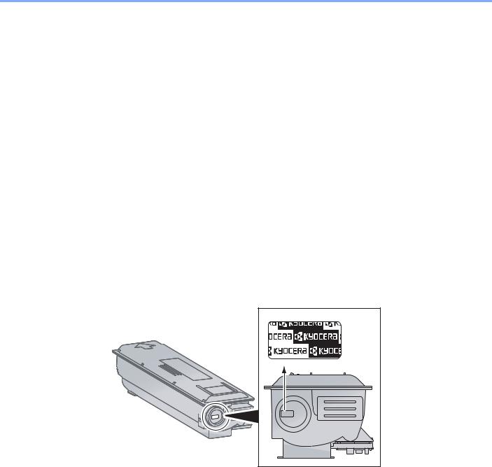
> Предисловие
Предисловие
Настоящее руководство содержит сведения по эксплуатации и техобслуживанию аппарата, а также описание несложных действий по устранению возникающих неполадок и поддержанию аппарата в как можно лучшем состоянии.
Перед эксплуатацией аппарата ознакомьтесь с данным руководством по эксплуатации.
Мы рекомендуем использовать наши фирменные расходные материалы.
Пожалуйста, примите во внимание, что в случае если пользователь решит использовать неоригинальный (контрафактный или совместимый) тонер, то мы не гарантируем надлежащую работу устройства. Мы не проводили тестирования тонеров, изготовленных другими производителями, в связи с чем мы не можем достоверно утверждать, что тот или иной тонер, изготовленный другим производителем, совместим с нашей продукцией. Мы рекомендуем использовать оригинальный тонер, как указано в Руководстве пользователя, прилагаемом к устройству. Использование неоригинального (контрафактного или совместимого) тонера может привести к повреждению устройства. Подобное повреждение может повлиять на условия гарантии и повлечь дополнительные расходы для пользователя в связи со снятием таких устройств с гарантийного ремонта. Кроме того, использование контрафактного тонера – это поддержка незаконной деятельности недобросовестных производителей, действующих с нарушением законов Российской Федерации. Просим принять во внимание настоящую информацию о рисках, связанных с использованием неоригинального тонера.
На фирменных расходных материалах имеется этикетка, изображенная ниже.
i

Cодержание
|
Предисловие………………………………………………………………………………………………………….. |
i |
|
|
Общие сведения…………………………………………………………………………………………………… |
vi |
|
|
Функции аппарата ……………………………………………………………………………………………….. |
vii |
|
|
Руководства, поставляемые с аппаратом…………………………………………………………….. |
x |
|
|
О руководстве по эксплуатации (данном документе) ………………………………………….. |
xi |
|
|
Структура документа……………………………………………………………………………………… |
xi |
|
|
Условные обозначения в данном руководстве……………………………………………….. |
xii |
|
|
Карта меню ………………………………………………………………………………………………………….. |
xv |
|
|
1 |
Правовая информация и правила техники безопасности ………… |
1-1 |
|
Примечание ……………………………………………………………………………………………………….. |
1-2 |
|
|
Условные обозначения по технике безопасности в данном руководстве ……….. |
1-2 |
|
|
Окружающая среда …………………………………………………………………………………….. |
1-3 |
|
|
Меры предосторожности при эксплуатации ………………………………………………….. |
1-3 |
|
|
Меры безопасности при работе с лазером в странах Европы ……………………….. |
1-4 |
|
|
Safety Instructions Regarding the Disconnection of Power ………………………………… |
1-5 |
|
|
Законодательные ограничения на копирование и сканирование …………………… |
1-5 |
|
|
EN ISO 7779 ……………………………………………………………………………………………….. |
1-5 |
|
|
EK1-ITB 2000 ………………………………………………………………………………………………. |
1-5 |
|
|
Правовая информация ……………………………………………………………………………….. |
1-6 |
|
|
Функция управления энергосбережением …………………………………………………….. |
1-7 |
|
|
Функция автоматического двустороннего копирования …………………………………. |
1-7 |
|
|
Сбережение ресурсов — бумага ………………………………………………………………….. |
1-7 |
|
|
Экологическая польза от функции «управления режимом питания» ……………….. |
1-7 |
|
|
Программа Energy Star (ENERGY STAR®) ……………………………………………………. |
1-8 |
|
|
2 |
Установка и настройка аппарата ……………………………………………….. |
2-1 |
|
Наименования компонентов ……………………………………………………………………………… |
2-2 |
|
|
Внешние элементы аппарата ………………………………………………………………………. |
2-2 |
|
|
Разъемы/внутренние компоненты ……………………………………………………………….. |
2-4 |
|
|
С установленным дополнительным оборудованием …………………………………….. |
2-5 |
|
|
Определение способа подключения и подготовка кабелей ……………………………… |
2-6 |
|
|
Пример подключения ………………………………………………………………………………….. |
2-6 |
|
|
Подготовка необходимых кабелей ……………………………………………………………….. |
2-6 |
|
|
Подсоединение кабелей …………………………………………………………………………………….. |
2-7 |
|
|
Подсоединение кабеля USB ………………………………………………………………………… |
2-7 |
|
|
Подсоединение кабеля питания ………………………………………………………………….. |
2-7 |
|
|
Включение/выключение питания ………………………………………………………………………. |
2-8 |
|
|
Включение питания …………………………………………………………………………………….. |
2-8 |
|
|
Выключение питания ………………………………………………………………………………….. |
2-9 |
|
|
Установка программного обеспечения ……………………………………………………………. |
2-10 |
|
|
Программное обеспечение на диске Product Library (Windows) ……………………. |
2-10 |
|
|
Установка программного обеспечения в Windows ………………………………………. |
2-11 |
|
|
Деинсталляция программного обеспечения ……………………………………………….. |
2-15 |
|
|
Настройка общего принтера ………………………………………………………………………. |
2-16 |
|
|
Установка программного обеспечения на компьютер Mac …………………………… |
2-17 |
|
|
KYOCERA Client Tool ………………………………………………………………………………… |
2-18 |
|
|
Настройка драйвера WIA …………………………………………………………………………… |
2-19 |
|
|
Имя пользователя и пароль администратора …………………………………………………. |
2-20 |
|
|
Параметры администратора ……………………………………………………………………… |
2-20 |
|
|
Параметры функции энергосбережения ………………………………………………………….. |
2-22 |
|
|
Режим ожидания и таймер режима ожидания …………………………………………….. |
2-22 |
|
|
Таймер отключения питания ……………………………………………………………………… |
2-23 |
|
|
Проверка счетчика …………………………………………………………………………………………… |
2-27 |
ii

|
3 |
Подготовка к использованию ……………………………………………………. |
3-1 |
|
Использование панели управления ………………………………………………………………….. |
3-2 |
|
|
Кнопки панели управления ………………………………………………………………………….. |
3-2 |
|
|
Метод работы …………………………………………………………………………………………….. |
3-3 |
|
|
Отображение оригиналов и бумаги ……………………………………………………………… |
3-4 |
|
|
Загрузка бумаги …………………………………………………………………………………………………. |
3-5 |
|
|
Перед загрузкой бумаги ………………………………………………………………………………. |
3-6 |
|
|
Загрузка в кассеты ……………………………………………………………………………………… |
3-7 |
|
|
Загрузка бумаги в универсальный лоток …………………………………………………….. |
3-10 |
|
|
Указание формата бумаги и типа носителя ………………………………………………… |
3-13 |
|
4 |
Печать с ПК ………………………………………………………………………………… |
4-1 |
|
Печать с ПК ………………………………………………………………………………………………………… |
4-2 |
|
|
Настройки печати драйвера принтера ………………………………………………………….. |
4-5 |
|
|
Справка по драйверу принтера ……………………………………………………………………. |
4-6 |
|
|
Изменение стандартных настроек драйвера принтера (Windows 7) ………………. |
4-6 |
|
|
Отмена заданий ………………………………………………………………………………………….. |
4-6 |
|
|
Использование ящика печати ……………………………………………………………………………. |
4-8 |
|
|
Сохранение документа в ящик печати …………………………………………………………. |
4-9 |
|
|
Печать документа из ящика печати ……………………………………………………………. |
4-10 |
|
5 |
Эксплуатация аппарата ……………………………………………………………… |
5-1 |
|
Загрузка оригиналов ………………………………………………………………………………………….. |
5-2 |
|
|
Размещение оригиналов на стекле оригинала ……………………………………………… |
5-2 |
|
|
Загрузка оригиналов в автоподатчик оригиналов (опция) ……………………………… |
5-3 |
|
|
Проверка серийного номера оборудования ……………………………………………………… |
5-6 |
|
|
Копирование ………………………………………………………………………………………………………. |
5-7 |
|
|
Основные операции ……………………………………………………………………………………. |
5-7 |
|
|
Прерывание копирования ……………………………………………………………………………. |
5-8 |
|
|
Копир. ID-карт (Копирование ID-карт) …………………………………………………………… |
5-9 |
|
|
Использование различных функций …………………………………………………………… |
5-11 |
|
|
Программа ……………………………………………………………………………………………….. |
5-26 |
|
|
Отмена заданий ………………………………………………………………………………………… |
5-30 |
|
|
Сканирование …………………………………………………………………………………………………… |
5-31 |
|
|
Сканирование изображения в указанное место назначения ………………………… |
5-33 |
|
|
Сканирование изображения с выбором места назначения |
||
|
(Быстрое сканирование) ……………………………………………………………………………. |
5-36 |
|
|
Сканирование с помощью TWAIN ………………………………………………………………. |
5-37 |
|
|
Отмена заданий ………………………………………………………………………………………… |
5-38 |
|
6 |
Проверка состояния ………………………………………………………………….. |
6-1 |
|
Проверка состояния задания …………………………………………………………………………….. |
6-2 |
|
|
Проверка журнала задания ……………………………………………………………………………….. |
6-4 |
|
|
Приостановка и возобновление заданий ………………………………………………………….. |
6-7 |
|
|
Отмена заданий, которые выполняются/ожидают печати ………………………………… |
6-8 |
|
|
Проверка состояния устройства ……………………………………………………………………….. |
6-9 |
|
|
Проверка остатка тонера и бумаги …………………………………………………………………… |
6-10 |
|
|
Проверка из KYOCERA Client Tool ……………………………………………………………………. |
6-11 |
|
7 |
Системное меню и KYOCERA Client Tool …………………………………… |
7-1 |
|
Настройки аппарата по умолчанию (системное меню) ……………………………………… |
7-2 |
|
|
Параметры системного меню ………………………………………………………………………. |
7-3 |
|
|
Отчет …………………………………………………………………………………………………………. |
7-4 |
|
|
Система ……………………………………………………………………………………………………… |
7-5 |
|
|
Админ/учет …………………………………………………………………………………………………. |
7-5 |
|
|
Общие параметры ………………………………………………………………………………………. |
7-5 |
iii

|
Копировать ……………………………………………………………………………………………….. |
7-14 |
|
|
Принтер ……………………………………………………………………………………………………. |
7-15 |
|
|
Настройка/обслуж (Настройка/обслуж) ………………………………………………………. |
7-15 |
|
|
Настройки на ПК по умолчанию (KYOCERA Client Tool) ………………………………….. |
7-16 |
|
|
Метод работы …………………………………………………………………………………………… |
7-16 |
|
|
Обзор экрана ……………………………………………………………………………………………. |
7-17 |
|
|
Настройка параметров администрирования ……………………………………………….. |
7-19 |
|
|
Параметры места назначения сканирования ……………………………………………… |
7-20 |
|
|
Параметры быстрого сканирования/TWAIN ………………………………………………… |
7-23 |
|
|
Параметры ящика печати ………………………………………………………………………….. |
7-26 |
|
|
8 |
Учет заданий ……………………………………………………………………………… |
8-1 |
|
Общие сведения об учете заданий ……………………………………………………………………. |
8-2 |
|
|
Включение учета заданий ………………………………………………………………………………….. |
8-4 |
|
|
Настройка учетной записи …………………………………………………………………………………. |
8-5 |
|
|
Добавление учетной записи ………………………………………………………………………… |
8-5 |
|
|
Ограничение использования аппарата ………………………………………………………… |
8-7 |
|
|
Редактирование учетной записи ………………………………………………………………….. |
8-8 |
|
|
Удаление учетной записи ……………………………………………………………………………. |
8-9 |
|
|
Учет заданий при совместном доступе к принтеру ……………………………………… |
8-10 |
|
|
Неизвестный идентификатор задания ……………………………………………………….. |
8-12 |
|
|
Настройка учета заданий …………………………………………………………………………………. |
8-13 |
|
|
Настройка по умолчанию …………………………………………………………………………… |
8-13 |
|
|
Подсчет количества напечатанных страниц ……………………………………………….. |
8-14 |
|
|
Отчет учета (Отчет об учете) …………………………………………………………………….. |
8-16 |
|
|
Использование учета заданий …………………………………………………………………………. |
8-18 |
|
|
Вход в систему/выход из системы ……………………………………………………………… |
8-18 |
|
|
Печать при совместном доступе к принтеру ……………………………………………….. |
8-18 |
|
|
9 |
Устранение неисправностей ……………………………………………………… |
9-1 |
|
Регулярное обслуживание …………………………………………………………………………………. |
9-2 |
|
|
Очистка ………………………………………………………………………………………………………. |
9-2 |
|
|
Замена контейнера с тонером ……………………………………………………………………… |
9-3 |
|
|
Замена бункера для отработанного тонера ………………………………………………….. |
9-6 |
|
|
Устранение неисправностей ……………………………………………………………………………… |
9-8 |
|
|
Устранение сбоев в работе …………………………………………………………………………. |
9-8 |
|
|
Реагирование на сообщения ……………………………………………………………………… |
9-12 |
|
|
Устранение замятия бумаги ………………………………………………………………………. |
9-17 |
|
|
10 |
Приложение ……………………………………………………………………………… |
10-1 |
|
Дополнительное оборудование ………………………………………………………………………. |
10-2 |
|
|
Общие сведения о дополнительном оборудовании …………………………………….. |
10-2 |
|
|
Способ ввода символов ………………………………………………………………………………….. |
10-4 |
|
|
Использование клавиш ……………………………………………………………………………… |
10-4 |
|
|
Символы, которые можно ввести с помощью цифровой клавиатуры …………… |
10-4 |
|
|
Ввод символов ………………………………………………………………………………………….. |
10-5 |
|
|
Ввод символов ………………………………………………………………………………………….. |
10-6 |
|
|
Бумага ………………………………………………………………………………………………………………. |
10-7 |
|
|
Основные характеристики бумаги ……………………………………………………………… |
10-7 |
|
|
Выбор подходящей бумаги ………………………………………………………………………… |
10-8 |
|
|
Бумага специального назначения …………………………………………………………….. |
10-11 |
|
|
Характеристики ………………………………………………………………………………………………. |
10-15 |
|
|
Набор основных функций ………………………………………………………………………… |
10-15 |
|
|
Функции копирования ………………………………………………………………………………. |
10-16 |
|
|
Функции принтера …………………………………………………………………………………… |
10-16 |
|
|
Функции сканера ……………………………………………………………………………………… |
10-17 |
|
|
Автоподатчик оригиналов (Автоматически в обратном порядке) |
iv

|
(дополнительно) ……………………………………………………………………………………… |
10-17 |
|
Податчик бумаги (на 300 листов) (дополнительно) ……………………………………. |
10-18 |
|
Устройство двусторонней печати (дополнительно) …………………………………… |
10-18 |
|
Глоссарий ………………………………………………………………………………………………………. |
10-19 |
|
Алфавитный указатель ………………………………………………….. |
Алфавитный указатель-1 |
v
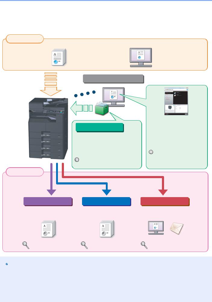
> Общие сведения
Общие сведения
Данный аппарат предлагает стандартные функции печати и копирования и может сохранять отсканированные изображения на компьютер.
|
Входные данные |
Электронные данные |
|
Оригинал |
Операции, выполняемые с ПК
Функции ящика печати
Функции ящика печати позволяют временно сохранять данные печати в ящике печати на компьютере и выводить эти данные на печать, выполняя операции на аппарате.
Использование ящика печати
 (стр. 4-8)
Выходные данные
|
Функции копирования |
Функции принтера |
KYOCERA Client Tool
Проверить состояние и изменить настройки сканирования аппарата можно с помощью
KYOCERA Client Tool,
установленного на компьютере.
 KYOCERA Client Tool (стр. 2-
  18)
18)
Функции сканера
|
Копирование и печать |
Печать данных с ПК. |
Сканирование оригиналов и |
|
оригиналов. |
отправка данных на ПК. |
|
Копирование (стр. 5-7) |
Печать с ПК (стр. 4-2) |
Сканирование (стр. 5-31) |


 ПРИМЕЧАНИЕ
•Прежде чем приступить к использованию аппарата, обязательно прочтите раздел Правовая информация и правила техники безопасности на стр. 1-1.
•Порядок выполнения действий по подготовке к эксплуатации аппарата, в том числе подключению кабелей и установке программного обеспечения, изложен в разделе Установка и настройка аппарата на стр. 2-1.
•Подробнее об использовании панели управления и загрузке бумаги см. в разделе Подготовка к использованию на стр. 3-1.
vi
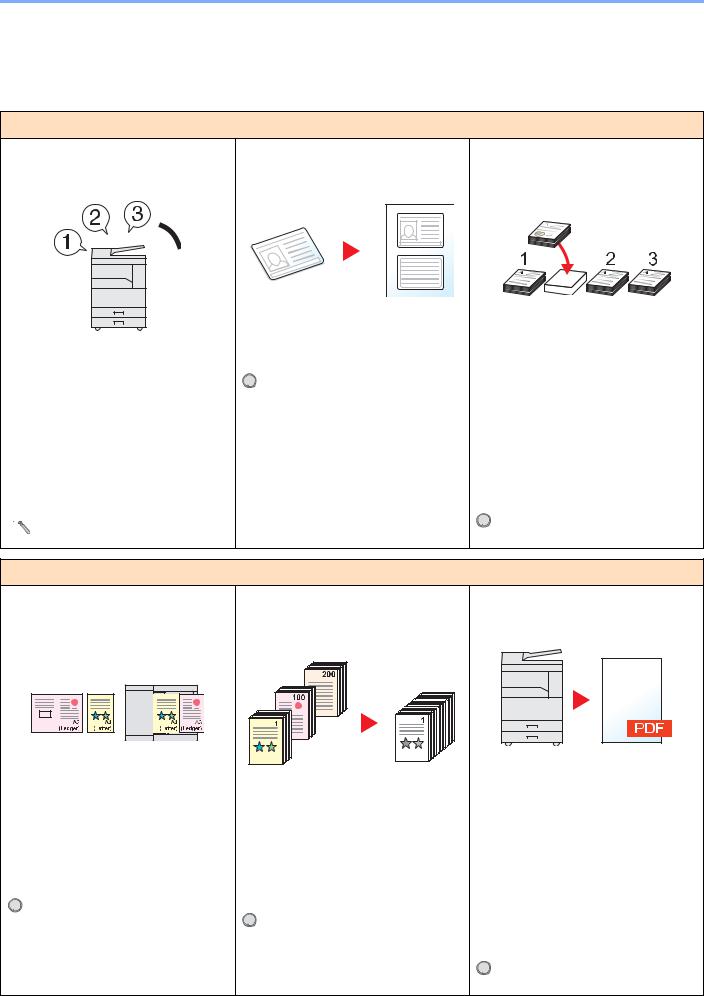
> Функции аппарата
Функции аппарата
Аппарат оснащен множеством полезных функций. Ниже приведены примеры некоторых из них. Подробнее см. Эксплуатация аппарата на стр. 5-1.
Оптимизация процессов обработки документов в офисе
Доступ к часто используемым функциям по одному нажатию (программа)
Можно заранее настроить часто используемые функции.
После включения функций в программу предварительно настроенных функций для их вызова потребуется только нажатие номера программы. Использование этой программы всегда приводит к получению одинаковых результатов, даже если ее используют различные пользователи.
 Программа (стр. 5-26)
Копирование обеих сторон ID-карты на одном листе (Копир. ID-карт)
Можно скопировать лицевую и оборотную стороны ID-карты на один лист бумаги.
 Копир. ID-карт (Копирование ID-
  карт) (стр. 5-9)
Прерывание других выполняемых заданий и немедленное выполнение копирования (Прер. копир-я)
Можно прервать все другие выполняемые задания и выполнить свое задание копирования немедленно.
Если другие пользователи выполняют копирование большого количества страниц, данная функция позволит прервать эти задания и немедленно произвести свое копирование.
По завершении этого копирования аппарат продолжит выполнять приостановленные задания печати.
 Прерывание копирования (стр. 5-

Оптимизация процессов обработки документов в офисе
Сканирование оригиналов различного размера за один раз (Оригиналы разных форматов)
Эта функция полезна при подготовке материалов для конференции.
За один раз можно настроить различныеразмерыоригиналов, чтобы не приходилось выполнять сброс параметров оригиналов вне зависимости от их размера.
 Ориг.Разн.Формат. (Оригиналы
  разных форматов) (стр. 5-22)
Сканирование множества оригиналов отдельнымипартиями, азатемвыпуск одним заданием (Непрерывное сканирование)
Эта функция полезна при подготовке многостраничных раздаточных материалов.
Когда невозможно поместить в автоподатчик оригиналов большое количество документов за один раз, оригиналы можно отсканировать отдельными партиями и затем скопировать или как одно задание.
 Непрерывное сканирование (стр.
  5-25)
5-25)
Сканирование документов в файлы PDF высокого сжатия
(PDF высокого сжатия)
Можно создавать цветные документы высокого качества в формате PDF такого же малого размера, что и чернобелые.
Данная функция позволяет сканировать документы в файлы PDF высокого сжатия, сохраняя удобочитаемость.
Посколькуполноцветныедокументыможно сжать до столь же малого размера, что и черно-белые, такие документы можно использовать в качестве вложений в сообщения электронной почты.
 Параметры быстрого
  сканирования/TWAIN (стр. 7-23)
vii
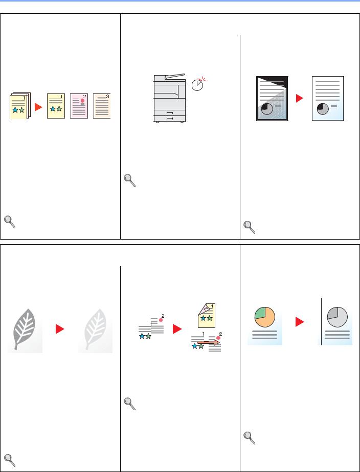
EcoPrint (стр. 5-22)
> Функции аппарата
|
Оптимизация процессов |
Экономия энергии и расходов |
|
|
обработки документов в офисе |
||
|
Каждая страница отсканированного |
Настраиваемые режимы экономии |
Удаление черных теней, |
|
документа сохраняется в отдельном |
энергии |
появляющихся на кромках копии |
|
файле |
(Ожидание/отключение питания) |
(Стирание границы) |
|
(Разделение файлов) |
Off
|
Аппарат оснащается функцией |
Данная функция позволяет печатать |
|
|
Можно создавать отдельный файл для |
энергосбережения, автоматически |
документы, не копируя ненужные |
|
каждой страницы документа. |
отключающей питание или |
участки, что помогает снизить расход |
|
Для каждой страницы сканируемого |
переводящей аппарат в режим |
тонера. |
|
ожидания. |
||
|
оригинала создается и сохраняется |
Можно удалить тени, появляющиеся |
|
|
отдельный файл. |
Параметры функции |
вокруг границ копии при сканировании |
|
К концу имени файла добавляется |
энергосбережения (стр. 2-22) |
оригинала. Также можно удалить тени, |
|
последовательный номер из трех |
появляющиеся на границах и в центре |
|
|
копии при сканировании книги. Таким |
||
|
цифр, например «abc_001.pdf» или |
||
|
образом, можно создать более |
||
|
«abc_002.pdf». |
||
|
привлекательный визуально документ. |
||
|
Параметры быстрого |
||
|
Стирание границы (стр. 5-24) |
||
|
сканирования/TWAIN (стр. 7-23) |
||
|
Экономия энергии и расходов |
Создание визуально |
|
|
привлекательных документов |
||
|
Использование для печати |
Печать нескольких оригиналов на |
Добавление полей для сшивания |
|
меньшего количества тонера |
одном листе |
(Поле) |
|
(EcoPrint) |
(Двусторонняя печать/совмещение) |
|
Это удобно при подготовке материалов |
||||||||||||||||||
|
Благодаря данной функции можно |
Оригиналы можно печатать на обеих |
к брошюрованию. |
||||||||||||||||
|
сократить расход тонера. |
сторонах листа бумаги. Кроме того, |
Можно сместить копируемое |
||||||||||||||||
|
несколько оригиналов можно |
||||||||||||||||||
|
Используйте эту функцию, чтобы |
изображение, чтобы предусмотреть |
|||||||||||||||||
|
напечатать на одном листе бумаги. |
||||||||||||||||||
|
сэкономить тонер, если вам нужно |
поле для сшивания копий. |
|||||||||||||||||
|
всего лишь проверить содержимое |
Совместить (стр. 5-18) |
Если копии двусторонние, поля на |
||||||||||||||||
|
печатного документа, например, при |
Двусторонняя (стр. 5-15) |
лицевой и оборотной сторонах можно |
||||||||||||||||
|
пробной печати, или распечатать |
настроить так, чтобы они находились в |
|||||||||||||||||
|
документ для внутреннего |
||||||||||||||||||
|
одинаковом положении. |
||||||||||||||||||
|
подтверждения. |
||||||||||||||||||
|
Поле (стр. 5-23) |
||||||||||||||||||
|
Используйте эту функцию, если не |
||||||||||||||||||
|
требуется высококачественная печать. |
viii
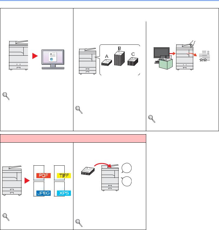
> Функции аппарата
|
Создание визуально |
Усиление безопасности |
|||||||||||||||
|
привлекательных документов |
||||||||||||||||
|
Сканирование оригиналов в цвете и |
Управление подсчетом |
Предотвращение потери готовых |
||||||||||||||
|
отправка их на ПК (Сканирование) |
скопированных/отпечатанныхкопий |
документов (Ящик печати) |
||||||||||||||
|
по учетной записи (Учет заданий) |
||||||||||||||||
|
100 |
400 |
200 |
|||
|
Можно сканировать оригиналы и |
Можно временно сохранить документ |
||||
|
преобразовывать их в электронные |
Можно контролировать и ограничивать |
принтера в ящике печати на |
|||
|
данные, например в цветные PDF. |
количество копируемых/печатаемых |
компьютере. При печати документа с |
|||
|
Сканирование (стр. 5-31) |
копий для учетной записи, присвоив |
аппарата устраняется риск попадания |
|||
|
каждой учетной записи идентификатор |
документа в руки другого человека. |
||||
|
учетной записи. |
Благодаря ПИН-коду, присвоенному |
||||
|
Общие сведения об учете |
ящику печати, можно усилить |
||||
|
безопасность. |
|||||
|
заданий (стр. 8-2) |
|||||
|
Использование ящика печати |
|||||
|
(стр. 4-8) |
|||||
|
Более эффективное использование функций |
|||||
|
Задание формата файла |
Добавление имени файла (Ввод |
||||
|
изображения |
имени файла) |
||||
|
(Формат файла) |
|||||
|
File |
|||||
|
01 |
|||||
|
Данная функция облегчает проверку |
|||||
|
При сохранении изображений можно |
журнала и состояния заданий. |
||||
|
выбрать различные форматы файла. |
Заданию можно присвоить имя и |
||||
|
Параметры быстрого |
номер. |
||||
|
сканирования/TWAIN (стр. 7-23) |
Ввод имени файла (стр. 5-25) |
ix
![]()
> Руководства, поставляемые с аппаратом
Руководства, поставляемые с аппаратом
В комплект поставки аппарата входят следующие руководства. При необходимости сверяйтесь с соответствующим руководством.
Содержание руководств может быть изменено без уведомления в целях улучшения технических характеристик аппарата.
Печатные руководства
Быстрое начало использования аппарата
Правила безопасного использования аппарата
Quick Guide
Объясняет основные функции аппарата.
Safety Guide
Содержит информацию о безопасности и предостережения относительно установки и эксплуатации аппарата. Обязательно прочитайте это руководство перед использованием данного аппарата.
Safety Guide (TASKalfa 1800/TASKalfa 2200)
В данном руководстве приведены указания относительно свободного пространства, необходимого для установки аппарата, описание предупредительных надписей и иные сведения о технике безопасности. Обязательно прочитайте это руководство перед использованием данного аппарата.
Руководства (PDF) на диске Product Library
Надлежащее
использование
аппарата
Печать данных с компьютера
Использование
KYOCERA Client Tool
Руководство по эксплуатации (данный документ)
Содержит описание процедур загрузки бумаги, выполнения операций копирования, печати и сканирования, а также содержит параметры по умолчанию и другую информацию.
Printer Driver User Guide
Содержит описание порядка установки драйвера принтера и использования функций принтера.
KYOCERA Client Tool User Guide
Объясняет использование KYOCERA Client Tool.
Для просмотра руководств, записанных на диске Product Library, необходимо установить Adobe Reader 8.0 или более поздней версии.
x

> О руководстве по эксплуатации (данном документе)
О руководстве по эксплуатации (данном документе)
Структура документа
В настоящем руководстве содержатся следующие разделы.
|
Раздел |
Содержание |
|
|
1 |
Правовая информация и |
Содержит описание мер предосторожности при использовании аппарата и |
|
правила техники |
информацию относительно торговых марок. |
|
|
безопасности |
||
|
2 |
Установка и настройка |
Содержит описание деталей аппарата, порядка подключения кабелей, установки |
|
аппарата |
программного обеспечения, а также иных процедур, связанных с |
|
|
администрированием аппарата. |
||
|
3 |
Подготовка к использованию |
Содержит описание настроек и процедур подготовки, необходимых для начала |
|
эксплуатации аппарата, в том числе порядка использования панели управления, |
||
|
создания адресной книги и загрузки бумаги. |
||
|
4 |
Печать с ПК |
Объясняет функции, доступные при использовании аппарата в качестве принтера. |
|
5 |
Эксплуатация аппарата |
Содержит описание основных процедур, связанных с эксплуатацией аппарата, в |
|
том числе процедуры размещения оригиналов, выполнения копий и |
||
|
сканирования. |
||
|
6 |
Проверка состояния |
Объясняет способы проверки состояния задания и журнала заданий, а также |
|
способы отмены заданий, которые уже печатаются или ожидают печати. Также |
||
|
объясняются способы проверки уровней высоты стопки бумаги и тонера, а также |
||
|
проверки состояния устройства. |
||
|
7 |
Системное меню и KYOCERA |
Объясняет системное меню, связанное с общей эксплуатацией и служебными |
|
Client Tool |
программами аппарата. |
|
|
8 |
Учет заданий |
Объясняет учет заданий. |
|
9 |
Устранение неисправностей |
Содержит описания порядка действий в ситуациях, когда закончился тонер, |
|
отображается ошибка, замялась бумага или возникла иная проблема. |
||
|
10 |
Приложение |
Содержит описание дополнительного оборудования для аппарата. Содержит |
|
сведения о типах носителя и форматах бумаги, а также глоссарий терминов. В |
||
|
этом разделе описывается ввод символов и указаны технические характеристики |
||
|
аппарата. |
||
xi
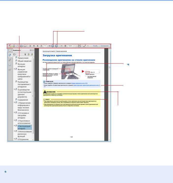
> О руководстве по эксплуатации (данном документе)
Условные обозначения в данном руководстве
В приведенных ниже объяснениях в качестве примера используется Adobe Reader X.
Щелкните элемент оглавления для быстрого перехода к соответствующей странице.
Щелкните для перехода от текущей страницы к ранее отображавшейся странице. Данная функция удобна, если необходимо вернуться к странице, с которой был выполнен быстрый переход к текущей странице.
 ПРИМЕЧАНИЕ
Указывает на дополнительные объяснения и справочную информацию по эксплуатации аппарата.
См. раздел
Щелкните подчеркнутый текст для перехода к соответствующей странице.

 ВНИМАНИЕ
Предупреждает о возможности получения травмы или механического повреждения аппарата при недостаточном внимании или несоблюдении соответствующих правил.

 ВАЖНО
ВАЖНО
Указывает на требования по эксплуатации и ограничения, которые необходимо соблюдать для правильной эксплуатации аппарата и недопущения повреждения самого аппарата или иного имущества.


 ПРИМЕЧАНИЕ
Отображаемые в программе Adobe Reader элементы могут различаться в зависимости от порядка использования программы. Если оглавление или инструменты не отображаются, см. справку по программе Adobe Reader.
К некоторым элементам в данном руководстве применяются следующие условные обозначения.
|
Условное |
Описание |
Пример |
|
обозначение |
||
|
[Жирный |
Указывает на кнопки на панели |
Нажмите клавишу [Старт]. |
|
шрифт] |
управления или экранные кнопки |
Нажмите кнопку [OK]. |
|
интерфейса. |
||
|
[Обычный |
Обозначает сообщение или настройку, |
На дисплее сообщений появляется [Готов к копированию.]. |
|
шрифт] |
отображаемую на дисплее сообщений. |
С помощью [▲] или [▼] выберите [Вкл.]. |
|
«Обычный |
Обозначает сообщение или настройку, |
Можно выбрать из меню «Размер печати». |
|
шрифт» |
отображаемую на экране компьютера. |
|
xii
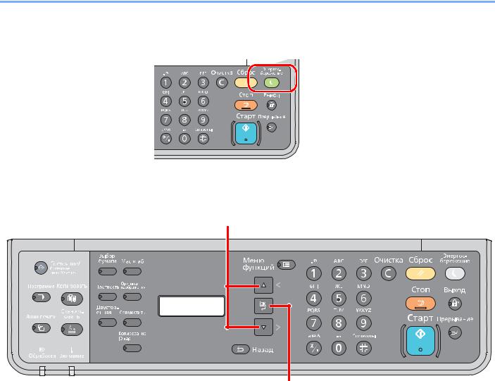
> О руководстве по эксплуатации (данном документе)
Условные обозначения в рабочих процедурах
Нажимаемые кнопки панели управления выделены красным.
Процедуры, состоящие из последовательности операций, выполняемых на панели управления или на компьютере, пронумерованы, как показано ниже.
xiii
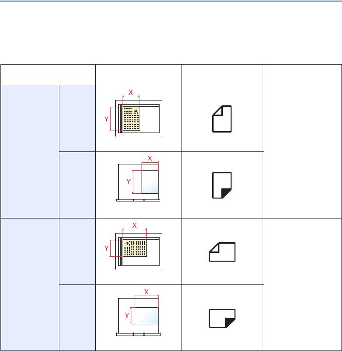
> О руководстве по эксплуатации (данном документе)
Формат и ориентация оригиналов и бумаги
Такие форматы оригиналов и бумаги, как A4, B5 и Letter, можно использовать и в горизонтальной, и в вертикальной ориентации. Для различения этих двух ориентаций при использовании указанных форматов к номеру формата добавляется «-R» для обозначения горизонтальной ориентации.
Для отображения ориентации оригинала и бумаги на дисплее сообщений используются следующие значки.
|
Ориентация |
Установка положения |
Дисплей |
Формат, указанный в |
|||
|
(X: ширина, Y: длина) |
данном руководстве*1 |
|||||
|
Вертикальный |
Оригинал |
A4, B5, Letter и пр. |
||||
|
Оригинал |
Оригинал |
|
Бумага |
|
|
Бумага |
Бумага |
|
Горизонтальный Оригинал |
A4-R, B5-R, Letter-R и пр. |
|
|
Оригинал |
Оригинал |
|
Бумага |
|
|
Бумага |
Бумага |
*1 Формат оригинала/бумаги, который можно использовать, различается в зависимости от функции и лотка бумаги. Подробнее см. Характеристики на стр. 10-15.
xiv

> Карта меню
Карта меню
(Здесь используются названия, отображаемые на дисплее сообщений. Они могут отличаться от заголовков соответствующих разделов.)
Выбор бумаги (стр. 5-13)
Масштаб (стр. 5-14)
Плотность (стр. 5-15)
Оригинал изобр. (стр. 5-15)
Двусторонняя (стр. 5-15)
Совместить (стр. 5-18)
Копир. ID-карт (стр. 5-9)
По копиям/сдвиг (стр. 5-20)
Формат оригинала (стр. 5-20)
Ориентация ориг. (стр. 5-21)
Ориг.Разн.Формат. (стр. 5-22)
EcoPrint (стр. 5-22)
Плотность фона (стр. 5-22)
Поле (стр. 5-23)
Стирание границы (стр. 5-24)
Непрерывное скан (стр. 5-25)
Автоповорот (стр. 5-25)
Ввод имени файла (стр. 5-25)
Готов к сканированию. (стр. 5-33)
xv
> Карта меню
Выбор программы (стр. 5-26)
Ящик печати (стр. 4-10)
|
Состояние |
Печ.сост.задания (стр. 6-2) |
||
|
Журн.задан.печ. (стр. 6-4) |
|||
|
Отпр.журн.задан. (стр. 6-4) |
|||
|
Сканер (стр. 6-9) |
|||
|
Принтер (стр. 6-9) |
|||
|
Состоян. тонера (стр. 6-10) |
|||
|
Состоян. бумаги (стр. 6-10) |
|||
|
Отчет |
Печать отчета |
Карта меню (стр. 7-4) |
|
|
Страница состояния (стр. 7-4) |
|||
|
Состояние сервиса (стр. 7-4) |
|||
|
Счетчик (стр. 2-27) |
|||
|
Система |
Уст. блок. и/ф. (стр. 7-5) |
||
|
Админ/учет |
Установки адми. (стр. 2-20) |
||
|
Настр. уч. зад. |
Учет заданий (стр. 8-4) |
||
|
Отчет учета (стр. 8-16) |
|||
|
Общий учет (стр. 8-14) |
|||
|
Учет кажд. зад. (стр. 8-14) |
|||
|
Список уч. зап. (стр. 8-5) |
|||
|
Парам. по умолч. (стр. 8-13) |
|||
|
Неизв. ид.задан. (стр. 8-12) |
|||
xvi

> Карта меню
|
Общие параметры |
Язык (стр. 7-5) |
|||
|
Экран по умолч. (стр. 7-6) |
||||
|
Звук |
Сигнал (стр. 7-6) |
|||
|
Яркость экрана (стр. 7-6) |
||||
|
Тихий режим (стр. 7-6) |
||||
|
Ориг./Пар. бум. |
Форм.польз.ориг. (стр. 7-6) |
|||
|
Польз. форм.бум. (стр. 7-7) |
||||
|
Настр. кассеты 1 |
Формат кассеты 1 (стр. 7-9) |
|||
|
Тип кассеты 1 (стр. 7-9) |
||||
|
Настр. кассеты 2 |
Формат кассеты 2 (стр. 7-9) |
|||
|
Тип кассеты 2 (стр. 7-9) |
||||
|
Настр. кассеты 3 |
Формат кассеты 3 (стр. 7-9) |
|||
|
Тип кассеты 3 (стр. 7-9) |
||||
|
Настр. кас. 4 |
Формат кассеты 4 (стр. 7-9) |
|||
|
Тип кассеты 4 (стр. 7-9) |
||||
|
Настр. ун. лотка |
Разм.унив.лотка (стр. 7-9) |
|||
|
Тип унив. лотка (стр. 7-9) |
||||
|
Уст. типа носит. (стр. 7-7) |
||||
|
Авт.обнар-е ориг. (стр. 7-7) |
||||
|
Носит. для авто (стр. 7-8) |
||||
|
Устр. под. по ум. (стр. 7-8) |
||||
|
Дств со спецбум. (стр. 7-8) |
||||
|
Устан. огран. (стр. 7-11) |
||||
|
Ед. измерения (стр. 7-11) |
||||
|
Обработка ошибок |
Ош. 2-стор. бум. (стр. 7-11) |
|||
|
ОшибНесоотвБум (стр. 7-11) |
||||
|
Настр. таймера |
Таймер сбр. ош. (стр. 7-12) |
|||
|
Таймер ожидания (стр. 7-12) |
||||
|
Таймер сбр. пан. (стр. 7-12) |
||||
|
Очистка прерыв. (стр. 7-12) |
||||
|
Правило выключ. (стр. 7-12) |
||||
|
Таймер выключ. (стр. 7-12) |
||||
|
Авт. удал. ошиб. (стр. 7-12) |
||||
|
Авт.сброс панели (стр. 7-12) |
||||
xvii

> Карта меню
|
Общие параметры |
Функция по умолч |
Оригинал изобр. (стр. 7-13) |
|
|
Масштаб (стр. 7-13) |
|||
|
По копиям/сдвиг (стр. 7-13) |
|||
|
Ориентация ориг. (стр. 7-13) |
|||
|
Стирание границы (стр. 7-13) |
|||
|
Поле (стр. 7-13) |
|||
|
Плотность фона (стр. 7-13) |
|||
|
EcoPrint (стр. 7-13) |
|||
|
Автоповорот (стр. 7-13) |
|||
|
Ввод имени файла (стр. 7-13) |
|||
|
Непрерывное скан (стр. 7-13) |
|||
|
Настр. деталей |
Макет 2 в 1 (стр. 7-14) |
||
|
Макет 4 в 1 (стр. 7-14) |
|||
|
Лин. границы (стр. 7-14) |
|||
|
Ориг. сшивание (стр. 7-14) |
|||
|
Сшив.книжн.ориг. (стр. 7-14) |
|||
|
Финиш. сшивание (стр. 7-14) |
|||
|
Копирование |
Выбор бумаги (стр. 7-14) |
||
|
Автовыбор бумаги (стр. 7-14) |
|||
|
Автом. приор. % (стр. 7-14) |
|||
|
Принтер |
Лим.врем.под.бум (стр. 7-15) |
||
|
Настройка/обслуж |
Рег. плотности (стр. 7-15) |
||
|
Плотность фона (стр. 7-15) |
|||
|
Плотность печати (стр. 7-15) |
|||
|
Правильно. Корр. черн полос (стр. 7-15) |
|||
|
Настройка службы |
Очистка барабана (стр. 7-15) |
||
xviii
1Правовая информация и правила техники безопасности
Перед использованием аппарата прочтите данную информацию. В этом разделе приводится информация по следующим темам.
|
Примечание …………………………………………………………………………………………………………………………………… |
1-2 |
|
Условные обозначения по технике безопасности в данном руководстве ………………………………….. |
1-2 |
|
Окружающая среда ……………………………………………………………………………………………………………….. |
1-3 |
|
Меры предосторожности при эксплуатации ……………………………………………………………………………. |
1-3 |
|
Меры безопасности при работе с лазером в странах Европы ………………………………………………….. |
1-4 |
|
Safety Instructions Regarding the Disconnection of Power …………………………………………………………… |
1-5 |
|
Законодательные ограничения на копирование и сканирование ……………………………………………… |
1-5 |
|
Правовая информация ………………………………………………………………………………………………………….. |
1-6 |
|
Функция управления энергосбережением ………………………………………………………………………………. |
1-7 |
|
Функция автоматического двустороннего копирования ……………………………………………………………. |
1-7 |
|
Сбережение ресурсов — бумага …………………………………………………………………………………………….. |
1-7 |
|
Экологическая польза от функции «управления режимом питания» ………………………………………….. |
1-7 |
|
Программа Energy Star (ENERGY STAR®) ………………………………………………………………………………. |
1-8 |
1-1
![]()
Правовая информация и правила техники безопасности > Примечание
Примечание
Условные обозначения по технике безопасности в данном руководстве
Специальные предупреждающие символы в разделах настоящего руководства и на компонентах аппарата призваны обратить внимание пользователя на возможную опасность как для него самого, так и для других людей и окружающих объектов, связанную с эксплуатацией данного аппарата, а также помочь обеспечить правильную и безопасную его эксплуатацию. Символы и их описания приведены ниже.
ПРЕДУПРЕЖДЕНИЕ! Предупреждает о возможности получения тяжелой травмы или смерти при недостаточном внимании или несоблюдении соответствующих
правил.
ВНИМАНИЕ! Предупреждает о возможности получения травмы или механического повреждения аппарата при недостаточном внимании или несоблюдении соответствующих правил.
Символы
Символ показывает, что соответствующий раздел включает в себя предупреждения относительно безопасности. Знаки внутри символа призваны привлечь внимание пользователя.
 … [Общее предупреждение]
 … [Предупреждение о высокой температуре]
Символ  указывает, что соответствующий раздел содержит информацию о запрещенных действиях. Внутри символа приводится условное обозначение запрещенного действия.
 … [Предупреждение о запрещенном действии]
 … [Разборка запрещена]
Символ указывает, что соответствующий раздел содержит информацию о действиях, которые должны быть выполнены. Внутри символа приводится условное обозначение обязательного действия.
 … [Уведомление об обязательном действии]
 … [Выньте вилку питания из сетевой розетки]
 … [Обязательно подключайте аппарат к сетевой розетке с заземлением]
Если предупреждения по технике безопасности в данном руководстве напечатаны неразборчиво или руководство утеряно, обратитесь к представителю сервисной службы и закажите новое руководство (услуга платная).
1-2

Правовая информация и правила техники безопасности > Примечание
Окружающая среда
Аппарат предназначен для эксплуатации в следующих условиях окружающей среды:
•Температура: от 10 до 32,5 °C
•Влажность: от 15 до 80%
Тем не менее, неблагоприятные условия окружающей среды могут негативно сказаться на качестве изображения. Избегайте установки аппарата в следующих местах.
•Вблизи окна или в местах, где на него будут попадать прямые солнечные лучи.
•В местах, подверженных вибрации.
•В местах с резкими перепадами температуры.
•В местах, находящихся по действием прямых потоков горячего или холодного воздуха.
•Избегайте мест с плохой вентиляцией.
Непрочный материал пола при перемещении аппарата после установки может быть поврежден роликами.
При копировании выделяется некоторое количество озона, но оно незначительно и не сказывается отрицательно на здоровье. Тем не менее, при длительном использовании аппарата в помещении с плохой вентиляцией или при изготовлении очень большого количества копий может ощущаться неприятный запах. Для обеспечения оптимальных условий окружающей среды при копировании рекомендуется хорошо проветривать помещение.
Меры предосторожности при эксплуатации
Меры предосторожности при обращении с расходными материалами
 ВНИМАНИЕ
Не пытайтесь поджечь детали, содержащие тонер. Искры от пламени могут стать причиной ожогов. Храните детали, содержащие тонер, в недоступном для детей месте.
Если тонер просыплется из деталей, его содержащих, не вдыхайте его и не проглатывайте, а также избегайте попадания в глаза и на кожу.
•Если вы вдохнули тонер, выйдите на свежий воздух и тщательно прополощите горло большим количеством воды. При появлении кашля обратитесь к врачу.
•Если вы проглотили тонер, прополощите рот водой и выпейте 1-2 чашки воды, чтобы разбавить содержимое желудка. При необходимости обратитесь к врачу.
•При попадании тонера в глаза тщательно промойте их водой. При продолжительном дискомфорте в глазах обратитесь к врачу.
•При попадании тонера на кожу помойте ее водой с мылом.
Не пытайтесь силой открыть или разрушить детали, содержащие тонер.
Другие меры предосторожности
Сдайте использованный контейнер с тонером и контейнер для отработанного тонера по месту приобретения аппарата или в службу поддержки. Переработка или утилизация использованных контейнеров с тонером и контейнеров для отработанного тонера производится в соответствии с установленными нормами.
Храните аппарат, избегая воздействия на него прямых солнечных лучей.
Храните аппарат в месте, где температура остается ниже 40 °C, избегая резких изменений температуры и влажности.
Если аппарат не будет использоваться в течение длительного периода, выньте бумагу из кассеты и универсального лотка, поместите ее обратно в оригинальную упаковку и запечатайте.
1-3
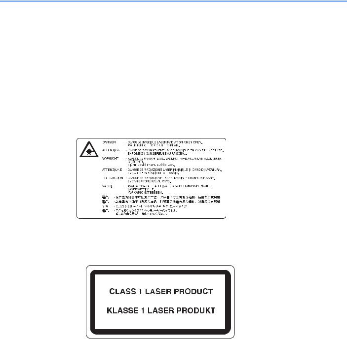
Правовая информация и правила техники безопасности > Примечание
Меры безопасности при работе с лазером в странах Европы
Лазерное излучение опасно для организма человека. Поэтому лазерное излучение, создаваемое внутри аппарата, герметично закрыто защитным кожухом и наружной крышкой. При правильной эксплуатации аппарата пользователем излучение не проникает за пределы его корпуса.
Настоящий аппарат классифицирован как лазерное изделие класса 1 в соответствии со стандартом
IEC/EN 60825-1:2007.
Внимание! Выполнение процедур, отличных от изложенных в данном руководстве, может привести к опасному воздействию лазерного излучения.
Эти наклейки прикреплены на блок лазерного сканера внутри аппарата и находятся вне зоны доступа пользователя.
Наклейка, представленная ниже, прикреплена на паспортной табличке.
1-4

Правовая информация и правила техники безопасности > Примечание
Safety Instructions Regarding the Disconnection of Power
Caution: The power plug is the main isolation device! Other switches on the equipment are only functional switches and are not suitable for isolating the equipment from the power source.
Attention: Le débranchement de la fiche secteur est le seul moyen de mettre l’appareil hors tension. Les interrupteurs sur l’appareil ne sont que des interrupteurs de fonctionnement: ils ne mettent pas l’appareil hors tension.
Законодательные ограничения на копирование и сканирование
Может быть запрещено копирование материала, защищенного авторскими правами, без разрешения владельца тех прав.
Копирование/сканирование следующих изображений запрещено и может быть уголовно наказуемым. Это может ограничиваться не только данными изображениями. Не копируйте/сканируйте умышленно изображения, которые не предназначены для копирования/сканирования.
•бумажные деньги;
•банкноты;
•ценные бумаги;
•печати;
•паспорта;
•сертификаты.
Местные законы и предписания могут запрещать или ограничивать копирование и сканирование иного, не упомянутого выше.


 ПРИМЕЧАНИЕ
В некоторых редких случаях может быть запрещено полноценное сканирование оригинала, чрезвычайно напоминающего банкноту.
EN ISO 7779
Maschinenlärminformations-Verordnung 3. GPSGV, 06.01.2004: Der höchste Schalldruckpegel beträgt 70 dB (A) oder weniger gemäß EN ISO 7779.
EK1-ITB 2000
Das Gerät ist nicht für die Benutzung im unmittelbaren Gesichtsfeld am Bildschirmarbeitsplatz vorgesehen. Um störende Reflexionen am Bildschirmarbeitsplatz zu vermeiden, darf dieses Produkt nicht im unmittelbaren Gesichtsfeld platziert werden.
1-5

Правовая информация и правила техники безопасности > Примечание
Правовая информация
Копирование или какое-либо иное воспроизведение настоящего руководства полностью или частично без предварительного письменного разрешения корпорации KYOCERA Document Solutions Inc. запрещено.
В отношении торговых марок
•TASKalfa — зарегистрированная торговая марка KYOCERA Document Solutions Inc.
•Microsoft, Windows, Windows XP, Windows Server 2003, Windows Vista, Windows Server 2008/R2, Windows 7, Windows Server 2012, Windows 8 и Internet Explorer являются зарегистрированными торговыми марками или торговыми марками Microsoft Corporation в США и (или) других странах.
•Adobe Acrobat и Flash являются зарегистрированными торговыми марками Adobe Systems Incorporated.
•IBM и IBM PC/AT являются торговыми марками International Business Machines Corporation.
•AppleTalk, Bonjour, Macintosh и Mac OS являются торговыми марками Apple Inc., зарегистрированными в США и других странах.
Все остальные торговые марки и названия продуктов, упомянутые в настоящем руководстве, являются зарегистрированными торговыми марками или торговыми марками соответствующих компаний. Обозначения ™ и ® в данном руководстве по эксплуатации не используются.
1-6

Правовая информация и правила техники безопасности > Примечание
Функция управления энергосбережением
Для уменьшения энергопотребления в ожидании выполнения задания устройство оснащается функцией управления энергосбережением, позволяющей переходить в режим ожидания, а также в режим «Питание выключено», в которых потребление электроэнергии автоматически снижается до минимума по истечении определенного времени с момента последнего использования устройства.
Режим ожидания
Аппарат автоматически переходит в режим ожидания по истечении 1 минуты с момента последнего использования функции копирования. Длительность простоя до перехода в режим ожидания может быть увеличена. При печати в режиме ожидания устройство возвращается в режим ожидания по завершении печати. Более подробная информация приведена в разделе Режим ожидания и таймер режима ожидания на стр. 2-22.
Режим «Питание выключено»
Устройство автоматически отключает свое питание по истечении 1 часа с момента его последнего использования. Длительность простоя до перехода в режим «Питание выключено» может быть увеличена. Для этого необходимо изменить настройки таймера отключения питания. Более подробная информация приведена в разделе Таймер отключения питания на стр. 2-23.
Функция автоматического двустороннего копирования
Для данного аппарата двустороннее копирование является необязательной функцией. Например, двустороннее копирование на один лист двух односторонних оригиналов позволяет сократить расход бумаги. Более подробная информация приведена в разделе Двусторонняя на стр. 5-15.
Печать в двустороннем режиме позволяет уменьшить расход бумаги и способствует сохранению лесных ресурсов. Использование режима двусторонней печати также приводит к уменьшению закупок бумаги и, следовательно, к снижению расходов. Рекомендуется в аппаратах, поддерживающих функцию двусторонней печати, использовать этот режим по умолчанию.
Сбережение ресурсов — бумага
В целях сохранения и рационального использования лесных ресурсов рекомендуется использовать переработанную, а также первичную бумагу, сертифицированную в соответствии с программами рационального использования природных ресурсов или снабженную общепризнанной экологической маркировкой,
соответствующую стандарту качества EN 12281:2002* или эквивалентному.
Данный аппарат также поддерживает печать на бумаге плотностью 64 г/м². Использование такой бумаги, на изготовление которой расходуется меньше сырья, вносит дополнительный вклад в сохранение лесных ресурсов.
*: EN12281:2002 «Бумага для печати и офиса — требования к бумаге для получения изображений с помощью сухого тонера»
Более подробную информацию по рекомендуемым типам бумаги можно получить у представителя сервисной службы или у торгового представителя.
Экологическая польза от функции «управления режимом питания»
Чтобы снизить энергопотребление в случае простоя, аппарат оснащен функцией управления режимом питания, которая автоматически активирует энергосберегающий режим, если аппарат не используется в течение определенного времени.
Хотя для возврата аппарата из энергосберегающего режима в режим ГОТОВНОСТИ потребуется незначительное время, это может существенно снизить энергопотребление. Рекомендуется для работы с аппаратом задать время активации энергосберегающего режима в качестве настройки по умолчанию.
1-7

Правовая информация и правила техники безопасности > Примечание
Программа Energy Star (ENERGY STAR®)
Наша компания, будучи участником международной программы Energy Star, определила, что данный продукт соответствует стандартам, утвержденным этой программой.
ENERGY STAR® — добровольная программа эффективного энергопотребления, целью которой является разработка и распространение изделий с высокими показателями энергосбережения, что способствует предотвращению глобального потепления. Приобретая изделия, отвечающие
критериям ENERGY STAR®, пользователи могут внести вклад в уменьшение выбросов парниковых газов при использовании изделия и сократить расходы на энергоресурсы.
1-8
2Установка и настройка аппарата
В данной главе содержится информация для администратора аппарата, в том числе наименования компонентов, порядок подключения кабелей и установки программного обеспечения.
|
Наименования компонентов ……………………………………………………………………………………………………………. |
2-2 |
|
Внешние элементы аппарата …………………………………………………………………………………………………. |
2-2 |
|
Разъемы/внутренние компоненты ………………………………………………………………………………………….. |
2-4 |
|
С установленным дополнительным оборудованием ……………………………………………………………….. |
2-5 |
|
Определение способа подключения и подготовка кабелей ……………………………………………………………….. |
2-6 |
|
Пример подключения …………………………………………………………………………………………………………….. |
2-6 |
|
Подготовка необходимых кабелей ………………………………………………………………………………………….. |
2-6 |
|
Подсоединение кабелей …………………………………………………………………………………………………………………. |
2-7 |
|
Подсоединение кабеля USB ………………………………………………………………………………………………….. |
2-7 |
|
Подсоединение кабеля питания …………………………………………………………………………………………….. |
2-7 |
|
Включение/выключение питания …………………………………………………………………………………………………….. |
2-8 |
|
Включение питания ……………………………………………………………………………………………………………….. |
2-8 |
|
Выключение питания …………………………………………………………………………………………………………….. |
2-9 |
|
Установка программного обеспечения …………………………………………………………………………………………… |
2-10 |
|
Программное обеспечение на диске Product Library (Windows) ………………………………………………. |
2-10 |
|
Установка программного обеспечения в Windows ………………………………………………………………….. |
2-11 |
|
Деинсталляция программного обеспечения ………………………………………………………………………….. |
2-15 |
|
Настройка общего принтера ………………………………………………………………………………………………… |
2-16 |
|
Установка программного обеспечения на компьютер Mac ……………………………………………………… |
2-17 |
|
KYOCERA Client Tool …………………………………………………………………………………………………………… |
2-18 |
|
Настройка драйвера WIA …………………………………………………………………………………………………….. |
2-19 |
|
Имя пользователя и пароль администратора …………………………………………………………………………………. |
2-20 |
|
Параметры администратора ………………………………………………………………………………………………… |
2-20 |
|
Параметры функции энергосбережения ………………………………………………………………………………………… |
2-22 |
|
Режим ожидания и таймер режима ожидания ……………………………………………………………………….. |
2-22 |
|
Таймер отключения питания ………………………………………………………………………………………………… |
2-23 |
|
Проверка счетчика ……………………………………………………………………………………………………………………….. |
2-27 |
2-1
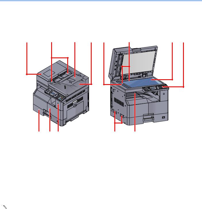
Установка и настройка аппарата > Наименования компонентов
Наименования компонентов
Внешние элементы аппарата
|
1 |
Устройство обработки документов (DP) |
8 |
Панель управления |
|
2 |
Направляющие ширины оригиналов |
9 |
Кассета 1 |
|
3 |
Лоток оригиналов |
10 |
Передняя крышка |
|
4 |
Выходной лоток оригиналов |
11 |
Выключатель питания |
|
5 |
Щелевое стекло |
12 |
Ручки |
|
6 |
Метки размера оригинала |
13 |
Внутренний лоток |
|
7 |
Стекло оригинала |
 Дополнительное оборудование (стр. 10-2)
2-2
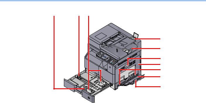
Установка и настройка аппарата > Наименования компонентов
14 Регулятор ширины бумаги
15 Направляющая длины бумаги
16 Направляющая ширины бумаги
17 Отделение для чистящей салфетки
18 Ограничитель оригиналов
19 Рычаг правой крышки 1
20 Правая крышка 1
21 Направляющая ширины бумаги
22 Универсальный лоток
23 Опорная часть универсального лотка
2-3
![]()
Установка и настройка аппарата > Наименования компонентов
Разъемы/внутренние компоненты
1
1Разъем интерфейса USB
2Контейнер с тонером
3Рычаг контейнера с тонером
4Бункер для отработанного тонера
2-4

Установка и настройка аппарата > Наименования компонентов
С установленным дополнительным оборудованием


 2 1
2 1 

3
4
5
1Крышка стекла экспонирования
2Устройство обработки документов (DP)
3Кассета 2
4Кассета 3
5Кассета 4
6Устройство двусторонней печати
7Правая крышка 2
8Правая крышка 3
9Правая крышка 4
Дополнительное оборудование (стр. 10-2)
2-5

Установка и настройка аппарата > Определение способа подключения и подготовка кабелей
Определение способа подключения и подготовка кабелей
Для подключения аппарата к компьютеру проверьте способ подключения и подготовьте соответствующие кабели для вашей среды.
Пример подключения
Подключите аппарат к ПК, руководствуясь приведенной ниже иллюстрацией.
KYOCERA Client Tool
•Параметры принтера
•Параметры устройства
•Параметры сканера
|
• |
Обслуживание |
|
МФУ |
|
|
Печать |
USB |
|
Сканирование |
Подготовка необходимых кабелей
Подготовьте необходимые кабели в соответствии с используемым интерфейсом.
Интерфейсы стандартной комплектации
|
Среда подключения |
Функция |
Необходимый кабель |
|
Подключение кабеля USB к |
Принтер/сканер |
Совместимый с интерфейсом USB 2.0 |
|
аппарату. |
(высокоскоростной, совместимый с |
|
|
интерфейсом USB, макс. длина 5,0 м, |
||
|
экранированный) |
||
2-6

Установка и настройка аппарата > Подсоединение кабелей
Подсоединение кабелей
Подсоединение кабеля USB
 ВАЖНО Если питание включено, выключите его с помощью выключателя.
 Выключение питания (стр. 2-9)
1 Подсоедините аппарат.
1 Подсоедините кабель USB к разъему интерфейса USB на левой стороне корпуса.
2 Подсоедините другой конец кабеля к ПК.
Подсоединение кабеля питания
Подсоедините один конец прилагаемого кабеля питания к аппарату, а другой — к розетке.
 ВАЖНО Используйте только кабель питания, поставляемый с аппаратом.
2-7

Установка и настройка аппарата > Включение/выключение питания
Включение/выключение питания
Включение питания
Если индикатор [Энергосбережение] светится… (выход из режима ожидания)
Индикатор [Энергосбережение]
Нажмите любую клавишу на панели управления.
Если индикатор [Энергосбережение] не светится…
Включите выключатель питания.
 ВАЖНО
ВАЖНО
Выключив аппарат с помощью выключателя питания, не включайте его сразу же после этого. Подождите как минимум 5 секунд и только потом включите питание.
2-8

Установка и настройка аппарата > Включение/выключение питания
Выключение питания
Без выключения выключателя питания… (режим ожидания)
Индикатор [Энергосбережение]
Нажмите клавишу [Энергосбережение]. Загорится индикатор [Энергосбережение].

 Режим ожидания и таймер режима ожидания (стр. 2-22)
Выключение с помощью выключателя питания…
Обратите внимание, что если выключатель питания выключен, аппарат не сможет автоматически получать данные печати от компьютеров или факсов.
 ВАЖНО
ВАЖНО
Когда светится или мигает индикатор [Обработка], это значит, что аппарат работает. Выключение выключателя питания во время работы аппарата может вызвать неисправность.
Выключите выключатель питания.
Если аппарат в течение длительного периода времени не используется…
 ВНИМАНИЕ
Если аппарат длительное время (например, в течение ночи) использоваться не будет, выключите его с помощью выключателя питания. Если аппарат не будет использоваться значительно больший период времени (например, во время отпуска), вытяните вилку шнура питания из розетки в качестве меры предосторожности.
 ВАЖНО Извлеките бумагу из кассет и уложите в упаковку для хранения, чтобы защитить ее от влаги.
2-9

Установка и настройка аппарата > Установка программного обеспечения
Установка программного обеспечения
Для использования функций принтера аппарата или передачи в режиме TWAIN/WIA с компьютера установите соответствующее программное обеспечение с прилагаемого диска Product Library.
Программное обеспечение на диске Product Library (Windows)
В качестве метода установки можно выбрать либо вариант [ Экспресс-установка], либо вариант
[Пользовательская установка]. Стандартным методом установки является [Экспресс-установка]. Для установки элементов, которые нельзя установить посредством [Экспресс-установки], используйте
[Пользовательскую установку]. Подробнее об использовании [Пользовательской установки] см.
Пользовательская установка на стр. 2-13.
|
Программное |
Описание |
Экспресс-установка |
|
обеспечение |
||
|
KYOCERA Client Tool |
Служебная программа, предоставляющая доступ к статусам |
|
|
текущего устройства и всех поддерживаемых устройств, их |
||
|
функциям и настройкам. |
||
|
При установке KYOCERA Client Tool также устанавливаются |
||
|
следующие служебные программы. |
||
|
• Монитор состояния (стр. 7-19) |
||
|
• Настройки места назначения сканирования и ящика печати |
||
|
(стр. 7-20, стр. 7-26) |
||
|
• Конфигурация (стр. 7-19) |
||
|
GX XPS DRIVER |
Драйвер принтера для формата XPS (XML Paper Specification), |
— |
|
разработанного корпорацией Microsoft. |
||
|
GX DRIVER |
Драйвер для печати на аппарате файлов с компьютера. Данный |
|
|
драйвер принтера позволяет полностью использовать возможности |
||
|
аппарата. |
||
|
Kyocera TWAIN Driver |
Данный драйвер дает возможность выполнять на аппарате |
|
|
GX |
сканирование с использованием приложения, совместимого с |
|
|
TWAIN. |
||
|
Kyocera WIA Driver |
WIA (Windows Imaging Acquisition) — функция Windows, дающая |
|
|
(Драйвер Kyocera WIA) |
возможность двустороннего обмена данными между устройством |
|
|
для работы с изображениями, например сканером, и программным |
||
|
приложением для обработки изображений. Изображение может быть |
||
|
получено с помощью приложения, совместимого с WIA, что удобно, |
||
|
если на компьютере не установлено приложение, совместимое с |
||
|
TWAIN. |
||


 ПРИМЕЧАНИЕ
•Для установки на компьютере под управлением ОС Windows у пользователя должны быть полномочия администратора.
•Когда аппарат находится в режиме ожидания, автоматическое конфигурирование не поддерживается. Для продолжения установки нажмите любую клавишу, чтобы вывести аппарат из режима ожидания, прежде чем продолжить.
•Драйвер WIA и GX XPS DRIVER невозможно установить в Windows XP.
•При соединении компьютера (хост-компьютер), подключенного к аппарату через USB, с компьютером в сети (клиентский компьютер) и в случае использования аппарата в качестве общего принтера, на хосткомпьютере должен быть установлен KYOCERA Client Tool.
2-10

Установка и настройка аппарата > Установка программного обеспечения
Установка программного обеспечения в Windows
Ниже приведен пример процедуры по установке программного обеспечения в Windows 7.
В качестве метода установки можно выбрать либо вариант [ Экспресс-установка], либо вариант [Пользовательская установка]. [Экспресс-установка] автоматически обнаруживает подключенные аппараты и устанавливает необходимое программное обеспечение. Если требуется указать порт принтера и выбрать программное обеспечение для установки, выберите [Пользовательскую установку].
1 Вставьте диск Product Library.


 ПРИМЕЧАНИЕ
•Для установки на компьютере под управлением ОС Windows у пользователя должны быть полномочия администратора.
•Откроется диалоговое окно «Мастер нового оборудования». Нажмите [Отмена].
•Если откроется экран автозапуска, нажмите [Запуск setup.exe].
•Если появится окно управления учетной записью, нажмите [Да] ([Разрешить]).
2 Откройте экран.
Щелкните [Просмотр лицензионного соглашения] и прочтите лицензионное соглашение. Щелкните [Принять].
Описанные ниже процедуры различны для [Экспресс-установки] и для [Пользовательской установки]. Перейдите к соответствующему шагу.
•Экспресс-установка (стр. 2-12)
•Пользовательская установка (стр. 2-13)
2-11

Установка и настройка аппарата > Установка программного обеспечения
Экспресс-установка
1 Установка с помощью [Экспресс-установки].
1
|
2 |
В пакеты входит следующее |
||
|
программное обеспечение: |
|||
|
• |
пакет драйверов: |
||
|
3 |
GX DRIVER, Kyocera TWAIN Driver |
||
|
GX, Kyocera WIA Driver, KYOCERA |
|||
|
4 |
Client Tool |
||


 ПРИМЕЧАНИЕ
•Невозможно обнаружить выключенный аппарат. Если компьютеру не удается обнаружить аппарат, убедитесь, что он включен и подключен к компьютеру через кабель USB, а затем щелкните  (Перезагрузить).
•Если появится окно безопасности Windows, нажмите [Все равно установить этот драйвер].
2 Завершение установки.


 ПРИМЕЧАНИЕ
Настройте параметры аппарата. Параметры устройства можно также настроить по завершении установки. Для получения дополнительной информации см. «Параметры устройства» в Printer Driver User Guide на диске Product Library.
Если появится сообщение о необходимости перезапуска системы, перезапустите компьютер, следуя указаниям на экране. Данное действие завершает процедуру установки драйвера принтера.
В случае установки драйвера TWAIN или драйвера WIA следует продолжить настройку Параметры быстрого сканирования/TWAIN на стр. 7-23 или Настройка драйвера WIA на стр. 2-19.
2-12

Установка и настройка аппарата > Установка программного обеспечения
Пользовательская установка
1 Установка с помощью [Пользовательской установки].
1Выберите вкладку [Пользовательская установка].
Выберите устройство для установки и нажмите кнопку со стрелкой, чтобы перейти к списку «Продукты для установки».
1
2
3
Предусмотрены следующие кнопки.
: Данная кнопка используется для переключения режима отображения между значками и текстом.
 : Данная кнопка используется для выбора нескольких элементов.
: В случае отсутствия на дисплее нужного устройства нажмите эту кнопку, чтобы напрямую выбрать устройство для использования.


 ПРИМЕЧАНИЕ
Невозможно обнаружить выключенный аппарат. Если компьютеру не удается обнаружить аппарат, убедитесь, что он включен и подключен к компьютеру через
кабель USB, а затем щелкните  (Перезагрузить).
2Выберите устройство и драйвер для установки и нажмите кнопку со стрелкой, чтобы перейти к списку «Продукты для установки».
1
2
 3
3
2-13
![]()
Установка и настройка аппарата > Установка программного обеспечения
3Выберите устройство и служебную программу для установки и нажмите кнопку со стрелкой, чтобы перейти к списку «Продукты для установки».
1
 2
2
4 Нажмите [Установить].


 ПРИМЕЧАНИЕ
Если появится окно безопасности Windows, нажмите [Все равно установить этот драйвер].
2 Завершение установки.
 ПРИМЕЧАНИЕ
Настройте параметры аппарата. Параметры устройства можно также настроить по завершении установки. Для получения дополнительной информации см. «Параметры устройства» в Printer Driver User Guide на диске Product Library.
Если появится сообщение о необходимости перезапуска системы, перезапустите компьютер, следуя указаниям на экране. Данное действие завершает процедуру установки драйвера принтера.
В случае установки драйвера TWAIN или драйвера WIA следует продолжить настройку Параметры быстрого сканирования/TWAIN на стр. 7-23 или Настройка драйвера WIA на стр. 2-19.
2-14

Установка и настройка аппарата > Установка программного обеспечения
Деинсталляция программного обеспечения
Для удаления программного обеспечения с компьютера выполните следующие процедуры.


 ПРИМЕЧАНИЕ
Деинсталляцию в Windows должен выполнять пользователь, вошедший с полномочиями администратора.
1 Откройте экран.
Чтобы открыть мастер удаления, в Windows нажмите кнопку [Пуск] и выберите [Все программы], [Kyocera] и [Удалить Kyocera Product Library].
В Windows 8 выберите в чудо-кнопках [Поиск], [Приложения], а затем [Удалить
Kyocera Product Library].
2 Удаление программного обеспечения.
Отметьте флажком программное обеспечение, подлежащее удалению.
 1
1
2
3 Завершение удаления.
Если появится сообщение о необходимости перезапуска системы, перезапустите компьютер, следуя указаниям на экране. Данное действие завершает процедуру деинсталляции программного обеспечения.


 ПРИМЕЧАНИЕ
•Программное обеспечение также можно деинсталлировать с помощью диска
Product Library.
•На экране установки Product Library выберите [Удалить] и следуйте указаниям на экране для удаления программного обеспечения.
2-15

Установка и настройка аппарата > Установка программного обеспечения
Настройка общего принтера
Если компьютер, подключенный к аппарату (хост-компьютер) через USB, также соединен с другим компьютером (клиентский компьютер) по сети, то возможна печать со второго компьютера по сети, для чего нужно настроить аппарат как общий принтер.
В данном разделе объясняется, как работать с устройством на хост-компьютере и на клиентском компьютере соответственно. В качестве примера показана настройка в ОС Windows 7.
|
Клиентский компьютер |
Хост-компьютер |
||||||||||||||||||||
|
Сеть |
USB |
||||||||||||||||||||

 Сеть
Сеть
Открытие общего доступа к принтеру на хост-компьютере
1Нажмите в Windows кнопку [Старт], а затем щелкните [Устройства и принтеры].
В Windows 8 выберите в чудо-кнопках рабочего стола [Параметры] и выберите [Панель управления], а затем [Устройства и принтеры].
2Щелкните правой кнопкой мыши по значку драйвера принтера аппарата и выберите меню [Свойства принтера] драйвера принтера.
3Выберите [Общий доступ к данному принтеру] на вкладке [Общий доступ].
4Нажмите кнопку [OK].
Добавление общего принтера на клиентский компьютер
1Нажмите в Windows кнопку [Старт], а затем щелкните [Устройства и принтеры].
В Windows 8 выберите в чудо-кнопках рабочего стола [Параметры] и выберите [Панель управления], а затем [Устройства и принтеры].
2Щелкните [Установка принтера].
3Щелкните [Добавить сетевой, беспроводной или Bluetooth-принтер].
4Выберите из списка на хост-компьютере добавленный таким образом принтер и нажмите [Далее].
5Подтвердите добавление принтера и нажмите [Далее].
6При необходимости распечатайте тестовую страницу и нажмите [Готово].
2-16

Установка и настройка аппарата > Установка программного обеспечения
Установка программного обеспечения на компьютер Mac
Компьютер Macintosh может использовать аппарат только в качестве принтера.


 ПРИМЕЧАНИЕ
• Для установки на компьютере под управлением ОС Mac OS необходимы полномочия администратора.
• На экране аутентификации введите имя и пароль, которые используются для входа в операционную систему.
1 Вставьте диск Product Library.
Дважды щелкните значок [Kyocera].
2 Откройте экран.
1
2
Дважды щелкните [OS X 10.5 or higher] и [Kyocera OS X 10.5+].
3 Установка ПО.
Установите драйвер принтера в соответствии с указаниями установщика. Данное действие завершает установку драйвера принтера.
2-17

Установка и настройка аппарата > Установка программного обеспечения
KYOCERA Client Tool
KYOCERA Client Tool предлагает быстрый доступ к стандартным возможностям и настройкам аппарата, а также к текущему статусу всех поддерживаемых аппаратов.
KYOCERA Client Tool можно также использовать для заказа тонера, загрузки драйверов принтера и открытия веб-сайта компании.
KYOCERA Client Tool предлагает следующие функции.
|
Функция |
Описание |
Страница для |
|
справки |
||
|
Печать |
Доступ к настройкам печати и свойствам драйвера аппарата. |
стр. 7-17 |
|
Устройство |
Настройка Монитора состояния, места назначения сканирования и |
стр. 7-17 |
|
ящика печати. |
||
|
Сканирование |
Настройка параметров TWAIN и быстрого сканирования. |
стр. 7-18 |
|
Также из этой вкладки можно выполнять «Сканировать в PDF», |
||
|
«Сканировать для эл. почты» и «Сканировать в папку». |
||
|
Обслуживание |
Заказ тонера на замену, просмотр нашего веб-сайта и загрузка ПО. |
стр. 7-18 |
Получение доступа к KYOCERA Client Tool
Запустите KYOCERA Client Tool.
 1
1
2
В Windows 8 выберите в чудо-кнопках [Поиск], [Приложения], а затем [KYOCERA Client Tool].
2-18

Установка и настройка аппарата > Установка программного обеспечения
Настройка драйвера WIA
Зарегистрируйте данный аппарат в драйвере WIA. Приведенные указания основываются на интерфейсе ОС
Windows 7.
1 Откройте экран.
1Нажмите в Windows кнопку [Пуск] и введите в поле [Найти программы и файлов] [Сканер]. Щелкните в списке поиска [Просмотр сканеров и камер], и откроется окно «Сканеры и камеры».
В Windows 8 нажмите в чудо-кнопках [Поиск], затем [Параметры] и введите в поле поиска «Сканер».
Щелкните в списке поиска [Просмотр сканеров и камер], и откроется окно «Сканеры и камеры».
2Выберите из драйверов WIA тот, который имеет такое же имя, что и аппарат, и
нажмите [Свойства].
1 2
2 Настройка драйвера WIA.
При управлении рядом заданий, отсканированных с помощью WIA с включенным учетом заданий, установите флажок рядом с [Ид. учетной зап] и введите идентификатор учетной записи из восьми цифр.
2-19

Установка и настройка аппарата > Имя пользователя и пароль администратора
Имя пользователя и пароль администратора
Если для настройки функции требуются полномочия администратора, необходимо ввести имя пользователя и пароль при входе.
Используемые по умолчанию заводские значения имени пользователя и пароля для входа приведены ниже.
|
Имя пользователя для входа |
Пароль для входа |
|
Admin*1 |
Admin*1 |
*1 Прописные и строчные буквы различаются (с учетом регистра).
Можно изменить стандартные имя пользователя и пароль при входе. См. Параметры администратора на стр. 2- 20.
Если вы забыли имя пользователя при входе или пароль, войти в систему будет невозможно.
Если включен учет заданий, необходимо ввести идентификатор учетной записи. См. Вход в систему/выход из системы на стр. 8-18.
1 Введите имя пользователя для входа.
Если во время произведения операций отобразится данный экран, введите имя пользователя при входе с помощью цифровых клавиш и нажмите клавишу [OK].
Способ ввода символов (стр. 10-4)
2 Введите пароль при входе.
Введите с помощью цифровых клавиш пароль при входе и нажмите клавишу [OK].
Способ ввода символов (стр. 10-4)
Параметры администратора
Измените имя пользователя при входе и пароль для администратора.
1 Откройте экран.
1 Нажмите клавишу [Состояние/Системное меню/Счетчик].
2-20

Установка и настройка аппарата > Имя пользователя и пароль администратора
2 С помощью клавиш [▲] или [▼] выберите [Админ/учет] и нажмите клавишу [OK].


 ПРИМЕЧАНИЕ
Если во время выполнения операции появится экран ввода имени пользователя для входа, войдите в систему с учетом сведений Имя пользователя и пароль администратора на стр. 2-20.
Используемые по умолчанию заводские значения имени пользователя и пароля для входа приведены ниже.
|
Имя пользователя для входа |
Пароль для входа |
|
Admin*1 |
Admin*1 |
*1 Прописные и строчные буквы различаются (с учетом регистра).
3С помощью клавиш [▲] или [▼] выберите [Установки админ.] и нажмите клавишу
[OK].
2 Настройте параметры.
1 Нажмите клавишу [OK].
.
 Admin
Admin
2Введите с помощью цифровых клавиш новое имя пользователя для входа и нажмите клавишу [OK].
Способ ввода символов (стр. 10-4)
3Введите с помощью цифровых клавиш новый пароль для входа и нажмите клавишу
[OK].
4Еще раз введите тот же пароль для входе с целью подтверждения и нажмите клавишу [OK].
5С помощью клавиш [▲] или [▼] выберите [Да] и нажмите клавишу [OK].
Имя пользователя и пароль для входа администратора изменены.
2-21

Установка и настройка аппарата > Параметры функции энергосбережения
Параметры функции энергосбережения
Для использования функции передачи настройте следующие параметры:
•Режим ожидания и таймер режима ожидания (стр. 2-22)
•Таймер отключения питания (стр. 2-23)
Режим ожидания и таймер режима ожидания
Режим ожидания
Для перехода в режим ожидания нажмите клавишу [Энергосбережение]. Все индикаторы на панели управления погаснут для экономии энергии, за исключением индикаторов [Энергосбережение]. Такое состояние называется режимом ожидания.
Если в режиме ожидания на аппарат поступают данные печати, задание печати выполняется без подсветки дисплея сообщений.
Для использования аппарата нажмите любую клавишу на панели управления. Аппарату требуется 11 секунд для перехода в основной режим работы.
Имейте в виду, что условия окружающей среды, такие как вентиляция, могут вызвать замедленную реакцию аппарата.
Таймер режима ожидания
Таймер режима ожидания автоматически переводит аппарат в режим ожидания в случае бездействия в течение заранее заданного времени.
Установленное время по умолчанию составляет 1 минуту.
Для изменения заранее заданного времени перехода в режим ожидания см. Таймер режима ожидания на стр. 7-12.
Чтобы настроить таймер режима ожидания, переводящий аппарат в режим ожидания при простое, выполните описанные ниже шаги.
1 Откройте экран.
1Нажмите клавишу [Состояние/Системное меню/Счетчик].
2С помощью клавиши [▲] или [▼] выберите [Общие параметры] и нажмите клавишу
[OK].
2-22

Установка и настройка аппарата > Параметры функции энергосбережения
3С помощью клавиши [▲] или [▼] выберите [Настройка таймера] и нажмите клавишу
[OK].
1 
 2
2
Если во время выполнения операции появится экран ввода имени пользователя для входа, войдите в систему с учетом сведений Имя пользователя и пароль администратора на стр. 2-20.
Используемые по умолчанию заводские значения имени пользователя и пароля для входа приведены ниже.
|
Имя пользователя для входа |
Пароль для входа |
|
Admin*1 |
Admin*1 |
*1 Прописные и строчные буквы различаются (с учетом регистра).
4С помощью клавиш [▲] или [▼] выберите [Таймер реж.ожид.] и нажмите клавишу
[OK].
2 Задайте время перехода в режим ожидания
С помощью цифровых клавиш или [▲] и [▼] введите время перехода в режим ожидания и нажмите клавишу [OK].
Таймер отключения питания
Если аппарат, находящийся в режиме ожидания, не используется, выполняется автоматическое выключение питания. Для настройки времени, по истечении которого происходит отключение питания, используется таймер отключения питания. Заводская настройка времени до отключения питания составляет 1 час.
Для изменения заранее заданного времени до отключения питания см. Правило выключ. на стр. 7-12 и Таймер отключения питания на стр. 7-12.
Для использования таймера отключения питания настройте следующие параметры:
•Правило выключения (стр. 2-24)
•Таймер отключения питания (стр. 2-25)
2-23
 Loading…
Download or browse on-line these Service Manual for Kyocera TASKalfa 1800 All in One Printer, Fax Machine.
Summary of Contents:
 |
[Page 1] Kyocera TASKalfa 1800 TASKalfa 1800/1801 TASKalfa 2200/2201 DP-480/PF-480 /DU-480 SERVICE MANUAL Published in August 2014 842NN116 2NNSM066 Rev.6 |
 |
[Page 2] Kyocera TASKalfa 1800 CAUTION RISK OF EXPLOSION IF BATTERY IS REPLACED BY AN INCORRECT TYPE. DISPOSE OF USED BAT- TERIES ACCORDING TO THE INSTRUCTIONS. It may be illegal to dispose of this battery into the municipal waste stream. Check with your local solid waste officia… |
 |
[Page 3] Kyocera TASKalfa 1800 Revision history Revision Date Pages Revised contents 1 9 September 2013 Contents Change: Page number of the contents 1-2-20 1-2-26 1-5-24 1-5-64 1-5-76 Correction: Number of the screws 1-5-27 Clerical error correction: Deleted procedure 1 1-5-29 Co… |
 |
[Page 4] Kyocera TASKalfa 1800 2 11 November 2013 1-3-15 Change: Item numbers 1-3-24, 1-3-25 Change: Data digit number of [LSU Out Top] and [LSU Out Left] 1-3-25 to 40 1-3-42 1-3-44 to 46 1-3-51 to 53 1-3-55, 1-3-63 1-3-67, 1-3-68 1-3-70 1-3-72 to 1-3-74 1-3-78 to 80 1-3-116 1-3-… |
 |
[Page 5] Kyocera TASKalfa 1800 2 11 November 2013 2-3-12 Change: Signal name of YC1, YC2 and YC6 Installation guide Added: IB-33 and FAX System(X) Address Change: Address on New Zealand 3 27 December 2013 Contents Change: Page numbers of the contents 1-3-79, 1-3-80 Added: “*: T… |
 |
[Page 6] Kyocera TASKalfa 1800 This page is intentionally left blank. |
 |
[Page 7] Kyocera TASKalfa 1800 Safety precautions This booklet provides safety warnings and precautions for our service personnel to ensure the safety of their customers, their machines as well as themselves during maintenance activities. Service personnel are advised to read th… |
 |
[Page 8] Kyocera TASKalfa 1800 Safety warnings and precautions Various symbols are used to protect our service personnel and customers from physical danger and to prevent damage to their property. These symbols are described below: DANGER: High risk of serious bodily injury or de… |
 |
[Page 9] Kyocera TASKalfa 1800 1. Installation Precautions WARNING • Do not use a power supply with a voltage other than that specified. Avoid multiple connections to one outlet: they may cause fire or electric shock. When using an extension cable, always check that it is adeq… |
 |
[Page 10] Kyocera TASKalfa 1800 2. Precautions for Maintenance WARNING • Always remove the power plug from the wall outlet before starting machine disassembly. ……………. • Always follow the procedures for maintenance described in the service manual and other related bro… |
 |
[Page 11] Kyocera TASKalfa 1800 • Do not remove the ozone filter, if any, from the copier except for routine replacement. …………………. • Do not pull on the AC power cord or connector wires on high-voltage components when removing them; always hold the plug itself. ….. |
 |
[Page 12] Kyocera TASKalfa 1800 This page is intentionally left blank. |
 |
[Page 13] Kyocera TASKalfa 1800 2NC/2NF/2NG/2NN/3P7/3P8/3P9-2 CONTENTS 1-1 Specifications 1-1-1 Specifications ………………………………………………………………………………………………………… 1-1-1 (1) Main unit …………………………… |
 |
[Page 14] Kyocera TASKalfa 1800 2NC/2NF/2NG/2NN/3P7/3P8/3P9-4 1-4-3 Self-diagnostic function …………………………………………………………………………………………. 1-4-19 (1) Self-diagnostic function ……………………………………………. |
 |
[Page 15] Kyocera TASKalfa 1800 2NC/2NF/2NG/2NN/3P7/3P8/3P9-4 1-4-10 Error codes ………………………………………………………………………………………………………….. 1-4-95 (1) Error code…………………………………………………… |
 |
[Page 16] Kyocera TASKalfa 1800 2NC/2NF/2NG/2NN/3P7/3P8/3P9-6 1-5-10 Othes ………………………………………………………………………………………………………………….. 1-5-74 (1) Detaching and refitting the rear cover ………………………. |
 |
[Page 17] Kyocera TASKalfa 1800 2NC/2NF/2NG/2NN/3P7/3P8/3P9-6 2-2-4 Power source PWB (PSPWB) ………………………………………………………………………………… 2-2-25 (1) Connector position…………………………………………………………… |
 |
[Page 18] Kyocera TASKalfa 1800 2NC/2NF/2NG/2NN/3P7/3P8/3P9 This page is intentionally left blank. |
 |
[Page 19] Kyocera TASKalfa 1800 2NC/2NF/2NG/2NN/3P7/3P8/3P9 1-1-1 1-1 Specifications 1-1-1 Specifications (1) Main unit Item Description 18 ppm 22 ppm Type Desktop Printing Method Electrophotography by semiconductor laser, single drum system Paper Weight Cassette 64 to 105 g/m2 M… |
 |
[Page 20] Kyocera TASKalfa 1800 2NC/2NF/2NG/2NN/3P7/3P8/3P9-4 1-1-2 Fusing system Heat and pressure fusing with the heat roller and the press roller Heat source: halogen heater Abnormally high temperature protection devices: thermostat Operating Environ- ment Temperature 10 to 32.5… |
 |
[Page 21] Kyocera TASKalfa 1800 2NC/2NF/2NG/2NN/3P7/3P8/3P9-2 1-1-3 Copy function Printer function Item Description 18 ppm 22 ppm Copy Speed feed from Cas- sette A4/Letter: A4-R/Letter-R: A3/Ledger: B4/Legal: B5: B5-R: A5-R: 18 sheets/min 13 sheets/min 8 sheets/min 8 sheets/mi… |
 |
[Page 22] Kyocera TASKalfa 1800 2NC/2NF/2NG/2NN/3P7/3P8/3P9 1-1-4 Scanner function (2) Document processor (DP-480) (Option) Item Description 18 ppm 22 ppm Resolution B/W: 600 dpi, 400 dpi, 300 dpi, 200 dpi Color: 300 dpi, 200 dpi File Format TIFF (MMR/JPEG compression), PDF (MMR/J… |
 |
[Page 23] Kyocera TASKalfa 1800 2NC/2NF/2NG/2NN/3P7/3P8/3P9-2 1-1-5 (3) Paper Feeder (PF-480) (Option) (4) Duplex Unit (DU-480) (Option) NOTE: These specifications are subject to change without notice. Item Description Paper Supply Method Automatic Feeding (No. Sheets: 300, 80 g/… |
 |
[Page 24] Kyocera TASKalfa 1800 2NC/2NF/2NG/2NN/3P7/3P8/3P9 1-1-6 1-1-2 Parts names (1) Parts names Figure 1-1-1 1 2 2 3 4 8 9 10 5 6 7 11 11 11 11 12 1. Document Processor (Reverse Automatic) (Option) 2. Original Width Guides 3. Original Table 4. Original Eject Table 5. Slit Gl… |
 |
[Page 25] Kyocera TASKalfa 1800 2NC/2NF/2NG/2NN/3P7/3P8/3P9-2 1-1-7 Figure 1-1-2 14 26 27 15 13 16 17 18 19 20 20 21 22 25 24 23 28 29 13. Paper Width Adjusting Tab 14. Paper Length Guide 15. Paper Width Guide 16. Cleaning Cloth 17. Original Stopper Compartment 18. Right Cover 1 L… |
 |
[Page 26] Kyocera TASKalfa 1800 2NC/2NF/2NG/2NN/3P7/3P8/3P9 1-1-8 (2) Option Figure 1-1-3 1 2 3 4 5 6 1. Original Cover 2. Document Processor (Reverse Automatic) 3. Cassette 2 4. Cassette 3 5. Cassette 4 6. Duplex Unit |
 |
[Page 27] Kyocera TASKalfa 1800 2NC/2NF/2NG/2NN/3P7/3P8/3P9-2 1-1-9 (3) Operation panel (3-1) Basic model Figure 1-1-4 2 14 3 6712 58913 1011 1418 1524 2123 19 172022 25 16 2627 1. Logout key 2. Energy Saver key 3. Stop key 4. Reset key 5. Clear key 6. Interrupt key 7. Start key … |
 |
[Page 28] Kyocera TASKalfa 1800 2NC/2NF/2NG/2NN/3P7/3P8/3P9-2 1-1-10 (3-2) Advanced model Figure 1-1-5 2 14 3 6712 58913 1011 16 1725 222124 20 30 34 18232632 19 28 27 1533 31 142935 1. Logout key 2. Energy Saver key 3. Stop key 4. Reset key 5. Clear key 6. Interrupt key 7. Start… |
 |
[Page 29] Kyocera TASKalfa 1800 2NC/2NF/2NG/2NN/3P7/3P8/3P9 1-1-11 1-1-3 Machine cross section Figure 1-1-6 8 11 1 4 12 5 7 2 3 9 6 10 Paper path Optical path / Original path (Option) / Paper path (Option) Main unit PF (Option) DP (Option)… |
 |
[Page 30] Kyocera TASKalfa 1800 2NC/2NF/2NG/2NN/3P7/3P8/3P9-2 1-1-12 1-1-4 Option composition (1) DP-480 (2) DU-480 (1) PLATEN COVER TYPE H (3) PF-480 (4) Fax System(X) (Advanced model only) (5) IB-33 (Advanced model only) |
 |
[Page 31] Kyocera TASKalfa 1800 2NC/2NF/2NG/2NN/3P7/3P8/3P9 1-2-1 1-2 Installation 1-2-1 Installation environment 1. Temperature: 10 to 32.5°C/50 to 90.5°F 2. Humidity: 15 to 80% RH 3. Power supply: 120 V AC, 12.0 A 220 — 240 V AC, 6.5 A 4. Power supply … |
 |
[Page 32] Kyocera TASKalfa 1800 2NC/2NF/2NG/2NN/3P7/3P8/3P9 1-2-2 1-2-2 Unpacking and installation (1) Installation procedure Unpacking Install the platen cover (option) Install the document processor (option) Install the other optional devicees Remove the tapes and spacer Start L… |
 |
[Page 33] Kyocera TASKalfa 1800 2NC/2NF/2NG/2NN/3P7/3P8/3P9-2 1-2-3 [Main unit] Figure 1-2-2 *: Place the machine on a level surface. Unpacking 11 13 12 1 1 15 16 10 14 5 8 7 6 2 3 3 4 9 1. Hinge joints 2. Outer case 3. Top pads 4. Inner case 5. Document tray 6. Plastic bag 7… |
 |
[Page 34] Kyocera TASKalfa 1800 2NC/2NF/2NG/2NN/3P7/3P8/3P9-2 1-2-4 [Document Processor (Option)] Figure 1-2-3 6 13 14 12 9 10 7 5 1 11 8 3 4 2 1. Acsessory tray 2. Plastic bag 3. Platen 4. Installation guide etc. 5. Right front upper pad 6. Left front upper pad 7. Right rear … |
 |
[Page 35] Kyocera TASKalfa 1800 2NC/2NF/2NG/2NN/3P7/3P8/3P9-2 1-2-5 [Paper feeder (Option)] Figure 1-2-4 5 11 9 6 7 8 4 1 10 2 3 9 10 1. Acsessory tray 2. Plastic bag 3. Installation guide etc. 4. Right middle inner case 5. Left middle inner case 6. Plastic sheet 7. Paper Feed… |
 |
[Page 36] Kyocera TASKalfa 1800 2NC/2NF/2NG/2NN/3P7/3P8/3P9 1-2-6 [Duplex unit (Option)] Figure 1-2-5 5 7 6 4 3 1 2 1. Plastic bag 2. Installation guide etc. 3. Inner case 4. acsessories 5. Plastic bag 6. Duplex unit 7. Outer case |
 |
[Page 37] Kyocera TASKalfa 1800 2NC/2NF/2NG/2NN/3P7/3P8/3P9 1-2-7 *: Removed the packing components that a fixed tape and shock absorbing material etc. are. 1. A main unit is carried on a paper feeder. 2. Fix the fixing plate of PF to main unit by four screws. *: Refer to the inst… |
 |
[Page 38] Kyocera TASKalfa 1800 2NC/2NF/2NG/2NN/3P7/3P8/3P9 1-2-8 1. A document processor is attached to a main unit. *: Refer to the installation guide for the details of attachment. Figure 1-2-7 1. The hinges of a platen cover are inserted in the attachment hole of a main u… |
 |
[Page 39] Kyocera TASKalfa 1800 2NC/2NF/2NG/2NN/3P7/3P8/3P9-2 1-2-9 Install the optional devices (Cassette heater, Fax system, Network interface etc.) as required. 1. Pull the cassette out toward you until it stops. 2. Remove the protection paper. Figure 1-2-9 3. Push down on the … |
 |
[Page 40] Kyocera TASKalfa 1800 2NC/2NF/2NG/2NN/3P7/3P8/3P9 1-2-10 4. Holding the paper width adjusting tab, move the paper width guides to fit the paper. Paper sizes are marked on the cas- sette. Figure 1-2-11 5. Squeeze the ends of the bottom of the paper length guide and mov… |
 |
[Page 41] Kyocera TASKalfa 1800 2NC/2NF/2NG/2NN/3P7/3P8/3P9 1-2-11 6. Align the paper flush against the right side of the cassette. Figure 1-2-13 7. Insert the appropriate paper size card in the slot to indicate the size of the paper inside. Figure 1-2-14 Cassette Paper Paper si… |
 |
[Page 42] Kyocera TASKalfa 1800 2NC/2NF/2NG/2NN/3P7/3P8/3P9 1-2-12 Before loading paper When you open a new package of paper, fan the sheets to separate them slightly prior to loading in the following steps. 1. Bend the whole set of sheets to swell them in the middle. 2. Hold … |
 |
[Page 43] Kyocera TASKalfa 1800 2NC/2NF/2NG/2NN/3P7/3P8/3P9 1-2-13 1. Strike the toner container approximately five or more times in the vertical direc- tion to stir toner. Figure 1-2-17 2. Shake the toner container approxi- mately five or more times in the vertical direction to … |
 |
[Page 44] Kyocera TASKalfa 1800 2NC/2NF/2NG/2NN/3P7/3P8/3P9 1-2-14 4. Open the front cover. 5. Gently push the toner container into the machine. Note: Push the container all the way into the machine until it locks in place. 6. Close the front cover. Figure 1-2-20 Toner container … |
 |
[Page 45] Kyocera TASKalfa 1800 2NC/2NF/2NG/2NN/3P7/3P8/3P9 1-2-15 1. Connect the USB cable to the USB interface connector located on the left side of the body. 2. Connect the other end of the cable to the PC. Figure 1-2-21 1. Connect one end of the supplied power cord to the m… |
 |
[Page 46] Kyocera TASKalfa 1800 2NC/2NF/2NG/2NN/3P7/3P8/3P9-2 1-2-16 1. Turn the main power switch on. Toner installation is started. 2. The drive chain is disengaged when toner installation is completed. Run maintenance mode U130 if [Add Toner] remains displayed even after the … |
 |
[Page 47] Kyocera TASKalfa 1800 2NC/2NF/2NG/2NN/3P7/3P8/3P9-2 1-2-17 1. Enter 001 using the numeric keys and press the start key. The machine exits the maintenance mode. 1. Place an original and make test copies. 1. Attach the cover labels to three screw holes in the machine. Exit … |
 |
[Page 48] Kyocera TASKalfa 1800 2NC/2NF/2NG/2NN/3P7/3P8/3P9 1-2-18 1-2-3 Installing an accessories (1) Installing the SD card (Option) Procedure 1. Remove the screw and remove the SDcard cover. 2. Insert the SD card in the SD card slot. 3. Refit the removed SD card cover. Figure … |
 |
[Page 49] Kyocera TASKalfa 1800 2NC/2NF/2NG/2NN/3P7/3P8/3P9 1-2-19 (2) Install the cassette heater (Service parts) Cassette heater installation requires the following parts: Supplied parts of cassette heater set (302KK94430): Supplied parts of cassette heater set (302KK94440): P… |
 |
[Page 50] Kyocera TASKalfa 1800 2NC/2NF/2NG/2NN/3P7/3P8/3P9-1 1-2-20 3. Remove nine screws. 4. Remove the left cover by pulling upward and releasing four hooks. Figure 1-2-26 5. Open the front cover. 6. Unhook two hooks using flat screw driver and then remove the front left cove… |
 |
[Page 51] Kyocera TASKalfa 1800 2NC/2NF/2NG/2NN/3P7/3P8/3P9 1-2-21 7. Remove the left tray. Figure 1-2-28 8. Remove a screw. 9. Remove the right tray. Figure 1-2-29 Left tray Screw Right tray |
 |
[Page 52] Kyocera TASKalfa 1800 2NC/2NF/2NG/2NN/3P7/3P8/3P9 1-2-22 10. Remove the screw. 11. Remove the exit rear cover forward with releasing two projections by lifting it up. Figure 1-2-30 12. Remove the screw. 13. Release the projection by sliding the middle rear cover backwar… |
 |
[Page 53] Kyocera TASKalfa 1800 2NC/2NF/2NG/2NN/3P7/3P8/3P9 1-2-23 15. Pass the heater wire through the aper- ture of the frame. 16. Set the heater to the cut-and-raised portion parts. 17. Bent two cut-and-raise portions and fix the heater. Figure 1-2-32 18. Pass the heater wire … |
 |
[Page 54] Kyocera TASKalfa 1800 2NC/2NF/2NG/2NN/3P7/3P8/3P9 1-2-24 This page is intentionally left blank. |
 |
[Page 55] Kyocera TASKalfa 1800 2NC/2NF/2NG/2NN/3P7/3P8/3P9-1 1-3-1 1-3 Maintenance Mode 1-3-1 Maintenance Mode The machine is equipped with a maintenance function which can be used to maintain and service the machine. (1) Executing a maintenance item Enter “10871087” using… |
 |
[Page 56] Kyocera TASKalfa 1800 2NC/2NF/2NG/2NN/3P7/3P8/3P9 1-3-2 (2) Maintenance modes item list Section Item No. Content of maintenance item Summary General U000 Mainte Report It outputs to printing of each report, and USB. U001 Exit Mainte Maintenance mode is canceled. U002 Se… |
 |
[Page 57] Kyocera TASKalfa 1800 2NC/2NF/2NG/2NN/3P7/3P8/3P9 1-3-3 Optical U071 DP Timing The timing of DP reading are adjusted. U072 DP Center The center line of DP reading image are adjusted. U074 Adj DP input The input light volume at the time of DP reading are adjusted. U089 O… |
 |
[Page 58] Kyocera TASKalfa 1800 2NC/2NF/2NG/2NN/3P7/3P8/3P9-2 1-3-4 Operation panel and support equipment U203 Chk DP Ope Each simulation is operated with DP simple substance. U204 Set Card/Counter The presence or absence of a key card and a key counter is set up. U207 Chk Panel … |
 |
[Page 59] Kyocera TASKalfa 1800 2NC/2NF/2NG/2NN/3P7/3P8/3P9-2 1-3-5 Image pro- cessing U402 Adjust margin The space of a leading edge, AC side, and a trailing edge is adjusted. U403 Scan Margin Tbl The margin of reading data is adjusted by picture reading by a scanner. U404 Scan … |
 |
[Page 60] Kyocera TASKalfa 1800 2NC/2NF/2NG/2NN/3P7/3P8/3P9-2 1-3-6 FAX U631 Comm Ctrl 2 It is set up whether transmission and reception can be performed in ECM. The frequency of CED is set up. U632 Comm Ctrl 3 It is set up whether sending out after bit33 of a DIS/DTC signal is … |
 |
[Page 61] Kyocera TASKalfa 1800 2NC/2NF/2NG/2NN/3P7/3P8/3P9-2 1-3-7 Others U901 Clr Paper FD Cnt The feed number of sheets count accord- ing to feed stage are displayed and cleared. U903 Clr paper JAM Cnt The number of times of JAM generating are displayed and cleared. U904 Clr … |
 |
[Page 62] Kyocera TASKalfa 1800 2NC/2NF/2NG/2NN/3P7/3P8/3P9 1-3-8 (3) Contents of the maintenance mode items U000 Mainte Report Description Outputs lists of the current settings of the maintenance items and paper jam and service call occurrences. Outputs the event log. Also sends … |
 |
[Page 63] Kyocera TASKalfa 1800 2NC/2NF/2NG/2NN/3P7/3P8/3P9-2 1-3-9 [Event log] Figure 1-3-1 2013/02/17 15:15 [XXX_XXXX.XXX.XXX] [XXX_XXXX.XXX.XXX] [XXX_XXXX.XXX.XXX] [XXX_XXXX.XXX.XXX] Paper Jam Log Counter Log J0000: J0100: J0101: J0104: J0105: J0106: J0107: J0110: J0111: J0211… |
 |
[Page 64] Kyocera TASKalfa 1800 2NC/2NF/2NG/2NN/3P7/3P8/3P9-2 1-3-10 [Detail of event log] No. Items Description (1) System version (2) * 1 System date (3) Engine software version (4) Engine boot software version (5) Operation panel software version (6) Option language version (7) … |
 |
[Page 65] Kyocera TASKalfa 1800 2NC/2NF/2NG/2NN/3P7/3P8/3P9 1-3-11 No. Items Description (8) cont. Paper Jam Log (d) Detail of paper type (Hexadecimal) 01: Plain 02: Transparency 03: Preprinted 04: Labels 05: Bond 06: Recycled 07: Vellum 08: Rough 09: Letterhead 0A: Color 0B: Prep… |
 |
[Page 66] Kyocera TASKalfa 1800 2NC/2NF/2NG/2NN/3P7/3P8/3P9 1-3-12 No. Items Description (11) Unknown Toner Log # Count. item Remembers 1 to 5 of occurrence of unknown toner detection. If the occurrence of the previous unknown toner detection is less than 5, all of the unkno… |
 |
[Page 67] Kyocera TASKalfa 1800 2NC/2NF/2NG/2NN/3P7/3P8/3P9-2 1-3-13 [Service status page] Figure 1-3-2 Firmware version 2NG_2000.000.000 2012.12.12 12/12/2012 15:15 [XXXXXXXX] [XXXXXXXX] [XXXXXXXX] [XXXXXXXX] Service Status Page MFP Memory status Size [XXXXXXXXXXXXXXXX] 256.0 MB … |
 |
[Page 68] Kyocera TASKalfa 1800 2NC/2NF/2NG/2NN/3P7/3P8/3P9-2 1-3-14 [Detail of service status page] No. Description Supplement (1) Firmware version — (2) * 1 System date — (3) Engine software version — (4) Engine boot version — (5) Operation panel software version — (6) Option lan… |
 |
[Page 69] Kyocera TASKalfa 1800 2NC/2NF/2NG/2NN/3P7/3P8/3P9-2 1-3-15 (28) Print start timing MPT Leading edge/MPT Center line/Cassette1 Leading edge/Cassette1 Center line/Cassette2 Leading edge/ Cassette2Center line/Cassette3 Leading edge/Cassette3 Center line/Cassette4 Leading e… |
 |
[Page 70] Kyocera TASKalfa 1800 2NC/2NF/2NG/2NN/3P7/3P8/3P9 1-3-16 U001 Exit Mainte Description Exits the maintenance mode and returns to the normal copy mode. Purpose To exit the maintenance mode. Method 1. Press the start key. The normal copy mode is entered. U002 Set Factory Def… |
 |
[Page 71] Kyocera TASKalfa 1800 2NC/2NF/2NG/2NN/3P7/3P8/3P9 1-3-17 U004 Machine No. Description Sets or displays the machine number. Purpose To check or set the machine number. Method Press the start key. If the machine serial number of engine PWB matches with that of main PWB. Dis… |
 |
[Page 72] Kyocera TASKalfa 1800 2NC/2NF/2NG/2NN/3P7/3P8/3P9 1-3-18 U019 Firm Version Description Displays the part number of the ROM fitted to each board. Purpose To check the part number or to decide, if the newest version of ROM is installed. Method 1. Press the start key. The RO… |
 |
[Page 73] Kyocera TASKalfa 1800 2NC/2NF/2NG/2NN/3P7/3P8/3P9 1-3-19 U021 Init memory Description Initializes all settings, except those pertinent to the type of machine, namely each counter, service call history and mode setting. Also initializes backup RAM according to region spe… |
 |
[Page 74] Kyocera TASKalfa 1800 2NC/2NF/2NG/2NN/3P7/3P8/3P9 1-3-20 U030 Chk motor Description Drives each motor. Purpose To check the operation of each motor. Method 1. Press the start key. 2. Select the motor to be operated. * : Press the start key. The operation starts. Display D… |
 |
[Page 75] Kyocera TASKalfa 1800 2NC/2NF/2NG/2NN/3P7/3P8/3P9 1-3-21 U031 Chk switch Description Displays the on-off status of each paper detection switch or sensor on the paper path. Purpose To check if the switches and sensors for paper conveying operate correctly. Method 1. Press … |
 |
[Page 76] Kyocera TASKalfa 1800 2NC/2NF/2NG/2NN/3P7/3P8/3P9 1-3-22 U032 Chk Clutch Description Turns each clutch on. Purpose To check the operation of each clutch. Method 1. Press the start key. 2. Select [Motor On] or [Motor Off]. Display Description Motor On Main motor (MM) is tu… |
 |
[Page 77] Kyocera TASKalfa 1800 2NC/2NF/2NG/2NN/3P7/3P8/3P9 1-3-23 U033 Chk Solenoid Description Turns each solenoid on. Purpose To check the operation of each solenoid. Method 1. Press the start key. 2. Select [Motor On] or [Motor Off]. Display Description Motor On Main motor (MM)… |
 |
[Page 78] Kyocera TASKalfa 1800 2NC/2NF/2NG/2NN/3P7/3P8/3P9-2 1-3-24 U034 Adj Paper timing Description Adjusts the leading edge registration or center line. Purpose Make the adjustment if there is a regular error between the leading edges of the copy image and original. Make the a… |
 |
[Page 79] Kyocera TASKalfa 1800 2NC/2NF/2NG/2NN/3P7/3P8/3P9-2 1-3-25 5. Change the setting value using change keys * or numeric keys. * : Zoom/Paper selection key (Basic model), Right/Left arrow key (Advanced model) For output example 1, increase the value. For output example… |
 |
[Page 80] Kyocera TASKalfa 1800 2NC/2NF/2NG/2NN/3P7/3P8/3P9-2 1-3-26 5. Change the setting value using change keys * or numeric keys. * : Zoom/Paper selection key (Basic model), Right/Left arrow key (Advanced model) For output example 1, increase the value. For output exampl… |
 |
[Page 81] Kyocera TASKalfa 1800 2NC/2NF/2NG/2NN/3P7/3P8/3P9-2 1-3-27 U035 Adj Folio Sz Description Changes the printing area for copying on folio paper. Purpose To prevent cropped images on the trailing edge or left/right side of copy paper by setting the actual printing area for … |
 |
[Page 82] Kyocera TASKalfa 1800 2NC/2NF/2NG/2NN/3P7/3P8/3P9-2 1-3-28 U051 Adj Paper Loop Description Adjusts the deflection in the paper at the registration roller. Purpose Make the adjustment if the leading edge of the copy image is missing or varies randomly, or if the copy pape… |
 |
[Page 83] Kyocera TASKalfa 1800 2NC/2NF/2NG/2NN/3P7/3P8/3P9-2 1-3-29 U053 Adj Motor Speed Description Performs fine adjustment of the speeds of the motors. Purpose To adjust the speed of the respective motors when the magnification is not correct. Setting 1. Press the start key. 2…. |
 |
[Page 84] Kyocera TASKalfa 1800 2NC/2NF/2NG/2NN/3P7/3P8/3P9-2 1-3-30 U063 Adj shading Description Changes the shading position of the scanner. Purpose Used when the white line continue to appear longitudinally on the image after the shading plate is cleaned. This is due to flaws o… |
 |
[Page 85] Kyocera TASKalfa 1800 2NC/2NF/2NG/2NN/3P7/3P8/3P9-2 1-3-31 U065 Adj Scn Description Adjusts the magnification of the original scanning. Purpose Make the adjustment if the magnification in the main scanning direction is incorrect. Make the adjustment if the magnification i… |
 |
[Page 86] Kyocera TASKalfa 1800 2NC/2NF/2NG/2NN/3P7/3P8/3P9-2 1-3-32 Adjustment: [X Zoom] 1. Change the setting value using change keys * or numeric keys. * : Zoom/Paper selection key (Basic model), Right/Left arrow key (Advanced model) For copy example 1, increase the value. For … |
 |
[Page 87] Kyocera TASKalfa 1800 2NC/2NF/2NG/2NN/3P7/3P8/3P9-2 1-3-33 U066 Table timing Description Adjusts the scanner leading edge registration of the original scanning. Purpose Make the adjustment if there is a regular error between the leading edges of the copy image and origin… |
 |
[Page 88] Kyocera TASKalfa 1800 2NC/2NF/2NG/2NN/3P7/3P8/3P9-2 1-3-34 U067 Table center Description Adjusts the scanner center line of the original scanning. Purpose Make the adjustment if there is a regular error between the center lines of the copy image and original. Adjustment … |
 |
[Page 89] Kyocera TASKalfa 1800 2NC/2NF/2NG/2NN/3P7/3P8/3P9-2 1-3-35 U068 DP Scn Start Pos Description Adjusts the position for scanning originals from the DP. Performs the test copy at the four scanning positions after adjusting. Purpose Used when the image fogging occurs because… |
 |
[Page 90] Kyocera TASKalfa 1800 2NC/2NF/2NG/2NN/3P7/3P8/3P9-2 1-3-36 U070 Adj DP Motor Description Adjusts the DP original scanning speed. Purpose Make the adjustment if the magnification is incorrect in the auxiliary scanning direction when the DP is used. Adjustment 1. Press the… |
 |
[Page 91] Kyocera TASKalfa 1800 2NC/2NF/2NG/2NN/3P7/3P8/3P9-2 1-3-37 U071 DP Timing Description Adjusts the DP original scanning timing. Purpose Make the adjustment if there is a regular error between the leading or trailing edges of the original and the copy image when the DP is … |
 |
[Page 92] Kyocera TASKalfa 1800 2NC/2NF/2NG/2NN/3P7/3P8/3P9-2 1-3-38 Adjustment: Trailing edge registration 1. Change the setting value using change keys * or numeric keys. * : Zoom/Paper selection key (Basic model), Right/Left arrow key (Advanced model) For copy example 1, increa… |
 |
[Page 93] Kyocera TASKalfa 1800 2NC/2NF/2NG/2NN/3P7/3P8/3P9-2 1-3-39 U072 DP Center Description Adjusts the scanning start position for the DP original. Purpose Make the adjustment if there is a regular error between the centers of the original and the copy image when the DP is us… |
 |
[Page 94] Kyocera TASKalfa 1800 2NC/2NF/2NG/2NN/3P7/3P8/3P9-2 1-3-40 U074 Adj DP input Description Adjusts the luminosity of the exposure lamp for scanning originals from the DP. Purpose Used if the exposure amount differs significantly between when scanning an original on the plat… |
 |
[Page 95] Kyocera TASKalfa 1800 2NC/2NF/2NG/2NN/3P7/3P8/3P9 1-3-41 U089 Output MIP-PG Description Selects and outputs the MIP-PG pattern created in the machine. Purpose To check copier status other than scanner when adjusting image printing, using MIP-PG pattern output (with-out s… |
 |
[Page 96] Kyocera TASKalfa 1800 2NC/2NF/2NG/2NN/3P7/3P8/3P9-2 1-3-42 U099 Detect Org Sz Description Checks the operation of the original size sensor and sets the sensing threshold value. Purpose To adjust the sensitiveness of the sensor and size judgement time if the original size … |
 |
[Page 97] Kyocera TASKalfa 1800 2NC/2NF/2NG/2NN/3P7/3P8/3P9-2 1-3-43 * : Reducing the value increases the sensitivity of the sensor allowing a document with more density to be detected, however, the document mat could be detected as an original docu- ment. If the values vary exces… |
 |
[Page 98] Kyocera TASKalfa 1800 2NC/2NF/2NG/2NN/3P7/3P8/3P9-2 1-3-44 U100 Main HV Output Description Performs main charging. * : Perform the high altitude settings when a leakage is developed on images in a high altitude installation, such as in Mexico City. Purpose To check main … |
 |
[Page 99] Kyocera TASKalfa 1800 2NC/2NF/2NG/2NN/3P7/3P8/3P9-2 1-3-45 U101 1ST TC Output Description Sets the control voltage for the primary transfer. Purpose To change the setting when any density problems, such as too dark or light, occur. Method 1. Press the start key. 2. Select… |
 |
[Page 100] Kyocera TASKalfa 1800 2NC/2NF/2NG/2NN/3P7/3P8/3P9-2 1-3-46 U108 Adj Sepa Sbias Description Adjusts output of separation shift bias and ON/OFF timing. Purpose To set when the separated malfunction of the paper occurs. Method 1. Press the start key. 2. Select the item to be… |