-
Contents
-
Table of Contents
-
Bookmarks
Quick Links
Voltage Regulator
®
TAPCON
230 basic
Operating Instructions
2117246/05 EN
Related Manuals for MR TAPCON 230 basic
Summary of Contents for MR TAPCON 230 basic
-
Page 1
Voltage Regulator ® TAPCON 230 basic Operating Instructions 2117246/05 EN… -
Page 2
© All rights reserved by Maschinenfabrik Reinhausen Dissemination and reproduction of this document and use and disclosure of its content are strictly prohibited unless expressly permitted. Infringements will result in liability for compensation. All rights reserved in the event of the granting of patents, utility models or designs. -
Page 3: Table Of Contents
Table of contents Table of contents Introduction……………………. 7 Manufacturer………………………. 7 Subject to change without notice …………………. 7 Completeness……………………….. 7 Safekeeping………………………. 7 Notation conventions …………………….. 7 1.5.1 Hazard communication system …………………….. 8 1.5.2 Information system………………………… 9 1.5.3 Instruction system ………………………… 9 1.5.4 Typographic conventions ………………………. 10 Safety……………………..
-
Page 4
Table of contents 5.1.3 Markings………………………….. 24 Transportation, receipt and handling of shipments……………. 24 Storage of shipments…………………… 26 Mounting ……………………… 27 Preparation ………………………. 27 Mounting device…………………….. 27 6.2.1 Flush panel mounting………………………. 29 6.2.2 Wall mounting with mounting brackets…………………… 30 6.2.3 Cap rail mounting ………………………… 31 6.2.4 Wall mounting ………………………… 32 6.2.5… -
Page 5
Table of contents 8.2.6 Activating/deactivating the automatic key lock……………….. 53 8.2.7 «Function monitoring» message for monitoring messages <30 V……………. 54 8.2.8 Setting motor runtime monitoring …………………… 55 8.2.9 Activate manual mode/auto mode…………………… 57 8.2.10 Activating Local/Remote ……………………….. 58 8.2.11 Setting the COM1 password …………………….. 58 8.2.12 Setting the password duration…………………….. 59 NORMset ………………………. -
Page 6
Table of contents 8.10.2 Displaying measured values …………………….. 93 8.10.3 Display calculated values………………………. 94 8.10.4 Carrying out LED test………………………. 95 8.10.5 Displaying status of the MIO card …………………… 95 8.10.6 Resetting parameters………………………. 96 8.10.7 Displaying memory overview …………………….. 97 8.10.8 Displaying event overview……………………… 97 Fault elimination ………………….. 98 No regulation in AUTO mode…………………. -
Page 7: Introduction
1 Introduction 1 Introduction This technical file contains detailed descriptions on the safe and proper in- stallation, connection, commissioning and monitoring of the product. It also includes safety instructions and general information about the prod- uct. This technical file is intended solely for specially trained and authorized per- sonnel.
-
Page 8: Hazard Communication System
1 Introduction 1.5.1 Hazard communication system Warnings in this technical file are displayed as follows. 1.5.1.1 Warning relating to section Warnings relating to sections refer to entire chapters or sections, sub-sec- tions or several paragraphs within this technical file. Warnings relating to sections use the following format: Type of danger! WARNING…
-
Page 9: Information System
1 Introduction Pictograms warn of dangers: Pictogram Meaning Warning of a danger point Warning of dangerous electrical voltage Warning of combustible substances Warning of danger of tipping Table 2: Pictograms used in warning notices 1.5.2 Information system Information is designed to simplify and improve understanding of particular procedures.
-
Page 10: Typographic Conventions
1 Introduction Multi-step instructions Instructions which consist of several process steps are structured as follows: Aim of action ü Requirements (optional). 1. Step 1. ð Result of step (optional). 2. Step 2. ð Result of step (optional). ð Result of action (optional). 1.5.4 Typographic conventions The following typographic conventions are used in this technical file: Typographic convention…
-
Page 11: Safety
2 Safety 2 Safety 2.1 General safety information The technical file contains detailed descriptions on the safe and proper in- stallation, connection, commissioning and monitoring of the product. ▪ Read this technical file through carefully to familiarize yourself with the product.
-
Page 12: Operator’s Duty Of Care
2 Safety 2.5 Operator’s duty of care To prevent accidents, disruptions and damage as well as unacceptable ad- verse effects on the environment, those responsible for transport, installa- tion, operation, maintenance and disposal of the product or parts of the prod- uct must ensure the following: ▪…
-
Page 13: It Security
3 IT security 3 IT security Observe the following recommendations to operate the product safely. General ▪ Ensure that only authorized personnel have access to the device. Use the device door lock for this purpose. ▪ Only use the device within an ESP (electronic security perimeter). Do not connect the device to the Internet in an unprotected state.
-
Page 14: Product Description
4 Product description 4 Product description This chapter contains an overview of the design and function of the product. 4.1 Scope of delivery The following components are included in the delivery: ▪ Voltage Regulator TAPCON® 230 basic ▪ Folder with all device documentation ▪…
-
Page 15: Function Description Of The Voltage Regulation
4 Product description Figure 4: Cap rail clip Please note the following: ▪ Check the shipment for completeness on the basis of the shipping docu- ments. ▪ Store the parts in a dry place until installation. 4.2 Function description of the voltage regulation The TAPCON®…
-
Page 16: Performance Features
4 Product description Summer Winter Regulation section regulating transformer Load profile of grid Automatic voltage regulator TAPCON® 230 basic Desired value Line voltage Control variable for line voltage Measurement transformer Inputs, digital and analog Figure 5: Overview of voltage regulation 4.3 Performance features The TAPCON®…
-
Page 17: Operating Modes
4 Product description 4.4 Operating modes The device can be operated in the following operating modes: Auto mode (AUTO) In auto mode, the voltage is automatically controlled in accordance with the set parameters. You cannot change further device settings in auto mode. There is no active management by a higher level control system in this oper- ating mode.
-
Page 18: Name Plate
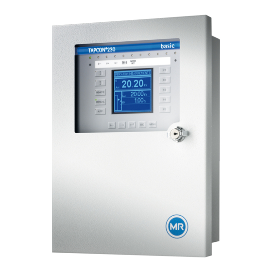
4 Product description Figure 6: Hardware 1 Operating panel with display and 3 Door LEDs 2 Door lock 4 Metric cable glands 4.5.1 Name plate The name plate is on the outside of the device: Figure 7: Name plate ® TAPCON 230 basic 2117246/05 EN Maschinenfabrik Reinhausen GmbH 2019…
-
Page 19: Operating Controls
4 Product description 4.5.2 Operating controls The device has 15 pushbuttons. The illustration below is an overview of all the device’s operating controls. Figure 8: Operating controls RAISE key: Sends control command for raise tap-change to the motor- drive unit in manual mode. LOWER key: Sends control command for lower tap-change to the motor- drive unit in manual mode.
-
Page 20: Display Elements
4 Product description MENU key: Select main menu. F1 to F5 function keys: Select functions displayed on the screen. 4.5.3 Display elements The device has a graphics display and 15 LEDs , which indicate the various operating statuses or events. Figure 9: Indicator elements 1 Operating status LED, green 9 LED 3, function can be freely as-…
-
Page 21
4 Product description Display Figure 10: Display 1 Status line 6 Time bar for delay time T1 2 Measured voltage U 7 Highlighting for measured voltage 3 Reference voltage U 8 Highlighting for reference voltage 9 Remaining delay time T1 Other measured values (use to switch between them) 5 Bandwidth (upper and lower limit) Other measured values In auto mode and manual mode the measured value display… -
Page 22: Serial Interface
4 Product description Unit Measured value Phase Phase angle Cosine Table 5: Measured value display Status line Current messages and events are displayed in the status line . You can find more information about messages and events in the Messages chapter. 4.5.4 Serial interface The parameters for the device can be set using a PC.
-
Page 23: Mio Card Module
4 Product description 4.5.5 MIO card module The device has an internal module. Carry out wiring in accordance with the supplied connection diagram. Figure 12: MIO card 1 Relay outputs (terminal X4) 4 Current transformer connection (terminal X1) 2 Signal inputs (terminal X4) 5 Voltage transformer connection and network connection (terminal 3 Relay outputs (terminal X3)
-
Page 24: Packaging, Transport And Storage
5 Packaging, transport and storage 5 Packaging, transport and storage 5.1 Packaging 5.1.1 Purpose The packaging is designed to protect the packaged goods during transport, loading and unloading as well as periods of storage in such a way that no (detrimental) changes occur.
-
Page 25
5 Packaging, transport and storage If a crate tips over, falls from a certain height (e.g. when slings tear) or is subject to an unbroken fall, damage must be expected regardless of the weight. Every delivered shipment must be checked for the following by the recipient before acceptance (acknowledgment of receipt): ▪… -
Page 26: Storage Of Shipments
5 Packaging, transport and storage 5.3 Storage of shipments When selecting and setting up the storage location, ensure the following: ▪ Protect stored goods against moisture (flooding, water from melting snow and ice), dirt, pests such as rats, mice, termites and so on, and against unauthorized access.
-
Page 27: Mounting
6 Mounting 6 Mounting This chapter describes how to correctly install and connect the device. Ob- serve the connection diagrams provided. Electric shock! DANGER Risk of fatal injury due to electrical voltage. Always observe the following safety regulations when working in or on electrical equipment. ►…
-
Page 28
6 Mounting ▪ Wall mounting with mounting brackets ▪ Rail mounting (optional) Preparing for mounting Before commencing mounting, the two mounting brackets back on the rear of the device must be removed and the cable gland plate taken off. To do so, proceed as follows: 1. -
Page 29: Flush Panel Mounting
6 Mounting 6.2.1 Flush panel mounting For flush panel mounting , the device is inserted through a cutout in the con- trol panel and fixed to the control panel or control cabinet from behind using the mounting brackets. The diagram below shows the dimensions required for the control panel cutout.
-
Page 30: Wall Mounting With Mounting Brackets
6 Mounting Proceed with wiring as shown in the connection diagram and as described in the Connecting device [►Section 6.3, Page 34] section. 6.2.2 Wall mounting with mounting brackets As an alternative to mounting the device directly on the wall, it can be fixed to the wall using the mounting brackets supplied.
-
Page 31: Cap Rail Mounting
6 Mounting Proceed with wiring as shown in the connection diagram and as described in the Connecting device [►Section 6.3, Page 34] section. 6.2.3 Cap rail mounting As an option, the device can be fitted with a cap rail clip (aluminum extrusion with wire spring integrated at center).
-
Page 32: Wall Mounting
6 Mounting 6.2.4 Wall mounting For wall mounting, , the device is fixed directly to the wall. Drill 4 holes, each 5.5 mm in diameter, in the wall as shown in the drilling template below. Figure 20: Drilling template for wall mounting To mount the device directly on the wall, proceed as follows: ü…
-
Page 33: Removing The Door
6 Mounting 6.2.5 Removing the door When the door is fitted, the device satisfies protection category IP54. The door may be removed if the device is used solely in a dry atmosphere pro- tected from environmental influences. The device then satisfies protection category IP21.
-
Page 34: Connecting Device
6 Mounting 3. Hook the cover strip in the upper and lower suspension mount and fasten it with the provided raised countersunk head screws. Figure 24: Fasten covering strip ð The door is removed and the exposed attachment points for the door are covered.
-
Page 35: Cable Recommendation
6 Mounting 2. Crimp stranded wires with wire end sleeves. 6.3.1 Cable recommendation Please note the following recommendation from Maschinenfabrik Rein- hausen when wiring the device. Excessive line capacitance can prevent the relay contacts from breaking the contact current. In control circuits operated with alternating current, take into account the effect of the line capacitance of long control cables on the func- tion of the relay contacts.
-
Page 36: Electromagnetic Compatibility
6 Mounting ▪ Be aware of sharp edges because they can damage the fiber-optic cable’s coating during laying or can place mechanical loads on the coating later ▪ Provide a sufficient cable reserve near distributor cabinets. Lay the re- serve such that the fiber-optic cable is neither bent nor twisted when tight- ened.
-
Page 37
6 Mounting Figure 25: Recommended wiring 1 Cable duct for lines causing inter- 3 Cable duct for lines susceptible to ference interference 2 Line causing interference (e.g. 4 Line susceptible to interference power line) (e.g. signal line) ▪ Short-circuit and ground reserve lines. ▪… -
Page 38
6 Mounting Figure 26: Recommended connection of the shielding 1 Connection of the shielding via a 2 Full-surface connection of the single conductor shielding 6.3.3.3 Wiring requirement in control cabinet Note the following when wiring the control cabinet: ▪ The control cabinet where the device will be installed must be prepared in accordance with EMC requirements: –… -
Page 39: Connecting Cables To The System Periphery
6 Mounting Figure 27: Ground strap connection Ground connection for wiring inside the device The diagram below shows the ground connection for wiring inside the de- vice. Figure 28: Grounding inside the device 6.3.4 Connecting cables to the system periphery To obtain a better overview when connecting cables, only use as many leads as necessary.
-
Page 40: Supplying The Voltage Regulator Using Auxiliary Voltage
6 Mounting To connect cables to the system periphery, proceed as follows: ü Use only the specified cables for wiring. Note the cable recommendation. ► Connect the lines to be wired to the device to the system periphery as shown in the connection diagrams supplied. 6.3.5 Supplying the voltage regulator using auxiliary voltage The device is normally supplied by the voltage transformer.
-
Page 41: Checking Functional Reliability
Check the following: ▪ Once you have connected the device to the grid, the screen displays the MR logo and then the operating screen. ▪ The green Operating display LED top left on the device’s front panel lights The device is fully mounted and can be configured. The actions required for this are described in the following chapter.
-
Page 42: Commissioning
7 Commissioning 7 Commissioning You need to set several parameters and perform function tests before com- missioning the device. These are described in the following sections. Damage to device and system periphery NOTICE An incorrectly connected device can lead to damages in the device and sys- tem periphery.
-
Page 43: Setting The Language
7 Commissioning 7.2.1 Setting the language You can use this parameter to set the display language for the device. The following languages are available: English Italian German Portuguese French Russian Spanish To set the language, proceed as follows: > Configuration > General.
-
Page 44: Function Tests
7 Commissioning 2. Set the bandwidth [►Section 8.4.3.2, Page 66]. 3. Set delay time T1 [►Section 8.4.4, Page 66]. Setting line drop compensation (optional) If you need line drop compensation, you must set all important parameters for this: 1. Select the LDC compensation method [►Section 8.6.1, Page 76]. 2.
-
Page 45: Checking Additional Functions
7 Commissioning 7. Set bandwidth depending on step voltage [►Section 8.4.3, Page 65]. 8. Set delay time T1 to 20 seconds [►Section 8.4.4, Page 66]. 9. Set control response T1 to linear [►Section 8.4.5, Page 67]. 10. Press to raise the on-load tap-changer 1 step. 11.
-
Page 46
7 Commissioning Checking undervoltage blocking U< 1. Press to select manual mode. 2. Set undervoltage U < [%] to 85 %. 3. Set the U< blocking parameter to On [►Section , Page 71]. 4. Set desired value 1 such that the measured voltage Uactual is below the undervoltage U<… -
Page 47
7 Commissioning Checking desired value 2 and desired value 3 1. Press to select manual mode. 2. Set desired value 2 to the value you want. 3. Apply voltage L+ to terminal X4:17 desired value 2 (see connection dia- gram). 4. Press until the main screen is displayed. ð… -
Page 48
7 Commissioning 11. Set the line drop compensation Ur and line drop compensation Ux parameters to the desired operating values. ð The function test for line drop compensation is complete. Checking Z compensation If you want to use Z compensation, you need to run this function test. A load current of ≥ 10 % of the nominal transformer current is needed for the follow- ing function test . -
Page 49: Operation
8 Operation 8 Operation This chapter describes all the functions and setting options for the device. 8.1 Key lock The device is equipped with a key lock to prevent unintentional operation. You can only set or change the parameters when the key lock is deactivated in manual mode.
-
Page 50: Setting The Baud Rate
8 Operation To set the device ID, proceed as follows: > Configuration > General > Press until the desired pa- rameter is displayed. ð Regulator ID. 2. Press to change the first digit. ð If you wish to enter a multi-digit sequence, proceed to step 3. If you do not wish to enter additional digits, proceed to step 7.
-
Page 51
8 Operation Switching pulse in normal If you set the switching pulse time to 1.5 seconds for example, after the set mode delay time T1 or delay time T2 there will be a switching pulse of 1.5 sec- onds The waiting time between 2 consecutive switching pulses corresponds to the set delay time T1 or delay time T2 Figure 32: Switching pulse time in normal mode 1 Set delay time T1 or T2… -
Page 52: Setting Operations Counter
8 Operation Switching pulse for rapid If you set the raise switching pulse time or lower switching pulse time to return control 1.5 seconds, for example , the next earliest switching pulse occurs in rapid return control mode 1.5 seconds after the previous switching pulse ended.
-
Page 53: Dimming Display
8 Operation To set the operations counter, proceed as follows: > Configuration > General > Press until the desired pa- rameter is displayed. ð Operations counter. 2. Press to highlight a digit. ð The desired position is highlighted and the value can be changed. 3.
-
Page 54: Function Monitoring» Message For Monitoring Messages <30 V
8 Operation To set the automatic key lock, proceed as follows: > Configuration > General > Press until the desired pa- rameter is displayed. ð Key lock 2. Press to select On or Off. 3. Press ð Automatic key lock is set. 8.2.7 «Function monitoring»…
-
Page 55: Setting Motor Runtime Monitoring
8 Operation To set the delay time for the Function monitoring message, proceed as fol- lows: > Configuration > General > Press until the desired pa- rameter is displayed. ð Delay function monitoring 2. Press to increase the value or to reduce it.
-
Page 56
8 Operation Wiring control input/output If you want to monitor the motor runtime, the device and motor-drive unit relay must be connected and parameterized as shown below. Figure 35: Wiring for motor runtime monitoring 1 Motor running control input I/O 3 Motor protective switch tripped GPO output relay (optional) 2 Motor protective switch triggered 4 Motor runtime exceeded GPO out-… -
Page 57: Activate Manual Mode/Auto Mode
8 Operation To set the motor runtime, proceed as follows: > Configuration > General > Press until the desired pa- rameter is displayed. ð Motor runtime. 2. Press to highlight the position. ð The desired position is highlighted and the value can be changed. 3.
-
Page 58: Activating Local/Remote
8 Operation 8.2.10 Activating Local/Remote This parameter can be used to activate the Local or Remote operation modes. This parameter has the same functions as the keys. Parameter Function Local You can operate the device using the control panel. Remote You can operate the device using an external con- trol level.
-
Page 59: Setting The Password Duration
8 Operation Proceed as follows to set the COM1 password: > Configuration > General > Press until the desired pa- rameter is displayed. ð COM1 password. 2. Enter the current COM1 password. Press to change a charac- ter and to select the next character. 3.
-
Page 60
8 Operation ▪ Primary voltage ▪ Secondary voltage Line drop compensation cannot be performed in NORMset mode. Set the following parameters to operate the device in NORMset mode. Activating/deactivating NORMset You can use this parameter to activate NORMset mode. A manual tap-change operation is required to activate NORMset. This is how the voltage regulator determines the bandwidth required. -
Page 61: Control Parameters
8 Operation To set the secondary voltage, proceed as follows: > NORMset > Press until the desired parameter is dis- played. ð Secondary voltage. 2. Press to increase the value or to reduce it. 3. Press ð The secondary voltage is set. Setting desired value 1 With this parameter, you can set the desired value for automatic voltage reg- ulation.
-
Page 62
8 Operation Behavior only with delay time T1 If the measured voltage U is within the set bandwidth , no control actual commands are issued to the motor-drive unit for the tap-change operation. Control commands will also not be issued to the motor-drive unit if the mea- sured voltage returns to the tolerance bandwidth within the set delay time . -
Page 63: Setting Desired Value 1
8 Operation delay time T2 starts once delay time T1 is complete. Once delay time T2 is complete, a control impulse is again output to the motor-drive unit for the tap change to return to the tolerance bandwidth. Figure 39: Behavior of the regulation function with delay times T1 and T2 1 + B %: Upper limit 4 Set delay times T1 and T2.
-
Page 64: Selecting A Desired Value
8 Operation Options for setting the The device provides the following ways of changing the desired voltage desired values value during operation: ▪ Using the control parameters menu item via the operating screen ▪ Using binary inputs ▪ Using control system protocols if a communication card is ready for opera- tion Reference of kV and V for Desired values set in kV refer to the primary voltage of the voltage trans-…
-
Page 65: Bandwidth
8 Operation 8.4.3 Bandwidth You can use this parameter to set the maximum permissible deviation in measured voltage U . The deviation relates to the activated desired value. The following sections describe how you determine and set the bandwidth required. 8.4.3.1 Determining bandwidth In order to set the correct value, the transformer’s step voltage and nominal voltage must be known.
-
Page 66: Setting Delay Time T1
8 Operation 8.4.3.2 Setting the bandwidth To enter the determined bandwidth, proceed as follows: > Parameter > Control parameter > Press until the de- sired parameter is displayed. 2. Press to highlight the position. ð The desired position is highlighted and the value can be changed. 3.
-
Page 67: Setting Control Response T1
8 Operation To set the delay time T1, proceed as follows: > Parameter > Control parameter > Press until the de- sired parameter is displayed. 2. Press to highlight the position. ð The desired position is highlighted and the value can be changed. 3.
-
Page 68: Setting Delay Time T2
8 Operation To set the control response T1, proceed as follows: > Parameter > Control parameter > Press until the de- sired parameter is displayed. 2. Press to set the response you want. 3. Press ð The control response T1 is set. 8.4.6 Setting delay time T2 With this parameter, you can set delay time T2.
-
Page 69: Limit Values
8 Operation 8.5 Limit values In the Limit values menu item, you can set all the parameters needed for limit value monitoring as relative or absolute values. You can set three limit values: ▪ Undervoltage U< ▪ Overvoltage U> ▪ Overcurrent I> Limit value monitoring is used to reduce damage to the system periphery.
-
Page 70
8 Operation Behavior If the measured voltage U falls below the set limit value , the red actual LED U< lights up . The switching pulses to the motor-drive unit are blocked at the same time provided you have activated the blocking undervoltage U< parameter. -
Page 71
8 Operation To set the limit value for undervoltage U< as %, proceed as follows: > Control parameter > Limit values > Press until the desired parameter is displayed. ð U< Undervoltage (%) 2. Press to increase the value or to reduce it. -
Page 72: Setting Overvoltage Monitoring U
8 Operation To activate/deactivate the undervoltage blocking, proceed as follows: > Control parameter > Limit values > Press until the desired parameter is displayed. ð U< blocking. 2. Press for On setting or for Off setting. 3. Press ð Undervoltage blocking is activated/deactivated. Activating/deactivating message for voltages below 30 V You can use this parameter to set whether the Undervoltage message is to be suppressed at a measured value of less than 30 V.
-
Page 73
8 Operation Response to high-speed If the measured voltage U exceeds the set limit value , the red LED U> actual return and associated signaling relay activate. The Overvoltage U> message ap- pears in the display. At the same time, the high-speed return function is acti- vated without delay time T1. -
Page 74: Setting Overcurrent Monitoring I
8 Operation Setting overvoltage U> as % The limit value is entered as a relative value (%) of the set desired value. To set the limit value, proceed as follows: > Control parameter > Limit values > Press until the desired parameter is displayed.
-
Page 75: Set Undercurrent Monitoring I
8 Operation Setting overcurrent I> as % To set the limit value I> overcurrent for overcurrent blocking, proceed as fol- lows: > Control parameter > Limit values > Press until the desired parameter is displayed. ð Overcurrent I> 2. Press to increase the value or to reduce it.
-
Page 76: Activate/Deactivate Active Power Monitoring
8 Operation Activating/deactivating I< undercurrent blocking To activate/deactivate undercurrent monitoring, proceed as follows: > Control parameter > Limit values > Press until the desired parameter is displayed. ð Blocking undercurrent I>. 2. Press to activate (ON)/deactivate (OFF) undercurrent block- ing. 3.
-
Page 77
8 Operation To set R&X compensation correctly, you need to calculate the ohmic and in- ductive voltage drop in V with reference to the secondary side of the voltage transformer. You also need to correctly set the transformer circuit used. Figure 46: Equivalent circuit Figure 47: Phasor diagram You can calculate the ohmic and inductive voltage drop using the following… -
Page 78
8 Operation Current transformer ratio Voltage transformer ratio Ohmic resistance load in Ω/km per phase Inductive resistance load in Ω/km per phase Length of line in km Nominal current factor Selecting the line drop compensation To select the line drop compensation, proceed as follows: ►… -
Page 79
8 Operation 8.6.1.2 Setting the inductive voltage drop Ux You can use this parameter to set the inductive voltage drop (inductive resis- tance load). The compensation effect can be rotated by 180° in the display using a plus or minus sign. If you do not want to use line drop compensation, you have to set the value 0.0 V. -
Page 80
8 Operation To use Z compensation, you need to calculate the increase in voltage (ΔU) taking the current into account. Use the following formula for this purpose: ∆U Voltage increase I Load current in A Transformer voltage with cur- Nominal current of current-trans- rent I former connection in A (1 A;… -
Page 81: Transformer Data
8 Operation To set the current dependent voltage increase, proceed as follows: ü Select Z compensation. > Parameter > Compensation > Press until the desired parameter is displayed. ð Z compensation. 2. Press to increase the value or to reduce it. 3.
-
Page 82: Setting The Primary Transformer Voltage
8 Operation ▪ Secondary current (current transformer connection) ▪ Transformer circuit The measured values displayed for the device are influenced by the settings for the above parameters. Note the table below. Parameter set Measured value display Primary Secondary Primary cur- Trans- Voltage (main Current (main…
-
Page 83: Setting Primary Transformer Current
8 Operation To set the secondary transformer voltage, proceed as follows: > Configuration > Transformer data > Press until the desired parameter is displayed. ð Secondary voltage. 2. Press to highlight the position. ð The desired position is highlighted and the value can be changed. 3.
-
Page 84: Setting The Current Transformer Connection
8 Operation 8.7.4 Setting the current transformer connection This parameter can be used to set the current transformer connection. This setting is needed for the device to display the correct secondary current in the info screen. If you select the «Unknown» option, the percentage of current (with reference to the current transformer connection used) is displayed in the info screen.
-
Page 85
8 Operation Circuit A: 1-phase measurement in 1-phase grid TAPCON® 230 Figure 52: Phase difference 0 1PH ▪ The voltage transformer VT is connected to the outer conductor and neu- tral conductor. ▪ The current transformer CT is looped into the outer conductor. ▪… -
Page 86
8 Operation Circuit C: TAPCON® 230 Figure 54: Phase difference 0 3PH ▪ The voltage transformer VT is connected to the outer conductors L1 and ▪ The current transformer CT1 is looped into the outer conductor L1 and CT2 into the outer conductor L2. ▪… -
Page 87
8 Operation Circuit E TAPCON® 230 Figure 56: Phase difference 30 3PH ▪ The voltage transformer VT is connected to the outer conductors L1 and ▪ The current transformer CT is looped into the outer conductor L2. ▪ The current I is ahead of voltage U by 30°. -
Page 88: Configurable Inputs And Outputs
8 Operation To set the phase difference for the transformer circuit, proceed as follows: > Configuration > Transformer data > Press until the desired parameter is displayed. ð Transformer circuit. 2. Press to select the required phase difference. 3. Press ð…
-
Page 89
8 Operation MPS tripped Input for MPS tripped feedback. MD in progr. Input for MD in progr. feedback. DVL 2 Activate desired value level 2 DVL 3 Activate desired value level 3 Blk U raise Block tap-change operations (raise). Blk U low. Block tap-change operations (lower). -
Page 90: Linking Outputs With Functions
8 Operation 8.8.2 Linking outputs with functions You can assign one of the following functions to the digital outputs (GPO 1 and 2): Function Description No function selected Local/Rem. Message: Local control/remote control Undervoltage Message: Undervoltage blocking Overvoltage Message: Overvoltage blocking Undercurrent Message: Undercurrent blocking Overcurrent…
-
Page 91: Led Selection
You can use labeling strips to label the LED. Depending on your device configuration, the following parameters can be used by MR for special functions. In this case, these parameters are pre-as- signed. You may not be able to view or freely assign these parameters.
-
Page 92
8 Operation Assigning function To assign a function to an LED, proceed as follows: > Configuration > LED selection > Press until the de- sired parameter is displayed. 2. Press to select the option you want. 3. Press ð The function is assigned. All additional LEDs can be assigned as described previously. -
Page 93: Information About Device
8 Operation 8.10 Information about device 8.10.1 Displaying info screen The info screen displays the following information: Figure 58: Info screen 1 Type designation 4 Additional cards 2 Software version 5 RAM memory 3 Serial number To display the info screen, proceed as follows: ►…
-
Page 94: Display Calculated Values
8 Operation The following measured values can be displayed: Figure 59: Measured values 1 Voltage U in V or kV 3 Frequency f in Hz 2 Current I in % or A 4 Measurement performance PMeas in % or MW To display the measured values, proceed as follows: ►…
-
Page 95: Carrying Out Led Test
8 Operation To display the calculated values, proceed as follows: ► > Info > Press until the desired display appears. ð Calculated values 8.10.4 Carrying out LED test You can check whether the LEDs are functioning properly. To do this, press the relevant function key to illuminate an LED: LED no.
-
Page 96: Resetting Parameters
8 Operation Digital inputs The status of the optocoupler inputs is shown in the «MIO card digital inputs» display. As soon as a continuous signal is present at the input, status 1 is displayed. 0 indicates no signal at the input. Proceed as follows to display the status: ►…
-
Page 97: Displaying Memory Overview
8 Operation 8.10.7 Displaying memory overview The memory overview can be used to display various database entries with the relevant number of data records. The information is not relevant for oper- ation. It is only needed for service checks. The following information is dis- played: ▪…
-
Page 98: Fault Elimination
9 Fault elimination 9 Fault elimination This chapter describes how to rectify simple operating faults. 9.1 No regulation in AUTO mode Characteristics/detail Cause Remedy Device control commands have LOCAL/REMOTE switch in motor- Check operating mode. Correct if necessary. no effect. drive unit switched to LOCAL.
-
Page 99: Man-Machine Interface
9 Fault elimination 9.3 Man-machine interface Characteristics/detail Cause Remedy Keys REMOTE operating mode active Press to activate LOCAL mode. ▪ MANUAL/AUTO operating and LED in key illuminated. mode cannot be changed Keys Parameter error Reset parameters to factory settings. ▪ LEDs in keys not illuminated.
-
Page 100: Customized Gpis/Gpos
9 Fault elimination Characteristics/detail Cause Remedy Measured current Transmission ratio not correctly Correct parameterization. parameterized. ▪ Measured value too high. Incorrect input connected. Remove short-circuiting jumper. ▪ Measured value too low. Phase angle Fault in external transformer cir- Check transformer circuit. cuit.
-
Page 101: Other Faults
9 Fault elimination Characteristics/detail Cause Remedy Relays chatter Supply voltage too low Check the supply voltage High EMC load Use shielded cables or external filters Poor grounding Check protective ground Table 30: General faults 9.7 Other faults If you cannot resolve a problem, please contact Maschinenfabrik Rein- hausen.
-
Page 102: Messages
10 Messages 10 Messages Event (yellow/ Event message Remark red) Undervoltage Message is displayed in the event of undervoltage. Set the Undervoltage U< [►Section , Page 69] parameter. Overvoltage Message is displayed in the event of overvoltage. Set the Overvoltage U> [►Section , Page 72] parameter. Overcurrent Message is displayed in the event of overcurrent.
-
Page 103
10 Messages Event (yellow/ Event message Remark red) Blocking: Raise blocked because Message is displayed if raise is blocked because the cor- tap position limit reached or ex- responding tap position limit has been reached or ex- ceeded ceeded. Yellow Tap position limit reached or ex- Message is displayed if the set tap position limit has been ceeded… -
Page 104: Disposal
11 Disposal 11 Disposal Observe the national requirements applicable in the country of use. ® TAPCON 230 basic 2117246/05 EN Maschinenfabrik Reinhausen GmbH 2019…
-
Page 105: Overview Of Parameters
12 Overview of parameters 12 Overview of parameters This section contains an overview of the relevant menus and parameters. The availability of individual parameters varies depending on your device function. Parameter Setting range Factory setting Current setting NORMset Normset activation On/Off Desired value 1 49 to 140 V…
-
Page 106
12 Overview of parameters Parameter Setting range Factory setting Current setting Configuration > Transformer data Primary voltage 0…9999 kV 0 kV Secondary voltage 57 to 123 V 100.0 V Primary current 0…10000 A 0 a Current transformer connection Unknown; 1 A; 5 A Unknown Transformer circuit See [►Section 8.7.5, 0 1PH Page 84] Display kV / V… -
Page 107
12 Overview of parameters Parameter Setting range Factory setting Current setting LED1 See [►Section 8.9, Page GPI 1 LED2 GPI 2 LED3 yellow LED3 green LED4 yellow LED4 red Info Info Measured values Calculated values LED test MIO inputs MIO outputs Default parameter Memory overview Event overview Table 32: Overview of parameters… -
Page 108: Technical Data
13 Technical data 13 Technical data 13.1 Display elements Display LCD, monochrome, graphics-capable 128 x 128 pixels LEDs 15 LEDs for operation display and mes- sages of which 4 LEDs are freely pro- grammable (2x yellow, 1x yellow/green, 1x yellow/red) Table 33: Display elements 13.2 Electrical data Permissible voltage range…
-
Page 109
13 Technical data Figure 61: Front view and side view Figure 62: View from above with installed door Figure 63: View from below without door ® Maschinenfabrik Reinhausen GmbH 2019 2117246/05 EN TAPCON 230 basic… -
Page 110: Ambient Conditions
13 Technical data 13.4 Ambient conditions Operating temperature -25°C…+70°C Storage temperature -40°C…+85°C Table 36: Ambient conditions 13.5 Electrical safety IEC 61010-1 Safety requirements for electrical mea- surement and control and regulation IEC 61010-2-030 equipment and laboratory instruments IEC 61010-2-201 ▪ Protection class 1 ▪…
-
Page 111: Environmental Durability Tests
13 Technical data 13.7 Environmental durability tests DIN EN 60529 Determination of protection class for «protection against contact, ingress of foreign objects and water for electrical equipment» Level IP54 IEC 60068-2-1 Dry cold — 25 °C / 16 hours IEC 60068-2-2 Dry heat + 70 °C / 16 hours IEC 60068-2-3 Constant moist heat + 40 °C / 93% / 21…
-
Page 112: Glossary
Glossary Glossary Electromagnetic compatibility Light-emitting diode General Purpose Input Maschinenfabrik Reinhausen GmbH General Purpose Output Raise/lower Line drop compensation ® TAPCON 230 basic 2117246/05 EN Maschinenfabrik Reinhausen GmbH 2019…
-
Page 113: List Of Key Words
List of key words List of key words Auxiliary supply 40 Factory setting 96, 105 Language 43 Fiber-optic cable LED selection 91 Information about laying 35 Limit value flush panel mounting 29 Limit value monitoring 69 Bandwidth 65 Function monitoring Overvoltage U>…
-
Page 114
List of key words Parameter Transformer V< also below 30 V 72 Bandwidth 65 Primary current 83 High-speed return 74 Transformer data 81 Overcurrent blocking 74 Current transformer connection Wall mounting 30, 32 Phase difference 84 84 Wiring 34, 40 Primary voltage 60 Primary voltage… -
Page 116
Maschinenfabrik Reinhausen GmbH Falkensteinstrasse 8 93059 Regensburg +49 (0)941 4090-0 +49(0)941 4090-7001 sales@reinhausen.com www.reinhausen.com ® 2117246/05 EN — TAPCON 230 basic — — 08/19 — Maschinenfabrik Reinhausen GmbH 2019 THE POWER BEHIND POWER.
© All rights reserved by Maschinenfabrik Reinhausen
Dissemination and reproduction of this document and use and disclosure of its content are strictly prohibited
unless expressly permitted.
Infringements will result in liability for compensation. All rights reserved in the event of the granting of patents,
utility models or designs.
The product may have been altered since this document was published.
We reserve the right to change the technical data, design and scope of supply.
Generally the information provided and agreements made when processing the individual quotations and orders
are binding.
The original operating instructions were written in German.
Types of Manuals:
The main types of MR TAPCON 230 Expert instructions:
- User guide — rules of useing and characteristics
- Service manual — repair, diagnostics, maintenance
- Operation manual — description of the main functions of equipment
Controller Instructions by MR:
-
Electrothermal MC227
Page 1 of 20 M7759 Issue 3.0 MC227 & MC228X1 CONTROLLER INSTRUCTION BOOK …
MC227 Controller, 20
-
Motec LTC
MoTeC LTC User Manual Contents Introduction …………………………………………………………………… 2 Installation …………………………………………………………………….. 4 LTC Installation …………………………………………………………………….. …
LTC Controller, 42
-
ESTERS ELEKTRONIK FMP 1836
P=Speed Pressure Flow Rate Temperature Instruction Manual IM 109 E Page 1 Phone: +49 (0) 6021 – 45 807 -0 Fax: +49 (0) 6021 – 45 807 -0 Esters Elektronik GmbH Hafenrandstr. 14 · D-63741 Aschaffenburg eMail: [email protected] Internet: http://www.esters.de Rev.-Nr.: IM 109 E V0.1-2017-06-26; FW 4.12 …
FMP 1836 Controller, 26
-
Rockwell Automation Allen-Bradley PLC-2/30
Artisan Technology Group is your source for quality new and certied-used/pre-owned equipment• FAST SHIPPING AND DELIVERY• TENS OF THOUSANDS OF IN-STOCK ITEMS• EQUIPMENT DEMOS• HUNDREDS OF MANUFACTURERS SUPPORTED• LEASING/MONTHLY RENTALS• ITAR CERTIFIED SECURE ASSET SOLUTIONSSERVICE CENTER …
Allen-Bradley PLC-2/30 Controller, 166
-
Siemens SCALANCE M800
___________________ ___________________ ___________________ SIMATIC NET Industrial Remote Communication Remote Networks SCALANCE M-800 Getting Started 01/2019 C79000-G8976-C337-07 Preface Connecting SCALANCE M-800 to WAN 1 SCALANCE M-800 as DHCP server 2 …
SCALANCE M800 Controller, 54
-
Johnson Controls CIR01
LIT-12012036 IMPORTANT: READ AND UNDERSTAND THIS MANUAL BEFORE USING THIS WIRELESS CONTROLLER. KEEP THIS MANUAL FOR FUTURE REFERENCE.Operation & InstallationManualWireless Controller- CIR01 -P5415475 …
CIR01 Controller, 12
-
Sony HKDV-900
HD DIGITAL VIDEO CONTROLLERHKDV-900OPERATION MANUAL [Japanese/English/French/German]1st Edition (Revised 4)Serial No. 11001 and Higher (SYL)電気製品は、安全のための注意事項を守らないと、火災や人身事故になることがあります。このオペレーションマニュアルには、事 …
HKDV-900 Controller, 70

Voltage Regulator TAPCON® 230Operating Instructions

2 225/01/01/0
Contents
Contents
1 General …………………………………………………………………………………………………………………………………………………………………………………….. 4
1.1 Safety instructions ………………………………………………………………………………………………………………………………………………………. 4
1.2 Specified application ………………………………………………………………………………………………………………………………………………….. 4
1.3 Design and performance features of the TAPCON® 230 ………………………………………………………………………………………… 5
2 Technical Data ………………………………………………………………………………………………………………………………………………………………………… 6
3 Operation ………………………………………………………………………………………………………………………………………………………………………………… 9
3.1 Input and output of data; functions ………………………………………………………………………………………………………………………… 9
3.2 Description of the front panel …………………………………………………………………………………………………………………………………… 10
3.2.1 Display ………………………………………………………………………………………………………………………………………………………………………….. 12
4 Parametering ………………………………………………………………………………………………………………………………………………………………………….. 11
4.1 Normset setting …………………………………………………………………………………………………………………………………………………………… 11
4.2 Setting the desired voltage level 1 ……………………………………………………………………………………………………………………………. 11
4.3 Setting the bandwidth ……………………………………………………………………………………………………………………………………………….. 11
4.4 Setting the delay time T1 or T2 (DELAY 1/DELAY 2) ……………………………………………………………………………………………….. 12
4.5 Setting the overvoltage detection (U>) with automatic return control ………………………………………………………………. 12
4.6 Setting the undervoltage blocking (U<) …………………………………………………………………………………………………………………… 12
4.7 Setting the overcurrent blocking (I>) ……………………………………………………………………………………………………………………….. 13
4.8 Measuring transformers (VT, CT configuration) ……………………………………………………………………………………………………….. 14
4.9 Setting the desired voltage levels DVL2 and DVL3 ………………………………………………………………………………………………….. 14
4.10 Line compensation ………………………………………………………………………………………………………………………………………………………. 14
4.10.1 Line drop compensation (LDC) ………………………………………………………………………………………………………………………. 14
4.10.2 Z-Compensation ……………………………………………………………………………………………………………………………………………… 15
4.11 Analog remote position indication (option) …………………………………………………………………………………………………………….. 15
4.12 Voltage regulator identification ………………………………………………………………………………………………………………………………… 16
4.13 Setting the unit to V or kV …………………………………………………………………………………………………………………………………………. 16
4.14 Selection of the display in the 4th line of the display …………………………………………………………………………………………….. 16
4.15 Language selection ……………………………………………………………………………………………………………………………………………………… 16

3225/01/01/0
Contents
NOTE
Data contained herein may differ in details from the equipment delivered. We reserve the right to make alterations withoutnotice.
5 Commissioning ……………………………………………………………………………………………………………………………………………………………………….. 17
5.1 Installation …………………………………………………………………………………………………………………………………………………………………… 17
5.2 Connection …………………………………………………………………………………………………………………………………………………………………… 17
5.3 Easy setting of operating modes with Normset ………………………………………………………………………………………………………. 18
5.4 Function tests; operational settings ………………………………………………………………………………………………………………………….. 18
5.5 Manual control of the on-load tap-changer …………………………………………………………………………………………………………… 18
6 Parallel control without system topology (Option) ………………………………………………………………………………………………………… 19
6.1 Parallel operation ………………………………………………………………………………………………………………………………………………………… 19
6.1.1 Parallel operation with „Minimum Circulating Reactive Current Method“ ……………………………………………… 206.1.2 System configuration; settings ……………………………………………………………………………………………………………………… 206.1.3 Setting the interference variable (CIRCUL. REAC. CURR. STABILITY) ………………………………………………………… 206.1.4 Setting the bandwidth for circulating reactive current (blocking threshold) …………………………………………. 20
6.1.5 Function tests, commissioning ………………………………………………………………………………………………………. 216.1.5.1 Preliminary settings ………………………………………………………………………………………………………………………… 216.1.5.2 Setting the interference variable (CIRCUL. REAC. CURR. STABILITY) ………………………………………… 216.1.5.3 Setting the circulating reactive current monitoring
(CIRCUL. REAC. CURR. MON. BANDWIDTH) ………………………………………………………………………………….. 21
6.2 Parallel operation according to synchronized tap-change operation Master/ Follower …………………………………….. 21
6.2.1 System configuration, settings ……………………………………………………………………………………………………… 226.2.1.1 Setting the tapping position range ………………………………………………………………………………………………. 226.2.1.2 Selecting the Master/Follower operation …………………………………………………………………………………….. 22
6.2.2 Function tests, commissioning and preliminary settings ……………………………………………………………………………. 22
6.3 Parallel operation with an existing parallel control unit SKB 30 to the principle of„minimum circulating reactive current“ …………………………………………………………………………………………………………………… 23
6.4 Disturbances during parallel operation …………………………………………………………………………………………………………………….. 23
7 Appendix ………………………………………………………………………………………………………………………………………………………………………………….. 23

4 225/01/01/0
1 General
1.1 Safety instructions
All personnel involved in installation, commissioning,maintenance or repair of this equipment must:
— be suitably qualified and- strictly observe these operating instructions.
Improper operation or misuse can lead to- serious or fatal injury,- damage to the equipment and property of the user
and- a reduction in the efficiency of the equipment.
Safety instructions in this manual are presented in three differentforms to emphasize important information.
WWWWWARNINGARNINGARNINGARNINGARNING
All relevant fire protection regulations must be strictlyobserved
1General
1.2 Specified application
The electronic voltage regulator TAPCON® 230 serves forautomatic control of transformers with a motor-driven on-load tap-changer. The motor-drive mechanism receives thecorresponding control commands from the voltage regulator.With these commands, the on-load tap-changer moves tothe next position and the transformer’s voltage value isadapted to the preset desired voltage level.
To allow individual adaptation of the control system to thevarious field service conditions encountered, influencingvariables such as time delay, bandwidth, and even line-dependent and load-dependent parameters can be pro-grammed for compensation of voltage-dependent and/orcurrent-dependent limits. As a special feature, the voltageregulator is also capable of controlling parallel transformeroperation.
WARNING
This information indicates particular danger to life andhealth. Disregarding such a warning can lead to serious orfatal injury.
CAUTION
This information indicates particular danger to the equip-ment or other property of the user. Serious or fatal injurycannot be excluded.
NOTE
These notes give important information on a certainsubject.
CAUTION
Installation, electrical connection and commissioning ofthe electronic voltage regulator may only be carried outby qualified, skilled personnel and only in accordance withthese operating instructions.It is the responsibility of the user to make sure that theelectronic voltage regulator is used for the specificapplication only. For safety reasons, any unauthorized andimproperly executed works, i.e. installation, modification,alteration of the equipment, electrical connection, orcommissioning of the equipment, are forbidden withoutfirst consulting MR!The trouble-free operation of the drive, the on-load tap-changer, and the transformer may be put at risk.

5225/01/01/0
1General
1.3 Design and performance features of theTAPCON® 230
The electronic voltage regulator TAPCON® 230 is mounted ina protective housing with hinged cover and inspection win-dow. The protective housing is suitable for both flush andprojected panel mounting.The front panel contains several function keys for setting theindividual operating parameters.
Display of the operating status is achieved by a 4-line, 16-digit alphanumeric LC display and light emitting diodes.
The electronic voltage regulator is controlled by a micro-controller (see appendix, block/connection diagram).Besides a voltage transformer and a current transformer itcontains optocoupler inputs with potential separation as wellas potential-free output relay contacts.
Apart from the usual well-known, versatile and individualsetting options for the ME control system, the TAPCON® 230voltage regulator also offers the option of fast and easyparametering by introducing the innovative „Normset“function.
The term „Normset“ function stands for an automatismwhich considerably simplifies the configuration of a voltageregulator. If the desired voltage level is entered while the„Normset“ function is active, the voltage regulator willexamine the given line/network conditions and proceed toperform an automatic adaptation of all further inputs(comprised in part of the pre-parametering and standardreference values) which used to be required for customaryregulators (also refer to the standard configuration accord-ing to Sub-menu 2).
The parameters of the regulator can be set by means of a PCvia the incorporated serial interface (RS232) integrated inthe controller; the appropriate PC software will be furnishedby MR.
A load-dependent line-voltage drop, e.g. of a spur line lead-ing from the transformer to the load, can be compensatedeither by line simulation (Line Drop Compensation) or byload-current dependent increase of the voltage level (Z com-pensation).
Trouble-free operation is ensured by the regulator’s inherentundervoltage blocking, overcurrent blocking and overvoltagemonitoring.
The functions of the TAPCON® 230 voltage regulator are justabout fully compatible with those of the earlier generationsof voltage regulators.
Parallel operation follows the principles of either minimumcirculating reactive current or the Master/Follower principle.
Parallel control of two groups comprised of up to 8 userstotal is possible without the need for a supplementary devicedue to the utilization of an internal bus system.
NOTE
When voltage regulation is effected by tap transformersand voltage regulators, it is assumed that a change of thetap position results in a significant voltage change. Whengenerators feed the voltage level to be regulated, however,quite different conditions may result so that a correctregulation of the voltage cannot be guaranteed. In suchcases MR should be consulted as early as the planningstage.

6 225/01/01/0
1Technical Data
2 Technical Data
Setting ranges
Standard settinge range Standard step width
Desired voltage level 1 85 – 140 V 0.5 Vsteps
Desired voltage level 2 85 – 140 V 0.5 Vsteps
Desired voltage level 3 85 – 140 V 0.5 Vsteps
Bandwidth ± 0,5 … ± 9 % 0.1 %
Delay time T1 1 … 180 s 1 s
Delay time T2 1 … 10 s 1 sSwitching pulse duration 1.5 s 0.5 s
LDC Ur = 0 … ± 25 V 0.1 VUx = 0 … ± 25 V 0.1 V
With optional Z compensation Voltage rise 0…15 % of desired voltage level 0.1 %selection limitation 0…15 % of desired voltage level 0.1 %
Undervoltage blocking 70 … 99 % of desired voltage level 1 %Overvoltage detection w/ 101 … 130 % of desired voltage level 1 %high speed returncontrol (interruptible) pulse signal 1.5 / 1.5 s
————
Overvoltage blocking 50 … 210 % 5 %Voltage transformer 0.1 … 999.9 kV/100 VCurrent transformer 100 … 5000 A/5/1/0.2 A
Measuring circuit Phase angle adjustablebetween current andvoltage circuit-30°, 0°, 30°, 90°and single-phase

7225/01/01/0
2Technical Data
Display 4-line, 16-digit LC display
1 LED lamp (green) for signalling status1 LED lamp (red) each for signalling U<, U>, I>1 LED lamp (green) for signalling ‚parallel operation active’ status1 LED lamp (green) for signalling ‚Normset active’ status
Inputs and outputs Input relays Output relays
1x manual control mode Rating of relay contacts:1x automatic control mode AC: 250 V 5 A1x group 1 parallel (optional) DC: 30 V 5 A; 110 V 0.4 A;1x group 2 parallel (optional) 220 V 0.3 A1x high-speed circuit breaker of voltage 1 x raise
limit monitoring indicator 1 x lower1 x analogue input of tapping position (optional) 1 x automatic control mode4- 20 mA; potentiometer 1 x status1 x desired voltage level 2 1x group interrupt U<, U>, I>1 x desired voltage level 3 1x monitoring (function monitoring)
Voltage transformer 85 … 140 V, measuring range 60 … 185 V,r.m.s. value 40 … 60 Hz, intrinsic consumption < 1 VA
Current transformer 0.2 / 1 / 5 A, 40 … 60 Hz, r.m.s. valueintrinsic consumption < 1 VA,overload capacity 2x In continuously, 40x In/1 s
Measuring errors Voltage measuring: < 0.3 % ± 40 ppm/°CCurent measuring: < 0.5 % ± 40 ppm/°C
Serial interfaces 1 x serial interface RS232 (COM1) forparametering via PCoptionally1 x CAN bus for parall operation1 x RS232 for parallel operation with digital MR parallel control unit SKB
Power supply 115 V (+25 % — 35 %) 40 — 60 Hz, can be changed over either fromthe measuring voltage or by separate change-over in the factory toa supply voltage of 230 VPower consumption approx. 5.5 VA (at 115V, idle state)

8 225/01/01/0
2Technical Data
Protective housing Steel-plate housing with inspection window for flush or projected panel mountingW x H x D: 216 x 326 x 137mmDegree of protection provided by enclosure: IP 44 according to IEC 60529Weight: approx. 5.4 kgs
Temperature limits Admissible ambient temperature for operation: -10 °C … + 60 °CAdmissible ambient temperature for storage and transport: -25 °C … +80 °C
Tests
IEC 255-5 Dielectric tests performed at 2.5 kV/1 min operating frequency and 5kV impulse voltage
IEC 61000-4-2 Interference immunity tests (EMC): electrostatic discharge 4 kV / 8 kV
IEC 61000-4-3 Interference immunity tests (EMV): electromagnetic fields 10 V/m80-1000 MHz
IEC 61000-4-4 Interference immunity tests (EMV): burst 1MHz, 4 kV
IEC 61000-4-5 Surge 4 kV
IEC 61000-4-6 HF interference immunity of leads: 10V, 150 kHz – 80 MHz
EN 50081-1 CE conformity
EN 50082-2 CE conformity
VDE 0435 Short-time current and continuous rating of the current transformer inputs,100 x In/1s and 2 x In/continuously
VDE 0100 Provisions governing the erection of electrical power installations featuring rated system voltagesup to 1,000 VGrounding conductors, protective conductors, equipotential bonding conductors,arrangement of operating elements
IEC 61010 / VDE 0411 Safety requirements for electrical equipment for measurement, control regulation andlaboratory use
VDE 0110 Provisions governing the rating of clearance in air and creepage distances in electrical equipment
IEC 60529 Determination of the degree of protection provided by enclosures: „Shock-hazard protection,protection against ingress of solid foreign bodies and protection against the ingress of water forelectrical equipment“ Level IP00
IEC 60068 Basic environmental test procedures
IEC 60068-2-1 Cold test for heat-dissipating specimens, with slow temperature change rate -10°C / 20 hours
IEC 60068-2-2 Dry-heat test for heat-dissipating specimens, with slow temperature change rate+70 °C / 16 hous
IEC 60068-2-3 Humid heat, constant+40 °C / 93 % / 56 days
IEC 60068-2-30 Humid heat, cyclical (12 + 12 hours)+ 55 °C / 93 % and + 25 °C / 95 % / 6 cycles
IEC 60068-2-31 Dropping and toppling in unpackaged condition from a drop height of 100 mm
IEC 61000-4-8 Power frequency magnetic field immunity test
IEC 61000-4-11 Voltage dips, short interruptions and voltage variations immunity tests

9225/01/01/0
3Operation
3 Operation
3.2 Description of the front panel (fig. 1)
Generally, the keys located at the front panel fall into twodifferent basic groups.• Operating keys• Function keys for menu guidance
The LED’s located in the front panel’s upper area serve forsignalling the following system statuses:
• Operating status display• Overcurrent blocking• Undervoltage blocking• Overvoltage monitoring• Parallel operation• NORMSET
Light-emittingdiodes
Change thewindows viathe Higher/Lower keys
Reset settingvaluesvia „SET“
Resetsetting values viathe Higher/Lower keys
Change-overbetween manualmode/automatic mode
LDC-Display
Parameteringinterface
3.1 Input and output of data; functions
The following instructions tell you how to call up the basicfunctions of the TAPCON® 230 voltage regulator and how toreset parameters.
1

10 225/01/01/0
3Operation
3.2.1 Display
The TAPCON® 230 contains a 4-line, 16-digit LC display.A distinction is made between the two following types ofdisplays: Basic display and parametering display.
a) Basic displayIn addition to the actual voltage level, the desired voltagelevel and the deviations the basic display indicates anadditional measuring value in the 4th line during normaloperation. Selection of this measuring value in the displaywindow „SELECT 4th LINE“.The following values are available:- Current I- Apparent power S- Reactive power Q- Active power P- Phase angle PHI- Power factor cos PHI- Frequency f- Status line- Position, optional
ACTUAL VOLT.LEVEL 64.90 kVDESIRED VOLT.LEVEL 66.00 kVdU% 1.67 %CURRENT I 253 A
b) Parametering display windowsThe TAPCON® 230 contains parametering display windowswhich serve to display set parameters and allow the user tomodify any previously set parameters to suit his specifica-tions.Generally, these windows are set up as follows:- 1st line: Title/designation of the parameter- 2nd line: Set value- 3rd line: Possible setting values and/or setting limits- 4th line: Serial number of the display
DESIRED VOLT.LEVEL SW1110V(85V- 140V)
02/29
LDC UR+ 20V(0V- +/-25V)
15/29
LDC UX+ 20V(0V- +/-25V)
16/29
CAN ADRESS1(1-
25/29
VOLT.REG.IDENTIFIER1111(0- 9999)
26/29
DISPLAY V/kVkV(V/ kV)
27/29
SELECTION 4th LINECURRENT I(I,S,Q,P,PHI,..)
28/29
BANDWIDTH+0,6%(+/-0,5%- +/-9%)
03/29
Z-COMP VOLTRISE10%(0%- 15%)
17/29
Z-COMP LIMIT12%(0%- 15%)
18/29
SELECT PARALLELCIRCUL.REAC.CURR.CRC/MAST/FOLLOW
19/29
POS MIN0(-35 bis 35)
20/29
POS MAX35(-35 bis 35)
21/29
CIRCUL.REAC.CURR.STABILITY100(0- 100) 23/29
CIRCUL.REAC.CURR.BANDWIDTH10%(0%- 20%) 24/29
NORMSETONON/ OFF
01/29
DES.VOLTAGE LEVEL DVL1110V(85V- 140V)
02/29
DELAY T1110s(0s- 180s)
04/29
T1 LINEAR INTEGRALLINEAR(LINEAR/INTEGRAL)
05/29
DELAY T210s(PERM,1-10s,OFF)
06/29
OVERVOLTAGE U>110%(101%-130%)
07/29
UNDERVOLTAGE U<80%(70%- 99%)
08/29
OVERCURRENT I>150%(50%- 210%)
09/29
NOM.TRANSF.VOLTAGE110V(0.1kV- 999.1kV)
10/29
CURRENT1000A(100A- 5000A)
11/29
TRANSFORMER PHASE30(30,0,30,90,1PH)
12/29
DES.VOLT.LEVEL DVL2110V(85V- 140V)
13/29
DES.VOLT.LEVEL DV3110V(85V- 140V)
14/29
< <
< <LANGUAGEGERMANGERMAN / ENGLISH
29/29
TAPPING DIRECTIONNEGATIVEPOSITIVE / NEGATIVE
22/29
The displays are situated behind one another in a ring-shaped arrangement, as shown in the illustration to the right,and can be selected by operating the function keys SELECTand . The display will remain visible for as long asthe SELECT key is being pressed, plus an additional 10seconds after the SELECT key was released. It is possible tomove in both directions within the menu. As a result, displayno. 28 of the basic display can be reached just as quickly asdisplay no. 1.The preset value can be altered within the setting values and/or setting limits by operating the SET and func-tion keys. Once the SET key is released, the new value will beset to ‚active’.For parametering purposes, please use the displays listedbelow, the functions of which are explained in detail in thefollowing.

11225/01/01/0
3Parametering
4 Parametering
4.1 Normset setting
The term „Normset“ function stands for an automatismwhich considerably simplifies the configuration of a voltageregulator. The only thing left to do for the operator whencommissioning during the Normset mode is to enter thedesired voltage level and subsequently take the device intooperation.
All other parameters required for simple voltage regulationwill be preassigned at the factory (e.g. bandwidth of ± 1 %).Should the actual value exit the set bandwidth, an appro-priate switching operation will be initiated at the on-loadtap-changer. The voltage change ensuing from the switchingoperation corresponds to the transformer’s tap voltage and ischecked for plausibility by the regulator, using the presetbandwidth. The bandwidth value is then optimised in accord-ance with the results gleaned from this check.
If the next system deviation occurs, the new bandwidth willbe used as basis, which will be rechecked and readjusted, ifnecessary.
The time parameters are handled in the same way by theregulator, which ensures optimum self-adjustment of theregulator after only a few regulating sequences.
Should the marginal conditions change, the regulator willagain optimise itself automatically.
It goes without saying that mains-specific and/or customer-specific settings such as LDC, parallel operation or positionindication can still be done in the standard mode and will betaken into consideration during determination of theoptimum parameters.
4.2 Setting the desired voltage level 1
The setting of the desired voltage level refers either to thesecondary or to the primary voltage side of the voltagetransformer connected to the TAPCON® 230.‘V’ stands for the secondary voltage which is indicated inVolt. ‘kV’ stands for the primary voltage which is indicated inKilovolt. Press the SET and function keys to set thedesired voltage level.
NONONONONOTETETETETE
The parameters for undervoltage/overvoltage and over-current are not set by the Normset function. These para-meters have to be entered manually during commissioning/initiation
NORMSETONON/ OFF
01/29
DES.VOLAGE LEVEL DVL1110V(85V- 140V)
02/29
4.3 Setting the bandwidth
Set the bandwidth from ± 0.5 % to ± 9% in steps of 0.1 %by pressing the SET and function keys. The trans-former’s step voltage must be known to ensure propersetting of this value.
BANDWIDTH+/- 0,6%(+/-0,5%- +/-9%)
03/29
BBBBB (%)(%)(%)(%)(%) = = = = = Contr Contr Contr Contr Control rol rol rol rol range ange ange ange ange (%) ===== Contr Contr Contr Contr Control rol rol rol rol range ange ange ange ange (%)
No. of steps No. of positions No. of positions No. of positions No. of positions No. of positions -11111
For increased regulating sensitivity it is also possible to setlower values, although it is highly unadvisable to go beneath60 % of the computed value. Higher values will cause adecrease in regulating sensitivity.
If the measuring-circuit voltage is altered far enough duringoperation to exceed the set bandwidth, the presignal willrespond. An output pulse will be generated according to theset delay time.
If no compensation occurs for more than 15 min, the„function monitoring“ relay will respond (see connectiondiagram). The relay will not be reset until a shortfall of thebandwidth threshold has occurred.
Standard setting range: ± 0.5 – ±9 %Standard step width: 0.1 %

12 225/01/01/0
4Parametering
T1 Linear/integral
The delay time T1 can be set with linear or integral response.If a delay time with integral response „Int“ is set, the delaytime is automatically shortened according to the relation ofactual system deviation to set bandwidth, down to aminimum of 1 s (fig. 2).The desired time behavior can be set by pressing the SET and function keys.
4.4 Setting the delay time T1 or T2 (DELAY 1/DELAY 2)
The delay time starts as soon as the deviation exceeds the setbandwidth limits above or below. At the same time the cor-responding presignal arrow appears. If the deviation is stillpresent after the delay time has elapsed, an output pulse isemitted. If the deviation returns to within bandwidth limits,then the current delay time is cancelled immediately.
Delay time T1
The delay time can be set from 0….180 s by pressing the SETand function keys.
DELAY TIME T1110s(0s- 180s)
04/29
Delay of the delay timeU/B – voltage change U in % of the desired value, inrelation to the set bandwidth of B in ± % of the desiredvalue.
U [%]B [± %]
2
T1 LINEAR INTEGRALLINEAR(LINEAR/INTEGRAL)
05/29
Delay time T2
The delay time T2 will become effective only if more than one tapchange is required for reduction of the control deviation belowthe bandwidth limit. The set delay time 2 is then valid for allconsecutive output pulses.Set the delay time T2 for a range of 1.0 … 10 s by pressing theSET and function keys.If the voltage regulator is set to PERM, it will emit a continuoussignal. If it is set to OFF, the delay time T2 will be deactivated.
4.5 Setting the overvoltage detection (U>)with automatic return control
The response threshold can be set from 101 % to 130 % ofthe desired voltage level in steps of 1 % by pressing the SETand function keys.
In the event of an overvoltage detection response, the on-load tap-changer is operated by periodic pulses to the motordrive until the overvoltage falls below the response threshold.The motor drive is controlled by periodic pulses of 1.5 sthrough the „Lower“ output relay while the set delay time re-mains inactive during this operation. At the same time thealarm signalling LED lamp responds and a signalling relay isenergized (contacts 17/18/19) as long as overvoltage is pre-sent. If the voltage regulator regulates towards a higher vol-tage than the set limit U> due to an unfavourable parame-tering (e.g. too high LDC settings), it is prevented from ex-ceeding the limit. This condition is signalled by the signallingrelay for ‘function monitoring’, after 15 minutes.
4.6 Setting the undervoltage blocking (U<)
The response threshold for undervoltage blocking can be setfrom 60 % to 100 % of the desired voltage level in steps of1 % by pressing the function keys Set and .
Undervoltage blocking prevents tap change operations inthe event of a network breakdown. The voltage regulatoroutput pulses are blocked and the alarm signalling LED lampand a signalling relay (Contacts 17/18/19) respond when themeasuring voltage falls below the set blocking value. After adelay time of approx. 10 s, the associated signalling relay isenergized and remains that way. The signalling relay doesnot respond in case of a failure of the measuring-circuitvoltage or supply voltage (< 30 V).
OVERVOLTAGE U>110%(101%-130%)
07/29
UNDERVOLTAGE U<80%(70%- 99%)
08/29
DELAY TIME T210s(PERM,1-10s,OFF)
06/29
T1
<

13225/01/01/0
4Parametering
4.7 Setting the overcurrent blocking (I>)
The overcurrent blocking response threshold can be set from50 % to 210 % (of the rated current of the current trans-former) in steps of 1 % by pressing the Set andfunction keys. Overcurrent blocking prevents tap changeoperations in the presence of overload. The voltage regula-tor output pulses are blocked and the alarm signalling LEDlamp responds when the measured current exceeds the setblocking value. At the same time the corresponding signallingrelay is energized and remains energized (contacts 17/18/19).
OVERCURRENT I>150%(50%- 210%)
09/29
4.8 Measuring transformers(VT, CT CONFIGURATION)
The transformation ratios and measuring set-ups of thevoltage and current transformers used can be set in thecorresponding display windows by pressing the Set and function keys.
Rated transformer current
Primary voltage of the voltage transformer in A
Rated transformer voltage
Primary voltage of the voltage transformer in kV, in relationto 100 V secondary voltage.
Transformer phase, measuring circuit
Phase angle of the current/voltage transformer, see fig. 3 forexplanations.
NOM.TRANSF.VOLTAGE110V(0.1kV- 999.1kV)
10/29
CURRENT1000A(100A- 5000A)
11/29
TRANSFORMER PHASE30(30,0,30,90,1PH)
12/29
Setting values for customary measuring circuits:0° (for 1-phase systems)0° (for single-phase systems)0° (for three-phase systems)90° (for three-phase systems)30° (for three-phase systems)-30° (for three-phase systems)
3 intc230de
Configuration a Phase angle setting
Configuration a Phase angle setting
Configuration b Phase angle setting
Configuration c Phase angle setting
Configuration d Phase angle setting
Configuration e Phase angle setting
TAPCON® 230
TAPCON® 230
TAPCON® 230
TAPCON® 230
TAPCON® 230
TAPCON® 230

14 225/01/01/0
4Parametering
The voltage regulator TAPCON® 230 permits the preselectionof three different desired voltage levels, each of which willbe activated specifically in relation to the actuation of inputs13 and 14.No signal present at terminals 13 and 14 => Desired voltage
level 1 is activePresence of a signal at terminal 13 => Desired voltage
level 2 is activePresence of a signal at terminal 1 => Desired voltage
level 3 is active
Setting the desired voltage levels 2 and 3 is identical to thesetting procedure for the desired voltage level 1, i.e. byoperating the function keys SET and .
4.10 Line compensation
The line compensation, i.e. the inclusion of the voltage dropof a line connected to the transformer in the regulatingprocess, can be accomplished in two different ways.
Comparison between LDC and Z CompensationApplication of the vectorial compensation (LDC):- requires knowledge of the exact line data- permits a more accurate determination of the line voltage
drops
Application of the Z compensation:- can be used in the case of minor shifts of the phase
angle — can be also used in meshed network applications.
4.9 Setting the desired voltage levels DVL2 andDVL3
4.10.1 Line Drop Compensation (LDC)
Setting the resistive voltage drop UR
The calculated resistive voltage drop is set in the UR displayby pressing the function keys SET and . The effectof the compensation can be reversed by 180° (minus signpreceding the setting). If no compensation is desired, thenthe value „0“ is to be set.
NONONONONOTETETETETE
For the correct setting of the LDC it is necessary to calcu-late the resistive and inductive line voltage drop in relationto the secondary side of the voltage transformer in V andthe correct setting of the existing measuring transformerconfiguration according to paragraph 4.8
Setting the inductive voltage drop Ux
The calculated inductive voltage drop is set in the Ux displayby pressing the function keys SET and . The effectof the compensation can be reversed by 180° (minus signpreceding the setting). If no compensation is desired, thenthe value „0“ is to be set (condition at the time of delivery).
intVC13a
ULa
4
DES.VOLT.LEVEL DVL2110V(85V- 140V)
13/29
DES.VOLT.LEVEL DV3110V(85V- 140V)
14/29
LDC UR+ 20V(0V- +/-25V)
15/28
LDC UX+ 20V(0V- +/-25V)
16/28

15225/01/01/0
4Parametering
4.10.2 Z-Compensation
For correct setting of the parameters the voltage rise („U) hasto be calculated in consideration of the current.
Calculation of the required setting values:
Setting the limitation for ∆U (LIMIT)
The value is set by pressing the function keys SET and . If compensation is set to a certain value whileavoidance of excessive transformer voltage rises (e.g. in caseof an unusually high load) is desired, the limit values can beset to the desired voltage level.If no compensation is desired, the value „0“ is to be set.
Setting the voltage rise (VOLTRISE)
The calculated percentage of the voltage rise, referred to thedesired voltage level, is set by pressing the function keys SETand . If no compensation is desired, the value „0“ isto be set (link with LIMIT).
Z-COMP VOLTRISE10%(0%- 15%)
17/29
Z-COMP LIMIT12%(0%- 15%)
18/29
4.11 Analog remote position indication (option)
Optionally, the voltage regulator TAPCON® 230 is available withan analog control/activation of the remote position indication.This option requires an analog module.The following analog values can be processed:
• 4 – 20 mA• 0 – x Ohm
Press the SET and function keys to set therespective minimum and maximum positions.For POS MIN, please enter the position corresponding to e.g.4mA; for POS MAX, please enter the position correspondingto e.g. 20mA.The analog position indication will be included automaticallyif the TAPCON® 230 is equipped with the parallel operationoption.
POS MIN0(-35 bis 35)
20/29
POS MAX35(-35 bis 35)
21/29
Calculation of the required setting values:
UTr — ULoad IN . RCT∆U (%) = = = = = 100 • •
ULoad I
∆U = Setting of Z-Compensation in %
UTr = Transformer voltage at current I
ULa = Line end voltage at current I and with the sameservice position of the tap-changer
I = Load current in A
IN = Rated current in A of the selected current trans-former connection to the voltage regulator,i.e. 0.2 A or 1 A or 5 A
RCT = Current transformer ratio, e. g. 200 A / 5 A
If the active voltage drops Ur and reactive voltage drops Ux areset correctly, then the line end voltage will remain constantregardless of load.
Ur = IN . RCT . r . L (V) RVT
Ux = IN . RCT
. x . L (V) RVT
Where
Ur = LDC setting for resistive line voltage drop in V
Ux = LDC setting for inductive line voltage drop in V
IN = Rated current in A of the selected current trans-former connection to the voltage regulator,i.e. 0.2 A or 1 A or 5 A
RCT = Current transformer ratio, e. g. 200 A/ 5 A
RVT = Voltage transformer ratio, e. g.
30000 V /3
100 V
r = Ohmic resistance of line in Ω/ km per phasex = Inductive reactance of line in Ω / km per phaseL = Length of line in km

16 225/01/01/0
4Parametering
4.12 Voltage regulator identification
The voltage regulator contains a parametering interface toallow parametering via laptop. The required visualizationsoftware is included in the standard scope of delivery.The purpose of voltage regulator identifier is to assign aspecific ‘address’ to the individual voltage regulator topermit specified operation via visualization software.A number ranging between 0 and 9999 can be entered toserve as a „name“ by operating the SET andfunction keys.
4.14 Selection of the display in the 4th line ofthe display
The basic display of the voltage regulator TAPCON® 230 showsan additional measuring value in the 4th line. This measuringvalue can be set individually by operating the SET and function keys.
The following measuring values are available:
— Current I
— Apparent power S
— Reactive power Q
— Active power P
— Phase angle PHI
— Power factor cos PHI
— Frequency f
— Status line
— Position, optional
CAN ADRESSE1(1-
25/29DISPLAY V/kVkV(V/ kV)
27/29
4.13 Setting the unit to V or kV
The voltage regulator TAPCON® 230 allows the user to bothdisplay and enter the unit of the actual voltage level and thedesired voltage level in the basic display as well as the para-metering displays for the ‚desired voltage level 1, 2 and 3’ inthe primary voltage transformer unit kV.To that end it is indispensable that the rated voltage of thevoltage transformer be entered as indicated under paragraph4.8. Set the desired unit by operating the SET andfunction keys.
VOLT.REG.IDENTIFIER1111(0- 9999)
26/29
4.15 Language selection
The screen texts are available in two languages. Select thedesired language by operating the SET andfunction key.
SELECTION 4th LINECURRENT I(I,S,Q,P,PHI,..)
28/29

17225/01/01/0
5Commissioning
5 Commissioning
5.1 InstallationThe voltage regulator is suitable for both flush and projectedpanel mounting (see dimension diagram). Be sure to install thedevice in an easily accessible place in the control room or in aswitching cabinet attached to the transformer.
5.2 Connection
The voltage regulator is to be connected in accordance withthe wiring diagram (see Appendix).When connecting the equipment, please pay attention to:– the correct phase angle of the secondary terminals of
current transformer and potential transformer– correct connection of the output relays to the motor
drive unit– correct connection to earth of the housing.
The voltage regulator is normally fed by the voltage trans-former.
Connect the voltage transformer to terminals 1 and 2, andthe auxiliary voltage to terminals 3 and 4 (see fig. 5).
The TAPCON® 230 is optionally available with a supply input ofAC 230 V preset at the factory.
WARNING
Take care to properly connect the voltage regulator andthe housing to ground. Danger to life
intVC19
6
intVC18
TAPCON® 230
Required connection for use of the auxiliary voltage
5
NOTE
The TAPCON® 230 was developed in accordance with therelevant EMC standards. The following instructions must beobserved to ensure preservation of the EMC properties:
– Ensure correct connection to ground by means of theground screw attached to the housing, wire section notless than 4mm².
– Be sure to lead the individual power circuits (motor-drive control, inputs, outputs) in separate cables.
– Be sure to use only shielded cables for the paralleloperation data links. The screenings at both line endsmust be connected to ground via the grounding anglecable clamps at the housing included in the delivery(see fig. 6)
NOTE
When using an auxiliary voltage AC 115V, 50…60Hz, besure to remove the links between terminals 1/3 and 2/4
GROUND INTERFACE CABLE SHIELDINGS HERE

18 225/01/01/0
5Commissioning
5.3 Easy setting of operating modes withNormset
Prior to commissioning, be sure to check the entire circuityand the measuring and operating voltage. To assess theworking mode of the voltage regulator, the use of a regis-tering device to record the regulator voltage (actual voltagelevel) is highly recommended.The related transformer should be subject to normal load.
a) Select the MANUAL operating mode at TAPCON® 230
b) Select the NORMSET function as indicated under 4.1
c) Set the Desired Voltage Level 1 as indicated under 4.2.
If you do not require a voltage display of the primary voltagein kV you may now proceed to initiate the regulator byoperating the AUTO function key.If you do require a voltage display in kV, however, pleaseproceed as follows:
d) Set the rated transformer voltage and the ratedtransformer current as indicated under 4.8.
If you wish to configure the TAPCON®230 voltage regulatorto suit your specific requirements, please proceed asindicated under 5.4.
5.4 Function tests; operational settings
Prior to commissioning, be sure to check the entire circuityand the measuring and operating voltage. To assess theworking mode of the voltage regulator, the use of aregistering device to record the regulator voltage (actualvoltage level) is highly recommended. The related transfor-mer should be subject to normal load.
a) Select the MANUAL operating mode at TAPCON® 230
b) Set the transformation ratios of the transformers asspecified under paragraph 4.8, as well as the measuringcircuit.
c) Let the measured actual voltage (= voltage from thevoltage transformer) be indicated on the display of thevoltage regulator.
d) Let the current, power, and phase angle values beindicated on the display and compare these values withthose from possibly existing service measuringinstruments. If wrong signs are indicated, reverse thepolarity of the current or voltage transformer.
e) Set the desired voltage level. By manual control of themotor drive, bring the on-load tap-changer to the serviceposition so that the desired voltage level is obtained.
f) Set the VOLTAGE LEVEL to this value.
g) Set the bandwidth „“U max“ to 1.0 %. In most cases thevoltage regulator is now in a balanced state (no presignalLED lamp lights up). Otherwise change the desired voltagelevel in steps of 0.5 V until a balanced state is reached.
h) Set the bandwidth „“U max“ dependently of the stepvoltage (see paragraph 4.3).
i) Set the delay time T1 to 20s lin. as per paragraph 4.4; bymanual control, move the on-load tap-changer towards„Raise“ by one step, the presignal LED lamp for „Lower“must come on. Set the mode of operation to „AUTO“; 20 safter the presignal lamp lights up, the voltage regulatormust control the on-load tap-changer back to its pre-vious service position. The presignal LED lamp goes out.Set the mode of operation to „MANUAL“. Repeat thecontrol procedure towards „Lower“.
Set the operating delay time T2 to 10 s. Set the mode ofoperation to „MANUAL“. By manual control, move the on-load tap-changer towards „Raise“ by two steps, the pre-signal LED lamp for „Lower“ must come on.
Set the mode of operation to „AUTO“, then 20 s after thepresignal lamp has come on, the voltage regulator mustautomatically control the on-load tap-changer back toits previous service position by one step and after further10 s by another step.
Set the delay times T1 and T2 to the desired value. If T2 isnot utilized, the „OFF“ setting will be required.
When putting the transformer into service, it is recom-mended to set the delay time T1 provisionally to 100 s.Depending on the existing operating conditions, you maywant to determine the definitive setting only after sometime of observation. For this purpose it is recommendedto register the variation of the actual voltage and thenumber of tap change operations on a day-to-day basis.If an inverse response of the voltage regulator is desired,set an integral time response for the delay time 1. In thiscase the delay time is automatically shortened inverselyproportional to the deviation.j) a
k) Set the response threshold for undervoltage blocking U <to 85 %. Set the mode of operation to „MANUAL“ and setthe existing voltage level, e.g. 110 V, to 110 V / 0.85 H“130 V, so that the actual voltage now corresponds to theset percentage of the response threshold for the blockingvalue. The presignal LED lamp for „Raise“ must light up.Set the mode of operation switch to „AUTO“. Afterapprox.10 s the signalling relay „U <„ must be energized,the signalling contact (Contacts 17/18/19) will open; theoutput relay „Raise“ must not issue a control command.LED U < will now respond. Upon completion of this func-tion test you may now set the desired response thresholdfor undervoltage blocking.
l) Set the response threshold for overvoltage detection U>to 115 %. Set the mode of operation to „MANUAL“, e.g.110 V to 110 V / 1.15 ≈ 95 V so that the actual voltagenow corresponds to the set percentage of the responsethreshold for overvoltage detection. The presignal LEDlamp for „Lower“ must light up. Set the mode of opera-tion to „AUTO“.

19225/01/01/0
Commissioning 5Parallel operation without system topology (Option) 6
6.1 Parallel operation
The TAPCON®230 permits controlled parallel operation of8 transformers maximum, either in a busbar arrangementor in two groups.Parallel operation management is achieved via the CAN bus.
Activation of parallel operation is achieved via the status in-puts, the terminals 41, 42 and 43. This way it can be deter-mined in which group the associated transformer engaged inparallel operation is contained.
Parallel control is possible in two different ways:Parallel operation according to the principle of „minimumcirculating reactive current“or
Parallel operation according to the principle of tap-changesynchronicity (Master-Follower).Selection of the desired parallel operation principle is effec-ted via a menu point.
Select the menu point by operating the SELECT key and the keys and set the desired parallel operation prin-ciple by pressing the SET and function keys.
Connect the paralleling voltage regulators via the CAN businterface in both cases (fig. 7). The voltage regulatorsengaged in parallel operation will signal the status at theterminals 38/39/40.
6 Parallel operation without systemtopology (Option)
SELECT PARALLELCIRCUL.REAC.CURR.CRC/MAST/FOLLOW
19/29
CAN ADRESS1(1-
25/29
Menû Parameter CAN AddressTo permit regulator communication viaCAN bus, each individual regulatorneeds a separate identifier. Assign anumber between 1 and 8 as address to
each regulator by pressing the SET key and func-tion keys. No parallel operation will be possible if the addressis at zero (condition at the time of delivery).
The output relay „Lower“ must issue periodic controlcommands at 1.5 s intervals. The group signalling contact17/18/19 will close/open. LED U > will now respond.Now set the desired response threshold for overvoltagedetection to the initially desired voltage level.
m) Set the response threshold for overcurrent blocking I >.A function check is not necessary.
n) Setting the load drop LDC (as per paragraph 4.10.1). Setthe mode of operation to „MANUAL“.Settings for Ux = Ur = 0, no presignal LED lamp for Raise/Lower must light up.Setting of Ur = 20 V, Ux = 0 V, the presignal LED lamp for„Raise“ must light up.Setting of Ur = -20 V, Ux = 0 V, the presignal LED lampfor „Lower“ must light up (during this function check aminimum load current of 5 % of the rated current of thecurrent transformer must flow.)If the presignals appear in opposite direction, change thepolarity of the current transformer.The actually desired LDC can be set upon completion ofthe above settings.Set the mode of operation to AUTO.Check if the setting is correct by observing the voltage atthe line end during service and with different loads.When the setting is correct the voltage at the line endwill remain constant.
o) Setting of Z Compensation (as per paragraph 4.10.2) asan alternative to LDC. Set the mode of operation toMANUAL. Set the voltage rise to 0, the voltage regulatoris in a balanced state, no presignal LED lamp must lightup. Set the voltage rise to 15 %, the presignal LED lampfor „Raise“ must light up (during this functional check aload current of 10 % of the rated current of the currenttransformer must flow.) The desired values for Z Compen-sation can be set upon completion of the above settings.Set the mode of operation to AUTO. Check if the settingis correct by observing the voltage at a specific point inthe line and with different loads. When the setting iscorrect the voltage at the line end will remain constant.
p) Set the DESIRED VOLTAGE LEVEL 2 to the desired value(refer to paragraph 4.9). Set the mode of operation toMANUAL and connect L+ to terminal 13. According tothe set value for Desired Voltage Level 2, the presignal„Lower“ or „Raise“ must respond.
Please proceed in the same manner for DESIRED VOLTAGELEVEL 3 by connecting L+ to to terminal 14 signallingrelay for DESIRED VOLTAGE LEVEL 3. Set the mode ofoperation to AUTO.
5.5 Manual control of the on-load tap-changer
The manual control of the on load tap changer is possible ifthe buttons „hand“ and resp. or direction „raise“resp. „lower“ are pushed at same time.
NOTE
Please bear in mind that the CAN bus must be connectedwith a 120 ohm resistor at both ends (at the first and lastregulator). The resistor is included in the scope of delivery.
7

20 225/01/01/0
6Parallel operation without system topology (Option)
6.1.1 Parallel operation with „MinimumCirculating Reactive Current Method“
The circulating reactive current is computed from the trans-former currents and their respective phase angles. For correc-tion of the measuring circuit voltage, a voltage proportionalto the circulating reactive current is applied to self-suffi-ciently operating regulators. This correction voltage can beeither decreased or increased through adjustment of the„stability“ (see para-graph 6.1.3).
If an inadmissibly high circulating reactive current is detec-ted, all on-load tap-changers involved will be reset after only10 s, regardless of the delay time preset at the regulator.
This method is suitable for transformers of comparable out-put and uk, whether with uniform or with non-uniform stepvoltage. No information on tap position is required.
6.1.2 System configuration, settings
Feed the additional connections/terminals to the regulators(see fig. 8).
8
6.1.3 Setting the interference variable(CIRCUL. REAC. CURR. STABILITY)
Operate the SELECT key and the keys to select themenu point and press the SET and function keys toset a stability value between 0 and 100. The stability value isa measure used for determining the effect of the circulatingreactive current on the voltage regulator. If it is set to „0“, noeffects will occur. For a circulating reactive current equal tothe rated current of the voltage transformer, a setting valueof 10 would result in a voltage correction of 10 % in thevoltage regulators.
6.1.4 Setting the bandwidth for circulatingreactive current (blocking threshold)
CIRCUL.REAC.CURR.STABILITY100(0- 100) 23/29
CIRCUL.REAC.CURR.BANDWIDTH10%(0%- 20%) 24/29
Operate the SELECT key and the keys to select themenu point and press the SET and function keys toset the bandwidth from 0.5 to 20 % (in relation to the ratedcurrent of the voltage transformer). If the circulating reac-tive current exceeds the preset threshold value during paral-lel operation, the message „circulating reactive current“ willbe displayed in the status line and after a period of 30 s thesignalling relay contact (terminal 35/36/37) will respond.All voltage regulators engaged in parallel operation will beblocked.

21225/01/01/0
6Parallel operation without system topology (Option)
6.1.5 Function tests, commissioning
6.1.5.1 Preliminary settings
The current transformer inputs must be connected and thetransformer configuration must be parameterised correctly.The voltage regulators must be set to identical operatingparameters for the desired voltage, bandwidth, time delay 1,and line compensation, if applicable (LDC or Z Compensation,respectively).In all cases, set STABILITY to „0“ and Blocking to „20“.During parallel operation, time delay 2 must never be setbelow 8 s!All settings must be performed in the „Manual“ operatingmode.
6.1.5.2 Setting the interference variable(CIRCUL. REAC. CURR. STABILITY)
Individually set both transformers to identical voltage withthe on-load tap-changers so that both voltage regulators arein a balanced state (no presignal LED are lighting up, theindication of „d U %“ must be as low as possible, i.e. lowerthan the preset bandwidth „dU max“).
Now switch the transformers to parallel operation and enableparallel control (close contact at terminals 41 and 42, respec-tively).The voltage regulators must continue to remain in a balancedstate, the LED lamp „parallel operation“ on the front panel islighting up.Raise one of the two transformers by one voltage step andlower the other of the two transformers by one voltage step.Both regulators must continue to remain in a balanced state.Raise the setting value „CIRC.REAC.CURR.STABILITY“ of bothregulators in small steps starting with „0“ until the corres-ponding presignals appear (the regulator of the transformerwith the higher voltage step must show the tendency „lower“while the other transformer must show the tendency „raise“).Now add the setting values thus established and set theadded-up value for both regulators.Select the „Auto“ operating mode for both voltage regula-tors. Both voltage regulators must control the on-load tap-changers back into their previous service positions. The pre-signals will go out.If the previous service position cannot be achieved that way,the „CIRC.REAC.CURR. STABILITY“ setting needs to be in-creased. If the on-load tap-changers are regulating out ofsync („pumping“), this setting needs to be reduced.
NOTE
The prerequisite for the proper functioning of paralleloperation is the commissioning of the voltage regulatorsfor individual operation.
6.1.5.3 Setting the circulating reactive currentmonitoring(CIRCUL. REAC. CURR. MON. BANDWIDTH)
Switch over one of the two voltage regulators to the„Manual“ operating mode. Using the manual control, theassociated motor drive must now be reset to „Raise“ by themaximum admissible difference of the service positionsbetween the parallel operating transformers (e.g. by 1 … 2steps).Starting with the preset value of „20“, reset the blockingtowards a lower value in small steps until the message„Circulating reactive current“ appears in the status line of thedisplay (please wait 2 – 3 s between the individual steps).The bandwidth threshold of the circulating reactive currentmonitoring is reached as soon as this message appears.All voltage regulators will block all further regulating actionsand the signalling relay will respond (terminals 35/36/37).Now reset the blocking again towards a higher value untilthe message „circulating reactive current“ disappears fromthe status line of the display.
Again switch the voltage regulator back to the „Auto“operating mode. The motor drive will be automaticallycontrolled back to the original service position.Use the value established for the „Blocking“ threshold to setit for all of the other regulators.
6.2 Parallel operation according to synchro-nized tap-change operation Master/Follower
This method is suitable for transformers featuring an identi-cal rated current, identical step voltage, and an identicalnumber of service positions. The motor drive must signal thetap-change position by means of a current of 4 … 20mA(with 4mA corresponding to the lowest position and 20mAcorresponding to the highest position). Optionally the con-nection of a potentiometer contact range in the motor driveis possible in lieu of the injected current.
During parallel operation, actual voltage regulation is per-formed by one of the voltage regulators (Master function).The second voltage regulator (Follower) receives the tap-change position of the motor drive from the first regulator,for comparison with the tap-change position of its ownmotor drive. If a difference is noted, the motor drive inquestion will receive a suitable control pulse.

22 225/01/01/0
6.2.2 Function tests, commissioning andpreliminary settings
The voltage regulators must be set to identical operatingparameters for the desired voltage, bandwidth, time delay 1,and line compensation, if applicable.The tap position indication at the regulators must functioncorrectly.Select the „MANUAL“ operating mode at the voltage regulators.Individually set all on-load tap-changers involved in paralleloperation to identical voltage so that the voltage regulators arein a balanced state (no presignals are responding).Now switch the transformers to parallel operation and close thecontacts at terminals 41 and 42, respectively. The voltageregulators must continue to remain in a balanced state and theLED lamps „Parallel“ at the regulators must respond. Switch theFollower voltage regulator to the „AUTO“ operating mode.Use the manual control to raise the MASTER regulating unitengaged in the „MANUAL“ operating mode by one step; thefollower regulator now has to automatically drag along theassociated transformer to do the same.
During the short period while a tap position difference ispresent, the message „TAP DIFFERENCE“ will appear in the statusline of the display. If a follower regulator fails to drag along itsassociated transformer, regulating action will be blocked and asignalling relay will respond (terminals 35/36/37).
6Parallel operation without system topology (Option)
6.2.1 System configuration, settings
Lead the additional connections/terminals (see fig. 9) to theregulators.
6.2.1.1 Setting the tapping position range
Operate the SELECT key and the keys to select themenu point and set the respective lowest/highest tap posi-tions between –35 and +35 by pressing the SET andkeys. To perform a function check, set the deactivated trans-former for all positions of the entire tap position range whilechecking the position indicator.
Operate the SELECT key and the keys to select themenu point and assign the respective regulator as a Masteror a Follower by pressing the SET and keys.If both regulators were assigned as „Follower“ or „Master“during parallel operation, the regulators will be blocked (seesection 6.3 – Disturbances during parallel operation).
Note
The prerequisite for the proper functioning of paralleloperation is the commissioning of the voltage regulatorsfor individual operation
POS MIN0(-35 bis 35)
20/29
POS MAX35(-35 bis 35)
21/29
SELECT PARALLELCIRCUL.REAC.CURR.CRC/MAST/FOLLOW
19/29
6.2.1.2 Selecting the Master/Follower operation
TAPPING DIRECTIONNEGATIVEPOSITIVE / NEGATIVE
22/29
Since a comparison of the tap positions of the transformersjointly engaged in parallel operation is performed duringparallel operation in accordance with the principle of tap-change synchronicity (Master-Follower), it is imperative tomaintain identical position designations for all of thesetransformers, and to ensure that the „higher“ and „lower“signals will effect identical voltage changes in all thetransformers.
9
If this is not the case, e.g. if the „Higher“ command (highervoltage) is not equal to a higher position, it is also possible to„turn the tap direction“ within the voltage regulator.This function is activated/deactivated through operation ofthe SELECT key and the function keys.
Fig. 9Feed the tap position signals to the regulator at terminals44-45-46 (see connection diagram)

23225/01/01/0
6Parallel operation without system topology (Option)
6.4 Disturbances during parallel operation
During parallel operation the following messages will be displayedin the status line:
7 Appendix
Front view …………………………………………………………………………………………………………………………………………………………………………………….. TC230_1
Control panel set-up and mounting …………………………………………………………………………………………………………………………………………. 899564
Block/connection diagram — standard 230 V …………………………………………………………………………………………………………………………… 714813
Block/connection diagram — standard 115 V ……………………………………………………………………………………………………………………………. 714814
Block/connection diagram, 230 V, parallel operation option; analog input for position indication 0 — x Ohm ……………… 714815
Block/connection diagram, 115 V, parallel operation option; analog input for position indication 0 — x Ohm ……………… 714816
Block/connection diagram, 230 V, parallel operation option; analog input for position indication 4-20 mA ……………….. 714817
Block/connection diagram, 115 V, parallel operation option; analog input for position indication 4 — 20 mA ……………… 714818
Block/connection diagram, 230 V, parallel operation option with SKB 30 ………………………………………………………………………….. 714819
Block/connection diagram, 115 V, parallel operation option with SKB 30 ………………………………………………………………………….. 714820
Message Cause
CIRCULATING Circulat. reactive currentREACTIVE CURRENT was exceeded
TAP DIFFERENCE Synchronism disturbance(tap difference 2 steps)
>1 MASTER More than one Masterwas selected
NO MASTER No Master was selected
NO POSITION Failure of positionindication
DIFF. METHOD Different methods ofparallel operation wereselected
DATA TRANSFER Data transfer betweenthe regulators wasinterrupted
CAN ADDRESS ERROR Wrong CAN-Address seton the regulator
If any of the above disturbances occur, the regulators will beblocked.
6.3 Parallel operation with an existing parallelcontrol unit SKB 30 to the principle of„minimum circulating reactive current“
In case of an extension of a plant, it is possible to add optio-nal a communication module instead of the CAN-bus mo-dule on factory site in the voltage regulator TAPCON® 230 towork with an existing parallel control unit SKB 30.The wiring has to be done according to the schematics71481900 resp. 71482000 (see appendix).The setting for parallel control has to be done according tooperating instruction BA 117 on the parallel control unitSKB 30.
NOTE
If the communication module to SKB 30 is added, theparameters for parallel control are shown in the menus19 … 25 of the TAPCON® 230. Changes of the parametersmade here are however without effect.

24 225/01/01/0
7Appendix
TAPCON® 230Front view
TC230_1

25225/01/01/0
9 7Appendix
TAPCON® 230Control panel set-up and mounting
8995640E
Clamp forflush mounting
Remove crimp cable-entries for flushmounting
Bracketing fishplatefor panel mountig
Panel cutout forflush mounting

26 225/01/01/0
TAPCON® 230Block/connection diagram — standard 230 V
71481300
7Appendix

27225/01/01/0
TAPCON® 230Block/connection diagram — standard 115 V 71481400
9 7Appendix

28 225/01/01/0
TAPCON® 230Block/connection diagram, 230 V, parallel operation option;
analog input for position indication 0 — x Ohm
71481500
7Appendix

29225/01/01/0
TAPCON® 230Block/connection diagram, 115 V, parallel operation option;
analog input for position indication 0 — x Ohm
71481600
9 7Appendix

30 225/01/01/0
TAPCON® 230Block/connection diagram, 230 V, parallel operation option;
analog input for position indication 4-20 mA71481700
7Appendix

31225/01/01/0
TAPCON® 230Block/connection diagram, 115 V, parallel operation option;
analog input for position indication 4 — 20 mA71481800
9 7Appendix

32 225/01/01/0
TAPCON® 230Block/connection diagram, 230 V,
parallel operation option with SKB 3071481900
7Appendix

33225/01/01/0
TAPCON® 230Block/connection diagram, 115 V,
parallel operation option with SKB 3071482000
9 7Appendix

© Maschinenfabrik Reinhausen GmbH 2002Postfach 12 03 6093025 RegensburgGermanyPhone: (+49) 9 41 / 40 90-0Fax: (+49) 9 41 / 40 90-111Internet: http://www.reinhausen.comEmail: [email protected]
BA 225/01 en — 0702/500225/01/01/0F0102200Printed in Germany
- Home
- Brands
- MR Manuals
- Controller
- MR TAPCON 230
1 docs – User Manuals, Help Guides and Specs – for the MR TAPCON 230 product are present in our data base.
|
|
Product Types:
|
")
Tips for Finding Manuals:
This web-page provides a list of 1 accessible operating manuals and information books describing MR TAPCON 230.
All manuals and instructions for MR TAPCON 230 are introduced in an easy-to-use PDF format and may be gratuitously downloaded or looked through directly from the site.
The page offers the following types of manuals: Controller.
Helpful hints: While selecting a necessary guide for MR TAPCON 230 one should pay special attention to the type of the document.
We try to supply you with the fullest possible set of papers we or our users are able to find. These may be overviews and specifications of the device, mounting and installing instructions, the unit operating rules and maintenance regulations and much more.
Haven’t found a required manual for your MR TAPCON 230?
Check in a while. We update our guides collection and add new documents on a daily basis for you to be always able to find the very paper you need on our web-site. In case you own a directory or an instruction for MR TAPCON 230, which is absent on our site, and you’d like to share it with the public, please send it to us as a scanned copy or a PDF file, and we’ll definitely place it on our page while providing your name as a supplier of the doc. Lots of our users will be grateful for your assistance!