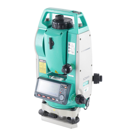
Серия электронных тахеометров фирмы Sokkia SET 1030R — это воплощение точности, надежности и самых передовых технологий.
Уникальный лазерный дальномер RED-tech класса 3R, установленный в этой серии электронных тахеометров, является лучшим фазовым дальномером. С его помощью можно легко выполнять измерения расстояний от 30 см до 350 м в безотражательном режиме. При этом расстояния могут быть измерены даже до небольших объектов, например, до провода линии электропередач.
Большая внутренняя память и компактная флэш-карта, которой оснащен прибор, позволяют сохранять до 18 800 точек. Встроенный световой указатель створа (опция) значительно повышает удобство работ при разбивке и выносе проектов.
Полная алфавитно-цифровая клавиатура и большой графический экран обеспечивают удобное управление прибором и быстрый доступ ко всем основным функциям и программам.
Беспроводная клавиатура SF-14 незаменима при производстве высокоточных измерений.
Высокая степень водо- и пылезащищенности IP64 позволяет проводить работы в самых сложных погодных условиях.
Электронные тахеометры оснащены программным обеспечением SDR33-expert, предназначенным для решения самого широкого круга прикладных задач.
Все перечисленные особенности делают Электронные тахеометры серии SET1030R самыми современными приборами среди аналогичных моделей.
Технические характеристики:
| Точность измерения углов, « |
1 |
| Зрительная труба: — Увеличение — Минимальное расстояние фокусирования, м — Минимальное измеряемое расстояние, м |
|
| Компенсатор / диапазон работы компенсатора |
двухосевой, ± 3 |
| Дальность измерения расстояний на одну призму, м |
до 5 000 |
| Дальность измерения расстояний на три призмы, м |
до 6 000 |
| Дальность измерения расстояний без отражателя, м |
350 |
| Точность измерения расстояний на призму, мм |
± (2 + 2 х 10 — 6хD) |
| Точность измерения расстояний без отражателя, мм |
до 200 м ± (3 + 2 х 10 — 6 х D) / 200-350 м ± (5 + 10 х 10-6 х D) |
| Время измерения расстояний, сек |
1,4 |
| Клавиатура |
алфавитно-цифровая с двух сторон, 43 клавиша |
| Дисплей |
ЖК |
| Количество строк / символов в строке |
8 строк по 20 символов |
| Пыле- и влагозащита |
IP64 |
| Внутренняя память |
около 8 800 точек + память флэш-карты до 128Мб |
| Диапазон рабочих температур, °C |
от -20 до +50 |
| Время работы от одного аккумулятора, часов |
5 |
| Время заряда одного аккумулятора, часов |
1,2 |
| Вес, кг |
5,9 |
В комплект поставки входит:
- Электронный тахеометр на трегере;
- 2 аккумулятора;
- Зарядное устройство;
- Буссоль;
- Юстировочные инструменты;
- Виниловый чехол;
- Отвес;
- Салфетка;
- Бленда;
- Руководство пользователя;
- Плечевой ремень;
- Свидетельство о метрологии;
- Футляр;
- Гарантия — 36 месяцев.
Дополнительно комплектуется:
- Веха телескопическая;
- Отражатель;
- Штатив деревянный или алюминиевый;
- Беспроводная клавиатура SF14.

Тахеометр Sokkia SET 1030 R3

GeoProm
Достоинства: Угловая точность 1″, видимый лазерный луч в качестве целеуказателя, карта памяти, расширенная клавиатура.
Недостатки: Операционная система DOS, нет порта для USB-флешки.
Комментарии:
Juss
Достоинства: Хороший прибор, и внешне и по характеристикам + большой дисплей
Недостатки: снят с производства
Комментарии: если мог бы, купил себе такой же новый (жаль их не делают больше).
Царек
Достоинства: простота в использовании и эксплуатации.
Недостатки: Операционная система дос. Прошлый век, ну как так(
Комментарии: Работает стабильно, но посматриваю уже на более продвинутые модели где и точек побольше и измерение точнее.
Голубков Емиль
Достоинства: То что производитель хвалит клаву-это да, она на самом деле очень удобная несмотря на ее габариты.
Недостатки: время одного измерения могли бы сделать и шустрее
Комментарии: Хорош, работаю 9 месяцев. Стал мне очень дорог. По функционалу не уступает многим другим производителям тахеометров.
Нинамен
Достоинства: Люблю когда понятное меню и все на месте) в этом сокия не подвела.
Недостатки: Особых недочетов я не заметил
Комментарии: Прибор я бы сказал среднего класса. Но для работ и точными показаниям очень даже ничего!
Довговцев Николай
Достоинства: Флэш, точность, экран, клавиатура.
Недостатки: Програмное обеспечение дополнительное выходит дорого.
Комментарии: Отличная модель для стройки и полевых робот.
КаталогПрайс-лист
Например: ГНСС, тахеометр, нивелир, теодолит, дальномер, штатив, рейка, рулетка
0
Инструкции
Тахеометры SOKKIA
- Тахеометры Sokkia серии iM (PDF, 10 Mb) Модели iM-102, iM-102L, iM-103, iM-105, iM-105L, iM-52, iM-55)
- Тахеометры Sokkia серии CX (PDF, 12.1 Mb) Модели CX-102, CX-102L, CX-105, CX-105L, CX-103, CX-106
- Тахеометры Sokkia серии CX-LN (PDF, 14.7 Mb) Модели CX-102 LN, CX-102 LNL, CX-105 LN, CX-105 LNL
- Тахеометры Sokkia серии FX (PDF, 7.7 Mb) Модели FX-101, FX-102, FX-105
- Краткое справочное руководство FX – Functional X-ellence Station (PDF, 2.8 Mb) Модели FX-101, FX-102, FX-105
- Тахеометры Sokkia серии DX (PDF, 2.5 Mb) Модели DX-101AC, DX-103AC, DX-105AC
- Тахеометры Sokkia серии PowerSet (PDF, 15.9 Mb) Модели SET1000, SET2000, SET3000, SET4000, SET400S
- Тахеометры Sokkia SET4110R (PDF, 1.1 Mb) Модель SET4110R
- Тахеометры Sokkia серии SETx00 (PDF, 6.16 Mb) Модели SET300, SET300s, SET500, SET500s, SET600, SET600s
- Тахеометры Sokkia серии SET10 (PDF, 9.0 Mb) Модели SET210, SET310, SET310S, SET510, SET510S, SET610, SET610S
- Тахеометры Sokkia серии SET30R (PDF, 7.5 Mb) Модели SET230R, SET330R, SET530R, SET530RS, SET630R
- Тахеометры Sokkia серии SET30RK (PDF, 11.6 Mb) Модели SET230RK, SET230RK3, SET330RK, SET330RK3, SET530RK, SET530RK3, SET630RK
- Тахеометры Sokkia серии SET50RX (PDF, 12.7 Mb) Модели SET250X, SET250RX, SET350X, SET350RX, SET550X, SET550RX, SET650X, SET650RX
- Тахеометры Sokkia серии SETX (PDF, 4.5 Mb) Модели SET1X, SET2X, SET3X, SET5X
Тахеометры TOPCON
- Тахеометры Topcon серии GM (PDF, 3 Mb) Модели GM-102, GM-105, GM-52, GM-55
- Тахеометры Topcon серии ES (PDF, 12.5 Mb) Модели ES-102L, ES-102, ES-103, ES-105L, ES-105
- Тахеометры Topcon серии ES-50 (PDF, 5.38 Mb) Модели ES-52, ES-52L, ES-55, ES-55L
- Тахеометры Topcon серии OS (PDF, 7.1 Mb) Модели OS-101L, OS-103L, OS-105L
- Тахеометры Topcon серии DS (PDF, 2.5 Mb) Модели DS-101, DS-103, DS-105
- Тахеометры Topcon серии IS-200 (PDF, 11.3 Mb) Модели IS-201, IS-203, IS-205
- Тахеометры Topcon серии IS-300 (PDF, 16.8 Mb) Модели IS-301, IS-303, IS-305
- Тахеометры Topcon серии GPT-3000 (PDF, 2.35 Mb) Модели GPT-3002, GPT-3003, GPT-3005, GPT-3007
- Тахеометры Topcon серии GPT-3100N (PDF, 2.38 Mb) Модели GPT-3102N, GPT-3103N, GPT-3105N, GPT-3107N
- Тахеометры Topcon серии GPT-7000 (PDF, 4.5 Mb) Модели GPT-7001, GPT-7002, GPT-7003, GPT-7005
- Тахеометры Topcon серии GPT-8200A (PDF, 3.65 Mb) Модели GPT-8201A, GPT-8202A, GPT-8203A, GPT-8203A
- Тахеометры Topcon серии GTS-100N (PDF, 2.2 Mb) Модели GTS-102N, GTS-105N
- Тахеометры Topcon серии GTS-230 (PDF, 3.5 Mb) Модели GTS-233, GTS-235, GTS-236, GTS-239
- Тахеометры Topcon серии GTS-230N (PDF, 1.5 Mb) Модели GTS-233N, GTS-235N, GTS-236N, GTS-239N
- Тахеометры Topcon серии GTS-720 (PDF, 2.1 Mb) Модели GTS-721, GTS-722, GTS-723, GTS-725
- Тахеометры Topcon серий GTS-750, GPT-7500 (PDF, 3.25 Mb) Модели GTS-751, GTS-753, GTS-755, GPT-7501, GPT-7503, GPT-7505
- Тахеометры Topcon серий GTS-900A, GPT-9000A (PDF, 4.65 Mb)
Нивелиры SOKKIA
- Оптические нивелиры Sokkia B20/B30/B40 (PDF, 0.8 Mb) Модели B20, B30-35, B40-35
- Оптические нивелиры Sokkia C300/310/320/330 (PDF, 2.35 Mb) Модели C300, C310, C320, C330
- Электронный нивелир Sokkia SDL50 (PDF, 2 Mb) Модель SDL50
- Электронный нивелир Sokkia SDL1X (PDF, 2.5 Mb) Модели SDL1X Standard, SDL1X Advanced
Полевые контроллеры TOPCON
- Полевой контроллер Topcon FC-200 (PDF, 0.6 Mb)
- Полевой контроллер Topcon FC-336 (PDF, 1.1 Mb)
- Полевой контроллер Topcon FC-500 (PDF, 2.1 Mb)
Полевые контроллеры SOKKIA
- Полевой контроллер Sokkia SHC336 (PDF, 1.1 Mb)
- Полевой контроллер Sokkia SHC-5000 (PDF, 15.6 Mb)
- Полевой контроллер Sokkia T-18 (PDF, 7.6 Mb)
- Полевой контроллер Sokkia Archer2 (PDF, 2.41 Mb)
ГНСС приемники SOKKIA
- Спутниковые приемники Sokkia GRX3 (PDF, 5.98 Mb)
- Спутниковые приемники Sokkia GRX2 (PDF, 3 Mb)
- Спутниковые приемники Sokkia GRX1 (PDF, 3.75 Mb)
- Спутниковые приемники Sokkia GSX2 (PDF, 1.5 Mb)
- Спутниковые приемники Sokkia GCX3 (PDF, 35.5 Mb)
- Выполнение RTK съемки приемниками GRX2 с GSM модемами (PDF, 1.1 Mb)
- Выполнение RTK съемки приемниками GRX2 с УВЧ модемами (PDF, 1.2 Mb)
- Подготовка приёмника Sokkia GRX1 (2) — Topcon HiPer II (V) для совместной работы с внешним радиомодемом Satelline Easy Pro 35W (PDF, 0.2 Mb)
- Настройка проекта съемки для GRX2 с внешним радиомодемом (PDF, 1.2 Mb)
- Создание проекта для выполнения RTK съемки ГНСС приемниками GRX2 (PDF, 2.2 Mb)
- Создание проекта MAGNET Field и выполнение съемки точек в режиме RTK ГНСС от базовых станций ГСИ (PDF, 2.4 Mb)
ГНСС приемники TOPCON
- Спутниковые приемники Topcon GR-3 (PDF, 2.8 Mb)
- Спутниковые приемники Topcon GR-5 (PDF, 6.65 Mb)
- Спутниковые приемники Topcon GRS-1 (PDF, 2.75 Mb)
- Спутниковые приемники Topcon Hiper (PDF, 0.3 Mb)
- Спутниковые приемники Topcon Hiper SR (PDF, 3.0 Mb)
- Спутниковые приемники Topcon Hiper V (PDF, 1.6 Mb)
- Выполнение RTK съемки приемниками GR-5 с GSM модемами (PDF, 1.2 Mb)
- Выполнение RTK съемки приемниками GR-5 с УВЧ модемами (PDF, 1.2 Mb)
- Руководство по созданию проекта RTK съемки ГНСС (PDF, 2.1 Mb)
- Создание проекта MAGNET Field и выполнение съемки точек в режиме RTK ГНСС от базовых станций ГСИ (PDF, 2.4 Mb)
ГНСС приемники COMNAV
- Руководство пользователя T300 Plus (pdf, 4 MB)
- Подключение к сети Topnet Live в ПО Survey Master GSM модем в контроллере (pdf, 0.7 MB)
- Подключение к сети Topnet Live в ПО Survey Master GSM модем в приемнике (pdf, 0.7 MB)
Программное обеспечние
- Программа PC-CDU (PDF, 3.2 Mb)
- Программа Topcon Tools (PDF, 21.1 Mb)
- Программа Magnet Office Tools Adv. Post processing (PDF, 3.36 Mb)
- Использование лазерного дальномера для определения координат недоступного объекта (PDF, 0.4 Mb)
Заполните поля формы, специалист в течении дня обработает Ваше сообщение и ответит на электронную почту, или перезвонит. Отправляя заявку, Вы соглашаетесь с обработкой собственных персональных данных в соответствии с Политикой конфиденциальности компании.
Имя*:
Телефон или E-mail*:
Сообщение:
Спасибо, Ваше сообщение отправлено!

В данном разделе можно просмотреть или бесплатно скачать инструкции и руководства пользователя для различных тахеометров Sokkia.
В профессиональной среде геодезистов хорошо известна высокоточная измерительная техника японской компании Sokkia. К каждой модели прикладывается техническая документация, в том числе и руководство по эксплуатации. Но что делать, если инструкция для тахеометра Sokkia отсутствует? Раньше это было серьёзной проблемой. Теперь есть хорошая новость: в любой момент доступен документ от производителя с подробным описанием прибора.
Для эффективной работы нужно не просто приобрести качественное оборудование, но и пройти инструктаж по работе с ним. Самый лёгкий способ – бесплатная инструкция к тахеометру Sokkia в электронной версии для скачивания. Из документа вы узнаете о возможностях модели, которая вас интересует. Общие принципы работы и комплектация тахеометров во многом схожи, но в каждом модельном ряду даже у одного производителя есть существенные различия. Особенно это касается пользовательского интерфейса и возможностей операционной системы. У производителя Sokkia не редкость модели с удобным управлением с помощью «горячих» клавиш и с обширной внутренней памятью.
Инструкция по эксплуатации тахеометра Sokkia – гарантия точных измерительных работ на местности и в помещениях. Знакомство с информацией о последовательности установки, настройки прибора и выполнении разных видов измерений существенно повышает производительность оператора. Разделы о технике безопасности при работе и правилах эксплуатации оборудования необходимы для предотвращения травматизма и обеспечения длительного срока службы прибора без поломок.
Помните, что модели разных производителей отличаются, и скачивайте нужные инструкции в соответствующих разделах сайта. Например, руководство пользователя для тахеометра Leica вы найдёте здесь. Бесплатный доступ ко всем инструкциям позволяет скачивать любое количество документов без финансовых трат. Теперь вам не нужно пытаться приспособить одну инструкцию для всех моделей. Выбирайте руководство по названию производителя, серии и номеру тахеометра для эффективной работы прибора.
-
Contents
-
Table of Contents
-
Bookmarks
Quick Links
SET230R3/330R3/530R3:
Class 3R Laser Product
Class 1 LED Product
SURVEYING INSTRUMENTS
Series
SET
SET
SET
Reflectorless Total Station
SET230R/330R/530R/630R:
Class 2 Laser Product
OPERATOR’S MANUAL
30R
2
30R/R3
3
30R/R3
5
30R/R3
SET
6
30R
Related Manuals for Sokkia 30R Series
Summary of Contents for Sokkia 30R Series
-
Page 1
SURVEYING INSTRUMENTS Series 30R/R3 30R/R3 30R/R3 Reflectorless Total Station SET230R3/330R3/530R3: SET230R/330R/530R/630R: Class 3R Laser Product Class 2 Laser Product Class 1 LED Product OPERATOR’S MANUAL… -
Page 2
S Li-ion Li-ion :This is the mark of the Japan Surveying Instruments Manufacturers Association. -
Page 3
Command operations from a host computer can also be performed. For details, refer to “Interfacing with the SOKKIA SDR Electronic Field Book” and “Command Explanations” manuals and ask your Sokkia agent. • The specifications and general appearance of the instrument may be altered at any time and may differ from those appearing in brochures and this manual. -
Page 4
HOW TO READ THIS MANUAL Symbols The following conventions are used in this manual. : Indicates precautions and important items which should be read before operations. : Indicates the chapter title to refer to for additional information. : Indicates supplementary explanation. : Indicates an explanation for a particular term or operation. -
Page 5: Table Of Contents
CONTENTS 1. PRECAUTIONS FOR SAFE OPERATION ..1 READ THIS 2. PRECAUTIONS ……5 FIRST 3.
-
Page 6
CONTENTS 14. SETTING-OUT MEASUREMENT ….59 MEASURE- 14.1 Distance Setting-out Measurement ..59 MENT 14.2 Coordinates Setting-out Measurement ..63 -MEASURE- 14.3 REM Setting-out Measurement . -
Page 7
CONTENTS 24. CHANGING THE SETTINGS ….113 ADDITIONAL 24.1 Changing Instrument Options … . . 113 DETAILS 24.2 Allocating Key Functions . -
Page 9: Precautions For Safe Operation
1. PRECAUTIONS FOR SAFE OPERATION For the safe use of the product and prevention of injury to operators and other persons as well as prevention of property damage, items which should be observed are indicated by an exclamation point within a triangle used with WARNING and CAUTION statements in this operator’s manual.
-
Page 10
1. PRECAUTIONS FOR SAFE OPERATION General Warning Do not use the unit in areas exposed to high amounts of dust or ash, in areas where there is inadequate ventilation, or near combustible materials. An explosion could occur. Do not perform disassembly or rebuilding. Fire, electric shock, burns, or hazardous radiation exposure could result. -
Page 11
1. PRECAUTIONS FOR SAFE OPERATION Power Supply Warning Do not use voltage other than the specified power supply voltage. Fire or electrical shock could result. Do not use damaged power cords, plugs or loose outlets. Fire or electric shock could result. Do not use power cords other than those designated. -
Page 12
1. PRECAUTIONS FOR SAFE OPERATION Tripod Warning When mounting the instrument to the tripod, tighten the centering screw securely. Failure to tighten the screw properly could result in the instrument falling off the tripod, causing injury. Tighten securely the leg fixing screws of the tripod on which the instrument is mounted. -
Page 13: Precautions
2. PRECAUTIONS Tribrach Clamp • When the instrument is shipped, the tribrach clamp is held firmly in place with a locking screw to prevent the instrument from shifting on the levelling base. Before using the instrument the first time, loosen this screw with a screwdriver.
-
Page 14
• Check the tripod for loose fit and loose screws. • If any trouble is found on the rotatable portion, screws or optical parts (e.g. lens), contact your SOKKIA agent. • When the instrument is not used for a long time, check it at least once every 3 months. -
Page 15: Laser Safety Information
3. LASER SAFETY INFORMATION Series 30R is classified as the following class of Laser Product and LED Product according to IEC Standard Publication 60825-1 Amd. 2: 2001 and United States Government Code of Federal Regulation FDA CDRH 21CFR Part1040.10 and 1040.11 (Complies with FDA performance standards for laser products except for deviations pursuant to Laser Notice No.50, dated July 26, 2001.) SET230R3/330R3/530R3…
-
Page 16
3. LASER SAFETY INFORMATION SET230R/330R/530R/630R Laser beam is emitted from here LED beam is emitted from here • Never point the laser beam at another person. If the laser beam strikes skin or an eye, it could cause serious injury. • Do not look directly into the laser beam source. Doing so could cause permanent eye damage. -
Page 17
3. LASER SAFETY INFORMATION • When using the Laser-pointer function, be sure to turn OFF the output laser after distance measurement is completed. Even if distance measurement is canceled, the Laser-pointer function is still operating and the laser beam continues to be emitted. (After turning ON the Laser-pointer, the laser beam is emitted for 5 minutes, and then automatically switches OFF. -
Page 18: Set Functions
4. SET FUNCTIONS Parts of the Instrument Handle Handle securing screw Instrument height mark Battery cover Operation panel Tribrach clamp Base plate Levelling foot screw Circular level adjusting screws 10 Circular level 11 Display 12 Objective lens (Includes Laser- pointer function) 13 Tubular compass slot 14 Beam detector for wireless keyboard…
-
Page 19
4. SET FUNCTIONS Peep sight Use peep sight to aim the SET in the direction of the measurement point. Turn the instrument until the triangle in the peep sight is aligned with the target. Instrument height mark The height of the SET is 236mm (from tribrach dish to this mark). «Instrument height»… -
Page 20
4. SET FUNCTIONS Laser-emission warning lamp (only SET230R3/330R3/530R3) Laser-emission warning lamp is red when laser beam is emitted or laser-pointer is used, and laser beam status can be known from the telescope eyepiece side. Laser radiation warning indicator Wireless keyboard (Optional accessory) «5.1 Basic Key Operation»… -
Page 21
4. SET FUNCTIONS Guide light (Optional function) «27.2 Optional Accessories» Guide light Guide light indicator Guide light and Guide light indicator Setting-out measurement etc. can be carried out effectively using the Guide light. The Guide light is composed of a light that is divided into a red and a green light. -
Page 22: Mode Diagram
4. SET FUNCTIONS Mode Diagram Note data Dist Coord Dist + Coord data Set-out line Point projection Changing Password…
-
Page 23: Basic Operation
5. BASIC OPERATION Basic Key Operation Learn basic key operations here before you read each measurement procedure. Location of operation keys on the panel and Location of operation keys on the wireless keyboard : «4.1 Parts of the Instrument» • Wireless keyboard (SF14) (Optional accessory) makes key operation easier and speedier.
-
Page 24
5. BASIC OPERATION Inputting letters / figures {F1} to {F4}: Input a letter or a figure allocated to the softkey {FUNC} Go to the next softkey page (search for the letter or figure you want to input) {FUNC} (hold for a moment): Go back one softkey page {FUNC} (continue to hold): Go to previous softkey pages {BS} Delete a character on the left… -
Page 25
5. BASIC OPERATION 4. Press { } or { } to move to the next option. The selection is set and you can set the next item. Switching modes [CNFG] From Status mode to Config Mode (Configuration Mode) [MEAS] From Status mode to Meas Mode (Measurement Mode) [MEM] From Status mode to Memory Mode {ESC}… -
Page 26
5. BASIC OPERATION Key operation for Wireless Keyboard (SF14) The SET is operated from the Wireless Keyboard by pointing the Wireless Keyboard beam at the Beam Detector on the SET and pressing the required operation keys. Remote operation • When sunlight shines directly into the Beam Detector on the SET, the Wireless Keyboard may not work correctly. -
Page 27: Display Functions
5. BASIC OPERATION Enter letters and figures editing mode (same as pressing [EDIT] on the screen) {BS} Delete a character on the left {ESC} Cancel the input data {SFT} Switch between upper and lower case Select / accept input word / value Selecting options {R} / {U} ( / is printed above the key)
-
Page 28
5. BASIC OPERATION Measuring screen F i n e Laser is emited *8 Input screen Previous page Input mode *9 Next page * 1 Distance Switching distance display status: “24.1 Changing Instrument Options Settings in Config Mode” S : Slope distance H : Horizontal distance V : Height difference * 2 Vertical angle… -
Page 29
5. BASIC OPERATION (This symbol is displayed every 3 seconds): No power remains. Stop the measurement and charge the battery. “6.1 Battery Charging” *5 Target display Press {SFT} to switch the selected target. This key function can be used only on the screens on which the target symbol is displayed. -
Page 30: Using The Battery
6. USING THE BATTERY Battery Charging The battery has not been charged at the factory. • Do not short circuit. Heat or ignition could result. • Batteries cannot be charged, even when the charging lamp is flashing, when the temperature is outside the charging temperature range. Do charge batteries within the charging temperature range.
-
Page 31: Installing / Removing The Battery
If the lamp is still off after the charger falls within its charging temperature range and the battery is mounted again, contact your Sokkia agent. (steps 2 and 3) • Charging time: Charging can take more than 2 hours when temperatures are either especially high or low.
-
Page 32
6. USING THE BATTERY • Battery cover If the battery cover is open during power on, SET notifies you by displaying the screen below and beeping. When the battery cover is closed, the previous screen is restored. -
Page 33: Preparation For Measure- Ment 7. Setting Up The Instrument
7. SETTING UP THE INSTRUMENT • Mount the battery in the instrument before performing this operation because the instrument will tilt slightly if the battery is mounted after levelling. Centering PROCEDURE 1. Set up the tripod Make sure the legs are spaced at equal intervals and the head is approximately level.
-
Page 34: Levelling
7. SETTING UP THE INSTRUMENT Levelling Instrument can be levelled using the screen. “ Levelling on the screen” PROCEDURE 1. Center the surveying point in the reticle Adjust the levelling foot screws to center the surveying point in the optical plummet reticle. 2.
-
Page 35
7. SETTING UP THE INSTRUMENT 4. Turn 90° and center the bubble Turn the upper part of the instrument though 90°. The plate level is now perpendicular to a line between levelling foot screws A and B. Center the air bubble using levelling foot screw C. -
Page 36
7. SETTING UP THE INSTRUMENT 7. Center the SET over the Surveying point Loosen the centering screw slightly. Looking through the optical plummet eyepiece, slide the instrument over the tripod head until the surveying point is exactly centered in the reticle. Retighten the centering screw securely. -
Page 37
7. SETTING UP THE INSTRUMENT PROCEDURE Levelling on the screen 1. Press {ON} to power on 2. Press [TILT] in the second page of Meas Mode to display the circular level on the screen. “ ” indicates bubble in circular level. -
Page 38: Focussing And Target Sighting
8. FOCUSSING AND TARGET SIGHTING • When sighting the target, strong light shining directly into the objective lens may cause the instrument to malfunction. Protect the objective lens from direct light by attaching the lens hood. Observe to the same point of the reticle when the telescope face is changed. PROCEDURE 1.
-
Page 39
8. FOCUSSING AND TARGET SIGHTING 4. Readjust the focus until there is no parallax Readjust the focus with the focussing ring until there is no parallax between the target image and the reticle. Eliminating parallax This is the relative displacement of the target image with respect to the reticle when the observer’s head is moved slightly before the eyepiece. -
Page 40: Power On
9. POWER ON Setting “V manual”: “24.1 Changing Instrument Options Settings in Config Mode”, Setting / changing password: «24.3 Changing Password» PROCEDURE 1. Power on Press {ON}. When the power is switched on, a self-check is run to make sure the instrument is operating normally.
-
Page 41: Angle Measurement
10. ANGLE MEASUREMENT This section explains the procedures for basic angle measurement. 10.1 Measuring the Horizontal Angle between Two Points (Horizontal Angle 0°) Use the “0SET” function to measure the included angle between two points. The horizontal angle can be set to 0 at any direction. PROCEDURE 1.
-
Page 42: Mode — (Horizontal Angle Hold)
10. ANGLE MEASUREMENT 10.2 Setting the Horizontal Angle to a Required Value (Horizontal Angle Hold) You can reset the horizontal angle to a required value and use this value to find the horizontal angle of a new target. PROCEDURE 1. Sight the first target. 2.
-
Page 43: Horizontal Angle Repetition
10. ANGLE MEASUREMENT 10.3 Horizontal Angle Repetition To find the horizontal angle with greater precision, perform repetition measurement. ・The maximum number of angle measurements that can be made is 10. PROCEDURE 1. In the second page of Meas mode Menu screen, press [MENU], then select Coordinate «Repetition».
-
Page 44: Angle Measurement And Outputting The Data
The following explains angle measurement and the features used to output measurement data to a computer or peripheral equipment. Communication cables: «27.2 Optional Accessories» Output format and command operations: “Interfacing with the SOKKIA SDR Electronic Field Book” and “Command Explanations” manuals. PROCEDURE 1.
-
Page 45: Distance Measurement
11. DISTANCE MEASUREMENT Perform the following settings as preparation for distance measurement. • Distance measurement mode • Target type • Prism constant correction value • Atmospheric correction factor • EDM ALC “24.1 Changing Instrument Options EDM Settings / Settings in Config Mode”…
-
Page 46: Returned Signal Checking
11. DISTANCE MEASUREMENT 11.1 Returned Signal Checking • Check to make sure that sufficient reflected light is returned by the reflective prism sighted by the telescope. Checking the returned signal is particularly useful when performing long distance measurements. • When the light intensity is sufficient even though the center of the reflective prism and the reticle are slightly misaligned (short distance etc.), “*”…
-
Page 47: Distance And Angle Measurement
4. Press {ESC} to finish signal checking and return to Meas Mode. • When is displayed persistently, contact your Sokkia agent. • If no key operations are performed for two minutes, the display automatically returns to the Meas mode screen. 11.2 Distance and Angle Measurement An angle can be measured at the same time as the distance.
-
Page 48: Recalling The Measured Data
11. DISTANCE MEASUREMENT 3. Press [STOP] to quit distance measurement. • Each time [ SHV] is pressed, S (Slope distance), H (Horizontal distance) and V (Height difference) are displayed alternately. • If the single measurement mode is selected, measurement automatically stops after a single measurement.
-
Page 49: Distance Measurement And Outputting The Data
The following explains distance measurement and the features used to output measurement data to a computer or peripheral equipment. Communication cables: «27.2 Optional Accessories» Output format and command operations: “Interfacing with the SOKKIA SDR Electronic Field Book” and “Command Explanations” manuals. PROCEDURE 1.
-
Page 50: Rem Measurement
11. DISTANCE MEASUREMENT 11.5 REM Measurement An REM measurement is a function used to measure the height to a point where a target cannot be directly installed such as power lines, overhead cables and bridges, etc. The height of the target is calculated using the following formula. Ht = h1 + h2 h2 = S sin θ…
-
Page 51
11. DISTANCE MEASUREMENT 3. In the second page of Meas mode screen, press [MENU] , then Resection select «REM». Area calculation Set-out line Point projection 4. The REM measurement is started and the height from the ground to the object is displayed in “Ht.”. 5. -
Page 52: Coordinate Measurement
12. COORDINATE MEASUREMENT By performing coordinate measurements it is possible to find the 3-dimensional coordinates of the target based on station point coordinates, instrument height, target height, and azimuth angles of the backsight station which are entered in advance. • EDM setting can be done in coordinate measurement menu. Setting items: “24.1 Changing Instrument Options EDM settings”…
-
Page 53
12. COORDINATE MEASUREMENT 3. Select “Stn Orientation,” then 0 . 0 0 0 “Stn coordinate.” Press [EDIT], then input the instrument station coordinates, instrument height and target READ R EC ED IT height. • When you wish to read in the registered coordinate data, press [READ]. -
Page 54
12. COORDINATE MEASUREMENT PROCEDURE Reading in Registered Coordinate Data Known point data, coordinate data and instrument station data in the current JOB and Coordinate Search JOB can be read in. Confirm that the correct JOB containing the coordinates you want to read in is already selected in Coordinate Search JOB in Memory Mode. -
Page 55: Azimuth Angle Setting
12. COORDINATE MEASUREMENT 3. Press [OK]. <Instrument Station Data Setting> is restored. • Press [EDIT] to edit the coordinate data that was read in. Editing does not affect the original coordinate data. After editing, the point number is no longer displayed. •…
-
Page 56
12. COORDINATE MEASUREMENT 2. Select “Back sight”, press [EDIT], then input the backsight station coordinates. • When you wish to read in and set coordinate data from memory, press [READ]. “12.1 Entering Instrument Station Data,PROCEDURE Reading in Registered Coordinate Data” 3. -
Page 57: 3-D Coordinate Measurement
12. COORDINATE MEASUREMENT 12.3 3-D Coordinate Measurement The coordinate values of the target can be found by measuring the target based on the settings of the instrument station and backsight station. The coordinate values of the target are calculated using the following formulae. N1 Coordinate = N0 + S x sinZ x cosAz E1 Coordinate = E0 + S x sinZ x sinAz Z1 Coordinate = Z0 + S x cosZ + ih — fh…
-
Page 58
12. COORDINATE MEASUREMENT • By pressing [HT], the instrument station data can be reset. When the target height of the next target is different, reenter the target height before beginning the observation. • [REC]: records measurement results Recording method: “20. RECORDING DATA — RECORD MENU -”… -
Page 59: Resection Measurement
13. RESECTION MEASUREMENT Resection is used to determine the coordinates of an instrument station by performing multiple measurements of points whose coordinate values are known. Registered coordinate data can be recalled and set as known point data. Residual of each point can be checked, if necessary. Entry Output Coordinates of known point : (Xi, Yi, Zi) Station point coordinates : (X0,Y0, Z0)
-
Page 60: Coordinate Resection Measurement
13. RESECTION MEASUREMENT 13.1 Coordinate Resection Measurement N, E, Z of an instrument station is determined by the measurement. • Between 2 and 10 known points can be measured by distance measurement, and between 3 and 10 known points by angle measurement. PROCEDURE 1.
-
Page 61
13. RESECTION MEASUREMENT 4. Press [YES] to use the Resection 1st Pt. measurement results of the first known point. • You can also input target height Tgt.h 1.400m here. EDIT 5. Repeat procedures 4 to 5 in the same way from the second point. When the minimum quantity of observation data required for the calculation is present, [CALC] is… -
Page 62
13. RESECTION MEASUREMENT 8. If there are problems with the results of a point, align the cursor with that point and press [BAD]. “*” is displayed on the left of the point. Repeat for all results that include problems. 9. Press [RE CALC] to perform calculation again without the point designated in step 8. -
Page 63: Height Resection Measurement
13. RESECTION MEASUREMENT 13.2 Height Resection Measurement Only Z (height) of an instrument station is determined by the measurement. • Known points must be measured by distance measurement only. • Between 1 and 10 known points can be measured. PROCEDURE 1.
-
Page 64
13. RESECTION MEASUREMENT 6. Press [CALC] or [YES] to automatically start calculations after observations of all known points are completed. Instrument station elevation and standard deviation, which describes the measurement accuracy, are displayed. 7. Press [RESULT] to check the result. If there are no problems in the 1 0 . -
Page 65
13. RESECTION MEASUREMENT Resection calculation process The NE coordinates are found using angle and distance observation equations, and the instrument station coordinates are found using the method of least squares. The Z coordinate is found by treating the average value as the instrument station coordinates. -
Page 66
13. RESECTION MEASUREMENT Precaution when performing resection In some cases it is impossible to calculate the coordinates of an unknown point (instrument station) if the unknown point and three or more known points are arranged on the edge of a single circle. An arrangement such as that shown below is desirable. -
Page 67: Setting-Out Measurement
14. SETTING-OUT MEASUREMENT Setting-out measurement is used to set out the required point. The difference between the previously input data to the instrument (the setting- out data) and the measured value can be displayed by measuring the horizontal angle, distance or coordinates of the sighted point. The horizontal angle difference and distance difference are calculated and displayed using the following formulae.
-
Page 68
14. SETTING-OUT MEASUREMENT PROCEDURE 1. Press [S-O] in the third page of the Meas mode screen to display <S-O>. 2. Enter the instrument station data. “12.1 Entering Instrument Station Data, PROCEDURE Reading in Registered Coordinate Data”. 3. Set the azimuth angle of the backsight point. -
Page 69
14. SETTING-OUT MEASUREMENT 6. Press [EDIT] and set the following items. (1) Sdist/Hdist/Vdist: distance 40 00 00 from the instrument station to the position to be set out. READ EDIT (2) H ang: included angle between the direction of the reference and the point to be set out. -
Page 70
14. SETTING-OUT MEASUREMENT • By pressing [← →], an arrow pointing to the left or right displays which direction the target should be moved. ← : Move the prism to left. → : Move the prism to right. ↓ : Move the prism forward. ↑… -
Page 71: Coordinates Setting-Out Measurement
14. SETTING-OUT MEASUREMENT 14.2 Coordinates Setting-out Measurement After setting the coordinates for the point to be set out, the SET calculates the setting-out horizontal angle and horizontal distance. By selecting the horizontal angle and then the horizontal distance setting-out functions, the required coordinate location can be set out.
-
Page 72
14. SETTING-OUT MEASUREMENT 5. Press [EDIT]. Enter the C o o r d coordinates of the setting-out point. • When [READ] is pressed, READ EDIT registered coordinates can be recalled and used as setting-out coordinates. “12.1 Entering Instrument Station Data, PROCEDURE Reading in Registered Coordinate Data”… -
Page 73: Ment 14.3 Rem Setting-Out Measurement
14. SETTING-OUT MEASUREMENT 14.3 REM Setting-out Measurement To find a point where a target cannot be directly installed, perform REM setting- out measurement. «11.5 REM Measurement» PROCEDURE 1. Install a target directly below or directly above the point to be found, then use a measuring tape etc.
-
Page 74
14. SETTING-OUT MEASUREMENT 7. Press [REM] to begin REM setting-out measurement. Move the telescope to find the point to be set out. “14.1 Distance Setting-out Measurement” steps 9 to 10 : Move the telescope near the zenith. : Move the telescope near the nadir. -
Page 75: Mode — 15. Setting-Out Line
15. SETTING-OUT LINE Setting-out line is used for setting out a required point at a designated distance from the baseline and for finding the distance from the baseline to a measured point. 2nd Pt. Fill Grade 1st Pt. Baseline Offset Length Azimuth 15.1…
-
Page 76
15. SETTING-OUT LINE 2. Enter the instrument station data. “12.1 Entering Instrument Station Data, PROCEDURE Reading in Registered Coordinate Data”. 3. Select “Define baseline” in <Set- Set-out line out line> and press [EDIT]. Stn. Orientation Define baseline • When [READ] is pressed, Set-out line registered coordinates can be recalled and used. -
Page 77
15. SETTING-OUT LINE 9. Sight the first point and press M e a s u r e 1 s t P t . [OBS]. 1 1 3 . 4 6 4 The measurement results are 9 1 . 0 8 8 displayed on the screen. -
Page 78: Setting-Out Line Point
15. SETTING-OUT LINE • It is also possible to perform setting-out line measurement when [S-O LINE] on the Meas mode screen. Allocating [S-O LINE]:»24.2 Allocating Key Functions». 15.2 Setting-out Line Point Setting-out line point measurement can be used to find the required point coordinate by inputting the length and offset based on the baseline.
-
Page 79: Setting-Out Line Line
15. SETTING-OUT LINE 3. Press [OK] on the screen of step S e t — o u t l i n e 2. The coordinate value of the 1 1 1 .7 9 6 required point is calculated and 9 4 . 6 7 5 1 2 .
-
Page 80
15. SETTING-OUT LINE PROCEDURE 1. Select “Line” in <Set-out line>. S e t — o u t l i n e P o i n t L i n e 2. Press [EDIT] and enter the offset S e t — o u t l i n e value. -
Page 81
15. SETTING-OUT LINE 4. Press [YES] to use the Set-out line measurement results. Displays the difference between the measured point and the Tgt.h 1.400m baseline. EDIT • Offline: A positive value indicates the point is on the right of the baseline and a negative value indicates it is on the left. -
Page 82: Point Projection
16. POINT PROJECTION Point projection is used for projecting a point onto the baseline. The point to project can be either measured or input. Displays the distances from the first point and point to project to the position at which a line extending from point to project intersects the baseline at right angles.
-
Page 83: Point Projection
16. POINT PROJECTION • It is also possible to perform setting-out line measurement when [P-PROJ] on the Meas mode screen. Allocating the function key: .»24.2 Allocating Key Functions» 16.2 Point Projection Before performing point projection, the baseline must be defined. PROCEDURE 1.
-
Page 84
16. POINT PROJECTION • Offset: Distance from point to project to the position at which a line extending from point of project intersects the baseline at right angles. (Y direction). • d.Elev: Elevation between the baseline and the projected point. •… -
Page 85: Offset Measurement
17. OFFSET MEASUREMENT Offset measurements are performed in order to find a point where a target cannot be installed directly or to find the distance and angle to a point which cannot be sighted. • It is possible to find the distance and angle to a point you wish to measure (target point) by installing the target at a location (offset point) a little distance from the target point and measuring the distance and angle from the surveying point to the offset point.
-
Page 86
17. OFFSET MEASUREMENT 2. Sight the offset point and press [DIST] in the first page of the Meas mode screen to begin measurement. The measurement results are displayed. Press [STOP] to stop the measurement. 3. Press [OFFSET] in page three of Meas mode to display <Offset>. -
Page 87: Angle Offset Measurement
17. OFFSET MEASUREMENT 7. Press [YES] to return to <Offset>. • Press [XYZ] to switch the screen display from distance values to coordinate values. Press [HVD] to return to distance values. • Press [No] to return to the previous of distance and angle. •…
-
Page 88
17. OFFSET MEASUREMENT 2. Sight the offset point and press [DIST] in the first page of the Meas mode screen to begin measurement. The measurement results are displayed. Press [STOP] to stop the measurement. 3. Press [OFFSET] in page three of Meas mode to display <Offset>. -
Page 89: Two-Distance Offset Measurement
17. OFFSET MEASUREMENT 17.3 Two-distance Offset Measurement By measuring the distances between the target point and the two offset points. Install two offset points (1st target and 2nd target) on a straight line from the target point, observe the 1st target and 2nd target, then enter the distance between the 2nd target and the target point to find the target point.
-
Page 90
17. OFFSET MEASUREMENT 2. Press [OFFSET] in page three of Meas mode to display <Offset>. 3. Enter the instrument station data. “12.1 Entering Instrument Station Data, PROCEDURE Reading in Registered Coordinate Data”. 4. Select “Offset/2D” in <Offset>. Offset Stn. Orientation Offset/Dist Offset/Angle Offset/2D… -
Page 91: Missing Line Measurement
18. MISSING LINE MEASUREMENT Missing line measurement is used to measure the slope distance, horizontal distance, and horizontal angle to a target from the target which is the reference (starting point) without moving the instrument. • It is possible to change the last measured point to the next starting position. •…
-
Page 92
18. MISSING LINE MEASUREMENT 2. Sight the second target and press [MLM] in the third page of Meas mode to begin observation. The following values are displayed: S : Slope distance of the starting position and 2nd target. H : Horizontal distance of the starting position and 2nd position. -
Page 93: Changing The Starting Point
18. MISSING LINE MEASUREMENT 18.2 Changing the Starting Point It is possible to change the last measured point to the next starting position. PROCEDURE 1. Observe the starting position and target following steps 1 to 3 in «18.1 Measuring the Distance between 2 or more Points».
-
Page 94
18. MISSING LINE MEASUREMENT 3. The last target measured is changed to the new starting position. Perform missing line measurement following steps 2 to 3 in «18.1 Measuring the Distance between 2 or more Points». -
Page 95: Surface Area Calculation
19. SURFACE AREA CALCULATION You can calculate the area of land enclosed by three or more known points on a line by inputting the coordinates of the points. Input Output Coordinates:P1 (N1, E1) Surface area: S P2 (N1, E2) P3 (N3, E3) •…
-
Page 96
19. SURFACE AREA CALCULATION 2. Sight the first point on the line enclosing the area, and press [MEAS]. Press [OBS] to begin observation. The measured values are R E A D M E A S displayed. 3. Press [OK] to enter the value of point 1 in “Pt.01”. -
Page 97
19. SURFACE AREA CALCULATION PROCEDURE Surface area calculation by reading in the points’ coordinates 1. In the second Meas mode screen, press [MENU], then select «Area calculation». 2. Press [READ] to display the list of coordinate data. : Known point date saved in the current JOB or in the R E A D… -
Page 98
19. SURFACE AREA CALCULATION • It is also possible to perform area measurement when [AREA] on the Meas mode screen. Allocating [AREA]:“24.2 Allocating Key Functions”… -
Page 99: Recording Data — Record Menu
20. RECORDING DATA — RECORD MENU — In Record menu, you can store the measurement data (distance, angle, coordinates), station point data and note in the current JOB. “21. SELECTING / DELETING A JOB” • A total of 10000 data can be stored inside the instrument. •…
-
Page 100
20. RECORDING DATA — RECORD MENU — 3. Press [EDIT] and set the following data items. (1) Instrument station coordinates (2) Point number (3) Instrument height EDIT READ (4) Codes (5) Operator (6) Date (7) Time (8) Weather (9) Wind (10)Temperature (11)Air pressure J a n / 2 8 / 2 0 0 1… -
Page 101: Recording Angle Measurement Data
20. RECORDING DATA — RECORD MENU — 20.2 Recording Angle Measurement Data Angle measurement data can be stored in the current JOB. • It is convenient to use [AUTO] to perform automatic operation from angle measurement to recording. PROCEDURE 1. Press [REC] in the third page of Meas mode to display <REC>.
-
Page 102: Recording Distance Measurement Data
20. RECORDING DATA — RECORD MENU — • Press [AUTO] to perform angle REC/Angle measurement and automatically record the results. [AUTO] is convenient for recording measurement data when point number, code, and target height are not set. 6. Press {ESC} to quit measurement and restore <REC>.
-
Page 103: Recording Coordinate Data
20. RECORDING DATA — RECORD MENU — 5. To continue measurement, sight the next point, press [DIST], then perform steps 3 and 4 above. • Press [OFFSET] to offset measurement in Record Mode. 6. Press {ESC} to quit measurement and restore <REC>. •…
-
Page 104: Recording Distance And Coordinate Data
20. RECORDING DATA — RECORD MENU — 3. Press [REC], then press [EDIT]. Set the following items. (1) Point number (2) Code (3) Target height 4. Check the input data, then press [OK]. 5. To continue measurement, sight the next point, press [OBS], then perform steps 3 and 4 above.
-
Page 105: Recording Notes
20. RECORDING DATA — RECORD MENU — 4. Press [REC], then press [EDIT]. R E C / D I S T + C r e c 3 9 7 0 Set the following items. 0 . 0 5 1 (1) Point number — 0 .
-
Page 106: Reviewing Job Data
20. RECORDING DATA — RECORD MENU — 20.7 Reviewing JOB Data It is possible to display the data within the current JOB that is selected. • It is possible to search for data within the JOB to be displayed by point number. But the note data cannot be searched.
-
Page 107
20. RECORDING DATA — RECORD MENU — • The search may take time if many data are registered. 3. Press {ESC} to conclude detailed display and restore the list of points. Press {ESC} again to restore <REC>. • If more than two points with the same point name exist in the current JOB, SET finds the newer data only. -
Page 108: Selecting / Deleting A Job
21. SELECTING / DELETING A JOB 21.1 Selecting a JOB Select the current JOB and Coordinate Search JOB. • A total of 10 JOBs have been prepared, and JOB1 was selected when your SET was shipped from the factory. • The names of the JOBs have been preset as JOB1 to JOB10; you can change them to any names you wish.
-
Page 109
21. SELECTING / DELETING A JOB 2. Select “JOB selection”. <JOB selection> is displayed. JOB selection JOB name edit JOB deletion Comms output Comms setup J O B s e l e c t i o n J O B 1 S . -
Page 110: Deleting A Job
21. SELECTING / DELETING A JOB 8. Align the cursor with the desired JOB as the coordinate search JOB and press { The JOB is determined and <JOB> is restored. • The list of JOB names is contained on up to 2 pages. •…
-
Page 111
21. SELECTING / DELETING A JOB • A JOB that has not been output to an auxiliary device (displayed with *) cannot be deleted. PROCEDURE 1. Select “JOB” in Memory Mode. 2. Select “JOB deletion.” <JOB deletion> is displayed. JOB selection JOB name edit JOB deletion •… -
Page 112: Registering/Deleting Data
• There are two registration methods: key entry and entry from an external instrument. Communication cables: «27.2 Optional Accessories» Output format and command operations: “Interfacing with the SOKKIA SDR Electronic Field Book” and “Command Explanations” manuals. • When entering known point data from an external device, SET does not check the repeated point number.
-
Page 113
22. REGISTERING/DELETING DATA 3. After setting the data, press The coordinate data is recorded in the current JOB and screen in step 2 is restored. 4. Continue to enter other known point coordinate data. 5. After the registration of all the coordinate data has been completed, press {ESC} to restore <Known data>. -
Page 114
22. REGISTERING/DELETING DATA PROCEDURE Deleting designated coordinate data 1. Select “Known data” in Memory Mode. 2. Select “Deletion” to display the list Known data of known point data. Job.JOB1 Key in coord Comms input Deletion View 3. Select the point number to be deleted and press { •… -
Page 115: Reviewing Known Point Data
22. REGISTERING/DELETING DATA PROCEDURE Clearing all coordinate data at once (initialization) 1. Select “Known data” in Memory Mode. 2. Select “Clear” and press { Known data Job.JOB1 Clear Comms setup 3. Press [YES]. <Known data> is restored. 22.2 Reviewing Known Point Data It is possible to display all the coordinate data within the current JOB.
-
Page 116: Mode- 22.3 Registering/Deleting Codes
22. REGISTERING/DELETING DATA 3. Select the point number to be displayed and press { The coordinates of the selected point number are displayed. 4. Press {ESC} to restore the point number list. Press {ESC} again to restore <Known data>. 22.3 Registering/Deleting Codes It is possible to save codes in memory.
-
Page 117: Reviewing Codes
22. REGISTERING/DELETING DATA PROCEDURE Deleting codes 1. Select “Code” in Memory Mode. 2. Select “Deletion.” The registered Code code list is displayed. Key in coord Deletion Code view Clear list 3. Align the cursor with the code to be deleted and press [DEL]. The designated code is deleted.
-
Page 118
22. REGISTERING/DELETING DATA 2. Select “Code view.” Code The registered code list is Key in coord displayed. Deletion Code view Clear list 3. Press {ESC} to restore <Code>. -
Page 119: Outputting Job Data
It is possible to output JOB data to a host computer or printer. Communication cables: «27.2 Optional Accessories» Output format and command operations: “Interfacing with the SOKKIA SDR Electronic Field Book” and “Command Explanations” manuals. • Measurement results, instrument station data, known point data, notes, and coordinate data in the JOB is output.
-
Page 120
23. OUTPUTTING JOB DATA 6. Select the output format and press Output starts. When the output is complete, the JOB list is restored. It is possible to continue output of the next JOB. • To stop output, press {ESC}. PROCEDURE Outputting JOB data to printer 1. -
Page 121: Changing The Settings
24. CHANGING THE SETTINGS This section explains the contents of parameter settings, how to change settings and how to perform initialization. 24.1 Changing Instrument Options The following explains the EDM settings and settings in Config mode. Each item can be changed to meet your measurement requirements. •…
-
Page 122
24. CHANGING THE SETTINGS Temp. (Temperature): -30 to 60°C (15*) Air pressure: 500 to 1400hPa (1013*), 375 to 1050mmHg (760*) ppm (Atmospheric correction factor): -499 to 499 (0*) Illum. hold: Laser (laser sight)* / Guide (Guide light) • The screen will be displayed only when «Illum. hold » is set to «Guide» and the cursor is on «Guide». -
Page 123
When selecting «None (Reflectorless)» in «Reflector», prism constant correction value is set to «0» automatically. • The following are samples of the prism constant correction values of reflective prisms from Sokkia. AP01 (Constant = 40mm) Correction Value = -40 Settings in Config Mode Select “Obs. -
Page 124
24. CHANGING THE SETTINGS Automatic tilt angle compensation mechanism The vertical and horizontal angles are automatically compensated for small tilt errors using the 2-axis tilt sensor. • Read the automatically compensated angles when the display has stabilized. • The horizontal angle error (vertical axis error) fluctuates according to the vertical axis, so when the instrument is not completely leveled, changing the vertical angle by rotating the telescope will cause the displayed horizontal angle value to change. -
Page 125
24. CHANGING THE SETTINGS Items set and options (*: Factory setting) Power off: 5min, 10min, 15min, 30min*, No Reticle lev: 0 to 5 level (3*) Contrast: 0 to 15 level (10*) Resume: On, Off* EDM ALC: Hold*, Free Guide pattern: 1 (the red and green lights flash simultaneously)*/ 2 (the red and green lights flash alternately) Power-saving automatic cut-off To save power, power to the SET is automatically cut off if it is not operated… -
Page 126
Stop bit: 1bit*, 2bit Check sum: Yes, No* Xon/Xoff: Yes*, No Output format and command operations: “Interfacing with the SOKKIA SDR Electronic Field Book” and “Command Operations” manuals. Select “Unit” in Config mode Items set and options (*: Factory setting) Temp. -
Page 127
24. CHANGING THE SETTINGS Inch (Fraction of an inch) “Fraction of an inch” is the unit used in the United States and expressed like the following example. • Even if “inch” is selected in this setting, all the data including the result of area calculation are output in “feet”… -
Page 128: Allocating Key Functions
24. CHANGING THE SETTINGS 24.2 Allocating Key Functions It is possible to allocate the softkeys in Meas mode to suit the measurement conditions. It is possible to operate the SET efficiently because unique softkey allocations can be preset to suit various applications and the ways that different operators handle the instrument.
-
Page 129
24. CHANGING THE SETTINGS [MENU] : To Menu mode (Coordinates measurement, setting-out measurement, offset measurement, repetition measurement, missing line measurement, REM measurement, resection measurement, surface area measurement, set-out line, point projection) [REM] : REM measurement [RESEC] : Resection measurement [R/L] : Select horizontal angle right/left [ZA / %] : Switch between zenith angle/slope in %… -
Page 130
24. CHANGING THE SETTINGS PROCEDURE Allocating functions 1. Select “Key function” in Config Mode. Select “Define.” Currently allocated softkeys are displayed in <Key function>. 2. Align the cursor with the softkeys whose allocation you want to change using { } / { }. The cursor of the selected softkey flashes. -
Page 131: Changing Password
24. CHANGING THE SETTINGS 3. Select “Registration.” Select either “User 1” or “User 2” as the softkey array to be registered. 4. Press { }. The softkey array is registered as user 1 or user 2 and <Key function> is restored. PROCEDURE Recalling an allocation 1.
-
Page 132: Restoring Default Settings
24. CHANGING THE SETTINGS 3. Input new password twice and press { }. The password is changed and <Config> is restored. • If no password was input as new password and { } was pressed, no password is set. • Input range of password: 3 or more characters and 8 or fewer characters 24.4 Restoring Default Settings The following explains the two methods of restoring default settings:…
-
Page 133
24. CHANGING THE SETTINGS PROCEDURE Restoring set items to initial settings and turning power on 1. Turn the power off. 2. While pressing {F4} and {BS}, press {ON}. 3. The SET is turned on, “Default set” appears on the screen and all items are restored to their initial settings. -
Page 134: Warning And Error Messages
Settings in Config Mode” Flash write error! Flash mount error! It is impossible to read in data. Contact your Sokkia agent. Incorrect Password Input password does not match set password. Input correct password. Invalid baseline During setting-out line measurement or point projection measurement,…
-
Page 135
25. WARNING AND ERROR MESSAGES Memory is full There is no more room to enter data. Record the data again after deleting unnecessary data from the JOB or coordinate data from the memory. Need 1st obs During missing line measurement, the observation of the starting position was not completed normally. -
Page 136
25. WARNING AND ERROR MESSAGES Out of range The tilt of the instrument exceeds the tilt angle compensation range during measurement. Sight again within ±3′. Out of value During gradient % display, the display range (less than ±1000%) has been exceeded. -
Page 137
25. WARNING AND ERROR MESSAGES Time out Measuring conditions are poor, and due to the insufficient amount of reflective light, measuring could not be carried out within the time specified. Resight the target. When using reflective prisms, effectiveness will be improved by increasing the number of prisms used. -
Page 138: Checks And Adjustments
26. CHECKS AND ADJUSTMENTS A SET is a precision instrument that requires fine adjustments. It must be inspected and adjusted before use so that it always performs accurate measurements. • Always perform checking and adjustment in the proper sequence beginning from «26.1 Plate Level»…
-
Page 139: Circular Level
If the bubble does not move to the center even when the adjustment has been repeated, ask your Sokkia agent to adjust it. 26.2 Circular Level PROCEDURE Checking and adjusting 1. Perform the plate level inspection…
-
Page 140: Tilt Sensor
26. CHECKS AND ADJUSTMENTS 3. First confirm the off-center direction. Use the adjusting pin to loosen the circular level adjustment screw on the side opposite to the direction the bubble is displaced to move the bubble to the center. 4. Adjust the adjusting screws until the tightening tension of the three screws is the same to align the bubble in the middle of the circle.
-
Page 141
26. CHECKS AND ADJUSTMENTS 3. Select “Instr. const” in the Config. Config mode screen to display the current Obs.condition correction constant in the X Instr.config (horizontal) direction and Y Instr.const Comms setup (vertical) direction. Unit Select “Tilt X Y” press { } to display the tilt angle in the X (sighting) direction and Y… -
Page 142
26. CHECKS AND ADJUSTMENTS If one of the offset values (Xoffset, Yoffset) exceeds ±20″, adjust the value using the following procedure. When the offset value falls within the range ±20″, adjustment is not necessary. Press {ESC} to return to <Instr. const>. -
Page 143
400±30, select [YES] to renew the correction angle. <Instr. const> is restored. Continue to step 12. If the values exceed the adjustment range, select [NO] to cancel the adjustment and restore <Instr. const>. Contact your Sokkia agent to perform the adjustment. -
Page 144
If one of the offset values (Xoffset, Yoffset) exceeds ±20″, repeat the check and adjustment procedures from the beginning. If the difference continues to exceed ±20″ after repeating the check 2 or 3 times, have your Sokkia agent perform the adjustment. -
Page 145: Collimation
26. CHECKS AND ADJUSTMENTS 26.4 Collimation With this option you can measure collimation error in your instrument so that the SET can correct subsequent single face observations. To measure the error, make angular observations using both faces. Procedure 1. Display <Collimation>. Select “Instr.const”…
-
Page 146: Reticle
If its movement deviates from the vertical line, have your Sokkia service representative adjust it. PROCEDURE Check 2: Vertical and horizontal reticle line positions • Perform the check procedure under slightly hazy and weakly scintillating conditions.
-
Page 147
=198° 34′ 20″- 18° 34′ 00″ =180° 00′ 20″ B2-B1 (Vertical angle) =269° 30′ 00″ + 90° 30′ 20″ =360° 00′ 20″ If the difference is large even after repeating the check 2 or 3 times, have your Sokkia service representative perform the adjustment. -
Page 148: Optical Plummet
26. CHECKS AND ADJUSTMENTS 26.6 Optical Plummet PROCEDURE Checking 1. Carefully level the SET and center a surveying point precisely in the reticle of the optical plummet. 2. Turn the upper part through 180° and check the position of the surveying point in the reticle.
-
Page 149
26. CHECKS AND ADJUSTMENTS 5. Use the 4 adjusting screws of the 1 (2) optical plummet to adjust the remaining half of the deviation as shown below. When the surveying point is on the lower (upper) part of the illustration: Loosen the upper (lower) adjusting screw slightly, and tighten the upper (lower) adjusting screw the… -
Page 150: Additive Distance Constant
26. CHECKS AND ADJUSTMENTS 26.7 Additive Distance Constant The additive distance constant K of the SET is adjusted to 0 before delivery. Although it almost never deviates, use a baseline with a known distance precision to check that the additive distance constant K is close to 0 several times a year and whenever the values measured by the instrument begin to deviate by a consistent amount.
-
Page 151: Guide Light
If the additive distance constant K is within ±3mm even once, adjustment is unnecessary. If it always exceeds this range, have your Sokkia service representative perform an adjustment. 26.8 Guide Light When the dividing line (the position where it switches back and forth from red to green) for the red and green guide lights is off centered from the reticle lines, use the following procedures to make adjustments.
-
Page 152
26. CHECKS AND ADJUSTMENTS 4. Hold { } down to turn the guide lights on. 5. Set the horizontal angle to 0° by pressing [0 SET] twice on the first page of the Meas mode. 6. Look through the telescope to verify that the guide lights are being reflected in the prism. -
Page 153
26. CHECKS AND ADJUSTMENTS 9. Calculate the difference of the angle of the horizontal angle to search for the offset direction of the dividing line of the guide lights from the measurement values of procedures 7 and 8. Example: Range for (Procedure 7) The horizontal both colors angle 0°03′ 30″… -
Page 154
26. CHECKS AND ADJUSTMENTS When the angle difference is less than 1′, adjustments are unnecessary. PROCEDURE Adjustments 10. Adjust the dividing line for the red and green lights of the guide lights that are reflected in the prism so that it is centered in the reticle. When only the red is visible, or if the dividing line shifts onto the red side: turn the guide light… -
Page 155: Standard Equipment And Optional Accesso
27. STANDARD EQUIPMENT AND OPTIONAL ACCESSORIES 27.1 Standard Equipment • Please verify that all equipment is included. SET main unit … . . 1 10 Screwdriver ….1 Battery (BDC46A) 11 Lens brush .
-
Page 156
27. STANDARD EQUIPMENT AND OPTIONAL ACCESSORIES Tubular compass (CP7) Slide the tubular compass into the tubular compass slot, loosen the clamp screw, then rotate the top part of the instrument until the compass needle bisects the index lines. The telescope’s face left sighting direction in this position will indicate magnetic north. -
Page 157: Optional Accessories
27. STANDARD EQUIPMENT AND OPTIONAL ACCESSORIES 27.2 Optional Accessories The following are optional accessories which are sold separately from the SET. Target and power supply optional accessories: «27.3 Target System», and «27.4 Power Supply System». Wireless keyboard (SF14) For SET230R/330R/530R SF14 makes measuring operation and inputting data easier and speedier.
-
Page 158
27. STANDARD EQUIPMENT AND OPTIONAL ACCESSORIES 1. Hold the Wireless Keyboard with the Battery Cover facing toward you. 2. Insert the edge of a coin into the Notch on the Battery Cover and push down the coin to lift up the cover. -
Page 159
27. STANDARD EQUIPMENT AND OPTIONAL ACCESSORIES (Slight haze, visibility about 20 km, sunny periods, weak scintillation) Light source: LED (red 626 nm/ green 524 nm) (Class 1 IEC60825-1/2001) Distance: 1.3 to 150m Visible range: Right and left:about ± 4°, about 7m (100m) Upward and downward: about ±… -
Page 160
27. STANDARD EQUIPMENT AND OPTIONAL ACCESSORIES Diagonal eyepiece (DE25) The diagonal eyepiece is convenient DE25 for observations near the nadir and in narrow spaces. Magnification:30X After removing the handle from the SET, loosen the attachment screw to remove the telescope eyepiece. Then screw the diagonal lens into place. -
Page 161: Target System
27. STANDARD EQUIPMENT AND OPTIONAL ACCESSORIES 27.3 Target System • Because all Sokkia reflecting prisms and accessories have standardized screws, it is possible to combine these prisms, accessories, etc. according to your objectives. • The following are all special accessories (sold separately).
-
Page 162
27. STANDARD EQUIPMENT AND OPTIONAL ACCESSORIES 2-point target (2RT500-K) This target is used for two-distance offset measurement. • For information about reflective sheet targets and target devices, contact your SOKKIA agent. Instrument height adaptor (AP41) Adjust the level of the AP41 instrument height adaptor following the checking and adjustment methods of plate level. -
Page 163: Power Supply System
27. STANDARD EQUIPMENT AND OPTIONAL ACCESSORIES 27.4 Power Supply System Operate your SET with the following combinations of power equipment. • Be sure to carefully read the operating manuals for the battery and charger before operating them. • Never use any combination other than those indicated below. If you do, the SET could be damaged.
-
Page 164
27. STANDARD EQUIPMENT AND OPTIONAL ACCESSORIES External power supply equipment • When using EDC14, EDC2A, or BDC12, mount the BDC46A in place to maintain the balance of the instrument. • Make sure that the car cigarette lighter is 12V DC and that its negative terminal is grounded. -
Page 165: Specifications
28. SPECIFICATIONS Except where stated, the following specifications apply to all SETs. “SET230R” means “SET230R/230R3”, “SET330R” means “SET330R/330R3” and “SET530R” means “SET530R/530R3”. Telescope Length: 171mm Aperture: 45mm(EDM:48mm) Magnification SET230R/330R/530R: 30X SET630R: Image: Erect Resolving power: SET230R/330R/530R: 2.5″ SET630R: 3.5″ Field of view 1°30′ Minimum focus: 1.3m…
-
Page 166
(When the prism or reflective sheet is selected in Config mode as target, the output is equivalent to Class 1). Measuring range: (Using Sokkia’s reflective prism/reflective sheet target during normal atmospheric conditions *1 / *2 is good atmospheric conditions) SET230R/330R/530R: Reflective sheet RS90N-K: 1.3 to 500 m (1,640ft) Reflective sheet RS50N-K: 1.3 to 300 m (980ft) -
Page 167
28. SPECIFICATIONS Minimum display: Fine/Rapid measurement: 0.001 m (0.01ft / 1/8inch) Tracking measurement: 0.01 m (0.1ft / 1/2inch) Maximum slope distance: Prism/ reflective sheet: 9599.999 m (31,496ft) Reflectorless: 599.999m (1,968.5ft) Distance unit: m/ft/inch (selectable) Accuracy: (Using prism) Fine measurement: ±(2 + 2 ppm X D) mm Rapid measurement (single): ±… -
Page 168
28. SPECIFICATIONS SET630R: Fine measurement: ±(3 + 2ppm X D) mm (0.3 to 30m) ±(5 + 5ppm X D) mm (over 30 to 50m) Rapid measurement (single): ±(6 + 2ppm X D) mm (0.3 to 30m) ±(8 + 5ppm X D) mm (over 30 to 50m) (D: measurement distance;… -
Page 169
28. SPECIFICATIONS Working duration at 25 °C: Distance and angle measurement (Fine single measurement = every 30 sec.) : BDC46A: SET230R/330R/530R/630R:about 6 hours SET230R3/330R3/530R3:about 5.5 hours BDC12: SET230R/330R/530R/630R:about 22.5 hours SET230R3/330R3/530R3:about 22 hours Angle measurement only: BDC46A: about 8.5 hours BDC12: SET230R/330R/530R/630R:about 30 hours SET230R3/330R3/530R3:about 29 hours… -
Page 170
28. SPECIFICATIONS Optical plummet: Image: Erect Magnification: Minimum focus: 0.3 m Horizontal and vertical motion screw: SET230R: 2 speed SET330R/530R/630R: 1 speed Operating temperature: -20 to 50 °C Storage temperature range: -30 to 70 °C Dust and water resistance: IP66 (IEC 60529: 1989) Instrument height: 236 mm from tribrach bottom Size (with handle):… -
Page 171: Regulations
29. REGULATIONS Radio Frequency Interference WARNING: Changes or modifications to this unit not expressly approved by the party responsible for compliance could void the user’s authority to operate the equipment. NOTE: This equipment has been tested and found to comply with the limits for a Class A digital device pursuant to Part 15 of the FCC Rules.
-
Page 172
29. REGULATIONS CE Conformity Declaration… -
Page 173
29. REGULATIONS… -
Page 174: Explanation
30. EXPLANATION 30.1 Manually Indexing the Vertical Circle by Face Left, Face Right Measurement The 0 index of the vertical circle of your SET is almost 100% accurate, but when it is necessary to perform particularly high precision angle measurements, you can eliminate any inaccuracy of the 0 index as follows.
-
Page 175: Atomospheric Correction For High Precision Dis
Sokkia recommends that extremely precise instruments be used to monitor the air temperature and pressure. • Finding the average temperature and pressure between two points in different…
-
Page 176
30. EXPLANATION • Calculation of atmospheric correction factor allowing for humidity The humidity has little influence, particularly on short distance measurements. The effect of humidity should be considered in cases where it is very hot and humid and high precision measurements are to be performed over a particularly long distance. -
Page 178
8th ed. 13-0408 Printed in Japan ©2002 SOKKIA CO., LTD.