-
Contents
-
Table of Contents
-
Troubleshooting
-
Bookmarks
Quick Links
California Proposition 65 Warning
Operating, servicing and maintaining a passenger
vehicle or off-road vehicle can expose you to
chemicals
monoxide, phthalates, and lead, which are known to
the State of California to cause cancer and birth
defects or other reproductive harm. To minimize
exposure, avoid breathing exhaust, do not idle the
engine except as necessary, service your vehicle in
a well-ventilated area and wear gloves or wash your
hands frequently when servicing your vehicle. For
more information go to www.P65Warnings.ca.gov/
passenger-vehicle.
This manual should be considered a permanent part of the
motorcycle and should remain with the motorcycle when resold
or otherwise transferred to a new owner or operator. The
manual contains important safety information and instructions
which should be read carefully before operating the motorcycle.
WARNING
including
engine
exhaust,
carbon
Chapters
Summary of Contents for Suzuki V-Strom DL650 2017
- Печать
Страницы: 1 … 3 4 [5] 6 7

Тема: Suzuki V-Strom Service manual (Прочитано 91641 раз)
Ребят, ни у кого нет РУКОВОДСТВА ПО ЭКСПЛУАТАЦИИ
на 12+, пусть даже на английском
Ведь мотоциклы продавались в россии и он всяко у кого то есть.У меня есть, но на ЯПОНСКОМ)
есть руководство по эксплуатации от L2 на русском языке, но надо найти время что бы его отсканировать и собрать в пдф.

Записан
Будь осторожен.
Ребят, ни у кого нет РУКОВОДСТВА ПО ЭКСПЛУАТАЦИИ
на 12+, пусть даже на английском
Ведь мотоциклы продавались в россии и он всяко у кого то есть.
У меня есть, но на ЯПОНСКОМ)есть руководство по эксплуатации от L2 на русском языке, но надо найти время что бы его отсканировать и собрать в пдф.
Высылайте почтой России. Осилю. Есть необходимые тех средства
Записан
Высылайте почтой России. Осилю. Есть необходимые тех средства
попробую взять его на работу, если время будет то за неделю отсканирую.
Записан
Будь осторожен.
Высылайте почтой России. Осилю. Есть необходимые тех средства
попробую взять его на работу, если время будет то за неделю отсканирую.
Отлично. Спасибо.
Записан
« Последнее редактирование: 28 Октября 2018, 20:28:15 от eccentric2000 »
Записан
Вот такое нашлось.
Жесть 
Записан
Вот такое нашлось.
Блин… У меня у одного никакой картинки не появляется? 
Записан
Чтобы пройти свой путь в мире, нужно взять с собой запас предусмотрительности и снисходительности: 1е убережет Вас от убытков и потерь, 2е–от споров и ссор
Вот такое нашлось.
Жесть
Согласен) лучше на нерусском, чем такой, и ошибок ещё наверно куча и рисунки непонятные.
Записан
Задняя подвеска: Тип связи (ссылки), пружина колледжа, с масляным амортизатором
Похоже это просто английский мануал пропущенный через машинный перевод.
Порхай как бабочка, жаль как полосатое жужжание собирать пыльца муха.
Записан
SV650 S ’99
DL1000 ‘2003
Перевел несколько разделов сервисного мануала на L2:
Service Manual V-strom DL650A L2 RUS.pdf
Это бетта версия, пока только разделы касающиеся севисного ТО и немного еще…
Исправления и конструктивная критика — приветствуются!
Так же может кто-то хочет так же поучаствовать в переводе? Или уже есть переводы каких то глав?
Присылайте переведенные разделы, желательно в формате Word, дополню!
« Последнее редактирование: 02 Декабря 2018, 20:41:13 от Alexnf »
Записан

Заценим 
Записан
Все класс. Но где найти хотя бы юзер мануал на 17й год?)) dl650
Записан
Все класс. Но где найти хотя бы юзер мануал на 17й год?)) dl650
У меня только на L2 есть. Тут кто то собирался отсканить эту версию, но если не кому, могу и я.
Записан
Все класс. Но где найти хотя бы юзер мануал на 17й год?)) dl650
У меня только на L2 есть.
Русский?
Тут кто то собирался отсканить эту версию, но если не кому, могу и я.
Собирались, но никто так и не сделал
Записан
Перевел несколько разделов сервисного мануала на L2:
Исправления и конструктивная критика — приветствуются!
Вы великий человек!
Жаль у меня с английским все туго, да еще и в школе немецкий изучал.
Записан
- Печать
Страницы: 1 … 3 4 [5] 6 7

Summary of Content for Suzuki V-STROM 1050XT DL1050 2022 Motorcycle Owner’s Manual PDF
California Proposition 65 Warning
Operating, servicing and maintaining a passenger vehicle or off-road vehicle can expose you to chemicals including engine exhaust, carbon monoxide, phthalates, and lead, which are known to the State of California to cause cancer and birth defects or other reproductive harm. To minimize exposure, avoid breathing exhaust, do not idle the engine except as necessary, service your vehicle in a well-ventilated area and wear gloves or wash your hands frequently when servicing your vehicle. For more information go to www.P65Warnings.ca.gov/passenger-vehicle.
WARNING
This manual should be considered a permanent part of the motorcycle and should remain with the motorcycle when resold or otherwise transferred to a new owner or operator. The manual contains important safety information and instructions which should be read carefully before operating the motorcycle.
2022 V-STROM 1050 / 1050XT
FOREWORD
Motorcycling is one of the most exhila- rating sports and to ensure your riding enjoyment, you should become thor- oughly familiar with the information pre- sented in this Owners Manual before riding the motorcycle.
The proper care and maintenance that your motorcycle requires is outlined in this manual. By following these instruc- tions explicitly, you will ensure a long trouble-free operating life for your motorcycle. This motorcycle also con- forms to the U.S. Environmental Protec- tion Agency (EPA) and California Air Resource Board (CARB) emission reg- ulations which apply to new motorcy- cles. The proper adjustment of engine components is necessary for this motorcycle to comply with the EPA and CARB regulations. Therefore, please
follow the maintenance instructions closely to ensure emission compliance. Your Suzuki dealer has experienced technicians that are trained to provide your machine with the best possible service with the right tools and equip- ment.
All information, illustrations and specifi- cations contained in this manual are based on the latest product information available at the time of publication. Due to improvements or other changes, there may be some discrepancies between information in this manual and your motorcycle. Suzuki reserves the right to make production changes at any time, without notice and without incurring any obligation to make the same or similar changes to vehicles previously built or sold.
Suzuki Motor Corporation believes in conservation and protection of Earths natural resources. To that end, we encourage every vehicle owner to recy- cle, trade in, or properly dispose of, as appropriate, used motor oil, coolant, and other fluids, batteries and tires.
IMPORTANT
WARNING/CAUTION/NOTICE/ NOTE Please read this manual and follow its instructions carefully. To emphasize special information, the symbol and the words WARNING, CAUTION, NOTICE and NOTE have special mean- ings. Pay particular attention to mes- sages highlighted by these signal words:
NOTE: Indicates special information to make maintenance easier or instruc- tions clearer.
WARNING Indicates a potential hazard that could result in death or serious injury.
CAUTION Indicates a potential hazard that could result in minor or moderate injury.
NOTICE Indicates a potential hazard that could result in vehicle or equipment damage.
TABLE OF CONTENTS
1
2
3
4
5
6
SAFETY INFORMATION
CONTROLS, EQUIPMENT AND ADJUSTMENTS
INSPECTION AND MAINTENANCE
TROUBLESHOOTING
STORAGE PROCEDURE AND MOTORCYCLE CLEANING
CONSUMER INFORMATION
SPECIFICATIONS
INDEX
1-1
1 SAFETY INFORMATION
SAFETY GUIDELINES ………………………………………………………………………………………………………………. 1-2 RIDING PRECAUTIONS …………………………………………………………………………………………………………… 1-17 FUEL GUIDELINES …………………………………………………………………………………………………………………. 1-30 LABELS …………………………………………………………………………………………………………………………………. 1-33 ACCESSORY USE AND MOTORCYCLE LOADING …………………………………………………………………… 1-37 MODIFICATION ………………………………………………………………………………………………………………………. 1-41
1-2
SAFETY INFORMATION
SAFETY GUIDELINES
MOST ACCIDENTS CAN BE AVOIDED Please follow the basic precautions described in this chapter regarding daily use, and ensure that you ride carefully. To prevent crashes, always pay the utmost attention when riding.
Motorcycle crashes sometimes occur because other drivers do not notice you. Please be careful of the following when riding. — Be aware that crashes often
occur when a car traveling towards a motorcycle turns left in front of the motorcycle.
— Do not ride in other drivers blind spots.
Do not turn the handlebars swiftly or ride with one hand, as this may cause skidding or falls.
To minimize injuries caused by falls or crashes, wear protective equip- ment such as helmets and gloves. For information on appropriate equipment and clothing, see PRO- TECTIVE APPAREL on page 1-5.
Read and follow all the labels on the motorcycle. Make sure you under- stand all of the labels. Do not remove any labels from the motorcy- cle.
When riding, grip the handlebars with both hands and place your feet on the footrests. Passengers should grip the riders body firmly with both hands, or hold onto the seat strap or grab bar, as equipped, and place their feet on the rear footrests.
1-3
The accessories you use with your motorcycle and the manner in which you load your gear onto the bike might create hazards. Aerodynam- ics, handling, balance, and corner- ing clearance can suffer, and the suspension and tires can be over- loaded. Refer to ACCESSORY USE AND MOTORCYCLE LOADING on page 1-37.
Routine checks and periodic inspec- tions To prevent crashes or breakdowns, be sure to carry out routine checks and periodic inspections. If the motorcycle makes an unusual sound, smells, or leaks fluid, have it inspected by a Suzuki dealer. For infor- mation on routine checks and periodic inspections, see INSPECTION BEFORE RIDING on page 3-10.
1-4
WARNING Riding at excessive speeds increases your chances of losing control of the motorcycle, which can result in a crash.
Always ride at a speed that is proper for the terrain, visibility and operat- ing conditions, and your skills and experience.
WARNING If you remove even one hand or foot from the motorcycle, you can reduce your ability to control the motorcy- cle. This could cause you to lose your balance and fall off the motorcy- cle.
Always keep both hands on the han- dlebars and both feet on the foot- rests of your motorcycle during operation.
1-5
PROTECTIVE APPAREL
Description Both rider and passenger should be sure to wear helmets, as well as cloth- ing and protective equipment that affords a high level of protection. Refer to the following when obtaining this equipment.
Helmet Be sure to wear a helmet and tighten
the strap firmly. Choose a helmet that fits your head snugly but does not exert excessive pressure.
Be sure to wear a helmet shield or goggles. These items protect the field of view from the wind, and also protect the eyes against airborne insects, dust, and small stones thrown up by vehicles driving ahead of you.WARNING
To reduce the risk of injury: Wear a helmet, eye
protection, and protective clothing.
Read owners manual carefully.
1-6
Riding gear Wear protective equipment and
clothing that affords a high level of protection. Wear bright, eye-catch- ing long-sleeved uppers and full- length trousers that expose a mini- mum of skin. This will reduce the impact of unexpected events on the body. Loose, fancy clothing can be uncomfortable and unsafe when rid- ing your motorcycle. Choose good quality motorcycle riding apparel when riding your motorcycle.
Be sure to wear gloves. Gloves made of friction-resistant leather are suitable.
Wear footwear that is easy to oper- ate the motorcycle in, and which covers your ankles.
When necessary, wear jackets and trousers fitted with protectors.
WARNING If you dont wear a helmet, you have an increased risk of death or severe injury in a crash. If you wear a helmet that doesnt fit properly or is not securely strapped on, the helmet may not provide the protection for which it was designed.
The rider and passenger should be sure to wear a helmet that fits prop- erly and is securely strapped on.
1-7
Gear of a passenger A passenger needs the same protection that you do, including a helmet and proper clothing. The passenger should not wear long shoe laces or loose pants that could get caught in the wheel or the chain.
WARNING If the person in the rear seat wears a long jacket or coat, they may obscure the tail light or turn signal light. This is dangerous as following vehicles may not be aware of you.
People riding in the rear seat should avoid wearing long jackets or coats if possible. If wearing such garments, place the tails of the garment under the buttocks so that they do not obscure the tail light or turn signal light.
1-8
IF A COLLISION IS IMMINENT, DO SOMETHING Many riders fear locking up their brakes or havent learned to swerve to avoid a crash. Many inexperienced riders (and too many seasoned riders) use only their rear brake in an emergency, result- ing in unnecessary impacts in some cases and unnecessarily high impact speeds in other cases. The front and rear brakes can and should be used together to maximize braking effective- ness.
Experienced motorcyclists learn to cover the brake lever by lightly resting a couple of fingers over the lever when riding in traffic and near intersections.
Emergency stopping and swerving are techniques that you should practice and master before you find yourself in an emergency situation. The best place to practice such techniques is in a con- trolled environment such as the Motor- cycle Safety Foundations (MSF) rider training courses. The MSFs Motorcycle Rider Courses (fundamental tech- niques) and Experienced Rider Courses (advanced strategies) present hands-on instruction of the basic princi- ples of motorcycling and a variety of crash-avoidance maneuvers. Even a seasoned motorcyclist can improve his or her riding skills, and pick up a few new skills, through these courses. Some insurance companies even offer discounts to course graduates.
1-9
SPECIAL SITUATIONS REQUIRE SPECIAL CARE
Windy day When riding in a strong crosswind, which can occur at the entrance to a tunnel, on a bridge, or when passing or being passed by large trucks, the motorcycle may be blown by the cross- wind. Control your speed, and grip the han- dlebars firmly when riding.
Rainy day, Snowy day When the road surface is wet, loose,
or rough, you should brake with care. Braking distances increase on a rainy day. Stay off the painted surface marks, manhole covers, and greasy- appearing areas, as they can be especially slippery. Use extra caution at railway crossings and on metal gratings and bridges. When it starts to rain, any oil or grease on the road rises to the surface of the water. Pull over and wait a few minutes until this oil film is washed away before riding. Whenever in doubt about road condi- tions, slow down!
Slow down before entering corners. In these situations, the traction avail- able between your tires and the road surface is limited. When youre leaned over in a corner, avoid brak- ing. Straighten up before braking.
WARNING Sudden side winds, which can occur when being passed by larger vehi- cles, at tunnel exits or in hilly areas, can cause you to lose control of the motorcycle.
Reduce your speed and be alert to the possibility of sudden side winds.
1-10
NOTE: After the motorcycle has been washed or when it has traveled through puddles, the brakes may grip poorly. If the brakes grip poorly, travel at low speed while paying sufficient attention to the front and rear of the motorcycle, operating the brakes lightly until they grip firmly.
Flooded road Do not ride your motorcycle on flooded roads. If you do ride your motorcycle on a flooded road, go slowly checking brak- ing operation. After riding on a flooded road, ask your Suzuki dealer to check for the following: Braking efficiency Wet connectors, wiring and water in
the battery box Drive belt slipping Poor lubrication for bearings etc. Level and appearance of gear oil (if
oil is whitish, there is water into the oil and an oil change is required)
WARNING Overbraking when traction is limited will cause your tires to skid, possibly resulting in loss of directional con- trol or causing you and your motor- cycle to fall over.
Brake carefully when traction is lim- ited.
1-11
KNOW YOUR LIMITS Always ride within the boundaries of your own skills. Knowing these limits and staying within them will help you avoid crashes.
A major cause of crashes involving only a motorcycle (and no other vehicles) is going too fast through a turn. Before entering a turn, select an appropriately low cornering speed and appropriate cornering angle.
Even on straight roads, ride at a speed that is appropriate for the traffic, visibil- ity and road conditions, your motorcy- cle, and your experience.
NOTICE Riding the motorcycle on a flooded road can cause the engine to stop running, and can cause failure of electric parts, drive belt slipping and engine damage.
Do not ride your motorcycle on flooded roads.
1-12
Riding a motorcycle safely requires that your mental and physical skills are fully part of the experience. You should not attempt to operate a motor vehicle, especially one with two wheels, if you are tired or under the influence of alco- hol or other drugs. Alcohol, illegal drugs, and even some prescription and over-the-counter drugs can cause drowsiness, loss of coordination, loss of balance, and especially the loss of good judgment. If you are tired or under the influence of alcohol or other drugs, PLEASE DO NOT RIDE your motorcy- cle.
PRACTICE AWAY FROM TRAFFIC Your riding skill and your mechanical knowledge form the foundation for safe riding practices. We suggest that you practice riding your motorcycle in a non- traffic situation until you are thoroughly familiar with your machine and its con- trols. Again, consider taking one of the MSFs Rider Courses. Even experts will be pleased with the caliber of the infor- mation presented in these courses. As the MSF says: The more you know, the better it gets!
1-13
CARRYING A PASSENGER This motorcycle has a capacity of two people. Do not attempt to ride while car- rying more than one passenger. Attempting to do so is very dangerous.
How to carry a passenger Carrying a passenger, when done cor- rectly, is a great way to share the joy of motorcycling. You will have to alter your riding style somewhat since the extra weight of a passenger will affect han- dling and braking.
You may also need to adjust tire pres- sures and suspension; please refer to the Tire Pressure and Loading section and the Suspension section for more details. TIRE PRESSURE AND LOADING:
( 3-74) SUSPENSION ADJUSTMENT:
( 2-123) LOADING LIMIT: ( 1-39)
1-14
Before you invite someone to be a pas- senger on your motorcycle, you need to be thoroughly familiar with motorcycle operation.
Ensure that passengers understand the following before they ride with you. The passenger should always hold
onto your waist or hips, or onto the seat strap or grab bar, as equipped.
Ask your passenger not to make any sudden movements. When you lean going around a corner, the passen- ger should lean with you.
The passenger should always keep his or her feet on the footrests, even when you are stopped at a light. To help prevent burn injuries, warn your passenger not to contact the exhaust pipe or muffler when mount- ing or dismounting your motorcycle.
MOTORCYCLE SAFETY FOUNDATIONS RIDING TIPS AND PRACTICE GUIDE HANDBOOK This special handbook, supplied with your owners manual, contains a variety of safety tips, helpful hints, and practice exercises. This manual can increase your riding enjoyment and safety. You should read it thoroughly.
1-15
ABOUT CARBON MONOXIDE To prevent carbon monoxide poisoning, start the engine in a well-ventilated location. Contained in exhaust gas, carbon mon- oxide is a colorless odorless gas, and thus is not noticed easily.
BE STREET SMART Always heed speed limits, local laws, and the basic rules of the road. Set a good example for others by demonstrat- ing a courteous attitude and a responsi- ble riding style.
WARNING Exhaust gas contains carbon mon- oxide, a dangerous gas that is diffi- cult to detect because it is colorless and odorless. Breathing carbon monoxide can cause death or severe injury.
Never start the engine or let it run indoors or where there is little or no ventilation.
1-16
CONCLUSION To avoid crashes, caution and judgment appropriate to the environment is required. In addition to the state of the traffic, the road, and the weather, the state of the motorcycle also changes. Additionally, the movement of other vehicles is difficult to predict, so always be attentive.
Circumstances beyond your control could lead to a crash. You need to pre- pare for the unexpected by wearing a helmet and other protective gear, and learning emergency braking and swerv- ing techniques to minimize the damage to you and your machine.
The best way to learn basic riding skills and evasive maneuvers or refresh your own riding skills is to take one of the courses offered by the Motorcycle Safety Foundation. Your Suzuki dealer can help you locate the fundamental or advanced riding skills course nearest you, or owners in the USA can call toll- free 1-800-446-9227.
Good riding on your new Suzuki!
1-17
RIDING PRECAUTIONS
BREAK-IN
Description The first 500 miles (800 km) is the most important in the life of your motorcycle. Proper operation during this break-in period will help assure maximum life and performance from your new motor- cycle. During the break-in period, avoid need- less idling, sudden acceleration or deceleration, abrupt steering changes, or sudden braking. The following guidelines explain proper break-in procedures.
Maximum Engine Speed Recommendation The table below shows the maximum engine speed recommendation during the break-in period.
Vary the engine speed Vary the engine speed during the break-in period. This allows the parts to load (aiding the mating process) and then unload (allowing the parts to cool). Although it is essential to place some stress on the engine components during break-in, you must be careful not to load the engine too much.
Initial 500 miles (800 km) Below 4500 r/min
Up to 1000 miles (1600 km) Below 6000 r/min
Over 1000 miles (1600 km) Below Red zone
1-18
Breaking in the new tires New tires need proper break-in to assure maximum performance, just as the engine does. Wear- in the tread sur- face by gradually increasing your cor- nering lean angles over the first 100 miles (160 km) before attempting maxi- mum performance. Avoid hard acceler- ation, hard cornering, and hard braking for the first 100 miles (160 km).
WARNING Failure to perform break-in of the tires could cause tire slip and loss of control.
Use extra care when riding on new tires. Perform proper break-in of the tires as described in this section and avoid hard acceleration, hard corner- ing, and hard braking for the first 100 miles (160 km).
1-19
Observe Your Initial and Most Critical Service The initial service (break-in mainte- nance) is the most important service your motorcycle will receive. During break-in operation, all of the engine components will have mated together and seated. Maintenance required as part of the initial service includes cor- rection of all adjustments, tightening of all fasteners and replacement of dirty oil. Timely performance of this service will help make sure you get the best service life and performance from the engine.
NOTE: The 600 miles (1000 km) ser- vice should be performed as outlined in the INSPECTION AND MAINTE- NANCE section of this Owners Manual. Pay particular attention to the CAUTION and WARNING messages in that sec- tion.
ON HILLS
Riding on a slope When climbing steep hills, the
motorcycle may begin to slow down and show lack of power. At this point you should shift to a lower gear so that the engine will again be operat- ing in its normal power range. Shift rapidly to prevent the motorcycle from losing momentum.
When descending a long, steep slope, use the engine compression to assist the brakes by shifting to a lower gear. Continuous brake appli- cation can overheat the brakes and reduce their effectiveness.
Be careful not to allow the engine to overrev when descending a slope.
1-20
PARKING
How to park To prevent theft, be sure to lock the handlebars and remove the key when leaving the motorcycle. See IGNITION SWITCH on page 2-88. Park the motorcycle in a location
where it will not interfere with traffic. Do not park illegally. Do not touch the exhaust pipe, muf-
fler or the engine when the engine is running, or for some time after it has stopped.
Park the motorcycle in a location where other people will not touch the exhaust pipe, muffler or the engine.
Park the motorcycle in a flat location, and turn the handlebars fully to the left. Avoid parking the motorcycle with the handlebars turned to the right.
WARNING If you use the brakes continuously on long downhill roads, the brakes may overheat, reducing their effec- tiveness.
Use engine braking on long downhill roads and avoid using the brakes continuously.
NOTICE Holding the motorcycle stopped with throttle and clutch lever operation on inclines can damage the motorcy- cles clutch.
Use the brakes when stopping the motorcycle on inclines.
1-21
When parking the motorcycle on an unstable surface such as an incline, on gravel, on an uneven surface, or on soft ground is unavoidable, be careful when leaning or moving it.
WARNING The catalytic converter installed in the muffler heats up to a very high temperature, and may cause fires if placed in close proximity to flamma- ble material when the motorcycle is parked.
When parking, check that there is no flammable material such as dry grass, lumber, paper, or oil in the vicinity.
CAUTION Hot exhaust pipes and mufflers can cause severe burns. The exhaust pipe or muffler will be hot enough to cause burns for some time after stopping the engine.
Park the motorcycle where pedestri- ans or children are not likely to touch the exhaust pipe or muffler.
1-22
NOTE: If the motorcycle is to be parked on
the side stand on a slight slope, the front end of the motorcycle should face up the incline to avoid rolling forward off the side stand. You may leave the motorcycle in 1st gear to help prevent it from rolling off the side stand. Shift to neutral before starting the engine.
If an optional anti-theft lock such as a U-shape lock, brake disk lock or chain is used to avoid theft, be sure to remove the anti-theft lock before moving the motorcycle.
WHEN PUSHING THE MOTORCYCLE Turn OFF the ignition switch when pushing the motorcycle.
ABOUT THE BRAKES
What is ABS? ABS is a device that controls braking during riding to prevent the wheels from locking up.
The inertial measurement unit (IMU) provides ABS control according to the gradient of the road surface to control the rear tire from lifting when the front brake is applied strongly. (V-STROM 1050XT)
Braking is performed using the brake lever and brake pedal in the same man- ner as on a motorcycle without ABS. ABS controls the brake pressure elec- tronically. This system monitors the rotational speed of the wheels and operates to prevent wheel lock-up by reducing brake pressure when wheel lock-up is detected.
1-23
No special braking operation is required, as the ABS operates continu- ously except at low speeds below 5 mph (8 km/h) and when the battery has run down. The brake lever and brake pedal vibrate gently when the ABS acti- vates to prevent wheel lock-up when the brakes are applied. This is not an abnormality. Continue to apply the brakes.
The braking distance with ABS may be longer than that of a motorcycle without ABS depending on misjudgment, incor- rect operation, and road surface and weather conditions. Do not become overly reliant on the ABS.
The ABS may not function properly if the tires are replaced with non-specified tires. To ensure that the ABS functions correctly, use only the specified tires on the front and rear. Refer to TIRES on page 3-71.
The ABS in this motorcycle offers two modes of intervention (mode 1 and mode 2) to provide appropriate opera- tion. (V-STROM 1050XT)
NOTE: For details about switching the ABS mode, see ABS MODE (V- STROM 1050XT) on page 2-76.
1-24
NOTE: In some situations, a motorcycle with ABS may require a longer stopping distance to stop on loose or uneven sur- faces than an equivalent motorcycle without ABS. Furthermore, as with a motorcycle without ABS, the slipperier the surface, the longer the braking dis- tance.
WARNING Failure to use good judgment with ABS can be hazardous. ABS cannot make up for bad road conditions, bad judgement, or improper operation of the brakes.
Remember that ABS will not com- pensate for poor judgment, incorrect braking techniques, or the need to slow down over bad roads or in poor weather conditions. Use good judg- ment and do not ride faster than con- ditions will safely allow.
1-25
Motion Track Brake System (V-STROM 1050XT) This model is equipped with a system called the Motion Track Brake System. This system controls ABS braking according to the motorcycle bank angle while the motorcycle is cornering. The system prevents wheel locking, within a certain range, if excessive or quick braking is applied. This supports the riders ability to follow the intended line of travel.
Even though ABS helps prevent wheel lock-up, you must still be careful when braking in curves. Hard braking while turning could cause wheel skidding and loss of control, whether or not your motor- cycle is equipped with ABS.
Having ABS does not mean you can take unnecessary risks. ABS will not compensate for poor judgment, incor- rect braking techniques, or not slowing down over bad roads or in poor weather conditions.
You must still ride sensibly and alertly.
WARNING The motion track brake system con- trols ABS braking according to bank angle when the brakes are applied while cornering. However, it is not able to control horizontal sliding beyond physical limits. Over reliance on ABS may cause unforeseen crashes.
Ride carefully, without relying too much on ABS.
1-26
What is the load-dependent control system? (V-STROM 1050XT) The load-dependent control system controls the braking force of the front and rear brakes according to the num- ber of riders and the motorcycle loading condition. Generally, stronger braking is required when the motorcycle is heavy com- pared to when it is light. The front and rear linked braking system uses the ABS unit to control the rear brake force according to the front brake input by the rider in order to reduce differences in braking force due to the difference in motorcycle weight.
The system learns the brake force cor- responding to the motorcycle weight and controls the brakes according to brake forces calculated from the learned data.
Fluctuations in weight due to the num- ber of riders and the motorcycle loading often occur when the ignition switch is turned off, and the required braking force also changes, so the learned data is reset each time the ignition switch is turned off.
NOTE: The load-dependent control system
starts when the ignition switch is turned on.
The more learning that occurs after the ignition switch is turned on, the closer the load-dependent control system makes the braking force approach the force suitable for the motorcycle weight.
The load-dependent control system does not operate if no learned data exists, such as when the brakes are applied for the first time after the ignition switch is turned on. Since
1-27
this control is limited, do not overly rely on it when braking.
When an error occurs in the load- dependent control system, the ABS indicator and master warning indica- tor light come on. In this situation, the ABS is not operating. Immedi- ately contact your Suzuki dealer if the indicators come on.
How to use the brake system 1. Twist the throttle grip away from
yourself to close the throttle com- pletely.
2. Apply the front and rear brakes evenly and at the same time.
3. Downshift through the gears as road speed decreases.
4. Select neutral with the clutch lever squeezed toward the grip (disen- gaged position) when the motorcy- cle is almost completely stopped.
1-28
WARNING Inexperienced riders tend to underuse the front brake. This can cause excessive stopping distance and lead to a crash. Using only the front or rear brake can cause skid- ding and loss of control.
Apply both brakes evenly and at the same time.
WARNING Hard braking on wet, loose, rough, or other slippery surfaces can cause wheel skid and loss of control.
Brake lightly and with care on slip- pery or irregular surfaces.
WARNING Braking while turning the motorcycle can be hazardous, whether or not your motorcycle is equipped with ABS. ABS can not control wheel side-slips that occur when you brake hard while turning and the side-slips could cause loss of control.
Slow down sufficiently in a straight line before you begin to turn and avoid other than slight braking while turning.
1-29
WARNING Sudden braking and sudden down- shifting can impair riding stability and cause side-slips and tumbles.
Avoid unnecessary sudden braking and sudden downshift. Extreme cau- tion is required when riding on slip- pery or poorly maintained roads while tilting the motorcycle to the side.
WARNING Following another vehicle too closely can lead to a crash. As vehicle speeds increase, stopping distance increases progressively.
Always maintain a safe stopping dis- tance between you and the vehicle in front of you.
WARNING Hard braking while turning may cause wheel skid, loss of control and/or capsize.
Brake before you begin to turn.
1-30
FUEL GUIDELINES Your motorcycle requires premium unleaded gasoline with a minimum pump octane rating of 90 ((R+M)/2 method). In some areas, the only fuels that are available are oxygenated fuels. Using unleaded premium gasoline extends the lifespan of spark plugs and exhaust system parts.
Fuel used: Unleaded premium gasoline Fuel tank capacity: 5.3/4.4 US/Imp. gal (20.0 L)
NOTE: The engine of this model is designed
to use premium unleaded gasoline. If the engine develops some trouble
like lack of acceleration or insuffi- cient power, the cause may be the fuel. In such case, try changing to a different gas station. If the situation is not improved by changing, consult your Suzuki dealer.
1-31
Oxygenated fuel recommendation Oxygenated fuels which meet the mini- mum octane requirement and the requirements described below may be used in your motorcycle without jeopar- dizing the New Vehicle Limited War- ranty or the Emission Control System Warranty.
NOTE: Oxygenated fuels are fuels which contain oxygen-carrying additives such as alcohol.
Gasoline/Ethanol blends Blends of unleaded gasoline and etha- nol (grain alcohol), also known as GASOHOL, are commercially avail- able in some areas. Blends of this type may be used in your motorcycle if they are no more than 10% ethanol. Make sure this gasoline-ethanol blend has octane ratings no lower than those rec- ommended for gasoline.
Fuel Pump Labeling In some states, pumps that dispense oxygenated fuels are required to be labeled for the type and percentage of oxygenate, and whether important addi- tives are present. Such labels may pro- vide enough information for you to determine if a particular blend of fuel meets the requirements listed above. In other states, pumps may not be clearly labeled as to the content or type of oxy- genate and additives. If you are not sure that the fuel you intend to use meets these requirements, check with the service station operator or the fuel supplier.
1-32
NOTE: To help minimize air pollution,
Suzuki recommends that you use oxygenated fuels.
Be sure that any oxygenated fuel you use has octane ratings of at least 90 pump octane ((R+M)/2 method).
If you are not satisfied with the driv- ability of your motorcycle when you are using an oxygenated fuel, or if engine pinging is experienced, sub- stitute another brand as there are differences between brands.
NOTICE Spilled gasoline containing alcohol can damage the painted surfaces of your motorcycle.
Be careful not to spill any fuel when filling the fuel tank. Wipe spilled gas- oline up immediately.
1-33
LABELS
LOCATION OF LABELS Read and follow all of the warnings labeled on your motorcycle. Make sure you understand all of the labels. Keep the labels on your motorcycle. Do not remove them for any reason.
1-35
4
California
I D L E S P E E D : E N G I N E O I L : A P I W I T H J A S O M A , A N D V I S C O S I T Y R AT I N G O F S A E 1 0 W — 4 0
R E F E R T O YO U R O W N E R ‘ S M A N U A L F O R A D D I T I O N A L M A I N T E N A N C E I N S T R U C T I O N S T H I S V E H I C L E C O N F O R M S T O U . S . E PA R E G U L AT I O N S A P P L I C A B L E T O M O D E L Y E A R N E W M O T O R C Y C L E S A N D I S C E R T I F I E D T O H C + N O x E N G I N E F A M I LY E X H A U S T E M I S S I O N S TA N D A R D
V A LV E L A S H : F U E L : E N G I N E T U N E — U P S P E C I F I C AT I O N S : A L L A D J U S T M E N T S A R E T O B E P E R F O R M E D W I T H T R A N S M I S S I O N I N N E U T R A L
E N G I N E F A M I LY : P E R M E AT I O N F A M I LY : E X H A U S T E M I S S I O N C O N T R O L S Y S T E M :
V E H I C L E E M I S S I O N C O N T R O L I N F O R M A T I O N S U Z U K I M O T O R C O R P O R AT I O N D I S P L A C E M E N T : c c
S G / S H / S J / S L / S M / S N
I D L E S P E E D : E N G I N E O I L : A P I W I T H J A S O M A , A N D V I S C O S I T Y R AT I N G O F S A E 1 0 W — 4 0
R E F E R T O YO U R O W N E R ‘ S M A N U A L F O R A D D I T I O N A L M A I N T E N A N C E I N S T R U C T I O N S T H I S V E H I C L E C O N F O R M S T O U . S . E PA A N D C A L I F O R N I A R E G U L AT I O N S A P P L I C A B L E T O M O D E L Y E A R N E W M O T O R C Y C L E S A N D I S C E R T I F I E D T O ( E PA ) A N D ( C A L I F O R N I A ) g / k m H C + N O x E N G I N E F A M I LY E X H A U S T E M I S S I O N S TA N D A R D S
V A LV E L A S H : F U E L : E N G I N E T U N E — U P S P E C I F I C AT I O N S : A L L A D J U S T M E N T S A R E T O B E P E R F O R M E D W I T H T R A N S M I S S I O N I N N E U T R A L
E N G I N E F A M I LY : E V A P F A M I LY : P E R M E AT I O N F A M I LY : E X H A U S T E M I S S I O N C O N T R O L S Y S T E M :
V E H I C L E E M I S S I O N C O N T R O L I N F O R M A T I O N S U Z U K I M O T O R C O R P O R AT I O N D I S P L A C E M E N T : c c
S G / S H / S J / S L / S M / S N
1-37
ACCESSORY USE AND MOTORCYCLE LOADING
ACCESSORIES
How to choose The addition of unsuitable accessories can lead to unsafe operating conditions. It is not possible for Suzuki to test each accessory on the market or combina- tions of all the available accessories; however, your dealer can assist you in selecting quality accessories and installing them correctly. Use extreme caution when selecting and installing the accessories on your motorcycle and consult your Suzuki dealer if you have any questions. Additionally, when attaching accesso- ries, ensure that they are within the load capacity. For information on the load capacity, see LOADING on page 1-39.
WARNING Improper installation of accessories or modification of the motorcycle may cause changes in handling which could lead to a crash.
Never use improper accessories, and make sure that any accessories that are used are properly installed. All parts and accessories added to the motorcycle should be genuine Suzuki parts designed for use on this motorcycle. Install and use them according to their instructions. If you have any questions, contact your Suzuki dealer.
1-38
Accessory installation guidelines Install aerodynamic-affecting acces-
sories, such as a fairing, windshield, backrests, saddlebags, and travel trunks, as low as possible, and as close to the motorcycle and as near the center of gravity as is feasible. Check that the mounting brackets and other attachment hardware are rigidly mounted.
Inspect for proper ground clearance and bank angle. Inspect that the accessory does not interfere with the operation of the suspension, steer- ing or other control operations.
Accessories fitted to the handlebars or the front fork area can create seri- ous stability problems. This extra weight will cause the motorcycle to be less responsive to your steering control. The weight may also cause oscillations in the front end and lead to instability problems. Accessories
added to the handlebars or front fork of the machine should be as light as possible and kept to a minimum.
Do not pull a trailer or sidecar. This motorcycle is not designed to pull a trailer or sidecar.
Some accessories may make it diffi- cult to achieve the correct riding position, or cause usability to deteri- orate. Check that you can attain the correct riding position.
Select only electrical accessories which do not exceed the motorcy- cles electrical system capacity. Severe overloads may damage the wiring harness or create hazardous situations. Use genuine Suzuki accessories.
1-39
LOADING
Loading limit Loading the motorcycle will make
the handling and safety characteris- tics of the motorcycle different than when it is not loaded.
Never exceed the G.V.W.R. (Gross Vehicle Weight Rating) of this motor- cycle. The G.V.W.R. is the maximum combined weight of the machine, accessories, payload, rider and pas- senger. When selecting your acces- sories, keep in mind the weight of the rider as well as the weight of the accessories. The additional weight of the accessories may not only cre- ate an unsafe riding condition but may also affect the riding stability.
G.V.W.R.: 440 kg (970 lbs) at the tire pressure (cold) Front: 36 psi (250 kPa, 2.50 kgf/cm2) Rear: 42 psi (290 kPa, 2.90 kgf/cm2)
WARNING Overloading or improper loading can cause loss of motorcycle control and a crash.
Follow loading limits and loading guidelines in this manual.
1-40
Loading guidelines This motorcycle is primarily intended to carry small items when you are not rid- ing with a passenger. Follow the loading guidelines below: When loading luggage onto the rear
seat, fix it firmly in place with rubber straps, etc. Do not overload with lug- gage.
Balance the load between the left and right side of the motorcycle and fasten it securely.
Keep cargo weight low and as close to the center of the motorcycle as possible.
Adjust suspension setting as neces- sary.
Do not attach large or heavy items to the handlebars, front forks or rear fender.
Do not attach luggage compart- ments, load boxes, or other items
that protrude from the tail end out- side the body of the motorcycle.
Check that both tires are properly inflated to the specified tire pressure for your loading conditions. Refer to TIRE PRESSURE AND LOADING on page 3-74.
Improperly loading your motorcycle can reduce your ability to balance and steer the motorcycle. Ride more slowly when carrying luggage or with accessories attached.
WARNING If luggage touches a hot muffler or engine, it may cause the luggage or motorcycle to catch fire.
When loading luggage on the motor- cycle, do not allow it to touch hot parts.
1-41
MODIFICATION Modification of the vehicle or removal of original equipment may render the vehi- cle unsafe or illegal. Obey all applicable regulations in your area including fed- eral and state regulations regarding environmental protection.
Suzukis limited warranties may not cover damage caused by modifications that would change the original vehicle specifications including, without limita- tion, modifications of any emission related parts such as the carburetor(s), fuel injection system components, the engine control module, air suction sys- tem components, the catalytic converter (if equipped), evaporative emission con- trol system components (such as the carbon canister, fuel tank, fuel hoses and vapor hoses), etc.
WARNING Placing objects in the space behind the fairing can interfere with steering and can cause loss of control.
Do not carry any objects in the space behind the fairing.
1-42
It is strictly prohibited to modify a vehicle by installing parts that can affect emissions control, except in accordance with very specific U.S. Environmental Protection Agency and California Air Resources Board regulations.
The frame of this motorcycle is made of an aluminum alloy. Therefore, never make any modifications such as drilling or welding to the frame as it weakens the frame significantly. This could result in an unsafe vehicle operating condition and subsequent crash. Suzuki will not be responsible in any way for personal injury or damage to the motorcycle caused by frame modifications.
Bolt-on-accessories that do not modify the frame in any way may be installed, provided that you do not exceed the loading limit described in this section.
WARNING Modification to an aluminum alloy frame, such as drilling or welding, weakens the frame. This could result in an unsafe operating condition and may lead to a crash.
Never make any modifications to the frame.
1-43
Mufflers are engraved with a Suzuki mark to indicate that they are genuine Suzuki parts.
Do not self-tune the engine or remove parts. Consult a Suzuki dealer regarding engine tuning.
We recommend that you use genu- ine Suzuki parts and specified/rec- ommended oils and lubricants for your motorcycle. Genuine parts are thoroughly inspected and are made to be suitable for Suzuki motorcy- cles.
Comply with loading limits when attaching luggage or accessories to the motorcycle.
2-1
2
CONTROLS, EQUIPMENT AND ADJUSTMENTS
NAMES OF PARTS AND LAYOUT DIAGRAM (PICTURE INDEX) …………………………………………………. 2-2 INSTRUMENT PANEL ……………………………………………………………………………………………………………… 2-24 RIDING ASSISTANCE SYSTEM SETTINGS ………………………………………………………………………………. 2-68 IGNITION SWITCH ………………………………………………………………………………………………………………….. 2-88 HANDLEBAR SWITCHES ………………………………………………………………………………………………………… 2-93 STARTING THE ENGINE …………………………………………………………………………………………………………. 2-98 REFUELING ………………………………………………………………………………………………………………………….. 2-105 SHIFTING GEARS …………………………………………………………………………………………………………………. 2-107 BRAKE LEVER ……………………………………………………………………………………………………………………… 2-112 REAR BRAKE PEDAL …………………………………………………………………………………………………………… 2-113 CLUTCH LEVER ……………………………………………………………………………………………………………………. 2-114 SEAT ……………………………………………………………………………………………………………………………………. 2-115 STANDS ……………………………………………………………………………………………………………………………….. 2-121 SUSPENSION ADJUSTMENT ………………………………………………………………………………………………… 2-123 WINDSHIELD ………………………………………………………………………………………………………………………… 2-129 OUTPUT TERMINAL (V-STROM 1050XT) ………………………………………………………………………………… 2-131 USB SOCKET ……………………………………………………………………………………………………………………….. 2-133 REAR CARRIER ……………………………………………………………………………………………………………………. 2-135
2-2
CONTROLS, EQUIPMENT AND ADJUSTMENTS
NAMES OF PARTS AND LAYOUT DIAGRAM (PICTURE INDEX) LOCATION OF PARTS Around the Handle V-STROM 1050
2-3
Around the Handle V-STROM 1050
1Clutch lever ( 2-114) 2Left handlebar switches ( 2-14) 3Clutch fluid reservoir ( 3-58) 4USB socket ( 2-133) 5 Instrument panel ( 2-16) 6 Ignition switch ( 2-88) 7Front brake fluid reservoir ( 3-61) 8Right handlebar switches ( 2-14) 9Throttle grip 0Brake lever ( 2-112) AFuel tank cap ( 2-105)
2-4
Left Side View V-STROM 1050
2-5
Left Side View V-STROM 1050
BAir cleaner ( 3-26) CAir cleaner drain plug ( 3-30) DBattery ( 3-20) EFuse ( 3-100) FTools ( 3-13) GRear carrier ( 2-135) HGearshift lever ( 2-107) ( 3-69) ISide stand ( 2-121) JFootrests KPassenger footrests LSeat lock ( 2-116)
2-6
Right Side View V-STROM 1050
2-7
Right Side View V-STROM 1050
MRear brake fluid reservoir ( 3-61) NEngine coolant reservoir ( 3-44) ORear brake light switch ( 3-67) PRear brake pedal ( 2-113) ( 3-66) QEngine oil filler cap ( 3-36) REngine oil inspection window ( 3-34) SEngine oil drain plug ( 3-38) TEngine oil filter ( 3-38)
2-8
Around the Handle V-STROM 1050XT
2-9
Around the Handle V-STROM 1050XT
1Clutch lever ( 2-114) 2Left handlebar switches ( 2-14) 3Clutch fluid reservoir ( 3-58) 4USB socket ( 2-133) 5 Instrument panel ( 2-16) 6 Ignition switch ( 2-88) 7Front brake fluid reservoir ( 3-61) 8Right handlebar switches ( 2-14) 9Throttle grip 0Brake lever ( 2-112) AFuel tank cap ( 2-105)
2-10
Left Side View V-STROM 1050XT
2-11
Left Side View V-STROM 1050XT
BAir cleaner ( 3-26) CAir cleaner drain plug ( 3-30) DBattery ( 3-20) EFuse ( 3-100) FTools ( 3-13) GOutput terminal ( 2-131) HRear carrier ( 2-135) IGearshift lever ( 2-107) ( 3-69) JSide stand ( 2-121) KFootrests LPassenger footrests MSeat lock ( 2-116) NCenter stand ( 2-122)
2-12
Right Side View V-STROM 1050XT
2-13
Right Side View V-STROM 1050XT
ORear brake fluid reservoir ( 3-61) PEngine coolant reservoir ( 3-44) QRear brake light switch ( 3-67) RRear brake pedal ( 2-113) ( 3-66) SEngine oil filler cap ( 3-36) TEngine oil inspection window ( 3-34) UEngine oil drain plug ( 3-38) VEngine oil filter ( 3-38)
2-14
HANDLEBAR SWITCHES
LEFT HANDLEBAR RIGHT HANDLEBAR
2-15
LEFT HANDLEBAR
1Dimmer switch/Headlight flasher switch ( 2-93) 2Select switch ( 2-20) ( 2-22) 3Mode switch ( 2-94) 4Turn signal light switch ( 2-95) 5Horn switch ( 2-94)
RIGHT HANDLEBAR
6Engine stop switch ( 2-96) 7Electric starter switch ( 2-96) 8Hazard warning switch ( 2-97) 9Cruise control switch (V-STROM 1050XT)( 2-77)
2-16
WARNING AND INDICATOR LIGHTS
2-17
1ABS indicator light ( 2-33) 2Turn signal indicator light ( 2-25) 3Engine rpm indicator light ( 2-25) 4Traction control indicator light ( 2-26) 5Neutral indicator light ( 2-27) 6Malfunction indicator light ( 2-28) 7Cruise control indicator light (V-STROM 1050XT) ( 2-28) 8Master warning indicator light ( 2-29) 9High beam indicator light ( 2-30) 0Freeze indicator light ( 2-30) AOil pressure / engine coolant temperature / battery voltage warning indicator light
( 2-30) BLCD( 2-18)
2-19
1Engine rpm indicator ( 2-25) 2Service reminder indicator ( 2-42) 3Tachometer ( 2-36) 4Gear position indicator ( 2-38) 5Red zone ( 2-36) 6Engine coolant temperature indicator ( 2-37) 7Fuel level indicator ( 2-39) 8Speedometer ( 2-36) 9Cruise control indicator (V-STROM 1050XT) (2-40) 0Oil pressure / engine coolant temperature / battery voltage warning indicator
symbol ( 2-31) AHill hold indicator (V-STROM 1050XT) ( 2-41) BSuzuki drive mode selector indicator (SDMS) ( 2-68) CTraction control system indicator ( 2-26) DABS mode indicator (V-STROM 1050XT) ( 2-76) EMultifunction display ( 2-20) FClock ( 2-44) GThermometer ( 2-45) HDiagnosis display ( 2-45)
2-20
MULTIFUNCTION DISPLAY Normal mode
: Select switch (Up) : Select switch (Down)
2-21
Operate the select switch (Up or Down) to set each item in the multifunction dis- play.
1 Instantaneous fuel consumption meter ( 2-47)
2Trip meter A /average fuel consump- tion meter A ( 2-49)
3Trip meter B /average fuel consump- tion meter B ( 2-49)
4Voltmeter/instrument panel light brightness ( 2-50)
5Odometer/driving range meter ( 2-47)
UP
DOWN
2-22
Setting mode
4
: Select switch (Up) : Select switch (Down)
: Select switch (Up) for about 2 seconds
2-23
Operate the select switch (Up or Down) to set each item in the multifunction dis- play.
1DATE&TIME Set the date and time. ( 2-52)
2RPM SET Set the engine rpm indicator light. ( 2-55)
3UNIT Set the units. ( 2-61)
4SERVICE Set the service interval notification. ( 2-63)
5HILL HOLD SET (V-STROM 1050XT) Set the hill hold control.( 2-66)
2
UP
DOWN
2-24
INSTRUMENT PANEL
INITIAL METER DISPLAY
When you turn the ignition switch to ON, the meter will act as follows. All LCD 1 segments appear and
then show the normal display. The following indicator lights come
on for 3 seconds. — Malfunction indicator light 2 — Master warning indicator light 3 — Freeze indicator light 4 — Engine rpm indicator light 5 — Cruise control indicator light 6 (V-STROM 1050XT)
The following indicator lights come on. — Oil pressure / engine coolant tem-
perature / battery voltage warning indicator light 7
— ABS indicator light 8 — Traction control indicator light 9
NOTE: Refer to the explanation of each indicator in this section for the turn-off condition.
2-25
TURN SIGNAL INDICATOR LIGHT Operate the right or left turn signal switch to make the turn signal indicator blink.
NOTE: If a turn signal light is not oper- ating properly due to bulb filament (V- STROM 1050) or circuit failure, the indi- cator light blinks more quickly to notify the rider of a problem.
ENGINE RPM INDICATOR LIGHT When engine speed reaches the set value, the engine RPM indicator light 1 comes on or blinks to indicate when to upshift. Methods of lighting and engine speed settings can be changed in the engine RPM indicator light setting mode. For details on the engine RPM indica- tor, see 2. RPM SET on page 2-55.
2-26
TRACTION CONTROL INDICATOR LIGHT TC Traction control (TC) indicator operation differs depending on the motorcycle settings. For details, see TRACTION CONTROL SYSTEM on page 2-71.
The traction control indicator: Comes on when the ignition switch
is turned ON, and turns off when the speed reaches approximately 6 mph (10 km/h) and the traction control system is operable.
Blinks when the traction control sys- tem is operating.
Blinks constantly when the traction control system is set to OFF.
If the traction control (TC) indicator comes on other than when the ignition switch is turned ON, park the motorcy- cle in a safe place and turn the ignition switch off. Wait for a short time, start the engine, and then check whether the traction control indicator TC and mal- function indicator come on when the motorcycle is traveling at 6 mph (10 km/ h) or faster.
The motorcycle is functioning cor- rectly if the traction control (TC) indi- cator turns off when the motorcycle is traveling at 6 mph (10 km/h) or faster.
The motorcycle is not functioning correctly if the traction control (TC) indicator does not turn off when the motorcycle is traveling at 6 mph (10 km/h) or faster. If the light does not go off, consult your Suzuki dealer.
2-27
NEUTRAL INDICATOR LIGHT N The green indicator light will come on when the transmission is in neutral. The light will turn off when you shift into any gear other than neutral.
WARNING When the traction control system malfunctions, the traction control (TC) indicator and malfunction indi- cator come on at the same time. The traction control system does not operate in these circumstances.
When these indicators come on at the same time, set the traction con- trol system to OFF, and consult your Suzuki dealer.
2-28
MALFUNCTION INDICATOR LIGHT When the ignition switch is turned ON, the malfunction Indicator light comes on for 3 seconds as a lamp check, and then turns off.
When there is a malfunction in an emis- sion control device or engine electrical device, the malfunction indicator light comes on.
If the malfunction indicator light comes on, FI appears on the multifunction display at the same time.
For details, see DIAGNOSIS DISPLAY on page 2-45.
NOTE: If the malfunction indicator light is lit or blinking, consult your Suzuki dealer immediately. .
CRUISE CONTROL INDICATOR LIGHT (V-STROM 1050XT) When the ignition switch is turned ON, the cruise control indicator light comes on for 3 seconds as a lamp check, and then turns off. The cruise control indicator light indi- cates the cruise control operation sta- tus, as follows.
2-29
For details, see CRUISE CONTROL (V-STROM 1050XT) on page 2-77.
MASTER WARNING INDICATOR LIGHT When the ignition switch is turned ON, the master warning indicator light comes on for 3 seconds as a lamp check, and then turns off.
When an issue related to the following occurs, the master warning indicator light comes on: Engine — related failure ABS — related failure Handlebar switches failure Ambient temperature sensor failure Motorcycle falls over
For details, see DIAGNOSIS DISPLAY on page 2-45.
NOTE: If the master warning indicator light is lit or blinking, consult your Suzuki dealer immediately.
Indicator System status
Not Lit OFF
Lit ON
3-second blinking
Target motorcycle speed is set
Resume function operated
2-30
HIGH BEAM INDICATOR LIGHT This blue indicator light will be lit when the headlight high beam is turned on.
FREEZE INDICATOR LIGHT When the ignition switch is turned ON, the freeze Indicator light comes on for 3 seconds as a lamp check, and then turns off.
The freeze indicator light starts blinking when the ambient temperature falls below 38F (3C). The freeze indicator light keeps flashing for 30 seconds and then remains lit until the ambient tem- perature rises above 41F (5C).
The multifunction display shows the temperature reading and blinks for 30 seconds when the ambient temperature falls below 38F (3C).
OIL PRESSURE / ENGINE COOLANT TEMPERATURE / BATTERY VOLTAGE WARNING INDICATOR LIGHT When the ignition switch is turned on, the oil pressure / engine coolant tem- perature / battery voltage warning indi- cator light 1 comes on, and normally, will turn off when the engine starts.
The individual indicators come on when the following malfunctions occur. Coolant temperature exceeds 248F
(120C) Engine oil pressure drops Battery performance is low
2-31
The oil pressure warning indicator sym- bol 2, engine coolant temperature warning indicator symbol 3 and battery charge malfunction warning indicator symbol 4 appear in the LCD display.
Oil Pressure Warning Indicator Symbol When the ignition switch is turned on, the oil pressure / engine coolant tem- perature / battery voltage warning indi- cator light comes on, and the oil pressure warning indicator symbol appears simultaneously. Normally, both the oil pressure / engine coolant tem- perature / battery voltage warning indi- cator light, and the oil pressure warning indicator symbol turn off when the engine starts.
2-32
NOTICE After starting the engine, opening the throttle or running the motorcy- cle with the oil pressure warning indicator light turned on, may adversely affect the engine.
Make sure that the oil pressure warn- ing indicator light has turned off before operating the throttle or run- ning the motorcycle.
NOTICE Riding the motorcycle or running the engine when the oil pressure warn- ing indicator symbol is displayed may result in damage to the engine.
If the oil pressure warning indicator symbol comes on, indicating low oil pressure, stop the engine immedi- ately. Check the oil level and add oil if necessary. If there is a proper amount of oil and the light still does not turn off, have your authorized Suzuki dealer or a qualified mechanic inspect your motorcycle.
2-33
Engine Coolant Temperature Warning Indicator Symbol For details, see ENGINE COOLANT TEMPERATURE INDICATOR on page 2-37.
Battery Charge Malfunction Warning Indicator Symbol This indicator comes on when battery performance is low, prompting you to have the battery inspected or charged.
NOTE: Consult a Suzuki dealer about inspecting and charging the battery.
ABS INDICATOR LIGHT This indicator normally comes on
when the ignition switch is turned ON and turns off after the motorcy- cle speed exceeds 3 mph (5 km/h).
If there is a problem with the ABS (Anti-lock Brake System), this indi- cator light comes on. The ABS does not operate when the ABS indicator light is on.
2-34
WARNING Riding the motorcycle with the ABS indicator light on can be hazardous.
If the ABS indicator light blinks or comes on while riding, stop the motorcycle in a safe place and turn off the ignition switch. Wait a few minutes, turn the ignition switch ON, and check whether the indica- tor light comes on. If the indicator light turns off after
starting to ride, the ABS will be functioning.
If it does not turn off after starting to ride, the ABS is not functioning. You should have the system checked by an authorized Suzuki dealer as soon as possible.
WARNING The ABS does not operate if the ABS indicator light is lit. Suddenly and overly applying the brakes when the ABS indicator light is lit may cause the wheels to lock, which may result in loss of control.
Have your motorcycle inspected by a Suzuki dealer promptly.
2-35
NOTE: If the ABS indicator light turns off
after you start the motorcycle but before you begin riding, check the ABS indicator light function by turn- ing the ignition switch off and on. If the ABS indicator light does not come on when the ignition switch is turned on, you should have the sys- tem checked by an authorized Suzuki dealer as soon as possible.
The ABS indicator light can turn off if the engine is revved at high speed before you begin riding.
When the motorcycle is placed on a center stand with the engine running after riding the motorcycle and rac- ing the engine, the ABS indicator light can come on. In such a case, check whether the ABS indicator light comes on by turning the ignition switch off and on. After that, check whether the ABS indicator light turns off after the motorcycle speed exceeds 3 mph (5 km/h). If the ABS indicator light does not turn off, you should have the system checked by an authorized Suzuki dealer as soon as possible.
2-36
SPEEDOMETER The speedometer indicates the road speed in miles per hour or kilometers per hour.
NOTE: Switching between mph and km/h is
done by selecting UNIT in the menu of the multifunction display. ( 2-61).
Select mph or km/h as appropriate, to comply with traffic regulations.
Check the speedometer display after changing the units.
TACHOMETER The tachometer indicates the engine speed in revolutions per minute (r/min).
The red zone 1 indicates an engine speed range in excess of permissible engine speed. Operating the engine in the red zone will stop it from running smoothly and negatively affect engine life.
2-37
ENGINE COOLANT TEMPERATURE INDICATOR The coolant temperature is displayed by an LCD segment temperature indicator 1, indicator symbol 2, warning indica- tor symbol 3, and oil pressure / engine coolant temperature / battery voltage warning indicator light 4.
If the coolant temperature exceeds 248F (120C) the oil pressure / engine coolant temperature / battery voltage warning indicator light 4 comes on and the engine coolant temperature indica- tor symbol 2 blinks. If the engine coolant temperature warn- ing indicator symbol 3 appears, stop the engine. When the engine has cooled, check the level of coolant in the reservoir tank.
NOTE: The engine coolant tempera- ture warning indicator symbol may appear when idling at high temperature for an extended period.
2-38
GEAR POSITION INDICATOR The gear position indicator displays gear position. This indicator displays N when the transmission is in neutral.
NOTE: When the display indicates CHEC in the multifunction display area, the gear position indicator does not indicate a number but indicates .
NOTICE Riding the motorcycle when the engine coolant temperature warning indicator symbol is displayed may result in damage to the engine due to overheating.
If the engine coolant temperature warning indicator symbol appears, stop the engine and let it cool. Addi- tionally, do not start the engine until the engine coolant temperature warning indicator symbol disap- pears.
2-39
FUEL LEVEL INDICATOR The fuel level indicator shows the amount of fuel remaining in the fuel tank. The fuel level indicator displays all 6
segments when the fuel tank is full. The mark 1 blinks when the fuel
level drops below 5.7/4.8 US/Imp. qt (5.4 L).
The mark and segment blink when the fuel drops below 2.3/1.9 US/Imp. qt (2.2 L). NOTE:
The fuel level indicator will not indi- cate correctly when the motorcycle is placed on the side stand. Turn the ignition switch to the ON position when the motorcycle is held upright.
If the fuel mark blinks, fill the fuel tank immediately. Also, the last seg- ment of the fuel level indicator blinks when the fuel tank is almost empty.
Fuel tank Approximately
2.3 US qt 1.9 Imp. qt
Approximately 5.7 US qt 4.8 Imp. qt
Full
Segments Blink
mark
Blink Blink
NOTICE Using all of the gasoline in the fuel tank (running out of gasoline) will damage the catalytic converter.
Replenish gasoline before it runs out.
2-40
CRUISE CONTROL INDICATOR (V-STROM 1050XT) The cruise control indicator in the LCD display indicates the cruise control operation status, as follows.
For details, see CRUISE CONTROL (V-STROM 1050XT) on page 2-77.
NOTE: The cruise control indicator blinks if the conditions that allow setting the target speed are not met.
Indicator System status
Not Lit OFF
Lit Standby mode
Blinking Target motorcycle speed could not be set
Lit Target motorcycle speed is set
2-41
HILL HOLD INDICATOR (V-STROM 1050XT) The hill hold indicator in the LCD dis- play indicates the hill hold operation sta- tus, as follows.
For details about hill hold, see HILL HOLD (V-STROM 1050XT) on page 2- 84.
NOTE: The hill hold indicator blinks to notify
the rider about 27 seconds after the brake lever and brake pedal are released. The system is deactivated about 3 seconds after the indicator starts blinking.
If the battery voltage is low, the ABS warning light and (H) OFF indicator light temporarily when the engine is started. There is no problem if both lights turn off when the motorcycle speed exceeds 3 mph (5 km/h).
Indicator System status
Not Lit Standby
Lit System controlling brakes
Blinking Advance notification of brake control release
Lit System off System failure
2-42
SERVICE REMINDER INDICATOR You can be reminded when the next service is due by setting the date and distance. When the set date or distance has been reached, the service reminder indicator comes on. For details, see 4. SERVICE on page 2-63.
NOTE: Consult your Suzuki dealer for the appropriate service reminder set- ting.
WARNING Hill hold does not work when HILL is displayed on the warning display of the multifunction display and the master warning indicator light is lit. When stopping on an uphill slope, the motorcycle may move backward and fall over or cause a crash.
Immediately contact your Suzuki dealer if HILL is displayed and the master warning indicator light is lit.
2-43
MULTIFUNCTION DISPLAY The multifunction display always shows the time and temperature.
You can set the upper side and lower side items displayed on the screen to one of the following items.
Upper: Instantaneous fuel consumption meter Odometer/Driving range meter
Lower: Odometer/Driving range meter Trip meter A/Average fuel consump-
tion meter A Trip meter B/Average fuel consump-
tion meter B Voltmeter/Instrument panel light
brightness
NOTE: When the odometer/driving range meter is selected on the upper side of the screen, the odometer/driving range meter cannot be selected on the lower side.
Upper
Lower
2-44
CLOCK The time is displayed using a 12-hour, AM/PM system.
It is adjusted by selecting DATE & TIME in the menu of the multifunction display. ( 2-52)
WARNING Changing the display while riding can be hazardous. Removing a hand from the handlebars can reduce your ability to control the motorcycle.
Never change the display while rid- ing. Change or confirm settings when the motorcycle is stopped.
2-45
THERMOMETER The thermometer always shows the ambient temperature. The temperature display range is from 14F to 122F (-10C to 50C). The thermometer displays Lo when the ambient air temperature is below 14F (-10C). The thermometer displays HI when the ambient air temperature is above 122F (50C).
The unit of temperature (F/C) can be changed by selecting UNIT in the menu of the multifunction display. ( 2-61)
NOTE: Use the temperature display as a guide. This display may not appear when the motorcycle is stopped or mov- ing at low speed.
DIAGNOSIS DISPLAY The Diagnosis display shows the cur- rent failure information. If any of the fol- lowing is displayed, immediately contact an authorized Suzuki dealer to have the motorcycle inspected.
1Communication between controllers failed
2Engine-related fault detected
2-46
3Motorcycle fell over
4Hill hold function failed
5Handlebar switch failed
6Ambient temperature sensor failed
NOTE: The engine cannot be started when CHEC is displayed. Inspect the below items. If the CHEC display does not disappear, have your motorcycle inspected by a Suzuki dealer. Are any fuses blown? Are the meter connectors con-
nected?
2-47
INSTANTANEOUS FUEL CONSUMPTION METER The instantaneous fuel consumption meter shows the instantaneous fuel consumption while running.
Fuel consumption is not measured while the motorcycle is parked.
The indication range for km/L is from 0 to 50, the indication range for L/100km is from 0 to 25, and the indication range for MPG US, IMP is from 0 to 99.
NOTE: The display shows estimated values, which may not be the actual val- ues.
ODOMETER/ DRIVING RANGE METER
Odometer 1 The odometer registers the total dis- tance that the motorcycle has been rid- den. The odometer ranges from 0 to 999999.
NOTE: The odometer display locks at 999999 when the total distance exceeds 999999.
2-48
Driving range meter 2 The driving range meter displays esti- mated driving range (distance) based on the remaining fuel within the range from 1 to 999 miles (km). The driving range is recalculated when you refuel, but the indication may not change when only a small amount of fuel is added.
The driving range will not be recalcu- lated when the motorcycle is placed on the side stand. Check the estimated driving range (distance) when the side stand is retracted. When the battery is disconnected, the driving range meter will be reset. When this happens, the meter indicates until the motor- cycle is ridden for a certain distance.
NOTE: Estimated driving range (distance) is
an estimated value. The display may differ from the actual distance trav- eled, so we recommend that you refuel early.
The meter does not use the average fuel consumption value to calculate driving range (distance) and the cal- culation result may not be the same as indicated by the average fuel con- sumption meter.
2-49
TRIP METER/AVERAGE FUEL CONSUMPTION METER
Trip Meter 1 After resetting, the distance traveled
is displayed in miles or km. There are 2 modes, TRIP A, and
TRIP B. The display range is 0.0 — 9999.9. When 9999.9 is exceeded, the display returns to 0.0.
To reset a meter to zero, press and hold the select switch (Down) for 2 seconds while the display indicates the trip meter A or B, you want to reset. When you reset the trip meter A or B, the fuel consumption meter will also be reset.
When the average fuel consumption meter is reset, the average fuel con- sumption is displayed as . until a set distance has been traveled.
NOTE: When the trip meter exceeds 9999.9, the trip meter will return to 0.0 and start counting again.
2
2-50
Average fuel consumption meter 2 This meter displays the fuel con-
sumption for the distance traveled for both TRIP A and TRIP B. Dis- plays are in the following ranges. — MPG US display range: 0.1 — 99.9 — km/L display range: 0.1 — 99.9 — L/100 km display range: 2.0 — 99.9
To reset average fuel consumption, reset the trip meter. When the trip meter is displaying 0.0, average fuel consumption is displayed as ..
NOTE: The display shows estimated values, which may not be the same as actual values.
VOLTMETER/INSTRUMENT PANEL LIGHT BRIGHTNESS
Voltmeter 1 The voltmeter displays the battery volt- age within the range of 10.0 to 16.0V.
NOTE: The displayed value may differ from
the value of other instruments. If a voltage below 12.0 V is fre-
quently displayed, have the motorcy- cle inspected by an authorized Suzuki dealer.
2-51
Instrument panel light brightness 2 Set the meter to instrument panel light brightness. Pushing the select switch (Up) will change the instrument panel light brightness in 6 steps. The bright- ness indicator indicates brightness from (min) to (max).
NOTE: When the MODE switch is pressed while adjusting instrument panel light brightness, the screen moves to drive mode selection; there- fore, the instrument panel light bright- ness can no longer be adjusted. In this case, press the MODE switch again to cancel the drive mode selection, and then the instrument panel light bright- ness can be adjusted.
2-52
MULTIFUNCTION DISPLAY SETTING OF EACH ITEM
1. DATE&TIME
Set the date and time using the follow- ing procedure.
1. From the MENU indication, select DATE & TIME and press the select switch (Down) for about 2 seconds. DATE & TIME starts blinking and the display changes to the setting screen.
2
2-53
2. Press the select switch (Up or Down) to select the year, month, day, hour, or minute indication. The selected item is highlighted.
3. Press the select switch (Down) for about 2 seconds to make arrow marks ( , ) appear above and below the indication.
4. Press the select switch (Up or Down) to set the year, month, day, hour, and minute indications.
The order of the year, month, and day indications can be selected from the following 3 patterns. Y/M/D (Year, Month, Day) M/D/Y (Month, Day, Year) D/M/Y (Day, Month, Year)
2
2-54
5. Press the select switch (Down) for about 2 seconds. The arrow marks ( , ) above and below the indica- tion disappear and the setting is confirmed before returning to the setting screen.
NOTE: When the select switch (Up) is
pressed for about 2 seconds while setting, the setting is terminated and the screen returns to the MENU indication.
The setting is also terminated when the ignition switch is turned OFF while setting or the switch is not operated for 10 seconds. In this case, the setting at the time of termi- nation is adopted.
The year can be set from 2019 to 2099.
When the battery terminals are dis- connected and reconnected, the date and time are reset. In such case, set them again.
2
2-55
2. RPM SET When the set engine speed is reached, the engine rpm indicator light and the engine rpm indicator come on or blink. To set the engine speed, use the follow- ing procedure.
1. From the MENU indication, select RPM SET and press the select switch (Down) for about 2 seconds. RPM SET starts blinking and the display moves to the setting screen.
2
2-56
2. By pressing the select switch (Up or Down), the arrow indicating the selection moves and the selected item is highlighted.
NOTE: When OFF is selected in the MODE setting, MAIN and BRIGHT cannot be selected. In this case, select LIGHT or BLINK in the MODE setting. ( 2-57)
The setting screen has the following items 1 to 3.
1.MODE Set the lighting function (LIGHT, BLINK, OFF) of the engine rpm indi- cator light MAIN (white) LED.
2.MAIN Set the engine rpm used to light the MAIN (white) LED.
3.BRIGHT Set the brightness of the MAIN (white) LED.
2-57
NOTE: When the battery terminal is discon-
nected and reconnected, be sure to set the engine rpm indicator light setting again.
When the select switch (Up) is pressed for about 2 seconds while setting, the setting is terminated and returns to the MENU indication. In this case, the setting at the time of termination is adopted.
The setting is also terminated when the ignition switch is turned OFF or the switch is not operated for 10 sec- onds. In this case, the setting at the time of termination is adopted.
MODE (lighting mode) setting Set the lighting mode of the engine rpm indicator lights using the following pro- cedure.
1. While MODE is selected, press the select switch (Down) for about 2 sec- onds to move to the setting screen.
2
2-58
2. Press the select switch (Up or Down) to select the lighting mode (LIGHT, BLINK, OFF) of the engine rpm indicator lights. The engine rpm indicator is interlinked with the selection of LIGHT or BLINK.
3. Press the select switch (Down) for about 2 seconds to confirm the set- ting and return to the setting screen.
Indication patterns of the engine rpm indicator lights and engine rpm indicator are shown below.
MODE LIGHT
BLINK OFF
MAIN LED Blink
Engine rpm indicator
2-59
MAIN (engine rpm preset) setting Set the preset rpm for the engine rpm indicator light using the following proce- dure.
1. While MAIN is selected, press the select switch (Down) for about 2 sec- onds to move to the setting screen.
2. Press the select switch (Up or Down) to set the preset rpm. The setting range is from 3000 r/min to 9250 r/min in increments of 250 r/ min. The tachometer indicates the preset rpm.
3. Press the select switch (Down) for about 2 seconds to confirm the set- ting and return to the setting screen.
2
2-60
BRIGHT (engine rpm indicator brightness) Set the brightness of the engine rpm indicator light.
1. While BRIGHT is selected, press the select switch (Down) for about 2 seconds to move to the setting screen.
2. Press the select switch (Up or Down) to set the brightness. The adjustment range is in 6 steps from (Lowest) to (Highest).
3. Press the select switch (Down) for about 2 seconds to confirm the set- ting and return to the setting screen.
2
2
2-61
3. UNIT Set the units of speed, distance, fuel consumption and ambient temperature using the following procedure.
1. From the MENU indication, select UNIT and press the select switch (Down) for about 2 seconds. UNIT starts blinking and the display moves to the setting screen.
2
2-62
2. Press the select switch (Up or Down) to select the units to be used. The selected item is highlighted.
3. Press the select switch (Down) for about 2 seconds. The check mark moves to the selected units. At the same time, the meter switches to the selected units.
NOTE: When the select switch (Up) is pressed for about 2 seconds while set- ting, the setting is terminated and the display returns to the MENU indica- tion. In this case, the setting at the time of termination is adopted.
2-63
4. SERVICE Service Reminder is a function that tells you when the next service is due by a date and distance indication and an indicator light.
NOTE: Consult your Suzuki dealer for the appropriate service reminder setting.
To check the date and distance that is set, select SERVICE from the MENU indication and press the select switch (Down) for about 2 seconds. SER- VICE starts blinking and moves to dis- play the indication screen.
WARNING Continuing to ride the motorcycle without performing required mainte- nance can adversely affect the motorcycle and may lead to a crash.
Use the service reminder to remind you when it is time to have mainte- nance performed. Ask your Suzuki dealer to perform the service and to reset the service reminder. 2
2-64
comes on> The set date is indicated. The remaining distance to the set
distance is indicated.
comes on> The and marks are indi-
cated when the set date or distance has been reached.
Regardless of which is reached first, distance or date, the distance is indi- cated with -km or -mile and the date is indicated with the set date.
When the ignition switch is turned ON, you are notified that the service interval has been reached for 3 sec- onds.
2-65
When 1 month or 600 miles (1000 km) remains before the set date or distance, advance notice of the service interval (inspection date, remaining distance) is indicated for 3 seconds when the igni- tion switch is turned ON.
If the service reminder indicator comes on, an alarm screen is indicated for 3 seconds when the ignition switch is turned ON.
2-66
5. HILL HOLD SET (V-STROM 1050XT) This sets the hill hold function. When hill hold is set ON, the function assists with pulling away again after stopping on an uphill slope.
For details about hill hold, see HILL HOLD (V-STROM 1050XT) on page 2- 84.
1. From the MENU indication, select HILL HOLD SET and press the select switch (Down) for about 2 sec- onds. HILL HOLD SET starts blink- ing and the display moves to the setting screen.
2
2-67
2. Press the select switch (Up or Down) to select ON or OFF. The selected item is highlighted.
The hill hold function is enabled. When the function is set to ON, the hill hold indicator 1 comes on, turns off, or blinks according to the system operation status.
The hill hold function is disabled. When the function is set to OFF, the following hill hold indicator 2 comes on.
2-68
3. After selecting ON or OFF, press the select switch (Down) for about 2 sec- onds to confirm the setting. The check mark moves to the con- firmed item.
RIDING ASSISTANCE SYSTEM SETTINGS
SUZUKI DRIVE MODE SELECTOR (SDMS) SDMS is a device that allows engine output characteristics to be chosen from A, B, or C drive modes to suit the riders preferences, with a range of choices available for riding modes including high-speed cruising and con- gested roads.
2
2-69
Drive Mode Characteristics Engine power
Throttle opening
A-mode A-mode provides sharp throttle response at all throttle openings to obtain maximum engine power.
B-mode B-mode provides softer throttle response than A-mode up to middle throttle openings.
C-mode C-mode provides softer throttle response than B-mode up to high throt- tle openings.
Mode setting When the ignition switch is turned ON, the motorcycle will be in the drive mode that was selected the last time the igni- tion switch was turned OFF. Follow the procedure below to operate the Suzuki drive mode selector.
1. Press the MODE switch 1 to go into the mode selection state.
A
B C
2-70
2. Close the throttle grip completely. Press the select switch 2 (Up or Down) to select a mode. By pressing the select switch 2 (Up), the indica- tion changes in the order of C B A. By pressing the select switch 2 (Down), the indication changes in the order of A B C.
3. The Suzuki drive mode selector indi- cator indicates the selected mode. When the MODE switch 1 is pressed, the mode selection state is canceled.
UP
DOWN
WARNING Operating the SDMS while the motor- cycle is traveling changes the engine speed and output, and may adversely affect riding stability.
Operate the SDMS only while the motorcycle is stopped.
2-71
NOTE: Operating the Suzuki drive mode
selector while riding with the throttle opened will change the engine speed because of the change in engine power characteristics.
The Suzuki drive mode selector indi- cator blinks when the drive mode change operation has failed.
When the mode is to be changed, do it with the throttle closed. When the throttle is opened, mode change is unavailable.
If the mode cannot be switched, the indicator blinks when the select switch 2 is pressed.
TRACTION CONTROL SYSTEM When the traction control system senses rear wheel spin during accelera- tion, it automatically controls engine power output to restore the gripping power of the rear tire. The traction con- trol indicator light TC blinks when the traction control system is controlling engine power output.
2-72
WARNING Relying too much on the traction control system can be hazardous.
The traction control system cannot provide control to limit rear wheel spin under certain conditions. The system cannot control rear wheel spin resulting from high speed cor- nering, excessive bank angle, brak- ing operation or engine braking effect. Be sure to operate the motor- cycle at an appropriate speed according to your riding skill, weather and road conditions.
WARNING When using tires of other than the specified size, the traction control system will be unable to control engine power normally.
When replacing tires, be sure to use the specified tires.
2-73
NOTE: When the traction control system is
controlling engine power output, the engine sound and exhaust sound will change.
When the front or rear tires do not stay in full contact with the road sur- face, such as when riding on a bumpy road, the traction control sys- tem will control engine power output.
When the traction control system is controlling engine power output, the engine speed will not increase even if the throttle grip is operated to increase engine power. If this hap- pens, close the throttle completely to restore the normal condition.
The traction control system can be turned OFF or can be set to one of 3 sensitivity settings (Mode 1 to Mode 3).
The traction control system regulates the engine output so as to reduce the rear wheels free spinning. The sensitiv- ity level is the lowest in Mode 1 and is the highest in Mode 3.
If TC OFF is selected, the engine out- put is not regulated even when the rear wheel spins freely.
2-74
NOTE: Before riding, check the setting mode on the traction control system indicator in the instrument panel.
Mode setting 1. Press the MODE switch 1 to go into
the mode selection state.
2. Close the throttle grip completely. Press the select switch 2 (Up or Down) to select a mode. — By pressing the select switch 2
(Up), the indication changes from Mode 3 to OFF.
— By pressing the select switch 2 (Down), the indication changes from OFF to Mode 3.
— If the MODE switch 1 is pressed while selecting a mode, then the mode selection state is canceled.
2-75
NOTE: Be sure to keep the throttle fully
closed when changing the mode. If the change of mode is not possible because the throttle is not fully closed, the selected mode on the traction control system indicator blinks.
If the mode cannot be changed, the indicator blinks when the select switch 2 is pressed.
UP
DOWN
WARNING Concentrating on the meters and switches while riding is dangerous.
If you must change the traction con- trol system mode while riding, be sure to pay sufficient attention to the safety of the surroundings.
2-76
ABS MODE (V-STROM 1050XT) It is possible to change the ABS MODE under the following condition A or B. A. When the motorcycle is stopped B. When the motorcycle is running with
the throttle closed completely and without operating the brake
The ABS mode selector sets two types of ABS control characteristics.
Mode 1: Control with little ABS intervention
Mode 2: Standard ABS control
1. Press the MODE switch 1 to go into the mode selection state.
2. Close the throttle grip completely. Press the select switch 2 (Up or Down) for about 2 seconds to select a mode. — By pressing the select switch 2
(Up) for about 2 seconds, the indica- tion changes in the order of 2 1.
— By pressing the select switch 2 (Down) for about 2 seconds, the indication changes in the order of 1 2.
2-77
3. The ABS mode indicator indicates the selected mode. When the MODE switch 1 is pressed, the mode selection state is canceled.
NOTE: If the mode cannot be changed, the indicator blinks when the select switch 2 is pressed.
CRUISE CONTROL (V-STROM 1050XT) Cruise control is a function that allows you to ride at a set speed on a road where little acceleration or deceleration is required, such as a highway, without operating the throttle grip. It offers a resume function that returns to the previously set speed after the set speed was canceled.
NOTE: The cruise control indicator blinks if
it is not possible to set the target motorcycle speed from the standby state because the conditions allow- ing setting are not met.
Cruise control may not be able to maintain the target motorcycle speed under some road conditions such as an uphill or downhill slope.
Cruise control is turned off when the main key is turned off.
UP
DOWN
2-78
Conditions allowing setting of the target motorcycle speed The following conditions must exist in order to set the target motorcycle speed. Cruise control is in the standby state Motorcycle speed is about 31 mph
(50 km/h) or higher Gear position is 4th or higher
WARNING Using cruise control in certain situa- tions may impair safety.
Do not use cruise control in the fol- lowing situations: In poor weather On roads with heavy traffic On roads with sharp curves On unpaved roads On slippery roads On steep downhill slopes
WARNING Misuse of cruise control may cause unintended acceleration that may lead to crashes.
When not using cruise control, turn it off.
2-79
Setting the cruise control to standby Press the cruise control switch 1 on the right handlebar switch assembly and check that the standby indicator 2 comes on in the cruise control display in the instrument panel. The cruise control indicator light 3 comes on at the same time.
Setting the target motorcycle speed 1. When the desired motorcycle speed
is reached while conditions allowing setting are met, press the select switch (SET/-) 1 on the left handle- bar switch to complete setting of the target motorcycle speed. The motor- cycle travels at the target motorcycle speed even if the throttle grip is turned back. The SET indicator 2 comes on in the cruise control display when the target motorcycle speed is set. The cruise control indicator light 3 comes on after blinking for 3 sec- onds.
2-80
2. When riding at the target motorcycle speed, press the select switch (RES/ +) or select switch (SET/-) to adjust the target motorcycle speed.
Select switch (RES/+) 1 Short press: Speed increases by about
0.6 mph (1 km/h) Long press: Speed increases con-
tinuously
Select switch (SET/-) 2 Short press: Speed decreases by about
0.6 mph (1 km/h) Long press: Speed decreases con-
tinuously
3
2-81
NOTE: During constant speed riding at the set speed, turn the throttle grip to accelerate above the set speed. Release the throttle grip to return to the target motorcycle speed. When riding at a speed above the target motorcycle speed, press the select switch (SET/-) to change the target motorcycle speed to the current speed.
Canceling constant speed riding Under the following conditions, constant speed riding is canceled and cruise control returns to the standby state. Throttle grip is turned in the close
direction from the fully closed posi- tion 1
2:Canceled position
Clutch lever is squeezed Brake lever or brake pedal is oper-
ated Motorcycle speed is less than about
31 mph (50 km/h) Gear position is 3rd or lower Set speed cannot be reached in a
long time, such as on a slope
2-82
Tires spin Cruise control is turned off, see
Cruise control released (turned off) on page 2-83.
NOTE: Constant speed riding is canceled
when a system error occurs. Constant speed riding is canceled
and cruise control is turned off when the MODE switch is pressed.
Resume function If setting data remains in the system when constant speed riding is can- celed, press the select switch (RES/+) to return to the target motorcycle speed at the time constant speed riding was canceled. On resume, the cruise control indicator light comes on after blinking for 3 sec- onds.
The resume function cannot be used in the following circumstances because the setting data is deleted. Motorcycle speed is less than about
31 mph (50 km/h) Ignition switch was turned off Cruise control is turned off
3
2-83
Cruise control released (turned off) Under the following conditions, cruise control operation is turned off. At this time, the cruise control indicator and the cruise control indicator light are turned off. Cruise control switch is pressed MODE switch is pressed
NOTE: Cruise control turns off when a system error occurs.
WARNING If the resume function is used when the speed is slower than the target motorcycle speed at the time con- stant speed riding was previously canceled, the motorcycle will accel- erate. Motorcycle acceleration could cause a crash if the resume function is used when the road conditions are not suitable.
Consider the target motorcycle speed and road conditions before using the resume function.
2-84
HILL HOLD (V-STROM 1050XT) Hill hold is a function that prevents the motorcycle from moving backwards when starting after stopping on an uphill slope and assists with pulling away smoothly. When the system operates, it controls the rear brake for about 30 seconds to prevent the motorcycle from moving backward without any operation of the brake lever or the brake pedal. About 3 seconds before the system is deactivated, the hill hold indicator starts blinking and the brake pressure is grad- ually reduced accordingly until the sys- tem is fully deactivated.
System operation conditions Motorcycle stopped on an uphill
slope Front brake, rear brake or both
brakes applied Hill hold is not turned off Not in the neutral gear position Side stand is not down
NOTE: Hill hold does not function until the
wheel rotation is fully stopped. For details about setting hill hold off,
see 5. HILL HOLD SET (V-STROM 1050XT) on page 2-66.
2-85
System operation method When the system operation conditions are met, the hill hold indicator 1 comes on in the instrument panel. When the indicator is lit, the system controls the rear brake to prevent the motorcycle from moving backward without any operation of the brake lever or the brake pedal.
WARNING If the brake is released while the hill hold function is not operating, the motorcycle may move backward and fall over or cause a crash.
When you intend to use the hill hold function, do not release the brakes until the hill hold indicator comes on.
2-86
System deactivation method The system is deactivated in the follow- ing circumstances. Motorcycle pulls away 30 seconds elapses after the brake
lever and brake pedal are released Brake lever is pulled 2 times rapidly Side stand is put down Transmission is put in neutral
NOTE: About 27 seconds after the brake lever and brake pedal are released, the hill hold indicator blinks for about 3 seconds to notify that the sys- tem will soon be deactivated. If the front brake or rear brake is operated during this interval, the time until the system is deactivated is extended by 30 seconds.
WARNING The system is deactivated about 3 seconds after the hill hold control system indicator starts blinking. If the system is deactivated in this situ- ation, the motorcycle may move backward and fall over or cause a crash.
When the hill hold control system indicator starts blinking, operate the front and rear brakes to keep the motorcycle from moving backward.
2-87
WARNING The hill hold control system has a limited ability to hold the motorcycle on a hill. The motorcycle may move backward when starting up on an extremely steep slope or slippery road, or if the motorcycle is over- loaded.
Always check the surroundings and operate the brake lever and brake pedal as necessary to ensure safe riding.
WARNING If the hill hold control system is acti- vated when climbing an extremely steep hill or slippery road, the tires may lock and cause loss of control.
Be very careful when stopping on an extremely steep hill or slippery road with the hill hold control system acti- vated.
2-88
IGNITION SWITCH
POSITIONS There are 4 positions for the ignition switch; ON 1, OFF 2, LOCK 3 and P 4.
A lid 5 is provided for the key cylinder 6 to prevent tampering. Turning the lid position covers the keyhole 7, to pre- vent any foreign substance from enter- ing the keyhole. To turn the lid, insert the tip of the key slightly into the lid and turn it.
2-89
Align the lid hole position with the key- hole position when inserting the key.
ON
IGNITION
OFF
P
L O
C
K
P U
S H
ON
IGNITION
OFF
P
L O
C K
P U
S H
WARNING Operating the key while the motorcy- cle is moving may result in a crash or may cause damage to the engine and the catalytic converter.
Operate the key only after stopping the motorcycle.
2-90
OFF (OFF position) The engine stops. The lights turn off. The key can be removed.
ON (ON position) The engine can start and the motor-
cycle is able to be ridden. The following lights turn on.
— Headlight — Taillight — Position light — License plate light
The key cannot be removed.
WARNING Falls caused by impact or slipping may result in malfunctioning of the motorcycle. Motorcycle malfunctions may result in fires, or could result in injury from moving parts such as the rear wheel.
If the motorcycle falls, turn the igni- tion switch off immediately and stop all devices. As falling may damage parts that are not visible, have your motorcycle inspected by a Suzuki dealer.
2-91
LOCK (LOCK position) The handlebars lock. The lights do not come on. The key can be removed. To prevent theft, lock the handlebars when leaving the motorcycle. We rec- ommend also using a chain lock.
1. Turn the handlebars all the way to
the left. 2. While pushing the key in, turn it from
OFF to LOCK. 3. Pull the key out.
NOTE: Move the handlebars to the left and
right, and check that they are locked firmly.
If the handlebars are difficult to lock, turn the key while moving them slightly to the right.
Insert the key and while pushing it in, turn it from LOCK to OFF.
NOTE: Before riding, move the handlebars
to the right and left, and check that they turn the same amount in both directions.
The ignition switch key hole features a lid that covers it.
If the lid hole is misaligned, align the lid hole to the key hole.
P (PARKING) position When parking the motorcycle, lock the steering and turn the key to the P position. The key can now be removed and the position light, license plate light and taillight will remain lit and the steer- ing will be locked. This position is for night time roadside parking to increase visibility.
2-92
.
WARNING Turning the ignition switch to the P (PARKING) or LOCK position while the motorcycle is moving can be haz- ardous. Moving the motorcycle while the steering is locked can be hazard- ous. You could lose your balance and fall, or you could drop the motor- cycle.
Stop the motorcycle and place it on the side stand before locking the steering. Never attempt to move the motorcycle when the steering is locked.
WARNING If the motorcycle falls down due to a slip or collision, damage to the motorcycle could cause the engine to keep running, which could result in a fire, or could result in injury from moving parts such as the rear wheel.
If the motorcycle falls down, turn the ignition switch off immediately. Ask your authorized Suzuki dealer to inspect the motorcycle for unseen damage.
2-93
HANDLEBAR SWITCHES
DIMMER SWITCH/HEADLIGHT FLASHER SWITCH
Dimmer switch Changes the headlight between high- beam and low-beam.
1: High-beam 2: Flasher
High-beam Push the switch away from you to change to high-beam.
Low-beam Pull the switch toward you to change to low-beam.
Headlight flasher switch Turns the headlights to high-beam while the switch is pulled toward you. Releas- ing the switch returns the headlights to low-beam.
NOTICE If tape is applied to the headlight, the location where the tape has been applied may melt due to heat from the light.
Do not apply tape to the headlight.
2-94
NOTE: Set the headlight to low-beam if there are oncoming vehicles or vehicles traveling ahead of you.
MODE SWITCH The MODE switch operates the follow- ing functions: Suzuki drive mode selector (SDMS)
( 2-68) Traction control system operation
( 2-71) ABS mode ( 2-76)
HORN SWITCH While the switch is pressed, the horn sounds.
NOTICE The heat of the headlight may melt the lens or damage objects.
Do not leave objects in front of the headlight or taillight, or cover the headlight or taillight with a cloth, etc.
2-95
TURN SIGNAL LIGHT SWITCH Use as a signal when turning right or left, or when changing lanes.
Right turn Set the switch to the side to make the right turn signal light blink. Push the switch in to cancel turn signal operation.
Left turn Set the switch to the side to make the left turn signal light blink. Push the switch in to cancel turn signal operation.
WARNING Leaving the turn signal on may cause others to misunderstand your intended direction of travel, and cause crashes.
The turn signal switch does not turn off automatically. After use, be sure to push the switch in to cancel turn signal operation.
2-96
ENGINE STOP SWITCH/ ELECTRIC STARTER SWITCH
Engine Stop Switch Stop the engine immediately in emer- gency situations such as a fall. Placing the engine stop switch in the (STOP) position stops the engine. Nor- mally, leave it in the position.
position Electric circuits related to the engine are connected. The engine can be started and can
run.
position Electric circuits related to the engine are not connected. The engine stops. The engine cannot be started.
NOTE: When the engine stop switch has been used to stop the engine, be sure to turn the ignition switch OFF. Leaving the ignition switch ON may cause the battery to run down.
NOTICE Changing the engine stop switch from to or from to to while riding may damage to the engine or the catalytic converter (if equipped).
Do not use the engine stop switch except in an emergency.
2-97
Electric Starter Switch Pushing the electric starter switch causes the starter motor to turn over and starts the engine. For details, see STARTING THE ENGINE on page 2-98
NOTE: The engine cannot start when the
engine stop switch is in the position.
The motorcycle is equipped with SUZUKI EASY START SYSTEM, so when you press the electric starter switch the starter motor will keep turning over for a few seconds even if you let the starter switch go. After a few seconds the engine starts, and the starter motor stops.
HAZARD WARNING SWITCH The hazard warning switch is used in emergency situations, such as when a malfunction has occurred. Pushing the switch causes all turn signals to blink.
NOTE: Do not use the hazard warning switch except for in emergencies. Using it when the engine is stopped may cause the battery to run down.
2-98
STARTING THE ENGINE
STARTING PROCEDURE Use the following procedure to start the engine. 1. Make sure that the transmission is in
neutral. 2. Check that the engine stop switch is
set to . 3. Set the ignition switch to ON. 4. Check that the malfunction indicator
light has gone out. 5. With the throttle grip closed, press
the electric starter switch . See SUZUKI EASY START SYSTEM on page 2-101.
6. Before riding, make sure that the side stand is fully up. See SIDE STAND/IGNITION INTERLOCK SYSTEM on page 2-104.
NOTE: This motorcycle has a starter interlock system for the ignition and starter circuit. The engine can only be started if: The transmission is in neutral,
or The transmission is in gear, the side
stand is fully up, and the clutch is pulled in.
NOTE: This motorcycle features the Suzuki Easy Start System, allowing you to start the engine with a single push of the electric starter switch. For details, see SUZUKI EASY START SYSTEM on page 2-101.
When the Engine is Hard to Start: Open the throttle approximately 1/8 turn and press the electric starter switch .
2-99
WARNING Exhaust gas contains carbon mon- oxide, a dangerous gas that is diffi- cult to detect because it is colorless and odorless. Breathing carbon monoxide can cause death or severe injury.
Never start the engine or let it run indoors or where there is little or no ventilation.
NOTICE Continuously turning the starter motor for 5 seconds or more con- sumes a large amount of power and may cause the battery to run down.
Do not push and hold the electric starter switch for 5 seconds or more or use the Suzuki Easy Start System to turn the starter motor over contin- uously.
2-100
NOTICE After starting the engine, opening the throttle or riding the motorcycle with the oil pressure warning indica- tor light turned on, may adversely affect the engine.
Make sure that the oil pressure warn- ing indicator light has turned off before opening the throttle or riding the motorcycle.
NOTICE If you start the engine with the gear position indicator and neutral indica- tor providing incorrect indications, engine damage can occur.
Before starting the engine, check whether the gear position indicator and neutral indicator are providing the indications described below. If they are not providing the indica- tions described below, have your motorcycle inspected promptly by a Suzuki dealer. When the gear position indicator
shows N, the neutral indicator is lit. When the gear position indicator
shows one of (1, 2, 3, 4, 5, 6), the neutral indicator turns off.
2-101
NOTE: When starting the engine, you must
pull in the clutch if the gear is in any position other than neutral.
When the motorcycle falls over, a system stops the engine. The mas- ter warning indicator light also comes on. To restart the engine, after righting the motorcycle, tempo- rarily turn the ignition switch OFF, then turn it on again. When the mal- function indicator light goes off the engine can be started again.
SUZUKI EASY START SYSTEM You can start the engine with a single push of the electric starter switch. The starter motor continues to turn over after you take your hand off the switch, and stops after a few seconds or after the engine starts. If the gear position is neutral you can
start the engine without pulling in the clutch.
If the gear position is anything except neutral you must pull in the clutch to start the engine.
In some cases the engine may not start due to the position of the side stand and the gear. For details see SIDE STAND/ IGNITION INTERLOCK SYSTEM on page 2-104.
NOTICE If you hold the electric starter switch down while the malfunction indicator is lit, the battery may run down.
Do not hold the electric starter switch down while the malfunction indicator is lit.
2-102
NOTE: Depending on the condition of the battery, the engine might not start easily by SUZUKI EASY START SYS- TEM. If the engine is difficult to start, squeeze the clutch lever with the trans- mission in neutral and continue press- ing the electric starter switch to start the engine. If the engine fails to start, the battery will most likely lose power. In this case, charge or change the battery.
PROPER WARM UP In the following circumstances, run the engine for a period of several tens of seconds to several minutes to warm it up before riding. When you have not used the motor-
cycle for an extended period In extremely low temperatures (as a
guide, 14F (-10C) or less) in cold regions
In any other circumstances, out of con- sideration for the environment, begin riding promptly after starting the engine.
2-103
NOTICE Leaving the engine running for an extended period without riding, in order to charge the battery, etc., may cause the engine to overheat. Over- heating may damage engine parts and cause the exhaust pipe to change color.
Stop the engine if you do not intend to begin riding promptly.
NOTICE Immediately after starting the engine, revving the engine, sudden accelera- tion, or abrupt braking may cause the engine to malfunction.
Run the engine for a period of sev- eral tens of seconds to several min- utes to warm it up before beginning to ride.
2-104
SIDE STAND/IGNITION INTERLOCK SYSTEM The motorcycle has a system to prevent riders from forgetting to stow the side stand and then traveling with it down. The system operates as follows.
The engine cannot be started when
the motorcycle is in gear. (The engine can be started if the motorcy- cle is in neutral)
Placing the motorcycle in gear while the engine is running stops the engine.
Moving the side stand down while the engine is running and the motorcycle is in gear stops the engine.
NOTE: If side stand is not completely up the
engine stops when you shift gears from neutral to any other gear.
Lubricate the side stand if it does not operate smoothly.
WARNING If you move the side stand down while riding the motorcycle, the engine will stop, which may cause a crash.
Never move the side stand down while riding the motorcycle.
2-105
REFUELING
REFUELING PROCEDURE Use the following procedure to refill with gasoline. 1. Open the fuel tank cap key cover. 2. Insert the key and turn it to the right
to unlock.
3. Open the cap.
4. Refill with gasoline. Since gasoline may leak from the cap, do not fill any higher than the lower edge 1 of the inlet.
Specified fuel: Unleaded premium gasoline Fuel tank capacity: 5.3/4.4 US/ Imp. gal (20.0 L)
2-106
2Fuel
5. Push down the cap, then turn the key to the left and remove it. The key cannot be removed if the cap is not locked.
WARNING Gasoline is very flammable and may cause fires if handled incorrectly.
When refilling with gasoline, stop the engine and do not bring flame into proximity.
Be sure to refill outdoors. Before opening the fuel tank cap,
touch a metal section of the motorcy- cle body or gasoline pump to elimi- nate static electricity from your body. If you are statically charged the static may discharge with a spark, causing the gasoline to catch fire.
Refill with gasoline yourself, away from other people.
After refilling, close the fuel tank cap firmly until it makes a clicking sound.
Wipe away any spilled gasoline with a cloth.
2-107
SHIFTING GEARS
DESCRIPTION This motorcycle has a 6-speed trans- mission, with neutral located between 1st and 2nd gear.
NOTE: When the transmission is in neutral, the green indicator light on the instrument panel will be lit. However, even though the light is illuminated, cautiously and slowly release the clutch lever to make sure that the transmission is positively in neutral.
NOTICE If the engine develops some trouble like lack of acceleration or insuffi- cient power, the cause may be due to the fuel the motorcycle uses.
In such case, try changing to a differ- ent gas station. If the situation is not improved by changing, consult your Suzuki dealer.
NOTICE Spilled gasoline containing alcohol can damage the painted surfaces of your motorcycle.
Be careful not to spill any fuel when filling the fuel tank. Wipe spilled gas- oline up immediately.
N
2-108
The table below shows the approximate speed range for each gear.
Shifting up schedule
Shifting down schedule
Disengage the clutch when the motor- cycle speed drops below 9 mph (15 km/ h).
Gear position km/h mph
1st 2nd 29 18
2nd 3rd 54 34
3rd 4th 70 43
4th 5th 86 53
5th 6th 97 60
Gear position km/h mph
6th 5th 86 53
5th 4th 70 43
4th 3rd 54 34
3th 2rd 29 18
2th 1st 21 13
2-109
GEARSHIFT PROCEDURE The transmission is designed to allow the engine to operate smoothly in its normal operating speed range. When riding, shift gears to match the condi- tions. Do not slip the clutch to adjust motorcycle speed as doing so causes wear on the clutch. When reducing speed, shift gears down to match the engine speed. 1. Before starting off, stow the side
stand. 2. Squeeze the clutch lever and oper-
ate the gearshift lever to change gears into 1st gear and move off smoothly.
3. Change gears according to motorcy- cle speed. Return the throttle grip temporarily and squeeze in the clutch lever com- pletely before changing gears. Operate the gearshift lever lightly with the toes, moving it firmly until you feel the lever click.
WARNING Downshifting when engine speed is too high can: cause the rear wheel to skid and
lose traction due to increased engine braking, resulting in a crash; or
force the engine to overrev in the lower gear, resulting in engine damage.
Reduce speed before downshifting.
2-110
WARNING Downshifting while the motorcycle is leaned over in a corner may cause rear wheel skid and loss of control.
Reduce your speed and downshift before entering a corner.
NOTICE Holding the motorcycle stopped with throttle and clutch lever operation on inclines can damage the motorcy- cles clutch.
Use the brakes when stopping the motorcycle on inclines.
NOTICE When the engine becomes abnormally hot, the clutch may not engage well.
If the engine becomes very hot and the clutch is not engaging well, stop the motorcycle in a safe place and let the engine cool.
NOTICE Incorrect gearshift operation or rid- ing with your foot on the gearshift lever may cause damage to the engine.
Do not apply excessive force when using the gearshift lever.
Do not ride with your foot on the gearshift lever.
2-111
NOTE: When changing gears, move the
lever firmly until you feel the lever click.
Do not increase engine speed excessively. Doing so will negatively affect engine life.
Do not ride at an excessive speed. If something appears strange while
riding, have the motorcycle checked immediately by a Suzuki dealer.
Take care when riding to ensure that engine speed does not enter the red zone.
It is easy to enter the red zone when revving the engine or accelerating suddenly in 1st or 2nd gear, so par- ticular care is required in such situa- tions.
If engine speed enters the red zone, close the throttle promptly to reduce engine speed.
When the gear position changes to neutral while riding, the engine speed limiter functions to protect the engine and power systems, limiting engine speed.
2-112
BRAKE LEVER
DESCRIPTION The front and rear brakes are simulta- neously applied by squeezing the brake lever gently toward the throttle grip. This motorcycle is equipped with a disk brake system and excessive pressure is not required to slow the machine down properly. The brake light will be lit when the lever is squeezed inward. The space between the brake lever and grip can be adjusted to 5 settings.
ADJUSTMENT 1. Push the brake lever forward and
rotate the adjuster 1 to the desired position.
2. Align the numbers on the adjuster with the Alignment mark 2.
2-113
NOTE: Adjust by aligning the protuberances
on the lever with the indentations on the adjuster.
The adjuster is set to the 3rd posi- tion at the factory.
REAR BRAKE PEDAL
DESCRIPTION Stepping on the rear brake pedal 1 applies the rear brake. The brake light comes on at the same time.
WARNING Adjusting the brake lever position while riding may result in a crash.
Adjust the brake lever position only while stopped.
2-114
CLUTCH LEVER
DESCRIPTION The distance between the grip and the clutch lever is adjustable to 4 positions. This motorcycle is delivered from the factory with its adjuster set on position 2.
CLUTCH LEVER ADJUSTMENT 1. Push the clutch lever forward and
rotate the adjuster 1 to the desired position.
2. Align the numbers on the adjuster with the Alignment mark 2.
2-115
SEAT
FRONT SEAT
Removal 1. Remove the rear seat. ( 2-116) 2. Remove the bolts 1.
3. Raise the rear end of the seat and slide it backward.
WARNING Adjusting the clutch lever position while riding can be hazardous. Removing a hand from the handle- bars can reduce your ability to con- trol the motorcycle.
Never adjust the clutch lever position while riding. Keep both hands on the handlebars.
2-116
Installation Slide the seat hooks into the seat hook retainers and tighten the bolts securely.
REAR SEAT AND SEAT LOCK
Removal 1. To remove the rear seat, insert the
ignition key into the seat lock and turn it clockwise.
2. Raise the front end of the seat and slide it forward.
WARNING Failure to install the seat properly could allow the seat to move and cause loss of rider control.
Fasten the seat securely in its proper position.
2-117
Installation 1. Slide the seat hooks into the seat
hook retainers. 2. Push down firmly until the seat
snaps into the locked position.
NOTE: Lift up the seat gently and check that
it is locked. Care is required, because if the seat
is locked with the key placed under- neath it, you will be unable to retrieve the key.
WARNING If the seat is not attached correctly it may move, interfering with riding.
Lock the seat firmly in the correct position.
2-118
FRONT SEAT HEIGHT ADJUSTMENT (V-STROM 1050XT) An adapter that increases the height of the front seat by approx. 0.8 in (20 mm) is installed on the underside of the rear seat.
1. Remove the rear seat, see REAR SEAT AND SEAT LOCK on page 2- 116.
2. Remove the bolt 1 on the underside of the rear seat and slide plate 2 toward the rear of the motorcycle to remove it.
3. Remove the following parts from the rear seat.
3 Front adapter 4 Rear adapter 5 Adapter mounting bolts
4. Remove the front seat, see FRONT SEAT on page 2-115.
2-119
5. Remove the bolts 6 from the under- side of the front seat, and remove seat frames 7 and 8.
6. Position the front adapter 3 and rear adapter 4 so that they are aligned with the mounting holes in the seat frames.
2-120
7. Use adapter mounting bolts 5 to install the seat frames 7 and 8. When installing the seat frame 8, pull it fully back toward the rear of the motorcycle and tighten the adapter mounting bolts 5.
NOTE: Stow the seat frame mounting bolts 6 removed at step 5 to the adapter mounting bolt 5 fixing posi- tions on the underside of the rear seat.
8. Reinstall the front seat, see FRONT SEAT on page 2-115.
9. Reinstall the rear seat, see REAR SEAT AND SEAT LOCK on page 2- 116.
2-121
DOCUMENT HOLDER A document holder is available when the rear seat is removed. Place the owners manual 1 in a plastic bag and store it here.
STANDS The stands are used when parking the motorcycle. This motorcycle is equipped with a side stand and center stand (V-STROM 1050XT).
SIDE STAND1 To place the motorcycle on the side stand, place your right foot on the end of the side stand and push down firmly until the stand pivots fully through its arc and comes to rest against its stop. For details on the side stand/ignition interlock system, see page 2-104.
2-122
NOTE: When parking the motorcycle, choose a surface that is as hard and flat as possible. If you cannot avoid parking on a slope, stop the motorcycle with the front facing up the slope, and place it in 1st gear to lock the tires in place.
CENTER STAND 2 (V-STROM 1050XT) To place the motorcycle on the center stand, place your foot on the stand extension and then rock the motorcycle to the rear and upward with your right hand on the rear carrier, while steady- ing the handlebars with your left hand.
WARNING Riding with the side stand incom- pletely retracted can result in a crash when you turn left.
Check operation of the side stand/ ignition interlock system before rid- ing. Always retract the side stand completely before starting off.
2-123
SUSPENSION ADJUSTMENT
DESCRIPTION The standard settings for both the front and rear suspensions are selected to meet various riding conditions such as low to high motorcycle speed and light to heavy load on the motorcycle. The suspension settings can be adjusted and fine-tuned according to your prefer- ence.
FRONT SUSPENSION
NOTICE Turning adjusters by force can dam- age the suspensions.
Do not turn adjusters beyond their natural limits.
WARNING Unequal suspension adjustment can cause poor handling and instability.
Adjust the right and left front forks to the same setting.
NOTICE When a dirty front fork is adjusted as it is, oil leakage might occur due to a sticking adjuster or seal damage.
Before adjustment, wash the dirt completely off from the front fork.
2-124
Spring Pre-load Adjustment To adjust the spring pre-load, turn the adjuster 1 clockwise or counterclock- wise. Turning the adjuster clockwise will
increase the spring pre-load. Turning the adjuster counterclock-
wise will decrease the spring pre- load.
NOTE: Adjust both the right and left adjusters to the same position.
There are 5 grooved lines on the side of the adjuster for reference. Position 5 provides the minimum spring pre-load and position 0 provides the maximum pre-load. This motorcycle is delivered from the factory with its adjuster set on position 4.
APosition 0 BPosition 4 CPosition 5
2-125
Damping Force Adjustment The rebound and compression damping force can be individually adjusted by turning the respective adjusters. The rebound damping force adjusters 2 are located at the top of the front suspension. The compression damping force adjusters 3 are located at the bottom of the front suspension.
To adjust the damping force, set the adjuster to the standard setting first and then adjust the adjuster to the desired position.
NOTE: Do not loosen the adjuster base 4,
or front fork oil will ooze through the adjuster base.
Adjust both the right and left to the same position.
2-126
setting> To set the rebound damping force adjuster to the standard position, turn the adjuster clockwise until it stops and then turn it counterclockwise 8 clicks. Turn the adjuster clockwise from the
standard position to stiffen the damping force.
Turn the adjuster counterclockwise from the standard position to soften the damping force.
The damping force should be adjusted gradually, 1 click at a time, to fine-tune the suspension.
setting> To set the compression damping force adjuster to the standard position, turn the adjuster clockwise until it stops and then turn it counterclockwise 8 clicks. Turn the adjuster clockwise from the
standard position to stiffen the damping force.
Turn the adjuster counterclockwise from the standard position to soften the damping force.
The damping force should be adjusted gradually, 1 click at a time, to fine-tune the suspension.
2-127
REAR SUSPENSION
NOTE: Ask your Suzuki dealer to dis- pose of the rear suspension unit.
WARNING
This unit contains high-pressure nitrogen gas. Mishandling can cause explosion.
Keep away from fire and heat. Read owners manual for more
information.
NOTICE Forcing the adjuster to turn may damage the suspension.
Do not rotate the adjuster beyond the limit.
NOTICE Adjusting the rear shock absorber while it is dirty may cause sand to enter the adjuster, or make the oil leak by damaging the oil seal.
Wash the adjuster before adjusting it to remove sand and other dirt suffi- ciently.
2-128
Spring Pre-load Adjustment To adjust the rear suspension spring pre-load, turn the adjuster 1.
As you turn the adjuster, you will notice the clicks. Count the number of clicks from the softest position. Turning the adjuster clockwise will stiffen the spring pre-load and turning it counterclockwise will soften the spring pre-load.
The spring pre-load is set at the factory on 11 clicks from the softest position.
Damping Force Adjustment The rebound damping force adjuster 2 is located at the bottom of the rear sus- pension damper unit. To adjust the damping force, set the adjuster to the standard setting first and then adjust it to the desired position.
H
S
2-129
To set the rebound damping force adjuster to the standard position, turn the adjuster clockwise until it stops and then turn it counterclockwise 1-1/4 turn. Turn the adjuster clockwise from the
standard position to stiffen the damping force.
Turn the adjuster counterclockwise from the standard position to soften the damping force.
The damping force should be adjusted gradually, 1/8 turn at a time, to fine-tune the suspension.
WINDSHIELD
HEIGHT ADJUSTMENT (V-STROM 1050) The windshield height can be adjusted to 3 positions. To change the windshield height, follow the procedure below.
1. Remove the bolts 1 and then remove the windshield 2.
2-130
2. Move the windshield nuts 3 up or down to the desired windshield posi- tion.
3. Reinstall the windshield in the reverse order of the removal.
HEIGHT ADJUSTMENT (V-STROM 1050XT) The windshield height can be adjusted to the desired windshield position. To change the windshield height, follow the procedure below.
1. Tilt the windshield lock lever 1 upward.
2. Move the windshield up and down to the desired windshield position.
2-131
3. Tilt the windshield lock lever 1 downward to lock the windshield.
NOTE: If a squeaking noise is heard when
the lock lever is operated, apply sili- cone oil to the lever hinge. Consult your Suzuki dealer for the silicone oil.
If the windshield movement is heavy, clean any dust and dirt from the slid- ing parts.
OUTPUT TERMINAL (V-STROM 1050XT)
V-STROM 1050XT has an output termi- nal 1 for attaching 12V electrical accessories. Total electrical accessory wattage that is available during riding is 36W. Electrical accessory wattage should not exceed 12W during idling. Check electrical accessory voltage and wattage before attaching accessories to the output terminal.
2-132
NOTICE Using the output terminal while the engine is idling or stopped may drain the battery.
Be aware of battery drain when using the output terminal.
NOTICE Using an output of more than 12W during idling may drain the battery.
Use 12W or less during idling.
NOTICE Using improper electrical accesso- ries can damage your motorcycle. Exceeding 36W or using other than a 12V accessory can seriously damage the electrical system and accessory.
Check voltage and wattage before connecting electrical accessories.
NOTICE When water enters the output termi- nal, it may cause a short circuit.
Do not use the output terminal when washing the motorcycle, or when there is rain. In such cases, remove the attachment plug and close the cap.
2-133
USB SOCKET
A USB socket 1 is provided at the left side of the Instrument panel. It can pro- vide up to 5.0 V output voltage and 2 A maximum current.
2Cap
NOTICE Using the USB socket while the engine is idling or stopped may drain the battery.
Be aware of battery drain when using the USB socket.
2-134
NOTE: Rated values are temporary capaci-
ties. Avoid long-term use to prevent battery drain.
When not using the USB socket, attach the cap to prevent foreign matter from entering it.
When attaching the cap 1, remove it from the hook 2.
NOTICE Failure to observe the following items when handling the USB socket may result in damage to the motorcy- cle or connected devices.
Do not connect any electronic device other than a mobile phone.
Do not use when washing the motorcycle or when it is raining. Pull out the USB cable and attach the cap.
2-135
REAR CARRIER
The rear carrier 1 load capacity is 10 kg (20 lbs).
WARNING Operating the motorcycle overloaded will decrease riding stability and can lead to loss of control.
Do not load the motorcycle more than load capacity.
3-1
3
INSPECTION AND MAINTENANCE
DESCRIPTION ………………………………………………………………………………………………………………………….. 3-2 INSPECTION BEFORE RIDING ………………………………………………………………………………………………… 3-10 TOOLS …………………………………………………………………………………………………………………………………… 3-13 FUEL TANK ……………………………………………………………………………………………………………………………. 3-13 LUBRICATION ………………………………………………………………………………………………………………………… 3-18 BATTERY ……………………………………………………………………………………………………………………………….. 3-20 SPARK PLUG …………………………………………………………………………………………………………………………. 3-26 AIR CLEANER ………………………………………………………………………………………………………………………… 3-26 ENGINE OIL ……………………………………………………………………………………………………………………………. 3-31 ENGINE COOLANT …………………………………………………………………………………………………………………. 3-44 ENGINE IDLE SPEED ……………………………………………………………………………………………………………… 3-50 FUEL HOSE ……………………………………………………………………………………………………………………………. 3-51 DRIVE CHAIN …………………………………………………………………………………………………………………………. 3-51 CLUTCH …………………………………………………………………………………………………………………………………. 3-58 BRAKES ………………………………………………………………………………………………………………………………… 3-60 GEARSHIFT LEVER ………………………………………………………………………………………………………………… 3-69 TIRES …………………………………………………………………………………………………………………………………….. 3-71 SPOKE WHEELS (V-STROM 1050XT) ………………………………………………………………………………………. 3-78 SIDE STAND/IGNITION INTERLOCK SYSTEM ………………………………………………………………………….. 3-80 FRONT WHEEL ………………………………………………………………………………………………………………………. 3-82 REAR WHEEL ………………………………………………………………………………………………………………………… 3-87 LIGHT BULB …………………………………………………………………………………………………………………………… 3-92 HEADLIGHT BEAM …………………………………………………………………………………………………………………. 3-99 FUSES ………………………………………………………………………………………………………………………………….. 3-100 DIAGNOSTIC CONNECTOR …………………………………………………………………………………………………… 3-107
3-2
INSPECTION AND MAINTENANCE
DESCRIPTION Regular inspection and maintenance are essential to riding your motorcycle safely, and to ensuring that it lasts a long time. Carry out periodic inspections even when you do not use the motorcycle for an extended period. Inspect your motor- cycle carefully when you begin using it again after an extended period of non- use.
Follow the guidelines in the chart. The intervals between periodic services in kilometers, miles and months are shown. At the end of each interval, be sure to perform the maintenance listed.
MAINTENANCE, REPLACEMENT OR REPAIR OF THE EMISSION CON- TROL DEVICES AND SYSTEMS MAY BE PERFORMED BY ANY MOTOR- CYCLE REPAIR ESTABLISHMENT OR INDIVIDUAL USING ANY MOTOR- CYCLE PART WHICH HAS BEEN CERTIFIED UNDER THE PROVI- SIONS IN THE CLEAN AIR ACT Sec. 207 (a)(2).
3-3
WARNING Improper maintenance or failure to perform recommended maintenance can lead to a crash.
Keep your motorcycle in good condi- tion. Ask your Suzuki dealer or a qualified mechanic to perform the maintenance items marked with an asterisk (*). You may perform the unmarked maintenance items by referring to the instructions in this section, if you have mechanical experience. If you are not sure how to do any of the jobs, ask your Suzuki dealer to do the maintenance.
WARNING Inspection with the engine running is dangerous, as your hands or cloth- ing may become caught in moving engine parts, resulting in serious injury.
Turn the engine off when inspecting anything other than the lights, engine stop switch, and throttle.
3-4
WARNING Exhaust gas contains carbon mon- oxide, a dangerous gas that is diffi- cult to detect because it is colorless and odorless. Breathing carbon monoxide can cause death or severe injury.
Never start the engine or let it run indoors or where there is little or no ventilation.
WARNING For inspections while riding, main- tain sufficient awareness of the traf- fic situation in the vicinity.
Reduce speed to less than normal, and perform the inspection in an area where there is little traffic.
3-5
WARNING Performing maintenance beyond your competence without specialist knowledge may cause crashes or breakdowns.
For safety, only perform maintenance that is within your knowledge and area of competence. Consult a Suzuki dealer regarding anything dif- ficult.
WARNING Because of the presence of gasoline and flammable oils, there is a risk of fire if there are any ignition sources in close proximity when performing inspection and maintenance.
Do not smoke or bring a flame close to the motorcycle when performing maintenance.
3-6
CAUTION The exhaust pipe, muffler and the engine become hot when the engine is running. Touching them before they cool down may cause burns.
When performing maintenance on parts close to the exhaust pipe, muf- fler or engine, wait until they have cooled down sufficiently to touch before starting maintenance.
NOTICE Performing maintenance with your motorcycle in an unstable location may result in the motorcycle falling over during the process.
Perform maintenance in a location with a flat solid surface.
NOTICE Servicing electrical parts with the ignition switch in the ON position can damage the electrical parts when the electrical circuit is shorted.
Turn off the ignition switch before servicing electrical parts to avoid short-circuit damage.
3-7
NOTE: The MAINTENANCE CHART speci-
fies the minimum requirements for maintenance. If you use your motor- cycle under severe conditions, per- form maintenance more often than shown in the chart. If you have any questions regarding maintenance intervals, consult your Suzuki dealer or a qualified mechanic.
Recycle or properly dispose of used oil.
NOTICE Poorly-made replacement parts can cause your motorcycle to wear more quickly and may shorten its useful life.
When replacing parts on your vehi- cle, use only genuine Suzuki replace- ment parts or their equivalent.
3-8
MAINTENANCE CHART Interval: This interval should be judged by number of months or odometer reading, whichever comes first.
Interval months 2 12 24 36 48 km 1000 6000 12000 18000 24000
Item miles 600 3750 7500 11250 15000 Air cleaner element ( 3-26) I I R I
* Exhaust pipe bolts and muffler bolts T T T * Valve clearance I * Spark plugs I I I R
Fuel hose ( 3-51) I I I I
*Replace every 4 years * Evaporative emission control system (if equipped) I I
Engine oil ( 3-31) R R R R R Engine oil filter ( 3-31) R R
* PAIR (air supply) system (if equipped) I I
* Engine coolant ( 3-44)
SUZUKI SUPER LONG LIFE COOLANT (Blue) Replace every 4 years or 48000 km (30000 miles)
SUZUKI LONG LIFE COOLANT (Green) or an engine coolant other than SUZUKI SUPER LONG LIFE COOLANT (Blue)
R R
Radiator hose ( 3-50) I I I I
Clutch hose ( 3-59) I I I I
*Replace every 4 years
3-9
NOTE: I= Inspect and clean, adjust, replace or lubricate as necessary; R= Replace; T= Tighten
Interval months 2 12 24 36 48 km 1000 6000 12000 18000 24000
Item miles 600 3750 7500 11250 15000
Clutch fluid ( 3-58) I I I I
*Replace every 2 years
Drive chain ( 3-55) I I I I I
Clean and lubricate every 1000 km (600 miles) * Brakes ( 3-60) I I I I I
Brake hose ( 3-59) I I I I
*Replace every 4 years
Brake fluid ( 3-61) I I I I
*Replace every 2 years Tires ( 3-71) I I I I
* Steering I I I * Front forks I I * Rear suspension I I * Chassis bolts and nuts T T T T T
Lubrication ( 3-18) Lubricate every 1000 km (600 miles)
* Spoke wheels (V-STROM 1050XT) ( 3-79) Tighten spokes at the initial 1000 km (600 miles) and every 6000 km (3750 miles) thereafter.
3-10
INSPECTION BEFORE RIDING Check the condition of the motorcycle to help make sure that you do not have mechanical problems or get stranded somewhere when you ride. Be sure your motorcycle is in good condition for the personal safety of the rider, passen- ger, and protection of the motorcycle.
WARNING If you operate this motorcycle with improper tires or improper or uneven tire pressure, you may lose control of the motorcycle. This will increase your risk of a crash.
Always use tires of the size and type specified in this owners manual. Always maintain proper tire pressure as described in the INSPECTION AND MAINTENANCE section.
3-11
WARNING Failure to inspect your motorcycle before riding and to properly main- tain your motorcycle increases the chances of a crash or equipment damage.
Always inspect your motorcycle each time you use it to make sure it is in safe operating condition. Refer to the INSPECTION AND MAINTENANCE section in this owners manual.
WARNING Checking maintenance items when the engine is running can be hazardous. You could be severely injured if your hands or clothing get caught in moving engine parts.
Shut the engine off when performing maintenance checks, except when checking the lights, engine stop switch, and throttle.
3-12
WHAT TO CHECK
CHECK FOR:
Steering Smoothness No restriction of movement No play or looseness
Throttle Smooth operation and positive return of the throttle grip to the closed position
Clutch ( 3-51,3-58)
Correct lever play No fluid leakage No sponginess Smooth and progressive action
Brakes ( 3-60, 3-61, 3-66)
Proper pedal and lever operation Fluid level in the reservoir to be
above LOWER line Correct pedal and lever play No sponginess No fluid leakage Brake pads not worn down to the
limit line
Suspension ( 2-123, 2-127)
Smooth movement
Fuel ( 2-43)
Enough fuel for the planned distance of operation
Drive chain ( 3-55)
Correct tension or slack Adequate lubrication No excessive wear or damage
Tires ( 3-71)
Correct pressure Adequate tread depth No cracks or cuts
Engine oil ( 3-31)
Correct level
Cooling system ( 3-44)
Proper coolant level No coolant leakage
Lighting ( 2-24, 2-93)
Operation of all lights and indicators
Horn ( 2-94)
Correct function
Engine stop switch ( 2-96)
Correct function
Side stand/Ignition interlock system ( 2-104)
Proper operation
Windshield ( 2-129)
Good visibility
Spoke wheels (V-STROM 1050) ( 3-78, 3-79)
Spoke tension Check for damage
3-13
TOOLS
LIST A tool kit 1 is supplied and located under the seat.
FUEL TANK
LIFTING Lift up the fuel tank using the following procedure. 1. Place the motorcycle on the side
stand. 2. Remove the front and rear seat by
referring to the SEAT section. ( 2- 115)
3. Remove the fasteners. Remove the center lower cowling 1.
3-14
4. Remove the bolts. Remove the fuel tank center cover 2.
5. Remove the bolts and fasteners. Unhook the hooks and remove the right and left side covers 3.
3-15
6. Remove the fasteners. Remove the right and left side inner upper cover 4.
7. Remove the bolts. Unhook the hooks and remove the right and left frame front cover 5.
3-16
8. Remove the bolt.
9. Remove the prop 6 and cushion 7.
10.Support the fuel tank 8 with the prop 6.
WARNING If you lift up the fuel tank when it is full, fuel can seep out from the fuel tank cap, creating a fire hazard.
Reduce the fuel level to less than 1/4 full before lifting up the fuel tank.
3-17
REMOVING 1. Lift the fuel tank by referring to the
FUEL TANK LIFTING section. ( 3-13)
2. Disconnect the hoses 1 and coupler 2.
3. Pull the retainer 3. 4. Disconnect the fuel feed hose joint
4 from the fuel pipe.
5. Remove the bolt and nut.
6. Remove the fuel tank.
3-18
LUBRICATION
LUBRICATION POINTS Proper lubrication is important for smooth operation and long life of each working part of your motorcycle and also for safe riding. It is good practice to lubricate the motorcycle after a long rough ride and after getting it wet it in the rain or after washing it.
Major lubrication points are indicated below.
NOTICE Lubricating electrical switches can damage the switches.
Do not apply grease or oil to electri- cal switches.
3-19
…. Grease …. Drive chain lubricant
1…. Clutch lever pivot 2…. Side stand pivot and spring hook 3…. Gearshift lever pivot and footrest
pivot 4…. Drive chain 5…. Brake lever pivot 6…. Brake pedal pivot and footrest
pivot 7…. Center stand pivot and spring
hook (V-STROM 1050XT)
D
3-20
BATTERY
DESCRIPTION The battery is a sealed-type battery and requires no maintenance. Have your dealer check the batterys state of charge periodically.
The crossed-out wheeled bin symbol A located on the battery label indicates that a used battery should be collected separately from ordinary household waste. The chemical symbol of Pb B indi- cates the battery contains more than 0.004% lead.
By ensuring the used battery is dis- posed of or recycled correctly, you will help prevent potential negative conse- quences for the environment and human health, which could otherwise be caused by inappropriate waste han- dling of the battery. The recycling of materials will help to conserve natural resources. For more detailed informa- tion about disposing or recycling of the used battery, consult your Suzuki dealer.
NOTE: For charging a sealed-type battery,
use a battery charger applicable to a sealed-type battery.
If you cannot charge the battery, con- sult your authorized Suzuki dealer.
Select the same type MF battery when replacing the battery.
Recharge the battery once a month if the motorcycle is not used for a long time.
3-21
WARNING Battery posts, terminals, and related accessories contain lead and lead compounds. Lead is harmful to your health if it gets into your blood stream.
Wash hands after handling any parts containing lead.
WARNING Batteries produce flammable hydro- gen gas which can explode if exposed to flames or sparks.
Keep flames and sparks away from the battery. Never smoke when work- ing near the battery.
WARNING The battery contains dilute sulfuric acid, which may cause blindness or severe burns.
Do not tip the battery when removing it. When working close to the battery, wear gloves and appropriate protec- tive equipment to protect the eyes. If sulfuric acid enters your eyes, wash them immediately in copious amounts of water for at least 15 min- utes and then consult a doctor.
3-22
If you ingest sulfuric acid, drink copi- ous amounts of water immediately and then consult a doctor. If sulfuric acid comes into contact with your skin or clothes, remove your clothes and wash them immediately in copi- ous amounts of water. Store in a location out of the reach of children.
WARNING Wiping the battery with a dry cloth can cause a static electricity spark, which can start a fire.
Wipe the battery with a damp cloth to avoid static electricity build up.
NOTICE Exceeding the maximum charging rate for the battery can shorten its life.
Never exceed the maximum charging rate for the battery. Consult a Suzuki dealer if anything is unclear.
3-23
REMOVING To remove the battery, follow the proce- dure below: 1. Support the motorcycle on the side
stand. 2. Set the ignition switch to OFF. 3. Remove the front seat. See FRONT
SEAT on page 2-115.
4. Disconnect the negative (-) terminal 1. 5. Disconnect the positive (+) terminal 2. 6. Remove the screw 3. 7. Release the lock 4 and remove the
fuse box 5 from the battery holder 6.
3-24
8. Remove the battery holder 6. 9. Remove the battery 7.
10.Wipe any white powder adhering to the terminal section away with warm water. If there is severe corrosion, buff it off with sandpaper.
NOTE: When removing battery cables, be
sure to set the ignition switch to OFF and remove the negative (-) side first. When attaching battery cables, attach the positive (+) side first.
Tighten so that there is no slackness in the terminal section, and attach the positive (+) terminal cover firmly.
When replacing the battery, consult a Suzuki dealer.
3-25
INSTALLATION To install the battery: 1. After cleaning, apply a thin layer of
grease to the terminal section, install the battery in the reverse order of removal.
2. Connect the battery terminals securely and reinstall the cap.
NOTE: Be sure to reset the engine rpm indicator in the instrument panel when the battery terminals are reconnected.
NOTICE Reversing the battery lead wires can damage the charging system and the battery.
Always attach the red lead to the (+) positive terminal and the black (or black with white tracer) lead to the () negative terminal.
3-26
SPARK PLUG
DESCRIPTION For the spark plug check or replace- ment procedure, consult with your Suzuki dealer or a qualified mechanic.
AIR CLEANER
DESCRIPTION The air cleaner element must be kept clean to provide good engine power and gas mileage. If you use your motorcycle under normal low-stress conditions, you should service the air cleaner at the intervals specified. If you ride in dusty, wet or muddy conditions, you will need to inspect the air cleaner element much more frequently.
Use the following procedure to remove the element and inspect it.
3-27
WARNING Operating the engine without the air cleaner element in place can be haz- ardous. A flame can spit back from the engine to the air intake box with- out the air cleaner element to stop it. Severe engine damage can also occur if dirt enters the engine due to running the engine without the air cleaner element.
Never run the engine without the air cleaner element in place.
NOTICE Failure to inspect the air cleaner ele- ment frequently if the vehicle is used in dusty, wet, or muddy conditions can damage your motorcycle. The air cleaner element can become clogged under these conditions, and engine damage may result.
Always inspect the air cleaner ele- ment after riding in severe condi- tions. Replace the element as necessary. If water gets in the air cleaner case, immediately clean the element and the inside of the case.
3-28
AIR CLEANER ELEMENT
Removing 1. Remove the fuel tank. See FUEL
TANK on page 3-13. 2. Remove the screws and pull up the
air cleaner cap 1.
3. Remove the air cleaner element 2.
3-29
4. Inspect the air cleaner element con- dition. Replace the air cleaner ele- ment periodically.
Installation 1. Reinstall the air cleaner element in
reverse order of removal.
NOTICE Compressed air can damage the air cleaner element.
Do not blow the air cleaner element with compressed air.
NOTICE A torn air cleaner element will allow dirt to enter the engine and can dam- age the engine.
Replace the air cleaner element with a new one if it is torn. Carefully examine the air cleaner element for tears during cleaning.
3-30
2. Reinstall the fuel tank.
NOTE: Check that the fuel tank drain hose and breather hose are not bent before reinstalling the fuel tank.
AIR CLEANER DRAIN PLUG CLEANING
Removing Every year, check to see if water or oil has accumulated in the air cleaner drain tube attached to the bottom of the air cleaner box. If dirt or water has accu- mulated, remove the air cleaner drain tube 1 and then remove any accumu- lated dirt and water.
Installation Attach the air cleaner drain tube firmly.
NOTICE Failure to position the air cleaner ele- ment properly can allow dirt to bypass the air cleaner element. This will cause engine damage.
Be sure to properly install the air cleaner element.
3-31
ENGINE OIL
DESCRIPTION Engine life depends on oil amount and quality. Daily oil level checks and peri- odic changes are two of the most important maintenance items to be per- formed.
NOTE: Before adding, draining, or replacing engine oil, read cautions on the engine oil container and instructions in this section.
SELECTING THE ENGINE OIL Suzuki recommends the use of SUZUKI Genuine Oil or Equivalent Engine Oil. < SUZUKI Genuine Oil >
Standard SAE JASO
Oil
ECSTAR R9000 10W-40 MA
ECSTAR R7000 10W-40 MA
ECSTAR R5000 10W-40 MA
3-32
< Equivalent Engine Oil >
Equivalent Engine Oil means engine oil that meets the following standards.
API: American Petroleum Institute JASO: Japanese Automobile Standards Organization
SAE engine oil viscosity If SAE 10W-40 engine oil is not avail- able, select an alternative according to the following chart.
*USE ONLY SJ or SL.
SAE API JASO
10W-40 SJ, SL, SM or SN
MA (MA1, MA2)
NOTICE Mixing oils of different makes and grades may alter the quality of the oil and cause a breakdown.
Do not mix oils or use low-quality oil.
ENGINE OIL
TEMP.
3-33
Energy conserving Suzuki does not recommend the use of ENERGY CONSERVING or RESOURCE CONSERVING oils. Some engine oils which have an API classification of SJ, SL, SM or SN have an ENERGY CONSERVING or RESOURCE CONSERVING indica- tion in the API classification donut mark. These oils can negatively affect engine life and clutch performance.
API SJ, SL, SM or SN
Recommended
API SJ, SL or SM API SN
Not recommended
AP I SERVICE SJ
SAE 10W-40
E N
E RGY CONSERVIN
G
AP I SERVICE SJ
SAE 10W-40
R E
SO URCE CONSERVI
N G
AP
I SERVICE SN
SAE 10W-40
3-34
JASO T903 The JASO T903 standard is an index to select engine oils for 4-stroke motorcy- cle and ATV engines. Motorcycle and ATV engines lubricate clutch and trans- mission gears with engine oil. JASO T903 specifies performance require- ments for motorcycle and ATV clutches and transmissions.
There are two classes, MA(MA1, MA2) and MB. For example, the oil container shows the MA classification as follows.
1 Code number of oil sales company 2 Oil classification
CHECKING THE ENGINE OIL LEVEL Check the engine oil level as follows: 1. Place the motorcycle on level
ground on the side stand. 2. Start the engine and allow it to idle
for three minutes. 3. Stop the engine and wait three min-
utes.
3-35
4. Stand the motorcycle upright, and check whether the surface of the engine oil in the sight glass on the right side of the engine is between F (upper level) 1 and L (lower level) 2.
If the oil is above the F (upper level) 1 or below the L (lower level) 2, adjust the oil level to be between F and L. — If the oil is below the L (lower
level) 2, add additional oil. — If the oil is above the F (upper
level) 1, drain oil to adjust the level. Consult a Suzuki dealer for information on how to drain oil.
F
L
CAUTION The exhaust pipe, muffler and the engine become hot when the engine is running and after it has stopped. Touching them before they cool may cause burns.
When performing maintenance on nearby parts, wait until the exhaust pipe, muffler and engine have cooled down sufficiently to touch before starting maintenance.
3-36
ADD THE ENGINE OIL Follow the following procedure to add additional engine oil. 1. Idle the engine for three minutes in a
flat area, and then stop the engine. 2. Wait three minutes, then remove the
oil filler cap 3.
3. Hold the motorcycle upright, and add oil so that the surface of the engine oil is between F (upper level) 1 and L (lower level) 2.
4. Attach the cap 3 firmly.
NOTICE Operating the motorcycle with too lit- tle or too much oil can damage the engine.
Place the motorcycle on level ground. Check the oil level in the engine oil inspection window before each use of the vehicle. Be sure the engine oil level is always above the L (low) line and not higher than the F (full) line.
3-37
WARNING Children and pets may be harmed by swallowing new or used oil.
Keep new and used oil and used oil filters away from children and pets.
WARNING Repeated, prolonged contact with used engine oil has caused skin can- cer in animal tests. Brief contact with oil may irritate skin.
To minimize your exposure to used oil, wear a long-sleeve shirt and moisture-proof gloves (such as dish- washing gloves) when changing oil. If oil contacts your skin, wash thor- oughly with soap and water. Launder any clothing or rags if wet with oil. Recycle or properly dispose of used oil and filters.
3-38
NOTE: Wipe up any spilled oil com- pletely.
CHANGING THE ENGINE OIL AND FILTER Change the engine oil and oil filter at the scheduled times. The engine should always be warm when the oil is changed so the oil will drain easily. The procedure is as follows: 1. Place the motorcycle on the side
stand. 2. Remove the oil filler cap 3. 3. Remove the drain plug 4 and gas-
ket 5 from the bottom of the engine and drain the engine oil into a drain pan.
NOTICE If any dirt enters from the oil filler opening, it may damage the engine.
Check that there is no dust, mud, or foreign matter adhering to the oil container, and ensure that foreign material does not enter via the oil filler opening.
3-39
NOTE: Recycle or properly dispose of used
oil. Before starting the work, check that
there is not any dust, mud, or foreign object inside the oil container or on the oil filter mounting surface.
4. Remove the left side fairing by refer- ring to the FAIRING REMOVAL sec- tion.
Available from Suzuki dealer Oil filter wrench (Part No. 09915-40620)
CAUTION Hot engine oil and exhaust pipes can burn you.
Wait until the oil drain plug and exhaust pipes are cool enough to touch with bare hands before drain- ing oil.
NOTICE Turning the engine while draining the engine oil will cause a reduced coat- ing of parts and adversely affect the engine.
Do not use the electric starter switch during engine oil replacement.
3-40
5. Turn the oil filter 6 counterclockwise and remove it with a Suzuki cap type oil filter wrench or a strap type filter wrench of the proper size.
6. Wipe off the mounting surface 7 on the engine where the new filter will be seated with a clean rag.
7. Smear a little engine oil around the rubber gasket 8 of the new oil filter.
3-41
8. Screw the new filter on by hand until the filter gasket contacts the mount- ing surface (small resistance will be felt).
NOTE: To tighten the oil filter properly, it is important to accurately identify the position at which the filter gasket first contacts the mounting surface.
9. Mark the top dead center position on the cap type filter wrench or on the oil filter. Use an oil filter wrench to tighten the filter 2 turns or to speci- fied torque.
Oil filter tightening torque: 14.5 lbf-ft (20 Nm, 2.0 kgf-m)
NOTICE Failure to use an oil filter with the correct design and thread specifica- tions can damage your motorcycles engine.
Be sure to use a genuine Suzuki oil filter or an equivalent one designed for your motorcycle.
3-42
10.Replace the drain plug gasket 5
with a new one. Reinstall the drain plug 4 and gasket 5. Tighten the plug securely with a torque wrench. Pour 3.2/2.6 US/Imp. qt (3000 ml) of new engine oil through the filler hole and install the filler cap. Be sure to always use the specified engine oil described in the SELECTING THE ENGINE OIL section on page 3-31.
Drain plug tightening torque: 16.5 lbf-ft (23 Nm, 2.3 kgf-m)
NOTE: About 2.9/2.4 US/Imp. qt (2700 ml) of oil will be required when chang- ing oil only.
Mark top dead center
Oil filter wrench
Tighten the filter 2 turns or to specified torque.
In the position at which the filter gasket first contacts the mounting surface.
3-43
11.Start the engine (while the motorcy- cle is outside on level ground) and allow it to idle for three minutes.
12.Turn the engine off and wait approxi- mately three minutes. Recheck the oil level in the engine oil inspection window while holding the motorcycle upright. If it is lower than the L line, add oil until the oil level is between the L line and the F line. Inspect the area around the drain plug and oil filter for leaks.
NOTE: If you do not have a proper oil fil- ter wrench, have your Suzuki dealer perform this service.
NOTICE Engine damage may occur if you use oil that does not meet Suzukis spec- ifications.
Be sure to use the oil specified in the SELECTING THE ENGINE OIL sec- tion.
3-44
ENGINE COOLANT
DESCRIPTION Coolant must be changed regularly. Replace it at appropriate intervals according to the maintenance schedule. Consult a Suzuki dealer regarding cool- ant replacement.
ABOUT THE ENGINE COOLANT Engine coolant performs as a rust inhib- itor and water pump lubricant as well as an anti-freeze solution. Therefore engine coolant should always be used even though the atmospheric tempera- ture in your area does not go down to the freezing point. Use SUZUKI SUPER LONG LIFE COOLANT or SUZUKI LONG LIFE COOLANT. If SUZUKI SUPER LONG LIFE COOLANT and SUZUKI LONG LIFE COOLANT are not available, use a glycol-based antifreeze compatible with an aluminum radiator mixed with distilled water only at the ratio of 50:50.
3-45
Solution capacity (total): 2.3/1.9 US/ Imp. qt (2130 ml)
NOTE: SUZUKI highly recommends the use of ECSTAR brand coolant. ECSTAR has been specially formulated for your SUZUKI product and contrib- utes to the desired motorcycle perfor- mance and ideal riding experience.
Suzuki super long life coolant (Blue) SUZUKI SUPER LONG LIFE COOL- ANT is pre-mixed to the proper ratio. Add only SUZUKI SUPER LONG LIFE COOLANT if the coolant level drops. It is not necessary to dilute SUZUKI SUPER LONG LIFE COOLANT when replacing coolant.
50%
Water 1.1/0.9 US/Imp. qt (1065 ml)
Coolant 1.1/0.9 US/Imp. qt (1065 ml)
WARNING Making a mistake when handling coolant may negatively affect both your body and the motorcycle.
Before beginning, read the cautions written on the container carefully. Consult a Suzuki dealer if anything is unclear.
3-46
NOTE: Before working with coolant, read
cautions on the coolant container and instructions in this section.
A 50% mixture will protect the cool- ing system from freezing at tempera- tures above 24F (31C). If the motorcycle is to be exposed to tem- perature below 24F (31C), this mixing ratio should be increased up to 55% (40F/40C) or 60% ( 67F/55C) coolant. The mixing ratio should not exceed 60% cool- ant.
CHECKING THE COOLANT LEVEL When the engine is cold, carry out an inspection according to the following procedure. 1. Park on a level surface using the
side stand. 2. Remove the bolts. Unhook the
hooks and remove the right and left frame front cover 1.
3-47
3. Hold the motorcycle upright, and check that the coolant level is between F (upper level) 2 and L (lower level) 3.
NOTE: A marked decrease in coolant may
indicate leaks in the radiator body or hoses. Have your motorcycle inspected by a Suzuki dealer.
If the engine coolant reservoir is empty, check the radiator coolant level.
Replenish with coolant. Do not use well water or natural water.
Consult a Suzuki dealer regarding coolant replacement.
3-48
TO ADD SPECIFIED ENGINE COOLANT To add specified engine coolant: 1. Place the motorcycle on the side
stand. 2. Lift the fuel tank by referring to the
FUEL TANK LIFT section. (3-13) 3. Remove the filler cap 1.
4. Add specified engine coolant through the filler hole until it reaches the F line 2 with the motorcycle held upright. Refer to the ENGINE COOLANT section. (3-44)
NOTE: Adding only water will dilute the engine coolant and reduce its effective- ness. Add specified engine coolant.
WARNING Engine coolant is harmful or fatal if swallowed or inhaled. The solution can be poisonous to animals.
Do not drink antifreeze or coolant solution. If swallowed, do not induce vomiting. Immediately contact a poi- son control center or a physician. Avoid inhaling mist or hot vapors; if inhaled, go to fresh air. If coolant gets in the eyes, flush eyes with water and seek medical attention. Wash thoroughly after handling. Keep out of the reach of children and animals.
3-49
WARNING Removing the radiator cap when the engine is hot may cause the coolant to spray out, causing burns.
Replenish coolant by removing the reservoir tank cap. Do not remove the radiator cap.
CAUTION If the engine coolant exceeds the F line when adding engine coolant, it may overflow from the reservoir tank when the engine becomes hot.
When adding engine coolant, make sure that the engine coolant level is not higher than the F line.
NOTICE Spilled engine coolant can damage the painted surfaces of your motor- cycle.
Be careful not to spill any fluid when filling the radiator. Wipe spilled engine coolant up immediately.
3-50
RADIATOR HOSE INSPECTION Inspect the radiator hoses for cracks, damage, or engine coolant leakage. If any issues are found, ask your Suzuki dealer to replace the radiator hose with a new one.
ENGINE IDLE SPEED
INSPECTION Inspect the engine idle speed. The engine idle speed should be 1200 1400 r/min when the engine is warm.
NOTE: If the engine idle speed is not within the specified range, ask your Suzuki dealer or a qualified mechanic to inspect and repair the motorcycle.
3-51
FUEL HOSE
INSPECTION Inspect the fuel hose 1 for damage and fuel leakage. If any issues are found, the fuel hose must be replaced.
DRIVE CHAIN
DESCRIPTION This motorcycle has an endless drive chain constructed from special materi- als. It does not use a master link. We recommend that you take your motorcy- cle to an authorized Suzuki dealer if the drive chain needs to be replaced. The condition and adjustment of the drive chain should be checked each day before you ride. Always follow the guidelines for inspecting and servicing the chain.
3-52
INSPECTING THE DRIVE CHAIN When inspecting the chain, look for the following: Loose pins Damaged rollers Dry or rusted links Kinked or binding links Excessive wear Improper chain adjustment
If you find anything wrong with the drive chain condition or adjustment, correct the problem if you know how.
If necessary, consult your authorized Suzuki dealer.
WARNING Riding with the chain in poor condi- tion or improperly adjusted can lead to a crash.
Inspect, adjust, and maintain the chain properly before each ride, according to the instructions in this section.
3-53
Damage to the drive chain means that the sprockets may also be damaged. Inspect the sprockets for the following: Excessively worn teeth Broken or damaged teeth Loose sprocket mounting nuts
If you find any of these issues with your sprocket, consult your Suzuki dealer.
WARNING Improperly installing a replacement chain, or using a joint-clip type chain, can be hazardous. An incom- pletely riveted master link, or a joint- clip type master link, may come apart and cause a crash or severe engine damage.
Do not use a joint-clip type chain. Chain replacement requires a special riveting tool and a high-quality, non- joint-clip type chain. Ask an autho- rized Suzuki dealer or a qualified mechanic to perform this work.
3-54
DRIVE CHAIN CLEANING AND OILING Clean and oil the drive chain using the following procedure. 1. Remove dirt and dust from the drive
chain. Be careful not to damage the seal rings.
2. For cleaning, use a dedicated sealed chain cleaner or water or neutral detergent and a soft brush. Even a soft brush may harm the seals, so be careful not to damage the seal rings.
NOTICE Cleaning the drive chain improperly can damage seal rings and ruin the drive chain.
Do not use a volatile solvent such as paint thinner, kerosene, or gaso- line.
Do not use a high pressure cleaner to clean the drive chain.
Do not use a wire brush to clean the drive chain.
3-55
3. Wipe off water and neutral deter- gent.
4. Lubricate with a motorcycle sealed drive chain lubricant or high viscosity oil (#80 90).
5. Lubricate both front and back plates of the drive chain.
6. Wipe off excess lubricant after lubri- cating all around the drive chain.
DRIVE CHAIN ADJUSTMENT Inspect the drive chain slack before each use of the motorcycle. Place the motorcycle on the side stand. The drive chain should be adjusted for 0.8 1.2 in (20 30 mm) of slack, as shown.
0.8 1.2 in (20 30 mm)
NOTICE Some drive chain lubricant contains solvents and additives which could damage the seal rings in the drive chain.
Use sealed drive chain lubricant, which is specifically intended for use with sealed drive chains.
3-56
To adjust the drive chain, follow the pro- cedure below: 1. Place the motorcycle on the side
stand. 2. Loosen the axle nut 1.
3. Loosen the right and left lock nuts 2.
4. Turn the right and left adjuster bolts 3 until the chain has 0.8 1.2 in (20 30 mm) of slack halfway between the engine sprocket and rear sprocket.
WARNING Too much chain slack can cause the chain to come off the sprockets, resulting in a crash or serious dam- age to the motorcycle.
Inspect and adjust the drive chain slack before each use.
CAUTION A hot exhaust pipe or muffler can burn you. The exhaust pipe or muf- fler will be hot enough to burn you for some time after stopping the engine.
Wait until the exhaust pipe or muffler cools before adjusting the drive chain.
3-57
5. At the same time that the chain is being adjusted, the rear sprocket must be kept in perfect alignment with the front sprocket. To assist you in performing this procedure, there are reference marks 4 on the swing- arm and each chain adjuster which are to be aligned with each other and to be used as a reference from one side to the other.
6. Tighten the axle nut 1 securely. 7. Recheck the chain slack after tight-
ening and readjust if necessary. 8. Tighten the right and left lock nuts
2.
Rear axle nut tightening torque: 72.5 lbf-ft (100 Nm, 10.0 kgf-m)
NOTE: Do not adjust the drive chain beyond the adjustable range 4. Replace the drive chain before the drive chain exceeds the limit.
3-58
CLUTCH
CLUTCH FLUID The clutch release mechanism of this motorcycle is operated by hydraulic pressure. There is no adjustment needed on the clutch release system because the system is self-adjusting. However, inspect the following each time before riding to make sure that the system is in good condition and func- tioning properly. Fluid level in the reservoir is above
the LOWER line 1. No fluid leakage. Smooth and sure action of the clutch
lever.
WARNING The use of any fluid except DOT4 fluid from a sealed container can damage the clutch system and lead to a crash.
Clean filler cap before removing. Use only DOT4 fluid from a sealed con- tainer. Never use or mix with differ- ent types of fluid.
3-59
CLUTCH HOSE INSPECTION Inspect the clutch hoses and hose joints for cracks or clutch fluid leakage. If any issues are found, ask your Suzuki dealer to replace the clutch hose with a new one.
WARNING Clutch fluid is harmful or fatal if swal- lowed, and harmful if it comes in contact with skin or eyes. Solution can be poisonous to animals.
If clutch fluid is swallowed, do not induce vomiting. Immediately con- tact a poison control center or a phy- sician. If fluid gets in the eyes, flush them with water and seek medical attention. Wash thoroughly after han- dling. Keep out of the reach of chil- dren and animals.
NOTICE Spilled clutch fluid can damage painted surfaces and plastic parts.
Be careful not to spill any fluid when filling the fluid reservoir. Wipe spilled fluid up immediately.
3-60
BRAKES
DESCRIPTION This motorcycle has front and rear disk brakes.
NOTE: Operating in mud, water, sand, or other extreme conditions can cause accelerated brake wear. If you operate your motorcycle under these conditions, the brakes must be inspected more often than recommended in the MAINTE- NANCE SCHEDULE.
BRAKE HOSE INSPECTION Inspect the brake hoses and hose joints for cracks, damage, or brake fluid leak- age. If any issues are found, ask your Suzuki dealer to replace the brake hose with a new one.
WARNING Failure to properly inspect and main- tain your motorcycles brake sys- tems can increase your chance of a crash.
Be sure to inspect the brakes before each use according to the INSPEC- TION BEFORE RIDING section. Always maintain your brakes accord- ing to the MAINTENANCE SCHED- ULE.
3-61
BRAKE FLUID Check the brake fluid level in both the front and rear brake fluid reservoirs. If the level in either reservoir is below the lower mark 1, inspect for brake pad wear and leaks.
FRONT
REAR
WARNING Brake fluid will gradually absorb moisture through the brake hoses. Brake fluid with high water content lowers the boiling point and can cause brake system (including ABS) malfunction due to corrosion of brake components. Boiling brake fluid or brake system (including ABS) mal- function could result in a crash.
Replace the brake fluid every two years to maintain braking perfor- mance.
3-62
WARNING A marked decrease in brake fluid may indicate leaks in the brake sys- tem. If there is insufficient brake fluid the brakes may not function fully, which may result in a crash.
Have your motorcycle inspected by a Suzuki dealer.
WARNING The use of any fluid except DOT4 brake fluid from a sealed container can damage the brake system and lead to a crash.
Clean filler cap before removing. Use only DOT4 brake fluid from a sealed container. Never use or mix with dif- ferent types of brake fluid.
WARNING If dirt enters the reservoir tank it may cause the brake system to malfunc- tion.
When adding brake fluid, clean around the filler cap before you open it.
3-63
NOTE: SUZUKI highly recommends the use of ECSTAR brand brake fluid. ECSTAR has been specially formulated for your SUZUKI product and contrib- utes to the desired motorcycle perfor- mance and ideal riding experience.
WARNING Brake fluid is harmful or fatal if swal- lowed, and harmful if it comes in contact with skin or eyes. The solu- tion can be poisonous to animals.
If brake fluid is swallowed, do not induce vomiting. Immediately con- tact a poison control center or a phy- sician. If brake fluid gets in the eyes, flush them with water and seek medi- cal attention. Wash thoroughly after handling. Keep out of the reach of children and animals.
NOTICE Spilled brake fluid can damage painted surfaces and plastic parts.
Be careful not to spill any fluid when filling the brake fluid reservoir. Wipe spilled fluid up immediately.
3-64
BRAKE PADS Inspect the front and rear brake pads to see if they are worn down to the grooved wear limit line 1. If a front or rear pad is worn to the grooved wear limit line, both front or both rear pads must be replaced with new ones.
After replacing either the front or rear brake pads, the brake lever or pedal must be pumped several times. This will extend the pads to their proper position. New brake pads work with different strength when applied, so ride carefully.
NOTE: Do not squeeze/depress the brake lever/pedal when the pads are not in their positions. It is difficult to push the pistons back and brake fluid leakage may result.
FRONT
REAR
3-65
FRONT REAR
WARNING Failure to inspect and maintain the brake pads and replace them when recommended can increase your chance of having a crash.
If you need to replace brake pads, have your Suzuki dealer do this work. Inspect and maintain the brake pads as recommended.
WARNING Replacing only one of the two brake pads can result in uneven braking action and can increase your chance of having a crash.
Always replace both pads together.
3-66
REAR BRAKE PEDAL ADJUSTMENT The rear brake pedal position must be properly adjusted at all times or the disk brake pads will rub against the disk causing damage to the pads and to the disk surface.
Adjust the brake pedal position in the following manner: 1. Loosen the lock nut 1, and turn the
push rod 2 to locate the pedal 0.8 1.2 in (20 30 mm) below the top face of the footrest.
0.8 1.2 in (20 30 mm)
WARNING If you ride this motorcycle after brake system repair or brake pad replace- ment without pumping the brake lever/pedal, you may get poor brak- ing performance, which could result in a crash.
After brake system repair or brake pad replacement, pump the brake lever/pedal several times until brake pads are pressed against the brake disks and proper lever/pedal stroke and firm feel are restored.
3-67
2. Retighten the lock nut 1 to secure the push rod 2 in the proper posi- tion.
REAR BRAKE LIGHT SWITCH Check that the brake light lights when the rear brake pedal is depressed approximately 0.4 in (10 mm). Adjust the rear brake light switch if the light lights too early or late.
0.4 in (10 mm)
NOTICE An incorrectly adjusted brake pedal may force brake pads to continu- ously rub against the disk, causing damage to the pads and disk.
Follow the steps in this section to adjust the brake pedal properly.
3-68
Fix the rear brake light switch body 1 with your finger so that it does not rotate, and then rotate the nut 2 to adjust it. Rotating the nut as shown in A makes the brake light lights earlier. Rotating as shown in B makes the light lights later.
NOTICE Rotating the rear brake light switch body when making adjustments may cause the wiring to disconnect.
Rotate the nut so that the rear brake light switch body does not rotate.
3-69
GEARSHIFT LEVER
DESCRIPTION If it is difficult to change gears when rid- ing, the gearshift lever height may not be right for your body. We recommend adjusting the height to suit your body.
GEARSHIFT LEVER ADJUSTMENT The height of the gearshift lever can be adjusted using the following procedure. 1. Rotate lock nut A and B forward ( )
to loosen them, and rotate the rod 1.
2. Rotate the rod forward ( ) to lower the pedal position, and in the oppo- site direction ( ) to raise it.
3-70
3. Locate the gearshift lever 0.8 1.2 in (20 30mm) below the top face of the footrest.
0.8 1.2 in (20 30 mm)
4. After adjusting, rotate lock nut A and B in the opposite direction of step 1 ( ) to tighten them.
NOTE: After adjusting, tighten the lock nuts firmly.
3-71
TIRES
DESCRIPTION Check that there are no cracks or dam- age in the contact surface or sides of the tires. Additionally, check that there are no nails, stones, or other foreign bodies piercing or embedded in the tires.
Also, check that there is no unusual wear on the contact surface of the tires. Consult a Suzuki dealer regarding any unusual wear.
3-72
When changing tires, be sure to use the designated tires below.
FRONT REAR
SIZE 110/80R19M/C 59V 150/70R17M/C 69V
TYPE BRIDGESTONE A41F F
BRIDGESTONE A41R F
WARNING Using non-designated tires may neg- atively affect the safe operation of your motorcycle.
Be sure to use the designated tires.
WARNING An improperly repaired, installed, or balanced tire can cause loss of con- trol and a crash, or can wear out sooner.
Ask your Suzuki dealer or a quali- fied mechanic to perform tire repair, replacement, and balancing because proper tools and experi- ence are required.
Install tires according to the rota- tion direction shown by arrows on the sidewall of each tire.
3-73
NOTE: As new tires slip easily, do not lean the motorcycle too far. Keep the angle of lean gentle while breaking in the tires.
WARNING The tires on your motorcycle form the crucial link between your motor- cycle and the road. Failure to take the precautions below may result in a crash due to tire failure.
Check tire condition and pressure before each ride, and adjust pres- sure if necessary.
Avoid overloading your motorcycle. Replace a tire when worn to the
specified limit, or if you find dam- age such as cuts or cracks.
Always use the size and type of tires specified in this owners manual.
Balance the wheel after tire instal- lation.
Read this section of the owners manual carefully.
WARNING Failure to perform break-in of the tires could cause tire slip and loss of control, which could result in a crash.
Use extra care when riding on new tires. Perform proper break-in of the tires referring to the BREAK-IN sec- tion of this manual and avoid hard acceleration, hard cornering, and hard braking for the first 100 miles (160 km).
3-74
TIRE PRESSURE AND LOADING For safe riding, read the owners man- ual for information on tire pressures and selecting tires to use.
Tires heat up when the motorcycle is traveling, increasing the air pressure. Accordingly, use the tire gauge when the tires are cool, before riding, and check to see if the tires are at the speci- fied pressure. Adjust to the appropriate pressure if the value is outside the specified range. Overloading your tires can lead to tire failure and loss of vehi- cle control.
Check tire pressure each day before you ride, and be sure the pressure is correct for the vehicle load according to the chart below.
Cold tire inflation pressure
LOAD
TIRE SOLO RIDING DUAL RIDING
FRONT 36 psi
250 kPa 2.50 kgf/cm2
36 psi 250 kPa
2.50 kgf/cm2
REAR 42 psi
290 kPa 2.90 kgf/cm2
42 psi 290 kPa
2.90 kgf/cm2
3-75
Under-inflated tires make smooth cor- nering difficult, and can result in rapid tire wear. Over-inflated tires cause a smaller amount of tire to be in contact with the road, which can contribute to skidding and loss of control.
NOTE: When you detect drops in tire pressure, check the tire for nails or other punctures, or a damaged wheel rim. Tubeless tires sometimes lose pressure gradually when punctured.
TIRE CONDITION AND TYPE Tire condition and tire type affect motor- cycle performance. Cuts or cracks in the tires can lead to tire failure and loss of motorcycle control. Worn tires are susceptible to puncture failures and subsequent loss of motorcycle control. Tire wear also affects the tire profile, changing motorcycle handling charac- teristics.
3-76
Check the condition of your tires each day before you ride. Replace tires if tires show visual evidence of damage, such as cracks or cuts, or if tread depth is less than 0.06 in (1.6 mm) front, 0.08 in (2.0 mm) rear. The mark indi- cates the place where the wear bars are molded into the tire. When the wear bars contact the road, it indicates that the tire wear limit has been reached.
FRONT
REAR
3-77
WARNING Failure to follow the instructions below for tubeless tires may result in a crash due to tire failure. Tubeless tires require different service proce- dures than tube tires.
Tubeless tires require an air-tight seal between the tire bead and wheel rim. Special tire irons and rim protectors or a specialized tire mounting machine must be used for removing and installing tires to prevent tire or rim damage which could result in an air leak.
Repair punctures in tubeless tires by removing the tire and applying an internal patch.
Do not use an external repair plug to repair a puncture since the plug may work loose as a result of the cornering forces experienced by a motorcycle tire.
After repairing a tire, do not exceed 50 mph (80 km/h) for the first 24 hours, and do not exceed 80 mph (130 km/h) thereafter. This is to avoid excessive heat build-up which could result in a tire repair failure and tire deflation.
Replace the tire if it is punctured in the sidewall area, or if a puncture in the tread area is larger than 3/16 in (6 mm). These punctures cannot be repaired adequately.
3-78
SPOKE WHEELS (V-STROM 1050XT)
WHEEL RIM INSPECTION Check to see if there is any damage like a crack, distortion or bend in the wheel rim.
WARNING Damaged rims can allow air to leak, resulting in reduced running stabil- ity, which can lead to a crash.
If any damage is found, replace the rim. Do not reuse the damaged rim by repairing or correcting it.
3-79
SPOKE INSPECTION
Check the tension of spokes to verify the tightness of the spoke nipples. The tension can be checked by hitting the spokes with a small metal bar. If the spoke nipple is loose, its sound will be dull.
To tighten the spoke nipples properly, tighten them equally to the specified torque. Loosened and overtightened spoke nipples may cause unequal ten- sion of spokes and may result in distor- tion of the wheel rim. Contact your Suzuki dealer to perform this service.
3-80
SIDE STAND/IGNITION INTERLOCK SYSTEM
INSPECTION Check the side stand/ignition interlock system for proper operation as follows: 1. Sit on the motorcycle in the normal
riding position, with the side stand up.
2. Shift into first gear, hold the clutch in, and start the engine.
3. While continuing to hold the clutch in, move the side stand to the down position.
1: Side stand/ignition interlock switch
3-81
If the engine stops running when the side stand is moved to the down posi- tion, then the side stand/ignition inter- lock system is working properly. If the engine continues to run with the side stand down and the transmission in gear, then the side stand/ignition inter- lock system is not working properly. Have your motorcycle inspected by an authorized Suzuki dealer or a qualified service mechanic.
WARNING If the side stand/ignition interlock system is not working properly, it is possible to ride the motorcycle with the side stand in the down position. This may interfere with rider control during a left turn and could cause a crash.
Check the side stand/ignition inter- lock system for proper operation before riding. Check that the side stand is returned to its full up posi- tion before starting off.
3-82
FRONT WHEEL
REMOVING 1. Place the motorcycle on the side
stand. (V-STROM 1050) Place the motorcycle on the center stand. (V-STROM 1050XT)
2. Remove the front wheel speed sen- sor by removing the mounting bolt 1.
3. Remove both brake calipers from the front forks by removing the mounting bolts 2 on each of the cal- ipers.
NOTE: Never squeeze the brake lever with the caliper removed. It is very diffi- cult to force the pads back into the cali- per assembly and brake fluid leakage may result.
3-83
4. Remove the axle nut 3. 5. Loosen the axle holder bolts 4.
6. Loosen the axle holder bolts 5.
7. Place an accessory service stand or equivalent under the swingarm to help stabilize the rear end. (V- STROM 1050)
8. Carefully position a jack under the exhaust pipe and raise it until the front wheel is slightly off the ground.
NOTICE Improper jacking may cause damage to the fairing or oil filter.
Do not place the jack under the lower part of the fairing or the oil filter when jacking up the motorcycle.
3-84
9. Draw out the axle shaft 6.
10.Slide the front wheel forward 7.
11.Put the new wheel in place and insert the axle shaft.
12.Remove the jack and service stand. 13.Hold the shaft and tighten the axle
nut 3 to the specified torque. 14.Tighten the axle holder bolts 4 to
the specified torque.
15.Move the steering up and down sev- eral times to seat the axle shaft.
3-85
16.Tighten the axle holder bolts 5 to the specified torque.
17.Reinstall the brake calipers and speed sensor.
18.After installing the wheel, apply the brake several times to restore the proper lever stroke.
Front axle nut tightening torque: 72.5 lbf-ft (100 Nm, 10.0 kgf-m)
Front axle holder bolt tightening torque: 16.5 lbf-ft (23 Nm, 2.3 kgf-m)
Front brake caliper mounting bolt tightening torque: 28.0 lbf-ft (39 Nm, 3.9 kgf-m)
Front wheel speed sensor mounting bolt tightening torque: 7.0 lbf-ft (10 Nm, 1.0 kgf-m)
3-86
WARNING Failure to extend brake pads after installing the wheel can cause poor braking performance and may result in a crash.
Before riding, pump the brake lever repeatedly until brake pads are pressed against the brake disks and proper lever stroke and firm feel are restored. Also check that the wheel rotates freely.
WARNING If the bolts and nuts are not properly tightened, the wheel can come off, causing a crash.
Be sure to tighten the bolts and nuts to the specified torque. If you do not have a torque wrench or do not know how to use one, ask your authorized Suzuki dealer to check the bolts and nuts.
3-87
REAR WHEEL
REMOVING WARNING
Installing the front wheel in the reverse direction can be hazardous. The tire for this motorcycle is direc- tional. Therefore, the motorcycle may have unusual handling if the wheel is installed incorrectly.
Install the front wheel so that the tire rotates in the specified direction, as indicated by the arrow on the side- wall of the tire.
CAUTION A hot exhaust pipe or muffler can burn you.
Wait until the exhaust pipe or muffler cools before removing the axle nut.
3-88
1. Place the motorcycle on the side stand. (V-STROM 1050) Place the motorcycle on the center stand. (V-STROM 1050XT)
2. Remove the rear wheel speed sen- sor by removing the mounting bolt 1.
NOTICE Removing the rear wheel without use of an accessory stand can result in your motorcycle falling over and being damaged.
Do not attempt roadside removal of the rear wheel. Only remove the rear wheel at a properly equipped servic- ing facility using an accessory ser- vice stand.
3-89
3. Remove the axle nut 2. 4. Place an accessory service stand or
an equivalent stand under the swing- arm to lift the rear wheel slightly off the ground. (V-STROM 1050)
5. Loosen the right and left lock nuts 3. Turn the right and left chain adjuster bolts 4 clockwise.
6. Draw out the axle shaft 5.
7. With the wheel moved forward, remove the chain 6 from the sprocket 7.
3-90
8. Remove the rear brake caliper assembly 8.
9. Pull the rear wheel assembly 9 rear- ward.
NOTE: Never depress the rear brake pedal with the rear wheel removed. It is very difficult to force the pads back into the caliper assembly.
10.To replace the wheel, reverse the complete sequence listed.
11.Adjust the drive chain slack. 12.After installing the wheel, apply the
brake several times and then check that the wheel rotates freely.
Rear axle nut tightening torque: 72.5 lbf-ft (100 Nm, 10.0 kgf-m)
Chain adjuster lock nut tightening torque: 16.0 lbf-ft (22 Nm, 2.2 kgf-m)
Rear wheel speed sensor mounting bolt tightening torque: 7.0 lbf-ft (10 Nm, 1.0 kgf-m)
3-91
WARNING Failure to adjust the drive chain and failure to torque bolts and nuts prop- erly could lead to a crash.
After installing the rear wheel, adjust the drive chain as described in the DRIVE CHAIN ADJUSTMENT section ( 3-55).
Torque bolts and nuts to the proper specifications. If you are not sure of the proper procedure, have your authorized Suzuki dealer or a quali- fied mechanic do this.
WARNING Failure to extend brake pads after installing the wheel can cause poor braking performance and may result in a crash.
Before riding, pump the brake pedal repeatedly until brake pads are pressed against the brake disks and proper pedal stroke and firm feel are restored. Also check that the wheel rotates freely.
3-92
LIGHT BULB
REPLACEMENT The wattage rating of each bulb is shown in the following chart. When replacing a burned-out bulb, always use the same wattage rating according to the following chart.
NOTE: This motorcycle is equipped with LED lighting. Because LED lights have been integrated into light assem- blies, replacement of only the LED lights is not available. If any of the LED lights cannot be turned on, consult with your Suzuki dealer.
Headlight LED
Position light LED
Front turn signal light
V-STROM 1050
12V 21W 2
V-STROM 1050XT
LED
Rear turn signal light
V-STROM 1050
12V 21W 2
V-STROM 1050XT
LED
Brake light/Taillight LED
License plate light 12V 5W
NOTICE Failure to use a light bulb with the correct wattage rating can overload the electrical system of your motor- cycle or cause the bulb to burn out sooner.
Use only the light bulbs shown in the chart as replacement bulbs.
3-93
Front and rear turn signal light (V-STROM 1050) To replace the front and rear turn signal light bulb, follow these directions. 1. Remove the screw and take off the
lens 1.
2. Push in on the bulb 2, twisting it to the left, and pull it out.
3. To fit the replacement bulb, push it in and twist it to the right while pushing.
4. Reinstall the lens.
NOTICE Overtightening the screws when reinstalling the lens may cause the lens to crack.
Tighten the screws only until they are snug.
3-94
License plate light To replace the license plate light bulb, follow these steps:
1. Place the motorcycle on the side stand.
2. Remove the front and rear seat by referring to the SEAT section. ( 2-115)
3. Remove the bolts. 4. Unhook the hooks and remove the
right and left frame front covers 1.
3-95
5. Remove the bolts. Remove the car- rier 2.
6. Remove the bolts. Remove the right and left side case upper brackets 3.
(V-STROM 1050)
(V-STROM 1050XT)
3-96
7. Remove the bolts. Unhook the hook and remove the left frame cover 4.
8. Remove the bolt and fastener. Unhook the hooks and remove the right frame cover 5.
3-97
9. Remove the fastener. Remove the frame center cover 6.
10.Remove the screws. Remove the rear fender 7 and disconnect the lead wire couplers 8.
3-98
11.Remove the license plate light by removing the mounting nuts 9.
12.Remove the screws 0 and take off the cover with the lens A.
13.Push in on the bulb, twisting it to the left, and pull it out.
14.To fit the replacement bulb, push it in and twist it to the right while pushing.
15.Reassemble the removed parts by reversing the above steps.
3-99
HEADLIGHT BEAM
DESCRIPTION The headlight beam can be adjusted up and down if necessary.
TO ADJUST THE BEAM UP AND DOWN Loosen the headlight beam adjuster bolt 1. To adjust the beam, move the headlight 2 upward or downward. After adjustment, tighten the headlight beam adjustment bolt.
3-100
FUSES
DESCRIPTION If something electrical on your motorcy- cle stops working, the first thing you should check for is a blown fuse. The electrical circuits on the motorcycle are protected from overload by fuses in the circuits.
WARNING Replacing a fuse with a fuse that has an incorrect amperage rating or sub- stitute, e.g. aluminum foil or wire, may cause serious damage to the electrical system and possibly fire.
Always replace a blown fuse with a fuse of the same amperage rating. If the new fuse blows in a short time, the electrical problem may not be fixed. Have your motorcycle inspected immediately by your Suzuki dealer.
3-101
NOTICE Installing electrical items such as lights, gauges, etc., that are not suit- able for the motorcycle may cause fuses to blow or may run down the battery.
Use genuine Suzuki parts when attaching electrical items.
NOTICE Spraying water or wiping forcefully around fuses when washing the motorcycle may cause water to enter the wiring, causing corrosion or short circuiting.
Do not spray water or wipe forcefully in the area around fuses.
3-102
MAIN FUSE The main fuse is located under the rear seat.
Inspect the main fuses using the follow- ing procedure. 1. Set the ignition switch to OFF. 2. Remove the rear seat. See REAR
SEAT AND SEAT LOCK on page 2- 116.
3. Remove the starter relay box cover, pull out the fuse 1, and inspect it.
4. If a fuse is blown, check the reason, and when you have remedied it, replace with a spare fuse 2 of the specified amperage. If you are unable to ascertain the reason, have your motorcycle inspected by a Suzuki dealer.
5.
3-103
FUSES The fuses are located under the rear seat.
Inspect fuses using the following proce- dure. 1. Set the ignition switch to OFF. 2. Remove the rear seat. See REAR
SEAT AND SEAT LOCK on page 2- 116.
3. Open the fuse box cover, pull out the fuses, and inspect them.
4. If a fuse is blown, check the reason, and when you have remedied it, replace with a spare fuse 3 of the specified amperage. If you are unable to ascertain the reason that the fuse has blown, have your motorcycle inspected by a Suzuki dealer.
3-104
LIST The following chart shows the main equipment that each fuse protects.
1: starter relay box 2: fuse box
1 2
345678
910
1112131415
17
16
18
3-105
Position Label Capacity Protection parts
1 MAIN 30A All electric circuits
2 SPARE 30A —
3 P-SOURCE 3A Power source
4 SIGNAL 15A
Position light Brake light/Taillight License plate light Turn signal light Speedometer Horn USB socket
5 IGNITION 10A
Ignition coil Starter relay Cooling fan relay Fuel pump relay Solenoid ECM Inertial sensor Oxygen sensor ABS
6 PARKING 10A
Position light Taillight License plate light Turn signal light
3-106
7 HEAD-HI 10A Head light (high-beam) High-beam relay Speedometer
8 HEAD-LO 10A Head light (low-beam)
9 SPARE 10A —
10 SPARE 3A —
11 FAN 15A Cooling fan motor
12 FUEL 10A
Speedometer Fuel injector Fuel pump ECM
13 — — —
14 ABS-VALVE 10A ABS (V-STROM 1050)
15A ABS (V-STROM 1050XT)
15 ABS-MOTOR 25A ABS
16 — — —
17 SPARE 25A —
18 SPARE 15A —
3-107
DIAGNOSTIC CONNECTOR The diagnostic connector 1 is located under the seat.
NOTE: The diagnostic connector is used by a Suzuki dealer or a qualified service mechanic.
4-1
4
TROUBLESHOOTING
DESCRIPTION ………………………………………………………………………………………………………………………….. 4-2 ENGINE DOES NOT START ………………………………………………………………………………………………………. 4-2 IN CASE OF OVERHEATING (OIL PRESSURE / ENGINE COOLANT TEMPERATURE / BATTERY VOLTAGE WARNING INDICATOR LIGHT COME ON) …………………………………………………. 4-3 WHEN THE OIL PRESSURE WARNING INDICATOR SYMBOL IS DISPLAYED WHILE RIDING (OIL PRESSURE / ENGINE COOLANT TEMPERATURE / BATTERY VOLTAGE WARNING INDICATOR LIGHT COME ON) …………………………………………………. 4-5 INDICATOR DISPLAYS ……………………………………………………………………………………………………………… 4-6 MOTORCYCLE CONDITION ………………………………………………………………………………………………………. 4-7
4-2
TROUBLESHOOTING
DESCRIPTION This troubleshooting guide is provided to help you find the cause of some com- mon complaints.
Consult your Suzuki dealer if your motorcycle is experiencing any issues or you notice something seems wrong.
ENGINE DOES NOT START Perform the following checks.
Make sure you are using the correct starting procedure. See STARTING PROCEDURE on page 2-98.
Make sure the fuel tank has fuel. See REFUELING PROCEDURE on page 2-105.
Check if the malfunction indicator light comes on. See MALFUNCTION INDICATOR LIGHT on page 2-28.
Check for loose battery terminals. See BATTERY on page 3-20.
Are any fuses blown? See FUSES on page 3-100.
Consult your Suzuki dealer if you notice any failures/issues.
NOTICE Making unsuitable repairs or adjust- ments may damage your motorcycle. In some cases damage may not be covered by the warranty.
Consult a Suzuki dealer if anything is unclear.
4-3
IN CASE OF OVERHEATING (OIL PRESSURE / ENGINE COOLANT TEMPERATURE / BATTERY VOLTAGE WARNING INDICATOR LIGHT COME ON)
NOTE: Overheating is a state in which all of the following conditions are satis- fied. Oil pressure / engine coolant tem-
perature / battery voltage warning indicator light 1: Lit
Engine coolant temperature warn- ing indicator symbol 2:On
Engine coolant temperature indica- tor symbol 3:Blinking
If the oil pressure / engine coolant tem- perature / battery voltage warning indi- cator light come on, stop the motorcycle in a safe place, perform the following checks, and take any necessary action.
1. Turn the ignition switch to the OFF position to stop the engine.
2. Turn the ignition switch to the ON position to start the radiator fan and cool the engine. If the radiator fan does not operate, do not start the engine. Consult your Suzuki dealer.
4-4
3. Once the engine has sufficiently cooled, check the coolant level and check hoses and such for leaks. a. If you find any leaks, do not start
the engine. Consult your Suzuki dealer.
b. Replenish the coolant if the cool- ant level is low and there are no leaks. If you have to use water instead of coolant, consult your Suzuki dealer as soon as possi- ble to have the coolant checked and replaced.
4. If no issues are found, the motorcy- cle can be ridden once the oil pres- sure / engine coolant temperature / battery voltage warning indicator light go off. Consult your Suzuki dealer for inspection as soon as pos- sible.
NOTICE Riding while the motorcycle is over- heating can cause serious damage to the engine.
Do not ride the motorcycle if the oil pressure / engine coolant tempera- ture / battery voltage warning indica- tor light come on.
4-5
WHEN THE OIL PRESSURE WARNING INDICATOR SYMBOL IS DISPLAYED WHILE RIDING (OIL PRESSURE / ENGINE COOLANT TEMPERATURE / BATTERY VOLTAGE WARNING INDICATOR LIGHT COME ON) If the oil pressure / engine coolant tem- perature / battery voltage warning indi- cator light come on, stop the motorcycle in a safe place, perform the following checks, and take any necessary action.
1. Turn the ignition switch to the OFF position to stop the engine.
2. Check the engine oil level. See CHECKING THE ENGINE OIL LEVEL on page 3-34. Replenish engine oil if the level is insufficient.
3. Start the engine. a. You can ride the motorcycle once
the oil pressure / engine coolant temperature / battery voltage warning indicator light go off.
b. If the oil pressure / engine cool- ant temperature / battery voltage warning indicator light do not go off, stop the engine and consult your Suzuki dealer.
4. The engine may be damaged if the oil level has decreased. Consult your Suzuki dealer for inspection.
4-6
INDICATOR DISPLAYS Consult a Suzuki dealer if the state of the indicator displays is as follows.
The malfunction indicator light (on page 2-28) comes on or blinks
The FI warning displays appear (on page 2-45)
The check displays (on page 2-45) do not go out
The ABS indicator light (on page 2- 33) does not reset or come on again after resetting to its default state
The neutral indicator light does not come on when the gear position indicator is in the N position (on page 2-27)
The neutral indicator light comes on while the gear position indicator is displaying 1, 2, 3, 4, 5, or 6
The TC indicator (on page 2-26) comes on
NOTICE Riding with low engine oil pressure may cause serious damage to the engine.
Do not ride the motorcycle if the oil pressure / engine coolant tempera- ture / battery voltage warning indica- tor light come on.
4-7
The service reminder indicator (on page 2-40) comes on
The engine coolant temperature indicator symbol or warning indicator symbol is flashing or lit and does not turn off when the engine is cold (on page 2-37)
The oil pressure warning indicator symbol comes on when the amount of engine oil is appropriate
MOTORCYCLE CONDITION Consult a Suzuki dealer if the state of the motorcycle is as follows.
The engine does not start You fall The motorcycle makes an unusual
noise, or leaks fluid Engine performance drops off or is
poor There is a marked decrease in brake
fluid, or you need to replace the brake fluid or pads
Brake performance is poor There is a marked decrease in cool-
ant, or you need to replace the cool- ant
You cannot ascertain why a fuse has blown
The tires are extremely worn or you need to replace them
5-1
5
STORAGE PROCEDURE AND MOTORCYCLE CLEANING
STORAGE PROCEDURE …………………………………………………………………………………………………………… 5-2 PROCEDURE FOR RETURNING TO SERVICE ……………………………………………………………………………. 5-5 CORROSION PREVENTION ………………………………………………………………………………………………………. 5-5 MOTORCYCLE CLEANING ……………………………………………………………………………………………………….. 5-8 INSPECTION AFTER CLEANING ……………………………………………………………………………………………… 5-14
5-2
STORAGE PROCEDURE AND MOTORCYCLE CLEANING
STORAGE PROCEDURE
DESCRIPTION When you do not intend to ride the motorcycle for a long time, it is import- ant to perform maintenance before stor- age. Perform the maintenance shown below.
NOTE: Suzuki recommends that you trust this maintenance work to your Suzuki dealer.
MOTORCYCLE Place the motorcycle on the side stand on a firm, flat surface where it will not fall over. For motorcycles equipped with a center stand, use the center stand for parking. Wash the motorcycle before storing, dry it, and then cover it with a body cover.
NOTE: Apply the body cover after the engine and muffler have cooled.
5-3
FUEL 1. Fill the fuel tank to the top with fuel
mixed with the amount of gasoline stabilizer recommended by the sta- bilizer manufacturer.
2. Run the engine for a few minutes until the stabilized gasoline fills the fuel injection system.
ENGINE 1. Drain the engine oil completely and
refill the crankcase with fresh engine oil all the way up to the filler hole.
2. Cover the air cleaner intake and the muffler outlet with oily rags to pre- vent humidity from entering.
NOTE: For the inside engine protection method, consult with your Suzuki dealer.
BATTERY 1. Remove the battery from the motor-
cycle by referring to the BATTERY section.
2. Clean the outside of the battery with a mild soap and remove corrosion from the terminals and wiring har- ness.
3. Store the battery in a room above freezing.
NOTE: Batteries lose electricity and self-discharge slowly, so remove the battery from the motorcycle, charge fully, and then store in a dark place in a room with good ventilation. When stor- ing with the battery mounted on the motorcycle, disconnect the (-) terminal.
5-4
TIRES Adjust tire pressure to the recom- mended pressure, and raise so that the front and rear wheels are off the ground.
NOTE: Consult a Suzuki dealer for information on how to raise the front and rear wheels off the ground.
EXTERNAL Spray all vinyl and rubber parts with
rubber protectant. Spray unpainted surfaces with rust
preventative. Coat painted surfaces with car wax.
MAINTENANCE DURING STORAGE Once a month, recharge the battery. Refer to the BATTERY section for instructions. If you cannot charge the battery, consult your authorized Suzuki dealer.
5-5
PROCEDURE FOR RETURNING TO SERVICE
HOW TO RETURN TO SERVICE 1. Clean the entire motorcycle. 2. Remove the oily rags from the air
cleaner intake and muffler outlet. 3. Drain all the engine oil. Install a new
oil filter and fill the engine with fresh oil as outlined in this manual.
4. Reinstall the battery by referring to the BATTERY section.
5. Make sure that the motorcycle is properly lubricated.
6. Perform the INSPECTION BEFORE RIDING as listed in this manual.
7. Start the motorcycle as outlined in this manual.
CORROSION PREVENTION
IMPORTANT INFORMATION ABOUT CORROSION Perform maintenance to prevent the motorcycle from rusting and extend its life.
The following can cause corrosion. Sea air, unpaved roads, road salt,
moisture and accumulation of chem- ical substances.
Damage to metal parts or painted surfaces caused by minor crashes, or by being struck by sand or stones, or other debris.
5-6
HOW TO HELP PREVENT CORROSION Wash your motorcycle frequently, at
least once a month. Keep your motorcycle as clean and dry as pos- sible.
Remove foreign material deposits. Foreign material such as road salt, chemicals, road oil or tar, tree sap, bird droppings and industrial fall-out may damage your motorcycles fin- ish. Remove these types of deposits as quickly as possible. If these deposits are difficult to wash off, an additional cleaner may be required. Follow the manufacturers directions when using these special cleaners.
Repair finish damage as soon as possible. Carefully examine your motorcycle for damage to the painted surfaces. Should you find any chips or scratches in the paint, touch them up immediately to pre- vent corrosion from starting. If the chips or scratches have gone through to the bare metal, have a Suzuki dealer make the repair.
Store your motorcycle in a dry, well- ventilated area. If you often wash your motorcycle in the garage or if you frequently park it inside when wet, your garage may be damp. The high humidity may cause or acceler- ate corrosion. A wet motorcycle may corrode even in a heated garage if the ventilation is poor.
5-7
Cover your motorcycle. Exposure to midday sun can cause the colors in paint, plastic parts, and instrument faces to fade. Covering your motor- cycle with a high-quality, breath- able motorcycle cover can help protect the finish from the harmful UV rays in sunlight, and can reduce the amount of dust and air pollution reaching the surface. Your Suzuki dealer can help you select the right cover for your motorcycle.
NOTE: Wax all areas of the motorcycle
before storage. This prevents rust- ing.
Clean the motorcycle with cool water immediately after riding on road salt or riding along the coast. Be sure to use cool water because warm water can accelerate corrosion.
5-8
MOTORCYCLE CLEANING
WASHING THE MOTORCYCLE Washing the motorcycle helps to extend its life and keeps it in pristine condition. Waxing will also provide you with the opportunity to find any abnormalities and to prevent malfunctions. Wash the motorcycle when it is cold. 1. Remove dirt and mud from the
motorcycle with cool running water. You may use a soft sponge or brush. Do not use hard materials which can scratch the paint.
2. Wash the entire motorcycle with a neutral detergent using a sponge or soft cloth. The sponge or cloth should be frequently soaked in the soap solution.
3. Once the dirt has been completely removed, rinse off the detergent with plenty of water.
NOTE: The detergent used to wash the motorcycle can negatively affect plastic parts if the detergent is not fully rinsed off. Make sure to fully rinse off all deter- gent with plenty of water after washing the motorcycle.
4. After rinsing, wipe off the motorcycle with a wet chamois or cloth and allow it to dry in the shade.
5. Check carefully for damage to painted surfaces. If there is any damage, obtain touch-up paint and touch-up the damage following the procedure below: a. Clean all damaged spots and
allow them to dry. b. Stir the paint and touch-up the
damaged spots lightly with a small brush.
c. Allow the paint to dry completely.
5-9
NOTE: The headlight lens can be fogged after washing the motorcycle or riding in the rain. Headlight fogging will be cleared gradually when the headlight is turned on. When clearing the head- light lens fogging, run the engine to avoid battery discharge.
NOTE: Avoid spraying or allowing water to flow over the following places: Ignition switch Spark plugs Fuel tank cap Fuel injection system Brake master cylinders Clutch master cylinder
WARNING Misplacing an object between the fairing and the handlebars could adversely affect operation of the han- dlebars.
When cleaning the motorcycle, do not place anything between the fair- ing and the handlebars.
5-10
NOTICE If water gets into the exhaust pipe, mufflers, air cleaner, or electrical parts during cleaning, it may cause failure to start or rust.
Be careful not to get water into the above parts during cleaning.
NOTICE Applying high pressure water to the radiator can damage the cooling fins.
Be careful when washing around the radiator.
NOTICE High pressure washers such as those found at coin-operated car washes have enough pressure to damage the parts of your motorcy- cle. It may cause rust, corrosion, and increased wear. Parts cleaner can also damage motorcycle parts.
Do not use high pressure washers to clean your motorcycle. Do not use parts cleaner on the throttle body and fuel injection sensors.
5-11
WHEELS Aluminum wheels do not hold up well to dirt from salt. To preserve aluminum wheels in pristine condition, clean them regularly (approximately once per week).
1. Soak a sponge in neutral detergent and wash off any dirt.
2. Wash with sufficient water, then wipe off the water with a dry cloth.
NOTE: Aluminum wheels scratch easily, so do not rub or brush with polishing powder, hard brushes, or metal brushes.
NOTICE Cleaning your motorcycle with any alkaline or strong acid cleaner, gaso- line, brake fluid, or any other solvent will damage the motorcycle parts.
Make sure to fully rinse off all deter- gent with plenty of water after wash- ing the motorcycle.
5-12
PLASTIC PARTS Plastic parts such as the headlight lens, speedometer display, windshield, and fairings, are easy to damage. When such parts are cleaned, wash them using water, after cleaning them using neutral detergent or soapy water, and wipe them with a soft cloth.
WARNING Placing objects in the space behind the fairings can interfere with steer- ing and can cause loss of control.
Do not carry any objects in the space behind the fairings.
NOTICE Foreign substances can scratch or damage plastic parts such as the headlight lens, speedometer display, and windshield.
Do not allow the following sub- stances to get on the plastic parts mentioned above; Wax compound Chemical supplies such as oil film
removing agents or repellents Acidic or alkaline detergent Brake fluid, gasoline, alcohol or
organic solvent, etc.
5-13
EXHAUST PIPES Stainless steel exhaust pipes may be subject to burn marks caused by oil and other dirt. Using kitchen cleaner for stainless
steel, wipe dirt off with a cloth or sponge, rinse with sufficient water, and then wipe dry with a dry cloth.
When burn marks occur, scrub with a fine compound and then wipe off the dirt.
NOTE: Although exhaust heat may cause the exhaust pipe to change color, this will not cause functional problems.
NOTICE The exhaust pipe, muffler and the engine become hot when the engine is running and stay hot after it has stopped. Touching them at this time may cause burns.
Do not touch the exhaust pipe, muf- fler or engine until they have cooled.
5-14
WAXING THE MOTORCYCLE After washing the motorcycle, waxing and polishing are recommended to fur- ther protect and beautify the paint. Only use good quality waxes and
polishes. When using waxes and polishes,
observe the precautions specified by the manufacturers.
SPECIAL CARE FOR MATTE FINISH PAINT Do not use polishing compounds or waxes that contain polishing com- pounds on surfaces which have a matte finish. Doing so will change the appear- ance of the matte finish.
Solid-type waxes may be difficult to remove from surfaces with a matte fin- ish.
Friction while riding and excessive rub- bing or polishing of a surface with a matte finish, will change its appearance.
5-15
INSPECTION AFTER CLEANING
DESCRIPTION After drying the motorcycle, apply grease. To help extend your motorcy- cles life, lubricate it according to the LUBRICATION POINTS section. Follow the procedures in the INSPEC- TION BEFORE RIDING section to check your motorcycle for any issues that may have arisen during your last ride.
WARNING Operating the motorcycle with wet brakes can be hazardous. Wet brakes may not provide as much stopping power as dry brakes. This could lead to a crash.
Test your brakes after washing the motorcycle, while riding at slow speed, and in a safe location. If nec- essary, apply the brakes several times to let friction dry out the lin- ings.
6-1
6
CONSUMER INFORMATION
WARRANTIES ………………………………………………………………………………………………………………………….. 6-2 EMISSION CONTROL SYSTEMS ……………………………………………………………………………………………….. 6-3 CATALYTIC CONVERTER …………………………………………………………………………………………………………. 6-4 REPORTING SAFETY DEFECTS ……………………………………………………………………………………………….. 6-6 TAMPERING WITH NOISE CONTROL SYSTEM PROHIBITED ……………………………………………………… 6-7 ON-BOARD MOTORCYCLE COMPUTER DATA INFORMATION ………………………………………………….. 6-8 SERIAL NUMBER LOCATION ……………………………………………………………………………………………………. 6-9
6-2
CONSUMER INFORMATION
WARRANTIES
DESCRIPTION The warranties for your motorcycle are explained in a separate warranty policy booklet given to you at the time of sale. Please read this booklet carefully so you can understand your rights and responsibilities. The following warran- ties are provided with your motorcycle: On-Road Motorcycle Limited War-
ranty Motorcycle Federal Emission Con-
trol System Limited Warranty California Emission Control System
Limited Warranty (Applies ONLY to Suzuki street-legal, emission-con- trolled motorcycles certified for sale and registered in California.)
Suzuki limited warranties and the Fed- eral and California Emission Control System Limited Warranty may not cover damage caused by modifications that would change the original vehicle speci- fications including, without limitation, modifications of any emission-related parts such as the carburetor(s), fuel injection system components, the engine control module, air suction sys- tem components, the catalytic converter (if equipped), evaporative emission con- trol system components, etc.
6-3
EMISSION CONTROL SYSTEMS
DESCRIPTION Your vehicle is subject to U.S. Environ- mental Protection Agency (EPA) and California Air Resources Board (CARB) emission regulations. These regulations set specific standards for exhaust emis- sion output levels and fuel permeation emissions, as well as particular servic- ing requirements.
EXHAUST EMISSION CONTROL SYSTEM The exhaust emission control system of your vehicle includes a number of parts. While the emission-related parts may vary from model to model, they gener- ally include components of the air induction system, fuel system, ignition system, and exhaust gas recirculation system, as well as devices such as cat- alytic converters, emission-related sen- sors, and electronic control units.
EVAPORATIVE EMISSION CONTROL SYSTEM (if equipped) The evaporative emission control sys- tem of your vehicle consists of the car- bon canister, fuel tank, fuel hoses, and fuel vapor hoses. These parts incorpo- rate technologies to control fuel evapo- rative emissions.
6-4
SERVICING REQUIREMENTS It is essential to have your vehicle ser- viced according to the maintenance schedule in this manual to maintain good emission performance and to pre- serve your emission warranty coverage. If parts replacement is necessary, replace the parts with Genuine Suzuki parts or their equivalent. Installing improper replacement parts or perform- ing improper adjustments can cause your vehicle to exceed emission level limits. Tampering with emission-related components in a manner which defeats or reduces the effectiveness of these components is prohibited by federal and California law.
CATALYTIC CONVERTER
DESCRIPTION
The muffler on this motorcycle contains a catalytic converter. This catalytic con- verter works to reduce the volume of toxic substances output in exhaust gases.
Inappropriate adjustment or erroneous handling may cause incomplete com- bustion (misfiring), resulting in the tem- perature of the catalytic converter rising to extreme levels. Take care, as this may damage the catalytic converter or other related parts.
Although the catalytic converter does not require any special inspections or maintenance, please perform specified engine inspections and maintenance.
6-5
NOTICE Improper motorcycle operation can cause catalyst or other motorcycle damage.
To avoid damage to the catalyst or other related components, you should take the following precau- tions: While the motorcycle is in motion,
do not operate the ignition switch or engine stop switch, or turn off the engine, except in an emer- gency.
Do not try to start the engine by pushing the motorcycle or by coasting down a hill.
Do not start the engine with the spark plug wire removed during diagnostic testing.
Do not idle the engine unnecessar- ily or for long periods.
Do not use all of the gasoline in the fuel tank.
If engine performance deteriorates or is poor, have your motorcycle inspected at a Suzuki dealer.
6-6
REPORTING SAFETY DEFECTS
DESCRIPTION If you believe that your vehicle has a defect which could cause a crash or could cause injury or death, you should immediately inform the National High- way Traffic Safety Administration (NHTSA) in addition to notifying Suzuki Motor of America, Inc.
If NHTSA receives similar complaints, it may open an investigation, and if it finds that a safety defect exists in a group of vehicles, it may order a recall and rem- edy campaign. However, NHTSA can- not become involved in individual problems between you, your dealer, or Suzuki Motor of America, Inc.
To contact NHTSA, you may either call the Vehicle Safety Hot Line toll-free 1- 888-327-4236 (TTY: 1-800-424-9153); go to http://www.safercar.gov; or write to: Administrator, NHTSA, 1200 New Jersey Ave., S.E., Washington DC 20590. You can also obtain other infor- mation about motor vehicle safety from http://www.safercar.gov.
To contact Suzuki Motor of America, Inc., owners in the continental United States can call toll-free 1-800-444- 5077, or write to: Suzuki Motor of Amer- ica, Inc. Motorcycle Customer Service P.O. Box 1100, Brea, CA 92822-1100.
For owners outside the continental United States, please refer to the dis- tributors address listed on your War- ranty Information brochure.
6-7
TAMPERING WITH NOISE CONTROL SYSTEM PROHIBITED
DESCRIPTION Federal law prohibits the following acts or the causing thereof; 1. The removal or rendering inopera-
tive by any person other than for pur- poses of maintenance, repair, or replacement, of any device or ele- ment of design incorporated into any new vehicle for the purpose of noise control prior to its sale or delivery to the ultimate purchaser or while it is in use, or
2. The use of the vehicle after such device or element of design has been removed or rendered inopera- tive by any person.
Among those acts presumed to consti- tute tampering are the acts listed below: Removing or puncturing the muffler,
baffles, header pipes, screen type spark arrester (if equipped) or any other component which conducts exhaust gases
Replacing the exhaust system or muffler with a system or muffler not marked with the same model spe- cific code as the code listed on the Motorcycle Noise Emission Control Information label, and certified to appropriate EPA noise standards
Removing or puncturing the air cleaner case, air cleaner cover, baf- fles, or any other component which conducts intake air.
Whenever replacing parts on your motorcycle, Suzuki recommends that you use genuine Suzuki replacement parts or their equivalent.
6-8
ON-BOARD MOTORCYCLE COMPUTER DATA INFORMATION
DESCRIPTION Your motorcycle is equipped with on- board computer systems, which monitor and control several aspects of motorcy- cle performance, including the follow- ing:
DATA TYPES Engine condition, such as engine
speed. Transmission condition, such as
gear position. Operating status, such as accelera-
tor, brakes (including ABS), gear position.
Information related to computer sys- tem failures of all kinds.
NOTE: Data recorded differs depending on
vehicle type. Voice data is not recorded. Depending on the conditions of use,
data may not be recorded in some cases.
6-9
SERIAL NUMBER LOCATION
DESCRIPTION Record the frame and engine serial numbers in the next page for use in pro- cedures such as creating vehicle regis- tration documents. You also need these numbers to help your dealer when you order parts.
6-10
FRAME NUMBER
The frame number 1 is stamped on the steering head as shown in the illustra- tion.
Write down the frame number here for your future reference.
ENGINE SERIAL NUMBER
The engine serial number 2 is stamped on the crankcase assembly.
Write down the serial number here for your future reference.
KEY NUMBER
This motorcycle comes with two keys and an alphanumeric key number printed on a plate.
NOTE: Damaging or losing these keys will
cause you to incur significant expense, so please handle them with care.
Please store the spare key carefully.
Frame No.:
Engine No.:
SPECIFICATIONS
DIMENSIONS AND CURB MASS Overall length …………………………………………………………….. 2265 mm (89.2 in) Overall width………………………………………………………………. 870 mm (34.3 in) … V-STROM 1050
940 mm (37.0 in) … V-STROM 1050XT Overall height …………………………………………………………….. 1470 — 1515 mm (57.9 — 59.6 in) … V-STROM 1050
1465 — 1510 mm (57.7 — 59.7 in) … V-STROM 1050XT Wheelbase ………………………………………………………………… 1555 mm (61.2 in) Ground clearance……………………………………………………….. 165 mm (6.5 in) … V-STROM 1050
160 mm (6.3 in) … V-STROM 1050XT Curb mass …………………………………………………………………. 236 kg (520 lbs) … V-STROM 1050
247 kg (545 lbs) … V-STROM 1050XT
ENGINE Type………………………………………………………………………….. Four-stroke, liquid-cooled, DOHC Number of cylinders ……………………………………………………. 2 Bore………………………………………………………………………….. 100.0 mm (3.937 in) Stroke ……………………………………………………………………….. 66.0 mm (2.598 in) Displacement……………………………………………………………… 1037 cm3 (63.3 cu. in) Compression ratio ………………………………………………………. 11.5 : 1 Fuel system……………………………………………………………….. Fuel injection Air cleaner …………………………………………………………………. Paper element Starter system ……………………………………………………………. Electric Lubrication system ……………………………………………………… Wet sump
DRIVE TRAIN Clutch ……………………………………………………………………….. Wet multi-plate type Transmission ……………………………………………………………… 6-speed constant mesh Gearshift pattern ………………………………………………………… 1-down, 5-up Primary reduction ratio ………………………………………………… 1.838 (57/31) Gear ratios, Low ……………………………………………………….. 3.000 (36/12)
2nd………………………………………………………… 1.933(29/15) 3rd ………………………………………………………… 1.500 (27/18) 4th…………………………………………………………. 1.227 (27/22) 5th…………………………………………………………. 1.086 (25/23) Top………………………………………………………… 1.000 (24/24)
Final reduction ratio…………………………………………………….. 2.411 (41/17) Drive chain ………………………………………………………………… RK525SMOZ8, 116 links
CHASSIS Front suspension ………………………………………………………… Inverted telescopic, coil spring, oil damped Rear suspension ………………………………………………………… Link type, coil spring, oil damped Front fork stroke …………………………………………………………. 160 mm (6.3 in) Rear wheel travel………………………………………………………… 160 mm (6.3 in) Steering angle ……………………………………………………………. 36 (right and left) Caster……………………………………………………………………….. 25 40 … V-STROM 1050
25 30 … V-STROM 1050XT Trail …………………………………………………………………………… 110 mm (4.33 in) … V-STROM 1050
109 mm (4.29 in) … V-STROM 1050XT Turning radius…………………………………………………………….. 3.0 m (9.8 ft) Front brake ………………………………………………………………… Disk brake, twin Rear brake…………………………………………………………………. Disk brake Front tire size……………………………………………………………… 110/80R19M/C 59V, tubeless Rear tire size ……………………………………………………………… 150/70R17M/C 69V, tubeless
ELECTRICAL Ignition type ……………………………………………………………….. Electronic ignition (Transistorized) Spark plug …………………………………………………………………. NGK LMAR8BI-9 Battery………………………………………………………………………. 12V 40.3 kC(11.2 Ah)/10 HR Generator ………………………………………………………………….. Three-phase A.C. generator Main fuse…………………………………………………………………… 30A Fuse …………………………………………………………………………. 3/10/10/10/10/10/15/15A ABS fuse …………………………………………………………………… 15/25A Headlight …………………………………………………………………… LED Position light ………………………………………………………………. LED Front turn signal light …………………………………………………… 12V 21W 2 … V-STROM 1050
LED …………….. V-STROM 1050XT Rear turn signal light …………………………………………………… 12V 21W 2 … V-STROM 1050
LED …………….. V-STROM 1050XT License plate light……………………………………………………….. 12V 5W Brake light/Taillight………………………………………………………. LED Instrument panel light ………………………………………………….. LED Neutral indicator light…………………………………………………… LED High beam indicator light……………………………………………… LED Turn signal indicator light……………………………………………… LED Oil pressure / engine coolant temperature / battery voltage warning indicator light ……………………………. LED Malfunction indicator light…………………………………………….. LED Traction control indicator light ……………………………………….. LED Freeze indicator light …………………………………………………… LED Engine rpm indicator light…………………………………………….. LED ABS indicator light ………………………………………………………. LED Master warning indicator light ………………………………………. LED
CAPACITIES Fuel tank……………………………………………………………………. 20.0 L (5.3/4.4 US/Imp. gal) Engine oil, oil change………………………………………………… 2700 ml (2.9/2.4 US/Imp. qt)
With filter change ……………………………………… 3000 ml (3.2/2.6 US/Imp. qt) Overhaul …………………………………………………. 3500 ml (3.7/3.1 US/Imp. qt)
Coolant ……………………………………………………………………… 2130 ml (2.3/1.9 US/Imp. qt)
INDEX
A ABS INDICATOR LIGHT ……………………..2-33 ABS MODE SELECT…………………………..2-76 AIR CLEANER……………………………………3-26 AIR CLEANER ELEMENT……………………3-28 AVERAGE FUEL CONSUMPTION METER ……………………………………………..2-50
B BATTERY …………………………………… 3-20,5-3 BATTERY CHARGE MALFUNCTION WARNING INDICATOR SYMBOL…………2-33 BRAKE FLUID ……………………………………3-61 BRAKE PADS…………………………………….3-64 BRAKES ……………………………………………3-60
C CATALYTIC CONVERTER …………………… 6-4 CENTRE STAND……………………………… 2-122 CLOCK …………………………………………….. 2-44 CLUTCH…………………………………………… 3-58 CLUTCH LEVER ……………………………… 2-114 CRUISE CONTROL …………………………… 2-77 CRUISE CONTROL INDICATOR…………. 2-40 CRUISE CONTROL INDICATOR LIGHT………………………………………………. 2-28 CRUISE CONTROL SWITCH ………………2-79
D DATE&TIME……………………………………… 2-52 DIAGNOSIS DISPLAY ……………………….. 2-45 DIAGNOSTIC CONNECTOR…………….. 3-107 DIMMER SWITCH……………………………… 2-93 DOCUMENT HOLDER……………………… 2-121 DRIVE CHAIN …………………………………… 3-51 DRIVING RANGE METER ………………….. 2-48
E ELECTRIC STARTER SWITCH……………2-97 EMISSION CONTROL SYSTEMS ………….6-3 ENGINE………………………………………………5-3 ENGINE COOLANT…………………………….3-44 ENGINE COOLANT TEMPERATURE INDICATOR……………………………………….2-37 ENGINE COOLANT TEMPERATURE WARNING INDICATOR SYMBOL…………2-33 ENGINE IDLE SPEED…………………………3-50 ENGINE OIL ………………………………………3-31 ENGINE OIL FILTER…………………………..3-38 ENGINE RPM INDICATOR ………………….2-76 ENGINE STOP SWITCH……………………..2-96 EXHAUST PIPES ……………………………….5-13 EXTERNAL………………………………………….5-4
F FREEZE INDICATOR LIGHT………………. 2-30 FRONT SEAT………………………………….. 2-115 FRONT SUSPENSION……………………… 2-123 FRONT WHEEL …………………………………3-82 FUEL …………………………………………. 1-30,5-3 FUEL HOSE ……………………………………… 3-51 FUEL LEVEL INDICATOR ………………….. 2-39 FUEL TANK………………………………………. 3-13 FUEL TANK CAP …………………………….. 2-105 FUSES……………………………………………. 3-100
G GEAR POSITION INDICATOR ……………. 2-38 GEARSHIFT LEVER ………………………… 2-109
H HANDLE SWITCHES ………………………….2-14 HAZARD WARNING SWITCH ……………..2-97 HEADLIGHT BEAM…………………………….3-99 HEADLIGHT FLASHER SWITCH …………2-93 HIGH BEAM INDICATOR LIGHT ………….2-30 HILL HOLD ………………………………………..2-84 HILL HOLD INDICATOR ……………………..2-41 HORN SWITCH………………………………….2-94
I IGNITION SWITCH……………………………..2-88 INSPECTION BEFORE RIDING …………..3-10 INSTANTANEOUS FUEL CONSUMPTION METER …………………….2-47 INSTRUMENT PANEL ………………………..2-24 INSTRUMENT PANEL LIGHT BRIGHTNESS ……………………………………2-51
K KEY NUMBER…………………………………… 6-10
L LCD …………………………………………………. 2-18 LIGHT BULB……………………………………… 3-92 LOCATION OF LABELS……………………… 6-10 LOCATION OF PARTS ………………………… 2-2 LUBRICATION ………………………………….. 3-18
M MAINTENANCE CHART………………………. 3-8 MAINTENANCE SCHEDULE………………… 3-2 MALFUNCTION INDICATOR LIGHT ……. 2-28 MASTER WARNING LIGHT………………… 2-29 MODE SWITCH…………………………………. 2-94 MULTIFUNCTION DISPLAY……….. 2-20,2-43
N NEUTRAL INDICATOR LIGHT……………..2-27
O ODOMETER………………………………………2-47 OIL PRESSURE WARNING INDICATOR SYMBOL…………………………2-31 OIL PRESSURE / ENGINE COOLANT TEMPERATURE / BATTERY VOLTAGE WARNING INDICATOR LIGHT…………….2-30 ON-BOARD MOTORCYCLE COMPUTER DATA INFORMATION ……….6-8 OUTPUT TERMINAL…………………………2-131 OXYGENATED FUEL RECOMMENDATION………………………….3-10
P PLASTIC PARTS……………………………….. 5-12
R RADIATOR HOSE……………………………… 3-50 REAR BRAKE PEDAL………………………. 2-113 REAR SEAT ……………………………………. 2-116 REAR SUSPENSION……………………….. 2-127 REAR WHEEL…………………………………… 3-87 RED ZONE……………………………………….. 2-36 REFUELING……………………………………. 2-105 REPORTING SAFETY DEFECTS …………. 6-4 RPM SET………………………………………….. 2-55
S SEAT LOCK……………………………………..2-115 SELECT SWITCH………………………. 2-20,2-22 SERIAL NUMBER LOCATION……………….6-9 SERVICE…………………………………………..2-63 SERVICE REMINDER INDICATOR………2-42 SHIFT PEDAL…………………………………….3-69 SHIFTING GEARS ……………………………2-107 SIDE STAND ……………………………………2-121 SIDE STAND/IGNITION INTERLOCK SYSTEM……………………………………………3-80 SPARK PLUG…………………………………….3-26 SPEEDOMETER ………………………………..2-36 SPOKE WHEELS ……………………………….3-78 STANDS ………………………………………….2-121 SUSPENSION ADJUSTMENT……………2-123 SUZUKI DRIVE MODE SELECTOR (SDMS) ……………………………………………..2-68 SUZUKI EASY START SYSTEM ………..2-101
T TACHOMETER …………………………………. 2-36 THERMOMETER ………………………………. 2-45 TIRES………………………………………… 3-71,5-4 TOOLS …………………………………………….. 3-13 TRACTION CONTROL INDICATOR LIGHT………………………………………………. 2-26 TRACTION CONTROL SYSTEM…………. 2-71 TRACTION CONTROL SYSTEM INDICATOR………………………………………. 2-40 TRIP METER…………………………………….. 2-49 TURN SIGNAL INDICATOR LIGHT……… 2-25 TURN SIGNAL LIGHT SWITCH…………… 2-95
U UNIT ………………………………………………… 2-61 USB SOCKET …………………………………. 2-133
V VARY THE ENGINE SPEED………………….5-2 VOLTMETER……………………………………..2-50
W WHEELS……………………………………………5-11 WINDSHIELD …………………………………..2-129
Total page: 340
99011-06L 61-03A
D L
1050R C
/R Q
Printed in Japan Part No. 99011-06L61-03A November, 2021 EN M2 Copyright SUZUKI MOTOR CORPORATION 2021 All Rights Reserved
TKS
WARNING To reduce the risk of injury: Wear a he
Manualsnet FAQs
If you want to find out how the DL1050 Suzuki works, you can view and download the Suzuki V-STROM 1050XT DL1050 2022 Motorcycle Owner’s Manual on the Manualsnet website.
Yes, we have the Owner’s Manual for Suzuki DL1050 as well as other Suzuki manuals. All you need to do is to use our search bar and find the user manual that you are looking for.
The Owner’s Manual should include all the details that are needed to use a Suzuki DL1050. Full manuals and user guide PDFs can be downloaded from Manualsnet.com.
The best way to navigate the Suzuki V-STROM 1050XT DL1050 2022 Motorcycle Owner’s Manual is by checking the Table of Contents at the top of the page where available. This allows you to navigate a manual by jumping to the section you are looking for.
This Suzuki V-STROM 1050XT DL1050 2022 Motorcycle Owner’s Manual consists of sections like Table of Contents, to name a few. For easier navigation, use the Table of Contents in the upper left corner.
You can download Suzuki V-STROM 1050XT DL1050 2022 Motorcycle Owner’s Manual free of charge simply by clicking the “download” button in the upper right corner of any manuals page. This feature allows you to download any manual in a couple of seconds and is generally in PDF format. You can also save a manual for later by adding it to your saved documents in the user profile.
To be able to print Suzuki V-STROM 1050XT DL1050 2022 Motorcycle Owner’s Manual, simply download the document to your computer. Once downloaded, open the PDF file and print the Suzuki V-STROM 1050XT DL1050 2022 Motorcycle Owner’s Manual as you would any other document. This can usually be achieved by clicking on “File” and then “Print” from the menu bar.
![]()
CLYMER.
SUZUKI
VS700-800 INTRUDER • 1985-1997
SERVICE • REPAIR • MAINTENANCE
QUICK REFERENCE DATA
TIRE INFLATION PRESSURE (COLD)*
|
Load |
Psi |
Tire Pressure Front |
kPa |
||
|
Rear kPa |
psi |
||||
|
Solo riding |
28 |
200 |
32 |
225 |
|
|
Dual riding |
32 |
225 |
36 |
250 |
|
|
» Tire inflation pressure for factory equipped tires. Aftermarket tires may |
require different inflation pressure. |
||||
|
RECOMMENDED LUBRICANTS AND FLUIDS |
|||||
|
Fuel |
Regular unleaded |
||||
|
U.S. and Canada |
87 [(R + M)/2 method] or 91 octane or higher |
||||
|
U.K. and all others |
85-95 octane |
||||
|
Engine oii |
SAE 10W-40 API grade SE or SF |
||||
|
Capacity |
2.4 L (2-5 U.S. qtJ2,1 Imp. qt.) |
||||
|
«• |
Change |
||||
|
Change and filter |
2.8 L (3.0 U.S. qt J2.5 Imp. qt.) |
||||
|
j> «»At overhaul |
3.3 L(3.5 U.S. qt/2.9 Imp. qt.) |
||||
|
C$dlanf |
Ethylene glycol |
||||
|
* Capacity at change |
1.7 L (1.8 U.S. qtJ1.5 imp. qt.) |
||||
|
^tt»al drive oil |
SAi 90 hypoid gear oil with |
||||
|
«. |
GL-5 under API classification |
||||
|
I ~ Capacity at change |
2-2.2 m) (6.8-7.0 U.S. qt J7.4-7.7 Imp. qt.) |
||||
|
‘• f rake fluid |
DOT4 |
||||
|
‘ulch hydraulic fluid |
DOT 3 or DOT 4 |
||||
|
-Hmtterf refilling |
Distilled water |
||||
|
5hptnt fork oil capacity (each fork leg) |
SAE 10W |
||||
|
3 «i |
981 |
||||
|
,^- Right-hand fork |
388 ml |
12.1 oz. |
|||
|
; |
Left-hand forte |
370 ml |
12.5 oz. |
||
|
;,:if8<M981 |
|||||
|
;.: u,s. |
383 mi |
13.4 oz. |
|||
|
r ‘»» U.K. |
394 ml |
13.8 oz. |
|||
|
*, /It92-1993 |
386 ml |
13.5 oz. |
|||
|
‘f: W§4-on |
412ml |
14.502, |
|||
|
J*Brflr*l fork oil leyet dimension |
153 mm |
6.02 in. |
|||
|
«‘t 1985-1989 |
|||||
|
t990-1991 |
|||||
|
UJS. and U.K. |
175 mm |
6.89 in. |
|||
|
• |
Canada |
187mm |
7.36 in. |
||
|
1992-1993 |
178 mm |
7.01 in. |
|||
|
y U.S., Canada and U.K. |
|||||
|
‘ 1994-on |
177mm |
6.97 in. |
|||
|
J^»rk oH type |
SAE 10W fork oil |
||||
|
Cables and pivot points |
Cabie lube or SAE 10W/30 motor oil |
||||
|
f; |
AND TUNE UP TIGHTENING TORQUES |
||||
|
MAINTENANCE |
|||||
|
Item |
N.m |
ft.-lb. |
|||
|
^•Oil drain plug |
18-23 |
13-16.5 |
|||
|
/ \telve adjuster locknut |
13-16 |
9.5-11.5 |
|||
|
Cylinder head side cover bolts |
|||||
|
(side opposite spark plug) |
21-23 |
15-18 |
|||
INTRODUCTION
This detailed, comprehensive manual covers the U.S and U.K. models of the Suzuki Intruder 700-800 cc V- twins from 1985-on.
The expert text gives complete information on maintenance, tune-up, repair and overhaul. Hundreds of photos and drawings guide you through every step. The book includes all you will need to know to keep your Suzuki running right. Throughout this book where differences occur among the models, they are clearly identified.
A shop manual is a reference. You want to be able to find information fast. As in all Clymer books, this one is designed with you in mind. All chapters are thumb tabbed. Important items are extensively indexed at the rear of the book. All procedures, tables, photos, etc., in this manual are for the reader who may be working on the bike for the first time or using this manual for the first time. All the most frequently used specifications and capacities are summarized in the Quick Reference Data pages at the front of the book.
Keep the book handy in your tool box. It will help you better understand how your bike runs, lower repair costs and generally improve your satisfaction with the bike.
CHAPTER ONE
GENERAL INFORMATION
This detailed, comprehensive manual covers the U.S. and the U.K. models of the Suzuki Intruder 700-800 cc V-twins from 1985-on. Table 1 lists the chassis numbers (VIN) for models covered in this manual.
Troubleshooting, tune-up, maintenance and repair are not difficult, if you know what tools and equipment to use and what to do. Step-by-step instructions guide you through jobs ranging from simple maintenance to complete engine and suspension overhaul.
This manual can be used by anyone from a first time do-it-yourselfer to a professional mechanic. Detailed drawings and clear photographs give you all the information you need to do the work right.
Some procedures will require the use of special tools. The resourceful mechanic can, in many cases, think of acceptable substitutes for special tools, there is always another way. This can be as simple as using a few pieces of threaded rod, washers and nuts to remove or install a bearing or fabricating a tool from
scrap material. However, using a substitute for a special tool is not recommended as it can be dangerous to and may damage the part. If you find that a tool can be designed and safely made, but will require some type of machine work, you may want to search out a local community college or high school that has a machine shop curriculum. Some shop teachers welcome outside work that can be used as practical shop applications for advanced students.
Table 1 lists model coverage with VIN and frame serial numbers. Metric and U.S. standards are used throughout this manual and U.S. to metric conversion is given in Table 2.
Tables 1-5 are located at the end of this chapter.
MANUAL ORGANIZATION
This chapter provides general information and discusses equipment and tools useful both for preventive maintenance and troubleshooting.

Chapter Two provides methods and suggestions for quick and accurate diagnosis and repair of problems. Troubleshooting procedures discuss typical symptoms and logical methods to pinpoint the trouble.
Chapter Three explains all periodic lubrication and routine maintenance necessary to keep your Suzuki operating well and competitive. Chapter Three also includes recommended tune-up procedures, eliminating the need to constantly consult other chapters on the various assemblies.
Subsequent chapters describe specific systems such as the engine top end, engine bottom end, clutch, transmission, fuel, exhaust, electrical, cooling, suspension, drive train, steering and brakes. Each chapter provides disassembly, repair and assembly procedures in simple step-by-step form. If a repair is impractical for a home mechanic, it is so indicated. It is usually faster and less expensive to take such repairs to a Suzuki dealer or competent repair shop. Specifications concerning a particular system are included at the end of the appropriate chapter.
NOTES, CAUTIONS
AND WARNINGS
The terms NOTE, CAUTION and WARNING have specific meanings in this manual. A NOTE provides additional information to make a step or procedure easier or clearer. Disregarding a NOTE could cause inconvenience, but would not cause damage or personal injury.
A CAUTION emphasizes an area where equipment damage could occur. Disregarding a CAUTION could cause permanent mechanical damage; however, personal injury is unlikely.
A WARNING emphasizes an area where personal injury or even death could result from negligence. Mechanical damage may also occur. WARNINGS are to be taken seriously. In some cases, serious injury and death has resulted from disregarding similar warnings.
SAFETY FIRST
Professional mechanics can work for years and never sustain a serious injury. If you observe a few rules of common sense and safety, you can enjoy many safe hours servicing your own machine. If you
ignore these rules you can hurt yourself or damage the equipment.
1.Never use gasoline as a cleaning solvent.
2.Never smoke or use a torch in the vicinity of flammable liquids, such as cleaning solvent, in open containers.
3.If welding or brazing is required on the machine, remove the fuel tank and rear shock to a safe dis tance, at least 50 feet away.
4.Use the proper sized wrenches to avoid damage to fasteners and injury to yourself.
5.When loosening a tight or stuck nut, be guided by what would happen if the wrench should slip. Be careful; protect yourself accordingly.
6.When replacing a fastener, make sure to use one with the same measurements and strength as the old one. Incorrect or mismatched fasteners can result in

damage to the bike and possible personal injury. Beware of fastener kits that are filled with cheap and poorly made nuts, bolts, washers and cotter pins. Refer to Fasteners in this chapter for additional information.
7.Keep all hand and power tools in good condition. Wipe greasy and oily tools after using them. They are difficult to hold and can cause injury. Replace or repair worn or damaged tools.
8.Keep your work area clean and uncluttered.
9.Wear safety goggles during all operations involv ing drilling, grinding, the use of a cold chisel or anytime you feel unsure about the safety of your eyes. Safety goggles should also be worn anytime solvent and compressed air is used to clean a part.
10.Keep an approved fire extinguisher nearby (Fig ure 1). Be sure it is rated for gasoline (Class B) and electrical (Class C) fires.
11.When drying bearings or other rotating pans with compressed air, never allow the air jet to rotate the bearing or part. The air jet is capable of rotating them at speeds far in excess of those for which they were designed. The bearing or rotating part is very likely to disintegrate and cause serious injury and
damage. To prevent bearing damage when using compressed air, hold the inner bearing race by hand
(Figure 2).
SERVICE HINTS
Most of the service procedures covered are straightforward and can be performed by anyone reasonably handy with tools. It is suggested, however, that you consider your own capabilities carefully before attempting any operation involving major disassembly of the engine or transmission.
Take your time and do the job right. Do not forget that a newly rebuilt engine must be broken-in the same way as a new one. Keep the rpm within the limits given in your owner’s manual when you get back on the road or out in the dirt.
1.«Front,» as used in this manual, refers to the front of the bike; the front of any component is the end closest to the front of the bike. The «left-» and «righthand» sides refer to the position of the parts as viewed by a rider sitting on the seat facing forward. For exam ple, the throttle control is on the right-hand side. These rules are simple, but confusion can cause a major inconvenience during service.
2.Whenever servicing the engine or clutch, or when removing a suspension component, the bike should be secured in a safe manner.
WARNING
Never disconnect the positive (+) battery cable unless the negative (-) cable has first been disconnected. Disconnecting the positive cable while the negative cable is still connected may cause a spark. This could ignite hydrogen gas given off by the battery, causing an explosion.
3.Disconnect the negative battery cable (Figure 3) when working on or near the electrical, clutch, or starter systems and before disconnecting any elec trical wires. On most batteries, the negative terminal will be marked with a minus (-) sign and the positive terminal with a plus (+) sign.
4.Tag all similar internal parts for location and mark all mating parts for position (A, Figure 4). Record number and thickness of any shims as they are removed. Small parts such as bolts can be iden tified by placing them in plastic sandwich bags (B, Figure 4). Seal and label them with masking tape.

5.Place parts from a specific are of the engine (e.g. cylinder head, cylinder, clutch, shift mechanism, etc.) into plastic boxes (C, Figure 4) to keep them separated.
6.When disassembling transmission shaft assem blies, use an egg flat (the type that restaurants get their eggs in) (D, Figure 4) and set the parts from the shaft in one of the depressions in the same order in which is was removed.
NOTE
Some of the procedures or service specifications listed in this manual may not be applicable if your Suzuki has been modified or if it has been equipped with non-stock equipment. When modifying or installing non-stock equipment, file all printed instruction or technical information regarding the new equipment in a folder or notebook for future reference. If your Suzuki was purchased second hand, the previous owner may have installed non-stock parts. If necessary, consult with your dealer or the accessory manufacturer on components that may affect tuning or repair procedures.
1. Wiring should be tagged with masking tape and marked as each wire is removed. Again, do not rely on memory alone.
8.Finished surfaces should be protected from physical damage or corrosion. Keep gasoline and brake fluid off painted surfaces.
9.Use penetrating oil on frozen or tight bolts, then strike the bolt head a few times with a hammer and punch (use a screwdriver on screws). Avoid the use of heat where possible, as it can warp, melt or affect the temper of parts. Heat also ruins finishes, espe cially paint and plastics.
10.No parts removed or installed (other than bush ings and bearings) in the procedures given in this manual should require unusual force during disas sembly or assembly. If a part is difficult to remove or install, find out why before proceeding.
11.Cover all openings after removing parts or com ponents to prevent dirt, small tools, etc. from falling in.
12.Read each procedure completely while looking at the actual parts before starting a job. Make sure you thoroughly understand what is to be done and then carefully follow the procedure, step-by-step.
13.Recommendations are occasionally made to re fer service or maintenance to a Suzuki dealer or a specialist in a particular field. In these cases, the work will be done more quickly and economically than if you performed the job yourself.
14.In procedural steps, the term «replace» means to discard a defective part and replace it with a new or exchange unit. «Overhaul» means to remove, disas semble, inspect, measure, repair or replace defective parts, reassemble and install major systems or parts.
15.Some operations require the use of a hydraulic press. Unless you have a press, it would be wiser to have these operations performed by a shop equipped for such work, rather than to try to do the job yourself with makeshift equipment that may damage your machine.
16.Repairs go much faster and easier if your ma chine is clean before you begin work. There are many special cleaners on the market, like Simple Green or Bel-Ray Degreaser, for washing the engine and related parts. Follow the manufacturer’s direc tions on the container for the best results. Clean all oily or greasy parts with cleaning solvent as you remove them.
WARNING
Never use gasoline as a cleaning agent. It presents an extreme fire hazard. Be sure to work in a well-ventilated area when using cleaning solvent. Keep afire extinguisher, rated for gasoline fires, handy in any case.
CAUTION
If you use a car wash to clean your bike, don’t direct the high pressure water hose at steering bearings, carburetor hoses,
suspension linkage components, wheel bearings and electrical components. The water will flush grease out of the bearings or damage the seals.
17.Much of the labor charges for repairs made by dealers are for the time involved during in the re moval, disassembly, assembly, and reinstallation of other parts in order to reach the defective part. It is frequently possible to perform the preliminary op erations yourself and then take the defective unit to the dealer for repair at considerable savings.
18.If special tools are required, make arrangements to get them before you start. It is frustrating and time-consuming to get partly into a job and then be unable to complete it.
19.Make diagrams (or take a Polaroid picture) wherever similar-appearing parts are found. For in stance, crankcase bolts are often not the same length. You may think you can remember where everything came from—but mistakes are costly. There is also the possibility that you may be sidetracked and not return to work for days or even weeks—in which the time carefully laid out parts may have become dis turbed.
20.When assembling parts, be sure all shims and washers are replaced exactly as they came out.
21.Whenever a rotating part butts against a station ary part, look for a shim or washer. Use new gaskets if there is any doubt about the condition of the old ones. A thin coat of oil on non-pressure type gaskets may help them seal more effectively.
22.High spots may be sanded off a piston with sandpaper, but fine emery cloth and oil will do a much more professional job.
23.Carbon can be removed from the head, the piston crowns and the exhaust ports with a dull screwdriver. Do not scratch machined surfaces. Wipe off the surface with a clean cloth when fin ished.
24.A baby bottle makes a good measuring device for adding oil to the front forks. Get one that is graduated in fluid ounces and cubic centimeters. After it has been used for this purpose, do not let a small child drink out of it as there will always be an oil residue in it.
25.If it is necessary to make a clutch cover or ignition cover gasket and you do not have a suitable old gasket to use as a guide, you can use the outline of the cover and gasket material to make a new gasket. Apply engine oil to the cover gasket surface. Then place the cover on the new gasket material and apply pressure with your hands. The oil will leave a very accurate outline on the gasket material that can be cut around.
CAUTION
When purchasing gasket material to make a gasket, measure the thickness of the old gasket and purchase gasket material with the same approximate thickness.
26.Heavy grease can be used to hold small parts in place if they tend to fall out during assembly. How ever, keep grease and oil away from electrical and brake components.
27.The carburetor is best cleaned by disassembling it and soaking the parts in a commercial cleaning solvent. Never soak gaskets and rubber parts in these cleaners. Never use wire to clean out jets and air passages. They are easily damaged. Use compressed air to blow out the carburetor only if the float has been removed first.
28.There are many items available that can be used on your hands before and after working on your bike. A little preparation prior to getting «all greased up» will help when cleaning up later. Before starting out, work Vaseline, soap or a product such as Invisible Glove (Figure 5) onto your forearms, into your hands and under your fingernails and cuticles. This will make cleanup a lot easier. For cleanup, use a waterless hand soap such as Sta-Lube and then finish up with powdered Boraxo and a fingernail brush
(Figure 6).
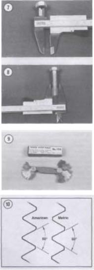
PARTS REPLACEMENT
When you order parts from the dealer or other parts distributor, always order by frame and engine serial numbers. Refer to Table 1. Compare new parts to old before purchasing them. If they are not alike, have the parts manager explain the difference to you.
TORQUE SPECIFICATIONS
Torque specifications throughout this manual are given in Newton-meters (N.m) and foot-pounds (ft.- lb.).
Existing torque wrenches calibrated in meter kilograms can be used by performing a simple conversion. All you have to do is move the decimal point one place to the right; for example, 3.5 mkg = 35 N.m. This conversion is accurate enough for mechanical work even though the exact mathematical conversion is 3.5 mkg = 34.3 N-m.
Refer to Table 3 for general torque specifications for various size screws, bolts and nuts that may not be listed in the respective chapters. To use the table, first determine the size of the bolt or nut. Use a vernier caliper and measure the inside dimension of the threads of the nut (Figure 7) and across the threads for a bolt (Figure 8).
FASTENERS
The materials and designs of the various fasteners used on your Suzuki are not arrived at by chance or accident. Fastener design determines the type of tool required to work the fastener. Fastener material is carefully selected to decrease the possibility of physical failure.
Nuts, bolts and screws are manufactured in a wide range of thread patterns. To join a nut and bolt, the diameter of the bolt and the diameter of the hole in the nut must be the same. It is just as important that the threads on both be properly matched.
The best way to tell if the threads on 2 fasteners are matched is to turn the nut on the bolt (or the bolt into the threaded hole in a piece of equipment) with fingers only. Be sure both pieces are clean. If much force is required, check the thread condition on each fastener. If the thread condition is good but the fasteners jam, the threads are not compatible. A thread pitch gauge (Figure 9) can also be used to determine pitch. Suzuki motorcycles are manufac-
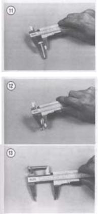
tured with ISO (International Organization for Standardization) metric fasteners. The threads are cut differently than that of American fasteners (Figure 10).
Most threads are cut so that the fastener must be turned clockwise to tighten it. These are called righthand threads. Some fasteners have left-hand threads; they must be turned counterclockwise to be light-
ened. Left-hand threads are used in locations where normal rotation of the equipment would tend to loosen a right-hand threaded fastener.
ISO Metric Screw Threads
ISO (International Organization for Standardization) metric threads come in 3 standard thread sizes: coarse, fine and constant pitch. The ISO coarse pitch is used for most all common fastener applications. The fine pitch thread is used on certain precision tools and instruments. The constant pitch thread is used mainly on machine pans and not for fasteners. The constant pitch thread, however, is used on all metric thread spark plugs.
ISO metric threads are specified by the capital letter M followed by the diameter in millimeters and the pitch (or the distance between each thread) in millimeters separated by the sign x. For example a M8 x 1.25 bolt is one that has a diameter of 8 millimeters with a distance of 1.25 millimeters between each thread. The measurement across 2 flats on the head of the bolt (Figure 11) indicates the proper wrench size to be used. Figure 12 shows how to determine bolt diameter.
NOTE
When purchasing a bolt from a dealer or parts store, it is important to know how to specify bolt length. The correct way to measure bolt length is by measuring the length starting from underneath the bolt head to the end of the bolt (Figure 13). Always measure bolt length in this manner to avoid purchasing bolts that are too long or too short.
Machine Screws
There are many different types of machine screws. Figure 14 shows a number of screw heads requiring different types of turning tools. Heads are also designed to protrude above the metal (round) or to be slightly recessed in the metal (flat). See Figure 15.
Bolts
Commonly called bolts, the technical name for these fasteners is cap screws. Metric bolts are described by the diameter and pitch (or the distance
![]()
between each thread). For example a M8 x 1.25 bolt is one that has a diameter of 8 millimeters and a distance of 1.25 millimeters between each thread. The measurement across 2 flats on the head of the bolt (Figure 11) indicates the proper wrench size to be used. Use a vernier caliper and measure across the threads (Figure 12) to determine the bolt diameter and to measure the length (Figure 13).
Nuts
Nuts are manufactured in a variety of types and sizes. Most are hexagonal (6-sided) and fit on bolts, screws and studs with the same diameter and pitch.
Figure 16 shows several types of nuts. The common nut is generally used with a lockwasher. Self-locking nuts have a nylon insert which prevents the nut from loosening; no lockwasher is required. Wing nuts are designed for fast removal by hand. Wing nuts are used for convenience in non-critical locations.
To indicate the size of a metric nut, manufacturers specify the diameter of the opening and the thread pitch. This is similar to bolt specifications, but without the length dimension. The measurement across 2 flats on the nut indicates the proper wrench size to be used (Figure 17).
Self-locking Fasteners
Several types of bolts, screws and nuts incorporate a system that develops an interference between the bolt, screw, nut or tapped hole threads. Interference is achieved in various ways: by distorting threads, coating threads with dry adhesive or nylon, distorting the top of an all-metal nut, using a nylon insert in the center or at the top of a nut, etc.
Self-locking fasteners offer greater holding strength and better vibration resistance. Some prevailing torque fasteners can be reused if in good condition. Others, like the nylon insert nut, form an initial locking condition when the nut is first in-
OPENINGS FOR TURNING TOOLS
MACHINE SCREWS

stalled; the nylon forms closely to the bolt thread 1 pattern, thus reducing any tendency for the nut to I loosen. When the nut is removed, the locking efficiency is greatly reduced. For greatest safety, it is recommended that you install new self-locking fasteners whenever they are removed.
Washers
There are 2 basic types of washers: flat washers and lockwashers. Flat washers are simple discs with a hole to fit a screw or bolt. Lockwashers are designed to prevent a fastener from working loose due to vibration, expansion and contraction. Figure 18 shows several types of washers. Washers are also used in the following functions:
a.As spacers.
b.To prevent galling or damage of the equipment by the fastener.
c.To help distribute fastener load during torquing.
d.As seals.
Note that flat washers are often used between a lockwasher and a fastener to provide a smooth bearing surface. This allows the fastener to be turned easily with a tool.
Cotter Pins
Cotter pins (Figure 19) are used to secure fasteners in a special location. The threaded stud, bolt or axle must have a hole in it. Its nut or nut lock piece has castellations around its upper edge into which the cotter pin fits to keep it from loosening. When properly installed, a cotter pin is a positive locking device.
The first step in properly installing a cotter pin is to purchase one that will fit snugly when inserted through the nut and the mating thread part. This should not be a problem when purchasing cotter pins through a Suzuki dealer; you can order them by their respective part numbers. However, when you purchase them at a hardware or automotive store, keep this in mind. The cotter pin should not be so tight that you have to drive it in and out, but you do not want it so loose that it can move or float after it is installed.
Before installing a cotter pin, tighten the nut to the recommended torque specification. If the castellations in the nut do not line up with the hole in the
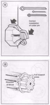
bolt or axle, tighten the nut until alignment is achieved. Do not loosen the nut to make alignmentInsert a new cotter pin through the nut and hole, then tap the head lightly to seat it. Bend one arm over the flat on the nut and the other against the top of the axle or bolt. Cut the arms to a suitable length to prevent them from snagging on clothing, or worse, your hands, arms or legs; the exposed arms will cut flesh easily. When the cotter pin is bent and its arms cut to length, it should be tight. If you can wiggle the cotter pin, it is improperly installed.
Cotter pins should not be reused as their ends may break and allow the cotter pin to fall out and perhaps the fastener to unscrew itself.
Circlips
Circlips can be internal or external design. They are used to retain items on shafts (external type) or within bores (internal type). In some applications, circlips of varying thicknesses are used to control the end play of parts assemblies. These are often called selective circlips. Circlips should be replaced during installation, as removal weakens and deforms them.
Two basic styles of circlips are available: machined and stamped circlips. Machined circlips (Figure 20) can be installed in either direction (shaft or housing) because both faces are machined, thus creating two sharp edges. Stamped circlips (Figure 21) are manufactured with one sharp edge and one rounded edge. When installing stamped circlips in a thrust situation (transmission shafts, fork tubes, etc.), the sharp edge must face away from the part producing the thrust. When installing circlips, observe the following:
a.Compress or expand circlips only enough to install them.
b.After the circlip is installed, make sure it is completely seated in its groove.
Transmission circlips become worn with use and increase side play. For this reason, always use new circlips when ever a transmission is to be reassembled.
LUBRICANTS
Periodic lubrication assures long life for any type of equipment. The type of lubricant used is just as important as the lubrication service itself, although in an emergency the wrong type of lubricant is better
than none at all. The following paragraphs describe the types of lubricants most often used on motorcycle equipment. Be sure to follow the manufacturer’s recommendations for lubricant types.
Generally, all liquid lubricants are called «oil.» They may be mineral-based (including petroleum bases), natural-based (vegetable and animal bases), synthetic-based or emulsions (mixtures). «Grease» is an oil to which a thickening base has been added so that the end product is semi-solid. Grease is often classified by the type of thickener added; lithium soap is commonly used.
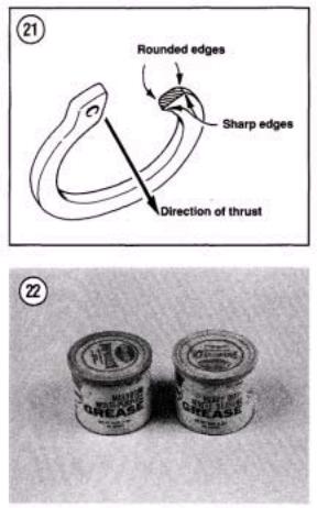
Engine Oil
Four-cycle oil for motorcycle and automotive engines is graded by the American Petroleum Institute (API) and the Society of Automotive Engineers (SAE) in several categories. Oil containers display these ratings on the top or label.
API oil grade is indicated by letters; oils for gasoline engines are identified by an «S». Suzuki models described in this manual require SE or SF graded oil.
Viscosity is an indication of the oil’s thickness. The SAE uses numbers to indicate viscosity; thin oils have low numbers while thick oils have high numbers. A «W» after the number indicates that the viscosity testing was done at low temperature to simulate cold-weather operation. Engine oils fall into the 5 to 50 range.
Multi-grade oils (for example 10W-40) are less viscous (thinner) at low temperatures and more viscous (thicker) at high temperatures. This allows the
oil to perform efficiently across a wide range of | engine operating conditions. The lower the number, the better the engine will start in cold climates. Higher numbers are usually recommended for engine running in hot weather conditions.
Grease
Greases are graded by the National Lubricating Grease Institute (NLGI). Greases are graded by number according to the consistency of the grease; these range from No. 000 to No. 6, with No. 6 being the most solid. A typical multipurpose grease is NLGI No. 2. For specific applications, equipment manufacturers may require grease with an additive such as molybdenum disulfide (MOS2) (Figure 22).
RTV GASKET SEALANT
Room temperature vulcanizing (RTV) sealant is used on some pre-formed gaskets and to seal some components. RTV is a silicone gel supplied in tubes and can be purchased in a number of different colors.
Moisture in the air causes RTV to cure. Always place the cap on the tube as soon as possible when using RTV sealants?RTV has a shelf life of one year and will not cure properly when the shelf life has expired. Check the expiration date on RTV tubes before using and keep partially used tubes tightly sealed.
Applying RTV Sealant
Clean all gasket residue from mating surfaces. Surfaces should be clean and free of oil and dirt. Remove all RTV gasket material from blind attaching holes, as it can cause a «hydraulic» effect and affect bolt torque.
Apply RTV sealant in a continuous bead. Circle all mounting holes unless otherwise specified. Torque mating parts within 10 minutes after application.
THREADLOCK
A chemical such as «Loctite.» A locking compound will lock fasteners against vibration loosening and seal against leaks. Loctite 242 (blue) and 271

(red) are recommended for many threadlock requirements described in this manual.
Loctite 242 (blue) is a medium strength threadlock and component disassembly can be performed with normal hand tools. Loctite 271 (red) is a high strength threadlock and heat or special tools, such as a press or puller, may be required for component disassembly.
Applying Threadlock
Surfaces should be clean and free of oil, grease, dirt and other residue; clean threads with an aerosol electrical contact cleaner before applying the Loctite. When applying Loctite, use a small amount. If too much is used, it may work its way into parts not meant to be stuck together.
GASKET REMOVER
Stubborn gaskets can present a problem during engine service as they can take a long time to remove. Consequently, there is the added problem of secondary damage occurring to the gasket mating surfaces from the incorrect use of gasket scraping tools. To quickly and safely remove stubborn gaskets, use a spray gasket remover. Spray gasket remover can be purchased through automotive parts houses. Follow the manufacturer’s directions for use.
EXPENDABLE SUPPLIES
Certain expendable supplies are required during maintenance and repair work. These include grease, oil. gasket cement, wiping rags and cleaning solvent. Ask your dealer for the special locking compounds, silicone lubricants and other products (Figure 23) which make bike maintenance simpler and easier. Cleaning solvent or kerosene is available at some service stations, paint or hardware stores.
WARNING
Having a stack of clean shop rags on hand is important when performing engine and suspension service work. However, to prevent the possibility of fire damage from spontaneous combustion from a pile of solvent soaked rags, store
them in a lid sealed metal container until they can be washed or discarded.
NOTE
To avoid absorbing solvent and other chemicals into your skin while cleaning parts, wear a pair of petroleum-resistant rubber gloves. These can be purchased through industrial supply houses or wellequipped hardware stores.
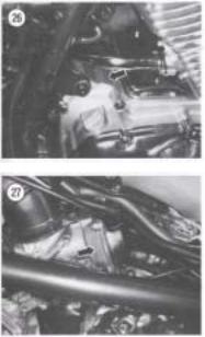
PARTS REPLACEMENT
Suzuki makes frequent changes during a model year, some minor, some relatively major. When you order parts from the dealer or other parts distributor, always order by frame and engine numbers. The frame number serial number is stamped on the righthand side of the steering head (Figure 24). The vehicle identification number (VIN) plate is attached to the left-hand side of the frame down tube (Figure 25). The engine number is stamped on a raised pad on the right-hand side of the crankcase (Figure 26) behind the starter motor cover. The carburetor number (Figure 27) is on the side of the carburetor body below the top cover.
Write the numbers down and carry them with you. Compare new parts to old before purchasing them. If they are not alike, have the parts manager explain the difference to you. Table 1 lists engine and frame serial numbers for the models covered in this manual.
NOTE
If your Suzuki was purchased secondhand and you are not sure of its model year, use the bike’s VINandframe serial numbers and the information listed in Table 1. Read your bike’s serial number. Then compare the numbers listed in Table 1. If your bike’s serial number is listed in Table 1, cross-reference the number with the adjacent model number and year.
BASIC HAND TOOLS
Many of the procedures in this manual can be carried out with simple hand tools and test equipment familiar to the average home mechanic. Keep your tools clean and in a tool box. Keep them organized with the sockets and related drives together, the open-end combination wrenches together, etc. After using a tool, wipe off dirt and grease with a clean cloth and return the tool to its correct place.
Top quality tools are essential; they are also more economical in the long run. If you are now starting to build your tool collection, stay away from the «advertised specials» featured at some parts houses, discount stores and chain drug stores. These are usually a poor grade tool that can be sold cheaply and that is exactly what they are—cheap. They are usually made of inferior material, and are thick, heavy and clumsy. Their rough finish makes them difficult to clean and they usually don’t last very long. If it is ever your misfortune to use such tools, you will probably find out that the wrenches do not fit the heads of bolts and nuts correctly and damage the fastener.
Quality tools are made of alloy steel and are heat treated for greater strength. They are lighter and better balanced than cheap ones. Their surface is smooth, making them a pleasure to work with and easy to clean. The initial cost of good quality tools may be more but they are cheaper in the long run. Don’t try to buy everything in all sizes in the beginning; do it a little at a time until you have the necessary tools.
The following tools are required to perform virtually any repair job on a bike. Each tool is described and the recommended size given for starting a tool collection. Table 4 includes the tools that should be on hand for simple home repairs and/or major over-
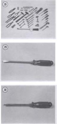
haul as shown in Figure 28. Additional tools and some duplicates may be added as you become more familiar with the bike. Almost all motorcycles and vehicles (with the exception of the U.S. built Harley Davidson and some English motorcycles) use metric size bolts and nuts. If you are starting your collection now, buy metric sizes.
Screwdrivers
The screwdriver is a very basic tool, but if used improperly it will do more damage than good. The slot on a screw has a definite dimension and shape. A screwdriver must be selected to conform with that shape. Use a small screwdriver for small screws and a large one for large screws or the screw head will be damaged.
Two basic types of screwdrivers are required: common (flat-blade) screwdrivers (Figure 29) and Phillips screwdrivers (Figure 30).
Note the following when selecting and using screwdrivers:
a.The screwdriver must always fit the screw head. If the screwdriver blade is too small for the screw slot, damage may occur to the screw slot and screwdriver. If the blade is too large, it cannot engage the slot properly and will result in damage to the screw head.
b.Standard screwdrivers are identified by the length of their blade. A 6-inch screwdriver has ablade six inches long. The width of the screw driver blade will vary, so make sure that the blade engages the screw slot the complete width of the screw.
c.Phillips screwdrivers are sized according to their point size. They are numbered one, two, three and four. The degree of taper determines the point size; the No. 1 Phillips screwdriver will be the most pointed. The points become more blunt as their number increases.
NOTE
You should also be aware of another screwdriver similar to the Phillips, and that is the Reed and Prince tip. Like the Phillips, the Reed and Prince screwdriver tip forms an «X» but with one major exception, the Reed and Prince tip has a much more pointed tip. The Reed and Prince screwdriver should never be used on Phillips screws and
vise versa. Intermixing these screwdrivers will cause damage to the screw and screwdriver. If you have both types in your tool box and they are similar in appearance, you may want to identify them by painting the screwdriver shank underneath the handle.
d.When selecting screwdrivers, note that you can apply more power with less effort with a longer

screwdriver than with a short one. Of course, there will be situations where only a short handle screwdriver can be used. Keep this in mind though, when having to remove tight screws.
e. Because the working end of a screwdriver receives quite a bit of abuse, you should purchase screwdrivers with hardened-tips. The extra money will be well spent. Screwdrivers are available in sets which often include an assortment of common and Phillips blades. If you buy them individually, buy at least the following:
a.Common screwdriver—5/16 x 6 in. blade.
b.Common screwdriver—3/8 x 12 in. blade.
c.Phillips screwdriver—size 2 tip, 6 in. blade.
d.Phillips screwdriver—size 3 tip, 6 and 8 in. blade.
Use screwdrivers only for driving screws. Never use a screwdriver for prying or chiseling metal. Do not try to remove a Phillips, Torx or Allen head screw with a standard screwdriver (unless the screw has a combination head that will accept either type); you can damage the head so that the proper tool will be unable to remove it.
Keep screwdrivers in the proper condition and they will last longer and perform better. Always keep the tip of a standard screwdriver in good condition. Figure 31 shows how to grind the tip to the proper shape if it becomes damaged. Note the symmetrical sides of the tip.
Pliers
Pliers come in a wide range of types and sizes. Pliers are useful for cutting, bending and crimping. They should never be used to cut hardened objects
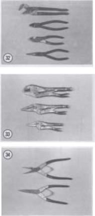
or to turn bolts or nuts. Figure 32 shows several pliers useful in repairing your Suzuki.
Each type of pliers has a specialized function. Slip-joint pliers are general purpose pliers and are used mainly for holding things and for bending. Needlenose pliers are used to hold or bend small objects. Water pump pliers can be adjusted to hold various sizes of objects; the jaws remain parallel to grip around objects such as pipe or tubing. There are many more types of pliers.
CAUTION
Pliers should not be used for loosening or tightening nuts or bolts. The pliers’ sharp teeth will grind off the nut or bolt corners and damage it.
CAUTION
If slip-joint or water pump pliers are going to be used to hold an object with a finished surface, wrap the object with tape or cardboard for protection.
Vise-grip Pliers
Vise-grip pliers (Figure 33) are used to hold objects very tightly while another task is performed on the object. While vise-grip pliers work well, caution should be followed with their use. Because vise-grip pliers exert more force than regular pliers, their sharp jaws can permanently scar the object. In addition, when vise-grip pliers are locked into position, they can crush or deform thin wall material.
Vise-grip pliers are available in many types for more specific tasks.
Circlip (Snap Ring) Pliers
Circlip pliers (Figure 34) are special in that they are only used to remove circlips from shafts or within engine or suspension housings. When purchasing circlip pliers, there are two kinds to distinguish from. External pliers (spreading) are used to remove circlips that fit on the outside of a shaft. Internal pliers (squeezing) are used to remove circlips which fit inside a gear or housing.
WARNING
Because circlips can sometimes slip and «fly off» during removal and installation, always wear safety glasses.
Box-end, Open-end and Combination Wrenches
Box-end, open-end and combination wrenches are available in sets or separately in a variety of sizes. On openand box-end wrenches, the number stamped near the end refers to the distance between 2 parallel flats on the hex head bolt or nut. On combination wrenches, the number is stamped near the center.
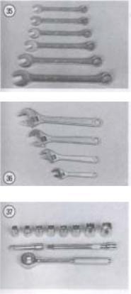
Box-end wrenches require clear overhead access to the fastener but can work well in situations where the fastener head is close to another part. They grip on all six edges of a fastener for a very secure grip. They are available in either 6-point or 12-point. The 6-point gives superior holding power and durability but requires a greater swinging radius. The 12-point works better in situations with limited swinging radius.
Open-end wrenches are speedy and work best in areas with limited overhead access. Their wide flat
jaws make them unstable for situations where the bolt or nut is sunken in a well or close to the edge of a casting. These wrenches grip only two flats of a fastener so if either the fastener head or the wrench jaws are worn, the wrench may slip off.
Combination wrenches (Figure 35) have openend on one side and box-end on the other with both ends being the same size. These wrenches are favored by professionals because of their versatility.
Adjustable (Crescent) Wrenches
An adjustable wrench (sometimes called crescent wrench) can be adjusted to fit nearly any nut or bolt head which has clear access around its entire perimeter. Adjustable wrenches (Figure 36) are best used as a backup wrench to keep a large nut or bolt from turning while the other end is being loosened or tightened with a proper wrench.
Adjustable wrenches have only two gripping surfaces which make them more subject to slipping off the fastener, damaging the part and possibly injuring your hand. The fact that one jaw is adjustable only aggravates this shortcoming.
These wrenches are directional; the solid jaw must be the one transmitting the force. If you use the adjustable jaw to transmit the force, it will loosen and possibly slip off.
Adjustable wrenches come in all sizes but something in the 6 to 8 in. range is recommended as an all-purpose wrench.
Socket Wrenches
This type is undoubtedly the fastest, safest and most convenient to use. Sockets which attach to a ratchet handle (Figure 37) are available with 6-point or 12-point openings and 1/4,3/8 and 3/4 in. drives. The drive size indicates the size of the square hole which mates with the ratchet handle (Figure 38).
Allen Wrenches
Allen wrenches (Figure 39) are available in sets or separately in a variety of sizes. These sets come in SAE and metric size, so be sure to buy a metric set. Allen bolts are sometimes called socket bolts. Sometimes the bolts are difficult to reach and it is suggested that a variety of Allen wrenches be pur-
![]()
chases (e.g. socket driven, T-handle and extension type) as shown in Figure 40.
Torque Wrench
A torque wrench is used with a socket to measure how tightly a nut or bolt is installed. They come in a wide price range and with either 3/8 or 1/2 in. square drive (Figure 41). The drive size indicates the size of the square drive which mates with the socket. Purchase one that measures 0-280 N-m (0- 200 ft.-lb.).
Impact Driver
This tool might have been designed with the bike in mind. This tool makes removal of fasteners easy and minimizes damage to bolts and screw slots. Impact drivers and interchangeable bits (Figure 42) are available at most large hardware, motorcycle and auto parts stores. Don’t purchase a cheap one as they do not work as well and require more force (the «use a larger hammer» syndrome) than a moderately priced one. Sockets can also be used with a hand impact driver. However, make sure that the socket is designed for use with an impact driver or air tool. Do not use regular hand sockets, as they may shatter during use.
Hammers
The correct hammer (Figure 43) is necessary for repairs. A hammer with a face (or head) of rubber or plastic or the soft-faced type that is filled with buckshot is sometimes necessary in engine tear downs. Never use a metal-faced hammer on engine or suspension parts, as severe damage will result in most cases. Ball-peen or machinist’s hammers will be required when striking another tool, such as a punch or impact driver. When striking a hammer against a punch, cold chisel or similar tool, the face of the hammer should be at least 1/2 in. larger than the head of the tool. When it is necessary to strike hard against a steel part without damaging it, a brass hammer should be used. A brass hammer can be used because brass will give when striking a harder object. When using hammers, note the following: a. Always wear safety glasses when using a hammer.
b.Inspect hammers for damaged or broken parts. Repair or replace the hammer as required. Do not use a hammer with a taped handle.
c.Always wipe oil or grease off of the hammer before using it.
d.The head of the hammer should always strike the object squarely. Do not use the side of the hammer or the handle to strike an object.
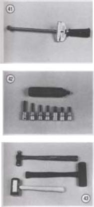
e. Always use the correct hammer for the job.
Tap and Die Set
Acomplete tap and die set is a relatively expensive tool. But when you need a tap or die to clean up a damaged thread, there is really no substitute. Be sure to purchase one for metric threads when working on your Suzuki.
Tire Levers
When changing tires, use a good set of tire levers. Never use a screwdriver in place of a tire lever; refer to Chapter Ten for tire changing procedures using these tools. Before using the tire levers, check the working ends of the tool and remove any burrs. Don’t use a tire lever for prying anything but tires. For better leverage when changing tires on your Suzuki, you may want to invest in a set of 16 in. long tire irons. These can be ordered through your dealer.
Drivers and Pullers
These tools are used to remove and install oil seals, bushings, bearings and gears. These will be called out during service procedures in later chapters as required.
PRECISION MEASURING TOOLS
Measurement is an important part of motorcycle service. When performing many of the service procedures in this manual, you will be required to make a number of measurements. These include basic checks such as valve clearance, engine compression and spark plug gap. As you get deeper into engine disassembly and service, measurements will be required to determine the size and condition of the piston and cylinder bore, valve and guide wear, camshaft wear, crankshaft runout and so on. When making these measurements, the degree of accuracy will dictate which tool is required. Precision measuring tools are expensive. If this is your first experience at engine or suspension service, it may be more worthwhile to have the checks made at a Suzuki dealer or machine shop. However, as your skills and enthusiasm increase for doing your own service work, you may want to begin purchasing some of these specialized tools. The following is a description of the measuring tools required during engine and suspension overhaul.
Feeler Gauge
Feeler gauges come in assorted sets and types (Figure 44). The feeler gauge is made of either a piece of a flat or round hardened steel of a specified thickness. Wire gauges are frequently recommended to measure spark plug gap. Flat gauges are used for
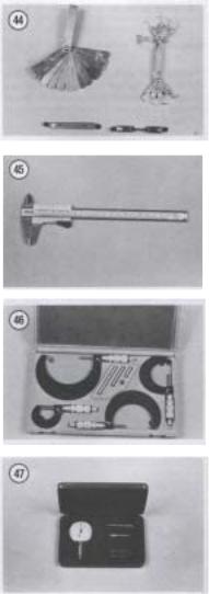
all other measurements. Feeler gauges are also designed for specialized uses, such as for measuring valve clearances. On these gauges, the gauge end is usually small enough and angled so as to make checking valve clearances easier.
Vernier Caliper
This tool (Figure 45) is invaluable when reading inside, outside and depth measurements to within close precision. It can be used to measure clutch spring length and the thickness of clutch plates, shims and thrust washers.
Outside Micrometers
One of the most reliable tools used for precision measurement is the outside micrometer (Figure 46). Outside micrometers will be required to measure valve shim thickness, piston diameter and valve stem diameter. Outside micrometers are also used with other tools to measure the cylinder bore and the valve guide inside diameters. Micrometers can be purchased individually or as a set.
Dial Indicator
Dial indicators (Figure 47) are precision tools used to check dimension variations on machined parts such as transmission shafts and axles and to check crankshaft and axle shaft end play. Dial indicators are available with various dial types for different measuring requirements.
Cylinder Bore Gauge
The cylinder bore gauge is a very specialized precision tool. The gauge set shown in Figure 48 is comprised of a dial indicator, handle and a number of length adapters to adapt the gauge to different bore sizes. The bore gauge can be used to make cylinder bore measurements such as bore size, taper and out-of-round. Depending on the bore gauge, it can sometimes be used to measure brake caliper and master cylinder bore sizes. An outside micrometer must be used together with the bore gauge to determine bore dimensions.

Small Hole Gauges
A set of small hole gauges allow you to measure a hole, groove or slot ranging in size up to 13 mm (0.500 in.). A small hole gauge will be required to measure valve guide, brake caliper and brake master cylinder bore diameters. An outside micrometer
must be used together with the small hole gauge to determine bore dimensions.
Compression Gauge
An engine with low compression cannot be properly tuned and will not develop full power. A compression gauge (Figure 49) measures engine compression. The one shown has a flexible stem with an extension that can allow you to hold it while kicking the engine over. Open the throttle all the way when checking engine compression. See Chapter Three.
Cylinder Leak Down Tester
By positioning a cylinder on its compression stroke so that both valves are closed and then pressurizing the cylinder, you can isolate engine problem areas (e.g. leaking valve, damaged head gasket, broken, worn or stuck piston rings) by listening for escaping air through the carburetors, exhaust pipe, cylinder head mating surface, etc. To perform this procedure, a leak down tester and an air compressor are required. This procedure is described in Chapter Three. Cylinder leak down testers can be purchased through Suzuki dealers, accessory tool manufacturers and automotive tool suppliers.
Strobe Timing Light
This instrument is useful for checking ignition timing. By flashing a light at the precise instant the spark plug fires, the position of the timing mark can be seen. The flashing light makes a moving mark appear to stand still opposite a stationary mark.
Suitable lights range from inexpensive neon bulb types to powerful xenon strobe lights (Figure 50). A light with an inductive pickup is recommended to eliminate any possible damage to ignition wiring. Use according to manufacturer’s instructions.
Multimeter or VOM
This instrument (Figure 51) is invaluable for electrical system troubleshooting. See Electrical Troubleshooting in Chapter Eight for its use.
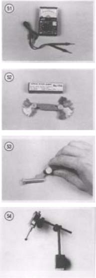
Screw Pitch Gauge
A screw pitch gauge (Figure 52) determines the thread pitch of bolts, screws, studs, etc. The gauge is made up of a number of thin plates. Each plate has a thread shape cut on one edge to match one thread pitch. When using a screw pitch gauge to determine a thread pitch size, try to fit different blade sizes onto the bolt thread until both threads match (Figure 53).
Magnetic Stand
A magnetic stand (Figure 54) is used to securely hold a dial indicator when checking the runout of a round object or when checking the end play of a shaft.
V-Blocks
V-blocks (Figure 55) are precision ground blocks used to hold a round object when checking its runout or condition. In motorcycle repair. V-blocks can be used when checking the runout of such items as valve stems, camshaft, balancer shaft, crankshaft, wheel axles and fork tubes.
Surface Plate
A surface plate can be used to check the flatness of parts or to provide a perfectly flat surface for minor resurfacing of cylinder head or other critical gasket surfaces. While industrial quality surface plates are quite expensive, the home mechanic can improvise. A thick metal plate can be put to use as a surface plate. The metal surface plate with a piece of sandpaper or dry wall surface sanding sheets glued to its surface can be used for cleaning and smoothing cylinder head and crankcase mating surfaces.
NOTE
Check with a local machine shop on the availability and cost of having a metal plate resurfaced/or use as a surface plate.
SPECIAL TOOLS
A few special tools may be required for major service. These are described in the appropriate chapters and are available either from a Suzuki dealer or other manufacturers as indicated.
This section describes special tools unique to this type of bike’s service and repair.
Spoke Wrench
This special wrench is used to tighten wheel spokes (Figure 56). Always use the correct size wrench to avoid rounding out and damaging the spoke nipple.
The Grabbit
The Grabbit (Figure 57) is a special tool used to hold the clutch boss when removing the clutch nut and to secure the drive sprocket when removing the sprocket nut.
Other Special Tools
A few other special tools may be required for major service. These are described in the appropriate chapters and are available from Suzuki dealers or other manufacturers as indicated.
CLEANING SOLVENT
With the environmental concern that is prevalent today concerning the disposal of hazardous solvents, the home mechanic should select a water soluble, biodegradable solvent. These solvents can be purchased through dealers, automotive parts houses and large hardware stores.
Selecting a solvent is only one of the problems facing the home mechanic when it comes to cleaning parts. You need some type of tank to clean parts as well as to store die solvent. There are a number of manufacturers offering different types and sizes of parts cleaning tanks. While a tank may seem a luxury to the home mechanic, you will find that it will quickly pay for itself through its efficiency and convenience. When selecting a parts washer, look for one that can recycle and store the solvent, as well as separate the sludge and contamination from the clean solvent. Most important, check the warranty, if any, as it pertains to the tank’s pump. Like most tools, when purchasing a parts washer, you get what you pay for.
WARNING
Having a stack of clean shop rags on hand is important when performing engine work. However, to prevent the possibility of fire damage from spontaneous combustion from a pile of solventsoaked rags, store them in a lid-sealed metal container until they can be washed or discarded.
NOTE
To avoid absorbing solvent and other chemicals into your skin while cleaning parts, wear a pair of petroleum-resistant
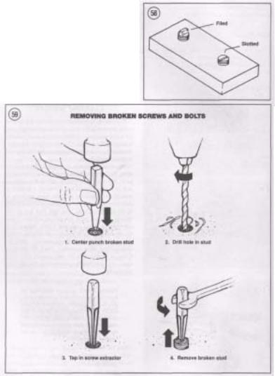
rubber gloves. These can be purchased through industrial supply houses or well-equipped hardware stores.
MECHANIC’S TIPS
Removing Frozen Nuts and Screws
When a fastener rusts and cannot be removed, several methods may be used to loosen it. First, apply penetrating oil such as Liquid Wrench or WD-40 (available at hardware or auto supply stores). Apply it liberally and let it penetrate for
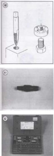
10-15 minutes. Rap the fastener several times with a small hammer; do not hit it hard enough to cause damage. Reapply the penetrating oil if necessary.
For frozen screws, apply penetrating oil as described, then insert a screwdriver in the slot and rap the top of the screwdriver with a hammer. This loosens the rust so the screw can be removed in the normal way. If the screw head is too chewed up to use this method, grip the head with vise-grip pliers and twist the screw out.
Avoid applying heat unless specifically instructed, as it may melt, warp or remove the temper from parts.
Removing Broken Screws or Bolts
When the head breaks off a screw or bolt, several methods are available for removing the remaining portion.
If a large portion of the remainder projects out, try gripping it with vise-grips. If the projecting portion is too small, file it to fit a wrench or cut a slot in it to fit a screwdriver. See Figure 58.
If the head breaks off flush, use a screw extractor. To do this, center punch the exact center of the remaining portion of the screw or bolt. Drill a small hole in the screw and tap the extractor into the hole. Back the screw out with a wrench on the extractor. See Figure 59.
Remedying Stripped Threads
Occasionally, threads are stripped through carelessness or impact damage. Often the threads can be cleaned up by running a tap (for internal threads on nuts) or die (for external threads on bolts) through the threads. See Figure 60. To clean or repair spark plug threads, a spark plug tap can be used (Figure
61).
NOTE
Tap and dies can be purchased individually or in a set as shown in Figure 62.
If an internal thread is damaged, it may be necessary to install a Helicoil (Figure 63) or some other type of thread insert. Follow the manufacturer’s instructions when installing their insert.
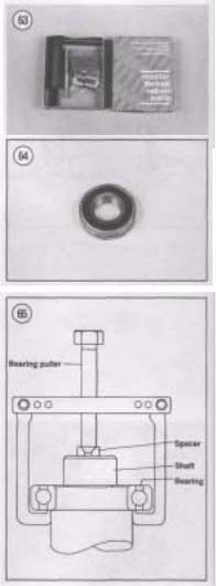
Removing Broken or Damaged Studs
If a stud is broken or the threads severely damaged, perform the following. A tube of red Loctite (No. 271), 2 nuts, 2 wrenches and a new stud will be required during this procedure. Studs that are stripped or damaged will require the use of a stud remover.
1. Thread two nuts onto the damaged stud. Then tighten the 2 nuts against each other so that they are locked.
NOTE
If the threads on the damaged stud do not allow installation of the 2 nuts, you will have to remove the stud with a stud remover.
2.Turn the bottom nut counterclockwise and un screw the stud.
3.Threaded holes with a bottom surface should be blown out with compressed air as dirt buildup in the bottom of the hole may prevent the stud from being torqued properly. If necessary, use a bottoming tap to true up the threads and to remove any deposits.
4.Install 2 nuts on the top half of the new stud as in Step 1. Make sure they are locked securely.
5.Coat the bottom half of a new stud with red Loctite (No. 271),
6.Turn the top nut clockwise and thread the new stud securely.
7.Remove the nuts and repeat for each stud as required.
8.Follow Loctite’s directions on cure time before assembling the component.
BALL BEARING REPLACEMENT
Ball bearings (Figure 64) are used throughout your Suzuki’s engine and chassis to reduce power loss, heat and noise resulting from friction. Because ball bearings are precision made parts, they must be maintained by proper lubrication and maintenance. When a bearing is found to be damaged, it should be replaced immediately. However, when installing a new bearing, care should be taken to prevent damage to the new bearing. While bearing replacement is described in the individual chapters where applicable, the following can be used as a guideline.
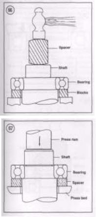
NOTE
Unless otherwise specified, install bearings with the manufacturer’s mark or number on the bearing facing outward.
Bearing Removal
While bearings are normally removed only when damaged, there may be times when it is necessary to
remove a bearing that is in good condition. Depending on the situation, you may be able to remove the bearing without damaging it. However, bearing removal in some situations, no matter how careful you are, will cause bearing damage. Care should always be given to bearings during their removal to prevent secondary damage to the shaft or housing. Note the following when removing bearings.
1.When using a puller to remove a bearing from a shaft, care must be taken so that shaft damage does not occur. Always place a piece of metal between the end of the shaft and the puller screw. In addition, place the puller arms next to the inner bearing race. See Figure 65.
2.When using a hammer to remove a bearing from a shaft, do not strike the hammer directly against the shaft. Instead, use a brass or aluminum spacer be tween the hammer and shaft (Figure 66). In addi tion, make sure to support both bearing races with wood blocks as shown in Figure 66.
3.The most ideal method of bearing removal is with a hydraulic press. However, certain procedures must be followed or damage may occur to the bearing, shaft or case half. Note the following when using a press:
a.Always support the inner and outer bearing races with a suitable size wood or aluminum spacer ring (Figure 67). If only the outer race is supported, the balls and/or the inner race will be damaged.
b.Always make sure the press ram (Figure 67) aligns with the center of the shaft. If the ram is not centered, it may damage the bearing and/or shaft.
c.The moment the shaft is free of the bearing, it will drop to the floor. Secure or hold the shaft to prevent it from falling.
Bearing Installation
1.When installing a bearing in a housing, pressure must be applied to the outer bearing race (Figure 68). When installing a bearing on a shaft, pressure must be applied to the inner bearing race (Figure
69).
2.When installing a bearing as described in Step 1, some type of driver will be required. Never strike the bearing directly with a hammer or the bearing will be damaged. When installing a bearing, a piece of pipe or a socket with an outer diameter that matches
![]()
the bearing race will be required. Figure 70 shows the correct way to use a socket and hammer when installing a bearing over a shaft. 3. Step 1 describes how to install a bearing in a case half and over a shaft. However, when installing a bearing over a shaft and into a housing at the same time, a snug fit will be required for both outer and inner bearing races. In this situation, a spacer must be installed underneath the driver tool so that pressure is applied evenly across both races. See Figure 71. If the outer race is not supported as shown in Figure 71, the balls will push against the outer bearing track and damage it.
Shrink Fit
1. Installing a bearing over a shaft: When a tight fit is required, the bearing inside diameter will be smaller than the shaft. In this case, driving the bearing on the shaft using normal methods may cause bearing damage. Instead, the bearing should be heated before installation. Note the following:
a.Secure the shaft so that it can be ready for bearing installation.
b.Clean the bearing surface on the shaft of all residue. Remove burrs with a file or sandpaper.
c.Fill a suitable pot or beaker with clean mineral oil. Place a thermometer (rated higher than 248° F [120° C]) in the oil. Support the ther mometer so that it does not rest on the bottom or side of the pot.
d.Remove the bearing from its wrapper and se cure it with a piece of heavy wire bent to hold
it in the pot. Hang the bearing in the pot so that it does not touch the bottom or sides of the pot.
e.Turn the heat on and monitor the thermometer. When the oil temperature rises to approximately 248° F (120° C), remove the bearing from the pot and quickly install it. If necessary, place a socket on the inner bearing race and tap the bearing into place. As the bearing chills, it will tighten on the shaft so you must work

quickly when installing it. Make sure the bearing is installed all the way.
2. Installing a bearing in a housing: Bearings are generally installed in a housing with a slight interference fit. Driving the bearing into the housing using normal methods may damage the housing or cause bearing damage. Instead, the housing should be heated before the bearing is installed. Note the following:
CAUTION
Before heating the crankcases in this procedure to remove the bearings, wash the cases thoroughly with detergent and water. Rinse and rewash the cases as required to remove all traces of oil and other chemical deposits.
a.The housing must be heated to a temperature of about 212° F (100° C) in an oven or on ahot plate. An easy way to check to see that it is at the proper temperature is to drop tiny drops of water on the case as it heats up; if they sizzle and evaporate immediately, the temperature is correct. Heat only one housing at a time.
CAUTION
Do not heat the housing with a torch (propane or acetylene). Never bring a flame into contact with the bearing or housing. The direct heat will destroy the case hardening of the bearing and will likely warp the housing.
b.Remove the housing from the oven or hot plate and hold onto the housing with a kitchen pot holder, heavy gloves or heavy shop cloths—it is hot.
NOTE
A suitable size socket and extension works well for removing and installing bearings.
c.Hold the housing with the bearing side down and tap the bearing out. Repeat for all bearings in the housing.
d.Before installing new bearings, heat the hous ing halves and place the new bearings in a freezer, if possible. Chilling the bearings will slightly reduce their overall diameter while the hot housing assembly is slightly larger due to heat expansion. This will make installation much easier.
NOTE
Always install bearings with the manufacturer’s mark or number facing outward.
e.While the housing is still hot, install the new bearing(s) into the housing. Install the bearings by hand, if possible. If necessary, lightly tap the bearing(s) into the housing with a socket placed on the outer bearing race. Do not install new bearings by driving on the inner bearing race. Install the bearing(s) until it seats com pletely.
OIL SEALS
Oil seals (Figure 72) are used to prevent leakage of oil, water, grease or combustion gasses from between a housing and a shaft. Improper removal of a seal can damage the housing or shaft. Improper installation of the seal can damage the seal. Note the following:
a.Prying is generally the easiest and most effective method of removing a seal from a housing.

Table 2 DECIMAL AND METRIC EQUIVALENTS
|
Decimal |
Metric mm |
Decimal |
Metric |
||
|
Fractions |
in. |
Fractions |
in. |
mm |
|
|
1/64 |
0.015625 |
0.39688 |
33/64 |
0.515625 |
13.09687 |
|
1/32 |
0.03125 |
0.79375 |
17/32 |
0.53125 |
13.49375 |
|
3/64 |
0.046875 |
1.19062 |
35/64 |
0.546875 |
13.89062 |
|
1/16 |
0.0625 |
1.58750 |
9/16 |
0.5625 |
14.28750 |
|
5/64 |
0.078125 |
1.98437 |
37/64 |
0.578125 |
14.68437 |
|
3/32 |
0.09375 |
2.38125 |
19/32 |
0.59375 |
15.08125 |
|
7/64 |
0.109375 |
2.77812 |
39/64 |
0.609375 |
15.47812 |
|
1/8 |
0.125 |
3.1750 |
5/8 |
0.625 |
15.87500 |
|
9/64 |
0.140625 |
3.57187 |
41/64 |
0.640625 |
16.27187 |
|
5/32 |
0.15625 |
3.96875 |
21/32 |
0.65625 |
16.66875 |
|
11/64 |
0.171875 |
4.36562 |
43/64 |
0.671875 |
17.06562 |
|
3/16 |
0.1875 |
4.76250 |
11/16 |
0.6875 |
17.46250 |
|
13/64 |
0.203125 |
5.15937 |
45/64 |
0.703125 |
17.85937 |
|
7/32 |
0.21875 |
5.55625 |
23/32 |
0.71875 |
18.25625 |
|
15/64 |
0.234375 |
5.95312 |
47/64 |
0.734375 |
18.65312 |
|
1/4 |
0.250 |
6.35000 |
3/4 |
0.750 |
19.05000 |
|
17/64 |
0.265625 |
6.74687 |
49/64 |
0.765625 |
19.44687 |
|
9/32 |
0.28125 |
7.14375 |
25/32 |
0.78125 |
19.84375 |
|
19/64 |
0.296875 |
7.54062 |
51/64 |
0.796875 |
20.24062 |
|
5/16 |
0.3125 |
7.93750 |
13/16 |
0.8125 |
20.63750 |
|
21/64 |
0.328125 |
8.33437 |
53/64 |
0.828125 |
21.03437 |
|
11/32 |
0.34375 |
8.73125 |
27/32 |
0.84375 |
21.43125 |
|
23/64 |
0.359375 |
9.12812 |
55/64 |
0.859375 |
22.82812 |
|
3/8 |
0.375 |
9.52500 |
7/8 |
0.875 |
22.22500 |
|
25/64 |
0.390625 |
9.92187 |
57/64 |
0.890625 |
22.62187 |
|
13/32 |
0.40625 |
10.31875 |
29/32 |
0.90625 |
23.01875 |
|
27/64 |
0.421875 |
10.71562 |
59/64 |
0.921875 |
23.41562 |
|
7/16 |
0.4375 |
11.11250 |
15/16 |
0.9375 |
23.81250 |
|
29/64 |
0.453125 |
11.50937 |
61/64 |
0.953125 |
24.20937 |
|
15/32 |
0.46875 |
11.90625 |
31/32 |
0.96875 |
24.60625 |
|
31/64 |
0.484375 |
12.30312 |
63/64 |
0.984375 |
25.00312 |
|
1/2 |
0.500 |
12.70000 |
1 |
1.00 |
25.40000 |
|
Table 3 STANDARD TIGHTENING |
TORQUES |
|
|
Conventional or «4» Marked bolt* |
||
|
Bolt diameter (mm) |
N.m |
ft.-lb. |
|
4 |
1-2 |
0.7-1.5 |
|
5 |
2-4 |
1.5-3.0 |
|
6 |
4-7 |
3-5 |
|
8 |
10-16 |
7-11.5 |
|
10 |
22-35 |
16-25.5 |
|
12 |
35-55 |
25.5-40 |
|
14 |
50-80 |
36-58 |
|
16 |
80-130 |
58-94 |
|
18 |
130-190 |
94-137.5 |
|
Bolt diameter (mm) |
«7» Marked bolt* |
|
|
N.m |
ft.-lb. |
|
|
4 |
1.5-3 |
1-2 |
|
5 |
3-6 |
2-4.5 |
|
6 |
8-12 |
6-8.5 |
|
8 |
18-28 |
13-20 |
|
10 |
40-60 |
29-43.5 |
|
12 |
70-100 |
50.5-72.5 |
|
14 |
110-160 |
79.5-115.5 |
(continued)

|
Table 3 STANDARD TIGHTENING |
TORQUES (continued) |
||||||||||||||||||||
|
16 |
170-250 |
123-181 18 |
|||||||||||||||||||
|
200-280 |
144-202 |
||||||||||||||||||||
|
* Number is marked on top of Suzuki bolt head. These are Suzuki numbers and do not appear on aftermarket |
|||||||||||||||||||||
|
bolts. |
|||||||||||||||||||||
|
Table |
4 WORKSHOP TOOLS Tool |
Size or specification |
|||||||||||||||||||
|
Screwdriver Common |
1/8 x 4 in. blade Common |
||||||||||||||||||||
|
5/16×8 in. blade Common |
3/8 x 1 2 in. blade Phillips |
||||||||||||||||||||
|
Size 2 tip, 6 in. overall Pliers Slip joint |
6 in. overall Vise Grips |
||||||||||||||||||||
|
1 0 in. overall Needlenose |
6 in. overall Channel lock |
||||||||||||||||||||
|
12 in. overall Snap ring |
Assorted Wrenches Box-end set |
||||||||||||||||||||
|
Assorted Open-end set |
Assorted Crescent |
||||||||||||||||||||
|
6 in. and 1 2 in. overall Socket set |
1/2 in. drive ratchet with assorted |
||||||||||||||||||||
|
metric sockets Socket drive extensions |
1/2 in. drive, 2 in., 4 in. and 6 in. Socket |
||||||||||||||||||||
|
universal joint |
1/2 in. drive Allen |
||||||||||||||||||||
|
Socket driven (long and short), T-handle driven and 90° Hammers Soft faced |
|||||||||||||||||||||
|
— Plastic faced |
— Metal faced |
— |
|||||||||||||||||||
|
Other special tools Impact driver |
1/2 in. drive with assorted bits Torque |
||||||||||||||||||||
|
wrench |
1/2 in. driver (ft.-lb.) Flat feeler gauge |
||||||||||||||||||||
|
Metric set |
|||||||||||||||||||||
|
Table 5 WINDCHILL FACTORS |
|||||||||||||||||||||
|
Estimated |
_1Q |
_2Q |
_3Q |
Actual thermometer reading (°F) wind speed |
5Q |
4Q |
3Q |
||||||||||||||
|
2Q |
1Q |
Q |
_4Q |
_5Q |
_g0 in mph Equivalent temperature (°F) |
||||||||||||||||
|
Calm |
50 |
40 |
30 |
20 |
10 |
0 |
-10 |
-20 |
-30 |
-40 |
-50 |
-60 5 |
|||||||||
|
48 |
37 |
27 |
16 |
6 |
-5 |
-15 |
-26 |
-36 |
-47 |
-57 |
-68 10 |
40 |
|||||||||
|
28 |
16 |
4 |
-9 |
-21 |
[«-33 |
-46 |
-58 |
-70 |
-83 |
-95 15 |
36 |
22 |
|||||||||
|
9 |
-5 |
-18 |
[ -36 |
-45 |
-58 |
-72 |
-85 |
-99 |
-112 20 |
32 |
18 |
4 |
|||||||||
|
-10 I |
-25 |
-39 |
-53 |
-67 |
|~-82 |
-96 |
-110 |
-124 25 |
30 |
16 |
0 |
-15 |
|||||||||
|
-29 |
-44 |
-59 |
-74 |
-88 |
-104 |
-118 |
-133 30 |
28 |
13 |
-2 |
-18 |
-33 |
|||||||||
|
-48 |
-63 |
-79 |
-94 |
-109 |
-125 |
-140 35 |
27 |
11 |
-4 |
-20 |
-35 |
-49 |
|||||||||
|
-67 |
-82 |
-98 |
-113 |
-129 |
-145 |
||||||||||||||||
|
40 |
26 |
10 |
-6 |
-21 |
-37 |
-53 |
-69 |
-85 |
-100 |
-116 |
-132 |
-148 |
|||||||||
|
* |
|||||||||||||||||||||
|
Little danger |
Increasing danger |
Great danger |
|||||||||||||||||||
|
3• ?^. P*°Per |
y |
• Danger from freezing of exposed flesh • clothed person) |
‘Wind speeds greater than 40 mph have little additional effect.
CHAPTER TWO
TROUBLESHOOTING
Every motorcycle engine requires an uninterrupted supply of fuel and air, proper ignition and adequate compression. If any of these are lacking, the engine will not run.
Diagnosing mechanical problems is relatively simple if you use orderly procedures and keep a few basic principles in mind.
The troubleshooting procedures in this chapter analyze typical symptoms and show logical methods of isolating causes. These are not the only methods. There may be several ways to solve a problem, but only a systematic approach can guarantee success.
Never assume anything. Do not overlook the obvious. If you are riding along and the bike suddenly quits, check the easiest, most accessible problem spots first. Is there gasoline in the tank? Has a spark plug wire fallen off?
If nothing obvious turns up in a quick check, look a little further. Learning to recognize and describe symptoms will make repairs easier for you or a mechanic at the shop. Describe problems accurately
and fully. Saying that «it won’t run» isn’t the same thing as saying «it quit at high speed and won’t start,» or that «it sat in my garage for 3 months and then wouldn’t start.»
Gather as many symptoms as possible to aid in diagnosis. Note whether the engine lost power gradually or all at once. Remember that the more complicated a machine is, the easier it is to troubleshoot because symptoms point to specific problems.
After the symptoms are defined, areas which could cause problems are tested and analyzed. Guessing at the cause of a problem may provide the solution, but it can easily lead to frustration, wasted time and a series of expensive, unnecessary parts replacements.
You do not need fancy equipment or complicated test gear to determine whether repairs can be attempted at home. A few simple checks could save a large repair bill and lost time while the bike sits in a dealer’s service department. On the other hand, be

realistic and don’t attempt repairs beyond your abilities. Service departments tend to charge heavily for putting together a disassembled engine that may have been abused. Some won’t even take on such a job—so use common sense and don’t get in over your head.
OPERATING REQUIREMENTS
An engine needs 3 basics to run properly: correct fuel/air mixture, compression and a spark at the correct time. If one or more are missing, the engine will not run. Four-stroke engine operating principles are described under Engine Principles in Chapter Four. The electrical system is the weakest link of the 3 basics. More problems result from electrical breakdowns than from any other source. Keep that in mind before you begin tampering with carburetor adjustments and the like.
If the machine has been sitting for any length of time and refuses to start, check and clean the spark plugs and then look to the gasoline delivery system. This includes the fuel tank, fuel pump, fuel filter, fuel shutoff valve and fuel lines to the carburetors. Gasoline deposits may have formed and gummed up the carburetor jets and air passages. Gasoline tends to lose its potency after standing for long periods. Condensation may contaminate the fuel with water. Drain the old fuel (fuel tank, fuel lines and carburetors) and try starting with a fresh tankful.
TROUBLESHOOTING INSTRUMENTS
Chapter One lists the instruments needed and instruction on their use.
TROUBLESHOOTING ,
When the bike is difficult to start, or won’t start at all, it doesn’t help to wear down the battery using the electric starter. Check for obvious problems even before getting out your tools. Go down the following list step-by-step. Do each one; you may be embarrassed to find the engine stop switch off, but that is better than wearing down the battery.
Engine Fails to Start
If the bike will not start, perform the following checks in order:
a.Fuel system check.
b.Compression check.
c.Battery check.
d.Ignition system check.
Fuel system check
WARNING
Do not use an open flame to check in the tank. A serious explosion is certain to result.
1.Is there fuel in the tank? Remove or open the filler cap (Figure 1) and rock the bike. Listen for fuel sloshing around.
2.Is the fuel shutoff valve in the ON position (Fig ure 2) and on models so equipped, is the vacuum line to the valve from the engine still connected?

3.Make sure the engine stop switch (Figure 3) is not in the OFF position.
4.Is the choke in the correct position? The choke knob should be pulled out (Figure 4) for a cold engine and pushed in (Figure 5) for a warm engine.
Compression check
A compression test shows how much pressure builds in a cylinder during starting. If the compression falls below specified levels, the engine will become difficult to start or will not start. Refer to Compression Testing in Chapter Three. Interpret results as follows:
a.Normal: Perform the Ignition Check in this chapter.
b.Abnormal: If the engine compression is low, perform the procedures listed under Compres sion Testing in Chapter Three.
Ignition check
Perform the following spark test to determine if the ignition system is operating properly.
1.Remove one of the spark plugs as described in Chapter Three.
2.Attach the spark plug wire connector to the spark plug and touch the spark plug base to a good ground like the engine cylinder head. Position the spark plug so you can see the electrodes.
WARNING
During the next step, do not hold the spark plug, wire or connector with fingers or a serious electrical shock may result. If necessary, use a pair of insulated pliers to hold the spark plug or wire. The high voltage generated by the ignition system could produce serious or fatal shocks.
3. Crank the engine over with the starter. A fat blue spark should be evident across the spark plug elec trodes.
NOTE
If the starter does not operate or if the starter motor rotates but the engine does not turn over, refer to Engine Will Not Crank in this section.
4.If the spark is good, recheck the fuel and com pression systems.
5.If the spark is not good, check for one or more of the following:
a.Loose electrical connections.
b.Dirty electrical connections.
c.Loose or broken ignition coil ground wire.
d.Broken or shorted high tension lead to the spark plug(s).
e.Ignition unit malfunction.
f.Clutch or sidestand switch malfunction.
g.Ignition or engine stop switch malfunction,
h.Blown fuse.
Battery check
If ignition system tests okay, but the starter turns slowly, service the battery as described under Battery in Chapter Three.
Engine is Difficult to Start
Check for one or more of the following possible malfunctions:
a.Fouled spark plug(s).
b.Improperly adjusted choke.
c.Intake tube(s) air leak.
d.Contaminated fuel system.
e.Improperly adjusted carburetor(s).
f.Weak ignitor unit.
g.Weak ignition coil(s).
h.Poor compression.
i. Engine and transmission oil too heavy.
Engine Will Not Crank
Check for one or more of the following possible malfunctions:
a.Blown fuse.
b.Discharged battery.
c.Defective starter motor and/or starter clutch.
d.Seized piston(s).
e.Seized crankshaft bearings.
f.Broken connecting rod(s).
g.Sidestand, neutral or clutch safety switch(s) malfunction.
h.Engine stop switch malfunction.
i. Defective starter motor button and contact.
ENGINE PERFORMANCE
In the following check list, it is assumed that the engine runs, but is not operating at peak performance. This will serve as a starting point from which to isolate a performance malfunction.
Engine Will Not Idle
a. Carburetor(s) incorrectly adjusted.
b.Fouled or improperly gapped spark plug(s).
c.Leaking head gasket.
d.Obstructed fuel line or fuel shutoff valve.
e.Obstructed fuel filter.
f.Ignition timing incorrect due to defective igni tion component(s).
g.Valve clearance incorrect.
Engine Misses at High Speed
a.Fouled or improperly gapped spark plugs.
b.Improper carburetor main jet selection.
c.Ignition timing incorrect due to defective igni tion component(s).
d.Weak ignition coil(s).
e.Obstructed fuel line or fuel shutoff valve.
f.Obstructed fuel filter.
g.Clogged carburetor jets,
h.Dirty air filter element.
Engine Overheating
a.Incorrect carburetor adjustment or jet selec tion.
b.Ignition timing retarded due to defective igni tion component(s).
c.Improper spark plug heat range.
d.Cooling system malfunction.
e.Incorrect coolant level.
f.Oil level low.
g.Oil not circulating properly,
h.Valves leaking.
i.Heavy engine carbon deposits, j.
Dragging brake(s). k. Clutch slipping.
Engine Overheating
a.Clogged radiator.
b.Damaged thermostat.
c.Worn or damaged radiator cap.
d.Water pump worn or damaged.
e.Thermostatic switch malfunction.
f.Damaged fan blades.
Smoky Exhaust and Engine Runs Roughly
a. Clogged air filter element.
b.Carburetor adjustment incorrect—mixture too rich.
c.Choke not operating correctly.
d.Water or other contaminants in fuel.
e.Clogged fuel line.
f.Spark plug(s) fouled.
g.Ignition coil(s) defective.
h. Ignitor unit or pickup coil defective, i. Loose or defective ignition circuit wire(s). j. Short circuit from damaged wire insulation, k. Loose battery cable connection. 1. Valve timing incorrect, m. Intake tube(s) or air filter(s) air leak.
Engine Loses Power at Normal Riding Speed
a.Carburetor incorrectly adjusted.
b.Engine overheating.
c.Ignition timing incorrect due to defective igni tion component(s).
d.Incorrectly gapped spark plugs.
e.Obstructed muffler.
f.Dragging brake(s).
Engine Lacks Acceleration
a.Carburetor mixture too lean.
b.Clogged fuel line.
c.Ignition timing incorrect due to defective igni tion component(s).
d.Dragging brake(s).
e.Slipping clutch.
ENGINE NOISES
Often the first evidence of an internal engine problem is a strange noise. That knocking, clicking or tapping sound which you never heard before may be warning you of impending trouble.
While engine noises can indicate problems, they are difficult to interpret correctly; inexperienced mechanics can be seriously misled by them.
Professional mechanics often use a special stethoscope (which looks like a doctor’s stethoscope) for isolating engine noises. You can do nearly as well with a «sounding stick» which can be an ordinary piece of doweling, a length of broom handle or a section of small hose. By placing one end in contact with the area to which you want to listen and the
other end near your year, you can hear sounds emanating from that area. The first time you do this, you may be horrified at the strange sounds coming from even a normal engine. If you can, have an experienced friend or mechanic help you sort out the noises.
Consider the following when troubleshooting engine noises:
1.Knocking or pinging during acceleration—
Caused by using a lower octane fuel than recom mended. May also be caused by poor fuel. Pinging can also be caused by a spark plug of the wrong heat range or carbon build-up in the combustion chamber. Refer to Correct Spark Plug Heat Range and Com pression Test in Chapter Three.
2.Slapping or rattling noises at low speed or during acceleration— May be caused by piston slap, i.e., excessive piston-cylinder wall clearance.
3.Knocking or rapping while decelerating—Usu ally caused by excessive rod bearing clearance.
4.Persistent knocking and vibration— Usually caused by worn main bearing(s).
5.Rapid on-off squeal— Compression leak around cylinder head gasket or spark plug(s).
6.Valve train noise— Check for the following:
a.Valves adjusted incorrectly.
b.Valve sticking in guide.
c.Low oil pressure.
ENGINE LUBRICATION
An improperly operating engine lubrication system will quickly lead to engine seizure. The engine oil level should be checked weekly and topped up, as described in Chapter Three. Oil pump service is described in Chapter Four.
Oil Consumption High or Engine Smokes Excessively
a.Worn valve guides.
b.Worn or damaged piston rings.
Excessive Engine Oil Leaks
a.Clogged air filter breather hose(s).
b.Loose engine parts.
c.Damaged gasket sealing surfaces.

Black Smoke
a.Clogged air filter element.
b.Incorrect carburetor fuel level (too high).
c.Choke stuck open.
d.Incorrect main jet (too large).
Gray Smoke
a.Worn valve guide.
b.Worn valve oil seal.
c.Worn piston ring oil ring.
d.Excessive cylinder and/or piston wear.
CLUTCH
The four basic clutch troubles are:
a.Clutch noise.
b.Clutch slipping.
c.Improper clutch disengagement or dragging.
d.Low hydraulic level in master cylinder or air in hydraulic fluid line.
All clutch troubles, except adjustments, require partial clutch disassembly to identify and cure the
problem. The troubleshooting chart in Figure 6 lists clutch troubles and checks to make. Refer to Chapter Five for clutch service procedures.
TRANSMISSION
The basic transmission troubles are:
a.Excessive gear noise.
b.Difficult shifting.
c.Gears pop out of mesh.
d.Incorrect shift lever operation.
Transmission symptoms are sometimes hard to distinguish from clutch symptoms. The troubleshooting chart in Figure 7 lists transmission troubles and checks to make. Refer to Chapter Six for transmission service procedures. Be sure that the clutch is not causing the trouble before working on the transmission.
ELECTRICAL PROBLEMS
If bulbs burn out frequently, the cause may be excessive vibration, loose connections that permit
![]()
TRANSMISSION TROUBLESHOOTING
Excessive gear noise
Difficult shitting
Gears pop out of mesh
Incorrect shift lever operation
Incorrect shifting after engine reassembly
Check:
•Worn bearings
•Worn or damaged gears
•Excessive gear backlash
Check:
•Damaged gears
•Damaged shift forks
•Damaged shift drum
•Damaged shift lever assembly
•Incorrect main shaft and countershaft engagement
•Incorrect clutch disengagement
Check:
•Worn gear or transmission shaft splines
•Shift forks worn or bent
•Worn dog holes in gears
•Insufficient shift lever spring tension
•Damaged shift lever linkage
Check:
•Bent shift lever
•Bent or damaged shift lever shaft
•Damaged shift lever linkage or gears
Check:
•Missing transmission shaft shims
•Incorrectly installed parts
•Shift forks bent during reassembly
•Incorrectly assembled crankcase assembly
•Incorrect clutch adjustment
•Incorrectly assembled shift linkage assembly
sudden current surges, or the installation of the wrong type of bulb.
Most light and ignition problems are caused by loose or corroded ground connections. Check these prior to replacing a bulb or electrical component.
EXCESSIVE VIBRATION
Usually this is caused by loose engine mounting hardware. If not, it can be difficult to find without disassembling the engine. High speed vibration may be due to a bent axle shaft or loose or faulty suspension components. Vibration can also be caused by the following conditions:
a.Broken frame.
b.Worn drive chain.
c.Improperly balanced wheels.
d.Defective or damaged wheels.
e.Defective or damaged tires.
f.Internal engine wear or damage.
CARBURETOR TROUBLESHOOTING
Basic carburetor troubleshooting procedures are found in Figure 8.
FRONT SUSPENSION AND STEERING
Poor handling may be caused by improper tire pressure, a damaged or bent frame or front steering components, worn wheel bearings or dragging brakes. Possible causes of suspension and steering malfunctions are listed in the following.
Irregular or Wobbly Steering
a.Loose wheel axle nuts.
b.Loose or worn steering head bearings.
c.Excessive wheel hub bearing play.
d.Damaged wheel.
e.Unbalanced wheel assembly.
f.Worn hub bearings.
g.Incorrect wheel alignment,
h.Loose or bent spoke.
i. Bent or damaged steering stem or frame (at
steering neck), j. Tire incorrectly seated on rim.
k.Excessive front end loading from non-standard equipment.
1.Damaged fairing assembly, m.
Loose fairing mounts or brackets.
Stiff Steering
a.Low front tire air pressure.
b.Bent or damaged steering stem or frame (at steering neck).
c.Loose or worn steering head bearings.
Stiff or Heavy Fork Operation
a.Incorrect fork springs.
b.Incorrect fork oil viscosity.
c.Incorrect fork adjustment.
d.Excessive amount of fork oil.
e.Bent fork tubes.
Poor Fork Operation
a.Worn or damage fork tubes.
b.Fork oil level low due to leaking fork seals.
c.Incorrect fork adjustment(s).
d.Bent or damaged fork tubes.
e.Contaminated fork oil.
f.Worn fork springs.
g.Heavy front end loading from non-standard equipment.
Poor Rear Shock Absorber Operation
a.Damper unit leaking.
b.Incorrect rear shock adjustment.
c.Heavy rear end loading from non-standard equipment.
d.Incorrect loading.
BRAKE PROBLEMS
Sticking disc brakes may be caused by a stuck piston(s) in a caliper assembly, warped pad shim(s) or improper rear brake adjustment. See Figure 9 for disc brake troubles and checks to make. Sticking brake shoes may be caused by an out-of-round brake drum.

CARBURETOR TROUBLESHOOTING
Hard starting
Fuel overflow
Poor idling
Poor acceleration
Lower power at all speeds
Poor power at high speeds
Fuel starvation
Check:
•Choke not operating correctly
•Idle mixture misadjusted
•Air leak at carburetor mount or hose
•Fuel overflow
Check:
•Worn float needle valve or dirty seat
•Incorrect float level
•Damaged float bowl O-ring
•Damaged float pin
•Damaged float
Check:
•Idle misadjusted
•Worn idle mixture screw
•Blocked jet or port in carburetor bore
•Air leak at carburetor mount
Check:
•Clogged pilot jet
•Float level too high
•Idle mixture misadjusted
Check:
•Dirty or plugged carburetor passages
•Clogged fuel line
•Clogged fuel tank strainer
•Air leak at carburetor mount
•Dirty air filter
•Loose carburetor jets
Check:
•Loose or clogged main jet
•Incorrect float level
•Dirty or plugged carburetor passages
Check:
•Clogged fuel line
•Carburetor dirty
•Fuel tank strainer clogged or dirty
•Fuel tank dirty

DISK BRAKE TROUBLESHOOTING
Disc brake fluid leakage
Brake overheating
Brake chatter
Brake locking
Insufficient brakes
Check:
•Loose or damaged line fittings
•Worn caliper piston seals
•Scored caliper piston and/or bore
•Loose banjo bolts
•Damaged sealing washers
•Leaking master cylinder diaphragm
•Leaking master cylinder secondary seal
•Cracked master cylinder housing
•Too high brake fluid level
•Loose master cylinder cover
Check:
•Warped brake disc
•Incorrect brake fluid
•Caliper piston and/or brake pads hanging up
•Riding brakes during riding
Check:
•Warped brake disc
•Loose brake disc
•Incorrect caliper alignment
•Loose front axle nut and/or clamps
•Worn wheel bearings
•Damaged front hub
•Restricted brake hydraulic line
•Contaminated brake pads
Check:
•Air in brake lines
•Worn brake pads
•Low brake fluid level
•Incorrect brake fluid
•Worn brake disc
•Worn caliper piston seals
•Glazed brake pads
•Leaking primary cup seal in master cylinder
•Contaminated brake pads and/or disc
|
Brake squeal |
Check: |
|
• Contaminated brake pads and/or disc |
|
|
• Dust or dirt collected behind brake pads |
|
|
• Loose parts |
CHAPTER THREE
LUBRICATION, MAINTENANCE AND TUNE-UP
A motorcycle, even in normal use, is subjected to tremendous heat, stress and vibration. When neglected, any bike becomes unreliable and actually dangerous to ride.
To gain the utmost in safety, performance and useful life from the Suzuki Intruder, it is necessary to make periodic inspections and adjustments. Frequently minor problems are found during these inspections that are simple and inexpensive to correct at the time. If they are not found and corrected at this time they could lead to major and more expensive problems later on.
Start out by doing simple tune-up, lubrication and maintenance. Tackle more involved jobs as you become more acquainted with the bike.
Table 1 is a suggested factory maintenance schedule. Tables 1-6 are located at the end of this chapter.
NOTE
Where differences occur relating to the United Kingdom (U.K.) models they are identified. If there is no (U.K.) designation relating to a procedure, photo or illustration it is identical to the United States (U.S.) models.
ROUTINE CHECKS
The following simple checks should be performed at each^top at a service station for gas.

Engine Oil Level
Refer to Engine Oil Level Check under Periodic Lubrication in this chapter.
Fuel
All Intruder engines are designed to use gasoline that has a pump octane number (R+M)/2 of 85 or higher or a gasoline with a research octane number of 89 or higher. The pump octane number is normally displayed at service station gas pumps. Using a gasoline with a lower octane number can cause pinging or spark knock, both conditions of which can lead to engine damage. Unleaded fuel is recommended because it reduces engine and spark plug deposits.
When choosing gasoline and filling the fuel tank, note the following:
a.When filling the tank, do not overfill it. Fuel expands in the tank due to engine heat or head ing by the sun. Stop adding fuel when the fuel level reaches the bottom of the filler tube inside the fuel tank.
b.To help meet clean air standards in some areas of the United States and Canada, oxy- I genated fuels are being used. Oxygenated fuels are conventional gasolines that are blended with an alcohol or ether compound to increase the gasoline’s octane. When using an oxygenated fuel, make sure that it meets the minimum octane rating as previously specified.
c.Because oxygenated fuels can damage plastic and paint, make sure not to spill fuel onto the fuel tank during fuel stops.
d.An ethanol (ethyl or grain alcohol) gasoline that contains more than 10 percent ethanol by volume may cause engine starting and per formance related problems.
e.Amethanol (methyl or wood alcohol) gasoline that contains more than 5 percent methanol by volume may cause engine starting and per formance related problems. Gasoline that con tains methanol must have corrosion inhibitors to protect the metal, plastic and rubber parts in the fuel system from damage.
f.Suzuki states that you can use a gasoline con taining no more than 15 percent MTBE (Methyl Tertiary Butyl Ether) by volume.
g.If your bike is experiencing fuel system dam age or performance related problems from the use of oxygenated fuels, consult with a me chanic in an area where this type of fuel is widely sold and used.
Coolant Level
Check the coolant level in the radiator only when the engine is COOL. Preferable prior to the first ride of the day. The coolant reserve tank (Figure 1) is not transparent and therefore cannot be used to check coolant level in the system. The only visual inspection possible is by removing the radiator cap and looking into the filler neck. 1. Remove the screws securing the radiator cover (Figure 2) and remove the cover.

WARNING
Do not remove the radiator cap when the engine is HOT. The coolant is under pressure and scalding and severe burns could result.
2.Slowly turn the radiator cap (Figure 3) counter clockwise to release any residual pressure.
3.Remove the radiator cap completely.
4.. Hold the bike vertical and observe the level in the radiator. The coolant should be up to the bottom of the radiator cap inlet fitting on the upper tank of the radiator.
NOTE
If the coolant level is very low, there may be a leak in the cooling system. If this condition exists, refer to Cooling System Inspection in this chapter.
NOTE
Never add just water to the system as this will dilute the coolant-to-water mixture to an unsafe level.
5. Insert a small funnel (Figure 4) into the radiator filler neck and add a 50:50 mixture of distilled water and antifreeze into the radiator to bring the level to the cap inlet fitting on the upper tank of the radiator, 6. Install the radiator cap and turn it clockwise until it stops turning and is locked in place. 7. Install the radiator cover and tighten the screws securely.
General Inspection
1. Quickly inspect the engine for signs of oil or fuel leakage.
2.Check the tires for embedded stones. Pry them out with a suitable small tool.
3.Make sure all lights work.
NOTE
At least check the brake light. It can burn out at any time. Motorists cannot stop as quickly as you and need all the warning you can give.
fire Pressure
Tire pressure must be checked with the tires cold. Correct tire pressure varies with the load you are arrying or if you have a passenger. See Table 2.
Brake Operation
Check that both brakes operate with full hydraulic (front) or mechanical (rear) advantage. Check the front brake fluid level as described under Disc Brake Fluid Level Inspection in this chapter. Check that there is no brake fluid leakage from the front master cylinder, front caliper or brake lines.

Battery
Remove the inspection cover (Figure 5) on the right-hand side of the battery case. The electrolyte level must be between the upper and lower level marks on the case.
NOTE
This inspection window area shows the electrolyte level in the one cell next to the window only. It is suggested that the battery be removed so the level can be checked in all 6 cells.
For complete details see Battery Removal, Installation and Electrolyte Level Check in this chapter.
Check the level more frequently in hot weather; electrolyte will evaporate rapidly as ambient heat increases.
Throttle
Sitting on the bike, with the brake ON, the transmission in NEUTRAL and with the engine idling, move the handlebars from side to side, making sure
the idle does not increase or decrease by itself. Check that the throttle opens and closes smoothly in all steering positions. Shut off the engine.
Engine Stop Switch
The engine stop switch (Figure 6) is designed | primarily as an emergency switch. It is part of the right-hand switch assembly next to the throttle housing and it has 2 operating positions: OFF and RUN. When the switch is in the OFF position, the engine will not start or run. In the RUN position, the engine should start and run with the ignition switch on, the clutch lever pulled in, while pressing the starter button. With the engine idling, move the switch to OFF. The engine should turn off.
Sidestand Check Switch System
Inspection (1987-on Models)
1.Place wood block(s) under the engine to support the bike securely with the rear wheel off the ground.
2.Check the sidestand spring (A, Figure 7). Make sure the spring is in good condition and has not lost tension.
3.Swing the sidestand (B, Figure 7) down and up a few times. The sidestand should swing smoothly and the spring should provide proper tension in the raised position.
4.While sitting on the motorcycle, shift the trans mission into NEUTRAL and move the sidestand up.
5.Start the engine and allow it to warm up. Then pull in the clutch lever and shift the transmission into gear.
6.Lower the sidestand with your foot. The engine should stop as the sidestand is lowered.
7.If the sidestand check switch did not operate as described, inspect the sidestand check switch as described in Chapter Eight.
Crankcase Breather Hose
Inspect the hose for cracks and deterioration and make sure that the hose clamps are tight.

Evaporative Emission Control System
(California Models)
Inspect the hoses to make sure they are not kinked or bent and that they are securely connected to their respective parts.
Lights and Horn
With the engine running, check the following.
1.Pull the front brake lever on and check that the brake light comes on.
2.Push the rear brake pedal down and check that the brake light comes on soon after you have begun depressing the pedal.
3.With the engine running, check to see that the headlight and taillight are on.
4.Move the dimmer switch up and down between the HI and LO positions and check to see that the headlight elements are working in the headlight(s).
5.On U.K. models, move turn the switch on and off and check to see that the headlight elements are working in the headlight.
6.Push the turn signal switch to the left and right positions and check that all 4 turn signals are work ing.
7.Push the horn button and make sure that the horn blows loudly.
8.If during the test, the rear brake pedal traveled too far before the brake light came on, adjust the rear brake light switch as described in Chapter Eight.
9.If the horn or any of the lights failed to operate properly, refer to Chapter Eight.
PRE-CHECKS
The following checks should be performed prior to the first ride of the day.
1.Inspect all fuel lines and fittings for wetness,
2.Make sure the fuel tank is full of fresh gasoline.
3.Make sure the engine oil level is correct. Add oil if necessary.
4.Make sure the final drive unit oil level is correct. Add oil if necessary.
5.Check the operation of the front brake. Add hy draulic fluid to the front brake master cylinder if necessary.
6.Check the operation of the rear brake. Adjust the rear brake pedal free play as described in this chap ter.
7.Check the operation of the clutch. Add hydraulic fluid to the clutch master cylinder if necessary.
8.Check the throttle and the rear brake pedal. Make sure they operate properly with no binding.
9.Inspect the front and rear suspension; make sure they have a good solid feel with no looseness.
10.Check tire pressure. Refer to Table 2.
11.Check the exhaust system for damage.
12.Check the tightness of all fasteners, especially engine mounting hardware.
SERVICE INTERVALS
The services and intervals shown in Table 1 are recommended by the factory. Strict adherence to these recommendations will ensure long service from the Suzuki. If the bike is run in an area of high humidity, the lubrication services must be done more frequently to prevent possible rust damage.
For convenience when maintaining your motorcycle, most of the services shown in these tables are described in this chapter. However, some procedures which require more than minor disassembly or adjustment are covered elsewhere in the appropriate

chapter. The Table of Contents and Index can help you locate a particular service procedure.
TIRES AND WHEELS
Tire Pressure
Tire pressure should be checked and adjusted to maintain the tire profile, good traction and handling and to get the maximum life out of the tire. A simple, accurate gauge (Figure  can be purchased for a few dollars and should be carried in your motorcycle tool kit. Tire pressure should be checked when the tires are cold. The appropriate tire pressures are shown in
Table 2.
NOTE
After checking and adjusting the air pressure, make sure to install the air valve cap (Figure 9). The cap prevents small pebbles and dirt from collecting in the valve stem; this could allow air leakage or result in incorrect lire pressure readings.
NOTE
A loss of air pressure may be due to a loose or damaged valve core. Put a few drops of water on the top of the valve core. If the water bubbles, tighten the valve core and recheck. If air is still leaking from the valve after tightening it, replace the valve stem assembly.
Tire Inspection
The tires take a lot of punishment so inspect them periodically for excessive wear. Inspect the tires for the following:
a.Deep cuts and imbedded objects (i.e., stones, nails, etc.). If you find a nail or other object in a tire, mark its location with a light crayon prior to removing it. This will help to locate the hole for repair. Refer to Chapter Ten for tire chang ing and repair information.
b.Flat spots.
c.Cracks.
d.Separating plies.
e.Sidewall damage.
Tire Wear Analysis
Abnormal tire wear should be analyzed to determine its causes. The most common causes are the following:
a.Incorrect tire pressure: Check tire pressure as described in this chapter.
b.Overloading.
c.Incorrect wheel balance: The tire/wheel assem bly should be balanced when installing a new tire and or tube and then re-balanced each time the tire is removed and reinstalled.
d.Worn or damaged wheel bearings.
Incorrect tire pressure is the biggest cause of abnormal tire wear Figure 10. Under-inflated tires will result in higher tire temperatures, hard or imprecise steering and abnormal tire wear. Overinflated tires will result in a hard ride and abnormal tire wear. Examine the tire tread, comparing wear in the center
 Loading…