
- Manuals
- Brands
- Subaru Manuals
- Automobile
- 2002 Impreza
- Owner’s manual
Subaru
-
Contents
-
Table of Contents
-
Bookmarks
Related Manuals for Subaru IMPREZA 2002
Summary of Contents for Subaru IMPREZA 2002
-
Page 1
2002 OWNER S MANUAL Always wear your seatbelt. -
Page 2
Foreword Congratulations on choosing a SUBARU vehicle. This Owner’s Manual has all the information necessary to keep your SUBARU in excellent condition and to properly maintain the emission control system for minimizing emission pollutants. We urge you to read this manual carefully so that you may understand your vehicle and its operation. -
Page 3
This manual describes the following vehicle types. HGF008AA Sedan HGF009AA Wagon and OUTBACK SPORT… -
Page 4
Booklet. Please read these warranties carefully. J Warranties for U.S.A. NOTE All SUBARU vehicles distributed by Subaru of Amer- ica, Inc. and sold at retail by an authorized SUBARU This vehicle does not contain mer- dealer in the United States come with the following warranties: cury devices or parts. -
Page 5
Chapter 8: Driving tips Each chapter begins with a brief table of contents, This chapter informs you how to drive your SUBARU so you can usually tell at a glance if that chapter in various conditions and explains some safety tips contains the information you want. -
Page 6: Safety Warnings
Please read these safety warnings as well as all oth- er portions of this manual carefully in order to gain a better understanding of how to use your SUBARU vehicle safely. HS0008…
-
Page 7: Child Safety
Safety precautions when driving the SRS airbag needs enough space for de- ployment, the driver should always sit upright J Seatbelt and SRS airbag and well back in the seat as far from the steer- ing wheel as practical while still maintaining full vehicle control and the front passenger WARNING should move the seat as far back as possible…
-
Page 8
and weight. If a child is too big for a child re- locks” section in chapter 2. D Always lock the passenger’s windows using straint system, the child should sit in the REAR seat and be restrained using the seat- the lock switch when children are riding in the belts. -
Page 9: Drinking And Driving
D If at any time you suspect that exhaust owner’s manual for instructions and precautions concerning the child restraint system, seatbelt sys- fumes are entering the vehicle, have the prob- tem and SRS airbag system. lem checked and corrected as soon as pos- sible.
-
Page 10
ently, you may have consumed too much alcohol to your doctor. drive safely even if the level of alcohol in your blood Never drive if you are under the influence of any illic- is below the legal limit. The safest thing you can do it mind-altering drugs. -
Page 11: Driving With Pets
J Modification of your vehicle J Driving with pets Unrestrained pets can interfere with your driving and distract your attention from driving. In a collision or CAUTION sudden stop, unrestrained pets or cages can be Your vehicle should not be modified. Modifica- thrown around inside the vehicle and hurt you or tion could affect its performance, safety or your passengers.
-
Page 12: California Proposition 65 Warning
WARNING Driving at high speeds with excessively low tire pressures can cause the tires to deform severely and to rapidly become hot. A sharp increase in temperature could cause tread separation, and destruction of the tires. The resulting loss of vehicle control could lead to an accident.
-
Page 14: Table Of Contents
Table of contents Seat, seatbelt and SRS airbags Keys and doors Instruments and controls Climate control Audio Interior equipment Starting and operating Driving tips In case of emergency Appearance care Maintenance and service Specifications Consumer information and Reporting safety defects Index –…
-
Page 15
Illustrated index J Exterior Engine hood (page 11-5) Headlight switch (page 3-15) Replacing bulbs (page 11-56) Wiper switch (page 3-21) Door locks (page 2-3) Tire pressure (page 11-38) Flat tires (page 9-5) Tire chains (page 8-14) Front fog light switch (page 3-19) 10) Tie-down eyes (page 9-15) 11) Towing eye (page 9-15) -
Page 16
Rear window defogger switch (page 3-24) Fuel filler lid and cap (page 7-4) Child safety locks (page 2-19) Towing eye (page 9-15) Trunk/Rear gate (page 2-23/2-27) HGF025BB – CONTINUED –… -
Page 17
J Interior B Passenger compartment area Lower anchorage for child restraint system (page 1-32) Seatbelt (page 1-11) Parking brake lever (page 7-25) Front seat (page 1-2) Rear seat (page 1-7) HBF030BB… -
Page 18
Cup holder (page 6-6) Center console (page 6-5) Glove compartment (page 6-5) Cigarette lighter (page 6-9) Ashtray (page 6-10) HGF031BB – CONTINUED –… -
Page 19
J Instrument panel Door locks (page 2-3) Light control lever (page 3-15) Combination meter (page 3-6) Wiper control lever (page 3-20) Hazard warning flasher switch (page 3-5) Audio (page 5-1) Gear shift lever (MT) (page 7-10)/Selector lever (AT) (page 7-13) Outside mirror switch (page 3-28) Climate control (page 4-1) -
Page 20
J Light control and wiper control levers/switches Parking light switch (page 3-19) Windshield wiper (page 3-20) Mist (page 3-21) Windshield washer (page 3-21) Rear window wiper and washer switch (page 3-23) Wiper control lever (page 3-21) Illumination brightness control (page 3-18) Light control lever (page 3-15) Headlight ON/OFF (page 3-15) 10) Headlight flasher High/Low… -
Page 21
J Combination meter B Overview Fuel gauge (page 3-7) Temperature gauge (page 3-8) Speedometer (page 3-6) Tachometer (page 3-7) Trip meter A/B selection and trip meter reset knob (page 3-6) Odometer and trip meter (page 3-6) Outside temperature indicator (page 3-9) Low fuel warning light (page 3-7) HGF026BB… -
Page 22
B Warning and indicator light Mark Name Page Mark Name Page Front-wheel drive warning Seatbelt warning light 3-14 light (if equipped) SRS airbag system warn- 3-10 Turn signal indicator lights 3-14 AIRBAG ing light CHECK ENGINE warning High beam indicator light 3-14 light/Malfunction indicator 3-10… -
Page 23
J Tire changing tools Jack (page 9-21) Jack handle (page 9-21) Spare tire (page 9-21) HGF035BB… -
Page 24
Seat, seatbelt and SRS airbags Front seats Top tether anchorages 1-35 …………… . SRS airbag Fore and aft adjustment . -
Page 25: Seat, Seatbelt And Srs Airbags
Seat, seatbelt and SRS airbags Front seats WARNING D Never adjust the seat while driving to avoid the possibility of loss of vehicle control and of personal injury. D Before adjusting the seat, make sure the hands and feet of rear seat passengers are clear of the adjusting mechanism.
-
Page 26: Fore And Aft Adjustment
Seat, seatbelt and SRS airbags J Fore and aft adjustment or in a seatbelt, whichever is appropriate for the child’s age, height and weight. Secure ALL types of child restraint devices (including for- ward facing child seat) in the REAR seats at all times.
-
Page 27: Reclining The Seatback
Seat, seatbelt and SRS airbags J Reclining the seatback WARNING To prevent the passenger from sliding under the seatbelt in the event of a collision, always put the seatback in the upright position while the vehicle is in motion. Also, do not place objects such as cushions between the pas- senger and the seatback.
-
Page 28: Seat Cushion Height Adjustment
Seat, seatbelt and SRS airbags J Seat cushion height adjustment J Head restraint adjustment (driver’s seat) To raise the head restraint, pull it up. The height of the seat can be adjusted by moving the seat cushion adjustment lever up and down. HB1016BA To lower it, push the head restraint down while HG1003BB…
-
Page 29: Seat Heater (If Equipped)
Seat, seatbelt and SRS airbags Seat heater (if equipped) HG1007BB 1) HI – Rapid heating 2) LO – Normal heating HG1004BA The indicator located on the switch comes on when The seat heater operates when the ignition switch is the seat heater is in operation. When the vehicle’s in- either in the “…
-
Page 30: Rear Seats
Seat, seatbelt and SRS airbags D Do not put anything on the seat which insu- Rear seats lates against heat, such as a blanket, cushion, or similar items. This may cause the seat heat- er to overheat. WARNING NOTE Seatbelts provide maximum restraint when D Use of the seat heater for a long period of time the occupant sits well back and upright in the seat.
-
Page 31: Armrest (If Equipped)
Seat, seatbelt and SRS airbags J Armrest (if equipped) WARNING D Never allow passengers to ride on the folded rear seatback or in the cargo area. Do- ing so may result in serious injury or death. D Never stack luggage or other cargo higher than the top of the seatback because it could tumble forward and injure passengers in the event of a sudden stop or accident.
-
Page 32: Folding Down The Rear Seat — Wagon
Seat, seatbelt and SRS airbags B Loading long objects operation of the car, possibly causing an acci- dent and serious injury. HG1029BA Folding down the armrest and opening the seatback HG1009BA panel affords a loading space for long objects. To open the seatback panel, pull the release tab. J Folding down the rear seat –…
-
Page 33: Headrest Adjustment (If Equipped)
Seat, seatbelt and SRS airbags D Secure skis and other lengthy items properly Unlock the seatback by pulling the release knob to prevent them from shooting forward and and then fold the seatback down. causing serious injury during a sudden stop. J Headrest adjustment (if equipped) HB1022BA HS1013CA…
-
Page 34: Seatbelts
Seat, seatbelt and SRS airbags pecially if they are 12 years of age and under Seatbelts and are not restrained or improperly re- J Seatbelt safety tips strained. Because children are lighter and weaker than adults, their risk of being injured WARNING from deployment is greater.
-
Page 35: Emergency Locking Retractor (Elr)
Seat, seatbelt and SRS airbags B Infants or small children and as low as possible over the hips, not over the waist. Use a child restraint system that is suitable for your vehicle. See information on “ Child restraint systems” J Emergency Locking Retractor (ELR) in this chapter.
-
Page 36: Seatbelt Warning Light And Chime
Seat, seatbelt and SRS airbags J Fastening the seatbelt When securing a child restraint system on the rear seats by the use of the seatbelt, the seatbelt must be changed over to the Automatic Locking Retractor WARNING (ALR) mode. D Never use a belt that is twisted or reversed. When the child restraint system is removed, make In an accident, this can increase the risk or sure that the seatbelt retracts fully and the retractor…
-
Page 37
Seat, seatbelt and SRS airbags B Front seatbelts can result in serious internal injury or death. D Never place the shoulder belt under the arm 1. Adjust the seat position: or behind the back. If an accident occurs, this Driver’s seat: Adjust the seatback to the upright can increase the risk or severity of injury. -
Page 38
Seat, seatbelt and SRS airbags n Adjusting the front seat shoulder belt anchor height The shoulder belt anchor height should be adjusted to the position best suited for you. To lower the an- chor height, push the release button and slide the anchor down. -
Page 39
Seat, seatbelt and SRS airbags bing in the door. WARNING B Rear seatbelts (except rear center seatbelt on When wearing the seatbelts, make sure the Wagon) shoulder portion of the webbing does not 1. Sit well back in the seat. pass over your neck. -
Page 40
Seat, seatbelt and SRS airbags 2) Place the lap belt as low as possible on your hips, not on your waist. HS1020BA Always adjust the anchor height so that the shoulder OM-H0044 belt passes over the middle of the shoulder without touching the neck. -
Page 41
Seat, seatbelt and SRS airbags n Unfastening the seatbelt plate into the mating buckle (on right-hand side), always check that the webbing is not Push the button on the buckle. twisted. HB0303 HB1030BA Before closing the door, make sure that the belts are retracted properly to avoid catching the belt web- bing in the door. -
Page 42
Seat, seatbelt and SRS airbags HG1012BA HG1023BA 1. Remove the tongue plate from the belt holder lo- cated under the right rear quarter glass and pull out the seatbelt slowly. HS1017BB 1) Center seatbelt tongue plate 2) Connector (tongue) HG1027BA 3) Connector (buckle) 4) Center seatbelt buckle –… -
Page 43
Seat, seatbelt and SRS airbags 2. After drawing out the seatbelt, pass it through the 4. Insert the center seatbelt tongue plate in the cen- belt guide as follows: First insert one edge of the ter seatbelt buckle marked “ CENTER” on the left- belt into the open gap in the comfort guide;… -
Page 44
Seat, seatbelt and SRS airbags 5. 1) To make the lap part tight, pull up on the n Unfastening the seatbelt shoulder belt. 2) Place the lap belt as low as possible on your hips, not on your waist. HS0317 Push the release button of the center seatbelt buckle (on the left-hand side) to unfasten the seat- HGS037BC… -
Page 45
Seat, seatbelt and SRS airbags disconnect from the buckle. HS1021BA HG1024BA 2. Allow the retractor to roll up the belt. You should hold the webbing end and guide it back into the re- tractor while it is rolling up. Insert the tongue plate into the belt holder. -
Page 46: Seatbelt Maintenance
Seat, seatbelt and SRS airbags trim during driving, causing damage to the CAUTION trim. D Keep the belts free of polishes, oils, chemi- cals and particularly battery acid. D Never attempt to make modifications or changes that will prevent the seatbelt from op- erating properly.
-
Page 47: Front Seatbelt Pretensioners
In the event that a preten- sioner is activated, both the driver’s and front passenger’s seatbelt retractor assemblies must be replaced only by an authorized SUBARU dealer. When replacing seatbelt retractor assem- blies, use only genuine SUBARU parts.
-
Page 48: System Monitors
Seat, seatbelt and SRS airbags J System monitors SUBARU dealer as soon as possible. D When you sell your vehicle, we urge you to explain to the buyer that it has seatbelt preten- sioners by alerting him to the contents of this section.
-
Page 49: System Servicing
SRS airbag nearest SUBARU dealer to have the system systems. For required servicing of the seat- checked. Unless checked and repaired, the seatbelt…
-
Page 50: Precautions Against Vehicle Modification
According to accident statistics, children are safer when properly restrained in the rear seating posi- tions than in the front seating positions. Always consult your SUBARU dealer if you want to install any accessory parts to your vehicle. – CONTINUED –…
-
Page 51
Seat, seatbelt and SRS airbags All U.S. states and Canadian provinces require that WARNING infants and small children be restrained in an approved child restraint system at all times while the Never let a passenger hold a child on his or vehicle is moving. -
Page 52
Seat, seatbelt and SRS airbags WARNING WARNING Children should be properly restrained at all Put children aged 12 and under in the rear times. Never allow a child to stand up, or to seat properly restrained at all times. The SRS kneel on any seat. -
Page 53
Seat, seatbelt and SRS airbags HS1031BA HS0042 WARNING WARNING D Child restraint systems and seatbelts can SINCE YOUR VEHICLE IS EQUIPPED WITH A PASSENGER’S AIRBAG, NEVER become hot in a vehicle that has been closed INSTALL A REARWARD FACING CHILD SAFE- up in sunny weather;… -
Page 54: Installing Child Restraint Systems With
Seat, seatbelt and SRS airbags J Installing child restraint systems with into the retractor. As the belt is rewinding, clicks will be heard which indicate the retractor functions as seatbelt ALR. 6. Before having a child sit in the child restraint sys- tem, move it back and forth to check if it is firmly secured.
-
Page 55: Installation Of Child Restraint Systems By
If you have any question concerning this type of of the seatbelts. Such child restraint systems are se- child restraint system, ask your SUBARU dealer. cured to the dedicated anchorages provided on the vehicle body.
-
Page 56
Seat, seatbelt and SRS airbags HB1090BA HG1030BA The lower anchorages (bars) are used for installing The tether anchorages (upper anchorages) are pro- a child restraint system only on the rear seat win- vided for all the seating positions (middle and both dow-side seating positions. -
Page 57
If you have any question concerning this type of child restraint system, ask your SUBARU dealer. HB1088BA Each lower anchorage is located where the seat WARNING cushion meets the seatback. -
Page 58: Top Tether Anchorages
Seat, seatbelt and SRS airbags J Top tether anchorages B Anchorage location HG1031BB 1) For left seat HG1032BB 2) For center seat 3) For right seat 1) For left seat Sedan: Three anchorages are installed on the rear 2) For center seat 3) For right seat parcel shelf.
-
Page 59
Seat, seatbelt and SRS airbags Wagon: There is an anchorage for the center seat- n Wagon ing position at the rear end of the ceiling, and anchorages for each of the two window-side seating positions on the rear wall of the cargo area. B To hook the top tether n Sedan HGS031BA… -
Page 60
Seat, seatbelt and SRS airbags HGS032BB HGS033BB Center Window-side F: Front of vehicle F: Front of vehicle 1) Top tether hook 1) Top tether hook 2) Upper anchorage 2) Upper anchorage 2. Fasten the top tether hook of the child restraint system to the appropriate upper anchorage. -
Page 61: Srs Airbag
Seat, seatbelt and SRS airbags *SRS airbag (Supplemental Restraint protection provided by the seatbelt. It does not do away with the need to fasten seatbelts. System airbag) In combination with the seatbelts, it offers the best combined protection in case of a serious *SRS: This stands for supplemental restraint system.
-
Page 62
Seat, seatbelt and SRS airbags deployment force. D The SRS airbags deploy with considerable speed and force. Occupants who are out of proper position when the SRS airbag deploys could suffer very serious injuries. Because the SRS airbag needs enough space for de- ployment, the driver should always sit upright and well back in the seat as far from the steer- ing wheel as practical while still maintaining… -
Page 63
Seat, seatbelt and SRS airbags strained at all times in a child restraint device CAUTION or in a seatbelt, whichever is appropriate for D When the SRS airbag deploys, some smoke the child’s age, height and weight. Secure ALL types of child restraint devices will be released. -
Page 64
Seat, seatbelt and SRS airbags Airbag control module (including impact sensors) Airbag module (driver’s side) Airbag module (passenger’s side) Front sub sensor (left hand side) Front sub sensor (right hand side) Side airbag module (driver’s side — if equipped) Side airbag module (passenger’s side —… -
Page 65: Srs Frontal Airbag
Seat, seatbelt and SRS airbags J SRS frontal airbag WARNING Never allow a child to stand up, or to kneel on WARNING the front passenger’s seat, or never hold a child on your lap or in your arms. The SRS air- NEVER INSTALL A REARWARD FACING bag deploys with considerable force and can…
-
Page 66
Seat, seatbelt and SRS airbags SRS airbag contacts an occupant not in prop- er position such as one thrown toward the front of the car during pre-accident braking. HG1013BA WARNING HG1001BA The SRS airbag deploys with considerable speed and force. Occupants who are out of The driver’s SRS frontal airbag is stowed in the cen- proper position when the SRS airbag deploys ter portion of the steering wheel. -
Page 67
Seat, seatbelt and SRS airbags WARNING WARNING Do not put any objects over the steering Do not attach accessories to the windshield, wheel pad and dashboard. If the SRS frontal or fit an extra-wide mirror over the rear view airbag deploys, those objects could interfere mirror. -
Page 68
Seat, seatbelt and SRS airbags B Operation The front passenger’s SRS frontal airbag deploys to- gether with driver’s SRS frontal airbag even when no The SRS airbag can function only when the ignition one occupies the front passenger’s seat. switch is in the “ ON” position. Although it is highly unlikely that the SRS airbag If the front sub sensors inside the both front fenders would activate in a non-accident situation, should it… -
Page 69
Seat, seatbelt and SRS airbags HS2001BB 1-46… -
Page 70
Seat, seatbelt and SRS airbags When the SRS airbag deploys, a sudden, fairly loud force experienced in the passenger compartment inflation noise will be heard and some smoke will be during a collision. That level differs from one type of released. -
Page 71
Seat, seatbelt and SRS airbags n At what other times might the SRS frontal air- The SRS frontal airbag may be activated when the bag deploy? vehicle sustains a hard impact in the undercarriage area from the road surface (such as when the ve- hicle plunges into a deep ditch, is severely bumped or knocked hard against an obstacle on the road such as a curb). -
Page 72
Seat, seatbelt and SRS airbags n When is the SRS frontal airbag unlikely to There are many types of collisions which might not deploy? necessarily require SRS frontal airbag deployment. If the vehicle strikes an object, such as a telephone pole or sign pole, or if it slides under a truck’s load bed, or if it sustains an oblique offset frontal impact, the SRS frontal airbag may not deploy depending on… -
Page 73
Seat, seatbelt and SRS airbags n When will the SRS frontal airbag not deploy? The SRS frontal airbag is basically not designed to deploy if the vehicle is struck from side or from behind, or if it rolls onto its side or roof, or if it is in- volved in a low-speed frontal collision. -
Page 74: Srs Side Airbag (If Equipped)
Seat, seatbelt and SRS airbags J SRS side airbag (if equipped) WARNING D The SRS side airbag is designed as only a supplement to the primary protection pro- vided by the seatbelt. It does not do away with the need to fasten seatbelts. It is also impor- tant to wear your seatbelt to help avoid inju- ries that can result when an occupant is not seated in a proper upright position.
-
Page 75
Seat, seatbelt and SRS airbags HS0351 HB0354 WARNING Never allow a child to kneel on the front pas- senger’s seat facing the side window or to wrap his/her arms around the front seatback. In the event of an accident, the force of the SRS side airbag deployment could injure the child seriously because his/her head or arms or other body parts are too close to the SRS… -
Page 76
Seat, seatbelt and SRS airbags WARNING WARNING Do not attach accessories to the door trim or Do not put any kind of cover or clothes or oth- near either SRS side airbags and do not place er objects over either front seatback and do objects near the SRS side airbags. -
Page 77
Seat, seatbelt and SRS airbags B Operation deploys between the occupant and the door panel and supplements the seatbelt by reducing the im- The SRS side airbag can function only when the pact on the occupant’s chest. ignition switch is in the “ ON” position. The driver’s and front passenger’s SRS side airbags deploy independently of each other since each has its own impact sensor. -
Page 78
Seat, seatbelt and SRS airbags The SRS side airbag deploys even when no one oc- cupies the seat on the side on which an impact is applied. When the SRS side airbag deploys, a sudden, fairly loud inflation noise will be heard and some smoke will be released. -
Page 79
Seat, seatbelt and SRS airbags of force experienced in the passenger compartment n When is the SRS side airbag unlikely to during a side impact collision. That level differs from deploy? one type of collision to another, and it may have no There are many types of collisions which might not bearing on the visible damage done to the vehicle necessarily require SRS side airbag deployment. -
Page 80
Seat, seatbelt and SRS airbags 1) The vehicle is involved in an oblique side-on impact. 2) The vehicle is involved in a side-on impact in an area outside the pas- senger compartment. 3) The vehicle strikes a telephone pole or similar object. 4) The vehicle is involved in a side-on impact from a motorcycle. -
Page 81
Seat, seatbelt and SRS airbags n When will the SRS side airbag not deploy? The SRS side airbag is basically not designed to deploy if the vehicle is involved in a frontal collision or is struck from behind. Examples of such acci- dents are illustrated. -
Page 82: Srs Airbag System Monitors
D All related wiring In the event of a malfunction indicated by any of fol- lowing, the vehicle should be taken promptly to your nearest SUBARU dealer to have the system checked. Unless checked and repaired, the SRS airbags will not function reliably: D Flashing or flickering of the indicator light.
-
Page 83: Srs Airbag System Servicing
SUBARU parts. To ensure their long-term reliability, the SRS airbags must be inspected by a SUBARU dealer ten years after the date of manufacture, which is shown on the certification plate attached to the driver’s door jamb.
-
Page 84: Precautions Against Vehicle Modification
Seat, seatbelt and SRS airbags J Precautions against vehicle modifica- NOTE In the following cases, contact your SUBARU tion dealer as soon as possible. D The front part of the vehicle was involved in an WARNING accident in which the SRS frontal airbags did not deploy.
-
Page 85
D Attachment of any equipment (side steps or side sill protectors, etc.) other than SUBARU genuine accessory parts to the side body (for vehicles with side airbags only). Always consult your SUBARU dealer if you want to install any accessory parts to your vehicle. 1-62… -
Page 86
Keys and doors Keys To cancel the trunk lid release 2-24 …………… Trunk lid release handle 2-25 Key number… -
Page 87: Keys And Doors
Keys and doors Keys locks. You can keep the trunk and glove compart- ment locked when you leave your vehicle and valet key at a parking facility. J Key number The key number is stamped on the metal plate attached to the key set. Write down the key number and keep it in another safe place, not in the vehicle.
-
Page 88: Door Locks
Keys and doors Door locks J Locking and unlocking from the out- side HB2024BC 1) Rotate the lock lever rearward. 2) Close the door. To lock the door from the outside without the key, rotate the lock lever rearward and then close the HS0010 door.
-
Page 89
Keys and doors NOTE Pull the inside door handle to open an unlocked door. Make sure that you do not leave the key inside the vehicle when locking the doors from the out- Always make sure that all doors and the rear gate side without the key. -
Page 90: Power Door Locking Switches (If Equipped)
Keys and doors Power door locking switches NOTE Make sure that you do not leave the key inside (if equipped) the vehicle before locking the doors from the outside using power door locking switches. HG2012BB 1) Lock 2) Unlock All doors and the rear gate (wagon) can be locked and unlocked by the power door locking switches located at the driver’s side and the front passenger’s side doors.
-
Page 91: Keyless Entry System (If Equipped)
Keys and doors Keyless entry system (if equipped) The operable distance of the keyless entry system is approximately 30 feet (10 meters). However, this distance will vary depending on environmental Two transmitters are provided for your vehicle. conditions. Range may be reduced near sources of The keyless entry system has the following func- RF interference such as power plants and radio/tele- tions.
-
Page 92: Sounding A Panic Alarm
Keys and doors that the doors (or the rear gate) are not properly closed. When you close the door, it will automatically lock. J Unlocking the doors Briefly press the “ UNLOCK/DISARM” button (for less than two seconds) to unlock the driver’s door. The horn will sound two times.
-
Page 93: Selecting Audible Signal Operation
Keys and doors “ UNLOCK/DISARM” button. Unless a button on the To replace the battery: remote is pressed, the alarm will be deactivated after approximately 30 seconds. J Selecting audible signal operation Using the horn, the system will give you an audible signal when the doors lock and unlock.
-
Page 94: Replacing Lost Transmitters
Keys and doors CAUTION Do not let dust, oil or water get on or in the transmitter when replacing the battery. J Replacing lost transmitters If you lose a transmitter or want to purchase addi- tional transmitters (up to four can be programmed), you should re-program all of your transmitters for security reasons.
-
Page 95
Keys and doors To enter the programming mode: HB1005BC HB1000CA 2. Open the driver’s door and sit in the driver’s seat. 3. Close the driver’s door. 1. Press “ UNLOCK/DISARM” button to disarm the security system. (If your vehicle is equipped with the optional security system.) HB2032BC 1) ON… -
Page 96
Keys and doors 4. Place the ignition key into the ignition switch and cycle the switch from LOCK to ON ten times within 15 seconds. Be sure to stop at the LOCK position. The horn will sound once to indicate that you are in the transmitter programming mode. -
Page 97: System Operation
Keys and doors operates by operating each transmitter. Security system (if equipped) B Deleting old transmitter codes The security system helps to protect your vehicle The control unit of the keyless entry system has four and valuables from theft. The horn sounds and the memory locations to store transmitter codes, giving parking lights flash if someone attempts to break it the ability to operate with up to four transmitters.
-
Page 98: Arming The System
Keys and doors breaking glass or forced entry). Note that there are two alarm levels for shock: warning and alarm. In warning mode, the alarm detects lower level vibra- tions and triggers 2 warning chirps on the horn and two flashes on the lights as a deterrent to would be vandals.
-
Page 99
Keys and doors 6. Briefly press the “ LOCK/ARM” button (for less than two seconds). All doors (and the rear gate on the wagon) will lock, the horn will sound one time, the parking lights will flash one time and the indica- tor light starts flashing slowly (approximately once every two seconds). -
Page 100: Sounding A Panic Alarm
Keys and doors J Disarming the system To deactivate it, press the “ LOCK/ARM” button or “ UNLOCK/DISARM” button. Briefly press the “ UNLOCK/DISARM” button (for less The parking lights will also flash when the alarm is than two seconds) on the remote transmitter. The activated.
-
Page 101
Keys and doors Note that in this mode, DOORS MUST BE MANUAL- LY LOCKED. B To enter the passive mode HB2038BC 1) Connector for SRS airbag system (yel- low) 2) Blue (1P) HB2036BA 2. Connect the blue (1 pole) connector. 1. -
Page 102
Keys and doors 2. Turn the ignition switch from “ ON” to “ LOCK” WARNING position and remove the key from the ignition switch. Do not disconnect or tamper with any yellow connector and/or any harness covered with yellow insulation and/or tape. Doing so could result in accidental inflation of the SRS airbag or could make the SRS airbag system inoperative, which may result in seri-… -
Page 103
Keys and doors The indicator light provides the following indications. CAUTION Flashing one time: Any door, the rear gate or the trunk lid has been opened. In passive mode, the system will automatically Flashing three times: The impact sensor in the sys- activate the alarm but WILL NOT automatically tem’s unit has been activated. -
Page 104: Child Safety Locks
Keys and doors Child safety locks WARNING Always use the child safety lock whenever a Each rear door has a child safety lock that prevents child rides in the rear seat. Serious injury the doors from being opened even if the inside door could result if a child accidentally opened the handle is pulled.
-
Page 105: Windows
Keys and doors B Driver’s side switches Windows J Power windows WARNING D When operating the power windows, be ex- tremely careful to prevent anyone’s fingers, arms or head from being caught in the win- dow. D Always lock the passengers’ windows using the lock switch when children are riding in the HG2016BB vehicle.
-
Page 106
Keys and doors n Operating the driver’s window n Operating the passengers’ windows HG2008DB HG2008CA 1) Open To open the passengers’ windows, push the ap- 2) Automatically open propriate switch down and hold it until the window 3) Close reaches the desired position. To close the window, pull the switch up and hold it until it reaches the de- AUTO switch: This switch has two functions. -
Page 107
Keys and doors n Locking the passengers’ windows “ LOCK” position, the passengers’ windows cannot be operated with the passengers’ switches. HG2013BB 1) Lock 2) Unlock To lock the passengers’ windows, push the lock switch. When the lock switch is in the “ LOCK” posi- tion, the passengers’… -
Page 108: Trunk Lid (Sedan)
Keys and doors J To open and close the trunk lid from Trunk lid (Sedan) outside WARNING D To prevent dangerous exhaust gas from en- tering the vehicle, always keep the trunk lid closed while driving. D Help prevent young children from locking themselves in the trunk.
-
Page 109: To Open The Trunk Lid From Inside
Keys and doors J To open the trunk lid from inside J To cancel the trunk lid release HB3000CC HG2009BA 1) Open The inside trunk lid release can be cancelled to help prevent unauthorized entry into the trunk. To cancel Pull the trunk lid release lever upward.
-
Page 110: Trunk Lid Release Handle
Keys and doors J Trunk lid release handle short time. The trunk lid release handle is a device designed to WARNING open the trunk lid from inside the trunk. In the event children or adults become locked inside the trunk, Never allow any child to get in the trunk and the handle allows them to open the lid.
-
Page 111
Keys and doors B Inspection Perform the following steps at least twice a year to check the release handle for correct operation. 1. Open the trunk lid. 2. Use a screwdriver with a thin blade. Slide the screwdriver blade from the slit aperture of the lock assembly fully to the end until you hear a click. -
Page 112: Rear Gate (Wagon)
Keys and doors If the latch is not released, contact your SUBARU Rear gate (Wagon) dealer. In that case, use the key to release the latch, then close the trunk lid. Also, if the movements of the release handle feel re-…
-
Page 113
Keys and doors latch engages. WARNING To prevent dangerous exhaust gas from enter- ing the vehicle, always keep the rear gate closed while driving. 2-28… -
Page 114
Instruments and controls Ignition switch Front-wheel drive warning light ……..(for AT vehicles –… -
Page 115: Instruments And Controls
Instruments and controls B Automatic transmission vehicles Ignition switch HB4016BA HB3014BA The ignition switch has four positions: LOCK, ACC, ON and START. J LOCK The key can only be inserted or removed in this position. The ignition switch will lock the steering wheel when you remove the key.
-
Page 116: Acc
Instruments and controls J ACC when the selector lever is in the “ P” position. B Manual transmission vehicles In this position the electrical accessories (radio, cig- arette lighter, etc.) can be used. J ON This is the normal operating position after the engine is started.
-
Page 117
Instruments and controls J Key interlock release (AT vehicles only) If the key can not be turned to the “ LOCK” position even when the selector lever is in the “ P” position: 1. Take out the screwdriver from the tool bag. HB3012BA HB3011BA 2. -
Page 118: Hazard Warning Flasher
Instruments and controls Hazard warning flasher Take your vehicle to the nearest SUBARU dealer im- mediately to have the key interlock system repaired. HG3004AA The hazard warning flasher is used to warn other drivers when you have to park your vehicle under emergency conditions.
-
Page 119: Meters And Gauges
Instruments and controls B Double trip meter Meters and gauges J Speedometer The speedometer shows the vehicle speed. J Odometer/Trip meter HG3006BB 1) A trip meter 2) B trip meter The trip meter shows the distance that the vehicle has been driven since you last set it to zero. To change the mode indication, briefly push the HG3005BB knob.
-
Page 120: Fuel Gauge
Instruments and controls J Fuel gauge CAUTION To ensure safety, do not attempt to change the function of the indicator during driving, as an accident could result. NOTE If the connection between the combination meter and battery is broken for any reason such as ve- hicle maintenance or fuse replacement, the data recorded on the trip meter will be lost.
-
Page 121: Fuel Gauge
Instruments and controls NOTE about 4.0 U.S. gal. (15 liters, 3.3 Imp. gal.). J Temperature gauge HG3016AA You will see the “ FUEL DOOR p” sign near the HG3008BB fuel gauge. This indicates that the fuel filter door (lid) is 1) Normal operating range located on the right side of the vehicle.
-
Page 122: (If Equipped)
D When there is too much sun. bulb or a malfunction of the corresponding system. D During idling; while running at low speeds in a Consult your authorized SUBARU dealer for repair. traffic jam; when the engine is restarted immediately following a shutdown.
-
Page 123: Check Engine Warning Light
If the CHECK ENGINE light comes on while you are driving, have your vehicle checked/re- J SRS airbag system warning paired by your SUBARU dealer as soon as light AIRBAG possible. Continued vehicle operation without having the emission control system checked When the ignition switch is turned to the “…
-
Page 124: Charge Warning Light
If the light does not go after the engine starts, stop the engine at the first out, take your vehicle to your authorized SUBARU safe opportunity and check the alternator belt. If the dealer immediately.
-
Page 125: At Oil Temperature Warning
If these occur, have the ABS system repaired is not working properly. Contact your nearest at the first available opportunity by your SUBARU dealer for service immediately. SUBARU dealer. (U.S.) J ABS warning light…
-
Page 126: Door Open Warning Lights
The door open warning light comes on if any door or by a SUBARU dealer immediately. the rear gate is not fully closed. D If at all in doubt about whether the brakes –…
-
Page 127: Turn Signal Indicator Lights
Instruments and controls Always make sure this light is out before you start to Clock drive. J Front-wheel drive warning light (for AT vehicles – if equipped) This light comes on when All Wheel Drive is disen- gaged and the drive mechanism is switched to Front Wheel Drive for maintenance or similar purposes.
-
Page 128: Light Control Switch
Instruments and controls J Headlights Light control switch The light switch operates only when the ignition switch is in the “ ON” position. WARNING To prevent battery discharge resulting from accidentally leaving your lights on when your vehicle is parked, the light switch operates only when the ignition switch is in the “…
-
Page 129: Headlight Flasher
Instruments and controls J High/low beam change (dimmer) J Headlight flasher HG3014CA HG3014BA To change from low beam to high beam, push the To flash the headlights, pull the lever toward you and turn signal lever forward. When the headlights are then release it.
-
Page 130: Turn Signal Lever
Instruments and controls J Daytime running light system Turn signal lever WARNING The tail lights, parking lights, and side marker lights are not turned on by the daytime run- ning light system. The light switch must al- ways be turned to the “ a” position when it is dark outside.
-
Page 131: Illumination Brightness Control
Instruments and controls the direction of the turn or lane change. The lever Illumination brightness control will return automatically to the neutral position when you release it. When the lighting switch is in the “ p” or “ a” position, you can adjust brightness of the instrument panel illumination for better visibility.
-
Page 132: Parking Light Switch
Instruments and controls Parking light switch Fog light switch (if equipped) The fog lights operate only when the headlights are on low beam. Push the fog light switch to turn the fog lights on. Press the switch again to turn them off. HB2018BA The parking light switch operates regardless of the ignition switch position.
-
Page 133: Wiper And Washer
In areas where water freezes in D Do not operate the wipers when the wind- winter, use SUBARU Windshield Washer Fluid shield or rear window is dry. This may scratch or the equivalent. (See the “ Windshield wash- the glass, damage the wiper blades and cause er fluid”…
-
Page 134: Windshield Wiper And Washer
Instruments and controls This will cause deterioration of the wiper blades with new ones. Refer to the “ Wiper blade blades. replacement” section (chapter 11) for replace- ment instructions. NOTE J Windshield wiper and washer D The wiper operates only when the ignition switch is in the “…
-
Page 135
Instruments and controls B Mist (for a single wipe) To turn the wipers off, return the lever to the “ OFF” position. B Wiper intermittent time control (if equipped) HG3011BA For a single wipe of the wipers, pull the lever toward HB2023BA you. -
Page 136: Rear Window Wiper And Washer
Instruments and controls J Rear window wiper and washer B Washer switch (if equipped) HB2020BA HB2021BB To wash the windshield, push the washer button at the end of the wiper control lever. The washer fluid 1) Rear wiper 2) Washer sprays until you release the washer button.
-
Page 137: Rear Window Defogger Switch
Instruments and controls washer fluid sprays until you release the knob. Rear window defogger switch To wash the rear window when the rear wiper is not in use, turn the knob on the end of the wiper control The rear window defogger operates only when the lever clockwise to the “…
-
Page 138: Mirrors
Instruments and controls To turn on the defogger, push the switch. To turn it Mirrors off, push the switch again. The indicator light located on the switch lights up Always check that the inside and outside mirrors are while the rear window defogger is operating. properly adjusted before you start driving.
-
Page 139
Instruments and controls B Compass mirror (if equipped) D By pressing and releasing the right button, the compass display is toggled on or off. When the compass is on, an illuminated compass reading will appear in the lower part of the mirror. Even with the mirror in anti-glare mode, the mirror surface turns bright if the transmission is shifted into reverse. -
Page 140
Instruments and controls blinded. For this reason, use care not to cover the n Compass zone adjustment sensors with stickers, or other similar items. Periodi- cally wipe the sensors clean using a piece of dry soft cotton cloth or an applicator. n Compass calibration 1. -
Page 141: Outside Mirrors
Instruments and controls 4. Releasing the button for 3 seconds will exit the tance of objects that you view in convex mir- zone setting mode. ror. J Outside mirrors B Remote control mirror switch The remote control mirrors operate only when the ignition switch is in the “…
-
Page 142
Instruments and controls The mirrors can also be adjusted manually. 15 minutes. If the mirror clears before that time, push the switch to turn it off. It also turns off when B Outside mirror defogger (if equipped) the ignition switch is turned to the “ ACC” or “ LOCK” The outside mirror defogger shares the switch with position. -
Page 143: Tilt Steering Wheel
Instruments and controls Tilt steering wheel WARNING Do not adjust the steering wheel tilt position while driving. This may cause loss of vehicle control and result in personal injury. HB4002BA 1. Adjust the seat position. Refer to the “ Front seat” section (chapter 1).
-
Page 144: Horn
Instruments and controls Horn OM-H0440 To sound the horn, push the horn pad. – CONTINUED – 3-31…
-
Page 146: Climate Control
Climate control Ventilator ……….Air flow selection .
-
Page 147: Climate Control
Climate control Ventilator J Air flow selection HG4003BA…
-
Page 148: Center And Side Ventilators
Climate control J Center and side ventilators B Side ventilators B Center ventilators HG4031BB 1) Open 2) Close HG4030BA Move the knob in any direction you prefer to adjust Move the tab up and down or right and left to adjust the flow direction.
-
Page 149: Climate Control System
Climate control Climate control system to red side (warm). B Fan speed control dial J Control panel The fan operates only when the ignition switch is turned to the “ ON” position. The fan speed control dial is used to select four fan speeds. B Air flow control dial This dial has the following five positions: : Air flows through the instrument panel out-…
-
Page 150: Heater Operation
Climate control B Air conditioner button (if equipped) WARNING Continued operation in the position may fog up the windows. Switch to the posi- tion as soon as the outside dusty condition clears. J Heater operation B Defrosting or defogging the windshield HB5010BB 1) Push The air conditioner operates only when the engine is…
-
Page 151
Climate control 2. Set the air flow control dial to the “ ” position. To direct warm air toward the floor and the wind- 3. Turn the temperature control dial all the way to shield: the right. 1. Set the air inlet selection lever to the “ ”… -
Page 152
Climate control To direct warm air toward the floor: This setting allows you to direct air of different tem- 1. Set the air inlet selection lever to the “ ” peratures from the instrument panel and foot outlets. position The air from the foot outlets is slightly warmer than 2. -
Page 153: Air Conditioner Operation
Climate control B Ventilation WARNING Continued operation in the “ ” position may fog up the windows. Switch to the “ ” position as soon as the outside dusty condition clears. J Air conditioner operation B Cooling or dehumidifying HG4027AA To force outside air through the instrument panel outlets: 1.
-
Page 154
Climate control 1. Set the air inlet selection lever to the “ ” posi- tion. tion. 3. Set the air conditioner button to the “ ON” posi- 2. Set the air flow control dial to the “ ” position. tion. 3. -
Page 155: Cleaning Ventilator Grille
This check is best performed by your SUBARU paired by any accumulation of insects and leaves dealer.
-
Page 156
Your air conditioner uses ozone friendly refrigerant HFC134a. Therefore, the method of adding, chang- ing or checking the refrigerant is different from the method for CFC12 (Freon). Consult your SUBARU dealer for service. Repairs needed as a result of – CONTINUED –… -
Page 157: Air Filtration System (If Equipped)
Since the filter element is a viscous type, it is unnecessary to clean or wash the element. Have your filter checked or replaced by your SUBARU dealer. Replacement schedule: Every 12 months or 7,500 miles (12,000 km) whichever comes first…
-
Page 158: Audio
Audio Antenna system ……..FM reception .
-
Page 159: Antenna System
Audio Antenna system Installation of accessories Always consult your SUBARU dealer before instal- ling a citizen band radio or other transmitting device in your vehicle. Such devices may cause the elec- tronic control system to malfunction if they are incor- rectly installed or if they are not suited for the ve- hicle.
-
Page 160: Type B Audio Set
Audio J Type B audio set Audio set Your SUBARU may be equipped with one of the fol- lowing audio sets. See the pages indicated in this section for operating details. J Type A audio set HS5004AA D Radio operation: refer to page 5-14…
-
Page 161: Radio Operation
Audio Type A audio set (if equipped) The radio will operate only when the ignition switch is in the “ ACC” or “ ON” position. J Radio operation (1) SCAN button (2) Power switch, Volume control, Bass/Middle/Treble control and Fader/Balance control dial (3) Tuning buttons (4) FM/AM selection button (5) Preset buttons…
-
Page 162
Audio B Power switch and volume/bass/treble/fader/ To change control modes: Each brief press of the balance control (PWR/VOL) “ T/B” button changes control modes in the following sequence starting from volume control mode. (When The dial (2) is used for both power (ON/OFF) and the radio is first turned on, the control mode is in the volume control. -
Page 163
Audio Display Control mode HB5036BA Turn counterclockwise Turn clockwise Bass control For less bass For more bass Treble control For less treble For more treble Balance con- To increase left speaker volume and decrease To increase right speaker volume and trol right speaker volume decrease left speaker volume… -
Page 164
Audio from the low end to the high end. Press the “ SCAN” button again to cancel the SCAN mode and to stop on any displayed frequency. When the “ SCAN” button is pressed for automatic tuning, stations are scanned in the direction of low The display indicates which one is currently frequencies to high frequencies only. -
Page 165: Compact Disc Player Operation
Audio NOTE preset buttons are cleared. If this occurs, it is necessary to reset the preset buttons. If the connection between the radio and battery is broken for any reason such as vehicle mainte- nance or radio removal, all stations stored in the J Compact disc player operation (7) Eject button (8) Disc slot…
-
Page 166
Audio B To play back a compact disc B To select a song from its beginning n When CD is not in the player n Forward direction ∧ Hold a disc with a finger in the center hole while Briefly press the “ ”… -
Page 167
An optional CD changer can be connected to this B Random playback audio unit. See your SUBARU dealer for more information. Press the “ RPT/RDM” button (10) and hold it in for more than 2 seconds while a disc is being played back to play all songs on the disc in a random order. -
Page 168
Audio (12) Track selection buttons (13) DISC button (14) Repeat/Randam button (15) Disc selection button HG5008DB – CONTINUED – 5-11… -
Page 169
Audio B To start playback azines can also be selected in a similar way. When the “ CD” button (13) is pressed, the CD NOTE changer will start playback. The display shows the D No disc change takes place if the button corre- current disc number, track number and the elapsed sponding to the magazine slot in which no disc time during playback. -
Page 170
Audio the CD changer will automatically stop fast forward- To cancel the random mode, press the button again. ing and start playback beginning with the first track Then the “ RDM” indicator goes out, and normal on the current disc. playback mode is restored. -
Page 171
Audio Type B audio set (if equipped) The radio will operate only when the ignition switch is in the “ ACC” or “ ON” position. J Radio operation (1) FM button (2) AM button (3) SCAN button (4) Tuning knob (5) Preset buttons (6) Fader/Balance selection button (7) Power switch, Volume control,… -
Page 172
Audio B Power switch and volume/bass/treble/fader/ This dial is used for bass/treble controls when the balance control (PWR/VOL) “ BAS/TRE” button (8) is in the depressed position. It The dial (7) is used for both power (ON/OFF) and is also used for fader/balance controls when the volume control. -
Page 173
Audio n Tone control To change control modes: Each brief press of the “ FAD/BAL” button (6) changes control modes in the The volume control dial (7) normally function as vol- following sequence starting from fader control ume control. The dial become a control for Bass or mode. -
Page 174
Audio B Manual tuning (TUNE) n Seek tuning Turn the tuning knob (4) and hold it for more than a half second. Seek tuning will operate and stop auto- matically on the next station. Continue this operation until you find the desired station. -
Page 175
Audio B How to preset stations 1. Press the “ FM/AM” selection button to select AM, FM1 or FM2 reception. 2. Press the “ SCAN” button (3) or tune the radio manually until the desired station frequency is dis- played. 3. -
Page 176: Cassette Player Operation
Audio J Cassette player operation (9) Cassette slot (10) Eject button (11) Repeat button (12) TAPE (cassette player selection) button (13) TPS button (14) Dolby B NR button (15) Fast forward button (16) Program switching button (17) Rewind button HS5004CB –…
-
Page 177
Audio NOTE B Program switching button (PROG) D Only use good quality cassettes (cassettes When the program switching button “ PROG” (16) is longer than C-90 are not recommended). pressed during playback, the tape travel indicators D Put cassettes back in their boxes immediately will switch and the player will begin playing back the after use to protect them from dust and dirt and opposite side of the tape. -
Page 178
Audio B Tape program sensor button (TPS) D When the blanks between selections are shorter than five seconds. n Blank skip D When there are no blanks between selections (live When the “ TPS” button (13) is pressed, the “ TPS” in- concerts, etc.). -
Page 179: Built In Cd Changer Operation
Audio B Dolby B NR button ( Dolby Laboratories Licensing Corporation. “ Dolby” and the double-D Symbol are trade marks of Dolby Laboratories Li- Press “ ” button (14) when playing tapes re- censing Corporation. corded using the Dolby NR system*. The “ ”…
-
Page 180
Audio D The disc indicator steadily lights up if a disc is al- NOTE ready inserted in the corresponding position of the Make sure to always insert a disc with the label magazine. side up. If a disc is inserted with the label side D While the player is in the loading mode, if you down, it might be ejected or the player might press any of the other mode buttons “… -
Page 181
Audio press any of the other mode buttons “ FM” (2), “ AM” When a CD is loaded, the player will start playback (1) and “ TAPE” (12), the player will enter standby of the CD, beginning with the first number. mode. -
Page 182
Audio n Skipping forward To cancel the repeat mode, press the button again. Then the “ RPT” indicator goes out, and normal play- Turn the “ TRACK” knob (24) clockwise and release it back mode is restored. immediately to skip to the beginning of the next track. -
Page 183
Audio whose “ DISC” indicator is ON. Precautions to observe when han- 2. Press the “ EJECT” button (22). Then the “ DISC” dling a compact disc (CD) indicator associated with the disc you have selected will blink, and the disc will be ejected. D To remove a disc from the case, press the center To remove more discs in succession, repeat Steps 1 of the case and hold both edges of the disc. -
Page 184
Audio HG5009BA – CONTINUED – 5-27… -
Page 186
Audio Antenna system ……..FM reception . -
Page 187
Audio Antenna system Installation of accessories Always consult your SUBARU dealer before instal- ling a citizen band radio or other transmitting device in your vehicle. Such devices may cause the elec- tronic control system to malfunction if they are incor- rectly installed or if they are not suited for the ve- hicle. -
Page 188
Audio J Type B audio set Audio set Your SUBARU may be equipped with one of the fol- lowing audio sets. See the pages indicated in this section for operating details. J Type A audio set HS5004AA D Radio operation: refer to page 5-14… -
Page 189
Audio Type A audio set (if equipped) The radio will operate only when the ignition switch is in the “ ACC” or “ ON” position. J Radio operation (1) SCAN button (2) Power switch, Volume control, Bass/Middle/Treble control and Fader/Balance control dial (3) Tuning buttons (4) FM/AM selection button (5) Preset buttons… -
Page 190
Audio B Power switch and volume/bass/treble/fader/ To change control modes: Each brief press of the balance control (PWR/VOL) “ T/B” button changes control modes in the following sequence starting from volume control mode. (When The dial (2) is used for both power (ON/OFF) and the radio is first turned on, the control mode is in the volume control. -
Page 191
Audio Display Control mode HB5036BA Turn counterclockwise Turn clockwise Bass control For less bass For more bass Treble control For less treble For more treble Balance con- To increase left speaker volume and decrease To increase right speaker volume and trol right speaker volume decrease left speaker volume… -
Page 192
Audio from the low end to the high end. Press the “ SCAN” button again to cancel the SCAN mode and to stop on any displayed frequency. When the “ SCAN” button is pressed for automatic tuning, stations are scanned in the direction of low The display indicates which one is currently frequencies to high frequencies only. -
Page 193
Audio NOTE preset buttons are cleared. If this occurs, it is necessary to reset the preset buttons. If the connection between the radio and battery is broken for any reason such as vehicle mainte- nance or radio removal, all stations stored in the J Compact disc player operation (7) Eject button (8) Disc slot… -
Page 194
Audio B To play back a compact disc B To select a song from its beginning n When CD is not in the player n Forward direction ∧ Hold a disc with a finger in the center hole while Briefly press the “ ”… -
Page 195
An optional CD changer can be connected to this B Random playback audio unit. See your SUBARU dealer for more information. Press the “ RPT/RDM” button (10) and hold it in for more than 2 seconds while a disc is being played back to play all songs on the disc in a random order. -
Page 196
Audio (12) Track selection buttons (13) DISC button (14) Repeat/Randam button (15) Disc selection button HG5008DB – CONTINUED – 5-11… -
Page 197
Audio B To start playback azines can also be selected in a similar way. When the “ CD” button (13) is pressed, the CD NOTE changer will start playback. The display shows the D No disc change takes place if the button corre- current disc number, track number and the elapsed sponding to the magazine slot in which no disc time during playback. -
Page 198
Audio the CD changer will automatically stop fast forward- To cancel the random mode, press the button again. ing and start playback beginning with the first track Then the “ RDM” indicator goes out, and normal on the current disc. playback mode is restored. -
Page 199
Audio Type B audio set (if equipped) The radio will operate only when the ignition switch is in the “ ACC” or “ ON” position. J Radio operation (1) FM button (2) AM button (3) SCAN button (4) Tuning knob (5) Preset buttons (6) Fader/Balance selection button (7) Power switch, Volume control,… -
Page 200
Audio B Power switch and volume/bass/treble/fader/ This dial is used for bass/treble controls when the balance control (PWR/VOL) “ BAS/TRE” button (8) is in the depressed position. It The dial (7) is used for both power (ON/OFF) and is also used for fader/balance controls when the volume control. -
Page 201
Audio n Tone control To change control modes: Each brief press of the “ FAD/BAL” button (6) changes control modes in the The volume control dial (7) normally function as vol- following sequence starting from fader control ume control. The dial become a control for Bass or mode. -
Page 202
Audio B Manual tuning (TUNE) n Seek tuning Turn the tuning knob (4) and hold it for more than a half second. Seek tuning will operate and stop auto- matically on the next station. Continue this operation until you find the desired station. -
Page 203
Audio B How to preset stations 1. Press the “ FM/AM” selection button to select AM, FM1 or FM2 reception. 2. Press the “ SCAN” button (3) or tune the radio manually until the desired station frequency is dis- played. 3. -
Page 204
Audio J Cassette player operation (9) Cassette slot (10) Eject button (11) Repeat button (12) TAPE (cassette player selection) button (13) TPS button (14) Dolby B NR button (15) Fast forward button (16) Program switching button (17) Rewind button HS5004CB –… -
Page 205
Audio NOTE B Program switching button (PROG) D Only use good quality cassettes (cassettes When the program switching button “ PROG” (16) is longer than C-90 are not recommended). pressed during playback, the tape travel indicators D Put cassettes back in their boxes immediately will switch and the player will begin playing back the after use to protect them from dust and dirt and opposite side of the tape. -
Page 206
Audio B Tape program sensor button (TPS) D When the blanks between selections are shorter than five seconds. n Blank skip D When there are no blanks between selections (live When the “ TPS” button (13) is pressed, the “ TPS” in- concerts, etc.). -
Page 207
Audio B Dolby B NR button ( Dolby Laboratories Licensing Corporation. “ Dolby” and the double-D Symbol are trade marks of Dolby Laboratories Li- Press “ ” button (14) when playing tapes re- censing Corporation. corded using the Dolby NR system*. The “ ”… -
Page 208
Audio D The disc indicator steadily lights up if a disc is al- NOTE ready inserted in the corresponding position of the Make sure to always insert a disc with the label magazine. side up. If a disc is inserted with the label side D While the player is in the loading mode, if you down, it might be ejected or the player might press any of the other mode buttons “… -
Page 209
Audio press any of the other mode buttons “ FM” (2), “ AM” When a CD is loaded, the player will start playback (1) and “ TAPE” (12), the player will enter standby of the CD, beginning with the first number. mode. -
Page 210
Audio n Skipping forward To cancel the repeat mode, press the button again. Then the “ RPT” indicator goes out, and normal play- Turn the “ TRACK” knob (24) clockwise and release it back mode is restored. immediately to skip to the beginning of the next track. -
Page 211
Audio whose “ DISC” indicator is ON. Precautions to observe when han- 2. Press the “ EJECT” button (22). Then the “ DISC” dling a compact disc (CD) indicator associated with the disc you have selected will blink, and the disc will be ejected. D To remove a disc from the case, press the center To remove more discs in succession, repeat Steps 1 of the case and hold both edges of the disc. -
Page 212
Audio HG5009BA – CONTINUED – 5-27… -
Page 214
Interior equipment Interior light ……… . . Dome light . -
Page 215: Interior Equipment
Interior equipment J Luggage area light (if equipped) Interior light When leaving your vehicle, make sure the light is turned off to avoid battery discharge. The interior light switch has three positions: J Dome light HG0157 DOOR:The light comes on only when the rear gate is opened.
-
Page 216: Spotlight (If Equipped)
Interior equipment Spotlight (if equipped) Sun visors HB6006CA HB7001BA To turn on the spotlight, push the switch. To turn it To block out glare, swing down the visors. To use the off, push the switch again. sun visor at a side window, swing it down and move it sideways.
-
Page 217: Center Visor
Interior equipment J Center visor J Vanity mirror (if equipped) HG6002BA HB0137 To block out glare, swing down the visor. To use the vanity mirror, swing down the sun visor and open the vanity mirror cover.
-
Page 218: Storage Compartment
Interior equipment To open the glove compartment, pull the handle. To Storage compartment close it, push the lid firmly upward. To lock the glove compartment, insert the key and CAUTION turn it clockwise. D Always keep the storage compartment J Center console closed while driving to reduce the risk of inju- ry in the event of sudden stops or an accident.
-
Page 219: Cup Holder
Interior equipment J In center console (if equipped) Cup holder J In instrument panel HG1004CA The front passenger’s cup holder is built in the cen- HG6004BA ter console, beside the parking brake lever. To use the cup holder, push its front surface and pull CAUTION it out completely.
-
Page 220: Accessory Power Socket
Interior equipment might burn you or your passengers. Spilled Accessory power socket beverages may also damage upholstery, car- pets or audio equipment. J In the luggage compartment (if equipped) CAUTION D Do not attempt to use a cigarette lighter in the accessory power socket.
-
Page 221
If they do, do not use the electrical ap- to use only a SUBARU genuine cigarette pliance while driving. lighter plug. Do not use non-genuine cigarette lighter plugs or any “… -
Page 222: Cigarette Lighter Socket (If Equipped)
To use the cigarette lighter, push in the knob and CAUTION wait a few moments. It will automatically spring up when ready for use. The electrical power socket located on the lower part of the instrument panel is designed to use only a SUBARU genuine cigarette – CONTINUED –…
-
Page 223: Ashtray
Interior equipment Ashtray WARNING To avoid being burned, never grasp the lighter Fully close the ashtray after using it to help reduce by the end with the heating element. Doing so residual smoke. could result in injury and could also damage the heating element.
-
Page 224: Floor Mat (If Equipped)
Interior equipment Floor mat (if equipped) CAUTION Make sure the driver’s floor mat is placed A retaining pin is located on the drivers side of the back in its proper location and correctly se- vehicle next to the fuel filler door release. cured on its retaining pin.
-
Page 225: Luggage Cover (If Equipped)
Interior equipment Luggage cover (if equipped) WARNING Do not place anything on the extended cover. The luggage cover is provided for covering the car- Putting excessive weight on the extended go area and to protect its contents from direct sun- cover can break it and an object on the cover light.
-
Page 226: To Install The Cover Housing
Interior equipment J To install the cover housing 1. Pull either sleeve on the end of the cover housing to shorten the cover’s length. HG6009BA 4. Store the cover housing under the luggage floor. HG6010BA 2. Insert the projections located on the both ends of the sleeve into the recesses of the retainers.
-
Page 227: Cargo Anchorage Eyelets (If Equipped)
Interior equipment Cargo anchorage eyelets CAUTION (if equipped) The cargo anchorage eyelets are designed only for securing light luggage. Never try to secure luggage that exceeds the capacity of the hooks. The maximum load capacity is 44 lb (20 kg) per an eyelet. HG6011BA The cargo area is equipped with four anchorage eyelets so that luggage can be secured with a lug-…
-
Page 228: Storage Tray (If Equipped)
Interior equipment Storage tray (if equipped) CAUTION D Always keep the lid of the storage tray closed while driving to reduce the risk of injury in the event of sudden stop or an acci- dent. D Do not store spray cans, containers with flammable or corrosive liquids or any other dangerous items in the storage tray.
-
Page 230
Starting and operating Fuel ABS system self-check 7-23 …………….. ABS warning light 7-23 Fuel requirements… -
Page 231: Starting And Operating
Starting and operating B Fuel octane rating Fuel This octane rating is the average of the Research Octane and Motor Octane numbers and is com- monly referred to as the Anti Knock Index (AKI). CAUTION Using a gasoline with a lower octane rating can Use of a fuel which is low in quality or use of cause persistent and heavy knocking, which can an inappropriate fuel additive may cause en-…
-
Page 232
(ethyl or grain alcohol) may be used in your vehicle, D Fuel system damage or driveability problems but should contain no more than 15% MTBE or 10% which result from the use of improper fuel are not ethanol for the proper operation of your SUBARU. – CONTINUED –… -
Page 233: Fuel Filler Lid And Cap
Starting and operating covered under the SUBARU Limited Warranty. CAUTION Do not let fuel spill on the exterior surfaces of the vehicle. Fuels containing alcohol may cause paint damage, which is not covered un- der the SUBARU Limited Warranty. J Fuel filler lid and cap…
-
Page 234
3. Stop filling the tank after the fuel filler pump auto- covered under the SUBARU Limited Warranty. D Always use a genuine SUBARU fuel filler matically stops. Do not add any more fuel. 4. Put the cap back on, turn it clockwise until you cap. -
Page 235: State Emission Testing (U.s. Only)
EXEMPTED At state inspection time, remember to tell your Subaru AWD vehicles from the portion of the testing inspection or service station in advance not to program that involves a two-wheel dynamometer. place your Subaru AWD vehicle on a two-wheel dynamometer.
-
Page 236: Preparing To Drive
CAUTION Resultant vehicle damage due to improper You should perform the following checks and adjust- testing is not covered under the SUBARU Lim- ments every day before you start driving. ited Warranty and is the responsibility of the 1. Check that all windows, mirrors, and lights are state inspection program or its contractors or clean and unobstructed.
-
Page 237: Starting The Engine
Starting and operating Starting the engine the key immediately after the engine has started. If the engine does not start within ten seconds, wait a while and then turn the ignition switch to the CAUTION “ START” position again while depressing the accel- erator pedal half way down.
-
Page 238: Starting A Flooded Engine
Starting and operating J Starting a flooded engine a while and then turn the ignition switch to the “ START” position again while depressing the accel- If the engine does not start, it may be flooded (ex- erator pedal half way down. cessive fuel in the engine).
-
Page 239: Stopping The Engine
Starting and operating Stopping the engine Manual transmission The ignition switch should be turned off only when The manual transmission is a fully synchromeshed the engine is idling. 5-forward and 1-reverse speed transmission. WARNING Do not stop the engine when the vehicle is moving.
-
Page 240: Shifting Speeds
Starting and operating WARNING Shift up mph (km/h) 1st to 2nd 15 (24) Do not drive the vehicle with the clutch disen- gaged (i.e., when clutch pedal 2nd to 3rd 25 (40) depressed) or with the shift lever in the neu- tral position.
-
Page 241: Driving Tips
Starting and operating 2.5 liter models (non-turbo) WARNING mph (km/h) When shifting down a gear, ensure that the TS, OUTBACK vehicle is not travelling at a speed exceeding 29 (46) 28 (45) the Maximum Allowable Speed for the gear which is about to be selected. Failure to 48 (77) 47 (75) observe this precaution can lead to engine…
-
Page 242: Automatic Transmission
Starting and operating labor. Automatic transmission On steep downgrades, downshift the transmission The automatic transmission is electronically con- to 4th, 3rd or 2nd gear as necessary; this helps to trolled with 4-forward speeds and 1-reverse speed. maintain a safe speed and to extend brake pad life. In this way, the engine provides a braking effect.
-
Page 243
Starting and operating J Selector lever for automatic transmis- CAUTION sion D Shift into the “ P” or “ R” position only after the vehicle is completely stopped. Shifting while the vehicle is moving may cause dam- age to the transmission. D Do not race the engine for more than five seconds in any position except the “… -
Page 244
Starting and operating ic transmission system to ensure safe starting of the vehicle. To shift the selector lever from the “ P” to the any oth- er position, you have to depress the brake pedal ful- ly when the ignition switch is in the “ ON” position. This prevents the vehicle from lurching when it is started. -
Page 245
Starting and operating of the vehicle. WARNING NOTE Do not drive the vehicle with the selector lever The transmission may downshift to 2nd or 1st in the “ N” (neutral) position. Engine braking gear, depending on the way the accelerator pedal has no effect in this condition and the risk of is pressed to accelerate the vehicle again. -
Page 246
Starting and operating B 3 (Third) B Maximum speeds This position is for using engine braking when going The following tables show the maximum speeds that down a hill or for climbing a grade. are possible with each different gear. The tachome- The transmission automatically shifts into a suitable ter’s needle will enter the red area if these speeds gear from 1st to 3rd according to the vehicle speed… -
Page 247: Shift Lock Release
Starting and operating B Driving tips imum Allowable Speed for the current gear is exceeded. D Always apply the foot or parking brake when the D Similarly, in order to prevent over-revving dur- vehicle is stopped in the “ D” , “ 3” , “ 2” , “ 1” or “ R” ing deceleration of the vehicle, the transmission position.
-
Page 248
Starting and operating 6. Remove the screwdriver from the hole. Depress the brake pedal and start the engine. Take your vehicle to the nearest SUBARU dealer im- mediately to have the system repaired. HB7010CA HG7010BA 4. Insert the screwdriver into the hole. -
Page 249: Rear Viscous Limited Slip Differential (Lsd) (If Equipped)
Starting and operating Rear viscous limited slip differential Power steering (LSD) (if equipped) The power steering system operates only when the engine is running. The LSD provides optimum distribution of power ac- If you lose power steering assist because the en- cording to the difference in revolutions between the gine stops or the system fails to function, you can right and left rear wheels that may be caused by…
-
Page 250: Braking
Starting and operating B Braking when a tire is punctured Braking Do not depress the brake pedal suddenly when a J Braking tips tire is punctured. This could cause a loss of control of the vehicle. Keep driving straight ahead while gradually reducing speed.
-
Page 251: Abs (Anti-Lock Brake System)
ABS equipped vehicle could easily lead to a disc brakes give a warning noise when the brake serious accident. pads are worn. If a squeaking or scraping noise is heard from the disc brakes while braking, immediately have your vehicle checked by your SUBARU dealer. 7-22…
-
Page 252: Abs Warning Light
Starting and operating J ABS warning light CAUTION D The ABS system does not always decrease stopping distance. You should always main- tain a safe following distance from other ve- hicles. D When driving on badly surfaced roads, grav- el roads, icy roads, or over deep newly fallen snow, stopping distances may be longer for a vehicle with the ABS system than one without.
-
Page 253
D The warning light comes on during driving. If these occur, have the ABS system repaired at the first available opportunity by your SUBARU dealer. NOTE If the warning light behavior is as described below, the ABS system may be considered nor- mal. -
Page 254: Parking Your Vehicle
Starting and operating Parking your vehicle CAUTION Never drive while the parking brake is set be- cause this will cause unnecessary wear on the WARNING brake linings. Before starting to drive, always D Never leave unattended children or pets in make sure that the parking brake has been ful- ly released.
-
Page 255
Starting and operating running, the parking brake warning light comes on. front wheels should be turned away from the curb. After starting the vehicle, be sure that the warning light has gone out before the vehicle is driven. Refer to the “ Warning and indicator lights” section (chap- ter 3). -
Page 256: Cruise Control (If Equipped)
Starting and operating J To set cruise control Cruise control (if equipped) Cruise control enables you to maintain a constant vehicle speed without holding your foot on the ac- celerator pedal and it is operative when the vehicle speed is 25 mph (40 km/h) or more. Make sure the main switch is turned “…
-
Page 257: To Turn Off The Cruise Control
Starting and operating porarily: D Depress the brake pedal. D Pull the control lever in the “ CANCEL” direction. (if so equipped) D Depress the clutch pedal (manual transmission vehicles only). D Shift the selector lever into the “ N” position (auto- matic transmission vehicles only).
-
Page 258
Starting and operating B To decrease the speed the desired speed. 1. Push the control lever downward in the “ SET, When the difference between the actual vehicle COAST” direction and hold it until the vehicle reach- speed and the set speed is less than 4 mph (6.8 es the desired speed. -
Page 260
Driving tips New vehicle break-in driving – Warranties and maintenance 8-27 ….Maximum load limits 8-27 the first 1,000 miles (1,600 km) . -
Page 261: Driving Tips
Driving tips New vehicle break-in driving – Fuel economy hints the first 1,000 miles (1,600 km) The following suggestions will help to save your fuel. D Select the proper gear position for the speed and The performance and long life of your vehicle are dependent on how you handle and care for your ve- road conditions.
-
Page 262: Engine Exhaust Gas (Carbon Monoxide)
Driving tips Engine exhaust gas sible. If you must drive under these condi- tions, drive only with all windows fully open. (Carbon monoxide) D Keep the trunk lid or rear gate closed while driving to prevent exhaust gas from entering the vehicle.
-
Page 263: Catalytic Converter
Driving tips Catalytic converter HB3003BA Non-turbo models HG8000BA The catalytic converter is installed in the exhaust Turbo models system. It serves as catalyst to reduce HC, CO and NOx in exhaust gases, thus providing cleaner ex- haust. To avoid damage to the catalytic converter: D Use only unleaded fuel.
-
Page 264: Periodic Inspections
(misfiring, backfiring or incomplete Periodic inspections combustion), have your vehicle checked and re- paired by an authorized SUBARU dealer. To keep your vehicle in the best condition at all D Do not apply undercoating or rust prevention times, always have the recommended maintenance…
-
Page 265: Driving In Foreign Countries
By shifting power between the front and rear wheels, SUBARU AWD can also provide added traction dur- ing acceleration and added engine braking force during deceleration.
-
Page 266
Driving tips D Tire chains should always be placed on the front AWD system, you should keep the following tips in mind: wheels only. D There are some precautions that you must ob- D An AWD vehicle is better able to climb steeper serve when towing your vehicle. -
Page 267: Off Road Driving
J All AWD models except OUTBACK roads or off-road. But please keep in mind that an SPORT AWD SUBARU is a passenger car and is neither a Your AWD vehicle is neither a conventional off-road conventional off-road vehicle nor an all-terrain ve- vehicle nor an all terrain vehicle.
-
Page 268
Driving tips aid kit and portable phone or citizens band radio. may cause it to stall. Never attempt to drive through D Drive carefully. Do not take unnecessary risks by rushing water; regardless of its depth, it can wash driving in dangerous areas or over rough terrain. away the ground from under your tires, resulting in D Slow down and employ extra caution at all times. -
Page 269: Winter Driving
Maintenance Booklet” . small shovel, and jumper cables. Remember that damage done to your Subaru while Check the battery and cables. Cold temperatures operating it off-road and not using common sense reduce battery capacity.
-
Page 270
Driving tips B Parking in cold weather Keep the door locks from freezing by squirting them with deicer or glycerin. Do not use the parking brake when parking for long periods in cold weather since it could freeze in that Forcing a frozen door open may damage or sepa- position. -
Page 271: Driving On Snowy And Icy Roads
The optional 17-inch tires for the WRX are sum- mer tires. Compared with winter and all-season If your SUBARU is not going to be used for an ex- tires, summer tires give significantly less grip on tended period, it is best to have the fuel tank filled to snowy and icy road surfaces.
-
Page 272: Corrosion Protection
Driving tips from working effectively. If snow is stuck on the WARNING wiper arm, pull off the road to a safe place, then remove it. If you stop the car at road side, use the Do not use the cruise control on slippery hazard warning flasher to alert other drivers.
-
Page 273: Tire Chains
Driving tips gerous and lead to loss of vehicle control. When you choose to install winter tires on your ve- D You must install four winter tires that are of hicle, be sure to use the correct tire size and type. the same size, construction, brand, and load You must install four winter tires that are of the same range.
-
Page 274: Loading Your Vehicle
Driving tips chains — overconfidence because you are driving Loading your vehicle with tire chains could easily lead to a serious acci- dent. WARNING CAUTION D Never allow passengers to ride on the Tire chains cannot be fitted with optional folded rear seatback, in the trunk or in the car- 215/45 R17 tires for the WRX because of lack go area.
-
Page 275: Vehicle Capacity Weight
Driving tips WARNING CAUTION D When you carry something inside the ve- Do not carry spray cans, containers with flam- hicle, secure it whenever you can to prevent it mable or corrosive liquids or any other dan- from being thrown around inside the vehicle gerous items inside the vehicle.
-
Page 276
Driving tips J GVWR and GAWR (Gross Vehicle Weight Rating and Gross Axle Weight Rating) HB0382 The load capacity of your vehicle is determined by weight, not by available cargo space. The maximum load you can carry in your vehicle is shown as the HGS028CA Vehicle Capacity Weight on the tire information label attached to the driver’s side door jamb. -
Page 277: Roof Rail And Crossbar (If Equipped)
Driving tips J Roof rail and crossbar (if equipped) bly) plus the vehicle capacity weight. In addition, the total weight applied to each axle (GAW) must never exceed the GAWR. The front and rear GAWs can be adjusted by relocating luggage inside the vehicle.
-
Page 278
Driving tips ter for information on loading cargo into or onto your etc. on the crossbars, follow the manufacturer’s vehicle. The maximum load limit of the cargo, cross- instructions and make sure that the attachment is bars and carrying attachment must not exceed 100 securely fixed to the crossbars. -
Page 279
Driving tips n To install the crossbar Front crossbar: Front crossbar has 100 LBS. Load Label on left- hand side. HG8010BB 8-20… -
Page 280
Driving tips F) Front of vehicle NOTE 1) T30 torxR head screw It may be necessary to squeeze the lower clamp 2) Front arrow label and the end support together to compress the 3) Front crossbar pads and gain a better alignment of the pieces 4) 100LBS load label while trying to start the screw. -
Page 281
Driving tips Rear crossbar: F) Front of vehicle 1) T30 torxR head screw 2) Front arrow label 3) Rear crossbar 4) 0 inch (0 mm) 5) Roof rail end support 6) Joint line 7) Front arrow label Install the rear crossbar in the same manner as the front crossbar. -
Page 282
Driving tips checked, and retightened if necessary to 35 inch Trailer hitch (if equipped) lbs. (4.0 N-m, 0.41 kg-m), as outlined in Step #5 above. The trailer hitch is designed to tow a Class 1 rated load. A maximum of 2,000 lbs. (906 kg) gross trailer weight and a maximum of 200 lbs. -
Page 283: Connecting A Trailer
Driving tips for positive locking placement before towing a trailer. If the ball mount comes off the hitch re- ceiver, the trailer could get loose and create a traffic safety hazard. D Use only the ball mount supplied with this hitch.
-
Page 284
Driving tips 4. Pull the ball mount to make sure it does not come off the hitch receiver. HB8020BC 1) Hitch ball installation point HB8020AA 2) Hooks for safety chains 5. Use only a hitch ball that is appropriate for the ball mount and your trailer. -
Page 285
Driving tips 9. Confirm proper function of the hitch wire harness by individually activating the brake, right turn signal, left turn signal, stop, and parking lights on the trailer. NOTE Always disconnect the trailer wire harness be- fore launching or retrieving a watercraft. J When you do not tow a trailer D Remove the ball mount from the hitch receiver tube and insert the receiver cover onto the hitch re-… -
Page 286: Trailer Towing
J Maximum load limits ment and cautious operation of your vehicle. Seek the advice of your SUBARU dealer to assist you in WARNING purchasing a hitch and other necessary towing equipment appropriate for your vehicle. In addition,…
-
Page 287
Driving tips B Total trailer weight The total trailer weight (trailer weight plus its cargo load) must never exceed the maximum weight shown below. Model Conditions Maximum total trailer weight MT models When towing a trailer with- 1,000 lbs out brakes. (453 kg) OM-H2781 When towing a trailer with… -
Page 288
Driving tips B Gross Axle Weight (GAW) and Gross Axle Weight Rating (GAWR) The total weight applied to each axle (GAW) must never exceed the Gross Axle Weight Rating (GAWR). The front and rear GAWs can be adjusted by relocating passengers and luggage inside the vehicle. -
Page 289
Driving tips towing coupler at the height at which it would be during actual towing, using a jack as shown. HGS028CA Certification label OM-H2785 To check both GVWR and GAWR and to confirm that Tongue load the total weight and weight distribution are within safe driving limits, you should have your vehicle and trailer weighed at a commercial weighing station. -
Page 290
Driving tips HG8009BB OM-H2787 1) Jack F) Front of vehicle 2) Bathroom scale The tongue load can be adjusted by proper distribu- WARNING tion of the load in the trailer. Never load the trailer If the trailer is loaded with more weight in the with more weight in the back than in the front;… -
Page 291: Trailer Hitches
Driving tips J Trailer hitches B WAGON including OUTBACK SPORT The use of a genuine SUBARU trailer hitch is recom- Choose a proper hitch for your vehicle and trailer. mended. A genuine SUBARU hitch is available from your SUBARU dealer.
-
Page 292
Your hitch ball. Allow sufficient slack in the chains taking SUBARU’s brake system is not designed to be tight-turn situations into account; however, be care- tapped into the trailer’s hydraulic brake system. -
Page 293
If you carry a regular size spare tire in your vehicle date wiring changes. To ensure the trailer lights are or trailer as a precaution against getting a flat tire, connected properly, please consult your SUBARU be sure that the spare tire is firmly secured. 8-34… -
Page 294: Trailer Towing Tips
Driving tips apparent, do not tow the trailer. WARNING D Check that the vehicle sits horizontally with the trailer attached. If the vehicle is tipped sharply up at Never tow a trailer when the temporary spare the front and down at the rear, check the total trailer tire is used.
-
Page 295
SUBARU dealer. D When passing other vehicles, considerable dis- B Driving on grades tance is required because of the added weight and… -
Page 296
Driving tips sudden downshifts. You should not park on a hill or slope. But if parking D When driving uphill in hot weather, the air condi- on a hill or slope cannot be avoided, you should tioner may turn off automatically to protect the take the following steps: engine from overheating. -
Page 298
In case of emergency If you park your vehicle in case of an emergency ……..Temporary spare tire (if equipped) . -
Page 299: In Case Of Emergency
In case of emergency If you park your vehicle in case of an NOTE When the hazard warning flasher is on, the turn emergency signals do not work. HG3004AA The hazard warning flasher should be used in day or night to warn other drivers when you have to park your vehicle under emergency conditions.
-
Page 300: Temporary Spare Tire (If Equipped)
In case of emergency D Do not exceed 50 mph (80 km/h). Temporary spare tire (if equipped) D Do not put a tire chain on the temporary spare tire. Because of the smaller tire size, a tire chain will not fit properly.
-
Page 301
In case of emergency CAUTION Never use any temporary spare tire other than the original. Using other sizes may result in severe mechanical damage to the drive train of your vehicle. HB8003BC 1) Spare fuse 2) FWD connector NOTE (If your vehicle is AWD with automatic transmis- sion, except Turbo models) Before driving your vehicle with the temporary spare tire, put a spare fuse inside the FWD connector in the main fuse… -
Page 302: Flat Tires
In case of emergency Flat tires 1. Park on a hard, level surface, whenever possible, then stop the engine. 2. Set the parking brake securely and shift a manual If you have a flat tire while driving, never brake sud- transmission vehicle in reverse or an automatic denly;…
-
Page 303
In case of emergency HGF014BB HGF020BB Sedan Wagon 1) Jack 3) Spare tire 1) Jack 3) Spare tire 2) Jack handle 2) Jack handle 5. Take out the spare tire, jack, and wheel nut wrench. The spare tire is stored under the floor of the trunk or cargo area. -
Page 304
In case of emergency HGS039BA Sedan: Remove the floor cover from the trunk. Re- move the storage tray (if so equipped). Turn the attaching bolt counterclockwise, then take the spare tire out. HGS040BA – CONTINUED –… -
Page 305
In case of emergency Wagon: Open the lid and hang the hook provided To take out the jack: on the under side of the lid on the rear edge of the Remove the cover, turn the jackscrew counterclock- roof to keep the lid open. wise to loosen it, then remove the jack. -
Page 306
In case of emergency OM-H0376 HGS044BA 7. Loosen the wheel nuts using the wheel nut Others wrench but do not remove the nuts. 8. Place the jack under the side sill at the front or rear jack-up point closest to the flat tire. Turn the jackscrew by hand until the jack head en- gages firmly into the jack-up point. -
Page 307
In case of emergency OM-H2263 HG0104 9. Insert the jack handle into the jackscrew, and 11. Before putting the spare tire on, clean the turn the handle until the tire clears the ground. Do mounting surface of the wheel and hub with a cloth. not raise the vehicle higher than necessary. -
Page 308
In case of emergency OM-H0377 HGS045BA 14. Use the wheel nut wrench to securely tighten 15. Store the flat tire in the spare tire compartment. the wheel nuts to the specified torque, following the Put the spacer and tighten the attaching bolt firmly. tightening order in the illustration. -
Page 309: Jump Starting
In case of emergency D Be sure the jumper cables and clamps on Jump starting them do not have loose or missing insulation. Do not jump start unless cables in suitable condition are available. WARNING D A running engine can be dangerous. Keep D Battery fluid is SULFURIC ACID.
-
Page 310
In case of emergency 1) Booster battery 2) Engine lifting bracket HB8007BC – CONTINUED – 9-13… -
Page 311: Engine Overheating
In case of emergency (1) Connect one jumper cable to the positive (+) Engine overheating terminal on the discharged battery. (2) Connect the other end of the jumper cable to the positive (+) terminal of the booster battery. WARNING (3) Connect one end of the other cable to the negative (–…
-
Page 312: Towing
If towing is necessary, it is best done by your 3. After engine coolant temperature SUBARU dealer or a commercial towing service. dropped, turn off the engine. Observe the following procedures for safety. If the temperature gauge stays at the overheated zone, turn the engine off.
-
Page 313: Towing And Tie-Down Eyes
In case of emergency operation or deterioration of the center differ- Front towing eye: ential. J Towing and tie-down eyes The towing eyes should be used only in an emer- gency (e.g., to free a stuck vehicle from mud, sand or snow).
-
Page 314
In case of emergency 1. Take out the towing eye, screwdriver and wheel Rear towing eye: nut wrench from the on board tool bag. 2. Pry off the cover on the front bumper using a screwdriver, and you will find a threaded hole for at- taching the towing eye. -
Page 315: Using A Flat-Bed Truck
In case of emergency Tie-down eyes: CAUTION Never use the tie-down eye on the underside of the vehicle closest to the muffler for towing purposes. J Using a flat-bed truck HG9002AA This is the best way to transport your vehicle. Use the following procedures to ensure safe transporta- tion.
-
Page 316: Towing With All Wheels On The Ground
In case of emergency 3. Secure the vehicle onto the carrier properly with 1. Check the transmission and differential oil levels safety chains. Each of safety chain should be and add oil to bring it to the upper level if necessary. equally tightened and care must be taken not to pull 2.
-
Page 317: Maintenance Tools
In case of emergency Maintenance tools CAUTION D If transmission failure occurs, transport your vehicle on a flat-bed truck. D Do not run the engine while being towed in this method. Transmission damage could re- sult if the vehicle is towed with engine run- ning.
-
Page 318: J Jack And Jack Handle
In case of emergency J Jack and jack handle HGF014BB Sedan HGS042BA 1) Jack 3) Spare tire The jack is stored on the left side of the trunk or 2) Jack handle cargo area. To take out the jack, turn the jackscrew counter- clockwise to loosen it, then remove the jack.
-
Page 319
In case of emergency HGF020BB Wagon 1) Jack 3) Spare tire 2) Jack handle The jack handle is stored under the spare tire cover. For how to use the jack, refer to “ Flat tires” . 9-22… -
Page 320: Appearance Care
Appearance care Exterior care 10-2 ……… . Washing 10-2 .
-
Page 321: Appearance Care
Appearance care Exterior care CAUTION D When washing the vehicle, the brakes may J Washing get wet. As a result, the brake stopping dis- The best way to preserve your vehicle’s beauty is tance will be longer. To dry the brakes, drive frequent washing.
-
Page 322: Waxing And Polishing
J Waxing and polishing undercoat. When in doubt, it is always best to con- tact your SUBARU dealer or an auto paint specialist. Always wash and dry the vehicle before waxing and polishing.
-
Page 323: To Help Prevent Corrosion
4. High temperatures will cause corrosion to parts of the vehicle which cannot dry quickly due to lack of proper ventilation. Your SUBARU has been designed and built to resist corrosion. Special materials and protective finishes J To help prevent corrosion…
-
Page 324: Cleaning The Interior
Use the cleaner according to its instructions. J Leather seat materials The leather used by SUBARU is a high quality natu- ral product which will retain its distinctive appear- ance and feel for many years with proper care.
-
Page 325: Synthetic Leather Upholstery
If your SUBARU is to be parked for a long time in bright sunlight, it is recommended that the seats and headrests be covered, or the windows shaded, to prevent fading or shrinkage.
-
Page 326: Maintenance And Service
Maintenance and service Maintenance schedule 11-3 Checking the oil level 11-26 ……
-
Page 327
Maintenance and service Wheel balance 11-41 ……..Wear indicators 11-41 . -
Page 328: Maintenance Schedule
“ Warranty and Maintenance Booklet” . you should familiarize yourself with the information provided in this section on general maintenance and service for your SUBARU. Incorrect or incomplete service could cause improper or unsafe vehicle operation. Any problems caused by improper maintenance and service per- formed by you are not eligible for warranty cover- age.
-
Page 329
If your SRS airbag or seatbelt pretensioner D Always use the proper tools and make cer- needs service, consult your nearest SUBARU tain that they are well maintained. dealer. D Never get under the vehicle supported only by a jack. -
Page 330: Engine Hood
Maintenance and service “ ON” position, the cooling fan may operate Engine hood suddenly even when the engine is stopped. To open the hood: J When you do checking or servicing in the engine compartment while the engine is running A running engine can be dangerous.
-
Page 331
Maintenance and service Lift up the hood, release the hood prop from its retainer and put the end of the hood prop into the slot in the hood. To close the hood: 1. Lift the hood slightly and remove the hood prop from the slot in the hood and return the prop to its retainer. -
Page 332: Engine Compartment Overview
Maintenance and service Engine compartment overview J 2.5 liter model 1) Manual transmission oil level gauge (MT) (page 11-23) or Differential gear oil level gauge (AT) (page 11-26) 2) Air cleaner element (page 11-18) 3) Clutch fluid reservoir (page 11-31) 4) Automatic transmission fluid level gauge (page 11-24) 5) Brake fluid reservoir (page 11-30)
-
Page 333
Maintenance and service J 2.0 liter (Turbo) model Manual transmission oil level gauge (MT) (page 11-23) Air cleaner element (page 11-18) Clutch fluid reservoir (page 11-31) Brake fluid reservoir (page 11-30) Windshield washer tank (page 11-46) Fuse box (page 11-51) Battery (page 11-50) Engine oil filler cap (page 11-9) -
Page 334: Engine Oil
Maintenance and service Engine oil J Checking the oil level Check the engine oil level at each fuel stop. 1. Park the vehicle on a level surface and stop the engine. 2. Pull out the dipstick, wipe it clean, and insert it again.
-
Page 335: Changing The Oil And Oil Filter
Maintenance and service engine oil level reading may be in a range between the upper level and the notch mark. This is caused by thermal expansion of the engine oil. To prevent overfilling the engine oil, do not add any additional oil above the upper level when the engine is cold.
-
Page 336
Maintenance and service 5. Wipe the seating surface of the drain plug with a CAUTION clean cloth and tighten it securely with a new seal- ing washer after the oil has completely drained out. Never over tighten the oil filter because that can result in an oil leak. -
Page 337
HGB018BB gether as long as they are the same API classifica- tion and SAE viscosity as those recommended by API Service label SUBARU. 1) Indicates the oil quality by API designa- tions Engine oil viscosity (thickness) affects fuel economy. 2) Indicates the SAE oil viscosity grade Oils of lower viscosity provide better fuel economy. -
Page 338: Cooling System
– 33°F (– 36°C). For adding, use genuine SUBARU If the vehicle is used in desert areas, in areas with coolant or an equivalent: a mixture of 50%…
-
Page 339: Engine Coolant
Check the fuse and re- place it if necessary. If the fuse is not blown, have the cooling system checked by your SUBARU deal- HGB001CB 1) “FULL” level mark If frequent addition of coolant is necessary, there 2) “LOW”…
-
Page 340
Maintenance and service HG0115 HGA000BD 1) Rubber gaskets 1) Drain plug 3. After refilling the reserve tank and the radiator, re- 3. Loosen the radiator cap to drain the coolant from install the caps and check that the rubber gaskets the radiator. -
Page 341
Maintenance and service HBB007BC HG0163 Non-turbo models Turbo models 1) Filler neck 1) Filler neck 2) Fill up to this level 2) Fill up to this level 11-16… -
Page 342
Maintenance and service to insufficient air bleeding and trapped air in the system. Coolant capacity: Non-turbo models: MT. 7.4 US qt (7.0 liters, 6.2 Imp qt) AT. 7.3 US qt (6.9 liters, 6.1 Imp qt) Turbo models: MT. 8.1 US qt (7.7 liters, 6.8 Imp qt) AT. -
Page 343: Air Cleaner Element
B Non-turbo models Replace the air cleaner element according to the maintenance schedule in the “ Warranty and Mainte- nance Booklet” . Under extremely dusty conditions, replace it more frequently. It is recommended that you always use genuine SUBARU parts. 11-18…
-
Page 344
Maintenance and service HBA002BC HBA003BC 1) Bolt 1) Air cleaner element 1. Remove the bolt securing the rear air cleaner ele- 3. Separate the rear air cleaner element case from ment case. the front cleaner element case and remove the air 2. -
Page 345
Maintenance and service B Turbo models 1. Unsnap the two clamps holding the air cleaner case cover. 2. Open the air cleaner case cover and remove the air cleaner element. 3. Clean the inside of the air cleaner cover and case with a damp cloth and install a new air cleaner element. -
Page 346: Spark Plugs
PFR6G (NGK) correct order. HBA004BA It may be difficult to replace the spark plugs. It is recommended that you have the spark plugs re- placed by your SUBARU dealer. The spark plugs should be replaced according to – CONTINUED – 11-21…
-
Page 347: Drive Belts
(98 N, 10 kg) midway between the pulleys by us- ing a spring scale. Belt deflection should be the amount specified. If a belt is loose, cracked, or worn, contact your SUBARU dealer. HGA005BC 1) Power steering pump pulley…
-
Page 348: Manual Transmission Oil
Maintenance and service Manual transmission oil J Checking the oil level Check the oil level monthly. 1. Park the vehicle on a level surface and stop the engine. HGB001JA Turbo model HGB001DB Non-turbo model 1) Yellow handle HGB034BB 1) Upper level 2) Lower level –…
-
Page 349: Automatic Transmission Fluid
Maintenance and service 2. Pull out the dipstick, wipe it clean, and insert it Automatic transmission fluid again. 3. Pull out the dipstick again and check the oil level J Checking the fluid level on it. If it is below the lower level, add oil through the The automatic transmission fluid expands largely as dipstick hole to bring the level up to the upper level.
-
Page 350: Recommended Fluid
Maintenance and service 4. Pull out the dipstick and check the fluid level on the gauge. If it is below the lower level on the “ HOT” range, add the recommended automatic transmis- sion fluid up to the upper level. B Checking the fluid level when the fluid is cold When the fluid level has to be checked without time to warm up the automatic transmission, check to…
-
Page 351: Front Differential Gear Oil (At Vehicles)
Maintenance and service Front differential gear oil (AT vehicles) J Checking the oil level Check the differential oil level monthly. HBA010BC 1) Upper level 2) Lower level 1. Park the vehicle on a level surface and stop the engine. 2. Pull out the dipstick, wipe it clean, and insert it again.
-
Page 352: Rear Differential Gear Oil
Maintenance and service Rear differential gear oil J Checking the gear oil level Your vehicle may be equipped with a rear differential protector. The differential protector provides protec- tion to the rear differential assembly during off-road use. Removal of the rear differential protector is not required when checking the oil level.
-
Page 353
SAE viscosity No. and Applicable Tem- perature CAUTION If the vehicle requires frequent refilling, there may be an oil leak. If you suspect a problem, have the vehicle checked at your SUBARU dealer. 11-28… -
Page 354: Power Steering Fluid
Maintenance and service Power steering fluid J Checking the fluid level The power steering fluid expands greatly as its tem- perature rises; the fluid level differs according to fluid temperature. Therefore, the reservoir tank has two different checking ranges for hot and cold fluids.
-
Page 355: Recommended Fluid
Maintenance and service If the fluid level is extreme low, it may indicate pos- Brake fluid sible leakage. Consult your SUBARU dealer for in- spection. J Checking the fluid level Check the fluid level monthly. WARNING Be careful not to burn yourself because the fluid may be hot.
-
Page 356: Checking The Fluid Level
D If the vehicle requires frequent refilling, there may be a leak. If you suspect a problem, have the vehicle checked at your SUBARU dealer. CAUTION D Never use different brands of brake fluid to- gether.
-
Page 357: Recommended Clutch Fluid
D Clutch fluid absorbs moisture from the air. Any absorbed moisture can cause improper clutch operation. D If the vehicle requires frequent refilling, there may be a leak. If you suspect a problem, have the vehicle checked at your SUBARU 11-32…
-
Page 358: Brake Booster
If the brake booster does not operate as described Check the brake pedal free play and reserve dis- below, have it checked by your SUBARU dealer. tance according to the maintenance schedule in the 1. With the engine off, depress the brake pedal sev- “…
-
Page 359: Checking The Clutch Function
(294 N, 30 kg) and measure the distance be- tween the upper surface of the pedal pad and the floor. When the measurement is smaller than the specifi- cation, or when the pedal does not operate smooth- ly, contact with your SUBARU dealer. 11-34…
-
Page 360: Replacement Of Brake Pad And Lining
SUBARU dealer. noise when the brake pedal is applied. If you hear this scraping noise each time you apply the brake pedal, have the brake pads serviced by your SUBARU dealer as soon as possible. – CONTINUED – 11-35…
-
Page 361
7 – 8 notches / 44 lb (196 N, 20 kg) linings When replacing the brake pad or lining, use only WARNING genuine SUBARU parts. After replacement, the new parts must be broken in as follows: A safe location and situation should be se- B Brake pad and lining lected for break-in driving. -
Page 362: Parking Brake Stroke
(snow) tires. SUBARU dealer. When installing winter tires, be sure to replace all four tires. B Winter (snow) tires Winter tires are best suited for driving on snow-cov- –…
-
Page 363: Tire Inspection
Check and, if necessary, ad- time, check the tires for abnormal wear. just the pressure of each tire (including the spare) at Contact your SUBARU dealer immediately if you find least once a month (for example, during a fuel stop) any problem.
-
Page 364
Maintenance and service D Correct tire pressure (tread worn evenly) Driving even a short distance warms up the tires and increases the tire pressures. Also, the tire pres- sures are affected by the ambient temperature. It is best to check tire pressure outdoors before driving the vehicle. -
Page 365
Maintenance and service D Abnormally low tire pressure (tread worn at D Abnormally high tire pressure (tread worn in shoulders) center) HGB024AA HGB025AA Rolling resistance is high, so fuel consumption is Ride comfort is poor. Also, the tire magnifies the also higher. -
Page 366: Wear Indicators
If you suspect that the wheels are not correctly balanced, have them checked and ad- justed by your SUBARU dealer. Also have them ad- justed after tire repairs and after tire rotation. NOTE…
-
Page 367: Tire Rotation
Maintenance and service J Tire rotation WARNING When a tire’s tread wear indicator becomes visible, the tire is worn beyond the acceptable limit and must be replaced immediately. With a tire in this condition, driving at high speeds in wet weather can cause the vehicle to hydro- plane.
-
Page 368: Tire Replacement
Maintenance and service check the wheel nuts again and retighten any nut For safe vehicle operation, SUBARU recommends that has become loose. replacing all four tires at the same time. J Tire replacement NOTE Unidirectional tires: Some tires have a specified The wheels and tires are important and integral direction of rotation.
-
Page 369: Wheel Replacement
Replacement wheels are available from SUBARU dealers. WARNING Use only those wheels that are specified for your vehicle. Wheels not meeting specifica-…
-
Page 370: Aluminum Wheels (If Equipped)
SUBARU parts designed for aluminum wheels. check the tightness of the wheel nuts after driv- ing approximately 600 miles (1,000 km). If any nut is loose, tighten it to the specified torque.
-
Page 371: Windshield Washer Fluid
Use windshield washer fluid. If windshield washer fluid is unavailable use clean water. In areas where water freezes in winter, use an anti- freeze type windshield washer fluid. SUBARU Wind- shield Washer Fluid contains 58.5% methyl alcohol and 41.5% surfactant, by volume. Its freezing tem- perature varies according to how much it is diluted, as indicated below.
-
Page 372: Replacement Of Windshield Wiper Blades
Maintenance and service Replacement of windshield wiper blades Grease, wax, insects, or other material on the wind- shield or the wiper blade results in jerky wiper operation and streaking on the glass. If you cannot remove the streaks after operating the windshield washer or if the wiper operation is jerky, clean the outer surface of the windshield (or rear window) and the wiper blades using a sponge or soft cloth with a…
-
Page 373
Maintenance and service HS0191 HS0192 1) Metal support 1) Metal spines 3. Grasp the locked end of the blade rubber as- 4. If the new blade rubber is not provided with two sembly and pull it firmly until the stoppers on the metal spines, remove the metal spines from the old rubber are free of the metal support. -
Page 374
Maintenance and service HS0193 HS0194 5. Align the claws of the metal support with the 1) Stopper grooves in the rubber and slide the blade rubber as- Be sure to position the claws at the end of the metal sembly into the metal support until it locks. support between the stoppers on the rubber as shown. -
Page 375: Battery
Maintenance and service Battery because a short circuit will result. D Keep everyone including children away from the battery. D Charge the battery in a well-ventilated area. WARNING D Battery posts, terminals and related acces- D Before beginning work on or near any bat- sories contain lead and lead compounds, chemicals known to the State of California to tery, be sure to extinguish all cigarettes,…
-
Page 376: Fuses
Maintenance and service Fuses CAUTION Never replace a fuse with one having a higher rating or with material other than a fuse be- cause serious damage or a fire could result. The fuses are designed to melt during an overload to prevent damage to the wiring harness and electri- OM-H1048 cal equipment.
-
Page 377
Maintenance and service main fuse box cover in the engine compartment. If any lights, accessories or other electrical controls do not operate, inspect the corresponding fuse. If a fuse has blown, replace it. HB8003CA The other one is housed in the engine compartment. HS0204 A) Good B) Blown… -
Page 378: Main Fuse
The main fuses are designed to melt during an over- 6. If the same fuse blows again, this indicates that load to prevent damage to the wiring harness and its system has a problem. Contact your SUBARU electrical equipment. Check the main fuses if any dealer for repairs.
-
Page 379: Installation Of Accessories
Maintenance and service Installation of accessories Always consult your SUBARU dealer before instal- ling fog lights or any other electrical equipment in your vehicle. Such accessories may cause the elec- tronic system to malfunction if they are incorrectly installed or if they are not suited for the vehicle.
-
Page 380: Replacing Bulbs
Maintenance and service Replacing bulbs HGF027BB – CONTINUED – 11-55…
-
Page 381: Headlight
High mount stop light NOTE Sedan (in compartment) 12V-18W If headlight aiming is required, consult your Sedan (in rear spoiler) 12V-1.2W — SUBARU dealer for proper adjustment of the Wagon 12V-13W headlight aim. 10) Backup light 12V– 21W 7440 11) Rear turn signal 12V–…
-
Page 382
Maintenance and service 2. Remove the bulb holder from the headlight as- sembly by turning it counterclockwise. HGB021BB 1) Push 2) Pull HGB023BA 1. Disconnect the electrical connector while press- 3. Remove the bulb from the headlight assembly. ing the lock release tab. 4. -
Page 383
When the headlight assembly has been removed and then re- installed, it may become necessary to make a head- light aiming adjustment. It may be difficult to replace the bulbs. Have your SUBARU dealer replace the bulbs if necessary. 11-58… -
Page 384
Maintenance and service 1. Remove the front grille. Use a screwdriver to de- tach the four clips at the top and the two hooks on each side. HGB028BA 2. Loosen three clips to remove the headlight side cover. HGB027BA f : Clip j : Hook HGB029BA –… -
Page 385
Maintenance and service 3. Remove three bolts and disconnect connectors, 4. Remove the bulb socket from the headlight as- and then detach headlight assembly. sembly by turning it counterclockwise. HGB030BA HGB010BA 5. Pull the bulb out of the socket. Install a new bulb. 6. -
Page 386: Front Fog Light (If Equipped)
Maintenance and service J Front fog light (if equipped) 2. Disconnect the connector. CAUTION Halogen fog light bulbs become very hot while in use. If you touch the bulb surface with bare hands or greasy gloves, finger prints or grease on the bulb surface develop into hot spots, causing the bulb to break.
-
Page 387: Front Side Marker Light
Maintenance and service J Front side marker light OM-H0412 1) Spring HGB020BA 2) Connector 1. Remove the front side marker light assembly by 4. Disconnect the connector behind the case cap. prying the edge of the lens with a regular screwdriv- 5.
-
Page 388: Rear Combination Lights
Maintenance and service J Rear combination lights B Sedan HGB012BB 1) Backup light 3) Brake light 2) Rear turn 4) Tail light signal light 5) Brake/tail light HGB011BA 2. Open the rear portion of the side trunk trim panel. 1. Remove the clip from the rear trunk trim with a 3.
-
Page 389
Maintenance and service B Wagon HGB014BA 2. Remove the upper and lower screws. Then, slide HGB013BA the rear combination lamp assembly to the rear and 1. Using a Phillips screwdriver, remove the upper remove it from the vehicle. and lower screws that secure the side cover of the rear combination light assembly. -
Page 390: License Plate Light
Maintenance and service J License plate light HGB015CB 1) Tail/stop light 2) Rear turn signal light HGF012FA 3) Backup light 4) Rear side marker light 1. Remove the mounting screws using a phillips screwdriver. 3. Remove the bulb holder from the rear combina- 2.
-
Page 391
Maintenance and service J Room light, spot light and cargo area light HB0386 1) Bulb HSA005BA 1. Remove the lens by prying the edge of the lens with a regular screwdriver. 2. Pull the bulb out of the socket. Install a new bulb. 3. -
Page 392: Trunk Light
Maintenance and service J Trunk light J High mount stop light B Sedan HG2009DA 1. Remove the cover by pulling it out. OM-H2350 2. Pull the bulb out of the socket. Install a new bulb. 1. Remove the high mount stop light cover by pry- 3.
-
Page 393
3. Remove the bulbs from the socket by pushing it and turning counterclockwise. Install a new bulb. 4. Reinstall the cover. 5. Tighten the mounting screws then reinstall the covers. NOTE Other bulbs may be difficult to replace. Have your SUBARU dealer replace these bulbs if necessary. 11-68… -
Page 394: Specifications
Specifications Specifications 12-2 ……..Dimensions 12-2 .
-
Page 395: Specifications
Specifications Specifications These specifications are subject to change without notice. J Dimensions in (mm) Item Sedan Wagon 2.5-liter 2.0-liter (Turbo) 2.5-liter 2.0-liter (Turbo) OUTBACK SPORT Drive system Transmission type Overall length 173.4 (4405) Overall Sedan 68.1 (1730) – width idth Wagon –…
-
Page 396: Electrical System
Specifications J Engine Engine model EJ251 EJ205 (2.5-liter, SOHC, non-turbo) (2.0-liter, DOHC, turbo) Engine type Horizontally opposed, liquid cooled 4 cylinder, 4-stroke gasoline engine Displacement cu in. (cc) 149.9 (2,457) 121.7 (1,994) Bore × Stroke in. (mm) 3.92 × 3.11 (99.5 × 79.0) 92.0 ×…
-
Page 397
Specifications J Capacities Fuel tank 15.9 US gal (60 liters, 13.2 Imp gal) Engine oil 2.5-liter engine model 4.2 US qt (4.0 liters, 3.5 Imp qt) Turbo engine model 4.8 US qt (4.5 liters, 4.0 Imp qt) Transmission oil (MT) 3.7 US qt (3.5 liters, 3.1 Imp qt) Transmission oil (AT) 10.0 US qt (9.5 liters, 8.4 Imp qt) -
Page 398: Wheel Alignment
Specifications J Tires Tire size 195/60R15 88H P205/55R16 89V 215/45R17 87W 15 × 6 JJ 16 × 6 17 × 7 JJ Wheel size Pressure Front 32 psi (220 kPa, 2.2 kg/cm 33 psi (230 kPa, 2.3 kg/cm Rear 29 psi (200 kPa, 2.0 kg/cm 32 psi (220 kPa, 2.2 kg/cm Temporary spare tire…
-
Page 399: Fuses And Circuits
Specifications Fuses and circuits Fuse panel Fuse rating Circuit J Fuse panel located behind the coin D Heater fan tray D Heater fan D Power door lock D Keyless entry D Cigarette lighter D Remote controlled rear view mirrors D Tail light D Parking light D SRS airbag D Fog light…
-
Page 400
Specifications Fuse panel Fuse rating Circuit D Illumination bright- ness control D Combination meter D SRS lamp D Rear window wiper and washer D Windshield wiper and washer D Brake light D Air conditioner D Backup light D Cruise control D Mirror heater –… -
Page 401: Compartment
Specifications J Fuse panel located in the engine Fuse panel Fuse rating Circuit compartment D Radiator cooling fan (Main) D Radiator cooling fan (Sub) D ABS motor D Rear window defog- D Hazard warning flasher D Horn D Turn signal lights D Automatic transmis- sion control unit D Alternator…
-
Page 402: Headlights
Specifications Bulb chart Description Wattage Bulb type Luggage compartment 12V-13W — Description Wattage Bulb type light Front ashtray light 12V-1.4W — Headlight 12V-60/55W 9007 (HB3) Room light 12V-8W — Front fog light 12V-55W — Spot light 12V-8W — Front turn signal 12V-21W —…
-
Page 403: Vehicle Identification
Specifications Vehicle identification Vehicle identification number Emission control label Vacuum hose connections label Tire inflation pressure label Certification plate Bar cord label Vehicle identification number plate Model number plate HGD003BB 12-10…
-
Page 404: Consumer Information And Reporting Safety Defects
Consumer information and Reporting safety defects Uniform tire quality grading standards 13-2 ..Treadwear 13-2 ……… . . Traction AA, A, B, C 13-2 .
-
Page 405: Uniform Tire Quality Grading Standards
Consumer information and Reporting safety defects J Treadwear For U.S.A. The following information has been compiled ac- The treadwear grade is a comparative rating based cording to Code of Federal Regulations “ Title 49, on the wear rate of the tire when tested under con- Part 575”…
-
Page 406
Consumer information and Reporting safety defects WARNING WARNING The traction grade assigned to this tire is The temperature grade for this tire is estab- based on straight-ahead braking traction lished for a tire that is properly inflated and tests, and does not include acceleration, cor- not overloaded. -
Page 407
However, NHTSA cannot be- come involved in individual problems be- tween you, your dealer, or Subaru of Amer- ica, Inc. To contact NHTSA, you may either call the Auto Safety Hotline toll-free at 1-800-424-9393 (or 366-0123 in the Wash- ington D.C. -
Page 408: Index
Index 14-1…
-
Page 409
Index ABS (Anti-lock Brake System) 7-22 Battery 11-50 …………..ABS system self-check 7-23 Brake booster… -
Page 410
Index CHECK ENGINE warning light/ Malfunction Cooling and dehumidifying in high humidity and indicator lamp 3-10 low temperature weather condition 4-11 …….. -
Page 411
Index Engine 12-3 Fuel filler lid and cap ……….. . -
Page 412
Index Keyless entry system (if equipped) … . . Key number If no steam is coming from the engine ……….Key reminder chime compartment 9-14… -
Page 413
Index Meters and gauges Power steering 7-20 …….. -
Page 414
Index Recommended spark plugs 11-21 Snow tires 8-13 …………..Refrigerant for your climate control system 4-11 Sounding a panic alarm… -
Page 415
Index Synthetic leather upholstery 10-6 To temporarily cancel the cruise control 7-28 ……. System monitors 1-25 To turn off the cruise control… -
Page 416
Index Valet mode 2-15 ……….Vanity mirror (if equipped) . -
Page 418
GAS STATION REFERENCE Fuel: Fuel capacity: 2.5 Liter models: 15.9 US gal (60 liters, 13.2 Imp gal) Use only unleaded gasoline with an octane Engine oil: rating of 87 AKI or higher. Use only API classification SJ or SH with the 2.0 Liter (Turbo) models: words “ENERGY CONSERVING II”…
Профиль Beex

Beex
Был больше месяца назад
Я езжу на Subaru Impreza (GD, GG)
Челябинск, Россия
Выкладываю моё собрание руководств по ремонту и обслуживанию сударыни субарыни ;). Жаль что про модель bugeye (лупарь) на английском языке, зато с хорошим меню и отлично читаемо. Если что можно пользоваться и руководством для fox(лиса) модели, там на русском все, разница не кардинальная.
Качаем с Я.диска
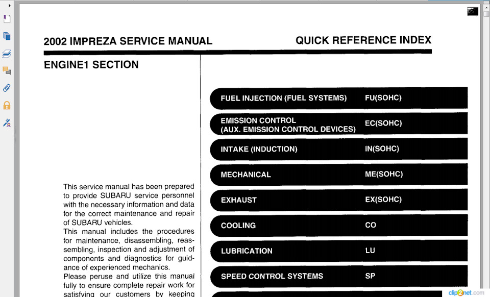
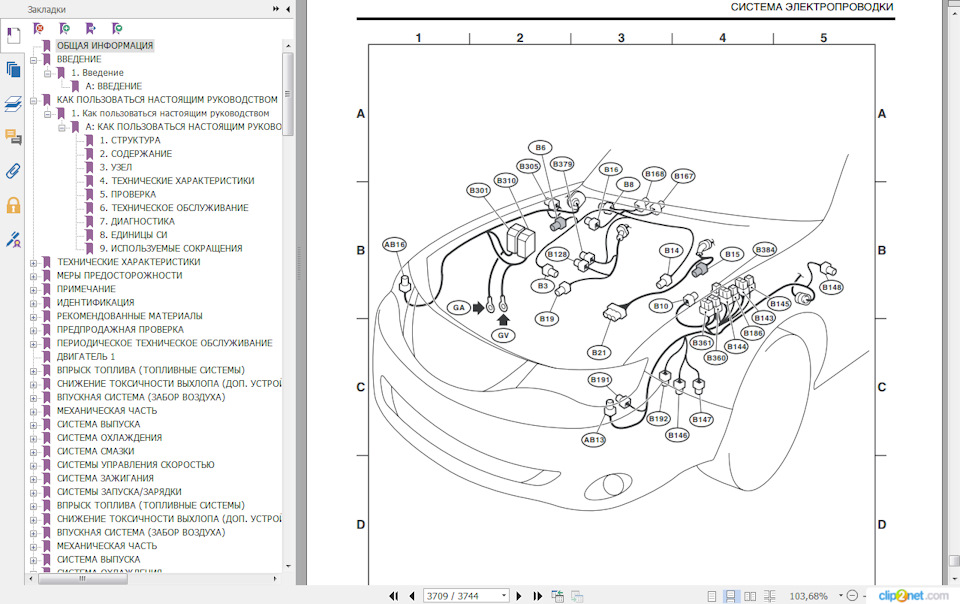
8 ноября 2018
8
Ранее Не официальные названия кузовов Subaru Impreza
Разместить рекламу
Реклама
Войдите или зарегистрируйтесь, чтобы писать комментарии, задавать вопросы и участвовать в обсуждении.
Войти
Зарегистрироваться
2002 IMPREZA SERVICE MANUAL
QUICK REFERENCE INDEX
NEW CAR INFORMATION SECTION
FOREWORD
This manual has been prepared to provide information
for the construction, operation and other technical de-
tails of SUBARU vehicles.
Read this manual thoroughly and make the most of it
to give better service to your customers and improve
your knowledge of vehicle maintenance.
All information, illustration and specifications con-
tained in this manual are based on the latest product
information available at the time of publication ap-
proval.
FUJI
HEAVY
INDUSTRIES LTD.
W1830BE

2002 IMPREZA SERVICE MANUAL QUICK REFERENCE INDEX
NEW CAR INFORMATION SECTION
FOREWORD
This manual has been prepared to provide information for the construction, operation and other technical de- tails of SUBARU vehicles. Read this manual thoroughly and make the most of it to give better service to your customers and improve your knowledge of vehicle maintenance.
All information, illustration and specifications con- tained in this manual are based on the latest product information available at the time of publication ap- proval.
FUJI HEAVY INDUSTRIES LTD.
W1830BE


FOREWORD QUICK REFERENCE INDEX
I) * — D
* e


FOREWORD QUICK REFERENCE INDEX


FOREWORD
All right reserved. This book may not be reproduced or copied, in whole or in part, without the written permis- sion of FUJI HEAVY INDUSTRIES LTD., TOKYO JA- PAN
SUBARU, @ and @ are trademarks of FUJI HEAVY INDUSTRIES LTD.
0 Copyright 2001 FUJI HEAVY INDUSTRIES LTD.


a SPECIFICATIONS SPC Page
1. lmpreza . . . . . . . . . . . . . . . . . . . . . . . . . . . . . . . . . . . . . . . . . . . . . . . . . . . . . . . . . . . . . . . . . . . . . . . . . . . . . . . . 2

IMPREZA Specifications
Model
Overall length mm (in)
Overall width mm (in)
Overall height (at CW) mm (in)
1. lmpreza
Sedan Wagon OUTBACK
4,405 (1 73.4)
1,730 (68.1) 1,695 (66.7) 1,710 (67.3) 1,440 (56.7) 1,465 (57.7), 1,475 (58.1),
1,485 (58.5)*2 1,495 (58.9)*2
A: DIMENSIONS
Compartment Length mm (in)
Width mm (in)
Height mm (in)
Wheelbase mm (in)
Tread Front mm (in)
Rear mm (in)
I I
1,890 (74.4) 1,845 (72.6) 1,380 (54.3)
1,180 (46.5) 1,200 (47.2), 1,200 (47.2), 1 ,I 50 (45.3)*3
2,525 (99.4)
1,485 (58.5) 1,465 (57.7) 1,460 (57.5)
1 ,I 50 (45.3)*3
1,475 (58.1), 1,455 (57.3) 1,455 (57.3) 1,480 (58.3)*1
Minimum road clearance mm (in) 150 (5.9), 150 (5.9), 160 (6.3) 155 (6.1)*1 155 (6.1)*1
B: ENGINE Model
Engine type
Turbo 2.0 L 2.5 L
Horizontally opposed, liquid cooled, 4-cylinder, 4-stroke gasoline engine
I Valve arrangement I Overhead camshaft type
Bore x Stroke mm (in)
Displacement cm3 (cu in)
Compression ratio
Idle speed at ParWNeutral rPm
Firing order
position (NC OFF)
Maximum output kW (HP)/rpm
Maximum torque N.m (kgf-m, ft-lb)/rpm
~~
92 x 75 (3.62 x 2.95)
99.5 x 79.0 (3.91 7 x 3.1 10)
1,994 (1 21.67) 2,457 (149.9)
8.0 10.0
1 — 3 — 2 — 4
650 (MT) 750 700 (AT)
123 (1 65)/5,600
226 (23.0, 166)/4,000
160 (21 5)/6,000
294 (30.0, 21 7)/4,000
SPC-2

IMPREZA Specifications
Model Turbo 2.0 L
12″ k 10″/750 Ignition timing at idling speed
Spark plug NGK: PFRGG
BTDC/rpm
Generator 12V — 75A
MT: 12V — 48AH (55D23L) AT: 12V — 52AH (65D23L)
Battery Type
Reserve capacity min MT: 99 AT: 111
Cold cranking amp MT: 356 amperes AT: 420
2.5 L
MT: 10″ f 1 0°/650 AT: 10″ f 1 O»I700
CHAMPION: RC1 OYC4 (standard) NGK: BKR5E-11 NGK: BKR6E-11
12V — 90A
M I 12V — 48AH (55D23L) AT: 12V — 52AH (75D23L)
MT: 99 AT: 118
MT: 356 AT: 520
I Model Turbo 2.0 L
Transmission type 5MTk1 4ATk2
Clutch type DSPD TCC
Gear ratio I 1st 3.454 2.785
I I I
2nd 1.947 1.545 I 4th
5th
I I I I I I
5MT*l:5 forward speeds with synchromesh and 1 -reverse 4AT*2:Electronically controlled fully-automatic, 4-forward speeds and 1 -reverse DSPD:Dry Single Plate Diaphragm TCC:Torque Converter Clutch
0.972 0.694
0.738 —
SPC-3
Reduction 1 st reduction gear (Front drive)
Final
J
Reverse 3.333 2.272
Type of gear — Helical
Gear ratio — 1.000
Tvpe of gear Hypoid Hypoid
Reduction gear (Rear drive)
— Transfer Type of gear Helical
1.100 reduction Gear ratio Final Tvpe of gear Hypoid Hypoid
—

IMPREZA
Model
Transmission type
Clutch type
Specifications
2.5 L
RS OTHERS
5MTA1 4ATA2 5MTA1 4ATA2
DSPD TCC DSPD TCC
Reduction gear (Front drive)
Reduction gear (Rear drive)
1 st I 3.454 I 3.027 I 3.454 I 2.785 I
1 st reduction
Final reduction
Transfer reduction
Final reduction
2nd I 2.062 I 1.619 I 2.062 I 1.545 I
Type of gear
Gear ratio
Type of gear
Gear ratio
Type of gear
Gear ratio
3rd I 1.448 I 1.000 I 1.448 I 1 .ooo I
~~ ~
Hypoid Hypoid Hypoid Hypoid
4.111 4.444 3.900 4.111 Helical — Helical — 1 .ooo — 1.000 — Hypoid Hypoid Hypoid Hypoid
4.111 4.444 3.900 4.111
4th I 1.088 I 0.694 1 1.088 1 1.694 I I 5th I 0.780 I — I 0.780 I —
Reverse I 3.333 I 2.272 I 3.333 I 2.272 I I — I — I — I Dual range I —
Typeofgear I — I Helical I — I Helical 1 Gear ratio I — I 1.000 I — I 1.000 1
SPC-4

IMPREZA Specifications
Turns, lock to lock Minimum turning m (ft) Curb to curb circle Wall to wall
E: STEERING
3.2 3 10.2 (33.5) 10.8 (35.4) 11.1 (36.3) 11.7(38.3)
Front
Rear
Macpherson strut type, Independent, Coil spring
Dual link type, Independent, Coil spring
Service brake system
Front
Rear
F: SUSPENSION
I
Dual circuit hydraulic with vacuum suspended power unit
Ventilated disc brake
Disc brake Drum brake, Disc brakekl I
Model TS Rim size 15 x 6JJ Tire size P195/60R15 87H
G: BRAKE
OTHERS
16 x 6 ‘/2 JJ P205/55R16 89V
Type Steel belted radial, Tubeless
I ParkinQ brake I Mechanical on rear brakes I
I Model Turbo 2.0 L
H: TIRE
2.5 L
Fuel tank e (US gal, Imp gal)
Engine oil 1 Upper level e (US qt, Imp qt)
I: CAPACITY
5MT 4AT 5MT 4AT
60 (15.9, 13.2) 60 (1 5.9, 13.2)
4.5 (4.8,4.0) 4.0 (4.2, 3.5)
Lower level (US qt, Imp qt) Transmission gear oil e (US qt, Imp qt) Automatic transmission fluid
AT differential gear oil
AWD rear differential gear oil
Power steering fluid
Engine coolant
(US qt, Imp qt)
e (US qt, Imp qt)
e (US qt, Imp qt)
e (US qt, Imp qt)
e (US qt, Imp qt)
I I I
3.5 (3.7,3.1) 3.0 (3.2, 2.6)
3.5 (3.7, 3.1) — 3.5 (3.7,3.1) — — 9.3 (9.8,8.2) — 9.5 (10.0,8.4)
— 1.2 (1.3, 1 .l) — 1.2(1.3, 1.1)
0.8 (0.8,0.6)
0.7 (0.7, 0.6)
7.7 (8.1, 6.8) I 7.6(8.0,6.7) I 7.0(7.4,6.2) I 6.9 (7.3,6.1)
a
SPC-5

Curb weight (C.W.) I Front kgf (Ib) 5MTA1 4ATA 1 5MT 4AT
826 (1,820) 851 (1,875) 778 (1,715) 803 (1,770)
4ATkl
851 (1,875)
5MTk2 4ATA2 5MT 4AT
773 796 783 805 (1,705) (1,755) (1,725) (1,775)
IMPREZA Specifications
J: WEIGHT 1. U.S. SPEC. VEHICLE Sedan Model I AWD I
I Turbo 2.0 L I 2.5 L I I WRX I RS I
I Rear kgf (Ib) I 569 (1,255) I 569 (1,255) I 567 (1,250) I 567 (1,250) I I Total kgf (Ib) I 1,395 (3,075) 1 1,420 (3,130) I 1,345 (2,965) I 1,370 (3,020) I Front kgf (Ib) 1 998 (2,200) I 998 (2,200) I 939 (2,070) I 939 (2,070) I Gross vehicle weight
(G. V. W.) Rear kgf (Ib) I 857 (1,890) I 857 (1,890) I 857 (1,890) I 857 (1,890) I Total kgf (Ib) I 1,837 (4,050) I 1,837 (4,050) I 1,778 (3,920) I 1,778 (3,920) I
A1 :Excl,udesweight of side air bag.
Wagon Model I AWD
I Turbo 2.0 L I 2.5 L I WRX I TS I OUTBACK
1 5MTA1 Curb weight (C.W.) Front
Rear kgf (Ib) I (1,335) 606
605 603 606 60 1 603 (1,335) 1 (1,330) 1 (1,335) I (1,325) 1 (1,330)
Total kgf (Ib) I (3,155)
1,458 1,376 1,402 1,384 1,408 (3,210) I (3,035) 1 (3,090) I (3,050) 1 (3,105)
Gross vehicle weight (G.V. W.)
998 939 939 939 939 (2,200) 1 (2,070) 1 (2,070) 1 (2,070) 1 (2,070) (2,200)
Front
Rear 925 925 925 925 925 (2,040) 1 (2,040) I (2,040) [ (2,040) I (2,040)
Total 1,901 1,833 1,833 1,833 1,033 (4,109) 1 (4,040) 1 (4,040) I (4,040) I (4,040)
A1 :Excludes weight of side air bag. A2:Excludes weight of ABS, cruise control.
SPC-6

IMPREZA Specifications
Model AWD Turbo 2.0 L 2.5 L
2. CANADA SPEC. VEHICLE
I I
WRX RS I 5MT 4AT 5MT 4AT
Curb weight (C.W.) I Front kgf (Ib) 826 (1,820) 851 (1,875) 778 (1,715) 803 (1,770)
I I I I I
Gross vehicle weight 1 Front kgf (Ib) I 998 (2,200) I 998 (2,200) I 939 (2,070) I 939 (2,070)
Rear kgf (Ib)
Total kgf (Ib)
(G.V. W.)
573 (1,265) 573 (1,265) 567 (1,250) 567 (1,250)
1,399 (3,085) 1,424 (3,140) 1,345 (2,965) 1,370 (3,020)
Rear kgf (Ib) Total kgf (Ib)
857 (1,890) 857 (1,890) 857 (1,890) 857 (1,890)
1,837 (4,050) 1,837 (4,050) 1,778 (3,920) 1,778 (3,920)
SPC-7
Rear kgf (Ib)
Total kgf (Ib)
925 925 925 925 925 925 (2,040) (2,040) (2,040) (2,040) (2,040) (2,040) 1,901 1,901 1,833 1,833 1,833 1,833
(4,190) (4,190) (4,040) (4,040) (4,040) (4,040)

IMPREZA SDecifications
MEMO
SPC-8

FU WHC) FUEL INJECTION (FUEL SYSTEM)
1. General . . . . . . . . . . . . . . . . . . . . . . . . . . . . . . . . . . . . . . . . . . . . . . . . . . . . . . . . . . . . . . . . . . . . . . . . . . . . . . . . 2 2. Air Line . . . . . . . . . . . . . . . . . . . . . . . . . . . . . . . . . . . . . . . . . . . . . . . . . . . . . . . . . . . . . . . . . . . . . . . . . . . . . . . . 3 Page I . .
3. Fuel Line . . . . . . . . . . . . . . . . . . . . . . . . . . . . . . . . . . . .
4. Sensors and Switches . . . . . . . . . . . . . . . . . . . . . . . . . . . . . . . . . . . . . . . . . . . . . . . . . . . . . . . . . . . 16
6. On-board Diagnosis System . . . . . . . . . . . . . . . . . . . . . . . . . . . . . . . . . . . . . . . . . . . . . . . . . . . . . . . 34 5. Control System . . . . . . . . . . . . . . . . . . . . . . . . . . . . . . . . . . . . . . . . . . . . . . . . . . . 26

GENERAL Fuel Injection (Fuel System)
1. General 0 The Multipoint Fuel Injection (MFI) system supplies optimum air-fuel mixture under every engine operating condition through the use of the latest electronic control technology. This system pressurizes the fuel to a constant pressure and injects it into each intake air port in the cylinder head. The injection quantity of fuel is controlled by an intermittent injection system where an electro-magnetic injection valve or injector opens for a short period that is precisely con- trolled depending on the quantity of air appropriate for each condition of operation. In actual con- trol, an optimum fuel injection quantity is achieved by varying the duration of an electric pulse ap- plied to the injector. This way of control enables simple, yet highly precise metering of the fuel. 0 The engine control module (ECM) that controls the fuel injection system corrects the fuel injec- tion amount depending on the vehicle speed, throttle opening, coolant temperature and other ve- hicle-operation-related information. The ECM receives the information in the form of electric sig- nals from the corresponding sensors and switches. The MFI system also has the following features: 0 Reduced exhaust emissions 0 Reduced fuel consumption 0 Increased engine output 0 Quick response to accelerator and brake pedal operation
Superior startability and warm-up performance in cold weather due to corrective controls made according to coolant and intake air temperatures
FU-2

AIR LINE Fuel Injection (Fuel System)
2. Air Line A: GENERAL The air filtered by the air cleaner enters the throttle body where it is regulated in the volume by the throttle valve and then enters the intake manifold. It is then distributed to each cylinder where the air is mixed with fuel injected by the injector. During idling operation, air flows into the cylinder through the idle air control solenoid valve, bypassing the throttle valve. This enables controlling the engine idling speed properly.
B: INTAKE MANIFOLD PRESSURE AND AIR TEMPERATURE SENSORS The intake manifold pressure sensor and the intake air temperature sensor are integrated into a single unit. The unit is mounted on the intake manifold and measures the absolute air pressure in the intake manifold as well as the temperature of the intake air. The measured pressure and temperature are converted into electrical signals and sent to the ECM. The ECM uses these signals to control injection and ignition timing as well as the fuel injec- tion amount.
H2H2825B
(1) Pressure sensor
(2) Intake air temperature sensor
FU-3

I
Fuel Injection (Fuel System) AIR LINE
C: ATMOSPHERIC PRESSURE SENSOR The atmospheric pressure sensor converts pressure values into electric signals, and sends the signals to the ECM.
NF0007
(1) Sensor unit
(2) O-ring
(3) Case
(4) Pipe
(5) Through capacity
(6) Terminal
(7) Inner lead
(8) Resin
(9) Metal lid
D: THROTTLE BODY In response to operation of the accelerator pedal, the throttle valve in the throttle body opens/
closes to regulate the volume of the air drawn into the combustion chamber. 0 During idling, the throttle valve is almost fully closed and the volume of air passing through the throttle body is less than that passing through the idle air control solenoid valve. 0 More than half of the air necessary for idling is supplied to the intake manifold via the idle air control solenoid valve which controls properly the engine idling speed, so the idling speed needs not be adjusted.
FU-4

a AIR LINE
Fuel Injection (Fuel System)
E: THROTTLE POSITION SENSOR 0 The throttle position sensor is mounted in the throttle body and linked to the throttle valve. 0 The throttle position sensor sends the ECM voltage signal corresponding to the opening of the throttle valve. When the sensor’s output voltage exceeds a predetermined level, the ECM inter- prets it as complete closure of the throttle valve. When the output voltage is at another predeter- mined level, the ECM recognizes that the throttle valve is at a wide open position. Since the output characteristics of the sensor change over years, the ECM is provided with a learning function to be able to interpret signals into throttle valve angles always correctly.
I
B2H2004B
(1) Lever
(2) Terminal
FU-5

AIR LINE Fuel Injection (Fuel System)
F: IDLE AIR CONTROL SOLENOID VALVE 0 The idle air control solenoid valve is located in the throttle body and regulates the amount of in- take air that flows bypassing the throttle valve into the intake manifold during engine idling. It is activated by a signal from the ECM in order to maintain the engine idling speed at a target speed. 0 The idle air control solenoid valve is a stepping motor type solenoid-actuated valve which con- sists of coils, a shaft, a permanent magnet, a spring and a housing. The housing is an integral part of the throttle body.
The stepping motor consists of two paired coils, the coils of each pair being arranged face to face with a shaft in between. 0 The shaft has a screw at the end around which the permanent magnets are arranged. 0 As current flows in the form of pulses through the paired coils sequentially while alternating the polarity, the N and S poles of the permanent magnets around the shaft are repelled by the same poles of the magnetism generated by the coils. This causes a nut externally fixed to the magnets and internally engaging with the screw of the shaft to turn. The shaft then goes upward or downward.
This upward and downward motions of the shaft open or close the valve port, adjusting the amount of bypass air.
B 2 H 2 0 0 5 B
(1 ) Connector
(2) Permanent magnet
(3) Shaft
(4) Coil
(5) Spring
FU-6

m AIR LINE
I Fuel Injection (Fuel System)
G: AIR ASSIST INJECTOR SOLENOID VALVE The air assist injector solenoid valve is located in the piping between the throttle body and the in- jector and secured to the intake manifold. This solenoid valve is opened or closed by the signals from the ECM, adjusting the flow rate of air supplied to the injector.
82H34478
(1) Valve sheet
(2) Solenoid
(3) Plunger and valve
(4) Spring
(5) Connector
A: From idle air control solenoid valve
B: To injector
FU-7

FUEL LINE Fuel Injection (Fuel System)
3. Fuel Line A: GENERAL 0 The fuel pressurized by the fuel tank inside pump is delivered to each fuel injector by way of the fuel pipe and fuel filter. Fuel injection pressure is regulated to an optimum level by the pressure regulator. 0 Each injector injects fuel into the intake port of the corresponding cylinder where the fuel is mixed with air. The mixture then enters the cylinder. Fuel injection amount and timing are regulated by the ECM.
(1) Fuel gauge
(2) Combination meter
(3) Fuel injector
(4) Pressure regulator
(5) Throttle body
(6) Intake manifold
(7) Fuel filter
(8) Purge control solenoid valve
(9) Drain valve
Canister (1 9) Fuel tank
ECM (20) Vent valve
Pressure control solenoid valve (21) Shut-off valve
Fuel tank pressure sensor (22) Drain filter
Fuel temperature sensor (23) Fuel sub level sensor
Fuel level sensor
Fuel pump
Jet pump
Fuel cut valve
(a) Fuel line
(b) Evaporation line
NF0477
FU-8

FUEL LINE Fuel lniection (Fuel System\
B: PRESSURE REGULATOR The pressure regulator is installed at the injector end of the fuel supply line. It has a fuel chamber and spring chamber separated by a diaphragm. Fuel chamber is connected to the fuel supply line and the spring chamber is connected to the intake manifold. Fuel chamber also has a relief valve connected to the fuel return line through which fuel returns to the fuel tank. When the intake manifold vacuum increases, the diaphragm is pulled and the relief valve opens to decrease the fuel supply line pressure (or fuel injection pressure). When the intake manifold vacuum decreases, the diaphragm is pushed by the spring to increase the fuel supply line pressure. Thus, the differ- ence between the fuel injection pressure and the intake manifold vacuum is kept at a constant level of 299.1 kPa (3.05 kgf/cm2, 43.4 psi) to precisely control the amount of injected fuel.
A
(1) Relief valve
(2) Diaphragm
S2H0623C
A: To intake manifold
B: Fuel IN C: FuelOUT
FU-9

FUEL LINE I
Fuel Injection (Fuel System)
C: FUEL INJECTORS 0 The MFI system employs top feed type fuel injectors with an air assist feature. 0 Each injector is installed in the fuel pipe in such a way that the injector is cooled by fuel. 0 The features of this type of fuel injector are as follows: 1) High heat resistance 2) Low driving noise 3) Easy to service 4) Small size 0 The injector injects fuel according to the valve open signal from the ECM. The needle valve is lifted by the solenoid which is energized on arrival of the valve open signal. 0 Since the injector’s nozzle hole area, the lift of valve and the fuel pressure are kept constant, the amount of fuel injected is controlled only by varying the duration of the valve open signal from the ECM. 0 Fuel atomization is enhanced using assist air supplied from the idle air control solenoid valve passing through the passage formed in the intake manifold at the area in which each injector is installed. This contributes not only to higher combustion efficiency and higher output but also to cleaner exhaust emissions.
S2H1943A
(1) Filter
(2) O-ring
(3) Plunger
(4) Seal
(5) O-ring
(6) Connector
FU-10

FUEL LINE Fuel Injection (Fuel System)
D: FUEL TANK The fuel tank utilizes a two-compartment design to ensure sufficient capacity without interfering with the rear differential. It is provided with a suction jet pump (included in the fuel pump and fuel level sensor assembly) which transfers fuel from one compartment to the other. Each compartment has an individual fuel level sensor. The fuel tank is located under the rear seat and secured with hold-down bands.
(1 ) Fuel pump and fuel level sensor assembly (2) Fuel sub level sensor
(3) Band
(4) Cushion
(5) Steel
NF0473
FU-11

FUEL LINE Fuel Injection (Fuel System)
E: FUEL PUMP AND FUEL LEVEL SENSOR ASSEMBLY 1. FUELPUMP The fuel pump consists of a motor, impeller, pump casing, pump cover, check valve and filter. It is located in the fuel tank and combined with the fuel level sensor into a single unit. The operation of this impeller type pump is very quiet.
(1) Fuel pump
(2) Fuel level sensor
(3) Jet pump
(4) Mesh filter
(5) Fuel temperature sensor
(6) Impeller
(7) Check valve
(8) Pump casing
NF0474
(9) Motor armature
(IO) Suction
(1 1 ) Discharge
(1 2) Vane groove
A: From engine (return line)
B: From sub tank
C: To engine (delivery line)
0 When the ignition switch is turned ON, fuel pump relay is activated. Then the motor operates to rotate the impeller. 0 As the impeller rotates, fuel in a vane groove of the impeller flows along the fuel passage into the next vane groove by centrifugal force. When fuel flows from one groove to the next, a pressure difference occurs due to friction. This creates a pumping effect. 0 The fuel pushed up by rotation of the impeller then passes through the clearance between the armature and the magnet of the motor and is discharged through the check valve. 0 When the fuel discharge pressure reaches the specified level, the relief valve opens and excess fuel is released into the fuel tank. In this manner, the relief valve prevents an abnormal increase in fuel pressure. 0 When the engine and the fuel pump stop, spring force acts on the check valve to close the dis- charge port, so that the fuel pressure in the fuel delivery line is retained.
FU-12

FUEL LINE Fuel Injection (Fuel System)
2. FUEL LEVEL SENSOR The fuel level sensor forms part of the fuel pump and located in the fuel tank. The sensor outputs an electric resistance signal that varies with movement of its float to indicate the level of the fuel remaining in the tank.
NF0327
(1) Fuel level sensor
(2) Float
FU-13

FUEL LINE Fuel Injection (Fuel System)
3. JETPUMP 0 The jet pump utilizes the velocity of fuel returning from the engine to produce negative pressure in it. 0 Using the pumping effect produced by the negative pressure, the jet pump transfers fuel from the sub-compartment to the main compartment of the fuel tank. 0 When the return line nozzle is clogged, the fuel sent back through the return line flows back into the fuel tank via the relief valve.
A A
+ t
(1) Relief valve
(2) Nozzle
A: Return line
FU-14

m FUEL LINE
Fuel lniection (Fuel System)
F: SUB-COMPARTMENT FUEL LEVEL SENSOR This sensor detects the level of the fuel in the sub-compartment (the compartment in which the fuel pump is not located) and acts as part of the fuel transfer line when the jet pump is in operation to maintain the fuel in both compartments at the same level.
NF0396
A: Tojet pump (1) Fuel level sensor (2) Float
G: FUEL FILTER The fuel filter located in the engine compartment is a pressure-withstanding, cartridge type. It has a filter element in a metal case. The fuel entering the filter flows from the perimeter of the element to the center of the filter and goes out from there.
NF0018
FU-15

SENSORS AND SWITCHES Fuel lniection (Fuel Svstem)
4. Sensors and Switches A: FRONT OXYGEN (NF) SENSOR 0 The front oxygen sensor uses zirconium oxide (Zr02) which is a solid electrolyte, at portions ex- posed to exhaust gas. 0 The zirconium oxide has the property of generating electromotive force when its both sides are exposed to oxygen ions of different concentration and the magnitude of this electromotive force depends on how much the difference is. 0 The front oxygen sensor detects the amount of oxygen in exhaust gases by making use of this property of the zirconium oxide material. 0 The zirconium oxide material is formed into a closed end tube and its external surface is ex- posed to exhaust gases with smaller oxygen ion concentration, whereas its internal surface is ex- posed to atmospheric air. The external surface has a porous platinum coating. The sensor housing is grounded to the exhaust pipe and the inside is connected to the ECM through the harness to be able to use the current output from the sensor. 0 The sensor incorporates a ceramic heater to improve its performance at low temperatures.
Y 1- (3)
I
(4)
(1) Sensor element
(2) Sensor housing
(3) Protection tube
(4) Gasket
S2H1791B
FU-16

SENSORS AND SWITCHES Fuel Injection (Fuel System)
0 When rich air-fuel mixture is burnt in the cylinder, the oxygen in the exhaust gases is almost com- pletely used in the catalytic reaction by the platinum coating on the external surface of the zirconia tube. This results in a very large difference in the oxygen ion concentration between the inside and outside of the tube, and the electromotive force generated is large. 0 When a lean air-fuel mixture is burnt in the cylinder, relatively large amount of oxygen remains in the exhaust gases even after the catalytic action, and this results in a small difference in the oxy- gen ion concentration between the tube’s internal and external surfaces. The electromotive force in this case is very small. 0 The difference in oxygen concentration changes drastically in the vicinity of the stoichiometric air-fuel ratio, and hence the change in the electromotive force is also large. By using this informa- tion, the ECM can determine the air-fuel ratio of the supplied mixture easily. The front oxygen sen- sor does not generate much electromotive force when the temperature is low. The output charac- teristics of the sensor stabilize at a temperature of approximately 700°C (1,292″F).
Atmospheric air /- Zro2
Lean — Air-fuel ratio — Rich
Ceramic heater -.J
NF0331
FU-17

SENSORS AND SWITCHES Fuel lniection (Fuel System)
B: REAR OXYGEN SENSOR 0 The rear oxygen sensor is used to sense oxygen concentration in the exhaust gas. If the air-fuel ratio is leaner than the stoichiometric ratio in the mixture (i.e., excessive amount of air), the exhaust gas contains more oxygen. To the contrary, if the fuel ratio is richer than the stoichiometric ratio, the exhaust gas contains almost no oxygen. 0 Detecting the oxygen concentration in exhaust gas using the oxygen sensor makes it possible to determine whether the air-fuel ratio is leaner or richer than the stoichiometry. 0 The rear oxygen sensor has azirconia tube (ceramic) which generates voltage if there is a differ- ence in oxygen ion concentration between the inside and outside of the tube. Platinum is coated on the inside and outside of the zirconia tube as a catalysis and electrode material. The sensor housing is grounded to the exhaust pipe and the inside is connected to the ECM through the har- ness. 0 A ceramic heater is employed to improve performance at low temperatures.
/ \ \ \
(5) (4)
(1) Protection tube
(2) Ceramic heater
(3) Zirconia tube
B2H381 OC
(4) Gasket
(5) Sensor housing
(6) Harness
FU-18

SENSORS AND SWITCHES Fuel lniection (Fuel System)
0 s s o C L
.- p z — s E % g z % 2 5s — x o w o >
Small
0 When rich air-fuel mixture is burnt in the cylinder, the oxygen in the exhaust gases is almost com- pletely used in the catalytic reaction by the platinum coating on the external surface of the zirconia tube. This results in a very large difference in the oxygen ion concentration between the inside and outside of the tube, and the electromotive force generated is large. 0 When a lean air-fuel mixture is burnt in the cylinder, relatively large amount of oxygen remains in the exhaust gases even after the catalytic action, and this results in a small difference in the oxy- gen ion concentration between the tube’s internal and external surfaces. The electromotive force in this case is very small.
as rich Comparison t voltage — — ~ —
4 To be judged
C: ENGINE COOLANT TEMPERATURE SENSOR The engine coolant temperature sensor is located on the engine coolant pipe. The sensor uses a thermistor whose resistance changes inversely with temperature. Resistance signals as engine coolant temperature information are transmitted to the ECM to make fuel injection, ignition timing, purge control solenoid valve and other controls.
A Temp. «C ( O F ) 1 -20 0 20 40 60 80 (-4) (32) (68) (104)(140)(176)
(1) Connector
S2H1113B
(2) Thermistor element
FU-19

SENSORS AND SWITCHES Fuel Injection (Fuel System)
D: CRANKSHAFT POSITION SENSOR The crankshaft position sensor is installed on the oil pump which is located in the front center
portion of the cylinder block. The sensor generates a pulse when one of the teeth on the perimeter of the crankshaft sprocket (rotating together with the crankshaft) passes in front of it. The ECM de- termines the crankshaft angular position by counting the number of pulses.
The crankshaft position sensor is a molded type which consists of a magnet, core, coil, terminals and other components as illustrated below.
(1) Terminal
(2) Yoke core (3) Magnet
NF0024
(4) Coil
(5) Core
(6) Cover
FU-20

SENSORS AND SWITCHES Fuel Injection (Fuel System)
0 As the crankshaft rotates, each tooth aligns with the crankshaft position sensor. At that time, the magnetic flux in the sensor’s coil changes since the air gap between the sensor pickup and the sprocket changes. This change in magnetic flux induces a voltage pulse in the sensor and the pulse is transmitted to the ECM.
NF0398
(1) Crankshaft position sensor
(2) Crankshaft sprocket
(3) Crankshaft half rotation
FU-21

SENSORS AND SWITCHES Fuel Injection (Fuel System)
E: CAMSHAFT POSITION SENSOR 0 The camshaft position sensor is located on the left-hand camshaft support. It detects the com- bustion cylinder at any given moment. 0 The sensor generates a pulse when one of the bosses on the back of the left-hand camshaft drive sprocket passes in front of the sensor. The ECM determines the camshaft angular position by counting the number of pulses. Internal construction and the basic operating principle of the camshaft position sensor are similar to those of the crankshaft position sensor. A total of seven bosses are arranged at equally spaced four locations (one each at two locations, two at one location, and three at one location) of the sprocket as shown below.
(1) Boss
(2) Camshaft sprocket
(3) Airgap
S2H1813A
(4) Camshaft position sensor
(5) Boss
(6) Camshaft one rotation (Crankshaft two rotations)
FU-22

SENSORS AND SWITCHES I
Fuel Injection (Fuel System)
F: KNOCK SENSOR 0 The knock sensor is installed on the cylinder block, and senses knocking that occurs in the en- gine. 0 The sensor is a piezo-electric type which converts vibration resulting from knocking into electric signals. 0 In addition to a piezo-electric element, the sensor has a weight and case as its components. If knocking occurs in the engine, the weight in the case moves causing the piezo-electric element to generate a voltage. 0 The knock sensor harness is connected to the bulkhead harness.
(2)
(1) Nut
(2) Weight
(3) Resistor
(4) Housing
(5) Piezo-electric element
B2H1998B
A: To knock sensor harness
FU-23

SENSORS AND SWITCHES Fuel lniection (Fuel System)
G: VEHICLE SPEED SENSOR 1. MT VEHICLES 0 The vehicle speed sensor is mounted on the transmission. 0 The vehicle speed sensor generates a 4-pulse signal for every rotation of the front differential and send it to the ECM and the combination meter.
B2H2458C
(1) Combination meter
(2) ECM
(3) Vehicle speed sensor
(4) Transmission
FU-24

SENSORS AND SWITCHES Fuel Injection (Fuel System)
2. AT VEHICLES 0 The vehicle speed sensor is mounted on the transmission. 0 The vehicle speed sensor generates a 16-pulse signal for every rotation of the front differential and send it to the transmission control module (TCM). The signal sent to the TCM is converted there into a 4-pulse signal, and then sent to the ECM and the combination meter.
62H24596
(1) Combination meter (2) ECM (3) TCM
(4) Vehicle speed sensor
(5) Transmission
FU-25

CONTROL SYSTEM Fuel lniection (Fuel System)
5. Control System A: GENERAL The ECM receives signals from various sensors, switches, and other control modules. Using these signals, it determines the engine operating conditions and if necessary, emits signals to one or more systems to control them for optimum operation. Major control items of the ECM are as follow: 0 Fuel injection control 0 Ignition system control 0 Idle air control 0 Fuel pump control 0 Canister purge controt*1 0 Radiator fan control** 0 On-board diagnosis function
*I : Canister purge control is described under “EC (SOHC) — Emission Control (Aux. Emission Con- trol Devices) Evaporative Emission Control System”. *2: Radiator fan control is described under “CO — Cooling”.
FU-26

CONTROL SYSTEM Fuel Injection (Fuel System)
B: INPUT AND OUTPUT SIGNALS ~ ~
Function
Detects the temperature of intake and amount of intake air (Mea- sures the absolute pressure). Detects the amount of intake air (Measure the atmospheric pres- sure).
Detects the throttle valve position.
Detects the density of oxygen in exhaust gases at the upstream of the front catalytic converter.
Detects the density of oxygen in exhaust gases at the downstream of the front catalytic converter.
Detects the crankshaft angular position.
Detects the combustion cylinder.
Detects the engine coolant temperature.
Detects engine knocking.
Detects the vehicle speed.
Detects operation of the ignition switch.
Detects the condition of engine cranking.
Detects that the gear is in neutral.
Detects shift positions.
Controls engine torque.
Detects abnormality in the heater circuit of the front and rear oxygen sensors.
Detects the self-diagnostics of the TCM.
Detects ON-OFF operation of the A/C switch.
Detects the temperature of the fuel in the fuel tank.
Detects the level of the fuel in the fuel tank.
Detects the evaporation gas pressure in the fuel tank.
Detects ON-OFF operation of the small light switch.
Detects ON-OFF operation of the blower fan switch.
Detects ON-OFF operation of the rear defogger switch.
Activates an injector.
Turns the primary ignition current ON or OFF.
Turns the fuel pump relay ON or OFF.
Turns the N C control relay ON or OFF.
Turns the radiator fan control relay ON or OFF.
Adjusts the amount of air flowing through the bypass line in the throttle body.
Indicates existence of abnormality.
Controls purge of evaporative gas absorbed by the canister.
Control ON/OFF of the main power supply relay.
Controls evaporation gas pressure in the fuel tank.
Closes the evaporation line between the fuel tank and canister to detect leakage of evaporation gases.
Signal Unit ~~ ~
Intake air temperature and pressure sensor
Atmospheric pressure sensor
Throttle position sensor
Front oxygen (NF) sensor
Rear oxygen sensor
Crankshaft position sensor
Camshaft position sensor
Engine coolant temperature sensor
Knock sensor
Vehicle speed sensor
Ignition switch nput signals
Starter switch
Neutral position switch (MT)
ParWNeutral position switch (AT)
Torque control signal (AT)
Heater circuit of front and rear oxy- gen sensor
Diagnostics of TCM (AT)
N C switch
Fuel temperature sensor
Fuel level sensor
Fuel tank pressure sensor
Small light switch
Blower fan switch
Rear defogger switch ~~
3utput signals
Fuel Injector
Ignition signal ~~
Fuel pump relay ~~
N C control relay
Radiator fan control relay
Idle air control solenoid valve
Malfunction indicator lamp
Purge control solenoid valve
Power supply
Pressure control solenoid valve
Drain valve
FU-27

CONTROL SYSTEM Fuel Injection (Fuel System)
C: FUEL INJECTION CONTROL 0 The ECM receives signals from various sensors and based on them, it determines the amount of fuel injected and the fuel injection timing. It performs the sequential fuel injection control over the entire engine operating range except during start-up of the engine. 0 The amount of fuel injected depends upon the length of time the injector stays open. The fuel injection duration is determined according to varying operating condition of the engine. For the purpose of achieving highly responsive and accurate fuel injection duration control, the ECM per- forms a new feedback control that incorporates a learning feature as detailed later. 0 The sequential fuel injection control is performed such that fuel is injected accurately at the time when the maximum air intake efficiency can be achieved for each cylinder (i.e., fuel injection is completed just before the intake valve begins to open).
1. FUEL INJECTION DURATION Fuel injection duration is basically determined as indicated below: 0 During engine start-up: The duration defined below is used.
0 Duration of fuel injection during engine start-up ….. Determined according to the engine cool- ant temperature detected by the engine coolant temperature sensor.
0 During normal operation: The duration is determined as follows:
Basic duration of fuel injection x Correction factors + Voltage correction time 0 Basic duration of fuel injection ….. The basic length of time fuel is injected. This is determined by two factors -the amount of intake air detected by the manifold pressure sensor and the en- gine speed monitored by the crankshaft position sensor. 0 Correction factors ….. See the next section. 0 Voltage correction time ….. This is added to compensate for the time lag before operation of injector that results from variation in the battery voltage.
FU-28

CONTROL SYSTEM Fuel lniection (Fuel System)
2. CORRECTION FACTORS The following factors are used to correct the basic duration of fuel injection in order to make the air-fuel ratio meet the requirements of varying engine operating conditions: 0 Air-fuel ratio feedback factor: This factor is used to correct the basic duration of fuel injection in relation to the actual engine speed. (See the next section for more detail.) 0 Start increment factor: This factor is used to increase the fuel injection duration only while the engine is being cranked to improve its startability. 0 Coolant-temperature-dependent increment factor: This factor is used to increase the fuel injection duration depending on engine coolant temperature signals to facilitate cold starting. The lower the coolant temperature, the greater the increment. 0 After-start increment factor:
0 This factor is used to increase the fuel injection duration for a certain period immediately after start of the engine to stabilize engine operation. 0 The increment depends on the coolant temperature at the start of the engine.
0 Wide-open-throttle increment factor: This factor is used to increase the fuel injection duration depending on the relationship between the throttle position sensor signal and manifold pressure sensor signal. 0 Acceleration increment factor: This factor is used to increase the fuel injection duration to compensate for a time lag between air flow measurement and fuel injection control for better engine response to driver’s pedal operation during acceleration.
FU-29

CONTROL SYSTEM Fuel Injection (Fuel System)
3. AIR-FUEL RATIO FEEDBACK FACTOR The ECM creates this factor utilizing the front oxygen sensor signal. When the signal voltage is low, the air-fuel ratio is richer than the stoichiometric ratio. The ECM then makes the fuel injection dura- tion shorter by modifying the factor. When the voltage is high showing that the mixture is lean, the ECM modifies the factor to make the injection duration longer. In this way, the air-fuel ratio is main- tained at a level close to the stoichiometric ratio at which the three-way catalyst acts most effective- ly.
(1 ) Front catalyst
(2) Exhaust gas
(3) Front oxygen (NF) sensor
(4) Fuel injector
(5) Combustion chamber
(6) ECM
B2H0989B
A: Injection duration increment signal
B: Injection duration decrement signal
C: High oxygen density
D: Low oxygen density
E: Lean signal
F: Rich signal
4. LEARNING FEATURE The air-fuel ratio feedback control includes a learning feature which contributes to more accurate and responsive control. 0 In the air-fuel ratio feedback control, the ECM calculates the necessary amount of correction based on data from the oxygen sensor and adds the result to the basic duration (which is stored in the ECM’s memory for each condition defined by the engine speed and various loads.) 0 Without a learning feature, the ECM carries out the above-mentioned process every time. This means that if the amount of necessary correction is large, the air-fuel ratio feedback control be- comes less responsive and less accurate.
The learning feature enables the ECM to store the amount of correction into memory and add it to the basic fuel injection duration to create a new reference fuel injection duration. Using the reference duration as the basic duration for the injection a few times later, the ECM can reduce the amount of correction and thus make its feedback control more accurate and responsive to changes in the air-fuel ratio due to difference in driving condition and sensor/actuator characteris- tics that may result from unit-to-unit variation or aging over time.
FU-30

m CONTROL SYSTEM Fuel lniection (Fuel Svstem)
Crankshaft position sensor b
Camshaft position sensor *
Engine coolant temperature sensor *
Atmospheric pressure sensor e
I 1
D: IGNITION SYSTEM CONTROL 0 The ECM determines operating condition of the engine based on signals from the pressure sen- sor, engine coolant temperature sensor, intake air temperature sensor, crankshaft position sensor and other sources. It then selects the ignition timing most appropriate for the condition thus deter- mined from those stored in its memory and outputs at that timing a primary current OFF signal to the ignitor to initiate ignition. 0 This control uses a quick-to-response learning feature by which the data stored in the ECM memory is processed in comparison with information from various sensors and switches. 0 Thus, the ECM can always perform optimum ignition timing taking into account the output, fuel consumption, exhaust gas, and other factors for every engine operating condition. 0 Ignition control during start-up Engine speed fluctuates during start of the engine, so the ECM cannot control the ignition timing. During that period, the ignition timing is fixed at 10″ BTDC by using the IO» signal from the crank-
I I
Knock sensor b
Throttle position sensor I I * I
Intake air temperature and pressure sensor I ECM
Neutral position switch (MT) I ParWNeutral position switch (AT) I
NC switch 1 * 1 I I
Ignition coil and ignitor assembly
— NF0031
FU-31

CONTROL SYSTEM Fuel Injection (Fuel System)
Ignition control after start of engine Between the 97″ and 65″ crank angle signal, the ECM measures the engine speed, and by using this data it decides the dwell set timing and ignition timing according to the engine condition.
#4 #1 #3 #2 #4
(1) I I I I I
97″ 65″ 10″ 97″ 65″ 10″ 97″ 65″ 10″ 97″ 65″ 10″
(2) I 1 I I I I I I 1 I I I
20″ 27.5″ 501 [ 20″ 20″ 50″ 20″
(6) I #4 i #1 I #3 I #2 I
(1) Cylinder number
(2) Crank angle pulse (BTDC)
(3) Cam angle pulse (ATDC)
(4) Ignition timing at starting
B2H041 OD
(5) Ignition timing at normal condition (6) Burning cylinder
(7) Dwellset
(8) Ignite
FU-32

CONTROL SYSTEM Fuel lniection (Fuel Svstem)
A certain period of time after ignition switch is turned ON
While cranking the engine
While engine is operating
When enaine stoos
E: IDLE AIR CONTROL
ON Operates
ON Operates
ON Operates
OFF Does not operate
0 The ECM activates the idle air control solenoid valve to control the bypass air flowing through the bypass passage in the throttle body depending on signalsfrom the crankshaft position sensor, engine coolant temperature sensor, pressure sensor and A/C switch so that the proper idle speed for each engine load is achieved. 0 The idle air control solenoid valve uses a duty-ratio-controlled solenoid which can continuously vary the opening area of the rotary valve. As the ECM increases the duty ratio, opening of the rotary valve increases so that the bypass air flow increases, and the engine idling speed becomes higher as a result. 0 The bypass air control is necessary for:
0 Increasing idling speed when the air conditioning system and/or electrical loads are turned on. 0 Increasing idling speed during early stage of warm up period. 0 Obtaining dashpot function when the throttle valve is quickly closed. 0 Prevention of engine speed variation during idling.
Intake air temperature and pressure sensor
Crankshaft position sensor
Camshaft position sensor
Throttle position sensor
Engine coolant temperature sensor
ECM
Ignition switch
A/C switch
Neutral position switch (MT) ParWNeutral position switch (AT)
Idle air control solenoid valve
NF0033
F: FUEL PUMP CONTROL Using the signal from the crankshaft position sensor, the ECM controls operation of the fuel pump by turning its relay ON or OFF. To improve safety, the fuel pump is stopped if the engine stalls with the ignition switch ON.
I ~~~~ ~
Ignition switch ON I Fuel pump relay I Fuel pump
FU-33

ON-BOARD DIAGNOSIS SYSTEM Fuel Injection (Fuel System)
6. On-board Diagnosis System A: GENERAL 0 The on-board diagnosis system detects and indicates a fault by generating a code correspond- ing to each fault location. The malfunction indicator lamp (CHECK ENGINE light) on the combina- tion meter indicates occurrence of a fault or abnormality. 0 When the malfunction indicator lamp comes on as a result of detection of a fault by the ECM, the corresponding diagnostic trouble code (DTC) and freeze frame engine condition are stored in the ECM. 0 On the OBD-I1 conformable car, it is necessary to connect the Subaru Select Monitor (SSM) or General Scan Tool (GST) to the data link connector in order to check the DTC. 0 The SSM and GST can read and erase DTCs. They can also read freeze frame data in addition to other pieces of engine data. 0 If there is a failure involving sensors which may affect drive control of the vehicle, the fail-safe function ensures minimum level of driveability.
B: FAIL-SAFE FUNCTION For a sensor or switch which has been judged faulty in the on-board diagnosis, the ECM, if ap- propriate, generates an associated pseudo signal to keep the vehicle operational. (The control becomes degraded .)
FU-34

FUEL INJECTION (FUEL SYSTEM)
1. 2. 3. 4. 5. 6.
Page General 2 Air Line . . . . . . . . . . . . . . . . . . . . . . . . . . . . . . . . . . . . . . . . . . . . . . . . . . . . . . . . . . . . . . . . . . . . . . . . . . . . . . . . 3
. . . . . . . . . . . . . . . . . . . . . . . . . . . . . . . . . . . . . . . . . . . . . . . . . . . . . . . . . . . . . . . . . . . . . . . . . . . . . . . . . .
. . . . . . . . . . . . . . . . . . . . . . . . . . . . . . . . . . . . . . . . . . . . . . . . . . . . . . . . . . . . . . . . 8a Fuel Line . . . . . . . . . . . . ……………….. 16 Sensors and Switches . . . . . . . . . . . . . . . . . . .
Control System . . . . . . . . . . . . . . . . . . . . . . . . . . . . . . . . . . . . . 27 On-board Diagnosis System . . . . . . . . . . . . . . . . . . . . . . . . . 36

GENERAL Fuel lniection (Fuel System)
1. General 0 The Multipoint Fuel Injection (MFI) system supplies optimum air-fuel mixture under every engine operating condition through the use of the latest electronic control technology. This system pressurizes the fuel to a constant pressure and injects it into each intake air port in the cylinder head. The injection quantity of fuel is controlled by an intermittent injection system where an electro-magnetic injection valve or injector opens for a short period that is precisely con- trolled depending on the quantity of air appropriate for each condition of operation. In actual con- trol, an optimum fuel injection quantity is achieved by varying the duration of an electric pulse ap- plied to the injector. This way of control enables simple, yet highly precise metering of the fuel. 0 The engine control module (ECM) that controls the fuel injection system corrects the fuel injec- tion amount depending on the vehicle speed, throttle opening, coolant temperature and other ve- hicle-operation-related information. The ECM receives the information in the form of electric sig- nals from the corresponding sensors and switches. The MFI system also has the following features: 0 Reduced exhaust emissions 0 Reduced fuel consumption 0 Increased engine output 0 Quick response to accelerator and brake pedal operation 0 Superior startability and warm-up performance in cold weather due to corrective controls made according to coolant and intake air temperatures
FU-2

AIR LINE Fuel Injection (Fuel System)
2. Air Line A: GENERAL The air filtered by the air cleaner enters the throttle body where it is regulated in the volume by the throttle valve and then enters the intake manifold. It is then distributed to each cylinder where the air is mixed with fuel injected by the injector. During idling operation, air flows into the cylinder through the idle air control solenoid valve, bypassing the throttle valve. This enables controlling the engine idling speed properly.
B: PRESSURE SENSOR The pressure sensor is attached to the top of the throttle body, and continuously sends to the en- gine control module (ECM) voltage signals that are proportional to intake manifold absolute pres- sures. The ECM controls the fuel injection and ignition timing based on the intake manifold abso- lute pressure signals in addition to other signals from many sensors and other control modules.
Connector
BkL Terminal
“i# I I I
I Absolute pressure
NF0318
C: THROlTLE BODY 0 In response to operation of the accelerator pedal, the throttle valve in the throttle body opens/ closes to regulate the volume of the air drawn into the combustion chamber. 0 During idling, the throttle valve is almost fully closed and the volume of air passing through the throttle body is less than that passing through the idle air control solenoid valve. 0 More than half of the air necessary for idling is supplied to the intake manifold via the idle air control solenoid valve which controls properly the engine idling speed, so the idling speed needs not be adjusted.
FU-3

AIR LINE Fuel Injection (Fuel System)
D: THROTTLE POSITION SENSOR 0 The throttle position sensor is mounted in the throttle body and linked to the throttle valve. 0 The throttle position sensor sends the ECM voltage signal corresponding to the opening of the throttle valve. When the sensor’s output voltage exceeds a predetermined level, the ECM inter- prets it as complete closure of the throttle valve. When the output voltage is at another predeter- mined level, the ECM recognizes that the throttle valve is at a wide open position. Since the output characteristics of the sensor change over years, the ECM is provided with a learning function to be able to interpret signals into throttle valve angles always correctly.
‘ Connector
I I 1
Wave washer
Return spring
Terminal NF0319
FU-4

AIR LINE Fuel Injection (Fuel System)
E: IDLE AIR CONTROL SOLENOID VALVE 0 The idle air control solenoid valve is located in the throttle body and regulates the amount of in- take air that flows bypassing the throttle valve into the intake manifold during engine idling. It is activated by a signal from the ECM in order to maintain the engine idling speed at a target speed. 0 The idle air control solenoid valve is a solenoid-actuated rotary valve consisting of a coil, rotary valve, spring and housing. The housing is an integral part of the throttle body and provided with a bypass air port whose opening area is changed by the rotary valve.
(1) Connector
(2) Air outlet port
(3) Air inlet pori
(4) Terminal
NF0397
FU-5

AIR LINE Fuel Injection (Fuel System)
F: MASS AIR FLOW AND INTAKE AIR TEMPERATURE SENSOR The mass air flow and the intake air temperature sensors are integrated into a single unit. The unit is mounted on the air cleaner case and measures the amount as well as the temperature of the intake air. The measured amount and temperature are converted into electrical signals and sent to the ECM. The ECM uses these signals to control injection and ignition timing as well as the fuel injection amount.
(1) Mass air flow and the intake air temperature sensor unit
(2) Mass air flow sensor
(3) Intake air temperature sensor
NF0321
A: Air
FU-6

AIR LINE Fuel Injection (Fuel System)
G: TUMBLE GENERATOR VALVES 0 A tumble generator valve is provided on each engine bank, between the intake manifold and intake air ports. The right bank tumble generator valve has butterfly valves for the #I and #3 cylin- ders and the left bank tumble generator valve has those for the #2 and #4 cylinders. The two butter- fly valves in each tumble generator valve are fitted on a single shaft that is driven by an actuator. 0 The tumble generator valves are controlled by the ECM according to the coolant temperature and the time elapsed after start of the engine. When the engine is started, the butterfly valves are moved to the closing ends. In this state, the intake air flows at very high speeds passing through narrowed passages in the directions determined by the individual intake air ports in the cylinder head. This creates tumbling air motions in the cylinders, which enables lean mixtures to be ignited and thus harmful exhaust emissions to be reduced during engine start. The tumble generator valves are fully open when the engine is operating at an ordinary driving speed, allowing intake air to flow without being changed in direction and velocity.
\
NF0322
(A) Activated
(B) Not activated
(1) Actuator
(2) Tumble generator valve position sensor (3) Tumble generator housing
(4) Intake manifold
(5) Tumble generator valve
(6) Tumble generating air passage
(7) Intake main air passage
(8) Piston
(9) Injector
(1 0) Cylinder head
FU-7

FUEL LINE Fuel Injection (Fuel System)
3. Fuel Line A: GENERAL 0 The fuel pressurized by the fuel tank inside pump is delivered to each fuel injector by way of the fuel pipe and fuel filter. Fuel injection pressure is regulated to an optimum level by the pressure regulator. 0 Each injector injects fuel into the intake port of the corresponding cylinder where the fuel is mixed with air. The mixture then enters the cylinder. Fuel injection amount and timing are regulated by the ECM.
— : A -: B
Purge control solenoid valve
Purge valve
Pressure regulator
Throttle body
Fuel filter
Intake manifold
ECM
Canister
Pressure control solenoid valve
Drain valve
NF0428
Drain filter (21) Fuel tank pressure sensor
Shut-off valve (22) Fuel gauge
Vent valve (23) Combination meter
Fuel temperature sensor (24) Fuel injector
Fuel level sensor
Fuel pump A: Fuel line
Jet pump B: Evaporation line
Fuel cut valve
Fuel sub level sensor
Fuel tank
FU-8

FUEL LINE Fuel Injection (Fuel System)
B: PRESSURE REGULATOR The pressure regulator is installed at the injector end of the fuel supply line. It has a fuel chamber and spring chamber separated by a diaphragm. Fuel chamber is connected to the fuel supply line and the spring chamber is connected to the intake manifold. Fuel chamber also has a relief valve connected to the fuel return line through which fuel returns to the fuel tank. When the intake manifold vacuum increases, the diaphragm is pulled and the relief valve opens to decrease the fuel supply line pressure (or fuel injection pressure). When the intake manifold vacuum decreases, the diaphragm is pushed by the spring to increase the fuel supply line pressure. Thus, the differ- ence between the fuel injection pressure and the intake manifold vacuum is kept at a constant level of 294 kPa (3.00 kgf/cm2, 43.0 psi) to precisely control the amount of injected fuel.
A 0
A: To intake manifold
B: Fuel IN
C: FuelOUT
B
NF0387
(1) Relief valve
(2) Diaphragm
FU-9

FUEL LINE Fuel Injection (Fuel System)
C: FUEL INJECTORS 0 The MFI system employs top feed type fuel injectors. 0 Each injector is installed in the fuel pipe in such a way that the injector is cooled by fuel. 0 The features of this type of fuel injector are as follows: 1) High heat resistance 2) Low driving noise 3) Easy to service 4) Small size 0 The injector injects fuel according to the valve open signal from the ECM. The needle valve is lifted by the solenoid which is energized on arrival of the valve open signal. 0 Since the injector’s nozzle hole area, the lift of valve and the fuel pressure are kept constant, the amount of fuel injected is controlled only by varying the duration of the valve open signal from the ECM. 0 The multi-hole nozzle makes it possible for the injector to produce fire fuel particles, which en- hances the combustion efficiency and output performance of the engine.
NF0388
FU-10

FUEL LINE Fuel Injection (Fuel System)
D: FUEL TANK The fuel tank utilizes a two-compartment design to ensure sufficient capacity without interfering with the rear differential. It is provided with a suction jet pump (included in the fuel pump and fuel level sensor assembly) which transfers fuel from one compartment to the other. Each compartment has an individual fuel level sensor. The fuel tank is located under the rear seat and secured with hold-down bands.
(1) Fuel pump and fuel level sensor assembly (2) Fuel sub level sensor
(3) Band
(4) Cushion (5) Steel
NF0473
FU-11

FUEL LINE Fuel injection (Fuel System)
E: FUEL PUMP AND FUEL LEVEL SENSOR ASSEMBLY 1. FUEL PUMP The fuel pump consists of a motor, impeller, pump casing, pump cover, check valve and filter. It is located in the fuel tank and combined with the fuel level sensor into a single unit. The operation of this impeller type pump is very quiet.
Fuel pump
Fuel level sensor
Jet pump
Mesh filter
Fuel temperature sensor
Impeller
Check valve
Pump casing
NF0474
(9) Motor armature
(IO) Suction
(1 1 ) Discharge
(1 2) Vane groove
A: From engine (return line)
B: From sub tank
C: To engine (delivery line)
0 When the ignition switch is turned ON, fuel pump relay is activated. Then the motor operates to rotate the impeller. 0 As the impeller rotates, fuel in a vane groove of the impeller flows along the fuel passage into the next vane groove by centrifugal force. When fuel flows from one groove to the next, a pressure difference occurs due to friction. This creates a pumping effect. 0 The fuel pushed up by rotation of the impeller then passes through the clearance between the armature and the magnet of the motor and is discharged through the check valve. 0 When the fuel discharge pressure reaches the specified level, the relief valve opens and excess fuel is released into the fuel tank. In this manner, the relief valve prevents an abnormal increase in fuel pressure. 0 When the engine and the fuel pump stop, spring force acts on the check valve to close the dis- charge port, so that the fuel pressure in the fuel delivery line is retained.
FU-12

FUEL LINE Fuel Injection (Fuel System)
2. FUEL LEVEL SENSOR The fuel level sensor forms part of the fuel pump and located in the fuel tank. The sensor outputs an electric resistance signal that varies with movement of its float to indicate the level of the fuel remaining in the tank.
NF0327
(1) Fuel level sensor (2) Float
FU-13

FUEL LINE Fuel lniection (Fuel Svstem)
3. JETPUMP 0 The jet pump utilizes the velocity of fuel returning from the engine to produce negative pressure in it. 0 Using the pumping effect produced by the negative pressure, the jet pump transfers fuel from the sub-compartment to the main compartment of the fuel tank. 0 When the return line nozzle is clogged, the fuel sent back through the return line flows back into the fuel tank via the relief valve.
r i r i
(1 ) Relief valve
(2) Nozzle
FU-14
A: Return line

FUEL LINE Fuel Injection (Fuel System)
F: SUB-COMPARTMENT FUEL LEVEL SENSOR This sensor detects the level of the fuel in the sub-compartment (the compartment in which the fuel pump is not located) and acts as part of the fuel transfer line when the jet pump is in operation to maintain the fuel in both compartments at the same level.
NF0396
A: Tojet pump (1) Fuel level sensor
(2) Float
G: FUEL FILTER The fuel filter located in the engine compartment is a pressure-withstanding, cartridge type. It has a filter element in a metal case. The fuel entering the filter flows from the perimeter of the element to the center of the filter and goes out from there.
NFOOI a
FU-15

SENSORS AND SWITCHES Fuel Injection (Fuel System)
4. Sensors and Switches A: FRONT OXYGEN (NF) SENSOR 0 The front oxygen sensor uses zirconium oxide (Zr02) which is a solid electrolyte, at portions ex- posed to exhaust gas. 0 The zirconium oxide has the property of generating electromotive force when its both sides are exposed to oxygen ions of different concentration and the magnitude of this electromotive force depends on how much the difference is. 0 The front oxygen sensor detects the amount of oxygen in exhaust gases by making use of this property of the zirconium oxide material. 0 The zirconium oxide material is formed into a closed end tube and its external surface is ex- posed to exhaust gases with smaller oxygen ion concentration, whereas its internal surface is ex- posed to atmospheric air. The external surface has a porous platinum coating. The sensor housing is grounded to the exhaust pipe and the inside is connected to the ECM through the harness to be able to use the current output from the sensor. 0 The sensor incorporates a ceramic heater to improve its performance at low temperatures.
(1 ) Protection tube
(2) Gasket
NF0389
(3) Sensor housing
(4) Ceramic heater
FU-16

SENSORS AND SWITCHES Fuel Injection (Fuel System)
0 When rich air-fuel mixture is burnt in the cylinder, the oxygen in the exhaust gases is almost com- pletely used in the catalytic reaction by the platinum coating on the external surface of the zirconia tube. This results in avery large difference in the oxygen ion concentration between the inside and outside of the tube, and the electromotive force generated is large. 0 When a lean air-fuel mixture is burnt in the cylinder, relatively large amount of oxygen remains in the exhaust gases even after the catalytic action, and this results in a small difference in the oxy- gen ion concentration between the tube’s internal and external surfaces. The electromotive force in this case is very small. 0 The difference in oxygen concentration changes drastically in the vicinity of the stoichiometric air-fuel ratio, and hence the change in the electromotive force is also large. By using this informa- tion, the ECM can determine the air-fuel ratio of the supplied mixture easily. The front oxygen sen- sor does not generate much electromotive force when the temperature is low. The output charac- teristics of the sensor stabilize at a temperature of approximately 700°C (1,292″F).
AtmosDheric air /- Zr02
Lean t— Air-fuel ratio — Rich
Ceramic heater 1 NF0331
FU-17

SENSORS AND SWITCHES Fuel lniection (Fuel System)
B: REAR OXYGEN SENSOR 0 The rear oxygen sensor is used to sense oxygen concentration in the exhaust gas. If the air-fuel ratio is leaner than the stoichiometric ratio in the mixture (i.e., excessive amount of air), the exhaust gas contains more oxygen. To the contrary, if the fuel ratio is richer than the stoichiometric ratio, the exhaust gas contains almost no oxygen. 0 Detecting the oxygen concentration in exhaust gas using the oxygen sensor makes it possible to determine whether the air-fuel ratio is leaner or richer than the stoichiometry. 0 The rear oxygen sensor has azirconia tube (ceramic) which generates voltage if there is a differ- ence in oxygen ion concentration between the inside and outside of the tube. Platinum is coated on the inside and outside of the zirconia tube as a catalysis and electrode material. The sensor housing is grounded to the exhaust pipe and the inside is connected to the ECM through the har- ness. 0 A ceramic heater is employed to improve performance at low temperatures
(1) Protection tube
(2) Gasket
(3) Sensor housing
NF0390
(4) Ceramic heater
(5) Zirconia tube
FU-18

SENSORS AND SWITCHES Fuel Injection (Fuel System)
0 When rich air-fuel mixture is burnt in the cylinder, the oxygen in the exhaust gases is almost com- pletely used in the catalytic reaction by the platinum coating on the external surface of the zirconia tube. This results in avery large difference in the oxygen ion concentration between the inside and outside of the tube, and the electromotive force generated is large. 0 When a lean air-fuel mixture is burnt in the cylinder, relatively large amount of oxygen remains in the exhaust gases even after the catalytic action, and this results in a small difference in the oxy- gen ion concentration between the tube’s internal and external surfaces. The electromotive force in this case is very small. 0 The difference in oxygen concentration changes drastically in the vicinity of the stoichiometric air-fuel ratio, and hence the change in the electromotive force is also large. By using this informa- tion, the ECM can determine the air-fuel ratio of the supplied mixture easily. The rear oxygen sensor does not generate much electromotive force when the temperature is low. The output characteris- tics of the sensor stabilize at a temperature of approximately 300 to 400°C (572 to 752°F).
Large I Stoichiometric mixture ratio
Exhaust * \\\ I To be judged I as lean
Small Lean -Air-fuel ratio- Rich
NF0333
FU-19

SENSORS AND SWITCHES Fuel Injection (Fuel System)
C: ENGINE COOLANT TEMPERATURE SENSOR The engine coolant temperature sensor is located on the engine coolant pipe. The sensor uses a thermistor whose resistance changes inversely with temperature. Resistance signals as engine coolant temperature information are transmitted to the ECM to make fuel injection, ignition timing, purge control solenoid valve and other controls.
I Temp. «C ( O F ) 1 ‘ -20 0 20 40 60 80 (-4) (32) (68) (104)(140)(176)
U
S2H1113B
(1) Connector (2) Thermistor element
D: EXHAUST GAS TEMPERATURE SENSOR The exhaust gas temperature sensor is located on the joint pipe and used to monitor the condition of the precatalytic converter.
FU-20

SENSORS AND SWITCHES Fuel injection (Fuel System)
E: CRANKSHAFT POSITION SENSOR 0 The crankshaft position sensor is installed on the oil pump which is located in the front center portion of the cylinder block. The sensor generates a pulse when one of the teeth on the perimeter of the crankshaft sprocket (rotating together with the crankshaft) passes in front of it. The ECM de- termines the crankshaft angular position by counting the number of pulses. 0 The crankshaft position sensor is a molded type which consists of a magnet, core, coil, terminals and other components as illustrated below.
(1) Terminal
(2) Yoke core
(3) Magnet
NF0024
(4) Coil
(5) Core
(6) Cover
FU-21

SENSORS AND SWITCHES Fuel Injection (Fuel System)
0 As the crankshaft rotates, each tooth aligns with the crankshaft position sensor. At that time, the magnetic flux in the sensor’s coil changes since the air gap between the sensor pickup and the sprocket changes. This change in magnetic flux induces a voltage pulse in the sensor and the pulse is transmitted to the ECM.
u u u u u u u u u u u u u u u u I-
(3)
NF0429
(1) Crankshaft position sensor
(2) Crankshaft sprocket
(3) Crankshaft half rotation
FU-22

SENSORS AND SWITCHES Fuel Injection (Fuel Svstem)
F: CAMSHAFT POSITION SENSOR 0 The camshaft position sensor is located on the left-hand camshaft support. It detects the com- bustion cylinder at any given moment. 0 The sensor generates a pulse when one of the bosses on the back of the left-hand camshaft drive sprocket passes in front of the sensor. The ECM determines the camshaft angular position by counting the number of pulses. Internal construction and the basic operating principle of the camshaft position sensor are similar to those of the crankshaft position sensor. Two bosses are provided on the sprocket as shown be- low.
(1) Boss
(2) Camshaft sprocket
(3) Air gap
NF0478
(4) Camshaft position sensor
(5) Camshaft one rotation (Crankshaft two rotations)
FU-23

SENSORS AND SWITCHES Fuel injection (Fuel System)
G: KNOCK SENSOR 0 The knock sensor is installed on the cylinder block, and senses knocking that occurs in the en- gine. 0 The sensor is a piezo-electric type which converts vibration resulting from knocking into electric signals. 0 In addition to a piezo-electric element, the sensor has a weight and case as its components. If knocking occurs in the engine, the weight in the case moves causing the piezo-electric element to generate a voltage. 0 The knock sensor harness is connected to the bulkhead harness.
(2).
(3)’
(1) Nut
(2) Weight
(3) Piezo-electric element
NF0391
(4) Housing
(5) Resistor
FU-24

SENSORS AND SWITCHES Fuel lniection (Fuel Svstem)
H: VEHICLE SPEED SENSOR 1. MT VEHICLES 0 The vehicle speed sensor is mounted on the transmission. 0 The vehicle speed sensor generates a 4-pulse signal for every rotation of the front differential and send it to the ECM and the combination meter.
82H2458C
(1) Combination meter
(2) ECM
(3) Vehicle speed sensor
(4) Transmission
FU-25

SENSORS AND SWITCHES I
Fuel Injection (Fuel System)
2. AT VEHICLES 0 The vehicle speed sensor is mounted on the transmission. 0 The vehicle speed sensor generates a 16-pulse signal for every rotation of the front differential and send it to the transmission control module (TCM). The signal sent to the TCM is converted there into a 4-pulse signal, and then sent to the ECM and the combination meter.
62H24596
(1) Combination meter
(2) ECM
(3) TCM
(4) Vehicle speed sensor
(5) Transmission
FU-26

CONTROL SYSTEM Fuel Injection (Fuel System)
5. Control System A: GENERAL The ECM receives signals from various sensors, switches, and other control modules. Using these signals, it determines the engine operating conditions and if necessary, emits signals to one or more systems to control them for optimum operation. Major control items of the ECM are as follow: 0 Fuel injection control 0 Ignition system control 0 Idle air control 0 Fuel pump control 0 Canister purge control*l 0 Radiator fan control*2 0 On-board diagnosis function *1: Canister purge control is described under “EC (DOHC TURBO) — Emission Control (Aux. Emis- sion Control Devices) Evaporative Emission Control System”. *2: Radiator fan control is described under “CO — Cooling”.
FU-27

CONTROL SYSTEM Fuel lniection (Fuel System)
Unit
Pressure sensor
B: INPUT AND OUTPUT SIGNALS Function
Detects the amount of intake air (Measures the absolute pressure).
Signal
Mass air flow and intake air tempera- ture sensor
Input signals
Detects the temperature and amount of intake air.
Tumble generator valve position sen- sor
Crankshaft position sensor
Detects the tumble generator valve position.
Detects the crankshaft angular position.
I
Throttle position sensor I Detects the throttle valve position.
Diagnostics of TCM (AT)
Torque control signal (AT)
NC switch
Fuel level sensor
Fuel temperature sensor
Fuel tank pressure sensor
Small light switch
Blower fan switch
Rear defogger switch
Front oxygen (NF) sensor
~~
Detects the self-diagnostics of the TCM.
Controls engine torque.
Detects ON-OFF operation of the N C switch.
Detects the level of the fuel in the fuel tank.
Detects the temperature of the fuel in the fuel tank.
Detects the evaporation gas pressure in the fuel tank.
Detects ON-OFF operation of the small light switch.
Detects ON-OFF operation of the blower fan switch.
Detects ON-OFF operation of the rear defogger switch.
Detects the density of oxygen in exhaust gases at the upstream of the front catalytic converter.
Rear oxygen sensor Detects the density of oxygen in exhaust gases at the downstream of the rear catalytic converter.
Exhaust gas temperature sensor I Detects the exhaust gas temperature.
Camshaft position sensor I Detects the combustion cylinder.
Engine coolant temperature sensor I Detects the engine coolant temperature.
Knock sensor I Detects engine knocking.
Vehicle speed sensor I Detects the vehicle speed.
Ignition switch I Detects operation of the ignition switch.
Starter switch I Detects the condition of engine cranking.
Neutral position switch (MT) I Detects that the gear is in neutral.
ParWNeutral position sensor (AT) I Detects shift positions.
Heater circuit of front and rear oxy- gen sensor sensor.
Detects the abnormality in heater circuit of front and rear oxygen
FU-28

CONTROL SYSTEM Fuel Injection (Fuel System)
Fuel Injector
lanition signal
Signal
Activates an injector.
Turns the primary ignition current ON or OFF.
3utput signals
Fuel pump controller
A/C control relay
Radiator fan control relay
Controls the fuel pump.
Turns the A/C control relay ON or OFF.
Turns the radiator fan control relay ON or OFF.
Adjusts the amount of air flowing through the bypass line in the throttle body. Idle air control solenoid valve
Tumble generator valve actuator I Operates the tumble generator valve. I Wastegate control solenoid valve I Controls supercharging pressure. I Malfunction indicator lamp I Indicates existence of abnormality. I Purge control solenoid valve I Controls purge of evaporative gas absorbed by the canister. I Pressure control solenoid valve I Controls evaporation gas pressure in the fuel tank. I
~~
Drain valve I Close the evaporation line between the fuel tank and canister to de- I tect leakage of evaporation gases. I
Power SUDD~V I Controls ON/OFF of the main Dower SUDP~Y relay. I
FU-29

CONTROL SYSTEM Fuel Injection (Fuel System)
C: FUEL INJECTION CONTROL 0 The ECM receives signals from various sensors and based on them, it determines the amount of fuel injected and the fuel injection timing. It performs the sequential fuel injection control over the entire engine operating range except during start-up of the engine. 0 The amount of fuel injected depends upon the length of time the injector stays open. The fuel injection duration is determined according to varying operating condition of the engine. For the purpose of achieving highly responsive and accurate fuel injection duration control, the ECM per- forms a new feedback control that incorporates a learning feature as detailed later. 0 The sequential fuel injection control is performed such that fuel is injected accurately at the time when the maximum air intake efficiency can be achieved for each cylinder (i.e., fuel injection is completed just before the intake valve begins to open).
1. FUEL INJECTION DURATION Fuel injection duration is basically determined as indicated below:
During engine start-up: The duration defined below is used.
0 Duration of fuel injection during engine start-up . . . . . Determined according to the engine cool- ant temperature detected by the engine coolant temperature sensor.
0 During normal operation: The duration is determined as follows:
Basic duration of fuel injection x Correction factors + Voltage correction time Basic duration of fuel injection ….. The basic length of time fuel is injected. This is determined
by two factors -the amount of intake air detected by the manifold pressure sensor and the en- gine speed monitored by the crankshaft position sensor. 0 Correction factors ….. See the next section. 0 Voltage correction time ….. This is added to compensate for the time lag before operation of injector that results from variation in the battery voltage.
FU-30

CONTROL SYSTEM Fuel lniection (Fuel System)
2. CORRECTION FACTORS The following factors are used to correct the basic duration of fuel injection in order to make the air-fuel ratio meet the requirements of varying engine operating conditions: 0 Air-fuel ratio feedback factor: This factor is used to correct the basic duration of fuel injection in relation to the actual engine speed. (See the next section for more detail.) 0 Start increment factor: This factor is used to increase the fuel injection duration only while the engine is being cranked to improve its startability. 0 Coolant-temperature-dependent increment factor: This factor is used to increase the fuel injection duration depending on engine coolant temperature signals to facilitate cold starting. The lower the coolant temperature, the greater the increment. 0 After-start increment factor:
0 This factor is used to increase the fuel injection duration for a certain period immediately after start of the engine to stabilize engine operation. 0 The increment depends on the coolant temperature at the start of the engine.
0 Wide-open-throttle increment factor: This factor is used to increase the fuel injection duration depending on the relationship between the throttle position sensor signal and manifold pressure sensor signal. 0 Acceleration increment factor: This factor is used to increase the fuel injection duration to compensate for a time lag between air flow measurement and fuel injection control for better engine response to driver’s pedal operation during acceleration.
FU-31

CONTROL SYSTEM Fuel Injection (Fuel System)
3. AIR-FUEL RATIO FEEDBACK FACTOR The ECM creates this factor utilizing the front oxygen sensor signal. When the signal voltage is low, the air-fuel ratio is richer than the stoichiometric ratio. The ECM then makes the fuel injection dura- tion shorter by modifying the factor. When the voltage is high showing that the mixture is lean, the ECM modifies the factor to make the injection duration longer. In this way, the air-fuel ratio is main- tained at a level close to the stoichiometric ratio at which the three-way catalyst acts most effective- ly.
1 I t——— I
B2H0989B
(1 ) Front catalyst
(2) Exhaust gas
(3) Front oxygen (NF) sensor
(4) Fuel injector
(5) Combustion chamber
(6) ECM
A: Injection duration increment signal
B: Injection duration decrement signal
C: High oxygen density
D: Low oxygen density
E: Lean signal
F: Rich signal
4. LEARNING FEATURE The air-fuel ratio feedback control includes a learning feature which contributes to more accurate and responsive control. 0 In the air-fuel ratio feedback control, the ECM calculates the necessary amount of correction based on data from the oxygen sensor and adds the result to the basic duration (which is stored in the ECM’s memory for each condition defined by the engine speed and various loads.) 0 Without a learning feature, the ECM carries out the above-mentioned process every time. This means that if the amount of necessary correction is large, the air-fuel ratio feedback control be- comes less responsive and less accurate. 0 The learning feature enables the ECM to store the amount of correction into memory and add it to the basic fuel injection duration to create a new reference fuel injection duration. Using the reference duration as the basic duration for the injection a few times later, the ECM can reduce the amount of correction and thus make its feedback control more accurate and responsive to changes in the air-fuel ratio due to difference in driving condition and sensor/actuator characteris- tics that may result from unit-to-unit variation or aging over time.
FU-32

CONTROL SYSTEM Fuel Injection (Fuel System)
Crankshaft position sensor +
Camshaft position sensor b
D: IGNITION SYSTEM CONTROL
Mass air flow and intake air temperature sensor
0 The ECM determines operating condition of the engine based on signals from the pressure sen- sor, engine coolant temperature sensor, intake air temperature sensor, crankshaft position sensor and other sources. It then selects the ignition timing most appropriate for the condition thus deter- mined from those stored in its memory and outputs at that timing a primary current OFF signal to the ignitor to initiate ignition. 0 This control uses a quick-to-response learning feature by which the data stored in the ECM memory is processed in comparison with information from various sensors and switches. 0 Thus, the ECM can always perform optimum ignition timing taking into account the output, fuel consumption, exhaust gas, and other factors for every engine operating condition. 0 Ignition control during start-up Engine speed fluctuates during start of the engine, so the ECM cannot control the ignition timing. During that period, the ignition timing is fixed at IO» BTDC by using the IO» signal from the crank- shaft position sensor.
+ ECM Ignition coil and ignitor assembly
plug #2
-4 plug Spark #3 I
— NF0432
FU-33

CONTROL SYSTEM Fuel lniection (Fuel Svstem)
I
(2)
\ » A \I b h , , h r
l#+i-l-l-l!IIlfl! l ! ! ~~# i ! ! ! ! ! ! i ! ! f ~ ! ! l -Hi ! ! ! ! ! l I l l /!#+++!!I! I’ ; I
#3 #2 #4 (3)
(5)
#1 #3 #2 #4 (4)
#4 #1 #3 #2
NF0430
(1) Cylinder number (TDC)
(2) Crank angle pulse
(3) Ignition timing at starting
(4) Ignition timing at normal condition (5) Burning cylinder
FU-34

CONTROL SYSTEM Fuel Injection (Fuel System)
Ignition switch ON
a
Fuel pump relay Fuel pump
E: IDLE AIR CONTROL
A certain period of time after ignition switch is turned ON
While cranking the engine
While engine is operating
When engine stops
0 The ECM activates the idle air control solenoid valve to control the bypass air flowing through the bypass passage in the throttle body depending on signals from the crankshaft position sensor, engine coolant temperature sensor, pressure sensor and A/C switch so that the proper idle speed for each engine load is achieved. 0 The idle air control solenoid valve uses a duty-ratio-controlled solenoid which can continuously vary the opening area of the rotary valve. As the ECM increases the duty ratio, opening of the rotary valve increases so that the bypass air flow increases, and the engine idling speed becomes higher as a result. 0 The bypass air control is necessary for:
0 Increasing idling speed when the air conditioning system and/or electrical loads are turned on. 0 Increasing idling speed during early stage of warm up period. 0 Obtaining dashpot function when the throttle valve is quickly closed. 0 Prevention of engine speed variation during idling.
ON Operates
ON Operates
ON Operates
OFF Does not operate
Crankshaft position sensor 1- Camshaft position sensor
Throttle position sensor
ECM Engine coolant temperature sensor
Vehicle speed sensor
Ignition switch
N C switch
*Neutral position switch (MT) *Park/Neutral position switch (AT)
Idle air control solenoid valve
NF0431
FU-35

ON-BOARD DIAGNOSIS SYSTEM Fuel lniection (Fuel Svstem)
6. On-board Diagnosis System A: GENERAL 0 The on-board diagnosis system detects and indicates a fault by generating a code correspond- ing to each fault location. The malfunction indicator lamp (CHECK ENGINE light) on the combina- tion meter indicates occurrence of a fault or abnormality. 0 When the malfunction indicator lamp comes on as a result of detection of a fault by the ECM, the corresponding diagnostic trouble code (DTC) and freeze frame engine condition are stored in the ECM. 0 On the OBD-II conformable car, it is necessary to connect the Subaru Select Monitor (SSM) or General Scan Tool (GST) to the data link connector in order to check the DTC. 0 The SSM and GST can read and erase DTCs. They can also read freeze frame data in addition to other pieces of engine data. 0 If there is a failure involving sensors which may affect drive control of the vehicle, the fail-safe function ensures minimum level of driveability.
B: FAIL-SAFE FUNCTION For a sensor or switch which has been judged faulty in the on-board diagnosis, the ECM, if ap- propriate, generates an associated pseudo signal to keep the vehicle operational. (The control becomes degraded.)
FU-36

EMISSION CONTROL
EC (SOHC) (AUX. EMISSION
CONTROL DEVICES)
1. 2. 3. 4. 5. 6. 7.
9. a.
Page
4 System Overview .. . . . . . . . . . . . . . . . . . . . . . . . . . . . . . . . . . . . . . . . . . . . . . . . . . . 2 Schematic Diagrams . . . . . . . . . . . . . . . . . . . . . . . . . . . . . . . . . . . . . . Crankcase Emission Con ……………….. 6 Three-way Catalyst . . . . . . . . . . . . . . . . . . . . . . . . . . . . . . . . . . . . . . . . . . . . . . . . . . . . a A/F Control System … . . . . . . . . . . . . . . . . . . . . . . . . . . . . . . . . . . . . . . . . . . . . . . . 9
Evaporative Emission Co m . . . . . . . . . . . . . . . . . . . . . . . . . . . . . 11 Ignition Control System .
On-board Refueling Vapor Recovery (ORVR) System . . . . . . . . . . . . . . 20 Vacuum Connections . . . . . . . . . . . . . . . . . . . . . . . . . . . . . . . . . . . . . . . . . . . . . . . . 22
. . . . . . . . . . . . . . . . . . . . . . . . . . . . . . . . . .
l o m

I SYSTEM OVERVIEW
Emission Control (Aux. Emission Control Devices)
Intake air tempera- ture and pressure sensor
ECM
Crankshaft position sensor Camshaft position sensor
Engine coolant tern- perature sensor
Knock sensor
1. System Overview There are three emission control systems which are as follows: 0 Crankcase emission control system 0 Exhaust emission control system
0 Three-way catalyst system 0 Air/fuel (A/F) control system 0 Ignition control system
0 On-board refueling vapor recovery (ORVR) system 0 Evaporative emission control system
Detects absolute pressure of intake manifold.
Detects intake air temperature of intake manifold.
Receives various signals, compares signals with basic data stored in memory, and emits a signal for optimal control of ignition timing.
Detects engine speed (Revolution).
Detects reference signal for combustion cylinder discrimination.
Detects coolant temperature.
Detects engine knocking.
tem I Main components I Function
;rankcase emission control system
Exhaust I Catalyst I Front mission :ontrol system I A/F control
Positive crankcase ventilation (PCV) valve
Three-way catalyst
Engine control mod- ule (ECM)
Draws blow-by gas into intake manifold from crankcase and burns it together with air-fuel mixture. Amount of blow-by gas to be drawn in is controlled by intake manifold pressure.
Oxidizes HC and CO contained in exhaust gases as well as reducing NOx.
Receives input signals from various sensors, compares signals with stored data, and emits a signal for optimal control of air-fuel mixture ratio.
Front oxygen (NF) sensor
Detects quantity of oxygen contained exhaust gases.
Rear oxygen sensor I Detects density of oxygen contained exhaust gases.
Throttle position sensor
I Detects throttle position.
Evaporative emission control system
3RVR system
Canister Absorbs evaporative gas which occurs in fuel tank when engine stops, and releases it to combustion chambers for a complete burn when engine is started. This prevents HC from being discharged into atmosphere.
Purge control solenoid valve absorbed by canister.
Receives a signal from ECM and controls purge of evaporative gas
Pressure control solenoid valve in fuel tank.
Receives a signal from ECM and controls evaporative gas pressure
I Ventvalve [Controls evaporation pressure in fuel tank.
Closes the evaporation line by receiving a signal from ECM to check evaporation gas leak.
I-Drainvalve
EC-2

SYSTEM OVERVIEW Emission Control (Aux. Emission Control Devices)
MEMO
EC-3

SCHEMATIC DIAGRAMS Emission Control (Aux. Emission Control Devices)
2. Schematic Diagrams
I —
L I
I I
I
NF0475
EC-4

SCHEMATIC DIAGRAMS Emission Control (Aux. Emission Control Devices)
Engine control module (ECM)
Ignition coil and ignitor assembly
Crankshaft position sensor
Camshaft position sensor
Throttle position sensor
Fuel injectors
Pressure regulator
Engine coolant temperature sensor
Intake air temperature and pressure sensor
Idle air control solenoid valve
Purge control solenoid valve
Fuel pump
PCV valve
Air cleaner element
Canister
Main relay
Fuel pump relay
Fuel filter
Front catalytic converter
Rear catalytic converter
Radiator fan
Radiator fan relay
Air assist injector solenoid valve
Knock sensor
Front oxygen (NF) sensor
Rear oxygen sensor
Atmospheric pressure sensor
A/C compressor
Inhibitor switch (AT vehicles only)
Neutral switch (MT vehicles only)
CHECK ENGINE malfunction indicator lamp (MIL)
Tachometer
A/C relay
A/C control module
Ignition switch
Transmission control module (TCM) (AT vehicles only)
Vehicle speed sensor
Data link connector
Fuel tank pressure sensor
Pressure control solenoid valve
Fuel temperature sensor
Fuel level sensor
Drain filter
Vent valve
Shut-off valve
Drain valve
Fuel cut valve
EC-5

CRANKCASE EMISSION CONTROL SYSTEM Emission Control (Aux. Emission Control Devices)
3. Crankcase Emission Control System 0 The positive crankcase ventilation (PCV) system prevents air pollution which will be caused by blow-by gas being emitted from the crankcase. The system consists of a sealed oil filler cap, rocker covers with fresh air inlet, connecting hoses, a PCV valve and an air intake duct. 0 In a part-throttle condition, the blow-by gas in the crankcase flows into the intake manifold through the connecting hose of crankcase and PCV valve by the strong vacuum created in the intake manifold. Under this condition, fresh air is introduced into the crankcase through the con- necting hose of the rocker cover. 0 In a wide-open-throttle condition, a part of blow-by gas flows into the air intake duct through the connecting hose and is drawn into the throttle chamber, because under this is condition, the intake manifold vacuum is not strong enough to introduce through the PCV valve all blow-by gases that increase in the amount with engine speed.
EC-6

CRANKCASE EMISSION CONTROL SYSTEM Emission Control (Aux. Emission Control Devices)
(1 ) Air cleaner case
(2) PCVvalve
(3) Throttle body
(4) Intake manifold
(5) Oil filler cap
B2H3534D
(6) Crankcase
(7) Case
(8) Valve
(9) Spring
(1 0) PCV valve
(A) Part-throttle condition
(B) Wide-open-throttle condition
C: Fresh air
D: Mixture of air and blow-by gas
E: Blow-by gas
EC-7

TH RE E-WAY CATALYST Emission Control (Aux. Emission Control Devices)
4. Three-way Catalyst 0 The basic material of three-way catalyst is platinum (Pt), rhodium (Rh) and palladium (Pd), and a thin coat of their mixture is applied onto honeycomb or porous ceramics of an oval shape (carri- er). To avoid damaging the catalyst, only unleaded gasoline should be used. 0 The catalyst reduces HC, CO and NOx in exhaust gases through chemical reactions (oxidation and reduction). These harmful components are reduced most efficiently when their concentra- tions are in a certain balance. These concentrations vary with the air-fuel ratio. The ideal air-fuel ratio for reduction of these components is the stoichiometric ratio. 0 Therefore, the air-fuel ratio needs to be controlled to around the stoichiometric ratio to purify the exhaust gases most efficiently.
EC-8

A/F CONTROL SYSTEM Emission Control (Aux. Emission Control Devices)
5. A/F Control System 0 The aidfuel (A/F) control system makes a correction to the basic fuel injection duration in accor- dance with the signal from the front oxygen sensor so that the stoichiometric ratio is maintained, thus ensuring most effective exhaust gas purification by the three-way catalyst. Different basic fuel injection durations are preset for various engine speeds and loads, as well as the amount of intake air. 0 This system also has a “learning” control function which stores the corrected data in relation to the basic fuel injection in the memory map. This allows an appropriate air-fuel ratio correction to be added automatically in quick response to any situation that requires such an effect. Thus, the air-fuel ratio is optimally maintained under various conditions while purifying exhaust gases most effectively, improving driving performance and compensating for changes in sensors’ perfor- mance over time.
EC-9

IGNITION CONTROL SYSTEM I
Emission Control (Aux. Emission Control Devices)
6. Ignition Control System 0 The ignition system is controlled by the ECM. The ECM monitors the operating condition of the engine using the signals from the sensors and switches shown below and determines the ignition timing most appropriate for each engine oper- ating condition. Then it sends a signal to the ignitor, commanding generation of a spark at that timing. 0 The ECM uses a preprogrammed map for a “closed-loop” control which provides its ignition tim- ing control with excellent transient characteristics, i.e., highly responsive ignition timing control.
B2H3536D
(1) Battery
(2) Ignition switch
(3) ECM
(4) Camshaft position sensor
(5) Knock sensor
(6) Intake air temperature and pressure sensor (7) Engine coolant temperature sensor
(8) Spark plug
(9) Ignition coil and ignitor assembly (IO) Crankshaft position sensor
EC-10

EVAPORATIVE EMISSION CONTROL SYSTEM Emission Control (Aux. Emission Control Devices)
7. Evaporative Emission Control System A: GENERAL 0 The evaporative emission control system prevents fuel vapors from escaping into atmosphere. This system includes a canister, purge control solenoid valve, fuel cut valve, and the lines connect- ing them. 0 Fuel vapors in the fuel tank is introduced into the canister through the evaporation line, and are absorbed by activated carbon in it. The fuel cut valve is also incorporated in the fuel tank line. 0 The purge control solenoid valve is controlled optimally by the ECM according to the engine condition. 0 The pressure control solenoid valve incorporated in the fuel tank evaporation line regulates the pressure/vacuum in the fuel tank under the control of the ECM which uses the signal from the fuel tank pressure sensor.
NF0476
(1) Fuel gauge (7) Pressure control solenoid valve (13) Fuel tank
(2) Intake manifold (8) Drain valve (1 4) Fuel cut valve
(3) Throttle body (9) Drain filter (1 5) Fuel tank pressure sensor
(4) Purge control solenoid valve (1 0) Shut-off valve (1 6) Vent valve
(5) Engine control module (ECM) (1 1 ) Fuel temperature sensor
(6) Canister (1 2) Fuel level sensor
EC-11

EVAPORATIVE EMISSION CONTROL SYSTEM Emission Control (Aux. Emission Control Devices)
B: FUEL CUT VALVE The fuel cut valve is built onto the evaporation pipe of the fuel tank cap. The rising level of the fuel in the fuel tank causes the float to move up and close the cap hole so that no fuel can enter the evaporation I i ne.
(1) Float
I
B1c A: To canister
B: Valveopen C: Valve closed
NF0469
EC-12

EVAPORATIVE EMISSION CONTROL SYSTEM Emission Control (Aux. Emission Control Devices)
C: FUEL TANK CAP The fuel tank cap has a relief valve which prevents development of vacuum in the fuel tank in the event of a problem with the fuel vapor line. When there is no problem with the fuel vapor line, the filler pipe is sealed at the portion (A) and by the seal pressed against the filler pipe end. If vacuum develops in the fuel tank, the atmospheric pressure forces the spring down to open the valve; consequently outside air flows into the fuel tank, thus controlling the inside pressure.
(1) Seal
(2) Spring
(3) Valve
(4) Filter
NF0470
EC-13

EVAPORATIVE EMISSION CONTROL SYSTEM Emission Control (Aux. Emission Control Devices)
D: CANISTER The charcoal filled in the canister temporarily stores fuel vapors. When the purge control solenoid valve is opened by a signal from the ECM, the external fresh air entering the canister carries the fuel vapors into the collector chamber.
H2H3223B
(1) Grid
(2) Filter
(3) Charcoal
(4) Filter
(5) Spring
A: To purge control solenoid valve
B: From fuel tank
C: Air
E: PURGE CONTROL SOLENOID VALVE The purge control solenoid valve is on the evaporation line between the canister and intake man- ifold. It is installed at the underside of intake manifold.
B2H0426B
A: To canister
B: To intake manifold
EC-14

EVAPORATIVE EMISSION CONTROL SYSTEM Emission Control (Aux. Emission Control Devices)
F: PRESSURE CONTROL SOLENOID VALVE The fuel tank pressure control solenoid valve is located in the evaporation line between the shut-off valve on fuel filler pipe and the fuel tank. It adjusts the fuel tank inside pressure under the control of the ECM. When the tank inside pressure becomes higher than the atmospheric pressure, the valve is opened allowing fuel vapors to be introduced into the canister. On the other hand, when the tank inside pressure becomes lower than the atmospheric pressure, external air is taken from the drain valve into the canister. The pressure control solenoid valve can also be electrically closed for the system diagnosis pur- poses.
B2H1719C
(1) Filter
(2) Coil
(3) Connector terminal
(4) Diaphragm
(5) Valve
A: Atmospheric pressure
B: From shut-off valve
C: To fuel tank
EC-15

EVAPORATIVE EMISSION CONTROL SYSTEM Emission Control (Aux. Emission Control Devices)
G: DRAIN FILTER The drain filter is installed at the air inlet port of the vent control solenoid valve. It cleans the air taken in the canister through the vent control solenoid valve.
A B
(1) Cap (2) Element
(3) Case
S2H0874B
A: To drain valve
B: To atmosphere
EC-16

EVAPORATIVE EMISSION CONTROL SYSTEM Emission Control (Aux. Emission Control Devices)
H: VENT VALVE The vent valve is located on the fuel tank. During filling the fuel tank, fuel vapors are introduced into the canister through the vent valve. When the fuel vapor pressure becomes higher than the atmospheric pressure and overcomes the spring force which is applied to the back side of the diaphragm, the port toward the canister is opened. The vent valve also has a float which blocks the fuel vapor passage when the tank is filled up. Increasing fuel level raises the float to close the port toward the canister.
B-
(1) Spring
(2) Diaphragm
(3) Plate cover
(4) Packing
(5) Float
(6) Float spring
H2H3224B
A: To filler pipe
B: To canister
EC-17

EVAPORATIVE EMISSION CONTROL SYSTEM I
Emission Control (Aux. Emission Control Devices)
I: SHUT-OFF VALVE The shut-off valve is located at the top of the fuel filler pipe. When a filler gun is inserted into the filler pipe, the shut-off valve closes the evaporation line.
A B
(1) Pin
(2) Valve
(3) Spring
(4) Plate
(5) Shaft
(6) Pin
B2H1769B
A: To canister
B: To fuel tank
EC-18

EVAPORATIVE EMISSION CONTROL SYSTEM Emission Control (Aux. Emission Control Devices)
J: DRAIN VALVE The drain valve is located on the line connecting the drain filter and canister, just below the drain filter. The drain valve is forcibly closed by a signal from the ECM while the evaporation system diag- nosis is being conducted.
. .
B2H1770A
(1) Magnetic plate
(2) Yoke
(3) Packing
(4) Spring
(5) Valve seat
(6) Valve
(7) Plate
(8) Retainer
(9) Moving core
(IO) Bobin
EC-19

ON-BOARD REFUELING VAPOR RECOVERY (ORVR) SYSTEM Emission Control (Aux. Emission Control Devices)
8. On-board Refueling Vapor Recovery (ORVR) System A: GENERAL The on-board refueling vapor recovery system allows the fuel vapors in the fuel tank to be introduced directly into the canister through the vent valve when the fuel tank inside pressure in- creases as a result of refueling. The diagnosis of the system is performed by monitoring the fuel tank inside pressure data from the fuel tank pressure sensor while forcibly closing the drain valve.
B: OPERATION 0 While driving Since the back side of the diaphragm in the pressure control solenoid valve is open to the atmo- sphere, the diaphragm is held pressed by the atmospheric pressure in the position where only the external air is introduced into the canister. When the fuel vapor pressure acting on the other side of the diaphragm increases and overcomes the atmospheric pressure, it pushes the diaphragm and opens the port through which the fuel vapors make their way to the canister.
NF0471
(1) Canister
(2) Pressure control solenoid valve
(3) Purge control solenoid valve
(4) Intake manifold
(5) Shut-off valve: opened
EC-20

ON-BOARD REFUELING VAPOR RECOVERY (ORVR) SYSTEM Emission Control (Aux. Emission Control Devices)
0 While refueling As the fuel enters the fuel tank, the tank inside pressure increases. When the inside pressure be- comes higher than the atmospheric pressure, the port of the vent valve opens, allowing the fuel vapors to be introduced into the canister through the vent line. The fuel vapors are absorbed by charcoal in the canister, so the air discharged from the drain valve contains no fuel. When a filler gun is inserted, the shut-off valve closes the evaporation line.
(1) Canister
(2) Pressure control solenoid valve
(3) Vent valve
NF0472
(4) Shut-off valve: closed
(5) Filler gun
EC-21

VACUUM CONNECTIONS Emission Control (Aux. Emission Control Devices)
9. Vacuum Connections The hose and pipe connections of the intake manifold, throttle body and other related parts are as shown in the illustration.
c) FRONT OF VEHICLE
— : A -: B
B2H3540B
(1) Pressure regulator
(2) Throttle body
(3) Purge control solenoid valve
(4) Air assist injector solenoid valve
A: HOSE
B: PIPE
C: To canister
EC-22

EMISSION (AUX.
CONTROL EMISSION EC (DOHC )
CONTROL DEVICES) TURBO Page
1. System Overview . . . . . . . . . . . . . . . . . . . . . . . . . . 2. Schematic Diagrams . . . . . . . . . . . . . . . . . . . . .
5. A/F Control System . . . . . . . . . . . . . . . . . . . . . . . . . . . . . . . . . . . . . . . .
3. Crankcase Emission Contr 4. Three-way Catalyst . .
6. Ignition Control System . . . 7. Evaporative Emission Con 8. On-board Refueling Vapor 9. Vacuum Connections . . . . . . . . . . . . . . . . . . . . . . . . . . . . . . . . . . . . . . . . .

I SYSTEM OVERVIEW Emission Control (Aux. Emission Control Devices)
:rankcase emission control system
1. System Overview There are three emission control systems which are as follows: 0 Crankcase emission control system 0 Exhaust emission control system
0 Three-way catalyst system 0 Air/fuel (A/F) control system 0 Ignition control system
0 On-board refueling vapor recovery (ORVR) system 0 Evaporative emission control system
Positive crankcase ventilation (PCV) valve
tern I Main components
>atalyst system
Pre Three-way catalyst
Front
Rear
Exhaust mission :ontrol system
WF control system
Function
Draws blow-by gas into intake manifold from crankcase and burns it together with air-fuel mixture. Amount of blow-by gas to be drawn in is controlled by intake manifold pressure.
Engine control mod- ule (ECM)
Evaporative emission control system
3RVR system
Oxidizes HC and CO contained in exhaust gases as well as reducing NOx.
Canister Absorbs evaporative gas which occurs in fuel tank when engine stops, and releases it to combustion chambers for a complete burn when engine is started. This prevents HC from being discharged into atmosphere.
Receives a signal from ECM and controls purge of evaporative gas
Controls evaporation pressure in fuel tank.
Closes the evaporation line by receiving a signal from ECM to check the evaporation gas leak.
Purge control solenoid valve absorbed by canister.
Vent valve
Drain valve
Receives input signals from various sensors, compares signals with stored data, and emits a signal for optimal control of air-fuel mixture ratio.
Front oxygen (NF) sensor
Detects quantity of oxygen contained exhaust gases.
I Rear oxygen sensor I Detects density of oxygen contained exhaust gases.
Throttle position sensor
1 Detects throttle position.
Mass air flow sensor and intake air tem- perature sensor
Detects amount of intake air.
Detects.intake air temperature of air cleaner case.
I ECM gnition control system
Receives various signals, compares signals with basic data stored in memory, and emits a signal for optimal control of ignition timing.
Crankshaft position sensor
Detects engine speed (Revolution).
Camshaft position sensor
Detects reference signal for combustion cylinder discrimination.
Engine coolant tem- perature sensor
Detects coolant temperature.
l%ck sensor 1 Detects engine knocking
EC-2

SYSTEM OVERVIEW Emission Control (Aux. Emission Control Devices)
MEMO
EC-3

SCHEMATIC DIAGRAMS Emission Control (Aux. Emission Control Devices)
2. Schematic Diagrams
1 I I I
NF0435
EC-4

m SCHEMATIC DIAGRAMS Emission Control (Aux. Emission Control Devices)
Engine control module (ECM)
Ignition coil and ignitor assembly
Crankshaft position sensor
Camshaft position sensor
Throttle position sensor
Fuel injectors
Pressure regulator
Engine coolant temperature sensor
Pressure sensor
Idle air control solenoid valve
Purge control solenoid valve
Fuel pump
Mass air flow and intake air tem- perature sensor
Air cleaner element
Canister
Main relay
Fuel pump relay
Fuel filter
Fuel pump controller
Front catalytic converter
Rear catalytic converter
Precatalytic converter
Exhaust temperature sensor
Front oxygen (NF) sensor
Rear oxygen sensor
Turbocharger
Wastegate control solenoid valve
Wastegate controller
Purge valve
Air bypass valve
Intercooler
Tumble generator valve position sensor
Tumble generator valve actuator
Radiator fan
Radiator fan relay
Knock sensor
A/C compressor
Inhibitor switch (AT vehicles only)
Neutral switch (MT vehicles only)
CHECK ENGINE malfunction indicator lamp (MIL)
Tachometer
A/C relay
A/C control module
Ignition switch
Transmission control module (TCM) (AT vehicles only)
Vehicle speed sensor
Data link connector
Fuel tank pressure sensor
Pressure control solenoid valve
Fuel temperature sensor
Fuel level sensor
Drain filter
Vent valve
Shut-off valve
Drain valve
Fuel cut valve
EC-5

CRANKCASE EMISSION CONTROL SYSTEM I Emission Control (Aux. Emission Control Devices)
3. Crankcase Emission Control System 0 The positive crankcase ventilation (PCV) system prevents air pollution which will be caused by blow-by gas being emitted from the crankcase. The system consists of a sealed oil filler cap, rocker covers with fresh air inlet, connecting hoses, a PCV valve and an air intake duct. 0 In a part-throttle condition, the blow-by gas in the crankcase flows into the intake manifold through the connecting hose of crankcase and PCV valve by the strong vacuum created in the intake manifold. Under this condition, fresh air is introduced into the crankcase through the con- necting hose of the rocker cover. 0 In a wide-open-throttle condition, a part of blow-by gas flows into the air intake duct through the connecting hose and is drawn into the throttle chamber, because under this is condition, the intake manifold vacuum is not strong enough to introduce through the PCV valve all blow-by gases that increase in the amount with engine speed.
(1) Air intake duct
(2) PCVvalve
(3) intake manifold
(4) Crankcase
(5) Case
(6) Valve
(7) Spring
(8) PCVvalve
NF0307
A: To intake manifold
EC-6

THREE-WAY CATALYST Emission Control (Aux. Emission Control Devices)
4. Three-way Catalyst 0 The basic material of three-way catalyst is platinum (Pt), rhodium (Rh) and palladium (Pd), and a thin coat of their mixture is applied onto honeycomb or porous ceramics of an oval shape (carri- er). To avoid damaging the catalyst, only unleaded gasoline should be used. 0 The catalyst reduces HC, CO and NOx in exhaust gases through chemical reactions (oxidation and reduction). These harmful components are reduced most efficiently when their concentra- tions are in a certain balance. These concentrations vary with the air-fuel ratio. The ideal air-fuel ratio for reduction of these components is the stoichiometric ratio. 0 Therefore, the air-fuel ratio needs to be controlled to around the stoichiometric ratio to purify the exhaust gases most efficiently.
EC-7

A/F CONTROL SYSTEM Emission Control (Aux. Emission Control Devices)
5. NF Control System 0 The aidfuel (A/F) control system makes a correction to the basic fuel injection duration in accor- dance with the signal from the front oxygen sensor so that the stoichiometric ratio is maintained, thus ensuring most effective exhaust gas purification by the three-way catalyst. Different basic fuel injection durations are preset for various engine speeds and loads, as well as the amount of intake air.
This system also has a “learning” control function which stores the corrected data in relation to the basic fuel injection in the memory map. This allows an appropriate air-fuel ratio correction to be added automatically in quick response to any situation that requires such an effect. Thus, the air-fuel ratio is optimally maintained under various conditions while purifying exhaust gases most effectively, improving driving performance and compensating for changes in sensors’ perfor- mance over time.
EC-8

I m IGNITION CONTROL SYSTEM
Emission Control (Aux. Emission Control Devices)
6. Ignition Control System 0 The ignition system is controlled by the ECM. The ECM monitors the operating condition of the engine using the signals from the sensors and switches shown below and determines the ignition timing most appropriate for each engine oper- ating condition. Then it sends a signal to the ignitor, commanding generation of a spark at that timing. 0 The ECM uses a preprogrammed map for a “closed-loop” control which provides its ignition tim- ing control with excellent transient characteristics, i.e., highly responsive ignition timing control.
(1) Battery
(2) Ignition switch
(3) ECM
(4) Camshaft position sensor
(5) Crankshaft position sensor
NF0308
(6) Ignition coil and ignitor assembly
(7) Knock sensor
(8) Mass air flow and intake air temperature sensor
(9) Engine coolant temperature sensor
EC-9

EVAPORATIVE EMISSION CONTROL SYSTEM Emission Control (Aux. Emission Control Devices)
7. Evaporative Emission Control System A: GENERAL 0 The evaporative emission control system prevents fuel vapors from escaping into atmosphere. This system includes a canister, purge control solenoid valve, fuel cut valve, and the lines connect- ing them. 0 Fuel vapors in the fuel tank is introduced into the canister through the evaporation line, and are absorbed by activated carbon in it. The fuel cut valve is also incorporated in the fuel tank line. 0 The purge control solenoid valve is controlled optimally by the ECM according to the engine condition. 0 The pressure control solenoid valve incorporated in the fuel tank evaporation line regulates the pressurelvacuum in the fuel tank under the control of the ECM which uses the signal from the fuel tank pressure sensor.
— : A -: B
(1 ) Purge control solenoid valve (11) Drain filter
(2) Purge valve (12) Shut-off valve
(21) Fuel tank pressure sensor
(22) Fuel gauge
(3) Pressure regulator (1 3) Vent valve (23) Combination meter
(4) Throttle body
(5) Fuel filter
(6) Intake manifold
(7) ECM
(14) Fuel temperature sensor (24) Fuel injector
(1 5) Fuel level sensor
(1 6) Fuel pump A: Fuel line
(1 7) Jet pump B: Evaporation line
NF0428
(8) Canister (1  Fuel cut valve
(9) Pressure control solenoid valve (19) Fuel sub level sensor
(1 0) Drain valve (20) Fuel tank
EC-10

EVAPORATIVE EMISSION CONTROL SYSTEM Emission Control (Aux. Emission Control Devices)
B: FUEL CUT VALVE The fuel cut valve is built onto the evaporation pipe of the fuel tank cap. The rising level of the fuel in the fuel tank causes the float to move up and close the cap hole so that no fuel can enter the evaporation line.
(1) Float A: To canister
B: Valveopen
C: Valve closed
NF0469
EC-11

EVAPORATIVE EMISSION CONTROL SYSTEM Emission Control (Aux. Emission Control Devices)
C: FUEL TANK CAP The fuel tank cap has a relief valve which prevents development of vacuum in the fuel tank in the event of a problem with the fuel vapor line. When there is no problem with the fuel vapor line, the filler pipe is sealed at the portion (A) and by the seal pressed against the filler pipe end. If vacuum develops in the fuel tank, the atmospheric pressure forces the spring down to open the valve; consequently outside air flows into the fuel tank, thus controlling the inside pressure.
NF0470
(1) Seal (2) Spring
(3) Valve
(4) Filter
EC-12

EVAPORATIVE EMISSION CONTROL SYSTEM Emission Control (Aux. Emission Control Devices)
D: CANISTER The charcoal filled in the canister temporarily stores fuel vapors. When the purge control solenoid valve is opened by a signal from the ECM, the external fresh air entering the canister carries the fuel vapors into the collector chamber.
(1) Grid
(2) Filter
(3) Charcoal
(4) Filter
(5) Spring
H2H3223B
A: To purge control solenoid valve
B: From fuel tank
C: Air
EC-13

EVAPORATIVE EMISSION CONTROL SYSTEM Emission Control (Aux. Emission Control Devices)
E: PURGE CONTROL SOLENOID VALVE The purge control solenoid valve is on the evaporation line between the canister and intake man- ifold. It is installed at the underside of intake manifold.
A B
t t
NF0386
A: To canister
B: To intake manifold
EC-14

a EVAPORATIVE EMISSION CONTROL SYSTEM
Emission Control (Aux. Emission Control Devices)
F: PRESSURE CONTROL SOLENOID VALVE The fuel tank pressure control solenoid valve is located in the evaporation line between the shut-off valve on fuel filler pipe and the fuel tank. It adjusts the fuel tank inside pressure under the control of the ECM. When the tank inside pressure becomes higher than the atmospheric pressure, the valve is opened allowing fuel vapors to be introduced into the canister. On the other hand, when the tank inside pressure becomes lower than the atmospheric pressure, external air is taken from the drain valve into the canister. The pressure control solenoid valve can also be electrically closed for the system diagnosis pur- poses.
(1) Filter
(2) Coil
(3) Connector terminal
(4) Diaphragm
(5) Valve
B2H1719C
A: Atmospheric pressure
B: From shut-off valve
C: To fuel tank
EC-15

EVAPORATIVE EMISSION CONTROL SYSTEM Emission Control IAux. Emission Control Devices)
G: DRAIN FILTER The drain filter is installed at the air inlet port of the vent control solenoid valve. It cleans the air taken in the canister through the vent control solenoid valve.
S2H0874B
(1) Cap (2) Element
(3) Case
A: To drain valve
B: To atmosphere
EC-16

a EVAPORATIVE EMISSION CONTROL SYSTEM
Emission Control fAux. Emission Control Devices)
H: VENT VALVE The vent valve is located on the fuel tank. During filling the fuel tank, fuel vapors are introduced into the canister through the vent valve. When the fuel vapor pressure becomes higher than the atmospheric pressure and overcomes the spring force which is applied to the back side of the diaphragm, the port toward the canister is opened. The vent valve also has afloat which blocks the fuel vapor passage when the tank is filled up. Increasing fuel level raises the float to close the port toward the canister.
B-
(1) Spring
(2) Diaphragm
(3) Plate cover
(4) Packing
(5) Float
(6) Float spring
H2H3224B
A: To filler pipe
B: To canister
EC-17

EVAPORATIVE EMISSION CONTROL SYSTEM Emission Control (Aux. Emission Control Devices)
I: SHUT-OFF VALVE The shut-off valve is located at the top of the fuel filler pipe. When a filler gun is inserted into the filler pipe, the shut-off valve closes the evaporation line.
A
\
n I
(1) Pin
(2) Valve
(3) Spring
(4) Plate
(5) Shaft
(6) Pin
A: To canister
B: To fuel tank
,(3)
— (4)
B2H1769B
EC-18

EVAPORATIVE EMISSION CONTROL SYSTEM Emission Control (Aux. Emission Control Devices)
J: DRAIN VALVE The drain valve is located on the line connecting the drain filter and canister, just below the drain filter. The drain valve is forcibly closed by a signal from the ECM while the evaporation system diag- nosis is being conducted.
(1 ) Magnetic plate
(2) Yoke
(3) Packing
(4) Spring
(5) Valve seat
(6) Valve
(7) Plate
(8) Retainer
(9) Moving core
(10) Bobin
B2H1770A
EC-19

ON-BOARD REFUELING VAPOR RECOVERY (ORVR) SYSTEM Emission Control (Aux. Emission Control Devices)
8. On-board Refueling Vapor Recovery (ORVR) System A: GENERAL The on-board refueling vapor recovery system allows the fuel vapors in the fuel tank to be introduced directly into the canister through the vent valve when the fuel tank inside pressure in- creases as a result of refueling. The diagnosis of the system is performed by monitoring the fuel tank inside pressure data from the fuel tank pressure sensor while forcibly closing the drain valve.
B: OPERATION 0 While driving Since the back side of the diaphragm in the pressure control solenoid valve is open to the atmo- sphere, the diaphragm is held pressed by the atmospheric pressure in the position where only the external air is introduced into the canister. When the fuel vapor pressure acting on the other side of the diaphragm increases and overcomes the atmospheric pressure, it pushes the diaphragm and opens the port through which the fuel vapors make their way to the canister.
II II 111 /
(1) Canister
(2) Pressure control solenoid valve
(3) Purge control solenoid valve
NF0471
(4) Intake manifold
(5) Shut-off valve: opened
EC-20

ON-BOARD REFUELING VAPOR RECOVERY (ORVR) SYSTEM Emission Control (Aux. Emission Control Devices)
0 While refueling As the fuel enters the fuel tank, the tank inside pressure increases. When the inside pressure be- comes higher than the atmospheric pressure, the port of the vent valve opens, allowing the fuel vapors to be introduced into the canister through the vent line. The fuel vapors are absorbed by charcoal in the canister, so the air discharged from the drain valve contains no fuel. When a filler gun is inserted, the shut-off valve closes the evaporation line.
(1) Canister
(2) Pressure control solenoid valve
(3) Vent valve
W (4) Shut-off valve: closed
(5) Filler gun
NF0472
EC-21

VACUUM CONNECTIONS I
Emission Control (Aux. Emission Control Devices)
9. Vacuum Connections The hose and pipe connections of the intake manifold, throttle body and other related parts are as shown in the illustration.
A
B
(1
9 D
(1 ) Pressure regulator
(2) Purge control solenoid valve
(3) Hose
(4) Pipe
— : (3) — : (4)
A: IN
B: OUT
C: To canister
D: Front of vehicle
NF0315
EC-22

INTAKE (INDUCTION) IN ( sow Page
1. General . . . . . . . . . . . . . . . . . . . . . . . . . . . . . . . . . . . . . . . . . . . . . . . . . . . . . . . . …… . . . . . . . . . . . . . . . . . . 2

GENERAL Intake (Induction)
1. General The intake system consists of an air intake duct, a resonator chamber, and an air cleaner element housed in its case. The resonator, located upstream of the air cleaner case, effectively reduces the intake noise level.
(1) Air intake duct (2) Resonator chamber (3) Air cleaner case (4) Air cleaner element
B
A NF0450
A: Fresh air B: To throttle body
IN-2

INTAKE (INDUCTION) IN (%ll;o) Page
1. Intake System . . . . . . . . . . . . . . . . . . . . . . . . . . . . . . . . . . . . . . . . . . . . . . . . . . . . . . . . . . . . . . . . . . . . . . . . 2 2. Turbocharger System . . . . . . . . . . . . . . . . . . . . . . . . . . . . . . . . . . . . . . . . . . . . . . . . . . . . . . . . . . . . . . . 3

INTAKE SYSTEM Intake (Induction)
1. Intake System A: GENERAL The intake system consists of an air intake duct, a resonator chamber, and an air cleaner element housed in its case. The resonator, located upstream of the air cleaner case, effectively reduces the intake noise level.
e),
NF0342
(1 ) Air intake duct A: Fresh air (2) Resonator chamber B: To turbocharger (3) Air cleaner case
(4) Mass air flow and intake air temperature sensor (5) Intake boot (6) Intake duct
IN-2

TURBOCHARGER SYSTEM Intake (Induction)
2. Turbocharger System A: GENERAL 0 The turbocharger system consists of a water-cooled turbocharger, air-cooled intercooler, waste- gate control solenoid valve, etc. 0 The outlet side turbine, rotated by exhaust gas pressure, rotates the inlet side turbine. As a re- sult, the inlet side turbine compresses the intake air before it is delivered to the intake manifold. 0 The intake air is heated when it passes through the turbocharger unit. The air is cooled as it passes through the intercooler. 0 This turbocharger system controls the supercharging pressure according to changes in the at- mospheric pressure. Even at a high altitude, therefore, the system offers stable performance with- out being affected by variations in atmospheric pressure.
— u u
NF0343
(1 ) Pressure sensor
(2) Crankshaft position sensor
(3) Camshaft position sensor
(4) Throttle position sensor
(5) Engine coolant temperature sensor
(6) Mass air flow and intake air temperature sensor
(7) Wastegate valve
(8) Turbocharger unit
(9) Wastegate controller
(1 0) Wastegate control solenoid valve
(1 1 ) Air bypass valve (1 2) Intercooler
(1 3) Throttle body
(14) Intake manifold
(15) ECM
IN-3

TURBOCHARGER SYSTEM Intake (Induction)
6: TURBOCHARGER UNIT The turbocharger is water-cooled. It utilizes a wastegate valve to adjust its supercharging pres- sure to an optimum level. The turbine is housed in a lightweight, thin-wall, heat-resistant casting. The compressor housing is made of thin-wall, aluminum alloy casting. The shaft for turbine and compressor is supported by a full-floating metal bearing system.
E
(1 ) Wastegate controller
(2) Compressor housing
(3) Turbine housing
W 1 A
A: Lubricating oil outlet
B: Exhaust gas outlet
C: Air outlet
D: Engine coolant inlet
NF0344
E: Lubricating oil inlet
F: Air inlet
G: Wastegate valve operating pressure
IN-4

TURBOCHARGER SYSTEM Intake (Induction)
C: LUBRICATION OF TURBOCHARGER The turbocharger is lubricated by engine oil branched out from the oil pump. To cope with very high speed of the turbocharger turbine and the compressor shaft which may reach a maximum of several hundred thousands of rpm, full-floating type bearings are used which can form ade- quate oil films on their inside and outside during running. Further the oil supplied to the turbocharger also plays a role of cooling the turbine so that heat from exhaust gas does not transmitted to the bearings.
NF0345
(1) Compressor housing
(2) Turbine wheel
(3) Turbine housing
(4) Compressor impeller
D: COOLING OF TURBOCHARGER The turbocharger unit is cooled by engine coolant, which enhances the reliability and durability of the unit. The engine coolant from the coolant drain hose located under the cylinder head is led by a pipe to the coolant passage provided in the turbocharger bearing housing. After cooling the bearing housing, the engine coolant is led into the coolant filler tank through a pipe.
I N-5

TURBOCHARGER SYSTEM Intake (Induction)
E: WASTEGATE CONTROL SOLENOID VALVE The wastegate control solenoid valve switches the intake air pressure passages to the wastegate controller in response to signals from the ECM. When the solenoid valve is closed, the intake air pressure upstream of the turbocharger unit is applied to the wastegate controller. When the sole- noid valve is opened, the intake air pressure downstream of the turbocharger unit (supercharged air pressure) is applied to the wastegate controller.
NF0346
(1) Coil
IN-6

TURBOCHARGER SYSTEM Intake (Induction)
F: REGULATION OF SUPERCHARGING PRESSURE 1. BASIC FUNCTION OF THE WASTEGATE VALVE When the engine speed increases as the throttle valve opens, the amount of exhaust gas in- creases. This increases the speed of the turbine (approx. 20,000 to 150,000 rpm), the supercharg- ing pressure and the engine output. If the resultant supercharging pressure is extremely high, however, it may cause knocking and an excessively high thermal load on such engine components as pistons. In the worst case, the en- gine may be damaged or broken. To prevent this, the wastegate valve and its controller are pro- vided. By sensing the supercharging pressure, the wastegate valve controller controls the opera- tion of the wastegate valve to maintain the supercharging pressure below a predetermined level.
NF0347
(1 ) Wastegate valve
(2) Turbocharger
(3) Wastegate valve controller
While the supercharging pressure is lower than the predetermined level, the wastegate valve is closed so that entire exhaust gas is directed to the turbine.
NF0348
IN-7

TURBOCHARGER SYSTEM Intake (Induction)
When the supercharging pressure reaches the predetermined level, the wastegate controller lets the supercharging pressure press the diaphragm. This causes the wastegate valve to open through a linkage. With the wastegate valve open, part of the exhaust gas is allowed to flow into the exhaust gas pipe that bypasses the passage to the turbine. This decreases the exhaust gas pressure that rotates the turbine and keeps the supercharging pressure constant. 0 It means P2 — P1 = constant. PI: Atmospheric pressure P2: Supercharging pressure
NF0349
2. CONCEPT OF THE WASTEGATE VALVE CONTROL At high altitudes, the atmospheric pressure (PI) is low, so that the supercharging pressure (P2) is also low in a conventional system. The wastegate solenoid valve operates in such a way that a constant supercharging pressure (P2) is maintained by acting in response to change in the atmo- spheric pressure.
NF0350
IN-8

TURBOCHARGER SYSTEM Intake (Induction)
G: INTERCOOLER 0 Since the intake air having passed through the turbocharger unit is heated to avery high temper- ature, the air itself is expanded, resulting in a lower supercharging charging efficiency. The inter- cooler is provided just before the throttle body to cool down the intake air and improve the super- charging efficiency. 0 The intercooler is an air cooled type. The air delivered from the air duct provided at the engine hood flows through the core and cools the intake air passing through the intercooler.
NF0351
A: From turbocharger B: To throttle body
I N-9

TURBOCHARGERSYSTEM Intake (Induction)
H: AIR BYPASS VALVE When a throttle valve is suddenly closed, low air suction noise may occur due to a sudden rise of the air pressure in the passage between the turbocharger and throttle body. To prevent this, an air bypass valve and air passage are provided. The air bypass valve, actuated by the vacuum created by a sudden closure of the throttle valve, allows the suction air to bypass the turbocharger and flow directly upstream, thus lowering the pressure in the air passage.
II
:i: B
NF0393
A: To intake manifold
B: To turbocharger inlet duct
C: From intercooler
IN-I 0

a
MECHANICAL ME ( ~ 0 ~ ~ ~ 1. 2. 3. 4. 5. 6. 7. 0. 9.
10. 11.
Page General .. . . . . . . . . . . . . . . . . . . . . . . . . . . . ………………………………….. 2
.. . . . . . . . . . 3 …………………………………. 4
. . . . . . . . . . . . . . . . . . . . . . . . . . . . . . . . . . . . . . 6
………………………………………………. 7 ……….. 8
………………………………………………. 9
………………………………………….. 10 Cranks haft …………………………….. .. ……………………… 11
.. 12 Piston … . . . . . . . . . . . . . . . . . . . ………………………………….. Engine Mounting ……………………………….. …………………….. 13
. . . . . . . . . . . . . . . . . . . . . . . . . . . . . . . . . . . .
. . . . . . . . . . . . . . . . . . . . . . . . . . . . . . . . . . . .
-. .

I Mechanical
GENERAL
1. General The engine used in this vehicle is of a horizontally opposed, four-cylinder design. This four-stroke- cycle, water-cooled, SOHC engine uses a total of 16 valves and its main components are made of aluminum alloy. It is fueled by a multiple fuel injection system. The engine’s major structural and functional features are as follows: 0 The cylinder head forms pentroof combustion chambers, each having a spark plug located at its center and two each of intake and exhaust valves (four valves per cylinder). The intake and ex- haust ports are located in a cross-flow arrangement. 0 There are a screw and nut at the valve end of each rocker arm. They are used for adjusting the valve clearance. 0 A single timing belt drives two camshafts on the left and right banks and the engine coolant pump on the left bank. Belt tension is automatically adjusted by a belt tension adjuster, eliminating need for a manual adjustment. 0 The crankshaft is supported by five bearings with high rigidity and strength. 0 The cylinder block is an aluminum die casting fitted with iron die-cast cylinder liners.
C. —
(1) Camshaft
(2) Intake valve
(3) Cylinder block
(4) Connecting rod
(5) Spark plug
(6) Camshaft cap
(7) Valve rocker cover
(8) Cylinder head
(9) Oil pan
(1 0) Exhaust valve
NF0039
(11) Exhaust rocker arm
(1 2) Exhaust rocker shaft
(13) Intake rocker shaft
(14) Intake rocker arm
M E-2

TIMING BELT a Mechanical
2. Timing Belt 0 A single timing belt drives two camshafts (one in the left bank and one in the right bank). The belt also drives the water pump by its non-toothed side. 0 The timing belt teeth have a specially designed round profile which contributes to quiet opera- tion. The timing belt is made of strong and inflexible core cords, wear-resistant canvas and heat-re- sistant rubber material. 0 A hydraulic automatic belt tension adjuster always keeps the belt taut to the specified tension. Any manual belt tension adjustment is unnecessary.
NF0040
(1) Timingindicator(FortimingmarkofcrankshaftpuI1ey) (2) *Piston position mark (9) Idler No. 2
(3) Belt tension pulley (1 0) Timing belt
(4) Automatic belt tension adjuster (5) Alignment mark (12) Idler
(6) **Piston position mark
(8) Water pump pulley
(11) Crankshaft sprocket
(1 3) Camshaft sprocket RH
(7) Camshaft sprocket LH
NOTE: *: The #I piston is at TDC when the piston position mark on the crankshaft sprocket is aligned with the timing mark on the cylinder block. **: The #I piston is at TDC on the compression stroke when the piston position mark on the cam- shaft sprocket is aligned with the timing mark on the belt cover.
M E-3

AUTOMATIC BELT TENSION ADJUSTER I Mechanical
3. Automatic Belt Tension Adjuster The automatic belt tension adjuster consists of a tensioner unit and a bracket. It maintains the tim- ing belt tension automatically at a specified level to enable the belt to transmit power correctly, reduce operating noise and increase the life of the belt. The cylinder of the tensioner unit incorporates an adjuster rod, wear ring, plunger spring, return spring, check ball and silicone oil. The automatic belt tension adjuster gives tension to the belt by a levering action which is produced by the push force of the tensioner unit’s adjuster rod. It operates in the process detailed below.
—
( I ) Oil seal
(2) Wear ring
(3) Oil reservoir chamber
(4) Return spring
(5) Adjuster rod
(6) Plunger
(7) Oil pressure chamber
NF0368
(8) Plunger spring
(9) Check ball
(1 0) Timing belt
(11) Belt tension pulley
(1 2) Tensioner bracket
(1 3) Cylinder
M E-4

AUTOMATIC BELT TENSION ADJUSTER Mechanical
0 Timing belt tensioning action When the belt becomes slack, the adjuster rod is pushed upward by the return spring. The oil in the reservoir chamber, which is pressurized by the plunger spring to a certain level, pushes open the check ball and flows into the oil pressure chamber to keep the pressure constant. The thrust force F resulting from extension of the adjuster rod applies a counterclockwise torque to the tensioner bracket, which causes the belt tension pulley at its end to turn in the same direc- tion. This applies tensioning pressure Pb to the timing belt. 0 Timing belt tension balancing action When the belt tension pulley is pushed against the timing belt with pressure Pb, reaction force Tb of the timing belt generates the reaction force P at the point on which the adjustor rod force is act- ing. This force P pushes the adjuster rod until it balances with the sum of the thrust force F and the pressure of the oil in the oil pressure chamber. Therefore, the timing belt tension is kept constant. 0 Overtension correction action If the tension of the timing belt increases excessively, the force P becomes larger than the thrust force F and silicone oil is returned from the oil pressure chamber to the reservoir chamber little by little until the force P balances again with the thrust force F. Thus the timing belt tension is main- tained at the specified level at all times.
r- .
M E-5

I Mechanical
BELT COVER
4. Belt Cover 0 The belt cover is made of lightweight, heat resistant synthetic resin molding. It constitutes a total- ly enclosed housing with its cylinder block mating edges sealed with rubber gaskets. This effec- tively protects the inside components from dust and liquid. 0 Rubber seals used between the cylinder block and the belt cover effectively reduces transmis- sion of noise and vibration. 0 The front belt cover has a line mark for ignition-timing checking.
gkp g k p ’
NF0042
(1) Front belt cover
(2) Belt cover No. 2 (RH)
(3) Belt cover No. 2 (LH)
(4) Belt cover (LH)
M E-6

VALVE ROCKER ASSEMBLY a
Mechanical
5. Valve Rocker Assembly 0 The intake valve rocker arms and the exhaust valve rocker arms are installed on their own rocker shafts both of which are retained by the camshaft caps. 0 The valve end of each rocker arm is provided with valve rocker adjusting screw and nut. Turning of this screw adjusts the valve clearance. 0 The exhaust valve rocker arms are Y-shaped, and each arm operates two exhaust valves simul- taneously. 0 Each rocker shaft has an oil passage in it.
(1) Valve rocker adjusting screw and nut
(2) Intake valve rocker arm
(4) Camshaft cap
(5) Supporter
NF0043
(3) Wave washer (6) Exhaust valve rocker arm
M E-7

CAMSHAFT Mechanical
6. Camshaft 0 The camshaft is supported inside the cylinder head at four journals. 0 The two flanges on each camshaft supports thrust forces to limit the end play of the camshaft within the tolerance. 0 Each camshaft has an oil passage in it.
U u u
B2H1987B
(1 ) Journal (2) Oil passage
(3) Shaft flange
M E-8

CYLINDER HEAD 9s
Mechanical
7. Cylinder Head 0 The cylinder head is made of aluminium die casting. 0 Each combustion chamber in the cylinder head is a compact, pentroof design. The spark plug is located at the center of the combustion chamber, which contributes to creation of a wide “squish area” for increased combustion efficiency. 0 The two intake and two exhaust valves are arranged on opposite sides for a cross-flow feature. 0 The cylinder head gasket is a metallic gasket consisting of three layers of the stainless steel sheets. It is highly resistant to heat and maintains high level of sealing performance for a long peri- od.
r- .
NF0045
(1 ) Intake valve
(2) Intake port
(3) Squish area
(4) Combustion chamber
(5) Exhaust port
(6) Exhaust valve
(7) Spark plug
M E-9

I Mechanical
CYLINDER BLOCK
8. Cylinder Block 0 The cylinder block is made of aluminum die casting. Its open-deck design provides it with such advantageous features as relatively small weight, high rigidity and excellent cooling efficiency. 0 The cylinder liners are made of cast iron. They are dry type which means their outer surfaces are entirely in contact with the cylinder block. 0 The cylinder block supports the crankshaft at its five journals. The journal supporting portions are designed such that sufficient stiffness and quiet operation are ensured. 0 The oil pump is located in the front center of the cylinder block and the engine coolant pump is located at the front of the left-cylinder bank. At the rear of the right-cylinder bank is an oil separa- tor which removes oil mist contained in blow-by gas.
—
ME-I 0

CRANKSHAFT m
Mechanical
9. Crankshaft The crankshaft is supported in the cylinder block by five bearings. Each corner formed by a journal or pin and a web is finished by fillet-rolling method which increases strength of that area. The five crankshaft bearings are made of aluminum alloy and the No. 5 bearing is provided with a flanged metal to support thrust forces.
r .
&v #1
#5
NF0372
ME-I1

PISTON Mechanical
IO. Piston 0 The pistons are of a slipper skirt design for reduced weight and friction. The oil control ring groove utilizes a thermal design. 0 The piston pin is offset either downward (Nos. 1 and 3 pistons) or upward (Nos. 2 and 4 pistons). 0 The piston head has recesses to prevent interference with the intake and exhaust valves. It also has engraved marks to identify the piston size and the direction of installation. All the pistons are common in their design. 0 Three piston rings are used for each piston — two compression rings and one oil control ring. The top piston ring has inner bevels and the second piston ring has an interrupt (cut) on the bottom outside to reduce oil consumption.
(1) Location mark (Engine front side) (2) Identification mark (Piston size)
(3) Engine capacity (2500 cc)
A
A: Top ring
B: Second ring
C: Oil ring
NF0449
(a) Inner-bevel
(b) Interrupt (cut)
(c) Upper rail
(d) Spacer
(e) Lower rail
ME-12

ENGINE MOUNTING Mechanical
11. Engine Mounting
NF0374
( I ) Bracket
(2) Cushion rubber
ME-I3

ENGINE MOUNTING Mechanical
MEMO
ME-14

MECHANICAL ME (%I::o) 1. 2. 3. 4. 5. 6. 7. 8. 9.
10.
Page 2
. . . . . . . . . . . . . . . . . . . . . . . . . . . . . . . . . . . . . . . . . . . . . . . . . . . . . . . . . . . . . . . . 3 4
. . . . . . . . . . . . . . . . . . . . . . . . . . . . . . . . . . . . . . . . . . . . . . . . . . . . . . . . 6 . . . . . . . . . . . . . 7
. . . . . . . . . . . . . . . . . . . . . . . . . . . . . . . . . . . . . . . . . . . . . . . . . . . . . . . . . . . . . . . . 8 9
. . . . . . . . . . . . . . . . . . . . . . . . . . . . . . . . . . . . . . . . . . . . . . . . 10 11
. . . . . . . . . . . . . . . . . . . . . . . . . . . . . . . . . . . . . . 12
General . . . . . . . . . . . . . . . . . . . . . . . . . . . . . . . . . . . . . . . . . . .
Cams haft . . . . . . . . . . . . . . . . . . . . . . . . . . . . . .
Piston . . . . . . . . . . . . . . . . . . . . . . . . . . . . . . . . . . . . . . . . . . . . . . . . . . . . . . . . . . . . . . . . . . . . . . .

GENERAL I
Mechanical
1. General The engine used in this vehicle is of a horizontally opposed, four-cylinder design. This four-stroke- cycle, water-cooled, DOHC turbocharged engine uses a total of 16 valves and its main compo- nents are made of aluminum alloy. It is fueled by a multiple fuel injection system. The engine’s major structural and functional features are as follows: 0 The cylinder head forms pentroof combustion chambers, each having a spark plug located at its center and two each of intake and exhaust valves (four valves per cylinder). The intake and ex- haust ports are located in a cross-flow arrangement. 0 A single timing belt drives four camshafts on the left and right banks and the engine coolant pump on the left bank. Belt tension is automatically adjusted by a belt tension adjuster, eliminating need for a manual adjustment. 0 The crankshaft is supported by five bearings with high rigidity and strength. 0 The cylinder block is an aluminum die casting fitted with iron die-cast cylinder liners.
(6)
NF0366
(1) Intake camshaft
(2) Intake valve
(3) Piston
(4) Cylinder block
(5) Crankshaft
(6) Connecting rod
(7) Spark plug
(8) Valve rocker cover
(9) Cylinder head
(IO) Oil pan
(1 1 ) Exhaust valve
(1 2 ) Exhaust camshaft
M E-2

TIMING BELT 1
Mechanical
2. Timing Belt 0 A single timing belt drives four camshafts (intake and exhaust camshafts on each bank). The belt also drives the water pump by its non-toothed side. 0 The timing belt teeth have a specially designed round profile which contributes to quiet opera- tion. The timing belt is made of strong and inflexible core cords, wear-resistant canvas and heat-re- sistant rubber material. 0 A hydraulic automatic belt tension adjuster always keeps the belt taut to the specified tension. Any manual belt tension adjustment is unnecessary.
Timing indicator (For timing mark of crankshaft pulley) (9) *Piston position mark (1 0) Belt tension pulley (11)
Automatic belt tension adjuster assembly (1 2)
Alignment mark (1 3)
**Piston position mark (1 4)
Intake camshaft sprocket LH (1 5) Exhaust camshaft sprocket LH
NF0367
Water pump pulley
Idler No. 2
Timing belt
Crankshaft sprocket
Idler
Exhaust camshaft sprocket RH
Intake camshaft sprocket RH
*: The #I piston is set at the top dead center (TDC) when the piston-position mark on the crankshaft sprocket is aligned with the mark on cylinder block. **: The #1 piston is set at TDC on the compression stroke when the piston-position mark on the camshaft sprocket is facing directly upward.
M E-3

AUTOMATIC BELT TENSION ADJUSTER Mechanical
3. Automatic Belt Tension Adjuster The automatic belt tension adjuster consists of a tensioner unit and a bracket. It maintains the tim- ing belt tension automatically at a specified level to enable the belt to transmit power correctly, reduce operating noise and increase the life of the belt. The cylinder of the tensioner unit incorporates an adjuster rod, wear ring, plunger spring, return spring, check ball and silicone oil. The automatic belt tension adjuster gives tension to the belt by a levering action which is produced by the push force of the tensioner unit’s adjuster rod. It operates in the process detailed below.
(1) Oil seal
(2) Wear ring
(3) Oil reservoir chamber
(4) Return spring
(5) Adjuster rod
(6) Plunger
(7) Oil pressure chamber
(8) Plunger spring
(9) Check ball
(10) Timing belt
(11) Belt tension pulley
(1 2) Tensioner bracket
(1 3) Cylinder
NF0368
M E-4

AUTOMATIC BELT TENSION ADJUSTER Mechanical
0 Timing belt tensioning action When the belt becomes slack, the adjuster rod is pushed upward by the return spring. The oil in the reservoir chamber, which is pressurized by the plunger spring to a certain level, pushes open the check ball and flows into the oil pressure chamber to keep the pressure constant. The thrust force F resulting from extension of the adjuster rod applies a counterclockwise torque to the tensioner bracket, which causes the belt tension pulley at its end to turn in the same direc- tion. This applies tensioning pressure Pb to the timing belt. 0 Timing belt tension balancing action When the belt tension pulley is pushed against the timing belt with pressure Pb, reaction force Tb of the timing belt generates the reaction force P at the point on which the adjustor rod force is act- ing. This force P pushes the adjuster rod until it balances with the sum of the thrust force F and the pressure of the oil in the oil pressure chamber. Therefore, the timing belt tension is kept constant. 0 Overtension correction action If the tension of the timing belt increases excessively, the force P becomes larger than the thrust force F and silicone oil is returned from the oil pressure chamber to the reservoir chamber little by little until the force P balances again with the thrust force F. Thus the timing belt tension is main- tained at the specified level at all times. c- —
M E-5

I Mechanical
BELT COVER
4. Belt Cover 0 The belt cover is made of lightweight, heat resistant synthetic resin molding. It constitutes a total- ly enclosed housing with its cylinder block mating edges sealed with rubber gaskets. This effec- tively protects the inside components from dust and liquid. 0 Rubber seals used between the cylinder block and the belt cover effectively reduces transmis- sion of noise and vibration. 0 The front belt cover has a line mark for ignition-timing checking.
e-
NF0369
M E-6

CAMSHAFT
— v u — V
7
U
ml h P L — ’ — — n —
Mechanical
—
— ~
(1 ) Left intake camshaft
(2) Journal
(3) Flange
—
NF0370
(4) Left exhaust camshaft
(5) Right intake camshaft
(6) Right exhaust camshaft
M E-7

I Mechanical
CYLINDER HEAD
6. Cylinder Head 0 The cylinder head is made of aluminium die casting. 0 Each combustion chamber in the cylinder head is a compact, pentroof design. The spark plug is located at the center of the combustion chamber, which contributes to creation of a wide “squish area” for increased combustion efficiency. 0 The two intake and two exhaust valves are arranged on opposite sides for a cross-flow feature. 0 The cylinder head gasket is a metallic gasket consisting of three layers of the stainless steel sheets. It is highly resistant to heat and maintains high level of sealing performance for a long peri- od.
(1) Intake valve
(2) Intake port
(3) Squish area
(4) Combustion chamber
(5) Exhaust port
(6) Exhaust valve
(7) Spark plug
NF0371
M E-8

CYLINDER BLOCK Mechanical
7. Cylinder Block 0 The cylinder block is made of aluminum die casting. Its open-deck design provides it with such advantageous features as relatively small weight, high rigidity and excellent cooling efficiency. 0 The cylinder liners are made of cast iron. They are dry type which means their outer surfaces are entirely in contact with the cylinder block. 0 The cylinder block supports the crankshaft at its five journals. The journal supporting portions are designed such that sufficient stiffness and quiet operation are ensured. 0 The oil pump is located in the front center of the cylinder block and the engine coolant pump is located at the front of the left-cylinder bank. At the rear of the right-cylinder bank is an oil separa- tor which removes oil mist contained in blow-by gas.
ME-9

I Mechanical
CRANKSHAFT
8. Crankshaft The crankshaft is supported in the cylinder block by five bearings. Each corner formed by a journal or pin and a web is finished by fillet-rolling method which increases strength of that area. The five crankshaft bearings are made of aluminum alloy and the No. 5 bearing is provided with a flanged metal to support thrust forces.
ME-I 0
NF0372

PISTON Mechanical
9. Piston 0 The pistons are of a slipper skirt design for reduced weight and friction. The oil control ring groove utilizes a thermal design. 0 The piston pin is offset either downward (Nos. 1 and 3 pistons) or upward (Nos. 2 and 4 pistons). 0 The piston head has recesses to prevent interference with the intake and exhaust valves. It also has engraved marks to identify the piston size and the direction of installation. All the pistons are common in their design. 0 Three piston rings are used for each piston — two compression rings and one oil control ring. The top piston ring has inner bevels and the second piston ring has a cut on the bottom outside to reduce oil consumption.
(1 ) Identification mark
(2) Location mark (Engine front side)
A: Topring
B: Second ring
C: Oil ring
A
NF0373
(a) Inner-bevel
(b) Cut
(c) Upper rail
(d) Spacer
(e) Lower rail
ME-11

Mechanical ENGINE MOUNTING
IO. Engine Mounting
(1) Bracket
(2) Cushion rubber
NF0374
ME-1 2

I
EXHAUST EX (SOHC) 1. General . . . . . . . . . . . . . . 2. Composition . . . . . . . .
Page . . . . . . . . . . . . . . . . . . . . . . . . . . . . . . . . . . . . . . . . . . . . . . . . . . . . . . . . . . . . . . . . . . 2 . . . . . . . . . . . . . . . . . . . . . . . . . . . . . . . . . . . . . . . . . . . . . . . . . . . . . . . . . . . . . . . . . . 3

GENERAL Exhaust
1. General 0 The exhaust system consists of front exhaust pipes, catalytic converters, a center exhaust pipe, a rear exhaust pipe and a muffler. The front catalytic converter is located immediately behind the front exhaust pipe, and the rear catalytic converter is incorporated in the center exhaust pipe. 0 The exhaust system features an improved sound suppression design; the two branches of the front exhaust pipe join at a point almost equal in distance from the engine’s exhaust ports and the rear exhaust pipe has resonance chambers in addition to a large capacity muffler.
EX-2

COMPOSITION Exhaust
2. Composition
NF0441
(1) Right front exhaust pipe
(2) Left front exhaust pipe
(3) Front catalytic converter
(4) Front oxygen (NF) sensor
(5) Rear oxygen sensor
— — (6) Center exhaust pipe
(7) Rear catalytic converter
(8) Resonance chamber
(9) Rear exhaust pipe
(IO) Muffler
EX-3

COMPOSITION Exhaust — MEMO
EX-4

I
EXHAUST Page
1. General 2 . . . . . . . . . . . . . . . . . . . . . . . . . . . . . . . . . . . . . . . . . . . . . . . . . . . . . . . . . . . . . . . . . . . . . . . . . . . . . . . . 2. Construction . . . . . . . . . . . . . . . . . . . . . . . . . . . . . . . . . . . . . . . . . . . . . . . . . . . . . . . . . . . . . . . . . . . . . . . . . . 3
r- .

I Exhaust
GENERAL
1. General 0 The exhaust system consists of left and right exhaust manifolds, afront joint pipe, a turbocharger joint pipe, a center exhaust pipe, a rear exhaust pipe and a muffler. The turbocharger joint pipe incorporates the precatalytic converter, the center exhaust pipe incorporates the front catalytic converter, and the rear exhaust pipe incorporates the rear catalytic converter. 0 The exhaust system features an improved sound suppression design; the rear exhaust pipe has a resonance chamber in ‘addition to a large capacity muffler.
EX-2

CONSTRUCTION Exhaust
2. Construction
Left exhaust manifold
Front joint pipe
Front oxygen (NF) sensor
Exhaust temperature sensor
Right exhaust manifold
Precatalytic converter
Front catalytic converter
7 NF0001
(8) Center exhaust pipe
(9) Rear catalytic converter
(1 0) Rear oxygen sensor
(11) Chamber
(1 2) Rear exhaust pipe
(13) Muffler
(14) Turbocharger joint pipe
EX-3

CONSTRUCTION Exhaust
MEMO
EX-4

COOLING co Page
1. General .. . . . . . . . . . . . . . . . . . . . . . . . . . . . . . . . . . . . . . . . . . . . . . . . . . . . . . . . . . . . . . . . . . 2 2. Cooling Circuits . . . . . . . . . . . . . . . . . . . . . . . . . . . . . . . . . . . . . . . . . . . . . . . . . . . . . . . 3 3. Water Pump . . . . . . . . . . . . . . . . . . . . . . . . . . . . . . . . . . . . . . . . . . . . . . . . . . . . . . . . . . . . . . 5 4. Mechanical Seal _ _ _ . . . . . . . . . . . . . . . . . . . . . . . . . . . . . . . . . . . . . . . . . . . . . . . . . . . 7 5. Thermostat ……………….. . . . . . . . . . . . . . . . . . . . . . . . . . . . . . . . . . . . . . . . . . . . . 8 6. Radiator Fan . . . . 9 . . . . . . . . . . . . . . . . . . . . . . . . . . . . . . . . . . . . . . . . . . . .

GENERAL Cooling
1. General 0 The engine cooling system consists of a down-flow radiator which features high heat-dissipation performance, an electric-motor-driven fan, a water pump, a thermostat, and an engine coolant temperature sensor. 0 The engine coolant reservoir tank is designed to minimize the need for replenishing coolant. 0 The ECM controls the operation of the radiator main fan and sub fan depending on the signals from the engine coolant temperature sensor, vehicle speed sensor and A/C switch.
co-2

COOLING CIRCUITS i$l Coolina
2. Cooling Circuits A: NON-TURBO MODEL The cooling system operates in three different phases depending on the temperature of the engine coolant. 0 1st phase (thermostat closed) When the engine coolant temperature is below 76°C (169″F), the thermostat remains closed. The coolant flows through the bypass and heater circuits. This permits the engine to warm up quickly. 0 2nd phase (thermostat open) When the engine coolant temperature is above 76 — 80°C (169 — 176″F), the thermostat opens. The coolant flows through the radiator where it is cooled. 0 3rd phase (thermostat open and radiator fan operating) When the engine coolant temperature sensor sends a signal indicating a temperature above 95°C (203°F) to the ECM, it causes the radiator fan (or fans) to operate.
p’ I
B2H2915C
(1) Radiator
(2) Water pump
(3) Engine coolant reservoir tank
(4) Thermostat
(5) Throttle body
(6) Heater core
(7) Cylinder head RH
(8) Cylinder jacket RH
(9) Cylinder block RH
(IO) Cylinder block LH
(1 1 ) Cylinder jacket LH
(12) Cylinder head LH
CO-3

COOLING CIRCUITS Coolina
B: TURBO MODEL The cooling system operates in three different phases depending on the temperature of the engine coolant. 0 1st phase (thermostat closed) When the engine coolant temperature is below 76°C (169″F), the thermostat remains closed. The coolant flows through the bypass and heater circuits. This permits the engine to warm up quickly. 0 2nd phase (thermostat open) When the engine coolant temperature is above 76 — 80°C (1 69 — 176″F), the thermostat opens. The coolant flows through the radiator where it is cooled. 0 3rd phase (thermostat open and radiator fan operating) When the engine coolant temperature sensor sends a signal indicating a temperature above 95°C (203°F) to the ECM, it causes the radiator fan (or fans) to operate. When the engine is stopped after high-speed operation, vapor produced in the turbocharger cool- ing section flows from the coolant filler tank to the reservoir tank where it condenses back into wa- ter. Water is then absorbed by the coolant filler tank as the engine cools down. C.. . .
T’
I
(1) Radiator
(2) Engine coolant reservoir tank
(3) Thermostat
(4) Throttle body
(5) Heater core
(6) Coolant filler tank
(7) Turbocharger
NF0483
(8) Oil cooler
(9) Cylinder head RH
(1 0) Cylinder jacket RH
(1 1 ) Cylinder block RH (12) Cylinder block LH
(1 3) Cylinder jacket LH
(1 4) Cylinder head LH
CO-4

WATER PUMP 3
Cooling
3. Water Pump The water pump is located in the front portion of the left bank cylinder block and is driven by the engine through the timing belt. The thermostat is fitted into the coolant inlet at the bottom of the water pump. When the pump’s impeller rotates, the coolant is drawn into the pump from the lower pipe (which is connected to the radiator hose) via the thermostat. It then flows along the perimeter of the impeller and then is discharged for circulation through a circuit depending on the coolant temperature.
A: NON-TURBO MODEL
—
(1) Pulley
(2) Ball bearing
(3) Mechanical seal
(4) Impeller
NF0050
(5) Thermostat
(6) Thermostat case
CO-5

WATER PUMP Coolina
B: TURBO MODEL
From engine oil cooler
From water tank
NF0051
(1) Pulley
(2) Ball bearing
(3) Mechanical seal
(4) Impeller
(5) Thermostat
(6) Thermostat case
CO-6

MECHANICAL SEAL Coolina
4. Mechanical Seal The mechanical seal has its seat tightly fitted on the water pump shaft. Since it is a hermetic seal forming an integral part of the water pump, the water pump cannot be disassembled.
NF0052
— (1) Carbon seal
(2) Ceramics seat
(3) Water pump shaft
CO-7

I Cooling
THERMOSTAT
5. Thermostat The thermostat has a totally-enclosed wax pellet which expands as the coolant temperature in- creases. It opens and closes accurately at the preset temperatures and features high durability.
NF0053
(1) Valve
(2) Spring
(3) Stopper
(4) Piston
(5) Guide
(6) Rubber packing
(7) Stop ring
(8) Wax element
(9) Jiggle valve
CO-8

RADIATOR FAN Cooling
6. Radiator Fan A: DESCRIPTION Each radiator fan is made of plastic. It is driven by an electric motor which is retained on a shroud. 1. NON-TURBO MODEL
—
Radiator
Radiator sub fan (model with N C )
Radiator sub fan motor (model with N C )
Radiator sub fan shroud (model with N C )
Overflow hose
Engine coolant reservoir tank cap
Engine coolant reservoir tank
Radiator main fan shroud
NF0054
(9) Radiator main fan
(1 0) Radiator main fan motor
(11) Lower cushion
(1 2) Radiator drain plug
(1 3) Upper bracket
(1 4) Upper cushion
N C : Air conditioning system
co-9

RADIATOR FAN Coolina
2. TURBO MODEL
(1
NF0437
(1) Radiator lower cushion (7) Engine coolant reservoir tank (1 3) Radiator main fan
(2) Radiator (8 ) Overflow pipe (1 4) Radiator main fan motor
(3) Radiator upper cushion (9) Sub fan shroud (1 5) Radiator drain plug
(4) Radiator upper bracket (1 0) Radiator sub fan (16) Engine coolant filler tank
(5) Engine coolant reservoir tank cap (11) Radiator sub fan motor (17) Engine coolant filler tank cap
(6) Overflow hose (12) Main fan shroud (1 8 ) Engine coolant hose
co-10

RADIATOR FAN Cooling
Vehicle speed
Lower than 19 km/h (12 MPH)
Between 20 and 69 km/h (12 and 43 MPH)
Between 70 and 89 km/h (43 and 55 MPH)
Higher than 90 km/h (56 MPH)
Engine coolant temperature
Between 95 and 99°C (203 and 21 0°F)
Operation of radiator fan
OFF ON ON
OFF ON ON
OFF OFF ON
OFF OFF ON
Lower than 95°C (203°F)
Operation of radiator fan
Higher than 100°C (212°F)
Operation of radiator fan
co-11

RADIATOR FAN Cooling
A/C com- pressor
2. MODELS WITH A/C On models equipped with an air conditioning system, the ECM receives signals from the engine coolant temperature sensor, vehicle speed sensor and A/C switch. According to these signals, the ECM turns ON or OFF the radiator main fan and sub fan simultaneously (and also selects the Hi or Low fan speed in turbo model). 0 Non-turbo model
Lower than 95°C Between 95 and 99°C Higher than 100°C (203°F) (203 and 21 0°F) (21 2°F)
Operation of radiator fans Operation of radiator fans Operation of radiator fans
I
A/C com- pressor
Vehicle speed
Lower than 90°C Between 90 and 95°C Higher than 96°C (1 94°F) (1 94 and 203°F) (205°F)
Operation of radiator fans Operation of radiator fans Operation of radiator fans
(12 MPH)
Between 20 and 69 km/h (12 and 43 MPH)
f43 and 55 MPH)
Lower than 19 km/h (12 MPH)
(56 MPH)
OFF OFF OFF OFF OFF Low-speed Low-speed
ON Low-speed*l Low-speed*l Hi-speed Hi-speed Hi-speed Hi-speed
High-speed*2 High-speed*2
I
Between 20 and 69 km/h (12 and 43 MPH)
0 Turbo model
OFF OFF OFF OFF OFF Hi-speed Hi-speed
ON Hi-speed Hi-speed Hi-speed Hi-speed Hi-speed Hi-speed
Engine coolant temperature
Between 70 and 105 km/h (43 and 65 MPH)
OFF OFF OFF OFF OFF Hi-speed Hi-speed
ON Low-speed Low-speed Low-speed Low-speed Hi-speed Hi-speed
I Main fan I sub fan 1 Main fan I sub fan I Main fan I subfan I
Higher than 106 km/h (66 MPH)
Vehicle speed
OFF OFF OFF OFF OFF Hi-speed Hi-speed
ON OFF OFF Low-speed OFF Hi-speed Hi-speed
I Engine coolant temperature
I Main fan I sub fan I Main fan I sub fan I Main fan I sub fan
*1: When the intake air temperature is 76°C (169°F). *2: When the intake air temperature is 78°C (1 72°F) or higher, the radiator fans perform “Hi-speed’’ operation for 10 minutes.
co-12

LU B R I CAT10 N LU Page
2 1. General . . . . . . . . . . . . . . . . . . . . . . . . . . . . . . . . . . . . . . . . . . . . . . . . . . . . . . . . . . . 2. Engine Oil Flow . . . . . . . . . . . . . . . . . . . . . . . . . . . . . . . . . . . . . . . . . . . . . . . . . . . . . . 5 3. Oil Pump . . . . . . . . . . . . . . . . . . . . . . . . . . . . . . . . . . . . . . . . . . . .
. . . . . . . . . . . . . . . . . . . . . . . . . . . . . . . . . . . . . . . . . . . . . . . . . . . . . . . . . . . . . 8 iI Strainer . . . . . . . . . . . . . . . . . . . . . . . . . . . . . . . . . . . . . . . . . . .
6. Oil Pressure Switch . . . . . . . . . . . . . . . . . . . . . . . . . . . . . . . . . . . . . . . . . . . . . . . . . . . . 11 7. Oil Cooler (Turbo Model Only) . . . . . . . . . . . . . . . . . . . . . . . . . . . . . . . . . . . . . . . . . . . . . 12
. . . . . . . . . . . . . . . .

I Lubrication
GENERAL
1. General 0 The lubrication system force-circulates engine oil throughout the engine using an oil pump. The oil pressure is regulated by the relief valve built into the oil pump. 0 The oil pump is a thin, large-diameter trochoid rotor type which can accommodate the engine’s high output. The pump is directly driven by the crankshaft. 0 The engine oil is cleaned by a full-flow, paper element type oil filter. The filter has a bypass valve which allows the engine oil to flow bypassing the filter if it is clogged. 0 The inside of the oil pan is fitted with a baffle plate which reduces changes in the oil level due to movement of the vehicle, thus ensuring uninterrupted suction of oil. 0 The engine oil discharged from the oil pump is delivered to the journal bearings, connecting rod bearings, and other parts requiring lubrication and cooling via the vertical passage in the right bank of the cylinder block, the oil filter, and the oil galleries in the right and left banks of the cylinder block. 0 The engine oil is also distributed to each cylinder head valve mechanism at a proper flow rate achieved by metering by the orifice provided in each oil gallery. O- -A water-cooled oil cooler is located between the oil filter and cylinder block to keep the engine oil in an optimum temperature range and prevent degradation of lubrication performance (Turbo model).
LU-2

GENERAL Lubrication
A: NON-TURBO MODEL
NF0057
(1) Oil filter
(2) Oil pump
(3) Oil strainer
(4) Camshaft
(5) Roller
(6) Rocker arm
(7) Rocker shaft
(a) Bypass valve opening pressure: 157 kPa (1.6 kgf/cm2, 23 psi)
(b) Relief valve opening pressure: 490 kPa (5.0 kgf/cm2, 71 psi)
LU-3

GENERAL Lubrication
B: TURBO MODEL
(1 ) Oil filter
(2) Oil cooler
(3) Oil pump
NF0058
(4) Oil strainer
(5) Intake gallery
(6) Exhaust gallery
(a) Bypass valve opening pressure: 157 kPa (1.6 kgf/cm2, 23 psi)
(b) Relief valve opening pressure: 588 kPa (6.0 kgf/cm2, 85 psi)
LU-4

ENGINE OIL FLOW Lubrication
2. Engine Oil Flow A: NON-TURBO MODEL
r.
Intake valve
I I Intake Exhaust Camshaft
I Intake I 1 Exhaust rocker shaft rocker shaft I Camshaft I
#—
77 Camshaft cap
#1 & # 3 cylinder head
(R.H.)
I I I
connecting connecting rod bearing
4 4 and roller and roller
Intake valve
bearing bearing bearing (Rear)
Camshaft cap
f2 & #4 cylinder head
bearing (Center)
#2 & #3 connecting
#3 journal bearing
I 1
Cylinder block main gallery L.H.
Cylinder block main gallery R.H.
Oil strainer + LU-5
NF0059

ENGINE OIL FLOW Lubrication
Intake gallery
B: TURBO MODEL
Exhaust gallery
Camshaft journal
t Camshaft journal TIT,
charger
Camshaft Camshaft 1 journal I
I 1 connecting connecting rod bearing
Oil pressure -t main gallery L.H.
Cylinder block I I (main gallery R.H.
I Oil pump rotor Oil pump i
I Oilstrainer I
NF0060
LU-6

OIL PUMP Lubrication
3. Oil Pump 0 The oil pump is a trochoid rotor type consisting of an inner rotor and outer rotor assembled with each other in a pump body. When the inner rotor is driven by the crankshaft, the outer rotor is ro- tated, changing the space between it and the inner rotor. The change in the space occurs because of the difference in the number of teeth between the rotors. 0 Engine oil is drawn into the large space created near the inlet of the pump. It is then carried to the discharge port. As the pump rotates, the space carrying the oil becomes smaller, thus the oil is pressurized and discharged from the outlet port. Oil pressure is regulated by the relief valve built into the pump. Excess oil is directly returned to the inlet port.
(1) Inner rotor
(2) Outer rotor
(3) Oilseal
(4) Oil pump case
(5) Oil pump cover
(3)
NF0061
(6) Plug (7) Gasket
(8) Relief valve spring
(9) Relief valve
LU-7

I Lubrication
OIL FILTER
4. Oil Filter The oil filter is a full-flow filtering, cartridge type that utilizes a paper element. It also has a built-in bypass valve. The filter element has a special pleat design to increase the effective filtering area.
(1) Oil seal
(2) Filter body
(3) Bypass valve
(4) Pleated element
S2H0249B
LU-8

OIL PAN AND OIL STRAINER 3
Lubrication
5. Oil Pan and Oil Strainer 0 The oil pan is attached to the cylinder block using liquid gasket for sealing. The oil strainer is a metal net type and removes large foreign particles from the engine oil. It is located in the middle of the oil pan. The pipe from the strainer is connected to the suction port of the oil pump in the left bank of the cylinder block. 0 There is a baffle plate in the oil pan, near the bottom of the cylinder block. It stabilizes the oil level and reinforces the oil pan.
A: NON-TURBO MODEL
(1 ) Oil strainer
(2) Level gauge guide
(3) Baffle plate
(4) Oil level gauge
S2H0852B
(a) LOW level
(b) FULL level (Engine HOT condition)
(c) FULL level (Engine COLD condition)
LU-9

I Lubrication
OIL PAN AND OIL STRAINER
B: TURBO MODEL
(1)
r .
(1) Oil strainer
(2) Level gauge guide
(3) Baffle plate
(4) Oil level gauge
NF0468
(a) LOWlevel
(b) FULL level (Engine HOT condition)
(c) FULL level (Engine COLD condition)
LU-10

OIL PRESSURE SWITCH Lubrication
6. Oil Pressure Switch The oil pressure switch is located in the front upper portion of the right cylinder block bank. The purpose of this switch is to monitor the operation of the oil pump as well as the lubricating oil pres- sure when the engine is running.
(1) Contact point
(2) Diaphragm
(3) Spring
r. . (4) Molded portion
(5) Terminal
NF0065
1) When oil pressure does not build up (immediately after ignition switch is turned ON): The diaphra-gm is pushed toward the cylinder block by the spring force (a force equivalent to the specified oil pressure). This closes the contact points, causing the oil pressure warning light in the combination meter to illuminate. 2) When oil pressure reaches the specified value (after engine starts): After reaching the specified value of 14.7 kPa (0.15 kgf/cm2, 2.1 psi), the oil pressure pushes the diaphragm overcoming the spring force. This opens the contact points and the oil pressure warn- ing light goes out.
LU-11

OIL COOLER (TURBO MODEL ONLY) Lubrication
7. Oil Cooler (Turbo Model Only) The oil cooler used in models is of a water cooled type. It serves to maintain engine oil in proper temperature range and so prevent degradation of lubricating oil performance.
r- .
(1) Oil cooler
(2) Water pipe
I
NF0360
(3) Connector
(4) Oil filter
LU-12

SPEED CONTROL SYSTEM SP Page
2 1. General _ _ . . . . . _ . . . . . . . . . . . , . . , , , , , . _ . . . . _ _ . . . . . . _ _ _ . . . . . . . , , , , . . . . . . . _ _ _ . . . . _ _ _ . . . . _ _ . .

I Speed Control System
GENERAL
1. General The accelerator outer cable is secured to the accelerator pedal bracket rather than to the toe- board. Securing the outer cable in this way has a merit of making the ratio of throttle valve move- ment to cable stroke less variable. This arrangement is also effective to prevent unsmooth cable return movement that may result from deformation of the toeboard or improper installation of the accelerator pedal and, therefore, to improve safety. In addition, the floating type casing cap through which the cable is attached to the bracket re- duces vibration of the pedal, thus improving quietness.
NF0438
(1 ) Accelerator cable
(2) Casing cap (floating type)
(3) Accelerator pedal
(4) Bracket
(5) Toeboard
(6) Grommet
SP-2

IGNITION /G (SOHC) Page
* . 1. Ignition Coil . . . . . . . . . . . . . . . . . . . . . . . . . . . . . . . . . . . . . . . . . . . . . . . . . . . . . . . . . . . . . . . . . . . . . . . . . . . 2 2. Spark Plug . . . . . . . . . . . . . . . . . . . . . . . . . . . . . . . . . . . . . . . . . . . . . . . . . . . . . . . . . . . . . . . . . . . . . . . . . . . . 4
r.

IGNITION COIL Ignition
1. Ignition Coil Ignition coils are made integral with an ignitor. The ignition system is of a dual-ignition-coil design, each coil causing two plugs to generate sparks simultaneously. In response to the signal from the ECM, the ignitor supplies current to an ignition coil and the ignition coil supplies high-voltage current to a pair of spark plugs (#1 and #2 or #3 and #4) simultaneously.
r .
NF0034
(1) Ignition coil and ignitor assembly
IG-2

I IGNITION COIL Ignition
3 (1) ECM
(2) Ignitor
(3) Ignition coil
(4) Spark plug #1
— .
I NF0035
(5) Spark plug #2 (6) Spark plug #3 (7) Spark plug #4
(8) Ignition switch
IG-3

SPARK PLUG
2. Spark Plug The spark plug’s thread diameter is 14 mm (0.551 in) and the gap is controlled to a value between 1 .O and 1 . I mm (0.039 and 0.043 in).
Gap: 1 .O — 1 .I mm (0.039 — 0.043 in)
NF0036
IG-4

I
Page 1. Ignition Coil . . . . . . . . . . . . . . . . . . . . . . . . . . . . . . . . . . . . . . . . . . . . . . . . . . . . . . . . . . . . . . . . . . . . . . . . . . . 2 2. Spark Plug . . . . . . . . . . . . . . . . . . . . . . . . . . . . . . . . . . . . . . . . . . . . . . . . . . . . . . . . . . . . . . . . . . . . . . . . . . . . 3

IGNITION COIL Ignition
1. Ignition Coil The engine uses a direct ignition system with one ignition coil mounted for each cylinder (or spark
The secondary terminal of the ignition coil is in contact with the spark plug terminal nut. Since no spark plug cable is used, secondary voltage drop, leaks, or other problems that are in- herent in a system using spark plug cables do not occur. The result is high performance and high reliability.
plug).
y n coil
Connector —
NF0316
IG-2

SPARK PLUG Ignition
2. Spark Plug The spark plug has a platinum tipped electrode. The thread diameter is 14 mm (0.551 in) and the gap is controlled to a value between 0.7 and 0.8 mm (0.028 and 0.031 in).
-&—Gap: 0.7 — 0.8 mm (0.028 — 0.031 in)
NF0317
r.
IG-3

SPARK PLUG Ignition
MEMO
IG-4

STARTI N GIC H ARG I N G sc Page
. . . . . . . . . . . 1. Starter . . . . . . . . . . . . . . . . . . . . . . . . . . . . . . . . . . . . . . . . . . . . . . 2 2. Generator . . . . . . . . . . . . . . . . . . . . . . . . . . . . . . . . . . .
. . . . . . . . . . . . . . . . . . . . . . . . . . . . . . . .

STARTER Starting/C harging
1. Starter The starter is of a reduction type. Its output is 1 .O kW on the MT model and 1.4 kW on the AT model.
r.
1 1 —
I —
Starter switch
Pinion
I I I
I I
I I I
I
! \ \ I I
NF0364
sc-2

cil GENERATOR
Starting/C harging
2. Generator The generator has a built-in regulator which provides diagnostic functions in addition to a voltage regulating function as follows: 1) Voltage regulation The on-off operation of transistor Trl connects and disconnects the field current circuit, providing a constant level of output voltage. 2) Diagnosis warning When any of the following problems occur, the charge lamp illuminates. a. No voltage generation
b. Excessive output
c. Terminal B disconnection
d. Terminal S disconnection
Brush wear exceeds specified wear limits, field coil circuit is broken, etc.
Output voltage is greater than 16 volts (approx).
Harness is disconnected from alternator terminal B.
Harness is disconnected from alternator terminal S. In this case, voltage is slightly greater than specified regulated voltage; however, voltage regulation is still controlled and the battery is prevented from becoming overcharged.
r- —
Plus diode (3 pcs.)
\ @
Trio diode (3 pcs.)
I i 4 I I I
I
I I I I I I I I I I I I I I I
I I I I I
I I
_ _ _ _ _ _ _ _ _ _ _ _ _ _ _ — — — — — _ _ J
I I
I I Tr2 Diagnostic and warning circuit
IC regulator 0 :Alternator terminal
0 : Regulator terminal Minus diode (3 pcs.)
NF0365
sc-3

BATTERY Starting/C harging
3. Battery The battery is located in the left front part of the engine compartment. It is held on a tray by the battery holder.
sc-4

CONTROL SYSTEM cs Page
1 . Gear Shift Lever . . . . . . . . . . . . . . . . . . . . . . . . . . . . . . . . . . . . . . . . . . . . . . . . . . . . . . . . . . . . . . . . . . . . . . 2 2 Select Lever 3 3 . Sift Lock System . . . . . . . . . . . . . . . . . . . . . . . . . . . . . . . . . . . . . . . . . . . . . . . . . . . . . . . . . . . . . . . . . . . . . 4
. . . . . . . . . . . . . . . . . . . . . . . . . . . . . . . . . . . . . . . . . . . . . . . . . . . . . . . . . . . . . . . . . . . . . . . . . . .
r .

I Control Svstem
GEAR SHIFT LEVER
1. Gear Shift Lever The manual transmission’s gear shift lever system is a parallel link type whose stay is mounted through a cushion rubber.
(1) Knob.
(2) Gear shift lever
(3) Cushion rubber
(4) Boot
NF0103
(5) Stay (6) Bush
(7) Joint
(8) Rod
cs-2

SELECT LEVER Control System
2. Select Lever 0 The automatic transmission’s select lever moves through seven positions. 0 The select lever makes shift direction (longitudinal) movements as well as select direction (later- al) movements. The select lever is guided by a gate to make these movements. 0 To transmit movements of the select lever to the transmission, a push-pull cable is used. 0 The detent arm is a new addition to the select lever mechanism. It ensures more precise posi- tioning of the select lever. 0 A plastic select lever base plate is used.
V
(1 ) Push-pull cable
(2) Detent spring
(3) Base plate
(4) Detent arm
View A @ NFOlO4
(5) Gate
(6) Select lever
(7) Arm
cs-3

SHIFT LOCK SYSTEM Control System
3. Shift Lock System A: GENERAL To increase safety during standing start, the shift lock system prevents movement of the select lever from the lip’’ position to any other position unless the brake pedal is depressed. This system is also provided with a key interlock function which prevents removal of the ignition key from the key cylinder unless the selector lever is placed in the “PI’ position.
Shift lock system
(1) “P” position switch
(2) Key cylinder
(3) Shift lock solenoid
Key interlock system
5’
B3H1753B
(4) Key lock solenoid
(5) Brake pedal switch
(6) Integrated module
cs-4

SHIFT LOCK SYSTEM Control System
B: SHIFT LOCK SYSTEM OPERATION The shift lock system has a solenoid-operated plunger (1 ). With the select lever in the “P” position, the plunger remains extended, holding the lock arm (2) in its raised (locking) position. When the brake pedal is depressed with the ignition switch in either the ON or START position, the solenoid is energized and the plunger is retracted. This causes the lock arm to tilt forward to the select lever release position. The select lever now can be moved to any other position. The “P” position of the select lever is detected by the “P” position switch (3).
r. —
I
\O / J
B3H1754A
(1) Solenoid
(2) Lockarm
(3) “P” position switch
cs-5

I Control Svstem
SHIFT LOCK SYSTEM
C: KEY INTERLOCK FUNCTION 0 When the select lever is at any position other than “P”, the solenoid is energized and its pin is held extended. Being caused to stay in its upright position by extension of the pin, the interlock lever interferes with the stopper portion of the rotator which turns together with the ignition key. Thus, the ignition key cannot be rotated to the “LOCK” position.
C.
Section
(1) Column cover
(3) Push button
(4) Extended
(5) Solenoid pin
(6) Solenoid unit
(7) Lever fulcrum
(8) Lever spring
(9) Interlock lever
(2) Key
(1 0) Interlock activated
(11) LOCK
S3H0575A
Interlock position
Stopper
ACC
ON
START
View B
Rotator
Key Interlock lever
Solenoid
CS-6

SHIFT LOCK SYSTEM Control System
0 When the select lever is moved to “P”, the “P” position switch in the select lever assembly oper- ates, deenergizing the solenoid. As the push force of the solenoid pin is removed, the lever spring causes the interlock lever to tilt and become clear of the rotator’s stopper. Then the key can be rotated to the “LOCK” position and removed from the ignition switch.
S3H0576A
(1 ) Retracted
(2) Interlock deactivated
cs-7

SHIFT LOCK SYSTEM Control System
MEMO
CS-8

I
AT a AUTOMATIC TRANSMISSION Page
1 . Electrohydraulic Control System …………………………………………… 2 Transmission Control Module (TCM) ………………………………………. 14 2 .
3 . On-board Diagnostics System …………………………………………….. 34 4 . Fail-safe Function . . . . . . . . . . . . . . . . . . . . . . . . . . . . . . . . . . . . . . . . . . . . . . . . . . . . . . . . . . . . . . . . . . . . 36 5 . Transmission Mounting . . . . . . . . . . . . . . . . . . . . . . . . . . . . . . . . . . . . . . . . . . . . . . . . . . . . . . . . . . . . . 38
..

—b I 1 — I I
I
FWD indicator light (non-turbo model) ; meter I I I I I I I
AT OIL TEMP light
ELECTROHYDRAULIC CONTROL SYSTEM Automatic Transmission
1. Electrohydraulic Control System A: GENERAL The electrohydraulic control system for the transmission and transfer consists of various sensors and switches, a transmission control module (TCM) and the hydraulic controlling units including solenoid valves. The system controls the automatic transmission operation, including gear shift- ing, lock-up clutch operation, line pressure, automatic control pattern selection (“Base” and “Pow- er’’), and gear-shift timing. It also controls the operation of the transfer clutch. The TCM determines vehicle operating conditions from various input signals and controls a total of eight solenoids (shift solenoids 1 and 2, low clutch timing solenoid, 2-4 brake timing solenoid, line pressure duty sole- noid, lock-up duty solenoid, transfer duty solenoid, and 2-4 brake duty solenoid) by sending ap- propriate signals to them.
INPUT OUTPUT ON-OFF
I I Throttle position sensor t- Shift solenoid 1
ON-OFF
Shift solenoid 2
Line pressure duty solenoid I ECM 4 Dropping resistor A (non-turbo model) I
4 Lock-up duty solenoid I 4 Transfer duty solenoid I
I Inhibitor switch t- ECM
Intake- (non-turbo model)
ECM
TCM Mass air flow signal (turbo model)
4 2-4 brake timing solenoid
I FWD switch (non-turbo model) t—. Low clutch timing solenoid
ECM
Torque control signal 1
FCM
I Battery voltage I—
I ABS signal k 4 Torque control signal 2
I Brake switch t- 4 AT diagnosis signal
~
ECM
I I I Cruise control signal I—
NF0464
AT-2

ELECTROHYDRAULIC CONTROL SYSTEM Automatic Transmission
B: INPUT SIGNALS Signal name
Throttle position sensor
Front vehicle speed sensor (located on transmission case)
Rear vehicle speed sensor (located on extension case)
Engine speed signal
Inhibitor switch
ATF temperature sensor
FWD switch (non-turbo model)
ABS signal
Cruise control signal
Torque converter turbine speed sensor
Torque control cut signal
.. .
Intake manifold pressure signal (non-turbo model)
Mass air flow signal (turbo model)
Brake switch
Major function
Indicates the throttle valve position. This signal is used to determine shift point, line pressure, and lock-up engaging vehicle speed, which vary with engine load.
Indicates the vehicle speed. This signal is used for control of gear shifting, lock-up engaging, line pressure, and transfer clutch operation.
Used to control transfer clutch, and also as backup signal in case of failure of front vehicle speed sensor.
Indicates the engine speed. This signal is used for control of lock-up clutch to en- sure smooth engagement.
Used to determine gears and line pressures in each of ranges “P”, “R”, “N”, “D”, “399, “2” and “1 3 3 ,
Indicates the ATF temperature. This signal is used for inhibition of lock-up, release of OD and determination of ATF temperature.
Used to change the mode from AWD to FWD. Also used to adapt the vehicle to FWD tester roller. Changeover from AWD to FWD can be made by inserting a fuse into the fuse holder.
Used when ABS is operating to optimize ABS control. In this control, transfer clutch torque load capacity is adjusted to eliminate the influence of engine braking and reduce the degree of coupling between front and rear wheels.
Indicates operation of cruise control system. It is used to expand “4th” operating range.
Tells the rotation speed of the input shaft. The proportion of this speed to the ve- hicle speed determines whether shifting should be made or not.
Sent from engine control module (ECM) to TCM to inhibit the torque control.
Used to determine line pressure of gear shifting.
Used to determine line pressure of gear shifting.
If this signal is issued during downhill driving, TCM makes shift down control, causing the vehicle speed to be reduced.
AT-3

ELECTROHYDRAULIC CONTROL SYSTEM I Automatic Transmission
Signal name
Shift solenoid 1, 2
Line pressure duty solenoid
C: OUTPUT SIGNALS Function
Each of these signals controls shift step by turning the corresponding solenoid ON/ OFF. Activating timing is controlled for each solenoid to reduce shift shock.
Regulates the line pressure according to driving conditions.
Torque control signal 1
Torque control signal 2
Lock-up duty solenoid
reverse inhibit function.
Reduces engine torque during range selection and gear change.
Reduces engine torque during range selection and gear change.
Regulates the hydraulic pressure of the lock-up clutch to operate it in three modes (open, smooth and lock-up). . . . .
Regulates the hydraulic pressure of the transfer clutch to control the driving force to the rear drive shaft. Transfer duty solenoid
Causes the light to illuminate when ATF becomes excessively hot (exceeds a set tem- perature level). This light is also used for on-board diagnostics. AT OIL TEMP light
2-4 brake duty solenoid I Regulates 2-4 brake operating pressure to reduce shifting shocks.
2-4 brake timing solenoid Switches on or off the pressure acting on 2-4 brake timing valve B to control the re- lease timing of the 2-4 brake.
Low clutch timing solenoid
Switches on or off the pressure acting on the low clutch timing valve B to control the release timing of the low clutch. Also switches on or off the pressure acting on the reverse inhibit valve to control the
AT-4

ELECTROHYDRAULIC CONTROL SYSTEM Automatic Transmission
D: CONTROL ITEMS Iescription of control
Jpshifting and downshifting are set for each range, gear and pattern according to throttle position and vehicle speed.
2ontrol item
Base shift control 0 Base pattern 0 Power pattern
ABS-in-operation control
ATF-low-temperature con- trol
Gear shift control g a r is locked in 3rd when ABS signal enters. ~~
Shifting into 4th gear is prevented when ATF temperature is Delow the preset value.
Power pattern control Power pattern is selected when throttle opening is changed at a speed exceeding the preset value.
When throttle opening is changed at a speed less than the preset value, Base pattern is resumed.
Lock-up ON is set for D-range 4th gear; ON/OFF is set for all gears (except D-range 4th) and patterns. Lock-up control is performed according to throttle position and vehicle speed. (Basically lock-up is OFF during gear shifting.)
Automatic pattern select control
Base pattern control
Base lock-up control Transmission control
Lock-up control
Smooth lock-up is performed when lock-up is switched on. Smooth control
Ordinary control
Shifting control
Starting control
Line pressure is regulated according to throttle position, vehicle speed and range signals.
Line pressure con- trol
Line pressure is regulated when shifting to lessen shifting shock.
Line pressure is lowered to a minimum so as to reduce en- gine cranking load.
Shift step control ON/OFF timing for shift solenoid is controlled.
When shifting,-the lock-up clutch is temporarily released.
When shifting, line pressure is controlled to the optimum level so as to reduce shifting shock.
Transfer clutch pressure is regulated according to the throttle valve angle and vehicle speed.
Transfer clutch pressure is increased.
Immediately after detecting a slip, transfer clutch pressure is controlled to the same pressure as 1 range. (This control is canceled if V 2 60 km/h (37 MPH), or when throttle valve is closed fully.)
Lock-up controt Shift timing control
Line pressure control
Ordinary transfer control
1 range control
AWD transfer clutch control (non-turbo model)
Slip control
Transfer clutch pressure is reduced after detecting a turn. Control in turns
Transfer clutch pressure is adjusted to a set level immedi- ately after reception of ABS signal. ABS-in-operation control
Multi-plate clutch (LSD) pressure is regulated according to the torque input to the transfer and the driving condition. Ordinary transfer control
When starting, the LSD pressure is adjusted proportionately to the throttle value angle.
When the front and rear wheel speed ratio is less than the set value for a vehicle speed, the LSD pressure is de- creased.
Start control
Control in turns AWD multi- plate clutch control (LSD) (turbo model)
When a front or rear wheel starts slipping, the LSD pressure is decreased.
The LSD pressure is adjusted to the set level immediately after reception of ABS signal.
When the brake switch is ON and throttle valve is fully closed, the LSD pressure is lowered.
The LSD pressure is increased to improve driveability.
Slip control
ABS-in-operation control
Base brake control
1 range control
AT-5

E: THROTTLE POSITION SENSOR The throttle position sensor provides electrical signals corresponding to throttle valve positions. The throttle valve angular position and accelerator depressing speed are detected by this throttle position sensor.
F: REAR VEHICLE SPEED SENSOR
This vehicle speed sensor (output shaft speed sensor) is externally mounted on the extension case. It detects the rear wheel speed in terms of the peripheral speed of the transfer clutch drum and sends sine wave signals (30 pulses per rotation) to the TCM.
1. NON-TURBO MODEL
r . .
(1 ) Rear vehicle speed sensor
NF0068
2. TURBO MODEL This vehicle speed sensor (output shaft speed sensor) is externally mounted on the extension case. It detects the rear wheel speed in terms of the peripheral speed of the rear drive shaft and sends sine wave signals (22 pulses per rotation) to the TCM.
d
(1) Rear vehicle speed sensor
H3H1818C
AT-6

ELECTROHYDRAULIC CONTROL SYSTEM Automatic Transmission
G: FRONT VEHICLE SPEED SENSOR This vehicle speed sensor (output shaft speed sensor) is externally mounted on the transmission case. It detects the front wheel speed and sends sine wave signals (1 6 pulses per rotation) to the TCM. The TCM converts the signals into pulse signals and outputs them to both the engine control mod- ule (ECM) and the combination meter. 1. NON-TURBO MODEL
(1) Front vehicle speed sensor
2. TURBO MODEL
NF0069
hJ
(1) Front vehicle speed sensor
H3H1818D
AT-7

ELECTROHYDRAULIC CONTROL SYSTEM Automatic Transmission
H: ATF TEMPERATURE SENSOR This sensor is located in the hydraulic control valve of the transmission. It detects the temperature of ATF and outputs it as an electrical resistance signal. The output characteristics of the sensor are shown below.
t 0)
m (I) (I)
2
2 4-4
._
Temperature —
NF0071
— — (1) ATF temperature sensor
I: TORQUE CONVERTER TURBINE SPEED SENSOR The torque converter turbine speed sensor (output shaft speed sensor) is externally mounted on the transmission case. The sensor detects the torque converter turbine speed in terms of the rotation speed of the periph- ery of the high clutch drum coupled to the input shaft, and sends sine wave signals (32 pulses per rotation) to the TCM. The TCM calculates the proportion of the input shaft speed to the vehicle speed and determines whether the shifting is to be made or not.
NF0072
(1 ) Torque converter turbine speed sensor
AT-8

ELECTROHYDRAULIC CONTROL SYSTEM Automatic Transmission
J: INHIBITOR SWITCH The inhibitor switch assures safety when starting the engine. This switch is mounted on the right side of the transmission case, and is operated by the selector lever. When the selector lever is set to P or N, the electrical circuit in the inhibitor switch is closed and the starter circuit is completed for cranking the engine. When the selector lever is in the R, D, 3, 2 or 1 range, the electrical circuit in the inhibitor switch is open. Hence engine cranking is disabled. In the R range, the backup light circuit is completed in the switch, and the backup lights come on. In addition to the above function, the inhibitor switch incorporates a circuit for detecting the se- lected range position and sending the range signal to the TCM.
Inhibitor switch side connector
NF0073
AT-9

ELECTROHYDRAULIC CONTROL SYSTEM I Automatic Transmission
K: SHIFT SOLENOIDS 1 AND 2 These solenoids are located in the transmission hydraulic control valve. They are turned ON or OFF according to signals from the TCM. The gear positions are changed according to the ON and OFF condition of these solenoids.
NF0074
C. (1) Shift solenoid 2
(2) Shift solenoid 1
L: LOW CLUTCH TIMING SOLENOID This solenoid is located in the transmission hydraulic control valve. It is turned ON r OFF accord- ing to signals from the TCM. It then controls the low clutch timing valve B and reverse inhibitor valve.
NF0075
(1) Low clwtch timing solenoid
AT-I 0

ELECTROHYDRAULIC CONTROL SYSTEM Automatic Transmission
M: 2-4 BRAKE TIMING SOLENOID This solenoid is located in the transmission hydraulic control valve. It is turned ON or OFF accord- ing to signals from the TCM. It then controls the 2-4 brake timing valve B to decrease the change gear shock.
NF0076
(1) 2-4 brake timing solenoid r-
N: LINE PRESSURE DUTY SOLENOID This solenoid is located in the transmission hydraulic control valve. Its duty ratio is controlled by signals from the TCM. This solenoid then controls the pressure modifier valve and accumulator control valve A to adjust the line pressure to an optimum pressure level suitable for operating conditions.
NF0077
(1) Line pressure duty solenoid
AT-1 1

ELECTROHYDRAULIC CONTROL SYSTEM I
Automatic Transmission
0: LOCK-UP DUTY SOLENOID This solenoid is located in the transmission hydraulic control valve. Its duty ratio is controlled by signals from the TCM. It then controls the lock-up control valve to provide smooth engagement and disengagement of the lock-up clutch.
NF0078
(1) Lock-up duty solenoid r.
P: 2-4 BRAKE DUTY SOLENOID This solenoid is located in the transmission hydraulic control valve. Its duty ratio is controlled by signals from the TCM. It modulates the 2-4 brake pressure when the 2-4 brake is operated, reduc- ing shifting shocks.
NF0079
(1 ) 2-4 brake duty solenoid
AT-1 2

ELECTROHYDRAULIC CONTROL SYSTEM Automatic Transmission
Q: TRANSFER DUTY SOLENOID This solenoid is located in the transfer hydraulic pressure control unit on the rear end of transmis- sion case. Its duty ratio is controlled by signals from the TCM. It then controls the transfer clutch/ control valve to control the pressure applied to the transfer clutch. 1. NON-TURBO MODEL
NF0080
r. — (1) Transfer duty solenoid
2. TURBO MODEL
H3H1929C
(1) Transfer duty solenoid
AT-1 3

TRANSMISSION CONTROL MODULE (TCM) Automatic Transmission
2. Transmission Control Module (TCM) The TCM receives various sensor signals and determines the running conditions of the vehicle. It then sends control signals to each solenoid according to the preset gearshift characteristic data, lock-up operation data, and transfer clutch torque data (duty ratios).
A: CONTROL SYSTEM
Ordinary lock-up control
Smooth control
Hvdraulic oil temDerature control
2ontrol item
Throttle position sensor Rear vehicle speed sensor Front vehicle speed sensor Engine speed Inhibitor switch
Throttle position sensor
ATF temDerature sensor
Shift control
-ock-up control
Ordinary shift control
ABS-in-operation control
Hydraulic oil temperature control
Reverse inhibiting control
Shift pattern (Base/Power) select control
Input signal
Throttle position sensor Rear vehicle speed sensor Front vehicle speed sensor Engine speed Inhibitor switch
ABS signal Throttle position sensor Rear vehicle speed sensor Front vehicle speed sensor Brake switch
ATF temperature sensor
Throttle position sensor Rear vehicle speed sensor Front vehicle speed sensor Inhibitor switch
Throttle position sensor Rear vehicle speed sensor Front vehicle speed sensor Inhibitor switch
Grade control Throttle position sensor Rear vehicle speed sensor Front vehicle speed sensor Brake switch Inhibitor switch Engine speed Intake manifold pressure
AT-1 4

TRANSMISSION CONTROL MODULE (TCM) Automatic Transmission
Oil pressure control
,.. . .
AWD transfer clutch (non-turbo model)
I Control item
Oil pressure control
,.. . .
AWD transfer clutch control (non-turbo model)
control
3rdinary pressure control
Shifting control
Starting control
Learning control
Ordinary transfer control
1 range control
Slip detection control
Steering control
ABS-in-operation control
Input signal
Throttle position sensor Rear vehicle speed sensor Front vehicle speed sensor Engine speed Inhibitor switch ATF temperature sensor
Throttle position sensor Rear vehicle speed sensor Front vehicle speed sensor Engine speed Torque converter turbine speed sensor Inhibitor switch ATF temperature sensor
Engine speed ATF temperature sensor Inhibitor switch
Shift solenoid A Shift solenoid B Rear vehicle speed sensor Front vehicle speed sensor Throttle position sensor Torque converter turbine speed sensor ATF temperature sensor
Throttle position sensor Rear vehicle speed sensor Front vehicle speed sensor Inhibitor switch ATF temperature sensor FWD switch
Throttle position sensor Rear vehicle speed sensor Front vehicle speed sensor Inhibitor switch
Throttle position sensor Rear vehicle speed sensor Front vehicle speed sensor
Throttle position sensor Rear vehicle speed sensor Front vehicle speed sensor
ABS signal Throttle position sensor Rear vehicle speed sensor Front vehicle speed sensor Brake switch
AT-I 5

TRANSMISSION CONTROL MODULE (TCM) Automatic Transmission
Ordinary transfer control ;ontrol item
\WD multi-plate clutch (LSD) :ontrol (turbo model)
Input signal
Throttle position sensor Rear vehicle speed sensor Front vehicle speed sensor Inhibitor switch ATF temperature sensor
1 range control
Slip detection control
Throttle position sensor Rear vehicle speed sensor Front vehicle speed sensor Inhibitor switch
Throttle position sensor Rear vehicle speed sensor Front vehicle speed sensor
___ ~~~
Steering control
ABS-in-operation control
Base brake operating control
Throttle position sensor Rear vehicle speed sensor Front vehicle speed sensor
ABS signal Throttle position sensor Rear vehicle speed sensor Front vehicle speed sensor Brake switch
Throttle position sensor Front vehicle speed sensor Brake switch
AT-1 6

I
ABS signal .————7 I —_— ——) I 1 I 1 .——— —. I I .————)
1 1 1 1 1 1 1 1 .———- I I 1 I I I ——— *
1 1 1 1 I I 1 1 ~ 1 I I .——— I I I I I I
I I I I I I I I———+ 1 1 1 1 1 1 1 I
FWD switch (non-turbo model) ( 1 1 1
Engine speed signal
Inhibitor switch
TRANSMISSION CONTROL MODULE (TCM) Automatic Transmission
Speedometer circuit
AT diagnosis signal
FWD indicator light (non-turbo model)
ATOILTEMPlight
9: SYSTEM DIAGRAM
Cruise control signal
Battery voltage
Torque control cut signal
Intake manifold pressure signal (non-turbo model)
Brake switch
Mass air flow signal (turbo model)
1 1 l 1 1 1 1 1 r .——-. I I I I I I I I ———) Torque control signal 1 1 1 1 1 1 1 1 1 1 1 1 1 1 1 1 I I I I I
Torque control signal 2 1 1 1 1 1 1 1 1 1 1 I I I I I I I I I I I I——* 1 1 1 1 1 1 1 1 1 1 1 1 1 1 1 1 1 1 1 1 1 1 1 1 ._____ I I t I I I I I I 1 1 I I I I I I I I I I I I I I I—-* Dropping resistor A (non-turbo model)
1 1 1 1 1 1 1 1 1 1 1 1 1 1 1 1 1 1 1 1 1 1 1 1 1 1 1 1 .—; ; ; ; ; ; ; ; ; ; ; ; ; ; ; ;—+ Dropping resistor 6 (non-turbo model)
1 1 1 1 1 1 1 1 1 1 1 1 1 1 1 1 1 1 1 1 1 1 1 1 1 1 1 1 1 1 1 1
«‘1 I I I I I I I I I I I I I I I I 1 1 1 1 1 1 1 1 1 1 1 1 1 1 1 1 1 1 1 1 1 1 1 1 1 1 1 1 1 1 1 1 1 1 1 1 1 1 1 1 1 1 ~ 1 1 1 1 1 1 1 1
«-1 I I 1 I I I I I 1 I I I I 1 I I I
. — — — — — —
l T V T T 7 T T V T , I I , 1 1 1 1 1 1 1 1 1 1 1 1
— — -D : Mechanical signal —+ : Electrical signal I Tires (rear wheels) I
NF0465
AT-1 7

TRANSMISSION CONTROL MODULE (TCM) I Automatic Transmission
Solenoid 1
1 st ON
2nd OFF
C: SHIFT CONTROL The TCM performs gear shifting control according to driving conditions by using the shift point characteristic data stored in its memory. Appropriate solenoids are operated at the proper timing corresponding to the shift pattern, throttle position, and vehicle speed for smooth shifting. NOTE: When the ATF temperature is below approximately 10°C (50″F), the gear cannot be shifted to the 4th speed.
Solenoid 2
ON
ON
Large
3rd
4th Small ~. — .
OFF OFF
ON OFF
Low High
Vehicle speed
TCM c I I
I I
I
NF0082
0 The TCM activates both solenoids 1 and 2 in response to throttle and vehicle speed signals. 0 Shift valves move in response to operation of the solenoids, supplying or interrupting the line pressure to each clutch. 0 A shift to each gear takes place according to ON-OFF operation of both the solenoids as indi- cated in the table above.
I Shift clutches I
Clutch fluid
r I
I L
Solenoi
i Throttle position I Vehicle speed I
I
NF0083
AT-I 8

TRANSMISSION CONTROL MODULE (TCM) Automatic Transmission
D: LOCK-UP CONTROL 0 The TCM has pre-programmed lock-up clutch engagement and disengagement conditions for each gear and shift pattern. In addition, it specifies engagement of the clutch whenever the 4th gear is selected in the D range. The engagement and disengagement conditions are defined in terms of the throttle valve position and vehicle speed. 0 The TCM controls the operation of the lock-up clutch by means of the duty solenoid which in turn controls the lock-up control valve as described below:
1. NON-LOCK-UP OPERATION The duty solenoid allows the pilot pressure (supplied from the pilot valve) to be applied to the “dis- engaging” end of the lock-up control valve spool. The lock-up control valve then opens the clutch disengaging circuit port to allow the lock-up operating pressure (torque converter clutch regular pressure) to build up in the circuit. On the other hand, the valve opens the clutch engaging circuit’s port and allows the fluid in the circuit to flow to the ATF cooler, thus lowering the pressure in the circuit. As a result, the lock-up clutch is disengaged due to difference in pressure between both circuits. This operation is performed for all the speed gears except the 4th gear of the D range.
r- —
2. LOCK-UP OPERATION The duty solenoid allows the pilot pressure to be applied to the “engaging” end of the lock-up con- trol valve spool. The lock-up control valve then opens the clutch engaging circuit’s port that com- municates to the torque converter’s impeller chamber, allowing high pressure fluid to flow to the lock-up clutch. The clutch then engages. 0 The TCM controls the current to the duty solenoid by gradually changing the duty ratio. As a result, the lock-up control valve also moves gradually, so the clutch engagement pressure in- creases smoothly. This causes the lock-up clutch to become initially in a half-engaged state and then in a fully engaged state, thus preventing shock during engagement. This operation is performed for all the speed gears and always when the 4th gear is selected in the D range.
AT-I 9

TRANSMISSION CONTROL MODULE (TCM) Automatic Transmission
E: LINE-PRESSURE CONTROL 0 The oil pump delivery pressure (line pressure) is regulated to a constant pressure by the pilot valve. This pressure is used as the pilot pressure for controlling spool valves. 0 The pilot pressure applied to the pressure modifier valve is modulated by the line pressure duty solenoid into the pressure modifier pressure. 0 The pressure modifier valve is an auxiliary valve for the pressure regulator valve, and it creates a signal pressure (pressure modifier pressure). The pressure modifier pressure is used to regulate the line pressure to a level optimum for a particular driving condition. 0 This pressure modifier pressure is applied to the pressure regulator valve which controls the oil pump delivery pressure. 0 The pressure modifier pressure from the pressure modifier valve is cushioned by the pressure modifier accumulator to remove pulsation of the pressure.
(1 ) Relief valve
(2) Pilot valve
(3) Line pressure
(4) Pilot pressure
(5 ) Filter
(6) Line pressure duty solenoid
NFOO84
(7) Filter (1 3) Pressure regulator valve
(8) Accumulator (14) Oil pump
(9) Pressure modifier valve (15) ON
(1 0) To ATF cooler circuit (16) OFF
(11) Accumulator
(12) From R range pressure circuit
AT-20

TRANSMISSION CONTROL MODULE (TCM) Automatic Transmission
F: LINE-PRESSURE CONTROL DURING SHIFTING The line pressure which engages shift clutches to create 1st to 4th speeds is controlled by the TCM to meet varying operating conditions. During gear shifting, the TCM decreases the line pressure to a level that matches the selected gear in order to minimize shifting shock loads.
: Line pressure
zp;r; : Pilot pressure
: Line pressure duty pressure
: Modifier pressure
ZZZZ : Accumulator control pressure
Throttle position, accelerator pedal depressing speed, etc.
NF0085
During gear shifting, the TCM controls the line pressure as follows: 0 The TCM receives signals such as throttle position signal and accelerator pedal speed signal. Based on these input signals, it issues a control signal to the line pressure duty solenoid. 0 The pressure from the line pressure duty solenoid (line pressure duty pressure) is converted by the pressure modifier valve into a modifier pressure, and the modifier pressure is applied to the pressure regulator valve. 0 The pressure regulator valve adjusts the oil-pump-generated line pressure according to the modifier pressure to make the line pressure matched to the driving condition.
AT-2 1

TRANSMISSION CONTROL MODULE (TCM) Automatic Transmission
Selector lever position
D and 3 ranges
G: SHIFT PAlTERN SELECTION CONTROL The TCM changes its gear shift control pattern automatically between the Base pattern suitable for ordinary economy driving and the Power pattern suitable for climbing uphill or rapid accelera- tion. In the Power pattern, the downshift point and upshift point are set higher than those of the Base pattern.
Changeover from Base to Power pattern
Performed automatically according to accelerator pedal depression speed.
“D” range (Base pattern) Large
Small High Low Vehicle speed
“D” range (Power pattern) Large
Small Low High
H3H1231A
Vehicle speed
AT-22

TRANSMISSION CONTROL MODULE (TCM) Automatic Transmission
H: GRADE CONTROL While the vehicle is driving up a hill, the gear is fixed to the 3rd to avoid repeated gear shift between the 3rd and 4th gears. When the vehicle is descending a steep slope at a speed of approximately 80 km/hour (50 miles/ hour), a 4th to 3rd downshift occurs automatically when the brake pedal is depressed. This gearshift control is cancelled when the accelerator pedal is depressed. The TCM performs these controls based mainly on the throttle opening, engine speed and vehicle speed.
WI r- —
BRAKEPEDAL ON
RE-ACCELERATION
“D” range (Base pattern) Throttle openin(
NF0087
“D” range (Grade control pattern) Throttle opening
0 Vehicle speed
NF0088
AT-23

TRANSMISSION CONTROL MODULE (TCM) I
Automatic Transmission
I: LEARNING CONTROL The TCM has a learning control function with which it can adapt gear shift timing optimally to the current vehicle conditions by updating correction factors in the memory. For this reason, gear shift shock may become larger after the power supply is interrupted (discon- nection of battery, flat battery, etc.) or immediately after the ATF is replaced. Larger gear shift shock after power supply interruption occurs because the correction data is reset to those for the new vehicle condition. The TCM starts learning function again as soon as the power supply is restored. After driving for a while, therefore, the transmission will become able to make gear shifts at the optimum timing. Larger shift shock immediately after ATF change is caused by change in friction characteristics of the transmission internal parts. Also in this case, the transmission recovers shockless gear shift- ing after driving for a while.
—
AT-24

TRANSMISSION CONTROL MODULE (TCM) Automatic Transmission
J: REVERSE INHIBITION CONTROL This control prevents the transmission from shifting into the reverse gear when the select lever is accidentally placed in the R position, thus protecting the components such as reverse clutch from being damaged. If the selector lever is moved to the R position during driving at a speed faster than the predeter- mined speed, the low clutch timing solenoid is energized. Then, the pilot pressure is supplied to the reverse inhibitor valve. This causes the reverse inhibitor valve to move downward, closing the low & reverse brake port. In this condition, the low & reverse brake does not engage since the ATF flowing from the manual valve is blocked by the reverse inhibitor valve. As a result, the transmission is put into the neutral state, and the shifting into the reverse gear is inhibited.
r. .
(1 ) Line pressure
(2) Pilot pressure
(3) 1 st reducing valve
(4) Shift valve A
(5) ON
NF0089
(6) Manual valve (P range) (11) Low & reverse brake (Release)
(7) Drain (12) Low clutch
(8 ) Shift valve B (1 3) 2-4 brake
(9) Low clutch timing solenoid (14) Reverse clutch
(IO) Reverse inhibitor valve (15) High clutch
AT-25

TRANSMISSION CONTROL MODULE (TCM) Automatic Transmission
K: AWD TRANSFER CLUTCH CONTROL (NON-TURBO MO DEL) Control item Type of control Gear position Remarks
Normal control
Regulates transfer clutch pressure in re- sponse to throttle position and vehicle speed.
1 Basic control 1 st thru 4th and reverse
Duty ratio
NF036′
2 1 range control Increases transfer clutch pressure above basic control pressure. 1 st
Increases transfer clutch pressure to the same level as in the 1 range immediately after a slip is detected.
1 st thru 4th and reverse Release: Nhen running faster than the set ve- iicle speed with fully closed throttle
3
— 4 . _
Slipcontrol
Turning control Decreases transfer clutch pressure upon detection of a turn. 1st thru 4th and reverse
5 ABS control Regulates to the specified transfer clutch pressure quickly when the ABS signal is input.
1st thru 4th and reverse
P and N range con- trol
Regulates to the specified transfer clutch pressure quickly when shifted to the P or N range.
P and N 6
I
output interface circuit c converter Throttle position sensor interface
ATF -1 temperature sensor b
Rear vehicle speed sensor (rear wheel rpm)
I I
(front wheel rpm) CPU Transfer clutch I I I I I
l+*l Input I Inhibitor switch Memory I I i I circuit
I
I interface
FWD switch
I
t Brake switch
ABS signal I
Constant voltage source
L i I I
NF0466
AT-26

TRANSMISSION CONTROL MODULE (TCM) Automatic Transmission
L: AWD CENTER DIFFERENTIAL CONTROL (TURBO MODEL) 1. CONTROL DESCRIPTION The TCM controls the engagement of the center differential’s multi-plate clutch (LSD) using maps that are pre-programmed based on the throttle opening and engine speed. It selects a map ac- cording to driving conditions and use it as the control basis. 2. ORDINARY CONTROL A specific map is given to each of the 1st to 4th gears and the reverse gear for use by the TCM to control the torque distribution appropriately during ordinary driving conditions. The maps are programmed in such a way that the differential action limiting torque decreases as the throttle valve opening decreases and as the vehicle speed increases. This way of control is employed in order to reduce internal circulation of torque and also to improve steering perfor- mance and stability of the vehicle’s behavior when the accelerator pedal is released or when a downshift is performed, thus upgrading the stability achieved by the AWD system. 3. START CONTROL When the vehicle speed is 0 km/h (0 MPH), the TCM makes control to generate differential action
This enables the vehicle to start smoothly without swerving even on a slippery road. ,.limiting torque that is proportional to the throttle angle.
4. TURNING CONTROL The TCM makes a correction such that the input torque to the multi-plate clutch steering angle increases. This function is performed to improves turning performance at certain vehicle 5. SLIP CONTROL
is reduced as the
speed range.
When front or rear wheels start slipping with the vehicle running slower than the predetermined speed, the TCM makes control to increase the differential action limiting torque. This function maintains traction and improves driving stability.
T
Low- Vehicle speed + High
NF0489
AT-27

TRANSMISSION CONTROL MODULE (TCM) Automatic Transmission
6. ABS CONTROL When the TCM receives an ABS operation signal from the ABS unit, it adjusts the differential action limiting torque to the predetermined level and selects the 3rd gear in which the one-way clutch is freewheeling. This function improves ABS control. 7. BASE BRAKE CONTROL When the brake switch is ON and the throttle valve is fully closed, the TCM makes control to de- crease the differential action limiting torque. The ABS control has priority over this control. This function improves stability during braking. 8. 1 RANGE CONTROL When the 1 range is selected, the TCM makes control to increase the differential action limiting torque. This function improves driving performance and traction. 9. CONTROL SYSTEM The TCM is constantly monitoring the driving conditions of the vehicle using the eleven input sig- nals. Based on the conditions it has determined, the TCM adjusts the duty ratio of current to the transfer duty solenoid thus changing the engagement of the multi-plate clutch. The input signals are used also for automatic transmission control.
Sensor TCM
I Input interface circuit !
‘
Throttle position sensor 1 ‘ I 1 I
N D + converter e
7 1 ATF temperature sensor I ! *u u L ‘ ! I
‘ I
(rear wheel rpm)
Front vehicle speed sensor (front wheel rpm)
b
b
Brake switch
ABS signal b
Input interface circuit
r cz CPU A v
t Constant voltage source
1 Output interface I- circuit i
—-
Actuator i solenoid
L-
Multi-plate
NF0493
AT-28

TRANSMISSION CONTROL MODULE (TCM) Automatic Transmission
MEMO
r. .
AT-29

TRANSMISSION CONTROL MODULE (TCM) Automatic Transmission
M: TRANSFER CONTROL
The transfer hydraulic pressure control unit includes a valve body attached to the side of the exten- sion case through a gasket and separator plate. The pressurized fluids for the transfer hydraulic pressure control (line pressure and pilot pressure) are supplied from the oil pump by way of the passages formed in the transmission case and then the passages in the extension case that lead to the hydraulic circuit in the transfer valve body. The line pressure is regulated by the transfer control valve whose opening is controlled by the transfer pressure created by the transfer duty solenoid. 0 The transfer duty solenoid is controlled by the TCM. The TCM changes the solenoid controlling duty ratio according to the driving conditions. 0 The transfer duty solenoid creates the transfer pressure from the pilot pressure. The transfer pressure is applied to the transfer control valve and adjusts the valve’s opening. 0 The line pressure directly led to the transfer control valve, on the other hand, is regulated by the transfer control valve and becomes the transfer clutch pressure. 0 -The transfer clutch pressure is applied to the transfer clutch and engages the clutch to a con- trolled degree. In this way, the degree of transfer clutch engagement is varied so that optimum torque is distrib- uted to the rear wheels according to vehicle driving conditions.
1. NON-TURBO MODEL
C.
AT-30

TRANSMISSION CONTROL MODULE (TCM) Automatic Transmission
(1 ) Transfer control valve
(2) Transfer clutch pressure
(3) Transfer duty solenoid
(4) Transfer pressure
(5) Filter
(6) Pilot pressure
NF0091
(7) Line pressure
(8) Oil pump
(9) Control valve
AT-31

TRANSMISSION CONTROL MODULE (TCM) Automatic Transmission
2. TURBO MODEL The drive power distribution system includes a valve body attached to the side of the extension case through a gasket and separator plate. The pressurized fluids for the drive power distribution system (line pressure and pilot pressure) are supplied from the oil pump by way of the passages formed in the transmission case and then the passages in the extension case that lead to the hydraulic circuit in the transfer valve body. The line pressure is regulated by the transfer control valve whose opening is controlled by the transfer pressure created by the transfer duty solenoid. 0 The pilot pressure created by passing through the pilot valve in the transmission’s hydraulic con- trol assembly is further regulated into the transfer pressure by the transfer duty solenoid. 0 The transfer duty solenoid is controlled by the TCM. The TCM changes the solenoid controlling duty ratio according to driving conditions. 0 The transfer pressure thus created is applied to the transfer control valve and adjusts the valve’s opening. 0 The line pressure directly led to the transfer control valve, on the other hand, is regulated by the kansfer control valve and becomes the transfer clutch pressure. 0 The transfer clutch pressure is applied to the multi-plate clutch (LSD) and engages the clutch to a controlled degree. In this way, the degree of multi-plate clutch engagement is varied so that optimum torque is distrib- uted to the rear wheels.
AT-32

TRANSMISSION CONTROL MODULE (TCM) Automatic Transmission
(1) Transfer control valve
(2) Transfer clutch pressure
(3) Transfer duty solenoid
I I ‘ I
(4) Transfer pressure
(5) Filter
(6) Pilot pressure
(7) Line pressure
(8) Oil pump
(9) Control valve
H3H0759A
AT-33

ON-BOARD DIAGNOSTICS SYSTEM Automatic Transmission
Shift solenoid 2
2-4 brake timing solenoid
3. On-board Diagnostics System A: FUNCTION The on-board diagnostics system detects and stores in the form of a code a fault that has occurred in any of the following input and output signal systems.
AT load signal circuit —
Torque control signal circuit —
I Rear vehicle speed sensor I Transfer duty solenoid I Low clutch timing solenoid I
ON
OFF
Abnormal ON
OFF
I Front vehicle speed sensor 1 ATF temperature sensor 1 Torque converter turbine speed sensor I
2 secs _ — _ _ _ _ — — — _
0.3secs — 4 — — — 4 —
2 secs — — — _ — — — — — — — — 4 0.3secs
I I I Throttle position sensor I Engine speed signal circuit —
I I I Shift solenoid 1 I Line pressure duty solenoid —
I — I Lock-up duty solenoid 1 2-4 brake duty solenoid I If a fault has been detected, the system tells the fault by causing the AT OIL TEMP warning light to operate as follows: 0 Repeated flashing at 4 Hz frequency … Errors such as battery trouble -o-Repeated flashing at 2 Hz frequency … No faults in the system 0 Flashing at different intervals and frequencies … Diagnostic trouble codes of corresponding faults 0 Continued illumination of light … Fault in inhibitor switch, idle switch, or wiring
B: OPERATION OF AT OIL TEMP WARNING LIGHT On starting the engine, the AT OIL TEMP warning light illuminates and then goes out as shown in the “Normal” diagram below. If any problem exists, the light continues flashing as shown in the “Abnormal” diagram below.
Engine starts I- Flashes
S3H0227B
AT-34

I
DTC
11
23
27
31
33
36
ON-BOARD DIAGNOSTICS SYSTEM Automatic Transmission
Faulty component
Engine speed signal circuit
Mass air flow signal circuit
ATF temperature sensor
Throttle position sensor
Front vehicle speed sensor
Torque converter turbine speed sensor
r .
I 38 I Torque control siqnal circuit I 45
71 Shift solenoid 1
72 Shift solenoid 2
73 Low clutch timing solenoid
74 2-4 brake timing solenoid
75 Line pressure duty solenoid
77 Lock-up duty solenoid
79 Transfer duty solenoid
93 Rear vehicle speed sensor
Intake manifold pressure signal circuit
— 76 2-4 brake duty solenoid
D: SELEC-T MONITOR Various sensor and switch data as well as diagnostic trouble codes for faults that are currently present and occurred in the past can be monitored by connecting the select monitor to the select monitor terminal located under the instrument panel.
AT-35

FAIL-SAFE FUNCTION Automatic Transmission
4. Fail-safe Function The fail-safe control function ensures minimum level of driveability even if a fault should occur in the vehicle speed sensors, throttle position sensor, inhibitor switch, or any of the solenoids. 0 FRONT AND REAR VEHICLE SPEED SENSORS A dual speed-sensing system is used. The speed signal is taken from the transmission (by the out- put shaft speed sensor). Even if one sensor system fails, the vehicle can be controlled normally with the other normally operating sensor system. If both the front and rear vehicle speed sensors become faulty, the vehicle is made to operate only in the 1st and 3rd speeds. 0 THROTTLE POSITION SENSOR If the throttle position sensor becomes faulty, the throttle opening is fixed at the predetermined angle. 0 INHIBITOR SWITCH If the TCM receives different signals simultaneously from a faulty inhibitor switch, it selects a range in the following priority: D > N ( P ) > R > 3 > 2 > 1 > 0 SHIFT SOLENOID 1 AND 2 If a fault occurs in either of solenoids 1 and 2, both the solenoids are de-energized, and the gear is held in the 3rd.
r. —
If both the solenoids should fail, the TCM invariably selects and keeps the 3rd gear. 0 LINE PRESSURE DUTY SOLENOID If the line pressure duty solenoid fails, the solenoid is de-energized and the line pressure is raised to the maximum to enable the vehicle to operate. In this condition, the usable gears are limited to the 1st and 3rd.
If the lock-up duty solenoid fails, the solenoid is de-energized and the lock-up clutch is disen- gaged. 0 TRANSFER DUTY SOLENOID When the transfer duty solenoid becomes faulty, it is de-energized. This causes maximum oil pres- sure to be applied to the transfer clutch so that the power is always transmitted to the rear axle (direct-coupled AWD condition).
If a fault occurs in the 2-4 brake duty solenoid, the solenoid is de-energized and the usable gears are limited to the 1st and 3rd.
If a fault occurs in the low clutch timing solenoid, the solenoid is de-energized and the usable gears are limited to the 1st and 3rd.
LOCK-UP DUTY SOLENOID
2-4 BRAKE DUTY SOLENOID
LOW-CLUTCH TIMING SOLENOID
AT-36

a FAIL-SAFE FUNCTION
Automatic Transmission _ _ _ _
0 2-4 BRAKE TIMING SOLENOID If a fault occurs in the 2-4 brake timing solenoid, the solenoid is de-energized and the usable gears are limited to the 1st and 3rd. 0 TORQUE CONVERTOR TURBINE SPEED SENSOR If a fault occurs in the torque converter turbine speed sensor, the usable gears are limited to the 1st and 3rd.
AT-37

TRANSMISSION MOUNTING Automatic Transmission
5. Transmission Mounting
B2H31456
(1) Pitching stopper
(2) Cushion rubber
(3) Cross member
AT-38

I
MT MANUAL TRANSMISSION AND DIFFERENTIAL
1. 2. 3. 4.
. . . . . . . . . . . . . . . . . . . . . . . . . . . . . . . . . . . . . . . . . . . . . . . . . . . . . . . . . . . . . . 4
. . . . . . . . . . . . . . . . . . . . . . . . . . . . . 10 Transmission Mounting . . . . . . . . . . . . . . . . . . . . . . . . . . . . . . . . . . . . . . . . . . . . . . 15

GENERAL Manual Transmission and Differential
1. General The Impreza’s single-range manual transmission is of a full-time all-wheel-drive design integrating a transmission assembly, front differential, and transfer gear assembly with center differential into a single unit. The transmission creates five forward speeds and one reverse using the correspond- ing gears all provided with inertia lock-key type synchronizers. The transmission and front differential are housed in an aluminum case which is split into right and left halves and constitutes also a clutch housing. Located at the rear and joined each other are the transfer case and extension case which house the transfer gears and center differential as well as part of the transmission assembly. The major features of the transmission are as follows: 0 The forward speed gears are helical gears featuring high tooth face strength, large tooth contact areas, and quiet operation. 0 Reversing rotation is achieved by making a slidable reverse idler gear engage with both the re- verse drive gear on the mainshaft and the reverse driven gear integral with the 1st-2nd synchroniz- er hub on the drive pinion shaft. The center differential compensates for the difference in front and rear axle speeds. It consists of
—a bevel gear set and a viscous coupling located at its rear end which are housed in a single case. The center differential, together with a pair of transfer gears, transmits the power from the transmis- sion to the drive pinion shaft (front wheel drive shaft) and the rear drive shaft. The viscous coupling functions as a differential-action-control element.
MT-2

GENERAL Manual Transmission and Differential
(1) Mainshaft (6) Transfer driven gear (1 1 ) Driven shaft (countershaft)
(2) 3rd drive gear
(3) 4th drive gear
(4) 5th drive gear
(5) Transfer case
(7) Extension case (1 2) 2nd driven gear
(8) Transfer drive gear (1 3) 1 st driven gear
(9) Viscous coupling (14) Drive pinion shaft
(1 0) Center differential assembly (1 5) Front differential assembly
NFOlll
MT-3

REVERSE CHECK MECHANISM Manual Transmission and Differential
2. Reverse Check Mechanism Located in the transfer case, the reverse check mechanism prevents a direct 5th-to-reverse shift by using a selector arm and cam combination which allows the gear to be shifted into the reverse only after it has been returned once into the neutral.
A: CONSTRUCTION The construction of the reverse check mechanism is as shown in the drawing on the opposing page. The reverse check sleeve is bolted to the transfer case and houses the mechanism’s main compo- nents. The reverse accent shaft is slidable inside the reverse check sleeve and its smaller-diameter end is fitted with the reverse check cam. The cam is rotatable and axially movable on the shaft but its leftward movement is restricted by a step formed on the sleeve’s inner wall. The reverse accent shaft has hollows in both ends. In the left end hollow are the 1 st return spring and its cap and in the right end hollow is the reverse return spring which pushes the shaft leftward. Around the check cam is the reverse check spring whose left end applies simultaneous leftward and rotational forces to the cam. Both the reverse check spring and reverse return spring are retained at their right ends by the re- verse check plate which is held in place by the snap ring. The reverse accent shaft has a V-groove in which the detent ball is pressed by the reverse accent spring fitted through the hole in the reverse check sleeve. The reverse check sleeve and reverse accent shaft have a slot and a notch at their bottoms, re- spectively, and he selector arm is inserted in the notch through the slot.
MT-4

REVERSE CHECK MECHANISM Manual Transmission and Differential
(1) Silect adjust shim (6) (2) Detent ball (7)
(3) Reverse accent spring (8)
(4) Reverse check sleeve (9)
(5) Reverse accent shaft (1 0)
Reverse check cam
Reverse return spring
Reverse check spring
Snap ring
Reverse check plate
NF0114
(1 1 ) Selector arm
(1 2) Spring cap
(1 3) 1 st return spring (14) O-ring
MT-5

REVERSE CHECK MECHANISM Manual Transmission and Differential
B: OPERATION The drawing below shows the state of the reverse check mechanism when the selector arm is in the neutral position. The 1st and 2nd gears will be selected if the selector arm is moved leftward from this point to a stop and then turned in either way. A rightward movement of the arm to a stop will enable selection of the 5th and reverse gears. In the neutral position, the selector arm receives a rightward force (force toward the 5th and reverse gear side) from the 1st return spring and a leftward force (force toward the 1st and 2nd gear side) from the reverse return spring to stay in that position. The following explanation describes how the selector arm and reverse check mechanism operate when the driver selects the 5th gear and then selects the reverse gear.
NF0115
(1 ) 1 st return spring (3) Reverse accent shaft (5) 5th and reverse gear side
(2) Reverse check sleeve (4) Reverse return spring (6) 1 st and 2nd gear side
MT-6

— REVERSE CHECK MECHANISM
Manual Transmission and Differential
1. WHEN SELECTOR ARM IS MOVED TOWARD 5TH AND REVERSE GEAR SIDE The selector arm moves rightward while pushing both the reverse accent shaft and reverse check cam simultaneously.
(1 ) Reverse check sleeve (3) Reverse check cam
(2) Reverse accent shaft (4) Selector arm
(5) Neutral position
NF0116
2. WHEN SHIFT IS MADE TO 5TH GEAR The selector arm is turned toward the 5th gear selection direction. When the arm clears the edge of the reverse check cam as it turns, the cam becomes free of the selector arm’s pressure and returns to its original position by the force of the reverse check spring.
‘ (4) NF0117
(1 ) Reverse check sleeve (3) Reverse check cam (5) Reverse check spring
(2) Reverse accent shaft (4) Selector arm
MT-7

REVERSE CHECK MECHANISM Manual Transmission and Differential
3. WHEN A SHIFT FROM 5TH TO REVERSE IS ATTEMPTED The selector arm turns toward the reverse gear while pushing the reverse accent shaft rightward and the reverse check cam counterclockwise (as viewed in the direction of arrows A). The reverse check cam, however, stops to rotate at a point where its stopper hits against the re- verse check plate (this point corresponds to the neutral position in terms of the angle) and pre- vents the selector arm from moving toward the reverse gear selection direction. The selector arm is then axially pushed to the neutral position by the reverse accent shaft which is given a leftward force by the reverse return spring.
(1 ) Reverse check sleeve
(2) Reverse accent shaft
(3) Reverse check cam
(4) Reverse return spring
\ I I
A — A 5th + Neutral Dosition
NF0118
(5) Reverse check plate
(6) Snap ring
(7) Selector arm
MT-8

i REVERSE CHECK MECHANISM
Manual Transmission and Differential
4. WHEN A SHIFT TO REVERSE IS MADE AFTER RETURN OF SELECTOR ARM TO NEU- TRAL As the ends of the reverse accent shaft and the reverse check cam are on the same plane, the selector arm now can turn toward the reverse gear selection direction after pushing leftward both the shaft and cam simultaneously.
NF0119
U
(1 ) Reverse check sleeve
(2) Reverse accent shaft (3)
(4)
Reverse check cam
Selector arm
MT-9

CENTER DIFFERENTIAL Manual Transmission and Differential
3. Center Differential A: CONSTRUCTION The center differential consists of a set of bevel gears and a viscous coupling. The center differential has the following two functions: distributing the engine torque to the front and rear wheel drive shafts and absorbing the difference in rotating speed between the front and rear wheels. The engine torque enters the center differential case from the transmission’s driven shaft. The torque is then distributed through the bevel gear set directly to the drive pinion shaft and via the transfer drive and driven gears to the rear drive shaft. The viscous coupling limits the bevel gear set’s differential action when either front or rear wheels spin so that adequate torques are transmitted to the front and rear wheels and proper traction is obtained.
Transfer driven gear (4) Center differential assembly (with viscous
Transfer drive gear (5) Drive pinion shaft
Viscous coupling (6) Driven shaft
NF0120
coupling)
MT-10

CENTER DIFFERENTIAL Manual Transmission and Differential
B: MECHANISM OF VISCOUS COUPLING The viscous coupling consists of a number of alternately arranged inner and outer plates and air- and-silicone oil mixture filled into a sealed space that is formed by the center differential case and the rear side gear of the differential gear set. The inner plates have their inner perimeters splined to the side gear and the outer plates have their outer perimeters splined to the center differential case. The outer plates are held apart by spacer rings. There are no spacer rings between the inner rings, so the inner rings are movable slightly in axial directions. X-section rings are used to prevent leakage of silicone oil which would otherwise occur if the oil is pressurized due to large difference in front and rear axle speeds.
4
1 (1 ) X-section ring
(2) O-ring
(3) Spacer ring
(4) Outer plate
NF0121
(5) Inner plate
(6) X-section ring
(7) Side gear (rear)
MT-I 1

CENTER DIFFERENTIAL Manual Transmission and Differential
1. TORQUE CHARACTERISTICS When a speed difference occurs between the center differential case and the rear side gear, a shear force is generated in the silicone oil placed between the outer and inner plates. The torque is then transmitted by the silicone oil between the center differential case and the rear side gear. The greater the speed difference, the greater the shear force generated in the silicone oil. The rela- tionship between the torque transmission and the speed difference is shown in the figure below. As can be seen from the figure, the smaller the speed difference, the smaller the torque transmis- sion and the differential action.
4 Speed difference
NF0122
2. HUMP PHENOMENON Silicone oil is heated and expanded as differential action continues. This causes the pressure of air inside the viscous coupling to increase and the pressure of oil between plates to decrease. As a result, the inner and outer plates are pushed together. This direct plate-to-plate contact causes a non-viscous operation to occur, and this phenomenon is called “hump”. The hump eliminates the rotating speed difference between the center differential case and the rear side gear (or locks the differential), so soon after it has occurred, the internal pressure and temperature drop. The viscous coupling then returns to the normal shear torque transmitting op- eration. (The hump phenomenon does not occur under normal operating conditions.)
MT-12

CENTER DIFFERENTIAL Manual Transmission and Differential
C: FUNCTION When there is no speed difference between the front and rear wheels, the center differential deliv- ers the engine torque to the front and rear wheels at a ratio of 5050. When a rotating speed difference occurs between the front and rear wheels, the center differential operates to absorb it in a controlled way by the function of the viscous coupling.
1. DURING NORMAL DRIVING During straight-line driving on aflat road at a constant speed, all the four wheels rotate at the same speed. The center differential delivers engine torque evenly to the front and rear drive axles. The viscous coupling does not generate shear torque because there is no relative movements be- tween the inner and outer plates.
(B)
NF0123
(1) Engine torque (A) To front differential (B) To rear differential
2. DURING TURNS AT LOW SPEEDS During turns at low speeds, rotating speed difference occurs between the front and rear wheels, as well as between the left and right wheels. More particularly, the front wheels rotate faster than the rear wheels. The center differential then acts to absorb the speed difference to enable smooth driving. Although the speed difference is small under this condition, operation of the viscous coupling causes more torque to be transmitted to the rear than to the front.
NFO124
MT-13

CENTER DIFFERENTIAL Manual Transmission and Differential
3. DRIVING ON ROUGH OR SLIPPERY ROADS 0 When front wheels are on a slippery surface When the front wheels begin to spin, the resulting speed difference between the front and rear drive shafts causes the viscous coupling to generate significant amount of shear torque. As a re- sult, the torque distributed to the rear wheels becomes much larger than that distributed to the spinning front wheels. The traction and driving stability are thus ensured on a rough or slippery road.
NFO125
0 When rear wheels are on a slippery surface When the vehicle is accelerated quickly from a standing start with the rear wheels on a slippery surface, the distribution of the vehicle weight on the front and rear wheels changes and the rear wheels start spinning. Due to the resulting speed difference between the front and rear drive shafts, the viscous coupling generates a significant amount of shear torque, now in the direction opposite to that generated when the front wheels are on a slippery surface. As a result, the torque distributed to the front wheels becomes much larger than that distributed to the rear wheels.
NF0126
MT-14

TRANSMISSION MOUNTING Manual Transmission and Differential
4. Transmission Mounting A: GENERAL The pitching stopper is made of resin. It is a non-adjusting type and has a slot on the transmission end as a bolt hole.
NFOI 28
(1) Pitching stopper
(2) Cushion rubber
(3) Cross member
MT-15

TRANSMISSION MOUNTING Manual Transmission and Differential
MEMO
MT-16

CLUTCH CL Page
. . . . . . . . . . . . . . . . . . . . . . . . . . . . . . . . . . . . . . . . . . . . . . . . . . . . . . . 2 3 . . . . . . . . . . . . . . . . . . . . . . . . . . . . . . . . . . . . . . . . . . . . . . . . .
. . . . . . . . . . . . . . . . . . . . . . . . . . . . . . . . . . . . . . . . . . . . . . . . . . . . . . . . . . . . . . . . . . . . . . . . . . . . . . . . . . . . . . . . . . . . . . . . . . . . . . . .
3. Cross Sectional View 4. Flywheel …………………………. 5. Hydraulic Clutch Pedal System . . . . . . . . . . . . . . . . ……………….. 7

OUTLINE Clutch
1. Outline A: NON-TURBO MODEL 0 The clutch control operates the release fork using the hydraulic pressure generated in the mas- ter cylinder when the pedal is depressed. This ensures smooth and reliable clutch control with minimum frictional resistance. 0 The clutch itself is a push type clutch. When the clutch pedal is depressed, the self-aligning re- lease bearing is caused to slide on a guide pressing the center of the diaphragm spring. The warped diaphragm spring disengages the pressure plate from the clutch disc. The clutch using a diaphragm spring has the advantage of little variation in push load even when the clutch disc facing is worn. The diaphragm spring is located inside the clutch cover. 0 The clutch has a clutch disc between the flywheel and the pressure plate. 0 Inside the clutch cover, there is a diaphragm spring and a pressure plate combined with each other by means of strap plates, which also serve to prevent the pressure plate from turning.
B: TURBO MODEL 0 The turbo model adopts a hydraulic control which is appropriate for increased clutch load. 0 The clutch control system operates the release fork using the hydraulic pressure that is gener- ated in the master cylinder when the clutch pedal is depressed. 0 The clutch itself is a pull type clutch. When the clutch pedal is depressed, the self-aligning re- lease bearing is caused to slide on a guide pulling the center of the diaphragm spring. The warped diaphragm spring disengages the pressure plate from the clutch disc. The clutch using a diaphragm spring has the advantage of little variation in push load even when the clutch disc facing is worn. The diaphragm spring is located inside the clutch cover. 0 The clutch has a clutch disc between the flywheel and the pressure plate. 0 Inside the clutch cover, there is a diaphragm spring and a pressure plate combined with each other by means of strap plates, which also serve to prevent the pressure plate from turning with respect to the clutch cover.
CL-2

OPERATION Clutch
2. Operation A: NON-TURBO MODEL Applying foot pressure to the clutch pedal moves the release lever. This causes the release bear- ing to slide on the guide, pressing the center of the diaphragm spring. The spring is warped and the force having pressed the pressure plate is lost. As a result, the flywheel, clutch disc and pres- sure plate are disengaged, disconnecting the driving power. The push type clutch has the point of action at the tips of the diaphragm spring fingers, through which the pressure plate is pressed to the clutch disc. When the power transmission is to be inter- rupted, the diaphragm spring is forced to warp using the pivots established on the inward side of the spring finger tips (on the principle of the lever and fulcrum) to disengage the pressure plate from the clutch disc.
B: TURBO MODEL Applying foot pressure to the clutch pedal moves the release lever. This causes the release bear- ing to slide on the guide, pulling the center of the diaphragm spring. The spring is warped and the force having pressed the pressure plate is lost. As a result, the flywheel, clutch disc and pres- sure pl$e are disengaged, disconnecting the driving power. In the pull type clutch, the diaphragm spring has the point of action located inward from the tip, through which the pressure plate is pressed against the clutch disc. When the power transmission is to be interrupted, the diaphragm spring is forced to pivot on the tip and warp away from the pres- sure plate (on the principle of lever and fulcrum).
CL-3

CROSS SECTIONAL VIEW Clutch
3. A:
Cross Sectional View NON-TURBO MODEL
(1) Operating cylinder
(2) Release lever
(3) Release bearing
NF0451
(4) Clutch cover (7) Ball bearing
(5) Transmission main shaft (8 ) Flywheel
(6) Clutch disc
CL-4

CROSS SECTIONAL VIEW Clutch
B: TURBO MODEL
NF0211
(1) Spring bracket
(2) Spring
(3) Release lever
(4) Operating cylinder
(5) Flywheel
(6) Clutch cover
(7) Clutch disc
(8) Transmission main shaft
CL-5
(9) Ball bearing
(1 0) Release bearing

FLYWHEEL Clutch
4. Flywheel A: OUTLINE The flywheel is of a flexible type, consisting of a drive plate, reinforcement and mass flywheel. This type of flywheel is characterized by less vibration and less noise, since it transmits the engine power from the crankshaft to the clutch disc through the drive plate and mass flywheel.
CL-6

HYDRAULIC CLUTCH PEDAL SYSTEM Clutch
5. Hydraulic Clutch Pedal System A: CONSTRUCTION 0 The hydraulic clutch pedal is connected to the master cylinder via a rod. 0 The clutch pedal and brake pedal are mounted on the same bracket. 0 The clutch pedal has a mechanism that reduces the initial force required to depress the clutch pedal.
NF0213
(1) Clutch pedal
(2) Brake pedal
(3) Brake and clutch pedal bracket (4) Rod
(5) Lever
B: OPERATION The clutch pedal used with the hydraulic clutch control system is similar to that for a mechanical clutch control system except that it has a spring that returns it to the original position.
CL-7

HYDRAULIC CLUTCH PEDAL SYSTEM Clutch
MEMO
C L-8

FRONT SUSPENSION FS Page
1. Front Suspension …………………………………………. . . . . . . . . . . . . . . . . . . . 2

FRONT SUSPENSION I
Front Suspension
1. Front Suspension A: OUTLINE The front suspension is a strut-type independent suspension, with cylindrical double-acting, low- pressure-gas-filled dampers and coil springs. The top of each strut assembly is attached to the body through a rubber cushion. Used in combination with other rubber cushions, this rubber cush- ion effectively insulate vibration and shock and thus improves ride comfort. This type also main- tains a wide distance between the upper and lower supporting points and makes adjustment of the caster unnecessary. The transverse link is an “L” shaped arm design to increase steering stability and reduce road noise. The transverse link has a maintenance-free ball joint fitted by a castle nut at its outer end. The front of the link’s inner end is fitted to the front crossmember through a rubber cushion and the rear of the inner end is bolted to the vehicle body through a fluid-filled bushing. The front crossmember is bolted to the vehicle body. The stabilizer is attached to the front crossmember through rubber cushions and its right and left ends are connected to the stabilizer links through rubber bushings. The lower end of the stabilizer link is connected to the transverse link through rubber bushings. A cambir angle adjustment mechanism, which uses eccentric bolts, is provided at the joint of the damper strut and axle housing.
FS-2

f t
t
E a i
t i
I
I I i i
FRONT SUSPENSION Front Suspension
(1) Strut mount
(2) Strut
(3) Transverse link
(4) Stabilizer link
NFO129
(5) Stabilizer
(6) Front crossmember
(7) Sub frame
FS-3

FRONT SUSPENSION Front Susoension
B: CONSTRUCTION 1. TRANSVERSE LINK All the Sedans have larger tread than the previous model for enhanced handling stability.
2. STRUTS 0 All models use struts with low-pressure-gas-filled dampers that feature stable shock attenuating performance. They improve ride quality and reduce vibration and noise. 0 The coil spring of each strut is arranged in an “S” form so that friction generated in the strut is minimized and riding comfort is improved.
FS-4

REAR SUSPENSION RS 1. Rear Suspension . . . . _ . . . . . . . . . . . . . . . . . . . . . . . . . . . . . . . . . . . . . . . . . . . . . . . . . . . . . . . . .
Page . . . 2
.

REAR SUSPENSION Rear Suspension
1. Rear Suspension A: OUTLINE The rear suspension is an independent, dual link strut type. The suspension on each side consists of two parallelly arranged lateral links, a trailing link, and a strut assembly. The strut assembly con- sists of a cylindrical double-acting low pressure gas- and oil-filled damper and coil spring. The respective component parts of this suspension are optimally designed to act in response to vertical, lateral and longitudinal loads transmitted from the tires. Thus, riding comfort and steering stability are substantially enhanced. 0 Longitudinal loads act on each trailing link. 0 Vertical loads act on each coil spring, strut and rubber mount (which is located on the top of each strut). 0 Lateral loads act on the two lateral links on each side. The crossmember is installed on the body frame via bushings. (AWD model) The stabilizer that extends to the rear of the crossmember, is installed on the body frame via a bracket and to the wheel side end of each rear lateral link via a stabilizer link.
(1) /
(1) Strut mount
(2) Strut
(3) Stabilizer
(4) Trailing link
NF0094
(5) Front lateral link
(6) Rear lateral link
(7) Rear crossmember
RS-2

REAR SUSPENSION Rear Suspension
B: CONSTRUCTION 1. LATERAL LINKS 0 All the Sedans have larger tread than the previous model for enhanced handling stability. 0 Unsprung weight of the lmpreza has been made smaller than the previous model by using a pair of steel-pipe lateral links on each side. This enhances both handling stability and riding com- fort.
2. STRUTS 0 The camber angle of the Impreza has been made more negative than in the earlier model to improve cornering performance. 0 The dampers used in the struts are of a gas-filled type that features stable shock attenuating performance. They improve ride quality and reduce vibration and noise. 0 Each strut has at its top a new type strut mount. The strut mounts effectively disperse input forces from coil springs and struts so that vibration and noise are reduced and riding comfort is improved. The body attaching flange of each strut mount is adequately rigid, which helps improve handling stab i I i ty. 0 The helper made of highly durable urethane enhances handling stability when the vehicle is loaded. It also satisfies riding comfort and anti-roll rigidity requirements simultaneously.
RS-3

I REAR SUSPENSION
Rear Suspension
(1) Strut mount
(2) Helper
(3) Damper strut
Dust cover
Rubber seat
Coil spring
I
I I I
NF0095
RS-4

DIFFERENTIALS DI Page
1. Rear Differential . . . . . . . . . . . . . . . . . . . . . . . . . . . . . . . . . . . . . . . . . . . . . . . . . . . . . . . . . . . . . . . . . . . . . . 2 2. Limited Slip Differential (LSD) . . . . . . .. . . . . . . . … … . . . . . . . . . . . . . . . . .. . . . . .. . .. . . . . . . 3

REAR DIFFERENTIAL Differentials
1. Rear Differential The drive gear is a hypoid gear with a nominal diameter of 160 mm (6.30 in). The drive pinion shaft is supported by three bearings. The bearing preload is adjusted by selecting a spacer and washer combination of a proper thickness. The drive pinion height is adjusted by properly selecting the thickness of the washers located at the drive pinion neck using Dummy Shaft and Gauge.
NFO097
DI-2

E
LIMITED SLIP DIFFERENTIAL (LSD) Differentials
2. Limited Slip Differential (LSD) A: OUTLINE The limited slip differential is of a viscous coupling (V/C) type which automatically limits the differ- ential action and distributes torque to the left and right wheels adequately to enhance driving sta- bility when the left and right wheels are rotating at speeds different from each other during driving on a slippery road (muddy, snow-covered or slushy road) or cornering.
B: STRUCTURE The V/C type LSD has outer plates and inner plates arranged alternately. Each outer plate is splined to the inside of the differential case at its outer periphery and each inner plate is splined to the outer circumference of the left side gear at its inner periphery. The inner plates are held in position by spacer rings while the outer rings can slide in the axial direction along the spline teeth. The mace between the differential case and the left side gear is filled with a mixture of high viscos- ity si I i’con e oil and air
(1) Spacer ring
(2) Inner plate
(3) Outer plate
(4) X-ring
(5) Pinion shaft
and hermetically sealed with X-rings.
\ (8)
(6) Pinion gear
(7) Side gear (right)
(8) Differential case
(9) Side gear (left)
(10) X-ring
NF0098
DI-3

LIMITED SLIP DIFFERENTIAL (LSD) Differentials
C: OPERATION 1. WHEN RIGHT AND LEFT WHEELS ROTATE AT THE SAME SPEED During normal straight-ahead driving where the right and left wheels rotate at the same speed, the differential case and side gears rotate together, just as in conventional differentials. As a result, driving torque is distributed equally to the right and left side gears.
DI-4
NF0099

LIMITED SLIP DIFFERENTIAL (LSD) Differentials
2. WHEN RIGHT AND LEFT WHEELS ROTATE AT DIFFERENT SPEEDS When a speed difference occurs between the right and left wheels, the differential case and the left side gear do not rotate at the same speed any more. The speed difference between them cor- responds to that between both the wheels. Because of the shear force caused in the silicone oil, a differential torque is then generated, which limits differential action. For example, if the left wheel spins due to small road resistance, a speed difference occurs be- tween the right and left wheels. Since there is the V/C between the differential case and left side gear, a differential torque corresponding to the speed difference is generated in the V/C. This dif- ferential torque is transferred from the left wheel to the right wheel. As a result, a greater driving torque is distributed to the right wheel which is rotating at a lower speed. When the right wheel spins, the differential torque is transferred from the right wheel to the left wheel. Also in this case, a torque greater by the differential torque than the torque to the spinning wheel is transmitted to the wheel rotating at the lower speed.
When left wheel spins
NF0100
DI-5

LIMITED SLIP DIFFERENTIAL (LSD) Differentials
When right wheel spins
NFO101
D: SERVICE PROCEDURES FOR LSD It is not recommended to disassemble the LSD assembly as component parts of LSD assembly are not available individually.
DI-6

DRIVE SHAFT SYSTEM DS L Page
1. Propeller Shaft . . . . . . . . . . . . . . . . . . . . . . . . . . . . . . . . . . . . . . . . . . . . . . . . . 2 2. Front Axle . . . . . . . . . . . . . . . . . . . . . . . . . . . . . . . 4 3. Rear Axle.. . . . . . . . . . . . . . . . . . . . . . . . . . . . . . . . . . . . . . . . . . . . . 6
E . . . . . . . . . . . . . . . . . . . . . . . . . . . . . . . . . .

PROPELLER SHAFT Drive Shaft Svstem
1. Propeller Shaft A: NON-TURBO MODELS The propeller shaft is of a two-piece design that uses three joints.
(A) (B)
(1) Center bearing (A) Transmission side (6) Rear differential side
DS-2
NF0150

PROPELLER SHAFT Drive Shaft System
B: TURBO MODELS The propeller shaft uses constant velocity joints for quiet operation of the driveline components. The center joint is a double offset joint (DOJ) type which can extend and retract in the axial direc- tions.
(B)
(1 ) Center bearing (2) DOJ
NF0149
(A) Transmission side (B) Rear differential side
DS-3

FRONT AXLE Drive Shaft System
2. Front Axle A: GENERAL 0 The inboard end of the axle shaft is connected to the transmission via a constant velocity joint (shudder-less freering tripod joint: SFJ) which is flexible in the axial directions, while the outboard end is connected via a high efficiency compact ball fixed joint (EBJ) to the wheel hub which is sup- ported by a taper roller bearing located inside the axle housing. The EBJ features a large operating angle. Both the constant velocity joints (SFJ and EBJ) ensure smooth, regular rotation of the drive wheels with minimum vibration. 0 The bearing is a preloaded, non-adjustable tapered roller unit bearing Each hub is fitted in the axle housing via the tapered roller bearing. 0 The EBJ’s spindle is splined to the hub and is secured with an axle nut clinched to it. 0 The disc rotor is an external mounting type. It is secured to the disc wheel using hub bolts to facilitate maintenance of the disc rotor.
-_
(1) EBJ
(2) Axle housing
(3) Tone wheel
NF0151
(4) Bearing
(5) Axle nut
(6) Hub
DS-4
(7) Oil seal
(8 ) Baffle plate
(9) Hub bolt

.I FRONT AXLE
Drive Shaft System
B: FRONT DRIVE SHAFT 0 A shudder-less freering tripod joint (SFJ) is used on the differential side of each front drive shaft. The SFJ can be disassembled for maintenance. It provides a maximum operating angle of 25″ and can be moved in the axial directions. 0 A high efficiency compact ball fixed joint (EBJ) is used on the wheel side of each front drive shaft. The EBJ’s maximum operating angle is 46.5″. i
NF0153
(1) SFJ
(2) EBJ (3) Transmission side (4) Wheel side
DS-5

REAR AXLE Drive Shaft System
3. Rear Axle A: NON-TURBO MODELS 0 The inboard end of each axle shaft is connected to the transmission via a double offset joint: DOJ which can extend and retract in the axial directions. 0 The outboard end is supported by angular contact ball bearings located inside the axle housing via a bell joint (BJ) which features a large operating angle. Both the constant velocity joints (DOJ and BJ) ensure smooth, regular rotation of the drive wheels with minimum vibration. 0 The bearing is a preloaded, non-adjustable angular contact ball unit type. Each hub is fitted in the axle housing via the angular contact ball bearing. 0 The BJ’s spindle is splined to the hub and secured with an axle nut clinched to it. 0 The disc rotor or brake drum is held in position by the hub bolts and wheel nuts together with the wheel. This facilitates removal and installation of the disc rotor or brake drum and thus im- p roves s e rv i c ea b i I it y.
(1) Bearing
(2) Hub
(3) Axle nut
(4) Oil seal
DS-6
S3H0644A
(5) BJ (6) Hub bolt
(7) Baffle plate

REAR AXLE Drive Shaft System
B: TURBO MODELS 0 The inboard end of each axle shaft is connected to the transmission via a double offset joint (DOJ) which can extend and retract in the axial directions. 0 The outboard end is supported by taper roller bearings located inside the axle housing via a high efficiency compact ball fixes joint (EBJ) which features a large operating angle. Both the constant velocity joint (DOJ and EBJ) ensure smooth, regular rotation of the drive wheels with mini- mum vibration. 0 The bearing is a preloaded, non-adjustable taper roller unit type. Each hub is fitted in the axle housing via the taper roller bearing. 0 The EBJ’s spindle is splined to the hub and secured with an axle nut clinched to it. 0 The disc rotor is held in position by the hub bolts and wheel nuts together with the wheel. This facilitates removal and installation of the disc rotor and thus improves serviceability.
S3H0645A
(1 ) Tapered roller bearing
(2) Hub
(3) Axle nut
(4) Oil seal
(5) EBJ
(6) Hub bolt
(7) Baffle plate
DS-7

I Drive Shaft System
REAR AXLE
C: REAR DRIVE SHAFT
A double offset joint (DOJ) is used on the differential side of each rear drive shaft. The DOJ can be disassembled for maintenance. It provides a maximum operating angle of 23″ and can be moved in the axial directions. 0 A bell joint (BJ) is used on the wheel side of each rear drive shaft. Its maximum operating angle is 42″.
1. NON-TURBO MODELS
0 (3)
(1) DOJ
(2) BJ (3) Differential side
(4) Wheel side
(4) 0 NF0156
2. TURBO MODELS 0 A double offset joint (DOJ) is used on the differential side of each rear drive shaft. The DOJ can be disassembled for maintenance. It provides a maximum operating angle of 23″ and can be moved in the axial directions. 0 A high efficiency compact ball fixed joint (EBJ) is used on the wheel side of each rear drive shaft. Its maximum operating angle is 42″.
(3)
(1) DOJ
(2) EBJ
(3) Differential side
(4) Wheel side
DS-8
(4)
NF0157

ABS ABS Page
2 1. Anti-lock Brake System (ABS) . . . . . . . . . . . . . . . . . . . . . . . . . . . . . . . . . . . . . . . . . . . . . . . . . . . . .

ANTI-LOCK BRAKE SYSTEM (ABS) ABS
1. Anti-lock Brake System (ABS) A: FEATURE 0 The 5.3i type ABS used in the lmpreza has a hydraulic control unit, an ABS control module, a valve relay and a motor relay integrated into a single unit (called “ABSCM & H/U”) for circuit sim- plicity and reduced weight. 0 The ABS electrically controls the brake fluid pressure to each wheel to prevent the wheel from locking during braking on slippery road surfaces, thereby enabling the driver to maintain the directional control. 0 If the ABS becomes inoperative, a fail-safe system is activated to ensure same level of braking performance as with a conventional brake system. In that case, the warning light comes on to indi- cate that the ABS is malfunctioning. 0 The ABS is a 4-sensor, 4-channel system; the front wheel system is an independent control de- sign*’, while the rear wheel system is a select-low control design*2. *I : A system which controls the front wheel brakes individually. *2: A system which applies the same fluid pressure to both the rear wheels if either wheel starts to lock. The pressure is determined based on the lower of the frictional coefficients of both wheels.
(1) ABS control module and hydraulic (5) G sensor
(2) Proportioning valve (6) ABS warning light
(3) Diagnosis connector (7) Tone wheel
(4) Data link connector (8 ) ABS sensor
control unit (ABSCM 8, H/U)
(for SUBARU select monitor)
ABS-2
NF0197
(9) Wheel cylinder
(1 0) Automatic transmission control module
(1 1 ) Brake switch
(1 2) Master cylinder

ANTI-LOCK BRAKE SYSTEM (ABS) ABS
B: FUNCTIONS OF SENSORS AND ACTUATORS
Name
4BS control module and iydraulic control unit :ABSCM & H/U)
ABSCM section
HIU section
Valve relay section
Motor relay section
ABS sensors (wheel speed sensors)
Tone wheels
S sensor
Stop light switch
ABS warning light
Automatic transmission control module
Function
0 It determines the conditions of the wheels and the vehicle body from the wheel speed data and controls the hydraulic unit depending on the re- sult.
0 When the ABS is active, the ABSCM provides the automatic transmis- sion control module with control signals which are used by the module for cooperative control of the vehicle with the ABSCM.
0 Whenever the ignition switch is placed at ON, the module performs a self diagnosis sequence. If anything wrong is detected, the module cuts off the system.
0 It communicates with the SUBARU select monitor.
0 When the ABS is active, the H/U changes fluid passages to the wheel cylin- ders in response to commands from the ABSCM.
0 It constitutes the brake fluid passage from the master cylinder to the wheel cylinders together with the piping.
It serves as a power switch for the solenoid valves and motor relay coil. It operates in response to a command from the ABSCM. It serves as a power switch for the pump motor. It operates in response to a command from the ABSCM.
They detect the wheel speed in terms of a change in the density of the magnetic flux passing through them and convert it into an electrical signal. The electrical signal is sent to the ABSCM.
They give a change in the magnetic flux density by the teeth around them- selves to let the ABS sensors generate electrical signals.
It detects a change in acceleration in the longitudinal direction of the ve- hicle and outputs it to the ABSCM as a voltage signal.
It provides information on whether the brake pedal is depressed or not to the ABSCM. The ABSCM uses it to determine ABS operation.
It alerts the driver to an ABS fault. When the diagnosis connector and diag- nosis terminal are connected, the light flashes to indicate a trouble code stored in the ABSCM.
It provides gear controls (fixing the speed at 3rd or changing power trans- mission to front and rear wheels) in response to control signals from the ABSCM.
ABS-3

ANTI-LOCK BRAKE SYSTEM (ABS) ABS
EATERY 0-
-L
I — —
I
IGN
ABS control module and hydraulic control unit
ABS control module section
Valve relay
Motor relay
Motor
Front left inlet solenoid valve
Front left outlet solenoid valve
Front right inlet solenoid valve
I I
(9) Front right outlet solenoid valve
Rear left inlet solenoid valve
Rear left outlet solenoid valve
Rear right inlet solenoid valve
Rear right outlet solenoid valve
Automatic transmission control module
Diagnosis connector
Data link connector (23) (24)
ABS warning light
Stop light switch
Stop light
G sensor
Front left ABS sensor
Front right ABS sensor
Rear left ABS sensor
Rear right ABS sensor
NF0198
ABS-4

ANTI-LOCK BRAKE SYSTEM (ABS) ABS
C: PRINCIPLE OF ABS CONTROL When the brake pedal is depressed during driving, the wheel speed decreases and the vehicle speed does as well. The decrease in the vehicle speed, however, is not always proportional to the decrease in the wheel speed. The non-correspondence between the wheel speed and vehicle speed is called “slip” and the magnitude of the slip is expressed by the “slip ratio” which is defined as follows: Slip ratio = Vehicle speed — Wheel speedNehicle speed x 100% When the slip ratio is 0%, the vehicle speed corresponds exactly to the wheel speed; when it is loo%, the wheels are completely locking (rotating at a zero speed) while the vehicle is moving. The braking effectiveness is represented by the “coefficient of friction” between the tire and road surface. The larger the Coefficient, the higher the braking effectiveness. The diagram below shows the relationship between the coefficient of friction and the slip ratio for two different road surface conditions (asphalt-paved road and icy road), assuming that the same tires are used for both the conditions and the vehicles are moving forward. Although the braking effectiveness (coefficient of friction) depends on the road surface condition as shown and also on the type of the tire, its peak range generally corresponds to the 8 — 30% range of the slip ratio. The ABS controls the fluid pressure to each wheel so that a coefficient of friction corresponding to this dip ratio range is maintained.
Control range by ABS
Asphalt-paved road
Icy road — I
* loo(%) Slip ratio
0
ABS-5
NF0199

ANTI-LOCK BRAKE SYSTEM (ABS) ABS
D: ABS SENSORS Each of the ABS sensors detects the speed of the corresponding wheel. The sensor consists of a permanent magnet, coil and tone wheel. The magnetic flux produced by the permanent magnet changes as each tooth of the tone wheel (which rotates together with the wheel) passes in front of the magnet’s pole piece. The changing magnetic flux induces voltages at a frequency corre- sponding to the wheel speed.
(A) (B)
(A) Front
(B) Rear
(4)
+v I /
(3)
\
I i -V i
(1 ) Sensor body (4) Full speed
(2) Pole piece (5) Low speed
(3) Tone wheel (6) Permanent magnet
NF0200
ABS-6

ANTI-LOCK BRAKE SYSTEM (ABS) ABS
E: ABS CONTROL MODULE AND HYDRAULIC CONTROL UNIT (ABSCM & H/U) 0 ABS CONTROL MODULE SECTION (ABSCM) The ABSCM contains two microcontrol modules (MCMs): master and slave. Both the MCMs pro- cess the same program and each MCM monitors the other’s outputs. If a mismatch occurs be- tween their outputs, the ABSCM cuts off the system and activate the fail-safe function. The ABSCM can store a maximum of 3 trouble codes in an EEP ROM. If more than 3 faults have occurred, only the 3 most recent failures are stored and others are erased. Trouble codes remain stored until they are internally or externally erased. The ABSCM has a test routine (sequence control pattern) which facilitates checking of the hydrau- lic control unit. 0 ABS control Using primarily the wheel speed data from each ABS sensor and secondarily the vehicle decelera- tion rate data from the G sensor as parameters, the ABSCM generates a simulated vehicle speed when there is a risk of wheel lock-up. Using the simulated vehicle speed (called “dummy” vehicle speed) as a reference, the ABSCM determines the state of the wheel in terms of the tendency to- ward lock-up. If the result shows that the wheels are about to lock, the ABSCM issues commands to energize or de-energize the solenoid valves and activate the motor pump of the H/U to modulate the brake fluid pressures that act on the wheel cylinders, thereby preventing the wheels from lock- ing. The ABSCM controls the right and left front wheel fluid pressures independently and the rear wheel fluid pressures based on the wheel which is the most likely to lock (select-low control). 0 Functions available using SUBARU select monitor When the SUBARU select monitor is connected, the ABSCM allows it
0 To read out analog data 0 To read out ON/OFF data 0 To read out or erase trouble code 0 To read out data showing conditions under which a trouble code has been stored (Freeze frame data) 0 To initiate ABS sequence control pattern
0 Indication functions Under the control of the ABSCM, the ABS warning light provides the following three indication func- tion:
0 ABS fault alerting 0 Trouble code indication (by flashing in the diagnosis mode) 0 Valve ON/OFF indication (when sequence control pattern is initiated)
ABS-7

ANTI-LOCK BRAKE SYSTEM (ABS) ABS
0 HYDRAULIC CONTROL UNIT SECTION (H/U) The H/U is a fluid pressure controller consisting of, among others, a motor, solenoid valves, a hous- ing and relays. It also constitutes passage of the two diagonally split brake circuits. 0 The pump motor drives an eccentric cam which in turn moves the plunger pump to generate hyd rau I ic pressure. 0 The housing accommodates the pump motor, solenoid valve and reservoir. It also constitutes a brake fluid passage. 0 The plunger pump, when operated, draws the brake fluid from the reservoir, lets the fluid in a wheel cylinder drain into the reservoir, and/or forces the fluid into the master cylinder. 0 The outlet solenoid valve is a 2-position type. It opens or closes the brake fluid passage between a wheel cylinder and the reservoir according to commands from the ABSCM. 0 The inlet solenoid valve is duty-controlled to reduce brake fluid pulsation for minimum ABS op- eration noise. 0 The reservoir temporarily stores the brake fluid drained from a wheel cylinder when pressure “decrease” control is performed. 0 The damper chamber suppresses brake fluid pulsation which would occur during pressure “de- crease” control in the fluid discharged from the plunger pump to minimize kickbacks of the brake pedal. 0 The valve relay controls power supply to the solenoid valves and motor relay in response to a command from the ABSCM. In normal (IG ON) condition, the relay is closed to supply power to the solenoid valves and motor relay. When an error occurs in the system, the valve relay is turned OFF to keep the fluid pressure circuit in the normal mode (non-ABS mode). 0 The motor relay closes and supplies power to the pump motor in response to a command from the ABSCM during the ABS drive mode operations. The H/U has four operating modes; normal mode (non-ABS mode), and three ABS active modes, i.e., “increase”, “hold” and “decrease” modes.
ABS-8

ANTI-LOCK BRAKE SYSTEM (ABS) ABS
MEMO
ABS-9

ANTI-LOCK BRAKE SYSTEM (ABS) ABS
1. DURING NORMAL BRAKING (ABS NOT ACTIVE) Both the inlet and outlet solenoid valves are not energized. This means that the inlet port of the inlet solenoid valve is open, whereas the outlet port of the outlet solenoid valve is closed. So the fluid pressure generated in the master cylinder is transmitted to the wheel cylinder, producing a brake force. NOTE: For simplicity of explanation, operation of the hydraulic control unit is represented by operation of a single wheel circuit.
ABS-1 0

ANTI-LOCK BRAKE SYSTEM (ABS) ABS
0 v — 0 0 0 0 0 0 n n
(5) [ L — 1
(1 ) From master cylinder
(2) Damper chamber
(3) Inlet port open
(4) Inlet solenoid valve
(5) Check valve
(6) De-energized
17) Pump
(8) Wheel cylinder
(9) Outlet solenoid valve
(10) Motor
(1 1 ) Outlet port closed (1 2) De-energized
(1 3) Reservoir
NF0201
ABS-11

ANTI-LOCK BRAKE SYSTEM (ABS) ABS
2. PRESSURE “DECREASE” CONTROL (ABS ACTIVE) Both the inlet and outlet solenoid valves are energized, which means that the inlet port is closed and the outlet port is open. In this state, the wheel cylinder is isolated from the master cylinder but open to the reservoir, so the brake fluid in it can be drained into the reservoir, decreasing its pressure and reducing the braking force of the wheel. The brake fluid collected in the reservoir is forced into the master cylinder by the pump. During this phase of ABS operation, the pump motor continues operating. NOTE: For simplicity of explanation, operation of the hydraulic control unit is represented by operation of a single wheel circuit.
ABS-1 2

ANTI-LOCK BRAKE SYSTEM (ABS) ABS
(1 ) From master cylinder
(2) Damper chamber
(3) Inlet port closed
(4) Inlet solenoid valve
(5) Check valve
(6) Energized
(7) Pump
t
NF0202
(8) Wheel cylinder
(9) Outlet solenoid valve
(10) Motor
(11) Outlet port open
(1 2) Energized
(1 3) Reservoir
ABS-1 3

ANTI-LOCK BRAKE SYSTEM (ABS) ABS
3. PRESSURE “HOLD” CONTROL (ABS ACTIVE) The inlet solenoid valve is energized, so the inlet port is closed. On the other hand, the outlet solenoid valve is de-energized, so the output port is also closed. In this state, all the passages connecting the wheel cylinder, master cylinder and reservoir are blocked. As a result, the fluid pressure in the wheel cylinder is held unchanged. During this phase of ABS operation, the pump motor continues operating. NOTE: For simplicity of explanation, operation of the hydraulic control unit is represented by operation of a single wheel circuit.
ABS-I 4

ANTI-LOCK BRAKE SYSTEM (ABS) ABS
(1 ) From master cylinder
(2) Damper chamber
(3) Inlet port closed
(4) Inlet solenoid valve
(5) Check valve
(6) Energized
(7) Pump
L
7 1 I ‘
NF0203
ABS-1 5
Wheel cylinder
Outlet solenoid valve
Motor
Outlet port closed
De-energized
Reservoir

ANTI-LOCK BRAKE SYSTEM (ABS) ABS
4. PRESSURE “INCREASE” CONTROL (ABS ACTIVE) Both the inlet and outlet solenoid valves are de-energized, which means that the inlet port of the inlet solenoid valve is open, whereas the outlet port of the outlet solenoid valve is closed. So the fluid pressure generated in the master cylinder is transmitted to the wheel cylinder and increased fluid pressure in the wheel cylinder applies the brake with a larger force. During this phase of ABS operation, the pump motor continues operating. NOTE: For simplicity of explanation, operation of the hydraulic control unit is represented by operation of a single wheel circuit.
ABS-I 6

ANTI-LOCK BRAKE SYSTEM (ABS) ABS
NF0204
(1) From master cylinder
(2) Damper chamber
(3) Inlet port open
(4) Inlet solenoid valve
(5) Check valve
(6) De-energized
(7) Pump
(8) Wheel cylinder
(9) Outlet solenoid valve
(IO) Motor
(1 1 ) Outlet port closed (1 2) De-energized
(1 3) Reservoir
ABS-I 7

ANTI-LOCK BRAKE SYSTEM (ABS) ABS
F: ABS CONTROL CYCLE CURVES Depressing the brake pedal increases the brake fluid pressure in each wheel cylinder, which in turn decreases the wheel speed (or increases the wheel deceleration rate). When the brake fluid pressure is increased to a level of point “A” of the brake fluid pressure curve in the diagram below (at which the wheel deceleration rate exceeds threshold “-bO”), the ABSCM makes a pressure “hold” control. At the same time, the ABSCM calculates a “dummy” vehicle speed which is a refer- ence speed it uses in the next stage of control. When the wheel speed then drops below the slip ratio setting, i.e., a speed lower than the “dummy” vehicle speed by the predetermined value (at point “B” of the pressure curve), the ABSCM makes a control to prevent the wheel from locking, or a pressure “decrease” control. As the wheel cylinder pressure decreases, the wheel speed starts increasing (or the wheel accel- eration rate starts rising). When the wheel acceleration rate exceeds threshold “+b10” (at point “C” of the pressure curve), the ABSCM makes a pressure “hold” control. When the wheel acceleration rate exceeds threshold “+b20” (at point “D” of the pressure curve), the ABSCM recognizes that wheel lock-up will not occur and then makes a pressure “increase” control. When the wheel acceleration rate drops below threshold “+b20”, (at point “E” of the pressure curve), the ABSCM starts pressure “hold” and “increase” control cycles at a given interval. When the wheel deceleration rate then exceeds threshold “-bo” (at point “F” of the pressure curve), the ABSCM immediately makes a pressure “decrease” control.
Slip ratio setting Wheel speed
Vehicle speed vehicle speed
— -. Speed
Wheel acceleration /deceleration
Brake fluid pressure
Outlet Oh valve
OFF Inlet Oh valve
OFF \ Time
NF0205
I I Inlet valve I Outlet valve Brake fluid I Pressure
I Increase I OFF I OFF I ’ I Hold I ON I OFF I I Decrease I ON I ON I
ABS-1 8

ANTI-LOCK BRAKE SYSTEM (ABS) ABS
G: ABS WARNING LIGHT When a fault occurs in the signal transmission system or the ABSCM, the ABS warning light in the combination meter comes on. At the same time, the current to the hydraulic control unit is inter- rupted. The brake system then functions in the same manner as a system without ABS. The warn- ing light utilizes a dual circuit design. If the warning light comes on, one or more trouble codes should be stored in the control module. They must be identified using the warning light’s code indicating function.
NF0467
(1) ABS warning light (U.S. spec. vehicles)
(2) ABS warning light (Canada spec. vehicles)
ABS-1 9

! ANTI-LOCK BRAKE SYSTEM (ABS)
ABS
H: G SENSOR The G sensor detects changes in the vehicle’s acceleration/deceleration rate in the longitudinal direct ion. The moving electrode of a capacitor in the sensor moves away from or close to the fixed electrode as the vehicle accelerates or decelerates and the resulting change in the capacitance of the ca- pacitor is outputs to the ABSCM as a change in the voltage.
1 Front
When vehicle is accelerated (A) When vehicle is cruising (8) When vehicle is decelerated (C)
J! Fixed electrode \
Moving electrode 4
G sensor output voltage
I ow I -1 G: Accelerated OG: Cruising +1 G: Decelerated
1 G Sensor Output Characteristics
NF0207
ABS-20

BRAKES BR ~
Page . . . . . . . . . . . . . . . . 2 1. Front and Rear Disc Brakes . . . . . . . . . . . . . . . . . . . . . . . . . . . . . . . . . . . . .
2. Rear Drum Brakes . . . . . . . . . . . . . . . . . . . . . . . . . . . . . . . . . . . . . . . . . . . . . . . . . . . . . . . .
4. Brake Booster …………………………………. 3. Master Cylinder ……………………………………………………………. 6
5. Proportioning Valve . . . . . . . . . . . . . . . . . . . . . . . . . . . . . . . . . . . . . . . . . . . . . . . . . . . . . . . . . . . . . . . . . . 10 . . . . . . . . . . . . . . . . . . . 9

FRONT AND REAR DISC BRAKES Brakes
1. Front and Rear Disc Brakes 0 The disc brakes are of a ventilated disc type which features high heat dissipation and superb braking stability. In addition, the front brakes quickly restores their original braking performance even when they get wet. 0 Ventilated discs are used only on the front wheels. 0 Each disc rotor, which is fitted on the outside of the hub, is secured together with the wheel using the hub bolts. This facilitates its removal and installation. 0 The inner brake pad is provided with a wear indicator.
NF0236
(1 ) Disc rotor
(2) Caliper body
B R-2
(3) Hub bolt (4) Hub

FRONT AND REAR DISC BRAKES Brakes
A: PAD WEAR INDICATOR A wear indicator is provided on the inner disc brake pads. When the pad wears down to 1.5 mm (0.059 in) the tip of the wear indicator comes into contact with the disc rotor, and makes a squeak- ing sound as the wheel rotates. This alerts the driver to the situation.
(1 ) Wear indicator
(2) Newpad
A
4 (4)
(3) Worn pad
(4) Disc rotor
B
9
1.5 mm (0.059 in) NF0237
NF0460
A: TURBO MODEL
E: NON-TURBO MODEL
B: FRICTIONAL MATERIAL OF BRAKE PADS The brake pads materials do not contain any asbestos which is harmful to human body.
B R-3

REAR DRUM BRAKES Brakes
2. Rear Drum Brakes 0 The rear drum brakes are of a leading-trailing shoe type. When fluid pressure is applied to each wheel cylinder, the piston expands the leading and trailing shoes. During expansion of the shoes, the lower shoe return spring joint acts as a pivot. The shoes come in contact with the inner surface of the drum, producing braking action. 0 When brakes are applied during the forward movement, the tip of the brake leading shoe lining is pressed against the inner surface of the drum so as to oppose the drum’s rotating force. This increases the braking force. The trailing shoe, however, undergoes a force that pushes it back so that braking force applied to the trailing shoe decreases. The above shoe actions are reverse while the vehicle is moving backward; the braking force ex- erted on the trailing shoe is greater than that on the leading shoe. This means that there is no differ- ence in braking force between when the vehicle is moving forward and when it is reversing. 0 An inspection hole is provided in the backing plate for easier inspection of the linings for wear. The hole is closed with a rubber cap.
(1) Wheel cylinder
(2) Upper shoe return spring
(3) Adjuster lever
B R-4
NF0238
(4) Trailing shoe
(5) Leading shoe
(6) Lower shoe return spring

REAR DRUM BRAKES Brakes
A: AUTOMATIC ADJUSTER The brake lining-to-drum clearance is automatically adjusted by the automatic adjuster. When the brake shoe is contracting after expansion, the adjuster lever rotates the adjuster assembly’s screw to lengthen the adjuster assembly so that the clearance is maintained at the specified value.
(1) Upper shoe return spring
(2) Adjuster assembly
(3) Leading shoe
(4) Trailing shoe
(5) Adjuster lever
(6) Parking lever
(7) Lower shoe return spring
NF0239
B R-5

MASTER CYLINDER Brakes
3. Master Cylinder 0 There is a brake fluid reservoir tank on the master cylinder. The reservoir is completely sealed for extended service life of the brake fluid. With ABS model
(1 ) Reservoir tank
(2) Secondary hydraulic chamber (chamber S) (3) Primary hydraulic chamber (chamber P)
B R-6
NF0461

MASTER CYLINDER Brakes
Without ABS model
iu NF0241
(1) Reservoir tank
(2) Secondary hydraulic chamber (chamber S)
(3) Primary hydraulic chamber (chamber P)
BR-7

MASTER CYLINDER Brakes
A: BRAKE FLUID LEVEL SWITCH The brake fluid level switch is located inside the brake fluid reservoir tank and causes the brake system warning light on the combination meter to come on when the fluid level has dropped below the predetermined level. The switch assembly consists of a reed switch (normally open) and a permanent magnet that is incorporated in a float. When the brake fluid level is normal, the float is far above the reed switch, so the force of the mag- net is unable to act on the reed switch. The warning light circuit, therefore, remains open. When the brake fluid level drops to a level approximately 30 mm (1 . I 8 in) below the maximum level and the float lowers accordingly, the magnet aligns with the reed switch, activating the reed switch contact. The warning light then comes on to warn the driver of the situation. The warning light may, although momentarily, illuminate even when the brake fluid level is normal if the vehicle tilts or swing largely.
Ai-
(1) Warning light
L ——- -J
(2) Reed switch
NF0242
(3) Permanent magnet
B R-8

BRAKE BOOSTER Brakes
4. Brake Booster The brake booster is a tandem type that uses two diaphragms. This design provides high brake boosting effects in spite of a reduced diameter.
(1) Push rod
(2) Return spring
(3) Reaction disc
(4) Key
(5) Filter
(6) Silencer
(7) Operating rod
(8) Poppet valve
B R-9
NF0243
(9) Valve body
(1 0) Plunger valve
(1 1 ) Diaphragm plate
(1 2) Valve return spring

PROPORTIONING VALVE Brakes
5. Proportioning Valve The proportioning valve prevents the rear wheels from locking and resultant skidding that would occur during hard braking due to transfer of vehicle weight toward the front wheels. The valve dis- tributes a reduced pressure to the rear wheel brakes as compared with the pressure to the front wheel brakes when a specified master cylinder fluid pressure (called “split point”) is exceeded as shown in the diagrams below.
\ : A : B
NF0248
(1) Master cylinder fluid pressure A: Brakes released
(2) Rear wheel cylinder fluid pressure (3) Split point
BR-10
B: Brakes kept applied

P R 0 PO RTlO N I N G VALVE Brakes
A: OPERATION 1) Operation before the split point The piston is held pressed toward the left by the spring so that the piston is kept away from its lip seal. Under this condition, fluid pressure “P3” to the rear wheel cylinders is equal to fluid pressure “P2” from the master cylinder.
I
-4
(1) To rear wheel cylinder
(2) From master cylinder
(3) Lip seal
NF0250
(4) Spring
(5 ) Piston
BR-11

PROPORTIONING VALVE Brakes
2) Operation at the split point pressure When pressure “P2” increases to the split point pressure, force “f2” is generated. (Piston’s cross sectional area “A” has been selected so that the force is generated starting with the split point pres- sure.) The pressure pushes the piston rightward, overcoming spring force “F”. As a result, the pis- ton moves rightward and comes in contact with the lip seal, blocking the passage toward the rear wheel cylinders.
(1) To rear wheel cylinder
(2) From master cylinder
(3) Lip seal
I F A
I f2
NF0251
(4) Spring
(5) Piston
3) Operation after reaching the split point pressure Immediately before the fluid passage toward the rear wheel cylinders is closed, pressure “P2” is slightly higher than pressure “P3”. So the piston can move in the spring force acting direction and the fluid can flow to the wheel cylinders. However, as soon as pressure ‘iP2” becomes equal to liP3”, the passage closes. This cycle is repeated as long as the pedal is depressed further, but pressure increasing rate of the rear wheel cylinders is smaller than that of the front wheel cylinders.
BR-I 2

PARKING BRAKE PB Page
1. Parking Brake (Rear Disc Brakes). . . . . . . . . . . , . . . . . . . . . . . . . . . . . . . . . . . . . . . . . . . . . . . . . 2 2. Parking Brake (Rear Drum Brakes) .. . . . . . . . . . . . . . . . . . . . . . . . . . . . . . . . . . . . . . . . . . . . . . 5

PARKING BRAKE (REAR DISC BRAKES) Parking Brake
1. Parking Brake (Rear Disc Brakes) The parking brake uses a drum housed in the disc rotor of each rear disc brake. The shoes are mechanically controlled through linkage and cables.
NF0106
PB-2

PARKING BRAKE (REAR DISC BRAKES) Parking Brake
A: OPERATION 1. SETTING When the parking brake lever is pulled, the shoe actuating lever to which the end of the parking brake cable is connected turns the strut in direction “F” around point “P”. The strut then presses the brake shoes A and B against the drum. These brake shoes utilize afloat- ing design and are movably supported by hold-down pins. The force applied to brake shoe A and the reaction force “F” applied to the brake shoe B via point “P” press them against the brake drum.
(1) Parking brake cable
(2) Lever
(3) Strut
(4) Brake shoe A
PB-3
NFO107
(5) Brake shoe B (6) Shoe return spring
(7) Shoe hold down pin
(8) Point “P”

PARKING BRAKE (REAR DISC BRAKES) Parking Brake
2. RELEASING When the parking brake lever is returned to the release position and the parking brake cables are slackened, the brake shoes A and B are moved back to their original positions by the tension of return springs, so that the parking brake is released.
NF0108
(1) Parking brake cable
(2) Lever
(3) Strut
(4) Brake shoe A
(5) Brake shoe B
(6) Shoe return spring
(7) Shoe hold down pin
(8 ) Point “P”
PB-4

PARKING BRAKE (REAR DRUM BRAKES) Parking Brake
2. Parking Brake (Rear Drum Brakes) When the parking brake lever is moved up, the parking lever in each rear drum brake moves around point “A” so that the trailing shoe expands. The leading shoe also expands by way of the adjuster assembly. The shoes are thus pressed against the drum to generate a wheel locking force.
(1) Wheel cylinder (2) Upper shoe return spring (3) Point“A (4) Adjuster lever (5) Trailing shoe (6) Leading shoe
NFO109
Lower shoe return spring Adjuster assembly Parking lever
Automatic brake lining clearance adjustment mechanism Parking brake mechanism
P B-5

PARKING BRAKE (REAR DRUM BRAKES) Parking Brake
MEMO
PB-6

PS POWER ASSISTED SYSTEM (POWER STEERING)
Page 1. Tilt Steering Column . . . . . . . . . . . . . . . . . . . . . . . . . . . . . . . . . . . . . . . . . . . . . . . . . . . . . . . . . . . . . . . . . 2 2. Power Steering System . . . . . . . . . . . . . . . . . . . . . . . . . . . . . . . . . . . . . . . . . . . . . . . . . . . . . . . . . . . . . 5

TILT STEERING COLUMN Power Assisted System (Power Steering)
1. Tilt Steering Column A: TILT MECHANISM 0 The steering wheel vertical position can be adjusted within a 50 mm (1.97 in) range by using the tilt lever to unlock the steering column and lock it again at the desired position.
\
L a I \ — 40 mm (1.58 in)’
— (2)
NF0279
\ (1) Tilt steering column
a (2) Tiltlever
PS-2

E
TILT STEERING COLUMN Power Assisted System (Power Steering)
B: ENERGY-ABSORBING MECHANISM 0 To absorb the backward movement energy generated in the engine in the event of a frontal colli- sion, a cylindrical fitting type steering column pipe has been adopted. When an impact load ex- ceeding a certain level is applied to the steering column, the shaft moves in the jacket. Since the shaft is press-fitted in the jacket, friction generated between them during the above-mentioned movement absorbs impact. The column bending load is supported by the fittings. 0 Another measure to alleviate impact on the driver in the event of a collision is the wire which is located between the tilt pin and the distance plate attached to the steering support beam. When a large impact load is applied to the steering column, the wire is deformed progressively. The im- pact energy is absorbed during this process.
— \
(A) Before absorption of impact energy
(B) After absorption of impact energy
NF0447
(1) Tilt pin
(2) Wire
(3) Distance plate
(4) Jacket
(5) Shaft
PS-3

TILT STEERING COLUMN Power Assisted System (Power Steering)
C: STEERING SUPPORT BEAM The steering column is held in position by a support beam which is installed crosswise in the ve- hicle body at a level close to the steering wheel to reduce the overhang distance of the steering wheel from the supporting point of the column. The steering shaft upper bearing is also located close to the steering wheel to increase supporting efficiency as well as to minimize vibration of the steering wheel.
NF0281
(1 ) Steering support beam
PS-4

POWER STEERING SYSTEM Power Assisted System (Power Steerina)
2. Power Steering System A: HYDRAULIC SYSTEM 0 The fluid pump is directly driven by the engine through a belt. 0 When the steering wheel is not being turned, the pressure-sensitive valve in the pump opens to drain the fluid into the fluid reservoir tank (Turbo model). 0 The fluid pressure is maintained almost constant regardless of change in the engine speed by the function of the flow control valve. The pressure-regulated fluid is delivered to the control valve via hose A. 0 When the steering wheel is turned, the rotary control valve connected to the pinion shaft opens the hydraulic circuit corresponding to the direction in which the steering wheel is turned. The fluid then flows into chamber A or B via pipe A or B. 0 The fluid pressure in chamber A or B acts on the rack piston in the same direction as that in which the rack shaft is moved by rotation of the steering wheel. This helps reduce the effort required of the driver to operate the steering wheel. 0 Movement of the rack piston causes the fluid in the other chamber to return to the reservoir tank via pipe A or B, control valve, and hose B.
0 As the steering shaft is connected to the pinion shaft mechanically via the rotary control valve, the steering system can operate as a manual system even if the hydraulic system becomes in- operative. 0 To control the maximum fluid pressure, a relief valve is built into the fluid pump to prevent build- up of an excessive fluid pressure.
PS-5

POWER STEERING SYSTEM Power Assisted System (Power Steering)
Power cylinder
Rack piston
Rack shaft
Pinion shaft
Chamber A Chamber B
Pipe A
Pipe B
Control valve
NF0283
Steering shaft
Steering wheel
Tank
Vane pump
Hose A
Hose B Turbo model: flow control, energy-saving and pressure sensitive valve assembly Non-turbo model: flow control and relief valve assembly
Fluid pump
Engine
PS-6

POWER STEERING SYSTEM Power Assisted System (Power Steering)
B: GEARBOX ASSEMBLY 1. POWER CYLINDER The gearbox integrates the control valve and power cylinder into a single unit. The rack shaft serves as a power cylinder piston. The rotary control valve is located around the pinion shaft. The rotary control valve and power cylinder are connected to each other by two pipes through which hydraulic fluid flows.
(1) Piston
(2) Rackshaft
(3) Cylinder
NF0284
(4) Power cylinder
(5) Pinion shaft
(6) Control valve
PS-7

POWER STEERING SYSTEM Power Assisted System (Power Steering)
2. ROTARY CONTROL VALVE The rotary control valve consists of a rotor (which rotates together with the steering shaft), a pinion (which is connected to the rotor and torsion bar), and a sleeve (which rotates together with the pinion). The rotor and sleeve have grooves C and D, respectively, which form fluid passages V1 through V4.
The pinion is in mesh with the rotor with adequate clearance, which enable the rack to be moved manually by rotating the steering shaft (fail-safe feature).
B
PS-8
NF0286

POWER STEERING SYSTEM Power Assisted System (Power Steering)
Torsion bar
Sleeve
Rotor
Pinion
Pinion-to-rotor engagement (fail-safe feature)
Fluid passage VI
Fluid passage V2
Fluid passage V3
Fluid passage V4
Groove C
Groove D
(1 2) Torsion bar
(13) Rotor
(14) Sleeve
(1 5) Fluid return line (to reservoir tank) (16) Pinion
(1 7) Torsion bar
(18) Rotor
(A) Cross-sectional view A (fluid passage switching circuit)
(B) Cross-sectional view B (pinion-to-rotor engagement)
PS-9

POWER STEERING SYSTEM Power Assisted System (Power Steering)
0 Principle of operation When the torsion bar is twisted by a rotational force applied to the steering wheel, the relative posi- tion between the rotor and sleeve changes. This changes the cross-sectional area of fluid pas- sages VI , V2, V3 and V4. The fluid passages are thus switched and the fluid pressure is controlled in accordance with the operation of the steering wheel.
0 When no steering force is applied: The rotor and sleeve are held at the neutral position. Fluid passages VI, V2, V3 and V4, which are formed by grooves C and D are open equally. Under this condition, the fluid from the pump returns to the reservoir tank so that neither fluid pressure builds up nor the rack piston moves in the power cylinder.
(1) ChamberA
(2) ChamberB
(3) VI
PS-10
NF0288
(7) From fluid pump
(8) To A
(9) To B

POWER STEERING SYSTEM Power Assisted System (Power Steering)
0 When steering force is applied: When the steering wheel is turned to the right, for example, fluid passages V1 and V3 are opened while fluid passages V2 and V4 are nearly closed. At this point, the fluid pressure in chamber A of the power cylinder increases depending on the degree of closure of fluid passages V2 and V4 so that the rack piston moves to the right. The fluid in chamber B, on the other hand, is drained through fluid passage V3 into the reservoir tank.
(1) ChamberA
(2) ChamberB
(3) v1
NF0290
(7) From fluid pump
(8) To A
(9) From B
0 Fail-safe feature If fluid pressure fails to build up due to, for example, a broken fluid pump drive belt, the steering wheel rotating torque is transmitted from the valve rotor to the pinion through mechanical engage- ment between them.
PS-11

POWER STEERING SYSTEM Power Assisted System (Power Steering)
C: FLUID PUMP AND RESERVOIR TANK
The fluid pump is a vane type driven by the engine via belt. The reservoir tank is mounted on the vehicle body. The fluid pump incorporates the flow control valve and relief valve, each performing the following functions: 0 The flow control valve regulates the flow rate of discharged fluid to a constant level irrespective of the engine speed. 0 The relief valve protects the system from an excessively high pressure which may occur, for ex- ample, when the steering wheel is turned all the way.
1. NON-TURBO MODEL
(1) Fluid pump
(2) Reservoir tank
NF0292
PS-12

POWER STEERING SYSTEM Power Assisted System (Power Steering)
I I I I I I I I I I I I I I I I I I I
NF0299
(1 ) Reservoir tank
(2) Flow control and relief valve assembly (3) Vanepump
(4) Fluid pump assembly
(5) Steering gearbox
PS-13

POWER STEERING SYSTEM Power Assisted System (Power Steering)
0 VANEPUMP The vane pump consists of a rotor, a cam ring, and ten vanes. When the rotor rotates, the vane movably fitted in each slot of the rotor is radially moved out by centrifugal force and pressed against the inside wall of the cam ring. Since the inside of the cam ring is oval-shaped, the fluid from the suction port is confined and pressurized in the chamber formed between two adjacent vanes as the rotor rotates and is delivered through the discharge port. The pressurized fluid circulates through the hydraulic circuit.
(1) .
(1 ) Discharge
(2) Rotor
(3) Suction
NF0381
(4) Vane
(5) Cam ring
0 FLOW CONTROL VALVE The flow control valve regulates flow rate of fluid which otherwise would increase as pump speed increases and deliver dangerously high pressure to the gearbox. It consists of orifices 1 and 2, valve spool, return port and flow control spring. When a pressure difference occurs between the front and rear of orifice 2 as a result of an increase in discharge rate, the valve spool moves against the tension of the flow control spring in such a way that the oil flow rate is controlled by opening and closing of the return port and orifice 2.
(1) Pump speed
(2) Oil flow
(3) Idling
NF0382
(4) When oil flow is not controlled (5) Low and mid-range speeds
(6) High speeds
PS-14

POWER STEERING SYSTEM Power Assisted System (Power Steering)
0 When the pump begins to rotate, pressure P increases, causing the valve spool to move to the right. If the pump is operating in the A-to-B speed range, the fluid delivered by the pump is sent to the gear box in its whole amount through orifice 1.
Pump speed range: A to B
r (4)
4 J
I
NF0448
(1) Oil reservoir tank
(2) Valve spool
(3) Orifice 1
(4) To gear box
PS-15

POWER STEERING SYSTEM Power Assisted Svstem (Power Steerina)
As the pump speed increases, pressure P increases further, pushing the valve spool further to the right. As a result, orifice 2 opens allowing part of fluid to return to the pump circuit. Accord- ingly, a constant flow of oil is maintained. Pump speed range: B to D
NF0384
(1) To gear box
(2) Orifice 1
(3) Valve spool
(4) Orifice 2
0 When the pump speed further increases, the valve spool is pushed fully to the right. Now, ori- fice 1 is restricted while orifice 2 opens wide. Oil flow to the gear box is thus maintained at a low rate. Pump speed range: D to E
NF0385
(1) To gear box
(2) Orifice 1
(3) Orifice 2
PS-16

POWER STEERING SYSTEM Power Assisted System (Power Steering)
2. TURBO MODEL 0 The reservoir tank is mounted on the vehicle body. 0 The fluid pump is belt-driven by the engine. The fluid pump for the turbo models is different from that for the non-turbo models in that it has additionally an energy-saving valve mechanism. This valve mechanism reduces the rate of fluid recirculation during straight-ahead driving, which helps reduce engine load.
I
I
NF0299
(1) Reservoir tank (4) Fluid pump assembly
(2) Flow control, energy-serving and pressure sensitive (5) Steering gearbox
(3) Vane pump
valve assembly
PS-17

POWER STEERING SYSTEM Power Assisted System (Power Steering)
0 VANE PUMP The vane pump consists of a rotor, a cam ring, and ten vanes. When the rotor rotates, the vane movably fitted in each slot of the rotor is radially moved out by centrifugal force and pressed against the inside wall of the cam ring. Since the inside of the cam ring is oval-shaped, the fluid from the suction port is confined and pressurized in the chamber formed between two adjacent vanes as the rotor rotates and is delivered through the discharge port. The pressurized fluid circulates through the hydraulic circuit.
FLOW CONTROL AND ENERGY-SAVING VALVE ASSEMBLY 0 During engine idling When the engine is idling, the fluid pump speed is low. As the delivery rate of the pump is small, the metering orifice allows whole fluid to flow passing through it. So, there is no difference in the fluid pressure between the right and left of the metering orifice. This means that pressure PI act- ing on the left end of the flow control valve is equal to pressure P2 (pressure of the fluid flowing through the pressure sensing holes in the valve body) acting on the right end of the valve. As a result, the flow control valve is held pressed leftward by the force of the control valve spring. With the flow control valve in this position, the passage to the fluid pump suction port is closed, so that the whole fluid delivered from the pump flows toward the power steering gear box.
(A) From fluid pump delivery port (E) To steering gear box
(C) To fluid pump suction port
PS-18
NF0301
(1) Metering orifice
(2) Flow control valve
(3) Flow control valve spring
(4) Pressure sensing hole in valve body

POWER STEERING SYSTEM Power Assisted System (Power Steering)
0 During straight-ahead driving The speed of the fluid pump increases and the fluid pressure becomes high. The metering ori- fice does not allow whole fluid to pass through it any longer. Since the amount of the fluid flowing toward the left end of the flow control valve is larger than the amount of the fluid flowing toward the right end of the valve passing through the pressure sensing holes, pressure P1 becomes larger than pressure P2. As a result, pressure P1 overcomes the force of the flow control valve spring and pushes the valve rightward. This keeps the passage to the fluid pump suction port open, allowing part of the fluid to return to the pump suction port and thus reducing flow of fluid to the steering gear box. The energy-saving valve mechanism reduces the fluid pump delivery pressure in this way when steering power assistance is unnecessary, thus reducing load on the engine.
NF0302
I’
(A) From fluid pump delivery port (B) To steering gear box
(C) To fluid pump suction port
(1) Metering orifice
(2) Flow control valve
(3) Flow control valve spring
PS-19

POWER STEERING SYSTEM Power Assisted System (Power Steering)
During a turn When the steering wheel is turned, the power steering system starts the steering assist function and the fluid pressure increases. Although the pressure of the fluid entering chamber B through the pressure sensing holes in the valve body increases, the pump delivery pressure is still higher than the chamber B pressure. So, the flow control valve cannot move leftward. The fluid in chamber B then enters chamber A at the right end of energy-saving valve piston and increase the pressure of chamber A. Since the pressure in chambers A and B is higher than the pressure (ambient pressure) in cham- ber C at the left end of the energy-saving valve piston, the energy-saving valve piston moves leftward, overcoming the force of the energy-saving valve spring. Leftward movement of the energy-saving valve piston compresses the flow control valve spring. The combination of the tension of the spring and the pressure in chamber B now causes the flow control valve to move leftward, overcoming the fluid pump delivery pressure. As a result, the flow control valve closes the passage to the fluid pump suction port and the passage in the metering orifice opens wider. This enables the fluid delivered by the pump to be supplied to the steering gear box at the same rate as in the system without an energy-saving valve mechanism.
(8) NF0303
(A) From fluid pump delivery port (1 ) Metering orifice (7) Low-pressure hole in energy-sav-
(B) To steering gear box (2) Flow control valve (8) Low-pressure hole in valve body
(C) To fluid pump suction port (3) Energy-saving valve piston (9) ChamberC (4) Energy-saving valve spring (10) Chamber B (5) Pressure sensing hole in piston (11) Pressure sensing holes in the
valve body
(6) ChamberA
— ing valve
PS-20

AC HVAC SYSTEM (HEATER, VENTILATOR AND N C )
Page 1. Heater System .. . . . . . . . . . . . . . . . . . . . . . . . . . . . . . . . . . . . . . . . . . . . . . . . . . . . . . . . . . . . . . . . . . . . . . 2 2. Air Conditioner . . . . . . . . . . . . . . . . .. . . . . . . . . . . . . . . . . . . . . . . . . . . . . . .. . . . . .. . . . . .. . .. . . . . . . . 10

HEATER SYSTEM HVAC Svstem (Heater. Ventilator and NCI
1. Heater System A: GENERAL 0 The Impreza’s HVAC system uses an integral air conditioning unit with thin-wall, high-perfor- mance heater core at the front and evaporator core at the rear. Being compact in size, this unit enables providing sufficient front passenger’s legroom while ensuring a high air-distribution effi- ciency by minimizing air flow resistance in all air passages. Overall, the system can create com- fortable interior air conditions quietly and in all seasons by its excellent heating, cooling, ventilat- ing, and defrosting performances. 0 There are three ventilation grilles in the dashboard; a trapezoidal grille at the center and round grilles at both sides. The side grilles are rotatable for air flow direction adjustments. 0 To ensure adequate ventilation, large-size air outlets are provided behind the side portions of the rear bumper where high-level vacuums are generated during driving.
AC-2

HEATER SYSTEM HVAC System (Heater, Ventilator and NC)
(3)
\
(1) Side defroster
(2) Front defroster
1. SPECIFICATIONS
NF0158
(3) Side ventilation grille
(4) Center ventilation grille
AC-3

HEATER SYSTEM HVAC System (Heater, Ventilator and N C )
B: AIR FLOW MODES
Side Front defroster d
1’1 F? I t / Outside air > A I
Position
w DEF
DE F/H EAT
4
HEAT
‘ ‘ Rear heater duct ‘ Y Y Heater unit door positions
Front
Evaporator Inr» Rear heater duct
Front
Eva’porator W W Rear heater duct
Front
Eviporator p m Rear heater duct
\ Evaporator
Position
4 3
BILEVEL
ti VENT
motor
Heater unit door positions
Front
Ev’aporator w m Rear heater duct
Front Side defroster Outside defroster I 4 I air
er r
Evaporator w w Rear heater duct
-his lever allows selecting either cabin- iir-recirculation or outside-air-introduction :abin air recirculation or outside air itroduction is selected when the lever ,witch is moved to the corresponding iosition.
NF0452
AC-4

HEATER SYSTEM HVAC System (Heater, Ventilator and N C )
C: CONTROL PANEL 0 The HVAC control panel is incorporated into the center panel. 0 A rear window defogger switch is located in the control panel
1. MODELS WITH AIR CONDITIONER 0 The control panel uses three large-diameter, dial type switches for easy operation and good visual recognition.
(1) (4) (2) (6) (3) I I l l I
(1) Air flow control dial: This switch allows selecting any of the five air flow modes.
(2) Fan speed control dial: This switch allows turning on/off the blower and selecting any of the four blower speeds.
0 1 2 3 4
NF0453
NF0376
NF0377
(3) Temperature control dial:
(4) Rear window defogger switch:
This switch allows adjusting the temperature of air delivered through ventilators steplessly.
This switch activates the rear defogger. When the switch is left on, a timer keeps the defogger activated for 15 minutes and then turns it off automatically.
This lever allows selecting either cabin-air-recirculation or outside-air-introduction.
This switch turns on or off the air conditioner compressor.
(5) FRESH/RECIRC lever:
(6) Air conditioner switch:
AC-5

HEATER SYSTEM HVAC System (Heater. Ventilator and A/C)
D: HEATER AND COOLING UNIT 0 Having an evaporator core at the front and a heater core at the rear, this single unit combines both heating and cooling functions.
The heater and cooling unit incorDorates doors for creating different air flow modes and a door for mixing heated air ana outside air. 0 The air flow mode switching doors and air sponding linkages.
nixing door are moved by cables through corre-
NF0454
1. SPECIFICATIONS
AC-6

HEATER SYSTEM HVAC System (Heater, Ventilator and N C )
2. DESIGN FEATURES FOR EACH AIR FLOW MODE 1) Ventilation (VENT) mode 0 The passage leading air from the evaporator to the ventilation outlet (VENT) is made straight to reduce air flow resistance. 0 When the air temperature is necessary to be adjusted, heated air is blown at right angles against the flow of cool air from the evaporator. This allows the airs to mix thoroughly.
(1) DEF VENT
HEAT
NF0163
(1 ) Evaporator
(2) Heater core
2) Foot/face (BILEVEL) mode 0 Warm and cool air flows are created by structural means, namely, by forming sealing surface for air toward leg area on the heated air passage side and that for air toward the ventilation outlet (VENT) on the cooled air passage side. To prevent an excessive difference in the temperature between the two air flows, a bypass pas- sage is provided to allow part of heated air to flow toward the ventilation (VENT) outlet.
VENT
NF0164
(1 ) Evaporator
(2) Bypass passage
(3) Heater core
AC-7

HEATER SYSTEM HVAC System (Heater, Ventilator and NC)
3) Heating (HEAT) mode 0 Warm and cool air flows are created by structural means, namely, by forming sealing surface for air toward leg area on the heated air passage side and that for air toward the defroster (DEF) outlet on the cooled air passage side. To prevent an excessive difference in the temperature between the two air flows, a bypass pas- sage is provided to allow part of heated air to flow toward the ventilation (VENT) outlet. 0 To maintain the passage toward the defroster (DEF) outlet even during the heating mode opera- tion, the door of the passage toward leg area is fully opened to the make the passage also serve as a passage toward the defroster (DEF) outlet.
DEF
\ NF0165
(1 ) Evaporator
(2) Bypass passage
(3) Heater core
4) Defroster (DEF) mode 0 Air passages are designed in such a way that air flow resistance is minimized and defrosting performance is maximized. 0 The air passages toward the defroster (DEF) outlet is long enough to ensure a same airflow rate at all defroster outlets.
DEF
(1) Evaporator
(2) Heater core
NFOl66

HEATER SYSTEM HVAC Svstem (Heater, Ventilator and N C )
E: BLOWER UNIT 0 The blower unit uses a low-noise-type motor.
NF0455
F: DUCTS 0 The ventilation duct and defroster duct are located behind the instrument panel. Both the ducts have been modified in the shape to reduce air flow resistance. 0 Defrosting air flow is divided at the center, so that air can flow out evenly through a wide center defroster as well as right and left side defrosters.
NF0457
AC-9

AIR CONDITIONER HVAC System (Heater, Ventilator and N C )
Specification
“Full-air-mix” type
Cooling capacity (W) 51 00
Air flow rate (m3/h) 450
2. Air Conditioner A: GENERAL The air conditioner has a newly-developed subcool condenser for improved heat-exchange eff i- ciency. As with the previous model’s air conditioner, the refrigerant employed is the chlorine-free HFC-134a (R134a), which does not contribute to ozone-layer damage. A simple system structure is realized by incorporation of the receiver dryer into the condenser.
1. SPECIFICATIONS Remarks Item
HFC-134a (9)
Air conditioner
500 f 50
Cooling performance
Type Capacity (g/revolution)
Maximum permissible speed (rpm)
Lubricant (amount con- tained in compressor in 9)
Refrigerant quantity
Rotary type with vanes
144
7000
DH-PR
Calsonic CR14 Compressor
Belt
Type
Fan Type
Fan diameter
Power consumption (W)
Type Expansion valve
Temperature control sensor Fast idle control
Magnetic clutch
Polyurethane V-belt with four ribs
Multi-flow type (with built-in liquid tank capatible with sub- cooling) Electric-motor-driven axial flow fan
320 mm (7+5 blades)
120 x 2 (turbo model), 70 x 2 (non-turbo model)
Laminated
External pressure equalizing type
Thermistor
Performed by engine control module (ECM)
Condenser
High and low pressure limit control
High-speed limit control
Radiator and condenser fan control
Evaporator
Low-pressure switch: turns off compressor at a pressure lower than 0.278 MPa High-pressure switch: turns off compressor at a pressure lower than 2.8 MPa
Performed by ECM
Performed by ECM
Other controls
Type I Dry, single disc I Power consumption (w) I 47 I Pulley ratio 1 :I .064 (crankshaft pulley diameter: 133 mm; compressor
pulley diameter: 125 mm)
AC-10

AIR CONDITIONER HVAC System (Heater, Ventilator and N C )
B: COMPRESSOR The rotary type compressor consists of an integrally formed rotor and shaft, five vanes, and a cylin- der. As the rotor turns, the vanes that are movally fitted in the rotor slide over the wall of the oval-shaped cylinder while drawing, compressing, and discharging refrigerant gas. The compressor shell has at its rear end an oil separator. High-pressure refrigerant gas having entered this chamber is separated from the oil it contains before flowing out through the compres- sor’s delivery port. There is a check valve in the front housing to avoid reverse rotation of the compressor which would otherwise occur when the compressor is stopped.
(1) Oil cut-off valve
(2) Oil separator chamber
(3) Shell
(4) Discharge
(5) Rear side plate
(6) Front side plate
(7) Suction
(8) Check valve
NFO170
(9) Shaft
(1 0) Suction port
(1 1 ) Cylinder
(12) Rotor
(13) Vane
(1 4) Discharge valve
(1 5) Discharge port
AC-11

I I
AIR CONDITIONER HVAC System (Heater, Ventilator and N C )
1. PRESSURE RELIEF VALVE This valve opens if the pressure of the high-pressure refrigerant gas rises to a dangerously high level to release part of refrigerant into the atmosphere, thus protecting the compressor. The valve is designed to limit the amount of released gas to the necessary minimum. Valve opening pressure: 3.72 MPa (38 kgf/cm2) Valve closing pressure: 1.8 MPa (1 7.5 kgf/cm2)
(1) .Seat rubber
(2) Seat cover
(3) O-ring
Operating characteristic
(elmin) (B) t
(A) Pressure
(B) Leakage
AC-12
NF0380
NFOl72

AIR CONDITIONER HVAC System (Heater, Ventilator and N C )
C: COOLING UNIT The heater unit and cooling unit are integrated into a single “heater and cooling unit”. The cooling section components of this unit include an evaporator, expansion valve, and case.
U NF0454
1. EVAPORATOR The evaporator is a laminated type. When a low-pressure, low-temperature refrigerant is sprayed by the expansion valve into the evaporator, it evaporates and cools the evaporator surfaces. The cabin air is drawn by the blower and cooled down as it flows over the evaporator. The cooled air then flows passing through the heater unit and delivered into the cabin through versions outlets.
NF0174
(A) Flow of refrigerant
(B) Outlet
(C) Inlet
AC-13

AIR CONDITIONER HVAC System (Heater, Ventilator and N C )
2. EXPANSION VALVE The expansion valve regulates the flow of refrigerant such that heat exchange takes place optimal-
The expansion valve performs two functions; it sprays the high-pressure refrigerant from the con- denser using a throttle valve, and it regulates the amount of the spray by changing opening of the throttle valve. The expansion valve consists of such main components as a heat sensing cylinder, diaphragm, ball valve, spring, and adjusting screw.
ly.
(1) Ball valve
(2) Shaft
(3) Heat sensing part
(4) Diaphragm
NF0175
Flow of refrigerant
From evaporator (low-pressure side)
To compressor
From condenser
To evaporator (high-pressure side)
The heat (temperature) sensing cylinder is held in contact with the evaporator outlet pipe so that a pressure corresponding to the sensed temperature may be applied to the chamber above the diaphragm. There is a pressure equalizing hole which communicates with the chamber below the diaphragm to transmit changes in the refrigerant pressure to the chamber. The ball valve is linked with the diaphragm and moves according to changes in the balance between the force applied to the diaphragm and the tension of the spring.
AC-14

m
AIR CONDITIONER HVAC System (Heater, Ventilator and N C )
D: CONDENSER The condenser used in the Impreza’s air conditioning system is the newly developed “subcooling condenser” that integrates a multi-flow type condenser and a modulator (gas-liquid separator) into a single unit. The condenser has a high heat-exchange efficiency.
NF0177
(1) Liquid tank
(2) Gasket
1. SUBCOOLING CONDENSER The new subcooling condenser has a subcooling section where part of the refrigerant that remains in gas form is cooled and reduced into liquid form. This enables almost 100% of the refrigerant to be requefied.
NF0488
(1) Liquid tank
AC-15
(A) Inlet
(8) Outlet

AIR CONDITIONER HVAC Svstem (Heater, Ventilator and N C )
E: PRESSURE SWITCH The pressure switch is a high-pressure side component of the refrigeration cycle (cooling cycle). It consists of a diaphragm that receives refrigerant gas pressure, a snap plate, a rod, and contacts that open both when the gas pressure is too low and when it is too high. The pressure switch plays the following roles: 0
0
is
Preventing “no-gas’’ operation due to leakage (when gas pressure is too low) Protecting the cooling system against abnormally high refrigerant pressure (when gas pressure too high)
(1) Snap plate (high pressure)
(2) Disc
(3) Rod
(4) Leaf spring
(5) Contact
ON-OFF pressures
NF0378
(6) Contact
(7) Snap plate (low pressure)
(8) Diaphragm
(9) Housing
NFOl79
(A) Low pressures
(B) High pressures
1. SPECIFICATIONS
AC-16

AIRBAG SYSTEM AB Page
1. Airbag System . . . . . . . . . . . . . . . . . . . . . . . . . . . . . . . . . . . . . . . . . . . . . . . . . . . . . . . . . . . . . . . . . . . . . . . . 2 2. Construction . . . . . . . . . . . . . . . . . . . . . . . . . . . . . . . . . . . . . . . . . . . . . . . . . . . . . . . . . . . . . . . . . . . . . . . . . . 5

AIRBAG SYSTEM Airbag System
1. Airbag System A: INSTALLATION
I
NF0224
(1) Front sub sensor
(2) 7-pin connector (Yellow)
(3) 2-pin connector (Yellow)
(4) Airbag module (Driver)
(5) 12-pin connector (Yellow)
(6) Airbag module (Passenger)
(7) Side airbag sensor
(8) 4-pin connector (Yellow)
(9) Airbag control module
(1 0) 28-pin connector (Yellow)
(11) 2-pin connector (Blue)
(12) Airbag module (Side)
(1 3) 2-pin connector (Yellow) (To seat belt pretensioner)
(14) 2-pin connector (Yellow)

AIRBAG SYSTEM Airbag System
B: FUNCTION 1. FRONT AIRBAGS The airbag system is provided as a driver and front passenger restraint system supplementary to the seat belts. When an impact greater than a set level is applied to the front of the vehicle, the sensors generate an electrical pulse to inflate the airbags in the airbag modules, thus preventing the driver’s and passenger’s upper bodies from directly hitting against the steering wheel, instru- ment panel and/or windshield:
Driver side
7=
I I 1
I v
Passenger side
Safetv sensor and
Collision
Front sub sensor, electric sensor and safety sensor detect an impact greater than the set level.
1 Inflators are ignited.
1 Gas is generated.
1 Airbag inflation
.1 Gas is discharged.
completes.
Airbags deflate.
NF0225
AB-3

AIRBAG SYSTEM Airbaa System
2. SIDE AIRBAGS The side airbags provide the driver and front passenger with a restraint supplementary to that by the seat belts in the event of a side-on collision. When an impact greater than the set level is applied to either side of the vehicle, the relevant side airbag sensor sends an ignition signal to the corre- sponding airbag control module. The side airbag module operates to inflate the airbag, thus re- ducing the shock inflicted in the outside upper body (chest) of the driver or front passenger.
Side airbag sensor
Collision
Side airbag sensor detects an impact greater than the set level.
1 Inflator is ignited.
L Gas is generated.
I Airbag inflation completes.
I Gas is discharged.
Airbag deflates.
NF0226

lm CONSTRUCTION
Airbag System
2. Construction A: GENERAL 0 The airbag system consists of an airbag control module, left and right front sub sensors, an elec- tric sensor and safety sensor built into the control module, driver’s and passenger’s airbag mod- ules each containing an inflator and airbag, and side airbag sensors and modules each contain- ing an inflator and airbag (Side airbag equipped model). 0 FRONT AIRBAG SYSTEM: A frontal impact exceeding the set level causes the safety sensor, electric sensor and one or both front sub sensors to input impact signals to the CPU. The CPU determines whether the airbags should be inflated or not based on these signals. 0 SIDE AIRBAG SYSTEM: Input of a side impact signal showing shock energy greater than the set level causes the airbag on the corresponding side to inflate.
Front sub , sensor (LH)
Airbag- control module
Electric- sensor
Side airbag sensor (LH)\
Front sub sensor (RH)
,Side airbag sensor (RH)
NF0227
AB-5

CONSTRUCTION Airbag System
B: AIRBAG CONTROL MODULE The airbag control module is installed in front of the front floor tunnel. It detects the vehicle’s decel- eration by receiving electrical signals from its inside safety and electric sensors as well as the front sub sensors and judges whether to inflate the airbags. This control module has a built-in self-diag- nosis function. If a fault occurs inside the system, it lights up the airbag warning light in the com- bination meter. The fault data is stored in the module. A back-up power supply is provided for pos- sible damage to the battery during an accident, and a boosting circuit is built into the module in case of a battery voltage drop.
NF0228
C: FRONT SUB SENSOR One front sub sensor is installed on each side, in front of the front wheel apron wall. The front sub sensor is a pendulum type sensor. If the sensor receives a frontal impact exceeding a certain limit, the mass in the sensor rotates forward to turn the switch ON.
v
Mass
0 c3 Switch.contacts
NF0229
AB-6

CONSTRUCTION Airbag System
D: AIRBAG SENSOR The safety sensor and electric sensor are incorporated into the airbag control module and the side airbag sensors. The safety sensor is also a pendulum type sensor. If the sensor receives a frontal or side impact exceeding a certain limit, the mass in the sensor moves in the direction opposite to the impact direction to turn the switch ON. The electric sensor consists of a semiconductor type sensor which senses the deceleration caused by collision in terms of change in the electrical resistance of the impact sensing circuit.
SAFETY SENSOR
Switch &ntacts
ELECTRIC SENSOR
NF0230
AB-7

CONSTRUCTION Airbag System
E: AIRBAG MODULE 1. FRONT AIRBAG The driver’s airbag module is located at the center of the steering wheel and the passenger’s air- bag module is located at upper portion of instrument panel. Each module contains an airbag and an inflator. If a collision occurs, the inflator produces a large volume of gas to inflate the airbag in a very short time.
Driver’s module Passenger’s module
NF0231
(4) Inflator (Passenger)
(5) Steering support beam
(1) Airbag
(2) Inflator (Driver)
(3) Airbag module lid
2. SIDE AIRBAG A side airbag module is located at the outer side of each front seat backrest, and it contains an airbag and an inflator. If a side-on collision occurs, the inflator produces a large volume of gas to inflate the airbag in a very short time.
Airbag / ,Seatframe
/ Inflator Section A
NF0232
AB-8

CONSTRUCTION Airbag System
F: AIRBAG CONNECTORS 1. DESCRIPTION The airbag system uses connectors with a double lock mechanism and an incomplete coupling detection mechanism for enhanced reliability. If coupling is incomplete, the airbag warning light comes on in the combination meter.
AB-9

CONSTRUCTION Airbag System
2. AIRBAG HARNESS-TO-AIRBAG HARNESS CONNECTOR
Slide lock
I , Lock arm
Disconnection:
(1)
(3)
Step 1: Push
Step 2: Slide and hold B
Step 3: Release
A Step 2: Hold
Step 2: Hold
u I
Step 4: Disconnect
NF0304
NF0305
Connection: Insert the male side connector half into the other until a “click” is heard.
AB-1 0

im CONSTRUCTION
Airbag System
3. AIRBAG HARNESS-TO-BODY HARNESS CONNECTOR Disconnection: Hold the slide lock (A) moved in the direction of the arrow, then pull the female connector in the direction of the arrow.
Connection: Push the connector (A) into the male connector carefully until a click is heard.
NFO130
NF0131
AB-I1

CONSTRUCTION Airbaa System
4. FRONT SUB SENSOR AND SIDE AIRBAG SENSOR CONNECTORS Disconnect ion: Holding the outer part (A), pull the connector in the direction of the arrow.
Connection: Holding the inner part, push the connector into the socket carefully until a click is heard. Do not hold the outer part (A) as it moves back during connection of the connector.
NF0132
NF0133
AB-I 2

CONSTRUCTION Airban System
G: STEERING ROLL CONNECTOR The steering roll connector is located between the steering column and steering wheel. The con- nector contains a spirally wound flat cable. The cable can follow rotational movements of the steer- ing wheel and ensures connection between the airbag module in the steering wheel and the air- bag harness through which electrical signals are transmitted from the airbag control module.
— 7 Flat cable
NF0234
H: AIRBAG WARNING LIGHT The airbag warning light is located inside the combination meter. It illuminates if a poor connection in the airbag circuit occurs, or if the airbag control module detects an abnormal condition. When the airbag system is normal, this light comes on when the ignition switch is turned ON and then goes out about 7 seconds later.
NF0134
I: WIRE HARNESS The airbag harnesses are integrated into the body harness as follows: 0 Front sub sensor harness: Integrated into the front harness. 0 Airbag main harness: Integrated into the bulkhead harness. 0 Pretensioner and side airbag harnesses: Integrated into the rear harness.
AB-1 3

CONSTRUCTION Airbaa Svstem
J: LOCATIONS OF WARNING AND CAUTION LABELS /
kd View A
View D
View B View C
View F NF0490
AB-I 4

SEAT BELT SYSTEM SB 1. Seat Belt . . . . . . . . . . . . . . . . . . _ . . . . . . . . . . . . . . . . . . . . . . . , . . . . ._. . . . _ . . . . .
Page . . . 2

SEAT BELT Seat Belt Svstem
1. Seat Belt A: ADJUSTABLE SHOULDER BELT ANCHOR 1. FRONT Each front seat belt system has an adjustable shoulder belt anchor which allows the occupant to select the most appropriate anchor height from among the five positions in a 100 mm (3.94 in) range.
NF0217
2. REAR The side rear seat belt system has an adjustable shoulder belt anchor which allows the occupant to select the most appropriate anchor height from among the three positions in a 36 mm (1.4 in) range.
NF0459
SB-2

SEAT BELT Seat Belt System
B: REAR CENTER THREE-POINT TYPE SEAT BELT 1. SEDAN A three-point type seat belt is available for the center seating position of the rear seat. The retractor for the seat belt is installed on the luggage shelf behind the seating position.
NF0218
(1 ) Retractor
SB-3

SEAT BELT Seat Belt System
Fully retracted Automatic locking mode Normal mode
A
2. WAGON A three-point type seat belt is available for the center seating position of the rear seat. The retractor is installed inside the right rear quarter panel.
Fully extended
NF0142
(1 ) Retractor
C: AUTOMATIC RETRACTOR When the front passenger’s seat belt and all the rear seat belts are drawn out completely, their re- tractors are placed in the automatic locking mode which is used when installing a child restraint system. In this mode, the belt can be retracted but cannot be extended. When the belt is retracted to a certain length, this mode is cancelled and normal operation is restored.
Belt can be retracted I but cannot be extended. — Belt can be
extended and retracted.
mode to normal mode changeover
automatic locking
NF0219
SB-4

SEAT BELT Seat Belt System
D: PRETENSIONER 1. CONSTRUCTION The driver’s and front passenger’s seat belts are equipped with seat belt pretensioners. The pretensioners use the front sub sensors and the airbag control module inside sensors to con- trol their operation. If the sensors detect an impact exceeding the predetermined level during a frontal or front-angled collision, the front seat belts are quickly rewound by the retractors to take up slacks for maximum restraining of the seat occupants. If the load placed on a seat belt exceeds the predetermined level, the torsion bar twists to allow the belt to be payed out, thus lessening the load imposed on the belt wearer’s chest. Once the seat belt pretensioner has been activated, the seat belt retractor remains locked.
Driver’s pretensioner The gas generator is activated. The generated gas pushes the steel balls. Moving steel balls cause the ring gear to rotate.
(1) Tube
(2) Ring gear
(3) Pinion
(4) Steel ball
(5) Spring
(6) Gas generator
(7) Torsion bar
NF0481
SB-5

SEAT BELT Seat Belt Svstem
Front passenger’s pretensioner The strip is wrapped onto the clutch shaft. The gas generator is activated. The generated gas pushes the strip. A pull given at the strip rotates the clutch shaft
(1) Webbing
(2) Gas generator
(3) Strip
I—- //
V
NF0482
(4) Clutch
(5) Torsion bar
S B-6

SEAT BELT Seat Belt System
2. FUNCTION
electric sensor
Front sub sensor
Collision occurs.
Front sub sensor, electric sensor and safety sensor detect an impact exceeding predetermined level.
Pretensioner operates.
Completion.
NF0221
SB-7

I Seat Belt Svstem
SEAT BELT
3. PRETENSIONER CONNECTOR Disconnection: Hold slide lock (A) moved in the direction of the arrow, then pull the connector (B) in the direction of the arrow.
Connection: Push the connector (A) into the male connector carefully until a click is heard.
NF0135
NF0136
SB-8

ww WIPER AND WASHER SYSTEMS
~~~ ~~~
Page 1. Front Wiper and Washer . . . . . . . . . . . . . . . . . . . . . . . . . . . . . . . . . . . . . . . . . . . . . . . . . . . . . . . . . . . . 2 2. Rear Wiper and Washer . . . . . . . . . . . . . . . . . . . . . . . . . . . . . . . . . . . . . . . . . . . . . . . . . . . . . . . . . . . . 4

FRONT WIPER AND WASHER Wber and Washer Svstems
1. Front Wiper and Washer A: DESCRIPTION 1. FRONT WIPER 1) The front wiper is of a tandem type featuring wide wiping area. The blade is installed to the arm by means of U-hook joint to improve serviceability. 2) The front wiper operates in the HI and LOW speed modes and the INTERMITTENT mode. The operation modes can be selected by turning the wiper switch incorporated in the combination switch.
3) In the INTERMITTENT mode, the intermittent unit installed behind the combination switch con- trols the front wiper operation interval. 4) The front wiper system uses a modular construction in which the wiper motor forms an integral part of the linkage. The motor is installed on the body through rubber mounting.
NF0223
2. FRONT WASHER SYSTEM 1) The washer system consists of a washer tank, a motor and pump unit and a pair of nozzles. 2) The washer tank is installed at the front of the strut mount on the left side of the engine compart- ment. 3) The washer motor and pump unit is installed at the bottom of the washer tank. 4) The washer nozzles are installed on the hood. Each nozzle has a diffusion jet hole.
5) Each washer nozzle is provided with a check valve which is located just below it.
ww-2

FRONT WIPER AND WASHER Wiper and Washer Systems
Speed [at 2.0 N m (20 kg-cm, 17 in-lb)]
3. SPECIFICATIONS
HIGH 66 & 6 rpm
Low 43 f 5 rpm
Washer Tank
I
Wiper Motor
Torque
Current 36.0 A or less
29.4 N-m (300 kg-cm, 2.2 ft-lb) or more
Wiper Blade
Current
Driver side
Passenger side
Capacity I 4.0 liters (4.2 US qt, 3.5 Imp qt) 1
31.5 A or less
550 mm (21.65 in)
425 mm (1 9.69 in)
Rated voltage 112v I No-load current 1 4 A or less I
~~~
Locked rotor charac- teristics
Length
I I
LOW I Torque I 34.3 N m (350 kg-cm, 2.5 ft-lb) I
ww-3

REAR WIPER AND WASHER Wiper and Washer Systems
2. Rear Wiper and Washer A: DESCRIPTION 1. REAR WIPER 1) The rear wiper operates intermittently at a 10-second interval 2) The rear wiper operates over a 168-degree angle.
NF0141
3) The wiper blade is attached to the arm by means of a U-hook joint in the same way as with the front wipers.
2. REAR WASHER SYSTEM 1) The same washer tank is shared by the front and rear washer systems. 2) The washer motor and pump unit is installed at the bottom of the washer tank, adjacent to the front washer’s unit. 3) The washer nozzle is installed on the upper portion of rear gate panel. The nozzle has two spray holes. 4) The washer nozzle is provided with a check valve which is located just below it.
3. S P ECI FI CAT1 0 N S
Wiper Motor I Rated voltage I 1 2 v I I No-load current 1 2 A or less I I Speed [at 0.5 N m (5 kg-cm, 4.3 in-lb)] I 25 rpm or more I I Locked rotor current I 13 A or less I
Wiper Blade I Length I 375 mm (14.76 in) I
ww-4

GLASS/WINDOWS/MIRRORS GW ~ ~~~~ ~
Page 1. Power Window . . . . . . . . . . . . . . . . . . . . . . . . . . . . . . . . . . . . . . . . . . . . . . . . . . . . . . . . . . . . . . . . . . . . . . . 2

POWER WINDOW Glass/Windows/Mirrors
1. Power Window A: CONSTRUCTION 0 The power window system consists of regulator motors and switches for individual doors, relays and a circuit breaker unit. 0 Each door window opens/closes by pushing down/pulling up the switch. 0 Only the driver’s door window switch has a 2-stage mechanism:
0 When the switch is pushed lightly and held in the pushed position, the window continues to lower until the switch is released. 0 When the switch is pushed down fully, the window lowers to the end position automatically.
NOTE: For the sake of safety, the power window system is designed to operate only when the ignition switch is in the ON position.
B: CIRCUIT DIAGRAM
NF0222
G W-2

BODY STRUCTURE BS Page
Refer to G1831 BE SUPPLEMENT for this section.

BODY STRUCTURE BS 1 . 2 . 3 . 4 . 5 . 6 . 7 . 8 . 9 .
10 . 11 . 12 . 13 . 14 .
Page Steering Support Beam .. . . . . . . . . . . . . . . . . . . . . . . . . . . . . . . . . . . . . . . . . . . . . . . . . . . . . . . . . . . . 2 Quietness . . . . . . . . . 3 Body Sealing . . . . . . . . . . . . . . . . . . . . . . . . . . . . . . . . . . . . . . . . . . . . . . . . . . . . . . . . . . . . . . . . . . . . . . . . . 5 Painting ………………… 6
…………………..
. . . . . . . . . . . . . . . . . . . . . . . . . . . . . . . . . . . . . . . . . . . . . . . . . . . . . . . Anti Chipping Coat (ACC) Application .. . Stone Guard Coat (SGC) Application . . . . Sealer Application … . . . . . . . . . . . . . . . . . . . . . . . Anti-rust Wax (Bitumen Wax) Application Polyvinyl Chloride (PVC) Application . . . . . Hot Wax Application …………………… Galvanized Sheet Metal Application .. . . . Aluminium Sheet Metal Application …… Vent i lat ion . . . . . . . . . . . . . . . . . . . . . . . . . . . . . . . . . . . . Child Seat Anchors …………………….
. .
..
..
. .
..
. . . . . .
. . . . . .
. . . . . .
. . . . . .
. . . . . .
. . . . . .
. . . . . .
. . . . . .
. . . . . .
. . . . . .
. .
. .
. .
. .
. .
. . . . . . . . . . . . . . . . . . . . . . . . . . . .
. . . . . . . . . . . . . . . . . . . . . . . . . . . .
. . . . . . . . . . . . . . . . . . . . . . . . . . . .
. . . . . . . . . . . . . . . . . . . . . . . . . . . .
. . . . . . . . . . . . . . . . . . . . . . . . . . . .
. . .
. . .
. . .
. . .
. . .
7 8 9
16 19 20 22 23 24 25


STEERING SUPPORT BEAM Bodv Structure
1. Steering Support Beam A steering support beam is provided between the left and right front pillars for reinforced support of the steering column. It also minimizes vibration of the steering column and limits its extension to a minimum in the event of a collision.
NF0498
BS-2

QUIETNESS Body Structure
2. Quietness Silencers, dual-wall panels, sound-absorbing materials, etc. are utilized in conjunction with a high- rigidity and vibrationlnoise-proof body structure in order to ensure quietness of the passenger compartment.
A: SILENCERS Silencers (= asphalt sheets) minimize transmission of noiselvibration into the passenger compart- ment.
NF0527
BS-3

I QUIETNESS
Body Structure
B: DUAL-WALL TOEBOARD The toeboard is a dual-wall design consisting of an asphalt sheet placed between two steel panels to reduce the transmission of noise and vibration from the engine compartment to the passenger compartment.
NF0499
(1) Dual-wall toeboard
BS-4

BODY SEALING Body Structure
3. Body Sealing A: SEALED PARTS All gauge holes and other holes used during the body manufacturing process are plugged to pre- vent entry of water and dust.
Any time the vehicle body has been repaired, the affected holes should be properly plugged with the use of the specified plugs.
BS-5

PAINTING Body Structure
Color name
PURE WHITE
PREMIUM SILVER (M)
GREEN (M)
RED MICA (M)
DEEP BLUE MICA
BLUE BLACK MICA
WR BLUE MICA
SPORTS YELLOW
PURE WHITE I GRAY (M)
RED MICA (M) I GRAY (M)
4. Painting A: SPECIFICATION
Color code
51 E
01 G
07V
94H
95H
08V
02c
797
OG5 (51 E 109V)
OL1 (94H 109V)
Color name
I PREMIUM SILVER (M) I GRAY (M) I OT9 (01 G I 09V) I
Paint film structure
I GREEN (M) I GRAY (M) I OA6 (07V I 09V) I I BLUE BLACK MICA / GRAY (MI I OA9 (08V 109V) I (M): Metallic
B: PAINT FILM STRUCTURE
0 PUREWHITE 0 SPORTS YELLOW Clear coat
Pigment l o o a E o O o Color base
OOO 0 0 0 0
Intermediate paint
NF0521
0 PREMIUM SILVER (M) 0 GREEN(M) 0 GRAY(M)
Aluminum pigment -\ Clear coat
0 ‘A 5 Colorbase Pigment -o O O o
Intermediate paint
NF0522
0 REDMlCA(M) 0 DEEP BLUE MICA 0 BLUE BLACK MICA 0 WRBLUEMICA
Aluminum pigment ~——-\ Clear coat
\
Colored mica ‘J& 00 0 0 2- Colorbase
Piament-O OD’ o — Intermediate paint
NF0523
(M): Metallic
BS-6

ANTI CHIPPING COAT (ACC) APPLICATION Body Structure
5. Anti Chipping Coat (ACC) Application
NF0500
BS-7

STONE GUARD COAT (SGC) APPLICATION Body Structure
6. Stone Guard Coat (SGC) Application
NF0533
BS-8

a
SEALER APPLICATION Body Structure
7. A:
Sealer Application ENGINE COMPARTMENT
NF0501
(1) Sealer
B: ENGINE HOOD
NF0502
(1) Sealer
BS-9

SEALER APPLICATION Body Structure
.
C: DOOR i
NF0503
(1) Sealer
D: REAR GATE
NF0504
(1) Sealer
E: TRUNK LID
NF0505
(1) Sealer
BS-IO

I
SEALER APPLICATION Body Structure
F: REAR END (WAGON)
(1) Sealer
NF0506
BS-11

SEALER APPLICATION Body Structure
G: REAR END (SEDAN)
NF0507
(1) Sealer
H: ROOF PANEL
NF0508
(1) Sealer
BS-12

SEALER APPLICATION Body Structure
I: FRONT FLOOR
NF0509
(1) Sealer
J: REAR FLOOR (WAGON)
NF0510
(1) Sealer
BS-I 3

SEALER APPLICATION Body Structure
K: REAR FLOOR (SEDAN)
(1) Sealer
L: UNDER BODY
(1) Sealer
BS-I 4
NF0511
NF0524

SEALER APPLICATION Bodv Structure
M: FUEL LID (WAGON)
NF0525
(1) Sealer
N: FUEL LID (SEDAN)
NF0526
(1) Sealer
BS-15

ANTI-RUST WAX (BITUMEN WAX) APPLICATION Body Structure
8. Anti-rust Wax (Bitumen Wax) Application
L
(1 ) Front suspension lower bracket (2) Front side frame
(3) Toeboard
(4) Front floor pan
(5) Subframe
(6) Under cover
BS-16

ANTI-RUST WAX (BITUMEN WAX) APPLICATION Body Structure
(J)
(1 ) Front side frame
(2) Rear side frame
(3) Subframe
(4) Front wheel apron
NF0529
(5) Under cover
(6) Toeboard
(7) Rear wheel apron
BS-17

ANTI-RUST WAX (BITUMEN WAX) APPLICATION Bodv Structure
NF0532
(1 ) Brake pipe
(2) Filler pipe
BS-I 8

POLYVINYL CHLORIDE (PVC) APPLICATION Body Structure
9. Polyvinyl Chloride (PVC) Application
A d
NF0514
BS-19

HOT WAX APPLICATION Body Structure
IO. Hot Wax Application
B
(1) Front hood panel
(2) Front hood hinge
(3) Side sill
F
V V
(5) Front and rear door hinge
(6) Rear gate hinge
(7) Side door panel (include rear door panel)
NF0515
(a) WAGON
(4) Rear gate outer panel
BS-20

HOT WAX APPLICATION Bodv Structure
(1) Trunklid (b) SEDAN
BS-21
NF0516

GALVANIZED SHEET METAL APPLICATION Bodv Structure
11. Galvanized Sheet Metal Application
NF0517
BS-22

ALUMINIUM SHEET METAL APPLICATION Body Structure
12. Aluminium Sheet Metal Application
NF0531
BS-23

I
Body Structure VENTILATION
13. Ventilation A: AIR OUTLET PORT
NF0518
(1) Air outlet port
(2) Airflow
BS-24

CHILD SEAT ANCHORS Body Structure
14. Child Seat Anchors Child seat anchors are added to the rear floor panel in order to conform with the FMVSS225 (ISO- FIX) requirements for child restraint anchorage systems.
NF0519
(1 ) Anchor
BS-25

CHILD SEAT ANCHORS Body Structure
MEMO
BS-26


INSTRUMENTATlON/DRlVER INFO ID/ _ _ ~
Page 1. Combination Meter . . . . . . . . . . . . . . . . . . . . . . . . . . . . . . . . . . . . . . . . . . . . . . . . . . . . . . . . . . . . . . . . . . 2 2. Outside Air Temperature Display . . . . . . . . . . . . . . . . . . . . . . . . . . . . . . . . . . . . . . . . . . . . . . . . . . 14

COMBINATION METER lnstrumentation/Driver Info
1. Combination Meter A: WARNING AND INDICATOR LIGHTS
NF0442
(1) CHECK ENGINE warning light This light illuminates when a fault occurs in the MFI (Multiple point Fuel Injection) system.
(2) Brake fluid level warning / parking brake indicator light This light illuminates when the fluid level in the brake reservoirtank lowers below the specified level and/or when the parking brake is applied.
(3) AT oil temperature warning light This light illuminates when the ATF temperature exceeds 150°C (302°F); it blinks when a fault occurs in the AT control sys- tem.
(4) AIR BAG system warning light This light illuminates when a fault occurs in the airbag system.
(5) ABS warning light This light illuminates when a fault occurs in any electrical component of the ABS (Anti-lock Brake System).
(6) Charge indicator light This light illuminates when a fault occurs in the charging system while the engine is running.
(7) Oil pressure warning light This light illuminates when the engine oil pressure decreases below 14.7 kPa (0.15 kg/cm2, 2.1 psi).
101-2

COMBINATION METER Instrumentation/Driver Info
(4) AIRBAG
(5) ABS
(6) Charge
(7) Oil pressure
If everything is normal, the warning and indicator lights should be ON or OFF as shown below ac- cording to ignition switch positions.
OFF *1 *1 *1
OFF ‘2 *2 *2
OFF ON ON OFF
OFF ON ON OFF
Warning/lndicator light I Ignition switch position
ILOCWACC ION I ST I While engine is running
(1) CHECK ENGINE I OFF I ON I ON I OFF
(2) Brake fluid level / parking brake 1 OFF I ON I ON I *3 (3) AT oil temperature I OFF I ON I ON I OFF
*1 :This light comes ON for about 7 seconds, and then goes out. *2:This light comes ON for about 2 seconds, and then goes out. *3:This light comes ON when the parking brake is applied.
I DI-3

COMBINATION METER Instrumentation/Driver Info
B: TELLTALE (GRAPHIC MONITOR)
NF0443
(1 ) Turn signal indicator light This light blinks in unison with the corresponding turn signal lights when … e turn signal switch is operk2c
(2) Seat belt warning light This light stays illuminated for about 6 seconds after the ignition switch has been turned ON.
(3) Headlight beam indicator light This light illuminates when the headlights are in the high-beam position.
(4) Door open warning light This light illuminates when one or more doors and/or rear gate are not completely closed.
(5) FWD indicator light (non-turbo AT model) This light illuminates when the drive mode is changed from AWD to FWD (with the fuse installed in the FWD switch).
(6) Security indicator light This light illuminates when the security system is armed.
(7) AT selector lever position indicator The light corresponding to the present AT select lever position illuminates when the ignition switch is in any position other than ACC and LOCK.
(8) Low fuel warning light This light illuminates when the quantity of the fuel remaining in the tank has decreased to about 9 liters (2.4 US gal, 2.0 Imp gal) or smaller.
IDI-4

COMBINATION METER
LOCWACC
Instrumentation/Driver Info
ON ST While engine is running
~~ ~ ~ ~~ ~
If everything is normal, the telltales should be ON, OFF or in other states as shown below according
t (1) Turn signal
(2) Seat belt
to ignition switch positions.
OFF Blink Blink Blink
OFF *2 *2 *2
Telltale light
(4) Door or reargate 0 Open ON ON ON ON 0 Shut OFF OFF OFF OFF
(6) Security
(7) AT setector lever position
(8) Lowfuel
1 I
(3) Headlight beam I 0 High beam I OFF 1 ON 1 ON 1 ON
*3 OFF OFF OFF
OFF ON ON ON
OFF *I *I *I
I I I I I 1 0 Lowbeam IOFF I OFF I OFF I OFF
I (5’ FWD
1 0 FWD 1 OFF I ON 1 ON 1 ON 1 0 AWD I OFF I OFF 1 OFF I OFF
*I :This light illuminates when quantity of the fuel remaining in the tank has decreased to about 9 liters (2.4 US gal, 2.0 Imp gal) or smaller. *2:This light stays illuminated for about 6 seconds after the ignition switch has been turned ON. *3:This light blinks when the security system is armed.
I DI-5

COMBINATION METER Instrumentation/Driver Info
~
Indication
Type Display
C: SPEEDOMETER 1. DESCRIPTION 0 The speedometer system is an electrical type that uses electric signals from the speed sensor in the MT model or the transmission control module (TCM) in the AT model. 0 The vehicle speed sensor is installed on the manual transmission. 0 Since the system does not use mechanical components such as rotating cable, there are no opportunities of occurring such problems as meter needle vibration and cable disconnection. Also, it does not constitute any means of mechanical noise transmission. 0 The odometer and tripmeter readings appear on a liquid crystal display (LCD).
Needle points to 60 km/h (37.3 miles) when 2,548 pulses are input per minute.
Pulse count type.
LCD/6 digits; 0 to 999,999 km (mile).
2. OPERATION MT model: The vehicle speed sensor sends vehicle speed signals (4 pulses per rotation of speed sensor’s driven shaft) to the speedometer drive circuit and odometerhipmeter drive circuit in the speedometer. AT model: The TCM sends vehicle speed signals (4 pulses per rotation of output shaft) to the speedometer drive circuit and odometerhripmeter drive circuit in the Speedometer. NOTE: Signals from the speed sensor or TCM are also used by the engine control module, automatic transmission control module, etc.
Tripmeter
3. SPECIFICATION
Counts up 1 km per 2,548 pulses (1 mile per 4,104 pulses). (Count down is impos- sible.)
LCD/4 digits; 0 to 9999 km (mile).
Counts up 1 km per 2,548 pulses (1 mile per 4,104 pulses). (To change the tripme- ter from A to B or B to A, push the knob momentarily. To return the tripmeter to zero indication, keep the knob pushed for more than 1 second.)
Indication
Type Pulse count type.
Display
Indication
Speedometer I Type 1 Electric pulse type. I
Odometer
IDI-6

COMBINATION METER Instrumentation/Driver Info
4. SYSTEM DIAGRAM
NF0484
MT model
AT model
Odometer/tripmeter drive circuit
Speedometer movement
Speedometer
Odometer/tripmeter
Speedometer drive circuit
Combination meter
(7) Front wheel
(8) Speed sensor
(9) TCM
(1 0) Electromagnetic pick-up
(1 1 ) Gear for the speed sensor
(12) Differential
IDI-7

COMBINATION METER Instrumentation/Driver Info
D: VEHICLE SPEED SENSOR The vehicle speed sensor uses a Hall IC pick-up to generate speed signals. (MT model) This sensor is installed on the transmission case and detects rotating speed of the transmission output gear. The sensor generates 4 pulses per rotation of the speed sensor driven shaft and send them to the speedometer.
1. CONSTRUCTION The speed sensor mainly consists of a Hall IC, magnet ring, driven shaft and spring.
NF0267
(1) Upper case
(2) O-ring
(3) Magnet ring
(4) Driven key
(5) Lowercase
(6) Driven shaft
(7) Rivet
(8) Hall IC
IDI-8

3 COMBINATION METER
Instrumentation/Driver Info
2. OPERATION As the driven key rotates, the magnet turns causing the magnetic field of the Hall IC to change. The Hall IC generates a signal that corresponds to a change in the magnetic field. One turn of the driven key in the speed sensor sends 4 pulses to the combination meter, engine control module and cruise control module.
Signal (4 pulses per revolution)
Low speed
High speed
Revolution of transmission + output gear
Vehicle speed I IG
A sensor
Combination meter — Speedometer drive circuit
Odometer and tripmeter drive circuit
I-, Engine control module Cruise control module
NF0268
E: TACHOMETER The tachometer drive circuit is connected to the engine speed sensing circuit in the engine control module. When the engine speed increases or decreases, the voltage of the circuit also increases or de- creases, changing the magnetic force of the tachometer drive coil. The tachometer needle then moves in accordance with change in the engine speed.
Combination meter
1 ..-..-..-..-.. I—
:
Tachometer drive circuit
ECM
— — NF0269
IDI-9

COMBINATION METER Instrumentation/Driver Info
F: WATER TEMPERATURE GAUGE 0 The water temperature gauge is a cross-coil type. 0 The water temperature signal is sent from the thermo gauge located on the engine. 0 The resistance of the thermo gauge changes according to the engine coolant temperature. Therefore, the current sent to the water temperature gauge also changes according to the engine coolant temperature. As the change in current causes the magnetic force of the coil to change, the gauge’s needle moves according to the engine coolant temperature. 0 When the coolant is at a normal operating temperature of approx. 70 to 100 «C (1 58 to 21 2 OF), the gauge’s needle stays in the middle of the indication range as shown below.
50 65 100 120 Temperature (C) —
Combination meter 1
NF0270
IDI-I 0

COMBINATION METER Instrumentation/Driver info
G: FUEL GAUGE 1. GENERAL 0 The fuel gauge unit consists of a float and a potentiometer whose resistance varies depending on movement of the float. It is located inside the fuel tank and forms an integral part of the fuel pump. The fuel gauge indicates the fuel level in the tank even when the ignition switch is in the LOCK position. 0 All models are equipped with two fuel level sensors. These sensors are installed in the fuel tank, one on the right side and the other on the left side. Two sensors are necessary because the fuel tank is divided into main and sub tank compartments.
8
NF0362
(1) Main fuel level sensor
(2) Sub fuel level sensor
(3) Float
IDI-11

COMBINATION METER Instrumentation/Driver Info
Main fuel level sensor
2. OPERATION
FULL 0.5-2.5 R 112 20.7-24.7 R
The low fuel warning light operates as follows: The combination meter CPU continually monitors the resistance signal from the fuel level sensor. It turns on the low fuel warning light if a resistance value corresponding to the critical fuel level (approx. 78 R) is detected successively for about 10 minutes or the period spent for driving a dis- tance of 10 km. This monitoring time has been decided to avoid false operation of the warning light which may happen when a large part of remaining fuel is collected temporarily in the sub tank compartment.
Sub fuel level
Main fuel level sensor
EMPTY 50.0-52.0 R FULL 0.5-2.5 R
Sub fuel level sensor
I
112 sensor
Fuel tank
19.5-23.5 R
NF0273
EMPTY
3. SPECIFICATIONS
42.0-44.0 R
IDI-I 2

a COM BIN ATlON METER
Instrumentation/Driver Info
4. CIRCUIT DIAGRAM
(1) Combination meter
(2) Ignition
(3) Low fuel warning light
(4) Driver
(5) IIF
NF0485
(6) CPU
(7) Fuel gauge
(8) Sub fuel level sensor
(9) Main fuel level sensor
IDI-13

OUTSIDE AIR TEMPERATURE DISPLAY InstrumentatiotdDriver Info
2. Outside Air Temperature Display A: CONSTRUCTION The outside air temperature display system consists of an ambient sensor, the CUSTOM CPU and a liquid crystal display installed in the combination meter. The ambient sensor detects the outside air temperature using the built-in thermistor which varies its resistance according to change in am- bient temperature, and sends signals to the CUSTOM CPU. As soon as the ignition switch is turned ON, the CUSTOM CPU compares the temperature data sent from the ambient sensor with the one that was stored in its memory when the ignition switch was turned OFF last time and it causes the lower of the temperatures to be displayed. However, if 60 minutes or more time has passed between the last turning OFF and the next turning ON of the ignition switch, the temperature that is displayed is a sensor-provided temperature. When the vehicle is running slowly, the heat released from the engine compartment raises the tem- perature of the air around the ambient sensor and this affects the temperature data the sensor sends to the CUSTOM CPU. The CPU then makes a special control using the vehicle speed data, i.e., when the vehicle is running at a speed slower than 10 km/h, the CPU uses the temperature that was detected during the most recent vehicle’s movement at a speed exceeding 10 km/h rather than a temperature currently being provided by the ambient sensor.
NF0140
(1 ) Ambient sensor
(2) Outside air temperature display
IDI-I 4

OUTSIDE AIR TEMPERATURE DISPLAY Instrumentation/Driver Info
B: CIRCUIT DIAGRAM
Outside air temperature display Ambient
sensor q.7 CUSTOM
CPU
T Combination meter Thermistor
Vehicle speed sensor
MTT
Transmission control module
NF0275
IDI-I 5

OUTSIDE AIR TEMPERATURE DISPLAY Instrumentation/Driver Info
MEMO
IDI-I 6

a SEATS SE Page
1. Front Seat .. . . . . . . . . . . . . . . . ………. .. . . . . . . ………. … . . . . . . . ……. . . . . . . . . . . . . . . . 2 2. Rear Seat . . . . … . ……. … . . . . . . . . . . . . …. . . . . . . . . . . . . . . ….. . …. . . . . . . …………. 3

FRONT SEAT Seats
1. Front Seat A: ADJUSTMENT 0 The height of each headrest is adjustable to any of the 3 positions available. 0 The angle of each backrest is adjustable to any of the 32 positions available at 2″ steps. 0 The front seat can be slid back and forth to one of the 16 positions available at 13.5 mm (0.53 in) steps.
33rd position
1 st
16 x 13.5 mm NF0486
B: HEIGHT ADJUSTER The driver’s seat is provided with a height adjuster. It allows adjusting the seat height within a range of 50 mm (2 in). Both the seat cushion and backrest rises every time the lifter lever is pulled up; they lowers every time the lever is pushed down.
Lifter lever
50 m.1- 50 mm
NF0146
SE-2

REAR SEAT Seats
2. Rear Seat A: OPERATION 1. SEDAN A trunk-through hatch is provided behind the seatback. It is accessed by folding down the central portion of the seatback which also serves as an armrest in its down position.
2. WAGON Unlock the seatback by pulling the release knob and then fold the seatback down.
HG1008B
NF0147
S E-3

REAR SEAT Seats
MEMO
SE-4

SECURITY AND LOCKS SL Page
. . . . . . . . . . . . . . . . . . . . . . . . . . . . . . . . . . . . . . . . . . . . . . . . . . . . . . . . . . . . . . . . . . . . . . . . . . . 1 Ignition Switch 2 . Power Door Lock . . . . . . . . . . . . . . . . . . . . . . . . . . . . . . . . . . . . . . . . . . . . . . . . . . . . . . . . . . . . . . . . . . . . . 3
. . . . . . . . . . . . . . . . . . . . . . . . . . . . . . . . . . . . . . . . . . . . . . . . . . . . . . . . . . . . . . . 3 . Keyless Entry System 4 5
5 . Trunk Lid Release Handle 7 4 . Security System . . . . . . . . . . . . . . . . . . . . . . . . . . . . . . . . . . . . . . . . . . . . . . . . . . . . . . . . . . . . . . . . . . . . . .
. . . . . . . . . . . . . . . . . . . . . . . . . . . . . . . . . . . . . . . . . . . . . . . . . . . . . . . . . .

IGNITION SWITCH Securitv and Locks
~~
1. Ignition Switch A: DESCRIPTION 1. IGNITION SWITCH 0 The ignition switch has a function of giving the driver warning by sound if he or she opens the door with the key still in the “LOCK” or “ACC” position. 0 The ignition switches on the MT models have a safety mechanism that prevents inadvertent lock- ing of the steering “LOCK” unless the
wheel during driving. The driver cannot turn the ignition key from “ACC” to key is pushed inward at the “ACC” position (arrow 1 in the drawing below).
NF0491
0 The ignition switches on the AT models have a key interlock mechanism to avoid locking of the steering wheel during driving. The ignition key can be turned to the “LOCK” position only when the select lever is in the P position. NOTE: Should the key be impossible to turn to “LOCK” when the select lever is in the P position due to failure of the key interlock mechanism, the interlocking can be cancelled by operating the release lever located on the underside of the steering column.
Ignition switch
\ IgnitiGn key cylinder Key interlock solenoid (AT)
NF0492
2. KEY REMINDER CHIME The reminder chime sounds when the driver’s door opens and the ignition key is in the “LOCK” or “ACC” position. The chime stops when the key is removed from the ignition switch.
SL-2

POWER DOOR LOCK Security and Locks
2. Power Door Lock A: CONSTRUCTION 0 The power door lock system consists of an integrated module, driver’s and front passenger’s door lock switches, a front door lock actuators, rear door lock actuators, and a rear gate lock ac- tuator. 0 When the driver’s/front passenger’s door is locked or unlocked using the door lock switch, the other doors and the rear gate are also locked or unlocked automatically.
B: CIRCUIT DIAGRAM
(1)
NF0444
(1) Integrated module (7) Rear LH actuator (13) Lock
(2) Lock output (8) Rear RH actuator (14) Unlock switch (3) Unlock output (Driver’s door) (9) Rear gate lock actuator (15) Lock switch
(4) Unlock output (Except driver’s door) (1 0) Front passenger’s door lock switch (1 6) Battery
(5) Front LH actuator (11) Driver’s door lock switch
(6) Front RH actuator (12) Unlock
SL-3

KEYLESSENTRYSYSTEM Security and Locks
3. Keyless Entry System A: CONSTRUCTION 0 The keyless entry system consists of a transmitter, keyless entry control module (with a built-in antenna), integrated module, door lock actuators, door switches, horn and interior light. 0 The keyless entry system operates on a radio frequency, so its transmitter can be used in almost all directions relative to the vehicle.
B: FUNCTION 1. DOOR LOCKING 1 ) Push the transmitter’s LOCK button once. 2) All doors are locked.
3) Check that the horn chirps once
2. DOOR UNLOCKING (DRIVER’S DOOR) 1) Push the transmitter’s UNLOCK button once. 2) The driver’s door is unlocked and the interior light turns ON (when the interior light switch is set at the DOOR position). NOTE: The interior light illuminates for 30 seconds and then goes out. (However, if a door locking proce- dure is performed again during this period, the light will go out immediately.) 3) Check that the horn chirps twice.
3. DOOR UNLOCKING (ALL DOORS) 1) Push the transmitter’s UNLOCK button twice within 5 seconds. 2) All doors are unlocked.
3) No audible or visible sign is given even after all the doors are unlocked.
4. PANIC ALARM SETTING 1 ) Push the transmitter’s LOCK button for more than 2 seconds. 2) The horn sounds continuously. To stop the horn, push any transmitter’s button.
5. ANSWER BACK (HORN SIGNALING) ON/OFF SELECTION 1) Push the transmitter’s UNLOCK button. 2) Push the transmitter’s LOCK and UNLOCK buttons simultaneously for more than 2 seconds to activate the answer back function and push them again to deactivate it. 3) When the answer back function is activated, the horn will sound once. When it is deactivated, the horn will sound twice.
6. DOOR OPEN WARNING FUNCTION The horn sounds three times if the transmitter’s LOCK button is pressed with any door, rear gate or trunk lid opened.
SL-4

SECURITY SYSTEM Security and Locks
4. Security System A: FEATURES 0 The security system protects the vehicle from a theft action (unauthorized entry into the vehicle). Upon detection of such an action, it gives audible and visible alarms by causing the horn to sound and the parking lights to flash. It also immobilizes the vehicle by disabling the starter circuit. 0 Unauthorized entry is monitored through the switches on the doors, rear gate and trunk lid. If one of the switches is turned ON, the system interprets it as an attempt of unauthorized entry and gives alarms while disabling the starter circuit. 0 Unauthorized entry is also monitored by the impact sensor. The system operates in the same manner as mentioned above whenever the sensor senses an abnormal impact on the vehicle.
1. ALARMS 0 When activated, the security system causes the parking lights to flash and the horn to sound intermittently. In addition, the security indicator light on combination meter flashes fast and the starter motor circuit is disabled. 0 The alarms automatically turn OFF after 30 seconds. However, they will be reactivated if the ve- hicle is tampered with again. 0 The alarms are activated when a door, rear gate or trunk lid is opened without using the keyless entry transmitter. (When the system is armed, the alarms will be triggered even if a door is opened by releasing the inside door handle or the trunk lid is opened by operating the trunk lid release I ever. ) 0 They are also activated when an impact on vehicle body is sensed.
2. HOW TO ARM THE SYSTEM 1) Remove the key from the ignition switch. 2) Make sure that the trunk lid is closed 3) Close all the windows. Close and lock all the doors and rear gate. 4) Push the transmitter’s LOCK button. 5) The horn will chirp once and the parking lights will flash once. NOTE: The system can be armed even if the windows are open. 6) Confirm that the security indicator light blinks slowly (once every two seconds). If any of the doors, rear gate or trunk lid is not properly closed, the system warns the driver of this by causing the horn to chirp three times, the parking lights to flash three times, and the security indicator to flash rapidly. When the door, rear gate or trunk lid is closed, it will be automatically locked and the security system starts working. The indicator light blinks every two seconds when the system is armed and continues to blink until the system is disarmed.
SL-5

SECURITY SYSTEM Securitv and Locks
3. HOW TO DISARM THE SYSTEM 1 ) Push keyless entry transmitter’s UNLOCK button. 2) The horn will chirp twice and the parking lights flash twice. 3) The security indicator light turns OFF. 4) The interior light will illuminate for 30 seconds and then turns OFF. (However, if a system arming procedure is performed during this period, the interior light will turn OFF.)
4. HOW TO STOP ALARMS Push the transmitter’s UNLOCK button or turn the ignition switch from “LOCK” to “ON” repeatedly three times at an interval shorter than five seconds.
S L-6

TRUNK LID RELEASE HANDLE Security and Locks
5. Trunk Lid Release Handle A: DESCRIPTION 0 The trunk lid release handle is a device designed to open the trunk lid from inside the trunk. 0 In the event children or adults become locked inside the trunk, the handle allows them to open the lid. 0 The handle is located on the inside of the trunk lid. 0 The handle is made of material that remains luminescent for approximately an hour in the dark trunk space after it is exposed to ambient light event for a short time.
NF0479
B: OPERATION To open the trunk lid from inside the trunk, press the yellow handle downward as indicated by the arrow on the handle, this operation unlocks the trunk lid. Then push up the lid.
NF0480
SL-7

TRUNK LID RELEASE HANDLE Securitv and Locks
MEMO
SL-8

EXTERIOR/INTERIOR TRIM El Page
1. Instrument Panel . . . . . . . . . . . . . . . . . . . . . . . . . . . . . . . . . . . . . . . . . . . . . . . . . . . . . . . . . . . . . . . . . . . . . 2

INSTRUMENT PANEL ExteriorAnterior Trim
1. Instrument Panel 0 A cup holder is provided on the dashboard. 0 A coin tray is provided. 0 The vent grills are barrel type. 0 The dashboard lower cover is fitted with a knee cover.
(1) Barrel type vent grill
(2) Cup holder
(3) Coin tray
(4) Glove compartment
NF0458
El-2

EXTERIOR BODY PANELS EB Page
1. Door.. . . . . . . . . . . . . . . . . . . . . , , , , . . . . . . . . . . . . . . , . . . . . . . . . . . . . . . . . . , , . . . . . . . . . . . . . . . . . . . . . . . 2

DOOR Exterior Body Panels
1. Door A: DOOR CHECKER The door checkers are of a new type that uses a molded resin part.
NF0216
B: DOOR CONSTRUCTION 0 All the front and rear doors have in their inside side door beams, inner reinforcements and rein- forcement latches. 0 Tight closure at the bottom of each door is ensured by dual sealing.
‘ ‘ Duaisealing Outer handle bracket \
\ Door beam (added) Reinforcement plate I \
NF0144
E B-2

CRUISE CONTROL SYSTEM cc ~~
Page 1. Cruise Control . . . . . . . . . . . . . . . . . . . . . . . . . . . . . . . . . . . . . . . . . . . . . . . . . . . . . . . . . . . . . . . . . . . _ . . . . 2

CRUISE CONTROL I
Cruise Control System
1. Cruise Control A: OPERATION 0 The cruise control system automatically controls the vehicle speed. It allows the vehicle to run at a constant speed without need for the driver to keep the accelerator pedal depressed. 0 When the driver has activated the system and made a desired speed setting, the cruise control module compares the actual vehicle speed detected by the speed sensor (MT) or transmission control module (AT) with the preset speed in the memory, then generates a signal according to the difference between the two speeds. This signal is transmitted to the actuator located in the engine compartment. The actuator operates the throttle cam as necessary to keep the preset vehicle speed.
cc-2

CRUISE CONTROL Cruise Control System
B: COMPONENT LOCATION
NF0462
(1) Actuator
(2) Inhibitor switch (AT)
(3) Command switch (cruise control lever)
(4) Main switch
(5) Clutch switch (MT)
(6) Stop and brake switch
(7) Control module
cc-3

CRUISE CONTROL Cruise Control Svstem
C: CONTROL AND OPERATION
Constant speed control
Speed setting control
Deceleration control
Acceleration control
Resume control
Manual cancel control
Low speed limit control
Motor control
When actual vehicle speed is higher than the “set” speed, the motor in the actuator operates to move the throttle valve in the closing direction by the amount corresponding to the difference between the two speeds. When actual driving speed is lower than “set” speed, the motor operates to move the throttle valve in the opening enabling direction according to the difference in speed.
When SETKOAST switch is pressed with main switch ON while the vehicle is being driven at a speed great- er than 40 km/h (25 MPH), current flows to the actuator. This causes the clutch in the actuator to engage, enabling the motor to operate. The motor moves the throttle valve to the position corresponding to the accel- erator pedal position. The vehicle is driven at the set speed.
When SETKOAST switch is turned ON while the vehicle is cruising at a constant speed, the motor in the actuator rotates to move the throttle valve in the closing direction. This causes the vehicle to coast. When the switch is turned OFF, the vehicle speed is stored in memory and the vehicle maintains that speed thereafter.
When RESUME/ACCEL switch is turned ON while the vehicle is cruising at a constant speed, the motor in the actuator rotates to move the throttle valve in the opening direction. This causes the vehicle to accelerate by a certain amount. When the switch is turned OFF, the vehicle speed is stored in memory and the vehicle maintains that speed thereafter.
When RESUME/ACCEL switch is turned ON after the cruise control is temporarily cancelled, vehicle speed returns to that speed which was stored in memory just before the cruise control is cancelled. This occurs only when the vehicle is running at a speed greater than 32 km/h (20 MPH). In the following cases, however, the set vehicle speed is completely cleared. Therefore, no resume control is performed. (1 ) Ignition switch is turned OFF (2) Main switch is turned OFF
When any of the following signals is entered into the cruise control module, the clutch is disengaged and the cruise control is deactivated. (1) Stop light switch ON signal (Brake pedal depressed) (2) Brake switch OFF signal (Brake pedal de- pressed) (3) Clutch switch OFF signal (Clutch pedal depressed — MT) (4) Inhibitor switch ON signal (Selector lever set to “N” — AT) (5) CANCEL switch ON signal (Command switch cruise control lever pulled) (6) Ignition switch OFF signal (7) Main switch OFF signal
When the vehicle speed drops below 32 km/h (20 MPH), the cruise control is automatically cancelled. Cruise control at any speed lower than 40 km/h (25 MPH) cannot be effected.
When the vehicle speed becomes 10 km/h (6 MPH) or more higher than the memorized speed while vehicle is running utilizing the cruise control (in a downgrade, for example), the actuator’s clutch is turned OFF so that the vehicle decelerates. When the vehicle’s speed becomes 8 km/h (5 MPH) or more lower than the memorized speed, the clutch is turned ON again so that the cruise control resumes.
cc-4

CRUISE CONTROL Cruise Control System
D: SCHEMATIC
Battery
I
To accelerator pedal
1
Clutch switch (MT) r+
Stop and brake switch I I
ir
Ciuise control cable
—
Ac :tuator
Vehicle speed sensor
MT
—f Vehicle 1 speed signal
Cruise control module
@+— Inhibitor switch (P and N)
RESUM WACCEL
1 — L
TCM (AT) i- =_L I
t Command switch (cruise control lever)
NF0258
cc-5

CRUISE CONTROL Cruise Control Svstem
Name Function Set Cancel Resume Coast
Supplies battery voltage to control
ON (with ignition switch ON). Main switch module after main switch is turned 0 0 0 0
E: SYSTEM CONSTRUCTION
Vehicle speed
0
Unit
Input signal (sensors)
RESUME/
switch
Control section
0 Sends a RESUME/ACCEL signal to control module.
output signal
CANCEL switch
Brake switch (NC)
Stop light switch (NO)
Clutch switch (NC) or inhibitor switch (NO)
Vehicle speed sensor
Simultaneously sends SET/ COAST and RESUME/ACCEL 0 signals to control module.
Disconnects power supply to clutch and stepping motor.
Sends a cancel signal to control module.
Sends a cancel signal to control module.
0 0
0 0
0 0
Detects vehicle speed. 0 0 0 0 0 I I I I I I
COAST SET/ 1 control module. switch
Sends a SET/COAST signal to
Stepping motor (PULL)
1 — 1
Controls vehicle speed.
Clutch I Cancels cruise control setting. 0 0 0 0 0
l o l o l o l o / o A safety device to protect system from damage. Built-in relay I
I o Stepping motor I Controls vehicle speed. 1 0 I I o I o (RELEASE) I I I I I I
NC:Normally close N0:Normally open
CC-6

CRUISE CONTROL Cruise Control System
F: ACTUATOR In response to a signal from the cruise control module, the clutch in the actuator is turned ON. This causes the stepping motor to operate, pulling the throttle cam for speed control.
Throttle cam
Pulley /
Gear ‘ Stepping motor
NF0260
G: MAIN SWITCH 0 The main switch is the main power supply switch of the cruise control module. It has a built-in power indicator and night illumination light. 0 When the ignition switch is placed in the OFF position with the main switch ON, the main switch is also turned OFF. Even if the ignition switch is turned ON again, the main switch will stay in the OFF state.
“ON” indicator
f light
Illumination light
NF0494
cc-7

CRUISE CONTROL Cruise Control Svstem
H: COMMAND SWITCH (CRUISE CONTROL LEVER) 0 When the vehicle is driven with the cruise control activated, the command switch controls its operation. It inputs SET/COAST signal, ACCEL/RESUME signal or CANCEL signal to the cruise control module.
Horn Horn
Command
RESUME/ACCEL module
NF0262
0 The command switch is located on the right side of the steering wheel, so the driver can operate it without releasing hands from the steering wheel. 0 The command switch is a self-returning lever type.
1. RESUMWACCEL AND SETKOAST SWITCH Each switch contact is held closed as long as the lever is kept pressed in the relevant direction and resulting current is applied as a signal to the control module.
2. CANCEL SWITCH All the switch contacts are closed as long as the lever is pulled toward the CANCEL position (to- ward the driver). This causes the RESUME/ACCEL and SET/COAST ON signals to be sent to the control module si mu1 taneousl y.
I: CANCEL SIGNALS The cancel signal deactivates the cruise control function. Operating any of the following switches results in generation of the cancel signal. On receiving the signal, the cruise control module can- cels the cruise control function. 0 Stop light switch 0 Brake switch 0 Clutch switch (MT model) 0 Inhibitor switch (AT model) 0 Main switch 0 Command switch (CANCEL position)
J: VEHICLE SPEED SENSOR Vehicle speed sensor is installed on the transmission, and sends signal to the cruise control mod- ule which uses it in controlling the cruise control function (MT model).
CC-8

CRUISE CONTROL Cruise Control System
K: ENGINE THROTTLE 0 The throttle body is equipped with two throttle cams. One is used during acceleration and the other during cruising in order to open or close the throttle valve. 0 These cams operate independently of each other. In other words, when one cam operates, the other may not.
NF0263
(1 ) Accelerator cable
(2) Cruise control cable
(3) Throttle cam
L: CONTROL MODULE 0 Based on signals from the related switches and sensors, the cruise control module controls all the following control functions: Constant speed control; speed setting control; deceleration control; acceleration control; resume control; manual cancel control; low speed limit control; stepping motor control; clutch control 0 The control module (A) is located inside of the front pillar lower portion (driver side).
NF0463
cc-9

CRUISE CONTROL Cruise Control System
M: FAIL-SAFE FUNCTION The cruise control system has a fail-safe function that cancels the cruise control operation when any of the following conditions occurs.
1. CONFLICT BETWEEN CRUISE CONTROL SWITCHES AND CANCELLATION SIGNAL GENERATING SWITCHES 1) The cruise control system is deactivated if any of the cruise control switches (SET/COAST, RE- SUME/ACCEL, and CANCEL switches) is turned ON while any of the cancellation signal generat- ing switches (brake, stop lamp, clutch, and inhibitor switches) is being operated. The system is re-activated when the cruise control switch is turned OFF and then turn ON again after the can- cellation signal generating switch has been returned to its released position. 2) The cruise control system becomes deactivated if the ignition switch is turned ON with any of the cruise control switches (including the main switch) in the ON position. The system deactivating function is retained until the main switch is turned OFF.
2. ABNORMALITIES IN ELECTRIC CIRCUITS The cruise control system is deactivated and the set speed is also canceled if any of the following abnormalities occurs in the system’s electric circuits. The system deactivation function is retained until the ignition switch is turned OFF. 1) The stepping motor terminal is grounded; or the stepping motor drive circuit is broken due to a short- or open-circuit. 2) The stepping motor clutch drive circuit is shorted. 3) Vehicle speed variation in a 350 ms period exceeds flOkm/h. 4) Fusion has occurred in an internal relay and is detected while the vehicle is running with the cruise control deactivated. 5) The cruise control module becomes inoperative or its operation is faulty. 6) There is discrepancy between the values stored in the two RAMS of the control module. 7) An abnormality is detected as a result of the self-diagnosis performed after turning ON of the ignition switch.
3. ABNORMALITIES IN STEPPING MOTOR The cruise control system is deactivated if either of the following abnormalities occurs in the step- ping motor. 1) The stepping motor does not operate properly. 2) The stepping motor is energized for unduly long period and too frequently. When the system is deactivated, it cannot be reactivated for 2 — 20 minutes after detection of the abnormal condition.
cc-10

Сборник руководств на английском языке по техническому обслуживанию и ремонту автомобиля Subaru Impreza gthdjuj gjrjktybz 1996-2000 годов выпуска.
- Автор: —
- Издательство: Fuji Heavy Industries Ltd.
- Год издания: —
- Страниц: —
- Формат: PDF
- Размер: 413,7 Mb
Сборник руководств на английском языке по техническому обслуживанию и ремонту автомобилей Subaru Impreza и Subaru Impreza WRX второго поколения 2000-2007 годов выпуска.
- Автор: —
- Издательство: Fuji Heavy Industries Ltd.
- Год издания: —
- Страниц: —
- Формат: PDF
- Размер: 1,3 Gb
Сборник руководств на английском языке по техническому обслуживанию и ремонту автомобилей Subaru Impreza/Impreza WRX/Impreza WRX STI третьего поколения 2008-2014 годов выпуска.
- Автор: —
- Издательство: Fuji Heavy Industries Ltd.
- Год издания: —
- Страниц: —
- Формат: PDF
- Размер: 686,5 Mb
Сборник руководств на английском языке по техническому обслуживанию и ремонту автомобилей Subaru Impreza/Impreza WRX/Impreza WRX STI четвертого поколения 2013-2015 годов выпуска.
- Автор: —
- Издательство: Fuji Heavy Industries Ltd.
- Год издания: —
- Страниц: —
- Формат: PDF
- Размер: 465,8 Mb
Руководство по эксплуатации, техническому обслуживанию и ремонту + каталог расходных запчастей автомобиля Subaru Impreza 2000-2007 годов выпуска с бензиновыми двигателями объемом 1,5/1,6/2,0/2,5 л.
- Автор: —
- Издательство: Легион-Автодата
- Год издания: 2014
- Страниц: 696
- Формат: —
- Размер: —
Руководство по эксплуатации и ремонту автомобилей Subaru Impreza и Subaru Impreza WRX STI с 2008 года выпуска с бензиновыми двигателями объемом 1,5/2,0/2,5 л.
- Автор: —
- Издательство: Монолит
- Год издания: —
- Страниц: 454
- Формат: —
- Размер: —

Руководство по техническому обслуживанию и ремонту автомобиля Subaru Impreza 2004 модельного года.
- Автор: —
- Издательство: Fuji Heavy Industries Ltd.
- Год издания: —
- Страниц: 3581
- Формат: PDF
- Размер: 96,7 Mb
Руководство по техническому обслуживанию и ремонту автомобиля Subaru Impreza 2008 модельного года.
- Автор: —
- Издательство: Fuji Heavy Industries Ltd.
- Год издания: —
- Страниц: 3744
- Формат: PDF
- Размер: 65,4 Mb
Руководство по эксплуатации и техническому обслуживанию автомобиля Subaru Impreza 2005 года выпуска.
- Автор: —
- Издательство: Fuji Heavy Industries Ltd.
- Год издания: 2004
- Страниц: 512
- Формат: PDF
- Размер: 10,0 Mb
Руководство по эксплуатации и техническому обслуживанию автомобиля Subaru Impreza 2007 года выпуска.
- Автор: —
- Издательство: Fuji Heavy Industries Ltd.
- Год издания: 2006
- Страниц: 464
- Формат: PDF
- Размер: 9,3 Mb
Руководство по эксплуатации и техническому обслуживанию автомобиля Subaru Impreza 2009 года выпуска.
- Автор: —
- Издательство: Fuji Heavy Industries Ltd.
- Год издания: 2008
- Страниц: 497
- Формат: PDF
- Размер: 7,7 Mb
Руководство по эксплуатации и техническому обслуживанию автомобией Subaru Impreza и Subaru XV 2012 года выпуска.
- Автор: —
- Издательство: Fuji Heavy Industries Ltd.
- Год издания: 2011
- Страниц: —
- Формат: PDF
- Размер: 184,2 Mb

Руководство по эксплуатации и техническому обслуживанию автомобиля Subaru Impreza 2000-2007 годов выпуска.
- Автор: —
- Издательство: MoToR
- Год издания: —
- Страниц: 512
- Формат: —
- Размер: —
Руководство по техническому обслуживанию и ремонту автомобиля Subaru Impreza 1993-2002 годов выпуска с бензиновыми двигателями объемом 1,5/1,6/1,8/2,0 л.
- Автор: —
- Издательство: Легион-Автодата
- Год издания: —
- Страниц: 656
- Формат: —
- Размер: —
Руководство по техническому обслуживанию и ремонту автомобилей Subaru Impreza/Impreza WRX/Impreza WRX STI с 2007 года выпуска с бензиновыми двигателями объемом 1,5/2,0/2,5 л.
- Автор: —
- Издательство: Легион-Автодата
- Год издания: 2012
- Страниц: 600
- Формат: —
- Размер: —
