- Manuals
- Brands
- Siemens Manuals
- Industrial Equipment
- SIMATIC STEP 7 V5.2
- Getting started
-
Contents
-
Table of Contents
-
Bookmarks
Quick Links
SIMATIC
Working with STEP 7 V5.2
Getting Started
This manual is part of the documentation
package with the order number:
6ES7810-4CA06-8BA0
Edition 12/2002
A5E00171228-01
Welcome to STEP 7,
Contents
Appendix
Appendix A
Index
1
2
3
4
5
6
7
8
9
10
11
A
Related Manuals for Siemens SIMATIC STEP 7 V5.2
Summary of Contents for Siemens SIMATIC STEP 7 V5.2
-
Page 1: Table Of Contents
Welcome to STEP 7, Contents Introduction to STEP 7 SIMATIC The SIMATIC Manager Programming with Symbols Working with STEP 7 V5.2 Creating a Program in OB1 Creating a Program with Function Blocks and Data Blocks Getting Started Configuring the Central Rack Downloading and Debugging the Program Programming a Function…
-
Page 2
Trademarks SIMATIC®, SIMATIC HMI® and SIMATIC NET® are registered trademarks of SIEMENS AG. Third parties using for their own purposes any other names in this document which refer to trademarks might infringe upon the rights of the trademark owners. -
Page 3
After you have installed STEP 7, you will find the electronic manuals in the Start menu under Simatic > Documentation or alternatively, you can order them from any Siemens sales center. All of the information in the manuals can be called up in STEP 7 from the online help. -
Page 4
Welcome to STEP 7… STEP 7 Getting Started A5E00171228-01… -
Page 5
Contents Introduction to STEP 7 What You Will Learn Combining Hardware and Software Basic Procedure Using STEP 7 Installing STEP 7 The SIMATIC Manager Starting the SIMATIC Manager and Creating a Project The Project Structure in the SIMATIC Manager and How to Call the Online Help In Chapters 3 to 5, you create a simple program. -
Page 6
Contents In Chapters 6 and 7, you configure the hardware and test your program. Configuring the Central Rack Configuring Hardware Downloading and Debugging the Program Establishing an Online Connection Downloading the Program to the Programmable Controller Testing the Program with Program Status Testing the Program with the Variable Table Evaluating the Diagnostic Buffer 7-12… -
Page 7: Introduction To Step
Introduction to STEP 7 What You Will Learn Using practical exercises, we will show you how easy it is to program in Ladder Logic, Statement List, or Function Block Diagram with STEP 7. Detailed instructions in the individual chapters will show you step-by-step the many ways in which you can use STEP 7.
-
Page 8
Introduction to STEP 7 The third binary logic operation is the memory element. The SR function reacts within a circuit diagram to certain voltage states and passes these on accordingly. Memory Element Key S Key R If key S is pressed, the bulb lights up and remains lit until key R is pressed. -
Page 9
Introduction to STEP 7 Combining Hardware and Software Using the STEP 7 software, you can create your S7 program within a project. The S7 programmable controller consists of a power supply unit, a CPU, and input and output modules (I/O modules). The programmable logic controller (PLC) monitors and controls your machine with the S7 program. -
Page 10
Introduction to STEP 7 Basic Procedure Using STEP 7 Before you create a project, you should know that STEP 7 projects can be created in different orders. Designing the solution to the automation task Creating a project (Chapter 2) Option 1 Option 2 Configuring the hardware Creating a program… -
Page 11
Introduction to STEP 7 Installing STEP 7 Regardless of whether you want to start with programming or configuring hardware, you first have to install STEP 7. If you are using a SIMATIC programming device, STEP 7 is already installed. When installing the STEP 7 software on a programming device or PC without a previously installed version of STEP 7, note the software and… -
Page 12
Introduction to STEP 7 STEP 7 Getting Started A5E00171228-01… -
Page 13: The Simatic Manager
The SIMATIC Manager Starting the SIMATIC Manager and Creating a Project The SIMATIC Manager is the central window which becomes active when STEP 7 is started. The default setting starts the STEP 7 Wizard, which supports you when creating a STEP 7 project. The project structure is used to store and arrange all the data and programs in order.
-
Page 14
The SIMATIC Manager For the «Getting Started» sample project, select CPU 314. The example has been created in such a way that you can actually select the CPU you have been supplied with at any time. The default setting for the MPI address is 2. -
Page 15
The SIMATIC Manager Double-click to select the suggested name in the «Project name» field and overwrite it with «Getting Started.» Click Make to generate your new project according to the preview. When you click the Make button, the SIMATIC Manager will open with the window for the «Getting Started»… -
Page 16
The SIMATIC Manager The Project Structure in the SIMATIC Manager and How to Call the Online Help As soon as the STEP 7 Wizard is closed, the SIMATIC Manager appears with the open project window «Getting Started.» From here, you can start all the STEP 7 functions and windows. -
Page 17
The SIMATIC Manager Calling the Help on STEP 7 Option 1: Place the cursor on any menu command and press the F1 key. The context-sensitive help for the selected menu command will appear. Option 2: Use the menu to open the STEP 7 online help. -
Page 18
The SIMATIC Manager Navigating in the Project Structure The project you have just created is displayed with the selected S7 station and CPU. Click the + or – sign to open or close a folder. You can start other functions later on by clicking the symbols displayed in the right-hand pane. -
Page 19: Programming With Symbols
Programming with Symbols Absolute Addresses Every input and output has an absolute address predefined by the hardware configuration. This address is specified directly; that is, absolutely. The absolute address can be replaced by any symbolic name you choose. Digital output Digital input module module…
-
Page 20
Programming with Symbols Symbolic Programming In the symbol table, you assign a symbolic name and the data type to all the absolute addresses which you will address later on in your program; for example, for input I 0.1 the symbolic name Key 1. These names apply to all parts of the program and are known as global variables. -
Page 21
Programming with Symbols Save the entries or changes you have made in the symbol table and close the window. Because there are lots of names for the entire «Getting Started» project, you can copy the symbol table to your «Getting Started» project in Section 4.1. Here you can see the symbol table for the S7 program in the «Getting Started»… -
Page 22
Programming with Symbols STEP 7 Getting Started A5E00171228-01… -
Page 23: Creating A Program In Ob1
Creating a Program in OB1 Opening the LAD/STL/FBD Program Window Choosing Ladder Logic, Statement List, or Function Block Diagram With STEP 7, you create S7 programs in the standard languages Ladder Logic (LAD), Statement List (STL), or Function Block Diagram (FBD). In practice, and for this chapter too, you must decide which language to use.
-
Page 24
Creating a Program in OB1 Copying the Symbol Table and Opening OB1 If necessary, open your «Getting Started» project. To do this, click the Open button in the toolbar, select the «Getting Started» project you created, and confirm with OK. Depending on which programming language you have decided to use, in the «Sample projects»… -
Page 25
Creating a Program in OB1 The LAD/STL/FBD Program Window All blocks are programmed in the LAD/STL/FBD program window. Here, you can see the view for Ladder Logic. Inserting a new network Toggling «Program elements» and «Call The most important program structure»… -
Page 26
Creating a Program in OB1 Programming OB1 in Ladder Logic In the following section, you will program a series circuit, a parallel circuit, and the set / reset memory function in Ladder Logic (LAD). Programming a Series Circuit in Ladder Logic If necessary, set LAD as the programming language in the View menu. -
Page 27
Creating a Program in OB1 Click the ??.? sign and enter the symbolic name «Key_1» (in quotation marks). Alternatively, you can select the name from the displayed pull-down list. Confirm with Enter. Enter the symbolic name «Key_2» for the second normally open contact. Enter the name «Green_Light»… -
Page 28
Creating a Program in OB1 Programming a Parallel Circuit in Ladder Logic Select Network 1. Insert a new network. Select the current path again. Insert a normally open contact and a coil. Select the vertical line of the current path. Insert a parallel branch. -
Page 29
Creating a Program in OB1 Programming a Memory Function in Ladder Logic Select Network 2 and insert another network. Select the current path again. Navigate in the Program Elements catalog under Bit Logic until you reach the SR element. Double-click to insert the element. -
Page 30
Creating a Program in OB1 Programming OB1 in Statement List In the following section, you will program an AND instruction, an OR instruction, and the memory instruction set/reset in Statement List (STL). Programming an AND Instruction in Statement List If necessary, set STL as the programming language in the View menu. -
Page 31
Creating a Program in OB1 In the same way, complete the AND instruction as shown. You have now programmed a complete AND instruction. Save the block if there are no more symbols shown in red. Symbols are indicated in red if, for example, they do not exist in the symbol table, or if there is a syntax error. -
Page 32
Creating a Program in OB1 Programming a Memory Instruction in Statement List Select Network 2 and insert another network. In the first line, type the instruction A with the symbolic name «Automatic_On.» Complete the memory instruction and save it. Close the block. If you want to see the difference between absolute and symbolic addressing, deactivate the menu command View >… -
Page 33
Creating a Program in OB1 Programming OB1 in Function Block Diagram In the following section, you will program an AND function, an OR function, and a memory function in Function Block Diagram (FBD). Programming an AND Function in Function Block Diagram If necessary, set FBD as the programming language in the View menu. -
Page 34
Creating a Program in OB1 Click on the ??.? sign and enter the symbolic name «Key_1» (in quotation marks). Alternatively, you can also select the name from the displayed pull-down list. Confirm with Enter. Enter the symbolic name «Key_2» for the second input. -
Page 35
Creating a Program in OB1 Programming an OR Function in Function Block Diagram Insert a new network. Select the input area again for the OR function. Insert an OR box (≥1) and an assignment (=). The addresses are still missing in the OR function. -
Page 36
Creating a Program in OB1 Programming a Memory Function in Function Block Diagram Select Network 2 and insert another network. Select the input area again (below the comment field). Navigate in the Program Elements catalog under Bit Logic until you reach the SR element. -
Page 37: Creating A Program With Function Blocks And Data Blocks
Creating a Program with Function Blocks and Data Blocks Creating and Opening Function Blocks (FB) The function block (FB) is below the organization block in the program hierarchy. It contains a part of the program which can be called many times in OB1. All the formal parameters and static data of the function block are saved in a separate data block (DB), which is assigned to the function block.
-
Page 38
Creating a Program with Function Blocks and Data Blocks Double-click FB1 to open the LAD/STL/FBD program window. In the «Properties – Function Block» dialog box, select the language in which you want to create the block, activate the check box «Multiple instance FB,»… -
Page 39
Creating a Program with Function Blocks and Data Blocks Programming FB1 in Ladder Logic We will now show you how to program a function block which can, for example, control and monitor a petrol or diesel engine using two different data blocks. All «engine-specific»… -
Page 40
Creating a Program with Function Blocks and Data Blocks Only letters, numbers, and the underscore are permitted characters for the names of the block parameters in the variable declaration table. If all the columns required are not displayed in your variable details, you can display it via the shortcut menu command (via a right-mouse click). -
Page 41
Creating a Program with Function Blocks and Data Blocks Check whether symbolic representation is activated. Select the question marks and enter the corresponding names from the variable declaration table (the # sign is assigned automatically). Enter the symbolic name «Automatic_Mode» for the normally closed contact in the series circuit. -
Page 42
Creating a Program with Function Blocks and Data Blocks Programming Speed Monitoring Insert a new network and select the current path. Then navigate in the Program Elements catalog until you reach the Compare function and insert a CMP>=I. Also insert a coil in the current path. Select the question marks again and label the coil and the comparator with the names from the variable declaration table. -
Page 43
Creating a Program with Function Blocks and Data Blocks Programming FB1 in Statement List We will now show you how to program a function block which can, for example, control and monitor a petrol or diesel engine using two different data blocks. All «engine-specific»… -
Page 44
Creating a Program with Function Blocks and Data Blocks Only letters, numbers, and the underscore are permitted characters for the names of the block parameters in the variable declaration table. Programming an Engine to Switch On and Off Check whether symbolic representation is activated. -
Page 45
Creating a Program with Function Blocks and Data Blocks Programming Speed Monitoring Insert a new network and enter the corresponding instructions. Then save your program. When is the engine switched on and off? When the variable #Switch_On has signal state «1» and the variable «Automatic_Mode» has signal state «0,»… -
Page 46
Creating a Program with Function Blocks and Data Blocks Programming FB1 in Function Block Diagram We will now show you how to program a function block which can, for example, control and monitor a petrol or diesel engine using two different data blocks. All «engine-specific»… -
Page 47
Creating a Program with Function Blocks and Data Blocks Local block variables are indicated with a # sign and are only valid in the block. Global variables appear in quotation marks. These are defined in the symbol table and are valid for the entire program. -
Page 48
Creating a Program with Function Blocks and Data Blocks Click the ??.? sign and enter the corresponding names from the declaration table (the # sign is assigned automatically). Make sure that one input of the AND function is addressed with the symbolic name «Automatic_Mode.»… -
Page 49
Creating a Program with Function Blocks and Data Blocks Programming Speed Monitoring Insert a new network and select the input area. Then navigate in the Program Elements catalog under you reach the Compare function, and insert a CMP>=I. Append an output assignment to the comparator and address the inputs with the names from the variable declaration table. -
Page 50
Creating a Program with Function Blocks and Data Blocks Generating Instance Data Blocks and Changing Actual Values You have just programmed the function block FB1 («Engine») and defined, among other things, the engine-specific parameters in the variable declaration table. In order for you to be able to program the call for the function block in OB1 later on, you must generate the corresponding data block. -
Page 51
Creating a Program with Function Blocks and Data Blocks Confirm the subsequent dialog with Yes to assign parameters to the instance data blocks. Next enter the value «1500» for the petrol engine in the Actual Value column (in the row «Setpoint_Speed). You have now defined the maximum speed for this engine. -
Page 52
Creating a Program with Function Blocks and Data Blocks Programming a Block Call in Ladder Logic All the work you have done programming a function block is of no use unless you call this block in OB1. A data block is used for each function block call, and in this way, you can control both engines. -
Page 53
Creating a Program with Function Blocks and Data Blocks Double-click the data block Petrol. This block is then entered automatically in the input frame in quotation marks. Click the question marks and after entering a quotation mark address all the other parameters of the function block using the corresponding symbolic names in the pull-down list. -
Page 54
Creating a Program with Function Blocks and Data Blocks Program the call for the function block «Engine» (FB1) with the data block «Diesel» (DB2) in a new network and use the corresponding addresses from the pull-down list. A signal «DE_xxx» is assigned to each of the variables for the diesel engine. -
Page 55
Creating a Program with Function Blocks and Data Blocks Programming a Block Call in Statement List All the work you have done programming a function block is of no use unless you call this block in OB1. A data block is used for each function block call, and in this way, you can control both engines. -
Page 56
Creating a Program with Function Blocks and Data Blocks Click the name Switch_On_PE. This is taken from the pull-down list and added automatically in quotation marks. Assign all the required addresses to the variables of the function block using the pull-down list. A signal «PE_xxx»… -
Page 57
Creating a Program with Function Blocks and Data Blocks Programming a Block Call in Function Block Diagram All the work you have done programming a function block is of no use unless you call this block in OB1. A data block is used for each function block call, and in this way, you can control both engines. -
Page 58
Creating a Program with Function Blocks and Data Blocks Double-click the data block Petrol. It is taken from the pull-down list and entered automatically in the input frame in quotation marks. Address all the other parameters of the function block using the corresponding symbolic names in the pull-down list. -
Page 59
Creating a Program with Function Blocks and Data Blocks Program the call for the function block «Engine» (FB1) with the data block «Diesel» (DB2) in a new network and use the corresponding addresses from the pull-down list. A signal «DE_xxx» is assigned to each of the variables for the diesel engine. -
Page 60
Creating a Program with Function Blocks and Data Blocks 5-24 STEP 7 Getting Started A5E00171228-01… -
Page 61: Configuring The Central Rack
Configuring the Central Rack Configuring Hardware You can configure the hardware once you have created a project with a SIMATIC station. The project structure which was created with the STEP 7 Wizard in Section 2.1 meets all the requirements for this. The hardware is configured with STEP 7.
-
Page 62
Configuring the Central Rack First you require a power supply module. Navigate in the catalog until you reach the PS307 2A and drag and drop this onto slot 1. Navigate until you find the input module (DI, Digital Input) SM321 DI32xDC24V and insert this in slot 4. -
Page 63: Downloading And Debugging The Program
Downloading and Debugging the Program Establishing an Online Connection Using the supplied project «GS-LAD_Example» or the «Getting Started» project you have created and a simple test configuration, we will show you how to download the program to the programmable logic controller (PLC) and then debug it. You should have: •…
-
Page 64
Downloading and Debugging the Program Configuring the Hardware To assemble a module on the rail, proceed in the order given below: • Attach the module onto the bus connector • Hang the module on the rail and swing it downwards •… -
Page 65
Downloading and Debugging the Program Downloading the Program to the Programmable Controller You must have already established an online connextion in order tp download the program……………………Applying Voltage Switch on the power supply using the ON/OFF switch. The diode «DC 5V» will light up on the CPU. -
Page 66
Downloading and Debugging the Program Start the SIMATIC Manager and open the «Getting Started» project in the «Open» dialog box (if it is not already open). In addition to the «Getting Started Offline» window, open the «Getting Started ONLINE» window. The online or offline status is indicated by the different colored headers. -
Page 67
Downloading and Debugging the Program Switching on the CPU and Checking the Operating Mode Turn the operating mode switch to RUN-P. The green «RUN» LED lights up and the red «STOP» LED goes out. The CPU is ready for operation. When the green LED lights up, you can start testing the program. -
Page 68
Downloading and Debugging the Program Testing the Program with Program Status Using the program status function, you can test the program in a block. The requirement for this is that you have established an online connection to the CPU, the CPU is in RUN or RUN-P mode, and the program has been downloaded. Open OB1 in the project window «Getting Started ONLINE.»… -
Page 69
Downloading and Debugging the Program Now press both keys in your test I 0.1 configuration. The diodes for input I 0.1 and I 0.2 light up on the input module. I 0.2 The diode for output Q 4.0 lights up on the output module. -
Page 70
Downloading and Debugging the Program Testing the Program with the Variable Table You can test individual program variables by monitoring and modifying them. The requirement for this is that you have established an online connection to the CPU, the CPU is in RUN-P mode, and the program has been downloaded. As with testing with program status, you can monitor the inputs and outputs in Network 1 (series circuit or AND function) in the variable table. -
Page 71
Downloading and Debugging the Program At first, the variable table is empty. Enter the symbolic names or the addresses for the «Getting Started» example according to the illustration below. The remaining details will be added when you complete your entry with Enter. Change the status format of all the speed values to DEC (decimal) format. -
Page 72
Downloading and Debugging the Program Monitoring Variables Click the Monitor Variables button in the toolbar. The operating mode of the CPU is displayed in the status bar. Press Key 1 and Key 2 in your test configuration and monitor the result in the variable table. -
Page 73
Downloading and Debugging the Program Following transfer, these values will be processed in your CPU. The result of the comparison becomes visible. Stop monitoring the variables (click the button in the toolbar again) and close the window. Acknowledge any queries with Yes or OK. Very large variable tables often cannot be displayed fully due to the limited screen space. -
Page 74
Downloading and Debugging the Program Evaluating the Diagnostic Buffer If, in an extreme case, the CPU goes into STOP while processing an S7 program, or if you cannot switch the CPU to RUN after you have downloaded the program, you can determine the cause of the error from the events listed in the diagnostic buffer. -
Page 75
Downloading and Debugging the Program The «Module Information» window provides you with information on the properties and parameters of your CPU. Now select the «Diagnostic Buffer» tab to determine the cause of the STOP state. The «Open Block» button is disabled, because there was no error in the block in the «Getting Started»… -
Page 76
Downloading and Debugging the Program STEP 7 Getting Started 7-14 A5E00171228-01… -
Page 77: Programming A Function
Programming a Function Creating and Opening Functions (FC) Functions, like function blocks, are below the organization block in the program hierarchy. In order for a function to be processed by the CPU, it must also be called in the block above it in the hierarchy. In contrast to the function block, however, no data block is necessary.
-
Page 78
Programming a Function Insert a Function (FC) from the pop-up menu. In the «Properties – Function» dialog box, accept the name FC1 and select the required programming language. Confirm the remaining default settings with OK. The function FC1 is added to the Blocks folder. -
Page 79
Programming a Function Programming Functions In this section, you will program a timer function in our example. The timer function enables a fan to switch on as soon as an engine is switched on (see Chapter 5), and the fan then continues running for four seconds after the engine is switched off (off-delay). -
Page 80
Programming a Function Select the question marks, enter «#» and select the corresponding names. Set the delay time at input TV of S_OFFDT. Here, S5T#4s means that a constant has been defined with the data type S5Time#(S5T#), lasting four seconds (4s). Then save the function and close the window. -
Page 81
Programming a Function Programming the Timer Function in Function Block Diagram If you are programming in Function Block Diagram, select the input area below the network and enter the FBD program below for the timer function. Then save the function and close the window. In order for the timer function to be processed, you need to call the function in a block which is higher up in the block hierarchy (in our example, in OB1). -
Page 82
Programming a Function Calling the Function in OB1 The call for the function FC1 is carried out in a similar way to the call for the function block in OB1. All the parameters of the function are supplied in OB1 with the corresponding addresses of the petrol or diesel engine. -
Page 83
Programming a Function Program the call for the function FC1 in Network 7 using the addresses for the diesel engine. You can do this in the same way as for the previous network (you have already added the addresses for the diesel engine to the symbol table). Save the block and then close the window. -
Page 84
Programming a Function Programming the Call in Statement List If you are programming in Statement List, select the input area below a new network and enter the STL statements shown here. Then save the call and close the window. Programming the Call in Function Block Diagram If you are programming in Function Block Diagram, select the input area below a new network and enter the FBD instructions shown below. -
Page 85: Programming A Shared Data Block
Programming a Shared Data Block Creating and Opening Shared Data Blocks If there are not enough internal memory bits in a CPU to save all the data, you can store specific data in a shared data block. The data in a shared data block are available to every other block. An instance data block, on the other hand, is assigned to one specific function block, and its data are only available locally in this function block (see Section 5.5).
-
Page 86
Programming a Shared Data Block Insert a Data Block (DB) from the pop-up menu. In the «Properties – Data Block» dialog box, accept all the default settings with Use the «Help“ Button for further information. The data block DB3 has been added to the Blocks folder. -
Page 87
Programming a Shared Data Block Assigning Symbols You can also assign symbolic names to data blocks. Open the Symbol Table and enter the symbolic name «S_Data» for the data block DB3. If you copied the symbol table from a sample project (zEn01_02_STEP7__STL_1-10, zEn01_06_STEP7__LAD_1-10 or zEn01_04_STEP7__FBD_1-10) to your… -
Page 88
Programming a Shared Data Block STEP 7 Getting Started A5E00171228-01… -
Page 89: Programming A Multiple Instance
10 Programming a Multiple Instance 10.1 Creating and Opening a Higher-Level Function Block In Chapter 5 you created a program for controlling an engine with the function block «Engine» (FB1). When the function block FB1 was called in the organization block OB1, it used the data blocks «Petrol»…
-
Page 90
Programming a Multiple Instance If you have worked through the «Getting Started» example in Chapters 1 to 7, open the «Getting Started» project. If not, open one of the following projects in the SIMATIC Manager: ZEn01_05_STEP7__LAD_1-9 for Ladder Logic, ZEn01_01_STEP7__STL_1-9 for Statement List ZEn01_03_STEP7__FBD_1-9 for Function Block Diagram. -
Page 91
Programming a Multiple Instance 10.2 Programming FB10 To call FB1 as a «local instance» of FB10, in the variable detail view a static variable must be declared with a different name for each planned call of FB1. Here, the data type is FB1 («Engine»). Declare / Define Variables FB10 is open in the LAD/STL/FBD program window. -
Page 92
Programming a Multiple Instance Programming FB10 in Ladder Logic Insert the call «Petrol_Engine» as the multiple-instance block «Petrol_Engine» in Network 1. Then insert the required normally open contacts and complete the call with the symbolic names. The «Actual_Speed» for the engines is not taken from a memory bit (see Section 5.6 onwards), but from a shared data block (see Section 9.1). -
Page 93
Programming a Multiple Instance Insert a new network and program a series circuit with the corresponding addresses. Then save your program and close the block. Use the respective temporary variables. You will recognize the temporary variables in the pull-down menu by the symbols displayed on the left. -
Page 94
Programming a Multiple Instance Programming FB10 in Function Block Diagram If you are programming in Function Block Diagram, select the input area under a new network and enter the FBD instructions below. Then save your program and close the block. To edit both calls for FB1 in FB10, FB10 must be called itself. -
Page 95
Programming a Multiple Instance 10.3 Generating DB10 and Adapting the Actual Value The new data block DB10 will replace the data blocks DB1 and DB2. The data for the petrol engine and the diesel engine are stored in DB10 and will be required later for calling FB10 in OB1 (see «Calling FB1 in OB1″… -
Page 96
Programming a Multiple Instance Change the actual value of the diesel engine to «1300,» save the block, and then close it. All the variables are now contained in the variable declaration table of DB10. In the first half, you can see the variables for calling the function block «Petrol_Engine» and in the second half the variables for calling the function block «Diesel_Engine»… -
Page 97
Programming a Multiple Instance 10.4 Calling FB10 in OB1 The call for FB10 is made in OB1 in our example. This call represents the same function which you have learned while programming and calling FB1 in OB1 (see Section 5.6 onwards.). Using multiple instances, you can replace Networks 4 and 5 programmed from Section 5.6 onwards. -
Page 98
Programming a Multiple Instance Complete the call below with the corresponding symbolic names. Delete the call for FB1 in OB1 (Networks 4 and 5 from Section 5.6 onwards), since we are now calling FB1 centrally via FB10. Then save your program and close the block. The output signal «Setpoint_Reached»… -
Page 99
Programming a Multiple Instance Programming the Call in Function Block Diagram If you are programming in Function Block Diagram, select the input area under the new network and enter the FBD instructions below. To do this, use the FB Blocks >… -
Page 100
Programming a Multiple Instance STEP 7 Getting Started 10-12 A5E00171228-01… -
Page 101: Configuring The Distributed I/O
11 Configuring the Distributed I/O 11.1 Configuring the Distributed I/O with PROFIBUS DP Automation systems with conventional configurations have the cable connections to the sensors and actuators inserted directly into the I/O modules of the central programmable logic controller. This often means a considerable amount of wiring is involved.
-
Page 102
Configuring the Distributed I/O Creating a New Project The starting point is the SIMATIC Manager. To make things easier to follow, close any open projects. Create a new project. Select the CPU 315-2DP in the corresponding dialog box (CPU with PROFIBUS-DP network). -
Page 103
Configuring the Distributed I/O Configuring the Station Select the folder SIMATIC 300 Station and double-click Hardware. The «HW Config» window is opened (see Section 6.1). The CPU 315-2 DP already appears in the rack. If necessary, open the Hardware catalog using the menu command View >… -
Page 104
Configuring the Distributed I/O Configuring the DP-Master System Select the DP master in slot 2.1 and insert a DP-master system. Apply the suggested address «1» in the dialog box displayed. Select «PROFIBUS(1)» in the «Subnet» field and then apply your settings with OK. You can now move any objects which you place in the master system by dragging them with the left mouse button held down. -
Page 105
Configuring the Distributed I/O In the same way, drag and drop the module B-16DO onto the master system. The node address is automatically adapted in the dialog box. Confirm this entry with OK. Drag and drop the interface module IM153 onto the master system and confirm the node address again with In our example, we are using the default node addresses. -
Page 106
Configuring the Distributed I/O Changing the Node Address In our example, we do not need to change the node address. In practice, however, this is often necessary. Select the other nodes one after another and check the input and output addresses. -
Page 107
Configuring the Distributed I/O Finally, save and compile the distributed I/O configuration. Close the window. The menu command Save and Compile means that the configuration is automatically checked for consistency. If there are no errors, the system data are generated and can be downloaded to the programmable controller. -
Page 108
STEP 7, you can use our comprehensive Help on STEP 7. If you want to extend your knowledge of STEP 7, there are a number of specialized training courses available. Your local Siemens representative will be happy to help you. We wish you lots of success with your projects! -
Page 109
Appendix A Overview of the Sample Projects for the Getting Started Manual • ZEn01_02_STEP7__STL_1-10: The programmed Chapters 1 to 10 including the symbol table in the STL programming language. • ZEn01_01_STEP7__STL_1-9: The programmed Chapters 1 to 9 including the symbol table in the STL programming language. -
Page 110
Appendix A STEP 7 Getting Started A5E00171228-01… -
Page 111
Index Diagnostic Buffer, evaluating ……. 7-12 Distributed I/O, configuring ……11-1 Downloading the program to the programmable controller ….7-3 Absolute address ………..3-1 DP-Master system, configuring….11-4 Actual values changing………..5-14 AND function ……….1-1 Applying voltage ……….7-3 Establishing an online connection….7-1 Evaluating the Diagnostic Buffer…. -
Page 112
Index Programming, symbolic ……..3-2 Project structure in the SIMATIC Manager ..2-4 Project structure, navigating ……2-6 Modifying variables ……..7-10 Projects, creating……….2-1 Module information, query ……7-12 Monitoring variables……..7-10 Multiple instance, programming ….10-1 Resetting the CPU and switching it to RUN..7-3 Node addresses, changing ……
Предлагаем приобрести
видеокурсы
по программированию и обслуживанию систем SIMATIC S7-300/400.
Видеокурсы S7-PROF1, S7-PROF2, S7-TECHN предназначены для самостоятельного изучения вопросов одноименных курсов. В состав видеокурса S7-TECHN включена программа SIMOD.
Автор уроков —
Альтерман Игорь
Все, кто проходил обучение в учебном центре «СИМАТИК», могут приобрести видеокурсы со
скидкой 25%
Вы можете познакомиться или приобрести отдельные видеоуроки, расположенные ниже.
Символ ($) означают небольшую плату (299 руб.) за доступ к просмотру и скачивание. Возможны различные способы оплаты.
Все уроки размещены на канале youtube.com/igoralterman. Если вам понравился урок, то ставьте лайк.
Общее количество уроков — 82!
Время на прочтение
4 мин
Количество просмотров 426K
Добрый день, хабровчане! Полазив по Хабру, мною было обнаружено всего несколько топиков, в котором упоминалось бы словосочетание «Simatic Step 7». Хочу поделиться с Вами небольшой частью информации, накопленной мною за все время работы с программируемыми логическими контроллерами, и показать, что из себя представляют ПЛК, оболочка и что мне приходилось на них строить.
Данный пост содержит общую ознакомительную информацию о программировании ПЛК Siemens.
Введение
Устроилась я в эту фирму еще на 5м курсе института. К слову, образование мое к программированию относится весьма косвенно и было это больше увлечением. Познания мои на тот момент ограничивались курсом Delphi и весьма базовым Ассемблером. Компания занималась (да и занимается) проектированием, строительством и обслуживанием грузоподъемных машин, таких как погрузчики, портальные, козловые, мостовые и прочие краны. К ГП машинам мое образование имело еще меньше отношения. Поэтому я решила попробовать.
Программируемые логические контроллеры Siemens
ПЛК фирмы Siemens — это промышленные контроллеры и используются для автоматизации технологических процессов. У нас, в частности, использовались для автоматизации работы грузоподъемных машин.
Simatic включает в себя несколько линеек ПЛК — Simatic S5 и Simatic S7. В свою очередь линейка Simatic S7 содержит семейства S7-200, S7-300, S7-400 и S7-1200.
Чаще всего мы использовали ПЛК семейств S7-300 и S7-400, для которых компанией Siemens было разработано собственное программное обеспечение Simatic Step 7.

ПЛК включали в себя:
- модуль центрального процессора (CPU);
- блоки питания (PS) для питания контроллера от сети переменного или постоянного тока;
- сигнальные модули (SM), предназначенные для ввода/вывода дискретных и аналоговых сигналов;
- коммуникационные процессоры (CP), выполняющие автономную обработку коммуникационных задач в промышленных сетях Profibus, Industrial Ethernet и др.;
- функциональные модули (FM), которые выполняли задачи автоматического регулирования, взвешивания, позиционирования и пр.;
- интерфейсные модули (IM) для подключения стоек расширения к базовому блоку контроллера.
Кроме этого, к ПЛК через сеть Profibus подключалось большое количество ведомых устройств, таких как частотные преобразователи, приводы, абсолютные/инкрементные энкодеры и пр.
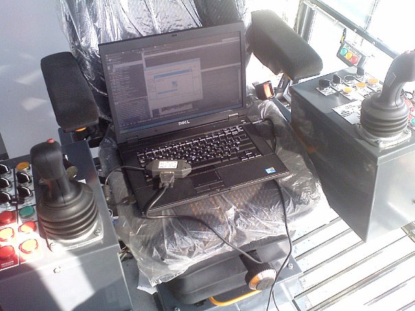
Вся работа ГП машины по максимуму автоматизировалась и крановщику нужно применять минимум усилий для управления оной.
Что из себя представляет Simatic Step 7?
Главной утилитой является Step 7 — Simatic Manager, которая позволяет производить конфигурацию ПЛК и сетей (утилиты HWConfig и NetPro).
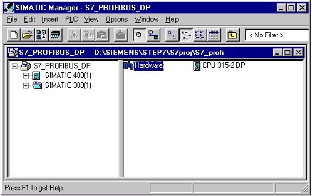
В процессе конфигурации определяется состав оборудования, способы подключения, используемые сети, адреса, выбираются настройки для используемых модулей. Готовая конфигурация загружается в ПЛК, что так же является настройкой оборудования.

Утилиты конфигурации позволяют осуществлять диагностику оборудования, обнаруживать аппаратные ошибки или неправильный монтаж.
Программирование ПЛК производится так же с помощью Simatic Manager, обеспечивающий написание программ в трех редакторах:
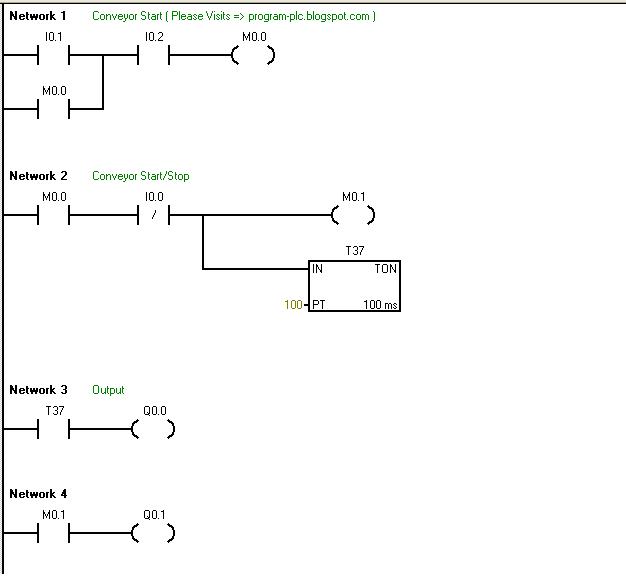
- LAD (Ladder Diagram) — релейные диаграммы. Редактор отображает программу в графическом представлении, похожем на электрическую монтажную схему. Логические схемы позволяют программе имитировать протекание электрического тока от источника напряжения через ряд логических условий на входах, которые активизируют условия на выходах. Источником напряжения выступает шина, находящаяся слева.
Основными элементами являются нормально замкнутые и нормально разомкнутые контакты.
Соответственно, замкнутые контакты позволяют потоку сигнала протекать через них к следующему элементу, разомкнутые контакты — препятствуют протеканию потока сигнала.
Логика делится на сегменты, т.н. нэтворки (Network), программа исполняется слева направо и сверху вниз.
Особенностями редактора LAD является простота в использовании и понимании для начинающих программистов. - FBD (Function Block Diagram) — функциональные блочные диаграммы. Этот редактор отображает программу в виде обычных логических схем. Контактов нет, но есть эквивалентные функциональные блоки. В данном редакторе не используется понятие «поток сигнала», как в LAD, его выражает аналогичное понятие потока управления через логические блоки FBD.
Потоком сигнала называется пусть состояния «1» через элементы FBD. Логика программы вытекает из связей между функциональными блоками, обозначающими команды.
Графическое представление функционального плана хорошо отражает процесс выполнения программы. - STL (Statement List) — список инструкций. Данный редактор дает возможность создавать программы, вводя мнемонические обозначения команд. В этом редакторе можно создавать программы, которые невозможно создать в редакторах LAD и FBD. Программирование в STL очень похоже на программирование на Ассемблере, несколько специфическое.
ПЛК выполняет команды в порядке, определяемом программой, сверху вниз, затем начинает сначала.
С помощью редактора STL всегда можно посмотреть или отредактировать программы, созданные на LAD или FBD, обратное не всегда возможно.

Я работала с самого начала в STL, пробовала LAD, мне показался слишком непонятным и многие вещи таки не удавалась так просто в нем сделать, как в STL. Плюс еще в том, что при загрузке программы в ПЛК, она компилируется в STL и, соответственно, при выкачке ее из ПЛК на программатор она так же представлена в STL.
Вместо заключения
Программирование ПЛК занятие увлекательное, особенно когда это не стенд, а реальное оборудование.
Моя работа заключалась в создании программы на ПЛК для управления всей ГП машины либо отдельных ее частей, а так же загрузке программного обеспечения непосредственно в оборудование и его отладке.
Случалось разное, но работать с железом было очень интересно, хоть и не легко иногда.
А строили мы вот такие ГП машины:
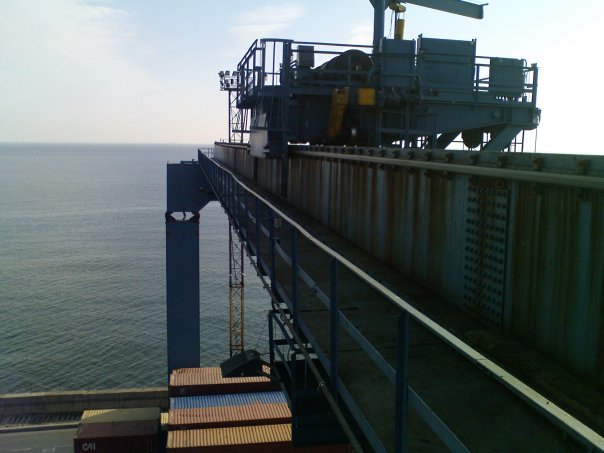
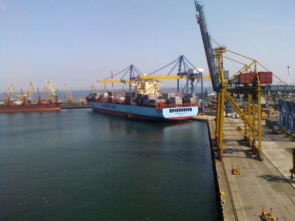
MaxPlant
Все статьи раздела SIEMENS
Содержание
- Краткий обзор TIA Portal
- Шаговый ПИД-регулятор PID_ES (Step Controller)
- Введение в HMI Faceplate
- Управление дискретной задвижкой
- Создание фейсплаты дискретной задвижки (продолжение урока 4)
- Программирование дискретной задвижки (продолжение урока 5)
- Обработка аналоговых сигналов в TIA Portal
- Создание фейсплаты аналогового датчика, авторизация пользователя SIMATIC Comfort Panel (продолжение урока 7)
-
Разработка функционального блока обработки аналогового сигнала в STEP7 Professional (продолжение уроков 7 и
-
Адаптация проекта для панели оператора SIMATIC Comfort Panel в проект WinCC Advanced для ПК
(продолжение уроков 7-9) - Аварии и тренды, оперативные и исторические данные в WinCC Advanced (продолжение уроков 7-10)
-
Установка TIA Portal V15.1. Конвертация проекта, разработанного в TIA Portal V14,
в проект TIA Portal V15.1 - Контроль присутствия устройств в сети PROFINET или PROFIBUS для S7-1200 и S7-1500
-
Программирование в TIA Portal обмена данными по сети PROFINET между преобразователем частоты ATV630 и
контроллером SIMATIC S7-1500 - Счётчик моточасов (времени наработки)
- Управление светозвуковой сигнализацией
- Управление режимами работы насосных агрегатов
- Управление электроприводом насосных агрегатов
- Групповое квитирование аварийных сообщений в операторских панелях
SIMATIC HMI Panels - Настройка преобразователя частоты Altivar Process ATV600
- Обновление прошивки контроллера S7-1500
- Загрузка проекта в S7-1500 и ET200SP
- Создание резервной копии S7-1500: выгрузка проекта из ПЛК, архивирование проекта
- Уставки (Setpoints) в TIA Portal STEP7 или как не потерять
настройки ПИД-регуляторов после пусконаладки - Общее устройство (Shared Device) или как в TIA Portal несколько контроллеров делят между
собой одну станцию распределённого ввода-вывода - MRP домен + IRT домен = MRPD домен или введение в технологии
Media Redundancy и Real-time communication - Конфигурирование доменов IRT и MRPD (продолжение урока 26)
- Time-based IO или
как управлять быстрым дискретным технологическим процессом строго по времени - Как загрузить программу ПЛК SIMATIC S7-1500, если нет связи между программатором и ПЛК
- Как загрузить две программы ПЛК SIMATIC S7-1500 в S7-PLCSIM Advanced V2.0
на локальной и удалённой машинах и подключить к ним WinCC по TCP - SIMATIC Automation Tool
- Как установить связь между онлайн симулятором панели Weintek и S7-PLCSIM для отладки программ HMI-PLC
без панели оператора и ПЛК - Как протестировать программу контроллера S7-1200 с ПИД-регулятором PID_Compact в симуляторе S7-PLCSIM с помощью HMI, разработанного на панели оператора Weintek
- Как связать LOGO! с WinCC
- …
SIMATIC Менеджер лицензий автоматизации Версия 1.0 Руководство
SIMATIC CFC для S7 Руководство
Регулирование на основе SIMATIC Практическое пособие
Загружаемый драйвер для PtP-соединения с протоколом MODBUS RTU-формата для модулей CP (в случае, когда S7 — ведущее устройство) Руководство
Загружаемый драйвер для PtP-соединения с протоколом MODBUS RTU-формата для модулей CP (в случае, когда S7 — ведомое устройство) Руководство
SIMATIC NET NCM S7 для Industrial Ethernet Руководство
SIMATIC NET NCM S7 для PROFIBUS
Modular PID Control (Модульное ПИД-управление)
PID Self-Tuner V5 (Система автонастройки для систем ПИД-управления в.5)
«Standard PID-Control» (Стандартное ПИД-управление)
PID Temperature Control (ПИД-управление температурой)
Ганс Бергер Автоматизация с помощью Программ STEP7 LAD и FBD
Ганс Бергер Автоматизация посредством STEP 7 с использованием STL и SCL и программируемых контроллеров SIMATIC S7-300/400
SIMATIC S7-GRAPH V5.3 для S7-300/400 Программирование систем последовательного управления
S7-GRAPH V5.3 для S7-300/400 Программирование систем последовательного управления Руководство
SIMATIC NET Отладка и ввод в работу ПК-станций – Руководство по быстрому запуску
Практическое пособие по регулированию на основе SIMATIC и SIMATIC РСS7
Модификация системы в режиме RUN (CiR) Руководство
Программирование в функциональном плане (FBD) для S7-300 и S7-400
Первые шаги в STEP 7 V 5.3
Конфигурирование аппаратуры и коммуникационных соединений STEP 7 V5.3
Начальный курс S7-HiGraph для S7-300/400
HiGraph для S7-300/400
Программирование в контактном плане (КОР) для S7-300 и S7-400
От S5 к S7, Руководство по конвертации
Системное ПО для систем S7-300/400 и стандартные функции -Том 1/2
Системное ПО для систем S7-300/400 и стандартные функции -Том 2/2
Стандартное ПО для S7-300 и S7-400. Стандартные функции. Часть 2
STL для S7-300 и S7-400. Программирование
Программирование в STEP 7 Lite V2.0
Введение в STEP 7 Lite V2.0
Программное резервирование для SIMATIC S7-300 и S7-400
DOCPRO
PRODAVE MPI
S7-PLCSIM V5.0
S7-SCL V5.1 для S7-300/S7-400
SIMATIC NET – Промышленная связь с программаторами и компьютерами