-
Bookmarks
Quick Links
HEATING SYSTEMS
Thermo G 300
with control unit 1588
Workshop Manual
Rev. 12/2018
Id.No. DOK50036
Related Manuals for Valeo Thermo G 300
Summary of Contents for Valeo Thermo G 300
-
Page 1
HEATING SYSTEMS Thermo G 300 with control unit 1588 Workshop Manual Rev. 12/2018 Id.No. DOK50036… -
Page 2
Thermo G Content Introduction Content and purpose Meaning of warnings and highlighted content Further documentation to be used Safety information and regulations 1.4.1 General safety regulations 1.4.2 Other safety information Suggestions for Improvement and change Technical data Heater 2.1.1 Altitude capability Gas pressure regulator Fuel Circulating pump… -
Page 3
Thermo G Content 5.4.3 Error symptom «Low voltage» 5.4.4 Error symptom «Extraneous light detected prior to ignition or during purge cycle» 5.4.5 Error symptoms «Temperature sensor / overheating protection defective» 5.4.6 Error symptom «Solenoid valve 1 or 2 defective» 5.4.7 Error symptom «Overheat protection has triggered»… -
Page 4
Thermo G Content 10 Packing / storage and shipping 1001 10.1 General 1001 Appendix Scheduled heater maintenance… -
Page 5
Spare parts required during maintenance and repair, you Warning! can order using the Thermo G Spare Parts List at Valeo. Danger to life and health! If necessary, Valeo will publish Technical Information (TI) for operation, maintenance or repair of the heater. -
Page 6
The temperature sensor cable may not be mechani- cally stressed (pull on the cable, carry the heater at the cable etc.). STOP! Suggestions for Improvement and change Please direct any complaints, improvement or modifica- tion suggestions regarding this manual to: service-valeobus@Valeo.com… -
Page 7
Thermo G 2 Technical data Technical data Unless limiting values are defined, the technical data should be understood with tolerances of ±10% common for heaters at an ambient temperature of +20°C, and at nominal voltage. Heater 2.1.1 Altitude capability The heater is adjusted in the factory, and without change of the CO adjustment unlimited usable up to an altitude of 1500 m above MSL, above an altitude of 1500 m up to… -
Page 8
L), the CO level must be adjusted according to section 7.6.2 in chapter 7. The max. oil content of the gas is 10 mg/m Circulating pump All desired information about the Valeo circulation pumps can be found under www.valeo-thermalbus.com/eu_en/ Products/Pumps. -
Page 9
An integrated control device controls on the basis of the signals of a temperature sensor the on and off switching The water heater Thermo G 300 operates in conjunction of the burner. with the on-board heating system –… -
Page 10
Thermo G 3 Description of assemblies and components Burner head 3.1.2 Control device The control unit 1588 ensures the operating sequence The burner head consists of the components and monitors the burner operation. • combustion air fan • control device Socket T •… -
Page 11
Thermo G 3 Description of assemblies and components 3.1.4 Heat protection cover and so to the ground potential. This ionization current is measured in the control device. Thereby, the presence or absence of a flame can be clearly detected. The heat protection cover is glued to the mixing chamber. The flame monitoring is part of the control. -
Page 12
Thermo G 3 Description of assemblies and components Temperature sensors with water temperature sensor and integrated overheating protection The water temperature sensor captures the coolant temperature at the heat exchanger outlet as electrical resistance. This signal is transmitted to the control unit, where it is processed. -
Page 13
The gas regulator further has an electrical preheating (ERH). The heating cartridge is connected to a dedicated All service information regarding your Valeo circulating output on the control unit. pump(s) can be found under www.valeo-thermalbus.com/ The ERH is activated at (water) temperatures below -20°C eu_en/Products/Pumps. -
Page 14
Thermo G 4 Heater functions Heater functions General heater functionality description The heater function is based on the principle of the low- pressure gas burner and is controlled by a micro processor. At the same time the integrated control unit takes over all monitoring functions. -
Page 15
Thermo G 4 Heater functions Operational heater sequence Process Signals Main switch Coolant temperature T > T_min T < T_min T >= T_max T < T_min T >= T_max T < T_min Actuators Operating display Combustion air motor Circulating pump Electronic ignition unit Solenoid valve 1 Solenoid valve 2… -
Page 16
Thermo G 4 Heater functions After a safety period of 5 seconds the purge cycle 2 starts. The flame monitoring is evaluated. The purge cycle ends approx. after 115 seconds. The combustion air fan is switched off. The heater is in a controlled break. The operation indication, the flame guard and the circula- ting pump continue their operation. -
Page 17
NOTE: affected by the failure or malfunction. It may only be After a combustion fault by a flameout the heater is swit- released by Valeo-trained personnel after eliminating the ched into the state „flushing“. cause. In this case, the gas supply is interrupted by the solenoid… -
Page 18
ATTENTION: Prior to releasing the heater interlock the cause of the fault must be eliminated! The heater interlock release is permitted by Valeo- trained personnel only. To release the heater interlock, the heater must be disconnected from the vehicle electrical system when it is… -
Page 19
• Corrosion on battery terminals • Cable insulation damage This section describes the troubleshooting at the heater Thermo G 300. ATTENTION: Prior to replacing a fuse troubleshooting needs to be ATTENTION: performed. The heater must be disconnected from the Troubleshooting may only be performed by briefed and vehicle electrical system and the fuse is to be replaced competent trained personnel. -
Page 20
Thermo G 5 Troubleshooting Table 503 General error symptoms Error symptom Possible cause Fehler im Wassersystem Circulating pump failure ( Aquavent 6000S and Aquavent • Error mode activated 6000SC only). In case of malfunctions the motor is switched off via the error mode Reactivation of the circulating pump motor For this purpose disconnect the power supply for >… -
Page 21
Thermo G 5 Troubleshooting Table 503 General error symptoms Error symptom Possible cause Error in the fuel supply No fuel supply to the heater • empty gas tank • bent, closed, clogged or leaky lines • frozen water inlets in the gas regulator or in the gas line •… -
Page 22
Thermo G 5 Troubleshooting Table 504 : Flash code No. of Error Error description impulses Control device error (is not indicated at timer 1531) Control device error No start within safety period No start within safety period (10 sec.) Flame interruption during burner operation, Flame interruption repeated starts unsuccessful High voltage (>… -
Page 23
Thermo G 5 Troubleshooting Error symptoms during functional tests with malfunction code output 5.4.1 Error symptom «No start within safety period» If due to a malfunction the heater unsuccessfully has attempted to start eight times in a row, it will be interlo- cked. -
Page 24
Thermo G 5 Troubleshooting Clean and securely mount the combustion air intake Are the combustion air intake opening and line and opening and line and the exhaust line. the exhaust line clean and securely mounted? Is sufficient fresh air intake ensured and are no Secure fresh air supply. -
Page 25
Thermo G 5 Troubleshooting 5.4.3 Error symptom «Low voltage» A value is stored in the control unit as smallest «permis- sible low voltage». It must be noted that the voltage may be lowered during heater start, and that the «low voltage» threshold may be violated. -
Page 26
Thermo G 5 Troubleshooting 5.4.4 Error symptom «Extraneous light detected prior to ignition or during purge cycle» Open valves, refill coolant, bleed coolant circuit. Verify Did overheating occur due to impaired the circulating pump is correct controlled. coolant flow? Is the burner properly screwed onto the Properly screw burner onto the heat ex- heat exchanger? changer. -
Page 27
Thermo G 5 Troubleshooting 5.4.5 Error symptoms «Temperature sensor / overheating protection defective» Is the plug “T“ of the temperature Correct error and/or replace the sensor system plugged in correct- component. ly? Is the plug, the pins and the cables of the temperature sensor system OK? Is the temperature sensor incl. -
Page 28
Thermo G 5 Troubleshooting Is the plug “V“ of the gas regulator Correct error and/or replace the harness plugged in correctly? component. Is the plug, the pins and the cables of the gas regulator harness OK? Are the solenoid valves at the gas regulator installed correctly? Replace gas regulator. -
Page 29
Thermo G 5 Troubleshooting Individual component tests 4. Inspect combustion chamber for cracks. Individual components can basically be tested using NOTE: visual inspection or manual electrical testing. Cracks in longitudinal direction at the end of the welding seam shorter than 80 mm are permissible. Warning! Danger to life and health! 5. -
Page 30
Thermo G 5 Troubleshooting 3. Inspect the motor for bearing conditions (stiffness). 4. Disconnect motor plug from the control unit. 5. Check motor with 24VDC (Pin 1 to 24V+). 6. Reconnect motor plug to the control unit. 7. Install mixing chamber to the fan housing (see 8.5). 8. -
Page 31
Thermo G 5 Troubleshooting Insulation body ignition electrode Ignition electrode Flame pipe Fig. 503 Burner head — ZF module 9. Disconnect the heater from the vehicle electrical system. 1. Remove burner head (see 8.4) 10. Disconnect the test plug. 2. Check distance of the electrode tips to the flame pipe 11. -
Page 32
Thermo G 5 Troubleshooting Fig. 504 Distance of the ignition electrodes Heat protection to the flame pipe cover Area of the heat protection cover are permitted in which outbreaks Fig. 506 Outbreaks at the heat protection cover 5.5.11 Gas pressure regulator inspection ATTENTION: The gas pressure regulator must not be disas- sembled. -
Page 33
Thermo G 5 Troubleshooting does not stop immediately, the gas regulator must be – Rated current at 24V: 1,0 Ampere replaced. The solenoid valve must open audibly when applying the DC voltage. 5.5.11.3 Test of the electrical functionality of the solenoid valves at the gas pressure 5. -
Page 34
Thermo G 6 Wiring diagrams Wiring diagrams General The following figures represent heater connection options to the vehicle electrical system. The in the table below shown cable cross-sections are to be used. Cable length <7.5m Cable length 7.5 — 15m 0.75 mm²… -
Page 35
Thermo G 6 Wiring diagrams Terminal. 58 Terminal 15 Terminal 30 (permanent plus) Terminal 31 (ground) SG 1588 T. 31 HG 2.5mm T. 30 HG 2.5mm T. 31 UP 2.5mm T. 30 UP 2.5mm UPFA ION- 0.75mm UPFA 0.75mm ION+ 0.75mm Electronic Ignition… -
Page 36
Thermo G 6 Wiring diagrams Position Designation Operation indicator max. 1x5W or 2x2W Combustion air motor (in the heater) Electrical regulator heating (gas press. regulator) Car flat-type fuse 20A acc. DIN 72581 part 3 Car flat-type fuse 20A acc. DIN 72581 part 3 Car flat-type fuse 5A acc. -
Page 37
Danger to life and health! Servicing Work on the heater must only be carried out by trained and / or by Valeo-trained personnel. In order to ensure long-term functional reliability, the follo- Any work on the gas supply line, for example when… -
Page 38
NOTE: The CO level of the Thermo G 300 replacement burner is 1. Check input voltage at the heater. adjusted by the manufacturer for use with CNG of class H. 2. Let the heater run approx. 3 minutes. -
Page 39
If components are disassembled to a degree not covered in this workshop manual, any warranty claim shall be voided. Only genuine Valeo spare parts should be used. Basically, the access to the individual components of the heater is for the purposes of testing or replacement as… -
Page 40
Thermo G 8 Repair Hood removal and installation 3. If necessary, disconnect the combustion air intake line from the heater. 4. Disconnect gas supply hose and seal it with a blank Removal plug. 1. Disconnect the heater from the vehicle electrical 5. -
Page 41
Thermo G 8 Repair Separating the fan housing from the chamber. 2. Bring the the fan housing (2) in assembly position with mixing chamber the mixing chamber (6). During this, ensure the new mixing chamber gasket ring (5) and the ZF module Separating grommet are in the correct position. -
Page 42
Thermo G 8 Repair Control device removal and Fan motor removal and installation Installation Removal 1. Separate the fan housing from mixing chamber (see Removal 8.5). 1. Disconnect the heater from the vehicle electrical system. Disconnect the plug “C“. 2. Disconnect the circulating pump plug “P“. ATTENTION: 3. -
Page 43
Thermo G 8 Repair 1 — Hood 8 — ZF module 2 — Fan motor 9 — Gasket ring, Mixing chamber 3 — Fan housing 10 — Mixing chamber 4 — Fan wheel 11 — Heat protection cover 5 — Control device 12 — Gasket, flame pipe 6 — Gas port 13 — Flame pipe… -
Page 44
Thermo G 8 Repair 8.10 Combustion chamber removal and installation not permissible Removal Caution! Risk of burns! Combustion chamber and heat exchanger can be permissible very hot. If necessary, let them cool down. Fig. 806 Combustion chamber welding seam position 1. -
Page 45
Thermo G 8 Repair position and mount the stand (4) to the vehicle using and remove the line. screws, nuts and washers according to the mounting 6. Remove the hose from the safety valve. points used. 7. Loosen the nut at the threaded attachment pin and 2. -
Page 46
Thermo G 8 Repair engine off and check the coolant level. Refill coolant as needed. While the vehicle engine is switched off, switch on the heater with the circulating pump and the vehicle heating fan. After the engine motor cooled down, the heater must automatically start and stop as soon as the upper swit- ching threshold is reached. -
Page 47
Modifications and retrofits For further optimization the heaters are continuously improved. Units in the field can usually be upgraded or retrofitted. For this purpose respective modification kits will be available. For Information, refer to the category ’’Service“ of the Valeo homepage. -
Page 48
10 Packing / storage / shipping Packing / storage and shipping 10.1 General The heater or its components, which are sent to Valeo for inspection or repair, must be cleaned and packaged to ensure that handling, transport and storage will not damage them. -
Page 49
Thermo G Maintenance plan Scheduled heater maintenance must be adhered. If there no such regulations, Valeo prescribes the here shown maintenance intervals for The heater should be inspected in scheduled time inter- common applications. vals, latest at the beginning of the heating period (time of… -
Page 50
Thermo G Maintenance plan Check / Maintenance Important notes Check result Measured values, accomplished repairs 4. Burner Head a) Inspect combustion air intake opening for clear passage. b) Inspect hood for damage. Replace damged parts. c) Inspect ignition electrodes for damage and correct distance and readjust if required. -
Page 51
memos… -
Page 52
Valeo Thermal Commercial Vehicles Germany GmbH Friedrichshafener Str. 7 — 82205 Gilching — Germany — Tel. +49 (0)8105 7721-0 — Fax +49 (0)8105 7721-889 www.valeo-thermalbus.com — service-valeobus@valeo.com…
Thermo G
1
Introduction
1.1
Content and purpose
1.2
Meaning of warnings and highlighted content
1.3
Further documentation to be used
1.4
Safety information and regulations
1.4.1
General safety regulations
1.4.2
Other safety information
1.5
Suggestions for Improvement and change
2
Technical data
2.1
Heater
2.1.1
Altitude capability
2.2
Gas pressure regulator
2.3
Fuel
2.4
Circulating pump
3
Description of assemblies and components
3.1
Burner head
3.1.1
Combustion air fan
3.1.2
Control device
3.1.3
Mixing chamber
3.1.4
Heat protection cover
3.1.5
ZF Module with electronic ignition unit and ionization electrode
3.1.6
Flame tube
3.2
Combustion chamber
3.3
Heat exchanger
3.4
Temperature sensors with water temperature sensor and integrated overheating protection
3.5
Gas pressure regulator
3.5.1
Heating of the gas pressure regulator
3.6
Circulating pump
4
Heater functions
4.1
General heater functionality description
4.2
Operational heater sequence
4.2.1
Switching on and start
4.2.2
Heating operation
4.2.3
Switching off
4.3
Malfunction interlock and heater interlock
4.4
Malfunction interlock
4.4.1
Malfunctions during switching-on and start procedure
4.4.2
Malfunctions during heater operation
4.4.3
Malfunctions during purge cycle
4.4.4
Malfunction interlock release and error clearance
4.5
Heater interlock
4.5.1
Heater interlock release
4.6
Error output
5
Troubleshooting
5.1
General
5.2
General error symptoms
5.3
Malfunction code output via flash code
5.4
Error symptoms during functional tests with malfunction code output
5.4.1
Error symptom «No start within safety period»
5.4.2
Error symptom «Flame interruption»
Content
101
101
101
101
101
101
102
102
201
201
201
202
202
202
301
302
302
302
302
303
303
303
303
303
304
305
305
305
401
401
402
402
402
403
404
404
404
404
404
405
405
405
405
501
501
501
503
505
505
505
1
-
flowair LEO D 2
LEO D 2, LEO DT 2, LEO D 2.2, LEO DT 2.2 DTR LEO D 2, D 2.2 (3V) 16.05 EN DESTRATIFICATOR TECHNICAL DOCUMENTATION OPERATION MANUAL PL DESTRATYFIKATOR DOKUMENTACJA TECHNICZNA INSTRUKCJA UŻYTKOWANIA DE DECKENLUFTVERTEILER TECHNISCHE DOKUMENTATION BETRIEBSANLEITUNG RU ДЕСТРАТИФИКАТОР Техническа …
LEO D 2 Heating System, 12
-
Laddomat 21-60
1Laddomat® 21-60 Charging unitUser and installation instructionsLM21-60_Manual_E.indd81260002-E090810The Laddomat 21-60 is designed to……allow the boiler to reach a high working temperature soon after fi ring….to heat the cold tank water in the bottom of the boiler so that the boiler does not rust away through c …
21-60 Heating System, 6
-
Magic-pac HWC9 V-Series
Page 1 of 20507389-02 Issue 1733Save these instructions for future reference (P) 507389-02*P507389-02*Manufactured ByAllied Air Enterprises LLCA Lennox International, Inc. Company215 Metropolitan DriveWest Columbia, SC 29170This manual must be left with the homeowner for future reference.This is a safety alert symbol a …
HWC9 V-Series Heating System, 20
-
Goodman A/GPG13 M SERIES W/R410A
Affix this manual and Users Information Manual adjacent to the unit.INSTALLATION & OPERATINGINSTRUCTIONS for A/GPG13 M SERIES W/R410ASINGLE PACKAGE GAS-ELECTRICHEATING & COOLING UNITGoodman Manufacturing Company, L.P.IO-357D 5151 San Felipe, Suite 500, Houston, TX 7705611/12 www.goodmanmfg.com — or — www.amana- …
A/GPG13 M SERIES W/R410A Heating System, 40
-
Mitsubishi Electric Ecodan EHSC-VM6D-CN
FOR INSTALLERINSTALLATION MANUALFor safe and correct use, read this manual and the outdoor unit installation manual thoroughly before installing the hydrobox. English is the original language. The Chinese version is translation of the original.Hydrobox | 空气源(热泵)热水机组EHSC-VM6D-CN安装说明书为� …
Ecodan EHSC-VM6D-CN Heat Pump, 54
-
Bio Smart Technologies BIO-1500FTA
Therapeutic Infrared Heat . .B I O S M A R T®Save these InstructionsIncludes: Application Guidelines User Information & Guidelines Operating Instructions Warranty & ServicingIn-Wall Heater Owner’s ManualTherapeutic infrared heating systemsfor a green, healthy environmentwith Patented BioSmart® Air Fil …
BIO-1500FTA Heating System, 24
-
National Comfort Products CPG41228-U
25Installation Guide for Comfort Pack (CPG) UnitsThe indoor blower motor and the outdoor fan motor have permanently lubricated bearings and do not require routine service. The refrigeration system is sealed and factory charged with R-410A so that routine maintenance is not required. Cleaning of the outdoor coil, indoor …
CPG41228-U Heating System, 21
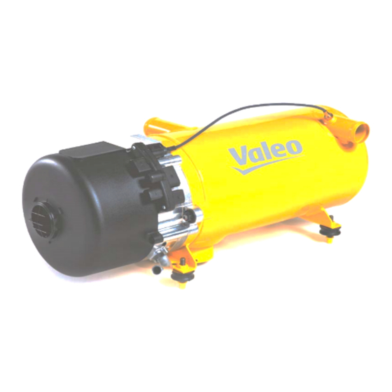
Предпусковой подогреватель THERMO G 300
ГАЗОВЫЕ ОТОПИТЕЛИ VALEO: НЕПРЕВЗАЙДЕННОЕ РЕШЕНИЕ ДЛЯ ГАЗОВОГО ТРАНСПОРТА
Газовый отопитель Valeo Thermo G, отличающийся высокой теплопроизводительностью в сочетании с низким уровнем выбросов и бесшумным горением, обеспечивает приятную температуру в транспортном средстве еще до начала поездки.
ПРЕИМУЩЕСТВА
Низкая стоимость жиненного цикла:
-
Оптимизированы возможности диагностики
-
Газовый редуктор (масса уменьшена на 50%, уменьшены габариты)
-
Снижение общей массы на 10%
Высокие стандарты экологичности:
-
Чрезвычайно низкий уровень шума
-
Соответствует действующим европейским стандартам ECE R122 и R110
Комфорт:
-
Полноценная работоспособность при экстремальном холоде до -40°C
-
Гарантированная надежность
-
Совместим с Valeo Thermo / Thermo S / Thermo E и предшественником GBW
-
Оптимизированный монтажный комплект
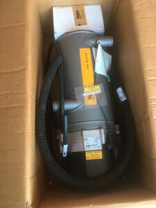
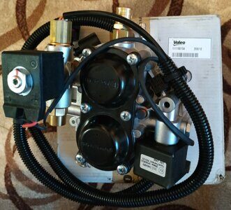
Отопитель газовый thermo G 300—11116413A (11122417B) применяется для подогрева газомоторных двигателей автобусов Нефаз, ЛиАЗ, МАЗ. 220000рублей
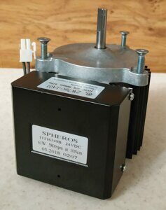
Мотор отопителя G-300 11116349B. 35000рублей.
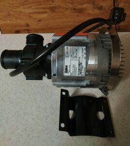
Насос циркуляционный 6000л U4855 (11114407B) 35000рублей.
Редуктор газовый 11119815А termo G 300. 50000рублей.
Заинтересовались, Звоните?
или оставьте заявку, и мы перезвоним Вам!