-
Contents
-
Table of Contents
-
Troubleshooting
-
Bookmarks
Quick Links
Related Manuals for SLE SLE5000
Summary of Contents for SLE SLE5000
-
Page 2
All rights reserved. No part of this publication may be reproduced, stored in any retrieval system, or transmitted in any form or by any means, electronic, mechanical, photocopy, recording or otherwise, without prior permission of SLE. © Copyright SLE 10/04/2006. Manual : UM0083 Issue 6 SLE Part Nº:… -
Page 3
SLE5000/SLE4000 Infant Ventilator The warnings on pages 28 to 32 must be read and understood before using the SLE5000/SLE4000 ventilator. Failure to do so could lead to injury or death of the patient. MAKE SURE THAT THE VENTILATOR BACK-UP POWER SUPPLY IS FULLY CHARGED: Page 134. -
Page 4
This page is intentionally blank. Page 4 of 292… -
Page 5: Table Of Contents
2.4.1. PSV with TTV ………………..20 2.5. SIMV (Synchronized Intermittent Mandatory Ventilation)………21 2.5.1. SIMV with PSV ………………22 2.5.2. SIMV with TTV……………….23 2.6. HFO (SLE5000 only) ………………23 2.7. HFO+CMV (SLE5000 only) …………….23 2.8. Mode controls ………………..24 2.8.1. TTV Control Mode ………………24 2.9. Technical Description ………………25 3.
-
Page 6
7.8.5. Set Trigger for CPAP, PSV, PTV & SIMV ……….57 7.8.6. Pressure Support in PSV …………….57 7.8.7. Pressure Support in SIMV…………….. 58 7.8.8. HFO Activity (SLE5000 Only)…………..58 7.9. Alarm Panel ………………… 59 7.10. Default Waveform Windows…………….60 7.11. -
Page 7
11.1.1. Complete Power Fail Alarm Test………….95 11.1.2. Setting FiO …………………96 11.1.3. Functional Testing with No Flow Sensor ……….96 11.1.4. Calibration of the Flow sensor …………..96 11.1.5. Oxygen Alarm Test ………………98 11.1.6. Function and Alarm Testing…………..100 11.1.7. High Pressure Alarm…………….104 11.1.8. -
Page 8
14.2.5. HFO Only Ventilator Set Threshold Alarms (SLE5000 only)….142 14.2.6. Patient Leak Alarm ……………… 143 14.2.7. Reset Contamination Alarm …………..143 14.3. Patient Circuits, Humidification and Nitric Oxide Therapy ……144 14.3.1. Patient Circuits with Incubators, Cots and Paediatric beds….. 144 14.3.2. -
Page 9
19.0.3. Breath Not Detected …………….194 19.0.4. Low Tidal Volume ………………194 19.0.5. Unexpected Rise or drop in Mean P (SLE5000 only) ……195 19.0.6. Unexpected Rise or Drop in Max P (SLE5000 only)……..195 19.0.7. Unexpected Rise or Drop in Min P (SLE5000 only)………195 19.0.8. -
Page 10
26. Patient Circuits ………………….. 247 26.1. Warnings for Patient Circuit Use…………..247 26.2. 10mm Diameter Re-usable Patient Circuit (SLE Part Nº N2391/50) ….. 248 26.2.1. Sterilising of the N2391/50 re-usable Patient Circuit……. 248 26.3. 10mm Patient Circuit, SLE Part Nº N5188 & N5188/850……250 26.4. -
Page 11
28.8. Power, Dimensions, Standards etc…………..272 28.9. Environmental Storage Conditions …………..272 29. Pneumatic Unit Schematic ………………273 30. Ventilator Labelling ………………..274 30.1. SLE4000………………….274 30.2. SLE5000………………….275 31. Consumables and Accessories …………….278 32. Glossary of Abbreviations Used in this Manual ……….284 33. Index …………………….287 Page 11 of 292… -
Page 12
This page is intentionally blank. Page 12 of 292… -
Page 13
Introduction Page 13 of 292… -
Page 14: Introduction
SLE4000 and SLE5000 ventilator is that the SLE5000 has two extra modes of operation, these being HFO and HFO+CMV. The user manual will from this point onwards refer to the SLE4000 and SLE5000 as “the ventilator”. Where the user manual details an operation or mode: specifically HFO or HFO+CMV then a statement will appear stating, “SLE5000 only”.
-
Page 15: Description Of The Ventilation Modes
2. Description of the Ventilation Modes The ventilator has the ability to be used as either a pressure controlled, volume targeted ventilator, as a pressure limited, time cycled ventilator, and the SLE5000 as a high frequency oscillation ventilator. 2.1 CPAP Continuous Positive Airway Pressure The ventilator generates a continuous positive airway pressure at a level set by the User.
-
Page 16: Cmv
2.2 CMV Continuous Mandatory Ventilation In this mode the inspiratory cycle is initiated by the ventilator at a set BPM rate. The breaths can be either time limited and pressure cycled or flow cycled and pressure limited. The User sets the following:- •…
-
Page 17: Ptv
2.3 PTV Patient Triggered Ventilation In this mode all the patient’s breath attempts are pressure supported. Mechanical breaths are delivered at the set parameters (Ti, PEEP and PIP) if no patient effort is recognised. This mode can be used with or without a flow sensor. The User sets the following:- •…
-
Page 18: Ptv With Ttv
Note: PTV will continue to function as stated, but with breath rates of 20 and above apnoea alarms will be ignored by the ventilator. Breath rates of 20BPM and above are deemed sufficient to support the patient. Should the breath rate be set below 20BPM the apnoea alarm is enabled.
-
Page 19: Psv
2.4 PSV Pressure Supported Ventilation This is a pressure limited mode of ventilation in which each breath is patient triggered and supported. The breath is patient triggered, pressure supported and patient terminated. The infant therefore has control of the whole cycle, i.e. the inspiratory time, frequency and minute volume.
-
Page 20: Psv With Ttv
PSV Flow and Tidal volume waveforms (with termination sensitivity). Note: PSV will continue to function as stated, but with breath rates of 20 and above apnoea alarms will be ignored by the ventilator. Breath rates of 20BPM and above are deemed sufficient to support the patient. Should the breath rate be set below 20BPM the apnoea alarm is enabled.
-
Page 21: Simv (Synchronized Intermittent Mandatory Ventilation)
2.5 SIMV (Synchronized Intermittent Mandatory Ventilation) The frequency of mandatory breaths is determined by the BPM control. When a mandatory breath is due an assist window opens and waits for a patient’s inspiratory effort. When this occurs the ventilator delivers a synchronised breath (SIMV breaths). Once the breath has been delivered the assist window closes until the next set breath is due.
-
Page 22: Simv With Psv
Note: SIMV will continue to function as stated, but with breath rates of 20 and above apnoea alarms will be ignored by the ventilator. Breath rates of 20BPM and above are deemed sufficient to support the patient. Should the breath rate be set below 20BPM the apnoea alarm is enabled.
-
Page 23: Simv With Ttv
Enables Targeted Tidal Volume and selects volume to be delivered • Max PIP • Max Ti 2.6 HFO (SLE5000 only) High Frequency Oscillation In this mode, the ventilator shall deliver continuous high frequency oscillation. There is no patient interaction. The User sets the following:- •…
-
Page 24: Mode Controls
2.8 Mode controls 2.8.1 TTV Control Mode (Targeted Tidal Volume) The aim of TTV is to prevent over distension of the alveoli and thereby limit volutrauma. By targeting a selected tidal volume, and achieving and maintaining the tidal volume with pressure ventilation, also limits barotrauma.
-
Page 25: Technical Description
2.9 Technical Description The ventilator is a computer controlled ventilator. The computer is broken down into three electronic subsystems that are housed in the upper (electronic) section of the ventilator. The three sub systems are user interface, monitor and control. The interface subsystem controls the user interface, the display and the touch screen.
-
Page 26: User/Owner Responsibility
SLE, or parts which are otherwise approved by SLE. Equipment which is not functioning correctly or is otherwise in need of repair or maintenance…
-
Page 27
Operational and Clinical Warnings Page 27 of 292… -
Page 28: Warnings
4. Warnings 4.1 Operational Warnings The following warnings must be read and understood before using the ventilator. Failure to do so could lead to injury or death of the patient. General The whole of this manual should be read and understood before using the ventilator. Operators must be suitably trained and clinically authorized for using the ventilator with patients.
-
Page 29
19. If the ventilator is adversely affected by equipment emitting electromagnetic interference then that equipment should be switched off or removed from the vicinity of the SLE5000. Conversely, if the ventilator is the source of interference to other neighbouring equipment, it should be switched off or taken to another location. -
Page 30
31. Do not use solvent based cleaning solutions to clean the touch screen or covers. Humidifier / Patient Circuit 32. Use only SLE approved patient circuits. On no account should antistatic or electrically conductive tubing be used. 33. The humidifier used in the patient circuit must be operated and maintained in accordance with its manufacturer’s instructions. -
Page 31: Clinical Warnings
“Circuit Disconnection Procedure” on page 138. 39. A new flow sensor is delivered clean, but not sterile. It should be autoclaved as described in the Cleaning and Disinfection Procedures prior to initial use. Use only SLE approved flow sensors (Part number: N5201).
-
Page 32
Circulatory abnormalities (reduced systemic or pulmonary venous return, hypotension, tachycardia, bradycardia, reduced cardiac output, excessive variability of blood pressure); Maintenance of an adequate airway is paramount in the infant or child undergoing high- frequency oscillatory ventilation. The following points should be stressed in airway management on units employing HFOV: 10. -
Page 33
Ventilator Description Page 33 of 292… -
Page 34: Ventilator Description
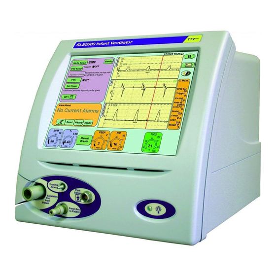
5. Ventilator Description Rear Cover Front cover Touch Screen Power On Flow Sensor Connector Exhalation Block Flap Proximal Airway Port Fresh Gas Port Exhalation Block Front View Page 34 of 292…
-
Page 35
Cooling louvres Battery Power Terminaton Switch RS232 & Viewlink Connector Exhaust port for Exhalation Block Mains Power Cable Air Supply Cell cover Inlet Oxygen Supply Mains Power Switch Inlet Fuse Holder Rear View Page 35 of 292… -
Page 36
Silencer Guides Exhalation Block Guides Silencer Exhalation Block Clamp Exhalation Block Guides Exhalation Block Exhalation Block Port Page 36 of 292… -
Page 37: Description Of Symbols And Buttons
6. Description of Symbols and Buttons Symbol Description Type BF connection (Situated on front panel). Type B device (Situated on rear panel). Read manual (Situated on rear panel). Date of Manufacture (Appears on serial number label). Do not dispose of as general waste (WEEE directive). (Appears on serial number label).
-
Page 38
Symbol Description Mains/Battery power indicator (Situated on front panel). Screen pause. Waveform display options. Display options and service data. Enables the Targated Tidal Volume Panel. Enables the breath detection threshold in the flow window. Night mode and Screen Lock. Return button. Returns the user to previous panel. Next Button. -
Page 39
Symbol Description Wave shaping controls. Language selection. Alarm mute. Picture capture button. Stored Loop (Loop on display). Stored Loop (Loop in memory). Zoom in. Zoom out. Please wait symbol. (Displayed when storing loop). High Tidal Volume Alarm in mbar Cycle Fail Alarm in mbar. Returns the waveform windows to their default settings of: Pressure, Flow and Tidal volume. -
Page 40
Symbol Description Pressure wave window with Flow versus Volume loop display. Pressure wave window with Flow versus Pressure loop display. Pressure wave window with Volume versus Pressure loop display. Pressure wave window and Tidal Volume wave window. Pressure wave window and Minute Volume wave window. Pressure wave window and Max pressure against time display. -
Page 41
Symbol Description Indicates a warning in the manual. Indicates a note in the manual. Indicates a caution in the manual. Check list item. A table explaining all abbreviations within this manual can be found on page 284. Page 41 of 292… -
Page 42
This page is intentionally blank. Page 42 of 292… -
Page 43
User Interface Description Page 43 of 292… -
Page 44: User Interface
7. User Interface Warning: Do not use a sharp instrument, such as a pen to activate the touch screen controls as the excessive pressure applied by the point will damage the touch screen membrane. Note: The ventilator touch screen works on a one touch principle. If the user touches the screen at two points, the first point touched is recognized and the second is ignored.
-
Page 45: Description Of User Interface Indicators
The touch screen as the name suggests is controlled by touch. When using the ventilator it is advisable to have clean dry hands (gloved hands will also activate controls). Only a small amount of pressure is required to activate a control. 7.2 Description of User Interface Indicators In the mode panel the user will find indicator lights next to functions that can be turned ON or OFF.
-
Page 46: Examples Of Control Use
7.3.1 Examples of Control Use The following section describes the use of each of the above controls. 7.3.1.1 Buttons Touch the mode select button and this will activate the mode select panel. Select the required mode. The mode selected will be highlighted by a colour change (from light green to dark green).
-
Page 47
7.3.1.3 Up / Down Arrows The arrows appear when a function or parameter which can be modified is selected. The up arrow increases the chosen value and the down arrow decreases the value. The arrow selected changes colour when touched. The arrow can be touched repeatedly to increment the parameter in individual increments or held down to rapidly change the value. -
Page 48: Description Of The Mode Panel In Ventilation Off Mode
Mode Select Panel. The panel displays all the ventilation modes that can be selected. SLE4000 SLE5000 Selection of the mode has to be confirmed by pressing the Confirm button. (Note the confirm button flashes between green and white).
-
Page 49: Oxygen Alarm Test
7.4.3 Oxygen Alarm Test The Oxygen Alarm Test button activates the Oxygen Alarm Testing panel. This panel allows the user to test the High and Low Oxygen alarm prior to use. For a detailed description on how this test is carried out, See “Oxygen Alarm Test”…
-
Page 50: Flow
7.5.1 Flow On pressing the Flow button (D) the Calibrate Flow Sensor panel will be displayed. The Calibrate button (I) runs the calibration routine for the flow sensor. For more details on the Flow Sensor and calibration see page 182. The Return button returns the user to the Services panel.
-
Page 51: Alarm Volume
7.5.4 Alarm Volume On pressing the Volume Control button (G) the Alarm Volume panel will be displayed. The alarm volume panel allows the user to set the alarm sounder volume between 7 maximum and 3 minimum. The sounder level settings below 3 can not be selected as normal background noise could mask the alarm.
-
Page 52: Language Toggle
Displayed on this panel are four buttons: Language Toggle button (L) Waveform Display Sync button (M) Set Time and Date button (N) Version.. (O) The Return button returns the user to the Services panel. 7.6.1 Language Toggle The ventilator software can be supplied to the user with a secondary language installed.
-
Page 53: Version Information Panel
7.6.1.2 Set Time and Date The Set Time and Date button (N) allows the user to set the internal clock and calendar of the ventilator. The date and time is displayed above the pressure waveform window. Note: the ventilator uses the 24 hour clock system and Day/Month/Year date system.
-
Page 54: Monitor Services
7.7.1 Monitor Services On pressing the Monitor button (P) the Monitor services panel will be displayed. This panel displays the Two point O calibration button and the software version numbers for the monitor subsystem. Note: See section 21. on page 214 for information on the two point oxygen sensor calibration.
-
Page 55: Mode Panel Functions In A Ventilation Mode
7.8 Mode Panel Functions in a Ventilation Mode For each ventilation mode, extra mode specific functions are displayed in the panel (except HFO Only). SLE4000 & SLE5000 For CPAP Apnoea Setup, Set Trigger and TTV buttons. For CMV TTV button.
-
Page 56: Apnoea Setup For Cpap
7.8.2 Apnoea Setup for CPAP The Apnoea Settings panel allows the user to set the Apnoea detection time and to activate backup breaths if apnoea is detected. The Backup breaths function is activated by the ON/OFF toggle button (S) and the Apnoea Detect time is controlled by the Arrow controls.
-
Page 57: Ttv For Cpap, Psv, Ptv & Simv
7.8.4 TTV for CPAP, PSV, PTV & SIMV The Targeted Tidal Volume panel allows the user to turn ON or OFF volume targeting. Volume targeting (TTV) is activated by the ON/OFF toggle button (T). When Volume Limiting is ON the Tidal volume parameter panel appears allowing the Tidal Volume limit to be set.
-
Page 58: Pressure Support In Simv
7.8.8 HFO Activity (SLE5000 Only) The HFO activity panel allows the user to toggle between oscillations in both inspiratory and expiratory phases of the CMV waveform or just the expiratory phase.
-
Page 59: Alarm Panel
7.9 Alarm Panel The Alarm Panel displays all the alarm messages. The Adjust button (U) activates the alarm setup panel in the Mode panel area, plus any alarm threshold in the waveform windows. It also allows the user to jump directly to the flow sensor and oxygen cell calibration panels when their respective alarms are triggered (provided no other higher priority alarms are active).
-
Page 60: Default Waveform Windows
The SLE4000 ventilator default setting is to display: Pressure, Flow and Tidal volume waveforms for CPAP, CMV, PTV, PSV and SIMV. The SLE5000 ventilator default setting is to display: Pressure, Flow and Tidal volume waveforms for CPAP, CMV, PTV, PSV, SIMV and HFO. For HFO+CMV the ventilator will only display Pressure and Flow waveforms.
-
Page 61
The alarm thresholds are also displayed in these waveform windows. The scales in waveform windows autoscale to match the set ventilation parameters. When the ventilator is used without a flow sensor the default layout changes to exclude flow related waveforms. The ventilator can also display loops and trends. -
Page 62: Alarm And Breath Detection Thresholds
7.11 Alarm and Breath Detection Thresholds The ventilator has the following user adjustable alarms and breath detection threshold. Default waveform windows (with flow sensor connected): High Pressure Low Pressure Breath detection High Tidal Volume Low Tidal Volume Minute volume graph (selected from graph options button): High Minute Volume Low Minute…
-
Page 63: How To Set An Alarm Threshold
7.12 How to Set an Alarm Threshold To adjust an alarm threshold press the Adjust button in the alarm panel. If no alarm condition is present the user will have to select the alarm threshold for modification. In an alarm condition the user on pressing the Adjust button will find that the crossed alarm threshold will automatically be selected.
-
Page 64
Note: The High and Low Pressure Alarm thresholds auto track the pressure waveform by 5mbar for conventional modes of ventilation and 10mbar for HFO modes. Note: In CPAP, PTV, PSV and SIMV modes, the Flow window has a breath detection threshold. This threshold is activated by the Set Trigger button or can modified in the same manner as an alarm threshold as described above. -
Page 65
Note: The user can only adjust the alarm thresholds to 15mbar above the maximum PIP or 15mbar below the minimum pressure in conventional ventilation or 20mbar above the maximum PIP or 20mbar below the minimum pressure in HFO or combined mode ventilation (HFO + CMV). This safety feature stops the user setting the alarm threshold so high that in practice the alarm is turned off. -
Page 66: Ventilation Parameters
7.13 Ventilation Parameters Each ventilation mode has a number of parameters that have to be changed to meet the clinical requirements. The interface displays the user definable parameters at the bottom of the touch screen. On power up the ventilator defaults to the stand by mode and only displays the FiO parameter.
-
Page 67
The parameters can be selected and modified in the same way as in the preview mode. In the preview mode the parameters panel displays the set value. In the ventilation mode the parameters panel displays the measured value in the centre of the eyebrow and the set value in the right hand corner. -
Page 68: Lung Mechanics And Measurement Panel
7.14 Lung Mechanics and Measurement Panel This panel displays the measured and calculated ventilation parameters. When no flow sensor is fitted only non flow based values are displayed. The panels shown display the parameters for each ventilation mode. SLE4000 & SLE5000 SLE5000 Only CPAP HFO+CMV SIMV Note: For CMV the IE ratio is replaced with measured Ti when TTV is on.
-
Page 69
Vmin (l) Minute volume is the accumulated expiratory tidal volume over a one-minute period. A measured value in litres. Texp(s) Total expiration time in seconds. A measured value. Leak(%) Percentage leak from the patient circuit. The difference between the expired volume compared to the inspired volume as a percentage. -
Page 70: The Pause Button
7.15 The Pause Button The pause button is located in the top right hand corner of the screen. Pressing the button will freeze all the waveform windows for 1 minute. Pressing the pause button at any time whilst the screen is frozen will unfreeze the waveform windows.
-
Page 71
Loops, Trends & Waveforms Page 71 of 292… -
Page 72: Loops, Trends & Waveforms
8. Loops, Trends & Waveforms This chapter details the way the ventilator displays patient data. The ventilator displays the realtime data collected from the proximal airway pressure transducer and ET manifold mounted flow sensor to provide Pressure, Flow and Tidal Volume waveforms.
-
Page 73
This means that the waveforms remain static (they do not creep from left to right) in the windows. For interactive ventilatory modes the data is enhanced by displaying the patient trigger in a different colour. To view the trigger point the ventilator colours the first 200 milli seconds orange, after the patient effort that has crossed the breath detection threshold. -
Page 74: Loops
8.2 Loops The ventilator displays the following three loops: flow versus volume, flow versus pressure and volume versus pressure. The ventilator draws three loops before refreshing the window. Each loop is coloured differently in each three loop cycle. The colours being red, green and black.
-
Page 75
The ventilator will display the time and date that the loop was saved as it copies the data to memory. The ventilator will now display the saved looped and the current active loops. Step 3. Stored Loop button Note: When viewing a stored loop the active loops are shown as dashed lines. -
Page 76: Trends
8.2.1.2 Retrieving Loops The user can retrieve a loop by pressing the Stored Loop button in the loop window. Note: The ventilator will revert to the axis scale of the stored loop. This could cause the current active loop to be drawn partially off the window. 8.3 Trends The ventilator can display eight different trends, these being Minute Volume, Max Pressure, Mean Pressure, Min Pressure, FiO…
-
Page 77
Ventilator Set-up Page 77 of 292… -
Page 78: Ventilator Set-Up
9. Ventilator Set-up Note: The ventilator cannot be started on battery power. 9.1 Preparing the Ventilator for Use To prepare the ventilator for functional testing and later patient ventilation, carry out the following steps. Step 1 Cleaning Make sure that the ventilator has been cleaned in accordance with the instructions in “Cleaning, Disinfection and Sterilization”…
-
Page 79
Step 3 Connection of Oxygen and Air Hoses to the Gas Supplies Oxygen outlet Air outlet Oxygen supply hose Air supply hose Plug into the gas supplies, at a gas pressure of about 4 bar. Step 4 Connection of Mains Power Check mains power switch is set to OFF (O) Connect plug to mains switch and turn on at… -
Page 80
Step 5 Fit the Exhalation Block and Silencer to the Gas Manifolds Connect the silencer to the exhalation block and then place the assembly onto the gas mainfolds (C). Lock the exhalation block by turning the clamp through 90 degrees until it is vertical (D). -
Page 81
Supply Line Humidifier Water Trap Connect the SLE approved patient circuit as shown in the diagram above (F). Note: Patient circuit type and design may vary from the diagram Fit the humidification chamber into the humidifier. Page 81 of 292… -
Page 82: Setup Related Items
Step 7 Setup Complete The ventilator is now ready for functional testing. Now see «Functional Testing» on page 94. 9.2 Setup Related Items 9.2.1 Shutting Down of the Ventilator The ventilator contains a battery back-up power supply that will continue to operate the ventilator in the event of a power failure.
-
Page 83
Quick Setup Guide Page 83 of 292… -
Page 84: Quick Setup
200, then the unit should not be used until it has been repaired. Please contact an SLE approved engineer, or SLE. Warning: The settings used for the quick setup of the ventilator do not bear any relation to settings for ventilation of a patient.
-
Page 85: Complete Power Fail Alarm Test
10.0.1 Complete Power Fail Alarm Test. Step 1 The ventilator has a complete power fail alarm. This alarm is activated when both mains power and back-up battery power fail. This alarm is a high pitched, continuous tone emitted by the ventilator in the event of complete power failure. Turn ON the ventilator allow the start up screen to clear and wait for it to enter the Ventilation Off mode.
-
Page 86: Calibration Of The Flow Sensor
10.0.2 Calibration of the Flow Sensor Step 2 Make sure that there is no flow passing the through the sensor. For this purpose, occlude the flow sensor by holding it between two fingers, closing both ends as shown in the following picture. Press the Options and Service Data button.
-
Page 87: Low Oxygen Alarm Test
10.0.3 Low Oxygen Alarm Test Step 3 In Ventilation Off mode panel press the Oxygen Alarm Test button. The Oxygen alarm testing window will now be displayed in the Mode Panel. With the Alarm Auto-Track button set to ON set the FiO parameter to 45% O Once set, press the Alarm Auto-Track button.
-
Page 88
Step 4 Press the Mode Select button to enter the Mode select panel. Step 5 From the Mode Select panel select CPAP, press the confirm button. Page 88 of 292… -
Page 89: Apnoea Alarm
10.0.4 Apnoea Alarm Step 6 Set the following parameters in the CPAP: Ti……1 sec CPAP ….5 mbar PIP……. 20 mbar ….. 21% Verify that: The visual and audible Apnoea alarm is triggered after 20 seconds. Step 7 Pull the test lung to mimic a breath, then acknowledge and reset the alarm. Verify that: a manual breath is delivered when the manual breath button is pressed.
-
Page 90: Leak / Block Alarm
10.0.5 Leak / Block Alarm Step 11 Disconnect the fresh gas tubing from the ventilator. This should initiate an audible and visual LEAK alarm indication. Step 12 Occlude the fresh gas outlet. This should initiate an audible and BLOCK visual alarm indication. Reconnect the tubing, audible and visual alarms should reset.
-
Page 91: Functional Test Of Hfo+Cmv Mode
For the SLE4000 ventilator: Select Ventilation Off from the Mode Select panel. Press the confirm button. Advance to set Step 18 For the SLE5000 ventilator: Select HFO+CMV from the Mode Select panel, but press the confirm button. Advance to Step 15.
-
Page 92
This page is intentionally blank. Page 92 of 292… -
Page 93
Functional Testing Page 93 of 292… -
Page 94: Functional Testing
200, then the unit should not be used until it has been repaired. Please contact an SLE approved engineer, or SLE. Warning: The settings used in the functional testing of the ventilator do not bear any relation to settings for ventilation of a patient.
-
Page 95: Stage 1 Functional Testing
Stage 1 Functional Testing 11.1 Stage 1 Functional testing 11.1.1 Complete Power Fail Alarm Test. Step 1 The ventilator has a complete power fail alarm. This alarm is activated when both mains power and back-up battery power fail. This alarm is a high pitched, continuous tone emitted by the ventilator in the event of complete power failure.
-
Page 96: Setting Fio
11.1.2 Setting FiO Step 2 In the ventilation off mode select the FiO parameter and using the arrow keys set the value to 21% FiO The ventilator defaults to 21% on start up.The measured value will be displayed once the O cell has finished it’s self calibration routine.
-
Page 97
From the services panel press the Flow button (A) With the flow sensor now occluded press the Calibrate button (B). This initiates the calibration cycle for the flow sensor. Keep the sensor occluded until the words “Calibration Complete” appear above the Calibrate button. The sensor has now been calibrated and can be fitted into the patient circuit. -
Page 98: Oxygen Alarm Test
11.1.5 Oxygen Alarm Test Step 5 In ventilation off mode panel press the Oxygen Alarm Test button. The Oxygen alarm testing window will now be displayed in the Mode Panel. With the Alarm Auto-Track button set to ON set the FiO parameter to 45% O Once set, press the Alarm Auto-Track button.
-
Page 99
Decrease the percentage of oxygen to 37%. The blender will reduce the percentage of oxygen to the set value. The Low Oxygen Alarm will now be triggered. Further decrease the percentage of oxygen to 21% and press the Return button to cancel the Oxygen alarm test. -
Page 100: Function And Alarm Testing
11.1.6 Function and Alarm Testing Step 8 Set the following parameters in the CPAP preview mode: Ti ……1 sec CPAP ….5 mbar PIP …….20 mbar ……21% After pressing the confirm button the user will be presented with the CPAP screen. Set the high alarm to 30 mbar Step 9 Check that:…
-
Page 101
Note: If functional testing the ventilator without a flow sensor fitted the TTV button will not appear and the Flow v Time & Tidal Volume v Time windows will be replaced by the Breath Trigger Level bar. Step 11 Pull the test lung to mimic a breath, then acknowledge and reset the alarm. Verify that: after 20 seconds the visual and audible Apnoea alarm is triggered. -
Page 102
Pull the test lung to mimic a breath, then acknowledge and reset the alarm. Verify that: after 10 seconds that the ventilator delivers a backup breath and the visual and audible Apnoea alarm is triggered. Note: Functional testing with a flow sensor, but with the patient circuit occluded, the Breath Not Detected alarm will be triggered on the second mechanical breath. -
Page 103
Step 17 Press the Mode Select button and select CMV from the Mode Select panel, but Do Not press the confirm button. Advance to Step 18. Step 18 Set the following parameters in the CMV preview mode: BPM….. 30 Ti……1 sec PEEP …. -
Page 104: High Pressure Alarm
11.1.7 High Pressure Alarm Step 20 Reduce high alarm setting to 19mbar. This should initiate an audible alarm and a High Pressure visual alarm. Reduce the high alarm threshold a further 6mbar below the measured PIP. The high pressure alarm should remain but all fresh gas should now be cut off.
-
Page 105: Breath Not Detected Alarm
11.1.9 Breath Not Detected Alarm Step 22 Set the PEEP to 1 mbar Remove the test lung from the flow sensor. Occlude the flow sensor. After 10 seconds this should initiate an audible and visual Breath Not Detected alarm. Refit the test lung to the flow sensor. The Alarm should self cancel.
-
Page 106: Leak / Block Alarm
11.1.10 Leak / Block Alarm Step 23 Disconnect the fresh gas tubing from the ventilator. This should initiate an audible and visual LEAK alarm indication. Step 24 Occlude the fresh gas outlet. This should initiate an audible and visual BLOCK alarm indication. Reconnect the tubing, audible and visual alarms should reset.
-
Page 107: Gas Supply Alarms
11.1.12 Gas Supply Alarms Warning: Disconnect the gas supplies from the wall outlet only. DO NOT unscrew the hose connections from the rear of the ventilator. Step 26 Disconnect Air supply from wall outlet, an audible / visual alarm should be activated.
-
Page 108: Flow Sensor Disconnect Alarm
11.1.13 Flow Sensor Disconnect Alarm Note: If functional testing without the flow sensor advance to Step 30. Step 29 Disconnect the flow sensor plug from the ventilator an audible / visual alarm should be activated. Press the Continue without flow button. 11.1.14 Cycle Fail Alarm When the ventilator is used without a flow sensor a Cycle Fail alarm threshold…
-
Page 109
For the SLE4000 ventilator: Select Ventilation Off from the Mode Select panel. Press the confirm button. Advance to Step 42. For the SLE5000 ventilator: Select HFO Only from the Mode Select panel, but do not press the confirm button. Advance to Step 34. -
Page 110: Functional Test Of Hfo Mode
11.1.15 Functional Test of HFO Mode Step 34 Set the following parameters in the HFO Only preview mode HFO Rate…..10Hz Mean ….5mbar ……21% Delta P ….Not available in preview mode After pressing the confirm button the user will be presented with the HFO screen.
-
Page 111
Note: If functional testing the ventilator without a flow sensor fitted the Flow v Time & Tidal Volume v Time windows will not appear. Press the Mode Select button and select HFO+CMV from the Mode Select panel, but do not press the confirm button. Advance to 11.1.16. -
Page 112: Functional Test Of Hfo+Cmv Mode
11.1.16 Functional Test of HFO+CMV Mode Step 36 For the functional test set the following parameters in the HFO+CMV preview mode BPM …..30 Ti ……1 sec HFO Rate…..10Hz PEEP….4mbar PIP …….30 mbar Delta P ….Not available in preview mode ……21% After pressing the confirm button the user will be presented with the HFO + CMV screen.
-
Page 113
Note: If functional testing the ventilator without a flow sensor fitted Flow v Time & Tidal Volume v Time windows will not appear. Step 37 Verify that: the ventilator cycles with oscillations in both the inspiratory and expiratory phases the waveforms appear in the waveform windows the I:E ratio in the breath parameter panel reads 1.0 : 2.0 Step 38 Press the HFO Activity… -
Page 114: Pressure Change Alarm
11.1.17 Pressure Change Alarm Step 40 Disconnect the flow sensor and test lung from the ET manifold for a maximum of 3 seconds then reconnect. Verify that: the visual and audible Pressure Change Detected alarm is triggered. Press the reset button to clear the alarm panel of the alarm notification.
-
Page 115: Stage 2 Functional Testing
Stage 2 Functional Testing 11.2 Stage 2 Functional testing The stage 2 testing routine must be carried out in conjunction with a stage 1 testing routine. 11.2.1 Functional Test of CMV Mode Step 43 For the functional test set the following parameters in the CMV preview mode: BPM…..
-
Page 116
Note: If functional testing the ventilator without a flow sensor fitted the Volume Limit button and the Flow v Time & Tidal Volume v Time windows will not appear. Step 44 Verify that: the ventilator is cycling, the I:E ratio in the breath parameter panel reads 1.0 : 1.0, the waveforms appear in the waveform windows. -
Page 117
Step 46 Verify that: the pressure wave form is modified accordingly. Default position Midway position Step 47 Return the indicator bar to its original position and press the Return button to return to the Services panel panel. Step 48 Press the Next.. button to reach the More Options panel. -
Page 118
Step 51 From the mode select panel press the TTV button. (Skip Step 51 to Step 55, if functional testing without a flow sensor). Step 52 Turn on the Volume targeting by pressing the button marked OFF. The text in the button will change to ON. -
Page 119
Step 54 Set a Tidal volume of 8ml and a Max PIP of 30mbar Verify that: The displayed waveform changes showing a rise in flow with a sharp cut off. Step 55 Turn off the volume limiting. Step 56 Press the Mode Select button and select PSV from the Mode Select panel, but do not press the confirm button. -
Page 120: Functional Test Of Psv Mode
11.2.2 Functional Test of PSV Mode Step 57 For the functional test set the following parameters in the PSV preview mode: Backup ….30 BPM PEEP….5 mbar PIP …….20 mbar Max Ti ….1 sec ……21% After pressing the confirm button the user will be presented with the PSV screen.
-
Page 121
Note: If functional testing the ventilator without a flow sensor fitted the TTV button will not appear and the Flow v Time & Tidal Volume v Time windows will be replaced by the Breath Trigger Level bar. Step 59 Press the PSV Setup button to display the Pressure Support panel. -
Page 122
Step 60 Reduce the back up rate to 19 BPM. The Apnoea Setup button should now become active. Press the Apnoea Setup button on the Mode Panel. The Apnoea Settings panel should now be displayed. Set the apnoea detection to 10 seconds. Press the Return button to return to the Mode panel. -
Page 123: Functional Test Of Simv Mode
11.2.3 Functional Test of SIMV Mode Step 63 For the functional test set the following parameters in the SIMV preview mode: BPM….. 30 Ti……1 sec PEEP ….4mbar PIP……. 25 mbar ….. 21% After pressing the confirm button the user will be presented with the SIMV screen.
-
Page 124
Note: If functional testing the ventilator without a flow sensor fitted the TTV button will not appear and the Flow v Time & Tidal Volume v Time windows will be replaced by the Breath Trigger Level bar. Step 64 Verify that: the ventilator cycles, the cycle waveform appears in the waveform windows, after 1 minute the BPM Tot should read 30 BPM in the breath… -
Page 125
Note: Without the flow sensor fitted the user will only be able to set the triggered breath level percentage. Press the ON/OFF button (F) to activate pressure support. Wait for the ventilator to deliver a new mandatory breath, on completion of this breath pull the test lung, after the ventilator has delivered the synchronized breath, pull the test lung in approximately 0.5 second intervals. -
Page 126
This page is intentionally blank. Page 126 of 292… -
Page 127
Functional Test Check List Page 127 of 292… -
Page 128
This page is intentionally blank. Page 128 of 292… -
Page 129: Stage 1 Check List
12. Stage 1 Check List The ventilator must pass all the test’s. Pass Fail Step 1: Complete power fail alarm test. Audible alarm triggered and cancelled. Step 2: Setting FiO Measured value corresponds to set value. Step 5: Oxygen alarm test. High and Low alarms triggered.
-
Page 130
Pass Fail Step 23: Leak alarm. Alarm triggered and cancelled. Step 24: Block alarm. Alarm triggered and cancelled. Step 25: Mains failure alarm. Alarm triggered and cancelled. Step 26: Gas supply alarms. No Air supply Alarm triggered and cancelled. Step 27: Gas supply alarms. No O supply Alarm triggered. -
Page 131: Stage 2 Check List
13. Stage 2 check list The ventilator must pass all the test’s. Pass Fail Step 44: CMV functional test. ventilator is cycling, waveforms appear and I:E ratio = 1:1. Step 46: Wave shape modified. Pressure wave modified. Step 49: Waveform display synchronisation. Waveforms should be displayed starting at the left hand edge of the window.
-
Page 132
Pass Fail Step 65: SIMV functional test. The ventilator delivers a synchronized breath. Step 66: SIMV functional test. The ventilator does not trigger on the 2 to 3 test lung initiated breaths before delivering the next synchronized breath. Step 67: SIMV functional test. The ventilator does not trigger on the 2 to 3 test lung initiated breaths before delivering the next synchronized breath, but provides… -
Page 133
Operational Considerations Page 133 of 292… -
Page 134: Operational Considerations
14. Operational Considerations 14.1 General 14.1.1 Ventilation Off Mode Warning: The user should never enter Ventilation Off mode when connected to a patient. The ventilator does not ventilate in this mode. 14.1.2 Gas Input Pressures The ventilator requires the gas input pressures to be between 4-5bar. The ventilator can operate with the gas pressures at 3-4bar, but when there is a high demand for gas, No O Supply or No Air Supply alarms can be triggered.
-
Page 135: Parameter Memory
Warning: Should the ventilator be in use in a mains power fail situation, the user must be aware that turning off the ventilator and terminating battery power will mean that the ventilator cannot be restarted, i.e the ventilator cannot be started on battery power. The ventilator can only be restarted once mains power has been restored.
-
Page 136: Breath Detection
14.1.10 Breath Detection The breath detection threshold needs to be set in all patient interactive modes. Setting the breath detection threshold at its most sensitive level (0.2ml) may allow the ventilator to interpret background noise in the patient circuit as patient breathing, resulting in auto-triggering.
-
Page 137: Overshoot
14.1.12.4 Continuing without flow with TTV ON When the user disconnects the flow sensor when ventilating in a mode with TTV ON, the ventilator on disconnection defaults the PIP level to 5 mbar above the set PEEP level, irrespective of what the user has set. 14.1.13 Overshoot Due to patient circuit and/or patient lung compliance overshoot may be present in the inspiratory part of…
-
Page 138: Circuit Disconnection Procedure
When the user now switches between TTV ventilation and standard ventilation the ventilator automatically switches between the two stored wave shape settings. 14.1.15 Circuit Disconnection Procedure Due to the method of monitoring of the flow sensor, under certain settings the ventilator can misinterpret the removal of the ET tube from the flow sensor (for endotracheal suctioning as an example) as flow sensor contamination.
-
Page 139: Bpm Tot. Measurement
14.1.16 BPM Tot. Measurement. The ventilator measures BPM in two different ways, with and without a flow sensor. When used without a flow sensor fitted, the ventilator measures pressure in the proximal airway tube to determine whether a breath has been delivered. Because of this monitoring of pressure, the BPM reading in the lung mechanics and measurement panel, displays the total number of machine delivered breaths (Mechanical breaths and triggered breaths).
-
Page 140: Alarms
14.2 Alarms 14.2.1 High and Low Alarm Operation The high and low alarm thresholds warn the user to a positive or negative increase in the pressure waveform. The high and low alarms are limited so that the user cannot set them so far above or below the pressure waveform that in practice they are turned Off.
-
Page 141: Minute Volume Alarm Threshold
Crossing the 20mbar ventilator set threshold If the high or low alarm threshold is exceeded by more than 20mbar the ventilator drops all the gas supplies for 6 seconds. It does not maintain the mean pressure and stops ventilating and this is true for all modes of ventilation. The ventilator will re-instate the fresh gas supply after 6 seconds and then restart ventilation a further 2 seconds after re-instatement of the fresh gas.
-
Page 142: Hfo Only Ventilator Set Threshold Alarms (Sle5000 Only)
14.2.5 HFO Only Ventilator Set Threshold Alarms (SLE5000 only) The user needs to be made aware that in HFO Only mode the ventilator sets 6 alarm thresholds that are invisible to the user. The thresholds are grouped in pairs and are as follows.
-
Page 143: Patient Leak Alarm
14.2.6 Patient Leak Alarm The user can modify the percentage at which the patient leak alarm is triggered or turn off the alarm all together. Note: If a patient leak alarm is triggered the user can reach the Patient Leak Alarm Limit panel in one action by pressing adjust button in the alarm panel.
-
Page 144: Patient Circuits, Humidification And Nitric Oxide Therapy
14.3 Patient Circuits, Humidification and Nitric Oxide Therapy 14.3.1 Patient Circuits with Incubators, Cots and Paediatric beds If using the ventilator to ventilate a patient in an incubator the user should select the N5188 or N5188/02 patient circuit. If using the ventilator to ventilate a patient in an IICS, Cot or Paediatric bed the user should select the N5188/02 patient circuit.
-
Page 145: Autofeed Humidification Chambers
14.3.2 Autofeed Humidification chambers When using autofeed humidification chambers the waterbag should be mounted higher than the max delta P or max PIP being used. To calculate the approximate height of the water bag use the following conversion: 1 mbar = 1cm, then add 25cm to the calcutated high for the final hight of the bag. Mounting the bag lower could allow the ventilator to pressurize the bag and thus prevent the chamber from filling with water.
-
Page 146: Nitric Oxide Therapy
When the ventilator is used in conjunction with an Inhaled Nitric Oxide Delivery System, the ventilator requires two NO scavenging filters (SLE part Nº N4110 connected in parallel with a dual exhaust hose assembly SLE part Nº N4110/10) fitted to the exhalation block (remove the silencer). This is supplied as a complete kit under SLE part Nº…
-
Page 147: Nebulization Of Medication
14.3.4 Nebulization of Medication When using a N2269 nebulizer kit with the N5188 patient circuit. The N2269 nebulizer requires an additional flow of gas which alters the prescribed set PIP and PEEP levels. Physical insertion of the N2269 nebulizer kit into the N5188 patient circuit. Disconnect the inspiratory limb (A) with amber restrictor from the ET manifold (B).
-
Page 148
Procedure Step 1 Note the set PIP and PEEP. Step 2 Disconnect the flow sensor cable from the ventilator and press the “Continue with out flow sensor” button. Step 3 Remove the flow sensor from the ET manifold. Step 4 Insert the nebulizer kit into the patient circuit. -
Page 149
Flow and Pressure Tiggering Page 149 of 292… -
Page 150: Flow And Pressure Triggering
15. Flow and Pressure Triggering 15.1 Breath Detection Threshold (Flow Triggering) When the ventilator is used with a flow sensor the flow waveform window contains a breath detection threshold. The breath detection threshold needs to be set in the following modes: CPAP, PTV, PSV and SIMV. The ventilator monitors gas flow to detect a patient breath.
-
Page 151: Breath Trigger Sensitivity (Pressure Triggering)
15.2 Breath Trigger Sensitivity (Pressure Triggering) The ventilator was designed primarily to be used with the N5201 flow sensor, but the ventilator can be operated without the flow sensor present. This changes the mode of operation of ventilator from a pressure ventilator with flow control to a pressure ventilator.
-
Page 152: Setting The Pressure Trigger Level In Cpap, Simv, Ptv And Psv
15.3 Setting the Pressure Trigger Level in CPAP, SIMV, PTV and PSV Note: The setting of the pressure trigger level can only be carried out once the ventilator is connected to a patient. Note: The Breath trigger sensitivity defaults to midway between min and max.
-
Page 153
Basic Setup Page 153 of 292… -
Page 154: Basic Set-Up
The parameters stated in this chapter should never override the user choice of ventilator settings. Note: Only SLE approved circuits should be used with this ventilator. 16.1 Pre Set-up Checks Check that the humidifier is turned on. (Refer to the manufactures instructions for more details).
-
Page 155: Setting The Fio
16.2 Setting the FiO Step 1. In the Ventilation OFF mode select the percentage of FIO required per the prescription. Note: the FI0 can be set in the preview of each selected mode. Step 2. Select the required mode of ventilation. For CPAP see section 16.3 on page 156.
-
Page 156: Cpap Set-Up
16.3 CPAP Set-up Step 1. From the Mode Select panel select CPAP. Step 2. Default parameters in the preview mode: Ti ……0.4 sec (for manual breaths) CPAP ….2 mbar PIP …….10 mbar (for manual breaths) ……As per prescription Note: Ti (Insp. time) and PIP parameters are for the Manual and Back up Breaths.
-
Page 157: Actions After Connection To Patient In Cpap
16.3.1 Actions After Connection to Patient in CPAP Step 4. To adjust the Apnoea detection time and to activate backup breaths in the event of Apnoea press the Apnoea Setup button on the Mode Panel. The Apnoea Settings panel should now be displayed.
-
Page 158
TTV (Volume targeting) of backup breaths in CPAP. When the user selects TTV the PIP control becomes the MAX PIP control. The Max PIP control allows the user to set the maximum pressure at which a volume limited backup breath is delivered. In TTV the volume that the machine delivers is the limiting factor. -
Page 159: Ventilation Without A Flow Sensor Connected
Step 9. If TTV (volume targeting) of the backup breaths is required, turn on the function and set the Max PIP and the Tidal Vol (Targeted Tidal Volume). The user may have to adjust the Low Tidal volume alarm threshold. Note: When TTV is discontinued the Max PIP returns to 5mbar above the set PEEP.
-
Page 160: Cmv Set-Up
16.4 CMV Set-up Step 1. From the Mode Select panel select CMV. Step 2. Default parameters in the preview mode: BPM …..30 Ti ……0.4 sec PEEP….2mbar PIP …….10mbar ……As per prescription Step 3. Press the Confirm button to enter the CMV mode. The ventilator will now start to ventilate at the set parameters.
-
Page 161: Actions After Connection To Patient In Cmv
16.4.1 Actions After Connection to Patient in CMV Step 4. The High and Low Pressure Alarm thresholds auto track the pressure waveform by 5mbar. The alarm thresholds can be adjusted if required. The thresholds are found in the pressure waveform window. High Step 5.
-
Page 162: Ventilation Without A Flow Sensor Connected
TTV (volume targeting) all mechanical breaths in CMV. When the user selects TTV the PIP control becomes the MAX PIP control. The Max PIP control allows the user to set the maximum pressure at which a volume limited backup breath is delivered. In TTV the volume that the machine delivers is the limiting factor.
-
Page 163: Ptv Set-Up
16.5 PTV Set-up Step 1. From the Mode Select panel select PTV. Step 2. Default parameters in the preview mode: Backup….30 BPM Ti……0.4 sec PEEP ….2 mbar PIP……. 10 mbar ….. As per prescription Note: Ti and PIP parameters are for the manual and back up breaths. Step 3.
-
Page 164: Actions After Connection To Patient In Ptv
16.5.1 Actions after connection to patient in PTV Step 4. Adjust the Backup parameter to the desired BPM rate. Step 5. If the backup breath rate is 19 BPM or lower the Apnoea setup is activated. Press the Apnoea Setup button on the Mode Panel. The Apnoea Settings panel should now be displayed.
-
Page 165
Interactive and limiting controls in PTV. The user needs to be aware that the following controls interact. The PEEP control interacts with the PIP control. When increasing the PEEP pressure, the PIP pressure will track accordingly if initially below the starting PEEP level. -
Page 166: Ventilation Without A Flow Sensor Connected
Step 9. If required, set the minute volume alarms. The alarm thresholds are found by selecting the minute volume graph . Once set the user can revert to the default waveform display. Note: The user cannot set the high and low minute volume alarms when the flow sensor is not connected.
-
Page 167: Psv Set-Up
16.6 PSV Set-up Step 1. From the Mode Select panel select PSV. Step 2. Default parameters in the preview mode: Backup….30 BPM Max Ti….0.4 sec PEEP ….2 mbar PIP……. 10 mbar ….. As per prescription Note: Ti and PIP parameters are for the manual and back up breaths. Step 3.
-
Page 168: Actions After Connection To Patient In Psv
16.6.1 Actions After Connection to Patient in PSV Step 4. Adjust the Backup parameter to the desired BPM rate. Step 5. If the backup breath rate is 19 BPM or lower the Apnoea setup is activated. Press the Apnoea Setup button on the Mode Panel.
-
Page 169
Interactive and limiting controls in PSV. The user needs to be aware that the following controls interact. The PEEP control interacts with the PIP control. When increasing the PEEP, the PIP will track accordingly if initially below the starting PEEP level. The PIP control is limited by the PEEP. -
Page 170: Ventilation Without A Flow Sensor Connected
Step 10. If TTV (volume targeting) of the triggered and mechanical breaths is required, turn on the function and set the Max PIP and the Tidal Vol (Targeted Tidal Volume). The user may have to adjust the Low Tidal volume alarm threshold. Note: When TTV is discontinued the Max PIP returns to 5mbar above the set PEEP.
-
Page 171: Simv Set-Up
16.7 SIMV Set-up Step 1. From the Mode Select panel select SIMV. Step 2. Default parameters in the preview mode: BPM….. 30 Ti……0.4 sec PEEP ….2mbar PIP……. 10 mbar ….. As per prescription Step 3. Press the Confirm button to enter the SIMV mode.
-
Page 172: Actions After Connection To Patient In Simv
16.7.1 Actions After Connection to Patient in SIMV Step 4. Adjust the BPM parameter to the desired BPM rate. Step 5. If the backup breath rate is 19 BPM or lower the Apnoea setup is activated. Press the Apnoea Setup button on the Mode Panel.
-
Page 173
Interactive and limiting controls in SIMV. The user needs to be aware that the following controls interact. The BPM and Ti controls interact. Increasing the number of breaths per minute can decrease the inspiratory time. Increasing the Insp time can decrease the number of breaths per minute. -
Page 174
Step 8. Set the Breath Detection threshold for Apnoea settings. The threshold is found in the flow waveform window. (This waveform will not appear when operating without a flow sensor). Breath Detection Step 9. If required, set the minute volume alarms. The alarm thresholds are found by selecting the minute volume graph . -
Page 175: Ventilation Without A Flow Sensor Connected
Note: Without the flow sensor connected the user will only be able to set the “Triggered breath level set to” percentage. Note: If TTV is ON the termination sensitivity and provide support values for non SIMV breaths will only come into effect if the targeted tidal volume could not be reached.
-
Page 176: Hfo Only Set-Up (Sle5000 Only)
16.8 HFO Only Set-up (SLE5000 only) Step 1. From the Mode Select panel select HFO Only. Step 2. Default parameters in the preview mode: HFO Rate…..10Hz Mean ….2mbar Delta P ….Can not be set in the preview mode Default value 4 mbar ……As per prescription…
-
Page 177: Actions After Connection To Patient In Hfo
16.8.1 Actions After Connection to Patient in HFO Step 4. Adjust the Delta P parameter as required. Note: Do not press the autoset button in the alarm panel until the required Delta P has been set. Pressing the autoset button before adjustment will only cause the unexpected drop/rise alarm to be re-triggered on changing the Delta P setting.
-
Page 178: Hfo+Cmv Set-Up (Sle5000 Only)
16.9 HFO+CMV Set-up (SLE5000 only) Step 1. From the Mode Select panel select HFO+CMV. Step 2. Default parameters in the preview mode: BPM …..30 Ti ……0.4 sec HFO Rate…..10Hz PEEP….2mbar PIP …….10 mbar Delta P ….Can not be set in the preview mode Default value 4 m ……Set as per prescription…
-
Page 179: Actions After Connection To Patient In Hfo+Cmv
16.9.1 Actions After Connection to Patient in HFO+CMV Step 4. The user can select which type of HFO activity is required by pressing the HFO Activity Button on the Mode panel. Select the mode required and press the Return Button. Limiting controls in HFO+CMV The user needs to be aware that the following controls interact.
-
Page 180
This page is intentionally blank. Page 180 of 292… -
Page 181
Flow Sensor Care Page 181 of 292… -
Page 182: N5201 Flow Sensor
To minimise dead space the sensor body fills much of the ET tube adapter and patient circuit connection. The ventilator flow sensor (SLE Part Nº N5201) is designed to measure flow rates that do not exceed 30 LPM. Do not use this flow sensor to monitor patients with ET tube sizes larger than 5.0 mm or that require more than 30 LPM.
-
Page 183
With the sensor now occluded press the Calibrate button (A). This initiates calibration cycle for the flow sensor. Keep the sensor occluded until the words Calibration Complete appears above the Calibrate button. The sensor has now been calibrated and can be fitted into the patient circuit. -
Page 184: Cleaning And Sterilization
17.2 Cleaning and Sterilization Remove the flow sensor connecting cable before any cleaning, disinfection or sterilisation. Rinse the sensor body immediately after use and put it into a disinfectant (recommended by the infection control authority of the hospital / organisation), otherwise the sensor will encrust and cannot be used any more.
-
Page 185
Prior to first use as well as after each use Clean or Disinfect/Sterilize the sensor. Cleaning: A soap solution or mild alkaline solution should be used. Disinfection: Use commercially available disinfectants that are recommended for use with PLASTIC MATERIALS. Immersion times and concentrations stated must be in accordance with manufacturer’s instructions Note:… -
Page 186
This page is intentionally blank. Page 186 of 292… -
Page 187
Frequently Asked Questions Page 187 of 292… -
Page 188: Frequently Asked Questions
18. Frequently Asked Questions 18.1 Ventilator Related Questions 18.1.1 What range of patients is the ventilator designed to ventilate? The ventilator is designed to ventilate neonates, infants and paediatric patients from 400gms to 20kg. 18.1.2 Can the ventilator be used without a flow sensor? Yes.
-
Page 189: What Happens When The Pause Button Is Pressed
18.1.6 What happens when the Pause button is pressed? Pressing the Pause button will freeze all the waveform windows for 1 minute. Whilst the waveforms are frozen ventilation does continue. Pressing the Pause button anytime whilst the waveforms are frozen will unfreeze the waveforms 18.1.7 What is the operating time of the battery? The battery is able to operate for 60 minutes.
-
Page 190: Mode Related Questions
18.2 Mode Related Questions 18.2.1 What is meant by Targeted Tidal Volume? The user selects the appropriate volume. This volume is then achieved, limited, and maintained by pressure. Changes in resistance and compliance are automatically accommodated. 18.2.2 What are appropriate Tidal Volumes? Preterm infants 4 — 6ml/kg Term infants 4 — 8ml/kg Paediatric patients 10 — 12ml/kg…
-
Page 191: Why Is There No Set Value For Map And Dp In Hfo Mode
18.3.6 Should bacterial filters be used on the expiratory limb? SLE recommends the use of a single use bacterial filter on the expiratory limb as a way of preventing contamination of the ventilator and the environment. It does need to be changed every 24hrs, or if wet at any time. A wet bacterial filter will no longer filter bacteria and will also cause an increase in pressure.
-
Page 192: How Often Does The Exhalation Block And Silencer Need To Be Autoclaved
18.3.8 How often does the exhalation block and silencer need to be autoclaved? Both the exhalation block and the silencer need autoclaving after each patient. The silencer can be autoclaved up to 25 times. Thereafter the plastic ends may become brittle and crack. 18.3.9 How do I clean the exhalation block and scavenging system after using NO? All patient circuitry must be single use.
-
Page 193
Commonly Seen Alarms Page 193 of 292… -
Page 194: Commonly Seen Alarms
The low pressure threshold is automatically set at 1mbar on power and should not be adjusted to a level below that. (SLE5000 Only). The alarm thresholds are set 10 mbar above and below peak pressure in HFO. If the PIP is more than 5 mbar above the alarm limit, the gasses will be cut and the ventilator will attempt to restart HFO within 6 seconds.
-
Page 195: Unexpected Rise Or Drop In Mean P (Sle5000 Only)
19.0.5 Unexpected Rise or drop in Mean P (SLE5000 only) In HFO mode MAP alarms are automatically set at 5 mbar above and below the mean pressure level. This is not a user set alarm and is not shown anywhere on the screen.
-
Page 196: High Patient Leak
19.0.10 High Patient Leak This “Leak” is the leak measured around the distal end of the endotracheal tube. Infant ET tubes are uncuffed and therefore there will be a leak around the end if the tube. The smaller the tube the greater the leak is likely to be. It is measured as a percentage and is the difference between what was inspired compared to what was expired.The user is able to set the “Leak Alarm”…
-
Page 197: Calibration Fail
19.0.13 Calibration Fail For some reason the flow sensor will not calibrate, even if the message has been “Calibration Complete”. The reason could be that the sensor is defective due to mishandling, or has secretions preventing adequate flow through the sensor. Action: Handle sensor according to the guidelines laid out in the user manual.
-
Page 198
This page is intentionally blank. Page 198 of 292… -
Page 199: Trouble Shooting Chart
Trouble Shooting Chart Page 199 of 292…
-
Page 200: Trouble Shooting Chart
20. Trouble Shooting Chart Warning: In all alarm conditions check the patient first. 20.1 Ventilator Related Problems Symptom Possible Cause Remedy Ventilator does not Mains power supply turned off. Turn on mains supply. power up when turned on but is Blown main fuse.
-
Page 201
Symptom Possible Cause Remedy Touch screen Touch screen failure. Remove patient to alternative buttons do not form of ventilation, then remove operate. ventilator from service. Refer ventilator to qualified service personnel. Total power fail Battery disconnect button not Depress button fully to cancel alarm active fully depressed on power down. -
Page 202
Symptom Possible Cause Remedy Controller failure A hardware/software fault has Remove patient to alternative alarm. developed within the ventilator. form of ventilation, then remove Alarm Message: ventilator from service. Controller Not Note alarm message and refer Responding. ventilator to qualified service (Displayed below personnel. -
Page 203
Symptom Possible Cause Remedy Low pressure alarm Air and Oxygen supply failed. If generated whilst connected to with CPAP/PEEP/ a patient, remove patient to Mean at zero and alternative form of ventilation. PIP/Delta P at zero. Alarm Message: Check Air and Oxygen supplies/ Low Pressure. -
Page 204
Symptom Possible Cause Remedy Pressure sensor A pressure sensor transducer Remove ventilator from service. drift alarm. has failed an internal system If generated whilst connected to Alarm Message: check. a patient, remove patient to Pressure Sensor alternative form of ventilation Drift. -
Page 205
Symptom Possible Cause Remedy Connect flow sensor Flow sensor cable not Connect flow sensor cable and alarm. connected to ventilator. recalibrate flow sensor. Refit Alarm Message: sensor into patient circuit. If to Connect flow be used without sensor press sensor. “Continue without flow”… -
Page 206
Symptom Possible Cause Remedy Fresh gas solenoid Pneumatic system failure. Remove patient to alternative fail alarm. form of ventilation, then remove Alarm Message: ventilator from service. Fresh Gas Note alarm message and refer Solenoid Fail. ventilator to qualified service personnel. High oxygen level Oxygen sensor drifting. -
Page 207
Symptom Possible Cause Remedy Calibrate Oxygen The oxygen sensor has Recalibrate O2 sensor. cell alarm. registered >105% oxygen Alarm Message: concentration. If sensor at fault a new oxygen Calibrate Oxygen cell alarm will be generated. If Cell. this messages appears remove patient to alternative form of ventilation, then remove ventilator from service. -
Page 208
Symptom Possible Cause Remedy High or low pressure A hardware fault has developed a) Check the alarm thresholds are set correctly. alarm with fresh gas within the pneumatic unit of the cut off. ventilator. b) Press the reset button to restart ventilation. -
Page 209: Ventilation Related Problems
20.2 Ventilation Related Problems Warning: In all alarm conditions check the patient first. Symptom Possible Cause Remedy Tidal volume Flow sensor incorrectly Calibrate flow sensor. maintained despite calibrated. low PIP. Blocked Fresh Gas Fresh gas supply tube blocked Check the fresh gas supply line alarm.
-
Page 210
Symptom Possible Cause Remedy Unexpected rise in The mean pressure has Check ventilator pressures. mean P alarm. increased by more than 5mbar. Check the patient circuit. Alarm Message: Press autoset to for new alarm Unexpected rise in thresholds. mean P. Unexpected drop in The mean pressure has Check ventilator pressures. -
Page 211
Symptom Possible Cause Remedy Clean flow sensor Flow sensor has become Remove sensor from patient alarm. encrusted with secretions. circuit. Alarm Message: Fit new flow sensor and Clean Flow calibrate. Sensor. Refit sensor into patient circuit. If no replacement sensor available press “Continue without flow”… -
Page 212
Symptom Possible Cause Remedy Breath not detected ET tube blocked or Check the patient for air entry. alarm. disconnected. Check the patient circuit. Alarm Message: Breath Not Detected. High alarm Alarm threshold set very high. Set alarm threshold closer to threshold does not Check numerical value against waveform. -
Page 213: Technical Information
Technical Information Page 213 of 292…
-
Page 214: Oxygen Calibration Routines
21. Oxygen Calibration Routines The ventilator has two oxygen cell calibration routines. The first calibration is the 100% oxygen calibration (one point). This calibration is carried out at the following intervals after the unit is turned on: 0.5 minutes, 30 minutes, 60 minutes, 90 minutes and then at 8 hourly intervals.
-
Page 215: Preventative Maintenance And Overhaul Schedule
22. Preventative Maintenance and Overhaul Schedule Warning: Preventative Maintenance, Overhaul and Calibration of this ventilator should only be carried out by an SLE trained hospital engineer or an SLE service engineer. Interval Maintenance type Kit type Part Nº 6 months…
-
Page 216: Rs232
23. RS232 This section describes the data format and connections for the serial interface of the infant ventilator. 23.1 Warnings for RS232 Any computer connected to the ventilator must be specified for medical use (i.e. it must comply with the requirements of BS-EN-60601:1990). Do not connect the RS232 port via the interface cable to other types of devices that do not comply to the requirements of BS-EN-60601:1990.
-
Page 217: Overview
23.3 Overview 23.3.1 Data and Pinout Description. Data Format: RS232-C compatible, 19200 bps, 8 data bits, 1 stop bit, no parity. The data output is a comma delimited ASCII text string terminated by carriage return and linefeed (<CR>,<LF>). There is 1 second between the start of consecutive text string transmissions.
-
Page 218: Parameter Descriptions And Format
23.3.3 Parameter Descriptions and Format The text string that is output contains 40 parameters. e.g. 60,2,6,10,23,100,4,2,100,1,0,5,20,0,45,20,30,160,280,0,45,0,15000,60,3,10,145 ,139,3,25,99,22,13,0,824,10,3275,6,39,64, A description of each parameter follows; 23.3.4 List of Parameters Details Param. Nº Description Units Set BPM breaths/minute 0 to 150 Set CPAP mbar Set CPAP pressure 0 to 35 mbar Set Tidal Volume…
-
Page 219
Details Param. Nº Description Units Set Termination Set percentage Sensitivity 0 to 50 = percentage of max. flow that triggers termination, if value < 0 then termination sens. is off Set Breath Trig. lpm for flow 2 to 200 (0.2 to 20lpm for flow Threshold triggering. -
Page 220
Details Param. Nº Description Units Measured Exp. 0.1ml 0 to 32768 (0 to 3.2768 l) Volume Measured PEEP mbar -175 to 175 mbar Measured PIP mbar -175 to 175 mbar Measured FiO2 0 to 100 % Measured HFO Delta mbar -175 to 175 mbar Measured HFO Mean mbar… -
Page 221: Table Of Current Alarm Condition Codes
23.3.5 Table of Current Alarm Condition Codes. Value Currently Displayed alarm condition No Current Alarms Oxygen Cell Disconnected Calibrate Oxygen Cell Oxygen Cell Exhausted O2 Calibration Fail High Oxygen Level Low Oxygen Level Monitor EEPROM Fail System Fail — Monitor Isolated System Fail Pressure Sensor Drift High Pressure Low Pressure…
-
Page 222
Battery Fault High Minute Volume Low Minute Volume Low Tidal Volume High Patient Leak Apnoea — Volume Breath Not Detected High Tidal Volume Blocked Fresh Gas Leaking Fresh Gas No O2 Supply No Air Supply No Gas Max. Pressure too low Fresh Gas Solenoid Fail Controller Failure — control subsys. -
Page 223: Rs232 Connection Settings And Testing Data Output
Monitor/Display Comms Fail EEProm Flow data corrupt EEProm Oxygen data corrupt EEProm Pressure Offset data corrupt EEProm Pressure Gain data corrupt EEProm Pressure Time constant Data corrupt 23.4 RS232 Connection Settings and Testing Data Output Connect a standard serial cable from the ventilator to the test computer. Turn on the ventilator and allow it to enter ventilation off mode.
-
Page 224: Alarms
24. Alarms 24.1 Alarm Protocols The following descriptions summarizes the alarms to be generated by the ventilator. The alarms are sorted by their priority ratings. An alarm of a higher priority can interrupt a lower priority alarm, effectively, masking lower priority alarms.
-
Page 225: Alarm Descriptions And Actions To Be Taken
24.3 Alarm Descriptions and Actions to be Taken Alarm 1. Monitor Failure Alarm message……..Monitor failure Alarm sub message ……Remove ventilator from service Priority of alarm……..1 Monitor mode……..N/A Can alarm be muted ……No Sounder Priority ……..High Alarm Description: If the monitor system fails this alarm is generated by the controller system.
-
Page 226
Alarm 3. Sub-ambient Pressure Alarm message ……..Sub ambient pressure Alarm sub message ……Safety shutdown activated and ventilator restarting Priority of alarm ……..3 Monitor mode ……..All Can alarm be muted ……No Sounder Priority……..High Alarm Description: If the proximal pressure falls below -2mbar for <50ms a sub-ambient alarm is generated but mean pressure is maintained. -
Page 227
Alarm 5. 101 System Fail (Memory Checksum Error) Alarm message……..Monitor EEPROM fail Alarm sub message ……Monitor checksum Fail Alarm code……….. 101 Priority of alarm……..5 Monitor mode……..All Can alarm be muted ……No Sounder Priority ……..High Alarm Description: At power up flow data in EEPROM corrupt. -
Page 228
Alarm 8. 104 System Fail (Memory Checksum Error) Alarm message ……..Monitor EEPROM fail Alarm sub message ……Monitor checksum Fail Alarm code ………..104 Priority of alarm ……..8 Monitor mode ……..All Can alarm be muted ……No Sounder Priority……..High Alarm Description: At power up pressure gain data in EEPROM corrupt. Action: Remove ventilator from service. -
Page 229
Alarm 11. Continuing Positive Pressure Alarm message……..Continuing positive pressure Alarm sub message ……Check patient circuit Priority of alarm……..11 Monitor mode……..All Can alarm be muted ……Yes Sounder Priority ……..High Alarm Description: When the ventilator detects a increase of 5mbar above the PEEP that is maintained for more than 10 seconds this alarm is generated. -
Page 230
Alarm 14. Pressure Change Detected Alarm message ……..Pressure Change Detected Alarm sub message ……Check Patient Connection Priority of alarm ……..14 Monitor mode ……..HFO+CMV only Can alarm be muted ……Yes Sounder Priority……..High Alarm Description: When the user changes a pressure related parameter the ventilator stores the maximum inspiration and expiration pressure values. -
Page 231
Alarm 17. Unexpected Rise in Mean P Alarm message……..Unexpected rise in mean P Alarm sub message ……Press autoset to adjust HFO alarms to new pressures Priority of alarm……..17 Monitor mode……..HFO Only Can alarm be muted ……Yes Sounder Priority …….. -
Page 232
Alarm 20. Unexpected Drop in Max P Alarm message ……..Unexpected drop in max P Alarm sub message ……Press autoset to adjust HFO alarms to new pressures Priority of alarm ……..20 Monitor mode ……..HFO Only Can alarm be muted ……Yes Sounder Priority……..High Alarm Description: When the ventilator set alarm threshold of 5mbar below the max pressure is crossed this alarm is generated. -
Page 233
Alarm 23. No Gas Alarm message……..No gas Alarm sub message ……Connect ventilator to gas Priority of alarm……..23 Monitor mode……..All Can alarm be muted ……No Sounder Priority ……..High Alarm Description: If no gas is detected by the ventilator this alarm is generated. Action: Connect gas supplies to ventilator. -
Page 234
Alarm 26. Battery Fault Alarm message ……..Battery fault Alarm sub message ……Internal battery not detected Priority of alarm ……..26 Monitor mode ……..All Can alarm be muted ……No Sounder Priority……..High Alarm Description: The battery can not be detected by the ventilators monitoring system Action: Remove ventilator from service. -
Page 235
Alarm 29. Leaking Fresh Gas Alarm message……..Leaking fresh gas Alarm sub message ……Fresh gas supply to patient may be leaking Priority of alarm……..29 Monitor mode……..All Can alarm be muted ……No Sounder Priority ……..High Alarm Description: If the fresh gas supply is detected to be leaking this alarm is generated. -
Page 236
Alarm 32. Flow Monitor (Flow ADC Unable to Calibrate) Alarm message ……..System Fail Alarm sub message ……Unable to calibrate flow ADC Priority of alarm ……..32 Monitor mode ……..Flow Can alarm be muted ……Yes Sounder Priority……..High Alarm Description: Errors detected within the flow monitoring device. Action: Remove patient to alternative form of ventilation, then remove ventilator from service. -
Page 237
Alarm 35. Connect Flow Sensor Alarm message……..Connect flow sensor Alarm sub message ……Flow sensor is not connected Priority of alarm……..35 Monitor mode……..Flow Can alarm be muted ……Yes Sounder Priority ……..Medium Alarm Description: If the sensor is not connected or both wires have been broken this alarm is generated. Action: Connect flow sensor, if sensor already in situ replace and discard the defective flow sensor. -
Page 238
Alarm 38. User Interface Failure Alarm message ……..User interface failure Alarm sub message ……User interface has reset unexpectedly Priority of alarm ……..38 Monitor mode ……..All Can alarm be muted ……Yes Sounder Priority……..High Alarm Description: When a hardware reset has taken place within the ventilator this alarm is generated. Action: Remove patient to alternative form of ventilation, then remove ventilator from service. -
Page 239
Alarm 41. Low Tidal Volume Alarm message……..High tidal volume Alarm sub message ……Tidal volume below low threshold Priority of alarm……..41 Monitor mode……..Flow Can alarm be muted ……Yes Sounder Priority ……..High Alarm Description: Tidal volumes lower than a user-selected threshold will generate this alarm. Action: Check patient. -
Page 240
Alarm 44. Breath Not Detected Alarm message ……..Breath not detected Alarm sub message ……Check patient connection Priority of alarm ……..44 Monitor mode ……..Flow Can alarm be muted ……Yes Sounder Priority……..Medium Alarm Description: If after a machine delivered breath the ventilator does not detect a patient response within 10 seconds then this alarm is generated. -
Page 241
Alarm 47. Main Power Failure Alarm message……..Main power fail Alarm sub message ……Running on internal battery Priority of alarm……..47 Monitor mode……..All Can alarm be muted ……Yes Sounder Priority ……..High Alarm Description: If the mains supply fails this alarm is generated. Action: Check mains connection. -
Page 242
Alarm 50. Calibrate Oxygen Cell Alarm message ……..Calibrate oxygen cell Alarm sub message ……The oxygen cell needs calibrating Priority of alarm ……..50 Monitor mode ……..All Can alarm be muted ……Yes Sounder Priority……..Medium Alarm Description: If at any time the measured oxygen is >100% this alarm will be generated. Action: Recalibrate O sensor. -
Page 243
Alarm 53. High Oxygen Level Alarm message……..High oxygen level Alarm sub message ……The O is higher than desired Priority of alarm……..53 Monitor mode……..All Can alarm be muted ……Yes Sounder Priority ……..High Alarm Description: If the delivered oxygen differs from the user selected level by more than 5% the above alarm is generated. -
Page 244: Software And System Fail Protocols
Alarm 56. Alarm Controller Fail Alarm message ……..System Fail Alarm sub message ……Alarm Controller Fail Priority of alarm ……..56 Monitor mode ……..All Can alarm be muted ……No Sounder Priority……..High Alarm Description: If the alarm controller fails this message is generated. Action: Remove patient to alternative form of ventilation, then remove ventilator from service.
-
Page 245: Bacterial Filters
The ventilator can be used without bacterial filters in place, but the user must take extra care in not allowing secretions or fluids to enter the ventilators gas ports. 25.1 Bacterial filter, SLE Part Nº:N2029 (Autoclavable) This autoclavable bacterial filter is fitted into the humidifier supply line and has to be fitted in accordance with the indicator arrow embossed on the surface of the filter.
-
Page 246: Bacterial Filter, Sle Part Nº: N2587 (Single Use)
25.2 Bacterial filter, SLE Part Nº: N2587 (Single use) This single use bacterial filter is fitted onto the exhalation block outlet. This filter should be disposed of in accordance with local hospital authority guidelines. A new filter should be used with each patient.
-
Page 247: Patient Circuits
The ventilator can use both single use and autoclavable patient circuits. 26.1 Warnings for Patient Circuit Use. Use only SLE approved patient circuits. Applicable to single use and re-usable patient circuits. Make sure that all connections are made properly and are tight before use.
-
Page 248: 10Mm Diameter Re-Usable Patient Circuit (Sle Part Nº N2391/50)
Clean and sterilize before and after use. It is recommended that a high quality bacteria filter (SLE part no. N2029) is fitted at the fresh gas connection to the humidifier inlet, however the circuit may be used without. Connect the patient circuit as shown in the diagram and described below.
-
Page 249
DIAGRAM INDEX A Proximal Airway Inlet 1 Humidifier Supply Line B Exhalation Port (From Patient) 2 Inspiratory Supply Line C Ø10 x 100 Tube Assembly 3 Expiratory Supply Line D Single Use Bacteria Filter 4 Proximal Airway Pressure Line E Autoclavable Bacteria Filter 5 Temperature Monitoring Port F ET Manifold 6 Inspiratory Supply Line… -
Page 250: 10Mm Patient Circuit, Sle Part Nº N5188 & N5188/850
The SLE N5188/850 circuit has a clover leaf heater wire connector. It is recommended that a high quality bacteria filter (SLE part No. N2029) is fitted at the fresh gas connection to the humidifier inlet, however the circuit may be used without.
-
Page 251
N5188/850 DIAGRAM INDEX A. Proximal Airway K. Water Trap B. Exhalation Port (from patient) L. N2257 adaptor for MR225/290/390 chamber* C. Short Tube 1 Humidifier Supply Line D. Single Use Bacteria Filter 2 Inspiratory Supply Line E. Autoclavable Bacteria Filter 3 Expiratory Supply Line F. -
Page 252: 10Mm Patient Circuit, Sle Part Nº N5188/02 & N5188/02/850
The SLE N5188/02/850 circuit has a clover leaf heater wire connector. It is recommended that a high quality bacteria filter (SLE part No. N2029) is fitted at the fresh gas connection to the humidifier inlet, however the circuit may be used without.
-
Page 253
N5188/02/850 DIAGRAM INDEX A. Proximal Airway K. Water Trap B. Exhalation Port (from patient) L. N2257 adaptor for MR225/290/390 chamber* C. Short Tube 1 Humidifier Supply Line D. Single Use Bacteria Filter 2 Inspiratory Supply Line E. Autoclavable Bacteria Filter 3 Expiratory Supply Line F. -
Page 254: N5238/50 Heated Patient Circuit For No Therapy
Nitric Oxide Therapy System or SLE INOSYS Inhaled NO System. With dual hose scavenger filter. It is recommended that a high quality bacteria filter (SLE part no. N2029) is fitted at the fresh gas connection to the humidifier inlet, however the circuit may be used without.
-
Page 255
Hyrdophobic filter N4108 Monitor Line Bacteria Filter N4117/06 Delivery line DIAGRAM INDEX A. Proximal Airway K. Water Trap B. Exhalation Port (from patient) L. N2257 adaptor for MR225/290/390 chamber* C. Short Tube 1 Humidifier Supply Line D. Single Use Bacteria Filter 2 Inspiratory Supply Line E. -
Page 256: Nitric Oxide Delivery Adaptor Kit (Sle Part Nº N2238/50)
This non-sterile circuit kit is for single patient use. It is designed to be used with an SLE type N5188 circuit, in combination with a Servo controlled humidifier (Fisher and Paykel Humidifier or equivalent) and an Inhaled Nitric Oxide Delivery System.
-
Page 257: Cleaning, Disinfection And Sterilization
62°C. DO NOT immerse any part of the ventilator in any liquid, with the exception of the expiratory exhalation block (SLE part No N6622). 27.1 Preparation of a New Ventilator Remove all transit packaging. Inspect the fresh gas port and proximal airway port for any packing material.
-
Page 258: Cleaning, Disinfection & Sterilization Chart
• Unlock the exhalation block by turning the clamp through 90 degrees until it is horizontal. • Gently pull away the exhalation block and silencer from the gas ports. • Separate the silencer and exhalation block. Refitting the silencer and exhalation block is the reversal of removal. Do not force the exhalation block into place.
-
Page 259: Disinfection Method
Ensure that the detergent solution does not enter the unit or the exhalation block gas ports on the side of the machine. (Touch Screen) Do not use any abrasive cleaners on the touch screen surface. Flow Sensor Wash in hand hot water/mild general purpose detergent solution (as prescribed by the appropriate hospital authority).
-
Page 260: Sterilization Method
27.5 Sterilization Method The silencer (N2186/01), flow sensor (N5201) and exhalation block (N6622) must be sterilized between use on patients. The ventilator cannot be sterilized. The exhalation block must be cleaned as an essential prerequisite to sterilization. For the silencer, flow sensor and exhalation block. Autoclave with pure dry saturated steam at: 134ºC (277ºF) (Allowable variation of temperature of +3ºC) at 220kPa (32psi) with a minimum holding time of 3 minutes…
-
Page 261: Technical Specification
28. Technical Specification This section summarizes the specification of the ventilator in terms of the modes, ranges and limits that are required on the controls and the displays. It also summarizes the mechanical and electrical power constraints. 28.1 Operating Modes Conventional Ventilation 28.1.1 CPAP Inspiratory Time: 0.1 to 3.0 seconds, steps of 0.01 seconds…
-
Page 262: Psv
28.1.4 PSV Inspiratory Time: 0.1 to 3.0 seconds, steps of 0.01 seconds CPAP Pressure: 0 mbar to 20 mbar Inspiratory Pressure: 0 mbar to 65 mbar Volume Targeting: 2 ml to 200 ml 21% to 100% Backup breaths are pressure limited, time cycled. 28.1.5 SIMV BPM: 1 to 150…
-
Page 263: Controls (Via Touch Screen Display)
28.2.3 Controls (Via touch screen display) Adjust button: Activates alarm thresholds for modification Alarm Auto-Track button: Sets selected %0 for testing Apnea Sup Button: Sends diagnostic pulse Apnoea setup button: Activates Backup/Apnoea settings panel Arrow buttons: Increments value up or down or scrolls left/right Auto set Button: Autoset high, cycle and low alarm thresholds Backup parameter control:…
-
Page 264
F/P Loop button: Selects flow versus pressure loop display Flow Trigger button Activates the breath detection threshold F/V Loop button: Selects flow versus volume loop display Graphs button: Activates waveform and loops panels HFO activity button: Activates HFO activity panel HFO Only button: Selects HFO only mode HFO rate parameter control:… -
Page 265
PIP parameter control: 0 to 65 mbar Picture capture button: Stores loop to memory PSV button: Selects PSV mode PSV Setup: button: Activates pressure support panel PTV button: Selects PTV mode Reset button: Resets current alarm Reset contamination alarm Resets the alarm button: Resistance Trend Button Selects resistance against time display… -
Page 266: Controls
28.2.4 Controls Battery power termination: Terminates backup battery power supply ON/OFF: Control for mains power supply 28.3 Measurement 28.3.1 Flow and Volume Flow Sensor Type: 10 mm dual-hot-wire-anemometer with replaceable hot- wire subassembly, autoclaveable. Sensor electrically isolated. Flow Rate: 0.2 lpm to 32 lpm (Accuracy ±8 % maximum) Expiratory Tidal Volume: 0 to 999ml (0.1ml) Expiratory Minute Volume:…
-
Page 267: Pressure
28.3.3 Pressure Real Time Pressure: Resolution 1mbar Drift detection: detects drift when there is a pressure difference of more than 5mbar between the two pressure transducers. Only active when the measured pressure is below 70mbar. Sampling Time: Peak Pressure: 0 to 175 mbar (resolution 1mbar) PEEP Pressure: 0 to 175 mbar (resolution 1mbar) Mean Pressure:…
-
Page 268: Alarms
28.4 Alarms 28.4.1 User settable Alarms High Pressure: Autoset when patient pressure controls are adjusted, or manually adjustable. Range: 10 to 110 mbar Resolution: 0.5 mbar Cycle Fail: Autoset when patient pressure controls are adjusted, or manually adjustable. Range: 0 or 5 mbar above low-pressure threshold (whichever is lower) to 5 mbar below high-pressure threshold.
-
Page 269: Obligatory Alarms (Non Adjustable By User)
28.4.2 Obligatory Alarms (non adjustable by user) Monitor Failure Sustained sub ambient Sub ambient Controller Failure System fail, Memory checksum error System fail, Alarm controller error Gas not connected not connected Air not connected Block alarm Leak alarm Battery fault Battery low Continuing positive pressure Pressure sensor drift…
-
Page 270: Outputs
Trigger Count Measured Minute Volume Measured Leak Measure Resistance Measured Compliance Measured C20/C Current Alarm ID For more details refer to the RS232 addendum. Contact SLE for more details. Compatability with: Vuelink. Contact SLE for more details. Page 270 of 292…
-
Page 271: Gas Supplies
28.7 Gas supplies Note: The ventilator requires the gas input pressures to be between 4-5bar. The ventilator can operate with the gas pressures at 3-4bar, but when there is a high demand for gas, No O Supply or No Air Supply alarms can be triggered.
-
Page 272: Power, Dimensions, Standards Etc
BS EN 60601-1-4: 1996 Medical Devices Directive (93/42/EEC) Patient Circuit Required: Model: 10 mm Single use for use with incubators (SLE Part Nº: N5188) Model: 10mm Single use for use cots (SLE Part Nº: N5188/02 Model: 10 mm Re-usable (SLE Part Nº: N2391/50) 28.9 Environmental Storage Conditions…
-
Page 273: Pneumatic Unit Schematic
29. Pneumatic Unit Schematic Below is a schematic representation of the pneumatic unit of the ventilator. Legend Page 273 of 292…
-
Page 274: Ventilator Labelling
30. Ventilator Labelling 30.1 SLE4000 Page 274 of 292…
-
Page 275: Sle5000
30.2 SLE5000 Page 275 of 292…
-
Page 276
This page is intentionally blank. Page 276 of 292… -
Page 277
Consumables & Accessories Page 277 of 292… -
Page 278: Consumables And Accessories
31. Consumables and Accessories Item Part N 10mm Patient Circuit (Single use) N5188 Temperature probe port 450mm from ET tube. Flying lead (Molex) heater wire connector. 10mm Patient Circuit (Single use) N5188/850 Temperature probe port 450mm from ET tube. Clover leaf heater wire connector. 10mm Patient Circuit (Single use) N5188/02 Temperature probe port at ET tube.
-
Page 279
Item Part N Bacteria filter (autoclavable) N2029 Bacteria filter (single use) N2587 (complete) 4 metres length N2035 Air hose, 4 bar (complete) 4 metres length N2199 MR850 Humidifier Heater Base. (230V) For UK Only N3850/00 MR850 Humidifier Heater Base. (230V) N3850/01 MR220 Single Use chamber. -
Page 280
Item Part N MR559 Heater Adapter for use with Single Use N3559 patient circuits & chambers and MR700 Humidifier Heater Base MR558 Heater Adapter for use with Re-usable N3558 patient circuits & chambers and MR700 Humidifier Heater Base MR859 Heater Adapter for use with Single Use N3859 patient circuits &… -
Page 281
Item Part N MR860 Dual Temperature Probe (for 850 F&P N3860 humidifier) Test Lung N6647 Basic pole and 5 star base M0770/80 Ventilator Cart with locking front castors, basket and N6627 medi rail. (Shelf height 82cm) Ventilator Cart with two locking castors, basket and N6650 medi rail. -
Page 282
Item Part N Patient Circuit Arm N6627/212 5 micron particulate filter and watertrap, for air inlet. Z0005/05 User Manual for SLE4000/5000 N6626/05 Quick setup guide N6626/06 Service Manual for SLE4000/5000 N6645 Page 282 of 292… -
Page 283
Glossary Page 283 of 292… -
Page 284: Glossary Of Abbreviations Used In This Manual
32. Glossary of Abbreviations Used in this Manual ASCII (American Standard Code for Information Interchange) is the most common format for text files in computers. Not suitable for non-English letters but suitable for numerics. Oxygen °C Degrees Celsius °F Degrees Fahrenheit ≈…
-
Page 285
Low Frequency Litres per Minute mbar Millibar Millilitres Millisecond NEEP Negative End Expiratory Pressure Mean P Mean Pressure PEEP Positive End Expiratory Pressure Peak Inspiratory Pressure Pounds per Square Inch Patient Triggered Ventilation Resist. Resistance RS232C RS232 is a long established standard for low speed serial data communication, “C”… -
Page 286
This page is intentionally blank. Page 286 of 292… -
Page 287: Index
33. Index ……106 Alarm, Leak/block ….235 Alarm, Leaking Fresh Gas ……..104 Alarm, Low ….239 Alarm, Low Minute Volume … 284 Abbreviations, used in the manual ….243 Alarm, Low Oxygen Level ….59 Adjust Button, location …….
-
Page 288
…….189 ….50 Battery charging time Flow Button, description of …….68 BPM Tot, Value Flow Sensor Connecting Cable, Part Nº .135 ….31 BPM, measured and set parameters Flow Sensor Warnings……136 Flow Sensor, Calibration 86, 96, Breath Detection ….150 Breath detection threshold ….151 Breath Trigger Sensitivity… -
Page 289
…….. 136 ….215 Max Ti in PSV Preventative Maintenance ……. 69 ……….55 Mean P, Value ..141 …. 120 Minute Voulme Alarm Threshold PSV mode, functional test of ……44 ….19 Mode panel location PSV, description of mode …. -
Page 290
..190 Targeted Tidal Volume, meaning ….261 Technical Specification …..58 Termination sensitivity …….68 Ti Meas., Value ……47 Ti parameter control ….135 Tidal Volume Parameter …..136 Tidal Volume Reading ……….72 Trends ……189 Trigger Sensitivity ………68 Trigger, Value ….57 TTV panel, description of ……24 TTV, control mode ……136… -
Page 291
SLE reserves the right to make changes without prior notice in equipment, publications and prices as may be deemed necessary or desirable. Page 291 of 292… -
Page 292
0120…
This manual is also suitable for:
Sle4000
-
Page 1: User Manual
SLE5000 / SLE4000 User manual Version 5.0 software…
-
Page 2
All rights reserved. No part of this publication may be reproduced, stored in any retrieval system, or transmitted in any form or by any means, electronic, mechanical, photocopy, recording or otherwise, without prior permission of SLE. © Copyright SLE 29/04/2016 Manual: UM131 Issue 4 SLE Part Nº:… -
Page 3
How To Use The SLE5000/SLE4000 Infant Ventilator The warnings on pages 24 to 27 must be read and understood before using the SLE5000/SLE4000 ventilator. Failure to do so could lead to injury or death of the patient. WE RECOMMEND THE VENTILATOR BACK-UP POWER SUPPLY IS FULLY CHARGED PRIOR TO USE: Page 68. -
Page 4
This page is intentionally blank. Page 4… -
Page 5: Table Of Contents
Contents 1. Introduction ……….10 4. Technical Description ……..20 About This Manual………10 5. User/Owner Responsibility ……21 Intended Use ………10 6. Warnings …………24 Intended Users ……..10 Operational Warnings ……24 2. What’s New in version 5 ……11 6.1.1 General ……….24 mode ……….11 plus 7.
-
Page 6
14.2.5 Sub-ambient Pressure Alarm in Non HFO 11. Loops, Trends & Waveforms ….54 Modes ……….. 74 11.1 Waveforms ……….54 14.2.6 HFO Only Ventilator Set Threshold Alarms 11.2 Loops ………… 55 (SLE5000 only) ……..74 11.2.1 Capturing, Retrieving & Deleting Loops.55 14.2.7 Patient Leak Alarm …….. -
Page 7
Unexpected Rise or Drop in Min P. 27.1 Bacterial filter, SLE Part Nº:N2029 (SLE5000 only)……..108 (Autoclavable)……..145 19.8 Continuing Positive Pressure ….108 27.2 Bacterial filter, SLE Part Nº: N2587/000/001 19.9 Leaking Fresh Gas ……..109 (Single use)……….145 19.10 High Patient Leak ……..109 28. Patient Circuits ………..146 19.11 Clean Flow Sensor ……..109… -
Page 8
29.4 Cleaning Method ……..151 31.1.14 Flow Sensor Disconnect Alarm ….. 168 29.4.1 Ventilator ……….151 31.1.15 Cycle Fail Alarm ……..168 29.4.2 Flow Sensor ………. 151 31.1.16 Functional Test of HFO Mode ….173 29.4.3 Exhalation block ……..151 31.1.17 Functional Test of HFO+CMV Mode .. -
Page 9
Introduction Page 9… -
Page 10: Intended Use
1. Introduction 1.2 Intended Use The ventilator is designed for use on patients up to 1.1 About This Manual 20kg, in conventional ventilation. In high frequency This user manual details the operation of the oscillation ventilation up to 20kg, dependant on lung SLE4000 and SLE5000 infant ventilators.
-
Page 11: What’s New In Version 5
2. What’s New in version 5 2.5 Cycle fail alarm with flow sensor connected 2.1 TTV mode plus The pressure waveform will display the cycle fail The TTV algorithm mode has been modified to alarm threshold in all conventional modes. The plus provide a more stable volume delivery.
-
Page 12: Default Flow Trigger Setting Of 0.6 L/Min
2.11 Default flow trigger setting of 0.6 l/ 2.14 Modified operation of Main Power Fail alarm The default setting for the flow trigger in the flow The user can now silence the main power fail alarm waveform window has been reduced from 2 l/min to by pressing the Reset button in the alarm panel.
-
Page 13: Description Of The Ventilation Modes
3. Description of the Ventilation 3.2 CPAP (without a flow sensor) Modes The ventilator generates a continuous positive airway pressure at a level set by the User. The ventilator has the ability to be used as either a pressure controlled, volume targeted ventilator, as a User sets the following:- pressure limited, time cycled ventilator, and the •…
-
Page 14
3.3 CMV 3.4 PTV Continuous Mandatory Ventilation Patient Triggered Ventilation In this mode the inspiratory cycle is initiated by the In this mode all the patient’s breath attempts are ventilator at a set BPM rate. The breaths are time pressure supported. Mechanical breaths are cycled. -
Page 15
3.5 PSV plus 3.5.1 PSV with TTV (Targeted Tidal Volume) This is as for basic PSV with Apnoea Support, Pressure Supported Ventilation where the inspiratory pressure shall be controlled by This is a pressure limited mode of ventilation in the ventilator to achieve the user set Vte (for which each breath is patient triggered and assisted breaths). -
Page 16: Simv
3.6 SIMV 3.6.1 SIMV with PSV SIMV with PSV allows the user to select the Synchronised Intermittent Mandatory termination sensitivity and pressure support level on Ventilation non SIMV breaths. Once a mechanical breath is The frequency of mandatory breaths is determined delivered to the patient, the flow to the infant rapidly by the BPM control.
-
Page 17: Hfo (Sle5000 Only)
3.7 HFO (SLE5000 only) High Frequency Oscillation In this mode, the ventilator shall deliver continuous high frequency oscillation. There is no patient interaction. • The User sets the following:- • HFO rate • HFO I:E ratio • Mean pressure • Pressure amplitude (Delta P) •…
-
Page 18: Simv With Ttv Plus
3.9 Overview of Conventional Ventilation Modes The following table is a brief description of the trigger, limit and cycle types for each conventional ventilation mode. Mode Trigger Limit Cycle CPAP CPAP with apnoea Time trigger Pressure limit Time cycled backup Time trigger Volume limit Time cycled…
-
Page 19
plus 3.12 HFO mean compensation 3.10 Detailed description of TTV , HFO MAP Compensation & Automatic The ventilator includes a compensation algorithm Leak Compensation in PSV modes that closely maintains the set mean airway pressure when the Delta P is increased/decreased. plus 3.10.1 TTV In certain situations the mean airway pressure may… -
Page 20: Technical Description
Pressure is monitored via the proximal airway port 4. Technical Description through a pair of pressure transducers with data The ventilator is a computer controlled ventilator. being sent to the monitor subsystem. The computer is broken down into three electronic subsystems that are housed in the upper Flow is monitored by a dual hot wire anemometer (electronic) section of the ventilator.
-
Page 21: User/Owner Responsibility
SLE, or parts which are otherwise approved by SLE. Equipment which is not functioning correctly or is…
-
Page 22
This page is intentionally blank. Page 22… -
Page 23
Operational and Clinical Warnings Page 23… -
Page 24: Warnings
12 The ventilator contains temperature dependant 6. Warnings devices which perform normally in controlled environments in hospitals. However if the 6.1 Operational Warnings ventilator has been stored at a temperature The following warnings must be read and different to that in which it will be used, allow the understood before using the ventilator.
-
Page 25
6.1.1.2 Humidifier / Patient Circuit 43 Use only SLE approved patient circuits. On no 31 The functioning of this machine may be account should antistatic or electrically adversely affected by the operation of equipment conductive tubing be used. -
Page 26
It should be autoclaved as described in circuit to come into contact with the patient. the Cleaning and Disinfection Procedure prior to initial use. Use only SLE approved flow sensors 49 Do not allow heated section of the patient circuit (Part number: N5402). -
Page 27: Clinical Warnings
7. Clinical Warnings Failure to take corrective action when the alarms are activated could result in injury or death to the patient. 7.1 Monitoring The minimum patient monitoring requirements are: 1 ECG/heart rate. 2 Blood pressure (either by invasive or non invasive means).
-
Page 28
This page is intentionally blank. Page 28… -
Page 29
Ventilator Description Page 29… -
Page 30: Ventilator Description
8. Ventilator Description Rear Cover Front cover Touchscreen Power On Flow Sensor Connector Exhalation Block Flap Proximal Airway Port Fresh Gas Port Exhalation Block Front View Page 30…
-
Page 31
Fuse Holder Power Switch RS232 & Viewlink Connector Exhaust port for Exhalation Block Cell cover Cooling louvres Oxygen Supply Inlet Mains Power Cable Air Supply Inlet Rear View Page 31… -
Page 32
Silencer Guide Silencer Exhalation Block Clamp Exhalation Block Exhalation Block Port Page 32… -
Page 33: Description Of Symbols And Buttons
9. Description of Symbols and Symbol Description Buttons Enables the HFO activity panel. Enables the Mode Select panel. Symbol Description Type BF connection (Situated on Enables the Pressure Support front panel). panel. Night mode and Screen Lock. Caution: Consult instructions for Return button.
-
Page 34
A table explaining all abbreviations within this Symbol Description manual can be found on page 194. Pressure wave window with Flow versus Pressure loop display. Pressure wave window with Volume versus Pressure loop display. Pressure wave window and Flow wave window. Pressure wave window and Tidal Volume wave window. -
Page 35
User Interface Description Page 35… -
Page 36: User Interface
10. User Interface 10.2 Description of User Interface Indicators Caution: Do not use a sharp instrument, such In the mode panel the as a pen to activate the touchscreen controls user will find indicator as the excessive pressure applied by the lights next to functions point will damage the touchscreen that can be turned ON…
-
Page 37
Select the required 10.3.1.3 Up / Down Arrows The arrows appear when a function or parameter mode. The mode which can be modified is selected. selected will be highlighted by a colour change (from light green to dark green). The up arrow increases the chosen value and the Touch the confirm down arrow decreases the value. -
Page 38: Description Of The Mode Panel In Ventilation Off Mode
10.4 Description of the Mode Panel in 10.5.1 Oxygen Alarm Test Ventilation Off Mode The Oxygen Alarm Test button The Mode panel functions vary between modes of ventilation and “Ventilation Off”. activates the Oxygen Mode Panel in Ventilation Off Mode Alarm Testing panel.
-
Page 39: Flow
10.6.1 Flow 10.6.4 Alarm Volume On pressing the On pressing the Flow button (D) Volume Control button the Calibrate Flow (G) the Alarm Volume Sensor panel will panel will be be displayed. The displayed. Calibrate button The alarm volume (I) runs the panel allows the user calibration routine to set the alarm…
-
Page 40: Language Toggle
Displayed on this 10.6.8 Waveform Display Sync panel are four The Waveform buttons: Display Sync button (M) Language Toggle overlays the button (L) waveforms from Waveform Display one sweep with Sync button (M) that from the next. See Set Time and “Waveforms”…
-
Page 41: Version Information Panel
10.6.10 Version Information Panel 10.6.12 Controller Services The Version Caution: The controller services should only button (O) be used by Qualified Service Personnel. advances the user to the Version On pressing the Information panel. Controller button (Q) the Controller services panel will be displayed.
-
Page 42: Mode Panel Functions In A Ventilation Mode
10.7 Mode Panel Functions in a Ventilation Mode The panel also displays software version numbers and the controller checksum for the controller For each ventilation mode, extra mode specific subsystem. The Elapsed time counter shows the functions are displayed in the panel (except HFO accumulated days and hours the ventilator has Only).
-
Page 43: Standby Button (All Modes)
10.7.1 Standby Button (All modes) 10.7.2.1 Disabling the Apnoea alarm in CPAP The user has the The Standby button ability to disable the (X) suspends the Apnoea alarm. When current mode of the flow sensor is ventilation for 90 disconnected in CPAP seconds.
-
Page 44: Apnoea Setup For Ptv & Psv And Simv
10.7.3 Apnoea Setup for PTV & PSV and SIMV For PTV, PSV and Warning: Disabling of the alarm in SIMV has SIMV the Apnoea been allowed, so the user can use the setup button only ventilator non-invasively. The ventilator becomes active when should not be used invasively with the the backup breath rate is 9 BPM or lower.
-
Page 45: Set Trigger For Cpap, Psv, Ptv Simv
10.7.5 Set Trigger for CPAP, PSV, PTV & SIMV 10.7.7 Pressure Support in SIMV The Set Trigger The Pressure Support button (AA) panel allows the user activates the to set the Provide breath detection Support at percentage threshold in the ∆…
-
Page 46: Alarm Panel
When an alarm 10.8 Alarm Panel condition is active the The Alarm Panel panel flashes between displays all the alarm red and yellow, messages. indicating an alarm When no alarms are has been triggered. active the panel The panel will only show the highest priority alarm. displays the text “No More than one alarm can be active at the same DD EE…
-
Page 47: Default Waveform Windows
The ventilator can also 10.9 Default Waveform Windows display loops and The windows display the waveforms and loops trends. These are generated during ventilation. accessed from the The default waveform layout. Waveform Display Option button The button activates the Loops and Waveforms panel.
-
Page 48
Minute volume graph (selected from graph options 10.11 How to Set an Alarm Threshold button) To adjust an alarm threshold press the Adjust button in the High Minute Volume alarm panel. If no alarm condition is Low Minute Volume present the user will have to select the alarm threshold for modification. -
Page 49
The first method is by using the up and down arrow Note: The High and Low Pressure Alarm keys in the lower right-hand corner of the screen. thresholds auto track the pressure waveform by 5mbar for conventional modes of Note: The user can only adjust the alarm ventilation and 10mbar for HFO modes. -
Page 50: Ventilation Parameters
The parameters can be selected and modified in the 10.12 Ventilation Parameters same way as in the preview mode. Each ventilation mode has a number of parameters that have to be changed to meet the clinical requirements. The interface displays the user In the preview mode the definable parameters at the bottom of the parameters panel displays…
-
Page 51: Lung Mechanics And Measurement Panel
10.13 Lung Mechanics and IE Ratio Measurement Panel Inspiratory to Expiratory ratio. A calculated value This panel displays the measured and calculated derived from the user set inspiratory time against ventilation parameters. When no flow sensor is the time divided by the user set BPM minus the fitted only non flow based values are displayed.
-
Page 52: The Pause Button
10.14 The Pause Button The Pause button is Is a gas transport coefficient. A calculated value located in the top based on tidal volume and frequency. Value right hand corner of smoothed with a filter (time constant equal to 3 the screen.
-
Page 53
Loops, Trends & Waveforms Page 53… -
Page 54: Loops, Trends & Waveforms
When changing the ventilatory parameters the axis 11. Loops, Trends & Waveforms in the windows autoscale to best display the patient This chapter details the way the ventilator displays data. patient data. The ventilator displays the real time data collected from the proximal airway pressure The ventilator displays the waveforms within each transducer and ET manifold mounted flow sensor, to window in real time.
-
Page 55: Loops
11.2 Loops The ventilator displays the following three loops: Note: When viewing a stored loop the active flow versus volume, flow versus pressure and loops are shown as grey lines. volume versus pressure. Step 3. Pressing the open folder button will The ventilator draws three loops before refreshing hide the stored loop and the ventilator will the window.
-
Page 56: Trends
11.3 Trends 11.3.2 Description of Trend Windows The example window is that of Max pressure The ventilator can display eight different trends, against time. these being Minute Volume, Max Pressure, Mean Pressure, Min Pressure, O %, DCO , Resistance and Compliance against time. The ventilator stores 24 hours of trend data for all six trend types in a memory buffer.
-
Page 57
Ventilator Set-up Page 57… -
Page 58: Ventilator Set-Up
12. Ventilator Set-up Step 3. Fit the Exhalation Block and Silencer to the Gas Manifolds 12.1 Preparing the Ventilator for Use To prepare the ventilator for setup and later patient ventilation, carry out the following steps. If commissioning the ventilator for the first time please refer to the installation chapter in the Technical Information section of this manual.
-
Page 59
Heater wire connector Water trap Humidifier Connect the SLE approved patient circuit as shown in the diagram above (E). Ensure the ET manifold is occluded. Caution: Ensure that all the conical connectors are pushed together tightly. Note: Patient circuit type and design may vary from the diagram Setup the humidifier as per the manufacturer’s… -
Page 60: Ventilator Power Up And Power Down
12.2 Ventilator Power Up and Power 12.3 Back-up Battery Charging Down. Prior to first use, the ventilator should be connected to a suitable power outlet that is ON for a minimum 12.2.1 Mains power indicator. of 24 hours. The ventilator does not need to be The ventilator has a LED indicator on the front facia turned on to charge the battery.
-
Page 61: Battery Indicator
12.4 Battery indicator 12.5 Suspension of the “Main Power Fail” alarm. The software now has two icons in the top left hand corner of the screen. The user can suspend the Mains Power fail alarm by pressing the Reset button when the “Main Power Fail”…
-
Page 62: Extended Storage
12.6 Extended storage 12.6.1 Screw cap fuse holder 1. Open the side flap and slide the rear cover If the user is intending to store the ventilator for a towards the rear of the machine to expose the period greater than 40 days and is unable to charge battery fuse holder on the left hand side of the the batteries during this time as recommended in machine (when viewed from the rear).
-
Page 63
Pre-use test Page 63… -
Page 64: Pre-Use Test
65, then the unit should not present. (PASS/FAIL) be used until it has been repaired. Please contact an SLE approved engineer, or SLE. d) Connect the oxygen hose to the supply. e) The “No Air” alarm should be triggered. (PASS/…
-
Page 65: Pre-Use Test Checklist
13.1 Pre-use test checklist Symptom Possible Cause User remedy Step 3a) Pass — The ventilator does not turn 1. Batteries are completely 1. Remove the ventilator from continue discharged. service. & charge batteries. to step 3b 2. Batteries are 2. Remove the ventilator from disconnected.
-
Page 66
This page is intentionally blank. Page 66… -
Page 67
Operational Considerations Page 67… -
Page 68: Operational Considerations
14. Operational Considerations 14.1.4 Gas Input Pressures The ventilator requires the gas input pressures to be 14.1 General between 4-5bar. The ventilator can operate with the gas pressures at 3-4bar, but when there is a high 14.1.1 Ventilation Off Mode demand for gas, No O Supply or No Air Supply alarms can be triggered.
-
Page 69: Parameter Memory
14.1.7 Parameter Memory 14.1.12 HFO variable I:E ratio The user should be aware that the ventilator will The variable I:E ratio allows the user to increase the remember user parameter settings when switching expiratory phase in proportion to the inspiratory between modes, except when switching between a phase by the indicated ratio 1:2 or 1:3.
-
Page 70: Breath Detection
14.1.14 Breath Detection plus 14.1.16.2 Continuing without flow with TTV When the user disconnects the flow sensor when The breath detection threshold needs to be set in all ventilating in a mode with TTV ON, the ventilator plus patient interactive modes. sets the PIP level to the last used PIP level form the Setting the breath detection threshold at its most MAX PIP control (Note: This is not the set MAX PIP)
-
Page 71: Wave Shaping
14.1.17 Wave Shaping 14.1.18 Flow sensor removal for suctioning or re- The ventilator allows the user to modify the wave calibration, pausing ventilation shape. Under certain settings the ventilator can on the removal of the ET tube from the flow sensor (for To modify the wave endotracheal suctioning as an example) trigger the shape the user…
-
Page 72: Flow Sensor Removal For Suctioning Or
14.1.19 Flow sensor removal for suctioning or re- 14.1.20 BPM Tot. Measurement. calibration but continuing ventilation The ventilator measures BPM in two different ways, If the user requires to keep the patient ventilated with and without a flow sensor. whilst carrying out suctioning the following When used without a flow sensor, the ventilator procedure for circuit disconnection should be used.
-
Page 73: Alarms
14.2 Alarms Crossing the 5mbar ventilator set threshold If the high or low alarm threshold is exceeded by 14.2.1 High and Low Alarm Operation more than 5mbar the ventilator drops the fresh gas The high and low alarm thresholds warn the user to supply for 3 seconds.
-
Page 74: Minute Volume Alarm Threshold
14.2.2 Minute Volume Alarm Threshold 14.2.6 HFO Only Ventilator Set Threshold The default values for the alarm thresholds are: Alarms (SLE5000 only) Low Vmin alarm set to 0ml The user needs to be made aware that in HFO Only High Vmin alarm set to 18000ml mode the ventilator sets 6 alarm thresholds that are invisible to the user.
-
Page 75: Patient Leak Alarm
14.2.7 Patient Leak Alarm 14.2.8 Reset Contamination Alarm The user can modify The ventilator monitors the flow sensor continually the percentage at to ensure that it has not become contaminated. which the patient leak Contamination is regarded as the build up of alarm is triggered or secretions on the sensor wires, or flooding of the turn off the alarm all…
-
Page 76: Patient Circuits, Humidification And Nitric Oxide Therapy
When using autofeed humidification chambers the N4110 connected in parallel with a dual exhaust waterbag should be mounted higher than the max hose assembly SLE part Nº N4110/10) fitted to the Delta P or MAX PIP being used. exhalation block (remove the silencer). This is supplied as a complete kit under SLE part Nº…
-
Page 77: Nebulization Of Medication
Step 13 Re-fit the flow sensor between the ET Operational Changes manifold and the ET tube. When using the SLE4000/5000 with a nebulizer, the Step 14 Adjust the PIP and PEEP to compensate ventilator should be used as time cycled pressure for the decreased flow of gas through the limited device by removal of the flow sensor.
-
Page 78
This page is intentionally blank. Page 78… -
Page 79
Flow and Pressure Triggering Page 79… -
Page 80: Flow And Pressure Triggering
and measurement panel the Trigger value flashes 15. Flow and Pressure Triggering white. 15.1 Breath Detection Threshold (Flow 15.2 Breath Trigger Sensitivity Triggering) (Pressure Triggering) When the ventilator is used with a flow sensor the The ventilator was designed primarily to be used flow waveform window contains a breath detection with the flow sensor, but the ventilator can be threshold.
-
Page 81: Setting The Pressure Trigger Level In Cpap, Simv, Ptv And Psv
15.3 Setting the Pressure Trigger Level in CPAP, SIMV, PTV and PSV Note: The setting of the pressure trigger level can only be carried out once the ventilator is connected to a patient. Note: The Breath trigger sensitivity defaults to midway between min and max. The procedure is the same for CPAP, SIMV, PTV and PSV.
-
Page 82
This page is intentionally blank Page 82… -
Page 83
Basic Setup Page 83… -
Page 84: Basic Set-Up
For CMV see section 16.4 on page 87. choice of ventilator settings. For PTV see section 16.5 on page 89. Note: Only SLE approved circuits should be For PSV see section 16.6 on page 91. used with this ventilator. For SIMV see section 16.7 on page 93.
-
Page 85: Cpap Set-Up
16.3 CPAP Set-up 16.3.1 Actions after connection to patient in CPAP Step 1. From the Step 4. To adjust the Apnoea alarm delay and to Mode Select panel activate backup breaths in the event of Apnoea select CPAP. press the Apnoea Setup button on the Mode Panel. The Apnoea Alarms Settings panel should now be displayed.
-
Page 86: Ttv Plus (Volume Targeting) Of Backup
Step 10. If TTV (volume targeting) of the backup plus plus 16.3.3 TTV (Volume targeting) of backup breaths is required, turn on the function and set the breaths in CPAP. Max PIP and the Vte (TTV) (Targeted Tidal When the user selects TTV the PIP control plus Volume).
-
Page 87: Cmv Set-Up
16.4 CMV Set-up 16.4.1 Actions after connection to patient in Step 1. From the Step 4. The High and Low Pressure Alarm Mode Select panel thresholds auto track the pressure waveform by 5 select CMV. mbar. The alarm thresholds can be adjusted if required.
-
Page 88: Ttv Plus (Volume Targeting) All Mechanical
plus 16.4.4 Ventilation without a flow sensor 16.4.3 TTV (volume targeting) all mechanical connected. breaths in CMV. When the ventilator is used without the flow sensor When the user selects TTV the PIP control plus connected, the user will have to set the “Cycle Fail” becomes the MAX PIP control.
-
Page 89: Ptv Set-Up
16.5 PTV Set-up 16.5.1 Actions after connection to patient in PTV Step 4. Adjust the Backup parameter to Step 1. From the Mode the desired BPM rate. Select panel select PTV. Step 5. If the backup breath rate is 9 BPM or lower the Apnoea setup is activated.
-
Page 90: Interactive And Limiting Controls In Ptv
Step 11. If TTV (volume targeting) of the triggered 16.5.2 Interactive and limiting controls in PTV. plus and mechanical breaths is required, turn on the The user needs to be aware that the following function and set the Max PIP and the Vte (TTV) controls interact.
-
Page 91: Psv Set-Up
16.6 PSV Set-up 16.6.1 Actions After Connection to Patient in Step 1. From the Step 4. Adjust the Backup parameter to Mode Select panel the desired BPM rate. select PSV. Step 5. If the backup breath rate is 9 BPM or lower the Apnoea setup is activated.
-
Page 92: Interactive And Limiting Controls In Psv
16.6.2 Interactive and limiting controls in PSV. The user needs to be aware that the following plus Note: When TTV is discontinued the Max controls interact. PIP returns to the last used PIP as shown in The PEEP control interacts with the PIP control. the MAX PIP parameter control (Not the set When increasing the PEEP, the PIP will track MAX PIP) or with a minimum of 5 mbar above…
-
Page 93: Simv Set-Up
16.7 SIMV Set-up 16.7.1 Actions After Connection to Patient in SIMV Step 1. From the Mode Step 4. Adjust the BPM parameter to Select panel select the desired BPM rate. SIMV. Step 5. If the backup breath rate is 9 BPM or lower the Apnoea setup is activated.
-
Page 94: Interactive And Limiting Controls In Simv
the default waveform display. 16.7.2 Interactive and limiting controls in SIMV. The user needs to be aware that the following Note: The user cannot set the high and low controls interact. minute volume alarms when the flow sensor The BPM and Ti controls interact. Increasing the is not connected.
-
Page 95: Ventilation Without A Flow Sensor Connected
plus Note: If TTV is ON the termination sensitivity and provide support values for non SIMV breaths will only come into effect if the targeted tidal volume could not be reached. 16.7.4 Ventilation Without a Flow Sensor Connected. When the ventilator is used without the flow sensor connected, the user will have to set the Breath Trigger Sensitivity and the Cycle Fail alarm.
-
Page 96: Hfo Only Set-Up (Sle5000 Only)
16.8 HFO Only Set-up (SLE5000 only) 16.8.1 Actions After Connection to Patient in Step 1. From the Step 4. Adjust the Delta P parameter as required. Mode Select panel select HFO Only. Note: Do not press the autoset button in the alarm panel until the required Delta P has been set.
-
Page 97: Interactive And Limiting Controls In Hfo
16.8.2 Interactive and limiting controls in HFO. The user needs to be aware that the following controls interact. The HFO I:E ratio & the Delta P control interact. When changing the HFO I:E Ratio the set Delta P can be reduced when the ratio is increased. Note: Decreasing the HFO I:E ratio will NOT increase the Delta P.
-
Page 98: Hfo+Cmv Set-Up (Sle5000 Only)
16.9 HFO+CMV Set-up (SLE5000 only) 16.9.1 Actions After Connection to Patient in HFO+CMV Step 1. From the Step 4. The user can Mode Select panel select which type of select HFO+CMV. HFO activity is required by pressing the HFO Activity Button on the Mode panel.
-
Page 99
Flow Sensor Care Page 99… -
Page 100: N5402-Rev2 & N5302 Flow Sensor
71 or ’14.1.19 Flow SLE offers two types of sensor the N5402-REV2 sensor removal for suctioning or re- which is a reusable sensor or the N5302 which is a calibration but continuing ventilation’…
-
Page 101: Cleaning And Sterilization Of The N5402-Rev2 Sensor
Sterilization For sterilization a validated steam 17.2 Cleaning and Sterilization of the sterilization according to BS EN554 N5402-REV2 Sensor can be applied. Autoclave at Remove the flow sensor connecting cable before 134ºC (277ºF) (Allowable variation of any cleaning, disinfection or sterilization. temperature of +3ºC) at 220kPa (32psi) with a minimum holding time of 3 minutes.
-
Page 102
This page is intentionally blank. Page 102… -
Page 103: Frequently Asked Questions
Frequently Asked Questions Page 103…
-
Page 104: Frequently Asked Questions
automatically returning to the ventilation mode. If 18. Frequently Asked Questions the user has completed the procedure before that time, simply pressing the “Standby” button will take 18.1 Ventilator Related Questions the user out of standby mode and back into the 18.1.0.1 What range of patients is the ventilator selected mode of ventilation.
-
Page 105: Mode Related Questions
18.1.0.10 When looking at the parameter 18.2 Mode Related Questions settings, what do I record? 18.2.0.1 What is meant by Targeted Tidal The setting in the upper right hand corner of the Volume? parameter window is what has been set. The The user selects the appropriate volume.
-
Page 106: Patient Circuits
18.3.0.4 Should bacterial filters be used on the expiratory limb? SLE recommends the use of a single use bacterial filter on the expiratory limb as a way of preventing contamination of the ventilator and the environment.
-
Page 107
Commonly Seen Alarms Page 107… -
Page 108: Commonly Seen Alarms
19. Commonly Seen Alarms 19.4 Low Tidal Volume The measured volume is below the selected alarm 19.1 High Pressure threshold. This can happen on switching between If the PIP is above the user set alarm threshold, this modes. When in triggered modes of ventilation, alarm is generated.
-
Page 109: Leaking Fresh Gas
19.9 Leaking Fresh Gas contaminated with secretions. The flow sensor must be removed and replaced with a sterile The alarm message “Leaking Fresh Gas” means flow sensor. The contaminated sensor must that fresh gas to the patient is leaking somewhere. then be cleaned according to the guidelines laid This must not be confused with the alarm message out the in the user manual.
-
Page 110
This page is intentionally blank. Page 110… -
Page 111
Troubleshooting Chart Page 111… -
Page 112: Troubleshooting Chart
20. Troubleshooting Chart 20.1 Ventilation Related Problems Warning: In all alarm conditions check the patient first. Symptom Possible Cause Remedy Tidal volume maintained Flow sensor incorrectly calibrated. Calibrate flow sensor. despite low PIP. Blocked Fresh Gas Fresh gas supply tube blocked or Check the fresh gas supply line and alarm.
-
Page 113
Symptom Possible Cause Remedy Unexpected rise in max The maximum pressure has increased Check ventilator pressures. P alarm. by more than 5mbar. Check the patient circuit. Press autoset to for new alarm Alarm Message: thresholds. Unexpected Rise in Max P. Unexpected drop in max The maximum pressure has Check ventilator pressures. -
Page 114: Ventilator Related Problems
Symptom Possible Cause Remedy Breath not detected ET tube blocked or disconnected. Check the patient for air entry. alarm. Check the patient circuit. Alarm Message: Breath Not Detected. High alarm threshold Alarm threshold set very high. Set alarm threshold closer to does not move from top Check numerical value against waveform.
-
Page 115
Symptom Possible Cause Remedy Touchscreen buttons do Touching the screen at two points. Touch the screen at one point only not operate as expected. Touchscreen out of alignment. Refer ventilator to qualified service personnel. Touchscreen buttons do Touchscreen failure. Remove patient to alternative form of not operate. -
Page 116
Symptom Possible Cause Remedy Leaking fresh gas alarm Air and Oxygen supply failed. If generated whilst connected to a with CPAP/PEEP/Mean patient, remove patient to alternative at zero and PIP/Delta P form of ventilation. at zero. Check Air and Oxygen Alarm Message: supplies/connections. -
Page 117
Symptom Possible Cause Remedy System fail alarm A hardware/software fault has Remove patient to alternative form of developed within the ventilator. ventilation, then remove ventilator from service. Alarm Message: Note alarm message and refer System Fail ventilator to qualified service (Monitor Isolated personnel. -
Page 118
Symptom Possible Cause Remedy User interface failure Internal hardware reset has occurred. Remove ventilator from service. alarm. If generated whilst connected to a patient, remove patient to alternative Alarm Message: form of ventilation User interface failure. Note alarm message and refer ventilator to qualified service personnel. -
Page 119
Symptom Possible Cause Remedy Oxygen calibration During the oxygen sensor calibration Remove patient to alternative form of failure. the ventilator could not achieve a ventilation, then remove ventilator reading of 100% oxygen. from service. Alarm Message: Note alarm message and refer Oxygen Calibration ventilator to qualified service Fail. -
Page 120
This page is intentionally blank Page 120… -
Page 121: Technical Information
Technical Information Page 121…
-
Page 122: Installation
If unsure on how to commission the ventilator refer the unit to qualified service personnel or contact the SLE service department. Caution: Failing to install the supplied water trap* will increase the risk of liquid contamination.
-
Page 123: Ventilator Mounting
21.2 Ventilator mounting. 21.3 Back-up battery connection The ventilator needs to be secured to the trolley with The internal back-up batteries need to be connected the screws and washers provided in the fittings prior to use. Remove the rear cover to reveal the pack.
-
Page 124: Mains Cable Attachment
21.5 Mains cable attachment 21.6 Water trap attachment Attach the mains cable as follows. Fit the water trap as follows. a. Remove the dust caps. b. Screw on the Water Trap to the Air inlet. Tighten the nut by hand only. Note: The mains lead is found in the language pack.
-
Page 125: Secondary Language Selection
NOT in use. The process requires the ventilator to exit the user interface and enter * Please contact SLE or your distributor for the Language Selection Program. The information on the availability of secondary ventilator will need to be restarted.
-
Page 126: Oxygen Calibration Routines
23. Oxygen Calibration Routines The ventilator has two oxygen cell calibration routines. The first calibration is the 100% oxygen calibration (one point). This calibration is carried out at the following intervals after the unit is turned on: start up, 10 minutes, 30 minutes, 60 minutes, 90 minutes and then at 8 hourly intervals.
-
Page 127: Functional Testing & Preventative Maintenance Schedule
C Warning: Preventative Maintenance, Overhaul and Calibration of this ventilator should only be carried out by a SLE trained hospital engineer or an SLE service engineer. 24.1 Functional testing Every three months the user shall perform the …
-
Page 128: Rs232
25. RS232 25.3 Overview This section describes the data format and 25.3.1 Data and Pinout Description. connections for the serial interface of the infant Data Format: RS232-C compatible, 19200 bps, 8 ventilator. data bits, 1 stop bit, no parity. The data output is a 25.1 Cautions for RS232 comma delimited ASCII text string terminated by carriage return and linefeed (<CR>,<LF>).
-
Page 129: Parameter Descriptions And Format
25.3.3 Parameter Descriptions and Format The text string outputted contains 41 parameters. e.g. 60,2,6,10,23,100,4,2,100,1,20,0,45,20,30,160,280, 0,45,0,15000,60,3,10,145,139,3,25,99,22,13,0,824, 10,3275,6,39,280,64 A description of each parameter follows; 25.3.4 List of Parameters Param. Description Units Details Nº Set BPM breaths/minute 1 to 150 Set CPAP mbar Set CPAP pressure 0 to 20 mbar Set Tidal Volume 0.2 ml…
-
Page 130
Param. Description Units Details Nº Set Patient Leak Alarm Percentage leak at which alarm occurs. 10 to 50%. Values above 50 = alarm off. Set Apnoea Alarm seconds 5 to 60 seconds Set Low Pressure Alarm 0.1 mbar -1200 to 1100 (-120 to 110 mbar) Set Cycle Fail Alarm 0.1 mbar 0 to 1150 (0 to 115 mbar) -
Page 131: Table Of Current Alarm Condition Codes
25.3.5 Table of Current Alarm Condition Codes. No O2 Supply Value Currently Displayed alarm condition No Air Supply No Current Alarms No Gas Oxygen Cell Disconnected Max. Pressure too low Calibrate Oxygen Cell Fresh Gas Solenoid Fail Oxygen Cell Exhausted Controller Failure — control subsys.
-
Page 132: Alarms
26. Alarms 26.1 Alarm Protocols The following descriptions summarize the alarms to be generated by the ventilator. The alarms are sorted by their priority ratings. An alarm of a high priority can interrupt a medium priority alarm, effectively, masking medium priority alarms. Upon the generation of alarms a message indicating the type of alarm will be displayed and then an audible alarm with the correct priority level is generated.
-
Page 133: Alarm Descriptions And Actions To Be Taken
26.3 Alarm descriptions and actions to be taken Alarm 3. Sub-Ambient Pressure Alarm message ….Sub Ambient Pressure Alarm sub message ….. Safety shutdown Alarm 1. Monitor Failure activated and Alarm message….Monitor EEPROM ventilator restarting Fail Priority of alarm….3 Alarm sub message…..
-
Page 134
Alarm 5. 101 System Fail (Memory Checksum Alarm 8. 104 System Fail (Memory Checksum Error) Error) Alarm message ….Monitor EEPROM Alarm message ….Monitor EEPROM fail fail Alarm sub message …..Monitor checksum Alarm sub message….Monitor checksum Fail Fail Alarm code ……101 Alarm code ……104 Priority of alarm ….5 Priority of alarm ….8… -
Page 135
Alarm 11. Continuing Positive Pressure Alarm 13. Low Pressure Alarm message….Continuing Positive Alarm message ….Low Pressure Pressure Alarm sub message ….. Pressure below low Alarm sub message….. Check the patient alarm threshold circuit Priority of alarm….13 Priority of alarm ….11 Monitor mode ……. -
Page 136
Alarm 15. Cycle Fail Alarm 17. Unexpected Rise in Mean P Alarm message ….Cycle Fail Alarm message ….Unexpected Rise in Mean P. Alarm sub message …..Mechanical Breath was not detected at Alarm sub message….Press AUTOSET to adjust HFO alarms to new pressures Priority of alarm ….15 Priority of alarm ….17 Monitor mode …….All… -
Page 137
Alarm 19. Unexpected Rise in Max P Alarm 21. Unexpected Rise in Min P Alarm message….Unexpected Rise in Alarm message ….Unexpected Rise in Max P. Min P. Alarm sub message….. Press AUTOSET to Alarm sub message ….. Press AUTOSET to adjust HFO alarms adjust HFO alarms to new pressures… -
Page 138
Alarm 23. No Gas Alarm 25. No Air Supply Alarm message ….No Gas Alarm message ….No Air Supply Alarm sub message …..Connect ventilator Alarm sub message….Connect air supply to gas to ventilator Priority of alarm ….23 Priority of alarm ….25 Monitor mode …….All Monitor mode …….All Can alarm be muted ….No… -
Page 139
Alarm 28. Blocked Fresh Gas Alarm 31. System Fail (Isolate System Error) Alarm message….Blocked Fresh Gas Alarm message ….System Fail Alarm sub message….. Fresh gas supply to Alarm sub message ….. Monitor isolated patient may be system fail blocked Priority of alarm…. -
Page 140
Alarm 34. Clean Flow Sensor Alarm 37. Calibrate Flow Sensor Alarm message ….Clean Flow Sensor Alarm message ….Calibrate Flow Sensor Alarm sub message …..Flow sensor is contaminated Alarm sub message….Calibration is required Priority of alarm ….34 Priority of alarm ….37 Monitor mode …….Flow Monitor mode …….Flow Can alarm be muted ….Yes… -
Page 141
Alarm 40. High Patient Leak Alarm 43. Low Minute Volume Alarm message….High Patient Leak Alarm message ….Low Minute Volume Alarm sub message….. Check Patient Alarm sub message ….. Minute volume Connection below low threshold Priority of alarm ….40 Priority of alarm…. -
Page 142
Alarm 46. Apnoea (Pressure) Alarm 48. Fresh Gas Solenoid Fail Alarm message ….Apnoea Alarm message ….Fresh Gas Solenoid Fail Alarm sub message …..Period between patient effort Alarm sub message….REMOVE exceeds Apnoea VENTILATOR limit FROM SERVICE Priority of alarm ….46 Priority of alarm ….48 Monitor mode …….Pressure Monitor mode …….All Can alarm be muted ….Yes… -
Page 143
Alarm 50. Calibrate Oxygen Cell Alarm 52. Oxygen Calibration Fail Alarm message….Calibrate Oxygen Alarm message ….Oxygen calibration Cell fail Alarm sub message….. The oxygen cell Alarm sub message ….. Check Oxygen needs calibrating supply Priority of alarm ….50 Priority of alarm…. -
Page 144: Software And System Fail Protocols
Alarm 54. Low Oxygen Level Alarm 57. Complete Power Fail Alarm. Alarm message ….Low Oxygen Level Type……..Audible Only Alarm sub message …..The Oxygen level is Can alarm be muted ….No lower than set Alarm Description: Priority of alarm ….54 If both mains and battery power fail this alarm is Monitor mode …….All sounded.
-
Page 145: Bacterial Filters
27. Bacterial Filters 27.2 Bacterial filter, SLE Part Nº: N2587/ 000/001 (Single use) It is recommended that bacterial filters are fitted in the fresh gas supply and on the patient side of the This single use bacterial filter is fitted onto the exhalation block.
-
Page 146: Patient Circuits
28. Patient Circuits The ventilator can use both single use and autoclavable patient circuits. 28.1 Warnings for Patient Circuit Use. Use only SLE approved patient circuits. Applicable to single use and re-usable patient circuits. Make sure that all connections are made properly and are tight before use.
-
Page 147: Generic 10Mm Re-Usable Patient Circuit
It is designed for use in combination with a Servo controlled humidifier. Clean and sterilize before and after use. It is recommended that a high quality bacteria filter (SLE part no. N2029) is fitted at the fresh gas connection to the humidifier inlet, however the circuit may be used without.
-
Page 148: Generic 10Mm Single Use Patient Circuit
28.3 Generic 10mm Single Use Patient Circuit It is recommended that a high quality bacteria filter (SLE part No. N2029) is fitted at the fresh gas connection to the humidifier inlet, however the circuit may be used without. Connect the patient circuit as shown in the diagram and described below.
-
Page 149: Generic Nitric Oxide Delivery Adaptor Kit
28.4 Generic Nitric Oxide Delivery Adaptor Kit The kit is for single patient use. It is designed to be used with an SLE approved patient circuit, in combination with a Servo controlled humidifier and an Inhaled Nitric Oxide Delivery System.
-
Page 150: Cleaning, Disinfection And Sterilization
62°C. DO NOT immerse any part of the ventilator in any liquid, with the exception of the expiratory exhalation block (SLE part No N6622). 29.1 Preparation of a New Ventilator 29.3 Cleaning, Disinfection &…
-
Page 151: Cleaning Method
29.4 Cleaning Method 29.5 Disinfection Method Note: Cleaning is an essential prerequisite to Note: Alcohols such as 70% isopropanol have disinfection and sterilization. a good activity against bacteria and viruses. They should only be used after all visible 29.4.1 Ventilator surface dirt has been removed from the area to be disinfected.
-
Page 152: Technical Specification
30. Technical Specification 30.1.3 PTV This section summarizes the specification of the Inspiratory Time: 0.1 to 3.0 seconds ventilator in terms of the modes, ranges and limits (Resolution 0.01 seconds) that are required on the controls and the displays. It CPAP Pressure: 0 mbar to 20 mbar also summarizes the mechanical and electrical…
-
Page 153: Simv
30.1.5 SIMV 30.1.6 HFO Ventilation BPM: 1 to 150 (Resolution 1BPM) HFO Only I:E Ratio: Calculated from BPM and Frequency Range: 3-20Hz. (1Hz resolution.) Inspiratory time settings. I:E Ratio 1:1 / 1:2 / 1:3 (11.2:1 to 1:600) Delta Press Range: 4 mbar to 160 mbar for 3.3 to Inspiratory Time: 0.1 to 3.0 seconds…
-
Page 154: Controls (Via Touchscreen Display)
30.1.8 Controls (Via touchscreen display) Flow button: Activates flow sensor calibration panel Adjust button: Activates alarm thresholds for modification Folder button: Retrieves loop from memory Alarm Auto-Track Sets selected % O Graphs button: Activates waveform and button: loops panels testing HFO activity Activates HFO activity panel Apnea Sup Button: Sends diagnostic pulse…
-
Page 155: Controls
PEEP parameter 0 to 20 mbar (Resolution 1 Waveform display Toggles waveform display control: mbar) sync button: synchronization PIP parameter 0 to 65 mbar (Resolution 1 Waveshaping Activates change wave shape control: mbar) button: panel Picture capture Stores loop to memory Zero button: Zeros seconds button…
-
Page 156: Pressure
Range: -10 mbar (Conventional)/ -70 30.2.3 Pressure mbar (HFO modes) to 10 Real Time Pressure: Resolution 1mbar, accuracy mbar below high-pressure ±1mbar threshold. Drift detection: detects drift when there is a Resolution: 0.5 mbar pressure difference of more High Tidal Volume: than 5mbar between the two pressure transducers.
-
Page 157: Patient Circuits
Set Insp Time For more details refer to the RS232 addendum. Set PIP Contact SLE for more details. Set O Compatibility with: Vuelink. Contact SLE for more details. Set HFO Delta P Set HFO Mean Set HFO Rate Ventilation Mode…
-
Page 158: Gas Supplies
30.7 Gas supplies 30.8 Power, Dimensions, Classification etc. The air and oxygen high pressure gas supplies are used as fresh gas. Voltage: 100-240V/ 50-60Hz Power: 115 VA 30.7.1 Oxygen supply Fuse: T2.0AH 250V (5x20mm) (Qty The ventilator requires a supply of pure oxygen between 2.8 to 6 bar Battery Backup 12 Volt up to 45-60 minutes…
-
Page 159
Functional Testing Page 159… -
Page 160: Functional Testing
Action: If the alarm fails to sound do not use the ventilator on a patient. Remove ventilator from service and contact an SLE approved engineer. Re-connect mains power. Turn ON the ventilator and wait for it to enter the Ventilation OFF mode.
-
Page 161: Back-Up Alarm Speaker Test
Action: If the beep fails to sound do not use flow sensor by holding it the ventilator on a patient. Remove ventilator between two fingers, from service and contact an SLE approved closing both ends as engineer. shown in the following picture.
-
Page 162: Oxygen Alarm Test
31.1.6 Oxygen Alarm Test Calibration” on page 126). If the fault Step 6. In Ventilation continues after calibration remove ventilator Off mode panel press from service and contact an SLE approved the Oxygen Alarm engineer. Test button. Further decrease the…
-
Page 163: Function And Alarm Testing
31.1.7 Function and Alarm Testing Step 9. Set the following parameters in the CPAP preview mode: 1 sec. CPAP 5 mbar 20 mbar After pressing the confirm button the user will be presented with the CPAP screen. Set the high alarm to 30 mbar Step 10.
-
Page 164
• If the fault continues after checking all possible causes, remove the ventilator Step 16. Gently constrict the proximal airway tube from service and contact an SLE approved so as to increase the pressure. Allow the pressure engineer. to increase but do not allow it to exceed the high alarm threshold. -
Page 165: High Pressure Alarm
If the fault continues after checking all necessary. possible causes remove the ventilator from If the fault continues after checking all service and contact an SLE approved possible causes remove the ventilator from engineer. service and contact an SLE approved engineer.
-
Page 166: Breath Not Detected Alarm
If the fault continues after checking all alarm panel of the possible causes remove the ventilator from alarm notification. service and contact an SLE approved engineer. Set the PEEP to 5 mbar. Action: If the “Breath Not Detected” alarm is not triggered perform the following actions.
-
Page 167: Mains Failure Alarm
If the gas supply is working correctly and the alarm still fails to trigger, remove the ventilator from service and contact an SLE approved engineer. Page 167…
-
Page 168: Flow Sensor Disconnect Alarm
If “Connect Flow Sensor Alarm” cannot be Flow Sensor” alarm is cancelled remove the ventilator from service activated, replacing and contact an SLE approved engineer. the “Connect Flow Sensor” alarm. If the ventilator passes these tests recalibrate the flow sensor, and then advance to Step 33.
-
Page 169
Step 35. Verify that: If the fault continues after checking all the the ventilator cycles, possible causes, remove the ventilator from service and contact an SLE approved the cycle waveform appears in the waveform engineer. windows, after 1 minute the BPM Tot should read 20 BPM in the breath parameter window. -
Page 170
SLE approved engineer. Top position Action: If the waveshape does not change as required, remove the ventilator from service and contact an SLE approved engineer. Page 170… -
Page 171
If the ventilator successfully passes all these tests after performing one of these actions, go to Step 47. • Replace the test lung with an SLE recommended test lung. • Check patient circuit is set up correctly as shown in Section 12: Ventilator Set-up. Pay close attention to proximal airway, fresh gas connection and the expiratory limb. -
Page 172
If the fault continues after checking all Set provide support to possible causes remove the ventilator from 75% of PIP and stop service and contact an SLE approved support at 40% of engineer. peak flow. Step 51. Set Pressure support to OFF… -
Page 173: Functional Test Of Hfo Mode
Check the test lung and replace if necessary. If the fault continues after checking all the possible causes remove the ventilator from service and contact an SLE approved engineer. Step 54. Verify that: the ventilator is oscillating, the oscillation waveform appears in the waveform windows.
-
Page 174
• Check the test lung and replace it if necessary. • If the fault continues after checking all possible causes remove the ventilator from service and contact an SLE approved engineer. • Re-calibrate the system • Check the software version and confirm it is correct. -
Page 175: Functional Test Of Hfo+Cmv Mode
• Check the test lung and replace if necessary. • Ensure threshold settings are correct. • Re-calibrate system. If the fault continues after checking all the possible causes, remove the ventilator from service and contact an SLE approved engineer. Page 175…
-
Page 176: Pressure Change Alarm
If the fault continues after checking all the you cannot find a fault, replace the possible causes, remove the ventilator from components of the patient circuit and try service and contact an SLE approved again. engineer • Check the test lung and replace if necessary.
-
Page 177
EMC table, Schematics & Overlays Page 177… -
Page 178: Emc Compliance
Compliance Electromagnetic environment- guidance RF emissions Group 1 The SLE4000/5000 uses RF energy only for its internal func- CISPR 11 tion. Therefore, its RF emissions are very low and are not likely to cause any interference in nearby electronic equip- ment.
-
Page 179: Electromagnetic Immunity
32.1 Electromagnetic immunity Guidance and manufacturer’s declaration — electromagnetic immunity The SLE4000 & SLE5000 is intended for use in the electromagnetic environment specified below. The customer or the user of the SLE4000 & SLE5000 should assure that it is used in such an environment. Immunity test IEC 60601 test level Compliance level…
-
Page 180: Recommended Separation Distances
Guidance and manufacturer’s declaration — electromagnetic immunity The SLE4000 & SLE5000 is intended for use in the electromagnetic environment specified below. The customer or the user of the SLE4000 & SLE5000 should assure that it is used in such an electromagnetic environment. Immunity test IEC 60601 TEST Compliance…
-
Page 181
32.2 Recommended separation distances between portable and mobile RF communications equipment and the SLE4000 & SLE5000 Recommended separation distances between portable and mobile RF communications equipment and the SLE4000 & SLE5000 The SLE4000 & SLE5000 is intended for use in an electromagnetic environment in which radiated RF disturbances are controlled. -
Page 182: Pneumatic Unit Schematic Sle4000 Model H, K & N
33. Pneumatic Unit Schematic SLE4000 Model H, K & N Below is a schematic representation of the pneumatic unit of the ventilator. Page 182…
-
Page 183: Pneumatic Unit Schematic Sle5000 Model G, G-R, J, L & M
34. Pneumatic Unit Schematic SLE5000 Model G, G- , J, L & Below is a schematic representation of the pneumatic unit of the ventilator. Page 183…
-
Page 184: Ventilator Labelling
35. Ventilator Labelling 35.1 SLE4000 model N Page 184…
-
Page 185: Sle5000 Model M-1
35.2 SLE5000 Model M-1 Page 185…
-
Page 186
This page is intentionally blank. Page 186… -
Page 187
Consumables & Accessories Page 187… -
Page 188: Consumables And Accessories
36. Consumables and Accessories Part No Item 10mm Patient Circuit (Single use). BC5188/100/15 Temperature probe port 100mm from ET tube. Box of 15 10mm Patient Circuit (Single use). BC5188/400/15 Temperature probe port 400mm from ET tube. Box of 15 10mm Patient Circuit (Single use) Dual Heated Wire. BC5488/DHW (Smooth bore).
-
Page 189
Part No Item Silencer (fitted to rear of exhalation block). N2186/01 Bacteria filter (autoclavable). N2029 Bacteria filter (single use). N2587/000/050 (complete) 4 metres length. N2035 Air hose, 4 bar (complete) 4 metres length. N2199 MR850 Humidifier Heater Base. (230V) For UK Only. N3850/00 MR850 Humidifier Heater Base. -
Page 190
Part No Item MR340 Re-usable chamber. N3340 Heater Adapter for use with Single Use patient N5603 circuits & chambers and MR730 Humidifier Heater Base. Dual Heater Adapter for use with Single Use patient N5604 circuits & chambers and MR730 Humidifier Heater Base. -
Page 191
N6670 hook and medi rail. (Shelf height 99cm). Patient Circuit Arm. N6627/212 Battery Fuse (10 Amp, 20 x 5mm ceramic, anti M0799/10 surge). User Manual for SLE4000/5000. (English) UM131/V05/UK Service Manual for SLE5000, Model G & G- N6645/G Page 191… -
Page 192
Part No Item Service Manual for SLE4000, Model H. N6645/H Service Manual for SLE5000, Model J. N6645/J Service Manual for SLE4000, Model K. N6645/K Service Manual for SLE5000, Model L. N6645/L Service Manual for SLE5000, Model M & M-1. N6645/M Service Manual for SLE4000, Model N. -
Page 193
Glossary Page 193… -
Page 194: Glossary Of Abbreviations Used In This Manual
37. Glossary of Abbreviations l/min Litres per Minute Used in this Manual mbar Millibar Millilitres ASCII (American Standard Code for Millisecond Information Interchange) is the most common format for text files in NEEP Negative End Expiratory Pressure computers. Not suitable for non- Mean P Mean Pressure English letters but suitable for…
-
Page 195: Index
Alarm, Low Tidal Volume 38. Index Alarm, Main Power Failure Alarm, Mains Failure Alarm, Monitor Failure Abbreviations, used in the manual Alarm, Monitor/Display Comms Fail Adjust Button, location Alarm, No Air Supply Air Hose, Part Number Alarm, No Gas Alarm panel location Alarm, No O Supply Alarm Panel, description of…
-
Page 196
C20/C, Value Gas Input Pressures Calibrate Oxygen Sensor Button, description of General Warnings. Graphs Button Change Wave Shape Button, description of Change Wave Shape panel Cleaning and sterilization HFO Activity Button, description of Cleaning prior to first use HFO Mean Compensation Cleaning when in service HFO mode, Functional test of Clinical Warnings… -
Page 197
Re-usable Patient Circuit Rise Time Hose, Part Number RS232 Parameter Control RS232 Cable Operating Environment RS232 Data and Pinout description Operational Warnings. RS232 location of Options and Service Data Button RS232 Parameter Descriptions Outputs Overhaul Schedule Oxygen — Clinical use. Sensor Contamination Oxygen — Fire Hazard. -
Page 198
Ventilation Off mode Ventilation related problems Ventilator control location 65, 114 Ventilator related problems Ventilator Setup Ventilator Warnings. Version info panel, description of Vmin(l), Value Vte (ml), Value Vte (TTV ) Vuelink Wave Form Display Options Wave forms Wave shaping 36, 47 Waveform display options Waveform Display Sync Button, description of… -
Page 199
SLE reserves the right to make changes without prior notice in equipment, publications and prices as may be deemed necessary or desirable. Page 199…
В наличии документация на медицинское оборудование фирмы SLE (в т.ч. на русском языке):
Modification: 21 September 2023
Сервисная инструкция (Service manual) на SLE 2000 [SLE] ИВЛ-Анестезия
![Сервисная инструкция Service manual на SLE 2000 [SLE]](https://medtechnic.net.ua/img_d/1000/1136.jpg "Сервисная инструкция Service manual на SLE 2000 [SLE]")
Инструкция по эксплуатации (Operation (Instruction) manual) на SLE 2000 [SLE] ИВЛ-Анестезия
![Инструкция по эксплуатации Operation (Instruction) manual на SLE 2000 [SLE]](https://medtechnic.net.ua/img_d/5000/5074.jpg "Инструкция по эксплуатации Operation (Instruction) manual на SLE 2000 [SLE]")
Сервисная инструкция (Service manual) на SLE 2000 HFO [SLE] ИВЛ-Анестезия
![Сервисная инструкция Service manual на SLE 2000 HFO [SLE]](https://medtechnic.net.ua/img_d/1000/1137.jpg "Сервисная инструкция Service manual на SLE 2000 HFO [SLE]")
Сервисная инструкция (Service manual) на SLE 2000 HFO [SLE] ИВЛ-Анестезия
![Сервисная инструкция Service manual на SLE 2000 HFO [SLE]](https://medtechnic.net.ua/img_d/5000/5076.jpg "Сервисная инструкция Service manual на SLE 2000 HFO [SLE]")
Инструкция по эксплуатации (Operation (Instruction) manual) на SLE 2000 HFO [SLE] ИВЛ-Анестезия
![Инструкция по эксплуатации Operation (Instruction) manual на SLE 2000 HFO [SLE]](https://medtechnic.net.ua/img_d/5000/5077.jpg "Инструкция по эксплуатации Operation (Instruction) manual на SLE 2000 HFO [SLE]")
Сервисная инструкция (Service manual) на SLE 3600 Inosys [SLE] ИВЛ-Анестезия
![Сервисная инструкция Service manual на SLE 3600 Inosys [SLE]](https://medtechnic.net.ua/img_d/1000/1035.jpg "Сервисная инструкция Service manual на SLE 3600 Inosys [SLE]")
Сервисная инструкция (Service manual) на SLE 4000 — SLE 5000 Mod. A, Ver.3 to 4.3.2 (Issue 12) [SLE] ИВЛ-Анестезия
![Сервисная инструкция Service manual на SLE 4000 - SLE 5000 Mod. A, Ver.3 to 4.3.2 (Issue 12) [SLE]](https://medtechnic.net.ua/img_d/5000/5084.jpg "Сервисная инструкция Service manual на SLE 4000 - SLE 5000 Mod. A, Ver.3 to 4.3.2 (Issue 12) [SLE]")
Сервисная инструкция (Service manual) на SLE 4000 — SLE 5000 Mod. A, Ver.3.3, 3, 3.1, 3.2, 4 & 4.1 (Issue 10) [SLE] ИВЛ-Анестезия
![Сервисная инструкция Service manual на SLE 4000 - SLE 5000 Mod. A, Ver.3.3, 3, 3.1, 3.2, 4 & 4.1 (Issue 10) [SLE]](https://medtechnic.net.ua/img_d/6000/6206.jpg "Сервисная инструкция Service manual на SLE 4000 - SLE 5000 Mod. A, Ver.3.3, 3, 3.1, 3.2, 4 & 4.1 (Issue 10) [SLE]")
Сервисная инструкция (Service manual) на SLE 4000 — SLE 5000 Mod. A, Ver.3.3, 3, 3.1, 3.2, 4 & 4.1 (Issue 7.1) [SLE] ИВЛ-Анестезия
![Сервисная инструкция Service manual на SLE 4000 - SLE 5000 Mod. A, Ver.3.3, 3, 3.1, 3.2, 4 & 4.1 (Issue 7.1) [SLE]](https://medtechnic.net.ua/img_d/6000/6934.jpg "Сервисная инструкция Service manual на SLE 4000 - SLE 5000 Mod. A, Ver.3.3, 3, 3.1, 3.2, 4 & 4.1 (Issue 7.1) [SLE]")
Инструкция пользователя (User manual) на SLE 4000 — SLE 5000 Mod. A,B,C,D Ver.4.1 (Issue 6.0) [SLE] ИВЛ-Анестезия
![Инструкция пользователя User manual на SLE 4000 - SLE 5000 Mod. A,B,C,D Ver.4.1 (Issue 6.0) [SLE]](https://medtechnic.net.ua/img_d/1000/1039.jpg "Инструкция пользователя User manual на SLE 4000 - SLE 5000 Mod. A,B,C,D Ver.4.1 (Issue 6.0) [SLE]")
Инструкция по эксплуатации (Operation (Instruction) manual) на SLE 4000 — SLE 5000 модели G — N Версия ПО 4.4 [SLE] ИВЛ-Анестезия
![Инструкция по эксплуатации Operation (Instruction) manual на SLE 4000 - SLE 5000 модели G - N Версия ПО 4.4 [SLE]](https://medtechnic.net.ua/img_d/6000/6398.jpg "Инструкция по эксплуатации Operation (Instruction) manual на SLE 4000 - SLE 5000 модели G - N Версия ПО 4.4 [SLE]")
Инструкция по наладке (Adjustment Instruction) на SLE 5000 [SLE] ИВЛ-Анестезия
![Инструкция по наладке Adjustment Instruction на SLE 5000 [SLE]](https://medtechnic.net.ua/img_d/6000/6939.jpg "Инструкция по наладке Adjustment Instruction на SLE 5000 [SLE]")
Инструкция по установке (Installation Manual) на SLE 5000 [SLE] ИВЛ-Анестезия
![Инструкция по установке Installation Manual на SLE 5000 [SLE]](https://medtechnic.net.ua/img_d/6000/6983.jpg "Инструкция по установке Installation Manual на SLE 5000 [SLE]")
Инструкция по эксплуатации (Operation (Instruction) manual) на SLE 5000 [SLE] ИВЛ-Анестезия
![Инструкция по эксплуатации Operation (Instruction) manual на SLE 5000 [SLE]](https://medtechnic.net.ua/img_d/6000/6984.jpg "Инструкция по эксплуатации Operation (Instruction) manual на SLE 5000 [SLE]")
Методические материалы (Methodical materials) на SLE 5000 (pneumatics principle) [SLE] ИВЛ-Анестезия
![Методические материалы Methodical materials на SLE 5000 (pneumatics principle) [SLE]](https://medtechnic.net.ua/img_d/6000/6985.jpg "Методические материалы Methodical materials на SLE 5000 (pneumatics principle) [SLE]")
Сервисная инструкция (Service manual) на SLE 5000 модели G & GR [SLE] ИВЛ-Анестезия
![Сервисная инструкция Service manual на SLE 5000 модели G & GR [SLE]](https://medtechnic.net.ua/img_d/3000/3587.jpg "Сервисная инструкция Service manual на SLE 5000 модели G & GR [SLE]")
Архив технической документации медицинского оборудования © 2006 … 2023
Режимы вентиляции:
Конвекционная принудительная вентиляция легких (CMV)
Вентиляция легких, инициируемая пациентом (PTV)
Синхронизируемая перемежающаяся принудительная вентиляция легких (SIMV)
Поддержка дыхания при постоянном положительном давлении (CPAP), ручной вдох
Неинвазивная вентиляция с помощью INCA CPAP
Снижение волюмотравмы и баротравма, возможность перейти на самостоятельное дыхание (TTV)
Положительное экспираторное давление (PEEP)
Вспомогательная вентиляция с поддержкой давлений (PSV)
Высокочастотная вентиляция (HFO)
Аппарат искусственной вентиляции легких для новорожденных SLE 5000
Проведение длительной респираторной поддержки новорожденных, младенцев и детей весом от 300 г до 20 кг.
Исполнение SLE 5000 с высокочастотной осцилляторной вентиляцией (HFO) позволяет выхаживать пациентов с тяжелыми респираторными нарушениями.
Преимущества
- Уникальная бесклапанная технология, исключающая сопротивление при дыхании
- Возможность сочетания традиционных и вспомогательных режимов вентиляции
- Мощный и бесшумный режим HFOV c активным выдохом
- Неинвазивная респираторная поддержка CPAP
- Переключение между режимами без замены контура (включая HFOV)
- Возможность ингаляции оксидом азота
- Корзина на стойке для хранения контуров и датчиков потока
Эффективный газообмен
- Функция TTVplus автоматически регулирует наименьшее возможное давление для стабильного дыхательного объема
- Режим вентиляции PSV с системой компенсации утечек
- Режим SIMV с поддержкой давления, уменьшающий работу дыхания на 20%
Удобный интерфейс
- Установка предварительных настроек параметров во всех режимах без прерывания процесса вентиляции легких
- Одновременный цифровой и графический мониторинг всех параметров вентиляции и механики легких
- Простая компоновка экрана и наличие ночного режима
Технические характеристики
| Режимы вентиляции Традиционные CPAP / PTV / PSV |
|
| Время вдоха | 0.1 — 3.0 сек |
| Давление CPAP | 0 — 20 мбар |
| Давление вдоха | 0 — 65 мбар |
| Заданный объем | 2 — 200 мл |
| FiO2 | 21% — 100% |
| CMV / SIMV | |
| BPM (частота дыхания) | 1-150 вд/мин |
| Отношение вдох/выдох I:E | 11.2:1 — 1:600 |
| Время вдоха | 0.1 — 3.0 сек |
| Давление PEEP | 0 — 20 мбар |
| Давление вдоха | 0 — 65 мбар |
| Заданный объем | 2 — 200 мл |
| FiO2 | 21% — 100% |
| Режимы вентиляции: HFO Высокочастотная вентиляция | |
| Диапазон частоты | 3 — 20 Гц |
| Отношение вдох/выдох (I:E) | 1:1 |
| Дельта давления диапазон | 4 — 180 мбар |
| Среднее давление диапазон | 0 — 35 мбар |
| FiO2 | 21% — 100% |
| HFO+CMV | |
| Частота дыхания BPM | 1 — 150 дых/мин |
| Время вдоха | 0.1 — 3.0 сек |
| Диапазон частоты | 3 — 20 Гц |
| Соотношение вдох/выдох | 1:1 / 1:2 / 1:3 |
| Давление вдоха | 0 — 65 мбар |
| Дельта давления диапазон | 4 — 160 мбар |
| Среднее давление диапазон | 4 — 160 мбар |
| FiO2 | 21% — 100% |
| Мониторируемые Параметры Измерения Потока и Объема | |
| Тип датчика потока — двойной нагреваемый анемометр (автоклавируемый или одноразовый) | 10 мм |
| Поток (Точность ±8%) | 0.2 — 32 л/мин |
| Экспираторный дыхательный объем | 0 — 999 мл |
| Экспираторный минутный объем | 0 — 18 л |
| Мертвое пространство | 1 мл |
| Вес | 10 г |
| Традиционная Вентиляция и комбинированные режимы: | |
| Утечка у пациента | 0 — 50% (Разрешение — 5%, среднее по последним 5 дыханиям) |
| Частота дыхания общая | 0 — 150 дых/мин |
| Динамический комплайенс | 0 — 100 мл/мбар (Разрешение — 1 мл/мбар) |
| C20/C | разрешение 0.1 |
| Время измерения | 2 мсек |
| Сопротивление | 0-1000 мбар.секунд/л |
| Чувствительности триггера потока | 0.2 — 10 л/мин |
Концентрация кислорода
| Диапазон | 21 — 100% (разрешение 1%) |
Давление
| Измерение давления в реальном времени | Разрешение 1 мбар |
| Время измерения | 2 мсек |
| Пиковое давление | 0 — 175 мбар (разрешение 1 мбар) |
| Давление PEEP | 0 — 175 мбар (разрешение 1 мбар) |
| Среднее Давление | -175 – 175 (разрешение 1 мбар) |
Тревоги, устанавливаемые пользователем
| Высокое давление Автоустановка, когда управление давлением пациента настраивается или может быть настроено вручную |
|
| Диапазон | 10 — 110 мбар |
| Разрешение | 0.5 мбар |
| Сбой Цикла Автоустановка, когда управление давлением пациента настраивается или может быть настроено вручную. |
|
| Низкое давление Автоустановка, когда управление давлением пациента настраивается или может быть настроено вручную |
|
| Диапазон | 10 — 70 мбар |
| Традиционные режимы, HFO режимы | до 10 мбар ниже порога высокого давления |
| Низкий Дыхательный Объем | |
| Диапазон | 0 — 200 мл |
| Разрешение | 0.2 мл |
| Низкий Минутный Объем | |
| Диапазон | от 0 до 0.02 литров ниже Порога Высокого Минутного Объема |
| Разрешение | 0.2 мл |
| Высокий Минутный Объем | |
| Диапазон | 0.02 от 18 л |
| Разрешение | 0.1 л |
| Время Апноэ Устанавливается в CPAP или когда частота поддержки дыхания менее 20 дых/мин BPM |
|
| Диапазон | от 3 до 60 сек |
| Разрешение | 1 сек |
Мощность
| Напряжение | 100-250 В / 50-60 Hz |
| Мощность | 115 ВА |
| Аккумулятор | 45-60 минут |
| Заряд батареи | Полная зарядка за 24часа, за 8 часов — зарядка 80% |
Выходы — RS-232C
Подключение воздуха и кислорода Air и O2
| Давление | 3 — 5 бар |
| Поток свежего газа | 8 л/мин |
| Максимальный поток газа | 60 л/мин |
Условия эксплуатации
| Температура | 10 — 40 ºC |
| Влажность | 0- 90% (без конденсации) |
Габариты
| Размер, только вентилятор | 330мм(Д) x 330мм(В) x 470мм(Г) |
| Высота на короткой стойке | 114 см |
| Высота на высокой стойке | 131 см |
| Вес, вентилятор без стойки | 21.8 кг |
Отзывы
- Отзыв о SLE 5000 от ГБУЗ «Брянский городской родильный дом», г. Брянск.
- Отзыв о SLE 5000 от ГБУЗ РМ «Мордовский республиканский клинический перинатальный центр», г. Саранск.
- Отзыв о SLE 5000 от ГБУЗ РО «Перинатальный центр», г. Ростов-на-Дону.
- Отзыв о SLE 5000 от МБУЗ «Детская городская больница №8», г. Челябинск.