Автогрейдеры Руководства и Инструкции по Ремонту и Эксплуатации Скачать Бесплатно

15,8 Мб
Автогрейдеры Caterpillar 140H, 160H: Руководство по
Формат: pdf
-
Год:
2000
-
Страниц:
182
-
Язык:
русский
-
Размер:
15,8 Мб
-
Категории:
Автогрейдеры
13,4 Мб
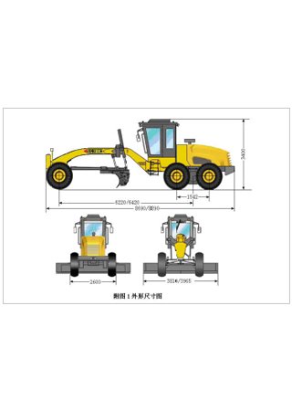
Каталог деталей автогрейдеров YTO PY180C-2, YTO PY180D-2 и
Формат: pdf
-
Год:
2008
-
Страниц:
102
-
Язык:
английский, китайский
-
Размер:
13,4 Мб
-
Категории:
Автогрейдеры

13,5 Мб
Руководство по эксплуатации автогрейдеров ЧСДМ ДЗ-98В
Формат: pdf
-
Год:
2018
-
Страниц:
119
-
Язык:
русский
-
Размер:
13,5 Мб
-
Категории:
Автогрейдеры
2,21 Мб
Руководство по эксплуатации автогрейдеров XGMA XG31651 и
Формат: doc
-
Год:
2007
-
Страниц:
45
-
Язык:
русский
-
Размер:
2,21 Мб
-
Категории:
Автогрейдеры
-
Contents
-
Table of Contents
-
Bookmarks
Quick Links
B A U M A S C H I N E N
Maintenance instructions
BG 160TA-4
Motor Grader
Motorgrader
Niveleuse
englisch
01/2007
Summary of Contents for GP HBM-NOBAS BG 160TA-4
-
Page 1
B A U M A S C H I N E N Maintenance instructions BG 160TA-4 Motor Grader Motorgrader Niveleuse englisch 01/2007… -
Page 2
Motor Grader Motorgrader Niveleuse BG 160TA-4 Maintenance instructions Wartungsanleitung Instructions d’entretien 01/2007 HBM/NOBAS construction machine… -
Page 3: Table Of Contents
Maintenance instructions Table of Contents Preface Safety regulations Running-in period Drive engine Daily Maintenance Procedures Daily Maintenance Procedures — Overview 4.1.1 Crankcase Breather Tube 4.1.2 Fuel-Water Separator 4.1.3 Lubricating Oil Level 4.1.4 Coolant Level 4.1.5 Drive Belts 4.1.6 Maintenance Procedures at 250 hours or 3 months Air Cleaner Restriction 4.2.1 Charge-Air Cooler…
-
Page 4
Maintenance instructions Table of Contents Air filter system Air filter Replacement, removal and insertion of the filter insert 6.1.1 Blowing-off the filter insert 6.1.2 Checking the filter insert 6.1.3 Replacement of safety cartridge 6.1.4 Ergopower gear Gear type 6 WG 160 Battery Rear axle Checking the oil levels… -
Page 5
Maintenance instructions Table of Contents Replacement of the hydraulic filter 13.4 Replacement of the filter cartridge of the backflow filter 13.4.1 High-pressure filter cleaning 13.4.2 Replace the filter cartridge of the high-pressure filter 13.4.2.1 Articulated frame joint and articulated steering cylinder Lubrication of the grading plate Rear ripper Changing the tyres… -
Page 6: Preface
Maintenance instructions 1 Preface Proper operation and care are important prerequisites for maintaining the serviceability of the building machine. These maintenance instructions should always be within the machine operator’s reach. Please read the maintenance instructions and safety rules carefully and follow them strictly. Carry out the inspections, checks and maintenance jobs at the specified intervals.
-
Page 7: Safety Regulations
Maintenance instructions 2 Safety regulations As to the inspections, checks and maintenance of the building machine, the safety regulations of the country in which the machine is used and those of the trade association concerned are applicable. The regulations specified in European standards EN 474-1 and EN 474-8 are applicable to this. In the Federal Republic of Germany, the requirements are applicable in accordance with the material content of the «Op- eration»…
-
Page 8: Running-In Period
Maintenance instructions 3 Running-in period It is particularly important to carry out the inspections and maintenance work in line with the following schedule (after the first 100 hours of operation): Engine Change oil and oil filter cartridge. Check the coolant level. Inspect the V-belt.
-
Page 9: Drive Engine
Maintenance instructions 4 Drive engine General Information At each scheduled maintenance interval, perform all previous maintenance checks that are due for scheduled mainte- nance. Maintenance Schedule Daily or Refueling — Maintenance Check Section 4.1 • Crankcase Breather Tube – Inspect •…
-
Page 10
Maintenance instructions Maintenance Record Maintenance Record Engine Serial No.: Engine Model: Owner’s Name: Equipment Name/Number: Date km [Miles], hours Actual km [Miles] Maintenance Check Per- Comments or Time Interval or hours Check Performed formed By… -
Page 11: Daily Maintenance Procedures
Maintenance instructions 4.1 Daily Maintenance Procedures 4.1.1 Daily Maintenance Procedures — Overview General Information Preventative maintenance begins with day-to-day awareness of the engine and its system. Before starting the engine, check the oil and coolant levels. Look for: • Leaks •…
-
Page 12: Crankcase Breather Tube
Maintenance instructions 4 4.1.2 Crankcase Breather Tube Fig. 4.1.2/1 Maintenance Check Inspect the breather tube for sludge, debris, or ice in the tube. The tube must be free. Inspect the tube more frequently in icy conditions. The line must be laid freely, and must not be kinked. Fig.
-
Page 13: Coolant Level
Maintenance instructions 4.1.5 Coolant Level Fig. 4.1.5/1 to 4.1.5/3 Maintenance Check Warning! Do not remove a pressure cap from a hot en- gine. Wait until the coolant temperature is below 50°C (120°F) before removing the pressure cap. Heated coolant spray or steam can cause per- sonal injury.
-
Page 14: Drive Belts
Maintenance instructions 4.1.6 Drive Belts Fig. 4.1.6/1 Maintenance Check Cogged Belt Inspect the belts daily. Replace the belts if they are cracked, frayed, or have chunks of material missing. Small cracks are acceptable. Adjust the belts that have a glazed or shiny surface, which indicates belt slippage.
-
Page 15: Maintenance Procedures At 250 Hours Or 3 Months
Maintenance instructions 4.2 Maintenance Procedures at 250 hours or 3 months 4.2.1 Air Cleaner Restriction Maintenance Check Refer to item 6.1of the maintenance instructions. Caution! Never operate the engine without an air cleaner. Intake air must be filtered to prevent dirt and debris from entering the engine and causing premature wear.
-
Page 16: Air Intake Piping
Maintenance instructions 4.2.5 Air Intake Piping Fig. 4.2.5/1 Maintenance Check Visually inspect the intake piping daily for wear points and damage to pip- ing, loose clamps, or punctures that can damage the engine. Replace damaged pipes, and tighten loose clamps, as necessary, to pre- vent the air system from leaking.
-
Page 17: Maintenance Procedures At 500 Hours Or 6 Months
Maintenance instructions 4.3 Maintenance Procedures at 500 hours or 6 months 4.3.1 Cooling System Maintenance Check — coolant Refer to item 22 of the maintenance instructions. 4.3.2 Fuel Filter (Spin-On Type) Remove Fig. 4.3.2/1 Remove the spin-on fuel filter with fuel filter wrench. Fig.
-
Page 18: Lubricating Oil And Filters
Maintenance instructions Prime Fig. 4.3.2/3 Warning! The fuel pump high-pressure fuel lines and fuel rail contain very high-pressure fuel. Never loosen any fittings while the engine is running. Personal injury and property damage can result. Use the installed filling device to fill the engine. Typically, a priming pump is installed at or near the prefilter.
-
Page 19
Maintenance instructions Remove Fig. 4.3.3/3 Clean the area around the lubricating oil filter head. Use the oil filter wrench to remove the filter. Clean the gasket surface of the filter head. Note: The o-ring can stick on the filter head. Make sure it is removed be- fore installing the new filter. -
Page 20: Maintenance Procedures At 1000 Hours Or 1 Year
Maintenance instructions 4.4 Maintenance Procedures at 1000 hours or 1 year 4.4.1 Cooling Fan Belt Tensioner Fig. 4.4.1/1 to Fig. 4.4.1/5 Maintenance Check With the engine turned off, check that neither the top nor bottom tensioner arm stop is touching the cast boss on the tensioner body. If either of the stops is touching a boss, the alternator belt must be replaced.
-
Page 21: Fan Hub, Belt Driven
Maintenance instructions 4.4.2 Fan Hub, Belt Driven Fig. 4.4.2/1 and 4.4.2/2 Maintenance Check Remove the drive belt. Fig. 4.4.2/1 Note: The fan hub must rotate without any wobble or excessive end play. Fan Hub End Play 0.15 0.006 Fig. 4.4.2/2…
-
Page 22: Maintenance Procedures At 2000 Hours Or 2 Years
Maintenance instructions 4.5 Maintenance Procedures at 2000 hours or 2 years 4.5.1 Cooling System Drain Fig. 4.5.1/1 to Fig. 4.5.1/3 Warning! Do not remove the pressure cap from a hot engine. Wait until the coolant temperature is below 50°C (122°F) before removing the pres- sure cap.
-
Page 23
Maintenance instructions Flush Fig. 4.5.1/4 to Fig. 4.5.1/7 Caution! The system must be filled properly to prevent air locks. During filling, air must be vented from the engine coolant passages. Wait 2 to 3 minutes to allow air to be vented; then add mixture to bring the level to the top. -
Page 24
Maintenance instructions Fill Fig. 4.5.1/8 to Fig. 4.5.1/10 Caution! The system must be filled properly to prevent air locks. During filling, air must be vented from the engine coolant passages. Wait 2 to 3 minutes to allow air to be vented; then add mixture to bring the level to the top. -
Page 25: Cooling System
Maintenance instructions 5 Cooling system 5.1 Checking the coolant level Fig. 5.1/1 Put down the engine horizontally, and turn off the engine. Slowly unscrew and remove the balance tank cover (D). When the engine is cold, the coolant level should be at the lower end of the filler neck (water must be always visible).
-
Page 26: Air Filter System
Maintenance instructions 6 Air filter system Fig. 6/1 and Fig. 6/2 The air filter is a combined air filter with an integrated filter-element (1) and a safety cartridge. The rough dust is discharged through the dust discharge valve (S), almost free of maintenance. The discharge slot of the valve must be checked for cleanness daily.
-
Page 27: Blowing-Off The Filter Insert
Maintenance instructions 6.1.2 Blowing-off the filter insert Fig. 6/6 The dry cleaning can be carried out with compressed air up to a maximum pressure of 6 bar (87 Psi). For this, the air nozzle is moved up and down at a minimum distance of approx.
-
Page 28: Ergopower Gear
Maintenance instructions 7 Ergopower gear 7.1 Gear type 6 WG 160 Fig. 7.1/1 shows the schematic structure of the Ergopower gear. For all activities at the gears, urgently comply with the prescribed safety regulations acc. to § 6 of the Regulation on the Prevention of Accidents at Propulsion Units. For example, the machine must be secured by wedges against rolling away, and articulated vehicles additionally against unintended turning (frame lockage).
-
Page 29
Maintenance instructions Oil change Oil change and filter replacement interval: • First oil change after 100 operating hours in application. • Every further oil change after 1000 operating hours in application, however at least once a year! • At every oil change, the Fine filter (pressure filter) has to be replaced. The oil change must be carried out as follows: •… -
Page 30
Maintenance instructions Oil temperature Fig. 7.1/3 The display range of the temperature sensor starts at 30°C (86°F). Gear oil temperature is monitored by a temperature sensor. The warning lamp (1) lights up when a temperature of 114°C (237°F) is reached. The lamp is lit and a buzzer sound is heard at a temperature of 120°C (248°F) or more. -
Page 31: Battery
Maintenance instructions 8 Battery Fig. 8/1 Please also observe section 18 on the «Electric System». The batteries are located at the rear part of the frame, to the left and right of the frame knuckle joint. There is easy access to the batteries after the fixing nuts of the protective hood have been loosened and the hood has been removed.
-
Page 32: Rear Axle
Maintenance instructions 9 Rear axle Do not connect the (-) pole to the rear axle during any welding work carried out on the machine. No welding is allowed at the rear axle! 9.1 Oil level checks Checking the oil level in the axle transmission Fig.
-
Page 33
Maintenance instructions 9.2 Oil change at the rear axle Always change the oil while it is warm. To do so, park the machine at a horizontal position. Do not allow any oil to drain into the soil. Always use containers to catch all oil. Replace the drain plug seal rings for every oil change. -
Page 34
Maintenance instructions Tandem oil change Fig. 9/7 and Fig. 9/8 Unscrew the oil filler hole (E) cover, and unscrew the two oil drain plugs (A). Drain oil into a container. Close the drain plugs (A), and fill in oil until the level fills half the inspection hole (Fig. -
Page 35
Maintenance instructions Oil drain plug (A) is checking screw (K). To top up oil, park the machine to have the checking screw (K) in a horizon- tal position. Unscrew oil plug (E) and checking screw (K). Fill oil into the fill hole (E) until the oil level reaches the bottom edge of the checking screw (K). -
Page 36: Spin Differential
Maintenance instructions 9.3 NO-SPIN differential Fig. 9.3/1 Caution! During repair activities at wheels, brakes, axles, or tyres, turn off the engine, and all drive wheels of an axle equipped with a NO-SPIN / Detroit Locker differential must be lifted so that the grader cannot move by itself.
-
Page 37
Maintenance instructions Checking of the NO-SPIN differential during driving If a permanent ticking can be heard when driving straight forward, or if a permanent pulling to the right or left is stated dur- ing forward driving, so e.g. the roll-on radius of the tyres could be the reason because of irregular wear or different tyre pressures (possibly correct tyre pressure, and measure the distance between the ground and the rim. -
Page 38
Maintenance instructions Step 3: Rotate both wheel sides backward as far as possible (both wheel sides should stop after a short rotating move- ment.) Step 4: The helper on the other side strongly keeps the right side of the wheel against the stop to the rear, and you rotate the left side of the wheel forward, and listen again for clicking engagement sounds (here again, the right side of the wheel has to be kept strongly against the stop, or the left wheel side will not freely disengage). -
Page 39: Drive Shafts
Maintenance instructions Important recommendations for the driver Drive the vehicle only when the two wheel pairs of the NO SPIN axle are firmly on the ground. Power transmission to one wheel pair only may entail steering problems. Be particularly careful when accelerating and braking with the engine on a slippery or unpaved road. Machines equipped with self-locking differentials tend to skid.
-
Page 40: Front Axle
Maintenance instructions 10 Front axle Fig. 10/1 The following points are to be greased at the intervals shown in the maintenance plan: King pins (1) — 4 lubrication points Axle (2) — 2 lubrication points Tipping cylinder (3) — 2 lubrication points Axles (4) — 4 lubrication points Clean the lubricating nipple thoroughly before regreasing.
-
Page 41: Braking System
Maintenance instructions 11 Braking system Fig. 11/1 The diagram of the operating brake system is shown in fig. 11/1. There is no specific maintenance obligation for the brak- ing system. Keep the whole system clean, and check it for leaks in compliance with the inspection schedule. Four measuring points are provided for check measurements: M1 = Storage pressure M3 = Service brake pressure…
-
Page 42: Bleeding The Brake
Maintenance instructions rear front fuel tank Fig. 11/1 11.2 Bleeding the brake Fig. 11.2/1 Start bleeding at the left rear brake of the tandem axle. Continue with the right rear brake, then the left front brake and finally the right front brake. Push a tube onto the nipple (N) beside the pipe connection and dip the tube into a con- tainer which is filled to half its capacity with hydraulic oil (see the consumable and lubri- cant table).
-
Page 43: Servicing The Wheel Brake
Maintenance instructions 11.3 Servicing the wheel brake The wet multidisk brakes installed in the wheel hubs are almost free of wear, and require no maintenance apart from the checking of the different wheel brakes. However you should take the following facts into due consideration: 1.
-
Page 44: Parking Brake Emergency Release
Maintenance instructions 11.4 Parking brake emergency release Fig. 11.5/1 Proceed as follows to release the parking brake mechanically if the pressure supply has failed: 1. Secure the vehicle to prevent it from rolling away. 2. Loosen and unscrew the screw cap. 3.
-
Page 45: Moldboard Assembly
Maintenance instructions 12 Moldboard assembly All sliding points and joints of the moldboard assembly shall always be well lubricated. Lubricate whenever necessary. Before lubricating, clean the nipples and sliding faces to be greased carefully. 12.1 Lubricating the moldboard assembly Fig. 12.1/1 Press grease into the nipples for the swing bearings of the lifting and swivelling cylinders in the forks, the fork bearings in the bridge, the piston rod heads of the hydraulic cylinders, and the…
-
Page 46
Maintenance instructions 12.2 Greasing the blade system (guided in babbitt bearings) Fig. 12.2/1 and 12.2/2 Apply lubricating grease to the sliding surfaces at the slewing ring top and bottom sides, to the ring’s gear teeth, and to the blade guide rails. Clean the sliding surface before greasing. -
Page 47: Circle Drive
Maintenance instructions 12.4 Slewing ring readjustment (guided in babbitt bearings) Fig. 12.4/1 to 12.4/3 The slewing ring (D) bottom side slides on 4 pads (P), and the slewing ring top side slides against set-on slide segments (G) of the draw beam. The pads (P) can be adjusted both horizontally and vertically.
-
Page 48: Hydraulic Working System
Maintenance instructions 13 Hydraulic working system The line scheme of the hydraulic working, braking, and steering systems is shown in the line diagram. The pressure is checked at the measuring point M1. The measuring point is located at the control block. 13.1 Checking the oil level Fig.
-
Page 49: Replacement Of The Hydraulic Filter
Maintenance instructions 13.4 Replacement of the hydraulic filter Stop the diesel engine before starting mainte- nance work, or before a filter change. 13.4.1 Replacement of the filter cartridge of the backflow filter Fig. 13.4/1 and 13.4.1/1 When the control lamp (H) indicates that the filter is contaminated the filter element must be urgently replaced.
-
Page 50: Replace The Filter Cartridge Of The High-Pressure Filter
Maintenance instructions 13.4.2.1 Replace the filter cartridge of the high-pressure filter Fig. 13.4/1 und 13.4.2.1/1 When the control lamp (D) indicates that the filter is contaminated the filter element must be urgently replaced. Disassemble and replace the filter element (6) as follows: 1.
-
Page 53: Articulated Frame Joint And Articulated Steering Cylinder
14/15/16 Maintenance instructions 14 Articulated frame joint and articulated steering cylinder Fig. 14/1 The articulated joint and the cylinder bearings have to be regularly lubri- cated in accordance with the inspection schedule. — 6 lubrication points — Thoroughly clean the grease nipples before the grease gun is attached. After a long-time operation with the articulated steering locked, the borings of the supporting fish-plate (H) may be widened.
-
Page 54: Changing The Tyres
Maintenance instructions 17 Changing the tyres The wheels must be removed from the machine in order to change the tyres. To do this, the machine must be raised so that the relevant wheel is clear of the ground. Loosen the wheel nuts one or two turns before lifting the grader. The grader can be lifted on one side with the aid of the hydraulics.
-
Page 55: Tyre Ballast (Option)
Maintenance instructions 17.1 Tyre Ballast (Option) As extra ballast to increase the available tractive force, the interior volume of the tyre can be half-filled with an anti-freeze solution with a density of 1.19 kg/dm (-30°C). To do this, use the tyre inflating equipment supplied in the on-board acces- sory set.
-
Page 56: Electrical System
Maintenance instructions 18 Electrical system 18.1 Electrical system on the machine Before you start any work at the electrical system of the machine, put the system out of operation. For this purpose, dis- connect the negative and afterwards the positive cables from the battery. When you reattach the cables, start with the positive cable and then fix the negative cable.
-
Page 59: Electrical Symbols
Maintenance instructions 18.2 Electrical symbols Microcontroller Signal light at the rear right Control box Signal light center right Transmission Boundary light in front left Plug motor control Boundary light in front right Foot gas Tail light at the rear left Hand gas Stop light at the rear left Plug motor control…
-
Page 60
Maintenance instructions Relay latch plate price increase Switch wiper down right Relay hand brake Switch differential lock Relay barrier 6. course Switch parking brake Relay voltage injection pump Switch diagnosis starter Diode block light test Heater engine Windshield wiper engine Plug connector Disk washer pump Rear windshield wiper engine… -
Page 61: Lubricants, Fuels, Filling Quantities
Maintenance instructions 19 Lubricants, fuels, filling quantities lubricants, quantity in litres lubricants, fuels temperature limits Viscosity classes fuels, (USgal) (international specifica- in °C (°F) filling quantities tion)* hydraulic system approx. 170 H-LP 46 10° — 50° ( 50° — 120°) ISO VG 100 (44,9) DIN 51524 Part 2…
-
Page 62: Lubricants
Maintenance instructions 20 Lubricants Only use lubricants which fulfil the specifications mentioned below and which are internationally known. Do not mix engine, gear and hydraulic oils! The viscosity limits (viscosity classes) mentioned in the table “”Lubricants, fuels and quantities”, e.g. ISO VG 46I corre- spond to the codes DIN 51 519 and ISO 3448.
-
Page 63: Diesel Fuels
Maintenance instructions 21 Diesel fuels The engine will generate the specified power and show the required running properties only if high-quality fuel is used. The fuel recommended to be used with Perkins engines shall have the following characteristics: Cetane number min.
-
Page 64: Long-Term Coolants
Maintenance instructions 22 Long-term coolants The cooling system is factory-filled with a long-term coolant which is a mixture of water, antifreeze and anti-corrosive agents. For moderate climate territories, its frost resistance is set at -37°C (-35 °F). A tag on the radiator informs on the use of an antifreeze. For corrosion protection reasons and to prevent furring, the cool- ing system should have an antifreeze content of 50 % vol.
-
Page 65
Maintenance instructions In tropical regions where the air temperature lies above +35 °C (95 °F), the low thermal conductivity of the long-term cool- ant may lead to an overheating of the engine. In this case, use water instead of the long-term coolant, and add a corrosion inhibitor to the water to prevent corrosion and furring. -
Page 66: Winter Operation
Maintenance instructions 23 Winter operation So as to ensure that the machine can be operated without any problems also in winter, a few precautionary measures must be taken before the cold season begins. Cooling system The cooling system must be sufficiently resistant to the low temperatures occurring in your region.
-
Page 67: Shutting The Machine Down For A Longer Period
Maintenance instructions 24 Shutting the machine down for a longer period 1. Drain the engine oil when it is still warm and fill up with the following slushing oil: a) Engines which are not supercharged (aspirating engines) — Slushing oil for piston engines, MIL-L 21 260, type 1 or type 2 — SAE class 10 W for preservation in winter — SAE class 30 for preservation in summer b) Supercharged engines…
-
Page 68: Maintenance And Inspection Plan
Maintenance instructions 25 Maintenance and inspection plan For the first time after the following operating hours Daily or every 10 operating hours or if required Every 50 operating hours Every 250 operating hours Every 500 operating hours Every 1000 operating hours Every 2000 operating hours or annually Every 4000 operating hours or max.
-
Page 69
Maintenance instructions Fig. 25…
Автогрейдеры Руководства и Инструкции по Ремонту и Эксплуатации Скачать Бесплатно
15,8 Мб
Автогрейдеры Caterpillar 140H, 160H: Руководство по
Формат: pdf
-
Год:
2000
-
Страниц:
182
-
Язык:
русский
-
Размер:
15,8 Мб
-
Категории:
Автогрейдеры
13,4 Мб
Каталог деталей автогрейдеров YTO PY180C-2, YTO PY180D-2 и
Формат: pdf
-
Год:
2008
-
Страниц:
102
-
Язык:
английский, китайский
-
Размер:
13,4 Мб
-
Категории:
Автогрейдеры
13,5 Мб
Руководство по эксплуатации автогрейдеров ЧСДМ ДЗ-98В
Формат: pdf
-
Год:
2018
-
Страниц:
119
-
Язык:
русский
-
Размер:
13,5 Мб
-
Категории:
Автогрейдеры
2,21 Мб
Руководство по эксплуатации автогрейдеров XGMA XG31651 и
Формат: doc
-
Год:
2007
-
Страниц:
45
-
Язык:
русский
-
Размер:
2,21 Мб
-
Категории:
Автогрейдеры
Автогрейдеры: Руководство по Эксплуатации и ремонту

Автор: Бандаков Б.Ф.
Формат: PDF
Размер: 11.8 Mb
Год: 1988
Страниц: 302
Пособие рассматривает особенности конструкции автогрейдеров, особенности управления, технического обслуживания и ремонта этих машин. Кроме того описывается технология работ, выполняемых автогрейдерами при строительстве, ремонте и содержании автомобильных дорог. Приведены сведения по охране труда, технике безопасности при эксплуатации техники. Пособие рекомендовано лицам, занимающимся управлением и ремонтом автогрейдеров.
ОБЩИЕ СВЕДЕНИЯ 4
1 ОПИСАНИЕ И РАБОТА АВТОГРЕЙДЕРА 8
1.1 Назначение 8
1.2 Технические характеристики 8
1.3 Устройство и работа автогрейдера 10
2 ОПИСАНИЕ И РАБОТА СОСТАВНЫХ ЧАСТЕЙ АВТОГРЕЙДЕРА 17
2.1 Двигатель 17
2.2 Трансмиссия 30
2.3 Ходовая часть 51
2.4 Пневмосистема 57
2.5 Гидросистема автогрейдера 67
2.6 Рулевое управление 74
2.7 Электрооборудование 78
2.8 Рабочее и дополнительное рабочее оборудование 81
2.9 Кабина 88
3 УКАЗАНИЯ МЕР БЕЗОПАСНОСТИ 90
3.1 Общие указания 90
3.2 Меры безопасности при техническом обслуживании 91
3.3 Меры пожарной безопасности 91
4 УКАЗАНИЯ ПО МОНТАЖУ И ОБКАТКЕ АВТОГРЕЙДЕРА 92
4.1 Подготовка к монтажу 92
4.2 Монтаж 92
4.3 Обкатка автогрейдера 94
5 ЭКСПЛУАТАЦИОННЫЕ ОГРАНИЧЕНИЯ 95
6 ПОДГОТОВКА АВТОГРЕИДЕРА К ИСПОЛЬЗОВАНИЮ 96
6.1 Эксплуатационные материалы 96
6.2 Пуск двигателя 96
6.3 Трогание с места и движение 98
6.4 Остановка 98
7 ИСПОЛЬЗОВАНИЕ АВТОГРЕИДЕРА ПО НАЗНАЧЕНИЮ 99
7.1 Общие указания 99
7.2 Углы установки отвала 100
7.3 Вынос тяговой рамы вправо на максимальный угол 101
7.4 Вынос тяговой рамы влево на максимальный угол 102
7.5 Работа дополнительным рабочим оборудованием 103
7.6 Рекомендации по эффективному использованию автогрейдера 104
7.7 Буксировка 105
7.8 Особенности эксплуатации автогрейдера в холодный период 106
7.9 Указания по использованию комплекта ЗИП 107
8 ТЕХНИЧЕСКОЕ ОБСЛУЖИВАНИЕ 108
8.1 Виды и периодичность технического обслуживания 108
8.2 Перечень работ по техническому обслуживанию 109
8.3 Техническое обслуживание в особых условиях эксплуатации 115
8.4 Таблица смазки 117
8.5 Перечень эквивалентных смазочных материалов 122
8.6 Содержание операций технического обслуживания 122
9 ТЕКУЩИЙ РЕМОНТ 129
9.1 Общие сведения 129
9.2 Возможные неисправности и способы их устранения 129
9.3 Особенности ремонта некоторых агрегатов 134
9.4 Частичная разборка автогрейдера 135
10 ХРАНЕНИЕ И КОНСЕРВАЦИЯ 144
10.1 Общие положения 144
10.2 Требования к кратковременному хранению 144
10.3 Требования к длительному хранению 145
10.4 Хранение аккумуляторных батарей в сухом виде 145
10.5 Хранение аккумуляторных батарей с электролитом 146
11 ТРАНСПОРТИРОВАНИЕ 147
12 ТЕХНИЧЕСКИЕ ПРИЗНАКИ (КРИТЕРИИ) ПРЕДЕЛЬНОГО СОСТОЯНИЯ АВТОГРЕЙДЕРА 149
ОБЩИЕ СВЕДЕНИЯ
![]()
![]() В связи с постоянной работой по совершенствованию автогрейдеров, в их конструкцию могут быть внесены некоторые изменения, не отраженные в настоящем издании.
В связи с постоянной работой по совершенствованию автогрейдеров, в их конструкцию могут быть внесены некоторые изменения, не отраженные в настоящем издании.
![]()
Настоящее руководство по эксплуатации (РЭ) распространяется на автогрейдер класса 250 ГС-250, его модификации и комплектации (далее по тексту автогрейдеры).
Автогрейдер ГС-250, его модификации и комплектации относятся к классу 250 по ГОСТ 11030 и предназначены для землеройно-профилировочных работ при строительстве, ремонте, содержании дорог, а также для использования в железнодорожном, мелиоративном и гидротехническом строительстве.
Модификации и комплектации автогрейдера унифицированы с базовой моделью и различаются двигателем, трансмиссией, рабочим и дополнительным оборудованием.
Основным рабочим оборудованием автогрейдера является регулируемый отвал (полноповоротный или неполноповоротный), расположенный между передними и задними колесами, который режет, перемещает и распределяет материал в целях профилирования.
Дополнительное оборудование бульдозерное, рыхлительное, путепрокладочное, снегоочистительное (далее по тексту оборудование), установленное на головке основной рамы автогрейдера, предназначено для расширения видов работ.
Каждой модели автогрейдера присвоено условное обозначение, состоящее из буквенных и цифровых кодов:
| ГС | 250 | Х | Х | Х |
| 1 | 2 | 3 | 4 | 5 |
1 – буквенный код обозначения производителя автогрейдера:
ГС – грейдер самоходный;
2 – цифровой код обозначения класса автогрейдера по ГОСТ 11030:
250 – класс 250;
3 – цифровой код обозначения рабочего оборудования:
1 – бульдозерное оборудование ДЗ98В1.2.25.02.000 с полноповоротным грейдерным отвалом;
2 – бульдозерное оборудование ДЗ98В1.2.25.02.000 с неполноповоротным грейдерным отвалом;
3 – рыхлительное оборудование ДЗ98В1.3.25.03.000-01 с полноповоротным грейдерным отвалом;
4 – рыхлительное оборудование ДЗ98В1.3.25.03.000-01 с неполноповоротным грейдерным отвалом;
5 – бульдозерное оборудование ДЗ98В1.2.25.02.000, рыхлительное оборудование ДЗ98В1.3.25.03.000-01, с полноповоротным грейдерным отвалом;
6 – бульдозерное оборудование ДЗ98В1.2.25.02.000, рыхлительное оборудование ДЗ98В1.3.25.03.000-01, с неполноповоротным грейдерным отвалом;
4 – цифровой код обозначения дополнительного оборудования:
1 – кирковочное оборудование на корме;
5 – буквенный код обозначения климатического исполнения:
С — северное исполнение;
без обозначения – исполнение для умеренного климата.
Модели автогрейдеров, на которые распространяются настоящее руководство по эксплуатации, приведены в таблице 1.
Таблица 1 – Модели, модификации и комплектации автогрейдеров
| Модель | Характеристика |
| 1 | 2 |
| ГС-250 | Базовая модель — Автогрейдер с механической
трансмиссией с полноповоротным грейдерным отвалом (без дополнительного оборудования), двигатель ЯМЗ-238НД3, климатического исполнения У |
| ГС-250-1 | Комплектация автогрейдера ГС-250:
Автогрейдер с бульдозерным оборудованием |
| ГС-250-2 | Комплектация автогрейдера ГС-250:
Автогрейдер с бульдозерным оборудованием с неполноповоротным грейдерным отвалом |
| ГС-250-3 | Комплектация автогрейдера ГС-250:
Автогрейдер с рыхлительным оборудованием |
| ГС-250-4 | Комплектация автогрейдера ГС-250:
Автогрейдер с рыхлительным оборудованием с неполноповоротным грейдерным отвалом |
| ГС-250-5 | Комплектация автогрейдера ГС-250:
Автогрейдер с бульдозерным и рыхлительным оборудованием |
| ГС-250-6 | Комплектация автогрейдера ГС-250:
Автогрейдер с бульдозерным и рыхлительным оборудованием с неполноповоротным грейдерным отвалом |
| ГС-250-0-1 | Комплектация автогрейдера ГС-250:
Автогрейдер с полноповоротным грейдерным отвалом (без дополнительного оборудования) с кирковочным оборудованием на корме |
| ГС-250-1-1 | Комплектация автогрейдера ГС-250:
Автогрейдер с бульдозерным оборудованием с кирковочным оборудованием на корме |
| ГС-250-2-1 | Комплектация автогрейдера ГС-250:
Автогрейдер с бульдозерным оборудованием с неполноповоротным грейдерным отвалом с кирковочным оборудованием на корме |
| ГС-250.С | Комплектация автогрейдера ГС-250:
Автогрейдер с полноповоротным грейдерным отвалом (без дополнительного оборудования) в северном исполнении |
| ГС-250-1.С | Комплектация автогрейдера ГС-250:
Автогрейдер с бульдозерным оборудованием, в северном исполнении |
| ГС-250-2.С | Комплектация автогрейдера ГС-250:
Автогрейдер с бульдозерным оборудованием с неполноповоротным грейдерным отвалом, в северном исполнении |
| ГС-250-3.С | Комплектация автогрейдера ГС-250:
Автогрейдер с рыхлительным оборудованием, в северном исполнении |
Окончание таблицы 1
| 1 | 2 |
| ГС-250-4.С | Комплектация автогрейдера ГС-250:
Автогрейдер с рыхлительным оборудованием с неполноповоротным грейдерным отвалом, в северном исполнении |
| ГС-250-5.С | Комплектация автогрейдера ГС-250:
Автогрейдер с бульдозерным и рыхлительным оборудованием, в северном исполнении |
| ГС-250-6.С | Комплектация автогрейдера ГС-250:
Автогрейдер с бульдозерным и рыхлительным оборудованием с неполноповоротным грейдерным отвалом, в северном исполнении |
| ГС-250-0-1.С | Комплектация автогрейдера ГС-250:
Автогрейдер с полноповоротным грейдерным отвалом (без дополнительного оборудования) с кирковочным оборудованием на корме, в северном исполнении |
| ГС-250-1-1.С | Комплектация автогрейдера ГС-250:
Автогрейдер с бульдозерным оборудованием с кирковочным оборудованием на корме, в северном исполнении |
| ГС-250-2-1.С | Комплектация автогрейдера ГС-250:
Автогрейдер с бульдозерным оборудованием с неполноповоротным грейдерным отвалом с кирковочным оборудованием на корме, в северном исполнении |
Руководство по эксплуатации предназначено для изучения конструкции, правил эксплуатации и текущего ремонта автогрейдера ГС-250, его модификаций и комплектаций.