Интернет-магазин
OILSHOP55.RU
Масла и смазки для автомобилей и мотоциклов, автохимия, расходные материалы, запчасти.
Воскресенье, 24.09.2023, 20:39
Приветствую Вас
Гость
| ВХОД НА САЙТ
|
Поиск товара |
|
| ОНЛАЙН КОНСУЛЬТАНТ |
| СТАТИСТИКА |
|
Онлайн всего: 56 Гостей: 56 Пользователей: 0 |

![]()
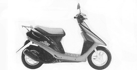
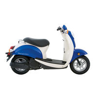
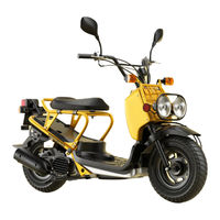
Руководство по эксплуатации скутеров HONDA DIO & Tact
|
[ Скачать с сервера (2.78 Mb)
] |
13.07.2011, 10:01 |
|
Полная инструкция ко всем скутерам HONDA DIO и Tact c двухтактным двигателем. Расписано и разрисовано СКАЧАТЬ Инструкцию по эксплуатации HONDA DIO и HONDA TACT Запчасти для скутеров HONDA DIO в нашем интернет-магазинеРекомендуем: Моторное масло для Honda Dio & Tact Трансмиссионное масло для Honda Dio & Tact: |
|
|
Категория: Скутеры | Добавил: Richas | Теги: Honda TACT, скачать инструкцию, инструкция по эксплуатации, инструкция к HONDA, эксплуатация и ремонт, инструкция, Honda dio, инструкция на скутер |
|
| Просмотров: 101246 | Загрузок: 5552 | Комментарии: 6 | Рейтинг: 4.3/3 |
| Всего комментариев: 6 | |
|
Порядок вывода комментариев: 6 Уголёк Нашёл искру-то? 5 Георгий Здравствуйте, подскажите пожалуйста размеры и диаметр болтов крышки вариатора на хонда дио аф 34 4 azer в сенагогу идите 2 АЛЕКСАНДР Что делать когда проподает искра 1 Юрий очень нужно |
|
СЕГОДНЯ В НАШЕМ МАГАЗИНЕ МОЖНО ЗАКАЗАТЬ ТОВАРЫ СО СКИДКОЙ…
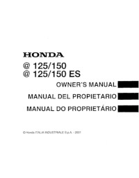
Руководство на английском языке по эксплуатации и техническому обслуживанию скутеров Honda @ 125/125 ES/150/150 ES.
- Издательство: Honda Italia Industriale S.p.A.
- Год издания: 2001
- Страниц: 114
- Формат: PDF
- Размер: 2,2 Mb
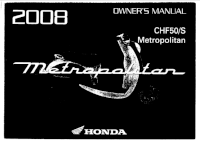
Руководство на английском языке по эксплуатации и техническому обслуживанию скутеров Honda CHF50 и CHF50S.
- Издательство: Honda Motor Co., Ltd.
- Год издания: 2007
- Страниц: 226
- Формат: PDF
- Размер: 4,5 Mb
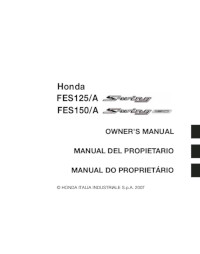
Руководство на английском, испанском и итальянском языках по эксплуатации и техническому обслуживанию скутеров Honda S-Wing FES125/FES125A/FES150/FES150A.
- Издательство: Honda Italia Industriale S.p.A.
- Год издания: 2007
- Страниц: 418
- Формат: PDF
- Размер: 4,9 Mb

Руководство на английском языке по эксплуатации и техническому обслуживанию скутеров Honda FES250.
- Издательство: Honda Motor Co., Ltd.
- Год издания: 1998
- Страниц: 114
- Формат: PDF
- Размер: 2,6 Mb
Сборник руководств на английском языке по эксплуатации и техническому обслуживанию скутеров Honda FJS400A/FJS400D/600A/600D Silver Wing и Honda SW-T400.
- Издательство: Honda Motor Co., Ltd.
- Год издания: 2004/2008
- Страниц: 154/154
- Формат: PDF
- Размер: 4,9 Mb

Сборник руководств на английском языке по эксплуатации и техническому обслуживанию скутеров Honda FSC600/FSC600A/FSC600D Silver Wing.
- Издательство: Honda Motor Co., Ltd.
- Год издания: 2004/2006/2008/2009
- Страниц: 249/249/256/245
- Формат: PDF
- Размер: 9,1 Mb

Сборник руководств на английском языке по эксплуатации и техническому обслуживанию скутеров Honda NSS250A/NSS250EX/NSS250S/NSS250X.
- Издательство: Honda Motor Co., Ltd.
- Год издания: 2005/2008
- Страниц: 188/204
- Формат: PDF
- Размер: 7,2 Mb
Руководство на английском языке по эксплуатации и техническому обслуживанию скутеров Honda SCV100 Lead.
- Издательство: Honda Motor Co., Ltd.
- Год издания: 2003
- Страниц: 114
- Формат: PDF
- Размер: 2,0 Mb

Руководство на английском языке по эксплуатации и техническому обслуживанию скутеров Honda SH125 и SH150CRF.
- Издательство: Honda Motor Co., Ltd.
- Год издания: 2009
- Страниц: 126
- Формат: PDF
- Размер: 3,8 Mb
Руководство на английском языке по эксплуатации и техническому обслуживанию скутеров Honda Spacy-i.
- Издательство: Honda Motor Co., Ltd.
- Год издания: 2013
- Страниц: 100
- Формат: PDF
- Размер: 7,1 Mb

Руководство на английском языке по эксплуатации и техническому обслуживанию электровелосипеда Honda TDR01Z.
- Издательство: —
- Год издания: —
- Страниц: 11
- Формат: PDF
- Размер: 956 Kb

Руководство на английском языке по эксплуатации и техническому обслуживанию скутеров Honda Today.
- Издательство: Honda Motor Co., Ltd.
- Год издания: —
- Страниц: 60
- Формат: PDF
- Размер: 1,3 Mb
Руководство на английском языке по эксплуатации и техническому обслуживанию скутеров Honda SH300/SH300A/SH300AR/SH300R.
- Издательство: Honda Italia Industriale S.p.A.
- Год издания: 2007
- Страниц: 142
- Формат: PDF
- Размер: 1,7 Mb
Руководство на английском языке по обслуживанию и ремонту скутеров Honda CN250.
- Издательство: Honda Motor Co., Ltd.
- Год издания: 1993
- Страниц: 219
- Формат: PDF
- Размер: 24,9 Mb

Руководство на английском языке по обслуживанию и ремонту скутеров Honda NSS250/NSS250A/NSS250AS/NSS250S Reflex 2001-2007 годов выпуска.
- Издательство: Honda Motor Co., Ltd.
- Год издания: 2004
- Страниц: 401
- Формат: PDF
- Размер: 11,0 Mb
Руководство на итальянском языке по техническому обслуживанию и ремонту скутеров Honda SH125 и SH150.
- Издательство: Honda Motor Co., Ltd.
- Год издания: 2005
- Страниц: 371
- Формат: PDF
- Размер: 8,4 Mb

Руководство на немецком языке по техническому обслуживанию и ремонту скутеров Honda FJS600 Silver Wing.
- Издательство: Honda Motor Co., Ltd.
- Год издания: 2001
- Страниц: 439
- Формат: PDF
- Размер: 33,5 Mb

Руководство по эксплуатации и техническому обслуживанию скутеров Honda FJS600A и FJS600D.
- Издательство: Honda Motor Co., Ltd.
- Год издания: —
- Страниц: 146
- Формат: PDF
- Размер: 3,6 Mb

Руководство по техническому обслуживанию и ремонту скутеров Honda Lead.
- Издательство: Легион-Автодата.
- Год издания: —
- Страниц: 128
- Формат: —
- Размер: —

Руководство по техническому обслуживанию и ремонту скутеров Honda Dio и Honda Tact.
- Издательство: Легион-Автодата.
- Год издания: —
- Страниц: 112
- Формат: —
- Размер: —

Руководство по техническому обслуживанию и ремонту скутеров Honda Tact и Honda Dio.
- Издательство: Легион-Автодата.
- Год издания: 2002
- Страниц: 73
- Формат: PDF
- Размер: 16,3 Mb

Руководство по техническому обслуживанию и ремонту скутеров с карбюраторними двигателями объемом 50 до 250 кубических сантиметров. Представлены модели Honda FES 125 Pantheon, FES 250 Foresight, NES 125@125, SCV 100 Lead, SES 125Dylan, SFX 50, SGX 50 Sky, SH 50, SH 125, SZX 50 (X8R-S и X8R-X).
- Издательство: Алфамер
- Год издания: —
- Страниц: 368
- Формат: —
- Размер: —

Воскресенье, 24.09.2023, 20:39
Приветствую Вас
Гость
HONDA LIFE
RSS
Меню сайта
-
Главная страница
-
Книги и инструкции
Категории раздела
Honda Dio
Статистика
![]()
Онлайн всего: 1
Гостей: 1
Пользователей: 0
Форма входа
Книги и инструкции
| Главная » Файлы » Honda Dio |
| В категории материалов: 6 Показано материалов: 1-6 |
Сортировать по
:
Дате ·
Названию ·
Комментариям ·
Загрузкам ·
Просмотрам
Электросхема AF-35
Honda Dio |
Просмотров: 2935 |
Загрузок: 654 |
Добавил: ADMIN |
Дата: 27.04.2011
Электросхема AF-18, AF-27
Honda Dio |
Просмотров: 5477 |
Загрузок: 1222 |
Добавил: ADMIN |
Дата: 27.04.2011
Honda lead описание в схемах
Honda Dio |
Просмотров: 1149 |
Загрузок: 348 |
Добавил: ADMIN |
Дата: 22.02.2011
Honda dio,Tact Устройство,техническое обслуживание и ремонт
Honda Dio |
Просмотров: 3407 |
Загрузок: 1260 |
Добавил: ADMIN |
Дата: 22.02.2011
Honda Dio устройство, эксплуатация, профилактика, ремонт
Honda Dio |
Просмотров: 4548 |
Загрузок: 1865 |
Добавил: ADMIN |
Дата: 22.02.2011
Скутеры Honda dio двухтактные и четырехтактные,эксплуатация обслуживание и ремонт
Honda Dio |
Просмотров: 3636 |
Загрузок: 1176 |
Добавил: ADMIN |
Дата: 22.02.2011
Поиск
Copyright Honda Life © 2023
|
Создать бесплатный сайт с uCoz
- Manuals
- Brands
- Honda Manuals
- Scooter
ManualsLib has more than 193 Honda Scooter manuals
Click on an alphabet below to see the full list of models starting with that letter:
1
2
3
A
B
C
D
E
F
G
I
K
L
M
N
P
R
S
T
W
X
Z
Popular manuals

129 pages
Click 125i 2019 Owner’s Manual

167 pages
X-ADV 750 User Manual

147 pages
PCX Owner’s Manual
320 pages
Metropolitan CHF50 Service Manual

155 pages
Forza 300 2019 Owner’s Manual

437 pages
PCX150 2013 Service Manual

297 pages
2003 NPS50 Ruckus Service Manual

143 pages
PCX125 Owner’s Manual

112 pages
Wave 110i User Manual
231 pages
Activa SCV110 Service Manual Digest

115 pages
scooter User Manual
297 pages
Zoomer Service Manual
115 pages
125/150 Owner’s Manual

186 pages
CH80 Service Manual

402 pages
NSS250/A Service Manual

150 pages
ADV150 2019 Owner’s Manual

136 pages
ACTIVA 125 2019 Manual

143 pages
Super Cub 2019 Manual

159 pages
NSS350A E 2020 Manual

122 pages
SCOOPY i 2020 Owner’s Manual
Models
Document Type
1
125/150

Owner’s Manual
125/150 ES
Owner’s Manual
1985 NIFTY 50
Owner’s Manual
1985 NQ50
Owner’s Manual
1985-1988 Elite CH250
Manual
1986 CH250
Owner’s Manual • Service Manual
1986 ELITE250
Owner’s Manual
1988 NH80
Owner’s Manual
1989 Elite CH250
Service Manual
1997 SA50P Elite S
Owner’s Manual
2
2001 NSS250
Service Manual
2001 NSS250A
Service Manual
2001 NSS250S
Service Manual
2001 NSS250SA
Service Manual
2002 NSS250
Service Manual
2002 NSS250A
Service Manual
2002 NSS250S
Service Manual
2002 NSS250SA
Service Manual
2003 NPS50 Ruckus
Service Manual • Service Manual
2003 NSS250
Service Manual
2003 NSS250A
Service Manual
2003 NSS250S
Service Manual
2003 NSS250SA
Service Manual
2004 NPS50 Ruckus
Service Manual
2004 NSS250
Service Manual
2004 NSS250A
Service Manual
2004 NSS250S
Service Manual
2004 NSS250SA
Service Manual
2005 FSC600A SILVER WING
Owner’s Manual
2005 FSC600D SILVER WING
Owner’s Manual
2005 NPS50 Ruckus
Service Manual
2005 NSS250
Service Manual
2005 NSS250A
Service Manual
2005 NSS250S
Service Manual
2005 NSS250SA
Service Manual
2006 NPS50 Ruckus
Service Manual
2006 NSS250
Service Manual • Owner’s Manual
2006 NSS250A
Service Manual • Owner’s Manual
2006 NSS250AS
Owner’s Manual
2006 NSS250S
Service Manual • Owner’s Manual
2006 NSS250SA
Service Manual
2007 NPS50 Ruckus
Service Manual • Service Manual
2007 NSS250SA
Service Manual
2007 SILVER WING FSC600D
Owner’s Manual
2009 FSC600
Owner’s Manual
2009 FSC600A
Owner’s Manual
2010 FSC600
Owner’s Manual
2010 FSC600A
Owner’s Manual
2010 SILVER WING FSC600
Owner’s Manual • Owner’s Manual
2010 SILVER WING FSC600A
Owner’s Manual • Owner’s Manual • Owner’s Manual
2015 Ruckus NPS50
Owner’s Manual
3
32KZLK000
Manual
A
ABS Sport
Owner’s Manual
ACB125CBF 2017
Owner’s Manual
ACB125CBF 2019
Owner’s Manual
ACB125CBT
Owner’s Manual
ACB125CBT 2019
Owner’s Manual
ACG110CBT 2016
Owner’s Manual
ACTIVA 125 2019
Manual
activa 2009
Owner’s Manual
Activa SCV110
Service Manual Digest
ADV150 2019
Owner’s Manual
ADV150A 2019
Owner’s Manual
ADV350A
Owner’s Manual
ADV750
Owner’s Manual
ANC125 2019
Owner’s Manual
ANF125
Owner’s Manual
B
BeAT 2022
Owner’s Manual
C
CH150
Manual
CH250 1989
Service Manual
CH250 Elite 1986
Service Manual
CH250 ELITE250
Owner’s Manual
CH80
Service Manual
CH80 2006
Owner’s Manual
CHF50 2007 Metropolitan
Owner’s Manual
CHF50 2008
Owner’s Manual
CHF50/S 2009
Owner’s Manual
CHF50S 2007 Metropolitan
Owner’s Manual
CHF50S 2008
Owner’s Manual
Click 125i 2017
Owner’s Manual
Click 125i 2019
Owner’s Manual
CLICK125
Owner’s Manual
CLICK125i 2018
Owner’s Manual
CLICK160
Owner’s Manual
CT70
Shop Manual • Owner’s Manual • Shop Manual • Shop Manual
CT70H
Shop Manual • Shop Manual
D
Dio 2020
Manual
E
ELITE 250 1989
Service Manual
Elite 50 1987
Service Manual
Elite 50 LX
Service Manual
Elite 50 lx 1988
Service Manual
Elite 50S 1987
Service Manual
ELITE 80 2006
Owner’s Manual
Elite CH 150 H
Service Manual
Elite CH250
Owner’s Manual
F
FES125 S-wing
Owner’s Manual
FES125A S-wing
Owner’s Manual
FES150 S-wing
Owner’s Manual
FES150A S-wing
Owner’s Manual
FES250
Owner’s Manual
FJS600 A SILVER WING
Owner’s Manual • Owner’s Manual • Owner’s Manual
Forza 250
Service Manual
Forza 300 2013
Owner’s Manual
Forza 300 2019
Owner’s Manual
Forza NSS300 2013
Owner’s Manual
Forza-300
Owner’s Manual
FSC600D/A 2005 SILVER WING
Owner’s Manual
FSH125 2020
Manual
G
Genio ACJ110 2020
Owner’s Manual
I
INTERCEPTOR ABS 2005
Owner’s Manual • Owner’s Manual
K
KF12
User Manual
L
LEAD SCV100
Owner’s Manual
M
Metropolitan CHF50
Owner’s Manual • Service Manual
Metropolitan CHF50P
Service Manual
Metropolitan CHF50S
Owner’s Manual • Service Manual
Minimoto Maxii
Instruction Manual
N
na50 express II
Shop Manual
NB50M
Manual
NC 50 EXPRESS
Owner’s Manual • Shop Manual
NHSO aeroBO 1983
Shop Manual
NHSO aeroBO 1984
Shop Manual
nps50/S 2009
Owner’s Manual
NPS50/S RUCKUS 2009
Owner’s Manual
NSS125AD
Manual
NSS250 2007
Service Manual • Owner’s Manual
NSS250 Reflex 2001-2007
Owner’s Manual • Service Manual • Owner’s Manual
NSS250A 2007
Service Manual • Owner’s Manual
NSS250A Reflex 2001-2007
Owner’s Manual • Service Manual • Owner’s Manual • Owner’s Manual • Manual • Owner’s Manual
NSS250AS Reflex 2001-2007
Service Manual • Owner’s Manual
NSS250EX
Owner’s Manual • Owner’s Manual
NSS250S
Service Manual • Owner’s Manual • Owner’s Manual • Manual
NSS250S 2007
Service Manual • Owner’s Manual
NSS250S/AS
Service Manual
NSS250X
Owner’s Manual • Owner’s Manual
NSS300
Owner’s Manual • Instructions For Use Manual
NSS300A
Owner’s Manual • Instructions For Use Manual
NSS300AD
Instructions For Use Manual
NSS300D
Instructions For Use Manual
NSS350A E 2020
Manual
NU50
Shop Manual
NU50M
Shop Manual
P
PA50
Owner’s Manual
PCX
Owner’s Manual
PCX WW125/S 2009
Owner’s Manual
PCX125
Owner’s Manual
PCX150
Owner’s Manual • Owner’s Manual
PCX150 2013
Service Manual
PCX150 2014
Service Manual
PCX150 2015
Service Manual
PCX150 2016
Service Manual
PCX150 2017
Service Manual
PCX150i
Owner’s Manual
R
REFLEX
Owner’s Manual
Reflex 2001-2007
Service Manual
Ruckus NPS50 2018
Owner’s Manual
S
sa50 1988
Service Manual
SCOOPY i 2020
Owner’s Manual
SCOOPY i EN 2020
Owner’s Manual
scooter
User Manual
SCV110F 2020
Manual
SCV110FB 2020
Manual
SCV125 2019
Manual
SCV125 ID 2019
Manual
SCV125 II ID 2019
Manual
SCV125 III ID 2019
Manual
SE50 1987
Service Manual
SE50P 1987
Service Manual
SH150i 2010
Owner’s Manual
SH300A 2015
Owner’s Manual
SILVER WING FSC600A 2007
Owner’s Manual
SILVER WING FSC600D 2007
Owner’s Manual
SK50M Dio SR 2000
Owner’s Manual
Spacy-i
Owner’s Manual
Sport
Owner’s Manual
Spree NQ501
Manual
ST50
Owner’s Manual • Shop Manual • Shop Manual • Shop Manual
ST70
Shop Manual • Shop Manual • Shop Manual
Super Cub 2019
Manual • Manual
T
TG50 Gyro
Service Manual
TG50M Gyro S
Shop Manual
TMX 125a 2018
Owner’s Manual
W
Wave 110 2018
Owner’s Manual
Wave 110 Alpha 2018
Owner’s Manual
Wave 110i
User Manual
Wave 110i 2011
User Manual
Wave 110R 2018
Owner’s Manual
WW125
Owner’s Manual • Manual
WW125/S
Owner’s Manual • Owner’s Manual
WW125A
Manual
WW125SPCX
Owner’s Manual
X
X-ADV 750
User Manual
Z
Zoomer
Service Manual
ZOOMER-X 2016
Owner’s Manual
the scooter
The scooter
Honda Dio
Manual device on operation preventive maintenance and repairBy
Andrey Levkovich Aka Dusha
Mail To: [email protected]
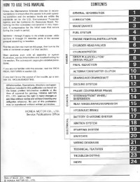
INDEX
1. Reduction and arbitrary symbols 2. General instructions on
repair 3. Identification 4. Description and the recommendation of
4.1 Recommendations regarding maintenance by 4.2 Recommendations
regarding control of scooter 5. Maintenance and the general audit
procedures and adjustment 5.1 Maintenance rate 5.2 Arrangement of
the elements of the systems of control, nourishment, electrical
equipment
5.3 Body elements (SK50M) 5.4 Adjustment of headlight 5.5
Adjustment of oil pump 5.6 Testing fuel pump 5.7 Cleaning air
filter 5.8 Pressure testing of the end of the compression stroke
5.9 Checking brake linings 6. Power unit 6.1 Oil pump 6.2 Oil tank
6.3 Choke 6.4 Carburetor 6.5 Petalous valve 6.6 Fuel tank 6.7 Fuel
pump 6.8 Air filter 6.9 Removal and installation of motor 6.10
Dismantling and assembling engine 6.11 Cylinder head, cylinder and
piston 6.12 Jackets of power unit 6.13 Kick- starter 6.14 Variator
6.15 Main drive 6.16 Carter engine 7. Checking and the repair of
power unit 8. Undercarriage 8.1 Front suspension and front brake
(SK50M) 8.2 Checking of the knot of front brake 8.3 Torr system
with disk front brake (SK50M) 8.4 Handle of gas 8.5 Rear suspension
and rear brake 8.6 Shock absorber 9. Electrical equipment 9.1
Storage battery 9.2 Regulator of voltage (rectifier) 9.3 Generator
9.4 Interrupter (block CDI) 9.5 Ignition coil 9.6 Checking the lead
angle of ignition 9.7 Starter 9.8 Sensor of fuel level 9.9 Sensor
of oil level 9.10 Lock of ignition 9.11 Switch of the turn
indicators of 9.12 Lamps 9.13 Steering switches of 9.14 Schematics
of the electrical equipment 1. Reduction and arbitrary
symbols of reduction
OFF……………………………… is switched off
ON…………………………………..vklyucheno
The arbitrary symbols 2. General instructions on repair
1. With the dismantling plot details in the appropriate order in
order to facilitate the subsequent
assembling. 2. Before the fulfillment of works with the
electrical equipment you will disconnect wire from
the negative terminal of storage battery. 3. Compulsorily
substitute split cotter pins, sealing gaskets, ferrules, stuffing
boxes and so forth
by the new. 4. If necessary it is necessary to bring the sealing
composition for averting the leakages to the
sealing gaskets. 5. Thoroughly soblyudayte all technical
specifications with respect to the values of the moment
of the delay of threaded connections. Compulsorily use a torque
wrench. 6. Depending on the nature of the repair produced can be
required the application of special materials and special tool for
the maintenance and the repair. 7. During the replacement of the
burnt out safety devices it is necessary to trace so that the new
safety fuse would be calculated for the appropriate current
strength. 3. Identification Series numbers are substituted in the
indicated in the figure places: The scooters of firm Honda are
differed from other stamps in terms of more durable (and heavier)
construction and sufficiently long-lived motors, which are worse
yielded to boosting. Are most common the scooters of family Dio
(Dio, Dio SR, Dio City Movement and others). Are in series produced
models Dio ZX and SuperDio ZX with the augmented engine, the disk
brakes and the sport suspension, and also different poluseriynye
Dio ZX — special modifications with the sport switchboards and the
carburetors, even by the more forced motors with the disposed
release, intensified by frame and suspensions. The weak place of
the usual Dio are the anthers of front fork. Bursting, they pass
mud inside the fork — as a result of bushing and feathers rapidly
they are worn out and go out of order. Furthermore, usual Dio have
a somewhat unsuccessful tuning of variator (with failure and
pickup), which hampers calm ride. These deficiencies are corrected
on the more expensive models Dio ZX. The scooters of family Tact
are intended for the beginning drivers. The merits of scooters
Honda include the vertical engine, which ensures larger than in
analogs, road clearance, and, in combination with the more rugged
construction, it makes it possible to use a machine not only around
the city, but also under the poor road conditions. With 1996-97 the
annual production of scooters Honda transferred into the Indian
branches of firm, which was reflected in the quality of those
completing and assembling of machines. 4. Description and
recommendation.4.1 Recommendations regarding the maintenance on the
scooters should be used gasoline with the octane number not lower
than 92. In the system of separate lubricant is compulsory the use
of special motor oil for the two-stroke engines. The tentative
consumption of oil — about 1 l on 1000 km with a decrease in the
oil level to the emergency reserve, lights up pilot lamp on the
combination of instruments. Sparkplugs should be checked every 1-2
thousand. km of path. After path in 4-8 thousand km (depending on
operating conditions) one should substitute sparkplug. The
periodicity of servicing air filter is 500 km with the ride along
the dusty roads. Transmission oil in the reducer of rear wheel
should be substituted yearly. 4.2 some recommendations regarding
control of scooter are examined below some distinctive special
features of the scooters of foreign production. 1. with the
zero-length launch and the acceleration from the low speed do not
twist out to the refusal the knob of gas to avoid the lift of
scooter to the rear wheel and the tilting. Especially this is
dangerous during the contact into the hill or with the significant
load on the baggage carrier. 2. because of the V-belt variator
acceleration occurs with a constant frequency of the rotation of
engine (close to the revolutions maximum power); therefore the
speed of scooter compulsorily should be checked on the speedometer.
3. with the braking should be used a front, and rear brake. With
the use only of rear brake is possible the heaping up of scooter
sideways, only front — the unguided drift or revolution through the
control. 4. small size of wheels and short base make scooter
sensitive to the unevennesses of road and they require the specific
strictness in control. 5. should be followed the height of the
protector of tires and as needed substituted they. Ride on the
scooter with the worn protector of wheels is extremely unsafe. 6.
with the passage of turnings one ought not to discard gas in the
turning in order to avoid of extension from the road. Turning
should be passed «vnatyag», checking gas or to in advance discard
it. Otherwise, with the sharp decrease of the frequency of rotation
centrifugal cohesion does not manage to disconnect engine from the
transmission and occurs intensive braking by engine. 7. always
include lower beam with the ride on the scooter. 5. Maintenance and
the general audit procedures and adjustment
Attention: in this management are used the following arbitrary
symbols of the modifications of scooters Honda: Honda
Dio…………….SK50M Honda Tact……………….SZ50P
ST………….Standart (base model) As…… of..AutoStand
(with the servodrive of support) DB…………… of..Disch Brake
(with the disk brake) the attention: removal and dismantling it is
main and aggregates it is achieved by way of the numbers, indicated
in the figures. Assembling and installation are accomplished in the
order, reverse to dismantling and to removal. Servicing
capacities:
Honda Dio The fuel tank……………………… of.4,0 l
motor oil…………………… of 0,8 l the transmission
oil……… of.0,09 l Honda Tact The fuel tank… of 5,0 l
(ST)/4,5 l (AS) motor oil…………………… of 1,2 l the
transmission oil……… of.0,09 l Fig. 3. recommended viscosity
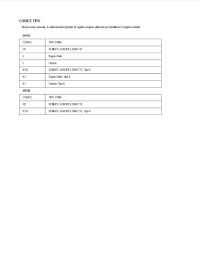
of motor oilCarburetor
Carburetor…………… PB80 (Dio) or PB80W (Tact): the
diameter of the choke……………… of 14 mm Frequency of the
rotation of idling…………………… by 1700-1900 r/min Main
jet……… of.88 (Dio) or 78 (Tact) Idle jet…………
of.35
Pressure in the tires: the front wheel…………… of 1,25
kg/cm the rear wheel……………… of.2,00 kg/cm.Electrical
equipment:
Storage battery. …………… 12V/ 3Ah the lead angle of
ignition…………… 17 VMT of sparkplug: Dio:
NGK………………..BPR5HS, BPR6HS, BPR7HS, BPR8HR
Denso……………… W16FPR, W20FPR, W22FPR, W24FPRTact:
NGK………………..BR4HSA, BR8HSA Denso………………
W14FR-L, W24FR-LMaintenance rate:
1000 km — checking and cleaning the air filter — checking and
the adjustment of the rope of the gas — checking the brakes —
pressure testing in the tires — checking the light instruments —
checking sparkplugs through 3000 km — decarbonizing from the engine
— checking the level of the transmission oil — checking the
bearings of the steering column — checking and the adjustment of
the ropes of the brakes — checking the brake linings — checking the
storage battery — checking the wear of the tires — checking the
fastening — the lubricant of ropes 6000 km — the replacement of
sparkplugs — the replacement of the transmission oil — checking the
front fork — checking the shock absorbers — cleaning the
carburetor
Fig. 4. Arrangement Of the elements Of electrical equipment
(SK50M). 1 — rectifier, 2 — the sensor of oil level, 3 —
high-voltage wire,4 — main plait of installation, 5 — ignition
coil.
Fig. 5. arrangement of ropes and plaits of installation (SK50M).
1 — rope of front brake, 2 — rope of rear brake, 3 — resistor, 4 —
installation of the lock of ignition, 5 — rope of gas, 6 — light
switch, 7 — right plait of steering switches, 8 — left plait of
steering switches, 9 — switch of the light of headlights, 10 —
switch of turn indicators, 11 — switch of sound signal, 12 — wire
of stop signal (from the lever of rear brake), 13 — wire of left
turn indicator, 14 — wire of front headlight, 15 — wire of right
turn indicator, 16 — wire of stop signal (from the lever of front
brake).
Fig. 6. arrangement of ropes and plaits of installation
(SK50M).1 — the rope of speedometer, 2 — the basic plait of
installation, 3 — rope of rear brake, 4 — rope of gas, 5 — hose of
front brake.
Fig. 7. arrangement of the elements of the system of control
(SK50M). 1 — the rope of gas, 2 — the rope of rear brake, 3 — rope
of speedometer, 4 — rope of front brake, 5 — main plait of
installation.
Fig. 9. arrangement of the elements of the system of control and
nourishment (SK50M).1 — plait of the installation of generator and
starter,2 — the rope of gas,3 — the unit of safety devices,4 —
interrupter,5 — relay of starter,6 — wire of electric starter,7 —
left tube of the ventilation of crankcase,8 — tube of the oil
supply,9 — rope of rear brake,10 — control cable of oil pump,11 —
oil tube,12 — wire of the sensor of fuel level.
Fig. 10. arrangement of ropes and plaits of installation
(SK50M).1 — the rope of speedometer, 2 — the installation of the
lock of ignition, 3 — rope of gas, 4 — hose of front brake, 5 —
rope of speedometer, 6 — rope of rear brake, 7 — yokes of wires, 8
— resistor, 9 — switch of starter, 10 — light switch, 11,12 —
installation of steering switches, 13 — switch of the light of
headlight, 14 — switch of turn indicators, 15 — wire of stop
signal, 16 — wire of left turn indicator, 17 — wire of front
headlight, 18 — wire of right turn indicator.
Fig. 15. lateral revetment.1 — catch, 2 — lateral revetment, 3 —
screws of the fastening
Fig. 16. front fairing.1 — the screws of fastening, 2 — front
fairing, 3 — front cover, 4 — screws of fastening, 5 — catch.
Fig. 17. lateral fairing.1 — flanged nut, 2 — flanged bolt, 3 —
rear baggage carrier, 4 — catch, 5 — lateral fairing, 6 — screws of
fastening.
Fig. 18. outdoor revetment.1 — catchs, 2 — the revetment of
steps, 3 — clamp bolts.
Fig. 19. front cover.1 — clamp bolt, 2 — front cover, 3 —
catchs, 4 — screws of fastening.
Fig. 20. baggage hold.
1 — flanged bolts, 2 — padding, 3 — cover of oil tank, 4 — rear
baggage carrier, 5 — flanged bolt, 6 — flanged nut, 7 — baggage
hold.
Fig. 21. steering fairing.
1 — mirror of rear form, 2 — joints of the installation of front
headlight and turn indicators, 3 — the screws of fastening, 4 —
steering fairing, 5 — clamp bolt, 6 — catchs.
Fig. 22. rear wing.
1 — catch, 2 — the wire of rear turn indicator, 3 — rear wing, 4
— clamp bolts.
Fig. 23. LATERAL REVETMENT.
Fig. 24. steering fairing.
1 — the rope of speedometer, 2 — the tail end of the steering
fairing, 3 — bolt, 4 — installation of steering switches, 5 —
screws of fastening.
Fig. 25. Body Elements.1 — lateral revetment, 2 — baggage hold,
3 — lateral fairing, 4 — outdoor revetment, 5 — rear wing, 6 —
front fairing, 7 — front cover, 8 — steering fairing, 9 — the tail
end of the steering fairing
Fig. 26. baggage hold.
1 — clamp bolt, 2 — the cover of tank, 3 — the packing washer, 4
— the baggage hold
Fig. 27. outdoor revetment. 1 — catch, 2 — clamp bolt, 3 —
outdoor revetment, 4 — catch, wing, 3 — screws of fastening.
Fig. 28. front wing
1 — the screws of fastening, 2 — front
Fig. 29. front cover.
1 — the screws of fastening, 2 — clamp, 3 — clamp bolt, 4 —
front cover, 5 — catch.
Fig. 30. lateral fairing. 1 — catch, 2 — fairing, 3 — rear
baggage carrier, 4 — clamp bolt, 5 — rope, 6 — joints of wiring, 7
— screws of the fastening
Fig. 31. rear wing. 1 — clamp bolt of oil tank, 2 — relay, 3 —
bracket, 4 — clamp bolt, 5 — interrupter (knot CDI), 6 — clamp, 7 —
rear wing.
Fig. 32. adjustment of headlight Prover’te the direction of the
light beam of front headlight and, if necessary, adjust it with the
aid of the adjusting screw
Fig. 33. steering fairing. 1 — the screws of fastening, 2 — the
screw of fastening, 3 — padding of master brake cylinder, 4 —
steering fairing, 5 — mirror of rear form.
Fig. 34. the tail end of the steering fairing. 1 — joint of the
switch of stop signal, 2 — joint of the switch of stop signal, 3 —
joint of the installation of the combination of instruments, 4 —
rope of speedometer, 5 — screws of fastening, 6 — joint of the
switch of stop signal (ST, AS).
Fig. 35. adjustment of fuel pump. 1 — controlling lever, 2 — the
housing of oil pump, 3 — marker, 4 — adjusting nut. You will
completely unscrew the handle of gas (open the throttle) and
prover’te, that the markers on the housing of oil pump and the
controlling lever coincide. If necessary, adjust with the aid of
the adjusting nut.
Fig. 36. testing fuel pump. 1 — carburetor, 2 — fuel tube, 3 —
fastening. With the work of engine at the idling measure a quantity
of fuel, supplied with pump for 10 s. Nominal
volume……………… of 20 cc
5.7 cleaning of air filter
Wash the filtering element in washing oil, after which slightly
finish harvesting and give completely to get dry. You will look
around exterior view and state of porolon. If porolon has cracks
and scalings, it should be replaced by the new filtering element.
Wipe with the clean rags, moistened in the gasoline, the internal
part of the cover of filter and the internal cavity of housing. You
will look around the air duct of filter to the carburetor. The
casing of filter and air duct must not have cracks. Impregnate the
dry and clean filtering element before the installation in oil. For
this use special oil for the impregnation, or another oil with a
sufficient viscosity. You will distribute oil evenly along the
filter, but do not twist out the filtering element. Filter is ready
to installation if it abundantly it is impregnated with oil on the
entire surface and the thickness. 5.8 pressure testing of the end
of the compression stroke
1. Turn inside out sparkplug.
2. You will establish compressometer. 3. You will completely
unscrew the handle of gas. 4. Measure the value of compression with
cranking of crankshaft by the electric starter (frequency of
rotation not less than 600 r/min), the nominal pressure……… of
10 kg/sq cm the reason for insufficient compression they can be: a)
The damage of the padding of the cylinder head, b) The wear of
piston rings, the damage of piston, c) The wear of cylinder. 5.9
Checking of the brake linings
Prover’te the state of the brake linings. a) press on the brake
beams. b) prover’te the position of indicator. If indicator exceeds
the limits of the zone, shown in the form of marker, then should be
replaced the brake linings. 6. Power unit
Attention: removal and dismantling it is main and aggregates it
is achieved by way of the numbers, indicated in the figures.
Assembling and installation are accomplished in the order, reverse
to dismantling and to removal.
Fig. 37. oil pump. Removal and installation. 1 — oil tube, 2 —
the tube of oil feed, 3 — clamp bolts of the bracket of control
cable, 4 — control cable with the bracket, 5 — oil pump.
Fig. 38. oil tank. Removal and installation. (SK50M).1 — oil
tube, 2 — the joint of installation, 3 — nut of fastening, 4 —
clamp bolt, 5 — rear wing, 6 — clamp bolt, 7 — oil tank.
Fig. 40. choke. Dismantling and assembling. 1 — choke, 2 — the
rope of gas, 3 — spring of choke, 4 — padding, 5 — cover of
carburetor, 6 — shielding cap, 7 — catch, 8 — locking needle, 9 —
clamp.
Fig. 41. Carburetor. Removal and installation. 1 — choke, 2 —
fuel tube, 3 — tube of oil feed, 4 — wire of starting enricher, 5 —
clamp bolts of carburetor, 6 — O-ring seal, 7 — padding, 8 — O-ring
seal, 9 — carburetor.
Fig. 42. Carburetor. Dismantling and assembling. 1 — cover of
starting enricher, 2 — screws of fastening, 3 — about rate, 4 —
starting enricher, 5 — O-ring seal, 6 — screws of fastening, 7 —
float chamber, 8 — O-ring seal, 9 — axis of float, 10 — float, 11 —
needle valve, 12 — screw of quality, 13 — idle jet, 14 — main jet,
15 — emulsion tube.
Fig. 43. petalous valve. Dismantling and assembling. 1 — clamp
bolt, 2 — clamp bolt, 3 — protective housing, 4 — clamp bolts, 5 —
inlet pipe, 6 — padding, 7 — petalous valve, 8 — padding.
Fig. 44. fuel tank. Removal and installation. 1 — the joint of
installation, 2 — holder, 3 — sensor of fuel level, 4 — packing, 5
— fuel tube, 6 — clamp bolt, 7 — cover plate, 8 — fuel tank.
Fig. 45. fuel pump. Removal and installation (SK50M). 1 — fuel
filter, 2 — fuel tube, 3 — fuel tube, 4 — vacuum hose, 5 — clamp
bolt, 6 — fuel pump, 7 — nut of fastening, 8 — fuel pump
bracket
Fig. 47. air filter. Removal and installation (SK50M).1 — the
screws of fastening, 2 — the cover of air filter, 3 — filtering
element, 4 — screw of yoke, 5 — clamp bolts, 6 — casing of air of
filter, 7 — vent pipe.
Fig. 49. removal and installation of motor (SK50M).
1 — installation of generator and electric starter, 2 — wire of
starting enricher, 3 — oil tube, 4 — fuel tube, 5 — vacuum hose, 6
— cover of sparkplug, 7 — clamp bolt of rear shock absorber, 8 —
control cable of oil pump, 9 — rope of rear brake, 10 — nut of
fastening, 11 — clamp bolt, 12 — engine, 13 — bolt of the mounting
bracket of engine, 14 — mounting bracket of the engine
Fig. 51. cylinder head, cylinder and piston. Removal and
installation.1 — clamp bolts of cylinder head, 2 — cylinder head, 3
— padding of cylinder head, 4 — cylinder, 5 — padding of cylinder,
6 — check rings, 7 — wrist pin, 8 — piston, 9 — piston rings, 10 —
dilator of rings, 11 — needle bearing 12 — upper ring, 13 — lower
ring.
Fig. 52. Jackets of power unit. Removal and installation.
1- clamp bolts, rear jacket is 2nd, 3- padding, 4- clamp bolts,
front jacket is 5th, 6- padding, 7- the dowel pin.
Fig. 53. Kick- starter. Removal and installation.
1- drive gear, it is 2nd washer, 3- clamp bolt, 4- pedal of
kick- starter, it is 5th check ring, 6- washer, 7- the gear
quadrant of kick- starter, it is eighth return spring, 9
bushing.6.13 checking is the kicks of starter
1. Verify kick- starter.
A) Verify splined bushing.
b) Verify the gear quadrant of kick- starter.
c) Verify the gear the drive of kick- starter.
Fig. 54. 1- drive gear, it is 2nd retaining spring, 3- the dowel
pin.
Fig. 55
1. Verify the beds of the axes of gear quadrant and drive
gear.
Fig. 56. 1- splined bushing, it is 2- return spring, 3-
bushing.
Fig. 58. Variator. Removal and installation.
1- gear of electric starter, it is 2nd the nut of fastening, 3-
bushing, 4- fixed cheek of guide pulley, V-belt is 5th, 6- nut of
fastening the drum of cohesion, 7- drum of cohesion, the unit of
cohesion and follower pulley is eighth, 9 muff of variator, 10
clutch of the variator
Fig. 59. Clutch of variator. Dismantling and assembling.
1- clamp bolts, it is 2nd the cover of the clutch of variator,
3- the guiding plate, 4- guiding, it is 5th O-ring seal, 6- small
weights, 7- mobile cheek.
Fig. 60. Unit of cohesion. Dismantling and assembling.
1- nut of fastening, it is 2nd check ring, 3- washer, 4-
boot-tree of cohesion, it is 5th the spring of the boot-trees of
cohesion, 6- damper, 7- supporting disk, it is eighth the thrust
bushing of spring, 9 spring of follower pulley, 10 bushing, 11-
guide pin, 12- mobile cheek of follower pulley, 13- O-ring seal,
14- stuffing box, 15- bearing, 16- check ring, 17- bearing, 18- the
fixed cheek
Fig. 61. Main drive. Dismantling and assembling.
1- clamp bolt, it is 2nd the cover of reducer, 3- padding, 4-
the dowel pin, it is 5th washer, 6- output shaft, 7- washer, it is
eighth idlers, 9 washer, 10 input shaft.
Fig. 62. Removal of crankcase
Installation of crankcase
1. Turn away clamp bolts.
1. You will install right bearing.
2. Remove the cover of crankcase.
2. You will install left bearing.
3. You will establish crankshaft.
4. You will establish the left stuffing
box
Fig. 64. Crankcase. Removal and installation.
1- clamp bolts, it is 2nd the cover of crankcase 3- padding, 4-
the dowel pin, crankshaft is 5th, 6- right stuffing box, 7- left
stuffing box, right bearing is eighth, 9 left bearing.7. Checking
and the repair of power unit
1. You will clean cylinder head.
A) You will clean remainders of padding and carbon deposit from
injector face. Note: you be careful, in order not to injure the
injector face of cylinder, mated with the padding.
2. Verify cylinder head. By precision rule and by flat probe, as
shown in figure, verify the nonplanarity of the working injector
face of the cylinder
The maximum permissible non planarity of …………………
0,02 mm
if the value of non planarity exceeds maximum permissible, you
will replace cylinder head or grind it.
3. You will clean carbon deposit from internal surface of
exhaust of cylinder.
4. Verify cylinder.
A) By precision rule and by flat probe, as shown in figure,
verify the non planarity of the surface of cylinder.
The maximum permissible non planarity of ………………..
0,02 mm
if the value of non planarity exceeds maximum permissible, you
will replace cylinder or grind it.
6) measure the diameter of cylinder. Fig. 67
by Indicator- inside calipers measure the diameter of cylinder
at three levels in transverse (a) and longitudinal (b) directions,
as shown in figure. If the diameter more than maximum permissible,
you will replace it.
Diameter of the cylinder:
SK50M
nominal ………. 39,000-39,020 mm
maximum ……………….. 39,050 mm
SZ50P
marker A
nominal ………. 39,000-39,005 mm
maximum of ……………….. 39,050 mi
without the marker
nominal ………. 39,005-39,010 mm
maximum ……………….. 39,050 mm
the maximum conicity of …… 0,05 mm
5. You will clean piston. A) By scraper remove carbon
deposit
and others carbonic the deposit [s] piston head.
b) You will clean deposits from grooves of piston with the piece
of the broken ring.
c) By solvent and by soft hair brush you will finally clean
piston.
Note: do not use wire brush.
6. Verify piston.
A) by micrometer measure the diameter of piston skirt of at a
distance 4 mm rel.un. of edge, also, in the direction,
perpendicular to the axis of wrist pin, as shown in Fig. 70.
Diameter of the piston:
SK50M
nominal ……… 38,955-38,970 mm
minimum ………………… 38,900 mm
SZ50P without the marker
nominal ……… 38,960-38,965 mm
minimum ………………… 38,900 mm
marker A
nominal ……… 38,955-38,960 mm
minimum ………………… 38,900 mm
marker into
nominal ……… 38,965-38,970 mm
minimum ………………… 38,900 mm
7. You will determine clearance between the cylinder and the
piston, after finding a difference in the results of the
measurements of the diameter of piston and diameter of cylinder.
The nominal clearance of …… 0,035-0,050 mm
if clearance is more than nominal, you will replace piston and
cylinder.
8. Verify clearance in the piston-ring lock.
A) put piston ring into the cylinder up to the distance of 10 mm
from the parting plane.
b) by flat probe measure the clearance in the lock
Fig. 71
Nominal clearance of ………. 0,10-0,25 mm
The maximum clearance of ……………. 0,40 mm
if clearance in the lock is more than maximum, you will replace
piston ring. If clearance in the lock is more than maximum even
with the new piston ring, you will replace cylinder and piston.
9. Verify end clearance compression ring — piston groove, after
measuring by its flat probe, as shown in Fig. 73.
Nominal clearance of ………. 0,03-0,05 mm
Fig. 72
maximum clearance of ……………. 0,10 mm
if the clearance it is more permitted, you will replace
piston.
10. Verify wrist pin. (Fig. 74)
a) Put piston the finger you will be convinced with the bearing
into the connecting-rod end, that the finger it pivots without the
perceptible gap.
b) By inside calipers, measure the inside bore diameter under
the finger in the piston.
Nominal
Fig. 73
diameter of ……………….. 12,002-12,008 mm
the maximum diameter of …… 12,030 mm
c) using a micrometer, measure the diameter of wrist pin.
Nominal diameter of ………. 11,994-12,000 mm
the minimum diameter of ……. 11,980 mm if it is necessary,
you will replace piston and wrist pin in the collection.
11. Verify cohesion.
Fig. 74
a) Measure internal the diameter of the drum of cohesion.
The nominal diameter of …………………… 107,0-107,2
mm
the maximum diameter of …….. 107,5 mm
b) measure the thickness
of the friction lining.
Fig. 75
Fig. 76Nominal thickness of …….. 4,0-4,1 mm
the minimum thickness of …………. 2,0 mm
12. Verify the clutch of variator.
a) Verify the surfaces of mobile and stationary cheeks.
b) Measure the diameter of bushing. The
nominal
thickness of ……………… 20,035-20,085 mm
the minimum thickness of ……. 20,600 mm
c) Verify the diameter of roller.
Nominal diameter.15,92-16,08 mm
the minimum diameter of ……… 15,40 mm
13. Verify V-belt. (Fig. 77)
a) Verify the surface condition of belt (1).
b) Measure the width of belt (2).
Nominal width of …………… 15,5 mm
Fig. 77
Minimum width of …………… 14,5 mm
14. Verify follower pulley. (Fig. 78)
a) Verify surface condition mobile and fixed of pulleys.
b) Verify and you will if necessary replace stuffing box.
c) Verify the smoothness of the rotation of pulley.
g) verify the length of unloaded spring.
Nominal length of ……………… 98,1 mm
The minimum length of ……………… 92,8 mm
Fig. 78
15. Verify electric starter.
a) Verify the state of flywheel and idlers.
16. Checking main drive.
a) Verify the state the driven gear of main drive shaft, idlers,
slave gear.
b) Verify the state the radial bearings of driven gears.
17. Verify crankshaft.
a) Verify the bend of crankshaft. Maximum bend of …………..
0,04 mm8. The undercarriage
Attention: removal and the dismantling of units and aggregates
is achieved by way of numbers, indicated in the figure.
Assembling and installation is accomplished in the order,
reverse to dismantling and to removal.
Fig. 79. Removal and the installation of front wheel (SK50M)1-
Screw of fastening, the rope of speedometer is 2nd, 3- the nut of
front brake, 4- [vtupka] of brake beams, the rope of front brake is
5th, 6- nut of axis, 7- axle of front wheel, it is eighth bushing,
9 front wheel, 10 front wing, 11- unit of front brake, 12- anther,
13- left bearing, 14- the spacing collar, 15- right bearing.8.2
checking of the unit of front brake
1.Measure the free motion of brake beams and with
the need adjust it.
Nominal motion by ……………….. 10-20 mm
2. Measure the diameter of the internal surface
of brake drum.
Nominal diameter of ………… 95,0 mm
the maximum diameter of ………. 95,5 mm
3. Measure the thickness of the brake linings.
Nominal thickness of ………….. 3,0 mm
the minimum thickness of ………….. 2,0 mm
Fig. 80.
1- anther, left bearing is 2nd,
3- the spacing collar, 4- right bearing.
Fig. 81. Dismantling and the assembly of the unit of front brake
(SK50M).
1- brake shoes with the springs, clamp bolt is 2nd, 3- lever, 4-
indicator of the wear of cover plates, it is 5th return spring, 6-
unclasping fist, 7- stuffing box of unclasping fist, anther is
eighth, 9 gear of speedometer, 10 housing of the unit of the front
brake
Fig. 82. The steering column (SK50M).
Dismantling and assembling. 1- nut of fastening the steering
column, it is 2nd upper lid, 3- the steering column, 4- lower
cover, it is 5th bearings, 6- bearing cap, 7- clamp bolts, it is
eighth fastening front wing, 9 clamp bolt, 10 front fork.
Fig. 83. Front fork (SK50M).
Dismantling and assembling. 1- cover of the feather of front
fork, anther is 2nd, 3- check ring, 4- bushing, it is 5th the
spring of the motion of return, 6- fixed pipe of the feather of
front fork, 7- spring of the feather of front fork, rubber damper
is eighth, 9 mobile tip.8.3 Torr system with the disk front brake
(SK50M)
Fig. 84. Front wheel. Removal and installation.
1- screw of fastening the rope of speedometer, the rope of
speedometer is 2nd, 3- the nut of axis, 4- wheel axle, it is 5th
front wheel, 6- bushing, 7- drive of the speedometer
Handle of gas. Removal and installation.
1- nut of fastening, the link bolt of the lever of front brake
is 2nd, 3- the lever of front brake, 4- rope of front brake, clamp
bolt is 5th, 6- the upper lid of the handle of gas, 7- bracket of
the lever of front brake, the rope of gas is eighth, 9 handle of
gas.
Fig. 85. Retarding disc. Removal and installation.
1- anther, right bearing is 2nd, 3- the spacing collar, 4- left
bearing, it is 5th the clamp bolts of retarding disc, 6- retarding
disc.
Fig. 86. Brake support. Removal and installation.
1- clamp bolt, it is 2nd guide fingers, 3- the brake linings, 4-
plate.
Fig. 87. Master brake cylinder (SK50M). Dismantling and
assembling.
1- screws of fastening cylinder cover, it is 2nd cylinder cover,
3- the membrane, 4- bypass bolt and washer, brake hose is 5th, 6-
the link bolt of brake beams, 7- brake beams, it is eighth the
clamp bolts of holder, 9 holder of cylinder, 10 brake cylinder in
the collection, 11- screws of fastening the switch of stop signal,
12- switch of stop signal, 13- bushing, 14- check ring, 15- valve,
16- spring.
Checking front disk brake
1. Measure the free motion of brake beams and if necessary
adjust it.
Nominal motion by ………………. 10-20 mm
2. Measure the diameter of the piston of master brake
cylinder.
Nominal diameter of ………… 10,957-10,984 mm
the minimum diameter of ……. 10,910 mm
3. Measure the diameter of master brake cylinder.
Nominal diameter of ……………….. 11,000-11,043 mm
the maximum diameter of …….. 11,05 mm
4. Measure the diameter of the piston of front, brake.
Nominal diameter of ……………….. 30,148-30,198 mm
the minimum diameter of …….. 30,290 mm
5. Measure the diameter of the cylinder of front brake.
Nominal diameter of ……………….. 30,230-30,280 mm
the maximum diameter of …….. 11,05 mm
6. Measure the thickness of retarding disc.
Nominal thickness of ………….. 3,0 mm
the minimum thickness of ………….. 2,5 mm
Fig. 88. Support of front brake (SK50M). Dismantling and
assembling.
1- bypass bolt and washer, it is 2nd the cover of guide of
finger, 3- the clamp bolts of support, 4- Torr support, it is 5th
the guide fingers of boot-trees, 6- brake shoes, 7- adjusting
plate, it is eighth unclasping spring, 9 guide finger, 10 bracket
of support, 11- cover of guide of finger, 12- bushing, 13- piston,
14- case, 15- collar.8.4 Rear suspension and the rear brake
Fig. 89. Dismantling and assembling rear brake.
1-adjusting nut, it is 2nd the bushing of lever, 3- the rope of
rear brake, 4- brake shoes with the springs, the clamp bolt of
lever is 5th, 6- lever of rear brake, 7- return spring, the
indicator of the wear of the brake linings is eighth, 9 stuffing
box, 10 unclasping fist, 11- travel limiter of boot-tree.
Fig. 90. Removal and the installation of shock absorber.
1- lower clamp bolt, upper clamp bolt is 2nd, 3- rear shock
absorber.
Fig. 91. Dismantling and assembling shock absorber.
1- bushing, it is 2nd the grommet, 3- the lower opening of
fastening, 4- spring, it is 5th the lock nut, 6- rubber damper, 7 —
, shock absorber is eighth.1. Remove bushing.
2. Remove the grommet.
3. Remove the lower opening of fastening.
4. Remove spring.
5. Turn away the lock nut.
6. Remove rubber damper.
7. Remove the saddle of spring.
8. Remove shock absorber.
Assembling shock absorber is produced in the order, reverse to
its dismantling.
FIG. 93
9. Electrical equipment is
Note. For the designation of the colors of wires the following
reductions are used: B is white, Ch is black, Kr — red, [Kch] —
brown, Zh is yellow, With dark-blue, 3- green, [Rz] — pink, Sr —
gray, About the orange, TZ — dark green, [TKch] — dark brown.
In this case the first part of the designation indicates the
primary color of wire, the second (if there is) — the color of
strips.
Fig. 94. Arrangement of the elements of electrical
equipment.
1- interrupter, rectifier is 2nd, 3- of the relay of starter, 4-
storage battery, electric starter is 5th, 6- it soaked ignitions,
7- switch of sound signal, the switch of turn indicators is eighth,
9 switch of the light of headlight, 10 light switch, 11- switch of
starter, 12- resistor, 13- winding of ignition, 14- alternator, 15-
ignition coil, 16- ignition coil.9.1 The storage Battery
Fig. 95.
1- screws of fastening the cover of storage battery, it is 2nd
cover, 3- negative terminal, 4- positive terminal, it is 5th
storage battery.
FIG. 97 FIG. 96Checking storage battery
1.Verify stress on the outputs of storage battery, if it lower
than nominal, you will load storage battery. (Fig. 96)
nominal stress. 13,0-13,2 [v]
minimum stress ……… 12,3 [v]
2.Verify with the aid of the ammeter the absence of closing to
the mass of electrical equipment.
Maximum current of …………………… 1 mA (Fig. 97) 9.2
Regulator of voltage (rectifier)
verify resistance between the outputs of the rectifier
FIG. 98
9.3 Generator
Checking on the engine
Verify stress, issued by generator.
a) You will neglect engine.
b) You will include illumination, the switch of the light of
headlights — to the position HI.
c) Measure the stress.
Nominal stress
(with 5000 aboutmin) ……………. 12,6-13,6 [v]FIG. 99
Fig. 100. Dismantling and assembling generator.
1- clamp bolt, fan housing is 2nd, 3- clamp bolt, 4-
cooling-system fan, it is 5th flanged nut, 6- rotor (flywheel), 7-
key, the wire of generator is eighth, 9 joint of starter, 10 clamp
bolt, 11- clamp bolt of pulse generator, 12- pulse generator, 13-
clamp bolt of stator, 14- stator, 15- the protective bushing
Checking Generator
1. Verify winding impedance of generator.
Nominal resistance:
The winding of charging ………….. 0,2-1,0 Ohm is
the windings of illumination ……… 0,1-0,8 Ohm
2. Measure the resistance of resistor.
Nominal resistance:
6,7 0[m], 5[Vt] of …………………. 4,7-5,3[Om]
5,9 Ohm, 30 W ……………….. 5,6-6,2 Ohm Fig. 1019.4
interrupter (block CDI) Measure the resistance between the
conclusions of the joint of the interrupter:
Wire Resistance, Ohm are
Excitation winding black- redgreen 500-900
Pulse generator dark-blue- yellowgreen 50-200
Ignition coils black- yellowgreen 0,2-0,39.5 Ignition coil
Measure the resistance
of the primary winding of ignition coil.
Nominal resistance:
Dio ……………………………….. 0,2-0,3 Ohm
Tact ……………………………… 0,1-0,4 Ohm
Measure the resistance
the secondary winding of ignition coil.
Nominal resistance:
with the tip of the spark plug:
Dio ……………………………… 8,2-9,3 kilohms
Of tact of …………………………… 6,35-9,7
kilohms
without the tip of spark plug 2,7-3,4 kilohms
Fig. 102
Fig. 103
Fig. 104 9.6 Checking the angle ignition advance
Verify the lead angle of ignition
with the frequency of rotation 1800 aboutmin.
Nominal lead angle
of the ignition of …….. 173[doVMT]
Fig. 1059.7 The Starter
Fig. 106. Removal and the installation of starter.
1- clamp bolt, the bracket of control cable of oil pump is 2nd,
3- the clamp bolt of starter, 4- starter, it is 5th O-ring seal, 6-
joint of starter.
Fig. 107. Dismantling and assembling starter.
1- clamp bolt, stator is 2nd, 3- anchor, 4- brush holder, it is
5th spring, 6- O-ring seal, 7- front cover of starter.9.8 Sensor of
Fuel Level
Measure the resistance between the outputs
of the sensor of fuel level with different
position of float.FIG. 108Conclusions Position of the float
upper lower
green- yellowwhite 25-41 Ohm
450-750 Ohm
green- are dark-bluewhite 430-700 Ohm
25-41 Ohm
are yellowwhite- dark-bluewhite450-750 Ohm
450-750 Ohm9.9 sensor of oil levelYou will connect ohmmeter and
will ascertain that with the upper position of float there is no
conductivity, and with the lower position — there is conductivity
between the outputs of sensor.
Fig. 109
9.10 lock of ignition
Prover’te conductivity between the outputs of the lock of
ignition with its different positions, as shown in diagram FIG.
1109.11 Switch of turn indicators
Prover’te conductivity between the outputs of the switch of turn
indicators with its different positions, as shown in diagram.
FIG. 111
9.12 lamps
Fig. 112. front headlight
Fig. 113. Illumination of the combination of the instruments
FIG 114 1 — bolt, 2 — the lock of ignition, 3 — joint of the
lock of ignition.9.13 The steering switches
Prover’te conductivity between the outputs of light switch with
its different positions, as shown in diagram.
FIG 115Top of Form
Prover’te conductivity between the outputs (zheltyy/krasnyy and
green) of the switch of starter with its switch oned position.
HTMLCONTROL Forms.HTML:Hidden.1 Bottom of Form
FIG. 116Prover’te conductivity between the outputs of the switch
of sound signal with its switch oned position. Prover’te
conductivity between the outputs of the switch of the light of
headlights with its different positions, as shown in diagram.
FIG. 117
Fig. 118. backing lamp.1 — lamp of rear turn indicators, 2 —
lamp of stop signal, 3 — glass- stop signal, 4 — screws of
fastening, 5 — glass- turn indicator.
Fig. 119. arrangement of the elements of the system of the drive
of support.1 — the relay of generator, 2 — the relay of the system
of drive, 3 — joint of magnetic valve, 4 — magnetic valve, 5 — lock
of ignition, b — buzzer, 7 servo drive, 8 — knot of the support
Fig. 120. schematic of the system of drive.1 — storage battery,
2 — the safety device of yShcha, 3 — lock of ignition, 4 — relay of
generator, 5 — generator, 6 — magnetic valve, 7 — buzzer, 8 —
switch of drive, 9 — servodrive, 10 — relay of the system of
drive.
Ris.121. Schematic of electrical equipment (Dio SK50M).
1 — the switch of stop signals, 2 — the switch of starter, 3 —
light switch, 4 — lock of ignition, 5 — relay of starter, 6 —
storage battery, 7 — regulator of voltage (rectifier), 8 — sensor
of fuel level, 9 — sensor of oil level, 10 — right rear turn
indicator, 11 — stop signal and rear dimensional fire, 12 — left
rear turn indicator, 13 — sparkplug, 14 — interrupter (knot CDI),
15 — starting enricher, 16 — generator, 17 — electric starter, 18 —
resistor, 19 — sound signal, 20 — switch of the light of headlight,
21 — switch of turn indicators, 22 — sound signal, 23 — relay of
turn indicators, 24 — left front turn indicator, 25 — front
headlight, 26 — right front turn indicator, 27 — combination of
instruments, 28 — lamp of illumination, 29 — level indicator of
fuel, 30 — the pilot lamp of the oil level, 31 — the pilot lamp of
exceeding allowable speed, 32 — the safety device of «A, 33 —
ignition coil
_1239107449.unknown
_1239107451.unknown