- Manuals
- Brands
- Siemens Manuals
- Control Unit
- SINUMERIK 802D sl
- Instruction manual
-
Contents
-
Table of Contents
-
Bookmarks
Quick Links
Instruction Manual 05/2005 Edition
sinumerik
Siemens Automation Parts
SINUMERIK 802D sl
Related Manuals for Siemens Sinumerik 802D sl
Summary of Contents for Siemens Sinumerik 802D sl
-
Page 1
Instruction Manual 05/2005 Edition sinumerik Siemens Automation Parts SINUMERIK 802D sl… -
Page 3
System Overview Component Description Operator Controls and Displays SINUMERIK 802D sl Interfaces Instruction Manual Dimensional Drawings and Drill Patterns Installation Connection Technical Data Start-Up Creating a Drive Project Starting Up the PLC Valid for Control system Software version Data Backup and… -
Page 4
Siemens. It is assumed that this product be transported, stored and installed as intended and maintained and operated with care to ensure that the product functions correctly and properly. -
Page 5
SINUMERIK control systems (e.g., Universal Interface, Measuring Cycles, etc.) can be obtained from your local Siemens branch office. A list of documents, updated on a monthly basis, is available on the Internet for the available languages at: http://www.siemens.com/motioncontrol… -
Page 6
Preface Internet address http://www.siemens.com/motioncontrol SINUMERIK 802D sl Instruction Manual (BA), 05/2005 Edition 6FC5 397-0CP10-1BA0… -
Page 7: Table Of Contents
7-51 General rules for operation of a SINUMERIK 802D sl …….
-
Page 8
……. . 10-157 SINUMERIK 802D sl Instruction Manual (BA), 05/2005 Edition 6FC5 397-0CP10-1BA0… -
Page 9
Basic protective measures against discharge of static electricity ….. C-241 Siemens Automation Parts SINUMERIK 802D sl Instruction Manual (BA), 05/2005 Edition 6FC5 397-0CP10-1BA0… -
Page 10
…………E-251 SINUMERIK 802D sl Instruction Manual (BA), 05/2005 Edition viii… -
Page 11: System Overview
PROFIBUS interface for the drives and for the I/O modules with the slimline operator panel into a ready-to-install unit (Panel Control Unit). The SINUMERIK 802D sl can control up to 5 axes digitally. Up to 2 of these 5 axes can be configured as a spindle.
-
Page 12
Mains supply Feed motor 3 conductor Feed motor 4 when using a Main spindle motor machine control panel Fig. 1-1 System overview: SINUMERIK 802D sl mit SINAMICS S120 (example) SINUMERIK 802D sl Instruction Manual (BA), 05/2005 Edition 1-10 6FC5 397-0CP10-1BA0… -
Page 13
To supply the module and the digital outputs, an external voltage source (+24 V DC) is required. S Drive units – SINAMICS S120 The communication between the SINUMERIK 802D sl control system and the SINAMICS S 120 drive is provided via the DRIVECLiQ communication system (Drive Component Link with IQ). System software… -
Page 14
S PLC user library S “Starter” – parameterization and commissioning tool for the SINAMICS drive Note The table of contents and notes for setup can be found in the siemense.txt file. SINUMERIK 802D sl Instruction Manual (BA), 05/2005 Edition 1-12 6FC5 397-0CP10-1BA0… -
Page 15: Description
Description Siemens Automation Parts SINUMERIK 802D sl Instruction Manual (BA), 05/2005 Edition 2-13 6FC5 397-0CP10-1BA0…
-
Page 16
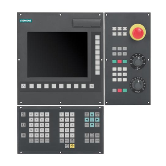
DRIVE CLiQ interfaceX1 and X2 Handwheel connectionX30 Digital inputs/outputs X20, X21 Optional interface Grounding screw Fig. 2-1 Position of the interfaces and front elements on the CNC operator panel SINUMERIK 802D sl Instruction Manual (BA), 05/2005 Edition 2-14 6FC5 397-0CP10-1BA0… -
Page 17
12-pin screw-type male connector for connecting the digital inputs Digital inputs/digital outputs and outputs X20 and X21 see Chapter 4.1.8 TB30 interface 48-pin female connector for connecting the MCPA module see Chapter 4.2 Siemens Automation Parts SINUMERIK 802D sl Instruction Manual (BA), 05/2005 Edition 2-15 6FC5 397-0CP10-1BA0… -
Page 18
Description Notes SINUMERIK 802D sl Instruction Manual (BA), 05/2005 Edition 2-16 6FC5 397-0CP10-1BA0… -
Page 19: Operator Controls And Displays
Operator Controls and Displays Operator controls Use the horizontal and vertical softkeys to select defined functions. For a description of the individual softkeys, please refer to the SINUMERIK 802D sl Programming and Operator’s Guide. References: /BP/, Programming and Operator’s Guide…
-
Page 20: Error And Status Displays
Sign-of-life monitoring CF (yellow) Reading from / writing to CF card Note For error descriptions, see SINUMERIK 802D sl Diagnostics Guide. References: /DG/, Diagnostics Guide LEDs on the PP 72/48 I/O module The following LEDs are installed on the I/O module (see Fig. 4-3): The individual LEDs and their functions are described in the table below.
-
Page 21: Interfaces
S for NC programs S to carry out software updates S to store user data S to save parameters which have been set by the user. Siemens Automation Parts SINUMERIK 802D sl Instruction Manual (BA), 05/2005 Edition 4-19 6FC5 397-0CP10-1BA0…
-
Page 22: Ethernet Interface
Received data – not assigned – not assigned – You can obtain additional information about the different cable systems for Ethernet from your SIEMENS contact person. 4.1.3 USB port (available soon) SINUMERIK 802D sl Instruction Manual (BA), 05/2005 Edition 4-20 6FC5 397-0CP10-1BA0…
-
Page 23: Rs232 Com Interface
Terminal ready Ready Ground Ground (GND) Data Set Ready Readiness for operation Request To Send Transmission request Clear To Send Ready to send – – assigned Siemens Automation Parts SINUMERIK 802D sl Instruction Manual (BA), 05/2005 Edition 4-21 6FC5 397-0CP10-1BA0…
-
Page 24: Profibus Dp Interface
The CNC operator panel has a fixed PROFIBUS DP address. The addresses of the PP 72/48 I/O modules must be set using the DIL switches S1 (see Section 7.12). SINUMERIK 802D sl Instruction Manual (BA), 05/2005 Edition 4-22 6FC5 397-0CP10-1BA0…
-
Page 25: Drive Cliq Interface
– Received data – not assigned – not assigned – not assigned – not assigned – Blanking plate for DRIVE-CLiQ interface: Molex corp., order no. 85999-3255 Siemens Automation Parts SINUMERIK 802D sl Instruction Manual (BA), 05/2005 Edition 4-23 6FC5 397-0CP10-1BA0…
-
Page 26: Handwheel Connection
Track B, channel 1 Track B_N, channel 1 5 V DC supply voltage Ground (GND) Track A, channel 2 Track A_N, channel 2 Track B, channel 2 Track B_N, channel 2 SINUMERIK 802D sl Instruction Manual (BA), 05/2005 Edition 4-24 6FC5 397-0CP10-1BA0…
-
Page 27
24 V DC ext. power supply + 24 V PROFIBUS operator P24_1 DI/DO0 panel (PCU) DI/DO1 DI/DO2 DI/DO3 P24_2 DI/DO4 DI/DO5 DI/DO6 DI/DO7 Grounding Fig. 4-1 Connection example Siemens Automation Parts SINUMERIK 802D sl Instruction Manual (BA), 05/2005 Edition 4-25 6FC5 397-0CP10-1BA0… -
Page 28
0 → 1 signal: 15 ms (typ. 6) DI/DO6 Digital I/O 1 → 0 signal: 150 ms (typically 40) 1 → 0 signal: 150 ms (typically 40) DI/DO7 Digital I/O Ground for DI/DO4…DI/ SINUMERIK 802D sl Instruction Manual (BA), 05/2005 Edition 4-26 6FC5 397-0CP10-1BA0… -
Page 29
2 (24 V-P-switching). Switches or proximity encoders (2 or 3-wire encoders) can be connected. Digital outputs (PCU) These fast outputs (onboard) correspond to Standard IEC 1131-2/DIN EN 61131-2 (24 V-P-switching). Siemens Automation Parts SINUMERIK 802D sl Instruction Manual (BA), 05/2005 Edition 4-27 6FC5 397-0CP10-1BA0… -
Page 30
Interface to the PCU 48-pin plug connectors for connecting the MCPA module to the PCU X110 Assignment of the interface to the MCP Designation: X1, X2 Type: 40-pin ribbon-cable connector SINUMERIK 802D sl Instruction Manual (BA), 05/2005 Edition 4-28 6FC5 397-0CP10-1BA0… -
Page 31
– not assigned – not assigned – not assigned – not assigned – not assigned – not assigned – not assigned – not assigned – Siemens Automation Parts SINUMERIK 802D sl Instruction Manual (BA), 05/2005 Edition 4-29 6FC5 397-0CP10-1BA0… -
Page 32
24 V DC supply voltage Digital output 0 Digital output 1 Digital output 2 Digital output 3 Digital output 4 Digital output 5 Digital output 6 X10²¹ Digital output 7 Ground (GND) SINUMERIK 802D sl Instruction Manual (BA), 05/2005 Edition 4-30 6FC5 397-0CP10-1BA0… -
Page 33
Analog drive enable (contact: electrically isolated n.o. contact) Analog Analog output 0 V Reference signal – assigned – assigned Enable 2 Analog drive enable (contact: electrically isolated n.o. contact) Siemens Automation Parts SINUMERIK 802D sl Instruction Manual (BA), 05/2005 Edition 4-31 6FC5 397-0CP10-1BA0… -
Page 34
X111 X222 X333 I/O module interfaces X111, X222 and X333 Fig. 4-4 Position of the interfaces and status displays on the I/O module when connecting 3 terminal strip converters SINUMERIK 802D sl Instruction Manual (BA), 05/2005 Edition 4-32 6FC5 397-0CP10-1BA0… -
Page 35
– assigned Data input/output (RS485) Transmission request 5 V reference potential 5 V power supply 90 mA, short-circuit-proof – assigned Data input/output (RS485) – assigned Siemens Automation Parts SINUMERIK 802D sl Instruction Manual (BA), 05/2005 Edition 4-33 6FC5 397-0CP10-1BA0… -
Page 36
= 0 for connector X111; m = 3 for connector X222; m = 6 for connector X333 n = 0 for connector X111; n = 2 for connector X222; n = 4 for connector X333 SINUMERIK 802D sl Instruction Manual (BA), 05/2005 Edition 4-34… -
Page 37
The connection cable between the voltage source and the load current supply connector and the associated reference potential M should exceed a maximum length of 10 m. Siemens Automation Parts SINUMERIK 802D sl Instruction Manual (BA), 05/2005 Edition 4-35 6FC5 397-0CP10-1BA0… -
Page 38: Digital Inputs/Digital Outputs
If an external power supply is used for the digital inputs, their reference ground must be con- nected to X111, X222, X333: pin 1 (M). In this case, X111, X222, X333: Pin 1 (P24OUT ) remains open. SINUMERIK 802D sl Instruction Manual (BA), 05/2005 Edition 4-36 6FC5 397-0CP10-1BA0…
-
Page 39
The 24 V power supply is to be designed as functional extra-low voltage with protective separation in accordance with EN60204-1, Section 6.4, PELV (with M ground). Siemens Automation Parts SINUMERIK 802D sl Instruction Manual (BA), 05/2005 Edition 4-37 6FC5 397-0CP10-1BA0… -
Page 40
6…8 Output byte 0…1 2…3 4…5 2nd PP 72/48 I/O module, PROFIBUS DP address 8 Connector X111 X222 X333 Input byte 9…11 12…14 15…17 Output byte 6…7 8…9 10…11 SINUMERIK 802D sl Instruction Manual (BA), 05/2005 Edition 4-38 6FC5 397-0CP10-1BA0… -
Page 41: Dimension Drawings
Dimension Drawings Siemens Automation Parts SINUMERIK 802D sl Instruction Manual (BA), 05/2005 Edition 5-39 6FC5 397-0CP10-1BA0…
-
Page 42: Dimension Drawing And Drilling Pattern For The Cnc Operator Panel (Pcu)
Dimension drawing and drilling pattern for the CNC operator panel (PCU) Dimension drawing CNC operator panel (PCU) 161.2 Required clearance Fig. 5-1 Dimension drawing for the CNC operator panel SINUMERIK 802D sl Instruction Manual (BA), 05/2005 Edition 5-40 6FC5 397-0CP10-1BA0…
-
Page 43
Dimension drawing and drilling pattern for the CNC operator panel (PCU) Drilling pattern for the CNC operator panel (PCU) $ 0.3 Fig. 5-2 Drilling pattern for the CNC operator panel Siemens Automation Parts SINUMERIK 802D sl Instruction Manual (BA), 05/2005 Edition 5-41 6FC5 397-0CP10-1BA0… -
Page 44: Dimension Drawing And Drilling Pattern For The Machine Control Panel (Mcp)
Dimension drawing and drilling pattern for the machine control panel (MCP) Dimension drawing of the machine control panel (MCP) 90° ∅ 4.5 (6x) 159.8 152.2 Fig. 5-3 Dimension drawing of the machine control panel SINUMERIK 802D sl Instruction Manual (BA), 05/2005 Edition 5-42 6FC5 397-0CP10-1BA0…
-
Page 45
Drilling pattern for the machine control panel (MCP) 1) M4 rivet-down, insert nut or M4 extruded hole Fig. 5-4 Drilling pattern for the machine control panel Siemens Automation Parts SINUMERIK 802D sl Instruction Manual (BA), 05/2005 Edition 5-43 6FC5 397-0CP10-1BA0… -
Page 46: Dimension Drawings And Drilling Patterns For The Nc Full Keyboard
(24 + 15) = 39 mm 2) Pin for fixing the position (2∅4.7) 172.2 158.8 13.4 Fig. 5-5 Dimension drawing for the NC full keyboard (installed next to the PCU) SINUMERIK 802D sl Instruction Manual (BA), 05/2005 Edition 5-44 6FC5 397-0CP10-1BA0…
-
Page 47
2) Drill holes for fixing the position ∅ 5 mm (2x) 3) Please observe the cutting direction. Fig. 5-6 Drilling pattern for the NC full keyboard (installed next to the PCU) Siemens Automation Parts SINUMERIK 802D sl Instruction Manual (BA), 05/2005 Edition 5-45 6FC5 397-0CP10-1BA0… -
Page 48
(24 + 15) = 39 mm 2) Pin for fixing the position (2∅4.7) 309.4 295.6 154.7 13.8 Fig. 5-7 Dimension drawing for the NC full keyboard (installed beneath the PCU) SINUMERIK 802D sl Instruction Manual (BA), 05/2005 Edition 5-46 6FC5 397-0CP10-1BA0… -
Page 49
1) M4 rivet-down, insert nut or M4 extruded hole (8x) 2) Drill holes for fixing the position ∅ 5 mm (2x) Fig. 5-8 Drilling pattern for the NC full keyboard (installed beneath the PCU) Siemens Automation Parts SINUMERIK 802D sl Instruction Manual (BA), 05/2005 Edition 5-47 6FC5 397-0CP10-1BA0… -
Page 50: Dimension Drawing For The Pp72/48 I/O Module
Dimension drawing for the PP72/48 I/O module Dimension drawing for the PP72/48 I/O module Dimension drawing for the PP72/48 I/O module Fig. 5-9 Dimension drawing for the PP 72/48 I/O module SINUMERIK 802D sl Instruction Manual (BA), 05/2005 Edition 5-48 6FC5 397-0CP10-1BA0…
-
Page 51: Installation
Installation Overview To install SINUMERIK 802D sl, first secure the individual components on the site of installa- tion and then connect them with each other. When doing so, observe the Section “Configu- ring the electrical design” (see Chapter 7, “Connecting”).
-
Page 52: Connection
Fig. 5-9. Installing the SINAMICS S120 drive For information regarding the SINAMICS S120 drive system (design, connection, planning, dimensioning, configuring, etc.), see: References: /GH1/, /GH2/, Equipment Manuals SINUMERIK 802D sl Instruction Manual (BA), 05/2005 Edition 6-50 6FC5 397-0CP10-1BA0…
-
Page 53: Connecting
Guideline, Planning Guide (HW) References: /EMV/, Description Standards and regulations When connecting SINUMERIK 802D sl, please observe the relevant VDE guidelines, in particular VDE 0100 or VDE 0113 for disconnecting devices, short-circuit and overload protection. Siemens Automation Parts SINUMERIK 802D sl Instruction Manual (BA), 05/2005 Edition…
-
Page 54: General Rules For Operation Of A Sinumerik 802D Sl
General rules for operation of a SINUMERIK 802D sl General rules for operation of a SINUMERIK 802D sl When integrating a SINUMERIK 802D sl into a plant, you must observe the following general rules. Starting the plant after certain events In case of …
-
Page 55: Rules Regarding Current Consumption And Power Loss Of A Cubicle Arrangement
For the current consumption and the power loss of the individual modules, please refer to Chapter 8, “Technical Specifications”. Siemens Automation Parts SINUMERIK 802D sl Instruction Manual (BA), 05/2005 Edition 7-53 6FC5 397-0CP10-1BA0…
-
Page 56: Overall Design Of The Sinumerik 802D Sl
Connecting Overall design of the SINUMERIK 802D sl Overall design of the SINUMERIK 802D sl The following section provides information on the overall design of the SINUMERIK 802D sl connected to a grounded power supply. Low voltage distribution e.g. TNS system (3 x 400 V)
-
Page 57: Connecting The Protective Conductor For The Individual Components
(installation acc. to EN 60204). If no grounding can be provided via the mounting plate, it must be connected to the central grounding point via an additional line (cross-section > 10 mm Siemens Automation Parts SINUMERIK 802D sl Instruction Manual (BA), 05/2005 Edition 7-55 6FC5 397-0CP10-1BA0…
-
Page 58: Connection Overview For The Sinumerik 802D Sl
Terminal strip X333 converter X200 SINAMICS S120 (max. 5 axes) Delivered length: 50 m Preassembled cable standard yard ware Single wiring Fig. 7-2 Connection overview without MCPA SINUMERIK 802D sl Instruction Manual (BA), 05/2005 Edition 7-56 6FC5 397-0CP10-1BA0…
-
Page 59
Machine control panel X333 (MCP) X200 Terminal strip converter SINAMICS S120 (max. 5 axes) Delivery length: 50 m Preassembled cable Single wiring Fig. 7-3 Connection overview with MCPA Siemens Automation Parts SINUMERIK 802D sl Instruction Manual (BA), 05/2005 Edition 7-57 6FC5 397-0CP10-1BA0… -
Page 60
Connection overview for the SINUMERIK 802D sl Note Connect the lines as shown in Fig. 7-2 or 7-3. The preassembled cable sets from Siemens provide optimum interference immunity. For information regarding the cables (cable designations, connector types, etc.) shown in the illustrations, see:… -
Page 61: Connecting The Mcpa Module
The variable assignment of the machine control panel is described in the PLC user interface (please refer to: Description of Functions 802Dsl). See also: PLC subroutine library V01.07.00 of SINUMERIK 802D sl. Siemens Automation Parts SINUMERIK 802D sl Instruction Manual (BA), 05/2005 Edition…
-
Page 62: Connecting The Analog Spindle
Inverted incremental signal A Incremental signal A Caution The sensor power supply can be parameterized to 5 V or 24 V. The sensor may be destroyed if you enter the wrong parameters. SINUMERIK 802D sl Instruction Manual (BA), 05/2005 Edition 7-60 6FC5 397-0CP10-1BA0…
-
Page 63: Connecting The Power Supply
Make sure that the interconnecting cable between the power supply and the load power supply connection does not exceed a maximum length of 10 m (with PP72/48 I/O module only). Siemens Automation Parts SINUMERIK 802D sl Instruction Manual (BA), 05/2005 Edition 7-61 6FC5 397-0CP10-1BA0…
-
Page 64
In case of a defect in the control system, an internally installed fuse protects the electronics from collateral damage (e.g. fire). In this case, the entire control system must be replaced. SINUMERIK 802D sl Instruction Manual (BA), 05/2005 Edition 7-62… -
Page 65: Connecting The Full Keyboard To The Cnc Operator Panel
Connect the female connector X9 on the CNC operator panel to the PS/2 socket on the rear of the NC full keyboard. For more information, please refer to: References: /BU/, Catalog Siemens Automation Parts SINUMERIK 802D sl Instruction Manual (BA), 05/2005 Edition 7-63 6FC5 397-0CP10-1BA0…
-
Page 66: Connecting The Ethernet Interface
Connecting the Ethernet interface 7.10 Connecting the Ethernet interface Connect the Ethernet connection cable to the CNC operator panel, female connector X5. Make sure that the connector locks into position when connecting. SINUMERIK 802D sl Instruction Manual (BA), 05/2005 Edition 7-64 6FC5 397-0CP10-1BA0…
-
Page 67: Connecting The Rs232 Com Port
PG/PC (9-pin D-Sub) Shield Shield PG/PC (25-pin D-Sub) CNC operator panel (9-pin D-Sub) Shield Shield Fig. 7-4 Connection diagram for interconnecting the CNC operator panel and the PG/PC Siemens Automation Parts SINUMERIK 802D sl Instruction Manual (BA), 05/2005 Edition 7-65 6FC5 397-0CP10-1BA0…
-
Page 68: Connecting The Pp72/48 I/O Module And The Drive
The PROFIBUS cable is a two-core, stranded and shielded cable which must not be twisted, stretched or squeezed. For more information regarding the bus connector, the bus cable and the cable length, please refer to: References: /BU/, Catalog SINUMERIK 802D sl Instruction Manual (BA), 05/2005 Edition 7-66 6FC5 397-0CP10-1BA0…
-
Page 69
Fig. 4-3). Use a screw driver to set the PROFIBUS DP address. It results from the addition of the switches to be found on the right (ON position). Siemens Automation Parts SINUMERIK 802D sl Instruction Manual (BA), 05/2005 Edition 7-67 6FC5 397-0CP10-1BA0… -
Page 70
You can change the PROFIBUS DP address once set at any time. However, the control system will accept the newly set PROFIBUS DP address only after turning off/turning on the 24 V DC power supply. SINUMERIK 802D sl Instruction Manual (BA), 05/2005 Edition 7-68 6FC5 397-0CP10-1BA0… -
Page 71
Connecting 7.12 Connecting the PP72/48 I/O module and the drive Networking example The diagram below shows a networking example for SINUMERIK 802D sl with two PP72/48 I/O modules. SINUMERIK 802D sl CNC operator À panel (PCU) Á 12 MBaud 1. PP72/48 2. -
Page 72: Connecting The Sinamics Drive To The Drive-Cliq Interface
SMCxx module (xx depends on the type of the measuring system you are using: e.g. SMC20 with incremental encoder or SMC30 with TTL encoder). SINUMERIK 802D sl Instruction Manual (BA), 05/2005 Edition 7-70 6FC5 397-0CP10-1BA0…
-
Page 73: Connecting The Digital Inputs/Outputs To The Pcu
Note To ensure optimim interference immunity when connecting sensing probes or BEROs, it is imperative to use shielded lines. The max. line length is 30 m. Siemens Automation Parts SINUMERIK 802D sl Instruction Manual (BA), 05/2005 Edition 7-71 6FC5 397-0CP10-1BA0…
-
Page 74: Connecting The Digital Inputs/Digital Outputs To The Pp72/48 I/O Module
I/O module to the terminal strip converter. The individual wiring can be performed on the ter- minal strip connectors. Remove the insulation from the cable end, insert the cable end (with end sleeve) into the screw terminal connection and tighten the fastening screw. SINUMERIK 802D sl Instruction Manual (BA), 05/2005 Edition 7-72 6FC5 397-0CP10-1BA0…
-
Page 75: Connecting The Machine Control Panel To The Pp72/48 I/O Module
More information regarding the machine control panel and the pin assignment of the connectors X1201 and X1202 is to be found on the installed toolbox at: Start > Programs > Toolbox802sl > PLC802slLibrary > Description. Siemens Automation Parts SINUMERIK 802D sl Instruction Manual (BA), 05/2005 Edition 7-73 6FC5 397-0CP10-1BA0…
-
Page 76: Connecting Shielded Lines Via The Shield Connection (Pcu)
EMC shield clip (see Fig. 7-10). Cable clamp (4x) Cutouts for snapping in the 4 EMC shield clips Fig. 7-10 Connecting the lines via the shield connection/fastening the lines mechanically SINUMERIK 802D sl Instruction Manual (BA), 05/2005 Edition 7-74 6FC5 397-0CP10-1BA0…
-
Page 77: Technical Data
NC full keyboard (upright design) Dimensions W D [mm] Weight [g] approx. 1,700 NC full keyboard (broad format) Dimensions W D [mm] Weight [g] approx. 1,700 Siemens Automation Parts SINUMERIK 802D sl Instruction Manual (BA), 05/2005 Edition 8-75 6FC5 397-0CP10-1BA0…
-
Page 78
In addition, take into account the PROFIBUS DP communication time and the application cycle time. A polarity reversal does not cause a high signal level nor does it destroy the inputs. SINUMERIK 802D sl Instruction Manual (BA), 05/2005 Edition 8-76… -
Page 79
S Galvanic isolation through opto-couplers S Current limited to max. 0.25 A S Protection from: – short-circuit – overtemperature – loss of grounding S automatic shutdown in case of undervoltage Siemens Automation Parts SINUMERIK 802D sl Instruction Manual (BA), 05/2005 Edition 8-77 6FC5 397-0CP10-1BA0… -
Page 80
Technical Data Notes SINUMERIK 802D sl Instruction Manual (BA), 05/2005 Edition 8-78 6FC5 397-0CP10-1BA0… -
Page 81: Start-Up
Adobe Acrobat Reader S The mechanical and electrical installation of the system must be completed. Commissioning sequence To commission the SINUMERIK 802D sl, proceed as follows: 1. Check that the PCU boots. 2. Set the language. 3. Setting the technology 4.
-
Page 82: Access Levels
Access levels Protection levels The SINUMERIK 802D sl provides a concept of protection levels for enabling data areas. There are the protection levels 0 to 7 whereby 0 is the highest and 7 the lowest level. The protection levels can be set for certain function areas (e.g. program editor) using the display machine data (USER_CLASS…).
-
Page 83: Structure Of Machine Data (Md) And Setting Data (Sd)
The activation stages are listed according to their priority. If any data is changed, it comes into effect after: S POWER ON (po) Turning off/turning on the SINUMERIK 802D sl S NEW_CONF (cf) With RESET at the PLC interface (V3000 0000.7) S RESET (re) With RESET at the PLC interface (V3000 0000.7) or at the end of the…
-
Page 84: Rcs802D Commissioning And Diagnostic Tool
Use the right mouse button to open the context menu dis- playing the “Properties” window. It displays the file size, the creation date and the DLL version. SINUMERIK 802D sl Instruction Manual (BA), 05/2005 Edition 9-82 6FC5 397-0CP10-1BA0…
-
Page 85: Turning On And Booting The Control System
CF card with a software update is inserted in the slot for the CF card. S PLC stop Select PLC Stop while the control system is booting if PLC Stop can not be triggered via the user interface any more. Siemens Automation Parts SINUMERIK 802D sl Instruction Manual (BA), 05/2005 Edition 9-83 6FC5 397-0CP10-1BA0…
-
Page 86: Language Setting And File Management
S Use Settings > Toolbox > Select Project to select a project (1), insert front and back- ground languages (2) and create the project (3) (see Fig. 9-1). Fig. 9-1 Creating a project SINUMERIK 802D sl Instruction Manual (BA), 05/2005 Edition 9-84 6FC5 397-0CP10-1BA0…
-
Page 87: Help, Language And Alarm Files
(see Fig. 9-3); change if necessary. S Use Connection on to establish the connection. Siemens Automation Parts SINUMERIK 802D sl Instruction Manual (BA), 05/2005 Edition 9-85 6FC5 397-0CP10-1BA0…
-
Page 88
Tools > Toolbox Manager, using Write Data to NC. See Fig. 9-4 and Fig. 9-5. S Click OK to transfer your selection to the 802D sl. S Restart the NC. S The required language files are now active. SINUMERIK 802D sl Instruction Manual (BA), 05/2005 Edition 9-86 6FC5 397-0CP10-1BA0… -
Page 89
Commissioning Language setting and file management Fig. 9-4 Transmitting user alarms to the control system Fig. 9-5 Transmitting the language to the control system Siemens Automation Parts SINUMERIK 802D sl Instruction Manual (BA), 05/2005 Edition 9-87 6FC5 397-0CP10-1BA0… -
Page 90: Setting The Technology
Setting the technology Note The SINUMERIK 802D sl is delivered with default machine data. In the next step, the appropriate setup file must be loaded from the toolbox into the control system. The following setup files are offered to choose from: setup_M.arc…
-
Page 91
Commissioning Setting the technology Fig. 9-6 Siemens Automation Parts SINUMERIK 802D sl Instruction Manual (BA), 05/2005 Edition 9-89 6FC5 397-0CP10-1BA0… -
Page 92: Entering The Machine Data
If you forget to save the data, the old data is effective again after the next drive reset. The machine data is activated depending on the machine data property “Activated”, Section 9.1.2. SINUMERIK 802D sl Instruction Manual (BA), 05/2005 Edition 9-90 6FC5 397-0CP10-1BA0…
-
Page 93: Setting The Profibus Address
Setting the Profibus address Setting the Profibus address Certain bus configurations have already been prepared for SINUMERIK 802D sl. The required configuration can be set via MD 11240[2]: PROFIBUS_SDB_NUMBER. Depending on the physical plant configuration, set the relevant setting data bit (SDB) accor- dingly to select the machine data 11240[2] Profibus_SDB_NUMBER.
-
Page 94: Starting Up The Plc
After starting up the Profibus, the prepared PLC user program is ready to run and can be used for further start-up. To load the PLC user program, use the Programming Tool. For a description, please refer to Section 11.5. SINUMERIK 802D sl Instruction Manual (BA), 05/2005 Edition 9-92 6FC5 397-0CP10-1BA0…
-
Page 95: Configuring Sinamics S120 With 802D Sl
STARTER tool. In any case, the macro must be started BEFORE commissioning the drives! Procedure: S Turn on the Sinumerik 802D sl and wait until the booting sequence is completed. S Use the System > Set Password softkeys to set the manufacturer password or higher.
-
Page 96
S Assign p15 a macro number. Note With SINUMERIK 802D sl, version v 01.00, up to 5 axes can be initialized. Macro 150111 – initialization of up to 6 axes + Active Line Module (ALM) + one/no BERO as zero mark equivalent Macro 150112 –… -
Page 97
24 P 150111 150112 Bidir. I/O, Bero 1 – zero mark substitute” p945 = 1 1µs, smoothed 150101 150102 Ground for pins 7, 8, 10, 11 Siemens Automation Parts SINUMERIK 802D sl Instruction Manual (BA), 05/2005 Edition 9-95 6FC5 397-0CP10-1BA0… -
Page 98
(to this end, load additonal SDB from the toolbox into the control system) P977 = Data backup of the selected SERVO components SINUMERIK 802D sl Instruction Manual (BA), 05/2005 Edition 9-96 6FC5 397-0CP10-1BA0… -
Page 99: Starting Up Motors Without Smi
Warning 1 r2122[0] r2124[0] r2123[0] r2125[0] Warning 2 r2122[1] r2124[1] r2123[1] r2125[1] […] […] […] […] […] Warning 8 r2122[7] r2124[7] r2123[7] r2125[7] Siemens Automation Parts SINUMERIK 802D sl Instruction Manual (BA), 05/2005 Edition 9-97 6FC5 397-0CP10-1BA0…
-
Page 100: Setpoint/Actual-Value Assignment
Commissioning Configuring SINAMICS S120 with 802D sl Note For the meanings of the contents of the individual warning codes and warning values, please refer to the Manual /DG/ SINUMERIK 802D sl “Diagnostics Guide”, Chapter “Sinamics Alarms”. 9.8.4 Setpoint/actual-value assignment The axis machine data MD 30130: CTRLOUT_TYPE can be used to switch the setpoint out- put, and MD 30240: ENC_TYPE can be used to switch the actual-value input between simu- lation and PROFIBUS drive.
-
Page 101: Default Settings Of The Axis Machine Data For Feed Axes
Note to the reader /FB/ SINUMERIK 802D sl “Description of Functions” Siemens Automation Parts SINUMERIK 802D sl Instruction Manual (BA), 05/2005 Edition 9-99 6FC5 397-0CP10-1BA0…
-
Page 102
The axis can now be traversed. The direction of movement can be reversed using MD 32100: AX_MOTION_DIR = 1 or –1 (without influencing the control direction of the position control). SINUMERIK 802D sl Instruction Manual (BA), 05/2005 Edition 9-100 6FC5 397-0CP10-1BA0… -
Page 103: Default Settings Of The Axis Machine Data For The Spindle
Default settings of the axis machine data for the spindle With SINUMERIK 802D sl, the spindle is a subfunction of the entire axis functionality. The machine data of the spindle are therefore to be found amongst the axis machine data (MD 35xxx).
-
Page 104
In SINAMICS_I, the message frame type must also be set in P922 = 103. For the actual-value assignment, the following machine data must be set: SINUMERIK 802D sl Instruction Manual (BA), 05/2005 Edition 9-102 6FC5 397-0CP10-1BA0… -
Page 105
To be able to transfer the encoder actual value, an SDB must be reloaded which reflects the hardware configuration (see Toolbox 802D_SL\V0100xx00\Special\DMSforSpindle). Thereafter, set the following machine data: Siemens Automation Parts SINUMERIK 802D sl Instruction Manual (BA), 05/2005 Edition 9-103 6FC5 397-0CP10-1BA0… -
Page 106
Bit 6 = 1 Spindle CCW >0 Bit 7 = 1 30134 = 2 32100 = –1 Spindle CW >0 – Bit 6 = 1 Spindle CCW >0 Bit 7 = 1 SINUMERIK 802D sl Instruction Manual (BA), 05/2005 Edition 9-104 6FC5 397-0CP10-1BA0… -
Page 107: Starter Start-Up Tool
– If you switch to the Expert list, a list of all parameters is displayed which you can view or change. S Detailed view: This area provides detailed information, for example, on faults and warnings. Siemens Automation Parts SINUMERIK 802D sl Instruction Manual (BA), 05/2005 Edition 9-105 6FC5 397-0CP10-1BA0…
-
Page 108: Operating Philosophy Of The Starter Commissioning Tool For Sinamics S120
The appropriate drive consists, for example, of a motor (power section) and of a motor with encoder. Fig. 9-10 shows the STARTER project navigator. You can see that a project (Project_Philo- sophy) and a drive unit (Drive_Unit_One_Motor) have been configured for a drive. SINUMERIK 802D sl Instruction Manual (BA), 05/2005 Edition 9-106 6FC5 397-0CP10-1BA0…
-
Page 109
Fig. 9-11 shows the STARTER project navigator. In the same project (Project_Philosophy), a second drive unit (Device_Unit_Two_Motors), which is designed for two drives, has been configured. Siemens Automation Parts SINUMERIK 802D sl Instruction Manual (BA), 05/2005 Edition 9-107 6FC5 397-0CP10-1BA0… -
Page 110
Commissioning STARTER start-up tool Fig. 9-11 Drive unit with two motors SINUMERIK 802D sl Instruction Manual (BA), 05/2005 Edition 9-108 6FC5 397-0CP10-1BA0… -
Page 111: Start-Up Sequence When Working With Starter
10.1.2 drive properties, drive with power section, motor, encoder, and so on. Save your project. 10.1.2 Continue with “Operating the STARTER control panel (motor rotating)”. 10.2 Siemens Automation Parts SINUMERIK 802D sl Instruction Manual (BA), 05/2005 Edition 9-109 6FC5 397-0CP10-1BA0…
-
Page 112: Creating A Drive Project
Configure and acquire the topology and configuration of the drive unit 10.3.2 automatically. Configure the motor and check the acquired topology. 10.3.3 Save your project. 10.3.3 Continue with “Operating the STARTER control panel (motor rotating)”. 10.2 SINUMERIK 802D sl Instruction Manual (BA), 05/2005 Edition 9-110 6FC5 397-0CP10-1BA0…
-
Page 113: Diagnosis Via Starter
S Analysis of the control behavior using the measuring function (see Section 9.11.3) S Output of voltage signals for external measuring instruments via measuring sockets (see Section 9.11.4) Siemens Automation Parts SINUMERIK 802D sl Instruction Manual (BA), 05/2005 Edition 9-111 6FC5 397-0CP10-1BA0…
-
Page 114: Function Generator
Any influence of overlaid closed-loop control circuits is suppressed automatically. Parameterizing and operating the function generator The function generator is parameterized and operated via the STARTER parameterization and commissioning tool. Fig. 9-12 The “Function generator” start screen SINUMERIK 802D sl Instruction Manual (BA), 05/2005 Edition 9-112 6FC5 397-0CP10-1BA0…
-
Page 115
Current Setpoint Speed Setpoint Controlled filter controller filter controller system from – – interpolator Disturbing torque funk_gen_ueber.vsd Fig. 9-13 Switching points of the function generator Siemens Automation Parts SINUMERIK 802D sl Instruction Manual (BA), 05/2005 Edition 9-113 6FC5 397-0CP10-1BA0… -
Page 116
5. Load the settings to the target system (“Download parameters” pushbutton) 6. Start the ramp-function generator (“Start FctGen” pushbutton) To stop the function generator, proceed as follows: “Stop FctGen” pushbutton SINUMERIK 802D sl Instruction Manual (BA), 05/2005 Edition 9-114 6FC5 397-0CP10-1BA0… -
Page 117: Trace Function
Parameterizing and operating the trace function The trace function is parameterized and operated via the STARTER parameterization and commissioning tool. Fig. 9-16 The “Trace function” start screen Siemens Automation Parts SINUMERIK 802D sl Instruction Manual (BA), 05/2005 Edition 9-115 6FC5 397-0CP10-1BA0…
-
Page 118: Measuring Function (Servo) (Available Soon)
The “trace function” parameter screen is selected via the following icon in the toolbar of the STARTER commissioning tool: Fig. 9-17 STARTER icon for “trace function/ramp-function generator” 9.11.3 Measuring function (SERVO) (available soon) Note This functionality is available soon. SINUMERIK 802D sl Instruction Manual (BA), 05/2005 Edition 9-116 6FC5 397-0CP10-1BA0…
-
Page 119
Fig. 9-18 “Measuring function” initial screen Note Please refer to the online help for more information about parameterizing and using the measuring sockets. Siemens Automation Parts SINUMERIK 802D sl Instruction Manual (BA), 05/2005 Edition 9-117 6FC5 397-0CP10-1BA0… -
Page 120
4. Load the settings to the target system (“Download parameters” pushbutton) 5. Start the measuring function (“Start Measuring Function” pushbutton) To stop the function generator, proceed as follows: “Stop Measuring Function” pushbutton SINUMERIK 802D sl Instruction Manual (BA), 05/2005 Edition 9-118 6FC5 397-0CP10-1BA0… -
Page 121: Measuring Sockets (Available Soon)
The “measuring function” parameter screen is selected via the following icon in the toolbar of the STARTER commissioning tool: Fig. 9-19 STARTER icon for “measuring function” 9.11.4 Measuring sockets (available soon) Note This functionality is available soon. Siemens Automation Parts SINUMERIK 802D sl Instruction Manual (BA), 05/2005 Edition 9-119 6FC5 397-0CP10-1BA0…
-
Page 122: Completing The Start-Up
– Select the Save data softkey in the System operating area. – To save the drive mmachine data, set parameter p977=1 in the CU (SINAMICS_I). 2. Resetting the access level: – Select the Delete passw. softkey. SINUMERIK 802D sl Instruction Manual (BA), 05/2005 Edition 9-120 6FC5 397-0CP10-1BA0…
-
Page 123: Service Display Of The Axis Drive Behavior
The trace function is selected in the System\Service display\SERVO Trace operating area. Note to the reader /BH/ SINUMERIK 802D sl “Operation and Programming”, Chapter 7 Siemens Automation Parts SINUMERIK 802D sl Instruction Manual (BA), 05/2005 Edition…
-
Page 124
Commissioning 9.13 Service display of the axis drive behavior Notes SINUMERIK 802D sl Instruction Manual (BA), 05/2005 Edition 9-122 6FC5 397-0CP10-1BA0… -
Page 125: Creating A Drive Project
Project Wizard will not appear any more when the STARTER is started next time. Fig. 10-1 Main screen of the STARTER parameterization and commissioning tool Siemens Automation Parts SINUMERIK 802D sl Instruction Manual (BA), 05/2005 Edition 10-123 6FC5 397-0CP10-1BA0…
-
Page 126
3. Select the Configure drive units offline button, as shown in Fig. 10-2. Fig. 10-2 Project Wizard Starter The wizard will guide you when creating a new project. 4. Enter the project name and, if required, a comment (see Fig. 10-3). SINUMERIK 802D sl Instruction Manual (BA), 05/2005 Edition 10-124 6FC5 397-0CP10-1BA0… -
Page 127
5. Click Continue > to set up a PPI interface in the PC/PG. Fig. 10-4 Setting up the interface 6. In this example, you need a PPI interface in the PC/PG. Choose Change and test..Siemens Automation Parts SINUMERIK 802D sl Instruction Manual (BA), 05/2005 Edition 10-125 6FC5 397-0CP10-1BA0… -
Page 128
– For corporate networks with DHCP server, the password for protection level 1 must be entered via HMI. Use System > Service display > Service control system > Service network to change the DHCP entry to yes. SINUMERIK 802D sl Instruction Manual (BA), 05/2005 Edition 10-126 6FC5 397-0CP10-1BA0… -
Page 129
Creating a Drive Project 10.1 Creating a drive project OFFLINE 169.254.11.22 Fig. 10-6 Features of SINAMICS Fig. 10-7 Connection properties Siemens Automation Parts SINUMERIK 802D sl Instruction Manual (BA), 05/2005 Edition 10-127 6FC5 397-0CP10-1BA0… -
Page 130
To add the components and data listed above, use the relevant list boxes for selection and click on Insert button. Note Section 10.1.2 shows you how to configure the drive unit and its components. SINUMERIK 802D sl Instruction Manual (BA), 05/2005 Edition 10-128 6FC5 397-0CP10-1BA0… -
Page 131
SINAMICS S120 drive unit (see Fig. 10-10). Fig. 10-10 Introduction 9. Work your way through the introduction by choosing >, or exit by choosing X. Siemens Automation Parts SINUMERIK 802D sl Instruction Manual (BA), 05/2005 Edition 10-129 6FC5 397-0CP10-1BA0… -
Page 132
STARTER project navigator (see Fig. 10-11). Fig. 10-11 “Machine Tool V1_2” preview 10.Click Continue >. Fig. 10-12 Summary 11. To complete the process of creating a new project for a drive unit, choose Complete. SINUMERIK 802D sl Instruction Manual (BA), 05/2005 Edition 10-130 6FC5 397-0CP10-1BA0… -
Page 133: Configuring A Drive Unit
As you can see in Fig. 10-14, the STARTER opens a wizard for configuring the drive unit components. Note The graphical representation corresponds to the SINAMICS CU 320, there is no special illustration for the CU 320 integrated into the 802D sl. Siemens Automation Parts SINUMERIK 802D sl Instruction Manual (BA), 05/2005 Edition 10-131 6FC5 397-0CP10-1BA0…
-
Page 134
Fig. 10-15 Configuration – Introduction to SINAMICS CU320 3. In this example, you are using a controlled SINAMICS infeed with DRIVE-CLiQ connection, an Active Line Module. Confirm the default setting Yes by choosing Continue >. SINUMERIK 802D sl Instruction Manual (BA), 05/2005 Edition 10-132 6FC5 397-0CP10-1BA0… -
Page 135
(order no.) (see rating plate), assign a name (Supply_1), and click the Line filter available field. 5. Click Continue > to select further data for the Active Line Module (infeed) (see Fig. 10-17). Siemens Automation Parts SINUMERIK 802D sl Instruction Manual (BA), 05/2005 Edition 10-133 6FC5 397-0CP10-1BA0… -
Page 136
7. For the supply in your example, you want to program a free message frame configuration with BICO interconnection. Confirm the default setting Free telegram configuration with BICO by choosing Continue >. SINUMERIK 802D sl Instruction Manual (BA), 05/2005 Edition 10-134 6FC5 397-0CP10-1BA0… -
Page 137
10.Choose Servo from the “Type of operation” listbox. 11. Assign a name for the first drive, Drive_1, and enter some general comments. Click Continue >. Siemens Automation Parts SINUMERIK 802D sl Instruction Manual (BA), 05/2005 Edition 10-135 6FC5 397-0CP10-1BA0… -
Page 138
Fig. 10-22 Configuring the motor module 13.Select the appropriate motor module from the Motor module selection list box accor- ding to type (order no.) (see rating plate) and assign a name (Power unit). SINUMERIK 802D sl Instruction Manual (BA), 05/2005 Edition 10-136 6FC5 397-0CP10-1BA0… -
Page 139
18. Choose “Without holding brake”. Fig. 10-23 Configuring the motor 18.Choose Without holding brake and click Continue > to select the encoder fitted to the motor (see Fig. 10-24). Siemens Automation Parts SINUMERIK 802D sl Instruction Manual (BA), 05/2005 Edition 10-137 6FC5 397-0CP10-1BA0… -
Page 140
Select Siemens message frame 102. Fig. 10-25 Control mode/setpoints 21.For your example with the drives, you want to select the Siemens message frame 102. Select the message frame and click Continue >. Alternatively, you can select the Siemens message frame 103 if the axis possesses a direct measuring system. -
Page 141
Chapter 10.2 “Starting the Drive Project (“Motor rotates)”. You will set the parameters of the interface with the drive and rotate the motor. Siemens Automation Parts SINUMERIK 802D sl Instruction Manual (BA), 05/2005 Edition 10-139 6FC5 397-0CP10-1BA0… -
Page 142: Operating The Control Panel In Starter (With The Motor Rotating)
2. To use the “control panel” function, you have to switch to ONLINE mode. To switch to the ONLINE mode, click the function key Connect to target system (as shown in Fig. 10-28). SINUMERIK 802D sl Instruction Manual (BA), 05/2005 Edition 10-140 6FC5 397-0CP10-1BA0…
-
Page 143
– When the system informs you that the data was successfully loaded to the target system, click OK. – Click OK for “Load from RAM to ROM”. Siemens Automation Parts SINUMERIK 802D sl Instruction Manual (BA), 05/2005 Edition 10-141 6FC5 397-0CP10-1BA0… -
Page 144
When loading, observe the LEDs on the control unit. The control unit is ready for operation when the LED RDY is continuously lit (green). The hardware configuration of the drive unit is completed. To operate the control panel in STARTER, proceed as follows: SINUMERIK 802D sl Instruction Manual (BA), 05/2005 Edition 10-142 6FC5 397-0CP10-1BA0… -
Page 145: Operating The Control Panel
(see Fig. 10-32). The control panel is displayed in STARTER (see Fig. 10-33). You can use the control panel to control the drive directly from the PC/PG. Siemens Automation Parts SINUMERIK 802D sl Instruction Manual (BA), 05/2005 Edition 10-143 6FC5 397-0CP10-1BA0…
-
Page 146
(e.g. BICO interconnection). Once control priority has been transferred to the PC, the BICO interconnections on bit 1 to bit 6 of the control word are no longer active. SINUMERIK 802D sl Instruction Manual (BA), 05/2005 Edition 10-144 6FC5 397-0CP10-1BA0… -
Page 147
Table 4-14 lists the most important digital input signals of the control word for sequence control, which are required to set a motor to motion and which are issued via the control panel for the control unit (CU320 in 802D). Siemens Automation Parts SINUMERIK 802D sl Instruction Manual (BA), 05/2005 Edition 10-145 6FC5 397-0CP10-1BA0… -
Page 148
6. Click Infeed control priority. The supply (Active Line Module) is turned on. 7. Before starting the motor by choosing Motor on (see Fig. 10-38), you have to make the following settings: SINUMERIK 802D sl Instruction Manual (BA), 05/2005 Edition 10-146 6FC5 397-0CP10-1BA0… -
Page 149
10.When you click Stop, the motor stops. You can also trigger a fast stop by pressing the space bar. In the following steps, reset the master controls to disconnect the drive: – Supply – Control unit Siemens Automation Parts SINUMERIK 802D sl Instruction Manual (BA), 05/2005 Edition 10-147 6FC5 397-0CP10-1BA0… -
Page 150
Fig. 10-42 Returning the control priority 13.Confirm the query Return control priority? with Yes (see Fig. 10-42) Now you are in the STARTER commissioning tool project, as shown in Fig. 10-43 below. SINUMERIK 802D sl Instruction Manual (BA), 05/2005 Edition 10-148 6FC5 397-0CP10-1BA0… -
Page 151
Operating the control panel in STARTER (with the motor rotating) Fig. 10-43 Commissioning completed Congratulations! You have now successfully completed your first start-up of a drive with the SINAMICS S120 drive system. Siemens Automation Parts SINUMERIK 802D sl Instruction Manual (BA), 05/2005 Edition 10-149 6FC5 397-0CP10-1BA0… -
Page 152: Creating A Drive Project Online
Fig. 10-44 The STARTER project wizard 2. Click on the Find drive units online ..button (see Fig. 10-44). The wizard will guide you when creating a new project. SINUMERIK 802D sl Instruction Manual (BA), 05/2005 Edition 10-150 6FC5 397-0CP10-1BA0…
-
Page 153
Once the search process is completed, the Project Wizard will display the drive unit with its PPI address Drive_unit_Addr5 in the preview (see Fig. 10-47) (for alternative PC/PG interface settings, see Figs. 10-6 to 10-8). Siemens Automation Parts SINUMERIK 802D sl Instruction Manual (BA), 05/2005 Edition 10-151 6FC5 397-0CP10-1BA0… -
Page 154
“Load drive configuration into PG/PC”. Fig. 10-47 Inserted drive unit 6. Click Continue >. The Project Wizard will list a project summary (see Fig. 10-48) Fig. 10-48 Summary SINUMERIK 802D sl Instruction Manual (BA), 05/2005 Edition 10-152 6FC5 397-0CP10-1BA0… -
Page 155: Acquiring The Component Topology And Configuring The Drive Unit Automatically
3. Select the drive unit Drive_unit_Addr5 in the Project Navigator. 4. Choose the Restore factory settings function key (see screenshot below). 4. Select Restore default settings. Fig. 10-50 Restoring the default settings Siemens Automation Parts SINUMERIK 802D sl Instruction Manual (BA), 05/2005 Edition 10-153 6FC5 397-0CP10-1BA0…
-
Page 156
7. Click on the Start automatic configuration button. STARTER will automatically search for all drive unit components connected correctly and will load them automatically into STARTER. In our case, it has detected a drive. SINUMERIK 802D sl Instruction Manual (BA), 05/2005 Edition 10-154 6FC5 397-0CP10-1BA0… -
Page 157
The drives are listed with standard motors. If a drive is equipped with a motor with a DRIVE-CLiQ interface, the motor does not need to be configured in OFFLINE mode. Siemens Automation Parts SINUMERIK 802D sl Instruction Manual (BA), 05/2005 Edition 10-155 6FC5 397-0CP10-1BA0… -
Page 158
The drive unit, all components and the drives are now integrated in the STARTER project. Now you must merely configure the motors of the drives and check the topology (see Section 10.3.3). SINUMERIK 802D sl Instruction Manual (BA), 05/2005 Edition 10-156 6FC5 397-0CP10-1BA0… -
Page 159: Configuring And Checking The Topology Of The Drives
1. In the project navigator, choose the Drives folder and double-click Drive navigator under the drive. The Drive Navigator dialog box provides an overview in which you can configure the main drive functions. Siemens Automation Parts SINUMERIK 802D sl Instruction Manual (BA), 05/2005 Edition 10-157 6FC5 397-0CP10-1BA0…
-
Page 160
Click on Carry out drive configuration. Fig. 10-59 Device configuration 3. Click on Carry out drive configuration. The Project Wizard for configuring the drive is displayed (see Fig. 10-60). SINUMERIK 802D sl Instruction Manual (BA), 05/2005 Edition 10-158 6FC5 397-0CP10-1BA0… -
Page 161
4. Work through the wizard by choosing Continue> until you reach the point at which you configure the motor (see Fig. 10-61). Note Change only the configuration of the motor. The supply etc. must not be changed! Siemens Automation Parts SINUMERIK 802D sl Instruction Manual (BA), 05/2005 Edition 10-159 6FC5 397-0CP10-1BA0… -
Page 162
7. Click on Continue > and Continue> again to proceed with the wizard until you have come to the dialog with the summary (see Fig. 10-62 below). Note Change only the configuration of the motor. The supply etc. must not be changed! SINUMERIK 802D sl Instruction Manual (BA), 05/2005 Edition 10-160 6FC5 397-0CP10-1BA0… -
Page 163
Before you save the project, use STARTER to check the topology you have created. Click on Check topology. Fig. 10-63 Device configuration 9. Click on Check topology. Siemens Automation Parts SINUMERIK 802D sl Instruction Manual (BA), 05/2005 Edition 10-161 6FC5 397-0CP10-1BA0… -
Page 164
(see Fig. 10-64). 11. Choose Project > Save and save the project under the name “Project_1”. To start the motor, continue with the steps described in Section 10.2. SINUMERIK 802D sl Instruction Manual (BA), 05/2005 Edition 10-162 6FC5 397-0CP10-1BA0… -
Page 165: Starting Up The Plc
Monitoring can be performed using software solutions, as shown in the example MCP_802D (SBR 34) from the subroutine library. Siemens Automation Parts SINUMERIK 802D sl Instruction Manual (BA), 05/2005 Edition 11-163 6FC5 397-0CP10-1BA0…
-
Page 166: Commissioning The Plc
Cold restart User pro- Stop unchanged Acceptance of gram *** the active and debug mode PLC MD Overall reset User pro- deleted Acceptance of gram *** the active PLC MD SINUMERIK 802D sl Instruction Manual (BA), 05/2005 Edition 11-164 6FC5 397-0CP10-1BA0…
-
Page 167
Only in the “Stop” mode can the user load a corrected or new project into the control system. The user program only becomes effective when the control system is booted the next time or if the “Run” mode is selected. Siemens Automation Parts SINUMERIK 802D sl Instruction Manual (BA), 05/2005 Edition 11-165 6FC5 397-0CP10-1BA0… -
Page 168: Plc Alarms
NCK via the user interface. S Read-in disable: Once the user program is executed, the PLC transmits the read-in disa- ble signal to the NCK via the user interface. SINUMERIK 802D sl Instruction Manual (BA), 05/2005 Edition 11-166 6FC5 397-0CP10-1BA0…
-
Page 169: General Plc Alarms
Other user alarms are canceled by the PLC after detecting the relevant cancel condition for the appropriate user alarms. If the bit of the user alarm, however, is still present, the alarm recurs. Siemens Automation Parts SINUMERIK 802D sl Instruction Manual (BA), 05/2005 Edition 11-167 6FC5 397-0CP10-1BA0…
-
Page 170
The % character in the alarm text denotes an additional variable. The variable type is the form of representation of the variable. The following variable types are possible: S %D integer decimal number S %I integer decimal number S %U decimal number without sign SINUMERIK 802D sl Instruction Manual (BA), 05/2005 Edition 11-168 6FC5 397-0CP10-1BA0… -
Page 171
S 700004 ‘’ %U Alarm number with variable and fixed alarm text ‘’ S 700005 ‘’Axis monitoring active : %U’’ Display: 700005 Axis monitoring active : 1 700005 Axis monitoring active : 3 Siemens Automation Parts SINUMERIK 802D sl Instruction Manual (BA), 05/2005 Edition 11-169 6FC5 397-0CP10-1BA0… -
Page 172: Plc Programming
PLC data types permitted in the control system Data type Size Address Range for logical operations Range for arithmetic operations alignment BOOL 1 Bit – BYTE 1 byte 00 … FF 0 … +255 SINUMERIK 802D sl Instruction Manual (BA), 05/2005 Edition 11-170 6FC5 397-0CP10-1BA0…
-
Page 173: Command Overview
T16 to T39 (10 ms) Counter C0 to C31 Image of digital inputs I0.0 to I17.7 Image of digital outputs Q0.0 to Q11.7 Flags M0.0 to M383.7 Siemens Automation Parts SINUMERIK 802D sl Instruction Manual (BA), 05/2005 Edition 11-171 6FC5 397-0CP10-1BA0…
-
Page 174
C(0–31) Byte Access VB(1000 0000–7999 9999) IB(0–17) QB(0–11) MB(0–383) AC(0–3) SMB(0) – KB (Constant) Word Access VW(1000 0000–7999 9998) T(0–39) C(0–31) IW(0–16) QW(0–10) MW(0–382) AC(0–3) – – KW (Constant) SINUMERIK 802D sl Instruction Manual (BA), 05/2005 Edition 11-172 6FC5 397-0CP10-1BA0… -
Page 175
The user can only view the statement list (STL) in PT802 under “View STL”. This type of representation (see Table : Mnemonic) shows the sequential processing. Siemens Automation Parts SINUMERIK 802D sl Instruction Manual (BA), 05/2005 Edition 11-173 6FC5 397-0CP10-1BA0… -
Page 176: Explanation Of The Stack Operations
And Byte . a t b open > =B Or Byte . Load Byte 3 a ≤ b close And Byte 3 a u b open < =B Or Byte 3 SINUMERIK 802D sl Instruction Manual (BA), 05/2005 Edition 11-174 6FC5 397-0CP10-1BA0…
-
Page 177
> =R Or RWord . Load RWord 3 a ≤ b close And RWord 3 a u b open < =R Or RWord 3 Siemens Automation Parts SINUMERIK 802D sl Instruction Manual (BA), 05/2005 Edition 11-175 6FC5 397-0CP10-1BA0… -
Page 178
Cxxx R=1, Reset Cnt Dn: (CD) ≥ PV, If C Value CTUD Reset: (R) Cxxx: C0 – 31 Preset: (PV) VW, T, C, IW, QW, MW, AC, Constant, LW SINUMERIK 802D sl Instruction Manual (BA), 05/2005 Edition 11-176 6FC5 397-0CP10-1BA0… -
Page 179
= a x b VD, ID, QD, MD, AC, Constant, LD b = b ÷ a Real Numbers Out: VD, ID, QD, MD, AC, LD Siemens Automation Parts SINUMERIK 802D sl Instruction Manual (BA), 05/2005 Edition 11-177 6FC5 397-0CP10-1BA0… -
Page 180
VW, T, C, IW, QW, MW, AC, LW Invert DWord If EN = 1, Enable: EN INV_DW a = /a VD, ID, QD, MD, AC, Constant, LD Out: VD, ID, QD, MD, AC, LD SINUMERIK 802D sl Instruction Manual (BA), 05/2005 Edition 11-178 6FC5 397-0CP10-1BA0… -
Page 181
If EN = 1, exit the sub- Enable: EN from Subroutine routine. Return from Subrou- Exit subroutine. tine Conditional End If EN = 1, END termi- Enable: EN nates the main scan. Siemens Automation Parts SINUMERIK 802D sl Instruction Manual (BA), 05/2005 Edition 11-179 6FC5 397-0CP10-1BA0… -
Page 182
VD, ID, QD, MD, AC, LD Swap Bytes If EN = 1, Enable: EN SWAP exchange MSB and VW, IW, QW, MW, T, C, AC, LW LSB of w. SINUMERIK 802D sl Instruction Manual (BA), 05/2005 Edition 11-180 6FC5 397-0CP10-1BA0… -
Page 183: Program Organization
(STEP7 connect active) to the control system can be checked in the “PLC/informa- tion” menu of the PLC 802 Programming Tool. If the interface is active, the active PLC mode, for example (Run/Stop) is displayed in this window. Siemens Automation Parts SINUMERIK 802D sl Instruction Manual (BA), 05/2005 Edition 11-181 6FC5 397-0CP10-1BA0…
-
Page 184: Testing And Monitoring Your Program
S PLC program: Display and monitoring (status) of the whole user program including sym- bols and comments S PT PLC 802: It is possible to connect a PG/PC and to activate the PT connection via mo- SINUMERIK 802D sl Instruction Manual (BA), 05/2005 Edition 11-182 6FC5 397-0CP10-1BA0…
-
Page 185: Plc Applications Download/Upload/Copy/Compare
Export/Import user machine data alarm texts Series machine start-up application Toolbox application CF card RCS802 Series machine start-up Fig. 11-1 PLC applications in the control system Siemens Automation Parts SINUMERIK 802D sl Instruction Manual (BA), 05/2005 Edition 11-183 6FC5 397-0CP10-1BA0…
-
Page 186
The programmer can use the start of the first comment line in the comment of OB1 in the PLC 802 Programming Tool for his own supplementary information in the version display (see “View Properties”). SINUMERIK 802D sl Instruction Manual (BA), 05/2005 Edition 11-184 6FC5 397-0CP10-1BA0… -
Page 187: User Interface
This interface comprises all signals exchanged between NCK/PLC and HMI/PLC. In addi- tion, the PLC decodes all auxiliary function commands for processing in the user program. Note to the reader /FB/ Sinumerik 802D sl Description of Functions, Chapter 20 Siemens Automation Parts SINUMERIK 802D sl Instruction Manual (BA), 05/2005 Edition…
-
Page 188
Starting Up the PLC 11.6 User interface Notes SINUMERIK 802D sl Instruction Manual (BA), 05/2005 Edition 11-186 6FC5 397-0CP10-1BA0… -
Page 189: Data Backup And Series Machine Start-Up
S In case of data loss of the buffered memory, the data saved in the permanent memory are automatically reloaded into the memory with POWER ON. Note Message “4062 Data backup copy has been loaded” is displayed on the screen. Siemens Automation Parts SINUMERIK 802D sl Instruction Manual (BA), 05/2005 Edition 12-187 6FC5 397-0CP10-1BA0…
-
Page 190: External Data Backup
– Start screen – Online help – HMI screens 3. Furthermore, the following data can be saved from the “Program Manager” operating area: – Manufacturer cycles – Standard cycles SINUMERIK 802D sl Instruction Manual (BA), 05/2005 Edition 12-188 6FC5 397-0CP10-1BA0…
-
Page 191: Data Backup Via V24
On the PC, one single file will result which contains the data you have selected for backup. Note to the reader /BP/ SINUMERIK 802D sl “Operation and Programming”, Chapter 7 Data backup in the “Program Manager” operating area The data from the Program Manager > NC directory operating area are output to the RS232 in the text format.
-
Page 192: Series Machine Start-Up
The start-up archive (HMI) incorporates the following data: S User cycles S User directories S Language file SP1 S Language file SP2 S Start screen S Online help S HMI screens SINUMERIK 802D sl Instruction Manual (BA), 05/2005 Edition 12-190 6FC5 397-0CP10-1BA0…
-
Page 193
At the end of the series machine start-up, the whole control system will re- boot (warm start). After an error-free series machine start-up, the control system will be in a fully configured operating condition. Siemens Automation Parts SINUMERIK 802D sl Instruction Manual (BA), 05/2005 Edition 12-191 6FC5 397-0CP10-1BA0… -
Page 194
Start-up archive (HMI) This data backup is created analogously to the start-up archive (NC/PLC). For creation and reading in, select System > 802D data > Start-up files > Start-up archive (HMI). SINUMERIK 802D sl Instruction Manual (BA), 05/2005 Edition 12-192 6FC5 397-0CP10-1BA0… -
Page 195: Data Backup In Case Of Backlight Failure
After turning on the control system, wait until the boot sequence is completed and press CTRL S. This will output the series machine start-up archives (NC/PLC and HMI) with the latest current data. Siemens Automation Parts SINUMERIK 802D sl Instruction Manual (BA), 05/2005 Edition 12-193 6FC5 397-0CP10-1BA0…
-
Page 196
Data Backup and Series Machine Start-Up 12.3 Data backup in case of backlight failure Notes SINUMERIK 802D sl Instruction Manual (BA), 05/2005 Edition 12-194 6FC5 397-0CP10-1BA0… -
Page 197
Range of values (minimum/maximum value) If no range of values is specified, the data type determines the input limits and the field is marked with “***”. Siemens Automation Parts SINUMERIK 802D sl Instruction Manual (BA), 05/2005 Edition A-195 6FC5 397-0CP10-1BA0… -
Page 198: A.1 List Of Machine Data
USER_CLASS_READ_PROGRAM decimal Protection level for “Read part program” immediately BYTE USER_CLASS_WRITE_PROGRAM decimal Protection level for “Enter part program” immediately BYTE USER_CLASS_SELECT_PROGRAM decimal Protection level for program selection immediately BYTE SINUMERIK 802D sl Instruction Manual (BA), 05/2005 Edition A-196 6FC5 397-0CP10-1BA0…
-
Page 199
Diameter for “Transverse axis active” immediately BYTE CTM_G91_DIAMETER_ON 10 (K1) decimal Incremental feed immediately BYTE G_GROUP1 decimal User-oriented G group for position display immediately 1000 INTEGER Siemens Automation Parts SINUMERIK 802D sl Instruction Manual (BA), 05/2005 Edition A-197 6FC5 397-0CP10-1BA0… -
Page 200
The positions of the elements must be specified in position 4 (mathematic coordinate system). The simulation will then auto- matically convert the representation to the relevant system. CONTOUR_MASK decimal Activating the 802 contour definition programming immediately BYTE SINUMERIK 802D sl Instruction Manual (BA), 05/2005 Edition A-198 6FC5 397-0CP10-1BA0… -
Page 201
Activate utilization display for the spindle, limit value 2 immediately 9999999 Integer SPINDLE_LOAD_BAR_LIM3 decimal Activate utilization display for the spindle, limit value 3 immediately 9999999 Integer Siemens Automation Parts SINUMERIK 802D sl Instruction Manual (BA), 05/2005 Edition A-199 6FC5 397-0CP10-1BA0… -
Page 202
Protection level for “Write user cycles” immediately Byte USER_CLASS_WRITE_TO_MON_DAT decimal Protection level for “Tool monitoring” immediately Byte USER_CLASS_LADDER_VIEW decimal Protection level for “Select user ladder view” immediately Byte SINUMERIK 802D sl Instruction Manual (BA), 05/2005 Edition A-200 6FC5 397-0CP10-1BA0… -
Page 203: A.1.2 General Machine Data
0, 0, 0, 0, 0, 0, 0, 0, 0, 0, 0, – – 0, 0, 0, 0, 0, 0, 0, 0, 0, 0, 0, 0, 0, 0, 0, 0, 0, 0, 0 Siemens Automation Parts SINUMERIK 802D sl Instruction Manual (BA), 05/2005 Edition A-201 6FC5 397-0CP10-1BA0…
-
Page 204
Double–resolver head with G68 POWER ON EXP, N12 – BOOLEAN Default – FALSE – – 10820 EXTERN_INTERRUPT_NUM_RETRAC – Interrupt number f. rapid retraction (G10.6) POWER ON EXP, N12 – BYTE Default – SINUMERIK 802D sl Instruction Manual (BA), 05/2005 Edition A-202 6FC5 397-0CP10-1BA0… -
Page 205
POWER ON – DWORD Default – –1 – – 11166 ACCESS_WRITE_CMA – Right protection for directory /_N_CMA_DIR POWER ON – DWORD Default – –1 – – Siemens Automation Parts SINUMERIK 802D sl Instruction Manual (BA), 05/2005 Edition A-203 6FC5 397-0CP10-1BA0… -
Page 206
102, 102, 102, 102, 102, – – 102, 102, 102, 102, 102, 102, 102, 102, 102, 102, 102, 102, 102, 102, 102, 102, 102, 102, 102, 102, 102, 102, 102, 102, 102, SINUMERIK 802D sl Instruction Manual (BA), 05/2005 Edition A-204 6FC5 397-0CP10-1BA0… -
Page 207
DWORD Default – 18040 VERSION_INFO – Version and (if necessary) date of PCMCIA card POWER ON READ STRING Default – – plus – “802D–TM2” – – Siemens Automation Parts SINUMERIK 802D sl Instruction Manual (BA), 05/2005 Edition A-205 6FC5 397-0CP10-1BA0… -
Page 208: A.1.3 Channelspecific Machine Data
C01, C10 – BYTE Default 1, 2, 3 20070 AXCONF_MACHAX_USED – Machine axis number valid in channel POWER ON C01, C10 – BYTE Default 1, 2, 3, 4, 5, 0, SINUMERIK 802D sl Instruction Manual (BA), 05/2005 Edition A-206 6FC5 397-0CP10-1BA0…
-
Page 209
Time monitoring for the tool in the toolholder POWER ON C06, C09 – DWORD Default – – – 20360 TOOL_PARAMETER_DEF_MASK – Definition of the tool parameters POWER ON – DWORD Default – 0xFFFF Siemens Automation Parts SINUMERIK 802D sl Instruction Manual (BA), 05/2005 Edition A-207 6FC5 397-0CP10-1BA0… -
Page 210
Circle end point monitoring factor POWER ON – DOUBLE Default – 0.001 – – 21020 WORKAREA_WITH_TOOL_RADIUS – Tool radius with working area limitation RESET C03, C06 – BOOLEAN Default – FALSE – – SINUMERIK 802D sl Instruction Manual (BA), 05/2005 Edition A-208 6FC5 397-0CP10-1BA0… -
Page 211
– – – – 22254 AUXFU_ASSOC_M0_VALUE – Additional M functions for program stop POWER ON C01, C03, C10 – DWORD Default – –1 – – Siemens Automation Parts SINUMERIK 802D sl Instruction Manual (BA), 05/2005 Edition A-209 6FC5 397-0CP10-1BA0… -
Page 212
NEW CONF – BYTE Default 1, 2, 3, 4, 5, 0, 0, 0, 0, 0, 0, 0, 0, 0, 0, 0, 0, 0, 0, 0, 0… plus – – – SINUMERIK 802D sl Instruction Manual (BA), 05/2005 Edition A-210 6FC5 397-0CP10-1BA0… -
Page 213
NEW CONF – DOUBLE Default 0.0, 0.0, 0.0 – – 24850 TRACYL_ROT_AX_OFFSET_2 degrees Rotary axis offset TRACYL 2 NEW CONF – DOUBLE Default – – – Siemens Automation Parts SINUMERIK 802D sl Instruction Manual (BA), 05/2005 Edition A-211 6FC5 397-0CP10-1BA0… -
Page 214
Sign of the rotary axis NEW CONF – BOOLEAN Default – TRUE – – 24961 TRANSMIT_POLE_SIDE_FIX_2 – Limitation of the working area in front of/after the pole NEW CONF – BYTE Default – SINUMERIK 802D sl Instruction Manual (BA), 05/2005 Edition A-212 6FC5 397-0CP10-1BA0… -
Page 215
EXP, C02 – DWORD Default – – – 28402 MM_ABSBLOCK_BUFFER_CONF – Dimension size of upload buffer POWER ON EXP, C02 – DWORD Default 0, 0 – – Siemens Automation Parts SINUMERIK 802D sl Instruction Manual (BA), 05/2005 Edition A-213 6FC5 397-0CP10-1BA0… -
Page 216: A.1.4 Axisspecific Machine Data
– Actual value: Encoder type POWER ON –, –, – – BYTE Default 30270 ENC_ABS_BUFFERING – Absolute encoder: Traversing range extension POWER ON EXP, –, – – BYTE Default SINUMERIK 802D sl Instruction Manual (BA), 05/2005 Edition A-214 6FC5 397-0CP10-1BA0…
-
Page 217
– BOOLEAN Default FALSE – – 31050 DRIVE_AX_RATIO_DENOM – Load gearbox denominator POWER ON –, – – DWORD Default 1, 1, 1, 1, 1, 1 2147000000 Siemens Automation Parts SINUMERIK 802D sl Instruction Manual (BA), 05/2005 Edition A-215 6FC5 397-0CP10-1BA0… -
Page 218
Traversing direction (not control direction) POWER ON –, –, – – DWORD Default – –1 32110 ENC_FEEDBACK_POL – Sign of actual value (control direction) POWER ON –, –, – – DWORD Default –1 SINUMERIK 802D sl Instruction Manual (BA), 05/2005 Edition A-216 6FC5 397-0CP10-1BA0… -
Page 219
NEW CONF EXP, – – DOUBLE Default – – – 32450 BACKLASH Backlash on reversal NEW CONF degrees – – DOUBLE Default 0.0, 0.0 – – Siemens Automation Parts SINUMERIK 802D sl Instruction Manual (BA), 05/2005 Edition A-217 6FC5 397-0CP10-1BA0… -
Page 220
NEW CONF –, – – DOUBLE Default – 1.0e8 – – 34000 REFP_CAM_IS_ACTIVE – Axis with reference point cam RESET –, – – BOOLEAN Default – TRUE – – SINUMERIK 802D sl Instruction Manual (BA), 05/2005 Edition A-218 6FC5 397-0CP10-1BA0… -
Page 221
–, –, –, – – DOUBLE Default – – 34100 REFP_SET_POS Reference point position RESET degrees –, – – DOUBLE Default 0.0, 0.0, 0.0, 0.0 –45000000 45000000 Siemens Automation Parts SINUMERIK 802D sl Instruction Manual (BA), 05/2005 Edition A-219 6FC5 397-0CP10-1BA0… -
Page 222
Gear stage for axis mode with M70 NEW CONF –, –, – CTEQ DWORD Default – 35020 SPIND_DEFAULT_MODE – Spindle park position RESET –, – CTEQ BYTE Default – SINUMERIK 802D sl Instruction Manual (BA), 05/2005 Edition A-220 6FC5 397-0CP10-1BA0… -
Page 223
30.0, 30.0, 25.0, 20.0, 1.0e–3 – 15.0, 10.0 35300 SPIND_POSCTRL_VELO rev/min Position controller starting speed NEW CONF –, – CTEQ DOUBLE Default – 500.0 – – Siemens Automation Parts SINUMERIK 802D sl Instruction Manual (BA), 05/2005 Edition A-221 6FC5 397-0CP10-1BA0… -
Page 224
Exact stop coarse NEW CONF degrees – – DOUBLE Default – 0.04 – – 36010 STOP_LIMIT_FINE Exact stop fine NEW CONF degrees – – DOUBLE Default – 0.01 – – SINUMERIK 802D sl Instruction Manual (BA), 05/2005 Edition A-222 6FC5 397-0CP10-1BA0… -
Page 225
NEW CONF EXP, – CTEQ DOUBLE Default 110.0 36300 ENC_FREQ_LIMIT – Encoder limit frequency POWER ON EXP, –, –, – – DOUBLE Default 3.0e5, 3.0e5 – – Siemens Automation Parts SINUMERIK 802D sl Instruction Manual (BA), 05/2005 Edition A-223 6FC5 397-0CP10-1BA0… -
Page 226
Sequence control when traveling to fixed stop POWER ON – – BYTE Default – 37010 FIXED_STOP_TORQUE_DEF Fixed stop clamping torque default setting POWER ON – CTEQ DOUBLE Default – 100.0 SINUMERIK 802D sl Instruction Manual (BA), 05/2005 Edition A-224 6FC5 397-0CP10-1BA0… -
Page 227
NEW CONF EXP, – – DOUBLE Default – 0.01 10.0 38000 MM_ENC_COMP_MAX_POINTS – Intermediate points for encoder/spindle compensation POWER ON –, –, – – DWORD Default 5000 Siemens Automation Parts SINUMERIK 802D sl Instruction Manual (BA), 05/2005 Edition A-225 6FC5 397-0CP10-1BA0… -
Page 228: A.2 Setting Data
Default value for path feedrate IMMED. – – DOUBLE Default – – – 42120 APPROACH_FEED mm/min Path feed in approach blocks IMMED. – – DOUBLE Default – – – SINUMERIK 802D sl Instruction Manual (BA), 05/2005 Edition A-226 6FC5 397-0CP10-1BA0…
-
Page 229
– DWORD Default – 2222 – – 42496 CUTCOM_CLSD_CONT – Behavior of the TRC with closed contour IMMED. – – BOOLEAN Default – FALSE – – Siemens Automation Parts SINUMERIK 802D sl Instruction Manual (BA), 05/2005 Edition A-227 6FC5 397-0CP10-1BA0… -
Page 230
Approach mode for spindle position with M19 IMMED. –, – – DWORD Default – 43340 EXTERN_REF_POSITION_G30_1 – Reference point position for G30.1 IMMED. –, – – DOUBLE Default – – – SINUMERIK 802D sl Instruction Manual (BA), 05/2005 Edition A-228 6FC5 397-0CP10-1BA0… -
Page 231
FIXED_STOP_SWITCH – Selection “Travel to fixed stop” IMMED. – – BYTE Default – 43510 FIXED_STOP_TORQUE Fixed stop clamping torque IMMED. – – DOUBLE Default – 800.0 Siemens Automation Parts SINUMERIK 802D sl Instruction Manual (BA), 05/2005 Edition A-229 6FC5 397-0CP10-1BA0… -
Page 232: A.3 Sinamics Parameters
Machine and Setting Data 802D SINAMICS parameters SINAMICS parameters Note to the reader SINAMICS S parameter list SINUMERIK 802D sl Instruction Manual (BA), 05/2005 Edition A-230 6FC5 397-0CP10-1BA0…
-
Page 233
SINUMERIK products are designed for use in industry. Range of application Requirements in respect of interference emission interference immunity Industry EN 50081-2: 1993 EN 61000-6-2: 1999 Siemens Automation Parts SINUMERIK 802D sl Instruction Manual (BA), 05/2005 Edition B-231 6FC5 397-0CP10-1BA0… -
Page 234: B.1 Electromagnetic Compatibility
DIN 61000-4-4 1 kV (signal cable) Surge complying to DIN EN 61000-4-5 Asymmetric coupling 0.5 kV (supply line) 1 kV (signal line/data line) Symmetric coupling 0.5 kV (supply line) SINUMERIK 802D sl Instruction Manual (BA), 05/2005 Edition B-232 6FC5 397-0CP10-1BA0…
-
Page 235
0.5 and 5 MHz < 73 dB (mV)Q < 60 dB (mV)M between 5 and 30 MHz < 73 dB (mV)Q < 60 dB (mV)M Siemens Automation Parts SINUMERIK 802D sl Instruction Manual (BA), 05/2005 Edition B-233 6FC5 397-0CP10-1BA0… -
Page 236: B.2 Transport And Storage Conditions
S in plants which require special supervision, e.g. – lifts – electrical equipment in especially hazardous rooms. An additional measure for use of the control system may be, for example, the installation incabinets. SINUMERIK 802D sl Instruction Manual (BA), 05/2005 Edition B-234 6FC5 397-0CP10-1BA0…
-
Page 237
If the control system is subjected to major impacts or vibration, appropriate measures must be taken to reduce the acceleration or the amplitude of the vibration. We recommend mounting the control system on shock-absorbing material (e.g. vibration- absorbing metal). Siemens Automation Parts SINUMERIK 802D sl Instruction Manual (BA), 05/2005 Edition B-235 6FC5 397-0CP10-1BA0… -
Page 238: B.4 Information On Insulation Tests, Safety Class, And Degree Of Protection
Degree of protection to IEC 529: S CNC operator panel (PCU) IP65 (front) IP00 (rear) S Machine control panel (MCP) IP54 (front) IP00 (rear) S PP 72/48 I/O module IP00 SINUMERIK 802D sl Instruction Manual (BA), 05/2005 Edition B-236 6FC5 397-0CP10-1BA0…
-
Page 239: B.5 Safety Of Electronic Control Systems
Additional measures (e.g. channel redundance, tests, checksums, etc.) must be implemented and cer- tified for the control system (DIN VDE 0801). Siemens Automation Parts SINUMERIK 802D sl Instruction Manual (BA), 05/2005 Edition B-237 6FC5 397-0CP10-1BA0…
-
Page 240
SINUMERIK 802D sl Instruction Manual (BA), 05/2005 Edition B-238 6FC5 397-0CP10-1BA0… -
Page 241: C.1 What Does Esd Mean?
The damage resulting at a module due to an overvoltage is in most cases not detected immediately, but only noticed after a longer period of operation. Siemens Automation Parts SINUMERIK 802D sl Instruction Manual (BA), 05/2005 Edition C-239 6FC5 397-0CP10-1BA0…
-
Page 242: C.2 Electrostatic Charging Of Persons
3 antistatic material such as wood or concrete 5 10 20 30 40 50 60 70 80 90 100 Relative humidity in % Fig. C-1 Electrostatic voltages to which an operator can be charged SINUMERIK 802D sl Instruction Manual (BA), 05/2005 Edition C-240 6FC5 397-0CP10-1BA0…
-
Page 243: C.3 Basic Protective Measures Against Discharge Of Static Electricity
If you must perform measurements at a module, discharge your body first before performing the work. To do so, touch a grounded metal object. To do so, touch grounded metal objects. Use only grounded measuring and test equipment. Siemens Automation Parts SINUMERIK 802D sl Instruction Manual (BA), 05/2005 Edition C-241 6FC5 397-0CP10-1BA0…
-
Page 244
Directive for handling electrostatically sensitive devices (ESD) Basic protective measures against discharge of static electricity Notes SINUMERIK 802D sl Instruction Manual (BA), 05/2005 Edition C-242 6FC5 397-0CP10-1BA0… -
Page 245: D.1 General Terms And Conditions For The Use Of Software For Sinumerik And Drive Technology
SINUMERIK 802D sl License Agreement License Agreement for the Sinumerik 802D sl Software – in the following referred to as “Software” General Terms and Conditions for the Use of Software for Sinumerik and Drive Technology This Software is protected by national and international copyright and treaties. Unauthorized…
-
Page 246: D.2 General Terms And Conditions For The Use Of Software For Sinumerik And Drive Technology
– for the Previous Version (downgrading). If the Software is an upgrade or a PowerPack as mentioned in Point D.2.4 below, Point D.2.4 shall apply in addition. SINUMERIK 802D sl Instruction Manual (BA), 05/2005 Edition D-244 6FC5 397-0CP10-1BA0…
-
Page 247: D.2.2 License Type
14 days, commencing at the time when the Software was started first, unless another time of use is specified in the Order Data or in the CoL. Siemens Automation Parts SINUMERIK 802D sl Instruction Manual (BA), 05/2005 Edition D-245 6FC5 397-0CP10-1BA0…
-
Page 248: D.2.3 Software Type
Licensee shall acquire a license in the Runtime Software according to the inten- ded type of use in accordance with the Siemens Catalog valid at this time each time when installing the Software or making copies, whichever is earlier. If the Licensee deli- vers the programs or data mentioned above for use by third parties, these must be bound in writing to the regulations of Point D.2.5 in respect of the embedded parts of the Run-…
-
Page 249: D.2.5 Further Rights And Duties Of The Licensee
Software. Otherwise, the provisions of the purchase contract shall apply, unless contrary provisions are specified expressly hereinafter for the Free Software. Siemens Automation Parts SINUMERIK 802D sl Instruction Manual (BA), 05/2005 Edition D-247 6FC5 397-0CP10-1BA0…
-
Page 250: D.3 License Provisions For Free Software Components
License Provisions for Free Software Components License Provisions for Free Software Components In the “Sinumerik 802D sl” software, the following free software components (in the following referred to as “Free Software”) are used either in unmodified form or after modification by…
-
Page 251: D.5 See Gpl.txt On The Toolbox Cd Under /Licenses
Toolbox CD under /licenses see bsd.txt on the Toolbox CD under /licenses see zlip.txt on the Toolbox CD under /licenses see lgpl.txt on the Toolbox CD under /licenses Siemens Automation Parts SINUMERIK 802D sl Instruction Manual (BA), 05/2005 Edition D-249 6FC5 397-0CP10-1BA0…
-
Page 252
SINUMERIK 802D sl License Agreement see lgpl.txt on the Toolbox CD under /licenses Notes SINUMERIK 802D sl Instruction Manual (BA), 05/2005 Edition D-250 6FC5 397-0CP10-1BA0… -
Page 253
Interface standard; describes an 8-pin plug connection for twisted-pair Ethernet RS232 Serial interface RS485 Interface standard; describes the physical properties of a digital serial interface System data block Siemens Automation Parts SINUMERIK 802D sl Instruction Manual (BA), 05/2005 Edition E-251 6FC5 397-0CP10-1BA0… -
Page 254
Abbreviations TB 30 Terminal Board 30 Underwriters Laboratories Inc. Universal Serial Bus SINUMERIK 802D sl Instruction Manual (BA), 05/2005 Edition E-252 6FC5 397-0CP10-1BA0… -
Page 255
Connect to target system, 10-140 Dimensions, 8-75 Connected loads, 8-75 Drilling patterns, 5-39, 5-41, 5-43, 5-45, 5-47 Connecting, 7-51 DRIVE CLiQ interface, 2-15, 4-23 Bus connector, 7-67 Siemens Automation Parts SINUMERIK 802D sl Instruction Manual (BA), 05/2005 Edition Index-253 6FC5 397-0CP10-1BA0… -
Page 256
CNC operator panel (PCU), 4-19 I/O interface, 4-34 PP 72/48 I/O module, 4-32 PP72/48 I/O module, Dimension drawing, 5-48 Interference sizes Probe, 7-71 Pulse-shaped, B-232 Product overview, 1-9 Sinusoidal, B-233 SINUMERIK 802D sl Instruction Manual (BA), 05/2005 Edition Index-254 6FC5 397-0CP10-1BA0… -
Page 257
Initial setting, 9-101 Unipolar, 9-104 Vibrations, B-235 Spindle actual-value encoder integrated into the motor, 9-102 mounted directly, 9-102 Start automatic configuration, 10-154 Weight, 8-75 Working range, 9-105 Siemens Automation Parts SINUMERIK 802D sl Instruction Manual (BA), 05/2005 Edition Index-255 6FC5 397-0CP10-1BA0… -
Page 258
Index Notes SINUMERIK 802D sl Instruction Manual (BA), 05/2005 Edition Index-256 6FC5 397-0CP10-1BA0… -
Page 259
Suggestions SIEMENS AG Corrections A&D MC BMS For publication/manual: Postfach 3180 SINUMERIK 802D sl D–91050 Erlangen (Tel. +49 (0) 180 5050 – 222 [Hotline] Manufacturer Documentation Fax +49 (0) 9131 98 – 63315 [Documentation] E-mail: motioncontrol.docu@siemens.com Instruction Manual From: Order No.: 6FC5397-0CP10-1BA0… -
Page 261
Siemens Automation Parts… -
Page 262
Siemens AG Automation & Drives Motion Control Systems Postfach 3180, D–91050 Erlangen Federal Republic of Germany Siemens AG 2005 Subject to change without prior notice www.ad.siemens.com Order No. 6FC5397-0CP10-0BA0 Printed in the Federal Republic of Germany…
More products and manuals for Security access control systems Siemens
| Models | Document Type |
|---|---|
|
Codelock K44 Duo |
Specifications
150 pages |
|
Codoor CD4000 |
User Manual
10 pages |
|
Codelock K44 Duo |
Service Manual
32 pages |
|
FIREFINDER-XLS |
Quick Start Manual
72 pages |
|
Codelock K44 Duo |
User Manual
184 pages |
|
IC60 |
User Manual
134 pages |
|
Codelock K44 Duo |
User Manual
101 pages |
|
P1 |
User Manual
28 pages |
|
Welder IPC227D |
User Manual
7 pages |
|
IC60 |
User Manual
8 pages |
|
FIREFINDER-XLS |
User Manual
12 pages |
|
FIREFINDER-XLS |
Specifications
12 pages |
|
FIREFINDER-XLS |
Technical Information
12 pages |
|
Codoor CD4000 |
User Manual
12 pages |
|
FIREFINDER-XLS |
User Manual
8 pages |
|
Codelock K44 Duo |
User Manual
116 pages |
|
P1 |
User Manual
32 pages |
|
IC60 |
User Manual
172 pages |
|
FIREFINDER-XLS |
User Manual
6 pages |


Литература по ЧПУ

SINUMERIK это ЧПУ станки от фирмы Siemens.
Siemens всегда славилась как компания производящая надежное промышленное оборудование, это только с сотовыми телефонами у нее не заладилось и то потому, что как и в ЧПУ станках основной упор сделали на надежность, а не на фишки типа MP3 плееров.
Так вот, раньше скачать документацию на ЧПУ станки Sinumerik было практически невозможно. Siemens продавали эту документацию отдельно и цена колебалась от 10 до 100 долларов за экземпляр.
Отдельные инструкции можно было найти в сети, на торентах и в файлхранилищах
Но на сегодняшний день проблем с тем, что бы скачать русскую документацию по Sinumerik ЧПУ не осталось. На сайте Сименса ее выложили в открытый доступ. Документация доступна для скачивания в формате PDF, на ней стоит запрет на печать документа и «водяная печать» — не для продажи с ЧПУ станками SINUMERIK.
Ссылку на документацию SINUMERIK можно открыть в конце статьи.
Список бесплатной документации Siemens Sinumerik на русском языке
SINUMERIK 840D Руководство NCU 571-573 Проектирование.
DNC MAСHINE Управление программами Описание функций.
DNC Управление программами ЧПУ.
MDA Cell Ввод в эксплуатацию.
MDA Machine Ввод в эксплуатацию.
MDA Machine Описание функций.
MDA Machine Руководство по вводу в эксплуатацию Machine Data Management.
MDA Machine/Cell Конфигурирование Руководство пользователя.
MDA Machine/Cell Машинные обработки Руководство пользователя.
MDA Machine/Cell/Plant Заводской календарь Руководство пользователя.
MDA Machine/Cell/Plant Системы обработки ошибок и сообщений Руководство пользователя.
MDA Machine/Cell/Plant Системы обработки типов деталей Руководство пользователя.
MDA Конфигурирование.
SIMODRIVE (Motoren) Руководство по проектированию ECO-Моторшпиндель 2SP1.
SIMODRIVE (Motoren) Руководство по проектированию Линейные двигатели 1FN1, 1FN3.
SIMODRIVE (Motoren) Руководство по проектированию Трехфазные серводвигатели 1FK7.
SIMODRIVE (Motoren) Трехфазные электродвигатели для приводов главного движения Синхронные встраиваемые электродвигатели 1FE1.
SIMODRIVE 611 digital SINUMERIK 840D/810D Функции привода.
SIMODRIVE 611 UNIVERSAL, SIMODRIVE 611 UNIVERSAL Е Описание функций Платы управления по скорости и положению.
SIMODRIVE 611 Руководство по проектированию Асинхронные двигатели приводы главного шпинделя 1PH7. 05.2004
SIMODRIVE 611 Справочник Руководство по проектированию трехфазные серводвигатели, общая часть.
SIMODRIVE 611A Транзисторный импульсный преобразователь трехфазного привода подач и трехфазного привода главного движения Руководство по вводу в эксплуатацию.
SIMODRIVE 611A/611D Руководство по проектированию преобразователей.
SIMODRIVE BASE LINE Руководство по вводу в эксплуатацию
SIMODRIVE SENSOR Руководство по проектированию и монтажу, измерительная система с полым валом SIMAG H.
SIMODRIVE SENSOR Руководство по проектированию и монтажу, измерительная система с полым валом SIMAG H2.
SIMODRIVE Руководство по проектированию Встраиваеме тороидальные двигатели 1FW6.
SINAMICS S120 Ввод в эксплуатацию с помощью инструмента STARTER.
SINAMICS S120 Руководство по вводу в эксплуатацию.
SINAMICS S120 Руководство по модулям управления и дополнительным системным компонентам.
SINAMICS S120 Руководство приводы, преобразователи AC/AC.
SINAMICS S120 Руководство силовая часть книжного формата.
SINAMICS S120 Силовая часть формата шасси.
SINAMICS S120 Списки параметров и функциональные схемы.
SINAMICS S120 Функциональное руководство.
SINUMERIK 802C BASE LINE Руководство по вводу в эксплуатацию.
SINUMERIK 802D sl Описание функций.
SINUMERIK 802D sl Руководство по вводу в эксплуатацию, SW 1.4.
SINUMERIK 802D sl Токарная, фрезерная обработка Руководство по диагностике.
SINUMERIK 802D sl Управление и программирование, Токарная обработка.
SINUMERIK 802D sl Фрезерная обработка Управление и программирование.
SINUMERIK 802D Руководство по вводу в эксплуатацию.
SINUMERIK 802D Руководство по диагностике.
SINUMERIK 802D Руководство Управление и программирование Токарная обработка.
SINUMERIK 802D Руководство Управление и программирование Фрезерная обработка.
SINUMERIK 802D Руководство, Описание функций.
SINUMERIK 802S BASE LINE Руководство по вводу в эксплуатацию.
SINUMERIK 802S Руководство по вводу в эксплуатацию.
SINUMERIK 802S/C BASE LINE Описание функций.
SINUMERIK 802S/C BASE LINE Руководство по диагностике.
SINUMERIK 802S/C BASE LINE Управление и программирование Токарная обработка.
SINUMERIK 810D ManualTurn, Руководство оператора.
SINUMERIK 810D Руководство по вводу в эксплуатацию.
SINUMERIK 810D Справочник, Проектирование.
SINUMERIK 840D / 840D sl ShopMill Управление/программирование.
SINUMERIK 840D / 840D sl ShopTurn Управление/программирование.
SINUMERIK 840D / 840D sl Измерительные циклы.
SINUMERIK 840D / 840D sl Расширенное программирование.
SINUMERIK 840D / 840D sl Руководство оператора, HMI Advanced.
SINUMERIK 840D / 840D sl Руководство по вводу в эксплуатацию. Часть 3 (ShopMill).
SINUMERIK 840D / 840D sl Руководство по диагностике.
SINUMERIK 840D / 840D sl Руководство по программированию, основы.
SINUMERIK 840D / 840D sl Списки (Том 1).
SINUMERIK 840D / 840D sl Список системных переменных.
SINUMERIK 840D / 840D sl Циклы, Программирование.
SINUMERIK 840D ManualTurn, Описание функций.
SINUMERIK 840D ShopTurn, Описание функций.
SINUMERIK 840D sl HMI-Embedded Руководство оператора.
SINUMERIK 840D sl NCU, руководство.
SINUMERIK 840D sl Компоненты управления.
SINUMERIK 840D sl Руководство по вводу в эксплуатацию.
SINUMERIK 840D Ввод в эксплуатацию TCU (IM5).
SINUMERIK 840D Изготовление инструмента и форм.
SINUMERIK 840D Компоненты управления.
SINUMERIK 840D Описание функций, Основы, Часть 1.
SINUMERIK 840D Описание функций, Основы, Часть 2.
SINUMERIK 840D Руководство по фрезерной и токарной обработке для начинающих.
SINUMERIK 840D Руководство пользователя.
SINUMERIK 840D Специальные функции, Часть 3.
SINUMERIK 840D Справочник, Измерительные циклы.
SINUMERIK 840D Учебное пособие по ShopMill.
SINUMERIK 840D Учебное пособие по ShopTurn.
SINUMERIK 840Di Руководство по вводу в эксплуатацию.
SINUMERIK 840Di Системный обзор.
яндекс
SINUMERIK FM-NC Справочник NCU 570, FM354 Проектирование.
SINUMERIK, 802S/C BASE LINE Управление и программирование Фрезерная обработка.
Синхронные двигатели 1FK7 SINAMICS S120 Руководство по проектированию.
Синхронные серводвигатели 1FT6 SINAMICS S120 Руководство по проектированию.
ТРМ Система поддержки технического обслуживания.
Все это богатство можно скачать бесплатно на сайте Сименса в
разделе Документация
UPD: Если раздел документация недоступен, то можно скачать тут или на торренте
Самодельный ЧПУ станок
File Specifications:986/986945-sinumerik_802d_sl.pdf file (21 Sep 2023) |
Accompanying Data:
Siemens SINUMERIK 802D sl Controller, Control Panel PDF Operator’s Manual (Updated: Thursday 21st of September 2023 05:26:12 PM)
Rating: 4.2 (rated by 5 users)
Compatible devices: SIMATIC EMS400S PSB-S, SINUMERIK 828D PPU Series, LAL Series, TB30, SINUMERIK 802C, 3RE10 Series, VGD4 series, SIWAREX WL270 CP-S SA.
Recommended Documentation:
Operator’s Manual (Text Version):
(Ocr-Read Summary of Contents of some pages of the Siemens SINUMERIK 802D sl Document (Main Content), UPD: 21 September 2023)
-
5, SINUMERIK 802D sl pro — Milling Control system overview for machine tools’ sales people, 07/2008 5 Table of contents Preface …………………………………………………………………………………………………………………………………… 3 1 Introduction……………………………………………………………………………………………………………………………… 7 1.1 A…
-
35, Siemens SINUMERIK 802D sl 4th axis machining and mold and die 7.2 3-axis mold and die machining SINUMERIK 802D sl pro — Milling Control system overview for machine tools’ sales people, 07/2008 35 7.2.4 Dynamic feedforward control ☑ Basic configuration Inaccuracies in the resulting workpiece contour due to following errors can practically be eliminated using dynamic feedforward control FFWON. The result is excelle…
-
26, Programming 5.6 Free Contour Programming / Contour Calculator SINUMERIK 802D sl pro — Milling 26 Control system overview for machine tools’ sales people, 07/2008 5.6 Free Contour Programming / Contour Calculator ☑ Basic configuration The SINUMERIK 802D sl supports you in free programming, from simple to complex contours. Free contour programming is a support tool for the DIN/ISO editor. Programs can …
-
4, Preface SINUMERIK 802D sl pro — Milling 4 Control system overview for machine tools’ sales people, 07/2008 Contact person at Siemens Sales & Marketing / Technical Consulting Phone: +49 xxx xxx Fax: +49 xxx xxx Web: http://www4.ad.siemens.de (worldwide) Service Phone: +49 xxx xxx Fax: +49 xxx xxx Web: http://www4.ad.siemens.de (worldwide) Homepage: Visit the JobShop internet porta…
-
46, PC software 10.2 SINUMERIK 802D on PC — SinuTrain SINUMERIK 802D sl pro — Milling 46 Control system overview for machine tools’ sales people, 07/2008 10.2 SINUMERIK 802D on PC — SinuTrain ☑ Option: SinuTrain 802D Controller-identical PC system for work preparation and CNC training • Complete range of functions of SINUMERIK 802D • Networking of several student and trainer units possible Highlight ● …
-
15, Setup functions 3.3 Tool data management SINUMERIK 802D sl pro — Milling Control system overview for machine tools’ sales people, 07/2008 15 3.3.2 Monitoring of tool life and quantity of workpieces ☑ Basic configuration The SINUMERIK 802D sl pro offers automatic tool monitoring. ● You can monitor tool wear by observing tool life and/or workpiece quantity. If a tool reaches its wear limit, an alarm is give…
-
33, 4th axis machining and mold and die 7.2 3-axis mold and die machining SINUMERIK 802D sl pro — Milling Control system overview for machine tools’ sales people, 07/2008 33 7.2.2 Online compressor ☑ Basic configuration Freeform programs in G01 format are converted to the internal control spline format during NC runtime. The number of traversing blocks is thereby drastically reduced. With an active compressor, free-form surfaces can be machined at a highe…
-
2, Siemens SINUMERIK 802D sl Legal information Warning notice system This manual contains notices you have to observe in order to ensure your personal safety, as well as to prevent damage to property. The notices referring to your personal safety are highlighted in the manual by a safety alert symbol, notices referring only to property damage have no safety alert symbol. These notices shown below are graded according to the degree of danger. DANGER indicates that death or severe pers…
-
9, Siemens SINUMERIK 802D sl SINUMERIK 802D sl pro — Milling Control system overview for machine tools’ sales people, 07/2008 9 System overview 2 2.1 SINUMERIK 802D sl The SINUMERIK 802D sl operator panel controller is the ideal package for use with standardized turning and milling machines. Used in conjunction with the new, compact and reliable SINAMICS S120 drive system, the SINUMERIK 802D sl represents a full package for machine tool applications. These range from small and medium batch production …
-
3, SINUMERIK 802D sl pro — Milling Control system overview for machine tools’ sales people, 07/2008 3 Preface Scope of validity This document provides you with an overview of the range of functions included in the SINUMERIK 802D solution line pro operator panel controller V1.4 for milling machines. The document is focusing on vendors and dealers of machine tools. Organization of the information ● Of the varied functional features of the SI…
-
14, Setup functions 3.3 Tool data management SINUMERIK 802D sl pro — Milling 14 Control system overview for machine tools’ sales people, 07/2008 3.3 Tool data management 3.3.1 Tool list ☑ Basic configuration For the purpose of managing tools, the SINUMERIK 802D sl pro provides you with an easy- to-use tool list, which displays all relevant tool data and wear. ● In the tool list, you can create and delet…
-
23, Programming 5.3 Machining Cycles SINUMERIK 802D sl pro — Milling Control system overview for machine tools’ sales people, 07/2008 23 5.3 Machining Cycles ☑ Basic configuration In the case of recurring machining operations, the SINUMERIK 802D sl pro provides you with graphical support for the following technology canned cycles. You can parameterize these and assemble them for the program in any way you wish. • Milling …
-
13, Setup functions 3.2 Measure tools SINUMERIK 802D sl pro — Milling Control system overview for machine tools’ sales people, 07/2008 13 3.2.2 Measure tools automatically in JOG ☑ Basic configuration In JOG mode, you can automatically determine the tool compensation values for the length and diameter in the machine. To this end, the SINUMERIK 802D sl pro offers graphical support for automatic measuring an…
-
Siemens SINUMERIK 802D sl User Manual
-
Siemens SINUMERIK 802D sl User Guide
-
Siemens SINUMERIK 802D sl PDF Manual
-
Siemens SINUMERIK 802D sl Owner’s Manuals
Recommended: SJ-DN2, I-Trigue 3000, PM-4510, X940e
Links & Tools
Operating Impressions, Questions and Answers:

-
Уже зарегистрированы? Войти
-
Регистрация
Изменение в правилах «Опознайки»
Один объект для опознания — одна тема.
Запрещается размещать групповые фотографии или несколько разных объектов для опознания.
Информация о файле
Руководство пользователя Sinumerik 802D