-
Contents
-
Table of Contents
-
Bookmarks
Quick Links
Related Manuals for Siemens SINAMICS G130
Summary of Contents for Siemens SINAMICS G130
-
Page 3
___________________ Inverter chassis units Preface ___________________ Safety information ___________________ SINAMICS Device overview ___________________ Mechanical installation SINAMICS G130 Inverter chassis units ___________________ Electrical installation ___________________ Commissioning Operating Instructions ___________________ Operation ___________________ Setpoint channel and closed- loop control ___________________ Output terminals ___________________… -
Page 4
Note the following: WARNING Siemens products may only be used for the applications described in the catalog and in the relevant technical documentation. If products and components from other manufacturers are used, these must be recommended or approved by Siemens. Proper transport, storage, installation, assembly, commissioning, operation and maintenance are required to ensure that the products operate safely and without any problems. -
Page 5: Preface
Preface Structure of this documentation The customer documentation comprises the following documents: ● Converter Operating Instructions The Operating Instructions consist of the following sections: – Device description – Mechanical installation – Electrical installation – Commissioning guide – Description of function –…
-
Page 6
– Programming and Operating Manual: DCC Editor description – Function Manual: Description of the standard DCC blocks Documentation in the Internet The documentation on SINAMICS G130 can be found on the Internet under the following link (https://support.industry.siemens.com/cs/ww/en/ps/13226/man). Technical support If you have any questions, please contact our hotline:… -
Page 7
In addition, measures for proper plant design to meet EMC requirements are described in detail in this manual and the «SINAMICS Low Voltage Configuration Manual». Certifications The following certifications can be found on the Internet under the link SINAMICS G130 certificates (https://support.industry.siemens.com/cs/de/en/ps/13226/cert): ● EC declaration of conformity with reference to the EMC directive: ●… -
Page 8
Preface Inverter chassis units Operating Instructions, 07/2016, A5E00331449A… -
Page 9: Table Of Contents
Table of contents Preface …………………………5 Safety information ……………………..17 General safety instructions ………………… 17 Safety instructions for electromagnetic fields (EMF) ………….. 21 Handling electrostatic sensitive devices (ESD) …………..22 Industrial security ……………………23 Residual risks of power drive systems ………………24 Device overview ……………………….
-
Page 10
Table of contents EMC-compliant design ………………….51 Connection overview ………………….54 Power connections ……………………. 58 4.7.1 Cable lugs ……………………..58 4.7.2 Connection cross-sections, cable lengths …………….59 4.7.3 Connecting the motor and power cables …………….60 4.7.4 DCPS, DCNS connection for a dV/dt filter with Voltage Peak Limiter ……..62 4.7.5 Adjusting the fan voltage …………………. -
Page 11
Table of contents 6.3.1 Parameters ……………………… 187 6.3.2 Drive objects ……………………. 190 6.3.3 Data sets ……………………..192 6.3.4 BICO technology: interconnecting signals …………….197 6.3.5 Propagation of faults ………………….203 Command sources …………………… 204 6.4.1 «PROFIdrive» default setting ………………..204 6.4.2 «TM31 terminals»… -
Page 12
Table of contents 6.8.4.5 PROFIenergy measured values ………………. 266 6.8.4.6 PROFIenergy energy-saving mode ………………266 6.8.4.7 Transition into the energy-saving mode from the PROFIdrive operating state (S4) …. 267 6.8.4.8 Inhibit PROFIenergy and idle time ………………267 6.8.4.9 PROFIenergy applications ………………..268 6.8.4.10 Function diagrams and parameters ……………… -
Page 13
Table of contents 7.3.1 Voltage boost ……………………331 7.3.2 Resonance damping ………………….334 7.3.3 Slip compensation ……………………. 335 Vector speed/torque control with/without encoder …………..337 7.4.1 Vector control without encoder ………………… 338 7.4.2 Vector control with encoder ………………..345 7.4.3 Actual speed value filter …………………. -
Page 14
Table of contents 9.2.9.3 Internal armature short-circuit braking …………….. 407 9.2.9.4 DC braking ……………………… 408 9.2.10 Increasing the output frequency ………………. 410 9.2.10.1 Description ……………………… 410 9.2.10.2 Default pulse frequencies ………………..411 9.2.10.3 Increasing the pulse frequency ……………….. 411 9.2.10.4 Maximum output frequency achieved by increasing the pulse frequency …… -
Page 15
Table of contents 9.4.5.1 Description ……………………..481 9.4.5.2 Temperature sensor connection at the customer terminal block TM31 ……. 481 9.4.5.3 Temperature sensor connection at a Sensor Module …………482 9.4.5.4 Temperature sensor connection directly at the Control Interface Module ……483 9.4.5.5 Temperature sensor evaluation ……………….. -
Page 16
Table of contents 11.7 Upgrading the chassis unit firmware ………………554 Technical specifications ……………………555 12.1 Chapter content……………………555 12.2 General specifications ………………….556 12.2.1 Derating data ……………………557 12.2.1.1 Current derating as a function of the ambient temperature ……….557 12.2.1.2 Installation altitudes between 2000 m and 5000 m above sea level …….. -
Page 17: Safety Information
Safety information General safety instructions DANGER Danger to life due to live parts and other energy sources Death or serious injury can result when live parts are touched. • Only work on electrical equipment if you are appropriately qualified. • Always observe the country-specific safety rules for all work. Generally, six steps apply when establishing safety: 1.
-
Page 18
Safety information 1.1 General safety instructions WARNING Danger to life when live parts are touched on damaged devices Improper handling of devices can cause damage. For damaged devices, hazardous voltages can be present at the enclosure or at exposed components; if touched, this can result in death or severe injury. •… -
Page 19
Safety information 1.1 General safety instructions WARNING Danger to life due to fire spreading if the housing is inadequate Fire and smoke can cause severe injury or material damage. • Install devices without a protective housing in a metal control cabinet (or protect the device by another equivalent measure) in such a way that contact with fire is prevented. -
Page 20
Safety information 1.1 General safety instructions WARNING Danger of an accident occurring due to missing or illegible warning labels Missing or illegible warning labels can result in accidents involving death or serious injury. • Check that the warning labels are complete based on the documentation. •… -
Page 21: Safety Instructions For Electromagnetic Fields (Emf)
Safety information 1.2 Safety instructions for electromagnetic fields (EMF) Safety instructions for electromagnetic fields (EMF) WARNING Danger to life from electromagnetic fields Electromagnetic fields (EMF) are generated by the operation of electrical power equipment such as transformers, converters or motors. People with pacemakers or implants are at a special risk in the immediate vicinity of these devices/systems.
-
Page 22: Handling Electrostatic Sensitive Devices (Esd)
Safety information 1.3 Handling electrostatic sensitive devices (ESD) Handling electrostatic sensitive devices (ESD) Electrostatic sensitive devices (ESD) are individual components, integrated circuits, modules or devices that may be damaged by either electric fields or electrostatic discharge. NOTICE Damage through electric fields or electrostatic discharge Electric fields or electrostatic discharge can cause malfunctions through damaged individual components, integrated circuits, modules or devices.
-
Page 23: Industrial Security
Siemens recommends strongly that you regularly check for product updates. For the secure operation of Siemens products and solutions, it is necessary to take suitable preventive action (e.g. cell protection concept) and integrate each component into a holistic, state-of-the-art industrial security concept.
-
Page 24: Residual Risks Of Power Drive Systems
Safety information 1.5 Residual risks of power drive systems Residual risks of power drive systems When assessing the machine or system-related risk in accordance with the respective local regulations (e.g. EC Machinery Directive), the machine manufacturer or system installer must take into account the following residual risks emanating from the control and drive components of a drive system: 1.
-
Page 25: Device Overview
Device overview Chapter content This chapter provides information on the following: ● Introduction to the chassis units ● The main components and features of the chassis units ● The chassis unit wiring ● Explanation of the type plate Inverter chassis units Operating Instructions, 07/2016, A5E00331449A…
-
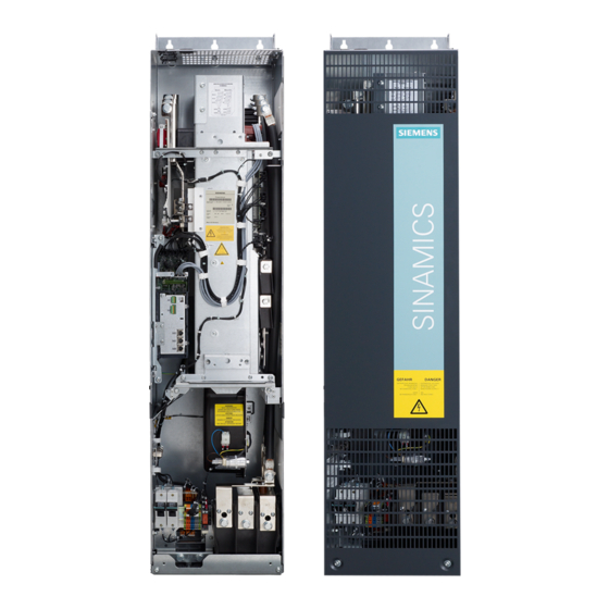
Page 26: Overview Of The Chassis Units
Device overview 2.2 Overview of the chassis units Overview of the chassis units Figure 2-1 Overview of the chassis units Inverter chassis units Operating Instructions, 07/2016, A5E00331449A…
-
Page 27: Overview Of The Power Modules
Device overview 2.3 Overview of the Power Modules Overview of the Power Modules Figure 2-2 Overview of the Power Modules Inverter chassis units Operating Instructions, 07/2016, A5E00331449A…
-
Page 28: Applications, Features
As a result, SINAMICS G130 chassis units are a cost-effective drive solution for all types of industrial applications that involve moving, conveying, pumping, compressing, or extracting solids, liquids, or gases.
-
Page 29
Device overview 2.4 Applications, features Quality SINAMICS G130 built-in units are manufactured to meet high standards of quality and exacting demands. This results in a high level of reliability, availability, and functionality for our products. The development, design, and manufacturing processes, as well as order processing and the logistics supply center have been certified to DIN ISO 9001 by an independent authority. -
Page 30: Wiring Principle
Device overview 2.5 Wiring principle Wiring principle Wiring principle for SINAMICS G130 Figure 2-3 Wiring principle for SINAMICS G130 Inverter chassis units Operating Instructions, 07/2016, A5E00331449A…
-
Page 31: Type Plate
Device overview 2.6 Type plate Type plate Specifications on the type plate Figure 2-4 Type plate of built-in unit Inverter chassis units Operating Instructions, 07/2016, A5E00331449A…
-
Page 32
Device overview 2.6 Type plate Type plate specifications (from type plate above) Position Specification Value Explanation ① Input 3 AC Three-phase connection 380 … 480 V Rated input voltage 775 A Rated input current ② Output 3 AC Three-phase connection 0 … -
Page 33: Mechanical Installation
Mechanical installation Chapter content This chapter provides information on the following: ● The conditions for installing the chassis units and optional components. ● The preparations for installing the chassis units and optional components. Transportation and storage Transport WARNING Danger to life due to incorrectly transporting the unit The unit can tip over if you transport it incorrectly –…
-
Page 34
• If you fail to contact them immediately, you may lose your right to claim compensation for the defects and damage. • If necessary, you can request the support of your local Siemens office. Storage The devices must be stored in clean, dry rooms. Temperatures between -25° C and +55° C are permissible (class 1K4 according to EN 60721-3-1). -
Page 35: Assembly
Mechanical installation 3.3 Assembly Assembly WARNING Danger to life if the general safety instructions and remaining risks are not carefully observed If the general safety instructions and remaining risks are not observed, accidents can occur involving severe injuries or death. •…
-
Page 36: Unpacking
Mechanical installation 3.3 Assembly Installation is realized in accordance with the dimension drawings supplied. The clearance to be maintained around the units is also specified on the dimension drawings. The cooling air for the power unit is drawn from the lower part of the device. The warmed air is expelled through the heat sink.
-
Page 37: Power Module
Mechanical installation 3.4 Power Module Power Module Description The Power Module is the power unit of an AC-AC converter. Line or motor-side components can be added to create a converter system. If required (e.g., for braking operation), a Braking Module can also be installed in the DC link of the converter. A slot is provided in the Power Module for this purpose.
-
Page 38: Dimension Drawings
Mechanical installation 3.4 Power Module 3.4.1 Dimension drawings Dimension drawing frame size FX Table 3- 1 Dimension drawing frame size FX Front view Side view Inverter chassis units Operating Instructions, 07/2016, A5E00331449A…
-
Page 39
Mechanical installation 3.4 Power Module Dimension drawing, frame size GX Table 3- 2 Dimension drawing, frame size GX Front view Side view Inverter chassis units Operating Instructions, 07/2016, A5E00331449A… -
Page 40
Mechanical installation 3.4 Power Module Dimension drawing (frame size HX) Table 3- 3 Dimension drawing (frame size HX) Side view Rear view Inverter chassis units Operating Instructions, 07/2016, A5E00331449A… -
Page 41
Mechanical installation 3.4 Power Module Dimension drawing (frame size JX) Table 3- 4 Dimension drawing (frame size JX) Side view Rear view Inverter chassis units Operating Instructions, 07/2016, A5E00331449A… -
Page 42: Control Unit Cu320-2
Mechanical installation 3.5 Control Unit CU320-2 Control Unit CU320-2 Description The CU320-2 is the central Control Unit in which the closed-loop and open-loop control functions are implemented. WARNING Fire hazard due to overheating because of inadequate ventilation clearances Insufficient ventilation clearances result in overheating with danger to persons as a result of smoke and fire.
-
Page 43: Tm31 Terminal Module
Mechanical installation 3.6 TM31 Terminal Module Note Installing the Control Unit With frame sizes FX and GX, the Control Unit is installed to the left of the Power Module. The required connection elements are supplied with the Power Module. With frame sizes HX and JX, the Control Unit is installed in the Power Module. Control Unit: Memory card The memory card contains the control software and parameters.
-
Page 44
Mechanical installation 3.6 TM31 Terminal Module Dimension drawing Figure 3-2 Dimension drawing of the TM31 Terminal Module Note Installation of the Terminal Module The TM31 is installed near the Power Module on a mounting rail, which must be provided by the customer. -
Page 45: Smc30 Sensor Module
Mechanical installation 3.7 SMC30 Sensor Module SMC30 Sensor Module Description The SMC30 Sensor Module is a module for evaluating encoder signals. TTL/HTL encoders (with or without open-circuit monitoring) can be connected to the SMC30. The motor temperature can also be detected using KTY84-1C130 or PTC thermistors. WARNING Fire hazard due to overheating because of inadequate ventilation clearances Insufficient ventilation clearances result in overheating with danger to persons as a result of…
-
Page 46
Mechanical installation 3.7 SMC30 Sensor Module Note Installation of the Sensor Module The SMC30 is installed near the Power Module on a mounting rail, which must be provided by the customer. Inverter chassis units Operating Instructions, 07/2016, A5E00331449A… -
Page 47: Electrical Installation
Electrical installation Chapter content This chapter provides information on the following: ● Establishing the electrical connections for the Power Module, the CU320-2 Control Unit, and the optional TM31 Terminal Module and SMC30 Sensor Module. ● Adjusting the fan voltage and the internal power supply in line with local conditions (supply voltage) ●…
-
Page 48: Important Safety Precautions
• Before switching on the device, it should be formed after a storage time exceeding two years, see Chapter «Maintenance and servicing». NOTICE Only use original Siemens accessories To ensure that the entire system functions properly, you are advised to use the original Siemens accessories.
-
Page 49: Introduction To Emc
Electrical installation 4.4 Introduction to EMC Introduction to EMC What is meant by EMC? Electromagnetic compatibility (EMC) describes the capability of an electrical device to function satisfactorily in an electromagnetic environment without itself causing interference unacceptable for other devices in the environment. EMC therefore represents a quality feature for the ●…
-
Page 50
Electrical installation 4.4 Introduction to EMC Noise emissions Product standard EN 61800–3 outlines the EMC requirements for variable-speed drive systems. It specifies requirements for converters with operating voltages of less than 1000 V. Different environments and categories are defined depending on where the drive system is installed. -
Page 51: Emc-Compliant Design
Electrical installation 4.5 EMC-compliant design Table 4- 2 Definition of categories C1 … C4 Definition of categories C1 … C4 Category C1 Rated voltage <1000 V; unrestricted use in the first environment. Category C2 Rated voltage for stationary drive systems <1000 V; for use in the second environment.
-
Page 52
Electrical installation 4.5 EMC-compliant design Use anti-interference elements ● If relays, contactors, and inductive or capacitive loads are connected, the switching relays or contactors must be provided with anti-interference elements. Cable installation ● Cables that are subject to or sensitive to interference should be laid as far apart from each other as possible. -
Page 53
Electrical installation 4.5 EMC-compliant design I/O interfacing ● Create a low-impedance ground connection for additional cabinets, system components, and distributed devices with the largest possible cross-section (at least 16 mm²). ● Ground unused lines at one end in the cabinet. ●… -
Page 54: Connection Overview
Electrical installation 4.6 Connection overview Connection overview Power Module, frame size FX Figure 4-3 Connection overview of Power Module, frame size FX (without front cover) Inverter chassis units Operating Instructions, 07/2016, A5E00331449A…
-
Page 55
Electrical installation 4.6 Connection overview Power Module (frame size GX) Figure 4-4 Connection overview of Power Module (frame size GX) (without front cover) Inverter chassis units Operating Instructions, 07/2016, A5E00331449A… -
Page 56
Electrical installation 4.6 Connection overview Power Module (frame size HX) Figure 4-5 Connection overview of Power Module (frame size HX) (without front cover) Inverter chassis units Operating Instructions, 07/2016, A5E00331449A… -
Page 57
Electrical installation 4.6 Connection overview Power Module (frame size JX) Figure 4-6 Connection overview of Power Module (frame size JX) (without front cover) Inverter chassis units Operating Instructions, 07/2016, A5E00331449A… -
Page 58: Power Connections
Electrical installation 4.7 Power connections Power connections WARNING Danger to life through electric shock caused by interchanging or short-circuiting device connections Interchanging the line connections and motor connections or short-circuiting the DC-link connections will damage the device that can cause death or severe injuries. •…
-
Page 59: Connection Cross-Sections, Cable Lengths
Cable lengths The maximum permissible cable lengths are specified for standard cable types or cable types recommended by SIEMENS. Longer cables can only be used after consultation. The listed cable length represents the actual distance between the converter and the motor, taking account factors such as parallel laying, current-carrying capacity, and the laying factor.
-
Page 60: Connecting The Motor And Power Cables
4.7 Power connections Note Shielded cables The PROTOFLEX-EMV-3 PLUS shielded cable recommended by Siemens is the protective conductor and comprises three symmetrically-arranged protective conductors. The individual protective conductors must each be provided with cable eyes and be connected to ground.
-
Page 61
Electrical installation 4.7 Power connections Direction of motor rotation EN 60034-7 defines the two ends of an electric motor as follows: ● DE (Drive End): usually the drive end of the motor ● NDE (Non-Drive End): usually the non-drive end of the motor An electric motor will rotate clockwise if the shaft is turning clockwise when looking at the DE side. -
Page 62: Dcps, Dcns Connection For A Dv/Dt Filter With Voltage Peak Limiter
Electrical installation 4.7 Power connections 4.7.4 DCPS, DCNS connection for a dV/dt filter with Voltage Peak Limiter Table 4- 5 DCPS, DCNS Frame size Connectable cross-section Terminal screw 1 x 70 mm² 1 x 70 mm² 1 x 185 mm² 2 x 185 mm²…
-
Page 63
Electrical installation 4.7 Power connections Note Fan transformer for 660 to 690 V 3 AC With the 660 V to 690 V 3 AC fan transformer, a jumper is inserted between the «600 V» terminal and «CON» terminal. The «600V» and «CON» terminals are for internal use. WARNING Danger of fire due to overheating resulting from insufficient device fan voltage If the terminals are not reconnected to correspond with the actual line voltage, overheating… -
Page 64: Removing The Connection Clip To The Basic Interference Suppression Module For Operation On An Ungrounded Line Supply (It System)
Electrical installation 4.7 Power connections 4.7.6 Removing the connection clip to the basic interference suppression module for operation on an ungrounded line supply (IT system) If the built-in unit is operated from a non-grounded supply (IT system), the connection clip to the basic interference suppression module of the Power Module must be removed.
-
Page 65
Electrical installation 4.7 Power connections Figure 4-10 Removing the connection clip to the basic interference suppression module, frame size Inverter chassis units Operating Instructions, 07/2016, A5E00331449A… -
Page 66
Electrical installation 4.7 Power connections Figure 4-11 Removing the connection clip to the basic interference suppression module, frame size Inverter chassis units Operating Instructions, 07/2016, A5E00331449A… -
Page 67
Electrical installation 4.7 Power connections Figure 4-12 Removing the connection clip to the basic interference suppression module, frame size Inverter chassis units Operating Instructions, 07/2016, A5E00331449A… -
Page 68
Electrical installation 4.7 Power connections Figure 4-13 Removing the connection clip to the basic interference suppression module, frame size JX Inverter chassis units Operating Instructions, 07/2016, A5E00331449A… -
Page 69: External 24 V Dc Supply
Electrical installation 4.8 External 24 V DC supply External 24 V DC supply Description An external 24 V DC supply is always recommended if communication and closed-loop control are to be independent of the supply system. An external auxiliary supply is particularly recommended for low-power lines susceptible to short-time voltage dips or power failures.
-
Page 70: Drive-Cliq Wiring Diagram
Electrical installation 4.9 DRIVE-CLiQ wiring diagram DRIVE-CLiQ wiring diagram The diagram below shows the specifications for the DRIVE-CLiQ connections between the components. NOTICE Comply with connection specifications These specifications for the DRIVE-CLiQ connections should be observed, otherwise faults may occur during commissioning via STARTER or the AOP30 operator panel. Figure 4-14 DRIVE-CLiQ wiring diagram Inverter chassis units…
-
Page 71: Signal Connections
Electrical installation 4.10 Signal connections 4.10 Signal connections 4.10.1 Power Module X9: Terminal block Table 4- 9 Terminal block X9 Terminal Function Technical data P24V External 24 V DC supply Voltage: 24 V DC (20.4 to 28.8 V) Current consumption: max. 4 A Reserved, do not use Reserved, do not use Control of the main contactor…
-
Page 72
Electrical installation 4.10 Signal connections WARNING Danger to life due to electric shock in the event of voltage flashovers at the temperature sensor Voltage flashovers in the signal electronics can occur in motors without safe electrical separation of the temperature sensors. •… -
Page 73
Electrical installation 4.10 Signal connections Note Safety Integrated Function Manual Detailed and comprehensive instructions and information for the Safety Integrated functions can be found in the associated Function Manual. This manual is available as additional documentation on the customer DVD supplied with the device. X42: Power supply for the Control Unit, Sensor Module and Terminal Module Table 4- 11 Terminal block X42… -
Page 74
Electrical installation 4.10 Signal connections WARNING Fire hazard due to overheating when permissible connection cable lengths are exceeded Excessively long connection cables connected to terminal strip X46 can cause components to overheat with the associated risk of fire and smoke. •… -
Page 75: Control Unit Cu320-2 Dp
Electrical installation 4.10 Signal connections 4.10.2 Control Unit CU320-2 DP Connection overview Figure 4-15 Connection overview of the CU320-2 DP Control Unit (without cover) Inverter chassis units Operating Instructions, 07/2016, A5E00331449A…
-
Page 76
Electrical installation 4.10 Signal connections Figure 4-16 Interface X140 and measuring sockets T0 to T2 — CU320-2 DP (view from below) NOTICE Malfunctions or damage to the option board by inserting and withdrawing in operation Withdrawing and inserting the option board in operation can damage it or cause it to malfunction. -
Page 77
Electrical installation 4.10 Signal connections Connection example Figure 4-17 Connection example of CU320-2 DP Inverter chassis units Operating Instructions, 07/2016, A5E00331449A… -
Page 78
Electrical installation 4.10 Signal connections X100 to X103: DRIVE-CLiQ interface Table 4- 14 DRIVE-CLiQ interface X100 – X103 Signal name Technical data Transmit data + Transmit data — Receive data + Reserved, do not use Reserved, do not use Receive data — Reserved, do not use Reserved, do not use + (24 V) -
Page 79
Electrical installation 4.10 Signal connections X122: Digital inputs/outputs Table 4- 15 Terminal block X122 Designation Technical data DI 0 Voltage (max.): -3 … +30 V DC Typical power consumption: 9 mA at 24 V DI 1 Electrical isolation: reference potential is terminal M1 DI 2 Level (with ripple) DI 3… -
Page 80
Electrical installation 4.10 Signal connections Note Ensuring the function of digital inputs An open input is interpreted as «low». Terminal M1 must be connected so that the digital inputs (DI) can function. This is achieved through one of the following measures: 1. -
Page 81
Electrical installation 4.10 Signal connections X132: Digital inputs/outputs Table 4- 16 Terminal block X132 Designation Technical data DI 4 Voltage (max.): -3 … +30 VDC Current consumption, typical: 9 mA at 24 V DI 5 Electrical isolation: The reference potential is terminal M2 DI 6 Level (including ripple) DI 7… -
Page 82
Electrical installation 4.10 Signal connections Note Ensuring the function of digital inputs An open input is interpreted as «low». To enable the digital inputs (DI) to function, terminal M2 must be connected. This is achieved through one of the following measures: 1. -
Page 83
Electrical installation 4.10 Signal connections X126: PROFIBUS connection The PROFIBUS is connected by means of a 9-pin SUB D socket (X126). The connections are electrically isolated. Table 4- 18 PROFIBUS interface X126 Signal name Meaning Range Not assigned M24_SERV Power supply for teleservice, ground RxD/TxD–P Receive/transmit data P (B) RS485… -
Page 84
Electrical installation 4.10 Signal connections Connectors The cables must be connected via PROFIBUS connectors as they contain the necessary terminating resistors. The figure below shows suitable PROFIBUS connectors with/without a PG/PC connector. PROFIBUS connector PROFIBUS connector without PG/PC connection with PG/PC connection 6ES7972-0BA42-0XA0 6ES7972-0BB42-0XA0 Bus terminating resistor… -
Page 85
Electrical installation 4.10 Signal connections PROFIBUS address switches The PROFIBUS address is set as a hexadecimal value via two rotary coding switches. Values between 0 ) and 127 ) can be set as the address. The upper rotary coding switch (H) is used to set the hexadecimal value for 16 and the lower rotary coding switch (L) is used to set the hexadecimal value for 16 Table 4- 19… -
Page 86
Electrical installation 4.10 Signal connections Note Address 126 is used for commissioning. Permitted PROFIBUS addresses are 1 … 126. When several Control Units are connected to a PROFIBUS line, you set the addresses differently than for the factory setting. Each PROFIBUS address in a PROFIBUS line can only be assigned once. -
Page 87
Electrical installation 4.10 Signal connections X140: serial interface (RS232) The AOP30 operator panel for operating/parameterizing the device can be connected via the serial interface. The interface is located on the underside of the Control Unit. Table 4- 22 Serial interface (RS232) X140 Designation Technical data Receive data… -
Page 88
Electrical installation 4.10 Signal connections Note Using the measuring socket contacts The measuring socket contacts support commissioning and diagnostic functions. It must not be connected for normal operation. DIAG button The DIAG pushbutton is reserved for service functions. Slot for the memory card Figure 4-19 Slot for the memory card WARNING… -
Page 89
• Do not return the memory card as well, but rather keep it in a safe place so that it can be inserted in the replacement unit. Note Please note that only SIEMENS memory cards can be used to operate the Control Unit. Inverter chassis units Operating Instructions, 07/2016, A5E00331449A… -
Page 90: Control Unit Cu320-2 Pn
Electrical installation 4.10 Signal connections 4.10.3 Control Unit CU320-2 PN Connection overview Figure 4-20 Connection overview of CU320-2 PN Control Unit (without cover) Inverter chassis units Operating Instructions, 07/2016, A5E00331449A…
-
Page 91
Electrical installation 4.10 Signal connections Figure 4-21 Interface X140 and measuring sockets T0 to T2 — CU320-2 PN (view from below) NOTICE Malfunctions or damage to the option board by inserting and withdrawing in operation Withdrawing and inserting the option board in operation can damage it or cause it to malfunction. -
Page 92
Electrical installation 4.10 Signal connections Connection example Figure 4-22 Connection example, CU320-2 PN Inverter chassis units Operating Instructions, 07/2016, A5E00331449A… -
Page 93
Electrical installation 4.10 Signal connections X100 to X103: DRIVE-CLiQ interface Table 4- 24 DRIVE-CLiQ interface X100 – X103 Signal name Technical data Transmit data + Transmit data — Receive data + Reserved, do not use Reserved, do not use Receive data — Reserved, do not use Reserved, do not use + (24 V) -
Page 94
Electrical installation 4.10 Signal connections X122: Digital inputs/outputs Table 4- 25 Terminal block X122 Designation Technical data DI 0 Voltage (max.): -3 … +30 V DC Typical power consumption: 9 mA at 24 V DI 1 Electrical isolation: reference potential is terminal M1 DI 2 Level (with ripple) DI 3… -
Page 95
Electrical installation 4.10 Signal connections Note Ensuring the function of digital inputs An open input is interpreted as «low». Terminal M1 must be connected so that the digital inputs (DI) can function. This is achieved through one of the following measures: 1. -
Page 96
Electrical installation 4.10 Signal connections X132: Digital inputs/outputs Table 4- 26 Terminal block X132 Designation Technical data DI 4 Voltage (max.): -3 … +30 VDC Current consumption, typical: 9 mA at 24 V DI 5 Electrical isolation: The reference potential is terminal M2 DI 6 Level (including ripple) DI 7… -
Page 97
Electrical installation 4.10 Signal connections Note Ensuring the function of digital inputs An open input is interpreted as «low». To enable the digital inputs (DI) to function, terminal M2 must be connected. This is achieved through one of the following measures: 1. -
Page 98
Electrical installation 4.10 Signal connections X127: LAN (Ethernet) Table 4- 28 X127 LAN (Ethernet) Designation Technical data Ethernet transmit data + Ethernet transmit data — Ethernet receive data + Reserved, do not use Reserved, do not use Ethernet receive data — Reserved, do not use Reserved, do not use Connector type: RJ45 socket… -
Page 99
Electrical installation 4.10 Signal connections X140: serial interface (RS232) The AOP30 operator panel for operating/parameterizing the device can be connected via the serial interface. The interface is located on the underside of the Control Unit. Table 4- 30 Serial interface (RS232) X140 Designation Technical data Receive data… -
Page 100
Electrical installation 4.10 Signal connections Note Connection cables The PROFINET interfaces support Auto MDI(X). It is therefore possible to use both crossover and non-crossover cables to connect the devices. For diagnostic purposes, the two PROFINET interfaces are each equipped with a green and a yellow LED. -
Page 101
Electrical installation 4.10 Signal connections DIAG button The DIAG pushbutton is reserved for service functions. Slot for the memory card Figure 4-23 Slot for the memory card Inverter chassis units Operating Instructions, 07/2016, A5E00331449A… -
Page 102
• Do not return the memory card as well, but rather keep it in a safe place so that it can be inserted in the replacement unit. Note Please note that only SIEMENS memory cards can be used to operate the Control Unit. Inverter chassis units Operating Instructions, 07/2016, A5E00331449A… -
Page 103: Tm31 Terminal Module
Electrical installation 4.10 Signal connections 4.10.4 TM31 Terminal Module Description The TM31 Terminal Module is a terminal extension board. The TM31 terminal Module can be used to increase the number of available digital/analog inputs/outputs within a drive system. Connection overview Figure 4-24 TM31 Terminal Module Inverter chassis units…
-
Page 104
Electrical installation 4.10 Signal connections Figure 4-25 Connection overview of TM31 Terminal Module Inverter chassis units Operating Instructions, 07/2016, A5E00331449A… -
Page 105
Electrical installation 4.10 Signal connections X500, X501: DRIVE-CLiQ interface Table 4- 34 DRIVE-CLiQ interface X500 and X501 Signal name Technical data Transmit data + Transmit data — Receive data + Reserved, do not use Reserved, do not use Receive data — Reserved, do not use Reserved, do not use + (24 V) -
Page 106
Electrical installation 4.10 Signal connections X520: 4 digital inputs Table 4- 36 Terminal block X520 Terminal Designation Technical data DI 0 Voltage: — 3 … +30 V Current consumption typical: 10 mA at 24 V DC DI 1 Input delay: DI 2 for «0»… -
Page 107
Electrical installation 4.10 Signal connections X530: 4 digital inputs Table 4- 37 Terminal block X530 Terminal Designation Technical data DI 4 Voltage: — 3 … +30 V Current consumption typical: 10 mA at 24 V DC DI 5 Input delay: DI 6 For «0»… -
Page 108
Electrical installation 4.10 Signal connections X521: 2 analog inputs (differential inputs) Table 4- 38 Terminal block X521 Terminal Designation Technical data AI 0+ The analog inputs can be toggled between current and voltage input using switches S5.0 and S5.1. AI 0- As voltage input: AI 1+ -10 … -
Page 109
Electrical installation 4.10 Signal connections S5: Selector for voltage/current AI0, AI1 Table 4- 39 Selector for voltage/current S5 Switch Function S5.0 Selector voltage (V) / current (I) Al0 S5.1 Selector voltage (V) / current (I) Al1 Note Delivery condition When delivered, both switches are set to voltage measurement (switch set to «V»). X522: 2 analog outputs, temperature sensor connection Table 4- 40 Terminal block X522… -
Page 110
Electrical installation 4.10 Signal connections NOTICE Damage or malfunctions through impermissible voltage values If the back EMF is impermissible then damage and malfunctions may occur on the components. • The back EMF at the outputs may only be in the range between -15 V and +15 V. NOTICE Damage to motor in the event of incorrectly connected KTY temperature sensor If a KTY temperature sensor is connected with incorrect polarity, it is not possible to detect… -
Page 111
Electrical installation 4.10 Signal connections X541: 4 non-floating digital inputs/outputs Table 4- 42 Terminal strip X541 Terminal Designation Technical data Auxiliary voltage: Voltage: +24 V DC DI/DO 11 Max. total load current of +24 V auxiliary voltage for DI/DO 10 terminals X540 and X541 combined: 150 mA DI/DO 9 As input:… -
Page 112
Electrical installation 4.10 Signal connections X542: 2 relay outputs (two-way contact) Table 4- 43 Terminal block X542 Terminal Designation Technical data DO 0.NC Contact type: Changeover contact max. load current: DO 0.COM Max. switching voltage: 250 V . 30 V DO 0.NO Max. -
Page 113: Sensor Module Cabinet-Mounted Smc30
DRIVE-CLiQ interface for evaluation purposes. In conjunction with SINAMICS G130 the following encoders can be connected to the SMC30 Sensor Module: ●…
-
Page 114
Electrical installation 4.10 Signal connections Table 4- 46 Specification of measuring systems that can be connected Parameters Designation Threshold Min. Max. Unit High signal level Hdiff (TTL bipolar at X520 or X521/X531) Low signal level Ldiff (TTL bipolar to X520 or X521/X531) High signal level High (HTL unipolar) -
Page 115
Electrical installation 4.10 Signal connections Figure 4-27 Position of the zero pulse to the track signals For encoders with a 5-V supply at X521/X531, the cable length is dependent on the encoder current (this applies cable cross-sections of 0.5 mm²): Figure 4-28 Signal cable length as a function of the encoder current consumption Inverter chassis units… -
Page 116
Electrical installation 4.10 Signal connections For encoders without Remote Sense the permissible cable length is restricted to 100 m (reason: the voltage drop depends on the cable length and the encoder current). Figure 4-29 SMC30 Sensor Module Inverter chassis units Operating Instructions, 07/2016, A5E00331449A… -
Page 117: Connection
Electrical installation 4.10 Signal connections 4.10.5.2 Connection X500: DRIVE-CLiQ interface Table 4- 47 DRIVE-CLiQ interface X500 Signal name Technical data Transmit data + Transmit data — Receive data + Reserved, do not use Reserved, do not use Receive data — Reserved, do not use Reserved, do not use + (24 V)
-
Page 118
Electrical installation 4.10 Signal connections X520: Encoder connection 1 for HTL/TTL encoder with open-circuit monitoring Table 4- 49 Encoder connection X520 Signal name Technical data +Temp Temperature sensor connection KTY84- 1C130 / PT1000 / PTC Reserved, do not use Reserved, do not use P encoder 5 V/24 V Encoder supply P encoder 5 V/24 V… -
Page 119
Electrical installation 4.10 Signal connections NOTICE Device failure as a result of unshielded or incorrectly routed cables to temperature sensors Unshielded or incorrectly routed cables to temperature sensors can result in interference being coupled into the signal processing electronics from the power side. This can result in significant disturbance of all signals (fault messages) up to failure of individual components (destruction of the devices). -
Page 120
Electrical installation 4.10 Signal connections X521 / X531: Encoder connection 2 for HTL/TTL encoder with open-circuit monitoring Table 4- 50 Encoder connection X521 Terminal Signal name Technical data Incremental signal A Inverse incremental signal A Incremental signal B Inverse incremental signal B Reference signal R Inverse reference signal R CTRL… -
Page 121
Electrical installation 4.10 Signal connections WARNING Danger to life due to electric shock in the event of voltage flashovers at the temperature sensor Voltage flashovers in the signal electronics can occur in motors without safe electrical separation of the temperature sensors. •… -
Page 122: Connection Examples
Electrical installation 4.10 Signal connections 4.10.5.3 Connection examples Connection example 1: HTL encoder, bipolar, without zero marker -> p0405 = 9 (hex) Figure 4-30 Connection example 1: HTL encoder, bipolar, without zero marker Connection example 2: TTL encoder, unipolar, without zero marker -> p0405 = A (hex) Figure 4-31 Connection example 2: TTL encoder, unipolar, without zero marker Inverter chassis units…
-
Page 123: Tm54F Terminal Module
Electrical installation 4.10 Signal connections 4.10.6 TM54F Terminal Module The TM54F Terminal Module is a terminal expansion module with safe digital inputs and outputs for controlling the Safety Integrated Extended functions of SINAMICS. The TM54F provides 4 fail-safe digital outputs and 10 fail-safe digital inputs. A fail-safe digital output consists of a 24 V DC switching output, a ground switching output, and a digital input for checking the switching state.
-
Page 124
Electrical installation 4.10 Signal connections Inverter chassis units Operating Instructions, 07/2016, A5E00331449A… -
Page 125: Chapter Content
Commissioning Chapter content This section provides information on the following: ● Initial commissioning of the chassis unit (initialization) with STARTER and AOP30 – Entering the motor data (drive commissioning) – Entering the most important parameters (basic commissioning), concluding with motor identification ●…
-
Page 126: Starter Commissioning Tool
Commissioning 5.2 STARTER commissioning tool Important information prior to commissioning The built-in unit offers a varying number of signal interconnections depending on the additional modules connected. For the converter control to be able to process the signals correctly, several software settings must be made. During initial power-up of the Control Unit and during first commissioning, parameter macros are executed and the necessary settings made.
-
Page 127
Commissioning 5.2 STARTER commissioning tool Prerequisites for installing STARTER Hardware The following minimum requirements must be complied with: ● PG or PC ● Pentium III, at least 1 GHz, (> 1 GHz recommended) ● 1 GB work memory (2 GB recommended) ●… -
Page 128: Installing Starter
Commissioning 5.2 STARTER commissioning tool 5.2.1 Installing STARTER STARTER is installed using the «setup» file on the customer DVD supplied. When you double-click the «Setup» file, the installation Wizard guides you through the process of installing STARTER. Note Installation time The installation time depends on the computer performance and from where the software is installed (e.g.
-
Page 129: Procedure For Commissioning Via Starter
Commissioning 5.3 Procedure for commissioning via STARTER Operating area Explanation 1: Toolbars In this area, you can access frequently used functions via the icons. 2: Project navigator The elements and projects available in the project are displayed here. 3: Working area In this area, you can change the settings for the drive units.
-
Page 130
Commissioning 5.3 Procedure for commissioning via STARTER Accessing the STARTER project wizard Figure 5-2 Main screen of the STARTER parameterization and commissioning tool ⇒ Hide STARTER Getting Started commissioning drive using HTML Help > Close The online help can be permanently hidden by deselecting Options > Settings > Workbench >… -
Page 131
Commissioning 5.3 Procedure for commissioning via STARTER The STARTER project wizard Figure 5-3 STARTER project wizard ⇒ click Arrange drive units offline… in the STARTER project wizard. Figure 5-4 Create new project ⇒ Enter a project name and, if necessary, the author, memory location and a comment. ⇒… -
Page 132
Commissioning 5.3 Procedure for commissioning via STARTER Figure 5-5 Set up interface ⇒ Under Access point: select the interface corresponding to your device configuration from: ● Select the S7ONLINE access (STEP7), if the connection to the drive unit is established via PROFINET or PROFIBUS. -
Page 133
Commissioning 5.3 Procedure for commissioning via STARTER Figure 5-6 Setting the interface Note Precondition To parameterize the interface, you must install the appropriate interface card (e.g., PC Adapter (PROFIBUS) Inverter chassis units Operating Instructions, 07/2016, A5E00331449A… -
Page 134
Commissioning 5.3 Procedure for commissioning via STARTER Figure 5-7 Setting the interface — properties Note Activate PG/PC is the only master on the bus You must activate PG/PC is the only master on bus if no other master (PC, S7, etc.) is available on the bus. -
Page 135
Commissioning 5.3 Procedure for commissioning via STARTER Figure 5-8 Complete setting the interface ⇒ Click Continue > to set up a drive unit in the project wizard. Figure 5-9 Inserting the drive unit ⇒ Choose the following data from the list fields: Device: Sinamics Type: G130 CU320-2 DP or G130 CU320-2 PN Version: 4.8… -
Page 136
Commissioning 5.3 Procedure for commissioning via STARTER Figure 5-10 Drive unit inserted ⇒ Click Continue > A project summary is displayed. Figure 5-11 Summary ⇒ Click Complete to finish creating a new drive unit project. Inverter chassis units Operating Instructions, 07/2016, A5E00331449A… -
Page 137: Configuring The Drive Unit
Commissioning 5.3 Procedure for commissioning via STARTER 5.3.2 Configuring the drive unit In the project navigator, open the component that contains your drive unit. Figure 5-12 Project navigator – configuring the drive unit ⇒ In the project navigator, click the plus sign next to the drive unit that you want to configure. The plus sign becomes a minus sign and the drive unit configuration options are displayed as a tree below the drive unit.
-
Page 138
Commissioning 5.3 Procedure for commissioning via STARTER Configuring the drive unit Figure 5-13 Configuring the drive unit ⇒ Under Connection voltage, choose the correct voltage. Under Cooling method: choose the correct cooling method for your drive unit. Note Make a pre-selection In this step, you make a preliminary selection of the chassis units. -
Page 139
Commissioning 5.3 Procedure for commissioning via STARTER Selecting options Figure 5-14 Selecting options ⇒ From the combination box Options selection: select the options belonging to your drive unit by clicking on the corresponding check box. NOTICE Damage to the sine-wave filter if it is not activated during commissioning The sine-wave filter may be damaged if it is not activated during commissioning. -
Page 140
Commissioning 5.3 Procedure for commissioning via STARTER NOTICE Damage to the du/dt filter if it is not activated during commissioning The du/dt filter may be damaged if it is not activated during commissioning. • Activate the du/dt filter during commissioning by activating the appropriate checkbox (option DU/DT). -
Page 141
Commissioning 5.3 Procedure for commissioning via STARTER Selecting the control structure Figure 5-15 Selecting the control structure Inverter chassis units Operating Instructions, 07/2016, A5E00331449A… -
Page 142
Commissioning 5.3 Procedure for commissioning via STARTER ⇒ Select the corresponding settings for the closed-loop control structure: ● Function modules: – Technology controller – Extended messages/monitoring ● Control: – n/M control + U/f control, I/f control – U/f control ● Control mode: Depending on the selected control, you can select from one of the following open- loop/closed-loop control modes: –… -
Page 143
Commissioning 5.3 Procedure for commissioning via STARTER Configuring the drive unit properties Figure 5-16 Configuring the drive unit properties ⇒ Under Standard:, choose the appropriate standard for your motor, whereby the following is defined: ● IEC motor (50 Hz, SI unit): Line frequency 50 Hz, motor data in kW ●… -
Page 144
Commissioning 5.3 Procedure for commissioning via STARTER Selecting a standard motor type from a list Figure 5-17 Configuring a motor – selecting the motor type, selecting a standard motor from a list ⇒ Under Motor name: enter a name for the motor. ⇒… -
Page 145
Commissioning 5.3 Procedure for commissioning via STARTER Configuring the motor – Selecting the type of connection Figure 5-18 Configuring the motor – Selecting the type of connection ⇒Under Connection type:, select whether the motor is connected in a star or delta connection. -
Page 146
Commissioning 5.3 Procedure for commissioning via STARTER Selecting the motor type by entering the motor data Figure 5-19 Configuring the motor – Selecting the motor type ⇒ Under Motor name: enter a name for the motor. ⇒ select Enter motor data ⇒… -
Page 147
Commissioning 5.3 Procedure for commissioning via STARTER Note Commissioning of an induction motor The steps described below also apply to commissioning an induction motor. When commissioning a permanent-magnet synchronous motor, there are a few special conditions that apply, which are detailed in a separate chapter (see «Setpoint channel and closed-loop control / permanent-magnet synchronous motors»). -
Page 148
Commissioning 5.3 Procedure for commissioning via STARTER Note Entering equivalent circuit diagram data You should only activate the Enter optional equivalent circuit diagram data if the data sheet with equivalent circuit diagram data is available. If any data is missing, an error message will be output when the system attempts to load the drive project to the target system. -
Page 149
Commissioning 5.3 Procedure for commissioning via STARTER Configuring the motor – Entering the equivalent circuit diagram data Figure 5-22 Entering equivalent circuit diagram data ⇒ Select one of the equivalent circuit diagram data representations: ● Physical system of units The equivalent circuit diagram data are shown in the form of physical units. ●… -
Page 150
Commissioning 5.3 Procedure for commissioning via STARTER Calculating the motor/controller data Figure 5-23 Calculating the motor/controller data ⇒ In Calculation of the motor/controller data, select the appropriate default settings for your device configuration. Note Manual input of the equivalent circuit diagram data If the equivalent circuit diagram data was entered manually (see «Entering the equivalent circuit diagram data»), then the motor/controller data should be calculated without calculating the equivalent circuit diagram data. -
Page 151
Commissioning 5.3 Procedure for commissioning via STARTER Configuring the motor holding brake Figure 5-24 Configuring the motor holding brake ⇒ Under Holding brake configuration: choose the appropriate setting for your device configuration: ● 0: No motor holding brake being used ●… -
Page 152
Commissioning 5.3 Procedure for commissioning via STARTER Entering the encoder data (option: SMC30 Sensor Module) Note Entering the encoder data If you specified the SMC30 Sensor Module when choosing the options, the Following input screen is displayed in which you can enter the encoder data. Figure 5-25 Entering the encoder data ⇒… -
Page 153
Figure 5-26 Entering encoder data – User-defined encoder data ⇒ Select the measuring system. You can choose the following encoders in conjunction with SINAMICS G130: ● HTL ● TTL ⇒ Enter the required encoder data. ⇒ under the Details tab, special encoder properties can be set, for example, gear ratio, fine resolution, inversion, measuring gear position tracking. -
Page 154
Commissioning 5.3 Procedure for commissioning via STARTER NOTICE Material damage when selecting the incorrect encoder supply voltage Once the encoder has been commissioned, the supply voltage (5/24 V) set for the encoder is activated on the SMC30 Module. If a 5 V encoder is connected and the supply voltage has not been set correctly, the encoder may be damaged. -
Page 155
Motorized potentiometer Fixed setpoint Note Use of CDS0 With SINAMICS G130, only CDS0 is normally used as a default setting for the command and setpoint sources. Make sure that the selected default setting is compatible with the actual system configuration. -
Page 156
Commissioning 5.3 Procedure for commissioning via STARTER Selecting drive functions Figure 5-28 Selecting drive functions ⇒ Select the required data: ● Technological application: – «(0) Standard drive (VECTOR)» Edge modulation is not enabled. The dynamic voltage reserve is increased (10 V), which reduces the maximum output voltage. -
Page 157
Commissioning 5.3 Procedure for commissioning via STARTER – «(4) Dynamic response in the field-weakening range» Space vector modulation with overmodulation is enabled. The dynamic voltage reserve is increased (30 V), which reduces the maximum output voltage. – «(5) Start-up with high break loose torque» This selection is suitable for speed-controlled start-up with sensorless vector control. -
Page 158
● 2: Standard telegram 2, PZD-4/4 ● 3: Standard telegram 3, PZD-5/9 ● 4: Standard telegram 4, PZD-6/14 ● 20: SIEMENS telegram 20, PZD-2/6 ● 220: SIEMENS telegram 220, PZD-10/10 ● 352: SIEMENS telegram 352, PZD-6/6 ● 999: Free telegram configuration with BICO (default setting) ⇒… -
Page 159
Commissioning 5.3 Procedure for commissioning via STARTER Entering important parameters Figure 5-30 Important parameters ⇒ Enter the required parameter values. Note Tooltips STARTER provides tool tips if you position your cursor on the required field without clicking in the field. ⇒… -
Page 160
Commissioning 5.3 Procedure for commissioning via STARTER Web server Figure 5-31 Web server ⇒ Configure the web server. The web server is already active in the factory settings. Activate and deactivate the web server under Activate web server. Select Only allow access via secure connection (https) if necessary. Note Industrial Security Observe the notes on industrial security. -
Page 161
Commissioning 5.3 Procedure for commissioning via STARTER Summary of the drive unit data Figure 5-32 Summary of the drive unit data ⇒ You can use the Copy to clipboard function to copy the summary of the drive unit data displayed on the screen to a word processing program for further use. ⇒… -
Page 162: Transferring The Drive Project
Commissioning 5.3 Procedure for commissioning via STARTER 5.3.3 Transferring the drive project You have created a project and saved it to your hard disk. You now have to transfer your project configuration data to the drive unit. Specifying the online access point To connect to the target system, the chosen access point must be specified.
-
Page 163
Commissioning 5.3 Procedure for commissioning via STARTER Specify access point: ● Select S7ONLINE access for a device, if the connection to the programming device or PC is established via PROFINET or PROFIBUS. ● Select DEVICE access for a device if the connection to the programming device or PC is established via the Ethernet interface. -
Page 164: Commissioning With Starter Via Ethernet
Commissioning 5.3 Procedure for commissioning via STARTER Results of the previous steps ● You have created a drive unit project offline using STARTER. ● You have saved the project data to the hard disk on your PC. ● You have transferred the project data to the drive unit. ●…
-
Page 165
Commissioning 5.3 Procedure for commissioning via STARTER STARTER via Ethernet (example) Figure 5-34 STARTER via Ethernet (example) Procedure for establishing online operation via Ethernet 1. Install the Ethernet interface in the PG/PC according to the manufacturer’s specifications. 2. Set the IP address of the Ethernet interface in Windows. –… -
Page 166
Commissioning 5.3 Procedure for commissioning via STARTER 7. Set the IP address of the PG/PC access interface to the Control Unit to 169.254.11.1 and the subnet mask to 255.255.0.0. Figure 5-35 Internet Protocol (TCP/IP) properties 8. Click «OK» and close the Windows-specific window of the network connections. Assigning the IP address and the name via STARTER, «Accessible nodes»… -
Page 167
Commissioning 5.3 Procedure for commissioning via STARTER 6. The SINAMICS drive object is detected and displayed as a bus node with IP address 169.254.11.22 and without name. Figure 5-36 Accessible nodes 7. Mark the bus node entry and select the displayed menu item «Edit Ethernet node» with the right mouse button. -
Page 168
Commissioning 5.3 Procedure for commissioning via STARTER Note Naming devices ST (Structured Text) conventions must be satisfied for the name assignment of IO devices in Ethernet (SINAMICS components). The names must be unique within Ethernet. Rules for assigning names: • Other than «-» and «.», no special characters (such as accented characters, spaces, brackets) are permitted in the name of an IO device. -
Page 169
Commissioning 5.3 Procedure for commissioning via STARTER 11.The SINAMICS drive is displayed as drive object in the project navigator. 12.You can now configure the drive unit (see Chapter «Configuring the drive unit»). Note Storage location of the IP address The IP address and device name are stored on the memory card of the Control Unit (non- volatile). -
Page 170: The Aop30 Operator Panel
Commissioning 5.4 The AOP30 operator panel The AOP30 operator panel Description An optional operator panel for operating, monitoring, and commissioning purposes is available. It has the following features: ● Graphic-capable, back-lit LCD for plain-text display and a «bar-type display» for process variables ●…
-
Page 171: First Commissioning With The Aop30
Commissioning 5.5 First commissioning with the AOP30 First commissioning with the AOP30 5.5.1 First commissioning Start screen When the system is switched on for the first time, the Control Unit is initialized automatically. The following screen is displayed: Figure 5-39 Initial screen When the system boots up, the parameter descriptions are loaded into the operating field from the CompactFlash card.
-
Page 172
Commissioning 5.5 First commissioning with the AOP30 Selecting the language When the system is first booted up, a screen for selecting the language appears. You can select the language in the dialog screen. To change the language, choose <F2> or <F3>. -
Page 173: Basic Commissioning
Commissioning 5.5 First commissioning with the AOP30 5.5.2 Basic commissioning Entering the motor data During initial commissioning, you have to enter motor data using the operator panel. Use the data shown on the motor type plate. Figure 5-41 Example of a motor type plate Table 5- 1 Motor data Parameter no.
-
Page 174
Commissioning 5.5 First commissioning with the AOP30 Basic commissioning: Selecting the motor type and entering the motor data You can select the motor standard and type in the dialog screen. The following is defined for the motor stand- ard: 0: Line frequency 50 Hz, motor data in kW 1: Line frequency 60 Hz, motor data in hp The corresponding motor is selected for the motor type. -
Page 175
Commissioning 5.5 First commissioning with the AOP30 Note Selecting the motor type The selection of the motor type pre-assigns specific motor parameters and optimizes the operating characteristics and behavior. Details are described in the List Manual in the p0300 parameter. Note Selection of a list motor (p0300 ≥… -
Page 176
Commissioning 5.5 First commissioning with the AOP30 Predefined encoders can be easily set by selecting parameter p0400 (encoder type selection): 3001: 1024 HTL A/B R at X521/X531 3002: 1024 TTL A/B R at X521/X531 3003: 2048 HTL A/B R at X521/X531 3005: 1024 HTL A/B at X521/X531 3006:… -
Page 177
Commissioning 5.5 First commissioning with the AOP30 Table 5- 3 Meaning of the bit settings for p0405 Meaning Value 0 Value 1 Signal Unipolar Bipolar Level Track monitoring None A/B>< -A/B Zero pulse 24 V unipolar Same as A/B track Switching threshold High Pulse/direction… -
Page 178
Commissioning 5.5 First commissioning with the AOP30 Basic commissioning: Entering the basic parameters Entering the basic commissioning parame- ters: If a sine-wave filter is connected, it must be activated in p0230 (p0230 = 3/4). Otherwise, it could be damaged. p0700: Preset command source 1: PROFIdrive 2: TM31 terminals 3: CU terminals… -
Page 179
• du/dt filter compact plus Voltage Peak Limiter: p0230 = 2 • du/dt filter plus Voltage Peak Limiter p0230 = 2 • Siemens sine-wave filter: p0230 = 3 When p0230 = 4 «External sine-wave filter», a separate sine-wave filter can be entered. An input mask for specific filter data then appears. -
Page 180
Commissioning 5.5 First commissioning with the AOP30 Basic commissioning: Motor identification Selecting motor identification To navigate through the selection fields, choose <F2> or <F3>. To activate a selection, choose <F5>. Stationary measurement increases the con- trol performance, as this minimizes devia- tions in the electrical characteristic values due to variations in material properties and manufacturing tolerances. -
Page 181
Commissioning 5.5 First commissioning with the AOP30 WARNING Danger to life if the motor unexpectedly moves during motor identification in the rotating mode When selecting motor identification with optimization in the rotating mode, after commissioning, the drive initiates that the motor rotates with speeds that can reach the maximum motor speed. -
Page 182: Status After Commissioning
Commissioning 5.6 Status after commissioning Status after commissioning LOCAL mode (control via operator panel) ● You switch to LOCAL mode by pressing the «LOCAL/REMOTE» key. ● Control (ON/OFF) is carried out via the «ON» and «OFF» keys. ● You can specify the setpoint using the «increase» and «decrease» keys or by entering the appropriate numbers using the numeric keypad.
-
Page 183: Commissioning An Encoder With Gear Factor
Commissioning 5.7 Commissioning an encoder with gear factor Commissioning an encoder with gear factor Description When encoders are commissioned (p0010 = 4), a gearbox must be parameterized by means of parameters p0432 (numerator), p0433 (denominator), and p0410 (sign). To ensure that the commutation position can be accurately determined from the encoder angle, the following applies: = number of poles •…
-
Page 184
Commissioning 5.8 Parameter reset to factory settings Parameter reset via STARTER With STARTER, the parameters are reset in online mode. The required steps are described below: Step Selection in toolbar Choose Project > Connect to target system Click the drive unit whose parameters you want to reset to the factory settings and click Restore factory settings icon in the toolbar. -
Page 185: Chapter Content
Operation Chapter content This chapter provides information on the following: ● Basic information about the drive system ● Command source selection via — PROFIdrive — terminal block TM31 — terminal block CU320 ● Setpoint input via — PROFIdrive — Analog inputs — Motorized potentiometer — Fixed setpoints ●…
-
Page 186: General Information About Command And Setpoint Sources
4 default settings are available for selecting the command sources and 4 for selecting the setpoint sources for the SINAMICS G130. The choice «no selection» is also available; if selected, no default settings are applied for the command and setpoint sources.
-
Page 187: Basic Information About The Drive System
Operation 6.3 Basic information about the drive system Basic information about the drive system 6.3.1 Parameters Overview The drive is adapted to the relevant drive task by means of parameters. Each parameter is identified by a unique parameter number and by specific attributes (e.g. read, write, BICO attribute, group attribute, and so on).
-
Page 188
Operation 6.3 Basic information about the drive system Parameter categories The parameters for the individual drive objects (see «Drive objects») are categorized according to data sets as follows (see «Operation/data sets»): ● Data-set-independent parameters These parameters exist only once per drive object. ●… -
Page 189
Operation 6.3 Basic information about the drive system Figure 6-2 Parameter categories Inverter chassis units Operating Instructions, 07/2016, A5E00331449A… -
Page 190: Drive Objects
Operation 6.3 Basic information about the drive system 6.3.2 Drive objects A drive object is a self-contained software function with its own parameters and, if necessary, its own faults and alarms. Drive objects can be provided as standard (e.g. I/O evaluation), or you can add single (e.g.
-
Page 191
Operation 6.3 Basic information about the drive system Properties of a drive object ● Separate parameter space ● Separate window in STARTER ● Separate fault/alarm system ● Separate PROFIdrive telegram for process data Configuring drive objects When you commission the system for the first time using the STARTER tool, you will use configuration parameters to set up the software-based «drive objects»… -
Page 192: Data Sets
Operation 6.3 Basic information about the drive system 6.3.3 Data sets Description For many applications, it is beneficial if more than one parameter can be changed simultaneously by means of one external signal during operation/when the system is ready for operation. This can be carried out using indexed parameters, whereby the parameters are grouped together in a data set according to their functionality and indexed.
-
Page 193
Operation 6.3 Basic information about the drive system Table 6- 1 Command data set: selection and display Select bit 1 Select bit 0 Display p0811 p0810 selected (r0836) active (r0050) If a command data set, which does not exist, is selected, the current data set remains active. Figure 6-4 Example: Switching between command data set 0 and 1 DDS: Drive data set… -
Page 194
Operation 6.3 Basic information about the drive system One drive object can manage up to 32 drive data sets. The number of drive data sets is configured with p0180. Binector inputs p0820 to p0824 are used to select a drive data set. They represent the number of the drive data set (0 to 31) in binary format (where p0824 is the most significant bit). -
Page 195
Operation 6.3 Basic information about the drive system MDS: Motor data set A motor data set contains various adjustable parameters describing the connected motor for the purpose of configuring the drive. It also contains certain display parameters with calculated data. ●… -
Page 196
Operation 6.3 Basic information about the drive system Copying the command data set (CDS) Set parameter p0809 as follows: 1. p0809[0] = number of the command data set to be copied (source) 2. p0809[1] = number of the command data to which the data is to be copied (target) 3. -
Page 197: Bico Technology: Interconnecting Signals
Operation 6.3 Basic information about the drive system Parameters Power Module data sets (PDS) number • p0120 Motor data sets (MDS) number • p0130 Copy motor data set (MDS) • p0139[0…2] Encoder data sets (EDS) number • p0140 Command data set (CDS) number •…
-
Page 198
Operation 6.3 Basic information about the drive system Binectors, BI: binector input, BO: Binector output A binector is a digital (binary) signal without a unit which can assume the value 0 or 1. Binectors are subdivided into binector inputs (signal sink) and binector outputs (signal source). -
Page 199
Operation 6.3 Basic information about the drive system The following information is required in order to connect a binector/connector input to a binector/connector output: Parameter number, bit number, and drive object ID • Binectors: Parameter number and drive object ID •… -
Page 200
Operation 6.3 Basic information about the drive system Internal encoding of the binector/connector output parameters The internal codes are needed, for example, to write BICO input parameters via PROFIdrive. Figure 6-6 Internal encoding of the binector/connector output parameters Example 1: interconnecting digital signals Suppose you want to operate a drive via terminals DI 0 and DI 1 on the Control Unit using jog 1 and jog 2. -
Page 201
Operation 6.3 Basic information about the drive system Example 2: connection of OC/OFF3 to several drives The OFF3 signal is to be connected to two drives via terminal DI 2 on the Control Unit. Each drive has a binector input 1. OFF3 and 2. OFF3. The two signals are processed via an AND gate to STW1.2 (OFF3). -
Page 202
Operation 6.3 Basic information about the drive system Binector-connector converters and connector-binector converters Binector-connector converter ● Several digital signals are converted to a 32-bit integer double word or to a 16-bit integer word. ● p2080[0…15] BI: PROFIdrive PZD send bit-serial Connector-binector converter ●… -
Page 203: Propagation Of Faults
Operation 6.3 Basic information about the drive system 6.3.5 Propagation of faults Forwarding faults to the Control Unit In the case of faults that are, for example, triggered by the Control Unit or a Terminal Module, central functions of the drive are also often affected. As a result of propagation, faults that are triggered by one drive object are therefore forwarded to other drive objects.
-
Page 204: Command Sources
Operation 6.4 Command sources Command sources 6.4.1 «PROFIdrive» default setting Preconditions ● The Power Module and the Control Unit have been correctly installed. ● The «PROFIdrive» default setting was chosen during commissioning: «PROFIdrive» • STARTER (p0700): «1: G130 PROFIdrive» • AOP30 (p0700): Command sources Figure 6-9 Command sources –…
-
Page 205
Operation 6.4 Command sources CU320 terminal assignment with «PROFIdrive» default setting When you choose the «PROFIdrive» default setting, use the following terminal assignment for the Control Unit: Figure 6-10 Terminal assignment, Control Unit with the «PROFIdrive» default setting Control word 1 The bit assignment for control word 1 is described in «Description of the control words and setpoints». -
Page 206: Tm31 Terminals» Default Setting
Operation 6.4 Command sources 6.4.2 «TM31 terminals» default setting Preconditions ● The Power Module, Control Unit and TM31 have been correctly installed. ● The «TM31 terminals» default setting was chosen during commissioning: «TM31 terminals» • STARTER (p0700): «2: TM31 terminals» •…
-
Page 207
Operation 6.4 Command sources TM31 terminal assignment with «TM31 terminals» default setting When you choose the «TM31 terminals» default setting, the terminal assignment for TM31 is as follows: Figure 6-12 TM31 terminal assignment with «TM31 terminals» default setting Changing over the command source If necessary, the command source can be changed over using the LOCAL/REMOTE key on the AOP30. -
Page 208: Cu Terminals» Default Setting
Operation 6.4 Command sources 6.4.3 «CU terminals» default setting Preconditions ● The Power Module and the Control Unit have been correctly installed. ● The «CU terminals» default setting was chosen during commissioning: «CU terminals» • STARTER (p0700): «3: CU terminals» •…
-
Page 209
Operation 6.4 Command sources Terminal assignment, Control Unit with «CU terminals» default setting When you choose the «CU terminals» default setting, use the following terminal assignment for the Control Unit: Figure 6-14 Terminal assignment, Control Unit with «CU terminals» default setting Changing over the command source If necessary, the command source can be changed over using the LOCAL/REMOTE key on the AOP30. -
Page 210: Profidrive+Tm31″ Default Setting
Operation 6.4 Command sources 6.4.4 «PROFIdrive+TM31» default setting Preconditions ● The Power Module, Control Unit, TM31 and PROFIBUS have been correctly installed. ● The «PROFIdrive+TM31» default setting was chosen during commissioning: «PROFIdrive+TM31» • STARTER (p0700): «4: PROFIdrive+TM31» • AOP30 (p0700): Command sources Figure 6-15 Command sources — AOP30 <->…
-
Page 211
Operation 6.4 Command sources TM31 terminal assignment with «PROFIdrive+TM31» default setting Figure 6-16 TM31 terminal assignment with «PROFIdrive+TM31» default setting Changing over the command source If necessary, the command source can be changed over using the LOCAL/REMOTE key on the AOP30. Inverter chassis units Operating Instructions, 07/2016, A5E00331449A… -
Page 212: Setpoint Sources
Operation 6.5 Setpoint sources Setpoint sources 6.5.1 Analog inputs Description The customer terminal block TM31 features two analog inputs for specifying setpoints for current or voltage signals. In the factory setting, analog input 0 (terminal X521:1/2) is used as a voltage input in the range 0 to 10 V.
-
Page 213
Operation 6.5 Setpoint sources Parameter Actual input voltage/current • r4052 Analog inputs smoothing time constant • p4053 Current referenced input value • r4055 Analog inputs type • p4056 Analog inputs, characteristic value x1 • p4057 Analog inputs, characteristic value y1 •… -
Page 214: Motorized Potentiometer
Operation 6.5 Setpoint sources F3505 – Fault: «Analog input wire break» This fault is triggered when the analog input type (p4056) is set to 3 (4 … 20 mA with open- circuit monitoring) and the input current of 2 mA has been undershot. The fault value can be used to determine the analog input in question.
-
Page 215: Fixed Speed Setpoints
Operation 6.5 Setpoint sources Signal flow diagram Figure 6-18 Signal flow diagram: Motorized potentiometer Function diagram FD 3020 Motorized potentiometer Parameter Motorized potentiometer, configuration • p1030 Motorized potentiometer, maximum speed • p1037 Motorized potentiometer, minimum speed • p1038 Motorized potentiometer, ramp-up time •…
-
Page 216
Operation 6.5 Setpoint sources Precondition The default setting for the fixed speed setpoints was chosen during commissioning: «Fixed setpoint» • STARTER (p1000): «4: Fixed setpoint» • AOP30 (p1000): Signal flow diagram Figure 6-19 Signal flow diagram: Fixed speed setpoints Function diagram FP 3010 Fixed speed setpoints Parameter… -
Page 217: Communication According To Profidrive
Operation 6.6 Communication according to PROFIdrive Communication according to PROFIdrive 6.6.1 General information PROFIdrive V4.1 is the PROFIBUS and PROFINET profile for drive technology with a wide range of applications in production and process automation. PROFIdrive is independent of the bus system used (PROFIBUS, PROFINET). Note References PROFIdrive for drive technology is described in the following document:…
-
Page 218
● Isochronous mode Interface IF1 and IF2 The Control Unit can communicate via two different interfaces (IF1 and IF2). Table 6- 7 Properties of IF1 and IF2 PROFIdrive and SIEMENS telegram Free telegram Isochronous mode Drive object types Can be used for… -
Page 219: Application Classes
Operation 6.6 Communication according to PROFIdrive Note For additional information on the IF1 and IF2 interfaces, see section «Parallel operation of communication interfaces». 6.6.2 Application classes Description There are different application classes for PROFIdrive according to the scope and type of the application processes.
-
Page 220: Cyclic Communication
Operation 6.6 Communication according to PROFIdrive Telegram Description Class 1 Class 3 Class 4 (p0922 = x) Speed setpoint, 32 bit with 2 position encoders, torque reduction and DSC Basic positioner with MDI, override and XIST_A Basic positioner in the MDI mode Speed setpoint, 32 bit with 2 position encoders, torque reduction and DSC, plus actual load, torque, power and current values…
-
Page 221: Zsw1
Operation 6.6 Communication according to PROFIdrive 6.6.3.1 Telegrams and process data General information Selecting a telegram via CU parameter p0922 determines which process data is transferred. From the perspective of the drive unit, the received process data comprises the receive words and the process data to be sent, the send words.
-
Page 222
Operation 6.6 Communication according to PROFIdrive Depending on the setting in p0922, the interface mode of the control and status word is automatically set: ● p0922 = 1, 352, 999: STW 1/STW 1: Interface Mode SINAMICS / MICROMASTER, p2038 = 0 ●… -
Page 223: Structure Of The Telegrams
Operation 6.6 Communication according to PROFIdrive Note Easy method for creating extended telegram interconnections If p0922 = 999, a telegram can be selected in p2079. A telegram interconnection is automatically made and blocked. However, the telegram can also be extended. This is an easy method of creating extended telegram interconnections on the basis of existing telegrams.
-
Page 224: Overview Of Control Words And Setpoints
Operation 6.6 Communication according to PROFIdrive 6.6.3.3 Overview of control words and setpoints Table 6- 10 Overview of control words and setpoints Abbreviation Description Parameter Function diagram STW1 Control word 1 (interface mode See table «Control word 1 (interface mode FP2442 SINAMICS, p2038 = 0) SINAMICS, p2038 = 0)»…
-
Page 225: Acyclic Communication
Operation 6.6 Communication according to PROFIdrive Abbreviation Description Parameter Function diagram MELD_NAMUR VIK-NAMUR message bit bar r3113, see table «NAMUR message bit bar» WARN_CODE Alarm code r2132 FP8065 ERROR_CODE Error code r2131 FP8060 6.6.4 Acyclic communication Acyclic communication, as opposed to cyclic communication, means data is transferred only when an explicit request is made (e.g., in order to read and write parameters).
-
Page 226
Operation 6.6 Communication according to PROFIdrive Figure 6-20 Reading and writing data Characteristics of the parameter channel ● One 16-bit address exists for each parameter number and subindex. ● Simultaneous access by several additional PROFIBUS masters (master class 2) or PROFINET IO Supervisor (e.g., commissioning tool). -
Page 227: Structure Of Requests And Responses
Operation 6.6 Communication according to PROFIdrive 6.6.4.1 Structure of requests and responses Structure of parameter request and parameter response Table 6- 12 Structure of the parameter request Parameter request Offset Values for Request header Request reference Request ID write access Axis Number of parameters only…
-
Page 228
Operation 6.6 Communication according to PROFIdrive Description of fields in the parameter request and response Table 6- 14 Fields in the parameter request and response Field Data type Values Comment Request reference Unsigned8 0x01 … 0xFF Unique identification of the request/response pair for the master. The master changes the request reference with each new request. -
Page 229
Operation 6.6 Communication according to PROFIdrive Field Data type Values Comment Format Unsigned8 0x02 Data type integer8 0x03 Data type integer16 0x04 Data type integer32 0x05 Data type unsigned8 0x06 Data type unsigned16 0x07 Data type unsigned32 0x08 Data type floating point Other values See PROFIdrive profile V3.1 0x40… -
Page 230
Operation 6.6 Communication according to PROFIdrive Error values in parameter responses Table 6- 15 Error values in parameter responses Error Meaning Comment Additional value info 0x00 Illegal parameter number. Access to a parameter that does not exist. – 0x01 Parameter value cannot be changed. Modification access to a parameter value that cannot be Subindex changed. -
Page 231
Operation 6.6 Communication according to PROFIdrive Error Meaning Comment Additional value info 0x6B Write access for the enabled control- Write access is possible while the device is in the «Control- – ler. ler enable» state. Pay attention to the parameter attribute «changeable» in the SINAMICS S120/S150 List Manual (C1, C2, U, T). -
Page 232
Operation 6.6 Communication according to PROFIdrive Error Meaning Comment Additional value info 0x7A Parameter %s [%s]: Write access – – only in the commissioning state, data record base configuration (de- vice: p0009 = 4). 0x7B Parameter %s [%s]: Write access –… -
Page 233: Determining The Drive Object Numbers
Operation 6.6 Communication according to PROFIdrive 6.6.4.2 Determining the drive object numbers Further information about the drive system (e.g., drive object numbers) can be determined as follows from parameters p0101, r0102 and p0107/r0107: 1. The value of parameter r0102 («Number of drive objects») is read via a read request from drive object 1.
-
Page 234
Operation 6.6 Communication according to PROFIdrive Create request Table 6- 16 Parameter request Parameter request Offset Request header Request reference = 25 hex Request ID = 01 hex 0 + 1 Axis = 02 hex Number of parameters = 01 hex 2 + 3 Parameter address Attribute = 10 hex… -
Page 235: Example 2: Writing Parameters (Multi-Parameter Request)
Operation 6.6 Communication according to PROFIdrive Information about the parameter response: ● Request reference mirrored: This response belongs to the request with request reference 25. ● Response identifier: 01 hex → Read request positive, values available starting from 1st value ●…
-
Page 236
Operation 6.6 Communication according to PROFIdrive Figure 6-21 Task description for multi-parameter request (example) Basic procedure 1. Create a request to write the parameters. 2. Invoke request. 3. Evaluate response. Create request Table 6- 18 Parameter request Parameter request Offset Request header Request reference = 40 hex Request ID = 02 hex… -
Page 237
Operation 6.6 Communication according to PROFIdrive Parameter request Offset Value = 02D2 hex Value = 0404 hex 2nd parameter value(s) Format = 07 hex Number of values = 01 hex 34 + 35 Value = 02D2 hex Value = 0405 hex 3rd parameter value(s) Format = 08 hex Number of values = 01 hex… -
Page 238: Diagnostics Channels
Operation 6.6 Communication according to PROFIdrive Evaluate response. Table 6- 19 Parameter response Parameter response Offset Response Request reference mirrored = 40 hex Response ID = 02 hex header Axis mirrored = 02 hex Number of parameters = 04 hex Notes on the parameter response: ●…
-
Page 239: Diagnostics Via Profinet
Operation 6.6 Communication according to PROFIdrive ● The drive transfers the messages in the sequence in which they occurred. ● The time stamps are generated from the higher-level controller when the messages are received ● The existing mechanisms of TIA and S7 Classic can be used. ●…
-
Page 240
Operation 6.6 Communication according to PROFIdrive Overview Figure 6-22 Components of a message Individual components of the Channel Diagnosis Data block can be included n times in a message. A precise explanation of these message components is subsequently provided: Inverter chassis units Operating Instructions, 07/2016, A5E00331449A… -
Page 241
Operation 6.6 Communication according to PROFIdrive Table 6- 20 Components of a message Designation Data For SINAMICS type/length Value Significance Channel Number 1 … 399 Component number 0x8000 No component assignment Channel Properties .Type Bits 7 … 0 No data length .Accumulative Bit 8 1 channel;… -
Page 242: Diagnostics Via Profibus
Operation 6.6 Communication according to PROFIdrive System response — reading out diagnostics data The converter requests diagnostics data via «Read data set» (detailed information is provided in the PROFINET-IO specification (http://www.profibus.com)). Example: For example, a read record with index 0x800C can be used to read out diagnostics data from specific sub slots.
-
Page 243
Operation 6.6 Communication according to PROFIdrive The other diagnostics data (types) can be in any sequence. This is the reason that the following diagnostics data include a header: ● Identifier-related diagnostics ● Status messages/module status ● Channel-related diagnostics The diagnostic data type can be uniquely identified based on the header. Note The master must operate in the DPV1 mode. -
Page 244
Operation 6.6 Communication according to PROFIdrive Identifier-related diagnostics The identifier-related diagnostics provides a bit (KB_n) for each slot 1 allocated when configuring the device. If a diagnostics message is active at a slot, then it’s KB_n = true. Octet Name Header- Block length (2 … -
Page 245
Operation 6.6 Communication according to PROFIdrive Channel-related diagnostics Channel-related diagnostics encompasses the following data: Octet Name Header- 0 … 63 (module number) including these bytes Byte x + 1 0 (no component assignment) x + 2 Message classes: 2 Undervoltage 3 Overvoltage 9 Error 16 Hardware/software error… -
Page 246: Further Information About Profidrive Communication
Operation 6.6 Communication according to PROFIdrive The structure is as follows: Octet Name Header-Byte = 15 (block length) = 1 (diagnostics alarm) 0 … 244 (slot number ≙ drive object) 0 … 31 (sequence number) Add_Ack Alarm_Specifier DS0 (byte 0) DS0 (byte 1) DS0 (Byte 2) DS0 (byte 3)
-
Page 247: Communication Via Profibus Dp
Operation 6.7 Communication via PROFIBUS DP Communication via PROFIBUS DP 6.7.1 PROFIBUS connection For more information about the PROFIBUS connection, see «Electrical installation». 6.7.2 Control via PROFIBUS Diagnostics LED «COM (PROFIdrive)» The PROFIBUS diagnostics LED is located on the front of the Control Unit. Its states are described in the following table.
-
Page 248: Monitoring: Telegram Failure
Operation 6.7 Communication via PROFIBUS DP 6.7.3 Monitoring: Telegram failure Description In monitoring for telegram failure, two cases are possible: ● Telegram failure with a bus fault After a telegram failure and the additional monitoring time has elapsed (p2047), bit r2043.0 is set to «1»…
-
Page 249: Further Information About Communication Via Profibus Dp
Operation 6.7 Communication via PROFIBUS DP 6.7.4 Further information about communication via PROFIBUS DP Further information about communication via PROFIBUS DP For more information about communication via PROFIBUS DP, refer to «Communication via PROFIBUS DP» in the accompanying «SINAMICS S120 Function Manual». Inverter chassis units Operating Instructions, 07/2016, A5E00331449A…
-
Page 250: Communication Via Profinet Io
Operation 6.8 Communication via PROFINET IO Communication via PROFINET IO 6.8.1 Communication Board Ethernet CBE20 Description The CBE20 communication board must be inserted into the option slot of the Control Unit. Four Ethernet interfaces are available on the module. Diagnosis of the function mode and communication are possible via LEDs.
-
Page 251
Operation 6.8 Communication via PROFINET IO X1400 Ethernet interface Table 6- 22 Connector X1400, port 1 — 4 Signal name Technical data Receive data + Receive data — Transmit data + Reserved, do not use Reserved, do not use Transmit data — Reserved, do not use Reserved, do not use Screened backshell… -
Page 252: Activating Online Operation: Starter Via Profinet Io
Operation 6.8 Communication via PROFINET IO 6.8.2 Activating online operation: STARTER via PROFINET IO Description Online operation with PROFINET IO is implemented using TCP/IP. Prerequisites ● STARTER Version 4.2 or higher ● Control unit CU320-2 PN or CBE20 STARTER via PROFINET IO (example) Figure 6-27 STARTER via PROFINET (example) Procedure, establishing online operation with PROFINET…
-
Page 253
Operation 6.8 Communication via PROFINET IO Set the IP address in Windows XP On the desktop, right-click on «Network environment» -> Properties -> double-click on Network card and choose -> Properties -> Internet Protocol (TCP/IP) -> Properties -> Enter the freely-assignable addresses. Figure 6-28 Properties of the Internet Protocol (TCP/IP) Inverter chassis units… -
Page 254
Operation 6.8 Communication via PROFINET IO Settings in STARTER The following settings are required in STARTER for communication via PROFINET: ● Extras -> Set PG/PC interface Figure 6-29 Set the PG/PC interface ● Right-click Drive unit -> Target device -> Online access -> Module address Figure 6-30 Activating online operation Inverter chassis units… -
Page 255
Operation 6.8 Communication via PROFINET IO Assigning the IP address and the name Note Naming devices ST (Structured Text) conventions must be satisfied for the name assignment of IO devices in PROFINET (SINAMICS components). The names must be unique within PROFINET. The characters «-«… -
Page 256: General Information About Profinet Io
IO devices: Drive units with PROFINET interface ● SINAMICS G130 with CU320-2 DP and inserted CBE20 ● SINAMICS G130 with CU320-2 PN With SINAMICS G130 and CBE20 or with CU320-2 PN, communication via PROFINET IO with RT is possible. Inverter chassis units…
-
Page 257: Real-Time (Rt) And Isochronous Real-Time (Irt) Communication
Operation 6.8 Communication via PROFINET IO Note CU320-2 DP and inserted CBE20 The cyclic process data channel for PROFIBUS DP is initially deactivated for a CU320-2 DP and inserted CBE20. However, it can be reactivated with parameter p8839 = 1 at any time (see «Parallel operation of communication interfaces»).
-
Page 258: Addresses
Operation 6.8 Communication via PROFINET IO PROFINET IO with RT (Real Time) Real-time data is treated with a higher priority than TCP(UDP)/IP data. Transmission of time- critical data takes place at guaranteed time intervals. RT communication is the basis for data exchange with PROFINET IO.
-
Page 259
Operation 6.8 Communication via PROFINET IO IP address The TCP/IP protocol is a prerequisite for establishing a connection and parameterization. To allow a PROFINET device to be addressed as a node on Industrial Ethernet, this device also requires an IP address that is unique within the network. The IP address is made up of 4 decimal numbers with a range of values from 0 through 255. -
Page 260: Data Transmission
Operation 6.8 Communication via PROFINET IO Device name (NameOfStation) When it is shipped, an IO device does not have a device name. An IO device can only be addressed by an IO controller, for example, for the transfer of project engineering data (including the IP address) during startup or for user data exchange in cyclic operation, after it has been assigned a device name with the IO supervisor.
-
Page 261: Communication Channels
Operation 6.8 Communication via PROFINET IO PROFIdrive telegram for cyclic data transmission, acyclic services Telegrams to send and receive process data are available for each drive object of a drive unit with cyclic process data exchange. In addition to cyclic data transfer, acyclic services can also be used for parameterizing and configuring the drive.
-
Page 262: Profienergy
Operation 6.8 Communication via PROFINET IO Control Unit with CBE20 The CBE20 Communication Board can be optionally inserted into Control Unit CU320-2 PN or CU320-2 DP: ● The CBE20 Communication Board is a PROFINET switch with 4 additional PROFINET ports. Note PROFINET routing Routing is neither possible between the onboard interfaces X127 and X150 of the CU320-2…
-
Page 263
Operation 6.8 Communication via PROFINET IO Figure 6-32 PROFIenergy functions Inverter chassis units Operating Instructions, 07/2016, A5E00331449A… -
Page 264: Tasks Of Profienergy
Operation 6.8 Communication via PROFINET IO 6.8.4.2 Tasks of PROFIenergy PROFIenergy is a data interface based on PROFINET. It allows loads to be shut down during non-operational periods in a controlled fashion, and irrespective of the manufacturer and device. Consequently, the process should be given only the energy it actually requires. The majority of the energy is saved by the process, the PROFINET device itself contributes only a few watts to the saving potential.
-
Page 265: Profienergy — Properties Of The Drive System
Operation 6.8 Communication via PROFINET IO 6.8.4.3 PROFIenergy — properties of the drive system SINAMICS drive system devices meet the following requirements: ● The devices are certified for PROFIenergy. ● The devices support PROFIenergy function unit, Class 3. ● The devices support PROFIenergy energy-saving mode 2. 6.8.4.4 PROFIenergy commands Principle of operation…
-
Page 266: Profienergy Measured Values
Operation 6.8 Communication via PROFINET IO Query commands Description Get_Measurement_List_with_object This command returns the measured value IDs and the asso- _number ciated object number that can be accessed using the «Get_Measurement_Values_with_object_number» command. Get_Measurement_Values The command returns the requested measured value using the measured value ID: For power measured values: The command addresses the •…
-
Page 267: Transition Into The Energy-Saving Mode From The Profidrive Operating State (S4)
Operation 6.8 Communication via PROFINET IO General converter behavior when in the PROFIenergy energy-saving mode ● When the PROFIenergy energy-saving mode is active, the converter issues alarm A08800. ● When the PROFIenergy energy-saving mode is active, the converter does not send any diagnostic alarms.
-
Page 268: Profienergy Applications
Operation 6.8 Communication via PROFINET IO 6.8.4.9 PROFIenergy applications Applications for PROFIenergy and for programming with SIMATIC S7 can be found under the following link: PROFIenergy applications (http://support.automation.siemens.com/WW/view/en/20229805/136000&cspltfrm=12&cssw= 0&csbinh=0). 6.8.4.10 Function diagrams and parameters Function diagram FP 2381 PROFIenergy — Control commands / query commands…
-
Page 269
Operation 6.8 Communication via PROFINET IO I&M parameters Table 6- 24 Parameter designation, assignment and meaning I&M parameter des- For- Size/oct Initialization SINAMICS Meaning ignation parameters I&M 0: r8820[62,63] The parameter indicates which I&M data sets IM_SUPPORTED are supported. The value 0x1E indicates that I&M data sets 1…4 are available. -
Page 270
Operation 6.8 Communication via PROFINET IO I&M parameter des- For- Size/oct Initialization SINAMICS Meaning ignation parameters I&M 3: Visible Space p8808[0…53] Text with any comments or notes. DESCRIPTOR string 0x20…0x20 I&M 4: SIGNATURE Octet Space p8809[0…53] The parameter can be filled automatically by string 0x00…0x00 the system, in which case it contains a stand-… -
Page 271: Further Information About Communication Via Profinet Io
Operation 6.9 Communication via SINAMICS Link 6.8.6 Further information about communication via PROFINET IO Further information about communication via PROFINET IO For more information about PROFINET IO communication, refer to «PROFINET IO communication» in the accompanying «SINAMICS S120 Function Manual». Communication via SINAMICS Link 6.9.1 Basic principles of SINAMICS Link…
-
Page 272
Operation 6.9 Communication via SINAMICS Link Send and receive data The SINAMICS Link telegram contains 32 indices (0…31) for the process data (PZD1…32). Each PZD is precisely 1 word long (= 16 bits). Slots that are not required are automatically filled with zeros. -
Page 273: Topology
Operation 6.9 Communication via SINAMICS Link Bus cycle and number of nodes The bus cycle of SINAMICS Link can be operated, synchronized with the current control cycle, or not synchronized. ● Synchronized operation is set with p8812[0] = 1. Up to 16 stations with 500 µs bus cycle can communicate with one another via SINAMICS Link.
-
Page 274
Operation 6.9 Communication via SINAMICS Link Features ● The CBE20 can be assigned to IF1 or IF2 when SINAMICS Link is used. The interface, assigned to the CBE20, must be switched into synchronous operation. You must also make the following parameter settings in order to assign, e.g. IF1 to SINAMICS Link: –… -
Page 275: Configuring And Commissioning
Operation 6.9 Communication via SINAMICS Link Corresponding parameters for IF1 or IF2 Use different parameters for configuring, depending on which interface SINAMICS Link is assigned: Table 6- 25 Corresponding parameters for IF1 or IF2 Parameters Setting of the processing mode for PROFIdrive STW1.10 «Control by PLC». p2037 p8837 Connector output to interconnect the PZD (setpoints) received from the fieldbus controller…
-
Page 276: Actual Speed Value Part 1
Operation 6.9 Communication via SINAMICS Link Sending data Note The parameters listed in the following description refer to the assignment of SINAMICS Link to IF1. If you assigned SINAMICS Link to IF2, then you find the corresponding parameters in the previous chapter. In this example, the first «Control Unit 1″…
-
Page 277: Slots In The Send Buffer P8871[X]
Operation 6.9 Communication via SINAMICS Link Table 6- 27 Compile send data of drive 2 (DO3) p2051[x] p2061[x] Contents From pa- Slots in the send buffer rameter p8871[x] Index Index Telegram word 0…5 ZSW1 r0899 Actual speed value part 1 r0061[0] Actual speed value part 2 Actual torque value part 1…
-
Page 278: R0046
Operation 6.9 Communication via SINAMICS Link Receiving data The sent telegrams of all nodes are simultaneously available at the SINAMICS Link. Each telegram has a length of 32 PZD. Each telegram has a marker of the sender. You select those PZD that you want to receive for the relevant node from all telegrams. You can process a maximum of 32 PZD.
-
Page 279
Operation 6.9 Communication via SINAMICS Link Note For double words, two PZD must be read in succession. To do this, read in a 32 bit setpoint, which is on PZD 2 + PZD 3 of the telegram of node 2. Emulate this setpoint on PZD 2 + PZD 3 of node 1: p8872[1] = 2, p8870[1] = 2, p8872[2] = 2, p8870[2] = 3 Activation… -
Page 280: Example
Operation 6.9 Communication via SINAMICS Link 6.9.4 Example Task Configure SINAMICS Link for two nodes and transfer the following values: ● Send data from node 1 to node 2 – r0898 CO/BO: Control word, sequence control, drive 1 (1 PZD), in the example PZD 1 –…
-
Page 281
Operation 6.9 Communication via SINAMICS Link 9. Define the receive data for node 2: – Specify that the data placed in the receive buffer p8872 of node 2 in locations 0 to 4 is received from node 1: p8872[0] = 1 p8872[1] = 1 p8872[2] = 1 p8872[3] = 1… -
Page 282: Communication Failure When Booting Or In Cyclic Operation
Operation 6.9 Communication via SINAMICS Link Figure 6-35 SINAMICS Link: Configuration example 6.9.5 Communication failure when booting or in cyclic operation If at least one SINAMICS link node does not correctly boot after commissioning or fails in cyclic operation, then alarm A50005 «Sender was not found on the SINAMICS Link» is output to the other nodes.
-
Page 283: Transmission Times For Sinamics Link
Operation 6.9 Communication via SINAMICS Link 6.9.6 Transmission times for SINAMICS Link Transmission times at a communication cycle of 1 ms p2048/p8848 = 1 ms Bus cycle [ms] Transfer times [ms] Sync both Sync send Sync receive Async both Transmission times at a communication cycle of 4 ms p2048/p8848 = 4 ms Bus cycle [ms] Transfer times [ms]…
-
Page 284: Communication Via Ethernet/Ip
Operation 6.10 Communication via EtherNet/IP Parameters Drive objects function module PROFINET CBE20 • r0108.31: Sampling time for additional functions • p0115 IF1 PROFIdrive STW1.10 = 0 mode • p2037 • r2050[0…31] CO: IF1 PROFIdrive PZD receive word • p2051[0…31] CI: IF1 PROFIdrive PZD send word •…
-
Page 285
Furthermore, you can find a detailed description of how to create a generic I/O module on the following Internet page: (Creating a generic I/O module (https://support.industry.siemens.com/cs/gr/en/view/92045369)). Routing and shielding Ethernet cables You can find information on how to do this on the following Internet page: Ethernet IP (https://www.odva.org/Publication-Download). -
Page 286: Configuring Communication
Identity object 4 hex Assembly Object 6 hex Connection Management Object 32C hex Siemens Drive Object 32D hex Siemens Motor Data Object F5 hex TCP/IP Interface Object F6 hex Ethernet Link Object 300 hex Stack Diagnostic Object 302 hex Adapter Diagnostic Object…
-
Page 287
Num of Instances Table 6- 31 Instance Attribute Service Type Name Value/explanation UINT16 Vendor ID 1251 UINT16 Device Type — Siemens Drive 0C hex UINT16 Product code r0964[1] UINT16 Revision UINT16 Status See the following table UINT32 Serial number bits 0 … 19: consecutive number;… -
Page 288
Operation 6.10 Communication via EtherNet/IP Table 6- 32 Explanation for No. 5 of the previous table Byte Bit Name Description Owned 0: Inverter is not assigned to any master 1: Inverter is assigned to a master Reserved Configured 0: EtherNet/IP basic settings 1: Modified EtherNet/IP settings Reserved 4 …… -
Page 289
UINT16 CloseOther Re- Counters jects UINT16 ConnTimeouts Counters Number of bus errors Siemens Drive Object, Instance Number: 32C hex Supported services Class Instance • Get Attribute single • Get Attribute single • Set Attribute single Inverter chassis units Operating Instructions, 07/2016, A5E00331449A… -
Page 290
Operation 6.10 Communication via EtherNet/IP Table 6- 37 Class Attribute Service Type Name UINT16 Revision UINT16 Max Instance UINT16 Num of Instances Table 6- 38 Instance Attribute Service Name Value/explanation get, set Commisioning state p0010: commissioning parameter filter 3 … 18 STW1 STW1 bit-by-bit access: Attr. -
Page 291
PID Feedback r2266: technology controller actual value after filter PID Output r2294: Technology controller output signal Siemens Motor Data Object, Instance Number: 32D hex Supported services Class Instance • Get Attribute single • Get Attribute single • Set Attribute single… -
Page 292
Operation 6.10 Communication via EtherNet/IP Table 6- 40 Instance Attribute Service Type Name Value/explanation get, set UINT16 Commisioning p0010: commissioning parameter filter state INT16 Motor Type p0300: motor type get, set REAL Rated Current p0305: rated motor current get, set REAL Rated Voltage p0304: rated motor voltage… -
Page 293
Operation 6.10 Communication via EtherNet/IP Table 6- 42 Instance Attribute Service Type Name Value/explanation UNIT32 Status Fixed value: 1 hex 1: Configuration acknowledged, by DHCP or saved values UNIT32 Configuration Fixed value: 94 hex Capability 4 hex: DHCP supported, 10 hex: Configuration can be adjusted, 80 hex: ACD-capable get, set UNIT32… -
Page 294
Operation 6.10 Communication via EtherNet/IP Table 6- 44 Instance Attribute Service Type Name Value/explanation UINT32 Interface Speed 0: link down, 10: 10 Mbps, 100: 100 Mbps Interface Flags Bit 1: Link-Status Bit 2: Duplex Mode (0: halb duplex, 1 duplex Bit 3 …… -
Page 295
Operation 6.10 Communication via EtherNet/IP Service Type Name Value/explanation UINT32 Frame Too Long Structure too large UINT32 MAC Receive Transmission unsuccessful as a result of an inter- Errors nal MAC sublayer receive error. get, set Struct of Interface Control UINT16 Control Bits UINT16 Forced Interface… -
Page 296: Integrate The Drive Device Into The Ethernet Network Via Dhcp
Operation 6.10 Communication via EtherNet/IP Parameter Object, Instance Number: 401 hex … 43E hex Supported services Class Instance • Get Attribute all • Get Attribute all • Get Attribute single • Set Attribute single Table 6- 46 Class Attribute Service Type Name UINT16…
-
Page 297: Parameters, Faults And Alarms
Operation 6.10 Communication via EtherNet/IP 6.10.6 Parameters, faults and alarms Parameters List of drive objects • p0978 IF1 PROFIdrive PZD telegram selection • p0922 • p0999[0…99] List of modified parameters 10 CBE20 firmware selection • p8835 COMM BOARD activate send configuration •…
-
Page 298: Communication Via Modbus Tcp
Operation 6.11 Communication via MODBUS TCP 6.11 Communication via MODBUS TCP 6.11.1 Overview The Modbus protocol is a communication protocol based on a master/slave architecture. Modbus offers three transmission modes: ● Modbus ASCII — via a serial interface data in the ASCII code. The data throughput is lower compared to RTU. ●…
-
Page 299: Configuring Modbus Tcp Via Interface X150
Operation 6.11 Communication via MODBUS TCP Drive object that can be addressed via Modbus With Modbus TCP, you always address drive object DO1 from the list of drive objects (p0978[0]). A vector drive object must be in this parameter. However, Modbus TCP is only activated if, under p0978[0], there is a drive object that is supported by Modbus TCP.
-
Page 300: Configuring Modbus Tcp Via Interface X1400
Operation 6.11 Communication via MODBUS TCP Modbus settings with interface X150 Using the following parameters, set the communication for Modbus TCP with a X150 interface: Parameters Explanation p2040 Setting the monitoring time to monitor the received process data via fieldbus interface.
-
Page 301: Mapping Tables
Operation 6.11 Communication via MODBUS TCP Modbus settings with interface X1400 Using the following parameters, set the communication for Modbus TCP with a X1400 interface: Parameters Explanation r2050[0…19] Connector output to interconnect the PZD received from the fieldbus controller via IF1. p2051[0…24] Selects the PZD (actual values) to be sent to the fieldbus controller in the word format via IF1.
-
Page 302
Operation 6.11 Communication via MODBUS TCP Table 6- 47 Assigning the Modbus register to the parameters — process data Register Description Unit Scaling ON/OFF text Data / parameter cess or Value range Control data 40100 Control word (see List Manual, func- Process data 1 tion diagram 2442) 40101… -
Page 303
Operation 6.11 Communication via MODBUS TCP Register Description Unit Scaling ON/OFF text Data / parameter cess or Value range 40342 Output frequency — 327.68 … 327.67 r0024 40343 Output voltage 0 … 65535 r0025 40344 DC-link voltage 0 … 65535 r0026 40345 Actual current value… -
Page 304: Write And Read Access Using Function Codes
Operation 6.11 Communication via MODBUS TCP Table 6- 49 Assignment of the Modbus register for general parameter access using DS47 Register Description Unit Scaling ON/OFF text Data / parameter cess or Value range 40601 DS47 Control 40602 DS47 header 40603 DS47 data 1 ……
-
Page 305
Operation 6.11 Communication via MODBUS TCP Structure of a read request via Modbus function code 03 (FC 03) Any valid register address is permitted as the start address. Via FC 03, the control can address more than one register with one request. The number of addressed registers is contained in bytes 10 and 11 of the read request. -
Page 306: Communication Via Data Set 47
Operation 6.11 Communication via MODBUS TCP Structure of a write request via Modbus function code 06 (FC 06) Start address is the holding register address. Via FC 06, with one request, only precisely one register can be addressed. The value, which is written to the addressed register, is contained in bytes 10 and 11 of the write request.
-
Page 307: Communication Details
Operation 6.11 Communication via MODBUS TCP Header In addition to the transfer type, the start address and the number of the following registers in the header. User data You control the access in the user data via register 40601. In register 40602, you define the access as well as the length of the request data. Register 40603 contains the request reference — it is defined by the user — and the access type -reading or writing.
-
Page 308: Examples: Read Parameter
Operation 6.11 Communication via MODBUS TCP 6.11.6.2 Examples: Read parameter Table 6- 57 Write parameter request: Reading the parameter value of r0002 from slave number 17 Value Byte Description MBAP header 10 h Function code (write multiple) 0258 h Register start address 0007 h 10,11 Number of registers to be read (40601 ……
-
Page 309: Examples: Write Parameter
Operation 6.11 Communication via MODBUS TCP Table 6- 60 Response for unsuccessful read operation — read request still not completed Value Byte Description MBAP header Number of following data bytes (20 h: 32 bytes ≙ 16 registers) 03 h Function code (read) 20 h 0001 h 9,10…
-
Page 310: Communication Procedure
Operation 6.11 Communication via MODBUS TCP Table 6- 63 Response for successful write operation Value Byte Description MBAP header Number of following data bytes (20 h: 32 bytes ≙ 16 registers) 03 h Function code (read) 20 h 0002 h 9,10 40601: DS47 Control = 2 (request was executed) 2F04 h…
-
Page 311: Parameters, Faults And Alarms
Operation 6.11 Communication via MODBUS TCP Process data monitoring time (setpoint timeout) The «Setpoint timeout» only applies for access to process data (40100 … 40109, 40110 … 40119). The «Setpoint timeout» is not generated for parameter data (40300 … 40522). Fieldbus interface: In parameter p2040 you define the time for cyclic data exchange for process data.
-
Page 312: Communication Services And Used Port Numbers
Operation 6.12 Communication services and used port numbers COMM BOARD state • r8854 • p8920[0…239] PN Name of Station PN IP address • p8921[0…3] PN default gateway • p8922[0…3] PN Subnet Mask • p8923[0…3 PN DHCP mode • p8924 PN interfaces configuration •…
-
Page 313
Operation 6.12 Communication services and used port numbers Layers and protocols Report Port number (2) Link layer Function Description (4) Transport layer PROFINET protocols Not relevant (2) Ethernet II and Accessible DCP is used by PROFINET to determine IEEE 802.1Q and nodes, PROFINET devices and to make basic Discovery and… -
Page 314: Parallel Operation Of Communication Interfaces
Operation 6.13 Parallel operation of communication interfaces Report Port number (2) Link layer Function Description (4) Transport layer Connection-oriented communication protocols HTTP (4) TCP Hypertext HTTP is used for the communication with transfer proto- the CU internal Web server. Hypertext transfer proto- Is open in the delivery state and can be deactivated.
-
Page 315
Operation 6.13 Parallel operation of communication interfaces For example, the following applications are possible: ● PROFIBUS DP for drive control and PROFINET for the acquisition of actual values/measured values of the drive. ● PROFIBUS DP for control and PROFINET for engineering only ●… -
Page 316
Operation 6.13 Parallel operation of communication interfaces Note Parallel operation of PROFIBUS and PROFINET The data of isochronous applications can only be processed via one of the two interfaces IF1 or IF2 (p8815). 2 parameterization options are available if additionally the PROFINET module CBE20 is inserted in the CU320-2 DP: — p8839[0] = 1 and p8839[1] = 2: PROFIBUS isochronous, PROFINET cyclic — p8839[0] = 2 and p8839[1] = 1: PROFINET isochronous, PROFIBUS cyclic… -
Page 317
Operation 6.13 Parallel operation of communication interfaces Parameters p8839 PZD interface hardware assignment Description: Assigning the hardware for cyclic communication via PZD interface 1 and interface Value: 0: Inactive 1: Control Unit onboard 2: COMM BOARD 99: Automatic For p8839, the following rules apply: ●… -
Page 318: Engineering Software Drive Control Chart (Dcc)
Operation 6.14 Engineering Software Drive Control Chart (DCC) 6.14 Engineering Software Drive Control Chart (DCC) Graphical configuring and expansion of the device functionality by means of available closed-loop control, arithmetic, and logic function blocks Drive Control Chart (DCC) expands the facility for the simplest possible configuring of technological functions for both the SIMOTION motion control system and the SINAMICS drive system.
-
Page 319: Chapter Content
Setpoint channel and closed-loop control Chapter content This chapter provides information on the setpoint channel and closed-loop control functions. ● Setpoint channel – Direction reversal – Skip speed – Minimum speed – Speed limitation – Ramp-function generator ● U/f control ●…
-
Page 320: Setpoint Channel
Function diagrams At certain points in this chapter, reference is made to function diagrams. These are stored on the documentation CD in the «SINAMICS G130/G150 List Manual», which provides experienced users with detailed descriptions of all the functions. Setpoint channel 7.2.1…
-
Page 321: Direction Reversal
Setpoint channel and closed-loop control 7.2 Setpoint channel 7.2.2 Direction reversal Description Due to the direction reversal in the setpoint channel the drive can be operated in both directions with the same setpoint polarity. Use the p1110 or p1111 parameter to block negative or positive direction of rotation. Note Incorrect rotating field when the cables were routed If an incorrect phase sequence was connected when the cables were installed, and the…
-
Page 322: Skip Frequency Bands And Minimum Speed
Setpoint channel and closed-loop control 7.2 Setpoint channel 7.2.3 Skip frequency bands and minimum speed Description In the case of variable-speed drives, it is possible for the control range of the overall drive train to contain bending-critical speeds that the drive must not be be operated at or the vicinity of in steady-state condition.
-
Page 323: Speed Limitation
Setpoint channel and closed-loop control 7.2 Setpoint channel Parameter Minimum speed • p1080 Skip frequency speed 1 • p1091 Skip frequency speed 2 • p1092 Skip frequency speed 3 • p1093 Skip frequency speed 4 • p1094 Suppression speed scaling •…
-
Page 324: Ramp-Function Generator
Setpoint channel and closed-loop control 7.2 Setpoint channel Function diagram FP 3050 Skip frequency bands and speed limiting Parameter Maximum speed • p1082 CO: Speed limit in positive direction of rotation • p1083 CO: Speed limit positive effective • r1084 CI: Speed limit in positive direction of rotation •…
-
Page 325
Setpoint channel and closed-loop control 7.2 Setpoint channel The ramp-up time (p1120) can be scaled using connector input p1138, the ramp-down time (p1121) using connector input p1139. Scaling is deactivated in the factory setting. Note Effective ramp-up time The effective ramp-up time increases when you enter initial and final rounding times. Effective ramp-up time = p1120 + (0.5 x p1130) + (0.5 x p1131) Signal flow diagram Figure 7-3… -
Page 326
Setpoint channel and closed-loop control 7.2 Setpoint channel Figure 7-4 Ramp-function generator tracking Without ramp-function generator tracking ● p1145 = 0 ● Drive accelerates to t2, although the setpoint after t1 is smaller than the actual value With ramp-function generator tracking ●… -
Page 327
Setpoint channel and closed-loop control 7.2 Setpoint channel CI: Ramp-function generator ramp-up time scaling • p1138 CI: Ramp-function generator, ramp-down time • p1139 BI: Enable ramp-function generator/disable ramp-function generator • p1140 BI: Continue ramp-function generator/freeze ramp-function generator • p1141 BI: Enable setpoint/inhibit setpoint •… -
Page 328: V/F Control
Setpoint channel and closed-loop control 7.3 V/f control V/f control Description The simplest solution for a control procedure is the V/f characteristic, whereby the stator voltage for the induction motor or synchronous motor is controlled proportionately to the stator frequency. This method has proved successful in a wide range of applications with low dynamic requirements, such as: ●…
-
Page 329
Setpoint channel and closed-loop control 7.3 V/f control Table 7- 1 p1300 V/f characteristics Parameter Meaning Application / property value Linear characteristic Standard with variable voltage boost Linear characteristic Characteristic that compensates for voltage with flux current losses in the stator resistance for static / control (FCC) dynamic loads (flux current control FCC). -
Page 330
Setpoint channel and closed-loop control 7.3 V/f control Parameter Meaning Application / property value Precise frequency Characteristic (see parameter value 0) that takes into account the specific technolog- drives (textiles) ical features of an application (e.g. textile applications). The current limitation (Imax controller) only affects the output voltage and not the •… -
Page 331: Voltage Boost
Setpoint channel and closed-loop control 7.3 V/f control 7.3.1 Voltage boost Description With low output frequencies, the V/f characteristics yield only a small output voltage. With low frequencies, too, the ohmic resistance of the stator windings has an effect and can no longer be ignored vis-à-vis the machine reactance.
-
Page 332
Setpoint channel and closed-loop control 7.3 V/f control Note Avoid thermal overload If the voltage boost value is too high, this can result in a thermal overload of the motor winding. Permanent voltage boost (p1310) The voltage boost is active across the entire frequency range up to the rated frequency f ;… -
Page 333
Setpoint channel and closed-loop control 7.3 V/f control Voltage boost during acceleration (p1311) The voltage boost is only effective for one acceleration operation and only until the setpoint is reached. Voltage boost is only effective if the signal «ramp-up active» (r1199.0 = 1) is present. You can use parameter r0056.6 to observe whether the voltage boost is active during acceleration. -
Page 334: Resonance Damping
Setpoint channel and closed-loop control 7.3 V/f control Parameter Voltage boost at startup active/inactive • r0056.5 Acceleration voltage active/inactive • r0056.6 Rated motor voltage • p0304 Rated motor current • p0305 Stator resistance, actual • r0395 Starting current (voltage boost) permanent •…
-
Page 335: Slip Compensation
Setpoint channel and closed-loop control 7.3 V/f control Note Automatic setting When p1349 = 0, the changeover limit is automatically set to 95% of the rated motor frequency, but only up to 45 Hz. Function diagram FP 6310 Resonance damping and slip compensation Parameters Output frequency •…
-
Page 336
Setpoint channel and closed-loop control 7.3 V/f control Figure 7-10 Slip compensation Function diagram FP 6310 Resonance damping and slip compensation Parameters Rated motor slip • r0330 Slip compensation start frequency • p1334 Slip compensation, scaling • p1335 p1335 = 0.0%: slip compensation is deactivated. p1335 = 100.0%: slip is fully compensated. -
Page 337: Vector Speed/Torque Control With/Without Encoder
Setpoint channel and closed-loop control 7.4 Vector speed/torque control with/without encoder Vector speed/torque control with/without encoder Description Compared with V/f control, vector control offers the following benefits: ● Stability vis-à-vis load and setpoint changes ● Short rise times with setpoint changes (–> better command behavior) ●…
-
Page 338: Vector Control Without Encoder
Setpoint channel and closed-loop control 7.4 Vector speed/torque control with/without encoder 7.4.1 Vector control without encoder Description For sensorless vector control only (SLVC: Sensorless Vector Control), the position of the flux and actual speed must be determined via the electric motor model. The model is buffered by the incoming currents and voltages.
-
Page 339
Setpoint channel and closed-loop control 7.4 Vector speed/torque control with/without encoder increased or acceleration pre-control for the speed controller can be used. This is also advisable to ensure that the motor is not subject to thermal overload at low speeds. If the moment of inertia of the drive is almost constant, acceleration precontrol using p1496 offers more advantages than the supplementary accelerating torque with p1611. -
Page 340
Setpoint channel and closed-loop control 7.4 Vector speed/torque control with/without encoder Note Operation in sensorless torque control Operation in sensor less torque control only makes sense if, in the speed range below the changeover speed of the motor model (p1755), the setpoint torque is greater than the load torque. -
Page 341
Setpoint channel and closed-loop control 7.4 Vector speed/torque control with/without encoder Active loads Active loads, which can reverse the drive, e.g. hoisting gear, must be started in the open- loop speed control mode. In this case, bit p1750.6 must be set to 0 (open-loop controlled operation when the motor is blocked). -
Page 342
(standstill). 1FW4 and 1PH8 series Siemens torque motors can be started from standstill with any load up to the rated torque or even hold the load at standstill. -
Page 343
Setpoint channel and closed-loop control 7.4 Vector speed/torque control with/without encoder Figure 7-13 Zero crossing in closed-loop controlled operation to zero speed Function diagram FP 6730 Interface to Motor Module (ASM), p0300 = 1) FP 6731 Interface to Motor Module (PEM), p0300 = 2) Parameters Rated motor current •… -
Page 344
Setpoint channel and closed-loop control 7.4 Vector speed/torque control with/without encoder Torque setpoint static (SLVC) • p1610 Supplementary accelerating torque (SLVC) • p1611 Motor model configuration • p1750 Motor model changeover speed sensorless operation • p1755 Motor model changeover speed hysteresis •… -
Page 345: Vector Control With Encoder
Setpoint channel and closed-loop control 7.4 Vector speed/torque control with/without encoder 7.4.2 Vector control with encoder Description Benefits of vector control with an encoder: ● The speed can be controlled right down to 0 Hz (standstill) ● Stable control response throughout the entire speed range ●…
-
Page 346: Actual Speed Value Filter
Setpoint channel and closed-loop control 7.4 Vector speed/torque control with/without encoder 7.4.3 Actual speed value filter Description The speed actual value filter is used to suppress cyclic disturbance variables in speed acquisition. The speed actual value filter can be set as follows: ●…
-
Page 347: Speed Controller
Setpoint channel and closed-loop control 7.4 Vector speed/torque control with/without encoder 7.4.4 Speed controller Both closed-loop control techniques with and without encoder (SLVC, VC) have the same speed controller structure that contains the following components as kernel: ● PI controller ●…
-
Page 348
Setpoint channel and closed-loop control 7.4 Vector speed/torque control with/without encoder If vibrations occur with these settings, the speed controller gain (Kp) will need to be reduced manually. Actual-speed-value smoothing can also be increased (standard procedure for gearless or high-frequency torsion vibrations) and the controller calculation performed again because this value is also used to calculate Kp and Tn. -
Page 349
Setpoint channel and closed-loop control 7.4 Vector speed/torque control with/without encoder Function diagram FP 6040 Speed controller with/without encoder Parameters CO: Speed setpoint after the filter • r0062 CO: Actual speed value smoothed • r0063 Automatic calculation of motor/control parameters •… -
Page 350: Speed Controller Pre-Control (Integrated Pre-Control With Balancing)
Setpoint channel and closed-loop control 7.4 Vector speed/torque control with/without encoder ● Kneader drives Kp (p1470) = 10 Tn (p1472) = 200 … 400 ms Note Check speed control gain We recommend checking the effective speed control gain (r1468) during operation. If this value changes during operation, the Kp adaptation is being used (p1400.5 = 1).
-
Page 351
Setpoint channel and closed-loop control 7.4 Vector speed/torque control with/without encoder Figure 7-15 Speed controller with pre-control When correctly adapted, when accelerating, the speed controller only has to compensate disturbance variables in its control loop. This is achieved with a relatively minor controlled variable change at the controller output. -
Page 352: Reference Model
Setpoint channel and closed-loop control 7.4 Vector speed/torque control with/without encoder The ramp-up and ramp-down times should always be set to values larger than the startup time. Note Setting the ramp-function generator The ramp-up and ramp-down times (p1120; p1121) of the ramp-function generator in the setpoint channel should be set accordingly so that the motor speed can track the setpoint during acceleration and braking.
-
Page 353
Setpoint channel and closed-loop control 7.4 Vector speed/torque control with/without encoder The reference model delays the setpoint-actual value deviation for the integral component of the speed controller so that settling (stabilizing) operations can be suppressed. The reference model can also be externally emulated and the external signal entered via p1437. -
Page 354: Speed Controller Adaptation
Setpoint channel and closed-loop control 7.4 Vector speed/torque control with/without encoder 7.4.4.3 Speed controller adaptation Description With the speed controller adaptation, any speed controller oscillation can be suppressed. Two adaptation methods are available, namely free Kp_n adaptation and speed-dependent Kp_n/Tn_n adaptation. Free Kp_n adaptation is also active in «operation without encoder»…
-
Page 355
Setpoint channel and closed-loop control 7.4 Vector speed/torque control with/without encoder Example of speed-dependent adaptation Figure 7-18 Example of speed-dependent adaptation For operation without encoder, a higher value is in p1464 than in p1465. As a consequence, the behavior is inverted: Kp increases with increasing speed and Tn decreases. Special case, encoderless operation in the field-weakening range In encoderless operation, dynamic reduction for the field-weakening range can be activated with p1400.0 = 1. -
Page 356: Droop Function
Setpoint channel and closed-loop control 7.4 Vector speed/torque control with/without encoder Free Kp_n adaptation Speed controller P gain adaptation signal • p1455 Speed controller P gain adaptation lower starting point • p1456 Speed controller P gain adaptation upper starting point •…
-
Page 357
Setpoint channel and closed-loop control 7.4 Vector speed/torque control with/without encoder Figure 7-19 Speed controller with droop Precondition ● All connected drives must be operated with vector and speed control (with or without speed actual value encoder). ● The setpoints at the ramp function generators of the mechanically connected drives must be identical;… -
Page 358: Open Actual Speed Value
Setpoint channel and closed-loop control 7.4 Vector speed/torque control with/without encoder 7.4.4.5 Open actual speed value Description Via parameter p1440 (CI: speed controller, speed actual value) is the signal source for the speed actual value of the speed controller. The unsmoothed actual speed value r0063[0] has been preset as the signal source in the factory.
-
Page 359
Setpoint channel and closed-loop control 7.4 Vector speed/torque control with/without encoder Monitoring of the speed deviation between motor model and external speed The external actual speed (r1443) is compared with the actual speed of the motor model (r2169). If the deviation is greater than the tolerance threshold set in p3236, after the switch- off delay time set in p3238 expires, fault F07937 (Drive: Speed deviation motor model to external speed) is generated and the drive switched-off corresponding to the set response (factory setting: OFF2). -
Page 360: Closed-Loop Torque Control
Setpoint channel and closed-loop control 7.4 Vector speed/torque control with/without encoder 7.4.5 Closed-loop torque control Description For sensorless closed-loop speed control (p1300 = 20) or closed-loop speed control with encoder VC (p1300 = 21), it is possible to change over to closed-loop torque control using BICO parameter p1501.
-
Page 361
Setpoint channel and closed-loop control 7.4 Vector speed/torque control with/without encoder A «real» closed-loop torque control (with a speed that automatically sets itself) is only possible in the closed-loop control range but not in the open-loop control range of the sensorless closed-loop vector control. -
Page 362: Torque Limiting
Setpoint channel and closed-loop control 7.4 Vector speed/torque control with/without encoder Parameter Motor moment of inertia • p0341 Ratio between the total and motor moment of inertia • p0342 Open-loop/closed-loop control mode • p1300 Accelerating for torque control, scaling • p1499 Change over between closed-loop speed/torque control •…
-
Page 363
Setpoint channel and closed-loop control 7.4 Vector speed/torque control with/without encoder The currently active torque limit values are displayed in the following parameters: Maximum drive output current • r0067 Torque limit, upper/motoring without offset • r1526 Torque limit, lower/regenerative without offset •… -
Page 364: Current Setpoint Filters
Setpoint channel and closed-loop control 7.4 Vector speed/torque control with/without encoder 7.4.7 Current setpoint filters Description The current setpoint filters are for suppressing cyclic disturbance variables that can be caused, for example, by mechanical vibrations in the drive train. The current actual value filters can be set as follows: ●…
-
Page 365: Current Controller Adaptation
Setpoint channel and closed-loop control 7.4 Vector speed/torque control with/without encoder 7.4.8 Current controller adaptation Current controller adaptation can be used to adapt the P gain of the current controller and the dynamic precontrol of the I current controller depending on the current. The current controller adaptation is directly activated with setting p1402.2 = 1 or deactivated with p1402.2 = 0.
-
Page 366: Permanent-Magnet Synchronous Motors
Typical applications include direct drives with torque motors which are characterized by high torque at low speeds, e.g. Siemens complete torque motors of the 1FW3 series. When these drives are used, gear units and mechanical parts subject to wear can be dispensed with if the application allows this.
-
Page 367
Setpoint channel and closed-loop control 7.4 Vector speed/torque control with/without encoder ● No thermal model is available for the closed-loop control of a permanent-magnet synchronous motor. The motor can only be protected against overheating by using temperature sensors (PTC, KTY). To achieve a high level of torque accuracy, we recommend the use of a temperature sensor (KTY) to measure the motor temperature. -
Page 368
Setpoint channel and closed-loop control 7.4 Vector speed/torque control with/without encoder The optional motor data can be entered if it is known. Otherwise, this data is estimated from the type plate data or determined by means of motor identification or speed controller optimization. -
Page 369: Chapter Content
Function diagrams At certain points in this chapter, reference is made to function diagrams. These are stored on the CD in the «SINAMICS G130/G150 List Manual», which provides experienced users with detailed descriptions of all the functions. Inverter chassis units…
-
Page 370: Tm31 Analog Outputs
Output terminals 8.2 TM31 analog outputs TM31 analog outputs Description The TM31 terminal block module features two analog outputs for outputting setpoints via current or voltage signals. Delivery condition: ● AO0: Actual speed value: 0 – 10 V ● AO1: Actual motor current: 0 – 10 V Preconditions ●…
-
Page 371: List Of Signals For The Analog Signals
Output terminals 8.2 TM31 analog outputs Parameter TM31 analog outputs, signal source • p4071 TM31 analog outputs, smoothing time constant • p4073 Analog outputs, actual output voltage/current • r4074 TM31 analog outputs, type • p4076 TM31 analog outputs, characteristic, value x1 •…
-
Page 372
Output terminals 8.2 TM31 analog outputs Scaling Table 8- 2 Scaling Size Scaling parameter Default for quick commissioning Reference speed 100 % = p2000 p2000 = Maximum speed (p1082) Reference voltage 100 % = p2001 p2001 = 1000 V Reference current 100 % = p2002 p2002 = Current limit (p0640) Reference torque… -
Page 373: Tm31 Digital Outputs
Output terminals 8.3 TM31 digital outputs Set TM31.AO_char. y1 to 0 mA. Set TM31.AO_char. x2 to 100.00%. Set TM31.AO_char. y2 to 20 mA. TM31 digital outputs Description Four bi-directional digital outputs (terminal X541) and two relay outputs (terminal X542) are available on the optional TM31 terminal block module.
-
Page 374
Output terminals 8.3 TM31 digital outputs Delivery condition Table 8- 3 Digital outputs, delivery condition Digital output Terminal Delivery condition X542: 2,3 «Enable pulses» X542: 5,6 «No fault» DI/DO8 X541: 2 «Ready to start» DI/DO9 X541: 3 DI/DO10 X541:4 DI/DO11 X541: 5 Selection of possible connections for the digital outputs … -
Page 375: Chapter Content
Functions, monitoring, and protective functions Chapter content This chapter provides information on: ● Drive functions: Motor identification, efficiency optimization, quick magnetization for induction motors, Vdc control, automatic restart, flying restart, motor changeover, friction characteristic, armature short-circuit braking, DC braking, increase in the output frequency, pulse frequency wobbling, runtime, simulation operation, direction reversal, unit changeover, derating behavior with increased pulse frequency, simple brake control, energy savings indicator for fluid-flow machines, write protection, know-how protection, emergency…
-
Page 376: Drive Functions
9.2 Drive functions Function diagrams At certain points in this chapter, reference is made to function diagrams. These are stored on the CD in the «SINAMICS G130/G150 List Manual», which provides experienced users with detailed descriptions of all the functions. Drive functions 9.2.1…
-
Page 377: Motor Data Identification
Functions, monitoring, and protective functions 9.2 Drive functions WARNING Danger to life if the motor unexpectedly moves during motor identification in the rotating mode When selecting motor identification with optimization in the rotating mode, after commissioning, the drive initiates that the motor rotates with speeds that can reach the maximum motor speed.
-
Page 378
Functions, monitoring, and protective functions 9.2 Drive functions Table 9- 1 Data determined using p1910 Induction motor Permanent-magnet synchronous motor p1910 = 1 Stator resistance (p0350) Stator resistance (p0350) • • Rotor resistance (p0354) Stator resistance q axis (p0356) • •… -
Page 379
Functions, monitoring, and protective functions 9.2 Drive functions Note Large spread of the rated motor impedance Leakage values in excess of 35 to 40% of the rated motor impedance will restrict the dynamic response of speed and current control in the voltage limit range and in field- weakening operation. -
Page 380: Rotating Measurement And Speed Controller Optimization
Functions, monitoring, and protective functions 9.2 Drive functions Carrying out motor identification ● Enter p1910 > 0. Alarm A07991 is displayed. ● Identification starts when the motor is switched on. ● p1910 resets itself to «0» (successful identification) or fault F07990 is output. ●…
-
Page 381
Functions, monitoring, and protective functions 9.2 Drive functions When commissioning induction machines, you are advised to proceed as follows: ● Before connecting the load, a complete «rotating measurement» (without encoder: p1960 = 1; with encoder: p1960 = 2) should be carried out. Since the induction machine is idling, you can expect highly accurate results for the saturation characteristic and the rated magnetization current. -
Page 382: Shortened Rotating Measurement
Functions, monitoring, and protective functions 9.2 Drive functions WARNING Danger to life if the motor unexpectedly moves during motor identification in the rotating mode When selecting motor identification with optimization in the rotating mode, after commissioning, the drive initiates that the motor rotates with speeds that can reach the maximum motor speed.
-
Page 383: Parameters
Functions, monitoring, and protective functions 9.2 Drive functions After measurement: Direct transfer to operation (p1959.13 = 1) If p1959.13 = 1 is set, the drive is not stopped after the end of the shortened measurement, but is instead moved to the desired setpoint speed with the set ramp up. Since braking to standstill cannot be performed during this measurement and no pulses are locked, no more parameters can be changed that could later be written back during operation.
-
Page 384: Efficiency Optimization
Functions, monitoring, and protective functions 9.2 Drive functions 9.2.2 Efficiency optimization Description The following can be achieved when optimizing efficiency using p1580: ● Lower motor losses in the partial load range ● Minimization of noise in the motor Figure 9-3 Efficiency optimization It only makes sense to activate this function if the dynamic response requirements of the speed controller are low (e.g.
-
Page 385: Fast Magnetization For Induction Motors
Functions, monitoring, and protective functions 9.2 Drive functions 9.2.3 Fast magnetization for induction motors Description Fast magnetization for induction motors reduces delay time during magnetization. Features ● Rapid flux build-up by impressing a field-producing current at the current limit, which considerably reduces the magnetization time.
-
Page 386
Functions, monitoring, and protective functions 9.2 Drive functions Notes When quick magnetization is selected (p1401.6 = 1), smooth starting is deactivated internally and alarm A07416 displayed. When the stator resistance identification function is active (see p0621 «Identification of stator resistance after restart»), quick magnetization is deactivated internally and alarm A07416 displayed. -
Page 387: Vdc Control
Functions, monitoring, and protective functions 9.2 Drive functions 9.2.4 Vdc control Description The «Vdc control» function can be activated using the appropriate measures if an overvoltage or undervoltage is present in the DC link. ● Overvoltage in the DC link –…
-
Page 388
Functions, monitoring, and protective functions 9.2 Drive functions Properties ● Vdc control – Comprises Vdc_max control and Vdc_min control (kinetic buffering), which are independent of each other. – Contains a joint PI controller. The dynamic factor is used to set Vdc_min and Vdc_max control independently of each other. -
Page 389
Functions, monitoring, and protective functions 9.2 Drive functions Note Activation of kinetic buffering Kinetic buffering must only be activated when the optional components (TM31, SMC30, VSM, etc.) are supplied by an external voltage source. When Vdc_min control is enabled with p1240 = 2.3 (p1280), it is activated if the power fails when the Vdc_min switch-in level (r1246 (r1286)) is undershot. -
Page 390
Functions, monitoring, and protective functions 9.2 Drive functions If a speed threshold set with parameter p1257 (p1297) is undershot when Vdc_min control is active (see diagram «Switching Vdc_min control on/off» <2>), the drive is shut down with F7405 (drive: kinetic buffering minimum speed not reached). If a shutdown with undervoltage in the DC link (F30003) occurs without the drive coming to a standstill despite the fact that Vdc_min control is active, the controller may have to be optimized via dynamic factor p1247 (p1287). -
Page 391
Functions, monitoring, and protective functions 9.2 Drive functions The switch-on level of the Vdc_max control (r1242 or r1282) is calculated as follows: ● when the automatic switch-on level sensing is disabled (p1254 (p1294) = 0) – ACAC device: r1242 (r1282) = 1.15 x √2 x p0210 (device supply voltage) –… -
Page 392: Automatic Restart Function
Functions, monitoring, and protective functions 9.2 Drive functions 9.2.5 Automatic restart function Description The automatic restart function automatically restarts the cabinet unit after an undervoltage or a power failure. The alarms present are acknowledged and the drive is restarted automatically. The drive can be restarted using: ●…
-
Page 393
Functions, monitoring, and protective functions 9.2 Drive functions Automatic restart mode Table 9- 2 Automatic restart mode p1210 Mode Meaning Disables automatic Automatic restart inactive restart Acknowledges all faults Any faults that are present, are acknowledged automatically without restarting once the cause has been rectified. If further faults occur after faults have been acknowledged, these will also be acknowledged automatically. -
Page 394
Functions, monitoring, and protective functions 9.2 Drive functions Note Start of a startup attempt A startup attempt starts immediately when the fault occurs. The faults are acknowledged automatically at intervals of half the waiting time p1212. Following successful acknowledgement and restoration of the voltage, the system is automatically powered up again. -
Page 395: Flying Restart
Functions, monitoring, and protective functions 9.2 Drive functions Faults without automatic restart (p1206) Up to 10 fault numbers for which the automatic restart should not be effective can be selected via p1206[0…9]. The parameter is only effective if p1210 = 6 and p1210 = 16. Parameters Faults without automatic restart •…
-
Page 396: Flying Restart Without An Encoder
Functions, monitoring, and protective functions 9.2 Drive functions Two different situations are possible here: 1. The drive rotates as a result of external influences, such as water (pump drives) or air (fan drives). In this case, the drive can also rotate against the direction of rotation. 2.
-
Page 397
Functions, monitoring, and protective functions 9.2 Drive functions occurs. Once the frequency has been found, the motor is magnetized. The output voltage during the magnetization time (p0346) is increased to the voltage value yielded from the V/f characteristic (see «Flying restart»). ●… -
Page 398
Functions, monitoring, and protective functions 9.2 Drive functions Flying restart without encoder for long cables In the case of long motor cables, the procedure described above can lead to problems during a flying restart. In such cases, the following settings can improve the flying restart function: ●… -
Page 399: Flying Restart With Encoder
Functions, monitoring, and protective functions 9.2 Drive functions For fast flying restart condition codes are the following: ● For U/f control: r1204.14 (fast flying start activated). ● For vector control: r1205.16 (fast flying restart activated) or r1205.17 (fast flying restart finished).
-
Page 400: Parameters
Functions, monitoring, and protective functions 9.2 Drive functions WARNING Danger to life as a result of unexpected motor movement when activating flying restart When the flying restart (p1200) function is active, the drive may still be accelerated by the search current despite the fact that it is at standstill and the setpoint is 0! For this reason, death, serious injury, or considerable material damage can occur if personnel enter the working area of a motor in this state.
-
Page 401: Motor Changeover/Selection
Functions, monitoring, and protective functions 9.2 Drive functions 9.2.7 Motor changeover/selection 9.2.7.1 Description The motor data set changeover is, for example, used for: ● Changing over between different motors ● Motor data adaptation Note Switch to a rotating motor To switch to a rotating motor, the «flying restart» function must be activated. 9.2.7.2 Example of changing over between two motors Preconditions…
-
Page 402: Function Diagram
Functions, monitoring, and protective functions 9.2 Drive functions Table 9- 3 Settings for the motor changeover example Parameter Settings Comment p0130 Configure 2 MDS p0180 Configure 2 DDS p0186[0..1] 0, 1 The MDS are assigned to the DDS. p0820 Digital input, DDS selection The digital input to change over the motor is selected via the DDS.
-
Page 403: Parameters
Functions, monitoring, and protective functions 9.2 Drive functions 9.2.7.4 Parameters Drive data set DDS effective • r0051 Motor data sets (MDS) number • p0130 Drive data set (DDS) number • p0180 Motor data sets (MDS) number • p0186 Copy drive data set DDS •…
-
Page 404
Functions, monitoring, and protective functions 9.2 Drive functions Commissioning Speeds for making measurements as a function of the maximum speed p1082 are pre- assigned in p382x when commissioning the drive system for the first time. These can be appropriately changed corresponding to the actual requirements. The automatic friction characteristic plot can be activated using p3845. -
Page 405: Armature Short-Circuit Braking, Dc Braking
Functions, monitoring, and protective functions 9.2 Drive functions Parameter Friction characteristic, value n0 • p3820 • … Friction characteristic, value M9 • p3839 Friction characteristic status word • r3840 Friction characteristic, output • r3841 Activate friction characteristic • p3842 Friction characteristic smoothing time friction moment difference •…
-
Page 406
Functions, monitoring, and protective functions 9.2 Drive functions This function controls an external contactor via output terminals, which then short-circuits the motor through resistors when the pulses are canceled. A prerequisite for the use of the external armature short circuit is the use of a permanent- magnet synchronous motor (p0300 = 2xx). -
Page 407: Internal Armature Short-Circuit Braking
Functions, monitoring, and protective functions 9.2 Drive functions 9.2.9.3 Internal armature short-circuit braking Description Internal armature short-circuit braking is only available for synchronous motors. It is used preferably when braking in a hazardous situation, if controlled braking via the drive is no longer possible (for example, in the event of a power failure, an EMERGENCY OFF, etc.) or if no regenerative infeed is used.
-
Page 408: Dc Braking
Functions, monitoring, and protective functions 9.2 Drive functions Parameters Mot type selection • p0300: BI: Armature short-circuit/DC braking activation • p1230 Armature short-circuit/DC braking configuration • p1231 • 4: Internal armature short-circuit/DC braking CO/BO: Armature short-circuit/DC braking status word • r1239 9.2.9.4 DC braking Description…
-
Page 409
Functions, monitoring, and protective functions 9.2 Drive functions Cancellation of the input signal for DC braking If DC braking is withdrawn, the drive returns to its selected operating mode. The following applies: ● With vector control (closed-loop controlled with or without encoder): The drive is synchronized with the motor frequency if the «Flying restart»… -
Page 410: Increasing The Output Frequency
Functions, monitoring, and protective functions 9.2 Drive functions Parameters Mot type selection • p0300: Motor encoder fault response: ENCODER • p0491 Threshold for standstill detection • p1226 BI: Armature short-circuit/DC braking activation • p1230 Armature short-circuit/DC braking configuration • p1231 •…
-
Page 411: Default Pulse Frequencies
Functions, monitoring, and protective functions 9.2 Drive functions 9.2.10.2 Default pulse frequencies The specified maximum output frequencies can be achieved with the default pulse frequencies listed below. Table 9- 4 Maximum output frequency with default pulse frequency Converter rating Default pulse frequency Maximum output frequency …
-
Page 412: Maximum Output Frequency Achieved By Increasing The Pulse Frequency
Functions, monitoring, and protective functions 9.2 Drive functions 6. After entering the frequency in p0113, parameter p0009 on the Control Unit must be set to 0 «Ready» again. 7. The Control Unit re-initializes. After booting, the pulse frequencies recommended in r0114[i] (i = 1, 2, …) can be entered in parameter p1800 «Pulse frequency»…
-
Page 413: Derating Behavior At Increased Pulse Frequency
Functions, monitoring, and protective functions 9.2 Drive functions 9.2.11 Derating behavior at increased pulse frequency Description To reduce motor noise or to increase output frequency, the pulse frequency can be increased relative to the factory setting. The increase in the pulse frequency normally results in a reduction of the maximum output current (see «Technical data/current derating depending on the pulse frequency»).
-
Page 414: Pulse Frequency Wobbling
Functions, monitoring, and protective functions 9.2 Drive functions Deactivation of the variable pulse frequency By changing the parameter p0290 to «0» or «1» the variable pulse frequency is deactivated. Function diagram FP 8014 Signals and monitoring functions — thermal monitoring power unit Parameter Power unit overload I2t •…
-
Page 415
Functions, monitoring, and protective functions 9.2 Drive functions Restrictions ● Pulse frequency wobbling can only be activated under the following conditions (p1810.2 = – The drive is pulse suppressed. – p1800 < 2 x 1000 / p0115[0] ● p1811 (Pulse frequency wobbling amplitude) can only be set under the following conditions: –… -
Page 416: Runtime (Operating Hours Counter)
Functions, monitoring, and protective functions 9.2 Drive functions 9.2.13 Runtime (operating hours counter) Total system runtime The entire system runtime is displayed in r2114 (Control Unit); it is made up of r2114[0] (milliseconds) and r2114[1] (days). Index 0 indicates the system runtime in milliseconds; after reaching 86.400.000 ms (24 hours), the value is reset.
-
Page 417: Simulation Operation
Functions, monitoring, and protective functions 9.2 Drive functions Time stamp mode The mode for the time stamp can be set via parameter p3100. Setting Explanation p3100 = 0 Time stamp based on operating hours p3100 = 1 Time stamp UTC format p3100 = 2 Time stamp operating hours + 01.01.2000 Additional setting for firmware V4.7 and above.
-
Page 418
Functions, monitoring, and protective functions 9.2 Drive functions Note Deactivated functions in simulation mode The following functions are deactivated in the simulation mode: • Motor data identification • Motor data identification, rotating without encoder • Pole position identification No flying restart is carried-out for V/f control and sensorless closed-loop vector control. Note Activating binector output r0863.1 in the simulation mode In the simulation mode, binector output r0863.1 is set = 1. -
Page 419: Direction Reversal
Functions, monitoring, and protective functions 9.2 Drive functions 9.2.15 Direction reversal Description The direction of rotation of the motor can be reversed using direction reversal via p1821 without having to change the motor rotating field by interchanging two phases on the motor and inverting the encoder signals using p0410.
-
Page 420: Unit Changeover
Functions, monitoring, and protective functions 9.2 Drive functions WARNING Danger to life as a result of an excessively high torque due to an inappropriate phase sequence of the motor after direction reversal If a drive is synchronized to the line supply, when the direction is reversed, high torques can be generated when connecting to the line supply if the phase sequence of the line voltage does not match the phase sequence of the rotating motor.
-
Page 421
Functions, monitoring, and protective functions 9.2 Drive functions ● A separate parameter is available for selecting technological units (p0595) for the representation of technological variables in the technology controller. ● If a changeover is made to referenced variables and the reference variable is subsequently changed, the % value entered in a parameter will not change. -
Page 422: Simple Brake Control
Functions, monitoring, and protective functions 9.2 Drive functions Parameter Commissioning parameter filter • p0010 IEC/NEMA mot stds • p0100 Unit system, motor equivalent circuit diagram data • p0349 Unit system selection • p0505 Technological unit selection • p0595 Technological unit reference variable •…
-
Page 423
Functions, monitoring, and protective functions 9.2 Drive functions Figure 9-8 Sequence diagram, simple brake control The start of the closing time for the brake depends on the expiration of the shorter of the two times p1227 (standstill detection monitoring time) and p1228 (pulse cancellation delay time). WARNING Danger to life when incorrectly using the basic brake control Accidents causing serious injury or death can occur if the basic brake control is incorrectly… -
Page 424
Functions, monitoring, and protective functions 9.2 Drive functions Signal connections The holding brake is controlled using free digital outputs on the Control Unit or the TM31 (for option G60). If necessary, control must be realized by means of a relay to connect a holding brake with higher voltage or with higher power demand. -
Page 425: Synchronization
Functions, monitoring, and protective functions 9.2 Drive functions Parameter Magnetizing completed • r0056.4 CO: Speed setpoint before the setpoint filter • r0060 CO: Actual speed value • r0063[0…2] Extended brake control • r0108.14 BI: Unconditionally release holding brake • p0855[C] BI: Speed controller enabled •…
-
Page 426
Functions, monitoring, and protective functions 9.2 Drive functions Features ● Connector inputs for the actual voltage sensing of the motor via VSM10 (p3661, r3662) ● Setting a phase difference (p3809) ● Can be activated by parameter (p3800) ● Enable via parameter (p3802) Function diagram FP 7020 Technology functions — Synchronizing… -
Page 427: Energy Saving Indicator For Pumps, Fans, And Compressors
Functions, monitoring, and protective functions 9.2 Drive functions 9.2.19 Energy saving indicator for pumps, fans, and compressors Function of the energy savings indicator This function determines the amount of energy used by pumps, fans, and compressors and compares it with the interpolated energy requirement for similar equipment controlled using conventional throttle control.
-
Page 428
Functions, monitoring, and protective functions 9.2 Drive functions Figure 9-9 Potential for energy savings Legend for top characteristic: H[%] = Head, P[%] = Flow pressure, Q[%] = Flow rate, V[%] = Volumetric flow Legend for bottom characteristic: P[%] = Power drawn by the conveyor motor, n[%] = Speed of conveyor motor Interpolation points p3320 to p3329 for system characteristic with n = 100%: P1…P5 = Power drawn, n1…n5 = Speed in accordance with variable speed motor Inverter chassis units… -
Page 429
Functions, monitoring, and protective functions 9.2 Drive functions Adapting the pump, fan, or compressor characteristic The 5 interpolation points of the pump, fan, or compressor characteristic are entered using parameters p3320 to p3329. This characteristic can be configured individually for each drive data set. -
Page 430: Write Protection
Functions, monitoring, and protective functions 9.2 Drive functions 9.2.20 Write protection Description Write protection is used to prevent setting parameters from being accidentally changed. No password is required for write protection. Activating write protection Write protection can be activated as follows: ●…
-
Page 431
Functions, monitoring, and protective functions 9.2 Drive functions Exceptions when write protection is active The following functions or adjustable parameters are excluded from the write protection: ● Changing the access level (p0003) ● Commissioning the parameter filter (p0009) ● Module detection via LED (p0124, p0144, p0154) ●… -
Page 432: Know-How Protection
Functions, monitoring, and protective functions 9.2 Drive functions 9.2.21 Know-how protection 9.2.21.1 Description The know-how protection is used, for example, so that machine manufacturers can encrypt their configuration know-how and protect it against changes and copying. For know-how protection, a password is required; saved data is encrypted. When know-how protection is activated, most of the setting parameters cannot be changed and cannot be read out.
-
Page 433
Functions, monitoring, and protective functions 9.2 Drive functions Note List of the exceptions when know-how protection is activated A list of the adjustable parameters which, in spite of activated know-how protection, can be changed, is provided in the List Manual. The list has the designation «KHP_WRITE_NO_LOCK». -
Page 434: Activating Know-How Protection
Functions, monitoring, and protective functions 9.2 Drive functions Note List of the setting parameters, which can only be read when know-how protection is active A list of the setting parameters, which can only be read when know-how protection is activated, are provided in the List Manual. The list has the designation «KHP_ACTIVE_READ».
-
Page 435: Deactivating Know-How Protection
Functions, monitoring, and protective functions 9.2 Drive functions Note Password check for know-how protection and Windows language settings A change to the Windows language settings after activating know-how protection can cause errors for a subsequent password verification. As a consequence, only characters from the ASCII character set should be used for the password.
-
Page 436: Changing The Know-How Protection Password
Functions, monitoring, and protective functions 9.2 Drive functions Note when deactivating know-how protection Note Permanently or temporarily deactivating know-how protection Temporary deactivation means that know-how protection is active again after a POWER ON. Data is still saved on the memory card in an encrypted form. The existing password is used to reactivate know-how protection.
-
Page 437: Memory Card Copy Protection
Functions, monitoring, and protective functions 9.2 Drive functions Note Changing parameter p7763 After parameter p7763 has been changed, a «Load to PG» must be realized so that the index field of parameter p7764 is adapted. In the factory setting, the exception list of the Control Unit consists of one parameter (p7763 = 1).
-
Page 438: Overview Of Important Parameters
Functions, monitoring, and protective functions 9.2 Drive functions Replacing a defective memory card or a defective Control Unit at the end customer Assumptions: ● The drive is protected with know-how protection and memory card copy protection ● The end customer has a replacement memory card and/or a replacement Control Unit on- site ●…
-
Page 439: Essential Service Mode
Functions, monitoring, and protective functions 9.2 Drive functions KHP memory card reference serial number • p7769}0…20] Memory card serial number • r7843[0…20] KHP: Know-how protection (know-how protection) 9.2.22 Essential service mode Description Essential Service Mode (ESM) enables the the drive to be operated for as long as possible if needed, even when errors occur.
-
Page 440
Functions, monitoring, and protective functions 9.2 Drive functions Note Loss of warranty for an converter operated in the essential service mode Should essential service mode apply, the customer can no longer lodge any claims for warranty. The essential service mode is an exceptional state, and is not suitable for continuous operation. -
Page 441
Functions, monitoring, and protective functions 9.2 Drive functions Setpoint source for essential service mode When essential service mode is activated, the setpoint which is set via p3881 is switched to: ● p3881 = 0: Last known setpoint (r1078 smoothed) — factory setting ●… -
Page 442
Functions, monitoring, and protective functions 9.2 Drive functions Bypass as a fallback strategy If the converter fails due to an internal, non-acknowledgeable fault, essential service mode is no longer possible. In this case, the motor can be operated via the controller in bypass mode in the event of converter failure. -
Page 443: Web Server
Functions, monitoring, and protective functions 9.2 Drive functions 9.2.23 Web server 9.2.23.1 Description General information The integrated web server provides information about the drive unit via its web pages. This is accessed via an Internet browser. The information on the Web pages is shown in English. For information about message texts, drive object states and parameter names, there is a language selection which allows a switchover of the display to the languages that are stored on the memory card.
-
Page 444
2. Select drive type «S120» in the search screen and «Web server» as the special feature. 3. Click on the desired tooltip in the list of results. The corresponding tooltip is then displayed in the SIEMENS Industry Online Support. Via the tooltip you can then download a detailed description as a PDF file. -
Page 445: Starting The Web Server
Functions, monitoring, and protective functions 9.2 Drive functions 9.2.23.2 Starting the web server Preconditions ● The web server is already active in the factory settings. ● A functional commissioned drive project. ● PG/PC is connected to the Control Unit (to the target device). Starting the web server 1.
-
Page 446
Functions, monitoring, and protective functions 9.2 Drive functions Figure 9-11 Start page after logging in After login, you can go to the various display areas of the web server using the navigation on the left-hand side. Logout If you no longer require the web server or want to block the detailed display areas, you can log out. -
Page 447: Web Server Configuration
Functions, monitoring, and protective functions 9.2 Drive functions 9.2.23.3 Web server configuration Configuration via STARTER The configuration dialog box is opened by selecting the drive in the project navigator and clicking «Web server» in the shortcut menu. Figure 9-12 Configuring web server via STARTER Activating the web server The web server is already active in the factory settings.
-
Page 448: Display Areas
Functions, monitoring, and protective functions 9.2 Drive functions Note Secure passwords No password rules are defined for the assignment of passwords. You can assign any passwords without restriction. No checks are made for illegal characters or passwords which have already been used. Therefore, as the user, you are responsible for the required password security.
-
Page 449
Functions, monitoring, and protective functions 9.2 Drive functions Diagnostics From this menu item, under the «Service overview» tab, the operating state is displayed for each drive object. In addition, color coding is used to indicate as to whether a fault or alarm is active for the particular drive object. -
Page 450: Overview Of Important Parameters
Functions, monitoring, and protective functions 9.3 Extended functions 9.2.23.5 Overview of important parameters IE IP Address of Station active • r8911 PN IP Address of Station active • r8931 Web server configuration • p8986 Web server port assignment • p8987[0…1] Extended functions 9.3.1 Technology controller…
-
Page 451
Functions, monitoring, and protective functions 9.3 Extended functions A value of 0 deactivates the corresponding component. Setpoints can be specified via two connector inputs. The setpoints can be scaled via parameters p2255 and p2256. A ramp-function generator in the setpoint channel can be used to set the setpoint ramp- up/ramp-down time via parameters p2257 and p2258. -
Page 452
Functions, monitoring, and protective functions 9.3 Extended functions Figure 9-13 Level control: Application Figure 9-14 Level control: Controller structure Function diagram FD 7950 Technology controller – fixed values, binary selection FP 7951 Technology controller – fixed values, direct selection FD 7954 Technology controller –… -
Page 453: Bypass Function
Functions, monitoring, and protective functions 9.3 Extended functions 9.3.2 Bypass function The bypass function uses digital drive outputs to activate two contactors and uses digital inputs to evaluate the contactor’s feedback (e.g., via TM31). This circuit allows the motor to be operated using the converter or directly on the supply line.
-
Page 454
Functions, monitoring, and protective functions 9.3 Extended functions NOTICE Device damage due to phase shift in the bypass circuit Changing the phase sequence or the direction of rotation using p1820/p1821, without physically adapting the phase cables results in incorrect synchronization, which can result in mechanical damage to the plant. -
Page 455: Bypass With Synchronizer With Degree Of Overlapping (P1260 = 1)
Functions, monitoring, and protective functions 9.3 Extended functions 9.3.2.1 Bypass with synchronizer with degree of overlapping (p1260 = 1) Description The «Bypass with synchronization with degree of overlapping» is used for drives with a low moment of inertia. These are drives for which their speed would sink very fast when the K1 contactor opens.
-
Page 456
Functions, monitoring, and protective functions 9.3 Extended functions Parameterization Once the bypass with synchronizer with degree of overlapping (p1260 = 1) function has been activated, the following parameters must be set: Table 9- 7 Parameter settings for bypass function with synchronizer with degree of overlapping Parameters Description r1261.0… -
Page 457
Functions, monitoring, and protective functions 9.3 Extended functions ● Since the bit is set while the converter is running, the «Transfer motor to line supply» synchronization process is started. ● Once motor synchronization to line frequency, line voltage and line phasing is complete, the synchronization algorithm reports this state (r3819.2). -
Page 458: Bypass With Synchronizer Without Degree Of Overlapping (P1260 = 2)
Functions, monitoring, and protective functions 9.3 Extended functions 9.3.2.2 Bypass with synchronizer without degree of overlapping (p1260 = 2) Description When «Bypass with synchronizer without degree of overlapping (p1260 = 2)» is activated, contactor K2 (to be closed) is only closed when contactor K1 is opened (anticipatory type synchronization).
-
Page 459
Functions, monitoring, and protective functions 9.3 Extended functions Figure 9-17 Example circuit for bypass with synchronizer without degree of overlapping Activation The synchronized bypass without overlap (p1260 = 2) function can only be activated using a control signal. It cannot be activated using a speed threshold. Parameterization Once the synchronized bypass without overlap (p1260 = 2) function has been activated, the following parameters must be set. -
Page 460: Bypass Without Synchronizer (P1260 = 3)
Functions, monitoring, and protective functions 9.3 Extended functions 9.3.2.3 Bypass without synchronizer (p1260 = 3) Description When the motor is transferred to the line supply, contactor K1 is opened (after the drive converter pulses have been inhibited); the system then waits for the motor de-excitation time and then contactor K2 is closed so that the motor is directly connected to the line supply.
-
Page 461: Function Diagram
Functions, monitoring, and protective functions 9.3 Extended functions automation system). If the digital signal is canceled, a swichover to converter operations is triggered once the debypass delay time (p1263) has expired. ● Bypass at a specific speed threshold (p1267.1 = 1): Once a certain speed is reached, the system switches to bypass (i.e., the drive is used as a starting drive).
-
Page 462: Parameters
Functions, monitoring, and protective functions 9.3 Extended functions 9.3.2.5 Parameters Bypass function Flying restart operating mode • p1200 Bypass configuration • p1260 CO/BO: Bypass control/status word • r1261 Bypass dead time • p1262 Debypass delay time • p1263 Bypass delay time •…
-
Page 463: Extended Brake Control
Functions, monitoring, and protective functions 9.3 Extended functions 9.3.3 Extended brake control Description The «Extended brake control» function module allows complex braking control for motor holding brakes and holding brakes for example. The brake is controlled as follows (the sequence reflects the priority): ●…
-
Page 464
Functions, monitoring, and protective functions 9.3 Extended functions Example 1: Starting against a closed brake When the device is switched on, the setpoint is enabled immediately (if other enable signals are issued), even if the brake has not yet been released (p1152 = 1). The factory setting p1152 = r0899.15 must be separated here. -
Page 465
Functions, monitoring, and protective functions 9.3 Extended functions Figure 9-19 Example: Service brake on a crane drive Control and status messages for extended brake control Table 9- 10 Control of extended brake control Signal name Binector input Control word sequence con- trol/interconnection parameters Enable speed setpoint p1142 BI: Enable speed setpoint… -
Page 466
Functions, monitoring, and protective functions 9.3 Extended functions Table 9- 11 Status message of extended brake control Signal name Parameter Brake status word Command, release brake (continuous r1229.1 B_STW.1 signal) Pulse enable, extended brake control r1229.3 B_STW.3 Brake does not release r1229.4 B_STW.4 Brake does not close… -
Page 467: Extended Monitoring Functions
Functions, monitoring, and protective functions 9.3 Extended functions Release/apply brake BI: Unconditionally release holding brake • p0855 BI: Unconditionally apply holding brake • p0858 Motor holding brake release time • p1216 Motor holding brake closing time • p1217 BI: Release motor holding brake •…
-
Page 468
Functions, monitoring, and protective functions 9.3 Extended functions Description of load monitoring This function monitors power transmission between the motor and the working machine. Typical applications include V-belts, flat belts, or chains that loop around the belt pulleys or cog wheels of drive and outgoing shafts and transfer the peripheral speeds and forces. Load monitoring can be used here to identify blockages in the working machine and interruptions to the power transmission. -
Page 469
Functions, monitoring, and protective functions 9.3 Extended functions Function diagram FD 8010 Speed messages 1 FP 8011 Speed messages 2 FD 8013 Load monitoring Parameters Hysteresis speed 3 • p2150 CI: Speed setpoint for messages • p2151 Speed threshold 3 •… -
Page 470: Moment Of Inertia Estimator
Functions, monitoring, and protective functions 9.3 Extended functions 9.3.5 Moment of inertia estimator Background From the load moment of inertia and the speed setpoint change, the inverter calculates the accelerating torque required for the motor. Via the speed controller precontrol, the accelerating torque specifies the main percentage of the torque setpoint.
-
Page 471
Functions, monitoring, and protective functions 9.3 Extended functions Calculating the load torque The load torque must first be determined to determine the moment of inertia. Figure 9-24 Calculating the load torque Phases with constant speed not equal to zero are required to determine the load torque (e.g. friction force). -
Page 472
Functions, monitoring, and protective functions 9.3 Extended functions Figure 9-25 Calculating the moment of inertia The moment of inertia J of the motor and load is then obtained from the accelerating torque and the angular acceleration α J = M / α… -
Page 473
Functions, monitoring, and protective functions 9.3 Extended functions You can configure the moment of inertia precontrol via p5310. ● Using bit 0, you can activate the calculation of the characteristic (p5312 … p5315). ● Using bit 1, you can activate the moment of inertia precontrol. The following bit combinations are possible: p5310.0 = 0, Moment of inertia precontrol not active… -
Page 474
Functions, monitoring, and protective functions 9.3 Extended functions Additional supplementary functions: ● Accelerated moment of inertia estimation (p1400.24 = 1) Using this setting, when the drive accelerates steadily, the moment of inertia can be more quickly estimated. ● Speed controller adaptation (p5271.2 = 1) The estimated load moment of inertia is taken into account for the speed controller gain. -
Page 475
Functions, monitoring, and protective functions 9.3 Extended functions Function diagram FP 6035 Moment of inertia estimator (r0108.10 = 1) Parameters Drive objects function module • r0108 Rated motor torque • r0333 motor moment of inertia • p0341 Ratio between the total and motor moment of inertia •… -
Page 476: Monitoring And Protective Functions
Functions, monitoring, and protective functions 9.4 Monitoring and protective functions Monitoring and protective functions 9.4.1 Protecting power components Description SINAMICS power modules offer comprehensive protection of power components. Table 9- 12 General protection for power units Protection against: Protective measure Response Overcurrent Monitoring with two thresholds:…
-
Page 477: Thermal Monitoring And Overload Responses
Functions, monitoring, and protective functions 9.4 Monitoring and protective functions 9.4.2 Thermal monitoring and overload responses Description The thermal power unit monitor is responsible for identifying critical situations. Possible reactions can be assigned and used when alarm thresholds are exceeded to enable continued operation (e.g., with reduced power) and prevent immediate shutdown.
-
Page 478
Functions, monitoring, and protective functions 9.4 Monitoring and protective functions Overload responses The power unit responds with alarm A07805. The Control Unit initiates the responses assigned via p0290 at the same time that the alarm is issued. Possible responses include: ●… -
Page 479: Block Protection
Functions, monitoring, and protective functions 9.4 Monitoring and protective functions 9.4.3 Block protection Description The «Motor blocked» fault is only triggered when the speed of the drive is below the adjustable speed threshold in p2175. With vector control, it must also be ensured that the speed controller is at the limit.
-
Page 480: Stall Protection (Only For Vector Control)
Functions, monitoring, and protective functions 9.4 Monitoring and protective functions 9.4.4 Stall protection (only for vector control) Description If, for closed-loop speed control with encoder, the speed threshold set in p1744 for stall detection is exceeded, then r1408.11 (speed adaptation, speed deviation) is set. If the fault threshold value set in p1745 is exceeded when in the low speed range (less than p1755 x (100% — p1756)), r1408.12 (motor stalled) is set.
-
Page 481: Thermal Motor Protection
Functions, monitoring, and protective functions 9.4 Monitoring and protective functions 9.4.5 Thermal motor protection 9.4.5.1 Description Description The priority of thermal motor protection is to identify critical situations. Possible reactions can be assigned (p0610) and used when alarm thresholds are exceeded to enable continued operation (e.g., with reduced power) and prevent immediate shutdown.
-
Page 482: Temperature Sensor Connection At A Sensor Module
Functions, monitoring, and protective functions 9.4 Monitoring and protective functions Temperature measurement via PT1000 The connection is made to user terminal block (TM31) at terminal X522:7/8. The measured temperature is limited to between –99 °C up to +188.6 °C and is available for further evaluation.
-
Page 483: Temperature Sensor Connection Directly At The Control Interface Module
Functions, monitoring, and protective functions 9.4 Monitoring and protective functions 9.4.5.4 Temperature sensor connection directly at the Control Interface Module Temperature measurement via KTY The device is connected to terminals X41:3 (Temp-) and X41:4 (Temp+) on the Control Interface Module in the forward direction of the diode. ●…
-
Page 484: Temperature Sensor Evaluation
Functions, monitoring, and protective functions 9.4 Monitoring and protective functions 9.4.5.5 Temperature sensor evaluation Temperature measurement via KTY, PT100 or PT1000 ● When the alarm threshold is reached (set via p0604; delivery state after commissioning 120 °C), alarm A07910 is triggered. Parameter p0610 can be used to set how the drive responds to the alarm triggered: –…
-
Page 485: Thermal Motor Models
Functions, monitoring, and protective functions 9.4 Monitoring and protective functions 9.4.5.6 Thermal motor models Thermal motor models are used so that thermal motor protection without a temperature sensor or with temperature sensor deactivated (p0600 = 0) is guaranteed. The simultaneous use of temperature sensors and a thermal motor model also makes sense.
-
Page 486
Functions, monitoring, and protective functions 9.4 Monitoring and protective functions Commissioning the motor model The thermal I2t motor model is activated via p0612.0 = 1, the expansions of the motor model can additionally be activated via p0612.8 = 1. Note When commissioning the motor, thermal motor model 1 (p0612.0 = 1) including expansion (p0612.8 = 1) is automatically activated. -
Page 487
Functions, monitoring, and protective functions 9.4 Monitoring and protective functions Taking into account the ambient temperature If, for thermal motor model 1, a temperature sensor has not been the parameterized, then motor module 1 automatically uses an ambient temperature of 20 °C for the calculation. You can enter one of these ambient temperatures deviating from the standard temperature as follows: 1. -
Page 488: Function Diagram
Functions, monitoring, and protective functions 9.4 Monitoring and protective functions 9.4.5.7 Function diagram FP 8016 Thermal monitoring motor FP 8017 Thermal motor models FP 9576 TM31 — temperature evaluation (KTY/PTC) 9.4.5.8 Parameters Temperature sensor evaluation CO: Motor temperature • r0035 Motor temperature sensor for monitoring •…
-
Page 489
Functions, monitoring, and protective functions 9.4 Monitoring and protective functions Mot_temp_mod 1/3 alarm threshold • p5390 Mot_temp_mod 1/3 fault threshold • p5391 Thermal motor model 2 (for induction motors) Motor weight • p0344 Thermal motor model configuration • p0612 Stator thermally relevant iron component •… -
Page 490: Temperature Sensing Via Tm150
Functions, monitoring, and protective functions 9.4 Monitoring and protective functions 9.4.6 Temperature sensing via TM150 9.4.6.1 Description The Terminal Module 150 (TM150) has 6x 4-pole terminals for temperature sensors. Temperature sensors can be connected in a 1×2, 1×3 or 1×4-wire system. In a 2×2-wire system, up to 12 input channels can be evaluated.
-
Page 491: Measurement With Up To 6 Channels
Functions, monitoring, and protective functions 9.4 Monitoring and protective functions Measuring the cable resistances When using 2-wire sensors (1×2, 2×2 wire systems), to increase the measuring accuracy, the cable resistance can be measured and saved. Procedure for determining the cable resistance: 1.
-
Page 492: Measurement With Up To 12 Channels
Functions, monitoring, and protective functions 9.4 Monitoring and protective functions Temperature measurement with a sensor in 4-wire technology With p4108[0…5] = 3, you sense the signals from a sensor in 4-wire technology at a 4-wire connection at terminals 3(+) and 4(-). The measuring cable is connected at terminal 1(+) and 2(-).
-
Page 493: Forming Groups Of Temperature Sensors
Functions, monitoring, and protective functions 9.4 Monitoring and protective functions 9.4.6.4 Forming groups of temperature sensors Using p4111[0…2], temperature channels can be combined to form groups. For each group, the following calculated values are provided from the temperature actual values (r4105[0…11]): ●…
-
Page 494: Function Diagram
Functions, monitoring, and protective functions 9.4 Monitoring and protective functions The following applies for the alarm thresholds: ● If the temperature actual value associated with a channel exceeds the set alarm threshold (r4105[x] > p4102[2x]), the corresponding alarm is output. Timer p4103[0…11] is started at the same time.
-
Page 495: Parameter
Functions, monitoring, and protective functions 9.4 Monitoring and protective functions 9.4.6.7 Parameter • p4100[0…11] TM150 sensor type TM150 sensor resistance • r4101[0…11] • p4102[0…23] TM150 fault threshold/alarm threshold • p4103[0…11] TM150 delay time BO: TM150 temperature evaluation status • r4104.0…23 CO: TM150 temperature actual value •…
-
Page 496
Functions, monitoring, and protective functions 9.4 Monitoring and protective functions Inverter chassis units Operating Instructions, 07/2016, A5E00331449A… -
Page 497: Chapter Content
Diagnosis / faults and alarms 10.1 Chapter content This chapter provides information on the following: ● Notes regarding diagnostic functions that are available and troubleshooting in the case of a fault Inverter chassis units Operating Instructions, 07/2016, A5E00331449A…
-
Page 498: Diagnosis
If you cannot identify the cause of the problem or you discover that components are defective, your regional office or sales office should contact Siemens Service and describe the problem in more detail. Addresses of contact persons are listed in the preface.
-
Page 499
Diagnosis / faults and alarms 10.2 Diagnosis Color State Description Cyclic communication is not (yet) running. PROFIdrive cyclic Note: operation The PROFIdrive is ready for communication when the Control Unit is ready for operation (see LED RDY). Green Continuous light Cyclic communication is taking place. -
Page 500
Diagnosis / faults and alarms 10.2 Diagnosis Table 10- 2 Description of the LEDs on the CU320-2 PN Control Unit Color State Description RDY (READY) The electronic power supply is missing or lies outside the permis- sible tolerance range. Green Continuous light The component is ready for operation and cyclic DRIVE-CLiQ communication is taking place. -
Page 501
Diagnosis / faults and alarms 10.2 Diagnosis TM31 customer terminal block Table 10- 3 Description of the LEDs on the TM31 Color State Description READY The electronic power supply is missing or lies outside the permissible tolerance range. Green Continuous light The component is ready for operation and cyclic DRIVE-CLiQ communi- cation is taking place. -
Page 502
Flashing There is a fault. If the LED continues to flash after you have performed light a POWER ON, please contact your Siemens service center. WARNING Danger to life when live parts of the DC link are touched Irrespective of the state of the LED «DC LINK», hazardous DC link voltages can always be present. -
Page 503
Diagnosis / faults and alarms 10.2 Diagnosis SMC30 – encoder evaluation Table 10- 6 Description of the LEDs on the SMC30 Color State Description READY The electronic power supply is missing or lies outside the permissible tolerance range. Green Continuous light The component is ready for operation and cyclic DRIVE-CLiQ communi- cation is taking place. -
Page 504: Diagnostics Via Parameters
Diagnosis / faults and alarms 10.2 Diagnosis TM150 — temperature sensor module Table 10- 7 Description of the LEDs on the TM150 Color State Description READY The electronic power supply is missing or lies outside the permissible tolerance range. Green Continuous light The component is ready for operation and cyclic DRIVE-CLiQ communi- cation is taking place.
-
Page 505
Diagnosis / faults and alarms 10.2 Diagnosis Control Unit: key diagnostic parameters (details in List Manual) Parameter Name Description r0002 Control Unit status display Status display for the Control Unit r0018 Control Unit firmware version Displays the firmware version of the Control Unit. For the display parameters for the firmware version of the other connected components, see the parameter description in the List Manual. -
Page 506
Diagnosis / faults and alarms 10.2 Diagnosis Parameter Name Description Displays the smoothed actual value of the DC link. r0027 CO: Absolute actual current, smoothed Displays the smoothed actual value of the current. r0031 Actual torque smoothed Displays the smoothed actual torque. r0034 CO: Motor utilization Displays the motor utilization from the thermal I2t motor model. -
Page 507: Indicating And Rectifying Faults
Diagnosis / faults and alarms 10.2 Diagnosis Parameter Name Description Displays the rated power unit power for various load duty cycles. r0208 Rated power unit line supply voltage Displays the rated line supply voltage of the power unit. r0209 Power unit, maximum current Displays the maximum output current of the power unit.
-
Page 508: Overview Of Warnings And Faults
Diagnosis / faults and alarms 10.3 Overview of warnings and faults What is a fault? A fault is a message from the drive indicating an error or other exceptional (unwanted) status. This could be caused by a fault within the converter or an external fault triggered, for example, from the winding temperature monitor for the induction motor.
-
Page 509: Chapter Content
Maintenance and servicing 11.1 Chapter content This chapter provides information on the following: ● Maintenance and servicing procedures that have to be carried out on a regular basis to ensure the availability of the devices. ● Exchanging device components when the unit is serviced ●…
-
Page 510: Cleaning
The actual intervals at which maintenance procedures are to be performed depend on the installation conditions and the operating conditions. Siemens offers its customers support in the form of a service contract. For further details, contact your regional office or sales office.
-
Page 511: Maintenance
Maintenance and servicing 11.3 Maintenance 11.3 Maintenance 11.3.1 Maintenance Servicing involves activities and procedures for maintaining and restoring the specified condition of the device. Required tools The following tools are required for replacing components: ● Standard set of tools with screwdrivers, screw wrenches, socket wrenches, etc. ●…
-
Page 512: Installation Device
Maintenance and servicing 11.3 Maintenance 11.3.2 Installation device Description The installation device is used for installing and removing the power blocks. It is used as an installation aid, which is placed in front of and secured to the module. The telescopic guide support allows the withdrawable device to be adjusted according to the height at which the power blocks are installed.
-
Page 513: Using Crane Lifting Lugs To Transport Power Blocks
Maintenance and servicing 11.3 Maintenance 11.3.3 Using crane lifting lugs to transport power blocks Crane lifting lugs The power blocks are fitted with crane lifting lugs for transportation on a lifting harness in the context of replacement. The positions of the crane lifting lugs are illustrated by arrows in the figures below. NOTICE Damage to the device due to improper transport Improper transport can subject the power block housing or the busbars to mechanical…
-
Page 514
Maintenance and servicing 11.3 Maintenance Figure 11-3 Crane lifting lugs on HX, JX power block Note Crane lifting lugs on power blocks HX, JX On HX and JX power blocks, the front crane lifting lug is located behind the busbar. Inverter chassis units Operating Instructions, 07/2016, A5E00331449A… -
Page 515: Replacing Components
Maintenance and servicing 11.4 Replacing components 11.4 Replacing components WARNING Danger to life due to improper transport or installation of devices and components Serious injury or even death and substantial material damage can occur if the devices are not transported or installed properly. •…
-
Page 516: Replacing The Control Interface Module, Frame Size Fx
Maintenance and servicing 11.4 Replacing components 11.4.1 Replacing the Control Interface Module, frame size FX Replacing the Control Interface Module Figure 11-4 Replacing the Control Interface Module, frame size FX Inverter chassis units Operating Instructions, 07/2016, A5E00331449A…
-
Page 517
Maintenance and servicing 11.4 Replacing components Preparatory steps ● Disconnect the built-in unit from the power supply. ● Allow unimpeded access. ● Remove the protective cover. Removal steps The removal steps are numbered in accordance with the numbers in the diagram. 1. -
Page 518: Replacing The Control Interface Module, Frame Size Gx
Maintenance and servicing 11.4 Replacing components 11.4.2 Replacing the Control Interface Module, frame size GX Replacing the Control Interface Module Figure 11-5 Replacing the Control Interface Module, frame size GX Inverter chassis units Operating Instructions, 07/2016, A5E00331449A…
-
Page 519
Maintenance and servicing 11.4 Replacing components Preparatory steps ● Disconnect the built-in unit from the power supply. ● Allow unimpeded access. ● Remove the protective cover. Removal steps The removal steps are numbered in accordance with the numbers in the diagram. 1. -
Page 520: Replacing The Control Interface Module, Frame Size Hx
Maintenance and servicing 11.4 Replacing components 11.4.3 Replacing the Control Interface Module, frame size HX Replacing the Control Interface Module Figure 11-6 Replacing the Control Interface Module, frame size HX Inverter chassis units Operating Instructions, 07/2016, A5E00331449A…
-
Page 521
Maintenance and servicing 11.4 Replacing components Preparatory steps ● Disconnect the built-in unit from the power supply. ● Allow unimpeded access. ● Remove the protective cover. Removal steps The removal steps are numbered in accordance with the numbers in the diagram. 1. -
Page 522: Replacing The Control Interface Module, Frame Size Jx
Maintenance and servicing 11.4 Replacing components 11.4.4 Replacing the Control Interface Module, frame size JX Replacing the Control Interface Module Figure 11-7 Replacing the Control Interface Module, frame size JX Inverter chassis units Operating Instructions, 07/2016, A5E00331449A…
-
Page 523
Maintenance and servicing 11.4 Replacing components Preparatory steps ● Disconnect the built-in unit from the power supply. ● Allow unimpeded access. ● Remove the protective cover. Removal steps The removal steps are numbered in accordance with the numbers in the diagram. 1. -
Page 524: Replacing The Power Block, Frame Size Fx
Maintenance and servicing 11.4 Replacing components 11.4.5 Replacing the power block, frame size FX Replacing the power block Figure 11-8 Replacing the power block, frame size FX Inverter chassis units Operating Instructions, 07/2016, A5E00331449A…
-
Page 525
Maintenance and servicing 11.4 Replacing components Preparatory steps ● Disconnect the built-in unit from the power supply. ● Allow unimpeded access to the power block. ● Remove the protective cover. ● Removing the Control Interface Module (see corresponding section) Removal steps The removal steps are numbered in accordance with the numbers in the diagram. -
Page 526
Maintenance and servicing 11.4 Replacing components Note Connection clip to the interference-suppression capacitor The connection clip to the interference-suppression capacitor is mounted on the spare power block together with a yellow warning label. Please note the information in Chapter «Removing the connection clip to the interference- suppression capacitor for operation on an ungrounded line supply (IT system)». -
Page 527: Replacing The Power Block (Frame Size Gx)
Maintenance and servicing 11.4 Replacing components 11.4.6 Replacing the power block (frame size GX) Replacing the power block Figure 11-9 Replacing the power block, frame size GX Inverter chassis units Operating Instructions, 07/2016, A5E00331449A…
-
Page 528
Maintenance and servicing 11.4 Replacing components Preparatory steps ● Disconnect the built-in unit from the power supply. ● Allow unimpeded access to the power block. ● Remove the protective cover. ● Removing the Control Interface Module (see corresponding section) Removal steps The removal steps are numbered in accordance with the numbers in the diagram. -
Page 529
Maintenance and servicing 11.4 Replacing components Note Connection clip to the interference-suppression capacitor The connection clip to the interference-suppression capacitor is mounted on the spare power block together with a yellow warning label. Please note the information in Chapter «Removing the connection clip to the interference- suppression capacitor for operation on an ungrounded line supply (IT system)». -
Page 530: Replacing The Power Block (Frame Size Hx)
Maintenance and servicing 11.4 Replacing components 11.4.7 Replacing the power block (frame size HX) Replacing the left power block Figure 11-10 Replacing the power block, frame size HX, left power block Inverter chassis units Operating Instructions, 07/2016, A5E00331449A…
-
Page 531
Maintenance and servicing 11.4 Replacing components Preparatory steps ● Disconnect the built-in unit from the power supply. ● Allow unimpeded access to the power block. ● Remove the protective cover. Removal steps The removal steps are numbered in accordance with the numbers in the diagram. 1. -
Page 532
Maintenance and servicing 11.4 Replacing components Installation steps To reinstall, perform the above steps in the reverse order. Note Specifications for the installation The tightening torques specified in the table «Tightening torques for screw connections» must be observed. Carefully insert the plug-in connections and ensure that they are secure. Note Connection clip to the interference-suppression capacitor The connection clip to the interference-suppression capacitor is mounted on the spare power… -
Page 533
Maintenance and servicing 11.4 Replacing components Replacing the right power block Figure 11-11 Replacing the power block, frame size HX, right power block Inverter chassis units Operating Instructions, 07/2016, A5E00331449A… -
Page 534
Maintenance and servicing 11.4 Replacing components Preparatory steps ● Disconnect the built-in unit from the power supply. ● Allow unimpeded access to the power block. ● Remove the protective cover. Removal steps The removal steps are numbered in accordance with the numbers in the diagram. 1. -
Page 535: Replacing The Power Block (Frame Size Jx)
Maintenance and servicing 11.4 Replacing components 11.4.8 Replacing the power block (frame size JX) Replacing the left power block Figure 11-12 Replacing the power block, frame size JX, left power block Inverter chassis units Operating Instructions, 07/2016, A5E00331449A…
-
Page 536
Maintenance and servicing 11.4 Replacing components Preparatory steps ● Disconnect the built-in unit from the power supply. ● Allow unimpeded access to the power block. ● Remove the protective cover. Removal steps The removal steps are numbered in accordance with the numbers in the diagram. 1. -
Page 537
Maintenance and servicing 11.4 Replacing components Note Connection clip to the interference-suppression capacitor The connection clip to the interference-suppression capacitor is mounted on the spare power block together with a yellow warning label. Please note the information in Chapter «Removing the connection clip to the interference- suppression capacitor for operation on an ungrounded line supply (IT system)». -
Page 538
Maintenance and servicing 11.4 Replacing components Replacing the right power block Figure 11-13 Replacing the power block, frame size JX, right power block Inverter chassis units Operating Instructions, 07/2016, A5E00331449A… -
Page 539
Maintenance and servicing 11.4 Replacing components Preparatory steps ● Disconnect the built-in unit from the power supply. ● Allow unimpeded access to the power block. ● Remove the protective cover. Removal steps The removal steps are numbered in accordance with the numbers in the diagram. 1. -
Page 540: Replacing The Fan, Frame Size Fx
Maintenance and servicing 11.4 Replacing components 11.4.9 Replacing the fan, frame size FX Replacing the fan Figure 11-14 Replacing the fan, frame size FX Inverter chassis units Operating Instructions, 07/2016, A5E00331449A…
-
Page 541
Maintenance and servicing 11.4 Replacing components Description The average service life of the device fans is 50,000 hours. In practice, however, the service life depends on other variables (e.g. ambient temperature, degree of cabinet protection, etc.) and, therefore, may deviate from this value. The fans must be replaced in good time to maintain the availability of the cabinet unit. -
Page 542: Replacing The Fan (Frame Size Gx)
Maintenance and servicing 11.4 Replacing components 11.4.10 Replacing the fan (frame size GX) Replacing the fan Figure 11-15 Replacing the fan, frame size GX Inverter chassis units Operating Instructions, 07/2016, A5E00331449A…
-
Page 543
Maintenance and servicing 11.4 Replacing components Description The average service life of the device fans is 50,000 hours. In practice, however, the service life depends on other variables (e.g. ambient temperature, degree of cabinet protection, etc.) and, therefore, may deviate from this value. The fans must be replaced in good time to ensure that the built-in unit is available. -
Page 544: Replacing The Fan (Frame Size Hx)
Maintenance and servicing 11.4 Replacing components 11.4.11 Replacing the fan (frame size HX) Replacing the fan, left power block Figure 11-16 Replacing the fan, frame size HX, left power block Inverter chassis units Operating Instructions, 07/2016, A5E00331449A…
-
Page 545
Maintenance and servicing 11.4 Replacing components Description The average service life of the device fans is 50,000 hours. In practice, however, the service life depends on other variables (e.g. ambient temperature, degree of cabinet protection, etc.) and, therefore, may deviate from this value. The fans must be replaced in good time to ensure that the built-in unit is available. -
Page 546
Maintenance and servicing 11.4 Replacing components Replacing the fan, right power block Figure 11-17 Replacing the fan, frame size HX, right power block Inverter chassis units Operating Instructions, 07/2016, A5E00331449A… -
Page 547
Maintenance and servicing 11.4 Replacing components Description The average service life of the device fans is 50,000 hours. In practice, however, the service life depends on other variables (e.g. ambient temperature, degree of cabinet protection, etc.) and, therefore, may deviate from this value. The fans must be replaced in good time to ensure that the built-in unit is available. -
Page 548: Replacing The Fan (Frame Size Jx)
Maintenance and servicing 11.4 Replacing components 11.4.12 Replacing the fan (frame size JX) Replacing the fan, left power block Figure 11-18 Replacing the fan, frame size JX, left power block Inverter chassis units Operating Instructions, 07/2016, A5E00331449A…
-
Page 549
Maintenance and servicing 11.4 Replacing components Description The average service life of the device fans is 50,000 hours. In practice, however, the service life depends on other variables (e.g. ambient temperature, degree of cabinet protection, etc.) and, therefore, may deviate from this value. The fans must be replaced in good time to ensure that the built-in unit is available. -
Page 550
Maintenance and servicing 11.4 Replacing components Replacing the fan, right power block Figure 11-19 Replacing the fan, frame size JX, right power block Inverter chassis units Operating Instructions, 07/2016, A5E00331449A… -
Page 551
Maintenance and servicing 11.4 Replacing components Description The average service life of the device fans is 50,000 hours. In practice, however, the service life depends on other variables (e.g. ambient temperature, degree of cabinet protection, etc.) and, therefore, may deviate from this value. The fans must be replaced in good time to ensure that the built-in unit is available. -
Page 552: Forming The Dc Link Capacitors
Maintenance and servicing 11.5 Forming the DC link capacitors 11.5 Forming the DC link capacitors Description If the device is kept in storage for more than two years, the DC-link capacitors have to be re- formed. If the cabinet is commissioned within two years of its date of manufacture, the DC-link capacitors do not need to be re-formed.
-
Page 553: Messages After Replacing Drive-Cliq Components
Maintenance and servicing 11.6 Messages after replacing DRIVE-CLiQ components 11.6 Messages after replacing DRIVE-CLiQ components After DRIVE-CLiQ components are replaced (Control Interface Module, TM31, SMCxx) when service is required, generally no message is output after power-up, since an identical component is identified and accepted as component when the system boots. The reason for this is that an identical component is detected and accepted as spare part when running-up.
-
Page 554: Upgrading The Chassis Unit Firmware
Maintenance and servicing 11.7 Upgrading the chassis unit firmware 11.7 Upgrading the chassis unit firmware Updating the device firmware (by installing a new memory card with a new firmware version, for example), may also make it necessary to update the firmware of the DRIVE-CLiQ components in the built-in unit.
-
Page 555: Technical Specifications
Technical specifications 12.1 Chapter content This chapter provides information on the following: ● General and specific technical specifications for the devices. ● Information on restrictions that apply when the devices are used in unfavorable ambient conditions (derating) Inverter chassis units Operating Instructions, 07/2016, A5E00331449A…
-
Page 556: General Specifications
Technical specifications 12.2 General specifications 12.2 General specifications Table 12- 1 General technical data Electrical data Line system configurations Grounded TN/TT systems or ungrounded IT systems (a grounded phase conductor is not permissible in 690 V line supplies) Line frequency 47 ……
-
Page 557: Derating Data
Technical specifications 12.2 General specifications Ambient conditions Storage Transport Operation Ambient temperature -25 … +55 °C -25 … +70 °C … +40 °C –40 °C from for 24 hours up to 55 °C with derating 5 to 95% Humidity range 5 …
-
Page 558: Installation Altitudes Between 2000 M And 5000 M Above Sea Level
Installation altitudes between 2000 m and 5000 m above sea level If the SINAMICS G130 converter units are operated at an installation altitude >2000 m above sea level, it must be taken into account that the air pressure and, consequently, the air density decreases.
-
Page 559: Current Derating As A Function Of The Pulse Frequency
Technical specifications 12.2 General specifications Using an isolating transformer to reduce transient overvoltages according to IEC 61800-5-1 This drops overvoltage category III to overvoltage category II, thereby reducing the requirements for insulation capacity of the air. Additional voltage derating (reduction of the input voltage) is not required if the following framework conditions are observed: ●…
-
Page 560
Technical specifications 12.2 General specifications Table 12- 5 Derating factor of the output current as a function of the pulse frequency for devices with a rated pulse fre- quency of 1.25 kHz Article no. Type rating Output current Derating factor at the pulse frequency at 1.25 kHz 6SL3310-… -
Page 561: Overload Capability
Technical specifications 12.2 General specifications 12.2.2 Overload capability The converter is equipped with an overload reserve to deal with breakaway torques, for example. In drives with overload requirements, the appropriate base load current must, therefore, be used as a basis for the required load. The overloads apply under the precondition that the converter is operated at its base-load current before and after the overload (a duty cycle duration of 300 s is used as a basis here).
-
Page 562: Technical Specifications
Technical specifications 12.3 Technical specifications 12.3 Technical specifications Note Notes on the technical data Current, voltage and power figures in these tables are rated values. The cables to the device are protected by fuses of operating class gG. The cable cross-sections have been determined for three-core copper cables routed horizontally in air at 40°…
-
Page 563: Power Module
Technical specifications 12.3 Technical specifications 12.3.1 Power Module Power Module, 380 … 480 V 3 AC Table 12- 6 Power Module, 380 … 480 V 3 AC, Part 1 Article number 6SL3310- 1GE32-1AAx 1GE32-6AAx 1GE33-1AAx Unit rating — for I at 50 Hz and 400 V — for I at 50 Hz and 400 V…
-
Page 564
Technical specifications 12.3 Technical specifications Article number 6SL3310- 1GE32-1AAx 1GE32-6AAx 1GE33-1AAx Recommended fuses — Line protection without semiconductor protection 3NA3144 3NA3250 3NA3254 Rated current frame size to IEC 60269 — Line and semiconductor protection 3NE1230-2 3NE1331-2 3NE1334-2 Rated current Frame size to IEC 60269 Minimum short-circuit current 3000 3600… -
Page 565
Technical specifications 12.3 Technical specifications Table 12- 7 Power Module, 380 … 480 V 3 AC, Part 2 Article number 6SL3310- 1GE33-8AAx 1GE35-0AAx 1GE36-1AAx Unit rating — for I at 50 Hz and 400 V — for I at 50 Hz and 400 V — for I at 60 Hz and 460 V — for I… -
Page 566
Technical specifications 12.3 Technical specifications Article number 6SL3310- 1GE33-8AAx 1GE35-0AAx 1GE36-1AAx Recommended fuses — Line protection without semiconductor protection 3NA3260 3NA3372 3NA3475 Rated current frame size to IEC 60269 — Line and semiconductor protection 3NE1334-2 3NE1436-2 3NE1438-2 Rated current Frame size to IEC 60269 Minimum short-circuit current 4400 8000… -
Page 567
Technical specifications 12.3 Technical specifications Table 12- 8 Power Module, 380 … 480 V 3 AC, Part 3 Article number 6SL3310- 1GE37-5AAx 1GE38-4AAx 1GE41-0AAx Unit rating — for I at 50 Hz and 400 V — for I at 50 Hz and 400 V — for I at 60 Hz and 460 V — for I… -
Page 568
Technical specifications 12.3 Technical specifications Article number 6SL3310- 1GE37-5AAx 1GE38-4AAx 1GE41-0AAx Recommended fuses — Line protection without semiconductor protection 3NA3475 3NA3365 3NA3472 Rated current 2 x 500 2 x 630 frame size to IEC 60269 — Line and semiconductor protection 3NE1448-2 3NE1436-2 3NE1437-2… -
Page 569
Technical specifications 12.3 Technical specifications Power Module, 500 … 600 V 3 AC Table 12- 9 Power Module, 500 … 600 V 3 AC, Part 1 Article number 6SL3310- 1GF31-8AAx 1GF32-2AAx 1GF32-6AAx Unit rating — for I at 50 Hz and 500 V — for I at 50 Hz and 500 V — for I… -
Page 570
Technical specifications 12.3 Technical specifications Article number 6SL3310- 1GF31-8AAx 1GF32-2AAx 1GF32-6AAx Recommended fuses — Line protection without semiconductor protection 3NA3244-6 3NA3252-6 3NA3354-6 Rated current frame size to IEC 60269 — Line and semiconductor protection 3NE1227-2 3NE1230-2 3NE1331-2 Rated current Frame size to IEC 60269 Minimum short-circuit current 2400 3000… -
Page 571
Technical specifications 12.3 Technical specifications Table 12- 10 Power Module, 500 … 600 V 3 AC, Part 2 Article number 6SL3310- 1GF33-3AAx 1GF34-1AAx 1GF34-7AAx Unit rating — for I at 50 Hz and 500 V — for I at 50 Hz and 500 V — for I at 60 Hz and 575 V — for I… -
Page 572
Technical specifications 12.3 Technical specifications Article number 6SL3310- 1GF33-3AAx 1GF34-1AAx 1GF34-7AAx Recommended fuses — Line protection without semiconductor protection 3NA3365-6 3NA3365-6 3NA3252-6 Rated current 2 x 315 frame size to IEC 60269 — Line and semiconductor protection 3NE1334-2 3NE1334-2 3NE1435-2 Rated current Frame size to IEC 60269 Minimum short-circuit current… -
Page 573
Technical specifications 12.3 Technical specifications Table 12- 11 Power Module, 500 … 600 V 3 AC, Part 3 Article number 6SL3310- 1GF35-8AAx 1GF37-4AAx 1GF38-1AAx Unit rating — for I at 50 Hz and 500 V — for I at 50 Hz and 500 V — for I at 60 Hz and 575 V — for I… -
Page 574
Technical specifications 12.3 Technical specifications Article number 6SL3310- 1GF35-8AAx 1GF37-4AAx 1GF38-1AAx Recommended fuses — Line protection without semiconductor protection 3NA3354-6 3NA3365-6 3NA3365-6 Rated current 2 x 355 2 x 500 2 x 500 frame size to IEC 60269 — Line and semiconductor protection 3NE1447-2 3NE1448-2 3NE1434-2… -
Page 575
Technical specifications 12.3 Technical specifications Power Module, 660 … 690 V 3 AC Table 12- 12 Power Module, 660 … 690 V 3 AC, Part 1 Article number 6SL3310- 1GH28-5AAx 1GH31-0AAx 1GH31-2AAx Unit rating — for I at 50 Hz and 690 V — for I at 50 Hz and 690 V Output current… -
Page 576
Technical specifications 12.3 Technical specifications Article number 6SL3310- 1GH28-5AAx 1GH31-0AAx 1GH31-2AAx Recommended fuses — Line protection without semiconductor protection 3NA3132-6 3NA3132-6 3NA3136-6 Rated current frame size to IEC 60269 — Line and semiconductor protection 3NE1022-2 3NE1022-2 3NE1224-2 Rated current Frame size to IEC 60269 Minimum short-circuit current 1050 1050… -
Page 577
Technical specifications 12.3 Technical specifications Table 12- 13 Power Module, 660 … 690 V 3 AC, Part 2 Article number 6SL3310- 1GH31-5AAx 1GH31-8AAx 1GH32-2AAx Unit rating — for I at 50 Hz and 690 V — for I at 50 Hz and 690 V Output current — Rated current I — Base load current I… -
Page 578
Technical specifications 12.3 Technical specifications Article number 6SL3310- 1GH31-5AAx 1GH31-8AAx 1GH32-2AAx Recommended fuses — Line protection without semiconductor protection 3NA3240-6 3NA3244-6 3NA3252-6 Rated current frame size to IEC 60269 — Line and semiconductor protection 3NE1225-2 3NE1227-2 3NE1230-2 Rated current Frame size to IEC 60269 Minimum short-circuit current 1600 2400… -
Page 579
Technical specifications 12.3 Technical specifications Table 12- 14 Power Module, 660 … 690 V 3 AC, Part 3 Article number 6SL3310- 1GH32-6AAx 1GH33-3AAx 1GH34-1AAx Unit rating — for I at 50 Hz and 690 V — for I at 50 Hz and 690 V Output current — Rated current I — Base load current I… -
Page 580
Technical specifications 12.3 Technical specifications Article number 6SL3310- 1GH32-6AAx 1GH33-3AAx 1GH34-1AAx Recommended fuses — Line protection without semiconductor protection 3NA3354-6 3NA3365-6 3NA3365-6 Rated current frame size to IEC 60269 — Line and semiconductor protection 3NE1331-2 3NE1334-2 3NE1334-2 Rated current Frame size to IEC 60269 Minimum short-circuit current 3600 5200… -
Page 581
Technical specifications 12.3 Technical specifications Table 12- 15 Power Module, 660 … 690 V 3 AC, Part 4 Article number 6SL3310- 1GH34-7AAx 1GH35-8AAx 1GH37-4AAx Unit rating — for I at 50 Hz and 690 V — for I at 50 Hz and 690 V Output current — Rated current I — Base load current I… -
Page 582
Technical specifications 12.3 Technical specifications Article number 6SL3310- 1GH34-7AAx 1GH35-8AAx 1GH37-4AAx Recommended fuses — Line protection without semiconductor protection 3NA3252-6 3NA3354-6 3NA3365-6 Rated current 2 x 315 2 x 355 2 x 500 frame size to IEC 60269 — Line and semiconductor protection 3NE1435-2 3NE1447-2 3NE1448-2… -
Page 583
Technical specifications 12.3 Technical specifications Table 12- 16 Power Module, 660 … 690 V 3 AC, Part 5 Article number 6SL3310- 1GH38-1AAx Unit rating — for I at 50 Hz and 690 V — for I at 50 Hz and 690 V Output current — Rated current I — Base load current I… -
Page 584
Technical specifications 12.3 Technical specifications Article number 6SL3310- 1GH38-1AAx Recommended fuses — Line protection without semiconductor protection 3NA3365-6 Rated current 2 x 500 frame size to IEC 60269 — Line and semiconductor protection 3NE1334-2 Rated current 2 x 500 Frame size to IEC 60269 Minimum short-circuit current 10400 Rated output of a typ. -
Page 585: Cu320-2 Dp And Cu320-2 Pn Control Units
Technical specifications 12.3 Technical specifications 12.3.2 CU320-2 DP and CU320-2 PN Control Units Table 12- 17 CU320-2 DP, CU320-2 PN Max. current requirements (at 24 V DC) 1.0 A (not taking into account digital outputs, option slot extension) Max. connectable cross section 2.5 mm digital inputs 12 isolated digital inputs…
-
Page 586
Technical specifications 12.3 Technical specifications Digital outputs (continuous short-circuit proof) Voltage 24 V DC Max. load current per digital output External/internal 24 V supply 100 mA / 20 mA Max. connectable cross section 1.5 mm Analog inputs (switching between the voltage and current input via the switch) As voltage input — Voltage range -10 … -
Page 587: Smc30 Sensor Module
Technical specifications 12.3 Technical specifications 12.3.4 SMC30 Sensor Module Table 12- 19 Technical specifications SMC30 Electronic power supply Voltage 24 V DC (20.4 … 28.8) Current max. 0.6 A Max. ambient temperature up to an altitude of 2000 m 55 °C Note: As of an altitude of 2000 m, the max.
-
Page 588
Technical specifications 12.3 Technical specifications Inverter chassis units Operating Instructions, 07/2016, A5E00331449A… -
Page 589: A.1 List Of Abbreviations
Appendix List of abbreviations A… Alarm Alternating current Analog input Analog output Advanced operator panel (with plain-text display) Binector input BICO Binector/connector Binector output Capacitance Serial bus system Communication board Command data set Connector input Center contact on a changeover contact Control Unit Direct current Drive data set…
-
Page 590
Appendix A.1 List of abbreviations Hardware Input/output International electrical engineering standard IGBT Insulated gate bipolar transistor Jog mode Inductance Light-emitting diode Ground Motor data set Normally closed contact NEMA Standardization body in the USA (United States of America) Normally open contact p … -
Page 591: A.2 Parameter Macros
Appendix A.2 Parameter macros Parameter macros Parameter macro p0015 = G130 built-in unit This macro is used to make default settings for operating the built-in unit. Table A- 1 Parameter macro p0015 = G130 built-in unit Sink Source Parameters Description Parameters Description p0400[0]…
-
Page 592
Appendix A.2 Parameter macros Sink Source Parameters Description Parameters Description p1240 Vdc controller configuration Vector Vdc-max controller enabled Vector p1254 Vdc controller automatic ON level Vector Automatic detection enabled Vector detection p1280 Vdc controller configuration (V/f) Vector Vdc-max controller enabled Vector p1300 Open-loop/closed-loop control… -
Page 593
Appendix A.2 Parameter macros Sink Source Parameters Description Parameters Description p4076[1] Type of analog outputs TM31 Voltage 0…10 V TM31 p4071[0] Signal analog output 0 TM31 r0063 Actual speed value smoothed Vector p4071[1] Signal analog output 1 TM31 r0068 Absolute current actual value Vector p4100 Type of temperature sensor… -
Page 594
Appendix A.2 Parameter macros Sink Source Parameter Description Parameter Description p0738 DI/DO8 r0899.11 Pulses enabled Vector p0748.8 Invert DI/DO8 Not inverted p0728.8 Set DI/DO8 input or output Output p0739 DI/DO9 r2139.3 Fault active Vector p0748.9 Invert DI/DO9 Inverted p0728.9 Set DI/DO9 input or output Output p0740 DI/DO10… -
Page 595
Appendix A.2 Parameter macros Sink Source Parameter Description Parameter Description p0922 Profibus PZD telegram selection Vector Free telegram configuration p1020 FSW bit 0 Vector r4022.1 TM31 DI1 TM31 p1021 FSW bit 1 Vector r4022.2 TM31 DI2 TM31 p1035 MOP raise Vector r4022.1 TM31 DI1… -
Page 596
Appendix A.2 Parameter macros Sink Source Parameter Description Parameter Description p4030 TM31 r0899.11 Pulses enabled Vector p4031 TM31 r2139.3 Fault Vector p4048.1 Invert DO1 TM31 Inverted p4038 TM31 r0899.0 Ready for switching on Vector p4028.8 Set DI/DO8 input or output TM31 Output p4039… -
Page 597
Appendix A.2 Parameter macros Sink Source Parameter Description Parameter Description p2112 Ext. alarm_1 Vector r0722.11 CU DI11 p2116 Ext. alarm_2 Vector Vector p0738 DI/DO8 r0899.11 Pulses enabled Vector p0748.8 Invert DI/DO8 Not inverted p0728.8 Set DI/DO8 input or output Output p0739 DI/DO9 r2139.3… -
Page 598
Appendix A.2 Parameter macros Parameter macro p0700 = 4: PROFIdrive+TM31 (70004) This macro is used to set the PROFIdrive interface and terminal block TM31 as the command source. Table A- 5 Parameter macro p0700 = 4: PROFIdrive+TM31 Sink Source Parameter Description Parameter Description… -
Page 599
Appendix A.2 Parameter macros Sink Source Parameter Description Parameter Description p0742 DI/DO12 r2138.7 Ack. Fault Vector p0748.12 Invert DI/DO12 Not inverted p0728.12 Set DI/DO12 input or output Output p0743 DI/DO13 p0748.13 Invert DI/DO13 Not inverted p0728.13 Set DI/DO13 input or output Output p0744 DI/DO14… -
Page 600
Appendix A.2 Parameter macros Parameter macro p1000 = 1: PROFIdrive (100001) This macro is used to set the default setpoint source via PROFIdrive. Table A- 6 Parameter macro p1000 = 1: PROFIdrive Sink Source Parameters Description Parameters Description p1070 Main setpoint Vector r2050[1] PROFIdrive PZD2… -
Page 601
Appendix A.2 Parameter macros Parameter macro p1000 = 4: Fixed setpoint (100004) This macro is used to set the fixed setpoint as the setpoint source. Table A- 9 Parameter macro p1000 = 4: Fixed setpoint Sink Source Parameters Description Parameters Description p1070 Main setpoint… -
Page 602
Appendix A.2 Parameter macros Inverter chassis units Operating Instructions, 07/2016, A5E00331449A… -
Page 603: Index
Index Encoder data set (EDS), 194 Interconnecting signals, 198 Motor data set (MDS), 195 Parameter categorization, 188 3-mass model, 487 Parameter types, 187 Parameters, 187 Basic information about the drive system, 187 BICO technology, 197 Actual speed value filter, 346 Interconnecting signals, 198 Acyclic communication, 225 Bimetallic NC contact, 484…
-
Page 604
Index Communication interfaces Diagnostics, 498 Parallel operation, 314 LEDs, 498 Connection cross-sections, 59 Parameter, 504 Connector input (CI), 198 Diagnostics channels, 238 Connector output (CO), 198 Digital inputs, 106, 107 Control Interface Module Digital inputs/outputs, 79, 81, 94, 96, 111 Frame size FX, replacement, 516 Digital outputs, 373 Frame size GX, replacement, 518… -
Page 605
Index Factory setting, 183 K50, 113 Kinetic buffering, 388 Frame size FX, replacement, 540 Know-how protection, 432 Frame size GX, replacement, 542 Activating, 434 Frame size HX, replacement, 544 Changing the password, 436 Frame size JX, replacement, 548 Copy protection, 437 Fan voltage, adjustment, 62 Deactivate, 435 Fast magnetization, 385… -
Page 606
Index Message classes for PROFINET, 239 PROFIBUS message classes, 242 Online operation with STARTER, 252 Supervisor, 218 open actual speed value, 358 PROFIenergy, 262 Operating hours counters, 416 Certification, 262 Operation on a non-grounded system, 64 Commands, 265 Operator panel, 170 PROFINET Output terminals, 369 Connection channels, 261… -
Page 607
Index Fan, frame size FX, 540 Skip frequency bands, 322 Fan, frame size GX, 542 Slip compensation, 335 Fan, frame size HX, 544 SMC30, 113 Fan, frame size JX, 548 SMC30 Sensor Module, 45 Installation device, 512 SMC30 Sensor Module Cabinet-Mounted (option Power block, frame size FX, 524 K50), 113 Power block, frame size GX, 527… -
Page 608
Index I2t motor model, 485 Logout, 446 KTY, 484 Start page, 445 PT100, 484 User-defined Web pages, 444 PTC, 484 Wire-breakage monitoring, 484 Wire-breakage monitoring, 484 Wiring diagram Thermal monitoring, 477 DRIVE-CLiQ connections, 70 Thermal motor models, 485 Write protection, 430 Thermal motor protection, 481 Tightening torques, 511 TM150…
-
Infeed Operating Display / INF Op_Display
33
-
Control Unit Operating Display / CU Op_Display
33
-
Encoder DO Operating Display / Enc DO Op_Display
34
-
DRIVE-Cliq Hub Module Operating Display / Hub Op_Display
34
-
TB30 Operating Display / TB30 Op_Display
34
-
TM150 Operating Display / TM150 Op_Display
35
-
TM31 Operating Display / TM31 Op_Display
35
-
TM54F Operating Display / TM54F Op_Display
35
-
Drive Operating Display / Drv Op_Display
36
-
BOP Access Level / BOP Acc_Level
36
-
BOP Display Filter / BOP Disp_Filter
37
-
BOP Operating Display Selection / BOP Op_Disp Sel
38
-
BOP Operating Display Mode / BOP Op_ Disp Mode
38
-
BOP Background Lighting / BOP Lighting
39
-
BOP Drive Object after Booting / BOP DO after Boot
39
-
Device Commissioning Parameter Filter / Dev Comm Par_Filt
39
-
Infeed Commissioning Parameter Filter / INF Comm Par_Filt
41
-
Encoder DO Commissioning Parameter Filter / Encdo Com Par_Filt
41
-
TB30 Commissioning Parameter Filter / TB30 Comm.par_Filt
41
-
TM150 Commissioning Parameter Filter / TM150 Com Par_Filt
42
-
TM31 Commissioning Parameter Filter / TM31 Comm Par_Filt
42
-
TM54F Commissioning Parameter Filter / TM54F Com Par_Filt
42
-
Drive Commissioning Parameter Filter / Drv Comm. Par_Filt
43
-
BOP Password Entry (P0013) / BOP Passw Ent P13
43
-
BOP Password Acknowledgement (P0013) / BOP Passw Ackn P13
43
-
BOP User-Defined List / BOP List
44
-
Macro Drive Object / Macro DO
44
-
Macro Drive Unit / Macro Drv Unit
45
-
Activate BOP User-Defined List / BOP User List Act
45
-
Control Unit Firmware Version / CU FW Version
45
-
CO/BO: Control Word BOP / STW BOP
46
-
Speed Setpoint Smoothed / N_Set Smth
46
-
CO: Actual Speed Smoothed / N_Act Smooth
46
-
Speed Actual Value Rpm Smoothed / N_Act Rpm Smooth
47
-
Output Frequency Smoothed / F_Outp Smooth
47
-
CO: Output Voltage Smoothed / U_Outp Smooth
47
-
CO: DC Link Voltage Smoothed / VDC Smooth
48
-
CO: Absolute Actual Current Smoothed / I_Act Abs Val Smth
48
-
Modulation Depth Smoothed / Mod_Depth Smth
49
-
Current Actual Value Field-Generating Smoothed / Id_Act Smooth
49
-
Current Actual Value Torque-Generating Smoothed / Iq_Act Smooth
50
-
Actual Torque Smoothed / M_Act Smooth
50
-
CO: Active Power Actual Value Smoothed / P_Actv_Act Smth
50
-
Torque Utilization Smoothed / M_Util Smooth
51
-
CO: Motor Utilization Thermal / Mot_Util Therm
51
-
CO: Temperature Input / Temp_Input
52
-
CO: Motor Temperature / Mot Temp
52
-
CO: Power Unit Overload I2T / PU Overload I2T
53
-
CO: Power Unit Temperatures / PU Temperatures
53
-
Control Unit Temperature / CU Temp
54
-
Power Factor Smoothed / Cos Phi Smooth
54
-
Energy Display / Energy Displ
54
-
Reset Energy Consumption Display / Energy Usage Reset
55
-
Energy Consumption Saved / Energy Cons Saved
55
-
Display Values Smoothing Time Constant / Disp_Val T_Smooth
55
-
CO/BO: Missing Enable Sig / Missing Enable Sig
55
-
CO/BO: Command Data Set CDS Effective / CDS Effective
59
-
CO/BO: Drive Data Set DDS Effective / DDS Effective
59
-
CO/BO: Status Word, Closed-Loop Control / ZSW Cl-Loop Ctrl
59
-
CO: Speed Setpoint before the Setpoint Filter / N_Set before Filt.
60
-
CO: Actual Speed Unsmoothed / N_Act Unsmoothed
60
-
CO: Actual Velocity Unsmoothed / V_Act Unsmoothed
60
-
CO: Speed Setpoint after the Filter / N_Set after Filter
61
-
CO: Speed Actual Value / N_Act
61
-
CO: Speed Controller System Deviation / N_Ctrl System Dev
61
-
Slip Frequency / F_Slip
62
-
CO: Output Frequency / F_Outp
62
-
CO: Output Current Maximum / I_Outp Max
62
-
CO: DC Current in the DC Link / IDC DC Link
62
-
CO: Absolute Current Actual Value / I_Act Abs Val
63
-
CO: Phase Current Actual Value / I_Phase Act Value
63
-
CO: Actual DC Link Voltage / VDC Act Val
63
-
Maximum Output Voltage / U_Output Max
64
-
CO: Output Voltage / U_Output
64
-
Maximum Modulation Depth / Modulat_Depth Max
64
-
CO: Modulat_Depth / Modulat_Depth
65
-
CO: Current Setpoint Field-Generating / Id_Set
65
-
CO: Current Actual Value Field-Generating / Id_Act
65
-
CO: Current Setpoint Torque-Generating / Iq_Set
65
-
CO: Current Actual Value Torque-Generating / Iq_Act
66
-
CO: Torque Setpoint / M_Set
66
-
CO: Torque Actual Value / M_Act
66
-
CO: Torque Utilization / M_Utilization
66
-
CO: Active Power Actual Value / P_Act
67
-
CO: Flux Setpoint / Flex Setp
67
-
CO: Flux Actual Value / Flux Act Val
67
-
CO: Actual Power Factor / Cos Phi Act
68
-
CO: DC Link Voltage Setpoint / VDC Setpoint
68
-
Actual Phase Voltage / U_Phase Act Val
68
-
Clock Synchronous Operation Pre-Assignment/Check / Cl Sync Op Pre-As
68
-
CO: Transformation Angle / Transformat_Angle
69
-
Select Drive Object Type / Select DO Type
69
-
Actual Device Topology / Device_Act Topo
70
-
Device Target Topology / Device_Target Topo
70
-
IEC/NEMA Mot Stds / IEC/NEMA Mot Stds
71
-
Drive Object Numbers / DO Numbers
71
-
Number of Drive Objects / DO Count
71
-
Application-Specific View / Appl_Spec View
72
-
Activate/De-Activate Drive Object / DO Act/Deact
72
-
Drive Object Type / DO Type
75
-
Drive Objects Function Module / DO Fct_Mod
77
-
Basic Sampling Times / T_Basis
79
-
Basic Sampling Time Selection / T_Basis Sel
79
-
Sampling Times Pre-Setting P0115 / T_Sample for P0115
80
-
Minimum Pulse Frequency, Selection / F_Puls Min Sel
82
-
Minimum Pulse Frequency Recommended / F_Puls Min Recom
82
-
Sampling Times for Internal Control Loops / T_Sample Int Ctrl
83
-
Sampling Time for Speed Detection / T_Sample N_Det
84
-
Sampling Time for Supplementary Functions / T_Samp Suppl_Fct
84
-
Drive Object Clock Cycle Recommended / Do_Clock Recom
85
-
Current Controller Computing Dead Time Mode / I_Ctrl T_Dead Mode
86
-
Current Controller Computing Dead Time / I_Ctrl T_Dead
86
-
Number of Power Unit Data Sets (PDS) / PDS Count
86
-
Power Unit Component Number / PU Comp_No
87
-
Power Unit Detection Via LED / PU Detection LED
87
-
Main Component Detection Using LED / M_Comp Detect LED
87
-
Activate/De-Activate Power Unit Components / Pu_Comp Act/Deact
87
-
Power Unit Components Active/Inactive / PU Comp Act/Inact
88
-
Power Unit EEPROM Data Version / PU EEPROM Version
88
-
Power Unit Firmware Version / PU FW Version
88
-
Number of Motor Data Sets (MDS) / MDS Count
89
-
Motor Component Number / Mot Comp_No
89
-
Motor Configuration / Motor Config
89
-
Copy Motor Data Set MDS / Copy MDS
89
-
Number of Encoder Data Sets (EDS) / EDS Count
90
-
Encoder Component Number / Encoder Comp_No
90
-
Sensor Module Detection Via LED / SM Detection LED
91
-
Activate/De-Activate Encoder Interface / Enc_Intf Act/Deact
91
-
Encoder Interface Active/Inactive / Enc_Intf Act/Inact
91
-
Sensor Module EEPROM Data Version / SM EEPROM Version
92
-
Sensor Module Firmware Version / SM FW Version
92
-
Number of VSM Data Sets / VSM Dat_Sets Qty.
92
-
DRIVE-Cliq Hub Module Component Number / Hub Comp_No
92
-
Terminal Module Component Number / TM Comp_No
93
-
Voltage Sensing Module Component Number / VSM Comp_No
93
-
DRIVE-Cliq Hub Module Detection Via LED / Hub Detection LED
93
-
Terminal Module Detection Via LED / TM Detection LED
93
-
Voltage Sensing Module Active/Inactive / VSM Act/Inact
94
-
DRIVE-Cliq Hub Module EEPROM Data Version / Hub EEPROM Version
94
-
Terminal Module EEPROM Data Version / TM EEPROM Version
94
-
Voltage Sensing Module EEPROM Data Version / VSM EEPROM Version
94
-
DRIVE-Cliq Hub Module Firmware Version / Hub FW Version
95
-
Terminal Module Firmware Version / TM FW Version
95
-
Voltage Sensing Module Firmware Version / VSM FW Version
95
-
Option Board Component Number / Opt Board Comp_No
95
-
Number of Command Data Sets (CDS) / CDS Count
96
-
Number of Drive Data Sets (DDS) / DDS Count
96
-
Motor Data Sets (MDS) Number / MDS Number
96
-
Encoder 1 Encoder Data Set Number / Enc 1 EDS Number
96
-
Encoder 2 Encoder Data Set Number / Enc 2 EDS Number
97
-
Encoder 3 Encoder Data Set Number / Enc 3 EDS Number
97
-
Power Unit Firmware Properties 1 / PU FW Property 1
97
-
Power Unit Firmware Properties 2 / PU FW Property 2
98
-
VSM Properties / VSM Properties
98
-
Topology Component Status / Top Comp Stat
99
-
Bootloader Version / Bootloader Vers
99
-
BIOS/EEPROM Data Version / BIOS/EEPROM Vers
100
-
Drive Object Name / DO Name
100
-
Power Unit Code Number Actual / PU Code No. Act
100
-
Power Unit Code Number / PU Code no
100
-
Actual Power Unit Type / PU Actual Type
101
-
Firmware Package Name / FW Pkg Name
102
-
Power Unit Hardware Properties / PU HW Property
102
-
Power Unit Application / PU Application
103
-
Rated Power Unit Power / PU P_Rated
103
-
Rated Power Unit Current / PU Pi_Rated
104
-
Rated Power Unit Line Supply Voltage / PU U_Rated
104
-
Power Unit Maximum Current / PU I_Max
104
-
Drive Unit Line Supply Voltage / V_Connect
105
-
Power Unit Configuration / PU Config
106
-
Drive Filter Type Motor Side / Drv Filt Type Mot
107
-
Power Unit Motor Reactor / PU Mot Reactor
108
-
Power Unit Sine-Wave Filter Capacitance / PU Sine Filter C
109
-
Motor Reactor in Series Number / L_Mot in Seriesqty
109
-
Internal Power Unit Resistance / PU R Internal
109
-
Voltage Measurement Configuration / U_Mes Config
109
-
Power Unit Cooling Type / PU Cool Type
110
-
Operating Hours Counter Power Unit Fan / PU Fan T_Oper
110
-
Maximum Operating Time Power Unit Fan / PU Fan T_Oper Max
110
-
Power Unit Contactor Monitoring Time / PU Cont T_Monit
111
-
CO/BO: Power Unit Contactor Inputs/Outputs Status / PU Contact IO Stat
111
-
Cooling Unit Starting Time 1 / RKA Start Time 1
113
-
Cooling Unit Fault Conductivity Delay Time / RKA Cond T_Del
113
-
Cooling Unit Fault Liquid Flow Delay Time / RKA Flow T_Del
113
-
Cooling Unit Run-On Time / RKA Run-On Time
114
-
BO: Cooling Unit Control Word / RKA STW
114
-
BI: Cooling Unit Feedback Signals Signal Source / RKA Fdbk S_Src
114
-
BO: Cooling Unit Status Word / RKA ZSW
114
-
DC Link Voltage Undervoltage Threshold Reduction / VDC U_Under Red
115
-
DC Link Voltage Offset Alarm Threshold / VDC Offs a Thresh
115
-
Ground Fault Monitoring Thresholds / Gnd Flt Threshold
115
-
CO: Maximum Power Unit Output Current / PU I_Outp Max
116
-
Power Unit Overload Response / PU Overld Response
116
-
CO: Power Unit Alarm Threshold Model Temperature / PU A_Thr Mod_Temp
117
-
Power Unit Alarm with I2T Overload / PU I2T Alrm Thresh
117
-
Fan Run-On Time / Fan Run-On Time
117
-
DC Link Voltage Undervoltage Threshold / VDC U_Lower_Thresh
118
-
DC Link Voltage Overvoltage Threshold / VDC U_Upper_Thresh
118
-
Motor Type Selection / Mot Type Sel
118
-
Motor Code Number Selection / Mot Code No. Sel
120
-
Motor Code Number of Motor with DRIVE-Cliq / Mot Code Mot W/ DQ
120
-
Motor with DRIVE-Cliq Status Word / Motor W DQ ZSW
121
-
Rated Motor Voltage / Mot U_Rated
121
-
Rated Motor Current / Mot I_Rated
121
-
Number of Motors Connected in Parallel / Motor Qty
122
-
Rated Motor Power / Mot P_Rated
122
-
Rated Motor Power Factor / Mot Cos Phi Rated
123
-
Rated Motor Efficiency / Mot Eta_Rated
123
-
Rated Motor Frequency / Mot F_Rated
123
-
Rated Motor Speed / Mot N_Rated
124
-
Motor Pole Pair Number, Actual (or Calculated) / Mot Polepairno Act
124
-
Motor Pole Pair Number / Mot Pole Pair No.
124
-
Motor Torque Constant / Mot Kt
125
-
Motor Stall Current / Mot I_Standstill
125
-
Maximum Motor Speed / Mot N_Max
126
-
Maximum Motor Current / Mot I_Max
126
-
Winding Maximum Speed / Winding N_Max
126
-
Optimum Motor Load Angle / Mot Phi_Load Opt
127
-
Motor Reluctance Torque Constant / Mot Kt_Reluctance
127
-
Motor Pole Position Identification Current / Mot Polid Current
128
-
Rated Motor Torque / Mot M_Rated
129
-
Actual Motor-Torque Constant / Mot Kt Act
129
-
Motor Cooling Type / Mot Cool Type
129
-
Actual Rated Motor Frequency / Mot F_Rated Act
130
-
Rated Motor EMF / Mot Emf_Rated
130
-
Automatic Calculation Motor/Control Parameters / Calc Auto Par
130
-
Motor Moment of Inertia / Mot M_Mom of Inert
132
-
Rated Motor Current Identified / Mot I_Rated Ident
133
-
Motor Weight (for the Thermal Motor Model) / Mot Weight Th Mod
133
-
Nominal Motor Starting Time / Mot T_Start_Rated
133
-
Motor Excitation Build-Up Time / Mot T_Excitation
133
-
Motor De-Excitation Time / Mot T_De-Excitat
134
-
Motor Stator Resistance Cold / Mot R_Stator Cold
134
-
Cable Resistance / R_Cable
135
-
Motor Series Inductance / Mot L_Series
135
-
Motor Damping Resistance Q Axis / Mot R_Damp Q
136
-
Motor Stator Leakage Inductance / Mot L_Stator Leak.
136
-
Motor Stator Inductance D Axis / Mot L_Stator D
136
-
Motor Damping Inductance Q Axis / Mot L_Damp Q
137
-
Motor Magnetizing Inductance Q Axis Saturated / Mot L_Magn Q Sat
137
-
Motor Saturation Characteristic Flux 1 / Mot Saturat.flux 1
138
-
Motor Saturation Characteristic Flux 2 / Mot Saturat.flux 2
138
-
Motor Saturation Characteristic Flux 3 / Mot Saturat.flux 3
139
-
Motor Saturation Characteristic Flux 4 / Mot Saturat.flux 4
140
-
Motor Saturation Characteristic I_Mag 1 / Mot Sat. I_Mag 1
140
-
Motor Saturation Characteristic I_Mag 2 / Mot Sat. I_Mag 2
141
-
Motor Saturation Characteristic I_Mag 3 / Mot Sat. I_Mag 3
141
-
Motor Saturation Characteristic I_Mag 4 / Mot Sat. I_Mag 4
142
-
Cable Resistance / Mot R_Cable
143
-
Motor Rated Stator Resistance / Mot R_Stator Rated
143
-
Rated Motor Rotor Resistance / Mot Rated R_Rotor
143
-
Motor Damping Time Constant Q Axis / Mot L_Damping Q
145
-
Motor Stator Leakage Time Constant / Mot T_Stator Leak
146
-
Motor Stator Leakage Time Constant Q Axis / Mot T_Sleak /T_Sq
146
-
Excitation Rated No-Load Current / Exc I_Noload_Rated
146
-
Rated Excitation Current / Exc I_Rated
146
-
Current Controller Adaptation P Gain Scaling / I_Adapt Kp Scal
147
-
Actual Stator Resistance / R_Stator Act
147
-
Actual Rotor Resistance / R_Rotor Act
148
-
Angle Magnetic Decoupling Maximum Angle / Magn Decpl Max_Ang
148
-
Angle Magn Decoupling (Cross Saturation) Coeff 1 / Magn Decoupl C1
148
-
Angle Magn Decoupling (Cross Saturation) Coeff 3 / Magn Decoupl C3
148
-
Encoder Type Selection / Enc_Typ Sel
149
-
Encoder Type OEM Selection / Enc Type OEM Sel
151
-
Gearbox Type Selection / Gearbox Type Sel
151
-
Encoder Configuration Effective / Enc_Config Eff
152
-
Square-Wave Encoder Track A/B / Sq-Wave Enc A/B
154
-
Linear Encoder Grid Division / Enc Grid DIV
154
-
Rotary Encoder Pulse Number / Rot Enc Pulse No.
155
-
Encoder Inversion Actual Value / Enc Inv Act Value
155
-
Measuring Gear Configuration / Meas Gear Config
156
-
Measuring Gear Position Tracking Tolerance Window / Pos Track Window
157
-
Encoder Safety Comparison Algorithm (Detected) / Safety Comp_Algo
158
-
Fine Resolution Gx_Xist1 (in Bits) / Enc Fine Gx_Xist1
158
-
Fine Resolution Absolute Value Gx_Xist2 (in Bits) / Enc Fine Gx_Xist2
158
-
Encoder Connection / Enc_Connection
158
-
Absolute Encoder Rotary Multiturn Resolution / Enc Abs Multiturn
159
-
Absolute Encoder Linear Measuring Step Resolution / Enc Abs Meas Step
159
-
Absolute Encoder Rotary Singleturn Resolution / Enc Abs Singleturn
159
-
Encoder Linear Zero Mark Distance / Enc Lin Zm_Dist
159
-
Encoder Rotary Zero Mark Distance / Enc Rot Dist ZM
160
-
Encoder Zero Mark Differential Distance / Enc ZM Dif_Dist
160
-
Encoder SSI Baud Rate / Enc SSI Baud Rate
160
-
Encoder SSI Monoflop Time / Enc SSI T_Monoflop
160
-
Encoder SSI Configuration / Enc SSI Config
161
-
Sensor Module Configuration / SM Config
161
-
Angular Commutation Offset / Ang_Com Offset
163
-
Gearbox Factor Encoder Revolutions / Grbx_Fact Enc_Rev
164
-
Gearbox Factor Motor/Load Revolutions / Grbx_Fact Mot_Rev
164
-
Encoder SSI Error Bit / Enc SSI Error Bit
164
-
Encoder SSI Alarm Bit / Enc SSI Alarm Bit
165
-
Encoder SSI Parity Bit / Enc SSI Parity Bit
165
-
Sensor Module Configuration Extended / SM Config Ext
165
-
Squarewave Encoder Filter Time / Enc T_Filt
168
-
Encoder Ramp-Up Time / Enc Ramp-Up Time
168
-
Copy Encoder Serial Number / Copy Enc Ser_No
168
-
Encoder Commissioning Serial Number Part 1 / Enc Comm Ser_No 1
169
-
Encoder Commissioning Serial Number Part 2 / Enc Comm Ser_No 2
169
-
Encoder Commissioning Serial Number Part 3 / Enc Comm Ser_No 3
169
-
Encoder Commissioning Serial Number Part 4 / Enc Comm Ser_No 4
169
-
Encoder SSI Number of Bits Absolute Value / Enc SSI Bit Val
170
-
Encoder SSI Number of Bits Filler Bits / Enc SSI Fill Bits
171
-
Commutation Angle Factor / Enc Commut_Factor
171
-
Squarewave Encoder Filter Time Display / Enc T_Filt Displ
171
-
Pulse Encoder Evaluation Zero Speed Measuring Time / Enc_Ev N_0 T_Meas
172
-
Encoder Configuration Recognized / Enc Config Act
172
-
Encoder Configuration Supported / Enc_Config Supp
173
-
Sensor Module Properties / SM Properties
175
-
Sensor Module Properties Extended / SM Prop Ext
178
-
Encoder Serial Number Part 1 / Enc Ser_No 1
180
-
Encoder Serial Number Part 2 / Enc Ser_No 2
181
-
Encoder Serial Number Part 3 / Enc Ser_No 3
181
-
Encoder Serial Number Part 4 / Enc Ser_No 4
182
-
Encoder 1 Identification Number/Serial Number / Enc1 Id_No/Ser_No
183
-
Encoder 2 Identification Number/Serial Number / Enc2 Id_No/Ser_No
183
-
Encoder 3 Identification Number/Serial Number / Enc3 Id_No/Ser_No
183
-
Absolute Encoder Linear Measuring Step / Enc Lin Meas Step
184
-
Redundant Coarse Position Value Valid Bits / Valid Bits
184
-
Redundant Coarse Position Value Fine Resolution Bits / Fine Bit
185
-
Redundant Coarse Position Value Relevant Bits / Relevant Bits
185
-
Non Safety-Relevant Measuring Steps Position Value Pos1 / Nsrpos1
185
-
Redundant Coarse Position Value Configuration / Red Pos Config
186
-
Gx_Xist1 Coarse Position Safe most Significant Bit / Gx_Xist1 Safe MSB
187
-
CO: Measuring Gear Position Difference / Meas Gear Pos Diff
187
-
CO: Diagnostics Encoder Position Actual Value Gn_Xist1 / Diag Gn_Xist1
188
-
CI: Encoder Control Word Gn_Stw Signal Source / Enc Gn_Stw S_Src
188
-
CO: Encoder Status Word Gn_Zsw / Enc Gn_Zsw
189
-
CO: Encoder Actual Position Value Gn_Xist1 / Enc Gn_Xist1
190
-
CO: Encoder Actual Position Value Gn_Xist2 / Enc Gn_Xist2
191
-
CO: Redundant Coarse Encoder Position + CRC / Enc Red Pos+Crc
192
-
CO: Measuring Gear Encoder Raw Value Incremental / Enc Raw Val Incr
193
-
CO: Measuring Gear Encoder Raw Value Absolute / Enc Raw Val Abs
194
-
Diagnostic Encoder Control Word Gn_Stw / Enc Gn_Stw
194
-
Measuring Probe 1 Input Terminal / Meas Probe 1 Inp
195
-
Measuring Probe 2 Input Terminal / Meas Probe 2 Inp
196
-
Motor Encoder Fault Response ENCODER / Fault Resp ENCODER
197
-
Square-Wave Encoder Maximum Speed Difference Per Sampling Cycle
198
-
Square-Wave Encoder Max. Velocity Difference Per Sampling Cycle
198
-
Maximum Speed Difference Per Sampling Cycle / N_Dif Max/Samp_Cyc
198
-
Zero Mark Selection Input Terminal / Zm_Sel Inp_Term
199
-
Equivalent Zero Mark Input Terminal / Zm_Equiv Inp_Term
200
-
Equivalent Zero Mark Input Terminal / Zm_Equiv Input
200
-
Encoder Diagnostic Signal Selection / Enc Diag Select
202
-
Encoder Diagnostic Signal Double Word / Enc Diag DW
205
-
CO: Encoder Diagnostic Signal Double Word / Enc Diag DW
205
-
Encoder Diagnostic Signal Low Word / Enc Diag Low Word
205
-
CO: Encoder Diagnostic Signal Low Word / Enc Diag Low Word
205
-
Encoder Diagnostic Signal High Word / Enc Diag High Word
206
-
CO: Encoder Diagnostic Signal High Word / Enc Diag High Word
206
-
Technology Application / Tec Application
206
-
Selecting the System of Units / Unit Sys Select
207
-
User-Specific Reference Quantities / Usrdef_Ref
207
-
Assignment Parameter 1 in Reference to P514[0] / Bicolist1_Ref1
208
-
Assignment Parameter 2 in Reference to P514[1] / Bicolist2_Ref2
208
-
Assignment Parameter 3 in Reference to P514[2] / Bicolist3_Ref3
208
-
Assignment Parameter 4 in Reference to P514[3] / Bicolist4_Ref4
209
-
Assignment Parameter 5 in Reference to P514[4] / Bicolist5_Ref5
209
-
Assignment Parameter 6 in Reference to P514[5] / Bicolist6_Ref6
209
-
Assignment Parameter 7 in Reference to P514[6] / Bicolist7_Ref7
210
-
Assignment Parameter 8 in Reference to P514[7] / Bicolist8_Ref8
210
-
Assignment Parameter 9 in Reference to P514[8] / Bicolist9_Ref9
210
-
Assignment Parameter 10 in Reference to P514[9] / Bicolist10_Ref10
211
-
Controller Gain System of Units / Ctrl_Gain Unit_Sys
211
-
Bearing Version Selection / Bearing Vers Sel
212
-
Bearing Code Number Selection / Bearing Codeno Sel
212
-
Bearing Maximum Speed / Bearing N_Max
212
-
CO: Probe Time Stamp / Probe T_Stamp
213
-
CO: Probe Time Stamp Reference / Probe T_Stamp Name
213
-
CO: Probe Diagnostics Word / Probe Diag_Word
213
-
Inhibit List Values Effective Number / Inhib List no
213
-
Activate/De-Activate Inhibit List / Inh_List Act/Deact
214
-
Inhibit Automatic Reference Value Calculation / Inhibit Calc
214
-
Calculate Technology-Dependent Parameters / Calc Tec Par
215
-
Technological Unit Selection / Tech Unit Select
215
-
Technological Unit Reference Quantity / Tech Unit Ref Qty
216
-
Motor Temperature Sensor for Monitoring / Mot Temp_Sensor
216
-
Temperature Sensor, Sensor Type / Temp_Sens Type
217
-
Motor Temperature Sensor Type / Mot_Temp_Sens Type
217
-
Par_Circuit Power Unit Number, Temperature Sensor / Pu_No Temp_Sensor
218
-
CI: Motor Temperature Signal Source / Mot Temp S_Src
218
-
Mot_Temp_Mod 2/KTY Alarm Threshold / Mod 2/KTY a Thresh
219
-
Mot_Temp_Mod 1/2 Threshold / Mod 1/2 Threshold
219
-
Mot_Temp_Mod 2/KTY Timer / Mod 2/KTY T_Timer
219
-
Temperature Sensor Fault Timer / Sensor Fault Time
220
-
CI: Motor Temperature Signal Source 2 / Mot_Temp S_Src 2
220
-
CI: Motor Temperature Signal Source 3 / Mot_Temp S_Src 3
221
-
Motor Overtemperature Response / Mot Temp Response
221
-
I2T Motor Model Thermal Time Constant / I2T Mot_Mod T
222
-
Mot_Temp_Mod Activation / Mot_Temp_Mod Act
222
-
Thermal Resistance Adaptation Reduction Factor / Therm R_Adapt Red
223
-
Mot_Temp_Mod 1 (I2T) Fault Threshold / I2T F Thresh
223
-
Motor Overtemperature Alarm Threshold 1 / Mot Temp Alarm 1
223
-
Thermal Adaptation, Stator and Rotor Resistance / Mot Therm_Adapt R
223
-
Identification Stator Resistance after Restart / Rst_Ident Restart
224
-
Motor Temperature Offset PT100 / Mot T_Offset PT100
225
-
Motor Ambient Temperature During Commissioning / Mot T_Ambient
225
-
Motor Overtemperature, Stator Core / Mot T_Over Core
226
-
Motor Overtemperature, Stator Winding / Mot T_Over Stator
226
-
Motor Overtemperature Rotor Winding / Mot T_Over Rotor
226
-
Stator Resistance Reference / R_Stator Ref
227
-
Mot_Temp_Mod Ambient Temperature / Mod T_Ambient
227
-
Mot_Temp_Mod Stator Iron Temperature / Mod T_Stator
227
-
Mot_Temp_Mod Stator Winding Temperature / Mod T_Winding
227
-
Mot_Temp_Mod Rotor Temperature / Mod Rotor Temp
228
-
Q Flux Flux Constant Unsaturated / PSIQ KPSI UNSAT
228
-
Q Flux Quadrature Axis Current Constant Unsaturated / PSIQ KIQ UNSAT
228
-
Q Flux Direct Axis Current Constant Unsaturated / PSIQ KID UNSAT
228
-
Current Limit / Current Limit
229
-
CI: Current Limit Variable / Curr Lim Var
229
-
Overvoltage Protection for Synchronous Motors / Overvolt_Protect
229
-
Current Limit Excitation Induction Motor / Imax Excitat ASM
230
-
Actual Motor Operating Hours / Mot T_Oper Act
230
-
Motor Operating Hours Maintenance Interval / Mot T_Op Maint
230
-
Motor Stator Resistance Scaling / Mot R_Stator Scal
231
-
Motor Stator Leakage Inductance Scaling / Mot L_S_Leak Scal
231
-
Motor Damping Inductance D Axis Scaling / Mot L_Damp D Scal
231
-
Motor Damping Inductance Q Axis Scaling / Mot L_Damp Q Scal
232
-
Motor Damping Resistance D Axis Scaling / Mot R_Damp D Scal
232
-
Motor Damping Resistance Q Axis Scaling / Mot R_Damp Q Scal
232
-
Central Measuring Probe Input Terminal / Cen Meas Inp
232
-
Central Measuring Probe Evaluation Technique / Cen Meas Eval_Tech
233
-
Central Measuring Probe Control Word Display / Cen Meas STW Disp
234
-
CO: Central Measuring Probe Status Word Display / Cen Meas ZSW Disp
235
-
Macro Binector Input (BI) / Macro BI
235
-
Macro Binector Input (BI) for Tms / Macro BI TM
236
-
CU Digital Inputs Terminal Actual Value / CU DI Term Act Val
236
-
CO/BO: CU Digital Inputs Status / CU DI Status
237
-
CO/BO: CU Digital Inputs Status Inverted / CU DI Status Inv
238
-
CU Set Input or Output / CU DI or DO
238
-
CU Digital Outputs Access Authority / CU DO Acc_Auth
239
-
BI: CU Signal Source for Terminal DI/DO 8 / CU S_Src DI/DO 8
239
-
BI: CU Signal Source for Terminal DI/DO 9 / CU S_Src DI/DO 9
239
-
BI: CU Signal Source for Terminal DI/DO 10 / CU S_Src DI/DO 10
240
-
BI: CU Signal Source for Terminal DI/DO 11 / CU S_Src DI/DO 11
240
-
BI: CU Signal Source for Terminal DI/DO 12 / CU S_Src DI/DO 12
240
-
BI: CU Signal Source for Terminal DI/DO 13 / CU S_Src DI/DO 13
240
-
BI: CU Signal Source for Terminal DI/DO 14 / CU S_Src DI/DO 14
241
-
BI: CU Signal Source for Terminal DI/DO 15 / CU S_Src DI/DO 15
241
-
CU Digital Outputs Status / CU DO Status
241
-
CU Invert Digital Outputs / CU DO Inv
242
-
CI: Test Sockets Signal Source / Test Skt S_Src
242
-
Test Sockets Output Signal / Testsktssignalval
242
-
Test Sockets Output Voltage / Testskts U_Output
243
-
Test Socket Mode / Test Skt Mode
243
-
Test Socket Characteristic Value X1 / Test Skt Char X1
243
-
Test Socket Characteristic Value Y1 / Test Skt Char Y1
244
-
Test Socket Characteristic Value X2 / Test Skt Char X2
244
-
Test Socket Characteristic Value Y2 / Test Skt Char Y2
244
-
Test Sockets Offset / Test Skt Offset
245
-
Test Socket Limit On/Off / Testsktlim On/Off
245
-
Test Socket Scaling Per Volt / Testsktscale/Volt
245
-
Test Sockets Physical Address / Test Skt Phyaddr
246
-
Test Sockets Physical Address Gain / Testsktphyaddrgain
246
-
Test Sockets Physical Address Signal Value / Testsktsphyaddrval
246
-
CU Digital Inputs Simulation Mode / CU DI Simulation
246
-
CU Digital Inputs Simulation Mode Setpoint / CU DI Simul Setp
247
-
CU Inputs/Outputs Sampling Time / CU I/O T_Sampl
248
-
BI: Inhibit Master Control / Pcctrl Inhibit
248
-
BO: Master Control Active / Pcctrl Active
248
-
Copy Command Data Set CDS / Copy CDS
249
-
BI: Command Data Set Selection CDS Bit 0 / CDS Select., Bit 0
249
-
BI: Command Data Set Selection CDS Bit 1 / CDS Select., Bit 1
249
-
Copy Drive Data Set DDS / Copy DDS
250
-
BI: Drive Data Set Selection DDS Bit 0 / DDS Select., Bit 0
250
-
BI: Drive Data Set Selection DDS Bit 1 / DDS Select., Bit 1
250
-
BI: Drive Data Set Selection DDS Bit 2 / DDS Select., Bit 2
250
-
BI: Drive Data Set Selection DDS Bit 3 / DDS Select., Bit 3
251
-
BI: Drive Data Set Selection DDS Bit 4 / DDS Select., Bit 4
251
-
Motor Changeover Motor Number / Mot_Chng Mot No.
251
-
Motor Changeover Status Word Bit Number / Mot_Chg ZSW Bitno.
251
-
BI: Motor Changeover Feedback Signal / Mot_Chng Fdbk Sig
252
-
CO/BO: Motor Changeover Status Word / Mot_Chngov ZSW
252
-
BI: Motor Changeover Contactor Feedback / Mot_Chg Cont Fdbk
252
-
Data Set Changeover Configuration / Ds_Chng Config
254
-
CO/BO: Data Set Changeover Status Word / DDS_ZSW
254
-
CO/BO: Command Data Set CDS Selected / CDS Selected
255
-
CO/BO: Drive Data Set DDS Selected / DDS Selected
255
-
Motor/Encoder Data Set Selected / MDS/EDS Selected
256
-
Motor Changeover Contactor Control Delay Time / Mot_Chg Ctrl T_Del
256
-
Bi: on / off (Off1) / on / off (Off1)
256
-
BI: no Coast-Down / Coast-Down (OFF2) Signal Source 1 / OFF2 S_Src 1
257
-
BI: no Coast-Down / Coast-Down (OFF2) Signal Source 2 / OFF2 S_Src 2
258
-
BI: no Quick Stop / Quick Stop (OFF3) Signal Source 1 / OFF3 S_Src 1
258
-
BI: no Quick Stop / Quick Stop (OFF3) Signal Source 2 / OFF3 S_Src 2
259
-
BI: Enable Operation/Inhibit Operation / Operation Enable
259
-
BI: Control by Plc/No Control by PLC / Master Ctrl by PLC
260
-
BI: Unconditionally Release Holding Brake / Uncond Open Brake
260
-
BI: Speed Controller Enable / N_Ctrl Enable
261
-
Power Unit Monitoring Time / PU T_Monit
261
-
BI: Unconditionally Close Holding Brake / Uncond Close Brake
261
-
BI: Line Contactor Feedback Signal / Line Contact Feedb
262
-
Line Contactor Monitoring Time / Linecontact T_Mon
262
-
Power Unit on Delay / PU T_On
262
-
CO/BO: Drive Coupling Status Word/Control Word / Couplezsw/Stw
262
-
BI: Infeed Operation / INF Operation
263
-
Power Unit Main Contactor Holding Time after OFF1 / PU T_Mc after OFF1
263
-
Power Unit DC Switch Debounce Time / PU DC Sw T_Deboun
264
-
Sequence Control Configuration / Seq_Ctrl Config
264
-
CO/BO: Infeed Total Operation / INF Total Oper
264
-
BI: Smart/ Basic Line Module Operation / SLM/BLM Operation
265
-
Parking Pre-Setting / Parking Pre-Set
265
-
BI: Activate/De-Activate Power Unit Components / Pu_Comp Act/Deact
265
-
BO: Parking Axis, Status Word / Parking Axis, ZSW
266
-
BI: Parking Axis Selection / Parking Axis Sel
266
-
CO/BO: Control Word Sequence Control Infeed / STW Seq_Ctrl INF
266
-
CO/BO: Control Word Drive Object 1 / STW DO1
266
-
CO/BO: Control Word Sequence Control Encoder DO / STW Seq_Ctrl Encdo
267
-
CO/BO: Control Word Sequence Control / STW Seq_Ctrl
267
-
CO/BO: Status Word Sequence Control Infeed / ZSW Seq_Ctrl INF
267
-
CO/BO: Status Word Drive Object 1 / ZSW DO1
268
-
CO/BO: Status Word Sequence Control Encoder DO / ZSW Seq_Ctrl Encdo
268
-
CO/BO: Status Word Sequence Control / ZSW Seq_Ctrl
268
-
PROFIBUS Address / PB Address
269
-
IF1 Profidrive PZD Telegram Selection / IF1 PZD Telegr
269
-
ZSW Bit Pulses Enabled / ZSW Pulse Enab
271
-
Profidrive Clock Synchronous Sign-Of-Life Tolerance / PD Sol_Tol
271
-
Profidrive Operating Mode / PD Operating Mode
272
-
CO: Counter for Fault Buffer Changes / Fault Buff Change
272
-
Fault Code / Fault Code
272
-
Fault Code List / Fault Code List
273
-
Fault Number / Fault Number
273
-
Fault Time Received in Milliseconds / T_Fault Recv Ms
273
-
Fault Value / Fault Value
273
-
Fault Cases Counter / Fault Cases Qty
274
-
PROFIBUS Baud Rate / PB Baud Rate
274
-
Device Identification / Device Ident
274
-
Profidrive Profile Number / PD Profile Number
275
-
System Runtime Relative / T_System Relative
275
-
Reset Infeed Parameter / INF Par Reset
275
-
ENCODER Reset Parameters / ENC Par Reset
276
-
TB30 Reset Parameters / TB30 Par Reset
276
-
TM150 Reset Parameters / TM150 Par Reset
276
-
TM31 Reset Parameters / TM31 Par Reset
277
-
TM54F Reset Parameters / TM54F Par Reset
277
-
Reset Drive Parameters / Drive Par Reset
277
-
Save Drive Object Parameters / Drv_Obj Par Save
278
-
Drive Unit Reset / Drv_Unit Reset
278
-
Drive Object Identification / DO Identification
279
-
Reset and Load All Parameters / Reset Load All Par
280
-
Save All Parameters / Save All Par
280
-
List of Drive Objects / List of the DO
281
-
Profidrive Encoder Format / PD Encoder Format
281
-
List of Existing Parameters 1 / List Avail Par 1
282
-
List of Existing Parameters 2 / List Avail Par 2
283
-
List of Existing Parameters 10 / List Avail Par 10
283
-
List of Modified Parameters 1 / List Chang Par 1
283
-
List of Modified Parameters 2 / List Chang Par 2
284
-
List of Modified Parameters 10 / List Chang Par 10
284
-
Macro Connector Inputs (CI) for Speed Setpoints / Macro CI N_Set
284
-
CO: Fixed Speed Setpoint 1 / N_Set_Fixed 1
285
-
CO: Fixed Speed Setpoint 2 / N_Set_Fixed 2
285
-
CO: Fixed Speed Setpoint 3 / N_Set_Fixed 3
285
-
CO: Fixed Speed Setpoint 4 / N_Set_Fixed 4
285
-
CO: Fixed Speed Setpoint 5 / N_Set_Fixed 5
286
-
CO: Fixed Speed Setpoint 6 / N_Set_Fixed 6
286
-
CO: Fixed Speed Setpoint 7 / N_Set_Fixed 7
286
-
CO: Fixed Speed Setpoint 8 / N_Set_Fixed 8
286
-
CO: Fixed Speed Setpoint 9 / N_Set_Fixed 9
287
-
CO: Fixed Speed Setpoint 10 / N_Set_Fixed 10
287
-
CO: Fixed Speed Setpoint 11 / N_Set_Fixed 11
287
-
CO: Fixed Speed Setpoint 12 / N_Set_Fixed 12
287
-
CO: Fixed Speed Setpoint 13 / N_Set_Fixed 13
288
-
CO: Fixed Speed Setpoint 14 / N_Set_Fixed 14
288
-
CO: Fixed Speed Setpoint 15 / N_Set_Fixed 15
288
-
BI: Fixed Speed Setpoint Selection Bit 0 / N_Set_Fixed Bit 0
288
-
BI: Fixed Speed Setpoint Selection Bit 1 / N_Set_Fixed Bit 1
289
-
BI: Fixed Speed Setpoint Selection Bit 2 / N_Set_Fixed Bit 2
289
-
BI: Fixed Speed Setpoint Selection Bit 3 / N_Set_Fixed Bit 3
289
-
CO: Fixed Speed Setpoint Effective / N_Set_Fixed Eff
290
-
Motorized Potentiometer Configuration / Mop Configuration
290
-
BI: Motorized Potentiometer Setpoint Raise / Mop Raise
291
-
BI: Motorized Potentiometer Lower Setpoint / Mop Lower
291
-
Motorized Potentiometer Maximum Speed / Motp N_Max
291
-
Motorized Potentiometer Minimum Speed / Motp N_Min
291
-
BI: Motorized Potentiometer Inversion / Motp Inv
292
-
Motorized Potentiometer Starting Value / Mop Start Value
292
-
BI: Motorized Potentiometer Manual/Automatic / Mop Manual/Auto
292
-
CI: Motorized Potentiometer Automatic Setpoint / Mop Auto Setpoint
292
-
BI: Motorized Potentiometer Accept Setting Value / Motp Acc Set Val
293
-
CI: Motorized Potentiometer Setting Value / Mop Set Val
293
-
CO: Mot. Potentiometer Speed Setp. in Front of Ramp-Fct. Gen.
293
-
Motorized Potentiometer Ramp-Up Time / Mop Ramp-Up Time
293
-
CO: Motor. Potentiometer Setpoint after the Ramp-Function Generator
294
-
CI: Speed Limit RFG Positive Direction of Rotation / N_Limit RFG Pos
294
-
CI: Speed Limit RFG Negative Direction of Rotation / N_Limit RFG Neg
294
-
BI: Jog Bit 0 / Jog Bit 0
294
-
BI: Jog Bit 1 / Jog Bit 1
295
-
Jog 1 Speed Setpoint / Jog 1 N_Set
295
-
Jog 2 Speed Setpoint / Jog 2 N_Set
295
-
Speed Limit Setpoint Channel / N_Limit Setp
295
-
CI: Main Setpoint / Main Setpoint
296
-
CI: Main Setpoint Scaling / Main Setp Scal
296
-
CO: Main Setpoint Effective / Main Setpoint Eff
296
-
CI: Supplementary Setpoint / Suppl Setp
296
-
CO: Supplementary Setpoint Effective / Suppl Setpoint Eff
297
-
CO: Total Setpoint Effective / Total Setpoint Eff
297
-
Minimum Speed / N_Min
297
-
Maximum Speed Scaling / N_Max Scal
297
-
Maximum Speed / N_Max
298
-
CO: Speed Limit in Positive Direction of Rotation / N_Limit Pos
298
-
CO: Speed Limit Positive Effective / N_Limit Pos Eff
299
-
CI: Speed Limit in Positive Direction of Rotation / N_Limit Pos
299
-
CO: Speed Limit in Negative Direction of Rotation / N_Limit Neg
299
-
CO: Speed Limit Negative Effective / N_Limit Neg Eff
299
-
Skip Speed 1 / N_Skip 1
300
-
Skip Speed 2 / N_Skip 2
300
-
Skip Speed 3 / N_Skip 3
300
-
Skip Speed 4 / N_Skip 4
300
-
CI: Skip Speed Scaling / N_Skip Scal
301
-
CO/BO: Skip Band Status Word / Skip Band ZSW
301
-
Skip Speed Bandwidth / N_Skip Bandwidth
301
-
CI: Minimum Speed Signal Source / N_Min S_Src
302
-
BI: Inhibit Negative Direction / Inhib Neg dir
302
-
BI: Inhibit Positive Direction / Inhib Pos dir
302
-
CO: Speed Setpoint after Minimum Limiting / N_Set Aft Min_Lim
302
-
CO: Setpoint after the Direction Limiting / Setp after Limit
303
-
Ramp-Function Generator Selection / RFG Selection
303
-
CO: Ramp-Function Generator Setpoint at the Input / RFG Setp at Inp
303
-
Ramp-Function Generator Ramp-Up Time / RFG Ramp-Up Time
303
-
Ramp-Function Generator Ramp-Down Time / RFG Ramp-Down Time
304
-
BI: Bypass Ramp-Function Generator / Bypass RFG
304
-
Ramp-Function Generator Initial Rounding-Off Time / RFG T_Start_Round
304
-
Ramp-Function Generator Final Rounding-Off Time / RFG T_End_Delay
304
-
Ramp-Function Generator Rounding-Off Type / RFG Round-Off Type
305
-
OFF3 Ramp-Down Time / OFF3 T_Rd
305
-
OFF3 Initial Rounding-Off Time / RFGOFF3 T_Strt_Rnd
305
-
OFF3 Final Rounding-Off Time / RFG OFF3 T_End_Del
305
-
CI: Ramp-Function Generator Ramp-Up Time Scaling / RFG T_Ru Scal
306
-
CI: Ramp-Function Generator Ramp-Down Time Scaling / RFG T_Rd Scal
306
-
BI: Enable Ramp-Function Generator/Inhibit Ramp-Function Generator
306
-
BI: Continue Ramp-Function Generator/Freeze Ramp-Function Generator
306
-
BI: Enable Setpoint/Inhibit Setpoint / Setpoint Enable
307
-
BI: Ramp-Function Generator, Accept Setting Value / RFG Accept Set V
307
-
CI: Ramp-Function Generator Setting Value / RFG Setting Value
308
-
Ramp-Function Generator Tracking Intensity. / RFG Track Intens
308
-
Ramp-Function Gen. Tolerance for Ramp-Up and Ramp-Down Active
308
-
CO: Ramp-Function Generator Acceleration / RFG Acceleration
309
-
CO: Ramp-Function Generator Speed Setpoint at the Output
309
-
Ramp-Function Generator Configuration / RFG Config
309
-
BI: Setpoint 2 Enable / Setp 2 Enab
310
-
CI: Speed Controller Speed Setpoint 1 / N_Ctrl N_Set 1
310
-
CI: Speed Controller Speed Setpoint 2 / N_Ctrl N_Set 2
310
-
CO: Speed Controller Speed Setpoints 1 and 2 / N_Ctrl N_Set 1/2
310
-
CO: Speed Controller Setpoint Sum / N_Ctrl Setp Sum
311
-
Speed Setpoint Configuration / N_Ctrl Config
311
-
Fixed Speed Setpoint Number Actual / N_Set_Fixed no Act
311
-
CO/BO: Control Word Setpoint Channel / STW Setpoint Chan
311
-
CO/BO: Ramp-Function Generator Status Word / RFG ZSW
312
-
Flying Restart Operating Mode / Flyrest Op_Mode
312
-
BI: Flying Restart Enable Signal Source / Fly_Res Enab S_Src
313
-
Flying Restart Search Current / Flyrest I_Srch
313
-
Flying Restart Search Rate Factor / Flyrst V_Srch Fact
314
-
CO/BO: Flying Restart U/F Control Status / Flyrest Uf St
314
-
CO/BO: Flying Restart Vector Control Status / Flyrest Vector St
314
-
Faults Without Automatic Restart / F W/Out Auto AR
315
-
BI: AR Connection Following Drive Object / AR Connection DO
315
-
BI: AR Modification Infeed / AR Modification
316
-
Automatic Restart Mode / AR Mode
316
-
Automatic Restart Start Attempts / AR Start Attempts
317
-
Automatic Restart Delay Time Start Attempts / AR T_Wait Start
319
-
Automatic Restart Monitoring Time / AR T_Monit
319
-
CO/BO: Automatic Restart Status / AR Status
320
-
Motor Holding Brake Configuration / Brake Config
322
-
Motor Holding Brake Opening Time / Brake T_Open
323
-
Motor Holding Brake Closing Time / Brake T_Close
323
-
BI: Open Motor Holding Brake / Open Brake
323
-
BI: Immediately Close Motor Holding Brake / Close Brake
324
-
CI: Open Motor Holding Brake Signal Source Threshold
324
-
Open Motor Holding Brake Threshold / Open Brake Thresh
324
-
BI: Motor Holding Brake Feedback Signal Brake Closed
324
-
BI: Motor Holding Brake Feedback Signal Brake Open / Brake Feedb Open
325
-
BI: Close Motor Holding Brake at Standstill / Brk Close Standst
325
-
CI: Standstill Detection Threshold Value / Standstill Thresh
325
-
Threshold for Zero Speed Detection / N_Standst N_Thresh
325
-
Zero Speed Detection Monitoring Time / N_Standst T_Monit
326
-
Pulse Suppression Delay Time / Pulse Suppr T_Del
326
-
CO/BO: Motor Holding Brake Status Word / Brake ZSW
327
-
BI: Armature Short-Circuit / DC Braking Activation / ASC/DCBRK Act
327
-
Armature Short-Circuit / DC Braking Configuration / ASC/DCBRK Config
327
-
DC Braking Braking Current / DCBRK I_Brake
329
-
DC Braking Time / DCBRK Time
329
-
Speed at the Start of DC Braking / DCBRK N_Start
330
-
BI: External Armature Short-Circuit Contactor Feedback Signal
330
-
Ext. Armature Short-Cct. Contactor Feedback Signal Monit. Time
330
-
External Armature Short-Circuit Delay Time When Opening
330
-
CO: Armature Short-Circuit External State / EASC State
331
-
CO/BO: Armature Short-Circuit / DC Braking Status Word / ASC/DCBRK ZSW
332
-
VDC Controller or VDC Monitoring Configuration / VDC Ctrl Config
333
-
Vdc_Max Controller Switch-In Level / Vdc_Max On_Level
334
-
Vdc_Max Controller Dynamic Factor / Vdc_Max Dyn_Factor
334
-
Vdc_Min Controller Switch-In Level (Kinetic Buffering)
334
-
Vdc_Max Controller Speed Threshold / Vdc_Max N_Thresh
335
-
VDC Controller Proportional Gain / Vdc_Ctrl Kp
335
-
VDC Controller Integral Time / Vdc_Ctrl Tn
336
-
VDC Controller Rate Time / Vdc_Ctrl T_Rate
336
-
Vdc_Max Controller Automatic on Level Detection / Vdc_Max Senseonlev
336
-
Vdc_Min Controller Time Threshold / Vdc_Min T_Thresh
336
-
Vdc_Min Controller Response (Kinetic Buffering) / Vdc_Min Response
337
-
Vdc_Min Controller Speed Threshold / Vdc_Min N_Thresh
337
-
CO: VDC Controller Output / Vdc_Ctrl Output
337
-
Bypass Configuration / Bypass Config
337
-
CO/BO: Bypass Control/Status Word / Bypass STW / ZSW
338
-
Bypass Dead Time / Bypass T_Dead
338
-
Debypass Delay Time / Debypass T_Del
338
-
Bypass Delay Time / Bypass T_Del
339
-
Bypass Speed Threshold / Bypass N_Thresh
339
-
BI: Bypass Control Command / Bypass Command
339
-
Bypass Changeover Source Configuration / Chngov_Src Config
339
-
BI: Bypass Feedback Synchronization Completed / FS Sync Compl
340
-
BI: Bypass Switch Feedback Signal / Bypass FS
340
-
Flying Restart Maximum Frequency for the Inhibited Direction
340
-
Simulation Mode / Simulation Mode
340
-
Bypass Switch Monitoring Time / Switch T_Monit
341
-
Motor Holding Brake Control Word / Brake STW
341
-
Motor Holding Brake Standstill Detection Bypass / Brk Standst Bypass
341
-
Motor Holding Brake Braking Threshold Delay Exceeded
342
-
Brake Control Diagnostics Evaluation / Brake Diagnostics
342
-
BI: Motor Holding Brake OR/AND Logic Operation / Brake or and
342
-
VDC Controller or VDC Monitoring Configuration (U/F)
343
-
Vdc_Max Controller Switch-In Level (U/F) / Vdc_Max On_Level
343
-
Vdc_Max Controller Dynamic Factor (U/F) / Vdc_Max Dyn_Factor
344
-
Vdc_Max Controller Time Threshold (U/F) / Vdc_Max T_Thresh
344
-
Vdc_Min Controller Switch-In Level (Kinetic Buffering) (U/F)
344
-
Vdc_Min Controller Dynamic Factor (Kinetic Buffering) (U/F)
345
-
Vdc_Max Controller Feedback Coupling Factor Ramp-Fct. Gen. (U/F)
345
-
Vdc_Max Controller Speed Threshold (U/F) / Vdc_Max N_Thresh
345
-
VDC Controller Proportional Gain (U/F) / Vdc_Ctrl Kp
345
-
VDC Controller Integral Time (U/F) / Vdc_Ctrl Tn
346
-
VDC Controller Rate Time (U/F) / Vdc_Ctrl T_Rate
346
-
VDC Min Controller Output Limit (U/F) / Vdc_Min Outp_Lim
346
-
Vdc_Max Controller Automatic Detection on Signal Level (U/F)
346
-
Vdc_Min Controller Response (Kinetic Buffering) (U/F
347
-
Vdc_Min Controller Speed Threshold (U/F) / Vdc_Min N_Thresh
347
-
CO: VDC Controller Output (U/F) / Vdc_Ctrl Output
347
-
Open-Loop/Closed-Loop Control Operating Mode / Op/Cl-Lp Ctrl_Mode
347
-
U/F Control Configuration / U/F Config
349
-
Starting Current (Voltage Boost) Permanent / I_Start (Ua) Perm
349
-
Starting Current (Voltage Boost) When Accelerating / I_Start Accel
350
-
Starting Current (Voltage Boost) When Starting / I_Start Start
350
-
Voltage Boost Total / U_Boost Total
351
-
U/F Control Programmable Characteristic Frequency 1 / Uf Char F1
351
-
U/F Control Programmable Characteristic Voltage 1 / Uf Char U1
351
-
U/F Control Programmable Characteristic Frequency 2 / Uf Char F2
351
-
U/F Control Programmable Characteristic Voltage 2 / Uf Char U2
352
-
U/F Control Programmable Characteristic Frequency 3 / Uf Char F3
352
-
U/F Control Programmable Characteristic Voltage 3 / Uf Char U3
352
-
U/F Control Programmable Characteristic Frequency 4 / Uf Char F4
352
-
U/F Control Programmable Characteristic Voltage 4 / Uf Char U4
353
-
CI: U/F Control Independent Voltage Setpoint / Uf U_Set Independ.
353
-
Voltage Limiting / U_Lim
353
-
U/F Control FCC Starting Frequency / U/F FCC F_Start
353
-
U/F Control Slip Compensation Starting Frequency / Slip Comp Start
354
-
Slip Compensation Scaling / Slip Comp Scal
354
-
Slip Compensation Limit Value / Slip Comp Lim Val
354
-
CO: Actual Slip Compensation / Slip Comp Act Val
354
-
U/F Mode Resonance Damping Gain / Uf Res_Damp Gain
355
-
U/F Mode Resonance Damping Filter Time Constant / Uf Res_Damp T
355
-
I_Max Frequency Controller Proportional Gain / I_Max_Ctrl Kp
355
-
I_Max Frequency Controller Integral Time / I_Max_Ctrl Tn
356
-
CO: I_Max Controller Frequency Output / I_Max_Ctrl F_Outp
356
-
I_Max Controller Voltage Output / I_Max_Ctrl U_Outp
356
-
I_Max Voltage Controller Proportional Gain / I_Max_U_Ctrl Kp
356
-
CO: U/F Control Eco Factor Actual Value / U/F Eco Fac Act V
357
-
U/F Mode Resonance Damping Maximum Frequency / Uf Res_Damp F_Max
357
-
U/F Control Soft Start / U/F Soft Start
357
-
CO: Motor Holding Brake Starting Frequency / Brake F_Start
358
-
CI: U/F Control Angular Setpoint / Uf Ang Setpoint
358
-
Angular Difference Symmetrizing Actual Angle / Sym Act Angle
358
-
CO: Angular Difference / Angular Difference
358
-
Braking Chopper Activation Threshold / Br_Chop Thresh
359
-
CO: Braking Chopper Output Voltage / Br_Chop U_Output
359
-
Braking Chopper Resistor Asymmetry / Br_Chop R Asym
359
-
CO: Phase Current Actual Value Filtered / I_Ph Act Val Filt
359
-
Speed Control Configuration / N_Ctrl Config
360
-
Flux Control Configuration / Flux Ctrl Config
360
-
Closed-Loop Current Control and Motor Model Configuration
361
-
CO/BO: Control Word Speed Controller / STW N_Ctrl
362
-
CO/BO: Status Word Speed Controller / ZSW N_Ctrl
362
-
CO/BO: Status Word Current Controller / ZSW I_Ctrl
363
-
Speed Setpoint Filter 1 Time Constant / N_Set_Filt 1 T
363
-
Speed Pre-Control Balancing Dead Time / N_Prectrbal T_Dead
363
-
Speed Pre-Control Balancing Time Constant / N_Prectr Bal T
364
-
CO: Speed Pre-Control to Motor Model / N_Prectrl Mot_Mod
364
-
Speed Controller Reference Model Natural Frequency / N_Ctrl Refmod Fn
364
-
Speed Controller Reference Model Damping / N_Ctrl Refmod D
364
-
Speed Controller Reference Model Dead Time / N_Ctrrefmod T_Dead
365
-
CO: Speed Controller Reference Model Speed Setpoint Output
365
-
CI: Speed Controller Reference Model I Component Input
365
-
CO: Speed Controller Speed Setpoint / N_Ctrl N_Set
366
-
Speed Setpoint I Component / N_Set I_Comp
366
-
CI: Speed Controller Speed Actual Value / N_Ctrl N_Act
366
-
Actual Speed Smoothing Time / N_Act T_Smooth
367
-
Speed Controller Speed Actual Value Smoothing Time
367
-
CO: Speed Controller Speed Actual Value at Actual Value Input
367
-
Speed Controller Speed Setpoint Steady-State (Static)
367
-
Motor Model Speed Actual Value Smoothing Time Sensorless
368
-
Speed Controller Speed Actual Value Smoothing Time (Sensorless)
368
-
CO: Speed Controller System Deviation I Component
368
-
Speed Controller P Gain Adaptation Lower Starting Point
369
-
Speed Controller P Gain Adaptation Upper Starting Point
369
-
Adaptation Factor Lower / Adapt_Factor Lower
369
-
Adaptation Factor Upper / Adapt_Factor Upper
369
-
Speed Controller P Gain Adaptation Speed Lower / N_Ctrl Kp N Lower
370
-
Speed Controller Kp Adaptation Speed Upper Scaling
370
-
Speed Controller Integral Time Adaptation Speed Lower
370
-
Speed Controller Tn Adaptation Speed Upper Scaling
370
-
Speed Controller Adaptation Speed Lower / N_Ctrl N Lower
371
-
Speed Controller Adaptation Speed Upper / N_Ctrl N Upper
371
-
CI: Speed Controller P-Gain Scaling / N_Ctrl Kp Scal
371
-
CO: Speed Controller P-Gain Effective / N_Ctr Kp Eff
372
-
Speed Controller Integral Time Effective / N_Ctr Tn Eff
372
-
Speed Controller Encoderless Operation P-Gain / N_Ctrl SL Kp
372
-
Speed Controller Encoderless Operation Integral Time / N_Ctrl SL Tn
372
-
BI: Speed Controller Hold Integrator / N_Ctrl Integ Stop
373
-
BI: Speed Controller Set Integrator Value / N_Ctrl Integ Set
373
-
CI: Speed Controller Integrator Setting Value / N_Ctr Integ_Setval
373
-
CI: Speed Controller Integrator Setting Value Scaling
374
-
CO: Speed Controller PI Torque Output / N_Ctrl PI-M_Outp
374
-
CO: Speed Controller P Torque Output / N_Ctrl P-M_Outp
374
-
CO: Speed Controller I Torque Output / N_Ctrl I-M_Outp
374
-
Droop Compensation Torque Scaling / Droop M_Comp Scal
375
-
Droop Input Source / Droop Input Source
375
-
Droop Feedback Scaling / Droop Scal
375
-
CO: Droop Feedback Speed Reduction / Droop N_Reduction
375
-
BI: Droop Feedback Enable / Droop Enable
376
-
CO: Moment of Inertia Total, Scaled / M_Mom Inert Tot_Sc
376
-
CI: Acceleration Pre-Control / A_Prectrl
376
-
Acceleration Pre-Control Scaling / A_Prectrl Scal
376
-
CI: Moment of Inertia Scaling Signal Source / M_Inert Scal S_Src
377
-
Load Moment of Inertia / Load M_Inertia
377
-
Accelerating for Torque Control Scaling / a for M_Ctrl Scal
377
-
Macro Connector Inputs (CI) for Torque Setpoints / Macro CI M_Set
377
-
BI: Change over between Closed-Loop Speed/Torque Control
378
-
BI: Freeze Moment of Inertia Estimator / J_Estim Freeze
378
-
CI: Torque Setpoint / M_Set
378
-
CO: Torque Setpoint before Supplementary Torque / M_Set Bef. M_Suppl
379
-
CI: Supplementary Torque 1 / M_Suppl 1
379
-
CI: Supplementary Torque 1 Scaling / M_Suppl 1 Scal
379
-
CI: Supplementary Torque 2 / M_Suppl 2
379
-
Supplementary Torque Total / M_Suppl Total
380
-
CO: Supplementary Torque and Acceleration Torque / M_Suppl + M_Accel
380
-
Accelerating Torque Smoothing Time Constant / M_Accel T_Smooth
380
-
CO: Accelerating Torque / M_Accel
380
-
CO: Torque Limit Upper / M_Max Upper
381
-
CO: Torque Limit Lower / M_Max Lower
381
-
CI: Torque Limit Upper / M_Max Upper
381
-
CI: Torque Limit Lower / M_Max Lower
382
-
CO: Torque Limit Upper Scaling / M_Max Upper Scal
382
-
CO: Torque Limit Lower Scaling / M_Max Lower Scal
382
-
CO: Torque Limit Upper Without Offset / M_Max up W/O Offs
382
-
CO: Torque Limit Lower Without Offset / M_Max Low W/O Offs
383
-
CI: Torque Limit Upper Scaling / M_Max Upper Scal
383
-
CI: Torque Limit Lower Scaling / M_Max Lower Scal
383
-
Power Limit Motoring / P_Max Mot
383
-
Power Limit Regenerative / P_Max Gen
384
-
Current Limit Torque-Generating Total / Iq_Max Total
384
-
Current Limit Maximum Torque-Generating Current / Isq_Max
384
-
Current Limit Minimum Torque-Generating Current / Isq_Min
384
-
CO: Upper Effective Torque Limit / M_Max Upper Eff
385
-
CO: Lower Effective Torque Limit / M_Max Lower Eff
385
-
CI: Torque Limit Speed Controller Upper Scaling / M_Max N-Ctr Upscal
385
-
CI: Torque Limit. Speed Controller Lower Scaling / M_Max Nctr Lowscal
385
-
BI: Activates Travel to a Fixed Stop / Tfs Activation
386
-
CO: Torque Limit for Speed Controller Output / M_Max Outp N_Ctrl
386
-
CO: Stall Current Limit Torque-Generating Maximum / Isq_Max Stall
386
-
BI: Torque Limit Variable/Fixed Signal Source / M_Lim Var/Fixs_Src
386
-
CI: Torque Limit Upper Scaling Without Offset / M_Max up W/O Offs
387
-
Stall Limit Scaling / Stall Limit Scal
387
-
CI: Torque Limit Lower Scaling Without Offset / M_Max Low W/O Offs
387
-
CI: Power Limit / P_Max
387
-
Power Limit Scaling / P_Max Scal
388
-
Moment of Inertia Estimator Accelerating Torque Threshold Value
388
-
Moment of Inertia Estimator Change Time Moment of Inertia / J_Est T J
388
-
Moment of Inertia Estimator Change Time Load / J_Est T Load
388
-
CO: Open-Loop Flux Control Closed-Loop Controlled Reluctance Motor
389
-
CI: Supplementary Torque 3 / M_Suppl 3
389
-
CI: Supplementary Flux Setpoint / Suppl Flux Setp
390
-
Supplementary Flux Setpoint / Suppl Flux Setp
390
-
Flux Threshold Value Magnetizing / Flux Thresh Magnet
390
-
Voltage Reserve Dynamic / U_Reserve Dyn
391
-
Voltage Target Value Limit / U_Tgt Val Lim
391
-
Flux Boost Adaptation Speed, Lower / Flux Boost N Lower
391
-
Flux Boost Adaptation Speed Upper / Flux Boost N Upper
391
-
Efficiency Optimization / Efficiency Opt.
392
-
Flux Setpoint Smoothing Time / Flux Setp T_Smth
392
-
Flux Setpoint Smoothed / Flux Setp Smooth
392
-
Field Weakening Operation Flux Setpoint Smoothing Time
392
-
Flux Actual Value Smoothing Time / Flux Actval T_Smth
393
-
Field Weakening Characteristic Scaling / Field Weak Scal
393
-
Field-Weakening Current Pre-Control Value / I_Fieldweak Prectr
393
-
Flux Controller P Gain / Flux Controller Kp
393
-
CO: Field Weakening Controller / Flux Controller Output
394
-
Field-Weakening Controller P Gain / Field_Ctrl Kp
394
-
Field Weakening Controller Additional Setpoint / Field_Ctr Add_Setp
394
-
Field Weakening Controller Integral-Action Time / Field_Ctrl Tn
394
-
CO: Field Weakening Controller Output / Field_Ctrl Outp
395
-
CO: Total Flux Setpoint / Flux Setp Total
395
-
Flux Controller Excitation Current Difference / Flux Ctr I_Exc_Dif
395
-
P Flux Controller P Gain / P Flux Ctrl Kp
395
-
CO: P Flux Controller Output / P Flux Ctrl Outp
396
-
Pulse Technique Current Limit / Pulse Current Lim
396
-
Pulse Technique Pattern Configuration / Puls Pattrn Config
396
-
CO: Pulse Technique Pattern Actual / Puls Pattern Act
396
-
Pulse Technique Stimulus / Puls Stimulus
397
-
CO: Pulse Technique Response / Puls Response
397
-
I/F Operation Current Setpoint / I/F Op I_Setp
397
-
Torque Setpoint Static (Sensorless) / M_Set Static
397
-
Additional Acceleration Torque (Sensorless) / M_Suppl_Accel
398
-
Current Setpoint Magnetizing Open-Loop Controlled / Id_Set Ctrl
398
-
EMF Maximum / EMF Max
398
-
Current Setpoint Smoothing Time / I_Set T_Smooth
398
-
CO: Torque Setpoint (Controlled) / M_Set Op-Loop Ctrl
399
-
Current Model Controller Pre-Control / I_Mod_Ctrl Prectrl
399
-
Setpoint/Actual Value Tracking Threshold / Setact Track Thrsh
399
-
Stator Current Minimum / I_Stator Min
399
-
Field-Generating Current Setpoint Smoothing Time Constant
400
-
Field-Generating Current Setpoint (Steady-State) / Id_Set Stationary
400
-
Field-Generating Current Setpoint Total / Id_Setp Total
400
-
Excitation Current Setpoint Calibration / I_Exc_Setp Cal
400
-
CO: Excitation Current Setpoint / I_Exc_Setp
401
-
CO: Current Model Load Angle / I_Mod Load Angle
401
-
Current Model Controller Dynamic Factor / I_Mod_Ctr Dyn_Fact
401
-
Current Model Controller P Gain / I_Mod_Ctrl Kp
401
-
Current Model Controller P Gain Effective / I_Mod Ctrl Kp Eff
402
-
Current Model Controller Integral Time Effective / I_Mod_Ctrl Tn Eff
402
-
Current Model Flux Setpoint / I_Mod Flux Setp
402
-
Current Model Flux Actual Value / I_Mod Flux Act Val
402
-
Current Model Controller Output / I_Mod_Ctrl Outp
403
-
Current Model Magnetizing Current D Axis / I_Mod I_Mag D-Ax
403
-
Current Model Magnetizing Current Q Axis / I_Mod I_Mag Q-Ax
403
-
CO: Current Model Isq after Actual Value Tracking / I_Mod Isq Track
403
-
Excitation Current Actual Value / I_Exc_Act Val
404
-
Minimum Excitation Current / Min I_Exc
404
-
Minimum Excitation Current Closed-Loop Control Gain Factor
404
-
CO: Excitation Current Monitoring Output / I_Exc_Monit Outp
404
-
Excitation Monitoring Time / Excit T_Monit
405
-
Excitation Switch-Off Delay Time / Exc T_Off
405
-
CO/BO: Excitation Control Word / Excitation STW
405
-
CO/BO: Excitation Status Word / Excitation ZSW
406
-
Current Setpoint Torque-Generating before Filter / Iq_Set before Filt
406
-
CO: Torque Setpoint Function Generator / M_Set FG
406
-
Current Setpoint Torque-Generating Smoothing Time Minimum
406
-
Curr. Setpoint Torque-Gen. Smoothing Time Field Weakening Range
407
-
CI: Current Setpoint/Speed Actual Value Filter Nat. Frequency Tuning
407
-
Current Setpoint/Speed Actual Value Filter Activation
407
-
Current Setpoint Filter 1 Type / I_Set_Filt 1 Type
407
-
Current Setpoint Filter 1 Denominator Natural Frequency
408
-
Current Setpoint Filter 1 Denominator Damping / I_Set_Filt 1 D_D
408
-
Current Setpoint Filter 1 Numerator Natural Frequency
408
-
Current Setpoint Filter 1 Numerator Damping / I_Set_Filt 1 D_N
408
-
Current Setpoint Filter 2 Denominator Natural Frequency
409
-
Current Setpoint Filter 2 Denominator Damping / I_Set_Filt 2 D_D
409
-
Current Setpoint Filter 2 Numerator Natural Frequency
409
-
Current Setpoint Filter 2 Numerator Damping / I_Set_Filt 2 D_N
409
-
Speed Actual Value Filter 5 Type / N_Act_Filt 5 Type
410
-
Speed Actual Value Filter 5 Denominator Natural Frequency
410
-
Speed Actual Value Filter 5 Denominator Damping / N_Act_Filt 5 D_D
410
-
Speed Actual Value Filter 5 Numerator Natural Frequency
410
-
Speed Actual Value Filter 5 Numerator Damping / N_Act_Filt 5 D_N
411
-
Filter Data Acceptance / Filt Data Accept
411
-
Isd Current Controller Pre-Control Scaling / Isd_Ctr_Prectrscal
411
-
Isq Current Controller Pre-Control Scaling / Isq_Ctr_Prectrscal
411
-
Isq Current Controller Pre-Control EMF Scaling / Isq_Ctrl EMF Scal
412
-
Flux Setpoint/Actual Value Tracking Threshold / Flux Track Thresh
412
-
Current Controller P Gain / I_Ctrl Kp
412
-
Current Controller Integral-Action Time / I_Ctrl Tn
412
-
Isq Controller Integral Component / Isq_Ctrl I_Comp
413
-
CO: Isd Controller Output / Isd_Ctrl Outp
413
-
Isd Controller Integral Component / Isd_Ctrl I_Comp
413
-
Isd Controller Integral Component Limit / Isd_Ctrl I_Limit
413
-
Quadrature Arm Decoupling at Voltage Limit Scaling
414
-
De-Coupling Voltage In-Line Axis / U_Dir-Axis_Decoupl
414
-
De-Coupling Voltage Quadrature Axis / U_Quad_Decoupl
414
-
Isd Controller Integral Component Shutdown Threshold
414
-
CO: Direct-Axis Voltage Setpoint / Direct U Set
415
-
CO: Quadrature-Axis Voltage Setpoint / Quad U Set
415
-
Gain Resonance Damping for Encoderless Closed-Loop Control
415
-
Motor Model Speed Threshold Stall Detection / Motmod N_Thr Stall
415
-
Motor Model Error Threshold Stall Detection / Motmod Threshstall
416
-
Motor Model Error Signal Stall Detection / Motmod Sig Stall
416
-
Motor Model Lower Changeover Speed N_Set -> N_Act
416
-
Motor Model Upper Changeover Speed / Increase Changeover Speed
416
-
Motor Model Configuration / Motmod Config
417
-
Motor Model Status / Motmod Status
418
-
Motor Model Changeover Speed Operation with Encoder
419
-
Motor Model Changeover Speed Hysteresis Operation with Encoder
419
-
Flux Angle Difference Smoothing Time / Angle Diff T_Smth
419
-
Motor Model Changeover Speed Encoderless Operation
420
-
Motor Model Changeover Speed Hysteresis Encoderless Operation
420
-
Motor Model W/O Enc. Op./Cl.-Loop Controlled Stab. Controller Kp
420
-
Motor Model Changeover Delay Time Closed/Open-Loop Control
421
-
Motor Model Changeover Delay Time Open/Closed-Loop Control
421
-
Motor Model with Encoder Speed Adaptation Kp / Motmod We N_Ada Kp
421
-
Motor Model with Encoder Speed Adaptation Tn / Motmod We N_Ada Tn
421
-
Motor Model Deviation Component 1 / Motmod Dev Comp 1
422
-
Motor Model Deviation Component 2 / Motmod Dev Comp 2
422
-
Motor Model Without Encoder Speed Adaptation Kp / Motmod Woe N_Adakp
422
-
Motor Model Speed Adaptation Kp Effective / Motm N_Ada Kp Act
422
-
Motor Model Voltage Model Calculation Enable / U_Mod Calc Enab
423
-
Motor Model Without Encoder Speed Adaptation Tn / Motmod Woe N_Adatn
423
-
Motor Model Speed Adaptation VI Effective / Motm N_Ada VI Act
423
-
CO: Motor Model Speed Adaptation Proportional Component
423
-
Motor Model Slip Speed / Motmod Slip
424
-
Motor Model Offset Voltage Compensation Beta / Motmod Offs Comp B
424
-
Motor Model Status Signals / Motmod Status Sig
424
-
Motor Model Flux Angle Difference / Motmod Ang Diff
425
-
Motor Model Absolute Flux / Motmod Abs Flux
425
-
Motor Model Adaptation Configuration / Motmod Adapt Conf
425
-
Motor Model Feedback Scaling / Motmod Fdbk Scal
426
-
Motor Model Lh Adaptation Kp / Motmod Lh Kp
426
-
Motor Model Lh Adaptation Integral Time / Motmod Lh Tn
427
-
Motor Model Lh Adaptation Corrective Value / Motmod Lh Corr
427
-
Motor Model Lh Adaptation Power-On Frequency / Motmod Lh F_On
427
-
Motor Model Lh Adaptation Power-On Slip / Motmod Lh Fslip
427
-
Motor Model Kt Adaptation Corrective Value / Motmod Kt Corr
428
-
Motor Model Pulse Technique Speed Adaptation Kp / Motmod Pulstech Kp
428
-
Pulse Frequency Setpoint / Pulse Freq Setp
428
-
CO: Pulse Frequency / Pulse Frequency
429
-
Modulator Mode / Modulator Mode
429
-
Maximum Modulation Depth / Modulat Depth Max
430
-
Filter Time Constant Smoothed Modulation Index / T_Filt Mod_Idxsmth
430
-
Filter Time Constant VDC Correction / T_Filt Vdc_Corr
430
-
Actual DC Link Voltage to Calculate the Modulation Depth
431
-
DC Link Voltage Actual Value for U_Max Calculation / VDC Act Val U_Max
431
-
CO: Modulator Mode Actual / Modulator Mode Act
431
-
Configuration
431
-
Pulse Frequency Wobbulation Amplitude / Puls Wobb Ampl
433
-
BI: Offset Calibration Output Current Measurement / Off_Calibr I_Outp
433
-
Phase for PWM Generation Subgroup / Ph for PWM Subgr
433
-
Set Phase for PWM Generation Manually / Set Ph for PWM
434
-
Minimum Ratio, Pulse Frequency to the Output Frequency
434
-
Phase for PWM Generation Configuration / Ph for PWM Config
434
-
Phase for PWM Generation / Ph for PWM
435
-
Reverse the Output Phase Sequence / Outp_Ph_Seq Rev
435
-
Dir of Rot / dir of Rot
436
-
Power Unit Line Phases Monitoring Tolerance Time / PU Ph Monit T_Tol
436
-
Converter Valve Threshold Voltage / Threshold Voltage
436
-
Compensation Valve Lockout Time Phase U / Comp T_Lock Ph U
437
-
Compensation Valve Lockout Time Phase V / Comp T_Lock Ph V
437
-
Compensation Valve Lockout Time Phase W / Comp T_Lock Ph W
437
-
Dead Time Compensation Current Level / T_Dead_Comp I_Lev
437
-
Pulse Frequency Reduction Switchover Frequency Shift
438
-
Gating Unit Configuration / Gating Unit Config
438
-
Pulse Frequency Reduction, Switchover Frequency / F_Puls_Red F_Sw
438
-
Actual Value Correction Configuration / Actval_Corr Conf
439
-
Actual Value Correction Status Word / Actval_Corr Status
439
-
Actual Value Correction Evaluation Factor Lsig / Actval_Cor Ev Lsig
439
-
Actual Value Correction Damping Factor / Actv_Corr D_Factor
440
-
Actual Value Correction Phase Currents / Actval_Corr I_Ph
440
-
Actual Value Correction Phase Voltages / Actval_Corr U_Ph
440
-
Motor Data Identification and Rotating Measurement
440
-
Test Pulse Evaluation Configuration / Test Puls Config
442
-
Test Pulse Evaluation Status / Test Puls Ev Stat
443
-
Parameter Tuning Selection / Par Tuning Select
443
-
Motor Data Identification Control Word / Motid STW
443
-
Motor Data Identification Selection / Motid Selection
444
-
Phases to be Identified Number / Ph to Ident Qty
445
-
Identified Stator Resistance / R_Stator Ident
445
-
Identified Rotor Time Constant / T_Rotor Ident
446
-
Identified Total Leakage Inductance / L_Total_Leak Ident
446
-
Identified Nominal Stator Inductance / L_Stator Ident
446
-
Identified Stator Inductance 1 / L_Stator 1 Ident
446
-
Identified Stator Inductance 2 / L_Stator 2 Ident
447
-
Identified Stator Inductance 3 / L_Stator 3 Ident
447
-
Identified Stator Inductance 4 / L_Stator 4 Ident
447
-
Identified Dynamic Leakage Inductance / L_Leak Dyn Ident
447
-
Identified Dynamic Leakage Inductance 1 / L_Leak 1 Dyn ID
448
-
Identified Dynamic Leakage Inductance 2 / L_Leak 2 Dyn ID
448
-
Identified Dynamic Leakage Inductance 3 / L_Leak 3 Dyn ID
448
-
Identified Dynamic Leakage Inductance 4 / L_Leak 4 Dyn ID
448
-
Identified Threshold Voltage / U_Threshold Ident
449
-
Identified Effective Valve Lockout Time / T_Lock_Valve ID
449
-
Identified Rotor Resistance / R_Rotor Ident
449
-
Identified Cable Resistance / R_Cable Ident
449
-
Q Inductance Identified / Lq Ident
450
-
Q Inductance Identification Current / Lq I_Ident
450
-
Rotating Measurement Configuration / Rot Meas Config
450
-
Rotating Measurement Selection / Rot Meas Sel
451
-
Saturation Characteristic Speed to Determine / Sat_Char N Determ
452
-
Saturation Characteristic Magnetizing Current / Sat_Char I_Mag
452
-
Saturation Characteristic Magnetizing Inductance / Sat_Char L_Main
452
-
Saturation Characteristic Rotor Flux / Sat_Char Rot Flux
453
-
Speed_Ctrl_Opt Speed / N_Opt Speed
453
-
Speed_Ctrl_Opt Dynamic Factor / N_Opt Dyn_Factor
453
-
Speed_Ctrl_Opt Dynamic Factor Actual / N_Opt Dyn_Fact Act
454
-
Speed_Ctrl_Opt Moment of Inertia Determined / N_Opt M_Inert Det
454
-
Speed_Ctrl_Opt Vibration Test Vibration Frequency Determined
454
-
Speed_Ctrl_Opt Vibration Test Standard Deviation Determined
454
-
Speed_Ctrl_Opt Vibration Test Number of Periods Determined
455
-
Rotating Measurement Encoder Test Pulse Number Determined
455
-
Speed_Ctrl_Opt Saturation Characteristic Rotor Flux Maximum
455
-
BO: Speed_Ctrl_Opt Status / N_Opt Status
455
-
Polid Technique / Polid Technique
456
-
Polid Selection / Polid Selection
456
-
Polid Angular Difference / Polid Ang Diff
457
-
Polid Saturation Curve / Polid Sat_Char
457
-
Polid Trigger Characteristic / Polid Trig_Char
457
-
Encoder Adjustment Determine Angular Commutation Offset
458
-
Motor Changeover Angular Commutation Correction / Ang_Com Corr
458
-
Ang. Commutation Offset Calibr. and Polld Scaling / Com_Ang_Offs Scal
458
-
Reference Frequency / F_Ref
459
-
Reference Velocity Reference Frequency / V_Ref F_Ref
459
-
Reference Voltage / Reference Voltage
460
-
Reference Current / I_Ref
460
-
Reference Torque / M_Ref
461
-
Reference Power / P_Ref
461
-
Reference Angle / Reference Angle
462
-
Reference Temp / Ref Temp
462
-
Reference Acceleration / A_Ref
462
-
Comm if Error Statistics / Comm Err
463
-
Field Bus Interface Baud Rate / Field Bus Baud
463
-
Field Bus Interface Address / Field Bus Address
463
-
Field Bus Int USS PZD No. / Field Bus USS PZD
464
-
Field Bus Int USS PKW No. / Field Bus USS PKW
464
-
Field Bus Int Error Statistics / Field Bus Error
464
-
Field Bus Int Protocol Selection / Field Bus Protocol
465
-
Master Control Control Word Effective / Pcctrl STW Eff
465
-
Fieldbus Interface USS PIV Drive Object Number / Fieldbus USS Do_No
466
-
IF1 Profidrive STW1.10 = 0 Mode / IF1 PD STW1.10=0
466
-
IF1 Profidrive STW/ZSW Interface Mode / PD STW/ZSW if Mode
466
-
Select Debug Monitor Interface / Debug Monit Select
467
-
Fieldbus Interface Monitoring Time / Fieldbus T_Monit
467
-
PROFIBUS Ident Number / PB Ident No.
467
-
BO: IF1 Profidrive PZD State / IF1 PD PZD State
467
-
IF1 Profidrive Fault Delay / IF1 PD Fault Delay
468
-
CI: PB/PN Clock Synchronous Controller Sign-Of-Life Signal Source
468
-
PROFIBUS Additional Monitoring Time / PB Suppl T_Monit
468
-
IF1 Profidrive PZD Sampling Time / IF1 PZD T_Sample
468
-
CO: IF1 Profidrive PZD Receive Word / IF1 PZD Recv Word
469
-
CI: IF1 Profidrive PZD Send Word / IF1 PZD Send Word
471
-
IF1 Profidrive Diagnostics PZD Send Word / IF1 Diag Send Word
473
-
PROFIBUS Status / PB Status
477
-
PROFIBUS Diagnostics Standard / PB Diag Standard
478
-
PROFIBUS Address Switch Diagnostics / PB Addr_Sw Diag
478
-
CO: IF1 Profidrive PZD Receive Double Word / IF1 PZD Recv DW
478
-
CI: IF1 Profidrive PZD Send Double Word / IF1 PZD Send DW
479
-
IF1 Profidrive Diagnostics PZD Send Double Word / IF1 Diag Send DW
480
-
PB/PN Diagnostics Clock Cycle Synchronism / PB/PN Diag Clock
482
-
PB/PN Controller Sign of Life Diagnostics / PB/PN Ctr Sol Diag
483
-
IF1 PZD Maximum Interconnected / IF1 Pzdmaxintercon
483
-
IF1 Profidrive SIC/SCC Start Receive / SIC/SCC Start Recv
483
-
IF1 Profidrive SIC/SCC Start Send / SIC/SCC Start Send
483
-
Response Receive Value after PZD Failure / Resp Aft PZD Fail
484
-
IF1 Profidrive Diagnostics Bus Address PZD Receive / If1Diag Addr Recv
484
-
IF1 Profidrive Diagnostics Telegram Offset PZD Receive
488
-
IF1 Profidrive Diagnostics Telegram Offset PZD Send
490
-
PROFIBUS Diagnostics Peer-To-Peer Data Transfer Addresses
491
-
IF1 Profidrive PZD Telegram Selection Extended / IF1 PZD Telegr Ext
493
-
BI: Binector-Connector Converter Status Word 1 / Bin/Con ZSW1
494
-
BI: Binector-Connector Converter Status Word 2 / Bin/Con ZSW2
494
-
BI: Binector-Connector Converter Status Word 3 / Bin/Con ZSW3
495
-
BI: Binector-Connector Converter Status Word 4 / Bin/Con ZSW4
495
-
BI: Binector-Connector Converter Status Word 5 / Bin/Con ZSW5
496
-
Invert Binector-Connector Converter Status Word / Bin/Con ZSW Inv
496
-
CO: Send Binector-Connector Converter Status Word / Bin/Con ZSW Send
497
-
BO: IF1 PROFIBUS PZD1 Receive Bit-Serial / IF1 PZD1 Recv Bitw
497
-
BO: IF1 Profidrive PZD2 Receive Bit-Serial / IF1 PZD2 Recv Bitw
498
-
BO: IF1 Profidrive PZD3 Receive Bit-Serial / IF1 PZD3 Recv Bitw
498
-
BO: IF1 Profidrive PZD4 Receive Bit-Serial / IF1 PZD4 Recv Bitw
499
-
BO: Connector-Binector Converter Binector Output / Con/Bin Outp
499
-
CI: Connector-Binector Converter Signal Source / Con/Bin S_Src
501
-
Change Fault Response Fault Number / Chng Resp F_No
501
-
Change Fault Response Response / Chng Resp Resp
501
-
BI: Acknowledge All Faults / Ackn All Faults
503
-
BI: 1. Acknowledge Faults / 1. Acknowledge
503
-
BI: 2. Acknowledge Faults / 2. Acknowledge
503
-
BI: External Fault 2 / External Fault 2
505
-
BI: External Fault 3 / External Fault 3
505
-
Fault Time Removed in Milliseconds / T_Flt Resolved Ms
506
-
Alarm Number / Alarm Number
506
-
Alarm Counter / Alarm Counter
506
-
BI: External Alarm 1 / External Alarm 1
506
-
System Runtime Total / Sys Runtime Tot
507
-
BI: External Alarm 2 / External Alarm 2
507
-
BI: External Alarm 3 / External Alarm 3
508
-
Change Message Type Message Number / Chng Type Msg_No
508
-
Change Message Type Type / Change Type Type
508
-
CO: Sum of Fault and Alarm Buffer Changes / Sum Buffer Changed
509
-
CO: Counter Alarm Buffer Changes / Alrm Buff Changed
509
-
Alarm Code / Alarm Code
509
-
Alarm Time Received in Milliseconds / T_Alarm Recv Ms
509
-
Alarm Value / Alarm Value
510
-
Alarm Time Removed in Milliseconds / T_Alarm Res Ms
510
-
Change Acknowledge Mode Fault Number / Chng Ackn F_No
510
-
Change Acknowledge Mode Mode / Chng Ackn Mode
510
-
Faults/Alarms Trigger Selection / F/A Trigger Sel
511
-
CO/BO: Faults/Alarms Trigger Signal / F/A Trigger Signal
511
-
Fault Time Received in Days / T_Fault Recv Days
512
-
CO: Actual Fault Code / Act Fault Code
512
-
CO: Actual Alarm Code / Actual Alarm Code
512
-
Fault Value for Float Values / Fault Val Float
512
-
Alarm Value for Float Values / Alarm Value Float
513
-
CO/BO: Status Word Faults/Alarms 2 / ZSW Fault/Alarm 2
513
-
Fault Time Removed in Days / T_Flt Resolv Days
513
-
CO/BO: Control Word Faults/Alarms / STW Fault/Alarm
513
-
CO/BO: Status Word Faults/Alarms 1 / ZSW Fault/Alarm 1
514
-
Hysteresis Speed 2 / N_Hysteresis 2
514
-
Speed Threshold 1 / N_Thresh Val 1
515
-
Hysteresis Speed 1 / N_Hysteresis 1
515
-
BI: Motor Stall Monitoring Enable (Negated) / Mot Stall Enab Neg
515
-
Alarm Time Received in Days / T_Alarm Recv Days
515
-
Alarm Time Removed in Days / T_Alarm Res Days
516
-
Delete Fault Buffer of All Drive Objects / del Fault Buffer
516
-
BI: RFG Active / RFG Active
516
-
Monitoring Configuration / Monit Config
516
-
Hysteresis Speed 3 / N_Hysteresis 3
517
-
CI: Speed Setpoint for Messages/Signals / N_Set for Msg
517
-
Speed Actual Value Filter Time Constant / N_Act_Filt T
518
-
CI: Speed Setpoint 2 / N_Set 2
518
-
Speed Threshold 2 / N_Thresh Val 2
518
-
On Delay Comparison Value Reached / T_On Cmpr Val Rchd
518
-
Speed Threshold 3 / N_Thresh Val 3
519
-
Hysteresis Speed N_Act > N_Max / Hyst N_Act>N_Max
519
-
Speed Threshold 4 / N_Thresh Val 4
519
-
Hysteresis Speed 4 / N_Hysteresis 4
519
-
Off Delay N_Act = N_Set / T_Del_Off N_I=N_So
520
-
Switch-On Delay N_Act = N_Set / T_On N_Act=N_Set
520
-
CO: Actual Speed Smoothed Signals / N_Act Smth Message
520
-
Torque Threshold Value 1 / M_Thresh Val 1
520
-
Motor Blocked Speed Threshold / Mot Lock N_Thresh
521
-
Motor Blocked Delay Time / Mot Lock T_Del
521
-
Motor Stalled Delay Time / Mot Stall T_Del
521
-
Load Monitoring Response / Load Monit Resp
521
-
Load Monitoring Speed Threshold Value 1 / N_Thresh 1
522
-
Load Monitoring Speed Threshold Value 2 / N_Thresh 2
522
-
Load Monitoring Speed Threshold Value 3 / N_Thresh 3
522
-
Load Monitoring Torque Threshold 1 Upper / M_Thresh 1 Upper
523
-
Load Monitoring Torque Threshold 2 Upper / M_Thresh 2 Upper
523
-
Load Monitoring Torque Threshold 3 Upper / M_Thresh 3 Upper
524
-
Load Monitoring Torque Threshold 3 Lower / M_Thresh 3 Lower
524
-
Load Monitoring Delay Time / Load Monit T_Del
524
-
Torque Threshold Value 2 / M_Thresh Val 2
524
-
Torque Utilization Switch-Off Delay / M_Util T_Off
525
-
Torque Utilization Scaling / M_Util Scal
525
-
CO/BO: Status Word Monitoring 1 / ZSW Monitor 1
525
-
CO/BO: Status Word Monitoring 2 / ZSW Monitor 2
526
-
CO/BO: Status Word Monitoring 3 / ZSW Monitor 3
526
-
BI: Technology Controller Enable / Tec_Ctrl Enable
527
-
CO: Technology Controller Fixed Value 1 / Tec_Ctrl Fix Val1
527
-
CO: Technology Controller Fixed Value 2 / Tec_Ctr Fix Val 2
527
-
CO: Technology Controller Fixed Value 3 / Tec_Ctr Fix Val 3
527
-
CO: Technology Controller Fixed Value 5 / Tec_Ctr Fix Val 5
528
-
CO: Technology Controller Fixed Value 6 / Tec_Ctr Fix Val 6
528
-
CO: Technology Controller Fixed Value 7 / Tec_Ctr Fix Val 7
528
-
CO: Technology Controller Fixed Value 8 / Tec_Ctr Fix Val 8
528
-
CO: Technology Controller Fixed Value 9 / Tec_Ctr Fix Val 9
529
-
CO: Technology Controller Fixed Value 10 / Tec_Ctr Fix Val 10
529
-
CO: Technology Controller Fixed Value 11 / Tec_Ctr Fix Val 11
529
-
CO: Technology Controller Fixed Value 12 / Tec_Ctr Fix Val 12
529
-
CO: Technology Controller Fixed Value 13 / Tec_Ctr Fix Val 13
530
-
CO: Technology Controller Fixed Value 14 / Tec_Ctr Fix Val 14
530
-
CO: Technology Controller Fixed Value 15 / Tec_Ctr Fix Val 15
530
-
Technology Controller Fixed Value Selection Method
530
-
BI: Technology Controller Fixed Value Selection Bit 1
531
-
BI: Technology Controller Fixed Value Selection Bit 2
531
-
BI: Technology Controller Fixed Value Selection Bit 3
531
-
CO: Technology Controller Fixed Value Effective / Tec_Ctr Fixval Eff
531
-
Technology Controller Number Actual / Tec_Ctrl No. Act
532
-
Technology Controller Motorized Potentiometer Configuration
532
-
Technology Controller Motorized Potentiometer Setpoint Memory
533
-
BI: Technology Controller Motorized Potentiometer Raise Setpoint
533
-
BI: Technology Controller Motorized Potentiometer Lower Setpoint
533
-
Technology Controller Motorized Potentiometer Maximum Value
533
-
Technology Controller Motorized Potentiometer Minimum Value
534
-
Technology Controller Motorized Potentiometer Starting Value
534
-
CO: Technology Controller Mot. Potentiometer Setpoint before RFG
534
-
Technology Controller Motorized Potentiometer Ramp-Up Time
534
-
Technology Controller Motorized Potentiometer Ramp-Down Time
535
-
CO: Technology Controller Motorized Potentiometer Setpoint after RFG
535
-
Technology Controller Configuration
535
-
CI: Technology Controller Setpoint 1 / Tec_Ctrl Setp 1
536
-
CI: Technology Controller Setpoint 2 / Tec_Ctrl Setp 2
536
-
Technology Controller Setpoint 1 Scaling
536
-
Technology Controller Setpoint 2 Scaling
536
-
Technology Controller Ramp-Up Time / Tec_Ctrl T_Ramp-Up
537
-
Technology Controller Ramp-Down Time / Tec_Ctrl T_Ramp-Dn
537
-
CO: Technology Controller Setpoint after Ramp-Function Generator
537
-
Technology Controller Setpoint Filter Time Constant
537
-
Technology Controller Type / Tec_Ctrl Type
538
-
CI: Technology Controller Actual Value / Tec_Ctrl Act Val
538
-
Technology Controller Actual Value Filter Time Constant
538
-
CO: Technology Controller Actual Value after Filter
538
-
Technology Controller Lower Limit Actual Value / Tec_Ctrl L_Lim Act
539
-
Technology Controller Gain Actual Value / Tech_Ctrl Gain Act
539
-
Technology Controller Actual Value Function / Tec_Ctr Actval Fct
539
-
Technology Controller Actual Value Inversion (Sensor Type)
539
-
CO: Technology Controller Actual Value Scaled / Tech_Ctrl Act Scal
540
-
CO: Technology Controller Error / Tec_Ctrl Error
540
-
Technology Controller Differentiation Time Constant
540
-
Technology Controller Proportional Gain / Tec_Ctrl Kp
540
-
Technology Controller Integral Time / Tec_Ctrl Tn
541
-
BI: Hold Technology Controller Integrator / Tec_Ctr Integ Hold
541
-
CI: Technology Controller Pre-Control Signal / Tec_Ctr Prectr_Sig
541
-
CO: Technology Controller Maximum Limiting / Tec_Ctrl Max_Lim
541
-
Technology Controller Ramp-Up/Ramp-Down Time / Tec_Ctr T_Ru/Rd
542
-
CO: Technology Controller Output Signal / Tec_Ctrl Outp_Sig
542
-
CO: Technology Controller Output Scaling / Tec_Ctrl Outp Scal
542
-
CI: Technology Controller Output Scaling / Tec_Ctrl Outp Scal
542
-
CI: Technology Controller Minimum Limit Signal Source
543
-
CI: Technology Controller Limit Offset / Tech_Ctrl Lim Offs
543
-
Technology Controller Fault Signal Inversion / Tec_Ctrl Fault Inv
543
-
CO/BO: Technology Controller Status Word / Tec_Ctrl Status
543
-
BI: Closed-Loop Cascade Control, Control Word / Csc_Ctrl STW
544
-
EPOS Search for Reference Reference Point Offset / Ref_Pt Offset
544
-
CO: Reference Frequency / F_Ref
544
-
CO: Reference Speed/Reference Frequency / N_Ref/F_Ref
545
-
CO: Reference Velocity/Reference Frequency Actual / V_Ref/F_Ref Act
545
-
CO: Reference Voltage / Reference Voltage
545
-
CO: Reference Current / Reference Current
546
-
CO: Reference Torque / Reference Torque
546
-
CO: Reference Power / Reference Power
546
-
CO: Reference Angle / Reference Angle
547
-
CO: Reference Temp / Reference Temp
547
-
CO: Reference Acceleration / Ref Accel
547
-
Load Gear Configuration / Load Gear Config
548
-
Load Gear Rotary Absolute Encoder Revolutions Virtual / Abs Rot Rev
548
-
Load Gear Position Tracking Tolerance Window / Pos Track Tol
548
-
CO: Load Gear Absolute Value / Load Gear Abs_Val
549
-
CO: Load Gear Position Difference / Load Gear Pos Diff
549
-
BI: and Logic Operation Inputs / and Inputs
549
-
CO/BO: and Logic Operation Result / and Result
549
-
BI: or Logic Operation Inputs / or Inputs
550
-
CO/BO: or Logic Operation Result / or Result
550
-
CO: Fixed Value 1 [%] / Fixed Value 1 [%]
550
-
CO: Fixed Value 2 [%] / Fixed Value 2 [%]
550
-
CO: Fixed Values [%] / Fixed Values [%]
551
-
CO: Fixed Value M [Nm] / Fixed Value M [Nm]
551
-
Direct Axis Flux Model Display / Mot Psid Trace
551
-
RTC Time Stamp Mode / RTC T_Stamp Mode
552
-
RTC Set UTC Time / RTC Set UTC
552
-
RTC Read UTC Time / RTC Read UTC
552
-
RTC Synchronization Source / RTC Sync_Source
553
-
BI: RTC Real Time Synchronization PING / RTC PING
553
-
RTC Synchronizing Time / RTC T_Sync
553
-
RTC Last Synchronization Deviation / RTC Sync_Dev
553
-
RTC Real Time Synchronization Tolerance Window / RTC Sync Tol
554
-
External Fault 3 Power-Up Delay / Ext Fault 3 T_On
554
-
BI: External Fault 3 Enable / Ext Fault 3 Enab
554
-
BI: External Fault 3 Enable Negated / Ext Flt 3 Enab Neg
555
-
CO/BO: NAMUR Message Bit Bar / NAMUR Bit Bar
555
-
CO/BO: Messages Status Word Global / Msg ZSW Global
556
-
Fault Drive Object Initiating / F DO Initiating
557
-
BI: Acknowledgement Automatically Suppressed / Ackn Suppress
557
-
Change Safety Message Type / Ch. si Mess Type
557
-
Component Fault / Comp Fault
557
-
Component Alarm / Comp Alarm
558
-
Diagnostic Attribute Fault / Diag_Attr Fault
558
-
Diagnostic Attribute Alarm / Diag_Attr Alarm
559
-
CO: Actual Fault Value / Act Fault Val
560
-
CO: Actual Component Number / Comp_No Act
560
-
Suppress Active Fault / Supp Act Flt
560
-
Excitation Current Outside the Tolerance Threshold Value
560
-
Excitation Current Outside the Tolerance Hysteresis
561
-
Excitation Current Outside the Tolerance Delay Time
561
-
Flux Outside the Tolerance Threshold Value / Flux N Tol Thresh
561
-
Flux Outside the Tolerance Hysteresis / Flux N Tol Hyst
561
-
Flux Outside Tolerance Delay Time / Flux N Tol T_Del
562
-
Zero Current Signal Threshold Value / I_0_Sig Thresh
562
-
Zero Current Signal Hysteresis / I_0_Sig Hyst
562
-
Zero Current Signal Delay Time / I_0_Sig T_Del
562
-
Torque Actual Value Filter Time Constant / M_Act_Filt T
563
-
Phase Failure Signal Motor Monitoring Time / Ph_Fail T_Monit
563
-
Speed Threshold 7 / N_Thresh Val 7
563
-
Hysteresis Speed 7 / N_Hysteresis 7
563
-
OFF Delay N_Act_Motor Model = N_Act External / T_Del N_A = N_Ext
564
-
Fluid Flow Machine Power Point 1 / Fluid_Mach P1
564
-
Fluid Flow Machine Speed Point 1 / Fluid_Mach N1
564
-
Fluid Flow Machine Power Point 2 / Fluid_Mach P2
565
-
Fluid Flow Machine Speed Point 2 / Fluid_Mach N2
565
-
Fluid Flow Machine Power Point 3 / Fluid_Mach P3
565
-
Fluid Flow Machine Speed Point 3 / Fluid_Mach N3
565
-
Fluid Flow Machine Power Point 4 / Fluid_Mach P4
566
-
Fluid Flow Machine Speed Point 4 / Fluid_Mach N4
566
-
Fluid Flow Machine Power Point 5 / Fluid_Mach P5
566
-
Fluid Flow Machine Speed Point 5 / Fluid_Mach N5
566
-
Infeed Status Internal BIC / INF State Int
567
-
CO/BO: Infeed Status Word / Inf ZSW
567
-
CO/BO: Status Word DC Link Control / ZSW Vdc_Ctrl
567
-
DC Link Capacitance Total / C_DC Tot
568
-
Infeed Delay Time OFF1 Command / INF T_Del OFF1
568
-
DC Link Voltage Setpoint / VDC Setp
568
-
CI: DC Link Voltage Supplementary Setpoint / VDC Z_Set
568
-
BI: Voltage-Controlled Operation Inhibit / U_Ctrl Op Inhib
569
-
CO: DC Link Controller Active Current Setpoint / VDC I_Act Set
569
-
CI: DC Link Pre-Control Power (Scaled) / VDC Prectrl P Scal
569
-
CI: DC Link Pre-Control Power (Not Scaled) / VDC Pre-Ctrl P
569
-
DC Link Pre-Control Power Scaling / VDC Prectrl P Scal
570
-
CO: DC Link Voltage Control Pre-Control Display / Dc_Ctr Prectr Disp
570
-
DC Link Pre-Control Power Smoothing / VDC Pre-Ctrl P Sm
570
-
VDC Controller Output / INF Vdc_Ctrl Outp
570
-
VSM Input Line Supply Voltage Voltage Scaler / VSM Inp U_Scaler
571
-
CO: VSM Input Line Supply Voltage U1 — U2 / VSM Inp U1-U2
571
-
CO: VSM Input Line Supply Voltage U2 — U3 / VSM Inp U2-U3
572
-
CO: VSM Temperature Evaluation Status / VSM Temp Status
572
-
VSM Temperature Evaluation Sensor Type / VSM Tempsensortype
572
-
CO: VSM Temperature KTY / VSM Temp KTY
572
-
VSM Line Filter Overtemperature Alarm Threshold / Vsmfilt_T A_Thresh
573
-
VSM Line Filter Overtemperature Shutdown Threshold
573
-
VSM Line Filter Overtemperature Hysteresis / VSM Filt_T Hyst
573
-
VSM 10 V Input CT Gain / VSM Ct_Gain
573
-
CO: VSM 10 V Input CT 1 Actual Value / VSM CT 1 I_Act
574
-
CO: VSM 10 V Input CT 2 Actual Value / VSM CT 2 I_Act
574
-
CO: VSM 10 V Input 1 Actual Value / VSM Inp 1 U_Act
574
-
CO: VSM 10 V Input 2 Actual Value / VSM Inp 2 U_Act
574
-
BI: Braking Module Internal Inhibit / BM Int Inhib
575
-
BI: Activating Braking Module Internal DC Link Fast Discharge
575
-
Braking Module Internal DC Link Fast Discharge Delay Time
575
-
Braking Module Internal Activation Threshold Brake Chopper
576
-
BO: Digital Braking Module: Pre-Alarm I2T Shutdown
576
-
BO: Digital Braking Module Fault / Dig BM Fault
576
-
BO: Digital Braking Module Pre-Alarm Overtemperature
576
-
BO: Digital Braking Module Uce Fault / Dig BM Uce Fault
577
-
Sync-Line-Drive Activation / Sync Act
577
-
Sync-Line-Drive Drive Object Number / Sync Do_No
577
-
BI: Sync-Line-Drive Enable / Sync Enable
578
-
CO/BO: Sync-Line-Drive Control Word / Sync STW
578
-
CO: Sync-Line-Drive Target Frequency / Sync F_Target
578
-
CO: Sync-Line-Drive Frequency Difference / Sync F_Diff
578
-
Sync-Line-Drive Frequency Difference Threshold Value
579
-
CO: Sync-Line-Drive Phase Difference / Sync Phase Diff
579
-
Sync-Line-Drive Phase Setpoint / Sync Phase Setp
579
-
Sync-Line-Drive Frequency Limiting / Sync F_Lim
579
-
Sync-Line-Drive Phase Synchronism Threshold Value
580
-
CO: Sync-Line-Drive Voltage Difference / Sync U_Diff
580
-
Sync-Line-Drive Voltage Difference Threshold Value
580
-
CO/BO: Sync-Line-Drive Status Word / Sync ZSW
580
-
Friction Characteristic Value N0 / Friction N0
581
-
Friction Characteristic Value N1 / Friction N1
581
-
Friction Characteristic Value N2 / Friction N2
581
-
Friction Characteristic Value N3 / Friction N3
581
-
Friction Characteristic Value N4 / Friction N4
582
-
Friction Characteristic Value N5 / Friction N5
582
-
Friction Characteristic Value N6 / Friction N6
582
-
Friction Characteristic Value N7 / Friction N7
582
-
Friction Characteristic Value N8 / Friction N8
583
-
Friction Characteristic Value N9 / Friction N9
583
-
Friction Characteristic Value M0 / Friction M0
583
-
Friction Characteristic Value M1 / Friction M1
583
-
Friction Characteristic Value M2 / Friction M2
584
-
Friction Characteristic Value M3 / Friction M3
584
-
Friction Characteristic Value M4 / Friction M4
584
-
Friction Characteristic Value M5 / Friction M5
584
-
Friction Characteristic Value M6 / Friction M6
585
-
Friction Characteristic Value M7 / Friction M7
585
-
Friction Characteristic Value M8 / Friction M8
585
-
Friction Characteristic Value M9 / Friction M9
585
-
CO/BO: Friction Characteristic Status Word / Friction ZSW
586
-
CO: Friction Characteristic Output / Frict Outp
586
-
Friction Characteristic Activation / Frict Act
586
-
Friction Characteristic Frictional Torque Diff. Smoothing Time
586
-
Friction Characteristic Number Changeover Point Upper
587
-
Friction Characteristic Record Activation / Frict Rec Act
587
-
Friction Characteristic Record Ramp-Up/Ramp-Down Time
588
-
Friction Characteristic Record Warm-Up Time / Frict Rec T_Warm
588
-
Number of Braking Modules Connected in Parallel
588
-
BO: Braking Module Inhibit/Acknowledgement
588
-
Braking Module DC Link Fast Discharge Delay Time / BM DC-Dischg T_Del
589
-
BI: Activating Braking Module DC Link Fast Discharge
589
-
BO: Braking Module DC Link Fast Discharge / BM DC Link Dischg
589
-
BI: Braking Module Pre-Warning I*T Shutdown / BM I*T Shutdown
590
-
BI: Braking Module Fault / BM Fault
590
-
BI: ESM Activation Signal Source / ESM Act S S
590
-
ESM Setpoint Source / ESM Setp_Src
591
-
ESM Setpoint Source Alternative / ESM Setp_Src Alt
591
-
BI: ESM Direction of Rotation Signal Source / ESM Rot dir S S
592
-
CI: ESM Setpoint TB30/TM31 Analog Input / ESM Setp TB30TM31
592
-
ESM Number of Activations/Faults / ESM Act/Fault Qty
592
-
ESM Reset Number of Activations/Faults / ESM Act/F Qty R
592
-
CO/BO: ESM Status Word / ESM ZSW
593
-
Completion of Quick Commissioning / Compl Quick_Comm
593
-
Power Unit EEPROM VDC Offset Calibration / PU EEPROM VDC Offs
594
-
Identification Final Display / Ident Final_Disp
594
-
Service Parameter / Serv Par
596
-
Drive Unit Status Word / Drv_Unit ZSW
596
-
BICO Counter Topology / BICO Counter Topo
596
-
BICO Counterdevice / BICO Counterdevice
597
-
BICO Counter Drive Object / BICO Counter DO
597
-
Faults Acknowledge Drive Object / Faults Ackn DO
597
-
Master Control Mode Selection / Pcctrl Mode Select
597
-
Parameter Count / Parameter No.
598
-
Boot State / Boot_State
598
-
Parameter Write Inhibit Status / Par_Write Inhib St
599
-
First Infeed Commissioning / First Inf_Comm
599
-
First Drive Commissioning / First Drv_Comm
600
-
TB30 Digital Inputs Terminal Actual Value / TB30 DI Act Value
600
-
TM31 Digital Inputs Terminal Actual Value / TM31 DI Act Value
600
-
CO/BO: TB30 Digital Inputs Status / TB30 DI Status
601
-
CO/BO: TM31 Digital Inputs Status / TM31 DI Status
601
-
BO: TB30 Digital Inputs Status Inverted / TB30 DI Status Inv
601
-
CO/BO: TM31 Digital Inputs Status Inverted / TM31 DI Status Inv
602
-
TM31 Set Input or Output / TM31 DI or DO
602
-
BI: TB30 Signal Source for Terminal DO 0 / TB30 S S DO 0
602
-
BI: TM31 Signal Source for Terminal DO 0 / TM31 S S DO 0
603
-
BI: TB30 Signal Source for Terminal DO 1 / TB30 S S DO 1
603
-
BI: TM31 Signal Source for Terminal DO 1 / TM31 S S DO 1
603
-
BI: TB30 Signal Source for Terminal DO 2 / TB30 S S DO 2
603
-
BI: TB30 Signal Source for Terminal DO 3 / TB30 S S DO 3
604
-
BI: TM31 Signal Source for Terminal DI/DO 8 / TM31 S_Src DI/DO8
604
-
BI: TM31 Signal Source for Terminal DI/DO 9 / TM31 S_Src DI/DO9
604
-
BI: TM31 Signal Source for Terminal DI/DO 10 / TM31 S_Src DI/DO10
604
-
TM31 Digital Outputs Limit Current / TM31 DO Limit Curr
605
-
TB30 Digital Outputs Status / TB30 DO Status
605
-
TM31 Digital Outputs Status / TM31 DO Status
605
-
TB30 Invert Digital Outputs / TB30 DO Inv
606
-
TM31 Invert Digital Outputs / TM31 DO Inv
606
-
CO: TB30 Analog Inputs Actual Input Voltage / TB30 AI U_Inp Act
606
-
CO: TM31 Analog Inputs Current Input Voltage/Current / TM31 AI U/I_Inp
607
-
TB30 Analog Inputs Smoothing Time Constant / TB30 AI T_Smooth
607
-
TM31 Analog Inputs Smoothing Time Constant / TM31 AI T_Smooth
607
-
CO: TB30 Analog Inputs Actual Value in Percent / TB30 AI Value in %
607
-
CO: TM31 Analog Inputs Actual Value in Percent / TM31 AI Value in %
608
-
TB30 Analog Inputs Type / TB30 AI Type
608
-
TM31 Analog Inputs Type / TM31 AI Type
608
-
TB30 Analog Inputs Characteristic Value X1 / TB30 AI Char X1
609
-
TM31 Analog Inputs Characteristic Value X1 / TM31 AI Char X1
609
-
TB30 Analog Inputs Characteristic Value Y1 / TB30 AI Char Y1
609
-
TM31 Analog Inputs Characteristic Value Y1 / TM31 AI Char Y1
610
-
TB30 Analog Inputs Characteristic Value X2 / TB30 AI Char X2
610
-
TM31 Analog Inputs Characteristic Value X2 / TM31 AI Char X2
610
-
TB30 Analog Inputs Characteristic Value Y2 / TB30 AI Char Y2
611
-
TM31 Analog Inputs Characteristic Value Y2 / TM31 AI Char Y2
611
-
TM31 Analog Inputs Wire Breakage Monitoring Response Threshold
611
-
TM31 Analog Inputs Wire Breakage Monitoring Delay Time
611
-
TB30 Analog Inputs Offset / TB30 AI Offset
612
-
TM31 Analog Inputs Offset / TM31 AI Offset
612
-
TB30 Analog Inputs Activate Absolute Value Generation
612
-
TM31 Analog Inputs Activate Absolute Value Generation
612
-
BI: TB30 Analog Inputs Invert Signal Source / TB30 AI Inv S S
613
-
BI: TM31 Analog Inputs Invert Signal Source / TM31 AI Inv S S
613
-
TB30 Analog Inputs Noise Suppression Window / TB30 AI Window
613
-
TM31 Analog Inputs Window to Suppress Noise / TM31 AI Window
613
-
BI: TB30 Analog Inputs Signal Source for Enable / TB30 AI Enable
614
-
BI: TM31 Analog Inputs Signal Source for Enable / TM31 AI Enable
614
-
CI: TB30 Analog Outputs Signal Source / TB30 AO S S
614
-
CI: TM31 Analog Outputs Signal Source / TM31 AO S S
614
-
TB30 Analog Outputs Output Value Currently Referred / TB30 AO Outp_Val
615
-
TM31 Analog Outputs Output Value Currently Referred / TM31 AO Outp_Val
615
-
TB30 Analog Outputs Smoothing Time Constant / TB30 AO T_Smooth
615
-
TM31 Analog Outputs Smoothing Time Constant / TM31 AO T_Smooth
615
-
TB30 Analog Outputs Actual Output Voltage / TB30 AO U_Outp
616
-
TM31 Analog Outputs Current Output Voltage/Current / TM31 AO U/I_Outp
616
-
TB30 Analog Outputs Activate Absolute Value Generation
616
-
TM31 Analog Outputs Activate Absolute Value Generation
616
-
TB30 Analog Outputs Type / TB30 AO Type
617
-
TM31 Analog Outputs Type / TM31 AO Type
617
-
TB30 Analog Outputs Characteristic Value X1 / TB30 AO Char X1
617
-
TM31 Analog Outputs Characteristic Value X1 / TM31 AO Char X1
618
-
TB30 Analog Outputs Characteristic Value Y1 / TB30 AO Char Y1
618
-
TM31 Analog Outputs Characteristic Value Y1 / TM31 AO Char Y1
618
-
TB30 Analog Outputs Characteristic Value X2 / TB30 AO Char X2
619
-
TM31 Analog Outputs Characteristic Value X2 / TM31 AO Char X2
619
-
TB30 Analog Outputs Characteristic Value Y2 / TB30 AO Char Y2
619
-
TM31 Analog Outputs Characteristic Value Y2 / TM31 AO Char Y2
619
-
BI: TB30 Analog Outputs Invert Signal Source / TB30 AO Inv S S
620
-
BI: TM31 Analog Outputs Invert Signal Source / TM31 AO Inv S S
620
-
TB30 Analog Outputs Offset / TB30 AO Offset
620
-
TM31 Analog Outputs Offset / TM31 AO Offset
620
-
TB30 Digital Inputs Simulation Mode / TB30 DI Sim_Mode
621
-
TM31 Digital Inputs Simulation Mode / TM31 DI Sim_Mode
621
-
TB30 Digital Inputs Simulation Mode Setpoint / TB30 DI Sim Setpt
622
-
TM31 Digital Inputs Simulation Mode Setpoint / TM31 DI Sim Setp
622
-
TB30 Analog Inputs Simulation Mode / TB30 AI Sim_Mode
622
-
TM31 Analog Inputs Simulation Mode / TM31 AI Sim_Mode
623
-
TB30 Analog Inputs Simulation Mode Setpoint / TB30 AI Sim Setp
623
-
TM31 Analog Inputs Simulation Mode Setpoint / TM31 AI Sim Setp
623
-
TB30 Inputs/Outputs Sampling Time / TB30 I/O T_Sample
624
-
TM31 Inputs/Outputs Sampling Time / TM31 I/O T_Sample
624
-
TM150 Sensor Type / TM150 Sensor Type
625
-
TM31 Sensor Type / TM31 Sensor Type
625
-
TM150 Sensor Resistance / TM150 R_Sensor
626
-
TM31 Sensor Resistance / TM31 R_Sensor
626
-
TM150 Fault Threshold/Alarm Threshold / TM150 F/A_Thresh
626
-
TM31 Fault Threshold/Alarm Threshold / TM31 F/A_Thresh
627
-
TM150 Delay Time / TM150 T_Delay
628
-
TM31 Temperature Evaluation Delay Time / TM31 Temp T_Delay
628
-
BO: TM150 Temperature Evaluation Status / TM150 Temp Status
629
-
BO: TM31 Temperature Evaluation Status / TM31 Temp Status
629
-
CO: TM150 Temperature Actual Value / TM150 Temp_Act Val
630
-
CO: TM31 Temperature Actual Value / TM31 Temp_Act Val
630
-
TM150 Terminal Block Measuring Method / TM150 Meas Method
631
-
TM150 Wire Resistance Measurement / TM150 R_Wire Meas
631
-
TM150 Wire Resistance Value / TM150 R_Wire Value
632
-
TM150 Group Channel Assignment / TM150 Grp Channel
633
-
CO: TM150 Group Temperature Actual Value Maximum Value
633
-
CO: TM150 Group Temperature Actual Value Minimum Value
634
-
CO: TM150 Group Temperature Average Actual Value / TM150 Grp Temp Av
634
-
TM150 Group Sensor Error Effect / TM150 Error Effect
634
-
TM150 Fault Threshold/Alarm Threshold Hysteresis / TM150 Thresh Hyst
635
-
TM150 Activate/Deactivate Smoothing / TM150 Smooth Act
635
-
TM150 Temperature Filter Time Constant / TM150 Temp_Filt T
636
-
TM150 Filter Rated Line Frequency / TM150 Filt F_Line
636
-
Motor Temperature Sensor 1 Sensor Type / Temp_Sens 1 Type
636
-
Motor Temperature Sensor 2 Sensor Type / Temp_Sens 2 Type
637
-
Motor Temperature Sensor 3 Sensor Type / Temp_Sens 3 Type
637
-
Motor Temperature Sensor 4 Sensor Type / Temp_Sens 4 Type
638
-
Motor Temperature Sensor 1 Sensor Type MDS / Temp Sens1 Typ MDS
638
-
Motor Temperature Sensor 2 Sensor Type MDS / Temp Sens2 Typ MDS
638
-
Motor Temperature Sensor 3 Sensor Type MDS / Temp Sens3 Typ MDS
639
-
Motor Temperature Sensor 4 Sensor Type MDS / Temp Sens4 Typ MDS
639
-
Motor Temperature Measured / Mot_Temp Meas
640
-
Encoder Diagnostics State Machine / Enc Diag Stat_Ma
640
-
OEM Encoder Diagnostic Signal Selection / OEM Enc Diag Sel
640
-
Encoder Functional Reserve Component Number / Enc Fct_Res Num
641
-
Encoder Functional Reserve / Enc Fct_Reserve
641
-
XIST1_ERW Reset Mode / XIST1_ERW Res Mode
641
-
CO: XIST1_ERW Actual Value / XIST1_ERW Actval
642
-
CO/BO: XIST1_ERW Status / XIST1_ERW Stat
643
-
BI: XIST1_ERW Reset Signal Source / XIST1_ERW Ress_Src
643
-
Sensor Module Filter Bandwidth / SM Filt_Bandw
644
-
Sensor Module Filter Bandwidth Display / SM Filt_Bandw Disp
644
-
Encoder Characteristic Type / Enc Char_Type
645
-
Encoder Characteristic K0 / Enc Char K0
645
-
Encoder Characteristic K1 / Enc Char K1
645
-
Encoder Characteristic K2 / Enc Char K2
646
-
Encoder Characteristic K3 / Enc Char K3
646
-
Analog Sensor Configuration / Ana_Sens Config
646
-
Analog Sensor Input / Ana_Sens Inp
647
-
Analog Sensor Channel a Voltage at Actual Value Zero
647
-
Analog Sensor Channel a Voltage Per Encoder Period / Ana_Sens a U/Per
647
-
Analog Sensor Channel B Voltage at Actual Value Zero
648
-
Analog Sensor Channel B Voltage Per Encoder Period
648
-
Analog Sensor Range Limit Threshold / Ana_Sens Lim Thr
648
-
Analog Sensor LVDT Configuration / Ana_Sens LVDT Conf
648
-
Analog Sensor LVDT Ratio / An_Sens LVDT Ratio
649
-
Analog Sensor LVDT Phase / An_Sens LVDT Ph
649
-
Zero Mark Monitoring Tolerance Permissible / Zm_Monit Tol Perm
649
-
Zero Mark Monitoring Tolerance Window Limit 1 Positive
649
-
Zero Mark Monitoring Tolerance Window Alarm Threshold Positive
650
-
Zero Mark Monitoring Tolerance Window Alarm Threshold Negative
650
-
Speed Actual Value Mean Value Generation / N_Act Mean Val
650
-
Zero Mark Minimum Length / ZM Min Length
651
-
CO: Zero Mark Monitoring Differential Pulse Count / ZM Diff_Pulse Qty
651
-
CO: Squarewave Encoder Diagnostics / Sq-Wave Enc Diag
651
-
SMI Spare Part Component Number / SMI Comp_No
652
-
SMI Spare Part Save/Download Data / Save/Dl SMI Data
652
-
SMI Spare Part Save Data of All Smis / Save SMI Data
654
-
SMI Spare Part Data Backup Directory / SMI Dat_Bkup dir
654
-
SMI Spare Part Data Backup Motor Order Number / SMI Dat_Bkup MLFB
655
-
Trace Control / Trace Control
655
-
Measuring Function Control / Meas Fct Ctrl
655
-
Trace Options / Trace Options
655
-
Trace Status / Trace Status
656
-
Measuring Function Status / Meas Fct Status
656
-
Measurement Function Configuration / Meas Fct Config
656
-
Trace Memory Space Required / Trace Mem Required
657
-
Trace Memory Space Required for Measuring Functions
657
-
Trace Trigger Condition / Trace Trig_Cond
657
-
Trace Trigger Signal / Trace Trig_Signal
657
-
Trace Trigger Threshold / Trace Trig_Thresh
658
-
Trace Tolerance Band Trigger Threshold 1 / Trace Trig Thr 1
658
-
Trace Tolerance Band Trigger Threshold 2 / Trace Trig Thr 2
658
-
Trace Bit Mask Trigger, Bit Mask / Trace Trig Mask
659
-
Trace Bit Mask Trigger Trigger Condition / Trace Trig_Cond
659
-
Measuring Function Number of Averaging Operations / Meas Fct Avg Qty
659
-
Measuring Function Number of Stabilizing Periods / Measfct Stabperqty
659
-
Trace Recording Cycle / Trace Record_Cyc
660
-
Trace Recording Time / Trace Record_Time
660
-
Trace Trigger Delay / Trace Trig_Delay
660
-
Trace Time Slice Cycle / Trace Cycle
660
-
Trace Average in the Time Range / Trace Average
661
-
Trace Data Type 1 Traced / Trace Rec Type 1
661
-
Trace Data Type 2 Traced / Trace Rec Type 2
661
-
Trace Data Type 3 Traced / Trace Rec Type 3
661
-
Trace Number of Recorded Values / Trace Rec Values
662
-
Trace Record Signal 0 / Trace Record Sig 0
662
-
Trace Record Signal 1 / Trace Record Sig 1
662
-
Trace Record Signal 2 / Trace Record Sig 2
662
-
Trace Record Signal 3 / Trace Record Sig 3
663
-
Trace Record Signal 5 / Trace Record Sig 5
663
-
Trace Record Signal 4 / Trace Record Sig 4
663
-
Trace Record Signal 6 / Trace Record Sig 6
664
-
Trace Record Signal 7 / Trace Record Sig 7
664
-
Trace 0 Trace Buffer Signal 0 Floating Point / Trace 0 Tr Sig 0
664
-
Trace 0 Trace Buffer Signal 1 Floating Point / Trace 0 Tr Sig 1
665
-
Trace 0 Trace Buffer Signal 2 Floating Point / Trace 0 Tr Sig 2
665
-
Trace 0 Trace Buffer Signal 3 Floating Point / Trace 0 Tr Sig 3
665
-
Trace 0 Trace Buffer Signal 4 Floating Point / Trace 0 Tr Sig 4
665
-
Trace 0 Trace Buffer Signal 6 Floating Point / Trace 0 Tr Sig 6
666
-
Trace 0 Trace Buffer Signal 7 Floating Point / Trace 0 Tr Sig 7
666
-
Trace 1 Trace Buffer Signal 0 Floating Point / Trace 1 Trace Sig0
666
-
Trace 1 Trace Buffer Signal 1 Floating Point / Trace 1 Tr Sig 1
666
-
Trace 1 Trace Buffer Signal 3 Floating Point / Trace 1 Tr Sig 3
667
-
Trace 1 Trace Buffer Signal 4 Floating Point / Trace 1 Tr Sig 4
667
-
Trace 1 Trace Buffer Signal 5 Floating Point / Trace 1 Tr Sig 5
667
-
Trace 1 Trace Buffer Signal 6 Floating Point / Trace 1 Tr Sig 6
667
-
Trace 0 Trace Buffer Signal 0 / Trace 0 Tr Sig 0
668
-
Trace 0 Trace Buffer Signal 1 / Trace 0 Tr Sig 1
668
-
Trace 0 Trace Buffer Signal 2 / Trace 0 Tr Sig 2
668
-
Trace 0 Trace Buffer Signal 3 / Trace 0 Tr Sig 3
668
-
Trace 0 Trace Buffer Signal 4 / Trace 0 Tr Sig 4
669
-
Trace 0 Trace Buffer Signal 5 / Trace 0 Tr Sig 5
669
-
Trace 0 Trace Buffer Signal 6 / Trace 0 Tr Sig 6
669
-
Trace 0 Trace Buffer Signal 7 / Trace 0 Tr Sig 7
669
-
Trace 1 Trace Buffer Signal 1 / Trace 1 Tr Sig 1
670
-
Trace 1 Trace Buffer Signal 2 / Trace 1 Tr Sig 2
670
-
Trace 1 Trace Buffer Signal 3 / Trace 1 Tr Sig 3
670
-
Trace 1 Trace Buffer Signal 4 / Trace 1 Tr Sig 4
670
-
Trace 1 Trace Buffer Signal 6 / Trace 1 Tr Sig 6
671
-
Trace 1 Trace Buffer Signal 7 / Trace 1 Tr Sig 7
671
-
Trace Physical Address Signal 0 / Trace Phyaddr Sig0
671
-
Trace Physical Address Signal 1 / Trace Phyaddr Sig1
671
-
Trace Physical Address Signal 2 / Trace Phyaddr Sig2
672
-
Trace Physical Address Signal 3 / Trace Phyaddr Sig3
672
-
Trace Physical Address Signal 4 / Trace Phyaddr Sig4
672
-
Trace Physical Address Signal 5 / Trace Phyaddr Sig5
672
-
Trace Physical Address Signal 6 / Trace Phyaddr Sig6
673
-
Trace Physical Address Signal 7 / Trace Phyaddr Sig7
673
-
Trace Physical Address Trigger Signal / Trace Phyaddr Trig
673
-
Trace Data Type 5 Traced / Trace Rec Type 5
673
-
Trace Data Type 6 Traced / Trace Rec Type 6
674
-
Trace Data Type 7 Traced / Trace Rec Type 7
674
-
Trace Data Type 8 Traced / Trace Rec Type 8
674
-
Trace Memory Bank Changeover / Trace Mem Changeov
674
-
Trace 1 Trigger Instant / Trace 1 T_Trigger
675
-
Trace Memory Location Free / Trace Mem Free
675
-
Function Generator Control / FG Control
675
-
Function Generator Status / FG Status
676
-
BO: Function Generator Status Signal / FG Status Signal
676
-
Function Generator Mode / FG Operating Mode
676
-
Function Generator Physical Address / FG Phys Address
677
-
Function Generator Physical Address Reference Value
677
-
Function Generator Drive Number / FG Drive Number
677
-
Function Generator Output Signal Integer Number Scaling
677
-
CO: Function Generator Output Signal Integer Number
678
-
CO: Function Generator Output Signal / FG Outp_Sig
678
-
BI: Function Generator Control / FG Control
678
-
Function Generator Signal Shape / FG Signal Shape
678
-
Function Generator Period / FG Period Duration
679
-
Function Generator Pulse Width / FG Pulse Width
679
-
Function Generator Bandwidth / FG Bandwidth
679
-
Function Generator Amplitude / FG Amplitude
679
-
Function Generator Offset / FG Offset
680
-
Function Generator Ramp-Up Time to Offset / FG Ramp-Up Offset
680
-
Function Generator Lower Limit / FG Lower Limit
680
-
Function Generator Upper Limit / FG Upper Limit
680
-
Function Generator Time Slice Cycle / FG Time Slice
681
-
Function Generator Amplitude Scaling / FG Amplitude Scal
681
-
Function Generator Offset Scaling / FG Offset Scal
681
-
CO: Function Generator Free Measurement Output Signal
682
-
Function Generator Free Measurement Function Scaling
682
-
Mtrace Cycle Number Setting / Cycle Number
682
-
Mtrace Cycle Actual Display / Cycle Act Display
683
-
Mtrace Ring Buffer Files Number / Ring Buff File Qty
683
-
OA DO-Specific Number / OA DO Qty
683
-
OA DO-Specific Identifier Total Length / OA DO ID Tot_Lgth
683
-
OA DO-Specific GUID Total Length / OA DO GUID Length
684
-
OA DO-Specific Identifier / OA DO Ident
684
-
OA DO-Specific Activation / OA DO Act
684
-
OA DO-Specific Version / OA DO Version
684
-
OA DO-Specific Interface Version / OA DO Interf_Vers
685
-
OA DO-Specific GUID / OA DO GUID
685
-
OA DO-Specific GUID Drive Object / OA DO GUID DO
685
-
OA Invalid Number / OA Inv No.
686
-
OA DO-Specific Logbook Module Selection / OA DO Log Module
686
-
OA Invalid Identifier Total Length / OA Inv ID Tot_Lgth
686
-
OA Invalid Identifier / OA Inv ID
686
-
OA Invalid Error Code / OA Inv Error Code
687
-
OA Number / OA no
687
-
OA Identifier Total Length / OA ID Tot_Length
687
-
OA GUID Total Length / OA GUID Tot_Length
687
-
OA Identifier / OA ID
688
-
OA Version / OA Version
688
-
OA Interface Version / OA Interf_Vers
688
-
Oa Guid / Oa Guid
689
-
Oa Guid es / Oa Guid es
689
-
OA Activation Status / OA Act Stat
689
-
OA Properties / OA Property
690
-
Autotuning Selection / Autotuning Select
690
-
One Button Tuning Configuration / OBT Config
691
-
Online Tuning Configuration / OT Config
691
-
Mot_Temp_Mod 3 Ambient Temperature Image P0613 / Ambtmp Image P0613
692
-
Mot_Temp_Mod 3 Alarm Threshold Image P5390 / a Thr Image P5390
693
-
Mot_Temp_Mod 3 Fault Threshold Image P5391 / F Thr Image P5391
693
-
Pe Energy Saving Mode ID / Pe Mode ID
693
-
Pe Energy-Saving Mode Pause Time Minimal / Pe Mod T_Pause Min
693
-
Pe Energy-Saving Mode Dwell Time Maximum / Pe T_Dwell Max
694
-
Pe Energy-Saving Properties Mode-Dependent / Pe Properties Mod
694
-
CO/BO: Pe Energy-Saving Active/Inactive / Pe Save Act/Inact
695
-
BI: Pe Set Switch-On Inhibit Signal Source / Pe Sw On_Inh S_Src
695
-
Motor Module Phase Shift Second System / MM Ph_Sh 2Nd Sys
695
-
Voltage Model Angle Smoothing / Volt_Mod Angle Sm
696
-
VSM Offset Voltage U1 — U2 / VSM Offset U1 — U2
696
-
VSM Offset Voltage U2 — U3 / VSM Offset U2 — U3
696
-
Voltage Actual Values, Offset Mode / U_Act_0 Offsetmode
696
-
Recorder Settings Display / Rec Setting Displ
697
-
CO/BO: Recorder Status Word / Rec ZSW
697
-
Recorder Trigger 2 Bit Mask / Rec Trig 2 Mask
697
-
CI: Recorder Trigger 2 Signal Source / Rec Trig 2 S_Src
698
-
Recorder Signals / Rec Sig
698
-
CO: Recorder Sequencer State / Rec State
698
-
BI: Recorder Trigger 1 Signal Sources / Rec Trig 1 S_Src
698
-
Recorder Parameterization / Rec Par
699
-
CO: Par_Circuit No. of Active Power Units / Qty Active PU
699
-
Par_Circuit Power Units Enable / PU Enable
700
-
CO: Par_Circuit Status Power Units / Status PU
700
-
Par_Circuit Winding System / Wind_Sys
700
-
Par_Circuit Current Dissymmetry Alarm Threshold / I_Dissym a Thresh
701
-
Par_Circuit DC Link Voltage Dissymmetry Alarm Threshold
701
-
Par_Circuit Holding Brake Power Unit Data Set / Brake PDS
701
-
CO: Par_Circuit Deviation Current in Phase U / Phase U Curr Dev
702
-
CO: Par_Circuit Deviation Current in Phase V / Phase V Curr Dev
702
-
CO: Par_Circuit Deviation Current in Phase W / Phase W Curr Dev
702
-
CO: Par_Circuit Max. Deviation Currents Phase U / Phase U Max I_Dev
702
-
CO: Par_Circuit Max. Deviation Currents Phase V / Phase V Max I_Dev
703
-
CO: Par_Circuit Max. Deviation Currents Phase W / Phase W Max I_Dev
703
-
CO: Par_Circuit DC Link Voltage Deviation / VDC Deviation
703
-
CO: Par_Circuit DC Link Voltage Maximum Deviation / VDC Deviation Max.
703
-
Par_Circuit Circulating Current Control Operating Mode
704
-
Par_Circuit Circulating Current Control Proportional Gain
704
-
Par_Circuit Circulating Current Control Integral Time
704
-
Par_Circuit Circulating Current Control Limit / I_Circ Limit
704
-
Par_Circuit Correction Valve Lockout Time Phase U / Comp T_Lockout U
705
-
Par_Circuit Correction Valve Lockout Time Phase V / Comp T_Lockout V
705
-
Par_Circuit Correction Valve Lockout Time Phase W / Comp T_Lockout W
705
-
Par_Circuit Circulating Current Phase U / Circ_I_Phase U
705
-
Par_Circuit Circulating Current Phase V / Circ_I_Phase V
706
-
Par_Circuit Circulating Current Phase W / Circ_I_Phase W
706
-
Par_Circuit Ring Buffer Fault/Alarm Code / Fault/Alarm Code
706
-
Par_Circuit Ring Buffer Data Set Number / Ring Buffer Ds_No
706
-
Par_Circuit Ring Buffer Fault/Alarm Received / F/A Received
707
-
Par_Circuit Ring Buffer Fault/Alarm Gone / F/A Gone
707
-
Par_Circuit Power Unit Overload I2T / PU Overload I2T
707
-
CO: Par_Circuit Power Unit Temperatures Max. Inverter
707
-
Par_Circuit Power Unit Temperatures Max. Depletion Layer
708
-
CO: Par_Circuit Power Unit Temperatures Max. Rectifier
708
-
CO: Par_Circuit Power Unit Temperatures Air Intake
708
-
Par_Circuit Power Unit Temperatures Electronics / PU Temp Electr
708
-
Par_Circuit Power Unit Temperatures Inverter 2 / PU Temp Inv 2
709
-
Par_Circuit Power Unit Temperatures Inverter 3 / PU Temp Inv 3
709
-
Par_Circuit Power Unit Temperatures Inverter 4 / PU Temp Inv 4
709
-
Par_Circuit Power Unit Temperatures Inverter 5 / PU Temp Inv 5
709
-
Par_Circuit Power Unit Temperatures Inverter 1 / PU Temp Rect 1
710
-
Par_Circuit Power Unit Temperatures Inverter 2 / PU Temp Rect 2
710
-
Par_Circuit Power Unit Temperatures Depletion Layer 1
710
-
Par_Circuit Power Unit Temperatures Depletion Layer 2
710
-
Par_Circuit Power Unit Temperatures Depletion Layer 4
711
-
Par_Circuit Power Unit Temperatures Depletion Layer 5
711
-
Par_Circuit Power Unit Temperatures Depletion Layer 6
711
-
CO: Par_Circuit Drive Output Current Maximum / Drv I_Outp Max
711
-
CO: Par_Circuit Phase Current Actual Value Phase U
712
-
CO: Par_Circuit Phase Current Actual Value Phase V
712
-
CO: Par_Circuit Phase Current Actual Value Phase W
712
-
CO: Par_Circuit Phase Current Actual Value Phase U Offset
712
-
CO: Par_Circuit Phase Current Actual Value Phase W Offset
713
-
CO: Par_Circuit Phase Current Actual Value Sum U, V, W
713
-
CO: Par_Circuit DC Link Voltage Actual Value / Vdc_Act
713
-
CO: Par_Circuit Phase Voltage Actual Value Phase U
713
-
CO: Par_Circuit Phase Voltage Actual Value Phase W
714
-
Par_Circuit Gating Unit Status Word 1 / Gating Unit ZSW1
714
-
Par_Circuit Power Unit Rated Power / PU P_Rated
714
-
Par_Circuit Power Unit Rated Current / PU Pi_Rated
715
-
Par_Circuit Maximum Power Unit Current / PU I_Max
715
-
IGBT Power Cycling Counter Valve 1 / IGBT Load Count 1
715
-
IGBT Power Cycling Counter Valve 2 / IGBT Load Count 2
716
-
IGBT Power Cycling Counter Valve 3 / IGBT Load Count 3
716
-
IGBT Power Cycling Counter Valve 4 / IGBT Load Count 4
716
-
IGBT Power Cycling Counter Valve 5 / IGBT Load Count 5
717
-
IGBT Power Cycling Counter Valve 6 / IGBT Load Count 6
717
-
KHP Control Unit Serial Number / KHP CU Ser_No
718
-
KHP Control Unit Reference Serial Number / KHP CU Ref Ser_No
718
-
Write Protection/Know-How Protection Status / Wr_Prot/Khp Stat
718
-
Write Protection / Write Protection
719
-
Write Protection Multi-Master Fieldbus System Access Behavior
719
-
KHP OEM Exception List Number of Indices for P7764 / KHP OEM Qty P7764
720
-
KHP OEM Exception List / KHP OEM Excep List
720
-
KHP Configuration / KHP Config
720
-
KHP Password Input / KHP Passw Input
721
-
KHP Password New / KHP Passw New
722
-
KHP Password Confirmation / KHP Passw Confirm
722
-
KHP Memory Card Reference Serial Number / KHP Mem Ref Ser_No
722
-
NVRAM Action / NVRAM Action
722
-
NVRAM Data Backup/Import/Delete / NVRAM Backup
723
-
Service Report / Service Report
723
-
Power Unit Sign-Of-Life Monitoring Tolerance Window / PU Sol Monit Tol
724
-
Power Unit Sign-Of-Life Monitoring Fault Threshold
724
-
Component Trace Signal / Comp Trace Sig
724
-
Component Trace Trigger / Comp Trace Trigger
725
-
Upload Component Trace Data / Upload Comp Trace
726
-
DRIVE-Cliq Component Component Number / DQ Compo_No
726
-
DRIVE-Cliq Component Parameter Number / DQ Para_No
726
-
DRIVE-Cliq Component Parameter Index / DQ Para_Index
726
-
DRIVE-Cliq Component Read Parameter Value / Read DQ Value
727
-
DRIVE-Cliq Component Versions / DQ Comp Version
727
-
Firmware Update Automatic / FW Update Auto
727
-
Firmware Update Progress Display / FW Update Progress
728
-
Firmware Download Component Number / FW Downl Comp_No
728
-
Activate Firmware Download / FW Download Act
728
-
Telegram Diagnostics Selection / Telegr Diag Sel
729
-
Telegram Diagnostics Signals / Telegr Diag Sig
729
-
Telegram Diagnostics Numerical Format / Telegr Diag Format
731
-
Telegram Diagnostics Unsigned / Telegr Diag Unsign
731
-
Telegram Diagnostics Signed / Telegr Diag Sign
731
-
Telegram Diagnostics Real / Telegr Diag Real
732
-
Memory Card Serial Number / Mem_Card Ser.no
734
-
Memory Card/Device Memory Firmware Version / Mem_Crd/Dev_Mem FW
734
-
Drive Object Operational/Not Operational / DO Ready for Oper
735
-
Number of Indices for R7853 / Qty Indices R7853
735
-
Component Available/Not Available / Comp Present
735
-
Sub-Boot Mode / Sub-Boot Mode
736
-
Component Number Global / Comp_No Global
736
-
Status/Configuration Changes Global / Changes Global
736
-
Configuration Changes Drive Object Reference / Config_Chng DO Ref
737
-
Status Changes Drive Object Reference / Status_Chng DO Ref
737
-
Configuration Changes Global / Config_Chng Global
738
-
Configuration Changes Drive Object / Config_Chng DO
739
-
Drive Object Status Changes / DO Stat_Chng
745
-
Drive Objects Priority / DO Priority
745
-
Sampling Times / T_Sample
746
-
Hardware Sampling Times Still Assignable / HW T_Samp Free
746
-
BI: Input Signal Bit-Serially 0 / Input_Sig Bit 0
746
-
BI: Input Signal Bit-Serially 1 / Input_Sig Bit 1
747
-
CI: Input Signal Word-Serially 0 / Input_Sig Word 0
747
-
CI: Input Signal Word-Serially 1 / Input_Sig Word 1
747
-
CI: Input Signal Word-Serially 2 / Input_Sig Word 2
748
-
CI: Input Signal Word-Serially 3 / Input_Sig Word 3
748
-
BO: Output Signal Bit-Serially 0 / Outp_Sig Bit 0
748
-
BO: Output Signal Bit-Serially 1 / Outp_Sig Bit 1
748
-
CO: Output Signal Wordwise 0 / Outp_Sig Word 0
749
-
CO: Output Signal Wordwise 1 / Outp_Sig Word 1
749
-
CO: Output Signal Wordwise 2 / Outp_Sig Word 2
749
-
CO: Output Signal Wordwise 3 / Outp_Sig Word 3
750
-
Aop Local/Remote / Aop Local/Remote
750
-
Macro Execution Actual / Macro Executed
751
-
CAN Device Type / Device Type
751
-
CAN Error Register / Error Register
752
-
CAN SYNC Object / SYNC Object
752
-
CAN COB-ID Emergency Message / COB-ID EMCY Msg
752
-
CAN Life Guarding / Life Guarding
753
-
CAN Producer Heartbeat Time / Prod Heartb Time
753
-
CAN Identity Object / Identity Object
753
-
CAN Clear Bus off Error / Clear Bus off Err
754
-
CAN Error Behavior / Error Behavior
754
-
CAN First Server SDO / First Server SDO
754
-
CAN Pre-Defined Error Field / Pre_Def Err Field
755
-
CAN Drive Object Server SDO / DO Server SDO
757
-
CAN Node-ID / Node ID
757
-
CAN Node-ID Active / Node ID Active
758
-
CAN Bit Rate / Bit Rate
758
-
CAN Bit Timing Selection / Bit Timing Select
758
-
CAN Virtual Objects / Virtual Objects
759
-
CAN Abort Connection Option Code / Abort con Opt Code
760
-
CAN Diagnosis Hardware / Diagnostics HW
760
-
CAN NMT State after Booting / NMT State Aft Boot
761
-
CAN NMT States / NMT States
761
-
CAN: RPDO Monitoring Time / RPDO T_Monit
761
-
CAN Receive PDO 1 / Receive PDO 1
761
-
CAN Receive PDO 2 / Receive PDO 2
762
-
CAN Receive PDO 3 / Receive PDO 3
762
-
CAN Receive PDO 4 / Receive PDO 4
762
-
CAN Receive PDO 5 / Receive PDO 5
763
-
CAN Receive PDO 6 / Receive PDO 6
763
-
CAN Receive PDO 7 / Receive PDO 7
763
-
CAN Receive PDO 8 / Receive PDO 8
764
-
CAN Receive Mapping for RPDO 1 / Mapping RPDO 1
764
-
CAN Receive Mapping for RPDO 2 / Mapping RPDO 2
764
-
CAN Receive Mapping for RPDO 3 / Mapping RPDO 3
765
-
CAN Receive Mapping for RPDO 4 / Mapping RPDO 4
765
-
CAN Receive Mapping for RPDO 5 / Mapping RPDO 5
765
-
CAN Receive Mapping for RPDO 6 / Mapping RPDO 6
766
-
CAN Receive Mapping for RPDO 7 / Mapping RPDO 7
766
-
CAN Receive Mapping for RPDO 8 / Mapping RPDO 8
766
-
CAN Transmit PDO 1 / Transmit PDO 1
767
-
CAN Transmit PDO 2 / Transmit PDO 2
767
-
CAN Transmit PDO 3 / Transmit PDO 3
768
-
CAN Transmit PDO 4 / Transmit PDO 4
768
-
CAN Transmit PDO 5 / Transmit PDO 5
769
-
CAN Transmit PDO 6 / Transmit PDO 6
769
-
CAN Transmit PDO 7 / Transmit PDO 7
770
-
CAN Transmit PDO 8 / Transmit PDO 8
770
-
CAN Transmit Mapping for TPDO 1 / Mapping TPDO 1
771
-
CAN Transmit Mapping for TPDO 2 / Mapping TPDO 2
771
-
CAN Transmit Mapping for TPDO 3 / Mapping TPDO 3
771
-
CAN Transmit Mapping for TPDO 4 / Mapping TPDO 4
771
-
CAN Transmit Mapping for TPDO 5 / Mapping TPDO 5
772
-
CAN Transmit Mapping for TPDO 6 / Mapping TPDO 6
772
-
CAN Transmit Mapping for TPDO 7 / Mapping TPDO 7
772
-
CAN Transmit Mapping for TPDO 8 / Mapping TPDO 8
773
-
CAN PDO Available Number / PDO Available No.
773
-
CAN Assignment Drive/Drive ID / Drive ID
773
-
CO: CAN Free PZD Receive Objects 16 Bit / Free PZD Recv 16
774
-
CI: CAN Free PZD Send Objects 16 Bit / Free PZD Send 16
774
-
CO: CAN Free PZD Receive Objects 32 Bit / Free PZD Recv 32
775
-
CI: CAN Free PZD Send Objects 32 Bit / Free PZD Send 32
776
-
CAN Mapped 16-Bit Receive Objects / RPDO 16 Mapped
776
-
CAN Mapped 16-Bit Transmit Objects / TPDO 16 Mapped
777
-
CAN Mapped 32-Bit Receive Objects / RPDO 32 Mapped
777
-
CAN Mapped 32-Bit Transmit Objects / TPDO 32 Mapped
778
-
CO: CAN Operating Mode Display / Op Mode Display
778
-
CO: CAN Status Word / Status Word
778
-
BI: CAN Status Word Bit 8 / Status Word Bit 8
779
-
BI: CAN Status Word Bit 14 / Status Word Bit 14
779
-
BI: CAN Status Word Bit 15 / Status Word Bit 15
779
-
CAN Control Word — Auto Interconnection / STW Interc Auto
779
-
CAN Stop Option Code / Stop Opt_Code
780
-
CO: CAN Velocity Mode I16 Setpoint / Vel Mod I16 Set
780
-
CO/BO: CAN Control Word / Control Word
781
-
CO: CAN Profile Velocity Mode I32 Setpoints / Pr Vel Mo I32 Set
781
-
CO: CAN Profile Torque Mode I16 Setpoints / Pr Tq Mod I16 Set
781
-
CAN Speed Conversion Factor / N_Conv_Factor
782
-
Identification and Maintenance 4 Configuration / I&M 4 Config
782
-
Identification and Maintenance 1 / I&M 1
782
-
Identification and Maintenance 2 / I&M 2
783
-
Identification and Maintenance 3 / I&M 3
783
-
Identification and Maintenance 4 / I&M 4
783
-
SINAMICS Link Project Selection / SINAMICS Link Proj
784
-
SINAMICS Link Settings / SINAMICS Link Cl C
784
-
IF1/IF2 PZD Functionality Selection / IF1/IF2 PZD Fct
785
-
Cbe2X Remote Controller Number / Cbe2X Rem Ctrl Num
785
-
CBE20 Firmware Selection / CBE20 FW Sel
785
-
SINAMICS Link Address / SINAMICS Link Add
786
-
IF2 STW1.10 = 0 Mode / IF2 STW1.10=0
786
-
PZD Interface Hardware Assignment / PZD if HW Assign
786
-
COMM BOARD Monitoring Time / CB T_Monit
787
-
COMM BOARD Send Configuration Data / CB S Config_Dat
787
-
Activate COMM BOARD Send Configuration / CB S Config Act
787
-
BO: IF2 PZD State / IF2 PZD State
788
-
IF2 Fault Delay / IF2 F Delay
788
-
IF2 PZD Sampling Time / IF2 PZD T_Sample
788
-
COMM BOARD Receive Configuration Data / CB R Config_Dat
789
-
CO: IF2 PZD Receive Word / IF2 PZD Recv Word
789
-
CI: IF2 PZD Send Word / IF2 PZD Send Word
792
-
IF2 Diagnostics PZD Send / IF2 Diag PZD Send
794
-
COMM BOARD Read Diagnostics Channel / CB Diag_Chan Read
798
-
COMM BOARD Identification Data / CB Ident Data
798
-
CO: IF2 PZD Receive Double Word / IF2 PZD Recv DW
799
-
CI: IF2 PZD Send Double Word / IF2 PZD Send DW
800
-
IF2 Diagnostics PZD Send Double Word / IF2 Diag Send DW
801
-
IF2 PZD Maximum Interconnected / IF2 Pzdmaxintercon
803
-
SINAMICS Link Receive Telegram Word PZD / Recv Link Word
803
-
SINAMICS Link Send Telegram Word PZD / Send Link Word
804
-
SINAMICS Link Address Receive PZD / Link Addr Recv
805
-
IF2 Diagnostics Bus Address PZD Receive / IF2 Diag Addr Recv
805
-
IF2 Diagnostics Telegram Offset PZD Receive / if Diag Offs Recv
808
-
IF2 Diagnostics Telegram Offset PZD Send / IF2 Diag Offs Send
810
-
BI: IF2 Binector-Connector Converter Status Word 1 / Bin/Con ZSW1
812
-
BI: IF2 Binector-Connector Converter Status Word 2 / Bin/Con ZSW2
813
-
BI: IF2 Binector-Connector Converter Status Word 3 / Bin/Con ZSW3
813
-
BI: IF2 Binector-Connector Converter Status Word 4 / Bin/Con ZSW4
814
-
BI: IF2 Binector-Connector Converter Status Word 5 / Bin/Con ZSW5
814
-
IF2 Invert Binector-Connector Converter Status Word
815
-
CO: IF2 Send Binector-Connector Converter Status Word
815
-
BO: IF2 PZD1 Receive Bit-Serial / IF2 PZD1 Recv Bitw
816
-
BO: IF2 PZD2 Receive Bit-Serial / IF2 PZD2 Recv Bitw
816
-
BO: IF2 PZD3 Receive Bit-Serial / IF2 PZD3 Recv Bitw
817
-
BO: IF2 PZD4 Receive Bit-Serial / IF2 PZD4 Recv Bitw
817
-
BO: IF2 Connector-Binector Converter Binector Output / Con/Bin Outp
818
-
IF2 Invert Connector-Binector Converter Binector Output
819
-
CI: IF2 Connector-Binector Converter Signal Source / Con/Bin S_Src
819
-
IE Name of Station / IE Name Stat
819
-
IE IP Address of Station / IE IP of Stat
820
-
IE Default Gateway of Station / IE Def Gateway
820
-
IE Subnet Mask of Station / IE Subnet Mask
820
-
IE DHCP Mode / IE DHCP Mode
820
-
IE Interface Configuration / IE if Config
821
-
Activate FTP / Act FTP
821
-
PN Device ID / PN Device ID
822
-
IE Name of Station Active / IE Name Stat Act
822
-
IE IP Address of Station Active / IE IP of Stat Act
822
-
IE Default Gateway of Station Active / IE Def Gateway Act
822
-
IE Subnet Mask of Station Active / IE Subnet Mask Act
823
-
IE DHCP Mode of Station Active / IE DHCP Mode Act
823
-
IE MAC Address of Station / IE MAC of Station
823
-
PN Name of Station / PN Name Stat
823
-
PN IP Address of Station / PN IP of Stat
824
-
PN Default Gateway of Station / PN Def Gateway
824
-
PN Subnet Mask of Station / PN Subnet Mask
824
-
PN DHCP Mode / PN DHCP Mode
824
-
PN Interface Configuration / PN if Config
825
-
PN Remote Controller Number / PN Rem Ctrl Num
825
-
PN Name of Station Active / PN Name Stat Act
826
-
PN IP Address of Station Active / PN IP of Stat Act
826
-
PN Default Gateway of Station Active / PN Def Gateway Act
826
-
PN Subnet Mask of Station Active / PN Subnet Mask Act
826
-
PN MAC Address of Station / PN MAC of Station
827
-
PN State Cyclic Connections / PN Stat Cyc Conn
827
-
PN Diagnostics / PN Diag
827
-
Pn Dap ID / Pn Dap ID
828
-
Cbe2X Name of Station / Cbe2X Name Stat
828
-
Cbe2X IP Address of Station / Cbe2X IP of Stat
828
-
Cbe2X Default Gateway of Station / Cbe2X Def Gateway
829
-
Cbe2X Subnet Mask of Station / Cbe2X Subnet Mask
829
-
Cbe2X DHCP Mode / Cbe2X DHCP Mode
829
-
Cbe2X Interface Configuration / Cbe2X Int Config
830
-
Cbe2X Name of Station Active / Cbe2X Name Act
830
-
Cbe2X IP Address of Station Active / Cbe2X IP Act
830
-
Cbe2X Default Gateway of Station Active / Cbe2X Def GW Act
830
-
Cbe2X Subnet Mask of Station Active / Cbe2X Sub Mask Act
831
-
Cbe2X DHCP Mode Active / Cbe2X DHCP Act
831
-
Cbe2X MAC Address of Station / Cbe2X MAC Addr
831
-
Cbe2X DAP ID / Cbe2X DAP ID
831
-
PN Subslot Controller Assignment / PN Subslot Assign
832
-
PN IP Address Remote Controller 1 / IP Addr Rem Ctrl1
832
-
PN IP Address Remote Controller 2 / IP Addr Rem Ctrl2
832
-
Profisafe Wait for Clock Synchronization / PS Wait Sync
832
-
Cbe2X Subslot Controller Assignment / Cbe2X Subslot
833
-
Cbe2X IP Address Remote Controller 1 / Cbe2X IP Rem Ctrl1
833
-
Cbe2X IP Address Remote Controller 2 / Cbe2X IP Rem Ctrl2
833
-
Web Server Configuration / Web Serv Config
833
-
Web Server Port Assignment / Webserv Portassign
834
-
Topology Direct Access / Topo Access
834
-
Topology Direct Access Integer Value / Topo Access Int
835
-
Topology Direct Access String / Topo Access String
835
-
Flashing Component Number / Flash Comp_No
835
-
Flash Function / Flash Fct.
835
-
Statistic Number of Entries / Statistic Size
836
-
Statistic Components ID / Statistic Compid
836
-
Statistic Drive-Cliq Acyclic Communication / Statistic
836
-
SI Motion Monitoring Clock Cycle (Motor Module) / si Mtn Clock MM
837
-
SI Motion Enable Safety Functions (Motor Module) / si Mtn Enable MM
837
-
SI Motion Axis Type (Motor Module) / si Mtn Axistype MM
837
-
SI Motion SP Modulo Value (Motor Module) / si Mtn SP Mod MM
838
-
SI Motion Function Specification (Motor Module) / si Mtn Fct_Spc MM
838
-
SI Motion Function Configuration MM / si Mtn Config MM
838
-
SI Motion Actual Value Sensing Clock Cycle (Motor Module)
840
-
Select si Motion Safety Functions Without Selection (MM)
840
-
SI Motion Non Safety-Relevant Measuring Steps POS1 (MM)
841
-
SI Motion Absolute Encoder Linear Measuring Steps (MM)
841
-
SI Motion Coarse Position Value Configuration (Motor Module)
841
-
SI Motion Encoder Configuration, Safety Functions (Motor Module)
841
-
SI Motion Linear Scale Grid Division (Motor Module)
842
-
SI Motion Encoder Pulses Per Revolution (Motor Module)
842
-
SI Motion Fine Resolution G1_XIST1 (Motor Module) / si Mtn G1_XIST1 MM
842
-
SI Motion Spindle Pitch (Motor Module) / si Mtn Sp_Pitch MM
843
-
SI Motion Gearbox Encoder (Motor)/Load Denom (Motor Module)
843
-
SI Motion Gearbox Encoder (Motor)/Load Numerator (Motor Module)
843
-
SI Motion Red. Coarse Position Value Valid Bits (Motor Module)
844
-
SI Motion Redundant Coarse Pos. Value Fine Resolution Bits (MM)
844
-
SI Motion Redundant Coarse Pos. Value Relevant Bits (MM)
844
-
SI Motion Encoder Assignment (Motor Module) / si Mtn Encoder MM
844
-
SI Motion Sensor Module Node Identifier (Motor Module)
845
-
SI Motion Gx_Xist1 Coarse Pos Safe most Significant Bit (MM)
845
-
SI Motion Standstill Tolerance (Motor Module) / si Mtn SOS Tol MM
845
-
SI Motion SLS Limit Values (Motor Module) / si Mtn SLS Lim MM
846
-
SI Motion SLP Upper Limit Values (Motor Module) / si Mtn SLP Uplimmm
846
-
SI Motion SLP Lower Limit Values (Motor Module) / si Mtn Slplowlimmm
847
-
SI Motion Gearbox Direction of Rotation Reversal (Motor Module)
848
-
SI Motion Encoder Comparison Algorithm (Motor Module)
848
-
SI Motion Act Val Comparison Tol (Crosswise) (Motor Module)
848
-
SI Motion Gearbox Switching Position Tolerance (MM)
849
-
SI Motion SSM Filter Time (Motor Module) / si Mtn SSM Filt MM
850
-
SI Motion SSM Velocity Limit (Motor Module) / si Mtn SSM V_Limmm
850
-
SI Motion Slip Velocity Tolerance (Motor Module) / si Mtn Slip MM
852
-
SI Motion SLS(SG) Changeover/Sos (SBH) Delay Time (MM)
852
-
SI Motion Transition Time STOP C to SOS (Motor Module)
853
-
SI Motion Transition Time STOP D to SOS (Motor Module)
853
-
SI Motion Transition Time STOP E to SOS (Motor Module)
853
-
SI Motion Transition Time STOP F to STOP B (Motor Module)
853
-
SI Motion STOP a Delay Time (Motor Module) / si Mtn IL T_Del MM
854
-
SI Motion STO Test Time (Motor Module) / si Mtn IL T MM
854
-
SI Motion Acceptance Test Mode Time Limit (Motor Module)
854
-
SI Motion STO Shutdown Velocity (Motor Module)
854
-
SI Motion Pulse Suppression Shutdown Speed (Motor Module)
855
-
SI Motion SLP Stop Response (Motor Module) / si Mtn SLP Stop MM
855
-
SI Motion SLS Stop Response (Motor Module) / si Mtn SLS Stop MM
855
-
SI Motion SDI Tolerance (Motor Module) / si Mtn SDI Tol MM
856
-
SI Motion SDI Delay Time (Motor Module) / si Mtn SDI T MM
856
-
SI Motion SDI Stop Response (Motor Module) / si Mtn SDI Stop MM
857
-
SI Motion SAM Velocity Limit (Motor Module) / si Mtn SAM V_Limmm
857
-
SI Motion Acceptance Test Mode (Motor Module) / si Mtn Acc_Mod MM
858
-
SI Motion Acceptance Test Status (Motor Module) / si Mtn Acc_Stat MM
858
-
SI Motion Safe Position Scaling (Motor Module) / si Mtn SP Scal MM
858
-
SI Motion SLP Delay Time (Motor Module) / si Mtn SLP T MM
859
-
SI Motion STO Delay Bus Failure (Motor Module) / si Mtn T to IL MM
859
-
SI Motion Brake Ramp Reference Value (Motor Module)
859
-
SI Motion Brake Ramp Delay Time (Motor Module) / si Mtn Rp T_Del MM
860
-
SI Motion Brake Ramp Monitoring Time (Motor Module)
860
-
SI Motion Actual Value Sensing Sensorless Fault Tolerance (MM)
860
-
SI Motion Actual Value Sensing Sensorless Delay Time (MM)
861
-
SI Motion Actual Value Sensing Sensorless Filter Time (MM)
861
-
SI Motion Actual Value Sensing Sensorless Minimum Current (MM)
861
-
SI Motion Actual Value Sensing Sensorless Accel. Limit (MM)
862
-
SI Motion Version Safety Motion Monitoring (Motor Module)
862
-
SI Motion Actual Checksum si Parameters (Motor Module)
862
-
SI Motion Reference Checksum si Parameters (Motor Module)
863
-
PS File Parameter Number Parameter Not Transferred
863
-
PS File Parameter Index Parameter Not Transferred
863
-
PS File Fault Code Parameter Not Transferred / PS Fault Code
864
-
Number of Parameters to be Saved / Qty Par to Save
864
-
Reference Value Change Parameter with Unsuccessful Calculation
864
-
Units Changeover Adapted Parameters / Unit_Chngov Par
865
-
Number of BICO Interconnections / BICO Count
865
-
BICO Interconnections BI/CI Parameters / BICO BI/CI Par
865
-
BICO Interconnections BO/CO Parameters / BICO BO/CO Par
865
-
BICO Interconnections Search Signal Source / BICO S_Src Srch
866
-
BICO Interconnections Signal Source Search Count
866
-
BICO Interconnections Signal Source Search First Index
866
-
Number of BICO Interconnections to Other Drives / Qty BICO to Drive
866
-
BI/CI of BICO Interconnections to Other Drives / BI/CI to Drive
867
-
BO/CO of BICO Interconnections to Other Drives / BO/CO to Drive
867
-
Reset BICO Interconnections to Other Drives / Reset BICO to Drv
867
-
BICO Behavior for De-Activated Drive Objects / Behav for Deact DO
868
-
BICO Behavior When Activating Drive Objects / Behav When Act DO
868
-
BICO Interconnections to De-Activated Drive Objects Number
868
-
BICO BI/CI Parameters to De-Activated Drive Objects /
869
-
BICO BO/CO Parameters to De-Activated Drive Objects
869
-
SI Motion Monitoring Clock Cycle (Control Unit) / si Mtn Clock CU
869
-
SI Motion Enable Safety Functions (Control Unit)
869
-
SI Motion Axis Type (Control Unit) / si Mtn Ax Type CU
870
-
SI Motion SCA (SN) Enable (Control Unit) / si Mtn SCA Enab
870
-
SI Motion SP Modulo Value (Control Unit) / si Mtn SP Mod CU
871
-
SI Motion Function Specification (Control Unit) / si Mtn Fct_Spc CU
871
-
SI Motion Function Specification (Control Unit) / si Mtn Config CU
871
-
SI Motion Behavior During Pulse Suppression (Control Unit)
872
-
SI Motion Clock-Cycle Synchronous PROFIBUS Master / si Mtn Sync Master
873
-
SI Motion Actual Value Sensing Cycle Clock (Control Unit)
873
-
Select si Motion Safety Functions Without Selection (CU)
874
-
SI Motion Non Safety-Relevant Measuring Steps POS1 (CU)
874
-
SI Motion Absolute Encoder Linear Measuring Steps (CU)
874
-
SI Motion Encoder Coarse Position Value Config (Control Unit)
875
-
SI Motion Encoder Configuration Safety Functions (Control Unit)
875
-
SI Motion Linear Encoder Grid Division (Control Unit)
875
-
SI Motion Encoder Pulses Per Revolution (Control Unit)
876
-
SI Motion Fine Resolution G1_XIST1 (Control Unit)
876
-
SI Motion Spindle Pitch (Control Unit) / si Mtn Sp_Pitch CU
876
-
SI Motion Gearbox Enc (Motor)/Load Denominator (Control Unit)
877
-
SI Motion Gearbox Encoder (Motor)/Load Numerator (Control Unit) /
877
-
SI Motion Redundant Coarse Pos. Value Valid Bits (Control Unit)
877
-
SI Motion Redundant Coarse Pos. Value Fine Resolution Bits (CU)
878
-
SI Motion Redundant Coarse Pos. Value Relevant Bits (CU)
878
-
SI Motion Encoder Assignment Second Channel / si Mtn Enc Chan 2
878
-
SI Motion Gx_Xist1 Coarse Pos. Safe most Significant Bit (CU)
879
-
SI Motion Standstill Tolerance (Control Unit) / si Mtn Standst_Tol
879
-
SI Motion SLS (SG) Limit Values (Control Unit) / si Mtn SLS Lim CU
879
-
SI Motion SLS (SG) Override Factor (Control Unit)
880
-
SI Motion SLS Setpoint Velocity Limiting (Control Unit)
880
-
SI Motion SLP (SE) Upper Limit Values (Control Unit)
881
-
SI Motion SLP (SE) Lower Limit Values (Control Unit)
882
-
SI Motion SCA (SN) Plus Cam Position (Control Unit)
882
-
SI Motion SCA (SN) Plus Cam Position (Control Unit) / si Mtn SCA+
883
-
SI Motion SCA (SN) Plus Cam Position (Control Unit) / si Mtn SCA-
883
-
SI Motion SCA (SN) Cam Track Assignment (Control Unit)
885
-
SI Motion Gearbox Direction of Rotation Reversal (Control Unit)
886
-
SI Motion SCA (SN) Tolerance (Control Unit) / si Mtn SCA Tol CU
887
-
SI Motion Encoder Comparison Algorithm (CU) / Enc Comp Algo
887
-
SI Motion Act Val Comparison Tol (Crosswise) (Control Unit)
887
-
SI Motion Gearbox Switching Position Tolerance Factor (CU)
888
-
SI Motion Actual Value Comparison Tolerance (Referencing) (CU)
888
-
SI Motion SSM (SGA N < Nx) Filter Time (Control Unit)
889
-
SI Motion SSM (SGA N < Nx) Velocity Limit (CU) / si Mtn SSM V_Limcu
889
-
SI Motion SSM (SGA N < Nx) Velocity Hysteresis (CU)
890
-
SI Motion SAM Actual Velocity Tolerance (Control Unit)
890
-
SI Motion Slip Velocity Tolerance (Control Unit)
891
-
SI Motion SGE Changeover Tolerance Time (Control Unit)
891
-
SI Motion SLS(SG) Changeover/Sos (SBH) Delay Time (CU)
891
-
SI Motion Transition Time STOP C to SOS (SBH) (Control Unit)
892
-
SI Motion Transition Time STOP D to SOS (SBH) (Control Unit)
892
-
SI Motion STOP a Delay Time (Control Unit) / si Mtn IL T_Del CU
893
-
SI Motion STO Test Time (Control Unit) / si Mtn IL T_Test
893
-
SI Motion Acceptance Test Mode Time Limit (Control Unit)
893
-
SI Motion Forced Checking Procedure Timer (Control Unit)
893
-
SI Motion STO Shutdown Velocity (Control Unit) / si Mtn IL V_Shutcu
894
-
SI Motion Pulse Suppression Shutdown Speed (Control Unit)
894
-
SI Motion SLS (SG) Stop Response (Control Unit) / si Mtn SLS Resp
894
-
SI Motion SLP (SE) Stop Response (Control Unit) / si Mtn SLP Stop CU
895
-
SI Motion SLS (SG)-Specific Stop Response (Control Unit)
895
-
SI Motion SDI Tolerance (Control Unit) / si Mtn SDI Tol CU
896
-
SI Motion SDI Delay Time (Control Unit) / si Mtn SDI T CU
896
-
SI Motion SDI Stop Response (Control Unit) / si Mtn SDI Stop CU
896
-
SI Motion SAM Velocity Limit (Control Unit) / si Mtn SAM V_Limcu
897
-
SI Motion Acceptance Test Mode (Control Unit) / si Mtn Acc_Mode
897
-
SI Motion Acceptance Test Status (Control Unit) / si Mtn Acc_Status
898
-
SI Motion Reference Position (Control Unit) / si Mtn Rel_Pos
898
-
SI Motion Accept Reference Position (Control Unit)
898
-
SI Motion Safe Position Scaling (Control Unit) / si Mtn SP Scal CU
899
-
SI Motion Acceptance Test SLP (SE) (Control Unit)
899
-
SI Motion SLP Delay Time (Control Unit) / si Mtn SLP T CU
899
-
SI Motion STO Delay Bus Failure (Control Unit)
899
-
SI Motion Brake Ramp Reference Value (Control Unit)
900
-
SI Motion Brake Ramp Delay Time (Control Unit) /
900
-
SI Motion Brake Ramp Monitoring Time (Control Unit)
900
-
SI Motion Actual Value Sensing Sensorless Fault Tolerance (CU)
901
-
SI Motion Actual Value Sensing Sensorless Delay Time (CU)
901
-
SI Motion Actual Value Sensing Sensorless Filter Time (CU)
901
-
SI Motion Actual Value Sensing Sensorless Minimum Current (CU)
902
-
SI Motion Act. Value Sensing Sensorless Acceleration Limit (CU)
902
-
SI Motion Version Safety Motion Monitoring (Control Unit)
902
-
SI Enable Functions Integrated in the Drive (Control Unit)
903
-
SI Enable Safe Brake Control (Control Unit) / si Enable SBC CU
904
-
SI Profisafe Address (Control Unit) / si Profisafe CU
904
-
SI Profisafe Telegram Selection (Control Unit)
904
-
BI: si Signal Source for STO (SH)/SBC/SS1 (Control Unit)
905
-
BI: si Safe Brake Adapter Signal Source (Control Unit)
905
-
SI SGE Changeover Discrepancy Time (Control Unit) / si SGE Chg T CU
906
-
SI STO/SBC/SS1 Debounce Time (Control Unit) / si STO T_Debou CU
906
-
SI Safe Stop 1 Delay Time (Control Unit) / si Stop 1 T_Del CU
906
-
SI Safe Stop 1 Drive-Based Braking Response / si SS1 Drv Resp
907
-
SI Transition Time STOP F to STOP a (Control Unit) / si STOP F->A CU
907
-
SI Forced Checking Procedure Timer / si FCP Timer
907
-
SI Forced Checking Procedure Remaining Time / si Frc Chk Remain
908
-
SI Motor Module Parameter Save / si MM Par Save
908
-
SI Module Identification Control Unit / Module ID CU
908
-
SI Module Identifier Motor Module / Module ID MM
909
-
SI Module Identifier Power Module / Module ID PM
909
-
SI Module Identifier Sensor Module Channel 1 / Module ID SM 1
909
-
SI Module Identifier Sensor Module Channel 2 / Module ID SM 2
909
-
SI Module Identifier Sensor Channel 2 / Module ID Sensor 2
910
-
SI Motion Bus Failure STO/SH Delay Time (CU) / si Mtn STO T CU
910
-
SI Motion Copy Function / si Mtn Copy Fct
910
-
Acknowledge si Motion Data Change / Ackn si Mtn Dat
911
-
SI Acknowledge Component Replacement / Comp_Replace Ackn
911
-
BI: si Motion: Test Stop Signal Source / si Mtn Test Stop
912
-
CO: si Motion Diagnostics Encoder Position Actual Value GX_XIST1
912
-
SI Motion Diagnostics Safe Position / si Mtn Safe Pos
912
-
SI Motion Diagnostics Result List 1 / si Mtn Res_List 1
914
-
SI Motion Diagnostics Result List 2 / si Mtn Res_List 2
914
-
CO: si Motion Diagnostics Position Actual Value Motor Side
915
-
CO: si Motion Diagnostics Position Actual Value Load Side
915
-
CO: si Motion Diagnostics Velocity / si Mtn Diag V
916
-
CO/BO: si Motion Control Signals 1 / si Mtn Ctrl_Sig 1
917
-
CO/BO: si Motion Control Signals 2 / si Mtn Ctrl_Sig 2
917
-
CO/BO: si Motion Control Signals Integrated in the Drive
918
-
CO/BO: si Motion Status Signals (Control Unit) / si Mtn Stat_Sig CU
918
-
CO/BO: si Motion Drive-Integrated Status Signals (Control Unit)
919
-
CO/BO: si Motion Diagnostic Signals Integrated in the Drive
919
-
SI Motion Crosswise Comparison Clock Cycle / si Mtn CDC Clk Cyc
920
-
SI Motion Diagnostics STOP F / si Mtn Diag STOP F
920
-
SI Motion User Agreement Selection/De-Selection / si Mtn Useragr Sel
921
-
SI Motion User Agreement Inside the Drive / si Mtn Useragr Int
921
-
SI Motion Actual Checksum si Parameters / si Mtn Act CRC
921
-
SI Motion Reference Checksum si Parameters / si Mtn Ref CRC
921
-
SI Motion Safe Maximum Velocity / si Mtn Safe V_Max
922
-
SI Motion Safe Position Accuracy / si Mtn Pos Acc
922
-
SI Motion Velocity Resolution / si Mtn V_Res
923
-
CO: si Motion Setpoint Speed Limit Effective / si Mtn Setp_Lim
923
-
CO/BO: si Safety Info Channel Status Word S_ZSW1B / SIC S_ZSW1B
924
-
SI Motion User Agreement Selection/De-Selection MM
925
-
SI Motion User Agreement Inside the Drive MM / si Mtn Useragr Int
925
-
CO/BO: si Safety Info Channel Status Word S_ZSW2B / SIC S_ZSW2B
925
-
SI Message Buffer Changes, Counter / si Msg_Buffer Chng
925
-
SI Components / si Comp
926
-
SI Message Code / si Msg_Code
926
-
SI Message Time Received in Milliseconds / si T_Msg Recv Ms
926
-
SI Message Value / si Msg_Value
927
-
SI Diagnostic Attributes / si Diag_Attr
927
-
SI Message Cases Counter / si Msg_Cases Count
928
-
SI Message Value for Float Values / si Msg_Val Float
928
-
SI Message Time Received in Days / si T_Msg Recv Days
928
-
SI Message Time Removed in Milliseconds / si T_Msg Rem Ms
928
-
SI Password Input / si Password Inp
929
-
SI Password New / si Password New
929
-
SI Password Acknowledgement / si Ackn Password
929
-
SI Motion Forced Check Procedure Remaining Time (Control Unit)
929
-
SI Profisafe Receive Control Words (Control Unit) / si Ps PZD Recv CU
930
-
SI Profisafe Send Status Words (Control Unit) / si Ps PZD Send CU
930
-
SI Version Drive-Integrated Safety Function (Control Unit)
930
-
SI Common Functions (Control Unit) / si Common Fct CU
931
-
CO/BO: si Status (Control Unit) / si Status CU
932
-
CO/BO: si Status (Control Unit + Motor Module) / si Status CU+MM
933
-
CO/BO: si Status (Group STO) / si Stat Group STO
933
-
SI Diagnostics / si Diag
933
-
SI Monitoring Clock Cycle (Control Unit) / si Monitor_Clck CU
934
-
SI Checksum to Check Changes (Control Unit) / si Chg Chksm CU
935
-
SI Time Stamps to Check Changes (Control Unit) / si Chg T CU
935
-
SI Motion Act. Value Sensing Sensorless Synchr. Motor I_Inject
935
-
SI Motion Diagnostics Sensorless Acceleration / Diag Sl a
936
-
SI Motion Diagnostics Sensorless Minimum Current / Diag Sl I_Min
936
-
SI Motion Diagnostics Sensorless Angle / Diag Sl Angle
937
-
SI Motion Diagnostics Sensorless Velocity Deviation
937
-
SI Diagnostics Component Replacement / Diag Comp_Replace
938
-
SI Crosswise Comparison List (Control Unit) / si Cdc_List CU
938
-
SI Diagnostics STOP F (Control Unit) / si Diag STOP F CU
938
-
SI Actual Checksum si Parameters (Control Unit) / si Act_Checksum CU
938
-
SI Reference Checksum si Parameters (Control Unit)
939
-
SI Enable Functions Integrated in the Drive (Motor Module)
939
-
SI Enable Safe Brake Control (Motor Module) / si Enable SBC MM
940
-
SI Profisafe Address (Motor Module) / si Profisafe MM
940
-
SI Profisafe Telegram Selection (Motor Module) / si Ps Telegram MM
940
-
BI: si Safe Brake Adapter Signal Source (Motor Module)
941
-
SI SBA Relay Delay Times (Motor Module) / si SBA Relay T MM
941
-
SI SGE Changeover Discrepancy Time (Motor Module) / si SGE Chg T MM
942
-
SI STO/SBC/SS1 Debounce Time (Motor Module) / si STO T_Debou MM
942
-
SI Safe Stop 1 Delay Time (Motor Module) / si Stop 1 T_Del MM
942
-
SI Transition Time STOP F to STOP a (Motor Module) / si STOP F->A MM
943
-
SI Version Drive-Integrated Safety Function (Motor Module)
943
-
SI Common Functions (Motor Module / si General Fct MM
943
-
CO/BO: si Status List (Motor Module) / si Status MM
944
-
SI Monitoring Clock Cycle (Motor Module) / si Monitor_Clck MM
945
-
SI Motion Sensor Module Node Identifier Second Channel
945
-
SI Version (Sensor Module) / si Version SM
945
-
SI Crosswise Comparison List (Motor Module) / si Cdc_List MM
946
-
SI Diagnostics STOP F (Motor Module) / si Diag STOP F MM
946
-
SI Motion Bus Failure STO Delay Time (MM) / si Mtn IL T_Del MM
946
-
SI Actual Checksum si Parameters (Motor Module) / si Act_Checksum MM
947
-
SI Reference Checksum si Parameters (Motor Module)
947
-
Actual Topology Number of Indices / Act Topo Indices
947
-
Actual Topology / Act Topo
947
-
Target Topology Number of Indices / Targettopo Indices
948
-
Target Topology / Target Topo
948
-
Topology Comparison Acknowledge Differences / Topo_Compare Ackn
949
-
Device Specialization / Specialization
949
-
Topology Comparison Comparison Stage of All Components
950
-
Topology Comparison Comparison Stage of the Component Number /
950
-
Topology Comparison Comparison Stage of a Component
950
-
Topology Comparison Component Replacement / Topo_Cmpr Replace
951
-
Target Topology Accept Additional Components / Add Comp Accept
951
-
Insert Drive Object / Drv_Obj Insert
952
-
Delete Drive Object / Drv_Obj Delete
952
-
Change Drive Object Number / Change Drv_Obj_No
953
-
Change Component Number / Change Comp_No
953
-
DRIVE-Cliq Data Transfer Error Shutdown Threshold Master
954
-
DRIVE-Cliq Data Transfer Error Shutdown Threshold Slave
954
-
Delete Component / Delete Comp
954
-
Licensing Enter License Key / Enter License Key
954
-
Licensing Activate License Key / Act License Key
955
-
Firmware File Incorrect / FW File Incorr
955
-
Firmware Check Status / FW Check Status
955
-
System Logbook Activation / SYSLOG Activation
956
-
System Logbook Module Selection / SYSLOG Mod Select.
956
-
Save System Logbook EEPROM / SYSLOG EEPROM Save
956
-
BO: POWER on Delay Signal / POWER on T_Delay
956
-
DRIVE-Cliq Diagnostic Error Counter Connection / Dqdiag Err Counter
957
-
DRIVE-Cliq Diagnostic Configuration / DQ Diag Config
957
-
DRIVE-Cliq Detailed Diagnostics Configuration / DQ Diag Config
957
-
DRIVE-Cliq Detailed Diagnostics Time Interval / DQ Detail T_Interv
958
-
Target Topology Feature Delete All Components / Feature Delete
958
-
DRIVE-Cliq Detailed Diagnostics Select Individual Connection
958
-
DRIVE-Cliq Detailed Diagn. Individual Connection Error Counter
959
-
System Utilization Measured / Sys Util Meas
959
-
System Utilization / Sys Util
959
-
Sampling Time with Largest Total Utilization / T_Sampl Lg Total
960
-
Sampling Times Utilization Calculated / T_Sampl Util Calc
960
-
Sampling Times Utilization Measured / T_Sampl Util Meas
963
-
Data Memory Utilization / Mem_Util Dat_Mem
966
-
Measured Data Memory Utilization (Actual Load) / Mem_Ut Dat_Mem Ms
966
-
Data Memory Utilization OA / Mem_Ut Dat_Mem OA
966
-
DRIVE-Cliq System Load / DQ System Load
966
-
DRIVE-Cliq Bandwidth Load / DQ Bandw Load
967
-
DRIVE-Cliq DPRAM Load / DQ DPRAM Load
967
-
DO Memory Usage Actual Value Determination Selection
967
-
Memory Usage Drive Object Actual Value / Mem_Use DO Actval
967
-
Memory Usage Drive Object Reference Value / Mem_Use DO Ref Val
968
-
Memory Usage OA Application / Mem_Use OA
968
-
Software Error Internal Supplementary Diagnostics / Sw_Err Int Diag
968
-
SI TM54F Communication Clock Cycle / TM54F Comm_Cycle
968
-
SI TM54F Delay Time for Test Stop at DO 0 … DO 3 / si T_Delay DO
969
-
SI TM54F F-DI Changeover Discrepancy Time / si F-DI Chg T
969
-
SI TM54F Forced Checking Procedure Timer / si Dyn T
969
-
SI TM54F Parameter Actual Checksum / si Par CRC Act
969
-
SI TM54F Parameter Target Checksum / si Par CRC Target
970
-
SI TM54F Acknowledgement Internal Event Input Terminal
970
-
BI: si TM54F Forced Checking Procedure F-DI/F-DO Signal Source
970
-
SI TM54F Operating Mode / si Op_Mod
971
-
SI TM54F SLP Retract F-DI / si SLP Retr F-DI
971
-
SI TM54F Drive Object Assignment / si Drv_Obj Assign
971
-
SI TM54F Drive Group Assignment / si Drv_Gr Assign
972
-
SI TM54F Motor/Hydraulic Module Node Identifier Word 1
972
-
SI TM54F Motor/Hydraulic Module Node Identifier Word 2
973
-
SI TM54F Motor/Hydraulic Module Node Identifier Word 3
973
-
SI TM54F Sampling Time / si T_Sample
973
-
SI TM54F Digital Inputs Debounce Time / si DI T_Debounce
974
-
SI TM54F Special Operating Mode Selection / si Spec Op Sel
974
-
SI TM54F Emergency Stop Stop Response / si Emergency Stop
974
-
SI TM54F STO Input Terminal / si STO F-DI
975
-
SI TM54F SS1 Input Terminal / si SS1 F-DI
975
-
SI TM54F SS2 Input Terminal / si SS2 F-DI
976
-
SI TM54F SOS Input Terminal / si SOS F-DI
976
-
SI TM54F SLS Input Terminal / si SLS F-DI
977
-
SI TM54F SLS Limit Bit 0 Input Terminal / si SLS Lim 0 F-DI
977
-
SI TM54F SLS Limit Bit 1 Input Terminal / si SLS Lim 1 F-DI
978
-
SI TM54F SDI Positive Input Terminal / si SDI Pos F-DI
978
-
SI TM54F SDI Negative Input Terminal / si SDI Neg F-DI
979
-
SI TM54F SLP Input Terminal / si SLP F-DI
980
-
SI TM54F SLP Position Range Input Terminal / si SLP Pos F-DI
980
-
SI TM54F Special Operating Mode Input Terminal / si Spec Mode F-DI
981
-
SI TM54F Agreement Input Terminal / si Agreement F-DI
981
-
SI TM54F Emergency Stop Input Terminal / si E-Stop F-DI
982
-
SI TM54F Safe State Signal Selection / si Safe State Sel
982
-
SI TM54F F-DI Input Mode / si F-DI Inp_Mode
983
-
SI TM54F F-DI Enable for Test / si F-DI Enab Test
983
-
SI TM54F F-DO 0 Signal Sources / si F-DO 0 S_Src
983
-
SI TM54F F-DO 1 Signal Sources / si F-DO 1 S_Src
985
-
SI TM54F F-DO 2 Signal Sources / si F-DO 2 S_Src
986
-
SI TM54F F-DO 3 Signal Sources / si F-DO 3 S_Src
987
-
SI TM54F F-DO Feedback Signal Input Activation / si F-DO FS Act
988
-
SI TM54F F-DO Test Stop Mode / si F-DO Test Mode
989
-
SI TM54F F-DI F-DO Test Stop Configuration / si Teststop Config
989
-
CO/BO: si TM54F Digital Inputs Status / si DI Status
989
-
CO/BO: si TM54F Digital Outputs Status / si DO Status
990
-
CO/BO: si TM54F Digital Inputs 20 … 23 Status / si DI 20…23 Stat
990
-
SI TM54F Failsafe Events Active / si Failsafe Act
991
-
SI TM54F Communication Status Drive-Specific / si Comm_Stat Drv
991
-
CO/BO: si TM54F Status / si Stat
992
-
SI TM54F Password Input / si Password Inp
992
-
SI TM54F Password New / si Password New
992
-
SI TM54F Password Acknowledgement / si Ackn Password
992
-
SI TM54F Module Identifier / si Module ID
993
-
SI TM54F Version / si Version
993
-
SI Motion SBT Enable / SBT Enable
993
-
SI Motion SBT Brake Selection / SBT Brake Select
993
-
SI Motion SBT Control Selection / SBT Control Select
994
-
SI Motion SBT Motor Type / SBT Motor Type
994
-
SI Motion SBT Test Torque Ramp Time / SBT M_Test T_Ramp
994
-
SI Motion SBT Brake Holding Torque / SBT Brake M_Stop
995
-
SI Motion SBT Test Torque Factor Sequence 1 / SBT M_Test Fact 1
995
-
SI Motion SBT Test Duration Sequence 1 / SBT T_Test Seq 1
995
-
SI Motion SBT Position Tolerance Sequence 1 / SBT Pos_Tol Seq 1
996
-
SI Motion SBT Test Torque Sign / SBT M_Test Sign
996
-
SI Motion SBT Test Torque Factor Sequence 2 / SBT M_Test Fact 2
996
-
SI Motion SBT Test Duration Sequence 2 / SBT T_Test Seq 2
997
-
SI Motion SBT Position Tolerance Sequence 2 / SBT Pos_Tol Seq 2
997
-
BI: si Motion SBT Control Word / SBT STW
997
-
SI Motion SBT Control Word Diagnostics / SBT STW Diag
998
-
CO/BO: si Safety Info Channel Status Word S_ZSW3B / SIC S_ZSW3B
998
-
CI: si Safety Control Channel Control Word S_STW3B / SCC S_STW3B
999
-
SI Motion SBT Test Torque Diagnostics / SBT M_Test Diag
999
-
SI Motion SBT Load Torque Diagnostics / SBT M_Load Diag
999
-
SI Motion SBT State Diagnostics / SBT State Diag
999
-
CI: si Safety Control Channel Control Word S_STW1B / SCC S_STW1B
1000
-
CO/BO: si Safety Control Channel Control Word S_STW1B Diagnostics
1000
-
Profisafe Telegram Selection / Ps Telegram_Sel
1000
-
IF1 Profidrive SIC/SCC Telegram Selection / IF1 SIC/SCC Telegr
1001
-
PROFINET Name of Station / PN Name of Station
1001
-
PROFINET IP of Station / PN IP of Station
1001
-
Parameters for Data Sets
1002
-
Parameters for Command Data Sets (CDS)
1002
Siemens SINAMICS G130 DC Drives PDF User Guides and Manuals for Free Download: Found (35) Manuals for Siemens SINAMICS G130 Device Model (Operating Instructions Manual, Function Manual)
More Control Unit Device Models:
-
Spirax Sarco
58
IM-P041-03 CH Issue 51Type 58 Control ValveInstallation and Maintenance Instructions1. Safety information2. Installation3. Operation4. Maintenance5. Available SparesIM-P041-03CH Issue 50410052/5© Copyright 2015Printed in GB …
58 Control Unit, 24
-
Siemens
SIMATIC NET
Montageanleitung für / Assembly Instructions for SIMATIC NET IE FC RJ45 Plug 180 6GK1901-1BB10-2AxxCopyright © 2017 Siemens AG1. Use the green knife cassette6GK1901-1GB01 (5.1 mm knife clearance)in the stripping tool.If your stripping tool was supplied with ayellow knife cassette, the cutting depth mustbe adjust …
SIMATIC NET Network Hardware, 6
-
Tohnichi
T-FHM
REMOTE SIGNAL TORQUE WRENCHMODEL: FHM/FHOperating InstructionTo use this product properly and safely, please read this operating instruction carefully before use. If you have any question about the product and its operations, please contact your nearest distributor or Tohnichi Mfg. Co., Ltd. …
T-FHM Power Tool, 56
-
WAGO
I/O-SYSTEM 750
Pos: 2 /Dokumentation allgemein/Einband/Einband Handbuch — Fronts eite 20 15 — mit Doc Var iabl en ( Sta ndar d) @ 9\ mod_1285229289866_0.docx @ 64941 @ @ 1 WAGO-I/O-SYSTEM 750 Manual 750-658 CAN Gateway Version 1.2.0, valid from FW/HW-Version 01/01 Pos: 3 /A lle Ser ien ( All ge mein e M odul e)/ Rec ht …
I/O-SYSTEM 750 Gateway, 108
Recommended Documentation:
-
Infeed Operating Display / INF Op_Display
33
-
Control Unit Operating Display / CU Op_Display
33
-
Encoder DO Operating Display / Enc DO Op_Display
34
-
DRIVE-Cliq Hub Module Operating Display / Hub Op_Display
34
-
TB30 Operating Display / TB30 Op_Display
34
-
TM150 Operating Display / TM150 Op_Display
35
-
TM31 Operating Display / TM31 Op_Display
35
-
TM54F Operating Display / TM54F Op_Display
35
-
Drive Operating Display / Drv Op_Display
36
-
BOP Access Level / BOP Acc_Level
36
-
BOP Display Filter / BOP Disp_Filter
37
-
BOP Operating Display Selection / BOP Op_Disp Sel
38
-
BOP Operating Display Mode / BOP Op_ Disp Mode
38
-
BOP Background Lighting / BOP Lighting
39
-
BOP Drive Object after Booting / BOP DO after Boot
39
-
Device Commissioning Parameter Filter / Dev Comm Par_Filt
39
-
Infeed Commissioning Parameter Filter / INF Comm Par_Filt
41
-
Encoder DO Commissioning Parameter Filter / Encdo Com Par_Filt
41
-
TB30 Commissioning Parameter Filter / TB30 Comm.par_Filt
41
-
TM150 Commissioning Parameter Filter / TM150 Com Par_Filt
42
-
TM31 Commissioning Parameter Filter / TM31 Comm Par_Filt
42
-
TM54F Commissioning Parameter Filter / TM54F Com Par_Filt
42
-
Drive Commissioning Parameter Filter / Drv Comm. Par_Filt
43
-
BOP Password Entry (P0013) / BOP Passw Ent P13
43
-
BOP Password Acknowledgement (P0013) / BOP Passw Ackn P13
43
-
BOP User-Defined List / BOP List
44
-
Macro Drive Object / Macro DO
44
-
Macro Drive Unit / Macro Drv Unit
45
-
Activate BOP User-Defined List / BOP User List Act
45
-
Control Unit Firmware Version / CU FW Version
45
-
CO/BO: Control Word BOP / STW BOP
46
-
Speed Setpoint Smoothed / N_Set Smth
46
-
CO: Actual Speed Smoothed / N_Act Smooth
46
-
Speed Actual Value Rpm Smoothed / N_Act Rpm Smooth
47
-
Output Frequency Smoothed / F_Outp Smooth
47
-
CO: Output Voltage Smoothed / U_Outp Smooth
47
-
CO: DC Link Voltage Smoothed / VDC Smooth
48
-
CO: Absolute Actual Current Smoothed / I_Act Abs Val Smth
48
-
Modulation Depth Smoothed / Mod_Depth Smth
49
-
Current Actual Value Field-Generating Smoothed / Id_Act Smooth
49
-
Current Actual Value Torque-Generating Smoothed / Iq_Act Smooth
50
-
Actual Torque Smoothed / M_Act Smooth
50
-
CO: Active Power Actual Value Smoothed / P_Actv_Act Smth
50
-
Torque Utilization Smoothed / M_Util Smooth
51
-
CO: Motor Utilization Thermal / Mot_Util Therm
51
-
CO: Temperature Input / Temp_Input
52
-
CO: Motor Temperature / Mot Temp
52
-
CO: Power Unit Overload I2T / PU Overload I2T
53
-
CO: Power Unit Temperatures / PU Temperatures
53
-
Control Unit Temperature / CU Temp
54
-
Power Factor Smoothed / Cos Phi Smooth
54
-
Energy Display / Energy Displ
54
-
Reset Energy Consumption Display / Energy Usage Reset
55
-
Energy Consumption Saved / Energy Cons Saved
55
-
Display Values Smoothing Time Constant / Disp_Val T_Smooth
55
-
CO/BO: Missing Enable Sig / Missing Enable Sig
55
-
CO/BO: Command Data Set CDS Effective / CDS Effective
59
-
CO/BO: Drive Data Set DDS Effective / DDS Effective
59
-
CO/BO: Status Word, Closed-Loop Control / ZSW Cl-Loop Ctrl
59
-
CO: Speed Setpoint before the Setpoint Filter / N_Set before Filt.
60
-
CO: Actual Speed Unsmoothed / N_Act Unsmoothed
60
-
CO: Actual Velocity Unsmoothed / V_Act Unsmoothed
60
-
CO: Speed Setpoint after the Filter / N_Set after Filter
61
-
CO: Speed Actual Value / N_Act
61
-
CO: Speed Controller System Deviation / N_Ctrl System Dev
61
-
Slip Frequency / F_Slip
62
-
CO: Output Frequency / F_Outp
62
-
CO: Output Current Maximum / I_Outp Max
62
-
CO: DC Current in the DC Link / IDC DC Link
62
-
CO: Absolute Current Actual Value / I_Act Abs Val
63
-
CO: Phase Current Actual Value / I_Phase Act Value
63
-
CO: Actual DC Link Voltage / VDC Act Val
63
-
Maximum Output Voltage / U_Output Max
64
-
CO: Output Voltage / U_Output
64
-
Maximum Modulation Depth / Modulat_Depth Max
64
-
CO: Modulat_Depth / Modulat_Depth
65
-
CO: Current Setpoint Field-Generating / Id_Set
65
-
CO: Current Actual Value Field-Generating / Id_Act
65
-
CO: Current Setpoint Torque-Generating / Iq_Set
65
-
CO: Current Actual Value Torque-Generating / Iq_Act
66
-
CO: Torque Setpoint / M_Set
66
-
CO: Torque Actual Value / M_Act
66
-
CO: Torque Utilization / M_Utilization
66
-
CO: Active Power Actual Value / P_Act
67
-
CO: Flux Setpoint / Flex Setp
67
-
CO: Flux Actual Value / Flux Act Val
67
-
CO: Actual Power Factor / Cos Phi Act
68
-
CO: DC Link Voltage Setpoint / VDC Setpoint
68
-
Actual Phase Voltage / U_Phase Act Val
68
-
Clock Synchronous Operation Pre-Assignment/Check / Cl Sync Op Pre-As
68
-
CO: Transformation Angle / Transformat_Angle
69
-
Select Drive Object Type / Select DO Type
69
-
Actual Device Topology / Device_Act Topo
70
-
Device Target Topology / Device_Target Topo
70
-
IEC/NEMA Mot Stds / IEC/NEMA Mot Stds
71
-
Drive Object Numbers / DO Numbers
71
-
Number of Drive Objects / DO Count
71
-
Application-Specific View / Appl_Spec View
72
-
Activate/De-Activate Drive Object / DO Act/Deact
72
-
Drive Object Type / DO Type
75
-
Drive Objects Function Module / DO Fct_Mod
77
-
Basic Sampling Times / T_Basis
79
-
Basic Sampling Time Selection / T_Basis Sel
79
-
Sampling Times Pre-Setting P0115 / T_Sample for P0115
80
-
Minimum Pulse Frequency, Selection / F_Puls Min Sel
82
-
Minimum Pulse Frequency Recommended / F_Puls Min Recom
82
-
Sampling Times for Internal Control Loops / T_Sample Int Ctrl
83
-
Sampling Time for Speed Detection / T_Sample N_Det
84
-
Sampling Time for Supplementary Functions / T_Samp Suppl_Fct
84
-
Drive Object Clock Cycle Recommended / Do_Clock Recom
85
-
Current Controller Computing Dead Time Mode / I_Ctrl T_Dead Mode
86
-
Current Controller Computing Dead Time / I_Ctrl T_Dead
86
-
Number of Power Unit Data Sets (PDS) / PDS Count
86
-
Power Unit Component Number / PU Comp_No
87
-
Power Unit Detection Via LED / PU Detection LED
87
-
Main Component Detection Using LED / M_Comp Detect LED
87
-
Activate/De-Activate Power Unit Components / Pu_Comp Act/Deact
87
-
Power Unit Components Active/Inactive / PU Comp Act/Inact
88
-
Power Unit EEPROM Data Version / PU EEPROM Version
88
-
Power Unit Firmware Version / PU FW Version
88
-
Number of Motor Data Sets (MDS) / MDS Count
89
-
Motor Component Number / Mot Comp_No
89
-
Motor Configuration / Motor Config
89
-
Copy Motor Data Set MDS / Copy MDS
89
-
Number of Encoder Data Sets (EDS) / EDS Count
90
-
Encoder Component Number / Encoder Comp_No
90
-
Sensor Module Detection Via LED / SM Detection LED
91
-
Activate/De-Activate Encoder Interface / Enc_Intf Act/Deact
91
-
Encoder Interface Active/Inactive / Enc_Intf Act/Inact
91
-
Sensor Module EEPROM Data Version / SM EEPROM Version
92
-
Sensor Module Firmware Version / SM FW Version
92
-
Number of VSM Data Sets / VSM Dat_Sets Qty.
92
-
DRIVE-Cliq Hub Module Component Number / Hub Comp_No
92
-
Terminal Module Component Number / TM Comp_No
93
-
Voltage Sensing Module Component Number / VSM Comp_No
93
-
DRIVE-Cliq Hub Module Detection Via LED / Hub Detection LED
93
-
Terminal Module Detection Via LED / TM Detection LED
93
-
Voltage Sensing Module Active/Inactive / VSM Act/Inact
94
-
DRIVE-Cliq Hub Module EEPROM Data Version / Hub EEPROM Version
94
-
Terminal Module EEPROM Data Version / TM EEPROM Version
94
-
Voltage Sensing Module EEPROM Data Version / VSM EEPROM Version
94
-
DRIVE-Cliq Hub Module Firmware Version / Hub FW Version
95
-
Terminal Module Firmware Version / TM FW Version
95
-
Voltage Sensing Module Firmware Version / VSM FW Version
95
-
Option Board Component Number / Opt Board Comp_No
95
-
Number of Command Data Sets (CDS) / CDS Count
96
-
Number of Drive Data Sets (DDS) / DDS Count
96
-
Motor Data Sets (MDS) Number / MDS Number
96
-
Encoder 1 Encoder Data Set Number / Enc 1 EDS Number
96
-
Encoder 2 Encoder Data Set Number / Enc 2 EDS Number
97
-
Encoder 3 Encoder Data Set Number / Enc 3 EDS Number
97
-
Power Unit Firmware Properties 1 / PU FW Property 1
97
-
Power Unit Firmware Properties 2 / PU FW Property 2
98
-
VSM Properties / VSM Properties
98
-
Topology Component Status / Top Comp Stat
99
-
Bootloader Version / Bootloader Vers
99
-
BIOS/EEPROM Data Version / BIOS/EEPROM Vers
100
-
Drive Object Name / DO Name
100
-
Power Unit Code Number Actual / PU Code No. Act
100
-
Power Unit Code Number / PU Code no
100
-
Actual Power Unit Type / PU Actual Type
101
-
Firmware Package Name / FW Pkg Name
102
-
Power Unit Hardware Properties / PU HW Property
102
-
Power Unit Application / PU Application
103
-
Rated Power Unit Power / PU P_Rated
103
-
Rated Power Unit Current / PU Pi_Rated
104
-
Rated Power Unit Line Supply Voltage / PU U_Rated
104
-
Power Unit Maximum Current / PU I_Max
104
-
Drive Unit Line Supply Voltage / V_Connect
105
-
Power Unit Configuration / PU Config
106
-
Drive Filter Type Motor Side / Drv Filt Type Mot
107
-
Power Unit Motor Reactor / PU Mot Reactor
108
-
Power Unit Sine-Wave Filter Capacitance / PU Sine Filter C
109
-
Motor Reactor in Series Number / L_Mot in Seriesqty
109
-
Internal Power Unit Resistance / PU R Internal
109
-
Voltage Measurement Configuration / U_Mes Config
109
-
Power Unit Cooling Type / PU Cool Type
110
-
Operating Hours Counter Power Unit Fan / PU Fan T_Oper
110
-
Maximum Operating Time Power Unit Fan / PU Fan T_Oper Max
110
-
Power Unit Contactor Monitoring Time / PU Cont T_Monit
111
-
CO/BO: Power Unit Contactor Inputs/Outputs Status / PU Contact IO Stat
111
-
Cooling Unit Starting Time 1 / RKA Start Time 1
113
-
Cooling Unit Fault Conductivity Delay Time / RKA Cond T_Del
113
-
Cooling Unit Fault Liquid Flow Delay Time / RKA Flow T_Del
113
-
Cooling Unit Run-On Time / RKA Run-On Time
114
-
BO: Cooling Unit Control Word / RKA STW
114
-
BI: Cooling Unit Feedback Signals Signal Source / RKA Fdbk S_Src
114
-
BO: Cooling Unit Status Word / RKA ZSW
114
-
DC Link Voltage Undervoltage Threshold Reduction / VDC U_Under Red
115
-
DC Link Voltage Offset Alarm Threshold / VDC Offs a Thresh
115
-
Ground Fault Monitoring Thresholds / Gnd Flt Threshold
115
-
CO: Maximum Power Unit Output Current / PU I_Outp Max
116
-
Power Unit Overload Response / PU Overld Response
116
-
CO: Power Unit Alarm Threshold Model Temperature / PU A_Thr Mod_Temp
117
-
Power Unit Alarm with I2T Overload / PU I2T Alrm Thresh
117
-
Fan Run-On Time / Fan Run-On Time
117
-
DC Link Voltage Undervoltage Threshold / VDC U_Lower_Thresh
118
-
DC Link Voltage Overvoltage Threshold / VDC U_Upper_Thresh
118
-
Motor Type Selection / Mot Type Sel
118
-
Motor Code Number Selection / Mot Code No. Sel
120
-
Motor Code Number of Motor with DRIVE-Cliq / Mot Code Mot W/ DQ
120
-
Motor with DRIVE-Cliq Status Word / Motor W DQ ZSW
121
-
Rated Motor Voltage / Mot U_Rated
121
-
Rated Motor Current / Mot I_Rated
121
-
Number of Motors Connected in Parallel / Motor Qty
122
-
Rated Motor Power / Mot P_Rated
122
-
Rated Motor Power Factor / Mot Cos Phi Rated
123
-
Rated Motor Efficiency / Mot Eta_Rated
123
-
Rated Motor Frequency / Mot F_Rated
123
-
Rated Motor Speed / Mot N_Rated
124
-
Motor Pole Pair Number, Actual (or Calculated) / Mot Polepairno Act
124
-
Motor Pole Pair Number / Mot Pole Pair No.
124
-
Motor Torque Constant / Mot Kt
125
-
Motor Stall Current / Mot I_Standstill
125
-
Maximum Motor Speed / Mot N_Max
126
-
Maximum Motor Current / Mot I_Max
126
-
Winding Maximum Speed / Winding N_Max
126
-
Optimum Motor Load Angle / Mot Phi_Load Opt
127
-
Motor Reluctance Torque Constant / Mot Kt_Reluctance
127
-
Motor Pole Position Identification Current / Mot Polid Current
128
-
Rated Motor Torque / Mot M_Rated
129
-
Actual Motor-Torque Constant / Mot Kt Act
129
-
Motor Cooling Type / Mot Cool Type
129
-
Actual Rated Motor Frequency / Mot F_Rated Act
130
-
Rated Motor EMF / Mot Emf_Rated
130
-
Automatic Calculation Motor/Control Parameters / Calc Auto Par
130
-
Motor Moment of Inertia / Mot M_Mom of Inert
132
-
Rated Motor Current Identified / Mot I_Rated Ident
133
-
Motor Weight (for the Thermal Motor Model) / Mot Weight Th Mod
133
-
Nominal Motor Starting Time / Mot T_Start_Rated
133
-
Motor Excitation Build-Up Time / Mot T_Excitation
133
-
Motor De-Excitation Time / Mot T_De-Excitat
134
-
Motor Stator Resistance Cold / Mot R_Stator Cold
134
-
Cable Resistance / R_Cable
135
-
Motor Series Inductance / Mot L_Series
135
-
Motor Damping Resistance Q Axis / Mot R_Damp Q
136
-
Motor Stator Leakage Inductance / Mot L_Stator Leak.
136
-
Motor Stator Inductance D Axis / Mot L_Stator D
136
-
Motor Damping Inductance Q Axis / Mot L_Damp Q
137
-
Motor Magnetizing Inductance Q Axis Saturated / Mot L_Magn Q Sat
137
-
Motor Saturation Characteristic Flux 1 / Mot Saturat.flux 1
138
-
Motor Saturation Characteristic Flux 2 / Mot Saturat.flux 2
138
-
Motor Saturation Characteristic Flux 3 / Mot Saturat.flux 3
139
-
Motor Saturation Characteristic Flux 4 / Mot Saturat.flux 4
140
-
Motor Saturation Characteristic I_Mag 1 / Mot Sat. I_Mag 1
140
-
Motor Saturation Characteristic I_Mag 2 / Mot Sat. I_Mag 2
141
-
Motor Saturation Characteristic I_Mag 3 / Mot Sat. I_Mag 3
141
-
Motor Saturation Characteristic I_Mag 4 / Mot Sat. I_Mag 4
142
-
Cable Resistance / Mot R_Cable
143
-
Motor Rated Stator Resistance / Mot R_Stator Rated
143
-
Rated Motor Rotor Resistance / Mot Rated R_Rotor
143
-
Motor Damping Time Constant Q Axis / Mot L_Damping Q
145
-
Motor Stator Leakage Time Constant / Mot T_Stator Leak
146
-
Motor Stator Leakage Time Constant Q Axis / Mot T_Sleak /T_Sq
146
-
Excitation Rated No-Load Current / Exc I_Noload_Rated
146
-
Rated Excitation Current / Exc I_Rated
146
-
Current Controller Adaptation P Gain Scaling / I_Adapt Kp Scal
147
-
Actual Stator Resistance / R_Stator Act
147
-
Actual Rotor Resistance / R_Rotor Act
148
-
Angle Magnetic Decoupling Maximum Angle / Magn Decpl Max_Ang
148
-
Angle Magn Decoupling (Cross Saturation) Coeff 1 / Magn Decoupl C1
148
-
Angle Magn Decoupling (Cross Saturation) Coeff 3 / Magn Decoupl C3
148
-
Encoder Type Selection / Enc_Typ Sel
149
-
Encoder Type OEM Selection / Enc Type OEM Sel
151
-
Gearbox Type Selection / Gearbox Type Sel
151
-
Encoder Configuration Effective / Enc_Config Eff
152
-
Square-Wave Encoder Track A/B / Sq-Wave Enc A/B
154
-
Linear Encoder Grid Division / Enc Grid DIV
154
-
Rotary Encoder Pulse Number / Rot Enc Pulse No.
155
-
Encoder Inversion Actual Value / Enc Inv Act Value
155
-
Measuring Gear Configuration / Meas Gear Config
156
-
Measuring Gear Position Tracking Tolerance Window / Pos Track Window
157
-
Encoder Safety Comparison Algorithm (Detected) / Safety Comp_Algo
158
-
Fine Resolution Gx_Xist1 (in Bits) / Enc Fine Gx_Xist1
158
-
Fine Resolution Absolute Value Gx_Xist2 (in Bits) / Enc Fine Gx_Xist2
158
-
Encoder Connection / Enc_Connection
158
-
Absolute Encoder Rotary Multiturn Resolution / Enc Abs Multiturn
159
-
Absolute Encoder Linear Measuring Step Resolution / Enc Abs Meas Step
159
-
Absolute Encoder Rotary Singleturn Resolution / Enc Abs Singleturn
159
-
Encoder Linear Zero Mark Distance / Enc Lin Zm_Dist
159
-
Encoder Rotary Zero Mark Distance / Enc Rot Dist ZM
160
-
Encoder Zero Mark Differential Distance / Enc ZM Dif_Dist
160
-
Encoder SSI Baud Rate / Enc SSI Baud Rate
160
-
Encoder SSI Monoflop Time / Enc SSI T_Monoflop
160
-
Encoder SSI Configuration / Enc SSI Config
161
-
Sensor Module Configuration / SM Config
161
-
Angular Commutation Offset / Ang_Com Offset
163
-
Gearbox Factor Encoder Revolutions / Grbx_Fact Enc_Rev
164
-
Gearbox Factor Motor/Load Revolutions / Grbx_Fact Mot_Rev
164
-
Encoder SSI Error Bit / Enc SSI Error Bit
164
-
Encoder SSI Alarm Bit / Enc SSI Alarm Bit
165
-
Encoder SSI Parity Bit / Enc SSI Parity Bit
165
-
Sensor Module Configuration Extended / SM Config Ext
165
-
Squarewave Encoder Filter Time / Enc T_Filt
168
-
Encoder Ramp-Up Time / Enc Ramp-Up Time
168
-
Copy Encoder Serial Number / Copy Enc Ser_No
168
-
Encoder Commissioning Serial Number Part 1 / Enc Comm Ser_No 1
169
-
Encoder Commissioning Serial Number Part 2 / Enc Comm Ser_No 2
169
-
Encoder Commissioning Serial Number Part 3 / Enc Comm Ser_No 3
169
-
Encoder Commissioning Serial Number Part 4 / Enc Comm Ser_No 4
169
-
Encoder SSI Number of Bits Absolute Value / Enc SSI Bit Val
170
-
Encoder SSI Number of Bits Filler Bits / Enc SSI Fill Bits
171
-
Commutation Angle Factor / Enc Commut_Factor
171
-
Squarewave Encoder Filter Time Display / Enc T_Filt Displ
171
-
Pulse Encoder Evaluation Zero Speed Measuring Time / Enc_Ev N_0 T_Meas
172
-
Encoder Configuration Recognized / Enc Config Act
172
-
Encoder Configuration Supported / Enc_Config Supp
173
-
Sensor Module Properties / SM Properties
175
-
Sensor Module Properties Extended / SM Prop Ext
178
-
Encoder Serial Number Part 1 / Enc Ser_No 1
180
-
Encoder Serial Number Part 2 / Enc Ser_No 2
181
-
Encoder Serial Number Part 3 / Enc Ser_No 3
181
-
Encoder Serial Number Part 4 / Enc Ser_No 4
182
-
Encoder 1 Identification Number/Serial Number / Enc1 Id_No/Ser_No
183
-
Encoder 2 Identification Number/Serial Number / Enc2 Id_No/Ser_No
183
-
Encoder 3 Identification Number/Serial Number / Enc3 Id_No/Ser_No
183
-
Absolute Encoder Linear Measuring Step / Enc Lin Meas Step
184
-
Redundant Coarse Position Value Valid Bits / Valid Bits
184
-
Redundant Coarse Position Value Fine Resolution Bits / Fine Bit
185
-
Redundant Coarse Position Value Relevant Bits / Relevant Bits
185
-
Non Safety-Relevant Measuring Steps Position Value Pos1 / Nsrpos1
185
-
Redundant Coarse Position Value Configuration / Red Pos Config
186
-
Gx_Xist1 Coarse Position Safe most Significant Bit / Gx_Xist1 Safe MSB
187
-
CO: Measuring Gear Position Difference / Meas Gear Pos Diff
187
-
CO: Diagnostics Encoder Position Actual Value Gn_Xist1 / Diag Gn_Xist1
188
-
CI: Encoder Control Word Gn_Stw Signal Source / Enc Gn_Stw S_Src
188
-
CO: Encoder Status Word Gn_Zsw / Enc Gn_Zsw
189
-
CO: Encoder Actual Position Value Gn_Xist1 / Enc Gn_Xist1
190
-
CO: Encoder Actual Position Value Gn_Xist2 / Enc Gn_Xist2
191
-
CO: Redundant Coarse Encoder Position + CRC / Enc Red Pos+Crc
192
-
CO: Measuring Gear Encoder Raw Value Incremental / Enc Raw Val Incr
193
-
CO: Measuring Gear Encoder Raw Value Absolute / Enc Raw Val Abs
194
-
Diagnostic Encoder Control Word Gn_Stw / Enc Gn_Stw
194
-
Measuring Probe 1 Input Terminal / Meas Probe 1 Inp
195
-
Measuring Probe 2 Input Terminal / Meas Probe 2 Inp
196
-
Motor Encoder Fault Response ENCODER / Fault Resp ENCODER
197
-
Square-Wave Encoder Maximum Speed Difference Per Sampling Cycle
198
-
Square-Wave Encoder Max. Velocity Difference Per Sampling Cycle
198
-
Maximum Speed Difference Per Sampling Cycle / N_Dif Max/Samp_Cyc
198
-
Zero Mark Selection Input Terminal / Zm_Sel Inp_Term
199
-
Equivalent Zero Mark Input Terminal / Zm_Equiv Inp_Term
200
-
Equivalent Zero Mark Input Terminal / Zm_Equiv Input
200
-
Encoder Diagnostic Signal Selection / Enc Diag Select
202
-
Encoder Diagnostic Signal Double Word / Enc Diag DW
205
-
CO: Encoder Diagnostic Signal Double Word / Enc Diag DW
205
-
Encoder Diagnostic Signal Low Word / Enc Diag Low Word
205
-
CO: Encoder Diagnostic Signal Low Word / Enc Diag Low Word
205
-
Encoder Diagnostic Signal High Word / Enc Diag High Word
206
-
CO: Encoder Diagnostic Signal High Word / Enc Diag High Word
206
-
Technology Application / Tec Application
206
-
Selecting the System of Units / Unit Sys Select
207
-
User-Specific Reference Quantities / Usrdef_Ref
207
-
Assignment Parameter 1 in Reference to P514[0] / Bicolist1_Ref1
208
-
Assignment Parameter 2 in Reference to P514[1] / Bicolist2_Ref2
208
-
Assignment Parameter 3 in Reference to P514[2] / Bicolist3_Ref3
208
-
Assignment Parameter 4 in Reference to P514[3] / Bicolist4_Ref4
209
-
Assignment Parameter 5 in Reference to P514[4] / Bicolist5_Ref5
209
-
Assignment Parameter 6 in Reference to P514[5] / Bicolist6_Ref6
209
-
Assignment Parameter 7 in Reference to P514[6] / Bicolist7_Ref7
210
-
Assignment Parameter 8 in Reference to P514[7] / Bicolist8_Ref8
210
-
Assignment Parameter 9 in Reference to P514[8] / Bicolist9_Ref9
210
-
Assignment Parameter 10 in Reference to P514[9] / Bicolist10_Ref10
211
-
Controller Gain System of Units / Ctrl_Gain Unit_Sys
211
-
Bearing Version Selection / Bearing Vers Sel
212
-
Bearing Code Number Selection / Bearing Codeno Sel
212
-
Bearing Maximum Speed / Bearing N_Max
212
-
CO: Probe Time Stamp / Probe T_Stamp
213
-
CO: Probe Time Stamp Reference / Probe T_Stamp Name
213
-
CO: Probe Diagnostics Word / Probe Diag_Word
213
-
Inhibit List Values Effective Number / Inhib List no
213
-
Activate/De-Activate Inhibit List / Inh_List Act/Deact
214
-
Inhibit Automatic Reference Value Calculation / Inhibit Calc
214
-
Calculate Technology-Dependent Parameters / Calc Tec Par
215
-
Technological Unit Selection / Tech Unit Select
215
-
Technological Unit Reference Quantity / Tech Unit Ref Qty
216
-
Motor Temperature Sensor for Monitoring / Mot Temp_Sensor
216
-
Temperature Sensor, Sensor Type / Temp_Sens Type
217
-
Motor Temperature Sensor Type / Mot_Temp_Sens Type
217
-
Par_Circuit Power Unit Number, Temperature Sensor / Pu_No Temp_Sensor
218
-
CI: Motor Temperature Signal Source / Mot Temp S_Src
218
-
Mot_Temp_Mod 2/KTY Alarm Threshold / Mod 2/KTY a Thresh
219
-
Mot_Temp_Mod 1/2 Threshold / Mod 1/2 Threshold
219
-
Mot_Temp_Mod 2/KTY Timer / Mod 2/KTY T_Timer
219
-
Temperature Sensor Fault Timer / Sensor Fault Time
220
-
CI: Motor Temperature Signal Source 2 / Mot_Temp S_Src 2
220
-
CI: Motor Temperature Signal Source 3 / Mot_Temp S_Src 3
221
-
Motor Overtemperature Response / Mot Temp Response
221
-
I2T Motor Model Thermal Time Constant / I2T Mot_Mod T
222
-
Mot_Temp_Mod Activation / Mot_Temp_Mod Act
222
-
Thermal Resistance Adaptation Reduction Factor / Therm R_Adapt Red
223
-
Mot_Temp_Mod 1 (I2T) Fault Threshold / I2T F Thresh
223
-
Motor Overtemperature Alarm Threshold 1 / Mot Temp Alarm 1
223
-
Thermal Adaptation, Stator and Rotor Resistance / Mot Therm_Adapt R
223
-
Identification Stator Resistance after Restart / Rst_Ident Restart
224
-
Motor Temperature Offset PT100 / Mot T_Offset PT100
225
-
Motor Ambient Temperature During Commissioning / Mot T_Ambient
225
-
Motor Overtemperature, Stator Core / Mot T_Over Core
226
-
Motor Overtemperature, Stator Winding / Mot T_Over Stator
226
-
Motor Overtemperature Rotor Winding / Mot T_Over Rotor
226
-
Stator Resistance Reference / R_Stator Ref
227
-
Mot_Temp_Mod Ambient Temperature / Mod T_Ambient
227
-
Mot_Temp_Mod Stator Iron Temperature / Mod T_Stator
227
-
Mot_Temp_Mod Stator Winding Temperature / Mod T_Winding
227
-
Mot_Temp_Mod Rotor Temperature / Mod Rotor Temp
228
-
Q Flux Flux Constant Unsaturated / PSIQ KPSI UNSAT
228
-
Q Flux Quadrature Axis Current Constant Unsaturated / PSIQ KIQ UNSAT
228
-
Q Flux Direct Axis Current Constant Unsaturated / PSIQ KID UNSAT
228
-
Current Limit / Current Limit
229
-
CI: Current Limit Variable / Curr Lim Var
229
-
Overvoltage Protection for Synchronous Motors / Overvolt_Protect
229
-
Current Limit Excitation Induction Motor / Imax Excitat ASM
230
-
Actual Motor Operating Hours / Mot T_Oper Act
230
-
Motor Operating Hours Maintenance Interval / Mot T_Op Maint
230
-
Motor Stator Resistance Scaling / Mot R_Stator Scal
231
-
Motor Stator Leakage Inductance Scaling / Mot L_S_Leak Scal
231
-
Motor Damping Inductance D Axis Scaling / Mot L_Damp D Scal
231
-
Motor Damping Inductance Q Axis Scaling / Mot L_Damp Q Scal
232
-
Motor Damping Resistance D Axis Scaling / Mot R_Damp D Scal
232
-
Motor Damping Resistance Q Axis Scaling / Mot R_Damp Q Scal
232
-
Central Measuring Probe Input Terminal / Cen Meas Inp
232
-
Central Measuring Probe Evaluation Technique / Cen Meas Eval_Tech
233
-
Central Measuring Probe Control Word Display / Cen Meas STW Disp
234
-
CO: Central Measuring Probe Status Word Display / Cen Meas ZSW Disp
235
-
Macro Binector Input (BI) / Macro BI
235
-
Macro Binector Input (BI) for Tms / Macro BI TM
236
-
CU Digital Inputs Terminal Actual Value / CU DI Term Act Val
236
-
CO/BO: CU Digital Inputs Status / CU DI Status
237
-
CO/BO: CU Digital Inputs Status Inverted / CU DI Status Inv
238
-
CU Set Input or Output / CU DI or DO
238
-
CU Digital Outputs Access Authority / CU DO Acc_Auth
239
-
BI: CU Signal Source for Terminal DI/DO 8 / CU S_Src DI/DO 8
239
-
BI: CU Signal Source for Terminal DI/DO 9 / CU S_Src DI/DO 9
239
-
BI: CU Signal Source for Terminal DI/DO 10 / CU S_Src DI/DO 10
240
-
BI: CU Signal Source for Terminal DI/DO 11 / CU S_Src DI/DO 11
240
-
BI: CU Signal Source for Terminal DI/DO 12 / CU S_Src DI/DO 12
240
-
BI: CU Signal Source for Terminal DI/DO 13 / CU S_Src DI/DO 13
240
-
BI: CU Signal Source for Terminal DI/DO 14 / CU S_Src DI/DO 14
241
-
BI: CU Signal Source for Terminal DI/DO 15 / CU S_Src DI/DO 15
241
-
CU Digital Outputs Status / CU DO Status
241
-
CU Invert Digital Outputs / CU DO Inv
242
-
CI: Test Sockets Signal Source / Test Skt S_Src
242
-
Test Sockets Output Signal / Testsktssignalval
242
-
Test Sockets Output Voltage / Testskts U_Output
243
-
Test Socket Mode / Test Skt Mode
243
-
Test Socket Characteristic Value X1 / Test Skt Char X1
243
-
Test Socket Characteristic Value Y1 / Test Skt Char Y1
244
-
Test Socket Characteristic Value X2 / Test Skt Char X2
244
-
Test Socket Characteristic Value Y2 / Test Skt Char Y2
244
-
Test Sockets Offset / Test Skt Offset
245
-
Test Socket Limit On/Off / Testsktlim On/Off
245
-
Test Socket Scaling Per Volt / Testsktscale/Volt
245
-
Test Sockets Physical Address / Test Skt Phyaddr
246
-
Test Sockets Physical Address Gain / Testsktphyaddrgain
246
-
Test Sockets Physical Address Signal Value / Testsktsphyaddrval
246
-
CU Digital Inputs Simulation Mode / CU DI Simulation
246
-
CU Digital Inputs Simulation Mode Setpoint / CU DI Simul Setp
247
-
CU Inputs/Outputs Sampling Time / CU I/O T_Sampl
248
-
BI: Inhibit Master Control / Pcctrl Inhibit
248
-
BO: Master Control Active / Pcctrl Active
248
-
Copy Command Data Set CDS / Copy CDS
249
-
BI: Command Data Set Selection CDS Bit 0 / CDS Select., Bit 0
249
-
BI: Command Data Set Selection CDS Bit 1 / CDS Select., Bit 1
249
-
Copy Drive Data Set DDS / Copy DDS
250
-
BI: Drive Data Set Selection DDS Bit 0 / DDS Select., Bit 0
250
-
BI: Drive Data Set Selection DDS Bit 1 / DDS Select., Bit 1
250
-
BI: Drive Data Set Selection DDS Bit 2 / DDS Select., Bit 2
250
-
BI: Drive Data Set Selection DDS Bit 3 / DDS Select., Bit 3
251
-
BI: Drive Data Set Selection DDS Bit 4 / DDS Select., Bit 4
251
-
Motor Changeover Motor Number / Mot_Chng Mot No.
251
-
Motor Changeover Status Word Bit Number / Mot_Chg ZSW Bitno.
251
-
BI: Motor Changeover Feedback Signal / Mot_Chng Fdbk Sig
252
-
CO/BO: Motor Changeover Status Word / Mot_Chngov ZSW
252
-
BI: Motor Changeover Contactor Feedback / Mot_Chg Cont Fdbk
252
-
Data Set Changeover Configuration / Ds_Chng Config
254
-
CO/BO: Data Set Changeover Status Word / DDS_ZSW
254
-
CO/BO: Command Data Set CDS Selected / CDS Selected
255
-
CO/BO: Drive Data Set DDS Selected / DDS Selected
255
-
Motor/Encoder Data Set Selected / MDS/EDS Selected
256
-
Motor Changeover Contactor Control Delay Time / Mot_Chg Ctrl T_Del
256
-
Bi: on / off (Off1) / on / off (Off1)
256
-
BI: no Coast-Down / Coast-Down (OFF2) Signal Source 1 / OFF2 S_Src 1
257
-
BI: no Coast-Down / Coast-Down (OFF2) Signal Source 2 / OFF2 S_Src 2
258
-
BI: no Quick Stop / Quick Stop (OFF3) Signal Source 1 / OFF3 S_Src 1
258
-
BI: no Quick Stop / Quick Stop (OFF3) Signal Source 2 / OFF3 S_Src 2
259
-
BI: Enable Operation/Inhibit Operation / Operation Enable
259
-
BI: Control by Plc/No Control by PLC / Master Ctrl by PLC
260
-
BI: Unconditionally Release Holding Brake / Uncond Open Brake
260
-
BI: Speed Controller Enable / N_Ctrl Enable
261
-
Power Unit Monitoring Time / PU T_Monit
261
-
BI: Unconditionally Close Holding Brake / Uncond Close Brake
261
-
BI: Line Contactor Feedback Signal / Line Contact Feedb
262
-
Line Contactor Monitoring Time / Linecontact T_Mon
262
-
Power Unit on Delay / PU T_On
262
-
CO/BO: Drive Coupling Status Word/Control Word / Couplezsw/Stw
262
-
BI: Infeed Operation / INF Operation
263
-
Power Unit Main Contactor Holding Time after OFF1 / PU T_Mc after OFF1
263
-
Power Unit DC Switch Debounce Time / PU DC Sw T_Deboun
264
-
Sequence Control Configuration / Seq_Ctrl Config
264
-
CO/BO: Infeed Total Operation / INF Total Oper
264
-
BI: Smart/ Basic Line Module Operation / SLM/BLM Operation
265
-
Parking Pre-Setting / Parking Pre-Set
265
-
BI: Activate/De-Activate Power Unit Components / Pu_Comp Act/Deact
265
-
BO: Parking Axis, Status Word / Parking Axis, ZSW
266
-
BI: Parking Axis Selection / Parking Axis Sel
266
-
CO/BO: Control Word Sequence Control Infeed / STW Seq_Ctrl INF
266
-
CO/BO: Control Word Drive Object 1 / STW DO1
266
-
CO/BO: Control Word Sequence Control Encoder DO / STW Seq_Ctrl Encdo
267
-
CO/BO: Control Word Sequence Control / STW Seq_Ctrl
267
-
CO/BO: Status Word Sequence Control Infeed / ZSW Seq_Ctrl INF
267
-
CO/BO: Status Word Drive Object 1 / ZSW DO1
268
-
CO/BO: Status Word Sequence Control Encoder DO / ZSW Seq_Ctrl Encdo
268
-
CO/BO: Status Word Sequence Control / ZSW Seq_Ctrl
268
-
PROFIBUS Address / PB Address
269
-
IF1 Profidrive PZD Telegram Selection / IF1 PZD Telegr
269
-
ZSW Bit Pulses Enabled / ZSW Pulse Enab
271
-
Profidrive Clock Synchronous Sign-Of-Life Tolerance / PD Sol_Tol
271
-
Profidrive Operating Mode / PD Operating Mode
272
-
CO: Counter for Fault Buffer Changes / Fault Buff Change
272
-
Fault Code / Fault Code
272
-
Fault Code List / Fault Code List
273
-
Fault Number / Fault Number
273
-
Fault Time Received in Milliseconds / T_Fault Recv Ms
273
-
Fault Value / Fault Value
273
-
Fault Cases Counter / Fault Cases Qty
274
-
PROFIBUS Baud Rate / PB Baud Rate
274
-
Device Identification / Device Ident
274
-
Profidrive Profile Number / PD Profile Number
275
-
System Runtime Relative / T_System Relative
275
-
Reset Infeed Parameter / INF Par Reset
275
-
ENCODER Reset Parameters / ENC Par Reset
276
-
TB30 Reset Parameters / TB30 Par Reset
276
-
TM150 Reset Parameters / TM150 Par Reset
276
-
TM31 Reset Parameters / TM31 Par Reset
277
-
TM54F Reset Parameters / TM54F Par Reset
277
-
Reset Drive Parameters / Drive Par Reset
277
-
Save Drive Object Parameters / Drv_Obj Par Save
278
-
Drive Unit Reset / Drv_Unit Reset
278
-
Drive Object Identification / DO Identification
279
-
Reset and Load All Parameters / Reset Load All Par
280
-
Save All Parameters / Save All Par
280
-
List of Drive Objects / List of the DO
281
-
Profidrive Encoder Format / PD Encoder Format
281
-
List of Existing Parameters 1 / List Avail Par 1
282
-
List of Existing Parameters 2 / List Avail Par 2
283
-
List of Existing Parameters 10 / List Avail Par 10
283
-
List of Modified Parameters 1 / List Chang Par 1
283
-
List of Modified Parameters 2 / List Chang Par 2
284
-
List of Modified Parameters 10 / List Chang Par 10
284
-
Macro Connector Inputs (CI) for Speed Setpoints / Macro CI N_Set
284
-
CO: Fixed Speed Setpoint 1 / N_Set_Fixed 1
285
-
CO: Fixed Speed Setpoint 2 / N_Set_Fixed 2
285
-
CO: Fixed Speed Setpoint 3 / N_Set_Fixed 3
285
-
CO: Fixed Speed Setpoint 4 / N_Set_Fixed 4
285
-
CO: Fixed Speed Setpoint 5 / N_Set_Fixed 5
286
-
CO: Fixed Speed Setpoint 6 / N_Set_Fixed 6
286
-
CO: Fixed Speed Setpoint 7 / N_Set_Fixed 7
286
-
CO: Fixed Speed Setpoint 8 / N_Set_Fixed 8
286
-
CO: Fixed Speed Setpoint 9 / N_Set_Fixed 9
287
-
CO: Fixed Speed Setpoint 10 / N_Set_Fixed 10
287
-
CO: Fixed Speed Setpoint 11 / N_Set_Fixed 11
287
-
CO: Fixed Speed Setpoint 12 / N_Set_Fixed 12
287
-
CO: Fixed Speed Setpoint 13 / N_Set_Fixed 13
288
-
CO: Fixed Speed Setpoint 14 / N_Set_Fixed 14
288
-
CO: Fixed Speed Setpoint 15 / N_Set_Fixed 15
288
-
BI: Fixed Speed Setpoint Selection Bit 0 / N_Set_Fixed Bit 0
288
-
BI: Fixed Speed Setpoint Selection Bit 1 / N_Set_Fixed Bit 1
289
-
BI: Fixed Speed Setpoint Selection Bit 2 / N_Set_Fixed Bit 2
289
-
BI: Fixed Speed Setpoint Selection Bit 3 / N_Set_Fixed Bit 3
289
-
CO: Fixed Speed Setpoint Effective / N_Set_Fixed Eff
290
-
Motorized Potentiometer Configuration / Mop Configuration
290
-
BI: Motorized Potentiometer Setpoint Raise / Mop Raise
291
-
BI: Motorized Potentiometer Lower Setpoint / Mop Lower
291
-
Motorized Potentiometer Maximum Speed / Motp N_Max
291
-
Motorized Potentiometer Minimum Speed / Motp N_Min
291
-
BI: Motorized Potentiometer Inversion / Motp Inv
292
-
Motorized Potentiometer Starting Value / Mop Start Value
292
-
BI: Motorized Potentiometer Manual/Automatic / Mop Manual/Auto
292
-
CI: Motorized Potentiometer Automatic Setpoint / Mop Auto Setpoint
292
-
BI: Motorized Potentiometer Accept Setting Value / Motp Acc Set Val
293
-
CI: Motorized Potentiometer Setting Value / Mop Set Val
293
-
CO: Mot. Potentiometer Speed Setp. in Front of Ramp-Fct. Gen.
293
-
Motorized Potentiometer Ramp-Up Time / Mop Ramp-Up Time
293
-
CO: Motor. Potentiometer Setpoint after the Ramp-Function Generator
294
-
CI: Speed Limit RFG Positive Direction of Rotation / N_Limit RFG Pos
294
-
CI: Speed Limit RFG Negative Direction of Rotation / N_Limit RFG Neg
294
-
BI: Jog Bit 0 / Jog Bit 0
294
-
BI: Jog Bit 1 / Jog Bit 1
295
-
Jog 1 Speed Setpoint / Jog 1 N_Set
295
-
Jog 2 Speed Setpoint / Jog 2 N_Set
295
-
Speed Limit Setpoint Channel / N_Limit Setp
295
-
CI: Main Setpoint / Main Setpoint
296
-
CI: Main Setpoint Scaling / Main Setp Scal
296
-
CO: Main Setpoint Effective / Main Setpoint Eff
296
-
CI: Supplementary Setpoint / Suppl Setp
296
-
CO: Supplementary Setpoint Effective / Suppl Setpoint Eff
297
-
CO: Total Setpoint Effective / Total Setpoint Eff
297
-
Minimum Speed / N_Min
297
-
Maximum Speed Scaling / N_Max Scal
297
-
Maximum Speed / N_Max
298
-
CO: Speed Limit in Positive Direction of Rotation / N_Limit Pos
298
-
CO: Speed Limit Positive Effective / N_Limit Pos Eff
299
-
CI: Speed Limit in Positive Direction of Rotation / N_Limit Pos
299
-
CO: Speed Limit in Negative Direction of Rotation / N_Limit Neg
299
-
CO: Speed Limit Negative Effective / N_Limit Neg Eff
299
-
Skip Speed 1 / N_Skip 1
300
-
Skip Speed 2 / N_Skip 2
300
-
Skip Speed 3 / N_Skip 3
300
-
Skip Speed 4 / N_Skip 4
300
-
CI: Skip Speed Scaling / N_Skip Scal
301
-
CO/BO: Skip Band Status Word / Skip Band ZSW
301
-
Skip Speed Bandwidth / N_Skip Bandwidth
301
-
CI: Minimum Speed Signal Source / N_Min S_Src
302
-
BI: Inhibit Negative Direction / Inhib Neg dir
302
-
BI: Inhibit Positive Direction / Inhib Pos dir
302
-
CO: Speed Setpoint after Minimum Limiting / N_Set Aft Min_Lim
302
-
CO: Setpoint after the Direction Limiting / Setp after Limit
303
-
Ramp-Function Generator Selection / RFG Selection
303
-
CO: Ramp-Function Generator Setpoint at the Input / RFG Setp at Inp
303
-
Ramp-Function Generator Ramp-Up Time / RFG Ramp-Up Time
303
-
Ramp-Function Generator Ramp-Down Time / RFG Ramp-Down Time
304
-
BI: Bypass Ramp-Function Generator / Bypass RFG
304
-
Ramp-Function Generator Initial Rounding-Off Time / RFG T_Start_Round
304
-
Ramp-Function Generator Final Rounding-Off Time / RFG T_End_Delay
304
-
Ramp-Function Generator Rounding-Off Type / RFG Round-Off Type
305
-
OFF3 Ramp-Down Time / OFF3 T_Rd
305
-
OFF3 Initial Rounding-Off Time / RFGOFF3 T_Strt_Rnd
305
-
OFF3 Final Rounding-Off Time / RFG OFF3 T_End_Del
305
-
CI: Ramp-Function Generator Ramp-Up Time Scaling / RFG T_Ru Scal
306
-
CI: Ramp-Function Generator Ramp-Down Time Scaling / RFG T_Rd Scal
306
-
BI: Enable Ramp-Function Generator/Inhibit Ramp-Function Generator
306
-
BI: Continue Ramp-Function Generator/Freeze Ramp-Function Generator
306
-
BI: Enable Setpoint/Inhibit Setpoint / Setpoint Enable
307
-
BI: Ramp-Function Generator, Accept Setting Value / RFG Accept Set V
307
-
CI: Ramp-Function Generator Setting Value / RFG Setting Value
308
-
Ramp-Function Generator Tracking Intensity. / RFG Track Intens
308
-
Ramp-Function Gen. Tolerance for Ramp-Up and Ramp-Down Active
308
-
CO: Ramp-Function Generator Acceleration / RFG Acceleration
309
-
CO: Ramp-Function Generator Speed Setpoint at the Output
309
-
Ramp-Function Generator Configuration / RFG Config
309
-
BI: Setpoint 2 Enable / Setp 2 Enab
310
-
CI: Speed Controller Speed Setpoint 1 / N_Ctrl N_Set 1
310
-
CI: Speed Controller Speed Setpoint 2 / N_Ctrl N_Set 2
310
-
CO: Speed Controller Speed Setpoints 1 and 2 / N_Ctrl N_Set 1/2
310
-
CO: Speed Controller Setpoint Sum / N_Ctrl Setp Sum
311
-
Speed Setpoint Configuration / N_Ctrl Config
311
-
Fixed Speed Setpoint Number Actual / N_Set_Fixed no Act
311
-
CO/BO: Control Word Setpoint Channel / STW Setpoint Chan
311
-
CO/BO: Ramp-Function Generator Status Word / RFG ZSW
312
-
Flying Restart Operating Mode / Flyrest Op_Mode
312
-
BI: Flying Restart Enable Signal Source / Fly_Res Enab S_Src
313
-
Flying Restart Search Current / Flyrest I_Srch
313
-
Flying Restart Search Rate Factor / Flyrst V_Srch Fact
314
-
CO/BO: Flying Restart U/F Control Status / Flyrest Uf St
314
-
CO/BO: Flying Restart Vector Control Status / Flyrest Vector St
314
-
Faults Without Automatic Restart / F W/Out Auto AR
315
-
BI: AR Connection Following Drive Object / AR Connection DO
315
-
BI: AR Modification Infeed / AR Modification
316
-
Automatic Restart Mode / AR Mode
316
-
Automatic Restart Start Attempts / AR Start Attempts
317
-
Automatic Restart Delay Time Start Attempts / AR T_Wait Start
319
-
Automatic Restart Monitoring Time / AR T_Monit
319
-
CO/BO: Automatic Restart Status / AR Status
320
-
Motor Holding Brake Configuration / Brake Config
322
-
Motor Holding Brake Opening Time / Brake T_Open
323
-
Motor Holding Brake Closing Time / Brake T_Close
323
-
BI: Open Motor Holding Brake / Open Brake
323
-
BI: Immediately Close Motor Holding Brake / Close Brake
324
-
CI: Open Motor Holding Brake Signal Source Threshold
324
-
Open Motor Holding Brake Threshold / Open Brake Thresh
324
-
BI: Motor Holding Brake Feedback Signal Brake Closed
324
-
BI: Motor Holding Brake Feedback Signal Brake Open / Brake Feedb Open
325
-
BI: Close Motor Holding Brake at Standstill / Brk Close Standst
325
-
CI: Standstill Detection Threshold Value / Standstill Thresh
325
-
Threshold for Zero Speed Detection / N_Standst N_Thresh
325
-
Zero Speed Detection Monitoring Time / N_Standst T_Monit
326
-
Pulse Suppression Delay Time / Pulse Suppr T_Del
326
-
CO/BO: Motor Holding Brake Status Word / Brake ZSW
327
-
BI: Armature Short-Circuit / DC Braking Activation / ASC/DCBRK Act
327
-
Armature Short-Circuit / DC Braking Configuration / ASC/DCBRK Config
327
-
DC Braking Braking Current / DCBRK I_Brake
329
-
DC Braking Time / DCBRK Time
329
-
Speed at the Start of DC Braking / DCBRK N_Start
330
-
BI: External Armature Short-Circuit Contactor Feedback Signal
330
-
Ext. Armature Short-Cct. Contactor Feedback Signal Monit. Time
330
-
External Armature Short-Circuit Delay Time When Opening
330
-
CO: Armature Short-Circuit External State / EASC State
331
-
CO/BO: Armature Short-Circuit / DC Braking Status Word / ASC/DCBRK ZSW
332
-
VDC Controller or VDC Monitoring Configuration / VDC Ctrl Config
333
-
Vdc_Max Controller Switch-In Level / Vdc_Max On_Level
334
-
Vdc_Max Controller Dynamic Factor / Vdc_Max Dyn_Factor
334
-
Vdc_Min Controller Switch-In Level (Kinetic Buffering)
334
-
Vdc_Max Controller Speed Threshold / Vdc_Max N_Thresh
335
-
VDC Controller Proportional Gain / Vdc_Ctrl Kp
335
-
VDC Controller Integral Time / Vdc_Ctrl Tn
336
-
VDC Controller Rate Time / Vdc_Ctrl T_Rate
336
-
Vdc_Max Controller Automatic on Level Detection / Vdc_Max Senseonlev
336
-
Vdc_Min Controller Time Threshold / Vdc_Min T_Thresh
336
-
Vdc_Min Controller Response (Kinetic Buffering) / Vdc_Min Response
337
-
Vdc_Min Controller Speed Threshold / Vdc_Min N_Thresh
337
-
CO: VDC Controller Output / Vdc_Ctrl Output
337
-
Bypass Configuration / Bypass Config
337
-
CO/BO: Bypass Control/Status Word / Bypass STW / ZSW
338
-
Bypass Dead Time / Bypass T_Dead
338
-
Debypass Delay Time / Debypass T_Del
338
-
Bypass Delay Time / Bypass T_Del
339
-
Bypass Speed Threshold / Bypass N_Thresh
339
-
BI: Bypass Control Command / Bypass Command
339
-
Bypass Changeover Source Configuration / Chngov_Src Config
339
-
BI: Bypass Feedback Synchronization Completed / FS Sync Compl
340
-
BI: Bypass Switch Feedback Signal / Bypass FS
340
-
Flying Restart Maximum Frequency for the Inhibited Direction
340
-
Simulation Mode / Simulation Mode
340
-
Bypass Switch Monitoring Time / Switch T_Monit
341
-
Motor Holding Brake Control Word / Brake STW
341
-
Motor Holding Brake Standstill Detection Bypass / Brk Standst Bypass
341
-
Motor Holding Brake Braking Threshold Delay Exceeded
342
-
Brake Control Diagnostics Evaluation / Brake Diagnostics
342
-
BI: Motor Holding Brake OR/AND Logic Operation / Brake or and
342
-
VDC Controller or VDC Monitoring Configuration (U/F)
343
-
Vdc_Max Controller Switch-In Level (U/F) / Vdc_Max On_Level
343
-
Vdc_Max Controller Dynamic Factor (U/F) / Vdc_Max Dyn_Factor
344
-
Vdc_Max Controller Time Threshold (U/F) / Vdc_Max T_Thresh
344
-
Vdc_Min Controller Switch-In Level (Kinetic Buffering) (U/F)
344
-
Vdc_Min Controller Dynamic Factor (Kinetic Buffering) (U/F)
345
-
Vdc_Max Controller Feedback Coupling Factor Ramp-Fct. Gen. (U/F)
345
-
Vdc_Max Controller Speed Threshold (U/F) / Vdc_Max N_Thresh
345
-
VDC Controller Proportional Gain (U/F) / Vdc_Ctrl Kp
345
-
VDC Controller Integral Time (U/F) / Vdc_Ctrl Tn
346
-
VDC Controller Rate Time (U/F) / Vdc_Ctrl T_Rate
346
-
VDC Min Controller Output Limit (U/F) / Vdc_Min Outp_Lim
346
-
Vdc_Max Controller Automatic Detection on Signal Level (U/F)
346
-
Vdc_Min Controller Response (Kinetic Buffering) (U/F
347
-
Vdc_Min Controller Speed Threshold (U/F) / Vdc_Min N_Thresh
347
-
CO: VDC Controller Output (U/F) / Vdc_Ctrl Output
347
-
Open-Loop/Closed-Loop Control Operating Mode / Op/Cl-Lp Ctrl_Mode
347
-
U/F Control Configuration / U/F Config
349
-
Starting Current (Voltage Boost) Permanent / I_Start (Ua) Perm
349
-
Starting Current (Voltage Boost) When Accelerating / I_Start Accel
350
-
Starting Current (Voltage Boost) When Starting / I_Start Start
350
-
Voltage Boost Total / U_Boost Total
351
-
U/F Control Programmable Characteristic Frequency 1 / Uf Char F1
351
-
U/F Control Programmable Characteristic Voltage 1 / Uf Char U1
351
-
U/F Control Programmable Characteristic Frequency 2 / Uf Char F2
351
-
U/F Control Programmable Characteristic Voltage 2 / Uf Char U2
352
-
U/F Control Programmable Characteristic Frequency 3 / Uf Char F3
352
-
U/F Control Programmable Characteristic Voltage 3 / Uf Char U3
352
-
U/F Control Programmable Characteristic Frequency 4 / Uf Char F4
352
-
U/F Control Programmable Characteristic Voltage 4 / Uf Char U4
353
-
CI: U/F Control Independent Voltage Setpoint / Uf U_Set Independ.
353
-
Voltage Limiting / U_Lim
353
-
U/F Control FCC Starting Frequency / U/F FCC F_Start
353
-
U/F Control Slip Compensation Starting Frequency / Slip Comp Start
354
-
Slip Compensation Scaling / Slip Comp Scal
354
-
Slip Compensation Limit Value / Slip Comp Lim Val
354
-
CO: Actual Slip Compensation / Slip Comp Act Val
354
-
U/F Mode Resonance Damping Gain / Uf Res_Damp Gain
355
-
U/F Mode Resonance Damping Filter Time Constant / Uf Res_Damp T
355
-
I_Max Frequency Controller Proportional Gain / I_Max_Ctrl Kp
355
-
I_Max Frequency Controller Integral Time / I_Max_Ctrl Tn
356
-
CO: I_Max Controller Frequency Output / I_Max_Ctrl F_Outp
356
-
I_Max Controller Voltage Output / I_Max_Ctrl U_Outp
356
-
I_Max Voltage Controller Proportional Gain / I_Max_U_Ctrl Kp
356
-
CO: U/F Control Eco Factor Actual Value / U/F Eco Fac Act V
357
-
U/F Mode Resonance Damping Maximum Frequency / Uf Res_Damp F_Max
357
-
U/F Control Soft Start / U/F Soft Start
357
-
CO: Motor Holding Brake Starting Frequency / Brake F_Start
358
-
CI: U/F Control Angular Setpoint / Uf Ang Setpoint
358
-
Angular Difference Symmetrizing Actual Angle / Sym Act Angle
358
-
CO: Angular Difference / Angular Difference
358
-
Braking Chopper Activation Threshold / Br_Chop Thresh
359
-
CO: Braking Chopper Output Voltage / Br_Chop U_Output
359
-
Braking Chopper Resistor Asymmetry / Br_Chop R Asym
359
-
CO: Phase Current Actual Value Filtered / I_Ph Act Val Filt
359
-
Speed Control Configuration / N_Ctrl Config
360
-
Flux Control Configuration / Flux Ctrl Config
360
-
Closed-Loop Current Control and Motor Model Configuration
361
-
CO/BO: Control Word Speed Controller / STW N_Ctrl
362
-
CO/BO: Status Word Speed Controller / ZSW N_Ctrl
362
-
CO/BO: Status Word Current Controller / ZSW I_Ctrl
363
-
Speed Setpoint Filter 1 Time Constant / N_Set_Filt 1 T
363
-
Speed Pre-Control Balancing Dead Time / N_Prectrbal T_Dead
363
-
Speed Pre-Control Balancing Time Constant / N_Prectr Bal T
364
-
CO: Speed Pre-Control to Motor Model / N_Prectrl Mot_Mod
364
-
Speed Controller Reference Model Natural Frequency / N_Ctrl Refmod Fn
364
-
Speed Controller Reference Model Damping / N_Ctrl Refmod D
364
-
Speed Controller Reference Model Dead Time / N_Ctrrefmod T_Dead
365
-
CO: Speed Controller Reference Model Speed Setpoint Output
365
-
CI: Speed Controller Reference Model I Component Input
365
-
CO: Speed Controller Speed Setpoint / N_Ctrl N_Set
366
-
Speed Setpoint I Component / N_Set I_Comp
366
-
CI: Speed Controller Speed Actual Value / N_Ctrl N_Act
366
-
Actual Speed Smoothing Time / N_Act T_Smooth
367
-
Speed Controller Speed Actual Value Smoothing Time
367
-
CO: Speed Controller Speed Actual Value at Actual Value Input
367
-
Speed Controller Speed Setpoint Steady-State (Static)
367
-
Motor Model Speed Actual Value Smoothing Time Sensorless
368
-
Speed Controller Speed Actual Value Smoothing Time (Sensorless)
368
-
CO: Speed Controller System Deviation I Component
368
-
Speed Controller P Gain Adaptation Lower Starting Point
369
-
Speed Controller P Gain Adaptation Upper Starting Point
369
-
Adaptation Factor Lower / Adapt_Factor Lower
369
-
Adaptation Factor Upper / Adapt_Factor Upper
369
-
Speed Controller P Gain Adaptation Speed Lower / N_Ctrl Kp N Lower
370
-
Speed Controller Kp Adaptation Speed Upper Scaling
370
-
Speed Controller Integral Time Adaptation Speed Lower
370
-
Speed Controller Tn Adaptation Speed Upper Scaling
370
-
Speed Controller Adaptation Speed Lower / N_Ctrl N Lower
371
-
Speed Controller Adaptation Speed Upper / N_Ctrl N Upper
371
-
CI: Speed Controller P-Gain Scaling / N_Ctrl Kp Scal
371
-
CO: Speed Controller P-Gain Effective / N_Ctr Kp Eff
372
-
Speed Controller Integral Time Effective / N_Ctr Tn Eff
372
-
Speed Controller Encoderless Operation P-Gain / N_Ctrl SL Kp
372
-
Speed Controller Encoderless Operation Integral Time / N_Ctrl SL Tn
372
-
BI: Speed Controller Hold Integrator / N_Ctrl Integ Stop
373
-
BI: Speed Controller Set Integrator Value / N_Ctrl Integ Set
373
-
CI: Speed Controller Integrator Setting Value / N_Ctr Integ_Setval
373
-
CI: Speed Controller Integrator Setting Value Scaling
374
-
CO: Speed Controller PI Torque Output / N_Ctrl PI-M_Outp
374
-
CO: Speed Controller P Torque Output / N_Ctrl P-M_Outp
374
-
CO: Speed Controller I Torque Output / N_Ctrl I-M_Outp
374
-
Droop Compensation Torque Scaling / Droop M_Comp Scal
375
-
Droop Input Source / Droop Input Source
375
-
Droop Feedback Scaling / Droop Scal
375
-
CO: Droop Feedback Speed Reduction / Droop N_Reduction
375
-
BI: Droop Feedback Enable / Droop Enable
376
-
CO: Moment of Inertia Total, Scaled / M_Mom Inert Tot_Sc
376
-
CI: Acceleration Pre-Control / A_Prectrl
376
-
Acceleration Pre-Control Scaling / A_Prectrl Scal
376
-
CI: Moment of Inertia Scaling Signal Source / M_Inert Scal S_Src
377
-
Load Moment of Inertia / Load M_Inertia
377
-
Accelerating for Torque Control Scaling / a for M_Ctrl Scal
377
-
Macro Connector Inputs (CI) for Torque Setpoints / Macro CI M_Set
377
-
BI: Change over between Closed-Loop Speed/Torque Control
378
-
BI: Freeze Moment of Inertia Estimator / J_Estim Freeze
378
-
CI: Torque Setpoint / M_Set
378
-
CO: Torque Setpoint before Supplementary Torque / M_Set Bef. M_Suppl
379
-
CI: Supplementary Torque 1 / M_Suppl 1
379
-
CI: Supplementary Torque 1 Scaling / M_Suppl 1 Scal
379
-
CI: Supplementary Torque 2 / M_Suppl 2
379
-
Supplementary Torque Total / M_Suppl Total
380
-
CO: Supplementary Torque and Acceleration Torque / M_Suppl + M_Accel
380
-
Accelerating Torque Smoothing Time Constant / M_Accel T_Smooth
380
-
CO: Accelerating Torque / M_Accel
380
-
CO: Torque Limit Upper / M_Max Upper
381
-
CO: Torque Limit Lower / M_Max Lower
381
-
CI: Torque Limit Upper / M_Max Upper
381
-
CI: Torque Limit Lower / M_Max Lower
382
-
CO: Torque Limit Upper Scaling / M_Max Upper Scal
382
-
CO: Torque Limit Lower Scaling / M_Max Lower Scal
382
-
CO: Torque Limit Upper Without Offset / M_Max up W/O Offs
382
-
CO: Torque Limit Lower Without Offset / M_Max Low W/O Offs
383
-
CI: Torque Limit Upper Scaling / M_Max Upper Scal
383
-
CI: Torque Limit Lower Scaling / M_Max Lower Scal
383
-
Power Limit Motoring / P_Max Mot
383
-
Power Limit Regenerative / P_Max Gen
384
-
Current Limit Torque-Generating Total / Iq_Max Total
384
-
Current Limit Maximum Torque-Generating Current / Isq_Max
384
-
Current Limit Minimum Torque-Generating Current / Isq_Min
384
-
CO: Upper Effective Torque Limit / M_Max Upper Eff
385
-
CO: Lower Effective Torque Limit / M_Max Lower Eff
385
-
CI: Torque Limit Speed Controller Upper Scaling / M_Max N-Ctr Upscal
385
-
CI: Torque Limit. Speed Controller Lower Scaling / M_Max Nctr Lowscal
385
-
BI: Activates Travel to a Fixed Stop / Tfs Activation
386
-
CO: Torque Limit for Speed Controller Output / M_Max Outp N_Ctrl
386
-
CO: Stall Current Limit Torque-Generating Maximum / Isq_Max Stall
386
-
BI: Torque Limit Variable/Fixed Signal Source / M_Lim Var/Fixs_Src
386
-
CI: Torque Limit Upper Scaling Without Offset / M_Max up W/O Offs
387
-
Stall Limit Scaling / Stall Limit Scal
387
-
CI: Torque Limit Lower Scaling Without Offset / M_Max Low W/O Offs
387
-
CI: Power Limit / P_Max
387
-
Power Limit Scaling / P_Max Scal
388
-
Moment of Inertia Estimator Accelerating Torque Threshold Value
388
-
Moment of Inertia Estimator Change Time Moment of Inertia / J_Est T J
388
-
Moment of Inertia Estimator Change Time Load / J_Est T Load
388
-
CO: Open-Loop Flux Control Closed-Loop Controlled Reluctance Motor
389
-
CI: Supplementary Torque 3 / M_Suppl 3
389
-
CI: Supplementary Flux Setpoint / Suppl Flux Setp
390
-
Supplementary Flux Setpoint / Suppl Flux Setp
390
-
Flux Threshold Value Magnetizing / Flux Thresh Magnet
390
-
Voltage Reserve Dynamic / U_Reserve Dyn
391
-
Voltage Target Value Limit / U_Tgt Val Lim
391
-
Flux Boost Adaptation Speed, Lower / Flux Boost N Lower
391
-
Flux Boost Adaptation Speed Upper / Flux Boost N Upper
391
-
Efficiency Optimization / Efficiency Opt.
392
-
Flux Setpoint Smoothing Time / Flux Setp T_Smth
392
-
Flux Setpoint Smoothed / Flux Setp Smooth
392
-
Field Weakening Operation Flux Setpoint Smoothing Time
392
-
Flux Actual Value Smoothing Time / Flux Actval T_Smth
393
-
Field Weakening Characteristic Scaling / Field Weak Scal
393
-
Field-Weakening Current Pre-Control Value / I_Fieldweak Prectr
393
-
Flux Controller P Gain / Flux Controller Kp
393
-
CO: Field Weakening Controller / Flux Controller Output
394
-
Field-Weakening Controller P Gain / Field_Ctrl Kp
394
-
Field Weakening Controller Additional Setpoint / Field_Ctr Add_Setp
394
-
Field Weakening Controller Integral-Action Time / Field_Ctrl Tn
394
-
CO: Field Weakening Controller Output / Field_Ctrl Outp
395
-
CO: Total Flux Setpoint / Flux Setp Total
395
-
Flux Controller Excitation Current Difference / Flux Ctr I_Exc_Dif
395
-
P Flux Controller P Gain / P Flux Ctrl Kp
395
-
CO: P Flux Controller Output / P Flux Ctrl Outp
396
-
Pulse Technique Current Limit / Pulse Current Lim
396
-
Pulse Technique Pattern Configuration / Puls Pattrn Config
396
-
CO: Pulse Technique Pattern Actual / Puls Pattern Act
396
-
Pulse Technique Stimulus / Puls Stimulus
397
-
CO: Pulse Technique Response / Puls Response
397
-
I/F Operation Current Setpoint / I/F Op I_Setp
397
-
Torque Setpoint Static (Sensorless) / M_Set Static
397
-
Additional Acceleration Torque (Sensorless) / M_Suppl_Accel
398
-
Current Setpoint Magnetizing Open-Loop Controlled / Id_Set Ctrl
398
-
EMF Maximum / EMF Max
398
-
Current Setpoint Smoothing Time / I_Set T_Smooth
398
-
CO: Torque Setpoint (Controlled) / M_Set Op-Loop Ctrl
399
-
Current Model Controller Pre-Control / I_Mod_Ctrl Prectrl
399
-
Setpoint/Actual Value Tracking Threshold / Setact Track Thrsh
399
-
Stator Current Minimum / I_Stator Min
399
-
Field-Generating Current Setpoint Smoothing Time Constant
400
-
Field-Generating Current Setpoint (Steady-State) / Id_Set Stationary
400
-
Field-Generating Current Setpoint Total / Id_Setp Total
400
-
Excitation Current Setpoint Calibration / I_Exc_Setp Cal
400
-
CO: Excitation Current Setpoint / I_Exc_Setp
401
-
CO: Current Model Load Angle / I_Mod Load Angle
401
-
Current Model Controller Dynamic Factor / I_Mod_Ctr Dyn_Fact
401
-
Current Model Controller P Gain / I_Mod_Ctrl Kp
401
-
Current Model Controller P Gain Effective / I_Mod Ctrl Kp Eff
402
-
Current Model Controller Integral Time Effective / I_Mod_Ctrl Tn Eff
402
-
Current Model Flux Setpoint / I_Mod Flux Setp
402
-
Current Model Flux Actual Value / I_Mod Flux Act Val
402
-
Current Model Controller Output / I_Mod_Ctrl Outp
403
-
Current Model Magnetizing Current D Axis / I_Mod I_Mag D-Ax
403
-
Current Model Magnetizing Current Q Axis / I_Mod I_Mag Q-Ax
403
-
CO: Current Model Isq after Actual Value Tracking / I_Mod Isq Track
403
-
Excitation Current Actual Value / I_Exc_Act Val
404
-
Minimum Excitation Current / Min I_Exc
404
-
Minimum Excitation Current Closed-Loop Control Gain Factor
404
-
CO: Excitation Current Monitoring Output / I_Exc_Monit Outp
404
-
Excitation Monitoring Time / Excit T_Monit
405
-
Excitation Switch-Off Delay Time / Exc T_Off
405
-
CO/BO: Excitation Control Word / Excitation STW
405
-
CO/BO: Excitation Status Word / Excitation ZSW
406
-
Current Setpoint Torque-Generating before Filter / Iq_Set before Filt
406
-
CO: Torque Setpoint Function Generator / M_Set FG
406
-
Current Setpoint Torque-Generating Smoothing Time Minimum
406
-
Curr. Setpoint Torque-Gen. Smoothing Time Field Weakening Range
407
-
CI: Current Setpoint/Speed Actual Value Filter Nat. Frequency Tuning
407
-
Current Setpoint/Speed Actual Value Filter Activation
407
-
Current Setpoint Filter 1 Type / I_Set_Filt 1 Type
407
-
Current Setpoint Filter 1 Denominator Natural Frequency
408
-
Current Setpoint Filter 1 Denominator Damping / I_Set_Filt 1 D_D
408
-
Current Setpoint Filter 1 Numerator Natural Frequency
408
-
Current Setpoint Filter 1 Numerator Damping / I_Set_Filt 1 D_N
408
-
Current Setpoint Filter 2 Denominator Natural Frequency
409
-
Current Setpoint Filter 2 Denominator Damping / I_Set_Filt 2 D_D
409
-
Current Setpoint Filter 2 Numerator Natural Frequency
409
-
Current Setpoint Filter 2 Numerator Damping / I_Set_Filt 2 D_N
409
-
Speed Actual Value Filter 5 Type / N_Act_Filt 5 Type
410
-
Speed Actual Value Filter 5 Denominator Natural Frequency
410
-
Speed Actual Value Filter 5 Denominator Damping / N_Act_Filt 5 D_D
410
-
Speed Actual Value Filter 5 Numerator Natural Frequency
410
-
Speed Actual Value Filter 5 Numerator Damping / N_Act_Filt 5 D_N
411
-
Filter Data Acceptance / Filt Data Accept
411
-
Isd Current Controller Pre-Control Scaling / Isd_Ctr_Prectrscal
411
-
Isq Current Controller Pre-Control Scaling / Isq_Ctr_Prectrscal
411
-
Isq Current Controller Pre-Control EMF Scaling / Isq_Ctrl EMF Scal
412
-
Flux Setpoint/Actual Value Tracking Threshold / Flux Track Thresh
412
-
Current Controller P Gain / I_Ctrl Kp
412
-
Current Controller Integral-Action Time / I_Ctrl Tn
412
-
Isq Controller Integral Component / Isq_Ctrl I_Comp
413
-
CO: Isd Controller Output / Isd_Ctrl Outp
413
-
Isd Controller Integral Component / Isd_Ctrl I_Comp
413
-
Isd Controller Integral Component Limit / Isd_Ctrl I_Limit
413
-
Quadrature Arm Decoupling at Voltage Limit Scaling
414
-
De-Coupling Voltage In-Line Axis / U_Dir-Axis_Decoupl
414
-
De-Coupling Voltage Quadrature Axis / U_Quad_Decoupl
414
-
Isd Controller Integral Component Shutdown Threshold
414
-
CO: Direct-Axis Voltage Setpoint / Direct U Set
415
-
CO: Quadrature-Axis Voltage Setpoint / Quad U Set
415
-
Gain Resonance Damping for Encoderless Closed-Loop Control
415
-
Motor Model Speed Threshold Stall Detection / Motmod N_Thr Stall
415
-
Motor Model Error Threshold Stall Detection / Motmod Threshstall
416
-
Motor Model Error Signal Stall Detection / Motmod Sig Stall
416
-
Motor Model Lower Changeover Speed N_Set -> N_Act
416
-
Motor Model Upper Changeover Speed / Increase Changeover Speed
416
-
Motor Model Configuration / Motmod Config
417
-
Motor Model Status / Motmod Status
418
-
Motor Model Changeover Speed Operation with Encoder
419
-
Motor Model Changeover Speed Hysteresis Operation with Encoder
419
-
Flux Angle Difference Smoothing Time / Angle Diff T_Smth
419
-
Motor Model Changeover Speed Encoderless Operation
420
-
Motor Model Changeover Speed Hysteresis Encoderless Operation
420
-
Motor Model W/O Enc. Op./Cl.-Loop Controlled Stab. Controller Kp
420
-
Motor Model Changeover Delay Time Closed/Open-Loop Control
421
-
Motor Model Changeover Delay Time Open/Closed-Loop Control
421
-
Motor Model with Encoder Speed Adaptation Kp / Motmod We N_Ada Kp
421
-
Motor Model with Encoder Speed Adaptation Tn / Motmod We N_Ada Tn
421
-
Motor Model Deviation Component 1 / Motmod Dev Comp 1
422
-
Motor Model Deviation Component 2 / Motmod Dev Comp 2
422
-
Motor Model Without Encoder Speed Adaptation Kp / Motmod Woe N_Adakp
422
-
Motor Model Speed Adaptation Kp Effective / Motm N_Ada Kp Act
422
-
Motor Model Voltage Model Calculation Enable / U_Mod Calc Enab
423
-
Motor Model Without Encoder Speed Adaptation Tn / Motmod Woe N_Adatn
423
-
Motor Model Speed Adaptation VI Effective / Motm N_Ada VI Act
423
-
CO: Motor Model Speed Adaptation Proportional Component
423
-
Motor Model Slip Speed / Motmod Slip
424
-
Motor Model Offset Voltage Compensation Beta / Motmod Offs Comp B
424
-
Motor Model Status Signals / Motmod Status Sig
424
-
Motor Model Flux Angle Difference / Motmod Ang Diff
425
-
Motor Model Absolute Flux / Motmod Abs Flux
425
-
Motor Model Adaptation Configuration / Motmod Adapt Conf
425
-
Motor Model Feedback Scaling / Motmod Fdbk Scal
426
-
Motor Model Lh Adaptation Kp / Motmod Lh Kp
426
-
Motor Model Lh Adaptation Integral Time / Motmod Lh Tn
427
-
Motor Model Lh Adaptation Corrective Value / Motmod Lh Corr
427
-
Motor Model Lh Adaptation Power-On Frequency / Motmod Lh F_On
427
-
Motor Model Lh Adaptation Power-On Slip / Motmod Lh Fslip
427
-
Motor Model Kt Adaptation Corrective Value / Motmod Kt Corr
428
-
Motor Model Pulse Technique Speed Adaptation Kp / Motmod Pulstech Kp
428
-
Pulse Frequency Setpoint / Pulse Freq Setp
428
-
CO: Pulse Frequency / Pulse Frequency
429
-
Modulator Mode / Modulator Mode
429
-
Maximum Modulation Depth / Modulat Depth Max
430
-
Filter Time Constant Smoothed Modulation Index / T_Filt Mod_Idxsmth
430
-
Filter Time Constant VDC Correction / T_Filt Vdc_Corr
430
-
Actual DC Link Voltage to Calculate the Modulation Depth
431
-
DC Link Voltage Actual Value for U_Max Calculation / VDC Act Val U_Max
431
-
CO: Modulator Mode Actual / Modulator Mode Act
431
-
Pulse Frequency Wobbulation Amplitude / Puls Wobb Ampl
433
-
BI: Offset Calibration Output Current Measurement / Off_Calibr I_Outp
433
-
Phase for PWM Generation Subgroup / Ph for PWM Subgr
433
-
Set Phase for PWM Generation Manually / Set Ph for PWM
434
-
Minimum Ratio, Pulse Frequency to the Output Frequency
434
-
Phase for PWM Generation Configuration / Ph for PWM Config
434
-
Phase for PWM Generation / Ph for PWM
435
-
Reverse the Output Phase Sequence / Outp_Ph_Seq Rev
435
-
Dir of Rot / dir of Rot
436
-
Power Unit Line Phases Monitoring Tolerance Time / PU Ph Monit T_Tol
436
-
Converter Valve Threshold Voltage / Threshold Voltage
436
-
Compensation Valve Lockout Time Phase U / Comp T_Lock Ph U
437
-
Compensation Valve Lockout Time Phase V / Comp T_Lock Ph V
437
-
Compensation Valve Lockout Time Phase W / Comp T_Lock Ph W
437
-
Dead Time Compensation Current Level / T_Dead_Comp I_Lev
437
-
Pulse Frequency Reduction Switchover Frequency Shift
438
-
Gating Unit Configuration / Gating Unit Config
438
-
Pulse Frequency Reduction, Switchover Frequency / F_Puls_Red F_Sw
438
-
Actual Value Correction Configuration / Actval_Corr Conf
439
-
Actual Value Correction Status Word / Actval_Corr Status
439
-
Actual Value Correction Evaluation Factor Lsig / Actval_Cor Ev Lsig
439
-
Actual Value Correction Damping Factor / Actv_Corr D_Factor
440
-
Actual Value Correction Phase Currents / Actval_Corr I_Ph
440
-
Actual Value Correction Phase Voltages / Actval_Corr U_Ph
440
-
Motor Data Identification and Rotating Measurement
440
-
Test Pulse Evaluation Configuration / Test Puls Config
442
-
Test Pulse Evaluation Status / Test Puls Ev Stat
443
-
Parameter Tuning Selection / Par Tuning Select
443
-
Motor Data Identification Control Word / Motid STW
443
-
Motor Data Identification Selection / Motid Selection
444
-
Phases to be Identified Number / Ph to Ident Qty
445
-
Identified Stator Resistance / R_Stator Ident
445
-
Identified Rotor Time Constant / T_Rotor Ident
446
-
Identified Total Leakage Inductance / L_Total_Leak Ident
446
-
Identified Nominal Stator Inductance / L_Stator Ident
446
-
Identified Stator Inductance 1 / L_Stator 1 Ident
446
-
Identified Stator Inductance 2 / L_Stator 2 Ident
447
-
Identified Stator Inductance 3 / L_Stator 3 Ident
447
-
Identified Stator Inductance 4 / L_Stator 4 Ident
447
-
Identified Dynamic Leakage Inductance / L_Leak Dyn Ident
447
-
Identified Dynamic Leakage Inductance 1 / L_Leak 1 Dyn ID
448
-
Identified Dynamic Leakage Inductance 2 / L_Leak 2 Dyn ID
448
-
Identified Dynamic Leakage Inductance 3 / L_Leak 3 Dyn ID
448
-
Identified Dynamic Leakage Inductance 4 / L_Leak 4 Dyn ID
448
-
Identified Threshold Voltage / U_Threshold Ident
449
-
Identified Effective Valve Lockout Time / T_Lock_Valve ID
449
-
Identified Rotor Resistance / R_Rotor Ident
449
-
Identified Cable Resistance / R_Cable Ident
449
-
Q Inductance Identified / Lq Ident
450
-
Q Inductance Identification Current / Lq I_Ident
450
-
Rotating Measurement Configuration / Rot Meas Config
450
-
Rotating Measurement Selection / Rot Meas Sel
451
-
Saturation Characteristic Speed to Determine / Sat_Char N Determ
452
-
Saturation Characteristic Magnetizing Current / Sat_Char I_Mag
452
-
Saturation Characteristic Magnetizing Inductance / Sat_Char L_Main
452
-
Saturation Characteristic Rotor Flux / Sat_Char Rot Flux
453
-
Speed_Ctrl_Opt Speed / N_Opt Speed
453
-
Speed_Ctrl_Opt Dynamic Factor / N_Opt Dyn_Factor
453
-
Speed_Ctrl_Opt Dynamic Factor Actual / N_Opt Dyn_Fact Act
454
-
Speed_Ctrl_Opt Moment of Inertia Determined / N_Opt M_Inert Det
454
-
Speed_Ctrl_Opt Vibration Test Vibration Frequency Determined
454
-
Speed_Ctrl_Opt Vibration Test Standard Deviation Determined
454
-
Speed_Ctrl_Opt Vibration Test Number of Periods Determined
455
-
Rotating Measurement Encoder Test Pulse Number Determined
455
-
Speed_Ctrl_Opt Saturation Characteristic Rotor Flux Maximum
455
-
BO: Speed_Ctrl_Opt Status / N_Opt Status
455
-
Polid Technique / Polid Technique
456
-
Polid Selection / Polid Selection
456
-
Polid Angular Difference / Polid Ang Diff
457
-
Polid Saturation Curve / Polid Sat_Char
457
-
Polid Trigger Characteristic / Polid Trig_Char
457
-
Encoder Adjustment Determine Angular Commutation Offset
458
-
Motor Changeover Angular Commutation Correction / Ang_Com Corr
458
-
Ang. Commutation Offset Calibr. and Polld Scaling / Com_Ang_Offs Scal
458
-
Reference Frequency / F_Ref
459
-
Reference Velocity Reference Frequency / V_Ref F_Ref
459
-
Reference Voltage / Reference Voltage
460
-
Reference Current / I_Ref
460
-
Reference Torque / M_Ref
461
-
Reference Power / P_Ref
461
-
Reference Angle / Reference Angle
462
-
Reference Temp / Ref Temp
462
-
Reference Acceleration / A_Ref
462
-
Comm if Error Statistics / Comm Err
463
-
Field Bus Interface Baud Rate / Field Bus Baud
463
-
Field Bus Interface Address / Field Bus Address
463
-
Field Bus Int USS PZD No. / Field Bus USS PZD
464
-
Field Bus Int USS PKW No. / Field Bus USS PKW
464
-
Field Bus Int Error Statistics / Field Bus Error
464
-
Field Bus Int Protocol Selection / Field Bus Protocol
465
-
Master Control Control Word Effective / Pcctrl STW Eff
465
-
Fieldbus Interface USS PIV Drive Object Number / Fieldbus USS Do_No
466
-
IF1 Profidrive STW1.10 = 0 Mode / IF1 PD STW1.10=0
466
-
IF1 Profidrive STW/ZSW Interface Mode / PD STW/ZSW if Mode
466
-
Select Debug Monitor Interface / Debug Monit Select
467
-
Fieldbus Interface Monitoring Time / Fieldbus T_Monit
467
-
PROFIBUS Ident Number / PB Ident No.
467
-
BO: IF1 Profidrive PZD State / IF1 PD PZD State
467
-
IF1 Profidrive Fault Delay / IF1 PD Fault Delay
468
-
CI: PB/PN Clock Synchronous Controller Sign-Of-Life Signal Source
468
-
PROFIBUS Additional Monitoring Time / PB Suppl T_Monit
468
-
IF1 Profidrive PZD Sampling Time / IF1 PZD T_Sample
468
-
CO: IF1 Profidrive PZD Receive Word / IF1 PZD Recv Word
469
-
CI: IF1 Profidrive PZD Send Word / IF1 PZD Send Word
471
-
IF1 Profidrive Diagnostics PZD Send Word / IF1 Diag Send Word
473
-
PROFIBUS Status / PB Status
477
-
PROFIBUS Diagnostics Standard / PB Diag Standard
478
-
PROFIBUS Address Switch Diagnostics / PB Addr_Sw Diag
478
-
CO: IF1 Profidrive PZD Receive Double Word / IF1 PZD Recv DW
478
-
CI: IF1 Profidrive PZD Send Double Word / IF1 PZD Send DW
479
-
IF1 Profidrive Diagnostics PZD Send Double Word / IF1 Diag Send DW
480
-
PB/PN Diagnostics Clock Cycle Synchronism / PB/PN Diag Clock
482
-
PB/PN Controller Sign of Life Diagnostics / PB/PN Ctr Sol Diag
483
-
IF1 PZD Maximum Interconnected / IF1 Pzdmaxintercon
483
-
IF1 Profidrive SIC/SCC Start Receive / SIC/SCC Start Recv
483
-
IF1 Profidrive SIC/SCC Start Send / SIC/SCC Start Send
483
-
Response Receive Value after PZD Failure / Resp Aft PZD Fail
484
-
IF1 Profidrive Diagnostics Bus Address PZD Receive / If1Diag Addr Recv
484
-
IF1 Profidrive Diagnostics Telegram Offset PZD Receive
488
-
IF1 Profidrive Diagnostics Telegram Offset PZD Send
490
-
PROFIBUS Diagnostics Peer-To-Peer Data Transfer Addresses
491
-
IF1 Profidrive PZD Telegram Selection Extended / IF1 PZD Telegr Ext
493
-
BI: Binector-Connector Converter Status Word 1 / Bin/Con ZSW1
494
-
BI: Binector-Connector Converter Status Word 2 / Bin/Con ZSW2
494
-
BI: Binector-Connector Converter Status Word 3 / Bin/Con ZSW3
495
-
BI: Binector-Connector Converter Status Word 4 / Bin/Con ZSW4
495
-
BI: Binector-Connector Converter Status Word 5 / Bin/Con ZSW5
496
-
Invert Binector-Connector Converter Status Word / Bin/Con ZSW Inv
496
-
CO: Send Binector-Connector Converter Status Word / Bin/Con ZSW Send
497
-
BO: IF1 PROFIBUS PZD1 Receive Bit-Serial / IF1 PZD1 Recv Bitw
497
-
BO: IF1 Profidrive PZD2 Receive Bit-Serial / IF1 PZD2 Recv Bitw
498
-
BO: IF1 Profidrive PZD3 Receive Bit-Serial / IF1 PZD3 Recv Bitw
498
-
BO: IF1 Profidrive PZD4 Receive Bit-Serial / IF1 PZD4 Recv Bitw
499
-
BO: Connector-Binector Converter Binector Output / Con/Bin Outp
499
-
CI: Connector-Binector Converter Signal Source / Con/Bin S_Src
501
-
Change Fault Response Fault Number / Chng Resp F_No
501
-
Change Fault Response Response / Chng Resp Resp
501
-
BI: Acknowledge All Faults / Ackn All Faults
503
-
BI: 1. Acknowledge Faults / 1. Acknowledge
503
-
BI: 2. Acknowledge Faults / 2. Acknowledge
503
-
BI: External Fault 2 / External Fault 2
505
-
BI: External Fault 3 / External Fault 3
505
-
Fault Time Removed in Milliseconds / T_Flt Resolved Ms
506
-
Alarm Number / Alarm Number
506
-
Alarm Counter / Alarm Counter
506
-
BI: External Alarm 1 / External Alarm 1
506
-
System Runtime Total / Sys Runtime Tot
507
-
BI: External Alarm 2 / External Alarm 2
507
-
BI: External Alarm 3 / External Alarm 3
508
-
Change Message Type Message Number / Chng Type Msg_No
508
-
Change Message Type Type / Change Type Type
508
-
CO: Sum of Fault and Alarm Buffer Changes / Sum Buffer Changed
509
-
CO: Counter Alarm Buffer Changes / Alrm Buff Changed
509
-
Alarm Code / Alarm Code
509
-
Alarm Time Received in Milliseconds / T_Alarm Recv Ms
509
-
Alarm Value / Alarm Value
510
-
Alarm Time Removed in Milliseconds / T_Alarm Res Ms
510
-
Change Acknowledge Mode Fault Number / Chng Ackn F_No
510
-
Change Acknowledge Mode Mode / Chng Ackn Mode
510
-
Faults/Alarms Trigger Selection / F/A Trigger Sel
511
-
CO/BO: Faults/Alarms Trigger Signal / F/A Trigger Signal
511
-
Fault Time Received in Days / T_Fault Recv Days
512
-
CO: Actual Fault Code / Act Fault Code
512
-
CO: Actual Alarm Code / Actual Alarm Code
512
-
Fault Value for Float Values / Fault Val Float
512
-
Alarm Value for Float Values / Alarm Value Float
513
-
CO/BO: Status Word Faults/Alarms 2 / ZSW Fault/Alarm 2
513
-
Fault Time Removed in Days / T_Flt Resolv Days
513
-
CO/BO: Control Word Faults/Alarms / STW Fault/Alarm
513
-
CO/BO: Status Word Faults/Alarms 1 / ZSW Fault/Alarm 1
514
-
Hysteresis Speed 2 / N_Hysteresis 2
514
-
Speed Threshold 1 / N_Thresh Val 1
515
-
Hysteresis Speed 1 / N_Hysteresis 1
515
-
BI: Motor Stall Monitoring Enable (Negated) / Mot Stall Enab Neg
515
-
Alarm Time Received in Days / T_Alarm Recv Days
515
-
Alarm Time Removed in Days / T_Alarm Res Days
516
-
Delete Fault Buffer of All Drive Objects / del Fault Buffer
516
-
BI: RFG Active / RFG Active
516
-
Monitoring Configuration / Monit Config
516
-
Hysteresis Speed 3 / N_Hysteresis 3
517
-
CI: Speed Setpoint for Messages/Signals / N_Set for Msg
517
-
Speed Actual Value Filter Time Constant / N_Act_Filt T
518
-
CI: Speed Setpoint 2 / N_Set 2
518
-
Speed Threshold 2 / N_Thresh Val 2
518
-
On Delay Comparison Value Reached / T_On Cmpr Val Rchd
518
-
Speed Threshold 3 / N_Thresh Val 3
519
-
Hysteresis Speed N_Act > N_Max / Hyst N_Act>N_Max
519
-
Speed Threshold 4 / N_Thresh Val 4
519
-
Hysteresis Speed 4 / N_Hysteresis 4
519
-
Off Delay N_Act = N_Set / T_Del_Off N_I=N_So
520
-
Switch-On Delay N_Act = N_Set / T_On N_Act=N_Set
520
-
CO: Actual Speed Smoothed Signals / N_Act Smth Message
520
-
Torque Threshold Value 1 / M_Thresh Val 1
520
-
Motor Blocked Speed Threshold / Mot Lock N_Thresh
521
-
Motor Blocked Delay Time / Mot Lock T_Del
521
-
Motor Stalled Delay Time / Mot Stall T_Del
521
-
Load Monitoring Response / Load Monit Resp
521
-
Load Monitoring Speed Threshold Value 1 / N_Thresh 1
522
-
Load Monitoring Speed Threshold Value 2 / N_Thresh 2
522
-
Load Monitoring Speed Threshold Value 3 / N_Thresh 3
522
-
Load Monitoring Torque Threshold 1 Upper / M_Thresh 1 Upper
523
-
Load Monitoring Torque Threshold 2 Upper / M_Thresh 2 Upper
523
-
Load Monitoring Torque Threshold 3 Upper / M_Thresh 3 Upper
524
-
Load Monitoring Torque Threshold 3 Lower / M_Thresh 3 Lower
524
-
Load Monitoring Delay Time / Load Monit T_Del
524
-
Torque Threshold Value 2 / M_Thresh Val 2
524
-
Torque Utilization Switch-Off Delay / M_Util T_Off
525
-
Torque Utilization Scaling / M_Util Scal
525
-
CO/BO: Status Word Monitoring 1 / ZSW Monitor 1
525
-
CO/BO: Status Word Monitoring 2 / ZSW Monitor 2
526
-
CO/BO: Status Word Monitoring 3 / ZSW Monitor 3
526
-
BI: Technology Controller Enable / Tec_Ctrl Enable
527
-
CO: Technology Controller Fixed Value 1 / Tec_Ctrl Fix Val1
527
-
CO: Technology Controller Fixed Value 2 / Tec_Ctr Fix Val 2
527
-
CO: Technology Controller Fixed Value 3 / Tec_Ctr Fix Val 3
527
-
CO: Technology Controller Fixed Value 5 / Tec_Ctr Fix Val 5
528
-
CO: Technology Controller Fixed Value 6 / Tec_Ctr Fix Val 6
528
-
CO: Technology Controller Fixed Value 7 / Tec_Ctr Fix Val 7
528
-
CO: Technology Controller Fixed Value 8 / Tec_Ctr Fix Val 8
528
-
CO: Technology Controller Fixed Value 9 / Tec_Ctr Fix Val 9
529
-
CO: Technology Controller Fixed Value 10 / Tec_Ctr Fix Val 10
529
-
CO: Technology Controller Fixed Value 11 / Tec_Ctr Fix Val 11
529
-
CO: Technology Controller Fixed Value 12 / Tec_Ctr Fix Val 12
529
-
CO: Technology Controller Fixed Value 13 / Tec_Ctr Fix Val 13
530
-
CO: Technology Controller Fixed Value 14 / Tec_Ctr Fix Val 14
530
-
CO: Technology Controller Fixed Value 15 / Tec_Ctr Fix Val 15
530
-
Technology Controller Fixed Value Selection Method
530
-
BI: Technology Controller Fixed Value Selection Bit 1
531
-
BI: Technology Controller Fixed Value Selection Bit 2
531
-
BI: Technology Controller Fixed Value Selection Bit 3
531
-
CO: Technology Controller Fixed Value Effective / Tec_Ctr Fixval Eff
531
-
Technology Controller Number Actual / Tec_Ctrl No. Act
532
-
Technology Controller Motorized Potentiometer Configuration
532
-
Technology Controller Motorized Potentiometer Setpoint Memory
533
-
BI: Technology Controller Motorized Potentiometer Raise Setpoint
533
-
BI: Technology Controller Motorized Potentiometer Lower Setpoint
533
-
Technology Controller Motorized Potentiometer Maximum Value
533
-
Technology Controller Motorized Potentiometer Minimum Value
534
-
Technology Controller Motorized Potentiometer Starting Value
534
-
CO: Technology Controller Mot. Potentiometer Setpoint before RFG
534
-
Technology Controller Motorized Potentiometer Ramp-Up Time
534
-
Technology Controller Motorized Potentiometer Ramp-Down Time
535
-
CO: Technology Controller Motorized Potentiometer Setpoint after RFG
535
-
Technology Controller Configuration
535
-
CI: Technology Controller Setpoint 1 / Tec_Ctrl Setp 1
536
-
CI: Technology Controller Setpoint 2 / Tec_Ctrl Setp 2
536
-
Technology Controller Setpoint 1 Scaling
536
-
Technology Controller Setpoint 2 Scaling
536
-
Technology Controller Ramp-Up Time / Tec_Ctrl T_Ramp-Up
537
-
Technology Controller Ramp-Down Time / Tec_Ctrl T_Ramp-Dn
537
-
CO: Technology Controller Setpoint after Ramp-Function Generator
537
-
Technology Controller Setpoint Filter Time Constant
537
-
Technology Controller Type / Tec_Ctrl Type
538
-
CI: Technology Controller Actual Value / Tec_Ctrl Act Val
538
-
Technology Controller Actual Value Filter Time Constant
538
-
CO: Technology Controller Actual Value after Filter
538
-
Technology Controller Lower Limit Actual Value / Tec_Ctrl L_Lim Act
539
-
Technology Controller Gain Actual Value / Tech_Ctrl Gain Act
539
-
Technology Controller Actual Value Function / Tec_Ctr Actval Fct
539
-
Technology Controller Actual Value Inversion (Sensor Type)
539
-
CO: Technology Controller Actual Value Scaled / Tech_Ctrl Act Scal
540
-
CO: Technology Controller Error / Tec_Ctrl Error
540
-
Technology Controller Differentiation Time Constant
540
-
Technology Controller Proportional Gain / Tec_Ctrl Kp
540
-
Technology Controller Integral Time / Tec_Ctrl Tn
541
-
BI: Hold Technology Controller Integrator / Tec_Ctr Integ Hold
541
-
CI: Technology Controller Pre-Control Signal / Tec_Ctr Prectr_Sig
541
-
CO: Technology Controller Maximum Limiting / Tec_Ctrl Max_Lim
541
-
Technology Controller Ramp-Up/Ramp-Down Time / Tec_Ctr T_Ru/Rd
542
-
CO: Technology Controller Output Signal / Tec_Ctrl Outp_Sig
542
-
CO: Technology Controller Output Scaling / Tec_Ctrl Outp Scal
542
-
CI: Technology Controller Output Scaling / Tec_Ctrl Outp Scal
542
-
CI: Technology Controller Minimum Limit Signal Source
543
-
CI: Technology Controller Limit Offset / Tech_Ctrl Lim Offs
543
-
Technology Controller Fault Signal Inversion / Tec_Ctrl Fault Inv
543
-
CO/BO: Technology Controller Status Word / Tec_Ctrl Status
543
-
BI: Closed-Loop Cascade Control, Control Word / Csc_Ctrl STW
544
-
EPOS Search for Reference Reference Point Offset / Ref_Pt Offset
544
-
CO: Reference Frequency / F_Ref
544
-
CO: Reference Speed/Reference Frequency / N_Ref/F_Ref
545
-
CO: Reference Velocity/Reference Frequency Actual / V_Ref/F_Ref Act
545
-
CO: Reference Voltage / Reference Voltage
545
-
CO: Reference Current / Reference Current
546
-
CO: Reference Torque / Reference Torque
546
-
CO: Reference Power / Reference Power
546
-
CO: Reference Angle / Reference Angle
547
-
CO: Reference Temp / Reference Temp
547
-
CO: Reference Acceleration / Ref Accel
547
-
Load Gear Configuration / Load Gear Config
548
-
Load Gear Rotary Absolute Encoder Revolutions Virtual / Abs Rot Rev
548
-
Load Gear Position Tracking Tolerance Window / Pos Track Tol
548
-
CO: Load Gear Absolute Value / Load Gear Abs_Val
549
-
CO: Load Gear Position Difference / Load Gear Pos Diff
549
-
BI: and Logic Operation Inputs / and Inputs
549
-
CO/BO: and Logic Operation Result / and Result
549
-
BI: or Logic Operation Inputs / or Inputs
550
-
CO/BO: or Logic Operation Result / or Result
550
-
CO: Fixed Value 1 [%] / Fixed Value 1 [%]
550
-
CO: Fixed Value 2 [%] / Fixed Value 2 [%]
550
-
CO: Fixed Values [%] / Fixed Values [%]
551
-
CO: Fixed Value M [Nm] / Fixed Value M [Nm]
551
-
Direct Axis Flux Model Display / Mot Psid Trace
551
-
RTC Time Stamp Mode / RTC T_Stamp Mode
552
-
RTC Set UTC Time / RTC Set UTC
552
-
RTC Read UTC Time / RTC Read UTC
552
-
RTC Synchronization Source / RTC Sync_Source
553
-
BI: RTC Real Time Synchronization PING / RTC PING
553
-
RTC Synchronizing Time / RTC T_Sync
553
-
RTC Last Synchronization Deviation / RTC Sync_Dev
553
-
RTC Real Time Synchronization Tolerance Window / RTC Sync Tol
554
-
External Fault 3 Power-Up Delay / Ext Fault 3 T_On
554
-
BI: External Fault 3 Enable / Ext Fault 3 Enab
554
-
BI: External Fault 3 Enable Negated / Ext Flt 3 Enab Neg
555
-
CO/BO: NAMUR Message Bit Bar / NAMUR Bit Bar
555
-
CO/BO: Messages Status Word Global / Msg ZSW Global
556
-
Fault Drive Object Initiating / F DO Initiating
557
-
BI: Acknowledgement Automatically Suppressed / Ackn Suppress
557
-
Change Safety Message Type / Ch. si Mess Type
557
-
Component Fault / Comp Fault
557
-
Component Alarm / Comp Alarm
558
-
Diagnostic Attribute Fault / Diag_Attr Fault
558
-
Diagnostic Attribute Alarm / Diag_Attr Alarm
559
-
CO: Actual Fault Value / Act Fault Val
560
-
CO: Actual Component Number / Comp_No Act
560
-
Suppress Active Fault / Supp Act Flt
560
-
Excitation Current Outside the Tolerance Threshold Value
560
-
Excitation Current Outside the Tolerance Hysteresis
561
-
Excitation Current Outside the Tolerance Delay Time
561
-
Flux Outside the Tolerance Threshold Value / Flux N Tol Thresh
561
-
Flux Outside the Tolerance Hysteresis / Flux N Tol Hyst
561
-
Flux Outside Tolerance Delay Time / Flux N Tol T_Del
562
-
Zero Current Signal Threshold Value / I_0_Sig Thresh
562
-
Zero Current Signal Hysteresis / I_0_Sig Hyst
562
-
Zero Current Signal Delay Time / I_0_Sig T_Del
562
-
Torque Actual Value Filter Time Constant / M_Act_Filt T
563
-
Phase Failure Signal Motor Monitoring Time / Ph_Fail T_Monit
563
-
Speed Threshold 7 / N_Thresh Val 7
563
-
Hysteresis Speed 7 / N_Hysteresis 7
563
-
OFF Delay N_Act_Motor Model = N_Act External / T_Del N_A = N_Ext
564
-
Fluid Flow Machine Power Point 1 / Fluid_Mach P1
564
-
Fluid Flow Machine Speed Point 1 / Fluid_Mach N1
564
-
Fluid Flow Machine Power Point 2 / Fluid_Mach P2
565
-
Fluid Flow Machine Speed Point 2 / Fluid_Mach N2
565
-
Fluid Flow Machine Power Point 3 / Fluid_Mach P3
565
-
Fluid Flow Machine Speed Point 3 / Fluid_Mach N3
565
-
Fluid Flow Machine Power Point 4 / Fluid_Mach P4
566
-
Fluid Flow Machine Speed Point 4 / Fluid_Mach N4
566
-
Fluid Flow Machine Power Point 5 / Fluid_Mach P5
566
-
Fluid Flow Machine Speed Point 5 / Fluid_Mach N5
566
-
Infeed Status Internal BIC / INF State Int
567
-
CO/BO: Infeed Status Word / Inf ZSW
567
-
CO/BO: Status Word DC Link Control / ZSW Vdc_Ctrl
567
-
DC Link Capacitance Total / C_DC Tot
568
-
Infeed Delay Time OFF1 Command / INF T_Del OFF1
568
-
DC Link Voltage Setpoint / VDC Setp
568
-
CI: DC Link Voltage Supplementary Setpoint / VDC Z_Set
568
-
BI: Voltage-Controlled Operation Inhibit / U_Ctrl Op Inhib
569
-
CO: DC Link Controller Active Current Setpoint / VDC I_Act Set
569
-
CI: DC Link Pre-Control Power (Scaled) / VDC Prectrl P Scal
569
-
CI: DC Link Pre-Control Power (Not Scaled) / VDC Pre-Ctrl P
569
-
DC Link Pre-Control Power Scaling / VDC Prectrl P Scal
570
-
CO: DC Link Voltage Control Pre-Control Display / Dc_Ctr Prectr Disp
570
-
DC Link Pre-Control Power Smoothing / VDC Pre-Ctrl P Sm
570
-
VDC Controller Output / INF Vdc_Ctrl Outp
570
-
VSM Input Line Supply Voltage Voltage Scaler / VSM Inp U_Scaler
571
-
CO: VSM Input Line Supply Voltage U1 — U2 / VSM Inp U1-U2
571
-
CO: VSM Input Line Supply Voltage U2 — U3 / VSM Inp U2-U3
572
-
CO: VSM Temperature Evaluation Status / VSM Temp Status
572
-
VSM Temperature Evaluation Sensor Type / VSM Tempsensortype
572
-
CO: VSM Temperature KTY / VSM Temp KTY
572
-
VSM Line Filter Overtemperature Alarm Threshold / Vsmfilt_T A_Thresh
573
-
VSM Line Filter Overtemperature Shutdown Threshold
573
-
VSM Line Filter Overtemperature Hysteresis / VSM Filt_T Hyst
573
-
VSM 10 V Input CT Gain / VSM Ct_Gain
573
-
CO: VSM 10 V Input CT 1 Actual Value / VSM CT 1 I_Act
574
-
CO: VSM 10 V Input CT 2 Actual Value / VSM CT 2 I_Act
574
-
CO: VSM 10 V Input 1 Actual Value / VSM Inp 1 U_Act
574
-
CO: VSM 10 V Input 2 Actual Value / VSM Inp 2 U_Act
574
-
BI: Braking Module Internal Inhibit / BM Int Inhib
575
-
BI: Activating Braking Module Internal DC Link Fast Discharge
575
-
Braking Module Internal DC Link Fast Discharge Delay Time
575
-
Braking Module Internal Activation Threshold Brake Chopper
576
-
BO: Digital Braking Module: Pre-Alarm I2T Shutdown
576
-
BO: Digital Braking Module Fault / Dig BM Fault
576
-
BO: Digital Braking Module Pre-Alarm Overtemperature
576
-
BO: Digital Braking Module Uce Fault / Dig BM Uce Fault
577
-
Sync-Line-Drive Activation / Sync Act
577
-
Sync-Line-Drive Drive Object Number / Sync Do_No
577
-
BI: Sync-Line-Drive Enable / Sync Enable
578
-
CO/BO: Sync-Line-Drive Control Word / Sync STW
578
-
CO: Sync-Line-Drive Target Frequency / Sync F_Target
578
-
CO: Sync-Line-Drive Frequency Difference / Sync F_Diff
578
-
Sync-Line-Drive Frequency Difference Threshold Value
579
-
CO: Sync-Line-Drive Phase Difference / Sync Phase Diff
579
-
Sync-Line-Drive Phase Setpoint / Sync Phase Setp
579
-
Sync-Line-Drive Frequency Limiting / Sync F_Lim
579
-
Sync-Line-Drive Phase Synchronism Threshold Value
580
-
CO: Sync-Line-Drive Voltage Difference / Sync U_Diff
580
-
Sync-Line-Drive Voltage Difference Threshold Value
580
-
CO/BO: Sync-Line-Drive Status Word / Sync ZSW
580
-
Friction Characteristic Value N0 / Friction N0
581
-
Friction Characteristic Value N1 / Friction N1
581
-
Friction Characteristic Value N2 / Friction N2
581
-
Friction Characteristic Value N3 / Friction N3
581
-
Friction Characteristic Value N4 / Friction N4
582
-
Friction Characteristic Value N5 / Friction N5
582
-
Friction Characteristic Value N6 / Friction N6
582
-
Friction Characteristic Value N7 / Friction N7
582
-
Friction Characteristic Value N8 / Friction N8
583
-
Friction Characteristic Value N9 / Friction N9
583
-
Friction Characteristic Value M0 / Friction M0
583
-
Friction Characteristic Value M1 / Friction M1
583
-
Friction Characteristic Value M2 / Friction M2
584
-
Friction Characteristic Value M3 / Friction M3
584
-
Friction Characteristic Value M4 / Friction M4
584
-
Friction Characteristic Value M5 / Friction M5
584
-
Friction Characteristic Value M6 / Friction M6
585
-
Friction Characteristic Value M7 / Friction M7
585
-
Friction Characteristic Value M8 / Friction M8
585
-
Friction Characteristic Value M9 / Friction M9
585
-
CO/BO: Friction Characteristic Status Word / Friction ZSW
586
-
CO: Friction Characteristic Output / Frict Outp
586
-
Friction Characteristic Activation / Frict Act
586
-
Friction Characteristic Frictional Torque Diff. Smoothing Time
586
-
Friction Characteristic Number Changeover Point Upper
587
-
Friction Characteristic Record Activation / Frict Rec Act
587
-
Friction Characteristic Record Ramp-Up/Ramp-Down Time
588
-
Friction Characteristic Record Warm-Up Time / Frict Rec T_Warm
588
-
Number of Braking Modules Connected in Parallel
588
-
BO: Braking Module Inhibit/Acknowledgement
588
-
Braking Module DC Link Fast Discharge Delay Time / BM DC-Dischg T_Del
589
-
BI: Activating Braking Module DC Link Fast Discharge
589
-
BO: Braking Module DC Link Fast Discharge / BM DC Link Dischg
589
-
BI: Braking Module Pre-Warning I*T Shutdown / BM I*T Shutdown
590
-
BI: Braking Module Fault / BM Fault
590
-
BI: ESM Activation Signal Source / ESM Act S S
590
-
ESM Setpoint Source / ESM Setp_Src
591
-
ESM Setpoint Source Alternative / ESM Setp_Src Alt
591
-
BI: ESM Direction of Rotation Signal Source / ESM Rot dir S S
592
-
CI: ESM Setpoint TB30/TM31 Analog Input / ESM Setp TB30TM31
592
-
ESM Number of Activations/Faults / ESM Act/Fault Qty
592
-
ESM Reset Number of Activations/Faults / ESM Act/F Qty R
592
-
CO/BO: ESM Status Word / ESM ZSW
593
-
Completion of Quick Commissioning / Compl Quick_Comm
593
-
Power Unit EEPROM VDC Offset Calibration / PU EEPROM VDC Offs
594
-
Identification Final Display / Ident Final_Disp
594
-
Service Parameter / Serv Par
596
-
Drive Unit Status Word / Drv_Unit ZSW
596
-
BICO Counter Topology / BICO Counter Topo
596
-
BICO Counterdevice / BICO Counterdevice
597
-
BICO Counter Drive Object / BICO Counter DO
597
-
Faults Acknowledge Drive Object / Faults Ackn DO
597
-
Master Control Mode Selection / Pcctrl Mode Select
597
-
Parameter Count / Parameter No.
598
-
Boot State / Boot_State
598
-
Parameter Write Inhibit Status / Par_Write Inhib St
599
-
First Infeed Commissioning / First Inf_Comm
599
-
First Drive Commissioning / First Drv_Comm
600
-
TB30 Digital Inputs Terminal Actual Value / TB30 DI Act Value
600
-
TM31 Digital Inputs Terminal Actual Value / TM31 DI Act Value
600
-
CO/BO: TB30 Digital Inputs Status / TB30 DI Status
601
-
CO/BO: TM31 Digital Inputs Status / TM31 DI Status
601
-
BO: TB30 Digital Inputs Status Inverted / TB30 DI Status Inv
601
-
CO/BO: TM31 Digital Inputs Status Inverted / TM31 DI Status Inv
602
-
TM31 Set Input or Output / TM31 DI or DO
602
-
BI: TB30 Signal Source for Terminal DO 0 / TB30 S S DO 0
602
-
BI: TM31 Signal Source for Terminal DO 0 / TM31 S S DO 0
603
-
BI: TB30 Signal Source for Terminal DO 1 / TB30 S S DO 1
603
-
BI: TM31 Signal Source for Terminal DO 1 / TM31 S S DO 1
603
-
BI: TB30 Signal Source for Terminal DO 2 / TB30 S S DO 2
603
-
BI: TB30 Signal Source for Terminal DO 3 / TB30 S S DO 3
604
-
BI: TM31 Signal Source for Terminal DI/DO 8 / TM31 S_Src DI/DO8
604
-
BI: TM31 Signal Source for Terminal DI/DO 9 / TM31 S_Src DI/DO9
604
-
BI: TM31 Signal Source for Terminal DI/DO 10 / TM31 S_Src DI/DO10
604
-
TM31 Digital Outputs Limit Current / TM31 DO Limit Curr
605
-
TB30 Digital Outputs Status / TB30 DO Status
605
-
TM31 Digital Outputs Status / TM31 DO Status
605
-
TB30 Invert Digital Outputs / TB30 DO Inv
606
-
TM31 Invert Digital Outputs / TM31 DO Inv
606
-
CO: TB30 Analog Inputs Actual Input Voltage / TB30 AI U_Inp Act
606
-
CO: TM31 Analog Inputs Current Input Voltage/Current / TM31 AI U/I_Inp
607
-
TB30 Analog Inputs Smoothing Time Constant / TB30 AI T_Smooth
607
-
TM31 Analog Inputs Smoothing Time Constant / TM31 AI T_Smooth
607
-
CO: TB30 Analog Inputs Actual Value in Percent / TB30 AI Value in %
607
-
CO: TM31 Analog Inputs Actual Value in Percent / TM31 AI Value in %
608
-
TB30 Analog Inputs Type / TB30 AI Type
608
-
TM31 Analog Inputs Type / TM31 AI Type
608
-
TB30 Analog Inputs Characteristic Value X1 / TB30 AI Char X1
609
-
TM31 Analog Inputs Characteristic Value X1 / TM31 AI Char X1
609
-
TB30 Analog Inputs Characteristic Value Y1 / TB30 AI Char Y1
609
-
TM31 Analog Inputs Characteristic Value Y1 / TM31 AI Char Y1
610
-
TB30 Analog Inputs Characteristic Value X2 / TB30 AI Char X2
610
-
TM31 Analog Inputs Characteristic Value X2 / TM31 AI Char X2
610
-
TB30 Analog Inputs Characteristic Value Y2 / TB30 AI Char Y2
611
-
TM31 Analog Inputs Characteristic Value Y2 / TM31 AI Char Y2
611
-
TM31 Analog Inputs Wire Breakage Monitoring Response Threshold
611
-
TM31 Analog Inputs Wire Breakage Monitoring Delay Time
611
-
TB30 Analog Inputs Offset / TB30 AI Offset
612
-
TM31 Analog Inputs Offset / TM31 AI Offset
612
-
TB30 Analog Inputs Activate Absolute Value Generation
612
-
TM31 Analog Inputs Activate Absolute Value Generation
612
-
BI: TB30 Analog Inputs Invert Signal Source / TB30 AI Inv S S
613
-
BI: TM31 Analog Inputs Invert Signal Source / TM31 AI Inv S S
613
-
TB30 Analog Inputs Noise Suppression Window / TB30 AI Window
613
-
TM31 Analog Inputs Window to Suppress Noise / TM31 AI Window
613
-
BI: TB30 Analog Inputs Signal Source for Enable / TB30 AI Enable
614
-
BI: TM31 Analog Inputs Signal Source for Enable / TM31 AI Enable
614
-
CI: TB30 Analog Outputs Signal Source / TB30 AO S S
614
-
CI: TM31 Analog Outputs Signal Source / TM31 AO S S
614
-
TB30 Analog Outputs Output Value Currently Referred / TB30 AO Outp_Val
615
-
TM31 Analog Outputs Output Value Currently Referred / TM31 AO Outp_Val
615
-
TB30 Analog Outputs Smoothing Time Constant / TB30 AO T_Smooth
615
-
TM31 Analog Outputs Smoothing Time Constant / TM31 AO T_Smooth
615
-
TB30 Analog Outputs Actual Output Voltage / TB30 AO U_Outp
616
-
TM31 Analog Outputs Current Output Voltage/Current / TM31 AO U/I_Outp
616
-
TB30 Analog Outputs Activate Absolute Value Generation
616
-
TM31 Analog Outputs Activate Absolute Value Generation
616
-
TB30 Analog Outputs Type / TB30 AO Type
617
-
TM31 Analog Outputs Type / TM31 AO Type
617
-
TB30 Analog Outputs Characteristic Value X1 / TB30 AO Char X1
617
-
TM31 Analog Outputs Characteristic Value X1 / TM31 AO Char X1
618
-
TB30 Analog Outputs Characteristic Value Y1 / TB30 AO Char Y1
618
-
TM31 Analog Outputs Characteristic Value Y1 / TM31 AO Char Y1
618
-
TB30 Analog Outputs Characteristic Value X2 / TB30 AO Char X2
619
-
TM31 Analog Outputs Characteristic Value X2 / TM31 AO Char X2
619
-
TB30 Analog Outputs Characteristic Value Y2 / TB30 AO Char Y2
619
-
TM31 Analog Outputs Characteristic Value Y2 / TM31 AO Char Y2
619
-
BI: TB30 Analog Outputs Invert Signal Source / TB30 AO Inv S S
620
-
BI: TM31 Analog Outputs Invert Signal Source / TM31 AO Inv S S
620
-
TB30 Analog Outputs Offset / TB30 AO Offset
620
-
TM31 Analog Outputs Offset / TM31 AO Offset
620
-
TB30 Digital Inputs Simulation Mode / TB30 DI Sim_Mode
621
-
TM31 Digital Inputs Simulation Mode / TM31 DI Sim_Mode
621
-
TB30 Digital Inputs Simulation Mode Setpoint / TB30 DI Sim Setpt
622
-
TM31 Digital Inputs Simulation Mode Setpoint / TM31 DI Sim Setp
622
-
TB30 Analog Inputs Simulation Mode / TB30 AI Sim_Mode
622
-
TM31 Analog Inputs Simulation Mode / TM31 AI Sim_Mode
623
-
TB30 Analog Inputs Simulation Mode Setpoint / TB30 AI Sim Setp
623
-
TM31 Analog Inputs Simulation Mode Setpoint / TM31 AI Sim Setp
623
-
TB30 Inputs/Outputs Sampling Time / TB30 I/O T_Sample
624
-
TM31 Inputs/Outputs Sampling Time / TM31 I/O T_Sample
624
-
TM150 Sensor Type / TM150 Sensor Type
625
-
TM31 Sensor Type / TM31 Sensor Type
625
-
TM150 Sensor Resistance / TM150 R_Sensor
626
-
TM31 Sensor Resistance / TM31 R_Sensor
626
-
TM150 Fault Threshold/Alarm Threshold / TM150 F/A_Thresh
626
-
TM31 Fault Threshold/Alarm Threshold / TM31 F/A_Thresh
627
-
TM150 Delay Time / TM150 T_Delay
628
-
TM31 Temperature Evaluation Delay Time / TM31 Temp T_Delay
628
-
BO: TM150 Temperature Evaluation Status / TM150 Temp Status
629
-
BO: TM31 Temperature Evaluation Status / TM31 Temp Status
629
-
CO: TM150 Temperature Actual Value / TM150 Temp_Act Val
630
-
CO: TM31 Temperature Actual Value / TM31 Temp_Act Val
630
-
TM150 Terminal Block Measuring Method / TM150 Meas Method
631
-
TM150 Wire Resistance Measurement / TM150 R_Wire Meas
631
-
TM150 Wire Resistance Value / TM150 R_Wire Value
632
-
TM150 Group Channel Assignment / TM150 Grp Channel
633
-
CO: TM150 Group Temperature Actual Value Maximum Value
633
-
CO: TM150 Group Temperature Actual Value Minimum Value
634
-
CO: TM150 Group Temperature Average Actual Value / TM150 Grp Temp Av
634
-
TM150 Group Sensor Error Effect / TM150 Error Effect
634
-
TM150 Fault Threshold/Alarm Threshold Hysteresis / TM150 Thresh Hyst
635
-
TM150 Activate/Deactivate Smoothing / TM150 Smooth Act
635
-
TM150 Temperature Filter Time Constant / TM150 Temp_Filt T
636
-
TM150 Filter Rated Line Frequency / TM150 Filt F_Line
636
-
Motor Temperature Sensor 1 Sensor Type / Temp_Sens 1 Type
636
-
Motor Temperature Sensor 2 Sensor Type / Temp_Sens 2 Type
637
-
Motor Temperature Sensor 3 Sensor Type / Temp_Sens 3 Type
637
-
Motor Temperature Sensor 4 Sensor Type / Temp_Sens 4 Type
638
-
Motor Temperature Sensor 1 Sensor Type MDS / Temp Sens1 Typ MDS
638
-
Motor Temperature Sensor 2 Sensor Type MDS / Temp Sens2 Typ MDS
638
-
Motor Temperature Sensor 3 Sensor Type MDS / Temp Sens3 Typ MDS
639
-
Motor Temperature Sensor 4 Sensor Type MDS / Temp Sens4 Typ MDS
639
-
Motor Temperature Measured / Mot_Temp Meas
640
-
Encoder Diagnostics State Machine / Enc Diag Stat_Ma
640
-
OEM Encoder Diagnostic Signal Selection / OEM Enc Diag Sel
640
-
Encoder Functional Reserve Component Number / Enc Fct_Res Num
641
-
Encoder Functional Reserve / Enc Fct_Reserve
641
-
XIST1_ERW Reset Mode / XIST1_ERW Res Mode
641
-
CO: XIST1_ERW Actual Value / XIST1_ERW Actval
642
-
CO/BO: XIST1_ERW Status / XIST1_ERW Stat
643
-
BI: XIST1_ERW Reset Signal Source / XIST1_ERW Ress_Src
643
-
Sensor Module Filter Bandwidth / SM Filt_Bandw
644
-
Sensor Module Filter Bandwidth Display / SM Filt_Bandw Disp
644
-
Encoder Characteristic Type / Enc Char_Type
645
-
Encoder Characteristic K0 / Enc Char K0
645
-
Encoder Characteristic K1 / Enc Char K1
645
-
Encoder Characteristic K2 / Enc Char K2
646
-
Encoder Characteristic K3 / Enc Char K3
646
-
Analog Sensor Configuration / Ana_Sens Config
646
-
Analog Sensor Input / Ana_Sens Inp
647
-
Analog Sensor Channel a Voltage at Actual Value Zero
647
-
Analog Sensor Channel a Voltage Per Encoder Period / Ana_Sens a U/Per
647
-
Analog Sensor Channel B Voltage at Actual Value Zero
648
-
Analog Sensor Channel B Voltage Per Encoder Period
648
-
Analog Sensor Range Limit Threshold / Ana_Sens Lim Thr
648
-
Analog Sensor LVDT Configuration / Ana_Sens LVDT Conf
648
-
Analog Sensor LVDT Ratio / An_Sens LVDT Ratio
649
-
Analog Sensor LVDT Phase / An_Sens LVDT Ph
649
-
Zero Mark Monitoring Tolerance Permissible / Zm_Monit Tol Perm
649
-
Zero Mark Monitoring Tolerance Window Limit 1 Positive
649
-
Zero Mark Monitoring Tolerance Window Alarm Threshold Positive
650
-
Zero Mark Monitoring Tolerance Window Alarm Threshold Negative
650
-
Speed Actual Value Mean Value Generation / N_Act Mean Val
650
-
Zero Mark Minimum Length / ZM Min Length
651
-
CO: Zero Mark Monitoring Differential Pulse Count / ZM Diff_Pulse Qty
651
-
CO: Squarewave Encoder Diagnostics / Sq-Wave Enc Diag
651
-
SMI Spare Part Component Number / SMI Comp_No
652
-
SMI Spare Part Save/Download Data / Save/Dl SMI Data
652
-
SMI Spare Part Save Data of All Smis / Save SMI Data
654
-
SMI Spare Part Data Backup Directory / SMI Dat_Bkup dir
654
-
SMI Spare Part Data Backup Motor Order Number / SMI Dat_Bkup MLFB
655
-
Trace Control / Trace Control
655
-
Measuring Function Control / Meas Fct Ctrl
655
-
Trace Options / Trace Options
655
-
Trace Status / Trace Status
656
-
Measuring Function Status / Meas Fct Status
656
-
Measurement Function Configuration / Meas Fct Config
656
-
Trace Memory Space Required / Trace Mem Required
657
-
Trace Memory Space Required for Measuring Functions
657
-
Trace Trigger Condition / Trace Trig_Cond
657
-
Trace Trigger Signal / Trace Trig_Signal
657
-
Trace Trigger Threshold / Trace Trig_Thresh
658
-
Trace Tolerance Band Trigger Threshold 1 / Trace Trig Thr 1
658
-
Trace Tolerance Band Trigger Threshold 2 / Trace Trig Thr 2
658
-
Trace Bit Mask Trigger, Bit Mask / Trace Trig Mask
659
-
Trace Bit Mask Trigger Trigger Condition / Trace Trig_Cond
659
-
Measuring Function Number of Averaging Operations / Meas Fct Avg Qty
659
-
Measuring Function Number of Stabilizing Periods / Measfct Stabperqty
659
-
Trace Recording Cycle / Trace Record_Cyc
660
-
Trace Recording Time / Trace Record_Time
660
-
Trace Trigger Delay / Trace Trig_Delay
660
-
Trace Time Slice Cycle / Trace Cycle
660
-
Trace Average in the Time Range / Trace Average
661
-
Trace Data Type 1 Traced / Trace Rec Type 1
661
-
Trace Data Type 2 Traced / Trace Rec Type 2
661
-
Trace Data Type 3 Traced / Trace Rec Type 3
661
-
Trace Number of Recorded Values / Trace Rec Values
662
-
Trace Record Signal 0 / Trace Record Sig 0
662
-
Trace Record Signal 1 / Trace Record Sig 1
662
-
Trace Record Signal 2 / Trace Record Sig 2
662
-
Trace Record Signal 3 / Trace Record Sig 3
663
-
Trace Record Signal 5 / Trace Record Sig 5
663
-
Trace Record Signal 4 / Trace Record Sig 4
663
-
Trace Record Signal 6 / Trace Record Sig 6
664
-
Trace Record Signal 7 / Trace Record Sig 7
664
-
Trace 0 Trace Buffer Signal 0 Floating Point / Trace 0 Tr Sig 0
664
-
Trace 0 Trace Buffer Signal 1 Floating Point / Trace 0 Tr Sig 1
665
-
Trace 0 Trace Buffer Signal 2 Floating Point / Trace 0 Tr Sig 2
665
-
Trace 0 Trace Buffer Signal 3 Floating Point / Trace 0 Tr Sig 3
665
-
Trace 0 Trace Buffer Signal 4 Floating Point / Trace 0 Tr Sig 4
665
-
Trace 0 Trace Buffer Signal 6 Floating Point / Trace 0 Tr Sig 6
666
-
Trace 0 Trace Buffer Signal 7 Floating Point / Trace 0 Tr Sig 7
666
-
Trace 1 Trace Buffer Signal 0 Floating Point / Trace 1 Trace Sig0
666
-
Trace 1 Trace Buffer Signal 1 Floating Point / Trace 1 Tr Sig 1
666
-
Trace 1 Trace Buffer Signal 3 Floating Point / Trace 1 Tr Sig 3
667
-
Trace 1 Trace Buffer Signal 4 Floating Point / Trace 1 Tr Sig 4
667
-
Trace 1 Trace Buffer Signal 5 Floating Point / Trace 1 Tr Sig 5
667
-
Trace 1 Trace Buffer Signal 6 Floating Point / Trace 1 Tr Sig 6
667
-
Trace 0 Trace Buffer Signal 0 / Trace 0 Tr Sig 0
668
-
Trace 0 Trace Buffer Signal 1 / Trace 0 Tr Sig 1
668
-
Trace 0 Trace Buffer Signal 2 / Trace 0 Tr Sig 2
668
-
Trace 0 Trace Buffer Signal 3 / Trace 0 Tr Sig 3
668
-
Trace 0 Trace Buffer Signal 4 / Trace 0 Tr Sig 4
669
-
Trace 0 Trace Buffer Signal 5 / Trace 0 Tr Sig 5
669
-
Trace 0 Trace Buffer Signal 6 / Trace 0 Tr Sig 6
669
-
Trace 0 Trace Buffer Signal 7 / Trace 0 Tr Sig 7
669
-
Trace 1 Trace Buffer Signal 1 / Trace 1 Tr Sig 1
670
-
Trace 1 Trace Buffer Signal 2 / Trace 1 Tr Sig 2
670
-
Trace 1 Trace Buffer Signal 3 / Trace 1 Tr Sig 3
670
-
Trace 1 Trace Buffer Signal 4 / Trace 1 Tr Sig 4
670
-
Trace 1 Trace Buffer Signal 6 / Trace 1 Tr Sig 6
671
-
Trace 1 Trace Buffer Signal 7 / Trace 1 Tr Sig 7
671
-
Trace Physical Address Signal 0 / Trace Phyaddr Sig0
671
-
Trace Physical Address Signal 1 / Trace Phyaddr Sig1
671
-
Trace Physical Address Signal 2 / Trace Phyaddr Sig2
672
-
Trace Physical Address Signal 3 / Trace Phyaddr Sig3
672
-
Trace Physical Address Signal 4 / Trace Phyaddr Sig4
672
-
Trace Physical Address Signal 5 / Trace Phyaddr Sig5
672
-
Trace Physical Address Signal 6 / Trace Phyaddr Sig6
673
-
Trace Physical Address Signal 7 / Trace Phyaddr Sig7
673
-
Trace Physical Address Trigger Signal / Trace Phyaddr Trig
673
-
Trace Data Type 5 Traced / Trace Rec Type 5
673
-
Trace Data Type 6 Traced / Trace Rec Type 6
674
-
Trace Data Type 7 Traced / Trace Rec Type 7
674
-
Trace Data Type 8 Traced / Trace Rec Type 8
674
-
Trace Memory Bank Changeover / Trace Mem Changeov
674
-
Trace 1 Trigger Instant / Trace 1 T_Trigger
675
-
Trace Memory Location Free / Trace Mem Free
675
-
Function Generator Control / FG Control
675
-
Function Generator Status / FG Status
676
-
BO: Function Generator Status Signal / FG Status Signal
676
-
Function Generator Mode / FG Operating Mode
676
-
Function Generator Physical Address / FG Phys Address
677
-
Function Generator Physical Address Reference Value
677
-
Function Generator Drive Number / FG Drive Number
677
-
Function Generator Output Signal Integer Number Scaling
677
-
CO: Function Generator Output Signal Integer Number
678
-
CO: Function Generator Output Signal / FG Outp_Sig
678
-
BI: Function Generator Control / FG Control
678
-
Function Generator Signal Shape / FG Signal Shape
678
-
Function Generator Period / FG Period Duration
679
-
Function Generator Pulse Width / FG Pulse Width
679
-
Function Generator Bandwidth / FG Bandwidth
679
-
Function Generator Amplitude / FG Amplitude
679
-
Function Generator Offset / FG Offset
680
-
Function Generator Ramp-Up Time to Offset / FG Ramp-Up Offset
680
-
Function Generator Lower Limit / FG Lower Limit
680
-
Function Generator Upper Limit / FG Upper Limit
680
-
Function Generator Time Slice Cycle / FG Time Slice
681
-
Function Generator Amplitude Scaling / FG Amplitude Scal
681
-
Function Generator Offset Scaling / FG Offset Scal
681
-
CO: Function Generator Free Measurement Output Signal
682
-
Function Generator Free Measurement Function Scaling
682
-
Mtrace Cycle Number Setting / Cycle Number
682
-
Mtrace Cycle Actual Display / Cycle Act Display
683
-
Mtrace Ring Buffer Files Number / Ring Buff File Qty
683
-
OA DO-Specific Number / OA DO Qty
683
-
OA DO-Specific Identifier Total Length / OA DO ID Tot_Lgth
683
-
OA DO-Specific GUID Total Length / OA DO GUID Length
684
-
OA DO-Specific Identifier / OA DO Ident
684
-
OA DO-Specific Activation / OA DO Act
684
-
OA DO-Specific Version / OA DO Version
684
-
OA DO-Specific Interface Version / OA DO Interf_Vers
685
-
OA DO-Specific GUID / OA DO GUID
685
-
OA DO-Specific GUID Drive Object / OA DO GUID DO
685
-
OA Invalid Number / OA Inv No.
686
-
OA DO-Specific Logbook Module Selection / OA DO Log Module
686
-
OA Invalid Identifier Total Length / OA Inv ID Tot_Lgth
686
-
OA Invalid Identifier / OA Inv ID
686
-
OA Invalid Error Code / OA Inv Error Code
687
-
OA Identifier Total Length / OA ID Tot_Length
687
-
OA GUID Total Length / OA GUID Tot_Length
687
-
OA Identifier / OA ID
688
-
OA Version / OA Version
688
-
OA Interface Version / OA Interf_Vers
688
-
Oa Guid es / Oa Guid es
689
-
OA Activation Status / OA Act Stat
689
-
OA Properties / OA Property
690
-
Autotuning Selection / Autotuning Select
690
-
One Button Tuning Configuration / OBT Config
691
-
Online Tuning Configuration / OT Config
691
-
Mot_Temp_Mod 3 Ambient Temperature Image P0613 / Ambtmp Image P0613
692
-
Mot_Temp_Mod 3 Alarm Threshold Image P5390 / a Thr Image P5390
693
-
Mot_Temp_Mod 3 Fault Threshold Image P5391 / F Thr Image P5391
693
-
Pe Energy Saving Mode ID / Pe Mode ID
693
-
Pe Energy-Saving Mode Pause Time Minimal / Pe Mod T_Pause Min
693
-
Pe Energy-Saving Mode Dwell Time Maximum / Pe T_Dwell Max
694
-
Pe Energy-Saving Properties Mode-Dependent / Pe Properties Mod
694
-
CO/BO: Pe Energy-Saving Active/Inactive / Pe Save Act/Inact
695
-
BI: Pe Set Switch-On Inhibit Signal Source / Pe Sw On_Inh S_Src
695
-
Motor Module Phase Shift Second System / MM Ph_Sh 2Nd Sys
695
-
Voltage Model Angle Smoothing / Volt_Mod Angle Sm
696
-
VSM Offset Voltage U1 — U2 / VSM Offset U1 — U2
696
-
VSM Offset Voltage U2 — U3 / VSM Offset U2 — U3
696
-
Voltage Actual Values, Offset Mode / U_Act_0 Offsetmode
696
-
Recorder Settings Display / Rec Setting Displ
697
-
CO/BO: Recorder Status Word / Rec ZSW
697
-
Recorder Trigger 2 Bit Mask / Rec Trig 2 Mask
697
-
CI: Recorder Trigger 2 Signal Source / Rec Trig 2 S_Src
698
-
Recorder Signals / Rec Sig
698
-
CO: Recorder Sequencer State / Rec State
698
-
BI: Recorder Trigger 1 Signal Sources / Rec Trig 1 S_Src
698
-
Recorder Parameterization / Rec Par
699
-
CO: Par_Circuit No. of Active Power Units / Qty Active PU
699
-
Par_Circuit Power Units Enable / PU Enable
700
-
CO: Par_Circuit Status Power Units / Status PU
700
-
Par_Circuit Winding System / Wind_Sys
700
-
Par_Circuit Current Dissymmetry Alarm Threshold / I_Dissym a Thresh
701
-
Par_Circuit DC Link Voltage Dissymmetry Alarm Threshold
701
-
Par_Circuit Holding Brake Power Unit Data Set / Brake PDS
701
-
CO: Par_Circuit Deviation Current in Phase U / Phase U Curr Dev
702
-
CO: Par_Circuit Deviation Current in Phase V / Phase V Curr Dev
702
-
CO: Par_Circuit Deviation Current in Phase W / Phase W Curr Dev
702
-
CO: Par_Circuit Max. Deviation Currents Phase U / Phase U Max I_Dev
702
-
CO: Par_Circuit Max. Deviation Currents Phase V / Phase V Max I_Dev
703
-
CO: Par_Circuit Max. Deviation Currents Phase W / Phase W Max I_Dev
703
-
CO: Par_Circuit DC Link Voltage Deviation / VDC Deviation
703
-
CO: Par_Circuit DC Link Voltage Maximum Deviation / VDC Deviation Max.
703
-
Par_Circuit Circulating Current Control Operating Mode
704
-
Par_Circuit Circulating Current Control Proportional Gain
704
-
Par_Circuit Circulating Current Control Integral Time
704
-
Par_Circuit Circulating Current Control Limit / I_Circ Limit
704
-
Par_Circuit Correction Valve Lockout Time Phase U / Comp T_Lockout U
705
-
Par_Circuit Correction Valve Lockout Time Phase V / Comp T_Lockout V
705
-
Par_Circuit Correction Valve Lockout Time Phase W / Comp T_Lockout W
705
-
Par_Circuit Circulating Current Phase U / Circ_I_Phase U
705
-
Par_Circuit Circulating Current Phase V / Circ_I_Phase V
706
-
Par_Circuit Circulating Current Phase W / Circ_I_Phase W
706
-
Par_Circuit Ring Buffer Fault/Alarm Code / Fault/Alarm Code
706
-
Par_Circuit Ring Buffer Data Set Number / Ring Buffer Ds_No
706
-
Par_Circuit Ring Buffer Fault/Alarm Received / F/A Received
707
-
Par_Circuit Ring Buffer Fault/Alarm Gone / F/A Gone
707
-
Par_Circuit Power Unit Overload I2T / PU Overload I2T
707
-
CO: Par_Circuit Power Unit Temperatures Max. Inverter
707
-
Par_Circuit Power Unit Temperatures Max. Depletion Layer
708
-
CO: Par_Circuit Power Unit Temperatures Max. Rectifier
708
-
CO: Par_Circuit Power Unit Temperatures Air Intake
708
-
Par_Circuit Power Unit Temperatures Electronics / PU Temp Electr
708
-
Par_Circuit Power Unit Temperatures Inverter 2 / PU Temp Inv 2
709
-
Par_Circuit Power Unit Temperatures Inverter 3 / PU Temp Inv 3
709
-
Par_Circuit Power Unit Temperatures Inverter 4 / PU Temp Inv 4
709
-
Par_Circuit Power Unit Temperatures Inverter 5 / PU Temp Inv 5
709
-
Par_Circuit Power Unit Temperatures Inverter 1 / PU Temp Rect 1
710
-
Par_Circuit Power Unit Temperatures Inverter 2 / PU Temp Rect 2
710
-
Par_Circuit Power Unit Temperatures Depletion Layer 1
710
-
Par_Circuit Power Unit Temperatures Depletion Layer 2
710
-
Par_Circuit Power Unit Temperatures Depletion Layer 4
711
-
Par_Circuit Power Unit Temperatures Depletion Layer 5
711
-
Par_Circuit Power Unit Temperatures Depletion Layer 6
711
-
CO: Par_Circuit Drive Output Current Maximum / Drv I_Outp Max
711
-
CO: Par_Circuit Phase Current Actual Value Phase U
712
-
CO: Par_Circuit Phase Current Actual Value Phase V
712
-
CO: Par_Circuit Phase Current Actual Value Phase W
712
-
CO: Par_Circuit Phase Current Actual Value Phase U Offset
712
-
CO: Par_Circuit Phase Current Actual Value Phase W Offset
713
-
CO: Par_Circuit Phase Current Actual Value Sum U, V, W
713
-
CO: Par_Circuit DC Link Voltage Actual Value / Vdc_Act
713
-
CO: Par_Circuit Phase Voltage Actual Value Phase U
713
-
CO: Par_Circuit Phase Voltage Actual Value Phase W
714
-
Par_Circuit Gating Unit Status Word 1 / Gating Unit ZSW1
714
-
Par_Circuit Power Unit Rated Power / PU P_Rated
714
-
Par_Circuit Power Unit Rated Current / PU Pi_Rated
715
-
Par_Circuit Maximum Power Unit Current / PU I_Max
715
-
IGBT Power Cycling Counter Valve 1 / IGBT Load Count 1
715
-
IGBT Power Cycling Counter Valve 2 / IGBT Load Count 2
716
-
IGBT Power Cycling Counter Valve 3 / IGBT Load Count 3
716
-
IGBT Power Cycling Counter Valve 4 / IGBT Load Count 4
716
-
IGBT Power Cycling Counter Valve 5 / IGBT Load Count 5
717
-
IGBT Power Cycling Counter Valve 6 / IGBT Load Count 6
717
-
KHP Control Unit Serial Number / KHP CU Ser_No
718
-
KHP Control Unit Reference Serial Number / KHP CU Ref Ser_No
718
-
Write Protection/Know-How Protection Status / Wr_Prot/Khp Stat
718
-
Write Protection / Write Protection
719
-
Write Protection Multi-Master Fieldbus System Access Behavior
719
-
KHP OEM Exception List Number of Indices for P7764 / KHP OEM Qty P7764
720
-
KHP OEM Exception List / KHP OEM Excep List
720
-
KHP Configuration / KHP Config
720
-
KHP Password Input / KHP Passw Input
721
-
KHP Password New / KHP Passw New
722
-
KHP Password Confirmation / KHP Passw Confirm
722
-
KHP Memory Card Reference Serial Number / KHP Mem Ref Ser_No
722
-
NVRAM Action / NVRAM Action
722
-
NVRAM Data Backup/Import/Delete / NVRAM Backup
723
-
Service Report / Service Report
723
-
Power Unit Sign-Of-Life Monitoring Tolerance Window / PU Sol Monit Tol
724
-
Power Unit Sign-Of-Life Monitoring Fault Threshold
724
-
Component Trace Signal / Comp Trace Sig
724
-
Component Trace Trigger / Comp Trace Trigger
725
-
Upload Component Trace Data / Upload Comp Trace
726
-
DRIVE-Cliq Component Component Number / DQ Compo_No
726
-
DRIVE-Cliq Component Parameter Number / DQ Para_No
726
-
DRIVE-Cliq Component Parameter Index / DQ Para_Index
726
-
DRIVE-Cliq Component Read Parameter Value / Read DQ Value
727
-
DRIVE-Cliq Component Versions / DQ Comp Version
727
-
Firmware Update Automatic / FW Update Auto
727
-
Firmware Update Progress Display / FW Update Progress
728
-
Firmware Download Component Number / FW Downl Comp_No
728
-
Activate Firmware Download / FW Download Act
728
-
Telegram Diagnostics Selection / Telegr Diag Sel
729
-
Telegram Diagnostics Signals / Telegr Diag Sig
729
-
Telegram Diagnostics Numerical Format / Telegr Diag Format
731
-
Telegram Diagnostics Unsigned / Telegr Diag Unsign
731
-
Telegram Diagnostics Signed / Telegr Diag Sign
731
-
Telegram Diagnostics Real / Telegr Diag Real
732
-
Memory Card Serial Number / Mem_Card Ser.no
734
-
Memory Card/Device Memory Firmware Version / Mem_Crd/Dev_Mem FW
734
-
Drive Object Operational/Not Operational / DO Ready for Oper
735
-
Number of Indices for R7853 / Qty Indices R7853
735
-
Component Available/Not Available / Comp Present
735
-
Sub-Boot Mode / Sub-Boot Mode
736
-
Component Number Global / Comp_No Global
736
-
Status/Configuration Changes Global / Changes Global
736
-
Configuration Changes Drive Object Reference / Config_Chng DO Ref
737
-
Status Changes Drive Object Reference / Status_Chng DO Ref
737
-
Configuration Changes Global / Config_Chng Global
738
-
Configuration Changes Drive Object / Config_Chng DO
739
-
Drive Object Status Changes / DO Stat_Chng
745
-
Drive Objects Priority / DO Priority
745
-
Sampling Times / T_Sample
746
-
Hardware Sampling Times Still Assignable / HW T_Samp Free
746
-
BI: Input Signal Bit-Serially 0 / Input_Sig Bit 0
746
-
BI: Input Signal Bit-Serially 1 / Input_Sig Bit 1
747
-
CI: Input Signal Word-Serially 0 / Input_Sig Word 0
747
-
CI: Input Signal Word-Serially 1 / Input_Sig Word 1
747
-
CI: Input Signal Word-Serially 2 / Input_Sig Word 2
748
-
CI: Input Signal Word-Serially 3 / Input_Sig Word 3
748
-
BO: Output Signal Bit-Serially 0 / Outp_Sig Bit 0
748
-
BO: Output Signal Bit-Serially 1 / Outp_Sig Bit 1
748
-
CO: Output Signal Wordwise 0 / Outp_Sig Word 0
749
-
CO: Output Signal Wordwise 1 / Outp_Sig Word 1
749
-
CO: Output Signal Wordwise 2 / Outp_Sig Word 2
749
-
CO: Output Signal Wordwise 3 / Outp_Sig Word 3
750
-
Aop Local/Remote / Aop Local/Remote
750
-
Macro Execution Actual / Macro Executed
751
-
CAN Device Type / Device Type
751
-
CAN Error Register / Error Register
752
-
CAN SYNC Object / SYNC Object
752
-
CAN COB-ID Emergency Message / COB-ID EMCY Msg
752
-
CAN Life Guarding / Life Guarding
753
-
CAN Producer Heartbeat Time / Prod Heartb Time
753
-
CAN Identity Object / Identity Object
753
-
CAN Clear Bus off Error / Clear Bus off Err
754
-
CAN Error Behavior / Error Behavior
754
-
CAN First Server SDO / First Server SDO
754
-
CAN Pre-Defined Error Field / Pre_Def Err Field
755
-
CAN Drive Object Server SDO / DO Server SDO
757
-
CAN Node-ID / Node ID
757
-
CAN Node-ID Active / Node ID Active
758
-
CAN Bit Rate / Bit Rate
758
-
CAN Bit Timing Selection / Bit Timing Select
758
-
CAN Virtual Objects / Virtual Objects
759
-
CAN Abort Connection Option Code / Abort con Opt Code
760
-
CAN Diagnosis Hardware / Diagnostics HW
760
-
CAN NMT State after Booting / NMT State Aft Boot
761
-
CAN NMT States / NMT States
761
-
CAN: RPDO Monitoring Time / RPDO T_Monit
761
-
CAN Receive PDO 1 / Receive PDO 1
761
-
CAN Receive PDO 2 / Receive PDO 2
762
-
CAN Receive PDO 3 / Receive PDO 3
762
-
CAN Receive PDO 4 / Receive PDO 4
762
-
CAN Receive PDO 5 / Receive PDO 5
763
-
CAN Receive PDO 6 / Receive PDO 6
763
-
CAN Receive PDO 7 / Receive PDO 7
763
-
CAN Receive PDO 8 / Receive PDO 8
764
-
CAN Receive Mapping for RPDO 1 / Mapping RPDO 1
764
-
CAN Receive Mapping for RPDO 2 / Mapping RPDO 2
764
-
CAN Receive Mapping for RPDO 3 / Mapping RPDO 3
765
-
CAN Receive Mapping for RPDO 4 / Mapping RPDO 4
765
-
CAN Receive Mapping for RPDO 5 / Mapping RPDO 5
765
-
CAN Receive Mapping for RPDO 6 / Mapping RPDO 6
766
-
CAN Receive Mapping for RPDO 7 / Mapping RPDO 7
766
-
CAN Receive Mapping for RPDO 8 / Mapping RPDO 8
766
-
CAN Transmit PDO 1 / Transmit PDO 1
767
-
CAN Transmit PDO 2 / Transmit PDO 2
767
-
CAN Transmit PDO 3 / Transmit PDO 3
768
-
CAN Transmit PDO 4 / Transmit PDO 4
768
-
CAN Transmit PDO 5 / Transmit PDO 5
769
-
CAN Transmit PDO 6 / Transmit PDO 6
769
-
CAN Transmit PDO 7 / Transmit PDO 7
770
-
CAN Transmit PDO 8 / Transmit PDO 8
770
-
CAN Transmit Mapping for TPDO 1 / Mapping TPDO 1
771
-
CAN Transmit Mapping for TPDO 2 / Mapping TPDO 2
771
-
CAN Transmit Mapping for TPDO 3 / Mapping TPDO 3
771
-
CAN Transmit Mapping for TPDO 4 / Mapping TPDO 4
771
-
CAN Transmit Mapping for TPDO 5 / Mapping TPDO 5
772
-
CAN Transmit Mapping for TPDO 6 / Mapping TPDO 6
772
-
CAN Transmit Mapping for TPDO 7 / Mapping TPDO 7
772
-
CAN Transmit Mapping for TPDO 8 / Mapping TPDO 8
773
-
CAN PDO Available Number / PDO Available No.
773
-
CAN Assignment Drive/Drive ID / Drive ID
773
-
CO: CAN Free PZD Receive Objects 16 Bit / Free PZD Recv 16
774
-
CI: CAN Free PZD Send Objects 16 Bit / Free PZD Send 16
774
-
CO: CAN Free PZD Receive Objects 32 Bit / Free PZD Recv 32
775
-
CI: CAN Free PZD Send Objects 32 Bit / Free PZD Send 32
776
-
CAN Mapped 16-Bit Receive Objects / RPDO 16 Mapped
776
-
CAN Mapped 16-Bit Transmit Objects / TPDO 16 Mapped
777
-
CAN Mapped 32-Bit Receive Objects / RPDO 32 Mapped
777
-
CAN Mapped 32-Bit Transmit Objects / TPDO 32 Mapped
778
-
CO: CAN Operating Mode Display / Op Mode Display
778
-
CO: CAN Status Word / Status Word
778
-
BI: CAN Status Word Bit 8 / Status Word Bit 8
779
-
BI: CAN Status Word Bit 14 / Status Word Bit 14
779
-
BI: CAN Status Word Bit 15 / Status Word Bit 15
779
-
CAN Control Word — Auto Interconnection / STW Interc Auto
779
-
CAN Stop Option Code / Stop Opt_Code
780
-
CO: CAN Velocity Mode I16 Setpoint / Vel Mod I16 Set
780
-
CO/BO: CAN Control Word / Control Word
781
-
CO: CAN Profile Velocity Mode I32 Setpoints / Pr Vel Mo I32 Set
781
-
CO: CAN Profile Torque Mode I16 Setpoints / Pr Tq Mod I16 Set
781
-
CAN Speed Conversion Factor / N_Conv_Factor
782
-
Identification and Maintenance 4 Configuration / I&M 4 Config
782
-
Identification and Maintenance 1 / I&M 1
782
-
Identification and Maintenance 2 / I&M 2
783
-
Identification and Maintenance 3 / I&M 3
783
-
Identification and Maintenance 4 / I&M 4
783
-
SINAMICS Link Project Selection / SINAMICS Link Proj
784
-
SINAMICS Link Settings / SINAMICS Link Cl C
784
-
IF1/IF2 PZD Functionality Selection / IF1/IF2 PZD Fct
785
-
Cbe2X Remote Controller Number / Cbe2X Rem Ctrl Num
785
-
CBE20 Firmware Selection / CBE20 FW Sel
785
-
SINAMICS Link Address / SINAMICS Link Add
786
-
IF2 STW1.10 = 0 Mode / IF2 STW1.10=0
786
-
PZD Interface Hardware Assignment / PZD if HW Assign
786
-
COMM BOARD Monitoring Time / CB T_Monit
787
-
COMM BOARD Send Configuration Data / CB S Config_Dat
787
-
Activate COMM BOARD Send Configuration / CB S Config Act
787
-
BO: IF2 PZD State / IF2 PZD State
788
-
IF2 Fault Delay / IF2 F Delay
788
-
IF2 PZD Sampling Time / IF2 PZD T_Sample
788
-
COMM BOARD Receive Configuration Data / CB R Config_Dat
789
-
CO: IF2 PZD Receive Word / IF2 PZD Recv Word
789
-
CI: IF2 PZD Send Word / IF2 PZD Send Word
792
-
IF2 Diagnostics PZD Send / IF2 Diag PZD Send
794
-
COMM BOARD Read Diagnostics Channel / CB Diag_Chan Read
798
-
COMM BOARD Identification Data / CB Ident Data
798
-
CO: IF2 PZD Receive Double Word / IF2 PZD Recv DW
799
-
CI: IF2 PZD Send Double Word / IF2 PZD Send DW
800
-
IF2 Diagnostics PZD Send Double Word / IF2 Diag Send DW
801
-
IF2 PZD Maximum Interconnected / IF2 Pzdmaxintercon
803
-
SINAMICS Link Receive Telegram Word PZD / Recv Link Word
803
-
SINAMICS Link Send Telegram Word PZD / Send Link Word
804
-
SINAMICS Link Address Receive PZD / Link Addr Recv
805
-
IF2 Diagnostics Bus Address PZD Receive / IF2 Diag Addr Recv
805
-
IF2 Diagnostics Telegram Offset PZD Receive / if Diag Offs Recv
808
-
IF2 Diagnostics Telegram Offset PZD Send / IF2 Diag Offs Send
810
-
BI: IF2 Binector-Connector Converter Status Word 1 / Bin/Con ZSW1
812
-
BI: IF2 Binector-Connector Converter Status Word 2 / Bin/Con ZSW2
813
-
BI: IF2 Binector-Connector Converter Status Word 3 / Bin/Con ZSW3
813
-
BI: IF2 Binector-Connector Converter Status Word 4 / Bin/Con ZSW4
814
-
BI: IF2 Binector-Connector Converter Status Word 5 / Bin/Con ZSW5
814
-
IF2 Invert Binector-Connector Converter Status Word
815
-
CO: IF2 Send Binector-Connector Converter Status Word
815
-
BO: IF2 PZD1 Receive Bit-Serial / IF2 PZD1 Recv Bitw
816
-
BO: IF2 PZD2 Receive Bit-Serial / IF2 PZD2 Recv Bitw
816
-
BO: IF2 PZD3 Receive Bit-Serial / IF2 PZD3 Recv Bitw
817
-
BO: IF2 PZD4 Receive Bit-Serial / IF2 PZD4 Recv Bitw
817
-
BO: IF2 Connector-Binector Converter Binector Output / Con/Bin Outp
818
-
IF2 Invert Connector-Binector Converter Binector Output
819
-
CI: IF2 Connector-Binector Converter Signal Source / Con/Bin S_Src
819
-
IE Name of Station / IE Name Stat
819
-
IE IP Address of Station / IE IP of Stat
820
-
IE Default Gateway of Station / IE Def Gateway
820
-
IE Subnet Mask of Station / IE Subnet Mask
820
-
IE DHCP Mode / IE DHCP Mode
820
-
IE Interface Configuration / IE if Config
821
-
Activate FTP / Act FTP
821
-
PN Device ID / PN Device ID
822
-
IE Name of Station Active / IE Name Stat Act
822
-
IE IP Address of Station Active / IE IP of Stat Act
822
-
IE Default Gateway of Station Active / IE Def Gateway Act
822
-
IE Subnet Mask of Station Active / IE Subnet Mask Act
823
-
IE DHCP Mode of Station Active / IE DHCP Mode Act
823
-
IE MAC Address of Station / IE MAC of Station
823
-
PN Name of Station / PN Name Stat
823
-
PN IP Address of Station / PN IP of Stat
824
-
PN Default Gateway of Station / PN Def Gateway
824
-
PN Subnet Mask of Station / PN Subnet Mask
824
-
PN DHCP Mode / PN DHCP Mode
824
-
PN Interface Configuration / PN if Config
825
-
PN Remote Controller Number / PN Rem Ctrl Num
825
-
PN Name of Station Active / PN Name Stat Act
826
-
PN IP Address of Station Active / PN IP of Stat Act
826
-
PN Default Gateway of Station Active / PN Def Gateway Act
826
-
PN Subnet Mask of Station Active / PN Subnet Mask Act
826
-
PN MAC Address of Station / PN MAC of Station
827
-
PN State Cyclic Connections / PN Stat Cyc Conn
827
-
PN Diagnostics / PN Diag
827
-
Pn Dap ID / Pn Dap ID
828
-
Cbe2X Name of Station / Cbe2X Name Stat
828
-
Cbe2X IP Address of Station / Cbe2X IP of Stat
828
-
Cbe2X Default Gateway of Station / Cbe2X Def Gateway
829
-
Cbe2X Subnet Mask of Station / Cbe2X Subnet Mask
829
-
Cbe2X DHCP Mode / Cbe2X DHCP Mode
829
-
Cbe2X Interface Configuration / Cbe2X Int Config
830
-
Cbe2X Name of Station Active / Cbe2X Name Act
830
-
Cbe2X IP Address of Station Active / Cbe2X IP Act
830
-
Cbe2X Default Gateway of Station Active / Cbe2X Def GW Act
830
-
Cbe2X Subnet Mask of Station Active / Cbe2X Sub Mask Act
831
-
Cbe2X DHCP Mode Active / Cbe2X DHCP Act
831
-
Cbe2X MAC Address of Station / Cbe2X MAC Addr
831
-
Cbe2X DAP ID / Cbe2X DAP ID
831
-
PN Subslot Controller Assignment / PN Subslot Assign
832
-
PN IP Address Remote Controller 1 / IP Addr Rem Ctrl1
832
-
PN IP Address Remote Controller 2 / IP Addr Rem Ctrl2
832
-
Profisafe Wait for Clock Synchronization / PS Wait Sync
832
-
Cbe2X Subslot Controller Assignment / Cbe2X Subslot
833
-
Cbe2X IP Address Remote Controller 1 / Cbe2X IP Rem Ctrl1
833
-
Cbe2X IP Address Remote Controller 2 / Cbe2X IP Rem Ctrl2
833
-
Web Server Configuration / Web Serv Config
833
-
Web Server Port Assignment / Webserv Portassign
834
-
Topology Direct Access / Topo Access
834
-
Topology Direct Access Integer Value / Topo Access Int
835
-
Topology Direct Access String / Topo Access String
835
-
Flashing Component Number / Flash Comp_No
835
-
Flash Function / Flash Fct.
835
-
Statistic Number of Entries / Statistic Size
836
-
Statistic Components ID / Statistic Compid
836
-
Statistic Drive-Cliq Acyclic Communication / Statistic
836
-
SI Motion Monitoring Clock Cycle (Motor Module) / si Mtn Clock MM
837
-
SI Motion Enable Safety Functions (Motor Module) / si Mtn Enable MM
837
-
SI Motion Axis Type (Motor Module) / si Mtn Axistype MM
837
-
SI Motion SP Modulo Value (Motor Module) / si Mtn SP Mod MM
838
-
SI Motion Function Specification (Motor Module) / si Mtn Fct_Spc MM
838
-
SI Motion Function Configuration MM / si Mtn Config MM
838
-
SI Motion Actual Value Sensing Clock Cycle (Motor Module)
840
-
Select si Motion Safety Functions Without Selection (MM)
840
-
SI Motion Non Safety-Relevant Measuring Steps POS1 (MM)
841
-
SI Motion Absolute Encoder Linear Measuring Steps (MM)
841
-
SI Motion Coarse Position Value Configuration (Motor Module)
841
-
SI Motion Encoder Configuration, Safety Functions (Motor Module)
841
-
SI Motion Linear Scale Grid Division (Motor Module)
842
-
SI Motion Encoder Pulses Per Revolution (Motor Module)
842
-
SI Motion Fine Resolution G1_XIST1 (Motor Module) / si Mtn G1_XIST1 MM
842
-
SI Motion Spindle Pitch (Motor Module) / si Mtn Sp_Pitch MM
843
-
SI Motion Gearbox Encoder (Motor)/Load Denom (Motor Module)
843
-
SI Motion Gearbox Encoder (Motor)/Load Numerator (Motor Module)
843
-
SI Motion Red. Coarse Position Value Valid Bits (Motor Module)
844
-
SI Motion Redundant Coarse Pos. Value Fine Resolution Bits (MM)
844
-
SI Motion Redundant Coarse Pos. Value Relevant Bits (MM)
844
-
SI Motion Encoder Assignment (Motor Module) / si Mtn Encoder MM
844
-
SI Motion Sensor Module Node Identifier (Motor Module)
845
-
SI Motion Gx_Xist1 Coarse Pos Safe most Significant Bit (MM)
845
-
SI Motion Standstill Tolerance (Motor Module) / si Mtn SOS Tol MM
845
-
SI Motion SLS Limit Values (Motor Module) / si Mtn SLS Lim MM
846
-
SI Motion SLP Upper Limit Values (Motor Module) / si Mtn SLP Uplimmm
846
-
SI Motion SLP Lower Limit Values (Motor Module) / si Mtn Slplowlimmm
847
-
SI Motion Gearbox Direction of Rotation Reversal (Motor Module)
848
-
SI Motion Encoder Comparison Algorithm (Motor Module)
848
-
SI Motion Act Val Comparison Tol (Crosswise) (Motor Module)
848
-
SI Motion Gearbox Switching Position Tolerance (MM)
849
-
SI Motion SSM Filter Time (Motor Module) / si Mtn SSM Filt MM
850
-
SI Motion SSM Velocity Limit (Motor Module) / si Mtn SSM V_Limmm
850
-
SI Motion Slip Velocity Tolerance (Motor Module) / si Mtn Slip MM
852
-
SI Motion SLS(SG) Changeover/Sos (SBH) Delay Time (MM)
852
-
SI Motion Transition Time STOP C to SOS (Motor Module)
853
-
SI Motion Transition Time STOP D to SOS (Motor Module)
853
-
SI Motion Transition Time STOP E to SOS (Motor Module)
853
-
SI Motion Transition Time STOP F to STOP B (Motor Module)
853
-
SI Motion STOP a Delay Time (Motor Module) / si Mtn IL T_Del MM
854
-
SI Motion STO Test Time (Motor Module) / si Mtn IL T MM
854
-
SI Motion Acceptance Test Mode Time Limit (Motor Module)
854
-
SI Motion STO Shutdown Velocity (Motor Module)
854
-
SI Motion Pulse Suppression Shutdown Speed (Motor Module)
855
-
SI Motion SLP Stop Response (Motor Module) / si Mtn SLP Stop MM
855
-
SI Motion SLS Stop Response (Motor Module) / si Mtn SLS Stop MM
855
-
SI Motion SDI Tolerance (Motor Module) / si Mtn SDI Tol MM
856
-
SI Motion SDI Delay Time (Motor Module) / si Mtn SDI T MM
856
-
SI Motion SDI Stop Response (Motor Module) / si Mtn SDI Stop MM
857
-
SI Motion SAM Velocity Limit (Motor Module) / si Mtn SAM V_Limmm
857
-
SI Motion Acceptance Test Mode (Motor Module) / si Mtn Acc_Mod MM
858
-
SI Motion Acceptance Test Status (Motor Module) / si Mtn Acc_Stat MM
858
-
SI Motion Safe Position Scaling (Motor Module) / si Mtn SP Scal MM
858
-
SI Motion SLP Delay Time (Motor Module) / si Mtn SLP T MM
859
-
SI Motion STO Delay Bus Failure (Motor Module) / si Mtn T to IL MM
859
-
SI Motion Brake Ramp Reference Value (Motor Module)
859
-
SI Motion Brake Ramp Delay Time (Motor Module) / si Mtn Rp T_Del MM
860
-
SI Motion Brake Ramp Monitoring Time (Motor Module)
860
-
SI Motion Actual Value Sensing Sensorless Fault Tolerance (MM)
860
-
SI Motion Actual Value Sensing Sensorless Delay Time (MM)
861
-
SI Motion Actual Value Sensing Sensorless Filter Time (MM)
861
-
SI Motion Actual Value Sensing Sensorless Minimum Current (MM)
861
-
SI Motion Actual Value Sensing Sensorless Accel. Limit (MM)
862
-
SI Motion Version Safety Motion Monitoring (Motor Module)
862
-
SI Motion Actual Checksum si Parameters (Motor Module)
862
-
SI Motion Reference Checksum si Parameters (Motor Module)
863
-
PS File Parameter Number Parameter Not Transferred
863
-
PS File Parameter Index Parameter Not Transferred
863
-
PS File Fault Code Parameter Not Transferred / PS Fault Code
864
-
Number of Parameters to be Saved / Qty Par to Save
864
-
Reference Value Change Parameter with Unsuccessful Calculation
864
-
Units Changeover Adapted Parameters / Unit_Chngov Par
865
-
Number of BICO Interconnections / BICO Count
865
-
BICO Interconnections BI/CI Parameters / BICO BI/CI Par
865
-
BICO Interconnections BO/CO Parameters / BICO BO/CO Par
865
-
BICO Interconnections Search Signal Source / BICO S_Src Srch
866
-
BICO Interconnections Signal Source Search Count
866
-
BICO Interconnections Signal Source Search First Index
866
-
Number of BICO Interconnections to Other Drives / Qty BICO to Drive
866
-
BI/CI of BICO Interconnections to Other Drives / BI/CI to Drive
867
-
BO/CO of BICO Interconnections to Other Drives / BO/CO to Drive
867
-
Reset BICO Interconnections to Other Drives / Reset BICO to Drv
867
-
BICO Behavior for De-Activated Drive Objects / Behav for Deact DO
868
-
BICO Behavior When Activating Drive Objects / Behav When Act DO
868
-
BICO Interconnections to De-Activated Drive Objects Number
868
-
BICO BI/CI Parameters to De-Activated Drive Objects /
869
-
BICO BO/CO Parameters to De-Activated Drive Objects
869
-
SI Motion Monitoring Clock Cycle (Control Unit) / si Mtn Clock CU
869
-
SI Motion Enable Safety Functions (Control Unit)
869
-
SI Motion Axis Type (Control Unit) / si Mtn Ax Type CU
870
-
SI Motion SCA (SN) Enable (Control Unit) / si Mtn SCA Enab
870
-
SI Motion SP Modulo Value (Control Unit) / si Mtn SP Mod CU
871
-
SI Motion Function Specification (Control Unit) / si Mtn Fct_Spc CU
871
-
SI Motion Function Specification (Control Unit) / si Mtn Config CU
871
-
SI Motion Behavior During Pulse Suppression (Control Unit)
872
-
SI Motion Clock-Cycle Synchronous PROFIBUS Master / si Mtn Sync Master
873
-
SI Motion Actual Value Sensing Cycle Clock (Control Unit)
873
-
Select si Motion Safety Functions Without Selection (CU)
874
-
SI Motion Non Safety-Relevant Measuring Steps POS1 (CU)
874
-
SI Motion Absolute Encoder Linear Measuring Steps (CU)
874
-
SI Motion Encoder Coarse Position Value Config (Control Unit)
875
-
SI Motion Encoder Configuration Safety Functions (Control Unit)
875
-
SI Motion Linear Encoder Grid Division (Control Unit)
875
-
SI Motion Encoder Pulses Per Revolution (Control Unit)
876
-
SI Motion Fine Resolution G1_XIST1 (Control Unit)
876
-
SI Motion Spindle Pitch (Control Unit) / si Mtn Sp_Pitch CU
876
-
SI Motion Gearbox Enc (Motor)/Load Denominator (Control Unit)
877
-
SI Motion Gearbox Encoder (Motor)/Load Numerator (Control Unit) /
877
-
SI Motion Redundant Coarse Pos. Value Valid Bits (Control Unit)
877
-
SI Motion Redundant Coarse Pos. Value Fine Resolution Bits (CU)
878
-
SI Motion Redundant Coarse Pos. Value Relevant Bits (CU)
878
-
SI Motion Encoder Assignment Second Channel / si Mtn Enc Chan 2
878
-
SI Motion Gx_Xist1 Coarse Pos. Safe most Significant Bit (CU)
879
-
SI Motion Standstill Tolerance (Control Unit) / si Mtn Standst_Tol
879
-
SI Motion SLS (SG) Limit Values (Control Unit) / si Mtn SLS Lim CU
879
-
SI Motion SLS (SG) Override Factor (Control Unit)
880
-
SI Motion SLS Setpoint Velocity Limiting (Control Unit)
880
-
SI Motion SLP (SE) Upper Limit Values (Control Unit)
881
-
SI Motion SLP (SE) Lower Limit Values (Control Unit)
882
-
SI Motion SCA (SN) Plus Cam Position (Control Unit)
882
-
SI Motion SCA (SN) Plus Cam Position (Control Unit) / si Mtn SCA+
883
-
SI Motion SCA (SN) Plus Cam Position (Control Unit) / si Mtn SCA-
883
-
SI Motion SCA (SN) Cam Track Assignment (Control Unit)
885
-
SI Motion Gearbox Direction of Rotation Reversal (Control Unit)
886
-
SI Motion SCA (SN) Tolerance (Control Unit) / si Mtn SCA Tol CU
887
-
SI Motion Encoder Comparison Algorithm (CU) / Enc Comp Algo
887
-
SI Motion Act Val Comparison Tol (Crosswise) (Control Unit)
887
-
SI Motion Gearbox Switching Position Tolerance Factor (CU)
888
-
SI Motion Actual Value Comparison Tolerance (Referencing) (CU)
888
-
SI Motion SSM (SGA N < Nx) Filter Time (Control Unit)
889
-
SI Motion SSM (SGA N < Nx) Velocity Limit (CU) / si Mtn SSM V_Limcu
889
-
SI Motion SSM (SGA N < Nx) Velocity Hysteresis (CU)
890
-
SI Motion SAM Actual Velocity Tolerance (Control Unit)
890
-
SI Motion Slip Velocity Tolerance (Control Unit)
891
-
SI Motion SGE Changeover Tolerance Time (Control Unit)
891
-
SI Motion SLS(SG) Changeover/Sos (SBH) Delay Time (CU)
891
-
SI Motion Transition Time STOP C to SOS (SBH) (Control Unit)
892
-
SI Motion Transition Time STOP D to SOS (SBH) (Control Unit)
892
-
SI Motion STOP a Delay Time (Control Unit) / si Mtn IL T_Del CU
893
-
SI Motion STO Test Time (Control Unit) / si Mtn IL T_Test
893
-
SI Motion Acceptance Test Mode Time Limit (Control Unit)
893
-
SI Motion Forced Checking Procedure Timer (Control Unit)
893
-
SI Motion STO Shutdown Velocity (Control Unit) / si Mtn IL V_Shutcu
894
-
SI Motion Pulse Suppression Shutdown Speed (Control Unit)
894
-
SI Motion SLS (SG) Stop Response (Control Unit) / si Mtn SLS Resp
894
-
SI Motion SLP (SE) Stop Response (Control Unit) / si Mtn SLP Stop CU
895
-
SI Motion SLS (SG)-Specific Stop Response (Control Unit)
895
-
SI Motion SDI Tolerance (Control Unit) / si Mtn SDI Tol CU
896
-
SI Motion SDI Delay Time (Control Unit) / si Mtn SDI T CU
896
-
SI Motion SDI Stop Response (Control Unit) / si Mtn SDI Stop CU
896
-
SI Motion SAM Velocity Limit (Control Unit) / si Mtn SAM V_Limcu
897
-
SI Motion Acceptance Test Mode (Control Unit) / si Mtn Acc_Mode
897
-
SI Motion Acceptance Test Status (Control Unit) / si Mtn Acc_Status
898
-
SI Motion Reference Position (Control Unit) / si Mtn Rel_Pos
898
-
SI Motion Accept Reference Position (Control Unit)
898
-
SI Motion Safe Position Scaling (Control Unit) / si Mtn SP Scal CU
899
-
SI Motion Acceptance Test SLP (SE) (Control Unit)
899
-
SI Motion SLP Delay Time (Control Unit) / si Mtn SLP T CU
899
-
SI Motion STO Delay Bus Failure (Control Unit)
899
-
SI Motion Brake Ramp Reference Value (Control Unit)
900
-
SI Motion Brake Ramp Delay Time (Control Unit) /
900
-
SI Motion Brake Ramp Monitoring Time (Control Unit)
900
-
SI Motion Actual Value Sensing Sensorless Fault Tolerance (CU)
901
-
SI Motion Actual Value Sensing Sensorless Delay Time (CU)
901
-
SI Motion Actual Value Sensing Sensorless Filter Time (CU)
901
-
SI Motion Actual Value Sensing Sensorless Minimum Current (CU)
902
-
SI Motion Act. Value Sensing Sensorless Acceleration Limit (CU)
902
-
SI Motion Version Safety Motion Monitoring (Control Unit)
902
-
SI Enable Functions Integrated in the Drive (Control Unit)
903
-
SI Enable Safe Brake Control (Control Unit) / si Enable SBC CU
904
-
SI Profisafe Address (Control Unit) / si Profisafe CU
904
-
SI Profisafe Telegram Selection (Control Unit)
904
-
BI: si Signal Source for STO (SH)/SBC/SS1 (Control Unit)
905
-
BI: si Safe Brake Adapter Signal Source (Control Unit)
905
-
SI SGE Changeover Discrepancy Time (Control Unit) / si SGE Chg T CU
906
-
SI STO/SBC/SS1 Debounce Time (Control Unit) / si STO T_Debou CU
906
-
SI Safe Stop 1 Delay Time (Control Unit) / si Stop 1 T_Del CU
906
-
SI Safe Stop 1 Drive-Based Braking Response / si SS1 Drv Resp
907
-
SI Transition Time STOP F to STOP a (Control Unit) / si STOP F->A CU
907
-
SI Forced Checking Procedure Timer / si FCP Timer
907
-
SI Forced Checking Procedure Remaining Time / si Frc Chk Remain
908
-
SI Motor Module Parameter Save / si MM Par Save
908
-
SI Module Identification Control Unit / Module ID CU
908
-
SI Module Identifier Motor Module / Module ID MM
909
-
SI Module Identifier Power Module / Module ID PM
909
-
SI Module Identifier Sensor Module Channel 1 / Module ID SM 1
909
-
SI Module Identifier Sensor Module Channel 2 / Module ID SM 2
909
-
SI Module Identifier Sensor Channel 2 / Module ID Sensor 2
910
-
SI Motion Bus Failure STO/SH Delay Time (CU) / si Mtn STO T CU
910
-
SI Motion Copy Function / si Mtn Copy Fct
910
-
Acknowledge si Motion Data Change / Ackn si Mtn Dat
911
-
SI Acknowledge Component Replacement / Comp_Replace Ackn
911
-
BI: si Motion: Test Stop Signal Source / si Mtn Test Stop
912
-
CO: si Motion Diagnostics Encoder Position Actual Value GX_XIST1
912
-
SI Motion Diagnostics Safe Position / si Mtn Safe Pos
912
-
SI Motion Diagnostics Result List 1 / si Mtn Res_List 1
914
-
SI Motion Diagnostics Result List 2 / si Mtn Res_List 2
914
-
CO: si Motion Diagnostics Position Actual Value Motor Side
915
-
CO: si Motion Diagnostics Position Actual Value Load Side
915
-
CO: si Motion Diagnostics Velocity / si Mtn Diag V
916
-
CO/BO: si Motion Control Signals 1 / si Mtn Ctrl_Sig 1
917
-
CO/BO: si Motion Control Signals 2 / si Mtn Ctrl_Sig 2
917
-
CO/BO: si Motion Control Signals Integrated in the Drive
918
-
CO/BO: si Motion Status Signals (Control Unit) / si Mtn Stat_Sig CU
918
-
CO/BO: si Motion Drive-Integrated Status Signals (Control Unit)
919
-
CO/BO: si Motion Diagnostic Signals Integrated in the Drive
919
-
SI Motion Crosswise Comparison Clock Cycle / si Mtn CDC Clk Cyc
920
-
SI Motion Diagnostics STOP F / si Mtn Diag STOP F
920
-
SI Motion User Agreement Selection/De-Selection / si Mtn Useragr Sel
921
-
SI Motion User Agreement Inside the Drive / si Mtn Useragr Int
921
-
SI Motion Actual Checksum si Parameters / si Mtn Act CRC
921
-
SI Motion Reference Checksum si Parameters / si Mtn Ref CRC
921
-
SI Motion Safe Maximum Velocity / si Mtn Safe V_Max
922
-
SI Motion Safe Position Accuracy / si Mtn Pos Acc
922
-
SI Motion Velocity Resolution / si Mtn V_Res
923
-
CO: si Motion Setpoint Speed Limit Effective / si Mtn Setp_Lim
923
-
CO/BO: si Safety Info Channel Status Word S_ZSW1B / SIC S_ZSW1B
924
-
SI Motion User Agreement Selection/De-Selection MM
925
-
SI Motion User Agreement Inside the Drive MM / si Mtn Useragr Int
925
-
CO/BO: si Safety Info Channel Status Word S_ZSW2B / SIC S_ZSW2B
925
-
SI Message Buffer Changes, Counter / si Msg_Buffer Chng
925
-
SI Components / si Comp
926
-
SI Message Code / si Msg_Code
926
-
SI Message Time Received in Milliseconds / si T_Msg Recv Ms
926
-
SI Message Value / si Msg_Value
927
-
SI Diagnostic Attributes / si Diag_Attr
927
-
SI Message Cases Counter / si Msg_Cases Count
928
-
SI Message Value for Float Values / si Msg_Val Float
928
-
SI Message Time Received in Days / si T_Msg Recv Days
928
-
SI Message Time Removed in Milliseconds / si T_Msg Rem Ms
928
-
SI Password Input / si Password Inp
929
-
SI Password New / si Password New
929
-
SI Password Acknowledgement / si Ackn Password
929
-
SI Motion Forced Check Procedure Remaining Time (Control Unit)
929
-
SI Profisafe Receive Control Words (Control Unit) / si Ps PZD Recv CU
930
-
SI Profisafe Send Status Words (Control Unit) / si Ps PZD Send CU
930
-
SI Version Drive-Integrated Safety Function (Control Unit)
930
-
SI Common Functions (Control Unit) / si Common Fct CU
931
-
CO/BO: si Status (Control Unit) / si Status CU
932
-
CO/BO: si Status (Control Unit + Motor Module) / si Status CU+MM
933
-
CO/BO: si Status (Group STO) / si Stat Group STO
933
-
SI Diagnostics / si Diag
933
-
SI Monitoring Clock Cycle (Control Unit) / si Monitor_Clck CU
934
-
SI Checksum to Check Changes (Control Unit) / si Chg Chksm CU
935
-
SI Time Stamps to Check Changes (Control Unit) / si Chg T CU
935
-
SI Motion Act. Value Sensing Sensorless Synchr. Motor I_Inject
935
-
SI Motion Diagnostics Sensorless Acceleration / Diag Sl a
936
-
SI Motion Diagnostics Sensorless Minimum Current / Diag Sl I_Min
936
-
SI Motion Diagnostics Sensorless Angle / Diag Sl Angle
937
-
SI Motion Diagnostics Sensorless Velocity Deviation
937
-
SI Diagnostics Component Replacement / Diag Comp_Replace
938
-
SI Crosswise Comparison List (Control Unit) / si Cdc_List CU
938
-
SI Diagnostics STOP F (Control Unit) / si Diag STOP F CU
938
-
SI Actual Checksum si Parameters (Control Unit) / si Act_Checksum CU
938
-
SI Reference Checksum si Parameters (Control Unit)
939
-
SI Enable Functions Integrated in the Drive (Motor Module)
939
-
SI Enable Safe Brake Control (Motor Module) / si Enable SBC MM
940
-
SI Profisafe Address (Motor Module) / si Profisafe MM
940
-
SI Profisafe Telegram Selection (Motor Module) / si Ps Telegram MM
940
-
BI: si Safe Brake Adapter Signal Source (Motor Module)
941
-
SI SBA Relay Delay Times (Motor Module) / si SBA Relay T MM
941
-
SI SGE Changeover Discrepancy Time (Motor Module) / si SGE Chg T MM
942
-
SI STO/SBC/SS1 Debounce Time (Motor Module) / si STO T_Debou MM
942
-
SI Safe Stop 1 Delay Time (Motor Module) / si Stop 1 T_Del MM
942
-
SI Transition Time STOP F to STOP a (Motor Module) / si STOP F->A MM
943
-
SI Version Drive-Integrated Safety Function (Motor Module)
943
-
SI Common Functions (Motor Module / si General Fct MM
943
-
CO/BO: si Status List (Motor Module) / si Status MM
944
-
SI Monitoring Clock Cycle (Motor Module) / si Monitor_Clck MM
945
-
SI Motion Sensor Module Node Identifier Second Channel
945
-
SI Version (Sensor Module) / si Version SM
945
-
SI Crosswise Comparison List (Motor Module) / si Cdc_List MM
946
-
SI Diagnostics STOP F (Motor Module) / si Diag STOP F MM
946
-
SI Motion Bus Failure STO Delay Time (MM) / si Mtn IL T_Del MM
946
-
SI Actual Checksum si Parameters (Motor Module) / si Act_Checksum MM
947
-
SI Reference Checksum si Parameters (Motor Module)
947
-
Actual Topology Number of Indices / Act Topo Indices
947
-
Actual Topology / Act Topo
947
-
Target Topology Number of Indices / Targettopo Indices
948
-
Target Topology / Target Topo
948
-
Topology Comparison Acknowledge Differences / Topo_Compare Ackn
949
-
Device Specialization / Specialization
949
-
Topology Comparison Comparison Stage of All Components
950
-
Topology Comparison Comparison Stage of the Component Number /
950
-
Topology Comparison Comparison Stage of a Component
950
-
Topology Comparison Component Replacement / Topo_Cmpr Replace
951
-
Target Topology Accept Additional Components / Add Comp Accept
951
-
Insert Drive Object / Drv_Obj Insert
952
-
Delete Drive Object / Drv_Obj Delete
952
-
Change Drive Object Number / Change Drv_Obj_No
953
-
Change Component Number / Change Comp_No
953
-
DRIVE-Cliq Data Transfer Error Shutdown Threshold Master
954
-
DRIVE-Cliq Data Transfer Error Shutdown Threshold Slave
954
-
Delete Component / Delete Comp
954
-
Licensing Enter License Key / Enter License Key
954
-
Licensing Activate License Key / Act License Key
955
-
Firmware File Incorrect / FW File Incorr
955
-
Firmware Check Status / FW Check Status
955
-
System Logbook Activation / SYSLOG Activation
956
-
System Logbook Module Selection / SYSLOG Mod Select.
956
-
Save System Logbook EEPROM / SYSLOG EEPROM Save
956
-
BO: POWER on Delay Signal / POWER on T_Delay
956
-
DRIVE-Cliq Diagnostic Error Counter Connection / Dqdiag Err Counter
957
-
DRIVE-Cliq Diagnostic Configuration / DQ Diag Config
957
-
DRIVE-Cliq Detailed Diagnostics Configuration / DQ Diag Config
957
-
DRIVE-Cliq Detailed Diagnostics Time Interval / DQ Detail T_Interv
958
-
Target Topology Feature Delete All Components / Feature Delete
958
-
DRIVE-Cliq Detailed Diagnostics Select Individual Connection
958
-
DRIVE-Cliq Detailed Diagn. Individual Connection Error Counter
959
-
System Utilization Measured / Sys Util Meas
959
-
System Utilization / Sys Util
959
-
Sampling Time with Largest Total Utilization / T_Sampl Lg Total
960
-
Sampling Times Utilization Calculated / T_Sampl Util Calc
960
-
Sampling Times Utilization Measured / T_Sampl Util Meas
963
-
Data Memory Utilization / Mem_Util Dat_Mem
966
-
Measured Data Memory Utilization (Actual Load) / Mem_Ut Dat_Mem Ms
966
-
Data Memory Utilization OA / Mem_Ut Dat_Mem OA
966
-
DRIVE-Cliq System Load / DQ System Load
966
-
DRIVE-Cliq Bandwidth Load / DQ Bandw Load
967
-
DRIVE-Cliq DPRAM Load / DQ DPRAM Load
967
-
DO Memory Usage Actual Value Determination Selection
967
-
Memory Usage Drive Object Actual Value / Mem_Use DO Actval
967
-
Memory Usage Drive Object Reference Value / Mem_Use DO Ref Val
968
-
Memory Usage OA Application / Mem_Use OA
968
-
Software Error Internal Supplementary Diagnostics / Sw_Err Int Diag
968
-
SI TM54F Communication Clock Cycle / TM54F Comm_Cycle
968
-
SI TM54F Delay Time for Test Stop at DO 0 … DO 3 / si T_Delay DO
969
-
SI TM54F F-DI Changeover Discrepancy Time / si F-DI Chg T
969
-
SI TM54F Forced Checking Procedure Timer / si Dyn T
969
-
SI TM54F Parameter Actual Checksum / si Par CRC Act
969
-
SI TM54F Parameter Target Checksum / si Par CRC Target
970
-
SI TM54F Acknowledgement Internal Event Input Terminal
970
-
BI: si TM54F Forced Checking Procedure F-DI/F-DO Signal Source
970
-
SI TM54F Operating Mode / si Op_Mod
971
-
SI TM54F SLP Retract F-DI / si SLP Retr F-DI
971
-
SI TM54F Drive Object Assignment / si Drv_Obj Assign
971
-
SI TM54F Drive Group Assignment / si Drv_Gr Assign
972
-
SI TM54F Motor/Hydraulic Module Node Identifier Word 1
972
-
SI TM54F Motor/Hydraulic Module Node Identifier Word 2
973
-
SI TM54F Motor/Hydraulic Module Node Identifier Word 3
973
-
SI TM54F Sampling Time / si T_Sample
973
-
SI TM54F Digital Inputs Debounce Time / si DI T_Debounce
974
-
SI TM54F Special Operating Mode Selection / si Spec Op Sel
974
-
SI TM54F Emergency Stop Stop Response / si Emergency Stop
974
-
SI TM54F STO Input Terminal / si STO F-DI
975
-
SI TM54F SS1 Input Terminal / si SS1 F-DI
975
-
SI TM54F SS2 Input Terminal / si SS2 F-DI
976
-
SI TM54F SOS Input Terminal / si SOS F-DI
976
-
SI TM54F SLS Input Terminal / si SLS F-DI
977
-
SI TM54F SLS Limit Bit 0 Input Terminal / si SLS Lim 0 F-DI
977
-
SI TM54F SLS Limit Bit 1 Input Terminal / si SLS Lim 1 F-DI
978
-
SI TM54F SDI Positive Input Terminal / si SDI Pos F-DI
978
-
SI TM54F SDI Negative Input Terminal / si SDI Neg F-DI
979
-
SI TM54F SLP Input Terminal / si SLP F-DI
980
-
SI TM54F SLP Position Range Input Terminal / si SLP Pos F-DI
980
-
SI TM54F Special Operating Mode Input Terminal / si Spec Mode F-DI
981
-
SI TM54F Agreement Input Terminal / si Agreement F-DI
981
-
SI TM54F Emergency Stop Input Terminal / si E-Stop F-DI
982
-
SI TM54F Safe State Signal Selection / si Safe State Sel
982
-
SI TM54F F-DI Input Mode / si F-DI Inp_Mode
983
-
SI TM54F F-DI Enable for Test / si F-DI Enab Test
983
-
SI TM54F F-DO 0 Signal Sources / si F-DO 0 S_Src
983
-
SI TM54F F-DO 1 Signal Sources / si F-DO 1 S_Src
985
-
SI TM54F F-DO 2 Signal Sources / si F-DO 2 S_Src
986
-
SI TM54F F-DO 3 Signal Sources / si F-DO 3 S_Src
987
-
SI TM54F F-DO Feedback Signal Input Activation / si F-DO FS Act
988
-
SI TM54F F-DO Test Stop Mode / si F-DO Test Mode
989
-
SI TM54F F-DI F-DO Test Stop Configuration / si Teststop Config
989
-
CO/BO: si TM54F Digital Inputs Status / si DI Status
989
-
CO/BO: si TM54F Digital Outputs Status / si DO Status
990
-
CO/BO: si TM54F Digital Inputs 20 … 23 Status / si DI 20…23 Stat
990
-
SI TM54F Failsafe Events Active / si Failsafe Act
991
-
SI TM54F Communication Status Drive-Specific / si Comm_Stat Drv
991
-
CO/BO: si TM54F Status / si Stat
992
-
SI TM54F Password Input / si Password Inp
992
-
SI TM54F Password New / si Password New
992
-
SI TM54F Password Acknowledgement / si Ackn Password
992
-
SI TM54F Module Identifier / si Module ID
993
-
SI TM54F Version / si Version
993
-
SI Motion SBT Enable / SBT Enable
993
-
SI Motion SBT Brake Selection / SBT Brake Select
993
-
SI Motion SBT Control Selection / SBT Control Select
994
-
SI Motion SBT Motor Type / SBT Motor Type
994
-
SI Motion SBT Test Torque Ramp Time / SBT M_Test T_Ramp
994
-
SI Motion SBT Brake Holding Torque / SBT Brake M_Stop
995
-
SI Motion SBT Test Torque Factor Sequence 1 / SBT M_Test Fact 1
995
-
SI Motion SBT Test Duration Sequence 1 / SBT T_Test Seq 1
995
-
SI Motion SBT Position Tolerance Sequence 1 / SBT Pos_Tol Seq 1
996
-
SI Motion SBT Test Torque Sign / SBT M_Test Sign
996
-
SI Motion SBT Test Torque Factor Sequence 2 / SBT M_Test Fact 2
996
-
SI Motion SBT Test Duration Sequence 2 / SBT T_Test Seq 2
997
-
SI Motion SBT Position Tolerance Sequence 2 / SBT Pos_Tol Seq 2
997
-
BI: si Motion SBT Control Word / SBT STW
997
-
SI Motion SBT Control Word Diagnostics / SBT STW Diag
998
-
CO/BO: si Safety Info Channel Status Word S_ZSW3B / SIC S_ZSW3B
998
-
CI: si Safety Control Channel Control Word S_STW3B / SCC S_STW3B
999
-
SI Motion SBT Test Torque Diagnostics / SBT M_Test Diag
999
-
SI Motion SBT Load Torque Diagnostics / SBT M_Load Diag
999
-
SI Motion SBT State Diagnostics / SBT State Diag
999
-
CI: si Safety Control Channel Control Word S_STW1B / SCC S_STW1B
1000
-
CO/BO: si Safety Control Channel Control Word S_STW1B Diagnostics
1000
-
Profisafe Telegram Selection / Ps Telegram_Sel
1000
-
IF1 Profidrive SIC/SCC Telegram Selection / IF1 SIC/SCC Telegr
1001
-
PROFINET Name of Station / PN Name of Station
1001
-
PROFINET IP of Station / PN IP of Station
1001
-
Parameters for Data Sets
1002
-
Parameters for Command Data Sets (CDS)
1002
Серия преобразователей частоты G130 разработана для вентиляторов, насосов, экструдеров, миксеров и мельниц. Обеспечивает гибкую комбинацию с другими системными компонентами и может быть установлена в различные шкафы управления.
Отличительные особенности:
Высококачественное векторное регулирование с управлением скоростью и током с обеспечением защиты двигателя и преобразователя
Высокий уровень функциональной надежности
Компактные размеры и бесшумность работы благодаря технологии IGBT силовых проводников
Простая интеграция и связь с системами автоматизации по протоколу Profibus и широкий выбор аналоговых и цифровых входов/выходов
Повышение степени готовности установок благодаря возможности легкой и быстрой замены отдельных модулей и силовых компонентов
Простые ввод в эксплуатацию и параметрирование с комфортной панели управления AOP30 с ЖК-дисплеем и интуитивно-понятным интерфейсом
Обзор встроенных устройств частотных преобразователей Siemens универсальной серии SINAMICS G130

Область применения преобразователей частоты Siemens серии SINAMICS G130
Встроенные устройства SINAMICS G130 специально разработаны и согласованы под требования к приводам с изменяемой частотой вращения и квадратичной и постоянной параметрической характеристикой нагрузки со средней производительностью без обратного сетевого питания и встроенные устройства SINAMICS G130 являются поэтому оптимальным решением для приводной техники, применяемой в промышленности и везде, где необходимо перемещать, подавать, нагнетать, сжимать или отсасывать твердые, жидкие или газообразные среды.
Особенности инверторов Siemens
Встроенные устройства SINAMICS G130 обеспечивают простоту привода в применении как на стадии проектирования, так и эксплуатации, благодаря следующим
факторам:
— компактная модульная конструкция, очень удобная в плане сервисного обслуживания.
— рациональное проектирование и ввод в эксплуатацию с поддержкой такими инструментами как SIZER и STARTER.
— простому монтажу, так как устройство поставляется уже готовым к подключению.
— быстрому и просто производимому вводу в эксплуатацию с помощью практичных меню и встроенному оптимальному ПО.
— опционально может осуществляться наблюдение за приводом и диагностикой, вводом в эксплуатацию и управлением с помощью удобной графической панели управления с индикаторами измеренных значений в виде открытого текста или в виде гистограмм.
— SINAMICS является неотъемлемой составной частью Комплексной автоматизации (Totally Integrated Automation, TIA). TIA — это концепция для оптимально подобранного спектра продукции техники автоматизации и приводов. Ядром данной концепции является сквозное проектирование, коммуникация и хранение данных по всем продуктам. SINAMICS полностью использует концепцию TIA. Разработаны собственные модули S7/PCS7 и лицевые платы под WinCC.
— Интеграция в системы SIMATIC H обеспечивается с помощью технологии Y-Link.
— Drive Control Chart (DCC) расширяет возможности простой настройки конфигурации технологических функций для SINAMICS.
Библиотека модулей содержит большой выбор регулирующих, вычислительных и логических блоков, а также обширные функции управления и регулирования.
Удобный редактор DCC обеспечивает простое в использовании графическое проектирование и наглядное представление структур автоматического регулирования, а также широкую возможность многократного использования уже созданных схем. DCC – это дополнение к утилите для ввода в эксплуатацию STARTER.
Качество частотного преобразователя Siemens серии SINAMICS G130
Встроенные устройства SINAMICS G130 изготавливаются в соответствии с высокими стандартами качества и с учетом всех требований.
Благодаря этому обеспечивается максимальная надежность, готовность и работоспособность нашей продукции.
Принцип подключения инвертора Siemens SINAMICS G130

Панель управления частотных преобразователей Siemens
Для управления, наблюдений и ввода в эксплуатацию опционально имеется панель управления со следующими особенностями:
— Жидкокристаллический графический дисплей с задней подсветкой для вывода сопроводительных текстовых сообщений и «полосовым индикатором» выполнения процессов
— Светодиоды для индикации состояний режимов
— Функция помощи с описанием причин и способов устранения неисправностей и предупреждений
— Клавиатура для производственного управления приводом
— Переключатель ЛОКАЛЬНЫЙ/УДАЛЕННЫЙ для выбора рабочего места для управления (приоритет управления с панели управления или клеммной колодки/PROFIBUS)
— Десятикнопочная клавиатур для цифрового ввода заданных значений или параметров
— Функциональные клавиши для навигации в системе меню
— Двухуровневая концепция защиты от случайного или несанкционированного изменения настроек
— Степень защиты IP54 (в монтированном состоянии)

U/f-управление преобразователях частоты Siemens

Самое простое решение в плане способа управления – это U/f-характеристика. Здесь идет управление напряжением статора асинхронного или синхронного двигателя пропорционально частоте статора. Данный способ зарекомендовал себя с хорошей стороны для широких областей применения без высоких динамических требований:
— Насосы и вентиляторы
— Приводы ленточных конвейеров
— Многодвигательные приводы
Технические данные частотного преобразователя Siemens универсальная серия SINAMICS G130

