-
Contents
-
Table of Contents
-
Bookmarks
Related Manuals for Siemens SINUMERIK 840D
Summary of Contents for Siemens SINUMERIK 840D
-
Page 1
Operator’s Guide 03/2004 Edition SINUMERIK 840D/840Di/810D HMI Advanced… -
Page 3
HMI Advanced Machine Parameters Operator’s Guide Program Services Diagnostics Startup Valid for Service Control Software version SINUMERIK 840D powerline SINUMERIK 840DE powerline (export version) SINUMERIK 840Di SINUMERIK 840DiE (export version) Appendix SINUMERIK 810D powerline SINUMERIK 810DE powerline (export version) 03.04 Edition… -
Page 4
, SINUMERIK and SIMODRIVE are registered trademarks of Siemens AG. The other designations in this publication may also be trademarks, the use of which by third parties may constitute copyright violation Additional information is available on the Internet under: http://www.siemens.com/motioncontrol Other functions not described in this documentation might be executable in the control. -
Page 5: Sinumerik 840D Powerline
More detailed information about other publications concerning SINUMERIK 840D and 810D and publications that apply to all SINUMERIK controls (e.g. Universal Interface, Measuring Cycles…) can be obtained from your local Siemens branch office.
-
Page 6
Synchronous actions step 2 Measurement level 2 Adaptive control Continuous dressing Using the compile cycles (OEM) Sag compensation, multi-dimensional — Function not possible 1) restricted functionality Ó Siemens AG, 2004. All rights reserved SINUMERIK 840D/840Di/810D Operator’s Guide HMI Advanced (BAD) – 03.04 Edition… -
Page 7
For safety reasons some functions are disabled to protect them from unauthorized access. The machine manufacturer can customize or modify the described functionality. Please follow the instructions of the machine-tool manufacturer. Ó Siemens AG, 2004. All rights reserved SINUMERIK 840D/840Di/810D Operator’s Guide HMI Advanced (BAD) – 03.04 Edition… -
Page 8
Cross-references to other documentation or sections Danger notes Additional notes or background information Ordering data supplement Explanation Description of syntax Programming examples Ó Siemens AG, 2004. All rights reserved viii SINUMERIK 840D/840Di/810D Operator’s Guide HMI Advanced (BAD) – 03.04 Edition… -
Page 9
This symbol appears whenever specific information can be found in other documentation. A complete list of available literature is included in the Appendix of this Operator’s Guide. Ó Siemens AG, 2004. All rights reserved SINUMERIK 840D/840Di/810D Operator’s Guide HMI Advanced (BAD) – 03.04 Edition… -
Page 10
(with a view to identifying externally visible defects and damage as well as changes in the operating behavior of the control). Ó Siemens AG, 2004. All rights reserved SINUMERIK 840D/840Di/810D Operator’s Guide HMI Advanced (BAD) – 03.04 Edition… -
Page 11
Improper usage gives rise to unforeseen danger to: · Life and limb of personnel, · The control, machine or other assets of the owner and the user. Ó Siemens AG, 2004. All rights reserved SINUMERIK 840D/840Di/810D Operator’s Guide HMI Advanced (BAD) – 03.04 Edition… -
Page 12
Preface 03.04 Structure of manual Notes Ó Siemens AG, 2004. All rights reserved SINUMERIK 840D/840Di/810D Operator’s Guide HMI Advanced (BAD) – 03.04 Edition… -
Page 13: Table Of Contents
Editor help ……………………. 2-73 2.7.2 Quick help for program commands…………….2-74 2.7.3 Extended help for program commands…………..2-77 Job list ……………………2-78 Ó Siemens AG, 2004. All rights reserved xiii SINUMERIK 840D/840Di/810D Operator’s Guide HMI Advanced (BAD) – 03.04 Edition…
-
Page 14
Display system frames ……………….. 4-133 MDI mode…………………… 4-135 4.5.1 Function and main screen ………………4-135 4.5.2 Save program, file function………………4-137 4.5.3 Teach-in ……………………4-138 Ó Siemens AG, 2004. All rights reserved SINUMERIK 840D/840Di/810D Operator’s Guide HMI Advanced (BAD) – 03.04 Edition… -
Page 15
Function ……………………5-232 5.4.2 Editing/deleting/finding R parameters …………..5-232 Setting data ………………….5-234 5.5.1 Working area limitation ………………. 5-234 5.5.2 Jog data ……………………5-235 Ó Siemens AG, 2004. All rights reserved SINUMERIK 840D/840Di/810D Operator’s Guide HMI Advanced (BAD) – 03.04 Edition… -
Page 16
Free contour programming………………6-275 6.5.1 General……………………6-275 6.5.2 Program contour…………………. 6-276 6.5.3 Contour elements ………………..6-280 6.5.4 Graphic representation of the contour…………..6-281 Ó Siemens AG, 2004. All rights reserved SINUMERIK 840D/840Di/810D Operator’s Guide HMI Advanced (BAD) – 03.04 Edition… -
Page 17
«Services» Operating Area 7-359 Function ……………………7-360 Directory structure………………..7-360 7.2.1 NC active data………………….7-360 7.2.2 Hard disk ……………………. 7-361 7.2.3 Directories ………………….. 7-363 Ó Siemens AG, 2004. All rights reserved xvii SINUMERIK 840D/840Di/810D Operator’s Guide HMI Advanced (BAD) – 03.04 Edition… -
Page 18
8.3.12 Displaying loadable compile cycles (from SW 6.3) ……….8-422 PLC status ………………….. 8-424 8.4.1 General……………………8-424 8.4.2 Changing/deleting values ………………8-425 Ó Siemens AG, 2004. All rights reserved xviii SINUMERIK 840D/840Di/810D Operator’s Guide HMI Advanced (BAD) – 03.04 Edition… -
Page 19
10-459 10.1 Operating data …………………. 10-460 10.2 Cleaning …………………… 10-461 Appendix A-463 Abbreviations………………….A-464 Terms ……………………A-474 References………………….A-497 Index ……………………I-511 Commands, identifiers ………………… I-516 Ó Siemens AG, 2004. All rights reserved SINUMERIK 840D/840Di/810D Operator’s Guide HMI Advanced (BAD) – 03.04 Edition… -
Page 20
Contents 03.04 Ó Siemens AG, 2004. All rights reserved SINUMERIK 840D/840Di/810D Operator’s Guide HMI Advanced (BAD) – 03.04 Edition… -
Page 21: Introduction
03.04 Introduction Introduction The SINUMERIK 840D/810D system …………… 1-22 Notes on handling ………………… 1-24 Activation/deactivation ………………..1-25 Ó Siemens AG, 2004. All rights reserved 1-21 SINUMERIK 840D/840Di/810D Operator’s Guide HMI Advanced (BAD) – 03.04 Edition…
-
Page 22: The Sinumerik 840D/810D System
Set up communication links between 1 or more control units (m) or 1 or more NCs (n) (m:n, m control units and n NCK/PLC units). Ó Siemens AG, 2004. All rights reserved 1-22 SINUMERIK 840D/840Di/810D Operator’s Guide HMI Advanced (BAD) – 03.04 Edition…
-
Page 23: Operator Components
Read Chapter 2 «Operator Components» carefully before proceeding with further chapters. All subsequent chapters are written on the assumption that you have done so! Ó Siemens AG, 2004. All rights reserved 1-23 SINUMERIK 840D/840Di/810D Operator’s Guide HMI Advanced (BAD) – 03.04 Edition…
-
Page 24: Notes On Handling
Before operating any of the control elements on this operator panel front: Please first read the explanations supplied in this documentation! Ó Siemens AG, 2004. All rights reserved 1-24 SINUMERIK 840D/840Di/810D Operator’s Guide HMI Advanced (BAD) – 03.04 Edition…
-
Page 25: Activation/Deactivation
Deactivation Please follow the instructions for switching off the control or the entire system! Machine manufacturer Please follow the machine manufacturer’s instructions! Ó Siemens AG, 2004. All rights reserved 1-25 SINUMERIK 840D/840Di/810D Operator’s Guide HMI Advanced (BAD) – 03.04 Edition…
-
Page 26
By pressing the «Area switchover» key twice, you can toggle between the operating areas last selected, e.g. between the «Parameters» and «Machine» areas. Ó Siemens AG, 2004. All rights reserved 1-26 SINUMERIK 840D/840Di/810D Operator’s Guide HMI Advanced (BAD) – 03.04 Edition… -
Page 27: Operator Components/Sequence Of Operations
Example of a job list with multi-channel m:n connections ……..2-84 2.8.4 «Execute job list» operating sequence…………… 2-85 2.8.5 Rename workpieces with job lists …………….2-87 Ó Siemens AG, 2004. All rights reserved 2-27 SINUMERIK 840D/840Di/810D Operator’s Guide HMI Advanced (BAD) – 03.04 Edition…
-
Page 28
Operator Components/Sequence of Operations 03.04 2.8.6 Copy workpieces with job lists …………….2-88 2.8.7 Archive workpieces with job lists in case of m:n…………. 2-88 Ó Siemens AG, 2004. All rights reserved 2-28 SINUMERIK 840D/840Di/810D Operator’s Guide HMI Advanced (BAD) – 03.04 Edition… -
Page 29: Operator Panels
3 Softkey bar (horizontal) 4 ETC key (menu extension) 5 Area switchover key 6 Softkey bar (vertical) All keys are described in the following sections. Ó Siemens AG, 2004. All rights reserved 2-29 SINUMERIK 840D/840Di/810D Operator’s Guide HMI Advanced (BAD) – 03.04 Edition…
-
Page 30: Op 010S Operator Panel
1 Machine area key 2 Recall (return) 3 Softkey bar (horizontal) 4 ETC key (menu extension) 5 Area switchover key 6 Softkey bar (vertical) Ó Siemens AG, 2004. All rights reserved 2-30 SINUMERIK 840D/840Di/810D Operator’s Guide HMI Advanced (BAD) – 03.04 Edition…
-
Page 31: Op 012 Operator Panel
(menu extension) 5 Area switchover key 6 Softkey bar (vertical) For further information about operator components, please see: /BH/ Operator Components Manual. Ó Siemens AG, 2004. All rights reserved 2-31 SINUMERIK 840D/840Di/810D Operator’s Guide HMI Advanced (BAD) – 03.04 Edition…
-
Page 32: Full Standard Keyboard
For further information about the configuration of operating keys, please see: /IAM/, IM4 Installation and Start-Up, Chapter 5 Functions/Parameters. Ó Siemens AG, 2004. All rights reserved 2-32 SINUMERIK 840D/840Di/810D Operator’s Guide HMI Advanced (BAD) – 03.04 Edition…
-
Page 33
Direct access to the Machine operating area. Direct access to the last selected operating area: Machine, Parameters, Program, Services, Diagnostics or Startup Ó Siemens AG, 2004. All rights reserved 2-33 SINUMERIK 840D/840Di/810D Operator’s Guide HMI Advanced (BAD) – 03.04 Edition… -
Page 34: Operator Panel Keys
Recall key Return to the next higher menu. Recall closes a window. ETC key Expansion of the softkey bar in the same menu. Ó Siemens AG, 2004. All rights reserved 2-34 SINUMERIK 840D/840Di/810D Operator’s Guide HMI Advanced (BAD) – 03.04 Edition…
-
Page 35
(the active window has a thicker border). Keyboard input e.g. the page keys, is possible only in the active window. Ó Siemens AG, 2004. All rights reserved 2-35 SINUMERIK 840D/840Di/810D Operator’s Guide HMI Advanced (BAD) – 03.04 Edition… -
Page 36
= UNDO). Ó Siemens AG, 2004. All rights reserved 2-36 SINUMERIK 840D/840Di/810D Operator’s Guide HMI Advanced (BAD) – 03.04 Edition… -
Page 37
A program can be opened in the text editor. Alarm Takes you directly to the Alarms screen User key Can be configured by the customer Ó Siemens AG, 2004. All rights reserved 2-37 SINUMERIK 840D/840Di/810D Operator’s Guide HMI Advanced (BAD) – 03.04 Edition… -
Page 38
NC. In the above cases, the operation is denied with alarms 1203xx. Ó Siemens AG, 2004. All rights reserved 2-38 SINUMERIK 840D/840Di/810D Operator’s Guide HMI Advanced (BAD) – 03.04 Edition… -
Page 39: Machine Control Panels
The machine tool can either be equipped with a standard machine control panel from SIEMENS (ordering data option) or with a specific machine control panel from the machine-tool manufacturer.
-
Page 40: Machine Control Panel Keys
Control of machine through execution of a block or a sequence of blocks. The blocks are entered on the operator panel front. Ó Siemens AG, 2004. All rights reserved 2-40 SINUMERIK 840D/840Di/810D Operator’s Guide HMI Advanced (BAD) – 03.04 Edition…
-
Page 41: Machine Control Panel Keys
Repositioning Repos Reposition, re-approach contour in «JOG» mode. Approaching a reference point Ref Point Approach the reference point (Ref) in «JOG» mode. Ó Siemens AG, 2004. All rights reserved 2-41 SINUMERIK 840D/840Di/810D Operator’s Guide HMI Advanced (BAD) – 03.04 Edition…
-
Page 42: Feed Control
Press these keys to traverse the selected axis (X…Z) in a positive +X +Z direction. Press these keys to traverse the selected axis (X…Z) in negative direction. Ó Siemens AG, 2004. All rights reserved 2-42 SINUMERIK 840D/840Di/810D Operator’s Guide HMI Advanced (BAD) – 03.04 Edition…
-
Page 43
You can switch between the machine and workpiece coordinate WCS MCS systems in the Machine operating area using softkeys (WCS)/(MCS) or the corresponding key on the machine control panel. Ó Siemens AG, 2004. All rights reserved 2-43 SINUMERIK 840D/840Di/810D Operator’s Guide HMI Advanced (BAD) – 03.04 Edition… -
Page 44: Spindle Control
— The maximum spindle speed and the values for the spindle speed override position are defined in the machine data and setting data (see information supplied by the machine-tool manufacturer). Ó Siemens AG, 2004. All rights reserved 2-44 SINUMERIK 840D/840Di/810D Operator’s Guide HMI Advanced (BAD) – 03.04 Edition…
-
Page 45: Keyswitch
2.4 Machine control panel keys 2.4.5 Keyswitch SIEMENS keyswitch The keyswitch on the SINUMERIK 840D, 810D has 4 settings to which protection levels 4 to 7 are assigned. Functions can be assigned to keyswitch positions by the machine Machine manufacturer manufacturer.
-
Page 46: Program Control
— The control is in its initial state and ready for a new program run. See also /FB/, K1, Description of Functions Mode Group, Channel, Program Operation Mode Ó Siemens AG, 2004. All rights reserved 2-46 SINUMERIK 840D/840Di/810D Operator’s Guide HMI Advanced (BAD) – 03.04 Edition…
-
Page 47: Screen Layout
You can display information by pressing the i key Recall: Return to higher-level menu > ETC.: Expansion of the softkey bar in the same menu. Ó Siemens AG, 2004. All rights reserved 2-47 SINUMERIK 840D/840Di/810D Operator’s Guide HMI Advanced (BAD) – 03.04 Edition…
-
Page 48: Global Machine Status Display
Parameters, Program, Services, Diagnosis, Start-Up). 2 Channel status The current channel status is displayed: — Channel reset — Channel interrupted — Channel active Ó Siemens AG, 2004. All rights reserved 2-48 SINUMERIK 840D/840Di/810D Operator’s Guide HMI Advanced (BAD) – 03.04 Edition…
-
Page 49
24 Wait: For tool change acknowledgement 25 Wait: For gear stage change 26 Wait: For position control 27 Wait: For thread cut Ó Siemens AG, 2004. All rights reserved 2-49 SINUMERIK 840D/840Di/810D Operator’s Guide HMI Advanced (BAD) – 03.04 Edition… -
Page 50
61 Wait: For axis replacement: Axis is currently coupled- motion axis 62 Wait: For axis replacement: Axis is currently coupled slave axis Ó Siemens AG, 2004. All rights reserved 2-50 SINUMERIK 840D/840Di/810D Operator’s Guide HMI Advanced (BAD) – 03.04 Edition… -
Page 51
9 Program control display Functions that have been activated are visible can be set via «Program control», see Section 4.6 Automatic mode, «Program control» Ó Siemens AG, 2004. All rights reserved 2-51 SINUMERIK 840D/840Di/810D Operator’s Guide HMI Advanced (BAD) – 03.04 Edition… -
Page 52: Program Control Display
Traverse movements are performed with the feedrate value set in the Dry run feedrate setting data «Dry run feedrate». This dry run feedrate function replaces the programmed motion commands. Ó Siemens AG, 2004. All rights reserved 2-52 SINUMERIK 840D/840Di/810D Operator’s Guide HMI Advanced (BAD) – 03.04 Edition…
-
Page 53
This function is not set/deactivated under Program Control, but via the Feed Start/Feed Stop keys on the machine control panel. Ó Siemens AG, 2004. All rights reserved 2-53 SINUMERIK 840D/840Di/810D Operator’s Guide HMI Advanced (BAD) – 03.04 Edition… -
Page 54: General Sequence Of Operation
The function of the keys and menus is the same in all operating areas. This identical functionality applies only if the operating areas are left intact as supplied by Siemens AG and no modifications have been configured by the user.
-
Page 55: Switch Menu Window
Position cursor in menu window: You can position the cursor at the desired point in the menu window with the «Direction keys». Ó Siemens AG, 2004. All rights reserved 2-55 SINUMERIK 840D/840Di/810D Operator’s Guide HMI Advanced (BAD) – 03.04 Edition…
-
Page 56: Select Directory/File
The subsequent files are selected continuously until you press «Cursor up» or «Cursor down» (without «Shift») key. Deselects a selected file. Cancels all selections. Ó Siemens AG, 2004. All rights reserved 2-56 SINUMERIK 840D/840Di/810D Operator’s Guide HMI Advanced (BAD) – 03.04 Edition…
-
Page 57: Edit Input/Values
Press the «Edit» key to open a complete list of possible or existing values. Position the cursor on the value of your choice using the «Direction» keys. Ó Siemens AG, 2004. All rights reserved 2-57 SINUMERIK 840D/840Di/810D Operator’s Guide HMI Advanced (BAD) – 03.04 Edition…
-
Page 58: Confirm/Cancel Input
The cursor remains positioned in the currently selected field. Switch from the horizontal menu level back to the call menu level. Ó Siemens AG, 2004. All rights reserved 2-58 SINUMERIK 840D/840Di/810D Operator’s Guide HMI Advanced (BAD) – 03.04 Edition…
-
Page 59: Editing Part Programs In The Ascii Editor
You have selected the file you wish to edit in the directory and pressed the «Input» key, the vertical softkey bar changes. Your selected file is opened in the text editor. Ó Siemens AG, 2004. All rights reserved 2-59 SINUMERIK 840D/840Di/810D Operator’s Guide HMI Advanced (BAD) – 03.04 Edition…
-
Page 60
The softkey pastes the cut or copied block from the buffer into the text Paste block in front of the cursor position. Ó Siemens AG, 2004. All rights reserved 2-60 SINUMERIK 840D/840Di/810D Operator’s Guide HMI Advanced (BAD) – 03.04 Edition… -
Page 61
Installation and Start-up of HMI Advanced (PCU 50). The function «Replace all texts» is only enabled for files located on the hard drive (i.e. not in the NC memory). Ó Siemens AG, 2004. All rights reserved 2-61 SINUMERIK 840D/840Di/810D Operator’s Guide HMI Advanced (BAD) – 03.04 Edition… -
Page 62
The part program block is inserted in the part program with the appropriate parameters. Example: CYCLE81 (110, 100, 2, 35) /PGC/, Programming Guide Cycles Ó Siemens AG, 2004. All rights reserved 2-62 SINUMERIK 840D/840Di/810D Operator’s Guide HMI Advanced (BAD) – 03.04 Edition… -
Page 63
«Renumber» function. · Number of first block · Incrementation of block numbers (e.g. 1, 2, 10) Ó Siemens AG, 2004. All rights reserved 2-63 SINUMERIK 840D/840Di/810D Operator’s Guide HMI Advanced (BAD) – 03.04 Edition… -
Page 64
· The coordinate system and the technology to be used are set via the machine data; see /IAM/ Installation and Start-Up Guide IM4. · Edited programs are automatically enabled after saving. Ó Siemens AG, 2004. All rights reserved 2-64 SINUMERIK 840D/840Di/810D Operator’s Guide HMI Advanced (BAD) – 03.04 Edition… -
Page 65: Switch Channel
1. Switch to next channel. 2. Switch over configured channel group/channels (1 NC). 3. Switch to another NC (with m:n link involving several NCs). Ó Siemens AG, 2004. All rights reserved 2-65 SINUMERIK 840D/840Di/810D Operator’s Guide HMI Advanced (BAD) – 03.04 Edition…
-
Page 66: M:n Communication Links
All current communication links and associated symbol names are listed in display «Channel menu». Important Only two links may be active simultaneously on one NCU. Ó Siemens AG, 2004. All rights reserved 2-66 SINUMERIK 840D/840Di/810D Operator’s Guide HMI Advanced (BAD) – 03.04 Edition…
-
Page 67
NC) only takes place upon activation of a vertical softkey. NC switchover You can change to another NC via the vertical softkeys if the channel is not on the current NC. Ó Siemens AG, 2004. All rights reserved 2-67 SINUMERIK 840D/840Di/810D Operator’s Guide HMI Advanced (BAD) – 03.04 Edition… -
Page 68
· If an application (e.g. processing from external source) disables switchover to the selected NC, then only the channels of the current NC are displayed in the channel menu. Ó Siemens AG, 2004. All rights reserved 2-68 SINUMERIK 840D/840Di/810D Operator’s Guide HMI Advanced (BAD) – 03.04 Edition… -
Page 69
After setting up a link to another NCU, the operating area selected last is always available for this (as for the NCU whose link was separated). Ó Siemens AG, 2004. All rights reserved 2-69 SINUMERIK 840D/840Di/810D Operator’s Guide HMI Advanced (BAD) – 03.04 Edition… -
Page 70: Pocket Calculator
· Enter the letter «I» (convert to inches) or «M» (convert to metric) · Press the «input» key, the value is converted. Ó Siemens AG, 2004. All rights reserved 2-70 SINUMERIK 840D/840Di/810D Operator’s Guide HMI Advanced (BAD) – 03.04 Edition…
-
Page 71: Help
Zoom + Zoom — decrease the zoom factor in the document view, with «Exit help» you return to the editor. Exit help Ó Siemens AG, 2004. All rights reserved 2-71 SINUMERIK 840D/840Di/810D Operator’s Guide HMI Advanced (BAD) – 03.04 Edition…
-
Page 72
«ETC.» key the function «MMC help» is directly invoked (corresponds to HMI MMC help Help). Ó Siemens AG, 2004. All rights reserved 2-72 SINUMERIK 840D/840Di/810D Operator’s Guide HMI Advanced (BAD) – 03.04 Edition… -
Page 73: Editor Help
From the context-sensitive help you can jump to the corresponding page in the documentation with the «information» key, e.g. jump to the Programming Guide, Fundamentals. Ó Siemens AG, 2004. All rights reserved 2-73 SINUMERIK 840D/840Di/810D Operator’s Guide HMI Advanced (BAD) – 03.04 Edition…
-
Page 74: Quick Help For Program Commands
· If there is no match, a full overview (see below) is displayed. Ó Siemens AG, 2004. All rights reserved 2-74 SINUMERIK 840D/840Di/810D Operator’s Guide HMI Advanced (BAD) – 03.04 Edition…
-
Page 75
If a heading is selected and you press «Input» or the softkey «Show heading», the instructions belonging to the selected heading are displayed. Show heading Ó Siemens AG, 2004. All rights reserved 2-75 SINUMERIK 840D/840Di/810D Operator’s Guide HMI Advanced (BAD) – 03.04 Edition… -
Page 76
«info» key, if the symbol for the info key is displayed on the bottom right part of the screen (see Fig. below). Ó Siemens AG, 2004. All rights reserved 2-76 SINUMERIK 840D/840Di/810D Operator’s Guide HMI Advanced (BAD) – 03.04 Edition… -
Page 77: Extended Help For Program Commands
You call the help function in the editor with the «information key». Press the «information» key once more to open the Programming Guide (pdf file) with the Adobe Acrobat Reader. Ó Siemens AG, 2004. All rights reserved 2-77 SINUMERIK 840D/840Di/810D Operator’s Guide HMI Advanced (BAD) – 03.04 Edition…
-
Page 78: Job List
· Backup (in preparation for the next software version) Notes Parallel setup, preparations for NC Start, parallel cleanup and backup can also be executed from the PLC. Ó Siemens AG, 2004. All rights reserved 2-78 SINUMERIK 840D/840Di/810D Operator’s Guide HMI Advanced (BAD) – 03.04 Edition…
-
Page 79
Manufacturer directory, and finally the Siemens directory. Job list templates can be stored according to language and system. See Programming operating area: 6.1.5 Templates. Ó Siemens AG, 2004. All rights reserved 2-79 SINUMERIK 840D/840Di/810D Operator’s Guide HMI Advanced (BAD) – 03.04 Edition… -
Page 80: Syntax Description For Job Lists
(loads all files from one directory, here e.g. all files from part programs (MPF.DIR)) LOAD PART1.MPF (loads one file, e.g. PART1.MPF from the currently selected workpiece directory of the job list) Ó Siemens AG, 2004. All rights reserved 2-80 SINUMERIK 840D/840Di/810D Operator’s Guide HMI Advanced (BAD) – 03.04 Edition…
-
Page 81
(PART2 is selected in the 2nd channel of NCU_2) SELECT /shaft1.wpd/side1.mpf CH=2 DISK (Part program PAGE1.MPF of workpiece SHAFT1.WPD is executed from hard disk in the 2nd channel) Ó Siemens AG, 2004. All rights reserved 2-81 SINUMERIK 840D/840Di/810D Operator’s Guide HMI Advanced (BAD) – 03.04 Edition… -
Page 82
NETNAMES.INI) COPY PART12.MPF NC=NCU_2 (Copies one file from the workpiece of the job list to the NC «NCU_2») Ó Siemens AG, 2004. All rights reserved 2-82 SINUMERIK 840D/840Di/810D Operator’s Guide HMI Advanced (BAD) – 03.04 Edition… -
Page 83: Example Of A Job List With Two-Channel 1:1 Connections
SELECT /WCS.DIR/Part1.WPD/Channel1.MPF CH=1 SELECT /WCS.DIR/Part1.WPD/Channel2.MPF CH=2 The destination is not specified for loading in a 1:1 link, the current NC is the default. Ó Siemens AG, 2004. All rights reserved 2-83 SINUMERIK 840D/840Di/810D Operator’s Guide HMI Advanced (BAD) – 03.04 Edition…
-
Page 84: Example Of A Job List With Multi-Channel M:n Connections
COPY /WORK.DIR/Part1.WPD/Channel3.MPF NC=NCU2 (or CH=CHANNEL3) COPY /WORK.DIR/Part1.WPD/Channel3.INI NC=NCU2 (or CH=CHANNEL3) COPY /WORK.DIR/Part1.WPD/Ch32.MPF NC=NCU2 (or CH=CHANNEL3) SELECT /WORK.DIR/Part1.WPD/Channel1.MPF CH=CHANNEL1 SELECT /WORK.DIRPart1.WPD/Channel2.MPF CH=CHANNEL2 SELECT /WORK.DIR/Part1.WPD/Channel3.MPF CH=CHANNEL3 Ó Siemens AG, 2004. All rights reserved 2-84 SINUMERIK 840D/840Di/810D Operator’s Guide HMI Advanced (BAD) – 03.04 Edition…
-
Page 85: Execute Job List» Operating Sequence
If the files have different time stamps or are of different lengths, the identifier is «!X!». Ó Siemens AG, 2004. All rights reserved 2-85 SINUMERIK 840D/840Di/810D Operator’s Guide HMI Advanced (BAD) – 03.04 Edition…
-
Page 86
With «Unload» only files are transferred from the passive file system of the NC. If, for example, modifications have been made to the active data in parameters, these must be saved beforehand. Ó Siemens AG, 2004. All rights reserved 2-86 SINUMERIK 840D/840Di/810D Operator’s Guide HMI Advanced (BAD) – 03.04 Edition… -
Page 87: Rename Workpieces With Job Lists
Place the cursor on the workpiece directory that you want to rename. The «Rename» dialog window opens. Rename Enter the new name. Ó Siemens AG, 2004. All rights reserved 2-87 SINUMERIK 840D/840Di/810D Operator’s Guide HMI Advanced (BAD) – 03.04 Edition…
-
Page 88: Copy Workpieces With Job Lists
«Programs/Data» file tree is displayed. The vertical softkey bar changes. Please refer to Chapter «Reading out data» in «Services» operating area for additional sequences of operation. Ó Siemens AG, 2004. All rights reserved 2-88 SINUMERIK 840D/840Di/810D Operator’s Guide HMI Advanced (BAD) – 03.04 Edition…
-
Page 89: Example Of Operation
Insert tool and run machining program Store the program · 6.10 Save a part program · To hard disk 7.5.3/7.5.4 · Read in/out via RS-232 interface Ó Siemens AG, 2004. All rights reserved 3-89 SINUMERIK 840D/840Di/810D Operator’s Guide HMI Advanced (BAD) – 03.04 Edition…
-
Page 90
Example of Operation 03.04 3.1 Typical sequence of operation Notes Ó Siemens AG, 2004. All rights reserved 3-90 SINUMERIK 840D/840Di/810D Operator’s Guide HMI Advanced (BAD) – 03.04 Edition… -
Page 91: Machine Operating Area
Executing programs from the hard disk …………4-145 4.6.6 Access to external network drive …………..4-146 4.6.7 Program editing ………………..4-148 4.6.8 Block search/setting the search destination………… 4-150 Ó Siemens AG, 2004. All rights reserved 4-91 SINUMERIK 840D/840Di/810D Operator’s Guide HMI Advanced (BAD) – 03.04 Edition…
-
Page 92
Block search in program testing mode, multi-channel ……..4-156 4.6.11 Overstore ………………….4-158 4.6.12 Program control ………………..4-160 4.6.13 DRF offset………………….4-164 Ó Siemens AG, 2004. All rights reserved 4-92 SINUMERIK 840D/840Di/810D Operator’s Guide HMI Advanced (BAD) – 03.04 Edition… -
Page 93: Data Structure Of The Nc Control
Only one copy exists of programs that are loaded from the hard disk to the NC memory. The program memory in the NC is limited (see memory display). Ó Siemens AG, 2004. All rights reserved 4-93 SINUMERIK 840D/840Di/810D Operator’s Guide HMI Advanced (BAD) – 03.04 Edition…
-
Page 94: Operating Modes And Machine Functions
In operating mode «Jog» you can select the following machine functions via the machine control panel or softkeys in the basic menu: Inc (traverse in preset increments) Ó Siemens AG, 2004. All rights reserved 4-94 SINUMERIK 840D/840Di/810D Operator’s Guide HMI Advanced (BAD) – 03.04 Edition…
-
Page 95: Data Structure Of The Nc Control
2. Traverse the tools/workpiece to the start position specified in the setup plan, 3. Download the part program to the control memory, 4. Check/enter the work offsets, 5. Check/enter the tool offsets. Ó Siemens AG, 2004. All rights reserved 4-95 SINUMERIK 840D/840Di/810D Operator’s Guide HMI Advanced (BAD) – 03.04 Edition…
-
Page 96: Mode Groups And Channels
Channel status Channel interrupted Channel active Channel RESET Channel operational messages Stop: Action is required (e.g. cancel feedrate disable). Ó Siemens AG, 2004. All rights reserved 4-96 SINUMERIK 840D/840Di/810D Operator’s Guide HMI Advanced (BAD) – 03.04 Edition…
-
Page 97: Channel-Wide Status Display With Symbols (Sw 6.2 And Higher)
Feedrate is not enabled Spindle status Spindle turning left or right Spindle is not enabled Spindle stop Application example with 4 channels and 2 spindles: Ó Siemens AG, 2004. All rights reserved 4-97 SINUMERIK 840D/840Di/810D Operator’s Guide HMI Advanced (BAD) – 03.04 Edition…
-
Page 98: Dual-Channel Display (Sw 6.4 And Higher)
For selecting and changing operating modes, please refer to the following chapter. Ó Siemens AG, 2004. All rights reserved 4-98 SINUMERIK 840D/840Di/810D Operator’s Guide HMI Advanced (BAD) – 03.04 Edition…
-
Page 99: Operating Mode Selection/Change
An error message is output if a mode change request is rejected by the system. The error message will indicate the error cause and possibly the remedy. Ó Siemens AG, 2004. All rights reserved 4-99 SINUMERIK 840D/840Di/810D Operator’s Guide HMI Advanced (BAD) – 03.04 Edition…
-
Page 100: Services
When a mode is selected, the LED next to the selection key on the MCP lights up. The same status is signaled in the mode field on the screen. Ó Siemens AG, 2004. All rights reserved 4-100 SINUMERIK 840D/840Di/810D Operator’s Guide HMI Advanced (BAD) – 03.04 Edition…
-
Page 101
To provide this type of protection, the control system offers a facility for disabling or enabling mode changes. /FB/, K1, Description of Functions Ó Siemens AG, 2004. All rights reserved 4-101 SINUMERIK 840D/840Di/810D Operator’s Guide HMI Advanced (BAD) – 03.04 Edition… -
Page 102: General Functions And Displays
Select «Jog» mode. Press the «Repos» key to reposition the tool on the contour. Repos Turning machine: Press the «+X» or «-X» key. Ó Siemens AG, 2004. All rights reserved 4-102 SINUMERIK 840D/840Di/810D Operator’s Guide HMI Advanced (BAD) – 03.04 Edition…
-
Page 103: Display Program Level
When you press softkey «Current block», the «Current block» window Current block containing the program blocks of the current part program is displayed again. Ó Siemens AG, 2004. All rights reserved 4-103 SINUMERIK 840D/840Di/810D Operator’s Guide HMI Advanced (BAD) – 03.04 Edition…
-
Page 104: Toggling Between Machine/Work (Mcs/Wcs)
Cartesian coordinate system. All geometry axes and special axes are displayed in the workpiece coordinate system. Work position Repos offset Ó Siemens AG, 2004. All rights reserved 4-104 SINUMERIK 840D/840Di/810D Operator’s Guide HMI Advanced (BAD) – 03.04 Edition…
-
Page 105
· The number of places displayed after the decimal point and units of measure can be set in machine data. /PA/, Programming Guide, Fundamentals Ó Siemens AG, 2004. All rights reserved 4-105 SINUMERIK 840D/840Di/810D Operator’s Guide HMI Advanced (BAD) – 03.04 Edition… -
Page 106: Display Axis Feeds
Using the «Page» keys you can scroll up and down to display other G functions. Ó Siemens AG, 2004. All rights reserved 4-106 SINUMERIK 840D/840Di/810D Operator’s Guide HMI Advanced (BAD) – 03.04 Edition…
-
Page 107: Display Auxiliary Functions
The «Auxiliary functions» window appears on the screen. Display Aux. fct. Up to 5 M functions and 3 H functions can be displayed. Ó Siemens AG, 2004. All rights reserved 4-107 SINUMERIK 840D/840Di/810D Operator’s Guide HMI Advanced (BAD) – 03.04 Edition…
-
Page 108: Display Spindles
· «Spindle Stop» · «Spindle not enabled» · «Spindle CCW direction of rotation» or «… CW» (=Spindle running) Ó Siemens AG, 2004. All rights reserved 4-108 SINUMERIK 840D/840Di/810D Operator’s Guide HMI Advanced (BAD) – 03.04 Edition…
-
Page 109: Handwheel
The machine-tool manufacturer is responsible for the design of handwheels. Operation may therefore differ from the explanation above. Please refer to the machine-tool manufacturer’s documentation! Ó Siemens AG, 2004. All rights reserved 4-109 SINUMERIK 840D/840Di/810D Operator’s Guide HMI Advanced (BAD) – 03.04 Edition…
-
Page 110: Status Of Synchronized Actions
The programmed synchronized actions are listed block by block with block number (static/modal actions are listed together with the number of the synchronized action) Ó Siemens AG, 2004. All rights reserved 4-110 SINUMERIK 840D/840Di/810D Operator’s Guide HMI Advanced (BAD) – 03.04 Edition…
-
Page 111
If the control finds matching program blocks, the associated condition and instruction parts are output with the other basic display data. Press RECALL to return to the «Automatic» basic display. Ó Siemens AG, 2004. All rights reserved 4-111 SINUMERIK 840D/840Di/810D Operator’s Guide HMI Advanced (BAD) – 03.04 Edition… -
Page 112: Preset
Other information Machine manufacturer The «Preset» function can be disabled by means of protection levels (keyswitch position). Ó Siemens AG, 2004. All rights reserved 4-112 SINUMERIK 840D/840Di/810D Operator’s Guide HMI Advanced (BAD) – 03.04 Edition…
-
Page 113: Setting The Actual Value
The new actual value is displayed in the «Position» column. Using «Abort», you can undo the entire offset entered up to now and Abort exit the input screen. Ó Siemens AG, 2004. All rights reserved 4-113 SINUMERIK 840D/840Di/810D Operator’s Guide HMI Advanced (BAD) – 03.04 Edition…
-
Page 114: Inch/Metric Switchover
The display resolution for the inch system of measurement is defined by machine data. Actions such as part program start or mode change are disabled for the duration of the switchover. Ó Siemens AG, 2004. All rights reserved 4-114 SINUMERIK 840D/840Di/810D Operator’s Guide HMI Advanced (BAD) – 03.04 Edition…
-
Page 115
NCUs whereby the interpolations can provide correct results only if the same unit systems are used. References: /FB/, B3, Distributed Systems Ó Siemens AG, 2004. All rights reserved 4-115 SINUMERIK 840D/840Di/810D Operator’s Guide HMI Advanced (BAD) – 03.04 Edition… -
Page 116: Reference Point Approach
Press the «Axis» keys. Milling machine: Select the axis to be traversed and 9th Axis then press the «+» or «-» key. Ó Siemens AG, 2004. All rights reserved 4-116 SINUMERIK 840D/840Di/810D Operator’s Guide HMI Advanced (BAD) – 03.04 Edition…
-
Page 117
· All axes of a mode group can approach the reference point simultaneously (depending on the PLC program of the machine- tool manufacturer). · The feedrate override is active. Ó Siemens AG, 2004. All rights reserved 4-117 SINUMERIK 840D/840Di/810D Operator’s Guide HMI Advanced (BAD) – 03.04 Edition… -
Page 118
The NC cannot be started in automatic mode until all axes with a defined reference point (see machine data MD) have actually reached this point. Ó Siemens AG, 2004. All rights reserved 4-118 SINUMERIK 840D/840Di/810D Operator’s Guide HMI Advanced (BAD) – 03.04 Edition… -
Page 119: Jog Mode
0.000 % feedrate Power [%] Feedrate mm/min Act. 7000.000 0.000% Zoom 7000.000 Act. val. Tool Act. val. Preselected tool: Scratch Preset Handwheel Ó Siemens AG, 2004. All rights reserved 4-119 SINUMERIK 840D/840Di/810D Operator’s Guide HMI Advanced (BAD) – 03.04 Edition…
-
Page 120
If the axes are traversed in the «Program interrupted» status in «Jog» mode, the path traversed by every axis with respect to the point of interruption is displayed in the REPOS offset. –0.1 Ó Siemens AG, 2004. All rights reserved 4-120 SINUMERIK 840D/840Di/810D Operator’s Guide HMI Advanced (BAD) – 03.04 Edition… -
Page 121
· The «delay time» can only be displayed if you have set «Punching with delay time». Increases the size of the actual-value display. Zoom act. val. Ó Siemens AG, 2004. All rights reserved 4-121 SINUMERIK 840D/840Di/810D Operator’s Guide HMI Advanced (BAD) – 03.04 Edition… -
Page 122: Traverse The Axes
Feedrate and rapid traverse override switches can be operative. One or several axes can be selected at the same time (depending on PLC program). Ó Siemens AG, 2004. All rights reserved 4-122 SINUMERIK 840D/840Di/810D Operator’s Guide HMI Advanced (BAD) – 03.04 Edition…
-
Page 123: Inc: Incremental Dimensions
(see also Section «Traversing axes»). Increment keys with preset increment sizes are temporarily inoperative. Ó Siemens AG, 2004. All rights reserved 4-123 SINUMERIK 840D/840Di/810D Operator’s Guide HMI Advanced (BAD) – 03.04 Edition…
-
Page 124: Repos (Repositioning)
The rapid traverse override switch is active. Non-compensated Repos offsets are compensated with programmed feedrate and linear interpolation on switchover to Automatic mode and selection of NC start. Ó Siemens AG, 2004. All rights reserved 4-124 SINUMERIK 840D/840Di/810D Operator’s Guide HMI Advanced (BAD) – 03.04 Edition…
-
Page 125: Si (Safety Integrated): User Agreement
Check whether the axis is referenced. If not, error message «Please reference axis first» is output. User agreement cannot be activated for the axis until it has been referenced. Ó Siemens AG, 2004. All rights reserved 4-125 SINUMERIK 840D/840Di/810D Operator’s Guide HMI Advanced (BAD) – 03.04 Edition…
-
Page 126: Scratching (Sw 6 Or Higher)
· The active NV is displayed and can be changed. · The active tool is displayed. No tool is displayed if none is active (message). Ó Siemens AG, 2004. All rights reserved 4-126 SINUMERIK 840D/840Di/810D Operator’s Guide HMI Advanced (BAD) – 03.04 Edition…
-
Page 127
«Approach direction» column on the axis to be altered and press the «Toggle key» so that the desired approach direction is visible. Ó Siemens AG, 2004. All rights reserved 4-127 SINUMERIK 840D/840Di/810D Operator’s Guide HMI Advanced (BAD) – 03.04 Edition… -
Page 128
If a toolholder is active in the present system, it is displayed in the G function window as «TCARR=n» (n = 1 or 2). Ó Siemens AG, 2004. All rights reserved 4-128 SINUMERIK 840D/840Di/810D Operator’s Guide HMI Advanced (BAD) – 03.04 Edition… -
Page 129
If an error occurs, e.g. the channel is in «active» state or the connection with the NC is disrupted, «Swiveling: adjustment not possible» is displayed in the message line. Ó Siemens AG, 2004. All rights reserved 4-129 SINUMERIK 840D/840Di/810D Operator’s Guide HMI Advanced (BAD) – 03.04 Edition… -
Page 130: Scratching (Sw 5 And Lower)
2. Use the cursor to select the first axis to be moved in the «Scratch» display. Selected axes are automatically marked in parallel in the actual value window. Ó Siemens AG, 2004. All rights reserved 4-130 SINUMERIK 840D/840Di/810D Operator’s Guide HMI Advanced (BAD) – 03.04 Edition…
-
Page 131
«Toggle key» to define how the tool offset must be included in the calculation. Example 1 Set «+R» with toggle key. Approach direction Ó Siemens AG, 2004. All rights reserved 4-131 SINUMERIK 840D/840Di/810D Operator’s Guide HMI Advanced (BAD) – 03.04 Edition… -
Page 132
«scratching» function cannot be used for G54 to G599. · Any rotation, mirroring or scale modification included in the offset to be measured remains valid. Ó Siemens AG, 2004. All rights reserved 4-132 SINUMERIK 840D/840Di/810D Operator’s Guide HMI Advanced (BAD) – 03.04 Edition… -
Page 133: Display System Frames
You can choose between the system frames and basic frames by scrolling through the desired section. The following figure shows sample screen contents Ó Siemens AG, 2004. All rights reserved 4-133 SINUMERIK 840D/840Di/810D Operator’s Guide HMI Advanced (BAD) – 03.04 Edition…
-
Page 134
As of SW 6.3: Workpiece reference corresponds to $P_WPFR) Cycles corresponds to $P_CYCFR) See also the figure at the end of 4.4.6 Ó Siemens AG, 2004. All rights reserved 4-134 SINUMERIK 840D/840Di/810D Operator’s Guide HMI Advanced (BAD) – 03.04 Edition… -
Page 135: Mdi Mode
«Channel Reset» or «Channel interrupted» state. The program generated in MDI mode can be stored · in the part programs directory (MPF.DIR) Ó Siemens AG, 2004. All rights reserved 4-135 SINUMERIK 840D/840Di/810D Operator’s Guide HMI Advanced (BAD) – 03.04 Edition…
-
Page 136
Press this softkey to access vertical softkeys providing editing Editor functions functions: Overwrite, Mark, Copy, Paste, Delete, Find, Find Next, Position. Ó Siemens AG, 2004. All rights reserved 4-136 SINUMERIK 840D/840Di/810D Operator’s Guide HMI Advanced (BAD) – 03.04 Edition… -
Page 137: Save Program, File Function
MDI buffer. The program is saved/stored as a part program (MPF) under the name you have entered in the Part Programs directory. Ó Siemens AG, 2004. All rights reserved 4-137 SINUMERIK 840D/840Di/810D Operator’s Guide HMI Advanced (BAD) – 03.04 Edition…
-
Page 138: Teach-In
«Teach In program» window. The axis name and axis positions are transferred to the MDI program as values referred to the workpiece coordinate system. Ó Siemens AG, 2004. All rights reserved 4-138 SINUMERIK 840D/840Di/810D Operator’s Guide HMI Advanced (BAD) – 03.04 Edition…
-
Page 139
· When using special kinematics or robots, the positions of the STAT machine and rotary axis TU are displayed in addition to the positions in the workpiece coordinate system. Ó Siemens AG, 2004. All rights reserved 4-139 SINUMERIK 840D/840Di/810D Operator’s Guide HMI Advanced (BAD) – 03.04 Edition… -
Page 140: Automatic Mode
Explanation of basic Like the Jog display, the Automatic display contains actual value, display spindle window, feedrate and tool windows. Ó Siemens AG, 2004. All rights reserved 4-140 SINUMERIK 840D/840Di/810D Operator’s Guide HMI Advanced (BAD) – 03.04 Edition…
-
Page 141
Unlike with function «Current block», the program created by the programmer is displayed. Other information The other softkeys are described in the sections below. Ó Siemens AG, 2004. All rights reserved 4-141 SINUMERIK 840D/840Di/810D Operator’s Guide HMI Advanced (BAD) – 03.04 Edition… -
Page 142: Program Overview
All programs of a particular type are displayed via the horizontal softkeys: Display of all workpiece directories Work- pieces Display of all existing part programs Part programs Ó Siemens AG, 2004. All rights reserved 4-142 SINUMERIK 840D/840Di/810D Operator’s Guide HMI Advanced (BAD) – 03.04 Edition…
-
Page 143: Loading And Unloading The Workpiece/Part Program
The highlighted workpiece/part program is loaded from the NC Upload NC->HD memory to the hard disk. The workpiece/program is erased from the NC memory. Ó Siemens AG, 2004. All rights reserved 4-143 SINUMERIK 840D/840Di/810D Operator’s Guide HMI Advanced (BAD) – 03.04 Edition…
-
Page 144: Log: Loading List Of The Programs
The «Program overview» is open. Program overview The softkey bars change. Select softkey «Log». The «Job log for program overview» is opened. Ó Siemens AG, 2004. All rights reserved 4-144 SINUMERIK 840D/840Di/810D Operator’s Guide HMI Advanced (BAD) – 03.04 Edition…
-
Page 145: Executing Programs From The Hard Disk
(softkey program run) or the larger multi-block display (softkey program blocks) can be selected during automatic operation. The setting made applies for the single block or NC stop status. Ó Siemens AG, 2004. All rights reserved 4-145 SINUMERIK 840D/840Di/810D Operator’s Guide HMI Advanced (BAD) – 03.04 Edition…
-
Page 146: Access To External Network Drive
Select the program that you want to execute with the cursor and then Execute fr. hard disk press the softkey «Execute from hard disk». The program starts when you press «NC Start». Cycle Start Ó Siemens AG, 2004. All rights reserved 4-146 SINUMERIK 840D/840Di/810D Operator’s Guide HMI Advanced (BAD) – 03.04 Edition…
-
Page 147
For further information about the EXTCALL command, please refer to: /PGA/ Programming Guide, Advanced, Chapter 2. /FB/, K1 Description of Functions «Processing programs from external» Ó Siemens AG, 2004. All rights reserved 4-147 SINUMERIK 840D/840Di/810D Operator’s Guide HMI Advanced (BAD) – 03.04 Edition… -
Page 148: Program Editing
«Level +». This is only possible if the NC has a correction block. After you have corrected the error, you can continue the program run by pressing «NC Start». Cycle Start Ó Siemens AG, 2004. All rights reserved 4-148 SINUMERIK 840D/840Di/810D Operator’s Guide HMI Advanced (BAD) – 03.04 Edition…
-
Page 149
«Correct block» softkey is pressed. In this case, program execution must be aborted with «NC Reset». The part program can then be edited under Programming. Ó Siemens AG, 2004. All rights reserved 4-149 SINUMERIK 840D/840Di/810D Operator’s Guide HMI Advanced (BAD) – 03.04 Edition… -
Page 150: Block Search/Setting The Search Destination
· by specifying a block number, a label, a program name or any character string. References For further information about block search, please refer to: /FB/ K1, BAG, Channel, Program control Ó Siemens AG, 2004. All rights reserved 4-150 SINUMERIK 840D/840Di/810D Operator’s Guide HMI Advanced (BAD) – 03.04 Edition…
-
Page 151
· When you press NC start the program is started and the process resumes at this destination block. Block search can be aborted with Reset. Reset Ó Siemens AG, 2004. All rights reserved 4-151 SINUMERIK 840D/840Di/810D Operator’s Guide HMI Advanced (BAD) – 03.04 Edition… -
Page 152
Preset search destination to last program interruption point: The search pointer is assigned the data of the last program Interrup. point interruption point. Ó Siemens AG, 2004. All rights reserved 4-152 SINUMERIK 840D/840Di/810D Operator’s Guide HMI Advanced (BAD) – 03.04 Edition… -
Page 153: Accelerated External Block Search
The following search destinations are entered in the Block search menu: Search target 1 ………………Search target 2 ………………Search target 3 ………………Ó Siemens AG, 2004. All rights reserved 4-153 SINUMERIK 840D/840Di/810D Operator’s Guide HMI Advanced (BAD) – 03.04 Edition…
-
Page 154
SUBPRG3.SPF; the previous statements are skipped, and the search stops. On NC Start, the subroutine SUBPRG3.SPF is processed starting at the destination line. Ó Siemens AG, 2004. All rights reserved 4-154 SINUMERIK 840D/840Di/810D Operator’s Guide HMI Advanced (BAD) – 03.04 Edition… -
Page 155
Type 1 (block number) and type 5 (line number) are possible as search target types. Start search without calculation for external programs. Ext. without calc. Ó Siemens AG, 2004. All rights reserved 4-155 SINUMERIK 840D/840Di/810D Operator’s Guide HMI Advanced (BAD) – 03.04 Edition… -
Page 156: Block Search In Program Testing Mode, Multi-Channel
The channel in which the destination block is searched for or the program pointer set is the destination channel. Other channels are started according to the setting in the «machine.ini» file. Ó Siemens AG, 2004. All rights reserved 4-156 SINUMERIK 840D/840Di/810D Operator’s Guide HMI Advanced (BAD) – 03.04 Edition…
-
Page 157
JOG mode, before program processing is continued via NC Start at the point in the program reached by the block search. Ó Siemens AG, 2004. All rights reserved 4-157 SINUMERIK 840D/840Di/810D Operator’s Guide HMI Advanced (BAD) – 03.04 Edition… -
Page 158: Overstore
Cycle Stop The «Overstore» window is opened. Overstore In this window you can now enter the NC blocks that are to be processed. Ó Siemens AG, 2004. All rights reserved 4-158 SINUMERIK 840D/840Di/810D Operator’s Guide HMI Advanced (BAD) – 03.04 Edition…
-
Page 159
«AUTO» mode when you press «NC Start» again. · Overstore does not alter the programs stored in the part program memory. Ó Siemens AG, 2004. All rights reserved 4-159 SINUMERIK 840D/840Di/810D Operator’s Guide HMI Advanced (BAD) – 03.04 Edition… -
Page 160: Program Control
When you select the DRY function «dry run feedrate» in «AUTOMATIC» mode, the feedrate entered in setting data SD 42100: DRY_RUN_FEED is applied in the program instead of the programmed feedrate. Ó Siemens AG, 2004. All rights reserved 4-160 SINUMERIK 840D/840Di/810D Operator’s Guide HMI Advanced (BAD) – 03.04 Edition…
-
Page 161
This allows you to see from the top window which level · is selected, but not yet active, · selected and active, · deselected and active, · deselected and not active. Ó Siemens AG, 2004. All rights reserved 4-161 SINUMERIK 840D/840Di/810D Operator’s Guide HMI Advanced (BAD) – 03.04 Edition… -
Page 162
The program control display is output irrespective of the selected menu. For further information about how to program skip levels, please see: References: /PG/, Programming Guide, Fundamentals Ó Siemens AG, 2004. All rights reserved 4-162 SINUMERIK 840D/840Di/810D Operator’s Guide HMI Advanced (BAD) – 03.04 Edition… -
Page 163
Blocks which are too long for the display window (approx. 65 characters) are truncated and the truncated code is replaced by «…». Ó Siemens AG, 2004. All rights reserved 4-163 SINUMERIK 840D/840Di/810D Operator’s Guide HMI Advanced (BAD) – 03.04 Edition… -
Page 164: Drf Offset
Traverse the required axes using the handwheel. Using the same operating sequence, you can also return the DRF offset to the value «0». Ó Siemens AG, 2004. All rights reserved 4-164 SINUMERIK 840D/840Di/810D Operator’s Guide HMI Advanced (BAD) – 03.04 Edition…
-
Page 165: Parameters» Operating Area
Display active work offset external…………….5-249 5.6.7 Display sum of the active work offsets…………..5-249 5.6.8 Immediately activate work offset and basic frame ……….5-250 Ó Siemens AG, 2004. All rights reserved 5-165 SINUMERIK 840D/840Di/810D Operator’s Guide HMI Advanced (BAD) – 03.04 Edition…
-
Page 166
Changing/finding user data/user variables………….. 5-252 Display system variables………………5-254 5.8.1 Creating/editing variable views …………….5-255 5.8.2 Manage variable views……………….. 5-257 5.8.3 Log system variables………………..5-257 Ó Siemens AG, 2004. All rights reserved 5-166 SINUMERIK 840D/840Di/810D Operator’s Guide HMI Advanced (BAD) – 03.04 Edition… -
Page 167: Tool Data
(drill, milling cutter, turning tools with cutting edge position etc.). Ó Siemens AG, 2004. All rights reserved 5-167 SINUMERIK 840D/840Di/810D Operator’s Guide HMI Advanced (BAD) – 03.04 Edition…
-
Page 168
Other values must Radius in Z/X be set to zero F — Toolholder Length1 in X G19: reference point Radius in Y/Z Ó Siemens AG, 2004. All rights reserved 5-168 SINUMERIK 840D/840Di/810D Operator’s Guide HMI Advanced (BAD) – 03.04 Edition… -
Page 169
Length 1 in Z reference point Other values must G18: Length 1 in Y be set to zero G19: Length 1 in X Ó Siemens AG, 2004. All rights reserved 5-169 SINUMERIK 840D/840Di/810D Operator’s Guide HMI Advanced (BAD) – 03.04 Edition… -
Page 170
Radius in Z/X Other values must Length 1 in Z be set to zero G19: Length 2 in Y Radius in Y/Z Ó Siemens AG, 2004. All rights reserved 5-170 SINUMERIK 840D/840Di/810D Operator’s Guide HMI Advanced (BAD) – 03.04 Edition… -
Page 171
Radius Radius in Z/X Length 1 in Z G19: Length 2 in Y Radius in Y/Z Base Length 2 Geometry Length 2 Siemens AG, 2004. All rights reserved 5-171 SINUMERIK 840D/840Di/810D Operator’s Guide HMI Advanced (BAD) – 03.04 Edition… -
Page 172
Length 2 in Z Radius Radius in Z/X Length 1 in Z G19: Length 2 in Y Length 2 (Z) Radius in Y/Z Ó Siemens AG, 2004. All rights reserved 5-172 SINUMERIK 840D/840Di/810D Operator’s Guide HMI Advanced (BAD) – 03.04 Edition… -
Page 173
R: Tool nose radius (tool radius) S: Tool nose center position Length 2 (Z) Tool tip P (Cutting edge 1 = D Ó Siemens AG, 2004. All rights reserved 5-173 SINUMERIK 840D/840Di/810D Operator’s Guide HMI Advanced (BAD) – 03.04 Edition… -
Page 174
Length 1 in Z G19: Length 2 in Y Radius Group type 7xy (special tools) · Slotting saw 3D probe Edge probe Fixed stop Ó Siemens AG, 2004. All rights reserved 5-174 SINUMERIK 840D/840Di/810D Operator’s Guide HMI Advanced (BAD) – 03.04 Edition… -
Page 175
Type 730 The stop is used to position the material in turning machines with bar feed. Only tool length compensation is important. Ó Siemens AG, 2004. All rights reserved 5-175 SINUMERIK 840D/840Di/810D Operator’s Guide HMI Advanced (BAD) – 03.04 Edition… -
Page 176
Reserved Reserved Reserved Wear Length and radius compensation Radius compensation Length 1 Length 2 Length 3 Radius Reserved Reserved Reserved Reserved Reserved Ó Siemens AG, 2004. All rights reserved 5-176 SINUMERIK 840D/840Di/810D Operator’s Guide HMI Advanced (BAD) – 03.04 Edition… -
Page 177
Other values must be set to zero Length 1 in X G19: Length 2 in Z Length 3 in Y Radius in Z/X Ó Siemens AG, 2004. All rights reserved 5-177 SINUMERIK 840D/840Di/810D Operator’s Guide HMI Advanced (BAD) – 03.04 Edition… -
Page 178
Length 1 in X be set to zero Length 2 in Z F: Toolholder Length 1 in Z G19: reference point Length 2 in Y Ó Siemens AG, 2004. All rights reserved 5-178 SINUMERIK 840D/840Di/810D Operator’s Guide HMI Advanced (BAD) – 03.04 Edition… -
Page 179
F´: Tool base reference point Other values must Length 1 in Z F: Toolholder be set to zero reference point Length 2 in Y Ó Siemens AG, 2004. All rights reserved 5-179 SINUMERIK 840D/840Di/810D Operator’s Guide HMI Advanced (BAD) – 03.04 Edition… -
Page 180
Basic length 2 Basic length 2 *(2 21 =2097152) $TC_DP23 Basic length 3 Basic length 3 Basic length 3 *(2 22 =4194304) Ó Siemens AG, 2004. All rights reserved 5-180 SINUMERIK 840D/840Di/810D Operator’s Guide HMI Advanced (BAD) – 03.04 Edition… -
Page 181
The tool lengths are not automatically compensated when the angle is altered. With inclined axis machines, the same angle must be used for the inclined axis and the inclined grinding wheel. Ó Siemens AG, 2004. All rights reserved 5-181 SINUMERIK 840D/840Di/810D Operator’s Guide HMI Advanced (BAD) – 03.04 Edition… -
Page 182: Tool Offsets
The number of parameters shown in the window is that for the tool type. The maximum number of offset parameters (T and D numbers) can be set by means of machine data. Ó Siemens AG, 2004. All rights reserved 5-182 SINUMERIK 840D/840Di/810D Operator’s Guide HMI Advanced (BAD) – 03.04 Edition…
-
Page 183
Find any tool or the active tool Go to… List of all available tools Overview… New cutting edge or a new tool New … Ó Siemens AG, 2004. All rights reserved 5-183 SINUMERIK 840D/840Di/810D Operator’s Guide HMI Advanced (BAD) – 03.04 Edition… -
Page 184: New Tool
Sets up another cutting edge for the tool you have just set up. OK + new cutting edge The window remains open. Ó Siemens AG, 2004. All rights reserved 5-184 SINUMERIK 840D/840Di/810D Operator’s Guide HMI Advanced (BAD) – 03.04 Edition…
-
Page 185: Display Tool
T No. T No. – Other information Input of the geometry and wear data of the tool can be disabled using the keyswitch. Ó Siemens AG, 2004. All rights reserved 5-185 SINUMERIK 840D/840Di/810D Operator’s Guide HMI Advanced (BAD) – 03.04 Edition…
-
Page 186: Delete Tool
The tool and all its edges are deleted. The tool offsets of the tool number preceding the deleted tool are displayed. Ó Siemens AG, 2004. All rights reserved 5-186 SINUMERIK 840D/840Di/810D Operator’s Guide HMI Advanced (BAD) – 03.04 Edition…
-
Page 187: New Cutting Edge
Another new cutting edge can be set up. A new cutting edge is set up. OK + new tool Another new tool can be set up. Ó Siemens AG, 2004. All rights reserved 5-187 SINUMERIK 840D/840Di/810D Operator’s Guide HMI Advanced (BAD) – 03.04 Edition…
-
Page 188: Delete Cutting Edge
Tool offset, absolute dimension Tool mounting point Machine reference point Workpiece zero Ó Siemens AG, 2004. All rights reserved 5-188 SINUMERIK 840D/840Di/810D Operator’s Guide HMI Advanced (BAD) – 03.04 Edition…
-
Page 189
If «Jog» mode is selected, it is also possible to change the position by traversing the axes. The control automatically calculates the value from the reference value and the new position. Ó Siemens AG, 2004. All rights reserved 5-189 SINUMERIK 840D/840Di/810D Operator’s Guide HMI Advanced (BAD) – 03.04 Edition… -
Page 190: Activate Tool Offset Immediately
The offset is applied after NC Start of the Reset in response to the next programmed axis movement in the part program. Ó Siemens AG, 2004. All rights reserved 5-190 SINUMERIK 840D/840Di/810D Operator’s Guide HMI Advanced (BAD) – 03.04 Edition…
-
Page 191: Tool Management
NC Start, ensure that the correct channel is selected for this tool. Ó Siemens AG, 2004. All rights reserved 5-191 SINUMERIK 840D/840Di/810D Operator’s Guide HMI Advanced (BAD) – 03.04 Edition…
-
Page 192
/FBW/ Description of Functions Tool Management or /FBS/ Description of Functions ShopMill Ó Siemens AG, 2004. All rights reserved 5-192 SINUMERIK 840D/840Di/810D Operator’s Guide HMI Advanced (BAD) – 03.04 Edition… -
Page 193: Basic Tool Management Functions
Wzg3 0.0000 0.0000 D check Buffer locations Search and position Next magazine Magazine Tool Load Unload Working Relocate offset list list list Ó Siemens AG, 2004. All rights reserved 5-193 SINUMERIK 840D/840Di/810D Operator’s Guide HMI Advanced (BAD) – 03.04 Edition…
-
Page 194
E = Tool has been used R = Unloading marking («radius») B = Loading marking S = Master tool Wear group assigned to the tool. Ó Siemens AG, 2004. All rights reserved 5-194 SINUMERIK 840D/840Di/810D Operator’s Guide HMI Advanced (BAD) – 03.04 Edition… -
Page 195
All other tool types are preset to a value of 0. Geo – Len 1 Tool offsets such as length, radius, wear, monitoring data, etc. Radius … Ó Siemens AG, 2004. All rights reserved 5-195 SINUMERIK 840D/840Di/810D Operator’s Guide HMI Advanced (BAD) – 03.04 Edition… -
Page 196
If you display transformed data and want to create a new tool in the magazine list (loading mode), the transformed data display is activated exclusively for input of this data block. Ó Siemens AG, 2004. All rights reserved 5-196 SINUMERIK 840D/840Di/810D Operator’s Guide HMI Advanced (BAD) – 03.04 Edition… -
Page 197
Only automatically accessible magazines are considered for processing. Any previously active tools are disabled by the activation of tools, especially if the wear group is changed. Ó Siemens AG, 2004. All rights reserved 5-197 SINUMERIK 840D/840Di/810D Operator’s Guide HMI Advanced (BAD) – 03.04 Edition… -
Page 198
The tool data are read from a code carrier and entered in the tool list Tool from (you can then edit the data). Ó Siemens AG, 2004. All rights reserved 5-198 SINUMERIK 840D/840Di/810D Operator’s Guide HMI Advanced (BAD) – 03.04 Edition… -
Page 199
Once you have set up a new tool, the cursor automatically jumps to the line containing the new tool when you return to the tool list. This gives you feedback about your operation. Ó Siemens AG, 2004. All rights reserved 5-199 SINUMERIK 840D/840Di/810D Operator’s Guide HMI Advanced (BAD) – 03.04 Edition… -
Page 200
The D number of the current tool is determined and displayed. Current D number Ó Siemens AG, 2004. All rights reserved 5-200 SINUMERIK 840D/840Di/810D Operator’s Guide HMI Advanced (BAD) – 03.04 Edition… -
Page 201: Modifying/Changing Tool Data
· Create new cutting edges · Modify cutting edge data · Modify monitoring data · Modify location-dependent offsets (DL numbers) · Delete cutting edges Ó Siemens AG, 2004. All rights reserved 5-201 SINUMERIK 840D/840Di/810D Operator’s Guide HMI Advanced (BAD) – 03.04 Edition…
-
Page 202
Press the «<<» softkey to return to the Tool details input screen form. The new cutting edge is defined. The display color changes. Ó Siemens AG, 2004. All rights reserved 5-202 SINUMERIK 840D/840Di/810D Operator’s Guide HMI Advanced (BAD) – 03.04 Edition… -
Page 203
— Tool point direction (for turning tools) — Tool clearance angle (for turning tools) You can define the value of Length1, Length2, Length3 and Radius1 for every parameter. Ó Siemens AG, 2004. All rights reserved 5-203 SINUMERIK 840D/840Di/810D Operator’s Guide HMI Advanced (BAD) – 03.04 Edition… -
Page 204
The D number is removed from the table and can be reallocated. Terminates input of the tool data and returns to the table displayed << previously. Ó Siemens AG, 2004. All rights reserved 5-204 SINUMERIK 840D/840Di/810D Operator’s Guide HMI Advanced (BAD) – 03.04 Edition… -
Page 205: Change Of Meaning/Representation Of Tool Wear Data
The current tool for channel «REV2» is indicated in row 1. The current value of G56 on channel «REV2» deviates from the G56 reset value Ó Siemens AG, 2004. All rights reserved 5-205 SINUMERIK 840D/840Di/810D Operator’s Guide HMI Advanced (BAD) – 03.04 Edition…
-
Page 206
Row 11 displays the current tool for channel «HAND». There the current value of G56 is equal to the reset value ( Ó Siemens AG, 2004. All rights reserved 5-206 SINUMERIK 840D/840Di/810D Operator’s Guide HMI Advanced (BAD) – 03.04 Edition… -
Page 207: Grinding Parameters Extension In Sw 6.2 Or Later
· Tool details basic screen · Tool details cutting edge data (secondary) screen · Tool details monitoring data (secondary) screen Ó Siemens AG, 2004. All rights reserved 5-207 SINUMERIK 840D/840Di/810D Operator’s Guide HMI Advanced (BAD) – 03.04 Edition…
-
Page 208
$TC_TPG6 Maximum peripheral speed [m/s, ft/s] $TC_TPG7 Angle of inclined wheel [degrees] $TC_TPG8 Parameter number for radius $TC_TPG9 calculation/compensation parameter for GWPS Ó Siemens AG, 2004. All rights reserved 5-208 SINUMERIK 840D/840Di/810D Operator’s Guide HMI Advanced (BAD) – 03.04 Edition… -
Page 209
— They are not saved in the tool cabinet/tool catalog. — They are not transferred via code carrier/SINCOM. — The extension is available in HMI Advanced Version 6.2 or later. Ó Siemens AG, 2004. All rights reserved 5-209 SINUMERIK 840D/840Di/810D Operator’s Guide HMI Advanced (BAD) – 03.04 Edition… -
Page 210: Loading
The magazine location is selected either by searching for an empty location or by entering a magazine number and location number in the corresponding columns of the list. Ó Siemens AG, 2004. All rights reserved 5-210 SINUMERIK 840D/840Di/810D Operator’s Guide HMI Advanced (BAD) – 03.04 Edition…
-
Page 211
Position the cursor on the location of your choice in the magazine list. Search via user-defined location (example) The assignment of the softkeys is configured by the machine manufacturer. Ó Siemens AG, 2004. All rights reserved 5-211 SINUMERIK 840D/840Di/810D Operator’s Guide HMI Advanced (BAD) – 03.04 Edition… -
Page 212
The loading operation is initiated. If the tool has not yet been created, Start it is created automatically. Ó Siemens AG, 2004. All rights reserved 5-212 SINUMERIK 840D/840Di/810D Operator’s Guide HMI Advanced (BAD) – 03.04 Edition… -
Page 213
The loading operation is initiated. If the tool has not yet been created, Start it is created automatically. «Load directly to spindle» is possible if the cursor is positioned on the spindle buffer location. Ó Siemens AG, 2004. All rights reserved 5-213 SINUMERIK 840D/840Di/810D Operator’s Guide HMI Advanced (BAD) – 03.04 Edition… -
Page 214: Unload
You can unload a tool from the «Magazine list» or the «Tool list». The sequence of operations is the same for both methods. Ó Siemens AG, 2004. All rights reserved 5-214 SINUMERIK 840D/840Di/810D Operator’s Guide HMI Advanced (BAD) – 03.04 Edition…
-
Page 215
If a host computer is connected, the data are transferred to the host computer each time a tool is deleted or unloaded. Ó Siemens AG, 2004. All rights reserved 5-215 SINUMERIK 840D/840Di/810D Operator’s Guide HMI Advanced (BAD) – 03.04 Edition… -
Page 216: Relocation
· Enter the magazine and location numbers in the «Relocate tool» window. · Select softkey «Find empty location» and select the desired data in the window. Ó Siemens AG, 2004. All rights reserved 5-216 SINUMERIK 840D/840Di/810D Operator’s Guide HMI Advanced (BAD) – 03.04 Edition…
-
Page 217: Tool Master Data In The Tool Catalog
«Ideal» tools are characterized by the relevant tool «master data» (i.e. with ideal tool dimensions, no wear, etc.). An «ideal» tool is uniquely defined by its «Tool name». Ó Siemens AG, 2004. All rights reserved 5-217 SINUMERIK 840D/840Di/810D Operator’s Guide HMI Advanced (BAD) – 03.04 Edition…
-
Page 218
(e.g. cutting edge data, user data). You can change this data later. Duplo number 0 is allocated to the tool. Ó Siemens AG, 2004. All rights reserved 5-218 SINUMERIK 840D/840Di/810D Operator’s Guide HMI Advanced (BAD) – 03.04 Edition… -
Page 219
Switches to the input screen «Tool user data». Up to 10 user-specific tool data are displayed here. Enter the required settings in the table. Ó Siemens AG, 2004. All rights reserved 5-219 SINUMERIK 840D/840Di/810D Operator’s Guide HMI Advanced (BAD) – 03.04 Edition… -
Page 220: Tool Offset Data In The Tool Cabinet
A «real» tool is uniquely defined by its «tool name» and the associated «Duplo number». It is the «Duplo number» that assigns actual data to a «real» tool. Ó Siemens AG, 2004. All rights reserved 5-220 SINUMERIK 840D/840Di/810D Operator’s Guide HMI Advanced (BAD) – 03.04 Edition…
-
Page 221
The defined tool data can be edited at any time. You can overwrite the data for the current tool or allocate a new Duplo number to create a replacement tool. Ó Siemens AG, 2004. All rights reserved 5-221 SINUMERIK 840D/840Di/810D Operator’s Guide HMI Advanced (BAD) – 03.04 Edition… -
Page 222
· Select «Abort» to discard the settings. Abort The data retain their old values. · Press «OK» to accept the changes. The data are updated. Ó Siemens AG, 2004. All rights reserved 5-222 SINUMERIK 840D/840Di/810D Operator’s Guide HMI Advanced (BAD) – 03.04 Edition… -
Page 223
A tool entered in the cabinet can be loaded to a magazine location via softkey «Tool from cabinet». Ó Siemens AG, 2004. All rights reserved 5-223 SINUMERIK 840D/840Di/810D Operator’s Guide HMI Advanced (BAD) – 03.04 Edition… -
Page 224: Batch Processing Of Tools
The function is available within the tool management. The parameters and other settings for the filter criteria are made in the paramtm.ini file without a separate operator interface. Ó Siemens AG, 2004. All rights reserved 5-224 SINUMERIK 840D/840Di/810D Operator’s Guide HMI Advanced (BAD) – 03.04 Edition…
-
Page 225
Country-specific sections are parameterized in the «language\patm_xx.ini» file in the [BatchTools] section; «xx» stands for the 2 letters user for the country code. Ó Siemens AG, 2004. All rights reserved 5-225 SINUMERIK 840D/840Di/810D Operator’s Guide HMI Advanced (BAD) – 03.04 Edition… -
Page 226
If the situation is the same when coming from the tool list, the preset value is «All magazines». Ó Siemens AG, 2004. All rights reserved 5-226 SINUMERIK 840D/840Di/810D Operator’s Guide HMI Advanced (BAD) – 03.04 Edition… -
Page 227
«Cursor» and for «Selected for job processing» is identical and corresponds to the general selection display. When selection of the tools is completed, press the softkey to start the batch function. Ó Siemens AG, 2004. All rights reserved 5-227 SINUMERIK 840D/840Di/810D Operator’s Guide HMI Advanced (BAD) – 03.04 Edition… -
Page 228
«on request» with magazine positioning. Depending on the setting, the dialog box prompts for positioning and the load point as appropriate to the setting. Ó Siemens AG, 2004. All rights reserved 5-228 SINUMERIK 840D/840Di/810D Operator’s Guide HMI Advanced (BAD) – 03.04 Edition… -
Page 229
If batch processing has been started and the necessary entries have been made, the display switches to the 3rd screen «Batch execution». Ó Siemens AG, 2004. All rights reserved 5-229 SINUMERIK 840D/840Di/810D Operator’s Guide HMI Advanced (BAD) – 03.04 Edition… -
Page 230
This softkey can only be used while job processing is halted. Any job processing that has been halted is continued. Continue This softkey can only be used while batch processing is halted. Ó Siemens AG, 2004. All rights reserved 5-230 SINUMERIK 840D/840Di/810D Operator’s Guide HMI Advanced (BAD) – 03.04 Edition… -
Page 231
Job processing continues running in the background when you switch from your operator interface to other tool management screens or to other operating areas. Ó Siemens AG, 2004. All rights reserved 5-231 SINUMERIK 840D/840Di/810D Operator’s Guide HMI Advanced (BAD) – 03.04 Edition… -
Page 232: R Parameters (Arithmetic Parameters)
You can page up and down using the «Page» keys. Change parameters: Position the cursor bar on the appropriate input field and enter the new values. Ó Siemens AG, 2004. All rights reserved 5-232 SINUMERIK 840D/840Di/810D Operator’s Guide HMI Advanced (BAD) – 03.04 Edition…
-
Page 233
When you press the «Input key», the cursor is automatically positioned on this parameter if it exists. Other information Input and deletion of parameters can be disabled via the keyswitch. Ó Siemens AG, 2004. All rights reserved 5-233 SINUMERIK 840D/840Di/810D Operator’s Guide HMI Advanced (BAD) – 03.04 Edition… -
Page 234: Setting Data
NC program until a «WALIMON» command is set. Other information The «Working area limitation» function can be disabled by means of the keyswitch. Ó Siemens AG, 2004. All rights reserved 5-234 SINUMERIK 840D/840Di/810D Operator’s Guide HMI Advanced (BAD) – 03.04 Edition…
-
Page 235: Jog Data
Select softkey «Setting data». Setting data The vertical softkey bar changes. Select softkey «Jog data». Jog data The «Jog data» window is opened. Ó Siemens AG, 2004. All rights reserved 5-235 SINUMERIK 840D/840Di/810D Operator’s Guide HMI Advanced (BAD) – 03.04 Edition…
-
Page 236: Spindle Data
· The limit values for the maximum and minimum permissible values are defined in the machine data. · The «Spindle data» function is displayed only if a spindle is configured. Ó Siemens AG, 2004. All rights reserved 5-236 SINUMERIK 840D/840Di/810D Operator’s Guide HMI Advanced (BAD) – 03.04 Edition…
-
Page 237: Dry Run Feedrate For Dry Run Dry
The vertical softkey bar changes. Select softkey «Feedrate DRY». Feedrate The «Dry run feedrate» window is opened. Change the dry run feedrate: Enter a new value. Ó Siemens AG, 2004. All rights reserved 5-237 SINUMERIK 840D/840Di/810D Operator’s Guide HMI Advanced (BAD) – 03.04 Edition…
-
Page 238: Starting Angle For Thread Cutting
The vertical softkey bar changes. Change starting angle: Starting angle Select softkey «Starting angle». The «Starting angle for thread» window opens. Enter a new value. Ó Siemens AG, 2004. All rights reserved 5-238 SINUMERIK 840D/840Di/810D Operator’s Guide HMI Advanced (BAD) – 03.04 Edition…
-
Page 239: Other Types Of Setting Data
«Find next». Change setting data: Position the cursor bar on the appropriate input field and enter a new value. Ó Siemens AG, 2004. All rights reserved 5-239 SINUMERIK 840D/840Di/810D Operator’s Guide HMI Advanced (BAD) – 03.04 Edition…
-
Page 240: Protection Zones
Select the plane in which the relevant protection zone is located: · Plane G17 (X,Y; Infeed direction Z) · Plane G18 (Z,X; Infeed direction Y) · Plane G19 (Y,Z; Infeed direction X) Ó Siemens AG, 2004. All rights reserved 5-240 SINUMERIK 840D/840Di/810D Operator’s Guide HMI Advanced (BAD) – 03.04 Edition…
-
Page 241: Electronic Gears (Sw 6.3 And Higher)
The motion component of the following axis is derived from the coupling factors of the individual leading axes. Ó Siemens AG, 2004. All rights reserved 5-241 SINUMERIK 840D/840Di/810D Operator’s Guide HMI Advanced (BAD) – 03.04 Edition…
-
Page 242: Work Offset
Workpiece reference point Effective WO The work offset effective in an axis $P_ACTFRAME=.. resulting from the sum of the following work offsets: Ó Siemens AG, 2004. All rights reserved 5-242 SINUMERIK 840D/840Di/810D Operator’s Guide HMI Advanced (BAD) – 03.04 Edition…
-
Page 243
· Rotation, ROT, AROT · Scale, SCALE, ASCALE · Mirroring, MIRROR, AMIRROR In the part program, all work offsets can be deselected non-modally with G53. Ó Siemens AG, 2004. All rights reserved 5-243 SINUMERIK 840D/840Di/810D Operator’s Guide HMI Advanced (BAD) – 03.04 Edition… -
Page 244: Changing The Settable Work Offset (G54 …)
Use the 3rd basic offset onwards for your own applications. The 1st and 2nd basic offsets are reserved for setting the actual value and the external work offset. Ó Siemens AG, 2004. All rights reserved 5-244 SINUMERIK 840D/840Di/810D Operator’s Guide HMI Advanced (BAD) – 03.04 Edition…
-
Page 245
· or a list of individual values, split into components for rotation, scale and mirror. You can select and, if necessary, change the individual values of the work offsets in both display modes. Ó Siemens AG, 2004. All rights reserved 5-245 SINUMERIK 840D/840Di/810D Operator’s Guide HMI Advanced (BAD) – 03.04 Edition… -
Page 246
· Settable WO;Coarse and fine (G57) · Programmable WO;G58 (TRANS), G59 (ATRANS) · T number and D number of active tool · G17 (geometry, wear, base). Ó Siemens AG, 2004. All rights reserved 5-246 SINUMERIK 840D/840Di/810D Operator’s Guide HMI Advanced (BAD) – 03.04 Edition… -
Page 247: Display Active Settable Work Offset
Ebene Längen 100.000 000.000 100.000 Radius 0.000 0.000 Istwert [WKS] 500.000 400.000 200.000 Work Setting Zero User offset data variable offset data Ó Siemens AG, 2004. All rights reserved 5-247 SINUMERIK 840D/840Di/810D Operator’s Guide HMI Advanced (BAD) – 03.04 Edition…
-
Page 248: Display Active Programmable Work Offset
Select softkeys «Work offset» and «Go to …». Work Go to… offset The vertical softkey bar changes. The «Active progr. WO» window opens. Active progr. WO Ó Siemens AG, 2004. All rights reserved 5-248 SINUMERIK 840D/840Di/810D Operator’s Guide HMI Advanced (BAD) – 03.04 Edition…
-
Page 249: Display Active Work Offset External
Sum WO = active settable WO + active programmable WO The values can be changed only in the «Settable work offsets» menu. (see Section «Settable work offsets» menu) Ó Siemens AG, 2004. All rights reserved 5-249 SINUMERIK 840D/840Di/810D Operator’s Guide HMI Advanced (BAD) – 03.04 Edition…
-
Page 250: Immediately Activate Work Offset And Basic Frame
(settable zero offset system) is to be displayed in the actual value display. For configuring instructions see /IAM/ IM4: Installation/Start-Up Functions HMI, Section Work Offset Ó Siemens AG, 2004. All rights reserved 5-250 SINUMERIK 840D/840Di/810D Operator’s Guide HMI Advanced (BAD) – 03.04 Edition…
-
Page 251: Service
For more information on how to protect global user data in the part program, please refer to /PGA/, Programming Guide, Advanced Section: File and Program Management Ó Siemens AG, 2004. All rights reserved 5-251 SINUMERIK 840D/840Di/810D Operator’s Guide HMI Advanced (BAD) – 03.04 Edition…
-
Page 252: Changing/Finding User Data/User Variables
The selected data are displayed in the «Global user data» window. Other information Up to 200 characters can be entered/displayed for GUD of type String. Ó Siemens AG, 2004. All rights reserved 5-252 SINUMERIK 840D/840Di/810D Operator’s Guide HMI Advanced (BAD) – 03.04 Edition…
-
Page 253
Other information A description of how to define and activate user data can be found · in Chapter «Services» Operating Area. Ó Siemens AG, 2004. All rights reserved 5-253 SINUMERIK 840D/840Di/810D Operator’s Guide HMI Advanced (BAD) – 03.04 Edition… -
Page 254: Display System Variables
With «Select view» a dialog is started in which the user can select Select view individual views or a file with several views. Ó Siemens AG, 2004. All rights reserved 5-254 SINUMERIK 840D/840Di/810D Operator’s Guide HMI Advanced (BAD) – 03.04 Edition…
-
Page 255: Creating/Editing Variable Views
The NCK does not assign a $ as initial character. The softkey «Properties» opens a dialog box in which the text Properties displayed with a variable can be altered. Ó Siemens AG, 2004. All rights reserved 5-255 SINUMERIK 840D/840Di/810D Operator’s Guide HMI Advanced (BAD) – 03.04 Edition…
-
Page 256
You can delete the entire contents of the display with «Delete all», Delete which does not affect a stored view on which the screen contents are based. Ó Siemens AG, 2004. All rights reserved 5-256 SINUMERIK 840D/840Di/810D Operator’s Guide HMI Advanced (BAD) – 03.04 Edition… -
Page 257: Manage Variable Views
This is done by writing the values selected for a log definition to a log file of defined size in the specified cycle. Ó Siemens AG, 2004. All rights reserved 5-257 SINUMERIK 840D/840Di/810D Operator’s Guide HMI Advanced (BAD) – 03.04 Edition…
-
Page 258
You can stop logging by pressing the button «Stop log» or with the Stop system variable $A_PROTO=0. $A_PROTO=0 After stopping, the log memory is automatically downloaded to a file. Ó Siemens AG, 2004. All rights reserved 5-258 SINUMERIK 840D/840Di/810D Operator’s Guide HMI Advanced (BAD) – 03.04 Edition… -
Page 259
The characteristic is automatically normalized to values between minimum and maximum. Binary signals are represented in expanded form. Ó Siemens AG, 2004. All rights reserved 5-259 SINUMERIK 840D/840Di/810D Operator’s Guide HMI Advanced (BAD) – 03.04 Edition… -
Page 260
«Parameters» Operating Area 03.04 5.8 Display system variables Notes Ó Siemens AG, 2004. All rights reserved 5-260 SINUMERIK 840D/840Di/810D Operator’s Guide HMI Advanced (BAD) – 03.04 Edition… -
Page 261: Program» Operating Area
Simulation with orientable toolholder …………..6-334 6.9.8 Quick display in the simulation for mold making…………. 6-335 6.9.9 Simulation with external network drive…………..6-337 Ó Siemens AG, 2004. All rights reserved 6-261 SINUMERIK 840D/840Di/810D Operator’s Guide HMI Advanced (BAD) – 03.04 Edition…
-
Page 262
6.10.9 Delete ……………………6-352 6.10.10 Rename ……………………6-353 6.10.11 Enabling……………………6-355 6.10.12 Log……………………… 6-356 6.11 Accessing an external network drive/computer …………6-357 Ó Siemens AG, 2004. All rights reserved 6-262 SINUMERIK 840D/840Di/810D Operator’s Guide HMI Advanced (BAD) – 03.04 Edition… -
Page 263: Program Types
Advanced, templates for job lists are stored in the file system by default. Specific user templates must first be created in template directories. This allows you to access them when creating new objects. Ó Siemens AG, 2004. All rights reserved 6-263 SINUMERIK 840D/840Di/810D Operator’s Guide HMI Advanced (BAD) – 03.04 Edition…
-
Page 264
Therefore, you can create a default template which can be used for all languages for which no language-specific variants are available. Ó Siemens AG, 2004. All rights reserved 6-264 SINUMERIK 840D/840Di/810D Operator’s Guide HMI Advanced (BAD) – 03.04 Edition… -
Page 265
Ó Siemens AG, 2004. All rights reserved 6-265 SINUMERIK 840D/840Di/810D Operator’s Guide HMI Advanced (BAD) – 03.04 Edition… -
Page 266
6.1 Program types Saving templates You can save existing templates under Services «Data out» or read in saved templates again with «Data in». Ó Siemens AG, 2004. All rights reserved 6-266 SINUMERIK 840D/840Di/810D Operator’s Guide HMI Advanced (BAD) – 03.04 Edition… -
Page 267: Storing Programs
Hard disk: NCU: setup data Press INPUT key for program overview Parts Sub- User Manufact. Work- Standard programs programs cycles cycles pieces cycles Ó Siemens AG, 2004. All rights reserved 6-267 SINUMERIK 840D/840Di/810D Operator’s Guide HMI Advanced (BAD) – 03.04 Edition…
-
Page 268: Program Main Screen
If activated templates exist for the created data type, they are proposed. If they are accepted, the copy of the template becomes the created object. Ó Siemens AG, 2004. All rights reserved 6-268 SINUMERIK 840D/840Di/810D Operator’s Guide HMI Advanced (BAD) – 03.04 Edition…
-
Page 269: Edit Programs
Flash File System, then an activity symbol (fan symbol) is displayed while the data is being copied into the Flash File System. See also Subsection 6.2.1 «HMI». Ó Siemens AG, 2004. All rights reserved 6-269 SINUMERIK 840D/840Di/810D Operator’s Guide HMI Advanced (BAD) – 03.04 Edition…
-
Page 270
— Recompilation from step to DIN code, contour definition and cycle display Step representation is described in Section 6.6 «Representation in the step editor». Ó Siemens AG, 2004. All rights reserved 6-270 SINUMERIK 840D/840Di/810D Operator’s Guide HMI Advanced (BAD) – 03.04 Edition… -
Page 271
Important: The time calculation must be performed again after any changes were made to the program. · For more information on multi-channel step display, see Section 6.8 «Multi-channel step display». Ó Siemens AG, 2004. All rights reserved 6-271 SINUMERIK 840D/840Di/810D Operator’s Guide HMI Advanced (BAD) – 03.04 Edition… -
Page 272: Undo And Redo In The Editor (From Sw 6.3)
The «undo» and «redo» functions affect files in the operating memory, not NC files or sub-areas. References: /IAM/, IM4 Installation and Start-Up, Chapter 5 Functions/Parameters. Ó Siemens AG, 2004. All rights reserved 6-272 SINUMERIK 840D/840Di/810D Operator’s Guide HMI Advanced (BAD) – 03.04 Edition…
-
Page 273: Selective Program Protection: *Ro
«Block cannot be written». Other information When creating a program template, remember to position the «Read Only» identifier directly at the end of the block. Ó Siemens AG, 2004. All rights reserved 6-273 SINUMERIK 840D/840Di/810D Operator’s Guide HMI Advanced (BAD) – 03.04 Edition…
-
Page 274: Reserved Character Strings
The following character strings must not be used in part program lines that are directly input: ;#END ;NCG ;*RO* ;*HD* Other information See selective program protection: *RO* Ó Siemens AG, 2004. All rights reserved 6-274 SINUMERIK 840D/840Di/810D Operator’s Guide HMI Advanced (BAD) – 03.04 Edition…
-
Page 275: Free Contour Programming
SW 6.2 or later. Straight lines and circular arcs can also be defined by polar coordinates in reference to a pole. See Subsection 6.5.6. Ó Siemens AG, 2004. All rights reserved 6-275 SINUMERIK 840D/840Di/810D Operator’s Guide HMI Advanced (BAD) – 03.04 Edition…
-
Page 276: Free Contour Programming
However, you can insert and edit user-defined afterwards, which will not be lost. Ó Siemens AG, 2004. All rights reserved 6-276 SINUMERIK 840D/840Di/810D Operator’s Guide HMI Advanced (BAD) – 03.04 Edition…
-
Page 277
(rapid traverse) to G1 (linear interpolation) via the new field «Approach starting point». You can define a specific feedrate for G1 via the field «Free text input», e.g. G1 F0.3. Ó Siemens AG, 2004. All rights reserved 6-277 SINUMERIK 840D/840Di/810D Operator’s Guide HMI Advanced (BAD) – 03.04 Edition… -
Page 278
Oblique line in X/Z direction. Enter the end point of the line as a coordinate or angle. Arc with any direction of rotation Vertical line Ó Siemens AG, 2004. All rights reserved 6-278 SINUMERIK 840D/840Di/810D Operator’s Guide HMI Advanced (BAD) – 03.04 Edition… -
Page 279
It is possible to change the allowance and the parameters from the original contour. These changes are applied to subsequent machining operations in the part program, e.g. for grinding. Ó Siemens AG, 2004. All rights reserved 6-279 SINUMERIK 840D/840Di/810D Operator’s Guide HMI Advanced (BAD) – 03.04 Edition… -
Page 280: Contour Elements
The elements of the contour and pole, if applicable, are displayed symbolically in the sequence in which they were programmed in a contour chain next to the graphic window. Ó Siemens AG, 2004. All rights reserved 6-280 SINUMERIK 840D/840Di/810D Operator’s Guide HMI Advanced (BAD) – 03.04 Edition…
-
Page 281: Graphic Representation Of The Contour
Check the contour elements you have already programmed. You may have forgotten to enter all the data you know. Ó Siemens AG, 2004. All rights reserved 6-281 SINUMERIK 840D/840Di/810D Operator’s Guide HMI Advanced (BAD) – 03.04 Edition…
-
Page 282: Input Screens For Setting Parameters For Contour Elements
Select softkey «Select dialog» to make the correct selection (solid line) Select Accept dialog dialog and confirm your choice with softkey «Accept dialog». Ó Siemens AG, 2004. All rights reserved 6-282 SINUMERIK 840D/840Di/810D Operator’s Guide HMI Advanced (BAD) – 03.04 Edition…
-
Page 283
Using the cursor keys, you can select a programmed contour element in the contour chain. The «Input» key displays the parameter input fields. These can now be altered. Ó Siemens AG, 2004. All rights reserved 6-283 SINUMERIK 840D/840Di/810D Operator’s Guide HMI Advanced (BAD) – 03.04 Edition… -
Page 284
Undoing an input By selecting softkey «Abort» you return to the basic display, without transferring the last edited values to the system. Abort Ó Siemens AG, 2004. All rights reserved 6-284 SINUMERIK 840D/840Di/810D Operator’s Guide HMI Advanced (BAD) – 03.04 Edition… -
Page 285: Specifying Contour Elements In Polar Coordinates, Closing The Contour
If the straight line that was generated with close contour is linked to the start element of the contour with a radius or chamfer, the radius or chamfer must be specified explicitly as follows: Ó Siemens AG, 2004. All rights reserved 6-285 SINUMERIK 840D/840Di/810D Operator’s Guide HMI Advanced (BAD) – 03.04 Edition…
-
Page 286
The positive direction of rotation is counter-clockwise. If there are several input poles, the definitive pole is the last pole before the input or edited element. Ó Siemens AG, 2004. All rights reserved 6-286 SINUMERIK 840D/840Di/810D Operator’s Guide HMI Advanced (BAD) – 03.04 Edition… -
Page 287
This also applies if the preceding element was entered as polar, and could relate to a different pole, if a pole was set in the meantime. Ó Siemens AG, 2004. All rights reserved 6-287 SINUMERIK 840D/840Di/810D Operator’s Guide HMI Advanced (BAD) – 03.04 Edition… -
Page 288
Pole1 element φ 0 ° φ 45.0 ° Polar coordinates with ref. to pole 0 (entry) φ 30.0 ° Pole 0 8.6603 Siemens AG, 2004. All rights reserved 6-288 SINUMERIK 840D/840Di/810D Operator’s Guide HMI Advanced (BAD) – 03.04 Edition… -
Page 289
The inputs for the circular arc are as follows: The code created in the part program is as follows: Compare: References: /PG/, Programming Guide Fundamentals «Circular programming with polar coordinates» Ó Siemens AG, 2004. All rights reserved 6-289 SINUMERIK 840D/840Di/810D Operator’s Guide HMI Advanced (BAD) – 03.04 Edition… -
Page 290: Undercuts In Turning Technology
The Select key and softkey «Alternative» can be used to select the following options: Form E Form F DIN 76 thread General thread Ó Siemens AG, 2004. All rights reserved 6-290 SINUMERIK 840D/840Di/810D Operator’s Guide HMI Advanced (BAD) – 03.04 Edition…
-
Page 291
If the diameter is already known when selecting the undercut, the list box displays a suggested value. Za is the machining allowance (grinding allowance) permitted according to DIN 509. Ó Siemens AG, 2004. All rights reserved 6-291 SINUMERIK 840D/840Di/810D Operator’s Guide HMI Advanced (BAD) – 03.04 Edition… -
Page 292
Following the thread undercut according to DIN (Fig. above), each thread special undercut, e.g. inch thread, can be generated with the «General thread» undercut. The following inputs can be made: Ó Siemens AG, 2004. All rights reserved 6-292 SINUMERIK 840D/840Di/810D Operator’s Guide HMI Advanced (BAD) – 03.04 Edition… -
Page 293: Help
· Straight line in any direction · Straight line any, angle entry field · Circle · Circle, angle entry field · Radius/chamfer Ó Siemens AG, 2004. All rights reserved 6-293 SINUMERIK 840D/840Di/810D Operator’s Guide HMI Advanced (BAD) – 03.04 Edition…
-
Page 294: Parameter Description Of Straight Line/Circle Contour Elements
Machine manufacturer The names of the identifiers (X or Y …) are defined in the machine data where they can also be changed. Ó Siemens AG, 2004. All rights reserved 6-294 SINUMERIK 840D/840Di/810D Operator’s Guide HMI Advanced (BAD) – 03.04 Edition…
-
Page 295: Examples Of User-Defined Contour Programming
Definition of coordinates in X in «inc» Observe angles in help screen! a1=-55 degrees X=5.67 abs CW direction of rotation, R=72, X=5.67 abs., Y=0 abs., Select dialog Ó Siemens AG, 2004. All rights reserved 6-295 SINUMERIK 840D/840Di/810D Operator’s Guide HMI Advanced (BAD) – 03.04 Edition…
-
Page 296
All parameters, a1=90 degrees, screen! Transition to following element: R=5 CW direction of rotation, R=25, X=0 abs., Y=0 abs. I=0 abs select dialog, select dialog. Ó Siemens AG, 2004. All rights reserved 6-296 SINUMERIK 840D/840Di/810D Operator’s Guide HMI Advanced (BAD) – 03.04 Edition… -
Page 297
Tangent to previous element Observe angles in help screen! a1=-158 degrees, Y=-14.8 abs., a2=0 degrees All parameters, L=5, select dialog Y=5.7 abs. X=0 abs. Ó Siemens AG, 2004. All rights reserved 6-297 SINUMERIK 840D/840Di/810D Operator’s Guide HMI Advanced (BAD) – 03.04 Edition… -
Page 298: Cycle Support
· The coordinate system and the technology to be used are set via the machine data; see /IAM/ Installation and Start-Up Guide HMI Advanced. · Edited programs are automatically enabled after saving. Ó Siemens AG, 2004. All rights reserved 6-298 SINUMERIK 840D/840Di/810D Operator’s Guide HMI Advanced (BAD) – 03.04 Edition…
-
Page 299: Display In The Step Editor (Option From Sw 6.4)
When you switch over in the dual editor, both editor panes switch over to step display. When you switch back to the standard ASCII editor, both panes change to ASCII display. Ó Siemens AG, 2004. All rights reserved 6-299 SINUMERIK 840D/840Di/810D Operator’s Guide HMI Advanced (BAD) – 03.04 Edition…
-
Page 300
Standard cycles and contours (geometry processor, contour Recompile definition) are recompiled. The full scope of editor functions is no longer available for the ASCII editor. Ó Siemens AG, 2004. All rights reserved 6-300 SINUMERIK 840D/840Di/810D Operator’s Guide HMI Advanced (BAD) – 03.04 Edition… -
Page 301
(see Section 6.8) which is e.g. activated by the simulation or as a correction editor cannot access the clipboard which contains data created in the Program operating area. Ó Siemens AG, 2004. All rights reserved 6-301 SINUMERIK 840D/840Di/810D Operator’s Guide HMI Advanced (BAD) – 03.04 Edition… -
Page 302: Program Relationship In The Dual Editor (From Sw 6.4)
If no wait marker instruction is found together with its brackets, the next wait marker instruction is displayed in the adjacent window regardless of the brackets. Ó Siemens AG, 2004. All rights reserved 6-302 SINUMERIK 840D/840Di/810D Operator’s Guide HMI Advanced (BAD) – 03.04 Edition…
-
Page 303: Synchronized Display In The Dual-Step Editor
SEDITOR.INI file. In the standard file SEDITOR.INI (directory \hmi_adv) the entries for the standard wait markers are already specified in the section SyncMarks_Siemens. Ó Siemens AG, 2004. All rights reserved 6-303 SINUMERIK 840D/840Di/810D Operator’s Guide HMI Advanced (BAD) – 03.04 Edition…
-
Page 304: Multi-Channel Step Display (Option From Sw 6.4)
Time computation for the steps is based on the time acquisition for computation individual instructions in the NC. The time computation is activated in the Machine operating area under program control. Ó Siemens AG, 2004. All rights reserved 6-304 SINUMERIK 840D/840Di/810D Operator’s Guide HMI Advanced (BAD) – 03.04 Edition…
-
Page 305
— Standard view, all steps are the same length — Time proportional steps — Synchronized display Synchronized display is possible without having performed the time computation. Ó Siemens AG, 2004. All rights reserved 6-305 SINUMERIK 840D/840Di/810D Operator’s Guide HMI Advanced (BAD) – 03.04 Edition… -
Page 306
«Data updated». See below. Time computation Preparatory phase: Message: Time computation is initialized. Please wait..Initiation of execution: Message: Time computation is active. Ó Siemens AG, 2004. All rights reserved 6-306 SINUMERIK 840D/840Di/810D Operator’s Guide HMI Advanced (BAD) – 03.04 Edition… -
Page 307
In addition: Unsymmetrical channel number data at the synchroniza- tion partner(s). Ó Siemens AG, 2004. All rights reserved 6-307 SINUMERIK 840D/840Di/810D Operator’s Guide HMI Advanced (BAD) – 03.04 Edition… -
Page 308
In synchronized view: Synchron. display Change to corresponding view if: No time data available à standardized view Time data available à time-related view Ó Siemens AG, 2004. All rights reserved 6-308 SINUMERIK 840D/840Di/810D Operator’s Guide HMI Advanced (BAD) – 03.04 Edition… -
Page 309
— which is executed at approximately the same time as the one just viewed. If the current channel is the leftmost channel, then the search is performed in the rightmost channel. Ó Siemens AG, 2004. All rights reserved 6-309 SINUMERIK 840D/840Di/810D Operator’s Guide HMI Advanced (BAD) – 03.04 Edition… -
Page 310
If you are in simulation or in the compensation editor and · switch the control off or · remove write access from the opened files, the labels are retained. Ó Siemens AG, 2004. All rights reserved 6-310 SINUMERIK 840D/840Di/810D Operator’s Guide HMI Advanced (BAD) – 03.04 Edition… -
Page 311: Program Simulation
The range of effectiveness (channel, spindle, tool, sequence) of the currently selected part program is visible in the status line on the lower edge of the simulation window. Ó Siemens AG, 2004. All rights reserved 6-311 SINUMERIK 840D/840Di/810D Operator’s Guide HMI Advanced (BAD) – 03.04 Edition…
-
Page 312: Simulation Operation
3. The model used is based on a 3D Cartesian model. 6.9.1 Simulation operation Main menu After a program or workpiece is selected, the Simulation softkey becomes available. Turning technology main screen Ó Siemens AG, 2004. All rights reserved 6-312 SINUMERIK 840D/840Di/810D Operator’s Guide HMI Advanced (BAD) – 03.04 Edition…
-
Page 313
Simulations single block ON/OFF — SINGLE BLOCK (status display in header SBL1, SBL2 or SBL3) Technology-specific workpiece views Milling Turning Milling: Top view Turning: External view, frontal Ó Siemens AG, 2004. All rights reserved 6-313 SINUMERIK 840D/840Di/810D Operator’s Guide HMI Advanced (BAD) – 03.04 Edition… -
Page 314
Milling turning With 2 window views only: External view view Free selection of the different views in window activated by means of Ó Siemens AG, 2004. All rights reserved 6-314 SINUMERIK 840D/840Di/810D Operator’s Guide HMI Advanced (BAD) – 03.04 Edition… -
Page 315
Show window pane border in active window Zoom… (Size can be altered with «+» — and «-» keys, position can be altered with cursor keys.) Ó Siemens AG, 2004. All rights reserved 6-315 SINUMERIK 840D/840Di/810D Operator’s Guide HMI Advanced (BAD) – 03.04 Edition… -
Page 316
Show window pane border in active window Zoom… (size can be altered with «+»- and «-» keys, position with «cursor» keys) Return to main simulation menu << Ó Siemens AG, 2004. All rights reserved 6-316 SINUMERIK 840D/840Di/810D Operator’s Guide HMI Advanced (BAD) – 03.04 Edition… -
Page 317
5. The simulation does not evaluate events set by MD 20108, which lead to program activation. Ó Siemens AG, 2004. All rights reserved 6-317 SINUMERIK 840D/840Di/810D Operator’s Guide HMI Advanced (BAD) – 03.04 Edition… -
Page 318
The cycles which have already been loaded into the simulation are Compare cycles replaced by cycles with more recent time stamps. Return to main simulation menu. << Ó Siemens AG, 2004. All rights reserved 6-318 SINUMERIK 840D/840Di/810D Operator’s Guide HMI Advanced (BAD) – 03.04 Edition… -
Page 319
4. It is recommended to set MD11210=0 «Adjust all machine data». Ó Siemens AG, 2004. All rights reserved 6-319 SINUMERIK 840D/840Di/810D Operator’s Guide HMI Advanced (BAD) – 03.04 Edition… -
Page 320
Skip. The designated section/program is not simulated in the current session. Leads to the manufacturer-specific channel settings (subject to correct Channel settings password). Milling Constant machine arrangement Ó Siemens AG, 2004. All rights reserved 6-320 SINUMERIK 840D/840Di/810D Operator’s Guide HMI Advanced (BAD) – 03.04 Edition… -
Page 321
By selecting such a line in the machining list you can place the simulation directly on the associated intermediate model again. Ó Siemens AG, 2004. All rights reserved 6-321 SINUMERIK 840D/840Di/810D Operator’s Guide HMI Advanced (BAD) – 03.04 Edition… -
Page 322
«Change default» under menu items «Channel settings» and «Spindle settings», which then apply globally for all new workpieces. Ó Siemens AG, 2004. All rights reserved 6-322 SINUMERIK 840D/840Di/810D Operator’s Guide HMI Advanced (BAD) – 03.04 Edition… -
Page 323: Simulation Settings
NC functions T, S, M and H. · Settable parameters: See Section «Settings secondary times» Ó Siemens AG, 2004. All rights reserved 6-323 SINUMERIK 840D/840Di/810D Operator’s Guide HMI Advanced (BAD) – 03.04 Edition…
-
Page 324
The tool diameter can be parameterized (providing access is enabled via a valid password) if ON is activated under the Options settings. The tool radius compensation is evaluated. Ó Siemens AG, 2004. All rights reserved 6-324 SINUMERIK 840D/840Di/810D Operator’s Guide HMI Advanced (BAD) – 03.04 Edition… -
Page 325
— Increment of 50 with «Cursor right» or «Cursor left» — Max/Min value with «Cursor up» or «Cursor down» — Standard value 100 with «toggle» key Ó Siemens AG, 2004. All rights reserved 6-325 SINUMERIK 840D/840Di/810D Operator’s Guide HMI Advanced (BAD) – 03.04 Edition… -
Page 326
In position «off» (default setting), the dwell is suppressed in the simulation and the dwell times are only taken into account in time calculations. Ó Siemens AG, 2004. All rights reserved 6-326 SINUMERIK 840D/840Di/810D Operator’s Guide HMI Advanced (BAD) – 03.04 Edition… -
Page 327
Ó Siemens AG, 2004. All rights reserved 6-327 SINUMERIK 840D/840Di/810D Operator’s Guide HMI Advanced (BAD) – 03.04 Edition… -
Page 328: Setting Downtimes
The default values can be modified according to the manufacturer’s needs if a valid password is entered. The new values are then globally Change valid for all new workpieces. default Ó Siemens AG, 2004. All rights reserved 6-328 SINUMERIK 840D/840Di/810D Operator’s Guide HMI Advanced (BAD) – 03.04 Edition…
-
Page 329: Display And Colors
Color selection option for background, blank, axis intersection, tool holder and tool edge. Ó Siemens AG, 2004. All rights reserved 6-329 SINUMERIK 840D/840Di/810D Operator’s Guide HMI Advanced (BAD) – 03.04 Edition…
-
Page 330: Section By Section Simulation
Section by section simulation allows the user to go to the individual section of the program via reference points (using block search). The reference points are always defined by path markers (program labels). Ó Siemens AG, 2004. All rights reserved 6-330 SINUMERIK 840D/840Di/810D Operator’s Guide HMI Advanced (BAD) – 03.04 Edition…
-
Page 331: Multi-Channel, Section By Section Program Simulation
(channel change per section required), before sequences are created for the next sections in the same manner. Ó Siemens AG, 2004. All rights reserved 6-331 SINUMERIK 840D/840Di/810D Operator’s Guide HMI Advanced (BAD) – 03.04 Edition…
-
Page 332
STEP Editor in the current workpiece directory. Ó Siemens AG, 2004. All rights reserved 6-332 SINUMERIK 840D/840Di/810D Operator’s Guide HMI Advanced (BAD) – 03.04 Edition… -
Page 333
(path labels) which are either programmed manually or generated internally via integrated functions. Ó Siemens AG, 2004. All rights reserved 6-333 SINUMERIK 840D/840Di/810D Operator’s Guide HMI Advanced (BAD) – 03.04 Edition… -
Page 334: Simulation With Orientable Toolholder
Changes in the active toolholder are not detected. This is why the simulation uses the toolholder kinematic set initially for a tool y. Ó Siemens AG, 2004. All rights reserved 6-334 SINUMERIK 840D/840Di/810D Operator’s Guide HMI Advanced (BAD) – 03.04 Edition…
-
Page 335: Quick Display In The Simulation For Mold Making
Automatic mode selection via program size The limit value for the program size is specified in the display machine data 9481: MA_STAND_LIMIT. Ó Siemens AG, 2004. All rights reserved 6-335 SINUMERIK 840D/840Di/810D Operator’s Guide HMI Advanced (BAD) – 03.04 Edition…
-
Page 336
Mark point B to enter two markers at the positions you have set via the cursor keys. The direct path (space diagonal) between the points is output in the message line. Ó Siemens AG, 2004. All rights reserved 6-336 SINUMERIK 840D/840Di/810D Operator’s Guide HMI Advanced (BAD) – 03.04 Edition… -
Page 337: Simulation With External Network Drive
TEMP directory of the HMI irrespective of the current directory. In this case, the simulation settings are lost when the directory on the drive is changed. Ó Siemens AG, 2004. All rights reserved 6-337 SINUMERIK 840D/840Di/810D Operator’s Guide HMI Advanced (BAD) – 03.04 Edition…
-
Page 338: Manage Programs
Services · Comments Services · Standard cycles Programs and Services · Manufacturer cycles Programs and Services · User cycles Programs and Services Ó Siemens AG, 2004. All rights reserved 6-338 SINUMERIK 840D/840Di/810D Operator’s Guide HMI Advanced (BAD) – 03.04 Edition…
-
Page 339: Nc Data Types And Directories
Please note that the directories for comments \COM.DIR and definitions \DEF.DIR can only be accessed in the Services operating area via «Manage data». Ó Siemens AG, 2004. All rights reserved 6-339 SINUMERIK 840D/840Di/810D Operator’s Guide HMI Advanced (BAD) – 03.04 Edition…
-
Page 340: New Workpiece/Part Program
You can set up various types of files such as main programs, initialization files, tool offsets, etc. in the new workpiece directory. Ó Siemens AG, 2004. All rights reserved 6-340 SINUMERIK 840D/840Di/810D Operator’s Guide HMI Advanced (BAD) – 03.04 Edition…
-
Page 341
For more information, see Subsection 6.1.5 Templates Ó Siemens AG, 2004. All rights reserved 6-341 SINUMERIK 840D/840Di/810D Operator’s Guide HMI Advanced (BAD) – 03.04 Edition… -
Page 342
.TCM Tool plan reformatted (for SINTDI) .STP MCSE data .SEA Setting data active .RPA Arithmetic parameters .PRO Protection zones .DAT Time calculation Ó Siemens AG, 2004. All rights reserved 6-342 SINUMERIK 840D/840Di/810D Operator’s Guide HMI Advanced (BAD) – 03.04 Edition… -
Page 343: Saving Setup Data
In this input window you can select the workpiece data that you wish to back up. E.g. you can select the following data types: · R parameters (RPA) · Work offset (UFR) Ó Siemens AG, 2004. All rights reserved 6-343 SINUMERIK 840D/840Di/810D Operator’s Guide HMI Advanced (BAD) – 03.04 Edition…
-
Page 344: Select Program For Execution
You can start the part program by pressing «NC Start». Cycle Start Select a workpiece: A workpiece directory can be selected for machining in the currently active channel. Ó Siemens AG, 2004. All rights reserved 6-344 SINUMERIK 840D/840Di/810D Operator’s Guide HMI Advanced (BAD) – 03.04 Edition…
-
Page 345
2. /SPF.DIR / name.type Global subroutines 3. /CUS.DIR / name.type User cycles 4. /CMA.DIR / name.type Manufacturer cycles 5. /CST.DIR / name.type Standard cycles Ó Siemens AG, 2004. All rights reserved 6-345 SINUMERIK 840D/840Di/810D Operator’s Guide HMI Advanced (BAD) – 03.04 Edition… -
Page 346
· The main programs stored in a workpiece directory can be selected and processed by several channels. For further information, please see /IAM/ Installation & Start-Up Guide HMI/MMC, IM4 Ó Siemens AG, 2004. All rights reserved 6-346 SINUMERIK 840D/840Di/810D Operator’s Guide HMI Advanced (BAD) – 03.04 Edition… -
Page 347: Load/Unload Program
If the files have different time stamps or are of different lengths, the identifier is «!X!». Ó Siemens AG, 2004. All rights reserved 6-347 SINUMERIK 840D/840Di/810D Operator’s Guide HMI Advanced (BAD) – 03.04 Edition…
-
Page 348: Load/Unload Program
The more frequent choice, file editing with «interactive programming», is the default setting. Alternatively, you can use the text editor to edit files. Confirm your input with the «Input» key. Ó Siemens AG, 2004. All rights reserved 6-348 SINUMERIK 840D/840Di/810D Operator’s Guide HMI Advanced (BAD) – 03.04 Edition…
-
Page 349: Copy/Paste
Files from the Workpieces directory can only be overwritten in another directory. All workpiece files of type .WPD can be copied from one drive to any drive. Ó Siemens AG, 2004. All rights reserved 6-349 SINUMERIK 840D/840Di/810D Operator’s Guide HMI Advanced (BAD) – 03.04 Edition…
-
Page 350
«Toggle key». The file types are matched automatically in the global part program and in the global subprogram directory. Ó Siemens AG, 2004. All rights reserved 6-350 SINUMERIK 840D/840Di/810D Operator’s Guide HMI Advanced (BAD) – 03.04 Edition… -
Page 351
The «OK» softkey is disabled if you have to enter a new name. The «Data type» input field accepts 0 to 3 letters. Ó Siemens AG, 2004. All rights reserved 6-351 SINUMERIK 840D/840Di/810D Operator’s Guide HMI Advanced (BAD) – 03.04 Edition… -
Page 352: Delete
If you wish to select several files, position the cursor on the first file, press the «Select» key and then position the cursor on the last file. The files you have selected are highlighted. Ó Siemens AG, 2004. All rights reserved 6-352 SINUMERIK 840D/840Di/810D Operator’s Guide HMI Advanced (BAD) – 03.04 Edition…
-
Page 353: Delete
When you rename a workpiece directory, all the workpiece files under that directory that have the same name as the directory are renamed. Ó Siemens AG, 2004. All rights reserved 6-353 SINUMERIK 840D/840Di/810D Operator’s Guide HMI Advanced (BAD) – 03.04 Edition…
-
Page 354
Exception: If a job list of the same name exists in the directory, then this one is not renamed. Ó Siemens AG, 2004. All rights reserved 6-354 SINUMERIK 840D/840Di/810D Operator’s Guide HMI Advanced (BAD) – 03.04 Edition… -
Page 355: Enabling
(after selection via operator input or from part program). If an enable is required it must have been set previously. (See also Chapter 6 «Changing properties of file/directory/archive») Ó Siemens AG, 2004. All rights reserved 6-355 SINUMERIK 840D/840Di/810D Operator’s Guide HMI Advanced (BAD) – 03.04 Edition…
-
Page 356: Log
All programs in the current job list are deleted. · The program currently being executed is not deleted. · The program currently being executed is aborted. Stop Ó Siemens AG, 2004. All rights reserved 6-356 SINUMERIK 840D/840Di/810D Operator’s Guide HMI Advanced (BAD) – 03.04 Edition…
-
Page 357: Accessing An External Network Drive/Computer
· Files on the network drives can be simulated. This applies to files with the identifier MPF or SPF. Ó Siemens AG, 2004. All rights reserved 6-357 SINUMERIK 840D/840Di/810D Operator’s Guide HMI Advanced (BAD) – 03.04 Edition…
-
Page 358
· The file name is displayed as it would be in the Windows Explorer with a long file name, but only up to 25 characters are displayed. Ó Siemens AG, 2004. All rights reserved 6-358 SINUMERIK 840D/840Di/810D Operator’s Guide HMI Advanced (BAD) – 03.04 Edition… -
Page 359: Services» Operating Area
Start-up functions ………………..7-397 7.7.1 Series start-up………………….7-397 7.7.2 Restoring the original state via NC card …………..7-399 7.7.3 Upgrade ……………………7-400 Ó Siemens AG, 2004. All rights reserved 7-359 SINUMERIK 840D/840Di/810D Operator’s Guide HMI Advanced (BAD) – 03.04 Edition…
-
Page 360: Function
Via «Copy/paste» any active data can be fetched from the NC and stored in files on the hard disk. NC-active data cannot be unloaded. Ó Siemens AG, 2004. All rights reserved 7-360 SINUMERIK 840D/840Di/810D Operator’s Guide HMI Advanced (BAD) – 03.04 Edition…
-
Page 361: Directory Structure
· The file exists on hard disk. When you select «OK» a copy is created if the name/file type are to remain unchanged! Ó Siemens AG, 2004. All rights reserved 7-361 SINUMERIK 840D/840Di/810D Operator’s Guide HMI Advanced (BAD) – 03.04 Edition…
-
Page 362
Data management Limit of data management (DM): A maximum of 100,000 files can be stored in the following data management directories: · Workpieces Ó Siemens AG, 2004. All rights reserved 7-362 SINUMERIK 840D/840Di/810D Operator’s Guide HMI Advanced (BAD) – 03.04 Edition… -
Page 363: Directories
Series start-up archives are also stored in this directory. Ó Siemens AG, 2004. All rights reserved 7-363 SINUMERIK 840D/840Di/810D Operator’s Guide HMI Advanced (BAD) – 03.04 Edition…
-
Page 364: Data Selection
NC active data NC data backup OEM data Standard cycles System Part programs Templates Subroutines RS-232 (V.24) interface FDD data Workpieces Tool management Clipboard Ó Siemens AG, 2004. All rights reserved 7-364 SINUMERIK 840D/840Di/810D Operator’s Guide HMI Advanced (BAD) – 03.04 Edition…
-
Page 365
· Log book · Communication error log · If your control includes additional directories, these can be found in the file tree. Ó Siemens AG, 2004. All rights reserved 7-365 SINUMERIK 840D/840Di/810D Operator’s Guide HMI Advanced (BAD) – 03.04 Edition… -
Page 366
Other information The file tree displays files that the operator may view on the basis of his or her access rights. Ó Siemens AG, 2004. All rights reserved 7-366 SINUMERIK 840D/840Di/810D Operator’s Guide HMI Advanced (BAD) – 03.04 Edition… -
Page 367: Formats For Saving And Importing Data
· Files can be stored without format conversion only when the «Manage/copy data» function is used. Ó Siemens AG, 2004. All rights reserved 7-367 SINUMERIK 840D/840Di/810D Operator’s Guide HMI Advanced (BAD) – 03.04 Edition…
-
Page 368: Formats For Saving And Importing Data
If it was, then it is read in again with a leader. Character for end of block/new line; ANSI value 10 (0x0A) CR L ANSI value 13 (0x0D) Ó Siemens AG, 2004. All rights reserved 7-368 SINUMERIK 840D/840Di/810D Operator’s Guide HMI Advanced (BAD) – 03.04 Edition…
-
Page 369
Any information (characters with ANSI values < ANSI value 32 (blank) and not equal to ANSI value 10 (0x0A)) which is not part of the useful tape data. Ó Siemens AG, 2004. All rights reserved 7-369 SINUMERIK 840D/840Di/810D Operator’s Guide HMI Advanced (BAD) – 03.04 Edition… -
Page 370: Pc Format
3. Part programs with name which cannot be assigned · PC format: Part program Directory: Clipboard (/_N_CLIP_DIR) %HUGO · Punched tape format: Part program Directory: Clipboard %_N_HUGO_MPF ;$PATH=/_N_CLIP_DIR Ó Siemens AG, 2004. All rights reserved 7-370 SINUMERIK 840D/840Di/810D Operator’s Guide HMI Advanced (BAD) – 03.04 Edition…
-
Page 371: Pc Format
· Start-up and update data must always be saved in PC format. Ó Siemens AG, 2004. All rights reserved 7-371 SINUMERIK 840D/840Di/810D Operator’s Guide HMI Advanced (BAD) – 03.04 Edition…
-
Page 372: Rs-232 Interface Parameters
Transfer From HMI software version 6.2, there is also the option of transmission via secured protocol (ZMODEM protocol). Ó Siemens AG, 2004. All rights reserved 7-372 SINUMERIK 840D/840Di/810D Operator’s Guide HMI Advanced (BAD) – 03.04 Edition…
-
Page 373: Interface Parameters
Number of stop bits for asynchronous transmission. Input: Selected in the «Interface» display under «Stop bits» · 1 Stop bit (= default) · 2 Stop bits Ó Siemens AG, 2004. All rights reserved 7-373 SINUMERIK 840D/840Di/810D Operator’s Guide HMI Advanced (BAD) – 03.04 Edition…
-
Page 374: Interface Parameters
Inactive: Transmission is not aborted. The time monitoring function can be set (seconds). Ó Siemens AG, 2004. All rights reserved 7-374 SINUMERIK 840D/840Di/810D Operator’s Guide HMI Advanced (BAD) – 03.04 Edition…
-
Page 375: Interface Parameters
Baud rate: >= 9600 Archive format: Binary format (PC format) This setting allows files in SINUMERIK 840D PC format to be archived and imported. «Stop with end of transmission character» must not be selected for transmission of MSD and FDD files.
-
Page 376: Operation
The current status of a file is indicated by an «X» in a column under «Loaded»: File loaded, file can be selected and executed with an NC Start. Ó Siemens AG, 2004. All rights reserved 7-376 SINUMERIK 840D/840Di/810D Operator’s Guide HMI Advanced (BAD) – 03.04 Edition…
-
Page 377
The access rights are not displayed as the numbers 1-7 in the display, instead the display only includes objects which can be executed depending on the rights assigned when the control was started. Ó Siemens AG, 2004. All rights reserved 7-377 SINUMERIK 840D/840Di/810D Operator’s Guide HMI Advanced (BAD) – 03.04 Edition… -
Page 378
(for data export). The yellow title in the window indicates the area. · V.24 (RS-232) RS-232 · PG · Disk Disk Ó Siemens AG, 2004. All rights reserved 7-378 SINUMERIK 840D/840Di/810D Operator’s Guide HMI Advanced (BAD) – 03.04 Edition… -
Page 379: Setting The Rs-232 Interface
Function You can output files to an external device or read them in from there via the RS-232 interface of the SINUMERIK 840D/810D. The RS-232 interface and your device must be compatible. The control provides you with an input screen form for this purpose in which you can define the specific data for your device.
-
Page 380
In this case, the parameters for the RS-232 and PG interfaces are available for editing as before. The parameters for the interfaces are saved independently from the RS-232.DIR directory. Ó Siemens AG, 2004. All rights reserved 7-380 SINUMERIK 840D/840Di/810D Operator’s Guide HMI Advanced (BAD) – 03.04 Edition… -
Page 381
When copying to a diskette or to the clipboard, a new file name cannot be specified. Ó Siemens AG, 2004. All rights reserved 7-381 SINUMERIK 840D/840Di/810D Operator’s Guide HMI Advanced (BAD) – 03.04 Edition… -
Page 382
(RS-232 or PG) is displayed again. The corresponding interface is then assigned the previous RS-232 parameters. Ó Siemens AG, 2004. All rights reserved 7-382 SINUMERIK 840D/840Di/810D Operator’s Guide HMI Advanced (BAD) – 03.04 Edition… -
Page 383: Reading In Data
When archives are read in, their format (punched tape/PC format) is recognized automatically. · Data with longer file names (> 8 + 3 characters) can be read in from diskette. Ó Siemens AG, 2004. All rights reserved 7-383 SINUMERIK 840D/840Di/810D Operator’s Guide HMI Advanced (BAD) – 03.04 Edition…
-
Page 384: Reading Out Data
Free memory areas on the NC card · Operating sequence The «Programs/Data» file tree is displayed. Data out The vertical softkey bar changes. Ó Siemens AG, 2004. All rights reserved 7-384 SINUMERIK 840D/840Di/810D Operator’s Guide HMI Advanced (BAD) – 03.04 Edition…
-
Page 385
You can terminate the action with «Abort», otherwise all joblists are executed and archiving is then started. Ó Siemens AG, 2004. All rights reserved 7-385 SINUMERIK 840D/840Di/810D Operator’s Guide HMI Advanced (BAD) – 03.04 Edition… -
Page 386: Log
Confirm the prompt with one of the vertical softkeys: Do not confirm · Confirm all · Yes all Confirm · Change name/type · Name/type Ó Siemens AG, 2004. All rights reserved 7-386 SINUMERIK 840D/840Di/810D Operator’s Guide HMI Advanced (BAD) – 03.04 Edition…
-
Page 387
7.5 Operation · Abort complete job Stop The currently displayed log is deleted. Delete The log window is closed on the last log. Ó Siemens AG, 2004. All rights reserved 7-387 SINUMERIK 840D/840Di/810D Operator’s Guide HMI Advanced (BAD) – 03.04 Edition… -
Page 388: Standardized Program And Data Management (From Sw 6.3)
HD->NC Unload Unload Paste NC->HD NC->HD Simulation Delete Delete Manage Rename Properties programs… Change Selection: Copy enable Save << Paste setup data Ó Siemens AG, 2004. All rights reserved 7-388 SINUMERIK 840D/840Di/810D Operator’s Guide HMI Advanced (BAD) – 03.04 Edition…
-
Page 389: Creating A New File/Directory
If a job list does not exist, all the files in that directory are loaded/ unloaded. Ó Siemens AG, 2004. All rights reserved 7-389 SINUMERIK 840D/840Di/810D Operator’s Guide HMI Advanced (BAD) – 03.04 Edition…
-
Page 390: Copy/Paste
The «Insert» function is available in addition to «Copy». You can display any existing compile cycles in the Diagnosis operating area under Service displays/Version/Compile cycles. Ó Siemens AG, 2004. All rights reserved 7-390 SINUMERIK 840D/840Di/810D Operator’s Guide HMI Advanced (BAD) – 03.04 Edition…
-
Page 391
The source files are copied to the target directory you have selected. Paste With this copying action in operating area «Services» the names remain unchanged. See Section «Copy/Insert» in the «Program» operating area. Ó Siemens AG, 2004. All rights reserved 7-391 SINUMERIK 840D/840Di/810D Operator’s Guide HMI Advanced (BAD) – 03.04 Edition… -
Page 392: Deleting
You can delete the highlighted file by pressing «OK». Archives stored on the NC card can be deleted by selecting «NC card» under «Manage data». Ó Siemens AG, 2004. All rights reserved 7-392 SINUMERIK 840D/840Di/810D Operator’s Guide HMI Advanced (BAD) – 03.04 Edition…
-
Page 393: Changing The Properties Of A File/Drive/Archive
If a job list with the name of the directory exists, the instructions in that job list are also renamed. Comment lines remain unchanged. Ó Siemens AG, 2004. All rights reserved 7-393 SINUMERIK 840D/840Di/810D Operator’s Guide HMI Advanced (BAD) – 03.04 Edition…
-
Page 394
Confirm your selection with the «Input» key (displayed next to the file type you have selected). The file is assigned the new file type. Ó Siemens AG, 2004. All rights reserved 7-394 SINUMERIK 840D/840Di/810D Operator’s Guide HMI Advanced (BAD) – 03.04 Edition… -
Page 395: Defining And Activating User Data (Gud)
Unload If a definition file is unloaded, the associated data block is deleted after a query is displayed. Ó Siemens AG, 2004. All rights reserved 7-395 SINUMERIK 840D/840Di/810D Operator’s Guide HMI Advanced (BAD) – 03.04 Edition…
-
Page 396
They do not need to be activated but are loaded to the passive file system of the NCK as follows: Definition and creation of user data See /PGA/, Programming Guide, Advanced. Ó Siemens AG, 2004. All rights reserved 7-396 SINUMERIK 840D/840Di/810D Operator’s Guide HMI Advanced (BAD) – 03.04 Edition… -
Page 397: Start-Up Functions
· ¨ PROFIBUS drives (SW 6.4 and higher) · Archive name: The suggested archive name depends on the selected area and can be changed if necessary. Ó Siemens AG, 2004. All rights reserved 7-397 SINUMERIK 840D/840Di/810D Operator’s Guide HMI Advanced (BAD) – 03.04 Edition…
-
Page 398
· Start reading in the archive. The softkey label changes to «Stop». Start Switchover from «Read» to «Make». Make start- up archive Ó Siemens AG, 2004. All rights reserved 7-398 SINUMERIK 840D/840Di/810D Operator’s Guide HMI Advanced (BAD) – 03.04 Edition… -
Page 399: Restoring The Original State Via Nc Card
The start-up archive with the name _N_ORIGINAL_ARC is located on the NC card (in the directory _N_NC_CARD_DIR\_N_ARC_DIR). Please read machine manufacturer’s instructions Ó Siemens AG, 2004. All rights reserved 7-399 SINUMERIK 840D/840Di/810D Operator’s Guide HMI Advanced (BAD) – 03.04 Edition…
-
Page 400: Upgrade
You can enter any archive name of your choice. The archiving operation commences when you select the target device. Data can be archived to: Ó Siemens AG, 2004. All rights reserved 7-400 SINUMERIK 840D/840Di/810D Operator’s Guide HMI Advanced (BAD) – 03.04 Edition…
-
Page 401
Select an archive file under softkeys «Diskette», «Archives» and «NC card». Start reading in the archive. The softkey label changes to «Stop». Start Ó Siemens AG, 2004. All rights reserved 7-401 SINUMERIK 840D/840Di/810D Operator’s Guide HMI Advanced (BAD) – 03.04 Edition… -
Page 402
«Services» Operating Area 03.04 7.7 Start-up functions Notes Ó Siemens AG, 2004. All rights reserved 7-402 SINUMERIK 840D/840Di/810D Operator’s Guide HMI Advanced (BAD) – 03.04 Edition… -
Page 403: Diagnosis» Operating Area
Symbolic PLC addresses ………………8-427 Selecting/creating operand screens for PLC status……….8-432 8.5.1 File functions ………………….8-433 Displaying NC system resources …………….8-434 Ó Siemens AG, 2004. All rights reserved 8-403 SINUMERIK 840D/840Di/810D Operator’s Guide HMI Advanced (BAD) – 03.04 Edition…
-
Page 404: Diagnostics Main Screen
Default setting for alarm buffer: 150 alarms/messages You can view updated information about axes and drives installed in Service displays your system under softkey «Service displays». Ó Siemens AG, 2004. All rights reserved 8-404 SINUMERIK 840D/840Di/810D Operator’s Guide HMI Advanced (BAD) – 03.04 Edition…
-
Page 405: Diagnostics Main Screen
MMC alarm acknowledged. MMC alarms correspond to HMI alarms. SQ alarms (PLC alarms) that have occurred can be acknowledged. Acknowl. SQ alarm Ó Siemens AG, 2004. All rights reserved 8-405 SINUMERIK 840D/840Di/810D Operator’s Guide HMI Advanced (BAD) – 03.04 Edition…
-
Page 406: Alarms/Messages/Alarm Log
Changing the chronological sorting sequence of the alarms in the Sorting old -> new display. Ó Siemens AG, 2004. All rights reserved 8-406 SINUMERIK 840D/840Di/810D Operator’s Guide HMI Advanced (BAD) – 03.04 Edition…
-
Page 407
The following symbols are available: P LC PLC alarms: Activation of the symbols is described in /IAM/, IM4, Installation and Start-Up Guide HMI/MMC Ó Siemens AG, 2004. All rights reserved 8-407 SINUMERIK 840D/840Di/810D Operator’s Guide HMI Advanced (BAD) – 03.04 Edition… -
Page 408: Service Display
In software version 6.3 Power section in i2t limitation and higher Motor temperature warning Measuring system 1 active Measuring system 2 active Ó Siemens AG, 2004. All rights reserved 8-408 SINUMERIK 840D/840Di/810D Operator’s Guide HMI Advanced (BAD) – 03.04 Edition…
-
Page 409
Press the vertical softkey «All axes» in the «Service overview» window. The maximum set of possible axes appears in the main «Service overview» menu. Ó Siemens AG, 2004. All rights reserved 8-409 SINUMERIK 840D/840Di/810D Operator’s Guide HMI Advanced (BAD) – 03.04 Edition… -
Page 410: Service Axis
The vertical softkey «Direct selection» in the window of the same name Direct selection… allows you to select an axis directly from the list of available axes. Ó Siemens AG, 2004. All rights reserved 8-410 SINUMERIK 840D/840Di/810D Operator’s Guide HMI Advanced (BAD) – 03.04 Edition…
-
Page 411: Service Drive
The vertical softkey «Direct selection» in the window of the same name Direct selection… allows you to select an axis directly from the list of available axes. Ó Siemens AG, 2004. All rights reserved 8-411 SINUMERIK 840D/840Di/810D Operator’s Guide HMI Advanced (BAD) – 03.04 Edition…
-
Page 412: Service Safety Integrated
Safe actual velocity limit Setpoint velocity limit Current velocity difference Maximum velocity difference Active safe software limit switch Active gear ratio (step) Ó Siemens AG, 2004. All rights reserved 8-412 SINUMERIK 840D/840Di/810D Operator’s Guide HMI Advanced (BAD) – 03.04 Edition…
-
Page 413
Use this softkey to display the safety-relevant input and output signals SGE/SGA SGE and SGA. Use this softkey to display the safe programmable logic signals SPL. Ó Siemens AG, 2004. All rights reserved 8-413 SINUMERIK 840D/840Di/810D Operator’s Guide HMI Advanced (BAD) – 03.04 Edition… -
Page 414
The following should then be selected for the remaining variables: $A_OUTSE(P) $A_INSI(P) $A_OUTSI $A_MARKERSI(P) Under Bit you can request an 8-bit range from the selected signal. Ó Siemens AG, 2004. All rights reserved 8-414 SINUMERIK 840D/840Di/810D Operator’s Guide HMI Advanced (BAD) – 03.04 Edition… -
Page 415
Interrupt processing for SPL start terminated NCK cross-checking has been started PLC cross-checking has been started Cyclic SPL checksum test active All SPL protection features active Ó Siemens AG, 2004. All rights reserved 8-415 SINUMERIK 840D/840Di/810D Operator’s Guide HMI Advanced (BAD) – 03.04 Edition… -
Page 416: Configuration Data
You can display this log by pressing the softkey The error log file is principally used by the control manufacturer (Siemens) as a diagnostic tool for communication errors. Ó Siemens AG, 2004. All rights reserved 8-416 SINUMERIK 840D/840Di/810D Operator’s Guide HMI Advanced (BAD) – 03.04 Edition…
-
Page 417: Action Log
«Cycle version» version data for each of the cycle packages (SW 6.3 Cycle version and higher) «Definitions» the version data for definitions Definitions Use the «Page» keys to scroll up and down. Ó Siemens AG, 2004. All rights reserved 8-417 SINUMERIK 840D/840Di/810D Operator’s Guide HMI Advanced (BAD) – 03.04 Edition…
-
Page 418: Sorting And Saving Version Information
The dialog messages are also written to the log file. The checking procedure takes place when the respective version display is first accessed. Ó Siemens AG, 2004. All rights reserved 8-418 SINUMERIK 840D/840Di/810D Operator’s Guide HMI Advanced (BAD) – 03.04 Edition…
-
Page 419: Displaying The Version Screen For Cycles (From Sw 6.3)
Extended stock removal cyc_c950.cyp Pocket surfaces with islands cyc_c73.cyp ISO compatibility for cycles cyc_iso.cyp Manufacturer cycles (predefined name) cyc_cma.cyp User cycles (predefined name) cyc_cus.cyp Ó Siemens AG, 2004. All rights reserved 8-419 SINUMERIK 840D/840Di/810D Operator’s Guide HMI Advanced (BAD) – 03.04 Edition…
-
Page 420
You can change to another version display by pressing a different horizontal softkey. The version information can be sorted according to the proposed Sort criteria in either ascending or descending order. Ó Siemens AG, 2004. All rights reserved 8-420 SINUMERIK 840D/840Di/810D Operator’s Guide HMI Advanced (BAD) – 03.04 Edition… -
Page 421: Display Cycle Versions (From Sw 6.3)
When the data has been saved, the following message appears: «File stored!» Services:\Diagnostics\LogFiles\xxx.com. ð xxx stands for the respective file name preceding the extension .COM for each type. Ó Siemens AG, 2004. All rights reserved 8-421 SINUMERIK 840D/840Di/810D Operator’s Guide HMI Advanced (BAD) – 03.04 Edition…
-
Page 422: Displaying Loadable Compile Cycles (From Sw 6.3)
Press the «Properties» softkey Properties The horizontal and vertical softkey menu changes and a «Properties» window, such as the one below for NC card, appears. Ó Siemens AG, 2004. All rights reserved 8-422 SINUMERIK 840D/840Di/810D Operator’s Guide HMI Advanced (BAD) – 03.04 Edition…
-
Page 423
Contents: Loadable compile cycle Version: MCSC Coupling axes Machine Time Date Advance version of compile cycle (Preliminary) Interface: 001.001@Interfaces=002.000 @TChain=001.000 Current access authorization access level: Ó Siemens AG, 2004. All rights reserved 8-423 SINUMERIK 840D/840Di/810D Operator’s Guide HMI Advanced (BAD) – 03.04 Edition… -
Page 424: Plc Status
IB 2 0101 1010 Outputs 0-127 Q20.1 QB 20 1101 0110 Markers 0-255 M 60.7 MB 60 1101 0110 MW 60 Timers 0-31 Ó Siemens AG, 2004. All rights reserved 8-424 SINUMERIK 840D/840Di/810D Operator’s Guide HMI Advanced (BAD) – 03.04 Edition…
-
Page 425: Plc Status
A selection window appears. Default format You can preset the format fields to «B» (binary), «H» (hexadecimal), «D» (decimal) or «G» (floating point). Ó Siemens AG, 2004. All rights reserved 8-425 SINUMERIK 840D/840Di/810D Operator’s Guide HMI Advanced (BAD) – 03.04 Edition…
-
Page 426
Accept continued. Other information Press the «information key». A description of the permissible input syntax for the PLC status display is overlaid. Ó Siemens AG, 2004. All rights reserved 8-426 SINUMERIK 840D/840Di/810D Operator’s Guide HMI Advanced (BAD) – 03.04 Edition… -
Page 427: Symbolic Plc Addresses
If the texts (symbol comments) are stored for multiple languages, you can also change language to work with texts in the other languages. Ó Siemens AG, 2004. All rights reserved 8-427 SINUMERIK 840D/840Di/810D Operator’s Guide HMI Advanced (BAD) – 03.04 Edition…
-
Page 428
«As in symbol table» means: In the same sequence as the symbol table in the PLC project. Ó Siemens AG, 2004. All rights reserved 8-428 SINUMERIK 840D/840Di/810D Operator’s Guide HMI Advanced (BAD) – 03.04 Edition… -
Page 429
After you change screens, the search term and search direction are retained in the dialog box. Press this softkey to jump to the beginning of the symbol table. Start Ó Siemens AG, 2004. All rights reserved 8-429 SINUMERIK 840D/840Di/810D Operator’s Guide HMI Advanced (BAD) – 03.04 Edition… -
Page 430
The previously entered values are transferred to the PLC interface. Accept Ó Siemens AG, 2004. All rights reserved 8-430 SINUMERIK 840D/840Di/810D Operator’s Guide HMI Advanced (BAD) – 03.04 Edition… -
Page 431
If a symbol is selected, the softkeys «Operand+» and «Operand-» defined for absolute addresses are not available. Otherwise, the above description for PLC status also applies to the status screen. Ó Siemens AG, 2004. All rights reserved 8-431 SINUMERIK 840D/840Di/810D Operator’s Guide HMI Advanced (BAD) – 03.04 Edition… -
Page 432: Selecting/Creating Operand Screens For Plc Status
The error log is transfer-specific, i.e. it is cleared before each new transfer. The ASCII editor is called with the selected file. Editor You can now edit the operand back-up file. Ó Siemens AG, 2004. All rights reserved 8-432 SINUMERIK 840D/840Di/810D Operator’s Guide HMI Advanced (BAD) – 03.04 Edition…
-
Page 433: File Functions
The contents of the selected operand screen form are loaded to the Load PLC status. Other information The operand screen forms are ASCII files. Ó Siemens AG, 2004. All rights reserved 8-433 SINUMERIK 840D/840Di/810D Operator’s Guide HMI Advanced (BAD) – 03.04 Edition…
-
Page 434: Displaying Nc System Resources
The display update can be halted with the softkey «Stop», the Stop displayed values are updated again with the softkey «Start». Start Ó Siemens AG, 2004. All rights reserved 8-434 SINUMERIK 840D/840Di/810D Operator’s Guide HMI Advanced (BAD) – 03.04 Edition…
-
Page 435: Startup» Operating Area
Changing the HMI interface ………………9-451 9.6.2 System settings………………….. 9-454 9.6.3 Transferring display MD from HMI Embedded …………9-457 Tool management ………………..9-458 Ó Siemens AG, 2004. All rights reserved 9-435 SINUMERIK 840D/840Di/810D Operator’s Guide HMI Advanced (BAD) – 03.04 Edition…
-
Page 436: Machine Data
/IAD/, Installation and Start-Up Guide, SINUMERIK 840D /IAC/, Installation and Start-Up Guide, SINUMERIK 810D /IAM/, IM4 Start-Up: HMI Advanced Ó Siemens AG, 2004. All rights reserved 9-436 SINUMERIK 840D/840Di/810D Operator’s Guide HMI Advanced (BAD) – 03.04 Edition…
-
Page 437
Here you can enter the basic settings for the operator panel front (e.g. color settings). You can configure the tool magazine under this key. Tool man- agement Ó Siemens AG, 2004. All rights reserved 9-437 SINUMERIK 840D/840Di/810D Operator’s Guide HMI Advanced (BAD) – 03.04 Edition… -
Page 438
The operator only has access to information protected by one particular level and the levels below it. The machine data is assigned different protection levels as a standard measure. Ó Siemens AG, 2004. All rights reserved 9-438 SINUMERIK 840D/840Di/810D Operator’s Guide HMI Advanced (BAD) – 03.04 Edition… -
Page 439
You must delete the old password before activating a password for a lower access level than the one activated. Ó Siemens AG, 2004. All rights reserved 9-439 SINUMERIK 840D/840Di/810D Operator’s Guide HMI Advanced (BAD) – 03.04 Edition… -
Page 440
The modified password must be confirmed in both input fields then confirmed by pressing softkey «OK». Both entered passwords must match for the modified one to become valid. Ó Siemens AG, 2004. All rights reserved 9-440 SINUMERIK 840D/840Di/810D Operator’s Guide HMI Advanced (BAD) – 03.04 Edition… -
Page 441: Machine Data
If data are not available, the «#» symbol is displayed instead of the value. If the value ends in an «H», it is a hexadecimal value. Ó Siemens AG, 2004. All rights reserved 9-441 SINUMERIK 840D/840Di/810D Operator’s Guide HMI Advanced (BAD) – 03.04 Edition…
-
Page 442
Press softkey «Machine data». Machine data The horizontal and vertical softkey bars change. You can select a machine data range, General e.g. «General MD». Ó Siemens AG, 2004. All rights reserved 9-442 SINUMERIK 840D/840Di/810D Operator’s Guide HMI Advanced (BAD) – 03.04 Edition… -
Page 443: Display Options: Suppression Filter
If none of the group bits is set and «All others» is not selected in the masking filter, then the MD is not displayed. Ó Siemens AG, 2004. All rights reserved 9-443 SINUMERIK 840D/840Di/810D Operator’s Guide HMI Advanced (BAD) – 03.04 Edition…
-
Page 444
The horizontal and vertical softkey bars change. Select the softkey «Display options», a list of all the ranges that can be Display displayed/hidden appears. options Ó Siemens AG, 2004. All rights reserved 9-444 SINUMERIK 840D/840Di/810D Operator’s Guide HMI Advanced (BAD) – 03.04 Edition… -
Page 445: User Views
In the «Designation» field you can change the name of the machine data. In the «Description» field you can label your entries. Ó Siemens AG, 2004. All rights reserved 9-445 SINUMERIK 840D/840Di/810D Operator’s Guide HMI Advanced (BAD) – 03.04 Edition…
-
Page 446
Save You can save the currently active user view. Load A specific user view can be loaded by entering the file name. Ó Siemens AG, 2004. All rights reserved 9-446 SINUMERIK 840D/840Di/810D Operator’s Guide HMI Advanced (BAD) – 03.04 Edition… -
Page 447: Plc Status
Incorrect parameterization may endanger human life and cause damage to the machine. 9.4.1 PLC status See Chapter 8, «PLC Status». Ó Siemens AG, 2004. All rights reserved 9-447 SINUMERIK 840D/840Di/810D Operator’s Guide HMI Advanced (BAD) – 03.04 Edition…
-
Page 448: Set Time/Clock
Enter the name of the file in which you wish to save the operands. You can select existing back-up files from a list. Ó Siemens AG, 2004. All rights reserved 9-448 SINUMERIK 840D/840Di/810D Operator’s Guide HMI Advanced (BAD) – 03.04 Edition…
-
Page 449: Drives/Servo
For further information about the meaning of this measurement parameter, please see: /IAD/ Installation and Start-Up Guide, Section «Measuring functions for coupled axes» Ó Siemens AG, 2004. All rights reserved 9-449 SINUMERIK 840D/840Di/810D Operator’s Guide HMI Advanced (BAD) – 03.04 Edition…
-
Page 450
HMI, start is inhibited for this slave axis and a message is issued. Ó Siemens AG, 2004. All rights reserved 9-450 SINUMERIK 840D/840Di/810D Operator’s Guide HMI Advanced (BAD) – 03.04 Edition… -
Page 451: Changing The Hmi Interface
The softkey offers the available system languages from which the first Language and second language can be selected. You can toggle between these languages with the «Change Language» softkey. Ó Siemens AG, 2004. All rights reserved 9-451 SINUMERIK 840D/840Di/810D Operator’s Guide HMI Advanced (BAD) – 03.04 Edition…
-
Page 452
1 to the highest bus address. List of addresses of active nodes that can be activated with «Update». node See «System settings» System settings Ó Siemens AG, 2004. All rights reserved 9-452 SINUMERIK 840D/840Di/810D Operator’s Guide HMI Advanced (BAD) – 03.04 Edition… -
Page 453
You can select existing drives via vertical softkeys. You open a DOS shell. SHELL Enter the «Exit» command to go back to the «Colors» menu. Ó Siemens AG, 2004. All rights reserved 9-453 SINUMERIK 840D/840Di/810D Operator’s Guide HMI Advanced (BAD) – 03.04 Edition… -
Page 454: System Settings
HMI displays. Example: Operator panel front in US layout , Select E.g. the selection key as symbol (), as text Ó Siemens AG, 2004. All rights reserved 9-454 SINUMERIK 840D/840Di/810D Operator’s Guide HMI Advanced (BAD) – 03.04 Edition…
-
Page 455
The «Settings for inquiries» window is opened. Inquiry You can specify whether or not an inquiry window should be displayed after certain commands, e.g. Delete. Ó Siemens AG, 2004. All rights reserved 9-455 SINUMERIK 840D/840Di/810D Operator’s Guide HMI Advanced (BAD) – 03.04 Edition… -
Page 456
The sorting sequence defined in the dialog box applies to the operating areas, in which the criterion set in the dialog box appears. Ó Siemens AG, 2004. All rights reserved 9-456 SINUMERIK 840D/840Di/810D Operator’s Guide HMI Advanced (BAD) – 03.04 Edition… -
Page 457: Transferring Display Md From Hmi Embedded
Transfer display machine data to the display if not yet activated: Services ® Select data Select «Display machine data» Copy display machine data: Services ® Manage data Display machine data\BDxxyy.tea Copy Ó Siemens AG, 2004. All rights reserved 9-457 SINUMERIK 840D/840Di/810D Operator’s Guide HMI Advanced (BAD) – 03.04 Edition…
-
Page 458: Tool Management
Select BDxxyy.tea ®Copy Continue as for the 1st case, destination directory, see above. Tool management Function /FBA/ Description of Functions, Tool Management Ó Siemens AG, 2004. All rights reserved 9-458 SINUMERIK 840D/840Di/810D Operator’s Guide HMI Advanced (BAD) – 03.04 Edition…
-
Page 459: Maintenance
03.04 Maintenance Maintenance 10.1 Operating data …………………. 10-460 10.2 Cleaning …………………… 10-461 Ó Siemens AG, 2004. All rights reserved 10-459 SINUMERIK 840D/840Di/810D Operator’s Guide HMI Advanced (BAD) – 03.04 Edition…
-
Page 460: Operating Data
· Back of machine control panel You will find the comprehensive operating data in the documentation /BH/ Operator Components Manual and in the relevant information sheets. Ó Siemens AG, 2004. All rights reserved 10-460 SINUMERIK 840D/840Di/810D Operator’s Guide HMI Advanced (BAD) – 03.04 Edition…
-
Page 461: Cleaning
2. Bases and lyes 3. Detergent solutions and 4. Alcohol Solvents such as chlorinate hydrocarbons, benzene, esters and ethers should be avoided! Ó Siemens AG, 2004. All rights reserved 10-461 SINUMERIK 840D/840Di/810D Operator’s Guide HMI Advanced (BAD) – 03.04 Edition…
-
Page 462
Maintenance 03.04 10.2 Cleaning Notes Ó Siemens AG, 2004. All rights reserved 10-462 SINUMERIK 840D/840Di/810D Operator’s Guide HMI Advanced (BAD) – 03.04 Edition… -
Page 463: Appendix
03.04 Appendix Appendix Abbreviations ………………….A-464 Terms ……………………A-474 References………………….A-497 Ó Siemens AG, 2004. All rights reserved A-463 SINUMERIK 840D/840Di/810D Operator’s Guide HMI Advanced (BAD) – 03.04 Edition…
-
Page 464: A Abbreviations
Channel 1 to Channel 4 Computer-Aided Design Computer-Aided Manufacturing Computerized Numerical Control Communication Communications Processor Central Processing Unit Carriage Return Cutter Radius Compensation Ó Siemens AG, 2004. All rights reserved A-464 SINUMERIK 840D/840Di/810D Operator’s Guide HMI Advanced (BAD) – 03.04 Edition…
-
Page 465
Deutsche Industrie Norm (German Industry Standard) Data Input/Output: Data transfer display Directory Dynamic Link Library Disk Operating System Dual-Port Memory Dual-Port RAM DRAM Dynamic Random Access Memory Ó Siemens AG, 2004. All rights reserved A-465 SINUMERIK 840D/840Di/810D Operator’s Guide HMI Advanced (BAD) – 03.04 Edition… -
Page 466
FIPO Fine Interpolator Function Module FM-NC Function Module Numerical Control Floating Point Unit Ó Siemens AG, 2004. All rights reserved A-466 SINUMERIK 840D/840Di/810D Operator’s Guide HMI Advanced (BAD) – 03.04 Edition… -
Page 467
Implicit communication (global data) Interpolative Compensation Interface Module Interface Module Receive: interface module for receiving data Interface Module Send: interface module for transmitting data Increment Ó Siemens AG, 2004. All rights reserved A-467 SINUMERIK 840D/840Di/810D Operator’s Guide HMI Advanced (BAD) – 03.04 Edition… -
Page 468
Light Emitting Diode Line Feed Local User Data Megabyte Measuring Circuit Machine Control Panel Machine Coordinate System (Machine) Machine Data Manual Data Input Ó Siemens AG, 2004. All rights reserved A-468 SINUMERIK 840D/840Di/810D Operator’s Guide HMI Advanced (BAD) – 03.04 Edition… -
Page 469
Operator Interface Operator Panel Operator Panel Interface Options Open Systems Interconnection: standardization for computer communication P bus I/O (peripherals) bus Personal Computer Ó Siemens AG, 2004. All rights reserved A-469 SINUMERIK 840D/840Di/810D Operator’s Guide HMI Advanced (BAD) – 03.04 Edition… -
Page 470
DTE and DCE devices Request To Send (serial data interfaces) Single Block Setting Data System Data Block Setting Data Active: File identifier for setting data Ó Siemens AG, 2004. All rights reserved A-470 SINUMERIK 840D/840Di/810D Operator’s Guide HMI Advanced (BAD) – 03.04 Edition… -
Page 471
Transform Milling into Turning: Coordinate conversion on turning machines for milling operations Tool Radius Compensation User Frame: Work offset Workpiece Coordinate System (Work) Ó Siemens AG, 2004. All rights reserved A-471 SINUMERIK 840D/840Di/810D Operator’s Guide HMI Advanced (BAD) – 03.04 Edition… -
Page 472
Workpiece Directory Zero offset (identical with WO – work offset) Zero Offset Active: Identifier (file type) for work offset data µC Micro controller Ó Siemens AG, 2004. All rights reserved A-472 SINUMERIK 840D/840Di/810D Operator’s Guide HMI Advanced (BAD) – 03.04 Edition… -
Page 473
03.04 Appendix Abbreviations Ó Siemens AG, 2004. All rights reserved A-473 SINUMERIK 840D/840Di/810D Operator’s Guide HMI Advanced (BAD) – 03.04 Edition… -
Page 474
Alarms and messages relating to the machine can be dis- played from the PLC program in plaintext. No additional function block packages are required for this purpose. Ó Siemens AG, 2004. All rights reserved A-474 SINUMERIK 840D/840Di/810D Operator’s Guide HMI Advanced (BAD) – 03.04 Edition… -
Page 475
B, C. Additional axes, which are parallel to those specified, can be identified with other letters. Axis name See -> axis identifier Ó Siemens AG, 2004. All rights reserved A-475 SINUMERIK 840D/840Di/810D Operator’s Guide HMI Advanced (BAD) – 03.04 Edition… -
Page 476
The function is provided for the purpose of testing parts programs or continuing machining after an interruption. Ó Siemens AG, 2004. All rights reserved A-476 SINUMERIK 840D/840Di/810D Operator’s Guide HMI Advanced (BAD) – 03.04 Edition… -
Page 477
Numerical control component for the implementation and coordination of communication. Compensation axis Axis having a setpoint or actual value modified by the compensation value. Ó Siemens AG, 2004. All rights reserved A-477 SINUMERIK 840D/840Di/810D Operator’s Guide HMI Advanced (BAD) – 03.04 Edition… -
Page 478
PCIN is a routine for transmitting and receiving CNC user data, e.g. PCIN parts programs, tool offsets, etc. via the serial interface. The PCIN program can run under MS-DOS on standard industrial PCs. Ó Siemens AG, 2004. All rights reserved A-478 SINUMERIK 840D/840Di/810D Operator’s Guide HMI Advanced (BAD) – 03.04 Edition… -
Page 479
SIMATIC S7-300 modules. · The SINUMERIK 840D is installed as a compact module in the SIMODRIVE 611D converter system. It has the same dimensions as a 50mm wide SIMODRIVE 611D module. The SINUMERIK 840D comprises the NCU module and the NCU box. -
Page 480
The coordinates of these points are stored on the control. Where possible, the control moves these axes in -> rapid traverse. Ó Siemens AG, 2004. All rights reserved A-480 SINUMERIK 840D/840Di/810D Operator’s Guide HMI Advanced (BAD) – 03.04 Edition… -
Page 481
CNC outputs (SINUMERIK 840D). HIGHSTEP Combination of the programming features for the -> PLC in the S7-300/400 range. Ó Siemens AG, 2004. All rights reserved A-481 SINUMERIK 840D/840Di/810D Operator’s Guide HMI Advanced (BAD) – 03.04 Edition… -
Page 482
Interpolative Interpolative compensation provides a means of compensating for compensation leadscrew errors (LEC) and measuring-system errors (MSEC) resulting from the production process. Ó Siemens AG, 2004. All rights reserved A-482 SINUMERIK 840D/840Di/810D Operator’s Guide HMI Advanced (BAD) – 03.04 Edition… -
Page 483
Compensation of mechanical inaccuracies in a leadscrew involved in compensation the feed motion. Errors are compensated by the control based on stored deviation measurements. Ó Siemens AG, 2004. All rights reserved A-483 SINUMERIK 840D/840Di/810D Operator’s Guide HMI Advanced (BAD) – 03.04 Edition… -
Page 484
In this case, a CNC channel ranks as an autonomous CNC control complete with decoding, block preparation and interpolation. Ó Siemens AG, 2004. All rights reserved A-484 SINUMERIK 840D/840Di/810D Operator’s Guide HMI Advanced (BAD) – 03.04 Edition… -
Page 485
4 axes and spindles can be implemented, with no more than 2 spindles. · SINUMERIK 840D: The signals from the sensors are analyzed in the SIMODRIVE 611D drive modules. The maximum configuration is a total of 8 axes and spindles, with up to 5 spindles being permissible. -
Page 486
-> NCK, -> PLC, -> MMC, -> COM. Note: CNC (computerized numerical control) would be a more appropriate description for the SINUMERIK 840D control or FM-NC : computerized numerical control. Numerical Control Kernel: Component of the NC control which executes ->… -
Page 487
Each file (programs and data) can be given a name consisting of a maximum of 16 alphanumeric characters. Ó Siemens AG, 2004. All rights reserved A-487 SINUMERIK 840D/840Di/810D Operator’s Guide HMI Advanced (BAD) – 03.04 Edition… -
Page 488
An axis which performs an auxiliary movement on a machine tool (e.g. tool magazine, pallet transport). Positioning axes are axes that do not interpolate with the -> path axes. Ó Siemens AG, 2004. All rights reserved A-488 SINUMERIK 840D/840Di/810D Operator’s Guide HMI Advanced (BAD) – 03.04 Edition… -
Page 489
A circularity test is performed to parameterize the quadrant error compensation function. Ó Siemens AG, 2004. All rights reserved A-489 SINUMERIK 840D/840Di/810D Operator’s Guide HMI Advanced (BAD) – 03.04 Edition… -
Page 490
Continuously turning rotary axes are used, for example, for eccentric machining, grinding and winding. Ó Siemens AG, 2004. All rights reserved A-490 SINUMERIK 840D/840Di/810D Operator’s Guide HMI Advanced (BAD) – 03.04 Edition… -
Page 491
A simulator module is a module, · on which, via control elements, digital input values can be simulated and · digital output values are displayed. Ó Siemens AG, 2004. All rights reserved A-491 SINUMERIK 840D/840Di/810D Operator’s Guide HMI Advanced (BAD) – 03.04 Edition… -
Page 492
-> Cycles are a type of subroutine. Synchronization Instructions in -> parts programs for coordination of the operations in different -> channels at specific machining points. Ó Siemens AG, 2004. All rights reserved A-492 SINUMERIK 840D/840Di/810D Operator’s Guide HMI Advanced (BAD) – 03.04 Edition… -
Page 493
· S7 Info Tool A tool employed to shape the workpiece, for example, a turning tool, milling cutter, drill, laser beam, etc. Ó Siemens AG, 2004. All rights reserved A-493 SINUMERIK 840D/840Di/810D Operator’s Guide HMI Advanced (BAD) – 03.04 Edition… -
Page 494
(global user data) for their own use. A definition contains a data type specification and the variable name. See also -> system variable. Ó Siemens AG, 2004. All rights reserved A-494 SINUMERIK 840D/840Di/810D Operator’s Guide HMI Advanced (BAD) – 03.04 Edition… -
Page 495
The workpiece zero forms the starting point for the -> workpiece coordinate system. It is defined by distances to the machine zero. Ó Siemens AG, 2004. All rights reserved A-495 SINUMERIK 840D/840Di/810D Operator’s Guide HMI Advanced (BAD) – 03.04 Edition… -
Page 496
PLC. 3. Programmable Zero offsets can be programmed for all path and positioning axes by means of the TRANS instruction. Ó Siemens AG, 2004. All rights reserved A-496 SINUMERIK 840D/840Di/810D Operator’s Guide HMI Advanced (BAD) – 03.04 Edition… -
Page 497: C References
Order No: 6ZB5000-0AA02-0BA0 Electronic Documentation /CD1/ The SINUMERIK System (03.04 Edition) DOC ON CD (includes all SINUMERIK 840D/840Di/810D/802 and SIMODRIVE publications) Order No.: 6FC5298-7CA00-0BG0 Ó Siemens AG, 2004. All rights reserved A-497 SINUMERIK 840D/840Di/810D Operator’s Guide HMI Advanced (BAD) – 03.04 Edition…
-
Page 498
SINUMERIK 840D/840Di/810D (03.02 Edition) Operator’s Guide CAD-Reader Order No.: (included in online help) /DA/ SINUMERIK 840D/840Di/810D (03.04 Edition) Diagnostics Guide Order No.: 6FC5298-7AA20-0BP0 Ó Siemens AG, 2004. All rights reserved A-498 SINUMERIK 840D/840Di/810D Operator’s Guide HMI Advanced (BAD) – 03.04 Edition… -
Page 499
Software for Data Transfer to/from MMC Module Order No.: 6FX2060-4AA00-4XB0 (English, French, German) Order from: WK Fürth /SYI/ SINUMERIK 840Di (02.01 Edition) System Overview Order No.: 6FC5298-6AE40-0BP0 Ó Siemens AG, 2004. All rights reserved A-499 SINUMERIK 840D/840Di/810D Operator’s Guide HMI Advanced (BAD) – 03.04 Edition… -
Page 500
ADI4 – Analog Drive Interface for 4 Axes Manual Order No.: 6FC5297-0BA01-0BP1 /PFK6/ SIMODRIVE, MASTERDRIVES MC (05.03 Edition) Planning Guide 1FK6 Synchronous Servomotors Order No.: 6SN1197-0AD05-0BP0 Ó Siemens AG, 2004. All rights reserved A-500 SINUMERIK 840D/840Di/810D Operator’s Guide HMI Advanced (BAD) – 03.04 Edition… -
Page 501
Planning Guide 1FN1, 1FN3 Linear Motors General Information about Linear Motors 1FN1 1FN1 Three-Phase AC Linear Motor 1FN3 1FN3 Three-Phase AC Linear Motor Connections Order No.: 6SN1197-0AB70-0BP4 Ó Siemens AG, 2004. All rights reserved A-501 SINUMERIK 840D/840Di/810D Operator’s Guide HMI Advanced (BAD) – 03.04 Edition… -
Page 502
AC Induction Motors for Main Spindle Drives Order No.: 6SN1197-0AC60-0BP0 /PPM/ SIMODRIVE (11.01 Edition) Planning Guide Hollow-Shaft Motors for 1PM4 and 1PM6 Main Spindle Drives Order No.: 6SN1197-0AD03-0BP0 Ó Siemens AG, 2004. All rights reserved A-502 SINUMERIK 840D/840Di/810D Operator’s Guide HMI Advanced (BAD) – 03.04 Edition… -
Page 503
Rotary Axes Synchronous Spindles Synchronized Actions (up to and including SW 3/higher/FBSY/) Stepper Motor Control Memory Configuration Indexing Axes Tool Change Grinding Ó Siemens AG, 2004. All rights reserved A-503 SINUMERIK 840D/840Di/810D Operator’s Guide HMI Advanced (BAD) – 03.04 Edition… -
Page 504
Scanning with Lasers (scancad laser) Milling Program Generation (scancad mill) /FBDM/ SINUMERIK 840D/840Di/810D (09.03 Edition) Description of Functions NC Program Management DNC Machines Order No.: 6FC5297-1AE81-0BP0 Ó Siemens AG, 2004. All rights reserved A-504 SINUMERIK 840D/840Di/810D Operator’s Guide HMI Advanced (BAD) – 03.04 Edition… -
Page 505
Introduction to Configuring of Operator Interface Screen Kit: Software Update and Configuration) /FBP/ SINUMERIK 840D (03.96 Edition) Description of Functions C-PLC-Programming Order No.: 6FC5297-3AB60-0BP0 Ó Siemens AG, 2004. All rights reserved A-505 SINUMERIK 840D/840Di/810D Operator’s Guide HMI Advanced (BAD) – 03.04 Edition… -
Page 506
SINUMERIK 840D/810D (11.02 Edition) Description of Functions Tool Management Order No.: 6FC5297-6AC60-0BP1 /HBA/ SINUMERIK 840D/840Di/810D (03.02 Edition) Manual @Event Order No.: 6AU1900-0CL20-0BA0 Ó Siemens AG, 2004. All rights reserved A-506 SINUMERIK 840D/840Di/810D Operator’s Guide HMI Advanced (BAD) – 03.04 Edition… -
Page 507
SIMODRIVE POSMO SI (04.02 Edition) Installation Guide (enclosed with POSMO SI) /POS5/ SIMODRIVE POSMO CD/CA (04.02 Edition) Installation Guide (enclosed with POSMO CD/CA) Ó Siemens AG, 2004. All rights reserved A-507 SINUMERIK 840D/840Di/810D Operator’s Guide HMI Advanced (BAD) – 03.04 Edition… -
Page 508
Order together with configuring package /SP/ SIMODRIVE 611-A/611-D SimoPro 3.1 Program for Configuring Machine-Tool Drives Order No.: 6SC6111-6PC00-0BAo Order from: WK Fürth Ó Siemens AG, 2004. All rights reserved A-508 SINUMERIK 840D/840Di/810D Operator’s Guide HMI Advanced (BAD) – 03.04 Edition… -
Page 509
Order No.: 6FC5297-6AE20-0BP3 Updates/Supplements Expanding the Operator Interface Online Help Starting up HMI Embedded Starting up HMI Advanced Creating Foreign Language Texts Ó Siemens AG, 2004. All rights reserved A-509 SINUMERIK 840D/840Di/810D Operator’s Guide HMI Advanced (BAD) – 03.04 Edition… -
Page 510
Appendix 03.04 References Notes Ó Siemens AG, 2004. All rights reserved A-510 SINUMERIK 840D/840Di/810D Operator’s Guide HMI Advanced (BAD) – 03.04 Edition… -
Page 511
Display selected axes 8-409 Configuration data 8-416 Display spindles 4-108 Continuous JOG 5-235 Display swivel data record 4-107 Display system frame 4-128 Ó Siemens AG, 2004. All rights reserved I-511 SINUMERIK 840D/840Di/810D Operator’s Guide HMI Advanced (BAD) – 03.04 Edition… -
Page 512
Step display 6-300 Find 2-61 Find path for program call 6-345 Leading axis 5-241 Find/Go to… 2-61 Limit of data management 7-362 Ó Siemens AG, 2004. All rights reserved I-512 SINUMERIK 840D/840Di/810D Operator’s Guide HMI Advanced (BAD) – 03.04 Edition… -
Page 513
Path name 7-367 PC format 7-371 Restoring the original state 7-399 PLC 9-447 NC active data 7-360 PLC status 8-424 Pocket calculator 2-70 Ó Siemens AG, 2004. All rights reserved I-513 SINUMERIK 840D/840Di/810D Operator’s Guide HMI Advanced (BAD) – 03.04 Edition… -
Page 514
Multi-channel simulation 6-310 Search destination 4-150 Operation 6-300 Select 6-344 Step identifier 6-301 2-81 Stop bits 7-373 SELECT Select operating mode 4-99 Subroutine 6-263 Ó Siemens AG, 2004. All rights reserved I-514 SINUMERIK 840D/840Di/810D Operator’s Guide HMI Advanced (BAD) – 03.04 Edition… -
Page 515
Slotting saw 5-174 Turning tools 5-173 Tool types 5-167 Tool zero 5-242 Tool-specific parameters 5-173 Traverse the axes 4-122 Traversing velocity 4-122 Ó Siemens AG, 2004. All rights reserved I-515 SINUMERIK 840D/840Di/810D Operator’s Guide HMI Advanced (BAD) – 03.04 Edition… -
Page 516: E Commands, Identifiers
Appendix 03.04 Index Commands, identifiers GUD 5-251 Password 9-439 Change 9-440 Delete 9-440 Set 9-439 Protection levels 9-438 SEFORM 6-299 Ó Siemens AG, 2004. All rights reserved I-516 SINUMERIK 840D/840Di/810D Operator’s Guide HMI Advanced (BAD) – 03.04 Edition…
-
Page 517
Suggestions Siemens AG Corrections For Publication/Manual: A&D MC BMS P.O. Box 3180 SINUMERIK 840D/840Di/810D D-91050 Erlangen, Germany HMI Advanced (Phone: ++49-(0)180-5050-222 [Hotline] Fax: ++49-(0)9131-98-2176 [Documentation] User Documentation E-mail: motioncontrol.docu@erlf.siemens.de Operator’s Guide From Name: Order No.: 6FC5298-6AF00-0BP3 03.04 Edition Should you come across any printing Company/Dept. -
Page 519
Overview of SINUMERIK 840D/840Di/810D Documentation (03.2004) General Documentation User Documentation Safety SINUMERIK SINUMERIK SINUMERIK SINUMERIK SINUMERIK SINUMERIK Integrated 840D/810D 840D/810D/ 840D/840Di/ 840D/840Di/ 840D/840Di/ 840D/840Di/ Application FM-NC 810D 810D 810D 810D/ Manual Brochure Catalog Safety AutoTurn Operator’s Guide Diagnostics Operator’s Guide *) Ordering Info. -
Page 520
Siemens AG Automation & Drives Motion Control Systems © Siemens AG, 2004 P.O. Box 3180, D-91050 Erlangen Subject to change without prior notice Germany Order No.: 6FC5298-6AF00-0BP3 Printed in Germany www.siemens.com/motioncontrol…

Официальная инструкция от производителя контроллера на русском языке. Приведены основные данные необходимые для эффективного использования станка ЧПУ
Прикрепленные файлы
Последние добавленные макеты

Резной наличник
Меч «Оскверненный испепелитель»
Клинок «Ледяная скорбь»
Набор из 100 вариантов топперов на все случаи жизни
Копилка — джойстик
Макет ключницы с дверью под 4 мм
![]()
SINUMERIK 840Di sl/840D sl/840D
HMI-Advanced
Operating Manual
Valid for
Control
SINUMERIK 840D sl / 840 DE sl SINUMERIK 840Di sl / 840 DiE sl
SINUMERIK 840D powerline / 840DE powerline
|
Software |
Software version |
|
HMI-Advanced |
7.5 |
01/2008 Edition
Introduction
Operator Components/
Operating Sequences
Example of Operation
Machine
Parameters
Program
Services
Diagnostics operating area
Commissioning operating area
Maintenance
Appendix

SINUMERIK® Documentation
Printing history
Brief details of this edition and previous editions are listed below.
The status of each version is indicated by the code in the «Remarks» columns.
Status code in the «Remarks» column:
A …. New documentation.
B …. Unrevised reprint with new order number.
C …. Revised edition with new status.
|
Edition |
Order No. |
Remarks |
SW assignment |
|
|
02.01 |
6FC5298-6AF00-0BP0 |
C |
||
|
11.02 |
6FC5298-6AF00-0BP2 |
C |
||
|
03.04 |
6FC5298-6AF00-0BP2 |
C |
NCU system software 7 |
|
|
08/2005 |
6FC5398-2AP10-0BA0 |
C |
HMI-Advanced V 7.1 |
|
|
01/2006 |
6FC5398-2AP10-1BA0 |
C |
HMI-Advanced V 7.2 SP1 |
|
|
11/2006 |
6FC5398-2AP10-2AA0 |
C |
||
|
01/2008 |
6FC5398-2AP10—3BA0 |
C |
||
Registered trademarks
All names with the protective right label ® are registered trademarks of the Siemens AG. The other product and system names in this document may be registered trademarks of their respective companies and must be treated accordingly. .
Disclaimer of liability
We have checked that the contents of this document correspond to the hardware and software described. Since deviations cannot be precluded entirely, we cannot guarantee full agreement. The information contained in this document is, however, reviewed regularly and any necessary changes will be included in the next edition.
|
Siemens AG |
Order No. 6FC5398-2AP10—3BA0 |
Copyright © Siemens AG 1995 — 2008 |
||
|
Automation and Drives |
||||
|
Subject to change without prior notice |
||||
|
Postfach 48 48 |
||||
|
90437 NUREMBERG |
||||
|
GERMANY |

|
0 |
01/2008 |
Preface |
0 |
|||||
|
Layout of manual |
||||||||
|
Preface |
||||||||
|
SINUMERIK |
The SINUMERIK documentation is organized in 3 parts: |
|||||||
|
Documentation |
• |
General documentation |
||||||
|
• |
User documentation |
|||||||
|
• |
Manufacturer/Service Documentation |
Target readership of this documentation
Standard scope
Questions on the manual
EC Declaration of
Conformity
An overview of publications, which is updated on a monthly basis and provides information about the language versions available, can be found on the Internet at:
http://www.siemens.com/motioncontrol
Follow the menu items «Support» «Technical Documentation» «Overview of Publications».
The Internet version of DOConCD (DOConWEB) is available at: http://www.automation.siemens.com/doconweb
Information about training courses and FAQs (Frequently Asked Questions) can be found in internet under: http://www.siemens.com/motioncontrol under menu item «Support»
This manual is intended for machine-tool users. The document describes in detail all the technical information an operator needs to operate the SINUMERIK 840Di sl/840D sl/840D controls.
This Operator’s Guide describes only the functionality of the standard version. Extensions or changes made by the machine manufacturer are documented by the machine manufacturer.
Other functions not described in this documentation might be executable in the control. This does not, however, represent an obligation to supply such functions with a new control or when servicing.
If you have any questions about the documentation (suggestions, corrections) please send
a fax or e-mail to the following address: Fax: +49 (0) 9131 / 98 — 63315
E-mail: docu.motioncontrol@siemens.com
The EC Declaration of Conformity for the EMC Directive can be viewed/downloaded from the Internet at: http://support.automation.siemens.com
under the Product Order No. 15257461 or at the relevant branch office of the A&D MC Division of Siemens AG.
♥ Siemens AG 2008 All rights reserved.
SINUMERIK 840Di sl/840D sl/840D Operating Manual HMI-Advanced (BAD) — 01/2008 Edition
iii

|
0 |
Preface |
01/2008 |
0 |
|||
|
Layout of manual |
||||||
|
Hotline |
If you have any questions, please contact the following hotline: |
|||||
|
Europe and Africa time zone: |
||||||
|
A&D Technical Support |
||||||
|
Tel.: +49 (0) 180 / 5050 — 222 |
||||||
|
Fax: +49 (0) 180 / 5050 — 223 |
||||||
|
Internet: http://www.siemens.de/automation/support-request |
||||||
|
E-mail: adsupport@siemens.com |
||||||
|
Asia and Australia time zone |
||||||
|
A&D Technical Support |
||||||
|
Tel.: +86 1064 719 990 |
||||||
|
Fax: +86 1064 747 474 |
||||||
|
Internet: http://www.siemens.com/automation/support-request |
||||||
|
E-mail: adsupport@siemens.com |
||||||
|
America time zone |
||||||
|
A&D Technical Support |
||||||
|
Tel.: +1 423 262 2522 |
||||||
|
Fax: +1 423 262 2289 |
||||||
|
Internet: http://www.siemens.com/automation/support-request |
||||||
|
E-mail: adsupport@siemens.com |
||||||
|
Internet address |
http://www.siemens.com/motioncontrol |
|||||
|
Safety information |
This Manual contains information which you should carefully observe |
|||||
|
to ensure your own personal safety and the prevention of material |
||||||
|
damage. The notices referring to your personal safety are highlighted |
||||||
|
in the manual by a safety alert symbol, notices referring to property |
||||||
|
damage only, have no safety alert symbol. Depending on the hazard |
||||||
|
level, warnings are indicated in a descending order as follows: |
||||||
|
Danger |
Indicates that death or severe personal injury will result if proper |
|||||
|
precautions are not taken. |
||||||
|
Warning |
This warning notice indicates that death or severe personal injury can |
|||||
|
result if proper precautions are not taken. |
||||||
iv
♥ Siemens AG 2008 All rights reserved. SINUMERIK 840Di sl/840D sl/840D Operating Manual HMI-Advanced (BAD) — 01/2008 Edition

|
0 |
01/2008 |
Preface |
0 |
|||||
|
Layout of manual |
||||||||
|
Caution |
means that there can be slight physical injury if the corresponding |
|||||||
|
safety measures are not followed. |
||||||||
|
Caution |
without a safety alert symbol, indicates that property damage may |
|||||||
|
result if proper precautions are not taken. |
||||||||
|
Notice |
This means that an undesirable result or an undesirable state can |
|||||||
|
occur if the information is ignored. |
||||||||
|
If multiple levels of hazards can occur, the warning is always |
||||||||
|
displayed with the highest possible level. If a warning with a warning |
||||||||
|
triangle is to indicate physical injury, the same warning may also |
||||||||
|
contain information about damage to property. |
||||||||
|
Qualified persons |
The associated device/system may only be set-up and operated in |
|||||||
|
conjunction with this documentation. The device/system must be |
||||||||
|
commissioned and operated by qualified personnel only. Qualified |
||||||||
|
personnel as referred to in the safety guidelines in this documentation |
||||||||
|
are those who are authorized to start up, earth and label units, |
||||||||
|
systems and circuits in accordance with the relevant safety standards. |
||||||||
|
Correct use |
Please observe the following: |
|||||||
|
Warning |
The device must only be used for the applications specified in the |
|||||||
|
catalog and in the technical description. The device must only be used |
||||||||
|
in conjunction with external devices and components recommended |
||||||||
|
or approved by Siemens. Correct, reliable operation of the product |
||||||||
|
required proper transport, storage, positioning and assembly, as well |
||||||||
|
as careful operation and maintenance. |
||||||||
♥ Siemens AG 2008 All rights reserved.
SINUMERIK 840Di sl/840D sl/840D Operating Manual HMI-Advanced (BAD) — 01/2008 Edition
v

|
0 |
Preface |
01/2008 |
0 |
|||||
|
Layout of manual |
||||||||
|
Export versions |
||||||||
|
Function |
840DE sl |
840DE |
||||||
|
840DiE sl |
||||||||
|
Helical interpolation 2D+6 |
− |
− |
||||||
|
(Basic version, no options) |
||||||||
|
Milling machining package |
− |
− |
||||||
|
Five axis machining package |
− |
− |
||||||
|
Handling transformation package |
− |
− |
||||||
|
Multi-axis interpolation |
− |
− |
||||||
|
(> 4 interpolating axes) |
||||||||
|
OA NCK compile cycles |
− |
− |
||||||
|
Clearance control 1D/3D in position-control |
− |
− |
||||||
|
cycle 1) |
||||||||
|
Synchronized actions 1) |
# |
# |
||||||
|
(Basic version, no options) |
||||||||
|
Master-value coupling and curve table |
# |
# |
||||||
|
interpolation |
||||||||
|
Sag compensation, multi-dimensional |
# |
# |
||||||
|
Synchronized actions, stage 2 1) |
− |
# |
||||||
|
Electronic gear 1) |
− |
# |
||||||
|
Electronic transfer |
− |
# |
||||||
# Restricted functionality
−Function not possible
1)In the case of the SINUMERIK 840DE sl/840DE/840DiE powerline export versions, the restricted functions are limited to «max. 4 interpolating axes“
vi
♥ Siemens AG 2008 All rights reserved. SINUMERIK 840Di sl/840D sl/840D Operating Manual HMI-Advanced (BAD) — 01/2008 Edition

|
0 |
01/2008 |
Preface |
0 |
|||||
|
Layout of manual |
||||||||
|
Structure of descriptions All functions and operating options have been described according to |
||||||||
|
the same internal structure as far as this is meaningful and |
||||||||
|
practicable. The various levels of information have been organized |
||||||||
|
such that you can selectively access the information you need for the |
||||||||
|
task in hand. |
||||||||
|
1. Function |
||||||||
|
The theoretical section is primarily intended as learning material for |
||||||||
|
the NC entry-level user and includes important information to assist |
||||||||
|
the user to understand the operator functions. |
||||||||
|
You should work through the manual at least once to get an idea of |
||||||||
|
the operational scope and capability of your SINUMERIK control. |
||||||||
|
2. Sequence of operations |
||||||||
|
This section contains the sequence of keys required for operation at a |
||||||||
|
glance. If inputs have to be made at individual stages of the sequence |
||||||||
|
or if you require additional information, you will find this next to the key |
||||||||
|
illustrations. |
||||||||
|
3. Additional information |
||||||||
|
For safety reasons, some functions are disabled to protect them from |
||||||||
|
unauthorized access. The machine manufacturer can customize or |
||||||||
|
modify the described functionality. Please comply fully with the |
||||||||
|
instructions of the machine-tool manufacturer. |
||||||||
|
In this documentation, you will find this symbol with a reference to an |
||||||||
|
ordering data option. The described function can only run if the control |
||||||||
|
contains the designated option. |
||||||||
|
Notes |
This symbol appears in this documentation whenever it is necessary |
|||||||
|
to draw your attention to an important item of information. |
||||||||
|
References |
This symbol appears whenever specific information can be found in |
|||||||
|
other documentation. |
||||||||
|
A complete list of available literature is included in the Appendix of this |
||||||||
|
Operator’s Guide. |
||||||||
♥ Siemens AG 2008 All rights reserved.
SINUMERIK 840Di sl/840D sl/840D Operating Manual HMI-Advanced (BAD) — 01/2008 Edition
vii

|
0 |
Preface |
01/2008 |
0 |
||
|
Layout of manual |
Explanation of symbols:
Function
Sequence of operations
Additional information
Cross-references to other documentation or sections
Danger notices
Additional notes or background information
Ordering data option
Explanation
Description of syntax
Programming Examples
viii
♥ Siemens AG 2008 All rights reserved. SINUMERIK 840Di sl/840D sl/840D Operating Manual HMI-Advanced (BAD) — 01/2008 Edition

|
0 |
01/2008 |
Contents |
0 |
||||
|
Contents |
|||||||
|
Introduction |
1-17 |
||||||
|
1.1 |
Product overview ………………………………………………………………………………………… |
1-18 |
|||||
|
1.2 |
Handling information ……………………………………………………………………………………. |
1-19 |
|||||
|
1.3 |
Switching on/switching off the control…………………………………………………………….. |
1-20 |
|||||
|
Operator Components/Operating Sequences ……………………………………….. |
2-23 |
||||||
|
2.1 |
Operator panel front…………………………………………………………………………………….. |
2-24 |
|||||
|
2.1.1 |
Keys on the operator panel front …………………………………………………………………… |
2-24 |
|||||
|
2.1.2 |
Standard full keyboard…………………………………………………………………………………. |
2-29 |
|||||
|
2.2 |
Machine control panel (MCP) ……………………………………………………………………….. |
2-30 |
|||||
|
2.2.1 |
EMERGENCY STOP button…………………………………………………………………………. |
2-31 |
|||||
|
2.2.2 |
Operating modes and machine functions ……………………………………………………….. |
2-31 |
|||||
|
2.2.3 |
Feedrate control………………………………………………………………………………………….. |
2-33 |
|||||
|
2.2.4 |
Spindle control ……………………………………………………………………………………………. |
2-35 |
|||||
|
2.2.5 |
Key-operated switch ……………………………………………………………………………………. |
2-36 |
|||||
|
2.2.6 |
Program control ………………………………………………………………………………………….. |
2-37 |
|||||
|
2.3 |
SINUMERIK HT 8 ……………………………………………………………………………………….. |
2-39 |
|||||
|
2.4 |
Screen layout ……………………………………………………………………………………………… |
2-42 |
|||||
|
2.4.1 |
Displaying the control states…………………………………………………………………………. |
2-42 |
|||||
|
2.4.2 |
Global machine status display ………………………………………………………………………. |
2-43 |
|||||
|
2.4.3 |
Program control display ……………………………………………………………………………….. |
2-48 |
|||||
|
2.5 |
General operating sequences……………………………………………………………………….. |
2-50 |
|||||
|
2.5.1 |
Program overview and program selection ………………………………………………………. |
2-50 |
|||||
|
2.5.2 |
Changing the menu window …………………………………………………………………………. |
2-51 |
|||||
|
2.5.3 |
Selecting a directory/file……………………………………………………………………………….. |
2-52 |
|||||
|
2.5.4 |
Editing inputs/values ……………………………………………………………………………………. |
2-53 |
|||||
|
2.5.5 |
Confirm/cancel input ……………………………………………………………………………………. |
2-54 |
|||||
|
2.5.6 |
Edit the part program in the ASCII editor………………………………………………………… |
2-55 |
|||||
|
2.5.7 |
Switching over the channel…………………………………………………………………………… |
2-61 |
|||||
|
2.5.8 |
Packet calculator…………………………………………………………………………………………. |
2-62 |
|||||
|
2.6 |
Calling the help function……………………………………………………………………………….. |
2-63 |
|||||
|
2.6.1 |
Editor help………………………………………………………………………………………………….. |
2-65 |
|||||
|
2.6.2 |
Quick help for program commands………………………………………………………………… |
2-66 |
|||||
|
2.6.3 |
Extended help for program commands…………………………………………………………… |
2-69 |
|||||
|
2.7 |
Job list……………………………………………………………………………………………………….. |
2-70 |
|||||
|
2.7.1 |
Syntax description for job lists ………………………………………………………………………. |
2-72 |
|||||
|
2.7.2 |
Example of a job list with two-channel 1:1 links ………………………………………………. |
2-75 |
|||||
|
2.7.3 |
Example of a job list with multi-channel m:n links ……………………………………………. |
2-76 |
|||||
|
2.7.4 |
“Execute job list” operating sequence…………………………………………………………….. |
2-77 |
|||||
♥ Siemens AG 2006 All rights reserved.
SINUMERIK 840Di sl/840D sl/840D Operating Manual HMI-Advanced (BAD) — 01/2008 Edition
ix

|
0 |
Contents |
01/2008 |
0 |
|||
|
2.7.5 |
Re-naming workpieces with job lists |
2-79 |
||||
|
2.7.6 |
Copying workpieces with job lists ………………………………………………………………….. |
2-80 |
||||
|
2.7.7 |
Archiving workpieces with job lists in the case of M:N………………………………………. |
2-80 |
||||
|
Example of Operation …………………………………………………………………………. |
3-81 |
|||||
|
3.1 |
Typical operating sequence ………………………………………………………………………….. |
3-81 |
||||
|
Machine operating area ………………………………………………………………………. |
4-83 |
|||||
|
4.1 |
CNC data structure ……………………………………………………………………………………… |
4-85 |
||||
|
4.1.1 |
Modes and machine functions ………………………………………………………………………. |
4-86 |
||||
|
4.1.2 |
Modes group and channels…………………………………………………………………………… |
4-88 |
||||
|
4.1.3 |
Cross-channel status display via symbols ………………………………………………………. |
4-89 |
||||
|
4.1.4 |
Two-channel display ……………………………………………………………………………………. |
4-90 |
||||
|
4.1.5 |
Mode selection, mode change ………………………………………………………………………. |
4-91 |
||||
|
4.2 |
General functions and displays……………………………………………………………………… |
4-94 |
||||
|
4.2.1 |
Start/stop/abort/continue part program …………………………………………………………… |
4-94 |
||||
|
4.2.2 |
Displaying the program level…………………………………………………………………………. |
4-95 |
||||
|
4.2.3 |
Switching over the machine/workpiece coordinate system (MCS/WCS) …………….. |
4-96 |
||||
|
4.2.4 |
Displaying several transverse axes ……………………………………………………………….. |
4-98 |
||||
|
4.2.5 |
Displaying axis feedrates ……………………………………………………………………………… |
4-99 |
||||
|
4.2.6 |
Display G functions, transformations and swivel data …………………………………….. |
4-100 |
||||
|
4.2.7 |
Displaying auxiliary functions………………………………………………………………………. |
4-101 |
||||
|
4.2.8 |
Displaying modal M functions ……………………………………………………………………… |
4-101 |
||||
|
4.2.9 |
Displaying spindles ……………………………………………………………………………………. |
4-103 |
||||
|
4.2.10 |
Handwheel ……………………………………………………………………………………………….. |
4-104 |
||||
|
4.2.11 |
Status of the synchronized actions ………………………………………………………………. |
4-105 |
||||
|
4.2.12 |
Preset ………………………………………………………………………………………………………. |
4-107 |
||||
|
4.2.13 |
Setting the actual value………………………………………………………………………………. |
4-108 |
||||
|
4.2.14 |
Inch ↔ Metric switchover……………………………………………………………………………. |
4-109 |
||||
|
4.3 |
Reference point approach…………………………………………………………………………… |
4-111 |
||||
|
4.4 |
JOG mode ………………………………………………………………………………………………… |
4-114 |
||||
|
4.4.1 |
Function and main screen…………………………………………………………………………… |
4-114 |
||||
|
4.4.2 |
Traversing axes…………………………………………………………………………………………. |
4-117 |
||||
|
4.4.3 |
Inc: Increment……………………………………………………………………………………………. |
4-118 |
||||
|
4.4.4 |
REPOS (repositioning)……………………………………………………………………………….. |
4-119 |
||||
|
4.4.5 |
SI (Safety Integrated): User agreement ………………………………………………………… |
4-120 |
||||
|
4.4.6 |
Scratching ………………………………………………………………………………………………… |
4-121 |
||||
|
4.4.7 |
Displaying system frames …………………………………………………………………………… |
4-124 |
||||
|
4.5 |
MDA mode ……………………………………………………………………………………………….. |
4-127 |
||||
|
4.5.1 |
Function and main screen…………………………………………………………………………… |
4-127 |
||||
|
4.5.2 |
Saving the program, file function………………………………………………………………….. |
4-129 |
||||
|
4.5.3 |
Teach in……………………………………………………………………………………………………. |
4-130 |
||||
|
4.6 |
Automatic mode ………………………………………………………………………………………… |
4-132 |
||||
|
4.6.1 |
Function and main screen…………………………………………………………………………… |
4-132 |
||||
x
♥ Siemens AG 2006 All rights reserved. SINUMERIK 840Di sl/840D sl/840D Operating Manual HMI-Advanced (BAD) — 01/2008 Edition
![]()
|
4.6.2 |
Program overview ……………………………………………………………………………………… |
4-134 |
|
4.6.3 |
Loading and unloading the workpiece/part program ………………………………………. |
4-135 |
|
4.6.4 |
Protocol: Program loading list……………………………………………………………………… |
4-136 |
|
4.6.5 |
Executing from the hard disk ………………………………………………………………………. |
4-137 |
|
4.6.6 |
Accessing an external network drive ……………………………………………………………. |
4-138 |
|
4.6.7 |
Program editing…………………………………………………………………………………………. |
4-140 |
|
4.6.8 |
Setting the block search/search target …………………………………………………………. |
4-141 |
|
4.6.9 |
Accelerated external block search……………………………………………………………….. |
4-145 |
|
4.6.10 |
Block search in Program test mode, multi-channel ………………………………………… |
4-148 |
|
4.6.11 |
Overstore …………………………………………………………………………………………………. |
4-150 |
|
4.6.12 |
Program control ………………………………………………………………………………………… |
4-152 |
|
4.6.13 |
DRF offset………………………………………………………………………………………………… |
4-156 |
|
Parameters operating area…………………………………………………………………. |
5-157 |
|
|
5.1 |
Tool data ………………………………………………………………………………………………….. |
5-159 |
|
5.1.1 |
Tool offset structure …………………………………………………………………………………… |
5-159 |
|
5.1.2 |
Tool types and tool parameters …………………………………………………………………… |
5-159 |
|
5.2 |
Tool offset ………………………………………………………………………………………………… |
5-174 |
|
5.2.1 |
Function and main screen Tool offset…………………………………………………………… |
5-174 |
|
5.2.2 |
New tool …………………………………………………………………………………………………… |
5-176 |
|
5.2.3 |
Display tool……………………………………………………………………………………………….. |
5-177 |
|
5.2.4 |
Deleting a tool …………………………………………………………………………………………… |
5-178 |
|
5.2.5 |
New cutting edge ………………………………………………………………………………………. |
5-179 |
|
5.2.6 |
Deleting a cutting edge ………………………………………………………………………………. |
5-180 |
|
5.2.7 |
Determining a tool offset…………………………………………………………………………….. |
5-180 |
|
5.2.8 |
Make tool offset immediately effective………………………………………………………….. |
5-181 |
|
5.3 |
Tool management ……………………………………………………………………………………… |
5-182 |
|
5.3.1 |
Main tool management functions…………………………………………………………………. |
5-183 |
|
5.3.2 |
Displaying/editing tool data…………………………………………………………………………. |
5-191 |
|
5.3.3 |
Change in the significance/representation of tool wear values ………………………… |
5-195 |
|
5.3.4 |
Grinding data expansion…………………………………………………………………………….. |
5-198 |
|
5.3.5 |
Load ………………………………………………………………………………………………………… |
5-200 |
|
5.3.6 |
Unload……………………………………………………………………………………………………… |
5-204 |
|
5.3.7 |
Relocating ………………………………………………………………………………………………… |
5-206 |
|
5.3.8 |
Tool master data in the tool catalog……………………………………………………………… |
5-207 |
|
5.3.9 |
Tool offset data in the tool cabinet……………………………………………………………….. |
5-210 |
|
5.3.10 |
Job processing of tools ………………………………………………………………………………. |
5-213 |
|
5.4 |
R parameters (calculation parameters) ………………………………………………………… |
5-221 |
|
5.5 |
Setting data………………………………………………………………………………………………. |
5-222 |
|
5.5.1 |
Working area limitation ………………………………………………………………………………. |
5-222 |
|
5.5.2 |
JOG data………………………………………………………………………………………………….. |
5-223 |
|
5.5.3 |
Spindle data ……………………………………………………………………………………………… |
5-224 |
|
5.5.4 |
Dry run feedrate for dry run operation DRY…………………………………………………… |
5-225 |
|
5.5.5 |
Starting angle for thread cutting…………………………………………………………………… |
5-226 |
|
5.5.6 |
Miscellaneous setting data …………………………………………………………………………. |
5-227 |
♥ Siemens AG 2006 All rights reserved.
SINUMERIK 840Di sl/840D sl/840D Operating Manual HMI-Advanced (BAD) — 01/2008 Edition
xi

|
0 |
Contents |
01/2008 |
0 |
||||
|
5.5.7 |
Protection zones |
5-228 |
|||||
|
5.5.8 |
Electronic gear ………………………………………………………………………………………….. |
5-229 |
|||||
|
5.6 |
Zero/work offset…………………………………………………………………………………………. |
5-230 |
|||||
|
5.6.1 |
Function……………………………………………………………………………………………………. |
5-230 |
|||||
|
5.6.2 |
Edit the settable work offset (G54 …)……………………………………………………………. |
5-232 |
|||||
|
5.6.3 |
Global zero offset/frame……………………………………………………………………………… |
5-232 |
|||||
|
5.6.4 |
Displaying an active settable work offset ………………………………………………………. |
5-235 |
|||||
|
5.6.5 |
Displaying an active programmable work offset …………………………………………….. |
5-236 |
|||||
|
5.6.6 |
Displaying an active external work offset………………………………………………………. |
5-237 |
|||||
|
5.6.7 |
Display the sum of the active work offsets…………………………………………………….. |
5-237 |
|||||
|
5.6.8 |
Activate active work offset and basic frame immediately ………………………………… |
5-238 |
|||||
|
5.6.9 |
Actual value display: Settable zero system, SZS……………………………………………. |
5-238 |
|||||
|
5.7 |
Define user data………………………………………………………………………………………… |
5-239 |
|||||
|
5.7.1 |
Define variables (GUD, PUD, LUD) ……………………………………………………………… |
5-239 |
|||||
|
5.7.2 |
Editing/finding user data……………………………………………………………………………… |
5-240 |
|||||
|
5.7.3 |
Activate user data (GUD) ……………………………………………………………………………. |
5-242 |
|||||
|
5.8 |
Display system variables…………………………………………………………………………….. |
5-244 |
|||||
|
5.8.1 |
Creating variable views ………………………………………………………………………………. |
5-245 |
|||||
|
5.8.2 |
Managing variable views…………………………………………………………………………….. |
5-247 |
|||||
|
5.8.3 |
Logging system variables……………………………………………………………………………. |
5-248 |
|||||
|
«Program» operating area……………………………………………………………………… |
6-251 |
||||||
|
6.1 |
Program types…………………………………………………………………………………………… |
6-253 |
|||||
|
6.1.1 |
Part program …………………………………………………………………………………………….. |
6-253 |
|||||
|
6.1.2 |
Subprogram………………………………………………………………………………………………. |
6-253 |
|||||
|
6.1.3 |
Workpiece ………………………………………………………………………………………………… |
6-253 |
|||||
|
6.1.4 |
Cycles………………………………………………………………………………………………………. |
6-253 |
|||||
|
6.1.5 |
Storing programs……………………………………………………………………………………….. |
6-253 |
|||||
|
6.1.6 |
Templates…………………………………………………………………………………………………. |
6-254 |
|||||
|
6.2 |
Main screen program …………………………………………………………………………………. |
6-256 |
|||||
|
6.3 |
Edit programs iin the standard ASCII Editor …………………………………………………. |
6-258 |
|||||
|
6.3.1 |
Undo and redo in the standard ASCII editor………………………………………………….. |
6-260 |
|||||
|
6.3.2 |
Additional optional editors …………………………………………………………………………… |
6-261 |
|||||
|
6.3.3 |
Selective program protection *RO* ………………………………………………………………. |
6-261 |
|||||
|
6.4 |
Structured step sequence display (option)…………………………………………………….. |
6-263 |
|||||
|
6.5 |
Multi-channel step sequence programming (option)……………………………………….. |
6-267 |
|||||
|
6.5.1 |
Multi-channel workpiece program views……………………………………………………….. |
6-270 |
|||||
|
6.5.2 |
Activating timing ………………………………………………………………………………………… |
6-276 |
|||||
|
6.5.3 |
Activating simulation ………………………………………………………………………………….. |
6-277 |
|||||
|
6.6 |
Multiple editor (option)………………………………………………………………………………… |
6-281 |
|||||
|
6.6.1 |
Operator/display functions in the ASCII full views ………………………………………….. |
6-281 |
|||||
|
6.6.2 |
Alignment of the channels/MPFs to be displayed…………………………………………… |
6-285 |
|||||
|
6.7 |
Free contour programming………………………………………………………………………….. |
6-287 |
|||||
xii
♥ Siemens AG 2006 All rights reserved. SINUMERIK 840Di sl/840D sl/840D Operating Manual HMI-Advanced (BAD) — 01/2008 Edition

|
0 |
01/2008 |
Contents |
0 |
|||||
|
6.7.1 |
Programming a contour |
6-288 |
||||||
|
6.7.2 |
Undercuts for turning technology…………………………………………………………………. |
6-293 |
||||||
|
6.7.3 |
Parameterizing contour elements ………………………………………………………………… |
6-296 |
||||||
|
6.7.4 |
Graphically displaying the contour……………………………………………………………….. |
6-298 |
||||||
|
6.7.5 |
Symmetrical contours with milling technology ……………………………………………….. |
6-299 |
||||||
|
6.7.6 |
Specifying contour elements in polar coordinates, closing the contour …………….. |
6-302 |
||||||
|
6.7.7 |
Support for contour programming………………………………………………………………… |
6-307 |
||||||
|
6.7.8 |
Parameter description of the contour elements straight line/circle……………………. |
6-308 |
||||||
|
6.7.9 |
Programming examples for freely programming a contour ……………………………… |
6-309 |
||||||
|
6.7.10 |
Cycle support ……………………………………………………………………………………………. |
6-313 |
||||||
|
6.8 |
Program simulation ……………………………………………………………………………………. |
6-314 |
||||||
|
6.8.1 |
Using the simulation function………………………………………………………………………. |
6-316 |
||||||
|
6.8.2 |
Simulation settings…………………………………………………………………………………….. |
6-325 |
||||||
|
6.8.3 |
Setting downtimes……………………………………………………………………………………… |
6-331 |
||||||
|
6.8.4 |
Display and colors……………………………………………………………………………………… |
6-332 |
||||||
|
6.8.5 |
Section-by-section simulation ……………………………………………………………………… |
6-333 |
||||||
|
6.8.6 |
Quick display in the simulation for mold making…………………………………………….. |
6-334 |
||||||
|
6.8.7 |
Simulation with external network drive …………………………………………………………. |
6-336 |
||||||
|
6.8.8 |
Simulation for orientable toolholder ……………………………………………………………… |
6-337 |
||||||
|
6.9 |
Managing programs…………………………………………………………………………………… |
6-337 |
||||||
|
6.9.1 |
New workpiece/part program………………………………………………………………………. |
6-339 |
||||||
|
6.9.2 |
Create programs/data in a workpiece directory……………………………………………… |
6-341 |
||||||
|
6.9.3 |
Saving setup data ……………………………………………………………………………………… |
6-342 |
||||||
|
6.9.4 |
Selecting a program to be executed …………………………………………………………….. |
6-343 |
||||||
|
6.9.5 |
Loading/unloading a program ……………………………………………………………………… |
6-346 |
||||||
|
6.9.6 |
Manage programs……………………………………………………………………………………… |
6-347 |
||||||
|
6.9.7 |
Copying/inserting ………………………………………………………………………………………. |
6-348 |
||||||
|
6.9.8 |
Deleting……………………………………………………………………………………………………. |
6-351 |
||||||
|
6.9.9 |
Renaming…………………………………………………………………………………………………. |
6-352 |
||||||
|
6.9.10 |
Enabling …………………………………………………………………………………………………… |
6-353 |
||||||
|
6.9.11 |
Protocol……………………………………………………………………………………………………. |
6-354 |
||||||
|
6.10 |
Accessing an external network drive/computer ……………………………………………… |
6-355 |
||||||
|
Services operating area …………………………………………………………………….. |
7-357 |
|||||||
|
7.1 |
Services main screen…………………………………………………………………………………. |
7-359 |
||||||
|
7.1.1 |
Reading-in data…………………………………………………………………………………………. |
7-362 |
||||||
|
7.1.2 |
Reading-out data ………………………………………………………………………………………. |
7-363 |
||||||
|
7.1.3 |
Displaying the log………………………………………………………………………………………. |
7-364 |
||||||
|
7.2 |
Managing data ………………………………………………………………………………………….. |
7-366 |
||||||
|
7.2.1 |
New file/new directory………………………………………………………………………………… |
7-367 |
||||||
|
7.2.2 |
Loading and unloading……………………………………………………………………………….. |
7-367 |
||||||
|
7.2.3 |
Copying and inserting ………………………………………………………………………………… |
7-368 |
||||||
|
7.2.4 |
Deleting……………………………………………………………………………………………………. |
7-369 |
||||||
|
7.2.5 |
Changing properties…………………………………………………………………………………… |
7-370 |
||||||
|
7.3 |
Data selection …………………………………………………………………………………………… |
7-373 |
||||||
♥ Siemens AG 2006 All rights reserved.
SINUMERIK 840Di sl/840D sl/840D Operating Manual HMI-Advanced (BAD) — 01/2008 Edition
xiii

|
0 |
Contents |
01/2008 |
0 |
|||
|
7.3.1 |
Special directories and memory areas |
7-376 |
||||
|
7.3.2 |
Data on the hard disk …………………………………………………………………………………. |
7-377 |
||||
|
7.4 |
Transfer display MD from HMI Embedded…………………………………………………….. |
7-380 |
||||
|
7.5 |
V.24 interface ……………………………………………………………………………………………. |
7-382 |
||||
|
7.5.1 |
Parameterizing the V.24 interface………………………………………………………………… |
7-382 |
||||
|
7.5.2 |
Using the V.24 interface……………………………………………………………………………… |
7-386 |
||||
|
Diagnostics operating area ………………………………………………………………… |
8-391 |
|||||
|
8.1 |
Diagnostics main screen…………………………………………………………………………….. |
8-392 |
||||
|
8.2 |
Remote diagnostics……………………………………………………………………………………. |
8-394 |
||||
|
8.3 |
Alarms and messages………………………………………………………………………………… |
8-394 |
||||
|
8.4 |
Service displays ………………………………………………………………………………………… |
8-396 |
||||
|
8.4.1 |
Service axis ………………………………………………………………………………………………. |
8-398 |
||||
|
8.4.2 |
Service drive……………………………………………………………………………………………… |
8-399 |
||||
|
8.4.3 |
Service SI (Safety Integrated) ……………………………………………………………………… |
8-400 |
||||
|
8.4.4 |
Systemressourcen anzeigen……………………………………………………………………….. |
8-412 |
||||
|
8.4.5 |
Configuration data output……………………………………………………………………………. |
8-413 |
||||
|
8.4.6 |
Communication error log…………………………………………………………………………….. |
8-413 |
||||
|
8.4.7 |
Action log………………………………………………………………………………………………….. |
8-414 |
||||
|
8.5 |
Calling theversion screen……………………………………………………………………………. |
8-414 |
||||
|
8.5.1 |
Sorting and saving version data…………………………………………………………………… |
8-415 |
||||
|
8.5.2 |
Display the version screens for cycles………………………………………………………….. |
8-416 |
||||
|
8.5.3 |
Cycle version output…………………………………………………………………………………… |
8-419 |
||||
|
8.5.4 |
Displaying loadable compile cycles ……………………………………………………………… |
8-419 |
||||
|
8.6 |
Interrogating the PLC status ……………………………………………………………………….. |
8-421 |
||||
|
8.6.1 |
Changing/deleting a value…………………………………………………………………………… |
8-422 |
||||
|
8.6.2 |
Assign symbolic PLC addresses………………………………………………………………….. |
8-423 |
||||
|
8.6.3 |
Select operand screens for PLC status ………………………………………………………… |
8-427 |
||||
|
8.6.4 |
File functions …………………………………………………………………………………………….. |
8-428 |
||||
|
Commissioning operating area…………………………………………………………… |
9-429 |
|||||
|
9.1 |
Startup main screen …………………………………………………………………………………… |
9-430 |
||||
|
9.2 |
Machine data…………………………………………………………………………………………….. |
9-432 |
||||
|
9.3 |
NC …………………………………………………………………………………………………………… |
9-434 |
||||
|
9.4 |
PLC …………………………………………………………………………………………………………. |
9-435 |
||||
|
9.5 |
Optimization/test (SINUMERIK powerline) ……………………………………………………. |
9-436 |
||||
|
Maintenance…………………………………………………………………………………….. |
10-439 |
|||||
|
10.1 |
Operating data…………………………………………………………………………………………. |
10-440 |
||||
|
10.2 |
Cleaning …………………………………………………………………………………………………. |
10-441 |
||||
xiv
♥ Siemens AG 2006 All rights reserved. SINUMERIK 840Di sl/840D sl/840D Operating Manual HMI-Advanced (BAD) — 01/2008 Edition

|
Appendix |
…………………………………………………………………………………………. |
A-443 |
|
|
A |
Abbreviations ……………………………………………………………………………………………. |
A-444 |
|
|
B |
Terms ………………………………………………………………………………………………………. |
A-448 |
|
|
Index …………………………………………………………………………………………………. |
I-463 |
||
|
I.1 |
Index ………………………………………………………………………………………………………… |
I-463 |
|
|
I.2 |
Commands and Identifier…………………………………………………………………………….. |
I-468 |
|
♥ Siemens AG 2006 All rights reserved.
SINUMERIK 840Di sl/840D sl/840D Operating Manual HMI-Advanced (BAD) — 01/2008 Edition
xv

xvi
♥ Siemens AG 2006 All rights reserved. SINUMERIK 840Di sl/840D sl/840D Operating Manual HMI-Advanced (BAD) — 01/2008 Edition

|
1 |
01/2008 |
Introduction |
1 |
||||
|
1.1 Product overview |
Introduction
|
1.1 |
…………………………………………………………………………………………Product overview |
1-18 |
|
|
1.2 |
Handling information ……………………………………………………………………………………. |
1-19 |
|
|
1.3 |
Switching on/switching off the control…………………………………………………………….. |
1-20 |
|
|
♥ Siemens AG 2008 All rights reserved. |
1-17 |
|
SINUMERIK 840Di sl/840D sl/840D Operating Manual HMI-Advanced (BAD) — 01/2008 Edition |

|
1 |
Introduction |
01/2008 |
1 |
||
1.1 Product overview |
|||||
|
1.1 |
Product overview |
|
The SINUMERIK controller is a CNC control system (Computerized |
||
|
Numerical Control) for machine tools. |
||
|
You can use the CNC control system to implement the following basic |
||
|
functions in conjunction with a machine tool: |
||
|
• Creation and adaptation of part programs |
||
|
• Execution of part programs |
||
|
• Manual control |
||
|
• Reading in and reading out of part programs and data |
||
|
• Editing of data for programs |
||
|
• Displaying and troubleshooting alarms |
||
|
• Editing of machine data |
||
|
• Setting up of communication links between 1 or more operating |
||
|
units (m) or 1 or more NCs (n) |
||
|
(m:n, m operating units and n NCK/PLC units). |
||
|
Operating areas |
The basic functions are grouped in the following operating areas in the |
|
|
control (in gray boxes): |
||
|
O p e r a tin g a re a s |
E x e c u t io n
o f p a rt p r o g ra m s , m a n u a l c o n tr o l
E d it in g d a ta fo r p ro g r a m s /
to o l m a n a g e m e n t
D e v e lo p m e n t a n d a d a p ta t io n
o f p a rt p r o g ra m s
R e a d in g in / o u t a n d a r c h iv in g
p r o g ra m s a n d d a ta
A la r m d is p la y s , s e rv ic e d is p la y s
A d a p t a tio n o f N C d a ta to m a c h in e , s y s te m s e ttin g s
M A C H IN E
P A R A M E T E R S
P R O G R A M
S E R V IC E S
D IA G N O S IS
S T A R T — U P
|
1-18 |
♥ Siemens AG 2008 All rights reserved. |
|
SINUMERIK 840Di sl/840D sl/840D Operating Manual HMI-Advanced (BAD) — 01/2008 Edition |
|
1 |
01/2008 |
Introduction |
1 |
|
1.2 |
Handling information |
||
|
The user can call up all the functions via the user interface. |
|||
|
The user interface consists of: |
|||
|
• Display units such as screen, LEDs, etc. |
|||
|
• Control elements such as keys, switches, handwheels, etc. |
|||
|
Read Chapter 2 «Operation» carefully before proceeding with further |
|||
|
chapters. |
|||
|
All subsequent chapters are written on the assumption that you have |
|||
|
done so! |
|||
|
1.2 |
Handling information |
Caution
The operator panel front/machine control panel may only be opened by trained personnel for servicing purposes.
Danger
Never open the operator panel front/machine control panel unless the power supply has been disconnected! Failure to comply could result in fatal injury!
Warning
Electronic components inside the operator panel/machine control panel can be destroyed by electrostatic discharge if they are handled incorrectly.
Before operating any of the control elements on this operator panel front:
Please first read the explanations supplied in this documentation!
|
♥ Siemens AG 2008 All rights reserved. |
1-19 |
|
SINUMERIK 840Di sl/840D sl/840D Operating Manual HMI-Advanced (BAD) — 01/2008 Edition |

|
1 |
Introduction |
01/2008 |
1 |
|||||||||||
1.3 Switching on/switching off the control |
||||||||||||||
|
1.3 Switching on/switching off the control |
||||||||||||||
|
Function |
||||||||||||||
|
Switching on |
A variety of methods can be employed to switch on the power supply |
|||||||||||||
|
to the control system or to the whole plant. |
||||||||||||||
|
Machine manufacturer |
||||||||||||||
|
Please follow the machine manufacturer’s instructions! |
||||||||||||||
|
After the control has been switched on, the «Reference point |
||||||||||||||
|
approach» display or another main screen programmed by the |
||||||||||||||
|
machine manufacturer will appear. |
||||||||||||||
|
Machine |
Jog |
|||||||||||||
|
Channel Reset |
||||||||||||||
|
Program aborted |
|
MCKS PositionPosition.Repos-Versch. |
Master spindle |
S1 |
|||||||||||||||||||||
|
-X |
0.000 |
mm |
0.000 |
Act. |
+ |
0.000 rev./min |
|||||||||||||||||
|
+X900.000mm900.00.000mm |
Set |
0.000 rev./min |
|||||||||||||||||||||
|
+Y |
0.000 |
mm |
|||||||||||||||||||||
|
—YY-156.000mm0-156. .000mm |
0.000 |
||||||||||||||||||||||
|
+Z230.000mm230. 00.000mm |
0.000 |
Pos. |
0.000 deg. |
||||||||||||||||||||
|
+Z |
0.000 |
mm |
|||||||||||||||||||||
|
+ |
0.000 |
mm |
0.000 % |
||||||||||||||||||||
|
Power [%\ |
|||||||||||||||||||||||
|
REF |
|||||||||||||||||||||||
|
Feedrate |
mm/min |
||||||||||||||||||||||
|
Act. |
0.000 |
0.000 % |
|||||||||||||||||||||
|
Set |
0.000 |
||||||||||||||||||||||
|
Tool |
|||||||||||||||||||||||
|
preselected tool : |
|||||||||||||||||||||||
|
G0 |
G91 |
||||||||||||||||||||||
|
Switching off |
Please follow the instructions below for switching off the control or the |
|
|
entire system! |
||
|
Machine manufacturer |
Please follow the machine manufacturer’s instructions!
|
1-20 |
♥ Siemens AG 2008 All rights reserved. |
|
SINUMERIK 840Di sl/840D sl/840D Operating Manual HMI-Advanced (BAD) — 01/2008 Edition |
![]()
|
1 |
01/2008 |
Introduction |
1 |
||||
|
1.3 Switching on/switching off the control |
Sequence of operations
When you press the «Area switchover» key, operating areas are displayed on the horizontal softkey bar and operating modes are displayed on the vertical softkey bar. You can use this key to go to the area menu bar from any location in the menu hierarchy if you wish to select another operating mode or a different operating area.
|
+ X |
900.000 |
mm |
||||||||||||
|
— Y |
-156.000 |
mm |
||||||||||||
|
+ Z |
230.000 |
mm |
H0.000000
H0.000000
H0.000000
Act. 3000.000 0.0 %
Set. 3000.000
G1


 Services
By pressing the «Area switchover» key twice, you can toggle between the operating areas last selected, e.g. between the «Parameters» and «Machine» areas.
|
♥ Siemens AG 2008 All rights reserved. |
1-21 |
|
SINUMERIK 840Di sl/840D sl/840D Operating Manual HMI-Advanced (BAD) — 01/2008 Edition |

|
1 |
Introduction |
01/2008 |
1 |
||
|
1.3 Switching on/switching off the control |
Notes
|
1-22 |
♥ Siemens AG 2008 All rights reserved. |
|
SINUMERIK 840Di sl/840D sl/840D Operating Manual HMI-Advanced (BAD) — 01/2008 Edition |

Operator Components/Operating Sequences |
2 |
|
2.1 Operator panel front |
Operator Components/Operating Sequences
|
2.1 |
……………………………………………………………………………………..Operator panel front |
2-24 |
|
|
2.1.1 |
Keys on the operator panel front……………………………………………………………………. |
2-24 |
|
|
2.1.2 |
Standard full keyboard …………………………………………………………………………………. |
2-29 |
|
|
2.2 |
Machine control panel (MCP) ……………………………………………………………………….. |
2-30 |
|
|
2.2.1 |
EMERGENCY STOP button…………………………………………………………………………. |
2-31 |
|
|
2.2.2 |
Operating modes and machine functions ……………………………………………………….. |
2-31 |
|
|
2.2.3 |
Feedrate control………………………………………………………………………………………….. |
2-33 |
|
|
2.2.4 |
Spindle control ……………………………………………………………………………………………. |
2-35 |
|
|
2.2.5 |
Key-operated switch ……………………………………………………………………………………. |
2-36 |
|
|
2.2.6 |
Program control…………………………………………………………………………………………… |
2-37 |
|
|
2.3 |
SINUMERIK HT 8 ……………………………………………………………………………………….. |
2-39 |
|
|
2.4 |
Screen layout ……………………………………………………………………………………………… |
2-42 |
|
|
2.4.1 |
Displaying the control states…………………………………………………………………………. |
2-42 |
|
|
2.4.2 |
Global machine status display ………………………………………………………………………. |
2-43 |
|
|
2.4.3 |
Program control display ……………………………………………………………………………….. |
2-48 |
|
|
2.5 |
General operating sequences……………………………………………………………………….. |
2-50 |
|
|
2.5.1 |
Program overview and program selection ………………………………………………………. |
2-50 |
|
|
2.5.2 |
Changing the menu window………………………………………………………………………….. |
2-51 |
|
|
2.5.3 |
Selecting a directory/file……………………………………………………………………………….. |
2-52 |
|
|
2.5.4 |
Editing inputs/values ……………………………………………………………………………………. |
2-53 |
|
|
2.5.5 |
Confirm/cancel input ……………………………………………………………………………………. |
2-54 |
|
|
2.5.6 |
Edit the part program in the ASCII editor………………………………………………………… |
2-55 |
|
|
2.5.7 |
Switching over the channel…………………………………………………………………………… |
2-61 |
|
|
2.5.8 |
Packet calculator…………………………………………………………………………………………. |
2-62 |
|
|
2.6 |
Calling the help function……………………………………………………………………………….. |
2-63 |
|
|
2.6.1 |
Editor help………………………………………………………………………………………………….. |
2-65 |
|
|
2.6.2 |
Quick help for program commands………………………………………………………………… |
2-66 |
|
|
2.6.3 |
Extended help for program commands…………………………………………………………… |
2-69 |
|
|
2.7 |
Job list ……………………………………………………………………………………………………….. |
2-70 |
|
|
2.7.1 |
Syntax description for job lists ………………………………………………………………………. |
2-72 |
|
|
2.7.2 |
Example of a job list with two-channel 1:1 links……………………………………………….. |
2-75 |
|
|
2.7.3 |
Example of a job list with multi-channel m:n links…………………………………………….. |
2-76 |
|
|
2.7.4 |
“Execute job list” operating sequence…………………………………………………………….. |
2-77 |
|
|
2.7.5 |
Re-naming workpieces with job lists………………………………………………………………. |
2-79 |
|
|
2.7.6 |
Copying workpieces with job lists ………………………………………………………………….. |
2-80 |
|
|
2.7.7 |
Archiving workpieces with job lists in the case of M:N………………………………………. |
2-80 |
|
|
♥ Siemens AG 2008 All rights reserved. |
2-23 |
|
SINUMERIK 840Di sl/840D sl/840D Operating Manual HMI-Advanced (BAD) — 01/2008 Edition |

|
2 |
Operator Components/Operating Sequences |
01/2008 |
2 |
||
2.1 Operator panel front |
|||||
|
2.1 |
Operator panel front |
|
Example |
In this example, the OP 012 SINUMERIK operator panel front is used |
|
|
to illustrate the operator components, which are available for operating |
||
|
the SINUMERIK control and machine tool. |
||
|
Properties |
The OP 012 operator panel front with 12.1″ TFT color display with a |
|
|
resolution of 800 x 600 pixels (SVGA) features a 59-key membrane |
||
|
keypad as well as 2 x (8 + 2) horizontal and 2 x 8 vertical softkeys and |
||
|
A Display |
a built-in mouse. |
|
BAlphanumeric keypad Correction/cursor keys
CMouse and mouse keys
1Machine area key
2Recall (return)
3Softkey bar (horizontal)
4ETC key
(menu extension)
5Area switchover key
6Softkey bar (vertical)
2.1.1Keys on the operator panel front
|
Keys on the operator |
|
panel front |
The elements of the operator panel keyboard and the symbols used to represent them in this manual are shown and explained below.
The keys marked with an * correspond to the key symbols in US layout.
Softkeys
Keys to which functions are assigned by means of a menu bar displayed on the screen.
•It is possible to access further menu levels via the horizontal softkeys in any operating area. Each horizontal menu item has a vertical menu bar/softkey assignment.
•The vertical softkeys are assigned functions for the currently selected horizontal softkey.
A function is called up by pressing one of the vertical softkeys. The assignments of the vertical softkey bar can change if further subsidiary functions are classified under a function.
|
2-24 |
♥ Siemens AG 2008 All rights reserved. |
|
SINUMERIK 840Di sl/840D sl/840D Operating Manual HMI-Advanced (BAD) — 01/2008 Edition |

|
Operator Components/Operating Sequences |
2 |
|
2.1 Operator panel front |
Softkey (horizontal or vertical):
This key symbol indicates that you must have selected an operating area or a menu item or have already performed certain functions before you are able to execute the function described in the relevant section.
Machine area key
Direct branch to the «Machine» operating area.
Recall key
Return to the higher-level menu. Recall closes a window.
ETC key
Expansion of the horizontal softkey bar in the same menu.
Area switchover key
You can call the main menu from any operating area by pressing this key. Pressing the key twice in succession changes from the current operating area to the previous one and back again.
The standard main menu branches into the following operating areas:
1.Machine
2.Parameters
3.Program
4.Services
5.Diagnostics
6.Commissioning
Shift key
Switches between functions on keys with double assignment.
Switch over channel
In a configuration with several channels, it is possible to switch between channels (switch from channel 1 through to channel n). When a «Channel menu» is configured, all existing communication links to other NCUs plus the associated channels are displayed on softkeys.
(See Section «Switch over channel»)
|
♥ Siemens AG 2008 All rights reserved. |
2-25 |
|
SINUMERIK 840Di sl/840D sl/840D Operating Manual HMI-Advanced (BAD) — 01/2008 Edition |
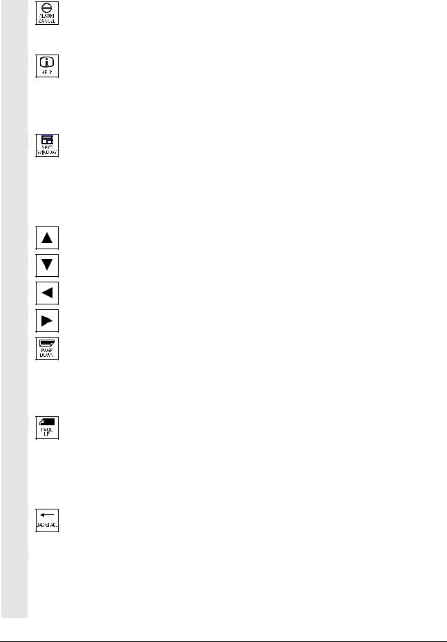
|
2 |
Operator Components/Operating Sequences |
01/2008 |
2 |
||
|
2.1 Operator panel front |
Acknowledge alarm key
By pressing this key, you can acknowledge the alarm marked by this
Cancel symbol.
Information key
This key displays explanatory information about the current operating status (e.g. support for programming, diagnostics, PLC, alarms). The letter «i» displayed in the user response line indicates that information is available.
Window selection key
If several windows are displayed on the screen, it is possible to make the next window the active one using the window selection key (the active window has a thicker border).
Keyboard input e.g. the page keys, is possible only in the active window.
Cursor up
Cursor down
Cursor to the left
Cursor to the right
PAGE DOWN
You «scroll» down by one display.
In a part program, you can «scroll» the display down (to end of program) or up (to start of program).
PAGE UP
You «scroll» up by one display.
With the page keys you scroll the visible/displayed area of the window that is active. The scroll bar indicates which part of the program/document/… is selected.
Backspace
Delete characters from right
Space character (Blank)
|
2-26 |
♥ Siemens AG 2008 All rights reserved. |
|
SINUMERIK 840Di sl/840D sl/840D Operating Manual HMI-Advanced (BAD) — 01/2008 Edition |

|
Operator Components/Operating Sequences |
2 |
|
2.1 Operator panel front |
Selection key
•Selection key for values set in input fields and selection lists labeled with this key symbol.
•Activate/deactivate a field:
|
= active |
= active |
|
= not active |
= not active |
|
Multiple option button |
Single-option button/option |
|
(you can select several options or |
(only one option can be active at a |
|
none) |
time) |
Edit key / undo key
•Switch over to edit mode in tables and input fields (in this case, the input field is in insert mode) or
•UNDO function on table elements and input fields (the value is not validated when you exit a field using the edit key; instead it is reset to the previous value = UNDO).
End of line key
•With this key, the cursor is moved to the end of the line in the page opened in the editor.
•Rapid positioning of the cursor on a group of related input fields.
•Has same effect as Tab key.
Delete key
The setting in a parameterization field is deleted.
The field remains blank.
Input key
•Accepts an edited value
•Opens/closes a directory
•Opening a file
Tab key
Ctrl key
Alt key
|
Tool offset |
Takes you directly to the tool offset |
|
♥ Siemens AG 2008 All rights reserved. |
2-27 |
|
SINUMERIK 840Di sl/840D sl/840D Operating Manual HMI-Advanced (BAD) — 01/2008 Edition |

|
2 |
Operator Components/Operating Sequences |
01/2008 |
2 |
||
|
2.1 Operator panel front |
Program management program overview
A program can be opened in the text editor.
|
Interrupt |
Takes you directly to the Alarms |
|
screen |
|
|
User key |
Can be configured by the customer |
Notes
The keys marked with an * also have a function in conjunction with ShopMill/ShopTurn.
For this function to work, at least one recently edited program must be found with sufficient read rights. The program must not be already open in either a simulation or any other application. Actions such as load, copy, select, etc. must not be in progress and the part program must not be running on the NC.
In the above cases, the operation is denied with alarms 1203xx.
Press this hardkey in any operating area to reopen and display the part program or file last edited in the Program operating area:
•If you are already in the Program operating area and the editor is open, the program you last edited is displayed.
•If you are in any other operating area, and the editor is open, you jump back to the editor in the Program operating area and the most recent editor status is displayed.
If the editor is not open:
•If you are in another user application, you jump back to the Program operating area and the editor is opened with the program you last edited.
|
2-28 |
♥ Siemens AG 2008 All rights reserved. |
|
SINUMERIK 840Di sl/840D sl/840D Operating Manual HMI-Advanced (BAD) — 01/2008 Edition |

|
Operator Components/Operating Sequences |
2 |
|
2.1 Operator panel front |
2.1.2 Standard full keyboard
Softkey assignment
Hardkey assignment
Caution
A full standard keyboard can be connected. However, a machine control panel is required in addition to this keyboard.
The special function keys of the operator keyboard can also be used with the full PC keyboard. The following table shows how the horizontal and vertical softkeys and the special keys for the operator panels are mapped onto the PC keyboard keys:
The following table shows how the hardkeys of the MF 2 keyboard on the PC are mapped onto the keys for the operator panels:
|
Hard-Hard-Hard-Hard-Hard-Hard-Hard-Hard- |
||
|
key key key key key key |
key |
key |
MFII 

MFII 

 out
out 


Position
The full standard keyboard does not meet the requirements (EMC) of a SINUMERIK control. For this reason, it can be used only for installation and service purposes.
Additional information
Since the English version of Windows is used in the control, the keyboard language is English. A different keyboard language cannot be set.
|
♥ Siemens AG 2008 All rights reserved. |
2-29 |
|
SINUMERIK 840Di sl/840D sl/840D Operating Manual HMI-Advanced (BAD) — 01/2008 Edition |

|
2 |
Operator Components/Operating Sequences |
01/2008 |
2 |
||
2.2 Machine control panel (MCP) |
2.2 Machine control panel (MCP)
1EMERGENCY STOP button
2Operating modes (with machine functions)
3Incremental mode
4Program control instructions
5Direction key with rapid traverse override
6Spindle control
7Feedrate control
8Key-operated switch
Actions on the machine tool, for example traversing the axes or program start, can only be initiated via a machine control panel.
The machine tool can either be equipped with a standard machine control panel from SIEMENS (ordering data option) or with a specific machine control panel from the machine-tool manufacturer.
The following description applies to the 19″ machine control panel supplied by SIEMENS (= standard). If you are using another machine control panel, please consult the operating instructions of the machine-tool manufacturer.
The standard machine control panel is equipped with the following control elements:
|
1 |
4 |
2 |
3 |
5 |
6 |
7 |
8 |
|
Machine control panel for turning machines |
|||||||
|
1 |
4 |
2 |
3 |
5 |
6 |
7 |
8 |
|
Machine control panel for milling machines |
|
2-30 |
♥ Siemens AG 2008 All rights reserved. |
|
SINUMERIK 840Di sl/840D sl/840D Operating Manual HMI-Advanced (BAD) — 01/2008 Edition |
![]()
|
Operator Components/Operating Sequences |
2 |
|
2.2 Machine control panel (MCP) |
2.2.1 EMERGENCY STOP button
EMERGENCY STOP button
Press this red key in emergency situations:
1.if life is at risk
2.When there is a danger of the machine or workpiece being
damaged.
As a rule, when operating the EMERGENCY STOP button, all drives are brought to a standstill with max. braking torque.
Machine manufacturer For details of other or additional responses to an EMERGENCY STOP:
Please read the information supplied by the machine tool manufacturer!
2.2.2 Operating modes and machine functions
Modes of operation
Jog
MDA
Auto *
The active mode is signaled and confirmed by the associated LED, which lights up.
The keys marked with an * correspond to the key symbols in US layout.
If you press a «Mode key», the corresponding mode is selected if permissible, and all other modes and functions are deselected.
JOG
(Jogging)
Axis travel in jog mode via:
•Continuous motion of the axes using the direction keys, or
•Incremental motion of the axes using the direction keys, or
•Handwheel
MDA
(Manual Data Automatic)
Control of machine through execution of a block or a sequence of blocks. The blocks are entered on the operator panel front.
Automatic
Control of machine through automatic execution of programs.
|
♥ Siemens AG 2008 All rights reserved. |
2-31 |
|
SINUMERIK 840Di sl/840D sl/840D Operating Manual HMI-Advanced (BAD) — 01/2008 Edition |

|
2 |
Operator Components/Operating Sequences |
01/2008 |
2 |
||
|
2.2 Machine control panel (MCP) |
Inc keys
VAR
|
1 |
10 |
100 |
1000 10000
Machine functions
|
MDA |
Teach In |
||
|
JOG |
Repos |
||
|
JOG |
Ref Point |
||
You can activate the Inc functions in conjunction with the following modes:
•«JOG» mode
•«MDA/Teach-in» operating mode
Inc VAR (Incremental feed VARiable)
Incremental mode with variable increment size (see operating area Parameters, Setting data).
Inc (Incremental feed)
Incremental mode with fixed increment size of 1, 10, 100, 1,000, 10,000 increments.
A machine data code defines how the incremental dimension is interpreted.
Teach In
Creation of programs in interactive mode with the machine in «MDA» mode.
Repos
Repositioning
Reposition, re-approach contour in «JOG» mode.
Ref
Approaching a reference point
Approach the reference point (Ref) in «JOG» mode.
|
2-32 |
♥ Siemens AG 2008 All rights reserved. |
|
SINUMERIK 840Di sl/840D sl/840D Operating Manual HMI-Advanced (BAD) — 01/2008 Edition |

|
Operator Components/Operating Sequences |
2 |
|
2.2 Machine control panel (MCP) |
2.2.3 Feedrate control
Feedrate rapid traverse override (feedrate override switch)
Control range:
0% to 120% of programmed feedrate.
In rapid traverse, the 100% value is not exceeded.
Settings,
0%, 1%, 2%, 4%, 6%, 8%, 10%, 20%, 30%, 40%, 50%, 60%, 70%, 75%, 80%, 85%, 90%, 95%, 100%, 105%, 110%, 115%, 120%
Feed stop
If you press the «Feed stop» key:
•Execution of the current program is stopped
•The axis drives are brought to a standstill under control, The associated LED lights up as soon as feed stop has been accepted by the control and
The following appears in the header (program control display): FST (= Feed Stop)
Example:
−In «MDA» mode, an error is detected during execution of a block.
−A tool change is to be carried out.
Feed start
If you press the «Feed start» key:
•The part program is continued in the current block,
•The feedrate is accelerated to the value specified by the program,
•The associated LED lights up as soon as feed start has been accepted by the control.
|
♥ Siemens AG 2008 All rights reserved. |
2-33 |
|
SINUMERIK 840Di sl/840D sl/840D Operating Manual HMI-Advanced (BAD) — 01/2008 Edition |

|
2 |
Operator Components/Operating Sequences |
01/2008 |
2 |
||
|
2.2 Machine control panel (MCP) |
+X +Z
X Z
+
Rapid
Machine manufacturer
WCS MCS
Axis keys (for turning machines):
Press these keys to traverse the selected axis (X … Z) in the positive direction.
Press these keys to traverse the selected axis (X … Z) in the negative direction.
Axis keys (for milling machines):
Select the axis (X … 9) for traversing
in the positive direction by pressing the «+» key or
in the negative direction by pressing the «-» key.
Rapid traverse override
If you press this key together with key «+» or «-«, the axis moves in rapid traverse mode.
•The specified increments and control range apply to standard machines.
•Increments and control range can be modified by the machine tool manufacturer to suit specific applications.
•Feedrate/rapid traverse feedrate and the values for the feedrate override positions (if the feedrate override switch is also active for rapid traverse) are defined in the machine data (see the information supplied by the machine manufacturer).
MCS/WCS
You can switch between the machine and workpiece coordinate systems in the Machine operating area using softkeys (MCS)/(WCS) or the corresponding key on the machine control panel.
|
2-34 |
♥ Siemens AG 2008 All rights reserved. |
|
SINUMERIK 840Di sl/840D sl/840D Operating Manual HMI-Advanced (BAD) — 01/2008 Edition |

|
Operator Components/Operating Sequences |
2 |
|
2.2 Machine control panel (MCP) |
2.2.4 Spindle control
Spindle Stop *
Spindle Start
Machine manufacturer
Spindle override (spindle speed override switch)
The rotary switch with latch positions allows you to increase or decrease the programmed spindle speed «S» (equivalent to 100%). The set spindle speed value «S» is output as an absolute value and a percentage in the «Spindles» display (vertical softkey on main screen).
Control range:
50% to 120% of programmed spindle speed
Increment:
5% between latch positions
Spindle stop
When you press the «Spindle stop» key:
The spindle is decelerated down to zero speed and
The associated LED lights up as soon as «Spindle stop» is reached.
Example:
To change a tool
To enter S, T, H, M functions during setup
Spindle start
When you press the «Spindle start» key:
The spindle speed is accelerated to the value defined in the program and
The associated LED lights up as soon as «Spindle start» has been accepted by the control.
•The specified increment and the control range apply to standard machine data (MD). These MD can be edited by the machine-tool manufacturer to suit the specific application.
•The maximum spindle speed and the values for the spindle speed override position are defined in the machine data and setting data (see information supplied by the machine-tool manufacturer).
|
♥ Siemens AG 2008 All rights reserved. |
2-35 |
|
SINUMERIK 840Di sl/840D sl/840D Operating Manual HMI-Advanced (BAD) — 01/2008 Edition |

|
2 |
Operator Components/Operating Sequences |
01/2008 |
2 |
||
|
2.2 Machine control panel (MCP) |
2.2.5 Key-operated switch |
||
|
Machine manufacturer |
Functions can be assigned to key-operated switch positions by the |
|
|
machine manufacturer. Using machine data, it is also possible to set |
||
|
access to programs, data and functions to suit the user’s |
||
|
requirements. |
||
|
SIEMENS key-operated |
The key-operated switch on the SINUMERIK 840D has 4 settings, |
|
|
switch |
assigned to protection levels 4 to 7. |
|
|
The key-operated switch has three different colored keys which can |
||
|
be removed in the specified positions: |
||
|
Switch positions |
||
|
Position 0 |
Lowest |
|
|
No key |
Access authorization |
|
|
Protection level 7 |
||
|
Position 1 |
||
|
Key 1 black |
||
|
Protection level 6 |
||
|
Position 2 |
||
|
Key 1 green |
||
|
Protection level 5 |
||
|
Position 3 |
||
|
Key 1 red |
↓ |
|
|
Highest |
||
|
Protection level 4 |
||
|
Access authorization |
||
|
Changing access rights |
The screen is not automatically updated after a change in access |
|
|
authorization (e.g., when the key-operated switch position is |
||
|
changed), but only when the screen is next refreshed (e.g., on closing |
||
|
and opening a directory). |
||
|
The currently valid access authorization is checked every time a |
||
|
function is executed. |
||
|
If the PLC is in the STOP state, the input image of the machine control |
||
|
panel is not scanned. For this reason, the key-operated switch |
||
|
positions are not evaluated during commissioning. |
||
|
2-36 |
♥ Siemens AG 2008 All rights reserved. |
|
|
SINUMERIK 840Di sl/840D sl/840D Operating Manual HMI-Advanced (BAD) — 01/2008 Edition |

|
Operator Components/Operating Sequences |
2 |
|
2.2 Machine control panel (MCP) |
|
Passwords |
As an additional option for setting access authorization, it is possible |
|
|
to enter three passwords in the «Commissioning» operating area. |
||
|
If the password is set, the key-operated switch positions are irrelevant. |
||
|
References |
/IAD/, Commissioning Manual 840D. |
|
2.2.6 Program control
Cycle Start
Single Block
NC Start
If you press the «NC Start» key, the selected part program (part program name is displayed in header) is started at the current block and the associated LED lights up.
NC stop
If you press the «NC Stop» key, processing of the active part program is halted and the associated LED lights up.
After this, you can continue processing with NC Start.
Single block
This function allows you to execute a part program block by block. You can activate the «Single Block» function in «Automatic» and «MDA» modes. If single block is activated, the associated LED on the machine control panel lights up.
•If single block execution is active, Stop is displayed on the screen in the cycle (in the program control line)
•The message «Stop: Block completed in single block» is displayed in the channel operational message line (in interrupt state).
•The current block in the part program will not be executed until you press the «NC Start» key.
•Program processing is stopped after one block is executed.
You can execute the next block by pressing the «NC Start» key again.
You can deselect the function by pressing the «Single block» key again.
|
♥ Siemens AG 2008 All rights reserved. |
2-37 |
|
SINUMERIK 840Di sl/840D sl/840D Operating Manual HMI-Advanced (BAD) — 01/2008 Edition |

|
2 |
Operator Components/Operating Sequences |
01/2008 |
2 |
||
|
2.2 Machine control panel (MCP) |
Reset
This function is dependent on the settings under «Program control» in the Machine operating area.
Reset
When you press the <Reset> key:
•Execution of the current part program is aborted.
•Messages issued by the monitoring function are deleted (except the alarms POWER ON, NC Start and «Acknowledge alarm»).
•The channel is set to «Reset» state, i.e.,
−The NC control remains synchronized with the machine.
−The control is in its initial state and ready for a new program run.
|
References |
/FB/ K1, Description of Functions BAG, Channel, Program control. |
|
2-38 |
♥ Siemens AG 2008 All rights reserved. |
|
SINUMERIK 840Di sl/840D sl/840D Operating Manual HMI-Advanced (BAD) — 01/2008 Edition |

|
Operator Components/Operating Sequences |
2 |
2.3 SINUMERIK HT 8 |
2.3SINUMERIK HT 8
The mobile SINUMERIK HT 8 handheld terminal combines the functions of an operating panel and a machine control panel. It is therefore ideal for visualization, operation, teach-in, and programming at the machine:
|
— |
Manipulators/robots |
|
— |
Machine tools |
|
— |
Production machines |
|
The 7.5 TFT color display provides touch operation. It also has |
|
|
membrane key for traversing the axes, for numeric input, for cursor |
|
|
control, and for machine control panel functions like start and stop. |
|
|
Prerequisite |
To operate the HT 8, you must have the operator privilege. |
|
Keyboard operation |
See section “Machine control panel” for a description of the individual |
|
|
keys. |
||
|
Machine manufacturer |
The four customer keys are freely assignable and can be set up |
|
|
customer-specifically by the machine manufacturer. |
||
|
This <STANDBY> key presently has no function. |
||
|
♥ Siemens AG 2008 All rights reserved. |
2-39 |
|
SINUMERIK 840Di sl/840D sl/840D Operating Manual HMI-Advanced (BAD) — 01/2008 Edition |

|
2 |
Operator Components/Operating Sequences |
01/2008 |
2 |
||
|
2.3 SINUMERIK HT 8 |
Key <U>
CPF softkeys
(Control Panel Function)
Back
Traversing keys
Switch over channel
The CPF softkey bar is displayed with the <U> key:
The CPF softkeys keys of the machine control panel emulated by the HMI software. When the HT 8 has operator rights, the CPF menu is displays with the <U> key. The menu is automatically hidden when the area is changed.
The following softkeys are available (see figure on the left):
•<MACHINE> softkey: Select the «Machine» operating area (corresponds to <Shift> + <F10>).
•< [VAR] > softkey: Select the axis feedrate in the increment.
•<Single Block> softkey: Switch single block execution on/off.
•<WCS MCS> softkey: Switching between MCS ↔ WCS
•«Back» softkey: Hide CPF menu; restoration of the user response line and the softkeys.
The CPF menu is not displayed when the area menu or the channel menu is active.
With the <MACHINE> softkey, the «multi-channel display» function is also operator-controllable on the HT 8. The respective state is displayed in the global machine status display (header).
(Mail Detlev Lutter from 15.06.2007)
The PLC interface signals, that are initiated using the softkeys of the CPF menus, are edge-controlled.
JOG and MDA / Teach In mode must be selected to set up the axes with the traversing keys.
The labeling of the 12 traversing keys is shown on the housing of the touch panel. Display of the labeling for up to 6 axes is performed by the PLC program (machine manufacturer).
If the labeling for the traversing keys is displayed, all the other softkeys cannot be operated.
Channel switchover is performed by touch operation of the touch surface on the global machine status display:
|
2-40 |
♥ Siemens AG 2008 All rights reserved. |
|
SINUMERIK 840Di sl/840D sl/840D Operating Manual HMI-Advanced (BAD) — 01/2008 Edition |
![]()
|
Operator Components/Operating Sequences |
2 |
|
2.3 SINUMERIK HT 8 |
Virtual keyboard
Language changeover
Calibrating touch panel
References
The virtual keyboard is displayed from the active operator area. The keyboard is automatically hidden again when changing the area or when exiting the application. The virtual keyboard is located across the complete header and can be shifted using the mouse.
The following languages can be selected for the virtual keyboard online: German, English, French, Spanish.
The virtual keyboard can be displayed and hidden in all operator areas using a touch field located above the vertical softkeys. This touch field is only displayed if the connected HT 8 or Touch Panel has operator rights.
To perform calibration, press the keys <Recall> + <MENU SELECT> simultaneously to start the command shell:
1.The «Calibrate TouchPanel» button starts calibration.
2.Follow the instructions on the screen and touch the three calibration points one after the other.
This completes the calibration.
3.Then press the horizontal softkey or button «1» to make the connection to the required PCU and return to the HMI-Advanced user interface.
“Operator Components and Networking” Manual
|
♥ Siemens AG 2008 All rights reserved. |
2-41 |
|
SINUMERIK 840Di sl/840D sl/840D Operating Manual HMI-Advanced (BAD) — 01/2008 Edition |

|
2 |
Operator Components/Operating Sequences |
01/2008 |
2 |
||
2.4 Screen layout |
|||||
|
2.4 |
Screen layout |
2.4.1 Displaying the control states
Global machine status display
|
1 |
CHAN1 |
4 |
6 |
\MPF.DIR |
7 |
||||
|
Machine |
Jog |
SHAFT1.MPFP |
|||||||
|
Channel interrupted |
Program stopped |
8 |
Auto |
||||||
|
2 |
3 |
||||||||
|
Stop: No NC Ready |
DRY ROV |
9 |
|||||||
|
5 |
MDI |
||||||||
|
MCS |
Position Repos offset |
||||||||
|
Auxiliary Functions |
Vertical |
||||||||
|
+ X |
900.000 |
mm |
0.000 |
M0 |
JOG |
||||
|
M0 |
11 |
softkeys |
|||||||
|
— Y |
-156.000 |
mm |
0.000 |
M0 |
|||||
|
M0 |
|||||||||
|
+ Z |
230.000 |
mm |
0.000 |
M0 |
REPOS |
19 |
|||
|
11 |
H0.000000 |
||||||||
|
H0.000000 |
|||||||||
|
13 |
H0.000000 |
REF |
|||||||
|
Feedrate |
mm/min |
||||||||
|
Act. |
3000.000 |
0.0 % |
|||||||
|
Set. |
3000.000 |
11 |
|||||||
|
Tool |
|||||||||
|
11 |
preselected tool: |
11 |
|||||||
|
G0 |
G91 |
||||
|
12 |
. |
i |
|||
|
17 |
|||||
|
Parameters Program Services Diagnosis |
Start-up |
10 |
> |
||
1Operating areas
2Channel status
3Channel operational messages
4Channel name
5Alarm and message line
6Operating mode, submode, (increment if relevant)
7Program name of the selected program
8Program status
9Program control
10Additional information (help)
i You can display information by pressing the i key ^ Recall: Return to higher-level menu
> ETC.: Expansion of the horizontal softkey bar in the same. Menu
|
2-42 |
♥ Siemens AG 2008 All rights reserved. |
|
SINUMERIK 840Di sl/840D sl/840D Operating Manual HMI-Advanced (BAD) — 01/2008 Edition |

|
Operator Components/Operating Sequences |
2 |
|
2.4 Screen layout |
11 Working windows, NC displays
The working windows (program editor) and NC displays (feedrate, tool) available in the selected operating area are displayed here. The unit for positional data is preceded by the diameter symbol in the work pane if the axis is currently the transverse axis and if the tool coordinate system is set. If diameter programming is disabled with DIAMOF, the symbol preceding the unit is no longer visible.
12 User response line with user information
Here user information is displayed for the selected function (if available).
13Focus
The selected pane is highlighted by a frame. The window header
display is inverted. Data entered on the operator panel front apply to this window.
16 Recall function, i.e., key ^ is active
17 ETC. function, i.e., > key is active
18 Horizontal softkeys
19 Vertical softkeys
The softkey functions available in the selected operating area are displayed in the horizontal/vertical softkey bar (corresponding to F1 to F8 on the full keyboard).
Additional information
The screen layout may differ slightly from the layout displayed above, depending on the screen size or resolution used.
2.4.2 Global machine status display
|
1 |
Operating areas |
The currently selected operating area is displayed (Machine, |
|
|
Parameters, Program, Services, Diagnostics, Commissioning). |
|||
|
2 |
Channel status |
The current channel status is displayed |
|
|
— Channel reset |
|||
|
— Channel interrupted |
|||
|
— Channel active |
|||
|
3 |
Channel operational |
For displaying the channel operational messages with symbols: |
|
|
messages |
|||
|
♥ Siemens AG 2008 All rights reserved. |
2-43 |
|
SINUMERIK 840Di sl/840D sl/840D Operating Manual HMI-Advanced (BAD) — 01/2008 Edition |

|
2 |
Operator Components/Operating Sequences |
01/2008 |
2 |
||
|
2.4 Screen layout |
If the status shows this symbol  , operating input is required.
|
1 Stop: |
No NC Ready |
|
|
2 Stop: |
Mode Group Ready |
|
|
3 Stop: |
EMERGENCY STOP active |
|
|
4 Stop: |
Alarm active with stop |
|
|
5 Stop: |
M0/M1 active |
|
|
6 Stop: |
Block ended in SBL mode |
|
|
7 Stop: |
Cycle stop active |
|
|
8 Wait: |
No read-in enable |
|
|
9 Wait: |
No feed enable |
|
|
12 Wait: |
No axis enable |
|
|
17 Wait: |
Feedrate override > 0% |
|
|
18 Stop: |
Error in NC block |
|
|
19 Wait: |
For external NC blocks |
|
|
22 Wait: |
No spindle enable |
|
|
23 Wait: |
Axis feedrate value is 0 |
|
|
31 Stop: |
No channel ready |
|
|
45 Stop: |
SERUPRO search has found search target and the |
|
|
NCK has stopped. SERUPRO is the abbreviation for |
||
|
“SEarchRUn by PROgram test”; it is a new type of |
||
|
block search. |
||
If the status shows this symbol  operation is generally not required.
10 Wait: Remaining dwell time __ Sec. for seconds or Remaining dwell time __ rev. for revolutions
|
This can be parameterized via an OPI variable. 0 = |
||
|
sec./1 = rev. |
||
|
11 Wait: |
No aux. funct. ackn. |
|
|
13 Wait: |
Exact stop not reached |
|
|
14 Wait: |
For positioning axis |
|
|
15 Wait: |
For spindle |
|
|
16 Wait: |
For other channel |
|
|
20 Wait: |
Due to SYNACT instruction |
|
|
21 Wait: |
Block search active |
|
|
2-44 |
♥ Siemens AG 2008 All rights reserved. |
|
SINUMERIK 840Di sl/840D sl/840D Operating Manual HMI-Advanced (BAD) — 01/2008 Edition |

|
Operator Components/Operating Sequences |
2 |
|
2.4 Screen layout |
|
24 Wait: |
For tool change acknowledgement |
||
|
25 Wait: |
For gear stage change |
||
|
26 Wait: |
For position control |
||
|
27 |
Wait: |
For thread cut |
|
|
29 |
Wait: |
For punching |
|
|
30 |
Wait: |
For safe operation |
|
|
32 |
Stop: |
Oscillation active |
|
|
33 |
Stop: |
Axis replacement active (block change inhibited |
|
|
because axis replacement in progress) |
|||
|
34 Wait: |
For axis container rotation |
||
|
35 |
Wait: |
AXCT axis active as slave axis |
|
|
36 |
Wait: |
AXCT axis active as master axis |
|
|
37 |
Wait: |
AXCT axis changing to follow-up |
|
|
38 |
Wait: |
AXCT internal status change in axis |
|
|
This delay status may be attributable to the following |
|||
|
causes: |
|||
|
• Activation of position control |
|||
|
• Requesting of zero marker |
|||
|
• Reference point approach active |
|||
|
• Parameter block change active |
|||
|
• Measuring system change active |
|||
|
• Measurement on-the-fly active |
|||
|
• Closed-loop controller enable removed |
|||
|
• Status change, axis/spindle disable |
|||
|
39 Wait: |
AXCT axis drive disable |
||
|
40 |
Wait: |
AXCT axis overlaid motion active |
|
|
41 |
Wait: |
AXCT axis axis replacement active |
|
|
42 |
Wait: |
AXCT axis interpolator active |
|
|
43 Wait: |
WAIT_FOR_CC_ENABLE: |
||
|
Waiting for compile cycle |
|||
|
44 |
Wait: |
On access to system variable |
|
|
46 |
Stop: |
ESR triggered |
|
|
47 Wait: |
Axis container rotation waiting for spindle stop |
||
|
48 |
Wait: |
Axis container rotation waiting for synchronization of |
|
|
MD data (New-Config) |
|||
|
♥ Siemens AG 2008 All rights reserved. |
2-45 |
|
SINUMERIK 840Di sl/840D sl/840D Operating Manual HMI-Advanced (BAD) — 01/2008 Edition |

|
2 |
Operator Components/Operating Sequences |
01/2008 |
2 |
||||
|
2.4 Screen layout |
|||||||
|
49 Wait: |
For axis replacement: Axis currently coupled |
||||||
|
50 Wait: |
For axis replacement: Lift fast active |
||||||
|
51 Wait: |
For axis replacement: New-Config active |
||||||
|
52 Wait: |
For axis replacement: Axis container rotation active |
||||||
|
53 Wait: |
For axis replacement: Waitp active |
||||||
|
54 Wait: |
For axis replacement: Axis is currently in another |
||||||
|
channel |
|||||||
|
55 Wait: |
For axis replacement: Axis is currently a PLC axis |
||||||
|
56 Wait: |
For axis replacement: Axis is currently an oscillating |
||||||
|
axis |
|||||||
|
57 Wait: |
For axis replacement: Axis is currently a JOG axis |
||||||
|
58 Wait: |
For axis replacement: Axis is currently a command |
||||||
|
axis |
|||||||
|
59 Wait: |
For axis replacement: Axis is currently an OEM axis |
||||||
|
60 Wait: |
For axis replacement: Axis is currently a slave axis |
||||||
|
coupled to the master value |
|||||||
|
61 Wait: |
For axis replacement: Axis is currently a coupled- |
||||||
|
motion slave axis |
|||||||
|
62 Wait: |
For axis replacement: Axis is currently a coupled |
||||||
|
slave axis |
|||||||
|
4 Channel name |
Name of the channel in which the program is running. |
||||||
|
5 Alarm and message line |
— Alarms and messages or |
||||||
|
— Instructions that were programmed in the part program using the |
|||||||
|
MSG command (if no alarms are active) |
|||||||
|
6 Operating mode display |
The currently selected operating mode, i.e. JOG, MDA or AUTO |
||||||
|
(automatic) is displayed. |
|||||||
|
The active submode is displayed next to the operating mode. An |
|||||||
|
active increment is also displayed underneath, e.g., |
|||||||
|
JOG Repos |
|||||||
|
1000 |
|||||||
|
7 Program name |
Press NC Start to execute this program. |
||||||
|
The «Program name» output field can be configured for JOG and MDA |
|||||||
|
(see machine manufacturer’s specifications). |
|||||||
|
2-46 |
♥ Siemens AG 2008 All rights reserved. |
|
SINUMERIK 840Di sl/840D sl/840D Operating Manual HMI-Advanced (BAD) — 01/2008 Edition |

|
Operator Components/Operating Sequences |
2 |
|
2.4 Screen layout |
|
8 Program status |
The current status of the part program being executed is output: |
||
|
• |
Program aborted |
||
|
• |
Program running |
||
|
• |
Program stopped |
||
|
The «program status» output field can be configured, e.g. with the |
|||
|
«Channel-wide status display with symbols» function (Subsection 4.1.3 |
|||
|
and see machine manufacturer’s specifications). |
|||
|
9 Program control display |
Functions that have been activated can be set via «Program control» |
||
|
so that they are displayed. |
|||
|
(See Section 4.6 Automatic mode, “Program control”) |
|||
|
♥ Siemens AG 2008 All rights reserved. |
2-47 |
|
SINUMERIK 840Di sl/840D sl/840D Operating Manual HMI-Advanced (BAD) — 01/2008 Edition |

|
2 |
Operator Components/Operating Sequences |
01/2008 |
2 |
||
|
2.4 Screen layout |
2.4.3 Program control display
|
Function |
||
|
Functions that have been activated are visible in the program control |
||
|
display (can be set via «Program control», see Subsection 4.6.12). The |
||
|
functions are displayed irrespective of the selected menu. |
||
|
SKP |
Program blocks in which the block number is preceded by a slash are |
|
|
Skip block |
skipped when you run the program (e.g. «/N100 …»). Up to 10 program |
|
|
levels can be hidden (e.g., «/6N100 ..»; the 7th program level is |
||
|
hidden) |
||
|
References: /PG/ Programming Manual Fundamentals, Chapter 2. |
||
|
SKPn |
n = active skip levels |
|
|
SBL1 |
If this function is active, execution is interrupted after every block that |
|
|
Single block with STOP after |
triggers a function on the machine |
|
|
each machine function block |
(calculation blocks do not cause an interruption). |
|
|
SBL2 |
If this function is active, the part program blocks are executed as |
|
|
Single block with stop after |
follows: Each block is decoded separately and execution is interrupted |
|
|
each block |
after every block. |
|
|
SBL3 |
If this function is active, the part program blocks are executed |
|
|
Stop in cycle |
individually in the cycle as follows: |
|
|
Each block is decoded separately and execution is interrupted after |
||
|
every block. Part program blocks are |
||
|
— Traversing blocks |
||
|
— Switching and auxiliary functions |
||
|
— Blocks generated internally in the controller (e.g. blocks inserted |
||
|
for tool radius compensation) |
||
|
— Thread blocks after retraction |
||
|
— Thread blocks with dry run feedrate |
||
|
Thread blocks without dry run feedrate are an exception to this. In |
||
|
such blocks, a stop is only performed at the end of the current thread |
||
|
block. SBL2 can only be selected in the Reset state. |
||
|
Either SBL1 or SBL2 can be selected! |
||
|
This function can be activated only in the «Single block» state. |
||
|
2-48 |
♥ Siemens AG 2008 All rights reserved. |
|
SINUMERIK 840Di sl/840D sl/840D Operating Manual HMI-Advanced (BAD) — 01/2008 Edition |

|
Operator Components/Operating Sequences |
2 |
|
2.4 Screen layout |
|
DRY |
Traverse movements are performed with the feedrate value set in the |
|
|
DRY run feedrate |
setting data «Dry run feedrate». |
|
|
This dry run feedrate function replaces the programmed motion |
||
|
commands. |
||
|
ROV |
The override switch for the feedrate also applies to the rapid traverse |
|
|
Rapid traverse override |
feedrate. |
|
|
M01 |
When this function is active, processing of the program is stopped at |
|
|
Programmed stop 1 |
every block in which miscellaneous function M01 is programmed. The |
|
|
message «Stop: M00/M01 active» is then displayed on the screen. |
||
|
Press the NC Start key to resume execution. If the function is not |
||
|
activated, special function M01 (from the part program) is not taken |
||
|
into account. |
||
|
Additional M fct. |
When this function is active, program execution on the NC is |
|
|
Programmed stop 2 |
interrupted on request by the PLC at blocks containing the additional |
|
|
function for a conditional stop. |
||
|
The machine data 22256: AUXFO_ASSOC_M1_VALUE you can |
||
|
define a function associated with M01. The value of this miscellaneous |
||
|
M function number is then equivalent to a programmed stop 2. |
||
|
References |
/FB1/Description of Functions — Basic Machine |
|
|
Predefined Auxiliary Function «Associated auxiliary functions for M0, |
||
|
M1″ |
||
|
DRF |
When the «DRF» function is active, DRF offsets are applied. |
|
|
DRF selection |
If «Program test» is selected, the output of setpoints to axes and |
|
|
PRT |
||
|
Program test |
spindles is disabled. The setpoint display «simulates» the traverse |
|
|
movements. |
||
|
FST |
The activated feed stop is displayed. |
|
|
Feed stop |
“Feed stop” is indicated in the feedrate window by means of the |
|
|
symbol “Feedrate not enabled” and is omitted from the program |
||
|
control display. This function is not activated/deactivated under |
||
|
Program Control, but via the “Feed Start/Feed Stop” keys on the |
||
|
machine control panel. |
||
|
♥ Siemens AG 2008 All rights reserved. |
2-49 |
|
SINUMERIK 840Di sl/840D sl/840D Operating Manual HMI-Advanced (BAD) — 01/2008 Edition |

|
2 |
Operator Components/Operating Sequences |
01/2008 |
2 |
||
2.5 General operating sequences |
|||||
|
2.5 |
General operating sequences |
|
Keys |
A range of keys are available in the various operating areas and |
|
|
menus. The function of the keys is the same in all operating areas. |
||
|
This identical functionality applies only if the operating areas are left |
||
|
intact as supplied by Siemens AG and no modifications have been |
||
|
configured by the user. |
||
|
Additional information |
||
|
It is possible to customize the menu trees. In this way, users are able |
||
|
to define softkeys according to their individual needs. Due to this |
||
|
capability, the menus and softkeys on your control may be different to |
||
|
those described in this Operator’s Guide. |
||
|
References |
Commissioning Manual HMI Advanced, |
|
|
see Chapter “Generating user operator menus” |
||
|
Functions |
The following section describes functions which you can select in |
|
|
several operating modes. |
||
2.5.1 Program overview and program selection
Function
After selection of a workpiece or program overview, individual workpieces or programs can be enabled or disabled for execution.
Sequence of operations
«AUTO» mode is selected in the «Machine» operating area. The appropriate channel is selected.
The channel is in reset state.
The workpiece/program to be selected is in the memory.
An overview of all workpiece directories/programs that exist is displayed.
Position the cursor on the desired workpiece/program.
Select the workpiece/program for execution:
|
2-50 |
♥ Siemens AG 2008 All rights reserved. |
|
SINUMERIK 840Di sl/840D sl/840D Operating Manual HMI-Advanced (BAD) — 01/2008 Edition |
 Loading…