-
Contents
-
Table of Contents
-
Bookmarks
Quick Links
Related Manuals for Siemens S7-1500
Summary of Contents for Siemens S7-1500
-
Page 2
___________________ Preface ___________________ Documentation guide Memory areas and retentive ___________________ SIMATIC memory ___________________ Memory usage and application examples S7-1500, ET 200SP, ET 200pro Structure and Use of the CPU ___________________ Memory SIMATIC memory card Function Manual 10/2018 A5E03461664-AC… -
Page 3
Note the following: WARNING Siemens products may only be used for the applications described in the catalog and in the relevant technical documentation. If products and components from other manufacturers are used, these must be recommended or approved by Siemens. Proper transport, storage, installation, assembly, commissioning, operation and maintenance are required to ensure that the products operate safely and without any problems. -
Page 4: Preface
Scope of the documentation This documentation is valid for the central modules of the S7-1500 and ET 200SP systems and for the ET 200pro CPU 1516pro-2 PN. The CPUs of the redundant system S7-1500R/H do not support all the memory objects described in this function manual.
-
Page 5
Functions that you will be familiar with Manual CPU 1510SP-1 PN • contents ual expanded to include the from the SIMATIC S7-1500 CPUs are (https://support.industry.sie CPUs of the ET 200SP implemented in CPUs in other designs mens.com/cs/ww/en/view/9 distributed I/O system and… -
Page 6
Siemens’ products and solutions undergo continuous development to make them more secure. Siemens strongly recommends that product updates are applied as soon as they are available and that the latest product versions are used. Use of product versions that are no longer supported, and failure to apply the latest updates may increase customers’ exposure to cyber threats. -
Page 7
This information is provided by the Siemens Industry Online Support in the Internet (https://support.industry.siemens.com). Industry Mall The Industry Mall is the catalog and order system of Siemens AG for automation and drive solutions on the basis of Totally Integrated Automation (TIA) and Totally Integrated Power (TIP). -
Page 8: Table Of Contents
Table of contents Preface …………………………3 Documentation guide ……………………..8 Memory areas and retentive memory ………………..13 Memory areas ……………………. 13 2.1.1 Specifics of the CPUs of the redundant system S7-1500R/H ……….16 Memory requirements and memory usage …………….18 Retentive memory areas ………………….
-
Page 9: Documentation Guide
Documentation guide The documentation for the SIMATIC S7-1500 automation system, for CPU 1516pro-2 PN based on SIMATIC S7-1500, and for the distributed I/O systems SIMATIC ET 200MP, ET 200SP and ET 200AL is divided into three areas. This division allows you easier access to the specific information you require.
-
Page 10
You must register once to use the full functionality of «mySupport». You can find «mySupport» on the Internet (https://support.industry.siemens.com/My/ww/en). «mySupport» — Documentation In the Documentation area in «mySupport» you can combine entire manuals or only parts of these to your own manual. -
Page 11
● Manuals, characteristics, operating manuals, certificates ● Product master data You can find «mySupport» — CAx data on the Internet (https://support.industry.siemens.com/my/ww/en/CAxOnline). Application examples The application examples support you with various tools and examples for solving your automation tasks. Solutions are shown in interplay with multiple components in the system — separated from the focus on individual products. -
Page 12
You can find the SIMATIC Automation Tool on the Internet (https://support.industry.siemens.com/cs/ww/en/view/98161300). PRONETA With SIEMENS PRONETA (PROFINET network analysis), you analyze the plant network during commissioning. PRONETA features two core functions: ● The topology overview independently scans PROFINET and all connected components. -
Page 13
Documentation guide SINETPLAN SINETPLAN, the Siemens Network Planner, supports you in planning automation systems and networks based on PROFINET. The tool facilitates professional and predictive dimensioning of your PROFINET installation as early as in the planning stage. In addition, SINETPLAN supports you during network optimization and helps you to exploit network resources optimally and to plan reserves. -
Page 14: Memory Areas And Retentive Memory
Memory areas and retentive memory Memory areas The automation data is located in the automation system in different memory areas. The offline data of the project created in STEP 7 is located on the hard disk of the programming device. The online data of the project is located in the load memory on the SIMATIC memory card.
-
Page 15: The Simatic Memory Card
For additional information on the CPUs, refer to the CPU 1518-4 PN/DP MFP (https://support.industry.siemens.com/cs/ww/en/view/109749061) manual and the CPU 1518(F)-4 PN/DP MFP (https://support.industry.siemens.com/cs/ww/en/view/109756478) product information. You can find information on creating C/C++ runtime applications in the SIMATIC S7-1500 ODK 1500S (https://support.industry.siemens.com/cs/ww/en/view/109752683) manual. Structure and Use of the CPU Memory Function Manual, 10/2018, A5E03461664-AC…
-
Page 16
Retentive behavior of the memory objects (Page 30). You can find additional information on the memory reset and reset to factory settings functions in the following manuals: ● System manual S7-1500, ET 200MP Automation System (http://support.automation.siemens.com/WW/view/en/59191792) ● System manual ET 200SP Distributed I/O System (http://support.automation.siemens.com/WW/view/en/58649293) -
Page 17: Specifics Of The Cpus Of The Redundant System S7-1500R/H
Memory areas and retentive memory 2.1 Memory areas Additional memory areas Besides the memory areas that have been described for the user program and data, the CPU has additional memory areas available. The additional memory areas include the following: ● Process images ●…
-
Page 18
CPUs. For additional information on redundancy IDs of the CPUs, refer to the Redundant System S7-1500R/H (https://support.industry.siemens.com/cs/ww/en/view/109754833) system manual. You can find an overview of the retentive behavior of the individual memory objects in section Retentive behavior of the memory objects (Page 30). -
Page 19: Memory Requirements And Memory Usage
You can access information regarding the memory areas of the CPUs in the following ways depending on product family used: Product family Information regarding the memory areas of the CPU is accessible via: STEP 7 Web server Display S7-1500 ✓ ✓ ✓ S7-1500R/H ✓ ✓…
-
Page 20
Memory areas and retentive memory 2.2 Memory requirements and memory usage Memory requirements of the program in the offline project During creation or modification of a project, the display of memory utilization in STEP 7 shows you the size of the project in the following memories: ●… -
Page 21
Therefore, the drop-down list with the size of your SIMATIC memory card only serves as a visual orientation aid. Also refer to the FAQ «How do you estimate the memory requirements of your project in the load memory of a SIMATIC S7-1500» on the Internet (https://support.industry.siemens.com/cs/ww/en/view/97553417). Note Display of the memory utilization under «Program info»… -
Page 22
Memory areas and retentive memory 2.2 Memory requirements and memory usage Data on the SIMATIC memory card In addition to the program and the associated program elements (blocks, data types, objects for motion control and PLC tags), the following data is also stored on the memory card: ●… -
Page 23
Memory areas and retentive memory 2.2 Memory requirements and memory usage Display of the memory utilization in STEP 7 In online mode, the online function «Memory» provides you with the following up-to-date memory information: ● Size of the total free and already allocated load memory on the SIMATIC memory card. ●… -
Page 24
Memory areas and retentive memory 2.2 Memory requirements and memory usage Display of the memory utilization on the display of the CPU To obtain information about the available memory via the display, proceed as follows: ● Select the «Diagnostics» menu on the display with the help of the arrow keys. ●… -
Page 25
Memory areas and retentive memory 2.2 Memory requirements and memory usage Note Display of the memory utilization of redundant system S7-1500R/H in non-redundant operation The CPU displays indicate the local memory utilization of the respective CPU. Display of the memory utilization of redundant system S7-1500R/H in redundant operation Irrespective of the sizes of the inserted SIMATIC memory cards, both CPU displays indicate the same (synchronized) fill level. -
Page 26
On the Web server, you can find information about the current usage of the individual memory areas on the Web page «Diagnostics» in the «Memory» tab. Detailed information about the use of the Web server can be found in the S7-1500 Web server (https://support.industry.siemens.com/cs/ww/en/view/59193560) function manual. -
Page 27: Retentive Memory Areas
Memory areas and retentive memory 2.3 Retentive memory areas Retentive memory areas Introduction The CPUs have a memory for storing retentive data at POWER OFF. You can find the size of the retentive memory in the technical specifications of the respective CPU. You can find the utilization of the retentive memory of the configured CPU in STEP 7 offline under «Program info >…
-
Page 28
Figure 2-6 Retentivity setting «Optimized block access» not activated You can find additional information on optimized and non-optimized data blocks in the Programming guideline for S7-1200/S7-1500 (https://support.industry.siemens.com/cs/de/de/view/90885040/en). Tags of an instance data block of a function block You can define the tags of the instance data block of a function block as retentive in STEP 7. -
Page 29
Memory areas and retentive memory 2.3 Retentive memory areas Creation of a data block in the user program The instruction «CREATE_DB» is used to create a new data block in the load and/or work memory. For data blocks which you create in the load memory, depending on the selection for the ATTRIB parameter, the generated data block either has the property «retentive»… -
Page 30
Memory areas and retentive memory 2.3 Retentive memory areas Bit memories, timers and counters You can define the number of retentive bit memories, timers and counters in STEP 7 in the PLC tag table using the «Retain» button. Figure 2-7 Definition of the number of retentive bit memories, timers and counters (beginning at 0, continuing without gaps) using the «Retain»… -
Page 31: Summary Of Retentive Behavior
Memory areas and retentive memory 2.4 Summary of retentive behavior Summary of retentive behavior 2.4.1 Retentive behavior of the memory objects This section gives an overview of the retentive behavior of the memory objects of the CPUs. In addition to the retentive memory areas described, there are other objects with retentive characteristics, for example, the diagnostics buffer.
-
Page 32
Reference You can find additional information on the memory reset and reset to factory settings functions in the following manuals: ● System manual S7-1500, ET 200MP Automation System (http://support.automation.siemens.com/WW/view/en/59191792) ● System manual ET 200SP Distributed I/O System (http://support.automation.siemens.com/WW/view/en/58649293) ●… -
Page 33: Memory Behavior When Loading Software Changes
Memory areas and retentive memory 2.5 Memory behavior when loading software changes Memory behavior when loading software changes Introduction You can download software changes in STOP and RUN without affecting the actual values of previously loaded tags. You load changes to the software in STEP 7 (in the project tree and with selected PLC station) under «Download to device >…
-
Page 34
Memory areas and retentive memory 2.5 Memory behavior when loading software changes Impacts of software changes on data blocks without memory reserve If you are not using memory reserve, you can load the following software changes without this reinitializing the actual values of DB tags that have already been loaded: ●… -
Page 35: Memory Requirements For Downloading Software Changes
Memory areas and retentive memory 2.6 Memory requirements for downloading software changes Memory requirements for downloading software changes Memory requirements in RUN state For the consistent and atomic execution of the complete download operation, the CPU requires adequate free memory space in the work memory and on the SIMATIC memory card.
-
Page 36
Memory areas and retentive memory 2.6 Memory requirements for downloading software changes Example: A STEP 7 program contains an organization block (OB), 20 functions (FC) and a data block (DB). The OB calls the 20 FCs. All the FCs access the DB. If you change the program code in one of the FCs, the following load procedure only contains the changed FC. -
Page 37
Memory areas and retentive memory 2.6 Memory requirements for downloading software changes To find the interdependencies of the individual objects, double-click «Program info» in the project tree. Change to the «Dependency structure» tab in the «Program info» dialog. Figure 2-9 Dependency structure Structure and Use of the CPU Memory Function Manual, 10/2018, A5E03461664-AC… -
Page 38
Internet (https://support.industry.siemens.com/cs/ww/en/view/107108015). ● «Why can you not load the project data into the load memory of the S7-1500 CPU when the number of alarms and messages is too large?» on the Internet (https://support.industry.siemens.com/cs/ww/en/view/109751485). -
Page 39: Memory Usage And Application Examples
Memory usage and application examples Memory usage for recipes Introduction A recipe is a collection of parameter sets with the same structure. These recipe data records are located in a non-runtime-relevant data block in the load memory, and do not occupy any storage space in the work memory.
-
Page 40
Figure 3-1 Processing sequence with «READ_DBL» and «WRIT_DBL» Also note the FAQ «How do you configure data blocks with the «Only store in load memory» attribute for the S7-1200/S7-1500? » in the Internet (https://support.industry.siemens.com/cs/ww/en/view/53034113). Note Instructions that access the SIMATIC memory card have a lower performance than instructions that access the work memory. -
Page 41: Section Service Life Of The
Memory usage and application examples 3.1 Memory usage for recipes NOTICE Service life of the SIMATIC memory card Only a limited number of delete and write operations are possible on the SIMATIC memory card. After expiration of the service life, there is a risk that the card can no longer be used.
-
Page 42
CPU (e.g. rename, save to hard disk, delete, etc.). To avoid undesired manipulation, set access rights for the web server in STEP 7. You can find additional information on the Web server in the Web Server (http://support.automation.siemens.com/WW/view/en/59193560) function manual. ● Export of recipe data The «RecipeExport»… -
Page 43
Reference You can find additional information on the instructions for recipes in the STEP 7 online help under «Programming a PLC > Instructions > Instructions (S7-1200, S7-1500) > Extended instructions > Recipes and data logging > Recipe functions». Note also FAQ «Using recipe functions for persistent data with SIMATIC S7-1200 and S7 1500″… -
Page 44: Memory Usage For Data Logging
Memory usage and application examples 3.2 Memory usage for data logging Memory usage for data logging 3.2.1 Overview of data logging With data logging, you save selected process values from the user program in a file, the data log. The data logs are saved on the SIMATIC memory card in csv format and stored in the «\datalogs»…
-
Page 45
Memory usage and application examples 3.2 Memory usage for data logging The following figure shows the basic sequence for creating a data log: Figure 3-3 Basic sequence during the creation of a data log Structure and Use of the CPU Memory Function Manual, 10/2018, A5E03461664-AC… -
Page 46: Data Structure Of The Data Logs
Memory usage and application examples 3.2 Memory usage for data logging 3.2.2 Data structure of the data logs Introduction You use the «DataLogCreate» instruction to create a data log in STEP 7. The NAME parameter assigns the data log a name. The DATA and HEADER parameters specify the data type of all data elements in a data log data record, and the header line of the data log.
-
Page 47: Instructions For Data Logging
Memory usage and application examples 3.2 Memory usage for data logging 3.2.3 Instructions for data logging Overview The following table gives an overview of the instructions for data logging. You will find the data logging instructions in «STEP 7» in the «Instructions» task card, under «Extended instructions >…
-
Page 48: Example Program For Data Logging
10 jobs of the instructions listed in the table in parallel. You can find additional information about asynchronous instructions in the following manuals: • System manual S7-1500, ET 200MP (http://support.automation.siemens.com/WW/view/en/59191792) • System manual ET 200SP Distributed I/O System (https://support.industry.siemens.com/cs/ww/en/view/109482416)
-
Page 49
Memory usage and application examples 3.2 Memory usage for data logging Tags of the data block The following figure shows the tags of the «My_Datalog_Vars» data block. These tags are used by the «Data logging» instructions «DataLogCreate» and «DataLogNewFile». The «MyDataLogName»… -
Page 50
Memory usage and application examples 3.2 Memory usage for data logging Network 2 Detect the output DONE of «DataLogCreate», because after the execution of «DataLogCreate» it is only set to 1 for one cycle. Figure 3-6 Network 2 Network 3 A rising edge triggers the point in time at which new process values are stored in the MyData structure. -
Page 51
Memory usage and application examples 3.2 Memory usage for data logging Network 5 Close the data log after the last data record has been written. After execution of the «DataLogWrite» instruction, which writes the last data record, the STATUS output is set to «1». -
Page 52
Memory usage and application examples 3.2 Memory usage for data logging Network 7 The ID parameter is an IN/OUT type. First you indicate the ID value of the existing data log whose structure you want to copy. After the «DataLogNewFile» instruction has been executed, a new and unique ID value for the new data log is written back into the address of the ID reference. -
Page 53
Memory usage and application examples 3.2 Memory usage for data logging In the file browser, you can download the data logs created in the example program. It is not possible to delete or rename the data logs in the Web server. To delete a data log you either use the «DataLogDelete»… -
Page 54: Calculation Of The Data Log Size
Memory usage and application examples 3.2 Memory usage for data logging Table 3- 2 Downloaded examples of data logs displayed in Microsoft Excel Two data records written in a data log which contains a maximum of five data records. Five data records written in a data log which contains a maximum of five data records.
-
Page 55
Memory usage and application examples 3.2 Memory usage for data logging Header Header bytes of the data log = header character bytes + 2 bytes Header character bytes ● No data header and no time stamp = 7 bytes ● No data header and time stamp (with time stamp header) = 21 bytes ●… -
Page 56
Memory usage and application examples 3.2 Memory usage for data logging Data type Bytes String Example 1: MyString String[10] The maximum character string size is specified with 10 characters. Text character + automatic filling with spaces = 10 bytes • Quotation marks at the start and end + comma character = 3 bytes •… -
Page 57
Memory usage and application examples 3.2 Memory usage for data logging Example for size of a CSV file The figure «Open CSV file» shows a CSV file opened in a spreadsheet program with five written data records in one data log. The figure «Size of the header and the data records»… -
Page 58: Simatic Memory Card
SIMATIC memory card SIMATIC memory card — Overview Introduction The automation system uses a SIMATIC memory card as the program memory. The SIMATIC memory card is a preformatted memory card compatible with the Windows file system. The memory card is available in different memory sizes and can be used for the following purposes: ●…
-
Page 59
SIMATIC memory card 4.1 SIMATIC memory card — Overview Labeling of the SIMATIC memory card ① Article number ② Serial number ③ Production version ④ Memory size ⑤ Slider for setting the write protection: Slider up: not write-protected • Slider down: write-protected •… -
Page 60
SIMATIC memory card 4.1 SIMATIC memory card — Overview Folders and files on the SIMATIC memory card The following folders and files can be found on the SIMATIC memory card: Table 4- 1 Folder structure Folder Description FWUPDATE.S7S Firmware update files for CPU and I/O modules SIMATIC.S7S User program, i.e. -
Page 61
You can find additional information on these CPUs in the CPU 1518-4 PN/DP MFP (https://support.industry.siemens.com/cs/ww/en/view/109749061) manual and the CPU 1518(F)-4 PN/DP MFP (https://support.industry.siemens.com/cs/ww/en/view/109756478) product information. You can find information on creating C/C++ runtime applications in the SIMATIC S7-1500 ODK 1500S (https://support.industry.siemens.com/cs/ww/en/view/109752683) manual. Structure and Use of the CPU Memory Function Manual, 10/2018, A5E03461664-AC… -
Page 62
The copy protection function is not supported by the CPUs of the redundant system S7-1500R/H. You can find additional information about copy protection in the following manuals: ● System manual S7-1500, ET 200MP Automation System (http://support.automation.siemens.com/WW/view/en/59191792) ● System manual ET 200SP Distributed I/O System (http://support.automation.siemens.com/WW/view/en/58649293) -
Page 63
SIMATIC memory card 4.1 SIMATIC memory card — Overview Removing a SIMATIC memory card from Windows computers If you are using the card in a commercially available card reader under Windows, use the «Eject» function before you remove the card from the card reader. If you remove the card without using the «Eject»… -
Page 64
You can find information on how to repair an inconsistent or incorrectly formatted card in the following FAQ on the Internet (https://support.industry.siemens.com/cs/ww/en/view/69063974). To free up memory space on your SIMATIC memory card, you have the option of formatting the SIMATIC memory card. During formatting, the entire content of the memory card is deleted with the exception of the IP address. -
Page 65: Setting The Card Type
SIMATIC memory card 4.2 Setting the card type Setting the card type Introduction You can use the SIMATIC memory card as a program card or as a firmware update card. Procedure 1. To set the card type, insert the SIMATIC memory card into the card reader of the programming device.
-
Page 66: Data Transfer With Simatic Memory Cards
In this case, the service data saved beforehand is transferred to the SIMATIC memory card. You will find additional information on the service data in the following manuals: – System manual S7-1500, ET 200MP Automation System (http://support.automation.siemens.com/WW/view/en/59191792) – System manual Redundant System S7-1500R/H (https://support.industry.siemens.com/cs/ww/en/view/109754833)
-
Page 67
SIMATIC memory card 4.3 Data transfer with SIMATIC memory cards Transferring trace recordings to the SIMATIC memory card The «Save measurements on device (memory card)» function allows you to save trace recordings on your SIMATIC memory card. Note Redundant system S7-1500R/H The CPUs of the redundant system S7-1500R/H do not support the saving of measurements on the SIMATIC memory card. -
Page 68
● STEP 7 online help Firmware update using SIMATIC memory card You can find information on how to perform a firmware update in the following: ● System manual S7-1500, ET 200MP Automation System (http://support.automation.siemens.com/WW/view/en/59191792) ● System manual Redundant System S7-1500R/H (https://support.industry.siemens.com/cs/ww/en/view/109754833) -
Page 69: Service Life Of The Simatic Memory Card
SIMATIC memory card 4.4 Service life of the SIMATIC memory card Service life of the SIMATIC memory card Calculation of the theoretical service life of a SIMATIC memory card serves as a decision- making aid for selecting which card you need for your automation task. The following examples only return a guide value, however.
-
Page 70
SIMATIC memory card 4.4 Service life of the SIMATIC memory card Maximum number of write/delete operations The internal controller of the memory card ensures that the available memory blocks are evenly used. In this way, a maximum number of write operations is possible on the SIMATIC memory card. -
Page 71
SIMATIC memory card 4.4 Service life of the SIMATIC memory card Guaranteed data retention time If you do not use your SIMATIC memory card for an extended period of time, there is the risk that data contained on the memory card may no longer be readable after a certain amount of time. -
Page 72
SIMATIC memory card 4.4 Service life of the SIMATIC memory card Calculation of the theoretical service life of a SIMATIC memory card We will use the following example as a basis for calculation: The user is using a new 256 MB memory card. In accordance with the table, this memory card type supports 200000 write operations. -
Page 73
Reference You can find an alternative method for calculating the service life of a SIMATIC memory card in an FAQ on the Internet (https://support.industry.siemens.com/cs/ww/en/view/109482591). GetSMCinfo instruction In STEP 7 (TIA Portal) you have the option of reading out the inserted SIMATIC memory card using the GetSMCinfo instruction. -
Page 74: Expanding The Load Memory Of The Cpus Of The Redundant System S7-1500R/H
SIMATIC memory card 4.5 Expanding the load memory of the CPUs of the redundant system S7-1500R/H Expanding the load memory of the CPUs of the redundant system S7-1500R/H Memory requirements If the memory space on one of the two SIMATIC memory cards is not sufficient, you can replace this card during operation of the redundant system S7-1500R/H.
-
Page 75: Glossary
Glossary Backup CPU When the R/H system is in RUN-Redundant system state, the Primary CPU controls the process. The Backup CPU synchronously executes the user program and can take over the process control at a failure of the Primary CPU. Bit memory Bit memory is a component of the system memory of the CPU for saving intermediate results.
-
Page 76
Glossary Diagnostics Monitoring functions include: ● Detection, localization, classification of errors, faults and alarms. ● Display and further evaluation of errors, faults and alarms. The monitoring functions run automatically during system operation. This increases the availability of systems because commissioning times and downtimes are reduced. Diagnostics buffer The diagnostics buffer is a buffered memory area in the CPU in which diagnostics events are stored in their order of occurrence. -
Page 77
Glossary Instance data block (DB) Each call of a function block in the STEP 7 user program is assigned a data block that is automatically generated. Values of the input, output and in/out parameters, as well as local block data, are stored in the instance data block. IP address The IP address is made up of four decimal numbers, each with a value range of 0 to 255. -
Page 78
Glossary Organization block Organization blocks (OBs) form the interface between the operating system of the CPU and the user program. The organization blocks determine the order in which the user program is executed. Parameter ● Variable of a STEP 7 code block ●… -
Page 79
Glossary Restart A restart (warm restart) deletes all non-retentive bit memory and resets non-retentive DB contents to the start values from the load memory. Retentive bit memory and retentive DB contents are retained. Program execution begins at the call of the first startup OB. Retentivity A memory area whose content is retained after power failure and after a transition from STOP to RUN is retentive. -
Page 80
Glossary User program In SIMATIC, a distinction is made between user programs and the firmware of the CPU. The user program contains all instructions, declarations and data that enable a plant or process to be controlled. The user program is assigned to a programmable module (e.g. CPU, FM) and can be structured in smaller units. -
Page 81: Index
RecipeImport, 41 WRIT_DBL, 39 C/C++, 14, 60 Counter, 29 Linux, 14, 60 Load memory, 14 Data block, 27, 33 Load memory S7-1500/H-CPUs, 73 Data logging Data structure, 45 DataLogCreate, 45 Example program, 48 Memory reserve, 32 Overview of data logging, 43…
-
Page 82
Index Possible applications, 65 Program card, 64 Repairing, 63 Updating firmware, 67 Software change, 32 Technology objects, 28 Timer, 29 Trace recordings, 66 Web server, 14, 25, 51, 67 Work memory, 13, 15 Structure and Use of the CPU Memory Function Manual, 10/2018, A5E03461664-AC…
Документация Siemens Simatic:
Введение в STEP 7. Руководство
Программное обеспечение SIMATIC для создания программ, используемых в программируемых логических контроллерах на языках программирования контактный план, функциональный план или список операторов для станций SIMATIC S7-300/400. Основы SIMATIC STEP 7. Наиболее важные экранные диалоговые окна и процедуры, практические упражнения.
Программирование с помощью STEP 7 V5.3
Обзор программирования с помощью STEP 7.
Знакомство с продуктом и установка программного обеспечения, основы проектирования структуры программы, запуск и функционирование, сборка и редактирование проекта, определение символов, создание блоков и библиотек, логических блоков. Создание исходных файлов на STL, управление и наблюдение за переменными. Установление соединения и настройка CPU, отладка, диагностика.
SIMATIC NET NCM S7 для PROFIBUS CP
Использование коммуникационных процессоров SIMATIC NET (PROFIBUS CP) для связи по SIMATIC NET PROFIBUS на полевом уровне. Производительность и область применения коммуникационных служб. Конфигурирование CP с помощью конфигурационного программного обеспечения NCM S7. Программирование коммуникационных интерфейсов для пользовательской программы
SIMATIC NET NCM S7 для Industrial Ethernet
“PROJECT ETHERNET” Примеры STEP 7 для Ethernet CP, связь по интерфейсу SEND/RECEIVE между станциями S7. Связь по интерфейсу SEND/RECEIVE между станциями S7 и S5.
Конфигурирование аппаратуры и коммуникационных соединений STEP 7 V5.3
Обзор конфигурирования аппаратуры и проектирование соединений с помощью программного обеспечения STEP 7. Поддержка при отображении структуры аппаратного обеспечения в форме проекта STEP 7, организация обмена данными между системами автоматизации.
Первые шаги в PLC S7-200
Установка оборудования ( Монтаж). Органы управления S7-200 (CPU 212). Подключение устройства. Схема учебного устройства. Схема подключения S7-200 (CPU 212). Запуск STEP 7-Micro/WIN
Программируемый контроллер S7-200 Руководство по эксплуатации
CPU S7–200. Модули расширения S7–200. Пакет для программирования STEP 7-Micro/WIN. Возможности обмена данными. Индикаторные панели. Первые шаги. Подключение CPU S7–200. Создание программы-примера. Загрузка программы-примера
CP 243-1 Коммуникационный процессор для Industrial Ethernet
Использование коммуникационного процессора CP 243-1.Информация о том, как эксплуатировать данный коммуникационный процессор, подключенный через Industrial Ethernet (IE).
Первые шаги в PLC S7-300
Основные функции аппаратного и программного обеспечения S7–300.
Система автоматизации S7-300 Данные модулей
Общие технические данные. Источники питания. Цифровые модули. Принципы обработки аналоговых величин. Представление аналоговых величин аналоговых модулей. Аналоговые модули. Другие сигнальные модули. Интерфейсные модули. Повторитель RS 485. Наборы параметров сигнальных модулей. Диагностические данные сигнальных модулей
S7-300 CPU 31xC и CPU 31x, технические данные
Путеводитель по документации S7-300. Элементы управления и индикации. Обмен данными. Концепция памяти. Времена цикла и реакции. Общие технические данные. Технические данные CPU 31xC. Технические данные CPU31x 8.
SIMATIC S5-90U, S5-95U, S5-95F, S5-100U
Программируемый контроллер S5-95U
SIMATIC S5. Контроллер S5-100U (CPU100/CPU102). Руководство по применению.
SIMATIC S5. Контроллер SIMATIC S5-115U
Программируемые контроллеры S7-200
SIMATIC S7–200. Обзор продукта.
SIMATIC S7-300. Общие сведения. Ч1.
SIMATIC S7-300. Функциональные модули. Ч2.
S7-400. Система автоматизации S7-400. Данные CPU.
Программируемые контроллеры S7-400. Обзор.
SIMATIC S7-1200 -микроконтроллер для Totally Integrated Automation
SIMATIC S7-1500 контроллер для Totally Integrated Automation
LOGO! Руководство.
Логические модули LOGO!
Скачать документацию:
Введение в STEP 7. Руководство.
Программирование с помощью STEP 7 V5.3
SIMATIC NET NCM S7 для PROFIBUS CP
SIMATIC NET NCM S7 для Industrial Ethernet
Конфигурирование аппаратуры и коммуникационных соединений STEP 7 V5.3
Первые шаги в PLC S7-200
Программируемый контроллер S7-200 Руководство по эксплуатации
CP 243-1 Коммуникационный процессор для Industrial Ethernet
Первые шаги в PLC S7-300
Система автоматизации S7-300 Данные модулей
S7-300 CPU 31xC и CPU 31x, технические данные
SIMATIC S5-90U, S5-95U, S5-95F, S5-100U
Программируемый контроллер S5-95U
SIMATIC S5. Контроллер S5-100U (CPU100/CPU102). Руководство по применению.
SIMATIC S5. Контроллер SIMATIC S5-115U
Программируемые контроллеры S7-200
SIMATIC S7–200. Обзор продукта.
SIMATIC S7-300. Общие сведения. Ч1.
S7-400. SIMATIC S7-300. Функциональные модули. Ч2.
S7-400. Система автоматизации S7-400. Данные CPU.
Программируемые контроллеры S7-400. Обзор.
SIMATIC S7-1200 -микроконтроллер для Totally Integrated Automation
SIMATIC S7-1500 -микроконтроллер для Totally Integrated Automation
LOGO! Руководство.
Логические модули LOGO!
Программное обеспечение
S7-300 Документация. Данные модулей.
1_General_r.pdf
2_PowerSupply_r.pdf
3_Digital_r_MN.pdf
4_Analog_r_MN.pdf
5_OtherSignalModules_r.pdf
6_InterfaceModules_r.pdf
7_Repeater_r_MN.pdf
8_SIMATIC_TOP_r.pdf
GS_SM331_4-20mA_r.pdf
GS_SM331_TC_r.pdf
GS_SM331_U&PT100_r.pdf
S7-300 Документация. Данные ЦПУ.
CPU_31xC_&_CPU_31x_r.pdf
S7-300 Документация. Модуль автоматическогого регулирования FM355.
00_Preface&Contents_r_355.pdf
01_Overview_r_355.pdf
02_Settings_r.pdf
03_Work_r.pdf
04_Installing_r.pdf
05_Wiring_r.pdf
06_Assign_Parameters_r.pdf
07_User_Programm_r.pdf
08_StartingUp_r_355.pdf
09_Properties_DIO-AIO_r.pdf
10_Connecting_r.pdf
11_Assignment_DB_r.pdf
12_Faults&Diagnostics_r.pdf
13_Examples_r.pdf
Appendix_r_355.pdf
S7-300 Документация. Первые шаги.
GS_Analog_r.pdf
GS_Controlling_r.pdf
GS_Counting_r.pdf
GS_Digital_r.pdf
GS_PtP_r.pdf
S7-300 Документация. Первые шаги в пуско-наладочных работах для FM355.
get_c_r.pdf
get_s_r.pdf
S7-300 Документация. Примеры программ.
S7-300C_TF-Sample_r.pdf
S7-300 Документация Система S7-300.Руководство по инсталяции
0_Titelblatt_r.pdf
01-04_Preface_r.pdf
05_Configuring_r.pdf
06-07_Installation_r.pdf
08-09_Addressing_r.pdf
10-11_Maintenance_r.pdf
12-13-ind_Appendix_r.pdf
S7-300 Документация. Список инструкций системы S7-300.
OpList_S7-300C_r.pdf
S7-300 Документация. Технологические функции CPU 31xC.
0_Preface_Contents_r_TF.pdf
1_Overview_r.pdf
2_Positioning_r.pdf
3_Positioning_AO_r.pdf
4_Positioning_DO_r.pdf
6_Point-to-Point_r.pdf
7_Controlling_r.pdf
S7-300 Документация. Функциональный модуль FM350-1.
01_ProductOverview_r.pdf
02_HowCounts_r.pdf
04_Wiring_r.pdf
05_Assigning_Parameters_r.pdf
06_Programming_r.pdf
07_Programming_in_M7_r.pdf
08_StartingUp_r_350.pdf
09_OperatingModes_r.pdf
10_EncoderSignals_r.pdf
11_DB_Assignments_r.pdf
12_M7_Function_Library_r.pdf
13_Faults&Diagnostics_r.pdf
A_Appendix_r_350.pdf
GetStarted_FM350-1_r.pdf
S7-200 Документация S7-200 Примеры применения
Contents_r.pdf
ContentsSort_e.pdf
S72_01.pdf
S72_02.pdf
S72_03.pdf
S72_04.pdf
S72_05.pdf
S72_06.pdf
S72_07.pdf
S72_08.pdf
S72_09.pdf
S72_10.pdf
S72_11.pdf
S72_12.pdf
S72_13.pdf
S72_14.pdf
S72_15.pdf
S72_16.pdf
S72_17.pdf
S72_18.pdf
S72_19.pdf
S72_20.pdf
S72_21.pdf
S72_22.pdf
S72_23.pdf
S72_24.pdf
S72_25.pdf
S72_26.pdf
S72_27.pdf
S72_28.pdf
S72_29.pdf
S72_30.pdf
S72_31.pdf
S72_32.pdf
S72_33.pdf
S72_34.pdf
S72_35.pdf
S72_36.pdf
S72_37.pdf
S72_38.pdf
S72_39.pdf
S72_40.pdf
S72_41.pdf
S72_42.pdf
S72_43.pdf
S72_44.pdf
S72_45.pdf
S72_46.pdf
S72_47.pdf
S72_48.pdf
S72_49.pdf
S72_50.pdf
S72_51.pdf
S72_52.pdf
S72_53.pdf
S72_54.pdf
S72_55.pdf
S72_56.pdf
S72_57.pdf
Интерфейс оператора TD 200
01_Overview&Installation_r.pdf
02_Configuring_r.pdf
03_Operating_r.pdf
04_Creating_programs_r.pdf
A_Appendix_r_TD200.pdf
Titel_r.pdf
Коммуникационный модуль CP243-1
CP243-1_1ru.pdf
Коммуникационный процессор CP 243-1 IT
CP243-1it_E.pdf
Первые шаги
1steps_r.pdf
Сенсорная панель TPO70
05_TP070_r.pdf
Системное руководство СРU21x
0_Preface_r.pdf
1_Introducing_r.pdf
2_Installing_HW_r.pdf
3_Installing_SW_r.pdf
4_GettingStarted_r.pdf
5_Programming_r.pdf
6_Memory_r.pdf
7_InputOutput_r.pdf
8_Communication_r.pdf
9_Instruction_r.pdf
A_TechData_r.pdf
B_Appendix_r.pdf
Системное руководство СРU22x
0_preface.pdf
01_Owerview_r.pdf
02_GettingStarted_r.pdf
03_Installing_r.pdf
04_PLC%20Concepts_r.pdf
05_ProgrammingConcepts_r.pdf
06_InstructionSet_r.pdf
07_Communicating_r.pdf
08_TroubleShooting_r.pdf
09_PositionModule_r.pdf
10_ModemModule_r.pdf
11_USS_Protocol_r.pdf
12_ModbusProtocol_r.pdf
A_Appendix_r1.pdf
I_Index_r.pdf»
06_InstructionSet_r.pdf
10_ModemModule_r.pdf
01_Introduction_r.pdf
02_S7-200_r.pdf
03_SIPLUS_r.pdf
A_Appendix_r.pdf
MaxPlant
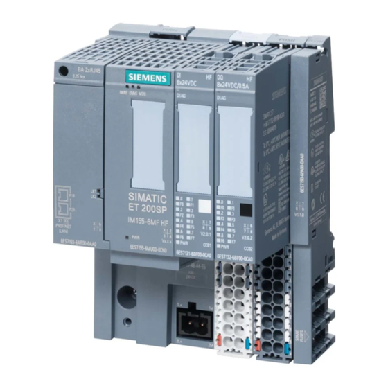
SIMATIC S7-1500 advanced controller
Опубликовано 13.09.2019
Промышленные контроллеры SIMATIC S7-1500
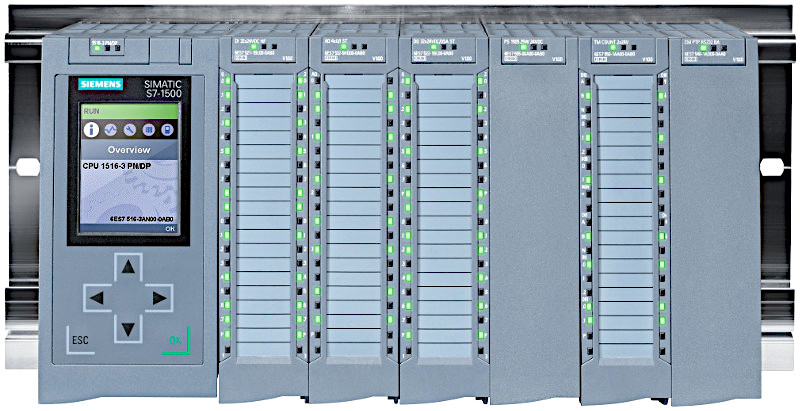
Центральные процессоры
- Standard CPU — стандартные
- Compact CPU — компактные со встроенными входами-выходами
- Failsafe CPU — объединяют в одном CPU функции: Standard и Safety
- Technology CPU — объединяют в одном CPU функции: Standard, Safety и расширенные функции управления движением Motion Control
- SIPLUS CPU — работают в экстремальных условиях
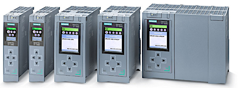
Сравнение моделей Standard CPU
| CPU 1511(T)-1 PN |
CPU 1513-1 PN |
CPU 1515(T)-2 PN |
CPU 1516-3 PN/DP |
CPU 1517(T)-3 PN/DP |
CPU 1518-4 PN/DP |
CPU 1518-4 PN/DP ODK |
|
|---|---|---|---|---|---|---|---|
| Максимум модулей ввода-вывода | 1024 | 2048 | 8192 | 16384 | |||
| Рабочая память для программ | 150(225) КБ | 300 КБ | 500(750) КБ | 1 МБ | 2(3) МБ | 4 МБ | |
| Рабочая память для данных | 1 МБ | 1,5 МБ | 3 МБ | 5 МБ | 8 МБ | 20 МБ | |
| Рабочая память для приложений ODK | — | 20 МБ | |||||
| Производительность (битовая операция) | 60 нс | 40 нс | 30 нс | 10 нс | 2 нс | 1 нс | |
| Максимальное количество блоков OB, FB, FC, DB | 2000 | 6000 | 10000 | ||||
| Максимальный размер блоков программ OB, FB, FC | 150 КБ | 300 КБ | 500 КБ | 512 КБ | |||
| Максимальный размер блоков данных DB | 1 МБ | 1,5 МБ | 3 МБ | 5 МБ | 8 МБ | 16 МБ |
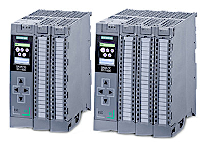
Сравнение моделей Compact CPU
| CPU 1511C-1 PN |
CPU 1512C-1 PN |
|
|---|---|---|
| Рабочая память для программ | 175 КБ | 250 КБ |
| Рабочая память для данных | 1 МБ | 1 МБ |
| Производительность (битовая операция) | 60 нс | 48 нс |
| Дискретных входов-выходов | 16DI/16DQ | 32DI/32DQ |
| Аналоговых входов-выходов | 5AI/2AQ | 5AI/2AQ |
Все CPU имеют встроенный интерфейс PROFINET с двухканальным коммутатором (2xRJ45).
CPU 1515/1516/1517 имеют один дополнительный интерфейс PROFINET со своим IP адресом.
CPU 1518 имеет два дополнительных интерфейса PROFINET со своими IP адресами.
CPU 1516/1517/1518 имеют интерфейс PROFIBUS DP.
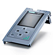
Все CPU имеют съёмный дисплей для диагностики и ввода в эксплуатацию.
Все CPU имеют поддержку функций управления перемещением и ПИД-регулирования.
Загрузочная память
Во всех моделях CPU в качестве загрузочной памяти (Load Memory) используется съёмная карта памяти SIMATIC Memory Card (от 4МБ до 32ГБ).
Без карты памяти контроллер работать не будет.
Web-сервер
Все CPU имеют встроенный веб-сервер с диагностической и сервисной информацией.
Сигнальные модули
Сигнальные модули делятся на классы:
- BA (Basic) — модули без диагностики
- ST (Standard) — с диагностикой на уровне модуля или группы каналов, класс точности для аналоговых модулей-0.3%
- HF (High Feature)- с диагностикой на уровне каждого канала, класс точности для аналоговых модулей-0.1%
- HS (High Speed) — с коротким временем фильтрации и преобразования аналоговых сигналов.
Сигнальные модули контроллера SIMATIC S7-1500 используются и в станциях распределённого ввода-вывода ET 200MP.
Сигнальные кабели подключаются к сигнальным модулям через съёмные фронтштекеры.
Сигнальные модули шириной 25мм поставляются в комплекте с фронтштекерами с отжимными контактами.
Для сигнальных модулей шириной 35мм фронтштекеры с контактами под винт или с отжимными контактами заказываются отдельно.
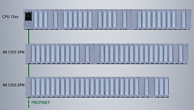
Станции распределённого ввода-вывода SIMATIC ET200 MP
Станции распределённого ввода-вывода SIMATIC ET200 MP могут подключаться к контроллерам SIMATIC S7-1500 по сети PROFINET или по сети PROFIBUS DP
с помощью интерфейсных модулей:
- IM 155-5 PN ST
- IM 155-5 PN HF — поддерживает протокол MRDP (Media Redundancy Protocol with Path Duplication)
- IM 155-5 DP HF
Справа от интерфейсного модуля IM можно установить до 31 модуля из линейки контроллера SIMATIC S7-1500.
Блоки питания
- Системные блоки питания PS
- Блоки питания нагрузки PM
Питание электроники модулей через внутреннюю шину S7-1500/ET 200MP.
Максимум 3 блока питания на контроллер S7-1500 или станцию ET 200MP.
Питание внешних цепей =24В S7-1500/ET 200MP.
Не имеет интерфейса для подключения к внутренней шине S7-1500/ET 200MP.
Не поддерживает функции диагностики.
Языки программирования
SIMATIC S7-1500 поддерживает языки программирования: LAD, FBD, STL, SCL, GRAPH.
Среда разработки
STEP 7 Professional (TIA Portal) — среда разработки прикладных технологических программ для контроллеров: SIMATIC S7-1200, SIMATIC S7-1500,
SIMATIC S7-300, SIMATIC S7-400, WinAC.
Монтаж
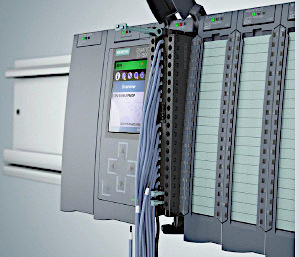
Модули S7-1500 устанавливаются на профильную шину.
В один ряд можно установить до 32 модулей (включая CPU).
Внешние сигнальные кабели подключаются через съёмные фронтштекеры.
SIPLUS extreme S7-1500
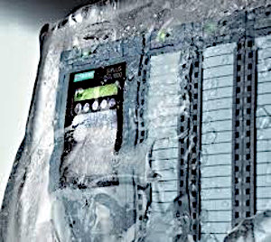
Контроллеры SIPLUS extreme S7-1500 предназначены для эксплуатации в тяжёлых промышленных условиях:
- возможность появления конденсата и льда
- наличие в воздухе химически, биологически и механически активных веществ
- диапазон рабочих температур от -40 до +70 °С.
Контроллеры SIPLUS extreme S7-1200 и SIMATIC S7-1500 имеют набор модулей с одинаковой функциональностью.
Стартовый пакет SIMATIC S7-1500
Состав стартового комплекта:
- CPU 1511C-1 PN
- Карта памяти SIMATIC Memory Card 4МБ
- Блок питания PM1507, 24V/3A
- Профильная шина 160 мм
- Фронтальные штекеры
- Кабель Ethernet
- Программное обеспечение STEP 7 V15, лицензия на 365 дней
- Документация
- Практичный чемоданчик
Каталог SIMATIC ST 70 • 2019
Скачать полный каталог на английском языке (50,4 Мб)
Обозначения:
PN — PROFINET
DP — PROFIBUS DP
DI/DQ — дискретные входы/выходы, AI/AQ — аналоговые входы/выходы
SM — сигнальные модули
Классы сигнальных модулей: BA (Basic), ST (Standard), HF (High Feature), HS (High Speed)
Данные для заказа
| N | Описание | Заказной номер | |
|---|---|---|---|
| Центральные процессоры CPU | |||
| 1 | CPU 1511-1 PN | 6ES7511-1AK01-0AB0 | |
| 2 | CPU 1511F-1 PN | 6ES7511-1FK02-0AB0 | |
| 3 | CPU 1511C-1 PN | 16DI/16DQ, 5AI/2AQ | 6ES7511-1CK00-0AB0 |
| 3 | CPU 1511T-1 PN | 16DI/16DQ, 5AI/2AQ | 6ES7511-1TK00-0AB0 |
| 4 | CPU 1512C-1 PN | 32DI/32DQ, 5AI/2AQ | 6ES7512-1CK01-0AB0 |
| 5 | CPU 1513-1 PN | 6ES7513-1AL01-0AB0 | |
| 6 | CPU 1513F-1 PN | 6ES7513-1FL02-0AB0 | |
| 7 | CPU 1515-2 PN | 6ES7515-2AM01-0AB0 | |
| 8 | CPU 1515T-2 PN | 6ES7515-2TM01-0AB0 | |
| 9 | CPU 1515F-2 PN | 6ES7515-2FM01-0AB0 | |
| 10 | CPU 1516-3 PN/DP | 6ES7516-3AN01-0AB0 | |
| 11 | CPU 1516F-3 PN/DP | 6ES7516-3FN01-0AB0 | |
| 12 | CPU 1517-3 PN/DP | 6ES7517-3AP00-0AB0 | |
| 13 | CPU 1517T-3 PN/DP | 6ES7517-3TP00-0AB0 | |
| 14 | CPU 1517F-3 PN/DP | 6ES7517-3FP00-0AB0 | |
| 15 | CPU 1518-4 PN/DP | 6ES7518-4AP00-0AB0 | |
| 16 | CPU 1518F-4 PN/DP | 6ES7518-4FP00-0AB0 | |
| 17 | CPU 1518-4 PN/DP ODK | 6ES7518-4AP00-3AB0 | |
| Карты памяти SIMATIC Memory Card | |||
| 18 | 4МБ | 6ES7954-8LC02-0AA0 | |
| 19 | 12МБ | 6ES7954-8LE02-0AA0 | |
| 20 | 24МБ | 6ES7954-8LF02-0AA0 | |
| 21 | 256МБ | 6ES7954-8LL02-0AA0 | |
| 22 | 2ГБ | 6ES7954-8LP02-0AA0 | |
| 23 | 32ГБ | 6ES7954-8LT02-0AA0 | |
| Модули ввода дискретных сигналов | |||
| 24 | SM 1521 | DI 32x24VDC BA, 3мс, тип 3, 25мм, с фронтштекером | 6ES7521-1BL10-0AA0 |
| 25 | SM 1521 | DI 32x24VDC HF, 3мс, тип 3, 35мм | 6ES7521-1BL00-0AA0 |
| 26 | SM 1521 | DI 16x24VDC BA, 3мс, тип 3, 25мм, с фронтштекером | 6ES7521-1BH10-0AA0 |
| 27 | SM 1521 | DI 16x24VDC HF, 3мс, тип 3, 35мм | 6ES7521-1BH00-0AA0 |
| 28 | SM 1521 | DI 16x24VDC SRC BA, 3мс, тип 1, минус на общей точке, 35мм | 6ES7521-1BH50-0AA0 |
| 29 | SM 1521 | DI 16x230VAC BA, 20мс, тип 1, 35мм | 6ES7521-1FH00-0AA0 |
| 30 | SM 1521 | DI 16×24…125VUC HF, 0.05…20мс, тип 3, 35мм | 6ES7521-7EH00-0AB0 |
| Модули вывода дискретных сигналов | |||
| 31 | SM 1522 | DQ 32x24VDC/0.5A BA, 25мм, с фронтштекером | 6ES7522-1BL10-0AA0 |
| 32 | SM 1522 | DQ 32x24VDC/0.5A ST, 35мм | 6ES7522-1BL00-0AB0 |
| 33 | SM 1522 | DQ 32x24VDC/0.5A HF, 35мм | 6ES7522-1BL01-0AB0 |
| 34 | SM 1522 | DQ 16x24VDC/0.5A BA, 25мм, с фронтштекером | 6ES7522-1BH10-0AA0 |
| 35 | SM 1522 | DQ 16x24VDC/0.5A ST, 35мм | 6ES7522-1BH00-0AB0 |
| 36 | SM 1522 | DQ 16x24VDC/0.5A HF, 35мм | 6ES7522-1BH01-0AB0 |
| 37 | SM 1522 | DQ 8x230VAC/5A ST, реле, 35мм | 6ES7522-5HF00-0AB0 |
| 38 | SM 1522 | DQ 16x230VAC/2A ST, реле, 35мм | 6ES7522-5HH00-0AB0 |
| 39 | SM 1522 | DQ 8x230VAC/2A ST, тиристоры, 35мм | 6ES7522-5FF00-0AB0 |
| 40 | SM 1522 | DQ 16x230VAC/1A ST, тиристоры, 35мм | 6ES7522-5FH00-0AB0 |
| 41 | SM 1522 | DQ 16×24…48VUC/125VDC/0.5A ST, тиристоры, 35мм | 6ES7522-5EH00-0AB0 |
| Модуль ввода-вывода дискретных сигналов | |||
| 42 | SM 1523 | DI 16x24VDC + DQ 16x24VDC/0.5A BA, 25мм, с фронтштекером | 6ES7523-1BL00-0AA0 |
| Модули ввода аналоговых сигналов | |||
| 43 | SM 1531 | AI 8xU/I/RTD/TC ST, 16 бит, 0.3%, 35мм | 6ES7531-7KF00-0AB0 |
| 44 | SM 1531 | AI 8xU/I HS, 14 бит, 0.3%, 35мм | 6ES7531-7NF10-0AB0 |
| 45 | SM 1531 | AI 8xU/I HF, 16 бит, 0.1%, 35мм | 6ES7531-7NF00-0AB0 |
| 46 | SM 1531 | AI 4xU/I/RTD/TC ST, 16 бит, 25мм, с фронтштекером | 6ES7531-7QD00-0AB0 |
| 47 | SM 1531 | AI 8xU/I/RTD/TC HF, 16 бит, 0.1%, 35мм | 6ES7531-7PF00-0AB0 |
| Модули вывода аналоговых сигналов | |||
| 48 | SM 1532 | AQ 8xU/I HS, 14 бит, 0.3%, 35мм | 6ES7532-5HF00-0AB0 |
| 49 | SM 1532 | AQ 4xU/I ST, 16 бит, 0.3%, 35мм | 6ES7532-5HD00-0AB0 |
| 50 | SM 1532 | AQ 2xU/I ST, 25мм, с фронтштекером | 6ES7532-5NB00-0AB0 |
| 51 | SM 1532 | AQ 4xU/I HF, 16 бит, 0.1%, 35мм | 6ES7532-5ND00-0AB0 |
| Модули ввода-вывода аналоговых сигналов | |||
| 52 | SM 1534 | AI 4xU/I/RTD/TC AQ 2xU/I ST, 25мм, с фронтштекером | 6ES7534-7QE00-0AB0 |
| Коммуникационные модули | |||
| 53 | CM PtP | CM PtP RS232 BA: Freeport, 3964(R), USS | 6ES7540-1AD00-0AA0 |
| 54 | CM PtP | CM PtP RS422/RS485 BA: Freeport, 3964(R), USS | 6ES7540-1AB00-0AA0 |
| 55 | CM PtP | CM PtP RS232 HF: Freeport, 3964(R), USS, Modbus RTU | 6ES7541-1AD00-0AB0 |
| 56 | C PtP | CM PtP RS422/RS485 HF: Freeport, 3964(R), USS, Modbus RTU | 6ES7541-1AB00-0AB0 |
| 57 | CP 1543-1 | Industrial Ethernet: TCP/IP, ISO, UDP, S7, Firewall, SNMPV1/V3, DHCP, FTP клиент, 1xRJ45 | 6GK7543-1AX00-0XE0 |
| 58 | CM 1542-5 | Коммуникационный модуль CM 1542-5 PROFIBUS DP | 6GK7542-5DX00-0XE0 |
| 59 | CP 1542-5 | Коммуникационный процессор CP 1542-5 PROFIBUS DP | 6GK7542-5FX00-0XE0 |
| 60 | CP 1542-1 | Коммуникационный процессор CP 1542-1 PN IO-Controller, TCP/IP, UDP, S7, ISO-ON-TCP | 6GK7542-1AX00-0XE0 |
| Технологические модули | |||
| 61 | TM Count | TM Count 2x24V — 2-канальный модуль скоростного счёта | 6ES7550-1AA00-0AB0 |
| 62 | TM PosInput | TM PosInput 2 — 2-канальный модуль для подключения датчиков позиционирования | 6ES7551-1AB00-0AB0 |
| 63 | TM Timer | TM Timer DIDQ 16x24V — сигналы с меткой времени | 6ES7552-1AA00-0AB0 |
| 64 | SIWAREX WP521 | 1-канальный модуль взвешивания статических грузов | 7MH4980-1AA01 |
| 65 | SIWAREX WP522 | 2-канальный модуль взвешивания статических грузов | 7MH4980-2AA01 |
| Интерфейсные модули для станции распределённого ввода-вывода SIMATIC ET 200MP | |||
| 66 | IM 1555-5 PN | Интерфейсный модуль IM 1555-5 PN ST | 6ES7155-5AA01-0AB0 |
| 67 | IM 1555-5 PN | Интерфейсный модуль IM 1555-5 PN HF | 6ES7155-5AA00-0AC0 |
| 68 | IM 1555-5 DP | Интерфейсный модуль IM 1555-5 DP HF | 6ES7155-5BA00-0AB0 |
| Блок питания нагрузки | |||
| 69 | PM 1507 | 70 Вт, вход: ~115/230В, выход: =24В/3А | 6EP1332-4BA00 |
| 70 | PM 1507 | 190 Вт, вход: ~115/230В, выход: =24В/8А | 6EP1333-4BA00 |
| Системные блоки (питание электроники по внутренней шине) | |||
| 71 | PS 1505 | 25 Вт, =24В | 6ES7505-0KA00-0AB0 |
| 72 | PS 1505 | 60 Вт, =24/48/60В | 6ES7505-0RA00-0AB0 |
| 73 | PS 1505 HF | 60 Вт, =24/48/60В | 6ES7505-0RB00-0AB0 |
| 74 | PS 1507 | 60 Вт, AC/DC 120/230В | 6ES7507-0RA00-0AB0 |
| Профильные шины S7-1500 | |||
| 75 | 160 мм | 6ES7590-1AB60-0AA0 | |
| 76 | 482 мм | 6ES7590-1AE80-0AA0 | |
| 77 | 530 мм | 6ES7590-1AF30-0AA0 | |
| 78 | 830 мм | 6ES7590-1AJ30-0AA0 | |
| 79 | 2000 мм | 6ES7590-1BC00-0AA0 | |
| Фронтштекеры для модулей шириной 35 мм | |||
| 80 | 40-полюсный с отжимными контактами | 6ES7592-1BM00-0XB0 | |
| 81 | 40-полюсный с контактами под винт | 6ES7592-1AM00-0XB0 | |
| Запасной дисплей | |||
| 82 | для CPU 1511-1 PN, CPU 1511F-1 PN, CPU 1511C-1 PN, CPU 1512C-1 PN, CPU 1513-1 PN, CPU 1513F-1 PN3 |
6ES7591-1AA00-0AA0 | |
| 83 | для CPU 1515(F)-2 PN, CPU 1516(F)-3 PN/DP, CPU 1517 (F)-3 PN/DP, CPU 1518(F)-4 PN/DP | 6ES7591-1BA00-0AA0 | |
| Запасные части | |||
| 84 | Универсальная крышка для IM 155-5 PN ST, 5 шт. | 6ES7528-0AA70-7AA0 | |
| 85 | фронтштекер 25 мм, push-in | 6ES7592-1BM00-0XA0 | |
| 86 | U-образный шинный соединитель, 5 шт. | 6ES7590-0AA00-0AA0 | |
| 87 | Разъём питания, 2х2 полюса, для модуля ввода-вывода =24В, 10 шт. | 6ES7193-4JB00-0AA0 | |
| 88 | Универсальная крышка для модуля ввода-вывода S7-1500, 5 шт. | 6ES7528-0AA00-7AA0 | |
| 89 | Маркировочные этикетки для модулей, 10 шт. | 6ES7592-2AX00-0AA0 | |
| 90 | Набор заземления экрана соединительного кабеля, 5 комплектов | 6ES7590-5CA00-0AA0 | |
| 91 | Терминал заземления, 5 шт. | 6ES7590-5BA00-0AA0 | |
| 92 | Коммутационная пермычка для фронтштекеров, 20 шт. | 6ES7592-3AA00-0AA0 | |
| 93 | Элемент заземления профильной шины 2000мм, 20 шт. | 6ES7590-5AA00-0AA0 | |
| Программное обеспечение | |||
| 94 | STEP7 Professional V15 | 6ES7822-1AA05-0YA5 | |
| 95 | ODK 1500S V2.0 | 6ES7806-2CD02-0YA0 | |
| Стартовый комплект SIMATIC S7-1500 | |||
| 96 | CPU 1511C-1 PN, блок питания PM 1507, профильная рейка 160мм, DI16x24VDC, DQ16x24VDC/0.5A, фронтштекеры, кабель Ethernet, лицензия STEP7 Professional V15 на 365 дней, документация |
6ES7511-1CK00-4YB5 | |