-
Contents
-
Table of Contents
-
Troubleshooting
-
Bookmarks
Quick Links
Instruction Manual May 2008
sitrans
PROBE LU (PROFIBUS PA)
Related Manuals for Siemens Sitrans PROBE LU
Summary of Contents for Siemens Sitrans PROBE LU
-
Page 1
Instruction Manual May 2008 sitrans PROBE LU (PROFIBUS PA) -
Page 2
The user is responsible for all changes and repairs made to the device by the user or the user’s agent. • All new components are to be provided by Siemens Milltronics Process Instruments Inc. • Restrict repair to faulty components only. -
Page 3: Table Of Contents
SITRANS Probe LU (PROFIBUS PA) …………….4 Applications ……………………..5 Level, volume, or flow …………………… 5 SITRANS Probe LU System Implementation …………….5 Programming ……………………..6 SITRANS Probe LU (PROFIBUS PA) Approvals and Certificates ……..6 Specifications ……………………7 Installation ……………………11 Mounting Location ……………………..11 Mounting Instructions ……………………12 SITRANS Probe LU Dimensions ………………..13…
-
Page 4
Diagnosis reply (applies only to cyclic masters) ……………28 Acyclic Diagnostics ……………………28 Acyclic Extended Diagnostics (General Fault Codes) …………30 Acyclic Data ……………………….32 Configuration Example ………………….33 Accessing parameters remotely …………………33 Functions ………………………..33 Changing parameter settings ………………..34 Appendix A: Technical References …………….35 Principles of operation ……………………35 Measurement Response ……………………35 Echo Lock …………………………35 Loss of Echo (LOE) ……………………..36… -
Page 5
Appendix G: Asynchronous Communications Data Map ……..61 Directory……………………….61 Physical Block 1……………………. 61 Analog Input Function Blocks: AIFB1 and AIFB2 ………….. 64 Level Transducer Block………………….66 Appendix H: Parameter Descriptions …………….73 Identification ……………………….73 Configuration……………………..73 Device ……………………….74 Statistics ……………………….76 Input ………………………….77 Target Mode…………………….. -
Page 7: Safety Notes
• Connect the equipment to an outlet on a different circuit from the one to which the receiver is connected. • Consult an experienced radio/TV technician for help. This warning symbol is used when there is no corresponding caution symbol on the product. 7ML19985JB02 SITRANS Probe LU (PROFIBUS PA) – INSTRUCTION MANUAL Page 1…
-
Page 8: The Manual
• This manual applies to the SITRANS Probe LU (PROFIBUS PA) only. This manual will help you set up your SITRANS Probe LU for optimum performance. We always welcome suggestions and comments about manual content, design, and accessibility.
-
Page 9
Controller PVDF Polyvinylidene fluoride parts per million Primary Value measured value SELV Safety Extra Low Voltage Secondary Value equivalent value Time Varying Threshold sensitivity threshold Input voltage Output voltage 7ML19985JB02 SITRANS Probe LU (PROFIBUS PA) – INSTRUCTION MANUAL Page 3… -
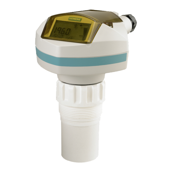
Page 10: Sitrans Probe Lu (Profibus Pa)
The transducer is available in ETFE (ethylene-tetrafluoroethylene) or PVDF (polyvinylidene fluoride), allowing SITRANS Probe LU to be used in a wide variety of industries and applications using corrosive chemicals. The ultrasonic transducer contains a temperature-sensing element to compensate for temperature changes in the application.
-
Page 11: Applications
Applications Level, volume, or flow SITRANS Probe LU is designed to measure levels of liquids in a variety of applications: • storage type vessels • simple process vessels with some surface agitation • liquids • slurries • open channels Volume Volume parameters allow you to obtain the measurement as volume instead of level.
-
Page 12: Programming
Programming SITRANS Probe LU carries out its level measurement function according to the set of built-in parameters. Parameter changes can be made via the Siemens infrared handheld programmer, or via a PC using SIMATIC PDM. SITRANS Probe LU (PROFIBUS PA) Approvals and…
-
Page 13: Specifications
Specifications Siemens makes every attempt to ensure the accuracy of these specifications Note: but reserves the right to change them at any time. SITRANS Probe LU (PROFIBUS PA) Power • Bus powered On PROFIBUS PA, as per IEC 61158-2 • Current consumed…
-
Page 14
Temperature dependent: typical value at +20 °C (+68 °F); maximum value at +80 °C (+176 °F) Submergence test under water at 2 m (6.5 ft) depth for 24 hours. Page 8 SITRANS Probe LU (PROFIBUS PA) – INSTRUCTION MANUAL 7ML19985JB02… -
Page 15
Class I, Div. 2, Groups A,B, C, D Intrinsically Safe wiring drawing (FM/CSA) on page 107 for drawing number 23650617. Non-incendive (FM Class I, Div. 2) wiring drawing on page 111 for drawing number 23650583. 7ML19985JB02 SITRANS Probe LU (PROFIBUS PA) – INSTRUCTION MANUAL Page 9… -
Page 16
Programmer (infrared keypad) Siemens Infrared IS (Intrinsically Safe) handheld programmer: for all locations, including hazardous. • approval ATEX II 1 G EEx ia IIC T4, SIRA 01ATEX2147 FM/CSA: Class I, Div. 1, Groups A, B, C, D −20 to +40 °C (−5 to +104 °F) •… -
Page 17: Installation
• Installation shall only be performed by qualified personnel and in accordance with local governing regulations. • SITRANS Probe LU is to be used only in the manner outlined in this manual, otherwise protection provided by the equipment may be impaired.
-
Page 18: Mounting Instructions
Mounting Instructions Note: • Ideally, mount SITRANS Probe LU so that the face of the transducer is at least 300 mm (1 ft) above the highest anticipated level. SITRANS Probe LU is available in three thread types: •…
-
Page 19: Sitrans Probe Lu Dimensions
51. 1 mm (2.01″) 54.0 mm (2. 1 3″) Flange Adaptor (optional) SITRANS Probe LU can be fitted with the optional 3″ (80 mm) flange adaptor for mating to 3″ ANSI, DIN 65PN10, and JIS 10K3B flanges. SITRANS Probe LU «A»…
-
Page 20: Wiring
Strip the cable jacket for approximately 70 mm (2.75″) from the end of the PROFIBUS PA cable, and thread the wires through the gland Safety Extra Low Voltage If cable is routed through conduit, use only approved suitable-size hubs for waterproof applications. Page 14 SITRANS Probe LU (PROFIBUS PA) – INSTRUCTION MANUAL 7ML19985JB02…
-
Page 21
PROFIBUS PA User and Installation Guidelines work properly. Please refer to the (order number 2.092), available from www.profibus.com. The instrument shield connection is internally connected to the external ground lug. 7ML19985JB02 SITRANS Probe LU (PROFIBUS PA) – INSTRUCTION MANUAL Page 15… -
Page 22: Startup
Use SIMATIC PDM to calibrate the four set points: High and Low Calibration Point, and High and Low Level Point. SITRANS Probe LU automatically starts up in RUN mode and detects the material level. The LCD displays the material level referenced from the Low Level Point (the output of Analog Input Function Block 1/AIFB1).
-
Page 23: Programming Sitrans Probe Lu (Profibus Pa)
PROGRAM mode, then enter the menu number (see menu structure on page 49). For more instructions on local programming using the handheld programmer, please Appendix D: programming via the handheld programmer on page 42. 7ML19985JB02 SITRANS Probe LU (PROFIBUS PA) – INSTRUCTION MANUAL Page 17…
-
Page 24: Program Mode Display
PROGRAM Mode Display SITRANS Probe LU (PROFIBUS PA) continues to monitor In and Out values even Note: when the device is in PROGRAM mode. 1 – Primary region (displays parameter value) 2 – Menu number region (displays Menu number) 3 – PROGRAM mode icon 4 –…
-
Page 25: Quick Setup
Keep infrared devices such as laptops, cell phones, and PDAs, away from Note: SITRANS Probe LU to prevent inadvertent operation. Power up the instrument. SITRANS Probe LU starts in RUN mode, and the LCD displays the output of AIFB1. Setting the PROFIBUS address via the handheld programmer Notes: •…
-
Page 26: Performing Calibration Via Profibus Pa
Probe LU product page of our website, at: https://pia.khe.siemens.com/index.asp?Nr=11157) Changing parameter settings • First launch SIMATIC PDM, connect to SITRANS Probe LU, and upload data from the device. • Adjust parameter values in the parameter view field (right side of screen).
-
Page 27: Using Auto False Echo Suppression
SITRANS Probe LU is now ready to operate. Using Auto False Echo Suppression If SITRANS Probe LU displays a false high level, or the reading is fluctuating between the correct level and a false high level, you can use the Auto False Echo Suppression TVT setup parameters to prevent false echo detection.
-
Page 28: Remote Operation Via Profibus Pa
Remote operation via PROFIBUS PA SITRANS Probe LU (PROFIBUS PA) is a Class B, Profile Version 3.0, rev. 1, PA device. It supports Class 1 Master for cyclic and acyclic data exchange, and Class 2 for acyclic services. The full range of SITRANS Probe LU functions is available only over a PROFIBUS PA network.
-
Page 29: Configuration
In the case of the Probe LU (PROFIBUS PA), the maximum PROFIBUS current is user- PROFIBUS Current Consumption selectable, and can be either 12, 13, 15, or 20 mA. (See page 79.) 7ML19985JB02 SITRANS Probe LU (PROFIBUS PA) – INSTRUCTION MANUAL Page 23…
-
Page 30: Cyclic Versus Acyclic Data
Configuration information is only needed periodically and is set up as acyclic data. Cyclic Data When you configure SITRANS Probe LU on the PROFIBUS PA bus, there are two slots available for modules. Each of the slots has to have a module defined in it.
-
Page 31: Status Byte
This could happen when a firmware download has been done, but a system reset has not been done. This could also happen if the function blocks are not configured properly using the handheld programmer, PDM or acyclic services. 7ML19985JB02 SITRANS Probe LU (PROFIBUS PA) – INSTRUCTION MANUAL Page 25…
-
Page 32: Condensed Status
Usability of the process value depends on the applica- tion. 0x68 UNCERTAIN – main- Value is potentially invalid. Cause is a wear detected …0x6B tenance demanded in the device. Maintenance is demanded within a short-term period. Page 26 SITRANS Probe LU (PROFIBUS PA) – INSTRUCTION MANUAL 7ML19985JB02…
-
Page 33
No measurement available because of 0x25 nance invalid process conditions. 0x3C BAD – function check / local over- Occurs during cleaning or calibration …0x3F ride, value not usable process. 7ML19985JB02 SITRANS Probe LU (PROFIBUS PA) – INSTRUCTION MANUAL Page 27… -
Page 34: Diagnostics
0x02000000 Mechanical failure 0x04000000 Motor Temperature too high 0x08000000 Electronics temperature too high 0x10000000 Memory error 0X20000000 Measurement failure 0X40000000 Device not initialized (no calibration) 0x80000000 Self calibration failed Page 28 SITRANS Probe LU (PROFIBUS PA) – INSTRUCTION MANUAL 7ML19985JB02…
-
Page 35
R indicates the message remains active as long as the reason for the message exists. A indicates the message will automatically reset after 10 seconds. PNO – PROFIBUS User Organization Values of the DIAGNOSIS bit: 0 = not set 1 = set 7ML19985JB02 SITRANS Probe LU (PROFIBUS PA) – INSTRUCTION MANUAL Page 29… -
Page 36: Acyclic Extended Diagnostics (General Fault Codes)
Point and Low Cali- Calibration Point and Low Cali- bration Point are the same. bration Point are different. Internal temperature sen- Repair required: contact your S:11 sor has failed. local Siemens representative. Page 30 SITRANS Probe LU (PROFIBUS PA) – INSTRUCTION MANUAL 7ML19985JB02…
-
Page 37
PLC was parameterized. and re-parameterize with the new Ident number. Factory calibration for the Repair required: contact your S:33 internal temperature sen- local Siemens representative. sor has been lost. 7ML19985JB02 SITRANS Probe LU (PROFIBUS PA) – INSTRUCTION MANUAL Page 31… -
Page 38: Acyclic Data
Acyclic Data SITRANS Probe LU supports up to four simultaneous connections by a Class 2 Master (C2 connection). It supports one connection by a Class 1 Master (C1 connection). In order for a Class 1 Master to read parameters from an instrument, it needs to know the slot and absolute index of the parameter.
-
Page 39: Configuration Example
Configuration Example To configure and use PROFIBUS PA with an S7-300/ 400 PLC If SITRANS Probe LU is not listed in the STEP 7 device catalog, you can download the GSD file from the product page of our web site at: https://pia.khe.siemens.com/index.asp?Nr=11157 under Downloads.
-
Page 40: Changing Parameter Settings
• Sensor Calibration Changing parameter settings • First launch SIMATIC PDM, connect to SITRANS Probe LU , and upload data from the device (the status fields change to Loaded). • Adjust parameter values in the parameter view field (right side of screen).
-
Page 41: Appendix A: Technical References
The transducer emits a series of ultrasonic pulses: each pulse is reflected as an echo from the material and sensed by the transducer. The echo is processed by SITRANS Probe LU, using Siemens proven Sonic Intelligence techniques. Filtering is applied to help discriminate between the true echo from the material and false echoes from acoustic and electrical noise, and agitator blades in motion.
-
Page 42: Loss Of Echo (Loe)
• When Echo Lock is Off, SITRANS Probe LU responds immediately to a new measurement (within the restrictions set by the Maximum Fill / Empty Rate). However, measurement reliability is affected. • When Maximum Verification or Material Agitator is selected, a new measurement outside the Echo Lock Window must meet the sampling criteria.
-
Page 43: Failsafe Value
Auto False-Echo Suppression The TVT adjustment parameters allow you to set a TVT (Time Varying Threshold) curve, so that SITRANS Probe LU will ignore false echoes. The default TVT curve hovers above the echo profile, and effectively screens out small false echoes.
-
Page 44
Distance (meters) Turn on Auto False-Echo Suppression when the material level is substantially lower than process full level (ideally when the tank is empty or almost empty). Page 38 SITRANS Probe LU (PROFIBUS PA) – INSTRUCTION MANUAL 7ML19985JB02… -
Page 45: Open Channel Monitoring (Ocm)
Open Channel Monitoring (OCM) OCM converts a level reading (head) into a flow value using a linear algorithm. SITRANS Probe LU can convert a head level measurement into a flow rate, using an eleven breakpoint head-versus-flow characteristic curve. This chart is usually available from the manufacturer of the v-notch weir, Parshall flume, or other open channel device.
-
Page 46: Appendix B: Troubleshooting
Write locking that Write Locking is Off (see on page 45). If you try to set a SITRANS Probe LU parameter via remote communications, but the parameter remains unchanged, make sure remote operation is enabled (see Remote operation enable on page 45). Also make sure that Write Locking is Off (see Write Locking on page 76).
-
Page 47: Appendix C: Maintenance
Please note the following: • The user is responsible for all changes and repairs made to the device. • All new components must be provided by Siemens Process Instruments Inc. • Restrict repair to faulty components only. •…
-
Page 48: Appendix D: Programming Via The Handheld Programmer
Although the complete range of parameters is only accessible via PDM , you can access and adjust many of the parameters via the Siemens infrared handheld programmer. Appendix H: Parameter Descriptions • For the complete list of parameters, see page 73.
-
Page 49: Handheld Programmer: Key Functions In Run Mode
Updates internal enclosure temperature value and displays it in LCD secondary region. Updates echo confidence value and displays it in LCD secondary region. Updates measurement value and displays it in LCD secondary region. 7ML19985JB02 SITRANS Probe LU (PROFIBUS PA) – INSTRUCTION MANUAL Page 43…
-
Page 50: Handheld Programmer: Key Functions In Navigation Mode
Add the corresponding character. Security Local operation enable Local Operation can be enabled or disabled via PDM. Go to Identification > Device > Local Operation Enable and select the desired setting. Page 44 SITRANS Probe LU (PROFIBUS PA) – INSTRUCTION MANUAL 7ML19985JB02…
-
Page 51: Write Locking
Config Menu, then scroll down to REMLOCK. 1. Identification 1.2. Configuration 1.2.2. Remote Lock • To enable programming, set REMLOCK to 0. To disable programming, enter 1. 7ML19985JB02 SITRANS Probe LU (PROFIBUS PA) – INSTRUCTION MANUAL Page 45…
-
Page 52: How To Do A Master Reset
The value returns to the default factory setting. Manufacturer’s settings: AIFB Filter Time Constant = 10 s LTB values set for 0 — 20 m (Low and High Calibration points; Near Range and Far Range) Page 46 SITRANS Probe LU (PROFIBUS PA) – INSTRUCTION MANUAL 7ML19985JB02…
-
Page 53: Fault Reset
Go to Low Level Point and enter the corresponding value in percent (default is 0). Go to High Level Point and enter the corresponding value in percent (default is 100). SITRANS Probe LU is now ready to operate. 7ML19985JB02 SITRANS Probe LU (PROFIBUS PA) – INSTRUCTION MANUAL…
-
Page 54
Notes Page 48 SITRANS Probe LU (PROFIBUS PA) – INSTRUCTION MANUAL 7ML19985JB02… -
Page 55: Appendix E: Lcd Menu Structure
Appendix E: LCD menu structure SITRANS Probe LU (PROFIBUS PA) – INSTRUCTION MANUAL Page 49 SITRANS Probe LU (PROFIBUS PA) – INSTRUCTION MANUAL 7ML19985JB02…
-
Page 56
52. 1. PV settings 2. SV1 Condensed status setup 3. SV2 6. Condensed status Condensed Status Setup on page 53 Page 50 SITRANS Probe LU (PROFIBUS PA) – INSTRUCTION MANUAL SITRANS Probe LU (PROFIBUS PA) – INSTRUCTION MANUAL 7ML19985JB02… -
Page 57
3. Upper Limit Warning 4. Upper Limit Alarm 5. Limit Hysteresis 6. Min. Out 7. Max Out Failsafe Mode 1. Failsafe Mode 2. Failsafe Value Interface A. Decimal Point 7ML19985JB02 SITRANS Probe LU (PROFIBUS PA) – INSTRUCTION MANUAL Page 51… -
Page 58
3. Maintenance Demanded Limit 4. Maintenance Alert Activation 5. Total Calibration Interval 6. Units 7. Maintenance Status 8. Acknowledge Status 9. Acknowledge Condensed Status Setup See Condensed Status Set- up page 53 Page 52 SITRANS Probe LU (PROFIBUS PA) – INSTRUCTION MANUAL 7ML19985JB02… -
Page 59
38. Tech Module Hardware S37 39. Tech Module Ramp S38 40. Transducer Temperature Sensor S39 41. Transducer Temperature High S40 42. Transducer Temperature Low S41 43. Transducer Temperature Calibration S42 7ML19985JB02 SITRANS Probe LU (PROFIBUS PA) – INSTRUCTION MANUAL Page 53… -
Page 60
Notes Page 54 SITRANS Probe LU (PROFIBUS PA) – INSTRUCTION MANUAL 7ML19985JB02… -
Page 61: Appendix F: Profibus Pa Profile Structure
The Level Transducer Block carries out adjustments to the sensor, such as level calibration and volume calibration. It supplies the outputs used by either or both of the AIFBs. 7ML19985JB02 SITRANS Probe LU (PROFIBUS PA) – INSTRUCTION MANUAL Page 55…
-
Page 62: Description Of The Blocks
(Level Units) AIFB2 High Level Low Level (Analog Point Point Input) Secondary Value 2 [Distance 1] (Sensor Units) Sensor Level unit Secondary Value 2 conversion [Distance 2] (Level Units) Page 56 SITRANS Probe LU (PROFIBUS PA) – INSTRUCTION MANUAL 7ML19985JB02…
-
Page 63
High Level Point Point Sensor Value Distance 1 or 2 (default: 100%) (SV2 or SV3) Level Low Level Point Calibration Level Offset Point (default: 0%) Secondary Value 1 Range 7ML19985JB02 SITRANS Probe LU (PROFIBUS PA) – INSTRUCTION MANUAL Page 57… -
Page 64: Analog Input Function Blocks 1 And 2
The output from the Level Transducer Block can be called the Primary Value (PV) or Secondary Value (SV1, SV2, or SV3). When it becomes the input to the AIFB, it is called the Process Variable. Page 58 SITRANS Probe LU (PROFIBUS PA) – INSTRUCTION MANUAL 7ML19985JB02…
-
Page 65
Variable scale are the same as the units used for the LTB output.) Output units together with Process Variable range determine how the LTB output is converted to whatever units the customer wants. 7ML19985JB02 SITRANS Probe LU (PROFIBUS PA) – INSTRUCTION MANUAL Page 59… -
Page 66
A hysteresis parameter prevents toggling in the Status field of the OUT value.) The OUT VALUE parameter is the value for the cyclic data transfer. Page 60 SITRANS Probe LU (PROFIBUS PA) – INSTRUCTION MANUAL 7ML19985JB02… -
Page 67: Appendix G: Asynchronous Communications Data Map
Block Object DD Revision UNSIGNED_INTEGER(2) Profile INTEGER (2) Profile Revision INTEGER (2) Execution Time UNSIGNED_INTEGER (1) Number of Parameters UNSIGNED_INTEGER(2) Index of View 1 UNSIGNED_INTEGER(2) Number of views UNSIGNED_INTEGER(1) 7ML19985JB02 SITRANS Probe LU (PROFIBUS PA) – INSTRUCTION MANUAL Page 61…
-
Page 68
UNSIGNED_INTEGER (1) Features Supported Value INTEGER (4) Features Enabled Value INTEGER (4) Condensed Status Value INTEGER (1) Mode Condensed Status Value Byte array (50) Setup Order Number ASCII (32) Page 62 SITRANS Probe LU (PROFIBUS PA) – INSTRUCTION MANUAL 7ML19985JB02… -
Page 69
Maintenance Demanded Calibration Interval UNSIGNED_INTEGER (4) Limit Maintenance Alarm INTEGER (1) Activation Total Calibration Interval UNSIGNED_INTEGER (4) Total Calibration Interval Calibration acknowledge INTEGER (1) Extended Diagnostics Value BIT_ENUMERATED (6) 7ML19985JB02 SITRANS Probe LU (PROFIBUS PA) – INSTRUCTION MANUAL Page 63… -
Page 70: Analog Input Function Blocks: Aifb1 And Aifb2
UNSIGNED_INTEGER (2) Batch Informa- tion Batch Operation UNSIGNED_INTEGER(2) Batch Phase UNSIGNED_INTEGER(2) Output Value FLOAT (2) Quality UNSIGNED_INTEGER (1) Status UNSIGNED_INTEGER (1) Upper FLOAT (2) PV Range Lower FLOAT (2) Page 64 SITRANS Probe LU (PROFIBUS PA) – INSTRUCTION MANUAL 7ML19985JB02…
-
Page 71
Quality INTEGER (1) Status INTEGER (1) Quality Simulation Value FLOAT (2) Simulation Enabled INTEGER (1) Out Unit Text ASCII(16) Max Out Value FLOAT (2) Min Out Value FLOAT (2) 7ML19985JB02 SITRANS Probe LU (PROFIBUS PA) – INSTRUCTION MANUAL Page 65… -
Page 72: Level Transducer Block
INTEGER (1) PV Units (Level/ Value INTEGER (2) Volume) Measured Value Value FLOAT (2) (Level) Level Units Value UNSIGNED_INTEGER (2) Sensor Value Value FLOAT (2) Sensor Units Value INTEGER (2) Page 66 SITRANS Probe LU (PROFIBUS PA) – INSTRUCTION MANUAL 7ML19985JB02…
-
Page 73
Value Process Temper- Value FLOAT (2) ature Temperature Value INTEGER (2) Units Max Process Value FLOAT (2) Temperature Min Process Value FLOAT (2) Temperature Temperature Value INTEGER (1) Source 7ML19985JB02 SITRANS Probe LU (PROFIBUS PA) – INSTRUCTION MANUAL Page 67… -
Page 74
INTEGER (1) Mode INTEGER (1) Auto TVT Range FLOAT (2) Reserved FLOAT (2) Reserved FLOAT (2) Long shots INTEGER (1) Number of shots Short shots INTEGER (1) Reserved INTEGER (1) Page 68 SITRANS Probe LU (PROFIBUS PA) – INSTRUCTION MANUAL 7ML19985JB02… -
Page 75
Meas x FLOAT (2) Step x TVT FLOAT (2) Echo Marker UNSIGNED_INTEGER Profile data part Value byte array Profile data part Value byte array Profile data part Value byte array 7ML19985JB02 SITRANS Probe LU (PROFIBUS PA) – INSTRUCTION MANUAL Page 69… -
Page 76
INTEGER (1) Point 15 INTEGER (1) Point 16 INTEGER (1) Point 17 INTEGER (1) Point 18 INTEGER (1) Point 19 INTEGER (1) Point 20 INTEGER (1) Point 21 INTEGER (1) Page 70 SITRANS Probe LU (PROFIBUS PA) – INSTRUCTION MANUAL 7ML19985JB02… -
Page 77
FLOAT (2) Temperatures Transducer Temperature FLOAT (2) Substance Value INTEGER (1) TVT Type Value INTEGER (1) Remaining Sensor Lifetime UNSIGNED_INTEGER (4) Sensor Life Status BIT_ENUMERATED (1) Maintenance ack BIT_ENUMERATED (1) 7ML19985JB02 SITRANS Probe LU (PROFIBUS PA) – INSTRUCTION MANUAL Page 71… -
Page 78
BIT_ENUMERATED (1) Maintenance Required Limit UNSIGNED_INTEGER (4) Calibration Maintenance Demanded Limit UNSIGNED_INTEGER (4) Interval Maintenance Alert Activation INTEGER (1) Total Service Interval UNSIGNED_INTEGER (4) Service Interval Service ack INTEGER (1) Page 72 SITRANS Probe LU (PROFIBUS PA) – INSTRUCTION MANUAL 7ML19985JB02… -
Page 79: Appendix H: Parameter Descriptions
1.2.1. Device Address (default 126) The unique address of the device on the network (also called PROFIBUS address). 0 — 126 Values Open the menu Device – Set Address. 7ML19985JB02 SITRANS Probe LU (PROFIBUS PA) – INSTRUCTION MANUAL Page 73…
-
Page 80: Device
Determines the length of time (in seconds) the device will stay in PROGRAM mode without any key presses occurring. 1.3. Device Manufacturer References a specific manufacturer, usually the name of the company responsible for the manufacture of this Field Device. Page 74 SITRANS Probe LU (PROFIBUS PA) – INSTRUCTION MANUAL 7ML19985JB02…
-
Page 81
Analog Input Function Blocks. Go to Identification > Device > Local Operation Enable and select the desired setting. 7ML19985JB02 SITRANS Probe LU (PROFIBUS PA) – INSTRUCTION MANUAL Page 75… -
Page 82: Statistics
The number of power cycles that have occurred since manufacture. Open menu View – Wear. 1.4.3. Internal Temperature The internal electronics temperature. Degrees C Value (view only) Open menu View – Peak Values, and select the tab Temperature. Page 76 SITRANS Probe LU (PROFIBUS PA) – INSTRUCTION MANUAL 7ML19985JB02…
-
Page 83: Input
Out of Service (O/S) Hand Manual Mode (MAN) programmer values Automatic Mode (AUTO) 2.2. Reset Filter Resets the rate filter. Hand the sensor value immediately goes to the target programmer distance value 7ML19985JB02 SITRANS Probe LU (PROFIBUS PA) – INSTRUCTION MANUAL Page 77…
-
Page 84: Standard Setup
Slower settings provide higher accuracy: faster settings allow for more level fluctuation. 2.3.2. Echo Lock Ensure the agitator is always running while SITRANS Probe LU is Note: monitoring the vessel, to avoid stationary blade detection. Selects the measurement verification process.
-
Page 85
This parameter cannot be reset to factory default settings. Temperature dependent: typical values at +20 °C (+68 °F); maximum values at +80 ° C (+176 °F). 7ML19985JB02 SITRANS Probe LU (PROFIBUS PA) – INSTRUCTION MANUAL Page 79… -
Page 86: Sensor Calibration
Sensor Value: the value produced by the echo processing, which represents the dis- tance from the Sensor Reference Point to the target. Level Value: the level measured in level units. Page 80 SITRANS Probe LU (PROFIBUS PA) – INSTRUCTION MANUAL 7ML19985JB02…
-
Page 87
Open the menu Device – Sensor Calibration, and click on the button for Wet or Dry calibration. Enter the values for Low Calibration Point, Low Calibration Level, High Calibration Point, High Level Point, then click on Transfer. 7ML19985JB02 SITRANS Probe LU (PROFIBUS PA) – INSTRUCTION MANUAL Page 81… -
Page 88: Measuring Limits
Open menu View – Peak Values, and click Sensor tab. 2.5.2. Max. Measured Value The maximum recorded Sensor value, defined in Sensor units. Open menu View – Peak Values, and click Sensor tab Page 82 SITRANS Probe LU (PROFIBUS PA) – INSTRUCTION MANUAL 7ML19985JB02…
-
Page 89: Linearization
Defines the tank shape and allows the Probe LU to calculate volume instead of level. If None is selected, no volume conversion is performed. Select the tank shape matching the monitored tank or reservoir (see table on next page). 7ML19985JB02 SITRANS Probe LU (PROFIBUS PA) – INSTRUCTION MANUAL Page 83…
-
Page 90
(flat linearization volume bottom) conical or pyramidal linearization volume, bottom dimension A linearization volume, parabolic bottom dimension A linearization volume, half-sphere bottom dimension A Page 84 SITRANS Probe LU (PROFIBUS PA) – INSTRUCTION MANUAL 7ML19985JB02… -
Page 91
Tank Shape Related Parameters Go to Input > Sensor Calibration > Unit (level) and select desired level units. Key in the height of the vessel bottom in level units. 7ML19985JB02 SITRANS Probe LU (PROFIBUS PA) – INSTRUCTION MANUAL Page 85… -
Page 92: Detailed Setup
Enter up to 32 level breakpoints, where the corresponding volume is known. The values corresponding to 100% and 0% levels must be entered. The breakpoints can be ordered from top to bottom, or the reverse. Breakpoints are normalized to 0. Page 86 SITRANS Probe LU (PROFIBUS PA) – INSTRUCTION MANUAL 7ML19985JB02…
-
Page 93
Use the level breakpoints to enter head level values, and the volume breakpoints to enter flow volumes. Each segment defined by a head breakpoint requires a corresponding flow value, so that SITRANS Probe LU can make the head-to-flow calculations. Use the Flow table associated with your open channel device (Parshall flume, v-notch weir, or other measuring device) to calculate the flow rate for each breakpoint. -
Page 94
Example: v-notch weir: Breakpoints flow characterization Break- Head Flow point (level) (volume) 0.4 m 113.5 0.3 m 55.3 0.2 m 20.07 head Illustrated breakpoint values are for example purposes only. Note: Page 88 SITRANS Probe LU (PROFIBUS PA) – INSTRUCTION MANUAL 7ML19985JB02… -
Page 95
Largest or irst echo (reserved for SMPI service personnel) 2.7.3.2. Threshold Short (default 10) The Threshold parameters are for use by authorized Siemens Note: Service personnel or technicians familiar with Siemens echo processing techniques. Sets the minimum Short Shot echo confidence that the echo must meet in order to be considered a valid echo. -
Page 96
Open menu Device – Offset and Velocity Calibration, select the option to change calibration, select the calibration type, then enter new calibration value. 2.7.4. Echo Sampling The Echo Sampling parameters are for use by authorized Siemens Note: Service personnel or technicians familiar with Siemens echo processing techniques. -
Page 97
, within which an echo should be considered valid. Range: 0 to 20 m Hand programmer values This parameter is for use only by Siemens service technicians. The transducer face. 7ML19985JB02 SITRANS Probe LU (PROFIBUS PA) – INSTRUCTION MANUAL Page 91… -
Page 98
Displays the amplitude (in dB above 1 µV rms) of the echo selected as the measurement echo. –20 to 99 Values (view only) Open the menu View – Profile. Page 92 SITRANS Probe LU (PROFIBUS PA) – INSTRUCTION MANUAL 7ML19985JB02… -
Page 99
2.7.7. TVT setup First SITRANS Probe LU learns the echo profile. Then the learned profile, or part of the learned profile, is used to screen out false echoes. 2.7.7.1. TVT Hover Level (default 33%) Defines in percent how high the TVT (Time Varying Threshold) curve is placed above the echo profile, with respect to largest echo. -
Page 100
Distance (meters) 2.7.7.9. Shaper Mode (default Off) Turns TVT Shaper on or off. (For use only by Siemens personnel.) This parameter cannot be reset to the factory default. Page 94 SITRANS Probe LU (PROFIBUS PA) – INSTRUCTION MANUAL… -
Page 101
Adjusts the Probe LU response to decreases in the actual material level. Empty Rate is automatically updated whenever Response Rate is altered. 0.0000 to 99999 Range: m/min. Values Response Rate Altered by Units (Level) Related High Level Point 7ML19985JB02 SITRANS Probe LU (PROFIBUS PA) – INSTRUCTION MANUAL Page 95… -
Page 102: Output
Used to request an operating mode from the Function Block. (Out-of-service mode is a safety feature, used for service purposes to stop the transducer firing). Out of Service (O/S) Manual Mode (MAN) Values Automatic Mode (AUTO) Page 96 SITRANS Probe LU (PROFIBUS PA) – INSTRUCTION MANUAL 7ML19985JB02…
-
Page 103
Identifies the active Control Recipe Unit Procedure or the related Unit (for example, reactor, centrifuge, drier). 3.1.5.3. Batch operation (default 0) Identifies the active Control Recipe Operation. 3.1.5.4. Batch Phase (default 0) Identifies the active Control Recipe Phase. 7ML19985JB02 SITRANS Probe LU (PROFIBUS PA) – INSTRUCTION MANUAL Page 97… -
Page 104
The setting for the lower warning limit in engineering units. 3.1.8.3. Upper Limit Warning The setting for the upper warning limit in engineering units. 3.1.8.4. Upper Limit Alarm The setting for the upper alarm limit in engineering units Page 98 SITRANS Probe LU (PROFIBUS PA) – INSTRUCTION MANUAL 7ML19985JB02… -
Page 105: Aifb2
If the code list does not contain a desired unit for the OUT parameter, (see General Requirement) you can write the specific text in this parameter. 3.2. AIFB2 (See AIFB1: the parameters for AIFB2 are identical.) 7ML19985JB02 SITRANS Probe LU (PROFIBUS PA) – INSTRUCTION MANUAL Page 99…
-
Page 106: Certificates And Approvals
5.3.1. Time Elapsed Since Last Service 5.3.2. Maintenance Required Limit 5.3.3. Maintenance Demanded Limit 5.3.4. Maintenance Alert Activation 5.3.5. Total Service Interval 5.3.6. Units 5.3.7. Maintenance Status 5.3.8. Acknowledge Status 5.3.9. Acknowledge Page 100 SITRANS Probe LU (PROFIBUS PA) – INSTRUCTION MANUAL 7ML19985JB02…
-
Page 107: Calibration Interval
6.1.31. Memory EEPROM Flags S30 (Status; Diagnosis) 6.1.32. Memory Flash S31 (Status; Diagnosis) 6.1.33. Ident Violation S32 (Status; Diagnosis) 6.1.34. Internal Temperature Calibration S33 (Status; Diagnosis) (continued on next page) 7ML19985JB02 SITRANS Probe LU (PROFIBUS PA) – INSTRUCTION MANUAL Page 101…
-
Page 108
6.1.39. Tech Module Ramp S38 (Status; Diagnosis) 6.1.40. Transducer Temperature Sensor S39 (Status; Diagnosis) 6.1.41. Transducer Temperature High S40 (Status; Diagnosis) 6.1.42. Transducer Temperature Low S41 (Status; Diagnosis) 6.1.43. Transducer Temperature Calibration S42 (Status; Diagnosis) Page 102 SITRANS Probe LU (PROFIBUS PA) – INSTRUCTION MANUAL 7ML19985JB02… -
Page 109: Appendix J: Hazardous Area Installations
FM/CSA: see on page 107 Intrinsically Safe wiring drawing (FM/CSA) for reference drawing number 23650617) Under the entity evaluation concept, SITRANS Probe LU has the following characteristics: = 24 V DC (max.) (input voltage) U (input current) I = 250 mA DC (max.) = 1.2 W…
-
Page 110: Fm/Csa
Note: Intrinsically Safe wiring drawing (FM/CSA) on page 107 for drawing number 23650617, also available from the product page of our website: www.siemens.com/ processautomation. The FISCO Concept allows interconnection of intrinsically safe apparatus to associated apparatus not specifically examined in such combination. The criteria for interconnection…
-
Page 111: Eu Equivalency
• The safe area is unspecified except that it must not be supplied from nor contain, under normal or abnormal conditions, a source of potential with respect to earth in excess of 250 V rms or 250 V DC. 7ML19985JB02 SITRANS Probe LU (PROFIBUS PA) – INSTRUCTION MANUAL Page 105…
-
Page 112: Device Nameplate
Device Nameplate Page 106 SITRANS Probe LU (PROFIBUS PA) – INSTRUCTION MANUAL 7ML19985JB02…
-
Page 113: Intrinsically Safe Wiring Drawing (Fm/Csa)
ULTRASONICS 18 / APRIL / 2005 R. CLYSDALE SITRANS Probe LU E. DeSIMONE PROFIBUS PA S. NGUYEN CONNECTION DRAWING PETERBOROUGH FOR INTERNAL USE ONLY 23650617 2365061700 1 : 1 7ML19985JB02 SITRANS Probe LU (PROFIBUS PA) – INSTRUCTION MANUAL Page 107…
-
Page 114
ULTRASONICS 18 / APRIL / 2005 R. CLYSDALE SITRANS Probe LU E. DeSIMONE PROFIBUS PA S. NGUYEN CONNECTION DRAWING PETERBOROUGH FOR INTERNAL USE ONLY 23650617 2365061700 1 : 1 Page 108 SITRANS Probe LU (PROFIBUS PA) – INSTRUCTION MANUAL 7ML19985JB02… -
Page 115
ULTRASONICS 18 / APRIL / 2005 R. CLYSDALE SITRANS Probe LU E. DeSIMONE PROFIBUS PA S. NGUYEN CONNECTION DRAWING PETERBOROUGH FOR INTERNAL USE ONLY 23650617 2365061700 1 : 1 7ML19985JB02 SITRANS Probe LU (PROFIBUS PA) – INSTRUCTION MANUAL Page 109… -
Page 116
ULTRASONICS 18 / APRIL / 2005 R. CLYSDALE SITRANS Probe LU E. DeSIMONE PROFIBUS PA S. NGUYEN CONNECTION DRAWING PETERBOROUGH FOR INTERNAL USE ONLY 23650617 2365061700 1 : 1 Page 110 SITRANS Probe LU (PROFIBUS PA) – INSTRUCTION MANUAL 7ML19985JB02… -
Page 117: Non-Incendive (Fm Class I, Div. 2) Wiring Drawing
29 / SEPT / 2004 R. CLYSDALE SITRANS Probe LU S. MILLIGAN CLASS I, Div. 2 S. NGUYEN CONNECTION DRAWING PETERBOROUGH FOR INTERNAL USE ONLY 23650583 2365058300 1 : 1 7ML19985JB02 SITRANS Probe LU (PROFIBUS PA) – INSTRUCTION MANUAL Page 111…
-
Page 118: Instructions Specific To Hazardous Area Installations
(Reference European ATEX Directive 94/9/EC, Annex II, 1/0/6) The following instructions apply to the SITRANS Probe LU covered by certificate number SIRA 03ATEX2142X: For use and assembly, refer to the main instructions. The equipment is certified for use as Category 1G equipment.
-
Page 119
12. Equipment Marking The equipment marking contains at least the information on the product nameplate, shown on page 67. 7ML19985JB02 SITRANS Probe LU (PROFIBUS PA) – INSTRUCTION MANUAL Page 113… -
Page 120: Appendix K: Firmware Revision History
Corrects a defect in the Volume Breakpoint 1.03 1.03.01 21 Sept 2005 table, where the table was not restored after a power failure. • updated Profibus Ident Number. 1.04 1.04.00 5 Mar 2007 Page 114 SITRANS Probe LU (PROFIBUS PA) – INSTRUCTION MANUAL 7ML19985JB02…
-
Page 121: Glossary
(decibel): a unit used to measure the amplitude of signals. 7ML19985JB02 SITRANS Probe LU (PROFIBUS PA) – INSTRUCTION MANUAL Page 115…
-
Page 122
The unit is a Henry. multiple echoes: secondary echoes that appear as double, triple, or quadruple echoes in the distance from the target echo. Page 116 SITRANS Probe LU (PROFIBUS PA) – INSTRUCTION MANUAL 7ML19985JB02… -
Page 123
“rack”: when configuring SITRANS Probe LU with Step 7, the Probe LU has a virtual “rack” to hold data range: distance between a transmitter and a target. -
Page 124
Notes Page 118 SITRANS Probe LU (PROFIBUS PA) – INSTRUCTION MANUAL 7ML19985JB02… -
Page 125: Index
(DD) overview diagnosis reply specifications diagnostics hysteresis dimensions setting distance 1 (SV2) specifications distance 2 (SV3) 7ML19985JB02 SITRANS Probe LU (PROFIBUS PA) – INSTRUCTION MANUAL Page 119…
-
Page 126
AIFB input near range (blanking) range description Page 120 SITRANS Probe LU (PROFIBUS PA) – INSTRUCTION MANUAL 7ML19985JB02… -
Page 127
1 (SV1) level secondary value 2 secondary value 2 (SV2) distance 1 secondary value 3 (SV3) distance 2 security local operation enable remote operation enable write locking 7ML19985JB02 SITRANS Probe LU (PROFIBUS PA) – INSTRUCTION MANUAL Page 121… -
Page 128
Siemens Milltronics Process Instruments Inc. Siemens Milltronics Process Instruments Inc. 2008 1954Technology Drive, P .O. Box 4225 Subject to change without prior notice Peterborough, ON, Canada K9J 7B1 Rev. 2.2 Tel: (705) 745-2431 Fax: (705) 741-0466 *7ml19985JB02* Email: techpubs.smpi@siemens.com…
File Specifications:1453/1453395-sitrans_probe_lu.pdf file (22 Jun 2023) |
Accompanying Data:
Siemens sitrans PROBE LU Measuring Instruments, Plumbing Product PDF Operating Instructions Manual (Updated: Thursday 22nd of June 2023 04:11:18 AM)
Rating: 4.7 (rated by 26 users)
Compatible devices: MOBILETT Plus, SICAM, SITRANS F M Intermag 2, SITRANS 7MF1570, SITRANS P250, SITRANS P, sitrans LU01, Synova FC330A.
Recommended Documentation:
Operating Instructions Manual (Text Version):
(Ocr-Read Summary of Contents of some pages of the Siemens sitrans PROBE LU Document (Main Content), UPD: 22 June 2023)
-
21, A5E32337695 SITRANS Probe LU (HART) – OPERATING INSTRUCTIONS Page 15 mmmmm Wiring Wiring Power 1 Connecting the SITRANS Probe LU 1. Strip the cable jacket for approximately 70 mm (2.75″) from the end of the cable, and thread the wires through the gland 2 . WARNINGS: DC terminals shall be supplied from an SELV 1 source in accordance with IEC-1010-1 Annex H. All field wiring must have insulation suitable for rated voltages. 1. Safety Extra Low Voltage No…
-
37, A5E32337695 SITRANS Probe LU (HART) – OPERATING INSTRUCTIONS Page 31 Parameters Quick Start (P001 to P010) P001 Operation Sets the type of measurement required for the application. (This affects the local LCD only: the primary variable for HART is controlled by P201.) To measure how full the vessel is, select Level. The reading can be returned as level or as volume: • for a level reading, ensure P050 is set to 0: the reading …
-
64, Page 58 SITRANS Probe LU (HART) – OPERATING INSTRUCTIONS A5E32337695 Parameters P805 Echo Confidence Measures echo reliability. It displays the echo confidence of the measurement echo from the last shot. P804 defines the minimum criterion for echo confidence. Press the measurement key to get a new reading that will update confidence values. Both short and long shot Echo Confidence values are displayed. P806 Echo Strength Displays the absolute strength (in dB above 1 μV rms) of the ec…
-
67, A5E32337695 SITRANS Probe LU (HART) – OPERATING INSTRUCTIONS Page 61 Parameters P832 TVT Shaper Adjust Allows manual adjustment of the TVT curve. P837 Auto False-Echo Suppression Use P837 and P838 together, to set SITRANS Probe LU to ignore false echoes 1 . Use P838 to set the Auto TVT distance first. If SITRANS Probe LU displays a full level, or if the reading fluctuates between a false high level and a correct level, set P83…
-
38, Page 32 SITRANS Probe LU (HART) – OPERATING INSTRUCTIONS A5E32337695 Parameters 1 P002 Material to be monitored P003 Measurement Response Sets the rate of response to level changes. Use a setting just faster than the maximum filling or emptying rate (whichever is greater). Slower settings provide higher accuracy: faster settings allow for more level fluctuation. • Echo Verification (P711): discriminat…
-
23, A5E32337695 SITRANS Probe LU (HART) – OPERATING INSTRUCTIONS Page 17 Operation Operating the SITRANS Probe LU SITRANS Probe LU has two modes of operation: RUN and PROGRAM. RUN Mode SITRANS Probe LU automatically starts in RUN mode when power is applied, and detects the material level. The primary reading displays the material level (in meters) referenced from Empty (process empty level). This i…
-
66, Page 60 SITRANS Probe LU (HART) – OPERATING INSTRUCTIONS A5E32337695 Parameters TVT (Time Varying Threshold) Adjustment Parameters (P830 to P839) First SITRANS Probe LU learns the echo profile. Then the learned profile, or part of the learned profile, is used to screen out false echoes. 1 The following parameters are for authorized Siemens Service personnel or technicians familiar with Siem…
-
54, Page 48 SITRANS Probe LU (HART) – OPERATING INSTRUCTIONS A5E32337695 Parameters P346 Serial Number Displays the serial number of the instrument. The numbers stored in Index 2, followed by the numbers stored in Index 1, give you the complete serial number. 1. Select P346. 2. The primary reading displays one part of the serial number, with the secondary index number visible in the auxiliary reading field. 3. Press DISPLAY twice to focus control on the …
-
85, A5E32337695 SITRANS Probe LU (HART) – OPERATING INSTRUCTIONS Page 79 C: HART Communications Chart 4 SIMATIC Process Device Manager (PDM): This software package is designed to permit easy configuration, monitoring and troubleshooting of HART devices. The HART DD for the SITRANS Probe LU was written with SIMATIC PDM in mind and has been extensively tested with this software. The Device Description for SIMATIC PDM may be downloaded from the product pa…
-
100, Siemens sitrans PROBE LU Page 94 SITRANS Probe LU (HART) – OPERATING INSTRUCTIONS A5E32337695 G: Hazardous Installation FM/CSA • Approved dust-tight and water-tight conduit seals are required for outdoor NEMA 4X / type 4X / NEMA 6, IP67, IP68 locations. • The maximum voltage of the non-intrinsically safe apparatus must not exceed 250 V rms. • Recommended intrinsically safe barriers are listed on page 95. EU Equivalency Any zener diode safety barrier, certified by …
-
72, Page 66 SITRANS Probe LU (HART) – OPERATING INSTRUCTIONS A5E32337695 Parameters P923 Distance Measurement Displays the distance between the monitored surface and the transducer face. P924 Volume (or Flow) Measurement The calculated vessel capacity in Maximum Volume (P051) or percent of Maximum Volume (volume calculation must be enabled at P050). P999 Master Reset Resets all parameters to their factory se…
-
89, A5E32337695 SITRANS Probe LU (HART) – OPERATING INSTRUCTIONS Page 83 mmmmm D: Troubleshooting S:12 Internal temperature of device has exceeded specifications: it is operating outside its temperature range. Relocate device and/or lower process temperature enough to cool device. Inspect for heat- related damage and contact your local Siemens representative if repair is required. S:17 Calibration interval as defined in Mainten…
-
103, A5E32337695 SITRANS Probe LU (HART) – OPERATING INSTRUCTIONS Page 97 G: Hazardous Installation Wiring setups for hazardous area installations Always check the device nameplate and process device tag to verify the approval rating. 1. Intrinsically Safe wiring • For power demands see “Loop Voltage versus Loop Resistance” on page 95. • For wiring requirements: follow local regulations. • Approved dust-tight and water-tight conduit seals are requir…
-
102, Siemens sitrans PROBE LU Page 96 SITRANS Probe LU (HART) – OPERATING INSTRUCTIONS A5E32337695 G: Hazardous Installation 5. Determine any non-linear voltage drops due to the barrier (Vbarrier) from the barrier data sheet (for example, voltage drops due to diodes). 6. Calculate Vworking = Vsupply – Vbarrier. 7. Using Vworking and Rworking, confirm that operation is within the shaded area of the graph Loop Voltage versus Loop Resistance on page 95. PLC Input Modules Passive Shunt Diode Barriers A…
-
70, Siemens sitrans PROBE LU Page 64 SITRANS Probe LU (HART) – OPERATING INSTRUCTIONS A5E32337695 Parameters P901 Memory Test Press ENTER to activate the test. Measurement P911 mA Output Value Access this parameter to display the current value of the mA output. 1. Set P201 to 0 (manual). 2. Enter a test value. P912 Temperature Displays the temperature in o C (as monitored by the connected transducer). This value is not affected by Te…
-
Siemens sitrans PROBE LU User Manual
-
Siemens sitrans PROBE LU User Guide
-
Siemens sitrans PROBE LU PDF Manual
-
Siemens sitrans PROBE LU Owner’s Manuals
Recommended: E488WV120, 1SLC805002F0001, B 60 D, OEM-6309, CS1028
Links & Tools
Operating Impressions, Questions and Answers:

-
Contents
-
Table of Contents
-
Bookmarks
Quick Links
Quick Start Manual June 2004
sitrans
PROBE LU
Related Manuals for Siemens SITRANS Probe LU
Summary of Contents for Siemens SITRANS Probe LU
-
Page 1
Quick Start Manual June 2004 sitrans PROBE LU… -
Page 2
Serial No: GYZ / S1034567 Amb.Temp.: –40°C to 80°C Nom., 30V Max., 4-20 mA Power Rating: 24V Siemens Milltronics Process Instruments Inc., Peterborough Made in Canada Refer to drawing: 23650516 U i = 30 V, I I 1 G I i = 120 mA, Class I, Div 1. -
Page 3: Safety Guidelines
SITRANS Probe LU Quick Start Manual This manual outlines the essential features and functions of SITRANS Probe LU. We strongly advise you to acquire the detailed version of the manual so you can use your instrument to its fullest potential. The complete manual is available on our website: www.siemens-milltronics.com.
-
Page 4: Specifications
Siemens Milltronics could void the user’s authority to operate the equipment. Note: SITRANS Probe LU is to be used only in the manner outlined in this manual, otherwise protection provided by the equipment may be impaired. SITRANS Probe LU is a loop-powered continuous level monitor, using advanced ultrasonic techniques.
-
Page 5: Installation
Note: Installation shall only be performed by qualified personnel and in accordance with local governing regulations. 7ML19985QR81 SITRANS Probe LU – QUICK START MANUAL Page EN-3…
-
Page 6: Mounting Location
Ideally, mount SITRANS Probe LU so that the face of the transducer is at least 300 mm (1 ft) above the highest anticipated level. SITRANS Probe LU is available in three thread types: 2″ NPT, 2″ BSP , or PF2/G. Before inserting SITRANS Probe LU into its mounting connection, ensure that the threads are of the same type to avoid damaging them.
-
Page 7
Close the cover and tighten screws: please do not overtighten screws. Recommended torque is 1.1 to 1.7 N-m (10 to 15 in-lb). Safety Extra Low Voltage If cable is routed through conduit, use only approved suitable-size hubs for waterproof application. 7ML19985QR81 SITRANS Probe LU – QUICK START MANUAL Page EN-5… -
Page 8: Run Mode Display
RUN Mode and PROGRAM Mode SITRANS Probe LU has two modes of operation: RUN and PROGRAM. SITRANS Probe LU automatically starts in RUN mode when power is applied, and detects the material level. The primary reading displays the material level (in meters) referenced from Empty (process empty level).
-
Page 9: Hand Programmer
• Activate PROGRAM mode at any time, to change parameter values and set operating conditions. • For local programming, use the Siemens Milltronics hand programmer. • For programming from a distance, use either a PC running SIMATIC PDM, or a HART handheld communicator.
-
Page 10: Activating Sitrans Probe Lu
* Factory setting for P069 is 1954: after a new value is entered and accepted, it becomes the default setting. Activating SITRANS Probe LU Power up the instrument. SITRANS Probe LU starts in RUN mode. Notes: • Keep infrared devices such as laptops, cell phones, and PDA’s, away from SITRANS Probe LU to prevent inadvertent operation.
-
Page 11: Master Reset (P999)
TEMPS REP . TIEMPO R. French P004 ANTENNA ANTENNE ANTENNE ANTENA P005 UNITS EINHEIT UNITES UNIDADES Spanish P006 EMPTY MESSBER. VIDE VACIO P007 SPAN MESSSPANNE PLAGE RANGO P010 LANGUAGE SPRACHE LANGUE IDIOMA 7ML19985QR81 SITRANS Probe LU – QUICK START MANUAL Page EN-9…
-
Page 12
0.0000 to 6.000 m (20 ft) or Range P007 0.0000 to 12.000 m (40 ft) Values P006 Default Maximum range Level Empty can be set to any distance: not necessarily the bottom of the tank. Empty Page EN-10 SITRANS Probe LU – QUICK START MANUAL 7ML19985QR81… -
Page 13
The TVT (Time Varying Threshold) curve sets a threshold which screens out false echoes . If SITRANS Probe LU displays an incorrect full level, or if the reading fluctuates between a false high level and a correct level, use P838 and P837 together to elevate the TVT (Time Varying Threshold) in this region and de-sensitize the receiver from any ‘base noise’… -
Page 14: Maintenance
Using P837 and P838 (continued) Notes: • Use this function only if there is a minimum distance of 2 meters from SITRANS Probe LU to the material. This function works best if the vessel is empty or nearly empty. • Set P837 and P838 during start up, if possible.
-
Page 15: Instructions Specific To Hazardous Area Installations (Reference European Atex Directive 94/9/Ec, Annex Ii, 1/0/6)
Instructions specific to hazardous area installations (Reference European ATEX Directive 94/9/EC, Annex II, 1/0/6) The following instructions apply to the SITRANS Probe LU covered by certificate number SIRA 03ATEX2142X: For use and assembly, refer to the main instructions. The equipment is certified for use as Category 1G equipment.
-
Page 16
12. Equipment Marking: The equipment marking contains at least the information on the product nameplate, shown on the inside front cover of this manual. Page EN-14 SITRANS Probe LU – QUICK START MANUAL 7ML19985QR81… -
Page 17
SITRANS Probe LU Kvikstart Manual Denne manual opridser de væsentligste karakteristika og funktioner af SITRANS Probe LU. Vi anbefaler dig kraftigt at anskaffe den detaljerede version af denne manual, så du kan anvende apparatet fuldt ud. Den komplette manual kan fås på vort website: www.siemens-milltronics.com. -
Page 18: Tekniske Data
Transduceren fås i ETFE (ethylen-tetrafluoroethylen) eller PVDF (polyvinylidenfluorid), hvilket gør det muligt at anvende SITRANS Probe LU inden for et stort udvalg af industrier og applikationer, hvor der bruges korrosive kemikalier. Ultralydstransduceren indeholder en temperaturføler for at kompensere for temperaturændringer i applikationen.
-
Page 19: Installation
Bemærk: Installationen må kun foretages af kvalificeret personale og under overholdelse af de lokalt gældende regler. 7ML19985QR81 SITRANS Probe LU – KVIKSTART MANUAL Side DA-3…
-
Page 20
SITRANS Probe LU bør ideelt monteres, således at transducerens overflade er mindst 300 mm over det højeste forventede niveau. SITRANS Probe LU fås med tre gevindtyper: 2″ NPT, 2″ BSP eller PF2/G. Inden SITRANS Probe LU indsættes i montagetilslutningen, skal det kontrolleres, at gevindene er af samme type for at undgå… -
Page 21: Elektrisk Installation
Det anbefalede moment er fra 1,1 til 1,7 N.m Safety Extra Low Voltage (Sikkerhed ekstralav spænding) Hvis kablet føres gennem kabelrør, brug kun muffer af en passende størrelse, der er godkendt til vandtætte applikationer. 7ML19985QR81 SITRANS Probe LU – KVIKSTART MANUAL Side DA-5…
-
Page 22: Normal Drift
RUN Mode og PROGRAM Mode SITRANS Probe LU har to driftstilstande: RUN og PROGRAM SITRANS Probe LU starter automatisk i RUN mode, når strømmen sluttes, og måler materialniveauet. Den primære visning viser materialniveauet (i meter) i forhold til Tom (proces tom niveau).
-
Page 23
• PROGRAM mode kan aktiveres når som helst for at ændre parameterværdierne og indstille driftsbetingelserne. • Brug Siemens Milltronics håndholdte programmeringsenhed til lokal programmering. • Til fjernprogrammering bruges enten en PC, der kører SIMATIC PDM, eller en HART håndholdt kommunikationsenhed. -
Page 24: Aktivering Af Sitrans Probe Lu
* Fabriksindstillingen for P069 er 1954: når en ny værdi indlæses og accepteres, bliver den standardindstillingen. Aktivering af SITRANS Probe LU Tænd for instrumentet. SITRANS Probe LU starter i RUN mode. Bemærkninger: • Hold infrarøde apparater, såsom bærbare computere, bærbare telefoner og PDA’er væk fra SITRANS Probe LU for at undgå…
-
Page 25: Master Reset (P999)
TEMPS REP . TIEMPO R. Fransk P004 ANTENNA ANTENNE ANTENNE ANTENA P005 UNITS EINHEIT UNITES UNIDADES Spansk P006 EMPTY MESSBER. VIDE VACIO P007 SPAN MESSSPANNE PLAGE RANGO P010 LANGUAGE SPRACHE LANGUE IDIOMA 7ML19985QR81 SITRANS Probe LU – KVIKSTART MANUAL Side DA-9…
-
Page 26
0,0000 til 6,000 m eller Måleområde P007 0,0000 til 12,000 m Værdier P006 Standardværdi Maksimalt måleområde Niveau Tom kan indstilles til en hvilken som helst afstand: det behøver ikke være bunden af tanken. Side DA-10 SITRANS Probe LU – KVIKSTART MANUAL 7ML19985QR81… -
Page 27
TVT-kurven (Time Varying Threshold — TidsVarierende Tærskel) definerer en tærskel, som filtrerer de falske ekkoer fra . Hvis SITRANS Probe LU ukorrekt angiver et fuldt niveau, eller hvis visningerne svinger mellem et falsk højt niveau og et korrekt niveau, så brug P838 og P837 sammen til at øge TVT i dette område og gøre modtageren mindre følsom over for eventuel… -
Page 28: Reparation Af Instrumentet Og Ansvarsbegrænsning
Ved hjælp af P837 og P838 (fortsat) Bemærkninger: • Brug kun denne funktion, hvis der er en afstand på mindst 2 meter fra SITRANS Probe LU til materialet. Denne funktion virker bedst, hvis beholderen er tom eller næsten tom. • Indstil så vidt muligt P837 og P838 i løbet af opstarten.
-
Page 29: Særlige Anvisninger Vedrørende Installation I Risikoområder (Reference: Det Europæiske Atex Direktiv 94/9/Ef, Bilag Ii, 1/0/6)
Særlige anvisninger vedrørende installation i risikoområder (Reference: det europæiske ATEX Direktiv 94/9/EF, Bilag II, 1/0/6) Følgende anvisninger gælder for SITRANS Probe LU, der er dækket af certifikat nummer SIRA 03ATEX2142X: Hvad angår brug og montage henvises der til de generelle anvisninger.
-
Page 30
12. Mærkning af udstyret: Udstyrets mærkning indeholder mindst oplysningerne på produktets navneskilt, der er vist på indersiden af omslaget til denne manual. Side DA-14 SITRANS Probe LU – KVIKSTART MANUAL 7ML19985QR81… -
Page 31: Sicherheitstechnische Hinweise
SITRANS Probe LU Kurzanleitung Diese Betriebsanleitung ist eine Kurzfassung der wesentlichen Merkmale und Funktionen des SITRANS Probe LU. Es ist sehr empfehlenswert, die ausführliche Version der Anleitung zu erwer- ben, damit Sie Ihr Gerät optimal nutzen können. Die vollständige Betriebsanleitung finden Sie auf unserer Webseite: www.siemens-milltronics.com.
-
Page 32: Technische Daten
Sensor und Prozessanschluss verbunden ist. Als Sensormaterial steht ETFE (Ethylen-Tetrafluorethylen) oder PVDF (Polyvinylidenfluorid) zur Auswahl. Damit ist der SITRANS Probe LU für den Einsatz in zahlreichen Industriebereichen und Applikationen mit korrosiven Chemikalien geeignet. Der Ultraschallsensor besitzt einen integrierten Temperaturfühler, um Temperaturschwankun- gen in der Applikation auszugleichen.
-
Page 33: Installation
Dieses muss den für den Flansch aufgestellten Bedingungen und dessen bestimmter Verwendung entsprechen und für die Betriebsbe- dingungen geeignet sein. Hinweis: Die Installation darf nur durch qualifiziertes Personal und unter Beachtung der lokalen, gesetzlichen Bestimmungen durchgeführt werden. 7ML19985QR81 SITRANS Probe LU – KURZANLEITUNG Seite DE-3…
-
Page 34
300 mm (1 ft.) zwischen der Sensorunterkante und dem maximal zu erwarten- den Füllstand gewährleistet ist. SITRANS Probe LU ist in drei Gewindeausführungen erhältlich: 2″ NPT, 2″ BSP oder PF2/G. Bevor Sie den SITRANS Probe LU einschrauben, überprüfen Sie, dass es sich um denselben Gewindetyp handelt, um eine Beschädigung zu vermeiden. -
Page 35
Gemäß IEC -1010-1 Anhang H müssen Gleichstromklemmen von einer Schutzkleinspannungsquelle (SELV) versorgt werden. Alle Feldanschlüsse müssen entsprechend der angelegten Spannung isoliert sein. Anschluss des SITRANS Probe LU Hinweise: • Nähere Angaben zur Schaltung bei Eigensicherheit finden Sie in der vollständigen Betriebsanleitung. -
Page 36: Anzeige Im Programmier-Modus
RUN Modus und PROGRAMMIER-Modus Der SITRANS Probe LU besitzt 2 Betriebsarten: RUN und PROGRAMMIERUNG. Sobald das Gerät eingeschaltet ist, startet der SITRANS Probe LU automatisch im RUN Modus und erfasst den Materialfüllstand. Auf der Hauptanzeige erscheint der Materialfüllstand (in Metern) bezogen auf den Messbereich (Nullpunkt des Prozesses). Dies entspricht der Voreinstel- lung der Anzeige.
-
Page 37
• Stellen Sie die Parameter entsprechend Ihrer Applikation ein. • Die PROGRAMMIERUNG kann jederzeit aktiviert werden, um Parameterwerte zu ändern und Betriebsbedingungen einzustellen. • Für die Programmierung am Gerät verwenden Sie den Siemens Milltronics Handpro- grammer. • Für eine Fernprogrammierung verwenden Sie entweder einen PC mit SIMATIC PDM, oder einen HART Hand-Communicator. -
Page 38: Start Des Sitrans Probe Lu
* Werkseinstellung für P069 ist 1954: nach Eingabe und Bestätigung eines neuen Wertes wird die- ser zur Vorgabe. Start des SITRANS Probe LU Schalten Sie das Gerät ein. Der SITRANS Probe LU startet im RUN Modus. Hinweise: • Halten Sie Infrarotgeräte, wie z. B. Laptops, Mobiltelefone und PDAs, vom SITRANS Probe LU fern, um einen versehentlichen Betrieb zu verhindern.
-
Page 39: Master Reset (P999)
TEMPS REP . TIEMPO R. Werte Deutsch P004 ANTENNA ANTENNE ANTENNE ANTENA Französisch P005 UNITS EINHEIT UNITES UNIDADES P006 EMPTY MESSBER. VIDE VACIO Spanisch P007 SPAN MESSSPANNE PLAGE RANGO P010 LANGUAGE SPRACHE LANGUE IDIOMA 7ML19985QR81 SITRANS Probe LU – KURZANLEITUNG Seite DE-9…
-
Page 40
0,0000 bis 6,000 m (20 ft) oder P006 bereich 0,0000 bis 12,000 m (40 ft) Werte Füllstand Vorein- Maximaler Bereich stellung Mess- Der Nullpunkt kann auf jeden beliebigen Abstand ein- bereich gestellt werden; nicht unbedingt auf den Tankboden. Seite DE-10 SITRANS Probe LU – KURZANLEITUNG 7ML19985QR81… -
Page 41
Die TVT (Time Varying Threshold) Kurve legt einen Schwellwert zum Ausblenden von Störechos fest. Wenn der SITRANS Probe LU einen falschen hohen Füllstand anzeigt oder wenn der Mess- wert zwischen einem falschen hohen Wert und dem Ist-Füllstand schwankt, kann die TVT Kennli- nie (Time Varying Threshold) mit P838 und P837 in diesem Bereich angehoben werden;… -
Page 42: Wartung
Verwendung von P837 und P838 (Fortsetzung) Hinweise: • Verwenden Sie diese Funktion nur, wenn der Abstand vom SITRANS Probe LU zum Material mindestens 2 Meter beträgt. Um diese Funktion optimal zu nutzen, sollte der Tank leer oder fast leer sein.
-
Page 43
Vorschriften bezüglich Installationen in Ex-gefährdeten Bereichen (Europäische ATEX Richtlinie 94/9/EG, Anhang II, 1/0/6) Folgende Vorschriften finden Anwendung auf den SITRANS Probe LU, der Gegenstand des Zertifi- kats Nr. SIRA 03ATEX2142X ist: Angaben zu Verwendung und Zusammenbau finden Sie im Hauptteil der Vorschrif- ten. -
Page 44
12. Gerätekennzeichnung: Die Kennzeichnung des Geräts enthält mindestens die Angaben auf dem Typenschild, das vorne auf der Innenseite des Umschlags dieser Betriebsanleitung abgebildet ist. Seite DE-14 SITRANS Probe LU – KURZANLEITUNG 7ML19985QR81… -
Page 45: Οδηγίες Ασφαλείας
για ηλεκτρονική έκδοση ή εκτυπωµένο αντίγραφο. Τα τεχνικά χαρακτηριστικά υπόκεινται σε τροποποιήσεις. Το ΜILLTRONICS είναι σήµα κατατεθέν της Siemens Milltronics Process Instruments Inc. Οδηγίες ασφαλείας Οι προειδοποιητικές υποδείξεις πρέπει να τηρούνται προκειµένου να διασφαλίζεται η προσωπική σας ασφάλεια και η ασφάλεια τρίτων καθώς και να προστατεύεται το προϊόν και…
-
Page 46
τη Siemens Milltronics θα µπορούσαν να αναστείλουν την άδεια του χρήστη να χρησιµοποιεί τον εξοπλισµό. Σηµείωση: Το SITRANS Probe LU πρέπει να χρησιµοποιείται µόνο µε τον τρόπο που περιγράφεται στο παρόν εγχειρίδιο, διαφορετικά ενδέχεται να διακυβευτεί η ασφάλεια που παρέχει ο εξοπλισµός. -
Page 47
προβλεπόµενης χρήσης της, και τα οποία να είναι κατάλληλα για τις συνθήκες λειτουργίας. Σηµείωση: Η εγκατάσταση πρέπει να πραγµατοποιείται από εξειδικευµένο προσωπικό και σύµφωνα µε τους κατά τόπους ισχύοντες κανονισµούς. 7ML19985QR81 SITRANS Probe LU – ΠΕΡΙΛΗΠΤΙΚΟ ΕΓΧΕΙΡΙ∆ΙΟ Ο∆ΗΓΙΩΝ Σελίδα EL-3… -
Page 48: Θέση Τοποθέτησης
τρόπο, ώστε η επιφάνεια του µορφοτροπέα να βρίσκεται τουλάχιστον 300 mm (1 ft.) πάνω από την υψηλότερη προβλεπόµενη στάθµη. Το SITRANS Probe LU διατίθεται µε τρεις τύπους σπειρωµάτων: 2″ NPT, 2″ BSP ή PF2/G. Προτού συνδέσετε το SITRANS Probe LU στη θέση τοποθέτησης, βεβαιωθείτε ότι τα…
-
Page 49
Κλείστε το κάλυµµα και σφίξτε τις βίδες: µην σφίγγετε υπερβολικά τις βίδες. Η προτεινόµενη ροπή είναι 1,1 έως 1,7 N-m (10 έως 15 in-lb). Πολύ χαµηλή τάση ασφαλείας Αν κάποιο καλώδιο περνά µέσα από αγωγό, να χρησιµοποιείτε µόνο κατάλληλου µεγέθους υδατοστεγείς διανοµείς. 7ML19985QR81 SITRANS Probe LU – ΠΕΡΙΛΗΠΤΙΚΟ ΕΓΧΕΙΡΙ∆ΙΟ Ο∆ΗΓΙΩΝ Σελίδα EL-5… -
Page 50: Οθόνη Λειτουργίας Program
Το SITRANS Probe LU έχει 2 τρόπους λειτουργίας: RUN και PROGRAM. Το SITRANS Probe LU ξεκινά αυτόµατα στη λειτουργία RUN µε το που θα τροφοδοτηθεί µε ρεύµα και µετρά τη στάθµη υλικού. Η κύρια ένδειξη απεικονίζει τη στάθµη υλικού (σε µέτρα) µε…
-
Page 51
Η λειτουργία του φορητού προγραµµατιστή είναι απενεργοποιηµένη • η οθόνη LCD θα εµφανίζει περιορισµένες µόνο πληροφορίες: το ραβδόγραµµα και τον ενδείκτη αξιόπιστης/αναξιόπιστης ηχούς Λειτουργία PROGRAM: • Η λειτουργία του φορητού προγραµµατιστή είναι απενεργοποιηµένη 7ML19985QR81 SITRANS Probe LU – ΠΕΡΙΛΗΠΤΙΚΟ ΕΓΧΕΙΡΙ∆ΙΟ Ο∆ΗΓΙΩΝ Σελίδα EL-7… -
Page 52
* Προεπιλεγµένη ρύθµιση για την P069 είναι η 1954: µετά την εισαγωγή και αποδοχή νέας τιµής, η τιµή αυτή αποτελεί τη νέα προεπιλεγµένη ρύθµιση. Ενεργοποίηση του SITRANS Probe LU Τροφοδοτήστε το όργανο µε ρεύµα. Το SITRANS Probe LU ξεκινά από τη λειτουργία RUN. Σηµειώσεις: •… -
Page 53
TIEMPO R. Γερµανικά P004 ANTENNA ANTENNE ANTENNE ANTENA Γαλλικά P005 UNITS EINHEIT UNITES UNIDADES Ισπανικά P006 EMPTY MESSBER. VIDE VACIO P007 SPAN MESSSPANNE PLAGE RANGO P010 LANGUAGE SPRACHE LANGUE IDIOMA 7ML19985QR81 SITRANS Probe LU – ΠΕΡΙΛΗΠΤΙΚΟ ΕΓΧΕΙΡΙ∆ΙΟ Ο∆ΗΓΙΩΝ Σελίδα EL-9… -
Page 54
0,0000 έως 12.000 m (40 ft.) P006 Τιµές Προεπιλεγ Στάθµη Μέγιστη εµβέλεια µένη τιµή Η τιµή Κενό µπορεί να ρυθµιστεί σε οποιαδήποτε Κενό απόσταση: όχι απαραίτητα στον πυθµένα του δοχείου. Σελίδα EL-10 SITRANS Probe LU – ΠΕΡΙΛΗΠΤΙΚΟ ΕΓΧΕΙΡΙ∆ΙΟ Ο∆ΗΓΙΩΝ 7ML19985QR81… -
Page 55
Η καµπύλη TVT (Μεταβλητό όριο χρόνου) καθορίζει ένα όριο που προστατεύει από παρασιτική ηχώ . Αν το SITRANS Probe LU εµφανίζει εσφαλµένη πλήρη στάθµη ή αν η ένδειξη παρουσιάζει διακυµάνσεις ανάµεσα σε µια εσφαλµένη υψηλή στάθµη και µια σωστή στάθµη, χρησιµοποιήστε τις P838 και P837 µαζί για να αυξήσετε το TVT (Μεταβλητό όριο… -
Page 56
Σηµειώσεις: • Χρησιµοποιήστε τη λειτουργία αυτή µόνο αν υπάρχει ελάχιστη απόσταση 2 µέτρων από το SITRANS Probe LU µέχρι το υλικό. Η λειτουργία αυτή είναι αποτελεσµατική αν το δοχείο είναι άδειο ή σχεδόν άδειο. • Ρυθµίστε τις P837 και P838 κατά την εκκίνηση, αν είναι δυνατόν. -
Page 57: Οδηγίες Ειδικά Για Εγκαταστάσεις Σε Επικίνδυνες Περιοχές
Οδηγίες ειδικά για εγκαταστάσεις σε επικίνδυνες περιοχές (κωδικός ευρωπαϊκής οδηγίας ATEX 94/9/EΚ, παράρτηµα II, 1/0/6) Οι οδηγίες που ακολουθούν ισχύουν για το SITRANS Probe LU που καλύπτεται από τον αριθµό πιστοποίησης SIRA 03ATEX2142X: Για τη χρήση και τη συναρµολόγηση, ανατρέξτε στις βασικές οδηγίες.
-
Page 58
12. Σήµανση εξοπλισµού: Η σήµανση του εξοπλισµού περιλαµβάνει τουλάχιστον τις πληροφορίες στην πινακίδα ονόµατος προϊόντος, η οποία φαίνεται στη µέσα µεριά του εξώφυλλου του παρόντος εγχειριδίου. Σελίδα EL-14 SITRANS Probe LU – ΠΕΡΙΛΗΠΤΙΚΟ ΕΓΧΕΙΡΙ∆ΙΟ Ο∆ΗΓΙΩΝ 7ML19985QR81… -
Page 59: Indicaciones De Seguridad
SITRANS Probe LU Este manual contiene indicaciones importantes y condiciones para la utilización del sistema SITRANS Probe LU. Le recomendamos encarecidamente que obtenga la versión completa del manual de instrucciones para beneficiarse de todas las funciones del dispositivo. Para copias electrónicas del documento consulte: www.siemens-milltronics.com.
-
Page 60: Especificaciones
éste manual. La realización técnica de estas condiciones es la condición para una utilización sin peligro alguno. SITRANS Probe LU es un sistema 2 hilos diseñado para la medición de nivel continua con técnicas ultrasónicas avanzadas. El sistema combina una electrónica conectada a un transductor y la conexión al proceso.
-
Page 61: Alimentación Eléctrica
Nota: Sólo el personal calificado está autorizado a intervenir en este equipo para la instalación. Observar las indicaciones y los procedimientos de seguridad. 7ML19985QR81 SITRANS Probe LU – GUIA PARA LA PUESTA EN MARCHA Página ES-3…
-
Page 62: Lugar De Montaje
300 mm (1 ft.) entre la superficie emisora del transductor y el máximo nivel esperado. SITRANS Probe LU está disponible con tres tipos de rosca: 2″ NPT, 2″ BSP o PF2/G. Se recomienda comprobar, antes de insertar el SITRANS Probe LU, que las roscas son idénticas para evitar dañarlas.
-
Page 63
1.1 a 1.7 N-m (10 a 15 in-lb). SELV (voltaje de seguridad especialmente bajo). Si se emplean conductos para tender los cables se recomienda utilizar prensaestopas certificados adecuados para garantizar la estanqueidad. 7ML19985QR81 SITRANS Probe LU – GUIA PARA LA PUESTA EN MARCHA Página ES-5… -
Page 64: Visualización En Modo Program
El sistema SITRANS Probe LU tiene dos modos de funcionamiento: RUN y PROGRAM. Una vez completada la puesta en marcha el SITRANS Probe LU arrancará en modo RUN con el cual se detecta el nivel del producto. La lectura principal corresponde al nivel del material (en metros) desde el nivel proceso vacío.
-
Page 65
• La programación local se efectúa con el calibrador de mano Siemens Milltronics. • Programación a distancia: utilizar un PC con SIMATIC PDM, o un comunicador portátil HART. -
Page 66: Activación Del Sitrans Probe Lu
Conectar la alimentación eléctrica del sistema. El SITRANS Probe LU accede directamente al modo RUN. Notas: • Para operar correctamente el SITRANS Probe LU debe funcionar lejos de computadoras laptop, teléfonos celulares y asistentes digitales personales. • Instrucciones para la utilización del calibrador de mano.
-
Page 67
P004 ANTENNA ANTENNE ANTENNE ANTENA Francés P005 UNITS EINHEIT UNITES UNIDADES P006 EMPTY MESSBER. VIDE VACIO Español P007 SPAN MESSSPANNE PLAGE RANGO P010 LANGUAGE SPRACHE LANGUE IDIOMA 7ML19985QR81 SITRANS Probe LU – GUIA PARA LA PUESTA EN MARCHA Página ES-9… -
Page 68
0.0000 a 12.000 m (40 ft.) Valores P006 Valor prede- Rango máximo Nivel terminado Ajustar el punto 0% libremente: no necesariamente Vacío corresponde al fondo del tanque. Página ES-10 SITRANS Probe LU – GUIA PARA LA PUESTA EN MARCHA 7ML19985QR81… -
Page 69
La curva TVT (Time Varying Threshold) define el umbral utilizado para eliminar los falsos ecos Si en la pantalla del SITRANS Probe LU aparece un nivel 100% incorrecto, o si la lectura varía (nivel alto incorrecto / nivel correcto), utilizar P838 y P837 para levantar la curva TVT… -
Page 70: Mantenimiento
Para más detalles acerca de todos los parámetros accessibles véase por favor la versión completa del manual de instrucciones. • Para más detalles sobre el Device Descriptor HART (DD) del SITRANS Probe LU consulte su distribuidor más cercano. • Recomendamos parametrizar el sistema utilizando el software SIMATIC Process Device Manager (PDM).
-
Page 71
Instrucciones específicas relativas a instalaciones en áreas peligrosas (Directiva Europea ATEX 04/9/CE, Anexo II, 1/0/6) Estas instrucciones se refieren al dispositivo SITRANS Probe LU que ha obtenido el certificado número SIRA 03ATEX2142X: Para más detalles acerca de la utilización y el montaje, véase el manual de instrucciones. -
Page 72
12. Identificación del aparato: El aparato debe ser provisto de una identificación que incluya los datos proporcionados en la etiqueta del producto, ilustrada en la portada interior de este documento. Página ES-14 SITRANS Probe LU – GUIA PARA LA PUESTA EN MARCHA 7ML19985QR81… -
Page 73: Consignes De Sécurité
SITRANS Probe LU – Mise en service simplifiée Ce manuel décrit les caractéristiques et les fonctions essentielles du système SITRANS Probe LU. Il est fortement recommandé de se reporter à la version complète de ce manuel d’utilisation pour accéder à l’ensemble des fonctions. Cette version est disponible sur : www.siemens-milltronics.com.
-
Page 74: Caractéristiques Techniques
Siemens Milltronics peut remettre en cause les droits d’utilisation du dispositif. Note : Pour garantir la sécurité le système SITRANS Probe LU doit être utilisé suivant les consignes fournies dans ce manuel d’utilisation. SITRANS Probe LU est un système ultrasonique très performant. Alimenté par boucle de courant, il délivre la mesure de niveau en continu.
-
Page 75: Alimentation Électrique
Note : L’installation doit être effectuée par un personnel qualifié, en accord avec les dispositions locales en vigueur. 7ML19985QR81 SITRANS Probe LU – MISE EN SERVICE SIMPLIFIEE Page FR-3…
-
Page 76: Instructions Pour Le Montage
émettrice du transducteur soit 300 mm (1 ft.) au dessus du niveau maximum attendu. SITRANS Probe LU est disponible avec trois types de filetage : 2″ NPT, 2″ BSP ou PF2/G. Avant d’insérer le SITRANS Probe LU dans le raccord de montage vérifier que les filetages soient identiques pour éviter de les endommager.
-
Page 77
Fermer le couvercle et serrer les vis. Eviter un serrage excessif ! Couple de serrage recommandé 1,1 à 1,7 N-m (10 à 15 in-lb). SELV (tension de sécurité extra-basse) Lorsque le câble est installé sous un tube protecteur, utiliser des bouchons étanches adaptés. 7ML19985QR81 SITRANS Probe LU – MISE EN SERVICE SIMPLIFIEE Page FR-5… -
Page 78: Fonctionnement Normal
SITRANS Probe LU fonctionne sous deux modes : RUN et PROGRAM(mation). Le système SITRANS Probe LU commute en mode RUN dès la mise sous tension, pour détecter le niveau de produit. Le lecture principale correspond au niveau de matériau (en mètres), depuis le niveau Vide (niveau process vide).
-
Page 79
• L’utilisateur peut faire commuter le système en mode PROGRAM à tout moment, pour modifier la valeur d’un paramètre et régler le fonctionnement du système. • Effectuer la programmation locale du système avec le programmateur portatif Siemens Milltronics. • Pour réaliser la programmation à distance, utiliser un PC équipé du logiciel SIMATIC PDM, ou un communicateur portable HART. -
Page 80: Démarrage Du Système Sitrans Probe Lu
Mettre le système sous tension. Le SITRANS Probe LU démarre en mode RUN. Notes : • Pour garantir le fonctionnement optimal du SITRANS Probe LU il est préférable de ne pas utiliser les ordinateurs, les téléphones portables et les assistants téléphoniques à…
-
Page 81
Valeurs Allemand P004 ANTENNA ANTENNE ANTENNE ANTENA Français P005 UNITS EINHEIT UNITES UNIDADES P006 EMPTY MESSBER. VIDE VACIO Español P007 SPAN MESSSPANNE PLAGE RANGO P010 LANGUAGE SPRACHE LANGUE IDIOMA 7ML19985QR81 SITRANS Probe LU – MISE EN SERVICE SIMPLIFIEE Page FR-9… -
Page 82
Valeurs P006 Valeur par Etendue maximale Niveau défaut Le niveau correspondant au Vide peut réglé au Vide choix. Il ne doit pas forcément correspondre au fond de la cuve. Page FR-10 SITRANS Probe LU – MISE EN SERVICE SIMPLIFIEE 7ML19985QR81… -
Page 83
La courbe TVT (Time Varying Threshold) définit le seuil utilisé pour différencier les échos parasites des échos réels . Si le SITRANS Probe LU indique un niveau plein erroné, ou si la lecture varie entre un niveau haut erroné et un niveau correct, régler P838 et P837 pour «… -
Page 84: Réparation De L’unité Et Limite De Responsabilité
Siemens Milltronics Process Instruments vous conseille d’utiliser SIMATIC Process Device Manager (PDM) pour programmer le SITRANS Probe LU. Maintenance Le SITRANS Probe LU ne requiert ni maintenance, ni nettoyage. Réparation de l’unité et limite de responsabilité Pour plus de détails veuillez vous reporter à la dernière page.
-
Page 85
Instructions spécifiques aux installations en zone dangereuse (réf. Directive Européenne ATEX Directive 94/9/ CE, Annexe II, 1/0/6) Consignes applicables au système SITRANS Probe LU objet du certificat N° SIRA 03ATEX2142X : Pour les informations concernant l’utilisation et l’assemblage, se reporter aux instructions principales. -
Page 86
12. Marquage du produit Le marquage du système devra comporter au moins les mentions reportées sur la plaque signalétique du produit, indiquées sur la couverture interne de ce document . Page FR-14 SITRANS Probe LU – MISE EN SERVICE SIMPLIFIEE 7ML19985QR81… -
Page 87: Indicazioni Di Sicurezza
Manuale per l’avvio rapido del sistema SITRANS Probe LU Questo manuale descrive le funzioni più importanti del sistema SITRANS Probe LU. Si consiglia all’operatore di leggere la versione completa del manuale d’installazione e d’istruzione per ottenere i massimi risultati. Le versioni complete sono disponibili sul nostro sito Web all’indirizzo: www.siemens-milltronics.com.
-
Page 88: Caratteristiche Tecniche
L’apparecchiatura SITRANS Probe LU funziona in modo appropriato e sicuro solo se trasportata se utilizzata osservando le avvertenze in questo manuale. SITRANS Probe LU è un misuratore di livello continuo a circuito alimentato a due fili, che utilizza una tecnologia ultrasonica avanzata. L’apparecchio è formato da un componente elettronico collegato a un trasduttore e da un attacco di collegamento al sistema.
-
Page 89: Installazione
Nota: L’installazione dovrà essere effettuata solamente da personale qualificato e nel rispetto delle normative delle leggi nazionali vigenti. 7ML19985QR81 SITRANS Probe LU – MANUALE PER L’ A VVIO RAPIDO Pagina IT-3…
-
Page 90: Istruzioni Per Il Montaggio
300 mm (1 ft.) sopra il massimo livello raggiungibile dal prodotto internamente nel serbatoio. SITRANS Probe LU è disponibile con tre tipi di filettatura: 2″ NPT, 2″ BSP , o PF2/G. Prima di inserire SITRANS Probe LU nell’attacco di collegamento, verificare la corrispondenza delle filettature onde evitare di danneggiarle.
-
Page 91
Safety Extra Low Voltage (tensione bassissima di sicurezza) Se il cavo viene inserito in un tubo protettivo, utilizzare solo tenute di dimensioni appropriate e certificate per applicazioni stagne. 7ML19985QR81 SITRANS Probe LU – MANUALE PER L’ A VVIO RAPIDO Pagina IT-5… -
Page 92: Funzionamento Normale
SITRANS Probe LU dispone di due modalità di funzionamento: RUN e PROGRAM. Dopo aver completado le procedure di installazione e aver acceso SITRANS Probe LU, l’apparecchio si avvia nel modo RUN e rileva il livello del materiale. Viene restituita la distanza (in metri) al livello di riferimento del materiale, da Vuoto (livello di processo vuoto).
-
Page 93
• Attrivare il modo PROGRAM in qualsiasi momento, per modificare i valori dei parametri o per impostare le condizioni di funzionamento. • Per la programmazione locale, utilizzare il programmatore manuale di Siemens Milltronics. • Per la programmazione a distanza, è possibile utilizzare un PC con software SIMATIC PDM o il programmatore tascabile HART. -
Page 94
* L’impostazione di fabbrica per P069 è 1954: il nuovo valore immesso e accettato diventa il valore predefinito. Attivazione di SITRANS Probe LU Accendere l’apparecchio. SITRANS Probe LU viene avviato en modo RUN. Note: • Tenere lontani i dispositivi a raggi infrarossi, quali laptop, telefoni cellulari e computer palmari, dal sistema SITRANS Probe LU onde evitare operazioni involontarie. -
Page 95
P004 ANTENNA ANTENNE ANTENNE ANTENA Français P005 UNITS EINHEIT UNITES UNIDADES P006 EMPTY MESSBER. VIDE VACIO Español P007 SPAN MESSSPANNE PLAGE RANGO P010 LANGUAGE SPRACHE LANGUE IDIOMA 7ML19985QR81 SITRANS Probe LU – MANUALE PER L’ A VVIO RAPIDO Pagina IT-9… -
Page 96
0,0000 a 12,000 m (40 ft.) Valore Livello Default Portata max. Il livello di vuoto può essere impostato da qualsiasi Vuoto distanza: non necessariamente dal fondo del serbatoio. Pagina IT-10 SITRANS Probe LU – MANUALE PER L’ A VVIO RAPIDO 7ML19985QR81… -
Page 97
La curva TVT (Time Varying Threshold) consente di definire la soglia di rilevamento dell’eco per eliminare false eco . Se SITRANS Probe LU visualizza un livello di pieno errato o se la lettura varia tra un alto livello falso e un livello corretto, utilizzare le funzioni P838 e P837 contemporaneamente onde evitare il rilevamento di false eco. -
Page 98: Manutenzione
Note: • Utilizzare questa funzione solo se è presente una distanza di almeno 2 metri tra il SITRANS Probe LU e il materiale. Questa funzione è più efficace se usata quando il serbatoio e vuoto o quasi vuoto. • Impostare P837 e P838 durante l’avvio dell’apparecchiatura, se è possibile.
-
Page 99
Istruzioni specifiche per installazioni in aree pericolose (riferimento ATEX Direttiva europea 94/9/CE, Allegato II, 1/0/6) TLe istruzioni che seguono riguardano le apparecchiature SITRANS Probe LU contrassegnate con numero di certificato SIRA 03ATEX2142X: Per l’uso e l’assemblaggio, fare riferimento alle istruzioni principali. -
Page 100
12. Contrassegno apparecchio: Il contrassegno dell’apparecchio contiene almeno le informazioni sull’etichetta del prodotto, illustrate all’interno della prima pagina di copertina del presente manuale. Pagina IT-14 SITRANS Probe LU – MANUALE PER L’ A VVIO RAPIDO 7ML19985QR81… -
Page 101
SITRANS Probe LU Quick Start Handleiding Deze handleiding beschrijft de belangrijkste kenmerken en functies van de SITRANS Probe LU. Wij raden u sterk aan de uitgebreide versie van de handleiding te verwerven zodat u uw instrument zo optimaal mogelijk kunt gebruiken. De volledige handleiding is beschikbaar op onze website: www.siemens-milltronics.com. -
Page 102
De antenne is leverbaar in ETFE (ethyleen-tetrafluor-ethyleen) of PVDF (polyvinylideen fluoride), waardoor de SITRANS Probe LU kan worden gebruikt in een breed scala sectoren en toepassingen waarbij corrosieve chemicaliën worden gebruikt. De ultrasone meetversterker bevat een temperatuurelement om de temperatuurveranderingen in de toepassing te compenseren. -
Page 103
Deze moeten binnen de flensmaat vallen, voldoen aan het bedoelde gebruik en geschikt zijn voor de bedrijfsomstandigheden. Opmerking: De installatie mag uitsluitend worden uitgevoerd door gekwalificeerd personeel en in overeenstemming met lokale regelgeving. 7ML19985QR81 SITRANS Probe LU – QUICK START HANDLEIDING Pagina NL-3… -
Page 104: Montage-Instructies
300 mm (1 ft.) boven het hoogste te verwachten niveau ligt. SITRANS Probe LU is beschikbaar in drie schroefdraaduitvoeringen: 2″ NPT, 2″ BSP , of PF2/G. Zorg er vóór het aanbrengen van de SITRANS Probe LU in de montage-aansluiting voor, dat de schroefdraadaansluitingen van hetzelfde type zijn zodat ze niet beschadigd raken.
-
Page 105
Aanbevolen koppel is 1. 1 tot 1.7 N-m (10 tot 15 in-lb). Safety Extra Low Voltage Wanneer de kabel door een doorvoer wordt gevoerd, gebruik dan uitsluitend wartels van de goede maat die zijn goedgekeurd voor een waterdichte toepassingen. 7ML19985QR81 SITRANS Probe LU – QUICK START HANDLEIDING Pagina NL-5… -
Page 106: Program Modus Display
RUN modus en PROGRAM modus De SITRANS Probe LU kent twee bedrijfsmodi: RUN en PROGRAM. De SITRANS Probe LU start automatisch in RUN modus wanneer de voedingsspanning wordt ingeschakeld en detecteert het materiaalniveau. De primaire uitlezing toont het materiaalniveau (in meters) ten opzichte van Leeg (Empty) (proces leeg niveau). Dit is de fabrieksinstelling voor het start display.
-
Page 107
Toet Programmeermodus Richt voor directe toegang tot de SITRANS Probe LU de Decimale punt programmeereenheid op het display van de SITRANS Probe LU en druk op de Negatieve waarde toetsen. (Raadpleeg de volgende pagina voor gedetailleerde instructies). WIS waarde Handprogrammeereenheid Eenheden / % van parameterwaarde Beëindig de PROGRAM sessie en activeer de… -
Page 108: Activeren Van De Sitrans Probe Lu
* Fabrieksinstelling voor P069 is 1954: nadat een nieuwe waarde is ingevoerd en geaccepteerd, wordt het de standaard instelling. Activeren van de SITRANS Probe LU Inschakelen van het instrument. De SITRANS Probe LU start in de RUN modus. Opmerkingen: • Houdt infrarood apparaten, zoals laptops, mobiele telefoons en PDA’s uit de buurt van de SITRANS Probe LU om ongewenste werking te voorkomen.
-
Page 109
TIEMPO R. Waarden Duits P004 ANTENNA ANTENNE ANTENNE ANTENA Frans P005 UNITS EINHEIT UNITES UNIDADES P006 EMPTY MESSBER. VIDE VACIO Spaans P007 SPAN MESSSPANNE PLAGE RANGO P010 LANGUAGE SPRACHE LANGUE IDIOMA 7ML19985QR81 SITRANS Probe LU – QUICK START HANDLEIDING Pagina NL-9… -
Page 110
Bereik P007 0,0000 tot 12,000 m (40 ft.) Waarden P006 Fabrieksin- Maximum bereik Niveau stelling Leeg kan worden ingesteld op elke afstand: niet Leeg noodzakelijkerwijze de bodem van de tank. Pagina NL-10 SITRANS Probe LU – QUICK START HANDLEIDING 7ML19985QR81… -
Page 111
Gebruik P837 en P838 (voer deze functie uit bij lage tankniveaus) De TVT (Time Varying Threshold) curve stelt een drempel in welke stoorecho’s uitfiltert Wanneer de SITRANS Probe LU een onjuist max. niveau weergeeft, of wanneer de meetwaarde fluctueert tussen een onjuist hoog niveau en een correct niveau, gebruik dan… -
Page 112: Reparatie Van De Eenheid En Uitsluiting Van Aansprakelijkheid
Opmerkingen: • Gebruik deze functie alleen wanneer er tenminste een afstand van 2 meter bestaat tussen de SITRANS Probe LU en het materiaal. Deze functie werkt het best wanneer de tank leeg is of bijna leeg is. • Stel P837 en P838 tijdens het opstarten in, indien mogelijk •…
-
Page 113: Instructies Speciaal Voor Installaties In Explosiegevaarlijke Zones (Raadpleeg De Europese Atex Richtlijn 94/9/Ec, Annex Ii, 1/0/6)
Instructies speciaal voor installaties in explosiegevaarlijke zones (Raadpleeg de Europese ATEX richtlijn 94/9/EC, Annex II, 1/0/6) De volgende instructies gelden voor de SITRANS Probe LU waarvoor een certificaat met het nr. SIRA 03ATEX2142 van toepassing is: Raadpleeg de volledige handleiding voor gebruik en montage.
-
Page 114
12. Markering van het instrument De apparatuurmarkering bevat tenminste de informatie op het product typeplaatje, zoals getoond aan de binnenzijde van het voorblad van deze handleiding. Pagina NL-14 SITRANS Probe LU – QUICK START HANDLEIDING 7ML19985QR81… -
Page 115: Instruções De Segurança
Os dados técnicos estão sujeitos a alterações. MILLTRONICS é uma marca comercial registada da Siemens Milltronics Process Instruments Inc. Instruções de Segurança As mensagens de aviso devem ser tidas em conta para garantir a sua segurança pessoal bem como a de terceiros e para proteger o produto e o equipamento a ele associado.
-
Page 116
A SITRANS Probe LU é para ser usada apenas da forma descrita neste manual, caso contrário a protecção fornecida pelo equipamento pode ser prejudicada. A SITRANS Probe LU é um monitor contínuo de nível alimentado em ‘loop’ , que utiliza técnica ultra-sónica avançada. A unidade consiste num componente electrónico acoplado ao transdutor e à… -
Page 117
Nota: A instalação só deverá ser efectuada por pessoal qualificado e em concordância com os regulamentos locais vigentes. 7ML19985QR81 SITRANS Probe LU – MANUAL DE INÍCIO RÁPIDO Página PT-3… -
Page 118: Instruções De Montagem
300 mm acima do mais elevado nível esperado. A SITRANS Probe LU está disponível com três tipos de rosca: 2″ NPT, 2″ BSP , ou PF2/G. Antes de instalar a SITRANS Probe LU na sua ligação de montagem, assegure-se de que as roscas são do mesmo tipo para evitar danificá-las.
-
Page 119: Instalação Eléctrica
é de 1,1 a 1,7 N-m. Baixa Tensão Extra de Segurança. Se o cabo for encaminhado através de conduta, utilize apenas cubos de tamanho adequado e aprovados para aplicação à prova de água. 7ML19985QR81 SITRANS Probe LU – MANUAL DE INÍCIO RÁPIDO Página PT-5…
-
Page 120: Funcionamento Normal
A SITRANS Probe LU tem dois modos de funcionamento: RUN e PROGRAM. A SITRANS Probe LU arranca automaticamente em modo RUN quando é ligada a alimentação, e detecta o nível do material. A primeira leitura mostra o nível do material (em metros) em referência a Empty (nível de processo vazio).
-
Page 121: Programador Manual
• Active o modo PROGRAM em qualquer altura, para alterar os valores dos parâmetros e definir as condições de funcionamento. • Para programação local, utilize o programador manual Siemens Milltronics. • Para programação à distância, utilize ou um PC que faça correr PDM SIMATIC, ou um comunicador de mão HART.
-
Page 122
* A definição de fábrica para P069 é 1954: após um valor novo ser introduzido e aceite, este torna-se a definição por defeito. Activação da SITRANS Probe LU Ligue o instrumento. A SITRANS Probe LU arranca em modo RUN. Notas: • Mantenha dispositivos com infra-vermelhos tais como computadores portáteis, telefones celulares, e PDAs, afastados da SITRANS Probe LU para impedir funcionamentos inadvertidos. -
Page 123
Valores Alemão P004 ANTENNA ANTENNE ANTENNE ANTENA Francês P005 UNITS EINHEIT UNITES UNIDADES P006 EMPTY MESSBER. VIDE VACIO Espanhol P007 SPAN MESSSPANNE PLAGE RANGO P010 LANGUAGE SPRACHE LANGUE IDIOMA 7ML19985QR81 SITRANS Probe LU – MANUAL DE INÍCIO RÁPIDO Página PT-9… -
Page 124
0.0000 a 6.000 m ou Gama P006 0.0000 a 12.000 m Valores Level Por defeito Gama máxima Empty pode ser definido para qualquer distância: Empty não necessariamente o fundo do reservatório. Página PT-10 SITRANS Probe LU – MANUAL DE INÍCIO RÁPIDO 7ML19985QR81… -
Page 125
A curva TVT (Time Varying Threshold — Limiar de Variação de Tempo) define um limiar ao qual elimina ecos falsos . Se a SITRANS Probe LU apresentar um nível cheio incorrecto, ou se a leitura variar entre um nível alto falso e um nível correcto, utilize os parâmetros P838 e P837 conjuntamente para elevar a curva TVT nesta região e para dessensibilizar o receptor de… -
Page 126: Reparação Da Unidade E Exclusões De Responsabilidade
Recomendamos que utilize o Gestor de Dispositivo de Processo SIMATIC (PDM) para programar o seu instrumento. Manutenção A SITRANS Probe LU não requer qualquer manutenção ou limpeza. Reparação da Unidade e Exclusões de Responsabilidade Para informações detalhadas, ver a contra capa interior.
-
Page 127
Instruções específicas para instalações em zonas perigosas (Referência Directiva Europeia ATEX 94/9/CE, Anexo II, 1/0/6) As instruções seguintes referem-se à SITRANS Probe LU coberta pelo certificado número SIRA 03ATEX2142X: Para utilização e montagem, consulte as instruções principais. O equipamento está certificado para ser utilizado como equipamento de Categoria 1G. -
Page 128
Marcação do equipamento: A marcação do equipamento contém pelo menos a informação que se encontra na placa de características do produto, apresentada no interior da capa frontal deste manual. Página PT-14 SITRANS Probe LU – MANUAL DE INÍCIO RÁPIDO 7ML19985QR81… -
Page 129
SITRANS Probe LU Pikakäyttöopas Tämä opas kertoo SITRANS Probe LU:n ominaisuuksista ja toiminnoista. On erittäin suositeltavaa tutustua myös oppaan laajaan versioon, jossa laitteen ominaisuudet on selvitetty yksityiskohtaisesti. Täydellinen opas löytyy verkkosivuiltamme osoitteesta www.siemens-milltronics.com. Painetun oppaan saat paikalliselta Siemens Milltronics — edustajaltasi. -
Page 130: Tekniset Tiedot
Viestinvälitys tapahtuu HART in välityksellä, ja signaalien käsittelyyn käytetään Sonic Intelligence® -tekniikkaa. Tekniset tiedot Täydellinen erittely löytyy SITRANS Probe LU -laitteen käyttöoppaasta. Hyväksynnät on merkitty laitteen nimikilpeen. Ympäristön lämpötila/käyttölämpötila Huomautus: Prosessilämpötila ja paineominaisuudet riippuvat tuotteen nimikilven tiedoista. Kilvessä mainitun viitepiirroksen voi ladata Siemens Milltronicsin verkkosivuilta osoitteesta www.siemens-milltronics.com…
-
Page 131
• Käyttäjä vastaa laipan kiinnitys- ja tiivistemateriaaleista, käyttötavasta ja huoltokelpoisuudesta. Huomautus: Asennuksen saa suorittaa ainoastaan asiantunteva henkilöstö ja asennuksessa on noudatettava paikallisia määräyksiä. 7ML19985QR81 SITRANS Probe LU – PIKAKÄYTTÖOPAS Sivu SU-3… -
Page 132
SITRANS Probe LU asennetaan ihannetapauksessa niin, että anturin pinta on ainakin 300 mm korkeimman arvioidun tason yläpuolella. SITRANS Probe LU on saatavissa kolmella eri kierteellä: NPT 2″ , BSP 2″ tai PF2/G. Ennen kuin työnnät SITRANS Probe LU:n asennusliitäntäänsä, varmista, että kierteet ovat samaa tyyppiä, jotta ne eivät vahingoitu. -
Page 133
Kiristä holkki, niin että johdot lukittuvat hyvin paikoilleen. Sulje kansi ja kiristä ruuvit: älä kiristä ruuveja liian tiukkaan. Suositeltu momentti on 1,1-1,7 N-m. Turvallinen pienoisjännite Jos vedät kaapelin putken kautta, käytä vain hyväksyttyjä ja sopivankokoisia vedenkestäviä keskittimiä. 7ML19985QR81 SITRANS Probe LU – PIKAKÄYTTÖOPAS Sivu SU-5… -
Page 134: Program-Ohjelmointitilan Näyttö
RUN- ja PROGRAM-tilat SITRANS Probe LU:ssa on kaksi toimintatilaa: RUN ja PROGRAM Kun virta kytketään, SITRANS Probe LU asettuu automaattisesti RUN-tilaan ja mittaa aineen korkeustasoa. Ensisijainen lukema näyttää aineen korkeuden (metreinä) suhteessa Tyhjään (prosessin perustasoon). Kyseessä on oletuskäynnistystila. Järjestelmän tila näkyy nestekidenäytöltä tai kaukonäytöstä.
-
Page 135
Ohjelmointi • Määritä parametrit sovelluksen mukaisiksi. • Voit aktivoida PROGRAM-ohjelmointitilan milloin tahansa, kun haluat muuttaa parametrien arvoja ja määrittää käyttöasetukset. • Käytä paikalliseen ohjelmointiin Siemens Milltronics -käsiohjelmointilaitetta. • Käytä etäohjelmointiin SIMATIC PDM -järjestelmällä toimivaa henkilökohtaista tietokonetta tai HART-yhteensopivaa taskutieturia. Käsiohjelmointilaite. -
Page 136: Sitrans Probe Lu:n Aktivointi
Kytke laitteeseen virta. SITRANS Probe LU käynnistyy RUN-tilassa. Huomautukset: • Pidä infrapunalaitteet, kuten kannettavat tietokoneet, matkapuhelimet ja taskutieturit poissa SITRANS Probe LU:n läheisyydestä, jottei sen toiminta häiriinny. • Seuraavat ohjeet koskevat käsiohjelmointilaitetta. • Älä käytä käsiohjelmointilaitetta samanaikaisesti SIMATIC PDM -taskutieturin kanssa, jottei laitteen toiminta häiriinny.
-
Page 137
TEMPS REP . TIEMPO R. Arvot saksa P004 ANTENNA ANTENNE ANTENNE ANTENA ranska P005 UNITS EINHEIT UNITES UNIDADES P006 EMPTY MESSBER. VIDE VACIO espanja P007 SPAN MESSSPANNE PLAGE RANGO P010 LANGUAGE SPRACHE LANGUE IDIOMA 7ML19985QR81 SITRANS Probe LU – PIKAKÄYTTÖOPAS Sivu SU-9… -
Page 138
P007-parametria koskevat 100 % huomautukset. P007 0,0000-6,000 m tai Alue P006 0,0000-12,000 m Arvot Pinnan korkeus Oletusarvo Enimmäisalue Tyhjäarvoksi voi määrittää minkä tahansa Tyhjä etäisyyden: Sen ei tarvitse olla säiliön pohja. Sivu SU-10 SITRANS Probe LU – PIKAKÄYTTÖOPAS 7ML19985QR81… -
Page 139
Toimintatilan tason oletusarvo on 0,25 m Väärät kaiut voivat johtua myös ultraäänikeilaan osuvista esteitä. Lisätietoja vääristä kaiuista johtuvasta pohjakohinasta on oppaan laajassa versiossa. 7ML19985QR81 SITRANS Probe LU – PIKAKÄYTTÖOPAS Sivu SU-11… -
Page 140: Laitteen Korjaaminen Ja Vastuuvapauslauseke
P837- ja P838-parametrien käyttäminen (jatkuu) Huomautukset: • Käytä toimintoa vain silloin, kun SITRANS Probe LU sijaitsee vähintään 2 metrin etäisyydellä aineesta. Toiminto toimii parhaiten silloin, kun säiliö on tyhjä tai melkein tyhjä. • Aseta P837- ja P838-parametrit käynnistyksen aikana, jos mahdollista.
-
Page 141: Räjähdysvaarallisten Tilojen Asennusta Koskevat Ohjeet (Atex-Direktiivi 94/9/Ey, Liite Ii, Kohta 1/0/6)
Räjähdysvaarallisten tilojen asennusta koskevat ohjeet (ATEX-direktiivi 94/9/EY, liite II, kohta 1/0/6) Seuraavat ohjeet koskevat sertifikaatin SIRA 03ATEX2142X mukaisia SITRANS Probe LU — laitteita: Käyttö- ja kokoamisohjeet ovat pääohjeissa. Laite on sertifioitu luokan 1G laitteeksi. Laitetta saadaan käyttää palavien kaasujen ja höyryjen yhteydessä laiteluokissa IIA, IIB ja IIC sekä…
-
Page 142
Laitteen merkinnät: Laitteen merkinnät sisältävät vähintään tuote-esitteen tiedot, jotka on esitelty tämän oppaan sisäkannessa. Sivu SU-14 SITRANS Probe LU – PIKAKÄYTTÖOPAS 7ML19985QR81… -
Page 143: Riktlinjer För Säkerhet
Probe LU. Vi råder dig på det bestämdaste att du skaffar dig den detaljerade versionen av manualen så att du kan få ut det mesta av din apparat. Den fullständiga manualen finns tillgänglig på vår webbplats: www.siemens-milltronics.com. Den tryckta manualen finns tillgänglig från din lokala representant för Siemens Milltronics.
-
Page 144
Instrumentet består av en elektronisk komponent som kopplats till antennen och processanslutningen. Transducern finns tillgänglig utförd i ETFE (etylen-tetrafluoroetylen) eller PVDF (polyvinylidenfluorid), vilket gör att SITRANS Probe LU kan användas i många olika industrier och tillämpningar där korrosiva kemikalier används. Den ultrasoniska transducern innehåller en temperatursond som skall kompensera temperaturvariationer i applikationen. -
Page 145
ändamål och som är lämpliga för de förhållanden som råder under användningen. Anmärkning: Installation får endast utföras av kompetent personal och enligt gällande lokala bestämmelser. 7ML19985QR81 SITRANS Probe LU – MANUAL FÖR SNABBSTART Sida SV-3… -
Page 146
SITRANS Probe LU finns tillgänglig i tre gängningstyper: 2″ NPT, 2″ BSP , eller PF2/G. Innan du sätter in SITRANS Probe LU i sin fattning skall du göra dig säker på att gängorna är av samma typ så att du undviker att skada dem. -
Page 147
Rekommenderat vridmoment är 1.1 till 1.7 N-m (10 till 15 in-lb). Extra låg spänning för säkerhet Om kabel dras genom isolerande tub skall du endast använda godkända hubbar av lämplig storlek för vattentät tillämpning. 7ML19985QR81 SITRANS Probe LU – MANUAL FÖR SNABBSTART Sida SV-5… -
Page 148
RUN-läge och PROGRAM-läge SITRANS Probe LU har två funktionssätt: RUN och PROGRAM. SITRANS Probe LU startar automatiskt i funktionssättet RUN när strömmen kopplas på och detekterar materialnivån. Den primära avläsningen visar materialnivån (i meter) räknat från Tom (processens tomnivå). Detta är standardsättet för start i displayläge. -
Page 149
• Aktivera PROGRAM läget när som helst, för att ändra parametervärdena och ställa in verkliga användningsförhållanden. • För lokal programmering använder du Siemens-Milltronics handprogrammerare. • För programmering från ett visst avstånd använder du antingen en PC som kör SIMATIC PDM, eller en HART handhållen kommunikator. -
Page 150: Aktivering Av Sitrans Probe Lu
* Fabriksinställning för P069 är 1954: efter det att ett nytt värde angivits och accepterats blir detta det nya standardvärdet. Aktivering av SITRANS Probe LU Inkoppling av instrumentet på elnätet. SITRANS Probe LU startar i arbetssättet RUN. Anmärkningar: • Håll infraröda apparater såsom laptops, celltelefoner och PDA borta från SITRANS Probe LU för att förhindra oavsiktliga manövrar.
-
Page 151
TIEMPO R. Värden Tyska P004 ANTENNA ANTENNE ANTENNE ANTENA Franska P005 UNITS EINHEIT UNITES UNIDADES P006 EMPTY MESSBER. VIDE VACIO Spanska P007 SPAN MESSSPANNE PLAGE RANGO P010 LANGUAGE SPRACHE LANGUE IDIOMA 7ML19985QR81 SITRANS Probe LU – MANUAL FÖR SNABBSTART Sida SV-9… -
Page 152
0.0000 till 6.000 m (20 ft.) eller Område P007 0.0000 till 12.000 m (40 ft.) Värden P006 Standard Maximal vidd Nivå Tomnivån kan ställas in på alla distanser: inte nödvändigtvis mot botten av tanken. Sida SV-10 SITRANS Probe LU – MANUAL FÖR SNABBSTART 7ML19985QR81… -
Page 153
TVT-kurvan (Time Varying Threshold) bestämmer en tröskel som skärmar av falska ekon . Om SITRANS Probe LU visar en felaktig full-tanknivå eller om det mätta värdet svävar mellan en falsk-högnivå och en korrekt nivå, användr du P838 och P837 tillsammans för att höja TVT- tröskeln (Time Varying Threshold) i denna region och gör mottagaren okänslig för vare form av… -
Page 154
Anmärkningar: • Använd endast denna funktion om det finns ett minimalt avstånd på 2 meter från SITRANS Probe LU till materialet. Denna funktion arbetar bäst om kärlet är tomt eller nästan tomt. • Ställ in P837 och P838 under start-up, om så är möjligt. -
Page 155: Instruktioner Som Gäller Installation På Riskabla Platser (Referens: Europeiska Atex-Direktivet 94/9/Ec, Bilaga Ii, 1/0/6)
Instruktioner som gäller installation på riskabla platser (Referens: Europeiska ATEX-direktivet 94/9/EC, Bilaga II, 1/0/6) Följande instruktioner är tillämpliga på SITRANS Probe LU täckt av certifikat nummer SIRA 03ATEX2142X: För all användning och montering skall du konsultera huvudinstruktionerna. Utrustningen har certifikat för användning som utrustning i Kategori 1G.
-
Page 156
12. Markering av utrustningen: Utrustningens markering innehåller minst den information som finns på tillverkningsplattan som visas på det inre pärmuppslaget i denna manual. Sida SV-14 SITRANS Probe LU – MANUAL FÖR SNABBSTART 7ML19985QR81… -
Page 157: Unit Repair And Excluded Liability
όλοι οι σχετικοί κανόνες ασφαλείας. Σηµειώστε τα παρακάτω: • Ο χρήστης είναι υπεύθυνος για όλες τις αλλαγές και επισκευές που γίνονται στη συσκευή. • Όλα τα καινούργια εξαρτήµατα πρέπει να παρέχονται από τη Siemens Milltronics Process Instruments Inc. • Περιορίστε τις επισκευές µόνο στα ελαττωµατικά εξαρτήµατα. •…
-
Page 158
Siemens Milltronics Process Instruments Inc. Siemens Milltronics Process Instruments Inc. 2004 1954Technology Drive, P .O. Box 4225 Subject to change without prior notice Peterborough, ON, Canada K9J 7B1 Rev. 1.0 Tel: (705) 745-2431 Fax: (705) 741-0466 *7ML19985QR81* Email: techpubs@siemens-milltronics.com…