- Manuals
- Brands
- Siemens Manuals
- Control Panel
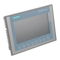
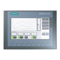
- SIMATIC HMI KTP700 Basic
Manuals and User Guides for Siemens SIMATIC HMI KTP700 Basic. We have 3 Siemens SIMATIC HMI KTP700 Basic manuals available for free PDF download: Operating Instructions Manual, Quick Start Manual
Siemens SIMATIC HMI KTP700 Basic Operating Instructions Manual (288 pages)
Mobile Panels 2nd Generation
Brand: Siemens
|
Category: Touch Panel
|
Size: 10.29 MB
Table of Contents
-
Legal Information
2
-
Preface
3
-
Table of Contents
7
-
1 Overview
13
-
Product Overview
13
-
Design of the Mobile Panels
14
-
KTP Mobile Connecting Cable
17
-
Connection Boxes
18
-
Scope of Delivery
20
-
Accessories
21
-
KTP Mobile Wall-Mounting Bracket
21
-
Fail-Safe KTP Mobile Spare Key
22
-
Protective Films
22
-
Storage Media
22
-
SIRIUS Safety Relays
23
-
Software Required
24
-
Terms for Fail-Safe Operation
24
-
Organizational Measures
28
-
Mobile Panel and Connection Box Compatibility
29
-
-
2 Safety Instructions
31
-
General Safety Instructions
31
-
Security Management for HMI Devices
36
-
Data Protection
36
-
Notes about Usage
37
-
Risk Assessment of the Plant
38
-
Important Information on Emergency Stop / Stop Button
39
-
Important Notes for the Enabling Mechanism
40
-
-
3 Installing System Components
43
-
Checking the Delivery
43
-
Mounting the Connection Box Compact
43
-
Mounting Position, Mounting Cutout and Clearance
43
-
Fastening the Connection Box Compact
45
-
Installing the Connection Box Standard and Connection Box Advanced
45
-
Mounting Position and Clearance
45
-
Fastening the Connection Box Standard and Connection Box Advanced
46
-
Attaching the KTP Mobile Wall-Mounting Bracket
47
-
Assembling the KTP Mobile Wall-Mounting Bracket
47
-
Mounting Position and Clearance
48
-
Fasteneing the KTP Mobile Wall-Mounting Bracket
50
-
Connecting the Mobile Panel
51
-
Connection Information
51
-
Inserting the SD Memory Card
51
-
Connecting the Mobile Panel Connecting Cable
53
-
Connecting a Configuring PC
54
-
Replacing the Connecting Cable
55
-
Replacing an SD Memory Card
57
-
Inserting the USB Memory Stick
58
-
Connecting the Connection Box
59
-
Connection Information
59
-
Opening and Closing Connection Box Standard and Connection Box Advanced
60
-
Equipotential Bonding of Connection Boxes
62
-
Connecting the Functional Grounding and Power Supply to the Connection Box
64
-
Connecting Cables for a Hardwired F-System
66
-
Connecting Ethernet to the Connection Box
67
-
Setting the Box ID of the Connection Box
70
-
Secure Cables and Seal Screw Glands
72
-
Connecting the KTP Mobile Connecting Cable to the Connection Box
73
-
Selecting the Connection Box
75
-
-
4 Handling the Mobile Panel
77
-
Holding the Mobile Panel and Attaching It to the Wall-Mounting Bracket
77
-
Keyswitches, Function Keys and Illuminated Pushbuttons
79
-
Operating the Enabling Button
81
-
Pressing the Emergency Stop / Stop Button
83
-
Testing Mobile Panel Readiness for Operation
85
-
-
5 Parameterizing the Mobile Panel
87
-
Firmware and Software
87
-
Desktop and Start Center
87
-
Operating the Desktop, Start Center and Control Panel
88
-
Installed Programs
88
-
Security Mode
89
-
Overview
89
-
Using the HMI Device in Password-Protected Security Mode
89
-
Control Panel
90
-
Opening the Settings
90
-
Overview of Functions
91
-
Operating the Control Panel
93
-
Display Types for the Screen Keyboard
93
-
Configuring Operation
96
-
Changing Display Brightness
96
-
Configuring the Screen Keyboard
97
-
Setting the Character Repeat Rate of the Screen Keyboard
98
-
Setting the Double-Click
99
-
Calibrating the Touch Screen
100
-
Restarting the HMI Device
101
-
General Settings
103
-
Regional and Language Settings
103
-
Setting the Date and Time
104
-
Entering and Deleting a Password
105
-
Setting the Screen Saver
107
-
Parameterizing Transfer
109
-
Storage Management
111
-
Displaying the Memory Distribution
111
-
Setting the Project Storage Location and Start Delay
111
-
Activating Memory Management
113
-
Activate/Deactivate Retentivity of the Alarm Buffer on the HMI Device
113
-
Backing up Registry Information and Temporary Data
115
-
Changing the Print Options
116
-
Displaying General System Properties
117
-
Displaying Information about the Mobile Panel
118
-
Display Firmware
118
-
Changing Internet Settings
119
-
Changing General Settings
119
-
Setting the Proxy Server
120
-
Changing Internet Security Settings
121
-
Activating Encryption Protocols
123
-
Importing, Displaying and Deleting Certificates
124
-
Enabling PROFINET
126
-
Enabling NTP
127
-
Setting the Profisafe Address
129
-
Configuring Network Operation
130
-
Overview
130
-
Specifying the Computer Name of the HMI Device
131
-
Specifying the IP Address and Name Server
132
-
Specifying the Logon Data
133
-
Configuring E-Mail
134
-
Configuring Telnet for Remote Control
136
-
Configure Sm@Rt Server
136
-
Configure Web Server
140
-
Assigning a Safety-Related Operating Mode
142
-
Functions for Service and Commissioning
144
-
Saving to External Storage Medium — Backup
144
-
Restoring from External Storage Medium — Restore
147
-
Update Operating System
149
-
Load Project from External Storage Medium
152
-
Using Automatic Backup
155
-
Editing IP Addresses and Communication Connections
159
-
Overview
159
-
Assigning IP Address and Device Name
160
-
Configuring a Communication Connection
162
-
-
6 Configuring the Mobile Panel
165
-
Configuration in Wincc
167
-
Adding a Controller to the Project
167
-
Adding the Mobile Panel to the Project
169
-
Configuring a Fail-Safe Mobile Panel
170
-
Configuring F-Fbs in STEP 7
174
-
Configuring Plant Areas in Wincc
179
-
Overview
179
-
Configuring Connection Point Detection
179
-
Configuring Zones and Start Screens
181
-
Additional Configuration Options in Wincc
182
-
Configuring Function and Direct Keys
182
-
Setting the Transfer Mode
183
-
Changing the Operating Mode
183
-
Controlling and Evaluating Operator Controls and Display Elements
184
-
Overview
184
-
Evaluating Operator Controls as Direct Keys
184
-
Controlling the Leds of the Function Keys by Means of System Functions
187
-
Controlling and Evaluating the Illuminated Pushbutton by Means of System Functions
187
-
Evaluating the Key-Operated Switch by Means of System Functions
188
-
-
7 Commissioning a Project
189
-
Overview
189
-
Using Existing Projects
190
-
Data Transmission Options
190
-
Transferring a Project with Wincc
191
-
Configuring Data Channel and Setting Transfer Mode
191
-
Starting the Transfer
191
-
Testing a Project
193
-
Backup and Restore
194
-
Backup and Restore with a PC
194
-
Backup and Restore with an External Storage Medium
194
-
Backup and Restore Via Prosave
194
-
Updating the Operating System Using Prosave
196
-
Reset to Factory Settings with Prosave
198
-
Managing Wincc Options
200
-
Transferring a License Key
201
-
-
8 Operating a Project
203
-
Overview
203
-
Function Keys
204
-
Direct Keys
205
-
Setting the Project Language
205
-
Entering and Modifying the Value, Date and Time
206
-
Displaying Infotext
207
-
Closing the Project
208
-
-
9 Fail-Safe Operation
209
-
Connecting the Connecting Cable
209
-
Unplugging the Connecting Cable
211
-
Safety-Related Dialogs
212
-
End Profisafe Communication» Dialog
212
-
Confirm Communication Error» Dialog
213
-
Fatal Error» Dialog
213
-
-
10 Maintenance and Care
215
-
General Information on Maintenance and Servicing
215
-
Replacing the Mobile Panel
215
-
Servicing the Mobile Panel
216
-
Cleaning the Mobile Panel
217
-
Spare Parts and Repairs
218
-
Recycling and Disposal
218
-
-
11 Technical Specifications
219
-
Software License Agreements
219
-
Certificates and Approvals
219
-
Standards on Operating Safety
221
-
Electromagnetic Compatibility
221
-
Mechanical Ambient Conditions
223
-
Storage Conditions
223
-
Operating Conditions
223
-
Climatic Ambient Conditions
224
-
Long-Term Storage
224
-
Transport and Short-Term Storage
224
-
Operating Conditions
224
-
Dimension Drawings
225
-
KTP400F Mobile Dimension Drawing
225
-
KTP700 Mobile Dimension Drawing
226
-
KTP700F Mobile Dimension Drawing
227
-
KTP900 Mobile Dimension Drawing
228
-
KTP900F Mobile Dimension Drawing
229
-
Connection Box Compact Dimension Drawing
230
-
Dimension Drawing for Connection Box Standard and Connection Box Advanced
231
-
KTP Mobile Wall-Mounting Bracket Dimension Drawing
232
-
Technical Specifications
233
-
Mobile Panel
233
-
Connecting Cable
235
-
Connection Boxes
236
-
Power Consumption Specifications
238
-
Reaction Times and Safety Characteristics for Fail-Safe Operation
239
-
Specification of Cables to be Used
242
-
Interface Description for Mobile Panel
243
-
Internal Interface X1P1
243
-
Internal Interface X80
243
-
External Interface X61
243
-
Connection Box Compact Interfaces
244
-
Position of the Interfaces
244
-
Interface X1
244
-
Plug-In Terminal Strip X10
245
-
Wiring of Safety-Related Operator Controls
246
-
Interfaces of the Connection Box Standard and Connection Box Advanced
248
-
Position of the Interfaces
248
-
Fast Connector X1 and X2
249
-
Plug-In Terminal Strip X10
249
-
Wiring of Safety-Related Operator Controls
250
-
Communication with Controllers
253
-
Scope of Functions with Wincc
254
-
Mobile Panel 2Nd Generation F-Fbs
258
-
Using F-Fbs
258
-
F_Fb_Ktp_Mobile
260
-
F_Fb_Ktp_Rng
263
-
Technical Support
267
-
Troubleshooting
267
-
A.1 Troubleshooting
267
-
Service and Support
268
-
Parameterization of the Connection Box Standard and Connection Box Advanced
269
-
System Events
269
-
-
Markings and Symbols
271
-
Safety-Relevant Symbols
271
-
-
List of Abbreviations
273
-
Glossary
275
-
Index
281
-
-
Advertisement
Siemens SIMATIC HMI KTP700 Basic Operating Instructions Manual (132 pages)
HMI devices
Basic Panels 2nd Generation
Brand: Siemens
|
Category: Control Panel
|
Size: 5.51 MB
Table of Contents
-
Preface
3
-
Table of Contents
7
-
1 Overview
11
-
Product Overview
11
-
Design of the PROFINET Devices
12
-
Design of the PROFIBUS Devices
13
-
Scope of Delivery
14
-
Accessories
15
-
-
2 Safety Instructions
17
-
General Safety Instructions
17
-
Notes about Usage
19
-
-
3 Mounting and Connecting
21
-
Preparations
21
-
Checking the Package Contents
21
-
Checking the Operating Conditions
21
-
Selecting a Mounting Position
22
-
Checking Clearances
23
-
Making the Mounting Cutout
24
-
Mounting the HMI Device
25
-
Connecting the HMI Device
27
-
Connection Sequence
27
-
Connecting the Equipotential Bonding Circuit
28
-
Connecting the Power Supply
29
-
Connecting a Programming Device
31
-
Connecting the Configuration PC
31
-
Connecting the Controller
33
-
Connecting a USB Device
35
-
Switching on and Testing the HMI Device
36
-
Securing the Cables
38
-
-
4 Operating the Device
39
-
Overview
39
-
General Functions of the Screen Keyboard
41
-
The Screen Keyboards
42
-
Entering Data
46
-
-
5 Configuring the Device
47
-
Opening the Settings
47
-
Overview of Functions
49
-
Save to External Storage Medium — Backup
50
-
Restore from External Storage Medium — Restore
51
-
Load Project from External Storage Medium
52
-
Update Operating System from External Storage Medium
53
-
Changing the IP Address and Device Name of a Controller
54
-
Editing Communication Connections
55
-
Configuring the Time Server
56
-
Enter Time and Date
57
-
Activating the Acoustic Signal
58
-
Configuring Autostart or Wait Time
59
-
Changing the Password Settings
60
-
Displaying Licensing Information for the HMI Device
61
-
Displaying Information about the HMI Device
62
-
Change Network Settings of PROFINET Devices
63
-
Change Network Settings of PROFIBUS Devices
64
-
Assigning Transfer Parameters
65
-
Configure Sm@Rt Server
66
-
Importing a Certificate Via USB
67
-
Displaying and Deleting Certificates
68
-
Calibrating the Touch Screen
69
-
Changing the Monitor Settings
70
-
Setting the Screen Saver
71
-
-
6 Commissioning a Project
73
-
Overview
73
-
Operating Modes
74
-
Data Transmission Options
75
-
Transfer
75
-
Overview
75
-
Starting the Manual Transfer
75
-
Starting the Transfer Automatically
77
-
Testing a Project
78
-
Backup and Restore
80
-
Overview
80
-
Backup and Restore Using Prosave
81
-
Backup and Restore Using Wincc
82
-
Updating the Operating System — Basic Panel DP
83
-
Overview
83
-
Resetting the Factory Settings
84
-
Updating the Operating System Using Prosave
84
-
Updating the Operating System — Basic Panel with PROFINET Interface
85
-
Overview
85
-
Resetting the Factory Settings
86
-
Updating the Operating System Using Prosave
87
-
Updating the Operating System Using Wincc
88
-
Resetting to Factory Settings with Prosave
89
-
Resetting to Factory Settings with Wincc
90
-
Reset to Factory Settings Via USB
91
-
Managing Wincc Options
92
-
Transferring a License Key
93
-
-
7 Maintenance and Care
95
-
Recycling
96
-
-
8 Technical Specifications
97
-
Certificates and Approvals
97
-
Electromagnetic Compatibility
99
-
Emitted Interference
99
-
Immunity to Interferences
99
-
Mechanical Ambient Conditions
99
-
Transport and Storage Conditions
99
-
Operating Conditions
99
-
Climatic Ambient Conditions
100
-
Long-Term Storage
100
-
Transport and Short-Term Storage
100
-
Operating Conditions
101
-
Climate Diagram
101
-
8.5 Information on Insulation Tests, Protection Class and Degree of Protection
102
-
Dimension Drawings
103
-
Dimensional Drawing of KTP400 Basic
103
-
Dimensional Drawing of KTP700 Basic
104
-
Dimensional Drawing of KTP700 Basic DP
105
-
Dimensional Drawing of KTP900 Basic
106
-
Dimension Drawings of KTP1200 Basic
107
-
Dimensional Drawing of KTP1200 Basic DP
108
-
Technical Specifications
109
-
Power Supply
109
-
KTP400 Basic, KTP700 Basic and KTP700 Basic DP
109
-
KTP900 Basic, KTP1200 Basic and KTP1200 Basic DP
111
-
Interface Description
113
-
Power Supply
113
-
PROFIBUS (Sub-D RS422/485)
113
-
Profinet (Lan)
114
-
Usb
114
-
Scope of Functions with Wincc
115
-
Technical Support
119
-
Service and Support
119
-
System Events
120
-
A.2 System Events
120
-
-
Abbreviations
121
-
Glossary
123
-
Index
129
-
-

Siemens SIMATIC HMI KTP700 Basic Quick Start Manual (2 pages)
Brand: Siemens
|
Category: Industrial Equipment
|
Size: 2.02 MB
Table of Contents
-
Mounting the HMI Device
1
-
Connecting the HMI Device
1
-
Installing
1
-
Equipotential Bonding
1
-
Transferring a Project
2
-
Connecting a Configuring PC
2
-
Replacing the HMI Device
2
-
Configuring the Data Channel
2
Advertisement
Advertisement
Related Products
-
Siemens SIMATIC HMI KTP400 Basic
-
Siemens SIMATIC HMI KTP900 Basic
-
Siemens SIMATIC HMI KP400 Comfort
-
Siemens SIMATIC HMI KP900 Comfort
-
Siemens SIMATIC HMI KP1200 Comfort
-
Siemens SIMATIC HMI KP1500 Comfort
-
Siemens SIMATIC HMI KP700 Comfort
-
Siemens SIMATIC HMI KP300 Basic mono PN
-
Siemens SIMATIC HMI KTP600 Basic mono PN
-
Siemens SIMATIC HMI TP1500 Comfort
Siemens Categories
Controller
Control Unit
Industrial Equipment
![]()
Washer
![]()
Switch
More Siemens Manuals
- Manuals
- Brands
- Siemens Manuals
- Control Panel
- SIMATIC HMI KTP700 Basic
Manuals and User Guides for Siemens SIMATIC HMI KTP700 Basic. We have 3 Siemens SIMATIC HMI KTP700 Basic manuals available for free PDF download: Operating Instructions Manual, Quick Start Manual
Siemens SIMATIC HMI KTP700 Basic Operating Instructions Manual (288 pages)
Mobile Panels 2nd Generation
Brand: Siemens
|
Category: Touch Panel
|
Size: 10.29 MB
Table of Contents
-
-
Design of the Mobile Panels
14
-
KTP Mobile Connecting Cable
17
-
KTP Mobile Wall-Mounting Bracket
21
-
Fail-Safe KTP Mobile Spare Key
22
-
Terms for Fail-Safe Operation
24
-
Organizational Measures
28
-
Mobile Panel and Connection Box Compatibility
29
-
-
General Safety Instructions
31
-
Security Management for HMI Devices
36
-
Risk Assessment of the Plant
38
-
Important Information on Emergency Stop / Stop Button
39
-
Important Notes for the Enabling Mechanism
40
-
-
3 Installing System Components
43
-
Mounting the Connection Box Compact
43
-
Mounting Position, Mounting Cutout and Clearance
43
-
Fastening the Connection Box Compact
45
-
Installing the Connection Box Standard and Connection Box Advanced
45
-
Mounting Position and Clearance
45
-
Fastening the Connection Box Standard and Connection Box Advanced
46
-
Attaching the KTP Mobile Wall-Mounting Bracket
47
-
Assembling the KTP Mobile Wall-Mounting Bracket
47
-
Mounting Position and Clearance
48
-
Fasteneing the KTP Mobile Wall-Mounting Bracket
50
-
Connecting the Mobile Panel
51
-
Connection Information
51
-
Inserting the SD Memory Card
51
-
Connecting the Mobile Panel Connecting Cable
53
-
Connecting a Configuring PC
54
-
Replacing the Connecting Cable
55
-
Replacing an SD Memory Card
57
-
Inserting the USB Memory Stick
58
-
Connecting the Connection Box
59
-
Connection Information
59
-
Opening and Closing Connection Box Standard and Connection Box Advanced
60
-
Equipotential Bonding of Connection Boxes
62
-
Connecting the Functional Grounding and Power Supply to the Connection Box
64
-
Connecting Cables for a Hardwired F-System
66
-
Connecting Ethernet to the Connection Box
67
-
Setting the Box ID of the Connection Box
70
-
Secure Cables and Seal Screw Glands
72
-
Connecting the KTP Mobile Connecting Cable to the Connection Box
73
-
Selecting the Connection Box
75
-
4 Handling the Mobile Panel
77
-
Holding the Mobile Panel and Attaching It to the Wall-Mounting Bracket
77
-
Keyswitches, Function Keys and Illuminated Pushbuttons
79
-
Operating the Enabling Button
81
-
Pressing the Emergency Stop / Stop Button
83
-
Testing Mobile Panel Readiness for Operation
85
-
-
5 Parameterizing the Mobile Panel
87
-
Desktop and Start Center
87
-
Operating the Desktop, Start Center and Control Panel
88
-
Using the HMI Device in Password-Protected Security Mode
89
-
Operating the Control Panel
93
-
Display Types for the Screen Keyboard
93
-
Changing Display Brightness
96
-
Configuring the Screen Keyboard
97
-
Setting the Character Repeat Rate of the Screen Keyboard
98
-
Setting the Double-Click
99
-
Calibrating the Touch Screen
100
-
Restarting the HMI Device
101
-
Regional and Language Settings
103
-
Setting the Date and Time
104
-
Entering and Deleting a Password
105
-
Setting the Screen Saver
107
-
Parameterizing Transfer
109
-
Displaying the Memory Distribution
111
-
Setting the Project Storage Location and Start Delay
111
-
Activating Memory Management
113
-
Activate/Deactivate Retentivity of the Alarm Buffer on the HMI Device
113
-
Backing up Registry Information and Temporary Data
115
-
Changing the Print Options
116
-
Displaying General System Properties
117
-
Displaying Information about the Mobile Panel
118
-
Changing Internet Settings
119
-
Changing General Settings
119
-
Setting the Proxy Server
120
-
Changing Internet Security Settings
121
-
Activating Encryption Protocols
123
-
Importing, Displaying and Deleting Certificates
124
-
Setting the Profisafe Address
129
-
Configuring Network Operation
130
-
Specifying the Computer Name of the HMI Device
131
-
Specifying the IP Address and Name Server
132
-
Specifying the Logon Data
133
-
Configuring Telnet for Remote Control
136
-
Configure Sm@Rt Server
136
-
Assigning a Safety-Related Operating Mode
142
-
Functions for Service and Commissioning
144
-
Saving to External Storage Medium — Backup
144
-
Restoring from External Storage Medium — Restore
147
-
Update Operating System
149
-
Load Project from External Storage Medium
152
-
Using Automatic Backup
155
-
Editing IP Addresses and Communication Connections
159
-
Assigning IP Address and Device Name
160
-
Configuring a Communication Connection
162
-
6 Configuring the Mobile Panel
165
-
Configuration in Wincc
167
-
Adding a Controller to the Project
167
-
Adding the Mobile Panel to the Project
169
-
Configuring a Fail-Safe Mobile Panel
170
-
Configuring F-Fbs in STEP 7
174
-
Configuring Plant Areas in Wincc
179
-
Configuring Connection Point Detection
179
-
Configuring Zones and Start Screens
181
-
Additional Configuration Options in Wincc
182
-
Configuring Function and Direct Keys
182
-
Setting the Transfer Mode
183
-
Changing the Operating Mode
183
-
Controlling and Evaluating Operator Controls and Display Elements
184
-
Evaluating Operator Controls as Direct Keys
184
-
Controlling the Leds of the Function Keys by Means of System Functions
187
-
Controlling and Evaluating the Illuminated Pushbutton by Means of System Functions
187
-
Evaluating the Key-Operated Switch by Means of System Functions
188
-
-
7 Commissioning a Project
189
-
Using Existing Projects
190
-
Data Transmission Options
190
-
Transferring a Project with Wincc
191
-
Configuring Data Channel and Setting Transfer Mode
191
-
Starting the Transfer
191
-
Backup and Restore with a PC
194
-
Backup and Restore with an External Storage Medium
194
-
Backup and Restore Via Prosave
194
-
Updating the Operating System Using Prosave
196
-
Reset to Factory Settings with Prosave
198
-
Managing Wincc Options
200
-
Transferring a License Key
201
-
8 Operating a Project
203
-
Setting the Project Language
205
-
Entering and Modifying the Value, Date and Time
206
-
9 Fail-Safe Operation
209
-
Connecting the Connecting Cable
209
-
Unplugging the Connecting Cable
211
-
Safety-Related Dialogs
212
-
End Profisafe Communication» Dialog
212
-
Confirm Communication Error» Dialog
213
-
-
10 Maintenance and Care
215
-
General Information on Maintenance and Servicing
215
-
Replacing the Mobile Panel
215
-
Servicing the Mobile Panel
216
-
Cleaning the Mobile Panel
217
-
Spare Parts and Repairs
218
-
Recycling and Disposal
218
-
-
11 Technical Specifications
219
-
Software License Agreements
219
-
Certificates and Approvals
219
-
Standards on Operating Safety
221
-
Electromagnetic Compatibility
221
-
Mechanical Ambient Conditions
223
-
Climatic Ambient Conditions
224
-
Transport and Short-Term Storage
224
-
KTP400F Mobile Dimension Drawing
225
-
KTP700 Mobile Dimension Drawing
226
-
KTP700F Mobile Dimension Drawing
227
-
KTP900 Mobile Dimension Drawing
228
-
KTP900F Mobile Dimension Drawing
229
-
Connection Box Compact Dimension Drawing
230
-
Dimension Drawing for Connection Box Standard and Connection Box Advanced
231
-
KTP Mobile Wall-Mounting Bracket Dimension Drawing
232
-
Technical Specifications
233
-
Power Consumption Specifications
238
-
Reaction Times and Safety Characteristics for Fail-Safe Operation
239
-
Specification of Cables to be Used
242
-
Interface Description for Mobile Panel
243
-
Internal Interface X1P1
243
-
Internal Interface X80
243
-
External Interface X61
243
-
Connection Box Compact Interfaces
244
-
Position of the Interfaces
244
-
Plug-In Terminal Strip X10
245
-
Wiring of Safety-Related Operator Controls
246
-
Interfaces of the Connection Box Standard and Connection Box Advanced
248
-
Position of the Interfaces
248
-
Fast Connector X1 and X2
249
-
Plug-In Terminal Strip X10
249
-
Wiring of Safety-Related Operator Controls
250
-
Communication with Controllers
253
-
Scope of Functions with Wincc
254
-
Mobile Panel 2Nd Generation F-Fbs
258
-
-
Parameterization of the Connection Box Standard and Connection Box Advanced
269
-
-
Safety-Relevant Symbols
271
-
-
List of Abbreviations
273
-
Advertisement
Siemens SIMATIC HMI KTP700 Basic Operating Instructions Manual (132 pages)
HMI devices
Basic Panels 2nd Generation
Brand: Siemens
|
Category: Control Panel
|
Size: 5.51 MB
Table of Contents
-
-
Design of the PROFINET Devices
12
-
Design of the PROFIBUS Devices
13
-
-
General Safety Instructions
17
-
-
3 Mounting and Connecting
21
-
Checking the Package Contents
21
-
Checking the Operating Conditions
21
-
Selecting a Mounting Position
22
-
Making the Mounting Cutout
24
-
Mounting the HMI Device
25
-
Connecting the HMI Device
27
-
Connecting the Equipotential Bonding Circuit
28
-
Connecting the Power Supply
29
-
Connecting a Programming Device
31
-
Connecting the Configuration PC
31
-
Connecting the Controller
33
-
Connecting a USB Device
35
-
Switching on and Testing the HMI Device
36
-
4 Operating the Device
39
-
General Functions of the Screen Keyboard
41
-
5 Configuring the Device
47
-
Save to External Storage Medium — Backup
50
-
Restore from External Storage Medium — Restore
51
-
Load Project from External Storage Medium
52
-
Update Operating System from External Storage Medium
53
-
Changing the IP Address and Device Name of a Controller
54
-
Editing Communication Connections
55
-
Configuring the Time Server
56
-
Activating the Acoustic Signal
58
-
Configuring Autostart or Wait Time
59
-
Changing the Password Settings
60
-
Displaying Licensing Information for the HMI Device
61
-
Displaying Information about the HMI Device
62
-
Change Network Settings of PROFINET Devices
63
-
Change Network Settings of PROFIBUS Devices
64
-
Assigning Transfer Parameters
65
-
Configure Sm@Rt Server
66
-
Importing a Certificate Via USB
67
-
Displaying and Deleting Certificates
68
-
Calibrating the Touch Screen
69
-
Changing the Monitor Settings
70
-
Setting the Screen Saver
71
-
6 Commissioning a Project
73
-
Data Transmission Options
75
-
Starting the Manual Transfer
75
-
Starting the Transfer Automatically
77
-
Backup and Restore Using Prosave
81
-
Backup and Restore Using Wincc
82
-
Updating the Operating System — Basic Panel DP
83
-
Resetting the Factory Settings
84
-
Updating the Operating System Using Prosave
84
-
Updating the Operating System — Basic Panel with PROFINET Interface
85
-
Resetting the Factory Settings
86
-
Updating the Operating System Using Prosave
87
-
Updating the Operating System Using Wincc
88
-
Resetting to Factory Settings with Prosave
89
-
Resetting to Factory Settings with Wincc
90
-
Reset to Factory Settings Via USB
91
-
Managing Wincc Options
92
-
Transferring a License Key
93
-
7 Maintenance and Care
95
-
8 Technical Specifications
97
-
Certificates and Approvals
97
-
Electromagnetic Compatibility
99
-
Immunity to Interferences
99
-
Mechanical Ambient Conditions
99
-
Transport and Storage Conditions
99
-
Climatic Ambient Conditions
100
-
Transport and Short-Term Storage
100
-
8.5 Information on Insulation Tests, Protection Class and Degree of Protection
102
-
Dimensional Drawing of KTP400 Basic
103
-
Dimensional Drawing of KTP700 Basic
104
-
Dimensional Drawing of KTP700 Basic DP
105
-
Dimensional Drawing of KTP900 Basic
106
-
Dimension Drawings of KTP1200 Basic
107
-
Dimensional Drawing of KTP1200 Basic DP
108
-
Technical Specifications
109
-
KTP400 Basic, KTP700 Basic and KTP700 Basic DP
109
-
KTP900 Basic, KTP1200 Basic and KTP1200 Basic DP
111
-
Interface Description
113
-
PROFIBUS (Sub-D RS422/485)
113
-
Scope of Functions with Wincc
115
-
Siemens SIMATIC HMI KTP700 Basic Quick Start Manual (2 pages)
Brand: Siemens
|
Category: Industrial Equipment
|
Size: 2.02 MB
Table of Contents
-
Mounting the HMI Device
1
-
Connecting the HMI Device
1
-
Connecting a Configuring PC
2
-
Replacing the HMI Device
2
-
Configuring the Data Channel
2
Advertisement
Advertisement
Related Products
-
Siemens SIMATIC HMI KTP400 Basic
-
Siemens SIMATIC HMI KTP900 Basic
-
Siemens SIMATIC HMI KP400 Comfort
-
Siemens SIMATIC HMI KP900 Comfort
-
Siemens SIMATIC HMI KP1200 Comfort
-
Siemens SIMATIC HMI KP1500 Comfort
-
Siemens SIMATIC HMI KP700 Comfort
-
Siemens SIMATIC HMI KP300 Basic mono PN
-
Siemens SIMATIC HMI KTP600 Basic mono PN
-
Siemens SIMATIC HMI TP1500 Comfort
Siemens Categories
Controller
Control Unit
Industrial Equipment
![]()
Washer
![]()
Switch
More Siemens Manuals
8.7
8.7.1
Power supply
The following table shows the permitted rated voltage and the corresponding tolerance
range.
Rated voltage
+24 V DC
8.7.2
KTP400 Basic, KTP700 Basic and KTP700 Basic DP
Weight
Weight without packaging
Display
Type
Active display area
Resolution
Possible colors
Brightness control
Backlighting
Half Brightness Life Time (MTBF
Pixel error class in accordance with
EN ISO 9241-307
MTBF: Operating hours after which the maximum brightness is reduced by half compared to the original value. MTBF is
1
increased by using the integrated dimming function, for example time-driven dimming using the screen saver or central
dimming by the controller.
Input device
Type
Function keys
Labeling strips
Basic Panels 2nd Generation
Operating Instructions, 10/2016, A5E33293231-AB
Tolerance range
19.2 … 28.8 V (–20%, +20%)
KTP400 Basic
Approx. 360 g
KTP400 Basic
95 x 53.9 mm (4.3″)
480 x 272 pixels
)
1
KTP400 Basic
4
KTP700 Basic
Approx. 780 g
KTP700 Basic
LCD TFT
154.1 x 85.9 mm (7″)
800 x 480 pixels
16-bit (65536 colors)
Yes
LED
20,000 h
II
KTP700 Basic
Touch screen, analog resistive
Yes
Technical specifications
8.7 Technical specifications
KTP700 Basic DP
Approx. 800 g
KTP700 Basic DP
KTP700 Basic DP
8
109
-
Главная
/
-
Каталог
/
-
Панели оператора SIEMENS
/
-
SIMATIC HMI Basic Panel
/
-
KTP700 Basic DP

Есть в наличииСклады в нескольких городах России.
Отгрузка 1
деньОтгрузим оборудование со склада в день оплаты.
Гарантия
1 годГарантийное обслуживание в течение 1 года.
Опт и
розницаСпециальные цены для оптовых покупателей.
Доставка по
РоссииДоставим оборудование в любой регион России.
Описание
Документация
Доставка
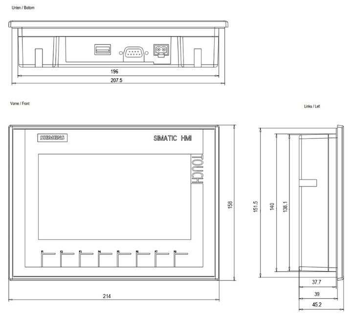
Панель оператора SIEMENS KTP700 Basic DP из серии SIMATIC HMI Basic Panel второго поколения. Устройство имеет цветной широкоформатный TFT-экран с диагональю 7 дюймов, 8 программируемых клавиш, встроенные интерфейсы USB-Host и PROFIBUS. Класс защиты лицевой части панели — IP65.
Заказной номер: 6AV2123-2GA03-0AX0, 6AV2 123-2GA03-0AX0
Технические характеристики
| Производитель | SIEMENS |
| Серия | SIMATIC HMI Basic Panel |
| Модель | KTP700 Basic DP |
| Заказной номер | 6AV2123-2GA03-0AX0 |
| Дисплей | |
|---|---|
| Тип | TFT, 65 536 цветов |
| Диагональ экрана | 7” |
| Разрешение, точек | 800 x 480 |
| Сенсорная аналоговая клавиатура | Есть |
| Количествово программируемых клавиш | 8 |
| Слот для MMC/SD/CF карты | — |
| Объем памяти пользователя | 10 Мбайт |
| Часы реального времени | Программные, синхронизируемые, типовой запас хода после отключиния питания 3 недели |
| Количество переменных на проект | 800 |
| Количество экранов на проект | 250 |
| Количество сообщений на проект | 1000, до 32 классов сообщений |
| Буфер сообщений | Есть, емкость 256 сообщений |
| Архивирование данных | Есть, 2 архива, до 10 переменных на архив, до 10000 значений на переменную, цикл архивирования 1 с |
| Пакет проектирования | SIMATIC WinCC Micro, Comfort, Advanced, Professional от V13 и выше |
| Напряжение питания | =24 В (=19.2 … 28.8 В) |
| Типовой/максимальный ток потребления | 230 мА/500 мА |
| Габариты (ШхВхГ), мм: | |
| фронтальной панели | 214х158 |
| монтажный проем/глубина | 196х140/39 |
| Масса, кг | 0.8 |
Самовывоз
Товар можно получить в будние дни на складе в Москве, Санкт-Петербурге, Ростове-на-Дону или Екатеринбурге. Сроки отгрузки — 1-3 дня после оплаты. Заказ должен быть предварительно согласован с менеджером ООО «ТПК «ТЕХПРИВОД».
Регионы России
Заказ может быть доставлен в любой регион России. Доставка осуществляется транспортной компанией «Деловые Линии» либо перевозчиком, выбранным заказчиком. До терминала транспортной компании товар доставляется бесплатно. Примерную стоимость доставки можно рассчитать с помощью тарифного калькулятора.
Уточнить условия доставки и задать дополнительные вопросы можно по телефонам: +7 (495) 966-07-07 и 8 (800) 707-66-72 (бесплатный звонок).

Заказать товар
Оставить заявку
Заказать товар
Подпишитесь на рассылку!
Никакого спама! Только полезная справочная информация.
8.7
8.7.1
Power supply
The following table shows the permitted rated voltage and the corresponding tolerance
range.
Rated voltage
+24 V DC
8.7.2
KTP400 Basic, KTP700 Basic and KTP700 Basic DP
Weight
Weight without packaging
Display
Type
Active display area
Resolution
Possible colors
Brightness control
Backlighting
Half Brightness Life Time (MTBF
Pixel error class in accordance with
EN ISO 9241-307
MTBF: Operating hours after which the maximum brightness is reduced by half compared to the original value. MTBF is
1
increased by using the integrated dimming function, for example time-driven dimming using the screen saver or central
dimming by the controller.
Input device
Type
Function keys
Labeling strips
Basic Panels 2nd Generation
Operating Instructions, 10/2016, A5E33293231-AB
Tolerance range
19.2 … 28.8 V (–20%, +20%)
KTP400 Basic
Approx. 360 g
KTP400 Basic
95 x 53.9 mm (4.3″)
480 x 272 pixels
)
1
KTP400 Basic
4
KTP700 Basic
Approx. 780 g
KTP700 Basic
LCD TFT
154.1 x 85.9 mm (7″)
800 x 480 pixels
16-bit (65536 colors)
Yes
LED
20,000 h
II
KTP700 Basic
Touch screen, analog resistive
Yes
Technical specifications
8.7 Technical specifications
KTP700 Basic DP
Approx. 800 g
KTP700 Basic DP
KTP700 Basic DP
8
109