
-
Contents
-
Table of Contents
-
Troubleshooting
-
Bookmarks
Quick Links
Barriere stradali
G3750
MANUALE DI INSTALLAZIONE
FA01237M04
IT Italiano
EN English
FR Français
RU Русский
IT Italiano
Related Manuals for CAME 001G3750
Summary of Contents for CAME 001G3750
-
Page 1
Barriere stradali FA01237M04 G3750 IT Italiano EN English FR Français RU Русский IT Italiano MANUALE DI INSTALLAZIONE… -
Page 2: Leggere Attentamente
Il quale è stato • l’ . came essere azIonata InvolontarIamente apparecchIo può essere utIlIzzato da espressamente studIato gnI altro uso è da consIderarsI perIcoloso bambInI dI età…
-
Page 3
LEGENDA Questo simbolo indica parti da leggere con attenzione. ⚠ Questo simbolo indica parti riguardanti la sicurezza. ☞ Questo simbolo indica cosa comunicare all’utente. DESCRIZIONE Barriera in acciaio zincato e verniciato con predisposizione per accessori. LE BARRIERE VANNO RICHIESTE DESTRE O SINISTRE IN FASE D’ORDINE. TUTTE LE ILLUSTRAZIONI DI QUESTO MANUALE RAPPRESENTANO UNA BARRIERA SINISTRA! Destinazione d’uso La barriera automatica è… -
Page 4
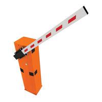
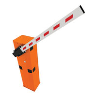
Descrizione delle parti Serratura sportello con chiave personalizzata Armadio Motoriduttore Piastra albero di trasmissione Quadro comando Copri attacco-asta Molla di bilanciamento Coperchio di protezione anticesoiamento 10. Sportello d’ispezione Sblocco motoriduttore con chiave personalizzata Impianto tipo Barriera Colonnina per fotocellule Lampeggiatore Appoggio fisso Asta semi-ellittica 10. -
Page 5
INDICAZIONI GENERALI PER L’INSTALLAZIONE ⚠ L’installazione deve essere effettuata da personale qualificato ed esperto e nel pieno rispetto delle normative vigenti. Importante! L’uso di dispositivi di comando, di sicurezza e di accessori originali CAME garantisce una facile installazione e manutenzione dell’impianto. Verifiche preliminari ⚠… -
Page 6: Installazione
INSTALLAZIONE ⚠ Le seguenti illustrazioni sono solo esempi in quanto lo spazio per il fissaggio della barriera e degli accessori varia a seconda della zona di installazione. Spetta all’installatore scegliere la soluzione più adatta. ⚠ Attenzione! Usare delle attrezzature di sollevamento per trasportare e posizionare la barriera. Durante le fasi di premontaggio e fissaggio, la barriera potrebbe essere instabile e potrebbe esserci il rischio di ribaltamento.
-
Page 7
Posizionare la piastra sopra la griglia. Riempire la cassa matta di cemento, la base deve essere perfettamente in bolla e con il filetto delle viti completamente in superficie. Attendere che si solidifichi per almeno 24h. Togliere la cassa matta. Riempire di terra lo scavo attorno al blocco di cemento. Togliere i dadi e le rondelle dalle viti. -
Page 8
Posizionare l’armadio sulla piastra di fissaggio e fissarlo con le rondelle e i dadi. Dado M12 UNI 5588 Rondella Per modificare la rotazione successivamente, richiedere la documentazione al vostro rivenditore di fiducia o contattare la sede Came del vostro Paese (vedere ultima pagina oppure www.came.com) Lato ingresso… -
Page 9
Inserire il profilo antiurto nella parte inferiore dell’asta. Inserire l’asta nel copri attacco e fissarla con le viti. Nota: per il montaggio con asta G0402, inserire e fissare i due spessori (in dotazione con l’asta) nell’attacco asta come da disegno. UNI 7687 M3x8… -
Page 10
Tagliare i profili copricava della lunghezza necessaria e inserire nelle canaline dell’asta. Procedura da eseguire su entrambi i lati. Fissare il tappo all’estremità dell’asta. Inserire e fissare il coperchio di protezione anticesoiamento sul copri attacco-asta. -
Page 11
Bilanciamento dell’asta Prima di procedere, verificare che la molla scelta sia adeguata considerando gli accessori da applicare e la luce di passaggio. G03750 Luce passaggio (3,75 m max.) Molla 001G02040 Ø 40 mm Molla 001G04060 Ø 50 mm Molla 001G06080 Ø 55 mm COMPOSIZIONE DELL’ASTA (m) 1,5 ÷… -
Page 12
Sbloccare il motoriduttore, posizionare l’asta in verticale e ribloccare il motoriduttore. SBLOCCO Avvitare la molla sul perno di ancoraggio agganciato al braccio di trasmissione. Agganciare il tirante ad occhiello della molla alla staffa di ancoraggio. -
Page 13
Ruotare manualmente la molla di bilanciamento per aumentare o diminuire la forza di trazione in modo che l’asta si stabilizzi a 45°. Fissare il dado del tirante e ribloccare il motoriduttore. Nota: verificare il corretto funzionamento della molla: — con asta posizionata in verticale, la molla non è in tensione; — con asta posizionata in orizzontale, la molla è… -
Page 14
COLLEGAMENTI ELETTRICI E PROGRAMMAZIONE ⚠ Attenzione! Prima di intervenire sul quadro comando, togliere la tensione di linea e, se presenti, scollegare le batterie. Alimentazione del quadro e dei dispositivi di comando: 24 V AC/DC. Le funzioni vengono impostate con i DIP, le regolazioni con i trimmer. Tutte le connessioni sono protette da fusibili rapidi. -
Page 15
Collegamento di fabbrica Il motoriduttore è già collegato. È illustrato il collegamento di una barriera sinistra. Una barriera a destra ha i cavi del motoriduttore invertiti sui morsetti M-N. Motore 24 V DC Microinterruttore di apertura Arancione Bianco Arancione Rosso Marrone Microinterruttore di chiusura… -
Page 16
Dispositivi di sicurezza Fotocellule Fotocellule DELTA-S Configurare il contatto C1 e/o C5 (NC), ingresso per dispositivi di sicurezza tipo fotocellule, conformi alle normative EN 12978. C1 riapertura durante la chiusura. In fase di chiusura dell’asta, l’apertura del contatto provoca l’inversione del movimento fino alla completa apertura;… -
Page 17
Tenere premuto il tasto di programmazione PROG sulla scheda elettronica. Il LED di programmazione lampeggia . Premere un tasto del trasmettitore da memorizzare. Il LED rimane acceso a segnalare l’avvenuta memorizzazione . 3 4 5 6 7 8 9 10 Tasto PROG LED di programmazione … -
Page 18
Per correggere la posizione orizzontale (=chiusura), alzare l’asta, regolare il fermo meccanico di chiusura e fissarlo con il controdado. Controdado Fermo meccanico di chiusura Regolazione della velocità Min. = minimo Med. = medio Max. = massimo COM = comune DIS. 27370 Velocità… -
Page 19
Regolazioni trimmer SENS. A.C.T. 3 4 5 6 7 8 9 10 SENS. A.C.T. Trimmer Descrizione delle funzioni Sensibilità SENS Regola la sensibilità di rilevamento degli ostacoli duranteil movimento del cancello. Minima sensibilità (-) o massima sensibilità (+). Tempo chiusura automatica Regola il tempo di attesa della barriera in posizione di apertura. -
Page 20
OPERAZIONI FINALI Terminati i collegamenti elettrici e la messa in funzione, riposizionare lo sportello d’ispezione , chiudere con la chiave SBLOCCO DELL’ASTA ⚠ L’operazione deve essere effettuata in assenza di tensione. Inserire la chiave nella serratura e girarla in senso orario . -
Page 21
COLLEGAMENTO ABBINATO CON COMANDO UNICO Stabilire la barriera Master e quella Slave. MASTER SLAVE Sulla scheda elettronica della barriera MASTER, eseguire i collegamenti elettrici, l’attivazione del comando radio, la programmazione delle funzioni e le regolazioni. MASTER 3 4 5 6 7 8 9 10 Sulla scheda elettronica della barriera SLAVE, collegare l’alimentazione su L-N, il lampeggiatore su 10-E , posizionare il DIP 7 in ON e regolare la velocità… -
Page 22: Risoluzione Dei Problemi
RISOLUZIONE DEI PROBLEMI PROBLEMA RIFERIMENTO VERIFICA L’asta non si apre e non si chiude 1-2-3-4-6-8-18 1 — Chiudere lo sportello d’ispezione con la chiave L’asta si apre ma non si chiude 4-7-10 2 — Disattivare la funzione AZIONE MANTENUTA L’asta si chiude ma non si apre 4-7-9 3 — Controllare l’alimentazione e i fusibili La barriera non effettua la chiusura automatica…
-
Page 23: Riferimenti Normativi
_____________________________________________________________________________________________________ DISMISSIONE E SMALTIMENTO ☞ CAME S.p.A. implementa all’interno dei propri stabilimenti un Sistema di Gestione Ambientale certificato e conforme alla norma UNI EN ISO 14001 a garanzia del rispetto e della tutela dell’ambiente. Vi chiediamo di continuare l’opera di tutela dell’ambiente, che CAME considera uno dei fondamenti di sviluppo delle proprie strategie operative e di mercato, semplicemente osservando brevi indicazioni in materia di smaltimento: SMALTIMENTO DELL’IMBALLO…
-
Page 24
CAME S.p.A. Via Martiri Della Libertà, 15 31030 Dosson di Casier — Treviso — Italy tel. (+39) 0422 4940 — fax. (+39) 0422 4941… -
Page 25
Street barriers FA01237-EN G3750 INSTALLATION MANUAL EN English… -
Page 26: Read Carefully
• T close supervision or once They have been properly insTrucTed To use The his producT should only be used for The purpose for which iT was . caMe s. apparaTus safely and To The poTenTial hazards involved hildren MusT…
-
Page 27
This symbol shows the parts which must be read with care. ⚠ This symbol shows the parts which describe safety issues. ☞ This symbol indicates what should be communicated to users. DESCRIPTION Barrier made of varnished galvanized steel set up to fit accessories. … -
Page 28
Description of parts Cabinet Gearmotor Transmission-shaft plate Control panel Boom-attachment cover Balancing spring Anti-shearing protective cover 10. Inspection hatch Gearmotor release with customized key Hatch lock with customized key Standard installation Barrier Photocell casing Flashing light Photocells post Semi-oval boom Fixed rest Luminous cord 10. -
Page 29
GENERAL INSTRUCTIONS FOR INSTALLING ⚠ Installation must be carried out by expert qualified personnel and in full compliance with the regulations in force. Important! Using original CAME control and safety devices and accessories ensures easy installation and system maintenance. Preliminary checks ⚠… -
Page 30: Installation
INSTALLATION ⚠ The following illustrations are mere examples. Consider that the space available where to fit the barrier and accessories will vary depending on the area where it is installed. It is up to the installer to find the most suitable solution. ⚠…
-
Page 31
Place the plate over the iron cage. Fill the foundation frame with concrete. The base must be perfectly level with the bolts which are entirely above surface. Wait at least 24 hrs for the concrete to solidify. Remove the foundation frame. Fill the hole with earth around the concrete block. -
Page 32
Place the cabinet onto the anchoring plate and fasten it using nuts and washers. M12 UNI 5588 nut Washer To change the rotation at a later date, request the documentation from your local retailer or contact Came in your Country (see the last page or visit www.came.com) Entry side… -
Page 33
Fit the shock-resistant frame to the boom’s lower side. Fit the boom into the boom-attaching cover and fasten it using the screws. Note: to mount with the G0402 boom, fit and fasten the two spacers (supplied with the boom) in the boom attachment, as shown in the figure. -
Page 34
Cut the groove profiles to length and fit them into the boom’s groove. Perform this procedure on both ends. Fit the cap onto the end of the boom. Fit and fasten the anti-shearing protective cover onto the boom attachment-cover. -
Page 35
Balancing the boom Before proceeding, check that the spring you have chosen is suitable for the accessories and the clearance. G03750 Passage clearance (3.75 m max.) 001G04060 Ø 50 mm 001G02040 Ø 40 mm springs 001G06080 Ø 55 mm springs springs BOOM COMPOSITION (m) 1.5 to 1.75… -
Page 36
Release the gearmotor and position the boom vertically. Lock the gearmotor again. RELEASING Screw the spring onto the anchoring pin, hooked onto the transmission arm. Hook the eyelet rod on the spring onto the anchoring bracket. -
Page 37
Manually turn the balancing spring to increase or reduce the traction force so that the boom balances at a 45-degree angle. Fasten the rod nut and lock the gearmotor again. Note: check the proper working state of the spring: — with the boom raised vertically, the spring is not taut; — with the boom lowered horizontally, the spring is taut. -
Page 38: Fuse Table
ELECTRICAL CONNECTIONS AND PROGRAMMING ⚠ Warning! Before working on the control panel, cut off the main current supply and, if present, remove any batteries. Power supply to the control panel and control devices: 24 V AC/DC. The features are set using the DIP switches, the adjustments using the trimmer. All connections are quick-fuse protected.
-
Page 39
Factory wiring The gearmotor is already connected. To install the barrier on the right, follow the instructions in the PREPARING THE BARRIER paragraph. Opening micro 24 V DC gearmotor switch Orange White Orange Blue Brown Closing micro switch PT F FC FA E +10 -11 1 C1 C5 Warning devices… -
Page 40
Safety devices DIR photocells DELTA-S photocells Configure contact C1 and/or C5 (NC), input for safety devices such as photocells, which comply with EN 12978 regulations. C1 reopening while closing. When the boom is closing, opening the contact causes its movement to invert until fully opened;… -
Page 41
Keep the PROG programming button pressed on the control board. The programming LED will flash . Press a button on the transmitter you wish to memorize. The LED stays lit to confirm that the transmitter is now memorized. . 3 4 5 6 7 8 9 10 PROG key Programming LED… -
Page 42
To correct the horizontal position (=closing), raise the bar, adjust the mechanical closing stop and secure it with the counter nut. counter nut Mechanical closing stop Adjusting speed Min. = minimum Med. = medium Max. = maximum COM = common DIS. -
Page 43
Trimmer adjustments SENS. A.C.T. 3 4 5 6 7 8 9 10 SENS. A.C.T. Trimmer Description of functions Sensitivity SENS It adjusts the obstruction detection sensitivity during gate movement. Minimum sensitivity (-) or maximum sensitivity (+). Automatic Closing Time A.C.T. It regulates the open barrier’s waiting time. -
Page 44: Final Operations
FINAL OPERATIONS When you have completed the electrical connections and setting up, fit the control panel cover,replace the inspection hatch . Lock the hatch by using the key . RELEASING THE BOOM ⚠ This procedure must be done with the mains power cut off. …
-
Page 45
PAIRED CONNECTION WITH A SINGLE COMMAND Establish the Master barrier and the Slave barrier. MASTER SLAVE On the MASTER barrier’s electronic board, make the necessary electrical connections, activate the radio control, program the functions and settings. MASTER 3 4 5 6 7 8 9 10 On the SLAVE barrier’s control board, connect the power supply to L-N, the flashing light on 10-E, set DIP switch 7 to ON and adjust the travel and slow-down speeds just like on the MASTER barrier. -
Page 46: Troubleshooting
TROUBLESHOOTING PROBLEM REFERENCE CHECK The barrier neither opens nor closes 1-2-3-4-6-8-18 1 — Lock the inspection hatch with the key The boom opens but does not close 4-7-10 2 — Deactivate the MAINTAINED ACTION function The boom closes but does not open 4-7-9 3 — Check the power supply and fuses The barrier does not automatically close…
-
Page 47: Dismantling And Disposal
________________________________________________________________________________________________ DISMANTLING AND DISPOSAL ☞ CAME S.p.A. complies with a certified Environmental Management System at its premises, compliant with the UNI EN ISO 14001 standard to ensure the environment is safeguarded. Please continue safeguarding the environment. At CAME we consider it one of the fundamentals of our operating and market strategies. Simply…
-
Page 48
CAME S.p.A. Via Martiri Della Libertà, 15 31030 Dosson di Casier — Treviso — Italy tel. (+39) 0422 4940 — fax. (+39) 0422 4941… -
Page 49: Manuel D’installation
Barrières routières FA01237-FR G3750 MANUEL D’INSTALLATION FR Français…
-
Page 50
Commande été expressément Conçu oute autre utilisation est à Considérer Comme . Came s. à distanCe émetteurs ou tout autre dispositif de Commande afin d éviter… -
Page 51
LÉGENDE Ce symbole indique des parties à lire attentivement. ⚠ Ce symbole indique des parties concernant la sécurité. ☞ Ce symbole indique ce qui doit être communiqué à l’utilisateur. DESCRIPTION Barrière avec encodeur en acier zingué et peint et équipement pour accessoires. Utilisation prévue La barrière automatique a été… -
Page 52
Armoire de commande Couvercle de protection anti-cisaillement Ressort d’équilibrage Déblocage motoréducteur avec clé personnalisée 10. Volet d’inspection Installation standard Barrière 001G3750 Colonnette pour photocellules Clignotant Appui fixe Lisse semi-elliptique 10. Dispositif de commande (clavier à code, clé magnétique, Cordon lumineux transpondeur, etc.) -
Page 53
⚠ L’installation doit être effectuée par du personnel qualifié et dans le plein respect des normes en vigueur. Important ! L’utilisation de dispositifs de commande, de sécurité et d’accessoires CAME garantit la simplicité du montage et de l’entretien de l’installation. -
Page 54
INSTALLATION ⚠ Les illustrations suivantes ne sont que des exemples étant donné que l’espace pour la fixation de la barrière et des accessoires varie en fonction de la zone d’installation. C’est donc l’installateur qui doit choisir la solution la plus indiquée. ⚠… -
Page 55
Positionner la plaque sur la grille. Remplir le coffrage de ciment, la plaque doit être parfaitement nivelée et avec le filetage des vis totalement en surface. Attendre que le tout se solidifie pendant au moins 24 heures. Enlever le coffrage. Remplir de terre le trou autour du bloc de ciment. -
Page 56
Positionner l’armoire sur la plaque de fixation et la fixer à l’aide des rondelles et des écrous. Ecrou M12 UNI 5588 Rondelle Si vous voulez modifier la rotation par la suite, demandez la documentation au revendeur ou contactez le siège Came le plus près (voir dernière page ou bien www.came.com) Côté entrée Côté… -
Page 57
Introduisez le profilé antichoc dans la partie inférieure de la lisse. Introduisez la lisse dans le couvre raccord-lisse et fixez-la avec les vis. Note : Pour le montage avec lisse 001G0402, introduisez et fixez les deux épaisseurs (fournies avec la lisse) dans le raccord-lisse comme sur le dessin. -
Page 58
Coupez les profilés couvre-joint de la longueur nécessaire et introduisez-les dans les goulottes de la lisse. Procédure à effectuer des deux côtés. Fixez le bouchon à l’extrémité de la lisse. Introduisez et fixez le couvercle de protection anti-cisaillement sur le couvre raccord-lisse. -
Page 59
Équilibrage de la lisse Avant l’exécution de cette opération, s’assurer que le ressort choisi est bien approprié en tenant compte des accessoires à appliquer et de la section de passage. G03750 SECTION DE PASSAGE (max. 3,75 m) Ressort 001G02040 Ø 40 mm Ressort 001G04060 Ø… -
Page 60
Débloquez le motoréducteur, placez la lisse verticalement et bloquez de nouveau le motoréducteur. Vissez le ressort sur le goujon d’ancrage attaché au bras de transmission. Accrochez le tirant à oeillet du ressort au goujon d’ancrage. -
Page 61
Tournez manuellement le ressort d’équilibrage pour augmenter ou diminuer la force de traction de manière à ce que la lisse se stabilise à 45 °. Fixez l’écrou du tirant et bloquez le motoréducteur. Bloquez de nouveau le motoréducteur. Note : contrôlez si le ressort fonctionne correctement : -avec la lisse en position verticale, le ressort n’est pas sous tension ;… -
Page 62
BRANCHEMENTS ÉLECTRIQUES ET PROGRAMMATION ⚠ Attention ! Avant d’intervenir sur l’armoire de commande, mettre hors tension et déconnecter les éventuelles batteries. Alimentation de l’armoire et des dispositifs de commande : 24 VAC/DC. Les fonctions sont configurées au moyen des micro-interrupteurs DIP et les réglages à l’aide des trimmers. Toutes les connexions sont protégées par des fusibles rapides. -
Page 63
Connexion par défaut Le motoréducteur est déjà connecté. Pour une installation de la barrière à droite, suivre les indications fournies au paragraphe PRÉPARATION DE LA BARRIÈRE. Micro-interrupteur Motoréducteur 24 V DC d’ouverture Orange Blanc Orange Bleu Rouge Marron Micro-interrupteur de fermeture PT F FC FA E +10 -11 1 C1 C5… -
Page 64
Dispositifs de sécurité Photocellules Photocellules DELTA-S Configurer le contact C1 et/ou C5 (NF), entrée pour dispositifs de sécurité type photocellules, conformes aux normes EN 12978. C1 réouverture durant la fermeture. Durant la phase de fermeture de la lisse, l’ouverture du contact provoque l’inversion du mouvement jusqu’à… -
Page 65
Maintenir enfoncée la touche de programmation PROG sur la carte électronique. Le voyant de programmation clignote . Appuyer sur une des touches de l’émetteur à mémoriser. Le voyant restera allumé pour signaler l’exécution effective de la mémorisation . 3 4 5 6 7 8 9 10 Touche PROG Voyant de programmation … -
Page 66
Pour corriger la position horizontale (=fermeture), levez la lisse, réglez l’arrêt mécanique de fermeture et fixez-le avec le contre-écrou. Contre-écrou Arrêt mécanique de fermeture Réglage de la vitesse Min. = minimum Moy. = moyen Max. = maximum COM = commun DIS. -
Page 67
Réglages trimmers SENS. A.C.T. 3 4 5 6 7 8 9 10 SENS. A.C.T. Trimmers Description des fonctions Sensibilité SENS Permet de régler la sensibilité de détection des obstacles durant le mouvement du portail. Sensibilité minimale (-) ou maximale (+). Temps de fermeture automatique Permet de régler le délai d’attente de la barrière en position d’ouverture. -
Page 68
OPÉRATIONS FINALES Après avoir effectué les branchements électriques et la mise en fonction, mettre le couvercle de l’armoire et le fixer à l’aide des vis. Remettre la porte de visite . Verrouiller la porte de visite avec la clé . … -
Page 69
CONNEXION VIS-À-VIS À COMMANDE UNIQUE Définir la barrière Maître et la barrière Esclave. MASTER SLAVE Effectuer, sur la carte électronique de la barrière MAÎTRE, les branchements électriques, l’activation de la commande radio, la programmation des fonctions et les réglages. MASTER 3 4 5 6 7 8 9 10 Sur la carte électronique de la barrière ESCLAVE, connecter l’alimentation sur L-N, le feu clignotant sur 10-E, positionner le commutateur DIP 7 sur ON et régler la vitesse de marche et des ralentissements comme sur la carte électronique de la barrière MAÎTRE. -
Page 70: Résolution Des Problèmes
RÉSOLUTION DES PROBLÈMES PROBLÈME RÉFÉRENCE CONTRÔLE La lisse ne s’ouvre pas et ne se ferme pas 1-2-3-4-6-8-18 1 — Fermer la porte de visite avec la clé La lisse s’ouvre mais ne se ferme pas 4-7-10 2 — Désactiver la fonction ACTION MAINTENUE La lisse se ferme mais ne s’ouvre pas 4-7-9 3 — Contrôler l’alimentation et les fusibles…
-
Page 71: Élimination De L’emballage
___________________________________________________________________________________________________ MISE AU REBUT ET ÉLIMINATION ☞ CAME S.p.A. adopte dans ses établissements un Système de Gestion Environnementale certifié et conforme à la norme UNI EN ISO 14001 qui garantit le respect et la sauvegarde de l’environnement. Nous vous demandons de poursuivre ces efforts de sauvegarde de l’environnement, que CAME considère comme l’un des fondements du développement de ses propres stratégies opérationnelles et de marché, en observant tout simplement de brèves indications en matière…
-
Page 72
CAME S.p.A. Via Martiri Della Libertà, 15 31030 Dosson di Casier — Treviso — Italy tel. (+39) 0422 4940 — fax. (+39) 0422 4941… -
Page 73
Автоматические дорожные шлагбаумы FA01237-RU G3750 РУКОВОДСТВО ПО УСТАНОВКЕ RU Pусский… -
Page 74
е позволяйте детям то изделие должно использоваться исключительно по назначению л играть с переносными или фиксированными устройствами управлениями юбое другое применение рассматривается как опасное came s не . н или находиться в зоне движения стрелы шлагбаума еобходимо держать несет никакой ответственности за ущерб… -
Page 75: Условные Обозначения
УСЛОВНЫЕ ОБОЗНАЧЕНИЯ Этот символ обозначает раздел, требующий особого внимания. ⚠ Этот символ обозначает раздел, связанный с вопросами безопасности. ☞ Этот символ обозначает раздел, предназначенный для ознакомления конечного пользователя. ОПИСАНИЕ Тумба шлагбаума с энкодером, изготовленная из оцинкованной, окрашенной стали, с возможностью установки дополнительных принадлежностей.
-
Page 76
Блок управления Защитная крышка Балансировочная пружина Разблокировка привода с помощью индивидуального 10. Смотровая дверца ключа Вариант типовой установки Шлагбаумы 001G3750 Стойка под фотоэлементы Сигнальная лампа Неподвижная опора Стрела полуовального сечения 10. Устройство управления (кодонаборная клавиатура, маг- Дюралайт нитный ключ, проксимити-устройство и т.д.) Красные… -
Page 77
ОБЩИЕ ИНСТРУКЦИИ ПО МОНТАЖУ ⚠ Монтаж должен производиться квалифицированным персоналом в полном соответствии с требованиями действующих норм безопасности. Важно! Использование оригинальных устройств управления, безопасности и аксессуаров компании CAME гарантирует исправную работу системы, упрощает ее эксплуатацию и техническое обслуживание. Предварительные проверки… -
Page 78
МОНТАЖ ⚠ Приведенные ниже рисунки носят иллюстративный характер, так как пространство для крепления шлагбаума и дополнительных принадлежностей может меняться от случая к случаю. Выбор наиболее подходящего решения должен осуществляться установщиком на месте. ⚠ Внимание! Для перемещения оборудования используйте необходимые грузоподъемные приспособления. Во… -
Page 79
Установите монтажное основание поверх сетки. Заполните опалубку цементным раствором. Монтажное основание должно быть абсолютно ровным, резьба винтов должна находиться полностью на поверхности. Подождите не менее 24 часов, чтобы цемент полностью затвердел. Удалите опалубку. Засыпьте пространство вокруг цементного блока землей. Отвинтите гайки и снимите шайбы с винтов. Вставьте… -
Page 80
Важное примечание: установите тумбу таким образом, чтобы смотровая дверца была обращена в более удобную для обслуживания сторону. Гайка M12 UNI 5588 Шайба Чтобы изменить направление вращения в дальнейшем, запросите техническую документацию в магазине или свяжитесь с бли- жайшим филиалом Came (смотрите последнюю страницу или зайдите на сайт www.came.com). Сторона въезда Сторона въезда ПРАВОСТОРОННИЙ Внутренняя… -
Page 81
Вставьте противоударный профиль в нижнюю часть стрелы. Вставьте стрелу в кожух крепления и зафиксируйте ее с помощью болтов. Примечание: для монтажа со стрелой 001G0402 вставьте и закрепите две уплотнительные прокладки (в комплекте со стрелой) в крепление стрелы так, как показано на рисунке. UNI 7687 M3x8… -
Page 82
Отрежьте профиль требуемой длины и вставьте его в пазы стрелы. Повторите процедуру с обеих сторон. Вставьте концевую заглушку стрелы. Вставьте и зафиксируйте на кожухе защитную крышку. -
Page 83
Балансировка стрелы Перед тем как продолжить, убедитесь в том, что выбрана подходящая пружина с учетом устанавливаемых аксессуаров и ширины проезда. G03750 Ширина проезда (до 3,75 мм) Пружина 001G02040 Ø 40 мм Пружина 001G04060 Ø 50 мм Пружина 001G06080 Ø 55 мм КОНФИГУРАЦИЯ… -
Page 84
Разблокирйте привод, установите стрелу в вертикальное положение и снова заблокируйте привод. РАЗБЛОКИРОВКА Привинтите пружину к анкерному стержню, прикрепленному к рычагу передачи. Прикрепите тягу с проушиной пружины к анкерной пластине. -
Page 85
Чтобы увеличить или уменьшить тяговое усилие, поверните балансировочную пружину вручную таким образом, чтобы стрела остановилась под углом в 45°. Затяните гайку тяги и заблокируйте привод.Заблокируйте привод. Примечание: проверьте правильность работы пружины: — при вертикальном положении стрелы пружина находится в свободном состоянии; — при… -
Page 86
ЭЛЕКТРИЧЕСКИЕ ПОДКЛЮЧЕНИЯ И ПРОГРАММИРОВАНИЕ ⚠ Внимание! Перед началом работ по эксплуатации, ремонту, настройке и регулировке блока управления отключите сетевое электропитание и/или отсоедините аккумуляторы. Электропитание блока и устройств управления: ~/=24 В. Для установки функций и режимов работы используются DIP-переключатели и регулировки с помощью триммеров. Все… -
Page 87
Заводские подключения Электродвигатель и микровыключатели уже подключены. В случае правосторонней установки шлагбаума следуйте инструкциям, содержащимся в параграфе «ПОДГОТОВКА ШЛАГБАУМА». Микровыключетель Привод =24 В замедления при Оранжевый открывании Белый Оранжевый Синий Красный Микровыключетель Коричневый замедления при закрывании PT F FC FA E +10 -11 1 C1 C5 Устройства… -
Page 88
Устройства безопасности Фотоэлементы Фотоэлементы DELTA-S Выполните конфигурацию контактов C1 и/или C5 (Н.З.), предназначенных для подключения устройств безопасности, например, фотоэлементов, соответствующих требованиям норматива EN 12978. C1: «Открывание в режиме закрывания». Размыкание контакта во время закрывания шлагбаума приводит к изменению направления движения на противоположное, вплоть до полного открывания. -
Page 89
Нажмите и удерживайте в нажатом положении кнопку PROG на блоке управления. Светодиодный индикатор мигает . Нажмите на кнопку программируемого передатчика. Если светодиодный индикатор горит ровным светом, программирование выполнено успешно . 3 4 5 6 7 8 9 10 Кнопка PROG Светодиодный… -
Page 90
Чтобы откорректировать горизонтальное положение (=закрывания), поднимите стрелу, отрегулируйте механический упор закрывания и зафиксируйте его с помощью контргайки. Механический упор Контргайка закрывания Регулировка скорости Min. = минимальное значение Med. = среднее значение Max. = максимальное значение COM = общий DIS. 27370 Velocità… -
Page 91
Регулировки SENS. A.C.T. 3 4 5 6 7 8 9 10 SENS. A.C.T. Регулировка Описание функций и режимов работы Чувствительность SENS Регулирует чувствительность токовой системы обнаружения препятствий во время движения стрелы. Диапазон регулировки: минимальная чувствительность (-) или максимальная чувствительность (+). Время… -
Page 92: Заключительные Работы
ЗАКЛЮЧИТЕЛЬНЫЕ РАБОТЫ После выполнения всех электрических подключений и подготовки системы к работе .Установите обратно дверцу. Закройте дверцу на ключ . РАЗБЛОКИРОВКА ШЛАГБАУМА ⚠ Перед выполнением операции обесточьте систему. Вставьте в замок ключ и поверните его по часовой стрелке …
-
Page 93
ПОДКЛЮЧЕНИЕ ШЛАГБАУМОВ ДЛЯ СИНХРОННОЙ РАБОТЫ С ЦЕНТРАЛИЗОВАННЫМ УПРАВЛЕНИЕМ Определите, какой шлагбаум будет Master (ведущим), а какой Slave (ведомым). MASTER SLAVE На плате управления ВЕДУЩЕГО шлагбаума выполните электрические подключения, активацию радиоуправления, программирование функций и режимов работы. MASTER 3 4 5 6 7 8 9 10 На… -
Page 94: Устранение Неисправностей
УСТРАНЕНИЕ НЕИСПРАВНОСТЕЙ НЕИСПРАВНОСТЬ ССЫЛКИ СПОСОБ УСТРАНЕНИЯ Стрела не двигается. 1-2-3-4-6-8-18 1 — Закройте дверцу ключом на замок. Шлагбаум только открывается. 4-7-10 2 — Отключите режим «ПРИСУТСТВИЕ ОПЕРАТОРА». Шлагбаум только закрывается. 4-7-9 3 — Проверьте электропитание и предохранители. Не работает автоматическое закрывание 11-12-13 4 — Н.З.
-
Page 95: Утилизация Упаковки
Выполненные работы ___________________________________________________________________________________ ___________________________________________________________________________________________________ УТИЛИЗАЦИЯ ☞ CAME S.p.A. имеет сертификат системы защиты окружающей среды UNI EN ISO 14001, гарантирующий экологическую безопасность на ее заводах. Мы просим, чтобы вы продолжали защищать окружающую среду. САМЕ считает одним из фундаментальных пунктов стратегии рыночных отношений выполнение этих кратких руководящих принципов: УТИЛИЗАЦИЯ…
-
Page 96
CAME S.p.A. Via Martiri Della Libertà, 15 31030 Dosson di Casier — Treviso — Italy tel. (+39) 0422 4940 — fax. (+39) 0422 4941…
This manual is also suitable for:
G3750
- Home
- Инструкции
- Автоматика для ворот
- CAME
- GARD G3750

| CAME GARD G3750 инструкция | |
|---|---|
| Тип инструкции: | Руководство по установке |
| Категория: | Автоматика для ворот CAME |
| Язык: | Русский |
| Размер: | 2.6 Mb |
| Формат файла: | |
| Дата добавления: | 12.06.2015 |
Информация, описание, технические характеристики изделия
ТЕХНИЧЕСКИЕ ХАРАКТЕРИСТИКИ
Масса: 47 кг;
Напряжение питания: =24 В;
Потребляемый ток: 15 А;
Мощность: 300 Вт;
Интенсивность использования: интенсивно;
Передача: 1/202;
Вращающий момент: 200 Нм;
Время открывания: 2-6 с;
Шлагбаум CAME GARD G3750, предназначенный для использования на частных и общественных парковках, в коллективном жилом секторе и местах с интенсивным автомобильным движением. Проезд шириной до 3,75 метров со временем открывания от 2 до 6 секунд.
Отзывы по оборудованию и комментарии к материалу
- Home
- Инструкции
- Автоматика для ворот
- CAME
- GARD G3750
![]() Автоматический шлагбаум CAME GARD G3750 инструкция по монтажу на русском языке в формате pdf, размер файла 2.6 Mb. Используйте кнопки «Скачать инструкцию» или «Открыть в новом окне» (документ откроется в новом окне или вкладке браузера). Функция просмотра доступна при наличии плагина Adobe Acrobat в вашем браузере.
Автоматический шлагбаум CAME GARD G3750 инструкция по монтажу на русском языке в формате pdf, размер файла 2.6 Mb. Используйте кнопки «Скачать инструкцию» или «Открыть в новом окне» (документ откроется в новом окне или вкладке браузера). Функция просмотра доступна при наличии плагина Adobe Acrobat в вашем браузере.
CAME GARD G3750 инструкция
Язык: Русский
Размер : 2.6 Mb
Формат файла: pdf
Добавлен: 12.06.2015
Руководство по установке
Предварительный просмотр
Информация, описание, технические характеристики изделия
ТЕХНИЧЕСКИЕ ХАРАКТЕРИСТИКИ
Масса: 47 кг;
Напряжение питания: =24 В;
Потребляемый ток: 15 А;
Мощность: 300 Вт;
Интенсивность использования: интенсивно;
Передача: 1/202;
Вращающий момент: 200 Нм;
Время открывания: 2-6 с;
Шлагбаум CAME GARD G3750, предназначенный для использования на частных и общественных парковках, в коллективном жилом секторе и местах с интенсивным автомобильным движением. Проезд шириной до 3,75 метров со временем открывания от 2 до 6 секунд.
Отзывы по оборудованию и комментарии к материалу
Здесь можно оставить свои отзывы по оборудованию «CAME GARD G3750 — Шлагбаум», а также написать комментарии к материалу.

-
Contents
-
Table of Contents
-
Troubleshooting
-
Bookmarks
Quick Links
Street barriers
FA01237-EN
G3750
EN English
Related Manuals for CAME G3750
Summary of Contents for CAME G3750
-
Page 1
Street barriers FA01237-EN G3750 INSTALLATION MANUAL EN English… -
Page 2
• T close supervision or once They have been properly insTrucTed To use The his producT should only be used for The purpose for which iT was . caMe s. apparaTus safely and To The poTenTial hazards involved hildren MusT… -
Page 3
The barrier is designed for use in private and public parking facilities, in residential settings and for high-rates of vehicle traffic. Any installation and use other than that specified in this manual is forbidden. Limits to use Model G3750 Maximum clearance width of the passage (m) 3.75 Technical data… -
Page 4
Description of parts Cabinet Gearmotor Transmission-shaft plate Control panel Boom-attachment cover Balancing spring Anti-shearing protective cover 10. Inspection hatch Gearmotor release with customized key Hatch lock with customized key Standard installation Barrier Photocell casing Flashing light Photocells post Semi-oval boom Fixed rest Luminous cord 10. -
Page 5
GENERAL INSTRUCTIONS FOR INSTALLING ⚠ Installation must be carried out by expert qualified personnel and in full compliance with the regulations in force. Important! Using original CAME control and safety devices and accessories ensures easy installation and system maintenance. Preliminary checks ⚠… -
Page 6
INSTALLATION ⚠ The following illustrations are mere examples. Consider that the space available where to fit the barrier and accessories will vary depending on the area where it is installed. It is up to the installer to find the most suitable solution. ⚠… -
Page 7
Place the plate over the iron cage. Fill the foundation frame with concrete. The base must be perfectly level with the bolts which are entirely above surface. Wait at least 24 hrs for the concrete to solidify. Remove the foundation frame. Fill the hole with earth around the concrete block. -
Page 8
Place the cabinet onto the anchoring plate and fasten it using nuts and washers. M12 UNI 5588 nut Washer To change the rotation at a later date, request the documentation from your local retailer or contact Came in your Country (see the last page or visit www.came.com) Entry side… -
Page 9
Fit the shock-resistant frame to the boom’s lower side. Fit the boom into the boom-attaching cover and fasten it using the screws. Note: to mount with the G0402 boom, fit and fasten the two spacers (supplied with the boom) in the boom attachment, as shown in the figure. -
Page 10
Cut the groove profiles to length and fit them into the boom’s groove. Perform this procedure on both ends. Fit the cap onto the end of the boom. Fit and fasten the anti-shearing protective cover onto the boom attachment-cover. -
Page 11
Balancing the boom Before proceeding, check that the spring you have chosen is suitable for the accessories and the clearance. G03750 Passage clearance (3.75 m max.) 001G04060 Ø 50 mm 001G02040 Ø 40 mm springs 001G06080 Ø 55 mm springs springs BOOM COMPOSITION (m) 1.5 to 1.75… -
Page 12
Release the gearmotor and position the boom vertically. Lock the gearmotor again. RELEASING Screw the spring onto the anchoring pin, hooked onto the transmission arm. Hook the eyelet rod on the spring onto the anchoring bracket. -
Page 13
Manually turn the balancing spring to increase or reduce the traction force so that the boom balances at a 45-degree angle. Fasten the rod nut and lock the gearmotor again. Note: check the proper working state of the spring: — with the boom raised vertically, the spring is not taut; — with the boom lowered horizontally, the spring is taut. -
Page 14
ELECTRICAL CONNECTIONS AND PROGRAMMING ⚠ Warning! Before working on the control panel, cut off the main current supply and, if present, remove any batteries. Power supply to the control panel and control devices: 24 V AC/DC. The features are set using the DIP switches, the adjustments using the trimmer. All connections are quick-fuse protected. -
Page 15
Factory wiring The gearmotor is already connected. To install the barrier on the right, follow the instructions in the PREPARING THE BARRIER paragraph. Opening micro 24 V DC gearmotor switch Orange White Orange Blue Brown Closing micro switch PT F FC FA E +10 -11 1 C1 C5 Warning devices… -
Page 16
Safety devices DIR photocells DELTA-S photocells Configure contact C1 and/or C5 (NC), input for safety devices such as photocells, which comply with EN 12978 regulations. C1 reopening while closing. When the boom is closing, opening the contact causes its movement to invert until fully opened;… -
Page 17
Keep the PROG programming button pressed on the control board. The programming LED will flash . Press a button on the transmitter you wish to memorize. The LED stays lit to confirm that the transmitter is now memorized. . 3 4 5 6 7 8 9 10 PROG key Programming LED… -
Page 18
To correct the horizontal position (=closing), raise the bar, adjust the mechanical closing stop and secure it with the counter nut. counter nut Mechanical closing stop Adjusting speed Min. = minimum Med. = medium Max. = maximum COM = common DIS. -
Page 19
Trimmer adjustments SENS. A.C.T. 3 4 5 6 7 8 9 10 SENS. A.C.T. Trimmer Description of functions Sensitivity SENS It adjusts the obstruction detection sensitivity during gate movement. Minimum sensitivity (-) or maximum sensitivity (+). Automatic Closing Time A.C.T. It regulates the open barrier’s waiting time. -
Page 20
FINAL OPERATIONS When you have completed the electrical connections and setting up, fit the control panel cover,replace the inspection hatch . Lock the hatch by using the key . RELEASING THE BOOM ⚠ This procedure must be done with the mains power cut off. … -
Page 21
PAIRED CONNECTION WITH A SINGLE COMMAND Establish the Master barrier and the Slave barrier. MASTER SLAVE On the MASTER barrier’s electronic board, make the necessary electrical connections, activate the radio control, program the functions and settings. MASTER 3 4 5 6 7 8 9 10 On the SLAVE barrier’s control board, connect the power supply to L-N, the flashing light on 10-E, set DIP switch 7 to ON and adjust the travel and slow-down speeds just like on the MASTER barrier. -
Page 22
TROUBLESHOOTING PROBLEM REFERENCE CHECK The barrier neither opens nor closes 1-2-3-4-6-8-18 1 — Lock the inspection hatch with the key The boom opens but does not close 4-7-10 2 — Deactivate the MAINTAINED ACTION function The boom closes but does not open 4-7-9 3 — Check the power supply and fuses The barrier does not automatically close… -
Page 23
________________________________________________________________________________________________ DISMANTLING AND DISPOSAL ☞ CAME S.p.A. complies with a certified Environmental Management System at its premises, compliant with the UNI EN ISO 14001 standard to ensure the environment is safeguarded. Please continue safeguarding the environment. At CAME we consider it one of the fundamentals of our operating and market strategies. Simply… -
Page 24
CAME S.p.A. Via Martiri Della Libertà, 15 31030 Dosson di Casier — Treviso — Italy tel. (+39) 0422 4940 — fax. (+39) 0422 4941…

Автоматические шлагбаумы
- Принадлежности для G4040 /G2080
- Принадлежности для G2500/G4000/G6000/G12000
Документация по монтажу автоматики и шлагбаумов
- Распашные ворота
- Откатные ворота
- Гаражные ворота
- Промышленные ворота
- Автоматические шлагбаумы
- Парковки и цепные барьеры
- Автоматика для дверей
- Блоки управления
- Радиоуправление
- Устройства управления
- Устройства безопасности
- Турникеты
- Контроль доступа
- Оконная автоматика MOWIN
Главная
- КОМПЛЕКТЫ CAME
- Автоматика для распашных ворот
- Автоматика для откатных ворот
- Автоматика для гаражных ворот
- Автоматика для промышленных ворот
- Автоматические шлагбаумы и барьеры
- Автоматика для дверей
- Аксессуары управления и безопасности
- Радиоуправление
- Комплекты для сборки и изготовления ворот
- Запасные части САМЕ
- ИНТЕРНЕТ-МАГАЗИН
- Карта сайта
- Документация по монтажу автоматики и шлагбаумов
- Статьи о продукции
- Сервисный центр
- Техподдержка
- Доставка
- Акции
- ЦЕНЫ
- Новости
- Контакты

![]()
![]()
![]()
- Manuals
- Brands
- Came Manuals
- Other
- G3750
Manuals and User Guides for Came G3750. We have 4 Came G3750 manuals available for free PDF download: Installation Manual, Quick Start Manual
CAME G3750 Installation Manual (96 pages)
Street barriers
Brand: CAME
|
Category: Control Systems
|
Size: 15.05 MB
Table of Contents
-
Leggere Attentamente
2
-
Installazione
6
-
Risoluzione Dei Problemi
22
-
Riferimenti Normativi
23
-
Read Carefully
26
-
Installation
30
-
Fuse Table
38
-
Final Operations
44
-
Troubleshooting
46
-
Maintenance Log
46
-
Dismantling and Disposal
47
-
Manuel D’installation
49
-
Résolution des Problèmes
70
-
Élimination de L’emballage
71
-
Условные Обозначения
75
-
Заключительные Работы
92
-
Устранение Неисправностей
94
-
Утилизация Упаковки
95
Advertisement
Came G3750 Installation Manual (25 pages)
Street Barrier
Brand: Came
|
Category: Other
|
Size: 3.95 MB
Table of Contents
-
Warning
2
-
Premise
2
-
Before Installing
2
-
Installation
2
-
Key
3
-
Description
3
-
Intended Use
3
-
Limits to Use
3
-
Description of Parts
4
-
Standard Installation
4
-
General Instructions for Installing
5
-
Preliminary Checks
5
-
Tools and Materials
5
-
Types of Cable and Minimum Sizes
5
-
Preparing the Fastening Plate
6
-
Installation
6
-
Fastening the Barrier
7
-
Balancing the Boom
11
-
Passage Clearance (3.75 M Max.)
11
-
Fitting the Springs
11
-
Electrical Connections and Programming
14
-
Fuse Table
14
-
Terminals for Powering Accessories
14
-
Main Component Parts
14
-
Factory Wiring
15
-
Warning Devices
15
-
Command and Control Devices
15
-
Safety Devices
16
-
DIR Photocells
16
-
Activating the Radio Control
16
-
Establishing the Endstop Points
17
-
Adjusting Speed
18
-
Mechanical Closing Stop
18
-
Counter Nut
18
-
Trimmer Adjustments
19
-
Programming the Features
19
-
Final Operations
20
-
Releasing the Boom
20
-
Paired Connection with a Single Command
21
-
Troubleshooting
22
-
Maintenance Log
22
-
Periodic Maintenance
22
-
Extraordinary Maintenance
23
-
Dismantling and Disposal
23
-
Reference Regulations
23
-
Disposing of the Packaging
23
CAME G3750 Installation Manual (28 pages)
STREET BARRIERS
Brand: CAME
|
Category: Security System
|
Size: 2.35 MB
Table of Contents
-
Table of Contents
2
-
Legend of Symbols
4
-
Description
5
-
Technical Data
5
-
-
Installation
6
-
Types of Cables and Thicknesses
7
-
Preparing the Anchoring Base
8
-
Installing the Operator
9
-
Balancing the Barrier Arm
12
-
Adjusting Endpoints
14
-
Manual Release of the Barrier Arm
16
-
-
Description of the Control Panel
17
-
Main Component Parts
17
-
-
Electrical Connections
18
-
Power Source and Accessories
18
-
Warning Devices
19
-
Selecting Functions
20
-
-
Activating the Radio Command
21
-
Memorisation
22
-
-
Connecting Two Coupled Barriers
23
-
Safety Instructions
24
-
Maintenance
25
-
Extraordinary Maintenance
25
-
Trouble Shooting
26
-
-
Dismantling and Disposal
27
-
CE Compliance Statement
27
Advertisement
CAME G3750 Quick Start Manual (12 pages)
Brand: CAME
|
Category: Control Systems
|
Size: 0.16 MB
Advertisement
Related Products
-
came g2500n
-
came g2500
-
CAME GARD G3250
-
CAME G4040E
-
CAME GARD PT Series
-
CAME GARD PT GPT40AGS
-
CAME G6500
-
Came GARD G6000
-
Came GARD G6001
-
CAME G3000
Came Categories
Gate Opener
Control Panel
Garage Door Opener
Control Systems
Control Unit
More Came Manuals
На этой странице размещено множество изображений из раздела ‘Схемы подключений’. Все изображения из подборки схема подключения came шлагбаум инструкция можно скачать и просмотреть бесплатно. Также вы можете поделиться содержимым с друзьями в социальных сетях и мессенджерах.

Плата ZBKN блока управления арт 88001-0063
Скачать

Плата управления шлагбаума came zl37 схема
Скачать

Крепление стрелы шлагбаума DOORHAN
Скачать

Came шлагбаум схема zl37
Скачать

Плата управления came zf1 схема подключения
Скачать

Схема платы came_zl38
Скачать

Схема подключения платы came zbx6
Скачать

Модуль GSM-3.0 DOORHAN

Скачать

Шлагбаум рубеж-АС 5000 мм схема подключения проводов
Скачать

Блок управления распашными воротами came схема
Скачать

Схема плата управления Дорхан PCB-SL
Скачать

Схема подключения платы came zbx6
Скачать

Шлагбаум came g3750dx
Скачать

Плата управления привода ворот DOORHAN схема
Скачать

Came платы управления zl38
Скачать

Схема подключения считывателя к шлагбауму
Скачать

Схема подключения фотоэлементов came
Скачать

Блок автоматики ворот 8113 IP
Скачать

Плата управления zbx6 came
Скачать

Схема подключения платы came zl38
Скачать

Привод ворот Дорхан схема подключения
Скачать

DOORHAN PCB-SL схема
Скачать

GSM модуль ИПРО шлагбаум

Плата управления для приводов откатных ворот и шлагбаумов DOORHAN PCB-SL V.1.0
Скачать

Комплект шлагбаума Gard 3750 проект чертежи

Схема подключения привода автоматики DOORHAN 800
Скачать

Плата управления zbx6 приводом откатных ворот came
Скачать

Тумба шлагбаума came g2080z

Скачать

Shaft 30 DOORHAN плата управления
Скачать

Схема подключения считывателя к шлагбауму
Скачать

Блок управления шлагбаумом nice wa20
Скачать

Схема подключения фото элимент came
Скачать

Шлагбаум came плата управления схема
Скачать

Схема электрическая принципиальная платы zl38
Скачать

Схема расключения шлагбаума саме
Скачать

Плата управления шлагбаума DOORHAN Barrier Pro
Скачать

Блок управления шлагбаумом АН Моторс
Скачать

Схема подключения считывателя к шлагбауму
Скачать

Came шлагбаум схема блока управления
Скачать

DOORHAN PCB-sh380 плата управления shaft-60, shaft-120
Скачать

Скачать

Zl38 плата блока управления
Скачать

Схема подключения считывателя к шлагбауму
Скачать

Схема шлагбаума FAAC 640
Скачать

Схема подключения электрического шлагбаума