 Contents:
1. General;
2. Specifications;
3. Consumable parts;
4. External views and internal structures;
5. Unpacking and installation;
6. Adjustments;
7. Simulations;
8. User Programs;
9. Trouble code list;
Trouble code list;
Details of trouble codes;
10. Maintenance;
11. Disassembly and assembly;
12. Flash ROM version up procedure;
Preparation;
Download procedure;
Installation procedure;
13. Electrical section.
Download Sharp AR-5316. Service Manual
Все материалы на сайте представлены исключительно для ознакомления. Все торговые марки и права на публикуемые материалы принадлежат их владельцам.
All materials on the site are presented solely for information. All trademarks and copyrights in the published materials belong to their respective owners.
-
Contents
-
Table of Contents
-
Bookmarks
Quick Links
AR-5316
(With optional AR-SP6 installed)
[ 1 ] GENERAL . . . . . . . . . . . . . . . . . . . . . . . . . . . . . . . . . . . . . . . . . . . . . . . . .1-1
[ 2 ] SPECIFICATIONS . . . . . . . . . . . . . . . . . . . . . . . . . . . . . . . . . . . . . . . . . . .2-1
[ 3 ] CONSUMABLE PARTS. . . . . . . . . . . . . . . . . . . . . . . . . . . . . . . . . . . . . . .2-1
[ 4 ] EXTERNAL VIEWS AND INTERNAL STRUCTURES . . . . . . . . . . . . . . .4-1
[ 5 ] UNPACKING AND INSTALLATION . . . . . . . . . . . . . . . . . . . . . . . . . . . . . .5-1
[ 6 ] ADJUSTMENTS . . . . . . . . . . . . . . . . . . . . . . . . . . . . . . . . . . . . . . . . . . . .6-1
[ 7 ] SIMULATIONS . . . . . . . . . . . . . . . . . . . . . . . . . . . . . . . . . . . . . . . . . . . . .7-1
[ 8 ] USER PROGRAMS . . . . . . . . . . . . . . . . . . . . . . . . . . . . . . . . . . . . . . . . .8-1
[ 9 ] TROUBLE CODE LIST . . . . . . . . . . . . . . . . . . . . . . . . . . . . . . . . . . . . . . .9-1
[10] MAINTENANCE . . . . . . . . . . . . . . . . . . . . . . . . . . . . . . . . . . . . . . . . . . .10-1
[11] DISASSEMBLY AND ASSEMBLY . . . . . . . . . . . . . . . . . . . . . . . . . . . . . .11-1
[12] FLASH ROM VERSION UP PROCEDURE . . . . . . . . . . . . . . . . . . . . . .12-1
[13] ELECTRICAL SECTION . . . . . . . . . . . . . . . . . . . . . . . . . . . . . . . . . . . . .13-1
Parts marked with «
» are important for maintaining the safety of the set.
Be sure to replace these parts with specified ones for maintaining the safety and performance of the set.
CONTENTS
SHARP CORPORATION
CODE : 00ZAR5316/A1E
DIGITAL COPIER
MODEL
(For North America)
This document has been published to be used for
after sales service only.
The contents are subject to change without notice.
AR-5316
Summary of Contents for Sharp AR-5316
Новости
Самые популярные статьи
-
Принтеры и МФУ -
-
Epson с СНПЧ и ПЗК -
Прошитый Samsung -
Принтер и МФУ HP -
Oki принтеры и мфу -
Ручной принтер -
Прошитый МФУ, принтер Pantum
-
-
СНПЧ -
-
СНПЧ Epson -
СНПЧ Canon -
СНПЧ Hp -
СНПЧ Brother -
СНПЧ Конструктор ( комплектующие )
-
-
Принтеры в разборе -
-
Epson струйные и лазерные принтеры и мфу -
HP струйные и лазерные принтеры и мфу -
Canon струйные и лазерные принтеры и мфу -
Samsung лазерные принтеры и мфу -
Brother струйные и лазерные принтеры и мфу -
OKI струйные и лазерные принтеры и МФУ -
Panasonic лазерные принтеры и мфу -
Xerox лазерные принтеры и МФУ -
Sharp лазерные принтеры и МФУ -
Ricoh лазерные принтеры и МФУ -
Kyocera лазерные принтеры и МФУ
-
-
ПЗК -
-
ПЗК Epson -
ПЗК HP -
ПЗК Canon -
ПЗК Brother
-
-
Чернила -
-
Чернила Epson -
Чернила Canon -
Чернила HP -
Чернила Brother -
Чернила Epson, Canon, HP в канистре
-
-
Фотобумага -
-
Фотобумага глянцевая -
Фотобумага матовая -
Фотобумага фактурная. Дизайнерская -
Рулонная фотобумага -
Фотобумага мелованная (2-х сторонний глянец для струйной печати) -
Оригинальная фотобумага HP, Canon, Epson
-
-
Термобумага для терминалов и банкоматов -
Тонер -
-
Тонер HP -
Тонер Samsung -
Тонер Canon -
Тонер Epson -
Тонер Xerox -
Тонер Brother -
Тонер Panasonic -
Тонер Kyocera -
Тонер OKI -
Тонер Ricoh -
Тонер Toshiba -
Тонер Konica -
Тонер Sharp -
Тонер Handan -
Тонер Lexmark
-
-
Лазерные картриджи -
-
Картридж Epson -
Картридж Canon -
Картридж HP -
Картридж Samsung -
Картридж Xerox -
Картридж Brother -
Картридж Panasonic -
Картридж Kyocera -
Картридж OKI -
Картридж Toshiba, Sharp, Lexmark, Ricoh
-
-
ЗИП для картриджа -
-
ЗИП картриджа Canon -
ЗИП картриджа HP -
ЗИП картриджа Samsung -
ЗИП картриджа Xerox -
ЗИП картриджа Brother -
ЗИП картриджа Panasonic -
ЗИП картриджа Lexmark -
ЗИП картриджа Ricoh, Kyocera, Sharp -
Пакеты для картриджей
-
-
Комплектующие (ЗИП) для принтера -
-
ЗИП Epson -
-
Print Head ( Печатающая головка ) -
Pump Assy ( Узел подачи чернил в сборе ) -
Board Assy ( Электронная плата ) -
DAMPER ( Демпер ) -
Cable Assy ( Шлейф в сборе ) -
Belt, Scale ( ремень каретки, лента позиционирования ) -
Motor Assy ( двигатель ) -
Paper feed unit ( узел подачи бумаги ) -
Gear ( Шестерня ) -
Scaner unit ( блок сканера ) -
Power Assy ( блок питания ) -
Разное Epson
-
-
ЗИП Canon -
-
Печатающая головка Canon -
Электронная плата Canon -
Узел термозакрепления Canon -
Узел подачи бумаги Canon -
Ремни, ленты позиционирования, диски энкодера Canon -
Шлейфы Canon -
Узел подачи чернил Canon -
Шестеренки Canon -
Блоки питания Canon -
Электродвигатели и соленоиды Canon -
Датчики Canon -
Разное Canon
-
-
ЗИП HP -
-
Печатающая головка HP -
Электронная плата HP -
Узел термозакрепления HP -
Узел подачи бумаги HP -
Ремни, ленты позиционирования, диски энкодера HP -
Шлейфы HP -
Узел подачи чернил HP -
Модули памяти HP -
Шестеренки HP -
Подшипники (бушинги) HP -
Блоки питания HP -
Электродвигатели и соленоиды HP -
Узел сканирования HP -
Датчики HP -
Разное HP
-
-
ЗИП Samsung -
-
Электронная плата Samsung -
Узел термозакрепления Samsung -
Узел подачи бумаги Samsung -
Шлейфы Samsung -
Шестеренки Samsung -
Подшипники (бушинги) Samsung -
Блоки питания Samsung -
Электродвигатели и соленоиды Samsung -
Узел сканирования Samsung -
Блок лазера Samsung -
Датчики Samsung -
Разное Samsung. Товары, не вошедшие в предыдущие категории
-
-
ЗИП Xerox -
-
Печатающая головка Xerox -
Электронная плата Xerox -
Узел термозакрепления Xerox -
Узел подачи бумаги Xerox -
Ремни, ленты позиционирования, диски энкодера Xerox -
Шлейфы Xerox -
Узел подачи чернил Xerox -
Шестеренки Xerox -
Электродвигатели и соленоиды Xerox -
Блоки питания Xerox -
Узел сканирования Xerox -
Датчики Xerox -
Блок лазера Xerox -
Разное Xerox
-
-
ЗИП Brother -
-
Печатающая головка Brother -
Электронная плата Brother -
Узел термозакрепления Brother -
Узел подачи бумаги Brother -
Ремни, ленты позиционирования, диски энкодера Brother -
Шлейфы Brother -
Узел подачи чернил Brother -
Шестеренки Brother -
Блоки питания Brother -
Электродвигатели и соленоиды Brother -
Датчики Brother -
Узел сканирования Brother -
Блок лазера Brother -
Разное Brother
-
-
ЗИП Kyocera -
-
Электронная плата Kyocera -
Узел термозакрепления Kyocera -
Узел подачи бумаги Kyocera -
Шлейфы Kyocera -
Шестеренки Kyocera -
Подшипники (бушинги) Kyocera -
Блоки питания Kyocera -
Электродвигатели и соленоиды Kyocera -
Узел сканирования Kyocera -
Блок лазера Kyocera -
Датчики Kyocera -
Разное Kyocera. Товары, не вошедшие в предыдущие категории
-
-
ЗИП Panasonic, OKI, Ricoh, Pantum -
-
Печатающая головка Panasonic, Oki, Ricoh, Pantum -
Электронная плата Panasonic, Oki, Ricoh, Pantum -
Узел термозакрепления Panasonic, Oki, Ricoh, Pantum -
Узел подачи бумаги Panasonic, Oki, Ricoh, Pantum -
Ремни, ленты позиционирования, диски энкодера Panasonic, Oki, Ricoh, Pantum -
Шлейфы Panasonic, Oki, Ricoh, Pantum -
Узел подачи чернил Panasonic, Oki, Ricoh, Pantum -
Шестеренки Panasonic, Oki, Ricoh, Pantum -
Блоки питания Panasonic, Oki, Ricoh, Pantum -
Электродвигатели и соленоиды Panasonic, Oki, Ricoh, Pantum -
Датчики Panasonic, Oki, Ricoh, Pantum -
Узел сканирования Panasonic, Oki, Ricoh, Pantum -
Блок лазера Panasonic, Oki, Ricoh, Pantum -
Разное Panasonic, Oki, Ricoh, Pantum
-
-
ЗИП Lexmark, Toshiba, Sharp -
-
Печатающая головка Lexmark, Toshiba, Sharp -
Электронная плата Lexmark, Toshiba, Sharp -
Узел термозакрепления Lexmark, Toshiba, Sharp -
Узел подачи бумаги Lexmark, Toshiba, Sharp -
Ремни, ленты позиционирования, диски энкодера Lexmark, Toshiba, Sharp -
Шлейфы Lexmark, Toshiba, Sharp -
Узел подачи чернил Lexmark, Toshiba, Sharp -
Шестеренки Lexmark, Toshiba, Sharp -
Блоки питания Lexmark, Toshiba, Sharp -
Электродвигатели и соленоиды Lexmark, Toshiba, Sharp -
Узел сканирования Lexmark, Toshiba, Sharp -
Блок лазера Lexmark, Toshiba, Sharp -
Датчики Lexmark, Toshiba, Sharp -
Разное Lexmark, Toshiba, Sharp
-
-
ЗИП Термопринтера -
Стекла для МФУ и сканера
-
-
Струйные картриджи -
-
Картриджи Epson -
Картриджи Canon -
Картриджи HP -
Картриджи Brother, Lexmark, Sharp
-
-
Чипы -
-
Чипы Epson -
Чипы Canon -
Чипы HP -
Чипы Samsung -
Чипы Xerox -
Чипы OKI -
Чипы Ricoh -
Чипы Pantum -
Чипы Kyocera -
Чипы Lexmark
-
-
Решение для принтера -
-
Прошивка Epson -
Генераторы, Прошивки Samsung -
Генераторы, Прошивки Xerox -
Прошитая оригиналом память -
Прошивка принтера Pantum -
Прошивки и Сервисные программы Canon
-
-
Химия для техники -
-
Промывочная жидкость -
Смазки и масла для техники -
Восстанавливающие, очищающие средства
-
-
Программаторы -
Радиодетали -
-
Транзисторы -
Микросхемы памяти FLASH -
Микросхемы памяти EEPROM -
Микроконтроллеры -
Конденсаторы -
Блок питания
-
-
Материалы для наружной рекламы -
Сублимация -
3D печать ABS PLA -
Планшетный принтер, текстильная печать -
Разработка сайтов и программного обеспечения -
Для ноутбука -
-
Зарядные устройства -
Аккумуляторы
-
-
Запчасти для телевизоров и мониторов -
-
Электронные платы для телевизоров -
Матрицы для телевизора -
Блоки питания для телевизоров -
Тюнеры для телевизора -
Светодиодная подсветка -
Шлейфы и кабели для телевизоров и мониторов -
Разное для телевизоров и мониторов
-
-
Запчасти для асиков (asic miner)
Вход
Самое покупаемое

-
Contents
-
Table of Contents
-
Troubleshooting
-
Bookmarks
Quick Links
MODEL
AR-5316
DIGITAL MULTIFUNCTIONAL
SYSTEM
OPERATION MANUAL
• BEFORE USING
THE MACHINE
• COPY FUNCTIONS
•
PRINTER FUNCTIONS
• USER SETTINGS
• TROUBLESHOOTING
• ROUTINE MAINTENANCE
• PERIPHERAL DEVICES
AND SUPPLIES
• APPENDIX
Page
8
18
29
31
40
56
60
62
Related Manuals for Sharp AR-5316
Summary of Contents for Sharp AR-5316
-
Page 1
MODEL AR-5316 DIGITAL MULTIFUNCTIONAL SYSTEM OPERATION MANUAL • BEFORE USING THE MACHINE • COPY FUNCTIONS • PRINTER FUNCTIONS • USER SETTINGS • TROUBLESHOOTING • ROUTINE MAINTENANCE • PERIPHERAL DEVICES AND SUPPLIES • APPENDIX Page… -
Page 2
Model Number Serial Number Date of Purchase Place of Purchase Authorized Sharp Copier Service Department Number ➣➢➣➢➣➢➣➢➣➢➣➢➣➢➣➢➣➢➣➢➣➢➣➢➣➢➣➢➣➢➣➢➣ Do not make copies of anything which is prohibited from copying by law. The following items are normally prohibited from copying by national law. Other items may be prohibited by local law. -
Page 3: Table Of Contents
CONTENTS CAUTIONS… 3 G CAUTIONS ON USING… 3 G IMPORTANT POINTS WHEN SELECTING AN INSTALLATION SITE … 3 G CAUTIONS ON HANDLING … 4 G ENVIRONMENTAL INFORMATION… 5 USING THE MANUAL … 5 G ABOUT THE OPERATION MANUALS… 5 G THE MEANING OF «R» IN ORIGINAL AND PAPER SIZE INDICATIONS … 5 G CONVENTIONS USED IN THIS MANUAL…
-
Page 4
ROUTINE MAINTENANCE CHECKING THE TOTAL OUTPUT COUNT AND TONER LEVEL… 56 G CHECKING THE TOTAL OUTPUT COUNT…56 CHECKING THE TONER LEVEL AND DRUM CARTRIDGE LIFE … 57 G TONER LEVEL …57 G DRUM CARTRIDGE LIFE …57 ROUTINE MAINTENANCE… 58 G CLEANING THE DOCUMENT GLASS AND SPF/DOCUMENT COVER …58 G CLEANING THE ORIGINAL SCANNING GLASS (ONLY WHEN A SPF IS INSTALLED)…58… -
Page 5: Cautions
CAUTIONS Follow the cautions below when using this machine. CAUTIONS ON USING Warning: • The fusing area is hot. Exercise care in this area when removing misfed paper. • Do not look directly at the light source. Doing so may damage your eyes. Caution: •…
-
Page 6: Cautions On Handling
The machine should be installed near an accessible power outlet for easy connection and disconnection. Be sure to connect the power cord only to a power outlet that meets the specified voltage and current requirements. Also make certain the outlet is properly grounded. Connect the machine to a power outlet which is not used for other electric appliances.
-
Page 7: Environmental Information
Sizes that can be placed only in the horizontal (landscape) orientation (8-1/2″ x 14″, 11″ x 17″) do not contain the «R» in their size indication. ® Partner, SHARP has determined that this product meets ® guidelines for energy efficiency.
-
Page 8: Conventions Used In This Manual
CONVENTIONS USED IN THIS MANUAL Warns the user that injury may result if the contents of the warning are not properly followed. Warning Cautions the user that damage to the machine or one of its components may result if the contents Caution of the caution are not properly followed.
-
Page 9: Main Features
MAIN FEATURES High-speed laser copying • First-copy time* at 300 dpi* is only 7.2 seconds . • Copying speed is 16 copies per minute. This is ideal for business use and provides a big boost to workplace productivity. First-Copy time may vary depending on the power-supply voltage, ambient temperature, and other operating conditions. «dpi»…
-
Page 10: The Machine
Chapter 1 BEFORE USING THE MACHINE This chapter contains basic information that should be read before using the machine. PART NAMES AND FUNCTIONS Glass cleaner Use to clean the original scanning glass. Document feeder cover (when the SPF is installed) /document cover Open to make copies from the document glass.
-
Page 11
Parallel connector Connect to your computer to use the printer function. (Software Setup Guide) Document feeder tray (when the SPF is installed) Place the original(s) that you wish to scan face up here. Holds up to 40 originals. Original guides (when the SPF is installed) Adjust to the size of the originals. -
Page 12: G Operation Panel
BEFORE USING THE MACHINE OPERATION PANEL ON LINE key / indicator Press to toggle the machine between online and off-line. The indicator lights up when the machine is online, and goes off when the machine is off-line. The indicator blinks while the machine is receiving print data and while printing is paused.
-
Page 13
AUDIT CLEAR POWER SAVE ORIGINAL PAPER AUTO SIZE SIZE TEXT PHOTO 8½ 8½ 8½ 5½ 8½ EXTRA 1 3 5 ORIGINAL SIZE TRAY AUTO IMAGE ENTER SELECT 15 16 17 18 19 20 PAPER SIZE indicators 16 15 Light up to show the selected copy paper size. (p.16) PAPER SIZE ENTER key Use to set the paper size in the paper tray. -
Page 14: Power On And Off
POWER ON AND OFF The power switch is located on the left side of the machine. POWER ON Turn the power switch to the «ON» position. It will take about 45 seconds for the machine to warm up. While the machine is warming up, the POWER SAVE indicator will blink.
-
Page 15: Loading Paper
G G G G There are many varieties of special paper available on the market, and some cannot be used with this machine. Before using special paper, contact a SHARP service center. G G G G Before using other than SHARP recommended paper, make a test copy to see if the paper is suitable. Size 5-1/2″…
-
Page 16: G Loading Paper
BEFORE USING THE MACHINE LOADING PAPER Make sure that the machine is not copying or printing, and then follow these steps to load paper. Loading the paper tray Gently lift and pull out the paper tray until it stops. Push the pressure plate down until it locks in place.
-
Page 17: Loading The Bypass Tray
• When loading envelopes, make sure that they are straight and flat and do not have loosely glued construction flaps (not the closure flap). • Special papers except SHARP recommended transparency film, labels, and envelopes must be fed one sheet at a time through the bypass tray.
-
Page 18: Changing A Tray’s Paper Size Setting
BEFORE USING THE MACHINE Envelopes Do not use the following envelopes, as misfeeds will occur. • Envelopes with metal tabs, clasps, strings, holes, or windows. • Envelopes with rough fibers, carbon paper, or glossy surfaces. • Envelopes with two or more flaps. •…
-
Page 19
Press the [START] key ( the [PAPER SIZE ENTER] key. To change the paper size START setting of another tray, repeat steps 2 to 5 after pressing the [START] key ( Affix the paper size label for the paper size Note selected in step 3 to the label position on the right end of the tray. -
Page 20: Copy Functions
Chapter 2 COPY FUNCTIONS This chapter explains basic copying functions such as normal copying, reduction or enlargement, and exposure adjustment. NORMAL COPYING This section explains how to make a regular copy. If «Auditing mode» has been enabled (p.39), enter your 3-digit account number. Copying from the document glass Open the document cover/SPF, and place the original.
-
Page 21: Document Feeder Tray
Copying from the SPF Make sure that an original has not been left on the document glass. Close the SPF. Adjust the original guides to the size of the original(s). Set the original(s) face up in the document feeder tray. G Insert the original into the document feeder tray as far as it will go.
-
Page 22: Removing The Document Cover
COPY FUNCTIONS Removing the document cover To copy large originals like newspapers, remove the document cover. To remove the cover, lift straight up as shown. To replace the cover, do the reverse. The SPF cannot be removed. Copying books or originals with folds or creases Press down on the document cover/SPF while copying as shown.
-
Page 23: G Making A Copy Darker Or Lighter
MAKING A COPY DARKER OR LIGHTER Automatic exposure adjustment is initially enabled. This function automatically adjusts the copy image according to the original being copied. If you wish to select the exposure level yourself, follow the steps below. (Select from two original types and five exposure levels for each original type.) The exposure level used in automatic exposure adjustment can also be changed.
-
Page 24: G Setting The Number Of Copies
COPY FUNCTIONS SETTING THE NUMBER OF COPIES Press the numeric keys to set the number of copies. G The set number of copies appears in the display. A maximum of 999 copies (factory default setting) can be set. G If you wish to make only a single copy, copying is possible with the display showing «0».
-
Page 25: Manual Ratio Selection
Press the [AUTO IMAGE] key. The AUTO IMAGE indicator lights up and the AUTO appropriate ratio for the IMAGE original size and paper size is selected. (The indicator of the selected ratio will light up.) • If the ORIGINAL SIZE indicator blinks, Note change the orientation of the placed original.
-
Page 26: Selecting The Vertical And Horizontal Copy Ratios Separately
COPY FUNCTIONS SELECTING THE VERTICAL AND HORIZONTAL COPY RATIOS SEPARATELY The XY ZOOM feature allows the horizontal and vertical copy ratios to be changed independently. Example: Reduction only in the horizontal direction. • To use the XY ZOOM feature with the DUAL PAGE COPY feature, set the DUAL PAGE COPY feature first and Note then the XY ZOOM feature.
-
Page 27: Tray
Use the [PRESET RATIO] selector keys ( ) and [Zoom] keys ( to change the copy ratio in the horizontal direction. Press the [PRESET RATIO] selector keys ( ) to select a ratio close to the desired ratio, and then press the [Zoom] keys ( the ratio in increments of 1%.
-
Page 28: Two-Sided Copying Using The Bypass Tray
TWO-SIDED COPYING USING THE BYPASS TRAY To perform manual two-sided copying, follow these steps. Example: Copying originals A and B onto each side of one sheet of paper Copy original A. Copied original A Original A Copied original A Original A Place original B as shown below.
-
Page 29: Dual
DUAL PAGE COPYING A dual page original can be automatically separated into two pages during copying. This feature is convenient for making copies of books and other dual page originals on individual sheets of paper. • 8-1/2″ x 11″ paper is used for dual page copying. Note •…
-
Page 30: Interrupting A Copy Run
INTERRUPTING A COPY RUN A copy run can be temporarily interrupted to allow another copy job to be performed. When the other job is finished, the copy run will resume using the original copy settings. Note Interrupt copying is not possible when the user programs are being configured. Press the [INTERRUPT] key ( interrupt the copy run.
-
Page 31: Printer Functions
Chapter 3 PRINTER FUNCTIONS The machine includes a USB 1.1 connector and a parallel connector as standard equipment. A computer can be connected to these connectors to use the machine as a printer. To use the machine as a printer, the printer driver must first be installed as explained in the «Software Setup Guide». •…
-
Page 32: G Operation In Copy And Printer Modes
PRINTER FUNCTIONS Pausing a print job To pause a print job during printing, press the [ON LINE] key on the operation panel to switch the machine off-line. Printing will be paused and the ON LINE indicator will blink. To cancel a print job, press the [CLEAR] key ( To resume printing, press the [ON LINE] key to switch the machine online.
-
Page 33: User Settings
Chapter 4 USER SETTINGS This chapter explains how to set the automatic exposure level, toner save mode/high image quality mode, and the user programs, which are custom settings that control fine points of the machine’s operation. ADJUSTING THE AUTOMATIC EXPOSURE LEVEL The exposure level used in automatic exposure adjustment, which automatically adjusts the copy exposure according to the original, can be adjusted.
-
Page 34: Toner Save Mode And High Image Quality Mode
TONER SAVE MODE AND HIGH IMAGE QUALITY MODE Toner save mode can be enabled to reduce toner consumption by about 10%. The high image quality mode improves copy image quality in the automatic and manual exposure modes by increasing copy density with a slight increase of toner consumption. To switch between toner save mode and high image quality mode, follow the steps below.
-
Page 35: Customizing Settings
CUSTOMIZING SETTINGS The user programs allow you to customize the machine to match your needs. USER PROGRAMS Program Program name number Auto clear time Preheat mode Auto power shut-off timer Stream feeding mode Auto power shut-off setting 10 to 15 Auditing mode When the SPF is installed.
-
Page 36
USER SETTINGS Program Program name number Resolution in Auto/Text mode Key auto repeat Key press time Audible signals volume Base setting beep signal Number of copies limit Use close paper size Default tray setting Default exposure mode Setting codes (factory default setting appears in bold) •… -
Page 37: Program
SELECTING A SETTING FOR A USER PROGRAM Hold down the [Light] key ( the alarm indicators ( , blink. The display shows «- -» with the left hyphen blinking. 1 3 5 Enter the program number with the numeric keys. •…
-
Page 38: Settings For Auditing Mode
SETTINGS FOR AUDITING MODE AUDITING MODE When «Auditing mode» is enabled, a count is kept of the number of copies made by each account (up to 20 accounts can be established), and the counts can be displayed and totaled as necessary. In «Auditing mode», the display shows «- — -«, and this indicates that a 3-digit account number must be entered in order to use the machine for copying.
-
Page 39: G Selecting Auditing Mode Settings
SELECTING AUDITING MODE SETTINGS Hold down the [Light] key ( the alarm indicators ( , blink. The display shows «- -» with the left hyphen blinking. 1 3 5 Enter the program number with the numeric keys. • See «AUDITING MODE SETTINGS»…
-
Page 40: Auditing Mode
USER SETTINGS Auditing mode (program No.10) 1 Press the [1] key to enable «Auditing mode» or the [0] key to disable it, and then press the [START] key ( After enabling «Auditing mode», use «Account Note number entry» to establish account numbers for each account (up 20 accounts can be established).
-
Page 41: Resetting Account
Resetting account (program No.15) The copy count of a single account or all accounts can be reset to 0. If no account numbers have been established, the error code «15E» will appear in the display. [Resetting all accounts] Press the [1] key and then press the [START] key ( The copy counts of all accounts will be deleted.
-
Page 42: Two-Sided Copying Using The Bypass Troubleshooting
If you experience difficulty using the machine, check the following troubleshooting guide before calling for service. Many problems can be easily resolved by the user. If you are unable to solve the problem using the troubleshooting guide, turn off the power switch and unplug the machine, and contact your SHARP service center. MACHINE/COPYING PROBLEMS The machine does not operate.
-
Page 43: G Machine/Copying Problems
MACHINE/COPYING PROBLEMS The following problems are related to the general operation of the machine and copying. Problem The machine does not operate. Copies are too dark or too light. Blank copies. Part of the image is cut off or there is too much blank space.
-
Page 44: Paper Misfeed
Problem Paper misfeed. Original size not selected automatically. (When the SPF is installed.) Cause and solution Misfeed occurs. → To remove the misfeed, see «MISFEED REMOVAL». The paper is outside of the specified size and weight range. → Use copy paper within the specified range. Paper curled or damp.
-
Page 45: Copies Are Smudged Or Dirty
Problem Copies are smudged or dirty. White or black lines appear on copies. Paper size for a paper tray cannot be set. A copy job stops before it is finished. The POWER SAVE indicator is lit. Any one of the alarm indicators ) is lit or blinking.
-
Page 46: G Printing Problems
(On Windows 95/98/Me/NT 4.0/2000, click the «Start» button, select «Settings» and then click «Printers».) 2 The «SHARP AR-5316» printer driver icon is not shown. 3 If the icon is shown but you still cannot print, the printer driver may not have been installed correctly. In this case, delete AR-5316 Software and then reinstall it.
-
Page 47: Printing Is Slow
See «INDICATORS AND DISPLAY MESSAGES» to check the meaning of the alarm indicator and error message in the display, and take appropriate action. Select «SHARP AR-5316 Series Printer Driver» from the list, and remove the software. For more information, refer to your operating manual or to the help files for your operating system.
-
Page 48: Indicators And Display Messages
If this does not clear the message, write down the code that appears and then unplug the power cord and contact your SHARP service center. Tell your SHARP service center what code appeared and the circumstances under which it appeared.
-
Page 49: Misfeed Removal
MISFEED REMOVAL When a misfeed occurs, the misfeed indicator ( will automatically stop. Check the blinking misfeed location indicator to identify the location of the misfeed and remove it. The paper may tear when you remove a misfeed. In this event, be sure to remove all torn pieces of paper from the Note machine, taking care not to touch the drum cartridge (the green part).
-
Page 50: Misfeed In The Bypass Tray
TROUBLESHOOTING Section C Remove the misfed original from the exit area. If the misfed original cannot be easily removed from the exit area, open the moveable part of the document feeder tray and remove the original. MISFEED IN THE BYPASS TRAY Gently pull the misfed paper out.
-
Page 51: Misfeed In The Machine
MISFEED IN THE MACHINE Open the bypass tray and the side cover. If the misfed paper is visible here, go to «C. Misfeed in the transport area». If paper is misfed here, go to «A. Misfeed in the paper feed area». A.
-
Page 52
TROUBLESHOOTING B. Misfeed in the fusing area Push gently on both ends of the front cover. Turn the roller rotating knob in the direction of the arrow. Roller rotating knob Carefully remove the misfed paper. Lower the fusing unit release levers to allow easier removal. -
Page 53
C. Misfeed in the transport area Open the fusing paper guide by pressing down the projection on either side of the guide and remove the misfed paper. Be careful not to tear the misfed paper during removal. The fusing unit is hot. Do not touch Warning the fusing unit when removing misfed paper. -
Page 54: Misfeed In The Paper Tray
TROUBLESHOOTING MISFEED IN THE PAPER TRAY Note Make sure that there is no misfed paper in the tray before pulling it out. (p.49) Lift and pull out the paper tray and remove the misfed paper. Be careful not to tear the misfed paper during removal.
-
Page 55: Replacing The Td Cartridge
REPLACING THE TD CARTRIDGE When the TD cartridge replacement required indicator ( Obtain a new cartridge. When the TD cartridge replacement required indicator ( be replaced before copying can be resumed. Replace the TD cartridge by following the procedure below. Note When the TD cartridge replacement indicator ( Push on both ends of the front cover…
-
Page 56: Replacing The Drum Cartridge
TROUBLESHOOTING Close the front cover. The TD cartridge replacement required indicator ( out. REPLACING THE DRUM CARTRIDGE The useful life of the drum cartridge is approximately 30,000 copies. When the internal counter reaches approximately 29,000 copies, the drum cartridge replacement required indicator ( replacement of the drum cartridge will be needed soon.
-
Page 57
Remove the new drum cartridge from the protective bag and gently insert the lead end of the drum cartridge along the guides. Do not touch the drum cartridge (green portion). Doing so may damage the drum and Caution cause smudges on copies. Remove the protective cover from the drum cartridge and then push the cartridge all the way into the machine. -
Page 58: Routine Maintenance
Chapter 6 ROUTINE MAINTENANCE This chapter explains how to keep the machine operating smoothly, including viewing copy count, the toner level indicator, and cleaning the machine. CHECKING THE TOTAL OUTPUT COUNT AND TONER LEVEL CHECKING THE TOTAL OUTPUT COUNT From the «0» display, you can check the total output count, total copy count, as explained below. The total output count is all pages (for both printing and copying) printed by the machine and the total output count can be counted up to 999,999.
-
Page 59: Checking The Toner Level And Drum Cartridge Life
CHECKING THE TONER LEVEL AND DRUM CARTRIDGE LIFE TONER LEVEL The toner level is indicated by a 6-level display. Use it as a guideline for replacing the TD cartridge. Hold down the [Light] key ( the alarm indicators ( , blink.
-
Page 60: Routine Maintenance
ROUTINE MAINTENANCE CLEANING THE DOCUMENT GLASS AND SPF/ DOCUMENT COVER If the document glass, SPF, underside of the document cover, or the scanner for originals coming from the SPF (the long narrow glass surface on the right side of the document glass) become dirty, the dirt may appear on copies. Always keep these parts clean.
-
Page 61: Cleaning The Bypass Tray Paper Feed Roller
CLEANING THE BYPASS TRAY PAPER FEED ROLLER If misfeeds occur frequently when feeding envelopes, thick paper, etc. through the bypass tray, wipe the paper feed roller at the feed slot of the bypass tray with a soft, clean cloth dampened with alcohol or water. CLEANING THE TRANSFER CHARGER If copies start becoming streaky or blotchy, the transfer charger may be dirty.
-
Page 62: Peripheral Devices And Supplies
Optional equipment and supplies are explained in this chapter. To purchase optional equipment and supplies, contact SHARP service. PERIPHERAL DEVICES As a part of our policy of continuous improvement, SHARP reserves the right to make design and specification Note changes for product improvement without prior notice. The performance specification figures indicated are nominal values of production units.
-
Page 63: Storage Of Supplies
Standard supplies for this product that are to be replaced by the user are paper and TD cartridge. For best copying results, be sure to use only SHARP Genuine Supplies which are designed, engineered and tested to maximize the life and performance of SHARP copiers. Look for the Genuine Supplies label on the toner package.
-
Page 64: Appendix
Chapter 8 APPENDIX SPECIFICATIONS Type Photoconductive type Document glass type Copy system Originals Original sizes Copy size Copying speed (one-sided copying at 100% copy ratio) Continuous copy First-copy time Warm-up time Copy ratio Exposure system Paper feed Fusing system Developing system Light source Resolution Gradation…
-
Page 65: Printer Function
* Print speed during printing of the second sheet and following sheets when using 8-1/2″ x 11″ plain paper and performing continuous one-sided printing of the same page. As a part of our policy of continuous improvement, SHARP reserves the right to make design and specification Note changes for product improvement without prior notice.
-
Page 66: Software License
(the «Software») and related documentation are licensed to you by SHARP. You own the disk on which the Software is recorded but SHARP and/or SHARP’s Licensors retain title to the Software and related documentation. This License allows you to use the Software on one or more computers connected to a single printer and make one copy of the Software in machine-readable form for backup purposes only.
-
Page 67
Clause 6. A disk will be replaced when it is returned to SHARP or a SHARP authorized representative with a copy of the receipt. SHARP will have no responsibility to replace a disk damaged by accident, abuse or misapplication. -
Page 76: Index
INDEX Symbols ] key…11, 56 About the operation manuals — Online Manual…5 — Operation Manual …5 — Software Setup Guide…5 Adjusting the automatic exposure level…31 Alarm indicators …10, 35, 37, 43, 45, 46 Appendix …62 Audible signals …34, 35 AUDIT CLEAR key…10, 39 Auditing mode …33, 36, 37, 38, 39 Auto clear …12, 18, 19, 33 AUTO IMAGE indicator …11, 21…
-
Page 77
ON LINE indicator …10, 29 ON LINE key …10, 29 Operation in copy and printer modes …30 Operation panel…8, 10 Original guides …9, 19 ORIGINAL SIZE ENTER key …10, 16, 18 ORIGINAL SIZE indicator …10, 19 Original types — AUTO …21 — PHOTO …21 — TEXT…21 Paper…13… -
Page 78
Copying Automatic ratio selection …22 Canceling a copy run …18, 19 Copying, starting …18, 19 Dual page copying … 27 Enlargement/reduction … 22 Exposure adjustment … 21 Exposure selector … 21 Interrupt copying … 28 Manual ratio selection … 23 Number of copies, setting … -
Page 79
Sharp. You should be aware, however, that Sharp does not itself extend any warranties, either express or implied, directly to you, the end-user, and no one is authorized to make any representations or warranties on behalf of Sharp. -
Page 80: Sharp Corporation
AR-5316 SHARP ELECTRONICS CORPORATION Sharp Plaza, Mahwah, New Jersey 07430-1163. www.sharp-usa.com SHARP ELECTRONICS OF CANADA LTD. 335 Britannia Road East, Mississauga, Ontario, L4Z 1W9 SHARP CORPORATION This manual has been printed using a vegetable-based soy oil ink to help protect the environment.
This manual is also suitable for:
Ar-5320
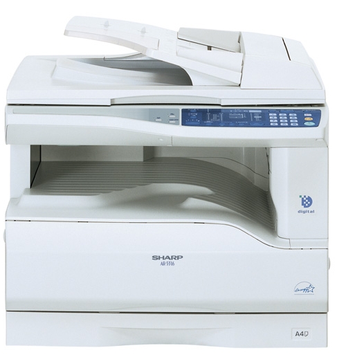
![]()
CODE : 00ZAR5316/A1E
DIGITAL COPIER
MODEL AR-5316
(For North America)
(With optional AR-SP6 installed)
CONTENTS
[ 1 ] GENERAL . . . . . . . . . . . . . . . . . . . . . . . . . . . . . . . . . . . . . . . . . . . . . . . . .1-1 [ 2 ] SPECIFICATIONS. . . . . . . . . . . . . . . . . . . . . . . . . . . . . . . . . . . . . . . . . . .2-1 [ 3 ] CONSUMABLE PARTS. . . . . . . . . . . . . . . . . . . . . . . . . . . . . . . . . . . . . . .2-1 [ 4 ] EXTERNAL VIEWS AND INTERNAL STRUCTURES . . . . . . . . . . . . . . .4-1 [ 5 ] UNPACKING AND INSTALLATION . . . . . . . . . . . . . . . . . . . . . . . . . . . . . .5-1 [ 6 ] ADJUSTMENTS . . . . . . . . . . . . . . . . . . . . . . . . . . . . . . . . . . . . . . . . . . . .6-1 [ 7 ] SIMULATIONS . . . . . . . . . . . . . . . . . . . . . . . . . . . . . . . . . . . . . . . . . . . . .7-1 [ 8 ] USER PROGRAMS . . . . . . . . . . . . . . . . . . . . . . . . . . . . . . . . . . . . . . . . .8-1 [ 9 ] TROUBLE CODE LIST . . . . . . . . . . . . . . . . . . . . . . . . . . . . . . . . . . . . . . .9-1 [10] MAINTENANCE . . . . . . . . . . . . . . . . . . . . . . . . . . . . . . . . . . . . . . . . . . .10-1 [11] DISASSEMBLY AND ASSEMBLY . . . . . . . . . . . . . . . . . . . . . . . . . . . . . .11-1 [12] FLASH ROM VERSION UP PROCEDURE . . . . . . . . . . . . . . . . . . . . . .12-1 [13] ELECTRICAL SECTION . . . . . . . . . . . . . . . . . . . . . . . . . . . . . . . . . . . . .13-1
Parts marked with “ “ are important for maintaining the safety of the set.
Be sure to replace these parts with specified ones for maintaining the safety and performance of the set.
This document has been published to be used for SHARP CORPORATION after sales service only.
The contents are subject to change without notice.
CONTENTS
[1] GENERAL
1. Note for servicing . . . . . . . . . . . . . . . . . . . . . . . . . . . . . 1-1
[2] SPECIFICATIONS
1. Copy mode . . . . . . . . . . . . . . . . . . . . . . . . . . . . . . . . . . 2-1
[3] CONSUMABLE PARTS
1. Supply system table . . . . . . . . . . . . . . . . . . . . . . . . . . . 2-1
[4] EXTERNAL VIEWS AND INTERNAL STRUCTURES
1. Appearance . . . . . . . . . . . . . . . . . . . . . . . . . . . . . . . . . 4-1 2. Internal . . . . . . . . . . . . . . . . . . . . . . . . . . . . . . . . . . . . . 4-1 3. Operation Section. . . . . . . . . . . . . . . . . . . . . . . . . . . . . 4-2 4. Motor, solenoid, clutch . . . . . . . . . . . . . . . . . . . . . . . . . 4-3
[5] UNPACKING AND INSTALLATION
5. Changing the copy paper size in the tray . . . . . . . . . . . 5-1
[6] ADJUSTMENTS
1. Adjustment item list . . . . . . . . . . . . . . . . . . . . . . . . . . . 6-1 2. Copier adjustment . . . . . . . . . . . . . . . . . . . . . . . . . . . . 6-1
[7] SIMULATIONS
1. Entering the simulation mode. . . . . . . . . . . . . . . . . . . . 7-1 2. Canceling the simulation mode . . . . . . . . . . . . . . . . . . 7-1 3. List of simulations. . . . . . . . . . . . . . . . . . . . . . . . . . . . . 7-1 4. Contents of simulations . . . . . . . . . . . . . . . . . . . . . . . . 7-2
[8] USER PROGRAMS
1. List of user programs . . . . . . . . . . . . . . . . . . . . . . . . . . 8-1
[9] TROUBLE CODE LIST
1. Trouble code list . . . . . . . . . . . . . . . . . . . . . . . . . . . . . . 9-1 2. Details of trouble codes . . . . . . . . . . . . . . . . . . . . . . . . 9-1
[10] MAINTENANCE
1. Maintenance table. . . . . . . . . . . . . . . . . . . . . . . . . . . . . 10-1 2. Maintenance display system . . . . . . . . . . . . . . . . . . . . . 10-1 3. Note for replacement of consumable parts . . . . . . . . . . 10-1
[11] DISASSEMBLY AND ASSEMBLY
1. High voltage section . . . . . . . . . . . . . . . . . . . . . . . . . . . 11-1 2. Optical section . . . . . . . . . . . . . . . . . . . . . . . . . . . . . . . 11-2 3. Fusing section . . . . . . . . . . . . . . . . . . . . . . . . . . . . . . . . 11-4 4. Paper exit section . . . . . . . . . . . . . . . . . . . . . . . . . . . . . 11-6 5. MCU . . . . . . . . . . . . . . . . . . . . . . . . . . . . . . . . . . . . . . . 11-8 6. Optical frame unit . . . . . . . . . . . . . . . . . . . . . . . . . . . . . 11-8 7. LSU . . . . . . . . . . . . . . . . . . . . . . . . . . . . . . . . . . . . . . . . 11-9 8. Tray paper feed section / Paper transport section . . . . . 11-9 9. Manual multi paper feed section . . . . . . . . . . . . . . . . . . 11-11 10. Power section . . . . . . . . . . . . . . . . . . . . . . . . . . . . . . . 11-13 11. Developing section . . . . . . . . . . . . . . . . . . . . . . . . . . . 11-14 12. Process section. . . . . . . . . . . . . . . . . . . . . . . . . . . . . . 11-15 13. Others . . . . . . . . . . . . . . . . . . . . . . . . . . . . . . . . . . . . . 11-15
[12] FLASH ROM VERSION UP PROCEDURE
1. Preparation . . . . . . . . . . . . . . . . . . . . . . . . . . . . . . . . . . 12-1 2. Download procedure . . . . . . . . . . . . . . . . . . . . . . . . . . . . 12-1 3. Installation procedure . . . . . . . . . . . . . . . . . . . . . . . . . . . 12-2
[13] ELECTRICAL SECTION
1. Block diagram . . . . . . . . . . . . . . . . . . . . . . . . . . . . . . . . 13-1 3. Actual wiring diagram . . . . . . . . . . . . . . . . . . . . . . . . . . 13-2

[1] GENERAL
1. Note for servicing
Pictogram
The label (
 ) in the fusing area of the machine indicates the following:
 : Caution, risk of danger
  : Caution, hot surface
A. Warning for servicing
•The fusing area is hot. Exercise care in this area when removing misfed paper.
•Do not look directly at the light source. Doing so may damage your eyes.
B. Cautions for servicing
•Do not switch the machine rapidly on and off. After turning the machine off, wait 10 to 15 seconds before turning it back on.
•Machine power must be turned off before installing any supplies. •Place the machine on a firm, level surface.
•Do not install the machine in a humid or dusty location.
•When the machine is not used for a long time, for example, during prolonged holidays, turn the power switch off and remove the power cord from the outlet.
•When moving the machine, be sure to turn the power switch off and remove the power cord from the outlet.
•Do not cover the machine with a dust cover, cloth or plastic film while the power is on. Doing so may prevent heat dissipation, damaging the machine.
•Use of controls or adjustments or performance of procedures other than those specified herein may result in hazardous laser radiation exposure.
•The socket-outlet shall be installed near the machine and should be easily accessible.
C. Note for installation place
Improper installation may damage the machine. Please note the following during initial installation and whenever the machine is moved.
Caution : If the machine is moved from a cool place to a warm place, condensation may form inside the machine. Operation in this condition will cause poor copy quality and malfunctions. Leave the machine at room temperature for at least 2 hours before use.
Do not install your machine in areas that are:
•damp, humid, or very dusty
•poorly ventilated
•exposed to direct sunlight
•subject to extreme temperature or humidity changes, e.g., near an air conditioner or heater.
The machine should be installed near an accessible power outlet for easy connection and disconnection.
Be sure to connect the power cord only to a power outlet that meets the specified voltage and current requirements. Also make certain the outlet is properly grounded.
Note : Connect the machine to a power outlet which is not used for other electric appliances. If a lighting fixture is connected to the same outlet, the light may flicker.
Be sure to allow the required space around the machine for servicing and proper ventilation.
8″ (20 cm)
AR-5316 GENERAL 1-1
[2] SPECIFICATIONS
The table below shows the specifications of this model and the contents of changes from the AR-M160/M205 and AR-5316.
|
Item |
AR-M160 |
AR-5316 |
|||||
|
Paper feed system |
1cassette + |
One automatic feeding paper tray(250sheets) + |
|||||
|
Multi manual paper feed |
bypass tray(100sheets) |
||||||
|
Weight |
Approx.31.3Kg |
Approx.31.3Kg |
|||||
|
(Not including TD cartridge) |
|||||||
|
Interface |
USB1.1/USB2.0 |
IEEE1284parallel connector/USB1.1 |
|||||
|
IEEE1284 |
|||||||
|
Option |
|||||||
|
Machine |
Model |
AR-M160 |
AR-5316 |
Remark |
|||
|
250 sheets paper feed unit |
AR-D24 / D25 |
O |
— |
||||
|
SPF |
AR-SP6 |
O |
O |
||||
|
Original cover |
AR-VR5 |
Standard |
Standard |
||||
O : The option can be installed.
— : The option cannot be installed.
[3] CONSUMABLE PARTS
1. Supply system table
|
NO |
Name |
Content |
Life |
Product name |
Remark |
|
|
1 |
TD cartridge(Black) |
Toner developer cartridge |
x1 |
9K |
AR-016TD |
*Life setting by LT 5% document |
|
(Toner: Net Weight 300g) |
||||||
|
(Developer: Net Weight 400g) |
||||||
|
IC chip |
x1 |
|||||
|
Polyethylene bag |
x1 |
|||||
|
2 |
Drum cartridge |
Drum cartridge |
x1 |
30K |
AR-016DR |
|
Packed items:DR cartridge(30K)/TD cartridge(4.5K)
Note 1: The individual carton is printed with English, German, French, and Spanish as well as the green mark.
AR-5316 SPECIFICATIONS 2-1

[4] EXTERNAL VIEWS AND INTERNAL STRUCTURES
1. Appearance
1
2 
 7 6 2
7 6 2 
 10
10
 11
11
15
|
9 |
12 |
13 |
14 |
|||||||
|
1 |
Glass cleaner |
2 |
Document feeder cover (when the SPF |
3 |
Document glass |
|||||
|
is installed) /document cover |
||||||||||
|
4 |
Handles |
5 |
Power switch |
6 |
Operation panel |
|||||
|
7 |
Paper output tray |
8 |
Front cover |
9 |
Paper trays |
|||||
|
10 |
Side cover |
11 |
Side cover handle |
12 |
Bypass tray guides |
|||||
|
13 |
Bypass tray |
14 |
Bypass tray extension |
15 |
Charger cleaner |
|||||
|
16 |
USB 1.1 connector |
17 |
Parallel connector |
|||||||
|
2. Internal |
||||||||||
|
25 |
24 |
18 |
19 |
20 |
|
29 |
||||||
|
28 |
26 |
27 |
30 |
|||
|
18 |
Document feeder tray |
19 |
Original guides |
20 |
Feeding roller cover |
|
|
(when the SPF is installed) |
(when the SPF is installed) |
(when the SPF is installed) |
||||
|
21 |
Right side cover |
22 |
Exit area |
23 |
TD cartridge |
|
|
(when the SPF is installed) |
(when the SPF is installed) |
|||||
|
24 |
TD cartridge strap |
25 |
TD cartridge lock release lever |
26 |
Roller rotating knob |
|
|
27 |
Fusing unit release levers |
28 |
Drum cartridge |
29 |
Drum cartridge handle |
|
|
30 |
Fusing unit paper guide |
AR-5316 EXTERNAL VIEWS AND INTERNAL STRUCTURES 4-1

3. Operation Section
1 2 3
XY-
 ZOOM
ZOOM
ON LINE
DUAL
 PAGE
PAGE
COPY
|
1 |
ON LINE key/indicator |
2 |
DUAL PAGE COPY key/indicator |
3 |
XY-ZOOM key/indicator |
||||||||
|
4 |
SPF indicator |
5 |
Paper feed location / misfeed location |
6 |
ORIGINAL SIZE ENTER key / |
||||||||
|
(when the SPF is installed) |
indicators |
ORIGINAL SIZE indicators |
|||||||||||
|
7 |
PAPER SIZE indicators |
8 |
PRESET RATIO selector keys / |
||||||||||
|
indicators |
|||||||||||||
|
9 |
10 |
11 |
12 |
13 |
14 |
15 |
16 |
17 |
|||||
|
AUDIT CLEAR |
POWER SAVE |
ZOOM |
25 |
400% |
INTERRUPT |
||||||||
|
AUTO |
ORIGINAL PAPER |
200% |
CLEAR |
||||||||||
|
SIZE |
SIZE |
||||||||||||
|
TEXT |
141 |
||||||||||||
|
11X17 |
|||||||||||||
|
PHOTO |
8½X14 |
129 |
|||||||||||
|
8½X11 |
121 |
CLEAR ALL |
|||||||||||
|
100% |
|||||||||||||
|
8½X5½ |
|||||||||||||
|
95 |
|||||||||||||
|
8½X11 |
|||||||||||||
|
77 |
|||||||||||||
|
1 |
3 |
5 |
EXTRA |
64 |
|||||||||
|
50% |
START |
||||||||||||
|
ORIGINALSIZE |
TRAY |
AUTO |
|||||||||||
|
PRESET RATIO |
|||||||||||||
|
ENTER |
SELECT |
IMAGE |
|||||||||||
|
18 |
6 |
7 |
5 |
8 |
|||||||||||||||||
|
19 |
4 |
20 |
21 |
22 |
23 |
24 |
25 |
26 |
|||||||||||||
|
Not used |
for this machine. |
||||||||||||||||||||
|
9 |
AUTO/TEXT/PHOTO key / indicators |
10 |
AUDIT CLEAR key |
11 |
Alarm indicators |
||||||||||||||||
|
12 |
POWER SAVE indicator |
13 |
Display |
14 |
Copy ratio display key |
||||||||||||||||
|
15 |
ZOOM indicator |
16 |
Zoom keys |
17 |
INTERRUPT key / indicator |
||||||||||||||||
|
18 |
Light and Dark keys / indicators |
19 |
PAPER SIZE ENTER key |
20 |
TRAY SELECT key |
||||||||||||||||
|
21 |
AUTO IMAGE key / indicator |
22 |
Numeric keys |
23 |
# key |
||||||||||||||||
|
24 |
START key / indicator |
25 |
CLEAR ALL key |
26 |
CLEAR key |
AR-5316 EXTERNAL VIEWS AND INTERNAL STRUCTURES 4-2

[5]UNPACKING AND INSTALLATION
5. Changing a tray’s paper size setting
Follow these steps to change a tray’s paper size setting.
Note:
•The paper size setting cannot be changed when the machine has stopped temporarily due to running out of paper or a misfeed, or during interrupt copying.
•During printing (even in copy mode), the paper size setting cannot be changed.
•Do not load paper that is a different size than the paper size setting. Copying will not be possible.
1)Hold down the [PAPER SIZE ENTER] key for more than 5 seconds to set the selected paper size.
The currently selected paper feed location indicator will blink and the corresponding paper size (which is currently set) indicator will light steadily.
All other indicators will go out.
INAL PAPER SIZE 11X17 
8½X14  8½X11
8½X11
 8½X5½
8½X5½  8½X11
8½X11 EXTRA
EXTRA
3)Squeeze the lock lever of the front guide and slide the front guide to match the width of the paper, and move the left guide to the appropriate slot as marked on the tray.
Left guide
Front guide
•The front guide is a slide-type guide. Grasp the locking knob on the guide and slide the guide to the indicator line of the paper to be loaded. •The left guide is an insert-type guide. Remove it and then insert it at the indicator line of the paper to be loaded.
•When using 11″ x 17″ sized paper store the left guide in the slot at the left front of the paper tray.
2)Use the [ORIGINAL SIZE ENTER] key to select the paper size. The indicator of the selected paper size lights up.
GINAL PAPER
SIZE
|
ORIGINAL SIZE |
11X17 |
|
8½X14 |
ENTER 8½X11
 8½X5½
8½X5½  8½X11
8½X11  EXTRA
EXTRA 
4)Press the [START] key and then the [PAPER SIZE ENTER] key.
To change the paper size setting of another tray, repeat steps 2) to 4) after pressing the [START] key.
START
Note:Affix the paper size label for the paper size selected in step 2) to the label position on the right end of the tray.
Important points when using the printer mode
•Make sure that the tray’s paper size setting is the same as the tray’s paper size setting in the printer driver. For example, if the tray’s paper size setting is 8-1/2”x11R, set «Setting Paper Size» to «Letter R». For more information, see «CONFIGURING THE PRINTER DRIVER» in the «Software Setup Guide».
AR-5316 UNPACKING AND INSTALLATION 5-1

[6]ADJUSTMENTS
1.Adjustment item list
|
Section |
Adjustment item |
Adjustment procedure/SIM No. |
||
|
A |
Process |
(1) |
Developing doctor gap adjustment |
Developing doctor gap adjustment |
|
section |
||||
|
(2) |
MG roller main pole position adjustment |
MG roller main pole position adjustment |
||
|
(3) |
Developing bias voltage check |
|||
|
(4) |
Main charger voltage check |
|||
|
B |
Mechanism |
(1) |
Image position adjustment |
SIM-50 |
|
section |
||||
|
(2) |
Main scanning direction (FR direction) distortion balance |
No. 2/3 mirror base unit installing position adjustment |
||
|
adjustment |
||||
|
Copy lamp unit installing position adjustment |
||||
|
(3) |
Main scanning direction (FR direction) distortion adjustment |
Rail height adjustment |
||
|
(4) |
Sub scanning direction (scanning direction) distortion |
Winding pulley position adjustment |
||
|
adjustment |
||||
|
(5) |
Main scanning direction (FR direction) magnification ratio |
SIM 48-1 |
||
|
adjustment |
||||
|
(6) |
Sub scanning direction (scanning direction) magnification ratio |
OC mode in copying (SIM 48-1) |
||
|
adjustment |
||||
|
SPF mode in copying (SIM 48-5) |
||||
|
(7) |
Off center adjustment |
OC mode (SIM 50-12) |
||
|
SPF mode (SIM 50-12) |
||||
|
(8) |
SPF white correction pixel position adjustment |
SIM63-7 |
||
|
(required in an SPF model when replacing the lens unit) |
||||
|
C |
Image density |
(1) |
Copy mode |
SIM 46-1 |
|
adjustment |
||||
2.Copier adjustment
A.Process section
(1) Developing doctor gap adjustment
1)Loosen the developing doctor fixing screw A.
2)Insert a thickness gauge of 1.5mm to the three positions at 20mm and 130mm from the both ends of the developing doctor as shown.
3)Push the developing doctor in the arrow direction, and tighten the developing doctor fixing screw. (Perform the same procedure for the front and the rear frames.)
4)Check the clearance of the developing doctor. If it is within the specified range, then fix the doctor fixing screw with screw lock.
*When inserting a thickness gauge, be careful not to scratch the developing doctor and the MG roller.
<Adjustment specification>
Developing doctor gap
Both ends (20mm from the both ends) : 1.5 +0.1— 0.15 mm
C (Center) (150mm from the both ends) :1.55 +0.15— 0.2 mm
(2) MG roller main pole position adjustment
1)Remove and separate the waste toner box and put the developing unit on a flat surface.
2)Tie a string to a needle or a pin.
3)Hold the string and bring the needle close to the MG roller horizontally. (Do not use paper clip, which is too heavy to make a correct adjustment.) (Put the developing unit horizontally for this adjustment.)
4)Do not bring the needle into contact with the MG roller, but bring it to a position 2 or 3mm apart from the MG roller. Mark the point on the MG roller which is on the extension line from the needle tip.
5)Measure the distance from the marking position to the top of the doctor plate of the developing unit to insure that it is 18mm.
If the distance is not within the specified range, loosen the fixing screw A of the main pole adjustment plate, and move the adjustment plate in the arrow direction to adjust.
AR-5316 ADJUSTMENT 6-1

(3)Developing bias voltage check
Note:Use a digital multi-meter with an internal resistance of 10MΩ or more.
1)Set the digital multi-meter range to DC700V.
2)Put the test rod of the digital multi-meter on the developing bias voltage output check pin.
3)Turn on the power, execute SIM25-1.
<Specification>
|
Mode |
Specification |
|
Developing bias voltage |
DC — 400±8V |
(4) Grid bias voltage check
Note:Use a digital multi-meter with an internal resistance of 10MΩ or more.
1)Set the digital multi-meter range to DC700V.
2)Put the test rod of the digital multi-meter on the grid bias voltage output check pin.
3)Turn on the power.
(The voltage is outputted in the grid bias High output mode during warming up, and in the grid bias Low output mode when warming up is completed.)
<Specification>
|
Mode |
Specification |
|
Grid bias LOW |
DC — 400±8V |
|
Grid bias HIGH |
DC — 525±10V |
B.Mechanism section
Note: If a jam error or paper empty occurs during copying in the adjustment by the simulation, the image data are not saved, and therefore recopying is required.
(1)Image position adjustment
a.OC image lead edge position adjustment (SIM 50-1)
Note:In advance to this adjustment, the sub scanning magnification ratio adjustment must be performed.
1) Set a scale on the OC table as shown below.
2)Make a copy.
3)Check the copy output. If necessary, perform the following adjustment procedures.
4)Execute SIM 50-1.
5)Set the OC lead edge position set value (Exposure display <<PHOTO>> ON) to [1]
The OC image scanning start position is shifted inside the document edge.
6)Set the main cassette lead edge void adjustment value (Exposure display <<TEXT>> ON) * to [1]
The lead edge void becomes the minimum.
7)Set the main cassette print start position value (Exposure display <<AUTO+MAIN CASSETTE LAMP>> ON) to [1] and make a copy. The print start position is shifted inside the document edge.
*The dimension varies depending on the model.
 Measure the image loss R of the copied image. Enter the set value of the image scanning lead edge position (Exposure display <<PHOTO>> ON) again.
•1 step of the set value corresponds to about 0.1mm shift. •Calculate the set value from the formula below. R/0.1(mm) = Image loss set value
<R: Image loss measurement value (mm)>
*The scanning edge is set.
(A line may be printed by scanning the document edge.)
Example: 4/0.1 = 40 = about 40
Note:If the set value is not obtained from the above formula, perform the fine adjustment.
AR-5316 ADJUSTMENT 6-2

9)Measure the distance H between the paper lead edge and the image print start position. Set the image print start position set value (Exposure display <<AUTO+MAIN CASSETTE LAMP>> ON) again.
•1 step of the set value corresponds to about 0.1mm shift. •Calculate the set value from the formula below. H/0.1(mm) = Image print start position set value
<H: Print start position measurement value (mm)>
*Fit the print edge with the paper edge, and perform the lead edge adjustment.
Example: 5/0.1 = 50 = about 50
Note:If the set value is not obtained from the above formula, perform the fine adjustment.
10) Set the lead edge void adjustment value (Exposure display <<TEXT>> ON)* again.
•1 step of the set value corresponds to about 0.1mm shift. •Calculate the set value from the formula below.
B/0.05 (mm) = Lead edge void adjustment value <B: Lead edge void (mm)>
|
Example: |
When setting the lead edge void to 2.5mm |
|
:2.5 /0.05 = about 50 |
Note:If the set value is not obtained from the above formula, perform the fine adjustment.
*Multi bypass tray lead edge void adjustment: Exposure display
<<TEXT + PHOTO>> <Adjustment specification>
|
Adjustment |
SIM |
LED |
Set |
Spec |
Set |
|
mode |
value |
value |
range |
||
|
OC image lead |
SIM |
PHOTO |
R/0.1 |
Lead edge |
1 ~ 99 |
|
edge position |
50-1 |
||||
|
void: |
|||||
|
Main cassette |
AUTO |
B/0.1 |
|||
|
print start |
+ |
1 — 4mm |
|||
|
position |
MAIN |
Image loss: |
|||
|
Multi bypass |
AUTO |
||||
|
3mm or |
|||||
|
tray print start |
+ |
||||
|
less |
|||||
|
position |
MULTI |
||||
|
Lead edge void |
TEXT |
B/0.05 |
|||
b.SPF image lead edge position adjustment (SIM50-6)
1) Set a scale on the OC table as shown below.
Note:Since the printed copy is used as a test chart, put the scale in paralled with the edge lines.
2)Make a copy, Then use the copy output as an original to make an SPF copy again.
3)Check the copy output. If necessary, perform the following adjustment procedures.
4)Execute SIM 50-6.
5)Set the SPF lead edge position set value (Exposure display <<AUTO>> ON) so that the same image is obtained as that obtained in the previous OC image lead edge position adjustment.
<Adjustment specification>
|
Adjustment mode |
SIM |
LED |
Set value |
Spec value |
Set |
|
range |
|||||
|
SPF image lead |
SIM |
AUTO |
1 step: |
Lead edge |
1 ~ 99 |
|
edge position |
50-6 |
0.1mm shift |
void: |
||
|
(1st print surface) |
1 — 4mm |
||||
|
Image loss: |
|||||
|
3mm or |
|||||
|
less |
|||||
AR-5316 ADJUSTMENT 6-3
![]()
c.Rear edge void adjustment (SIM50-1, SIM50-19)
1) Set a scale as shown in the figure below.
A4(8.5″ x 11″)
Paper rear edge
2)Set the document size to A4 (8.5″ x 11″), and make a copy at 100%.
3)If necessary, perform the following adjustment procedure.
Void amount (Standard value: 4mm or less)
Scale image
Paper rear edge
4)Execute SIM 50-1 and set the density mode to AUTO + TEXT + PHOTO (Rear edge void).The currently set adjustment value is displayed.
5)Enter the set value and press the start key. The correction value is stored and a copy is made.
<Adjustment specification>
|
Mode |
SIM |
LED |
Set value |
Specifi- |
Set |
|
cation |
range |
||||
|
Rear edge void |
SIM |
AUTO |
1 step: |
4mm or |
1 ~ 99 |
|
50-1 |
+ |
0.1mm shift |
less |
||
|
TEXT |
|||||
|
+ |
|||||
|
PHOTO |
|||||
d. Paper off center adjustment (SIM50-10)
1)Set a test chart (UKOG-0089CSZZ) on the document table.
2)Select a paper feed port and make a copy. Compare the copy and the test chart. If necessary, perform the following adjustment procedure.
3)Execute SIM 50-10. After completion of warm-up, shading is performed and the currently set off center adjustment value of each paper feed port is displayed.
4)Enter the set value and press the start key. The correction value is stored and a copy is made.
<Adjustment specification>
|
Mode |
SIM |
LED |
Set value |
Specifi- |
Set |
|
cation |
range |
||||
|
Paper off |
SIM |
AUTO |
Add 1: |
Single: |
1 ~ 99 |
|
center |
50-10 |
+ |
0.1mm shift |
Center |
|
|
Selected |
to R side. |
±2.0mm |
|||
|
tray ON |
|||||
|
Reduce 1: |
|||||
|
0.1mm shift |
|||||
|
to L side. |
|||||
e.Side edge void area adjustment (SIM26-43)
Note:Before performing this adjustment, be sure to check that the paper off center adjustment (SIM 50-10) is completed.
1)Set a test chart (UKOG-0089CSZZ) on the document table.
2)Select a paper feed port and make two copies. Compare the 2nd copy and the test chart. If necessary, perform the following
adjustment procedure.
*The 1st copy does not show the void. Be sure to check the 2nd copy.
3)Execute SIM 26-43 and set the density mode to AUTO(right edge void) + TEXT (Left edge void).
The currently set adjustment value is displayed.
4)Enter the set value and press the start key. The correction value is stored.
<Adjustment specification>
|
ode |
SIM |
LED |
Set value |
Specifi- |
Set |
|
cation |
range |
||||
|
Left edge void |
SIM |
AUTO |
1 step: |
0.5 ~ 4mm |
1 ~ 99 |
|
26-43 |
(right |
0.5mm shift |
|||
|
edge) |
|||||
|
+ |
|||||
|
TEXT |
|||||
|
(left edge) |
|||||
*The void adjustment values on the right and the left must be the same.
(2)Main scanning direction(FR direction) distortion balance adjustment
1) Remove the OC glass and the right cabinet.
AR-5316 ADJUSTMENT 6-4

2) Loosen the copy lamp unit wire fixing screw.
4)Loosen the set screw of the scanner drive pulley which is not in contact with No. 2/3 mirror base unit positioning plate.
5)Without moving the scanner drive pulley shaft, manually turn the scanner drive pulley until the positioning plate is brought into contact with No. 2/3 mirror base unit, then fix the scanner drive pulley.
Wire fixing screw
3)Manually turn the mirror base drive pulley and bring No. 2/3 mirror base unit into contact with the positioning plate. At that time, if the front frame side and the rear frame side of No. 2/3 mirror base unit are brought into contact with the positioning plate at the same time, the mirror base unit parallelism is proper. If one of them is in contact with the positioning plate, perform the adjustment of 4).
6)Put No. 2/3 mirror base unit on the positioning plate again, push the projections on the front frame side and the rear frame side of the copy lamp unit to the corner frame, and tighten the wire fixing screw.
AR-5316 ADJUSTMENT 6-5

(3)Main scanning direction (FR direction) distortion adjustment
This adjustment must be performed in the following cases: •When the mirror base drive wire is replaced.
•When the lamp unit, or No. 2/3 mirror holder is replaced. •When a copy as shown is made.
Paper exit direction
1) Set A3 (11″ x 17″) white paper on the original table as shown below.
Allow a little space.
|
Glass holding plate |
A3 (11″ x 17″) white paper |
Fit the paper edge and
the glass holding plate edge.
2)Open the original cover and make a normal (100%) copy.
3)Measure the width of the black background at the lead edge and at the rear edge.
Paper exit direction
La: Lead edge black background width
Lb: Rear edge black background width
If the width (La) of the black background at the lead edge is equal that (Lb) at the rear edge, there is no need to execute the following procedures of 4) ~ 7).
4)Loosen the mirror base drive pulley fixing screw on the front frame side or on the rear frame side.
 When La < Lb
Turn the mirror base drive pulley on the front frame side in the arrow direction A.
(Do not move the mirror base drive pulley shaft.)
 When La > Lb
Turn the mirror base drive pulley on the front frame side in the arrow direction A.
(Do not move the mirror base drive pulley shaft.)
Rear side
A
B
Front side
5)Tighten the mirror base drive pulley fixing screw.
<Adjustment specification>
La = Lb
6)Execute the main scanning direction (FR) distartion balance adjustment previously described in 2) again.
(4)Sub scanning direction (scanning direction) distortion adjustment
When there is no skew copy in the mirror base scanning direction and there is no horizontal error (right angle to the scanning direction), the adjustment can be made by adjusting the No. 2/3 mirror base unit rail height.
Before performing this adjustment, be sure to perform the horizontal image distortion adjustment in the laser scanner section.
This adjustment must be performed in the following cases: •When the mirror base wire is replaced.
•When the copy lamp unit or No. 2/3 mirror unit is replaced. •When the mirror unit rail is replaced or moved.
•When a following copy is made.
AR-5316 ADJUSTMENT 6-6

1)Making of a test sheet
Make test sheet by drawing parallel lines at 10mm from the both ends of A3 (11″ x 17″) white paper as shown below. (These lines must be correctly parallel to each other.)
|
Parallel line |
Parallel line |
|
10mm |
10mm |
White paper
2)Make a normal (100%) copy of the test sheet on A3 (11″ x 17″) paper. (Fit the paper edge with the glass holding plate edge.)
3)Measure the distances (La, Lb, Lc, Ld) at the four corners as shown below.
|
La |
Lc |
|||||
Paper exit direction
When La = Lb and Lc = Ld, no need to perform the procedures 4) and 5).
4)Move the mirror base F rail position up and down (in the arrow direction) to adjust.
Note:If the rear side rail is used for the adjustment, the scanning position of the white balance sheet is shifted and «E7-04» may occur only when scanning with the SPF. Therefore it is advisable to use the front side rail for the adjustment.
 When La > Lb
Shift the mirror base B rail upward by the half of the difference of La — Lb.
 When La < Lb
Shift the mirror base B rail downward by the half of the difference of Lb — La.
Example: When La = 12mm and Lb = 9mm, shift the mirror base B rail upward by 1.5mm.
 When Lc > Ld
Shift the mirror base B rail downward by the half of the difference of Lc — Ld.
 When Lc < Ld
Shift the mirror base B rail downward by the half of the difference of Ld — Lc.
 When moving the mirror base rail, hold the mirror base rail with your hand.
<Adjustment specification>
La = Lb, Lc = Ld
5)After completion of adjustment, manually turn the mirror base drive pulley, scan the mirror base A and mirror base B fully, and check that
the mirror bases are not in contact with each other.
*If the mirror base rail is moved extremely, the mirror base may be in contact with the frame or the original glass. Be careful to avoid this.
(5)Main scanning direction (FR direction) magnification ratio adjustment (SIM 48-1)
Note:Before performing this adjustment, be sure to check that the CCD unit is properly installed.
1) Put a scale on the original table as shown below.
2)Execute SIM 48-1.
3)After warm-up, shading is performed and the current set value of the main scanning direction magnification ratio is displayed on the display section in 2 digits.
4)Select the mode and press the start key again.
5)Manual correction mode (TEXT lamp ON) Enter the set value and press the start key. The set value is stored and a copy is made.
AR-5316 ADJUSTMENT 6-7

<Adjustment specification>
Note: A judgment must be made with 200mm width, and must not be made with 100mm width.
|
Mode |
Specification |
SIM |
Set value |
Set range |
|
Main scanning |
At normal: |
SIM 48-1 |
Add 1:0.1% |
1 ~ 99 |
|
direction |
±1.0% |
increase |
||
|
magnification |
Reduce 1: |
|||
|
ratio |
0.1% |
|||
|
decrease |
||||
(6)Sub scanning direction (scanning direction) magnification ratio adjustment (SIM 48-1, SIM 48-5)
a. OC mode in copying (SIM48-1)
Note:Before performing this adjustment, be sure to check that the CCD unit is properly installed.
1)Put a scale on the original table as shown below, and make a normal (100%) copy.
2)Compare the scale image and the actual image. If necessary, perform the following adjustment procedures.
3)Execute SIM 48-1.<<PHOTO>>
4)After warm-up, shading is performed and the current set value of the main scanning direction magnification ratio is displayed on the display section in 2 digits.
5)When the photo lamp is lighted by pressing the density selection key, the current magnification ratio correction value in the sub scanning direction is displayed in lower 2 digits of the display section.
6)Enter the set value and press the start key. The set value is stored and a copy is made.
<Adjustment specification>
|
Mode |
Specification |
SIM |
Set value |
Set range |
|
Sub scanning |
Normal |
SIM 48-1 |
Add 1:0.1% |
1 ~ 99 |
|
direction |
±1.0% |
(PHOTO) |
increase |
|
|
magnification |
Reduce 1: |
|||
|
ratio |
0.1% |
|||
|
(OC mode) |
decrease |
|||
b. SPF sub scanning direction magnification ratio (SIM48-5)
Note:
•Before performing this adjustment, be sure to check that the CCD unit is properly installed.
•Before performing this adjustment, the OC mode adjustment in copying must be completed.
1)Put a scale on the original table as shown below, and make a normal (100%) copy to make a test chart.
Note:Since the printed copy is used as a test chart, put the scale in parallel with the edge lines.
2)Set the test chart on the SPF and make a normal (100%) copy.
3)Compare the scale image and the actual image. If necessary, perform the following adjustment procedures.
4)Execute SIM 48-5.
5)After warm-up, shading is performed.
The auto density lamp lights up and the current front surface sub scanning direction magnification ratio correction value is displayed in two digits on the display section.
6)Enter the set value and press the start key. The set value is stored and a copy is made.
<Adjustment specification>
|
Mode |
Specification |
SIM |
Set value |
Set range |
|
Sub scanning |
Normal |
SIM 48-5 |
Add 1:0.1% |
1 ~ 99 |
|
direction |
±1.0% |
increase |
||
|
magnification |
Reduce 1: |
|||
|
ratio |
0.1% |
|||
|
(SPF mode) |
decrease |
|||
(7) Off center adjustment (SIM 50-12)
a. OC mode (SIM50-12)
1) Make a test chart as shown below and set it so that its center line is fit with the original guide center mark.
*To make a test chart, draw a line on A3 or 11″ x 17″ paper at the center in the paper transport direction.
Original guide
Center
Copy paper
(A3 or 17″ x 11″)
2)Make a normal copy from the manual paper feed tray, and compare the copy and the test chart.
If necessary, perform the following adjustment procedures.
3)Execute SIM 50-12.
4)After warm-up, shading is performed and the current set value of the off center adjustment is displayed on the display section in 2 digits.
5)Enter the set value and press the start key. The set value is stored and a copy is made.
<Adjustment specification>
|
Mode |
Specification |
SIM |
Set value |
Set range |
|
Original off |
Single: |
SIM 50-12 |
Add 1: |
1 ~ 99 |
|
center mode |
Center ±2.0mm |
(AE lamp |
0.1mm shift |
|
|
(OC mode) |
ON) |
to R side |
||
|
Reduce 1: |
||||
|
0.1mm shift |
||||
|
to L side |
||||
AR-5316 ADJUSTMENT 6-8

b. SPF original off-center adjustment (SIM50-12)
Note:Before performing this adjustment, be sure to check that the paper off center is properly adjusted.
1) Make a test chart for the center position adjustment and set it on the SPF.
<Adjustment specification>
Draw a line on a paper in the scanning direction.
2)Make a normal copy from the manual paper feed tray, and compare the copy and the original test chart.
If necessary, perform the following adjustment procedures.
3)Execute SIM 50-12.
4)After warm-up, shading is performed and the current set value of the off center adjustment at each paper feed port is displayed on the display section in 2 digits.
5)Enter the set value and press the start key. The set value is stored and a copy is made.
<Adjustment specification>
|
Mode |
Specification |
SIM |
Set value |
Set |
|
range |
||||
|
Original off |
Single: |
SIM |
Add 1: |
1 ~ 99 |
|
center |
Center ±3.0mm(TEXT lamp) |
50-12 |
0.1mm shift |
|
|
mode |
to R side |
|||
|
(SPF mode) |
Reduce 1: |
|||
|
0.1mm shift |
||||
|
to L side |
||||
(8)SPF white correction pixel position adjustment(SIM63-7) (required in an SPF model when replacing the lens unit)
1)Fully open the SPF.
2)Execute SIM 63-7.
3)When the operation panel displays «COMPLETE,»the adjustment is completed.
4)If the operation panel displays «ERROR,»perform the following measures.
•When the display is 0: Check that the SPF is open.
Check that the lamp is ON.(If the lamp is OFF,check the MCU connector.) Check that the CCD harness is properly inserted into the MCU connector.
•When the display is 281 or above:
1)Remove the table glass.
2)Remove the dark box.
3)Slide the lens unit toward the front side and attach it,then execute
SIM.
•When the display is 143 or below:
1)Remove the table glass.
2)Remove the dark box.
3)Slide the lens unit toward the rear side and attach it,then execute SIM.
F R
C.Image density adjustment
(1)Copy mode (SIM 46-1)
1)Set a test chart (UKOG-0162FCZZ) on the OC table as shown below.
2)Put several sheets of A3 or 11″ x 17″ white paper on the test chart.
3)Execute SIM 46-1.
4)After warm-up, shading is performed and the current set value of the density level is displayed on the display section in 2 digits.
For mode selection, use the density select key.
5)Change the set value with the 10-key to adjust the copy image density.
6)Make a copy and check that the specification below is satisfied.
<Adjustment specification>
|
Density |
Display |
Exposure |
Sharp Gray |
Set value |
Set |
|
mode |
lamp |
level |
Chart output |
range |
|
|
Auto |
Auto |
— |
«2» is slightly |
The greater the |
1 ~ 99 |
|
copied. |
set value is the |
||||
|
greater the |
|||||
|
Text |
Text |
3 |
«3» is slightly |
||
|
copied. |
density is The |
||||
|
smaller the set |
|||||
|
Photo |
Photo |
3 |
«2» is slightly |
||
|
copied. |
value is the |
||||
|
smaller the |
|||||
|
Toner |
Text/ |
3 |
«3» is slightly |
||
|
density is. |
|||||
|
save |
Photo |
copied |
|||
|
Toner |
Auto/ |
— |
«2» is slightly |
||
|
save |
Photo |
copied |
|||
*When the lens unit is moved,execute the OC main scanning magnification ratio auto adjustment,SIM 48-1-1,IM48-3 and the PF original off-center adjustment.
*This adjustment is basically O.K.with IM 63-7.
AR-5316 ADJUSTMENT 6-9
[7] SIMULATIONS
1. Entering the simulation mode
Perform the following procedure to enter the simulation mode. «#» key  Interrupt key
  «C» key
  Interrupt key
  Main code
  Start key
  Sub code
  Start key
2. Canceling the simulation mode
When the clear all key is pressed, the simulation mode is cancelled. When the interruption key is pressed, the process is interrupted and the screen returns to the sub code entering display.
*After canceling the simulation mode, be sure to turn OFF/ON the power and check the operation.
Note: If the machine is terminated by a jam error or paper empty during copying in the adjustment by the simulation, recopying is required.
3. List of simulations
|
Main |
Sub |
Contents |
|
|
code |
code |
||
|
01 |
01 |
Mirror scanning operation |
|
|
02 |
Mirror home position sensor (MHPS) status display |
||
|
06 |
Mirror scanning operation aging |
||
|
02 |
01 |
Single paper feeder (SPF) aging |
|
|
02 |
SPF sensor status display |
||
|
03 |
SPF motor operation check |
||
|
08 |
SPG paper feed solenoid operation check |
||
|
11 |
SPF PS release solenoid operation check |
||
|
05 |
01 |
Operation panel display check |
|
|
02 |
Fusing lamp and cooling fan operation check |
||
|
03 |
Copy lamp lighting check |
||
|
06 |
01 |
Paper feed solenoid operation check |
|
|
02 |
Resist roller solenoid operation check |
||
|
10 |
Cassette semi-circular roller cleaning |
||
|
07 |
01 |
Warm-up display and aging with jam |
|
|
06 |
Intermittent aging |
||
|
08 |
Shifting with warm-up display |
||
|
08 |
01 |
Developing bias output |
|
|
02 |
Main charger output (Grid = HIGH) |
||
|
03 |
Main charger output (Grid = LOW) |
||
|
06 |
Transfer charger output |
||
|
10 |
— |
Toner motor operation |
|
|
14 |
— |
Trouble cancel (except for U2) |
|
|
16 |
— |
U2 trouble cancel |
|
|
20 |
01 |
Maintenance counter clear |
|
|
21 |
01 |
Maintenance cycle setting |
|
|
22 |
01 |
Maintenance counter display |
|
|
02 |
Maintenance preset display |
||
|
03 |
Jam memory display |
||
|
04 |
Jam total counter display |
||
|
05 |
Total counter display |
||
|
08 |
SPF counter display |
||
|
09 |
Paper feed counter display |
||
|
12 |
Drum counter display |
||
|
13 |
CRUM type display |
||
|
14 |
P-ROM version display |
||
|
Main |
Sub |
Contents |
|
|
code |
code |
||
|
22 |
15 |
Trouble memory display |
|
|
17 |
Copy counter display |
||
|
18 |
Printer counter display |
||
|
21 |
Scanner counter display |
||
|
22 |
SPF jam counter display |
||
|
24 |
01 |
Jam total counter clear |
|
|
02 |
Trouble memory clear |
||
|
04 |
SPF counter clear |
||
|
06 |
Paper feed counter clear |
||
|
07 |
Drum counter clear |
||
|
08 |
Copy counter clear |
||
|
09 |
Printer counter clear |
||
|
13 |
Scanner counter clear |
||
|
14 |
SPF jam total counter clear |
||
|
25 |
01 |
Main motor operation check |
|
|
10 |
Polygon motor operation check |
||
|
26 |
02 |
Size setting |
|
|
03 |
Auditor setting |
||
|
05 |
Count mode setting |
||
|
06 |
Destination setting |
||
|
07 |
Machine condition check (CPM) |
||
|
18 |
Toner save mode setting |
||
|
30 |
CE mark conformity control ON/OFF |
||
|
31 |
Auditor mode exclusive setup |
||
|
36 |
Cancel of stop at maintenance life over |
||
|
38 |
Cancel of stop at drum life over |
||
|
39 |
Memory capacity check |
||
|
42 |
Transfer ON/OFF timing control setting |
||
|
43 |
Side void amount setting |
||
|
51 |
Copy temporary stop function setting |
||
|
30 |
01 |
Paper sensor status display |
|
|
42 |
01 |
Developing counter clear |
|
|
43 |
01 |
Fusing temperature setting |
|
|
12 |
Standby mode fusing fan rotation setting |
||
|
13 |
Fusing paper interval control allow/inhibit setting |
||
|
44 |
34 |
Transfer current setting |
|
|
40 |
Setting of rotation time before toner supply |
||
|
46 |
01 |
Copy density adjustment (300dpi) |
|
|
02 |
Copy density adjustment (600dpi) |
||
|
09 |
Copy exposure level adjustment, individual setting |
||
|
(Text) 300dpi |
|||
|
10 |
Copy exposure level adjustment, individual setting |
||
|
(Text) 600dpi |
|||
|
11 |
Copy exposure level adjustment, individual setting |
||
|
(Photo) 600dpi |
|||
|
18 |
Image contrast adjustment (300dpi) |
||
|
19 |
Exposure mode setting |
||
|
(Gamma table setting/AE operation mode setting/ |
|||
|
Photo image process setting) |
|||
|
20 |
SPF exposure correction |
||
|
29 |
Image contrast adjustment (600dpi) |
||
|
30 |
AE limit setting |
||
|
31 |
Image sharpness adjustment |
||
|
48 |
01 |
Main scanning magnification ratio adjustment |
|
|
05 |
SPF mode sub scanning magnification ratio adjustment |
||
|
in copying |
|||
|
49 |
01 |
Flash ROM program writing mode |
|
|
12 |
Standby mode fusing fan RPM setting |
||
AR-5316 SIMULATIONS 7-1
 Loading…