-
Contents
-
Table of Contents
-
Bookmarks
Quick Links
1HDB 050016-YN-A
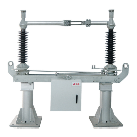
Two-Column Rotary Disconnector
Type SGF
Instruction Manual
Optionally with built on
Rated Voltages : 36 — 362kV
Rated Current : 1600 — 3150 A
Related Manuals for ABB SGF
Summary of Contents for ABB SGF
-
Page 1
1HDB 050016-YN-A Two-Column Rotary Disconnector Type SGF Instruction Manual Optionally with built on Earthing Switch Type TEC Rated Voltages : 36 — 362kV Rated Current : 1600 — 3150 A… -
Page 2
1HDB 050016-YN-A Contents Please Read First…………….1 Copyright …………….1 Guarantee…………….1 Conventions…………….1 Function ………………2 Disconnector …………….2 Earthing Switch …………..2 Variants……………… 2 Mounting Alternatives …………..3 Parallel Arrangement of Disconnector Poles ……3 Series Arrangement of Disconnector Poles ……Basic Design ……………… -
Page 3
1HDB 050016-YN-A Mounting of Operating Mechanism For Earthing Switch …………..44 13.1 Direct Mounting …………..44 13.2 Separate Mounting …………… 46 Mounting of Earthing Switch …………54 14.1 Earthing Switch Poles in Parallel ……….. 54 14.2 Earthing Switch Poles in Series And Mounting on Individual Disconnector Poles …. -
Page 4
Figure 2 : 3-pole type SGF two-column rotary disconnector In series arrangement (basic design) ……..3 Figure 3 : Basic design of type SGF two-column rotary disconnector ..4 Figure 4 : Basic design of earthing switch ……….5 Figure 5 :… -
Page 5
1HDB 050016-YN-A Figure 24 : Mounting of operating mechanism for disconnector, Separate mounting if measurement m3 = 6 … 12 m : Details A and detail B ………….. 30 Figure 25 : Mounting of operating mechanism for disconnector, Separate mounting : Laterally offset operating mechanism ..31 Figure 26 : Mounting of operating mechanism for disconnector, Separate mounting : Mounting of operating lever (74) -
Page 6
1HDB 050016-YN-A Figure 45 : Mounting of earthing switch, earthing switch poles in parallel : Mounting of earthing switch link (336) ……..56 Figure 46 : Mounting of earthing switch, earthing switch poles in parallel : Mounting of earthing connections (79, 343), detail 1 and detail 2 : Two earthing connections for rated short-time currents >… -
Page 7
1HDB 050016-YN-A Figure 59 : Mounting of earthing switch, earthing -switch poles in series : Mounting of earthing -switch lever (19) and operating rod (71) if operating mechanism for earthing switch on finger side ……….71 Figure 60 : Mounting of earthing switch, earthing-switch poles in series : Adjustment of operating mechanism for earthing switch if operating mechanism for earthing switch on contact side .. -
Page 8
© ABB Calor Emag Schaltanlagen AG 1994. Guarantee If these service instructions are followed, this will, in our experience, guarantee the safe and reliable operation of our products. -
Page 9
Outdoor installation and formation of groups The type SGF two column rotary disconnector described in these service instructions is a single — pole disconnector for outdoor installation. Two or three poles can be coupled to form a group. -
Page 10
Note : The side for mounting the operating mechanism is finalized with the order. Later changes are not possible. Parallel Arrangement of Disconnector Poles Figure 1 shows a 3-poles type SGF two-column rotary disconnector with two earthing switches in parallel arrangement. Figure 1 : 3-pole type SGF two-column rotary disconnector in parallel arrangement (basic design) -
Page 11
4/113 Basic Design Disconnecetor Figure 3 and Table 1 contain the most important components of the type SGF two-column rotary disconnector. Figure 3 : Basic design of type SGF two-column rotary disconnector Table 1 : Basic design of type SGF two-column rotary disconnector Designation Item No. -
Page 12
1HDB 050016-YN-A 5/113 Earthing — Switch Figure 4 and Table 2 contain the most important components of the earthing switch. Figure 4 : Basic design of earthing switch Table 2 : Basic design of earthing switch Designation Item No. Remarks Earthing connection 79 Cu, flexible Earthing-switch shaft… -
Page 13
6/113 Mode of Operation General The type SGF two-column rotary disconnector has separate operating mechanisms for the disconnector and the earthing switch. Prevention of automatic operating or closing When the equipments switched on or off, a dead-center position is passed through just before the end positions are reached. -
Page 14
1HDB 050016-YN-A 7/113 Earthing Switch Figure 6 : Mode of operation of earthing switch (example : 3-pole in parallel arrangement) Operating mechanism :- The operating mechanism (77) of the earthing switch transfers the operating energy via the operating rod (71) to the earthing-switch shaft (337). The tubular contact arm (23) swivels up (ON) or down (OFF). -
Page 15
General Electrical Data Note : The precise electrical data is contained in the data sheets supplied. The data in Table 3 contains of standard values. Table 3 : General electrical data of type SGF two-column rotary disconnector (standard values) Rated voltage 72.5… -
Page 16
Note : The precise dimensions are contained in the dimensions drawings supplied. The dimensions in Table 5 are standard values. Figure 7 : General main dimension of SFG two-column rotary disconnector Table 5 : General main dimensions of type SGF two-column rotary disconnector (standard values) Rated voltage 72.5… -
Page 17
1HDB 050016-YN-A 10/113 Minimum Distance between Disconnector Poles Note : The precise dimensions are contained in the dimension drawing supplied. The dimensions in Table 6 are standard values. Table 8 : Minimum distances Pmin between poles of disconnector in parallel arrangement Figure 9 : Minimum distances Pmin between poles of disconnector in series arrangement Table 6 : Minimum distances P between poles of disconnector in series and parallel arrangement… -
Page 18
1HDB 050016-YN-A 11/113 Scope of Supply Note : The disconnector is supplied in components Disconnector The scope of supply does not include the fixing materials for mounting the disconnector on the supporting structures. The components supplied comprises : Disconnector base (2) consisting of : Sectional-steel base frame (221), rotary pedestals (70), diagonal rod (68), disconnector operating lever (69), connecting lever (3) and transportation angle (328) Figure 13… -
Page 19
1HDB 050016-YN-A 12/113 Earthing Switch The supply of the earthing switch comprises. Earthing-switch links (336) Tubular contact arms (23) wiwth contact finger (20) and T-type clamp(329) Earthing contact (18) Operating mechanism for earthing switch (77) Operating rod (37) Operating lever (76) with clamping cover (334) Earthing connections (79) For 2nd earthing switch : earthing connections (343) Earthing — switch shaft (337) -
Page 20
1HDB 050016-YN-A 13/113 Shipping and Storage Shipping The equipment is shipped on pallets (Germany) or in boxes (outside Germany) Note : After unpacking, check all supplied equipment immediately for shipping damage. Report shipping damage without delay to the forwarding agency. Storage Caution : In the case of inappropriate storage of the individual components, there is the risk of ingress of water. -
Page 21
1HDB 050016-YN-A 14/113 Mounting, General The type SGF two-column rotary disconnector can be mounted in two positions Horizontal (standard) Vertical (must be expressly specified when ordering and is only possible for rated voltage < 170 kV) Note : For vertical mounting of the disconnector, you require the additionally supplied documents. -
Page 22
1HDB 050016-YN-A 15/113 Treatment of contact Surfaces and Intersection Surfaces Caution : Bolted or sliding contact surfaces that conduct current have an effect on the electrical resistance of the current path. Dirty or oxidized contact surfaces increase the electrical resistance. This may result in irreparable damage to equipment., The following regulations must be observed. -
Page 23
Caution : The diagonal rods (68) Figure 13 have been adjusted at the factory for the precise engagement of the main contacts. The adjustment may only be changed by ABB-trained specialist erectors. Mounting steps :… -
Page 24
1HDB 050016-YN-A 17/113 Finger side (FS) Contact side (KS) Figure 12 : Mounting of disconnector : Shipping of disconnector base (2) if mounting on supporting structure Finger side (FS) Contact side (KS) Figure 13 : Mounting of disconnector : Shipping of premounted disconnector pole if mounting in front of supporting structure (example : Version for rated normal current 1 600 A) -
Page 25
1HDB 050016-YN-A 18/113 Item numbers 400-… : IEC support insulators Item numbers 401-… : DIN support insulators Finger side (FS) Contact side (KS) Rated voltage 1000 72.5 1000 1400 1650 1830 2620 2620 3200 Finger side (FS) Contact side (KS) Figure 14 : Mounting of disconnector… -
Page 26
1HDB 050016-YN-A 19/113 Item numbers 400-… : IEC support insulators Item numbers 401-… : DIN support insulators Finger side (FS) Contact side (KS) Figure 15 : Mounting of disconnector : Mounting of corona-protection fittings (87) on rotary heads (only for rated voltages 300kV & 362 kV) -
Page 27
1HDB 050016-YN-A 20/113 Figure 16 : Mounting of disconnector : Mounting of corona-protection fittings (7) on finger side (only for rated voltages 245kV ..362 kV) -
Page 28
1HDB 050016-YN-A 21/113 Figure 17 : Mounting of disconnector : Mounting of corona-protection fittings (7) on contact side (only for rated voltages 245kV ..362 kV) -
Page 29
1HDB 050016-YN-A 22/113 Mounting of Operating Mechanism for Disconnector Note : The mounting side of the operating mechanism is apparent from the position of the disconnector operating lever (69) Figure 18.The pole on which the operating mechanism is mounted can be freely selected. -
Page 30
1HDB 050016-YN-A 23/113 Figure 18 : Mounting of operating mechanism for disconnector : Direct mounting… -
Page 31
1HDB 050016-YN-A 24/113 Figure 19 : Mounting of operating mechanism for disconnector, direct mounting : Mounting of operating lever (74) if operating mechanism for disconnector at opening side. -
Page 32
1HDB 050016-YN-A 25/113 Figure 20 : Mounting of operating mechanism for disconnector, direct mounting : Mounting of operating lever (74) if operating mechanism for disconnector at opposite opening side. -
Page 33
1HDB 050016-YN-A 26/113 11.2 Separate Mounting In case of separate mounting of the operating mechanism for the disconnector, the mounting steps are dependent on measurement m3 of operating shaft (43) A Figure 22, Figure 23 and a possible lateral offset of operating mechanism and disconnector A Figure 25 : Separate mounting if measurement m3 <… -
Page 34
1HDB 050016-YN-A 27/113 Motor-operated mechanism Manual operating mechanism Figure 21 : Mounting of operating mechanism for disconnector, separate mounting : Measurement m3 < 6 m… -
Page 35
1HDB 050016-YN-A 28/113 Figure 22 : Mounting of operating mechanism for disconnector, separate mounting if measurement m3 < 6 m : Mounting dimensions… -
Page 36
1HDB 050016-YN-A 29/113 Figure 23 : Mounting of operating mechanism for disconnector, separate mounting if measurement m3 = 6 … 12 m : Mounting dimensions (Details A And Detail B : Figure 24) -
Page 37
1HDB 050016-YN-A 30/113 Figure 24 : Mounting of operating mechanism for disconnector, separate mounting if measurement m3 = 6 … 12 m : Detail A and Detail B… -
Page 38
1HDB 050016-YN-A 31/113 Figure 25 : Mounting of operating mechanism for disconnector, separate mounting : Laterally offset operating mechanism… -
Page 39
1HDB 050016-YN-A 32/113 Figure 26 : Mounting of operating mechanism for disconnector, separate mounting : Mounting of operating lever (74) if operating mechanism for disconnector at opening side… -
Page 40
1HDB 050016-YN-A 33/113 Figure 27 : Mounting of operating mechanism for disconnector, separate mounting : Mounting of operating lever (74) if operating mechanism for disconnector at opposite opening side… -
Page 41
1HDB 050016-YN-A 34/113 Mounting of Coupling of Disconnectors, Cabling Caution : For rated voltages 245 … 362 kV : If the disconnector poles are arranged in parallel, the coupling rods (15) must always be mounted on the same side on which the earthing switch is mounted Note : Make sure that the disconnector poles are in the ON position before coupling and that the transportation angles (328) are still mounted. -
Page 42
1HDB 050016-YN-A 35/113 Item numbers 400-… : IEC support insulators Item numbers 401-… : DIN support insulators Figure 28 : Mounting of coupling of disconnectors : Overview… -
Page 43
1HDB 050016-YN-A 36/113 Figure 29 : Mounting of coupling of disconnectors : Disconnector poles in parallel… -
Page 44
1HDB 050016-YN-A 37/113 Figure 30 : Mounting of coupling of disconnectors : Disconnector poles in series… -
Page 45
1HDB 050016-YN-A 38/113 Item numbers 420-… : Direct mounting Item numbers 422-… : Separate mounting Figure 31 : Mounting of coupling of disconnectors : Mounting of operating rod (37) if operating mechanism for disconnector at opening side… -
Page 46
1HDB 050016-YN-A 39/113 Item numbers 420-… : Direct mounting Item numbers 422-… : Separate mounting Figure 32 : Mounting of coupling of disconnectors : Mounting of operating rod (37) if operating mechanism for disconnector at opposite opening side… -
Page 47
1HDB 050016-YN-A 40/113 Item numbers 420-… : Direct mounting Item numbers 422-… : Separate mounting Rated voltage R (U = 100 mm) R (U = 150 mm) 72.5 83 + 1 1 222 1 222 Figure 33 : Mounting of coupling of disconnectors : Adjustment of operating mechanism for disconnector if operating mechanism for disconnector at opening side… -
Page 48
1HDB 050016-YN-A 41/113 Item numbers 420-… : Direct mounting Item numbers 422-… : Separate mounting Rated voltage R (U = 10 mm) R (U = 50 mm) 72.5 83 + 1 1 222 1 222 Figure 34 : Mounting of coupling of disconnectors : Adjustment of operating mechanism for disconnector if operating mechanism for disconnector at opposite opening side… -
Page 49
1HDB 050016-YN-A 42/113 K=(55+5)mm for Disconnectors upto 300 kV K=(95+5)mm for Disconnectors 362 kV & above Figure 35 : Mounting of coupling of disconnectors : Disconnector main contacts, engagement… -
Page 50
1HDB 050016-YN-A 43/113 Figure 36 : Mounting of coupling of disconnectors : Disconnector main contacts, adjusting measurements… -
Page 51
1HDB 050016-YN-A 44/113 Mounting of Operating Mechanism for Earthing Switch 13.1 Direct Mounting Note : Make sure that the operating mechanism is in the ON position (as-delivered state). If the operating mechanism is in the OFF position, set it to the ON position using the emergency hand crank (39). -
Page 52
1HDB 050016-YN-A 45/113 Figure 37 : Mounting of operating mechanism for earthing switch : Direct mounting… -
Page 53
1HDB 050016-YN-A 46/113 13.2 Separate Mounting In case of separate mounting of operating mechanism for earthing switch, the mounting steps are dependent on measurement m3 of operating shaft (43) Figure 39, Figure 40 and on a possible offset of operating mechanism and earthing switch Figure 42 : •… -
Page 54
1HDB 050016-YN-A 47/113 Figure 38 : Mounting of operating mechanism for earthing switch, separate mounting : Measurement m3 < 6 m… -
Page 55
1HDB 050016-YN-A 48/113 Figure 39 : Mounting of operating mechanism for earthing switch, separate mounting if measurement m3 < 6 m : Mounting dimensions… -
Page 56
1HDB 050016-YN-A 49/113 Figure 40 : Mounting of operating mechanism for earthing switch, separate mounting if measurement m3 = 6 … 12 m : Mounting dimensions (Details A and Details B : Figure 41) -
Page 57
1HDB 050016-YN-A 50/113 Figure 41 : Mounting of operating mechanism for earthing switch, separate mounting if measurement m3 = 6 … 12 m : Detail A and Detail B… -
Page 58
1HDB 050016-YN-A 51/113 Figure 42 : Mounting of operating mechanism for earthing switch, separate mounting : Laterally offset operating mechanism… -
Page 59
1HDB 050016-YN-A 52/113 Figure 43 : Mounting of operating mechanism for earthing switch, direct and separate mounting : Mounting of operating lever (76) if operating mechanism for earthing switch on contact side. -
Page 60
1HDB 050016-YN-A 53/113 Figure 44 : Mounting of operating mechanism for earthing switch, direct and separate mounting : Mounting of operating lever (76) if operating mechanism for earthing switch on finger side. -
Page 61
1HDB 050016-YN-A 54/113 Mounting of Earthing Switch Note : If you suspect shipping damage, check the spacing dimensions of contact fingers (20) Figure 69, Figure 70. 14.1 Earthing Switch Pole in Parallel Note : Make sure that the disconnector poles are in the OFF position before mounting the earthing switches Mounting steps Grease clamps sleeves (433-353, 434-353) -
Page 62
1HDB 050016-YN-A 55/113 Mounting steps (continued) : Shorten operating rod (71) so that, during a manual test operation, all the rear contact fingers are up against the stop in the ON position. Check distance between contact finger (20) and stop (21). the distance on one pole of 3-pole group must not be more than 5 mm Figure 64 If necessary, correct the contact of the contact fingers by adjusting operating rod (71) and check… -
Page 63
1HDB 050016-YN-A 56/113 Item numbers 433-… : Poles Distance P < 2 500 mm Item numbers 434-… : Pole distance P > 2 500 mm Figure 45 : Mounting of earthing switch, earthing-switch poles in parallel : Mounting of earthing-switch link (336) -
Page 64
1HDB 050016-YN-A 57/113 Figure 46 : Mounting of earthing switch, earthing-switch poles in parallel : Mounting of earthing connections (79, 343). Detail 1 and Detail 2 : Two earthing connections for rated short-time currents > 40 kA, 1 sec. -
Page 65
1HDB 050016-YN-A 58/113 Figure 47 : Mounting of earthing switch, earthing-switch poles in parallel : Spacing dimensions… -
Page 66
1HDB 050016-YN-A 59/113 Figure 48 : Mounting of earthing switch, earthing-switch poles in parallel : Mounting of coupling piece (342, 334) for connection of earthing-switch shafts (337) for pole distances P > 2 500 mm… -
Page 67
1HDB 050016-YN-A 60/113 Item numbers 421-… : Direct mounting Item numbers 423-… : Separate mounting Figure 49 : Mounting of earthing switch, earthing-switch poles in parallel : Mounting of earthing-switch lever (19) and operating rod (71) if operating mechanism for earthing switch on contact side… -
Page 68
1HDB 050016-YN-A 61/113 Item numbers 421-… : Direct mounting Item numbers 423-… : Separate mounting Figure 50 : Mounting of earthing switch, earthing-switch poles in parallel : Mounting of earthing-switch lever (19) and operating rod (71) if operating mechanism for earthing switch on finger side… -
Page 69
1HDB 050016-YN-A 62/113 W = 132 mm for Disconnector of 123,145,170,245,300 & 362 kV W = 108 for 36 kV W = 120 for 72.5 kV Rated Voltage S (U = 100 mm) S (U = 100 mm) Y1 (U = 100 mm) Y2 (U = 100 mm) 90.5+1 140+1… -
Page 70
1HDB 050016-YN-A 63/113 Rated Voltage S (U = 100 mm) S (U = 100 mm) Y1 (U = 100 mm) Y2 (U = 100 mm) 109.5+1 159.5+1 72.5 110.5+1 160.5+1 1 077 1 472 111.5 + 1 161.5 + 1 50 + 5 100 + 5 1 472… -
Page 71
1HDB 050016-YN-A 64/113 14.1 Earthing Switch Poles in Series and Mounting on Individual Disconnector Poles Note : Make sure that the disconnector poles are in the OFF position before mounting the earthing switches Mounting steps Grease clamps sleeves (43 -353, 43 -353) with silicone grease Figure Place earthing-switch links (336) or base frame of earthing switch (336a) into mounting position… -
Page 72
1HDB 050016-YN-A 65/113 Mounting steps (continued) : If necessary, correct the contact of all contact fingers on the operated pole by adjusting operating rod (71) and check by means of test operation Tighten lock nuts on operating rod (left-, right-hand thread) Figure 60, Figure 61 Correct the contact of the contact fingers on the coupled poles by adjusting coupling rods (15) and check by means of test operation… -
Page 73
1HDB 050016-YN-A 66/113 Item numbers 433-… : 3-pole version, pole distance P < 2 500 mm Item numbers 434-… : 3-pole version, pole distance P > 2 500 mm Item numbers 431-… : 1-pole version or 2-pole version in parallel Item numbers 436-… -
Page 74
1HDB 050016-YN-A 67/113 Figure 54 : Mounting of earthing switch, earthing-switch poles in series : Mounting of earthing connection (79, 343). Detail 1 and Detail 2 : Two earthing connections for rated short-time currents > 40 kA, 1 sec… -
Page 75
1HDB 050016-YN-A 68/113 Figure 55 : Mounting of earthing switch, earthing-switch poles in series : Mounting of coupling rods (15) -
Page 76
1HDB 050016-YN-A 69/113 Figure 56 : Mounting of earthing switch, earthing-switch poles in series : Adjusting measurements for earthing-switch shaft (73), and earthing-switch lever (339), earthing switch on finger side Figure 57 : Mounting of earthing switch, earthing-switch poles in series : Adjusting measurements for earthing-switch shaft (73) and earthing-switch lever (339), earthing switch on contact side… -
Page 77
1HDB 050016-YN-A 70/113 Item numbers 421-… : Direct mounting Item numbers 423-… : Separate mounting Figure 58 : Mounting of earthing switch, earthing-switch poles in series : Mounting of earthing-switch lever (19) and operating rod (71) if operating mechanism for earthing switch on contact side… -
Page 78
1HDB 050016-YN-A 71/113 Item numbers 421-… : Direct mounting Item numbers 423-… : Separate mounting Figure 59 : Mounting of earthing switch, earthing-switch poles in series : Mounting of earthing-switch lever (19) and operating rod (71) if operating mechanism for earthing switch on finger side… -
Page 79
1HDB 050016-YN-A 72/113 Rated Voltage S (U = 100 mm) S (U = 100 mm) Y1 (U = 100 mm) Y2 (U = 150 mm) 90.5+1 140+1 72.5 89.5+1 139.5+1 1 077 88.5 + 1 138.5 + 1 80 + 5 130 + 5 1 472 1 472… -
Page 80
1HDB 050016-YN-A 73/113 Rated Voltage S (U = 100 mm) S (U = 100 mm) Y1 (U = 100 mm) Y2 (U = 150 mm) 109.5+1 159.5+1 72.5 110.5+1 160.5+1 1 077 111.5 + 1 161.5+1 50 + 5 100 + 5 1 472 1 472 Figure 61 : Mounting of earthing switch, earthing-switch poles in series : Adjustment of operating mechanism… -
Page 81
1HDB 050016-YN-A 74/113 Figure 62 : Mounting of earthing switch : Mounting of earthing contact (18) for rated voltages 36 … 170 kV and rated peak-with-stand currents < 100 kA Figure 63 : Mounting of earthing switch : Mounting of earthing contact (18) for rated voltages 245 … 362 kV or rated peak-with-stand currents >… -
Page 82
1HDB 050016-YN-A 75/113 I = distance between rear contact finger (20) and stop (21) of earthing contact (18) Rated voltage 245 … 362 kV, Rated voltage 36 … 170 kV, and rated peak — withstand current > 100 kA and rated peak — withstand current < 100 kA I (recommended presetting on poles a, b, c during mounting) I (after Pole distance… -
Page 83
1HDB 050016-YN-A 76/113 Mounting of Mechanical Interlocking Caution : The interlocking segments, the operating mechanism for the disconnector and the operating mechanism for the earthing switch must be mounted together on one pole. For rated voltages 245 … 362 kV : If the disconnector poles are arranged in parallel, the coupling rods (15) must always be mounted on the same side on which the earthing switch is mounted. -
Page 84
1HDB 050016-YN-A 77/113 Item number 289 : Only for rated voltage 245 … 362 kV and earthing switch on contact side (KS) Switching state : Disconnector ON Earthing switch OFF Switching state : Disconnector OFF Earthing switch ON Detail 1 Figure 65 : Mounting of mechanical interlocking : Adjusting measurement of mechanical interlocking between disconnector and earthing switch… -
Page 85
Commissioning of Disconnector Caution : The diagonal rods (68) are adjusted at the factory for precise engagement of the main contacts. The adjustment may only be changed by ABB-trained specialist erectors. Commissioning Agent Carry out a test operation manually, checking that there is satisfactory contact engagement of… -
Page 86
16.5 De-commissioning The type SGF two-column rotary disconnector is an environmentally friendly product. If the herein-described switching device is de-commissioned, the materials remove should be reused. The switching device can be disposed of in an environmentally friendly manner on the basis of the existing legal regulations. -
Page 87
1HDB 050016-YN-A 80/113 Maintenance Caution : We recommend that the inspection intervals given in Table 8 for normal and extreme ambient conditions be complied with. They are essential to the trouble-free operation of the equipment. Warning : In the case of work on high-voltage equipment, there is danger to life if the applicable safety rules are not observed and complied with. -
Page 88
1HDB 050016-YN-A 81/113 17.1 Treatment of Contact Surfaces and Intersection Sufaces Caution : Bolted or sliding contact surfaces that conduct current have an effect on the electrical resistance of the current path. Dirty or oxidized contact surfaces increase the electrical resistance. This may result in irreparable damage to equipment. -
Page 89
1HDB 050016-YN-A 82/113 17.2 Disconnector Warning : In the case of work on high-voltage equipment, there is danger to life if the applicable safety rules are not observed and complied with. The safety rules also include the five safety rules according to DIN/VDE 0105 Part 1 The five safety rules according to DIN/VDE Disconnection Safeguard against reconnection… -
Page 90
1HDB 050016-YN-A 83/113 Figure 66 : Maintenance of disconnector : Replacement of contact fingers (66) and contact pieces (67) -
Page 91
1HDB 050016-YN-A 84/113 17.3 Earthing Switch Warning : In the case of work on high-voltage equipment, there is danger to life if the applicable safety rules are not observed and complied with. The safety rules also include the five safety rules according to DIN/VDE 0105 Part 1 The five safety rules according to DIN/VDE Disconnection Safeguard against reconnection… -
Page 92
1HDB 050016-YN-A 85/113 Figure 67 : Maintenance of earthing switch : Replacement of earthing contact (18) for rated voltages 36 … 170 kV and rated peak-withstand currents < 100 kA. -
Page 93
1HDB 050016-YN-A 86/113 Figure 68 : Maintenance of earthing switch : Replacement of earthing contact (18) for rated voltage 245 … 362 kV or rated peak-withstand currents > 100 kA. -
Page 94
1HDB 050016-YN-A 87/113 Figure 69 : Maintenance of earthing switch : Contact finger dimensions for rated voltages 123 … 170 kV and rated peak-withstnad currents < 100 kA Figure 70 : Maintenance of earthing switch : Contact finger dimensions for rated voltages 245 … 362 kV or rated peak-withstand currents >… -
Page 95
1HDB 050016-YN-A 88/113 Instructions for Assembling Adapter Plate (Reference : Service Instruction Manual GPDT 069622a E, Fig:14, Page : 18) Remove adapter, which is assembled with rotating flange (70) on the frame assembly(221) Remove fasteners from the adapter plate supplied. Insert M16 screw (discard M16 nuts supplied) along with washers into adopter plate hole and engage in the hole of bottom flange of insulator as shown in Fig : 1 Tighten all screws with torque of 174Nm. -
Page 96
1HDB 050016-YN-A 89/113 Fig. 72 : Rotational Alignment of contact fingers (66) for Perfect Contact on Contact Piece (67) In case Fingers are found to be not getting properly alignment with the conhtact Piece (67), Then following steps are to be followed. Loosen the Fasteners Allow the Complete finger assembly to rotate the extent required to take its self aligned position with respect to Contact Piece (67) -
Page 97
1HDB 050016-YN-A 90/113 Figure 73 : Tilting of Column for alignment When it is required to tilt the complete pole columns any direction for proper clearances, alignment etc. follow the following steps. Just Loosen the check nuts, Tilt the Pole in the direction needed by rotating these nuts either in clockwise or anti-clockwise direction. -
Page 98
+ 1E ……Number of earthing switches per pole Example of an order number An example of the order number on the rating plate of a type SGF two-column rotary disconnector is GP 251 2130 04 c. The individual parts of this designation have the following significance : •… -
Page 99
Note : The quantities given in the following tables apply to each pole. For two or more poles, increase the quantity accordingly. Table 10 : List of spare parts for type SGF two-column rotary disconnector. Designation of spare part Qty. -
Page 100
1HDB 050016-YN-A 93/113 List of Item Numbers 19.1 Item Numbers Note : The numbers in parentheses in the «Remarks» column are also item numbers. These numbers also appear as item numbers in the first column in the list. No. Description Remarks Foundation, supporting structure, support Onsite… -
Page 101
1HDB 050016-YN-A 94/113 Description Remarks T-type clamp Tubular contact arm (23) Thrust bearing Earthing-switch link, earthing-switch shaft (73) Collared bush Earthing-switch link, earthing-switch shaft (73) Spacer Earthing connection (79) Disconnector pole assy Only for deliveries in Germany Clamping cover Operating lever (74, 76), earthing-switch lever (19), separate mounting of operating mechanism Coupling piece Operating shaft (43), separate mounting of… -
Page 102
1HDB 050016-YN-A 95/113 19.2 Connecting Sets Connecting sets are included in the scope of supply. If necessary, connecting sets can be re-ordered from us. Order Information To ensure speedy processing of your order, we need to know the item number and the order number of the connecting set you require. -
Page 103
1HDB 050016-YN-A 96/113 Item No. 421, Order No. : GPDT 06 0004 R56 Connecting set, (motor-operated) mechanism, earthing switch (mounting, operating mechanism and operating linkage Items No. Description Size Qty. Standard 421-303 Hexagon screw M16x60 DIN 933 8.8-tzn 421-306 Hexagon screw M16x30 DIN 933 8.8-tzn 421-323… -
Page 104
1HDB 050016-YN-A 97/113 Item No. 431, Order No. GPDT 06 4000 R61 Connecting set, mounting, earthing switch, 1-pole and parallel arrangement, 2-pole. (fixing, earthihng-switch links, earthing-switch shaft and flexible connections) Items No. Description Size Qty. Standard 431-305 Hexagon screw M12x45 DIN 933 8.8-tzn 431-309 Hexagon screw… -
Page 105
1HDB 050016-YN-A 98/113 Item No. 435, Order No. GPDT 06 4000 R66 Connecting set, earthing switch, series arrangement, 2-pole (fixing, earthihng-switch links, earthing-switch shaft and flexible connections) Items No. Description Size Qty. Standard 435-305 Hexagon screw M12x45 DIN 933 8.8-tzn 435-309 Hexagon screw M10x35sp… -
Page 106
1HDB 050016-YN-A 99/113 Item No. 439, Order No. GPDT 06 0004 R39 Connecting set, separate mounting of operating mechanism (for collared bush and coupling piece) Items No. Description Size Qty. Standard 439-302 Hexagon screw M10x35sp DIN 933 A2-70 439-305 Hexagon screw M16x110 DIN 933 8.8-tzn 439-324… -
Page 107
1HDB 050016-YN-A 100/113 Index Address, 104 Ambient conditions, 80 Bag with desiccative, 78 Base frame, 7, 11, 16, 90 Base-frame length, 9 Of earthing switch, 64, 91 Catching hook, 90 Clamp sleeve, 55, 65 Earthing-switch link, 54, 64 on operating rod 83, 90 Clamping cover, 11,12,76, 91 Collared bush, 26, 46, 54, 64, 91 Separate mounting m3 = 6 … -
Page 108
1HDB 050016-YN-A 101/113 Dead-center position, 6, 78 Dead-center position, 34 Diagonal rod, 6, 11, 16, 78, 90 Disconnector base, 4, 11, 16, 17, 90 Disconnector operating lever, 11 Disconnector operating lever for operating mechanism, 90 Distances in contact zone, 34, 43 Driving plate, Separate mounting M3 = 6 … -
Page 109
1HDB 050016-YN-A 102/113 Main dimensions, 9 Measurement m1, 26, 46 Measurement m3, 26, 27, 28, 29, 30, 46, 47, 48, 49, 50 Minimum distances between poles, 10 Mounting side of operating mechanism, 22 Offset bearing. 12. 46. 91 Operating lever Disconnector, 11, 22, 25, 26, 32, 33, 34, 78, 90 Earthing switch, 12, 44, 46, 52, 53, 54, 64, 78 ,90 Spacing dimensions, 54, 64… -
Page 110
1HDB 050016-YN-A 103/113 Support insulator, 4, 6, 11, 16, 82, 90 Insulator height, 9 Minimum breaking load, 8 Support-insulator distance, 9 Switching time, 78 T-type clamp, 12, 54, 64, 91 Fixing bolt for, 55, 65, 78, 91 Hole through, 55, 65 Technical data Electrical, 8 Mechanical, 8… -
Page 111
We are always at pains to improve the quality of our documentation. For this reason, we are very interested in any comments you may have on the present ABB Limited documentation. Please complete this form if you have found any missing or… -
Page 112
1HDB 050016-YN-A 105/113 Space for further comments :… -
Page 113
«ABB is woking continuously to improve the products. We therefore reserve the right to change designs, dimensions data without prior notice.» ABB Limited For Overseas Inquiries Maneja Works Maneja Works Maneja, Vadodara — 390 013 Maneja, Vadodara — 390 013… -
Page 114
1 HDU 05004-YN Rev. C Motor Operated Mechanisms Types MT50 and MT100 Instruction Manual… -
Page 115
1 HDU 05004-YN Rev. C 2/16 For High-Voltage Disconnectors and Earthing Switches for Outdoor Installation Table of Contents Description Page General Remarks Design Optional Extras Method of Operation Technical Data Transportation and Storage Installation Commissioning Maintenance Spare Parts List of Components… -
Page 116
1 HDU 05004-YN Rev. C 3/16 General remarks Practical experience has shown that strict adherence to the recommendation of this instruction manual will ensure the best possible safe performance of the equipment. In an instruction manual it is not possible to cover every possible eventuality that might occur when using technical apparatus. -
Page 117
1 HDU 05004-YN Rev. C 4/16 Unauthorised manual operation is restricted by providing a cover (15) alongwith a padlock arrangement on the door. For manual operation first the front door to be opened after removing the padlock and then cover (15) can be removed for insertion of the manual handle. Ensure blocking magnet (19) (if provided) is energised or pulled up manually. -
Page 118
1 HDU 05004-YN Rev. C 5/16 2, 2a Figure 1 : Inside view of motor-operated mechanisms type MT 50 and MT 100 Motor (with cover 1a) Operating spindle (with cover 2a) and gear-train Auxiliary switch Mounting plate Terminal strip Control contractor Supply lead plate Operating shaft Housing (with door 12a) -
Page 119
1 HDU 05004-YN Rev. C 6/16 Optional Extras (depending on customer’s order) Additional Auxiliary switch contacts upto max. 16 contacts in any combination can be provided. Please refer to schematic drawing submitted against order for details. Caution :- Ensure Auxiliary switch elements positions are not altered if removed for any maintenance. -
Page 120
1 HDU 05004-YN Rev. C 7/16 part 2. A “CLOSED” position signal is given after closing near the top dead center (i.e. after closing of the current path of the disconnector and near top dead center interlocking by the operating linkage) and is cancelled upon opening even before the top dead center is reached (i.e. -
Page 121
1 HDU 05004-YN Rev. C 8/16 Figure 2a Example of internal wiring diagram (MT50 standard design), for motor operation with DC supply. -
Page 122
1 HDU 05004-YN Rev. C 9/16 Figure 2b Example of internal wiring diagram (MT50 standard design), for motor operation with single phase AC supply… -
Page 123
1 HDU 05004-YN Rev. C 10/16 Technical Data Technical data of the motor-operated mechanisms Rated motor voltage 48,110,125,220, 250VDC, 415 VAC Admissible deviation from the rated motor voltage +10% / -15% Rated motor output, short time duty type MT 50 470 W &MT100 Switching time (depending on load) -
Page 124
1 HDU 05004-YN Rev. C 11/16 Technical Data of the Auxiliary Switches Switching capacity of each contact = 2 A at 220 V DC, T = 20 ms Current carrying capacity = 10 A 9.5 …17.5 9.5 …17.5 NC contact NO contact Main contact of disconnector… -
Page 125
1 HDU 05004-YN Rev. C 12/16 Commissioning After connecting all cables, first operate the motor operated mechanism with the emergency crank. It is not permitted to use a boring machine instead of the emergency crank. If the disconnector or earthing switch engages properly according to the corresponding operating instructions, the operating mechanism can be actuated electrically. -
Page 126
1 HDU 05004-YN Rev. C 13/16 Spare Parts It is recommeded to keep the following parts in stock so that, in case of disturbances, prolonged periods of interruption are avoided by rapidly replacing the individual parts. When ordering spare parts, indicate the following details : Type and serial number according to the rating plate of the specific unit. -
Page 127
1 HDU 05004-YN Rev. C 14/16 List of Components Item Designation Fig. Motor (with cover 1a) Operating spindle (with cover 2a) and gear-train Auxiliary switch Mounting plate Terminal strip Control contractor Auxiliary pin for emergengy operation Supply lead plate (with earthing connection angle 23 and ventilating hole 16) Operating shaft Anticondensation heater Housing (with door 12a) -
Page 128
1 HDU 05004-YN Rev. C 15/16 Note :… -
Page 129
«ABB is woking continuously to improve the products. We therefore reserve the right to change designs, dimensions data without prior notice.» ABB Limited Business Area : Disconnectors Maneja, Vadodara 390 013 India India Tel. : +91-265-2604080 +91-265-2604082/2604261 Fax : +91-265-2638927…
- Главная
- О Компании
- Оборудование
- Высоковольтные вводы
- Трансформаторные вводы 110кВ
- KH 1.9.006
- KH 1.9.001 У
- KH 1.9.002
- KH 1.9.003
- KH 1.9.004
- KH 1.9.005
- KH 1.9.007 У
- Трансформаторные вводы 110-500кВ
- Выключательные вводы 35-220кВ
- Линейные вводы 110-220кВ
- Трансформаторные вводы 150кВ
- KH 1.9.020
- Трансформаторные вводы 220кВ
- KH 2.9.001
- KH 2.9.002
- KH 2.9.003
- KH 2.9.004
- KH 2.9.005
- KH 2.9.006
- KH 2.9.007
- Трансформаторные вводы 330кВ
- Трансформаторные вводы 500кВ
- Выключательные ввода 35кВ
- KH 1.9.009
- Выключательные ввода 110кВ
- KH 1.9.008
- Выключательные ввода 220кВ
- GOEB 900
- Линейные вводы 110кВ
- KH 1.9.011
- KH 1.9.012
- KH 1.9.013
- KH 1.9.014
- KH 1.9.015
- KH 1.9.016
- Линейные вводы 150кВ
- Линейные вводы 220кВ
- Трансформаторные вводы 110кВ
- Выключатели
- Элегазовые колонковые выключатели типа LTB 110-330кВ
- Описание
- Элегазовые колонковые выключатели типа HPL 220-750кВ
- Элегазовые баковые выключатели типа PM 35-500кВ
- Элегазовые баковые выключатели типа PMC 110кВ
- Элегазовые баковые выключатели типа PMI 110-330кВ
- Элегазовые баковые выключатели типа PMI-B 220кВ
- Элегазовые баковые выключатели типа PMG-B 220кВ
- Элегазовые колонковые выключатели
- Элегазовые баковые выключатели
- Элегазовые колонковые выключатели типа LTB 110-330кВ
- Трансформаторы
- Трансформаторы тока типа TG 35-750кВ
- Трансформаторы тока типа IMB 35-750кВ
- Трансформаторы напряжения типа CPB 35-750кВ
- Трансформаторы напряжения типа EMF 35-150кВ
- Трансформаторы тока
- Трансформаторы напряжения
- Разъединители и заземлители
- Разъединители типа SGF, SDF 110-500кВ
- Заземлители типа DEA 110-220кВ
- Шинные опоры
- Шинные опоры типа BBS 110-500кВ
- Ограничители перенапряжения ОПН
- Ограничители перенапряжения типа PEXLIM 110-750кВ
- Ограничители перенапряжения типа EXLIM 110-750кВ
- Переключающие устройства РПН
- Переключающие устройства РПН типа UZ
- Переключающие устройства РПН типа UBB
- Переключающие устройства РПН типа UCG
- Переключающие устройства РПН типа UCL
- Переключающие устройства РПН типа UCC
- КРУЭ
- КРУЭ типа ELK 110-500кВ
- Новая страница
- Высоковольтные вводы
- Сделать запрос
- Контакты
Разъединители типа SGF, SDF 110-500кВ
- Главная
- Оборудование
- Разъединители и заземлители
- Разъединители типа SGF, SDF 110-500кВ
|
Разъединители типа SGF, SDF |
SGF123 SDF123 |
SGF245 SDF245 |
SGF420 SDF420 |
SGF550 SDF550 |
|
|
Номинальное напряжение |
кВ |
100 |
220 |
330 |
500 |
|
Наибольшее рабочее напряжение |
кВ |
126 |
252 |
363 |
525 |
|
Номинальная частота |
Гц |
50/60 |
|||
|
Номинальный ток |
А |
1600, 2500, 3150, 4000 |
|||
|
Ток термической стойкости |
кА |
40/50/63 |
|||
|
Ток электродинамической стойкости |
кА |
2,5x Iн.п. (для 50 Гц) / 2,6x Iн.п. (для 60 Гц) |
|||
|
Испытательное переменное одноминутное напряжение: -относительно земли -между разомкнутыми контактами разъединителя |
кВ |
275 315 |
460 530 |
520 610 |
620 800 |
|
Испытательное напряжение грозового импульса: -относительно земли -между разомкнутыми контактами разъединителя |
кВ |
650 750 |
1050 1200 |
1425 1425 (+240) |
1550 1550 (+315) |
|
Испытательное напряжение коммутационного импульса: -относительно земли -между разомкнутыми контактами разъединителя |
кВ |
— |
— |
1050 900 (+345) |
1175 900 (+450) |
Характерные особенности:
Разъединители AББ находятся в эксплуатации по всему миру свыше двух десятилетий, обеспечивая бесперебойную работу с высочайшими показателями эксплуатационной надежности. Опыт эксплуатации в различных климатических условиях используется для постоянного улучшения изделия. Компания AББ уже более 15 лет изготавливает разъединители в России на производственной площадке в городе Екатеринбурге. Разъединители полностью адаптированы к требованиям российских стандартов и условиям эксплуатации.
Применение:
Разъединители являются контактными коммутационными аппаратами, обеспечивающими в отключенном положении изоляционный промежуток. Разъединители способны коммутировать уравнительные токи, токи холостого хода трансформаторов, зарядные токи воздушных и кабельных линий. Возможность заземления отключенных частей цепи обеспечена путем установки на каждом полюсе разъединителя одного или двух заземлителей. Горизонтально-поворотные разъединители типа SDF (SGF) доступны на напряжение до 550кВ.
Стандарты
Разъединители типа SDF соответствуют стандартам IEC 62271-102, IEC 62271-1 и ГОСТ Р 52726-2007; сертифицированы и полностью адаптированы к российским условиям. В соответствии с требованиями стандартов, разъединители успешно прошли квалификационные испытания в аккредитованных испытательных лабораториях. Для обеспечения качества мирового класса, каждый выпускаемый аппарат подвергается всесторонним приемосдаточным испытаниям.
Минимальное сопротивление контактов
Сварные алюминиевые токопроводы сводят к минимуму переходное сопротивление, в течение всего срока службы.
Отсутствие дополнительных пружин в главных контактах для максимальной надежности
Контактные пальцы главных контактов разъединителя типа SDF выполнены из специального сплава и не имеют дополнительных пружин, что повышает надежность разъединителя.
Простой и быстрый монтаж
Поворотные контактные выводы на главных контактах предназначены для простого и быстрого подключения ошиновки.
Низкий коэффициент трения для плавной работы
Тяги с необслуживаемыми подшипниками из нержавеющей стали требуют меньшей мощности привода для оперирования и обеспечивают плавную передачу движения без рывков.
Блокировка в мертвой точке для обеспечения надежной работы в экстремальных условиях
Блокировка привода в мертвой точке обеспечивает отсутствие случайных отклонений во включенном или отключенном положении разъединителя, даже при экстремальных внешних воздействиях, таких как бури, землетрясения и т.д.
Превосходная конструкция механической блокировки
Механическая блокировка между главными и заземляющими ножами выполнена так, что отсутствует возможность для ошибочного оперирования.
Способность к ломке корки льда
Повышенная механическая прочность позволяет выполнять переключения в тяжелых условиях образования льда.
Прочные поворотные основания
Гарантируют отсутствие деформаций даже при высоких статических и динамических нагрузках на выводы.
Подходит для различных условий окружающей среды
Разъединители способны работать в широком диапазоне температур, а также в условиях загрязненной окружающей среды.
Минимальная потребность в обслуживании
Специальные комплектующие и смазочные материалы, применяемые в закрытых поворотных основаниях и поворотных контактных выводах делают разъединитель практически необслуживаемым.
Конструкция, основанная на передовых технологиях и опыте
Несущим элементом разъединителя является стальная рама. На ней установлены необслуживаемые поворотные основания с изоляторами. На опорных изоляторах крепится токоведущая система, выполненная в виде двух токопроводов с пальцевым и кулачковым контактами. Путь тока проходит через вращающиеся контактные выводы главных токоведущих контактов. Контактные выводы поворачиваются на 360°, поэтому установка жесткой или гибкой ошиновки возможна в любом направлении. Стальные элементы конструкции защищены от атмосферных воздействий методом горячего цинкования.
Привод
Разъединители, в соответствии с требованиями заказчика, могут поставляться с ручными или электродвигательными приводами. Для трехполюсной группы (разъединитель или заземлитель) необходим один привод. Приводы содержат вспомогательные контакты для управления и контроля, а также для выполнения электрической блокировки. Для максимальной надежности главные контакты разъединителя и заземлителя проходят через мертвую точку непосредственно перед достижением ими конечных положений. Таким образом исключается самопроизвольное отключение или включение от воздействий внешних сил (короткое замыкание, буря, землетрясение).
Блокировки
Подвижные части разъединителей и заземлителей, составляющих единое целое, сблокированы механически так, что при включенном положении главной цепи невозможно включение заземляющей цепи, при включенном положении заземляющей цепи не допускается включение главной цепи. В приводах, как дополнительное блокировочное устройство, установлен блокировочный электромагнит, который в обесточенном состоянии делает работу привода невозможной.
Заземлитель
Дополнительно может быть установлен заземлитель, который навешивается на опорную раму. Заземлитель может быть установлен со стороны любого контакта или с обеих сторон. При наличии заземлителя, момент от привода передается на вал заземлителя. Нож заземлителя поднимается вверх вовремя включения.
Заказать обратный звонок
File Specifications:1794/1794249-sgf.pdf file (27 Aug 2023) |
Accompanying Data:
ABB SGF Industrial Electrical PDF Instruction Manual (Updated: Sunday 27th of August 2023 03:47:38 AM)
Rating: 4.3 (rated by 18 users)
Compatible devices: SACE PR021/K, TPS44-H32, Three Phase Mechanical AutoLink, ACS880-107, Advance, ACS800-04, System pro E power, DCS800.
Recommended Documentation:
Instruction Manual (Text Version):
(Ocr-Read Summary of Contents of some pages of the ABB SGF Document (Main Content), UPD: 27 August 2023)
-
78, Figure 59 : Mounting of earthing switch, earthing-switch poles in series : Mounting of earthing-switch lever (19) and operating rod (71) if operating mechanism for earthing switch on finger side Item numbers 421-… : Direct mounting Item numbers 423-… : Separate mounting 71/113 1HDB 050016-YN-A
… -
61, 14 Mounting of Earthing Switch Note : If you suspect shipping damage, check the spacing dimensions of contact fingers (20) Figure 69, Figure 70. 14.1 Earthing Switch Pole in Parallel Note : Make sure that the disconnector poles are in the OFF position before mounting the earthing switches Mounting steps 1. Grease clamps sleeves (433-353, 434-353) Figure 45 with silicone grease 2. Bring earthing-switch links (336) into mounting …
-
46, Figure 32 : Mounting of coupling of disconnectors : Mounting of operating rod (37) if operating mechanism for disconnector at opposite opening side Item numbers 420-… : Direct mounting Item numbers 422-… : Separate mounting 39/113 1HDB 050016-YN-A
… -
38, ABB SGF Figure 25 : Mounting of operating mechanism for disconnector, separate mounting : Laterally offset operating mechanism 31/113 1HDB 050016-YN-A
… -
33, 11.2 Separate Mounting In case of separate mounting of the operating mechanism for the disconnector, the mounting steps are dependent on measurement m3 of operating shaft (43) A Figure 22, Figure 23 and a possible lateral offset of operating mechanism and disconnector A Figure 25 : Separate mounting if measurement m3 < 6 m Separate mounting if measurement m3 = 6 … 12 m Separate mounting laterally offset with measurement…
-
50, Figure 36 : Mounting of coupling of disconnectors : Disconnector main contacts, adjusting measurements 43/113 1HDB 050016-YN-A
… -
68, Figure 50 : Mounting of earthing switch, earthing-switch poles in parallel : Mounting of earthing-switch lever (19) and operating rod (71) if operating mechanism for earthing switch on finger side Item numbers 421-… : Direct mounting Item numbers 423-… : Separate mounting 61/113 1HDB 050016-YN-A
… -
57, Figure 41 : Mounting of operating mechanism for earthing switch, separate mounting if measurement m3 = 6 … 12 m : Detail A and Detail B 50/113 1HDB 050016-YN-A
… -
98, ABB SGF 18 Spare Parts 18.1 Order Information We advise you constant to keep a stock of the following spare parts for your version of disconnector. This will enable you, should the need arise, to re-commission your disconnector quickly. You can order or re-roder the spare parts at any time. Please send your order to the address given on the left. Order information To ensure the speedy processing of your order, we require the following information from you. • Type and order number of the disc…
-
104, ABB SGF Item No. 431, Order No. GPDT 06 4000 R61 Connecting set, mounting, earthing switch, 1-pole and parallel arrangement, 2-pole. (fixing, earthihng-switch links, earthing-switch shaft and flexible connections) Items No. Description Size Qty. Standard 431-305 Hexagon screw M12x45 6 DIN 933 8.8-tzn 431-309 Hexagon screw M10x35sp 2 DIN 933 A2-70 431-324 Hexagon nut M12 6 DIN 934 A2-70 431-326 Hexagon nut M10 2 DIN 934 A2-70 431-341 Washer A13 6 DIN 125 A2-70 431-342 Washer A10,5 2 …
-
126, 13/16 1 HDU 05004-YN Rev. C 10 Spare Parts It is recommeded to keep the following parts in stock so that, in case of disturbances, prolonged periods of interruption are avoided by rapidly replacing the individual parts. When ordering spare parts, indicate the following details : a) Type and serial number according to the rating plate of the specific unit. b) Designation of spare part, item no. and order no. in accordance with these instr…
-
84, Figure 65 : Mounting of mechanical interlocking : Adjusting measurement of mechanical interlocking between disconnector and earthing switch Item number 289 : Only for rated voltage 245 … 362 kV and earthing switch on contact side (KS) Switching state : Disconnector ON Earthing switch OFF Switching state : Disconnector OFF Earthing switch ON Detail 1 77/113 1HDB 050016-YN-A
… -
21, 9 Mounting, General The type SGF two-column rotary disconnector can be mounted in two positions l Horizontal (standard) l Vertical (must be expressly specified when ordering and is only possible for rated voltage < 170 kV) Note : For vertical mounting of the disconnector, you require the additionally supplied documents. Should the documents not have been supplied, please send for them. Our addr…
Recommended: PB402-4, X-19, Keylock 8800, skip 100
Links & Tools
Operating Impressions, Questions and Answers:
Страница 1 из 8
Технологическая инструкция по ремонту разъединителей 110, 154, 330 кВ
1. ВВЕДЕНИЕ.
1.1. Назначение документа, классификация технологии.
Настоящая технологическая инструкция на ремонт разъединителей 110÷330 кВ наружной установки описывает отдельные операции и процесс ремонта разъединителей в целом с указанием возможных для применения при выполнении операций видов оборудования, технологической оснастки и предназначена для ремонтного персонала электрического цеха электростанции и подрядных организаций при организации и проведении ремонтов разъединителей.
1.2. Перечень документов, на основании которых составлена технология.
1.2.1. Программа обеспечения качества технического обслуживания и ремонта систем и оборудования электростанции. ПОКАС (рем). Основные положения. Книга 1. № 0-18-01ПОКАС (рем).
1.2.2. Программа обеспечения качества технического обслуживания и ремонта систем и оборудования электростанции. ПОКАС (рем). Техническое обслуживание и ремонт систем и оборудования. Книга 2. № 0-18-02ПОКАС (рем).
1.2.3. Программа обеспечения качества технического обслуживания и ремонта систем и оборудования электростанции. ПОКАС (рем). Процедуры, регламентирующие технические требования к подготовке и проведению ремонта оборудования и трубопроводов электростанции. Книга 3. № 0-18-03ПОКАС (рем).
1.2.4. Инструкция по охране труда электрослесаря по ремонту оборудования распределительных устройств. № 0-03-136ИОТ.
1.2.5. Инструкция по пожарной безопасности электрического цеха электростанции. № 0-03-53ИП.
1.2.6. Руководящий документ. Правила организации технического обслуживания и ремонта систем и оборудования атомных станций. РДЭО 0069-97.
1.2.7. Стандарт организации. Основные правила обеспечения эксплуатации атомных станций (ОПЭ АС). СТО 1.1.1.01.0678-2007.
1.2.8. Объем и нормы испытаний электрооборудования». РД 34.45-51.300-97.
1.2.9. Правила безопасности при работе с инструментом и приспособлениями. РД34.03.204-93.
1.2.10. Межотраслевые правила по охране труда (правила безопасности) при эксплуатации электроустановок. ПОТ РМ-016-2001. РД-153-34.0-03.154-00.
1.2.11. Нормы периодичности планово-предупредительного ремонта силового электрооборудования электроцеха электростанции.
1.2.12. Классификация компонентов и деятельности по категориям качества. Руководство. № 0-48-54ИП.
1.2.13. Инструкция по охране труда по безопасному хранению и применению лакокрасочных материалов. № 0-31-132ИОТ
1.2.14. Общие положения обеспечения безопасности атомных станций. ОПБ-88/97, ПНАЭ Г-01-011-97.
1.2.15. Инструкция по входному контролю оборудования, основных материалов, полуфабрикатов и комплектующих изделий поступающих на электростанцию. №0-18-02ИП
1.2.16. Правила устройства и безопасной эксплуатации грузоподъемных кранов. ПБ 10-382-00.
1.2.17. Правила устройства и безопасной эксплуатации подъемников (вышек). ПБ 10-611-03.
1.2.18. Циркуляр Ц-01-01 (э). «О предупреждении поломок опорно-стержневых изоляторов разъединителей 110-220 кВ».
1.2.19. Методические указания по контролю механического состояния фарфоровых опорно-стержневых изоляторов разъединителей 110 кВ и выше и фарфоровых покрышек высоковольтных воздушных и масляных выключателей в условиях эксплуатации.
1.2.20. Технологическая инструкция на техническое обслуживание и ремонт сборок ПР, РТЗО, Ш-3 и электрических панелей. № 0-03-14ТИ.
1.2.21. Разъединители высоковольтные типов РНДЗ-330/3154У1, РНДЗ-330Б/3154У1. Техническое описание и инструкция по эксплуатации. ВИЛЕ. 674.216.002.ТО.
1.2.22. Разъединители типа РНДЗ-330/3200, РНДЗ-330У/3200. Инструкция по монтажу и эксплуатации. КЛО.412.192.
1.2.23. Разъединители наружной установки на 330, 500 кВ типов РНД-330, РНД-500. Инструкция по монтажу и эксплуатации. КЛО.412.089.
1.2.24. Инструкция по монтажу и эксплуатации разъединителей типа РЛНД с ручным приводом КЛО.412.029.
1.2.25. Разъединители серии РГ на напряжение 110 кВ. Руководство по эксплуатации. ИВЕЖ.674214.018-01 РЭ
1.2.26. Привод типа ПРГ-00-2УХЛ1. Руководство по эксплуатации. ИВЕЖ.303333.007РЭ.
1.2.27. Руководство пользователя. Центральный разъединитель. Тип: SSBII-AM-362. IM0240.
1.2.28. Горизонтально-поворотный разъединитель SSBII-AM-362. Паспорт.
1.2.29. Руководство по эксплуатации. Двухколонковые поворотные разъединители типа SGF. 2БП.055.001РЭ.
1.2.30. Двухколонковый поворотный разъединитель SGF 123. Паспорт. 2БП.055 001 ПС.
1.2.31. Электродвигательные приводы МТ50 и МТ100 для высоковольтных разъединителей и заземлителей наружной установки. Руководство по эксплуатации. 2БП.055001РЭпр.
1.2.32. Ручной привод НА31-80 для высоковольтных разъединителей и заземлителей наружной установки. Руководство по эксплуатации. 2БП. 055001РЭпр_р.
1.3. Область применения технологии
Настоящая технологическая инструкция распространяет свое действие на ремонт разъединителей наружной установки 110, 154, 330 кВ используемых на электростанции.
1.3.1. Назначение разъединителей.
Разъединители высоковольтные, двухколонковые, однополюсные на напряжение 110, 154, 330 кВ предназначены для включения и отключения под напряжением обесточенных участков сетей переменного тока, а также заземления отключенных участков при помощи стационарных заземляющих ножей при их наличии и применяются в распределительных устройствах наружной установки.
Основные характеристики разъединителей эксплуатируемых на электростанции приведены в таблице 1.
Таблица 1
|
Технические характеристики |
Единица |
Величина |
|
Разъединитель 330 кВ 1,2 блока типа РНД-330 |
||
|
Номинальное напряжение |
В |
330 000 |
|
Номинальный ток |
А |
2 000 |
|
Конструктивное исполнение |
однополюсное |
|
|
Способ управления заземляющими ножами |
ручной (приводом ПНД-1) |
|
|
Разъединитель 330 кВ 3,4 блока типа РНДЗ-330/3200 и РНДЗ-330У/3200 |
||
|
Номинальное напряжение |
кВ |
330 |
|
Наибольшее рабочее напряжение |
кВ |
363 |
|
Номинальный ток |
А |
3 200 |
|
Амплитуда предельного сквозного тока |
А |
не менее 160 |
|
Наибольший ток термической устойчивости |
кА |
не менее 63 |
|
Время протекания наибольшего тока термической устойчивости |
сек |
не менее 2 |
|
Тип привода главных ножей |
ПДН-1 |
|
|
Способ управления главными ножами |
электродвигательный и ручной |
|
|
Время выполнения одной операции главными ножами: от эл. двигательного привода от руки |
сек мин |
10 2 — 3 |
|
Тип привода заземляющих ножей |
ПРН-1 |
|
|
Способ управления заземляющими ножами |
ручной |
|
|
Время выполнения одной операции заземляющими ножами |
сек |
20 — 30 |
|
Номинальное расстояние между осями соседних полюсов |
мм |
5 000 |
|
Разъединитель РЛНД-110 |
||
|
Номинальное напряжение |
кВ |
110 |
|
Номинальный ток |
А |
1000 |
|
10-секундный ток термической стойкости |
А |
15000 |
|
Тип привода |
ПРН-110М |
|
|
Разъединители РГ.1-110II/1000УХЛ1 (с одним заземлителем со стороны ведущей колонки), РГ.2-110II/1000УХЛ1 (с двумя заземлителями) |
||
|
Номинальное напряжение |
кВ |
110 |
|
Наибольшее рабочее напряжение |
кВ |
126 |
|
Номинальный ток |
А |
1000 |
|
Номинальный кратковременный выдерживаемый ток (ток термической стойкости) |
кА |
31,5 |
|
Наибольший пик номинального кратковременного выдерживаемого тока (ток электродинамической стойкости) |
кА |
80 |
|
Время протекания номинального кратковременного выдерживаемого тока — для главных ножей — для заземлителя |
с |
3 1 |
|
Номинальная частота |
Гц |
50 |
|
Испытательное одноминутной напряжение промышленной частоты: — относительно земли и между полюсами — между разомкнутыми контактами разъединителей |
кВ |
230 265 |
|
Испытательное напряжение грозового импульса 1,2/50 мкс — относительно земли и между полюсами — между разомкнутыми контактами разъединителей |
кВ |
550 630 |
|
Допустимая механическая нагрузка на выводы |
кН |
0,8 |
|
Сопротивление постоянному току главного токоведущего контура, не более |
Ом |
120х10-6 |
|
Изоляторы на номинальный ток 1000 А |
Тип |
С4-550I-М УХЛ1 |
|
Изоляторы на номинальный ток 2000 А |
Тип |
С6-550I-М УХЛ1 |
|
Привод |
Тип |
ПРГ-00-2УХЛ1 |
|
Разъединитель РНДЗ-2-150 |
||
|
Номинальное напряжение |
кВ |
154 |
|
Номинальный ток |
А |
1000 |
|
Номинальный кратковременный выдерживаемый ток (ток термической стойкости) |
кА |
31,5 |
|
Тип привода |
ПРН-220М |
|
|
Разъединители SGF 123 n III 100 УХЛ1 +2Е (HAPAM) |
||
|
Номинальное напряжение |
кВ |
110 |
|
Номинальная частота |
Гц |
50 |
|
Наибольшее рабочее напряжение |
кВ |
123 |
|
Номинальный ток |
А |
1600 |
|
Ток электродинамической стойкости для разъединителя и заземлителя |
кА |
100 |
|
Ток термической стойкости для разъединителя и заземлителя |
кА |
40 |
|
Номинальное напряжение питания цепей управления и вспомогательных цепей |
В |
~220 |
|
Время протекания номинального кратковременного выдерживаемого тока короткого замыкания для разъединителя. |
с |
3 |
|
Испытательное одноминутное напряжение промышленной частоты (50 Гц): — относительно земли и между полюсами; — между разомкнутыми контактами разъединителя |
кВ кВ |
230 265 |
|
Испытательное напряжение грозового импульса 1,2/50 мкс: — относительно земли и между полюсами; — между разомкнутыми контактами разъединителя |
кВ кВ |
550 650 |
|
Напряжение радиопомех |
мкВ |
≤500 при 78 кВ |
|
Разрывная способность в трехфазной цепи при индуктивной нагрузке и емкостной нагрузке |
А |
2 |
|
Габаритные размеры одного полюса — длина — ширина (в отключенном положении) — высота |
мм |
2300 875 1775 |
|
Масса одного полюса (без привода) |
кг |
655 |
|
Тип привода разъединителя (один на трехполюсную группу) |
Тип |
МТ 50 |
|
Тип привода заземлителя (по одному на три полюса) |
Тип |
НА31-80 |
|
Разъединители SSBII-АМ-362 (HAPAM) |
||
|
Номинальное напряжение |
кВ |
330 |
|
Номинальная частота |
Гц |
50 |
|
Номинальный ток |
А |
3150 |
|
Ток электродинамической стойкости для разъединителя и заземлителя |
кА |
100 |
|
Ток термической стойкости для разъединителя и заземлителя |
кА |
40 |
|
Номинальное напряжение питания цепей управления и вспомогательных цепей |
В |
~220 |
|
Время протекания номинального кратковременного выдерживаемого тока для разъединителя и заземлителя |
с |
1 |
|
Габаритные размеры одного полюса — длина (во включенном положении); — ширина — высота |
мм |
2800 3363 3426 |
|
Масса одного полюса (без привода) |
кг |
655 |
|
Тип привода разъединителя |
Тип |
МТ 50 |
1.3.2. Виды ремонтов и их периодичность.
В соответствии с «Нормами периодичности планово-предупредительного ремонта силового оборудования » установлены следующие виды ремонтов:
Таблица 2 .
|
Тип |
Периодичность ремонтов |
|||
|
К.Р. |
С.Р. |
Т.Р. |
Т.О. |
|
|
РНД — 330 |
1 раз в 4 года |
— |
1раз в год |
— |
|
SSBII-АМ-362 (330 кВ) |
— |
— |
— |
1 раз в 5 лет |
|
SGF 123 (110 кВ) |
— |
— |
— |
1 раз в 5 лет |
|
РГ.1 — 110II/1000УХЛ1 |
— |
— |
— |
1 раз в 1 год |
1.4. Требования к персоналу, квалификация.
1.4.1. К работам по ремонту разъединителей наружной установки допускается подготовленный персонал, прошедший обучение на рабочем месте, изучивший настоящую инструкцию и документацию завода-изготовителя, имеющий квалификацию электрослесаря по ремонту и обслуживанию электрооборудования. Состав бригады не менее 2-х человек. Производителем работ по наряду может быть электрослесарь по ремонту и обслуживанию электрооборудования, имеющий группу по электробезопасности не ниже IV и разряд не ниже 4-го.
1.5. Периодичность пересмотра технологической инструкции.
1.5.1. Технологическая инструкция на ремонт разъединителей подлежит пересмотру при изменении требований безопасности труда, технологии работ, оснастки, организации труда и т.п., но не реже 1 раз в 5 лет.
1.6. Принятые сокращения и обозначения.
1.6.1. Принятые сокращения.
АЭС (АС) — атомная электрическая станция;
АТ — автотрансформатор;
АТП — автотранспортное предприятие (например, ООО «электрическая станция — Авто»);
БПРП — безопасное производство работ подъемником;
ВО — внешний осмотр;
Г/к — гаечный ключ;
ГС — главная схема;
ЗГИрем — заместитель главного инженера по ремонту;
ЗГИэ — заместитель главного инженера по эксплуатации;
ЗНЭЦ — заместитель начальника электрического цеха;
КЗ — короткое замыкание;
КК — контрольная карта;
КР — капитальный ремонт;
КСА — блок-контакт, установленный в цепях сигнализации и автоматики;
ЛГС — лаборатория главной схемы;
ЛЭП — линия электропередач;
НСС — начальник смены станции;
НТД — нормативно-технические документы;
НЭЦ — начальник электрического цеха;
НС АЭС (ЭЦ) — начальник смены АЭС (ЭЦ);
ППР — планово-предупредительный ремонт;
ОАО — открытое акционерное общество;
ООО — общество ограниченной ответственности;
ООТ — отдел охраны труда;
ОППР — отдел подготовки и проведения ремонтов;
ОРУ — открытое распределительное устройство;
РД — руководящие документы;
РЗАИ — релейная защита, автоматика и измерения;
РУ — распределительное устройство;
РЩ — релейный щит;
СР — средний ремонт;
ТО — техническое обслуживание;
ТР — текущий ремонт;
ТЭН — теплонагревательный элемент;
ТЭН ППР — Автоматизированная информационно-справочная система
технико-экономических
нормативов ППР электрооборудования
электростанции;
ЦДУ — центральное диспетчерское управление;
эл/двигатель — электрический двигатель;
ЭЦ — электроцех;
1.6.2. Принятые обозначения.
А — Ампер;
кВ — киловольт;
кгс — килограмм силы — внесистемная единица веса = 9,8 Н;
мк — микро;
МОм — мегаом;
Н — Ньютон (1Н=0,102 кгс или округленно 1Н=0,1 кгс);
Расшиновать — отсоединить шинные спуски от разъединителя.
![]()
- Инженеры
- Статьи
- Регистрация
- Войти

 лучшие Инженеры
 - топ Закачек
- топ Просмотров
- топ За месяц
 лучшие Инженеры
  топ Закачек
  топ Просмотров
  топ За месяц
 Регистрация
- Как тут качать файлы?
- Войти
- Правила
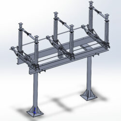
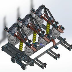
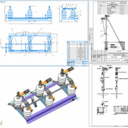
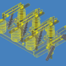
Двухколонковый разъединители SGF горизонтально-поворотного типа с номинальным напряжением 110 кВ
Состав: 3D Сборка ![]()
Софт: STEP AP214
Файлы:
-
Каталог
-
Промышленность
-
Энергетика
- Разъединитель SGF-123
Разъединитель.STEP
Чтобы скачать чертеж, 3D модель или проект, Вы должны зарегистрироваться
и принять участие в жизни сайта. Посмотрите, как тут скачивать файлы
Еще чертежи и проекты по этой теме:
Рейтинг: 80
Софт: Autodesk Inventor 2020
Состав: 3d сборки без метизов
0
1
2
Разъединители ИНТЕГРАЛ
Рейтинг: 100
Софт: Autodesk Inventor 2019
Состав: 3D Сборка
0
1
1
Разъединитель 10 кВ
Рейтинг: 50
Софт: SolidWorks 19
Состав: Модель одной деталью без истор
0
0
2
Высоковольтные разъединители НВА Коренево
Рейтинг: 50
Софт: КОМПАС-3D 17.1
Состав: 3D Сборка, Вид общий (ВО), Опо
0
19
6
Разъединитель РЛНД на 10 кВ
Рейтинг: 50
Софт: Autodesk Inventor 2015
Состав: 3D сборка
0
0
45
Разъединитель РВФЗ
Автор: BeeFeedOK
Дата: 2023-04-20
Просмотры:
75
- 110 кв
- 3D Модели
- Разъединитель
- Энергетика
Нет комментариев
Чтобы оставить комментарий, нужно войти на сайт
или войти с помощью: