-
Contents
-
Table of Contents
-
Bookmarks
Quick Links
AC Servo Drives
V
—
Series
USER’S MANUAL
Setup
Rotational Motor
SGDV SERVOPACK
SGMJV/SGMAV/SGMPS/SGMGV/SGMSV/SGMCS Servomotors
MANUAL NO. SIEP S800000 43G
Overview of Setup
Installation
Wiring and Connection
Safety Function
Trial Operation
(Checking Servomotor Operation)
1
2
3
4
5
Related Manuals for YASKAWA SGDV
Summary of Contents for YASKAWA SGDV
-
Page 1
AC Servo Drives Series USER’S MANUAL Setup Rotational Motor SGDV SERVOPACK SGMJV/SGMAV/SGMPS/SGMGV/SGMSV/SGMCS Servomotors Overview of Setup Installation Wiring and Connection Safety Function Trial Operation (Checking Servomotor Operation) MANUAL NO. SIEP S800000 43G… -
Page 2
All rights reserved. No part of this publication may be reproduced, stored in a retrieval system, or transmitted, in any form, or by any means, mechanical, electronic, photo- copying, recording, or otherwise, without the prior written permission of Yaskawa. No patent liability is assumed with respect to the use of the information contained herein. -
Page 3: About This Manual
Term Meaning Σ-V Series SGMJV, SGMAV, SGMPS, SGMGV, SGMSV, or Servomotor SGMCS (Direct Drive) servomotor Σ-V Series SGDV SERVOPACK SERVOPACK A set including a servomotor and SERVOPACK (i.e., a servo Servo Drive amplifier) A servo control system that includes the combination of a servo…
-
Page 4
Manuals Related to the Σ-V Series Refer to the following manuals as required. Selecting Trial Ratings Models Panels Operation Maintenance System Trial Name Specifi- Design Operation Peripheral Wiring Servo Inspection cations Devices Adjustment Σ-V Series Product Catalog (KAEP S800000 42) Σ-V Series User’s Manual Design and… -
Page 5
User’s Manual EtherCAT (CoE) Network Module (SIEP C720829 04) AC SERVOMOTOR Safety Precautions (TOBP C230200 00) Σ-V Series AC SERVOPACK SGDV Safety Precautions (TOBP C710800 10) Σ-V Series Option Module Safety Precautions (TOBP C720829 00) Σ-V Series Command Option Module… -
Page 6
(cont’d) Selecting Trial Ratings Models Panels Operation Maintenance System Trial Name Specifi- Design Operation Peripheral Wiring Servo Inspection cations Devices Adjustment Σ-V Series Indexer Module Installation Guide (TOBP C720829 02) Σ-V Series Feedback Option Module Installation Guide (TOBP C720829 03) Σ… -
Page 7
Safety Information The following conventions are used to indicate precautions in this manual. Failure to heed precautions provided in this manual can result in serious or possibly even fatal injury or damage to the products or to related equipment and systems. Indicates precautions that, if not heeded, could WARNING possibly result in loss of life or serious injury. -
Page 8: Safety Precautions
Safety Precautions These safety precautions are very important. Read them before performing any pro- cedures such as checking products on delivery, storage and transportation, installa- tion, wiring, operation and inspection, or disposal. Be sure to always observe these precautions thoroughly. WARNING •…
-
Page 9
WARNING • Provide an appropriate braking device on the machine side to ensure safety. The holding brake on a servomotor with a brake is not a braking device for ensuring safety. Failure to observe this warning may result in injury. •… -
Page 10
Storage and Transportation (cont’d) CAUTION • If disinfectants or insecticides must be used to treat packing materials such as wooden frames, pallets, or plywood, the packing materials must be treated before the product is packaged, and methods other than fumigation must be used. -
Page 11
Wiring CAUTION • Be sure to wire correctly and securely. Failure to observe this caution may result in motor overrun, injury, or malfunction. • Do not connect a commercial power supply to the U, V, or W terminals for the servomotor connection. Failure to observe this caution may result in injury or fire. -
Page 12
Wiring (cont’d) CAUTION • Do not reverse the polarity of the battery when connecting it. Failure to observe this caution may result in damage to the battery, the SERVO- PACK, or cause an explosion. • Wiring or inspection must be performed by a technical expert. •… -
Page 13
Operation (cont’d) CAUTION • When using JOG operations (Fn002) origin search operations (Fn003), or EasyFFT operations (Fn206), the dynamic brake function does not work for reverse overtravel or forward overtravel. Take necessary precautions. Failure to observe this caution may result in damage to the product. •… -
Page 14
• The drawings presented in this manual are typical examples and may not match the product you received. • If the manual must be ordered due to loss or damage, inform your nearest Yaskawa representative or one of the offices listed on the back of this manual. -
Page 15: Warranty
Limitations of Liability 1. Yaskawa shall in no event be responsible for any damage or loss of opportunity to the customer that arises due to failure of the delivered product. 2. Yaskawa shall not be responsible for any programs (including parameter settings) or the results of program execution of the programs provided by the user or by a third party for use with programmable Yaskawa products.
-
Page 16
Yaskawa product is used in combination with any other products. 2. The customer must confirm that the Yaskawa product is suitable for the systems, machines, and equipment used by the customer. 3. Consult with Yaskawa to determine whether use in the following applications is acceptable. -
Page 17: Applicable Standards
∗ Underwriters Laboratories Inc. European Standards EMC Directive Low Voltage Safety Model Directive Standards EN55011 EN954-1 EN50178 EN61800-3 SERVOPACK • SGDV group 1 class A, IEC61508- EN61800-5-1 EN61000-6-2 EN61800-3 1 to 4 • SGMJV IEC60034-1 • SGMAV EN55011 IEC60034-5 EN61800-3 Servomotor •…
-
Page 18: Table Of Contents
3.2 System Configuration Diagram ……… . 3-3 3.2.1 Connecting to SGDV- SERVOPACK (Analog Pulse Model) .
-
Page 19
4 Safety Function ……… . 4-1 4.1 Outline . -
Page 20: Overview Of Setup
Overview of Setup This chapter describes how to set up the Σ-V series of servo drives.
-
Page 21
1 Overview of Setup This chapter describes the flow of the setup procedure from installation until a JOG operation. A panel operator, a digital operator, and SigmaWin+, (which is an engi- neering tool that can be used with a PC) are available to set up a servo drive. The panel operator is included with the SERVOPACK of analog pulse models, and the digital operator and SigmaWin+ are sold separately. -
Page 22: Installation
2.4 EMC Installation Conditions ……2-13 2.4.1 SGDV- (Analog Pulse Model) ….2-13 2.4.2 SGDV-…
-
Page 23: Installation Environment And Applicable Standards
2 Installation 2.1.1 Servomotor Installation Environment Installation Environment and Applicable Standards The installation environment and the applicable standards for servomotors and SERVOPACKs are described in this section. 2.1.1 Servomotor Installation Environment Ambient temperature: 0 to 40°C Ambient humidity: 80% RH or less (with no condensation) Altitude: 1, 000 m or less Vibration resistance The servomotor will withstand the following…
-
Page 24: Servopack Installation Environment
2.1 Installation Environment and Applicable Standards 2.1.2 SERVOPACK Installation Environment Surrounding air temperature: 0 to 55°C Ambient humidity: 90% RH or less (with no condensation) Altitude: 1,000 m or less Vibration resistance: 4.9 m/s Shock resistance: 19.6 m/s Installation Precautions •…
-
Page 25: Installation Conditions For Applicable Standards
Conditions Protection class: IP10 UL Standard and Low Voltage Directive: Σ Satisfy the conditions outlined in -V Series AC SERVOPACK SGDV Safety Installation Precautions (TOBP C710800 10) Conditions EMC Directive: Certification is required after installation in the user’s machine under the…
-
Page 26: Servomotor Installation
2.2 Servomotor Installation Servomotor Installation 2.2.1 Orientation Servomotors can be installed either horizontally or vertically. Servomotors with gears can be installed only horizontally, depending on gear lubrica- Σ tion conditions. Refer to -V Series Product Catalog (KAEP S800000 42) for details. 2.2.2 Installation Standards The motor rated specifications (rated output, rated torque, and rated speed) are the…
-
Page 27: Connecting Servomotor To Machine
2 Installation 2.2.3 Connecting Servomotor to Machine 2.2.3 Connecting Servomotor to Machine The end of the motor shaft is coated with anticorrosive paint. Thoroughly remove the paint prior to installation. Align the shaft of the servomotor with the shaft of the machine, and then couple the shafts.
-
Page 28: Protective Structure
2.2 Servomotor Installation 2.2.4 Protective Structure The servomotor protective structure is described below. Model Without Gears With Gears SGMJV, SGMAV IP65 IP55 IP55 SGMPS IP55 IP67 (Optional) − SGMGV IP67 IP67 − SGMSV (SGMSV-70 servomotor only: IP22) IP42 − SGMCS-02 to -35 (expect for gaps on the rotating section of the shaft) −…
-
Page 29: Other Precautions
2 Installation 2.2.5 Other Precautions 2.2.5 Other Precautions Handling Oil and Water If the servomotor is used in a location that is subject to water or oil mist, use a servo- motor with an oil seal to seal the through shaft section. Precautions on using a servo- motor with an oil seal are described below.
-
Page 30: Servopack Installation
2.3 SERVOPACK Installation SERVOPACK Installation 2.3.1 Orientation The SERVOPACK is available in models that are base-mounted, models that are rack-mounted, and models that are duct-ventilated. In any case, mount the SERVO- PACK with a vertical orientation. Firmly secure the SERVOPACK to the mounting surface, using either two or four mounting holes depending on the SERVOPACK capacity.
-
Page 31
2 Installation 2.3.1 Orientation • Duct-ventilated Duct Air Flow 2-10… -
Page 32: Installation Standards
Leave sufficient space on each side and at the top and the bottom of each SERVO- PACK. The width on each side varies in accordance with the models of the SERVO- PACKS used. Side SERVOPACK Model Top and bottom SGDV- Left Right R70F, R90F, 2R1F, 1 mm or more R70A, R90A, 1R6A, 2R8A…
-
Page 33
The conditions inside the control panel should be the same as the environmental con- ditions of the SERVOPACK. Refer to 2.1.2 SERVOPACK Installation Environment. The SGDV- B SERVOPACKs have an Installation Environment monitor (Un022). With this monitor, operation conditions in the installation environment can be observed and measured. -
Page 34: Emc Installation Conditions
SERVOPACK models such as the rack-mounted types as well. This section describes the EMC installation conditions satisfied in test conditions prepared by Yaskawa. The actual EMC level may differ depending on the actual sys- tem’s configuration, wiring, and other conditions. However, because this product is built-in, check that the following conditions are still met after being installed in the user’s product.
-
Page 35
2 Installation 2.4.1 SGDV- (Analog Pulse Model) Three-phase 200 V • SGDV- A01B ( = R70, R90, 1R6, 2R8) Shield box Brake Power Supply SERVOPACK Brake U, V, W Power supply: Noise L1, L2, L3 Three-phase filter 200 VAC Servomotor… -
Page 36
2.4 EMC Installation Conditions Three-phase 200 V • SGDV- A01A ( = R70, R90, 1R6, 2R8, 3R8, 5R5, 7R6) Shield box Brake Power Supply SERVOPACK Brake U, V, W Power supply: Noise L1, L2, L3 Three-phase filter 200 VAC Servomotor… -
Page 37
2 Installation 2.4.1 SGDV- (Analog Pulse Model) Three-phase 200 V • SGDV- A01A ( = 120) Shield box Brake Power Supply SERVOPACK Brake U, V, W Power supply: Noise L1, L2, L3 Three-phase filter 200 VAC Servomotor One turn L1C, L2C… -
Page 38
2.4 EMC Installation Conditions Three-phase 200 V • SGDV- A01A ( = 180, 200, 330) Shield box Brake Power Supply SERVOPACK Brake U, V, W Power supply: Noise L1, L2, L3 Three-phase filter 200 VAC Servomotor One turn L1C, L2C… -
Page 39
2 Installation 2.4.1 SGDV- (Analog Pulse Model) Three-phase 200 V • SGDV- A01A ( = 470, 550, 590, 780) Shield box Cooling fan Brake Power Supply SERVOPACK Brake U, V, W Power supply: Noise L1, L2, L3 Three-phase filter 200 VAC… -
Page 40
2.4 EMC Installation Conditions Three-phase 400 V • SGDV- D01A ( = 1R9, 3R5, 5R4, 8R4, 120, 170) Shield box Power supply: Noise Brake Power Single-phase Supply filter* 200 VAC Surge SERVOPACK absorber Control Brake power U, V, W 24 V, 0 V… -
Page 41
2 Installation 2.4.1 SGDV- (Analog Pulse Model) Three-phase 400 V • SGDV- D01A ( = 210, 260, 280, 370) Shield box Power supply: Noise Brake Power Single-phase Supply filter* 200 VAC Surge SERVOPACK Control absorber Brake power U, V, W… -
Page 42: Sgdv- (M-Ii Model)
2.4 EMC Installation Conditions 2.4.2 SGDV- (M-II Model) Single-phase 100 V • SGDV- F11A ( = R70, R90, 2R1, 2R8) Shield box Brake Power Supply One turn SERVOPACK Brake U, V, W Power supply: Noise L1, L2 Single-phase filter 100 VAC…
-
Page 43
2 Installation 2.4.2 SGDV- (M-II Model) Three-phase 200 V • SGDV- A11B ( = R70, R90, 1R6, 2R8) Shield box Brake Power Supply SERVOPACK Brake U, V, W Power supply: Noise L1, L2, L3 Three-phase filter 200 VAC Servomotor Surge… -
Page 44
2.4 EMC Installation Conditions Three-phase 200 V • SGDV- A11A ( = R70, R90, 1R6, 2R8, 3R8, 5R5, 7R6) Shield box Brake Power Supply SERVOPACK Brake U, V, W Power supply: Noise L1, L2, L3 Three-phase filter 200 VAC Servomotor… -
Page 45
2 Installation 2.4.2 SGDV- (M-II Model) Three-phase 200 V • SGDV- A11A ( = 120) Shield box Brake Power Supply SERVOPACK Brake U, V, W Power supply: Noise L1, L2, L3 Three-phase filter 200 VAC Servomotor One turn Surge L1C, L2C… -
Page 46
2.4 EMC Installation Conditions Three-phase 200 V • SGDV- A11A ( = 180, 200, 330) Shield box Brake Power Supply SERVOPACK Brake U, V, W Power supply: Noise L1, L2, L3 Three-phase filter 200 VAC Servomotor One turn Surge L1C, L2C… -
Page 47
2 Installation 2.4.2 SGDV- (M-II Model) Three-phase 200 V • SGDV- A11A ( = 470, 550, 590, 780) Shield box Cooling fan Brake Power Supply SERVOPACK Brake U, V, W Power supply: Noise L1, L2, L3 Three-phase filter 200 VAC… -
Page 48
2.4 EMC Installation Conditions Three-phase 400 V • SGDV- D11A ( = 1R9, 3R5, 5R4, 8R4, 120, 170) Shield box Power supply: Brake Power Noise Single-phase Supply filter* 200 VAC Surge SERVOPACK absorber Control Brake power U, V, W 24 V, 0 V… -
Page 49
2 Installation 2.4.2 SGDV- (M-II Model) Three-phase 400 V • SGDV- D11A ( = 210, 260, 280, 370) Shield box Power supply: Brake Power Noise Single-phase Supply filter* 200 VAC Surge SERVOPACK absorber Control Brake power U, V, W 24 V, 0 V… -
Page 50: Sgdv- (M-Iii Model)
2.4 EMC Installation Conditions 2.4.3 SGDV- (M-III Model) Single-phase 100 V • SGDV- F21A ( = R70, R90, 2R1, 2R8) Shield box Brake Power Supply One turn SERVOPACK Brake U, V, W Noise Power supply: L1, L2 filter Single-phase 100 VAC…
-
Page 51
2 Installation 2.4.3 SGDV- (M-III Model) Three-phase 200 V • SGDV- A21B ( = R70, R90, 1R6, 2R8) Shield box Brake Power Supply SERVOPACK Brake U, V, W Power supply: Noise L1, L2, L3 Three-phase filter 200 VAC Servomotor Surge… -
Page 52
2.4 EMC Installation Conditions Three-phase 200 V • SGDV- A21A ( =R70, R90, 1R6, 2R8, 3R8, 5R5, 7R6) Shield box Brake Power Supply SERVOPACK Brake U, V, W Noise Power supply: L1, L2, L3 filter Three-phase 200 VAC 5 Servomotor… -
Page 53
2 Installation 2.4.3 SGDV- (M-III Model) Three-phase 200 V • SGDV- A21A ( = 120) Shield box Brake Power Supply SERVOPACK Brake U, V, W Noise Power supply: L1, L2, L3 filter Three-phase 200 VAC Servomotor One turn L1C, L2C… -
Page 54
2.4 EMC Installation Conditions Three-phase 200 V • SGDV- A21A ( = 180, 200, 330) Shield box Brake Power Supply SERVOPACK Brake U, V, W Noise Power supply: L1, L2, L3 filter Three-phase 200 VAC Servomotor One turn L1C, L2C… -
Page 55
2 Installation 2.4.3 SGDV- (M-III Model) Three-phase 200 V • SGDV- A21A ( = 470, 550, 590, 780) Shield box Brake Power Cooling fan Supply SERVOPACK Brake U, V, W Noise Power supply: L1, L2, L3 filter Three-phase 200 VAC 5… -
Page 56
2.4 EMC Installation Conditions Three-phase 400 V • SGDV- D21A ( = 1R9, 3R5, 5R4, 8R4, 120, 170) Shield box Power supply: Brake Power Single-phase Supply 200 VAC SERVOPACK Control Brake Noise 24 V, Surge power U, V, W absorber… -
Page 57
2 Installation 2.4.3 SGDV- (M-III Model) Three-phase 400 V • SGDV- D21A ( = 210, 260, 280, 370) Shield box Power supply: Brake Power Single-phase Supply 200 VAC SERVOPACK Control Brake Surge Noise power 24 V, U, V, W absorber… -
Page 58: Sgdv- E1A (Command Option Attachable Type)
2.4 EMC Installation Conditions 2.4.4 SGDV- E1A (Command Option Attachable Type) For SERVOPACKs of command option attachable type, EMC installation conditions may differ depending on the attached option module. For details, refer to the user’s manual for each option module.
-
Page 59: Wiring And Connection
3.1 Precautions for Wiring ……. . 3-2 3.2 System Configuration Diagram ……3-3 3.2.1 Connecting to SGDV- SERVOPACK (Analog Pulse Model) .
-
Page 60: Precautions For Wiring
3 Wiring and Connection Precautions for Wiring CAUTION • Be sure to wire correctly and securely. Failure to observe this caution may result in motor overrun, injury, or malfunction. • Do not bundle or run the main circuit cables together with the I/O signal cables or the encoder cables in the same duct.
-
Page 61: System Configuration Diagram
3.2 System Configuration Diagram System Configuration Diagram 3.2.1 Connecting to SGDV- SERVOPACK (Analog Pulse Model) SGDV- F01A Power supply Single-phase 100 VAC Molded-case circuit breaker (MCCB) Protects the power supply line by shutting the circuit OFF when overcurrent is detected.
-
Page 62: Connecting To Sgdv
3 Wiring and Connection 3.2.1 Connecting to SGDV- SERVOPACK (Analog Pulse Model) SGDV- • Using a Three-phase, 200-V Power Supply Power supply Three-phase 200 VAC R S T Molded-case circuit breaker (MCCB) Protects the power supply line by shutting the…
-
Page 63
Single-phase 200 VAC Molded-case circuit breaker (MCCB) Protects the power supply line by shutting the circuit OFF when overcurrent is detected. Digital SGDV- operator SERVOPACK Noise filter Used to eliminate external noise from Magnetic the power line. contactor Turns the servo Personal ON and OFF. -
Page 64
3 Wiring and Connection 3.2.1 Connecting to SGDV- SERVOPACK (Analog Pulse Model) SGDV- D01A Power supply Three-phase 400 VAC R S T Molded-case circuit breaker (MCCB) Protects the power supply line by shutting the circuit OFF when overcurrent is detected. -
Page 65: Servopack (M-Ii Model)
3.2 System Configuration Diagram 3.2.2 Connecting to SGDV- SERVOPACK (M-II Model) SGDV- F11A Power supply Single-phase 100 VAC Molded-case circuit breaker (MCCB) Protects the power supply line by shutting the circuit OFF when overcurrent is detected. Noise filter Used to eliminate external noise from the power line.
-
Page 66
3 Wiring and Connection 3.2.2 Connecting to SGDV- SERVOPACK (M-II Model) SGDV- • Using a Three-phase, 200-V Power Supply Power supply Three-phase 200 VAC R S T Molded-case circuit breaker (MCCB) Protects the power supply line by shutting the circuit OFF when overcurrent is detected. -
Page 67
Single-phase 200 VAC Molded-case circuit breaker (MCCB) Protects the power supply line by shutting the circuit OFF when overcurrent is detected. Connect to the SGDV- MECHATROLINK-II SERVOPACK Digital Noise filter operator Used to eliminate external noise from Magnetic the power line. -
Page 68
3 Wiring and Connection 3.2.2 Connecting to SGDV- SERVOPACK (M-II Model) SGDV- D11A Power supply Three-phase 400 VAC R S T Molded-case circuit breaker (MCCB) Protects the power supply line by shutting the circuit OFF when overcurrent is detected. Noise filter… -
Page 69
3.2 System Configuration Diagram 3.2.3 Connecting to SGDV- SERVOPACK (M-III Model) SGDV- F21A Power supply Single-phase 100 VAC Molded-case circuit breaker (MCCB) Protects the power supply line by shutting the circuit OFF when overcurrent is detected. Noise filter SGDV- F21A… -
Page 70: Servopack (M-Iii Model)
3 Wiring and Connection 3.2.3 Connecting to SGDV- SERVOPACK (M-III Model) SGDV- • Using a Three-phase, 200-V Power Supply Power supply Three-phase 200 VAC R S T Molded-case circuit breaker (MCCB) Protcts the power supply line by shutting the circuit OFF when overcurrent is detected.
-
Page 71
Power supply Single-phase 200 VAC Molded-case circuit breaker (MCCB) Protcts the power supply line by shutting the circuit OFF when overcurrent is detected. SGDV- SERVOPACK Noise filter Digital operator Used to eliminate Connect to the external noise from MECHATROLINK-III. the power line. -
Page 72
3 Wiring and Connection 3.2.3 Connecting to SGDV- SERVOPACK (M-III Model) SGDV- D21A Power supply Three-phase 400 VAC R S T Molded-case circuit breaker MCCB) Protects the power supply line by shutting the circuit OFF when overcurrent is detected. Noise filter… -
Page 73
3.2 System Configuration Diagram 3.2.4 Connecting to SGDV- E1A SERVOPACK (Command Option Attachable Type) SGDV- FE1A Power supply Single-phase 100 VAC Molded-case circuit breaker (MCCB) Protects the power supply line by shutting the circuit OFF when overcurrent is detected. Noise filter… -
Page 74: Connecting To Sgdv- E1A Servopack
3 Wiring and Connection 3.2.4 Connecting to SGDV- E1A SERVOPACK (Command Option Attachable Type) SGDV- AE1A • Using a Three-phase, 200-V Power Supply Power supply Three-phase 200 VAC R S T Molded-case circuit breaker (MCCB) Protects the power supply line by shutting the…
-
Page 75
(MCCB) Protects the power supply line by shutting the circuit OFF when overcurrent is detected. Digital operator Noise filter SGDV- AE1A Used to eliminate SERVOPACK external noise from the power line. Option module Personal Connection cable computer for digital operator… -
Page 76
3 Wiring and Connection 3.2.4 Connecting to SGDV- E1A SERVOPACK (Command Option Attachable Type) SGDV- DE1A Power supply Three-phase 400 VAC R S T Molded-case circuit breaker (MCCB) Protects the power supply line by shutting the circuit OFF when overcurrent is detected. -
Page 77: Main Circuit Wiring
Names and Functions of Main Circuit Terminals SGDV-1R6AE1A Command Option Analog Pulse Models M-II Models M-III Models Attachable Types Terminal Name Model SGDV- Description Symbols Single-phase 100 to 115 V, L1, L2 +10% to -15% (50/60 Hz) Main circuit input Three-phase 200 to 230 V, terminals…
-
Page 78: Servopack Main Circuit Wire Size
3 Wiring and Connection 3.3.2 SERVOPACK Main Circuit Wire Size (cont’d) Terminal Name Model SGDV- Description Symbols If the regenerative capacity is insuf- R70F, R90F, 2R1F, 2R8F, ficient, connect an external regener- R70A, R90A, 1R6A, ative resistor (option) between B1/ 2R8A and B2.
-
Page 79
3.3 Main Circuit Wiring Wire Types Use the following type of wire for main circuit. Cable Type Allowable Conductor Temperature °C Symbol Name 600 V polyvinyl chloride insulated wire 600 V grade heat-resistant polyvinyl chloride insulated wire The following table shows the wire sizes and allowable currents for three wires. Use wires with specifications equal to or less than those shown in the table. -
Page 80
3 Wiring and Connection 3.3.2 SERVOPACK Main Circuit Wire Size Single-phase, 100 V SERVOPACK Model SGDV- Terminal External Terminal Name Symbols Main circuit power input L1, L2 HIV1.25 HIV2.0 terminals Control power input terminals L1C, L2C HIV1.25 Servomotor connection U, V, W HIV1.25… -
Page 81
3.3 Main Circuit Wiring Three-phase, 400 V SERVOPACK Model SGDV- External Terminal Terminal Name Symbols 1R9 3R5 5R4 8R4 120 170 210 260 280 370 Main circuit power input L1, L2, L3 HIV1.25 HIV2.0 HIV3.5 14.0 terminals Control power 24V, 0V HIV1.25… -
Page 82: Typical Main Circuit Wiring Examples
ON and OFF. • After the actual operation starts, the allowable interval for turn- ing power ON and OFF is one hour or longer. The following wiring examples show the Σ-V Series SGDV SERVOPACK (Analog pulse model). Single-phase 100 V, SGDV-…
-
Page 83
1KM: Magnetic contactor (for control power supply) 2KM: Magnetic contactor (for main power supply) 3SA: Surge absorber 1D: Flywheel diode 1Ry: Relay ∗ For SGDV-R70A, -R90A, -1R6A, -2R8A, terminals B2 and B3 are not short-circuited. • SGDV-470A, 550A, 590A, 780A R S T SERVOPACK SGDV-… -
Page 84
3 Wiring and Connection 3.3.3 Typical Main Circuit Wiring Examples Three-phase 400 V, SGDV- • SGDV-1R9D, 3R5D, 5R4D, 8R4D, 120D, 170D R S T SERVOPACK SGDV- 1FIL DC power 24 V supply − 24 V (For servo +24 V alarm display) -
Page 85
3.3 Main Circuit Wiring Precautions When Using More Than One SERVOPACK This section shows an example of the wiring when more than one SERVOPACK is used and the precautions. • Wiring Example (Analog pulse model) Connect the alarm output (ALM) terminals for the three SERVOPACKs in series to enable alarm detection relay 1RY to operate. -
Page 86: Wiring The Main Circuit Terminal Connector (Spring Type)
Two types of main circuit terminals are available: a connector type and a terminal screw type. • SERVOPACKs with terminal screws: SGDV-180A, 200A, 330A, 470A, 550A, 590A, 780A, 8R4D, 120D, 170D, 210D, 260D, 280D, 370D • SERVOPACKs with connectors: SGDV-R70F, R90F, 2R1F, 2R8F, R70A, R90A, 1R6A, 2R8A, 3R8A, 5R5A, 7R6A, 120A, 1R9D, 3R5D, 5R4D A spring connector is used for SERVOPACKs with connectors.
-
Page 87
3.3 Main Circuit Wiring Wiring Procedure Remove the main circuit terminal connector from the SERVOPACK. Enlarged View 1 Press the lock. 2. Remove the main circuit terminal connector while pressing the lock. Main circuit Lock terminal connector Strip the end of the wires. Applicable wire sizes: Refer to 3.3.2 SERVOPACK Main Circuit Wire Size. -
Page 88
3 Wiring and Connection 3.3.4 Wiring the Main Circuit Terminal Connector (Spring Type) Using a screwdriver Use a commercially available flat-blade screwdriver with a blade width of 3.0 to 3.5 mm. Insert the screwdriver into the slot and press down firmly to open the wire termi- nal. -
Page 89: Connecting Regenerative Resistors
• Be sure to connect the regenerative resistor correctly. Failure to observe this warning may result in fire or damage to the product. 3.4.1 Connecting Regenerative Resistor SERVOPACKs: Model SGDV-R70F, R90F, 2R1F, 2R8F, R70A, R90A, 1R6A, 2R8A Connect an external regenerative resistor between B1/ and B2 terminals. After connecting a resistor, select the capacity.
-
Page 90
3 Wiring and Connection 3.4.1 Connecting Regenerative Resistor SERVOPACKs: Model SGDV-3R8A, 5R5A, 7R6A, 120A, 180A, 200A, 330A, 1R9D, 3R5D, 5R4D, 8R4D, 120D, 170D Disconnect the wiring between the SERVOPACK’s B2 and B3 terminals and connect an external regenerative resistor between the B1/ and B2 terminals or between the B1 and B2 terminals. -
Page 91
3.4 Connecting Regenerative Resistors SERVOPACKs: Model SGDV-470A, 550A, 590A, 780A, 210D, 260D, 280D, 370D No built-in regenerative resistor is provided, so the external regenerative resistor is required. The regenerative resistor units are as follow: Main Applicable Applicable Circuit Resistance SERVOPACK… -
Page 92: Safety Function
Safety Function This chapter describes the safety functions. 4.1 Outline ……….4-2 4.2 Hard Wire Base Block (HWBB) Function .
-
Page 93: Outline
4 Safety Function Outline The safety function is incorporated in the SERVOPACK to reduce the risk associated with the machine by protecting workers from injury and by securing safe machine operation. Especially when working in hazardous areas inside the safeguard, as for machine maintenance, it can be used to avoid adverse machine movement.
-
Page 94: Hard Wire Base Block (Hwbb) Function
4.2 Hard Wire Base Block (HWBB) Function Hard Wire Base Block (HWBB) Function The Hard Wire Base Block function (hereinafter referred to as HWBB function) is a safety function designed to baseblock the motor (shut off the motor current) by using the hardwired circuits: Each circuit for two channel input signals blocks the run sig- nal to turn off the power module, and the motor current is shut off.
-
Page 95: Safety Function Signal (Cn8) Names And Functions
4 Safety Function Safety Function Signal (CN8) Names and Functions The following table shows the terminal layout of safety function signals (CN8). Signal Pin No. Function Name − − − − − − /HWBB1- Hard wire baseblock input 1 Hard wire baseblock input /HWBB1+ Baseblock (motor current off) /HWBB2-…
-
Page 96: Connecting A Safety Function Device
Remove the servomotor connection terminal connector while pressing the lock. Applicable SERVOPACKs: SGDV-R70F, -R90F, -2R1F, -R70A, -R90A, -1R6A, -2R8A, -1R9D, -3R5D, — 5R4D For SERVOPACK models not listed above, it is not necessary to remove the servomotor connection terminal connector. Go to step 2.
-
Page 97
4 Safety Function <Using previous model> Slide the lock injector of the safety function’s jumper connector to the SERVOPACK side to unlock and remove the safety function’s jumper connector. Enlarged View 1. Slide the lock injector to the SERVOPACK side. Remove the safety function’s jumper connector while the lock injector is slid Safety function’s… -
Page 98: Trial Operation (Checking Servomotor Operation)
Trial Operation (Checking Servomotor Operation) This chapter describes how to perform trial operation. 5.1 Outline ……….5-2 5.2 Inspection and Checking before Trial Operation .
-
Page 99: Outline
5 Trial Operation (Checking Servomotor Operation) Outline The trial operation described here is a JOG operation for servomotors not connected to machinery (without a load). The purpose of this trial operation is to check whether the SERVOPACK and servomotor are properly connected and whether the servomo- tor is operating normally.
-
Page 100
5.2 Inspection and Checking before Trial Operation An example of the circuit wiring Servomotor SERVOPACK with brake Power supply 24 VDC power supply Brake power supply 24 VDC or 90 VDC A 24 VDC power supply is not included. Brake power supply Input voltage of 200 V: LPSE-2H01-E Input voltage of 100 V: LPDE-1H01-E Configure the relay circuit to apply the holding brake by the emer- gency stop. -
Page 101
5 Trial Operation (Checking Servomotor Operation) Installing the Servomotor and SERVOPACK Install the servomotor and SERVOPACK according to the installation conditions. Secure the mounting plate of the servomotor to the equipment. Do not connect any load to the shaft. <Note> •… -
Page 102: Jog Operation Using A Panel Operator
5.3 JOG Operation Using a Panel Operator JOG Operation Using a Panel Operator This section describes the procedure for executing a JOG operation using a panel operator. The panel operator is located under the front cover of the SERVOPACK (analog pulse models only).
-
Page 103
5 Trial Operation (Checking Servomotor Operation) (cont’d) Step Display after operation Keys Operation Press the Up Cursor Key to rotate the ser- vomotor in the forward direction and press the Down Cursor Key to rotate it in reverse. The servomotor will operate while the key is being pressed. -
Page 104: Jog Operation Using A Digital Operator
Connect the digital operator to the SERVOPACK CN3 connector. Σ-V series Σ-III series JUSP-OP05A-1-E JUSP-OP05A Digital Operator Digital Operator SGDV SERVOPACK Digital operator conversion conneotor Model: JZSP-CVS05-A3-E Insert securely into SERVOPACK CN3 connector. The digital operator can be connected or removed while the SERVOPACK power is…
-
Page 105
5 Trial Operation (Checking Servomotor Operation) (cont’d) Step Display after operation Keys Operation − J O G − P n 3 0 4 = 0 0 5 0 0 Press the Key. U n 0 0 0 = 0 0 0 0 0 The display changes to the execution display of Fn002. -
Page 106
5.4 JOG Operation Using a Digital Operator (cont’d) Step Display after operation Keys Operation Press the Key twice to return to the initial display (step 1). Alarm Display An alarm is automatically displayed if a problem occurs for some reason. Check the alarm using the user’s manual for the corresponding SERVOPACK or command Σ… -
Page 107: Jog Operation Using Sigmawin
5 Trial Operation (Checking Servomotor Operation) JOG Operation Using SigmaWin+ This section describes the procedure for executing a JOG operation using Sig- maWin+. In the following example, test-run procedures are explained using the JOG operation window of Test Run on the main menu of SigmaWin+. Step Operation Display…
-
Page 108
5.5 JOG Operation Using SigmaWin+ (cont’d) Step Operation Display (5) Once SigmaWin+ is started, the connec- tion window is displayed. Note: is used for operation with no SERVOPACK connected. Click to search for the con- nected SERVOPACK. Connection Window (6) Search Condition Setting window is open. Select only Σ-V Select Σ-V( ), and click… -
Page 109
5 Trial Operation (Checking Servomotor Operation) (cont’d) Step Operation Display • Run test operation. Test Run (R) → Jog (J) (1) Select Test Run first, and then select Jog (J) from the menu on the main window. Main Window (2) Warnings for the JOG operation window will be displayed. -
Page 110
5.5 JOG Operation Using SigmaWin+ (cont’d) Step Operation Display • Set the JOG speed The motor speed is set to 500 [min ]. Click if you need to change it. • Servo ON Click . The display changes from Servo OFF to Servo ON and is lit in green. 5-13… -
Page 111
5 Trial Operation (Checking Servomotor Operation) (cont’d) Step Operation Display • Start JOG operation. When you click the servomotor will rotate in the forward direction. When you click it will rotate in reverse. Confirm that the servomotor operation is cor- rect. -
Page 112: Revision History
June 2011 <5> Preface Deletion: Description of “(will be available soon.)” Revision: Illustration of CD March 2011 <4> 2.3.2, 2.4.1, Addition: Description of SGDV-B SERVOPACKs 2.4.2, 3.2.1, 3.2.2 February 2011 <3> Front cover Revision: Format Back cover Revision: Address and format June 2009 <2>…
-
Page 113
Phone 81-4-2962-5151 Fax 81-4-2962-6138 http://www.yaskawa.co.jp YASKAWA AMERICA, INC. 2121, Norman Drive South, Waukegan, IL 60085, U.S.A. Phone 1-800-YASKAWA (927-5292) or 1-847-887-7000 Fax 1-847-887-7310 http://www.yaskawa.com YASKAWA ELÉTRICO DO BRASIL LTDA. 777, Avenida Piraporinha, Diadema, São Paulo, 09950-000, Brasil Phone 55-11-3585-1100 Fax 55-11-3585-1187 http://www.yaskawa.com.br…
- Manuals
- Brands
- YASKAWA Manuals
- Servo Drives
- SGDV-330A
Manuals and User Guides for YASKAWA SGDV-330A. We have 2 YASKAWA SGDV-330A manuals available for free PDF download: Manual, Safety Precautions

YASKAWA SGDV-330A Manual (53 pages)
Brand: YASKAWA
|
Category: Servo Drives
|
Size: 5.41 MB
Table of Contents
Advertisement

YASKAWA SGDV-330A Safety Precautions (33 pages)
AC Servopack
Brand: YASKAWA
|
Category: Servo Drives
|
Size: 1.04 MB
Table of Contents
-
Notes for Safe Operation
4
-
Storage and Transportation
7
-
Maintenance and Inspection
12
-
Checking Products on Delivery
14
-
Servopack’s Parts Replacement Schedule
22
-
Overload Characteristics
30
Advertisement
Related Products
-
YASKAWA SGDV-370D
-
YASKAWA SGDV-3R8AE5A
-
YASKAWA SGDV-330AE5A
-
YASKAWA SGDV-3R5DE5A
-
YASKAWA SGDV-3R8A
-
YASKAWA SGDV-3R5D
-
YASKAWA SGDV-2R8AE5A
-
YASKAWA SGDV-200AE5A
-
YASKAWA SGDV-7R6A
-
YASKAWA SGDV-1R9D
YASKAWA Categories
Controller
DC Drives
Servo Drives
Robotics
Control Unit
More YASKAWA Manuals
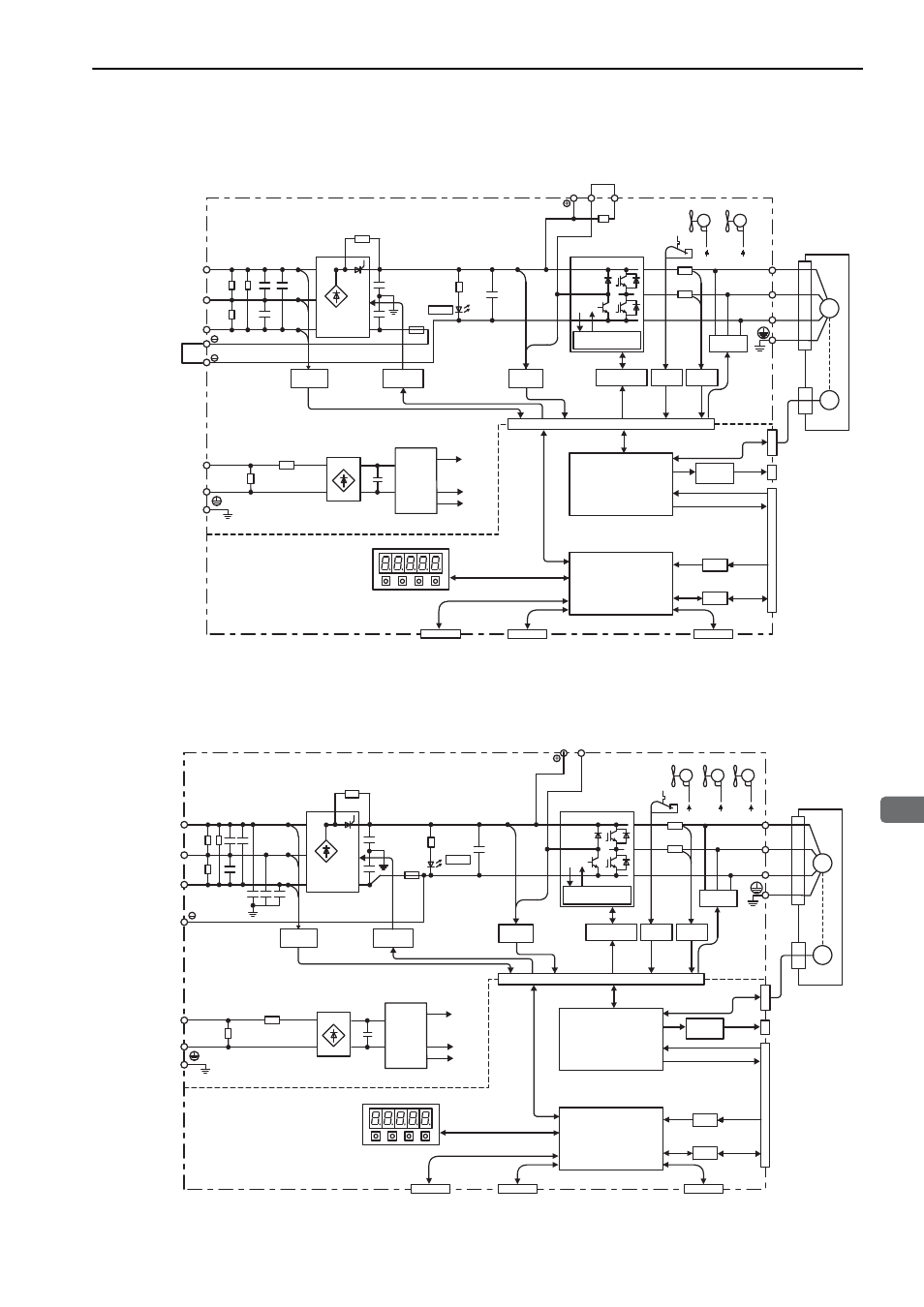
1.4 SERVOPACK Internal Block Diagrams
1-13
1
Outline
1.4.9 Three-phase 200 V, SGDV-330A01A Model
1.4.10 Three-phase 200 V, SGDV-470A01A, -550A01A Models
L1
B1/ B2 B3
L2
L3
1
2
L1C
L2C
U
V
W
CN3
CN2
ENC
A/D
I/O
CN1
CN5
M
CHARGE
CN7
CN8
Varistor
+
–
+
–
+15 V
× 4
±12 V
+5 V
Current
sensor
Dynamic
brake circuit
Servomotor
Gate drive
Voltage
sensor
Voltage
sensor
Varistor
Temperature
sensor
Thyristor
drive
Fan 2
Fan 1
ASIC
(PWM control, etc.)
CPU
(Position/speed
calculation, etc.)
Panel operator
Digital operator
Analog monitor
output
Reference pulse
input
Rference voltage input
I/O signal
Analog
voltage
converter
Personal
computer
Signal for safety function
Overheat protector,
overcurrent protector
Control
power
supply
±
12 V
±
12 V
Main circuit
power supply
Control power
supply
Encoder output pulse
Analog
L1
B1/ B2
L2
L3
L1C
L2C
U
V
W
CN3
CN2
ENC
A/D
I/O
CN1
CN5
M
CHARGE
CN7
CN8
+15 V
× 4
±
12 V
+5 V
±
12 V
±
12 V
±
12 V
Current
sensor
Dynamic
brake circuit
Servomotor
Gate
drive
Voltage
sensor
Voltage
sensor
Varistor
Varistor
Temperature
sensor
Thyristor
drive
Fan 1
Fan 2
Fan 3
ASIC
(PWM control, etc.)
CPU
(Position/speed
calculation, etc.)
Panel operator
Digital operator
Analog monitor
output
Reference pulse
input
Rference voltage input
I/O signal
Analog
voltage
converter
Personal
computer
Signal for safety function
Control
power
supply
Overheat protector,
overcurrent protector
Main circuit
power supply
Control power
supply
Encoder output pulse
+
–
+
–
Analog
![]()
Рекомендуемые сообщения
-
#1
Всем доброго времени суток!
Начну по порядку:
Имеется станок с ЧПУ на котором установлены 3 оси под управлением Yaskawa.
На проблемной оси, которая уходила в ошибку энкодера (С.90) заменили кабель (на подручный, не экранированный 6-ти жильный с большим сопротивлением x6) Ошибка исчезла и более не беспокоила.
Станок нормально функционировал 3 месяца(на неэкранированном кабеле)сейчас стоит витая пара FTP(оригинальный кабель ждём)
Сейчас проблема возникает при обработке длинных заготовок, короткие выходят в размер.
Погрешность не постоянная и набегает примерно на 1 М — 1ММ, максимум 12М заготовка. То есть на большой заготовке набег минимум 10ММ и максимум 16ММ было замечано.
Ещё из энкодера серводвигателя слышен нехарактерный писк.
Сервоусилитель при этом никаких неисправностей не сообщает. Но погрешность набегает пропорционально длине заготовки в любом случае.
Вопрос заключается в следующем:
Могли ли мы по неопытности «поджечь» энкодер неэкранированным кабелем, что он ошибается в позиционировании ?
Могла ли сварка узлов линии без отключения силовых и кабеля энкодера повредить n-кодер ?
Изменено 11.12.2019 03:42 пользователем RegEdit
Поделиться сообщением
Ссылка на сообщение
-
#2
Пожечь энкодер можно, но по вашему проявлению неисправности это маловероятно.
Кабель неэкранированный, а на разъеме энкодера для экрана был контакт?
В общем по проявлению неисправности я бы полез крутить ось руками, щупать механику. Проверять муфты и прочие мехсоединения на проскальзывание.
Поделиться сообщением
Ссылка на сообщение
-
#3
Если бы энкодер терял импульсы, то система бы выдавала ошибку однозначно. И что то долго кабель идет, видимо так «сильно» надо.
Поделиться сообщением
Ссылка на сообщение
-
#4
1 час назад, Pavel47 сказал:
Если бы энкодер терял импульсы, то система бы выдавала ошибку однозначно. И что то долго кабель идет, видимо так «сильно» надо.
Да, я тоже уверен, что серва уже бы выдала аларм, там это предусмотрено, на сколько я знак, как в любой серве.
Доставка и необходимость кабеля — это проблема руководства уже, а не моя.
2 часа назад, pchel сказал:
Кабель неэкранированный, а на разъеме энкодера для экрана был контакт?
На сколько я знаю там есть для него контакт, вот даташит:

Изменено 11.12.2019 06:16 пользователем RegEdit
Поделиться сообщением
Ссылка на сообщение
-
#5
Пока ждете кабель, попробуйте туда провод бросить. От PG до PG.
Поделиться сообщением
Ссылка на сообщение
-
#6
3 часа назад, RegEdit сказал:
Погрешность не постоянная и набегает
шикарный оборот. погрешность всегда набегает. вопрос только в плюс или в минус от заданного значения.
у вас проблема-то в чём? импульсы пропадают или лишние появляются?
Поделиться сообщением
Ссылка на сообщение
-
#7
1 минуту назад, n-a-v сказал:
шикарный оборот. погрешность всегда набегает. вопрос только в плюс или в минус от заданного значения.
у вас проблема-то в чём? импульсы пропадают или лишние появляются?
Длина заготовки увеличивается пропорционально пройденному расстоянию оси. То есть на 4М +3/ММ+4ММ, на 12 больше 10ММ
16 минут назад, pchel сказал:
Пока ждете кабель, попробуйте туда провод бросить. От PG до PG.
Отдельный от всех ? А если он звонится, то смысл ?
Поделиться сообщением
Ссылка на сообщение
-
#8
13 минут назад, RegEdit сказал:
Длина заготовки увеличивается
т.е. пройденный путь увеличивается.
если в работе отсутствует реверс мотора, то импульсы теряются. другими словами, механическое проскальзывание эркодера или дурят мозги энкодера.
если реверс мотора есть, то возможно набегание импульсов на реверсе. это могут быть помехи, проскальзывание, или каюк мозгам.
13 минут назад, RegEdit сказал:
Отдельный от всех ?
по правилам, трассы кабелей данных (энкодер в том числе) должны прокладываться на расстоянии 20-30см от питающих трасс, особенно моторов с шим управлением. перекрёстные пересечения в плотную допускаются, но лучше и их разносить
Изменено 11.12.2019 07:24 пользователем n-a-v
Поделиться сообщением
Ссылка на сообщение
-
#9
22 минуты назад, n-a-v сказал:
механическое проскальзывание эркодера
Если энкодер стоит в двигателе,то исключено .Серводвигатель вообще работать не будет,дёрнется и выбьет по току и тд.
А вот хреновый кабель вполне помеху может ловить.
Поделиться сообщением
Ссылка на сообщение
-
#10
32 минуты назад, n-a-v сказал:
т.е. пройденный путь увеличивается.
если в работе отсутствует реверс мотора, то импульсы теряются. другими словами, механическое проскальзывание эркодера или дурят мозги энкодера.
если реверс мотора есть, то возможно набегание импульсов на реверсе. это могут быть помехи, проскальзывание, или каюк мозгам
да пройденный путь само собой увеличивается.
реверс в смысле движение назад? Да ось может в прямом и обратном направлении перемещаться, но в режиме задания только вперед.
Есть ещё один момент:
В схеме станка присутствует так называемый «дублирующий энкодер» может в нём проблема, но он заменен не так давно, проверить не ясно как его.(да и не чем)
5 минут назад, Gyuri сказал:
А вот хреновый кабель вполне помеху может ловить
Да я тоже думаю, он бы в ошибку ушёл уже давным давно.
Есть мысли, что люфт какой-то в соединении серводвигателя и основной шестерни, либо ремень.
Изменено 11.12.2019 07:58 пользователем RegEdit
Поделиться сообщением
Ссылка на сообщение
-
#11
12 минут назад, RegEdit сказал:
может в нём проблема
легко. нужно мониторить
в софтине для приводов есть мониторинг. найдите там показания счётчика энкодера и счётчика задания. гоняя туда сюда ось и сравнивая значения с PG1 смотрите кто врёт. ну и дальше по результатам
12 минут назад, RegEdit сказал:
он заменен не так давно
мож банально муфту не затянули? или раскрутилась?
Изменено 11.12.2019 08:04 пользователем n-a-v
Поделиться сообщением
Ссылка на сообщение
-
#12
10 минут назад, n-a-v сказал:
мож банально муфту не затянули? или раскрутилась?
Смотрели, люфтов нет, но нужно снять серву и посмотреть что там с механизмом.
11 минут назад, n-a-v сказал:
в софтине для приводов есть мониторинг. найдите там показания счётчика энкодера и счётчика задания. гоняя туда сюда ось и сравнивая значения с PG1 смотрите кто врёт. ну и дальше по результатам
С PG1 это в смысле на контакте импульсы смотреть ?
Поделиться сообщением
Ссылка на сообщение
-
#13
2 минуты назад, RegEdit сказал:
С PG1 это в смысле на контакте импульсы смотреть ?
зачем. должен же в системе быть его счётчик
24 минуты назад, RegEdit сказал:
он бы в ошибку ушёл уже давным давно
с какой радости? какая разница, каким образом импульс не дошел до головы? потерялся по дороге или просто его не было?
сервак вывалиться в аварию по импульсам энкодера в случае превышения ошибки выше заданной. если погрешность задана большая, никаких ошибок не будет
Поделиться сообщением
Ссылка на сообщение
-
#14
1 минуту назад, n-a-v сказал:
зачем. должен же в системе быть его счётчик
В управляющей программе ЧПУ, есть счетчик пройденного расстояния.
Есть I/O Monitor, есть функция считывания параметров сервы, но они(параметры) будут теже, что и в SigmaWin+
Поделиться сообщением
Ссылка на сообщение
-
#15
1 минуту назад, RegEdit сказал:
В управляющей программе ЧПУ,
где-то в сервисе должен быть выведен этот счётчик. это обязательно для наладки
Поделиться сообщением
Ссылка на сообщение
-
#16
Всем доброго времени суток!
Вообщем, заменили кабель n-кодера на оригинальный и погрешность изчезла.
Теперь внимание вопрос на засыпку: как до этого энкодер мог не ошибаться, работая на неэкранированном кабеле с сопротивлением превышающим стандартного в 6 раз ?
Поделиться сообщением
Ссылка на сообщение
-
#17
Это вы кому вопрос задаете? Где вы тут видите толпу сервисных инженеров специализирующихся на сервоприводах Yaskawa? Одни догадки.
Изменено 26.12.2019 05:34 пользователем Pavel47
Поделиться сообщением
Ссылка на сообщение
-
#18
31 минуту назад, Pavel47 сказал:
Это вы кому вопрос задаете? Где вы тут видите толпу сервисных инженеров специализирующихся на сервоприводах Yaskawa? Одни догадки
Ну догадки тоже бы не помешали.
Всё-таки логика какая-то должна в этом всём быть.
Поделиться сообщением
Ссылка на сообщение
-
#19
У меня встречный вопрос. Зачем Вы неэкранированный кабель через 3 месяца заменили, если родной ещё не пришел?
Поделиться сообщением
Ссылка на сообщение
-
#20
57 минут назад, RegEdit сказал:
Всё-таки логика какая-то должна в этом всём быть.
При чем здесь логика , когда нет не сервис-мануалов, не описания нормального.
Поделиться сообщением
Ссылка на сообщение
-
#21
11 часов назад, RegEdit сказал:
как до этого энкодер мог не ошибаться, работая на неэкранированном кабеле
Ему везло.
Забейте, сейчас уже не выяснить.
Если вы, имея проблему не нашли причину, то сейчас то как и зачем нам выяснять?
Поделиться сообщением
Ссылка на сообщение
-
#22
21 час назад, vad0000 сказал:
У меня встречный вопрос. Зачем Вы неэкранированный кабель через 3 месяца заменили, если родной ещё не пришел?
Потому что его оплатили оплатили только спустя 3 месяца.
А мне нужно за свой счёт для организации кабель покупать ? (риторический вопрос)
21 час назад, vad0000 сказал:
неэкранированный кабель через 3 месяца заменили, если родной ещё не пришел?
Заменили т.к. это было временное решение.
Затем это временное решение заменили(когда началась погрешность) на другое временное решение — FTP, но это тоже не решило траблы, хотя FTP c экраном.
13 часов назад, pchel сказал:
Ему везло.
Забейте, сейчас уже не выяснить.
Если вы, имея проблему не нашли причину, то сейчас то как и зачем нам выяснять?
N-кодер фартовый оказался
Да, в принципе уже забил.
Изменено 27.12.2019 03:21 пользователем RegEdit
Поделиться сообщением
Ссылка на сообщение
Для публикации сообщений создайте учётную запись или авторизуйтесь
Вы должны быть пользователем, чтобы оставить комментарий
Войти
Уже есть аккаунт? Войти в систему.
Войти
-
Последние посетители
0 пользователей онлайн
Ни одного зарегистрированного пользователя не просматривает данную страницу
1.4 SERVOPACK Internal Block Diagrams
1-13
1
Outline
1.4.9 Three-phase 200 V, SGDV-330A01A Model
1.4.10 Three-phase 200 V, SGDV-470A01A, -550A01A Models
L1
B1/ B2 B3
L2
L3
1
2
L1C
L2C
U
V
W
CN3
CN2
ENC
A/D
I/O
CN1
CN5
M
CHARGE
CN7
CN8
Varistor
+
–
+
–
+15 V
× 4
±12 V
+5 V
Current
sensor
Dynamic
brake circuit
Servomotor
Gate drive
Voltage
sensor
Voltage
sensor
Varistor
Temperature
sensor
Thyristor
drive
Fan 2
Fan 1
ASIC
(PWM control, etc.)
CPU
(Position/speed
calculation, etc.)
Panel operator
Digital operator
Analog monitor
output
Reference pulse
input
Rference voltage input
I/O signal
Analog
voltage
converter
Personal
computer
Signal for safety function
Overheat protector,
overcurrent protector
Control
power
supply
±
12 V
±
12 V
Main circuit
power supply
Control power
supply
Encoder output pulse
Analog
L1
B1/ B2
L2
L3
L1C
L2C
U
V
W
CN3
CN2
ENC
A/D
I/O
CN1
CN5
M
CHARGE
CN7
CN8
+15 V
× 4
±
12 V
+5 V
±
12 V
±
12 V
±
12 V
Current
sensor
Dynamic
brake circuit
Servomotor
Gate
drive
Voltage
sensor
Voltage
sensor
Varistor
Varistor
Temperature
sensor
Thyristor
drive
Fan 1
Fan 2
Fan 3
ASIC
(PWM control, etc.)
CPU
(Position/speed
calculation, etc.)
Panel operator
Digital operator
Analog monitor
output
Reference pulse
input
Rference voltage input
I/O signal
Analog
voltage
converter
Personal
computer
Signal for safety function
Control
power
supply
Overheat protector,
overcurrent protector
Main circuit
power supply
Control power
supply
Encoder output pulse
+
–
+
–
Analog