Перейти к контенту

Госреестр № 29967-05, до 01.10.2010
Код товара: 3332
Гарантия: 24 мес.
 Версия для печати
- общие данные SFG-2004
- Технические характеристики SFG-2004
- Комплектность SFG-2004
- дополнительный материал по SFG-2004
- примечание
Прямой цифровой синтез
Высокая стабильность и точность установки частоты
Малые гармонические искажения (менее -55 дБн)
Широкий частотный диапазон (4, 7 и 10 МГц)
Форма сигнала: синус, треугольник, меандр, импульс, АМ, ЧМ, ГКЧ
Разрешение по частоте 100 мГц
Режим постоянного смещения
Встроенный 6-разрядный частотомер для измерения внутр./внешн. частоты (до 150 МГц)
Память на 10 настроек
|
ОСНОВНЫЕ ВЫХОДНЫЕ ПАРАМЕТРЫ |
SFG-2004 |
|
|
Частотный диапазон (для синуса и меандра) |
0,1 Гц … 4 МГц |
|
|
Частотный диапазон (для треугольника) |
0,1 Гц … 1 МГц |
|
|
Разрешение по частоте |
0,1 Гц |
|
|
Погрешность установки |
± (20Ч10-6) |
|
|
Амплитуда |
> 10 Впик (на 50Ом) |
|
|
Неравномерность АЧХ (синус относительно 1 кГц) |
< ± 0,3 дБ (0,1 Гц – 1 МГц) |
|
|
< ± 0,5 дБ (1 МГц – 4 МГц) < ± 2 дБ (4 МГц – 10 МГц) |
||
|
Выходное сопротивление |
50 Ом ± 10% |
|
|
Аттенюатор |
2 Ч ( -20 дБ ± 1 дБ) |
|
|
Постоянное смещение |
± 5 В (на 50 Ом) |
|
|
Асимметрия формы |
0,2…0,8 (до 1 МГц) – плавная регулировка с разрешением 0,01 |
|
|
Дисплей |
9-разрядный, СД-индикаторы |
|
|
СИНУСОИДАЛЬНЫЙ СИГНАЛ |
Коэффициент гармоник (при уровне сигнала от 0,1 MAX до максимального) |
> — 55 дБн, 0,1 Гц – 200 кГц |
|
> — 40 дБн, 0,2 МГц – 4 МГц |
||
|
> — 30 дБн, 4 МГц – 10 МГц |
||
|
ТРЕУГОЛЬНЫЙ СИГНАЛ |
Нелинейность |
≤ 2% (0,1Гц…100кГц), ≤ 5% (100 кГц…1 МГц) |
|
ПРЯМОУГОЛЬНЫЙ СИГНАЛ |
Асимметрия импульсов Время нарастания/спада |
± (1% от периода + 4 нс), 0,1 Гц…100 кГц ≤ 25 нс (макс. уровень 50 Ом) |
|
КМОП-ВЫХОД |
Выходной уровень |
От (4 ± 1) В до (14,5 ± 0,5) В с плавной регулировкой |
|
Время нарастания/спада |
≤ 120нс |
|
|
ТТЛ-ВЫХОД |
Выходной уровень |
≥ 3В |
|
Коэффициент нагрузки |
20 ТТЛ-элементов |
|
|
Время нарастания/спада |
≤ 25 нс |
|
|
ОБЩИЕ ДАННЫЕ |
Напряжение питания |
115 В / 230 В ± 15%, 50 /60 Гц |
|
Габаритные размеры |
107х 266х 293 мм |
|
|
Масса |
Приблизительно 3,2 кг |
Цена на изделие « Генератор сигналов SFG-2004″ приведена как справочная информация, не является публичной офертой, определяемой положениями статьи 437 Гражданского кодекса Российской Федерации и может быть изменена в любое время без предупреждения. Наличие на складе или предполагаемый срок поставки позиции « Генератор сигналов SFG-2004« уточняйте у менеджеров отдела продаж по телефонам: +7 (4912) 24-59-59, 24-59-58, 24-59-57 или по e-maill: jais@jais.ru.
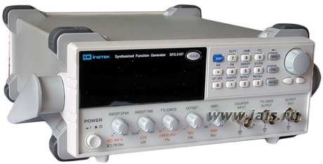
Компактный прибор со встроенным шестиразрядным частотомером используется для воспроизведения электромагнитных сигналов 4 стандартных форм.
Применяется в промышленной, энергетической, радиотехнической и электронной отраслях, а также в научно-исследовательской сфере.
Благодаря низкой погрешности и малому уровню искажений, данный аппарат можно применять для отладки высокоточного оборудования и каналов связи.
Устройство имеет интерфейс USB для подключения к компьютеру и передачи информации.
Изделие снабжено памятью на десять настроек. Питается модель от электрической сети 115-230 В.
[code1]
Особенности GW Instek SFG-2004:

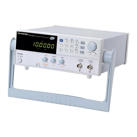
Современный дизайн, и корпус, выполненный из высококачественных материалов.

Интуитивно понятные кнопки управления расположены на лицевой панели.

Для транспортировки и расположения под рабочим углом предусмотрена ручка-упор.
Преимущества GW Instek SFG-2004:
- яркие светодиодные индикаторы;
- высокая стабильность и точность установки;
- настройка асимметрии формы сигнала;
- двухступенчатый аттенюатор с плавной регулировкой;
- небольшие габариты и вес.
* Изображения служат только для ознакомления,
см. техническую документацию
Добавить в корзину 1 шт.
на сумму 23 900 руб.
Номенклатурный номер: 8010288369
Страна происхождения: КИТАЙ
Бренд / Производитель: GW Instek
Описание
Диапазон частот 0,1 Гц — 4 МГц, прямой цифровой синтез, погрешность установки частоты 0,002%, виды сигналов: синус, прямоугольник, треугольник, пила, ТТЛ.
Особенности:
- Прямой цифровой синтез
- Высокая стабильность и точность установки частоты
- Малые гармонические искажения (менее -55 дБн)
- Широкий частотный диапазон (4, 7 и 10 МГц)
- Форма сигнала: синус, треугольник, меандр, импульс, АМ, ЧМ, ГКЧ
- Разрешение по частоте 100 мГц
- Режим постоянного смещения
- Встроенный 6-разрядный частотомер для измерения внутр./внешн. частоты (до 150 МГц)
- Память на 10 настроек
Сроки доставки
Доставка в регион Курск
| Магазин «ЧИП и ДИП» | 18 мая1 | бесплатно |
| ПВЗ Boxberry | 10 мая1 | бесплатно |
| ПВЗ СДЭК | 11 мая1 | бесплатно |
| ПВЗ Л-Пост | 11 мая1 | бесплатно |
| ПВЗ 5Post | 12 мая1 | бесплатно |
| Почта России | 19 мая1 | бесплатно |
| Курьер | 11 мая1 | 416 руб.2 |
| ТК DPD | 10 мая1 | 546 руб.2 |
| ТК «Деловые линии» | 11 мая1 | 824 руб.2 |
Цена и наличие в магазинах
| ул. Карла Маркса, 68, ТЦ «Мега Гринн», 1 этаж | нет в наличии |
-

-
Гарантия
12 месяцев
-
Госреестр РФ
29967-05 -
Производитель
GW Instek, Тайвань
- Частотный диапазон 0,1Гц … 4МГц
- Форма сигнала: синус, треугольник, пила, прямоугольник
- Регулировка асимметрии формы сигнала
- Добавление постоянного смещения
- 2-ступенчатый аттенюатор (-20дБ x 2) с плавной регулировкой
- Функция внешнего управления частотой
- Регулируемый ТТЛ/КМОП-выход
- Цифровой дисплей, встроенный 6-разрядный частотомер для измерения внутр./внешн. частоты
-
-
ХАРАКТЕРИСТИКИ ПАРАМЕТРЫ ЗНАЧЕНИЯ ОСНОВНЫЕ ВЫХОДНЫЕ ПАРАМЕТРЫ Частотный диапазон (для синуса и меандра) 0,1 Гц … 4 МГц Частотный диапазон (для треугольника) 0,1 Гц … 1 МГц Разрешение по частоте 0,1 Гц Погрешность установки ± (20×10-6 ) Амплитуда > 10 Впик (на 50Ом) Неравномерность АЧХ (синус относительно 1 кГц) < ± 0,3 дБ (0,1 Гц – 1 МГц) < ± 0,5 дБ (1 МГц – 4 МГц) < ± 2 дБ (4 МГц – 10 МГц) Выходное сопротивление 50 Ом ± 10% Аттенюатор 2 x ( -20 дБ ± 1 дБ) Постоянное смещение ± 5 В (на 50 Ом) Асимметрия формы 0,2…0,8 (до 1 МГц) – плавная регулировка с разрешением 0,01 Дисплей 9-разрядный, СД-индикаторы СИНУСОИДАЛЬНЫЙ СИГНАЛ Коэффициент гармоник (при уровне сигнала от 0,1 MAX до максимального) > — 55 дБн, 0,1 Гц – 200 кГц > — 40 дБн, 0,2 МГц – 4 МГц > — 30 дБн, 4 МГц – 10 МГц ТРЕУГОЛЬНЫЙ СИГНАЛ Нелинейность £ 2% (0,1Гц…100кГц), £ 5% (100 кГц…1 МГц) ПРЯМОУГОЛЬНЫЙ СИГНАЛ Асимметрия импульсов ± (1% от периода + 4 нс), 0,1 Гц…100 кГц Время нарастания/спада £ 25 нс (макс. уровень 50 Ом) КМОП-ВЫХОД Выходной уровень От (4 ± 1) В до (14,5 ± 0,5) В с плавной регулировкой Время нарастания / спада £ 120нс ТТЛ-ВЫХОД Выходной уровень ³ 3В Коэффициент нагрузки 20 ТТЛ-элементов Время нарастания/спада £ 25 нс ОБЩИЕ ДАННЫЕ Напряжение питания 115 В / 230 В ± 15%, 50 / 60 Гц Габаритные размеры 107 x 266 x 293 мм Масса Приблизительно 3,2 кг -
Дополнительная комплектация SFG-2004

Все товары группы
-
Contents
-
Table of Contents
-
Bookmarks
Quick Links
GW Instek
SFG-2000 Series
User Manual
Related Manuals for GW Instek SFG-2000 Series
Summary of Contents for GW Instek SFG-2000 Series
-
Page 1
Artisan Technology Group is your source for quality new and certified-used/pre-owned equipment SERVICE CENTER REPAIRS WE BUY USED EQUIPMENT • FAST SHIPPING AND DELIVERY Experienced engineers and technicians on staff Sell your excess, underutilized, and idle used equipment at our full-service, in-house repair center We also offer credit for buy-backs and trade-ins •… -
Page 2
Synthesized Function Generator SFG-2000/SFG-2100 Series USER MANUAL GW INSTEK PART NO. 82FG-21200MD ISO-9001 CERTIFIED MANUFACTURER Artisan Technology Group — Quality Instrumentation … Guaranteed | (888) 88-SOURCE | www.artisantg.com… -
Page 3
This manual contains proprietary information, which is protected by copyrights. All rights are reserved. No part of this manual may be photocopied, reproduced or translated to another language without prior written consent of Good Will company. The information in this manual was correct at the time of printing. However, Good Will continues to improve products and reserves the rights to change specification, equipment, and maintenance procedures at any time without notice. -
Page 4: Table Of Contents
Table of Contents Table of Contents SAFETY INSTRUCTIONS …………5 Safety Symbols…………5 Safety Guidelines …………. 6 GETTING STARTED …………9 Technical background ……….10 Lineup/Features…………12 Front Panel ………….13 Rear Panel……………19 Set Up …………..20 Operation Shortcuts ……….22 Default Setting Contents………24 SINE/SQUARE/TRIANGLE WAVE ……..25 Select the waveform……….26 Set the Frequency ………..26 Set the Duty Cycle (Square Waveform) ….28…
-
Page 5
SFG-2000 Series User Manual FREQUENCY MODULATION……….. 38 COUNTER INPUT …………40 STORE/RECALL SETTING……….42 APPLICATION EXAMPLES ……….44 Reference Signal for PLL System ……44 Trouble-Shooting Signal Source ……44 Transistor DC Bias Characteristics Test ….45 Amplifier Over-Load Characteristic Test ….46 Amplifier Transient Characteristics Test …. -
Page 6: Safety Instructions
Warning: Identifies conditions or practices that could result in injury or loss of life. WARNING Caution: Identifies conditions or practices that could result in damage to SFG-2000 series or to other CAUTION properties. Attention Refer to the Manual Earth (ground) Terminal…
-
Page 7: Safety Guidelines
SFG-2000 Series User Manual Safety Guidelines Do not place any heavy object on SFG-2000 series. General Guideline • Avoid severe impacts or rough handling that leads to • damaging SFG-2000 series. CAUTION Do not discharge static electricity to SFG-2000 series.
-
Page 8
Temperature: 0°C to 40°C • (Note) EN 61010-1:2001 specifies the pollution degrees and their requirements as follows. SFG-2000 series falls under degree 2. Pollution refers to “addition of foreign matter, solid, liquid, or gaseous (ionized gases), that may produce a reduction of dielectric strength or surface resistivity”. -
Page 9
SFG-2000 Series User Manual Power cord for the United Kingdom When using SFG-2000 series in the United Kingdom, make sure the power cord meets the following safety instructions. NOTE: This lead / appliance must only be wired by competent persons… -
Page 10: Getting Started
GETTING STARTED ETTING STARTED This chapter describes SFG-2000 series in a nutshell, including main features and front/rear/display introduction. Follow the Set Up section to properly install and power up SFG-2000 series. Technical background ……….10 SFG-2000 series overview Series lineup …………12 Main features…………
-
Page 11: Technical Background
SFG-2000 Series User Manual Technical background SFG-2000 series uses the latest Direct Digital Synthesis Traditional (DDS) technology to generate stable, high resolution function output frequency. The DDS technology solves several generators problems encountered in traditional function generators, as follows. Constant current circuit methodology…
-
Page 12
GETTING STARTED DDS synthesizer consists of Phase accumulator Block diagram (counter), lookout table data (ROM), Digital-to-analog converter (DAC), and Low-pass filter (LPF). Frequency Control Word (K) 28bit 28bit Phase Accumulator 28bit System Clock Register (fs) Table ROM/RAM 12bit Digital-Analog Converter Low-Pass Filter Output (fo) -
Page 13: Lineup/Features
SFG-2000 Series User Manual Lineup/Features Series lineup Features Duty Offset TTL/ Sweep Counter Lineup cycle CMOS ● ● ● ― ― ― SFG-2004 (4MHz) ● ● ● ― ― ― SFG-2007 (7MHz) ● ● ● ― ― ― SFG-2010 (10MHz) ●…
-
Page 14: Front Panel
Switch Control Input Output Log/Lin Selector Amplitude/ CMOS Sweep Span/ TTL/CMOS Attenuation Amplitude AM/FM Output Control Control Control SFG-2000 series front panel Main Waveform Entry Editing Cursor Display selection Key Keys Knob Keys Amplitude/ Power CMOS DC Offset Waveform TTL/CMOS…
-
Page 15
SFG-2000 Series User Manual Shows the waveform frequency, Main display counter frequency, and duty cycle. (7 segment) For SFG-2100 series only. In the counter mode, indicates that the leftmost digit (100MHz) is hidden but contains a real number. For counter details, see page40. -
Page 16
GETTING STARTED Indicates the waveform shape: Sine, Square, and Triangle. For details, see page26. Indicates that the Shift key is pressed. Indicates the output frequency: MHz, kHz, or Hz. Indicates the duty cycle unit. For duty cycle details, see page28. Selects the waveform shape: sine, Waveform WAVE… -
Page 17
SFG-2000 Series User Manual STORE Stores the parameter setting (page42). RECALL Recalls the parameter setting (page42). Recalls the default parameter setting (page43). Switches to counter mode (page40). Accepts external modulation signal (page37-AM) or (page38-FM). Increases (right turn) or decreases (left Editing knob turn) the frequency or duty cycle. -
Page 18
GETTING STARTED AMPL Sets the sine/square/triangle waveform Amplitude/ amplitude. Turn left (decrease) or right Attenuation (increase). control When pulled out, attenuates the −20dB sine/square/triangle waveform amplitude by −20dB. The −20dB display turns On. For details, see page29. OFFSET DC offset When pulled out, sets the DC control offset level for sine/square/triangle… -
Page 19
SFG-2000 Series User Manual SWEEP TIME This knob is available in SFG-2100 Sweep speed series only. It becomes effective in control sweep time mode. Log/Linear Sets the sweep speed. Turn left (slow) or SLOW FAST sweep selector right (fast). The range is 1 ~ 30 seconds. -
Page 20: Rear Panel
GETTING STARTED Rear Panel External AC Voltage AC Power Modulator Selector Input Input Accepts the modulation signal from external device. External BNC male connector, 10Vp-p maximum. SFG Modulator Input automatically switches the modulation signal from internal to external. For modulation details, see page37 (AM) or page38(FM). Accepts the AC power cord.
-
Page 21: Set Up
SFG-2000 Series User Manual Set Up Pull out the Tilt stand handle sideways and rotate it. Place SFG horizontally, Or tilt stand. Place the handle vertically for hand carry. Artisan Technology Group — Quality Instrumentation … Guaranteed | (888) 88-SOURCE | www.artisantg.com…
-
Page 22: Power Up
GETTING STARTED 1. Select the AC voltage on the rear Power up panel accordingly. AC 100/110/120V→select 115V. AC 220/230/240V→select 230V. 2. Connect the power cord. 3. Push and turn On the main power switch on the front panel. 4. The display shows model name and the last setup. Example: SFG-2110, 500Hz triangle wave in sweep mode and −20dB attenuation enabled Press…
-
Page 23: Operation Shortcuts
SFG-2000 Series User Manual Operation Shortcuts Here are the collections of operation example shortcuts. 1. Press Wave key and select Sine Sine wave 250Hz, WAVE −20dB amplitude 2. Press 2 + 5 + 0 + Hz/% key Hz/% 3. Press Shift + 8 key (−20dB) OUTPUT −20dB…
-
Page 24
GETTING STARTED 1. Press Wave key and select Sine Linear Sweep, WAVE 2. Press 2 + 5 + 0 + Hz/% key 1kHz start, Hz/% SWEEP Sine wave 250Hz 3. Press Shift + 5 key (Sweep) OUTPUT 4. Press SWEEP TIME knob (LIN) SWEEP TIME LIN Ω… -
Page 25: Default Setting Contents
SFG-2000 Series User Manual 1. Press Shift + 1 (Counter) Counter input, sine wave 1MHz COUNTER 2. The Gate sign flashes when INPUT counted 1. Press Shift + 6 (Store) STORE Store the setting to memory No.1 2. The “Store” sign appears 3.
-
Page 26: Sine/Square/Triangle Wave
SINE/SQUARE/TRIANGLE WAVE INE/SQUARE/TRIANGLE WAVE Select the waveform……….26 Select waveform Enter frequency …………26 Set frequency Edit frequnency …………27 Enter duty cycle …………. 28 Set duty cycle (for square Edit duty cycle…………28 wave) Normal output …………29 Set amplitude Attenuate by −20dB ……….
-
Page 27: Select The Waveform
SFG-2000 Series User Manual Select the waveform WAVE Sine / Square Press key repeatedly. The corresponding icon appears on the display. / Triangle Sine waveform. Square waveform. Triangle waveform. OUTPUT The waveform comes out from the main Ω terminal. 10Vp-p maximum (50Ω load)
-
Page 28: Edit Frequnency
SINE/SQUARE/TRIANGLE WAVE Triangle waveform frequency is limited to maximum 1MHz. When the input exceeds it, the following message (Freq-Err2) appears and forces the frequency to 1MHz. For full error message list, see page52. Left cursor key moves the active Edit cursor left.
-
Page 29: Set The Duty Cycle (Square Waveform)
SFG-2000 Series User Manual Set the Duty Cycle (Square Waveform) The duty cycle setting is not available in sine/triangle waveform. DUTY Press the Shift key, then 7 to Enter duty enter duty cycle editing mode. cycle The duty sign appears on the display.
-
Page 30: Set Amplitude
SINE/SQUARE/TRIANGLE WAVE Set Amplitude Turn the Amplitude knob right AMPL Normal (increase) or left (decrease). output The range is 10Vpp for 50Ω load. −20dB Sine/square/triangle waveform can be attenuated by Attenuate by −20dB, in two ways: −40dB altogether. −20dB Method1 Pull out the Amplitude knob.
-
Page 31: Set Offset
SFG-2000 Series User Manual Set Offset SFG can add or delete offset to the sine/square/triangle Activate waveform, thus changing the waveform vertical position. offset Use the OFFSET knob. Pushed: Offset Off Pulled: Offset On OFFSET Turn the knob right (higher position) Adjust offset or left (lower position).
-
Page 32: Ttl Cmos Output
TTL CMOS OUTPUT TL CMOS OUTPUT Select the waveform……….32 Select waveform Enter frequency …………32 Set frequency Edit frequency …………33 Enter duty cycle …………. 33 Set duty cycle Edit duty cycle…………34 Set Amplitude …………34 Set amplitude Artisan Technology Group — Quality Instrumentation …
-
Page 33: Select The Waveform
SFG-2000 Series User Manual Select the waveform Press Shift key, then 9. The TTL sign TTL/CMOS appears on the display. The TTL/CMOS output is always On when the square wave activated. Push/pull the TTL/CMOS knob to TTL/CMOS select the waveform.
-
Page 34: Set The Duty Cycle
TTL CMOS OUTPUT Left cursor key moves the active Edit cursor left. frequency Right cursor key moves the active cursor right. Turn the editing knob left to decrease the frequency. Turn the editing knob right to increase the frequency. Set the Duty Cycle DUTY Press the Shift key, then 7 to Enter duty…
-
Page 35: Set Amplitude
SFG-2000 Series User Manual The editing knob changes the Edit duty value, and the cursor keys cycle moves the active digit (same as entering frequency). When inactive for 5 seconds, the display automatically goes back to previous mode (frequency view).
-
Page 36: Sweep
SWEEP WEEP SFG can add sweep to the waveform output, a convenient tool for measuring the frequency response of the DUT. Sweep function applies only to SFG-2100 series. • Sweep and Modulation (page37) cannot be used together. • 1. Output the waveform. Sine/Triangle/Square Activate (page25) or TTL/CMOS (page31).
-
Page 37
SFG-2000 Series User Manual Sweep time sets the time it takes for a single sweep from Set Sweep the start frequency to the end frequency. Time Rotate the SWEEP TIME knob, right (fast) or left (slow). SWEEP TIME SLOW FAST… -
Page 38: Amplitude Modulation
2. Turn the knob left (shallow) or right (deep). AM % 0 ~ 100% Range SFG-2000 series uses an internal 400Hz sine wave as the Use external default modulating signal. modulating 1. Connect the modulating signal to the rear panel signal terminal.
-
Page 39: Frequency Modulation
SFG-2000 Series User Manual REQUENCY MODULATION FM applies only to SFG-2100 series. • Modulation and Sweep (page35) cannot be used together. • 1. Output the waveform. Sine/Triangle/Square Activate FM (page25) or TTL/CMOS (page31). 2. Press the Shift key, then 4 (FM). FM is activated and the sign appears on the display.
-
Page 40
SFG-2104 300kHz ~ 6.7MHz SFG-2107 300kHz ~ 9.7MHz SFG-2110 300kHz ~ 19.7MHz SFG-2120 SFG-2000 series uses an internal Use external 400Hz sine wave as the default modulating modulating signal. signal 1. Connect the modulating signal to the rear panel terminal. -
Page 41: Counter Input
SFG-2000 Series User Manual OUNTER INPUT Counter input applies only to SFG-2100 series. 1. Connect the signal input to the Counter input terminal. Press Shift key, then 1 (Counter). Activate counter COUNTER 2. EXT and COUNT sign appear on the display.
-
Page 42
COUNTER INPUT The following table shows the relationship between Gate time / counter frequency, gate time, resolution, and display. Resolution table Input Gate Resolution Display time 0.01s 100µHz 1.0000Hz 0.1s 10µHz 1.00000Hz 1µHz 1.000000Hz 100nHz 1.0000000Hz 0.01s 100µHz 10.0000Hz 0.1s 10µHz 10.00000Hz 10Hz… -
Page 43: Store/Recall Setting
SFG-2000 Series User Manual TORE/RECALL SETTING STORE Press the Shift key, then 6 to store Store the the current panel setting to internal panel setting memories. Memory range: 0 ~ 9 (10 set) The “Store 0” sign appears. Enter the memory number, 0 ~ 9. (for example, 1) The “done”…
-
Page 44
STORE/RECALL SETTING Press the shift key, then 2 to recall Recall the the default panel setting. default panel setting The “done” message appears. The panel is updated with the default setting. Sine wave Wave type 10.0000kHz Frequency Disabled TTL/CMOS Disabled −20dB Disabled Modulation… -
Page 45: Application Examples
SFG-2000 Series User Manual PPLICATION EXAMPLES Reference Signal for PLL System The SFG output can be used as a cost-effective reference Description signal for Phase-Locked-Loop system. Directly connect SFG output to PLL input. SFG series Block diagram Reference In Output…
-
Page 46: Transistor Dc Bias Characteristics Test
APPLICATION EXAMPLES Transistor DC Bias Characteristics Test Use SFG-2000 series as the signal source for a transistor. Description Compare the transistor input/output waveform using the oscilloscope. Adjust the DC voltage source to find out the maximum output without distorting the waveform.
-
Page 47: Amplifier Over-Load Characteristic Test
SFG-2000 Series User Manual Amplifier Over-Load Characteristic Test Use the triangle wave output from SFG-2000 series to Description check the amplifier output distortion caused by overload. The common sine wave is not the ideal source in this case. Observe the linearity of the triangle waveform using an oscilloscope.
-
Page 48
APPLICATION EXAMPLES 1. Apply a triangle waveform to the amplifier first. Test step Adjust the waveform amplitude to make sure there is no clipping. 2. Switch to square waveform and adjust its frequency to the middle of the amplifier pass band, such as 20Hz, 1kHz, and 10kHz. -
Page 49: Logic Circuit Test
SFG-2000 Series User Manual Logic Circuit Test Use the TTL/CMOS output from SFG-2000 series to Description test digital circuits. Observe the timing relation of input/output waveform using an oscilloscope. Oscilloscope SFG series Block diagram TTL/CMOS Out Digital Circuit Impedance Matching Network Test…
-
Page 50: Speaker Driver Test
APPLICATION EXAMPLES Speaker Driver Test Use SFG-2000 series for testing the frequency Description characteristics of audio speakers. Record the volt reading versus the input signal frequency. Block diagram The peak voltage occurs on the resonant frequency of Graph the speaker.
-
Page 51: Sweep For Speaker Test
SFG-2000 Series User Manual Sweep for Speaker Test Use the sweep feature in SFG-2000 series for testing the Description frequency response of an audio speaker. 1. Set SFG output to sine wave, 20Hz. Test 2. Activate sweep and set LIN/LOG, sweep time, and description sweep span.
-
Page 52: Faq
● I pressed the Power key on the front panel but nothing happens. ● How can I get out of Counter/Sweep/Modulation/TTL/−20dB mode? ● The device accuracy does not match the specification. ● What are these error messages? I pressed the Power key on the front panel but nothing happens. Make sure the AC source voltage setting on the rear panel is correct (page21).
-
Page 53: Appendix
SFG-2000 Series User Manual PPENDIX Error Messages Frequency Sine and square wave frequency over range. FrEq-Err1 error This message appears when entering sine or square waveform frequency larger than the rating. See page26 for sine/square rating. Triangle wave Frequency over range. This…
-
Page 54: Specification
APPENDIX Specification Output Function Sine, Square, Triangle Amplitude Range 10Vp-p (into 50Ω load) Impedance 50Ω ± 10% −20dB ± 1dB x2 Attenuator Main < −5V ~ >+5V (50Ω load) DC Offset Duty Range 20% ~ 80%, 2Hz~1MHz (Square Wave) Duty Resolution 1% (Square Wave Only) Display 9 digits LED display…
-
Page 55
Humidity: ≤70% Environment Instruction Manual x 1, Power Cord x 1 Accessories GTL-101 x 2 (SFG-2100 Series) GTL-101 x 1 (SFG-2000 Series) Dimension 107 (W) x 266 (H) x 293 (D) Approx. 3.2kg (SFG-2100 Series) Weight Approx. 3.1kg (SFG-2000 Series) Note1: In order to get the maximum sweep span, sweep time needs to be tuned. -
Page 56: Declaration Of Conformity
APPENDIX Declaration of Conformity GOOD WILL INSTRUMENT CO., LTD. (1) No.7-1, Jhongsing Rd., Tucheng City, Taipei County, Taiwan (2) No. 69, Lu San Road, Suzhou City (Xin Qu), Jiangsu Sheng, China declare, that the below mentioned product Type of Product: Synthesized Function Generator Model Number: SFG-2004, SFG-2007, SFG-2010, SFG-2020, SFG-2104, SFG-2107, SFG-2110, SFG-2120 are herewith confirmed to comply with the requirements set out in the…
-
Page 57: Index
SFG-2000 Series User Manual INDEX setup………… 28 duty cycle error ……… 28, 52 20dB attenuation ……..29 faq…………51 example setting……..22 EN 61010……… 6, 7, 55 EN55011……….55 example setting……..23 EN61000……….55 setup ……….. 37 external modulation ……37, 39 amplifier application example….
-
Page 58
INDEX symbol……….. 5 UK power cord……..8 main feature list……..12 setup step……….20 memory recall sine wave example setting……..24 example setting ……..22 memory store selection ……….26 example setting……..24 speaker application example … 49, 50 model lineup……….12 specification ……….53 FAQ …………. -
Page 59
Artisan Technology Group is your source for quality new and certified-used/pre-owned equipment SERVICE CENTER REPAIRS WE BUY USED EQUIPMENT • FAST SHIPPING AND DELIVERY Experienced engineers and technicians on staff Sell your excess, underutilized, and idle used equipment at our full-service, in-house repair center We also offer credit for buy-backs and trade-ins •…
-
-
Гарантия
12 месяцев
-
Госреестр РФ
29967-05 -
Производитель
GW Instek, Тайвань
- Частотный диапазон 0,1Гц … 4МГц
- Форма сигнала: синус, треугольник, пила, прямоугольник
- Регулировка асимметрии формы сигнала
- Добавление постоянного смещения
- 2-ступенчатый аттенюатор (-20дБ x 2) с плавной регулировкой
- Функция внешнего управления частотой
- Регулируемый ТТЛ/КМОП-выход
- Цифровой дисплей, встроенный 6-разрядный частотомер для измерения внутр./внешн. частоты
-
-
Технические характеристики SFG-2004:
ХАРАКТЕРИСТИКИ ПАРАМЕТРЫ ЗНАЧЕНИЯ ОСНОВНЫЕ ВЫХОДНЫЕ ПАРАМЕТРЫ Частотный диапазон (для синуса и меандра) 0,1 Гц … 4 МГц Частотный диапазон (для треугольника) 0,1 Гц … 1 МГц Разрешение по частоте 0,1 Гц Погрешность установки ± (20×10-6 ) Амплитуда > 10 Впик (на 50Ом) Неравномерность АЧХ (синус относительно 1 кГц) < ± 0,3 дБ (0,1 Гц – 1 МГц) < ± 0,5 дБ (1 МГц – 4 МГц) < ± 2 дБ (4 МГц – 10 МГц) Выходное сопротивление 50 Ом ± 10% Аттенюатор 2 x ( -20 дБ ± 1 дБ) Постоянное смещение ± 5 В (на 50 Ом) Асимметрия формы 0,2…0,8 (до 1 МГц) – плавная регулировка с разрешением 0,01 Дисплей 9-разрядный, СД-индикаторы СИНУСОИДАЛЬНЫЙ СИГНАЛ Коэффициент гармоник (при уровне сигнала от 0,1 MAX до максимального) > — 55 дБн, 0,1 Гц – 200 кГц > — 40 дБн, 0,2 МГц – 4 МГц > — 30 дБн, 4 МГц – 10 МГц ТРЕУГОЛЬНЫЙ СИГНАЛ Нелинейность £ 2% (0,1Гц…100кГц), £ 5% (100 кГц…1 МГц) ПРЯМОУГОЛЬНЫЙ СИГНАЛ Асимметрия импульсов ± (1% от периода + 4 нс), 0,1 Гц…100 кГц Время нарастания/спада £ 25 нс (макс. уровень 50 Ом) КМОП-ВЫХОД Выходной уровень От (4 ± 1) В до (14,5 ± 0,5) В с плавной регулировкой Время нарастания / спада £ 120нс ТТЛ-ВЫХОД Выходной уровень ³ 3В Коэффициент нагрузки 20 ТТЛ-элементов Время нарастания/спада £ 25 нс ОБЩИЕ ДАННЫЕ Напряжение питания 115 В / 230 В ± 15%, 50 / 60 Гц Габаритные размеры 107 x 266 x 293 мм Масса Приблизительно 3,2 кг -
Дополнительная комплектация SFG-2004
Все товары группы

* Производитель оставляет за собой право без уведомления дилера менять характеристики, внешний вид, комплектацию товара и место его производства.
Выбирая прибор с поверкой, не нужно включать ползунок услуги при оформлении заказа! Стоимость поверки уже включена.
Характеристики и Комплектация
Гарантия
?
Гарантия не распространяется:• на батареи, идущие в комплекте с прибором;• на приборы с механическими повреждениями, вызванными непра-вильной эксплуатацией или применением некачественных компо-нентов третьих фирм;• на приборы с повреждениями компонентов и
—
12 месяцев
Вид применения
—
Профессиональный
Тип
—
Пилообразный, Прямоугольный, Синусоидальный, Треугольный
Все характеристики
Нет в наличии
Нашли дешевле?
Доставка от 20 000 рублей бесплатно
Работаем с организациями по договору
* Производитель оставляет за собой право без уведомления дилера менять характеристики, внешний вид, комплектацию товара и место его производства.
Выбирая прибор с поверкой, не нужно включать ползунок услуги при оформлении заказа! Стоимость поверки уже включена.

Доступные цены
на лучшие бренды


Услуги
Сервисные службы
Наша компания оказывает услуги по ремонту измерительного и электроизмерительного, оборудования. Мы осуществляет ремонт и техническое обслуживание приборов.
Сервисные службы
Поверка измерительного оборудования – это комплекс процедур, основное назначение которых сводится к подтверждению соответствия характеристик устройства заявленным стандартам и требованиям. Поверочные работы проводятся на основании метрологических параметров техники, определяемых экспериментальным путем. Осуществляется в определенные сроки, которые индивидуальны для каждого конкретного прибора и зависят от его типа.
SFG-2004 генератор сигналов функциональный
Технические характеристики генератора SFG-2004
|
Основные выходные параметры |
|
|
Частотный диапазон |
0,1Гц … 4 МГц |
|
Погрешность установки |
±(5% + 1Гц) |
|
Амплитуда |
> 10В (на 50Ом) |
|
Выходное сопротивление |
50Ом |
|
Аттенюатор |
2х(минус 20дБ ± 1дБ) с плавной регулировкой |
|
Постоянное смещение |
±5В (на 50Ом) |
|
Асимметрия формы |
0,2 ¼0,8 (1МГц) – плавно регулируется |
|
Дисплей |
6-разрядный, СД-индикаторы |
|
Синусоидальный сигнал |
|
|
Коэффициент гармоник |
£ 1.2% при максимальной амплитуде (0,3Гц…200кГц), |
|
Неравномерность |
£ 0,3дБ, (0,3Гц … 300кГц), £ 0,5дБ, (300кГц…3МГц) |
|
Треугольный сигнал |
|
|
Нелинейность |
£ 2% (0,3Гц…100кГц), £ 5% (100Гц…3МГц) |
|
Прямоугольный сигнал |
|
|
Асимметрия импульсов |
±2% (0,3Гц…100кГц) |
|
Время нарастания/спада |
£ 100нс (макс. уровень,50Ом) |
|
КМОП-выход |
|
|
Выходной уровень |
От (4 ±1)В до (14,5 ±0,5)В с плавной регулировкой |
|
Время нарастания / спада |
£ 120нс |
|
ТТЛ-выход |
|
|
Выходной уровень |
³ 3В |
|
Коэффициент нагрузки |
20 ТТЛ-элементов |
|
Время нарастания/спада |
£ 25нс |
|
Внешнее управление частотой |
|
|
Входное напряжение |
0…(10 ±1)В |
|
Входное сопротивление |
10кОм |
|
Синхровыход |
|
|
Выходное напряжение |
0…2В (0,1Гц…4 МГц) |
|
Частотомер |
|
|
Частотный диапазон |
0,3Гц…3МГц (внутренняя)/5Гц…150МГц (внешняя) ( ±10-5) |
|
Разрешение |
10нГц для предела 1Гц; 0,1Гц для предела 100МГц |
|
Стабильность опорн. ген-ра |
±10-5 (23 °С ± 5 °С) после 30 мин. работы |
|
Входной импеданс |
1МОм/150пФ |
|
Чувствительность |
£ 35мВ (5Гц…100МГц), £ 45мВ (100МГц…150МГц) |
|
Общие данные |
|
|
Напряжение питания |
115В/230В ± 15%, 50/60Гц |
|
Габаритные размеры |
251 ´91 ´291мм |
|
Масса |
Приблизительно 2 кг |