-
Contents
-
Table of Contents
-
Bookmarks
Quick Links
Edition
®
MOVITRAC
07
02/2003
Operating Instructions
1056 411x / EN
Related Manuals for SEW-Eurodrive MOVITRAC 07
Summary of Contents for SEW-Eurodrive MOVITRAC 07
-
Page 1
Edition ® MOVITRAC 02/2003 Operating Instructions 1056 411x / EN… -
Page 2
SEW-EURODRIVE… -
Page 3: Table Of Contents
Contents 1 Important Notes………………..4 2 Safety Notes …………………. 6 3 Unit Structure ………………..7 Unit design ………………..7 Unit designation and scope of delivery ……….. 11 4 Installation ………………….. 13 Installation instructions…………….13 UL compliant installation …………….. 17 Power shield clamp …………….. 18 Touch guard ………………..
-
Page 4: Important Notes
Important Notes Important Notes Safety and warn- Always follow the safety and warning instructions contained in this publication! ing instructions Electrical hazard Possible consequences: Severe or fatal injuries. Hazard Possible consequences: Severe or fatal injuries. Hazardous situation Possible consequences: Slight or minor injuries. Harmful situation Possible consequences: Damage to the unit and the environment.
-
Page 5
Important Notes ® MOVITRAC 07 frequency inverters are units intended for stationary installation in switch cabinets. All instructions referring to the technical data and the permissible con- ditions where the unit is operated must be followed. Do not start up the unit (take it into operation in the designated fashion) until: •… -
Page 6: Safety Notes
Safety Notes Safety Notes Installation and • Never install damaged products or take them into operation. Please submit a startup complaint to the transport company immediately in the event of damage. • Installation, startup and service work on the unit only by trained personnel. The personnel must be trained in the relevant aspects of accident prevention and must comply with the regulations in force (e.g.
-
Page 7: Unit Structure
Unit Structure Unit design Unit Structure Unit design Size 0S, 0M, 0L 02978BXX ® Figure 1: MOVITRAC 07 unit structure, sizes 0S, 0M, 0L 1. X1: Mains connection 3-phase: L1 / L2 / L3 / PE or 1-phase: L/N/PE 2. Operating panel 3.
-
Page 8
Unit Structure Unit design Size 1, 2S, 2 05132AXX ® Figure 2: MOVITRAC 07 unit structure, sizes 1, 2S, 2 1. X1: Mains connection 3-phase: L1 / L2 / L3 / PE screw 2. Operating panel 3. DIP switch S11 changeover U-signal / I-signal 4. -
Page 9
Unit Structure Unit design Size 3 05295AXX ® Figure 3: MOVITRAC 07 unit structure, size 3 1. PE connections 2. X1: Mains connection 3-phase: L1 (1) / L2 (2) / L3 (3) 3. X4: DC link circuit connection (not used) 4. -
Page 10
Unit Structure Unit design Size 4 05296AXX ® Figure 4: MOVITRAC 07 unit structure, size 4 1. X2: PE connection 2. X1: Mains connection 3-phase: L1 (1) / L2 (2) / L3 (3) 3. X4: DC link circuit connection (not used) 4. -
Page 11: Unit Designation And Scope Of Delivery
Unit Structure Unit designation and scope of delivery Unit designation and scope of delivery Sample unit designation Type MC Series and generation Version A Recommended motor 022 = 2.2 kW power 2 = 200 … 240 V Connection voltage 5 = 380 … 500 V B = Radio interference suppres- sion B Radio interference sup-…
-
Page 12
Unit Structure Unit designation and scope of delivery Scope of delivery loose items 03000AXX Figure 6: Scope of delivery, included loose size 0 Scope of delivery, included loose for size • Shield clamps for electronics cables (2 clamps with one screw each) [1] •… -
Page 13: Installation
Installation Installation instructions Installation Installation instructions It is essential to comply with the safety notes during installation! Tightening • Only use genuine connection elements. Note the permitted tightening torques ® torques of MOVITRAC 07 power terminals. → – Size 0S/M/L 0.5 Nm (4.4 lb.in) →…
-
Page 14
Installation Installation instructions Line choke • When more than four 3-phase units or more than one 1-phase unit are connect- ed to a supply system contactor designed for the total current: Insert a line choke in the circuit to limit the inrush current. Separate cable •… -
Page 15
Installation Installation instructions ® Line filter MOVITRAC 07 frequency inverters are equipped with an line filter as standard. They comply with the following limit value class to EN 55011 on the line side without further measures: • B: 1-phase connection •… -
Page 16
Installation Installation instructions ® HD output choke • Install the output choke close to MOVITRAC 07 beyond the minimum clearance. • Always route all three phases (not the PE!) together through the output choke. • If the cable is shielded, the shield is not allowed to be routed through the output choke. -
Page 17: Ul Compliant Installation
Installation UL compliant installation UL compliant installation Please note the following points for UL compliant installation: • Only use copper cables with the following temperature ranges as connection leads: ® – For MOVITRAC 07 … Temperature range 60/75 °C. ® •…
-
Page 18: Power Shield Clamp
Installation Power shield clamp Power shield clamp ® For sizes 1 / 2S SEW-EURODRIVE supplies a power shield clamp as standard with MOVITRAC size 1 / 2S. Install this power shield clamp together with the retaining screws of the unit. 02012BXX ®…
-
Page 19: Touch Guard
Installation Touch guard For size 2 SEW-EURODRIVE supplies a power shield clamp with two retaining screws as stan- ® dard with MOVITRAC 07 size 2. Install this power shield clamp together with the two retaining screws on X6. 01469BXX ® Figure 11: Power shield clamp for MOVITRAC 07 size 2 1.
-
Page 20: Wiring Diagram 230 V 0.37 … 2.2 Kw / 400 V 0.55 … 4.0 Kw
Installation Wiring diagram 230 V 0.37 … 2.2 kW / 400 V 0.55 … 4.0 kW Wiring diagram 230 V 0.37 … 2.2 kW / 400 V 0.55 … 4.0 kW 3 x 230 V / PE 1 x 230 V / N / PE 3 x 400/500 V / PE…
-
Page 21
Installation Wiring diagram 230 V 3.7 … 30 kW / 400 V 5.5 … 30 kW Wiring diagram 230 V 3.7 … 30 kW / 400 V 5.5 … 30 kW 3 x 230 V / PE 3 x 400/500 V / PE F11/F12/F13 (AC-3) -
Page 22
Installation Wiring diagram 230 V 3.7 … 30 kW / 400 V 5.5 … 30 kW Connection of the brake rectifier A separate supply system lead is required for connecting the brake rectifier; sup- ply from the motor voltage is not permitted! Only use contactors in utilization category AC-3 (IEC 158-1) for K11 and K12. -
Page 23: System Bus (Sbus) Installation
SC21 = System bus high SC12 = System bus low SC11 = System bus high = System bus terminating resistor SBus MOVITRAC 07: Connect the terminating equipment to SC11/SC12. SC21/SC22 are only active when S12 = OFF. Operating Instructions – MOVITRAC® 07…
-
Page 24: Startup
Startup General startup instructions Startup Using the IN/OUT key : Press the key once to go further down into the menu struc- ture (selecting functions). Press twice or use one long key press to change to higher lev- els in the menu structure. General startup instructions It is essential to adhere to the safety notes during startup! Prerequisite…
-
Page 25: Integrated Operating Panel
Startup Integrated operating panel Integrated operating panel Operation The following basic principle applies: Press the key once to start editing. Double- click the key to exit edit mode. Functions of the The UP, DOWN and IN/OUT buttons are used for navigating through the menus. The operating panel RUN and STOP/RESET buttons are used for controlling the drive.
-
Page 26: Principles Of Operation With The Integrated Operating Panel
Startup Principles of operation with the integrated operating panel Principles of operation with the integrated operating panel n11 n12 n [rpm] [rpm] [s/rpm] P081 [F-00 … F-99] <-2x 1x-> <-2x 1x-> P100 … P861 [ms/%/…] <-2x 1x-> P-01 … P-05 [kW/Hz/…] <-2x 1x->…
-
Page 27
Startup Principles of operation with the integrated operating panel Available sym- You can select the following symbols using keys bols Symbol Function Displays the inverter status or (in «drive enabled» status) the calculated actual speed in [rpm] Displays the apparent output current in [A] Sets the accelerating ramp in [s] Sets the deceleration ramp in [s] Sets the maximum speed in [rpm]… -
Page 28: Manual Speed Control Module And External Setpoint Selection
Startup Manual speed control module and external setpoint selection Fault indication If a fault occurs, the display changes to the symbol and it shows the flashing fault code, e.g. F-11 (fault list in Sec. Operation and servicing). Warnings Some parameters are not allowed to be altered in all operating states. If you try to do so, the following display appears: r-19 …
-
Page 29
Startup Manual speed control module and external setpoint selection You can limit the speed by P301 Minimum speed and P302 Maximum speed . After a fault, a reset can be performed using the «STOP/RESET» button, the terminal or the interface. «Manual speed control module» operating mode is once again active after the reset. -
Page 30
Startup Manual speed control module and external setpoint selection Enable direction of The direction of rotation is determined by the setpoint if you set P101 Control signal rotation with RS- source and P100 Setpoint source to RS485 or SBus (RS485 only for service purposes). 485 or SBus You must enable the setpoint via SBus or RS-485 using the «CW/STOP»… -
Page 31: Startup With The Integrated Operating Panel
Startup Startup with the integrated operating panel Startup with the integrated operating panel 02975GXX Figure 18: Startup with the integrated operating panel (2x = double-click / * = factory setting) P-01 = Operating mode P-03 = Rated motor speed P-05 = Rated motor voltage P-02 = Rated motor power P-04 = Rated motor frequency Operating Instructions –…
-
Page 32
Startup Startup with the integrated operating panel General informa- If you are not connecting the motor indicated in the motor selection table: Enter param- tion eters P-01 to P-05 correctly according to the nameplate (access via Name Range / factory setting P-01 Operating mode VFC or VFC &… -
Page 33: Starting The Motor
Startup Starting the motor Starting the motor Analog setpoints The following table shows which signals must be present on terminals X10:2 … X10:4 (DIØ1 … DIØ5) when the «UNIPOL/FIX.SETPT» setpoint is selected (P100), in order to operate the drive with analog setpoints. Terminal X10:13/14 X10:2…
-
Page 34: Loading A Logodrive Program
Startup Loading a LOGODrive program Loading a LOGODrive program • Start MOVITOOLS Manager. ® • Connect the MOVITRAC 07 to a vacant serial port on your PC using the UWS21A interface converter. Select this interface in the PC Interface group. ®…
-
Page 35: Parameter List
Startup Parameter list Parameter list All parameters which can also be displayed and edited using the symbol on the op- erating panel have a • in the «OP» (operating panel) column. If more than one value can be selected, the factory setting is highlighted in bold. OP Index Name Range / factory setting…
-
Page 36
Startup Parameter list OP Index Name Range / factory setting Value after startup dec. Display MOVITOOLS Binary outputs Binary output /FAULT (factory setting) DO01 Binary output BRAKE RELEASED (factory setting) DO02 Binary outputs Binary display DO01, DO02 Unit data Unit type [Text] Output rated cur- rent… -
Page 37
Startup Parameter list OP Index Name Range / factory setting Value after startup dec. Display MOVITOOLS Analog input 1 (+10 V) • 8463 AI1 scaling 0.1 … 1 … 10 • 8465 AI1 operation 3000 rpm (0 – 10 V) mode N-MAX (0 –… -
Page 38
Startup Parameter list OP Index Name Range / factory setting Value after startup dec. Display MOVITOOLS Fixed setpoints (set 2) • 8492 Internal setpoint 0 … 150 … 5000 [rpm] • 8493 Internal setpoint 0 … 750 … 5000 [rpm] •… -
Page 39
Startup Parameter list OP Index Name Range / factory setting Value after startup dec. Display MOVITOOLS Reference signals Speed reference signal • 8539 Speed reference 0 … 750 … 5000 [rpm] value • 8540 Hysteresis 0 … 100 … +500 [rpm] •… -
Page 40
Startup Parameter list OP Index Name Range / factory setting Value after startup dec. Display MOVITOOLS Binary outputs • 8804 Binary outputs DO01 DO02 /FAULT BRAKE RELEASED READY BRAKE RELEASED SPEED REFERENCE BRAKE RELEASED SP/ACT.VAL.COMP. BRAKE RELEASED /FAULT SPEED REFERENCE /FAULT SP/ACT.VAL.COMP. -
Page 41
Startup Parameter list OP Index Name Range / factory setting Value after startup dec. Display MOVITOOLS Unit functions Setup • 8594 Factory setting FACTORY SETTING DELIVERY CONDITION • 8595 Parameter lock 8596 Reset statistic data FAULT MEMORY Serial communication • 8597 RS485 address 0 … -
Page 42
Startup Parameter list OP Index Name Range / factory setting Value after startup dec. Display MOVITOOLS Fieldbus parameterization 8304 Setpoint descrip- NO FUNCTION (factory setting P872) tion PO1 SPEED (factory setting P871) MAX. SPEED 8305 Setpoint descrip- RAMP tion PO CTRL. -
Page 43: Fault Information
Operation and Service Fault information Operation and Service Fault information Fault memory The inverter stores the fault message in fault memory P080. The inverter does not save a new fault until the fault message has been acknowledged. The local operating panel shows the fault which occurred most recently.
-
Page 44
Operation and Service Fault information Reset A fault message can be acknowledged by: • Switching the supply system off and on again. Recommendation: Observe a mini- mum switch-off time of 10 s for the supply system contactor. • Reset via input terminals, i.e. via an appropriately assigned binary input (DIØ2…DIØ5). -
Page 45
Operation and Service List of errors (F-00 … F-97) List of errors (F-00 … F-97) Name Response Possible cause Action No error Over-current Immediate • Short circuit on output • Rectify the short circuit switch-off • Output switching • Only switch when output stage inhibited •… -
Page 46
Operation and Service List of errors (F-00 … F-97) Name Response Possible cause Action Overtempera- Rapid stop Thermal overload of inverter • Reduce load and/or ensure ade- ture with inhibit quate cooling • If the braking resistor is integrated in the heat sink: Mount the braking resistor externally System fault Immediate… -
Page 47: List Of Warnings (R-17 … R-32)
Operation and Service List of warnings (r-17 … r-32) Name Response Possible cause Action Initialization Immediate Error during initialization Contact SEW Service for advice. switch-off with inhibit System bus Rapid stop Fault during communication via system Check system bus connection. timeout without inhibit…
-
Page 48: Sew Electronics Service
Operation and Service SEW electronics service SEW electronics service Send in for repair Please contact the SEW electronics service if a fault cannot be rectified (→ «Cus- tomer and spare parts service»). Please always specify the service code number when you contact the SEW electronics service.
-
Page 49: Ce-Marking, Ul Approval And C-Tick
Technical Data CE-marking, UL approval and C-Tick Technical Data CE-marking, UL approval and C-Tick CE-marking ® Low Voltage Direc- MOVITRAC 07 frequency inverters comply with the regulations of the Low Voltage Di- tive rective 73/23/EEC. ® Electromagnetic MOVITRAC 07 frequency inverters are components of machines and systems. They compatibility EMC comply with the EMC product standard EN 61800-3 Variable-speed electrical drives .
-
Page 50: General Technical Data
Technical Data General technical data General technical data ® The following technical data applies to all MOVITRAC 07 frequency inverters, regard- less of size. ® MOVITRAC All sizes Interference immunity To EN 61800-3 Interference emission with To limit value class EMC-compliant installation •…
-
Page 51: Technical Data Of Movitrac® 07
Technical Data Technical data of MOVITRAC® 07 ® Technical data of MOVITRAC 230 V 51115AXX ® Figure 20: MOVITRAC 07 230 V units Size Power [kW / HP] 0.37 / 0.5 1.1 / 1.5 5.5 / 7.5 11 / 15 22 / 30 0.55 / 0.75 1.5 / 2.0…
-
Page 52
Technical Data Technical data of MOVITRAC® 07 230 V / 1-phase / size 0S / 0.37 … 0.75 kW / 0.5 … 1.0 HP 51105AXX ® Figure 22: MOVITRAC 07 / size 0S / 1-phase 230 V ® MOVITRAC MC07A (1-phase supply system) 004-2B1-4-.. -
Page 53
Technical Data Technical data of MOVITRAC® 07 ® MOVITRAC MC07A (1-phase supply system) 004-2B1-4-.. 005-2B1-4-.. 008-2B1-4-.. GENERAL Power loss at I 45 W 55 W 65 W Current limitation 125 % I continuous duty (fan/pump operation) 150 % I for maximum 60 seconds PWM frequency 4 / 8 / 12 / 16 kHz Speed range… -
Page 54
Technical Data Technical data of MOVITRAC® 07 230 V / 1-phase / size 0L / 1.1 … 2.2 kW / 1.5 … 3.0 HP ® Figure 24: MOVITRAC 07 / size 0L / 1-phase 230 V ® MOVITRAC MC07A (1-phase supply system) 011-2B1-4-.. -
Page 55
Technical Data Technical data of MOVITRAC® 07 ® MOVITRAC MC07A (1-phase supply system) 011-2B1-4-.. 015-2B1-4-.. 022-2B1-4-.. GENERAL Power loss at I 75 W 100 W 125 W Current limitation 125 % I continuous duty (fan/pump operation) 150 % I for maximum 60 seconds PWM frequency 4 / 8 / 12 / 16 kHz Speed range… -
Page 56
Technical Data Technical data of MOVITRAC® 07 230 V / 3-phase / size 0S / 0.37 … 0.75 kW / 0.5 … 1.0 HP 51105AXX ® Figure 26: MOVITRAC 07 / size 0S / 3-phase 230 V ® MOVITRAC 07A (3-phase supply system) 004-2A3-4-.. -
Page 57
Technical Data Technical data of MOVITRAC® 07 ® MOVITRAC 07A (3-phase supply system) 004-2A3-4-.. 005-2A3-4-.. 008-2A3-4-.. GENERAL Power loss at I 45 W 55 W 65 W Current limitation 125 % I continuous duty (fan/pump operation) 150 % I for maximum 60 seconds PWM frequency 4 / 8 / 12 / 16 kHz Speed range… -
Page 58
Technical Data Technical data of MOVITRAC® 07 230 V / 3-phase / size 0L / 1.1 … 2.2 kW / 1.5 … 3.0 HP ® Figure 28: MOVITRAC 07 / size 0L / 3-phase 230 V ® MOVITRAC 07A (3-phase supply system) 011-2A3-4-.. -
Page 59
Technical Data Technical data of MOVITRAC® 07 ® MOVITRAC 07A (3-phase supply system) 011-2A3-4-.. 015-2A3-4-.. 022-2A3-4-.. GENERAL Power loss at I 75 W 100 W 125 W Current limitation 125 % I continuous duty (fan/pump operation) 150 % I for maximum 60 seconds PWM frequency 4 / 8 / 12 / 16 kHz Speed range… -
Page 60
Technical Data Technical data of MOVITRAC® 07 230 V / 3-phase / size 1 / 3.7 kW / 5.0 HP ® Figure 30: MOVITRAC 07 / size 1 / 3-phase 230 V ® MOVITRAC 07A (3-phase supply system) 037-2A3-4-.. Part number 827 278 6 Part number with LOGODrive 827 285 9… -
Page 61
Technical Data Technical data of MOVITRAC® 07 ® MOVITRAC 07A (3-phase supply system) 037-2A3-4-.. GENERAL Power loss at I 210 W Current limitation 125 % I continuous duty (fan/pump operation) 150 % I for maximum 60 seconds PWM frequency 4 / 8 / 12 / 16 kHz Speed range 0 … -
Page 62
Technical Data Technical data of MOVITRAC® 07 230 V / 3-phase / size 2 / 5.5 … 7.5 kW / 7.5 … 10 HP ® Figure 32: MOVITRAC 07 / size 2 / 3-phase 230 V ® MOVITRAC 07A (3-phase supply system) 055-2A3-4-.. -
Page 63
Technical Data Technical data of MOVITRAC® 07 ® MOVITRAC 07A (3-phase supply system) 055-2A3-4-.. 075-2A3-4-.. GENERAL Power loss at I 300 W 380 W Current limitation 125 % I continuous duty (fan/pump operation) 150 % I for maximum 60 seconds PWM frequency 4 / 8 / 12 / 16 kHz Speed range… -
Page 64
Technical Data Technical data of MOVITRAC® 07 230 V / 3-phase / size 3 / 11 … 15 kW / 15 … 20 HP ® Figure 34: MOVITRAC 07 / size 3 / 3-phase 230 V ® MOVITRAC 07A (3-phase supply system) 110-203-4-.. -
Page 65
Technical Data Technical data of MOVITRAC® 07 ® MOVITRAC 07A (3-phase supply system) 110-203-4-.. 150-203-4-.. GENERAL Power loss at I 580 W 720 W Current limitation 125 % I continuous duty (fan/pump operation) 150 % I for maximum 60 seconds PWM frequency 4 / 8 / 12 / 16 kHz Speed range… -
Page 66
Technical Data Technical data of MOVITRAC® 07 230 V / 3-phase / size 4 / 22 … 30 kW / 30 … 40 HP ® Figure 36: MOVITRAC 07 / size 4 / 3-phase 230 V ® MOVITRAC 07A (3-phase supply system) 220-203-4-.. -
Page 67
Technical Data Technical data of MOVITRAC® 07 ® MOVITRAC 07A (3-phase supply system) 220-203-4-.. 300-203-4-.. GENERAL Power loss at I 1100 W 1300 W Current limitation 125 % I continuous duty (fan/pump operation) 150 % I for maximum 60 seconds PWM frequency 4 / 8 / 12 / 16 kHz Speed range… -
Page 68
Technical Data Technical data of MOVITRAC® 07 400/500 V / 3-phase / size 0M / 0.55 … 1.1 kW / 0.75 … 1.5 HP ® Figure 38: MOVITRAC 07 / size 0M / 3-phase 400/500 V ® MOVITRAC 07A (3-phase supply system) 005-5A3-4-.. -
Page 69
Technical Data Technical data of MOVITRAC® 07 ® MOVITRAC 07A (3-phase supply system) 005-5A3-4-.. 008-5A3-4-.. 011-5A3-4-.. GENERAL Power loss at I 42 W 48 W 58 W Current limitation 125 % I continuous duty (fan/pump operation) 150 % I for maximum 60 seconds PWM frequency 4 / 8 / 12 / 16 kHz Speed range… -
Page 70
Technical Data Technical data of MOVITRAC® 07 400/500 V / 3-phase / size 0L / 1.5 … 4.0 kW / 2.0 … 5.0 HP ® Figure 40: MOVITRAC 07 / size 0L / 3-phase 400/500 V ® MOVITRAC 07A (3-phase supply system) 015-5A3-4- 022-5A3-4- 030-5A3-4-… -
Page 71
Technical Data Technical data of MOVITRAC® 07 ® MOVITRAC 07A (3-phase supply system) 015-5A3-4- 022-5A3-4- 030-5A3-4- 040-5A3-4- GENERAL Power loss at I 74 W 97 W 123 W 155 W Current limitation 125 % I continuous duty (fan/pump operation) 150 % I for maximum 60 seconds PWM frequency 4 / 8 / 12 / 16 kHz… -
Page 72
Technical Data Technical data of MOVITRAC® 07 400/500 V / 3-phase / size 2S / 5.5 … 7.5 kW / 7.5 … 10 HP ® Figure 42: MOVITRAC 07 / size 2S / 3-phase 400/500 V ® MOVITRAC 07A (3-phase supply system) 055-5A3-4-.. -
Page 73
Technical Data Technical data of MOVITRAC® 07 ® MOVITRAC 07A (3-phase supply system) 055-5A3-4-.. 075-5A3-4-.. GENERAL Power loss at I 220 W 290 W Current limitation 125 % I continuous duty (fan/pump operation) 150 % I for maximum 60 seconds PWM frequency 4 / 8 / 12 / 16 kHz Speed range… -
Page 74
Technical Data Technical data of MOVITRAC® 07 400/500 V / 3-phase / size 2 / 11 kW / 15 HP ® Figure 44: MOVITRAC 07 / size 2 / 3-phase 400/500 V ® MOVITRAC 07A (3-phase supply system) 110-5A3-4-.. Part number 827 256 5 Part number with LOGODrive 827 301 4… -
Page 75
Technical Data Technical data of MOVITRAC® 07 ® MOVITRAC 07A (3-phase supply system) 110-5A3-4-.. GENERAL Power loss at I 400 W Current limitation 125 % I continuous duty (fan/pump operation) 150 % I for maximum 60 seconds PWM frequency 4 / 8 / 12 / 16 kHz Speed range 0 … -
Page 76
Technical Data Technical data of MOVITRAC® 07 400/500 V / 3-phase / size 3 / 15 … 30 kW / 20 … 40 HP ® Figure 46: MOVITRAC 07 / size 3 / 3-phase 400/500 V ® MOVITRAC 07 (3-phase supply system) 150-503-4-.. -
Page 77
Technical Data Technical data of MOVITRAC® 07 ® MOVITRAC 07 (3-phase supply system) 150-503-4-.. 220-503-4-.. 300-503-4-.. GENERAL Power loss at I 550 W 750 W 950 W Current limitation 125 % I continuous duty (fan/pump operation) 150 % I for maximum 60 seconds PWM frequency 4 / 8 / 12 / 16 kHz Speed range… -
Page 78
Technical Data Technical data of MOVITRAC® 07 ® MOVITRAC 07 sizes 0S, 0M, 0L for DIN rail mounting (optional accessory) 04329AXX ® Figure 48: MOVITRAC 07 dimensions for DIN rail mounting (optional accessory) ® MOVITRAC 230 V Dimensions A x B x C 90 x 185 x 150 mm 90 x 295 x 150 mm 3.5 x 7.2 x 5.9 in… -
Page 79: Change Index
Change Index Change Index The text has been completely revised and the layout adapted. The following changes were implemented in the respective sections. Technical Data • Information on long-term storage. • Overview of the different series. • Assignment of dimension sheetes to data tables. •…
-
Page 80: Index
Index Index Immediate switch-off 43 Input filter 15 Accelerating ramp 27 Input fuses 14 Actual speed 27 Installation 13 Ambient temperature 50 Installation instructions 13 Analog setpoints 33 Integrated operating panel 25 Apparent output current 27 Operation 26 Application environment 5 Startup 31 Available symbols 27 Interference emission 50…
-
Page 81
Index S11 7, 8, 9, 10 S12 7, 8, 9, 10 Safety Notes 6 Safety notes 4 SBus 30 Scope of delivery 12 Setpoint direction of rotation 29 Setpoint selection, external 28, 29 Setpoint speed 29 Shielding 14 Speed 29 Speed control module, manual 28 Starting the motor 33 Startup 24, 27, 31… -
Page 82
16, rue des Frères Zaghnoun Fax +213 21 8222-84 Bellevue El-Harrach 16200 Alger Argentina Assembly Buenos Aires SEW EURODRIVE ARGENTINA S.A. Tel. +54 3327 4572-84 Sales Centro Industrial Garin, Lote 35 Fax +54 3327 4572-21 Service Ruta Panamericana Km 37,5 sewar@sew-eurodrive.com.ar… -
Page 83
Address List Austria Assembly Wien SEW-EURODRIVE Ges.m.b.H. Tel. +43 1 617 55 00-0 Sales Richard-Strauss-Strasse 24 Fax +43 1 617 55 00-30 Service A-1230 Wien http://sew-eurodrive.at sew@sew-eurodrive.at Belgium Assembly Brüssel CARON-VECTOR S.A. Tel. +32 10 231-311 Sales Avenue Eiffel 5 Fax +32 10 231-336 Service B-1300 Wavre… -
Page 84
Address List Colombia Assembly Bogotá SEW-EURODRIVE COLOMBIA LTDA. Tel. +57 1 54750-50 Sales Calle 22 No. 132-60 Fax +57 1 54750-44 Service Bodega 6, Manzana B sewcol@andinet.com Santafé de Bogotá Croatia Sales Zagreb KOMPEKS d. o. o. Tel. +385 1 4613-158 Service PIT Erdödy 4 II Fax +385 1 4613-158… -
Page 85
Address List India Assembly Baroda SEW-EURODRIVE India Pvt. Ltd. Tel. +91 265 2831021 Sales Plot No. 4, Gidc Fax +91 265 2831087 Service Por Ramangamdi · Baroda — 391 243 sew.baroda@gecsl.com Gujarat Technical Offices Bangalore SEW-EURODRIVE India Private Limited Tel. +91 80 22266565 308, Prestige Centre Point Fax +91 80 22266569 7, Edward Road… -
Page 86
Address List Morocco Sales Casablanca S. R. M. Tel. +212 2 6186-69 + 6186-70 + 6186- Société de Réalisations Mécaniques 5, rue Emir Abdelkader Fax +212 2 6215-88 05 Casablanca srm@marocnet.net.ma Netherlands Assembly Rotterdam VECTOR Aandrijftechniek B.V. Tel. +31 10 4463-700 Sales Industrieweg 175 Fax +31 10 4155-552… -
Page 87
Address List Slovenia Sales Celje Pakman — Pogonska Tehnika d.o.o. Tel. +386 3 490 83-20 Service UI. XIV. divizije 14 Fax +386 3 490 83-21 SLO – 3000 Celje pakman@siol.net South Africa Assembly Johannesburg SEW-EURODRIVE (PROPRIETARY) LIMITED Tel. +27 11 248-7000 Sales Eurodrive House Fax +27 11 494-2311… -
Page 88
Address List Production Greenville SEW-EURODRIVE INC. Tel. +1 864 439-7537 Assembly 1295 Old Spartanburg Highway Fax Sales +1 864 439-7830 Sales P.O. Box 518 Fax Manuf. +1 864 439-9948 Service Lyman, S.C. 29365 Fax Ass. +1 864 439-0566 Telex 805 550 http://www.seweurodrive.com cslyman@seweurodrive.com Assembly… -
Page 92
SEW-EURODRIVE GmbH & Co KG · P.O. Box 3023 · D-76642 Bruchsal/Germany Phone +49 7251 75-0 · Fax +49 7251 75-1970 http://www.sew-eurodrive.com · sew@sew-eurodrive.com…
|
|
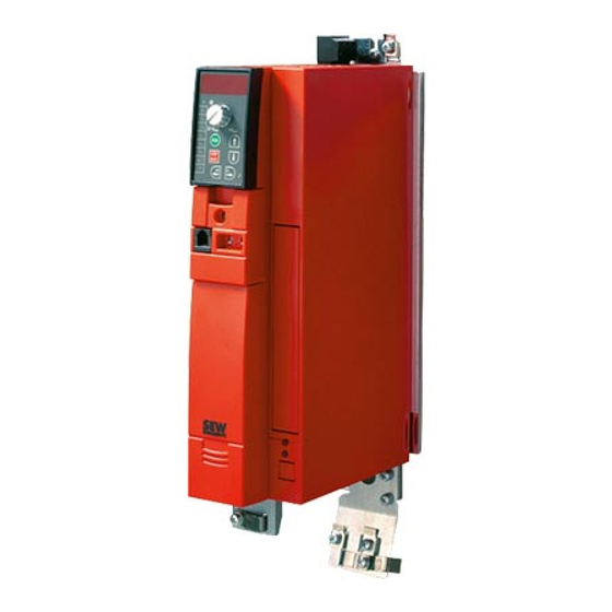
Ремонт частотных преобразователей SEW-EURODRIVE
 Ремонт частотного преобразователя SEW-EURODRIVE, впрочем, как и ремонт частотников других производителей имеет ряд особенностей в силу своего конструктива. Частотные преобразователи, точнее их начинка делятся на две части:
- Аппаратная часть,
- Программная часть.
Частотники данного производителя не являются исключением из правил, именно поэтому ремонт частотного преобразователя SEW-EURODRIVE имеет точно такой же ряд особенностей, как и у других преобразователей.
Диагностировать ту или иную неисправность помогают коды ошибок частотного преобразователя, которые отображаются на небольшом дисплее, расположенном на лицевой панели привода. Коды ошибок частотного преобразователя SEW-EURODRIVE в зависимости от серии описаны в инструкции, пользователя которые можно скачать с нашего сайта.
Ремонт частотных преобразователей SEW-EURODRIVE в Челеке, как и любых других преобразователей, выпущенных под другими брендами, всегда начинается с аппаратной части, после успешного ремонта аппаратной части наступает очередь программной.
Настройка частотного преобразователя SEW-EURODRIVE также прописана в инструкции завода производителя, для каждой серии частотных преобразователей настройка будет индивидуальной, так как каждая линейка преобразователей решает свои собственные задачи, этим обусловливается широкая номенклатура данного промышленного оборудования.
Ремонт частотных преобразователей SEW-EURODRIVE в сервисном центре
 Компания «Кернел» производит ремонт частотных преобразователей SEW-EURODRIVE в Челеке с 2002 года. За время существования компании наши сотрудники накопили колоссальный опыт в ремонте преобразователей частоты такого известного производителя как SEW-EURODRIVE. Ремонт подобного промышленного оборудования ответственное и сложное занятие, требующие максимальной отдачи, профессионализма и максимально полной материальной базе.
Специалисты нашего сервисного центра максимальное внимание уделяют качеству исполнения ремонта, программирования и настройке промышленных преобразователей частоты, не зависимо от производителя данного промышленного оборудования. Именно поэтому мы смело даем гарантию на все выполненные работы шесть месяцев.
Ремонт частотных преобразователей SEW-EURODRIVE в Челеке производится исключительно с использованием оригинальных запасных частей, на компонентном уровне с применением высокотехнологичного диагностического оборудования, квалифицированным персоналом с инженерным образованием.
В случае выхода из строя преобразователя частоты на вашем производстве либо появились проблемы с приводом, которые вы не можете решить самостоятельно, мы всегда рады вам помочь. Специалисты нашего сервисного центра в минимальные сроки проведут глубокую диагностику с последующим ремонтом частотного преобразователя SEW-EURODRIVE.
Инженеры сервисного центра выполняют качественный ремонт частотных преобразователей SEW-EURODRIVE всех серий, когда-либо выпускаемых компанией.
|
Серии частотных преобразователей SEW-EURODRIVE |
Типы частотных преобразователей SEW-EURODRIVE |
|
MOVITRAC® LTE-B |
MC-LTE-B0004-101-1-00, MC-LTE-B0008-101-1-00, MC-LTE-B0011-101-4-00, MC-LTE-B0004-2B1-1-00, MC-LTE-B0008-2B1-1-00 |
|
MOVITRAC® LTE-B+ |
MC-LTE-B0015-2B1-4-00, MC-LTE-B0022-2B1-4-00, MC-LTE-B0040-2B1-4-00, MC-LTE-B0015-2A3-4-00, MC-LTE-B0015-5A3-1-00 |
|
MOVITRAC® LTP-B |
MC-LTP-B0008-2B1-4-00, LTP-B MC-LTP-B0015-2B1-4-00, LTP-B MC-LTP-B0022-2B1-4-00, LTP-B MC-LTP-B0015-2A3-4-00 |
|
MOVITRAC®B |
MC-07B-0003-2B1-4-00, MC-07B-0004-2B1-4-00, MC-07B-0005-2B1-4-00, MC-07B-0008-2B1-4-00, MC-07B-0015-2B1-4-00 |
|
MOVIDRIVE®B |
MC-07B-0005-2A3-4-00/S0, MC-07B-0008-2A3-4-00/S0, MC-07B-0011-2A3-4-00/S0, MC-07B-0015-2A3-4-00/S0, MC-07B-0022-2A3-4-00/S0 |
|
MOVIAXIS® |
MD-X60-61B-0005-5A3-4-0, MD-X60-61B-0008-5A3-4-0, MD-X60-61B-0011-5A3-4-0, MD-X61B-0015-5A3-4-0, MD-X61B-0110-5A3-4-0 |
В данной таблице присутствуют далеко не все частотные преобразователи SEW-EURODRIVE ремонт которых предлагает наш сервисный центр.
Настройка частотного преобразователя SEW-EURODRIVE, программирование
 Настройка частотных преобразователей SEW-EURODRIVE (программирование) происходит в рамках установленных производителем правил, существует общий алгоритм по программированию (настройке частотных преобразователей), относящийся ко всем производителям данного промышленного оборудования. Ниже представлена пошаговая инструкция по настройке частотных преобразователей SEW-EURODRIVE.
- Выбор режима управления приводом SEW-EURODRIVE (управление по показанию датчиков, дистанционное управление, дистанционное управление).
- В случае использования отдельного (выносного) монитора, настраивается вывод на него технической информации.
- Далее определяем конфигурацию подключения серводвигателя. На данной стадии задаются такие параметры как- возможность применения обратной связи либо без ее применения, а в память блока заносятся данные по: величине крутящего момента, мощности потребителей, номинальное значения частоты, напряжение, ток и скорости вращения ротора.

- Программируется минимально допустимая величина напряжения и частоты, а также время ускорения ротора от ноля до номинального значения.
- И в завершении, в программу управления частотным преобразователем SEW-EURODRIVE вносятся функциональные данные со значениями отдельных клемм и особенностями сигналов. Отмечаются действия оборудования, выполняющиеся автоматически при отсутствии информации поступающей в оперативном режиме с датчика.

В некоторых частотниках существует пункт наличия/отсутствия фильтра в цепи питания двигателя. Этот пункт отвечает за подключение различных видов нагрузок, в том случае, когда возможно выбрать нормальное или инверсное изменение частоты при повышении уровня сигнала обратной связи.
Все настройки частотных преобразователей SEW-EURODRIVE приведены в технической документации ниже в удобном формате (PDF) который можно скачать на свой компьютер, распечатать или просто открыть на нашем сайте.
Коды ошибок частотного преобразователя SEW-EURODRIVE
 В процессе работы выходит из строя даже самое надежное промышленное оборудование. В данной статье мы приведем ошибки частотного преобразователя SEW-EURODRIVE, а точнее SEW-EURODRIVE серии MOVITRAC LTE-B. Частотники в наше время, нашли широкое применение абсолютно во всех сферах промышленности, управляя как мини моторами в оргтехнике, так и гигантскими двигателями в горнодобывающей промышленности.
Для простоты общения со столь сложной электроникой все частотные преобразователи оснащены небольшими дисплеями с помощью которых выводятся информационные сообщения с кодами ошибок, расшифровав которые можно сразу же узнать причину ее возникновения. Если учесть распространенность данной промышленной электроники, то появляется острая нужда в расшифровке кодов ошибок частотных преобразователей. В этой статье мы рассмотрим одного из самых известных производителей промышленной электроники имеющему уважение во всем мире, SEW-EURODRIVE.
Существует несколько видов ошибок, некоторые из них можно устранить автоматически, а некоторые возможно исправить только, обратившись в специализированный сервисный центр. В таблицах ниже приведены коды ошибок частотного преобразователя SEW-EURODRIVE MOVITRAC LTE-B и их расшифровка.
Обязательно должны соблюдаться все рекомендации, изложенные в инструкции по монтажу и эксплуатации насосов, в особенности требования по технике безопасности!
Ошибки частотных преобразователей SEW-EURODRIVE серии MOVITRAC LTE-B
|
Код ошибки |
Значение |
Устранение |
|
P-dEF |
Загружены установленные на заводе-изготовителе параметры. |
Нажать клавишу <стоп>. Теперь преобразователь можно конфигурировать под желаемое применение. |
|
O-I |
Избыточный ток на выходе преобразователя к двигателю. Перегрузка в двигателе. Перегрев на радиаторе преобразователя. |
Ошибка при постоянной частоте вращения:
Ошибка при разблокировке преобразователя:
Ошибка во время эксплуатации:
|
|
I.t-trP |
Ошибка из-за перегрузки. Возникает, если преобразователь в течении определенного времени подавал более 100% номинального тока. Индикация мигает, чтобы показать перегрузку. |
|
|
OI-b |
Избыточный ток тормозного канала. Избыточный ток в цепи тормозного резистора. |
|
|
OL-br |
Тормозной резистор перегружен. |
|
|
PS-trP |
Внутренняя ошибка выходного каскада. |
Ошибка при разблокировке преобразователя:
Ошибка во время эксплуатации:
|
|
O.Uolt |
Перенапряжение звена постоянного тока. |
|
|
U.Uolt |
Пониженное напряжение в цепи постоянного тока. |
Возникает обычно при отключении преобразователя. Проверить напряжение электросети, если ошибка возникает при работающем двигателе. |
|
O-hEat |
Слишком высокая температура окружающей среды. |
|
|
O-t |
Перегрев радиатора. |
|
|
U-t |
Пониженная температура. |
|
|
Th-FIt |
Неисправный термистор на радиаторе. |
Обратитесь в сервисный центр. |
|
E-triP |
Внешняя ошибка (в сочетании с двоичным входом 3). |
|
|
SC-trP |
Ошибка: сбой обмена данными. |
|
|
P-LOSS |
Ошибка: отказ фазы входа. |
|
|
SPIn-F |
Запуск вращения не удался. |
Функция запуска вращения не может определить частоту вращения двигателя. |
|
dAtA-F |
Внутренняя ошибка памяти. |
Параметры не сохраняются, воспроизводятся заводские настройки. Попытаться еще раз. Если данная проблема появляется повторно, обратитесь в сервисный центр. |
|
EE-F |
Параметры неисправности EEPROM не сохраняются, воспроизводятся заводские настройки. |
Параметры неисправности EEPROM не сохраняются, воспроизводятся заводские настройки. При повторной появлении ошибки обратитесь в сервисный центр. |
|
4_20 F |
Ток на аналоговом входе за границами установленного диапазона. |
Убедиться, что входной ток находится в установленном P-16 диапазоне. Проверить соединительный кабель. |
|
SC-FLt |
Внутренняя ошибка преобразователя. |
Обратитесь в сервисный центр. |
|
FAULtY |
||
|
Prog__ |
 1)Для функционального испытания для преобразователей частоты мощностью свыше 0.75kw нажмите все кнопки встроенной клавишной цепи одновременно.
Преобразователь частоты разработан таким образом, что он пытается избежать аварийных отключений путем ограничения момента, перенапряжения и т.п.
Появление сбоев при вводе в эксплуатацию или вскоре после него обычно свидетельствует о неверной настройке или неправильном подключении.
Возникновение неисправностей или проблем после длительного режима бесперебойной работы обычно происходит по причине изменений в системе или ее окружении (например, в результате износа).
Дополнительную информацию по частотным преобразователям SEW-EURODRIVE можно посмотреть и скачать в файлах ниже.
Частотный преобразователь SEW-EURODRIVE, скачать инструкции по эксплуатации
Ниже вы можете скачать руководства по эксплуатации частотных преобразователей SEW-EURODRIVE для всех серий, когда-либо выпущенных данным производителем.
|
Частотный преобразователь SEW-EURODRIVE MOVITRAC® LTE-B инструкция, руководство пользователя. |
 Скачать PDF Скачать PDF |
|
Частотный преобразователь SEW-EURODRIVE MOVITRAC® LTE-B+ инструкция, руководство пользователя. |
Скачать PDF |
|
Частотный преобразователь SEW-EURODRIVE MOVITRAC® LTP-B инструкция, руководство пользователя. |
Скачать PDF |
|
Частотный преобразователь SEW-EURODRIVE MOVITRAC® B инструкция, руководство пользователя. |
Скачать PDF |
|
Частотный преобразователь SEW-EURODRIVE инструкция, руководство пользователя. |
Скачать PDF |
|
Частотный преобразователь SEW-EURODRIVE MOVIDRIVE®B инструкция, руководство пользователя. |
Скачать PDF |
|
Частотный преобразователь SEW-EURODRIVE MOVIAXIS® инструкция, руководство пользователя. |
Скачать PDF |
Схемы подключения частотных преобразователей SEW-EURODRIVE
Схемы подключений частотных преобразователей SEW-EURODRIVE могут, отличатся друг от друга даже если эти преобразователи относятся ко одной линейке. Схема подключения преобразователя зависит от многих факторов таких как потребляемая частотным преобразователем нагрузка или питающая сеть к которой подключается частотник 200V – 380V и конечно же зависит от CPU в паре, с которым предполагается работа преобразователя.
|
Схема подключения частотных преобразователей SEW-EURODRIVE MOVITRAC на 230v (0.37kw…2.2kw) 400v (0.55kw…4.0kw) |
Схема подключения частотных преобразователей SEW-EURODRIVE MOVITRAC на 230v (3.7kw…30kw) 400v (5.5kw…30kw) |
|
|
 400v (5.5kw…30kw)")
|
 400v (0.55kw…4.0kw)")
Другие схемы подключений частотных преобразователей SEW-EURODRIVE вы найдете в руководстве пользователя.
Оставьте заказ на ремонт промышленного оборудования, используя форму на сайте, либо свяжетесь с нашими менеджерами, сделать это очень просто.
Оставить заявку на ремонт частотных преобразователей SEW-EURODRIVE
У вас вышел из строя частотник? Вам необходим срочный ремонт частотных преобразователей SEW-EURODRIVE в Челеке? Оставьте заявку на ремонт нажав на одноименную кнопку в верхней правой части экрана либо свяжитесь с нашими менеджерами. Связаться с ними можно несколькими способами:

- Заказав обратный звонок (кнопка в правом нижнем углу сайта)
- Посредством чата (кнопка расположена с левой стороны сайта)
- Позвонив по номеру телефона:
- +7(8482) 79-78-54;
- +7(8482) 55-96-39;
- +7(917) 121-53-01
- Написав на электронную почту: 89171215301@mail.ru
Далеко не полный список производителей промышленной электроники и оборудования, ремонтируемой в нашей компании.
-
Page 1
Edition ® MOVITRAC 02/2003 Operating Instructions 1056 411x / EN… -
Page 2
SEW-EURODRIVE… -
Page 3: Table Of Contents
Contents 1 Important Notes………………..4 2 Safety Notes …………………. 6 3 Unit Structure ………………..7 Unit design ………………..7 Unit designation and scope of delivery ……….. 11 4 Installation ………………….. 13 Installation instructions…………….13 UL compliant installation …………….. 17 Power shield clamp …………….. 18 Touch guard ………………..
-
Page 4: Important Notes
Important Notes Important Notes Safety and warn- Always follow the safety and warning instructions contained in this publication! ing instructions Electrical hazard Possible consequences: Severe or fatal injuries. Hazard Possible consequences: Severe or fatal injuries. Hazardous situation Possible consequences: Slight or minor injuries. Harmful situation Possible consequences: Damage to the unit and the environment.
-
Page 5
Important Notes ® MOVITRAC 07 frequency inverters are units intended for stationary installation in switch cabinets. All instructions referring to the technical data and the permissible con- ditions where the unit is operated must be followed. Do not start up the unit (take it into operation in the designated fashion) until: •… -
Page 6: Safety Notes
Safety Notes Safety Notes Installation and • Never install damaged products or take them into operation. Please submit a startup complaint to the transport company immediately in the event of damage. • Installation, startup and service work on the unit only by trained personnel. The personnel must be trained in the relevant aspects of accident prevention and must comply with the regulations in force (e.g.
-
Page 7: Unit Structure
Unit Structure Unit design Unit Structure Unit design Size 0S, 0M, 0L 02978BXX ® Figure 1: MOVITRAC 07 unit structure, sizes 0S, 0M, 0L 1. X1: Mains connection 3-phase: L1 / L2 / L3 / PE or 1-phase: L/N/PE 2. Operating panel 3.
-
Page 8
Unit Structure Unit design Size 1, 2S, 2 05132AXX ® Figure 2: MOVITRAC 07 unit structure, sizes 1, 2S, 2 1. X1: Mains connection 3-phase: L1 / L2 / L3 / PE screw 2. Operating panel 3. DIP switch S11 changeover U-signal / I-signal 4. -
Page 9
Unit Structure Unit design Size 3 05295AXX ® Figure 3: MOVITRAC 07 unit structure, size 3 1. PE connections 2. X1: Mains connection 3-phase: L1 (1) / L2 (2) / L3 (3) 3. X4: DC link circuit connection (not used) 4. -
Page 10
Unit Structure Unit design Size 4 05296AXX ® Figure 4: MOVITRAC 07 unit structure, size 4 1. X2: PE connection 2. X1: Mains connection 3-phase: L1 (1) / L2 (2) / L3 (3) 3. X4: DC link circuit connection (not used) 4. -
Page 11: Unit Designation And Scope Of Delivery
Unit Structure Unit designation and scope of delivery Unit designation and scope of delivery Sample unit designation Type MC Series and generation Version A Recommended motor 022 = 2.2 kW power 2 = 200 … 240 V Connection voltage 5 = 380 … 500 V B = Radio interference suppres- sion B Radio interference sup-…
-
Page 12
Unit Structure Unit designation and scope of delivery Scope of delivery loose items 03000AXX Figure 6: Scope of delivery, included loose size 0 Scope of delivery, included loose for size • Shield clamps for electronics cables (2 clamps with one screw each) [1] •… -
Page 13: Installation
Installation Installation instructions Installation Installation instructions It is essential to comply with the safety notes during installation! Tightening • Only use genuine connection elements. Note the permitted tightening torques ® torques of MOVITRAC 07 power terminals. → – Size 0S/M/L 0.5 Nm (4.4 lb.in) →…
-
Page 14
Installation Installation instructions Line choke • When more than four 3-phase units or more than one 1-phase unit are connect- ed to a supply system contactor designed for the total current: Insert a line choke in the circuit to limit the inrush current. Separate cable •… -
Page 15
Installation Installation instructions ® Line filter MOVITRAC 07 frequency inverters are equipped with an line filter as standard. They comply with the following limit value class to EN 55011 on the line side without further measures: • B: 1-phase connection •… -
Page 16
Installation Installation instructions ® HD output choke • Install the output choke close to MOVITRAC 07 beyond the minimum clearance. • Always route all three phases (not the PE!) together through the output choke. • If the cable is shielded, the shield is not allowed to be routed through the output choke. -
Page 17: Ul Compliant Installation
Installation UL compliant installation UL compliant installation Please note the following points for UL compliant installation: • Only use copper cables with the following temperature ranges as connection leads: ® – For MOVITRAC 07 … Temperature range 60/75 °C. ® •…
-
Page 18: Power Shield Clamp
Installation Power shield clamp Power shield clamp ® For sizes 1 / 2S SEW-EURODRIVE supplies a power shield clamp as standard with MOVITRAC size 1 / 2S. Install this power shield clamp together with the retaining screws of the unit. 02012BXX ®…
-
Page 19: Touch Guard
Installation Touch guard For size 2 SEW-EURODRIVE supplies a power shield clamp with two retaining screws as stan- ® dard with MOVITRAC 07 size 2. Install this power shield clamp together with the two retaining screws on X6. 01469BXX ® Figure 11: Power shield clamp for MOVITRAC 07 size 2 1.
-
Page 20: Wiring Diagram 230 V 0.37 … 2.2 Kw / 400 V 0.55 … 4.0 Kw
Installation Wiring diagram 230 V 0.37 … 2.2 kW / 400 V 0.55 … 4.0 kW Wiring diagram 230 V 0.37 … 2.2 kW / 400 V 0.55 … 4.0 kW 3 x 230 V / PE 1 x 230 V / N / PE 3 x 400/500 V / PE…
-
Page 21
Installation Wiring diagram 230 V 3.7 … 30 kW / 400 V 5.5 … 30 kW Wiring diagram 230 V 3.7 … 30 kW / 400 V 5.5 … 30 kW 3 x 230 V / PE 3 x 400/500 V / PE F11/F12/F13 (AC-3) -
Page 22
Installation Wiring diagram 230 V 3.7 … 30 kW / 400 V 5.5 … 30 kW Connection of the brake rectifier A separate supply system lead is required for connecting the brake rectifier; sup- ply from the motor voltage is not permitted! Only use contactors in utilization category AC-3 (IEC 158-1) for K11 and K12. -
Page 23: System Bus (Sbus) Installation
SC21 = System bus high SC12 = System bus low SC11 = System bus high = System bus terminating resistor SBus MOVITRAC 07: Connect the terminating equipment to SC11/SC12. SC21/SC22 are only active when S12 = OFF. Operating Instructions – MOVITRAC® 07…
-
Page 24: Startup
Startup General startup instructions Startup Using the IN/OUT key : Press the key once to go further down into the menu struc- ture (selecting functions). Press twice or use one long key press to change to higher lev- els in the menu structure. General startup instructions It is essential to adhere to the safety notes during startup! Prerequisite…
-
Page 25: Integrated Operating Panel
Startup Integrated operating panel Integrated operating panel Operation The following basic principle applies: Press the key once to start editing. Double- click the key to exit edit mode. Functions of the The UP, DOWN and IN/OUT buttons are used for navigating through the menus. The operating panel RUN and STOP/RESET buttons are used for controlling the drive.
-
Page 26: Principles Of Operation With The Integrated Operating Panel
Startup Principles of operation with the integrated operating panel Principles of operation with the integrated operating panel n11 n12 n [rpm] [rpm] [s/rpm] P081 [F-00 … F-99] <-2x 1x-> <-2x 1x-> P100 … P861 [ms/%/…] <-2x 1x-> P-01 … P-05 [kW/Hz/…] <-2x 1x->…
-
Page 27
Startup Principles of operation with the integrated operating panel Available sym- You can select the following symbols using keys bols Symbol Function Displays the inverter status or (in «drive enabled» status) the calculated actual speed in [rpm] Displays the apparent output current in [A] Sets the accelerating ramp in [s] Sets the deceleration ramp in [s] Sets the maximum speed in [rpm]… -
Page 28: Manual Speed Control Module And External Setpoint Selection
Startup Manual speed control module and external setpoint selection Fault indication If a fault occurs, the display changes to the symbol and it shows the flashing fault code, e.g. F-11 (fault list in Sec. Operation and servicing). Warnings Some parameters are not allowed to be altered in all operating states. If you try to do so, the following display appears: r-19 …
-
Page 29
Startup Manual speed control module and external setpoint selection You can limit the speed by P301 Minimum speed and P302 Maximum speed . After a fault, a reset can be performed using the «STOP/RESET» button, the terminal or the interface. «Manual speed control module» operating mode is once again active after the reset. -
Page 30
Startup Manual speed control module and external setpoint selection Enable direction of The direction of rotation is determined by the setpoint if you set P101 Control signal rotation with RS- source and P100 Setpoint source to RS485 or SBus (RS485 only for service purposes). 485 or SBus You must enable the setpoint via SBus or RS-485 using the «CW/STOP»… -
Page 31: Startup With The Integrated Operating Panel
Startup Startup with the integrated operating panel Startup with the integrated operating panel 02975GXX Figure 18: Startup with the integrated operating panel (2x = double-click / * = factory setting) P-01 = Operating mode P-03 = Rated motor speed P-05 = Rated motor voltage P-02 = Rated motor power P-04 = Rated motor frequency Operating Instructions –…
-
Page 32
Startup Startup with the integrated operating panel General informa- If you are not connecting the motor indicated in the motor selection table: Enter param- tion eters P-01 to P-05 correctly according to the nameplate (access via Name Range / factory setting P-01 Operating mode VFC or VFC &… -
Page 33: Starting The Motor
Startup Starting the motor Starting the motor Analog setpoints The following table shows which signals must be present on terminals X10:2 … X10:4 (DIØ1 … DIØ5) when the «UNIPOL/FIX.SETPT» setpoint is selected (P100), in order to operate the drive with analog setpoints. Terminal X10:13/14 X10:2…
-
Page 34: Loading A Logodrive Program
Startup Loading a LOGODrive program Loading a LOGODrive program • Start MOVITOOLS Manager. ® • Connect the MOVITRAC 07 to a vacant serial port on your PC using the UWS21A interface converter. Select this interface in the PC Interface group. ®…
-
Page 35: Parameter List
Startup Parameter list Parameter list All parameters which can also be displayed and edited using the symbol on the op- erating panel have a • in the «OP» (operating panel) column. If more than one value can be selected, the factory setting is highlighted in bold. OP Index Name Range / factory setting…
-
Page 36
Startup Parameter list OP Index Name Range / factory setting Value after startup dec. Display MOVITOOLS Binary outputs Binary output /FAULT (factory setting) DO01 Binary output BRAKE RELEASED (factory setting) DO02 Binary outputs Binary display DO01, DO02 Unit data Unit type [Text] Output rated cur- rent… -
Page 37
Startup Parameter list OP Index Name Range / factory setting Value after startup dec. Display MOVITOOLS Analog input 1 (+10 V) • 8463 AI1 scaling 0.1 … 1 … 10 • 8465 AI1 operation 3000 rpm (0 – 10 V) mode N-MAX (0 –… -
Page 38
Startup Parameter list OP Index Name Range / factory setting Value after startup dec. Display MOVITOOLS Fixed setpoints (set 2) • 8492 Internal setpoint 0 … 150 … 5000 [rpm] • 8493 Internal setpoint 0 … 750 … 5000 [rpm] •… -
Page 39
Startup Parameter list OP Index Name Range / factory setting Value after startup dec. Display MOVITOOLS Reference signals Speed reference signal • 8539 Speed reference 0 … 750 … 5000 [rpm] value • 8540 Hysteresis 0 … 100 … +500 [rpm] •… -
Page 40
Startup Parameter list OP Index Name Range / factory setting Value after startup dec. Display MOVITOOLS Binary outputs • 8804 Binary outputs DO01 DO02 /FAULT BRAKE RELEASED READY BRAKE RELEASED SPEED REFERENCE BRAKE RELEASED SP/ACT.VAL.COMP. BRAKE RELEASED /FAULT SPEED REFERENCE /FAULT SP/ACT.VAL.COMP. -
Page 41
Startup Parameter list OP Index Name Range / factory setting Value after startup dec. Display MOVITOOLS Unit functions Setup • 8594 Factory setting FACTORY SETTING DELIVERY CONDITION • 8595 Parameter lock 8596 Reset statistic data FAULT MEMORY Serial communication • 8597 RS485 address 0 … -
Page 42
Startup Parameter list OP Index Name Range / factory setting Value after startup dec. Display MOVITOOLS Fieldbus parameterization 8304 Setpoint descrip- NO FUNCTION (factory setting P872) tion PO1 SPEED (factory setting P871) MAX. SPEED 8305 Setpoint descrip- RAMP tion PO CTRL. -
Page 43: Fault Information
Operation and Service Fault information Operation and Service Fault information Fault memory The inverter stores the fault message in fault memory P080. The inverter does not save a new fault until the fault message has been acknowledged. The local operating panel shows the fault which occurred most recently.
-
Page 44
Operation and Service Fault information Reset A fault message can be acknowledged by: • Switching the supply system off and on again. Recommendation: Observe a mini- mum switch-off time of 10 s for the supply system contactor. • Reset via input terminals, i.e. via an appropriately assigned binary input (DIØ2…DIØ5). -
Page 45
Operation and Service List of errors (F-00 … F-97) List of errors (F-00 … F-97) Name Response Possible cause Action No error Over-current Immediate • Short circuit on output • Rectify the short circuit switch-off • Output switching • Only switch when output stage inhibited •… -
Page 46
Operation and Service List of errors (F-00 … F-97) Name Response Possible cause Action Overtempera- Rapid stop Thermal overload of inverter • Reduce load and/or ensure ade- ture with inhibit quate cooling • If the braking resistor is integrated in the heat sink: Mount the braking resistor externally System fault Immediate… -
Page 47: List Of Warnings (R-17 … R-32)
Operation and Service List of warnings (r-17 … r-32) Name Response Possible cause Action Initialization Immediate Error during initialization Contact SEW Service for advice. switch-off with inhibit System bus Rapid stop Fault during communication via system Check system bus connection. timeout without inhibit…
-
Page 48: Sew Electronics Service
Operation and Service SEW electronics service SEW electronics service Send in for repair Please contact the SEW electronics service if a fault cannot be rectified (→ «Cus- tomer and spare parts service»). Please always specify the service code number when you contact the SEW electronics service.
-
Page 49: Ce-Marking, Ul Approval And C-Tick
Technical Data CE-marking, UL approval and C-Tick Technical Data CE-marking, UL approval and C-Tick CE-marking ® Low Voltage Direc- MOVITRAC 07 frequency inverters comply with the regulations of the Low Voltage Di- tive rective 73/23/EEC. ® Electromagnetic MOVITRAC 07 frequency inverters are components of machines and systems. They compatibility EMC comply with the EMC product standard EN 61800-3 Variable-speed electrical drives .
-
Page 50: General Technical Data
Technical Data General technical data General technical data ® The following technical data applies to all MOVITRAC 07 frequency inverters, regard- less of size. ® MOVITRAC All sizes Interference immunity To EN 61800-3 Interference emission with To limit value class EMC-compliant installation •…
-
Page 51: Technical Data Of Movitrac® 07
Technical Data Technical data of MOVITRAC® 07 ® Technical data of MOVITRAC 230 V 51115AXX ® Figure 20: MOVITRAC 07 230 V units Size Power [kW / HP] 0.37 / 0.5 1.1 / 1.5 5.5 / 7.5 11 / 15 22 / 30 0.55 / 0.75 1.5 / 2.0…
-
Page 52
Technical Data Technical data of MOVITRAC® 07 230 V / 1-phase / size 0S / 0.37 … 0.75 kW / 0.5 … 1.0 HP 51105AXX ® Figure 22: MOVITRAC 07 / size 0S / 1-phase 230 V ® MOVITRAC MC07A (1-phase supply system) 004-2B1-4-.. -
Page 53
Technical Data Technical data of MOVITRAC® 07 ® MOVITRAC MC07A (1-phase supply system) 004-2B1-4-.. 005-2B1-4-.. 008-2B1-4-.. GENERAL Power loss at I 45 W 55 W 65 W Current limitation 125 % I continuous duty (fan/pump operation) 150 % I for maximum 60 seconds PWM frequency 4 / 8 / 12 / 16 kHz Speed range… -
Page 54
Technical Data Technical data of MOVITRAC® 07 230 V / 1-phase / size 0L / 1.1 … 2.2 kW / 1.5 … 3.0 HP ® Figure 24: MOVITRAC 07 / size 0L / 1-phase 230 V ® MOVITRAC MC07A (1-phase supply system) 011-2B1-4-.. -
Page 55
Technical Data Technical data of MOVITRAC® 07 ® MOVITRAC MC07A (1-phase supply system) 011-2B1-4-.. 015-2B1-4-.. 022-2B1-4-.. GENERAL Power loss at I 75 W 100 W 125 W Current limitation 125 % I continuous duty (fan/pump operation) 150 % I for maximum 60 seconds PWM frequency 4 / 8 / 12 / 16 kHz Speed range… -
Page 56
Technical Data Technical data of MOVITRAC® 07 230 V / 3-phase / size 0S / 0.37 … 0.75 kW / 0.5 … 1.0 HP 51105AXX ® Figure 26: MOVITRAC 07 / size 0S / 3-phase 230 V ® MOVITRAC 07A (3-phase supply system) 004-2A3-4-.. -
Page 57
Technical Data Technical data of MOVITRAC® 07 ® MOVITRAC 07A (3-phase supply system) 004-2A3-4-.. 005-2A3-4-.. 008-2A3-4-.. GENERAL Power loss at I 45 W 55 W 65 W Current limitation 125 % I continuous duty (fan/pump operation) 150 % I for maximum 60 seconds PWM frequency 4 / 8 / 12 / 16 kHz Speed range… -
Page 58
Technical Data Technical data of MOVITRAC® 07 230 V / 3-phase / size 0L / 1.1 … 2.2 kW / 1.5 … 3.0 HP ® Figure 28: MOVITRAC 07 / size 0L / 3-phase 230 V ® MOVITRAC 07A (3-phase supply system) 011-2A3-4-.. -
Page 59
Technical Data Technical data of MOVITRAC® 07 ® MOVITRAC 07A (3-phase supply system) 011-2A3-4-.. 015-2A3-4-.. 022-2A3-4-.. GENERAL Power loss at I 75 W 100 W 125 W Current limitation 125 % I continuous duty (fan/pump operation) 150 % I for maximum 60 seconds PWM frequency 4 / 8 / 12 / 16 kHz Speed range… -
Page 60
Technical Data Technical data of MOVITRAC® 07 230 V / 3-phase / size 1 / 3.7 kW / 5.0 HP ® Figure 30: MOVITRAC 07 / size 1 / 3-phase 230 V ® MOVITRAC 07A (3-phase supply system) 037-2A3-4-.. Part number 827 278 6 Part number with LOGODrive 827 285 9… -
Page 61
Technical Data Technical data of MOVITRAC® 07 ® MOVITRAC 07A (3-phase supply system) 037-2A3-4-.. GENERAL Power loss at I 210 W Current limitation 125 % I continuous duty (fan/pump operation) 150 % I for maximum 60 seconds PWM frequency 4 / 8 / 12 / 16 kHz Speed range 0 … -
Page 62
Technical Data Technical data of MOVITRAC® 07 230 V / 3-phase / size 2 / 5.5 … 7.5 kW / 7.5 … 10 HP ® Figure 32: MOVITRAC 07 / size 2 / 3-phase 230 V ® MOVITRAC 07A (3-phase supply system) 055-2A3-4-.. -
Page 63
Technical Data Technical data of MOVITRAC® 07 ® MOVITRAC 07A (3-phase supply system) 055-2A3-4-.. 075-2A3-4-.. GENERAL Power loss at I 300 W 380 W Current limitation 125 % I continuous duty (fan/pump operation) 150 % I for maximum 60 seconds PWM frequency 4 / 8 / 12 / 16 kHz Speed range… -
Page 64
Technical Data Technical data of MOVITRAC® 07 230 V / 3-phase / size 3 / 11 … 15 kW / 15 … 20 HP ® Figure 34: MOVITRAC 07 / size 3 / 3-phase 230 V ® MOVITRAC 07A (3-phase supply system) 110-203-4-.. -
Page 65
Technical Data Technical data of MOVITRAC® 07 ® MOVITRAC 07A (3-phase supply system) 110-203-4-.. 150-203-4-.. GENERAL Power loss at I 580 W 720 W Current limitation 125 % I continuous duty (fan/pump operation) 150 % I for maximum 60 seconds PWM frequency 4 / 8 / 12 / 16 kHz Speed range… -
Page 66
Technical Data Technical data of MOVITRAC® 07 230 V / 3-phase / size 4 / 22 … 30 kW / 30 … 40 HP ® Figure 36: MOVITRAC 07 / size 4 / 3-phase 230 V ® MOVITRAC 07A (3-phase supply system) 220-203-4-.. -
Page 67
Technical Data Technical data of MOVITRAC® 07 ® MOVITRAC 07A (3-phase supply system) 220-203-4-.. 300-203-4-.. GENERAL Power loss at I 1100 W 1300 W Current limitation 125 % I continuous duty (fan/pump operation) 150 % I for maximum 60 seconds PWM frequency 4 / 8 / 12 / 16 kHz Speed range… -
Page 68
Technical Data Technical data of MOVITRAC® 07 400/500 V / 3-phase / size 0M / 0.55 … 1.1 kW / 0.75 … 1.5 HP ® Figure 38: MOVITRAC 07 / size 0M / 3-phase 400/500 V ® MOVITRAC 07A (3-phase supply system) 005-5A3-4-.. -
Page 69
Technical Data Technical data of MOVITRAC® 07 ® MOVITRAC 07A (3-phase supply system) 005-5A3-4-.. 008-5A3-4-.. 011-5A3-4-.. GENERAL Power loss at I 42 W 48 W 58 W Current limitation 125 % I continuous duty (fan/pump operation) 150 % I for maximum 60 seconds PWM frequency 4 / 8 / 12 / 16 kHz Speed range… -
Page 70
Technical Data Technical data of MOVITRAC® 07 400/500 V / 3-phase / size 0L / 1.5 … 4.0 kW / 2.0 … 5.0 HP ® Figure 40: MOVITRAC 07 / size 0L / 3-phase 400/500 V ® MOVITRAC 07A (3-phase supply system) 015-5A3-4- 022-5A3-4- 030-5A3-4-… -
Page 71
Technical Data Technical data of MOVITRAC® 07 ® MOVITRAC 07A (3-phase supply system) 015-5A3-4- 022-5A3-4- 030-5A3-4- 040-5A3-4- GENERAL Power loss at I 74 W 97 W 123 W 155 W Current limitation 125 % I continuous duty (fan/pump operation) 150 % I for maximum 60 seconds PWM frequency 4 / 8 / 12 / 16 kHz… -
Page 72
Technical Data Technical data of MOVITRAC® 07 400/500 V / 3-phase / size 2S / 5.5 … 7.5 kW / 7.5 … 10 HP ® Figure 42: MOVITRAC 07 / size 2S / 3-phase 400/500 V ® MOVITRAC 07A (3-phase supply system) 055-5A3-4-.. -
Page 73
Technical Data Technical data of MOVITRAC® 07 ® MOVITRAC 07A (3-phase supply system) 055-5A3-4-.. 075-5A3-4-.. GENERAL Power loss at I 220 W 290 W Current limitation 125 % I continuous duty (fan/pump operation) 150 % I for maximum 60 seconds PWM frequency 4 / 8 / 12 / 16 kHz Speed range… -
Page 74
Technical Data Technical data of MOVITRAC® 07 400/500 V / 3-phase / size 2 / 11 kW / 15 HP ® Figure 44: MOVITRAC 07 / size 2 / 3-phase 400/500 V ® MOVITRAC 07A (3-phase supply system) 110-5A3-4-.. Part number 827 256 5 Part number with LOGODrive 827 301 4… -
Page 75
Technical Data Technical data of MOVITRAC® 07 ® MOVITRAC 07A (3-phase supply system) 110-5A3-4-.. GENERAL Power loss at I 400 W Current limitation 125 % I continuous duty (fan/pump operation) 150 % I for maximum 60 seconds PWM frequency 4 / 8 / 12 / 16 kHz Speed range 0 … -
Page 76
Technical Data Technical data of MOVITRAC® 07 400/500 V / 3-phase / size 3 / 15 … 30 kW / 20 … 40 HP ® Figure 46: MOVITRAC 07 / size 3 / 3-phase 400/500 V ® MOVITRAC 07 (3-phase supply system) 150-503-4-.. -
Page 77
Technical Data Technical data of MOVITRAC® 07 ® MOVITRAC 07 (3-phase supply system) 150-503-4-.. 220-503-4-.. 300-503-4-.. GENERAL Power loss at I 550 W 750 W 950 W Current limitation 125 % I continuous duty (fan/pump operation) 150 % I for maximum 60 seconds PWM frequency 4 / 8 / 12 / 16 kHz Speed range… -
Page 78
Technical Data Technical data of MOVITRAC® 07 ® MOVITRAC 07 sizes 0S, 0M, 0L for DIN rail mounting (optional accessory) 04329AXX ® Figure 48: MOVITRAC 07 dimensions for DIN rail mounting (optional accessory) ® MOVITRAC 230 V Dimensions A x B x C 90 x 185 x 150 mm 90 x 295 x 150 mm 3.5 x 7.2 x 5.9 in… -
Page 79: Change Index
Change Index Change Index The text has been completely revised and the layout adapted. The following changes were implemented in the respective sections. Technical Data • Information on long-term storage. • Overview of the different series. • Assignment of dimension sheetes to data tables. •…
-
Page 80: Index
Index Index Immediate switch-off 43 Input filter 15 Accelerating ramp 27 Input fuses 14 Actual speed 27 Installation 13 Ambient temperature 50 Installation instructions 13 Analog setpoints 33 Integrated operating panel 25 Apparent output current 27 Operation 26 Application environment 5 Startup 31 Available symbols 27 Interference emission 50…
-
Page 81
Index S11 7, 8, 9, 10 S12 7, 8, 9, 10 Safety Notes 6 Safety notes 4 SBus 30 Scope of delivery 12 Setpoint direction of rotation 29 Setpoint selection, external 28, 29 Setpoint speed 29 Shielding 14 Speed 29 Speed control module, manual 28 Starting the motor 33 Startup 24, 27, 31… -
Page 82
16, rue des Frères Zaghnoun Fax +213 21 8222-84 Bellevue El-Harrach 16200 Alger Argentina Assembly Buenos Aires SEW EURODRIVE ARGENTINA S.A. Tel. +54 3327 4572-84 Sales Centro Industrial Garin, Lote 35 Fax +54 3327 4572-21 Service Ruta Panamericana Km 37,5 sewar@sew-eurodrive.com.ar… -
Page 83
Address List Austria Assembly Wien SEW-EURODRIVE Ges.m.b.H. Tel. +43 1 617 55 00-0 Sales Richard-Strauss-Strasse 24 Fax +43 1 617 55 00-30 Service A-1230 Wien http://sew-eurodrive.at sew@sew-eurodrive.at Belgium Assembly Brüssel CARON-VECTOR S.A. Tel. +32 10 231-311 Sales Avenue Eiffel 5 Fax +32 10 231-336 Service B-1300 Wavre… -
Page 84
Address List Colombia Assembly Bogotá SEW-EURODRIVE COLOMBIA LTDA. Tel. +57 1 54750-50 Sales Calle 22 No. 132-60 Fax +57 1 54750-44 Service Bodega 6, Manzana B sewcol@andinet.com Santafé de Bogotá Croatia Sales Zagreb KOMPEKS d. o. o. Tel. +385 1 4613-158 Service PIT Erdödy 4 II Fax +385 1 4613-158… -
Page 85
Address List India Assembly Baroda SEW-EURODRIVE India Pvt. Ltd. Tel. +91 265 2831021 Sales Plot No. 4, Gidc Fax +91 265 2831087 Service Por Ramangamdi · Baroda — 391 243 sew.baroda@gecsl.com Gujarat Technical Offices Bangalore SEW-EURODRIVE India Private Limited Tel. +91 80 22266565 308, Prestige Centre Point Fax +91 80 22266569 7, Edward Road… -
Page 86
Address List Morocco Sales Casablanca S. R. M. Tel. +212 2 6186-69 + 6186-70 + 6186- Société de Réalisations Mécaniques 5, rue Emir Abdelkader Fax +212 2 6215-88 05 Casablanca srm@marocnet.net.ma Netherlands Assembly Rotterdam VECTOR Aandrijftechniek B.V. Tel. +31 10 4463-700 Sales Industrieweg 175 Fax +31 10 4155-552… -
Page 87
Address List Slovenia Sales Celje Pakman — Pogonska Tehnika d.o.o. Tel. +386 3 490 83-20 Service UI. XIV. divizije 14 Fax +386 3 490 83-21 SLO – 3000 Celje pakman@siol.net South Africa Assembly Johannesburg SEW-EURODRIVE (PROPRIETARY) LIMITED Tel. +27 11 248-7000 Sales Eurodrive House Fax +27 11 494-2311… -
Page 88
Address List Production Greenville SEW-EURODRIVE INC. Tel. +1 864 439-7537 Assembly 1295 Old Spartanburg Highway Fax Sales +1 864 439-7830 Sales P.O. Box 518 Fax Manuf. +1 864 439-9948 Service Lyman, S.C. 29365 Fax Ass. +1 864 439-0566 Telex 805 550 http://www.seweurodrive.com cslyman@seweurodrive.com Assembly… -
Page 92
SEW-EURODRIVE GmbH & Co KG · P.O. Box 3023 · D-76642 Bruchsal/Germany Phone +49 7251 75-0 · Fax +49 7251 75-1970 http://www.sew-eurodrive.com · sew@sew-eurodrive.com…