- Manuals
- Brands
- Yamaha Manuals
- Motorcycle
- WR450F
- Owner’s manual
-
Contents
-
Table of Contents
-
Troubleshooting
-
Bookmarks
Quick Links
Read this manual carefully before operating this vehicle.
q
OWNER’S MANUAL
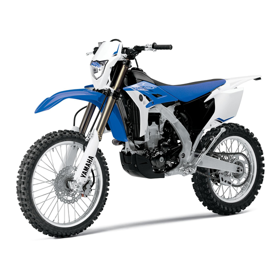
WR450F
1DX-28199-E1
Related Manuals for Yamaha WR450F
Summary of Contents for Yamaha WR450F
-
Page 1
Read this manual carefully before operating this vehicle. OWNER’S MANUAL WR450F 1DX-28199-E1… -
Page 2
EAU46090 Read this manual carefully before operating this vehicle. This manual should stay with this vehicle if it is sold. -
Page 3
Yamaha a reputation for dependability. Please take the time to read this manual thoroughly, so as to enjoy all advantages of your WR450F. The Owner’s Manual does not only instruct you in how to operate, inspect and maintain your motorcycle, but also in how to safeguard yourself and others from trouble and injury. -
Page 4: Important Manual Information
IMPORTANT MANUAL INFORMATION EAU10133 Particularly important information is distinguished in this manual by the following notations: This is the safety alert symbol. It is used to alert you to potential personal injury hazards. Obey all safety messages that follow this symbol to avoid possible injury or death.
-
Page 5
IMPORTANT MANUAL INFORMATION EAU10200 WR450F OWNER’S MANUAL ©2012 by Yamaha Motor Co., Ltd. 1st edition, July 2012 All rights reserved. Any reprinting or unauthorized use without the written permission of Yamaha Motor Co., Ltd. is expressly prohibited. Printed in Japan. -
Page 6: Table Of Contents
TABLE OF CONTENTS SAFETY INFORMATION ….1-1 Ignition circuit cut-off system ..3-19 Checking the throttle grip free play ……….6-17 DESCRIPTION ……..2-1 FOR YOUR SAFETY – Valve clearance ……6-18 Left view ………. 2-1 PRE-OPERATION CHECKS ….. 4-1 Tires ……….
-
Page 7
TABLE OF CONTENTS Checking the steering ….6-30 Checking the wheel bearings ..6-30 Battery ………. 6-30 Replacing the fuse ……6-32 Replacing the headlight bulb ..6-32 Tail/brake light ……6-34 Replacing a turn signal light bulb ……….. 6-34 Replacing the license plate light bulb …….. -
Page 8: Safety Information
SAFETY INFORMATION EAU53004 Take a training course. Beginners replaced with non-specified com- should receive training from a cer- ponents, the vehicle will no longer tified instructor. Contact an autho- meet the regulations. Be a Responsible Owner rized motorcycle dealer to find out Watch carefully for other vehicles As the vehicle’s owner, you are respon- about the training courses nearest…
-
Page 9
SAFETY INFORMATION motorist’s blind spot. • Always obey the speed limit and could contribute to an impairment • Never maintain a motorcycle never travel faster than warrant- of vision that could delay seeing a without proper knowledge. Con- ed by road and traffic conditions. hazard. -
Page 10
Yamaha accessories, which are avail- When loading within this weight limit, ports. able only from a Yamaha dealer, have keep the following in mind: Do not run engine outdoors where been designed, tested, and approved … -
Page 11: Specifications
SAFETY INFORMATION mended by Yamaha, even if sold and sion travel, steering travel or con- electric failure could result, which installed by a Yamaha dealer. trol operation, or obscure lights or could cause a dangerous loss of reflectors. lights or engine power.
-
Page 12
SAFETY INFORMATION tie-downs or suitable straps that are attached to solid parts of the motorcycle, such as the frame or upper front fork triple clamp (and not, for example, to rubber-mount- ed handlebars or turn signals, or parts that could break). Choose the location for the straps carefully so the straps will not rub against painted surfaces during transport. -
Page 13: Description
DESCRIPTION EAU10410 Left view 1, 2 4, 5 6 1. Front fork compression damping force adjusting screw (page 3-14) 8. Shift pedal (page 3-8) 2. Bleed screw (page 3-15) 9. Engine oil filler cap (page 6-8) 3. Starter knob (page 3-12) 10.Engine oil drain bolt (oil tank) (page 6-8) 4.
-
Page 14: Right View
DESCRIPTION EAU10420 Right view 1, 2 1. Shock absorber assembly compression damping force adjusting 7. Coolant drain bolt (page 6-13) screw (for slow compression damping) (page 3-16) 8. Brake pedal (page 3-9) 2. Shock absorber assembly compression damping force adjusting nut 9.
-
Page 15: Controls And Instruments
DESCRIPTION EAU10430 Controls and instruments 1. Clutch lever (page 3-8) 8. Throttle grip (page 6-17) 2. Left handlebar switches (page 3-7) 3. Multi-function display (page 3-2) 4. Main switch (page 3-1) 5. Front brake fluid reservoir (page 6-23) 6. Right handlebar switches (page 3-7) 7.
-
Page 16: Instrument And Control Functions
INSTRUMENT AND CONTROL FUNCTIONS EAU10451 EAU52471 EAU49392 Main switch Indicator lights and warning All electrical systems are off. lights EWA16130 WARNING Never push the main switch to “OFF” while the vehicle is moving, otherwise the electrical systems will be switched off, which may result in loss of control or an accident.
-
Page 17: Multi-Function Display
“ON”, or if the warning light remains This warning light comes on when the operator and increase the risk of an on, have a Yamaha dealer check the fuel level drops below approximately accident. electrical circuit.
-
Page 18
INSTRUMENT AND CONTROL FUNCTIONS last set to zero) ton until the display changes after a clock the main switch is pushed to “ON”. Measurement mode: Basic mode a speedometer a distance-compensation tripme- Odometer and tripmeter modes ter (which shows the accumulated Push the “SLCT 2”… -
Page 19
INSTRUMENT AND CONTROL FUNCTIONS push either select button to set the Changing from the basic mode to hours. the measurement mode 3. Push the “RST” button, and the With the odometer selected, push the minute digits will start flashing. “SLCT 1” button and “SLCT 2” button 4. -
Page 20
INSTRUMENT AND CONTROL FUNCTIONS Auto start 1. Push the “SLCT 1” button for at Starting measurement consists of the least two seconds to set the auto following two starts, either of which can start. be selected. Manual start Starting measurement by the rider When the stopwatch is set to auto start, himself operating the button. -
Page 21
Resetting the distance-compensation specified. For further information con- tripmeter cerning the use of this meter, please 1. Check that the stopwatch mea- consult your nearby Yamaha dealer. surement is in operation. Calibrate the distance-compensation 2. Reset the distance-compensation tripmeter as follows. -
Page 22: Handlebar Switches
INSTRUMENT AND CONTROL FUNCTIONS EAU1234B EAU12400 with the starter. See page 5-1 for start- Handlebar switches Dimmer switch “ ” ing instructions prior to starting the en- Set this switch to “ ” for the high gine. Left beam and to “ ”…
-
Page 23: Clutch Lever
INSTRUMENT AND CONTROL FUNCTIONS EAU12820 EAU12871 EAU41264 Clutch lever Shift pedal Brake lever The brake lever is located on the right side of the handlebar. To apply the front brake, pull the lever toward the throttle grip. 1. Clutch lever 1.
-
Page 24: Brake Pedal
INSTRUMENT AND CONTROL FUNCTIONS 3. While holding the lever pushed EAU12941 EAU13182 Brake pedal Fuel tank cap away from the throttle grip, turn the adjusting bolt in direction (a) to in- crease the distance, and in direc- tion (b) to decrease it. Distance between the brake lever and the throttle grip: Minimum (shortest):…
-
Page 25: Fuel
Gasoline is poisonous and can Your Yamaha engine has been de- heat from the engine or the sun cause injury or death. Handle gaso- signed to use premium unleaded gaso- can cause fuel to spill out of the line with care.
-
Page 26: Fuel Tank Breather Hose
INSTRUMENT AND CONTROL FUNCTIONS spark plug life and reduce maintenance EAU41360 EAU13433 Fuel tank breather hose Catalytic converter costs. This model is equipped with a catalytic converter in the exhaust system. EWA10862 WARNING The exhaust system is hot after op- eration.
-
Page 27: Starter Knob
INSTRUMENT AND CONTROL FUNCTIONS converter. EAU53230 EAU13650 Starter knob Kickstarter 1. Starter knob/idle adjusting screw 1. Kickstarter lever Starting a cold engine requires a richer To start the engine, fold out the kick- air-fuel mixture, which is supplied by starter lever, move it down lightly with the starter.
-
Page 28: Steering Lock
INSTRUMENT AND CONTROL FUNCTIONS EAU53100 rection. EAU53200 Steering lock Seat 3. Remove the key. WARNING! Never ride with the key inserted To remove the seat into the steering lock, which Remove the bolts, and then slide the may result in loss of control and seat to the rear and pull upward.
-
Page 29: Install Seat
INSTRUMENT AND CONTROL FUNCTIONS To install the seat EAU52450 Adjusting the front fork 1. Fit the slot in the seat onto the pro- EWA10180 jection on the fuel tank. WARNING Always adjust both fork legs equal- ly, otherwise poor handling and loss of stability may result.
-
Page 30: Front Fork Bleeding
INSTRUMENT AND CONTROL FUNCTIONS each fork leg in direction (b). range. To obtain a precise adjustment, EAU14793 Front fork bleeding it would be advisable to check the num- EWA10200 ber of clicks of each damping force ad- WARNING justing mechanism and to modify the Always bleed both fork legs, other- specifications as necessary.
-
Page 31: Adjusting The Shock Absorber Assembly
Maximum (hard): Spring preload Distance A = 222 mm (8.74 in) Spring preload adjustment should be made by a Yamaha dealer, since this Rebound damping force service requires special tools and tech- To increase the rebound damping force nical skills. The specified settings are and thereby harden the rebound damp- listed below.
-
Page 32
INSTRUMENT AND CONTROL FUNCTIONS sion damping force and thereby soften sion damping, turn the adjusting screw the compression damping, turn the ad- in direction (a). To decrease the com- justing bolt in direction (b). pression damping force and thereby soften the compression damping, turn the adjusting screw in direction (b). -
Page 33: Sidestand
INSTRUMENT AND CONTROL FUNCTIONS visable to check the actual total number absorber assembly to a Yamaha EAU15305 Sidestand of clicks or turns of each damping force dealer for any service. The sidestand is located on the left side adjusting mechanism. This adjustment of the frame.
-
Page 34: Ignition Circuit Cut-Off System
INSTRUMENT AND CONTROL FUNCTIONS Yamaha dealer repair it if it does not EAU52861 Ignition circuit cut-off system function properly. The ignition circuit cut-off system (com- prising the sidestand switch, clutch switch and neutral switch) has the fol- lowing functions. …
-
Page 35
INSTRUMENT AND CONTROL FUNCTIONS WARNING With the engine turned off: 1. Move the sidestand down. If a malfunction is noted, have a Yamaha 2. Make sure that the engine stop switch is set to “ ”. dealer check the system before riding. -
Page 36: For Your Safety — Pre-Operation Checks
• If necessary, add recommended coolant to specified level. 6-12 • Check cooling system for leakage. • Check operation. • If soft or spongy, have Yamaha dealer bleed hydraulic system. • Check brake pads for wear. Front brake • Replace if necessary.
-
Page 37
• Make sure that operation is smooth. • Check throttle grip free play. Throttle grip 6-17, 6-27 • If necessary, have Yamaha dealer adjust throttle grip free play and lubricate cable and grip housing. • Make sure that operation is smooth. Control cables 6-27 •… -
Page 38
• Tighten if necessary. Instruments, lights, signals • Check operation. — and switches • Correct if necessary. • Check operation of ignition circuit cut-off system. Sidestand switch 3-18 • If system is not working correctly, have Yamaha dealer check vehicle. -
Page 39: Operation And Important Riding Points
a lean angle sensor to stop the en- celerate hard when the engine is understand, ask your Yamaha dealer. gine in case of a turnover. In this cold! EWA10271 case, the multi-function display in-…
-
Page 40
Use the kickstarter when the ambient light should come on. If not, ask a temperature is below 10 C (50 F) or Yamaha dealer to check the elec- when at high altitude. trical circuit. 5. When the engine is warm, turn the 3. -
Page 41: Starting A Warm Engine
OPERATION AND IMPORTANT RIDING POINTS EAU52971 EAU16671 Starting a warm engine Shifting If the engine fails to start, push the main Follow the same procedure as for start- switch to “OFF” and give the kickstarter ing a cold engine with the exception 10 to 20 slow kicks at full throttle in or- that the starter is not required when the der to clear the engine of the rich air-fu-…
-
Page 42: Tips For Reducing Fuel Consumption
Do not rev the engine while shifting you are not familiar with vehicle ser- Always use the clutch while down, and avoid high engine vice, have a Yamaha dealer perform changing gears to avoid damag- speeds with no load on the engine. service. …
-
Page 43: Parking
EWA10311 for about 10 to 15 more minutes. period, immediately have a WARNING The motorcycle will now be ready Yamaha dealer check the vehi- Since the engine and exhaust to ride normally. cle. system can become very hot,…
-
Page 44: Periodic Maintenance And Adjustment
– possibly leading to pending on the weather, terrain, geo- that is certified (if applicable). Yamaha death. See page 1-2 for more in- graphical location, and individual use, dealers are trained and equipped to…
-
Page 45: Owner’s Tool Kit
If you do not have the tools or experi- ence required for a particular job, have a Yamaha dealer perform it for you.
-
Page 46: Periodic Maintenance Chart For The Emission Control System
From 7000 km (4200 mi) or 9 months, repeat the maintenance intervals starting from 3000 km (1800 mi) or 3 months. Items marked with an asterisk should be performed by a Yamaha dealer as they require special tools, data and technical skills.
-
Page 47: General Maintenance And Lubrication Chart
PERIODIC MAINTENANCE AND ADJUSTMENT EAU52581 General maintenance and lubrication chart ODOMETER INITIAL READINGS ANNUAL 3000 km 5000 km ITEM CHECKS AND MAINTENANCE JOBS 1000 km CHECK (1800 mi) (3000 mi) (600 mi) or or 3 or 6 1 month months months •…
-
Page 48
PERIODIC MAINTENANCE AND ADJUSTMENT ODOMETER INITIAL READINGS ANNUAL 3000 km 5000 km ITEM CHECKS AND MAINTENANCE JOBS 1000 km CHECK (1800 mi) (3000 mi) (600 mi) or or 3 or 6 1 month months months • Check bearing play and steering for roughness. … -
Page 49
PERIODIC MAINTENANCE AND ADJUSTMENT ODOMETER INITIAL READINGS ANNUAL 3000 km 5000 km ITEM CHECKS AND MAINTENANCE JOBS 1000 km CHECK (1800 mi) (3000 mi) (600 mi) or or 3 or 6 1 month months months • Check hoses for cracks of damage. … -
Page 50: Removing And Installing The Panel
Do not attempt to diagnose 1. Panel A such problems yourself. Instead, have EAU52872 a Yamaha dealer check the vehicle. If the spark plug shows signs of elec- trode erosion and excessive carbon or Panel A other deposits, it should be replaced.
-
Page 51: Check Engine Oil Level
PERIODIC MAINTENANCE AND ADJUSTMENT wire thickness gauge and, if necessary, past finger tight. However, the spark EAU52964 Engine oil and oil filter adjusted to specification. plug should be tightened to the speci- element fied torque as soon as possible. The engine oil level should be checked before each ride.
-
Page 52
PERIODIC MAINTENANCE AND ADJUSTMENT And do not touch the radiator pipe after high-speed operation, otherwise the cooling system is hot and cause burns. Always let the engine oil cool down suffi- ciently before removing the oil tank cap. NOTICE: Do not [EWA16140] operate the vehicle until you know that the engine oil level is… -
Page 53: Change Engine Oil
PERIODIC MAINTENANCE AND ADJUSTMENT 6. Install the engine oil tank cap, and and the engine oil filler cap. then the check bolt and its gasket. To change the engine oil (with or without oil filter element replace- ment) 1. Place the vehicle on a level sur- face.
-
Page 54
PERIODIC MAINTENANCE AND ADJUSTMENT Tightening torques: Engine oil drain bolt (oil tank): Skip steps 8–10 if the oil filter element 20 Nm (2.0 m·kgf, 14 ft·lbf) is not being replaced. Engine oil drain bolt (crank case): 20 Nm (2.0 m·kgf, 14 ft·lbf) 8. -
Page 55: Coolant
If this occurs, Make sure that no foreign mate- have a Yamaha dealer repair the EAUM1295 rial enters the crankcase. vehicle. To check the coolant level …
-
Page 56: Change Coolant
The coolant should be at the bottom of sion. If water has been added to the radiator filler neck. The level will the coolant, have a Yamaha change with variation of engine temper- 1. Coolant drain bolt dealer check the antifreeze con- ature.
-
Page 57: Cleaning The Air Filter Element And Check Hose
9. Start the engine, and then check the vehicle for coolant leakage. If coolant is leaking, have a Yamaha dealer check the cooling system. 1. Holding clip 2. Air filter element 3.
-
Page 58
Recommended oil: erly seated in the air filter case. Yamaha foam air filter oil or other The engine should never be op- quality foam air filter oil erated without the air filter ele- 1. -
Page 59
PERIODIC MAINTENANCE AND ADJUSTMENT 1. Hole 1. Holding clip 1. Air filter check hose 2. Projection 2. Projection 2. If dirt or water is visible, remove 3. Air filter element 8. Close the air filter case cover, and the hose, clean it, and then install 7. -
Page 60: Adjusting The Engine Idling Speed
Yamaha dealer make the adjustment. turn the screw in direction (a). To and, if necessary, have a Yamaha decrease the engine idling speed, dealer adjust it. turn the screw in direction (b).
-
Page 61: Valve Clearance
Tire air pressure (measured on cold from occurring, the valve clearance small area of road contact. Therefore, it tires): must be adjusted by a Yamaha dealer is essential to maintain the tires in good 0–90 kg (0–198 lb): Front: at the intervals specified in the periodic condition at all times and replace them 150 kPa (1.50 kgf/cm…
-
Page 62
Yamaha dealer re- The replacement of all wheel- place the tire immediately. -
Page 63: Spoke Wheels
If any damage is found, have a Yamaha dealer replace the wheel. Do not attempt even the smallest repair to the wheel. A de- formed or cracked wheel must be replaced.
-
Page 64: Checking The Brake Lever Free Play
1. No brake lever free play (b). There should be no free play at the brake lever end. If there is free play, have a Yamaha dealer inspect the brake system. EWA14211 WARNING A soft or spongy feeling in the brake lever can indicate the presence of air in the hydraulic system.
-
Page 65: Checking The Shift Pedal
Brake light switches dent. The operation of the shift pedal should be checked before each ride. If opera- tion is not smooth, have a Yamaha dealer check the vehicle. 1. Rear brake light switch 2. Rear brake light switch adjusting nut…
-
Page 66: Checking The Front And Rear Brake Pads
PERIODIC MAINTENANCE AND ADJUSTMENT EAU22392 peared, have a Yamaha dealer replace EAU22581 Checking the front and rear Checking the brake fluid level the brake pads as a set. brake pads Before riding, check that the brake fluid is above the minimum level mark.
-
Page 67: Changing The Brake Fluid
Rear brake may deteriorate, causing leak- EAU52952 Changing the brake fluid age. Have a Yamaha dealer change the Refill with the same type of brake fluid at the intervals specified in brake fluid. Adding a brake fluid the periodic maintenance and lubrica- other than DOT 4 may result in a tion chart.
-
Page 68: Drive Chain Slack
EAU34317 To adjust the drive chain slack 3. Pull the drive chain up above the Consult a Yamaha dealer before ad- drive chain guard installation bolt justing the drive chain slack. with a force of 50 N (5.0 kgf, 11 1.
-
Page 69: Cleaning And Lubricating The Drive Chain
PERIODIC MAINTENANCE AND ADJUSTMENT nuts to their specified torques. EAU23025 may contain substances that Cleaning and lubricating the could damage the O-rings. [ECA11111] Tightening torques: drive chain Axle nut: The drive chain must be cleaned and 125 Nm (12.5 m·kgf, 90 ft·lbf) lubricated at the intervals specified in Locknut: the periodic maintenance and lubrica-…
-
Page 70: Checking And Lubricating The Cables
Yamaha dealer at the intervals speci- bricated if necessary. ed if necessary. If a cable is damaged fied in the periodic maintenance chart.
-
Page 71: Checking And Lubricating The Brake Pedal
EWA10731 Lithium-soap-based grease WARNING If the sidestand does not move up and down smoothly, have a Yamaha dealer check or repair it. Otherwise, the sidestand could contact the ground and distract the operator, re- sulting in a possible loss of control.
-
Page 72: Lubricating The Swingarm Pivots
The swingarm pivots must be lubricat- intervals specified in the periodic main- ed by a Yamaha dealer at the intervals tenance and lubrication chart. specified in the periodic maintenance and lubrication chart.
-
Page 73: Checking The Steering
If any free This model is equipped with a VRLA the wheel bearings. play can be felt, have a Yamaha (Valve Regulated Lead Acid) battery. dealer check or repair the steering. There is no need to check the electro- lyte or to add distilled water.
-
Page 74: To Store Battery
To charge the battery necessary. Have a Yamaha dealer charge the bat- 3. Fully charge the battery before in- tery as soon as possible if it seems to stallation. NOTICE: When install- have discharged.
-
Page 75: Replacing The Fuse
ECA10650 NOTICE 4. If the fuse immediately blows Take care not to damage the follow- again, have a Yamaha dealer ing parts: check the electrical system. Headlight bulb Do not touch the glass part of the headlight bulb to keep it free 1.
-
Page 76
7. Have a Yamaha dealer adjust the 1. Do not touch the glass part of the bulb. headlight beam if necessary. 1. Remove the headlight cowling to- 1. -
Page 77: Tail/Brake Light
1. Remove the turn signal light lens If the tail/brake light does not come on, by removing the screw. have a Yamaha dealer check it. 1. Turn signal light bulb 3. Insert a new bulb into the socket, push it in, and then turn it clock- wise until it stops.
-
Page 78: Replacing The License Plate Light Bulb
PERIODIC MAINTENANCE AND ADJUSTMENT EAU24313 EAU45224 Replacing the license plate Replacing an auxiliary light light bulb bulb 1. Remove the license plate light unit If the auxiliary light bulb burns out, re- by removing the screws. place it as follows. 1.
-
Page 79: Supporting The Motorcycle
PERIODIC MAINTENANCE AND ADJUSTMENT EAU24350 frame in front of the rear wheel or under Supporting the motorcycle each side of the swingarm. Since this model is not equipped with a centerstand, follow these precautions when removing the front and rear wheel or performing other maintenance requiring the motorcycle to stand up- right.
-
Page 80: Front Wheel
PERIODIC MAINTENANCE AND ADJUSTMENT EAU24360 installing the spacers, be sure Front wheel to install them on the correct side. [ECA17700] EAU49332 2. Lift the wheel up between the fork To remove the front wheel legs. EWA10821 WARNING Make sure that there is enough space To avoid injury, securely support the between the brake pads before install- vehicle so there is no danger of it…
-
Page 81: Rear Wheel
PERIODIC MAINTENANCE AND ADJUSTMENT EAU25080 Tightening torque: Rear wheel Front wheel axle pinch bolt: 21 Nm (2.1 m·kgf, 15 ft·lbf) EAU45183 To remove the rear wheel 8. Push down hard on the handlebar EWA10821 several times to check for proper WARNING fork operation.
-
Page 82
PERIODIC MAINTENANCE AND ADJUSTMENT into the slot in the swingarm. Tightening torques: Make sure that there is enough Axle nut: The drive chain does not need to be space between the brake pads be- 125 Nm (12.5 m·kgf, 90 ft·lbf) disassembled in order to remove and Locknut: fore installing the wheel. -
Page 83: Troubleshooting
The following troubleshooting charts represent quick and easy procedures for checking these vital systems your- self. However, should your motorcycle require any repair, take it to a Yamaha dealer, whose skilled technicians have the necessary tools, experience, and know-how to service the motorcycle properly.
-
Page 84: Troubleshooting Charts
Remove the spark plug and check the electrodes. The engine does not start. Have a Yamaha dealer check the vehicle. Check the compression. 4. Compression The engine does not start. Have a There is compression.
-
Page 85
Start the engine. If the engine overheats again, have a The coolant level Yamaha dealer check and repair the cooling system. is OK. If coolant is not available, tap water can be temporarily used instead, provided that it is changed to the recommended coolant as soon as possible. -
Page 86: Motorcycle Care And Storage
Be ble. Rust and corrosion can develop Cleaning sure to consult a Yamaha dealer for even if high-quality components are ECA10772 advice on what products to use be- NOTICE used.
-
Page 87
MOTORCYCLE CARE AND STORAGE off any detergent residue using Test the product on a small hid- remain well into spring. plenty of water, as it is harmful den part of the windshield to 1. Clean the motorcycle with cold wa- to plastic parts. -
Page 88: Storage
EWA11131 Consult a Yamaha dealer for ad- WARNING ECA10810 NOTICE vice on what products to use. Contaminants on the brakes or tires …
-
Page 89
MOTORCYCLE CARE AND STORAGE stabilizer (if available) to prevent pivoting points of all levers and the fuel tank from rusting and the pedals as well as of the sidestand/ fuel from deteriorating. centerstand. 3. Perform the following steps to pro- 5. -
Page 90: Specifications
SPECIFICATIONS Dimensions: EAU50975 Displacement: With oil filter element replacement: 449 cm 1.00 L (1.06 US qt, 0.88 Imp.qt) Overall length: Bore stroke: Cooling system: 2315 mm (91.1 in) 95.0 63.4 mm (3.74 2.50 in) Overall width: Radiator capacity (including all routes): Compression ratio: 825 mm (32.5 in) 1.04 L (1.10 US qt, 0.92 Imp.qt)
-
Page 91
SPECIFICATIONS Transmission type: Manufacturer/model: Operation: Constant mesh 5-speed BRIDGESTONE/GRITTY-ED04 E Right foot operation Operation: Maximum load: Specified brake fluid: Left foot operation 90 kg (198 lb) DOT 4 Gear ratio: * (Total weight of rider, cargo and accesso- Front suspension: 1st: ries) Type:… -
Page 92
SPECIFICATIONS Tail/brake light: Front turn signal light: 12 V, 10.0 W 2 Rear turn signal light: 12 V, 10.0 W 2 Auxiliary light: 12 V, 5.0 W 1 License plate light: 12 V, 5.0 W 1 Meter lighting: EL (Electroluminescent) Neutral indicator light:… -
Page 93: Consumer Information
Record the vehicle identification num- ber and model label information in the spaces provided below for assistance when ordering spare parts from a Yamaha dealer or for reference in case the vehicle is stolen. VEHICLE IDENTIFICATION NUMBER: 1. Vehicle identification number 1.
-
Page 94
INDEX Air filter element and check hose, Front and rear brake pads, checking..6-23 Panel, removing and installing ….6-7 cleaning ……….6-14 Front fork, adjusting……… 3-14 Parking …………5-5 Auxiliary light bulb, replacing ….6-35 Front fork, bleeding……..3-15 Part locations ……….2-1 Front fork, checking ……… -
Page 95
INDEX Turn signal switch……..3-7 Valve clearance ……..6-18 Vehicle identification number…..9-1 Wheel bearings, checking …….6-30 Wheel (front)……….6-37 Wheel (rear)……….6-38 Wheels………….6-20… -
Page 98
PRINTED ON RECYCLED PAPER PRINTED IN JAPAN 2012.08-0.4×1 !
-
Страница 1
5TJ-28199-45 WR450F OWNER’S SERVICE MANUAL MANUEL D’ATELIER DU PROPRIETAIRE FAHRER- UND WARTUNGSHANDBUCH MANUAL DE SERVICIO DEL PROPIETARIO PRINTED IN JAPAN 2007.10-1.6 × 1 CR (E,F,G,S) WR450F PRINTED ON RECYCLED PAPER Y AMAHA MO T OR CO . , L TD . 2500 SHINGAI IW A T A SHIZUOKA JAP AN 2008 2008[…]
-
Страница 2
[…]
-
Страница 3
WR450F 5TJ-28199-45-E0 2008 OW NER’S SERVICE MANUAL[…]
-
Страница 4
[…]
-
Страница 5
WR450F OWNER’S SERVICE MANUAL ©2007 by Yamaha Motor Co., Ltd. 1st Edition, October 2007 All rights reserved. Any reprin ting or unauthorized use wi thout the written permission of Yamaha Motor Co., Ltd. is expressly prohib ited. Printed in Japan[…]
-
Страница 6
FOREWORD INTRODUCTION Congratul ations on your pu rchase of a Yamaha WR series. This model is the culmination of Yamaha’ s vast ex- perience in the production of paceset- ting racing machines. It represents the highest grade of craftsmanship and reliability that have made Yama- ha a leader. This manual explain s operation, in- spection, basic […]
-
Страница 7
TO THE NEW OWNER This manual will provide you with a good basic understanding of fea- tures, operation, and basic mainte- nance and inspection items of this machine. Please read this manual carefully and comple tely before oper- ating your new machine. If you have any questions regarding the ope ra- tion or maintenan ce of your machine, please cons[…]
-
Страница 8
HOW TO READ DESCRIPTIONS To help identify parts and clarify pro- cedure steps, there are exploded dia — grams at the start of each removal and disassembly section. 1. An easy-to-see exploded diagram «1» is provided for removal and disassembly jobs. 2. Numbers «2» are given in the or- der of the jobs in the exploded di- agram. A […]
-
Страница 9
TABLE OF CONTENTS GENERAL INFORMATION 1 SPECIFICATIONS 2 REGULAR INSPECTION AND ADJUSTMENTS 3 TUNING 4 ENGINE 5 CHASSIS 6 ELECTRICAL 7[…]
-
Страница 10
CONTENTS CHAPTER 1 GENERAL INFOR- MATION DESCRIPTION …………….. 1-1 MACHINE IDENTIFICATION …………. 1-2 INCLUDED PARTS ………. 1-2 IMPORTANT INFORMATION…………….. 1-2 CHECKING OF CONNEC- TION …………………………… 1-3 SPECIAL TOOLS …………. 1-4 CONTROL FUNCTIONS .. 1-8 MULTI-FUNCTION DISPLAY ………………[…]
-
Страница 11
1-1 DESCRIPTION GENERAL INFORMATION DESCRIPTION • The machine you have purchased may differ slightly from those shown in the following. • Designs and specifications are subject to chang e without notice. 1. Clutch lever 2. Hot starter lever 3. Engine stop switch 4. Multi-function displ ay 5. Main switch 6. Start switch 7. Front brake lever 8. T[…]
-
Страница 12
1-2 MACHINE IDENTIFICATION MACHINE IDENTIFICATION There are two signifi cant reasons for knowing the serial number of your machine: 1. When ordering parts, you can give the number to your Yamaha dealer for positive identification of the model you own. 2. If your machine is stolen, the au- thorities will need the number to search for and identify yo[…]
-
Страница 13
1-3 CHECKING OF CONNECTION ALL REPLACEMENT PARTS 1. We recommend to use Yamaha genuine parts for all replace- ments. Use oil and/or grease rec- ommended by Yamaha for assembly and adj ustment. GASKETS, OIL SEALS AND O- RINGS 1. All gaskets, oil seals, and O-rings should be replaced when an en- gine is overhauled. Al l gasket sur- faces, oil seal li[…]
-
Страница 14
1-4 SPECIAL TOOLS SPECIAL TOOLS The proper spe cial tools are necessary for complet e and accura te tune-up and asse mbly. Using the correct sp ecial tool will help prevent damage caused by the use of improper too ls or improvised techniques . The shape an d part number used fo r the special tool differ by coun try, so two types are provided. Refer[…]
-
Страница 15
1-5 SPECIAL TOOLS Damper rod holder YM-01494, 90890-01494 Use this tool to remove and install the damper rod. Fork seal driver YM-A0948, 90890-01502 This tool is used when install th e fork oil seal. Sheave holder YS-1880-A, 90890-01701 This tool is used for when loosening or tightening the flywheel magneto securing nut. Pocket tester YU-3112-C, 90[…]
-
Страница 16
1-6 SPECIAL TOOLS Clutch holding tool YM-91042, 90890-04086 This tool is used to hold the clutch when removing or installing th e clutch boss securing nut. Valve guide remover Intake 4.5 mm (0.18 in) Exhaust 5.0 mm (0.20 in) YM-4116, 90890-04116 YM-4097, 90890-04097 This tool is needed to remove and install the valve gui de. Valve guide installer I[…]
-
Страница 17
[…]
-
Страница 18
1-8 CONTROL FUNCTIONS CONTROL FUNCTIONS MAIN SWITCH Functions of the respective switch po- sitions are as follows: ON: The engine can be started only at this position. OFF: All electrical circuits are switched off. Main switch indicator light The main switch «1» is equipped with an indicator light «2» to avoid forget- ting to tu[…]
-
Страница 19
1-9 MULTI-FUNCTION DISPLAY COLD STARTER KNOB When cold, the engine requires a richer air-fuel mixture for starting. A separate starter circuit, which i s con- trolled by the cold starter knob «1», supplies this mixture. Pull the cold starter knob out to open the circuit for starting. When the engine has warmed up, push it in to close the […]
-
Страница 20
1-10 MULTI-FUNCTION DISPLAY To reset the digits, se lect the tripme- ter involved and push the «RST» but- ton for 2 seconds or more. CHANGEOVER TO BASIC MODE/ RACE MODE • Measurement using the time r func- tion can be made in RACE MODE. • Indicator will light up as an identifier that shows RACE MODE has been selected. • RACE MODE ca[…]
-
Страница 21
1-11 MULTI-FUNCTION DISPLAY If the machine is run while timer mea — surement is not made, n o change will occur to the digit in tripmeter A (TRIP A). 5. To resume the mea surement, again pushing the «SLCT1» button and «SLCT2» button at the same time. Resetting measurement data Resetting can be made in the follow- ing two manners[…]
-
Страница 22
1-12 MULTI-FUNCTION DISPLAY FUNCTION DIAGRAM A short push on the button changes the operation in the arrowed direction. A short push on the button changes the operation in both arrowed directions. A long push on the button changes the operation in the arrowed direction. A long push on the button changes the operation in both arrowed directions. Met[…]
-
Страница 23
1-13 MULTI-FUNCTION DISPLAY The following diagram illustrates th e multi-function display rega rding the direction and operation condition in- volved in each of its functions. A. A short push on the button changes the operation i n the ar- rowed direction. B. A short push on the button changes the operation i n both arrowed di rections. C. A long p[…]
-
Страница 24
1-14 STARTING AND BREAK-IN STARTING AND BREAK-IN FUEL Always use the recommended fuel as stated below. Also, be sure to use new gasoline the day of a race. Use only unleaded gaso line. The use of leaded g asoline will cause severe damage to the engi ne inter- nal parts such as valv es, piston rings, and exhaust system, etc. If knocking or pingi ng […]
-
Страница 25
1-15 STARTING AND BREAK-IN The engine fails to start Pull the hot starter lever all the way out and while holding the lever, kick the kickstarter crank 10 to 20 times to clear the engine. Then, re start the en- gine. Refer to «Restarting an engine after a fall». Observe the fo llowing break-in procedures during ini tial opera tion to ensu[…]
-
Страница 26
1-16 TORQUE-CHECK POINTS TORQUE-CHECK POINTS Concerning the tightening torque, refer to «TIGHTENING TORQUES» section in the CHAPTER 2. Frame construction Frame to rear frame Combined seat and fuel tank Fuel tank to frame Exhaust system Silencer to rear frame Engine mounting Frame to engine Engine bracket to engine Engine bracket to frame […]
-
Страница 27
1-17 CLEANING AND STORAGE CLEANING AND STORAGE CLEANING Frequent cleaning of your machine will enhance its appe arance, maintain good overall perfo rmance, and ex- tend the life of many components. 1. Before washing the machine, block off the en d of the exhaust pipe to prevent water from enter- ing. A plastic bag secured with a rubber band may be […]
-
Страница 28
2-1 GENERAL SPECIFICATIONS SPECIFICATIONS GENERAL SPECIFICATIONS Model name: WR450FX (CDN, AUS, NZ) WR450F (EUROPE, ZA) Model code numbe r: 5TJK (CDN) 5TJL (EUROPE) 5TJM (AUS, NZ, ZA) Dimensions: CDN, ZA AUS, NZ EUROPE Overall length 2,175 mm (85.63 in) 2,190 mm (86.22 in) 2,200 mm (86.61 in) Overall width 825 mm (32.48 in) ←← Overall height 1,[…]
-
Страница 29
2-2 GENERAL SPECIFICATIONS (Except for CDN) SAE10W30, SAE10W40, SAE15W40, SAE20W40 or SAE20W50 API service SG type or higher, JASO standard MA Oil capacity: Engine oil Periodic oil change 0.95 L (0.84 Imp qt, 1.00 US qt) With oil filter replacement 1.0 L (0.88 Imp qt, 1.06 US qt) Total amount 1.2 L (1.06 Imp qt, 1.27 US qt) Coolant capacity (includ[…]
-
Страница 30
2-3 GENERAL SPECIFICATIONS Chassis: CDN, ZA AUS, NZ EUROPE Frame type Semi double cra- dle ←← Caster angle 27.3 ° 27.0 ° 26.8 ° Trail 117 mm (4.61 in) 116 mm (4.57 in) 115 mm (4.53 in) Tire: Type With tube Size (front) 80/100-21 51M (CDN, ZA) 90/90-21 54R (AUS, N Z, EUROPE) Size (rear) 110/100-18 64M (CDN, Z A) 130/90-18 69R (AUS, NZ, EUROPE[…]
-
Страница 31
2-4 MAINTENANCE SPECIFICATIONS MAINTENANCE S PECIFICATIONS ENGINE Item Standard Limit Cylinder head: Warp limit —- 0.05 mm (0.002 in) Cylinder: Bore size 95.00–95.01 mm (3.7402 –3.7406 in) —- Out of round limit —- 0.05 mm (0.002 in) Camshaft: Drive method Chain drive (Left) —- Camshaft cap inside diameter 22.000–22.021 mm (0.8661–0.[…]
-
Страница 32
2-5 MAINTENANCE SPECIFICATIONS Valve, valve seat, valve guide: Valve clearance (cold) IN 0.10–0.15 mm (0.0039–0.0059 in ) —- EX 0.20–0.25 mm (0.0079–0.0098 in ) —- Valve dimensions: «A» head diameter (IN) 26.9–27.1 mm (1.0591–1.0669 in) —- «A» head diameter (EX) 27.9–28.1 mm (1.0984–1.1063 in) —- «B&[…]
-
Страница 33
2-6 MAINTENANCE SPECIFICATIONS Stem runout limit —- 0.01 mm (0.0004 in) Valve spring: Free length (IN) 39.46 mm (1.55 in) 38.46 mm (1.51 in) Free length (EX) 37.61 mm (1.48 in) 36.61 mm (1.44 in) Set length ( valve closed ) (IN) 27.87 mm (1.10 in) —- Set length ( valve closed ) (EX) 28.38 mm (1.12 in) —- Compressed force (installed) (IN) 13 0[…]
-
Страница 34
2-7 MAINTENANCE SPECIFICATIONS Piston rings: Top ring: Type Barrel —- Dimensions (B × T) 1.2 × 3.5 mm (0.05 × 0.14 in) —- End gap (installed) 0.20–0.30 mm (0 .008–0.012 in) 0.55 mm (0.022 in) Side clearance (insta lled) 0.030–0.065 mm (0.0012–0.0026 in) 0.12 mm (0.005 in) 2nd ring: Type Taper —- Dimensions (B × T) 1.00 × 3.35 mm […]
-
Страница 35
2-8 MAINTENANCE SPECIFICATIONS Clutch: Friction plate thickness 2.92–3.08 mm (0.115–0.121 in) 2.8 mm (0.110 in) Quantity 8 —- Clutch plate 1 thickness 1.9–2.1 mm (0.075–0.083 in ) —- Quantity 4 —- Warp limit —- 0.1 mm (0.004 in) Clutch plate 2 thickness 1.5–1.7 mm (0.059–0.067 in ) —- Quantity 3 —- Warp limit —- 0.1 mm (0.[…]
-
Страница 36
2-9 MAINTENANCE SPECIFICATIONS Lubrication system: Oil filter type Paper type —- Oil pump type Trochoid type —- Tip clearance 0.12 mm or less (0.0047 in or less) 0.20 mm (0.008 in) Side clearance 0.09–0.17 mm (0.0035–0.0067 in) 0.24 mm (0.009 in) Housing and rotor clearance 0.03–0.10 mm (0.0012–0.0039 in) 0.1 7 mm (0.0067 in) Bypass val[…]
-
Страница 37
2-10 MAINTENANCE SPECIFICATIONS CHASSIS Item Sta ndard Limit Steering system: Steering bearing type Taper roller bearing —- Front suspension: CDN AUS, NZ, ZA, EUROPE Front fork travel 300 mm (11.8 in) ← —- Fork spring free length 460 mm (18.1 in) ← 455 mm (17.9 in) Spring rate, STD K = 4.5 N/mm (0.459 kg/ mm, 25.7 lb/in) ← —- Optional s[…]
-
Страница 38
2-11 MAINTENANCE SPECIFICATIONS ELECTRICAL Drive chain: Type/manufacturer DID520VM/DAIDO —- Number of links 113 links + joint —- Chain slack 48–58 mm (1.9–2.3 in) —- Chain length (15 links) —- 239.3 mm (9.42 in) Front disc brake: Disc outside dia. × Thickness 250 × 3.0 mm (9.84 × 0.12 in) 250 × 2.5 mm (9.84 × 0.10 in) Pad thickness[…]
-
Страница 39
2-12 MAINTENANCE SPECIFICATIONS Charging system: System type AC magneto —- Model (stator)/manufacture r 5TJ 50/YAMAHA —- Normal output 14 V/120 W at 5,000 r/min —- Charging coil resistance (color) 0.28 8–0.432 Ω at 20 °C (68 °F) (White– Ground) —- Lighting coil resistance (color) 0.224–0.336 Ω at 20 °C (68 °F) (Yellow– Ground)[…]
-
Страница 40
2-13 TIGHTENING TORQUES TIGHTENING TORQUES ENGINE △ — marked portion shall be checked for torque ti ghtening after brea k-in or before each race. *1: Tighten the cylinder head bo lts to 30 Nm (3.0 m•kg, 22 ft•l b) in the prop er tightening sequence, remove and retighten the cylinder head bolts to 20 Nm (2.0 m•kg, 14 ft•lb) in the proper t[…]
-
Страница 41
2-14 TIGHTENING TORQUES Radiator pipe 1, 2 M10 × 1.0 2 10 1.0 7.2 Impeller M8 × 1.25 1 14 1.4 10 Water pump housing cover M6 × 1.0 3 10 1.0 7.2 Coolant drain bol t M6 × 1.0 1 10 1.0 7.2 Oil pump cove r M4 × 0.7 1 2 0.2 1.4 Oil pump M6 × 1.0 2 10 1.0 7.2 Oil pump drive gear sha ft M6 × 1.0 1 10 1.0 7.2 Engine oil drain bolt (oil filter) M6 ×[…]
-
Страница 42
2-15 TIGHTENING TORQUES CHASSIS △ — marked portion shall be checked for torque ti ghtening after brea k-in or before each race. Part to be tightened Thread size Q’ty Tightening torque Nm m•kg ft•lb △ Upper bracket and outer tube M8 × 1.25 4 21 2.1 15 △ Lower bracket and outer tube M8 × 1.25 4 21 2.1 15 △ Upper bracket and steeri […]
-
Страница 43
2-16 TIGHTENING TORQUES △ Driven sprocket and wheel hub M8 × 1.25 6 50 5.0 36 △ Nipple (spoke) — 72 3 0.3 2.2 △ Disc cover and rear brake caliper M6 × 1.0 2 10 1.0 7.2 △ Protector and rear brake calip er M6 × 1.0 2 7 0.7 5.1 Chain puller adjust bolt and locknut M8 × 1.25 2 19 1.9 13 Engine mounting: △ Engine uppe r bracket and frame[…]
-
Страница 44
2-17 TIGHTENING TORQUES 1. First, tighten the steering ring nut app roximately 38 Nm (3.8 m•kg, 27 ft•l b) by using the steerin g nut wrench, then loosen the steering ring nut one turn. 2. Retighten the steering ring nut 7 Nm (0.7 m•kg, 5.1 ft•lb). ELECTRICAL Tighten the rotor nut to 65 Nm (6.5 m•k g, 47 ft•lb), loose n and retighten th[…]
-
Страница 45
2-18 TIGHTENING TORQUES GENERAL TORQUE SPECIFICA TIONS This chart specifies torque for stan- dard fasteners with standard I.S.O. pitch threads. Torque specifications for special components or assem- blies are included in the applicable sections of this book. To avoid warpage, tighten multi-fastener as- semblies in a crisscr oss fashion, in progress[…]
-
Страница 46
2-19 LUBRICATION DIAGRAMS LUBRICATION DIAGRAMS 1. Oil filter element 2. Oil pump 3. Drive axle 4. Main axle 5. Crankshaft 6. Connecting rod A. From cylinder B. To oil tank[…]
-
Страница 47
2-20 LUBRICATION DIAGRAMS 1. Intake camshaft 2. Exhaust camshaft A. To main axle B. From oil pump[…]
-
Страница 48
2-21 CABLE ROUTING DIAGRAM CABLE ROUTING DIAGRAM 1. Fuel tank breather hose 2. Clamp 3. Diode 4. Hot starter cable 5. Throttle position sensor lead 6. Wire harness 7. Hump (frame) 8. Negative battery lead 9. Starter motor lead 10. Neutral switch le ad 11. AC magneto lead 12. Brake hose 13. Rectifier/regulator lead 14. Carburetor breather hose 15. C[…]
-
Страница 49
2-22 CABLE ROUTING DIAGRAM C. Fasten the diode (at the mark- ing), throttle cable and hot start- er cable onto the frame. Locate the clamp end facing towa rd the lower right of the frame and with the tie end facing downward . D. Fasten the wire harness, throttle position sensor lead and clutch cable onto the frame. Pass the clamp through the hole i[…]
-
Страница 50
2-23 CABLE ROUTING DIAGRAM 1. Throttle cable (pull) 2. Throttle cable (return) 3. Catch tank hose 4. Ignition coil 5. Clamp 6. Air induction hose (air cut-off valve — rear of cylinder he ad) 7. Catch tank breather hose A. Cross the pull and push throttle cables. B. Fasten the catch tank ho se and air induction hose (air cut-off valve-rear of cylind[…]
-
Страница 51
2-24 CABLE ROUTING DIAGRAM 1. Brake ma ster cylinder 2. Brake hose holder 3. Brake ho se A. Install the brake hose so that its pipe portion directs as shown and lightly touches the projec- tion on the brake caliper. B. Pass the brake hose into the brake hose holders. C. If the brake hose contacts the spring (rear shock absorber), correct its twist.[…]
-
Страница 52
2-25 CABLE ROUTING DIAGRAM 1. Clamp 2. Positive battery lead 3. Battery 4. Negative battery lead 5. Taillight coupler 6. CDI unit coupler (6-pin) 7. CDI unit coupler (3-pin) 8. CDI unit coupler (6-pin) A. Fasten the wire harness to th e upper engine bracket (left side). Locate the clamp end fa cing to- ward the upper side of the frame with the tie […]
-
Страница 53
2-26 CABLE ROUTING DIAGRAM E. Connect the wire harness to the starter relay. F. Fasten the catch tank breather hose and catch tank hose to the rear frame. Clamp them close to where they are joined to the frame. Fasten the pipe tightly enough not to crush it. Locate the clamp end facing towa rd the rear of the frame with the tie end facing downward.[…]
-
Страница 54
2-27 CABLE ROUTING DIAGRAM 1. Throttle cable 2. Clamp 3. Brake ho se 4. Clutch cable 5. Hose guide 6. Main switch coupler 7. Wire harness 8. Headlight coupler 9. Hot starter cable 10. Multi-function displ ay bracket 11. Main switch 12. Upper bracket 13. Clutch switch coupler 14. Engine stop switch coupler 15. Multi-function display cou pler 16. Sta[…]
-
Страница 55
2-28 CABLE ROUTING DIAGRAM D. Secure the coupl er by inserting it into the multi-function display bracket. E. Pass the throttle cables, clutch cable and hot starter cable be- tween the upper bracket and multi-function displ ay bracket. F. Fasten the multi-function display leads to the bracket. Cut off the tie end. G. Secure the coupler by pushing i[…]
-
Страница 56
3-1 MAINTENANCE INTERVALS REGULAR INSPECTION AND ADJUSTMENTS MAINTENANCE IN TERVALS The following schedule is intended as a gen eral guide to maint enance and l ubrication. Bear in mind that such factors as weather, terrain, geographical location, and individual u sage will alter the requ ired maintenance and lubrication intervals. If you are a dou[…]
-
Страница 57
3-2 MAINTENANCE INTERVALS CLUTCH Inspect and adjust ●● Insp ect housing, friction plate, clutch plate and spring. Replace ● TRANSMISSION Inspect ● Replace bearing ● SHIFT FORK, SHIFT CAM, GUIDE BAR Inspect ● Inspect wear. ROTOR NUT Retighten ●● MUFFLER Inspect and retighten ●● Clean ● Replace ● CRANK Inspect and clean ●●[…]
-
Страница 58
3-3 MAINTENANCE INTERVALS FUEL TANK, COCK Clean and insp ect ●● BRAKES Adjust lever position a nd pedal height ●● Lubricate pivot point ●● Check brake disc surface ●● Check fluid level and leakage ●● Retighten brake d isc bolts, cali- per bolts, master cylinder bolts and union bolts ●● Replace pads ● Replace brake fluid ?[…]
-
Страница 59
3-4 MAINTENANCE INTERVALS TIRE, WHEELS Inspect air pressure , wheel run- out, tire wear and spoke loose- ness ●● Retighten sprocke t bolt ●● Inspect bearings ● Replace bearings ● Lubricate ● Lithium ba se grease THROTTLE, CONTROL CABLE Check routing and connectio n ●● Lubricate ●● Yamaha cable lube or SAE 10W-30 motor oil HOT […]
-
Страница 60
3-5 PRE-OPERATION INSPECTION AND MAINTENANCE PRE-OPERATION INSPECTION AND MAINTENANCE Before riding for break-in operation or practice, make sure the machine is in goo d operating condition. Before using this machine, ch eck the following points. GENERAL INSPECTION AND MAINTENANCE Item Routine Page Coolant Check that coolant is fill ed up to the ra[…]
-
Страница 61
3-6 ENGINE ENGINE REMOVING THE SEAT, FUEL TANK AND SIDE COVERS Order Part name Q’ty Remarks Turn the fuel cock to «OFF». Disconnect the fuel hose. 1S e a t 1 2 Air scoop (left and right) 2 3 Bolt (fuel tank) 2 4 Fuel tank 1 5 Left side cover 1 Open the air filter case cover. 6 Right side cover 1 Refe r to removal section. 7 Headlight[…]
-
Страница 62
3-7 ENGINE REMOVING THE SIDE COVER 1. Remove: • Bolt (side cover) • Right side cover «1» Draw the side cover backward to re- move it because its claw «a» is insert- ed in the air filter case.[…]
-
Страница 63
3-8 ENGINE REMOVING THE EXHAUST PIPE AND SILENCER Order Part name Q’ty Remarks Right side cover Refer to «REMOVING THE SEAT, FUEL TANK AND SIDE COVERS» section. 1 Bolt (silencer clamp) 1 Onl y loosening. 2 Bolt [silencer (front)] 1 3 Bolt [silencer (rear)] 1 4 Collar 1 5 Silencer 1 6 Silencer clamp 1 7 Nut (exhaust pipe) 1 8 Bolt (ex[…]
-
Страница 64
3-9 ENGINE CHECKING THE SILENCER AND EXHAUST PIPE 1. Inspect: • Gasket «1» Damage → Replace. INSTALLING THE SILENCER AND EXHAUST PIPE 1. Install: • Gasket • Exhaust pipe «1» • Nut (exhaust pipe) «2» • Bolt (exhaust pipe) «3» First, temporarily tighten the nut (ex- haust pipe), then tighten the bol[…]
-
Страница 65
3-10 ENGINE Handling note s of coolant: The coolant is harmful so it should be handled with sp ecial care. • When cool ant splashes to your eye. Thoroughly wash your eye wi th water and see your do ctor. • When cool ant splashes to your clothes. Quickly wash it away with water and then with soap. • When co olant is swallowed . Quickly make hi[…]
-
Страница 66
3-11 ENGINE 2. Adjust: • Throttl e grip free play Throttle grip free play adjus tment steps: a. Slide the adjuster cover. b. Loosen the locknut «1». c. Tu rn the adjuster «2» until the specified free play is obtained. d. Tighten the lockn ut. Before adjusting the th rottle cable free play, the engine idle speed should be adjus[…]
-
Страница 67
3-12 ENGINE 5. Inspect: • Air filter element Damage → Replace. 6. Apply: • Foam-air-filter oil or equivalent oil to the el ement • Squeeze out the e xcess oil. Ele- ment shoul d be wet but not drip- ping. • Wipe off the oil left on the element surface using a clean dry cloth. (Ex- cess oil in the element may ad- versely affect engine star[…]
-
Страница 68
3-13 ENGINE • Do not add any chemical add i- tives or use oils with a grade of CD «a» or higher. • Do not use oi ls labeled «ENERGY CONSERVING II» «b» or higher. Engine oil also lubricates the clutch and additives could cause clutch slippage. • Do not allow foreign material to enter the crankcase. 5. Start the en[…]
-
Страница 69
3-14 ENGINE ADJUSTING THE PILOT SCREW 1. Adjust: • Pilot screw «1» Adjustme nt steps: To optimize the fuel flo w at a smaller throttle opening, e ach machine’s pilot screw has been individuall y set at the factory. Before adju sting the pilo t screw, turn it in fully and count the number of turns. Record this number as the factory-[…]
-
Страница 70
3-15 ENGINE 5. Adjust: • Valve clearance Adjustme nt steps: a. Remove the camshaft (intake and exhaust). Refer to «CAMSHAFTS» section in the CHAPTER 5. b. Remove the valve lifters «1» and the pads «2». • Place a rag in the timing chain space to prevent pads from falling into the crankcase. • Identity each valve l[…]
-
Страница 71
3-16 ENGINE INTAKE EXHAUST[…]
-
Страница 72
3-17 CHASSIS CLEANING THE SPARK ARRESTER (For USA) • Be sure the exhaust pipe and si- lencer a re cool before cleaning the spark arre ster. • Do not sta rt the engine whe n cleaning the exhaus t system. 1. Remove: • Screw (silencer ca p) «1» 2. Remove: • Bolt (spark arrester) «1» 3. Remove: • Tail pipe «1» ?[…]
-
Страница 73
3-18 CHASSIS 2. Remove: • Brake lever cover 3. Adjust: • Brake lever position Brake lever position adjustment steps: a. Loosen the locknut «1». b. Turn the adjusti ng bolt «2» until the lever position «a» is within speci- fied position. c. Ti ghten the locknut. Be sure to tighten the locknut, as it will cause poor […]
-
Страница 74
3-19 CHASSIS i. Insta ll the brake caliper «8» and tighten the pad pin «9». j. Insta ll the pad pin plug «10». 3. Inspect: • Brake fluid level Refer to «CHECKING THE BRAKE FLUID LEVEL» section. 4. Check: • Brake lever operation A softy or spongy feeling → Bleed brake system. Refer to «BLEEDING THE […]
-
Страница 75
3-20 CHASSIS 3. Inspect: • Brake fluid level Refer to «CHECKING THE BRAKE FLUID LEVEL» section. 4. Check: • Brake pedal operation A softy or spongy feeling → Bleed brake system. Refer to «BLEEDING THE HY- DRAULIC BRAKE SYSTEM» sec- tion. CHECKING THE REAR BRAKE PAD INSULATOR 1. Remove: • Brake pad Refer to «CHECKING[…]
-
Страница 76
3-21 CHASSIS When installing th e drive chain, apply the lithium soap base grease on th e chain joint and O-rings. 7. Install: • Link plate • Press the link plate onto the chain joint using a drive chain riveter «5». • Rivet the end of the chain joint us- ing a drive chai n riveter. • After riveting the chain joint, make sure its […]
-
Страница 77
3-22 CHASSIS 1. Elevate the front wheel by placing a suitable stand under the engine. 2. Remove the air bleed screw «1» and release the internal pressure from the front fork. 3. Install: • Air bleed screw ADJUSTING THE FRONT FORK REBOUND DAMPING FORCE 1. Adjust: • Rebound dampin g force By turning the adjuster «1». • STAND[…]
-
Страница 78
3-23 CHASSIS Never attempt to turn the adjuster beyond the maximum or minimum setting. 5. Tighten: •L o c k n u t 6. Install: • Rear frame (upper) • Rear frame (lower) ADJUSTING THE REAR SHOCK ABSORBER REBOUND DAMPING FORCE 1. Adjust: • Rebound dampin g force By turning the adjuster «1». • STANDARD POSITION: This is the position[…]
-
Страница 79
3-24 CHASSIS CHECKING THE TIRE PRESSURE 1. Measure: • Tire pressure Out of specification → Adjust. • Check the tire while it is cold. • Loose bead stoppers a llow the tire to slip off its position on t he rim when the tire pressure is low. • A tilted tire valve stem indicates that the tire slips off its position on the rim. • If the tir[…]
-
Страница 80
3-25 CHASSIS • The handlebar upper holder should be installed with the punched mark «a» forward. • Install the handleb ar so that the marks «b» are in place on both sides. • Install the han dlebar so that the pro- jection «c» of the handlebar upper holder is positioned at the mark on the handlebar a s shown. • […]
-
Страница 81
3-26 CHASSIS LUBRI CATION To ensure smooth operation of all components, lubricate your machine during setup, afte r break-in, and after every race. 1. All control cable 2. Clutch lever pivot 3. Shift pedal pivot 4. Footrest pivot 5. Throttle-to-handlebar contact 6. Drive chain 7. Tube guide ca ble winding por- tion 8. Throttle cable end 9. Clutch c[…]
-
Страница 82
3-27 ELECTRICAL ELECTRICAL CHECKING THE SPARK PLUG 1. Remove: • Spark plug 2. Inspect: • Electrode «1» Wear/damage → Replace. • Insulator color «2» Normal condition is a medium to light tan color. Distinctly different color → Check the engine condition. When the engine runs for many hours at low speeds, the spark plug […]
-
Страница 83
3-28 ELECTRICAL 3. Remove: • Battery band •B a t t e r y 4. Measure: • Battery charge Measurement steps: a. Connect a pocket tester «1» to the battery terminals. • The charge state of an MF battery can be checked by measuring its open-circuit voltage (i.e., the vol t- age when the positive terminal is disconnected). • No chargin[…]
-
Страница 84
3-29 ELECTRICAL Charging method using a variabl e voltage charger[…]
-
Страница 85
3-30 ELECTRICAL Charging method usin g a constant voltage charger[…]
-
Страница 86
3-31 ELECTRICAL 6. Install: •B a t t e r y • Battery band 7. Connect: • Battery leads (to the batte ry terminals) First, connect the positiv e lead «1», then the negative lead «2». 8. Check: • Battery terminals Dirt → Clean with a wire brush. Loose connection → Connect properly. 9. Lubricate: • Battery terminal 10.[…]
-
Страница 87
3-32 ELECTRICAL ADJUSTING THE HEADLIGHT BEAMS 1. Adjust: • Headlight beam (ve rtically) Adjusting steps: a. Turn the adjustin g screw «1» in di- rection «a» or «b». Direction «a» Headlight beam is raised. Direction «b» Headlight beam is lowered.[…]
-
Страница 88
4-1 ENGINE TUNING ENGINE CARBURETOR SETTING • The air/fuel mixture will vary de- pending on atmospheric conditi ons. Therefore, it is necessary to take into consideration the air pressure, ambient temperature, hu midity, etc., when adjusting the carburetor. • Perform a test run to check for prop- er engine performance (e.g., throt- tle response[…]
-
Страница 89
4-2 ENGINE ADJUSTING THE PILOT JET The richness of the air-fuel mixtu re with the throttle open 1/4 or less can be set by adjusti ng the pilot jet «1». Effects of adjusting the pilot jet (reference) A. Idle B. Fully open 1. #48 2. #42 3. #45 ADJUSTING THE JET NEEDLE GROOVE POSITION Adjusting the jet needl e «1» position affects […]
-
Страница 90
4-3 ENGINE CARBURETOR SETTING PARTS Main jet Size Part number (-14943-) Rich #185 4MX-44 #182 4MX-94 #180 4MX-43 #178 4MX-93 #175 4MX-42 #172 4MX-92 #170 4MX-41 #168 4MX-91 #165 4MX-40 (STD) #162 4MX-90 *(STD) Lean #160 4MX-39 Pilot jet Size Part number (-14948-) Rich #55 4MX-09 #52 4MX-08 #50 4MX-07 *(STD) #48 4MX-06 (STD) Lean #45 4MX-05 Jet need[…]
-
Страница 91
4-4 ENGINE EXAMPLES OF CARBURETOR SETTING DEPENDING ON SYMPTOM * This should be taken simply for an example. It is necessary to set the carbureto r while checking the operating conditions of the engine. Symptom Setting Checking At full throttle Hard breathing Shearing noise Whitish spark plug ↓ Lean mixture Increase main jet cal ibration no. (Gra[…]
-
Страница 92
4-5 CHASSIS CHASSIS SELECTION OF THE SECONDARY REDUCTION RATIO (SPROCKET) <Requirement for selection of sec- ondary gear reduction ra tio> • It is generally said that the second- ary gear ratio should be reduced for a longer straight portion of a speed course and should be in creased for a course with many corners. Actual — ly, however, as […]
-
Страница 93
4-6 CHASSIS A. Air spring characteristics in relation to oil l evel change B. Load C. Stroke 1. Max. oil level 2. Standard oil level 3. Min. oil level ADJUSTING THE SPRING PRELOAD The spring preload is adjusted by in- stalling the adjustment washer «1 » be- tween the fork spring «2» and damper rod «3». Do not install t[…]
-
Страница 94
4-7 CHASSIS 2. Setting of damping force • Change the rebound damping. • Change the compression damp- ing. CHOOSING SET LENGTH 1. Place a stand or bl ock under the engine to put the rear wheel above the floor, and measure the length «a» between the rear wheel axle center and the re ar fender holding bolt. 2. Remove the stand or bl ock […]
-
Страница 95
4-8 CHASSIS SUSPENSION SETTING (FRONT FORK) • If any of the following symptoms is experienced with the standard position as the base, make resetting by reference to the adjustment procedure gi ven in the same chart. • Before any change, set t he rear shock absorber sunken length to the standard figure 90–100 mm (3.5–3.9 in). Symptom Section[…]
-
Страница 96
4-9 CHASSIS SUSPENSION SETTING (REAR SHOCK ABSORBER) • If any of the following symptoms is experienced with the standard position as the base, make resetting by reference to the adjustment procedure gi ven in the same chart. • Adjust the rebound damping in 2-click increments or decrements. • Adjust the low compression damping in 1-click incre[…]
-
Страница 97
5-1 RADIATOR ENGINE RADIATOR REMOVING THE RADIATOR Order Part name Q’ty Remarks Drain the coolant. Refer to «CHANGING THE COOLANT» sec — tion in the CHAPTER 3. Seat, fuel tank and left side cover Refer to «REMOVING THE SEAT, FUEL TANK AND SIDE COVERS» section in the CHAPTER 3. Exhaust pipe Refer to «REMOVING THE EXHAUS[…]
-
Страница 98
5-2 RADIATOR 11 Pipe 1/O-ring 1/1 12 Catch tank breather hose 1 13 Catch tank 1 Order Part name Q’ty Remarks[…]
-
Страница 99
5-3 RADIATOR HANDLING NOTE Do not remove the radiator cap when the engine and ra diator are hot. Scaldi ng hot fluid and ste am may be blown out under pressure, which could ca use serious in jury. When the engin e has cooled, open the radiator cap by th e following procedure: Place a thick rag, like a towel, over the radiator cap, sl owly rotate th[…]
-
Страница 100
5-4 CARBURETOR CARBURETOR REMOVING THE CARBURETOR Order Part name Q’ty Remarks Seat and fuel ta nk Refer to «REMOVING THE SEAT, FUEL TANK AND SIDE COVERS» section in the CHAPTER 3. Rear shock absorber Refer to «REAR SHOCK ABSORBER» sec- tion in the CHAPTER 6. 1C l a m p 2 2 Throttle position sensor lead coupler 1 3 Throttle[…]
-
Страница 101
5-5 CARBURETOR 13 Bracket (cylinder head breather pipe) 1 14 Carburetor joint 1 Order Part name Q’ty Remarks[…]
-
Страница 102
5-6 CARBURETOR DISASSEMBLING THE CARBURETOR Order Part name Q’ty Remarks 1 Carburetor breather hose 4 2 Valve lever housing cover 1 3 Screw (throttle shaft) 1 4 Throttle valve 1 5 Need le holder 1 6 Jet needle 1 7 Accelerator pump cover 1 8S p r i n g 1 9 Diaphragm (accelerator pump) 1 10 Air cut valve cover 1 11 Spring (air cut valve) 1 12 Di[…]
-
Страница 103
5-7 CARBURETOR 19 Main jet 1 20 Needle jet 1 21 Spacer 1 22 Pilot jet 1 23 Starter jet 1 24 Push rod 1 Pull the push rod. 25 Throttle shaft assembly 1 26 Push rod link lever assembly 1 27 Pilot air jet 1 28 Cold starter plunger 1 Order Part name Q’ty Remarks[…]
-
Страница 104
5-8 CARBURETOR HANDLING NOTE Do not loosen th e screw (throttle position sensor) «1» except when changing the th rottle position sen- sor due to failur e because it will cause a drop in engine pe rfor- mance. REMOVING THE PILOT SCREW 1. Remove: • Pilot screw «1» To optimize th e fuel flow at a small throttle opening, e ach mac[…]
-
Страница 105
5-9 CARBURETOR e. If both are fine, adjust the float height by bending th e float tab «b» on the float. f. Recheck the float height. CHECKING THE FLOAT 1. Inspect: • Float «1» Damage → Replace. CHECKING THE STARTER PLUNGER 1. Inspect: • Cold starter plunger «1» • Hot starter plunger «2» Wear/damage ?[…]
-
Страница 106
5-10 CARBURETOR • Apply the fluoro chemical grease on the bearings. • Fit the projection «a» on the throttle shaft assembly into the slot «b» in the throttle posit ion sensor. • Make sure the stopper «c» of the spring fits into the recess in the car- buretor . • Turn the throttle shaft assembl y left while hold[…]
-
Страница 107
5-11 CARBURETOR 17. Install: • Throttle valve assembly «1» • Screw (throt tle shaft) «2» Install the valve lever rollers «3» into the slits «a» of the throttle valve. 18. Install: • O-ring «1» • Valve lever housing cover «2» • Bolt (valve lever housing cov er) «3» 19. I[…]
-
Страница 108
5-12 CARBURETOR 7. Install: • Throttle cable cover «1» • Bolt (thr ottle cable cover) «2» 8. Install: • Throttle po sition sensor lead cou- pler «1» • Clamp «2 » Refer to «CABLE R OUTING DIA- GRAM» section in the CHAPTER 2. 9. Install: • Clamp «1 » Refer to «CABLE R OUTING D[…]
-
Страница 109
5-13 AIR INDICTOIN SYSTEM AIR INDICTOIN SYSTEM REMOVING THE AIR INDUCTION SYSTEM Order Part name Q’ty Remarks 1 Bracket 1 2 Air cut-off valve assembly 1 3 Air induction hose (ai r cut-off valve — front of cyl- inder head) 1 4 Air induction pipe 1 5 Gasket 1 6 Air induction hose (air cut-off valve — rear of cylin- der head) 1 7 Air induction ho[…]
-
Страница 110
5-14 AIR INDICTOIN SYSTEM CHECKING THE AIR INDUCTION SYSTEM 1. Inspect: • Air induction hose Crack/damage → Replace. • Air induction pipe Crack/damage → Replace. 2. Check: • Operation of air cut valve Pass air through the pipe and check the air cut valve for opera- tion. Does not meet the followi ng con- dition → Replace the air cut val[…]
-
Страница 111
5-15 CAMSHAFTS CAMSHAFTS REMOVING THE CYLINDER HEAD COVER Order Part name Q’ty Remarks Seat and fuel ta nk Refer to «REMOVING THE SEAT, FUEL TANK AND SIDE COVERS» section in the CHAPTER 3. Air cut-off valve assembly Refer to «AIR INDUCTION SYSTEM» section. Engine upper bracket (right) Refer to «ENGINE REMOVAL» se […]
-
Страница 112
5-16 CAMSHAFTS REMOVING THE CAMSHAFTS Order Part name Q’ty Remarks 1 Timing mark accessing screw 1 Refer to removal section. 2 Crankshaft end accessing screw 1 Refer to removal section. 3 Timing chain tensioner cap bolt 1 Refer to removal section. 4 Timing chain tensioner 1 Refer to removal section. 5 Gasket 1 Refer to removal section. 6 Bolt […]
-
Страница 113
5-17 CAMSHAFTS REMOVING THE CAMSHAFT 1. Remove: • Timing mark accessing screw «1» • Crankshaft end accessing screw «2» 2. Align: • T.D.C. mark With align mark. Checking steps: a. Turn the crankshaft counterclock- wise with a wren ch. b. Align the T.D.C. mark «a» on th e rotor with the align mark «b» on […]
-
Страница 114
[…]
-
Страница 115
5-19 CAMSHAFTS Do not turn the cranksha ft during the camshaft insta llation. Damage or improper valve timing will re- sult. d. Install the clips, camshaft caps «4» and bolts (camshaft cap) «5». • Before removing the clip s, cover the cylinder head with a clean rag to prevent the clips from into the cylin- der head cavity. •[…]
-
Страница 116
5-20 CYLINDER HEAD CYLINDER HEAD REMOVING THE CYLINDER HEAD Tighten the cylinder head bolts to 30 Nm (3.0 m•kg, 22 ft•lb ) in the proper ti ghtening sequenc e, remove and retighten the cylinder head bolts to 20 Nm (2.0 m•kg , 14 ft•lb) in the prop er tightening sequ ence, and then tighten th e cylinder head bolts further to reach the specif[…]
-
Страница 117
5-21 CYLINDER HEAD CHECKING THE CYLINDER HEAD 1. Eliminate: • Carbon deposits (from the com- bustion chambers) Use a rounded scraper. Do not use a sharp instrument to avoid damaging or scratching: • Spark plug threads • Valve seats 2. Inspect: • Cylinder head Scratches/damage → Replace. 3. Measure: • Cylinder head warpage Out of specifi[…]
-
Страница 118
5-22 CYLINDER HEAD 3. Install: • Bolt (cylinder head) «1» Bolt (cylinder head): 10 Nm (1.0 m•kg, 7.2 ft•lb)[…]
-
Страница 119
5-23 VALVES AND VALVE SPRINGS VALVES AND VALVE SPRINGS REMOVING THE VALVES AND VALVE SPRINGS Order Part name Q’ty Remarks Cylinder head Refer to «CYLINDER HEAD» section. 1 Valve lifter 5 Refer to removal sectio n. 2 Adjusting pad 5 Refer to removal section. 3 Valve cotter 10 Refer to removal section. 4 Valve spring retainer 5 5 Valve[…]
-
Страница 120
5-24 VALVES AND VALVE SPRINGS REMOVING THE VALVE LIFTER AND VALVE COTTER 1. Remove: • Valve lifter «1» • Pad «2» Identify each lifter «1» and pad «2» po- sition very carefully so that they can be reinstalled in their original pla ce. 2. Check: • Valve sealing Leakage at the valve seat → In- spect the […]
-
Страница 121
5-25 VALVES AND VALVE SPRINGS 4. Measure: • Margin thickness «a» Out of specification → Replace. 5. Measure: • Runout (valve stem) Out of specification → Replace. • When installing a new valve always replace the guide. • If the valve is removed or replaced always replace the oil seal. 6. Eliminate: • Carbon deposits (from th[…]
-
Страница 122
5-26 VALVES AND VALVE SPRINGS CHECKING THE VALVE SPRINGS 1. Measure: • Valve spring free length «a» Out of specification → Replace. 2. Measure: • Compressed spring force «a» Out of specification → Replace. b. Installed length 3. Measure: • Spring tilt «a» Out of specification → Replace. CHECKING THE VALVE L[…]
-
Страница 123
5-27 CYLINDER AND PISTON CYLINDER AND PISTON REMOVING THE CYLINDER AND PISTON Order Part name Q’ty Remarks Cylinder head Refer to «CYL INDER HEAD» section. 1 Bolt (cylinder) 1 2 Cylinder 1 3 Gasket 1 4 Dowel pin 2 5 Piston pin clip 2 Refer to removal section. 6 Piston pin 1 Refer to removal section. 7 Piston 1 Refer to removal sectio[…]
-
Страница 124
5-28 CYLINDER AND PISTON REMOVING THE PISTON AND PISTON RING 1. Remove: • Piston pin clip «1» • Piston pin «2» • Piston «3» • Put identification marks on each piston head for reference during re- installation. • Before removing each piston pin, deburr the clip groove and pin hole area. If the piston pin groov[…]
-
Страница 125
5-29 CYLINDER AND PISTON 3. Measure: • Ring end gap Out of specification → Replace. You cannot measure the end gap on the expander spacer of the oil control ring. If the oil control ring rails show excessive gap, replace all three rings. CHECKING THE PISTON PIN 1. Inspect: • Piston pin Blue discoloration/gro oves → Re- place, then inspect t[…]
-
Страница 126
5-30 CLUTCH CLUTCH REMOVING THE CLUTCH Order Part name Q’ty Remarks Drain the engine oil . Refer to «CHANGING THE ENGINE OIL» section in the CHAPTER 3. Brake pedal Refer to «ENGINE REMOVAL» section. Clutch cable Disconnect at engine side. 1 Clutch cover 1 2 Gasket 1 3 Dowel pin 2 4 Clutch spring 6 5 Pressure plate 1 6 Push […]
-
Страница 127
5-31 CLUTCH 14 Nut (clutch boss) 1 Refer to removal section. 15 Lock washer 1 Refer to removal sectio n. 16 Clutch boss 1 Refer to removal section. 17 Thrust washer 1 18 Primary driven gear 1 19 Push lever shaft 1 Order Part name Q’ty Remarks[…]
-
Страница 128
5-32 CLUTCH REMOVING THE CLUTCH BOSS 1. Remove: •N u t » 1 » • Lock washer «2» • Clutch boss «3» Straighten the lock washer tab and use the clutch holding tool «4» to hold the clutch boss. A. For USA and CDN B. Except for USA and CDN CHECKING THE CLUTCH HOUSING AND BOSS 1. Inspect: • Clutch housing &q[…]
-
Страница 129
5-33 CLUTCH 2. Install: • Lock washer «1» • Nut (clutch boss) «2» Make sure to tighten to specifica- tion; otherw ise, it may damage the other part that is fastened togeth- er. • Install the lock washer with its con- caves fitted over the convexes of the clutch boss. • Use the clutch holding tool «3» to hold th[…]
-
Страница 130
5-34 OIL FILTER ELEMENT AND WATER PUMP OIL FILTER ELEMENT AND WATER PUMP REMOVING THE OIL FILTER ELEMENT AND WATER PUMP Order Part name Q’ty Remarks Right engine guard Refer to «ENGINE REMOVAL» section. Drain the engine oil . Refer to «CHANGING THE ENGINE OIL» section in the CHAPTER 3. Drain the coolant. Refer to «CHAN[…]
-
Страница 131
5-35 OIL FILTER ELEMENT AND WATER PUMP 9 Gasket 1 10 Dowel pin/O-ring 3/1 11 Impeller 1 Refer to removal section. 12 Washer 1 Refer to removal section. 13 Impeller shaft 1 Refer to removal section. 14 Oil seal 1 1 Refer to removal sectio n. 15 Oil seal 2 1 Refer to removal sectio n. 16 Bearing 1 Refer to removal section. Order Part name Q’ty R[…]
-
Страница 132
5-36 OIL FILTER ELEMENT AND WATER PUMP REMOVING THE IMPELLER SHAFT 1. Remove: • Impeller «1» • Washer «2» • Impeller shaft «3» Hold the impeller shaft on its width across the flats «a» with spanners, etc. and remove the impeller. REMOVING THE OIL SEAL It is not necessary to disassemble the water pump, u[…]
-
Страница 133
5-37 OIL FILTER ELEMENT AND WATER PUMP 2. Install: • Right crankcase cover «1» •B o l t » 2 » •B o l t • Apply the engine oil on the impeller shaft end. • When installing the crankcase cov- er onto the crankca se, be sure that the impeller shaft end «2» aligns with the balancer end slot «3». • Tig[…]
-
Страница 134
5-38 BALANCER BALANCER REMOVING THE BALANCER Order Part name Q’ty Remarks Primary driven gear Refer to «CLUTCH» secti on. Right crankcase cover Refer to «OIL FILTER ELEMENT AND WA- TER PUMP» section. Stator Refer to «CDI MAGNETO» section. 1 Nut (balancer) 1 Refer to removal section. 2 Nut (primary drive gear) 1 R […]
-
Страница 135
5-39 BALANCER REMOVING THE BALANCER 1. Straighten the lock wa sher tab. 2. Loosen: • Nut (balancer) «1» • Nut (primary drive gear) «2» • Nut (balancer shaft driven gear) «3» Place an aluminum plate «a» b etween the teeth of the balancer shaft drive gear «4» and driven gear «5». CHECK[…]
-
Страница 136
5-40 OIL PUMP OIL PUMP REMOVING THE OIL PUMP Order Part name Q’ty Remarks Primary driven gear Refer to «CLUTCH» section. Right crankcase cover Refer to «OIL FILTER ELEMENT AND WA- TER PUMP» section. 1 Circlip 1 2 Washer 1 3 Oil pump drive gear 1 4 Oil pump assembly 1 5 Dowel pin 2 6 Outer rotor 2 1 7 Circlip 1 8 Inner rotor[…]
-
Страница 137
5-41 OIL PUMP 15 Oil pump drive shaft 1 16 Rotor housing 1 Order Part name Q’ty Remarks[…]
-
Страница 138
5-42 OIL PUMP CHECKING THE OIL PUMP 1. Inspect: • Oil pump drive gear • Oil pump drive shaft • Rotor housing • Oil pump cover Cracks/wear/damage → Replace. 2. Measure: • Tip clearance «a» (between the inner rotor «1» and outer rotor «2») • Side clea rance «b» (between the outer rotor «2&quo[…]
-
Страница 139
5-43 KICK SHAFT AND SHIFT SHAFT KICK SHAFT AND SHIFT SHAFT REMOVING THE KICK SHAFT AND SHIFT SHAFT Order Part name Q’ty Remarks Oil pump Refer to «OIL PUMP» section. 1 Kick idle gear 1 2 Kick shaft assembly 1 Ref er to removal section. 3 Spring guide 1 4 Torsion spring 1 5 Ratch et wheel 1 6 Kick gear 1 7 Kick shaft 1 8 Washer 1 9 Sh[…]
-
Страница 140
5-44 KICK SHAFT AND SHIFT SHAFT 17 Pawl 2 18 Pawl pin 2 19 Spring 2 20 Bolt (stopper lever) 1 21 Stopper lever 1 22 Torsion spring 1 23 Segment 1 Refer to removal section. Order Part name Q’ty Remarks[…]
-
Страница 141
5-45 KICK SHAFT AND SHIFT SHAFT REMOVING THE KICK SHAFT ASSEMBLY 1. Remove: • Kick shaft assembly «1» Unhook the torsion spring «2» from the hole «a» in the crankcase. REMOVING THE SHIFT GUIDE AND SHIFT LEVER ASSEMBLY 1. Remove: • Bolt (shift guide) • Shift gui de «1» • Shift lever assembly «2&qu[…]
-
Страница 142
5-46 KICK SHAFT AND SHIFT SHAFT INSTALLING THE SHIFT GUIDE AND SHIFT LEVER ASSEMBLY 1. Install: • Spring «1» • Pawl pin «2» •P a w l » 3 » To shift lever «4». Apply the engine oil on the spring, pawl pin and p awl. 2. Install: • Shift lever assembly «1» To shift guide «2». 3. Insta[…]
-
Страница 143
5-47 KICK SHAFT AND SHIFT SHAFT INSTALLING THE KICK IDLE GEAR 1. Install: • Kick idle gear «1» • Washer «2» • Circlip «3» • Apply the e ngine oil on the kick idle gear inner circumference. • Install the kick idle gear with its de- pressed side «a » toward you.[…]
-
Страница 144
5-48 AC MAGNETO AND STARTER CLUTCH AC MAGNETO AND STARTER CLUTCH REMOVING THE AC MAGNETO AND STARTER CLUTCH Order Part name Q’ty Remarks Drain the engine oil . Refer to «CHANGING THE ENGINE OIL» section in the CHAPTER 3. Seat and fuel ta nk Refer to «REMOVING THE SEAT, FUEL TANK AND SIDE COVERS» section in the CHAPTER 3. Di[…]
-
Страница 145
5-49 AC MAGNETO AND STARTER CLUTCH Tighten the rotor nut to 65 Nm (6.5 m•kg, 47 ft•lb), loosen and retighten th e rotor nut to 65 Nm (6.5 m•kg, 47 ft•lb). 12 Woodruff key 1 13 Starter clutch assembly co ver 1 Refer to removal section. 14 Starter clutch 1 Refer to removal section. 15 Starter clutch drive gear 1 16 Holder 1 17 Pickup coil 1 1[…]
-
Страница 146
5-50 AC MAGNETO AND STARTER CLUTCH REMOVING THE ROTOR 1. Remove: • Nut (rot or) «1» • Washer Use the sheave holder «2». 2. Remove: • Rotor «1» Use the rotor puller «2». REMOVING THE STARTER CLUTCH 1. Remove: • Starter cl utch a ssembly cover «1» Insert a thin screwdriver or the like under th[…]
-
Страница 147
5-51 AC MAGNETO AND STARTER CLUTCH • Pass the AC magneto lead «5» un- der the pickup coil. • Pass the AC magneto lead «4» un- der the holder as shown. • Take care not to catch the AC mag- neto lead between crankcase cover ribs. • Tighten the bolt (stator) usi ng the T25 bit. • Apply the sealant to the grommet of the AC[…]
-
Страница 148
5-52 AC MAGNETO AND STARTER CLUTCH Install the co ver (idle gear 1) wi th its mark «a» facing upw ard. 11. Connect: • AC magneto lead Refer to «CABLE R OUTING DIA- GRAM» section in the CHAPTER 2. 12. Install: • Shift pedal «1» • Bolt (shift pedal) When installing the shift pedal onto the shift shaft, be su re tha[…]
-
Страница 149
5-53 ENGINE REMOVAL ENGINE REMOVAL REMOVING THE ENGINE Order Part name Q’ty Remarks Hold the machine by placing the suitable stand under the frame. Refer to «HANDLING NOTE». Drain the engine oil . Refer to «CHANGING THE ENGINE OIL» section in the CHAPTER 3. Seat and fuel ta nk Refer to «REMOVING THE SEAT, FUEL TANK AND[…]
-
Страница 150
5-54 ENGINE REMOVAL Ignition coil Disconnect the AC magneto lead. Disconnect the starter motor lead. Refer to «ELECTRIC STARTING SYSTEM» section in the CHAPTER 7. Negative battery lead Disconnect at the engine side. 1 Engine guard 1 2 Neutr al switch 1 3 Drive chain sprocket cover 1 4 Nut (drive sprocket) 1 Ref er to removal section. 5 Lo[…]
-
Страница 151
5-55 ENGINE REMOVAL HANDLING NOTE Support the machine securely so there is no dange r of it falling over. REMOVING THE DRIVE SPROCKET 1. Remove: • Nut (drive sprocket) «1» • Lock washer «2» • Straighten the lock washer tab . • Loosen the nut while applyi ng the rear brake. 2. Remove: • Drive sprocket «1» • […]
-
Страница 152
5-56 ENGINE REMOVAL 2. Install: • Lock washer «1» • Nut (drive sprocket) «2» Tighten the nut while applying the rear brake. Make sure to tighten to specifica- tion; otherw ise, it may damage the other part that is fastened togeth- er. 3. Bend the lock washer tab to lock the nut. 4. Install: • Drive chain sprocket guide •[…]
-
Страница 153
5-57 CRANKCASE AND CRANKSHAFT CRANKCASE AND CRANKSHAFT REMOVING THE CRANKSHAFT Order Part name Q’ty Remarks Engine Refer to «ENGINE REMOVAL» section. Piston Refer to «CYLINDE R AND PISTON» section. Balancer Refer to «BALANCER» section. Kick shaft assembly Refer to «KICK SHAFT AND SHIFT SHAFT» section. Se[…]
-
Страница 154
5-58 CRANKCASE AND CRANKSHAFT 9 Left crankcase 1 Refer to removal section. 10 Oil strainer 1 11 Balancer shaft 1 Refer to removal section. 12 Crankshaft 1 Refer to removal sectio n. Order Part name Q’ty Remarks[…]
-
Страница 155
5-59 CRANKCASE AND CRANKSHAFT REMOVING THE CRANKCASE BEARING Order Part name Q’ty Remarks Transmission Refer to «TRANSMISSION, SHIFT CAM AND SHIFT FORK» section. Shift cam and shift fork Refer to «TRANSMISSION, SHIFT CAM AND SHIFT FORK» section. 1 Oil seal 3 2 Bearing 10 Refer to remova l section.[…]
-
Страница 156
5-60 CRANKCASE AND CRANKSHAFT DISASSEMBLING THE CRANKCASE 1. Separate: • Right crankcase • Left crankcase Separation steps: a. Remove the crankcase bolts, hose guide an d clutch cable hold — er. Loosen each bolt 1/4 of a turn at a time and after all the bolts are loos- ened, remove them. b. Remove the right crankcase. • Place the crankcase wi[…]
-
Страница 157
5-61 CRANKCASE AND CRANKSHAFT CHECKING THE CRANKSHAFT 1. Measure: • Runout limit «a» • Small end free play limit «b» • Connecting rod big end side clearance «c» • Crank w idth «d» Out of specification → Replace. Use the dial gauge and a thick- ness gauge. CHECKING THE OIL STRAINER 1. Inspect: • Oi[…]
-
Страница 158
5-62 CRANKCASE AND CRANKSHAFT 4. Apply: • Sealant On the right crankc ase. Clean the contacting surface of left and right crankcase before applying the sealant. 5. Install: • Dowel pin «1» • O-ring «2» • Right crankcase To left crankcase. • Apply the lithium soap ba se grease on the O-ring. • Fit the right crankca se[…]
-
Страница 159
5-63 TRANSMISSION, SHIFT CAM AND SHIFT FORK TRANSMISSION, SHIFT CAM AND SHIFT FORK REMOVING THE TRANSMISSION, SHIFT CAM AND SHIFT FORK Order Part name Q’ty Remarks Engine Refer to «ENGINE REMOVAL» section. Separate the crankcase. Refer to «CRANKCASE AND CRANK- SHAFT» section. 1 Main axle 1 Refer to remova l section. 2 Drive[…]
-
Страница 160
5-64 TRANSMISSION, SHIFT CAM AND SHIFT FORK REMOVING THE TRANSMISSION 1. Remove: • Main axle «1» • Drive axle «2» • Shift cam • Shift fork 3 • Shift fork 2 • Shift fork 1 • Remove assembly with the collar «3» installed to the crankcase. • Remove assembly carefully. Note the position of each part. Pay pa[…]
-
Страница 161
5-65 TRANSMISSION, SHIFT CAM AND SHIFT FORK • Be sure the circlip sharp-edged cor- ner «a» is po sitioned oppo site side to the washer and gear «b». • Install the circlip with its ends «c» settled evenly on the spline crests. 4. Install: •C o l l a r » 1 » • Apply the lithium soap ba se grease on the […]
-
Страница 162
6-1 FRONT WHEEL AND REAR WHEEL CHASSIS FRONT WHEEL AND REAR WHEEL REMOVING THE FRONT WHEEL Order Part name Q’ty Remarks Hold the machine by placing the suitable stand under the engine. Refer to «HANDLING NOTE». 1 Bolt (axle holder) 4 Only loosening. 2 Nut (front wheel axle) 1 3 Front wheel axle 1 4 Front wheel 1 5 Speed sensor 1 6 Co[…]
-
Страница 163
6-2 FRONT WHEEL AND REAR WHEEL REMOVING THE REAR WHEEL Order Part name Q’ty Remarks Hold the machine by placing the suitable stand under the engine. Refer to «HANDLING NOTE». 1 Nut (rear wheel axle) 1 2 Rear whe el axle 1 3 Drive chain puller 2 4 Rear wheel 1 Refer to removal section. 5 Collar 2 6 Rear wheel sprocket 1 7 Oil seal 2 8[…]
-
Страница 164
6-3 FRONT WHEEL AND REAR WHEEL HANDLING NOTE Support the machine securely so there is no dange r of it falling over. REMOVING THE REAR WHEEL 1. Remove: • Wheel «1» Push the wheel forward and remove the drive chain «2». REMOVING THE WHEEL BEARING 1. Remove: • Bearing «1» Remove the bearing using a general bearing pu[…]
-
Страница 165
6-4 FRONT WHEEL AND REAR WHEEL 2. Install: • Brake disc «1» • Bolt (brake disc) «2» Tighten the bolts in stage, using a crisscross pattern. 3. Install: •C o l l a r » 1 » Apply the lithium soap base grease on the oil seal lip. 4. Install: • Speed sensor «1» • Apply the lithium soap ba se grease on t[…]
-
Страница 166
6-5 FRONT WHEEL AND REAR WHEEL 2. Install: • Brake disc «1» • Bolt (brake disc) «2» Tighten the bolts in stage, using a crisscross pattern. 3. Install: • Rear wheel sprocket «1» • Bolt (rear wheel sprocket) «2» • Washer (rear wheel sprocket) «3» • Nut (rear wheel sprocket) «4» […]
-
Страница 167
6-6 FRONT BRAKE AND REAR BRAKE FRONT BRAKE AND REAR BRAKE REMOVING THE FRONT BRAKE Order Part name Q’ty Remarks Hold the machine by placing the suitable stand under the engine. Refer to «HANDLING NOTE». Drain the brake fluid. Refer to removal section. 1 Brake hose hold er (protector) 2 2 Brake hose hold er (brake calipe r) 1 3 Union […]
-
Страница 168
6-7 FRONT BRAKE AND REAR BRAKE REMOVING THE REAR BRAKE Order Part name Q’ty Remarks Hold the machine by placing the suitable stand under the engine. Refer to «HANDLING NOTE». Rear wheel Refer to «FRONT WHEEL AND REAR WHEEL» section. Drain the brake fluid. Refer to removal section. 1 Brake pedal 1 2 Brake master cylinder 1 3[…]
-
Страница 169
6-8 FRONT BRAKE AND REAR BRAKE DISASSEMBLING THE BRAKE CALIPER Order Part name Q’ty Remarks A. Front B. Rear AB 1P a d p i n 1 1 2 Brake pad 2 2 3 Pad support 1 1 4 Brake caliper piston 2 1 Re fer to removal section. 5 Brake caliper piston dust s eal 2 1 Refer to removal section. 6 Brake caliper piston seal 2 1 Refer to removal section.[…]
-
Страница 170
6-9 FRONT BRAKE AND REAR BRAKE DISASSEMBLING THE BRAKE MASTER CYLINDER Order Part name Q’ty Remarks A. Front B. Rear 1 Brake master cylinder cap 1 2 Diaphragm 1 3 Reserv oir float 1 4 Brake master cylinder boot 1 5 Circlip 1 Use a long nose circlip pliers. 6 Washer 1 7 Push rod 1 8 Brake master cylinder kit 1[…]
-
Страница 171
6-10 FRONT BRAKE AND REAR BRAKE HANDLING NOTE Support the machine securely so there is no dange r of it falling over. DRAINING THE BRAKE FLUID 1. Remove: • Brake master cylinder cap «1» • Protector (rear brake) Do not remove the diaphragm. A. Front B. Rear 2. Connect the transparent hose » 2″ to the bleed screw «1»[…]
-
Страница 172
6-11 FRONT BRAKE AND REAR BRAKE 4. Inspect: • Brake master cylinder piston «1» • Brake master cylinder cup «2» Wear/damage/score marks → Re- place brake master cylinder kit. A. Front B. Rear CHECKING THE BRAKE CALIPER 1. Inspect: • Brake caliper cylinder inner sur- face «a» Wear/score marks → Replace brake ca[…]
-
Страница 173
6-12 FRONT BRAKE AND REAR BRAKE 4. Install: • Pad pin plug «4» INSTALLING THE REAR BRAKE CALIPER 1. Install: • Pad support «1» • Brake pad «2» • Pad pin «3» • Install the brake pads with th eir pro- jections «a» into the brake caliper re — cesses «b». • Tempora rily tighten the[…]
-
Страница 174
6-13 FRONT BRAKE AND REAR BRAKE 2. Install: • Brake lever «1» • Bolt (brake lever) «2» • Nut (brake lever) «3» Apply the silicone grease on the brake lever sliding surface, bolt an d contacting surface of the brake mas- ter cylinder piston. INSTALLING THE REAR BRAKE MASTER CYLINDER 1. Install: • Copper washer &[…]
-
Страница 175
6-14 FRONT BRAKE AND REAR BRAKE 3. Install: • Brake hose hol der «1» • Nut (brake h ose holder) «2» Align the top «a» of the brake hose holder with the paint «b» of the brake hose. 4. Pass the brake hose through the front brake hose guides «1». 5. Install: • Copper washer «1» • Bra[…]
-
Страница 176
6-15 FRONT BRAKE AND REAR BRAKE 3. Inspect: • Brake fluid level Fluid at lower l evel → Fill up. Refer to «CHECKING THE BRAKE FLUID LEVEL» section in the CHAPTER 3. 4. Install: • Reservoir float (front brake) • Diaphragm • Brake master cylinder cap «1» • Screw (bolt) {brake master cylin- der cap} «2» After […]
-
Страница 177
6-16 FRONT FORK FRONT FORK REMOVING THE FRONT FORK Order Part name Q’ty Remarks Hold the machine by placing the suitable stand under the engine. Refer to «HANDLING NOTE». Front wheel Refer to «FRONT WHEEL AND REAR WHEEL» section. Front brake caliper Refer to «FRONT BRAKE AND REAR BRAKE» section. Headlight Handleba[…]
-
Страница 178
6-17 FRONT FORK DISASSEMBLING THE F RONT FORK Order Part name Q’ty Remarks 1 Front fork cap bolt 1 Refer to removal section. 2 Fork spring 1 Drain the fork oil. 3 Dust seal 1 Refer to removal sectio n. 4 Stopper ring 1 Refer to removal section. 5 Inner tube 1 Refer to removal section. 6 Outer tube 1 7 Piston metal 1 8 Slide metal 1 9 Oil seal […]
-
Страница 179
6-18 FRONT FORK HANDLING NOTE Support the machine securely so there is no dange r of it falling over. The front fork requires careful atten- tion. So it is recommended that the front fork be maintained at the deal- ers. To prevent an ac cidental explosion of air, the following instructions should be observed: • The front fork with a built- in pis[…]
-
Страница 180
6-19 FRONT FORK The bending value is shown by one half of the dial gauge reading. Do not attempt to straighten a bent inner tube as this may dangerous- ly weaken the tube . CHECKING THE OUTER TUBE 1. Inspect: • Outer tub e «1» Score marks/we ar/damage → Re- place. CHECKING THE FRONT FORK CAP BOLT 1. Inspect: • Front fork cap bolt &q[…]
-
Страница 181
6-20 FRONT FORK 8. Install: • Outer tub e «1» To inner tube «2». 9. Install: • Slide metal » 1″ • Oil seal washer «2» To outer tube slot. Press the slide metal into the outer tube with fork seal driver «3». 10. Install: • Oil seal «1» Press the oil seal into the outer tube with for[…]
-
Страница 182
6-21 FRONT FORK Be sure to install the spring guide «2» when checking the oil level. Never fail to make the oil level ad- justment between the maximum and minimum level and always ad — just each front fork to the same setting. Uneven adjustmen t can cause poor h andling and loss of stability. 21. Measure: • Distance «a» Out of[…]
-
Страница 183
6-22 FRONT FORK 3. Adjust: • Front fork top end «a» 4. Tighten: • Pinch bolt (upper bracket) «1» • Pinch bolt (lower bracket) «2» Tighten the lower brac ket to speci- fied torque. If to rqued too much, it may cause the fron t fork to mal- function. 5. Install: • Speed sensor lead «1» • Plate 1 «[…]
-
Страница 184
6-23 HANDLEBAR HANDLEBAR REMOVING THE HANDLEBAR Order Part name Q’ty Remarks Headlight 1 Hot starter cable 1 Disconnect at the lever side. 2 Hot start er lever holder 1 3 Clutch cable 1 Disconnect at the lever side. 4 Clutch lever holder 1 Disconnect the clutch switch lead. 5 Engine stop switch 1 Disconnect the engine stop switch lead. 6 Brake[…]
-
Страница 185
6-24 HANDLEBAR REMOVING THE BRAKE MASTER CYLINDER 1. Remove: • Brake master cylinder bracket «1» • Brake master cylinder «2» • Do not let the brake master cylin- der hang on th e brake hose. • Keep the brake master cylin der cap side horizontal to prevent air from coming in. REMOVING THE GRIP 1. Remove: •G r i p «[…]
-
Страница 186
6-25 HANDLEBAR 5. Install: • Right grip «1» •C o l l a r » 2 » Apply the adhesive o n the tube guide «3». • Before applying the adhesive, wipe off grease or oil on the tube guide surface «a» with a lacquer thinner. • Install the grip to the tube guide so that the grip match mark «b» and tube[…]
-
Страница 187
6-26 HANDLEBAR 12. Install: • Clutch cable «1» • Hot starter cable «2» Apply the lithium soap base grease on the clutch cable end and hot start- er cable end. 13. Adjust: • Clutch lever free play Refer to «ADJUSTING THE CLUTCH CABLE FREE PLAY» section in the CHAPTER 3. • Hot starter lever free play Refer to &qu[…]
-
Страница 188
6-27 STEERING STEERING REMOVING THE STEERING Order Part name Q’ty Remarks TIGHTENING STEPS: • Tighten ring nut. 38 Nm (3.8 m•kg, 27 ft•lb) • Loosen it one turn. • Retighten it. 7 Nm (0.7 m•kg, 5.1 ft• lb) Hold the machine by placing the suitable stand under the engine. Refer to «HANDLING NOTE». Headlight Handlebar Refer[…]
-
Страница 189
6-28 STEERING 9 Bearing race cover 1 10 Upper bearing 1 11 Lower bearing 1 Refer to removal section. 12 Bearing race 2 Refer to removal sectio n. Order Part name Q’ty Remarks[…]
-
Страница 190
6-29 STEERING HANDLING NOTE Support the machine securely so there is no dange r of it falling over. REMOVING THE STEERING RING NUT 1. Remove: • Steering ring nut «1» Use the steering nut wrench «2». Support the steering stem so that it may not fall d own. REMOVING THE LOWER BEARING 1. Remove: • Lower bearing «1» Us[…]
-
Страница 191
6-30 STEERING 6. Install: • Washer «1» 7. Install: • Front fork «1» • Upper bracket «2» • Main switch «3» • Front brake hose guide bracket «4» • Temporarily tighten the p inch bolts (lower brack et). • Do not tighten the pinch bolts (up- per bracket) yet. 8. Install: • Guide (speed s[…]
-
Страница 192
6-31 SWINGARM SWINGARM REMOVING THE SWINGARM Order Part name Q’ty Remarks Hold the machine by placing the suitable stand under the engine. Refer to «HANDLING NOTE». Brake hose holder Refer to «FRONT BRAKE AND REAR BRAKE» section. Rear brake caliper Refer to «FRONT BRAKE AND REAR BRAKE» section. Bolt (brake pedal) […]
-
Страница 193
6-32 SWINGARM DISASSEMBLING THE SWINGARM Order Part name Q’ty Remarks 1 Cap 2 Refer to removal section. 2 Relay arm 1 3 Connecting rod 1 4 Collar 2 5 Oil seal 2 6 Thrust bearing 2 7 Bushing 2 8 Oil seal 8 9 Bearing 10 Refer to remova l section.[…]
-
Страница 194
6-33 SWINGARM HANDLING NOTE Support the machine securely so there is no dange r of it falling over. REMOVING THE CAP 1. Remove: • Left cap «1» Remove with a slotted-head screw- driver inserted under the mark » a» on the left cap. REMOVING THE BEARING 1. Remove: • Bearing «1» Remove the bearing by pressing its outer[…]
-
Страница 195
6-34 SWINGARM INSTALLING THE SWINGARM 1. Install: • Bushing «1» • Thrust bearing «2» • Oil seal «3» •C o l l a r » 4 » To swingarm «5» Apply the molybdenum disulfide grease on the bushin gs, thrust bear- ings, oil seal lips and contact surfaces of the collar and thrust b earing. 2. Install: […]
-
Страница 196
6-35 SWINGARM 10. Tighten: • Nut (connecting rod) «1» 11. Tighten: • Nut (relay arm) «1» 12. Install: •C a p » 1 » Install the right cap with its mark «a» facing forward. 13. Install: • Bolt (lower chain tensioner) «1» • Washer «2» •C o l l a r » 3 » • Lower chain t[…]
-
Страница 197
6-36 REAR SHOCK ABSORBER REAR SHOCK ABSORBER REMOVING THE REAR SHOCK ABSORBER Order Part name Q’ty Remarks Hold the machine by placing the suitable stand under the engine. Refer to «HANDLING NOTE». Seat and side cover Refer to «REMOVING THE SEAT, FUEL TANK AND SIDE COVERS» section in the CHAPTER 3. Silencer Refer to «R[…]
-
Страница 198
6-37 REAR SHOCK ABSORBER 1 Locking tie 4 2 Taillight coupler 1 3 CDI unit coupler 3 4 Plastic band 1 5 Clamp (air filter joint) 1 Only loosening. 6R e a r f r a m e 1 7 Bolt (rear shock absorber-relay arm) 1 Hold the swingarm. 8 Bolt (rear shock absorber-frame) 1 9 Rear shock absorber 1 10 Locknut 1 Only l oosening. 11 Adjuster 1 Only loosen ing. 1[…]
-
Страница 199
6-38 REAR SHOCK ABSORBER HANDLING NOTE • Support the machin e securely so there is no danger of it falling over. • This rear s hock absorber is pro- vided with a separate type tank filled with high- pressure nitro- gen gas. To pr event the danger of explosion, read and u nder- stand the follow ing information before handli ng the shock ab- sorb[…]
-
Страница 200
6-39 REAR SHOCK ABSORBER 3. Install: • Lower bearing «1» Install the bearing by pressing it on the side having the manufacture’ s marks or numbers. INSTALLING THE SPRING (REAR SHOCK ABSORBER) 1. Install: • Spring «1» • Upper spring guide «2» • Lower spring guide «3» 2. Tighten: •A d j u s t e r[…]
-
Страница 201
6-40 REAR SHOCK ABSORBER 7. Tighten: • Screw (air filter joint) «1» 8. Install: • Plastic band • Taillight coupler • Locking tie Screw (air filter joint): 3 Nm (0.3 m•kg, 2.2 ft•lb)[…]
-
Страница 202
7-1 ELECTRICAL COMPONENTS AND WIRING DIAGRAM ELECTRICAL ELECTRICAL COMPONENTS AND WIRING DIAGRAM ELECTRICAL COMPONENTS 1. Headlight 2. Multi-function displ ay 3. Engine stop switch 4. Clutch switch 5. Diode 6. Starter relay diode 7. Throttle position sensor 8. Starter relay 9. Fuse 10. Starting circuit cut-off relay 11. CDI unit 12. Taillight 13. N[…]
-
Страница 203
7-2 ELECTRICAL COMPONENTS AND WIRING DIAGRAM WIRING DIAGRAM 1. Headlight 2. Multi-function displ ay 3. Engine stop switch 4. Clutch switch 5. Diode 6. Starter relay diode 7. Throttle position sensor 8. Starter relay 9. Fuse 10. Starting circuit cut-off relay 11. CDI unit 12. Taillight 13. Neutral switch 14. Starter motor 15. AC magneto 16. Re ctifi[…]
-
Страница 204
7-3 IGNITION SYSTEM IGNITION SYSTEM INSPECTION STEPS Use the following steps for checking the possibility of the malfuncti oning engine being attributable to igni tion system failure and for checking the spa rk plug which will not spark. *1 marked: Refer to «CHECKING TH E FUSE» section in the CHAPTER 3. *2 marked: Refer to «CHECKING […]
-
Страница 205
7-4 IGNITION SYSTEM SPARK GAP TEST 1. Disconnect the ignition coil from spark plug. 2. Remove the ignition co il cap. 3. Connect the dynamic spark tester «1» (ignition ch ecker «2») as shown. • Ignition coil «3» • Spark plug «4» A. For USA and CDN B. Except for USA and CDN 4. Kick the kickstarter crank. 5[…]
-
Страница 206
7-5 ELECTRIC STARTING SYSTEM 4. Inspect: • Sealed portion of ignition coil «a» • Spark plug terminal pin «b» • Threaded portion of sp ark plug «c» Wear → Replace. CHECKING THE AC MAGNETO 1. Inspect: • Pickup coil resistance Out of specification → Replace. CHECKING THE NEUTRAL SWITCH 1. Inspect: • Neutral […]
-
Страница 207
7-6 ELECTRIC STARTING SYSTEM INSPECTION STEPS If the starter motor will not operate, use the fo llowing inspection steps. *1 marked: Refer to «CHECKING TH E FUSE» section in the CHAPTER 3. *2 marked: Refer to «CHECKING AND CHARGIN G THE BATTERY» section in the CHAPTER 3. *3 marked: Refer to «CHECKING THE MAIN SWITCH» s[…]
-
Страница 208
7-7 ELECTRIC STARTING SYSTEM CHECKING THE COUPLERS AND LEADS CONNECTION 1. Check: • Couplers and leads con nection Rust/dust/looseness/short-circuit → Repai r or replace. CHECKING THE STARTER MOTOR OPERATION 1. Connect the posi tive battery ter- minal «1» and starter motor lead «2» with a jumper lead » 3″. Not oper[…]
-
Страница 209
7-8 ELECTRIC STARTING SYSTEM 2. Inspect: • Rubber part «a» Tears/damage → Replace.[…]
-
Страница 210
7-9 ELECTRIC STARTING SYSTEM REMOVING THE STARTER MOTOR Order Part name Q’ty Remarks Exhaust pipe Refer to «REMOVING THE EXHAUST PIPE AND SILENCER» section in the CHAPTER 3. 1 Starter motor 1[…]
-
Страница 211
7-10 ELECTRIC STARTING SYSTEM DISASSEMBLING THE STARTER MOTOR Order Part name Q’ty Remarks 1 Starter motor front cover 1 2 Washer (starter motor front cover) 1 3 Washer 1 4 Circlip 1 5O — r i n g 1 6 Starter motor yoke 1 7 Armature assembly 1 8 Starter motor rear cover 1 9 Brush 2 10 Brush spring 2[…]
-
Страница 212
7-11 ELECTRIC STARTING SYSTEM CHECKING AND REPAIRING THE STARTER MOTOR 1. Check: • Commutator Dirt → Clean with 600 grit san dpa- per. 2. Measure: • Commutator diameter «a» Out of specification → Replace the starter motor. 3. Measure: • Mica undercut «a» Out of specification → Scrape the mica to the prope r measureme[…]
-
Страница 213
7-12 ELECTRIC STARTING SYSTEM • For installation, align the proj ec- tions on the washer with the slots in the front cover. • Align the match mark «a» on the starter motor yoke with the match mark «b» on the starter motor front cover. 5. Install: •B o l t » 1 » • O-ring «2» Apply the lithium soap base[…]
-
Страница 214
7-13 CHARGING SYSTEM CHARGING SYSTEM INSPECTION STEPS If the battery is not charged, use the followin g inspection steps. *1 marked: Refer to «CHECKING TH E FUSE» section in the CHAPTER 3. *2 marked: Refer to «CHECKING AND CHARGIN G THE BATTERY» section in the CHAPTER 3. • Remove the following p arts before i nspection. 1. Sea[…]
-
Страница 215
7-14 CHARGING SYSTEM CHECKING THE COUPLERS AND LEADS CONNECTION 1. Check: • Couplers and leads con nection Rust/dust/looseness/short-circuit → Repai r or replace. CHECKING THE CHARGING VOLTAGE 1. Start the engine. 2. Inspect: • Chargin g voltage Out of specification → If no failure is found in checking the source coil resistance, replace th[…]
-
Страница 216
7-15 THROTTLE POSITION SENSOR SYSTEM THROTTLE POSITION SENSOR SYSTEM INSPECTION STEPS If the throttle position senso r will not operate, use the follo wing inspection steps. Use the following special to ols in this inspection. Check entire ignition system for connection. No good → Repai r or replace. OK ↓ Check throttle position sen sor.(Thrott[…]
-
Страница 217
7-16 THROTTLE POSITION SENSOR SYSTEM HANDLING NOTE Do not loosen th e screw (throttle position sensor) «1» except when changing the th rottle position sen- sor due to failur e because it will cause a drop in engine pe rfor- mance. CHECKING THE COUPLERS AND LEADS CONNECTION 1. Check: • Couplers and leads con nection Rust/dust/looseness/s[…]
-
Страница 218
7-17 THROTTLE POSITION SENSOR SYSTEM Measure the output voltage accurate- ly with a digital e lectronic voltmeter that gives an easy reading of a small voltage. 10. Put the aligning marks «a» on the throttle position sensor and car- buretor. 11. Stop the engine. 12. Remove the carburetor. 13. Tighten: • Screw (throttle position sensor) […]
-
Страница 219
7-18 LIGHTING SYSTEM LIGHTING SYSTEM INSPECTION STEPS Refer to th e following flow chart when inspect ing the lighting system for possible problems. • Remove the following p arts before i nspection. 1. Seat 2. Fuel tank 3. Left side cover • Use the following special to ols in this inspection. Check the bulb and bulb socket. No goo d → Rep lac[…]
-
Страница 220
7-19 LIGHTING SYSTEM CHECKING THE TAILLIGHT (LEDs) 1. Disconnect the taillight coupler. 2. Connect two jumper leads «1» from the battery terminals to the respective coupler terminal as shown. 3. Check: • LED (for proper operation) Does not light → Replace the tail — light assemb ly. • A wire that is used as a jumper lead must have a[…]
-
Страница 221
7-20 SIGNALING SYSTEM SIGNALING SYSTEM INSPECTION STEPS If the speedometer will not operate , use the following inspection steps. *1 marked: Refer to «CHECKING AND CHARGIN G THE BATTERY» section in the CHAPTER 3. • Remove the following p arts before i nspection. 1. Headlight • Use the following special to ols in this inspection. *1 Ch[…]
-
Страница 222
7-21 SIGNALING SYSTEM CHECKING THE COUPLERS AND LEADS CONNECTION 1. Check: • Couplers and leads con nection Rust/dust/looseness/short-circuit → Repai r or replace. CHECKING THE MULTI-FUNCTION DISPLAY INPUT VOLTAGE 1. Disconne ct the multi-function dis- play coupler. 2. Set the main switch to «ON». 3. Measure: • Multi-function displa[…]
-
Yamaha WR450F (2012) — page 1
q Read this manual carefull y before operating this vehic le. O WNER’S MANU AL WR450F 1DX-28199-E1 U1DXE1_Hyoshi.indd 1 2012/08/08 17:42:00 …
-
Yamaha WR450F (2012) — page 2
Q Read thi s ma nu al c aref ull y b ef ore ope rati ng t his vehi c le. Thi s ma nu al s houl d st a y wi th t his vehi c le i f it is sol d. EAU46090 U1DXE1_Hyoshi.indd 2 2012/08/08 17:42:01 …
-
Yamaha WR450F (2012) — page 3
INTRODUCTION EAU10102 Welcome to the Yamaha world of mot orcycling! As the owner of the WR450F, you are benefiting from Ya maha’s vast experience and newes t technology regarding the de- sign and manufacture of high-qualit y products, which have e arned Yamaha a reputation for dependabilit y. Please take the time to read this manual t horoughly, …
-
Yamaha WR450F (2012) — page 4
IMPORTANT MANUAL INFORMATION EAU10133 Particularly important informatio n is distingui shed in this manual by the following notations: *Product and specifications are subject to change without notice. This is the saf ety alert symbol. It is us ed to alert yo u to potential per sonal injury hazar ds. Obe y all safet y messages that fo llow thi s sym …
-
Yamaha WR450F (2012) — page 5
IMPORTANT MANUAL INFORMATION EAU10200 WR450F O WNER’S MANU AL ©2012 b y Y amaha Motor Co., Ltd. 1st edition, J uly 2012 All rights reserved. Any repr inting or unauthorized use without the written permission of Y amaha Motor Co., Ltd. is expressl y prohibited. Printed in Japan. 1DX-9-E1.book 2 ページ 20 12年7月3 1日 火曜? …
-
Yamaha WR450F (2012) — page 6
TABLE OF CONTENTS SAFETY INFORMATION ……………. .. 1-1 DESCRIPTION …………. ……….. ………. 2-1 Left view ………… ………….. ………….. .. 2-1 Right view …………. ………….. …………. 2-2 Controls and instrument s …………. …. 2-3 INSTRUMENT AND CONTROL FUNCTIONS …………… ………….. ….. …
-
Yamaha WR450F (2012) — page 7
TABLE OF CONTENTS Checking the steering ………………. 6-30 Checking the wheel bearings ……. 6-30 Battery ………. ………….. …………… … 6-30 Replacing the fuse …………………… 6-32 Replacing the headli ght bulb …….. 6-32 Tail/brake light ………………… ……… 6-34 Replacing a turn signal light bulb … …
-
Yamaha WR450F (2012) — page 8
1-1 1 SAFETY INFORMATION EAU53004 Be a Responsi ble Owner As the vehicle’s owner, you are respon- sible for the safe and proper operation of your motorcycle. Motorcycles are single-track vehicles. Their safe use and operation are de- pendent upon the use of proper riding techniques as well as the expertise of the operator. Every operator should k …
-
Yamaha WR450F (2012) — page 9
1-2 1 SAFETY INFORMATION motorist’s blind spot. • Never maintain a motorcycle without proper knowledge. Con- tact an authorized motorcycle dealer to inform you on basic motorcycle maintenance. Cer- tain maintenance can only be carried out by certified staff. Many accidents involve inexperi- enced operators. • Make sure that you are qua li …
-
Yamaha WR450F (2012) — page 10
1-3 SAFETY INFORMATION 1 unable to save yourself. Also, deadly levels of carbon monoxide can linger for hours or days in enclosed or poorly ventilated areas. If you experience any symptoms of carbon monoxide poison- ing, leave the area immediately, get fresh air, and SEEK MEDICAL TREAT- MENT. Do not run engine indoors. Even if you try to ventil …
-
Yamaha WR450F (2012) — page 11
1-4 1 SAFETY INFORMATION mended by Yamaha, even if sold and installed by a Yamaha dealer. Aftermarket Parts , Accessories, and Modifications While you may find aftermarket prod- ucts similar in design and quality to genuine Yamaha accessories, recog- nize that some aftermarket accessories or modifications are not suitable be- cause of potential saf …
-
Yamaha WR450F (2012) — page 12
1-5 SAFETY INFORMATION 1 tie-downs or suitable straps t hat are attached to solid parts of the motorcycle, such as the frame or upper front fork triple clamp (and not, for example, to rubber-mount- ed handlebars or turn signals, or parts that could break). Choose the location for the straps carefully so the straps will not rub against painted surfa …
-
Yamaha WR450F (2012) — page 13
2-1 1 2 DESCRI PTION EAU10410 Left view 12 1, 2 3 4, 5 6 7 8 10 9 11 1. F ront f ork compression damping force adjusting screw (page 3-14) 2. Bleed screw (page 3-15) 3. Star ter knob (page 3-12) 4. Batter y (page 6-30) 5. Main fuse (page 6-32) 6. Air filter element (page 6-14) 7. Engine oil check bolt (page 6-8) 8. Shift pedal (page 3-8) 9. Engine …
-
Yamaha WR450F (2012) — page 14
DESCRIPTION 2-2 1 2 3 4 5 6 7 8 9 EAU10420 Right view 1, 2 3 5 7 8 11 6 10 12 9 4 1. Shock absorber assemb ly comp ression damping force adjusting screw (f or slow compre ssion damping) (page 3-16) 2. Shock absorber assemb ly compression damping force adjusting nut (for f ast compression damping) (page 3-16) 3. Kickstarter (page 3-12) 4. Fuel tank …
-
Yamaha WR450F (2012) — page 15
DESCRI PTION 2-3 2 3 4 5 6 7 8 9 EAU10430 Controls and instruments 12 3 4 5 6 8 7 1. Clutch lev er (page 3-8) 2. Left handlebar switches (page 3-7) 3. Multi-function display (page 3-2) 4. Main switch (page 3-1) 5. F ront brake fluid reservoir (page 6-23) 6. Right handlebar switches (page 3-7) 7. Brake le ver (page 3-8) 8. Throttle grip (page 6-17) …
-
Yamaha WR450F (2012) — page 16
3-1 1 2 3 4 5 6 7 8 9 INSTRUMENT AND CONTROL FUNCTIONS EAU10451 Main switch The main switch controls the ignit ion and lighting systems. The various main switch positions are described below. EAU52430 ON All electrical circui ts are supplied with power; the meter lighting , taillight, li- cense plate light and auxiliary light come on, and the engin …
-
Yamaha WR450F (2012) — page 17
INSTRUMENT AND CONTROL FUNCTIONS 3-2 2 3 4 5 6 7 8 9 EAU11080 High beam indicator light “ ” This indicator light comes on when the high beam of the headlight is switched on. EAU52390 Fuel level warning light “ ” This warning light comes on when the fuel level drops below approximately 3.0 L (0.79 US gal, 0.66 Imp.gal). When this occurs, ref …
-
Yamaha WR450F (2012) — page 18
INSTRUMENT AND CONTROL FUNCTIONS 3-3 1 2 3 4 5 6 7 8 9 TIP The multi-function display can be set to the basic mode or the mea- surement mode. Tripmeter A will automatically re- set to zero when changing from the basic mode to the measure- ment mode or vice versa. Basic mode: a speedometer an odometer two tripmeters (which show t …
-
Yamaha WR450F (2012) — page 19
INSTRUMENT AND CONTROL FUNCTIONS 3-4 2 3 4 5 6 7 8 9 TIP Indicator “ ” comes on when tripmeter A is selected, and indicator “ ” comes on when tripmeter B is selected. To reset a tripmeter, select it by push- ing the “SLCT 2” button, and then push the “RST” button for at least one sec- ond. Clock The clock displays when the main swit …
-
Yamaha WR450F (2012) — page 20
INSTRUMENT AND CONTROL FUNCTIONS 3-5 1 2 3 4 5 6 7 8 9 TIP Starting measurement consists of the following two starts, either of which can be selected. Manual start Starting measurement by the rider himself operating the button. (A long push on the “SLCT 2” button will put measurement on standby.) Auto start Starting timer measurement au …
-
Yamaha WR450F (2012) — page 21
INSTRUMENT AND CONTROL FUNCTIONS 3-6 2 3 4 5 6 7 8 9 ton together again. TIP The stopwatch will continue counting when the vehicle is stopped. To stop and/or resume counting, repeat steps 3 and 4. Measurement mode (for ca librating the distance- compensation tripme- ter’s reading) The distance-compensation tripmeter is a feature intended to provi …
-
Yamaha WR450F (2012) — page 22
INSTRUMENT AND CONTROL FUNCTIONS 3-7 1 2 3 4 5 6 7 8 9 EAU1234B Handlebar switches Left Right EAU12400 Dimmer switch “ / ” Set this switch to “ ” for the high beam and to “ ” for the low beam. EAU12460 Turn signal switch “ / ” To signal a right-hand turn, push this switch to “ ”. To signal a left-hand turn, push this switch to ? …
-
Yamaha WR450F (2012) — page 23
INSTRUMENT AND CONTROL FUNCTIONS 3-8 2 3 4 5 6 7 8 9 EAU12820 Clutch lever The clutch lever is located at the lef t handlebar grip. To disengage the clutch, pull the lever toward the handle- bar grip. To engage the clutch, release the lever. The lever should be pulled rapidly and released slowly for smooth clutch operation. The clutch lever is equi …
-
Yamaha WR450F (2012) — page 24
INSTRUMENT AND CONTROL FUNCTIONS 3-9 1 2 3 4 5 6 7 8 9 3. While holding the lever pushed away from the throttle grip, turn the adjusting bolt in direction (a) to in- crease the distance, and in direc- tion (b) to decrease it. 4. Tighten the locknut. 5. Slide the rubber cover to its origi- nal position. EAU12941 Brake pedal The brake pedal is on the …
-
Yamaha WR450F (2012) — page 25
INSTRUMENT AND CONTROL FUNCTIONS 3-10 2 3 4 5 6 7 8 9 EAU13212 Fuel Make sure there is sufficient gasoline in the tank. W ARNING EWA10881 Gasoline and gasoline vapors are extremely flammable. To avoid fires and explosions and to reduce the risk of injury when refueling, follow these instructions. 1. Before refueling, turn off the en- gine and be su …
-
Yamaha WR450F (2012) — page 26
INSTRUMENT AND CONTROL FUNCTIONS 3-11 1 2 3 4 5 6 7 8 9 spark plug life and reduce maintenance costs. EAU41360 Fuel tank breather hose Before operating the motorcycle: Check the fuel tank breather hose connection. Check the fuel tank breather hose for cracks or damage, and replace it if damaged. Make sure that the end of the fuel tank b …
-
Yamaha WR450F (2012) — page 27
INSTRUMENT AND CONTROL FUNCTIONS 3-12 2 3 4 5 6 7 8 9 converter. EAU53230 Starter knob Starting a cold engine requires a richer air-fuel mixture, which is supplied by the starter. Move the knob in direction (a) to turn on the starter. Move the knob in direction (b) to turn off the starter. EAU13650 Kickstarter To start the engine, fold out the kick …
-
Yamaha WR450F (2012) — page 28
INSTRUMENT AND CONTROL FUNCTIONS 3-13 1 2 3 4 5 6 7 8 9 EAU53100 Steering lock To lock the stee ring 1. Turn the handlebar all the way to the left. 2. Insert the key into the steering lock under the steering head pipe, and then turn it 1/2 turn in either dir ec- tion. 3. Check that the steering is locked, and then remove the key from the lock. To u …
-
Yamaha WR450F (2012) — page 29
INSTRUMENT AND CONTROL FUNCTIONS 3-14 2 3 4 5 6 7 8 9 To instal l the se at 1. Fit the slot in the seat onto the pro- jection on the fuel tank. 2. Place the seat in the original posi- tion, and then tighten the bolts. TIP Make sure that the seat is p roperly se- cured before riding. EAU52450 Adjusting the front fork W ARNING EWA10180 Always adjust …
-
Yamaha WR450F (2012) — page 30
INSTRUMENT AND CONTROL FUNCTIONS 3-15 1 2 3 4 5 6 7 8 9 each fork leg in direction (b). TIP Although the total number of clicks of a damping force adjusting mechanism may not exactly match the above spec- ifications due to small differences in production, the actual number of clicks always represents the entire adjusting range. To obtain a precise …
-
Yamaha WR450F (2012) — page 31
INSTRUMENT AND CONTROL FUNCTIONS 3-16 2 3 4 5 6 7 8 9 3. Install the bleed screws. 4. Lower the front wheel so that it is on the ground, and then put the sidestand down. EAU52892 Adjusting the shock absorber assembly This shock absorber assembly is equipped with a spring preload adjust- ing ring, a rebound damping force ad- justing screw, a compres …
-
Yamaha WR450F (2012) — page 32
INSTRUMENT AND CONTROL FUNCTIONS 3-17 1 2 3 4 5 6 7 8 9 Compression damping force Compression damping force (for fast compression damping) To increase the compression damping force and thereby harden the compres- sion damping, turn the adjusting bolt in direction (a). To decrease the compres- sion damping force and thereby soften the compression da …
-
Yamaha WR450F (2012) — page 33
INSTRUMENT AND CONTROL FUNCTIONS 3-18 2 3 4 5 6 7 8 9 visable to check the actual total number of clicks or turns of each damping force adjusting mechanism. This adjustment range may not exactly match the spec- ifications listed due to small d ifferences in production. W ARNING EWA10221 This shock absorber assembly con- tains highly pressurized nit …
-
Yamaha WR450F (2012) — page 34
INSTRUMENT AND CONTROL FUNCTIONS 3-19 1 2 3 4 5 6 7 8 9 Yamaha de aler rep air it if it do es not function properly. EAU52861 Ignition circuit cut-off system The ignition circuit cut-off system (com- prising the sidestand switch, clutch switch and neutral switch) has the fol- lowing functions. It prevents starting when the t rans- mission is in …
-
Yamaha WR450F (2012) — page 35
INSTRUMENT AND CONTROL FUNCTIONS 3-20 2 3 4 5 6 7 8 9 With the engine turned off: 1. Mov e the sidestand down. 2. Make sure that the engine stop s witch is set to “ 3. Push the main switch to “ON”. 4. Shift the transmission into the neutral position. 5. Push the star t switch. Does the engine start? With the engine still running: 6. Mov e the …
-
Yamaha WR450F (2012) — page 36
4-1 1 2 3 4 5 6 7 8 9 FOR YOUR SAFETY – PRE-OPERATION CHECKS EAU15596 Inspect your vehicle each time you use it to make sure the vehi cle is in safe operating condition. Always follow the inspection and maintenance procedures and schedules described in the Owner ’s Manual. W ARNING EWA11151 Failure to inspect or maintain the vehicle properly in …
-
Yamaha WR450F (2012) — page 37
FOR YOUR SAFETY – PRE-OPERATION CHECKS 4-2 2 3 4 5 6 7 8 9 Rear brake • Check operation. • If soft or spongy , have Y amaha dealer bleed h ydraulic system. • Check brak e pads f or wear . • Replace if necessar y . • Check fluid le v el in reser voir . • If necessar y , add specified brak e fluid to specified le vel. • Check h ydraul …
-
Yamaha WR450F (2012) — page 38
FOR YOUR SAFETY – PRE-OPERATION CHECKS 4-3 1 2 3 4 5 6 7 8 9 Chassis fasteners • Make sure that all nuts, bolts and scre ws are properly tightened. • Tighten if necessar y . — Instruments, lights, signals and switches • Check operation. • Correct if necessar y . — Sidestand switch • Check operation of ignition circuit cut-off system …
-
Yamaha WR450F (2012) — page 39
5-1 2 3 4 5 6 7 8 9 OPERATION AND IMPORT ANT RIDING POINTS EAU15951 Read the Owner’s Manual carefully to become familiar with all controls. If there is a control or function you do not understand, ask your Yamaha dealer. W ARNING EWA10271 Failure to familiarize yourself with the controls can lead to loss of con- trol, which could cause an acciden …
-
Yamaha WR450F (2012) — page 40
OPERATION AND IMPORTANT RIDING POINTS 5-2 1 2 3 4 5 6 7 8 9 pushed to “ON”, or if a warning light remains on, see page 3-1 for the cor- responding warning light circuit check. 2. Shift the transmission into the neu- tral position. The neutral indicator light should come on. If not, ask a Yamaha dealer to check the elec- trical circuit. 3. Turn …
-
Yamaha WR450F (2012) — page 41
OPERATION AND IMPORT ANT RIDING POINTS 5-3 2 3 4 5 6 7 8 9 TIP If the engine fails to start, push the main switch to “OFF” and give the kickstarter 10 to 20 slow kicks at full throttle in or- der to clear the engine o f the rich air-fu- el mixture retained in it. EAU52971 Starting a warm engine Follow the same procedure as for start- ing a cold …
-
Yamaha WR450F (2012) — page 42
OPERATION AND IMPORTANT RIDING POINTS 5-4 1 2 3 4 5 6 7 8 9 the neutral position, do not coast for long periods of time with the engine off, and do not tow the motorcycle for long dis- tances. The transmission is properly lubricated only when the engine is running. Inade- quate lubrication may damage the transmission. Always use the cl utch whi …
-
Yamaha WR450F (2012) — page 43
OPERATION AND IMPORT ANT RIDING POINTS 5-5 2 3 4 5 6 7 8 9 5. Start the engine and check the op- eration of the motorcycle through- out its entire operating range. Restart the motorcycle and ride it for about 10 to 15 more minutes. The motorcycle will now be ready to ride normally. After the engine break-in period, thor- oughly check the motorcycle …
-
Yamaha WR450F (2012) — page 44
6-1 1 2 3 4 5 6 7 8 9 PERIODIC MAINTENANCE AND ADJUSTMENT EAU17244 Periodic inspection, adjustment, and lu- brication will keep your vehicle in the safest and most efficient cond ition pos- sible. Safety is an obligation of the vehi- cle owner/operator. The most important points of vehicle inspection, adjust- ment, and lubrication are explained on …
-
Yamaha WR450F (2012) — page 45
PERIODIC MAINTENANCE AND ADJUSTMENT 6-2 2 3 4 5 6 7 8 9 EAU17311 Owner’s tool kit The service information included in this manual and the tools provided in the owner’s tool kit are intended to assist you in the performance of preventive maintenance and minor repairs. How- ever, additional tools such as a torque wrench may be necessary to per fo …
-
Yamaha WR450F (2012) — page 46
PERIODIC MAINTENANCE AND ADJUSTMENT 6-3 1 2 3 4 5 6 7 8 9 EAU52500 TIP The annual checks must be performed every year, exc ept if a kilometer-based maintenance, or f or the UK, a mileage-based maintenance, is performed instead. From 7000 km (4200 mi) or 9 months, repeat the maintenance int ervals starting from 3000 km (1 800 mi) or 3 months …
-
Yamaha WR450F (2012) — page 47
PERIODIC MAINTENANCE AND ADJUSTMENT 6-4 2 3 4 5 6 7 8 9 EAU52581 General maintenance an d lubrication chart NO . ITEM CHECKS AND MAINTENANCE JOBS INITIAL ODOMETER READINGS ANNU A L CHECK 1000 km (600 mi) or 1 month 3000 km (1800 mi) or 3 months 5000 km (3000 mi) or 6 months 1* Air filter element • Clean. • Replace if damaged. 2 Clutch …
-
Yamaha WR450F (2012) — page 48
PERIODIC MAINTENANCE AND ADJUSTMENT 6-5 1 2 3 4 5 6 7 8 9 12 * Steering bearings • Check bearing play and steering f or roughn ess. • Lubricate with lithium-soap-based grease. 13 * Chassis fasteners • Make sure that all nuts, bolts and scre ws are properly tightened. 14 Brake lever piv ot shaft • Lubricate with silico …
-
Yamaha WR450F (2012) — page 49
PERIODIC MAINTENANCE AND ADJUSTMENT 6-6 2 3 4 5 6 7 8 9 EAU53210 TIP The air filter needs more frequent service if y ou are riding in unusually wet or dusty areas. Hydraulic brake service • Regularly check and, if necessary, correct the bra ke fluid level. • Every two years replace the internal components of t he brake master cylinders …
-
Yamaha WR450F (2012) — page 50
PERIODIC MAINTENANCE AND ADJUSTMENT 6-7 1 2 3 4 5 6 7 8 9 EAU18751 Removing and installing the panel The panel shown needs to be removed to perform some of the maintenance jobs described in this chapter. Refer to this section each time the panel needs to be removed and installed. EAU52872 Panel A To remove the panel 1. Remove the seat. (See page 3- …
-
Yamaha WR450F (2012) — page 51
PERIODIC MAINTENANCE AND ADJUSTMENT 6-8 2 3 4 5 6 7 8 9 wire thickness gauge and, if necessary, adjusted to specification. Clean the surface of the spark plug gasket and its mating surface, and then wipe off any grime from t he spark plug threads. TIP If a torque wrench is not available when installing a spark plug, a good estimate of the correct t …
-
Yamaha WR450F (2012) — page 52
PERIODIC MAINTENANCE AND ADJUSTMENT 6-9 1 2 3 4 5 6 7 8 9 And do not touch the radiator pipe after high-speed operation, otherwise the cooling system is hot and cause burns. Always let the engine oil cool down suffi- ciently before removing the oil tank cap. [EWA16140 ] NOTICE: Do not operate the vehicle until you know that the engine oil l evel is …
-
Yamaha WR450F (2012) — page 53
PERIODIC MAINTENANCE AND ADJUSTMENT 6-10 2 3 4 5 6 7 8 9 6. Install the engine oil tank cap, and then the check bolt and its gasket. To change the engine oil (with or without oil filter element re place- ment) 1. Place the vehicle on a level sur- face. 2. Start the engine, warm it up for several minutes, and then turn it off. 3. Place an oil pan un …
-
Yamaha WR450F (2012) — page 54
PERIODIC MAINTENANCE AND ADJUSTMENT 6-11 1 2 3 4 5 6 7 8 9 TIP Skip steps 8–10 if the oil filter element is not being replaced. 8. Remove the oil filter element cover by removing the bolts. 9. Remove and replace the oil filter element and O-rings. 10. Install the oil filter element cover by installing the bolts, and t hen tight- en the bolts to t …
-
Yamaha WR450F (2012) — page 55
PERIODIC MAINTENANCE AND ADJUSTMENT 6-12 2 3 4 5 6 7 8 9 mix any chemical additives. Do not use oils with a diesel speci- fication of “CD” or oils of a high- er quality than specified. In addition, do not use oils labeled “ENERGY CONSERV ING II” or higher. Make sure that no foreign mate- rial enters the crankcase. 13. Start the engine, …
-
Yamaha WR450F (2012) — page 56
PERIODIC MAINTENANCE AND ADJUSTMENT 6-13 1 2 3 4 5 6 7 8 9 TIP The coolant should be at the bottom of the radiator filler neck. The level will change with variation of engine temper- ature. 3. If the coolant is below the correct coolant level, add coolant, and then install the radiator cap. NOTICE: If coolant is not avail- able, use distilled water …
-
Yamaha WR450F (2012) — page 57
PERIODIC MAINTENANCE AND ADJUSTMENT 6-14 2 3 4 5 6 7 8 9 into the radiator until it is full. 7. Install the radiator cap, start the engine, let it idle for sever al min- utes, and then turn it off . 8. Remove the radiat or cap to check the coolant level in the radiator. If necessary, add sufficient coolant until it reaches the bottom of the radiato …
-
Yamaha WR450F (2012) — page 58
PERIODIC MAINTENANCE AND ADJUSTMENT 6-15 1 2 3 4 5 6 7 8 9 with solvent, and then squeeze the remaining solvent out. WARNING! Use only a dedicated parts cleaning solvent. To avoid the risk of fire or explosion, do not use gasoline or solvents with a low flash point. [EWA10431] NOTICE: To avoid damaging the foam material, handle it gently and carefu …
-
Yamaha WR450F (2012) — page 59
PERIODIC MAINTENANCE AND ADJUSTMENT 6-16 2 3 4 5 6 7 8 9 7. Place the holding clip in the origi- nal position. TIP Hook the holding clip so that it contacts the filter guide projections. 8. Close the air filter case cover, and then tighten the quick fastener screw. To clean the air f ilter check ho se 1. Check the hose at the bottom of the air filt …
-
Yamaha WR450F (2012) — page 60
PERIODIC MAINTENANCE AND ADJUSTMENT 6-17 1 2 3 4 5 6 7 8 9 EAU52460 Adjusting the engine idling speed The engine idling speed must be checked and, if necessary, adjusted as follows. TIP A digital tachometer is needed to make this adjustment. 1. Position the digital tachometer at the ignition coil, which is located in the spark plug cap. 2. Check th …
-
Yamaha WR450F (2012) — page 61
PERIODIC MAINTENANCE AND ADJUSTMENT 6-18 2 3 4 5 6 7 8 9 EAU21401 Valve clearance The valve clearance changes wit h use, resulting in improper air-fuel mixture and/or engine noise. To prevent this from occurring, the valve clearance must be adjusted by a Yamaha dealer at the intervals specified in the periodic maintenance and lubrication chart. EAU …
-
Yamaha WR450F (2012) — page 62
PERIODIC MAINTENANCE AND ADJUSTMENT 6-19 1 2 3 4 5 6 7 8 9 Tire inspection The tires must be checked before each ride. If the center tread dept h reaches the specified limit, if the tire has a nail or glass fragments in it, or if the sidewall is cracked, have a Yamaha dealer re- place the tire immediately. TIP The tire tread depth limits may differ …
-
Yamaha WR450F (2012) — page 63
PERIODIC MAINTENANCE AND ADJUSTMENT 6-20 2 3 4 5 6 7 8 9 high-quality product. Ride at moderate speeds after changing a tire since the tire surface must first be “broken in” for it to develop its optimal characteristics. EAU21943 Spoke wheels W ARNING EWA10610 The wheels on this model are not de- signed for use with tubeless tires. Do not a …
-
Yamaha WR450F (2012) — page 64
PERIODIC MAINTENANCE AND ADJUSTMENT 6-21 1 2 3 4 5 6 7 8 9 could be obtained as described above, skip steps 2–5. 2. Fully turn the adjusting bolt in di- rection (a) to loo sen the clutch ca- ble. 3. Slide the rubber cover back further down the clutch cable, and then loosen the locknut. 4. To increase the clutch lever free play, turn the clutch le …
-
Yamaha WR450F (2012) — page 65
PERIODIC MAINTENANCE AND ADJUSTMENT 6-22 2 3 4 5 6 7 8 9 sult in loss of control and an acci- dent. EAU44820 Checking the shift pedal The operation of the shift pedal should be checked before each ride. If opera- tion is not smooth, have a Yamaha dealer check the vehicle. EAU22273 Brake light switches The brake light, which is activated by the brak …
-
Yamaha WR450F (2012) — page 66
PERIODIC MAINTENANCE AND ADJUSTMENT 6-23 1 2 3 4 5 6 7 8 9 EAU22392 Checking the front and rear brake pads The front and rear brake pads must be checked for wear at the intervals spec- ified in the periodic maintenance and lubrication chart. EAU22430 Front brake pads Each front brake pad is provided with wear indicator grooves, which allow you to c …
-
Yamaha WR450F (2012) — page 67
PERIODIC MAINTENANCE AND ADJUSTMENT 6-24 2 3 4 5 6 7 8 9 Rear brake W ARNING EWA15990 Improper maintenance can result in loss of braking ability. Observe these precautions: Insufficient brake fluid may al- low air to enter the brake sys- tem, reducing braking perfor mance . Clean the filler cap before re- moving. Use only DOT 4 brake fluid …
-
Yamaha WR450F (2012) — page 68
PERIODIC MAINTENANCE AND ADJUSTMENT 6-25 1 2 3 4 5 6 7 8 9 EAU22760 Drive chain slack The drive chain slack should be checked before each ride and adjusted if necessary. EAU52480 To check the drive chain slack 1. Place the motorcycle on the side- stand. TIP When checking and adjusting the drive chain slack, there should be no weight on the motorcyc …
-
Yamaha WR450F (2012) — page 69
PERIODIC MAINTENANCE AND ADJUSTMENT 6-26 2 3 4 5 6 7 8 9 nuts to their specified torques. 4. Make sure that the drive chain pull- ers are in the same position, the drive chain slack is correct, and the drive chain moves smooth ly. EAU23025 Cleaning and l ubricating the drive chain The drive chain must be cleaned and lubricated at the intervals spec …
-
Yamaha WR450F (2012) — page 70
PERIODIC MAINTENANCE AND ADJUSTMENT 6-27 1 2 3 4 5 6 7 8 9 EAU23095 Checking and lubricating the cables The operation of all control cables and the condition of the cables should be checked before each ride, and the ca- bles and cable ends should be lubricat- ed if necessary. If a cable is damaged or does not move smoothly, have a Yamaha dealer che …
-
Yamaha WR450F (2012) — page 71
PERIODIC MAINTENANCE AND ADJUSTMENT 6-28 2 3 4 5 6 7 8 9 Clutch lever EAU23183 Checking and lubr icating the brake pedal The operation of the brake pedal should be checked before each ride, and the pedal pivot should be lubricat- ed if necessary. EAU23202 Checking and lubricating the sidestand The operation of the sidestand should be checked before …
-
Yamaha WR450F (2012) — page 72
PERIODIC MAINTENANCE AND ADJUSTMENT 6-29 1 2 3 4 5 6 7 8 9 EAUM1652 Lubricating the swingarm pivots The swingarm pivots must be lubricat- ed by a Yamaha dealer at the intervals specified in the periodic maintenance and lubrication chart. EAU23272 Checking the front fork The condition and operation of the f ront fork must be checked as follows at th …
-
Yamaha WR450F (2012) — page 73
PERIODIC MAINTENANCE AND ADJUSTMENT 6-30 2 3 4 5 6 7 8 9 EAU23283 Checking the steering Worn or loose steering bearings may cause danger. Therefore, the operation of the steering must be checked as fol- lows at the intervals specified in the pe- riodic maintenance and lubrication chart. 1. Place a stand under the en gine to raise the front wheel of …
-
Yamaha WR450F (2012) — page 74
PERIODIC MAINTENANCE AND ADJUSTMENT 6-31 1 2 3 4 5 6 7 8 9 skin, eyes or clothing and al- ways shield your eyes when working near batteries. In case of contact, administer the fol- lowing FIRST AID. • EXTERNAL: Flush with plenty of water. • INTERNAL: Drink large quan- tities of water or milk and im- mediately call a physician. • EYES: Flush w …
-
Yamaha WR450F (2012) — page 75
PERIODIC MAINTENANCE AND ADJUSTMENT 6-32 2 3 4 5 6 7 8 9 EAU52422 Replacing the fuse The fuse is located under the seat. (See page 3-13.) If the fuse is blown, replace it as fol- lows. 1. Push the main switch to “OFF” and turn off all electrical circuits. 2. Remove the blown fuse, and then install a new fuse of the specified amperage. WARNING! …
-
Yamaha WR450F (2012) — page 76
PERIODIC MAINTENANCE AND ADJUSTMENT 6-33 1 2 3 4 5 6 7 8 9 1. Remove the headlight cowling to- gether with the headlight unit by removing the bolts and pulling up- ward as shown. 2. Disconnect the headlight coupler, and then remove the headlight bulb cover. 3. Remove the headlight bulb holder by turning it counterclockwise, and then remove the burn …
-
Yamaha WR450F (2012) — page 77
PERIODIC MAINTENANCE AND ADJUSTMENT 6-34 2 3 4 5 6 7 8 9 EAU24181 Tail/brake light This model is equipped with an LED-type tail/brake light. If the tail/brake light does not come on, have a Yamaha dealer check it. EAU24204 Replacing a turn signal light bulb 1. Remove the turn signal light lens by removing the screw. 2. Remove the burnt-out bulb by …
-
Yamaha WR450F (2012) — page 78
PERIODIC MAINTENANCE AND ADJUSTMENT 6-35 1 2 3 4 5 6 7 8 9 EAU24313 Replacing the license plate light bulb 1. Remove the license plate light unit by removing the screws. 2. Remove the license plate light bulb socket (together with the bulb) by pulling it out. 3. Remove the burnt-out bulb by pull- ing it out. 4. Insert a new bulb into the socket. 5. …
-
Yamaha WR450F (2012) — page 79
PERIODIC MAINTENANCE AND ADJUSTMENT 6-36 2 3 4 5 6 7 8 9 4. Insert a new bulb into the socket. 5. Install the socket (together with the bulb) by pushing it in. 6. Install the headlight unit. EAU24350 Supporting the motorcycle Since this model is not equipped with a centerstand, follow these precautions when removing the front and rear wheel or perf …
-
Yamaha WR450F (2012) — page 80
PERIODIC MAINTENANCE AND ADJUSTMENT 6-37 1 2 3 4 5 6 7 8 9 EAU24360 Front wheel EAU49332 To remove the front wheel W ARNING EWA10821 To avoid injury, securely support the vehicle so there is no danger of it falling over. 1. Remove the rubber cap, and then loosen the front wheel axle pinch bolts and the axle nut. 2. Lift the front wheel off the grou …
-
Yamaha WR450F (2012) — page 81
PERIODIC MAINTENANCE AND ADJUSTMENT 6-38 2 3 4 5 6 7 8 9 8. Push down hard on the handlebar several times to check for proper fork operation. EAU25080 Rear wheel EAU45183 To remove the rear wheel W ARNING EWA10821 To avoid injury, securely support the vehicle so there is no danger of it falling over. 1. Loosen the axle nut. 2. Lift the rear wheel o …
-
Yamaha WR450F (2012) — page 82
PERIODIC MAINTENANCE AND ADJUSTMENT 6-39 1 2 3 4 5 6 7 8 9 TIP The drive chain does not need to be disassembled in order to remove and install the rear wheel. 7. While supporting the brake caliper, pull the wheel axle out. 8. Remove the drive chain puller s, spacers and the wheel. NOTICE: Do not apply the brake after the wheel has been removed to- …
-
Yamaha WR450F (2012) — page 83
PERIODIC MAINTENANCE AND ADJUSTMENT 6-40 2 3 4 5 6 7 8 9 EAU25871 Troubleshooting Although Yamaha motorcycles receive a thorough inspection before shipment from the factory, trouble may o ccur dur- ing operation. Any problem in the fuel, compression, or ignition systems, for example, can cause poor starting and loss of power. The following troubles …
-
Yamaha WR450F (2012) — page 84
PERIODIC MAINTENANCE AND ADJUSTMENT 6-41 1 2 3 4 5 6 7 8 9 EAU53122 Troubleshooting charts Starting problems or poo r engine performance Check the fuel level in the fuel tank. 1. Fuel There is enough fuel. There is no fuel. Check the compression. Supply fuel. The engine does not start. Check the battery. Operate the electric starter or the kickstar …
-
Yamaha WR450F (2012) — page 85
PERIODIC MAINTENANCE AND ADJUSTMENT 6-42 2 3 4 5 6 7 8 9 Engine ov erheatin g W ARNING EWAT1040 Do not remove the radiator cap when the engine and radiator are hot. Scalding hot fluid and steam may be blown out under pressure, which could cause serious injury. Be s ure to wait until the engine has cooled. Place a thick rag, like a towel, ov …
-
Yamaha WR450F (2012) — page 86
7-1 1 2 3 4 5 6 7 8 9 MOTORCYCLE CARE AND STORAGE EAU37833 Matte color caution NO TICE ECA15192 Some models are equipped with matte colored finished parts. Be sure to consult a Yamaha dealer for advice on what products to use be- fore cleaning the vehicle. Using a brush, harsh chemical products or cleaning compounds when cleaning these parts will s …
-
Yamaha WR450F (2012) — page 87
MOTORCYCLE CARE AND STORAGE 7-2 2 3 4 5 6 7 8 9 off any detergent residue using plenty of water, as it is harmful to plastic parts. Do not use any harsh chemical products on plastic parts. Be sure to avoid using cloths or sponges which have been in contact with strong or abrasive cleaning products, solvent or thinner, fuel (gasoline), rust re- …
-
Yamaha WR450F (2012) — page 88
MOTORCYCLE CARE AND STORAGE 7-3 1 2 3 4 5 6 7 8 9 including chrome- and nickel-plat- ed, surfaces. 5. Use spray oil as a universal clean- er to remove any remaining dirt. 6. Touch up minor paint damage caused by stones, etc. 7. Wax all painted surfaces. 8. Let the motorcycle dry completely before storing or covering it. W ARNING EWA11131 Contaminan …
-
Yamaha WR450F (2012) — page 89
MOTORCYCLE CARE AND STORAGE 7-4 2 3 4 5 6 7 8 9 stabilizer (if available) to prevent the fuel tank from rusting and the fuel from deteriorating. 3. Perform the following steps to pro- tect the cylinder, piston rings, etc. from corrosion. a. Remove the spark plug cap and spark plug. b. Pour a teaspoonful of engine oil into the spark plug bore. c. In …
-
Yamaha WR450F (2012) — page 90
8-1 1 2 3 4 5 6 7 8 9 SPECIFICATIONS EAU50975 Dimensions: Overall length: 2315 mm (91.1 in) Overall width: 825 mm (32.5 in) Overall height: 1275 mm (50.2 in) Seat height: 960 mm (37.8 in) Wheelbase: 1475 mm (58.1 in) Ground clearance: 335 mm (13.19 in) Minimum turning radius: 2400 mm (94.5 in) Weight: Curb weight: 129 kg (284 lb) Technical permissi …
-
Yamaha WR450F (2012) — page 91
SPECIFICATIONS 8-2 2 3 4 5 6 7 8 9 Transmission type: Constant mesh 5-speed Operation: Left foot operation Gear ratio: 1st: 2.417 (29/12) 2nd: 1.733 (26/15) 3rd: 1.313 (21/16) 4th: 1.050 (21/20) 5th: 0.840 (21/25) Chassis: Frame type: Semi double cradle Caster angle: 27.00 Trail: 115 mm (4.5 in) Front tire: Type: With tube Size: 80/100-21M/C 51 …
-
Yamaha WR450F (2012) — page 92
SPECIFICATIONS 8-3 1 2 3 4 5 6 7 8 9 Tail/brake light: LED Front turn signal light: 12 V, 10.0 W 2 Rear turn signal light: 12 V, 10.0 W 2 Auxiliary light: 12 V, 5.0 W 1 License plate light: 12 V, 5.0 W 1 Meter lighting: EL (Electroluminescent) Neutral indicator light: 12 V, 1.7 W 1 High beam indicator light: 12 V, 1.7 W 1 Tu …
-
Yamaha WR450F (2012) — page 93
9-1 2 3 4 5 6 7 8 9 CONSUMER INFORMATION EAU48612 Identification numbers Record the vehicle identification num- ber and model label information in the spaces provided bel ow for assistance when ordering spare parts from a Yamaha dealer or for reference in case the vehicle is stolen. VEHICLE IDENTIFICATION NUMBER: MODEL LABEL INFORMATION: EAU26400 V …
-
Yamaha WR450F (2012) — page 94
INDEX A Air filter element and check hose, cleaning ………………………………………. …6-14 Auxiliary light bulb, replacing ………………. 6-35 B Battery………………………… ……………………6-30 Brake and clutch levers, checking and lubricating …………………. ……………………6- 27 Brake fluid, c …
-
Yamaha WR450F (2012) — page 95
INDEX Turn signal switch ……………………………….. 3-7 V Valve clearance ………………………………… 6-18 Vehicle identification number ………………… 9-1 W Wheel bearings, c hecking ………………….. 6-30 Wheel (front) ………………. ……………………. 6-37 Wheel (rear) ………………………. …
-
Yamaha WR450F (2012) — page 96
1DX-9-E1.book 4 ページ 20 12年7月3 1日 火曜日 午前9時3 1分 …
-
Yamaha WR450F (2012) — page 97
U1DXE1_Hyoshi.indd 3 2012/08/08 17:42:01 …
-
Yamaha WR450F (2012) — page 98
PRINTED ON RECYCLED P APER PRINTED IN JAP AN 2012.08-0.4×1 ! (E) U1DXE1_Hyoshi.indd 4 2012/08/08 17:42:02 …
-
Page 1
OWNER’S SERVICE MANUAL MANUEL D’ATELIER DU PROPRIETAIRE FAHRER- UND WARTUNGS-HANDBUCH MANUAL DE SERVICIO DEL PROPIETARIO WR450F(W) 5TJ-28199-44… -
Page 2
EC010010 WR450F(W) OWNER’S SERVICE MANUAL ©2006 by Yamaha Motor Co., Ltd. 1st Edition, August 2006 All rights reserved. Any reprinting or unauthorized use without the written permission of Yamaha Motor Co., Ltd. is expressly prohibited. Printed in Japan… -
Page 3
MANUAL DE SERVICIO WARTUNGS-HANDBUCH DU PROPRIETAIRE DEL PROPIETARIO ©2006 Yamaha Motor Co., Ltd. ©2006 Yamaha Motor Co., Ltd. ©2006 por Yamaha Motor Co., Ltd. 1ère édition, août 2006 1. Auflage, August 2006 1ª Edición, agosto 2006 Tous droits réservés Alle Rechte vorbehalten. -
Page 4
EC020000 INTRODUCTION Congratulations on your purchase of a Yamaha WR series. This model is the culmina- tion of Yamaha’s vast experience in the pro- duction of pacesetting racing machines. It represents the highest grade of craftsmanship and reliability that have made Yamaha a leader. -
Page 5
Daraus resultiert ein hohes plus élevé de la dextérité manuelle et de carreras en las que se puede apreciar el la fiabilité qui ont fait de Yamaha un lea- Maß an Qualität und die sprichwörtli- alto grado de manufacturación y fiabili- der. -
Page 6: Important Notice
IMPORTANT NOTICE THIS MACHINE IS DESIGNED STRICTLY FOR COMPETITION USE, ONLY ON A CLOSED COURSE. It is illegal for this machine to be operated on any public street, road, or highway. Off-road use on public lands may also be illegal. Please check local regula- tions before riding.
-
Page 7
ZUR BEACHTUNG NOTICE NOTA IMPORTANTE IMPORTANTE Dieses Motorrad ist ausschließlich ESTE VEHÍCULO HA SIDO ESPE- für den Einsatz im Gelände-Renn- CIALMENTE DISEÑADO PARA SU CETTE MACHINE EST STRICTE- sport auf geschlossenen Kursen UTILIZACIÓN COMPETICIO- MENT DESTINEE A LA COMPETI- bestimmt. Die Benutzung dieses NES Y EN UN CIRCUITO CERRADO TION, UNIQUEMENT SUR CIRCUIT Fahrzeugs auf öffentlichen Straßen… -
Page 8
5. GASOLINE IS HIGHLY FLAMMABLE. Always turn off the engine while refu- eling. Take care to not spill any gaso- line on the engine or exhaust system. Never refuel in the vicinity of an open flame, or while smoking. 6. GASOLINE CAN CAUSE INJURY. If you should swallow some gasoline, inhale excess gasoline vapors, or allow any gasoline to get into your… -
Page 9
L’ESSENCE EST HAUTE- Benzin ist äußerst entzünd- LA GASOLINA ES ALTA- MENT INFLAMMABLE. MENTE INFLAMABLE. bar und u. U. explosiv. Toujours arrêter le moteur en Apague siempre el motor a la Stellen Sie vor dem Tanken faisant le plein. Faire attention hora de repostar. -
Page 10
If you have any questions regarding the operation or maintenance of your machine, please consult your Yamaha dealer. NOTE: This manual should be considered a perma- nent part of this machine and should remain with it even if the machine is subsequently sold. -
Page 11
Sie sich ou l’entretien de votre machine, veuillez Yamaha. vor Unfällen schützen. consulter votre concessionnaire Yamaha. Este manual debe considerarse como una Wenn Sie die vielen Tipps der Bedie- pieza permanente del vehículo y debe N.B.:… -
Page 12: Description
EC080000 HOW TO USE THIS MANUAL EC081000 PARTICULARLY IMPORTANT INFORMATION The Safety Alert Symbol means ATTENTION! BECOME ALERT! YOUR SAFETY INVOLVED! WARNING Failure to follow WARNING instructions could result in severe injury or death to the machine operator, a bystander, or a person inspecting or repairing the machine.
-
Page 13
BENUTZERHINWEISE COMMENT UTILISER CÓMO UTILIZAR CE MANUEL ESTE MANUAL KENNZEICHNUNG WICHTIGER HINWEISE INFORMATIONS PARTI- INFORMACIÓN ESPE- CULIEREMENT IMPOR- CIALMENTE IMPOR- TANTES TANTE Ausrufezeichen bedeutet: “GEFAHR! Achten Sie auf Ihre El símbolo de alerta significa: ¡DEBE Le symbole d’alerte de sécurité signifie Sicherheit!”… -
Page 14
EC083000 MANUAL FORMAT All of the procedures in this manual are organized in a sequential, step-by-step format. The informa- tion has been complied to provide the mechanic with an easy to read, handy reference that contains comprehensive explanations of all disassembly, repair, assembly, and inspection operations. In this revised format, the condition of a faulty component will precede an arrow symbol and the course of action required will follow the symbol, e.g., •… -
Page 15
AUFBAU FORMAT DU MANUEL FORMATO DEL MANUAL Diese Anleitung wurde zusammen- Dans ce manuel, toutes les procédures Todos los procedimientos de este gestellt, um dem Benutzer ein leicht sont décrites pas à pas. Les informations manual están organizados secuencial- verständliches Nachschlagewerk in ont été… -
Page 16
ILLUSTRATED SYMBOLS (Refer to the illustration) Illustrated symbols 1 to 7 are designed as SPEC INFO thumb tabs to indicate the chapter’s number and content. 1 General information INSP 2 Specifications 3 Regular inspection and adjustments 4 Engine 5 Chassis 6 Electrical 7 Tuning –… -
Page 17
ABGEBILDETEN SYMBOLES SÍMBOLOS ILUSTRADOS SYMBOL GRAPHIQUES (Consulte la ilustración) (Siehe Abbildung) Los símbolos ilustrados 1 a 7 están (Voir l’illustration) Die unter 1 bis 7 abgebildeten diseñados como lengüetas a seguir con el Les symboles graphiques 1 à 7 servent dedo para indicar el número del capítulo Symbole weisen auf die Themen der à… -
Page 18
EC090010 INDEX GENERAL INFORMATION SPECIFICATIONS REGULAR INSPECTION AND ADJUSTMENTS ENGINE CHASSIS ELECTRICAL TUNING… -
Page 19
INDEX INDEX INDEX ALLGEMEINE RENSEIGNEMENTS INFORMACIÓN GENERAUX GENERAL ANGABEN INFO TECHNISCHE CARACTERISTI- ESPECIFICACIONES QUES DATEN SPEC REGELMÄSSIGE CONTROLES ET REVISIONES Y REGLAGES WARTUNGS- UND AJUSTES INSP PERIODIQUES PERIÓDICOS EINSTELLARBEITEN MOTOR MOTEUR MOTOR FAHRWERK CHASSIS CHASIS CHAS – ELEKTRISCHE PARTIE SISTEMA ELECTRIQUE ELÉCTRICO ANLAGE… -
Page 20: Table Of Contents
EC0A0000 CONTENTS CHAPTER 1 GENERAL INFORMATION DESCRIPTION ………..1-1 MACHINE IDENTIFICATION …..1-2 IMPORTANT INFORMATION ….1-3 CHECKING OF CONNECTION ….1-6 SPECIAL TOOLS ……..1-7 CONTROL FUNCTIONS ……1-10 MULTI-FUNCTION DISPLAY ….1-14 FUEL …………1-21 STARTING AND BREAK-IN ….1-22 TORQUE-CHECK POINTS ……1-26 CLEANING AND STORAGE ….1-27 CHAPTER 2 SPECIFICATIONS GENERAL SPECIFICATIONS ….2-1…
-
Page 21: Table Of Contents
INHALT TABLES DES ÍNDICE MATIERES KAPITEL 1 CAPÍTULO 1 CHAPITRE 1 ALLGEMEINE INFORMACIÓN ANGABEN RENSEIGNEMENTS GENERAL GENERAUX FAHRZEUGBESCHREIBUNG ..1-1 DESCRIPCIÓN …….1-1 FAHRZEUG-IDENTIFIZIERUNG..1-2 IDENTIFICACIÓN DESCRIPTION ……. 1-1 WICHTIGE INFORMATIONEN..1-3 DE LA MÁQUINA ……1-2 IDENTIFICATION KABELANSCHLÜSSE INFORMACIÓN DE LA MOTO ……… 1-2 KONTROLLIEREN ……
-
Page 22: Table Of Contents
CHAPTER 4 ENGINE SEAT, FUEL TANK AND SIDE COVERS ……..4-1 EXHAUST PIPE AND SILENCER …..4-3 RADIATOR ……….4-5 CARBURETOR ……….4-8 AIR INDUCTION SYSTEM ……4-22 CAMSHAFTS ………..4-24 CYLINDER HEAD ……..4-33 VALVES AND VALVE SPRINGS ….4-37 CYLINDER AND PISTON ……4-46 CLUTCH ………..4-52 OIL FILTER, WATER PUMP AND CRANKCASE COVER (RIGHT) ..4-59 BALANCER ……….4-66 OIL PUMP ……….4-70…
-
Page 23: Table Of Contents
KAPITEL 4 CHAPITRE 4 CAPÍTULO 4 MOTOR MOTEUR MOTOR SELLE, RESERVOIR SITZBANK, KRAFTSTOFFTANK SILLÍN, DEPÓSITO DE CARBURANT UND SEITENABDECKUNGEN… 4-1 DE COMBUSTIBLE ET CACHES LATERAUX….. 4-1 AUSPUFFKRÜMMER Y CUBIERTAS LATERALES ..4-1 TUBE D’ECHAPPEMENT UND SCHALLDÄMPFER…. 4-3 TUBO DE ESCAPE ET SILENCIEUX ……4-3 KÜHLER ……..
-
Page 24: Table Of Contents
CHAPTER 6 ELECTRICAL ELECTRICAL COMPONENTS AND WIRING DIAGRAM ……6-1 IGNITION SYSTEM ……..6-2 ELECTRIC STARTING SYSTEM ….6-6 CHARGING SYSTEM ……6-16 TPS (THROTTLE POSITION SENSOR) SYSTEM ………..6-18 LIGHTING SYSTEM ……..6-23 SIGNALING SYSTEM ……6-26 CHAPTER 7 TUNING ENGINE …………7-1 CHASSIS ………..7-9…
-
Page 25: Table Of Contents
KAPITEL 6 CHAPITRE 6 CAPÍTULO 6 ELEKTRISCHE PARTIE SISTEMA ELECTRIQUE ANLAGE ELÉCTRICO COMPOSANTS ELECTRIQUES ELEKTRISCHE BAUTEILE COMPONENTES ET SCHEMA DE CABLAGE ..6-1 UND SCHALTPLAN….6-1 Y ESQUEMA ELÉCTRICO ..6-1 SYSTEME D’ALLUMAGE … 6-2 ZÜNDSYSTEM ……6-2 SISTEMA DE ENCENDIDO ..6-2 DEMARRAGE ELECTRIQUE ..
-
Page 26: General Information
DESCRIPTION INFO EC100000 GENERAL INFORMATION EC110000 DESCRIPTION 1 Clutch lever G Rear brake pedal 2 Hot starter lever H Valve joint 3 “ENGINE STOP” button I Fuel cock 4 Multi-function display J Cold starter knob 5 Main switch K Air cleaner 6 Start switch L Catch tank 7 Front brake lever…
-
Page 27: Allgemeine Angaben
DESCRIPTION FAHRZEUGBESCHREIBUNG DESCRIPCIÓN INFO RENSEIGNEMENTS ALLGEMEINE INFORMACIÓN GENERAUX ANGABEN GENERAL FAHRZEUGBESCHREI- DESCRIPTION DESCRIPCIÓN 1 Levier d’embrayage 1 Maneta de embrague BUNG 2 Levier de démarrage à chaud 2 Mando de arranque en caliente 1 Kupplungshebel 3 Bouton “ENGINE STOP” 3 Botón “ENGINE STOP” (paro del motor) 2 Warmstarthebel 4 Ecran multifonction 4 Visor multifunción…
-
Page 28: Machine Identification
There are two significant reasons for knowing the serial number of your machine: 1. When ordering parts, you can give the number to your Yamaha dealer for positive identification of the model you own. 2. If your machine is stolen, the authorities will need the number to search for and identify your machine.
-
Page 29: Identification De La Moto
Nummer zur exakten rio Yamaha a fin de facilitar la iden- Identifizierung des Modells. En cas de vol de la moto, la police tificación del modelo que posee.
-
Page 30: Important Information
IMPORTANT INFORMATION INFO EC130000 IMPORTANT INFORMATION EC131010 PREPARATION FOR REMOVAL AND DISASSEMBLY 1. Remove all dirt, mud, dust, and foreign material before removal and disassembly. When washing the machine with high pres- sured water, cover the parts as follows. • Silencer exhaust port •…
-
Page 31: Wichtige Informationen
INFORMATIONS IMPORTANTES WICHTIGE INFORMATIONEN INFO INFORMACIÓN IMPORTANTE INFORMATIONS WICHTIGE INFORMACIÓN INFORMATIONEN IMPORTANTES IMPORTANTE VORBEREITUNG FÜR AUSBAU PREPARATION A LA DEPOSE ET PREPARACIÓN PARA LA AU DEMONTAGE UND ZERLEGUNG EXTRACCIÓN Y DESMONTAJE Vor dem Ausbau oder Zerlegen Eliminer soigneusement saletés, Antes de extraer y desmontar, eli- boue, poussière et corps étrangers der Bauteile und -gruppen sämt- mine toda la suciedad, barro, polvo…
-
Page 32
IMPORTANT INFORMATION INFO EC132000 ALL REPLACEMENT PARTS 1. We recommend to use Yamaha genuine parts for all replacements. Use oil and/or grease recommended by Yamaha for assembly and adjustment. EC133000 GASKETS, OIL SEALS AND O-RINGS 1. All gaskets, oil seals, and O-rings should be replaced when an engine is overhauled. -
Page 33: Informations Importantes
Nur von Yamaha emp- sustituciones. Utilice el aceite o graisses et/ou huiles recommandées fohlene Schmiermittel verwen- grasa recomendados por Yamaha par Yamaha lors des remontages et den. para el montaje y el ajuste. réglages. JOINTS, BAGUES D’ETANCHEITE DICHTUNGEN, DICHTRINGE UND…
-
Page 34
IMPORTANT INFORMATION INFO EC136000 CIRCLIPS 1. All circlips should be inspected carefully before reassembly. Always replace piston pin clips after one use. Replace distorted circlips. When installing a circlip 1, make sure that the sharp-edged corner 2 is posi- tioned opposite to the thrust 3 it receives. See the sectional view. -
Page 35
INFORMATIONS IMPORTANTES WICHTIGE INFORMATIONEN INFO INFORMACIÓN IMPORTANTE CIRCLIPS SICHERUNGSRINGE ANILLOS ELÁSTICOS Vérifier soigneusement tous les cir- Sicherungsringe vor dem Wie- Todos los anillos elásticos se deben clips avant le remontage. Toujours dereinbau sorgfältig kontrollie- revisar con cuidado antes de insta- remplacer les circlips d’axe de pis- ren. -
Page 36: Checking Of Connection
CHECKING OF CONNECTION INFO EC1C0001 CHECKING OF CONNECTION Dealing with stains, rust, moisture, etc. on the connector. 1. Disconnect: • Connector 2. Dry each terminal with an air blower. 3. Connect and disconnect the connector two or three times. 4. Pull the lead to check that it will not come off.
-
Page 37: Verification Des Connexions
VERIFICATION DES CONNEXIONS KABELANSCHLÜSSE KONTROLLIEREN INFO COMPROBACIÓN DE LAS CONEXIONES VERIFICATION DES KABELANSCHLÜSSE COMPROBACIÓN DE KONTROLLIEREN CONNEXIONS LAS CONEXIONES Sämtliche Steckverbinderkontakte Traitement des taches, de la rouille, de Tratamiento de manchas, óxido, hume- l’humidité, etc., sur le connecteur. und Kabelanschlüsse auf Flecke, dad, etc.
-
Page 38: Special Tools
SPECIAL TOOLS INFO EC140001 SPECIAL TOOLS The proper special tools are necessary for complete and accurate tune-up and assembly. Using the correct special tool will help prevent damage caused by the use of improper tools or improvised techniques. The shape and part number used for the special tool differ by country, so two types are provided.
-
Page 39
SPECIAL TOOLS INFO Part number Tool name/How to use Illustration YS-1880-A, 90890-01701 Sheave holder YS-1880-A 90890-01701 This tool is used for when loosening or tightening the flywheel magneto securing nut. YU-3112-C, 90890-03112 Pocket tester YU-3112-C 90890-03112 Use this tool to inspect the coil resistance, output voltage and amperage. -
Page 40
YB-35956-A, 90890-06756 Vacuum/pressure pump gauge set YB-35956-A 90890-06756 This tool is used to check the air induction system. 90890-85505 YAMAHA Bond No. 1215 90890-85505 90890-85505 (ThreeBond ® No. 1215) This sealant (Bond) is used for crankcase mating sur- face, etc. -
Page 41: Outils Speciaux
OUTILS SPECIAUX INFO OUTILS SPECIAUX Il est indispensable d’utiliser les outils spéciaux appropriés pour pouvoir effectuer un assemblage et une mise au point complets et précis. L’utilisation des outils spéciaux corrects permettra d’éviter les endommagements dus à l’emploi d’outils impropres ou de techniques improvisées. La forme et le numéro de référence des outils spéciaux pouvant différer selon les pays, il existe parfois deux versions d’un outil.
-
Page 42
OUTILS SPECIAUX INFO Numéro de référence Nom et usage de l’outil Illustration YS-1880-A, 90890-01701 Clé à sangle YS-1880-A 90890-01701 Cet outil permet de desserrer ou de serrer l’écrou de fixa- tion du volant magnétique. YU-3112-C, 90890-03112 Multimètre YU-3112-C 90890-03112 Cet instrument permet de mesurer la résistance, la tension de sortie et l’intensité… -
Page 43
YB-35956-A, 90890-06756 Ensemble dépressiomètre/manomètre YB-35956-A 90890-06756 Cet outil est utilisé pour contrôler le système d’induction d’air. 90890-85505 YAMAHA Bond N°1215 90890-85505 90890-85505 ® (ThreeBond N°1215) Cet agent d’étanchéité (pâte) s’utilise sur les surfaces de contact du carter moteur, etc. -
Page 44
SPEZIALWERKZEUGE INFO SPEZIALWERKZEUGE Die folgenden Spezialwerkzeuge sind für korrekte und vollständige Einstell- und Montagearbeiten unerlässlich. Durch die Verwendung dieser Werkzeuge werden Beschädigungen vermieden, die beim Gebrauch ungeeigneter Hilfsmittel oder improvisierter Techniken entstehen können. Die Aus- führung und Teilenummer der Spezialwerkzeuge weicht je nach Bestimmungsland ab. Bei der Bestellung von Spezialwerkzeugen sollten die im Folgenden aufgeführten Bezeichnungen und Tei- lenummern angegeben werden. -
Page 45
SPEZIALWERKZEUGE INFO Teilenummer Werkzeug/Anwendung Abbildung YS-1880-A, 90890-01701 Rotorhalter YS-1880-A 90890-01701 Zum Lösen und Festziehen der Schwungrad-Mag- netzünder-Mutter. YU-3112-C, 90890-03112 Taschen-Multimeter YU-3112-C 90890-03112 Zur Prüfung von Widerständen, Spannungen und Stromstärken. YM-33277-A, 90890-03141 Stroboskoplampe YM-33277-A 90890-03141 Zur Prüfung des Zündzeitpunktes. YM-4019, 90890-04019 Ventilfederspanner YM-4019 90890-04019… -
Page 46
Zum Ausbau der Kurbelwelle. YM-34487 Zündfunkenstrecken-Tester YM-34487 90890-06754 90890-06754 Zündungstester Zur Prüfung des Zündsystems. YB-35956-A, 90890-06756 Manometersatz YB-35956-A 90890-06756 Zur Prüfung des Sekundärluftsystems. 90890-85505 YAMAHA-Dichtmasse Nr.1215 90890-85505 90890-85505 ® (ThreeBond Nr.1215) Zum Abdichten von Kurbelgehäuse-Passflächen und dergleichen. 1 — 9… -
Page 47: Herramientas Especiales
HERRAMIENTAS ESPECIALES INFO HERRAMIENTAS ESPECIALES Para realizar un reglaje y un montaje completos y precisos es necesario utilizar las herramientas especiales adecuadas. Con el uso de las herramientas especiales correctas evitará los daños provocados por herramientas inadecuadas o técnicas improvisadas. La forma y el número de referencia de las herramientas especiales varía según los países, por lo que se suministran dos tipos.
-
Page 48
HERRAMIENTAS ESPECIALES INFO Referencia Nombre de la herramienta/Cómo se utiliza Ilustración YS-1880-A, 90890-01701 Soporte de roldana YS-1880-A 90890-01701 Esta herramienta se utiliza para aflojar o apretar la tuerca de sujeción de la magneto del volante. YU-3112-C, 90890-03112 Comprobador de bolsillo YU-3112-C 90890-03112 Utilice esta herramienta para comprobar la resistencia, la… -
Page 49
Juego de comprobación de vacío/presión en la bomba YB-35956-A 90890-06756 Esta herramienta se usa para comprobar el sistema de inducción de aire. 90890-85505 YAMAHA Bond Nº1215 90890-85505 90890-85505 ® (ThreeBond Nº1215) Este sellador (Bond) se utiliza para las superficies de con- tacto del cárter, etc. -
Page 50: Control Functions
CONTROL FUNCTIONS INFO EC150000 CONTROL FUNCTIONS MAIN SWITCH Functions of the respective switch positions are as follows: The engine can be started only at this position. OFF: All electrical circuits are switched off. Main switch indicator light The main switch 1 is equipped with an indica- tor light 2 to avoid forgetting to turn it off.
-
Page 51: Engine
FONCTIONS DES COMMANDES BEDIENUNGSELEMENTE UND DEREN FUNKTION INFO FUNCIONES DE LOS MANDOS FONCTIONS DES BEDIENUNGSELEMENTE FUNCIONES DE LOS UND DEREN FUNKTION COMMANDES MANDOS ZÜNDSCHALTER CONTACTEUR A CLE INTERRUPTOR PRINCIPAL Les fonctions correspondant aux diffé- Die einzelnen Zündschalterstellun- Las funciones de las diferentes posicio- gen sind nachfolgend beschrieben: rentes positions du contacteur sont les nes del interruptor son las siguientes:…
-
Page 52
CONTROL FUNCTIONS INFO EC152000 CLUTCH LEVER The clutch lever 1 is located on the left han- dlebar; it disengages or engages the clutch. Pull the clutch lever to the handlebar to disen- gage the clutch, and release the lever to engage the clutch. -
Page 53: Fonctions Des Commandes
FONCTIONS DES COMMANDES BEDIENUNGSELEMENTE UND DEREN FUNKTION INFO FUNCIONES DE LOS MANDOS LEVIER D’EMBRAYAGE KUPPLUNGSHEBEL MANETA DE EMBRAGUE Le levier d’embrayage 1 est situé sur la Der Kupplungshebel 1 befindet sich La maneta de embrague 1 se encuentra partie gauche du guidon et permet links am Lenker.
-
Page 54
CONTROL FUNCTIONS INFO EC157000 REAR BRAKE PEDAL The rear brake pedal 1 is located on the right side of the machine. Press down on the brake pedal to activate the rear brake. FUEL COCK The fuel cock supplies fuel from the tank to carburetor and also filters the fuel. -
Page 55
FONCTIONS DES COMMANDES BEDIENUNGSELEMENTE UND DEREN FUNKTION INFO FUNCIONES DE LOS MANDOS PEDALE DE FREIN ARRIERE FUSSBREMSHEBEL PEDAL DE FRENO TRASERO La pédale de frein arrière 1 est située du Der Fußbremshebel 1 befindet sich El pedal de freno trasero 1 se encuentra côté… -
Page 56
CONTROL FUNCTIONS INFO SIDESTAND This sidestand 1 is used to support only the machine when standing or transporting it. WARNING • Never apply additional force to the side- stand. • Hold up the sidestand before starting out. EC15F000 VALVE JOINT This valve joint 1 prevents fuel from flowing out and is installed to the fuel tank breather hose. -
Page 57
FONCTIONS DES COMMANDES BEDIENUNGSELEMENTE UND DEREN FUNKTION INFO FUNCIONES DE LOS MANDOS BEQUILLE LATERALE SEITENSTÄNDER CABALLETE LATERAL La béquille latérale 1 ne sert qu’à sup- Der Seitenständer 1 dient lediglich Este caballete lateral 1 se utiliza para porter la moto à l’arrêt ou durant le zum Abstützen der Maschine im apoyar la máquina, y solo ella, cuando transport. -
Page 58: Multi-Function Display
MULTI-FUNCTION DISPLAY INFO MULTI-FUNCTION DISPLAY WARNING Be sure to stop the machine before making any setting changes to the multi-function display. The multi-function display is equipped with the following: BASIC MODE: • Speedometer • Clock • Two tripmeters (which shows the distance that has been traveled since it was last set to zero) RACE MODE:…
-
Page 59
ECRAN MULTIFONCTION MULTIFUNKTIONSANZEIGE INFO VISOR MULTIFUNCIÓN ECRAN MULTIFONC- MULTIFUNKTIONSAN- VISOR MULTIFUNCIÓN ZEIGE TION ADVERTENCIA No olvide parar la máquina antes de AVERTISSEMENT WARNUNG cambiar cualquier parámetro en el Veiller à arrêter le véhicule avant Einstellungen der Multifunktions- visor multifunción. d’apporter modifications anzeige nur bei angehaltenem réglage de l’écran multifonction. -
Page 60
MULTI-FUNCTION DISPLAY INFO BASIC MODE Changing speedometer display (for U.K.) 1. Push the “SLCT2” button for 2 seconds or more to change the speedometer units. The speedometer display will change in the following order: MPH → km/h → MPH. Setting the time 1. -
Page 61: Mode De Base
ECRAN MULTIFONCTION MULTIFUNKTIONSANZEIGE INFO VISOR MULTIFUNCIÓN MODE DE BASE NORMAL-BETRIEBSART FUNCIÓN BÁSICA Modification de l’affichage du comp- Geschwindigkeitsmesseranzeige Cambio de la indicación del velocíme- teur de vitesse (pour le Royaume-Uni) wechseln (für U.K.) tro (Reino Unido) Appuyer sur le bouton “SLCT2” Die Taste “SLCT2”…
-
Page 62
MULTI-FUNCTION DISPLAY INFO Changing odometer and tripmeter A/B (TRIP A/B) 1. Push the “SLCT2” button to change the tripmeter display. The display will change in the following order: Odometer → TRIP A → TRIP B → TRIP A → Odometer. NOTE: To reset the digits, select the tripmeter involved and push the “RST”… -
Page 63
ECRAN MULTIFONCTION MULTIFUNKTIONSANZEIGE INFO VISOR MULTIFUNCIÓN Modification de l’affichage du comp- Kilometerzähler und Tageskilome- Cambio de cuentakilómetros y cuenta- teur kilométrique et totalisateur jour- terzähler A/B (TRIP A/B) verändern kilómetros parcial A/B (TRIP A/B) nalier A/B (TRIP A/B) Die Taste “SLCT2” drücken, um Pulse el botón “SLCT2”… -
Page 64
MULTI-FUNCTION DISPLAY INFO Returning to BASIC MODE from RACE MODE NOTE: It is possible to return to BASIC MODE with timer measurement at a stop. 1. Check that the timer is not in operation. If the timer is in operation, stop the timer by pushing the “SLCT1”… -
Page 65
ECRAN MULTIFONCTION MULTIFUNKTIONSANZEIGE INFO VISOR MULTIFUNCIÓN Retour au MODE DE BASE depuis le Von RENNSPORT- auf NORMAL- Vuelta a FUNCIÓN BÁSICA desde MODE COURSE BETRIEBSART wechseln FUNCIÓN COMPETICIÓN N.B.: HINWEIS: NOTA: Wenn der Timer stillsteht, kann auf Il est possible de revenir en MODE DE Se puede volver a la FUNCIÓN BASE avec la mesure du chronomètre die NORMAL-BETRIEBSART zurück… -
Page 66
MULTI-FUNCTION DISPLAY INFO 2. Start timer measurement by pushing the “RST” button. 3. When stopping timer measurement, push- ing the “SLCT1” button and “SLCT2” button at the same time. NOTE: If the machine is run while timer measurement is not made, no change will occur to the digit in tripmeter A (TRIP A). -
Page 67
ECRAN MULTIFONCTION MULTIFUNKTIONSANZEIGE INFO VISOR MULTIFUNCIÓN Lancer la mesure du chronomètre Den Timer durch Drücken der Ponga en marcha el cronómetro pul- en appuyant sur le bouton “RST”. Taste “RST” starten. sando el botón “RST”. Pour arrêter la mesure du chrono- Beim Stoppen des Timers müs- Para parar el cronómetro, pulse el mètre, appuyer sur les boutons… -
Page 68
MULTI-FUNCTION DISPLAY INFO Resetting measurement data NOTE: Resetting can be made in the following two manners. Resetting is possible while timer measurement is made: • Reset tripmeter A. Resetting is possible while timer measurement is not made: • Reset tripmeter A and timer. Resetting tripmeter A (TRIP A) 1. -
Page 69
ECRAN MULTIFONCTION MULTIFUNKTIONSANZEIGE INFO VISOR MULTIFUNCIÓN Remise à zéro des données de mesure Rückstellung Puesta a cero del cronómetro HINWEIS: N.B.: NOTA: La remise à zéro peut être effectuée des Rückstellung kann auf beide folgen- El cronómetro se puede poner a cero de den Weisen erfolgen. -
Page 70
MULTI-FUNCTION DISPLAY INFO FUNCTION DIAGRAM NOTE: The following diagram illustrates the multi-function display regarding the direction and operation condition involved in each of its functions. A short push on the button changes the opera- tion in the arrowed direction. Meter function A short push on the button changes the opera- tion in both arrowed directions. -
Page 71
ECRAN MULTIFONCTION MULTIFUNKTIONSANZEIGE INFO VISOR MULTIFUNCIÓN DIAGRAMME DE FUNKTIONSDIAGRAMM DIAGRAMA DE FONCTIONNEMENT FUNCIONAMIENTO HINWEIS: Nachfolgendes Diagramm gibt Auf- N.B.: NOTA: schluss über den Betrieb der Multi- Le diagramme suivant illustre le sens et En el diagrama siguiente se ilustra el les conditions d’utilisation de chacune funktionsanzeige. -
Page 72: Fuel
FUEL INFO FUEL Always use the recommended fuel as stated below. Also, be sure to use new gasoline the day of a race. Recommended fuel: Premium unleaded gasoline only with a research octane number of 95 or higher. CAUTION: Use only unleaded gasoline. The use of leaded gasoline will cause severe damage to the engine internal parts such as valves, piston rings, and exhaust system, etc.
-
Page 73
CARBURANT KRAFTSTOFF INFO COMBUSTIBLE CARBURANT KRAFTSTOFF COMBUSTIBLE Toujours utiliser le carburant recom- Nur den empfohlenen Kraftstoff tan- Utilice siempre el combustible recomen- ken. Am Anfang eines Renntages fri- mandé, comme indiqué ci-après. Le jour dado que se indica más abajo. Asi- de la course, toujours utiliser de schen Kraftstoff einfüllen. -
Page 74: Starting And Break-In
STARTING AND BREAK-IN INFO STARTING AND BREAK-IN WARNING Never start or run the engine in a closed area. The exhaust fumes are poisonous; they can cause loss of consciousness and death in a very short time. Always operate the machine in a well-ventilated area. CAUTION: •…
-
Page 75: Puesta En Marcha Y Rodaje
MISE EN MARCHE ET RODAGE STARTEN UND EINFAHREN INFO PUESTA EN MARCHA Y RODAJE MISE EN MARCHE ET STARTEN UND PUESTA EN MARCHA Y EINFAHREN RODAGE RODAJE AVERTISSEMENT WARNUNG ADVERTENCIA Ne jamais démarrer ou faire tourner Den Motor unter keinen Umstän- No arranque ni tenga nunca el motor le moteur dans un endroit clos.
-
Page 76
STARTING AND BREAK-IN INFO NOTE: If the engine fails to start by pushing the start switch, release the switch, wait a few seconds, and then try again. Each starting attempt should be as short as possible to preserve the battery. Do not crank the engine more than 10 seconds on any one attempt. -
Page 77
MISE EN MARCHE ET RODAGE STARTEN UND EINFAHREN INFO PUESTA EN MARCHA Y RODAJE N.B.: HINWEIS: NOTA: Si le moteur ne répond pas au contacteur Falls der Motor bei Verwendung des Si el motor no arranca pulsando el inte- du démarreur, relâcher ce dernier, atten- Elektrostarters nicht sofort anspringt, rruptor de arranque, suelte el interruptor, den Starterschalter freigeben und… -
Page 78
STARTING AND BREAK-IN INFO STARTING A WARM ENGINE Do not operate the cold starter knob and throt- tle. Pull the hot starter lever 1 and start the engine by pushing the start switch or by kick- ing the kickstarter forcefully with a firm stroke. As soon as the engine starts, release the hot starter lever to close the air passage. -
Page 79
MISE EN MARCHE ET RODAGE STARTEN UND EINFAHREN INFO PUESTA EN MARCHA Y RODAJE MISE EN MARCHE A CHAUD WARMEN MOTOR ANLASSEN ARRANQUE DEL MOTOR EN Ne pas utiliser la commande de départ à Weder den Chokehebel noch den CALIENTE froid ni les gaz. -
Page 80: Torque-Check Points
STARTING AND BREAK-IN INFO BREAK-IN PROCEDURES 1. Before starting the engine, fill the fuel tank with the fuel. 2. Perform the pre-operation checks on the machine. 3. Start and warm up the engine. Check the idle speed, and check the operation of the controls and the “ENGINE STOP”…
-
Page 81
MISE EN MARCHE ET RODAGE STARTEN UND EINFAHREN INFO PUESTA EN MARCHA Y RODAJE PROCEDURE DE RODAGE EINFAHRVORSCHRIFTEN PROCEDIMIENTO DE RODAJE Avant de démarrer le moteur, faire Vor dem Starten voll tanken. Antes de poner en marcha el motor le plein du réservoir de carburant. Die “Routinekontrolle vor Fahrt- llene el depósito de combustible. -
Page 82
TORQUE-CHECK POINTS INFO TORQUE-CHECK POINTS Frame construction Frame to rear frame Combined seat and tank Fuel tank to frame Exhaust system Silencer to rear frame Engine mounting Frame to engine Engine bracket to engine Engine bracket to frame Steering Steering shaft to Steering shaft to frame handlebar Steering shaft to handle crown… -
Page 83: Points De Verification Des Couples De Serrage
POINTS DE VERIFICATION DES COUPLES DE SERRAGE INFO POINTS DE VERIFICATION DES COUPLES DE SERRAGE Cadre Cadre au cadre arrière Selle et réservoir combinés Réservoir de carburant au cadre Système d’échappement Silencieux au cadre arrière Bâti moteur Cadre au moteur Support de moteur au moteur Support de moteur au cadre Direction…
-
Page 84: Anzugsdrehmomente Kontrollieren
ANZUGSDREHMOMENTE KONTROLLIEREN INFO ANZUGSDREHMOMENTE KONTROLLIEREN Fahrgestell Rahmen und Rahmenhinterteil Sitzbank-Krafstofftank-Baugruppe Kraftstofftank und Rahmen Auspuffsystem Schalldämpfer und Rahmenhinterteil Motorlager Rahmen und Motor Motorhalterung und Motor Motorhalterung und Rahmen Lenkung Lenkkopf und Lenker Lenkkopf und Rahmen Lenkkopf und obere Gabelbrücke Obere Gabelbrücke und Lenker Radaufhängung Vorn Lenkkopf und Gabelholme…
-
Page 85
PUNTOS DE COMPROBACIÓN DE APRIETE INFO PUNTOS DE COMPROBACIÓN DE APRIETE Construcción del bastidor Bastidor a bastidor trasero Combinación de sillín y depósito Depósito de combustible a bastidor Sistema de escape Silenciador a bastidor trasero Sujeción del motor Bastidor a motor Soporte del motor a motor Soporte del motor a bastidor Dirección… -
Page 86: Cleaning And Storage
CLEANING AND STORAGE INFO EC1B0000 CLEANING AND STORAGE EC1B1000 CLEANING Frequent cleaning of your machine will enhance its appearance, maintain good overall performance, and extend the life of many com- ponents. 1. Before washing the machine, block off the end of the exhaust pipe to prevent water from entering.
-
Page 87: Limpieza Y Almacenamiento
NETTOYAGE ET REMISAGE PFLEGE UND LAGERUNG INFO LIMPIEZA Y ALMACENAMIENTO NETTOYAGE ET PFLEGE UND LIMPIEZA Y LAGERUNG REMISAGE ALMACENAMIENTO FAHRZEUGWÄSCHE NETTOYAGE LIMPIEZA Un nettoyage fréquent de la moto préser- Regelmäßige Wäsche optimiert das Una limpieza frecuente de la máquina Aussehen, die Leistung und die vera son apparence, maintiendra ses bon- mejora su aspecto, mantiene un buen nes performances et augmentera la durée…
-
Page 88
CLEANING AND STORAGE INFO 8. Automotive wax may be applied to all painted or chromed surfaces. Avoid combi- nation cleaner-waxes, as they may contain abrasives. 9. After completing the above, start the engine and allow it to idle for several min- utes. -
Page 89
NETTOYAGE ET REMISAGE PFLEGE UND LAGERUNG INFO LIMPIEZA Y ALMACENAMIENTO Une cire pour carrosserie peut être Alle lackierten und verchromten Puede aplicar cera de automóviles a utilisée pour toutes les surfaces Oberflächen mit Pflegewachs todas las superficies pintadas o cro- peintes chromées. -
Page 90: General Specifications
SPEC GENERAL SPECIFICATIONS EC200000 SPECIFICATIONS EC211000 GENERAL SPECIFICATIONS Model name: WR450FW (USA, CDN, AUS, NZ) WR450F (EUROPE, ZA) Model code number: 5TJE (USA) 5TJF (EUROPE) 5TJG (CDN, AUS, NZ, ZA) Dimensions: USA, ZA, CDN EUROPE, AUS, NZ Overall length 2,175 mm (85.63 in) 2,190 mm (86.22 in) ←…
-
Page 91: Chassis
SPEC GENERAL SPECIFICATIONS Oil capacity: Engine oil Periodic oil change 0.95 L (0.84 Imp qt, 1.00 US qt) With oil filter replacement 1.0 L (0.88 Imp qt, 1.06 US qt) Total amount 1.2 L (1.06 Imp qt, 1.27 US qt) Coolant capacity (including all routes): 1.0 L (0.88 Imp qt, 1.06 US qt) Air filter:…
-
Page 92
SPEC GENERAL SPECIFICATIONS Brake: Front brake type Single disc brake Operation Right hand operation Rear brake type Single disc brake Operation Right foot operation Suspension: Front suspension Telescopic fork Rear suspension Swingarm (link type monocross suspension) Shock absorber: Front shock absorber Coil spring/oil damper Rear shock absorber Coil spring/gas, oil damper… -
Page 93: Maintenance Specifications
SPEC MAINTENANCE SPECIFICATIONS MAINTENANCE SPECIFICATIONS ENGINE Item Standard Limit Cylinder head: Warp limit —- 0.05 mm (0.002 in) Cylinder: Bore size 95.00 ~ 95.01 mm —- (3.7402 ~ 3.7406 in) Out of round limit —- 0.05 mm (0.002 in) Camshaft: Drive method Chain drive (Left) —-…
-
Page 94
SPEC MAINTENANCE SPECIFICATIONS Item Standard Limit Cam chain: Cam chain type/No. of links 98XRH2010-118M/118 —- Cam chain adjustment method Automatic —- Valve, valve seat, valve guide: Valve clearance (cold) 0.10 ~ 0.15 mm —- (0.0039 ~ 0.0059 in) 0.20 ~ 0.25 mm —- (0.0079 ~ 0.0098 in) Valve dimensions:… -
Page 95
SPEC MAINTENANCE SPECIFICATIONS Item Standard Limit Valve spring: Free length 39.46 mm (1.55 in) 38.46 mm (1.51 in) 37.61 mm (1.48 in) 36.61 mm (1.44 in) Set length (valve closed) 27.87 mm (1.10 in) —- 28.38 mm (1.12 in) —- Compressed force (installed) 130.2 ~ 149.8 N at 27.87 mm… -
Page 96
SPEC MAINTENANCE SPECIFICATIONS Item Standard Limit Piston rings: Top ring: Type Barrel —- Dimensions (B × T) 1.2 × 3.5 mm (0.05 × 0.14 in) —- End gap (installed) 0.20 ~ 0.30 mm 0.55 mm (0.008 ~ 0.012 in) (0.022 in) Side clearance (installed) 0.030 ~ 0.065 mm 0.12 mm… -
Page 97
SPEC MAINTENANCE SPECIFICATIONS Item Standard Limit Clutch: Friction plate thickness 2.92 ~ 3.08 mm 2.8 mm (0.115 ~ 0.121 in) (0.110 in) Quantity —- Clutch plate 1 thickness 1.9 ~ 2.1 mm (0.075 ~ 0.083 in) —- Quantity —- Warp limit —- 0.1 mm (0.004 in) -
Page 98
SPEC MAINTENANCE SPECIFICATIONS Item Standard Limit Lubrication system: Oil filter type Paper type —- Oil pump type Trochoid type —- Tip clearance “A” 0.12 mm or less 0.20 mm (0.0047 in or less) (0.008 in) Tip clearance “B” 0.09 ~ 0.17 mm 0.24 mm (0.0035 ~ 0.0067 in) (0.009 in) -
Page 99
SPEC MAINTENANCE SPECIFICATIONS Item Standard Lubrication chart: Oil tank Pressure feed Splashed scavenge Camshaft Cylinder head Valve lifter Piston cooler nozzle Piston Transmission gears Piston pin Main axle Oil filter Crank pin Drive axle Check ball Oil pump rotor 1 Oil pump rotor 2 Oil strainer Oil pan… -
Page 100
SPEC MAINTENANCE SPECIFICATIONS Tightening torque Part to be tightened Thread size Q’ty m·kg ft·lb M10S × 1.0 Spark plug M6 × 1.0 Camshaft cap M12 × 1.0 Cylinder head blind plug screw M8 × 1.25 Cylinder head (stud bolt) M10 × 1.25 (bolt) Refer to NOTE.* M6 ×… -
Page 101
SPEC MAINTENANCE SPECIFICATIONS Tightening torque Part to be tightened Thread size Q’ty m·kg ft·lb M6 × 1.0 Engine oil drain bolt (oil filter) M6 × 1.0 Oil filter cover M6 × 1.0 Oil check bolt (cylinder head) Oil hose clamp —… -
Page 102
SPEC MAINTENANCE SPECIFICATIONS EC212201 CHASSIS Item Standard Limit Steering system: Steering bearing type Taper roller bearing —- Front suspension: USA, CDN EUROPE AUS, NZ, ZA 300 mm (11.8 in) ← ← Front fork travel 460 mm (18.1 in) ← ← Fork spring free length ←… -
Page 103
SPEC MAINTENANCE SPECIFICATIONS Item Standard Limit Wheel: Front wheel type Spoke wheel —- Rear wheel type Spoke wheel —- 21 × 1.60/Aluminum Front rim size/material —- 18 × 2.15/Aluminum Rear rim size/material —- Rim runout limit: Radial —- 2.0 mm (0.08 in) Lateral —-… -
Page 104
SPEC MAINTENANCE SPECIFICATIONS Tightening torque Part to be tightened Thread size Q’ty m·kg ft·lb M8 × 1.25 Handle crown and outer tube M8 × 1.25 Under bracket and outer tube M24 × 1.0 Handle crown and steering shaft 14.5 M8 × 1.25 Handlebar holder (upper) M12 ×… -
Page 105
SPEC MAINTENANCE SPECIFICATIONS Tightening torque Part to be tightened Thread size Q’ty m·kg ft·lb M20 × 1.5 Rear wheel axle and nut 12.5 M8 × 1.25 Driven sprocket and wheel hub Nipple (spoke) — M6 × 1.0 Disc cover and rear brake caliper M6 ×… -
Page 106
SPEC MAINTENANCE SPECIFICATIONS Tightening torque Part to be tightened Thread size Q’ty m·kg ft·lb M6 × 1.0 Speed sensor lead holder and under bracket Headlight body and headlight unit — M6 × 1.0 Headlight mounting (left and right) Taillight mounting —… -
Page 107
Advancer type Electrical —- C.D.I.: 248 ~ 372 Ω at 20 °C (68 °F) Pickup coil resistance (color) —- (White – Red) CDI unit-model/manufacturer 5TJ-E0/YAMAHA (For USA) —- 5TJ-F0/YAMAHA —- (Except for USA) Ignition coil: Model/manufacturer 5TA-10/DENSO —- Minimum spark gap 6 mm (0.24 in) -
Page 108
SPEC MAINTENANCE SPECIFICATIONS Item Standard Limit Starter relay: Model/manufacturer 2768090-A/JIDECO —- Amperage rating 180 A —- 4.2 ~ 4.6 Ω at 20 °C (68 °F) Coil winding resistance —- Starting circuit cut-off relay: Model/manufacturer ACM33221 M06/MATSUSHITA —- 75.69 ~ 92.51 Ω at 20 °C (68 °F) Coil winding resistance —- Fuse (amperage ×… -
Page 109: General Torque Specifications
GENERAL TORQUE SPECIFICATIONS/ SPEC DEFINITION OF UNITS EC220001 GENERAL TORQUE SPECIFICATIONS This chart specifies torque for standard fasten- ers with standard I.S.O. pitch threads. Torque specifications for special components or assemblies are included in the applicable sec- tions of this book. To avoid warpage, tighten multi-fastener assemblies in a crisscross fash- ion, in progressive stages, until full torque is reached.
-
Page 110: Caracteristiques Generales
SPEC CARACTERISTIQUES GENERALES CARACTERISTIQUES CARACTERISTIQUES GENERALES Nom du modèle: WR450FW (USA, CDN, AUS, NZ) WR450F (EUROPE, ZA) Numéro de code de modèle: 5TJE (USA) 5TJF (EUROPE) 5TJG (CDN, AUS, NZ, ZA) Dimensions: USA, ZA, CDN EUROPE, AUS, NZ Longueur totale 2.175 mm (85,63 in) 2.190 mm (86,22 in) ←…
-
Page 111
SPEC CARACTERISTIQUES GENERALES Capacité d’huile: Huile moteur Vidange périodique 0,95 L (0,84 Imp qt, 1,00 US qt) Avec remplacement du filtre à huile 1,0 L (0,88 Imp qt, 1,06 US qt) Quantité totale 1,2 L (1,06 Imp qt, 1,27 US qt) Quantité… -
Page 112
SPEC CARACTERISTIQUES GENERALES Freins: Type de frein avant Frein monodisque Commande Main droite Type de frein arrière Frein monodisque Commande Pied droit Suspension: Suspension avant Fourche télescopique Suspension arrière Bras oscillant (suspension monocross à bras) Amortisseur: Amortisseur avant Ressort hélicoïdal/amortisseur hydraulique Amortisseur arrière Ressort hélicoïdal/pneumatique, amortisseur hydraulique… -
Page 113
SPEC CARACTERISTIQUES D’ENTRETIEN CARACTERISTIQUES D’ENTRETIEN MOTEUR Elément Standard Limite Culasse: Limite de déformation —- 0,05 mm (0,002 in) Cylindre: Alésage 95,00 à 95,01 mm —- (3,7402 à 3,7406 in) Limite d’ovalisation —- 0,05 mm (0,002 in) Arbre à cames: Méthode de transmission Transmission par chaîne (gauche) —- Diamètre intérieur du chapeau d’arbre à… -
Page 114
SPEC CARACTERISTIQUES D’ENTRETIEN Elément Standard Limite Chaîne de came: Type de chaîne de came/nbre de maillons 98XRH2010-118M/118 —- Méthode de réglage de la chaîne de came Automatique —- Soupape, siège de soupape, guide de soupape: Jeu aux soupapes (à froid) 0,10 à… -
Page 115
SPEC CARACTERISTIQUES D’ENTRETIEN Elément Standard Limite Ressort de soupape: Longueur libre 39,46 mm (1,55 in) 38,46 mm (1,51 in) 37,61 mm (1,48 in) 36,61 mm (1,44 in) Longueur du ressort posé (soupape fermée) 27,87 mm (1,10 in) —- 28,38 mm (1,12 in) —- Force comprimée (en place) -
Page 116
SPEC CARACTERISTIQUES D’ENTRETIEN Elément Standard Limite Segments de piston: Segment de feu: Type Cylindrique —- Dimensions (B × T) 1,2 × 3,5 mm (0,05 × 0,14 in) —- Ecartement des becs (segment monté) 0,20 à 0,30 mm 0,55 mm (0,008 à 0,012 in) (0,022 in) Jeu latéral (monté) 0,030 à… -
Page 117
SPEC CARACTERISTIQUES D’ENTRETIEN Elément Standard Limite Embrayage: Epaisseur du disque garni 2,92 à 3,08 mm 2,8 mm (0,115 à 0,121 in) (0,110 in) Quantité —- Epaisseur du plateau de pression 1 1,9 à 2,1 mm (0,075 à 0,083 in) —- Quantité… -
Page 118
SPEC CARACTERISTIQUES D’ENTRETIEN Elément Standard Limite Système de graissage: Type de filtre à huile Papier —- Type de pompe à huile Type trochoïde —- Jeu entre rotors “A” 0,12 mm ou moins 0,20 mm (0,0047 in ou moins) (0,008 in) Jeu entre rotors “B”… -
Page 119
SPEC CARACTERISTIQUES D’ENTRETIEN Elément Standard Tableau de lubrification: Réservoir d’huile Graissage sous pression Barbotage Arbre à cames Culasse Poussoir de soupape Buse de réfrigération du piston Piston Engrenage de la transmission Axe de piston Arbre primaire Filtre à huile Maneton de bielle Arbre secondaire Bille d’arrêt Rotor de pompe à… -
Page 120
SPEC CARACTERISTIQUES D’ENTRETIEN Couple de serrage Diamètre du Pièce à serrer Qté filet m·kg ft·lb M10S × 1,0 Bougie M6 × 1,0 Chapeau d’arbre à cames M12 × 1,0 Vis de plot borgne de culasse M8 × 1,25 Culasse (goujon) M10 ×… -
Page 121
SPEC CARACTERISTIQUES D’ENTRETIEN Couple de serrage Diamètre du Pièce à serrer Qté filet m·kg ft·lb Axe de pignon menant de transmission de la pompe à M6 × 1,0 huile M6 × 1,0 Boulon de vidange de l’huile moteur (filtre à huile) M6 ×… -
Page 122
SPEC CARACTERISTIQUES D’ENTRETIEN CHASSIS Elément Standard Limite Système de direction: Type de roulement de direction Roulement à rouleaux coniques —- Suspension avant: USA, CDN EUROPE AUS, NZ, ZA ← ← Débattement de fourche 300 mm (11,8 in) ← ← Longueur libre de ressort de fourche 460 mm (18,1 in) ←… -
Page 123
SPEC CARACTERISTIQUES D’ENTRETIEN Elément Standard Limite Roue: Type de roue avant Roue à rayons —- Type de roue arrière Roue à rayons —- 21 × 1,60/Aluminium Taille/matériau de la jante avant —- 18 × 2,15/Aluminium Taille/matériau de la jante arrière —- Limite de voilage de la jante: Radial… -
Page 124
SPEC CARACTERISTIQUES D’ENTRETIEN Couple de serrage Diamètre du Pièce à serrer Qté filet m·kg ft·lb M8 × 1,25 Couronne de poignée et fourreau M8 × 1,25 Té inférieur et fourreau M24 × 1,0 Couronne de poignée et arbre de direction 14,5 M8 ×… -
Page 125
SPEC CARACTERISTIQUES D’ENTRETIEN Couple de serrage Diamètre du Pièce à serrer Qté filet m·kg ft·lb M20 × 1,5 Axe de roue arrière et écrou d’axe 12,5 M8 × 1,25 Pignon de sortie de boîte et moyeu de roue Ecrou (rayon) —… -
Page 126
SPEC CARACTERISTIQUES D’ENTRETIEN Couple de serrage Diamètre du Pièce à serrer Qté filet m·kg ft·lb M6 × 1,0 Té inférieur et support du fil du capteur de vitesse Corps du phare et bloc de phare — M6 × 1,0 Fixation des phares (gauche et droit) Ancrage du feu arrière —… -
Page 127
248 à 372 Ω à 20 °C (68 °F) Résistance de la bobine d’excitation (couleur) —- (blanc – rouge) Modèle/fabricant du boîtier CDI 5TJ-E0/YAMAHA (USA) —- 5TJ-F0/YAMAHA (Sauf USA) —- Bobine d’allumage: Modèle/fabricant 5TA-10/DENSO —- Longueur d’étincelle minimum 6 mm (0,24 in) —- 0,08 à… -
Page 128
SPEC CARACTERISTIQUES D’ENTRETIEN Elément Standard Limite Relais de démarreur: Modèle/fabricant 2768090-A/JIDECO —- Ampérage 180 A —- 4,2 à 4,6 Ω à 20 °C (68 °F) Résistance de l’enroulement —- Relais de coupe-circuit de démarrage: Modèle/fabricant ACM33221 M06/MATSUSHITA —- 75,69 à 92,51 Ω à 20 °C (68 °F) Résistance de l’enroulement —- Fusibles (ampérage ×… -
Page 129: Caracteristiques Generales De Couple
CARACTERISTIQUES GENERALES DE COUPLE/ SPEC DEFINITION DES UNITES CARACTERISTIQUES GENERALES DE COUPLE Ce tableau spécifie les couples de serrage des atta- ches standard avec filet à pas I.S.O. standard. Les spécifications de couple pour les composants ou ensembles spéciaux sont indiquées dans les sec- tions appropriées de ce manuel.
-
Page 130: Technische Daten
SPEC ALLGEMEINE TECHNISCHE DATEN TECHNISCHE DATEN ALLGEMEINE TECHNISCHE DATEN Modellbezeichnung: WR450FW (USA, CDN, AUS, NZ) WR450F (EUROPE, ZA) Modellcode: 5TJE (USA) 5TJF (EUROPE) 5TJG (CDN, AUS, NZ, ZA) Abmessungen: USA, ZA, CDN EUROPE, AUS, NZ Gesamtlänge 2.175 mm (85,63 in) 2.190 mm (86,22 in) ←…
-
Page 131: Fahrwerk
SPEC ALLGEMEINE TECHNISCHE DATEN Füllmenge: Motoröl Ölwechsel ohne Filterwechsel 0,95 L (0,84 Imp qt, 1,00 US qt) Ölwechsel mit Filterwechsel 1,0 L (0,88 Imp qt, 1,06 US qt) Gesamtmenge 1,2 L (1,06 Imp qt, 1,27 US qt) Kühlsystem-Fassungsvermögen: 1,0 L (0,88 Imp qt, 1,06 US qt) Luftfilter: Naßfiltereinsatz Kraftstoff:…
-
Page 132: Allgemeine Technische Daten
SPEC ALLGEMEINE TECHNISCHE DATEN Bremsen: Vorderradbremse Einscheibenbremse Betätigung Handbremshebel (rechts) Hinterradbremse Einscheibenbremse Betätigung Fußbremshebel (rechts) Radaufhängung: Vorn Teleskopgabel Hinten Monocross-Schwinge (mit Umlenkhebelabstüt- zung) Federung/Dämpfung: Vorn Spiralfeder, hydraulisch gedämpft Federbein Federbein mit gasdruckunterstütztem Stoß- dämpfer und Spiralfeder Radfederweg: Vorn 300 mm (11,8 in) Hinten 305 mm (12,0 in) Elektrische Anlage:…
-
Page 133
SPEC WARTUNGSDATEN WARTUNGSDATEN MOTOR Bezeichnung Standard Grenzwert Zylinderkopf: Max. Verzug —- 0,05 mm (0,002 in) Zylinder: Bohrungsdurchmesser 95,00–95,01 mm —- (3,7402–3,7406 in) Max. Ovalität —- 0,05 mm (0,002 in) Nockenwelle: Antriebsart Kettenantrieb (links) —- Nockenwellenlager-Durchmesser 22,000–22,021 mm —- (0,8661–0,8670 in) Nockenwellenzapfen-Durchmesser 21,959–21,972 mm —-… -
Page 134
SPEC WARTUNGSDATEN Bezeichnung Standard Grenzwert Steuerkette: Typ/Anzahl Kettenglieder 98XRH2010-118M/118 —- Kettenspannung Automatisch —- Ventile, Ventilsitze, Ventilführungen: Ventilspiel (kalt) Einlass 0,10–0,15 mm —- (0,0039–0,0059 in) Auslass 0,20–0,25 mm —- (0,0079–0,0098 in) Ventilabmessungen Ventilteller-Durchmesser Ventilkegel-Breite Ventilsitz-Breite Ventilteller-Stärke Ventilteller-Durchmesser “A” Einlass 26,9–27,1 mm —- (1,0591–1,0669 in) Auslass… -
Page 135
SPEC WARTUNGSDATEN Bezeichnung Standard Grenzwert Ventilfeder: Ungespannte Länge Einlass 39,46 mm (1,55 in) 38,46 mm (1,51 in) Auslass 37,61 mm (1,48 in) 36,61 mm (1,44 in) Einbaulänge (Ventil geschlossen) Einlass 27,87 mm (1,10 in) —- Auslass 28,38 mm (1,12 in) —- Federdruck (bei Einbaulänge) -
Page 136
SPEC WARTUNGSDATEN Bezeichnung Standard Grenzwert Kolbenringe: 1. Kompressionsring (Topring): Ausführung Abgerundet —- Abmessungen (B × T) 1,2 × 3,5 mm (0,05 × 0,14 in) —- Ringstoß (in Einbaulage) 0,20–0,30 mm 0,55 mm (0,008–0,012 in) (0,022 in) Ringnutspiel (in Einbaulage) 0,030–0,065 mm 0,12 mm (0,0012–0,0026 in) (0,005 in) -
Page 137
SPEC WARTUNGSDATEN Bezeichnung Standard Grenzwert Kupplung: Reibscheiben-Stärke 2,92–3,08 mm 2,8 mm (0,115–0,121 in) (0,110 in) Anzahl —- Stärke der Stahlscheibe 1 1,9–2,1 mm (0,075–0,083 in) —- Anzahl —- Max. Verzug —- 0,1 mm (0,004 in) Stärke der Stahlscheibe 2 1,5–1,7 mm (0,059–0,067 in) —- Anzahl —-… -
Page 138
SPEC WARTUNGSDATEN Bezeichnung Standard Grenzwert Schmiersystem: Ölfilter-Ausführung Papiereinsatz —- Ölpumpen-Bauart Trochoidenpumpe —- Innenrotor-Radialspiel “A” Max. 0,12 mm 0,20 mm (Max. 0,0047 in) (0,008 in) Außenrotor-Radialspiel “B” 0,09–0,17 mm 0,24 mm (0,0035–0,0067 in) (0,009 in) Innen- und 0,03–0,10 mm 0,17 mm Außenrotor-Axialspiel “C”… -
Page 139
SPEC WARTUNGSDATEN Bezeichnung Standard Schmiersystem-Schaubild: Öltank Druckspeisung Spritzschmierung Nockenwelle Zylinderkopf Tassenstößel Kolbenkühlerdüse Kolben Getriebezahnräder Kolbenbolzen Einhangswelle Kurbelzapfen Ölfilter Ausgangswelle Rückschlagventil Ölpumpenrotor 1 Ölpumpenrotor 2 Ölsieb Ölwanne 2 — 10… -
Page 140
SPEC WARTUNGSDATEN Anzugsmoment Gewinde- Festzuziehendes Teil Anz. größe m·kg ft·lb M10S × 1,0 Zündkerze M6 × 1,0 Nockenwellen-Lagerdeckel M12 × 1,0 Zylinderkopf-Abdeckschraube M8 × 1,25 Zylinderkopf (Stiftschraube) M10 × 1,25 (Schraube) Siehe unter HINWEIS.* M6 × 1,0 (Schraube) M6 × 1,0 Zylinderkopfdeckel M6 ×… -
Page 141
SPEC WARTUNGSDATEN Anzugsmoment Gewinde- Festzuziehendes Teil Anz. größe m·kg ft·lb M6 × 1,0 Welle des Ölpumpen-Antriebsritzels M6 × 1,0 Motoröl-Ablassschraube (Ölfilter) M6 × 1,0 Ölfilter-Gehäusedeckel M6 × 1,0 Ölstand-Kontrollschraube Ölschlauchschelle — M6 × 1,0 Kupplungsdeckel M6 × 1,0 Kurbelgehäusedeckel rechts M6 ×… -
Page 142
SPEC WARTUNGSDATEN FAHRWERK Bezeichnung Standard Grenzwert Lenkung: Lenkkopflager-Bauart Schrägkugellager —- Vorderradaufhängung: USA, CDN EUROPE AUS, NZ, ZA 300 mm (11,8 in) ← ← Telskopgabel-Federweg Länge der ungespannten Gabelfeder 460 mm (18,1 in) ← ← ← ← Standard-Federrate K = 4,5 N/mm (0,459 kg/mm, 25,7 lb/in) ←… -
Page 143
SPEC WARTUNGSDATEN Bezeichnung Standard Grenzwert Räder: Vorderrad-Bauart Speichenrad —- Hinterrad-Bauart Speichenrad —- Vorderrad-Felgendimension/-material 21 × 1,60/Aluminium —- Hinterrad-Felgendimension/-material 18 × 2,15/Aluminium —- Max. Felgenschlag: Höhenschlag —- 2,0 mm (0,08 in) Seitenschlag —- 2,0 mm (0,08 in) Antriebskette: Typ/Hersteller DID520VM/DAIDO —- Anzahl Glieder 113 Glieder + Schloss —-… -
Page 144
SPEC WARTUNGSDATEN Anzugsmoment Gewinde- Festzuziehendes Teil Anz. größe m·kg ft·lb M8 × 1,25 Obere Gabelbrücke und Standrohre M8 × 1,25 Untere Gabelbrücke und Standrohre M24 × 1,0 Obere Gabelbrücke und Lenkkopf 14,5 M8 × 1,25 Lenkerhalter (oben) M12 × 1,25 Lenkerhalter (unten) M28 ×… -
Page 145
SPEC WARTUNGSDATEN Anzugsmoment Gewinde- Festzuziehendes Teil Anz. größe m·kg ft·lb M20 × 1,5 Hinterachse und Achsmutter 12,5 M8 × 1,25 Kettenrad und Radnabe Speichennippel — Bremsscheiben-Abdeckung und Hinterrad- M6 × 1,0 Bremssattel M6 × 1,0 Protektor und Hinterrad-Bremssattel Kettenspanner-Einstellschraube und Siche- M8 ×… -
Page 146
SPEC WARTUNGSDATEN Anzugsmoment Gewinde- Festzuziehendes Teil Anz. größe m·kg ft·lb Aufhängung der Multifunktionsanzeigenhalte- M6 × 1,0 rung M5 × 0,8 Aufhängung der Multifunktionsanzeige M5 × 0,8 Scheibe 1 und Schutz Scheibe 2 und Schutz — 0,05 0,36 Geschwindigkeitssensor-Kabelhalter und M6 × 1,0 untere Halterung Scheinwerfertopf und -einsatz —… -
Page 147
Elektrisch —- Schwunglichtmagnetzünder: 248–372 Ω bei 20 °C (68 °F) Impulsgeber-Widerstand (Kabelfarbe) —- (Weiß–Rot) Zündbox-Typ/-Hersteller 5TJ-E0/YAMAHA (USA) —- 5TJ-F0/YAMAHA (nicht USA) —- Zündspule: Typ/Hersteller 5TA-10/DENSO —- Min. Zündfunkenstrecke 6 mm (0,24 in) —- 0,08–0,10 Ω bei 20 °C (68 °F) Primärwicklungs-Widerstand… -
Page 148
SPEC WARTUNGSDATEN Bezeichnung Standard Grenzwert Starter-Relais: Typ/Hersteller 2768090-A/JIDECO —- Amperezahl 180 A —- 4,2–4,6 Ω bei 20 °C (68 °F) Wicklungs-Widerstand —- Anlasssperrelais: Typ/Hersteller ACM33221 M06/MATSUSHITA —- 75,69–92,51 Ω bei 20 °C (68 °F) Wicklungs-Widerstand —- Sicherungs-Stärke × Anzahl: 10 A × 1 Hauptsicherung —- 10 A ×… -
Page 149: Allgemeine Anzugsmomente
ALLGEMEINE ANZUGSMOMENTE/ SPEC MASSEINHEITEN ALLGEMEINE ANZUGSMOMENTE Aus der folgenden Tabelle sind die Anzugsmo- mente für normale Schraubverbindungen mit ISO-Normgewinde ersichtlich. Anzugsmo- mente für spezielle Verschraubungen und Bauteile werden in jedem Abschnitt dieser Anleitung gesondert aufgeführt. Um ein Ver- ziehen der Bauteile zu vermeiden, sollten die Schraubverbindungen über Kreuz angezogen werden, bis die vorgeschriebenen Anzugsmo- mente erreicht sind.
-
Page 150: Especificaciones Generales
SPEC ESPECIFICACIONES GENERALES ESPECIFICACIONES ESPECIFICACIONES GENERALES Nombre del modelo: WR450FW (USA, CDN, AUS, NZ) WR450F (EUROPE, ZA) Código de modelo: 5TJE (USA) 5TJF (EUROPE) 5TJG (CDN, AUS, NZ, ZA) Dimensiones: USA, ZA, CDN EUROPE, AUS, NZ Longitud total 2.175 mm (85,63 in) 2.190 mm (86,22 in) ←…
-
Page 151
SPEC ESPECIFICACIONES GENERALES Capacidad de aceite: Aceite del motor Cambio periódico de aceite 0,95 L (0,84 Imp qt, 1,00 US qt) Con sustitución del filtro de aceite 1,0 L (0,88 Imp qt, 1,06 US qt) Cantidad total 1,2 L (1,06 Imp qt, 1,27 US qt) Capacidad de refrigerante (incluidos todos los 1,0 L (0,88 Imp qt, 1,06 US qt) pasos):… -
Page 152
SPEC ESPECIFICACIONES GENERALES Frenos: Tipo de freno delantero Freno de un disco Accionamiento Accionamiento con la mano derecha Tipo de freno trasero Freno de un disco Accionamiento Pie derecho Suspensión: Suspensión delantera Horquilla telescópica Suspensión trasera Basculante (suspensión monocruz articulada) Amortiguadores: Amortiguador delantero Muelle helicoidal/amortiguador de aceite… -
Page 153: Especificaciones De Mantenimiento
SPEC ESPECIFICACIONES DE MANTENIMIENTO ESPECIFICACIONES DE MANTENIMIENTO MOTOR Elemento Estándar Límite Culata: Límite de deformación —- 0,05 mm (0,002 in) Cilindro: Diámetro 95,00 ~ 95,01 mm —- (3,7402 ~ 3,7406 in) Límite de deformación circunferencial —- 0,05 mm (0,002 in) Eje de levas: Sistema de accionamiento Transmisión por cadena (izquierda)
-
Page 154
SPEC ESPECIFICACIONES DE MANTENIMIENTO Elemento Estándar Límite Cadena del eje de levas: Tipo de cadena/nº de eslabones 98XRH2010-118M/118 —- Sistema de ajuste de la cadena del eje de levas Automático —- Válvulas, asientos de válvula, guías de válvula: Holgura de la válvula (en frío) Admisión 0,10 ~ 0,15 mm —-… -
Page 155
SPEC ESPECIFICACIONES DE MANTENIMIENTO Elemento Estándar Límite Muelles de válvula: Longitud libre Admisión 39,46 mm (1,55 in) 38,46 mm (1,51 in) Escape 37,61 mm (1,48 in) 36,61 mm (1,44 in) Longitud accionada (válvula cerrada) Admisión 27,87 mm (1,10 in) —- Escape 28,38 mm (1,12 in) —-… -
Page 156
SPEC ESPECIFICACIONES DE MANTENIMIENTO Elemento Estándar Límite Aros de pistón: Aro superior: Tipo Barril —- Dimensiones (B × T) 1,2 × 3,5 mm (0,05 × 0,14 in) —- Distancia entre extremos (montado) 0,20 ~ 0,30 mm 0,55 mm (0,008 ~ 0,012 in) (0,022 in) Holgura lateral (montado) 0,030 ~ 0,065 mm… -
Page 157
SPEC ESPECIFICACIONES DE MANTENIMIENTO Elemento Estándar Límite Embrague: Espesor de las placas de fricción 2,92 ~ 3,08 mm 2,8 mm (0,115 ~ 0,121 in) (0,110 in) Cantidad —- Espesor del disco de embrague 1 1,9 ~ 2,1 mm (0,075 ~ 0,083 in) —- Cantidad —-… -
Page 158
SPEC ESPECIFICACIONES DE MANTENIMIENTO Elemento Estándar Límite Sistema de engrase: Tipo del filtro de aceite Papel —- Tipo de bomba de aceite Tipo trocoidal —- Holgura entre rotores interior 0,12 mm máximo 0,20 mm y exterior “A” (0,0047 in máximo) (0,008 in) Holgura entre rotores interior 0,09 ~ 0,17 mm… -
Page 159
SPEC ESPECIFICACIONES DE MANTENIMIENTO Elemento Estándar Cuadro de engrase: Depósito de aceite Alimentación a presión Eliminación de salpicaduras Eje de levas Culata Levantaválvulas Boquilla del enfriador del pistón Pistón Engranajes de la caja de cambios Pasador del pistón Eje principal Filtro de aceite Pasador del cigüeñal Eje posterior… -
Page 160
SPEC ESPECIFICACIONES DE MANTENIMIENTO Par de apriete Tamaño de la Pieza que se debe apretar Ctd. rosca m·kg ft·lb M10S × 1,0 Bujía M6 × 1,0 Tapa del eje de levas M12 × 1,0 Tornillo del tapón ciego de la culata M8 ×… -
Page 161
SPEC ESPECIFICACIONES DE MANTENIMIENTO Par de apriete Tamaño de la Pieza que se debe apretar Ctd. rosca m·kg ft·lb M6 × 1,0 Eje del engranaje de accionamiento de la bomba de aceite M6 × 1,0 Tornillo de vaciado de aceite del motor (filtro de aceite) M6 ×… -
Page 162
SPEC ESPECIFICACIONES DE MANTENIMIENTO CHASIS Elemento Estándar Límite Sistema de dirección: Tipo de cojinetes de la dirección Cojinetes de rodillos cónicos —- Suspensión delantera: USA, CDN EUROPE AUS, NZ, ZA ← ← Recorrido de la horquilla delantera 300 mm (11,8 in) ←… -
Page 163
SPEC ESPECIFICACIONES DE MANTENIMIENTO Elemento Estándar Límite Rueda: Tipo de rueda delantera Rueda de radios —- Tipo de rueda trasera Rueda de radios —- 21 × 1,60/Aluminio Tamaño/material de la llanta delantera —- 18 × 2,15/Aluminio Tamaño/material de la llanta trasera —- Límite de descentramiento de la llanta: Radial… -
Page 164
SPEC ESPECIFICACIONES DE MANTENIMIENTO Par de apriete Tamaño de la Pieza que se debe apretar Ctd. rosca m·kg ft·lb M8 × 1,25 Corona del manillar y tubo exterior M8 × 1,25 Soporte inferior y tubo exterior M24 × 1,0 Corona del manillar y eje de la dirección 14,5 M8 ×… -
Page 165
SPEC ESPECIFICACIONES DE MANTENIMIENTO Par de apriete Tamaño de la Pieza que se debe apretar Ctd. rosca m·kg ft·lb M20 × 1,5 Eje de la rueda trasera y tuerca 12,5 M8 × 1,25 Piñón y cubo de la rueda Tuerca (radio) —… -
Page 166
SPEC ESPECIFICACIONES DE MANTENIMIENTO Par de apriete Tamaño de la Pieza que se debe apretar Ctd. rosca m·kg ft·lb Sujeción del cable del sensor de velocidad y M6 × 1,0 soporte inferior Carcasa del faro y conjunto del faro — M6 ×… -
Page 167
—- C.D.I. (Encendido por descarga de capacitador): 248 ~ 372 Ω a 20 °C (68 °F) Resistencia de la bobina captadora (color) —- (Blanco – Rojo) Unidad CDI, modelo/fabricante 5TJ-E0/YAMAHA (USA) —- 5TJ-F0/YAMAHA —- (Excepto USA) Bobina de encendido: Modelo/fabricante… -
Page 168
SPEC ESPECIFICACIONES DE MANTENIMIENTO Elemento Estándar Límite Relé de arranque: Modelo/fabricante 2768090-A/JIDECO —- Amperaje 180 A —- 4,2 ~ 4,6 Ω a 20 °C (68 °F) Resistencia del devanado de la bobina —- Relé de corte del circuito de arranque: Modelo/fabricante ACM33221 M06/MATSUSHITA —-… -
Page 169: Especificaciones Generales De Apriete
ESPECIFICACIONES GENERALES DE APRIETE/ SPEC DEFINICIÓN DE UNIDADES ESPECIFICACIONES GENERALES DE APRIETE En este cuadro se especifican los pares de apriete para las fijaciones estándar con pasos de rosca ISO. Los pares de apriete para los componentes o con- juntos especiales se incluyen en las secciones correspondientes de este manual.
-
Page 170: Lubrication Diagrams
SPEC LUBRICATION DIAGRAMS LUBRICATION DIAGRAMS 1 Oil filter element 2 Oil pump 3 Drive axle 4 Main axle 5 Crankshaft 6 Connecting rod È From cylinder É To oil tank 2 — 21…
-
Page 171
DIAGRAMMES DE LUBRIFICATION SCHMIERSYSTEM-SCHAUBILDER SPEC DIAGRAMAS DE ENGRASE DIAGRAMMES DE SCHMIERSYSTEM- DIAGRAMAS DE SCHAUBILDER LUBRIFICATION ENGRASE 1 Elément de filtre à huile 1 Ölfiltereinsatz 1 Elemento del filtro de aceite 2 Pompe à huile 2 Ölpumpe 2 Bomba de aceite 3 Arbre secondaire 3 Ausgangswelle 3 Eje posterior… -
Page 172
SPEC LUBRICATION DIAGRAMS 1 Intake camshaft 2 Exhaust camshaft È To main axle É From oil pump 2 — 22… -
Page 173: Diagrammes De Lubrification
DIAGRAMMES DE LUBRIFICATION SCHMIERSYSTEM-SCHAUBILDER SPEC DIAGRAMAS DE ENGRASE 1 Arbre à cames d’admission 1 Einlass-Nockenwelle 1 Eje de levas de admisión 2 Arbre à cames d’échappement 2 Auslass-Nockenwelle 2 Eje de levas de escape È Vers l’arbre primaire È Zur Getriebe-Eingangswelle È…
-
Page 174: Cable Routing Diagram
SPEC CABLE ROUTING DIAGRAM EC240000 CABLE ROUTING DIAGRAM 1 Fuel tank breather hose D Carburetor breather hose 2 Clamp E Carburetor overflow hose 3 Diode F Catch tank breather hose 4 Hot starter cable 5 Throttle position sensor lead 6 Wire harness 7 Hump (frame) 8 Negative battery lead 9 Starter motor lead…
-
Page 175: De Cheminement Des Cables
DIAGRAMME DE CHEMINEMENT DES CABLES KABELFÜHRUNGS-SCHAUBILD SPEC DIAGRAMA DE CABLEADO DIAGRAMME DE KABELFÜHRUNGS- DIAGRAMA DE SCHAUBILD CHEMINEMENT DES CABLEADO 1 Kraftstofftank-Belüftungsschlauch 1 Tubo respiradero del depósito de combus- CABLES 2 Klemme tible 1 Durit de mise à l’air du réservoir de car- 3 Diode 2 Brida burant…
-
Page 176
SPEC CABLE ROUTING DIAGRAM È Insert the end of the fuel tank breather hose into Ì Fasten the throttle position sensor lead onto the the hole in the steering stem. frame. Locate the clamp end facing toward the É Fasten the throttle cable, hot starter cable and lower side of the frame and cut off the tie end. -
Page 177
DIAGRAMME DE CHEMINEMENT DES CABLES KABELFÜHRUNGS-SCHAUBILD SPEC DIAGRAMA DE CABLEADO È Insérer l’extrémité de la durit de mise à È Das Ende des Kraftstofftank-Belüf- È Introduzca el extremo del tubo respira- l’air du réservoir de carburant dans l’ori- tungsschlauchs durch die Bohrung in dero del depósito de combustible por el fice de la colonne de direction. -
Page 178
SPEC CABLE ROUTING DIAGRAM Ð Fasten the AC magneto lead and neutral switch the headlight unit. lead onto the frame. Locate the clamp end fac- ing toward the rear of the frame and cut off the tie end. Ñ Pass the neutral switch lead and AC magneto lead on the inside of the wire harness. -
Page 179
DIAGRAMME DE CHEMINEMENT DES CABLES KABELFÜHRUNGS-SCHAUBILD SPEC DIAGRAMA DE CABLEADO Ð Fixer le fil de l’alternateur avec rotor à Ð Leerlaufschalter- Ð Sujete el cable de la magneto CA y el Lichtmaschi- aimantation permanente et le fil du con- nen-Kabel am Rahmen befestigen. cable del interruptor de punto muerto al tacteur de point mort au cadre. -
Page 180
SPEC CABLE ROUTING DIAGRAM 1 Throttle cable (pull) È Cross the pull and push throttle cables. 2 Throttle cable (return) É Fasten the catch tank hose and air induction 3 Catch tank hose hose (air cut-off valve — rear of cylinder head) 4 Ignition coil onto the frame. -
Page 181
DIAGRAMME DE CHEMINEMENT DES CABLES KABELFÜHRUNGS-SCHAUBILD SPEC DIAGRAMA DE CABLEADO 1 Câble des gaz (tiré) 1 Gasgeberzug 1 Cable del acelerador (tracción) 2 Câble des gaz (retour) 2 Gasnehmerzug 2 Cable del acelerador (retorno) 3 Durit du réservoir de récupération 3 Auffangtank-Schlauch 3 Tubo del depósito de recuperación 4 Bobine d’allumage… -
Page 182
SPEC CABLE ROUTING DIAGRAM 1 Brake master cylinder È Install the brake hose so that its pipe portion 2 Brake hose holder directs as shown and lightly touches the projec- 3 Brake hose tion on the brake caliper. É Pass the brake hose into the brake hose hold- ers. -
Page 183
DIAGRAMME DE CHEMINEMENT DES CABLES KABELFÜHRUNGS-SCHAUBILD SPEC DIAGRAMA DE CABLEADO 1 Maître-cylindre de frein 1 Hauptbremszylinder 1 Bomba de freno 2 Support de durit de frein 2 Bremsschlauch-Halterung 2 Soporte del tubo de freno 3 Durit de frein 3 Bremsschlauch 3 Tubo de freno È… -
Page 184
SPEC CABLE ROUTING DIAGRAM 1 Clamp È Fasten the wire harness to the upper engine 2 Positive battery lead bracket (left side). Locate the clamp end facing 3 Battery toward the upper side of the frame with the tie 4 Negative battery lead end cut off on the inside of the frame. -
Page 185
DIAGRAMME DE CHEMINEMENT DES CABLES KABELFÜHRUNGS-SCHAUBILD SPEC DIAGRAMA DE CABLEADO 1 Collier à pince 1 Klemme 1 Brida 2 Câble positif de batterie 2 Batterie-Pluskabel 2 Cable positivo de la batería 3 Batterie 3 Batterie 3 Batería 4 Câble négatif de batterie 4 Batterie-Minuskabel 4 Cable negativo de la batería 5 Fiche rapide du feu arrière… -
Page 186
SPEC CABLE ROUTING DIAGRAM Í Fasten the catch tank breather Ñ Fasten the wire harness to the Ô Fasten the taillight lead to the hose and catch tank hose to the rear frame. Locate the clamp rear frame. Locate the clamp rear frame. -
Page 187
DIAGRAMME DE CHEMINEMENT DES CABLES KABELFÜHRUNGS-SCHAUBILD SPEC DIAGRAMA DE CABLEADO Í Fixer la durit de mise à l’air du réservoir Í Auffangtank-Belüftungsschlauch und Í Sujete el tubo respiradero del depósito de de récupération et la durit du réservoir de Auffangtank-Schlauch am hinteren recuperación y el tubo del depósito de récupération au cadre arrière. -
Page 188
SPEC CABLE ROUTING DIAGRAM 1 Throttle cable 2 Clamp 3 Brake hose 4 Clutch cable 5 Hose guide 6 Main switch coupler 7 Wire harness 8 Headlight coupler 9 Hot starter cable 0 Multi-function display bracket A Main switch B Upper bracket C Clutch switch coupler D Engine stop switch coupler E Multi-function display coupler… -
Page 189
DIAGRAMME DE CHEMINEMENT DES CABLES KABELFÜHRUNGS-SCHAUBILD SPEC DIAGRAMA DE CABLEADO 1 Câble des gaz 1 Gaszug 1 Cable del acelerador 2 Collier à pince 2 Klemme 2 Brida 3 Durit de frein 3 Bremsschlauch 3 Tubo de freno 4 Câble d’embrayage 4 Kupplungszug 4 Cable de embrague 5 Guide de durit… -
Page 190
SPEC CABLE ROUTING DIAGRAM È Fasten the start switch lead to the handlebar Ð Fasten the main switch lead (wire harness side) with the plastic bands. to the multi-function display bracket. Locate the É Fasten the engine stop switch lead and clutch clamp end facing toward the lower side of the switch lead to the handlebar with the plastic frame and cut off the tie end. -
Page 191
DIAGRAMME DE CHEMINEMENT DES CABLES KABELFÜHRUNGS-SCHAUBILD SPEC DIAGRAMA DE CABLEADO È Fixer le fil du contacteur du démarreur au È Das Starter-Kabel mit Kunststoffbin- È Sujete el cable del interruptor de arranque guidon à l’aide des bandes en plastique. dern am Lenker befestigen. al manillar con las bandas de plástico. -
Page 192: Maintenance Intervals
If you are a doubt as to what intervals to follow in maintaining and lubricating your machine, consult your Yamaha dealer. Every…
-
Page 193
INSP MAINTENANCE INTERVALS Every Every After Every As re- third fifth Item Remarks break-in race quired 500 km) 1,000 km) ROTOR NUT Retighten MUFFLER Inspect and retighten Clean Replace * Whichever comes first *SPARK ARRESTER (Every six months) Clean CRANK Inspect and clean CARBURETOR Inspect, adjust and clean… -
Page 194
Retighten sprocket bolt Inspect bearings Replace bearings Lubricate Lithium base grease THROTTLE, CONTROL CABLE Yamaha cable lube or Check routing and connection SAE 10W-30 motor oil Lubricate HOT STARTER, CLUTCH LEVER Inspect free play BATTERY… -
Page 195
Si une question se pose quant aux fréquences de l’entretien ou de la lubrification du véhicule, demander conseil à son concessionnaire Yamaha. A cha-… -
Page 196
INSP PROGRAMME D’ENTRETIEN A cha- Toutes les Toutes les Après trois cour- cinq courses Elément néces- Remarques ses (ou rodage saire course 500 km) 1.000 km) ECROU DU ROTOR Resserrer POT D’ECHAPPEMENT Contrôler et resserrer Nettoyer Remplacer * Au premier des deux cas *PARE-ETINCELLES (Tous les six mois) -
Page 197
Remplacer les roulements Lubrifier Graisse à base de lithium ACCELERATEUR, CABLE DE COM- MANDE Lubrifiant pour câbles Contrôler le cheminement et le raccorde- Yamaha ou huile moteur SAE 10W-30 ment Lubrifier LEVIER DE DEMARRAGE A CHAUD, LEVIER D’EMBRAYAGE Contrôler le jeu BATTERIE Contrôler la fixation de la borne et… -
Page 198
Die hier empfohlenen Zeitabstände für Wartung und Schmierung sollten lediglich als Richtwerte für den Normalbetrieb angesehen werden. Je nach Wetterbedingungen, Belastung und Einsatzgebiet können in Abweichung des regelmäßigen Wartungsplans kürzere Intervalle notwendig werden. Wenden Sie sich im Zweifelsfalle an Ihren Yamaha-Händler. Nach Nach… -
Page 199
INSP WARTUNGSINTERVALLE Nach Nach Nach Nach jedem 3. jedem 5. Nach Bezeichnung dem Ein- jedem Bemerkungen Rennen Rennen Bedarf (oder (oder fahren Rennen 500 km) 1.000 km) ROTORMUTTER Spannen SCHALLDÄMPFER Kontrollieren und spannen Reinigen Erneuern * Was immer zuerst eintritt (alle 6 *FUNKENFÄNGER Monate) -
Page 200
Luftdruck kontrollieren und auf Ver- zug, Verschleiß sowie lose Speichen prüfen Kettenrad-Schraube spannen Lager kontrollieren Lager erneuern Schmieren Lithiumseifenfett SEILZÜGE Yamaha-Seilzugschmier- Verlauf und Anschluss kontrollieren mittel oder SAE 10W-30 Motoröl Schmieren WARMSTART- UND KUPPLUNGSHE- Spiel kontrollieren BATTERIE Anschlüsse auf Lockerheit und Korro-… -
Page 201
En caso de duda sobre los intervalos que debe observar para el mantenimiento y el engrase de la máquina, consulte a su concesionario Yamaha. Des- Según… -
Page 202
INSP INTERVALOS DE MANTENIMIENTO Des- Según Cada tres Cada cinco Cada Elemento pués del Observaciones sea nece- carreras (o carreras (o carrera 500 km) 1.000 km) sario rodaje TUERCA DEL ROTOR Volver a apretar SILENCIADOR Comprobar y volver a apretar Limpiar Cambiar * De ambos, lo que venga primero… -
Page 203
Volver a apretar el tornillo del piñón Comprobar los cojinetes Cambiar los cojinetes Lubricar Grasa de litio ACELERADOR, CABLE DE CONTROL Lubricante Yamaha para Compruebe la colocación del cable y la cables o aceite de motor conexión SAE 10W-30 Lubricar… -
Page 204: Pre-Operation Inspection And Maintenance
INSP PRE-OPERATION INSPECTION AND MAINTENANCE EC320000 PRE-OPERATION INSPECTION AND MAINTENANCE Before riding for break-in operation, practice or a race, make sure the machine is in good operating condition. Before using this machine, check the following points. GENERAL INSPECTION AND MAINTENANCE Item Routine Page…
-
Page 205
INSP CONTROLE ET ENTRETIEN AVANT UTILISATION CONTROLE ET ENTRETIEN AVANT UTILISATION Avant d’entamer le rodage du véhicule, un entraînement ou une course, s’assurer que la moto est en bon état de marche. Avant d’utiliser cette moto, contrôler les points suivants. CONTROLE GENERAL ET ENTRETIEN Elément Travail… -
Page 206: Routinekontrolle Vor Fahrtbeginn
INSP ROUTINEKONTROLLE VOR FAHRTBEGINN ROUTINEKONTROLLE VOR FAHRTBEGINN Ob zum Einfahren, Training oder Rennen, vor dem Starten stets die “Routinekontrolle vor Fahrtbe- ginn” ausführen. Vor dem ersten Einsatz folgende Punkte kontrollieren. ALLGEMEINE KONTROLL- UND WARTUNGSARBEITEN Bezeichnung Ausführung Seite Sicherstellen, dass die Kühlflüssigkeit bis zum Kühlerdeckel Kühlflüssigkeit reicht.
-
Page 207
INSP REVISIÓN PREVIA Y MANTENIMIENTO REVISIÓN PREVIA Y MANTENIMIENTO Antes de proceder al rodaje, prácticas o una carrera, verifique que la máquina se encuentre en buen estado de funcionamiento. Antes de utilizar esta máquina compruebe los puntos siguientes. REVISIÓN Y MANTENIMIENTO GENERALES Elemento Rutina Página… -
Page 208
ENGINE/COOLANT LEVEL INSPECTION/ INSP COOLANT REPLACEMENT EC350000 ENGINE COOLANT LEVEL INSPECTION WARNING Do not remove the radiator cap 1, drain bolt and hoses when the engine and radia- tor are hot. Scalding hot fluid and steam may be blown out under pressure, which could cause serious injury. -
Page 209
MOTEUR/CONTROLE DU NIVEAU DU LIQUIDE DE REFROIDISSEMENT/ INSP CHANGEMENT DU LIQUIDE DE REFROIDISSEMENT MOTOR/KÜHLFLÜSSIGKEITSSTAND KONTROLLIEREN/KÜHLFLÜSSIGKEIT WECHSELN MOTOR/COMPROBACIÓN DEL NIVEL DE REFRIGERANTE/CAMBIO DEL REFRIGERANTE MOTEUR MOTOR MOTOR CONTROLE DU NIVEAU DU KÜHLFLÜSSIGKEITSSTAND COMPROBACIÓN DEL NIVEL DE KONTROLLIEREN LIQUIDE DE REFROIDISSEMENT REFRIGERANTE WARNUNG AVERTISSEMENT ADVERTENCIA… -
Page 210
INSP COOLANT REPLACEMENT CAUTION: Take care so that coolant does not splash on painted surfaces. If it splashes, wash it away with water. 1. Place a container under the engine. 2. Remove: • Seat • Left side cover 3. Remove the catch tank hose from the catch tank and drain the tank of its coolant. -
Page 211
CHANGEMENT DU LIQUIDE DE REFROIDISSEMENT INSP KÜHLFLÜSSIGKEIT WECHSELN CAMBIO DEL REFRIGERANTE ATTENTION: ACHTUNG: ATENCION: Keine Kühlflüssigkeit an lackierte Veiller à ne pas laisser échapper de Evite que se vierta refrigerante sobre liquide de refroidissement sur les sur- Flächen lassen. Spritzer sofort mit las superficies pintadas. -
Page 212
INSP COOLANT REPLACEMENT 8. Fill: • Radiator • Engine To specified level. Recommended coolant: High quality ethylene glycol anti-freeze containing anti-corrosion for aluminum engine Coolant 1 and water (soft water) 2 mixing ratio: 50%/50% Coolant capacity: 1.0 L (0.88 Imp qt, 1.06 US qt) CAUTION: •… -
Page 213
CHANGEMENT DU LIQUIDE DE REFROIDISSEMENT INSP KÜHLFLÜSSIGKEIT WECHSELN CAMBIO DEL REFRIGERANTE Remplir: Einfüllen: Llenar: • Radiateur • Kühler • Radiador • Moteur • Motor • Motor au niveau spécifié. (bis vorgeschriebenen Hasta el nivel especificado. Stand) Liquide de refroidissement Refrigerante recomendado: recommandé: Anticongelante de alta Empfohlene Kühlflüssig-… -
Page 214: Radiator Cap Inspection
RADIATOR CAP INSPECTION/ INSP RADIATOR CAP OPENING PRESSURE INSPECTION EC355000 RADIATOR CAP INSPECTION 1. Inspect: • Seal (radiator cap) 1 • Valve and valve seat 2 Crack/damage → Replace. Exist fur deposits 3 → Clean or replace. EC356001 RADIATOR CAP OPENING PRESSURE INSPECTION 1.
-
Page 215
CONTROLE DU BOUCHON DE RADIATEUR/ CONTROLE DE LA PRESSION D’OUVERTURE DU BOUCHON DE RADIATEUR KÜHLERVERSCHLUSSDECKEL KONTROLLIEREN/ INSP ÖFFNUNGSDRUCK DES KÜHLERVERSCHLUSSDECKELS KONTROLLIEREN COMPROBACIÓN DEL TAPÓN DEL RADIADOR/ COMPROBACIÓN DE LA PRESIÓN DE APERTURA DEL TAPÓN DEL RADIADOR CONTROLE DU BOUCHON DE KÜHLERVERSCHLUSSDECKEL COMPROBACIÓN DEL TAPÓN RADIATEUR… -
Page 216
COOLING SYSTEM INSPECTION/ INSP CLUTCH ADJUSTMENT EC357002 COOLING SYSTEM INSPECTION 1. Inspect: • Coolant level 2. Attach: • Radiator cap tester 1 and adapter 2 Radiator cap tester: YU-24460-01/90890-01325 Adapter: YU-33984/90890-01352 3. Apply the specified pressure. Standard pressure: 180 kPa (1.8 kg/cm , 25.6 psi) NOTE: •… -
Page 217
CONTROLE DU CIRCUIT DE REFROIDISSEMENT/REGLAGE DE L’EMBRAYAGE INSP KÜHLSYSTEM KONTROLLIEREN/KUPPLUNG EINSTELLEN REVISIÓN DEL SISTEMA DE REFRIGERACIÓN/AJUSTE DEL EMBRAGUE KÜHLSYSTEM KONTROLLIEREN CONTROLE DU CIRCUIT DE REVISIÓN DEL SISTEMA DE Kontrollieren: REFROIDISSEMENT REFRIGERACIÓN • Kühlflüssigkeitsstand Contrôler: Comprobar: Anschließen: • Niveau du liquide de refroidisse- •… -
Page 218
INSP THROTTLE CABLE ADJUSTMENT 2. Adjust: • Clutch lever free play Clutch lever free play adjustment steps: • Loosen the locknut 1. • Turn the adjuster 2 until free play a is within the specified limits. • Tighten the locknut. Locknut: 4 Nm (0.4 m ·… -
Page 219
REGLAGE DU CABLE DES GAZ INSP GASZUG EINSTELLEN AJUSTE DEL CABLE DEL ACELERADOR Régler: Einstellen: Ajustar: • Jeu du levier d’embrayage • Kupplungshebel-Spiel • Holgura de la maneta de embra- Etapes du réglage du jeu du levier Kupplungshebel-Spiel einstel- d’embrayage: len: Procedimiento de ajuste de la hol- •… -
Page 220
THROTTLE LUBRICATION/ INSP HOT STARTER LEVER ADJUSTMENT THROTTLE LUBRICATION 1. Remove: • Cover (throttle cable cap) 1 • Cover (grip cap) 2 • Throttle cable cap 3 2. Apply: • Lithium soap base grease On the throttle cable end a. 3. -
Page 221
GRAISSAGE DE L’ACCELERATEUR/REGLAGE DU LEVIER DE DEMARRAGE A CHAUD INSP GASDREHGRIFF UND -ZUG SCHMIEREN/WARMSTARTHEBEL EINSTELLEN ENGRASE DEL ACELERADOR/AJUSTE DEL MANDO DE ARRANQUE EN CALIENTE GASDREHGRIFF UND -ZUG GRAISSAGE DE ENGRASE DEL ACELERADOR SCHMIEREN L’ACCELERATEUR Extraer: Demontieren: Déposer: • Cubierta (tapa del cable del acele- rador) 1 •… -
Page 222
INSP AIR FILTER CLEANING AIR FILTER CLEANING NOTE: Proper air filter maintenance is the biggest key to preventing premature engine wear and damage. CAUTION: Never run the engine without the air filter element in place; this would allow dirt and dust to enter the engine and cause rapid wear and possible engine damage. -
Page 223
NETTOYAGE DU FILTRE A AIR INSP LUFTFILTER REINIGEN LIMPIEZA DEL FILTRO DE AIRE NETTOYAGE DU FILTRE A AIR LUFTFILTER REINIGEN LIMPIEZA DEL FILTRO DE AIRE HINWEIS: N.B.: NOTA: Un bon entretien du filtre à air est la Sachgemäße Luftfilter-Wartung ist El mantenimiento adecuado del filtro de ausschlaggebend im Schutz vor früh- meilleure façon d’éviter l’usure et… -
Page 224
INSP AIR FILTER CLEANING CAUTION: • Do not twist the element when squeezing the element. • Leaving too much of solvent in the ele- ment may result in poor starting. 5. Inspect: • Air filter element Damage → Replace. 6. Apply: •… -
Page 225
NETTOYAGE DU FILTRE A AIR INSP LUFTFILTER REINIGEN LIMPIEZA DEL FILTRO DE AIRE ATTENTION: ACHTUNG: ATENCION: • Darauf achten, dass der Filter- • Ne pas tordre l’élément. • No tuerza el elemento al estrujarlo. • Un excès de solvant risque de provo- einsatz beim Ausdrükken nicht •… -
Page 226
INSP ENGINE OIL LEVEL INSPECTION ENGINE OIL LEVEL INSPECTION 1. Stand the machine on a level surface. NOTE: • When checking the oil level make sure that the machine is upright. • Place the machine on a suitable stand. WARNING Never remove the oil tank cap just after high speed operation. -
Page 227
CONTROLE DU NIVEAU D’HUILE MOTEUR INSP MOTORÖLSTAND KONTROLLIEREN COMPROBACIÓN DEL NIVEL DE ACEITE DEL MOTOR CONTROLE DU NIVEAU D’HUILE MOTORÖLSTAND COMPROBACIÓN DEL NIVEL DE MOTEUR KONTROLLIEREN ACEITE DEL MOTOR Placer la moto sur une surface hori- Das Motorrad auf eine ebene Sitúe la máquina sobre una superfi- zontale. -
Page 228: Engine Oil Level Inspection
INSP ENGINE OIL LEVEL INSPECTION (For USA and CDN) 110 130 ˚F Recommended oil: Yamalube 4, SAE10W30 or YAMALUBE 4(10W-30) or SAE 10W-30 SAE20W40 Yamalube 4-R, SAE10W50 YAMALUBE 4(20W-40) or SAE 20W-40 API service SG type or higher, JASO standard MA YAMALUBE 4-R(10W-50) or SAE 10W-50 50 ˚C CAUTION:…
-
Page 229
CONTROLE DU NIVEAU D’HUILE MOTEUR INSP MOTORÖLSTAND KONTROLLIEREN COMPROBACIÓN DEL NIVEL DE ACEITE DEL MOTOR (USA et CDN) (USA und CDN) (USA y CDN) Empfohlene Ölsorte: Huile recommandée: Aceite recomendado: Yamalube 4, Yamalube 4, SAE10W30 Yamalube 4, SAE10W30 oder ou SAE20W40 SAE10W30 o SAE20W40 Yamalube 4-R,… -
Page 230
INSP ENGINE OIL REPLACEMENT 6. Idle the engine more than 10 seconds while keeping the machine upright. Then stop the engine and add the oil to the maxi- mum level. 7. Install: • Oil tank plug ENGINE OIL REPLACEMENT 1. Start the engine and let it warm up for sev- eral minutes. -
Page 231: Cambio De Aceite Del Motor
CHANGEMENT DE L’HUILE MOTEUR INSP MOTORÖL WECHSELN CAMBIO DE ACEITE DEL MOTOR Faire tourner le moteur au ralenti Motor mindestens Mantenga el motor al ralentí pendant plus de 10 secondes tout en Sekunden lang betreiben; dabei durante más de 10 segundos mien- gardant la moto verticale.
-
Page 232: Engine Oil Replacement
INSP ENGINE OIL REPLACEMENT 4. If the oil filter is to be replaced during this oil change, remove the following parts and reinstall them. Replacement steps: • Remove the oil filter cover 1 and oil filter element 2. • Check the O-rings 3, if cracked or dam- aged, replace them with a new one.
-
Page 233
CHANGEMENT DE L’HUILE MOTEUR INSP MOTORÖL WECHSELN CAMBIO DE ACEITE DEL MOTOR Si le filtre à huile doit être remplacé Falls der Ölfilter beim Ölwechsel Si debe cambiar el filtro cuando à l’occasion du changement d’huile, zu erneuern ist, folgende Bau- cambie el aceite, extraiga las piezas déposer et remonter les pièces sui- teile demontieren und anschlie-… -
Page 234
INSP IDLE SPEED ADJUSTMENT 9. Check: • Oil pressure Checking steps: • Slightly loosen the oil gallery bolt 1. • Start the engine and keep it idling until oil starts to seep from the oil gallery bolt. If no oil comes out after one minute, turn the engine off so it will not seize. -
Page 235
REGLAGE DU REGIME DE RALENTI INSP LEERLAUFDREHZAHL EINSTELLEN AJUSTE DEL RALENTÍ DEL MOTOR Contrôler: Kontrollieren: Comprobar: • Pression d’huile • Öldruck • Presión de aceite Etapes du contrôle: Arbeitsvorgang: Procedimiento de comprobación: • Die Öldruck-Kontrollschraube • Desserrer légèrement le boulon de •… -
Page 236: And Side Covers
INSP VALVE CLEARANCE ADJUSTMENT VALVE CLEARANCE ADJUSTMENT NOTE: • The valve clearance should be adjusted when the engine is cool to the touch. • The piston must be at Top Dead Center (T.D.C.) on compression stroke to check or adjust the valve clearance. 1.
-
Page 237
REGLAGE DU JEU AUX SOUPAPES INSP VENTILSPIEL EINSTELLEN AJUSTE DE LA HOLGURA DE VÁLVULAS REGLAGE DU JEU AUX VENTILSPIEL EINSTELLEN AJUSTE DE LA HOLGURA DE SOUPAPES VÁLVULAS HINWEIS: • Das Ventilspiel sollte bei abgekühl- N.B.: NOTA: tem Motor eingestellt werden. •… -
Page 238
INSP VALVE CLEARANCE ADJUSTMENT NOTE: In order to be sure that the piston is at Top Dead Center, the punch mark c on the exhaust camshaft and the punch mark d on the intake camshaft must align with the cyl- inder head surface, as shown in the illustra- tion. -
Page 239
REGLAGE DU JEU AUX SOUPAPES INSP VENTILSPIEL EINSTELLEN AJUSTE DE LA HOLGURA DE VÁLVULAS N.B.: HINWEIS: NOTA: Le piston est au point mort haut lors- Der Kolben befindet sich im obe- Para estar seguro de que el pistón se que le repère poinçonné c de l’arbre ren Totpunkt, wenn die Körner- encuentra en el punto muerto supe- rior, la marca perforada c en el eje… -
Page 240
INSP VALVE CLEARANCE ADJUSTMENT • Remove the valve lifters 4 and the pads NOTE: • Place a rag in the timing chain space to prevent pads from falling into the crank- case. • Identity each valve lifter and pad position very carefully so that they can be rein- stalled in their original place. -
Page 241
REGLAGE DU JEU AUX SOUPAPES INSP VENTILSPIEL EINSTELLEN AJUSTE DE LA HOLGURA DE VÁLVULAS • Die Tassenstößel 4 und Ventil- • Extraiga los levantaválvulas 4 y • Déposer les poussoirs de soupapes 4 et les plaquettes 5. plättchen 5 demontieren. los taqués 5. -
Page 242
INSP VALVE CLEARANCE ADJUSTMENT • Locate the rounded-off value and the mea- sured valve clearance in the chart “PAD SELECTION TABLE”. The field where these two coordinates intersect shows the new pad number to use. NOTE: Use the new pad number only as a guide when verifying the valve clearance adjust- ment. -
Page 243
REGLAGE DU JEU AUX SOUPAPES INSP VENTILSPIEL EINSTELLEN AJUSTE DE LA HOLGURA DE VÁLVULAS • Rechercher la valeur arrondie et le • Die gerundete Ventilplättchen- • Busque “TABLA Nummer sowie das gemessene jeu aux soupapes mesuré dans le SELECCIÓN DE TAQUÉS” el tableau “TABLEAU DE SELEC- Ventilspiel in der Tabelle für die valor redondeado y la holgura de… -
Page 244: Valve Clearance Adjustment
INSP VALVE CLEARANCE ADJUSTMENT INTAKE MEASURED INSTALLED PAD NUMBER CLEARANCE 120 125 130 135 140 145 150 155 160 165 170 175 180 185 190 195 200 205 210 215 220 225 230 235 240 0.00 ~ 0.04 120 125 130 135 140 145 150 155 160 165 170 175 180 185 190 195 200 205 210 215 220 225 230 0.05 ~ 0.09 120 125 130 135 140 145 150 155 160 165 170 175 180 185 190 195 200 205 210 215 220 225 230 235 0.10 ~ 0.15…
-
Page 245
INSP REGLAGE DU JEU AUX SOUPAPES ADMISSION NUMERO DE PLAQUETTE MONTEE JEU MESURE 120 125 130 135 140 145 150 155 160 165 170 175 180 185 190 195 200 205 210 215 220 225 230 235 240 0,00 à 0,04 120 125 130 135 140 145 150 155 160 165 170 175 180 185 190 195 200 205 210 215 220 225 230 0,05 à… -
Page 246
INSP VENTILSPIEL EINSTELLEN EINLASS GEMESSE- NUMMER DES EINGEBAUTEN VENTILPLÄTTCHENS NES SPIEL 120 125 130 135 140 145 150 155 160 165 170 175 180 185 190 195 200 205 210 215 220 225 230 235 240 0,00–0,04 120 125 130 135 140 145 150 155 160 165 170 175 180 185 190 195 200 205 210 215 220 225 230 0,05–0,09 120 125 130 135 140 145 150 155 160 165 170 175 180 185 190 195 200 205 210 215 220 225 230 235 0,10–0,15… -
Page 247
INSP AJUSTE DE LA HOLGURA DE VÁLVULAS ADMISIÓN HOLGURA NÚMERO DEL TAQUÉ INSTALADO MEDIDA 120 125 130 135 140 145 150 155 160 165 170 175 180 185 190 195 200 205 210 215 220 225 230 235 240 0,00 ~ 0,04 120 125 130 135 140 145 150 155 160 165 170 175 180 185 190 195 200 205 210 215 220 225 230 0,05 ~ 0,09 120 125 130 135 140 145 150 155 160 165 170 175 180 185 190 195 200 205 210 215 220 225 230 235… -
Page 248: Exhaust Pipe And Silencer
INSP SPARK ARRESTER CLEANING (For USA) SPARK ARRESTER CLEANING (For USA) WARNING • Be sure the exhaust pipe and silencer are cool before cleaning the spark arrester. • Do not start the engine when cleaning the exhaust system. 1. Remove: •…
-
Page 249
NETTOYAGE DU PARE-ETINCELLES (USA) INSP FUNKENFÄNGER REINIGEN (USA) LIMPIEZA DEL PARACHISPAS (USA) NETTOYAGE DU PARE- FUNKENFÄNGER REINIGEN (USA) LIMPIEZA DEL PARACHISPAS ETINCELLES (USA) (USA) WARNUNG AVERTISSEMENT ADVERTENCIA • Die Reinigung des Funkenfän- gers erst nach Abkühlen des • Attendre que le tuyau d’échappe- •… -
Page 250
INSP CHASSIS/BRAKE SYSTEM AIR BLEEDING EC360000 CHASSIS EC361012 BRAKE SYSTEM AIR BLEEDING WARNING Bleed the brake system if: • The system has been disassembled. • A brake hose has been loosened or removed. • The brake fluid is very low. •… -
Page 251
CHASSIS/PURGE D’AIR DU CIRCUIT DE FREINAGE INSP FAHRWERK/HYDRAULISCHE BREMSANLAGE ENTLÜFTEN CHASIS/PURGA DE AIRE DEL SISTEMA DE FRENOS CHASSIS FAHRWERK CHASIS PURGE D’AIR DU CIRCUIT DE HYDRAULISCHE BREMSANLAGE PURGA DE AIRE DEL SISTEMA ENTLÜFTEN FREINAGE DE FRENOS WARNUNG AVERTISSEMENT ADVERTENCIA Purger l’air du circuit de freinage si: Die Bremshydraulik in folgenden Debe purgar el sistema de frenos si: Fällen entlüften:… -
Page 252
INSP FRONT BRAKE ADJUSTMENT NOTE: If bleeding is difficult, it may be necessary to let the brake fluid system stabilize for a few hours. Repeat the bleeding procedure when the tiny bubbles in the system have disap- peared. j. Add brake fluid to the level line on the reservoir. -
Page 253
REGLAGE DU FREIN AVANT INSP VORDERRADBREMSE EINSTELLEN AJUSTE DEL FRENO DELANTERO N.B.: HINWEIS: NOTA: Si la purge est difficile, il peut être Kann die Bremsanlage nicht zufrie- Si la purga resulta difícil, puede ser den stellend entlüftet werden, nécessaire de laisser le circuit du necesario dejar que el líquido de fre- liquide de frein se stabiliser pendant sollte die Flüssigkeit einige Stun-… -
Page 254: Rear Brake Adjustment
REAR BRAKE ADJUSTMENT/ INSP FRONT BRAKE PAD INSPECTION AND REPLACEMENT EC364002 REAR BRAKE ADJUSTMENT 1. Check: • Brake pedal height a Out of specification → Adjust. Brake pedal height a: 10 mm (0.39 in) 2. Adjust: • Brake pedal height Pedal height adjustment steps: •…
-
Page 255
REGLAGE DU FREIN ARRIERE/CONTROLE ET REMPLACEMENT DES PLAQUETTES DE FREIN AVANT HINTERRADBREMSE EINSTELLEN/ INSP VORDERRAD-SCHEIBENBREMSBELÄGE KONTROLLIEREN UND ERNEUERN AJUSTE DEL FRENO TRASERO/ COMPROBACIÓN Y CAMBIO DE LAS PASTILLAS DEL FRENO DELANTERO REGLAGE DU FREIN ARRIERE HINTERRADBREMSE AJUSTE DEL FRENO TRASERO Contrôler: EINSTELLEN Comprobar:… -
Page 256
INSP FRONT BRAKE PAD INSPECTION AND REPLACEMENT • Loosen the pad pin 2. • Remove the caliper 3 from the front fork. • Remove the pad pin and brake pads 4. • Connect the transparent hose 5 to the bleed screw 6 and place the suitable con- tainer under its end. -
Page 257
CONTROLE ET REMPLACEMENT DES PLAQUETTES DE FREIN AVANT INSP VORDERRAD-SCHEIBENBREMSBELÄGE KONTROLLIEREN UND ERNEUERN COMPROBACIÓN Y CAMBIO DE LAS PASTILLAS DEL FRENO DELANTERO • Afloje el pasador de la pastilla 2. • Desserrer la goupille de plaquette • Extraiga la pinza 3 de la horquilla •… -
Page 258: Front Wheel And Rear Wheel
INSP REAR BRAKE PAD INSPECTION AND REPLACEMENT • Install the pad pin plug 0. Pad pin plug: 3 Nm (0.3 m • kg, 2.2 ft • lb) 3. Inspect: • Brake fluid level Refer to “BRAKE FLUID LEVEL INSPEC- TION” section. 4.
-
Page 259
CONTROLE ET REMPLACEMENT DES PLAQUETTES DE FREIN ARRIERE INSP HINTERRAD-SCHEIBENBREMSBELÄGE KONTROLLIEREN UND ERNEUERN COMPROBACIÓN Y CAMBIO DE LAS PASTILLAS DEL FRENO TRASERO • Die Bremsbelag-Haltestift- • Monter le bouchon de goupille de • Instale el tapón del pasador de la plaquette 0. -
Page 260
INSP REAR BRAKE PAD INSPECTION AND REPLACEMENT • Remove the pad pin 6 and brake pads 7. • Connect the transparent hose 8 to the bleed screw 9 and place the suitable con- tainer under its end. • Loosen the bleed screw and push the cali- per piston in. -
Page 261
CONTROLE ET REMPLACEMENT DES PLAQUETTES DE FREIN ARRIERE INSP HINTERRAD-SCHEIBENBREMSBELÄGE KONTROLLIEREN UND ERNEUERN COMPROBACIÓN Y CAMBIO DE LAS PASTILLAS DEL FRENO TRASERO • Déposer la goupille de plaquette 6 • Den Bremsbelag-Haltestift 6 • Extraiga el pasador de las pastillas et les plaquettes de frein 7. -
Page 262
REAR BRAKE PAD INSULATOR INSPECTION/ INSP BRAKE FLUID LEVEL INSPECTION 3. Inspect: • Brake fluid level Refer to “BRAKE FLUID LEVEL INSPEC- TION” section. 4. Check: • Brake pedal operation A softy or spongy feeling → Bleed brake system. Refer to “BRAKE SYSTEM AIR BLEED- ING”… -
Page 263
CONTROLE DE L’ISOLANT DE PLAQUETTE DE FREIN ARRIERE/ CONTROLE DU NIVEAU DU LIQUIDE DE FREIN HINTERRAD-SCHEIBENBREMSBELAG-ISOLIERUNG KONTROLLIEREN/ INSP BREMSFLÜSSIGKEITSSTAND KONTROLLIEREN COMPROBACIÓN DEL AISLAMIENTO DE LAS PASTILLAS DEL FRENO TRASERO/ COMPROBACIÓN DEL NIVEL DE LÍQUIDO DE FRENOS Contrôler: Kontrollieren: Comprobar: • Bremsflüssigkeitsstand •… -
Page 264
INSP SPROCKETS INSPECTION/DRIVE CHAIN INSPECTION EC368000 SPROCKETS INSPECTION 1. Inspect: • Sprocket teeth a Excessive wear → Replace. NOTE: Replace the drive, driven sprockets and drive chain as a set. DRIVE CHAIN INSPECTION 1. Measure: • Drive chain length (15 links) a Out of specification →… -
Page 265
CONTROLE DES PIGNONS/CONTROLE DE LA CHAINE DE TRANSMISSION INSP KETTENRÄDER KONTROLLIEREN/ANTRIEBSKETTE KONTROLLIEREN COMPROBACIÓN DE LOS PIÑONES/COMPROBACIÓN DE LA CADENA DE TRANSMISIÓN KETTENRÄDER CONTROLE DES PIGNONS COMPROBACIÓN DE LOS KONTROLLIEREN Contrôler: PIÑONES • Dents de pignon a Kontrollieren: Comprobar: Usure excessive → Remplacer. •… -
Page 266
INSP DRIVE CHAIN INSPECTION 4. Inspect: • O-ring 1 (drive chain) Damage → Replace the drive chain. • Roller 2 • Side plate 3 Damage/wear → Replace the drive chain. 5. Check: • Drive chain stiffness a Clean and oil the chain and hold as illus- trated. -
Page 267
CONTROLE DE LA CHAINE DE TRANSMISSION INSP ANTRIEBSKETTE KONTROLLIEREN COMPROBACIÓN DE LA CADENA DE TRANSMISIÓN Contrôler: Kontrollieren: Comprobar: • Joint torique 1 (chaîne de trans- • O-Ringe 1 der Antriebskette • Junta tórica 1 (cadena de trans- Beschädigt → Antriebskette mission) misión) Endommagement →… -
Page 268
INSP DRIVE CHAIN SLACK ADJUSTMENT DRIVE CHAIN SLACK ADJUSTMENT 1. Elevate the rear wheel by placing the suit- able stand under the engine. 2. Check: • Drive chain slack a Above the seal guard installation bolt. Out of specification → Adjust. Drive chain slack: 48 ~ 58 mm (1.9 ~ 2.3 in) NOTE:… -
Page 269
REGLAGE DE LA TENSION DE LA CHAINE DE TRANSMISSION INSP ANTRIEBSKETTEN-DURCHHANG EINSTELLEN AJUSTE DE LA HOLGURA DE LA CADENA DE TRANSMISIÓN REGLAGE DE LA TENSION DE LA ANTRIEBSKETTEN-DURCHHANG AJUSTE DE LA HOLGURA DE LA CHAINE DE TRANSMISSION EINSTELLEN CADENA DE TRANSMISIÓN Surélever la roue arrière en plaçant Das Motorrad aufbocken, um das Eleve la rueda trasera colocando un… -
Page 270: Front Fork Inspection
FRONT FORK INSPECTION/ INSP FRONT FORK OIL SEAL AND DUST SEAL CLEANING • Tighten the axle nut while pushing down the drive chain. Axle nut: 125 Nm (12.5 m • kg, 90 ft • lb) • Tighten the locknuts. Locknut: 19 Nm (1.9 m •…
-
Page 271
CONTROLE DE LA FOURCHE/ NETTOYAGE DE LA BAGUE D’ETANCHEITE ET DU JOINT ANTIPOUSSIERE DE FOURCHE TELESKOPGABEL KONTROLLIEREN/ INSP GABEL-DICHT- UND -STAUBSCHUTZRINGE REINIGEN REVISIÓN DE LA HORQUILLA DELANTERA/ LIMPIEZA DE LA JUNTA DE ACEITE Y LA JUNTA ANTIPOLVO DE LA HORQUILLA DELANTERA •… -
Page 272
INSP FRONT FORK INTERNAL PRESSURE RELIEVING/ FRONT FORK REBOUND DAMPING FORCE ADJUSTMENT FRONT FORK INTERNAL PRESSURE RELIEVING NOTE: If the front fork initial movement feels stiff dur- ing a run, relieve the front fork internal pres- sure. 1. Elevate the front wheel by placing a suit- able stand under the engine. -
Page 273
REDUCTION DE LA PRESSION INTERNE DE LA FOURCHE/ REGLAGE DE LA FORCE D’AMORTISSEMENT A LA DETENTE DE LA FOURCHE INSP GABEL-LUFTDRUCK AUSGLEICHEN/ZUGSTUFEN-DÄMPFUNGSKRAFT DER TELESKOPGABEL EINSTELLEN REDUCCIÓN DE LA PRESIÓN INTERNA DE LA HORQUILLA DELANTERA/ AJUSTE DE LA AMORTIGUACIÓN EN EXTENSIÓN DE LA HORQUILLA DELANTERA REDUCTION DE LA PRESSION GABEL-LUFTDRUCK REDUCCIÓN DE LA PRESIÓN… -
Page 274
FRONT FORK COMPRESSION DAMPING FORCE INSP ADJUSTMENT • STANDARD POSITION: This is the position which is back by the spe- cific number of clicks from the fully turned-in position. Standard position: 8 clicks out CAUTION: Do not force the adjuster past the minimum or maximum extent of adjustment. -
Page 275
REGLAGE DE LA FORCE D’AMORTISSEMENT A LA COMPRESSION DE LA FOURCHE INSP DRUCKSTUFEN-DÄMPFUNGSKRAFT DER TELESKOPGABEL EINSTELLEN AJUSTE DE LA AMORTIGUACIÓN EN COMPRESIÓN DE LA HORQUILLA DELANTERA • STANDARDEINSTELLUNG: • POSITION STANDARD: • POSICIÓN ESTÁNDAR: Die Einstellschraube völlig hinein- Position à laquelle le dispositif de Esta es la posición que se obtiene drehen und dann um die vorge- réglage est dévissé… -
Page 276
INSP REAR SHOCK ABSORBER INSPECTION • STANDARD POSITION: This is the position which is back by the spe- cific number of clicks from the fully turned-in position. Standard position: 9 clicks out CAUTION: Do not force the adjuster past the minimum or maximum extent of adjustment. -
Page 277
CONTROLE DE L’AMORTISSEUR ARRIERE INSP FEDERBEIN KONTROLLIEREN COMPROBACIÓN DEL AMORTIGUADOR TRASERO • POSITION STANDARD: • STANDARDEINSTELLUNG: • POSICIÓN ESTÁNDAR: Position à laquelle le dispositif de Die Einstellschraube völlig hinein- Esta es la posición que se obtiene réglage est dévissé du nombre de drehen und dann um die vorge- retrocediendo el número específico de déclics spécifié… -
Page 278
REAR SHOCK ABSORBER SPRING PRELOAD INSP ADJUSTMENT REAR SHOCK ABSORBER SPRING PRELOAD ADJUSTMENT 1. Elevate the rear wheel by placing the suit- able stand under the engine. 2. Remove: • Rear frame 3. Loosen: • Locknut 1 4. Adjust: • Spring preload By turning the adjuster 2. -
Page 279
REGLAGE DE LA PRECONTRAINTE DU RESSORT DE L’AMORTISSEUR ARRIERE INSP FEDERVORSPANNUNG DES FEDERBEINS EINSTELLEN AJUSTE DE LA PRECARGA DEL MUELLE DEL AMORTIGUADOR TRASERO FEDERVORSPANNUNG DES REGLAGE DE LA AJUSTE DE LA PRECARGA DEL FEDERBEINS EINSTELLEN PRECONTRAINTE DU RESSORT MUELLE DEL AMORTIGUADOR Das Motorrad aufbocken, um DE L’AMORTISSEUR ARRIERE TRASERO… -
Page 280
REAR SHOCK ABSORBER REBOUND DAMPING FORCE INSP ADJUSTMENT EC36N014 REAR SHOCK ABSORBER REBOUND DAMPING FORCE ADJUSTMENT 1. Adjust: • Rebound damping force By turning the adjuster 1. Stiffer a → Increase the rebound damp- ing force. (Turn the adjuster 1 in.) Softer b →… -
Page 281
INSP REGLAGE DE LA FORCE D’AMORTISSEMENT A LA DETENTE DE L’AMORTISSEUR ARRIERE ZUGSTUFEN-DÄMPFUNGSKRAFT DES FEDERBEINS EINSTELLEN AJUSTE DE LA AMORTIGUACIÓN EN EXTENSIÓN DEL AMORTIGUADOR TRASERO ZUGSTUFEN-DÄMPFUNGSKRAFT REGLAGE DE LA FORCE AJUSTE DE LA AMORTIGUACIÓN DES FEDERBEINS EINSTELLEN D’AMORTISSEMENT A LA EN EXTENSIÓN DEL Einstellen: DETENTE DE L’AMORTISSEUR… -
Page 282
REAR SHOCK ABSORBER LOW COMPRESSION INSP DAMPING FORCE ADJUSTMENT EC36c000 REAR SHOCK ABSORBER LOW COMPRESSION DAMPING FORCE ADJUSTMENT 1. Adjust: • Low compression damping force By turning the adjuster 1. Stiffer a → Increase the low compres- sion damping force. (Turn the adjuster 1 in.) Softer b →… -
Page 283
REGLAGE DE LA FORCE D’AMORTISSEMENT A LA COMPRESSION INSP BASSE DE L’AMORTISSEUR ARRIERE UNTERE DRUCKSTUFEN-DÄMPFUNGSKRAFT DES FEDERBEINS EINSTELLEN AJUSTE DE LA AMORTIGUACIÓN EN COMPRESIÓN BAJA DEL AMORTIGUADOR TRASERO UNTERE DRUCKSTUFEN- REGLAGE DE LA FORCE AJUSTE DE LA AMORTIGUACIÓN DÄMPFUNGSKRAFT DES D’AMORTISSEMENT A LA EN COMPRESIÓN BAJA DEL FEDERBEINS EINSTELLEN… -
Page 284
REAR SHOCK ABSORBER HIGH COMPRESSION INSP DAMPING FORCE ADJUSTMENT EC36d000 REAR SHOCK ABSORBER HIGH COMPRESSION DAMPING FORCE ADJUSTMENT 1. Adjust: • High compression damping force By turning the adjuster 1. Stiffer a → Increase the high compres- sion damping force. (Turn the adjuster 1 in.) Softer b →… -
Page 285
REGLAGE DE LA FORCE D’AMORTISSEMENT A LA COMPRESSION INSP HAUTE DE L’AMORTISSEUR ARRIERE OBERE DRUCKSTUFEN-DÄMPFUNGSKRAFT DES FEDERBEINS EINSTELLEN AJUSTE DE LA AMORTIGUACIÓN EN COMPRESIÓN ALTA DEL AMORTIGUADOR TRASERO OBERE DRUCKSTUFEN- REGLAGE DE LA FORCE AJUSTE DE LA AMORTIGUACIÓN DÄMPFUNGSKRAFT DES D’AMORTISSEMENT A LA EN COMPRESIÓN ALTA DEL FEDERBEINS EINSTELLEN… -
Page 286
TIRE PRESSURE CHECK/SPOKES INSPECTION AND INSP TIGHTENING/WHEEL INSPECTION EC36Q000 TIRE PRESSURE CHECK 1. Measure: • Tire pressure Out of specification → Adjust. Standard tire pressure: 100 kPa (1.0 kgf/cm , 15 psi) NOTE: • Check the tire while it is cold. •… -
Page 287
CONTROLE DE LA PRESSION DES PNEUS/CONTROLE ET SERRAGE DES RAYONS/CONTROLE DES ROUES INSP REIFENLUFTDRUCK KONTROLLIEREN/SPEICHEN KONTROLLIEREN UND SPANNEN/RÄDER KONTROLLIEREN COMPROBACIÓN DE LA PRESIÓN DE LOS NEUMÁTICOS/COMPROBACIÓN Y APRIETE DE LOS RADIOS/ REVISIÓN DE LAS RUEDAS CONTROLE DE LA PRESSION DES REIFENLUFTDRUCK COMPROBACIÓN DE LA PNEUS… -
Page 288
INSP STEERING HEAD INSPECTION AND ADJUSTMENT 2. Inspect: • Bearing free play Exist play → Replace. STEERING HEAD INSPECTION AND ADJUSTMENT 1. Elevate the front wheel by placing a suit- able stand under the engine. 2. Check: • Steering shaft Grasp the bottom of the forks and gently rock the fork assembly back and forth. -
Page 289
CONTROLE ET REGLAGE DE LA TETE DE FOURCHE INSP LENKKOPFLAGER KONTROLLIEREN UND EINSTELLEN REVISIÓN Y AJUSTE DE LA COLUMNA DE LA DIRECCIÓN Contrôler: Kontrollieren: Comprobar: • Jeu des roulements • Lagerspiel • Holgura de los cojinetes Il y a du jeu → Remplacer. Vorhanden →… -
Page 290
INSP STEERING HEAD INSPECTION AND ADJUSTMENT • Tighten the ring nut 3 using ring nut wrench 4. NOTE: • Apply the lithium soap base grease on the thread of the steering shaft. • Set the torque wrench to the ring nut wrench so that they form a right angle. -
Page 291
CONTROLE ET REGLAGE DE LA TETE DE FOURCHE INSP LENKKOPFLAGER KONTROLLIEREN UND EINSTELLEN REVISIÓN Y AJUSTE DE LA COLUMNA DE LA DIRECCIÓN • Serrer l’écrou de blocage 3 à • Die Ringmutter 3 mit dem • Apriete la tuerca anular 3 con la Hakenschlüssel 4 festziehen. -
Page 292
INSP STEERING HEAD INSPECTION AND ADJUSTMENT • Install the handlebar so that the projection c of the handlebar holder (upper) is posi- tioned at the mark on the handlebar as shown. • Insert the end of the fuel breather hose B into the hole in the steering shaft. -
Page 293
CONTROLE ET REGLAGE DE LA TETE DE FOURCHE INSP LENKKOPFLAGER KONTROLLIEREN UND EINSTELLEN REVISIÓN Y AJUSTE DE LA COLUMNA DE LA DIRECCIÓN • Den Lenker so montieren, dass • Monter le guidon de manière que • Instale el manillar de forma que el l’ergot c du support du guidon der Vorsprung c der oberen saliente c de su sujeción (supe-… -
Page 294
INSP LUBRICATION È Use Yamaha cable lube or equivalent on these LUBRICATION areas. To ensure smooth operation of all compo- É Use SAE 10W-30 motor oil or suitable chain nents, lubricate your machine during setup, lubricants. after break-in, and after every race. -
Page 295
9 Extremo del cable de embrague È Utiliser pour ces zones du lubrifiant 0 Warmstartzug-Ende 0 Extremo del cable de arranque en caliente È Yamaha-Seilzugschmiermittel È Utilice lubricante de cables Yamaha o un Yamaha pour câbles ou un lubrifiant équi- Ä valent. verwenden. -
Page 296: Electrical
INSP ELECTRICAL/SPARK PLUG INSPECTION EC370000 ELECTRICAL EC371001 SPARK PLUG INSPECTION 1. Remove: • Spark plug 2. Inspect: • Electrode 1 Wear/damage → Replace. • Insulator color 2 Normal condition is a medium to light tan color. Distinctly different color → Check the engine condition.
-
Page 297: Moteur
PARTIE ELECTRIQUE/CONTROLE DE LA BOUGIE INSP ELEKTRISCHE ANLAGE/ZÜNDKERZE KONTROLLIEREN SISTEMA ELÉCTRICO/COMPROBACIÓN DE LA BUJÍA ELEKTRISCHE ANLAGE PARTIE ELECTRIQUE SISTEMA ELÉCTRICO ZÜNDKERZE KONTROLLIEREN CONTROLE DE LA BOUGIE COMPROBACIÓN DE LA BUJÍA Déposer: Demontieren: Extraer: • Zündkerze • Bougie • Bujía Contrôler: Kontrollieren: Comprobar: •…
-
Page 298
INSP IGNITION TIMING CHECK IGNITION TIMING CHECK 1. Remove: • Timing plug 1 2. Attach: • Timing light • Inductive tachometer To the ignition coil lead (orange lead 1). Timing light: YM-33277-A/90890-03141 3. Adjust: • Engine idling speed Refer to “IDLE SPEED ADJUSTMENT”. 4. -
Page 299
CONTROLE DE L’AVANCE A L’ALLUMAGE INSP ZÜNDZEITPUNKT KONTROLLIEREN COMPROBACIÓN DEL REGLAJE DEL ENCENDIDO CONTROLE DE L’AVANCE A ZÜNDZEITPUNKT COMPROBACIÓN DEL REGLAJE L’ALLUMAGE KONTROLLIEREN DEL ENCENDIDO Déposer: Demontieren: Extraer: • Bouchon de calage 1 • Rotor-Abdeckschraube 1 • Tapa de la distribución 1 Fixer: Anschließen: Acoplar:… -
Page 300
INSP BATTERY INSPECTION AND CHARGING BATTERY INSPECTION AND CHARGING WARNING Batteries generate explosive hydrogen gas and contain electrolyte which is made of poisonous and highly caustic sulfuric acid. Therefore, always follow these preventive measures: • Wear protective eye gear when handling or working near batteries. -
Page 301
CONTROLE ET CHARGE DE LA BATTERIE INSP BATTERIE KONTROLLIEREN UND LADEN COMPROBACIÓN Y CARGA DE LA BATERÍA CONTROLE ET CHARGE DE LA BATTERIE KONTROLLIEREN UND COMPROBACIÓN Y CARGA DE BATTERIE LADEN LA BATERÍA AVERTISSEMENT WARNUNG ADVERTENCIA Die in der Batterie enthaltene Les batteries produisent de l’hydro- Las baterías generan gas hidrógeno gène, un gaz explosif et contiennent de… -
Page 302
INSP BATTERY INSPECTION AND CHARGING NOTE: Since MF batteries are sealed, it is not possi- ble to check the charge state of the battery by measuring the specific gravity of the electro- lyte. Therefore, the charge of the battery has to be checked by measuring the voltage at the battery terminals. -
Page 303
CONTROLE ET CHARGE DE LA BATTERIE INSP BATTERIE KONTROLLIEREN UND LADEN COMPROBACIÓN Y CARGA DE LA BATERÍA N.B.: HINWEIS: NOTA: Les batteries sans entretien (MF) sont Da die wartungsfreie Batterie dicht Puesto que las baterías sin manteni- scellées; il est donc impossible de véri- verschlossen ist, kann deren Lade- miento están selladas, no se puede com- zustand nicht durch Messung der… -
Page 304
INSP BATTERY INSPECTION AND CHARGING È • Check the charge of the battery, as shown in the charts and the following example. Example Open-circuit voltage = 12.0 V Charging time = 6.5 hours Charge of the battery = 20 ~ 30% È… -
Page 305
CONTROLE ET CHARGE DE LA BATTERIE INSP BATTERIE KONTROLLIEREN UND LADEN COMPROBACIÓN Y CARGA DE LA BATERÍA • Contrôler la charge de la batterie, • Den Ladezustand der Batterie • Compruebe la carga de la batería anhand der nebenstehenden conformément aux diagrammes et como se muestra en los cuadros y à… -
Page 306
INSP BATTERY INSPECTION AND CHARGING • Before removing the battery charger lead clips from the battery terminals, be sure to turn off the battery charger. • Make sure the battery charger lead clips are in full contact with the battery termi- nal and that they are not shorted. -
Page 307
CONTROLE ET CHARGE DE LA BATTERIE INSP BATTERIE KONTROLLIEREN UND LADEN COMPROBACIÓN Y CARGA DE LA BATERÍA • Ne pas oublier de couper l’alimenta- • Ebenso die Anschlussklemmen • Antes de quitar de los terminales de tion du chargeur avant de retirer les des Ladegeräts erst von den la batería las pinzas de los cables del pinces du chargeur des bornes de la… -
Page 308
INSP BATTERY INSPECTION AND CHARGING Charging method using a variable voltage charger NOTE: Measure the open-circuit Leave the battery unused for voltage prior to charging. Charger more than 30 minutes before Ammeter measuring its open-circuit voltage. Connect a charger and NOTE: ammeter to the battery Set the charging voltage to 16-… -
Page 309
INSP BATTERY INSPECTION AND CHARGING Charging method using a constant voltage charger NOTE: Measure the open-circuit Leave the battery unused for voltage prior to charging. more than 30 minutes before measuring its open-circuit voltage. Connect a charger and ammeter to the battery and start charging. -
Page 310
INSP CONTROLE ET CHARGE DE LA BATTERIE Méthode de charge à l’aide d’un chargeur à tension variable N.B.: Mesurer la tension en circuit Laisser la batterie de côté pendant ouvert avant la charge. Chargeur plus de 30 minutes avant de mesurer Ampèremètre sa tension en circuit ouvert. -
Page 311
INSP CONTROLE ET CHARGE DE LA BATTERIE Méthode de charge à l’aide d’un chargeur à tension constante N.B.: Mesurer la tension en circuit Laisser la batterie de côté pendant ouvert avant la charge. plus de 30 minutes avant de mesurer sa tension en circuit ouvert. -
Page 312
INSP BATTERIE KONTROLLIEREN UND LADEN Lademethode für ein Ladegerät mit variabler Spannung HINWEIS: Vor dem Aufladen die Vor dem Messen der Ruhespan- Ruhespannung messen. Ladegerät nung die Batterie mindestens Amperemeter 30 Minuten lang nicht benutzen. Ladegerät und Ampere- HINWEIS: meter an die Batterie Die Ladespannung auf 16–17 V anschließen und mit dem einstellen. -
Page 313
INSP BATTERIE KONTROLLIEREN UND LADEN Lademethode für ein Ladegerät mit konstanter Spannung HINWEIS: Vor dem Aufladen die Vor dem Messen der Ruhespan- Ruhespannung messen. nung die Batterie mindestens 30 Minuten lang nicht benutzen. Ladegerät und Ampere- meter an die Batterie anschließen und mit dem Laden beginnen. -
Page 314
INSP COMPROBACIÓN Y CARGA DE LA BATERÍA Método de carga con un cargador de voltaje variable Mida el voltaje en circuito NOTA: abierto antes de proceder a Deje la batería en reposo durante más Cargador la carga. de 30 minutos antes de medir el vol- Amperímetro taje en circuito abierto. -
Page 315
INSP COMPROBACIÓN Y CARGA DE LA BATERÍA Método de carga con un cargador de voltaje constante NOTA: Mida el voltaje en circuito Deje la batería en reposo durante más abierto antes de proceder a de 30 minutos antes de medir el vol- la carga. -
Page 316
INSP FUSE INSPECTION 6. Install: • Battery • Battery band 7. Connect: • Battery leads (to the battery terminals) CAUTION: First, connect the positive lead 1, then the negative lead 2. 8. Check: • Battery terminals Dirt → Clean with a wire brush. Loose connection →… -
Page 317
CONTROLE DES FUSIBLES INSP SICHERUNG KONTROLLIEREN COMPROBACIÓN DE LOS FUSIBLES Monter: Montieren: Instalar: • Batterie • Batterie • Batería • Sangle de la batterie • Batterie-Haltegummi • Correa de la batería Connecter: Anschließen: Conectar: • Câbles de la batterie • Batteriekabel •… -
Page 318
INSP REPLACING THE HEADLIGHT BULBS 3. Replace: • Blown fuse Replacement steps: • Set the main switch to “OFF”. • Install a new fuse of the correct amperage. • Set on the switches to verify if the electri- cal circuit is operational. •… -
Page 319
REMPLACEMENT DES AMPOULES DE PHARE INSP SCHEINWERFERLAMPE ERNEUERN CAMBIO DE LAS BOMBILLAS DEL FARO Remplacer: Erneuern: Cambiar: • Fusible grillé • Durchgebrannte Sicherung • Fusible fundido Etapes de remplacement: Arbeitsvorgang: Procedimiento de cambio: • Den Zündschalter auf “OFF” • Placer le contacteur à clé sur •… -
Page 320
INSP ADJUSTING THE HEADLIGHT BEAMS 4. Remove: • Headlight bulb WARNING Since the headlight bulb gets extremely hot, keep flammable products and your hands away from the bulb unit it has cooled down. 5. Install: • Headlight bulb CAUTION: Avoid touching the glass part of the head- light bulb to keep it free form oil, otherwise the transparency of the glass, the life of the bulb and the luminous flux will be… -
Page 321
REGLAGE DES FAISCEAUX DE PHARE INSP SCHEINWERFER EINSTELLEN AJUSTE DEL HAZ DEL FARO Déposer: Demontieren: Extraer: • Ampoule de phare • Scheinwerferlampe • Bombilla del faro AVERTISSEMENT WARNUNG ADVERTENCIA Scheinwerferlampen werden sehr Une ampoule de phare allumée deve- La bombilla del faro se calienta nant très chaude, éviter de la toucher schnell heiß, deshalb entflammba- mucho, por tanto, mantenga los pro-… -
Page 322
SEAT, FUEL TANK AND SIDE COVERS EC400000 ENGINE EC4R0000 SEAT, FUEL TANK AND SIDE COVERS 1 Seat removal 2 Fuel tank removal Extent of removal: 3 Side covers removal 4 Headlight removal Extent of removal Order Part name Q’ty Remarks SEAT, FUEL TANK AND SIDE COVERS REMOVAL Preparation for removal… -
Page 323
SELLE, RESERVOIR DE CARBURANT ET CACHES LATERAUX SITZBANK, KRAFTSTOFFTANK UND SEITENABDECKUNGEN SILLÍN, DEPÓSITO DE COMBUSTIBLE Y CUBIERTAS LATERALES MOTEUR SELLE, RESERVOIR DE CARBURANT ET CACHES LATERAUX 1 Dépose de la selle 2 Dépose du réservoir de carburant Organisation de la dépose: 3 Dépose des caches latéraux 4 Dépose du phare Organisation de la dépose… -
Page 324
SEAT, FUEL TANK AND SIDE COVERS REMOVAL POINTS Side cover 1. Remove: • Bolt (side cover) • Side cover (right) 1 NOTE: Draw the side cover backward to remove it because its claw a is inserted in the air filter case. -
Page 325
SELLE, RESERVOIR DE CARBURANT ET CACHES LATERAUX SITZBANK, KRAFTSTOFFTANK UND SEITENABDECKUNGEN SILLÍN, DEPÓSITO DE COMBUSTIBLE Y CUBIERTAS LATERALES POINTS DE DEPOSE DEMONTAGE-EINZELHEITEN PUNTOS DE DESMONTAJE Cache latéral Seitenabdeckung Cubierta lateral Déposer: Demontieren: Extraer: • Boulon (cache latéral) • Seitenabdeckungs-Schraube • Tornillo (cubierta lateral) •… -
Page 326
EXHAUST PIPE AND SILENCER EC4S0000 EXHAUST PIPE AND SILENCER 1 Silencer removal 2 Exhaust pipe removal Extent of removal: Extent of removal Order Part name Q’ty Remarks EXHAUST PIPE AND SILENCER REMOVAL Preparation for removal Side cover (right) Refer to “SEAT, FUEL TANK AND SIDE COVERS”… -
Page 327: Tubo De Escape Y Silenciador
TUBE D’ECHAPPEMENT ET SILENCIEUX AUSPUFFKRÜMMER UND SCHALLDÄMPFER TUBO DE ESCAPE Y SILENCIADOR TUBE D’ECHAPPEMENT ET SILENCIEUX 1 Dépose du silencieux 2 Dépose du tube d’échappement Organisation de la dépose: Organisation de la dépose Ordre Nom de la pièce Qté Remarques DEPOSE DU TUBE D’ECHAPPEMENT ET DU SILENCIEUX Préparation à…
-
Page 328
EXHAUST PIPE AND SILENCER INSPECTION Exhaust pipe and silencer 1. Inspect: • Gasket 1 Damage → Replace. ASSEMBLY AND INSTALLATION Exhaust pipe and silencer 1. Install: • Gasket • Exhaust pipe 1 • Nut (exhaust pipe) 2 20 Nm (2.0 m · kg, 1.4 ft · lb) •… -
Page 329
TUBE D’ECHAPPEMENT ET SILENCIEUX AUSPUFFKRÜMMER UND SCHALLDÄMPFER TUBO DE ESCAPE Y SILENCIADOR CONTROLE KONTROLLE COMPROBACIÓN Tube d’échappement et silencieux Auspuffkrümmer und Schalldämp- Tubo de escape y silenciador Contrôler: Comprobar: • Joint 1 • Junta 1 Kontrollieren: Endommagement → Remplacer. • Dichtung 1 Dañada →… -
Page 330: Radiator
RADIATOR EC450001 RADIATOR 1 Radiator removal 2 Coolant reservoir removal Extent of removal: Extent of removal Order Part name Q’ty Remarks RADIATOR REMOVAL Preparation for removal Drain the coolant. Refer to “COOLANT REPLACEMENT” section in the CHAPTER 3. Seat, fuel tank and side cover Refer to “SEAT, FUEL TANK AND SIDE COVERS”…
-
Page 331
RADIATEUR KÜHLER RADIADOR RADIATEUR 1 Dépose du radiateur 2 Dépose du réservoir de liquide de refroidissement Organisation de la dépose: Organisation de la dépose Ordre Nom de la pièce Qté Remarques DEPOSE DU RADIATEUR Préparation à la dépose Vidanger le liquide de refroidissement. Se reporter à… -
Page 332
RADIATOR EC456000 HANDLING NOTE WARNING Do not remove the radiator cap when the engine and radiator are hot. Scalding hot fluid and steam may be blown out under pressure, which could cause serious injury. When the engine has cooled, open the radi- ator cap by the following procedure: Place a thick rag, like a towel, over the radi- ator cap, slowly rotate the cap counter-… -
Page 333
RADIATEUR KÜHLER RADIADOR REMARQUES CONCERNANT LA HANDHABUNGSHINWEISE NOTA RELATIVA A LA MANIPULATION MANIPULACIÓN WARNUNG AVERTISSEMENT ADVERTENCIA Der Kühlerverschlussdeckel darf niemals bei heißem Motor abge- Ne pas enlever le bouchon du radia- No quite el tapón del radiador cuando teur quand le moteur et le radiateur nommen werden. -
Page 334
RADIATOR 3. Install: • Catch tank hose 1 • Radiator (right) 2 10 Nm (1.0 m · kg, 7.2 ft · lb) Refer to “CABLE ROUTING DIAGRAM” section in the CHAPTER 2. 4. Install: • Panel 1 NOTE: First fit the inner hook portion a and then the outer one b onto the radiator. -
Page 335
RADIATEUR KÜHLER RADIADOR Monter: Montieren: Instalar: • Auffangtank-Schlauch 1 • Durit du réservoir de récupération • Tubo del depósito de recupera- • Kühler rechts 2 ción 1 • Radiateur (droit) 2 • Radiador (derecha) 2 10 Nm (1,0 m · kg, 7,2 ft · lb) Siehe unter “KABELFÜH-… -
Page 336: Carburetor
CARBURETOR CARBURETOR 1 Carburetor removal Extent of removal: Extent of removal Order Part name Q’ty Remarks CARBURETOR REMOVAL Preparation for removal Fuel tank Refer to “SEAT, FUEL TANK AND SIDE COVERS” section. Rear shock absorber Refer to “REAR SHOCK ABSORBER” section in the CHAPTER 5.
-
Page 337
CARBURATEUR VERGASER CARBURADOR CARBURATEUR 1 Dépose du carburateur Organisation de la dépose: Organisation de la dépose Ordre Nom de la pièce Qté Remarques DEPOSE DU CARBURATEUR Préparation à la dépose Réservoir de carburant Se reporter à la section “SELLE, RESERVOIR DE CAR- BURANT ET CACHES LATERAUX”. -
Page 338
CARBURETOR 1 Carburetor removal Extent of removal: Extent of removal Order Part name Q’ty Remarks Cylinder head breather hose 2 Cylinder head breather hose 3 Bracket (cylinder head breather pipe) Carburetor joint 4 — 9… -
Page 339
CARBURATEUR VERGASER CARBURADOR Organisation de la dépose Ordre Nom de la pièce Qté Remarques Durit de mise à l’air de la culasse 2 Durit de mise à l’air de la culasse 3 Support (tube reniflard de la culasse) Raccord de carburateur Reihen- Arbeitsumfang Bauteil… -
Page 340
CARBURETOR CARBURETOR DISASSEMBLY 1 Carburetor disassembly Extent of removal: Extent of removal Order Part name Q’ty Remarks CARBURETOR DISASSEMBLY Breather hose Valve lever housing cover Screw (throttle shaft) Throttle valve Needle holder Jet needle Cover Spring Diaphragm (accelerator pump) Air cut valve cover Spring (air cut valve) Diaphragm (air cut valve) Float chamber… -
Page 341
CARBURATEUR VERGASER CARBURADOR DEMONTAGE DU CARBURATEUR 1 Démontage du carburateur Organisation de la dépose: Organisation de la dépose Ordre Nom de la pièce Qté Remarques DEMONTAGE DU CARBURATEUR Durit de mise à l’air Couvercle du boîtier du levier de soupape Vis (axe du papillon) Papillon des gaz Support d’aiguille… -
Page 342
CARBURETOR Extent of removal Order Part name Q’ty Remarks Needle valve Main jet Needle jet Spacer Pilot jet Starter jet Push rod Pull the push rod. Throttle shaft assembly Push rod link lever assembly Pilot air jet Cold starter plunger 4 — 11… -
Page 343
CARBURATEUR VERGASER CARBURADOR Organisation de la dépose Ordre Nom de la pièce Qté Remarques Pointeau Gicleur principal Gicleur d’aiguille Entretoise Gicleur de ralenti Gicleur de starter Tige de débrayage Tirer la tige de débrayage. Axe du papillon complet Ensemble levier articulé de la tige de débrayage Gicleur d’air de ralenti Plongeur de démarrage à… -
Page 344
CARBURETOR EC466020 HANDLING NOTE CAUTION: Do not loosen the screw {TPS (throttle position sensor)} 1 except when changing the TPS (throttle position sensor) due to failure because it will cause a drop in engine performance. INSPECTION Carburetor 1. Inspect: • Carburetor body Contamination →… -
Page 345
CARBURATEUR VERGASER CARBURADOR REMARQUES CONCERNANT LA HANDHABUNGSHINWEISE NOTA RELATIVA A LA MANIPULATION MANIPULACIÓN ACHTUNG: ATTENTION: ATENCION: Drosselklappensensor- Schraube 1 darf nicht gelockert Ne pas desserrer la vis {TPS (capteur No afloje el tornillo {TPS (sensor de de position de papillon des gaz)} 1 posición del acelerador)} 1 salvo para werden, außer wenn der Drossel- klappensensor wegen Fehlfunk-… -
Page 346
CARBURETOR Needle valve 1. Inspect: • Needle valve 1 • Valve seat 2 Grooved wear a → Replace. Dust b → Clean. • Filter c Clogged → Clean. EC464300 Throttle valve 1. Check: • Free movement Stick → Repair or replace. NOTE: Insert the throttle valve 1 into the carburetor body, and check for free movement. -
Page 347
CARBURATEUR VERGASER CARBURADOR Pointeau Nadelventil Válvula de aguja Contrôler: Kontrollieren: Comprobar: • Pointeau 1 • Nadelventil 1 • Válvula de aguja 1 • Siège de pointeau 2 • Ventilsitz 2 • Asiento de la válvula 2 Usure en creux a → Remplacer. Riefig a →… -
Page 348
CARBURETOR Measurement and adjustment steps: • Hold the carburetor in an upside down position. NOTE: • Slowly tilt the carburetor in the opposite direction, then take the measurement when the needle valve aligns with the float arm. • If the carburetor is level, the weight of the float will push in the needle valve, resulting in an incorrect measurement. -
Page 349
CARBURATEUR VERGASER CARBURADOR Etapes de la mesure et du réglage: Arbeitsvorgang: Procedimiento de medición y • Den Vergaser auf den Kopf • Tenir le carburateur à l’envers. ajuste: stellen. • Sostenga el carburador en posi- N.B.: ción invertida. • Incliner lentement le carburateur HINWEIS: •… -
Page 350
CARBURETOR Accelerator pump 1. Inspect: • Diaphragm (accelerator pump) 1 • Spring 2 • Cover 3 • O-ring 4 • Push rod 5 Tears (diaphragm)/damage → Replace. Dirt → Clean. 2. Inspect: • Throttle shaft 1 • Spring 2 • Lever 1 3 •… -
Page 351
CARBURATEUR VERGASER CARBURADOR Pompe de reprise Beschleunigungspumpe Bomba de aceleración Contrôler: Kontrollieren: Comprobar: • Diaphragme (pompe de reprise) • Membran (Beschleunigungs- • Diafragma (bomba de acelera- pumpe) 1 ción) 1 • Ressort 2 • Feder 2 • Muelle 2 • Couvercle 3 •… -
Page 352
CARBURETOR 3. Install: • Spring 1 1 • Lever 1 2 To lever 2 3. NOTE: Make sure the spring 1 fits on the stopper a of the lever 2. 4. Install: • Spring 2 1 To lever 2 2. 5. -
Page 353
CARBURATEUR VERGASER CARBURADOR Monter: Montieren: Instalar: • Ressort 1 1 • Feder 1 1 • Muelle 1 1 • Levier 1 2 • Hebel 1 2 • Palanca 1 2 Sur le levier 2 3. (am Hebel 2 3) A la palanca 2 3. N.B.: HINWEIS: NOTA:… -
Page 354
CARBURETOR 8. Install: 1 2 3 • Throttle shaft assembly 1 • Plain washer (metal) 2 • Plain washer (resin) 3 • Valve lever 4 NOTE: • Apply the fluorochemical grease on the bear- ings. • Fit the projection a on the throttle shaft assembly into the slot b in the TPS (throttle position sensor). -
Page 355
CARBURATEUR VERGASER CARBURADOR Monter: Montieren: Instalar: • Axe du papillon complet 1 • Drosselklappenwelle 1 • Conjunto del eje del acelerador • Rondelle pleine (métallique) 2 • Metall-Beilagscheibe 2 • Rondelle pleine (résine) 3 • Kunstharz-Beilagscheibe 3 • Arandela plana (metal) 2 •… -
Page 356
CARBURETOR 11. Install: • Needle valve 1 • Float 2 • Float pin 3 NOTE: • After installing the needle valve to the float, install them to the carburetor. • Check the float for smooth movement. 12. Install: • O-ring •… -
Page 357
CARBURATEUR VERGASER CARBURADOR 11. Monter: 11. Montieren: 11. Instalar: • Pointeau 1 • Nadelventil 1 • Válvula de aguja 1 • Flotteur 2 • Schwimmer 2 • Flotador 2 • Axe de flotteur 3 • Schwimmerachse 3 • Pasador del flotador 3 N.B.: HINWEIS: NOTA:… -
Page 358
CARBURETOR 16. Install: • Throttle valve assembly 1 • Screw (throttle shaft) 2 NOTE: Install the valve lever rollers 3 into the slits a of the throttle valve. 17. Install: • O-ring 1 • Valve lever housing cover 2 • Bolt (valve lever housing cover) 3 18. -
Page 359
CARBURATEUR VERGASER CARBURADOR 16. Monter: 16. Montieren: 16. Instalar: • Papillon complet 1 • Drosselklappe 1 • Conjunto de la válvula de mari- • Vis (axe du papillon) 2 posa 1 • Drosselklappenwellen- Schraube 2 • Tornillo (eje del acelerador) 2 N.B.: Monter les galets du levier de soupape HINWEIS:… -
Page 360
CARBURETOR Carburetor installation 1. Install: • Carburetor joint 1 • Bracket (cylinder head breather pipe) 2 • Bolt (carburetor joint) 3 10 Nm (1.0 m · kg, 7.2 ft · lb) • Cylinder head breather pipe 4 • Cylinder head breather hose 1 5 •… -
Page 361
CARBURATEUR VERGASER CARBURADOR Montage du carburateur Vergaser montieren Instalación del carburador Monter: Montieren: Instalar: • Raccord de carburateur 1 • Vergaserauslass-Anschluss 1 • Junta del carburador 1 • Support (tube reniflard de la • Halterung (Zylinderkopf-Entlüf- • Soporte (tubería respiradero de la culasse) 2 tungsrohr) 2 culata) 2… -
Page 362
CARBURETOR 5. Install: • Throttle cable (pull) 1 4 Nm (0.4 m · kg, 2.9 ft · lb) • Throttle cable (return) 2 11 Nm (1.1 m · kg, 8.0 ft · lb) 6. Adjust: • Throttle grip free play Refer to “THROTTLE CABLE ADJUST- MENT”… -
Page 363
CARBURATEUR VERGASER CARBURADOR Monter: Montieren: Instalar: • Câble des gaz (tiré) 1 • Gasgeberzug 1 • Cable del acelerador (tracción) 1 4 Nm (0,4 m · kg, 2,9 ft · lb) 4 Nm (0,4 m · kg, 2,9 ft · lb) 4 Nm (0,4 m ·… -
Page 364: Air Induction System
AIR INDUCTION SYSTEM AIR INDUCTION SYSTEM 1 Air induction system removal Extent of removal: Extent of removal Order Part name Q’ty Remarks AIR INDUCTION SYSTEM REMOVAL Bracket Air cut-off valve assembly Air induction hose (air cut-off valve — front of cylinder head) Air induction pipe Gasket Air induction hose (air cut-off…
-
Page 365
SYSTEME D’INDUCTION D’AIR SEKUNDÄRLUFTSYSTEM SISTEMA DE INDUCCIÓN DE AIRE SYSTEME D’INDUCTION D’AIR 1 Dépose du système d’induction d’air Organisation de la dépose: Organisation de la dépose Ordre Nom de la pièce Qté Remarques DEPOSE DU SYSTEME D’INDUCTION D’AIR Support Clapet de coupure d’air Durit d’induction d’air (clapet de coupure d’air — avant de la culasse) Tuyau d’induction d’air… -
Page 366
AIR INDUCTION SYSTEM INSPECTION Air induction system 1. Inspect: • Air induction hose Crack/damage → Replace. • Air induction pipe Crack/damage → Replace. 2. Check: È • Operation of air cut valve Pass air through the pipe and check the air cut valve for operation. -
Page 367
SYSTEME D’INDUCTION D’AIR SEKUNDÄRLUFTSYSTEM SISTEMA DE INDUCCIÓN DE AIRE CONTROLE KONTROLLE COMPROBACIÓN Système d’induction d’air Sekundärluftsystem Sistema de inducción de aire Contrôler: Kontrollieren: Comprobar: • Durit d’induction d’air • Sekundärluftsystem-Schlauch • Tubo de inducción de aire Craquelures/endommagement → Rissig/beschädigt → Erneu- Grietas/daños →… -
Page 368: Camshafts
CAMSHAFTS CAMSHAFTS CYLINDER HEAD COVER 1 Cylinder head cover removal Extent of removal: Extent of removal Order Part name Q’ty Remarks CYLINDER HEAD COVER REMOVAL Preparation for removal Seat and fuel tank Refer to “SEAT, FUEL TANK AND SIDE COVERS” section. Air cut-off valve assembly Refer to “AIR INDUCTION SYSTEM”…
-
Page 369: Arbres A Cames
ARBRES A CAMES NOCKENWELLEN EJES DE LEVAS ARBRES A CAMES COUVRE-CULASSE 1 Dépose du couvre-culasse Organisation de la dépose: Organisation de la dépose Ordre Nom de la pièce Qté Remarques DEPOSE DU COUVRE-CULASSE Préparation à la dépose Selle et réservoir de carburant Se reporter à…
-
Page 370
CAMSHAFTS CAMSHAFTS 1 Camshaft removal Extent of removal: Extent of removal Order Part name Q’ty Remarks CAMSHAFTS REMOVAL Timing plug Straight plug Tensioner cap bolt Timing chain tensioner Gasket Refer to “REMOVAL POINTS”. Bolt (camshaft cap) Camshaft cap Clip Exhaust camshaft Intake camshaft 4 — 25… -
Page 371
ARBRES A CAMES NOCKENWELLEN EJES DE LEVAS ARBRES A CAMES 1 Dépose des arbres à cames Organisation de la dépose: Organisation de la dépose Ordre Nom de la pièce Qté Remarques DEPOSE DES ARBRES A CAMES Bouchon de calage Clavette droite Boulon-capuchon du tendeur Tendeur de chaîne de distribution Joint… -
Page 372
CAMSHAFTS REMOVAL POINTS Camshaft 1. Remove: • Timing plug 1 • Straight plug 2 2. Align: • “I” mark With stationary pointer. Checking steps: • Turn the crankshaft counterclockwise with a wrench. • Align the “I” mark a on the rotor with the stationary pointer b on the crankcase cover. -
Page 373
ARBRES A CAMES NOCKENWELLEN EJES DE LEVAS POINTS DE DEPOSE DEMONTAGE-EINZELHEITEN PUNTOS DE DESMONTAJE Arbre à cames Nockenwelle Eje de levas Déposer: Demontieren: Extraer: • Bouchon de calage 1 • Rotor-Abdeckschraube 1 • Tapa de la distribución 1 • Clavette droite 2 •… -
Page 374
CAMSHAFTS 6. Remove: • Clips • Exhaust camshaft 1 • Intake camshaft 2 NOTE: Attach a wire 3 to the timing chain to prevent it from falling into the crankcase. INSPECTION Camshaft 1. Inspect: • Cam lobes Pitting/scratches/blue discoloration → Replace. -
Page 375
ARBRES A CAMES NOCKENWELLEN EJES DE LEVAS Déposer: Demontieren: Extraer: • Clips • Clips • Clips • Arbre à cames d’échappement 1 • Auslass-Nockenwelle 1 • Eje de levas de escape 1 • Arbre à cames d’admission 2 • Einlass-Nockenwelle 2 •… -
Page 376
CAMSHAFTS 4. Measure: • Camshaft-to-cap clearance Out of specification → Measure camshaft journal diameter. Camshaft-to-cap clearance: 0.028 ~ 0.062 mm (0.0011 ~ 0.0024 in) <Limit>: 0.08 mm (0.003 in) Measurement steps: • Install the camshaft onto the cylinder head. 1 onto the ®… -
Page 377
ARBRES A CAMES NOCKENWELLEN EJES DE LEVAS Mesurer: Messen: Medir: • Jeu arbre à cames-chapeau • Nockenwellen-Lagerspiel • Holgura entre eje de levas y tapa Hors spécifications → Mesurer le Nicht nach Vorgabe → Durch- Fuera del valor especificado → diamètre extérieur de l’arbre à… -
Page 378
CAMSHAFTS Decompression system 1. Check: • Decompression system Checking steps: • Check that the decompressor cam 1 moves smoothly. • Check that the decompressor lever pin 2 projects from the camshaft. Timing chain tensioner 1. Check: • While pressing the tensioner rod lightly with fingers, use a thin screwdriver 1 and wind the tensioner rod up fully clock- wise. -
Page 379
ARBRES A CAMES NOCKENWELLEN EJES DE LEVAS Décompresseur Dekompressionssystem Sistema de descompresión Contrôler: Kontrollieren: Comprobar: • Décompresseur • Dekompressionssystem • Sistema de descompresión Arbeitsvorgang: Etapes du contrôle: Procedimiento de comprobación: • Contrôler que la came du décom- • Sicherstellen, dass die Nocke •… -
Page 380
CAMSHAFTS • Fit the timing chain 3 onto both camshaft sprockets and install the camshafts on the cylinder head. NOTE: The camshafts should be installed onto the cylinder head so that the exhaust cam sprocket punch mark c and the intake cam sprocket punch mark d align with the sur- face of the cylinder head. -
Page 381
ARBRES A CAMES NOCKENWELLEN EJES DE LEVAS • Monter la chaîne de distribution 3 • Die Steuerkette 3 an den Nok- • Monte la cadena de distribución 3 kenwellenrädern anbringen und sur les deux pignons d’arbre à en los piñones de los ejes de levas cames et monter les arbres à… -
Page 382
CAMSHAFTS • With the rod fully wound and the chain ten- sioner UP mark a facing upward, install the gasket 1, the chain tensioner 2 and the gasket 3 and tighten the bolt 4 to the specified torque. Bolt (timing chain tensioner): 10 Nm (1.0 m •… -
Page 383
ARBRES A CAMES NOCKENWELLEN EJES DE LEVAS • Die Dichtung 1, den Steuerket- • La tige étant complètement enrou- • Con la varilla completamente tenspanner 2 (mit vollständig hin- lée et le repère UP a du tendeur girada hacia dentro y la marca UP a del tensor de la cadena hacia étant orienté… -
Page 384
• Cylinder head cover 2 • Bolt (cylinder head cover) 3 10 Nm (1.0 m · kg, 7.2 ft · lb) NOTE: Apply the sealant on the cylinder head cover gasket. YAMAHA Bond No. 1215 ® (ThreeBond No. 1215): 90890-85505 7. Install: •… -
Page 385
10 Nm (1,0 m · kg, 7,2 ft · lb) Appliquer le produit d’étanchéité sur le Aplique sellador a la junta de tapa de joint de couvre-culasse. culata. HINWEIS: Dichtmasse auf die Zylinderkopfdek- kel-Dichtung auftragen. YAMAHA Bond N°1215 YAMAHA Bond N°1215 (ThreeBond ® N°1215): (ThreeBond ® N°1215):… -
Page 386
CYLINDER HEAD CYLINDER HEAD CYLINDER HEAD 1 Cylinder head removal Extent of removal: Extent of removal Order Part name Q’ty Remarks CYLINDER HEAD REMOVAL Preparation for removal Seat and fuel tank Refer to “SEAT, FUEL TANK AND SIDE COVERS” section. Exhaust pipe and silencer Refer to “EXHAUST PIPE AND SILENCER”… -
Page 387
CULASSE ZYLINDERKOPF CULATA CULASSE CULASSE 1 Dépose de la culasse Organisation de la dépose: Organisation de la dépose Ordre Nom de la pièce Qté Remarques DEPOSE DE LA CULASSE Préparation à la dépose Selle et réservoir de carburant Se reporter à la section “SELLE, RESERVOIR DE CARBURANT ET CACHES LATERAUX”. -
Page 388
CYLINDER HEAD INSPECTION Cylinder head 1. Eliminate: • Carbon deposits (from the combustion chambers) Use a rounded scraper. NOTE: Do not use a sharp instrument to avoid damag- ing or scratching: • Spark plug threads • Valve seats 2. Inspect: •… -
Page 389
CULASSE ZYLINDERKOPF CULATA CONTROLE KONTROLLE COMPROBACIÓN Culasse Zylinderkopf Culata Eliminer: Entfernen: Eliminar: • Dépôts de calamine (des cham- • Kohleablagerungen (im Brenn- • Depósitos de carbón (de las bres de combustion) raum) cámaras de combustión) Utiliser un grattoir arrondi. Einen abgerundeten Schaber Utilice una rasqueta redondeada. -
Page 390
CYLINDER HEAD ASSEMBLY AND INSTALLATION 1. Install: • Timing chain guide (front) 1 • Dowel pin 2 • Cylinder head gasket 3 • Cylinder head 4 NOTE: While pulling up the timing chain, install the timing chain guide (front) and cylinder head. 2. -
Page 391
CULASSE ZYLINDERKOPF CULATA ASSEMBLAGE ET MONTAGE ZUSAMMENBAU UND MONTAGE MONTAJE E INSTALACIÓN Monter: Montieren: Instalar: • Steuerkettenschiene (vorn) 1 • Patin de chaîne de distribution • Guía de la cadena de distribución (avant) 1 • Passhülse 2 (parte delantera) 1 •… -
Page 392
CYLINDER HEAD • Remove the bolts. • Again apply the molybdenum disulfide grease on the threads and contact sur- faces of the bolts and on both contact sur- faces of the plain washers. • Retighten the bolts. NOTE: Tighten the bolts to the specified torque in two or three steps in the proper tightening sequence as shown. -
Page 393
CULASSE ZYLINDERKOPF CULATA • Déposer les boulons. • Die Schrauben losdrehen. • Extraiga los tornillos. • Die Gewinde und Kontaktflä- • Appliquer une nouvelle fois de la • Vuelva a aplicar grasa de disulfuro graisse au bisulfure de molybdène chen der Schrauben sowie die de molibdeno a las roscas y a las Kontaktflächen der Beilagschei- sur les filets et les surfaces de con-… -
Page 394: Valves And Valve Springs
VALVES AND VALVE SPRINGS VALVES AND VALVE SPRINGS VALVES AND VALVE SPRINGS 1 Valve removal Extent of removal: Extent of removal Order Part name Q’ty Remarks VALVES AND VALVE SPRINGS REMOVAL Preparation for removal Cylinder head Refer to “CYLINDER HEAD” section. Valve lifter Use special tool.
-
Page 395: Soupapes Et Ressorts De Soupapes
SOUPAPES ET RESSORTS DE SOUPAPES VENTILE UND VENTILFEDERN VÁLVULAS Y MUELLES DE VÁLVULAS SOUPAPES ET RESSORTS DE SOUPAPES SOUPAPES ET RESSORTS DE SOUPAPES 1 Dépose de la soupape Organisation de la dépose: Organisation de la dépose Ordre Nom de la pièce Qté…
-
Page 396
VALVES AND VALVE SPRINGS REMOVAL POINTS Valve lifter and valve cotter 1. Remove: • Valve lifters 1 • Pads 2 NOTE: Identify each lifter 1 and pad 2 position very carefully so that they can be reinstalled in their original place. 2. -
Page 397
SOUPAPES ET RESSORTS DE SOUPAPES VENTILE UND VENTILFEDERN VÁLVULAS Y MUELLES DE VÁLVULAS POINTS DE DEPOSE DEMONTAGE-EINZELHEITEN PUNTOS DE DESMONTAJE Poussoir de soupape et clavette de sou- Tassenstößel und Ventilkeil Levantaválvulas y chaveta de válvula pape Demontieren: Extraer: • Tassenstößel 1 •… -
Page 398
VALVES AND VALVE SPRINGS INSPECTION Valve 1. Measure: • Stem-to-guide clearance Stem-to-guide clearance = valve guide inside diameter a – valve stem diameter b Out of specification → Replace the valve guide. Clearance (stem to guide): Intake: 0.010 ~ 0.037 mm (0.0004 ~ 0.0015 in) <Limit>: 0.08 mm (0.003 in) Exhaust:… -
Page 399
SOUPAPES ET RESSORTS DE SOUPAPES VENTILE UND VENTILFEDERN VÁLVULAS Y MUELLES DE VÁLVULAS CONTROLE KONTROLLE COMPROBACIÓN Soupape Ventil Válvula Mesurer: Messen: Medir: • Jeu queue-guide • Ventilschaft-Spiel • Holgura de vástago a guía Jeu queue-guide = Ventilschaft-Spiel = Holgura de vástago a guía = diamètre intérieur du guide de Ventilführungs-Innendurch- diámetro interior de la guía de… -
Page 400
VALVES AND VALVE SPRINGS Valve guide remover: Intake: 4.5 mm (0.18 in) YM-4116/90890-04116 Exhaust: 5.0 mm (0.20 in) YM-4097/90890-04097 Valve guide installer: Intake: YM-4117/90890-04117 Exhaust: YM-4098/90890-04098 Valve guide reamer: Intake: 4.5 mm (0.18 in) YM-4118/90890-04118 Exhaust: 5.0 mm (0.20 in) YM-4099/90890-04099 NOTE: After replacing the valve guide reface the… -
Page 401
SOUPAPES ET RESSORTS DE SOUPAPES VENTILE UND VENTILFEDERN VÁLVULAS Y MUELLES DE VÁLVULAS ‘ Outil de dépose de guide de Ventilführungs-Austrei- Extractor de guía de vál- soupape: ber: vula: Admission: Einlass: Admisión: 4,5 mm (0,18 in) 4,5 mm (0,18 in) 4,5 mm (0,18 in) YM-4116/90890-04116 YM-4116/90890-04116… -
Page 402
VALVES AND VALVE SPRINGS 5. Measure: • Runout (valve stem) Out of specification → Replace. Runout limit: 0.01 mm (0.0004 in) NOTE: • When installing a new valve always replace the guide. • If the valve is removed or replaced always replace the oil seal. -
Page 403
SOUPAPES ET RESSORTS DE SOUPAPES VENTILE UND VENTILFEDERN VÁLVULAS Y MUELLES DE VÁLVULAS Mesurer: Messen: Medir: • Faux-rond (queue de soupape) • Ventilschaft-Schlag • Descentramiento (vástago de la Hors spécifications → Rempla- Nicht nach Vorgabe → Erneu- válvula) Fuera del valor especificado → cer. -
Page 404
VALVES AND VALVE SPRINGS 9. Lap: • Valve face • Valve seat NOTE: After refacing the valve seat or replacing the valve and valve guide, the valve seat and valve face should be lapped. Lapping steps: • Apply a coarse lapping compound to the valve face. -
Page 405
SOUPAPES ET RESSORTS DE SOUPAPES VENTILE UND VENTILFEDERN VÁLVULAS Y MUELLES DE VÁLVULAS Roder: Einschleifen: Lapidar: • Portée de soupape • Ventilkegel • Frontal de la válvula • Siège de soupape • Ventilsitz • Asiento de la válvula HINWEIS: N.B.: NOTA: Après rectification du siège de soupape Nach dem Einschleifen des Ventilsit-… -
Page 406
VALVES AND VALVE SPRINGS Valve spring 1. Measure: • Valve spring free length a Out of specification → Replace. Free length (valve spring): Intake: 39.46 mm (1.55 in) <Limit>: 38.46 mm (1.51 in) Exhaust: 37.61 mm (1.48 in) <Limit>: 36.61 mm (1.44 in) 2. -
Page 407
SOUPAPES ET RESSORTS DE SOUPAPES VENTILE UND VENTILFEDERN VÁLVULAS Y MUELLES DE VÁLVULAS Ressort de soupape Ventilfeder Muelle de la válvula Mesurer: Messen: Medir: • Länge a der ungespannten • Longueur libre du ressort de sou- • Longitud libre del muelle de la pape a válvula a Ventilfeder… -
Page 408
VALVES AND VALVE SPRINGS ASSEMBLY AND INSTALLATION 1. Apply: • Molybdenum disulfide oil Onto the valve stem and valve stem seal. 2. Install: • Valves 1 • Valve spring seats 2 • Valve stem seals 3 • Valve springs 4 •… -
Page 409
SOUPAPES ET RESSORTS DE SOUPAPES VENTILE UND VENTILFEDERN VÁLVULAS Y MUELLES DE VÁLVULAS ASSEMBLAGE ET MONTAGE ZUSAMMENBAU UND MONTAGE MONTAJE E INSTALACIÓN Appliquer: Auftragen: Aplicar: • Huile au bisulfure de molybdène • Molybdändisulfidöl • Aceite de disulfuro de molibdeno Sur la queue de soupape et le (auf Ventilschaft und Dich- En el vástago y la junta del joint de queue de soupape. -
Page 410
VALVES AND VALVE SPRINGS 5. Install: • Adjusting pad 1 • Valve lifter 2 NOTE: • Apply the engine oil on the valve lifters. • Apply the molybdenum disulfide oil on the valve stem end. • Valve lifter must turn smoothly when rotated with a finger. -
Page 411
SOUPAPES ET RESSORTS DE SOUPAPES VENTILE UND VENTILFEDERN VÁLVULAS Y MUELLES DE VÁLVULAS Monter: Montieren: Instalar: • Cale de réglage 1 • Ventilplättchen 1 • Taqué de ajuste 1 • Poussoir de soupape 2 • Tassenstößel 2 • Levantaválvula 2 HINWEIS: N.B.: NOTA:… -
Page 412: Cylinder And Piston
CYLINDER AND PISTON CYLINDER AND PISTON CYLINDER AND PISTON 1 Cylinder removal 2 Piston removal Extent of removal: Extent of removal Order Part name Q’ty Remarks CYLINDER AND PISTON REMOVAL Preparation for removal Cylinder head Refer to “CYLINDER HEAD” section. Bolt (cylinder) Cylinder Gasket…
-
Page 413: Cylindre Et Piston
CYLINDRE ET PISTON ZYLINDER UND KOLBEN CILINDRO Y PISTÓN CYLINDRE ET PISTON CYLINDRE ET PISTON 1 Dépose du cylindre 2 Dépose du piston Organisation de la dépose: Organisation de la dépose Ordre Nom de la pièce Qté Remarques DEPOSE DES CYLINDRES ET DES PIS- TONS Préparation à…
-
Page 414
CYLINDER AND PISTON REMOVAL POINTS Piston 1. Remove: • Piston pin clips 1 • Piston pin 2 • Piston 3 NOTE: • Put identification marks on each piston head for reference during reinstallation. • Before removing each piston pin, deburr the clip groove and pin hole area. -
Page 415
CYLINDRE ET PISTON ZYLINDER UND KOLBEN CILINDRO Y PISTÓN POINTS DE DEPOSE DEMONTAGE-EINZELHEITEN PUNTOS DE DESMONTAJE Piston Kolben Pistón Déposer: Demontieren: Extraer: • Agrafes d’axes de pistons 1 • Clips del pasador de pistón 1 • Kolbenbolzen-Sicherungs- • Axe de piston 2 ringe 1 •… -
Page 416
CYLINDER AND PISTON 95.00 ~ 95.01 mm Cylinder bore “C” (3.7402 ~ 3.7406 in) Taper limit “T” 0.05 mm (0.002 in) Out of round “R” 0.05 mm (0.002 in) “C” = Maximum D “T” = (Maximum D or D – (Maximum D or D “R”… -
Page 417
CYLINDRE ET PISTON ZYLINDER UND KOLBEN CILINDRO Y PISTÓN 95,00–95,01 mm Alésage de cylin- 95,00 à 95,01 mm Diámetro del 95,00 ~ 95,01 mm Zylinderboh- (3,7402– dre “C” (3,7402 à 3,7406 in) cilindro “C” (3,7402 ~ 3,7406 in) rung “C” 3,7406 in) Limite de coni- Límite de conici-… -
Page 418
CYLINDER AND PISTON Piston ring 1. Measure: • Ring side clearance Use a feeler gauge 1. Out of specification → Replace the piston and rings as a set. NOTE: Clean carbon from the piston ring grooves and rings before measuring the side clearance. Side clearance: Standard <Limit>… -
Page 419
CYLINDRE ET PISTON ZYLINDER UND KOLBEN CILINDRO Y PISTÓN Segment de piston Kolbenringe Aro de pistón Mesurer: Messen: Medir: • Jeu latéral du segment • Ringnutspiel • Holgura lateral del aro Eine Fühlerlehre 1 verwen- Utilice una galga palpadora 1. Utiliser une jauge d’épaisseur à… -
Page 420
CYLINDER AND PISTON Piston pin 1. Inspect: • Piston pin Blue discoloration/grooves → Replace, then inspect the lubrication system. 2. Measure: • Piston pin-to-piston clearance Measurement steps: • Measure the outside diameter (piston pin) If out of specification, replace the piston pin. -
Page 421
CYLINDRE ET PISTON ZYLINDER UND KOLBEN CILINDRO Y PISTÓN Axe de piston Kolbenbolzen Pasador del pistón Contrôler: Kontrollieren: Comprobar: • Axe de piston • Kolbenbolzen • Pasador del pistón Décoloration bleue/rainures → Blaubrüchig/riefig → Kolben- → Decoloración azul/estrías Remplacer, puis contrôler le sys- bolzen erneuern und Schmier- Cambiar y luego comprobar el tème de lubrification. -
Page 422
CYLINDER AND PISTON 2. Position: • Top ring • 2nd ring • Oil ring Offset the piston ring end gaps as shown. a Top ring end b 2nd ring end c Oil ring end (upper) d Oil ring e Oil ring end (lower) 3. -
Page 423
CYLINDRE ET PISTON ZYLINDER UND KOLBEN CILINDRO Y PISTÓN Position: Anordnen: Situar: • Segment de feu • 1. Kompressionsring (Topring) • Aro superior • Segment d’étanchéité • 2. Kompressionsring • 2º aro • Segment racleur d’huile • Ölabstreifring • Aro de engrase Excentrer les coupes des seg- Die Ringspalte, wie in der Descentre… -
Page 424: Clutch
CLUTCH CLUTCH CLUTCH 1 Push rod and push lever removal 2 Push rod 1 disassembly Extent of removal: 3 Friction plate and clutch plate removal 4 Clutch housing removal Extent of removal Order Part name Q’ty Remarks CLUTCH REMOVAL Preparation for removal Drain the engine oil.
-
Page 425
EMBRAYAGE KUPPLUNG EMBRAGUE EMBRAYAGE EMBRAYAGE 1 Dépose de la tige de débrayage et de la tige de poussée 2 Démontage de la tige de débrayage 1 Organisation de la dépose: 3 Dépose du disque garni et du plateau de pression 4 Dépose de la cloche d’embrayage Organisation de la dépose Ordre… -
Page 426
CLUTCH Extent of removal Order Part name Q’ty Remarks Clutch plate Friction plate Use special tool. Lock washer Refer to “REMOVAL POINTS”. Clutch boss Thrust washer Clutch housing Push lever 4 — 53… -
Page 427
EMBRAYAGE KUPPLUNG EMBRAGUE Organisation de la dépose Ordre Nom de la pièce Qté Remarques Plateau de pression Disque garni Ecrou Utiliser l’outil spécial. Rondelle-frein Se reporter à “POINTS DE DEPOSE”. Noix d’embrayage Rondelle de butée Cloche d’embrayage Tige de poussée Reihen- Arbeitsumfang Bauteil… -
Page 428
CLUTCH EC493000 REMOVAL POINTS EC483211 Clutch boss 1. Remove: • Nut 1 • Lock washer 2 • Clutch boss 3 NOTE: Straighten the lock washer tab and use the clutch holding tool 4 to hold the clutch boss. È É Clutch holding tool: YM-91042/90890-04086 È… -
Page 429
EMBRAYAGE KUPPLUNG EMBRAGUE POINTS DE DEPOSE DEMONTAGE-EINZELHEITEN PUNTOS DE DESMONTAJE Noix d’embrayage Kupplungsnabe Resalte de embrague Déposer: Demontieren: Extraer: • Ecrou 1 • Mutter 1 • Tuerca 1 • Rondelle-frein 2 • Sicherungsscheibe 2 • Arandela de seguridad 2 • Noix d’embrayage 3 •… -
Page 430
CLUTCH EC484500 Friction plate 1. Measure: • Friction plate thickness Out of specification → Replace friction plate as a set. Measure at all four points. Friction plate thickness: 2.92 ~ 3.08 mm (0.115 ~ 0.121 in) <Limit>: 2.8 mm (0.110 in) EC484600 Clutch plate 1. -
Page 431
EMBRAYAGE KUPPLUNG EMBRAGUE Disque garni Reibscheibe Placa de fricción Mesurer: Messen: Medir: • Epaisseur du disque garni • Reibscheiben-Stärke • Espesor de las placas de fricción Hors spécifications → Remplacer Nicht nach Vorgabe → Reib- Fuera del valor especificado → le disque garni complet. -
Page 432
CLUTCH EC4A5000 ASSEMBLY AND INSTALLATION Push lever 1. Install: • Push lever 1 NOTE: • Apply the lithium soap base grease on the oil seal lip. • Apply the engine oil on the push lever. Clutch 1. Install: • Primary driven gear 1 •… -
Page 433
EMBRAYAGE KUPPLUNG EMBRAGUE ASSEMBLAGE ET MONTAGE ZUSAMMENBAU UND MONTAGE MONTAJE E INSTALACIÓN Tige de poussée Kupplungsausrücker Palanca de empuje Monter: Montieren: Instalar: • Tige de poussée 1 • Kupplungsausrücker 1 • Palanca de empuje 1 N.B.: HINWEIS: NOTA: • Die Dichtringlippen mit Lithiumsei- •… -
Page 434
CLUTCH 3. Bend the lock washer 1 tab. 4. Install: • Friction plate 1 • Clutch plate 1 [t = 2.0 mm (0.079 in)] 2 • Clutch plate 2 [t = 1.6 mm (0.063 in)] 3 NOTE: • Install the clutch plates and friction plates alternately on the clutch boss, starting with a friction plate and ending with a friction plate. -
Page 435
EMBRAYAGE KUPPLUNG EMBRAGUE Die Lasche 1 der Sicherungs- Replier l’onglet de la rondelle-frein Doble la solapa de la arandela de seguridad 1. scheibe umbiegen. Monter: Montieren: Instalar: • Disque garni 1 • Reibscheibe 1 • Placa de fricción 1 • Stahlscheibe 1 •… -
Page 436
CLUTCH 7. Install: • Pressure plate 1 8. Install: • Clutch spring • Bolt (clutch spring) 10 Nm (1.0 m · kg, 7.2 ft · lb) NOTE: Tighten the bolts in stage, using a crisscross pattern. 9. Install: • Gasket (clutch cover) 1 •… -
Page 437
EMBRAYAGE KUPPLUNG EMBRAGUE Monter: Montieren: Instalar: • Disque de pression 1 • Druckplatte 1 • Placa de presión 1 Monter: Montieren: Instalar: • Ressort d’appui du plateau de • Kupplungsfeder • Muelle del embrague • Kupplungsfeder-Schraube pression • Tornillo (muelle de embrague) •… -
Page 438: Oil Filter, Water Pump And Crankcase Cover (Right)
OIL FILTER, WATER PUMP AND CRANKCASE COVER (RIGHT) OIL FILTER, WATER PUMP AND CRANKCASE COVER (RIGHT) OIL FILTER, WATER PUMP AND CRANKCASE COVER (RIGHT) 1 Oil filter removal 2 Water pump removal Extent of removal: 3 Crankcase cover (right) removal Extent of removal Order Part name…
-
Page 439
FILTRE A HUILE, POMPE A EAU ET COUVERCLE DE CARTER MOTEUR (DROIT) ÖLFILTER, WASSERPUMPE UND KURBELGEHÄUSEDECKEL RECHTS FILTRO DE ACEITE, BOMBA DE AGUA Y TAPA DEL CÁRTER (DERECHA) FILTRE A HUILE, POMPE A EAU ET COUVERCLE DE CARTER MOTEUR (DROIT) FILTRE A HUILE, POMPE A EAU ET COUVERCLE DE CARTER MOTEUR (DROIT) 1 Dépose du filtre à… -
Page 440
OIL FILTER, WATER PUMP AND CRANKCASE COVER (RIGHT) Extent of removal Order Part name Q’ty Remarks Kickstarter Crankcase cover (right) Gasket Dowel pin/O-ring Impeller Plain washer Impeller shaft Refer to “REMOVAL POINTS”. Oil seal 1 Oil seal 2 Bearing 4 — 60… -
Page 441
FILTRE A HUILE, POMPE A EAU ET COUVERCLE DE CARTER MOTEUR (DROIT) ÖLFILTER, WASSERPUMPE UND KURBELGEHÄUSEDECKEL RECHTS FILTRO DE ACEITE, BOMBA DE AGUA Y TAPA DEL CÁRTER (DERECHA) Organisation de la dépose Ordre Nom de la pièce Qté Remarques Kick Couvercle de carter moteur (droit) Joint Goujon /joint torique… -
Page 442
OIL FILTER, WATER PUMP AND CRANKCASE COVER (RIGHT) REMOVAL POINTS EC4G3110 Impeller shaft 1. Remove: • Impeller 1 • Plain washer 2 • Impeller shaft 3 NOTE: Hold the impeller shaft on its width across the flats a with spanners, etc. and remove the impeller. -
Page 443
FILTRE A HUILE, POMPE A EAU ET COUVERCLE DE CARTER MOTEUR (DROIT) ÖLFILTER, WASSERPUMPE UND KURBELGEHÄUSEDECKEL RECHTS FILTRO DE ACEITE, BOMBA DE AGUA Y TAPA DEL CÁRTER (DERECHA) DEMONTAGE-EINZELHEITEN POINTS DE DEPOSE PUNTOS DE DESMONTAJE Laufradwelle Axe de pompe Eje del rotor Demontieren: Déposer: Extraer:… -
Page 444
OIL FILTER, WATER PUMP AND CRANKCASE COVER (RIGHT) EC4H4600 Bearing 1. Inspect: • Bearing Rotate inner race with a finger. Rough spot/seizure → Replace. EC444400 Oil seal 1. Inspect: • Oil seal Wear/damage → Replace. ASSEMBLY AND INSTALLATION EC4G5110 Oil seal 1. -
Page 445
FILTRE A HUILE, POMPE A EAU ET COUVERCLE DE CARTER MOTEUR (DROIT) ÖLFILTER, WASSERPUMPE UND KURBELGEHÄUSEDECKEL RECHTS FILTRO DE ACEITE, BOMBA DE AGUA Y TAPA DEL CÁRTER (DERECHA) Lager Roulement Cojinete Kontrollieren: Contrôler: Comprobar: • Lager • Roulement • Cojinete Den Innenlaufring mit den Fin- Faire tourner la cage interne avec Gire la guía interior con un dedo. -
Page 446: Balancer
OIL FILTER, WATER PUMP AND CRANKCASE COVER (RIGHT) EC4G5220 Impeller shaft 1. Install: • Impeller shaft 1 • Plain washer 2 • Impeller 3 14 Nm (1.4 m · kg, 10 ft · lb) NOTE: • Take care so that the oil seal lip is not dam- aged or the spring does not slip off its posi- tion.
-
Page 447
FILTRE A HUILE, POMPE A EAU ET COUVERCLE DE CARTER MOTEUR (DROIT) ÖLFILTER, WASSERPUMPE UND KURBELGEHÄUSEDECKEL RECHTS FILTRO DE ACEITE, BOMBA DE AGUA Y TAPA DEL CÁRTER (DERECHA) Laufradwelle Axe de pompe Eje del rotor Montieren: Monter: Instalar: • Axe de pompe 1 •… -
Page 448
OIL FILTER, WATER PUMP AND CRANKCASE COVER (RIGHT) Kick crank 1. Install: • Kickstarter 1 • Plain washer • Bolt (kickstarter) 33 Nm (3.3 m · kg, 24 ft · lb) NOTE: Install so that there is a clearance a of 8 mm (0.31 in) or more between the kickstarter and frame and that the kickstarter does not contact the crankcase cover when it is pulled. -
Page 449
FILTRE A HUILE, POMPE A EAU ET COUVERCLE DE CARTER MOTEUR (DROIT) ÖLFILTER, WASSERPUMPE UND KURBELGEHÄUSEDECKEL RECHTS FILTRO DE ACEITE, BOMBA DE AGUA Y TAPA DEL CÁRTER (DERECHA) Kickstarterhebel Lanceur au pied Arranque a pedal Montieren: Monter: Instalar: • Kick 1 •… -
Page 450
OIL FILTER, WATER PUMP AND CRANKCASE COVER (RIGHT) 3. Install: • O-ring • Coolant pipe 1 • Bolt (coolant pipe) 2 10 Nm (1.0 m · kg, 7.2 ft · lb) Oil filter 1. Install: • Oil filter 1 • O-ring 2 •… -
Page 451
FILTRE A HUILE, POMPE A EAU ET COUVERCLE DE CARTER MOTEUR (DROIT) ÖLFILTER, WASSERPUMPE UND KURBELGEHÄUSEDECKEL RECHTS FILTRO DE ACEITE, BOMBA DE AGUA Y TAPA DEL CÁRTER (DERECHA) Montieren: Monter: Instalar: • O-Ring • Joint torique • Junta tórica • Kühlflüssigkeitsrohr 1 •… -
Page 452
BALANCER BALANCER BALANCER 1 Balancer drive gear 2 Balancer Extent of removal: Extent of removal Order Part name Q’ty Remarks BALANCER REMOVAL Preparation for removal Clutch housing Refer to “CLUTCH” section. Crankcase cover (right) Refer to “OIL FILTER, WATER PUMP AND CRANKCASE COVER (RIGHT)”… -
Page 453
BALANCIER AUSGLEICHSWELLE COMPENSADOR BALANCIER BALANCIER 1 Pignon menant de balancier 2 Balancier Organisation de la dépose: Organisation de la dépose Ordre Nom de la pièce Qté Remarques DEPOSE DU BALANCIER Préparation à la dépose Cloche d’embrayage Se reporter à la section “EMBRAYAGE”. Couvercle de carter moteur (droit) Se reporter à… -
Page 454
BALANCER 1 Balancer drive gear 2 Balancer Extent of removal: Extent of removal Order Part name Q’ty Remarks Conical washer Primary drive gear Balancer drive gear Lock washer Balancer driven gear 4 — 67… -
Page 455
BALANCIER AUSGLEICHSWELLE COMPENSADOR Organisation de la dépose Ordre Nom de la pièce Qté Remarques Rondelle conique Pignon menant de transmission primaire Pignon menant du balancier Rondelle-frein Pignon mené du balancier Reihen- Arbeitsumfang Bauteil Anz. Bemerkungen folge Federscheibe Primärantriebsritzel Ausgleichswellen-Antriebsritzel Sicherungsscheibe Ausgleichswellen-Antriebsrad Extensión del desmontaje Orden… -
Page 456
BALANCER REMOVAL POINTS Balancer, balancer drive gear and balancer driven gear 1. Straighten the lock washer tab. 2. Loosen: • Nut (balancer) 1 • Nut (primary drive gear) 2 • Nut (balancer driven gear) 3 NOTE: Place an aluminum plate a between the teeth of the balancer drive gear 4 and balancer driven gear 5. -
Page 457
BALANCIER AUSGLEICHSWELLE COMPENSADOR POINTS DE DEPOSE DEMONTAGE-EINZELHEITEN PUNTOS DE DESMONTAJE Balancier, pignon menant et pignon Ausgleichsvorrichtung, -Antriebs- Compensador, engranaje de acciona- mené du balancier ritzel und -rad miento del compensador y engranaje Redresser l’onglet de la rondelle- Die Lasche der Sicherungs- accionado del compensador frein. -
Page 458
BALANCER ASSEMBLY AND INSTALLATION Balancer, balancer drive gear and balancer driven gear 1. Install: • Balancer driven gear 1 NOTE: Install the balancer driven gear and balancer shaft with their lower splines a aligning with each other. 2. Install: • Balancer drive gear 1 NOTE: •… -
Page 459
BALANCIER AUSGLEICHSWELLE COMPENSADOR ASSEMBLAGE ET MONTAGE ZUSAMMENBAU UND MONTAGE MONTAJE E INSTALACIÓN Balancier, pignon menant et pignon Ausgleichswelle, -Antriebsritzel Compensador, engranaje impulsor del mené du balancier und -rad compensador y engranaje conducido Monter: Montieren: del compensador • Pignon mené du balancier 1 •… -
Page 460: Oil Pump
OIL PUMP OIL PUMP OIL PUMP 1 Oil pump removal 2 Oil pump disassembly Extent of removal: Extent of removal Order Part name Q’ty Remarks OIL PUMP REMOVAL AND DIS- ASSEMBLY Preparation for removal Clutch housing Refer to “CLUTCH” section. Crankcase cover (right) Refer to “OIL FILTER, WATER PUMP AND CRANKCASE COVER (RIGHT)”…
-
Page 461: Pompe A Huile
POMPE A HUILE ÖLPUMPE BOMBA DE ACEITE POMPE A HUILE POMPE A HUILE 1 Dépose de la pompe à huile 2 Démontage de la pompe à huile Organisation de la dépose: Organisation de la dépose Ordre Nom de la pièce Qté…
-
Page 462
OIL PUMP Extent of removal Order Part name Q’ty Remarks Washer Oil pump drive shaft Rotor housing 4 — 71… -
Page 463
POMPE A HUILE ÖLPUMPE BOMBA DE ACEITE Organisation de la dépose Ordre Nom de la pièce Qté Remarques Goupille Rondelle Arbre d’entraînement de pompe à huile Boîtier du rotor Reihen- Arbeitsumfang Bauteil Anz. Bemerkungen folge Stift Beilagscheibe Ölpumpen-Antriebswelle Rotorgehäuse Extensión del desmontaje Orden Nombre de la pieza Ctd. -
Page 464
OIL PUMP INSPECTION Oil pump 1. Inspect: • Oil pump drive gear • Oil pump driven gear • Rotor housing • Oil pump cover Cracks/wear/damage → Replace. 2. Measure: • Tip clearance a Between the inner rotor 1 and the outer rotor 2. -
Page 465
POMPE A HUILE ÖLPUMPE BOMBA DE ACEITE CONTROLE KONTROLLE COMPROBACIÓN Pompe à huile Ölpumpe Bomba de aceite Contrôler: Kontrollieren: Comprobar: • Pignon menant de pompe à huile • Ölpumpen-Antriebsritzel • Engranaje impulsor de la bomba • Pignon mené de pompe à huile •… -
Page 466
OIL PUMP 2. Install: • Outer rotor 1 1 NOTE: Apply the engine oil on the outer rotor 1. 3. Install: • Oil pump cover 1 • Screw (oil pump cover) 2 2 Nm (0.2 m · kg, 1.4 ft · lb) •… -
Page 467
POMPE A HUILE ÖLPUMPE BOMBA DE ACEITE Monter: Montieren: Instalar: • Rotor externe 1 1 • Außenrotor 1 1 • Rotor exterior 1 1 N.B.: HINWEIS: NOTA: Motoröl auf den Außenrotor 1 auftra- Appliquer de l’huile moteur sur le rotor Aplique aceite de motor al rotor exterior externe 1. -
Page 468: Kick Axle And Shift Shaft
KICK AXLE AND SHIFT SHAFT KICK AXLE AND SHIFT SHAFT KICK AXLE AND SHIFT SHAFT 1 Kick axle removal 2 Kick axle disassembly Extent of removal: 3 Shift shaft removal 4 Segment removal Extent of removal Order Part name Q’ty Remarks KICK AXLE AND SHIFT SHAFT REMOVAL…
-
Page 469: Arbre De Kick Et Axe De Selecteur
ARBRE DE KICK ET AXE DE SELECTEUR KICKHEBELWELLE UND SCHALTWELLE EJE DEL PEDAL DE ARRANQUE Y EJE DEL CAMBIO ARBRE DE KICK ET AXE DE SELECTEUR ARBRE DE KICK ET AXE DE SELECTEUR 1 Dépose de l’arbre de kick 2 Démontage de l’arbre de kick Organisation de la dépose: 3 Dépose de l’axe de sélecteur 4 Dépose des segments…
-
Page 470
KICK AXLE AND SHIFT SHAFT Extent of removal Order Part name Q’ty Remarks Roller Shift guide Refer to “REMOVAL POINTS”. Shift lever assembly Shift lever Pawl Pawl pin Spring Bolt (stopper lever) Stopper lever Torsion spring Segment Refer to “REMOVAL POINTS”. 4 — 75… -
Page 471
ARBRE DE KICK ET AXE DE SELECTEUR KICKHEBELWELLE UND SCHALTWELLE EJE DEL PEDAL DE ARRANQUE Y EJE DEL CAMBIO Organisation de la dépose Ordre Nom de la pièce Qté Remarques Rouleau Guide de sélecteur Se reporter à “POINTS DE DEPOSE”. Levier de sélecteur complet Levier de sélecteur Cliquet… -
Page 472
KICK AXLE AND SHIFT SHAFT REMOVAL POINTS EC4B3101 Kick axle assembly 1. Remove: • Kick axle assembly 1 NOTE: Unhook the torsion spring 2 from the hole a in the crankcase. EC4C3101 Shift guide and shift lever assembly 1. Remove: •… -
Page 473
ARBRE DE KICK ET AXE DE SELECTEUR KICKHEBELWELLE UND SCHALTWELLE EJE DEL PEDAL DE ARRANQUE Y EJE DEL CAMBIO POINTS DE DEPOSE DEMONTAGE-EINZELHEITEN PUNTOS DE DESMONTAJE Arbre de kick complet Kickhebelwelle komplett Conjunto del eje del pedal de arran- Déposer: Demontieren: •… -
Page 474
KICK AXLE AND SHIFT SHAFT EC4C4300 Kick gear, kick idle gear and ratchet wheel 1. Inspect: • Kick gear 1 • Kick idle gear 2 • Ratchet wheel 3 • Gear teeth a • Ratchet teeth b Wear/damage → Replace. EC4B4400 Shift shaft 1. -
Page 475
ARBRE DE KICK ET AXE DE SELECTEUR KICKHEBELWELLE UND SCHALTWELLE EJE DEL PEDAL DE ARRANQUE Y EJE DEL CAMBIO Pignon de kick, pignon fou de kick et Kickstarter-Ritzel, -Zwischenrad Engranaje del pedal de arranque, roue à rochet und -Klinkenrad engranaje intermedio del pedal de Contrôler: Kontrollieren: arranque y rueda de trinquete… -
Page 476
KICK AXLE AND SHIFT SHAFT EC4C5000 ASSEMBLY AND INSTALLATION Segment 1. Install: • Segment 1 • Bolt (segment) 30 Nm (3.0 m · kg, 22 ft · lb) NOTE: Align the notch a on the segment with the pin b on the shift cam. CAUTION: If the segment gets an impact, it may be damaged. -
Page 477
ARBRE DE KICK ET AXE DE SELECTEUR KICKHEBELWELLE UND SCHALTWELLE EJE DEL PEDAL DE ARRANQUE Y EJE DEL CAMBIO ASSEMBLAGE ET MONTAGE ZUSAMMENBAU UND MONTAGE MONTAJE E INSTALACIÓN Segment Stiftplatte Segmento Monter: Montieren: Instalar: • Segment 1 • Stiftplatte 1 •… -
Page 478: Ac Magneto And Starter Clutch
KICK AXLE AND SHIFT SHAFT 3. Install: • Shift lever assembly 1 • Shift guide 2 NOTE: • The shift lever assembly is installed at the same time as the shift guide. • Apply the engine oil on the bolt (segment) shaft.
-
Page 479
ARBRE DE KICK ET AXE DE SELECTEUR KICKHEBELWELLE UND SCHALTWELLE EJE DEL PEDAL DE ARRANQUE Y EJE DEL CAMBIO Monter: Montieren: Instalar: • Levier de sélecteur complet 1 • Schaltklinke komplett 1 • Conjunto de la palanca de cambio • Guide de sélecteur 2 •… -
Page 480
KICK AXLE AND SHIFT SHAFT Kick axle assembly 1. Install: • Kick gear 1 • Plain washer 2 • Circlip 3 • Ratchet wheel 4 • Spring 5 • Plain washer 6 • Circlip 7 To kick axle 8. NOTE: •… -
Page 481
ARBRE DE KICK ET AXE DE SELECTEUR KICKHEBELWELLE UND SCHALTWELLE EJE DEL PEDAL DE ARRANQUE Y EJE DEL CAMBIO Arbre de kick complet Kickhebelwelle komplett Conjunto del eje del pedal de arran- Monter: Montieren: • Pignon de kick 1 • Kickstarter-Ritzel 1 Instalar: •… -
Page 482
KICK AXLE AND SHIFT SHAFT 4. Install: • Kick axle assembly 1 • Plain washer 2 NOTE: • Apply the molybdenum disulfide grease on the contacting surfaces of the kick axle stop- per a and ratchet wheel guide 3. • Apply the engine oil on the kick axle. •… -
Page 483
ARBRE DE KICK ET AXE DE SELECTEUR KICKHEBELWELLE UND SCHALTWELLE EJE DEL PEDAL DE ARRANQUE Y EJE DEL CAMBIO Monter: Montieren: Instalar: • Arbre de kick complet 1 • Kickhebelwelle komplett 1 • Conjunto del eje del pedal de • Rondelle pleine 2 •… -
Page 484
AC MAGNETO AND STARTER CLUTCH AC MAGNETO AND STARTER CLUTCH 1 Starter clutch/wheel gear removal 2 Rotor removal Extent of removal: 3 Pickup coil/stator removal Extent of removal Order Part name Q’ty Remarks AC MAGNETO AND STATOR REMOVAL Preparation for removal Drain the engine oil. -
Page 485: Lichtmaschine Und Starterkupplung
ALTERNATEUR AVEC ROTOR A ALIMENTATION PERMANENTE ET EMBRAYAGE DU DEMARREUR LICHTMASCHINE UND STARTERKUPPLUNG MAGNETO CA Y EMBRAGUE DEL MOTOR DE ARRANQUE ALTERNATEUR AVEC ROTOR A ALIMENTATION PERMANENTE ET EMBRAYAGE DU DEMARREUR 1 Dépose de l’embrayage/du pignon du démarreur 2 Dépose du rotor Organisation de la dépose: 3 Dépose de la bobine d’excitation/du stator Organisation de la dépose…
-
Page 486
AC MAGNETO AND STARTER CLUTCH Extent of removal Order Part name Q’ty Remarks Idle gear Bearing Shaft Nut (rotor) Refer to NOTE. Rotor Use special tool. Refer to “REMOVAL POINTS”. Woodruff key Starter clutch assembly cover Refer to “REMOVAL POINTS”. Starter clutch Starter clutch drive gear Holder… -
Page 487
ALTERNATEUR AVEC ROTOR A ALIMENTATION PERMANENTE ET EMBRAYAGE DU DEMARREUR LICHTMASCHINE UND STARTERKUPPLUNG MAGNETO CA Y EMBRAGUE DEL MOTOR DE ARRANQUE Organisation de la dépose Ordre Nom de la pièce Qté Remarques Pignon fou Roulement Ecrou (rotor) Se reporter à N.B.. Rotor Utiliser l’outil spécial. -
Page 488
AC MAGNETO AND STARTER CLUTCH EC4L3000 REMOVAL POINTS Rotor 1. Remove: • Nut (rotor) 1 • Plain washer Use the sheave holder 2. Sheave holder: YS-1880-A/90890-01701 2. Remove: • Rotor 1 Use the rotor puller 2. Rotor puller: YM-04142/90890-04142 Starter clutch 1. -
Page 489
ALTERNATEUR AVEC ROTOR A ALIMENTATION PERMANENTE ET EMBRAYAGE DU DEMARREUR LICHTMASCHINE UND STARTERKUPPLUNG MAGNETO CA Y EMBRAGUE DEL MOTOR DE ARRANQUE POINTS DE DEPOSE DEMONTAGE-EINZELHEITEN PUNTOS DE DESMONTAJE Rotor Rotor Rotor Déposer: Demontieren: Extraer: • Ecrou (rotor) 1 • Rotor-Mutter 1 •… -
Page 490
AC MAGNETO AND STARTER CLUTCH EC4L4200 Woodruff key 1. Inspect: • Woodruff key 1 Damage → Replace. Starter clutch 1. Check: • Starter clutch Damage/wear → Replace. 2. Check: • Idle gear • Idle gear shaft • Starter clutch gear Pitting/burrs/chips/roughness/wear →… -
Page 491
ALTERNATEUR AVEC ROTOR A ALIMENTATION PERMANENTE ET EMBRAYAGE DU DEMARREUR LICHTMASCHINE UND STARTERKUPPLUNG MAGNETO CA Y EMBRAGUE DEL MOTOR DE ARRANQUE Clavette demi-lune Scheibenfeder Chaveta de media luna Contrôler: Kontrollieren: Comprobar: • Clavette demi-lune 1 • Scheibenfeder 1 • Chaveta de media luna 1 Endommagement →… -
Page 492
• Take care not to catch the AC magneto lead between crankcase cover ribs. • Tighten the bolt (stator) using the T25 bit. • Apply the sealant to the grommet of the AC magneto lead. YAMAHA Bond No. 1215 ® (ThreeBond No. 1215): 90890-85505 2. -
Page 493
T25. • Aplique sellador al aislante del cable • Appliquer le produit d’étanchéité sur Lichtmaschinen-Kabels auftragen. de la magneto CA. l’oeillet caoutchouc du fil de l’alterna- teur. YAMAHA-Dichtmasse YAMAHA Bond N°1215 ® Nr.1215 (ThreeBond N°1215): ® (ThreeBond Nr.1215): 90890-85505 YAMAHA Bond N°1215… -
Page 494
AC MAGNETO AND STARTER CLUTCH 3. Install: • Starter clutch 1 To rotor 2. NOTE: • Install the starter clutch with its plate side upward. • While installing the starter clutch, push in the projections a one by one on the clutch cir- cumference. -
Page 495
ALTERNATEUR AVEC ROTOR A ALIMENTATION PERMANENTE ET EMBRAYAGE DU DEMARREUR LICHTMASCHINE UND STARTERKUPPLUNG MAGNETO CA Y EMBRAGUE DEL MOTOR DE ARRANQUE Monter: Montieren: Instalar: • Embrayage du démarreur 1 • Starterkupplung 1 • Embrague del motor de arranque Sur le rotor 2. (am Rotor 2) Al rotor 2. -
Page 496
AC MAGNETO AND STARTER CLUTCH 7. Install: • Shaft 1 • Bearing 2 • Idle gear 2 3 NOTE: Apply the engine oil on the shaft, bearing and idle gear inner circumference. 8. Install: • Dowel pin • Gasket [crankcase cover (left)] •… -
Page 497
ALTERNATEUR AVEC ROTOR A ALIMENTATION PERMANENTE ET EMBRAYAGE DU DEMARREUR LICHTMASCHINE UND STARTERKUPPLUNG MAGNETO CA Y EMBRAGUE DEL MOTOR DE ARRANQUE Monter: Montieren: Instalar: • Axe 1 • Welle 1 • Eje 1 • Roulement 2 • Lager 2 • Cojinete 2 •… -
Page 498: Engine Removal
ENGINE REMOVAL EC4M0000 ENGINE REMOVAL Extent of removal Order Part name Q’ty Remarks ENGINE REMOVAL Preparation for removal Hold the machine by placing the WARNING suitable stand under the frame. Support the machine securely so there is no danger of it falling over. Drain the engine oil Refer to “ENGINE OIL REPLACEMENT”…
-
Page 499: Depose Du Moteur
DEPOSE DU MOTEUR MOTOR DEMONTIEREN DESMONTAJE DEL MOTOR DEPOSE DU MOTEUR Organisation de la dépose Ordre Nom de la pièce Qté Remarques DEPOSE DU MOTEUR AVERTISSEMENT Préparation à la dépose Caler la moto en plaçant un support adéquat Bien caler la moto afin qu’elle ne risque pas de basculer. sous le cadre.
-
Page 500
ENGINE REMOVAL 1 Engine removal Extent of removal: Extent of removal Order Part name Q’ty Remarks Cylinder head breather hose Refer to “CAMSHAFTS” section. Ignition coil Disconnect the AC magneto lead. Disconnect the starter motor Refer to “ELECTRIC STARTING SYS- lead. -
Page 501: Desmontaje Del Motor
DEPOSE DU MOTEUR MOTOR DEMONTIEREN DESMONTAJE DEL MOTOR 1 Dépose du moteur Organisation de la dépose: Organisation de la dépose Ordre Nom de la pièce Qté Remarques Durits de mise à l’air de la culass Se reporter à la section “ARBRES A CAMES”. Bobine d’allumage Déconnecter le fil de l’alternateur avec rotor à…
-
Page 502
ENGINE REMOVAL Extent of removal Order Part name Q’ty Remarks Engine upper bracket (right) Engine upper bracket (left) Engine lower bracket Engine mounting bolt Pivot shaft Refer to “REMOVAL POINTS”. Engine 4 — 91… -
Page 503
DEPOSE DU MOTEUR MOTOR DEMONTIEREN DESMONTAJE DEL MOTOR Organisation de la dépose Ordre Nom de la pièce Qté Remarques Support de moteur supérieur (droit) Support de moteur supérieur (gauche) Support de moteur inférieur Boulon d’ancrage du moteur Boulon-pivot Se reporter à “POINTS DE DEPOSE”. Moteur Reihen- Arbeitsumfang… -
Page 504
ENGINE REMOVAL EC4M3000 REMOVAL POINTS EC4F3100 Drive sprocket 1. Remove: • Nut (drive sprocket) 1 • Lock washer 2 NOTE: • Straighten the lock washer tab. • Loosen the nut while applying the rear brake. 2. Remove: • Drive sprocket 1 •… -
Page 505
DEPOSE DU MOTEUR MOTOR DEMONTIEREN DESMONTAJE DEL MOTOR POINTS DE DEPOSE DEMONTAGE-EINZELHEITEN PUNTOS DE DESMONTAJE Couronne arrière Antriebsritzel Piñón motor Déposer: Demontieren: Extraer: • Ecrou (couronne arrière) 1 • Antriebsritzel-Mutter 1 • Tuerca (piñón motor) 1 • Rondelle-frein 2 • Sicherungsscheibe 2 •… -
Page 506
ENGINE REMOVAL EC4M5000 ASSEMBLY AND INSTALLATION Engine installation 1. Install: • Engine 1 Install the engine from right side. • Pivot shaft 2 85 Nm (8.5 m · kg, 61 ft · lb) • Engine mounting bolt (lower) 3 53 Nm (5.3 m · kg, 38 ft · lb) •… -
Page 507
DEPOSE DU MOTEUR MOTOR DEMONTIEREN DESMONTAJE DEL MOTOR ASSEMBLAGE ET MONTAGE ZUSAMMENBAU UND MONTAGE MONTAJE E INSTALACIÓN Motor montieren Montage du moteur Montaje del motor Monter: Instalar: Montieren: • Moteur 1 • Motor 1 • Motor 1 Monter le moteur par le côté Instale el motor por el lado derecho. -
Page 508
ENGINE REMOVAL Drive sprocket 1. Install: • Drive sprocket 1 • Drive chain 2 NOTE: Install the drive sprocket together with the drive chain. 2. Install: • Lock washer 1 • Nut (drive sprocket) 2 75 Nm (7.5 m · kg, 54 ft · lb) NOTE: Tighten the nut while applying the rear brake. -
Page 509
DEPOSE DU MOTEUR MOTOR DEMONTIEREN DESMONTAJE DEL MOTOR Couronne arrière Antriebsritzel Piñón motor Monter: Montieren: Instalar: • Couronne arrière 1 • Antriebsritzel 1 • Piñón motor 1 • Chaîne de transmission 2 • Antriebskette 2 • Cadena de transmisión 2 N.B.: HINWEIS: NOTA:… -
Page 510: Crankcase And Crankshaft
CRANKCASE AND CRANKSHAFT CRANKCASE AND CRANKSHAFT CRANKCASE AND CRANKSHAFT 1 Crankcase separation 2 Crankshaft removal Extent of removal: Extent of removal Order Part name Q’ty Remarks CRANKCASE SEPARATION Preparation for removal Engine Refer to “ENGINE REMOVAL” section. Piston Refer to “CYLINDER AND PISTON” sec- tion.
-
Page 511: Carter Moteur Et Vilebrequin
CARTER MOTEUR ET VILEBREQUIN KURBELGEHÄUSE UND KURBELWELLE CÁRTER Y CIGÜEÑAL CARTER MOTEUR ET VILEBREQUIN CARTER MOTEUR ET VILEBREQUIN 1 Séparation du carter moteur 2 Dépose du vilebrequin Organisation de la dépose: Organisation de la dépose Ordre Nom de la pièce Qté…
-
Page 512
CRANKCASE AND CRANKSHAFT Extent of removal Order Part name Q’ty Remarks Oil strainer Balancer shaft Refer to “REMOVAL POINTS”. Crankshaft Use special tool. Refer to “REMOVAL POINTS”. 4 — 96… -
Page 513
CARTER MOTEUR ET VILEBREQUIN KURBELGEHÄUSE UND KURBELWELLE CÁRTER Y CIGÜEÑAL Organisation de la dépose Ordre Nom de la pièce Qté Remarques Crépine à huile Arbre de balancier Se reporter à “POINTS DE DEPOSE”. Vilebrequin Utiliser l’outil spécial. Se reporter à “POINTS DE DEPOSE”. Reihen- Arbeitsumfang Bauteil… -
Page 514: Transmission, Shift Cam And Shift Fork
CRANKCASE AND CRANKSHAFT CRANKCASE BEARING 1 Crankcase bearing removal Extent of removal: Extent of removal Order Part name Q’ty Remarks CRANKCASE BEARING REMOVAL Preparation for removal Transmission Refer to “TRANSMISSION, SHIFT CAM AND SHIFT FORK” section. Shift cam and shift fork Oil seal Bearing Refer to “REMOVAL POINTS”.
-
Page 515
CARTER MOTEUR ET VILEBREQUIN KURBELGEHÄUSE UND KURBELWELLE CÁRTER Y CIGÜEÑAL ROULEMENT DE CARTER MOTEUR 1 Dépose du roulement de carter moteur Organisation de la dépose: Organisation de la dépose Ordre Nom de la pièce Qté Remarques DEPOSE DU ROULEMENT DE CARTER MOTEUR Préparation à… -
Page 516
CRANKCASE AND CRANKSHAFT REMOVAL POINTS Crankcase 1. Separate: • Crankcase (right) • Crankcase (left) Separation steps: • Remove the crankcase bolts, hose guide and clutch cable holder. NOTE: Loosen each bolt 1/4 of a turn at a time and after all the bolts are loosened, remove them. -
Page 517
CARTER MOTEUR ET VILEBREQUIN KURBELGEHÄUSE UND KURBELWELLE CÁRTER Y CIGÜEÑAL POINTS DE DEPOSE DEMONTAGE-EINZELHEITEN PUNTOS DE DESMONTAJE Carter moteur Kurbelgehäuse Cárter Séparer: Trennen: Separar: • Carter moteur (droit) • Kurbelgehäuseteil rechts • Cárter (derecho) • Carter moteur (gauche) • Kurbelgehäuseteil links •… -
Page 518
CRANKCASE AND CRANKSHAFT Crankshaft 1. Remove: • Crankshaft 1 Use the crankcase separating tool 2. Crankcase separating tool: YU-A9642/90890-04152 CAUTION: Do not use a hammer to drive out the crankshaft. Crankshaft bearing 1. Remove: • Bearing 1 NOTE: • Remove the bearing from the crankcase by pressing its inner race. -
Page 519
CARTER MOTEUR ET VILEBREQUIN KURBELGEHÄUSE UND KURBELWELLE CÁRTER Y CIGÜEÑAL Vilebrequin Kurbelwelle Cigüeñal Déposer: Demontieren: Extraer: • Vilebrequin 1 • Kurbelwelle 1 • Cigüeñal 1 Utilice el separador de cárter 2. Utiliser l’outil de séparation de Das Kurbelgehäuse-Trenn- carter moteur 2. werkzeug 2 verwenden. -
Page 520
CRANKCASE AND CRANKSHAFT 2. Inspect: • Bearing Rotate inner race with a finger. Rough spot/seizure → Replace. 3. Inspect: • Oil seal Wear/damage → Replace. EC4N4201 Crankshaft 1. Measure: • Runout limit a • Small end free play limit b •… -
Page 521
CARTER MOTEUR ET VILEBREQUIN KURBELGEHÄUSE UND KURBELWELLE CÁRTER Y CIGÜEÑAL Contrôler: Kontrollieren: Comprobar: • Roulement • Lager • Cojinete Faire tourner la cage interne avec Den Innenlaufring mit den Fin- Gire la guía interior con un dedo. Punto duro/agarrotamiento → le doigt. -
Page 522
CRANKCASE AND CRANKSHAFT EC4N5000 ASSEMBLY AND INSTALLATION Crankshaft bearing 1. Install: • Bearing • Bearing stopper • Bolt (bearing stopper) 10 Nm (1.0 m · kg, 7.2 ft · lb) • Screw (bearing stopper) 10 Nm (1.0 m · kg, 7.2 ft · lb) •… -
Page 523
CARTER MOTEUR ET VILEBREQUIN KURBELGEHÄUSE UND KURBELWELLE CÁRTER Y CIGÜEÑAL ASSEMBLAGE ET MONTAGE ZUSAMMENBAU UND MONTAGE MONTAJE E INSTALACIÓN Roulement de vilebrequin Kurbelwellen-Hauptlager Cojinete del cigüeñal Monter: Montieren: Instalar: • Roulement • Lager • Cojinete • Butoir de roulement • Lagerdeckel •… -
Page 524
• Oil strainer 1 • Bolt (oil strainer) 2 10 Nm (1.0 m · kg, 7.2 ft · lb) 4. Apply: • Sealant On the crankcase (right). YAMAHA Bond No. 1215 ® (ThreeBond No. 1215): 90890-85505 NOTE: Clean the contacting surface of crankcase (left and right) before applying the sealant. -
Page 525
Aplicar: Appliquer: rechts) • Sellador • Pâte d’étanchéité En el cárter (derecha). Sur le carter moteur (droit). YAMAHA-Dichtmasse Nr.1215 (ThreeBond ® Nr.1215): YAMAHA Bond N°1215 YAMAHA Bond N°1215 90890-85505 ® ® (ThreeBond N°1215): (ThreeBond N°1215): 90890-85505 90890-85505 HINWEIS: Vor dem Auftragen des Dichtmittels NOTA: N.B.:… -
Page 526
CRANKCASE AND CRANKSHAFT 5. Install: • Dowel pin 1 • O-ring 2 • Crankcase (right) To crankcase (left). NOTE: • Fit the crankcase (right) onto the crankcase (left). Tap lightly on the case with soft ham- mer. • When installing the crankcase, the connect- ing rod should be positioned at TDC (top dead center). -
Page 527
CARTER MOTEUR ET VILEBREQUIN KURBELGEHÄUSE UND KURBELWELLE CÁRTER Y CIGÜEÑAL Monter: Montieren: Instalar: • Goujon 1 • Passhülse 1 • Clavija de centrado 1 • Joint torique 2 • O-Ring 2 • Junta tórica 2 • Carter moteur (droit) • Kurbelgehäuseteil rechts •… -
Page 528
TRANSMISSION, SHIFT CAM AND SHIFT FORK TRANSMISSION, SHIFT CAM AND SHIFT FORK TRANSMISSION, SHIFT CAM AND SHIFT FORK 1 Shift fork, shift cam, main axle and drive axle removal Extent of removal: Extent of removal Order Part name Q’ty Remarks TRANSMISSION, SHIFT CAM AND SHIFT FORK REMOVAL Preparation for removal… -
Page 529
BOITE DE VITESSES, TAMBOUR ET FOURCHETTES DE SELECTION GETRIEBE, SCHALTWALZE UND SCHALTGABELN CAJA DE CAMBIOS, LEVA DE CAMBIO Y HORQUILLA DE CAMBIO BOITE DE VITESSES, TAMBOUR ET FOURCHETTES DE SELECTION BOITE DE VITESSES, TAMBOUR ET FOURCHETTES DE SELECTION 1 Dépose des fourchettes de sélection, du tambour, de l’arbre primaire et de l’arbre secondaire Organisation de la dépose: Organisation de la dépose Ordre… -
Page 530
TRANSMISSION, SHIFT CAM AND SHIFT FORK EC4H3000 REMOVAL POINTS Shift fork, shaft cam and transmission 1. Remove: • Main axle 1 • Drive axle 2 • Shift cam • Shift fork 3 • Shift fork 2 • Shift fork 1 NOTE: •… -
Page 531
BOITE DE VITESSES, TAMBOUR ET FOURCHETTES DE SELECTION GETRIEBE, SCHALTWALZE UND SCHALTGABELN CAJA DE CAMBIOS, LEVA DE CAMBIO Y HORQUILLA DE CAMBIO POINTS DE DEPOSE DEMONTAGE-EINZELHEITEN PUNTOS DE DESMONTAJE Fourchette de sélection, tambour et Schaltgabeln, Schaltwalze und Horquilla de cambio, leva de cambio y boîte de vitesses Getriebe caja de cambios… -
Page 532
TRANSMISSION, SHIFT CAM AND SHIFT FORK EC4H4600 Bearing 1. Inspect: • Bearing 1 Rotate inner race with a finger. Rough spot/seizure → Replace. EC4H4801 Shift fork, shift cam and segment 1. Inspect: • Shift fork 1 Wear/damage/scratches → Replace. 2. Inspect: •… -
Page 533
BOITE DE VITESSES, TAMBOUR ET FOURCHETTES DE SELECTION GETRIEBE, SCHALTWALZE UND SCHALTGABELN CAJA DE CAMBIOS, LEVA DE CAMBIO Y HORQUILLA DE CAMBIO Roulement Lager Cojinete Contrôler: Kontrollieren: Comprobar: • Roulement 1 • Lager 1 • Cojinete 1 Faire tourner la cage interne avec Den Innenlaufring mit den Fin- Gire la guía interior con un dedo. -
Page 534
TRANSMISSION, SHIFT CAM AND SHIFT FORK ASSEMBLY AND INSTALLATION Transmission 1. Install: • 5th pinion gear (25T) 1 • 3rd pinion gear (16T) 2 • Collar 3 • 4th pinion gear (20T) 4 • 2nd pinion gear (15T) 5 To main axle 6. NOTE: Apply the molybdenum disulfide oil on the inner and end surface of the idler gear and on… -
Page 535
BOITE DE VITESSES, TAMBOUR ET FOURCHETTES DE SELECTION GETRIEBE, SCHALTWALZE UND SCHALTGABELN CAJA DE CAMBIOS, LEVA DE CAMBIO Y HORQUILLA DE CAMBIO ASSEMBLAGE ET MONTAGE ZUSAMMENBAU UND MONTAGE MONTAJE E INSTALACIÓN Boîte de vitesses Getriebe Caja de cambios Monter: Montieren: Instalar: •… -
Page 536
TRANSMISSION, SHIFT CAM AND SHIFT FORK 3. Install: • Plain washer 1 • Circlip 2 NOTE: • Be sure the circlip sharp-edged corner a is positioned opposite side to the plain washer and gear b. • Install the circlip with its ends c settled evenly on the spline crests. -
Page 537
BOITE DE VITESSES, TAMBOUR ET FOURCHETTES DE SELECTION GETRIEBE, SCHALTWALZE UND SCHALTGABELN CAJA DE CAMBIOS, LEVA DE CAMBIO Y HORQUILLA DE CAMBIO Monter: Montieren: Instalar: • Rondelle pleine 1 • Beilagscheibe 1 • Arandela plana 1 • Circlip 2 • Sicherungsring 2 •… -
Page 538
TRANSMISSION, SHIFT CAM AND SHIFT FORK 6. Install: • Transmission assembly 1 To crankcase (left) 2. NOTE: Apply the engine oil on the bearings and guide bars. 7. Check: • Shifter operation • Transmission operation Unsmooth operation → Repair. 4 — 109… -
Page 539
BOITE DE VITESSES, TAMBOUR ET FOURCHETTES DE SELECTION GETRIEBE, SCHALTWALZE UND SCHALTGABELN CAJA DE CAMBIOS, LEVA DE CAMBIO Y HORQUILLA DE CAMBIO Monter: Montieren: Instalar: • Boîte de vitesses complète 1 • Getriebe komplett 1 • Conjunto de la caja de cambios Sur le carter moteur (gauche) 2. -
Page 540
CHAS FRONT WHEEL AND REAR WHEEL EC500000 CHASSIS EC590000 FRONT WHEEL AND REAR WHEEL EC598000 FRONT WHEEL 1 Front wheel removal 2 Wheel bearing removal Extent of removal: 3 Brake disc removal Extent of removal Order Part name Q’ty Remarks FRONT WHEEL REMOVAL WARNING Preparation for removal… -
Page 541: Roue Avant Et Roue Arriere
ROUE AVANT ET ROUE ARRIERE VORDER- UND HINTERRAD CHAS RUEDA DELANTERA Y RUEDA TRASERA CHASSIS ROUE AVANT ET ROUE ARRIERE ROUE AVANT 1 Dépose de la roue avant 2 Dépose du roulement de roue Organisation de la dépose: 3 Dépose du disque de frein Organisation de la dépose Ordre Nom de la pièce…
-
Page 542
CHAS FRONT WHEEL AND REAR WHEEL EC598100 REAR WHEEL 1 Rear wheel removal 2 Wheel bearing removal Extent of removal: 3 Brake disc removal Extent of removal Order Part name Q’ty Remarks REAR WHEEL REMOVAL WARNING Preparation for removal Hold the machine by placing the Support the machine securely so there is no suitable stand under the engine. -
Page 543
ROUE AVANT ET ROUE ARRIERE VORDER- UND HINTERRAD CHAS RUEDA DELANTERA Y RUEDA TRASERA ROUE ARRIERE 1 Dépose de la roue arrière 2 Dépose du roulement de roue Organisation de la dépose: 3 Dépose du disque de frein Organisation de la dépose Ordre Nom de la pièce Qté… -
Page 544
CHAS FRONT WHEEL AND REAR WHEEL EC593000 REMOVAL POINTS EC523101 Rear wheel 1. Remove: • Wheel 1 NOTE: Push the wheel forward and remove the drive chain 2. EC513201 Wheel bearing (if necessary) 1. Remove: • Bearing 1 NOTE: Remove the bearing using a general bearing puller 2. -
Page 545
ROUE AVANT ET ROUE ARRIERE VORDER- UND HINTERRAD CHAS RUEDA DELANTERA Y RUEDA TRASERA POINTS DE DEPOSE DEMONTAGE-EINZELHEITEN PUNTOS DE DESMONTAJE Roue arrière Hinterrad Rueda trasera Déposer: Demontieren: Extraer: • Roue 1 • Rad 1 • Rueda 1 N.B.: HINWEIS: NOTA: Das Hinterrad nach vorn drücken Pousser la roue vers l’avant et déposer la… -
Page 546
CHAS FRONT WHEEL AND REAR WHEEL EC514200 Wheel axle 1. Measure: • Wheel axle bends Out of specification → Replace. Use the dial gauge 1. Wheel axle bending limit: 0.5 mm (0.020 in) NOTE: The bending value is shown by one half of the dial gauge reading. -
Page 547
ROUE AVANT ET ROUE ARRIERE VORDER- UND HINTERRAD CHAS RUEDA DELANTERA Y RUEDA TRASERA Axe de roue Radachse Eje de la rueda Mesurer: Messen: Medir: • Déformations de l’axe de roue • Radachs-Verbiegung • Flexión del eje de la rueda Hors spécifications →… -
Page 548
CHAS FRONT WHEEL AND REAR WHEEL EC595000 ASSEMBLY AND INSTALLATION Front wheel 1. Install: • Bearing (left) 1 • Spacer 2 • Bearing (right) 3 • Oil seal 4 NOTE: • Apply the lithium soap base grease on the bearing and oil seal lip when installing. •… -
Page 549
ROUE AVANT ET ROUE ARRIERE VORDER- UND HINTERRAD CHAS RUEDA DELANTERA Y RUEDA TRASERA ASSEMBLAGE ET MONTAGE ZUSAMMENBAU UND MONTAGE MONTAJE E INSTALACIÓN Roue avant Vorderrad Rueda delantera Monter: Montieren: Instalar: • Roulement (gauche) 1 • Lager (links) 1 • Cojinete (izquierda) 1 •… -
Page 550
CHAS FRONT WHEEL AND REAR WHEEL 5. Install: • Wheel NOTE: • Install the brake disc 1 between the brake pads 2 correctly. • Make sure that the projections a in the speed sensor fits over the stopper b on the front fork inner tube. -
Page 551
ROUE AVANT ET ROUE ARRIERE VORDER- UND HINTERRAD CHAS RUEDA DELANTERA Y RUEDA TRASERA Monter: Montieren: Instalar: • Roue • Rad • Rueda N.B.: HINWEIS: NOTA: • Die Bremsscheibe 1 korrekt zwi- • Instale el disco de freno 1 entre las •… -
Page 552
CHAS FRONT WHEEL AND REAR WHEEL 8. Tighten: • Bolt (axle holder) 1 23 Nm (2.3 m · kg, 17 ft · lb) NOTE: Before tightening the bolt, fit the wheel axle to the axle holder by stroking the front fork sev- eral times with the front brake applied. -
Page 553
ROUE AVANT ET ROUE ARRIERE VORDER- UND HINTERRAD CHAS RUEDA DELANTERA Y RUEDA TRASERA Serrer: Festziehen: Apretar: • Boulon (support d’axe) 1 • Achshalterungs-Schraube 1 • Tornillo (soporte del eje) 1 23 Nm (2,3 m · kg, 17 ft · lb) 23 Nm (2,3 m ·… -
Page 554
CHAS FRONT WHEEL AND REAR WHEEL 2. Install: • Brake disc 1 • Bolt (brake disc) 2 14 Nm (1.4 m · kg, 10 ft · lb) NOTE: Tighten the bolts in stage, using a crisscross pattern. 3. Install: • Driven sprocket 1 •… -
Page 555
ROUE AVANT ET ROUE ARRIERE VORDER- UND HINTERRAD CHAS RUEDA DELANTERA Y RUEDA TRASERA Monter: Montieren: Instalar: • Disque de frein 1 • Bremsscheibe 1 • Disco de freno 1 • Boulon (disque de frein) 2 • Bremsscheiben-Schraube 2 • Tornillo (disco de freno) 2 14 Nm (1,4 m ·… -
Page 556
CHAS FRONT WHEEL AND REAR WHEEL 7. Install: • Chain puller (left) 1 • Wheel axle 2 NOTE: • Install the chain puller (left), and insert the wheel axle from left side. • Apply the lithium soap base grease on the wheel axle. -
Page 557
ROUE AVANT ET ROUE ARRIERE VORDER- UND HINTERRAD CHAS RUEDA DELANTERA Y RUEDA TRASERA Monter: Montieren: Instalar: • Tendeur de chaîne (gauche) 1 • Kettenspanner links 1 • Tensor de la cadena (izquierda) • Axe de roue 2 • Radachse 2 •… -
Page 558: Front Brake And Rear Brake
CHAS FRONT BRAKE AND REAR BRAKE EC5A0000 FRONT BRAKE AND REAR BRAKE EC5A8000 FRONT BRAKE 1 Brake hose removal 2 Caliper removal Extent of removal: 3 Master cylinder removal Extent of removal Order Part name Q’ty Remarks FRONT BRAKE REMOVAL WARNING Preparation for removal Hold the machine by placing the…
-
Page 559: Frein Avant Et Frein Arriere
FREIN AVANT ET FREIN ARRIERE VORDER- UND HINTERRADBREMSEN CHAS FRENO DELANTERO Y FRENO TRASERO FREIN AVANT ET FREIN ARRIERE FREIN AVANT 1 Dépose de la durit de frein 2 Dépose de l’étrier de frein Organisation de la dépose: 3 Dépose du maître-cylindre Organisation de la dépose Ordre Nom de la pièce…
-
Page 560
CHAS FRONT BRAKE AND REAR BRAKE EC5A8100 REAR BRAKE 1 Master cylinder removal 2 Brake hose removal Extent of removal: 3 Caliper removal Extent of removal Order Part name Q’ty Remarks REAR BRAKE REMOVAL WARNING Preparation for removal Hold the machine by placing the Support the machine securely so there is no suitable stand under the engine. -
Page 561
FREIN AVANT ET FREIN ARRIERE VORDER- UND HINTERRADBREMSEN CHAS FRENO DELANTERO Y FRENO TRASERO FREIN ARRIERE 1 Dépose du maître-cylindre 2 Dépose de la durit de frein Organisation de la dépose: 3 Dépose de l’étrier de frein Organisation de la dépose Ordre Nom de la pièce Qté… -
Page 562
CHAS FRONT BRAKE AND REAR BRAKE EC5A8200 CALIPER DISASSEMBLY È Front É Rear 1 Front caliper disassembly 2 Rear caliper disassembly Extent of removal: Extent of removal Order Part name Q’ty Remarks CALIPER DISASSEMBLY Pad pin Brake pad Pad support Caliper piston Dust seal Refer to “REMOVAL POINTS”. -
Page 563
FREIN AVANT ET FREIN ARRIERE VORDER- UND HINTERRADBREMSEN CHAS FRENO DELANTERO Y FRENO TRASERO DEMONTAGE DE L’ETRIER DE FREIN È Avant É Arrière 1 Démontage de l’étrier de frein avant 2 Démontage de l’étrier de frein arrière Organisation de la dépose: Organisation de la dépose Ordre Nom de la pièce… -
Page 564
CHAS FRONT BRAKE AND REAR BRAKE EC5A8300 MASTER CYLINDER DISASSEMBLY È Front É Rear 1 Front master cylinder disassembly 2 Rear master cylinder disassembly Extent of removal: Extent of removal Order Part name Q’ty Remarks MASTER CYLINDER DISAS- SEMBLY Master cylinder cap Diaphragm Reservoir float Master cylinder boot… -
Page 565
FREIN AVANT ET FREIN ARRIERE VORDER- UND HINTERRADBREMSEN CHAS FRENO DELANTERO Y FRENO TRASERO DEMONTAGE DU MAITRE-CYLINDRE DE FREIN È Avant É Arrière 1 Démontage du maître-cylindre avant 2 Démontage du maître-cylindre arrière Organisation de la dépose: Organisation de la dépose Ordre Nom de la pièce Qté… -
Page 566
CHAS FRONT BRAKE AND REAR BRAKE EC5A3000 È REMOVAL POINTS Brake fluid 1. Remove: [Front] • Master cylinder cap 1 [Rear] • Master cylinder cap 1 • Protector NOTE: Do not remove the diaphragm. É È Front É Rear 2. Connect the transparent hose 2 to the bleed screw 1 and place a suitable con- tainer under its end. -
Page 567
FREIN AVANT ET FREIN ARRIERE VORDER- UND HINTERRADBREMSEN CHAS FRENO DELANTERO Y FRENO TRASERO POINTS DE DEPOSE DEMONTAGE-EINZELHEITEN PUNTOS DE DESMONTAJE Liquide de frein Bremsflüssigkeit Líquido de frenos Déposer: Demontieren: Extraer: [Avant] [Vorn] [Delantero] • Capuchon du maître-cylindre 1 • Tapa de la bomba de freno 1 •… -
Page 568
CHAS FRONT BRAKE AND REAR BRAKE EC533402 È Piston seal kit 1. Remove: • Dust seal 1 • Piston seal 2 NOTE: Remove the piston seals and dust seals by pushing them with a finger. CAUTION: Never attempt to pry out piston seals and É… -
Page 569
FREIN AVANT ET FREIN ARRIERE VORDER- UND HINTERRADBREMSEN CHAS FRENO DELANTERO Y FRENO TRASERO Kit joint de piston Staubschutz und Dichtringe Conjunto de junta del pistón Déposer: Demontieren: Extraer: • Joint antipoussière 1 • Staubschutzring 1 • Junta antipolvo 1 •… -
Page 570
CHAS FRONT BRAKE AND REAR BRAKE 4. Inspect: È É • Master cylinder piston 1 • Master cylinder cup 2 Wear/damage/score marks → Replace master cylinder kit. È Front É Rear EC534214 È É Caliper 1. Inspect: • Caliper cylinder inner surface a Wear/score marks →… -
Page 571
FREIN AVANT ET FREIN ARRIERE VORDER- UND HINTERRADBREMSEN CHAS FRENO DELANTERO Y FRENO TRASERO Contrôler: Kontrollieren: Comprobar: • Piston du maître-cylindre 1 • Bremskolben 1 • Pistón de la bomba de freno 1 • Coupelle du maître-cylindre 2 • Cubeta de la bomba de freno 2 •… -
Page 572
CHAS FRONT BRAKE AND REAR BRAKE EC5A5800 È Caliper piston 1. Clean: • Caliper • Piston seal • Dust seal • Caliper piston Clean them with brake fluid. 2. Install: • Piston seal 1 • Dust seal 2 É WARNING Always use new piston seals and dust seals. -
Page 573
FREIN AVANT ET FREIN ARRIERE VORDER- UND HINTERRADBREMSEN CHAS FRENO DELANTERO Y FRENO TRASERO Piston de l’étrier de frein Bremskolben Pistón de la pinza Nettoyer: Reinigen: Limpiar: • Etrier • Bremssattel • Pinza • Joint de piston • Bremskolben-Dichtring • Junta del pistón •… -
Page 574
CHAS FRONT BRAKE AND REAR BRAKE 2. Install: • Caliper 1 • Bolt (caliper) 2 23 Nm (2.3 m · kg, 17 ft · lb) 3. Tighten: • Pad pin 3 18 Nm (1.8 m · kg, 13 ft · lb) 4. -
Page 575
FREIN AVANT ET FREIN ARRIERE VORDER- UND HINTERRADBREMSEN CHAS FRENO DELANTERO Y FRENO TRASERO Monter: Montieren: Instalar: • Etrier 1 • Bremssattel 1 • Pinza 1 • Boulon (étrier) 2 • Bremssattel-Schraube 2 • Tornillo (pinza) 2 23 Nm (2,3 m · kg, 17 ft · lb) 23 Nm (2,3 m ·… -
Page 576
CHAS FRONT BRAKE AND REAR BRAKE 3. Install: • Caliper 1 • Rear wheel 2 Refer to “FRONT WHEEL AND REAR WHEEL” section. 4. Tighten: • Pad pin 3 18 Nm (1.8 m · kg, 13 ft · lb) 5. Install: •… -
Page 577
FREIN AVANT ET FREIN ARRIERE VORDER- UND HINTERRADBREMSEN CHAS FRENO DELANTERO Y FRENO TRASERO Monter: Montieren: Instalar: • Etrier 1 • Bremssattel 1 • Pinza 1 • Roue arrière 2 • Hinterrad 2 • Rueda trasera 2 Se reporter à la section “ROUE Siehe unter “VORDER- UND Consulte el apartado “RUEDA AVANT ET ROUE ARRIERE”. -
Page 578
CHAS FRONT BRAKE AND REAR BRAKE 4. Install: È [Front] • Master cylinder kit 1 • Plain washer 2 • Circlip 3 • Master cylinder boot 4 To master cylinder 5. [Rear] • Master cylinder kit 1 • Push rod 2 •… -
Page 579
FREIN AVANT ET FREIN ARRIERE VORDER- UND HINTERRADBREMSEN CHAS FRENO DELANTERO Y FRENO TRASERO Monter: Montieren: Instalar: [Avant] [Vorn] [Delantero] • Kit de maître-cylindre 1 • Conjunto de la bomba de freno 1 • Hauptbremszylinder-Bauteile • Rondelle pleine 2 • Arandela plana 2 •… -
Page 580
CHAS FRONT BRAKE AND REAR BRAKE 2. Install: • Brake lever 1 • Bolt (brake lever) 2 6 Nm (0.6 m · kg, 4.3 ft · lb) • Nut (brake lever) 3 6 Nm (0.6 m · kg, 4.3 ft · lb) NOTE: Apply the lithium soap base grease on the brake lever sliding surface, bolt and contacting… -
Page 581
FREIN AVANT ET FREIN ARRIERE VORDER- UND HINTERRADBREMSEN CHAS FRENO DELANTERO Y FRENO TRASERO Monter: Montieren: Instalar: • Levier de frein 1 • Handbremshebel 1 • Maneta de freno 1 • Boulon (levier de frein) 2 • Handbremshebel-Schraube 2 • Tornillo (maneta de freno) 2 6 Nm (0,6 m ·… -
Page 582
CHAS FRONT BRAKE AND REAR BRAKE 4. Install: • Pin 1 • Plain washer 2 • Cotter pin 3 NOTE: After installing, check the brake pedal height. Refer to “REAR BRAKE ADJUSTMENT” sec- tion in the CHAPTER 3. Front brake hose 1. -
Page 583
FREIN AVANT ET FREIN ARRIERE VORDER- UND HINTERRADBREMSEN CHAS FRENO DELANTERO Y FRENO TRASERO Monter: Montieren: Instalar: • Goupille 1 • Stift 1 • Pasador 1 • Rondelle pleine 2 • Beilagscheibe 2 • Arandela plana 2 • Goupille fendue 3 •… -
Page 584
CHAS FRONT BRAKE AND REAR BRAKE 4. Pass the brake hose through the hose guides 1. 5. Install: • Copper washer 1 • Brake hose 2 • Union bolt 3 30 Nm (3.0 m · kg, 22 ft · lb) WARNING Always use new copper washers. -
Page 585
FREIN AVANT ET FREIN ARRIERE VORDER- UND HINTERRADBREMSEN CHAS FRENO DELANTERO Y FRENO TRASERO Acheminer la durit de frein dans les Den Bremsschlauch durch die Pase el tubo de freno por las guías guides de durit 1. Schlauchführungen 1 leiten. Monter: Montieren: Instalar:… -
Page 586
CHAS FRONT BRAKE AND REAR BRAKE 2. Install: • Brake hose holder 1 • Screw (brake hose holder) 2 2 Nm (0.2 m · kg, 1.4 ft · lb) CAUTION: After installing the brake hose holders, make sure the brake hose does not contact the spring (rear shock absorber). -
Page 587
FREIN AVANT ET FREIN ARRIERE VORDER- UND HINTERRADBREMSEN CHAS FRENO DELANTERO Y FRENO TRASERO Monter: Montieren: Instalar: • Support de durit de frein 1 • Bremsschlauch-Halterung 1 • Soporte del tubo de freno 1 • Vis (support de durit de frein) 2 •… -
Page 588
CHAS FRONT BRAKE AND REAR BRAKE 2. Air bleed: • Brake system Refer to “BRAKE SYSTEM AIR BLEED- ING” section in the CHAPTER 3. 3. Inspect: • Brake fluid level Fluid at lower level → Fill up. Refer to “BRAKE FLUID LEVEL INSPEC- TION”… -
Page 589
FREIN AVANT ET FREIN ARRIERE VORDER- UND HINTERRADBREMSEN CHAS FRENO DELANTERO Y FRENO TRASERO Purger l’air: Entlüften: Purga de aire: • Circuit de freinage • Bremshydraulik • Sistema de frenos Se reporter à la section “PURGE Siehe unter “HYDRAULISCHE Consulte el apartado “PURGA D’AIR DU CIRCUIT DE FREI- BREMSANLAGE ENTLÜF-… -
Page 590: Front Fork
CHAS FRONT FORK EC550000 FRONT FORK 1 Front fork removal Extent of removal: Extent of removal Order Part name Q’ty Remarks FRONT FORK REMOVAL WARNING Preparation for removal Hold the machine by placing the Support the machine securely so there is no suitable stand under the engine.
-
Page 591: Horquilla Delantera
FOURCHE TELESKOPGABEL CHAS HORQUILLA DELANTERA FOURCHE 1 Dépose de la fourche Organisation de la dépose: Organisation de la dépose Ordre Nom de la pièce Qté Remarques DEPOSE DE LA FOURCHE AVERTISSEMENT Préparation à la dépose Caler la moto en plaçant un support adéquat Bien caler la moto afin qu’elle ne risque pas de bascu- sous le moteur.
-
Page 592
CHAS FRONT FORK EC558000 FRONT FORK DISASSEMBLY 1 Oil seal removal 2 Damper rod removal Extent of removal: Extent of removal Order Part name Q’ty Remarks FRONT FORK DISASSEMBLY Cap bolt Refer to “REMOVAL POINTS”. Fork spring Drain the fork oil. Dust seal Stopper ring Refer to “REMOVAL POINTS”. -
Page 593
FOURCHE TELESKOPGABEL CHAS HORQUILLA DELANTERA DEMONTAGE DE LA FOURCHE 1 Dépose de la bague d’étanchéité 2 Dépose de la tige d’amortissement Organisation de la dépose: Organisation de la dépose Ordre Nom de la pièce Qté Remarques DEMONTAGE DE LA FOURCHE Boulon capuchon Se reporter à… -
Page 594
CHAS FRONT FORK EC556000 HANDLING NOTE NOTE: The front fork requires careful attention. So it is recommended that the front fork be maintained at the dealers. CAUTION: To prevent an accidental explosion of air, following instructions should observed: • The front fork with a built-in piston rod has a very sophisticated internal con- struction and is particularly sensitive to foreign material. -
Page 595
FOURCHE TELESKOPGABEL CHAS HORQUILLA DELANTERA REMARQUES CONCERNANT LA HANDHABUNGSHINWEISE NOTA RELATIVA A LA MANIPULATION MANIPULACIÓN HINWEIS: Die Teleskopgabel muss mit großer N.B.: NOTA: Vorsicht gehandhabt werden. Es Les interventions sur la fourche sont très La horquilla delantera requiere mucha délicates. Il est donc préférable de con- wird empfohlen, Arbeiten an der atención. -
Page 596
CHAS FRONT FORK EC553201 Inner tube 1. Remove: • Dust seal 1 • Stopper ring 2 Using slotted-head screwdriver. CAUTION: Take care not to scratch the inner tube. 2. Remove: • Inner tube 1 Oil seal removal steps: • Push in slowly a the inner tube just before it bottoms out and then pull it back quickly •… -
Page 597
FOURCHE TELESKOPGABEL CHAS HORQUILLA DELANTERA Tube plongeur Gleitrohr Tubo interior Déposer: Demontieren: Extraer: • Joint antipoussière 1 • Staubschutzring 1 • Junta antipolvo 1 • Bague d’arrêt 2 • Sicherungsring 2 • Anillo de tope 2 Se servir d’un tournevis à lame (mit einem Schlitz-Schrauben- Con un destornillador de cabeza droite. -
Page 598
CHAS FRONT FORK EC554200 Base valve 1. Inspect: • Valve assembly 1 Wear/damage → Replace. • O-ring 2 Damage → Replace. EC554400 Fork spring 1. Measure: • Fork spring free length a Out of specification → Replace. Fork spring free length: Standard Limit 460 mm (18.1 in) -
Page 599
FOURCHE TELESKOPGABEL CHAS HORQUILLA DELANTERA Soupape de base Gabelventil Válvula base Contrôler: Kontrollieren: Comprobar: • Soupape complète 1 • Ventil 1 • Conjunto de la válvula 1 Usure/endommagement → Rem- Verschlissen/beschädigt → Desgaste/daños → Cambiar. • Junta tórica 2 placer. Erneuern. -
Page 600
CHAS FRONT FORK EC554700 Cap bolt 1. Inspect: • Cap bolt 1 • O-ring 2 • Air bleed screw 3 Wear/damage → Replace. EC555000 ASSEMBLY AND INSTALLATION Front fork assembly 1. Wash the all parts in a clean solvent. 2. Install: •… -
Page 601
FOURCHE TELESKOPGABEL CHAS HORQUILLA DELANTERA Boulon capuchon Gabel-Abdeckschraube Perno capuchino Contrôler: Kontrollieren: Comprobar: • Boulon capuchon 1 • Gabel-Abdeckschraube 1 • Perno capuchino 1 • Joint torique 2 • O-Ring 2 • Junta tórica 2 • Vis de purge d’air 3 •… -
Page 602
CHAS FRONT FORK 5. Install: • Spring guide 1 • Locknut 2 To damper rod 3. NOTE: • Install the spring guide with its smaller dia. end a facing downward. • With its thread b facing upward, fully finger tighten the locknut onto the damper rod. 6. -
Page 603
FOURCHE TELESKOPGABEL CHAS HORQUILLA DELANTERA Monter: Montieren: Instalar: • Guide de ressort 1 • Federführung 1 • Guía del muelle 1 • Contre-écrou 2 • Sicherungsmutter 2 • Contratuerca 2 Sur la tige d’amortissement 3. (am Dämpferrohr 3) A la varilla del amortiguador 3. N.B.: HINWEIS: NOTA:… -
Page 604
CHAS FRONT FORK 9. Install: • Slide metal 1 • Oil seal washer 2 To outer tube slot. NOTE: Press the slide metal into the outer tube with fork seal driver 3. Fork seal driver: YM-A0948/90890-01502 10. Install: • Oil seal 1 NOTE: Press the oil seal into the outer tube with fork seal driver 2. -
Page 605
FOURCHE TELESKOPGABEL CHAS HORQUILLA DELANTERA Monter: Montieren: Instalar: • Bague antifriction 1 • Gleitbuchse 1 • Metal deslizante 1 • Dichtring-Beilagscheibe 2 • Arandela de la junta de aceite 2 • Rondelle de bague d’étanchéité (an der Standrohr-Nut) A la ranura del tubo exterior. Dans la fente du fourreau. -
Page 606
CHAS FRONT FORK 13. Check: • Inner tube smooth movement Tightness/binding/rough spots → Repeat the steps 2 to 12. 14. Compress the front fork fully. 15. Fill: • Front fork oil Until outer tube top surface with recom- mended fork oil 1. Recommended oil: Suspension oil “S1”… -
Page 607
FOURCHE TELESKOPGABEL CHAS HORQUILLA DELANTERA 13. Contrôler: 13. Kontrollieren: 13. Comprobar: • Mouvement régulier du tube • Leichtgängigkeit Gleit- • Suavidad de movimiento del tubo plongeur rohrs interior Raideur/coincement/rugosités → Schwergängig/fest/stockend Apretado/atascado/puntos duros → Schritte 2–12 wiederholen. → Repita los pasos 2 a 12. Répéter les étapes 2 à… -
Page 608
CHAS FRONT FORK 19. Wait ten minutes until the air bubbles have been removed from the front fork, and the oil has dispense evenly in system before setting recommended oil level. NOTE: Fill with the fork oil up to the top end of the outer tube, or the fork oil will not spread over to every part of the front forks, thus making it impossible to obtain the correct level. -
Page 609
FOURCHE TELESKOPGABEL CHAS HORQUILLA DELANTERA 19. Attendre dix minutes jusqu’à ce que 19. Vor dem Messen des Gabelöl- 19. Espere diez minutos hasta que se les bulles d’air aient disparu de la standes 10 Minuten warten, hayan eliminado las burbujas de fourche et que l’huile se soit répar- damit sich das Öl setzten und aire de la horquilla delantera y el… -
Page 610
CHAS FRONT FORK 21. Measure: • Distance a Out of specification → Turn into the lock- nut. Distance a: 18 mm (0.71 in) or more Between damper rod 1 top and locknut 2 top. 22. Loosen: • Rebound damping adjuster 1 NOTE: •… -
Page 611
FOURCHE TELESKOPGABEL CHAS HORQUILLA DELANTERA 21. Mesurer: 21. Messen: 21. Medir: • Distance a • Abstand a • Distancia a Hors spécifications → Serrer le Nicht nach Vorgabe → In die Fuera del valor especificado → contre-écrou. Sicherungsmutter hineindrehen. Girar la contratuerca. Distance a: Abstand a: Distancia a:… -
Page 612
CHAS FRONT FORK 26. Install: • Cap bolt 1 To outer tube. NOTE: Temporarily tighten the cap bolt. 27. Install: • Protector guide 1 NOTE: Install the protector guide with its wider side a facing downward. Installation 1. Install: • Front fork 1 NOTE: •… -
Page 613
FOURCHE TELESKOPGABEL CHAS HORQUILLA DELANTERA 26. Monter: 26. Montieren: 26. Instalar: • Boulon capuchon 1 • Gabel-Abdeckschraube 1 • Perno capuchino 1 Sur le fourreau. (am Standrohr) Al tubo exterior. HINWEIS: N.B.: NOTA: Serrer provisoirement le bouchon de Die Gabel-Abdeckschraube proviso- Apriete provisionalmente el tornillo de risch festziehen. -
Page 614
CHAS FRONT FORK 5. Install: • Speed sensor lead 1 • Plate 1 2 • Bolt (plate 1) 3 4 Nm (0.4 m · kg, 2.9 ft · lb) To protector (right) 4. NOTE: Install the speed sensor lead so that its paint a directs as shown and align the bottom b of the plate 1 with the same paint. -
Page 615
FOURCHE TELESKOPGABEL CHAS HORQUILLA DELANTERA Monter: Montieren: Instalar: • Fil du capteur de vitesse 1 • Cable del sensor de velocidad 1 • Geschwindigkeitssensor- • Plaque 1 2 Kabel 1 • Placa 1 2 • Boulon (plaque 1) 3 • Scheibe 1 2 •… -
Page 616
CHAS HANDLEBAR EC5B0000 HANDLEBAR 1 Handlebar removal Extent of removal: Extent of removal Order Part name Q’ty Remarks HANDLEBAR REMOVAL Preparation for removal Headlight Hot starter cable Disconnect at the lever side. Hot starter lever holder Clutch cable Disconnect at the lever side. Clutch lever holder Disconnect the clutch switch lead. -
Page 617
GUIDON LENKER CHAS MANILLAR GUIDON 1 Dépose du guidon Organisation de la dépose: Organisation de la dépose Ordre Nom de la pièce Qté Remarques DEPOSE DU GUIDON Préparation à la dépose Phare Câble de démarrage à chaud Déconnecter du côté levier. Support du levier de démarrage à… -
Page 618
CHAS HANDLEBAR EC5B3000 REMOVAL POINTS EC5B3100 Master cylinder 1. Remove: • Master cylinder bracket 1 • Master cylinder 2 CAUTION: • Do not let the master cylinder hang on the brake hose. • Keep the master cylinder cap side hori- zontal to prevent air from coming in. -
Page 619
GUIDON LENKER CHAS MANILLAR POINTS DE DEPOSE DEMONTAGE-EINZELHEITEN PUNTOS DE DESMONTAJE Maître-cylindre Hauptbremszylinder Bomba de freno Déposer: Demontieren: Extraer: • Support de maître-cylindre 1 • Soporte de la bomba de freno 1 • Hauptbremszylinder-Halte- • Maître-cylindre 2 rung 1 • Bomba de freno 2 •… -
Page 620
CHAS HANDLEBAR EC5B5000 ASSEMBLY AND INSTALLATION Handlebar 1. Install: • Handlebar holder (lower) 1 • Plain washer 2 • Nut [handlebar holder (lower)] 3 NOTE: • Install the handlebar holder (lower) with its side having the greater distance a from the mounting bolt center facing forward. -
Page 621
GUIDON LENKER CHAS MANILLAR ASSEMBLAGE ET MONTAGE ZUSAMMENBAU UND MONTAGE MONTAJE E INSTALACIÓN Guidon Lenker Manillar Monter: Montieren: Instalar: • Support (inférieur) du guidon 1 • untere Lenker-Halterung 1 • Soporte del manillar (inferior) 1 • Rondelle plate 2 • Beilagscheibe 2 •… -
Page 622
CHAS HANDLEBAR 3. Tighten: • Nut [handlebar holder (lower)] 1 34 Nm (3.4 m · kg, 24 ft · lb) 4. Install: • Grip (left) 1 Apply the adhesive to the handlebar 2. NOTE: • Before applying the adhesive, wipe off grease or oil on the handlebar surface a with a lacquer thinner. -
Page 623
GUIDON LENKER CHAS MANILLAR Serrer: Festziehen: Apretar: • Ecrou [support (inférieur) du gui- • Mutter (untere Lenker-Halte- • Tuerca [soporte del manillar don] 1 rung) 1 (inferior)] 1 34 Nm (3,4 m · kg, 24 ft · lb) 34 Nm (3,4 m · kg, 24 ft · lb) 34 Nm (3,4 m ·… -
Page 624
CHAS HANDLEBAR 6. Install: • Cover (grip cap) 1 • Throttle grip 2 NOTE: Apply the lithium soap base grease on the throttle grip sliding surface. 7. Install: • Throttle cables 1 To tube guide 2. NOTE: Apply the lithium soap base grease on the throttle cable end and tube guide cable wind- ing portion. -
Page 625
GUIDON LENKER CHAS MANILLAR Monter: Montieren: Instalar: • Cubierta (tapa del puño) 1 • Cache (capuchon de la poignée) • Gaszuggehäuse-Abdeckung • Puño del acelerador 2 • Poignée des gaz 2 • Gasdrehgriff 2 NOTA: Aplique grasa de jabón de litio a la N.B.: HINWEIS: Die Gleitfläche des Gasdrehgriffs mit… -
Page 626
CHAS HANDLEBAR 10. Install: • Start switch 1 • Master cylinder 2 • Master cylinder bracket 3 • Bolt (master cylinder bracket) 4 9 Nm (0.9 m · kg, 6.5 ft · lb) • Clamp 5 NOTE: • The start switch and master cylinder bracket should be installed according to the dimen- sions shown. -
Page 627
GUIDON LENKER CHAS MANILLAR 10. Monter: 10. Montieren: 10. Instalar: • Contacteur du démarreur 1 • Starterschalter 1 • Interruptor de arranque 1 • Maître-cylindre 2 • Hauptbremszylinder 2 • Bomba de freno 2 • Support de maître-cylindre 3 • Soporte de la bomba de freno 3 •… -
Page 628
CHAS HANDLEBAR 13. Adjust: • Clutch lever free play Refer to “CLUTCH ADJUSTMENT” sec- tion in the CHAPTER 3. • Hot starter lever free play Refer “HOT STARTER LEVER ADJUSTMENT” section in the CHAPTER 5 — 45… -
Page 629
GUIDON LENKER CHAS MANILLAR 13. Régler: 13. Einstellen: 13. Ajustar: • Jeu du levier d’embrayage • Kupplungshebel-Spiel • Holgura de la maneta de embra- Se reporter à la section “REGLA- Siehe unter “KUPPLUNG EIN- GE DE L’EMBRAYAGE” au STELLEN” in KAPITEL 3. Consulte el apartado “AJUSTE CHAPITRE 3. -
Page 630: Steering
CHAS STEERING EC560000 STEERING 1 Under bracket removal 2 Bearing removal Extent of removal: Extent of removal Order Part name Q’ty Remarks STEERING REMOVAL WARNING Preparation for removal Hold the machine by placing the Support the machine securely so there is no suitable stand under the engine.
-
Page 631
DIRECTION LENKUNG CHAS DIRECCIÓN DIRECTION 1 Dépose du té inférieur 2 Dépose du roulement Organisation de la dépose: Organisation de la dépose Ordre Nom de la pièce Qté Remarques DEPOSE DE LA DIRECTION AVERTISSEMENT Préparation à la dépose Caler la moto en plaçant un support adéquat Bien caler la moto afin qu’elle ne risque pas de basculer. -
Page 632
CHAS STEERING Extent of removal Order Part name Q’ty Remarks Bearing (upper) Bearing (lower) Refer to “REMOVAL POINTS”. Bearing race 5 — 47… -
Page 633
DIRECTION LENKUNG CHAS DIRECCIÓN Organisation de la dépose Ordre Nom de la pièce Qté Remarques Roulement (supérieur) Roulement (inférieur) Se reporter à “POINTS DE DEPOSE”. Cage de roulement Reihen- Arbeitsumfang Bauteil Anz. Bemerkungen folge Lager (oben) Lager (unten) Siehe unter “DEMONTAGE-EINZELHEITEN”. Lagerlaufring Extensión del desmontaje Orden… -
Page 634
CHAS STEERING EC563000 REMOVAL POINTS EC563202 Ring nut 1. Remove: • Ring nut 1 Use the ring nut wrench 2. Ring nut wrench: YU-33975/90890-01403 WARNING Support the steering shaft so that it may not fall down. EC563300 Bearing (lower) 1. Remove: •… -
Page 635
DIRECTION LENKUNG CHAS DIRECCIÓN POINTS DE DEPOSE DEMONTAGE-EINZELHEITEN PUNTOS DE DESMONTAJE Ecrou de direction Ringmutter Tuerca anular Déposer: Demontieren: Extraer: • Ecrou de direction 1 • Ringmutter 1 • Tuerca anular 1 (mit dem Hakenschlüssel 2) Utiliser la clé pour écrou de Utilice la llave para tuercas anu- direction 2. -
Page 636
CHAS STEERING Bearing and bearing race 1. Wash the bearings and bearing races with a solvent. 2. Inspect: • Bearing 1 • Bearing race Pitting/damage → Replace bearings and bearing races as a set. Install the bearing in the bearing races. Spin the bearings by hand. -
Page 637
DIRECTION LENKUNG CHAS DIRECCIÓN Roulement et cage de roulement Lager und Laufring Cojinete y guía de cojinete Nettoyer les roulements et les cages Die Lager und Laufringe mit Lave los cojinetes y las guías con de roulements avec du solvant. einem Lösungsmittel reinigen. -
Page 638
CHAS STEERING 4. Install: • Ring nut 1 7 Nm (0.7 m · kg, 5.1 ft · lb) Tighten the ring nut using the ring nut wrench 2. Refer to “STEERING HEAD INSPEC- TION AND ADJUSTMENT” section in the CHAPTER 3. 5. -
Page 639
DIRECTION LENKUNG CHAS DIRECCIÓN Monter: Montieren: Instalar: • Ecrou de direction 1 • Ringmutter 1 • Tuerca anular 1 7 Nm (0,7 m · kg, 5,1 ft · lb) 7 Nm (0,7 m · kg, 5,1 ft · lb) 7 Nm (0,7 m · kg, 5,1 ft · lb) Ringmutter Serrer l’écrou de direction à… -
Page 640
CHAS STEERING 9. Install: • Plain washer 1 • Steering shaft nut 2 145 Nm (14.5 m · kg, 105 ft · lb) 10. After tightening the nut, check the steering for smooth movement. If not, adjust the steering by loosening the ring nut little by little. -
Page 641
DIRECTION LENKUNG CHAS DIRECCIÓN Monter: Montieren: Instalar: • Rondelle pleine 1 • Beilagscheibe 1 • Arandela plana 1 • Ecrou de d’arbre de direction 2 • Lenkkopfmutter 2 • Tuerca del eje de la dirección 2 145 Nm (14,5 m · kg, 105 ft · lb) 145 Nm (14,5 m ·… -
Page 642: Swingarm
CHAS SWINGARM EC570000 SWINGARM 1 Swingarm Extent of removal: removal Extent of removal Order Part name Q’ty Remarks SWINGARM REMOVAL WARNING Preparation for removal Hold the machine by placing the Support the machine securely so there is no suitable stand under the engine. danger of it falling over.
-
Page 643: Frein Avant Et Frein Arriere
BRAS OSCILLANT SCHWINGE CHAS BASCULANTE BRAS OSCILLANT 1 Dépose du bras oscillant Organisation de la dépose: Organisation de la dépose Ordre Nom de la pièce Qté Remarques DEPOSE DU BRAS OSCILLANT AVERTISSEMENT Préparation à la dépose Caler la moto en plaçant un support adéquat Bien caler la moto afin qu’elle ne risque pas de bascu- sous le moteur.
-
Page 644
CHAS SWINGARM EC578000 SWINGARM DISASSEMBLY 1 Swingarm disassembly 2 Connecting rod removal and disassembly Extent of removal: 3 Relay arm removal and disassembly Extent of removal Order Part name Q’ty Remarks SWINGARM DISASSEMBLY Refer to “REMOVAL POINTS”. Relay arm Connecting rod Collar Oil seal Thrust bearing… -
Page 645: Bras Oscillant
BRAS OSCILLANT SCHWINGE CHAS BASCULANTE DEMONTAGE DU BRAS OSCILLANT 1 Démontage du bras oscillant 2 Dépose et démontage de la bielle Organisation de la dépose: 3 Dépose et démontage du bras relais Organisation de la dépose Ordre Nom de la pièce Qté…
-
Page 646
CHAS SWINGARM EC573000 REMOVAL POINTS 1. Remove: • Cap (left) 1 NOTE: Remove with a slotted-head screwdriver inserted under the mark a on the cap (left). EC573200 Bearing 1. Remove: • Bearing 1 NOTE: Remove the bearing by pressing its outer race. EC574010 INSPECTION Wash the bearings, bushes and collars in a… -
Page 647
BRAS OSCILLANT SCHWINGE CHAS BASCULANTE POINTS DE DEPOSE DEMONTAGE-EINZELHEITEN PUNTOS DE DESMONTAJE Capuchon Abdeckung Tapa Déposer: Demontieren: Extraer: • Capuchon (gauche) 1 • Abdeckung (links) 1 • Tapa (izquierda) 1 N.B.: HINWEIS: NOTA: Einen Schlitz-Schraubendreher unter Déposer en insérant un tournevis à lame Extráigala introduciendo un destornilla- droite sous le repère a du capuchon (à… -
Page 648
CHAS SWINGARM Connecting rod 1. Inspect: • Bearing 1 • Collar 2 Free play exists/unsmooth revolution/rust → Replace bearing and collar as a set. 2. Inspect: • Oil seal 3 Damage → Replace. EC575000 ASSEMBLY AND INSTALLATION Bearing and oil seal 1. -
Page 649
BRAS OSCILLANT SCHWINGE CHAS BASCULANTE Bielle Übertragungshebel Biela Contrôler: Kontrollieren: Comprobar: • Roulement 1 • Lager 1 • Cojinete 1 • Entretoise épaulée 2 • Distanzhülse 2 • Casquillo 2 Jeu/rotation irrégulière/rouille → Holgura/giro no suave/óxido → Spiel vorhanden/stockend/ rostig → Lager und Distanz- Remplacer ensemble le roulement Cambiar el conjunto de cojinete y et l’entretoise épaulée. -
Page 650
CHAS SWINGARM 3. Install: • Bearing 1 • Oil seal 2 To connecting rod. NOTE: • Apply the molybdenum disulfide grease on the bearing when installing. • Install the bearing by pressing it on the side having the manufacture’s marks or numbers. Installed depth of bearings a: Zero mm (Zero in) Swingarm… -
Page 651
BRAS OSCILLANT SCHWINGE CHAS BASCULANTE Monter: Montieren: Instalar: • Roulement 1 • Lager 1 • Cojinete 1 • Bague d’étanchéité 2 • Dichtring 2 • Junta de aceite 2 Sur la bielle. (am Übertragungshebel) A la biela. N.B.: HINWEIS: NOTA: •… -
Page 652
CHAS SWINGARM 3. Install: • Collar 1 To connecting rod 2. NOTE: Apply the molybdenum disulfide grease on the collar and oil seal lips. 4. Install: • Connecting rod 1 • Bolt (connecting rod) 2 • Plain washer 3 • Nut (connecting rod) 4 80 Nm (8.0 m ·… -
Page 653
BRAS OSCILLANT SCHWINGE CHAS BASCULANTE Monter: Montieren: Instalar: • Entretoise épaulée 1 • Distanzhülse 1 • Casquillo 1 Sur la bielle 2. (am Übertragungshebel 2) A la biela 2. HINWEIS: N.B.: NOTA: Appliquer de la graisse au bisulfure de Molybdändisulfidfett auf die Distanz- Aplique grasa de disulfuro de molibdeno hülse und Dichtringlippen auftragen. -
Page 654
CHAS SWINGARM 6. Install: • Swingarm 1 • Pivot shaft 2 85 Nm (8.5 m · kg, 61 ft · lb) NOTE: • Apply the molybdenum disulfide grease on the pivot shaft. • Insert the pivot shaft from right side. 7. -
Page 655
BRAS OSCILLANT SCHWINGE CHAS BASCULANTE Monter: Montieren: Instalar: • Bras oscillant 1 • Schwinge 1 • Basculante 1 • Boulon-pivot 2 • Schwingenachse 2 • Eje pivote 2 85 Nm (8,5 m · kg, 61 ft · lb) 85 Nm (8,5 m · kg, 61 ft · lb) 85 Nm (8,5 m ·… -
Page 656
CHAS SWINGARM 11. Tighten: • Nut (relay arm) 1 70 Nm (7.0 m · kg, 50 ft · lb) 12. Install: • Cap 1 NOTE: Install the cap (right) with its mark a facing forward. 13. Install: • Bolt [chain tensioner (lower)] 1 •… -
Page 657
BRAS OSCILLANT SCHWINGE CHAS BASCULANTE 11. Serrer: 11. Festziehen: 11. Apretar: • Ecrou (bras relais) 1 • Umlenkhebel-Mutter 1 • Tuerca (barra de unión) 1 70 Nm (7,0 m · kg, 50 ft · lb) 70 Nm (7,0 m · kg, 50 ft · lb) 70 Nm (7,0 m ·… -
Page 658
CHAS REAR SHOCK ABSORBER EC580000 REAR SHOCK ABSORBER 1 Rear shock absorber removal 2 Rear shock absorber disassembly Extent of removal: Extent of removal Order Part name Q’ty Remarks REAR SHOCK ABSORBER WARNING REMOVAL Support the machine securely so there is no Preparation for removal Hold the machine by placing the danger of it falling over. -
Page 659: Et Caches Lateraux
AMORTISSEUR ARRIERE FEDERBEIN CHAS AMORTIGUADOR TRASERO AMORTISSEUR ARRIERE 1 Dépose de l’amortisseur arrière 2 Démontage de l’amortisseur arrière Organisation de la dépose: Organisation de la dépose Ordre Nom de la pièce Qté Remarques DEPOSE DE L’AMORTISSEUR ARRIERE AVERTISSEMENT Préparation à la dépose Caler la moto en plaçant un support adéquat Bien caler la moto afin qu’elle ne risque pas de bascu- sous le moteur.
-
Page 660
CHAS REAR SHOCK ABSORBER Extent of removal Order Part name Q’ty Remarks Cylinder head breather hose Disconnect at the air filter case side. Battery Refer to “BATTERY INSPECTION AND CHARGING” section in the CHAPTER 3. Disconnect the starter relay cou- pler. -
Page 661: Amortisseur Arriere
AMORTISSEUR ARRIERE FEDERBEIN CHAS AMORTIGUADOR TRASERO Organisation de la dépose Ordre Nom de la pièce Qté Remarques Durit de mise à l’air de la culasse La débrancher sur le côté du boîtier du filtre à air. Batterie Se reporter à la section “CONTROLE ET CHARGE DE LA BATTERIE”…
-
Page 662
CHAS REAR SHOCK ABSORBER Extent of removal Order Part name Q’ty Remarks Rear shock absorber Locknut Only loosening. Adjuster Only loosening. Spring guide (lower) Spring guide (upper) Spring (rear shock absorber) Bearing Refer to “REMOVAL POINTS”. 5 — 62… -
Page 663
AMORTISSEUR ARRIERE FEDERBEIN CHAS AMORTIGUADOR TRASERO Organisation de la dépose Ordre Nom de la pièce Qté Remarques Amortisseur arrière Contre-écrou Desserrer uniquement. Dispositif de réglage Desserrer uniquement. Guide de ressort (inférieur) Guide de ressort (supérieur) Ressort (amortisseur arrière) Roulement Se reporter à “POINTS DE DEPOSE”. Reihen- Arbeitsumfang Bauteil… -
Page 664
1. Wear eye protection to prevent eye damage from escaping gas and/or metal chips. WARNING To dispose of a damaged or worn-out shock absorber, take the unit to your Yamaha dealer for this disposal procedure. 5 — 63… -
Page 665
Confier la mise au rebut d’un amortis- Die Entsorgung des Stoßdämpfers Para desechar un amortiguador ave- seur endommagé ou usé à un conces- sollte am besten dem Yamaha- riado o desgastado, lleve la unidad a sionnaire Yamaha. Händler überlassen werden. -
Page 666
CHAS REAR SHOCK ABSORBER EC583000 REMOVAL POINTS EC583320 Bearing 1. Remove: • Stopper ring (upper bearing) 1 NOTE: Press in the bearing while pressing its outer race and remove the stopper ring. 2. Remove: • Upper bearing 1 NOTE: Remove the bearing by pressing its outer race. 3. -
Page 667
AMORTISSEUR ARRIERE FEDERBEIN CHAS AMORTIGUADOR TRASERO POINTS DE DEPOSE DEMONTAGE-EINZELHEITEN PUNTOS DE DESMONTAJE Roulement Lager Cojinete Déposer: Demontieren: Extraer: • Aro de tope (cojinete superior) 1 • Bague d’arrêt (roulement supé- • Sicherungsring (oberes Lager) rieur) 1 NOTA: Presione el cojinete mientras presiona la N.B.: HINWEIS: Appuyer sur le roulement tout en pous-… -
Page 668
CHAS REAR SHOCK ABSORBER EC585000 ASSEMBLY AND INSTALLATION EC585300 Bearing 1. Install: • Upper bearing 1 NOTE: Install the bearing parallel until the stopper ring groove appears by pressing its outer race. CAUTION: Do not apply the grease on the bearing outer race because it will wear the rear shock absorber surface on which the bear- ing is press fitted. -
Page 669
AMORTISSEUR ARRIERE FEDERBEIN CHAS AMORTIGUADOR TRASERO ASSEMBLAGE ET MONTAGE ZUSAMMENBAU UND MONTAGE MONTAJE E INSTALACIÓN Roulement Lager Cojinete Monter: Montieren: Instalar: • Roulement supérieur 1 • Oberes Lager 1 • Cojinete superior 1 N.B.: HINWEIS: NOTA: Zum Einbau des Lagers parallel auf Monter roulement parallèlement… -
Page 670
CHAS REAR SHOCK ABSORBER 2. Tighten: • Adjuster 1 3. Adjust: • Spring length (installed) Refer to “REAR SHOCK ABSORBER SPRING PRELOAD ADJUSTMENT” sec- tion in the CHAPTER 3. 4. Tighten: • Locknut 1 Rear shock absorber 1. Install: • Dust seal 1 •… -
Page 671
AMORTISSEUR ARRIERE FEDERBEIN CHAS AMORTIGUADOR TRASERO Serrer: Festziehen: Apretar: • Dispositif de réglage 1 • Federvorspannring 1 • Regulador 1 Régler: Einstellen: Ajustar: • Longueur du ressort (monté) • Einbaulänge der Feder • Longitud del muelle (montada) Siehe unter “FEDERVOR- reporter à… -
Page 672
CHAS REAR SHOCK ABSORBER 2. Install: • Bush 1 • Collar 2 • Dust seal 3 NOTE: • Apply the molybdenum disulfide grease on the bearing and dust seal lips. • Install the dust seals with their lips facing out- ward. -
Page 673
AMORTISSEUR ARRIERE FEDERBEIN CHAS AMORTIGUADOR TRASERO Monter: Montieren: Instalar: • Bague 1 • Buchse 1 • Manguito 1 • Entretoise épaulée 2 • Distanzhülse 2 • Casquillo 2 • Joint antipoussière 3 • Staubschutzring 3 • Junta antipolvo 3 N.B.: HINWEIS: NOTA: •… -
Page 674
CHAS REAR SHOCK ABSORBER 8. Install: • Plastic band • Taillight coupler • Locking tie 5 — 68… -
Page 675
AMORTISSEUR ARRIERE FEDERBEIN CHAS AMORTIGUADOR TRASERO Monter: Montieren: Instalar: • Collier réutilisable • Kunststoffbinder • Banda de plástico • Fiche rapide du feu arrière • Rücklicht-Steckverbinder • Acoplador del piloto trasero • Collier • Kabelbinder • Abrazadera 5 — 68… -
Page 676: And Wiring Diagram
– ELEC ELECTRICAL COMPONENTS AND WIRING DIAGRAM EC600000 ELECTRICAL EC610000 ELECTRICAL COMPONENTS AND WIRING DIAGRAM EC611000 ELECTRICAL COMPONENTS 1 Headlight A CDI unit COLOR CODE 2 Multi-function display B Taillight W ….. White B …… Black Y …… Yellow 3 “ENGINE STOP” but- C Neutral switch Br …..
-
Page 677: Ecran Multifonction
COMPOSANTS ELECTRIQUES ET SCHEMA DE CABLAGE ELEKTRISCHE BAUTEILE UND SCHALTPLAN – ELEC COMPONENTES Y ESQUEMA ELÉCTRICO PARTIE ELEKTRISCHE SISTEMA ELECTRIQUE ANLAGE ELÉCTRICO ELEKTRISCHE BAU- COMPOSANTS ELECTRI- COMPONENTES Y TEILE UND SCHALTPLAN QUES ET SCHEMA DE ESQUEMA ELÉCTRICO CABLAGE ELEKTRISCHE BAUTEILE COMPONENTES ELÉCTRICOS 1 Scheinwerfer 1 Faro…
-
Page 678: Ignition System
– ELEC IGNITION SYSTEM EC620000 IGNITION SYSTEM INSPECTION STEPS Use the following steps for checking the possibility of the malfunctioning engine being attributable to ignition system failure and for checking the spark plug which will not spark. No good Replace fuse and *1 Check fuse.
-
Page 679: Carburant
– ELEC SYSTEME D’ALLUMAGE SYSTEME D’ALLUMAGE ETAPES DU CONTROLE Suivre la procédure ci-dessous pour déterminer si le mauvais fonctionnement du moteur est dû à une panne dans le circuit d’allumage et pour vérifier une bougie qui ne produit pas d’étincelle. Problème Remplacer le fusible et *1 Contrôler le fusible.
-
Page 680
– ELEC ZÜNDSYSTEM ZÜNDSYSTEM KONTROLLE Folgende Prüfschritte dienen zur Diagnose von zündungsbedingten Motorstörungen und von Zünd- kerzenausfall. Sicherung erneuern Nicht in Ordnung *1 Sicherung kontrollieren. und Kabelbaum kon- trollieren. In Ordnung Nicht in Ordnung *2 Batterie kontrollieren. Laden, ggf. erneuern. In Ordnung Funke vorhanden Zündfunkenstrecke kontrol-… -
Page 681: Sistema De Encendido
– ELEC SISTEMA DE ENCENDIDO SISTEMA DE ENCENDIDO PROCEDIMIENTO DE REVISIÓN Utilice el procedimiento siguiente para verificar la posibilidad de que se esté produciendo un fallo del motor atribuible a un fallo del sistema de encendido, así como para comprobar la bujía. Incorrecto Cambiar el fusible y com- *1 Comprobar fusible.
-
Page 682
– ELEC IGNITION SYSTEM SPARK GAP TEST È 1. Disconnect the ignition coil from spark plug. 2. Remove the ignition coil cap. 3. Connect the dynamic spark tester 1 (igni- tion checker 2) as shown. • Ignition coil 3 • Spark plug 4 È… -
Page 683
SYSTEME D’ALLUMAGE ZÜNDSYSTEM – ELEC SISTEMA DE ENCENDIDO TEST DE LA LONGUEUR ZÜNDFUNKENSTRECKE PRUEBA DE LA BUJÍA D’ETINCELLE KONTROLLIEREN Desconecte la bobina de encendido Déconnecter la bobine d’allumage Das Zündkabel von der Zünd- de la bujía. de la bougie. kerze abziehen. Retire la tapa de la bobina de encen- Déposer le capuchon de la bobine Den Stecker von der Zündspule… -
Page 684
– ELEC IGNITION SYSTEM MAIN SWITCH INSPECTION 1. Inspect: • Main switch conduct Tester (+) lead → Red lead 1 Tester (–) lead → Brown lead 2 Tester selec- tor position Ω × × × × 1 Continuous while the main switch is moved to “OFF”… -
Page 685
SYSTEME D’ALLUMAGE ZÜNDSYSTEM – ELEC SISTEMA DE ENCENDIDO CONTROLE DU CONTACTEUR A ZÜNDSCHALTER COMPROBACIÓN DEL KONTROLLIEREN INTERRUPTOR PRINCIPAL Contrôler: Kontrollieren: Comprobar: • Continuité du contacteur à clé • Zündschalter-Durchgang • Conducto del interruptor princi- Fil (+) du multimètre → fil rouge 1 Messkabel (+) →… -
Page 686
– ELEC IGNITION SYSTEM 3. Inspect: • Secondary coil resistance Out of specification → Replace. Tester (+) lead → Orange lead 1 Tester (–) lead → Spark plug terminal 2 Secondary coil Tester selector resistance position 4.6 ~ 6.8 kΩ at kΩ… -
Page 687
SYSTEME D’ALLUMAGE ZÜNDSYSTEM – ELEC SISTEMA DE ENCENDIDO Contrôler: Kontrollieren: Comprobar: • Résistance l’enroulement • Sekundärwicklungs-Widerstand • Resistencia de la bobina secundaria Nicht nach Vorgabe → Erneu- Fuera del valor especificado → secondaire Hors spécifications → Remplacer. ern. Cambiar. Fil (+) du multimètre → fil orange 1 Messkabel (+) →… -
Page 688: Electric Starting System
– ELEC ELECTRIC STARTING SYSTEM ELECTRIC STARTING SYSTEM STARTING CIRCUIT CUT-OFF SYSTEM OPERATION If the main switch is set to “ON”, the starter motor can only operate if at least one of the fol- lowing conditions is met: • The transmission is in neutral (the neutral switch is closed).
-
Page 689: Demarrage Electrique
DEMARRAGE ELECTRIQUE E-STARTER – ELEC SISTEMA DE ARRANQUE ELÉCTRICO DEMARRAGE E-STARTER SISTEMA DE ARRANQUE ELECTRIQUE FUNKTION DES ELÉCTRICO ANLASSSPERRSYSTEMS FONCTIONNEMENT DU FUNCIONAMIENTO DEL Wenn der Zündschalter auf “ON” DISPOSITIF DE COUPURE DU SISTEMA DE CORTE DEL gestellt ist, arbeitet der Starter nur, CIRCUIT DE DEMARRAGE CIRCUITO DE ARRANQUE wenn eine der folgenden Bedingun-…
-
Page 690
– ELEC ELECTRIC STARTING SYSTEM INSPECTION STEPS If the starter motor will not operate, use the following inspection steps. No good Replace fuse and *1 Check fuse. check wire harness. No good *2 Check battery. Recharge or replace. No good Check each coupler and Repair or replace. -
Page 691
– ELEC DEMARRAGE ELECTRIQUE ETAPES DU CONTROLE Si le démarreur ne fonctionne pas, effectuer les contrôles suivants. Problème Remplacer le fusible et *1 Contrôler le fusible. contrôler le faisceau de fils. Problème *2 Contrôler la batterie. Recharger ou remplacer. Problème Contrôler toutes les connexions Réparer ou remplacer. -
Page 692
– ELEC E-STARTER KONTROLLE Folgende Prüfschritte dienen zur Diagnose des Starters, wenn dieser nicht dreht. Sicherung erneuern und Nicht in Ordnung *1 Sicherung kontrollieren. Kabelbaum kontrollie- ren. In Ordnung Nicht in Ordnung *2 Batterie kontrollieren. Laden, ggf. erneuern. In Ordnung Nicht in Ordnung Sämtliche Steckverbinder- und Instand setzen, ggf. -
Page 693
– ELEC SISTEMA DE ARRANQUE ELÉCTRICO PROCEDIMIENTO DE REVISIÓN Si el motor de arranque no funciona utilice el procedimiento de comprobación siguiente. Incorrecto Cambiar el fusible y com- *1 Comprobar fusible. probar el mazo de cables. Correcto Incorrecto *2 Comprobar batería. Recargar o cambiar. -
Page 694
– ELEC ELECTRIC STARTING SYSTEM EC624000 COUPLERS AND LEADS CONNECTION INSPECTION 1. Check: • Couplers and leads connection Rust/dust/looseness/short-circuit → Repair or replace. STARTER MOTOR OPERATION 1. Connect the positive battery terminal 1 and starter motor lead 2 with a jumper lead 3. -
Page 695
DEMARRAGE ELECTRIQUE E-STARTER – ELEC SISTEMA DE ARRANQUE ELÉCTRICO CONTROLE DES CONNEXIONS STECKVERBINDER- UND KABEL- COMPROBACIÓN DE LA DES FICHES RAPIDES ET DES ANSCHLÜSSE KONTROLLIEREN CONEXIÓN DE ACOPLADORES Y FILS Kontrollieren: CABLES Contrôler: • Steckverbinder- und Kabelan- Comprobar: • Connexion des fiches rapides et schlüsse •… -
Page 696
– ELEC ELECTRIC STARTING SYSTEM STARTER RELAY INSPECTION 1. Remove: • Starter relay 2. Inspect: • Starter relay conduct Use 12 V battery. Battery (+) lead → Starter relay terminal 1 Battery (–) lead → Starter relay terminal 2 Tester (+) lead → Starter relay terminal 3 Tester (–) lead →… -
Page 697
DEMARRAGE ELECTRIQUE E-STARTER – ELEC SISTEMA DE ARRANQUE ELÉCTRICO CONTROLE DU RELAIS DE STARTER-RELAIS COMPROBACIÓN DEL RELÉ DE DEMARREUR KONTROLLIEREN ARRANQUE Déposer: Demontieren: Extraer: • Relais de démarreur • Starter-Relais • Relé de arranque Contrôler: Kontrollieren: Comprobar: • Continuité du relais de démarreur •… -
Page 698
– ELEC ELECTRIC STARTING SYSTEM DIODE INSPECTION 1. Remove the diode from wire harness. 2. Inspect: • Diode continuity Use pocket tester (tester selection posi- tion Ω × 1) Tester (+) → Blue/Red terminal 1 Continuous Tester (–) → Sky blue terminal 2 Tester (+) →… -
Page 699
DEMARRAGE ELECTRIQUE E-STARTER – ELEC SISTEMA DE ARRANQUE ELÉCTRICO CONTROLE DE LA DIODE DIODE KONTROLLIEREN COMPROBACIÓN DEL DIODO Déposer la diode du faisceau de fils. Diode Kabelbaum Extraiga el diodo del mazo de Contrôler: lösen. cables. • Continuité de la diode Kontrollieren: Comprobar: Utiliser le multimètre de poche… -
Page 700
– ELEC ELECTRIC STARTING SYSTEM STARTER MOTOR 1 Starter motor disassembly Extent of removal: Extent of removal Order Part name Q’ty Remarks STARTER MOTOR REMOVAL Preparation for removal Exhaust pipe Refer to “EXHAUST PIPE AND SILENCER” in the CHAPTER 3. Starter motor STARTER MOTOR DISASSEM- Starter motor front cover… -
Page 701
DEMARRAGE ELECTRIQUE E-STARTER – ELEC SISTEMA DE ARRANQUE ELÉCTRICO DEMARREUR 1 Démontage du démarreur Organisation de la dépose: Organisation de la dépose Ordre Nom de la pièce Qté Remarques DEPOSE DU DEMARREUR Préparation à la dépose Tube d’échappement Se reporter à la section “TUBE D’ECHAPPEMENT ET SILENCIEUX”… -
Page 702
– ELEC ELECTRIC STARTING SYSTEM Extent of removal Order Part name Q’ty Remarks Starter motor yoke Armature assembly Starter motor rear cover Brush Brush spring 6 — 12… -
Page 703
DEMARRAGE ELECTRIQUE E-STARTER – ELEC SISTEMA DE ARRANQUE ELÉCTRICO Organisation de la dépose Ordre Nom de la pièce Qté Remarques Carcasse du démarreur Ensemble d’induit Couvercle arrière du démarreur Balai Ressort de balai Reihen- Arbeitsumfang Bauteil Anz. Bemerkungen folge Polgehäuse Anker Kollektorlagerschild Kohlebürste… -
Page 704
– ELEC ELECTRIC STARTING SYSTEM INSPECTION AND REPAIR 1. Check: • Commutator Dirt → Clean with 600 grit sandpaper. 2. Measure: • Commutator diameter a Out of specification → Replace the starter motor. Min. commutator diameter: 16.6 mm (0.65 in) 3. -
Page 705
DEMARRAGE ELECTRIQUE E-STARTER – ELEC SISTEMA DE ARRANQUE ELÉCTRICO CONTROLE ET REPARATION KONTROLLE UND REVISIÓN Y REPARACIÓN Contrôler: INSTANDSETZUNG Comprobar: • Collecteur Kontrollieren: • Colector Saleté → Nettoyer à l’aide de Suciedad → Limpiar con papel de • Kollektor Schmutzig → Mit Schleifpapier papier émeri de grain n°… -
Page 706
– ELEC ELECTRIC STARTING SYSTEM 5. Measure: • Brush length a Out of specification → Replace the brushes as a set. Min. brush length: 3.5 mm (0.14 in) 6. Measure: • Brush spring force Out of specification → Replace the brush springs as a set. -
Page 707
DEMARRAGE ELECTRIQUE E-STARTER – ELEC SISTEMA DE ARRANQUE ELÉCTRICO Mesurer: Messen: Medir: • Longueur des balais a • Kohlebürsten-Länge a • Longitud de la escobilla a Hors spécifications → Remplacer Nicht nach Vorgabe → Kohle- Fuera del valor especificado → ensemble tous les balais. -
Page 708
– ELEC ELECTRIC STARTING SYSTEM 3. Install: • O-ring 1 • Starter motor yoke 2 NOTE: • Align the match mark a on the starter motor yoke with the match mark b on the starter motor rear cover. • Install the starter motor yoke with its groove c facing rear cover. -
Page 709
DEMARRAGE ELECTRIQUE E-STARTER – ELEC SISTEMA DE ARRANQUE ELÉCTRICO Monter: Montieren: Instalar: • Joint torique 1 • O-Ring 1 • Junta tórica 1 • Carcasse du démarreur 2 • Polgehäuse 2 • Horquilla de articulación del motor de arranque 2 HINWEIS: N.B.: •… -
Page 710: Charging System
– ELEC CHARGING SYSTEM EC680000 CHARGING SYSTEM EC681001 INSPECTION STEPS If the battery is not charged, use the following inspection steps. No good Replace fuse and *1 Check fuse. check wire harness. No good *2 Check battery. Recharge or replace. No good Check each coupler and Repair or replace.
-
Page 711: Systeme De Charge
– ELEC SYSTEME DE CHARGE SYSTEME DE CHARGE ETAPES DU CONTROLE Si la batterie n’est pas chargée, effectuer les contrôles suivants. Remplacer le fusible et Problème *1 Contrôler le fusible. contrôler le faisceau de fils. Problème *2 Contrôler la batterie. Recharger ou remplacer.
-
Page 712
– ELEC LADESYSTEM LADESYSTEM KONTROLLE Folgende Prüfschritte dienen zur Diagnose des Ladesystems, wenn die Batterie nicht lädt. Sicherung erneuern Nicht in Ordnung *1 Sicherung kontrollieren. und Kabelbaum kon- trollieren. In Ordnung Nicht in Ordnung *2 Batterie kontrollieren. Laden, ggf. erneuern. In Ordnung Sämtliche Steckverbinder- Nicht in Ordnung… -
Page 713: Sistema De Carga
– ELEC SISTEMA DE CARGA SISTEMA DE CARGA PROCEDIMIENTO DE REVISIÓN Si la batería no está cargada utilice el procedimiento de comprobación siguiente. Cambiar el fusible y Incorrecto *1 Comprobar fusible. comprobar el mazo de cables. Correcto Incorrecto *2 Comprobar batería. Recargar o cambiar.
-
Page 714
– ELEC CHARGING SYSTEM EC624000 COUPLERS AND LEADS CONNECTION INSPECTION 1. Check: • Couplers and leads connection Rust/dust/looseness/short-circuit → Repair or replace. CHARGING VOLTAGE INSPECTION 1. Start the engine. 2. Inspect: • Charging voltage Out of specification → If no failure is found in checking the source coil resis- tance, replace the rectifier/regulator. -
Page 715
SYSTEME DE CHARGE LADESYSTEM – ELEC SISTEMA DE CARGA CONTROLE DES CONNEXIONS STECKVERBINDER- UND KABEL- COMPROBACIÓN DE LA DES FICHES RAPIDES ET DES ANSCHLÜSSE KONTROLLIEREN CONEXIÓN DE ACOPLADORES Y FILS Kontrollieren: CABLES Contrôler: • Steckverbinder- und Kabelan- Comprobar: • Connexion des fiches rapides et schlüsse •… -
Page 716
– ELEC TPS (THROTTLE POSITION SENSOR) SYSTEM EC690000 TPS (THROTTLE POSITION SENSOR) SYSTEM INSPECTION STEPS If the TPS will not operate, use the following inspection steps. No good Check entire ignition Repair or replace. system for connection. No good Check TPS. TPS coil Replace. -
Page 717
SYSTEME TPS (CAPTEUR DE POSITION DE PAPILLON – ELEC DES GAZ) SYSTEME TPS (CAPTEUR DE POSITION DE PAPILLON DES GAZ) ETAPES DU CONTROLE Si le TPS ne fonctionne pas, effectuer les contrôles suivants. Contrôler les connexions de Problème l’ensemble du système d’allu- Réparer ou remplacer. -
Page 718
– ELEC DROSSELKLAPPENSENSOR DROSSELKLAPPENSENSOR KONTROLLE Folgende Prüfschritte dienen zur Diagnose des Drosselklappensensors, wenn dieser nicht funktio- niert. Kabelanschlüsse des Nicht in Ordnung Instand setzen, ggf. gesamten Zündsystems erneuern. kontrollieren. In Ordnung Drosselklap- Nicht in Ordnung Drosselklappensensor kon- pensensor- Erneuern. trollieren. Spule In Ordnung Drosselklap-… -
Page 719
SISTEMA TPS (SENSOR DE POSICIÓN DEL – ELEC ACELERADOR) SISTEMA TPS (SENSOR DE POSICIÓN DEL ACELERADOR) PROCEDIMIENTO DE REVISIÓN Si el TPS no funciona utilice el procedimiento de comprobación siguiente. Incorrecto Comprobar las conexiones de Reparar o cambiar. todo el sistema de encendido. Correcto Incorrecto Comprobar el TPS. -
Page 720
– ELEC TPS (THROTTLE POSITION SENSOR) SYSTEM HANDLING NOTE CAUTION: Do not loosen the screw {TPS (throttle position sensor)} 1 except when changing the TPS (throttle position sensor) due to failure because it will cause a drop in engine performance. EC624000 COUPLERS AND LEADS CONNECTION INSPECTION… -
Page 721
SYSTEME TPS (CAPTEUR DE POSITION DE PAPILLON DES GAZ) DROSSELKLAPPENSENSOR – ELEC SISTEMA TPS (SENSOR DE POSICIÓN DEL ACELERADOR) REMARQUES CONCERNANT LA HANDHABUNGSHINWEISE NOTA RELATIVA A LA MANIPULATION MANIPULACIÓN ACHTUNG: ATTENTION: ATENCION: Die Drosselklappensensor-Schraube 1 darf nicht gelockert werden, außer Ne pas desserrer la vis {TPS (capteur No afloje el tornillo {TPS (sensor de de position de papillon des gaz)} 1… -
Page 722
– ELEC TPS (THROTTLE POSITION SENSOR) SYSTEM 3. Inspect: • TPS coil variable resistance Check that the resistance in increased as the throttle grip is moved from the full close position to the full open position. Out of specification → Replace. Tester (+) lead →… -
Page 723: Carburateur
SYSTEME TPS (CAPTEUR DE POSITION DE PAPILLON DES GAZ) DROSSELKLAPPENSENSOR – ELEC SISTEMA TPS (SENSOR DE POSICIÓN DEL ACELERADOR) Contrôler: Kontrollieren: Comprobar: • Résistance variable de la bobine • Drosselklappensensor-Wider- • Resistencia variable de la bobina du TPS stand del TPS Vérifier que la résistance aug- Darauf achten,…
-
Page 724
– ELEC TPS (THROTTLE POSITION SENSOR) SYSTEM 6. Adjust: • Idle speed Refer to “IDLE SPEED ADJUSTMENT” section in the CHAPTER 3. 7. Insert the thin electric conductors 2 (lead) into the TPS coupler 1, as shown, and connect the tester to them. Tester (+) lead →… -
Page 725
SYSTEME TPS (CAPTEUR DE POSITION DE PAPILLON DES GAZ) DROSSELKLAPPENSENSOR – ELEC SISTEMA TPS (SENSOR DE POSICIÓN DEL ACELERADOR) Régler: Einstellen: Ajustar: • Ralenti • Leerlaufdrehzahl • Ralentí reporter à section Siehe unter “LEERLAUF- Consulte el apartado “AJUSTE “REGLAGE DU REGIME DE DREHZAHL EINSTELLEN”… -
Page 726
– ELEC TPS (THROTTLE POSITION SENSOR) SYSTEM 10. Put the aligning marks a on the TPS and carburetor. 11. Stop the engine. 12. Remove the carburetor. 13. Tighten: • Screw (TPS) 1 NOTE: Tighten the screw (TPS) using the T25 bit. 14. -
Page 727
SYSTEME TPS (CAPTEUR DE POSITION DE PAPILLON DES GAZ) DROSSELKLAPPENSENSOR – ELEC SISTEMA TPS (SENSOR DE POSICIÓN DEL ACELERADOR) 10. Placer les repères d’alignement a 10. Die Ausrichtungsmarkierungen 10. Coloque las marcas de alineación a auf den Drosselklappensen- a en el sensor de posición del ace- sur le capteur de position du papillon et le carburateur. -
Page 728: Lighting System
– ELEC LIGHTING SYSTEM LIGHTING SYSTEM INSPECTION STEPS Refer to the following flow chart when inspecting the lighting system for possible problems. No good Check the bulb and bulb Replace the bulb socket. and/or bulb socket. No good Replace the taillight Check the taillight (LEDs).
-
Page 729
– ELEC ECLAIRAGE ECLAIRAGE ETAPES DU CONTROLE Se reporter au diagramme suivant pour le contrôle du système d’éclairage. Contrôler l’ampoule et sa Problème Remplacer l’ampoule douille. et/ou la douille. Problème Remplacer le feu Contrôler le feu arrière (DEL). arrière complet. Contrôler l’alternateur avec Bobine Problème… -
Page 730
– ELEC BELEUCHTUNGSANLAGE BELEUCHTUNGSANLAGE KONTROLLE Folgende Prüfschritte dienen zur Diagnose von Problemen in der Beleuchtungsanlage. Lampe und/oder Nicht in Ordnung Lampen und Lampenfassun- Lampenfassung gen kontrollieren. erneuern. In Ordnung Nicht in Ordnung Rücklicht (LEDs) Rücklicht-Baugruppe kontrollieren. ersetzen. In Ordnung Nicht in Ordnung Lichtmaschine kontrollieren. -
Page 731
– ELEC SISTEMA DE ILUMINACIÓN SISTEMA DE ILUMINACIÓN PROCEDIMIENTO DE REVISIÓN Consulte el diagrama de flujo siguiente cuando compruebe posibles fallos del sistema de iluminación. Cambiar la bombilla o Comprobar la bombilla y el Incorrecto el casquillo de la casquillo de la bombilla. bombilla. -
Page 732
– ELEC LIGHTING SYSTEM CHECKING THE TAILLIGHT (LEDs) 1. Disconnect the taillight coupler. 2. Connect two jumper leads 1 from the bat- tery terminals to the respective coupler ter- minal as shown. Battery (+) terminal → Blue lead 2 Battery (–) terminal → Black lead 3 3. -
Page 733
ECLAIRAGE BELEUCHTUNGSANLAGE – ELEC SISTEMA DE ILUMINACIÓN CONTROLE DU FEU ARRIERE RÜCKLICHT (LEDs) COMPROBAR EL PILOTO (DEL) KONTROLLIEREN TRASERO (LEDs) Débrancher la fiche rapide du feu Rücklicht-Steckverbinder Desconecte el acoplador del piloto arrière. abziehen. trasero. Brancher deux cavaliers 1 des bor- Conecte dos puentes 1 desde los Batteriepole mit den entspre- nes de la batterie aux bornes corres-… -
Page 734
– ELEC LIGHTING SYSTEM RECTIFIER/REGULATOR INSPECTION 1. Connect the battery leads. 2. Start the engine. 3. Turn on the headlight and taillight by turn- ing on the lights switch. 4. Inspect: • Out-put voltage Out of specification → Replace rectifier/ regulator. -
Page 735
ECLAIRAGE BELEUCHTUNGSANLAGE – ELEC SISTEMA DE ILUMINACIÓN CONTROLE DU REDRESSEUR/ GLEICHRICHTER/REGLER COMPROBACIÓN DEL REGULATEUR KONTROLLIEREN RECTIFICADOR/REGULADOR Raccorder les câbles de la batterie. Die Batteriekabel anschließen. Conectar los cables de la batería. Mettre le moteur en marche. Den Motor starten. Arranque el motor. Allumer le phare et le feu arrière à… -
Page 736: Signaling System
– ELEC SIGNALING SYSTEM SIGNALING SYSTEM INSPECTION STEPS If the speedometer will not operate, use the following inspection steps. No good *1 Check battery. Recharge or replace. No good Check each coupler and Repair or replace. wire connection. No good Check multi-function dis- Input voltage Replace wire harness.
-
Page 737: Systeme De Signalisation
– ELEC SYSTEME DE SIGNALISATION SYSTEME DE SIGNALISATION PROCEDURE DE CONTROLE Si le compteur de vitesse ne fonctionne pas, effectuer les contrôles suivants. Problème *1 Contrôler la batterie. Recharger ou remplacer. Problème Contrôler chaque fiche rapide Réparer ou remplacer. et connexion de fils. Problème Contrôler l’écran multifonc- Tension…
-
Page 738: Signalanlage
– ELEC SIGNALANLAGE SIGNALANLAGE KONTROLLE Folgende Prüfschritte dienen zur Diagnose des Geschwindigkeitssensors, wenn dieser nicht funkti- oniert. Nicht in Ordnung *1 Batterie kontrollieren. Laden, ggf. erneuern. In Ordnung Sämtliche Steckverbinder- Nicht in Ordnung Instand setzen, ggf. und Kabelanschlüsse kon- erneuern. trollieren.
-
Page 739: Sistema De Señalización
– ELEC SISTEMA DE SEÑALIZACIÓN SISTEMA DE SEÑALIZACIÓN PROCEDIMIENTO DE REVISIÓN Si el velocímetro no funciona utilice el procedimiento de comprobación siguiente. Incorrecto *1 Comprobar batería. Recargar o cambiar. Correcto Incorrecto Comprobar todos los acopla- Reparar o cambiar. dores y conexiones de cables. Correcto Incorrecto Comprobar el visor multifun-…
-
Page 740
– ELEC SIGNALING SYSTEM COUPLERS AND LEADS CONNECTION INSPECTION 1. Check: • Couplers and leads connection Rust/dust/looseness/short-circuit → Repair or replace. MULTI-FUNCTION DISPLAY INPUT VOLTAGE INSPECTION 1. Disconnect the multi-function display cou- pler. 2. Set the main switch to “ON”. 3. -
Page 741: Kabelanschlüsse Kontrollieren
SYSTEME DE SIGNALISATION SIGNALANLAGE – ELEC SISTEMA DE SEÑALIZACIÓN CONTROLE DES CONNEXIONS STECKVERBINDER- UND COMPROBACIÓN DE LA DES FICHES RAPIDES ET DES KABELANSCHLÜSSE CONEXIÓN DE ACOPLADORES Y FILS KONTROLLIEREN CABLES Contrôler: Kontrollieren: Comprobar: • Connexion des fiches rapides et • Steckverbinder- und Kabelan- •…
-
Page 742
– ELEC SIGNALING SYSTEM 3. Measure: • Multi-function display output voltage Out of specification → Replace multi- function display. Tester (+) lead → Red lead 1 Tester (–) lead → Black/White lead 2 Multi-function dis- Tester selec- play output voltage tor position 4.5 V or more DCV-20… -
Page 743
SYSTEME DE SIGNALISATION SIGNALANLAGE – ELEC SISTEMA DE SEÑALIZACIÓN Mesurer: Messen: Medir: • Tension de sortie de l’écran mul- • Ausgangsspannung der Multi- • Voltaje de salida del visor multi- tifonction funktionsanzeige función Hors spécifications → Remplacer Nicht nach Vorgabe → Multi- Fuera del valor especificado →… -
Page 744
– ELEC SIGNALING SYSTEM 3. Measure: • Speed sensor output voltage Output voltage not correct → Replace the speed sensor. Measurement steps: • Elevate the front wheel and slowly rotate • Measure the voltage (DCV) of white lead and black lead. With each full rotation of the front wheel, the voltage reading should cycle from 0.6 V to 4.8 V to 0.6 V to 4.8 V. -
Page 745
SYSTEME DE SIGNALISATION SIGNALANLAGE – ELEC SISTEMA DE SEÑALIZACIÓN Mesurer: Messen: Medir: • Tension de sortie du capteur de • Geschwindigkeitssensor-Aus- • Voltaje de salida del sensor de vitesse gangsspannung velocidad Tension de sortie incorrecte → Nicht nach Vorgabe → Voltaje de salida incorrecto →… -
Page 746
T U N SETTING EC700000 TUNING EC710000 ENGINE Carburetor setting • The air/fuel mixture will vary depending on atmospheric conditions. Therefore, it is nec- essary to take into consideration the air pres- sure, ambient temperature, humidity, etc., when adjusting the carburetor. •… -
Page 747
REGLAGE EINSTELLUNG T U N PUESTA A PUNTO MISE AU POINT ABSTIMMUNG REGLAJE MOTOR MOTEUR MOTOR Vergaser-Abstimmung Réglage du carburateur Ajuste del carburador • Le mélange air/carburant varie en • Das Gemisch hängt u. a. von den • La mezcla de aire y combustible varía fonction des conditions atmosphéri- atmosphärischen Bedingungen ab. -
Page 748
T U N SETTING CAUTION: • The carburetor is extremely sensitive to foreign matter (dirt, sand, water, etc.). During installation, do not allow foreign matter to get into the carburetor. • Always handle the carburetor and its components carefully. Even slight scratches, bends or damage to carburetor parts may prevent the carburetor from… -
Page 749
REGLAGE EINSTELLUNG T U N PUESTA A PUNTO ATTENTION: ACHTUNG: ATENCION: • Der Vergaser reagiert besonders • Le carburateur est extrêmement • El carburador es muy sensible a los sensible aux corps étrangers (pous- empfindlich Fremdkörper materiales extraños (suciedad, (Staub, Sand, Wasser usw.). Bei sière, sable, eau, etc.). -
Page 750
T U N SETTING Effects of the setting parts on the throttle valve opening È Closed É Fully open È É 1 Pilot jet 2 Throttle valve cutaway 3 Jet needle 4 Main jet Main system The FLATCR carburetor has a primary main jet. -
Page 751
REGLAGE EINSTELLUNG T U N PUESTA A PUNTO Effet des réglages sur l’ouverture du Einflussbereich der einstellbaren Efectos del ajuste de piezas en la aper- papillon des gaz Bauteile in Bezug auf die Drossel- tura de la válvula de mariposa 1 Vis de ralenti 1 Tornillo piloto klappenöffnung… -
Page 752
T U N SETTING Main jet adjustment The richness of the air-fuel mixture at full throt- tle can be set by changing the main jet 1. Standard main jet #162 If the air-fuel mixture is too rich or too lean, the engine power will drop, resulting in poor accel- eration. -
Page 753
REGLAGE EINSTELLUNG T U N PUESTA A PUNTO Réglage du gicleur principal Hauptdüse einstellen Ajuste del surtidor principal Le gicleur principal 1 permet de modi- Im Volllastbereich lässt das Gemisch La riqueza de la mezcla de aire y com- fier la richesse du mélange air-carburant sich durch Auswechseln der Haupt- bustible a pleno gas se puede ajustar düse 1 einstellen. -
Page 754
T U N SETTING Jet needle groove position adjustment NOTE: For setting adjustment, replace the standard jet needle with the one designed for setting. Adjusting the jet needle 1 position affects the acceleration when the throttle is 1/8 to 3/4 open. -
Page 755
REGLAGE EINSTELLUNG T U N PUESTA A PUNTO Réglage de la position de l’aiguille Düsennadel-Position einstellen Ajuste de la posición de la ranura de la aguja HINWEIS: N.B.: Pour ajuster le réglage, remplacer Die Einstellung erfolgt durch Austau- NOTA: schen Standard-Düsennadel l’aiguille standard par l’aiguille spécifi- Para ajustar, cambie la aguja estándar de… -
Page 756
T U N SETTING Effects of changing the jet needle (refer- ence) (Diameter of the straight portion) Changing the diameter of the straight portion adjusts the air-fuel mixture when the throttle is 1/8 to 1/4 open. È É +10% –10% È… -
Page 757
REGLAGE EINSTELLUNG T U N PUESTA A PUNTO Effets du remplacement de l’aiguille Effekt verschiedener Düsennadeln Efectos de cambiar la aguja del surti- (référence) (Düsennadelschaft-Durchmesser) dor (referencia) (Diamètre de la partie droite) Im Bereich zwischen 1/8 und 1/4 (Diámetro de la parte recta) La modification du diamètre de la partie geöffneter Drosselklappe lässt das Si se cambia el diámetro de la parte recta… -
Page 758
T U N SETTING Relationship with throttle opening The flow of the fuel through the carburetor main system is controlled by the main jet and then, it is further regulated by the area between the main nozzle and the jet needle. The fuel flow relates to the diameter of the straight portion of the jet needle with the throt- tle 1/8 to 1/4 open and relates to the clip posi-… -
Page 759
REGLAGE EINSTELLUNG T U N PUESTA A PUNTO Relation avec l’ouverture du papillon Wirkung der Drosselklappenöff- Relación con la apertura del acelerador Le débit du carburant dans le système de nung El caudal de combustible a través del sis- carburateur principal est contrôlé par le Der Kraftstofffluss im Hauptsystem tema principal del carburador se controla gicleur principal, puis une nouvelle régu-… -
Page 760
T U N SETTING Examples of carburetor setting depending on symptom Symptom Setting Checking Discoloration of spark plug → At full throttle Increase main jet calibration no. Hard breathing (Gradually) If tan color, it is in good condition. Shearing noise If cannot be corrected: Whitish spark plug Clogged float valve seat… -
Page 761
T U N REGLAGE Exemples de réglages du carburateur en fonction des symptômes Symptômes Réglages Contrôles Décoloration de la bougie → A pleine ouverture des gaz Augmenter le calibre du gicleur principal. Crachotements (progressivement) Brun clair = bon état. Bruit de frottement de pièces Si correction impossible: métalliques Siège de pointeau bouché… -
Page 762: Kraftstoff
T U N EINSTELLUNG Beispiele von Symptomen mit entsprechenden Vergasereinstellungen Symptom Einstellung Kontrolle Verfärbung der Zündkerze → Bei völlig geöffneter Dros- Hauptdüsen-Nr. erhöhen. selklappe (schrittweise) Falls rehbraun, in Ordnung. Schweres Saugen Falls nicht korrigierbar: Schergeräusch Schwimmer-Ventilsitz verstopft Weißliches Zündkerzen- Kraftstoffschlauch verstopft gesicht Kraftstoffhahn verstopft Sicherstellen, dass die Beschleuni-…
-
Page 763: Combustible
T U N PUESTA A PUNTO Ejemplos de ajuste del carburador dependiendo del síntoma Síntoma Ajuste Comprobación Decoloración de la bujía → A pleno gas Aumente el nº de calibrado del surtidor Al motor le cuesta respirar principal. Un color canela significa que está en Ruido cortante (gradualmente) buen estado.
-
Page 764
T U N SETTING EC720000 CHASSIS EC71P002 Selection of the secondary reduction ratio (Sprocket) Secondary Number of driven sprocket teeth reduction Number of drive sprocket teeth ratio Standard secondary 50/13 (3.846) reduction ratio <Requirement for selection of secondary gear reduction ratio> •… -
Page 765
REGLAGE EINSTELLUNG T U N PUESTA A PUNTO CHASSIS FAHRWERK CHASIS Sélection du taux de réduction secon- Sekundärübersetzung (Kettenrad) Selección de la relación de reducción auswählen daire (pignons) secundaria (piñón) Anzahl Kettenrad- Nombre de dents du Número de dientes Relación de pignon de sortie de Zähne del piñón de la rueda… -
Page 766
T U N SETTING EC72N000 Drive and driven sprockets setting parts Part name Size Part number Drive sprocket 1 (STD) 5TJ-17460-00 *(STD) *13T 9383E-13233 **14T 9383E-14215 * For CDN, EUROPE, AUS, NZ and ZA ** For AUS and NZ Part name Size Part number Driven sprocket 2… -
Page 767
REGLAGE EINSTELLUNG T U N PUESTA A PUNTO Pièces de réglage du pignon de sortie Verfügbare Antriebsritzel und Ket- Piezas del ajuste del piñón motor y de de boîte et de la couronne arrière tenräder los piñones de la rueda trasera Numéro de Bauteil Größe Teilenummer… -
Page 768
T U N SETTING EC722011 Front fork setting The front fork setting should be made depend- ing on the rider’s feeling of an actual run and the circuit conditions. The front fork setting includes the following three factors: 1. Setting of air spring characteristics •… -
Page 769: Fourche
REGLAGE EINSTELLUNG T U N PUESTA A PUNTO Réglage de la fourche Teleskopgabel einstellen Ajuste de la horquilla delantera Régler la fourche en fonction de l’expé- Teleskopgabel-Einstellung La horquilla delantera se debe ajustar rience de conduite du pilote sur le terrain eine Sache persönlichen…
-
Page 770
T U N SETTING È Air spring characteristics in relation to oil level È change É Load Ê Stroke 1 Max. oil level 2 Standard oil level 3 Min. oil level EC727020 Spring preload adjustment The spring preload is adjusted by installing the adjustment washer 1 between the fork spring 2 and damper rod 3. -
Page 771
REGLAGE EINSTELLUNG T U N PUESTA A PUNTO È Caractéristiques de l’amortissement pneu- È Luftfederungs-Charakteristik in È Características del amortiguador neumático matique en fonction du niveau d’huile Abhängigkeit des Ölstands en relación con el cambio de nivel de aceite É Charge É… -
Page 772
T U N SETTING EC72A001 Setting of spring after replacement As the front fork setting can be easily affected by rear suspension, take care so that the machine front and rear are balanced (in posi- tion, etc.) when setting the front fork. 1. -
Page 773: Lenker
REGLAGE EINSTELLUNG T U N PUESTA A PUNTO Réglage du ressort après remplace- Feder nach Austausch einstellen Ajuste del muelle después de cam- ment Da die Einstellung der Hinterradfede- biarlo La suspension arrière pouvant influencer rung sich auch auf die Vorderradfe- Dado que el ajuste de la horquilla delan- le réglage de la fourche, il convient donc derung…
-
Page 774
T U N SETTING EC72P000 Front fork setting parts • Adjustment washer 1 TYPE (thickness) PART NUMBER T = 2.3 mm (0.09 in) 5XE-23364-00 • Front fork spring 2 I.D. SPRING SPRING PART TYPE MARK RATE NUMBER (slits) 0.408 5TJ-23141-00 0.418 5TJ-23141-10 SOFT… -
Page 775
REGLAGE EINSTELLUNG T U N PUESTA A PUNTO Pièces de réglage de la fourche Einstellbare Teleskopgabel-Bau- Piezas del ajuste de la horquilla delan- • Rondelle de réglage 1 teile tera • Einstellscheibe 1 • Arandela de ajuste 1 TYPE (épaisseur) REFERENCE AUSFÜHRUNG TIPO (espesor) -
Page 776
T U N SETTING EC72B000 Rear suspension setting The rear suspension setting should be made depending on the rider’s feeling of an actual run and the circuit conditions. The rear suspension setting includes the fol- lowing two factors: 1. Setting of spring preload •… -
Page 777
REGLAGE EINSTELLUNG T U N PUESTA A PUNTO Réglage de la suspension arrière Hinterradaufhängung einstellen Ajuste de la suspensión trasera Effectuer le réglage de la suspension Die Einstellung der Hinterradaufhän- La suspensión trasera se debe ajustar arrière en fonction de l’expérience du gung ist eine Sache des persönli- según las sensaciones del piloto en un pilote lors de la conduite ainsi que des… -
Page 778
T U N SETTING NOTE: • If the machine is new and after it is broken in, the same set length of the spring may change because of the initial fatigue, etc. of the spring. Therefore, be sure to make re- evaluation. -
Page 779
REGLAGE EINSTELLUNG T U N PUESTA A PUNTO N.B.: HINWEIS: NOTA: • Si la moto est neuve et après qu’elle a • Bei neuen sowie eingefahrenen • En una máquina nueva y después del été rodée, la longueur du ressort peut Maschinen kann die Einbaulänge rodaje, la misma longitud extendida sich verändern, wenn die Feder… -
Page 780
T U N SETTING CAUTION: When using a rear cushion other than cur- rently installed, use the one whose overall length a does not exceed the standard as it may result in faulty performance. Never use one whose overall length is greater than standard. -
Page 781: Federbein
REGLAGE EINSTELLUNG T U N PUESTA A PUNTO ATTENTION: ACHTUNG: ATENCION: Beim Austauschen des Feder- Lors du remplacement de l’amortis- Cuando vaya a utilizar un amortigua- seur arrière, veiller à monter un beins darauf achten, dass dessen dor que no sea el instalado actual- amortisseur dont la longueur totale a Gesamtlänge a das Standardmaß…
-
Page 782
T U N SETTING EC72Q000 Rear shock absorber setting parts • Rear shock spring 1 I.D. SPRING TYPE SPRING SPRING COLOR/ FREE RATE PART NUMBER POINT LENGTH 5UN-22212-00 Brown/1 5UN-22212-10 Green/1 5UN-22212-20 Red/1 SOFT 5UN-22212-30 Black/1 5UN-22212-40 Blue/1 5UN-22212-50 Yellow/1 5UN-22212-60 Pink/1 STIFF… -
Page 783
REGLAGE EINSTELLUNG T U N PUESTA A PUNTO Pièces de réglage de l’amortisseur Einstellbare Federbein-Bauteile Piezas del ajuste del amortiguador • Feder 1 arrière trasero • Ressort d’amortisseur arrière 1 • Muelle del amortiguador trasero 1 KENN- ZEICH- UNGE- AUS- RAI- LON- COLOR… -
Page 784: Suspension Setting
T U N SETTING EC72H002 Suspension setting • Front fork NOTE: • If any of the following symptoms is experienced with the standard position as the base, make resetting by reference to the adjustment procedure given in the same chart. •…
-
Page 785
T U N SETTING • Rear shock absorber NOTE: • If any of the following symptoms is experienced with the standard position as the base, make resetting by reference to the adjustment procedure given in the same chart. • Adjust the rebound damping in 2-click increments or decrements. •… -
Page 786
T U N REGLAGE Réglage de la suspension • Fourche N.B.: • Si un des symptômes décrits ci-dessous apparaît alors que le réglage de la suspension est standard, effectuer un nouveau réglage en se référant aux procédures reprises dans le tableau. •… -
Page 787
T U N REGLAGE • Amortisseur arrière N.B.: • Si un des symptômes décrits ci-dessous apparaît alors que le réglage de la suspension est standard, effectuer un nouveau réglage en se référant aux procédures reprises dans le tableau. • Régler l’amortissement à la détente de 2 clics, dans un sens ou dans l’autre. •… -
Page 788
T U N EINSTELLUNG Radaufhängung einstellen • Gabelholm HINWEIS: • Treten bei der Standardeinstellung die in folgender Tabelle aufgeführten Symptome auf, die ent- sprechenden Einstellungen ausführen. • Vor der Einstellung sicherstellen, dass die Einbaulänge der Federbein-Feder 90–100 mm (3,5– 3,9 in) beträgt. Abschnitt Symptom Kontrolle… -
Page 789
T U N EINSTELLUNG • Federbein HINWEIS: • Treten bei der Standardeinstellung die in folgender Tabelle aufgeführten Symptome auf, die ent- sprechenden Einstellungen ausführen. • Die Zugstufen-Dämpfungskraft um je 2 Raststellungen verstellen. • Die untere Druckstufen-Dämpfungskraft um je 1 Raststellung verstellen. •… -
Page 790
T U N PUESTA A PUNTO Ajuste de la suspensión • Horquilla delantera NOTA: • Si observa cualquiera de los siguientes síntomas con la posición estándar como base, reajuste según el pro- cedimiento que se facilita en el mismo cuadro. •… -
Page 791
T U N PUESTA A PUNTO • Amortiguador trasero NOTA: • Si observa cualquiera de los siguientes síntomas con la posición estándar como base, reajuste según el pro- cedimiento que se facilita en el mismo cuadro. • Ajuste la amortiguación en extensión en incrementos o decrementos de dos chasquidos. •… -
Page 794
YAMAHA MOTOR CO., LTD. PRINTED ON RECYCLED PAPER PRINTED IN JAPAN 2006.09-2.5×1 CR 2500 SHINGAI IWATA SHIZUOKA JAPAN (E,F,G,S)

Руководство по эксплуатации и техническому обслуживанию мотоциклов Yamaha WR250X.
- Издательство: Yamaha Motor Co., Ltd.
- Год издания: 2007
- Страниц: 98
- Формат: PDF
- Размер: 1,9 Mb
Сборник руководств на английском языке по эксплуатации и техническому обслуживанию мотоциклов Yamaha моделей WR25/WR125/WR250/WR400 различных модификаций.
- Издательство: Yamaha Motor Co., Ltd.
- Год издания: 2005-2012
- Страниц: —
- Формат: PDF
- Размер: 28,1 Mb
Сборник руководств на английском, немецком, французском, испанском и итальянском языках по техническому обслуживанию и ремонту мотоциклов Yamaha WR250 различных модификаций.
- Издательство: Yamaha Motor Co., Ltd.
- Год издания: 2000-2012
- Страниц: —
- Формат: PDF
- Размер: 185,9 Mb
Руководство на английском, немецком, французском и испанском языках по техническому обслуживанию и ремонту мотоциклов Yamaha моделей WR400F, WR400FN, WR426F и WR426FN.
- Издательство: Yamaha Motor Co., Ltd.
- Год издания: 2000
- Страниц: 762
- Формат: PDF
- Размер: 22,2 Mb

Руководство на английском, немецком, французском и испанском языках по техническому обслуживанию и ремонту мотоциклов Yamaha моделей WR400F, WR400FP, WR426F и WR426FP.
- Издательство: Yamaha Motor Co., Ltd.
- Год издания: 2001
- Страниц: 776
- Формат: PDF
- Размер: 41,6 Mb

Сборник руководств на английском, немецком, французском, испанском и итальянском языках по техническому обслуживанию и ремонту мотоциклов Yamaha WR450F различных модификаций.
- Издательство: Yamaha Motor Co., Ltd.
- Год издания: 2002-2004
- Страниц: 340/754/754/758
- Формат: PDF
- Размер: 96,4 Mb

Сборник руководств на английском, французском, немецком, испанском и итальянском языках по ремонту мотоциклов Yamaha моделей WR250F, WR450F и др.
- Издательство: Yamaha
- Год издания: —
- Страниц: —
- Формат: ISO
- Размер: 1,7 Gb
