
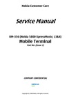
Nokia Customer Care
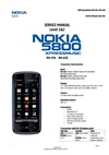
Service Manual
RM-356 (Nokia 5800 XpressMusic; L3&4)
Mobile Terminal
Part No: (Issue 1)
COMPANY CONFIDENTIAL
Copyright © 2008 Nokia. All rights reserved.

Amendment Record Sheet
Amendment Record Sheet
Amendment No Date Inserted By Comments
Issue 1 10/2008 ET
RM-356
Page ii COMPANY CONFIDENTIAL Issue 1
Copyright © 2008 Nokia. All rights reserved.

RM-356
Copyright
Copyright
Copyright © 2008 Nokia. All rights reserved.
Reproduction, transfer, distribution or storage of part or all of the contents in this document in any form
without the prior written permission of Nokia is prohibited.
Nokia, Nokia Connecting People, and Nokia X and Y are trademarks or registered trademarks of Nokia
Corporation. Other product and company names mentioned herein may be trademarks or tradenames of
their respective owners.
Nokia operates a policy of continuous development. Nokia reserves the right to make changes and
improvements to any of the products described in this document without prior notice.
Under no circumstances shall Nokia be responsible for any loss of data or income or any special, incidental,
consequential or indirect damages howsoever caused.
The contents of this document are provided «as is». Except as required by applicable law, no warranties of
any kind, either express or implied, including, but not limited to, the implied warranties of merchantability
and fitness for a particular purpose, are made in relation to the accuracy, reliability or contents of this
document. Nokia reserves the right to revise this document or withdraw it at any time without prior notice.
The availability of particular products may vary by region.
IMPORTANT
This document is intended for use by qualified service personnel only.
Issue 1 COMPANY CONFIDENTIAL Page iii
Copyright © 2008 Nokia. All rights reserved.

RM-356
Warnings and cautions
Warnings and cautions
Warnings
•
IF THE DEVICE CAN BE INSTALLED IN A VEHICLE, CARE MUST BE TAKEN ON INSTALLATION IN VEHICLES FITTED
WITH ELECTRONIC ENGINE MANAGEMENT SYSTEMS AND ANTI-SKID BRAKING SYSTEMS. UNDER CERTAIN FAULT
CONDITIONS, EMITTED RF ENERGY CAN AFFECT THEIR OPERATION. IF NECESSARY, CONSULT THE VEHICLE DEALER/
MANUFACTURER TO DETERMINE THE IMMUNITY OF VEHICLE ELECTRONIC SYSTEMS TO RF ENERGY.
•
THE PRODUCT MUST NOT BE OPERATED IN AREAS LIKELY TO CONTAIN POTENTIALLY EXPLOSIVE ATMOSPHERES,
FOR EXAMPLE, PETROL STATIONS (SERVICE STATIONS), BLASTING AREAS ETC.
•
OPERATION OF ANY RADIO TRANSMITTING EQUIPMENT, INCLUDING CELLULAR TELEPHONES, MAY INTERFERE
WITH THE FUNCTIONALITY OF INADEQUATELY PROTECTED MEDICAL DEVICES. CONSULT A PHYSICIAN OR THE
MANUFACTURER OF THE MEDICAL DEVICE IF YOU HAVE ANY QUESTIONS. OTHER ELECTRONIC EQUIPMENT MAY
ALSO BE SUBJECT TO INTERFERENCE.
•
BEFORE MAKING ANY TEST CONNECTIONS, MAKE SURE YOU HAVE SWITCHED OFF ALL EQUIPMENT.
Cautions
•
Servicing and alignment must be undertaken by qualified personnel only.
•
Ensure all work is carried out at an anti-static workstation and that an anti-static wrist strap is worn.
•
Ensure solder, wire, or foreign matter does not enter the telephone as damage may result.
•
Use only approved components as specified in the parts list.
•
Ensure all components, modules, screws and insulators are correctly re-fitted after servicing and
alignment.
•
Ensure all cables and wires are repositioned correctly.
•
Never test a mobile phone WCDMA transmitter with full Tx power, if there is no possibility to perform the
measurements in a good performance RF-shielded room. Even low power WCDMA transmitters may disturb
nearby WCDMA networks and cause problems to 3G cellular phone communication in a wide area.
•
During testing never activate the GSM or WCDMA transmitter without a proper antenna load, otherwise
GSM or WCDMA PA may be damaged.
Page iv COMPANY CONFIDENTIAL Issue 1
Copyright © 2008 Nokia. All rights reserved.

RM-356
For your safety
For your safety
QUALIFIED SERVICE
Only qualified personnel may install or repair phone equipment.
ACCESSORIES AND BATTERIES
Use only approved accessories and batteries. Do not connect incompatible products.
CONNECTING TO OTHER DEVICES
When connecting to any other device, read its user’s guide for detailed safety instructions. Do not connect
incompatible products.
Issue 1 COMPANY CONFIDENTIAL Page v
Copyright © 2008 Nokia. All rights reserved.

RM-356
ESD protection
ESD protection
Nokia requires that service points have sufficient ESD protection (against static electricity) when servicing
the phone.
Any product of which the covers are removed must be handled with ESD protection. The SIM card can be
replaced without ESD protection if the product is otherwise ready for use.
To replace the covers ESD protection must be applied.
All electronic parts of the product are susceptible to ESD. Resistors, too, can be damaged by static electricity
discharge.
All ESD sensitive parts must be packed in metallized protective bags during shipping and handling outside
any ESD Protected Area (EPA).
Every repair action involving opening the product or handling the product components must be done under
ESD protection.
ESD protected spare part packages MUST NOT be opened/closed out of an ESD Protected Area.
For more information and local requirements about ESD protection and ESD Protected Area, contact your local
Nokia After Market Services representative.
Page vi COMPANY CONFIDENTIAL Issue 1
Copyright © 2008 Nokia. All rights reserved.

RM-356
Care and maintenance
Care and maintenance
This product is of superior design and craftsmanship and should be treated with care. The suggestions below
will help you to fulfil any warranty obligations and to enjoy this product for many years.
•
Keep the phone and all its parts and accessories out of the reach of small children.
•
Keep the phone dry. Precipitation, humidity and all types of liquids or moisture can contain minerals that
will corrode electronic circuits.
•
Do not use or store the phone in dusty, dirty areas. Its moving parts can be damaged.
•
Do not store the phone in hot areas. High temperatures can shorten the life of electronic devices, damage
batteries, and warp or melt certain plastics.
•
Do not store the phone in cold areas. When it warms up (to its normal temperature), moisture can form
inside, which may damage electronic circuit boards.
•
Do not drop, knock or shake the phone. Rough handling can break internal circuit boards.
•
Do not use harsh chemicals, cleaning solvents, or strong detergents to clean the phone.
•
Do not paint the phone. Paint can clog the moving parts and prevent proper operation.
•
Use only the supplied or an approved replacement antenna. Unauthorised antennas, modifications or
attachments could damage the phone and may violate regulations governing radio devices.
All of the above suggestions apply equally to the product, battery, charger or any accessory.
Issue 1 COMPANY CONFIDENTIAL Page vii
Copyright © 2008 Nokia. All rights reserved.

RM-356
Company policy
Company policy
Our policy is of continuous development; details of all technical modifications will be included with service
bulletins.
While every endeavour has been made to ensure the accuracy of this document, some errors may exist. If
any errors are found by the reader, NOKIA MOBILE PHONES Business Group should be notified in writing/email.
Please state:
•
Title of the Document + Issue Number/Date of publication
•
Latest Amendment Number (if applicable)
•
Page(s) and/or Figure(s) in error
Please send to:
NOKIA CORPORATION
Nokia Mobile Phones Business Group
Nokia Customer Care
PO Box 86
FIN-24101 SALO
Finland
E-mail: Service.Manuals@nokia.com
Page viii COMPANY CONFIDENTIAL Issue 1
Copyright © 2008 Nokia. All rights reserved.

RM-356
Battery information
Battery information
Note: A new battery’s full performance is achieved only after two or three complete charge and
discharge cycles!
The battery can be charged and discharged hundreds of times but it will eventually wear out. When the
operating time (talk-time and standby time) is noticeably shorter than normal, it is time to buy a new battery.
Use only batteries approved by the phone manufacturer and recharge the battery only with the chargers
approved by the manufacturer. Unplug the charger when not in use. Do not leave the battery connected to
a charger for longer than a week, since overcharging may shorten its lifetime. If left unused a fully charged
battery will discharge itself over time.
Temperature extremes can affect the ability of your battery to charge.
For good operation times with Li-Ion batteries, discharge the battery from time to time by leaving the product
switched on until it turns itself off (or by using the battery discharge facility of any approved accessory
available for the product). Do not attempt to discharge the battery by any other means.
Use the battery only for its intended purpose.
Never use any charger or battery which is damaged.
Do not short-circuit the battery. Accidental short-circuiting can occur when a metallic object (coin, clip or
pen) causes direct connection of the + and — terminals of the battery (metal strips on the battery) for example
when you carry a spare battery in your pocket or purse. Short-circuiting the terminals may damage the battery
or the connecting object.
Leaving the battery in hot or cold places, such as in a closed car in summer or winter conditions, will reduce
the capacity and lifetime of the battery. Always try to keep the battery between 15°C and 25°C (59°F and 77°
F). A phone with a hot or cold battery may temporarily not work, even when the battery is fully charged.
Batteries’ performance is particularly limited in temperatures well below freezing.
Do not dispose of batteries in a fire!
Dispose of batteries according to local regulations (e.g. recycling). Do not dispose as household waste.
Issue 1 COMPANY CONFIDENTIAL Page ix
Copyright © 2008 Nokia. All rights reserved.

RM-356
Battery information
(This page left intentionally blank.)
Page x COMPANY CONFIDENTIAL Issue 1
Copyright © 2008 Nokia. All rights reserved.

RM-356
Nokia 5800 XpressMusic; L3&4 Service Manual
Structure
Nokia 5800 XpressMusic; L3&4 Service Manual Structure
1 General Information
2 Service Tools and Service Concepts
3 BB Troubleshooting and Manual Tuning Guide
4 RF troubleshooting
5 Camera Module Troubleshooting
6 System Module and User Interface
Glossary
Issue 1 COMPANY CONFIDENTIAL Page xi
Copyright © 2008 Nokia. All rights reserved.

RM-356
Nokia 5800 XpressMusic; L3&4 Service Manual
Structure
(This page left intentionally blank.)
Page xii COMPANY CONFIDENTIAL Issue 1
Copyright © 2008 Nokia. All rights reserved.

Nokia Customer Care
1 — General Information
Issue 1 COMPANY CONFIDENTIAL Page 1 –1
Copyright © 2008 Nokia. All rights reserved.

RM-356
General Information
(This page left intentionally blank.)
Page 1 –2 COMPANY CONFIDENTIAL Issue 1
Copyright © 2008 Nokia. All rights reserved.

RM-356
General Information
Table of Contents
Product selection………………………………………………………………………………………………………………………………….1–5
Product features and sales package………………………………………………………………………………………………………1–5
Product and module list ……………………………………………………………………………………………………………………….1–7
Mobile enhancements…………………………………………………………………………………………………………………………..1–8
Technical specifications…………………………………………………………………………………………………………………….. 1–11
Transceiver general specifications ………………………………………………………………………………………………… 1–11
Main RF characteristics for GSM850/900/1800/1900 and WCDMA VIII (900) and WCDMA I (2100)
phones………………………………………………………………………………………………………………………………… 1–11
Battery endurance………………………………………………………………………………………………………………………… 1–13
List of Tables
Table 1 Audio……………………………………………………………………………………………………………………………………….1–8
Table 2 Car……………………………………………………………………………………………………………………………………………1–9
Table 3 Data ……………………………………………………………………………………………………………………………………… 1–10
Table 4 Messaging…………………………………………………………………………………………………………………………….. 1–10
Table 5 Music ……………………………………………………………………………………………………………………………………. 1–10
Table 6 Navigation ……………………………………………………………………………………………………………………………. 1–11
Table 7 Power…………………………………………………………………………………………………………………………………… 1–11
List of Figures
Figure 1 View of RM-356……………………………………………………………………………………………………………………….1–5
Issue 1 COMPANY CONFIDENTIAL Page 1 –3
Copyright © 2008 Nokia. All rights reserved.

RM-356
General Information
(This page left intentionally blank.)
Page 1 –4 COMPANY CONFIDENTIAL Issue 1
Copyright © 2008 Nokia. All rights reserved.

RM-356
General Information
Product selection
RM-356 is a GSM/HSDPA/WCDMA tri-mode handportable monoblock phone with a person centric touch UI,
integrated GPS (A-GPS OMA SUPL), WLAN and a TV-out connection. It supports EGSM850/900/1800/1900 and
WCDMA900/2100 bands, and CSD/HSCSD, GPRS/EGPRS, WCDMA/HSDPA data bearers.
For WCDMA the maximum bit rate is up to 384 kbit/s for downlink and 384 kbit/s for uplink with simultaneous
CS speech or CS video (max. 64 kbit/s). The HSDPA peak is 3.6 Mbit/s downlink (with limited use cases).
For GPRS/EGPRS networks the RM-356 is a Class B GPRS/EGPRS MSC 32 (5 Rx + 3 Tx, max sum 6) device, which
means a maximum uplink speed of 177 kbit/s and downlink speed of 296 kbit/s. RM-356 also supports Dual
Transfer Mode (DTM) for simultaneous voice and packet data connection in GSM/EDGE networks; simple class
A, multi slot class 11, (4 Rx + 3 Tx, max sum 5 ).
RM-356 has a large nHD 3.2”(640 x 360 pixels) colour display (active area 39.6 mm x 70.4 mm) with 16 million
colors. It also has a 3.2 megapixel autofocus camera with 3 x digital zoom and an integrated dual LED flash.
RM-356 is an MMS (Multimedia Messaging Service) enabled multimedia device. The MMS implementation
follows the OMA MMS standard release 1.3. RM-356 also supports the Bluetooth 2.0 + EDR standard.
RM-356 uses a S60 5.0 operating system and supports the full Web Browser for S60, which brings desktoplike Web browsing experience to mobile devices.
RM-356 also supports MIDP Java 2.0, providing a good platform for compelling 3rd party applications.
Figure 1 View of RM-356
Product features and sales package
New hardware characteristics
•
Touch screen phone:
Issue 1 COMPANY CONFIDENTIAL Page 1 –5
Copyright © 2008 Nokia. All rights reserved.

•
Full touch UI – no physical input or UI navigation keys
•
Contacts Bar — Person centric UI
•
Media Bar – Easy access to media
Bearers and transport
•
WCDMA DL 384kbit/s, UL 384 kbit/s
•
HSDPA up to 3.6Mbps
•
GPRS/EGPRS Class B, Multi slot class 32 (5 Rx + 3 Tx = 6)
•
Dual Transfer Mode (DTM) class A, multi slot class 11 (4 Rx + 3 Tx = 5)
Connectivity
•
Integrated GPS (A-GPS OMA SUPL)
•
TV-out connection
•
WLAN IEEE802.11 b/g
•
Bluetooth 2.0 (A2DP & AVRCP)
•
USB2.0 High Speed with microUSB interface
•
MicroSD memory card — support up to 16GB
•
3.5 mm AV connector
RM-356
General Information
Display
•
3.2” nHD (640 x 360 pixels) colour display (active area 39.6 mm x 70.4 mm), up to 16M colors, 16:9 aspect
ratio
•
Digital Ambient Light Sensor (ALS) – used to optimize display/key brightness and power consumption
Imaging and video
•
3.2Mpix autofocus camera with 3 x digital zoom and an integrated dual LED flash
•
True 16:9 high definition widescreen optimised for mobile entertainment
•
Video center for enjoying downloaded and streamed content, WMV support, video feeds (vodcasting) and
mobile TV (IP TV)
•
CS video call
•
Video sharing
•
Video streaming (3GPP and CIF)
Music
•
DAC33 for hi-fi sound quality
•
Podcasting, internet radio, best in class music player on the go
•
Superb music player UI, bass booster, stereo widening, loudness
•
Stereo music player supporting MP3, SpMidi, AAC, AAC+, eAAC+, WMA
•
3D stereo ringing tones, 64 polyphonic Midi, MP3 tones, video ringing tones
•
Stereo FM Radio
Productivity
Context management
•
Full OMA client provisioning
Page 1 –6 COMPANY CONFIDENTIAL Issue 1
Copyright © 2008 Nokia. All rights reserved.

RM-356
General Information
•
PIM (Calendar + Contacts)
•
OTA provisioning & over the air SW update (FOTA)
•
Nokia PC Suite connectivity with USB, Bluetooth
•
Web Browser (OSS), Java ™ MIDP 2.0, XHTML browsing over TCP/IP
Messaging
•
MS, MMS (OMA 1.3)
•
Native Email and IM client, Email with attachments (push)
•
Audio messaging (AMS)
Voice
•
Rich Calls: 2-way video conferencing (Video Call), Video Sharing
•
Speaker independent dialing and voice commands (SIND)
Add-on software framework
•
S60 5.0 OS
•
Java: MIDP2.0
Additional technical specifications
•
Vibrating alert
•
3GPP Rel 5 compliant
•
Speech codecs supported: AMR, NB-AMR, FR, EFR
Sales package
•
Transceiver RM-356
•
Battery (BL-5J)
•
Charger (AC-8)
•
Stereo headset (HS-45 + AD-54 audio controller)
•
TV-out cable (CA-75U)
•
MicroUSB connectivity cable (CA-101)
•
Mini DVD
•
Extra stylus
•
CP-306 plectrum stylus in wrist strap
•
CP-305 carrying case
•
DT-29 desk stand
•
User Guide
Product and module list
Module name Type code Notes
System/RF Module 2JD Main PWB with components.
UI Flex Module 2JY
Issue 1 COMPANY CONFIDENTIAL Page 1 –7
Copyright © 2008 Nokia. All rights reserved.

Mobile enhancements
Table 1 Audio
Enhancement Type
Audio controller AD-54
Hearing aid HDA-12
Wired headsets HS-16
HS-41
HS-43
HS-45 (+ AD-54)
HS-45
HS-48
WH-201
WH-202
RM-356
General Information
WH-500
WH-600
WH-700
WH-800
Page 1 –8 COMPANY CONFIDENTIAL Issue 1
Copyright © 2008 Nokia. All rights reserved.

RM-356
General Information
Enhancement Type
Wireless headsets BH-102
BH-103
BH-212
BH-303
BH-500
BH-501
BH-703
BH-804
BH-904
HS-24W
HS-25W
HS-38W
HS-51W
HS-52W
HS-57W
HS-58W
HS-59W
HS-72W
HS-76W
HS-79W
HS-89W
HS-91W
HS-94W
HS-95W
HS-96W
HS-100W
Table 2 Car
Enhancement Type
FM transmitter CA-300
Mobile holder CR-39
CR-82
CR-99
CR-103
Mobile holder mounting device HH-12
Issue 1 COMPANY CONFIDENTIAL Page 1 –9
Copyright © 2008 Nokia. All rights reserved.

Enhancement Type
Mobile charger DC-4
Navigation Nokia 500 Auto Navigation
Wireless car kit CK-7W
CK-15W
CK-100
CK-300
Wireless plug-in car handsfree HF-33W
HF-200
HF-300
Table 3 Data
Enhancement Type
RM-356
General Information
MicroSD card, 512 MB MU-28
MicroSD card, 1 GB MU-22
MicroSD card, 2 GB MU-37
MicroSD card, 4 GB MU-41
MicroSD card, 8 GB MU-43
MicroUSB connectivity adapter cable CA-101
Video connectivity cable CA-75U
Table 4 Messaging
Enhancement Type
Wireless keyboard SU-8W
Digital pen SU-27W
CP-306 plectrum stylus CP-306
Table 5 Music
Enhancement Type
Wireless Audio Gateway AD-42W
Wireless speakers MD-5W
MD-7W
Music speakers MD-6
MD-8
Page 1 –10 COMPANY CONFIDENTIAL Issue 1
Copyright © 2008 Nokia. All rights reserved.

RM-356
General Information
Table 6 Navigation
Enhancement Type
Wireless GPS module LD-3W
LD-4W
Table 7 Power
Enhancement Type
Battery 1320mAh BL-5J
Charging connectivity cable CA-126
Charger AC-4
AC-5
AC-6C (+CA-100c)
AC-8
DC-1
DC-8
DC-9
Charger adapter CA-44
USB charger CA-100
Technical specifications
Transceiver general specifications
Unit Dimensions (L x W x T)
Transceiver with BL-5J
1320 mAh Li-Ion battery
back
(mm)
111 x 51.7 x 15.5 109 83
Weight with battery (g) Volume (cm3)
Main RF characteristics for GSM850/900/1800/1900 and WCDMA VIII (900) and WCDMA I (2100)
phones
Parameter Unit
Cellular system GSM850, EGSM900, GSM1800/1900, WCDMA VIII
(900) and WCDMA I (2100)
Issue 1 COMPANY CONFIDENTIAL Page 1 –11
Copyright © 2008 Nokia. All rights reserved.

Parameter Unit
Rx frequency band GSM850: 869 — 894 MHz
EGSM900: 925 — 960 MHz
GSM1800: 1805 — 1880 MHz
GSM1900: 1930 — 1990 MHz
WCDMA VIII (900): 925- 960 MHz
WCDMA I (2100): 2110 — 2170 MHz
Tx frequency band GSM850: 824 — 849 MHz
EGSM900: 880 — 915 MHz
GSM1800: 1710 — 1785 MHz
GSM1900: 1850 — 1910 MHz
WCDMA VIII (900): 880 — 915 MHz
WCDMA I (2100): 1920 — 1980 MHz
RM-356
General Information
Output power GSM850: +5 …+33dBm/3.2mW … 2W
GSM900: +5 … +33dBm/3.2mW … 2W
GSM1800: +0 … +30dBm/1.0mW … 1W
GSM1900: +0 … +30dBm/1.0mW … 1W
WCDMA VIII (900): -50 … +24 dBm/0.01μW …
251.2mW
WCDMA I (2100): -50 … +24 dBm/0.01μW …
251.2mW
EDGE output power EDGE850: +5 … +29dBm/3.2mW … 794mW
EDGE900: +5 … +29dBm/3.2mW … 794mW
EDGE1800: +0 … +26dBm/1.0mW … 400mW
EDGE1900:+0 … +26dBm/1.0mW … 400mW
Number of RF channels GSM850: 124
GSM900: 174
GSM1800: 374
GSM1900: 299
WCDMA VIII (900): 152
WCDMA I (2100): 277
Channel spacing 200 kHz
Page 1 –12 COMPANY CONFIDENTIAL Issue 1
Copyright © 2008 Nokia. All rights reserved.

RM-356
General Information
Parameter Unit
Number of Tx power levels GSM850: 15
GSM900: 15
GSM1800: 16
GSM1900: 16
WCDMA VIII (900): 75
WCDMA I (2100): 75
Battery endurance
Battery Capacity (mAh) Talk time Stand-by Music playback
BL-5J 1320 Up to 8.8 h (GSM)
Up to 5 h (WCDMA)
Up to 406.2 h (GSM)
Up to 400 h (GSM)
Up to 35h
Issue 1 COMPANY CONFIDENTIAL Page 1 –13
Copyright © 2008 Nokia. All rights reserved.

RM-356
General Information
(This page left intentionally blank.)
Page 1 –14 COMPANY CONFIDENTIAL Issue 1
Copyright © 2008 Nokia. All rights reserved.

Nokia Customer Care
2 — Service Tools and Service
Concepts
Issue 1 COMPANY CONFIDENTIAL Page 2 –1
Copyright © 2008 Nokia. All rights reserved.

RM-356
Service Tools and Service Concepts
(This page left intentionally blank.)
Page 2 –2 COMPANY CONFIDENTIAL Issue 1
Copyright © 2008 Nokia. All rights reserved.

RM-356
Service Tools and Service Concepts
Table of Contents
Service tools…………………………………………………………………………………………………………………………………………2–5
Product specific tools……………………………………………………………………………………………………………………….2–5
FS-77…………………………………………………………………………………………………………………………………………..2–5
MJ-165 ………………………………………………………………………………………………………………………………………..2–5
RJ-230 …………………………………………………………………………………………………………………………………………2–5
SA-131 ………………………………………………………………………………………………………………………………………..2–5
SA-166 ………………………………………………………………………………………………………………………………………..2–6
SS-195…………………………………………………………………………………………………………………………………………2–6
Rework jigs and stencils…………………………………………………………………………………………………………………..2–7
RJ-157 …………………………………………………………………………………………………………………………………………2–7
RJ-160 …………………………………………………………………………………………………………………………………………2–7
RJ-166 …………………………………………………………………………………………………………………………………………2–7
RJ-169 …………………………………………………………………………………………………………………………………………2–8
RJ-184 …………………………………………………………………………………………………………………………………………2–8
RJ-201 …………………………………………………………………………………………………………………………………………2–8
RJ-73 …………………………………………………………………………………………………………………………………………..2–8
RJ-93 …………………………………………………………………………………………………………………………………………..2–8
ST-29…………………………………………………………………………………………………………………………………………..2–9
ST-40…………………………………………………………………………………………………………………………………………..2–9
ST-53…………………………………………………………………………………………………………………………………………..2–9
ST-55…………………………………………………………………………………………………………………………………………..2–9
ST-59…………………………………………………………………………………………………………………………………………..2–9
ST-61……………………………………………………………………………………………………………………………………….. 2–10
ST-65……………………………………………………………………………………………………………………………………….. 2–10
General tools………………………………………………………………………………………………………………………………… 2–10
AC-33……………………………………………………………………………………………………………………………………….. 2–10
AC-35……………………………………………………………………………………………………………………………………….. 2–10
CU-4…………………………………………………………………………………………………………………………………………. 2–11
FLS-5 ……………………………………………………………………………………………………………………………………….. 2–12
FPS-10……………………………………………………………………………………………………………………………………… 2–12
FPS-21……………………………………………………………………………………………………………………………………… 2–13
JXS-1………………………………………………………………………………………………………………………………………… 2–13
PK-1…………………………………………………………………………………………………………………………………………. 2–14
PKD-1 ………………………………………………………………………………………………………………………………………. 2–14
SB-6…………………………………………………………………………………………………………………………………………. 2–14
SPS-1……………………………………………………………………………………………………………………………………….. 2–14
SPS-2……………………………………………………………………………………………………………………………………….. 2–15
SRT-6……………………………………………………………………………………………………………………………………….. 2–15
SS-102……………………………………………………………………………………………………………………………………… 2–15
SS-46……………………………………………………………………………………………………………………………………….. 2–15
SS-62……………………………………………………………………………………………………………………………………….. 2–15
SS-93……………………………………………………………………………………………………………………………………….. 2–16
SX-4…………………………………………………………………………………………………………………………………………. 2–16
Cables…………………………………………………………………………………………………………………………………………… 2–16
CA-101 …………………………………………………………………………………………………………………………………….. 2–16
CA-31D …………………………………………………………………………………………………………………………………….. 2–16
CA-35S……………………………………………………………………………………………………………………………………… 2–17
CA-58RS……………………………………………………………………………………………………………………………………. 2–17
CA-75U …………………………………………………………………………………………………………………………………….. 2–17
CA-89DS …………………………………………………………………………………………………………………………………… 2–18
Issue 1 COMPANY CONFIDENTIAL Page 2 –3
Copyright © 2008 Nokia. All rights reserved.

RM-356
Service Tools and Service Concepts
DAU-9S…………………………………………………………………………………………………………………………………….. 2–18
PCS-1……………………………………………………………………………………………………………………………………….. 2–18
XCS-4……………………………………………………………………………………………………………………………………….. 2–19
XRS-6……………………………………………………………………………………………………………………………………….. 2–19
Service concepts ……………………………………………………………………………………………………………………………….. 2–20
POS (Point of Sale) flash concept …………………………………………………………………………………………………… 2–20
Flash concept with FPS-10…………………………………………………………………………………………………………….. 2–21
Flash concept with FPS-21…………………………………………………………………………………………………………….. 2–22
CU-4 flash concept with FPS-10……………………………………………………………………………………………………… 2–23
CU-4 flash concept with FPS-21……………………………………………………………………………………………………… 2–24
Module jig service concept……………………………………………………………………………………………………………. 2–25
RF testing concept with RF coupler ……………………………………………………………………………………………….. 2–26
Service concept for RF testing and RF/BB tuning……………………………………………………………………………. 2–27
GPS testing concept with GPS RF coupler……………………………………………………………………………………….. 2–28
Bluetooth testing concept with SB-6 …………………………………………………………………………………………….. 2–29
WLAN functionality testing concept with SB-7 ………………………………………………………………………………. 2–30
List of Tables
Table 8 Attenuation values ……………………………………………………………………………………………………………….. 2–17
List of Figures
Figure 2 Basic flash concept with FPS-10……………………………………………………………………………………………. 2–21
Figure 3 Basic flash concept with FPS-21……………………………………………………………………………………………. 2–22
Figure 4 CU-4 flash concept with FPS-10…………………………………………………………………………………………….. 2–23
Figure 5 CU-4 flash concept with FPS-21…………………………………………………………………………………………….. 2–24
Figure 6 Module jig service concept …………………………………………………………………………………………………… 2–25
Figure 7 RF testing concept with RF coupler ………………………………………………………………………………………. 2–26
Figure 8 Service concept for RF testing and RF/BB tuning …………………………………………………………………… 2–27
Figure 9 RF testing concept with RF coupler ………………………………………………………………………………………. 2–28
Figure 10 Service concept for RF testing and RF/BB tuning…………………………………………………………………. 2–29
Figure 11 WLAN functionality testing concept with SB-7 ……………………………………………………………………. 2–30
Page 2 –4 COMPANY CONFIDENTIAL Issue 1
Copyright © 2008 Nokia. All rights reserved.

RM-356
Service Tools and Service Concepts
Service tools
Product specific tools
The table below gives a short overview of service devices that can be used for testing, error analysis, and
repair of product RM-356. For the correct use of the service devices, and the best effort of workbench setup,
please refer to various concepts.
FS-77 Flash adapter
For flashing (also dead phones) with SS-46. RF testing and tuning, and
EM calibration on ATO level with SS-62 (mechanical locking concept),
CU-4 supported.
MJ-165 Module jig
MJ-165 is meant for troubleshooting, testing, tuning and flashing on
the engine level (CU-4 supported).
The jig includes an RF interface for GPS, GSM, WCDMA and Bluetooth.
RJ-230 Soldering jig
RJ-230 is a soldering jig used for soldering and as a rework jig for the
engine module.
SA-131 RF coupler
SA-131 is a RF coupler for GPS testing. It is used together with SS-62.
Issue 1 COMPANY CONFIDENTIAL Page 2 –5
Copyright © 2008 Nokia. All rights reserved.

RM-356
Service Tools and Service Concepts
SA-166 RF coupler
SA-166 is an RF coupler for WCDMA and GSM RF testing. It is used
together with the product-specific flash adapter.
The following table shows attenuations from the antenna pads of the
mobile terminal to the SMA connectors of SA-166 . The setup used for
measuring the values is SA-166 + FS-77 + CU-4.
•
Attenuation values for inductive RF coupler SA-166
Band Channel Attenuation TX
(dB)
Low 24,5 19,5
GSM 850
GSM 900
GSM
1800
GSM
1900
WCDMA
Band I
Mid 24,3 20,5
High 23,5 18,5
Low 21,2 17,5
Mid 19,4 17,5
High 18,8 15,5
Low 11,4 9,2
Mid 10,7 9,2
High 9,0 9,2
Low 8,0 8,2
Mid 7,5 8,2
High 8,6 9,2
Low 9,2 11,1
Mid 9,1 12,1
High 10,1 13,1
Attenuation RX
(dB)
Low 18,7 19,5
WCDMA
Band VIII
SS-195 Display removal tool
SS-195 is used for removing displays.
Page 2 –6 COMPANY CONFIDENTIAL Issue 1
Copyright © 2008 Nokia. All rights reserved.
Mid 18,5 19,5
High 19,5 19,5

RM-356
Service Tools and Service Concepts
Rework jigs and stencils
The table below gives a short overview of service devices that can be used for testing, error analysis, and
repair of product RM-356. For the correct use of the service devices, and the best effort of workbench setup,
please refer to various concepts.
RJ-157 Rework jig
RJ-157 is a rework jig used when servicing the Z7540 duplexer. It is
used together with the ST-55 stencil.
RJ-160 Rework jig
RJ-160 is a rework jig used when servicing the WCDMA duplexer
(Z7541). It is used together with the ST-55 stencil.
RJ-166 Rework jig
RJ-166 is a jig used when servicing the accelerometer (N6501).
It is used together with the ST-53 stencil.
Issue 1 COMPANY CONFIDENTIAL Page 2 –7
Copyright © 2008 Nokia. All rights reserved.

RM-356
Service Tools and Service Concepts
RJ-169 Rework jig
RJ-169 is a rework jig used when servicing the WCDMA PA (N7540)
component. It is used together with the ST-59 stencil.
RJ-184 Rework jig
RJ-184 is a rework jig used when servicing the microphone (B2170).
It is used together with the ST-61 rework stencil.
RJ-201 Rework jig
RJ-201 is a rework jig used when servicing the GSM 850/900 TX filter
(Z7503) component.
This jig is used together with the ST-65 stencil.
RJ-73 Rework jig
RJ-73 is a rework jig used when servicing the N1451 component. It is
used together with the ST-29 rework stencil.
RJ-93 Rework jig
RJ-93 is used as a rework jig for the Front End Module (FEM).
This rework jig takes the FEM or power amplifier (PA) module (N7520)
for spreading the soldering paste to the component. Must be used
together with the ST-40 stencil.
Page 2 –8 COMPANY CONFIDENTIAL Issue 1
Copyright © 2008 Nokia. All rights reserved.

RM-356
Service Tools and Service Concepts
ST-29 rework stencil
ST-29 is a rework stencil used when servicing the N1451 component.
It is used together with rework jig RJ-73.
ST-40 Rework stencil
ST-40 is a rework stencil that is used with the RJ-93 rework jig to
service the Front End Module (N7520).
ST-53 Rework stencil
ST-53 is a rework stencil used when servicing the accelerometer
(N6501).
It is used together with the rework jig RJ-166.
ST-55 Rework stencil
ST-55 is a rework stencil used when servicing the Z7540 and Z7541
duplexers. It is used together with the rework jigs RJ-157 and RJ-160.
ST-59 Rework stencil
ST-59 is a rework stencil used when servicing the WCDMA PA (N7540)
component. It is used together with rework jig RJ-169.
Issue 1 COMPANY CONFIDENTIAL Page 2 –9
Copyright © 2008 Nokia. All rights reserved.

RM-356
Service Tools and Service Concepts
ST-61 Rework stencil
ST-61 is a rework stencil used when servicing the microphone (B2170).
It is used together with the rework jig RJ-184.
ST-65 Rework stencil
ST-65 is a rework stencil used when servicing the GSM 850/900 TX filter
(Z7503).
This stencil is used together with the rework jig RJ-201.
General tools
The table below gives a short overview of service devices that can be used for testing, error analysis, and
repair of product RM-356. For the correct use of the service devices, and the best effort of workbench setup,
please refer to various concepts.
AC-33 Power supply
Universal power supply for FPS-10; included in the FPS-10 sales
package.
AC-35 Power supply
Universal power supply for FPS-21; included in the FPS-21 sales
package.
Input 100V…230V 50Hz…60Hz, output voltage of 12 V and output
current up to 3 A.
Page 2 –10 COMPANY CONFIDENTIAL Issue 1
Copyright © 2008 Nokia. All rights reserved.

RM-356
Service Tools and Service Concepts
CU-4 Control unit
CU-4 is a general service tool used with a module jig and/or a flash
adapter. It requires an external 12 V power supply.
The unit has the following features:
•
software controlled via USB
•
EM calibration function
•
Forwards FBUS/Flashbus traffic to/from terminal
•
Forwards USB traffic to/from terminal
•
software controlled BSI values
•
regulated VBATT voltage
•
2 x USB2.0 connector (Hub)
•
FBUS and USB connections supported
When using CU-4, note the special order of connecting cables and
other service equipment:
Instructions
1 Connect a service tool (jig, flash adapter) to CU-4.
2 Connect CU-4 to your PC with a USB cable.
3 Connect supply voltage (12 V)
4 Connect an FBUS cable (if necessary).
5 Start Phoenix service software.
Note: Phoenix enables CU-4 regulators via USB when it is
started.
Reconnecting the power supply requires a Phoenix restart.
Issue 1 COMPANY CONFIDENTIAL Page 2 –11
Copyright © 2008 Nokia. All rights reserved.

RM-356
Service Tools and Service Concepts
FLS-5 Flash device
FLS-5 is a dongle and flash device incorporated into one package,
developed specifically for POS use.
Note: FLS-5 can be used as an alternative to PKD-1.
FPS-10 Flash prommer
FPS-10 interfaces with:
•
PC
•
Control unit
•
Flash adapter
•
Smart card
FPS-10 flash prommer features:
•
Flash functionality for BB5 and DCT-4 terminals
•
Smart Card reader for SX-2 or SX-4
•
USB traffic forwarding
•
USB to FBUS/Flashbus conversion
•
LAN to FBUS/Flashbus and USB conversion
•
Vusb output switchable by PC command
FPS-10 sales package includes:
•
FPS-10 prommer
•
Power Supply with 5 country specific cords
•
USB cable
Note: FPS-21 is substitute FPS-10 if FPS-10 has not been set
up.
Page 2 –12 COMPANY CONFIDENTIAL Issue 1
Copyright © 2008 Nokia. All rights reserved.

RM-356
Service Tools and Service Concepts
FPS-21 Flash prommer
FPS-21 sales package:
•
FPS-21 prommer
•
AC-35 power supply
•
CA-31D USB cable
FPS-21 interfaces:
Front
•
Service cable connector
Provides Flashbus, USB and VBAT connections to a mobile device.
•
SmartCard socket
A SmartCard is needed to allow DCT-4 generation mobile device
programming.
Rear
•
DC power input
For connecting the external power supply (AC-35).
•
Two USB A type ports (USB1/USB3)
Can be used, for example, for connecting external storage memory
devices or mobile devices
•
One USB B type device connector (USB2)
For connecting a PC.
•
Phone connector
Service cable connection for connecting Flashbus/FLA.
•
Ethernet RJ45 type socket (LAN)
For connecting the FPS-21 to LAN.
Inside
•
Four SD card memory slots
For internal storage memory.
Note: In order to access the SD memory card slots inside
FPS-21, the prommer needs to be opened by removing the
front panel, rear panel and heatsink from the prommer body.
Note: FPS-10 can be used for flashing instead of FPS-21 if
necessary.
JXS-1 RF shield box
Because the WCDMA network disturbs the RX side testing of the WCDMA
phone and the Tx signal of the WCDMA phone can severely disturb the
WCDMA network, a shield box is needed in all testing, tuning and fault
finding which requires WCDMA RF signal.
The shield box is not an active device, it contains only passive filtering
components for RF attenuation.
Issue 1 COMPANY CONFIDENTIAL Page 2 –13
Copyright © 2008 Nokia. All rights reserved.

RM-356
Service Tools and Service Concepts
PK-1 Software protection
key
PK-1 is a hardware protection key with a USB interface. It has the same
functionality as the PKD-1 series dongle.
PK-1 is meant for use with a PC that does not have a series interface.
To use this USB dongle for security service functions please register
the dongle in the same way as the PKD-1 series dongle.
PKD-1 SW security device
SW security device is a piece of hardware enabling the use of the
service software when connected to the parallel (LPT) port of the PC.
Without the device, it is not possible to use the service software.
Printer or any such device can be connected to the PC through the
device if needed.
SB-6 Bluetooth test and
interface box (sales
package)
The SB-6 test box is a generic service device used to perform Bluetooth
bit error rate (BER) testing, and establishing cordless FBUS connection
via Bluetooth. An ACP-8x charger is needed for BER testing and an
AXS-4 cable in case of cordless interface usage testing .
Sales package includes:
•
SB-6 test box
•
Installation and warranty information
SPS-1 Soldering Paste
Spreader
The SPS-1 allows spreading of solder to the LGA components pads over
the rework stencils.
Page 2 –14 COMPANY CONFIDENTIAL Issue 1
Copyright © 2008 Nokia. All rights reserved.

RM-356
Service Tools and Service Concepts
SPS-2 Soldering paste
spreader
SRT-6 Opening tool
SRT-6 is used to open phone covers.
SS-102 Camera removal tool
The camera removal tool SS-102 is used to remove/attach a camera
module from/to the camera socket.
SS-46 Interface adapter
SS-46 acts as an interface adapter between the flash adapter and
FPS-10.
SS-62 Generic flash adapter
base for BB5
•
generic base for flash adapters and couplers
•
SS-62 equipped with a clip interlock system
•
provides standardised interface towards Control Unit
•
provides RF connection using galvanic connector or coupler
•
multiplexing between USB and FBUS media, controlled by VUSB
Issue 1 COMPANY CONFIDENTIAL Page 2 –15
Copyright © 2008 Nokia. All rights reserved.

RM-356
Service Tools and Service Concepts
SS-93 Opening tool
SS-93 is used for opening JAE connectors.
SX-4 Smart card
SX-4 is a BB5 security device used to protect critical features in tuning
and testing.
SX-4 is also needed together with FPS-10 when DCT-4 phones are
flashed.
Cables
The table below gives a short overview of service devices that can be used for testing, error analysis, and
repair of product RM-356. For the correct use of the service devices, and the best effort of workbench setup,
please refer to various concepts.
CA-101 Micro USB cable
The CA-101 is a USB-to-microUSB data cable that allows connections
between the PC and the phone.
CA-31D USB cable
The CA-31D USB cable is used to connect FPS-10 or FPS-11 to a PC. It is
included in the FPS-10 and FPS-11 sales packages.
Page 2 –16 COMPANY CONFIDENTIAL Issue 1
Copyright © 2008 Nokia. All rights reserved.

RM-356
Service Tools and Service Concepts
CA-35S Power cable
CA-35S is a power cable for connecting, for example, the FPS-10 flash
prommer to the Point-Of-Sales (POS) flash adapter.
CA-58RS RF tuning cable
Product-specific adapter cable for RF tuning.
•
Table 8 Attenuation values
Band Attenuation Rx/Tx
GSM850/900 0.2…0.3 dB
GSM1800/1900 0.3…0.4 dB
WCDMA900 0.2…0.3 dB
WCDMA2100 0.4…0.6 dB
CA-75U Video-out cable
The CA-75U enables viewing video recordings on a TV screen or
computer monitor. It can also be used while video conferencing.
The cable is used to connect the 3.5 mm AV connector of the phone to
the RCA connectors of an AV device.
Issue 1 COMPANY CONFIDENTIAL Page 2 –17
Copyright © 2008 Nokia. All rights reserved.

RM-356
Service Tools and Service Concepts
CA-89DS Cable
Provides VBAT and Flashbus connections to mobile device
programming adapters.
DAU-9S MBUS cable
The MBUS cable DAU-9S has a modular connector and is used, for
example, between the PC’s serial port and module jigs, flash adapters
or docking station adapters.
Note: Docking station adapters valid for DCT4 products.
PCS-1 Power cable
The PCS-1 power cable (DC) is used with a docking station, a module
jig or a control unit to supply a controlled voltage.
Page 2 –18 COMPANY CONFIDENTIAL Issue 1
Copyright © 2008 Nokia. All rights reserved.

RM-356
Service Tools and Service Concepts
XCS-4 Modular cable
XCS-4 is a shielded (one specially shielded conductor) modular cable
for flashing and service purposes.
XRS-6 RF cable
The RF cable is used to connect, for example, a module repair jig to
the RF measurement equipment.
SMA to N-Connector approximately 610 mm.
Attenuation for:
•
GSM850/900: 0.3+-0.1 dB
•
GSM1800/1900: 0.5+-0.1 dB
•
WCDMA900: 0.3+-0.1 dB
•
WCDMA2100: 0.6+-0.1dB
Issue 1 COMPANY CONFIDENTIAL Page 2 –19
Copyright © 2008 Nokia. All rights reserved.

Service concepts
POS (Point of Sale) flash concept
RM-356
Service Tools and Service Concepts
Type Description
Product specific tools
BL-5J Battery
Other tools
FLS-5 POS flash dongle
PC with Phoenix service software
Cables
CA-101 Micro USB cable
Page 2 –20 COMPANY CONFIDENTIAL Issue 1
Copyright © 2008 Nokia. All rights reserved.

RM-356
Service Tools and Service Concepts
Flash concept with FPS-10
Figure 2 Basic flash concept with FPS-10
Type Description
Product specific devices
FS-77 Flash adapter
Other devices
FPS-10 Flash prommer box
PKD-1/PK-1 SW security device
SS-46 Interface adapter
PC with Phoenix service software
Cables
XCS-4 Modular cable
CA-35S Power cable
USB cable
Issue 1 COMPANY CONFIDENTIAL Page 2 –21
Copyright © 2008 Nokia. All rights reserved.

Flash concept with FPS-21
RM-356
Service Tools and Service Concepts
Figure 3 Basic flash concept with FPS-21
Type Description
Product specific devices
FS-77 Flash adapter
Other devices
FPS-21 Flash prommer box
AC-35 Power supply
PK-1/PKD-1 SW security device
SS-46 Interface adapter
PC with Phoenix service software
Cables
CA-89DS Service cable
USB cable
Page 2 –22 COMPANY CONFIDENTIAL Issue 1
Copyright © 2008 Nokia. All rights reserved.

RM-356
Service Tools and Service Concepts
CU-4 flash concept with FPS-10
Figure 4 CU-4 flash concept with FPS-10
Type Description
Product specific devices
FS-77 Flash adapter
Other devices
CU-4 Control unit
FPS-10 Flash prommer box
PKD-1/PK-1 SW security device
SS-62 Flash adapter base
SX-4 Smart card
PC with Phoenix service software
Cables
PCS-1 Power cable
XCS-4 Modular cable
Standard USB cable
USB cable
Issue 1 COMPANY CONFIDENTIAL Page 2 –23
Copyright © 2008 Nokia. All rights reserved.

CU-4 flash concept with FPS-21
RM-356
Service Tools and Service Concepts
Figure 5 CU-4 flash concept with FPS-21
Type Description
Product specific devices
FS-77 Flash adapter
Other devices
CU-4 Control unit
FPS-21 Flash prommer box
AC-35 Power supply
PK-1/PKD-1 SW security device
SS-62 Flash adapter base
SX-4 Smart card (for DCT-4 generation mobile device programming)
PC with Phoenix service software
Cables
PCS-1 Power cable
CA-89DS Service cable
Standard USB cable
Page 2 –24 COMPANY CONFIDENTIAL Issue 1
Copyright © 2008 Nokia. All rights reserved.
 Loading…
Смартфон Nokia 5800 XpressMusic RM-356, RM-427, RM-428 — Сервис-мануалы и схемы, разборка / сборка. Скачать бесплатно.
Смартфон Nokia 5800 XpressMusic RM-356, RM-427, RM-428 — Сервис-мануалы и схемы, разборка / сборка. Скачать бесплатно.
Смартфон
Nokia 5800 XpressMusic RM-356, RM-427, RM-428
— Схема. Версия: 2.0. Скачать

Смартфон
Nokia 5800 XpressMusic RM-356, RM-427, RM-428
— Руководство по обслуживанию. Уровни 1 и 2. Версия: 1.0. Скачать
Смартфон
Nokia 5800 XpressMusic RM-356, RM-427, RM-428
— Руководство по обслуживанию. Уровни 1 и 2. Версия: 3.0. Скачать
Смартфон
Nokia 5800 XpressMusic RM-356, RM-427, RM-428
— Схема. Версия: 1.0. Скачать
Смартфон
Nokia 5800 XpressMusic RM-356, RM-427, RM-428
— Руководство по обслуживанию. Уровни 3 и 4. Версия: 1.0. Скачать
-
Contents
-
Table of Contents
-
Bookmarks
Quick Links
1
SERVICE MANUAL
Level 1&2
RM-356 RM-428
Transceiver characteristics
Band:
RM-356: HSDPA, WCDMA 900/2100 GSM/EDGE
850/900/1800/1900
RM-428: HSDPA, WCDMA 850/1900
GSM/EDGE 850/900/1800/1900
Display:
3.2» nHD (640×360 pixels), active area 39.6 mm x 70.4
mm, 16:9 aspect ratio, up to 16 million colours
Camera:
3.2 Mpix with 4x digital zoom
Operating System:
S60 5.0
Connections:
Transceiver with BL-5J battery pack
Talk time
GSM: Up to 8.8 h
WCDMA: Up to
4.7 h
Confidential
Copyright @ 2008 NOKIA. All rights reserved
5800 XpressMusic RM-356 / RM-428
WLAN
o
Bluetooth 2.0
o
3.5 mm AV connector
o
Micro USB connector
o
USB 2.0 (high speed)
o
MicroSD card (hot swap)
o
TV-Out
o
Standby
GSM: Up to 406.2
h
WCDMA: Up to
400 h
Service Manual Level 1&2
Note
Depends on
network
parameters and
phone settings
ISSUE 3
Summary of Contents for Nokia 5800 XpressMusic RM-356
![]()
KODAK DRYVIEW 5800 5850 FULL

Type:  (PDF)
(PDF)
Size
35.7 MB
Page
316
Category
PRINTER
SERVICE MANUAL
If you get stuck in repairing a defective appliance
download
this repair information for help. See below.
Good luck to the repair!
Please do not offer the downloaded file for sell only
use it for personal usage!
Looking for similar kodak manual?
Document preview [1st page]

Click on the link for free download!
Document preview [2nd page]

Click on the link for free download!
Please tick the box below to get download link:
- Also known:
KODAK DRYVIEW 5800 5850 FULL
- If you have any question about repairing write your question to the Message board. For this no need registration.
- If the site has helped you and you also want to help others, please Upload a manual, circuit diagram or eeprom that is not yet available on the site.
Have a nice Day! - Please take a look at the below related repair forum topics. May be help you to repair.
Warning!
If you are not familiar with electronics, do not attempt to repair!
You could suffer a fatal electrical shock! Instead, contact your nearest service center!
Note! To open downloaded files you need acrobat reader or similar pdf reader program. In addition,
some files are archived,
so you need WinZip or WinRar to open that files. Also some files are djvu so you need djvu viewer to open them.
These free programs can be found on this page: needed progs
If you use opera you have to disable opera turbo function to download file!
If you cannot download this file, try it with CHROME or FIREFOX browser.
Relevant PRINTER forum topics:
Sziasztok !
A menyemnek van egy EPSON DX5050 nyomtatója . Már a patronok megvannak . Fotót megpróbálok föltenni ! Hogyan kell a patronokat kicserélni ? Úgy , hogy működjön és ne rontsam el a nyomtatót ? Előre is köszönöm a tanácsitokat és a segítségeteket .Üdv Jano
Sziasztok !
A patroncsere sikerrel lezárult . A fiamék sikerrel megoldották . Ezúton köszönöm a segítségeteket . Köszönöm szépen . Üdv Jano
Sziasztok. Van egy, a cimben megnevezett multifunkcios nyomtatom. A feketet csikokban vitte fel, ezert a hengeregyseget szet kellett szedjem, es kitakaritsam a fekete developer egyseget. Mivel a papiron 2 halvany szines csik is jelentkezett, kivettem a transfer folia egyseget is, es elforgattam. Osszerakas utan «transfer belt error» hibaval kiall, es barmilyen pozicioba forgatom el a transfer foliat, a hiba marad. Bekapcsolaskor nem azonnal dobja ki a hibauzenetet, hanem vegez egy ontesztet es utana. Tudja valaki a megoldast erre?
Kedves Kollégák !
A lézernyomtatók sokszor meglepően olcsó eladási ára és a tonerkazetták durván magas ára közötti összefüggést ismerjük. Az utángyártott tonerektől azzal próbál elijeszteni az eredeti gyártó, hogy ha a chip nem eredeti, akkor így-úgy tönkremegy a nyomtató stb. Pedig meglehetően nagy körben gyártanak és forgalmaznak jóval olcsóbb utángyártott tonereket — legálisan.
A konkrét típus jelen esetben: https://store.hp.com/us/en/pdp/hp-laserjet-pro-m15w-printer
Az eladó nyomatékosan lebeszélt minket arról (még nem vettük meg), hogy utángyártott tonert használjunk hozzá, a fenti okokra hivatkozva.
Kérdesem az volna, hogy akkor mi az igazság ?
Köszönöm
Köszönöm az eddigi válaszokat, pontosításként idézem a gyártói szöveget:
Dynamic security enabled printer. Only intended to be used with cartridges using an HP original chip. Cartridges using a non-HP chip may not work, and those that work today may not work in the future.
http://www.hp.com/go/learnaboutsupplies
Tehát azok a nyomtatók, tapasztalatok érdekesek, amelyeknél ez a «Dynamic security» érvényes.
Xp alatt a HP Laserjet 4050-nek megvan a meghajtója és rendesen működik is. Viszont van egy kérdésem: nyák vasalásos készítéséhez akarom használni, ahol jó, ha a festék «bőségesen» kerül a papírra. Lehet-e, és hogyan ezt elérni ezzel a típussal? Gondolom a dpi beálítás nem ezt produkálja. Vagy mégis?
A beálítási lehetőségekben ugyanis más lehetőséget nem találtam. Vagy — van más meghajtó amiről ez a nyomtató meghajtható és a festék adagolás állítható?
Similar manuals:
If you want to join us and get
repairing help
please sign in or sign up by completing a simple electrical test
or write your question to the Message board without registration.
You can write in English language into the forum (not only in Hungarian)!
E-Waste Reduce
(Ocr-Read Summary of Contents of some pages of the NEC Express5800/120Rd-2 Document (Main Content), UPD: 06 March 2023)
-
26, 1-8 System Overview Internal View 1 SCSI backplane 2 Power supply unit 3 Riser card (for full-height boards) 4 Processor (mounted under the heat sink) 5 DIMM (Two DIMMs are mounted as standard in slots #1A and #1B.) 6 System board 7 Riser card (for only low-profile boards) 8 Cooling fans (Each number following the bold-faced number indicates the corresponding fan name.) 8-1 System FAN 3 8-2 System FAN 1 9 Cover open…
-
91, Chapter 3 Configuring Your System This chapter describes Basic Input Output System (BIOS) configuration. When you install the server for the first time or install/remove optional devices, thoroughly read this chapter for a better understanding BIOS setup requirements. SYSTEM BIOS ~ SETUP ~ The BIOS SETUP utility allows you to make basic hardware configuration changes to the server. This utility is pre-installed in the flash memory of the server a…
-
321, Disassembly and Reassembly 7-77 Replacing the Power Supply Cage Perform the following steps to replace the power supply cage. 1. See the section «Preparing for Installation and Removal» described earlier to prepare. 2. Unlock the front bezel with the security key, and remove the front bezel. 3. Extend the server out of the rack. 4. Remove the top cover. 5. Remove the power su…
-
32, 1-14 System Overview IMPORTANT: If the server is turned off during rebuild processing, the processing is stopped. Restart the server, mount the new hard disk in hot swap mode, and then perform rebuild processing again. Observe the following notes on using the auto-rebuild function. ! Do not turn the power off. (Once the power is turned off, the auto- build function does not start.) ! When dismounting a failed hard disk drive, wait 90 seconds before mounting the new hard disk drive.…
-
1, () ■■■■■■■ ■■■■■■■ ■■■■■■■ ■■■■■■■ ■■■■■■■ ■■■■■■■ ■■■■■■■ ■■■■■■■ ■■■■■■■ ■■■■■■■ ■■■■■■■ ■■■■■■■ ■■■■■■■ ■■■■■■■ Service Guide E XPRESS 5800/120Rd-2
… -
114, 3-24 Configuring Your System Console Redirection Select «Console Redirection» on the Server menu and press Enter to display the following screen. See the table below for setup options on the screen. Option Parameter Description Your Setting Serial Console Redirection [Disabled] Enabled Specifies whether BIOS uses the specified serial port to redirect the console to MWA or remote terminals using hyper terminal. Disable t…
-
170, NEC Express5800/120Rd-2 4-36 Installing the Operating System Installing Maintenance Utilities Various maintenance utilities are contained in your EXPRESSBUILDER CD-ROM. Refer to your EXPRESSBUILDER User’s Guide for installing the utilities on your server or management workstations. Updating the System — Applying Service Pack — Update the system in the situation below: ! The system configuration was modified. ! The recovery process was used to recover th…
-
331, Illustrated Parts Breakdown 8-9 RAID Controllers and Cache Upgrades Part Number Description US Europe AcceleRAID 160, Mylex, Single Channel, 16 MB Cache AIF-0678-00-16 AIF-0678-00-16 AcceleRAID 352, Mylex, No Cache AIF-0688-00-HU AIF-0688-00-HU Cache, 64 MB, Mylex F/352 AMR-0364-00-00 AMR-0364-00-00 Battery Backup with 64 MB, Mylex F/352 AMR-0365-00-00 AMR-0365-00-00 Replaceable Parts Part Number Description US Europe…
-
322, NEC Express5800/120Rd-2 7-78 Disassembly and Reassembly Replacing the System Board Perform the following steps to replace the system board. 1. See the section «Preparing for Installation and Removal» described earlier to prepare. 2. Unlock the front bezel with the security key, and remove the front bezel. 3. Extend the server out of the rack. 4. Remove the top cover. 5. Remove the riser cards following procedures described…
-
243, Troubleshooting 6-41 RESETTING THE SERVER If the server halts before starting the OS, press and hold Ctrl and Alt and press Delete. This restarts the server. IMPORTANT: Resetting the server clears the DIMM memory and the data in process. To reset the server when it is not frozen, make sure that no processing is in progress. FORCED SHUTDOWN Use this function when an OS command does not shut down the server, the POWER switch does not turn off the server, or resetting does not work. Press…
-
79, Setting Up Your Server 2-15 IMPORTANT: ! In the next step, with two persons holding the bottom of each side of the server, slowly slide the server out of the rack. 6. Press in the right and left release levers and carefully slide the server from the rack. 7. Place the server on a flat stable surface. Release lever Screws Handles
… -
190, 4-56 Installing the Operating System 24. Log into «Root» and from the «Unix» window issue the following: «mount -f/dev/fd0/mnt.» «cp/mnt/idscsi/etc/conf/bin» This concludes the installation of SCO 5.0X UNIX. You need to open the diskette drive and reboot the SCO 5.0X UNIX operating system from the system drive you just installed. Note: During the installation of SCO or any time thereafter when booting SCO a warning message may appear as f…
-
106, 3-16 Configuring Your System Option Parameter Description Your Setting Serial Port 1 Address Disabled [3F8] 2F8 3E8 2E8 Used to configure the base I/O address for serial port 1. Serial Port 1 IRQ [4] 3 Used to configure the interrupt for serial port 1. Serial Port 1 Address Disabled 3F8 [2F8] 3E8 2E8 Used to configure the base I/O address for serial port 2. Serial Port 1 irq 4 [3] Used to configure the interrupt for serial port 2. Diskette Write Protect [Disabled] Enabled Displa…
-
192, 4-58 Installing the Operating System Note: When configuring multiple sub-networks on the same system, the system names for each sub-network must be unique. 9. At the «Product successfully completed» message, select OK. 10. After the configuration is complete and the current networking configuration is displayed, select Hardware from the menu bar, and then select Exit. 11. At the message the «UNIX kernel…
-
184, NEC Express5800/120Rd-2 4-50 Installing the Operating System 5. The system displays standard SCO OpenServer Rel. 5.0X copyright messages such as Restricted Rights Legend. Use duplication, or disclosure. Press ENTER to continue. Press ENTER to accept. 6. The system displays the message: Identifying the installation media device. Make sure the IDE indicates CD- ROM secondary and master. Press ENTER. 7. The system displays the message: Keyboard Press ENTER. 8. The system displays the message: Enter L…
-
267, Disassembly and Reassembly 7-23 Installation When installing the top cover, confirm that the tab of the cover is securely inserted into the slot in the server frame. 1. Slide the top cover toward the front of the server. The top cover is locked when a «click» is heard. At this time, check the release button for normal state. When the top cover is securely locked, the release button springs up. If the …
-
130, 3-40 Configuring Your System Configuring SCSI Controller on Optional Board To configure SCSI devices connected to an optional SCSI controller board, use the SCSI BIOS utility provided with the optional SCSI controller board. Refer to the manual that comes with the optional SCSI controller board for details. When the server has multiple SCSI controller boards installed, the server first displays the start- up message of the SCSISelect utility for the SCS…
-
358, 8 Glossary R RAM (Random-Access Memory) A temporary storage area for data and programs. This type of memory must be periodically refreshed to maintain valid data, and is lost when the computer is powered off. See also NVRAM and SRAM. real-time clock The IC in your computer that maintains the time and date. ROM (Read-Only Memory) A type of memory device that usually is used to store system BIOS code. This code cannot be altered and is not lost when the computer is powered o…
-
205, Troubleshooting 6-3 ERROR MESSAGES If an error occurs in the server, an error message appears on the display unit connected to the server or a beep code corresponding to the error may be heard. Beep codes are discussed later in this chapter. Error Messages after Power-on Powering on the server automatically starts the self-diagnostic program, POST (Power On Self- Test). When POST detects any error, it displays an error message on the display unit. Use t…